WO2015141168A1 - Image display device - Google Patents
Image display device Download PDFInfo
- Publication number
- WO2015141168A1 WO2015141168A1 PCT/JP2015/001201 JP2015001201W WO2015141168A1 WO 2015141168 A1 WO2015141168 A1 WO 2015141168A1 JP 2015001201 W JP2015001201 W JP 2015001201W WO 2015141168 A1 WO2015141168 A1 WO 2015141168A1
- Authority
- WO
- WIPO (PCT)
- Prior art keywords
- plane
- light
- image
- optical system
- image light
- Prior art date
Links
Images


Classifications
-
- G—PHYSICS
- G02—OPTICS
- G02B—OPTICAL ELEMENTS, SYSTEMS OR APPARATUS
- G02B27/00—Optical systems or apparatus not provided for by any of the groups G02B1/00 - G02B26/00, G02B30/00
- G02B27/0081—Optical systems or apparatus not provided for by any of the groups G02B1/00 - G02B26/00, G02B30/00 with means for altering, e.g. enlarging, the entrance or exit pupil
-
- G—PHYSICS
- G02—OPTICS
- G02B—OPTICAL ELEMENTS, SYSTEMS OR APPARATUS
- G02B27/00—Optical systems or apparatus not provided for by any of the groups G02B1/00 - G02B26/00, G02B30/00
- G02B27/01—Head-up displays
- G02B27/017—Head mounted
- G02B27/0172—Head mounted characterised by optical features
-
- G—PHYSICS
- G02—OPTICS
- G02B—OPTICAL ELEMENTS, SYSTEMS OR APPARATUS
- G02B5/00—Optical elements other than lenses
- G02B5/18—Diffraction gratings
- G02B5/1861—Reflection gratings characterised by their structure, e.g. step profile, contours of substrate or grooves, pitch variations, materials
-
- G—PHYSICS
- G02—OPTICS
- G02B—OPTICAL ELEMENTS, SYSTEMS OR APPARATUS
- G02B6/00—Light guides; Structural details of arrangements comprising light guides and other optical elements, e.g. couplings
- G02B6/0001—Light guides; Structural details of arrangements comprising light guides and other optical elements, e.g. couplings specially adapted for lighting devices or systems
- G02B6/0011—Light guides; Structural details of arrangements comprising light guides and other optical elements, e.g. couplings specially adapted for lighting devices or systems the light guides being planar or of plate-like form
- G02B6/0013—Means for improving the coupling-in of light from the light source into the light guide
- G02B6/0023—Means for improving the coupling-in of light from the light source into the light guide provided by one optical element, or plurality thereof, placed between the light guide and the light source, or around the light source
- G02B6/0031—Reflecting element, sheet or layer
-
- G—PHYSICS
- G02—OPTICS
- G02B—OPTICAL ELEMENTS, SYSTEMS OR APPARATUS
- G02B6/00—Light guides; Structural details of arrangements comprising light guides and other optical elements, e.g. couplings
- G02B6/0001—Light guides; Structural details of arrangements comprising light guides and other optical elements, e.g. couplings specially adapted for lighting devices or systems
- G02B6/0011—Light guides; Structural details of arrangements comprising light guides and other optical elements, e.g. couplings specially adapted for lighting devices or systems the light guides being planar or of plate-like form
- G02B6/0033—Means for improving the coupling-out of light from the light guide
- G02B6/005—Means for improving the coupling-out of light from the light guide provided by one optical element, or plurality thereof, placed on the light output side of the light guide
- G02B6/0055—Reflecting element, sheet or layer
-
- G—PHYSICS
- G02—OPTICS
- G02B—OPTICAL ELEMENTS, SYSTEMS OR APPARATUS
- G02B6/00—Light guides; Structural details of arrangements comprising light guides and other optical elements, e.g. couplings
- G02B6/0001—Light guides; Structural details of arrangements comprising light guides and other optical elements, e.g. couplings specially adapted for lighting devices or systems
- G02B6/0011—Light guides; Structural details of arrangements comprising light guides and other optical elements, e.g. couplings specially adapted for lighting devices or systems the light guides being planar or of plate-like form
- G02B6/0033—Means for improving the coupling-out of light from the light guide
- G02B6/0056—Means for improving the coupling-out of light from the light guide for producing polarisation effects, e.g. by a surface with polarizing properties or by an additional polarizing elements
-
- G—PHYSICS
- G02—OPTICS
- G02B—OPTICAL ELEMENTS, SYSTEMS OR APPARATUS
- G02B27/00—Optical systems or apparatus not provided for by any of the groups G02B1/00 - G02B26/00, G02B30/00
- G02B27/01—Head-up displays
- G02B27/0101—Head-up displays characterised by optical features
- G02B2027/0123—Head-up displays characterised by optical features comprising devices increasing the field of view
- G02B2027/0125—Field-of-view increase by wavefront division
-
- G—PHYSICS
- G02—OPTICS
- G02B—OPTICAL ELEMENTS, SYSTEMS OR APPARATUS
- G02B27/00—Optical systems or apparatus not provided for by any of the groups G02B1/00 - G02B26/00, G02B30/00
- G02B27/01—Head-up displays
- G02B27/017—Head mounted
- G02B27/0172—Head mounted characterised by optical features
- G02B2027/0174—Head mounted characterised by optical features holographic
-
- G—PHYSICS
- G02—OPTICS
- G02B—OPTICAL ELEMENTS, SYSTEMS OR APPARATUS
- G02B27/00—Optical systems or apparatus not provided for by any of the groups G02B1/00 - G02B26/00, G02B30/00
- G02B27/01—Head-up displays
- G02B2027/0192—Supplementary details
- G02B2027/0196—Supplementary details having transparent supporting structure for display mounting, e.g. to a window or a windshield
Definitions
- the present invention relates to a display device that projects an image by enlarging an exit pupil.
- the image light is propagated while being repeatedly reflected in the light guide plate, and part of the image light is deflected toward the observer on one side of the light guide plate
- Various image display devices are known which enlarge the exit pupil by emitting light.
- a method of deflecting the image light in the light guide plate a method of utilizing a diffractive action is known (see, for example, Patent Document 1).
- a polarization beam split for controlling the extraction efficiency to the diffraction grating side of the light guide plate A functional film such as a film is attached, and a thin adhesive layer is provided and connected between the surface of the light guide plate to which the functional film is attached and the diffraction grating.
- the image light component propagating in the adhesive layer causes deterioration in image quality such as bleeding and light and dark of the image to be displayed. The reason why the image deterioration occurs will be described below.
- FIG. 13 is a side view schematically showing a configuration example of a pupil expansion optical system 110 of an image display apparatus including a diffraction grating.
- the pupil expansion optical system 110 is configured to include the light guide plate 111, the functional film 112, the incident deflection unit 113, and the diffraction plate 114.
- the light guide plate 111 has a first plane S101 and a second plane S102 facing each other, and the image light propagates while being repeatedly reflected between the first plane S101 and the second plane S102. .
- the incident deflection unit 113 is joined to the image light incident side end of the light guide plate 111, and the image light incident from one end of the second plane S102 of the light guide plate 111 is transmitted through the first plane S101.
- the light is reflected by the slope S103 of the light incident / deflecting portion 113, and obliquely incident on the light guide plate 111 from the first plane S101 again.
- a functional film 112 for controlling reflection and transmittance of image light is vapor deposited at a position where the incident deflection part 113 of the first plane S101 of the light guide plate 111 is not joined.
- the diffraction plate 114 is bonded to the light guide plate 111 by a transparent adhesive layer 115, and a diffractive surface S104 is formed on the bonding surface. Respective diffraction grooves of the diffraction plate 114 extend in a direction orthogonal to the traveling direction of the image light in the light guide plate 111 (left direction in the drawing).
- the advancing angle of the image light propagating in the light guide plate 111 satisfies the total reflection condition with the second plane S102.
- part of the image light incident on the first plane 101 is transmitted through the functional film 112 and diffracted by the diffractive surface of the diffraction grating 114 in a direction substantially perpendicular to the first plane S101.
- the diffracted light again enters the light guide plate 111 from the first plane S101, and is emitted from the second plane S102 toward the eyeballs of the observer.
- the image light enters the pupil magnification optical system 110 as a light flux having a width, and is emitted from each position of the second plane S 102 of the light guide plate 111.
- the second plane S102 forms an enlarged exit pupil.
- FIG. 14 is an enlarged view of a portion surrounded by a two-dot chain line in FIG.
- the adhesive layer 115 is usually only about 10 ⁇ m thick and much thinner than the light guide plate 111 with a thickness of several millimeters (mm)
- FIG. 14 shows this in an enlarged manner for explanation.
- FIG. 14 when the image light b11 propagating through the light guide plate 111 passes through the functional film 112 and is incident on the diffraction surface S104 of the diffraction grating 114, zero-order diffracted light b12 is generated in addition to first-order diffracted light.
- the functional film 112 is designed to reflect most of the image light
- the zero-order diffracted light b12 is multi-reflected inside the adhesive layer 115 and is incident on the diffractive surface S104 every time it is incident thereon.
- a part becomes first-order diffracted light b13, passes through the light guide plate 111, and is emitted from the second plane S102.
- a plurality of first-order diffracted lights b13 parallel to each other are generated, and they interfere with each other on the retina of the observer to cause light and dark and unevenness of the image. Note that among the plurality of arrows of the first-order diffracted light b13 in the figure, the light ray at the right end that is first diffracted is the image light that contributes to normal imaging, and the other arrows are unnecessary light.
- an object of the present invention made in view of the above problems is to provide an image display apparatus in which image deterioration due to unnecessary light generated when diffracting image light is reduced.
- the invention of an image display apparatus which achieves the above object is: An image projection optical system which projects image light corresponding to an arbitrary image at infinity; Transmission of the part of the image light projected from the image projection optical system in the first plane and the image light formed in a plate shape having a first plane and a second plane which are parallel and opposite to each other A first light guide section for propagating in the x direction perpendicular to the direction of the optical axis of the image projection optical system while repeating the reflection between the remaining first plane and the second plane; A first spacer plate formed in a plate shape having a third plane and a fourth plane which are parallel and opposed to each other, and the third plane is joined to the first plane; A first output deflection unit formed or joined in the fourth plane, which diffracts a part of the image light transmitted through the first plane in a direction substantially perpendicular to the first plane; It is characterized by having.
- the first output deflection unit includes a reflective diffraction surface.
- a propagation angle of the image light in the first space plate, where the image light is diffracted perpendicularly to the fourth plane by the first output deflection unit, ⁇ c1 , of the first space plate Assuming that the thickness is t 1 , the wavelength of the image light is ⁇ , the refractive index of the first spacer is n s1 , and the refractive index of the first light guide is n w1 . It is preferable to satisfy Alternatively, the first output deflection unit includes a transmissive diffraction surface.
- a propagation angle of the image light in the first space plate, where the image light is diffracted perpendicularly to the fourth plane by the first output deflection unit, ⁇ c1 , of the first space plate Assuming that the thickness is t 1 , the wavelength of the image light is ⁇ , and the refractive index of the first spacer is n s1 . May be satisfied.
- T v1 abs (n (n s1 t 1 ) -m (n w1 T 1 ))
- the above-described image display device is formed in a plate shape having fifth and sixth planes parallel and opposite to each other, and the image of the part diffracted by the first output deflection unit
- a second spacer plate formed in a plate shape having a seventh plane and an eighth plane which are parallel and opposed to each other, and the seventh plane is joined to the fifth plane;
- a second output deflection unit formed or joined in the eighth plane and diffracting part of the image light transmitted from the fifth plane in a direction substantially perpendicular to the fifth plane.
- the second output deflection unit comprises a reflective diffraction surface.
- the propagation angle of the image light in the spacer in which the image light is diffracted perpendicularly to the eighth plane by the second output deflector is ⁇ c2 , and the thickness of the second spacer is t 2, the wavelength of the image light lambda, the second refractive index n s2 of spacers, when the refractive index of the second light guide section and n w2, Shall meet
- the second output deflection unit includes a transmissive diffraction surface.
- the propagation angle of the image light in the second spacer plate where the image light is diffracted perpendicularly to the eighth plane by the second output deflector is ⁇ c2 of the second spacer plate Assuming that the thickness is t 2 , the wavelength of the image light is ⁇ , and the refractive index of the second spacer is n s2 May be satisfied.
- T v2 abs (n (n s2 t 2 ) -m (n w2 T 2 ))
- the image display apparatus configured as described above, it is possible to reduce image deterioration due to unnecessary light generated when diffracting the image light.
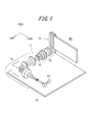
- FIG. 1 is a perspective view of an image display device according to a first embodiment of the present invention. It is a block diagram which shows roughly the structure of the imaging
- FIG. 1 is a perspective view of a display device according to a first embodiment of the present invention.
- the image display device 10 is configured to include an image projection optical system 11 and a pupil expansion optical system 12.
- a direction along the optical axis of the image projection optical system 11 is z direction, and two directions perpendicular to the z direction and perpendicular to each other are x direction (first direction) and y direction (second direction).
- the upper direction is the x direction.
- the lower right direction is the y direction, and the lower left direction is the z direction.
- the image projection optical system 11 projects image light corresponding to an arbitrary image at infinity.
- the pupil expansion optical system 12 receives the image light projected by the image projection optical system 11, expands the exit pupil, and emits the light. By looking at any part of the enlarged projection area PA of the exit pupil, the observer can observe the image.
- the image projection optical system 11 includes a light source 13, an illumination optical system 14, a transmission type chart 15, and a projection optical system 16.
- the light source 13 is driven by a light source driver (not shown), and uses a power supplied from a battery (not shown) to emit a laser as illumination light.
- the wavelength of the laser is, for example, 532 nm.
- the illumination optical system 14 includes a collimator lens 17, a first lenticular lens 18, a second lenticular lens 19, a first lens 20, a diffusion plate 21, and It is configured to include two lenses 22.
- the collimator lens 17, the first lenticular lens 18, the second lenticular lens 19, the first lens 20, the diffusion plate 21, and the second lens 22 are optically coupled.
- the collimator lens 17 converts the illumination light emitted from the light source 13 into parallel light.
- the first lenticular lens 18 has a lens pitch shorter than the width of the luminous flux of the illumination light emitted from the collimating lens 17, for example, 0.1 to 0.5 mm, and has a plurality of lens elements, and the incident parallel luminous flux has a plurality of lenses Configured to be illuminated across elements.
- the first lenticular lens 18 has a refractive power in the x direction, and diverges the illumination light converted into the parallel light beam along the x direction.
- the second lenticular lens 19 has a shorter focal length than the first lenticular lens 18.
- the focal lengths of the first lenticular lens 18 and the second lenticular lens 19 are 1.6 mm and 0.8 mm.
- the second lenticular lens 19 is disposed such that the back focal positions of the first lenticular lens 18 and the second lenticular lens 19 substantially coincide with each other.
- the second lenticular lens 19 has a lens pitch shorter than the width of the luminous flux of the illumination light emitted from the collimating lens 17, for example, 0.1 to 0.5 mm, and has a plurality of lens elements, and a plurality of incident parallel luminous fluxes Configured to be illuminated across the lens elements of The second lenticular lens 19 has a refractive power in the y direction, and diverges the illumination light diverged in the x direction along the y direction.
- a lenticular lens having a divergence angle in the y direction larger than that in the x direction of the first lenticular lens 18 is used as the second lenticular lens 19.
- the first lens 20 is arranged such that the front focal position of the first lens 20 substantially matches the back focal position of the first lenticular lens 18 and the second lenticular lens 19.
- the focal length of the first lens 20 is, for example, 50 mm. Therefore, the first lens 20 converts each of the illumination light components emitted from the plurality of lens elements of the second lenticular lens 19 into parallel light beams with different emission angles, and emits them.
- the diffuser plate 21 is arranged to substantially coincide with the back focal position of the first lens 20. Therefore, the plurality of parallel light beams emitted from the first lens 20 are irradiated in a manner to be folded on the diffusion plate 21. As a result, on the diffusion plate 21, a rectangular illumination light having a Gaussian intensity distribution and a substantially uniform intensity distribution, and having a light beam width longer in the y direction than in the x direction, is emitted.
- the diffusion plate 21 is driven by a diffusion plate drive mechanism (not shown), vibrates along a plane perpendicular to the optical axis OX, and reduces the visibility of speckle.
- the diffusion plate 21 is, for example, a holographic diffuser whose diffusion angle is designed to be rectangular, and irradiates the illumination light emitted from the diffusion plate 21 to the entire region of the rectangular transmission type chart 15 described later with uniform intensity and without excess or deficiency. Do.
- the second lens 22 is arranged such that the front focal position of the second lens 22 substantially coincides with the position of the diffusion plate 21.
- the focal length of the second lens 22 is, for example, 26 mm.
- the second lens 22 condenses illumination light incident at various angles at each angle.
- the transmission chart 15 is disposed at the back focal position of the second lens 22.
- the transmission chart 15 is, for example, a rectangle having a length of 5.6 mm in the x direction and 4.5 mm in the y direction.
- the transmission chart 15 is driven by a chart drive unit (not shown) to form an arbitrary image to be displayed on the image display device 10.
- a chart drive unit not shown
- Each parallel light flux collected at each angle is irradiated to each pixel constituting the image of the transmission type chart 15. Therefore, the light transmitted through each pixel constitutes the image light.
- the projection optical system 16 is arranged such that the exit pupil of the projection optical system 16 and the diffusion plate 21 are optically conjugate. Therefore, the shape of the exit pupil is a rectangle longer in the y direction than in the x direction.
- the projection optical system 16 has a focal length of 28 mm, for example, and projects the image light on which the transmission type chart 15 is projected at infinity.
- the projection optical system 16 is a group of parallel light beams having angular components in the x and y directions according to the height of the object from the optical axis OX in the x and y directions of each pixel of the transmission chart 15. Emit as image light.
- the light is emitted in an angular range of ⁇ 4.6 ° in the x direction and ⁇ 5.7 ° in the y direction.
- the image light projected by the projection optical system 16 is incident on the pupil magnification optical system 12.
- the pupil expansion optical system 12 includes a polarizer 23, a first propagation optical system 24, a half wave plate 25, and a second propagation optical system 26.
- the polarizer 23, the first propagation optical system 24, the half-wave plate 25, and the second propagation optical system 26 are displayed with a large distance for the sake of explanation. Are placed close to each other as shown in FIG.
- the polarizer 23 is disposed between the exit pupil of the projection optical system 16 and the projection optical system 16, receives image light emitted from the projection optical system 16, and emits S-polarized light.
- the first propagation optical system 24 includes an incident area (not shown in FIG. 3) of a second plane (not shown in FIG. 3) of a first light guide (not shown in FIG. 3) to be described later.
- the exit pupils of the projection optical system 16 are arranged so as to be aligned, and the exit pupil projected as S-polarized light by the polarizer 23 is enlarged in the x direction and emitted (see the reference “Ex”).
- the half-wave plate 25 rotates the polarization plane of the image light expanded in the x direction by 90 °.
- the second propagation optical system 26 expands the image light whose polarization plane has been rotated by the half-wave plate 25 in the y direction and emits the light (see reference numeral “Ey”).
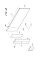
- the first propagation optical system 24 includes a first light guide 27, a first polarization beam split film 28, a first spacer 29, a first input deflection unit 30, and a first light deflector 27. It is configured to include one output deflection unit 31.
- the first polarization beam split film 28 is vapor-deposited on the first light guide 27 as described later, and can not be separated from each other, but in FIG. 4, it is schematically separated and described.
- the first light guide 27 is a transparent flat plate having a first plane S1 and a second plane S2 which are parallel and opposite to each other.
- the first spacing plate 29 is formed in a plate shape having a third plane S3 and a fourth plane S4 which are parallel and opposed to each other, and the third plane S3 is a first plane of the first light guide 27.
- the first polarization beam split film 28 is bonded to S1.
- the first input deflection unit 30 is a prism, and has a flat input side bonding surface S5 and an inclined surface S6 inclined with respect to the input side bonding surface S5.
- the first output deflection unit 31 is a plate-like reflective diffraction grating whose surface on the first space plate 29 side is a diffractive surface S7.
- the third plane S3, the fourth plane S4, and the diffraction plane of the first output deflection unit 31 of the first spacing plate 29 are provided.
- a first polarized beam split film 28 having substantially the same size as S7 is formed by vapor deposition.
- the area of the first plane S1 where the first polarized beam split film 28 is formed is bonded to the third plane S3 of the first spacer 29 by a transparent adhesive.
- the diffractive surface S7 of the first output deflection unit 31 is joined to the fourth plane S4 of the first spacing plate 29.
- the first input deflection unit 30 is bonded to the area on the input side bonding surface S5 with a transparent adhesive in a region other than the region where the first polarization beam split film 28 is formed in the first plane S1.
- the first Propagation optical system 24 is integrated.
- the region where the first input deflection unit 30 is provided is the incident region
- the region where the first output deflection unit 31 is provided is the It is called an exit area (see FIG. 5).
- the first polarization beam splitting film 28 is formed so as to slightly protrude toward the incident area side.
- the integrated first propagation optical system 24 is flat and has a length direction ("x direction" in Fig. 4) and a width direction (Fig. 4) of the first propagation optical system 24 and the first light guide 27.
- the lengths Wx1 and Wy1 of “y direction” in 4 are, for example, 60 mm and 20 mm.
- the length Wx1e in the longitudinal direction of the first polarization beam splitting film 28 is, for example, 50 mm.
- the length Wx1i of the first input deflection unit 30 in the longitudinal direction is, for example, 7 mm.
- the first input deflection unit 30 may include a portion having a surface other than the inclined surface S6 as a surface facing the input side bonding surface S5.
- the longitudinal length Wx1i of the above is a length along the longitudinal direction of the inclined surface S6.
- the first polarization beam splitting film 28 is a multilayer film designed to transmit light incident from a substantially perpendicular direction and to reflect most of the light incident from an oblique direction.
- a thin film having low-pass or band-pass spectral reflection characteristics can have such characteristics.
- the first polarization beam splitting film 28 has a transmittance for obliquely incident light, which varies according to the position along the x direction.
- the first polarization may be such that the transmittance is increased in a geometric progression according to the distance from one end of the first polarization beam splitting film 28 on the first input deflection unit 30 side (see FIG. 6).
- a beam split film 28 is formed.
- the distance from the vapor deposition source is arranged to change according to the planar distance from the first input deflection unit 30, and the difference in the distance It is possible to form a film by designing in advance to have a desired reflection characteristic at each position according to the difference in film thickness).
- quartz transparent medium having a thickness of 3 mm, that is, a length in the z direction is used (see FIG. 4).
- quartz transparent medium
- it has heat resistance against heating when depositing the first polarization beam split film 28, and it is hard so that it is difficult to warp against film stress Have.
- An AR film 32 is formed on the second plane S2 of the first light guide 27.
- the AR film 32 suppresses the reflection of image light incident from the vertical direction.
- the AR film 32 is designed and formed so that the film stress is balanced with the film stress of the first polarization beam split film 28. By balancing the film stress, distortion of the first propagation optical system 24 can be suppressed, which can contribute to good propagation of the image light.
- a plate-like member made of, for example, quartz is used as the first spacer 29.
- the first spacing plate 29 is bonded to the first plane S1 of the first light guide 27 on which the first polarization beam splitting film 28 is formed by a transparent adhesive.
- the first spacer 29 has a refractive index substantially equal to that of the transparent adhesive, and the refractive index is, for example, 1.5. By setting the refractive index substantially equal to that of the transparent adhesive, it is possible to prevent the occurrence of multiple reflections of image light in the transparent adhesive.
- the thickness of the first spacer i.e., the length in the z direction, may be, for example, 1.9 mm.
- the first input deflection unit 30 is formed of, for example, quartz. By forming the first input deflection unit 30 using quartz which is the same material as the first light guide unit 27, the reflection at the interface between the input side joint surface S5 and the first plane S1 is ideal. Can be reduced to
- Aluminum is vapor-deposited on the inclined surface S6 of the first input deflection unit 30, and functions as a reflective film. As shown in FIG. 5, the normal to the inclined surface S6 extends to the emission area side of the first light guide 27. Therefore, a light flux vertically incident on the second plane S2 of the first light guide portion 27 in the incident region is reflected by the inclined surface S6 inside the first input deflection portion 30, and is propagated toward the emission region Ru.
- the apex angle formed by the input side joint surface S5 and the inclined surface S6 will be described later. Further, the interface between the first input deflection unit 30 and the first spacing plate 29 and the first output deflection unit 31 is colored in black, and absorbs the incident light without reflecting it.
- the first output deflection unit 31 is a reflective diffraction grating whose surface in contact with the first spacing plate 29 is a diffractive surface S7.
- the lengths in the length direction (x direction) and the width direction (y direction) of the first output deflection unit 31 are the same as those of the first polarization beam splitting film 28, that is, 50 mm and 20 mm, respectively.
- the thickness, i.e., the length in the z direction can be, for example, 2 mm or 3 mm.
- the diffractive surface S7 is provided with a large number of diffractive grooves extending in the y direction orthogonal to the direction in which the image light propagates.
- the grating density of the diffractive surface S7 is, for example, 2150 [l / mm], and the first-order diffracted light of the image light incident on the diffractive surface S7 according to the wavelength ⁇ of the image light in vacuum is substantially perpendicular to the diffractive surface S7. It is designed to be in the direction. Further, the diffraction grooves of the diffraction surface S7 are shaped and arranged such that the diffraction efficiency of the first-order diffracted light is maximized. It is also possible to form a diffractive surface directly on the fourth surface S4 of the first spacing plate instead of the first output deflection section 31 and use it as the first output deflection section.
- the apex angle formed by the input-side joint surface S5 and the inclined surface S6 of the first input deflection unit 30 is determined based on the critical angle in the second plane S2 of the first light guide 27 as described below.
- the first propagation optical system 24 is disposed so that the light beam Lx parallel to the optical axis OX of the image projection optical system 11 is perpendicularly incident from the outside on the incident area on the second plane S2.
- the light flux Lx vertically incident on the incident region enters the first input deflection unit 30 from the first light guide 27 and is obliquely reflected by the inclined surface S6.
- the obliquely reflected light flux Lx is transmitted through the first light guide 27 into the second plane S2.
- the apex angle formed by the input side joint surface S5 of the first input deflection unit 30 and the inclined surface S6 is determined so that the light beam Lx incident on the second plane S2 in the first light guide 27 is totally reflected.
- the first light guide 27 is formed of quartz, so the critical angle is 43.6 °.
- the incident angle ⁇ to the second plane S 2 in the first light guide 27 with respect to the luminous flux of the object height vertically incident from the image projection optical system 11 is the input side joint surface of the first input deflection unit 30 Because the angle of inclination of the inclined surface S6 with respect to S5 is a double angle, the angle of inclination needs to be 21.8 ° or more. In the present embodiment, the inclination angle is, for example, 25.8 ° and 21.8 ° or more.
- the angle of a ray incident on the incident area of the second plane S2 for example, the angle of the incident ray On the air side, ⁇ 4.6 ° in the x direction, ⁇ 5.7 ° in the y direction, ⁇ 3.1 ° in the x direction, and y direction in the medium of the first light guide 27 formed of quartz It is possible to limit the angle of the image light according to all object heights in the first propagation optical system 24 described above.
- the luminous flux can be totally reflected in the first light guide 27 at the second plane S2.
- the light beam Lx vertically incident on the incident region of the second plane S2 is reflected by the inclined surface S6 of the first input deflection unit 30,
- the light is obliquely incident on the emission area of the second plane S2 inside the first light guide portion 27.
- the light beam Lx incident from an oblique direction is incident on the second plane S2 at an angle exceeding the critical angle, and is totally reflected.
- the totally reflected light beam Lx obliquely enters the first polarization beam splitting film 28, transmits only a predetermined amount of light, and reflects the remaining light.
- the light beam Lx reflected by the first polarization beam splitting film 28 again enters the second plane S2 at an angle exceeding the critical angle, and is totally reflected. Thereafter, the light beam Lx is propagated in the x direction of the first light guide 27 while repeating partial reflection in the first polarization beam split film 28 and total reflection in the second plane S2. However, each time the light is incident on the first polarization beam split film 28, the light is transmitted at a predetermined rate and emitted to the first spacer 29.
- the light beam Lx incident from the third plane S3 of the first space plate 29 is diffracted by the diffractive surface S7 of the first output deflection unit 30 joined to the fourth plane S4, and is perpendicular to the diffractive surface S7. It is deflected in the direction.
- the light beam Lx deflected in the direction perpendicular to the diffractive surface S7 is transmitted through the first spacing plate 29, vertically incident on the first polarization beam splitting film 28, and transmitted at a transmittance of substantially 100%. Further, the light is perpendicularly incident on the second plane S2 and emitted from the second plane S2 to the outside.
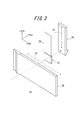
- the half-wave plate 25 (see FIG. 3) is formed in a shape substantially the same size as the emission area of the second plane S2.
- the half-wave plate 25 is disposed with an air gap at a position facing the emission region of the second plane S2. Therefore, a light beam obliquely incident on the second plane S2 at an angle larger than the critical angle in the first light guide portion 27 does not pass through the second plane S2, and total reflection is ensured.
- the half-wave plate 25 rotates the polarization plane of the light beam emitted from the first propagation optical system 24 by 90 degrees.
- the second propagation optical system 26 includes a second light guide 33, a second polarization beam split film 34, a second spacer 35, a second input deflection unit 36, and It comprises the output deflection part 37 of two. Similar to the first propagation optical system 24, these constituent members are in the form of an integrated flat plate, and the width direction of the second propagation optical system 26 and the second light guide portion 33 (the "x direction in FIG. The lengths Wx2 and Wy2 of the length direction (the “y direction” in FIG. 7) are, for example, 50 mm and 110 mm.
- the longitudinal length Wy2e of the second polarization beam splitting film 34, the second spacer plate 35 and the second output deflection unit 37 in the second propagation optical system 26 is, for example, 100 mm.
- the length Wy2i of the second input deflection unit 36 in the longitudinal direction is, for example, 10 mm.
- the functions of the second light guide 33, the second polarization beam split film 34, the second spacer 35, the second input deflection unit 36, and the second output deflection unit 37 are respectively the first light guide Similar to the unit 27, the first polarization beam split film 28, the first spacer 29, the first input deflection unit 30, and the first output deflection unit 31.
- the second light guide 33 has a fifth plane S8 on which the second polarization beam split film 34 is deposited and a sixth plane S9 opposed to the fifth plane S8.
- the emission area of the second plane S2 of the first propagation optical system 24 and the incident area of the sixth plane S9 of the second propagation optical system 26 face each other.
- the propagation optical system 26 is disposed in a posture rotated 90 ° around a straight line parallel to the z direction with respect to the first propagation optical system 24 (see FIG. 3). Therefore, the second propagation optical system 26 enlarges the image light emitted from the first propagation optical system 24 in the y direction and emits it.
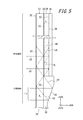
- the configuration of the first propagation optical system 24 including the first space plate 29 it is possible to reduce the image deterioration caused by the zeroth-order diffracted light generated in the diffractive surface S7 of the first output deflection unit 31. explain.
- the first one is most along the x direction.
- the light beam from the output deflection unit 31 is referred to as a first light beam b1
- the light beam from the first input deflection unit 30 is referred to as a second light beam b2.
- the following description describes the second ray b2, but the same applies to the first ray b1 and other rays in the luminous flux Lx.
- the second light ray b2 is incident on the first light guide 27 from the second plane S2, is reflected by the inclined surface S6 of the first input deflection unit 20, and is incident on the first light guide 27. , And propagate in the first light guide 27.
- a first polarization beam split film a part of which is deposited on the first plane S1
- the light passes through the third plane S3 and enters the first spacing plate 29 from the third plane S3
- a part of the second light beam b2 travels in the first spacing plate 29 to the fourth plane S4, and
- the light is incident on the diffractive surface S7 of the first output deflection unit 31 joined to the plane S4 of FIG.
- the incident second light beam b2 is emitted in the direction perpendicular to the diffractive surface S7 as a third light beam b3 which is first-order diffracted light.
- the third light beam b3 passes through the first spacing plate 29 and the first light guide 27 and exits from the second plane S2.
- a portion of the second beam b2 in the diffraction plane S7, and a fourth light beam b4 is a zero-order diffracted light
- First polarization beam splitter film 28 disposed between the first spacers 29 and the first light guide portion 27 reflects a large portion of the image light of a wavelength ⁇ incident at the incident angle theta 1 Characteristics
- the fourth ray b4 of the zeroth-order diffracted light is specularly reflected, propagates again in the second spacer plate 20, and is incident on the fourth plane S4.
- a part of the fourth light beam b4 emitted from the fourth plane S4 is first-order diffracted by the diffractive surface S7 of the first output deflection unit 31 and emitted as the fifth light beam b5 in the direction perpendicular to the diffractive surface S7 .
- the fifth light ray b5 passes through the first spacing plate 29 and the first light guide 27 and exits from the second plane S2. Also, the remaining part of the fourth light beam b4 propagates in the first spacing plate 29 again in the regular reflection direction.
- the occurrence of the zeroth-order diffracted light causes the third light beam b3 and the fifth light beam b5 parallel to each other based on the second light beam b2 to be emitted toward the observer's eye.
- the third light beam b3 and the fifth light beam b5 are focused at the same point on the retina of the observer's eye to cause interference.
- Such interference causes bright and dark stripes to form on the retina in the eye and affects the quality of the observed image.
- the thickness of the first spacer plate is t 1
- the optical path difference due to one reflection in the first spacer plate 29 is 2t 1 / cos ⁇ 1.
- the refractive index of the first spacers 29 n s1 the wavelength of the image light in the first spacers and lambda ', satisfy the following equation.
- a ray b p indicates a ray which is diffracted by the diffractive surface S ⁇ b> 7 of the first output deflection unit 31 and is reflected perpendicularly to the diffractive surface S ⁇ b> 7.
- the propagation angle in the first spacer 29 is assumed to be ⁇ c1 .
- the light beam b i is a light beam whose propagation angle differs from the light beam b p in the first spacing plate 29 in the xz in-plane direction by the pitch ⁇ 1 of light and dark of the interference fringes.
- the light ray b i is converted into a bright and dark pitch ⁇ air1 of interference fringes observed from the outside of the image display device 10 by refraction when exiting from the first light guide 27.
- the refractive index of the first light guide 27 is n w1 and ⁇ d1 and ⁇ air1 are minute, the approximation similar to that described above is performed. It becomes.
- ⁇ air1 decreases as t 1 increases. That is, by providing the first spacers 29 having a thickness t 1, fringe spacing [Delta] [theta] Air1 interference fringes compared with the case without the first spacing plate 29 is reduced. By reducing the stripe interval ⁇ air1 , the visibility of the image is improved. Therefore, the first spacer 29 can reduce image deterioration due to interference fringes caused by the zeroth-order diffracted light.
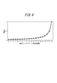
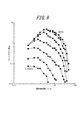
- the spatial contrast sensitivity function corresponds to the transfer function of the visual system, the value of which depends on the spatial frequency and the brightness of the object to be observed.
- Fig. 9 (Asakura Shoten quoted from the structure and initial function of visual system I visual system (P 209).
- the source is Van Nes FL, Bouman MA: Spatial modulation transfer in the human eye. Journal of the Optical Society of America, 57: 401 Experimental results as shown in -406, 1967.) are widely known.
- a plurality of lines on the graph of FIG. 9 correspond to differences in brightness, and the graph on the upper right has values in a bright environment.
- the horizontal axis indicates the repetition period of the structure per degree of angle. According to this, it can be seen that at spatial frequencies of 30 c / d and above, even when a bright object is viewed, the contrast appears to be lower than in the low frequency region. Therefore, setting the period of the interference fringes to 30 c / d or more is one indication of the present invention.
- the period 30c / d of the interference fringes corresponds to a two-point resolution of 0.0006 [rad] of the human eye, and this spatial frequency is equivalent to a frequency that can be resolved by a person with visual acuity of 0.5.
- the contrast of the interference fringes is low, and it is hard to be recognized by the human eye.
- the two-point resolution of 0.0003 [rad] corresponds to 60 c / d as a spatial frequency, which corresponds to a limit of 1.0 for human vision when it is converted to visual acuity. Also from the graph of FIG. 9, it can be seen that the contrast sensitivity is greatly reduced at 60 c / d.
- the interference fringes are not visually recognized if the fringe spacing ⁇ is smaller than this. That is, It is more preferable if
- the thickness t1 of the first spacing plate 29 satisfies the equation (5), more preferably the equation (6), the brightness and darkness of the image caused by the zeroth-order diffracted light is visually recognized by human eyes It disappears.
- the thickness t1 of the first spacer may be 0.14 mm or more. Furthermore, in order to satisfy Formula (6), the thickness t1 of the first spacer may be 0.28 mm or more.
- the portion of the second light beam b2 transmitted through the first surface S1 becomes zeroth-order diffracted light in the fourth plane S4, and the third light beam in the first spacer 29 is produced.
- a fourth ray b4 reciprocated between the plane S3 and the fourth plane one or more times, and a portion reflected by the first plane S1 of the second ray b2 are the first plane S1 and the second plane S1.
- Interference with the plane S2 may occur between the fourth ray b4 and the sixth ray b6 when coming close to the sixth ray b6 transmitting the first plane S1 by reciprocating back and forth one or more times. .
- T v1 abs (n (n s1 t 1 ) -m (n w1 T 1 ))
- abs (X) is a function that represents the absolute value of X.
- the second propagation optical system 26 by providing the second spacing plate 35, it is possible to suppress the generation of interference fringes due to the influence of zero-order diffracted light of the image light. If there is no first spacer 29 or its thickness is narrow, interference fringes generated in the first propagation optics 24 appear as light and dark in the x direction. On the other hand, in the second propagation optical system 26, since the image light propagates in the y direction, light and dark in the y direction may occur for the same reason as the first propagation optical system 24. By providing the second spacer 35, the distance between the interference fringes becomes narrow, so that the interference fringes become difficult to be recognized visually. Thus, the image quality can be improved.
- T v2 abs (n (n s2 t 2 ) -m (n w2 T 2 ))
- a fifth spacing plate 29 provided with a first spacer 29 between the first output deflecting portion 31a and the second polarization beam splitting film 34 of the second propagation optical system 26. Since the second spacing plate 35 is provided between S8 and the diffractive surface S14 of the second output deflection unit 37, even if interference fringes are generated due to the generation of zero-order diffracted light, the light-dark spacing is By narrowing it so as not to be visible to the human eye, degradation of the observed image is reduced. In particular, with the settings that satisfy Equations (6) and (9), image deterioration can be completely prevented since light and dark are not visually recognized at all in the two-point resolution of a normal human eye.
- the first propagation optical system 24 and the second propagation optical system 26 have a first output deflection unit 31 and a second output deflection having reflection type diffractive surfaces S7 and S14, respectively. Part 37 was used.
- the first propagation optical system 24 and the second propagation optical system 26 instead of the first propagation optical system 24 and the second propagation optical system 26, the first propagation optical system 24a and the second propagation optical system 26a having the transmission type diffractive surface are arranged as shown in FIG. It is also possible to configure the pupil magnification optical system 12.
- the polarizer 23 and the half wave plate 25 have the same functions as those of the first embodiment.
- the first propagation optical system 24a and the second propagation optical system 26a are different from the first embodiment in that image light is emitted from the surface opposite to the incident side.
- FIG. 11 is a view for explaining the diffraction of image light in the first propagation optical system 24a, and shows a first light guiding portion 27 for transmitting the image light, a first polarization beam splitting film 28, and a first spacing plate. 29 and a part of the first output deflection unit 31a are shown in an enlarged manner.
- the first output deflection unit 31a differs from the first output deflection unit 31 of the first embodiment in that the diffractive surface S7 is a transmissive diffraction grating.
- the first output deflection unit 31a is a plate-like member made of a material that transmits light at the wavelength of image light, and the surface facing the diffractive surface S7 is a flat light transmission surface. .
- the other configuration is the same as that of the first propagation optical system 24 of the first embodiment.
- the image light transmitted through the first beam splitting film 28 is transmitted through the first spacing plate 29 and is diffracted by the diffractive surface S7 of the first output deflecting unit 31 to be approximately the same as the diffractive surface S7. Ejected in the orthogonal direction.
- the second propagation optical system 26a is similarly configured.
- the observer can observe the image from the + z direction side (upper right side in FIG. 10) of the second propagation optical system 26a.
- the same effect as that of the first embodiment is obtained.
- light b p receives the diffracted by the diffraction surface S7 in the first output deflecting unit 31a, shows a light ray which passes perpendicularly to the diffraction plane S7.
- the ray b i is a ray different from the ray b p in propagation angle in the xz plane direction by the pitch ⁇ of interference fringes.
- Equation (2) the pitch ⁇ 1 of the light and dark of the interference fringes can be expressed by Equation (2).
- an angle at which the light ray b p is diffracted by the diffractive surface S7 of the first output deflection unit 31 and transmitted in the direction perpendicular to the diffractive surface S7 is ⁇ c1
- the light ray b i makes the first output deflection portion 31 a
- the propagation angle ⁇ air1 that permeates and is emitted into the air can be expressed by the following equation. However, the same approximation as in the first embodiment is performed.
- equation (5) is changed to If so, the contrast of the interference fringes can be low and it can be difficult to view.
- the interference fringes are almost invisible to human eyes.
- the contrast of the interference fringes can be lowered and it can be made difficult to see.
- the interference fringes are not visually recognized by satisfying the following equation.
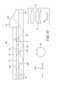
- FIG. 12 is a side view schematically showing an optical system of the image display device according to the second embodiment.
- the image display apparatus according to the second embodiment has a propagation optical system in only the x direction, unlike the first embodiment.
- the propagation optical system 44 guides the image light from the image projection optical system 41 mounted on the head and arranged on the side of the head in front of the user's eyes while the propagation optical system 44 Project the image towards the
- the image projection optical system 41 includes a display element 42 such as an LCD or an organic EL display, and a projection optical system 43 for projecting image light from the display element.
- the projection optical system 43 is disposed such that the exit pupil is aligned with the incident surface of the propagation optical system 44 (the second plane S22 of the light guide 45).
- the propagation optical system 44 further includes a light guide 45, a polarization beam split film 46, a spacer 47, an input deflection unit 48, and an output deflection unit 49.
- Each component of the propagation optical system 44 is the first light guiding portion of the first propagation optical system 24 shown in FIG. 4 and FIG. 5 of the first embodiment except for differences in size and fine shape.
- the first polarization beam split film 28, the first spacing plate 29, the first input deflection unit 30, and the first output deflection unit 31 are configured in the same manner.
- the first plane S21, the second plane S22, the third plane S23, the fourth plane S24, the input-side joint surface S25, the inclined surface S26, and the diffractive surface S27 are also the first embodiment of the first embodiment.
- Each of these components propagates the image light incident from the image projection optical system 41 in the same manner as the first propagation optical system 24 of the first embodiment, so in the present embodiment the configuration and operation of each component I omit explanation.
- the spacer 47 is provided between the light guide 45 and the output deflector 49 as in the first embodiment, the interference due to the zero-order diffracted light is the same as in the first embodiment. Since it becomes difficult to visually recognize light and dark, it is possible to reduce the deterioration of the observed image. Further, by satisfying the equation (4), the light and dark due to the interference fringes will not be visible to the human eye. Furthermore, it is also the same as in the first embodiment that it is preferable to satisfy the relationship of the formula (5).
- the dimensions, shapes, arrangements, and the like of the components described in the first embodiment are merely examples, and various dimensions, shapes, arrangements, and the like can be taken within the scope of the present invention.
- the image projection optical system 11 may have various configurations as long as the exit pupil for projecting the display image coincides with the incident area of the pupil expansion optical system 12.
- the first output deflection unit 31 is not a reflective diffraction grating but a transmissive diffraction grating, and projected image light is emitted from the surface facing the diffractive surface S7 of the first output deflection unit 31. You may do so.
- a diffractive surface is directly formed on the fourth surface S4 of the first spacing plate 29, and this is used as the first output deflection. It is also possible to use a department. The same applies to the second propagation optical system 26 and the second embodiment.
Landscapes
- Physics & Mathematics (AREA)
- General Physics & Mathematics (AREA)
- Optics & Photonics (AREA)
- Diffracting Gratings Or Hologram Optical Elements (AREA)
- Projection Apparatus (AREA)
Abstract
An image display device has: an image projection optical system that projects image light an infinite distance; a first light guide unit (27) formed in a plate shape having a first flat surface (S1) and a second flat surface (S2) and propagating the image light in an x direction while repeating transmission in the first flat surface (S1) of part of the image light projected from the image projection optical system and reflection between the first flat surface (S1) and the second flat surface (S2) of the remaining image light; a first spacing plate (29) formed in a plate shape having a third flat surface (S3) and a fourth flat surface (S4) such that the third flat surface (S3) is joined to the first flat surface (S1); and a first output deflecting unit (31) formed on or joined to the fourth flat surface (S4) such that the part of image light transmitted through the first flat surface (S1) is diffracted in a direction substantially orthogonal to the first flat surface (S1).
Description
本出願は、2014年3月20日に出願された日本国特許出願2014-59021号の優先権を主張するものであり、この先の出願の開示全体をここに参照のために取り込む。
This application claims priority to Japanese Patent Application 2014-59021, filed March 20, 2014, the entire disclosure of which is incorporated herein by reference.
本発明は、射出瞳を拡大して画像を投影する表示装置に関する。
The present invention relates to a display device that projects an image by enlarging an exit pupil.
2次元画像を観察者の視野内に投影する装置として、導光板内で画像光を反射を繰り返させながら伝播させつつ、導光板の一方の面側で一部の画像光を観察者側に偏向して出射させることにより射出瞳を拡大する、種々の画像表示装置が知られている。導光板内の画像光を偏向する方法としては、回折作用を利用する方法が知られている(例えば、特許文献1参照)。
As a device for projecting a two-dimensional image into the field of view of the observer, the image light is propagated while being repeatedly reflected in the light guide plate, and part of the image light is deflected toward the observer on one side of the light guide plate Various image display devices are known which enlarge the exit pupil by emitting light. As a method of deflecting the image light in the light guide plate, a method of utilizing a diffractive action is known (see, for example, Patent Document 1).
しかし、画像光を導光板内で反射により伝搬させ、回折格子により伝播する画像光の一部を順次偏向させて取り出す方法では、導光板の回折格子側に取り出し効率を制御するための偏光ビームスプリット膜などの機能膜が付され、導光板のこの機能膜が付された面と回折格子との間に薄い接着層を設けて接続している。しかし、本発明者らが鋭意検討した結果、接着層内を伝搬する画像光の成分により、表示しようとする画像ににじみや像の明暗などの画質劣化が生じることが確認された。以下に、画像劣化が生じる理由について説明する。
However, in the method of reflecting the image light by reflection in the light guide plate and sequentially deflecting and extracting a part of the image light propagated by the diffraction grating, a polarization beam split for controlling the extraction efficiency to the diffraction grating side of the light guide plate A functional film such as a film is attached, and a thin adhesive layer is provided and connected between the surface of the light guide plate to which the functional film is attached and the diffraction grating. However, as a result of intensive studies by the present inventors, it has been confirmed that the image light component propagating in the adhesive layer causes deterioration in image quality such as bleeding and light and dark of the image to be displayed. The reason why the image deterioration occurs will be described below.
図13は、回折格子を含む画像表示装置の瞳拡大光学系110の構成例を概略的に示す側面図である。瞳拡大光学系110は、導光板111と機能膜112と入射偏向部113と回折板114とを含んで構成される。導光板111は、互いに対向する第1の平面S101と第2の平面S102とを有し、これら第1の平面S101と第2の平面S102との間を、画像光が反射を繰り返しながら伝搬する。導光板111の画像光入射側端部には入射偏向部113が接合されており、導光板111の第2の平面S102の一方の端部から入射した画像光が、第1の平面S101を透過し入射偏向部113の斜面S103にて反射され、第1の平面S101から導光板111に斜めに傾斜して再度入射する。また、導光板111の第1の平面S101の入射偏向部113が接合されていない位置には、画像光の反射、透過率をコントロールする機能膜112が蒸着されている。回折板114は、透明な接着層115により導光板111に接着されており、この接着面に回折面S104が形成されている。回折板114の各回折溝は、導光板111内の画像光の進行方向(図において左方向)に直交する方向に延びている。
FIG. 13 is a side view schematically showing a configuration example of a pupil expansion optical system 110 of an image display apparatus including a diffraction grating. The pupil expansion optical system 110 is configured to include the light guide plate 111, the functional film 112, the incident deflection unit 113, and the diffraction plate 114. The light guide plate 111 has a first plane S101 and a second plane S102 facing each other, and the image light propagates while being repeatedly reflected between the first plane S101 and the second plane S102. . The incident deflection unit 113 is joined to the image light incident side end of the light guide plate 111, and the image light incident from one end of the second plane S102 of the light guide plate 111 is transmitted through the first plane S101. The light is reflected by the slope S103 of the light incident / deflecting portion 113, and obliquely incident on the light guide plate 111 from the first plane S101 again. Further, a functional film 112 for controlling reflection and transmittance of image light is vapor deposited at a position where the incident deflection part 113 of the first plane S101 of the light guide plate 111 is not joined. The diffraction plate 114 is bonded to the light guide plate 111 by a transparent adhesive layer 115, and a diffractive surface S104 is formed on the bonding surface. Respective diffraction grooves of the diffraction plate 114 extend in a direction orthogonal to the traveling direction of the image light in the light guide plate 111 (left direction in the drawing).
導光板111内を伝搬する画像光の進行角度は、第2の平面S102との間で全反射条件を満たす。一方、第1の平面101に入射する画像光の一部は、機能膜112を透過して回折格子114の回折面で第1の平面S101に略垂直方向に回折される。この回折光は、第1の平面S101から導光板111に再び入射し、第2の平面S102から観察者の眼球に向けて射出される。画像光は幅を有する光束として瞳拡大光学系110に入射し、導光板111の第2の平面S102の各位置から射出される。これによって、第2の平面S102は拡大された射出瞳を形成する。
The advancing angle of the image light propagating in the light guide plate 111 satisfies the total reflection condition with the second plane S102. On the other hand, part of the image light incident on the first plane 101 is transmitted through the functional film 112 and diffracted by the diffractive surface of the diffraction grating 114 in a direction substantially perpendicular to the first plane S101. The diffracted light again enters the light guide plate 111 from the first plane S101, and is emitted from the second plane S102 toward the eyeballs of the observer. The image light enters the pupil magnification optical system 110 as a light flux having a width, and is emitted from each position of the second plane S 102 of the light guide plate 111. By this, the second plane S102 forms an enlarged exit pupil.
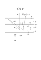
しかし、このような回折格子114を用いた瞳拡大光学系110では、次のような課題が生じる。図14は図13の二点鎖線により囲まれた部分の拡大図である。ただし、接着層115は通常10μm程度の厚さしかなく、数ミリメートル(mm)の厚さの導光板111に比べはるかに薄いが、図14では説明のためこれを拡大して示している。図14において導光板111を伝搬する画像光b11が、機能膜112を透過し、回折格子114の回折面S104に入射すると、1次の回折光以外に0次の回折光b12が発生する。機能膜112は、画像光の大部分を反射させるように設計されているので、0次の回折光b12は、接着層115の内部で多重反射するとともに、回折面S104に入射する度に、その一部が1次回折光b13となって、導光板111を通り第2の平面S102から射出される。このため、互いに平行な複数の1次回折光b13が生じてしまい、これらが観察者の網膜上で互いに干渉して明暗や画像のムラを生じさせる。なお、図中の1次回折光b13の複数の矢印のうち、最初に回折される右端の光線が正規の結像に寄与する画像光であり、他の矢印は不要な光である。
However, in the pupil expansion optical system 110 using such a diffraction grating 114, the following problems occur. FIG. 14 is an enlarged view of a portion surrounded by a two-dot chain line in FIG. However, although the adhesive layer 115 is usually only about 10 μm thick and much thinner than the light guide plate 111 with a thickness of several millimeters (mm), FIG. 14 shows this in an enlarged manner for explanation. In FIG. 14, when the image light b11 propagating through the light guide plate 111 passes through the functional film 112 and is incident on the diffraction surface S104 of the diffraction grating 114, zero-order diffracted light b12 is generated in addition to first-order diffracted light. Since the functional film 112 is designed to reflect most of the image light, the zero-order diffracted light b12 is multi-reflected inside the adhesive layer 115 and is incident on the diffractive surface S104 every time it is incident thereon. A part becomes first-order diffracted light b13, passes through the light guide plate 111, and is emitted from the second plane S102. For this reason, a plurality of first-order diffracted lights b13 parallel to each other are generated, and they interfere with each other on the retina of the observer to cause light and dark and unevenness of the image. Note that among the plurality of arrows of the first-order diffracted light b13 in the figure, the light ray at the right end that is first diffracted is the image light that contributes to normal imaging, and the other arrows are unnecessary light.
したがって、上記のような問題点に鑑みてなされた本発明の目的は、画像光を回折するときに生じる不要光による画像劣化を低減した画像表示装置を提供することである。
Therefore, an object of the present invention made in view of the above problems is to provide an image display apparatus in which image deterioration due to unnecessary light generated when diffracting image light is reduced.
上記目的を達成する画像表示装置の発明は、
任意の画像に対応する画像光を無限遠に投影する映像投影光学系と、
互いに平行且つ対向する第1の平面および第2の平面を有する板状に形成され、前記映像投影光学系から投影される前記画像光の一部の前記第1の平面における透過と前記画像光の残りの前記第1の平面および前記第2の平面間での反射とを繰返しながら前記映像投影光学系の光軸の方向に垂直なx方向に伝播させる第1の導光部と、
互いに平行且つ対向する第3の平面および第4の平面を有する板状に形成され、前記第3の平面は前記第1の平面に接合される第1の間隔板と、
前記第4の平面に形成または接合され、前記第1の平面を透過した一部の前記画像光を、前記第1の平面に実質的に垂直な方向に回折する第1の出力偏向部と
を有することを特徴とするものである。 The invention of an image display apparatus which achieves the above object is:
An image projection optical system which projects image light corresponding to an arbitrary image at infinity;
Transmission of the part of the image light projected from the image projection optical system in the first plane and the image light formed in a plate shape having a first plane and a second plane which are parallel and opposite to each other A first light guide section for propagating in the x direction perpendicular to the direction of the optical axis of the image projection optical system while repeating the reflection between the remaining first plane and the second plane;
A first spacer plate formed in a plate shape having a third plane and a fourth plane which are parallel and opposed to each other, and the third plane is joined to the first plane;
A first output deflection unit formed or joined in the fourth plane, which diffracts a part of the image light transmitted through the first plane in a direction substantially perpendicular to the first plane; It is characterized by having.
前記第1の出力偏向部は、反射型の回折面を備え、
前記画像光が前記第1の出力偏向部により前記第4の平面に対し垂直に回折される前記第1の間隔板内での該画像光の伝播角度をθc1、前記第1の間隔板の厚みをt1、前記画像光の波長をλ、前記第1の間隔板の屈折率をns1、前記第1の導光部の屈折率をnw1とするとき、

を満たすことが好ましい。
あるいは、前記第1の出力偏向部は、透過型の回折面を備え、
前記画像光が前記第1の出力偏向部により前記第4の平面に対し垂直に回折される前記第1の間隔板内での該画像光の伝播角度をθc1、前記第1の間隔板の厚みをt1、前記画像光の波長をλ、前記第1の間隔板の屈折率をns1とするとき、

を満たすようにしても良い。
The first output deflection unit includes a reflective diffraction surface.
A propagation angle of the image light in the first space plate, where the image light is diffracted perpendicularly to the fourth plane by the first output deflection unit, θ c1 , of the first space plate Assuming that the thickness is t 1 , the wavelength of the image light is λ, the refractive index of the first spacer is n s1 , and the refractive index of the first light guide is n w1 .
It is preferable to satisfy
Alternatively, the first output deflection unit includes a transmissive diffraction surface.
A propagation angle of the image light in the first space plate, where the image light is diffracted perpendicularly to the fourth plane by the first output deflection unit, θ c1 , of the first space plate Assuming that the thickness is t 1 , the wavelength of the image light is λ, and the refractive index of the first spacer is n s1 .
May be satisfied.
前記画像光が前記第1の出力偏向部により前記第4の平面に対し垂直に回折される前記第1の間隔板内での該画像光の伝播角度をθc1、前記第1の間隔板の厚みをt1、前記画像光の波長をλ、前記第1の間隔板の屈折率をns1、前記第1の導光部の屈折率をnw1とするとき、
あるいは、前記第1の出力偏向部は、透過型の回折面を備え、
前記画像光が前記第1の出力偏向部により前記第4の平面に対し垂直に回折される前記第1の間隔板内での該画像光の伝播角度をθc1、前記第1の間隔板の厚みをt1、前記画像光の波長をλ、前記第1の間隔板の屈折率をns1とするとき、
A propagation angle of the image light in the first space plate, where the image light is diffracted perpendicularly to the fourth plane by the first output deflection unit, θ c1 , of the first space plate Assuming that the thickness is t 1 , the wavelength of the image light is λ, the refractive index of the first spacer is n s1 , and the refractive index of the first light guide is n w1 .
Alternatively, the first output deflection unit includes a transmissive diffraction surface.
A propagation angle of the image light in the first space plate, where the image light is diffracted perpendicularly to the fourth plane by the first output deflection unit, θ c1 , of the first space plate Assuming that the thickness is t 1 , the wavelength of the image light is λ, and the refractive index of the first spacer is n s1 .
前記第1の導光部の厚みをT1とするとき、任意の5より小さい自然数nおよびmの組み合わせについて、
Tv1=abs(n(ns1t1)-m(nw1T1))
とするとき、

を満たすことが好ましい。
Assuming that the thickness of the first light guiding portion is T 1 , for any combination of natural numbers n and m smaller than 5,
T v1 = abs (n (n s1 t 1 ) -m (n w1 T 1 ))
And when
It is preferable to satisfy
Tv1=abs(n(ns1t1)-m(nw1T1))
とするとき、
T v1 = abs (n (n s1 t 1 ) -m (n w1 T 1 ))
And when
さらに好ましくは、上述の画像表示装置は、互いに平行且つ対向する第5の平面および第6の平面を有する板状に形成され、前記第1の出力偏向部で回折された前記一部の前記画像光が、前記第2の平面から出射した画像光を伝播させる第2の導光部であって、前記画像光の一部の前記第5の平面における透過と前記画像光の残りの前記第5の平面および前記第6の平面間での反射とを繰返しながら前記映像投影光学系の光軸の方向に垂直かつ x方向にも垂直なy方向に伝播させる第2の導光部と、
互いに平行且つ対向する第7の平面および第8の平面を有する板状に形成され、前記第7の平面は前記第5の平面に接合される第2の間隔板と、
前記第8の平面に形成または接合され、前記第5の平面から透過した一部の前記画像光を前記第5の平面に実質的に垂直な方向に回折する第2の出力偏向部と
を有する。 More preferably, the above-described image display device is formed in a plate shape having fifth and sixth planes parallel and opposite to each other, and the image of the part diffracted by the first output deflection unit A second light guiding portion for propagating image light emitted from the second plane, the transmission of a portion of the image light in the fifth plane and the remaining fifth of the image light A second light guide portion for propagating in the y direction perpendicular to the direction of the optical axis of the image projection optical system and also perpendicular to the x direction while repeating reflections between the first plane and the sixth plane;
A second spacer plate formed in a plate shape having a seventh plane and an eighth plane which are parallel and opposed to each other, and the seventh plane is joined to the fifth plane;
And a second output deflection unit formed or joined in the eighth plane and diffracting part of the image light transmitted from the fifth plane in a direction substantially perpendicular to the fifth plane. .
好ましくは、前記第2の出力偏向部は、反射型の回折面を備え、
前記画像光が前記第2の出力偏向部により前記第8の平面に対し垂直に回折される前記間隔板内での該画像光の伝播角度をθc2、前記第2の間隔板の厚みをt2、前記画像光の波長をλ、前記第2の間隔板の屈折率をns2、前記第2の導光部の屈折率をnw2とするとき、

を満たすものとする。
あるいは、前記第2の出力偏向部は、透過型の回折面を備え、
前記画像光が前記第2の出力偏向部により前記第8の平面に対し垂直に回折される前記第2の間隔板内での該画像光の伝播角度をθc2、前記第2の間隔板の厚みをt2、前記画像光の波長をλ、前記第2の間隔板の屈折率をns2とするとき、

を満たすようにしても良い。
Preferably, the second output deflection unit comprises a reflective diffraction surface.
The propagation angle of the image light in the spacer in which the image light is diffracted perpendicularly to the eighth plane by the second output deflector is θ c2 , and the thickness of the second spacer is t 2, the wavelength of the image light lambda, the second refractive index n s2 of spacers, when the refractive index of the second light guide section and n w2,
Shall meet
Alternatively, the second output deflection unit includes a transmissive diffraction surface.
The propagation angle of the image light in the second spacer plate where the image light is diffracted perpendicularly to the eighth plane by the second output deflector is θ c2 of the second spacer plate Assuming that the thickness is t 2 , the wavelength of the image light is λ, and the refractive index of the second spacer is n s2
May be satisfied.
前記画像光が前記第2の出力偏向部により前記第8の平面に対し垂直に回折される前記間隔板内での該画像光の伝播角度をθc2、前記第2の間隔板の厚みをt2、前記画像光の波長をλ、前記第2の間隔板の屈折率をns2、前記第2の導光部の屈折率をnw2とするとき、
あるいは、前記第2の出力偏向部は、透過型の回折面を備え、
前記画像光が前記第2の出力偏向部により前記第8の平面に対し垂直に回折される前記第2の間隔板内での該画像光の伝播角度をθc2、前記第2の間隔板の厚みをt2、前記画像光の波長をλ、前記第2の間隔板の屈折率をns2とするとき、
The propagation angle of the image light in the spacer in which the image light is diffracted perpendicularly to the eighth plane by the second output deflector is θ c2 , and the thickness of the second spacer is t 2, the wavelength of the image light lambda, the second refractive index n s2 of spacers, when the refractive index of the second light guide section and n w2,
Alternatively, the second output deflection unit includes a transmissive diffraction surface.
The propagation angle of the image light in the second spacer plate where the image light is diffracted perpendicularly to the eighth plane by the second output deflector is θ c2 of the second spacer plate Assuming that the thickness is t 2 , the wavelength of the image light is λ, and the refractive index of the second spacer is n s2
さらに、前記第2の導光部の厚みをT2とするとき、任意の5より小さい自然数nおよびmの組み合わせについて、
Tv2=abs(n(ns2t2)-m(nw2T2))
とするとき

を満たすことが好適である。
Furthermore, when the thickness of the second light guide portion is T 2 , for any combination of natural numbers n and m smaller than 5,
T v2 = abs (n (n s2 t 2 ) -m (n w2 T 2 ))
When to
It is preferable to satisfy
Tv2=abs(n(ns2t2)-m(nw2T2))
とするとき
T v2 = abs (n (n s2 t 2 ) -m (n w2 T 2 ))
When to
上記のように構成された本発明に係る画像表示装置によれば、画像光を回折するときに生じる不要光による画像劣化を低減することが可能である。
According to the image display apparatus according to the present invention configured as described above, it is possible to reduce image deterioration due to unnecessary light generated when diffracting the image light.
以下、本発明の実施形態について、図面を参照して説明する。
Hereinafter, embodiments of the present invention will be described with reference to the drawings.
(第1の実施形態)
図1は、本発明の第1の実施形態に係る表示装置の斜視図である。 First Embodiment
FIG. 1 is a perspective view of a display device according to a first embodiment of the present invention.
図1は、本発明の第1の実施形態に係る表示装置の斜視図である。 First Embodiment
FIG. 1 is a perspective view of a display device according to a first embodiment of the present invention.
図1に示すように、画像表示装置10は、映像投影光学系11および瞳拡大光学系12を含んで構成される。本実施形態において、映像投影光学系11の光軸に沿った方向をz方向、z方向に垂直且つ互いに垂直な2方向をx方向(第1の方向)およびy方向(第2の方向)とする。図1においては、上方向をx方向とする。また、図1において、瞳拡大光学系12近傍においては、右斜め下方をy方向、左斜め下方をz方向とする。
As shown in FIG. 1, the image display device 10 is configured to include an image projection optical system 11 and a pupil expansion optical system 12. In this embodiment, a direction along the optical axis of the image projection optical system 11 is z direction, and two directions perpendicular to the z direction and perpendicular to each other are x direction (first direction) and y direction (second direction). Do. In FIG. 1, the upper direction is the x direction. Further, in FIG. 1, in the vicinity of the pupil expansion optical system 12, the lower right direction is the y direction, and the lower left direction is the z direction.
映像投影光学系11は、任意の画像に対応する画像光を無限遠に投影する。瞳拡大光学系12は、映像投影光学系11が投影する画像光を受光し、射出瞳を拡大して射出する。拡大された射出瞳の投影領域PA内のいずこかに目を合わせることにより、観察者は画像を観察可能である。
The image projection optical system 11 projects image light corresponding to an arbitrary image at infinity. The pupil expansion optical system 12 receives the image light projected by the image projection optical system 11, expands the exit pupil, and emits the light. By looking at any part of the enlarged projection area PA of the exit pupil, the observer can observe the image.
次に、映像投影光学系11の構成について説明する。映像投影光学系11は、光源13、照明光学系14、透過型チャート15、および投影光学系16を含んで構成される。
Next, the configuration of the image projection optical system 11 will be described. The image projection optical system 11 includes a light source 13, an illumination optical system 14, a transmission type chart 15, and a projection optical system 16.
光源13は、光源ドライバ(図示せず)に駆動され、バッテリ(図示せず)から供給される電力を用いて、照明光としてレーザを出射する。レーザの波長は、例えば532nmである。
The light source 13 is driven by a light source driver (not shown), and uses a power supplied from a battery (not shown) to emit a laser as illumination light. The wavelength of the laser is, for example, 532 nm.
図2(a)、(b)に示すように、照明光学系14は、コリメートレンズ17、第1のレンチキュラレンズ18、第2のレンチキュラレンズ19、第1のレンズ20、拡散板21、および第2のレンズ22を含んで構成される。コリメートレンズ17、第1のレンチキュラレンズ18、第2のレンチキュラレンズ19、第1のレンズ20、拡散板21、および第2のレンズ22は、光学的に結合される。
As shown in FIGS. 2A and 2B, the illumination optical system 14 includes a collimator lens 17, a first lenticular lens 18, a second lenticular lens 19, a first lens 20, a diffusion plate 21, and It is configured to include two lenses 22. The collimator lens 17, the first lenticular lens 18, the second lenticular lens 19, the first lens 20, the diffusion plate 21, and the second lens 22 are optically coupled.
コリメートレンズ17は、光源13から出射した照明光を平行光に変換する。
The collimator lens 17 converts the illumination light emitted from the light source 13 into parallel light.
第1のレンチキュラレンズ18はコリメートレンズ17から出射する照明光の光束の幅よりも短いレンズピッチ、例えば0.1から0.5mmで複数のレンズ要素を有し、入射する平行光束が複数のレンズ要素にまたがって照射されるように、構成される。第1のレンチキュラレンズ18はx方向に屈折力を有し、平行光束に変換された照明光をx方向に沿って発散させる。
The first lenticular lens 18 has a lens pitch shorter than the width of the luminous flux of the illumination light emitted from the collimating lens 17, for example, 0.1 to 0.5 mm, and has a plurality of lens elements, and the incident parallel luminous flux has a plurality of lenses Configured to be illuminated across elements. The first lenticular lens 18 has a refractive power in the x direction, and diverges the illumination light converted into the parallel light beam along the x direction.
第2のレンチキュラレンズ19は第1のレンチキュラレンズ18より短い焦点距離を有する。例えば第1のレンチキュラレンズ18および第2のレンチキュラレンズ19の焦点距離は、1.6mmおよび0.8mmである。第2のレンチキュラレンズ19は、第1のレンチキュラレンズ18および第2のレンチキュラレンズ19の後側焦点位置が実質的に一致するように、配置される。また、第2のレンチキュラレンズ19はコリメートレンズ17から出射する照明光の光束の幅よりも短いレンズピッチ、例えば0.1から0.5mmで複数のレンズ要素を有し、入射する平行光束が複数のレンズ要素にまたがって照射されるように、構成される。第2のレンチキュラレンズ19はy方向に屈折力を有し、x方向に発散された照明光をy方向に沿って発散させる。y方向への発散角度が第1のレンチキュラレンズ18のx方向への発散角度より大きなレンチキュラレンズが、第2のレンチキュラレンズ19として用いられる。
The second lenticular lens 19 has a shorter focal length than the first lenticular lens 18. For example, the focal lengths of the first lenticular lens 18 and the second lenticular lens 19 are 1.6 mm and 0.8 mm. The second lenticular lens 19 is disposed such that the back focal positions of the first lenticular lens 18 and the second lenticular lens 19 substantially coincide with each other. The second lenticular lens 19 has a lens pitch shorter than the width of the luminous flux of the illumination light emitted from the collimating lens 17, for example, 0.1 to 0.5 mm, and has a plurality of lens elements, and a plurality of incident parallel luminous fluxes Configured to be illuminated across the lens elements of The second lenticular lens 19 has a refractive power in the y direction, and diverges the illumination light diverged in the x direction along the y direction. A lenticular lens having a divergence angle in the y direction larger than that in the x direction of the first lenticular lens 18 is used as the second lenticular lens 19.
第1のレンズ20は、第1のレンズ20の前側焦点位置が第1のレンチキュラレンズ18および第2のレンチキュラレンズ19の後側焦点位置が実質的に一致するように、配置される。第1のレンズ20の焦点距離は、例えば50mmである。したがって、第1のレンズ20は、第2のレンチキュラレンズ19の複数のレンズ要素から出射した各照明光成分を、それぞれ異なる出射角度の平行光束に変換して、出射する。
The first lens 20 is arranged such that the front focal position of the first lens 20 substantially matches the back focal position of the first lenticular lens 18 and the second lenticular lens 19. The focal length of the first lens 20 is, for example, 50 mm. Therefore, the first lens 20 converts each of the illumination light components emitted from the plurality of lens elements of the second lenticular lens 19 into parallel light beams with different emission angles, and emits them.
拡散板21は、第1のレンズ20の後側焦点位置に実質的に一致するように、配置される。したがって、第1のレンズ20から出射する複数の平行光束は、拡散板21上に畳み込まれる態様で照射される。その結果、拡散板21上に、ガウシアン強度分布を有するレーザが略均一化された強度分布を有し、x方向よりy方向の光束幅が長い矩形の照明光が照射される。拡散板21は、拡散板駆動機構(図示せず)に駆動され、光軸OXに垂直な平面に沿って振動し、スペックルの視認性を低減化する。拡散板21は、例えば拡散角度を矩形に設計したホログラフィックディフューザであり、拡散板21から出射する照明光を、均一な強度且つ過不足無く、後述する矩形の透過型チャート15の全領域に照射する。
The diffuser plate 21 is arranged to substantially coincide with the back focal position of the first lens 20. Therefore, the plurality of parallel light beams emitted from the first lens 20 are irradiated in a manner to be folded on the diffusion plate 21. As a result, on the diffusion plate 21, a rectangular illumination light having a Gaussian intensity distribution and a substantially uniform intensity distribution, and having a light beam width longer in the y direction than in the x direction, is emitted. The diffusion plate 21 is driven by a diffusion plate drive mechanism (not shown), vibrates along a plane perpendicular to the optical axis OX, and reduces the visibility of speckle. The diffusion plate 21 is, for example, a holographic diffuser whose diffusion angle is designed to be rectangular, and irradiates the illumination light emitted from the diffusion plate 21 to the entire region of the rectangular transmission type chart 15 described later with uniform intensity and without excess or deficiency. Do.
第2のレンズ22は、第2のレンズ22の前側焦点位置が拡散板21の位置と実質的に一致するように、配置される。第2のレンズ22の焦点距離は、例えば26mmである。第2のレンズ22は、多様な角度で入射する照明光を、角度毎に集光させる。
The second lens 22 is arranged such that the front focal position of the second lens 22 substantially coincides with the position of the diffusion plate 21. The focal length of the second lens 22 is, for example, 26 mm. The second lens 22 condenses illumination light incident at various angles at each angle.
透過型チャート15は、第2のレンズ22の後側焦点位置に配置される。透過型チャート15は、例えばx方向に5.6mm、y方向に4.5mmの長さを有する矩形である。透過型チャート15は、チャート駆動部(図示せず)により駆動され、画像表示装置10で表示すべき任意の画像を形成する。透過型チャート15の画像を構成する各画素には角度毎に集光した各平行光束が照射される。したがって、各画素を透過した光が画像光を構成する。
The transmission chart 15 is disposed at the back focal position of the second lens 22. The transmission chart 15 is, for example, a rectangle having a length of 5.6 mm in the x direction and 4.5 mm in the y direction. The transmission chart 15 is driven by a chart drive unit (not shown) to form an arbitrary image to be displayed on the image display device 10. Each parallel light flux collected at each angle is irradiated to each pixel constituting the image of the transmission type chart 15. Therefore, the light transmitted through each pixel constitutes the image light.
投影光学系16は、投影光学系16の射出瞳と拡散板21とが光学的に共役となるように、配置される。したがって、射出瞳の形状はx方向よりy方向に長い矩形となる。投影光学系16はたとえば焦点距離が28mmであり、透過型チャート15を投影した画像光を無限遠に投影する。なお、投影光学系16は、透過型チャート15の各画素のx方向およびy方向の位置、すなわち光軸OXからの物体高に応じたx方向およびy方向の角度成分を有する平行光束の群を画像光として出射する。本実施形態においては、例えばx方向に±4.6°、y方向に±5.7°の角度範囲で出射される。投影光学系16が投影する画像光は、瞳拡大光学系12に入射する。
The projection optical system 16 is arranged such that the exit pupil of the projection optical system 16 and the diffusion plate 21 are optically conjugate. Therefore, the shape of the exit pupil is a rectangle longer in the y direction than in the x direction. The projection optical system 16 has a focal length of 28 mm, for example, and projects the image light on which the transmission type chart 15 is projected at infinity. The projection optical system 16 is a group of parallel light beams having angular components in the x and y directions according to the height of the object from the optical axis OX in the x and y directions of each pixel of the transmission chart 15. Emit as image light. In this embodiment, for example, the light is emitted in an angular range of ± 4.6 ° in the x direction and ± 5.7 ° in the y direction. The image light projected by the projection optical system 16 is incident on the pupil magnification optical system 12.
次に、瞳拡大光学系12の構成について、図3を用いて説明する。瞳拡大光学系12は、偏光子23、第1の伝播光学系24、1/2波長板25、および第2の伝播光学系26を含んで構成される。図3においては、説明のために、偏光子23、第1の伝播光学系24、1/2波長板25、および第2の伝播光学系26を大きく離間させた状態で表示されるが、実際には、図1に示すように、近接して配置される。
Next, the configuration of the pupil magnification optical system 12 will be described with reference to FIG. The pupil expansion optical system 12 includes a polarizer 23, a first propagation optical system 24, a half wave plate 25, and a second propagation optical system 26. In FIG. 3, the polarizer 23, the first propagation optical system 24, the half-wave plate 25, and the second propagation optical system 26 are displayed with a large distance for the sake of explanation. Are placed close to each other as shown in FIG.
偏光子23は、投影光学系16の射出瞳および投影光学系16の間に配置され、投影光学系16から出射される画像光を受光して、S偏光を出射する。第1の伝播光学系24は、後述する第1の導光部(図3において図示せず)の第2の平面(図3において図示せず)の入射領域(図3において図示せず)と投影光学系16の射出瞳が合わさるように配置され、偏光子23によりS偏光として投影される射出瞳をx方向に拡大して出射する(符号“Ex”参照)。1/2波長板25は、x方向に拡大された画像光の偏光面を90°回転させる。偏光面を90°回転させることにより、第2の伝播光学系26の第1の偏光ビームスプリット膜(図3において図示せず)にS偏光で画像光を入射させることが可能である。第2の伝播光学系26は、1/2波長板25により偏光面が回転した画像光をy方向に拡大して出射する(符号“Ey”参照)。
The polarizer 23 is disposed between the exit pupil of the projection optical system 16 and the projection optical system 16, receives image light emitted from the projection optical system 16, and emits S-polarized light. The first propagation optical system 24 includes an incident area (not shown in FIG. 3) of a second plane (not shown in FIG. 3) of a first light guide (not shown in FIG. 3) to be described later. The exit pupils of the projection optical system 16 are arranged so as to be aligned, and the exit pupil projected as S-polarized light by the polarizer 23 is enlarged in the x direction and emitted (see the reference “Ex”). The half-wave plate 25 rotates the polarization plane of the image light expanded in the x direction by 90 °. By rotating the polarization plane by 90 °, it is possible to cause the image light to be incident on the first polarization beam split film (not shown in FIG. 3) of the second propagation optical system 26 as S-polarization. The second propagation optical system 26 expands the image light whose polarization plane has been rotated by the half-wave plate 25 in the y direction and emits the light (see reference numeral “Ey”).
次に、第1の伝播光学系24による射出瞳の拡大機能について、第1の伝播光学系24の構成とともに説明する。図4に示すように、第1の伝播光学系24は、第1の導光部27、第1の偏光ビームスプリット膜28、第1の間隔板29、第1の入力偏向部30、および第1の出力偏向部31を含んで構成される。なお、第1の偏光ビームスプリット膜28は、後述するように、第1の導光部27に蒸着されており、互いに分離できないが、図4においては、模式的に分離して記載される。
Next, the magnifying function of the exit pupil by the first propagation optical system 24 will be described together with the configuration of the first propagation optical system 24. As shown in FIG. 4, the first propagation optical system 24 includes a first light guide 27, a first polarization beam split film 28, a first spacer 29, a first input deflection unit 30, and a first light deflector 27. It is configured to include one output deflection unit 31. The first polarization beam split film 28 is vapor-deposited on the first light guide 27 as described later, and can not be separated from each other, but in FIG. 4, it is schematically separated and described.
第1の導光部27は、互いに平行且つ対向する第1の平面S1および第2の平面S2を有し、透過性を有する平板である。第1の間隔板29は、互いに平行且つ対向する第3の平面S3および第4の平面S4を有する板状に形成され、第3の平面S3は第1の導光部27の第1の平面S1に第1の偏光ビームスプリット膜28を挟んで接合される。第1の入力偏向部30はプリズムであり、平面状の入力側接合面S5および入力側接合面S5に対して傾斜した傾斜面S6を有する。第1の出力偏向部31は、第1の間隔板29側の面を回折面S7とする板状の反射型回折格子である。
The first light guide 27 is a transparent flat plate having a first plane S1 and a second plane S2 which are parallel and opposite to each other. The first spacing plate 29 is formed in a plate shape having a third plane S3 and a fourth plane S4 which are parallel and opposed to each other, and the third plane S3 is a first plane of the first light guide 27. The first polarization beam split film 28 is bonded to S1. The first input deflection unit 30 is a prism, and has a flat input side bonding surface S5 and an inclined surface S6 inclined with respect to the input side bonding surface S5. The first output deflection unit 31 is a plate-like reflective diffraction grating whose surface on the first space plate 29 side is a diffractive surface S7.
第1の導光部27の第1の平面S1の一部の領域には、第1の間隔板29の第3の平面S3、第4の平面S4および第1の出力偏向部31の回折面S7と実質的に同じ大きさの第1の偏光ビームスプリット膜28が蒸着により形成される。第1の平面S1における第1の偏光ビームスプリット膜28が形成された領域は、透明接着剤により、第1の間隔板29の第3の平面S3に接合される。さらに、第1の間隔板29の第4の平面S4において第1の出力偏向部31の回折面S7が接合される。また、第1の平面S1における第1の偏光ビームスプリット膜28が形成された領域以外の領域には、透明接着剤により、入力側接合面S5において第1の入力偏向部30が接合される。第1の導光部27と第1の間隔板29、および第1の入力偏向部30との接合、並びに、第1の間隔板29と第1の出力偏向部31との接合により、第1の伝播光学系24は一体化される。以下、第1の伝播光学系24の長手方向(図4における“x方向”)において、第1の入力偏向部30が設けられる領域を入射領域、第1の出力偏向部31が設けられる領域を出射領域と呼ぶ(図5参照)。なお、第1の偏光ビームスプリット膜28は、入射領域側に僅かに食み出すよう形成されることが好ましい。
In a partial region of the first plane S1 of the first light guide 27, the third plane S3, the fourth plane S4, and the diffraction plane of the first output deflection unit 31 of the first spacing plate 29 are provided. A first polarized beam split film 28 having substantially the same size as S7 is formed by vapor deposition. The area of the first plane S1 where the first polarized beam split film 28 is formed is bonded to the third plane S3 of the first spacer 29 by a transparent adhesive. Furthermore, the diffractive surface S7 of the first output deflection unit 31 is joined to the fourth plane S4 of the first spacing plate 29. Further, the first input deflection unit 30 is bonded to the area on the input side bonding surface S5 with a transparent adhesive in a region other than the region where the first polarization beam split film 28 is formed in the first plane S1. By joining the first light guide portion 27 to the first spacing plate 29 and the first input deflection portion 30, and by joining the first spacing plate 29 to the first output deflection portion 31, the first Propagation optical system 24 is integrated. Hereinafter, in the longitudinal direction of the first propagation optical system 24 (the “x direction” in FIG. 4), the region where the first input deflection unit 30 is provided is the incident region, and the region where the first output deflection unit 31 is provided is the It is called an exit area (see FIG. 5). Preferably, the first polarization beam splitting film 28 is formed so as to slightly protrude toward the incident area side.
一体化された第1の伝播光学系24は平板状であり、第1の伝播光学系24および第1の導光部27の長さ方向(図4における“x方向”)および幅方向(図4における“y方向”)の長さWx1、Wy1は、例えば60mm、20mmである。また、第1の偏光ビームスプリット膜28の長手方向の長さWx1eは、例えば50mmである。また、第1の入力偏向部30の長手方向の長さWx1iは、例えば7mmである。なお、図4に示すように、第1の入力偏向部30は、入力側接合面S5と対向する面として、傾斜面S6以外の面を有する部位を含み得るが、第1の入力偏向部30の長手方向の長さWx1iは、傾斜面S6の長手方向に沿った長さである。
The integrated first propagation optical system 24 is flat and has a length direction ("x direction" in Fig. 4) and a width direction (Fig. 4) of the first propagation optical system 24 and the first light guide 27. The lengths Wx1 and Wy1 of “y direction” in 4 are, for example, 60 mm and 20 mm. Further, the length Wx1e in the longitudinal direction of the first polarization beam splitting film 28 is, for example, 50 mm. The length Wx1i of the first input deflection unit 30 in the longitudinal direction is, for example, 7 mm. As shown in FIG. 4, the first input deflection unit 30 may include a portion having a surface other than the inclined surface S6 as a surface facing the input side bonding surface S5. The longitudinal length Wx1i of the above is a length along the longitudinal direction of the inclined surface S6.
第1の偏光ビームスプリット膜28は、実質的に垂直な方向から入射する光を透過し、斜方から入射する光の大部分を反射するように設計された多層膜である。このような特性を、ローパス型またはバンドパス型の分光反射特性を有する薄膜は有し得る。
The first polarization beam splitting film 28 is a multilayer film designed to transmit light incident from a substantially perpendicular direction and to reflect most of the light incident from an oblique direction. A thin film having low-pass or band-pass spectral reflection characteristics can have such characteristics.
また、第1の偏光ビームスプリット膜28は、x方向に沿った位置に応じて変動する、斜入射光に対する透過率を有する。例えば、第1の偏光ビームスプリット膜28の、第1の入力偏向部30側の一端からの距離に応じて等比級数的に透過率が増加するように(図6参照)、第1の偏光ビームスプリット膜28が形成される。蒸着によってこのような膜を形成するには、例えば蒸着源からの距離が第1の入力偏向部30からの平面状の距離に応じて変化するように配置し、その距離の差(製膜される膜厚の差)によるそれぞれの位置において所望の反射特性をもつように予め設計することにより、成膜可能である。
Also, the first polarization beam splitting film 28 has a transmittance for obliquely incident light, which varies according to the position along the x direction. For example, the first polarization may be such that the transmittance is increased in a geometric progression according to the distance from one end of the first polarization beam splitting film 28 on the first input deflection unit 30 side (see FIG. 6). A beam split film 28 is formed. In order to form such a film by vapor deposition, for example, the distance from the vapor deposition source is arranged to change according to the planar distance from the first input deflection unit 30, and the difference in the distance It is possible to form a film by designing in advance to have a desired reflection characteristic at each position according to the difference in film thickness).
第1の導光部27には、例えば3mmの厚み、すなわちz方向の長さを有する石英(透明媒質)が用いられる(図4参照)。第1の導光部27に石英を用いることにより、第1の偏光ビームスプリット膜28を蒸着させるときの加熱に対して耐熱性を有し、硬質であるため膜応力に対して反りにくくなる利点を有する。
For the first light guide 27, for example, quartz (transparent medium) having a thickness of 3 mm, that is, a length in the z direction is used (see FIG. 4). By using quartz for the first light guide 27, it has heat resistance against heating when depositing the first polarization beam split film 28, and it is hard so that it is difficult to warp against film stress Have.
第1の導光部27の第2の平面S2には、AR膜32が形成される。AR膜32は垂直な方向から入射する画像光の反射を抑制する。AR膜32は、膜応力が第1の偏光ビームスプリット膜28の膜応力とつり合うように設計され、形成される。膜応力をつりあわせることにより、第1の伝播光学系24の歪みを抑制し、画像光の良好な伝播に寄与可能である。
An AR film 32 is formed on the second plane S2 of the first light guide 27. The AR film 32 suppresses the reflection of image light incident from the vertical direction. The AR film 32 is designed and formed so that the film stress is balanced with the film stress of the first polarization beam split film 28. By balancing the film stress, distortion of the first propagation optical system 24 can be suppressed, which can contribute to good propagation of the image light.
第1の間隔板29は、例えば石英により形成された板状部材が用いられる。第1の間隔板29は、透明接着剤により第1の偏光ビームスプリット膜28が形成された第1の導光部27の第1の平面S1に接合される。第1の間隔板29は透明接着剤と略等しい屈折率を有し、その屈折率は例えば1.5である。透明接着剤と略等しい屈折率とすることによって、透明接着剤内で画像光の多重反射が生じることを防止することができる。第1の間隔板の厚み、すなわち、z方向の長さは、例えば、1.9mmとすることができる。
A plate-like member made of, for example, quartz is used as the first spacer 29. The first spacing plate 29 is bonded to the first plane S1 of the first light guide 27 on which the first polarization beam splitting film 28 is formed by a transparent adhesive. The first spacer 29 has a refractive index substantially equal to that of the transparent adhesive, and the refractive index is, for example, 1.5. By setting the refractive index substantially equal to that of the transparent adhesive, it is possible to prevent the occurrence of multiple reflections of image light in the transparent adhesive. The thickness of the first spacer, i.e., the length in the z direction, may be, for example, 1.9 mm.
第1の入力偏向部30は、例えば石英により形成される。第1の入力偏向部30を、第1の導光部27と同一な材質である石英を用いて形成することにより、入力側接合面S5および第1の平面S1間の界面における反射を理想的に低減化可能である。
The first input deflection unit 30 is formed of, for example, quartz. By forming the first input deflection unit 30 using quartz which is the same material as the first light guide unit 27, the reflection at the interface between the input side joint surface S5 and the first plane S1 is ideal. Can be reduced to
第1の入力偏向部30の傾斜面S6にはアルミが蒸着され、反射膜として機能する。図5に示すように、傾斜面S6の法線は、第1の導光部27の出射領域側に延びる。したがって、入射領域において第1の導光部27の第2の平面S2に垂直に入射する光束が、第1の入力偏向部30の内部において傾斜面S6に反射され、出射領域に向かって伝播される。入力側接合面S5および傾斜面S6のなす頂角については、後述する。また、第1の入力偏向部30の、第1の間隔板29および第1の出力偏向部31との界面は黒色に色付けられ、入射する光束を反射すること無く、吸収する。
Aluminum is vapor-deposited on the inclined surface S6 of the first input deflection unit 30, and functions as a reflective film. As shown in FIG. 5, the normal to the inclined surface S6 extends to the emission area side of the first light guide 27. Therefore, a light flux vertically incident on the second plane S2 of the first light guide portion 27 in the incident region is reflected by the inclined surface S6 inside the first input deflection portion 30, and is propagated toward the emission region Ru. The apex angle formed by the input side joint surface S5 and the inclined surface S6 will be described later. Further, the interface between the first input deflection unit 30 and the first spacing plate 29 and the first output deflection unit 31 is colored in black, and absorbs the incident light without reflecting it.
第1の出力偏向部31は、第1の間隔板29に接する面を回折面S7とする反射型の回折格子である。第1の出力偏向部31の長さ方向(x方向)および幅方向(y方向)の長さは、第1の偏光ビームスプリット膜28と同様、すなわち、それぞれ50mmおよび20mmである。また、厚み、すなわちz方向の長さは、例えば、2mmまたは3mmとすることができる。回折面S7には、画像光が伝播する方向と直交するy方向に延びる、多数の回折溝が設けられている。回折面S7の格子密度は、例えば、2150[l/mm]であり、画像光の真空中の波長λに応じて回折面S7に入射する画像光の1次回折光が、回折面S7に略垂直方向になるように設計されている。また、回折面S7の回折溝は、1次回折光の回折効率が最も高くなるような形状、配列となっている。なお、第1の出力偏向部31に代えて、第1の間隔板の第4の面S4に回折面を直接形成し、これを第1の出力偏向部とすることも可能である。
The first output deflection unit 31 is a reflective diffraction grating whose surface in contact with the first spacing plate 29 is a diffractive surface S7. The lengths in the length direction (x direction) and the width direction (y direction) of the first output deflection unit 31 are the same as those of the first polarization beam splitting film 28, that is, 50 mm and 20 mm, respectively. Also, the thickness, i.e., the length in the z direction, can be, for example, 2 mm or 3 mm. The diffractive surface S7 is provided with a large number of diffractive grooves extending in the y direction orthogonal to the direction in which the image light propagates. The grating density of the diffractive surface S7 is, for example, 2150 [l / mm], and the first-order diffracted light of the image light incident on the diffractive surface S7 according to the wavelength λ of the image light in vacuum is substantially perpendicular to the diffractive surface S7. It is designed to be in the direction. Further, the diffraction grooves of the diffraction surface S7 are shaped and arranged such that the diffraction efficiency of the first-order diffracted light is maximized. It is also possible to form a diffractive surface directly on the fourth surface S4 of the first spacing plate instead of the first output deflection section 31 and use it as the first output deflection section.
第1の入力偏向部30の入力側接合面S5および傾斜面S6のなす頂角は、以下に説明するように、第1の導光部27の第2の平面S2における臨界角に基づいて定められる。
The apex angle formed by the input-side joint surface S5 and the inclined surface S6 of the first input deflection unit 30 is determined based on the critical angle in the second plane S2 of the first light guide 27 as described below. Be
第1の伝播光学系24は、映像投影光学系11の光軸OXに平行な光束Lxが、第2の平面S2における入射領域に外部から垂直に入射するように、配置される。入射領域に垂直に入射した当該光束Lxは第1の導光部27から第1の入力偏向部30に入射し、傾斜面S6により斜方に反射される。斜方に反射された光束Lxは第1の導光部27に内に透過し、第2の平面S2に入射する。第1の導光部27内で第2の平面S2に入射する当該光束Lxが全反射するように、第1の入力偏向部30の入力側接合面S5および傾斜面S6のなす頂角が定められる。
The first propagation optical system 24 is disposed so that the light beam Lx parallel to the optical axis OX of the image projection optical system 11 is perpendicularly incident from the outside on the incident area on the second plane S2. The light flux Lx vertically incident on the incident region enters the first input deflection unit 30 from the first light guide 27 and is obliquely reflected by the inclined surface S6. The obliquely reflected light flux Lx is transmitted through the first light guide 27 into the second plane S2. The apex angle formed by the input side joint surface S5 of the first input deflection unit 30 and the inclined surface S6 is determined so that the light beam Lx incident on the second plane S2 in the first light guide 27 is totally reflected. Be
したがって、第1の導光部27内部での第2の平面S2に対する入射角度θが臨界角を超える、すなわちθ>臨界角=sin-1(1/n)(nは第1の導光部27の屈折率)であることが必要である。本実施形態においては、上述のように第1の導光部27は石英によって形成されるので、臨界角は43.6°である。
Therefore, the incident angle θ with respect to the second plane S2 inside the first light guide 27 exceeds the critical angle, that is, θ> critical angle = sin −1 (1 / n) (n is the first light guide It is necessary to be the refractive index of 27). In the present embodiment, as described above, the first light guide 27 is formed of quartz, so the critical angle is 43.6 °.
映像投影光学系11から垂直に入射する物体高の光束に関して、第1の導光部27内での第2の平面S2への入射角度θは、第1の入力偏向部30の入力側接合面S5に対する傾斜面S6の傾斜角度の倍角なので、当該傾斜角度は21.8°以上であることが必要である。本実施形態では、当該傾斜角度は、例えば、25.8°であって、21.8°以上である。
The incident angle θ to the second plane S 2 in the first light guide 27 with respect to the luminous flux of the object height vertically incident from the image projection optical system 11 is the input side joint surface of the first input deflection unit 30 Because the angle of inclination of the inclined surface S6 with respect to S5 is a double angle, the angle of inclination needs to be 21.8 ° or more. In the present embodiment, the inclination angle is, for example, 25.8 ° and 21.8 ° or more.
ここで、透過型チャート15のサイズと、投影光学系16の焦点距離とに基づいて、第2の平面S2の入射領域に入射する光線の角度を制限可能であり、例えば、入射する光線の角度を、空気側でx方向に±4.6°、y方向に±5.7°、石英により形成された第1の導光部27の媒質中でx方向に±3.1°、y方向に3.9°の範囲内に制限することは可能であり、このような角度に制限することにより、上述の第1の伝播光学系24において、全ての物体高に応じた画像光の角度の光束を、第1の導光部27内で第2の平面S2において全反射させることが可能である。
Here, based on the size of the transmission chart 15 and the focal length of the projection optical system 16, it is possible to limit the angle of a ray incident on the incident area of the second plane S2, for example, the angle of the incident ray On the air side, ± 4.6 ° in the x direction, ± 5.7 ° in the y direction, ± 3.1 ° in the x direction, and y direction in the medium of the first light guide 27 formed of quartz It is possible to limit the angle of the image light according to all object heights in the first propagation optical system 24 described above. The luminous flux can be totally reflected in the first light guide 27 at the second plane S2.
上述のように構成および配置した第1の伝播光学系24において、第2の平面S2の入射領域に垂直に入射した光束Lxは、第1の入力偏向部30の傾斜面S6に反射され、第1の導光部27の内部で第2の平面S2の出射領域に斜方から入射する。斜方から入射した光束Lxは第2の平面S2に臨界角を超える角度で入射し、全反射される。全反射された光束Lxは、第1の偏光ビームスプリット膜28に斜方から入射し、所定の割合の光量だけ透過し、残りの光量は反射する。第1の偏光ビームスプリット膜28に反射された光束Lxは、再び第2の平面S2に臨界角を超える角度で入射し、全反射される。以後、第1の偏光ビームスプリット膜28における一部反射と、第2の平面S2における全反射とを繰返しながら、光束Lxは第1の導光部27のx方向に伝播される。ただし、第1の偏光ビームスプリット膜28に入射するたびに、所定の割合で透過し、第1の間隔板29に出射する。
In the first propagation optical system 24 configured and arranged as described above, the light beam Lx vertically incident on the incident region of the second plane S2 is reflected by the inclined surface S6 of the first input deflection unit 30, The light is obliquely incident on the emission area of the second plane S2 inside the first light guide portion 27. The light beam Lx incident from an oblique direction is incident on the second plane S2 at an angle exceeding the critical angle, and is totally reflected. The totally reflected light beam Lx obliquely enters the first polarization beam splitting film 28, transmits only a predetermined amount of light, and reflects the remaining light. The light beam Lx reflected by the first polarization beam splitting film 28 again enters the second plane S2 at an angle exceeding the critical angle, and is totally reflected. Thereafter, the light beam Lx is propagated in the x direction of the first light guide 27 while repeating partial reflection in the first polarization beam split film 28 and total reflection in the second plane S2. However, each time the light is incident on the first polarization beam split film 28, the light is transmitted at a predetermined rate and emitted to the first spacer 29.
第1の間隔板29の第3の平面S3から入射した光束Lxは、第4の平面S4に接合された第1の出力偏向部30の回折面S7により回折を受け、回折面S7に垂直な方向に偏向される。回折面S7に垂直な方向に偏向された光束Lxは第1の間隔板29を透過し、第1の偏光ビームスプリット膜28に垂直に入射してこれを実質的に100%の透過率で透過し、さらに第2の平面S2に垂直に入射してこの第2の平面S2から外部に出射される。
The light beam Lx incident from the third plane S3 of the first space plate 29 is diffracted by the diffractive surface S7 of the first output deflection unit 30 joined to the fourth plane S4, and is perpendicular to the diffractive surface S7. It is deflected in the direction. The light beam Lx deflected in the direction perpendicular to the diffractive surface S7 is transmitted through the first spacing plate 29, vertically incident on the first polarization beam splitting film 28, and transmitted at a transmittance of substantially 100%. Further, the light is perpendicularly incident on the second plane S2 and emitted from the second plane S2 to the outside.
1/2波長板25(図3参照)は、第2の平面S2の出射領域と実質的に同じサイズの形状に形成される。1/2波長板25は、第2の平面S2の出射領域と対向する位置において、空隙を設けて配置される。したがって、第1の導光部27内で第2の平面S2に臨界角より大きな角度で斜めに入射する光束は、第2の平面S2を透過すること無く、全反射が保障される。前述のように、1/2波長板25は、第1の伝播光学系24から出射する光束の偏光面を90°回転させる。
The half-wave plate 25 (see FIG. 3) is formed in a shape substantially the same size as the emission area of the second plane S2. The half-wave plate 25 is disposed with an air gap at a position facing the emission region of the second plane S2. Therefore, a light beam obliquely incident on the second plane S2 at an angle larger than the critical angle in the first light guide portion 27 does not pass through the second plane S2, and total reflection is ensured. As described above, the half-wave plate 25 rotates the polarization plane of the light beam emitted from the first propagation optical system 24 by 90 degrees.
第2の伝播光学系26のサイズおよび配置以外の構成は、第1の伝播光学系24と同じである。図7に示すように、第2の伝播光学系26は、第2の導光部33、第2の偏光ビームスプリット膜34、第2の間隔板35、第2の入力偏向部36、および第2の出力偏向部37を含んで構成される。第1の伝播光学系24と同様に、これらの構成部材は一体化された平板状であり、第2の伝播光学系26および第2の導光部33の幅方向(図7における“x方向”)および長さ方向(図7における“y方向”)の長さWx2、Wy2は、例えば50mm、110mmである。また、第2の伝播光学系26における第2の偏光ビームスプリット膜34、第2の間隔板35および第2の出力偏向部37の長手方向の長さWy2eは、例えば100mmである。また、第2の入力偏向部36の長手方向の長さWy2iは、例えば10mmである。第2の導光部33、第2の偏光ビームスプリット膜34、第2の間隔板35、第2の入力偏向部36、および第2の出力偏向部37の機能は、それぞれ第1の導光部27、第1の偏光ビームスプリット膜28、第1の間隔板29、第1の入力偏向部30、および第1の出力偏向部31と同様である。
The configuration other than the size and arrangement of the second propagation optical system 26 is the same as that of the first propagation optical system 24. As shown in FIG. 7, the second propagation optical system 26 includes a second light guide 33, a second polarization beam split film 34, a second spacer 35, a second input deflection unit 36, and It comprises the output deflection part 37 of two. Similar to the first propagation optical system 24, these constituent members are in the form of an integrated flat plate, and the width direction of the second propagation optical system 26 and the second light guide portion 33 (the "x direction in FIG. The lengths Wx2 and Wy2 of the length direction (the “y direction” in FIG. 7) are, for example, 50 mm and 110 mm. The longitudinal length Wy2e of the second polarization beam splitting film 34, the second spacer plate 35 and the second output deflection unit 37 in the second propagation optical system 26 is, for example, 100 mm. The length Wy2i of the second input deflection unit 36 in the longitudinal direction is, for example, 10 mm. The functions of the second light guide 33, the second polarization beam split film 34, the second spacer 35, the second input deflection unit 36, and the second output deflection unit 37 are respectively the first light guide Similar to the unit 27, the first polarization beam split film 28, the first spacer 29, the first input deflection unit 30, and the first output deflection unit 31.
第2の導光部33は、第2の偏光ビームスプリット膜34が蒸着される第5の平面S8および第5の平面S8に対向する第6の平面S9を有する。第2の伝播光学系26は、第1の伝播光学系24の第2の平面S2の出射領域と第2の伝播光学系26の第6の平面S9の入射領域とが対向し、第2の伝播光学系26を第1の伝播光学系24に対してz方向に平行な直線を軸に90°回転させた姿勢で、配置される(図3参照)。したがって、第2の伝播光学系26は、第1の伝播光学系24から出射する画像光をy方向に拡大して出射する。
The second light guide 33 has a fifth plane S8 on which the second polarization beam split film 34 is deposited and a sixth plane S9 opposed to the fifth plane S8. In the second propagation optical system 26, the emission area of the second plane S2 of the first propagation optical system 24 and the incident area of the sixth plane S9 of the second propagation optical system 26 face each other. The propagation optical system 26 is disposed in a posture rotated 90 ° around a straight line parallel to the z direction with respect to the first propagation optical system 24 (see FIG. 3). Therefore, the second propagation optical system 26 enlarges the image light emitted from the first propagation optical system 24 in the y direction and emits it.
次に、第1の間隔板29を含む第1の伝播光学系24の構成によって、第1の出力偏向部31の回折面S7で発生する0次回折光に起因する画像劣化が低減されることを説明する。
Next, by the configuration of the first propagation optical system 24 including the first space plate 29, it is possible to reduce the image deterioration caused by the zeroth-order diffracted light generated in the diffractive surface S7 of the first output deflection unit 31. explain.
図5において、第1の導光部27の第2の平面S2に入射し、第1の導光部27内を伝播する有効な光束Lxの光線のうち、x方向に沿って最も第1の出力偏向部31よりの光線を第1の光線b1とし、最も第1の入力偏向部30よりの光線を第2の光線b2とする。以下の説明は、第2の光線b2について説明するが、第1の光線b1や光束Lx中の他の光線についても同様のことが当てはまる。
In FIG. 5, among the rays of the effective light beam Lx that is incident on the second plane S2 of the first light guiding portion 27 and propagates in the first light guiding portion 27, the first one is most along the x direction. The light beam from the output deflection unit 31 is referred to as a first light beam b1, and the light beam from the first input deflection unit 30 is referred to as a second light beam b2. The following description describes the second ray b2, but the same applies to the first ray b1 and other rays in the luminous flux Lx.
第2の光線b2は、第2の平面S2から第1の導光部27入射した後、第1の入力偏向部20の傾斜面S6で反射され、第1の導光部27に入射して、第1の導光部27内を伝播する。例えば、第2の光線b2が、第1の導光部27の第2の平面S2で1回反射された後、その一部が第1の平面S1に蒸着された第1の偏光ビームスプリット膜28を透過して、第3の平面S3から第1の間隔板29に入射した場合、当該第2の光線b2の一部は第1の間隔板29内を第4の平面S4まで進み、第4の平面S4に接合された第1の出力偏向部31の回折面S7に入射する。入射した第2の光線b2の大部分は、回折面S7と垂直方向に1次の回折光である第3の光線b3となって射出される。第3の光線b3は、第1の間隔板29、第1の導光部27を透過して、第2の平面S2から出射する。
The second light ray b2 is incident on the first light guide 27 from the second plane S2, is reflected by the inclined surface S6 of the first input deflection unit 20, and is incident on the first light guide 27. , And propagate in the first light guide 27. For example, after the second light ray b2 is reflected once by the second plane S2 of the first light guiding portion 27, a first polarization beam split film, a part of which is deposited on the first plane S1 When the light passes through the third plane S3 and enters the first spacing plate 29 from the third plane S3, a part of the second light beam b2 travels in the first spacing plate 29 to the fourth plane S4, and The light is incident on the diffractive surface S7 of the first output deflection unit 31 joined to the plane S4 of FIG. Most of the incident second light beam b2 is emitted in the direction perpendicular to the diffractive surface S7 as a third light beam b3 which is first-order diffracted light. The third light beam b3 passes through the first spacing plate 29 and the first light guide 27 and exits from the second plane S2.
しかし、回折面S7において第2の光線b2の一部分は、0次の回折光である第4の光線b4となって、第1の間隔板29の第4の平面S4への入射角θ1と同じ反射角度θ1で傾斜して、第3の平面S3に同じ入射角θ1で入射する。第1の間隔板29と第1の導光部27との間に配置された第1の偏光ビームスプリット膜28は、入射角度θ1で入射した波長λの画像光の大部分を反射する特性を有し、0次回折光の第4の光線b4は正反射されて、再び第2の間隔板20内を伝播し第4の平面S4へ入射する。
However, a portion of the second beam b2 in the diffraction plane S7, and a fourth light beam b4 is a zero-order diffracted light, the incident angle theta 1 to the fourth plane S4 in the first spacers 29 inclined at the same reflection angle theta 1, incident on the third plane S3 in the same incident angle theta 1. First polarization beam splitter film 28 disposed between the first spacers 29 and the first light guide portion 27 reflects a large portion of the image light of a wavelength λ incident at the incident angle theta 1 Characteristics The fourth ray b4 of the zeroth-order diffracted light is specularly reflected, propagates again in the second spacer plate 20, and is incident on the fourth plane S4.
第4の平面S4から出射した第4の光線b4の一部は、第1の出力偏向部31の回折面S7で1次回折され第5の光線b5として回折面S7と垂直方向に出射される。第5の光線b5は、第1の間隔板29、第1の導光部27を透過して、第2の平面S2から出射する。また、第4の光線b4の残りの部分は、再び第1の間隔板29内を正反射方向に伝播する。
A part of the fourth light beam b4 emitted from the fourth plane S4 is first-order diffracted by the diffractive surface S7 of the first output deflection unit 31 and emitted as the fifth light beam b5 in the direction perpendicular to the diffractive surface S7 . The fifth light ray b5 passes through the first spacing plate 29 and the first light guide 27 and exits from the second plane S2. Also, the remaining part of the fourth light beam b4 propagates in the first spacing plate 29 again in the regular reflection direction.
このようにして、0次の回折光が生じることによって、第2の光線b2に基づく互いに平行な第3の光線b3および第5の光線b5が観察者の眼球方向に射出される。これら第3の光線b3および第5の光線b5は、観察者の眼球の網膜上の同一点に集光し干渉を生じる。このような干渉は、眼球内の網膜上に明暗の縞を形成し観察される画像品質に影響を与える原因となる。
Thus, the occurrence of the zeroth-order diffracted light causes the third light beam b3 and the fifth light beam b5 parallel to each other based on the second light beam b2 to be emitted toward the observer's eye. The third light beam b3 and the fifth light beam b5 are focused at the same point on the retina of the observer's eye to cause interference. Such interference causes bright and dark stripes to form on the retina in the eye and affects the quality of the observed image.
ここで、第1の間隔板の厚みをt1とするとき、第1の間隔板29内を1回反射することによる光路差は、2t1/cosθ1であるから、干渉縞の縞間隔Δθ1は、第1の間隔板29の屈折率をns1、第1の間隔板中の画像光の波長をλ’とすると、次の式を満たす。

Here, assuming that the thickness of the first spacer plate is t 1 , the optical path difference due to one reflection in the first spacer plate 29 is 2t 1 / cosθ 1. 1, and the refractive index of the first spacers 29 n s1, the wavelength of the image light in the first spacers and lambda ', satisfy the following equation.
ここで、Δθ1は微小であり、sin(Δθ1)=Δθ1、cos(Δθ1)=1と近似すると、

となる。
Here, Δθ 1 is minute, and it can be approximated as sin (Δθ 1 ) = Δθ 1 , cos (Δθ 1 ) = 1.
It becomes.
次に、画像表示装置10の観察者に観察される干渉縞の明暗のピッチについて、図8を参照して説明する。図8において、光線bpは、第1の出力偏向部31の回折面S7で回折を受け、回折面S7に垂直に反射される光線を示している。このときの、第1の間隔板29内の伝播角度をθc1とする。また、光線biは、第1の間隔板29内で光線bpに対し、伝播角度がxz面内方向に干渉縞の明暗のピッチΔθ1だけ異なる光線である。
Next, the pitch of light and dark of the interference fringes observed by the observer of the image display device 10 will be described with reference to FIG. In FIG. 8, a ray b p indicates a ray which is diffracted by the diffractive surface S <b> 7 of the first output deflection unit 31 and is reflected perpendicularly to the diffractive surface S <b> 7. At this time, the propagation angle in the first spacer 29 is assumed to be θ c1 . The light beam b i is a light beam whose propagation angle differs from the light beam b p in the first spacing plate 29 in the xz in-plane direction by the pitch Δθ 1 of light and dark of the interference fringes.
回折面S7に入射する前の光線bpと光線biとの間の伝播角度の差Δθ1は、回折により次のΔθd1に変換される。なお、Δθ1およびΔθd1は、微小なので、sin(Δθ)=Δθ、cos(Δθ)=1、sin(Δθd1)=Δθ、cos(Δθd1)=1と近似できる。

The difference [Delta] [theta] 1 of the propagation angle between the ray b p and the ray b i before entering the diffractive surface S7, is converted into the following [Delta] [theta] d1 by diffraction. Since Δθ 1 and Δθ d 1 are minute, they can be approximated as sin (Δθ) = Δθ, cos (Δθ) = 1, sin (Δθ d1 ) = Δθ, cos (Δθ d1 ) = 1.
さらに、光線biは、第1の導光部27から出射する際に屈折により、画像表示装置10の外部から観察される干渉縞の明暗のピッチΔθair1に変換される。ここで、第1の導光部27の屈折率をnw1とし、Δθd1およびΔθair1は微小であるから、上述と同様の近似によって、

となる。
Furthermore, the light ray b i is converted into a bright and dark pitch Δθ air1 of interference fringes observed from the outside of the image display device 10 by refraction when exiting from the first light guide 27. Here, assuming that the refractive index of the first light guide 27 is n w1 and Δθ d1 and Δθ air1 are minute, the approximation similar to that described above is performed.
It becomes.
式(4)によれば、θc1およびλが固定値の場合、Δθair1はt1が大きいほど小さくなる。すなわち、厚みt1を有する第1の間隔板29を設けることによって、第1の間隔板29が無い場合に比べ干渉縞の縞間隔Δθair1は小さくなる。縞間隔Δθair1が小さくなることによって、画像の視認性は改善される。したがって、第1の間隔板29により、0次の回折光に起因して生じる干渉縞による画像劣化を軽減することができる。
According to equation (4), when θ c1 and λ are fixed values, Δθ air1 decreases as t 1 increases. That is, by providing the first spacers 29 having a thickness t 1, fringe spacing [Delta] [theta] Air1 interference fringes compared with the case without the first spacing plate 29 is reduced. By reducing the stripe interval Δθ air1 , the visibility of the image is improved. Therefore, the first spacer 29 can reduce image deterioration due to interference fringes caused by the zeroth-order diffracted light.
本発明の干渉縞Δθair1は、明暗の縞状に現れるので、その見え方の低減具合を、空間的コントラスト感度から評価することができる。空間的コントラスト感度関数は視覚系の伝達関数に当たるもので、その値は観察対象の空間周波数と明るさに依存する。例えば図9(朝倉書店 視覚I 視覚系の構造と初期機能 (P209)より引用。原典は、Van Nes FL, Bouman MA: Spatial moduration transfer in the human eye. Journal of the Optical Society of America, 57: 401-406, 1967.)に示すような実験結果が広く知られている。図9のグラフ上の複数の線は明るさの違いに対応し、右上のグラフの方が明るい環境での値になる。また、横軸は角度1度当たりの構造の繰り返し周期を示している。これによると、空間周波数30c/d以上では、明るい物体を見た場合においても、低周波数領域に比べコントラストが低く見えることが分かる。したがって干渉縞の周期を30c/d以上にしてやることが、本発明のひとつの目安となる。干渉縞の周期30c/dは、ヒトの眼の2点分解能0.0006[rad]に相当し、この空間周波数は視力0.5の人が分解できる周波数と同等である。
Since the interference fringe Δθ air1 of the present invention appears in the form of bright and dark stripes, the degree of reduction in appearance can be evaluated from the spatial contrast sensitivity. The spatial contrast sensitivity function corresponds to the transfer function of the visual system, the value of which depends on the spatial frequency and the brightness of the object to be observed. For example, Fig. 9 (Asakura Shoten quoted from the structure and initial function of visual system I visual system (P 209). The source is Van Nes FL, Bouman MA: Spatial modulation transfer in the human eye. Journal of the Optical Society of America, 57: 401 Experimental results as shown in -406, 1967.) are widely known. A plurality of lines on the graph of FIG. 9 correspond to differences in brightness, and the graph on the upper right has values in a bright environment. Also, the horizontal axis indicates the repetition period of the structure per degree of angle. According to this, it can be seen that at spatial frequencies of 30 c / d and above, even when a bright object is viewed, the contrast appears to be lower than in the low frequency region. Therefore, setting the period of the interference fringes to 30 c / d or more is one indication of the present invention. The period 30c / d of the interference fringes corresponds to a two-point resolution of 0.0006 [rad] of the human eye, and this spatial frequency is equivalent to a frequency that can be resolved by a person with visual acuity of 0.5.
従って、式(4)から以下の条件を満たせば、干渉縞のコントラストが低いので、ヒトの眼には視認されにくい。

Therefore, if the following condition is satisfied from the equation (4), the contrast of the interference fringes is low, and it is hard to be recognized by the human eye.
さらに、2点分解能0.0003[rad]は空間周波数として60c/dに相当し、視力に換算すると1.0の人が分解できる限界に相当する。図9のグラフからも、60c/dではコントラスト感度が大きく落ちていることが分かる。
Furthermore, the two-point resolution of 0.0003 [rad] corresponds to 60 c / d as a spatial frequency, which corresponds to a limit of 1.0 for human vision when it is converted to visual acuity. Also from the graph of FIG. 9, it can be seen that the contrast sensitivity is greatly reduced at 60 c / d.
従って、縞間隔Δθがこれより小さいと、干渉縞は視認されない。すなわち、

が満たされればより好適である。
Therefore, the interference fringes are not visually recognized if the fringe spacing Δθ is smaller than this. That is,
It is more preferable if
よって、第1の間隔板29の厚みt1が、式(5)、さらに好ましくは、式(6)を満たすことによって、0次回折光に起因する画像の明暗は、ヒトの眼には視認されなくなる。
Therefore, when the thickness t1 of the first spacing plate 29 satisfies the equation (5), more preferably the equation (6), the brightness and darkness of the image caused by the zeroth-order diffracted light is visually recognized by human eyes It disappears.
例えば、式(5)を満たすためには、θc1=51.6°、λ=532nmのとき、第1の間隔板の厚みt1は、0.14mm以上とすれば良い。更には、式(6)を満たすためには、第1の間隔板の厚みt1は、0.28mm以上とすれば良い。
For example, in order to satisfy the equation (5), when θ c1 = 51.6 ° and λ = 532 nm, the thickness t1 of the first spacer may be 0.14 mm or more. Furthermore, in order to satisfy Formula (6), the thickness t1 of the first spacer may be 0.28 mm or more.
次に、再び図5を参照して、第2の光線b2の第1の面S1を透過した部分が、第4の平面S4で0次回折光となり、第1の間隔板29内において第3の平面S3と第4の平面との間を1回以上往復した第4の光線b4と、第2の光線b2の第1の平面S1で反射された部分が、第1の平面S1と第2の平面S2との間を1回以上往復して第1の平面S1を透過する第6の光線b6と近接した場合、これらの第4の光線b4および第6の光線b6の間に干渉が生じ得る。
Next, referring to FIG. 5 again, the portion of the second light beam b2 transmitted through the first surface S1 becomes zeroth-order diffracted light in the fourth plane S4, and the third light beam in the first spacer 29 is produced. A fourth ray b4 reciprocated between the plane S3 and the fourth plane one or more times, and a portion reflected by the first plane S1 of the second ray b2 are the first plane S1 and the second plane S1. Interference with the plane S2 may occur between the fourth ray b4 and the sixth ray b6 when coming close to the sixth ray b6 transmitting the first plane S1 by reciprocating back and forth one or more times. .
このような干渉による画像劣化を防ぐためには、第1の導光部27の厚みをT1とするとき、任意の5より小さい自然数nおよびmの組み合わせについて、
Tv1=abs(n(ns1t1)-m(nw1T1))
とするとき

を満たすようにすれば良い。なお、abs(X)は、Xの絶対値を表す関数である。
In order to prevent the image degradation due to such interference, when the thickness of the first light guide 27 is T 1 , for any combination of natural numbers n and m smaller than 5,
T v1 = abs (n (n s1 t 1 ) -m (n w1 T 1 ))
When to
It is good to satisfy Here, abs (X) is a function that represents the absolute value of X.
Tv1=abs(n(ns1t1)-m(nw1T1))
とするとき
T v1 = abs (n (n s1 t 1 ) -m (n w1 T 1 ))
When to
式(7)の条件を満たすことによって、第1の間隔板29内を反射して伝播した画像光と第1の導光部27内を反射して伝播した画像光とが、少ない往復回数で略重ならないので、干渉の影響による画像劣化をあまり受けないという効果を有する。例えば、T1=3mm、t1=1.9mmの場合、このような条件が満たされている。
By satisfying the condition of Expression (7), the image light reflected and propagated in the first space plate 29 and the image light reflected and propagated in the first light guide 27 can be reciprocated with a small number of reciprocations. Since they do not substantially overlap, they have the effect of being less susceptible to image degradation due to the influence of interference. For example, in the case of T 1 = 3 mm and t 1 = 1.9 mm, such a condition is satisfied.
上記説明は、第1の伝播光学系24についてのものであった。しかし、第2の伝播光学系26においても、第2の間隔板35を設けることによって、画像光の0次回折光の影響による干渉縞の発生を抑制することができる。第1の間隔板29がないか厚さが狭い場合、第1の伝播光学系24において生じる干渉縞は、x方向の明暗として現れる。これに対して、第2の伝播光学系26では、y方向に画像光が伝播するので、第1の伝播光学系24と同様の理由によりy方向の明暗が発生し得る。第2の間隔板35を設けることで、干渉縞の間隔が狭くなるので干渉縞は視認しにくくなる。よって、画像品質を向上させることができる。
The above description was for the first propagation optics 24. However, also in the second propagation optical system 26, by providing the second spacing plate 35, it is possible to suppress the generation of interference fringes due to the influence of zero-order diffracted light of the image light. If there is no first spacer 29 or its thickness is narrow, interference fringes generated in the first propagation optics 24 appear as light and dark in the x direction. On the other hand, in the second propagation optical system 26, since the image light propagates in the y direction, light and dark in the y direction may occur for the same reason as the first propagation optical system 24. By providing the second spacer 35, the distance between the interference fringes becomes narrow, so that the interference fringes become difficult to be recognized visually. Thus, the image quality can be improved.
また、第1伝播光学系24についての説明したものと同様の理由により、第5の平面S8を透過した一部の画像光を、回折面S14により第8の平面S11に垂直に回折させる第2の間隔板内での角度をθc2、第2の間隔板35の厚みをt2、第2の間隔板35の屈折率をns2、第2の導光部の屈折率をnw2、画像光の波長をλとするとき、干渉縞の明暗のピッチθair2に関し以下の式

を満たすようにする。
Further, for the same reason as that described for the first propagation optical system 24, a part of the image light transmitted through the fifth plane S8 is diffracted perpendicularly to the eighth plane S11 by the diffractive surface S14. c2 the angle at intervals within plate θ of the thickness t 2 of the second spacers 35, the refractive index of the second spacers 35 n s2, n w2 the refractive index of the second light guide section, the image Assuming that the wavelength of light is λ, the following equation can be obtained with respect to the pitch θ air2 of contrast fringes
To meet
さらに、式(6)に関して記載したものと同じ理由により、干渉縞の明暗のピッチΔθairが、次の式よりも小さければ干渉縞は視認されない。

Furthermore, for the same reason as described in relation to equation (6), if the pitch Δθ air of the interference fringes is smaller than the following equation, the interference fringes are not visible.
また、第1伝播光学系24と同様に、第2の導光部33の厚みをT2とするとき、任意の5より小さい自然数nおよびmの組み合わせについて、
Tv2=abs(n(ns2t2)-m(nw2T2))
とするとき

を満たすことが好ましい。
Further, similarly to the first propagation optical system 24, when the thickness of the second light guide portion 33 is T2, for any combination of natural numbers n and m smaller than 5,
T v2 = abs (n (n s2 t 2 ) -m (n w2 T 2 ))
When to
It is preferable to satisfy
Tv2=abs(n(ns2t2)-m(nw2T2))
とするとき
T v2 = abs (n (n s2 t 2 ) -m (n w2 T 2 ))
When to
以上説明したように、本実施の形態によれば、画像光を投影する画像表示装置10において、第1の伝播光学系24の第1の偏光ビームスプリット膜28が設けられた第1の平面S1と第1の出力偏向部31aの回折面S7との間に、第1の間隔板29を設け、第2の伝播光学系26の第2の偏光ビームスプリット膜34が設けられた第5の平面S8と第2の出力偏向部37の回折面S14との間に第2の間隔板35を設けたので、0次回折光の発生に起因して干渉縞が発生しても、その明暗の間隔を狭くしてヒトの眼に視認しにくくすることにより、観察される画像の劣化を低減する。特に、式(6)および式(9)を満たす設定によって、通常のヒトの眼の2点分解能では明暗は全く視認されなくなるので、画像劣化を完全に防止することができる。
As described above, according to the present embodiment, in the image display apparatus 10 for projecting image light, the first plane S1 on which the first polarization beam splitting film 28 of the first propagation optical system 24 is provided. And a fifth spacing plate 29 provided with a first spacer 29 between the first output deflecting portion 31a and the second polarization beam splitting film 34 of the second propagation optical system 26. Since the second spacing plate 35 is provided between S8 and the diffractive surface S14 of the second output deflection unit 37, even if interference fringes are generated due to the generation of zero-order diffracted light, the light-dark spacing is By narrowing it so as not to be visible to the human eye, degradation of the observed image is reduced. In particular, with the settings that satisfy Equations (6) and (9), image deterioration can be completely prevented since light and dark are not visually recognized at all in the two-point resolution of a normal human eye.
(変形例)
なお、第1の実施形態では、第1の伝播光学系24および第2の伝播光学系26は、それぞれ反射型の回折面S7、S14を有する第1の出力偏向部31および第2の出力偏向部37を用いていた。しかし、第1の伝播光学系24および第2の伝播光学系26に代えて、透過型の回折面を備える第1の伝播光学系24aおよび第2の伝播光学系26aを図10のように配置して、瞳拡大光学系12を構成することも可能である。図10において、偏光子23、1/2波長板25は、第1の実施形態と同様の機能を有する。一方、第1の伝播光学系24aおよび第2の伝播光学系26aは、入射側とは反対側の面から画像光が射出される点で、第1の実施形態と異なる。 (Modification)
In the first embodiment, the first propagationoptical system 24 and the second propagation optical system 26 have a first output deflection unit 31 and a second output deflection having reflection type diffractive surfaces S7 and S14, respectively. Part 37 was used. However, instead of the first propagation optical system 24 and the second propagation optical system 26, the first propagation optical system 24a and the second propagation optical system 26a having the transmission type diffractive surface are arranged as shown in FIG. It is also possible to configure the pupil magnification optical system 12. In FIG. 10, the polarizer 23 and the half wave plate 25 have the same functions as those of the first embodiment. On the other hand, the first propagation optical system 24a and the second propagation optical system 26a are different from the first embodiment in that image light is emitted from the surface opposite to the incident side.
なお、第1の実施形態では、第1の伝播光学系24および第2の伝播光学系26は、それぞれ反射型の回折面S7、S14を有する第1の出力偏向部31および第2の出力偏向部37を用いていた。しかし、第1の伝播光学系24および第2の伝播光学系26に代えて、透過型の回折面を備える第1の伝播光学系24aおよび第2の伝播光学系26aを図10のように配置して、瞳拡大光学系12を構成することも可能である。図10において、偏光子23、1/2波長板25は、第1の実施形態と同様の機能を有する。一方、第1の伝播光学系24aおよび第2の伝播光学系26aは、入射側とは反対側の面から画像光が射出される点で、第1の実施形態と異なる。 (Modification)
In the first embodiment, the first propagation
図11は、第1の伝播光学系24aにおける画像光の回折を説明する図であり、画像光を伝播する第1の導光部27、第1の偏光ビームスプリット膜28、第1の間隔板29および第1の出力偏向部31aのそれぞれ一部を拡大して示している。第1の出力偏向部31aは、第1の実施形態の第1の出力偏向部31とは異なり、回折面S7が、透過型の回折格子となっている。また、第1の出力偏向部31aは画像光の波長に光を透過する材料で形成されている板状の部材であり、回折面S7に対抗する面は、平坦な光透過面となっている。その他の構成は、第1の実施形態の第1の伝播光学系24と同様である。
FIG. 11 is a view for explaining the diffraction of image light in the first propagation optical system 24a, and shows a first light guiding portion 27 for transmitting the image light, a first polarization beam splitting film 28, and a first spacing plate. 29 and a part of the first output deflection unit 31a are shown in an enlarged manner. The first output deflection unit 31a differs from the first output deflection unit 31 of the first embodiment in that the diffractive surface S7 is a transmissive diffraction grating. The first output deflection unit 31a is a plate-like member made of a material that transmits light at the wavelength of image light, and the surface facing the diffractive surface S7 is a flat light transmission surface. . The other configuration is the same as that of the first propagation optical system 24 of the first embodiment.
このため、第1のビームスプリット膜28を透過した画像光は、第1の間隔板29を透過して、第1の出力偏向部31の回折面S7で回折を受けて、回折面S7に略直交する方向に射出される。また、第2の伝播光学系26aについても同様に構成される。このように、観察者は、第2の伝播光学系26aの+z方向側(図10の右上側)から画像を観察することができる。この変形例においても、第1の間隔板29および第2の間隔板35を設けたことにより、第1の実施形態と同様の効果を有する。
For this reason, the image light transmitted through the first beam splitting film 28 is transmitted through the first spacing plate 29 and is diffracted by the diffractive surface S7 of the first output deflecting unit 31 to be approximately the same as the diffractive surface S7. Ejected in the orthogonal direction. In addition, the second propagation optical system 26a is similarly configured. Thus, the observer can observe the image from the + z direction side (upper right side in FIG. 10) of the second propagation optical system 26a. Also in this modification, by providing the first spacing plate 29 and the second spacing plate 35, the same effect as that of the first embodiment is obtained.
さらに、透過型回折格子を用いる場合について、図11を用いて、図8を用いて説明したと同様に、干渉縞が視認できない条件について議論する。図11において、光線bpは、第1の出力偏向部31aの回折面S7で回折を受け、回折面S7に垂直に透過する光線を示している。また、光線biは、光線bpと伝播角度がxz面内方向に干渉縞の明暗のピッチΔθだけ異なる光線である。
Further, in the case of using a transmission type diffraction grating, conditions under which the interference fringes can not be recognized will be discussed in the same manner as described with reference to FIG. 8 using FIG. 11, light b p receives the diffracted by the diffraction surface S7 in the first output deflecting unit 31a, shows a light ray which passes perpendicularly to the diffraction plane S7. The ray b i is a ray different from the ray b p in propagation angle in the xz plane direction by the pitch Δθ of interference fringes.
第1の間隔板29を伝播する画像光の伝播角度をθ1とするとき、干渉縞の明暗のピッチΔθ1は、式(2)で表すことができた。光線bpが、第1の出力偏向部31の回折面S7で回折を受け、回折面S7に垂直方向に透過する角度を、θc1とすると、光線biが第1の出力偏向部31aを透過し、空気中へ射出される伝播角度Δθair1は次式で表すことができる。ただし、第1の実施形態と同様の近似を行っている。

Assuming that the propagation angle of the image light propagating through the first spacing plate 29 is θ 1 , the pitch Δθ 1 of the light and dark of the interference fringes can be expressed by Equation (2). Assuming that an angle at which the light ray b p is diffracted by the diffractive surface S7 of the first output deflection unit 31 and transmitted in the direction perpendicular to the diffractive surface S7 is θ c1 , the light ray b i makes the first output deflection portion 31 a The propagation angle Δθ air1 that permeates and is emitted into the air can be expressed by the following equation. However, the same approximation as in the first embodiment is performed.
したがって、透過型の第1の出力偏向部31aを用いる場合は、式(5)を変更して、

とすれば、干渉縞のコントラストが低く、視認しにくくすることができる。
Therefore, when using the transmission-type first output deflection unit 31a, equation (5) is changed to
If so, the contrast of the interference fringes can be low and it can be difficult to view.
また、

とすれば、ヒトの眼に干渉縞は略視認されなくなる。
Also,
In this case, the interference fringes are almost invisible to human eyes.
さらに、同様の理由によって、第2伝播光学系26aについても、以下の式

を満たすことにより、干渉縞のコントラストを低くし、見えにくくすることができる。
Furthermore, for the second propagation optical system 26a, for the same reason,
By satisfying the above, the contrast of the interference fringes can be lowered and it can be made difficult to see.
また、次の式よりを満たすことによって干渉縞は視認されない。

In addition, the interference fringes are not visually recognized by satisfying the following equation.
(第2の実施形態)
図12は、第2の実施形態に係る画像表示装置の光学系を概略的に示す側面図である。第2の実施形態に係る画像表示装置は、第1の実施とは異なり、x方向のみの伝播光学系を有する。この表示装置は、例えば、頭部に装着して側頭部に配置した映像投影光学系41からの画像光を、伝播光学系44により使用者の眼前で導光しつつ、使用者の眼球50に向けて画像を投影するものである。 Second Embodiment
FIG. 12 is a side view schematically showing an optical system of the image display device according to the second embodiment. The image display apparatus according to the second embodiment has a propagation optical system in only the x direction, unlike the first embodiment. In this display device, for example, the propagationoptical system 44 guides the image light from the image projection optical system 41 mounted on the head and arranged on the side of the head in front of the user's eyes while the propagation optical system 44 Project the image towards the
図12は、第2の実施形態に係る画像表示装置の光学系を概略的に示す側面図である。第2の実施形態に係る画像表示装置は、第1の実施とは異なり、x方向のみの伝播光学系を有する。この表示装置は、例えば、頭部に装着して側頭部に配置した映像投影光学系41からの画像光を、伝播光学系44により使用者の眼前で導光しつつ、使用者の眼球50に向けて画像を投影するものである。 Second Embodiment
FIG. 12 is a side view schematically showing an optical system of the image display device according to the second embodiment. The image display apparatus according to the second embodiment has a propagation optical system in only the x direction, unlike the first embodiment. In this display device, for example, the propagation
映像投影光学系41は、LCDや有機ELディスプレイ等の表示素子42と、表示素子からの画像光を投影する投影光学系43を備える。投影光学系43は、射出瞳が伝播光学系44の入射面(導光部45の第2の平面S22)に合わさるように配置される。また、伝播光学系44は、導光部45、偏光ビームスプリット膜46、間隔板47、入力偏向部48および出力偏向部49を備える。これらの伝播光学系44の各構成要素は、サイズや細かい形状の違いを除き、第1の実施形態の図4および図5で示される第1の伝播光学系24の、第1の導光部27、第1の偏光ビームスプリット膜28、第1の間隔板29、第1の入力偏向部30、第1の出力偏向部31と同様に構成される。また、第1の平面S21、第2の平面S22、第3の平面S23、第4の平面S24、入力側接合面S25、傾斜面S26、回折面S27も、それぞれ第1の実施形態の第1の平面S1、第2の平面S2、第3の平面S3、第4の平面S4、入力側接合面S5、傾斜面S6、回折面S7と同様の平面である。これらの各構成要素は、映像投影光学系41から入射した画像光を第1の実施形態の第1の伝播光学系24と同様に伝播させるので、本実施形態では各構成要素の構成及び作用の説明を省略する。
The image projection optical system 41 includes a display element 42 such as an LCD or an organic EL display, and a projection optical system 43 for projecting image light from the display element. The projection optical system 43 is disposed such that the exit pupil is aligned with the incident surface of the propagation optical system 44 (the second plane S22 of the light guide 45). The propagation optical system 44 further includes a light guide 45, a polarization beam split film 46, a spacer 47, an input deflection unit 48, and an output deflection unit 49. Each component of the propagation optical system 44 is the first light guiding portion of the first propagation optical system 24 shown in FIG. 4 and FIG. 5 of the first embodiment except for differences in size and fine shape. The first polarization beam split film 28, the first spacing plate 29, the first input deflection unit 30, and the first output deflection unit 31 are configured in the same manner. In addition, the first plane S21, the second plane S22, the third plane S23, the fourth plane S24, the input-side joint surface S25, the inclined surface S26, and the diffractive surface S27 are also the first embodiment of the first embodiment. Plane S1, second plane S2, third plane S3, fourth plane S4, input side joint surface S5, inclined surface S6, and diffractive surface S7. Each of these components propagates the image light incident from the image projection optical system 41 in the same manner as the first propagation optical system 24 of the first embodiment, so in the present embodiment the configuration and operation of each component I omit explanation.
このように、一方向に画像光を伝播する伝播光学系44を用いた場合でも、画像光の伝播方向に瞳を拡大する効果がある。さらに、第1の実施形態と同様に導光部45と出力偏向部49との間に間隔板47を設けたので、第1の実施形態と同様の理由により、0次の回折光による干渉による明暗が視認しにくくなるので、観察される画像の劣化を低減することができる。また、式(4)を満たすことによって、干渉縞による明暗はヒトの眼に視認されなくなる。さらに、式(5)の関係を満たすことが好ましいことも、第1の実施形態と同様である。
As described above, even in the case of using the propagation optical system 44 for propagating the image light in one direction, there is an effect of expanding the pupil in the propagation direction of the image light. Furthermore, since the spacer 47 is provided between the light guide 45 and the output deflector 49 as in the first embodiment, the interference due to the zero-order diffracted light is the same as in the first embodiment. Since it becomes difficult to visually recognize light and dark, it is possible to reduce the deterioration of the observed image. Further, by satisfying the equation (4), the light and dark due to the interference fringes will not be visible to the human eye. Furthermore, it is also the same as in the first embodiment that it is preferable to satisfy the relationship of the formula (5).
本発明を諸図面や実施例に基づき説明してきたが、当業者であれば本開示に基づき種々の変形や修正を行うことが容易であることに注意されたい。従って、これらの変形や修正は本発明の範囲に含まれることに留意されたい。
Although the present invention has been described based on the drawings and examples, it should be noted that those skilled in the art can easily make various changes and modifications based on the present disclosure. Therefore, it should be noted that these variations and modifications are included in the scope of the present invention.
例えば、第1の実施形態に記載された各構成要素の寸法、形状、配置等は例示であって、本発明の範囲内で種々の寸法、形状、配置等をとることができる。また、映像投影光学系11は、表示画像を投影する射出瞳が、瞳拡大光学系12の入射領域に一致していれば良く、種々の構成が可能である。また、第1の出力偏向部31は、反射型の回折格子ではなく透過型の回折格子とし、投影される画像光が第1の出力偏向部31の回折面S7に対向する面から射出されるようにしても良い。さらに、上述したように、独立した部材である第1の出力偏向部31に代えて、第1の間隔板29の第4の面S4に回折面を直接形成し、これを第1の出力偏向部とすることも可能である。第2の伝播光学系26および第2の実施形態においても同様である。
For example, the dimensions, shapes, arrangements, and the like of the components described in the first embodiment are merely examples, and various dimensions, shapes, arrangements, and the like can be taken within the scope of the present invention. Further, the image projection optical system 11 may have various configurations as long as the exit pupil for projecting the display image coincides with the incident area of the pupil expansion optical system 12. The first output deflection unit 31 is not a reflective diffraction grating but a transmissive diffraction grating, and projected image light is emitted from the surface facing the diffractive surface S7 of the first output deflection unit 31. You may do so. Furthermore, as described above, instead of the first output deflection unit 31, which is an independent member, a diffractive surface is directly formed on the fourth surface S4 of the first spacing plate 29, and this is used as the first output deflection. It is also possible to use a department. The same applies to the second propagation optical system 26 and the second embodiment.
10 画像表示装置
11 映像投影光学系
12 瞳拡大光学系
13 光源
14 照明光学系
15 透過型チャート
16 投影光学系
17 コリメートレンズ
18 第1のレンチキュラレンズ
19 第2のレンチキュラレンズ
20 第1のレンズ
21 拡散板
22 第2のレンズ
23 偏光子
24、24a 第1の伝播光学系
25 1/2波長板
26、26a 第2の伝播光学系
27 第1の導光部
28 第1の偏光ビームスプリット膜
29 第1の間隔板
30 第1の入力偏向部
31、31a 第1の出力偏向部
32 AR膜
33 第2の導光部
34 第2の偏光ビームスプリット膜
35 第2の間隔板
36 第2の入力偏向部
37 第2の出力偏向部
41 映像投影光学系
42 表示素子
43 投影光学系
44 伝播光学系
45 導光部
46 偏光ビームスプリット膜
47 間隔板
48 入力偏向部
49 出力偏向部
50 眼球
b1 第1の光線
b2 第2の光線
b3 第3の光線
b4 第4の光線
b5 第5の光線
b6 第6の光線
Lx 光束
OX 光軸
PA 投影領域
S1 第1の平面
S2 第2の平面
S3 第3の平面
S4 第4の平面
S5 入力側接合面
S6 傾斜面
S7 回折面
S8 第5の平面
S9 第6の平面
S10 第7の平面
S11 第8の平面
S12 傾斜面
S13 入力側接合面
S14 回折面
S21 第1の平面
S22 第2の平面
S23 第3の平面
S24 第4の平面
S25 入力側接合面
S26 傾斜面
S27 回折面 DESCRIPTION OF SYMBOLS 10 image display apparatus 11 image projection optical system 12 pupil expansion optical system 13 light source 14 illumination optical system 15 transmission type chart 16 projection optical system 17 collimate lens 18 1st lenticular lens 19 2nd lenticular lens 20 1st lens 21 diffusion Plate 22 Second lens 23 Polarizer 24, 24a First propagation optical system 25 1/2 wavelength plate 26, 26a Second propagation optical system 27 First light guide 28 First polarization beam splitting film 29 First film 1 spacing plate 30 first input deflection unit 31, 31a first output deflection unit 32 AR film 33 second light guiding unit 34 second polarization beam splitting film 35 second spacing plate 36 second input deflection Part 37 Second output deflection part 41 Image projection optical system 42 Display element 43 Projection optical system 44 Propagation optical system 45 Light guide part 46 Polarized beam split Film 47 Interval plate 48 Input deflection unit 49 Output deflection unit 50 eye b1 first beam b2 first beam b3 third beam b4 fourth beam b5 fifth beam b6 sixth beam Lx beam OX optical axis PA Projection area S1 first plane S2 second plane S3 third plane S4 fourth plane S5 input side joint surface S6 inclined surface S7 diffractive surface S8 fifth plane S9 sixth plane S10 seventh plane S11 Eight planes S12 inclined plane S13 input side joint plane S14 diffractive plane S21 first plane S22 second plane S23 third plane S24 fourth plane S25 input side joint plane S26 inclined plane S27 diffractive plane
Claims (8)
- 任意の画像に対応する画像光を無限遠に投影する映像投影光学系と、
互いに平行且つ対向する第1の平面および第2の平面を有する板状に形成され、前記映像投影光学系から投影される前記画像光の一部の前記第1の平面における透過と前記画像光の残りの前記第1の平面および前記第2の平面間での反射とを繰返しながら前記映像投影光学系の光軸の方向に垂直なx方向に伝播させる第1の導光部と、
互いに平行且つ対向する第3の平面および第4の平面を有する板状に形成され、前記第3の平面は前記第1の平面に接合される第1の間隔板と、
前記第4の平面に形成または接合され、前記第1の平面を透過した一部の前記画像光を、前記第1の平面に実質的に垂直な方向に回折する第1の出力偏向部と
を有する画像表示装置。 An image projection optical system which projects image light corresponding to an arbitrary image at infinity;
Transmission of the part of the image light projected from the image projection optical system in the first plane and the image light formed in a plate shape having a first plane and a second plane which are parallel and opposite to each other A first light guide section for propagating in the x direction perpendicular to the direction of the optical axis of the image projection optical system while repeating the reflection between the remaining first plane and the second plane;
A first spacer plate formed in a plate shape having a third plane and a fourth plane which are parallel and opposed to each other, and the third plane is joined to the first plane;
A first output deflection unit formed or joined in the fourth plane, which diffracts a part of the image light transmitted through the first plane in a direction substantially perpendicular to the first plane; Image display device having. - 前記第1の出力偏向部は、反射型の回折面を備え、
前記画像光が前記第1の出力偏向部により前記第4の平面に対し垂直に回折される前記第1の間隔板内での該画像光の伝播角度をθc1、前記第1の間隔板の厚みをt1、前記画像光の波長をλ、前記第1の間隔板の屈折率をns1、前記第1の導光部の屈折率をnw1とするとき、

A propagation angle of the image light in the first space plate, where the image light is diffracted perpendicularly to the fourth plane by the first output deflection unit, θ c1 , of the first space plate Assuming that the thickness is t 1 , the wavelength of the image light is λ, the refractive index of the first spacer is n s1 , and the refractive index of the first light guide is n w1 .
- 前記第1の出力偏向部は、透過型の回折面を備え、
前記画像光が前記第1の出力偏向部により前記第4の平面に対し垂直に回折される前記第1の間隔板内での該画像光の伝播角度をθc1、前記第1の間隔板の厚みをt1、前記画像光の波長をλ、前記第1の間隔板の屈折率をns1とするとき、

A propagation angle of the image light in the first space plate, where the image light is diffracted perpendicularly to the fourth plane by the first output deflection unit, θ c1 , of the first space plate Assuming that the thickness is t 1 , the wavelength of the image light is λ, and the refractive index of the first spacer is n s1 .
- 前記第1の導光部の厚みをT1とするとき、任意の5より小さい自然数nおよびmの組み合わせについて、
Tv1=abs(n(ns1t1)-m(nw1T1))
とするとき、

T v1 = abs (n (n s1 t 1 ) -m (n w1 T 1 ))
And when
- 互いに平行且つ対向する第5の平面および第6の平面を有する板状に形成され、前記第1の出力偏向部で回折された前記一部の前記画像光が、前記第2の平面から出射した画像光を伝播させる第2の導光部であって、前記画像光の一部の前記第5の平面における透過と前記画像光の残りの前記第5の平面および前記第6の平面間での反射とを繰返しながら前記映像投影光学系の光軸の方向に垂直かつx方向にも垂直なy方向に伝播させる第2の導光部と、
互いに平行且つ対向する第7の平面および第8の平面を有する板状に形成され、前記第7の平面は前記第5の平面に接合される第2の間隔板と、
前記第8の平面に形成または接合され、前記第5の平面から透過した一部の前記画像光を前記第5の平面に実質的に垂直な方向に回折する第2の出力偏向部と
を有する請求項1~4の何れか一項に記載の画像表示装置。 The part of the image light diffracted by the first output deflection unit is formed in a plate shape having fifth and sixth planes which are parallel and opposed to each other, and is emitted from the second plane A second light guiding portion for propagating image light, between the transmission of a portion of the image light in the fifth plane and the remaining fifth plane and the sixth plane of the image light; A second light guide section for propagating in the y direction perpendicular to the direction of the optical axis of the image projection optical system and also perpendicular to the x direction while repeating reflection;
A second spacer plate formed in a plate shape having a seventh plane and an eighth plane which are parallel and opposed to each other, and the seventh plane is joined to the fifth plane;
And a second output deflection unit formed or joined in the eighth plane and diffracting part of the image light transmitted from the fifth plane in a direction substantially perpendicular to the fifth plane. The image display device according to any one of claims 1 to 4. - 前記第2の出力偏向部は、反射型の回折面を備え、
前記画像光が前記第2の出力偏向部により前記第8の平面に対し垂直に回折される前記第2の間隔板内での該画像光の伝播角度をθc2、前記第2の間隔板の厚みをt2、前記画像光の波長をλ、前記第2の間隔板の屈折率をns2、前記第2の導光部の屈折率をnw2とするとき、

The propagation angle of the image light in the second spacer plate where the image light is diffracted perpendicularly to the eighth plane by the second output deflector is θ c2 of the second spacer plate the thickness t 2, the wavelength of the image light lambda, and the refractive index of the second spacers n s2, the refractive index of the second light guide section and n w2,
- 前記第2の出力偏向部は、透過型の回折面を備え、
前記画像光が前記第2の出力偏向部により前記第8の平面に対し垂直に回折される前記間隔板内での該画像光の伝播角度をθc2、前記第2の間隔板の厚みをt2、前記画像光の波長をλ、前記第2の間隔板の屈折率をns2とするとき、

The propagation angle of the image light in the spacer in which the image light is diffracted perpendicularly to the eighth plane by the second output deflector is θ c2 , and the thickness of the second spacer is t 2, the wavelength of the image light lambda, the refractive index of the second spacers when the n s2,
- 前記第2の導光部の厚みをT2とするとき、任意の5より小さい自然数nおよびmの組み合わせについて、
Tv2=abs(n(ns2t2)-m(nw2T2))
とするとき

T v2 = abs (n (n s2 t 2 ) -m (n w2 T 2 ))
When to
Priority Applications (1)
| Application Number | Priority Date | Filing Date | Title |
|---|---|---|---|
| US15/257,155 US10108009B2 (en) | 2014-03-20 | 2016-09-06 | Image display device |
Applications Claiming Priority (2)
| Application Number | Priority Date | Filing Date | Title |
|---|---|---|---|
| JP2014059021A JP6265805B2 (en) | 2014-03-20 | 2014-03-20 | Image display device |
| JP2014-059021 | 2014-03-20 |
Related Child Applications (1)
| Application Number | Title | Priority Date | Filing Date |
|---|---|---|---|
| US15/257,155 Continuation US10108009B2 (en) | 2014-03-20 | 2016-09-06 | Image display device |
Publications (1)
| Publication Number | Publication Date |
|---|---|
| WO2015141168A1 true WO2015141168A1 (en) | 2015-09-24 |
Family
ID=54144155
Family Applications (1)
| Application Number | Title | Priority Date | Filing Date |
|---|---|---|---|
| PCT/JP2015/001201 WO2015141168A1 (en) | 2014-03-20 | 2015-03-05 | Image display device |
Country Status (3)
| Country | Link |
|---|---|
| US (1) | US10108009B2 (en) |
| JP (1) | JP6265805B2 (en) |
| WO (1) | WO2015141168A1 (en) |
Families Citing this family (8)
| Publication number | Priority date | Publication date | Assignee | Title |
|---|---|---|---|---|
| JP6477051B2 (en) | 2015-03-09 | 2019-03-06 | セイコーエプソン株式会社 | Image display device |
| JP6597197B2 (en) * | 2015-11-05 | 2019-10-30 | セイコーエプソン株式会社 | Beam diameter expanding element and display device |
| GB2550958B (en) * | 2016-06-03 | 2022-02-23 | Bae Systems Plc | Waveguide structure |
| KR102068138B1 (en) * | 2017-10-24 | 2020-01-20 | 주식회사 엘지화학 | Diffraction light guide plate and manufacturing method for diffraction light guide plate |
| FI129167B (en) | 2017-12-22 | 2021-08-31 | Dispelix Oy | Interference-free waveguide display |
| CN110082907B (en) * | 2018-01-26 | 2021-02-23 | 华为技术有限公司 | Optical waveguide structure and display device |
| WO2020012568A1 (en) * | 2018-07-10 | 2020-01-16 | 株式会社島津製作所 | Image display device |
| CN109683317A (en) * | 2018-12-28 | 2019-04-26 | 北京灵犀微光科技有限公司 | Augmented reality eyepiece device and augmented reality display device |
Citations (5)
| Publication number | Priority date | Publication date | Assignee | Title |
|---|---|---|---|---|
| WO2006025317A1 (en) * | 2004-08-31 | 2006-03-09 | Nikon Corporation | Light flux expanding optical system and imag display unit |
| JP2008535032A (en) * | 2005-04-04 | 2008-08-28 | ミラージュ イノヴェイションズ リミテッド | Multi-plane optical device |
| JP2010282231A (en) * | 2004-03-29 | 2010-12-16 | Sony Corp | Image display device |
| US20120127577A1 (en) * | 2009-07-31 | 2012-05-24 | Horiba Jobin Yvon Sas | Planar optical system for wide field-of-view polychromatic imaging |
| JP2013061480A (en) * | 2011-09-13 | 2013-04-04 | Olympus Corp | Optical element and optical mechanism |
Family Cites Families (2)
| Publication number | Priority date | Publication date | Assignee | Title |
|---|---|---|---|---|
| EP1748305A4 (en) * | 2004-05-17 | 2009-01-14 | Nikon Corp | Optical element, combiner optical system, and image display unit |
| GB201212270D0 (en) * | 2012-07-10 | 2012-08-22 | Light Blue Optics Ltd | Head up displays |
-
2014
- 2014-03-20 JP JP2014059021A patent/JP6265805B2/en not_active Expired - Fee Related
-
2015
- 2015-03-05 WO PCT/JP2015/001201 patent/WO2015141168A1/en active Application Filing
-
2016
- 2016-09-06 US US15/257,155 patent/US10108009B2/en active Active
Patent Citations (5)
| Publication number | Priority date | Publication date | Assignee | Title |
|---|---|---|---|---|
| JP2010282231A (en) * | 2004-03-29 | 2010-12-16 | Sony Corp | Image display device |
| WO2006025317A1 (en) * | 2004-08-31 | 2006-03-09 | Nikon Corporation | Light flux expanding optical system and imag display unit |
| JP2008535032A (en) * | 2005-04-04 | 2008-08-28 | ミラージュ イノヴェイションズ リミテッド | Multi-plane optical device |
| US20120127577A1 (en) * | 2009-07-31 | 2012-05-24 | Horiba Jobin Yvon Sas | Planar optical system for wide field-of-view polychromatic imaging |
| JP2013061480A (en) * | 2011-09-13 | 2013-04-04 | Olympus Corp | Optical element and optical mechanism |
Also Published As
| Publication number | Publication date |
|---|---|
| US10108009B2 (en) | 2018-10-23 |
| JP2015184385A (en) | 2015-10-22 |
| US20160370582A1 (en) | 2016-12-22 |
| JP6265805B2 (en) | 2018-01-24 |
Similar Documents
| Publication | Publication Date | Title |
|---|---|---|
| WO2015141168A1 (en) | Image display device | |
| EP3583351B1 (en) | Waveguide structure | |
| US10409069B2 (en) | Display device and light guide device | |
| CN105929535B (en) | Image display device | |
| JP7232182B2 (en) | Method and system for high resolution digitized display | |
| TWI653478B (en) | Aperture multiplier using a rectangular waveguide | |
| JP6867999B2 (en) | Imaging light guide with reflective conversion array | |
| JP6992251B2 (en) | Video display device and light guide device | |
| US20160370693A1 (en) | Image display device | |
| US9885877B2 (en) | Image display apparatus having an optical scanner | |
| US20200183079A1 (en) | Display device comprising a light guide | |
| TW202212884A (en) | A method for producing a light-guide optical element | |
| CN107076986B (en) | Imaging optics and data glasses | |
| CN107861243B (en) | Optical element and display device | |
| EP3236305A1 (en) | Optical element, display device, and manufacturing method for optical element | |
| US10012833B2 (en) | Displaying apparatus including optical image projection system and two plate-shaped optical propagation systems | |
| WO2019187332A1 (en) | Light-guiding plate, light-guiding plate manufacturing method, and video display device | |
| EP3361147A1 (en) | Waveguide structure | |
| JP2017161564A (en) | Light guide device and virtual image display device | |
| JP6296841B2 (en) | Display device | |
| US20220413283A1 (en) | Waveguide structure | |
| JP2017161563A (en) | Light guide device and virtual image display device | |
| GB2561944A (en) | Waveguide structure |
Legal Events
| Date | Code | Title | Description |
|---|---|---|---|
| 121 | Ep: the epo has been informed by wipo that ep was designated in this application |
Ref document number: 15764420 Country of ref document: EP Kind code of ref document: A1 |
|
| NENP | Non-entry into the national phase |
Ref country code: DE |
|
| 122 | Ep: pct application non-entry in european phase |
Ref document number: 15764420 Country of ref document: EP Kind code of ref document: A1 |