WO2015131117A1 - Systems and methods for partial or complete oxidation of fuels - Google Patents
Systems and methods for partial or complete oxidation of fuels Download PDFInfo
- Publication number
- WO2015131117A1 WO2015131117A1 PCT/US2015/018123 US2015018123W WO2015131117A1 WO 2015131117 A1 WO2015131117 A1 WO 2015131117A1 US 2015018123 W US2015018123 W US 2015018123W WO 2015131117 A1 WO2015131117 A1 WO 2015131117A1
- Authority
- WO
- WIPO (PCT)
- Prior art keywords
- reactor
- metal oxide
- fuel
- gas
- syngas
- Prior art date
Links
Classifications
-
- C—CHEMISTRY; METALLURGY
- C10—PETROLEUM, GAS OR COKE INDUSTRIES; TECHNICAL GASES CONTAINING CARBON MONOXIDE; FUELS; LUBRICANTS; PEAT
- C10J—PRODUCTION OF PRODUCER GAS, WATER-GAS, SYNTHESIS GAS FROM SOLID CARBONACEOUS MATERIAL, OR MIXTURES CONTAINING THESE GASES; CARBURETTING AIR OR OTHER GASES
- C10J3/00—Production of combustible gases containing carbon monoxide from solid carbonaceous fuels
- C10J3/72—Other features
- C10J3/725—Redox processes
-
- B—PERFORMING OPERATIONS; TRANSPORTING
- B01—PHYSICAL OR CHEMICAL PROCESSES OR APPARATUS IN GENERAL
- B01J—CHEMICAL OR PHYSICAL PROCESSES, e.g. CATALYSIS OR COLLOID CHEMISTRY; THEIR RELEVANT APPARATUS
- B01J8/00—Chemical or physical processes in general, conducted in the presence of fluids and solid particles; Apparatus for such processes
- B01J8/02—Chemical or physical processes in general, conducted in the presence of fluids and solid particles; Apparatus for such processes with stationary particles, e.g. in fixed beds
- B01J8/0278—Feeding reactive fluids
-
- C—CHEMISTRY; METALLURGY
- C01—INORGANIC CHEMISTRY
- C01B—NON-METALLIC ELEMENTS; COMPOUNDS THEREOF; METALLOIDS OR COMPOUNDS THEREOF NOT COVERED BY SUBCLASS C01C
- C01B3/00—Hydrogen; Gaseous mixtures containing hydrogen; Separation of hydrogen from mixtures containing it; Purification of hydrogen
- C01B3/02—Production of hydrogen or of gaseous mixtures containing a substantial proportion of hydrogen
- C01B3/32—Production of hydrogen or of gaseous mixtures containing a substantial proportion of hydrogen by reaction of gaseous or liquid organic compounds with gasifying agents, e.g. water, carbon dioxide, air
- C01B3/34—Production of hydrogen or of gaseous mixtures containing a substantial proportion of hydrogen by reaction of gaseous or liquid organic compounds with gasifying agents, e.g. water, carbon dioxide, air by reaction of hydrocarbons with gasifying agents
- C01B3/344—Production of hydrogen or of gaseous mixtures containing a substantial proportion of hydrogen by reaction of gaseous or liquid organic compounds with gasifying agents, e.g. water, carbon dioxide, air by reaction of hydrocarbons with gasifying agents using non-catalytic solid particles
-
- C—CHEMISTRY; METALLURGY
- C10—PETROLEUM, GAS OR COKE INDUSTRIES; TECHNICAL GASES CONTAINING CARBON MONOXIDE; FUELS; LUBRICANTS; PEAT
- C10G—CRACKING HYDROCARBON OILS; PRODUCTION OF LIQUID HYDROCARBON MIXTURES, e.g. BY DESTRUCTIVE HYDROGENATION, OLIGOMERISATION, POLYMERISATION; RECOVERY OF HYDROCARBON OILS FROM OIL-SHALE, OIL-SAND, OR GASES; REFINING MIXTURES MAINLY CONSISTING OF HYDROCARBONS; REFORMING OF NAPHTHA; MINERAL WAXES
- C10G2/00—Production of liquid hydrocarbon mixtures of undefined composition from oxides of carbon
- C10G2/30—Production of liquid hydrocarbon mixtures of undefined composition from oxides of carbon from carbon monoxide with hydrogen
- C10G2/32—Production of liquid hydrocarbon mixtures of undefined composition from oxides of carbon from carbon monoxide with hydrogen with the use of catalysts
-
- B—PERFORMING OPERATIONS; TRANSPORTING
- B01—PHYSICAL OR CHEMICAL PROCESSES OR APPARATUS IN GENERAL
- B01J—CHEMICAL OR PHYSICAL PROCESSES, e.g. CATALYSIS OR COLLOID CHEMISTRY; THEIR RELEVANT APPARATUS
- B01J2208/00—Processes carried out in the presence of solid particles; Reactors therefor
- B01J2208/02—Processes carried out in the presence of solid particles; Reactors therefor with stationary particles
- B01J2208/023—Details
-
- C—CHEMISTRY; METALLURGY
- C01—INORGANIC CHEMISTRY
- C01B—NON-METALLIC ELEMENTS; COMPOUNDS THEREOF; METALLOIDS OR COMPOUNDS THEREOF NOT COVERED BY SUBCLASS C01C
- C01B2203/00—Integrated processes for the production of hydrogen or synthesis gas
- C01B2203/02—Processes for making hydrogen or synthesis gas
- C01B2203/0205—Processes for making hydrogen or synthesis gas containing a reforming step
- C01B2203/0211—Processes for making hydrogen or synthesis gas containing a reforming step containing a non-catalytic reforming step
- C01B2203/0216—Processes for making hydrogen or synthesis gas containing a reforming step containing a non-catalytic reforming step containing a non-catalytic steam reforming step
-
- C—CHEMISTRY; METALLURGY
- C01—INORGANIC CHEMISTRY
- C01B—NON-METALLIC ELEMENTS; COMPOUNDS THEREOF; METALLOIDS OR COMPOUNDS THEREOF NOT COVERED BY SUBCLASS C01C
- C01B2203/00—Integrated processes for the production of hydrogen or synthesis gas
- C01B2203/02—Processes for making hydrogen or synthesis gas
- C01B2203/0205—Processes for making hydrogen or synthesis gas containing a reforming step
- C01B2203/0211—Processes for making hydrogen or synthesis gas containing a reforming step containing a non-catalytic reforming step
- C01B2203/0222—Processes for making hydrogen or synthesis gas containing a reforming step containing a non-catalytic reforming step containing a non-catalytic carbon dioxide reforming step
-
- C—CHEMISTRY; METALLURGY
- C10—PETROLEUM, GAS OR COKE INDUSTRIES; TECHNICAL GASES CONTAINING CARBON MONOXIDE; FUELS; LUBRICANTS; PEAT
- C10J—PRODUCTION OF PRODUCER GAS, WATER-GAS, SYNTHESIS GAS FROM SOLID CARBONACEOUS MATERIAL, OR MIXTURES CONTAINING THESE GASES; CARBURETTING AIR OR OTHER GASES
- C10J2300/00—Details of gasification processes
- C10J2300/09—Details of the feed, e.g. feeding of spent catalyst, inert gas or halogens
- C10J2300/0913—Carbonaceous raw material
- C10J2300/0916—Biomass
-
- C—CHEMISTRY; METALLURGY
- C10—PETROLEUM, GAS OR COKE INDUSTRIES; TECHNICAL GASES CONTAINING CARBON MONOXIDE; FUELS; LUBRICANTS; PEAT
- C10J—PRODUCTION OF PRODUCER GAS, WATER-GAS, SYNTHESIS GAS FROM SOLID CARBONACEOUS MATERIAL, OR MIXTURES CONTAINING THESE GASES; CARBURETTING AIR OR OTHER GASES
- C10J2300/00—Details of gasification processes
- C10J2300/09—Details of the feed, e.g. feeding of spent catalyst, inert gas or halogens
- C10J2300/0953—Gasifying agents
- C10J2300/0969—Carbon dioxide
-
- C—CHEMISTRY; METALLURGY
- C10—PETROLEUM, GAS OR COKE INDUSTRIES; TECHNICAL GASES CONTAINING CARBON MONOXIDE; FUELS; LUBRICANTS; PEAT
- C10J—PRODUCTION OF PRODUCER GAS, WATER-GAS, SYNTHESIS GAS FROM SOLID CARBONACEOUS MATERIAL, OR MIXTURES CONTAINING THESE GASES; CARBURETTING AIR OR OTHER GASES
- C10J2300/00—Details of gasification processes
- C10J2300/09—Details of the feed, e.g. feeding of spent catalyst, inert gas or halogens
- C10J2300/0983—Additives
- C10J2300/0986—Catalysts
-
- C—CHEMISTRY; METALLURGY
- C10—PETROLEUM, GAS OR COKE INDUSTRIES; TECHNICAL GASES CONTAINING CARBON MONOXIDE; FUELS; LUBRICANTS; PEAT
- C10J—PRODUCTION OF PRODUCER GAS, WATER-GAS, SYNTHESIS GAS FROM SOLID CARBONACEOUS MATERIAL, OR MIXTURES CONTAINING THESE GASES; CARBURETTING AIR OR OTHER GASES
- C10J2300/00—Details of gasification processes
- C10J2300/16—Integration of gasification processes with another plant or parts within the plant
- C10J2300/164—Integration of gasification processes with another plant or parts within the plant with conversion of synthesis gas
- C10J2300/1656—Conversion of synthesis gas to chemicals
- C10J2300/1659—Conversion of synthesis gas to chemicals to liquid hydrocarbons
-
- C—CHEMISTRY; METALLURGY
- C10—PETROLEUM, GAS OR COKE INDUSTRIES; TECHNICAL GASES CONTAINING CARBON MONOXIDE; FUELS; LUBRICANTS; PEAT
- C10J—PRODUCTION OF PRODUCER GAS, WATER-GAS, SYNTHESIS GAS FROM SOLID CARBONACEOUS MATERIAL, OR MIXTURES CONTAINING THESE GASES; CARBURETTING AIR OR OTHER GASES
- C10J2300/00—Details of gasification processes
- C10J2300/16—Integration of gasification processes with another plant or parts within the plant
- C10J2300/164—Integration of gasification processes with another plant or parts within the plant with conversion of synthesis gas
- C10J2300/1656—Conversion of synthesis gas to chemicals
- C10J2300/1665—Conversion of synthesis gas to chemicals to alcohols, e.g. methanol or ethanol
-
- C—CHEMISTRY; METALLURGY
- C10—PETROLEUM, GAS OR COKE INDUSTRIES; TECHNICAL GASES CONTAINING CARBON MONOXIDE; FUELS; LUBRICANTS; PEAT
- C10J—PRODUCTION OF PRODUCER GAS, WATER-GAS, SYNTHESIS GAS FROM SOLID CARBONACEOUS MATERIAL, OR MIXTURES CONTAINING THESE GASES; CARBURETTING AIR OR OTHER GASES
- C10J2300/00—Details of gasification processes
- C10J2300/18—Details of the gasification process, e.g. loops, autothermal operation
- C10J2300/1807—Recycle loops, e.g. gas, solids, heating medium, water
-
- C—CHEMISTRY; METALLURGY
- C10—PETROLEUM, GAS OR COKE INDUSTRIES; TECHNICAL GASES CONTAINING CARBON MONOXIDE; FUELS; LUBRICANTS; PEAT
- C10J—PRODUCTION OF PRODUCER GAS, WATER-GAS, SYNTHESIS GAS FROM SOLID CARBONACEOUS MATERIAL, OR MIXTURES CONTAINING THESE GASES; CARBURETTING AIR OR OTHER GASES
- C10J3/00—Production of combustible gases containing carbon monoxide from solid carbonaceous fuels
- C10J3/02—Fixed-bed gasification of lump fuel
- C10J3/06—Continuous processes
-
- F—MECHANICAL ENGINEERING; LIGHTING; HEATING; WEAPONS; BLASTING
- F23—COMBUSTION APPARATUS; COMBUSTION PROCESSES
- F23C—METHODS OR APPARATUS FOR COMBUSTION USING FLUID FUEL OR SOLID FUEL SUSPENDED IN A CARRIER GAS OR AIR
- F23C2900/00—Special features of, or arrangements for combustion apparatus using fluid fuels or solid fuels suspended in air; Combustion processes therefor
- F23C2900/99008—Unmixed combustion, i.e. without direct mixing of oxygen gas and fuel, but using the oxygen from a metal oxide, e.g. FeO
-
- Y—GENERAL TAGGING OF NEW TECHNOLOGICAL DEVELOPMENTS; GENERAL TAGGING OF CROSS-SECTIONAL TECHNOLOGIES SPANNING OVER SEVERAL SECTIONS OF THE IPC; TECHNICAL SUBJECTS COVERED BY FORMER USPC CROSS-REFERENCE ART COLLECTIONS [XRACs] AND DIGESTS
- Y02—TECHNOLOGIES OR APPLICATIONS FOR MITIGATION OR ADAPTATION AGAINST CLIMATE CHANGE
- Y02E—REDUCTION OF GREENHOUSE GAS [GHG] EMISSIONS, RELATED TO ENERGY GENERATION, TRANSMISSION OR DISTRIBUTION
- Y02E20/00—Combustion technologies with mitigation potential
- Y02E20/34—Indirect CO2mitigation, i.e. by acting on non CO2directly related matters of the process, e.g. pre-heating or heat recovery
-
- Y—GENERAL TAGGING OF NEW TECHNOLOGICAL DEVELOPMENTS; GENERAL TAGGING OF CROSS-SECTIONAL TECHNOLOGIES SPANNING OVER SEVERAL SECTIONS OF THE IPC; TECHNICAL SUBJECTS COVERED BY FORMER USPC CROSS-REFERENCE ART COLLECTIONS [XRACs] AND DIGESTS
- Y02—TECHNOLOGIES OR APPLICATIONS FOR MITIGATION OR ADAPTATION AGAINST CLIMATE CHANGE
- Y02E—REDUCTION OF GREENHOUSE GAS [GHG] EMISSIONS, RELATED TO ENERGY GENERATION, TRANSMISSION OR DISTRIBUTION
- Y02E50/00—Technologies for the production of fuel of non-fossil origin
- Y02E50/10—Biofuels, e.g. bio-diesel
Definitions
- the operating condition is characterized by a critical point of operation, wherein the oxygen transfer from the oxygen carrier to the solid fuel and from the steam to the oxygen carrier is maximized while minimizing the oxygen transfer from steam to the fuel.
- the oxygen carrier undergoes an overall loss of oxygen in the reducer reactor, while gaining it in the oxidizer reactor. A part of the swing is utilized to produce energy for satisfying the parasitic energy requirement of the system.
- the current disclosure also provides a method used in-conjunction with the specific operating condition to enhance the savings on the net operating energy.
- Fig. 1 is a configuration where an oxidation state swing is used in the second reactor, according to one or more embodiments described herein.
- Fig. 7 is the oxidation state swing in the second reactor with co-current downward gas-solid flow, according to one or more embodiments described herein.
- a specific operating strategy obtained by a unique combination of a suitable oxygen carrier, a co-current downward reaction mode obtained by a specific flow ratio of the oxygen carrier to the solid fuel, the chosen flow enhancer gas injection, and the temperature swing of the near-adiabatic operation.
- the configurations described use a metal-oxide oxygen carrier in conjunction with a unique reactor configuration to convert fuels like coal, biomass etc. to a H 2 -rich syngas.
- the configurations have two basic reactors in which the conversions take place.
- the first reactor also known as reducer converts the fuel mixture to a syngas stream with high carbon- utilization.
- the first reactor in the process of partially oxidizing the fuel reduces the metal- oxide oxygen carrier.
- the metal-oxide oxygen carrier is re-oxidized back in the oxidizer using an oxygen source like air, steam etc.
- the first reactor uses solid fuels such as lignite, bituminous, sub-bituminous anthracite, pet-coke, and/or biomass.
- the second reactor uses a gaseous fuel such as natural gas, shale-gas or syngas, etc to react and provide the counter-current contact mode.
- the first reactor can be a packed moving bed, rotary kiln and/or downer to simulate the counter-current gas-solid contact mode.
- the solid fuel is introduced into the first reactor system to simulate a counter-current contact mode with the oxygen carrier.
- the metal-oxide oxygen carrier flows from the top to the bottom in the first reactor.
- the fuel residence time and the gas-solid contact pattern is designed to entirely convert the solid fuel to a gaseous form when reaching the top of the reactor.
- the preferred products are completely oxidized to include CO 2 and H 2 O.
- the metal oxide donates oxygen to the solid fuel to reform and/or fully oxidize it.
- the oxygen carrier is written as FeO a Ti0 2
- the product outlet will be FeO b Ti0 2 governed by the relationship a>b.
- the overall defining relationship is 1.5>a>b>0.1.
- a portion of the recycle stream can be used in combination with the recycled slip-stream out of the gaseous product of the first reactor.
- the C1-C4 hydrocarbons can be 0 to 100 % of the enhancing gas volumetric flow rate with the complimentary being the gaseous product of the first reactor.
- the dotted arrows in Fig. 2 indicate the possible locations/ways in which enhancing gas is injected.
- a variation of the first and second reactors is used for producing syngas as illustrated in Fig. 9.
- the first reactor is used for providing enhancing gas by partial or complete oxidation of a carbonaceous source including gaseous fuels like methane, shale gas, liquid fuels like gasoline, diesel or solid fuels like coal, biomass, solid waste etc.
- the product gas from the first reactor is introduced to the second reactor as an enhancer gas for solid fuel gasification.
- a gaseous fuel such as natural gas or shale gas is also introduced to the second reactor as illustrated in Fig. 10.
- the product gas from first reactor is used to reform the gaseous fuel and/or partially oxidize the oxygen carrier.
- This case analyzes the chemical looping at 1 atm case without the expander- compressor coupling from Case 1.
- the schematic for the case is shown in Fig. 16. This case assumes that the CH 4 is pre-heated to 600 C.
- the air outlet is used to extract heat in two stages: a primary pass reducing the temperature to 400 C and a secondary pass further reducing the stream temperature to 170 C.
- the syngas compressor pressurizes the syngas to 30 atm using similar assumptions to those stated in Case 1.
- the overall heat extracted is summarized in Table 3.
- Fig. 25 and Fig. 26 plot the CO/CO2 curves and H2/CO value in syngas for varying iron-oxide flows as a function of steam injection per mole of Carbon. It can be seen that in the regions where there is no carbon deposition, the H2/CO ratio increases with increasing steam injection. The CO/CO2 ratio decreases with increased steam injection, pointing to the presence of the so-called critical point (claimed specific operating condition) beyond which the oxygen donation from the steam to the fuel occurs. The H2 produced increases as a function of the increasing steam injection as shown in Fig. 30. The CO2 produced also increases while the CO decreases as a function of increased steam injection. The temperature outlet profile does not show a significant difference as a function of steam injection.
- Fig. 33 the CO2 separated from the post- combustion capture can be recycled with after moisture removal.
- the CO2 recycle is to improve the condition to suppress the Carbon deposition, satisfying the heat-balance conditions at a lower circulation rate.
- Another advantage of this recycle CO2 injection is to suppress the CO conversion to CO2.
- Fig. 34 and Fig. 35 show the system performance with different levels of CO2 injection at a steam to fuel carbon molar ratio of 0.5. The figures illustrate that the addition of a small amount of CO2 helps suppress the Carbon deposition to a higher extent. Higher addition has no significant benefits as shown in Fig. 33 and 34.
- a small addition of CO2 as disclosed in this configuration, in combination with the unique operating condition disclosed earlier for maximizing the oxygen transfer has some benefits over in cases where CO2 can be recycled feasibly.
- a system for producing syngas from one or more carbon- based fuels using oxidation-reduction of metal oxides can be configured for partially or fully oxidizing a fuel in a first reactor, optionally to serve as an enhancing gas in a second reactor.
- the metal oxide can undergo an oxidation-reduction swing in the second reactor (e.g., a reduced metal oxide entering the second reactor can undergo oxidation, with CO 2 or H 2 0 for example, and subsequently undergo reduction, with a carbon-based fuel for example).
- the flow pattern in the first reactor can be counter-current or co-current, preferably counter-current.
- the flow pattern in the second reactor can be counter-current or co-current.
- disclosed is a system methodology for minimizing the operating energy requirement of the reactor system and choosing the reactor pressure for the configurations disclosed.
- the methodology can be applied to any combination of fuels processed, the oxygen carrier used and the downstream standard technologies used for any of the disclosed reactor configurations.
- Clause 17 The system of any one of clauses 1-15, wherein the second fuel is a gaseous fuel (e.g., natural gas, gasified coal, a light hydrocarbon off-gas stream, or a combination thereof).
- a gaseous fuel e.g., natural gas, gasified coal, a light hydrocarbon off-gas stream, or a combination thereof.
- Clause 19 The system of any one of clauses 1-18, wherein the first metal oxide has formula FeO a Ti x or FeO a Al x , the second metal oxide has formula FeO b Tix or FeO b Al x , the third metal oxide has formula FeO c Ti x or FeO c Al x , and the fourth metal oxide has formula
- the third metal oxide has formula FeO c Ti0 2 or FeO c Al 2 0 3
- the fourth metal oxide has formula FeOaTi0 2 or FeO d Al 2 0 3 , wherein 1.5>a>b, b ⁇ c>d, and 1.5>c.
- Clause 21 The system of any one of clauses 1 -20, wherein the third metal oxide produced in the second reactor is the same as the first metal oxide.
- Clause 22 The system of any one of clauses 1-20, wherein the third metal oxide produced in the second reactor is different from the first metal oxide.
- Clause 34 The system of clause 33, wherein the gaseous product generated in the fourth reactor is used in the first reactor to gasify the first fuel.
- Clause 42 The system of clause 40 or clause 41, wherein at least a portion of the product gas stream from the first reactor is used to separate the devolatilized fuel from the oxygen carrying particles in the solid-fine separation device and to convey the devolatilized fuel to the first reactor.
- Clause 43 The system of any one of clauses 40-42, wherein at least a portion of the product gas stream from the first reactor is recycled to the second reactor.
- Clause 47 The system of clause 46, wherein the system comprises both (i) and (ii).
- Clause 63 The system of any one of clauses 1-62, wherein the first metal oxide is a fully oxidized metal oxide (e.g., Fe 2 0s).
- a fully oxidized metal oxide e.g., Fe 2 0s.
Abstract
A system used for converting multiple fuel feedstocks may include three reactors. The reactor system combination can be so chosen that one of the reactors completely or partially converts the fuel while the other generates the gaseous product required by utilizing the gaseous product from the second reactor. The metal-oxide composition and the reactor flow-patterns can be manipulated to provide the desired product. A method for optimizing the system efficiency where a pressurized gaseous fuel or a pressurized utility is used for applications downstream can be used to any system processing fuels and metal-oxide.
Description
SYSTEMS AND METHODS FOR PARTIAL OR COMPLETE OXIDATION OF
FUELS
CROSS REFERENCE TO RELATED APPLICATION
[0001] This application claims priority to U.S. Provisional Application 61/945,257, filed February 27, 2014; and U.S. Provisional Application 62/041,703, filed August 26, 2014, each of which is incorporated herein by reference in its entirety.
TECHNICAL FIELD
[0002] The present disclosure relates to systems and methods for converting carbon-based fuels such as methane-rich sources like natural gas or shale gas, syngas, biomass, and coal to value-added products with oxidation-reduction metal-oxides. The exemplary embodiments detail the oxidation-state of the metal oxide in multiple reactor configurations and ways to utilize multiple carbonaceous sources.
BACKGROUND
[0003] The rise in human population is related to the rise in global energy demand for value-added products such as gasoline, jet- fuel, diesel, and synthetic intermediates for polyester, polyethylene, Teflon, etc. Conversion of fossil fuels (e.g. natural gas, coal) to value-added products can be used to meet the growing energy demand. Given the abundance of natural fossil resources worldwide and the potential benefits of economic liquid fuel production, the fuel projects have seen some of the highest capital investments for a single fuel processing project worldwide. The cost- intensive nature of the conventional technology has led to considerable research in developing alternatives for fuel-to-liquids conversion.
[0004] Conventional technologies for liquid fuel production from coal and natural gas utilize a two-step process. The initial step involves converting the fuel to a synthesis gas (syngas) composing an appropriate H2/CO ratio that can vary from 1.0 for co-firing to 2.0 or greater for the Fischer-Tropsch reaction or methanol synthesis. This initial step, also known as the syngas-generating step, is capital and energy intensive in terms of the overall plant capital cost and the syngas generation efficiency, respectively.
[0005] As energy demands rise due to global population increase, developing systems and system components that can convert fuels efficiently are a necessity. This need also opens the opportunity to develop processes that can flexibly operate using multiple types of hydrocarbon feeds and/or can reduce the demands of conventional cost-intensive process unit operations.
SUMMARY
[0006] In one aspect, disclosed is a system for conversion of fuels to produce syngas, the system comprising a series of reactors. In one embodiment, a reactor system is used to produce syngas by reaction with an oxygen carrier material while the fuel source consists of two feedstocks. The reactor system is designed to partially or fully oxidize a given fuel and the resultant gaseous product stream can act as an enhancing agent for gasifying the second fuel. The gas-solid contact mode can be designed to react the metal-oxide with the first and second fuel to convert them to a high purity, syngas with a flexible H2/CO ratio. A third reactor is used to re-oxidize the metal oxide oxygen carrier and complete the loop auto- thermally. The present disclosure also includes a system and method for increasing the overall system thermal efficiency and decreasing the cost by applying a unique system configuration of compressors/expanders.
[0007] In another aspect, disclosed is a system for conversion of fuel (e.g., coal) to produce high quality syngas. The specified operating condition obtained by combination of oxygen carrier and reactor contact pattern selectively oxidizes the fuel feed-stock to a syngas suitable for liquids and/or chemicals production. The combination disclosed increases the carbon utilization efficiency and reduces the costs associated with additional reforming while producing syngas. The operating strategy includes a combination of a suitable oxygen carrier and its temperature swing for sustainable heat management, a co-current downward reaction mode obtained by a specific flow ratio of the oxygen carrier to the solid fuel, and a specific steam flow. The operating condition is characterized by a critical point of operation, wherein the oxygen transfer from the oxygen carrier to the solid fuel and from the steam to the oxygen carrier is maximized while minimizing the oxygen transfer from steam to the fuel. At the specified operating condition, the oxygen carrier undergoes an overall loss of oxygen in the reducer reactor, while gaining it in the oxidizer reactor. A part of the swing is utilized to produce energy for satisfying the parasitic energy requirement of the system. The current
disclosure also provides a method used in-conjunction with the specific operating condition to enhance the savings on the net operating energy.
[0008] Additional features include the advantages and process configurations with detailed description for each system disclosed. The method disclosure has a general description followed by a detailed example of analysis demonstrating how the method can be applied.
BRIEF DESCRIPTION OF THE DRAWINGS
[0009] The following detailed description of specific embodiments of the present disclosure can be best understood when read in conjunction with the following drawings, where like structure is indicated with like reference numerals.
[0010] Fig. 1 is a configuration where an oxidation state swing is used in the second reactor, according to one or more embodiments described herein.
[0011] Fig. 2 illustrates the oxidation state swing of metal-oxide using light hydrocarbon recycle or any waste hydrocarbon stream from the liquid fuel production facility or otherwise, according to one or more embodiments described herein.
[0012] Fig. 3 illustrates the use of the first reactor to produce syngas and the second reactor to generate enhancing gas while over-reducing the metal-oxide, according to one or more embodiments described herein.
[0013] Fig. 4 illustrates the oxidation state swing of metal-oxide using light hydrocarbon recycle or any waste hydrocarbon stream from the liquid fuel production facility or otherwise, according to one or more embodiments described herein.
[0014] Fig. 5 is a configuration with the enhancing gas obtained from the second reactor according to one or more embodiments described herein.
[0015] Fig. 6 is a similar configuration as Fig. 5 with light hydrocarbon recycle used an enhancing gas for either fuel, according to one or more embodiments described herein.
[0016] Fig. 7 is the oxidation state swing in the second reactor with co-current downward gas-solid flow, according to one or more embodiments described herein.
[0017] Fig. 8 is a variation of Fig. 7 to use a light hydrocarbon recycle from the liquid fuel production facility, flare gas recycle or otherwise, according to one or more embodiments described herein.
[0018] Fig. 9 illustrates syngas production in a co-current downward flow reactor producing syngas with metal-oxide oxidation state swing, according to one or more embodiments described herein.
[0019] Fig. 10 shows a variation of Fig. 9 using light hydrocarbons, according to one or more embodiments described herein.
[0020] Fig. 1 1 illustrates a combination of partial/full oxidation to generate enhancing gas in combination with metal re-oxidation or any combination thereof, according to one or more embodiments described herein.
[0021] Fig. 12 shows oxidation of a carbon-containing and/or hydrogen-containing source in a fourth reactor system, a combination of partial/full oxidation to generate enhancing gas in combination with metal re-oxidation or any combination thereof with light hydrocarbon recycle from liquid fuel production facility or otherwise, according to one or more embodiments described herein.
[0022] Fig. 13 illustrates a two-reactor system for high temperature separation of char, oxygen carrier particles, and abraded particle and ash fines, according to one or more embodiments described herein.
[0023] Fig. 14 illustrates a two reactor system for syngas generation with a gas compressor and expansion used on the gas stream for the second reactor, according to one or more embodiments described herein.
[0024] Fig. 15 shows a schematic of a chemical looping reactor scheme operated at 1 atm, heat integration Scheme 1
[0025] Fig. 16 shows a schematic of a chemical looping reactor scheme operated at 1 atm, heat integration Scheme 2.
[0026] Fig. 17 shows an overall schematic representative of Case 3 to Case 6 (5 to 25 atm), heat integration Scheme 2.
[0027] Fig. 18 shows an overall flow diagram and the heat integration optimization schematic for Case 7, heat integration Scheme 2.
[0028] Fig. 19 shows the overall % operating cost for specific case over the ASU operating cost for same methane input baseline.
[0029] Fig. 20 shows the basic reactor system set-up analyzed and used in the disclosure for reducer reactor for various configurations described.
[0030] Fig. 21a illustrates the variation in net-duty (kW/mol C) as a function of Fe20s/C ratio variation for a 50% HHV input of methane and PRB coal at an iso-thermal temperature of 900 C for the reducer reactor.
[0031] Fig. 21b illustrates the variation in the H2/CO ratio and M value as a function of Fe2C>3/C ratio variation for a 50% HHV input of methane and PRB coal and an iso-thermal temperature of 900 C for the reducer reactor.
[0032] Fig. 22a illustrates the variation in the H2/CO ratio and M value as a function of Fe2C>3/C ratio variation for a 50% HHV input of methane and PRB coal and varying temperatures for the reducer reactor.
[0033] Fig. 22b illustrates the variation in the net-duty (kW/mol C) as a function of Fe2C>3/C ratio variation for a 50% HHV input of methane and PRB coal and varying temperatures for the reducer reactor.
[0034] Fig. 23a illustrates the variation in the H2/CO ratio as a function of Fe2( C ratio variation for a 50% HHV input of methane and PRB coal and varying temperatures for the reducer reactor for varying amount of ¾0 injection.
[0035] Fig. 23b illustrates the variation in the M value ((H2-C02)/(CO+C02)) as a function of Fe2C>3/C ratio variation for a 50% HHV input of methane and PRB coal for the reducer reactor for varying amount of ¾0 injection.
[0036] Fig. 24a illustrates the variation in the net reducer duty (kW/mole C) as a function of Fe2C>3/C ratio variation for a 50% HHV input of methane and PRB coal for the reducer reactor for varying amount of ¾0 injection.
[0037] Fig. 24b illustrates the variation in the %Syngas (%(CO +H2) in gas-stream) as a function of Fe2C>3/C ratio variation for a 50% HHV input of methane and PRB coal for the reducer reactor for varying amount of H2O injection.
[0038] Fig. 25 illustrates the variation in the CO/CO2 ratio of syngas produced as a function of Fe2C>3/C ratio variation for a 50% HHV input of methane and PRB coal for the reducer reactor for varying amount of ¾0 injection.
[0039] Fig. 26 illustrates the variation in the H2/CO ratio of syngas produced as a function of Fe2C>3/C ratio variation for a 50% HHV input of methane and PRB coal for the reducer reactor for varying amount of ¾0 injection.
[0040] Fig. 27 illustrates the variation in the temperature of the solids coming out of reducer reactor produced as a function of Fe2C>3/C ratio variation for a 50% HHV input of methane and PRB coal for the reducer reactor for varying amount of ¾0 injection.
[0041] Fig. 28 illustrates the variation in the CO content in the syngas coming out of reducer reactor produced as a function of Fe203/C ratio variation for a 50% HHV input of methane and PRB coal for the reducer reactor for varying amount of H2O injection.
[0042] Fig. 29 illustrates the variation in the CO2 content in the syngas coming out of reducer reactor produced as a function of Fe20s/C ratio variation for a 50% HHV input of methane and PRB coal for the reducer reactor for varying amount of H2O injection.
[0043] Fig. 30 illustrates the variation in the ¾ content in the syngas coming out of reducer reactor produced as a function of Fe20s/C ratio variation for a 50% HHV input of methane and PRB coal for the reducer reactor for varying amount of H2O injection.
[0044] Fig. 31 illustrates the variation in the Carbon deposition in the reduced solids coming out of reducer reactor produced as a function of Fe20s/C ratio variation for a 50% HHV input of methane and PRB coal for the reducer reactor for varying amount of H2O injection.
[0045] Fig. 32 illustrates the variation in the M value of the syngas coming out of reducer reactor produced as a function of Fe20s/C ratio variation for a 50% HHV input of methane and PRB coal for the reducer reactor for varying amount of H2O injection.
[0046] Fig. 33 shows the basic reactor system set-up analysed with CO2 recycle from an Acid Gas Removal (AGR) type system.
[0047] Fig. 34a illustrates the variation in the temperature of the solids coming out of reducer reactor produced as a function of Fe20s/C ratio variation for a 50% HHV input of methane and PRB coal for the reducer reactor for varying amount of CO2 recycle with steam injection.
[0048] Fig. 34b illustrates the Carbon deposition as a function of Fe20s/C ratio variation for a 50% HHV input of methane and PRB coal for the reducer reactor; for varying amount of CO2 recycle with steam injection.
[0049] Fig. 35a shows the shifted M value ((H2-C02(NET))/(CO + C02( ET))) in the syngas coming out of reducer reactor produced as a function of Fe20s/C ratio variation for a 50% HHV input of methane and PRB coal for the reducer reactor for varying amount of CO2 recycle with steam injection.
[0050] Fig. 35b shows the variation in the H2/CO ratio in the syngas coming out of reducer reactor produced as a function of Fe20s/C ratio variation for a 50% HHV input of methane and PRB coal for the reducer reactor for varying amount of with CO2 recycle with steam injection.
[0051] Fig. 36a shows the variation in the Carbon deposition in the solids coming out of reducer reactor produced as a function of Fe20s/C ratio variation for a 50% HHV input of methane and PRB coal for the reducer reactor for varying amount of steam injection.
[0052] Fig. 36b shows the variation in the Temperature of the solids coming out of reducer reactor produced as a function of Fe20s/C ratio variation for a 50% HHV input of methane and PRB coal for the reducer reactor for varying amount of steam injection.
[0053] Fig. 37a shows the variation in the CO content of syngas coming out of reducer reactor produced as a function of Fe20s/C ratio variation for a 50% HHV input of methane and PRB coal for the reducer reactor for varying amount of steam injection.
[0054] Fig. 37b shows the variation in the H2 content of syngas coming out of reducer reactor produced as a function of Fe20s/C ratio variation for a 50% HHV input of methane and PRB coal for the reducer reactor for varying amount of steam injection.
[0055] Fig. 37c shows the variation in the CO2 content of syngas coming out of reducer reactor produced as a function of Fe20s/C ratio variation for a 50% HHV input of methane and PRB coal for the reducer reactor for varying amount of steam injection.
[0056] Fig. 38a shows the variation in the M value ((H2-C02)/(CO+C02)) of syngas coming out of reducer reactor produced as a function of Fe2( C ratio variation for a 50%
HHV input of methane and PRB coal for the reducer reactor for varying amount of steam injection.
[0057] Fig. 38b shows the variation in the CO/CO2 value of syngas coming out of reducer reactor produced as a function of Fe20s/C ratio variation for a 50% HHV input of methane and PRB coal for the reducer reactor for varying amount of steam injection.
[0058] Fig. 38c shows the variation in the H2/CO value of syngas coming out of reducer reactor produced as a function of Fe20s/C ratio variation for a 50% HHV input of methane and PRB coal for the reducer reactor for varying amount of steam injection.
[0059] Fig. 39 shows the M value out of the reactor configuration proposed as a function of varying the %HHV of coal types and methane.
[0060] Fig. 40 shows the %Syngas (% (CO + H2)) out of the reactor configuration proposed as a function of varying the %HHV of coal types and methane.
[0061] Fig. 41 shows the H2/CO ratio in the syngas coming out of the reactor
configuration proposed as a function of varying the %HHV of coal types and methane.
[0062] Fig. 42 illustrates a reactor configuration which includes fuel injection in the oxidizer for satisfying the heat balance while getting a higher quality of syngas.
[0063] Fig. 43 shows the percentage carbon utilization for the cases shown in Table 19 and Table 20.
[0064] Fig. 44 shows an illustration of the methodology used in conjunction with the configurations disclosed for reducing the net operating energy of the system.
[0065] Fig. 45 shows an illustration of the application of the methodology in Fig. 44 for a specific case.
DETAILED DESCRIPTION
[0066] In certain embodiments, disclosed is the use of a specific metal-oxide composition to perform the selective partial oxidation of a fuel feedstock. The chemical looping processes typically use a metal-oxide to perform reduction-oxidation cycles. The overall fuel reforming reaction is exothermic. The first step is the reaction of fuel feed with the metal oxide to partially oxidize it to synthesis gas stream consisting predominantly of H2 and CO and is generally endothermic or slightly exothermic. The second step is the exothermic reaction of the metal oxide with an oxygen containing reactant. The metal-oxide can be developed and directed towards the particular application it is used for.
[0067] In certain embodiments, disclosed is a specific operating strategy obtained by a unique combination of a suitable oxygen carrier, a co-current downward reaction mode obtained by a specific flow ratio of the oxygen carrier to the solid fuel, the chosen flow enhancer gas injection, and the temperature swing of the near-adiabatic operation. The configurations described use a metal-oxide oxygen carrier in conjunction with a unique reactor configuration to convert fuels like coal, biomass etc. to a H2-rich syngas. The configurations have two basic reactors in which the conversions take place. The first reactor, also known as reducer converts the fuel mixture to a syngas stream with high carbon- utilization. The first reactor in the process of partially oxidizing the fuel reduces the metal- oxide oxygen carrier. The metal-oxide oxygen carrier is re-oxidized back in the oxidizer using an oxygen source like air, steam etc.
[0068] Syngas production is often used in determining the overall economics of a liquids/chemicals production facility. The syngas production systems can make a significant contribution to the capital cost and the operating cost of the plant. The disclosed
configurations and methodologies provide improvements in the overall economics of the process, and provide greater flexibility for providing efficient and economic syngas production systems and methods.
1. Definitions
[0069] Unless otherwise defined, all technical and scientific terms used herein have the same meaning as commonly understood by one of ordinary skill in the art. In case of conflict, the present document, including definitions, will control. Preferred methods and materials are described below, although methods and materials similar or equivalent to those described herein can be used in practice or testing of the present invention. All publications, patent applications, patents and other references mentioned herein are incorporated by reference in their entirety. The materials, methods, and examples disclosed herein are illustrative only and not intended to be limiting.
[0070] The terms "comprise(s)," "include(s)," "having," "has," "can," "contain(s)," and variants thereof, as used herein, are intended to be open-ended transitional phrases, terms, or words that do not preclude the possibility of additional acts or structures. The singular forms "a," "an" and "the" include plural references unless the context clearly dictates otherwise. The present disclosure also contemplates other embodiments "comprising," "consisting of and "consisting essentially of," the embodiments or elements presented herein, whether explicitly set forth or not.
[0071] The conjunctive term "or" includes any and all combinations of one or more listed elements associated by the conjunctive term. For example, the phrase "an apparatus comprising A or B" may refer to an apparatus including A where B is not present, an apparatus including B where A is not present, or an apparatus where both A and B are present. The phrases "at least one of A, B, . . . and N" or "at least one of A, B, . . . N, or combinations thereof are defined in the broadest sense to mean one or more elements selected from the group comprising A, B, . . . and N, that is to say, any combination of one or more of the elements A, B, . . . or N including any one element alone or in combination with one or more of the other elements which may also include, in combination, additional elements not listed.
[0072] For the recitation of numeric ranges herein, each intervening number there between with the same degree of precision is explicitly contemplated. For example, for the range of 6- 9, the numbers 7 and 8 are contemplated in addition to 6 and 9, and for the range 6.0-7.0, the number 6.0, 6.1, 6.2, 6.3, 6.4, 6.5, 6.6, 6.7, 6.8, 6.9, and 7.0 are explicitly contemplated.
2. Syngas Production Systems
[0073] Syngas production systems play a role in the overall cost of a Fischer Tropsch plant configuration for liquid fuel production from natural gas. Typical syngas production systems include steam-methane reforming, auto-thermal oxidation and partial direct oxidation of the gaseous fuel. The present disclosure provides systems and methods to produce high- quality products like syngas, with lower fuel consumption per unit heating value of product produced.
[0074] In one embodiment illustrated in Fig. 1, a three reactor system is used for flexibly producing syngas from a combination of fuels. This reactor system consists of 3 reactors to perform multiple reduction-oxidation cycles. During the reduction cycle, those skilled in the art can design the gas-solid contact mode to partially or fully oxidize the fuels in combination to produce high-quality syngas with a variable EbiCO ratio.
[0075] As illustrated in Fig. 1, the first reactor uses solid fuels such as lignite, bituminous, sub-bituminous anthracite, pet-coke, and/or biomass. The second reactor uses a gaseous fuel such as natural gas, shale-gas or syngas, etc to react and provide the counter-current contact mode. The first reactor can be a packed moving bed, rotary kiln and/or downer to simulate the counter-current gas-solid contact mode. The solid fuel is introduced into the first reactor system to simulate a counter-current contact mode with the oxygen carrier. The metal-oxide oxygen carrier flows from the top to the bottom in the first reactor. The fuel residence time and the gas-solid contact pattern is designed to entirely convert the solid fuel to a gaseous form when reaching the top of the reactor. The preferred products are completely oxidized to include CO2 and H2O. The metal oxide donates oxygen to the solid fuel to reform and/or fully oxidize it. In certain embodiments, the oxygen carrier is written as FeOaTi02 the product outlet will be FeObTi02 governed by the relationship a>b. For the specific case shown in Fig. l, the overall defining relationship is 1.5>a>b>0.1.
[0076] The second reactor receives the metal-oxide from the first reactor. The second reactor can be a packed moving bed, rotary kiln, a downer or a combination thereof. In certain embodiments, a series of fluidized beds simulating multiple stages of equilibrium can be used. The fully or partially oxidized gaseous products from the first reactor are fed into the middle of this reactor. The gaseous fuel is fed from the bottom. In embodiments when shale and natural gas are used, the predominant gaseous fuel is methane. The gaseous product injection from the first reactor should be manipulated such that it is sent in a location where all the methane has been converted to a mixture of CO, CO2, H2, and H20. The gaseous fuel
and the gaseous products flow counter-currently to the flow of the solid oxygen carrier particles from the bottom to the top in Fig. l . The final product is syngas. The counter-current equilibrium differential can produce a syngas stream with a flexible composition, which can be used downstream for producing liquid fuels. The syngas will have a H2/CO ratio between 1 and 4.
[0077] The metal-oxide oxidation state swing is a unique characteristic of this reactor operation. In the top section of the second reactor, the metal oxide gains oxygen as it reforms the fully or partially oxidized product to syngas. This involves gaining oxygen to convert CO2 to CO and H2O to ¾. In certain embodiments, the oxygen carrier introduced into the second reactor has a formula FeObTiC^. At the location of where the gaseous fuel is introduced to the second reactor, the oxygen carrier has a formula FeOcTi02. In the top section of the second reactor, the oxygen carrier gains oxygen due to its reaction the product gases from the first reactor. Therefore, the governing equation is c>b. The same oxygen carrier will donate oxygen to partially or fully oxidize the gaseous fuels injected from the bottom of the reactor. In some embodiments, the formula FeOaTi02 represents the oxygen carrier at this stage and the governing equation is d<c. Thus, the overall governing equation is 1.5>a>b and b<=c=>d and 1.5>c. In case when c is fully oxidized, the value of c can range from b to 1.33. The governing equations are important in simulating the oxygen swing of the oxygen carrier.
[0078] The third reactor uses air and/or an oxygen-containing source such as oxygen from an air-separation to re-oxidize the metal-oxide to its full oxidation state. From Fig. 1, the metal-oxide enters the third reactor in the form of FeOaTi02 and exits in the form FeOaTi02, where 1.5>=a>d>0.1. This value 'a' corresponds to the value of the oxidation state introduced into the first reactor and thereby completing the redox cycle.
[0079] The overall reactor operation is auto-thermal or near auto-thermal with the inert percentage of the metal-oxide carrier varying between 5 to 100 % depending on the capacity and the flow-rates used. The average operating pressure of the system can vary between 1 and 80 atm. The operating temperature of the reactor system can be 600 C to 1,300 C for isothermal operation. For an overall adiabatic operation the operating temperature is manipulated so no additional heat reactor system is required. The gaseous fuel is pre-heated to maintain the auto-thermal temperature profile. The solid fuel can preferably be processed to have a suitable pellet size for ease of injection and reaction. In certain exemplary embodiments, the metal-oxide oxygen carrier is FeOaTi02, with the inert T1O2 composing of
20 wt % and with an operating pressure of 20 atm. The temperature in the first, second and third reactor will range from 1200 C to 900 C, 900 C to 700 C, and 700 C to 1200 C, respectively. The corresponding syngas composition can be designed to have a H2/CO ratio of between 4: 1 to 2: 1 and the CO2 and H20 % will be less than 10 v/v% of the total product flow.
[0080] In another embodiment as illustrated in Fig. 2, the syngas from the system is sent to the Fischer-Tropsch and/or methanol synthesis system. The light hydrocarbon tail-gas which comes from the various unit-operations in the liquid fuel production is recycled to combine with the gaseous fuel and pre-heated to increase the overall carbon-efficiency process to greater than 99%. The overall system can produce excess energy from the high-quality heat extraction from the third reactor and the air-product stream. This will offset the burning requirement for the light hydrocarbon from the down-stream liquid fuel production complex and thereby some of the gas can be recycled to the chemical looping reactor schematic.
[0081] It should be noted that although it is stated that the first reactor can use solid fuels, liquid fuels such as naphtha, gasoline, or residual oil could also be used either in a co-current or a counter-current manner. The reactor system design will change to account for the pressure change in vaporization and the respective residence time requirement to complete the oxidation prior to introducing the product gas stream into the second reactor. From Fig. 2, an enhancing gas is introduced into the first reactor for promoting char gasification in solid fuel. The enhancing gas can be supplied by providing a slip-stream from the outlet of the first reactor. The volume percentage of the slip-stream as compared to the product outlet stream will vary between 0 to 30 %. In the case where the light hydrocarbons from the liquid fuel production facility are recycled, a portion of the recycle stream can be used in combination with the recycled slip-stream out of the gaseous product of the first reactor. The C1-C4 hydrocarbons can be 0 to 100 % of the enhancing gas volumetric flow rate with the complimentary being the gaseous product of the first reactor. The dotted arrows in Fig. 2 indicate the possible locations/ways in which enhancing gas is injected.
[0082] In yet another embodiment illustrated in Fig. 3, the first reactor is used to partially oxidize the solid fuel source while the second reactor fully oxidizes the gaseous fuel to CO2 and H2O. The first and the second reactors utilize a fuel source while the third reactor reoxidizes the reduced metal oxide to its full-oxidation state. In the first two reactors the metal oxide moves downwards. In the first reactor, the gas and solid move co-currently while in the second reactor, the gas and solid move counter-currently. In this embodiment, the solid
fuel is partially converted to syngas while the gaseous fuel is partially or fully oxidized to increase the gasification efficiency.
[0083] From Fig. 3, a packed moving bed reactor design is used for both the first and second reactor to provide multiple stages for the oxygen carrier and thereby separate the two fuel partial oxidation reaction front for easier large-scale integration. The first reactor can utilize solid fuels like coal, pet-coke, biomass, etc. The metal-oxide oxygen carrier is introduced at the top of the reactor while it exits the reactor at the bottom. In certain embodiments, the reactor is a packed downward moving bed, a rotary kiln or a down-comer. In other embodiments, a fluidized bed can be configured to provide multiple equilibrium stages and perform the same function as the moving bed reactor. The solid fuel is introduced at the top of the reactor along a level below the metal-oxide injection. The gasifying product from the second reactor is introduced at the top to gasify the solid fuel. It is injected at a level above the solid fuel. In the embodiment illustrated in Fig.3, the highest oxidation state of oxygen carrier is in contact with the fresh solid feed introduced. This leads to a higher driving force for oxygen donation and correspondingly faster kinetics and a smaller reactor size. The metal oxide will donate oxygen to the solid char and the gaseous products and drive the conversion to produce syngas. In certain embodiments, the oxygen carrier is iron based and has the formula of FeOaTi02 and the outlet metal oxide has a formula of FeObTi02, the governing equation relating the value of 'a' and 'b' will be 1.5=>a>b=>0.75. The solid fuel flows co-currently with the gas phase products and reactants.
[0084] The second reactor takes in a gaseous fuel such as natural gas or shale gas and fully-oxidizes it to a mixture of CO2 and H2O. The gaseous fuel is pre-heated and injected at the bottom of the second reactor. The gaseous fuel travels upwards counter-currently while extracting oxygen from the oxygen carrier reducing it to a lower oxidation state. The oxygen carrier flows downwards counter-currently with the gas phase products and reactants. The reduction of the oxygen carrier has a catalyzing effect initially in converting methane. The greater the reduction of the oxygen carrier can also help reduce the overall solids circulation rate by creating a larger exothermic reaction in the third reactor to fully oxidize the oxygen carrier. The second reactor can be configured to produce a fully or partially oxidized gaseous stream. The final product is a mixture which serves as a gasifying agent to convert the solid fuel to a flexible mixture of syngas with the H2/CO ratio varying from 1 : 1 to 4: 1. In certain embodiments, the oxygen carrier entering the second reactor from the first reactor has a
formula of FeObTi02 and the outlet will have a formula of FeOcTi02. The governing equation for this reactor in terms of the oxygen carrier oxidation states is 0. l<c<b.
[0085] In Fig. 3, the third reactor uses oxygen from air or from equipment such as an air separation unit and/or vacuum distillation unit to re-oxidize the metal oxide to the original oxidation state. In certain embodiments, the inlet metal-oxide has a formula of FeOcTi02 and the outlet has a formula of FeOaTi02. The overall governing equation will be a>c. The overall system governing equation will be 1.5>=a>b>c>0.1 and c<a. The overall reactor system can be operated in an iso-thermal or adiabatic mode of operation. The iso-thermal operation can include a range of operating temperatures from 700 C to 1,300 C. The adiabatic operation can be auto-thermal with respect to the oxygen carrier if the endothermic or near endothermic reactions in the first and second reactor are balanced or less than the heat extracted from the third reactor step. In certain embodiments, the pre-heating of the gaseous fuel stream and the air-stream assists in the auto-thermal operation of the reactor system. The solid fuel can have a suitable pellet size relative to the oxygen carrier for ease of injection and good mixing. In certain embodiments, the oxygen carrier is FeOaTi02 with 80 wt% T1O2. The operating pressure of the system is set at 20 atm and the air and gaseous fuel are pre-heated to 600 C. The first reactor has a temperature range from 1200 C to 1000 C. In the second reactor the temperature ranges from 1000 C to 700 C. The third reactor has a temperature range from 700 C to 1300 C.
[0086] In another embodiment as illustrated in Fig. 4, the light hydrocarbons (C1-C4) from the liquid fuel production units can be utilized along with the gaseous fuels. This embodiment increases the carbon-efficiency to a value greater than 90%. The overall energy requirement can be offset and the carbon emission removed by extracting heat and using it in a gas- turbine/ steam-turbine system to generate electricity to compensate for parasitic energy consumption. In another variation, the gaseous fuels and/or solid fuels can be substituted with a liquid fuel such as waste gasoline or petroleum in a co-current downward flow or counter- current upward flow. The possible configurations for the hydrocarbon recycle are shown as dotted lines in Fig. 4.
[0087] In another embodiment illustrated in Fig. 5, a system to generate syngas in a three reactor system is disclosed. Similar to Fig. 3, the first reactor converts the solid fuel to syngas in a co-current gas-solid flow. The oxygen carrier donates oxygen to the fuel to partially oxidize it to a high quality syngas. The gaseous products from the second reactor enhance the gasification of the solid fuels in the first reactor. The reduced metal oxide is sent to the
second reactor. The second reactor operates in a co-current gas-solid contact pattern. The gaseous fuel is injected from the top and exits the bottom. Both the reactors can be moving bed, downer and/or a rotary kiln. The possible benefit of this operation mode is that the fuel receives oxygen in the first step from a relatively oxygen rich oxygen carrier. This leads to a higher driving force and correspondingly a lower residence time requirement and a smaller size of the reactor. In certain embodiments, FeObTi02 enters the second reactor at the top and exits as FeOcTi02 at the bottom; the governing equation for the system will be c<b. It should be noted that though this embodiment is similar to Fig. 4 except for the contact mode in the second reactor - it is co-current downwards as opposed to counter-current upwards.
Correspondingly the value of 'c' at the outlet of the second reactor in Fig. 3 is lower than in Fig.5.
[0088] In the embodiment illustrated in Fig. 5, the operating pressure of the system can vary from 1 atm to 100 atm. The auto-thermal operation can have a temperature range from 1300 C to 700 C in the first and second reactor. The third reactor schematic is similar to that in Fig. 3. The syngas quality will have a H2/CO ratio between 1 : 1 to 1 :4 and a combined CO2, H2O content of less than or equal to 15%.
[0089] In another embodiment illustrated in Fig. 6, the C1-C4 off-gas stream from various unit operations in a liquid chemicals production refinery can be used to off-set the power generation unit in the refinery complex. High quality heat can be extracted and the carbon efficiency can achieve greater than 90% for this configuration. The inert percentage can vary between 20 to 80% for near auto-thermal operation. The oxygen can be provided by air or pure oxygen from an air-separation unit, vacuum distillation unit or oxygen tanks.
[0090] In another embodiment illustrated in Fig. 7, the first and second reactors operate in a counter and co-current gas-solid flow, respectively. The first and second reactor can be configured to have a downward flow of the oxygen carrier. Similar to the case disclosed in Fig. 2, the enhancing gas for the first reactor can include up to 30 v/v% slip-stream from the outlet of the first reactor. In another embodiment illustrated in Fig. 8, the light hydrocarbons are recycled to the first reactor for greater end-product production efficiency. The light hydrocarbons can range between 0 to 100 v/v% of the enhancing gas stream.
[0091] From Fig. 7 in comparison to Fig. 1, the metal oxide enters from the top and exits out of the second reactor, undergoing a partial oxidation in the top-section and partial reduction in the bottom section. The gaseous fuel will enter from the top of the second reactor in this schematic. The gaseous product from the first reactor will enter the middle of the
second reactor at a place such that all the methane is converted to a gas mixture composing predominantly CO, CO2, H2, and H20. In certain embodiments, the metal oxide is represented as FeOb i02 exiting the first reactor and enters the second where T1O2 is the inert (85 wt %), and FeOcTi02 is the metal oxide state where the gaseous products are introduced in the second reactor. This is the phase where the metal-oxide donates oxygen and hence the governing equation is 0<c<b. The oxygen carrier exits the second reactor as FeOaTi02 and the governing equation will be d>c as the metal-oxide will take in oxygen from the gaseous product CO2 to convert it to CO and H2O to convert it to H2. The difference in Fig. 7 and Fig. 8 as compared to Fig. 1 and Fig. 2 is the mode of operation is co-current instead of counter- current. This helps to contact the injected methane to react with a higher oxidation state of iron than a lower one. The catalytic effect of the iron-phase along with the oxygen donation capacity will help in lowering the residence time requirement. The syngas produced is high quality with < 25% of H20 and CO2 present and the H2/CO ratio can vary between 1 : 1 and 4: 1. The CO/CO2 ratio can be as high as 9, but in general is greater than 3. The operating temperature range is similar to the iso-thermal and the auto-thermal conditions presented in Fig. 1 and Fig. 2. The operating pressures can vary from 1 atm to 100 atm. The secondary metal oxide in the oxygen carrier required for satisfying the heat balance can vary from 5 % to 95%.
[0092] In yet another embodiment, a variation of the first and second reactors is used for producing syngas as illustrated in Fig. 9. The first reactor is used for providing enhancing gas by partial or complete oxidation of a carbonaceous source including gaseous fuels like methane, shale gas, liquid fuels like gasoline, diesel or solid fuels like coal, biomass, solid waste etc. The product gas from the first reactor is introduced to the second reactor as an enhancer gas for solid fuel gasification. In certain embodiments, a gaseous fuel such as natural gas or shale gas is also introduced to the second reactor as illustrated in Fig. 10. The product gas from first reactor is used to reform the gaseous fuel and/or partially oxidize the oxygen carrier.
[0093] From Fig. 9, the carbonaceous fuel reacts in a counter-current gas-solid contact mode with the oxygen carrier in the first reactor. The objective of the first reactor is to enable the metal-oxide to donate oxygen in a counter-current manner with the fuel. The
carbonaceous fuel is converted to gaseous product which is sent to the top of the second reactor. In certain embodiments, the oxygen carrier is of the form FeOaTi02 where the T1O2
percentage is 85 w t% and the outlet metal-oxide is of the form FeObTi02 and the governing equation for the system is that 0. l<=b<a<=l .5.
[0094] As illustrated in Fig. 10, the gases produced in the second reactor flow co-currently with the solid fuel and oxygen carrier gasifying the solid fuel which is introduced in the middle of the reactor. In the top half of the reactor, the metal-oxide oxygen carrier gains oxygen by converting the CO2 and H2O to CO and H2 respectively. In certain embodiments, the oxygen carrier entering the second reactor has the formula FeObTi02 and the oxygen carrier oxidation state where the solid fuel is injected is FeOcTi02, the governing equation for this section of the reactor in terms of metal oxide is 1.33>=c>=b. The solid fuel is injected in the middle and the syngas is extracted from the bottom of the reactor. In the lower section of the second reactor, the metal-oxide will donate oxygen to partially oxidize the solid fuel. In certain embodiments, the oxygen carrier formula at the exit of the reactor is FeOaTiC , and the governing equation for this section of the reactor will be 0.1 <=d<=c<=l.33. The syngas generated is of high quality with the H2/CO ratio ranging from 1 : 1 to 4: 1. The % CO2 and H2O in this configuration is below 25 % v/v and the CO/CO2 ratio is > 3 with an ideal value close to 8. The overall set of governing equations for this reactor scheme in terms of the oxygen carrier oxidation states are 1.33>=c>=b and 0.1 <=d<=c<=1.33. Note that the second reactor follows a swing in the oxidation state of the oxygen carrier. In the top section the oxygen carrier gains oxygen and in the bottom section the oxygen carrier loses oxygen. This oxidation state change is different from the configuration shown in Fig. 1, Fig. 2, Fig. 7 and Fig. 8 as the syngas is produced with the oxygen carrier constantly reducing in oxidation states in one direction, while the fresh fully-oxidized Fe203 from the top of the reducer reactor is used to fully oxidize the enhancing gas. This embodiment enables the enhancing gas to react with the oxygen-rich oxidation state of iron. In certain embodiments of Fig. 10, the solid fuel can be introduced to the second reactor from the top.
[0095] The carbonaceous fuel in the first and second reactor can be reacted with the metal oxide counter-currently or co-currently in a moving bed, a rotary kiln and/or a downer reactor design. The oxygen carrier is sent to the third reactor to react with air or an oxygen source to re-oxidize the reduced oxygen carrier to complete the redox cycle. The heat can be extracted inside the third reactor and from the spent air stream through heat-exchangers for satisfying the parasitic energy consumption. In a variation of the scheme shown in Fig. 10, the C1-C4 hydrocarbons from the liquid chemical complex can be used as enhancing gas for the solid fuel and/or to supplement the carbonaceous fuel source in the first reactor.
[0096] In the following two configurations, the general circulation path of the metal oxide solids does not change from prior configurations. In prior configurations, the enhancer gas, a CO2 and H2O mixture, is recycled from different locations. Another possibility for the source of the enhancing gas, an oxidized carbon form and/or oxidized hydrogen form, occurs from the oxidation of at least either a carbon-containing or hydrogen-containing source, including hydrocarbons, in a gaseous, liquid, or solid form, or combination thereof. Examples include natural gas, syngas, and tail gas from the F-T reactor, waste gas, liquid fuels, coke, coal, biomass, and solid waste. The generation of enhancing gas can occur in the third reactor, a new fourth reactor, or a combination of the two. By independently generating the enhancing gas, additional electricity or high-quality heat can be produced while removing the necessity for gas cooling, compression, and re-heating that is necessary for recycling enhancing gas shown in previous configurations. Further, if oxidation of the carbon-containing and/or hydrogen-containing source occurs solely in the fourth reactor, no temperature restriction exists and the oxidation, either partially or fully, can occur at temperatures higher than the third reactor, thus allowing for electricity production or heat transfer without worry of metal oxide degradation.
[0097] In Fig. 11, the reduced metal oxide, FeObiC^, exiting the first reactor can be split into two streams with split fractions m and n where m+n = 1. The split stream m enters the third reactor while split stream n continues on its normal circulation path to the second reactor. The split stream m containing FeObiC^ mixes with FeOci02 exiting the second reactor and reacts with the oxygen-source to regenerate the metal oxide entering the first reactor, FeOai02.
[0098] In the third reactor or an entirely new reactor, a carbon-containing source, hydrogen-containing source, or combination thereof, can be oxidized, either partially or fully, to COs and EtOt where 0<s<2 and 0<t<2. If oxidation of the carbon-containing and/or hydrogen-containing source occurs in the third reactor, the outlet temperature of the
COs/H20t mixture is dictated by the reaction temperature of the third reactor. The generation of enhancing gas in the third reactor has another added benefit over prior configurations by removing the need for a gas-solid separation device as the enhancing gas can also assist in pneumatically transporting the solids into the first reactor. If a fourth reactor is used to generate the enhancing gas, the reactor temperature has no restrictions. For example, the fourth reactor system can be a gas turbine where natural gas combustion occurs to produce electricity, CO2 and H2O. The electricity can be used either internally or distributed to the
grid while the CO2 and H2O enters the first reactor. Here, adiabatic flame temperatures are in the range of 2000 C to 3000 C, which would deactivate the metal oxide if such temperatures were used in the third reactor.
[0099] The source of oxygen is unimportant so long as the carbon-containing, hydrogen containing source or mixture thereof can be oxidized, either partially or fully, at temperatures near the operating temperature of the first reactor where minimal re-heat of the gas stream is necessary. Sources of oxygen can include ambient air, oxygen-enhanced air, or oxygen derived from an air separation unit, with the purity of oxygen necessary being dependent upon the desired CO2 concentration in the first reactor system. Both air and oxygen-enhanced air have a large volume fraction of nitrogen present, thus diluting the CO2 stream exiting the first reactor. From literature, guidelines for CO2 purity required for sequestration are typically greater than 90% with nitrogen less than 7%. However, should the gas stream containing CO2 and H20 exiting the first reactor be used for purposes other than geological sequestration such as biological fixation or re-utilization, then the CO2 purity will not be as important so long as it is a concentrated source of CO2 with impurities meeting the specifications required for the purpose. The oxidation of a carbon-containing, hydrogen-containing source or mixture thereof with an oxygen source in a separate vessel removes the need for the cooling, compression, and re-heating of CO2 and H2O for recycle, but rather additional heat can be generated for additional electricity generation or heat transfer.
[00100] In Fig. 12, the four main reactors are equivalent to Fig. 11. In Fig. 12, the syngas, with a CO:H2 ratio between 1 and 3 is used to generate chemicals through either a Fischer- Tropsch or methanol synthesis process. A portion of the C1-C4 hydrocarbons are recycled into the second reactor, which reduces the overall consumption of pipeline/shale natural gas going into the second reactor as compared to the configuration shown in Fig. 11.
[00101] In yet another embodiment, as shown in Fig. 13, a 3-reactor system is used to convert solid and gaseous fuel to high purity CO2/H2O and high quality syngas. In certain embodiments, the gaseous and solid fuel can be coal and natural gas. The solid and gaseous fuels are fed into the second reactor and converted to syngas. A portion of unreacted devolatilized solid fuel formed in the second reactor is discharged with the oxygen carriers from the solids outlet. This devolatilized solid fuel (e.g. char) is then separated from the oxygen carrier via a solid-fine separation device. The oxygen carrier is discharged to the third reactor from the solid-fine separation device while the devolatilized solid fuel is sent to the first reactor. In the first reactor, the devolatilized solid fuel reacts with the fully oxidized
oxygen carrier discharged from the third reactor to produce a gas stream predominately consisting of CO2, CO, H2, and H20. The first and second reactor can operate in a co-current and counter-current gas-solid contact mode. In certain embodiments, Fe2C>3 is the primary metal oxide used as the fully oxidized oxygen carrier. The iron-based oxygen carrier enter the first reactor in the oxidation state of FeOx and the outlet state of FeOy where 1.5>= x>=y>=0.75. The iron-based oxygen carrier then enter the second reactor as FeOy and exit as FeOz where y>=z>=0.01. In certain embodiments, a 3-reactor system can be reduced to a two-reactor system with char-separation and re-oxidation of the oxygen carrier as the second reactor. The oxygen carrier sent to the third reactor is re-oxidized with air and/or an oxygen- containing source. In the case of an iron-based oxygen carrier, the oxygen carrier enters the third reactor as FeOz and exits as FeOx where 1.5>=z>=y>=0. In certain embodiments, a recycled product gas stream from the first reactor is used to separate the devolatilized solid fuel from the oxygen carrier in the solid- fine separation device and convey the devolatilized solid fuel to the first reactor. The recycled product gas stream can also serve to enhance the devolatilized solid fuel gasification in this embodiment. Yet another embodiment, the product gas stream from the first reactor is also recycled to the second reactor to enhance the gasification of the solid fuel and reform the gaseous fuel introduced. The amount of devolatilized solid fuel discharged from the second reactor and transferred to the first reactor is based on the thermodynamic, kinetic, and hydrodynamic properties of the solid fuel in addition to the oxygen carrier properties and reactor contact mode used. The devolatilized solid fuel discharge amount can be adjusted to produce a flexible syngas H2/CO ratio and for additional heat for the system and/or electricity generation. This exemplary embodiment produces a sequester-ready stream of CO2 without the need for additional gas-gas separation techniques resulting in operating and capital cost reductions.
[00102] In yet another embodiment, a two-reactor system is used to convert gaseous fuels such as natural gas and shale gas to high quality syngas as illustrated in Fig. 14. In the first reactor, the gaseous fuel is introduced and reacted with the oxygen carrier in a co-current gas solid flow to produce high quality syngas. In the second reactor, the reduced oxygen carrier is reacted with air and/or other gaseous oxygen-containing reactants in a fluidized bed/entrained bed in a co-current or counter-current gas-solid contacting mode. The gas produced from the second reactor consists of an oxygen-depleted gas stream. The gaseous fuel is introduced to the first reactor at varying pressures ranging from ambient to as high as required for the downstream reactor system. The first and second reactors operate at the same or lower
pressure than the pressure of the gaseous fuel stream. A gas compressor is used to provide high pressure oxygen-containing gas to the second reactor. An expander is also placed on the product gas stream for the second reactor to recuperate a portion or all of the energy used for compressing the gas inlet stream. A similar philosophy is used to design the expander- compressor coupling for the gaseous fuel inlet and the gaseous product outlet stream. The high-pressure gaseous fuel is subjected to a Joule-Thomson expansion in an expander after pre-heating it to a suitable temperature. The work extracted from the expander is used to compress the gaseous product by coupling the expander with a compressor. Down-stream of the expander, the gaseous fuel is heated before it is injected to the reactor system. The gaseous product has a compressor which is coupled with the expander from the inlet stream. Down-stream of this product stream, another compressor can be used to pressurize the product gas to the requisite value. This method follows an optimization pathway to reduce the operating energy requirement for a gaseous fuel to gaseous product system.
3. Metal Oxide
[00103] The metal oxide used in the disclosed systems and methods includes a primary metal oxide, a secondary metal oxide, and optionally a tertiary metal oxide. In certain embodiments, the metal oxide composition used is MeOx (primary )-Al203 (secondary) or FeOx (primary)-Ti02 (secondary) (where 0<x<1.5) to ensure overall high (>85%) ratio of (CO+H2)/(CO+H2+H20+C02).
[00104] The primary metal oxides can consist of Ni, Cu, Mn, Mg, Co, Zn, Mo, or any combination thereof. The primary metal-oxide can be chosen from any of Fe203, NiO, Cu, Mn, Mg, Zn, Mo, Co etc. The primary metal-oxide should be able to donate oxygen to the fuel mixture (e.g., the primary metal oxide must have the capacity to donate oxygen to selectively oxidize fuels to a mixture of syngas).
[00105] The secondary metal oxide can be chosen from any of the previously listed primary metal oxides or other metals such as Ti, Al, Ca, etc, that provide support and enhance reactivity to oxidation/reduction reaction with air and/or solids fuels at the operating temperatures. In certain embodiments, the secondary metal-oxide can be Ti02, A1203, Co, Cu, Mg, Mn, Zn, or a combination thereof. The secondary metal-oxide can serve to strengthen the primary metal-oxide and can enhance reactivity.
[00106] A tertiary component like Ag, Au, Ca etc may be added to impart catalytic effect to the oxygen carrier. In some embodiments, the tertiary metal oxides like Pt, Mo, Ag, Au,
and Zn serve to catalyze the tar decomposition and char gasification reaction for solids fuels. It can also serve to catalyze gaseous fuel decomposition reaction for methane and higher hydrocarbons.
[00107] The oxygen-carrier metal-oxide may contain a combination of primary, secondary and tertiary metal-oxides in varying weight percentages. The metal oxide can have varying percentages of the primary metal oxide ranging from greater than 0 to 100 wt %, and the secondary metal oxide compositions can vary from 0 to 100 wt % as well. In addition to the primary and the secondary metal oxide, a tertiary metal oxide can be added in varying percentages up to less than 100 wt % as a promoter to enhance the reactivity of the primary metal oxide.
[00108] The metal oxide particles can vary in size from 250 microns to 5000 microns, with a density varying between 500 kg/m3 to 3000 kg/m3 depending on the method of synthesis. The method of synthesis can vary from dry mixing and pelletizing via dry or wet mixing methods. Other techniques can include extrusion, co-precipitation, wet or dry impregnation, spray drying and/or sintering after mechanical compression. Techniques like sintering the synthesized metal-oxide or adding a binder with sol-gel combustion can be used to increase the strength of the metal-oxide.
[00109] In certain embodiments, the metal oxide has a primary component as iron-oxide and a secondary component as AI2O3. In certain embodiments, the metal oxide has a primary component as iron-oxide and secondary component as T1O2.
4. Feedstock
[00110] In general, the feedstock used in the disclosed systems and methods can be classified into two separate categories: (1) solids fuels and (2) gaseous fuels. Each embodiment described below includes gaseous and the solid fuels used in conjunction. The solid fuel can include coal (anthracite, lignite, bituminous and subbituminous type), biomass, pet-coke, and/or solid hydrocarbon-based waste products including municipal solid waste. The gaseous fuels can include natural gas, gasified coal (syngas), and/or the light hydrocarbon off-gas stream. The light hydrocarbon stream can be a combination produced from various units of the refinery operation including but not limited to hydrocracking, hydrogenation, isomerization, etc. In cases where waste naptha and residual oil (which are essentially liquid fuels) are present, they can be used in conjunction with or replace either solid or gaseous fuels. The overall reaction efficiency can be increased by (1) pre-treating the
solid fuels by de-moisturizing; and (2) pre-heating the gaseous and liquid fuels as close to the reaction temperature as possible. The solid fuel can be pretreated to ensure that the distribution of the fuel is uniform in the reactor to simulate the proper reaction method and the desired solids profile. The gaseous and/or liquid fuels can be pre-heated as close to the reaction temperature as feasibly possible.
[00111] In certain embodiments, the feedstock for this application can be any solid fuel like coal, pet-coke, biomass etc. The co-injection of a higher intrinsic ¾ content fuel like methane, flare gas etc. may be used in some variations. The solid fuel can be pre-treated and the injection mode designed to ensure uniform distribution of fuel through the radial reactor direction. It is generally expected that the overall reaction efficiency will increase with increasing the pre-heat temperature of the fuel to a value near or above the reactor operating condition.
[00112] The present invention has multiple aspects, illustrated by the following non- limiting examples.
5. Examples
[00113] Examples 1-8 refer to the exemplary embodiment of the two-reactor system with a gas compressor and expander for significant increase in process efficiency. The example studies performed herein provide a detailed analysis of the expected efficiency gain from this disclosed exemplary embodiment.
[00114] This method can be flexibly applied to a combination of high-pressure gaseous fuel and a high temperature reactor system for the concept of chemical looping or otherwise. The system uses a synergy between a compressor-expander device to recover a portion of the energy expended in compressing the gaseous fuel or utility.
[00115] Syngas production systems play a role in the overall cost of a Fischer-Tropsch plant configuration for liquid fuel production from natural gas. Typical syngas production systems include steam-methane reforming, auto-thermal oxidation and partial direct oxidation of the gaseous fuel. In reference to the various configurations disclosed above and this analysis comprehensively investigates the operating power requirements for running the chemical looping syngas production system in an auto-thermal operation mode. As an example, the syngas produced needs a pressure and temperature equivalent to the
downstream reactor system; out of the syngas production system. This particular analysis explores applications and benefits of the method disclosed.
[00116] Establishing a baseline for partial oxidation energy requirements: The partial direct oxidation system uses an Air Separation Unit (ASU) to supply 99% pure oxygen for partially oxidizing the methane in a combustion chamber. The combustion chamber is operated around 1400 C. The inlet pressure for the oxygen as an example is expected to be around 30 atmospheres which gives a baseline for comparing the chemical looping case against.
[00117] The reaction chemistry targeted in direct partial oxidation is shown in Reaction 1 :
CH4 + 0.5O2 -> CO + 2 H2 (1 )
[00118] This reaction is slightly exothermic. Reaction 1 shows the stoichiometric ratio of O2/CH4 to be 0.5. The actual ratios used can vary from 0.73 to 3.0 depending on the combustion chamber design and methane conversions targeted. For this analysis a conservative number of 0.73 is used. The air separation unit is typically designed for two purities: 95 % pure O2 and 99% pure (¾. The energy consumption for the O2 produced from an ASU can be found in a variety of literature sources between 160 to 250 kWh/met tonne O2 (95 and 99% purity). The power consumption for a 99% pure stream of O2 pressurized to 30 atm is 378.34 kWh/met tonne (¾. If 1 kmol/hr of CH4 is selected as the basis flow for analysis, the amount of O2 will be 0.73 kmol/hr. The operating power can be calculated as 9.08 kWe, assuming the heating value of CH4 to be 52582 kJ/kg. This value when translated on a per unit fuel input basis becomes 3.815 % kWe/(kWth CH4) processed. The comparison of the chemical looping cases operating energy consumption is computed with this number as the baseline.
Example 1
Chemical looping reactor operated at 1 atm ("Case 1")
[00119] The chemical looping cases are analyzed assuming the outlet pressure of syngas produced is 30 atm. The inlet pressure of methane is taken to be 30 atm. The overall analysis indicates that the operating power requirement is a function of the operating pressure of the chemical looping system. The analysis starts from a basic set-up analysis of the chemical looping scheme being operated at 1 atm, in two modes of heat-integration as shown in Figs. 15 and 16. For the chemical looping case with heat- integration scheme 1, the methane is expanded to a pressure of 1.2 atm in an expander which recovers work. This expansion is coupled with a compressor on the syngas outlet stream from the reducer. The compressor compresses the syngas produced at near atmospheric conditions from the reducer reactor. The
basis of analysis is 1 kmol/hr CH4. The reactor modeling is optimized as per the earlier discussion to produce the syngas in accordance with performance results for an auto-thermal operation and an optimal % of secondary metal support. The air flow is set at 15% excess of the stoichiometric requirement for full re-oxidation of metal oxide. An air-compressor is used to compress the air to overcome the pressure drop in the combustor and for transporting the solids to the reducer reactor. The reducer reactor inlet temperature is set at 1 190 C. The product gases for the reducer and the combustor reactor are assumed to be exiting at 1190 C. The methane inlet temperature is 600 C. The methane stream loses heat in the expander, and is heated again to 600 C. The air-pre-heat temperature is also set to 600 C. The heat- extraction takes place from the air-outlet and the syngas streams to satisfy the heating requirement and produce work to off-set the compressor power requirements. The syngas compressor for Case I, heat integration scheme 1 compresses the syngas to 30 atm using a pressure ratio of 1.6. The compression efficiencies used are 0.86 for the polytropic efficiency and 0.98 for the mechanical efficiency. The cooling water temperature for each stage is set at 69 F. The compression method used for modeling the power requirements is polytropic using ASME method. The heat-extraction specification after heat-integration is specified in Table 1 below.
[00120] Table 1 : Available heat for Case 1, heat integration Scheme 1, Fig. 15

[00121] The parasitic energy consumption is shown in Table 2 below.
[00122] Table 2: Parasitic energy consumption for Case 1, Fig. 15

[00123] The last column in Table 2 converts and compares the operating energy requirement from 1 kmol/hr CH4 to %kWe/(kWth CH4 basis).
Example 2
Chemical looping reactor operated at 1 atm, Fig. 16 ("Case 2")
[00124] This case analyzes the chemical looping at 1 atm case without the expander- compressor coupling from Case 1. The schematic for the case is shown in Fig. 16. This case assumes that the CH4 is pre-heated to 600 C. The air outlet is used to extract heat in two stages: a primary pass reducing the temperature to 400 C and a secondary pass further reducing the stream temperature to 170 C. The syngas compressor pressurizes the syngas to 30 atm using similar assumptions to those stated in Case 1. The overall heat extracted is summarized in Table 3.
[00125] Table 3 : Available heat for Case 2, Heat integration Scheme 2, Fig. 15

[00126] The total operating energy requirement is given in Table 4.
[00127] Table 4: Parasitic energy consumption for Case 2, heat integration scheme 2.

[00128] The last column gives a % kWe/(kWth CH4 input) value. If we compare the values in Table 2 and Table 4 we can see that the heat-integration Scheme 1 gives a lower operating cost which outweighs the energy lost in heating up the methane gas before the expander unit. Hence, for the cases at higher pressure the compressor-expander coupling unit is added wherever feasible. The unit is used to couple the methane inlet stream with the syngas outlet stream. The unit is also used to couple the air-inlet stream with the air-outlet stream to effectively utilize the energy and reduce the operating power requirements.
Example 3
Chemical looping reactor operated at 5 atm, Fig. 17 ("Case 3")
[00129] The schematic for this case is shown in Fig. 17. The general schematic for this case is similar in terms of the number of units used to analyze higher pressure cases (Case 4 to
Case 7). The methane inlet condition for this example is 30 atm. This stream is heated to 600 C, before being subjected to a Joule-Thomson expansion to reduce the general stream pressure to a value slightly above the system operating pressure. This expander is coupled with a compressor to save on the overall syngas compression cost. The methane inlet stream is heated to 600 C as it loses temperature after the expander. The syngas produced is compressed using the compressor coupled with the expander. This is followed by a syngas compressor which compresses the syngas to 30 atm. The specifications for this compressor are the same as those specified for Case 1. The air inlet stream is initially compressed by a compressor which is coupled to an expander downstream of the combustor reactor. This leads to two scenarios where the expander supplies enough power to compress the inlet air beyond the combustor operating pressure. In an alternative scenario, the pressure of the air-stream at the outlet of the coupled compressor is lower than the combustor operating pressure. In this case an additional syngas compressor is used to compress the air to a pressure higher than the combustor operating pressure. The assumptions on this compressor are similar to those in Case 1 analysis. The compression typically increases the temperature of the gas-stream. The air-stream is pre-heated to 600 C. If the compressor outlet temperature is lower than 600 C, a heat-exchanger is added to heat the air stream to 600 C. The air outlet stream goes through an expander and then through two heat-extraction passes. The primary pass cools down the stream to 400 C and the secondary pass cools down the stream to 170 C. The expander decompresses the gas to a pressure value slightly higher than 1 atm (-1.2 atm). The syngas outlet stream also passes through two passes with similar specifications to the air outlet stream and passes through a condenser stream before the coupling compressor and the syngas compressor.
[00130] A break-down of the available heat for the Case 3 is given in Table 5.
[00131] Table 5: Available heat for Case 3, 5 atm, Fig. 17
Available heat
Unit Description Q (cal/sec) Tin (C) Tout (C) P (bar)
B17(S36) Spent air stream 2567 1190 398 5
B2 Combustor (heat 875 1190 1190 5
extrn)
[00132] Table 6 shows the operating energy consumption for Case 3.
[00133] Table 6: Parasitic energy consumption for Case 3, heat integration scheme 2.

[00134] The expander-compressor coupling for the air compressor is sufficient to offset the amount of energy required to compress the air inlet stream slightly above5 atm. The compression cost is reduced by 55% over the Case 2 scenario. As compared to the ASU case the cost is around 60% lower on the same basis.
Example 4
Chemical looping reactor operated at 10 atm, Fig. 17 ("Case 4")
[00135] This case uses the same schematic set-up described in Case 3. The expander for syngas stream has a discharge pressure of 10.2 atm and the air compressor outlet pressure is desired to be > 10 atm. The advantage of this scheme is that the syngas compressor requirements will go down as the syngas is produced at a pressure of 10 atm. The available heat for this case is shown in Table 7 below.
[00136] Table 7: Available heat for Case 4, 10 atm, heat integration Scheme 2, Fig. 3

[00137] Table 8 shows the operating energy consumption.
[00138] Table 8: Parasitic energy consumption for Case 4
Parasitic operating energy consumption
Unit Description % kWe/kWth
B7 Syngas compressor 2.27 kWe 0.972
B3 Air compressor 0 kWe 0
[00139] For this case the coupling is sufficient to offset the energy requirements for the air- compressor and the syngas compressor power requirement goes down by 35 % over the 5 atm case.
Example 5
Chemical looping reactor operated at 15 atm and Fig. 17 ("Case 5")
[00140] The syngas compressor requirement goes down further as the base pressure after coupling is higher than 15 atm. This case shows a higher air compressor energy demand than the Case 4. The coupling is not sufficient to increase the pressure of the air to greater than 10 atm. An additional single stage air-compressor is used to compress the air to greater than 10 atm. The available heat for Case 5 is shown in Table 9.
[00141] Table 9: Available heat for Case 5, 15 atm, Fig. 16
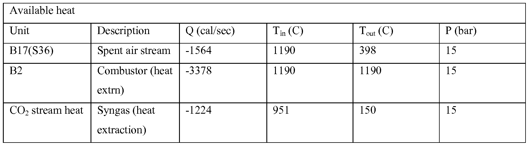
[00142] The parasitic energy consumption for Case 5 is shown in Table 10 below.
[00143] Table 10: Parasitic energy consumption for Case 5

[00144] As compared to Case 4 the syngas compressor power consumption by itself goes down by 30 %. The net including air compressor reduces the cost by 15 %.
Example 6
Chemical looping reactor operated at 20 atm, Fig. 17 ("Case 6")
[00145] This investigation analyzes the case when the chemical looping reactors are operated at a pressure of 20 atm. In this analysis the air compressor parasitic energy requirement is expected to be higher than that in Case 5. The corresponding value of the
syngas compressor energy requirement is supposed to go lower. The schematic is similar to the one used in Fig. 17. The available heat and the parasitic energy requirements are shown in
Table 1 1 and Table 12.
[00146] Table 11 : Available heat for Case 6, 20 atm, Fig. 17

[00147] Table 12: Parasitic energy consumption for Case 6

[00148] In case 6 at 20 atm, the syngas compressor requirement is 50 % lower than the case 5. This is expected as a higher starting point is given in terms of pressure for the syngas compressor. The air power requirement is 20 % higher than case 4. The overall efficiency is around 5% reducing in the compression energy requirement over case 5.
Example 7
Chemical looping reactor operated at 25 atm, Fig. 17 ("Case 7")
[00149] This case is expected to further reduce the syngas compression cost, but the air compression cost increases. Operating the chemical looping reactors at 25 atm shows the case where the air compression cost increase outweighs the decrease in syngas compression cost. The available heat and the parasitic energy consumption are shown in Table 13 and Table 14.
[00150] Table 13 : Available heat for Case 7, 25 atm, Fig. 17
Available heat
Unit Description Q (cal/sec) Tin (C) Tout (C) P (bar)
B17(S36) Spent air stream -1189 1190 398 25
B2 Combustor (heat -4221 1190 1190 25
extrn)
C02 stream heat Syngas (heat -4999 951 150 25
extraction)
[00151] Table 14: Parasitic energy consumption for Case 7

[00152] The overall net compression energy requirement goes up by 50% over that required in case 6. The syngas compression cost decreases minimally, while the air compression cost increases by around 50 % value.
Example 8
Chemical looping reactor operated at 30 atm, Fig. 18 ("Case 8")
[00153] This case investigates the operating cost at a pressure of 30 atm. This case follows a schematic as shown in Fig. 18. As the chemical looping reactors are operated at 30 atm, the syngas compression cost goes down to zero. The air compression cost however will outweigh this decrease despite the coupling effect with a high temperature spent-air stream. The available heat and the parasitic energy consumption are shown in Table 15 and 16.
[00154] Table 15: Available heat for Case 8, 30 atm, Fig. 17

[00155] Table 16: Parasitic energy consumption for Case 8, Heat integration scheme 2

[00156] As compared to an ASU this energy requirement is still around 48 % lower. The air compressor follows similar specifications to those defined in Case 1 and Case 2, with a polytropic efficiency of 0.86 and a mechanical efficiency of 0.98.
[00157] Discussion Overall analysis: The pressure sensitivity in terms of operating cost is shown in Table 17.
[00158] Table 17: An overall analysis for the example cases is shown where the disclosed optimization method is applied

[00159] The energy percentage in the last column is an energy consumption ratio of energy consumed for case to ASU, and is computed as a % of the overall %kWe/kWth for each case as compared to the ASU case. As we go in blocks of 5 atm from 1 atm to 30 atm, the overall percentage goes through a minima in-between 15-20 atm. This same pattern can be observed in Fig. 18. The overall analysis is a method of analysis which can be applied to a combination of fuels and corresponding pressurized products. The optima are obtained by a consideration of the expander-compressor coupling and the overall heat-integration schematic.
Example 9
Specific Operating Condition
[00160] The explanation of the specific operating condition is initially shown in an isothermal condition in the reducer. The reducer system is a downward co-current moving bed. The metal-oxide combination chosen is Fe203 as the primary component and AI2O3 as the secondary component. Fig. 20 shows a sample reducer reactor configuration investigated for the optimal reactor operation condition, configuration and analysis. The model used is a Gibbs-energy minimization reactor. The minimization of Gibbs free energy gives the thermodynamic performance of the system. The Gibbs reactor simulates the co-current downward flowing moving bed performance. The temperature swing for the oxygen carrier in
an adiabatic reactor is limited between 1250 C and 750 C. If the temperature swing is set between 1200 C and 900 C, the performance is shown in Fig. 21. This condition is analyzed at a 50% HHV ratio of CH4 and PRB Coal. The steam injection is 1 mol H2O per mole of Carbon entering the reducer. The feasible area of operation for satisfying the heat balance is determined by the value of heat duty being either zero or negative. For example, when the heat duty is negative, the temperature of the solids will be higher than 900 C. If the heat duty is positive, the temperature will be lower than 900 C. The heat-duty may be manipulated by increasing or decreasing the support content in the metal-oxide, increasing or decreasing the solids flow and changing the pre-heat temperatures. A similar scan at temperatures of 950 C and 1000 C give the values listed in Table 18 and plotted on Fig. 22. Expectedly, it was found that higher the temperature of analysis, higher is the heat-duty required. If the fuel pre-heat and the oxygen carrier inlet temperature and support weight % are kept constant, then the neutral heat-duty condition is only satisfied when going to a higher solids circulation rate. This leads to a higher oxygen transfer to the syngas produced, which converts more CO to CO2 reducing the carbon utilization of the system.
[00161] Table 18: Illustration of reactor performance for different solids outlet temperatures

[00162] Figs. 23a, 23b, 24a and 24b show a sensitivity analysis of the effect of steam addition to the reducer reactor. The steam addition is to increase the syngas H2/CO ratio and the syngas M value (M: (H2-CO2/CO + CO2) to the required values for some of downstream processes. Note that there is no significant change in the net-duty curve beyond a certain point of water injection. Note that the H2/CO ratio increases with increasing H2O addition while the amount of CO produced decreases correspondingly. The point beyond where the heat-duty does not show a significant deviation for incremental values of steam injection is a special point of interest around which the system can be designed to maximize the carbon utilization.
[00163] Analyzing the regions before and after this point shows two distinct trends. Before this point, the oxygen for production of H2 and CO from the solid fuel comes exclusively from the oxygen carrier. Going beyond the so-called critical point of steam injection, the
amount of oxygen donated by the oxygen carrier stays more or less constant. The amount of CO produced from the fuel is constant. The additional steam starts donating oxygen to the CO, converting it to CO2, while producing more H2. This increases the H2/CO ratio to the requisite value at the cost of converting CO to CO2. The CO2 itself can be removed in a standard rectisol type configuration to give a M value which is very close to the H2/CO ratio. As shown in Fig. 23, the H2/CO ratio increases with addition of more water. Note that the M value remains more of less the same. As shown in Fig. 24b, the % syngas drops as predicted by the hypothesis mentioned above. The specific operating condition is designed around the system for this particular injection condition uniquely by a combination of an iron based metal-oxide and the co-current downward flow and solid fuel. This condition is unique in the sense that the operation is designed to harness the sweet spot of maximizing the oxygen donation from the oxygen carrier for producing syngas rather than the water-gas shift reaction. The importance of oxygen donation from the oxygen carrier is in the fact that it donates oxygen in a reducing environment without oxidizing the CO to CO2. A conventional coal-gasifier using only a water gas shift based system gives a fuel to syngas carbon conversion values of between 25 and 35 %. This is because of the fact that the water- gas shift reaction provides an oxidizing environment which increases the H2 content of the syngas at the cost of converting CO to CO2. The role of oxygen carrier in providing the oxygen can be controlled by a combination of the oxygen carrier material, the reactor operation mode and the amount of steam injection. The conditions claimed satisfy the heat- balance for an isothermal operation.
[00164] The analysis presented so-far held a constant temperature to evaluate the effect of various parameters for deriving a specific condition and confirmation of the theory of maximizing the oxygen donation by the oxygen carrier.
[00165] Figs. 25 to 32 analyze the behavior of the looping reducer for a commercial prototype adiabatic system. The fuel system is maintained similar to the iso-thermal case analyzed above for ease of understanding. The commercial reactor system is typically designed with refractory lining of the reactor wall to have an adiabatic operating condition. For this analysis, this will accurately represent a realistic commercial operation. This evaluating the GIBBS reactor system under the condition of heat duty being near zero instead of a constant temperature. The variable which changes with varying iron-oxide flow-rate is the temperature coming out of the system. The temperature swing is within the specified oxygen carrier limits of 1250 C and 750 C. The system behavior is analyzed with steam
addition as a parameter, while the other inlet conditions remaining similar to the isothermal cases analyzed in Figs. 21-24.
[00166] The first condition to be isolated for an acceptable reactor performance is the absence of Carbon deposition in the reducer. The set of operating curves are shown as a function of the amount of water-injected per mole of Carbon input to the reducer. The conditions where there is no carbon-deposition are acceptable for evaluating the system performance. Fig. 31 shows that for the same amount of fuel injection, the minimal amount of oxygen-carrier flow required for no-carbon deposition decreases with increase of water flow for increasing temperature. In other words, the system can have a lower solids flow and a lower reducer outlet temperature with higher water injection for the same amount of carbon input to the system.
[00167] Fig. 25 and Fig. 26 plot the CO/CO2 curves and H2/CO value in syngas for varying iron-oxide flows as a function of steam injection per mole of Carbon. It can be seen that in the regions where there is no carbon deposition, the H2/CO ratio increases with increasing steam injection. The CO/CO2 ratio decreases with increased steam injection, pointing to the presence of the so-called critical point (claimed specific operating condition) beyond which the oxygen donation from the steam to the fuel occurs. The H2 produced increases as a function of the increasing steam injection as shown in Fig. 30. The CO2 produced also increases while the CO decreases as a function of increased steam injection. The temperature outlet profile does not show a significant difference as a function of steam injection. Using a standard post-combustion rectisol-type system downstream of the unique looping reactor helps decide the optimal system goals for this case. The goals in accordance with previous iso-thermal analysis are reaching a reasonable H2/CO ratio while maximizing the CO/CO2 ratio. The specific point of operation would be close to the point where the critical point of transition occurs wherein the oxygen transfer from steam to the fuel begins dominating over that from steam to the oxygen carrier and the oxygen carrier to the fuel. This specific condition can be achieved only with the unique combination of the oxygen carrier, heat management, steam injection, fuel feedstock and a downward co-current contact between the oxygen carrier and the fuel type reactor.
[00168] In a different configuration, illustrated in Fig. 33 the CO2 separated from the post- combustion capture can be recycled with after moisture removal. The CO2 recycle is to improve the condition to suppress the Carbon deposition, satisfying the heat-balance conditions at a lower circulation rate. Another advantage of this recycle CO2 injection is to
suppress the CO conversion to CO2. Fig. 34 and Fig. 35 show the system performance with different levels of CO2 injection at a steam to fuel carbon molar ratio of 0.5. The figures illustrate that the addition of a small amount of CO2 helps suppress the Carbon deposition to a higher extent. Higher addition has no significant benefits as shown in Fig. 33 and 34. A small addition of CO2 as disclosed in this configuration, in combination with the unique operating condition disclosed earlier for maximizing the oxygen transfer has some benefits over in cases where CO2 can be recycled feasibly.
[00169] Fig. 36 and Fig. 37 show a case where a different amount of natural gas and coal is added. The case essentially demonstrates the fact that the specific operating condition can be claimed for different combination of various fuels claimed. The metal-oxide composition used is Fe203-Ai203. In this case the coal HHV contribution to the fuel mix is 45%. The trends shown are similar to those analyzed for the base case above. The areas for no carbon deposition are isolated (Fig.36) and the corresponding performance ratios for the systems are analyzed. A similar behavior for the oxygen transfer from the oxygen carrier is observed. Initially at low steam injections, the oxygen transfer from the oxygen carrier is dominant. Later, the oxygen transfer from steam starts to dominate. This case shows the specific operating condition to be present at a lower steam flow-rate than the 50% HHV case. This is attributed to the fact that the CH4 amount decreases per mole of carbon which leads to a drop in intrinsic ¾ content from the fuel mixture. A syngas composition which is suitable for downstream application is obtained at a higher solids flow and lower steam injection requirement. This case shows that using a combination of any of the oxygen carriers disclosed earlier and the unique control offered by a co-current downward moving bed reactor can be applied with a specific amount of steam injection to derive the claimed specific condition for syngas production. This case shows that a similar behavior can be expected for different combinations of fuel injections with the critical point being present at differing operating conditions depending on the coal type, fuel type and the intrinsic ¾ content of the fuel.
[00170] Figs. 39, 40 and 41 show the overall performance curve using Illinois # 6 and PRB coals in combination with methane input at the unique operating conditions for the optimal steam injection using the Fe203-Ti02 based particles as example. This case is analyzed to verify the claim of a different metal-oxide being used for the operating condition. It should be seen that presence of a H2-rich co-injection fuel helps improve the carbon utilization of the system by minimizing the steam usage. A scan of different HHV'S ratios of coal and methane
fuel injection is analyzed. Application of the given condition can improve the carbon utilization significantly while maintaining the syngas quality and eliminating the need for molecular oxygen transport from an air-separation unit. The application of the specific condition is true for all the fuel feedstock, oxygen carrier compositions specified.
[00171] Fig. 42 shows a configuration in which the reducer is operated with fuel injection. The general principle for operating an oxygen carrier based looping unit is the fact that it should be auto-thermal in operation. If carbon capture from a chemical looping with heat- balance is considered, it leads to two design configurations. One configuration has a part of fuel burned in the oxidizer reactor to attain the auto-thermal operating condition. This configuration can operate at a lower solids circulation rate, which improves the syngas yield near the critical point of steam injection. The configuration may require dilute CO2 capture from the oxidizer exhaust stream. An alternative configuration avoids this dilute CO2 capture, by increasing the solids circulation rate for heat-balance purposes. This ensures that the excess CO2 is obtained as a part of the CO2 rich syngas stream, reducing the cost of separation of CO2.
[00172] Fig. 43 shows the application of the heat balance concept and its effect on syngas capacity using Fe203-Al203 particles as an example. The Fe203-Al203 particles have shown equivalent performance to the T1O2 particles used in earlier examples for this specific application. The tables 19 and 20 show the conditions investigated as demonstrations for applying the heat balance concept while burning some amount of a fuel like natural gas for electricity production.
[00173] Table 19: Carbon utilization per mole of C input to the system shown in Fig. 43
Case CO Carbon % C C Coal CH4 Coal CH4 H20 M utilization capture total reducer reducer Oxidizer NGCC reducer value after rectisol
1 0.35 35 90 1 0.9 0 0 0.1 2 2.01
2 0.564 51. 81.8190 1.11 0.55 0.35 0.1 0.1 1 2.01
3 0.564 54.12 90 1 0.65 0.25 0 0.1 1.1 2.01
4 0.611 60.47 90 1 0.65 0.25 0 0.1 1.1 1.7
5 0.6 60.72 95 1 0.65 0.3 0 0.05 1 2.01
6 0.66 66.41 96 1 0.65 0.3 0 0.05 0.7 1.7
[00174] Table 20: Material balance for 1 mole of C input to the system shown in Fig. 43

[00175] The M values and the H2/CO values are similar to those produced by conventional gasification systems. The carbon utilization is higher because of application of the specific operating condition. Fig. 43 shows the increase of syngas production per mole of total carbon in the system over the baseline coal gasification technology. A similar performance was obtained for combinations of other H2 deficient fuels which need some steam injection for increasing the H2/CO ratio.
[00176] Fig. 44 shows a methodology to reduce the operating energy requirements of a chemical looping unit. The example shown illustrates the application of the methodology in conjunction with the special operating condition used. The methodology is used with the configurations disclosed above for reducing the operating energy requirement wherever applicable. This methodology involves coupling the air streams and the natural gas streams used for power generation purposes. The typical downstream syngas processing units operate at a pressure between 30 and 80 atm. The chemical looping unit has two main reactors namely the reducer and the oxidizer. The reducer produces the syngas which needs to be compressed to the requisite downstream processing pressure. The following methodology disclosed in Figs. 44 and 45 shows a way to analyze the looping problem and identify the optimal pressure for reducing the operating energy. The disadvantage of operating at a pressure close to the downstream syngas processing system is that the air has to be compressed to that high value while the syngas compression cost diminishes. On the other hand, operating at pressure close to atmospheric will diminish the cost of air-compression while significantly increasing the cost of syngas compression. It is expected that the actual minima would lie somewhere in middle of the pressure range scanned.
[00177] The methodology of coupling the air stream and the syngas stream with incoming natural gas stream is unique and has certain intrinsic advantages. The air is initially compressed and a large volume of air remains unreacted. The options for recovery of air from
this stream include the heat extraction from a rankine-cycle type steam cycle coupled with a Brayton-cycle type gas turbine. The gas-turbine may have a certain let-down which can be designed to offset some of the inlet compressor duty. The net compressor duty would then be the excess remaining to be supplied by the air compressor in terms of an effective net-duty. A similar analysis for offsetting some of the load on syngas compressor will include coupling of the high-pressure fuel stream and the syngas stream coming out at the operating pressure of the chemical looping unit. This will intrinsically offset some of the requirement for syngas compression, with the net compression energy being the balance requirement for the syngas compression. Note the intrinsic difference in coupling on the reducer streams and the oxidizer streams. The reducer side streams let-down the pressure on the inlet lines. It uses that to offset some of the syngas compression requirements on the outlet side. The let- down process itself follows the Joule-Thomson cooling effect and requires some pre-heating of the inlet fuel to offset for the temperature loss. Depending on the reactor operating pressure, the oxygen carrier composition, it may be chosen to add an additional heater to heat-up the fuel entering in the reducer. The oxidizer works in a reverse way as the let-down is on a high- temperature air-stream. This intrinsically heats the inlet air-stream and depending on the reactor operation it could be heated further.
[00178] Fig. 45 shows a model example sample of results for the net operating energy requirement as a function of operating pressure of the unit. It assumes that the natural gas input is at 30 atm to the unit, while the final syngas pressure is required to be 31 atm for a model chemical synthesis process (e.g., methanol, F-T etc). As predicted, the net syngas compression cost becomes lower as the operating pressure of the system increases.
Correspondingly the net air compression cost increases as the operating pressure of the system increases. The net-effect is a total-net operating energy curve for the chemical looping system which passes through minima for the 10 atm to 15 atm range. This can be chosen as a suitable operating pressure for the looping system for identifying the critical point of steam injection beyond which the maximum oxygen transfer from the oxygen carrier to the fuel occurs.
6. Exemplary Embodiments
[00179] In one aspect, disclosed is a system for producing syngas from one or more carbon- based fuels using oxidation-reduction of metal oxides. The system can be configured for partially or fully oxidizing a fuel in a first reactor, optionally to serve as an enhancing gas in a
second reactor. The metal oxide can undergo an oxidation-reduction swing in the second reactor (e.g., a reduced metal oxide entering the second reactor can undergo oxidation, with CO2 or H20 for example, and subsequently undergo reduction, with a carbon-based fuel for example). The flow pattern in the first reactor can be counter-current or co-current, preferably counter-current. The flow pattern in the second reactor can be counter-current or co-current. The system can include a third reactor to regenerate the reduced metal-oxide, using air for example. The first reactor can use a recycled light hydrocarbon stream, from a Fischer-Tropsch or methanol synthesis system for example. The enhancing gas used in the second reactor can be derived from the first reactor, the third reactor, or one or more additional reactors through oxidation of a fuel with a metal oxide or through a combustion process (e.g., natural gas combustion).
[00180] In another aspect, disclosed is a system for producing syngas from one or more carbon-based fuels using oxidation-reduction of metal oxides. The system can be configured to oxidize a fuel in a first reactor to produce syngas. A second reactor in communication with the first reactor can produce a gaseous product (e.g., CO2/H2O) that can be used in the first reactor for gasifying the fuel in the first reactor (e.g., gasifying a solid fuel such as coal or biomass). The system can include a third reactor to regenerate the reduced metal-oxide, using air for example. Gaseous product for gasifying the fuel in the first reactor can also be derived from the third reactor, or one or more additional reactors through oxidation of a fuel with a metal oxide or through a combustion process (e.g., natural gas combustion).
[00181] In another aspect, disclosed is a system for producing sequester-ready CO2. A second reactor can process solid fuel and optionally gaseous fuel to produce syngas. The unconverted solid fuel can be separated in a high-temperature separation device to recycle the char to the top of the first reactor to produce sequester-ready CO2.
[00182] In another aspect, disclosed is a method for reducing the operating energy and cost requirements for a chemical system converting fuel to a product, operating at different pressures. The method can employ expander-compressor coupling to recuperate energy used for compression of gaseous fuel, gaseous product, or a combination thereof.
[00183] In another aspect, disclosed is a specific unique operating condition configuration for producing high-quality syngas from a flexible solid fuel feedstock like coal, biomass amongst others. The specific operating condition requires a unique combination of the oxygen carrier, the support percentage in the oxygen carrier, effective heat-management strategy, a specific amount of steam injection and a co-current downward flowing moving
bed system. The operating reactor configurations can be selected to maximize the oxygen transfer from the oxygen carrier to the fuel, maximize the steam oxygen transfer to the oxygen carrier while minimizing the steam oxygen transfer to the fuel to produce the exact syngas specifications that are required for a downstream application.
[00184] In certain embodiments, disclosed is a system configuration which includes fuel addition to the oxidizer to satisfy the auto-thermal operating condition of the reactor system. The trade-off is dependent on the permissible carbon emissions and the carbon-capture mechanism used. A higher carbon utilization of the fuel can be achieved by adhering to a lower oxygen carrier flow- rate which will satisfy the heat balance. An alternative configuration with a higher solids flow rate can be used for additional carbon capture through the syngas, coupled with higher oxygen carrier flow rates and higher carbon utilization.
[00185] In certain embodiments, disclosed is a system methodology for minimizing the operating energy requirement of the reactor system and choosing the reactor pressure for the configurations disclosed. The methodology can be applied to any combination of fuels processed, the oxygen carrier used and the downstream standard technologies used for any of the disclosed reactor configurations.
[00186] For reasons of completeness, various aspects of the disclosure are set out in the following numbered clauses:
[00187] Clause 1. A system for the production of syngas, comprising: a first reactor comprising a plurality of oxygen carrying particles comprising a first metal oxide, wherein the first reactor is configured to provide a counter-current contact mode between the first metal oxide and a first fuel to reduce the first metal oxide to a second metal oxide; a second reactor in communication with the first reactor, the second reactor configured to oxidize the second metal oxide to a third metal oxide, and further configured to reduce the third metal oxide to a fourth metal oxide with a second fuel to provide a partially or fully oxidized gaseous fuel comprising one or more of CO, CO2, H2, and H20, wherein the second metal oxide is oxidized to the third metal oxide using an enhancing gas of CO2 and H2O, the partially or fully oxidized gaseous fuel, or a combination thereof, to generate syngas; and a third reactor in communication with the second reactor, the third reactor configured to regenerate the first metal oxide by oxidizing the fourth metal oxide with an oxygen source.
[00188] Clause 2. The system of clause 1, wherein the counter-current contact mode between the first metal oxide and the first fuel is such that the first metal oxide moves downward and the first fuel moves upward.
[00189] Clause 3. The system of clause 1 or clause 2, wherein the first metal oxide is introduced to the top of the first reactor, and the first fuel is introduced to the bottom of the first reactor.
[00190] Clause 4. The system of any one of clauses 1-3, wherein the second reactor is configured to provide a counter-current contact mode between the second metal oxide and the enhancing gas, and a counter-current contact mode between the third metal oxide and the second fuel.
[00191] Clause 5. The system of clause 4, wherein the second metal oxide is introduced to the top of the second reactor, the enhancing gas is introduced to the middle of the second reactor, and the second fuel is introduced to the bottom of the second reactor.
[00192] Clause 6. The system of any one of clauses 1-3, wherein the second reactor is configured to provide a co-current contact mode between the second metal oxide and the enhancing gas, and a co-current contact mode between the third metal oxide and the second fuel.
[00193] Clause 7. The system of clause 6, wherein the second metal oxide is introduced to the top of the second reactor, the enhancing gas is introduced to the middle of the second reactor, and the second fuel is introduced to the top of the second reactor.
[00194] Clause 8. The system of clause 6, wherein the second metal oxide is introduced to the top of the second reactor, the enhancing gas is introduced to the top of the second reactor, and the second fuel is introduced to the top or the middle of the second reactor.
[00195] Clause 9. The system of any one of clauses 1-8, wherein at least a portion of the enhancing gas is derived from the first reactor resulting from the reduction of the first metal oxide with the first fuel.
[00196] Clause 10. The system of any one of clauses 1-9, wherein at least a portion of the enhancing gas is derived from oxidation of a carbon-containing or hydrogen-containing source in the third reactor, a fourth reactor, or a combination thereof.
[00197] Clause 1 1. The system of any one of clauses 1-10, wherein the third reactor is communication with the first reactor, wherein at least a portion of the second metal oxide is circulated directly to the third reactor, and oxidation of a carbon-containing or hydrogen- containing source with an oxygen source in the third reactor generates a stream of enhancing gas, wherein at least a portion of the enhancing gas generated in the third reactor is used in the second reactor as an enhancing gas.
[00198] Clause 12. The system of any one of clauses 1-1 1, comprising a fourth reactor in communication with the first reactor, configured to generate a stream of enhancing gas comprising CO2 and H20.
[00199] Clause 13. The system of clause 12, wherein at least a portion of the enhancing gas generated in the fourth reactor is used in the second reactor as an enhancing gas.
[00200] Clause 14. The system of any one of clauses 1-13, wherein the first fuel is a solid fuel (e.g., biomass, coal, pet-coke, solid hydrocarbon-based waste products, or a combination thereof).
[00201] Clause 15. The system of any one of clauses 1-13, wherein the first fuel is a gaseous fuel (e.g., natural gas, gasified coal, a light hydrocarbon off-gas stream, or a combination thereof).
[00202] Clause 16. The system of any one of clauses 1-15, wherein the second fuel is a solid fuel (e.g., biomass, coal, pet-coke, solid hydrocarbon-based waste products, or a combination thereof).
[00203] Clause 17. The system of any one of clauses 1-15, wherein the second fuel is a gaseous fuel (e.g., natural gas, gasified coal, a light hydrocarbon off-gas stream, or a combination thereof).
[00204] Clause 18. The system of any one of clauses 1-17, wherein the second reactor is in communication with a Fischer-Tropsch or methanol synthesis system that produces a light hydrocarbon tail-gas, wherein the second reactor provides syngas to the Fischer-Tropsch or methanol synthesis system and the light hydrocarbon tail-gas is optionally recycled to first reactor, the second reactor, or a combination thereof.
[00205] Clause 19. The system of any one of clauses 1-18, wherein the first metal oxide has formula FeOaTix or FeOaAlx, the second metal oxide has formula FeObTix or FeObAlx, the third metal oxide has formula FeOcTix or FeOcAlx, and the fourth metal oxide has formula
FeOaTix or FeOaAlx, wherein 1.5>a>b, b<c>d, 1.5>c, and x is 0.01 to 5.
[00206] Clause 20. The system of any one of clauses 1-19, wherein the first metal oxide has formula FeOaTi02 or FeOaAi203, the second metal oxide has formula FeObTi02 or
FeObA^Os, the third metal oxide has formula FeOcTi02 or FeOcAl203, and the fourth metal oxide has formula FeOaTi02 or FeOdAl203, wherein 1.5>a>b, b<c>d, and 1.5>c.
[00207] Clause 21. The system of any one of clauses 1 -20, wherein the third metal oxide produced in the second reactor is the same as the first metal oxide.
[00208] Clause 22. The system of any one of clauses 1-20, wherein the third metal oxide produced in the second reactor is different from the first metal oxide.
[00209] Clause 23. The system of any one of clauses 1-22, wherein the fourth metal oxide produced in the second reactor is the same as the second metal oxide.
[00210] Clause 24. The system of any one of clauses 1-22, wherein the fourth metal oxide produced in the second reactor is different from the second metal oxide.
[00211] Clause 25. A system for the production of syngas, comprising: a first reactor comprising a plurality of oxygen carrying particles comprising a first metal oxide, wherein the first reactor is configured to provide a co-current contact mode between the first metal oxide and a first fuel to reduce the first metal oxide to a second metal oxide and to generate syngas; a second reactor in communication with the first reactor, the second reactor configured to reduce the second metal oxide to a third metal oxide with a second fuel; and a third reactor in communication with the second reactor, the third reactor configured to regenerate the first metal oxide by oxidizing the third metal oxide with an oxygen source; wherein a gaseous product comprising CO2 and H20 is used in the first reactor to gasify the first fuel.
[00212] Clause 26. The system of clause 25, wherein at least a portion of the gaseous product used in the first reactor is derived from a gaseous product produced in the second reactor resulting from the reduction of the second metal oxide with the second fuel.
[00213] Clause 27. The system of clause 25 or clause 26, wherein the co-current contact mode between the first metal oxide and the first fuel is such that the first metal oxide moves downward and the first fuel moves downward.
[00214] Clause 28. The system of any one of clauses 25-27, wherein the first metal oxide is introduced to the top of the first reactor, the first fuel is introduced to the top of the first reactor at a level below the metal oxide introduction, and the gaseous product is introduced to the top of the first reactor.
[00215] Clause 29. The system of any one of clauses 25-28, wherein the second reactor is configured to provide a counter-current contact mode between the second metal oxide and the second fuel.
[00216] Clause 30. The system of any one of clauses 25-29, wherein the second metal oxide is introduced to the top of the second reactor, and the second fuel is introduced to the bottom of the second reactor.
[00217] Clause 31. The system of any one of clauses 25-30, wherein at least a portion of the gaseous product is derived from oxidation of a carbon-containing or hydrogen-containing source in the third reactor, a fourth reactor, or a combination thereof.
[00218] Clause 32. The system of any one of clauses 25-31, wherein the third reactor is communication with the first reactor, wherein at least a portion of the second metal oxide is circulated directly to the third reactor, and oxidation of a carbon-containing or hydrogen- containing source with an oxygen source in the third reactor generates a gaseous product, wherein at least a portion of the gaseous product generated in the third reactor is used in the first reactor to gasify the first fuel.
[00219] Clause 33. The system of any one of clauses 25-32, comprising a fourth reactor in communication with the first reactor, configured to generate a stream of gaseous product comprising CO2 and H2O.
[00220] Clause 34. The system of clause 33, wherein the gaseous product generated in the fourth reactor is used in the first reactor to gasify the first fuel.
[00221] Clause 35. The system of any one of clauses 25-34, wherein the first fuel is a solid fuel (e.g., biomass, coal, pet-coke, solid hydrocarbon-based waste products, or a combination thereof).
[00222] Clause 36. The system of any one of clauses 25-35, wherein the second fuel is a gaseous fuel (e.g., natural gas, gasified coal, a light hydrocarbon off-gas stream, or a combination thereof).
[00223] Clause 37. The system of any one of clauses 25-36, wherein the first reactor is in communication with a Fischer-Tropsch or methanol synthesis system that produces a light hydrocarbon tail-gas, wherein the first reactor provides syngas to the Fischer-Tropsch or methanol synthesis system and the light hydrocarbon tail-gas is optionally recycled to first reactor, the second reactor, or a combination thereof.
[00224] Clause 38. The system of any one of clauses 25-37, wherein the first metal oxide has formula FeOaTix or FeOaAlx, the second metal oxide has formula FeObTix or FeObAlx, and the third metal oxide has formula FeOcTix or FeOcAlx, wherein 1.5>a>b>c>0.2, and x is 0.01 to 5.
[00225] Clause 39. The system of any one of clauses 25-38, wherein the first metal oxide has formula FeOaTi02 or FeOaAl203, the second metal oxide has formula FeObTi02 or FeObA^Os, and the third metal oxide has formula FeOcTi02 or FeOcAl203, and wherein 1.5>a>b>c>0.2.
[00226] Clause 40. A system for producing sequester-ready CO2, comprising: a first reactor comprising a plurality of oxygen carrying particles comprising a first metal oxide, wherein the first reactor is configured to provide a co-current contact mode or counter-current contact mode between the first metal oxide and a devolatilized solid fuel to reduce the first metal oxide to a second metal oxide and to generate product stream comprising sequester-ready CO2; a second reactor in communication with the first reactor, the second reactor configured to reduce the second metal oxide to a third metal oxide with a solid fuel and a gaseous fuel to generate syngas and a devolatilized solid fuel; and a third reactor in communication with the second reactor, the third reactor configured to regenerate the first metal oxide by oxidizing the third metal oxide with an oxygen source.
[00227] Clause 41. The system of clause 40, wherein the oxygen carrying particles are separated from devolatilized solid with a solid-fine separation device prior to the particles entering the third reactor.
[00228] Clause 42. The system of clause 40 or clause 41, wherein at least a portion of the product gas stream from the first reactor is used to separate the devolatilized fuel from the oxygen carrying particles in the solid-fine separation device and to convey the devolatilized fuel to the first reactor.
[00229] Clause 43. The system of any one of clauses 40-42, wherein at least a portion of the product gas stream from the first reactor is recycled to the second reactor.
[00230] Clause 44. The system of any one of clauses 40-43, wherein the first metal oxide is FeOx; the second metal oxide is FeOy; and the third metal oxide is FeOz; wherein
1.5>x>y>0.75, and y>z>0.01.
[00231] Clause 45. The system of any one of clauses 1-44, comprising at least one expander-compressor coupling (e.g., coupled such that the work extracted from the expander (e.g., used to expand a pre-heated gaseous fuel) is used to compress the syngas product from the first reactor or second reactor; or coupled to recuperate at least a portion of the energy used for compressing the oxygen-containing gas in the third reactor).
[00232] Clause 46. A system for producing syngas, comprising: a first reactor comprising a plurality of oxygen carrying particles, wherein the first reactor is configured to reduce the oxygen carrying particles with a gaseous fuel to generate syngas and reduced oxygen carrying particles; a second reactor in communication with the first reactor, the second reactor configured to oxidize the reduced oxygen carrying particles with an oxygen- containing gas to regenerate to the oxygen carrying particles and produce a spent gas; and (i)
a first expander configured to subject the gaseous fuel to an expansion after pre-heating and prior to entering the first reactor, and a first compressor configured to compress the syngas from the first reactor, wherein the first expander and the first compressor are coupled such that the work extracted from the expander is used to compress the syngas; or (ii) a second expander configured to subject the spent gas from the second reactor to an expansion, and a second compressor configured to provide compressed oxygen-containing gas to the second reactor, wherein the second expander and the second compressor are coupled such that the second expander recuperate at least a portion of the energy used for compressing the oxygen- containing gas.
[00233] Clause 47. The system of clause 46, wherein the system comprises both (i) and (ii).
[00234] Clause 48. The system of clause 46 or clause 47, further comprising a condenser between the first reactor and the first compressor.
[00235] Clause 49. The system of any one of clauses 1-48, wherein the metal oxide undergoes a swing of oxidation state (e.g., oxidation followed by reduction) within the first reactor, within the second reactor, or both the first reactor and the second reactor.
[00236] Clause 50. The system of any one of clauses 1-49, where the first reactor, the second reactor, and the third reactor are each independently selected from a packed moving bed reactor, a rotary kiln, a down-comer, a fluidized bed reactor, a fixed bed reactor, or any combination thereof.
[00237] Clause 51. The system of any one of clauses 1-50, wherein the first fuel, the second fuel, or both the first fuel and the second fuel are pre-heated prior to entering the first reactor or the second reactor.
[00238] Clause 52. The system of any one of clauses 1-51, wherein the first metal oxide is FeOaTi02 with 80 wt% Ti02.
[00239] Clause 53. The system of any one of clauses 1-52, wherein the system has an operating pressure of 1-100 atm (e.g., 20 atm).
[00240] Clause 54. The system of any one of clauses 1-53, wherein the air and gaseous fuels are pre-heated to about 600 C.
[00241] Clause 55. The system of any one of clauses 1-54, wherein the first reactor has an operating temperature of 1200 C to 900 C.
[00242] Clause 56. The system of any one of clauses 1-55, wherein the second reactor has an operating temperature of 100 C to 700 C.
[00243] Clause 57. The system of any one of clauses 1-56, wherein the third reactor has an operating temperature of 700 C to 1300 C.
[00244] Clause 58. The system of any one of clauses 1-57, wherein the H2/CO ratio of the generated syngas is from 1 : 1 to 4: 1.
[00245] Clause 59. The system of any one of clauses 1-58, wherein the carbon efficiency of the system is 90% or greater.
[00246] Clause 60. The system of any one of clauses 1-59, wherein the generated syngas has a combined CO2, H20 content of less than or equal to 15%.
[00247] Clause 61. The system of any one of clauses 1-60, wherein the third reactor uses ambient air, oxygen derived from an air separation unit, or oxygen-enhanced air (e.g., pure oxygen from an air-separation unit, vacuum distillation unit, or oxygen tanks), or a combination thereof to regenerate the first metal oxide.
[00248] Clause 62. The system of any one of clauses 1-61, wherein the heat is extracted from the third reactor for satisfying parasitic energy consumption in the system.
[00249] Clause 63. The system of any one of clauses 1-62, wherein the first metal oxide is a fully oxidized metal oxide (e.g., Fe20s).
[00250] Clause 64. The system of any one of clauses 1-62, where the second metal oxide is a reduced metal (e.g., Fe) or reduced metal oxide (e.g., FeO, Fe304).
[00251] Clause 65. The system of any one of clauses 1-24, clause 63, or clause 64, wherein the third metal oxide is a metal oxide intermediate (e.g., Fe203, Fe304).
[00252] Clause 66. The system of any one of clauses 1-24, or clauses 63-65, wherein the fourth metal oxide is a reduced metal (e.g., Fe) or reduced metal oxide (e.g., FeO, Fe304).
[00253] Clause 67. The system of any one of clauses 25-39, wherein the third metal oxide is a reduced metal (e.g., Fe) or reduced metal oxide (e.g., FeO).
[00254] Clause 68. The system of any one of clauses 1-67, wherein the third reactor generates heat, and said heat is used to satisfy endothermic requirements of one or more of the first or second reactors.
[00255] Clause 69. The system of any one of clauses 1-68, wherein the system operates under autothermal conditions.
[00256] Clause 70. A method of reducing the operating energy of a system for converting fuel, the system comprising at least one reactor comprising a plurality of oxygen carrying particles, wherein the reactor is configured to reduce the oxygen carrying particles with a gaseous fuel to generate syngas and reduced oxygen carrying particles; at least one reactor
configured to oxidize the reduced oxygen carrying particles with an oxygen-containing gas to regenerate to the oxygen carrying particles and produce a spent gas; and at least one expander configured to expand a gas stream, and at least one compressor configured to compress a gas stream, wherein the expander and the compressor are coupled, the method comprising: using the expander to recuperate at least a portion of the energy used for compressing a gas stream; or using the work extracted from a high-pressure Joule-Thomson expansion in the expander to compress a gas stream with the compressor.
[00257] It is to be understood that the first, second, third, and fourth metal oxides referred to herein may be produced and moved through the reactor systems in combination with other metal oxides (e.g., FeO/Fe can be reduced metal oxides that are produced and traverse one or more reactors). For example, conversion of a first metal oxide to a second metal oxide may be incomplete, and thus, a first metal oxide and a second metal oxide may be communicated to a second reactor.
[00258] It is understood that the foregoing detailed description and accompanying examples are merely illustrative and are not to be taken as limitations upon the scope of the invention, which is defined solely by the appended claims and their equivalents.
[00259] Various changes and modifications to the disclosed embodiments will be apparent to those skilled in the art. Such changes and modifications, including without limitation those relating to the chemical structures, substituents, derivatives, intermediates, syntheses, compositions, formulations, or methods of use of the invention, may be made without departing from the spirit and scope thereof.
Claims
1. A system for the production of syngas, comprising:
a first reactor comprising a plurality of oxygen carrying particles comprising a first metal oxide, wherein the first reactor is configured to provide a counter-current contact mode between the first metal oxide and a first fuel to reduce the first metal oxide to a second metal oxide;
a second reactor in communication with the first reactor, the second reactor configured to oxidize the second metal oxide to a third metal oxide, and further configured to reduce the third metal oxide to a fourth metal oxide with a second fuel to provide a partially or fully oxidized gaseous fuel comprising one or more of CO, C02, H2, and H20, wherein the second metal oxide is oxidized to the third metal oxide using an enhancing gas of C02 and H20, the partially or fully oxidized gaseous fuel, or a combination thereof, to generate syngas; and
a third reactor in communication with the second reactor, the third reactor configured to regenerate the first metal oxide by oxidizing the fourth metal oxide with an oxygen source.
2. The system of claim 1, wherein the counter-current contact mode between the first metal oxide and the first fuel is such that the first metal oxide moves downward and the first fuel moves upward.
3. The system of claim 1, wherein the first metal oxide is introduced to the top of the first reactor, and the first fuel is introduced to the bottom of the first reactor.
4. The system of claim 1, wherein the second reactor is configured to provide a counter- current contact mode between the second metal oxide and the enhancing gas, and a counter- current contact mode between the third metal oxide and the second fuel.
5. The system of claim 4, wherein the second metal oxide is introduced to the top of the second reactor, the enhancing gas is introduced to the middle of the second reactor, and the second fuel is introduced to the bottom of the second reactor.
6. The system of claim 1, wherein the second reactor is configured to provide a co- current contact mode between the second metal oxide and the enhancing gas, and a co-current contact mode between the third metal oxide and the second fuel.
7. The system of claim 6, wherein the second metal oxide is introduced to the top of the second reactor, the enhancing gas is introduced to the middle of the second reactor, and the second fuel is introduced to the top of the second reactor.
8. The system of claim 6, wherein the second metal oxide is introduced to the top of the second reactor, the enhancing gas is introduced to the top of the second reactor, and the second fuel is introduced to the top or the middle of the second reactor.
9. The system of claim 1, wherein at least a portion of the enhancing gas is derived from the first reactor resulting from the reduction of the first metal oxide with the first fuel.
10. The system of claim 1, wherein at least a portion of the enhancing gas is derived from oxidation of a carbon-containing or hydrogen-containing source in the third reactor, a fourth reactor, or a combination thereof.
11. The system of claim 1, wherein the third reactor is communication with the first reactor, wherein at least a portion of the second metal oxide is circulated directly to the third reactor, and oxidation of a carbon-containing or hydrogen-containing source with an oxygen source in the third reactor generates a stream of enhancing gas, wherein at least a portion of the enhancing gas generated in the third reactor is used in the second reactor as an enhancing gas.
12. The system of claim 1, comprising a fourth reactor in communication with the first reactor, configured to generate a stream of enhancing gas comprising CO2 and H2O.
13. The system of claim 12, wherein at least a portion of the enhancing gas generated in the fourth reactor is used in the second reactor as an enhancing gas.
14. The system of claim 1, wherein the first fuel is a solid fuel selected from biomass, coal, pet-coke, solid hydrocarbon-based waste products, or a combination thereof.
15. The system of claim 1, wherein the first fuel is a gaseous fuel selected from natural gas, gasified coal, a light hydrocarbon off-gas stream, or a combination thereof.
16. The system of claim 1, wherein the second fuel is a solid fuel selected from biomass, coal, pet-coke, solid hydrocarbon-based waste products, or a combination thereof.
17. The system of claim 1, wherein the second fuel is a gaseous fuel selected from natural gas, gasified coal, a light hydrocarbon off-gas stream, or a combination thereof.
18. The system of claim 1, wherein the second reactor is in communication with a Fischer-Tropsch or methanol synthesis system that produces a light hydrocarbon tail-gas, wherein the second reactor provides syngas to the Fischer-Tropsch or methanol synthesis system and the light hydrocarbon tail-gas is optionally recycled to first reactor, the second reactor, or a combination thereof.
19. The system of claim 1, wherein
the first metal oxide has formula FeOaTix or FeOaAlx,
the second metal oxide has formula FeObTix or FeObAlx,
the third metal oxide has formula FeOcTix or FeOcAlx, and
the fourth metal oxide has formula FeOaTix or FeOaAlx,
wherein 1.5>a>b, b<c>d, 1.5>c, and x is 0.01 to 5.
20. The system of claim 1, wherein
the first metal oxide has formula FeOaTi02 or FeOaAl203,
the second metal oxide has formula FeObTi02 or FeObAl203,
the third metal oxide has formula FeOcTi02 or FeOcAl203, and
the fourth metal oxide has formula FeOaTi02 or FeOaA^Os,
wherein 1.5>a>b, b<c>d, and 1.5>c.
Applications Claiming Priority (4)
| Application Number | Priority Date | Filing Date | Title |
|---|---|---|---|
| US201461945257P | 2014-02-27 | 2014-02-27 | |
| US61/945,257 | 2014-02-27 | ||
| US201462041703P | 2014-08-26 | 2014-08-26 | |
| US62/041,703 | 2014-08-26 |
Publications (1)
| Publication Number | Publication Date |
|---|---|
| WO2015131117A1 true WO2015131117A1 (en) | 2015-09-03 |
Family
ID=52630538
Family Applications (1)
| Application Number | Title | Priority Date | Filing Date |
|---|---|---|---|
| PCT/US2015/018123 WO2015131117A1 (en) | 2014-02-27 | 2015-02-27 | Systems and methods for partial or complete oxidation of fuels |
Country Status (2)
| Country | Link |
|---|---|
| US (2) | US20150238915A1 (en) |
| WO (1) | WO2015131117A1 (en) |
Cited By (2)
| Publication number | Priority date | Publication date | Assignee | Title |
|---|---|---|---|---|
| US10253266B2 (en) | 2009-09-08 | 2019-04-09 | Ohio State Innovation Foundation | Synthetic fuels and chemicals production with in-situ CO2 capture |
| US10549236B2 (en) | 2018-01-29 | 2020-02-04 | Ohio State Innovation Foundation | Systems, methods and materials for NOx decomposition with metal oxide materials |
Families Citing this family (15)
| Publication number | Priority date | Publication date | Assignee | Title |
|---|---|---|---|---|
| CA2737946C (en) | 2008-09-26 | 2016-11-15 | The Ohio State University | Conversion of carbonaceous fuels into carbon free energy carriers |
| CN102695670B (en) | 2009-09-08 | 2016-02-24 | 俄亥俄州立大学研究基金会 | There is the reformation/water-splitting of integrated carbon trapping and integrated for the electro-chemical systems that generates electricity |
| US10010847B2 (en) | 2010-11-08 | 2018-07-03 | Ohio State Innovation Foundation | Circulating fluidized bed with moving bed downcomers and gas sealing between reactors |
| CA2835419C (en) | 2011-05-11 | 2020-06-02 | Ohio State Innovation Foundation | Systems for converting fuel |
| EP2707583B1 (en) | 2011-05-11 | 2019-07-10 | Ohio State Innovation Foundation | Oxygen carrying materials |
| CN105358475B (en) | 2013-02-05 | 2018-12-04 | 俄亥俄州国家创新基金会 | Method for fuel conversion |
| US9616403B2 (en) | 2013-03-14 | 2017-04-11 | Ohio State Innovation Foundation | Systems and methods for converting carbonaceous fuels |
| US20150238915A1 (en) | 2014-02-27 | 2015-08-27 | Ohio State Innovation Foundation | Systems and methods for partial or complete oxidation of fuels |
| GB201511855D0 (en) * | 2015-07-07 | 2015-08-19 | Univ Newcastle | Chemical looping |
| EP3429738A4 (en) * | 2016-04-12 | 2019-09-18 | Ohio State Innovation Foundation | Chemical looping syngas production from carbonaceous fuels |
| US11090624B2 (en) | 2017-07-31 | 2021-08-17 | Ohio State Innovation Foundation | Reactor system with unequal reactor assembly operating pressures |
| WO2020033500A1 (en) | 2018-08-09 | 2020-02-13 | Ohio State Innovation Foundation | Systems, methods and materials for hydrogen sulfide conversion |
| US11453626B2 (en) | 2019-04-09 | 2022-09-27 | Ohio State Innovation Foundation | Alkene generation using metal sulfide particles |
| CN111506865B (en) * | 2020-07-01 | 2020-09-15 | 西南石油大学 | Shale gas well production fitting and predicting method |
| US20230357005A1 (en) * | 2022-05-04 | 2023-11-09 | Ohio State Innovation Foundation | Redox looping systems and methods for production of oxidized products |
Citations (4)
| Publication number | Priority date | Publication date | Assignee | Title |
|---|---|---|---|---|
| EP1933087A2 (en) * | 2006-12-11 | 2008-06-18 | General Electric Company | Systems and methods using an unmixed fuel processor |
| WO2010037011A2 (en) * | 2008-09-26 | 2010-04-01 | The Ohio State University | Conversion of carbonaceous fuels into carbon free energy carriers |
| WO2011031752A2 (en) * | 2009-09-08 | 2011-03-17 | The Ohio State University Research Foundation | Synthetic fuels and chemicals production with in-situ co2 capture |
| US20110303875A1 (en) * | 2009-01-30 | 2011-12-15 | Hoteit Ali | Integrated oxidation, reduction and gasification method for chemical looping syngas and energy production |
Family Cites Families (206)
| Publication number | Priority date | Publication date | Assignee | Title |
|---|---|---|---|---|
| US1658939A (en) | 1928-02-14 | Chaeles e | ||
| US2899374A (en) | 1959-08-11 | Methods and apparatus for handling particulate solids | ||
| US971206A (en) | 1908-12-02 | 1910-09-27 | Corp Internationale Wasserstoff Ag | Process of producing hydrogen. |
| US1078686A (en) | 1910-07-16 | 1913-11-18 | Int Wasserstoff Ag | Process for the production of hydrogen. |
| US2182747A (en) | 1938-04-18 | 1939-12-05 | Kellogg M W Co | Production of hydrogen by the high pressure iron process |
| US2198560A (en) | 1938-04-18 | 1940-04-23 | Kellogg M W Co | Method for the production of hydrogen |
| US2449635A (en) | 1943-03-19 | 1948-09-21 | Standard Catalytic Co | Production of hydrogen |
| US2614067A (en) | 1948-07-02 | 1952-10-14 | Union Oil Co | Refining process and apparatus |
| US2635947A (en) | 1948-07-02 | 1953-04-21 | Union Oil Co | Hydrogen process |
| US2694622A (en) | 1948-07-02 | 1954-11-16 | Union Oil Co | Hydrocarbon refining apparatus |
| US2686819A (en) | 1949-09-01 | 1954-08-17 | Kellogg M W Co | Synthesis of methane |
| US2697686A (en) | 1951-04-26 | 1954-12-21 | Universal Oil Prod Co | Method for effecting the conversion of fluid reactant streams by contact with a moving bed of solid particles |
| US3031287A (en) * | 1958-06-23 | 1962-04-24 | Homer E Benson | Process for manufacturing mixtures of hydrogen, carbon monoxide, and methane |
| US3027238A (en) | 1959-12-07 | 1962-03-27 | Universal Oil Prod Co | Hydrogen manufacture |
| NL293037A (en) | 1962-05-23 | |||
| US3338667A (en) | 1963-12-02 | 1967-08-29 | Johns Manville | Recovery of silica, iron oxide and magnesium carbonate from the treatment of serpentine with ammonium bisulfate |
| US3421869A (en) | 1964-06-01 | 1969-01-14 | Con Gas Service Corp | Method for the production of a mixture of hydrogen and steam |
| US3442613A (en) | 1965-10-22 | 1969-05-06 | Braun & Co C F | Hydrocarbon reforming for production of a synthesis gas from which ammonia can be prepared |
| GB1150906A (en) | 1966-07-27 | 1969-05-07 | Mullard Ltd | Improvement relating to Screened Ferrite Elements |
| US3573224A (en) | 1967-11-14 | 1971-03-30 | Chemical Construction Corp | Production of hydrogen-rich synthesis gas |
| US3494858A (en) | 1967-11-17 | 1970-02-10 | Exxon Research Engineering Co | Two-stage countercurrent catalyst regenerator |
| US3442619A (en) * | 1968-03-27 | 1969-05-06 | Consolidation Coal Co | Production of hydrogen via the steam-iron process utilizing dual solids recycle |
| US3442620A (en) | 1968-04-18 | 1969-05-06 | Consolidation Coal Co | Production of hydrogen via the steam-iron process |
| US3619142A (en) | 1969-02-11 | 1971-11-09 | Consolidation Coal Co | Continuous steam-iron process |
| US3726966A (en) | 1970-10-06 | 1973-04-10 | Phillips Petroleum Co | Barium promoted iron oxide for use as a catalyst in steam-iron process for producing hydrogen |
| US4017270A (en) | 1974-01-31 | 1977-04-12 | Kamyr, Inc. | Coal gasification process with improved procedures for continuously feeding lump coal under pressure |
| US4334959A (en) | 1974-03-07 | 1982-06-15 | Occidental Petroleum Corporation | Mixing method and apparatus |
| CA1050736A (en) | 1974-05-24 | 1979-03-20 | Occidental Petroleum Corporation | Mixing of particulate materials |
| US4075079A (en) | 1976-06-09 | 1978-02-21 | Exxon Research & Engineering Co. | Process for the production of hydrocarbons from coal |
| US4057402A (en) | 1976-06-28 | 1977-11-08 | Institute Of Gas Technology | Coal pretreatment and gasification process |
| US4155832A (en) | 1977-12-23 | 1979-05-22 | The United States Of America As Represented By The United States Department Of Energy | Hydrogenation process for solid carbonaceous materials |
| US4272399A (en) | 1979-09-21 | 1981-06-09 | Monsanto Company | Conversion of carbon-containing materials to synthesis gas |
| US4343624A (en) | 1979-12-10 | 1982-08-10 | Caterpillar Tractor Co. | Rotating fluidized bed hydrogen production system |
| US4318711A (en) * | 1979-12-28 | 1982-03-09 | Atlantic Richfield Company | Converting low BTU gas to high BTU gas |
| US4325833A (en) | 1980-06-27 | 1982-04-20 | Chevron Research Company | Three-stage catalyst regeneration |
| JPS5836034B2 (en) | 1980-12-22 | 1983-08-06 | 重質油対策技術研究組合 | Method for producing reduced iron through pyrolysis of heavy oil |
| US4348487A (en) | 1981-11-02 | 1982-09-07 | Exxon Research And Engineering Co. | Production of methanol via catalytic coal gasification |
| US4404086A (en) | 1981-12-21 | 1983-09-13 | Standard Oil Company (Indiana) | Radial flow retorting process with trays and downcomers |
| NL190510C (en) | 1983-02-17 | 1994-04-05 | Hoogovens Groep Bv | Gas mixer. |
| US4778585A (en) | 1983-07-14 | 1988-10-18 | Research Foundation Of The City Univ. Of Ny | Two-stage pyrolysis of coal for producing liquid hydrocarbon fuels |
| US4594140A (en) | 1984-04-04 | 1986-06-10 | Cheng Shang I | Integrated coal liquefaction, gasification and electricity production process |
| FR2563118B1 (en) | 1984-04-20 | 1987-04-30 | Creusot Loire | PROCESS AND PLANT FOR TREATING FLUIDIZED BED MATERIAL |
| US4861165A (en) | 1986-08-20 | 1989-08-29 | Beloit Corporation | Method of and means for hydrodynamic mixing |
| US4869207A (en) | 1987-07-13 | 1989-09-26 | A. Ahlstrom Corporation | Circulating fluidized bed reactor |
| FR2619023B1 (en) | 1987-08-07 | 1991-04-12 | Lamort E & M | PRESSURE MIXER INJECTOR |
| DE3727119A1 (en) | 1987-08-14 | 1989-02-23 | Didier Werke Ag | METHOD FOR PRODUCING CATALYSTS FOR REDUCING NITROGEN OXIDES FROM EXHAUST GASES OR FOR CHEMICAL AIR PURIFYING METHODS AND CATALYSTS MANUFACTURED BY THE METHOD |
| US5130106A (en) | 1988-12-28 | 1992-07-14 | Uop | Moving bed radial flow reactor for high gas flow |
| WO1990013773A1 (en) | 1989-05-01 | 1990-11-15 | Ronald Stanley Tabery | Fluidized bed device for combustion of low-melting fuels |
| US5916529A (en) | 1989-07-19 | 1999-06-29 | Chevron U.S.A. Inc | Multistage moving-bed hydroprocessing reactor with separate catalyst addition and withdrawal systems for each stage, and method for hydroprocessing a hydrocarbon feed stream |
| US4902586A (en) | 1989-08-28 | 1990-02-20 | International Fuel Cells Corporation | Once through molten carbonate fuel cell system |
| HU9201539D0 (en) | 1990-09-11 | 1992-08-28 | Kortec Ag | Method and device for gasifying gasifiable materials and/or transforming gas as well as heat exchanger of high temperature for executing said method |
| US5578498A (en) | 1991-05-22 | 1996-11-26 | Behringwerke Ag | Metal chelate containing compositions for use in chemiluminescent assays |
| US5365560A (en) | 1991-07-29 | 1994-11-15 | General Electric Company | Method and apparatus for acquiring a uniform distribution of radon data sufficiently dense to constitute a complete set for exact image reconstruction of an object irradiated by a cone beam source |
| JP3315719B2 (en) | 1992-06-03 | 2002-08-19 | 東京電力株式会社 | Chemical loop combustion power plant system |
| AU660852B2 (en) | 1992-11-25 | 1995-07-06 | Elan Pharma International Limited | Method of grinding pharmaceutical substances |
| US5827496A (en) | 1992-12-11 | 1998-10-27 | Energy And Environmental Research Corp. | Methods and systems for heat transfer by unmixed combustion |
| US5509362A (en) | 1992-12-11 | 1996-04-23 | Energy And Environmental Research Corporation | Method and apparatus for unmixed combustion as an alternative to fire |
| US5630368A (en) | 1993-05-24 | 1997-05-20 | The University Of Tennessee Research Corporation | Coal feed and injection system for a coal-fired firetube boiler |
| US5529599A (en) | 1995-01-20 | 1996-06-25 | Calderon; Albert | Method for co-producing fuel and iron |
| JPH09272815A (en) | 1996-04-02 | 1997-10-21 | Merck Japan Kk | Composite metal oxide fine particle and production of the same |
| TW406055B (en) | 1996-04-08 | 2000-09-21 | Air Prod & Chem | Integrated steam methane reforming process for producing carbon monoxide and hydrogen |
| US5858210A (en) | 1996-05-20 | 1999-01-12 | Uop Llc | Method for regulating particle transfer rates |
| US6007699A (en) | 1996-08-21 | 1999-12-28 | Energy And Environmental Research Corporation | Autothermal methods and systems for fuels conversion |
| JP3094093B2 (en) | 1997-03-11 | 2000-10-03 | 科学技術庁無機材質研究所長 | Method for immobilizing CO2 with alkaline earth silicate |
| US6025403A (en) | 1997-07-07 | 2000-02-15 | Mobil Oil Corporation | Process for heat integration of an autothermal reformer and cogeneration power plant |
| CN1502546A (en) | 1997-10-07 | 2004-06-09 | JFE�عɹ�˾ | Catalyst for manufacturing hydrogen or synthesis gas and manufacturing method of hydrogen or synthesis gas |
| US6187465B1 (en) | 1997-11-07 | 2001-02-13 | Terry R. Galloway | Process and system for converting carbonaceous feedstocks into energy without greenhouse gas emissions |
| US5958222A (en) | 1997-11-17 | 1999-09-28 | Uop Llc | Standpipe distributor for short time contact of hydrocarbon compounds with particles |
| US6348278B1 (en) | 1998-06-09 | 2002-02-19 | Mobil Oil Corporation | Method and system for supplying hydrogen for use in fuel cells |
| US6334895B1 (en) | 1998-07-20 | 2002-01-01 | The University Of Wyoming Research Corporation | System for producing manufactured materials from coal combustion ash |
| GB9819645D0 (en) | 1998-09-10 | 1998-11-04 | Bp Chem Int Ltd | Process |
| JP3898892B2 (en) | 1998-10-14 | 2007-03-28 | アイダテック・エルエルシー | Reformer |
| US6143203A (en) | 1999-04-13 | 2000-11-07 | The Boc Group, Inc. | Hydrocarbon partial oxidation process |
| WO2000068339A1 (en) | 1999-05-07 | 2000-11-16 | Rentech, Inc. | Convertible methanol/fischer-tropsch plant and method |
| FI107758B (en) | 1999-11-10 | 2001-09-28 | Foster Wheeler Energia Oy | Reactor with circulating fluidized bed |
| US6790430B1 (en) | 1999-12-09 | 2004-09-14 | The Regents Of The University Of California | Hydrogen production from carbonaceous material |
| CA2340822C (en) | 2000-03-17 | 2010-08-03 | Snamprogetti S.P.A. | Process for the production of hydrogen |
| JP2001299744A (en) | 2000-04-18 | 2001-10-30 | Hitachi Medical Corp | Medical radiotomographic instrument |
| US6688387B1 (en) | 2000-04-24 | 2004-02-10 | Shell Oil Company | In situ thermal processing of a hydrocarbon containing formation to produce a hydrocarbon condensate |
| AU2001281329A1 (en) | 2000-07-25 | 2002-02-05 | Apollo Energy Systems, Incorporated | Ammonia cracker for production of hydrogen |
| US7247279B2 (en) | 2000-08-01 | 2007-07-24 | Enviroscrub Technologies Corporation | System for removal of pollutants from a gas stream |
| US6509000B1 (en) | 2000-08-31 | 2003-01-21 | Council Of Scientific And Industrial Research | Low temperature process for the production of hydrogen |
| DE10047642A1 (en) | 2000-09-26 | 2002-04-11 | Basf Ag | Process for the dehydrogenation of hydrocarbons |
| US6444712B1 (en) | 2000-09-28 | 2002-09-03 | Exxonmobil Chemical Patents, Inc. | Methanol, olefin, and hydrocarbon synthesis process |
| WO2002058557A2 (en) | 2000-10-24 | 2002-08-01 | The Johns Hopkins University | Method and apparatus for multiple-projection, dual-energy x-ray absorptiometry scanning |
| US6412559B1 (en) | 2000-11-24 | 2002-07-02 | Alberta Research Council Inc. | Process for recovering methane and/or sequestering fluids |
| DE10063862A1 (en) | 2000-12-21 | 2002-07-11 | Solarworld Ag | Process for the production of high-purity, granular silicon |
| JP4267325B2 (en) | 2001-03-02 | 2009-05-27 | インテリジェント・エネルギー・インコーポレーテッド | Ammonia-based hydrogen generator and method of using the same |
| US6685754B2 (en) | 2001-03-06 | 2004-02-03 | Alchemix Corporation | Method for the production of hydrogen-containing gaseous mixtures |
| US6682714B2 (en) | 2001-03-06 | 2004-01-27 | Alchemix Corporation | Method for the production of hydrogen gas |
| US6663681B2 (en) | 2001-03-06 | 2003-12-16 | Alchemix Corporation | Method for the production of hydrogen and applications thereof |
| WO2002085788A1 (en) | 2001-04-20 | 2002-10-31 | Shell Internationale Research Maatschappij B.V. | Process for mineral carbonation with carbon dioxide |
| US20020179887A1 (en) | 2001-05-01 | 2002-12-05 | Yongxian Zeng | Supported perovskite-type oxides and methods for preparation thereof |
| EP1262235A3 (en) | 2001-05-23 | 2003-04-16 | Rohm And Haas Company | Mixed-metal oxide catalysts containing molybdenum and vanadium and processes for preparing the same |
| JP4092090B2 (en) | 2001-06-26 | 2008-05-28 | 株式会社日本触媒 | Solid particle packed reactor and catalytic gas phase oxidation method using the reactor |
| US6568206B2 (en) | 2001-07-18 | 2003-05-27 | Air Products And Chemicals, Inc. | Cryogenic hydrogen and carbon monoxide production with membrane permeate expander |
| US6669917B2 (en) | 2001-07-31 | 2003-12-30 | General Electric Co. | Process for converting coal into fuel cell quality hydrogen and sequestration-ready carbon dioxide |
| US6494153B1 (en) | 2001-07-31 | 2002-12-17 | General Electric Co. | Unmixed combustion of coal with sulfur recycle |
| US6834623B2 (en) | 2001-08-07 | 2004-12-28 | Christopher T. Cheng | Portable hydrogen generation using metal emulsions |
| US6667022B2 (en) | 2001-08-14 | 2003-12-23 | General Electric Co. | Process for separating synthesis gas into fuel cell quality hydrogen and sequestration ready carbon dioxide |
| CA2461716A1 (en) | 2001-09-28 | 2003-04-10 | Ebara Corporation | Combustible gas reforming method and combustible gas reforming apparatus and gasification apparatus |
| US6797253B2 (en) | 2001-11-26 | 2004-09-28 | General Electric Co. | Conversion of static sour natural gas to fuels and chemicals |
| FR2833005B1 (en) | 2001-11-30 | 2004-01-23 | Atofina | PROCESS FOR MANUFACTURING ACRYLIC ACID FROM PROPANE AND IN THE ABSENCE OF MOLECULAR OXYGEN |
| US6703343B2 (en) | 2001-12-18 | 2004-03-09 | Caterpillar Inc | Method of preparing doped oxide catalysts for lean NOx exhaust |
| US20030119658A1 (en) | 2001-12-21 | 2003-06-26 | Conocophillips Company | Recovery of rhenium from a spent catalyst via sublimation |
| US20080031809A1 (en) | 2006-07-18 | 2008-02-07 | Norbeck Joseph M | Controlling the synthesis gas composition of a steam methane reformer |
| US20030162846A1 (en) | 2002-02-25 | 2003-08-28 | Wang Shoou-L | Process and apparatus for the production of synthesis gas |
| US7056488B2 (en) | 2002-03-13 | 2006-06-06 | Conocophillips Company | Controlled-pore catalyst structures and process for producing synthesis gas |
| US7244399B2 (en) | 2002-04-26 | 2007-07-17 | Foster Wheeler Energia Oy | Grid construction for a fluidized bed reactor |
| TWI225426B (en) | 2002-05-01 | 2004-12-21 | Rohm & Haas | Supported mixed metal oxide catalyst |
| AU2003231473A1 (en) | 2002-06-26 | 2004-01-19 | Kiyoshi Otsuka | Method for producing hydrogen and apparatus for supplying hydrogen |
| CA2500546A1 (en) | 2002-10-16 | 2004-04-29 | Conocophillips Company | Fischer-tropsch processes and catalysts made from a material comprising boehmite |
| CN1705504B (en) | 2002-10-17 | 2013-10-16 | 安格斯公司 | Method for purifying carbon dioxide |
| US20040126293A1 (en) | 2002-10-23 | 2004-07-01 | Geerlings Jacobus Johannes Cornelis | Process for removal of carbon dioxide from flue gases |
| CA2448715C (en) | 2002-11-11 | 2011-07-05 | Nippon Telegraph And Telephone Corporation | Fuel cell power generating system with two fuel cells of different types and method of controlling the same |
| EP1569869A4 (en) | 2002-11-11 | 2008-11-19 | Conocophillips Co | Stabilized alumina supports, catalysts made therefrom, and their use in partial oxidation |
| US7945021B2 (en) | 2002-12-18 | 2011-05-17 | Varian Medical Systems, Inc. | Multi-mode cone beam CT radiotherapy simulator and treatment machine with a flat panel imager |
| ITMI20030192A1 (en) | 2003-02-05 | 2004-08-06 | Eni Spa | CATALYTIC SYSTEM AND PRODUCTION PROCESS |
| WO2004076017A2 (en) | 2003-02-26 | 2004-09-10 | Questair Technologies Inc. | Hydrogen recycle for high temperature fuel cells |
| US20040213705A1 (en) | 2003-04-23 | 2004-10-28 | Blencoe James G. | Carbonation of metal silicates for long-term CO2 sequestration |
| US7604787B2 (en) | 2003-05-02 | 2009-10-20 | The Penn State Research Foundation | Process for sequestering carbon dioxide and sulfur dioxide |
| US7075532B2 (en) | 2003-05-23 | 2006-07-11 | International Business Machines Corporation | Robust tetrahedralization and triangulation method with applications in VLSI layout design and manufacturability |
| US7255840B2 (en) | 2003-06-26 | 2007-08-14 | Praxair Technology, Inc. | Autothermal reactor and method for production of synthesis gas |
| TW200519073A (en) | 2003-08-21 | 2005-06-16 | Pearson Technologies Inc | Process and apparatus for the production of useful products from carbonaceous feedstock |
| US7496450B2 (en) | 2003-08-22 | 2009-02-24 | Instituto Mexicano Del Petroleo | Method for imaging multiphase flow using electrical capacitance tomography |
| US7767191B2 (en) | 2003-12-11 | 2010-08-03 | The Ohio State University | Combustion looping using composite oxygen carriers |
| US20070157517A1 (en) | 2004-02-06 | 2007-07-12 | David Tsay | Single stage membrane reactor for high purity hydrogen production |
| ITMI20040555A1 (en) | 2004-03-23 | 2004-06-23 | Eni Spa | PROCEDURE FOR THE PRODUCTION OF HYDROGEN AND THE CO-PRODUCTION OF CARBON DIOXIDE |
| US20050274648A1 (en) | 2004-04-21 | 2005-12-15 | Goldstein Stuart S | Method for revamping fixed-bed catalytic reformers |
| US20060021308A1 (en) | 2004-07-29 | 2006-02-02 | Merkel Gregory A | Mullite-aluminum titanate body and method for making same |
| US20060042565A1 (en) | 2004-08-26 | 2006-03-02 | Eaton Corporation | Integrated fuel injection system for on-board fuel reformer |
| US7223714B2 (en) | 2004-11-04 | 2007-05-29 | Exxonmobil Chemical Patents Inc. | Method of transferring catalyst in a reaction system |
| US20110289845A1 (en) | 2005-04-12 | 2011-12-01 | Ze-Gen, Inc. | Method for controlling syngas production in a system with multiple feed materials using a molten metal bath |
| FR2889248B1 (en) | 2005-07-29 | 2007-09-07 | Inst Francais Du Petrole | NOVEL OXYDO-REDUCTIVE ACTIVE MASS FOR A LOOP OXYDO-REDUCTION PROCESS |
| CN104694169A (en) | 2006-01-12 | 2015-06-10 | 俄亥俄州立大学 | Systems and methods of converting fuel |
| CN101389734A (en) | 2006-01-12 | 2009-03-18 | 俄亥俄州立大学 | Systems and methods of converting fuel |
| DE102006017614A1 (en) | 2006-04-12 | 2007-10-18 | J. Eberspächer GmbH & Co. KG | Fuel cell system and associated operating method |
| EP2021435A2 (en) | 2006-04-24 | 2009-02-11 | University Of The Witwatersrand, Johannesburg | Improvement of carbon efficiencies in hydrocarbon production |
| NZ573217A (en) | 2006-05-05 | 2011-11-25 | Plascoenergy Ip Holdings S L Bilbao Schaffhausen Branch | A facility for conversion of carbonaceous feedstock into a reformulated syngas containing CO and H2 |
| WO2007134075A2 (en) | 2006-05-08 | 2007-11-22 | Alchemix Corporation | Method for the gasification of hydrocarbon feedstocks |
| US20090308731A1 (en) | 2006-08-04 | 2009-12-17 | Zabolotny Ernest R | Gasification process |
| US7824574B2 (en) | 2006-09-21 | 2010-11-02 | Eltron Research & Development | Cyclic catalytic upgrading of chemical species using metal oxide materials |
| WO2008039783A2 (en) | 2006-09-25 | 2008-04-03 | The Ohio State University | Calcium looping process for high purity hydrogen production |
| WO2008071215A1 (en) | 2006-12-14 | 2008-06-19 | Horst Grochowski | Method and device for scrubbing effluent gases from a sintering process for ores or other metal-containing materials in metal production |
| US7902416B2 (en) | 2006-12-28 | 2011-03-08 | Uop Llc | Fluidized bed reactor with back-mixing for dehydrogenation of light paraffins |
| WO2008082312A1 (en) | 2007-01-05 | 2008-07-10 | Sinvent As | Hydrogen production |
| NO328522B1 (en) | 2007-03-19 | 2010-03-08 | Statoil Asa | Hydrogen production process, hydrogen production plant, a water gas exchange reactor and a process for producing hydrogen from syngas. |
| US7840053B2 (en) | 2007-04-05 | 2010-11-23 | Liao Hstau Y | System and methods for tomography image reconstruction |
| CA2693117A1 (en) | 2007-06-14 | 2008-12-24 | Kansas State University Research Foundation | Fluidized bed precipitator |
| DE102007031635A1 (en) | 2007-07-06 | 2009-01-15 | Evonik Degussa Gmbh | Process for the preparation of metal oxide granules |
| MX2010000234A (en) | 2007-07-09 | 2010-03-22 | Range Fuels Inc | Methods and apparatus for producing syngas. |
| WO2009018200A1 (en) | 2007-07-27 | 2009-02-05 | The Trustees Of Columbia University In The City Of New York | Methods and systems for producing synthetic fuel |
| US20090042070A1 (en) | 2007-08-08 | 2009-02-12 | The University Corporation, Inc. At California State University, Northridge | Barometric thermal trap and collection apparatus and method thereof for combining multiple exhaust streams into one |
| AT505526B1 (en) | 2007-08-14 | 2010-09-15 | Univ Wien Tech | FLUID BED REACTOR SYSTEM |
| FR2923732B1 (en) | 2007-11-16 | 2011-03-04 | Nicolas Ugolin | METHOD USING PLASMA-COUPLED SOLAR THERMAL ENERGY TO PRODUCE LIQUID FUEL AND DIHYDROGEN FROM BIOMASS OR FOSSIL CHARCOAL (P-SL AND P-SH PROCESS) |
| FR2924035B1 (en) | 2007-11-23 | 2010-09-03 | Sebatien Roux | FORMULATION OF OXIDES, ITS OBTAINING AND ITS USE AS OXYGEN CARRIER IN A PROCESS FOR OXIDATION AND / OR DEOXIDATION OF A GASEOUS FLOW |
| US7880481B2 (en) | 2007-12-19 | 2011-02-01 | Infineon Technologies Ag | Capacitive sensor and measurement system |
| US8374709B2 (en) | 2008-03-03 | 2013-02-12 | Alstom Technology Ltd | Control and optimization system |
| TWI461522B (en) | 2008-03-05 | 2014-11-21 | Thyssenkrupp Uhde Gmbh | Continuous fuel supply system for a coal gasification reactor |
| FR2930733B1 (en) | 2008-04-30 | 2014-04-11 | Inst Francais Du Petrole | ACTIVE OXYDO-REDUCTION MASS AND CHEMICAL LOOP COMBUSTION METHOD |
| US20110176988A1 (en) | 2008-09-17 | 2011-07-21 | Junji Okamura | Ammonia decomposition catalysts and their production processes, as well as ammonia treatment method |
| WO2010033850A2 (en) | 2008-09-19 | 2010-03-25 | Greatpoint Energy, Inc. | Processes for gasification of a carbonaceous feedstock |
| FR2937119B1 (en) | 2008-10-15 | 2010-12-17 | Air Liquide | METHOD FOR GENERATING ENERGY AND CAPTURING CO 2 |
| US8790048B2 (en) | 2008-11-14 | 2014-07-29 | J-Power Entech, Inc. | Lock hopper |
| WO2010063923A2 (en) | 2008-12-02 | 2010-06-10 | Jean-Xavier Morin | Facility having thermochemical cycle for reactive fuel |
| US20100187159A1 (en) | 2009-01-28 | 2010-07-29 | Christopher Naunheimer | Moving Bed Hydrocarbon Conversion Process |
| WO2010090863A2 (en) | 2009-01-21 | 2010-08-12 | Rentech, Inc. | System and method for dual fluidized bed gasification |
| JP2010167366A (en) | 2009-01-22 | 2010-08-05 | Ngk Insulators Ltd | Honeycomb catalytic article |
| FR2945034B1 (en) | 2009-04-29 | 2012-06-08 | Inst Francais Du Petrole | INTEGRATED METHOD OF GENERATING ENERGY AND / OR SYNTHESIS GAS BY IN SITU OXYGEN PRODUCTION, CHEMICAL LOOP COMBUSTION AND GASIFICATION |
| US8500868B2 (en) | 2009-05-01 | 2013-08-06 | Massachusetts Institute Of Technology | Systems and methods for the separation of carbon dioxide and water |
| WO2011002793A1 (en) | 2009-06-30 | 2011-01-06 | The University Of Connecticut | Multiple excitation capacitance polling for enhanced electronic capacitance tomography |
| US8202349B2 (en) | 2009-06-30 | 2012-06-19 | General Electric Company | Method and apparatus for removal of carbon dioxide from pre-combustion syngas |
| US8303696B2 (en) | 2009-07-10 | 2012-11-06 | Southern Company | Carbon dioxide absorber and regeneration assemblies useful for power plant flue gas |
| US8366882B2 (en) | 2009-07-14 | 2013-02-05 | C20 Technologies, Llc | Process for treating agglomerating coal by removing volatile components |
| FR2948177B1 (en) | 2009-07-16 | 2011-08-05 | Inst Francais Du Petrole | CHEMICAL LOOP COMBUSTION PROCESS WITH INDEPENDENT CONTROL OF SOLIDS CIRCULATION |
| WO2011021161A2 (en) | 2009-08-18 | 2011-02-24 | Oron Zachar | Method and system for producing syngas |
| CN102695670B (en) | 2009-09-08 | 2016-02-24 | 俄亥俄州立大学研究基金会 | There is the reformation/water-splitting of integrated carbon trapping and integrated for the electro-chemical systems that generates electricity |
| US9873840B2 (en) | 2009-09-18 | 2018-01-23 | Wormser Energy Solutions, Inc. | Integrated gasification combined cycle plant with char preparation system |
| EP2493755A4 (en) | 2009-10-26 | 2014-06-18 | Waxless Surfboard Systems Inc | Traction surface and methods therefor |
| US20110094226A1 (en) | 2009-10-28 | 2011-04-28 | Mchugh Lawrence F | Process and apparatus for high energy efficiency chemical looping combustion |
| US8961629B2 (en) | 2009-12-21 | 2015-02-24 | Southern Company Services, Inc. | Apparatus, components and operating methods for circulating fluidized bed transport gasifiers and reactors |
| US8761943B2 (en) | 2010-01-29 | 2014-06-24 | Alstom Technology Ltd | Control and optimization system and method for chemical looping processes |
| EP2576041A1 (en) | 2010-05-28 | 2013-04-10 | ExxonMobil Chemical Patents Inc. | Reactor with reactor head and integrated valve |
| FR2960940B1 (en) | 2010-06-02 | 2015-08-07 | Inst Francais Du Petrole | CHEMICAL LOOP COMBUSTION PROCESS WITH A REACTION ZONE INTEGRATING A GAS-SOLID SEPARATION AREA AND INSTALLATION USING SUCH A METHOD |
| FR2960869B1 (en) | 2010-06-02 | 2014-08-08 | Inst Francais Du Petrole | PROCESS AND PLANT FOR PRODUCING OXYGEN BY FLUIDIZED BED CHEMICAL LOOP |
| AT509586B8 (en) | 2010-06-11 | 2011-12-15 | Univ Wien Tech | IMPROVED SWITCH LAYER REACTOR SYSTEM |
| WO2012016582A1 (en) | 2010-08-02 | 2012-02-09 | Siemens Aktiengesellschaft | Chemical looping system |
| US8508238B2 (en) | 2010-08-12 | 2013-08-13 | General Electric Company | System and method for performing electrical impedance tomography |
| CA2754948A1 (en) | 2010-10-13 | 2012-04-13 | Song Sit | Chemical looping combustion |
| EP2450420A1 (en) | 2010-11-08 | 2012-05-09 | Shell Internationale Research Maatschappij B.V. | Multi stage process for producing hydrocarbons from syngas |
| US10010847B2 (en) | 2010-11-08 | 2018-07-03 | Ohio State Innovation Foundation | Circulating fluidized bed with moving bed downcomers and gas sealing between reactors |
| KR20120064030A (en) | 2010-12-08 | 2012-06-18 | 에스케이이노베이션 주식회사 | Carbon dioxide free gasification |
| EP2515038A1 (en) | 2011-04-21 | 2012-10-24 | Nederlandse Organisatie voor toegepast -natuurwetenschappelijk onderzoek TNO | Fixed bed chemical looping combustion |
| CA2835419C (en) | 2011-05-11 | 2020-06-02 | Ohio State Innovation Foundation | Systems for converting fuel |
| EP2707583B1 (en) | 2011-05-11 | 2019-07-10 | Ohio State Innovation Foundation | Oxygen carrying materials |
| USRE48040E1 (en) | 2011-09-23 | 2020-06-09 | The University Of Newcastle | Integrated chemical looping air separation in large-scale oxy-fuel plants |
| US9259168B2 (en) | 2011-10-04 | 2016-02-16 | The Ohio State University | Adaptive electrical capacitance volume tomography |
| US20130255272A1 (en) | 2012-03-30 | 2013-10-03 | Alstom Technology Ltd. | Method for carbon capture in a gas turbine based power plant using chemical looping reactor system |
| EP2926053B1 (en) | 2012-11-30 | 2020-05-06 | Saudi Arabian Oil Company | Staged chemical looping process with integrated oxygen generation |
| CN105358475B (en) | 2013-02-05 | 2018-12-04 | 俄亥俄州国家创新基金会 | Method for fuel conversion |
| CA2905966A1 (en) | 2013-03-13 | 2014-10-02 | Ohio State Innovation Foundation | Oxygen carrying materials and methods for making the same |
| WO2014159956A1 (en) | 2013-03-13 | 2014-10-02 | Ohio State Innovation Foundation | Distributing secondary solids in packed moving bed reactors |
| US9481837B2 (en) | 2013-03-15 | 2016-11-01 | The Babcock & Wilcox Company | Chemical looping processes for partial oxidation of carbonaceous fuels |
| EP2810709A1 (en) | 2013-06-06 | 2014-12-10 | Saudi Basic Industries Corporation | Catalyst composition for the production of syngas |
| US20150238915A1 (en) | 2014-02-27 | 2015-08-27 | Ohio State Innovation Foundation | Systems and methods for partial or complete oxidation of fuels |
| AU2015324075B2 (en) | 2014-10-01 | 2018-01-04 | Shell Internationale Research Maatschappij B.V. | Systems and methods for providing feed material to a pressurized system |
-
2015
- 2015-02-27 US US14/634,319 patent/US20150238915A1/en not_active Abandoned
- 2015-02-27 WO PCT/US2015/018123 patent/WO2015131117A1/en active Application Filing
-
2017
- 2017-07-11 US US15/647,084 patent/US10022693B2/en active Active
Patent Citations (4)
| Publication number | Priority date | Publication date | Assignee | Title |
|---|---|---|---|---|
| EP1933087A2 (en) * | 2006-12-11 | 2008-06-18 | General Electric Company | Systems and methods using an unmixed fuel processor |
| WO2010037011A2 (en) * | 2008-09-26 | 2010-04-01 | The Ohio State University | Conversion of carbonaceous fuels into carbon free energy carriers |
| US20110303875A1 (en) * | 2009-01-30 | 2011-12-15 | Hoteit Ali | Integrated oxidation, reduction and gasification method for chemical looping syngas and energy production |
| WO2011031752A2 (en) * | 2009-09-08 | 2011-03-17 | The Ohio State University Research Foundation | Synthetic fuels and chemicals production with in-situ co2 capture |
Cited By (3)
| Publication number | Priority date | Publication date | Assignee | Title |
|---|---|---|---|---|
| US10253266B2 (en) | 2009-09-08 | 2019-04-09 | Ohio State Innovation Foundation | Synthetic fuels and chemicals production with in-situ CO2 capture |
| US10865346B2 (en) | 2009-09-08 | 2020-12-15 | Ohio State Innovation Foundation | Synthetic fuels and chemicals production with in-situ CO2 capture |
| US10549236B2 (en) | 2018-01-29 | 2020-02-04 | Ohio State Innovation Foundation | Systems, methods and materials for NOx decomposition with metal oxide materials |
Also Published As
| Publication number | Publication date |
|---|---|
| US10022693B2 (en) | 2018-07-17 |
| US20150238915A1 (en) | 2015-08-27 |
| US20180065101A1 (en) | 2018-03-08 |
Similar Documents
| Publication | Publication Date | Title |
|---|---|---|
| US10022693B2 (en) | Systems and methods for partial or complete oxidation of fuels | |
| Fan et al. | Utilization of chemical looping strategy in coal gasification processes | |
| US9481837B2 (en) | Chemical looping processes for partial oxidation of carbonaceous fuels | |
| US8877147B2 (en) | Conversion of carbonaceous fuels into carbon free energy carriers | |
| Gnanapragasam et al. | Hydrogen production from coal using coal direct chemical looping and syngas chemical looping combustion systems: Assessment of system operation and resource requirements | |
| US11111143B2 (en) | Chemical looping syngas production from carbonaceous fuels | |
| Kong et al. | Biogas to H2 conversion with CO2 capture using chemical looping technology: Process simulation and comparison to conventional reforming processes | |
| Lyngfelt | Chemical looping combustion (CLC) | |
| Di et al. | Thermodynamic analysis on the parametric optimization of a novel chemical looping methane reforming in the separated productions of H2 and CO | |
| WO2011031755A1 (en) | Integration of reforming/water splitting and electrochemical systems for power generation with integrated carbon capture | |
| WO2011112484A1 (en) | Using fossil fuels to increase biomass-based fuel benefits | |
| WO2014209605A1 (en) | Acid gas management in liquid fuel production process | |
| Zhang et al. | Autothermal operation strategies of chemical looping processes for hydrogen generation: process simulation, parametric studies, and exergy analysis | |
| Joshi et al. | Acetic acid production using calcium ferrite-assisted chemical looping gasification of petroleum coke with in situ sulfur capture | |
| Roshan Kumar et al. | Process analysis of chemical looping gasification of biomass for Fischer–Tropsch crude production with net-negative CO2 emissions: part 1 | |
| Sandvik et al. | Operating strategy of chemical looping systems with varied reducer and combustor pressures | |
| US8268896B2 (en) | Co-production of fuels, chemicals and electric power using gas turbines | |
| CN115697895B (en) | Flexible process for converting carbon dioxide, hydrogen and methane to synthesis gas | |
| Dziva et al. | Hydrogen production from biomass via moving bed sorption-enhanced reforming: Kinetic modeling and process simulation | |
| WO2015160609A1 (en) | Method and system for oxygen transport membrane enhanced integrated gasifier combined cycle (igcc) | |
| Dziva et al. | Hydrogen production through two-stage sorption-enhanced biomass gasification: process design and thermodynamic analysis | |
| Barua et al. | Experimental Investigation of the Effects of Fluidizing Gas on Copper–Manganese Mixed Oxide’s Reactivity for Chemical Looping Combustion of CH4 | |
| EP2681292A1 (en) | Gasification of a carbonaceous material | |
| Tong et al. | The moving bed fuel reactor process | |
| Antonini et al. | Report on optimal plants for production of low-carbon H2 with state-of-the-art technologies |
Legal Events
| Date | Code | Title | Description |
|---|---|---|---|
| 121 | Ep: the epo has been informed by wipo that ep was designated in this application |
Ref document number: 15708683 Country of ref document: EP Kind code of ref document: A1 |
|
| NENP | Non-entry into the national phase |
Ref country code: DE |
|
| 122 | Ep: pct application non-entry in european phase |
Ref document number: 15708683 Country of ref document: EP Kind code of ref document: A1 |