WO2015111467A1 - Transmission device, transmission method, receiving device and receiving method - Google Patents
Transmission device, transmission method, receiving device and receiving method Download PDFInfo
- Publication number
- WO2015111467A1 WO2015111467A1 PCT/JP2015/050686 JP2015050686W WO2015111467A1 WO 2015111467 A1 WO2015111467 A1 WO 2015111467A1 JP 2015050686 W JP2015050686 W JP 2015050686W WO 2015111467 A1 WO2015111467 A1 WO 2015111467A1
- Authority
- WO
- WIPO (PCT)
- Prior art keywords
- level
- video data
- transmission
- electro
- level range
- Prior art date
Links
Images


Classifications
-
- H—ELECTRICITY
- H04—ELECTRIC COMMUNICATION TECHNIQUE
- H04N—PICTORIAL COMMUNICATION, e.g. TELEVISION
- H04N19/00—Methods or arrangements for coding, decoding, compressing or decompressing digital video signals
- H04N19/10—Methods or arrangements for coding, decoding, compressing or decompressing digital video signals using adaptive coding
- H04N19/134—Methods or arrangements for coding, decoding, compressing or decompressing digital video signals using adaptive coding characterised by the element, parameter or criterion affecting or controlling the adaptive coding
- H04N19/136—Incoming video signal characteristics or properties
-
- H—ELECTRICITY
- H04—ELECTRIC COMMUNICATION TECHNIQUE
- H04N—PICTORIAL COMMUNICATION, e.g. TELEVISION
- H04N19/00—Methods or arrangements for coding, decoding, compressing or decompressing digital video signals
- H04N19/10—Methods or arrangements for coding, decoding, compressing or decompressing digital video signals using adaptive coding
- H04N19/134—Methods or arrangements for coding, decoding, compressing or decompressing digital video signals using adaptive coding characterised by the element, parameter or criterion affecting or controlling the adaptive coding
- H04N19/162—User input
-
- H—ELECTRICITY
- H04—ELECTRIC COMMUNICATION TECHNIQUE
- H04N—PICTORIAL COMMUNICATION, e.g. TELEVISION
- H04N19/00—Methods or arrangements for coding, decoding, compressing or decompressing digital video signals
- H04N19/10—Methods or arrangements for coding, decoding, compressing or decompressing digital video signals using adaptive coding
- H04N19/169—Methods or arrangements for coding, decoding, compressing or decompressing digital video signals using adaptive coding characterised by the coding unit, i.e. the structural portion or semantic portion of the video signal being the object or the subject of the adaptive coding
- H04N19/186—Methods or arrangements for coding, decoding, compressing or decompressing digital video signals using adaptive coding characterised by the coding unit, i.e. the structural portion or semantic portion of the video signal being the object or the subject of the adaptive coding the unit being a colour or a chrominance component
-
- H—ELECTRICITY
- H04—ELECTRIC COMMUNICATION TECHNIQUE
- H04N—PICTORIAL COMMUNICATION, e.g. TELEVISION
- H04N19/00—Methods or arrangements for coding, decoding, compressing or decompressing digital video signals
- H04N19/46—Embedding additional information in the video signal during the compression process
- H04N19/463—Embedding additional information in the video signal during the compression process by compressing encoding parameters before transmission
-
- H—ELECTRICITY
- H04—ELECTRIC COMMUNICATION TECHNIQUE
- H04N—PICTORIAL COMMUNICATION, e.g. TELEVISION
- H04N19/00—Methods or arrangements for coding, decoding, compressing or decompressing digital video signals
- H04N19/70—Methods or arrangements for coding, decoding, compressing or decompressing digital video signals characterised by syntax aspects related to video coding, e.g. related to compression standards
-
- H—ELECTRICITY
- H04—ELECTRIC COMMUNICATION TECHNIQUE
- H04N—PICTORIAL COMMUNICATION, e.g. TELEVISION
- H04N19/00—Methods or arrangements for coding, decoding, compressing or decompressing digital video signals
- H04N19/90—Methods or arrangements for coding, decoding, compressing or decompressing digital video signals using coding techniques not provided for in groups H04N19/10-H04N19/85, e.g. fractals
- H04N19/98—Adaptive-dynamic-range coding [ADRC]
-
- H—ELECTRICITY
- H04—ELECTRIC COMMUNICATION TECHNIQUE
- H04N—PICTORIAL COMMUNICATION, e.g. TELEVISION
- H04N21/00—Selective content distribution, e.g. interactive television or video on demand [VOD]
- H04N21/20—Servers specifically adapted for the distribution of content, e.g. VOD servers; Operations thereof
- H04N21/23—Processing of content or additional data; Elementary server operations; Server middleware
- H04N21/234—Processing of video elementary streams, e.g. splicing of video streams, manipulating MPEG-4 scene graphs
- H04N21/2343—Processing of video elementary streams, e.g. splicing of video streams, manipulating MPEG-4 scene graphs involving reformatting operations of video signals for distribution or compliance with end-user requests or end-user device requirements
-
- H—ELECTRICITY
- H04—ELECTRIC COMMUNICATION TECHNIQUE
- H04N—PICTORIAL COMMUNICATION, e.g. TELEVISION
- H04N5/00—Details of television systems
- H04N5/14—Picture signal circuitry for video frequency region
- H04N5/20—Circuitry for controlling amplitude response
-
- H—ELECTRICITY
- H04—ELECTRIC COMMUNICATION TECHNIQUE
- H04N—PICTORIAL COMMUNICATION, e.g. TELEVISION
- H04N7/00—Television systems
- H04N7/01—Conversion of standards, e.g. involving analogue television standards or digital television standards processed at pixel level
-
- H—ELECTRICITY
- H04—ELECTRIC COMMUNICATION TECHNIQUE
- H04N—PICTORIAL COMMUNICATION, e.g. TELEVISION
- H04N5/00—Details of television systems
- H04N5/14—Picture signal circuitry for video frequency region
- H04N5/20—Circuitry for controlling amplitude response
- H04N5/202—Gamma control
Definitions
- the present technology relates to a transmission device, a transmission method, a reception device, and a reception method, and more particularly, to a transmission device that compresses and transmits a level range of video data.
- FIG. 23A shows an example of a luminance level distribution of an original HDR image having a level range from 0% to 100 * N%.
- the value “%” indicates the ratio of brightness with 100 cd / m 2 as 100%.
- FIG. 23B shows an example of the luminance level distribution of the LDR image obtained by compressing the original HDR image into the LDR region. Since the luminance peak of the LDR image shifts to a lower luminance level with respect to the luminance peak of the HDR image, the entire image becomes dark.
- Non-Patent Document 1 is generated by encoding transmission video data obtained by applying a gamma curve to input video data having a level of 0 to 100% * N (N is greater than 1). For example, transmitting a video stream is described.
- High Efficiency Video Coding (HEVC) text specification draft 10 for FDIS & Last Call
- An object of the present technology is to enable favorable display of LDR images based on HDR video data.
- the concept of this technology is A transmission video having a second level range that is narrower than the first level range by applying a predetermined level mapping curve to the input video data having the first level range or equivalent to the first level range.
- the transmission apparatus includes a transmission unit that transmits the transmission video data together with auxiliary information for performing level conversion on the reception side.
- a predetermined level mapping curve is applied to the input video data having the first level range by the level conversion unit, so that it is narrower than the first level range or equivalent to the first level range.
- Transmission video data having a second level range is obtained.
- the first level range is a level range from 0% to N% (N is a number greater than 100)
- the second level range is 0% to P% (P is a number greater than or equal to 100 and less than N). There may be.
- the transmission video data obtained by the level conversion unit is transmitted by the transmission unit together with auxiliary information for performing level conversion on the reception side.
- the transmission unit may transmit a video stream obtained by encoding transmission video data, and the auxiliary information may be inserted into a layer of the video stream.
- Data is to be transmitted. Therefore, for example, by using an appropriate characteristic according to the image content as a predetermined level mapping curve, it is possible to display an LDR image satisfactorily by transmission video data.
- auxiliary information for performing level conversion on the receiving side is transmitted together with the transmission video data. Therefore, for example, on the receiving side, an appropriate level conversion process can be performed on the transmission video data based on the auxiliary information, and a good image display can be performed.
- the auxiliary information may be level mapping curve information and / or electro-optic conversion characteristic information.
- the level mapping curve information for example, HDR video data for HDR monitoring can be reproduced from transmission video data, and a good HDR image can be displayed.
- the transmission video data or the video data obtained by level mapping the transmission video data based on the level mapping curve information is used for the monitor gamma.
- Level conversion electro-optic conversion suitable for characteristics can be performed, and good image display becomes possible.
- the electro-optical conversion characteristic information that the transmission unit transmits together with the transmission video data may include information on a plurality of electro-optical conversion characteristics.
- an electro-optic conversion characteristic corresponding to the brightness of the viewing environment can be automatically or manually selected from a plurality of electro-optic conversion characteristics, and can be used depending on the brightness of the viewing environment. A good image can be displayed.
- a second level range that is narrower than or equal to the first level range obtained by applying a predetermined level mapping curve to input video data having the first level range.
- the receiving unit is narrower than or equal to the first level range obtained by applying a predetermined level mapping curve to the input video data having the first level range.
- the transmission video data having the second level range is received.
- the level of the transmission video data is converted by the processing unit based on the auxiliary information received together with the transmission video data.
- the level of the transmission video data is converted based on the auxiliary information received together with the transmission video data. Therefore, since appropriate level conversion is performed on the received transmission video data, a good image can be displayed on the monitor.
- the auxiliary information may be level mapping curve information and / or electro-optic conversion characteristic information.
- the level mapping curve information for example, HDR video data for HDR monitoring can be reproduced from transmission video data, and a good HDR image can be displayed.
- the electro-optic conversion characteristic information for example, the transmission video data or the video data obtained by level mapping the transmission video data based on the level mapping curve information has the gamma characteristic of the monitor. Matching level conversion (electro-optical conversion) can be performed, and a good image display is possible.
- the processing unit obtains transmission video data having a second level range based on the level mapping curve information, and output video data having a third level range equal to or greater than the second level range.
- the first level range is a level range of 0% to N% (N is a number greater than 100)
- the second level range is 0% to P% (P is 100 or more and N or less).
- the third level range may be from 0% to Q% (Q is a number greater than or equal to 100 and less than or equal to N).
- the maximum level of the third level range may be determined based on information on the maximum level that can be displayed.
- the processing unit may transmit the transmission video data having the second level range based on the electro-optic conversion characteristic information, or the second obtained by level mapping the transmission video data based on the level mapping curve information.
- the video data having a third level range equal to or greater than the above level range may be subjected to electro-optic conversion to obtain output video data.
- the electro-optic conversion characteristic information received together with the transmission video data includes information on a plurality of electro-optic conversion characteristics, and further includes a selection unit that selects one electro-optic conversion characteristic to be used in the processing unit from the plurality of electro-optic conversion characteristics. It may be made to provide.
- the selection unit may select one electro-optical conversion characteristic used by the processing unit from a plurality of electro-optical conversion characteristics based on sensor output or user operation input.
- an electro-optic conversion characteristic corresponding to the brightness of the viewing environment can be automatically or manually selected from a plurality of electro-optic conversion characteristics, and a good image corresponding to the brightness of the viewing environment can be displayed. It becomes possible to do.
- an LDR image based on HDR video data can be displayed favorably. Note that the effects described in the present specification are merely examples and are not limited, and may have additional effects.
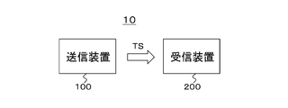
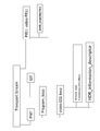
- FIG. 1 shows a configuration example of a transmission / reception system 10 as an embodiment.
- the transmission / reception system 10 includes a transmission device 100 and a reception device 200.
- the transmission apparatus 100 generates an MPEG2 transport stream TS as a container, and transmits the transport stream TS on a broadcast wave or a net packet.
- This transport stream TS has a video stream obtained by encoding transmission video data.
- This transmission video data is LDR image video data obtained by applying a predetermined level mapping curve to the original HDR image video data as input video data.
- the level range of the transmission video data is compressed with respect to the level range of the input video data, but the entire area is not necessarily compressed uniformly. A compression region occurs, and the width and position of the low compression region also change.
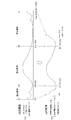
- FIG. 2A shows an example of an original HDR level, that is, a level distribution of input video data.
- the input video data has a level range of 0% to N% (N> 100).
- FIG. 2B shows an example of a coded transmission level, that is, a level distribution of transmission video data.
- the area from 0% to J% of the input video data is a high compression area, and is converted from 0% to J ′% of the transmission video data by the level mapping process.
- the J% to K% region of the input video data is a low compression region, and is converted from the J ′% to K ′% region of the transmission video data by the level mapping process.
- the K% to N% region of the input video data is a high compression region, and is converted from the K ′% to P% region of the transmission video data by the level mapping process.
- the low-compression range is a level region that is transmitted with little original quality loss in the level mapping process with respect to the brightness level.
- the high compression area is a level area in which the original quality is positively compressed by the level mapping process so as to be within a predetermined display level.
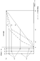
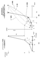
- FIG. 3 shows an example of HDR conversion characteristics, that is, a level mapping curve.
- the level mapping curve (1) is an example in which a dark portion of an image is expressed finely. In this case, of the three divided level ranges, the dark level range is converted to multiple levels, the central level range is then converted to multiple levels, and the bright level range is converted to low levels.
- the level mapping curve (2) is an example in the case where the central level portion of the image is expressed finely. In this case, among the three divided level ranges, the middle level range is converted to multiple levels, the bright level range is then converted to multiple levels, and the dark level range is converted to small levels.
- the level mapping curve (3) is an example in the case where the brightness portions of the image are expressed equally.
- FIG. 3 shows that the number of level mapping curves to be chained is 3, but this number is not limited to 3.
- the transmission device 100 transmits the transmission video data together with auxiliary information for performing level conversion on the reception side.
- the transmission apparatus 100 inserts level mapping curve information and / or electro-optic conversion characteristic information as auxiliary information in the layer of the video stream.
- the level mapping curve information includes, for example, the percentage value of the brightness peak level on the uncompressed axis (see “Uw” in FIG. 3), the level of the mapping point in the peak percentage range on the uncompressed axis. (See “U1, U2” in FIG. 3), percent value of peak brightness level on the level-compressed axis (see “Vw” in FIG. 3), and mapping points in the peak percent range on the compression axis ( mapping percentage level) (see “V1, V2” in FIG. 3).
- the electro-optical conversion characteristic information includes, for example, the type of electro-optical conversion characteristic or a look-up table (LUT) value indicating the electro-optical conversion characteristic.
- the receiving device 200 receives the transport stream TS transmitted from the transmitting device 100 on broadcast waves or net packets.
- This transport stream TS has a video stream obtained by encoding transmission video data.
- the receiving apparatus 200 performs processing such as decoding on the video stream to obtain display video data (output video data).
- level mapping curve information and / or electro-optic conversion characteristic information is inserted into the video stream layer as auxiliary information.
- the receiving apparatus 200 subjects the transmission video data to HDR inverse conversion that is the inverse of the above-described HDR conversion in the transmission apparatus 100, and generates video data of a reproduced HDR image. .
- the level range of the video data of the reproduced HDR image has a third level range that is equal to or higher than the second level range that is the level range of the transmission video data.
- the maximum level (peak level) of the video data of the reproduced HDR image is, for example, the maximum level (peak level) of the video data of the original HDR image, or the maximum level (peak level) that can be displayed defined by the reception function. Limited.
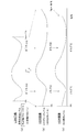
- FIG. 4 (a) shows an example of the encoded transmission level, that is, the level distribution of transmission video data, similar to FIG. 2 (b).
- FIG. 4B shows an example of the level distribution of the video data of the HDR image obtained by subjecting the transmission video data to the conversion opposite to the HDR conversion on the transmission side based on the level mapping curve information. ing.
- the video data of the HDR image in this example has a level range of 0% to N% (N> 100), like the video data of the original HDR image.
- FIG. 5 shows an example of the HDR inverse conversion characteristics based on the level mapping curve information.
- the HDR inverse conversion characteristics of (1), (2), and (3) correspond to the level mapping curves of (1), (2), and (3) of FIG.
- the maximum level of the video data of the reproduced HDR image obtained by the HDR inverse transform is the maximum level (N%) of the video data of the original HDR image and the maximum displayable level defined by the reception function ( Q%) is determined as follows. That is, when P ⁇ Q ⁇ N, the maximum level of the video data of the reproduced HDR image is Q%. When P ⁇ N ⁇ Q, the maximum level of the video data of the reproduced HDR image is N%.
- FIG. 4B also shows the level distribution of the video data of the playback HDR image when the maximum level of the video data of the playback HDR image is N%.
- the area from 0% to J ′% of the transmission video data is converted from 0% to J% of the video data of the reproduced HDR image by the HDR inverse transformation.
- the J ′% to K ′% region of the transmission video data is converted into the J% to K% region of the video data of the reproduced HDR image by the HDR reverse conversion.
- the K ′% to P% region of the transmission video data is converted into the K% to N% region of the video data of the reproduced HDR image by the HDR reverse conversion.
- the video data level of the reproduced HDR image is obtained by multiplying the level of the transmission video data by the ratio of (NK) / (PK ′). become.
- FIG. 4C shows the level distribution of the video data of the playback HDR image when the maximum level of the video data of the playback HDR image is Q%.
- the area from 0% to J ′% of the transmission video data is converted from 0% to J% of the video data of the reproduced HDR image by the HDR inverse transformation.
- the J ′% to K ′% area of the input video data is converted to the J% to K% area of the video data of the reproduced HDR image by HDR inverse transformation.
- the region from K ′% to P% of the input video data is converted into the region of K% to Q% of the video data of the reproduced HDR image by HDR inverse conversion.
- the video data level of the reproduced HDR image is obtained by multiplying the level of the transmission video data by the ratio of (QK) / (PK ′). become.
- the receiving apparatus 200 performs electro-optic conversion processing on the transmission video data or the video data of the HDR image obtained by performing the HDR inverse transformation on the transmission video data based on the electro-optic conversion characteristic information, and performs display.
- Video data output video data is generated.
- FIG. 6 shows an example of electro-optic conversion characteristics.
- a curve a shows an example of an electro-optic conversion characteristic for displaying low luminance with high accuracy.
- a curve b shows an example of the electro-optic conversion characteristic for making the extremely low luminance part rough and displaying the other luminance part with high accuracy.
- a curve c shows an example of an electro-optic conversion characteristic for displaying with a good balance between high luminance and low luminance accuracy.
- the photoelectric conversion characteristic in the transmission apparatus 100 is set to be opposite to the electro-optical conversion characteristic in the reception apparatus 200.
- FIG. 7 shows a configuration example of the transmission device 100.
- the transmission apparatus 100 includes a control unit 101, a camera 102, a photoelectric conversion unit 103, an HDR conversion unit 104, a video encoder 105, a system encoder 106, and a transmission unit 107.
- the control unit 101 includes a CPU (Central Processing Unit), and controls the operation of each unit of the transmission device 100 based on a control program stored in a storage (not shown).
- CPU Central Processing Unit
- the camera 102 images a subject and outputs video data of an HDR (High Dynamic Range) image.
- This video data has a level range of 0 to 100% * N, for example, 0 to 400% or 0 to 800%.
- the level of 100% corresponds to a white luminance value of 100 cd / m2.
- the photoelectric conversion unit 103 performs photoelectric conversion on the video data obtained from the camera 102 by applying a gamma curve.
- the HDR conversion unit 104 applies HDR conversion (level mapping) to the video data of the HDR image after photoelectric conversion by applying a predetermined level mapping curve (see FIG. 3), and the LDR in which the level range is compressed.
- the transmission video data of the image is generated (see FIG. 2).
- the level mapping curve applied here for example, a predetermined level mapping curve associated with a parameter indicating the brightness of an image is selected automatically or by a user operation.
- the video encoder 105 performs encoding such as MPEG4-AVC, MPEG2 video, or HEVC (high Efficiency Video Coding) on the transmission video data generated by the HDR conversion unit 104 to obtain encoded video data. . Further, the video encoder 105 generates a video stream (video elementary stream) including the encoded video data by a stream formatter (not shown) provided in the subsequent stage.
- encoding such as MPEG4-AVC, MPEG2 video, or HEVC (high Efficiency Video Coding)
- HEVC High Efficiency Video Coding
- the video encoder 105 inserts auxiliary information into the layer of the video stream.
- This auxiliary information is information for performing level conversion on the reception side, and is information on the level mapping curve applied by the HDR conversion unit 104, and electro-optic conversion characteristic information.
- the electro-optical conversion characteristic indicated by the electro-optical conversion characteristic information depends on the characteristic of the image and is selected automatically or by a user operation.
- the system encoder 106 generates a transport stream TS including the video stream generated by the video encoder 105. Then, the transmitting unit 107 transmits this transport stream TS to the receiving apparatus 200 on a broadcast wave or a net packet.
- the system encoder 106 inserts auxiliary information (level mapping curve information, electro-optic conversion characteristic information) for performing level conversion on the receiving side into the layer of the transport stream TS and into the layer of the video stream. It may be configured to insert identification information indicating that the In this case, for example, the system encoder 106 inserts the identification information under a video elementary loop (Video ES loop) of a program map table (PMT: Program Map Table) included in the transport stream TS.
- auxiliary information level mapping curve information, electro-optic conversion characteristic information
- PMT Program Map Table
- Video data of an HDR image obtained by imaging with the camera 102 is subjected to photoelectric conversion by applying a gamma curve by the photoelectric conversion unit 103, and then supplied to the HDR conversion unit 104.
- the HDR conversion unit 104 applies HDR to the video data of the HDR image after photoelectric conversion by applying a predetermined level mapping curve, and generates transmission video data of the LDR image (FIG. 2A ), (B)).
- the transmission video data of the LDR image generated by the HDR conversion unit 104 is supplied to the video encoder 105.
- the video encoder 105 performs encoding such as HEVC on the transmission video data of the LDR image, and generates a video stream (video elementary stream) including the encoded video data.
- the video encoder 105 inserts auxiliary information (level mapping curve information, electro-optic conversion characteristic information) for performing level conversion on the receiving side into the layer of the video stream.
- the video stream generated by the video encoder 105 is supplied to the system encoder 106.
- the system encoder 106 generates an MPEG2 transport stream TS including a video stream.
- the transport stream TS is transmitted to the receiving apparatus 200 by the transmitting unit 107 on a broadcast wave or a net packet.
- auxiliary information level mapping curve information, electro-optic conversion characteristic information
- HDR_mapping SEI message HDR mapping / SEI message
- FIG. 8 shows the top access unit of GOP (Group Of Pictures) when the encoding method is HEVC.
- a decoding SEI message group “Prefix_SEIs” is arranged before a slice (slices) in which pixel data is encoded, and a display SEI message group “ “Suffix_SEIs” is arranged.
- the HDR mapping / SEI message is arranged as an SEI message group “Suffix_SEIs”.
- FIG. 9 and 10 show a structural example (Syntax) of “HDR mapping“ SEI message ”.
- FIG. 11 shows the contents (Semantics) of main information in the structural example.
- “HDR_mapping_refresh_flag” is 1-bit flag information. “1” indicates that the previous HRD mapping message is refreshed. “0” indicates that the message is not refreshed.
- the 8-bit field of “coded_data_bits” indicates the bit length of the encoded data as a value.
- a 16-bit field of “uncompressed_peak_level_percentage” indicates a percentage value (relative to 100 cd / m 2) of the maximum level of the source image data. For example, it is the value of “Uw” in FIG.
- a 16-bit field of “compressed_peak_level_percentage” indicates a percentage value (relative to 100 cd / m 2) of the maximum level of the encoded image data. For example, it is the value of “Vw” in FIG.
- Level_mapping_flag is 1-bit flag information indicating whether or not there is a level mapping parameter. “1” indicates that there is a level mapping parameter. “Eotf_linked_flag” is 1-bit flag information, and indicates whether or not level mapping is performed by incorporating a conversion curve of electro-optic conversion (EOTF). “1” indicates that level mapping is performed by taking in a conversion curve of electro-optic conversion (EOTF).
- An 8-bit field of “number_of_mapping_periods” indicates the number of level mapping curves to be chained. For example, in the case of FIG. 3, the number of level mapping curves to be chained is 3.
- a 16-bit field of “compressed_mapping_point” indicates a change point of the level mapping curve on the level compression axis as a percentage value where “compressed_peak_level_percentage” is 100%. For example, it is the value of “V1, V2, Vw” in FIG.
- a 16-bit field of “uncompressed_mapping_point” indicates a change point of the level mapping curve on the level uncompressed axis as a percentage value where “uncompressed_peak_level_percentage” is 100%. For example, it is the value of “U1, U2, Uw” in FIG.
- a 4-bit field of “eotf_table_type_main” indicates a main type of a conversion curve of electro-optic conversion (EOTF). Further, when “eotf_linked_flag” is “0xF”, it indicates that a conversion curve of electro-optic conversion (EOTF) specialized for a specific image is sent.
- a 16-bit field of “tbl [j]” indicates an output value for the input value “j” in the conversion curve of the electro-optic conversion (EOTF) to be transmitted.
- FIG. 12 shows a structural example (Syntax) of an HDR information descriptor (HDR_information descriptor) as identification information.
- FIG. 13 shows the contents (Semantics) of main information in the structural example.
- the 8-bit field of“ HDR_information “descriptor” tag indicates a descriptor type, and here indicates that it is an HDR information descriptor.
- the 8-bit field of “HDR_ information descriptor length” indicates the length (size) of the descriptor, and indicates the number of subsequent bytes as the descriptor length.
- the 1-bit field of “HDR_mapping_SEI_existed” is flag information indicating whether HDR mapping / SEI information exists in the video layer (video stream layer). “1” indicates that HDR mapping / SEI information exists, and “0” indicates that HDR mapping / SEI information does not exist.
- FIG. 14 shows a configuration example of the transport stream TS.
- the transport stream TS includes a PES packet “PID1: video PES1” of the video elementary stream.
- PES packet “PID1: video PES1” of the video elementary stream.
- the above-described HDR mapping SEI message (HDR_mapping SEI message) is inserted into this video elementary stream.
- the transport stream TS includes a PMT (Program Map Table) as PSI (Program Specific Information).
- PSI Program Specific Information
- This PSI is information describing to which program each elementary stream included in the transport stream belongs.
- the transport stream TS includes an EIT (Event Information Table) as SI (Serviced Information) for managing events (programs).
- the PMT there is an elementary loop having information related to each elementary stream.
- a video elementary loop (Video ES loop).
- information such as a stream type and a packet identifier (PID) is arranged corresponding to the above one video elementary stream, and information related to the video elementary stream is described.
- a descriptor is also arranged.
- the HDR information descriptor (HDR_information descriptor) is placed under the video elementary loop (Video ES loop) of this PMT. As described above, this descriptor indicates that the HDR mapping / SEI information is inserted in the video stream.
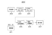
- FIG. 15 illustrates a configuration example of the receiving device 200.
- the receiving apparatus 200 includes a control unit 201, a receiving unit 202, a system decoder 203, a video decoder 204, an HDR inverse conversion unit 205, an electro-optic conversion unit 206, and a display unit 207.
- the control unit 201 includes a CPU (Central Processing Unit), and controls the operation of each unit of the receiving device 200 based on a control program stored in a storage (not shown).
- CPU Central Processing Unit
- the receiving unit 202 receives the transport stream TS transmitted from the transmitting device 100 on broadcast waves or net packets.
- the system decoder 203 extracts a video stream (elementary stream) from the transport stream TS. Further, when the system decoder 203 has inserted identification information indicating that auxiliary information (level mapping curve information, electro-optic conversion characteristic information) is inserted in the layer of the transport stream TS as described above, This identification information is extracted and sent to the control unit 201.
- control unit 201 Based on this identification information, the control unit 201 recognizes that there is insertion of auxiliary information (level mapping curve information, electro-optic conversion characteristic information), that is, HDR mapping / SEI message (HDR_mappingmSEI message), in the video stream. it can. Based on the recognition, the control unit 201 can control the video decoder 204 to actively acquire the HDR mapping / SEI message, for example.
- auxiliary information level mapping curve information, electro-optic conversion characteristic information
- HDR mapping / SEI message HDR mapping / SEI message
- the video decoder 204 performs decoding processing on the video stream extracted by the system decoder 203 to obtain baseband video data (transmission video data).
- the video decoder 204 extracts the SEI message inserted in the video stream and sends it to the control unit 201.
- This SEI message includes an HDR mapping / SEI message (HDR_mapping SEI message).
- the control unit 201 controls decoding processing and display processing based on the SEI message.
- the HDR inverse transform unit 205 performs HDR inverse transform on the transmission video data obtained by the video decoder 204 based on the level mapping curve information included in the HDR mapping / SEI message, and reproduces the level range expanded. Video data of the HDR image is generated (see FIG. 4). In this case, for example, when the input image of the HDR inverse transform unit 205 is indicated by 10 bits or less, the output image of the HDR inverse transform unit 205 is indicated by 12 bits or more.
- the HDR inverse conversion unit 205 determines the maximum level of video data of the reproduced HDR image as the maximum level (N%) of the video data of the original HDR image and the maximum displayable level (Q%) defined by the reception function. ). That is, when Q ⁇ N, the maximum level of the video data of the playback HDR image is Q%, and when N ⁇ Q, the maximum level of the video data of the playback HDR image is N%.
- the HDR inverse conversion unit 205 outputs the transmission video data of the LDR image input from the video decoder 204 as it is when there is no level mapping curve information (level mapping parameter) in the HDR mapping / SEI message.
- the electro-optic conversion unit 206 converts the video data (reproduced HDR image video data or LDR image transmission video data) output from the HDR inverse conversion unit 205 into the electro-optic conversion characteristic information included in the HDR mapping / SEI message. Based on this, light-to-light conversion, that is, level mapping is performed.
- the electro-optic conversion unit 206 uses a conversion curve of the type indicated by the HDR mapping / SEI message or a conversion curve sent by the HDR mapping / SEI message as the conversion curve of electro-optic conversion (EOTF). As another transmission method, it can also be identified by signaling sent in a video parameter set (SPS).
- SPS video parameter set
- the information indicating the conversion curve type of electro-optic conversion (EOTF) included in the HDR mapping / SEI message is “eotf_table_type_main”, which indicates the main type of the conversion curve (see FIG. 10).
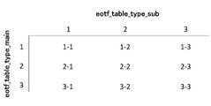
- the main type indicated by “eotf_table_type_main” is further subdivided into sub-types indicated by “eotf_table_type_sub”. That is, the electro-optic conversion unit 206 uses an electro-optic conversion (EOTF) conversion curve determined by both the main type and the sub type.
- FIG. 16 shows an example of a combination of the main type indicated by the information “eotf_table_type_main” and the sub type indicated by the information “eotf_table_type_sub”. This example shows a case where there are three types “1”, “2”, and “3” as main types and “1”, “2”, and “3” as sub types.
- each of the main and sub types indicates the characteristics of the conversion curve as shown in FIG. 17, for example. That is, the main type “1” indicates a conversion curve suitable for finely reproducing a dark level of an image.
- the main type “2” indicates a conversion curve suitable for reproducing an extremely low luminance portion with a rougher portion and improving the other luminance portions.
- the main type “3” indicates a conversion curve suitable for finely reproducing an intermediate level of an image.
- the sub type “1” indicates a conversion curve suitable for viewing in a dark room.
- the sub type “2” indicates a conversion curve suitable for viewing in a bright room.
- the sub type “3” indicates a conversion curve suitable for viewing in a room with intermediate brightness.
- the main type and sub type are not limited to three. Also, the type characteristics are not limited to the contents shown in FIG.
- the information of “eotf_table_type_main” is given by the HDR mapping / SEI message from the transmission device 100 as described above.
- the information of “eotf_table_type_sub” is given in the receiving apparatus 200 according to, for example, the viewing environment.
- the sub type indicated by “eotf_table_type_sub” is determined according to the output of the brightness sensor or the user operation. Thereby, one of a plurality of sub-types included in the main type is selected, and the electro-optical conversion characteristic used in the electro-optical conversion unit 206 is selected.
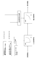
- FIG. 18 schematically shows the linkage between HDR reverse conversion and light-optical conversion in the receiving apparatus 200.
- the received image becomes a display image through the HDR reverse conversion and the electro-optic conversion.
- the conversion characteristics of the HDR inverse conversion correspond to the level mapping curve applied in the HDR conversion on the transmission side. As described above, on the transmission side, for example, a predetermined level mapping curve associated with a parameter indicating the brightness of an image is applied.
- the electro-optic conversion characteristic is specified by a combination of the main type indicated by the information “eotf_table_type_main” and the sub type indicated by the information “eotf_table_type_sub”.
- the main type is set on the transmission side depending on the characteristics of the image.
- the sub type is set on the receiving side according to the viewing environment.
- the electro-optic converter 206 when there is no electro-optic conversion characteristic information in the HDR mapping / SEI message, the electro-optic converter 206 performs electro-optic conversion, for example, by applying a conventional gamma inverse characteristic.
- the display unit 207 performs image display using display video data output from the electro-optic conversion unit 206.
- the display unit 207 is configured by, for example, a liquid crystal display panel, an organic EL display panel, or the like.
- the reception unit 202 receives the transport stream TS transmitted from the transmission device 100 on broadcast waves or net packets.
- This transport stream TS is supplied to the system decoder 203.
- the system decoder 203 extracts a video stream (elementary stream) from the transport stream TS.
- the video stream extracted by the system decoder 203 is supplied to the video decoder 204.
- the video decoder 204 performs decoding processing on the video stream to obtain baseband video data (transmission video data). Further, the video decoder 204 extracts the SEI message inserted in this video stream and sends it to the control unit 201.
- This SEI message includes an HDR mapping / SEI message (HDR_mapping SEI message).
- the control unit 201 controls decoding processing and display processing based on the SEI message.
- the transmission video data of the LDR image obtained by the video decoder 204 is supplied to the HDR inverse conversion unit 205.
- the HDR inverse transform unit 205 performs HDR inverse transform on the transmission video data of the LDR image obtained by the video decoder 204 based on the level mapping curve information included in the HDR mapping / SEI message, and level expands. Reproduced HDR image video data is obtained.
- the HDR inverse conversion unit 205 outputs the transmission video data of the LDR image input from the video decoder 204 as it is when there is no level mapping curve information in the HDR mapping / SEI message.
- the video data obtained by the HDR reverse conversion unit 205 is supplied to the electric light conversion unit 206.
- the electro-optic conversion unit 206 performs electro-optic conversion, that is, level mapping, on the video data (reproduced HDR image video data or LDR image transmission video data) output from the HDR inverse conversion unit 205 to display video. Data is obtained.
- a conversion curve of the type indicated by the HDR mapping / SEI message or a conversion curve sent by the HDR mapping / SEI message is used as the conversion curve of the electro-optic conversion (EOTF). Note that when there is no electro-optical conversion characteristic information in the HDR mapping / SEI message, for example, the conventional gamma inverse characteristic is applied to perform electro-optical conversion.
- the video data for display obtained by the electro-optic conversion unit 206 is supplied to the display unit 207.
- the display unit 207 displays an image based on the video data for display.
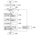
- FIG. 19 shows an example of the processing flow of the receiving apparatus 200.
- the receiving device 200 starts processing. Thereafter, the receiving apparatus 200 receives the video stream in step ST2.
- the receiving apparatus 200 determines whether to read the HDR mapping / SEI message. When the HDR stream / SEI message is included in the video stream, the receiving apparatus 200 determines to read the HDR mapping / SEI message.
- the receiving apparatus 200 When determining that the HDR mapping / SEI message is to be read, the receiving apparatus 200 recognizes the encoded bit and the peak level percentage value of the encoded image data in step ST4. Next, in step ST5, the receiving apparatus 200 recognizes the percentage value of the peak level of the original image.
- step ST6 the receiving apparatus 200 performs reverse HDR conversion based on the level mapping curve information included in the HDR mapping / SEI message to obtain video data of a reproduced HDR image.
- step ST7 the receiving apparatus 200 recognizes the type of conversion curve of electro-optic conversion (EOTF) or receives the conversion curve of electro-optic conversion (EOTF) specialized for a specific image, and performs electro-optic conversion. To obtain video data for display.
- the receiving apparatus 200 ends the process in step ST8.
- the receiving apparatus 200 When determining that the HDR mapping / SEI message is not read in step ST3, the receiving apparatus 200 performs electro-optic conversion using the conventional gamma inverse correction as a conventional LDR image in step ST9, and displays it for display. Get video data. After the process of step ST9, the receiving apparatus 200 ends the process in step ST8.
- the transmission device 100 applies a specific level mapping curve to the video data of the original HDR image to compress the level range, and transmits the transmission video of the LDR image. Data is generated and transmitted. Therefore, for example, by using an appropriate characteristic according to the image content as a predetermined level mapping curve, it is possible to display a good LDR image on the LDR monitor using the transmission video data.
- the transmission device 100 transmits auxiliary information for performing level conversion on the reception side together with the transmission video data. Therefore, for example, on the receiving side, an appropriate level conversion process can be performed on the transmission video data based on the auxiliary information, and a good image display can be performed.
- the transmission device 100 transmits electro-optical conversion characteristic information including information on a plurality of electro-optical conversion characteristics, that is, information of “eotf_table_type_main”. Therefore, on the receiving side, an electro-optic conversion characteristic corresponding to the brightness of the viewing environment can be automatically or manually selected from a plurality of electro-optic conversion characteristics, and the monitor can be used according to the brightness of the viewing environment. An image can be displayed.
- the HDR inverse conversion unit 205 performs the HDR inverse conversion
- the electro-optic conversion unit 206 performs the electro-optical conversion.
- the HDR inverse conversion and the electro-optic conversion can be performed simultaneously only by the electro-optic conversion unit 206.
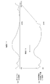
- FIG. 20A shows the level mapping characteristic (HDR inverse conversion characteristic).
- This level mapping characteristic is information for converting an LDR image into an HDR image in correspondence with the relative level on the compression level axis and the relative level on the non-compression level axis.
- FIG. 20B shows the electro-optic conversion characteristics.
- the LC curve shows the conventional electro-optical conversion characteristic
- the HDC curve shows the electro-optical conversion characteristic in which the HDR inverse conversion characteristic is reflected in the conventional electro-optical conversion characteristic.
- the NTr line indicates a linear straight line in all the minimum and maximum areas with respect to the curve of electro-optic conversion.
- the LC -1 curve is a curve having an inverse characteristic that is axisymmetric with respect to the NTr line with respect to the LC curve, and is used for the purpose of transmitting the characteristics between the vertical axis and the horizontal axis in FIG.
- T1, T2, Tw of (a) are arranged on the horizontal axis of (b) as T1 ′, T2 ′, Tw ′.
- the output for input V1 is T1.
- the plot of (b) that satisfies the characteristics of (a) and the characteristics of the LC curve of (b) is the value of the vertical axis of b1 with respect to V1 arranged on the horizontal axis of (b). This is the value of the vertical axis of b11 with respect to V1.
- the horizontal axis of (b), the value of the vertical axis for V2 is a plot b2 on the LC curve for T2′2, which can be expressed as b21 for V2.
- the output Tw of (a) of the input Vw is represented by Tw ′ of (b)
- the value of the vertical axis with respect to Vw corresponds to the point that the plot b3 on the LC curve with respect to Tw ′ corresponds to Vw, that is, b31. It becomes the plot of.
- the HDC curve has a characteristic that satisfies the characteristics of (a) and the LC curve of (b) at the same time. This means that the electro-optical conversion characteristics satisfy the HDR reverse conversion and the electro-optical conversion by one.
- FIG. 21A shows level mapping characteristics (HDR inverse conversion characteristics) corresponding to (2) of FIG.
- FIG. 21B shows the electro-optic conversion characteristics.
- the LC curve shows the conventional electro-optical conversion characteristic
- the HDC curve shows the electro-optical conversion characteristic in which the HDR reverse conversion characteristic shown in FIG.
- the method for obtaining the HDC curve is as shown in FIG.
- the photoelectric conversion unit 103 performs photoelectric conversion in the transmission device 200 and the HDR conversion unit 104 performs HDR conversion.
- the photoelectric conversion and the HDR conversion can be performed simultaneously only by the photoelectric conversion unit 103.
- FIG. 22B shows level mapping characteristics (HDR conversion characteristics) corresponding to (1) of FIG.
- FIG. 22A shows a conventional photoelectric conversion characteristic and an HDR photoelectric conversion characteristic in which the HDR conversion characteristic shown in FIG. 22B is reflected in this conventional photoelectric conversion characteristic.
- the method for obtaining the HDR photoelectric conversion characteristic is the same as that for obtaining the electro-optic conversion characteristic (HDC curve) reflecting the above-described HDR inverse conversion characteristic.
- the HDR conversion unit 104 of the transmission apparatus 100 converts the HDR image into an LDR image, transmits the parameters (level mapping curve information) together with the LDR image, and performs the HDR inverse conversion of the reception apparatus 200.
- the unit 205 shows an example in which an LDR image is converted into an HDR image and displayed based on the transmitted parameters.
- the HDR conversion unit 104 of the transmission device 100 transmits parameters for converting the HDR image into the LDR image together with the HDR image without converting the HDR image into the LDR image, and receives the reception device 200.
- the HDR inverse conversion unit 205 may convert the received HDR image into an LDR image according to the parameter and display it.
- the HDR is converted to LDR and has a conversion characteristic having the conventional electro-optical conversion characteristic.
- this technique can also take the following structures.
- a transmission apparatus comprising: a transmission unit configured to transmit the transmission video data together with auxiliary information for performing level conversion on a reception side.
- the transmission unit transmits a video stream obtained by encoding the transmission video data, The transmission apparatus according to (1), wherein the auxiliary information is inserted into a layer of the video stream.
- the first level range is a level range of 0% to N% (N is a number greater than 100), and the second level range is 0% to P% (P is 100 or more and N or less).
- the transmission device according to (1) or (2).
- (4) The transmission device according to any one of (1) to (3), wherein the auxiliary information is level mapping curve information and / or electro-optic conversion characteristic information.
- the light-emission conversion characteristic information transmitted by the transmission unit together with the transmission video data includes information on a plurality of light-emission conversion characteristics.
- a second level equal to or smaller than the first level range obtained by applying a predetermined level mapping curve to the input video data having the first level range.
- a receiving apparatus comprising: a processing unit that converts the level of the transmission video data based on auxiliary information received together with the transmission video data.
- the processing unit The transmission video data having the second level range is converted into output video data having a third level range equal to or higher than the second level range based on the level mapping curve information. Receiver.
- the first level range is a level range of 0% to N% (N is a number greater than 100), and the second level range is 0% to P% (P is 100 or more and N or less).
- the third level range is 0% to Q% (Q is a number of 100 or more and N or less).
- the receiving apparatus according to (9).
- (11) The receiving device according to (9) or (10), wherein the maximum level of the third level range is determined based on information on a maximum level that can be displayed.
- the processing unit Transmission video data having the second level range based on the electro-optic conversion characteristic information, or more than the second level range obtained by level conversion of the transmission video data based on the level mapping curve information
- the receiving device according to any one of (8) to (11), wherein the video data having the third level range is subjected to electro-optic conversion to obtain output video data.
- the electro-optic conversion characteristic information received together with the transmission video data includes information on a plurality of electro-optic conversion characteristics,
- the receiving apparatus according to any one of (8) to (12), further including a selection unit that selects one electro-optical conversion characteristic used by the processing unit from the plurality of electro-optical conversion characteristics.
- the receiving device (14) The receiving device according to (13), wherein the selection unit selects one electro-optic conversion characteristic used in the processing unit from the plurality of electro-optic conversion characteristics based on a sensor output or a user operation input.
- the main feature of the present technology is that the transmission video data of the LDR image generated by applying a specific level mapping curve to the video data of the original HDR image is transmitted to display the LDR image on the receiving side. (See FIGS. 2 and 7).
- the main feature of the present technology is that by transmitting auxiliary information for performing level conversion on the receiving side together with the transmission video data, appropriate level conversion processing can be performed on the receiving side, and good image display is achieved. This is possible (see FIGS. 4 and 15).
- DESCRIPTION OF SYMBOLS 10 ... Transmission / reception system 100 ... Transmission apparatus 101 ... Control part 102 ... Camera 103 ... Photoelectric conversion part 104 ... HDR conversion part 105 ... Video encoder 106 ... System encoder 107 ... Transmission unit 200 ... Reception device 201 ... Control unit 202 ... Reception unit 203 ... System decoder 204 ... Video decoder 205 ... HDR inverse conversion unit 206 ... Electro-optic conversion unit 207 ... Display section
Abstract
Description
第1のレベル範囲を持つ入力ビデオデータに所定のレベルマッピング・カーブを適用して上記第1のレベル範囲より狭いか、あるいは該第1のレベル範囲と同等の第2のレベル範囲を持つ伝送ビデオデータを得るレベル変換部と、
上記伝送ビデオデータを、受信側でレベル変換を行うための補助情報と共に送信する送信部を備える
送信装置にある。 The concept of this technology is
A transmission video having a second level range that is narrower than the first level range by applying a predetermined level mapping curve to the input video data having the first level range or equivalent to the first level range. A level conversion unit for obtaining data;
The transmission apparatus includes a transmission unit that transmits the transmission video data together with auxiliary information for performing level conversion on the reception side.
第1のレベル範囲を持つ入力ビデオデータに所定のレベルマッピング・カーブを適用して得られた上記第1のレベル範囲より狭いか、あるいは該第1のレベル範囲と同等の第2のレベル範囲を持つ伝送ビデオデータを受信する受信部と、
上記伝送ビデオデータのレベルを、該伝送ビデオデータと共に受信される補助情報に基づいて変換する処理部を備える
受信装置にある。 Other concepts of this technology are
A second level range that is narrower than or equal to the first level range obtained by applying a predetermined level mapping curve to input video data having the first level range. A receiving unit for receiving transmission video data having;
The receiving apparatus includes a processing unit that converts the level of the transmission video data based on auxiliary information received together with the transmission video data.
1.実施の形態
2.変形例 Hereinafter, modes for carrying out the invention (hereinafter referred to as “embodiments”) will be described. The description will be given in the following order.
1.
[送受信システムの構成例]
図1は、実施の形態としての送受信システム10の構成例を示している。この送受信システム10は、送信装置100および受信装置200により構成されている。 <1. Embodiment>
[Configuration example of transmission / reception system]
FIG. 1 shows a configuration example of a transmission /
図7は、送信装置100の構成例を示している。この送信装置100は、制御部101と、カメラ102と、光電変換部103と、HDR変換部104と、ビデオエンコーダ105と、システムエンコーダ106と、送信部107を有している。制御部101は、CPU(Central Processing Unit)を備えて構成され、図示しないストレージに格納されている制御プログラムに基づいて、送信装置100の各部の動作を制御する。 "Example of transmission device configuration"
FIG. 7 shows a configuration example of the
上述したように、ビデオストリームのレイヤに、補助情報(レベルマッピング・カーブの情報、電光変換特性情報)が挿入される。例えば、符号化方式がHEVCである場合、この補助情報は、アクセスユニット(AU)の“SEIs”の部分に、HDRマッピング・SEIメッセージ(HDR_mapping SEI message)として挿入される。 [Auxiliary information, identification information, TS configuration]
As described above, auxiliary information (level mapping curve information, electro-optic conversion characteristic information) is inserted into the layer of the video stream. For example, when the encoding method is HEVC, this auxiliary information is inserted as an HDR mapping / SEI message (HDR_mapping SEI message) in the “SEIs” portion of the access unit (AU).
図15は、受信装置200の構成例を示している。この受信装置200は、制御部201と、受信部202と、システムデコーダ203と、ビデオデコーダ204と、HDR逆変換部205と、電光変換部206と、表示部207を有している。制御部201は、CPU(Central Processing Unit)を備えて構成され、図示しないストレージに格納されている制御プログラムに基づいて、受信装置200の各部の動作を制御する。 "Example of receiver configuration"
FIG. 15 illustrates a configuration example of the receiving
なお、上述の実施の形態において、受信装置200では、HDR逆変換部205でHDR逆変換が行われると共に、電光変換部206で電光変換が行われる例を示した。しかし、例えば、電光変換特性にHDR逆変換特性を反映させておくことで、電光変換部206のみでHDR逆変換と電光変換とを同時に行わせることができる。 <2. Modification>
In the above-described embodiment, in the receiving
(1)第1のレベル範囲を持つ入力ビデオデータに所定のレベルマッピング・カーブを適用して上記第1のレベル範囲より狭いか、あるいは該第1のレベル範囲と同等の第2のレベル範囲を持つ伝送ビデオデータを得るレベル変換部と、
上記伝送ビデオデータを、受信側でレベル変換を行うための補助情報と共に送信する送信部を備える
送信装置。
(2)上記送信部は、上記伝送ビデオデータが符号化されて得られたビデオストリームを送信し、
上記補助情報は、上記ビデオストリームのレイヤに挿入される
前記(1)に記載の送信装置。
(3)上記第1のレベル範囲は0%からN%(Nは100より大きい数)のレベル範囲であり、上記第2のレベル範囲は0%からP%(Pは100以上でN以下の数)である
前記(1)または(2)に記載の送信装置。
(4)上記補助情報は、レベルマッピング・カーブ情報および/または電光変換特性情報である
前記(1)から(3)のいずれかに記載の送信装置。
(5)上記送信部が上記伝送ビデオデータと共に送信する電光変換特性情報は、複数の電光変換特性の情報を含む
前記(4)に記載の送信装置。
(6)第1のレベル範囲を持つ入力ビデオデータに所定のレベルマッピング・カーブを適用して上記第1のレベル範囲より狭い第2のレベル範囲を持つ伝送ビデオデータを得るレベル変換ステップと、
送信部により、上記伝送ビデオデータを、受信側でレベル変換を行うための補助情報と共に送信する送信ステップとを有する
送信方法。
(7)第1のレベル範囲を持つ入力ビデオデータに所定のレベルマッピング・カーブを適用して得られた上記第1のレベル範囲より狭いか、あるいは該第1のレベル範囲と同等の第2のレベル範囲を持つ伝送ビデオデータを受信する受信部と、
上記伝送ビデオデータのレベルを、該伝送ビデオデータと共に受信される補助情報に基づいて変換する処理部を備える
受信装置。
(8)上記補助情報は、レベルマッピング・カーブ情報および/または電光変換特性情報である
前記(7)に記載の受信装置。
(9)上記処理部は、
上記レベルマッピング・カーブ情報に基づいて、上記第2のレベル範囲を持つ伝送ビデオデータを、該第2のレベル範囲以上の第3のレベル範囲を持つ出力ビデオデータに変換する
前記(8)に記載の受信装置。
(10)上記第1のレベル範囲は0%からN%(Nは100より大きい数)のレベル範囲であり、上記第2のレベル範囲は0%からP%(Pは100以上でN以下の数)であり、上記第3のレベル範囲は0%からQ%(Qは100以上でN以下の数)である
前記(9)に記載の受信装置。
(11)上記第3のレベル範囲の最大レベルは、表示可能な最大レベルの情報に基づいて決定される
前記(9)または(10)に記載の受信装置。
(12)上記処理部は、
上記電光変換特性情報に基づいて、上記第2のレベル範囲を持つ伝送ビデオデータ、あるいは上記レベルマッピング・カーブ情報に基づいて該伝送ビデオデータがレベル変換されて得られた上記第2のレベル範囲以上の第3のレベル範囲を持つビデオデータに、電光変換を施して出力ビデオデータを得る
前記(8)から(11)のいずれかに記載の受信装置。
(13)上記伝送ビデオデータと共に受信される電光変換特性情報は、複数の電光変換特性の情報を含み、
上記複数の電光変換特性から上記処理部で使用する一つの電光変換特性を選択する選択部をさらに備える
前記(8)から(12)のいずれかに記載の受信装置。
(14)上記選択部は、センサ出力あるいはユーザ操作入力に基づいて、上記複数の電光変換特性から上記処理部で使用する一つの電光変換特性を選択する
前記(13)に記載の受信装置。
(15)受信部により、第1のレベル範囲を持つ入力ビデオデータに所定のレベルマッピング・カーブを適用して得られた上記第1のレベル範囲より狭い第2のレベル範囲を持つ伝送ビデオデータを受信する受信ステップと、
上記伝送ビデオデータのレベルを、該伝送ビデオデータと共に受信される補助情報に基づいて変換する処理ステップを有する
受信方法。 Moreover, this technique can also take the following structures.
(1) Applying a predetermined level mapping curve to input video data having a first level range, a second level range that is narrower than the first level range or equivalent to the first level range A level conversion unit for obtaining transmission video data having,
A transmission apparatus comprising: a transmission unit configured to transmit the transmission video data together with auxiliary information for performing level conversion on a reception side.
(2) The transmission unit transmits a video stream obtained by encoding the transmission video data,
The transmission apparatus according to (1), wherein the auxiliary information is inserted into a layer of the video stream.
(3) The first level range is a level range of 0% to N% (N is a number greater than 100), and the second level range is 0% to P% (P is 100 or more and N or less). The transmission device according to (1) or (2).
(4) The transmission device according to any one of (1) to (3), wherein the auxiliary information is level mapping curve information and / or electro-optic conversion characteristic information.
(5) The transmission device according to (4), wherein the light-emission conversion characteristic information transmitted by the transmission unit together with the transmission video data includes information on a plurality of light-emission conversion characteristics.
(6) a level conversion step of obtaining transmission video data having a second level range narrower than the first level range by applying a predetermined level mapping curve to the input video data having the first level range;
And a transmission step of transmitting the transmission video data together with auxiliary information for performing level conversion on the reception side by a transmission unit.
(7) A second level equal to or smaller than the first level range obtained by applying a predetermined level mapping curve to the input video data having the first level range. A receiver for receiving transmission video data having a level range;
A receiving apparatus comprising: a processing unit that converts the level of the transmission video data based on auxiliary information received together with the transmission video data.
(8) The reception device according to (7), wherein the auxiliary information is level mapping curve information and / or electro-optic conversion characteristic information.
(9) The processing unit
The transmission video data having the second level range is converted into output video data having a third level range equal to or higher than the second level range based on the level mapping curve information. Receiver.
(10) The first level range is a level range of 0% to N% (N is a number greater than 100), and the second level range is 0% to P% (P is 100 or more and N or less). The third level range is 0% to Q% (Q is a number of 100 or more and N or less). The receiving apparatus according to (9).
(11) The receiving device according to (9) or (10), wherein the maximum level of the third level range is determined based on information on a maximum level that can be displayed.
(12) The processing unit
Transmission video data having the second level range based on the electro-optic conversion characteristic information, or more than the second level range obtained by level conversion of the transmission video data based on the level mapping curve information The receiving device according to any one of (8) to (11), wherein the video data having the third level range is subjected to electro-optic conversion to obtain output video data.
(13) The electro-optic conversion characteristic information received together with the transmission video data includes information on a plurality of electro-optic conversion characteristics,
The receiving apparatus according to any one of (8) to (12), further including a selection unit that selects one electro-optical conversion characteristic used by the processing unit from the plurality of electro-optical conversion characteristics.
(14) The receiving device according to (13), wherein the selection unit selects one electro-optic conversion characteristic used in the processing unit from the plurality of electro-optic conversion characteristics based on a sensor output or a user operation input.
(15) Transmission video data having a second level range narrower than the first level range obtained by applying a predetermined level mapping curve to input video data having the first level range by the receiving unit. A receiving step for receiving;
A receiving method comprising a step of converting the level of the transmission video data based on auxiliary information received together with the transmission video data.
100・・・送信装置
101・・・制御部
102・・・カメラ
103・・・光電変換部
104・・・HDR変換部
105・・・ビデオエンコーダ
106・・・システムエンコーダ
107・・・送信部
200・・・受信装置
201・・・制御部
202・・・受信部
203・・・システムデコーダ
204・・・ビデオデコーダ
205・・・HDR逆変換部
206・・・電光変換部
207・・・表示部 DESCRIPTION OF
Claims (15)
- 第1のレベル範囲を持つ入力ビデオデータに所定のレベルマッピング・カーブを適用して上記第1のレベル範囲より狭いか、あるいは該第1のレベル範囲と同等の第2のレベル範囲を持つ伝送ビデオデータを得るレベル変換部と、
上記伝送ビデオデータを、受信側でレベル変換を行うための補助情報と共に送信する送信部を備える
送信装置。 A transmission video having a second level range that is narrower than the first level range by applying a predetermined level mapping curve to the input video data having the first level range or equivalent to the first level range. A level conversion unit for obtaining data;
A transmission apparatus comprising: a transmission unit configured to transmit the transmission video data together with auxiliary information for performing level conversion on a reception side. - 上記送信部は、上記伝送ビデオデータが符号化されて得られたビデオストリームを送信し、
上記補助情報は、上記ビデオストリームのレイヤに挿入される
請求項1に記載の送信装置。 The transmission unit transmits a video stream obtained by encoding the transmission video data,
The transmission apparatus according to claim 1, wherein the auxiliary information is inserted into a layer of the video stream. - 上記第1のレベル範囲は0%からN%(Nは100より大きい数)のレベル範囲であり、上記第2のレベル範囲は0%からP%(Pは100以上でN以下の数)である
請求項1に記載の送信装置。 The first level range is a level range of 0% to N% (N is a number greater than 100), and the second level range is 0% to P% (P is a number of 100 or more and N or less). The transmission device according to claim 1. - 上記補助情報は、レベルマッピング・カーブ情報および/または電光変換特性情報である
請求項1に記載の送信装置。 The transmission apparatus according to claim 1, wherein the auxiliary information is level mapping curve information and / or electro-optic conversion characteristic information. - 上記送信部が上記伝送ビデオデータと共に送信する電光変換特性情報は、複数の電光変換特性の情報を含む
請求項4に記載の送信装置。 The transmission device according to claim 4, wherein the electro-optical conversion characteristic information transmitted by the transmission unit together with the transmission video data includes information on a plurality of electro-optical conversion characteristics. - 第1のレベル範囲を持つ入力ビデオデータに所定のレベルマッピング・カーブを適用して上記第1のレベル範囲より狭い第2のレベル範囲を持つ伝送ビデオデータを得るレベル変換ステップと、
送信部により、上記伝送ビデオデータを、受信側でレベル変換を行うための補助情報と共に送信する送信ステップとを有する
送信方法。 A level conversion step of obtaining transmission video data having a second level range narrower than the first level range by applying a predetermined level mapping curve to the input video data having the first level range;
And a transmission step of transmitting the transmission video data together with auxiliary information for performing level conversion on the reception side by a transmission unit. - 第1のレベル範囲を持つ入力ビデオデータに所定のレベルマッピング・カーブを適用して得られた上記第1のレベル範囲より狭いか、あるいは該第1のレベル範囲と同等の第2のレベル範囲を持つ伝送ビデオデータを受信する受信部と、
上記伝送ビデオデータのレベルを、該伝送ビデオデータと共に受信される補助情報に基づいて変換する処理部を備える
受信装置。 A second level range that is narrower than or equal to the first level range obtained by applying a predetermined level mapping curve to input video data having the first level range. A receiving unit for receiving transmission video data having;
A receiving apparatus comprising: a processing unit that converts the level of the transmission video data based on auxiliary information received together with the transmission video data. - 上記補助情報は、レベルマッピング・カーブ情報および/または電光変換特性情報である
請求項7に記載の受信装置。 The receiving apparatus according to claim 7, wherein the auxiliary information is level mapping curve information and / or electro-optic conversion characteristic information. - 上記処理部は、
上記レベルマッピング・カーブ情報に基づいて、上記第2のレベル範囲を持つ伝送ビデオデータを、該第2のレベル範囲以上の第3のレベル範囲を持つ出力ビデオデータに変換する
請求項8に記載の受信装置。 The processing unit
9. The transmission video data having the second level range is converted to output video data having a third level range equal to or higher than the second level range based on the level mapping curve information. Receiver device. - 上記第1のレベル範囲は0%からN%(Nは100より大きい数)のレベル範囲であり、上記第2のレベル範囲は0%からP%(Pは100以上でN以下の数)であり、上記第3のレベル範囲は0%からQ%(Qは100以上でN以下の数)である
請求項9に記載の受信装置。 The first level range is a level range of 0% to N% (N is a number greater than 100), and the second level range is 0% to P% (P is a number of 100 or more and N or less). The receiving apparatus according to claim 9, wherein the third level range is 0% to Q% (Q is a number of 100 or more and N or less). - 上記第3のレベル範囲の最大レベルは、表示可能な最大レベル情報に基づいて決定される
請求項9に記載の受信装置。 The receiving device according to claim 9, wherein the maximum level of the third level range is determined based on displayable maximum level information. - 上記処理部は、
上記電光変換特性情報に基づいて、上記第2のレベル範囲を持つ伝送ビデオデータ、あるいは上記レベルマッピング・カーブ情報に基づいて該伝送ビデオデータがレベル変換されて得られた上記第2のレベル範囲以上の第3のレベル範囲を持つビデオデータに、電光変換を施して出力ビデオデータを得る
請求項8に記載の受信装置。 The processing unit
Transmission video data having the second level range based on the electro-optic conversion characteristic information, or more than the second level range obtained by level conversion of the transmission video data based on the level mapping curve information The receiving apparatus according to claim 8, wherein the video data having the third level range is subjected to electro-optic conversion to obtain output video data. - 上記伝送ビデオデータと共に受信される電光変換特性情報は、複数の電光変換特性の情報を含み、
上記複数の電光変換特性から上記処理部で使用する一つの電光変換特性を選択する選択部をさらに備える
請求項8に記載の受信装置。 The electro-optic conversion characteristic information received together with the transmission video data includes information on a plurality of electro-optic conversion characteristics,
The receiving device according to claim 8, further comprising: a selection unit that selects one electro-optical conversion characteristic used by the processing unit from the plurality of electro-optical conversion characteristics. - 上記選択部は、センサ出力あるいはユーザ操作入力に基づいて、上記複数の電光変換特性から上記処理部で使用する一つの電光変換特性を選択する
請求項13に記載の受信装置。 The receiving device according to claim 13, wherein the selection unit selects one electro-optic conversion characteristic used in the processing unit from the plurality of electro-optic conversion characteristics based on a sensor output or a user operation input. - 受信部により、第1のレベル範囲を持つ入力ビデオデータに所定のレベルマッピング・カーブを適用して得られた上記第1のレベル範囲より狭い第2のレベル範囲を持つ伝送ビデオデータを受信する受信ステップと、
上記伝送ビデオデータのレベルを、該伝送ビデオデータと共に受信される補助情報に基づいて変換する処理ステップを有する
受信方法。 Reception for receiving transmission video data having a second level range narrower than the first level range obtained by applying a predetermined level mapping curve to the input video data having the first level range by the receiving unit. Steps,
A receiving method comprising a step of converting the level of the transmission video data based on auxiliary information received together with the transmission video data.
Priority Applications (9)
| Application Number | Priority Date | Filing Date | Title |
|---|---|---|---|
| KR1020167018843A KR102293193B1 (en) | 2014-01-24 | 2015-01-13 | Transmission device, transmission method, receiving device and receiving method |
| RU2016128922A RU2667083C1 (en) | 2014-01-24 | 2015-01-13 | Transmission device, transmission method, reception device and reception method |
| JP2015558805A JP6686438B2 (en) | 2014-01-24 | 2015-01-13 | Transmission device, transmission method, reception device, and reception method |
| CA2936313A CA2936313C (en) | 2014-01-24 | 2015-01-13 | Transmission device, transmission method, reception device, and reception method |
| CN201580004856.9A CN105917646B (en) | 2014-01-24 | 2015-01-13 | Transmission device, transmission method, reception device, and reception method |
| US15/036,996 US10701403B2 (en) | 2014-01-24 | 2015-01-13 | Transmission device, transmission method, reception device, and reception method |
| MX2016009262A MX367832B (en) | 2014-01-24 | 2015-01-13 | Transmission device, transmission method, receiving device and receiving method. |
| EP15740130.8A EP3099062A4 (en) | 2014-01-24 | 2015-01-13 | Transmission device, transmission method, receiving device and receiving method |
| US16/884,668 US11405656B2 (en) | 2014-01-24 | 2020-05-27 | Transmission device, transmission method, reception device, and reception method |
Applications Claiming Priority (2)
| Application Number | Priority Date | Filing Date | Title |
|---|---|---|---|
| JP2014011890 | 2014-01-24 | ||
| JP2014-011890 | 2014-01-24 |
Related Child Applications (2)
| Application Number | Title | Priority Date | Filing Date |
|---|---|---|---|
| US15/036,996 A-371-Of-International US10701403B2 (en) | 2014-01-24 | 2015-01-13 | Transmission device, transmission method, reception device, and reception method |
| US16/884,668 Continuation US11405656B2 (en) | 2014-01-24 | 2020-05-27 | Transmission device, transmission method, reception device, and reception method |
Publications (1)
| Publication Number | Publication Date |
|---|---|
| WO2015111467A1 true WO2015111467A1 (en) | 2015-07-30 |
Family
ID=53681274
Family Applications (1)
| Application Number | Title | Priority Date | Filing Date |
|---|---|---|---|
| PCT/JP2015/050686 WO2015111467A1 (en) | 2014-01-24 | 2015-01-13 | Transmission device, transmission method, receiving device and receiving method |
Country Status (9)
| Country | Link |
|---|---|
| US (2) | US10701403B2 (en) |
| EP (1) | EP3099062A4 (en) |
| JP (1) | JP6686438B2 (en) |
| KR (1) | KR102293193B1 (en) |
| CN (1) | CN105917646B (en) |
| CA (1) | CA2936313C (en) |
| MX (1) | MX367832B (en) |
| RU (1) | RU2667083C1 (en) |
| WO (1) | WO2015111467A1 (en) |
Cited By (12)
| Publication number | Priority date | Publication date | Assignee | Title |
|---|---|---|---|---|
| WO2017043046A1 (en) * | 2015-09-11 | 2017-03-16 | パナソニックIpマネジメント株式会社 | Video reception method, video transmission method, video reception apparatus, and video transmission apparatus |
| WO2017047014A1 (en) * | 2015-09-14 | 2017-03-23 | パナソニックIpマネジメント株式会社 | Video reception method, video transmission method, video reception device, and video transmission device |
| JP2017060150A (en) * | 2015-09-14 | 2017-03-23 | パナソニックIpマネジメント株式会社 | Video reception method, video transmission method, video reception device and video transmission device |
| JP2017512421A (en) * | 2014-02-25 | 2017-05-18 | トムソン ライセンシングThomson Licensing | Method for generating a bitstream related to an image / video signal, a bitstream carrying specific information data, and a method for obtaining such specific information |
| WO2017094482A1 (en) * | 2015-12-02 | 2017-06-08 | 日本電気株式会社 | Video encoding method, video encoding apparatus, video decoding method, video decoding apparatus, program, and video system |
| JP2017103809A (en) * | 2017-02-03 | 2017-06-08 | 日本電気株式会社 | Video encoding device, video decoding device, video system, video encoding method and video encoding program |
| JP2017195645A (en) * | 2017-08-07 | 2017-10-26 | 日本電気株式会社 | Video encoding device, video decoding device, video system, video encoding method, and video encoding program |
| CN107950031A (en) * | 2015-09-11 | 2018-04-20 | 松下知识产权经营株式会社 | Image method of reseptance, image sending method, video receiver and image dispensing device |
| CN108141623A (en) * | 2015-10-07 | 2018-06-08 | 松下知识产权经营株式会社 | Image sending method, image method of reseptance, image sending device and video receiver |
| CN108353136A (en) * | 2015-09-18 | 2018-07-31 | 菲力尔系统公司 | High dynamic range radiant heat video on low bit rate interface |
| JP2020171034A (en) * | 2015-10-01 | 2020-10-15 | マクセル株式会社 | Display control method |
| JP2022087351A (en) * | 2015-10-07 | 2022-06-09 | パナソニックIpマネジメント株式会社 | Video transmission method, video reception method, video transmission device, and video reception device |
Families Citing this family (3)
| Publication number | Priority date | Publication date | Assignee | Title |
|---|---|---|---|---|
| WO2015190045A1 (en) * | 2014-06-10 | 2015-12-17 | パナソニックIpマネジメント株式会社 | Conversion method and conversion device |
| CN109923580B (en) * | 2016-11-04 | 2023-12-15 | 特利丹菲力尔有限责任公司 | Dynamic range compression for thermal video |
| CN107277399B (en) | 2017-06-09 | 2020-10-20 | 深圳Tcl新技术有限公司 | Television terminal, method for converting HDR image into SDR and computer readable storage medium |
Citations (6)
| Publication number | Priority date | Publication date | Assignee | Title |
|---|---|---|---|---|
| JPH05130413A (en) * | 1991-10-31 | 1993-05-25 | Fujitsu Ltd | Coder and decoder for picture data and coding method and decoding method |
| JPH06164410A (en) * | 1992-11-20 | 1994-06-10 | Sony Corp | Adaptive dynamic range encoder or decoder |
| JP2001008092A (en) * | 1999-06-22 | 2001-01-12 | Fuji Photo Film Co Ltd | Picture data forming device and picture data processing method |
| JP2002542739A (en) * | 1999-04-15 | 2002-12-10 | サーノフ コーポレイション | Standard compression with increased dynamic range of image area |
| JP2007257641A (en) * | 2006-03-24 | 2007-10-04 | Sharp Corp | Messaging method and system for tone mapping, image reception device, image transmission device, and program |
| JP2011010108A (en) * | 2009-06-26 | 2011-01-13 | Seiko Epson Corp | Imaging control apparatus, imaging apparatus, and imaging control method |
Family Cites Families (20)
| Publication number | Priority date | Publication date | Assignee | Title |
|---|---|---|---|---|
| US8135230B2 (en) * | 2007-07-30 | 2012-03-13 | Dolby Laboratories Licensing Corporation | Enhancing dynamic ranges of images |
| KR101662696B1 (en) * | 2008-08-22 | 2016-10-05 | 톰슨 라이센싱 | Method and system for content delivery |
| US9754629B2 (en) * | 2010-03-03 | 2017-09-05 | Koninklijke Philips N.V. | Methods and apparatuses for processing or defining luminance/color regimes |
| EP2596622B1 (en) * | 2010-07-22 | 2023-06-28 | Dolby Laboratories Licensing Corporation | System, apparatus and methods for mapping between video ranges of image data and display |
| WO2012153224A1 (en) * | 2011-05-10 | 2012-11-15 | Koninklijke Philips Electronics N.V. | High dynamic range image signal generation and processing |
| US9451292B2 (en) * | 2011-09-15 | 2016-09-20 | Dolby Laboratories Licensing Corporation | Method and system for backward compatible, extended dynamic range encoding of video |
| JP6407717B2 (en) * | 2011-09-27 | 2018-10-17 | コーニンクレッカ フィリップス エヌ ヴェKoninklijke Philips N.V. | Apparatus and method for dynamic range conversion of images |
| US9129445B2 (en) * | 2012-03-14 | 2015-09-08 | Dolby Laboratories Licensing Corporation | Efficient tone-mapping of high-bit-depth video to low-bit-depth display |
| WO2014128586A1 (en) * | 2013-02-21 | 2014-08-28 | Koninklijke Philips N.V. | Improved hdr image encoding and decoding methods and devices |
| EP3926963A3 (en) * | 2013-04-30 | 2022-01-26 | Saturn Licensing LLC | Transmitting device, transmitting method, receiving device, and receiving method |
| CN103391435A (en) * | 2013-07-02 | 2013-11-13 | 广东工业大学 | Coding method for high dynamic range (HDR) image compatible with low dynamic range (LDR) and decoding method thereof |
| US9712781B2 (en) * | 2013-09-06 | 2017-07-18 | Lg Electronics Inc. | Method and apparatus for transmitting and receiving ultra-high definition broadcasting signal for high dynamic range representation in digital broadcasting system |
| JP2016541140A (en) | 2013-11-13 | 2016-12-28 | エルジー エレクトロニクス インコーポレイティド | Broadcast signal transmitting / receiving method and apparatus for providing HDR broadcasting service |
| ES2825699T3 (en) * | 2014-12-11 | 2021-05-17 | Koninklijke Philips Nv | High dynamic range imaging and optimization for home screens |
| EP3399497A1 (en) * | 2017-05-05 | 2018-11-07 | Koninklijke Philips N.V. | Optimizing decoded high dynamic range image saturation |
| EP3416363A1 (en) * | 2017-06-13 | 2018-12-19 | Koninklijke Philips N.V. | Gamut mapping for hdr (de)coding |
| EP3525463A1 (en) * | 2018-02-13 | 2019-08-14 | Koninklijke Philips N.V. | System for handling multiple hdr video formats |
| EP3864845A1 (en) * | 2018-10-09 | 2021-08-18 | V-Nova International Ltd | Dynamic range support within a multi-layer hierarchical coding scheme |
| US11128809B2 (en) * | 2019-02-15 | 2021-09-21 | Samsung Electronics Co., Ltd. | System and method for compositing high dynamic range images |
| US11533512B2 (en) * | 2020-04-10 | 2022-12-20 | Qualcomm Incorporated | Dynamic range adjustment parameter signaling and enablement of variable bit depth support |
-
2015
- 2015-01-13 RU RU2016128922A patent/RU2667083C1/en active
- 2015-01-13 JP JP2015558805A patent/JP6686438B2/en active Active
- 2015-01-13 CA CA2936313A patent/CA2936313C/en active Active
- 2015-01-13 CN CN201580004856.9A patent/CN105917646B/en active Active
- 2015-01-13 US US15/036,996 patent/US10701403B2/en active Active
- 2015-01-13 WO PCT/JP2015/050686 patent/WO2015111467A1/en active Application Filing
- 2015-01-13 MX MX2016009262A patent/MX367832B/en active IP Right Grant
- 2015-01-13 KR KR1020167018843A patent/KR102293193B1/en active IP Right Grant
- 2015-01-13 EP EP15740130.8A patent/EP3099062A4/en not_active Ceased
-
2020
- 2020-05-27 US US16/884,668 patent/US11405656B2/en active Active
Patent Citations (6)
| Publication number | Priority date | Publication date | Assignee | Title |
|---|---|---|---|---|
| JPH05130413A (en) * | 1991-10-31 | 1993-05-25 | Fujitsu Ltd | Coder and decoder for picture data and coding method and decoding method |
| JPH06164410A (en) * | 1992-11-20 | 1994-06-10 | Sony Corp | Adaptive dynamic range encoder or decoder |
| JP2002542739A (en) * | 1999-04-15 | 2002-12-10 | サーノフ コーポレイション | Standard compression with increased dynamic range of image area |
| JP2001008092A (en) * | 1999-06-22 | 2001-01-12 | Fuji Photo Film Co Ltd | Picture data forming device and picture data processing method |
| JP2007257641A (en) * | 2006-03-24 | 2007-10-04 | Sharp Corp | Messaging method and system for tone mapping, image reception device, image transmission device, and program |
| JP2011010108A (en) * | 2009-06-26 | 2011-01-13 | Seiko Epson Corp | Imaging control apparatus, imaging apparatus, and imaging control method |
Non-Patent Citations (1)
| Title |
|---|
| See also references of EP3099062A4 * |
Cited By (39)
| Publication number | Priority date | Publication date | Assignee | Title |
|---|---|---|---|---|
| JP2017512421A (en) * | 2014-02-25 | 2017-05-18 | トムソン ライセンシングThomson Licensing | Method for generating a bitstream related to an image / video signal, a bitstream carrying specific information data, and a method for obtaining such specific information |
| JP7058632B2 (en) | 2014-02-25 | 2022-04-22 | インターデジタル ヴイシー ホールディングス, インコーポレイテッド | A method and device for generating a bitstream related to an image / video signal, and a method and device for acquiring specific information. |
| JP2020053972A (en) * | 2014-02-25 | 2020-04-02 | インターデジタル ヴイシー ホールディングス, インコーポレイテッド | Method and apparatus for generating bitstream relative to image/video signal, and method and apparatus for obtaining specific information |
| US10721497B2 (en) | 2015-09-11 | 2020-07-21 | Panasonic Intellectual Property Management Co., Ltd. | Video reception method, video transmission method, video reception apparatus, and video transmission apparatus |
| JP2017055383A (en) * | 2015-09-11 | 2017-03-16 | パナソニックIpマネジメント株式会社 | Video reception method, video transmission method, video reception device and video transmission device |
| CN107950031B (en) * | 2015-09-11 | 2021-02-19 | 松下知识产权经营株式会社 | Video receiving method and video receiving device |
| CN112954324A (en) * | 2015-09-11 | 2021-06-11 | 松下知识产权经营株式会社 | Decoding method and decoding device |
| CN112954324B (en) * | 2015-09-11 | 2024-04-16 | 松下知识产权经营株式会社 | Decoding method and decoding device |
| US11800157B2 (en) | 2015-09-11 | 2023-10-24 | Panasonic Intellectual Property Management Co., Ltd. | Video reception method, video transmission method, video reception apparatus, and video transmission apparatus |
| CN107950031A (en) * | 2015-09-11 | 2018-04-20 | 松下知识产权经营株式会社 | Image method of reseptance, image sending method, video receiver and image dispensing device |
| WO2017043046A1 (en) * | 2015-09-11 | 2017-03-16 | パナソニックIpマネジメント株式会社 | Video reception method, video transmission method, video reception apparatus, and video transmission apparatus |
| US11146830B2 (en) | 2015-09-11 | 2021-10-12 | Panasonic Intellectual Property Management Co., Ltd. | Video reception method, video transmission method, video reception apparatus, and video transmission apparatus |
| WO2017047014A1 (en) * | 2015-09-14 | 2017-03-23 | パナソニックIpマネジメント株式会社 | Video reception method, video transmission method, video reception device, and video transmission device |
| EP3352163A4 (en) * | 2015-09-14 | 2018-09-26 | Panasonic Intellectual Property Management Co., Ltd. | Video reception method, video transmission method, video reception device, and video transmission device |
| JP2021061619A (en) * | 2015-09-14 | 2021-04-15 | パナソニックIpマネジメント株式会社 | Video receiving method, video transmitting method, video receiving device and video transmitting device |
| JP2022023986A (en) * | 2015-09-14 | 2022-02-08 | パナソニックIpマネジメント株式会社 | Video receiving method, video transmitting method, video receiving device and video transmitting device |
| US10629162B2 (en) | 2015-09-14 | 2020-04-21 | Panasonic Intellectual Property Management Co., Ltd. | Video reception method, video transmission method, video reception apparatus, and video transmission apparatus |
| JP7233029B2 (en) | 2015-09-14 | 2023-03-06 | パナソニックIpマネジメント株式会社 | Video receiving method, video transmitting method, video receiving device and video transmitting device |
| CN108028878A (en) * | 2015-09-14 | 2018-05-11 | 松下知识产权经营株式会社 | Image method of reseptance, image sending method, video receiver and image dispensing device |
| CN112954353A (en) * | 2015-09-14 | 2021-06-11 | 松下知识产权经营株式会社 | Decoding device and decoding method |
| US11972741B2 (en) | 2015-09-14 | 2024-04-30 | Panasonic Intellectual Property Management Co., Ltd. | Decoding device for decoding a coded video in a system stream with a transfer characteristic if the transfer characteristic is provided in the system stream |
| JP2017060150A (en) * | 2015-09-14 | 2017-03-23 | パナソニックIpマネジメント株式会社 | Video reception method, video transmission method, video reception device and video transmission device |
| CN108028878B (en) * | 2015-09-14 | 2021-02-05 | 松下知识产权经营株式会社 | Video receiving method, video transmitting method, video receiving apparatus, and video transmitting apparatus |
| EP3700211A1 (en) * | 2015-09-14 | 2020-08-26 | Panasonic Intellectual Property Management Co., Ltd. | Video reception method, video transmission method, video reception device, and video transmission device |
| CN108353136A (en) * | 2015-09-18 | 2018-07-31 | 菲力尔系统公司 | High dynamic range radiant heat video on low bit rate interface |
| CN108353136B (en) * | 2015-09-18 | 2021-06-04 | 菲力尔系统公司 | Method, device and system for user-defined enhancement of LDR radiometric thermal images |
| US10623667B2 (en) | 2015-09-18 | 2020-04-14 | Flir Systems, Inc. | High dynamic range radiometric thermal video over low bitrate interface |
| JP2020171034A (en) * | 2015-10-01 | 2020-10-15 | マクセル株式会社 | Display control method |
| JP7108864B2 (en) | 2015-10-07 | 2022-07-29 | パナソニックIpマネジメント株式会社 | Video transmission method, video reception method, video transmission device and video reception device |
| JP2021072635A (en) * | 2015-10-07 | 2021-05-06 | パナソニックIpマネジメント株式会社 | Video transmission method, video reception method, video transmission device, and video reception device |
| JP7281759B2 (en) | 2015-10-07 | 2023-05-26 | パナソニックIpマネジメント株式会社 | Video transmission method, video reception method, video transmission device and video reception device |
| CN108141623A (en) * | 2015-10-07 | 2018-06-08 | 松下知识产权经营株式会社 | Image sending method, image method of reseptance, image sending device and video receiver |
| JP2022087351A (en) * | 2015-10-07 | 2022-06-09 | パナソニックIpマネジメント株式会社 | Video transmission method, video reception method, video transmission device, and video reception device |
| WO2017094482A1 (en) * | 2015-12-02 | 2017-06-08 | 日本電気株式会社 | Video encoding method, video encoding apparatus, video decoding method, video decoding apparatus, program, and video system |
| US10827201B2 (en) | 2015-12-02 | 2020-11-03 | Nec Corporation | Video encoding method, video encoding device, video decoding method, video decoding device, program, and video system |
| US10645421B2 (en) | 2015-12-02 | 2020-05-05 | Nec Corporation | Video encoding method, video encoding device, video decoding method, video decoding device, program, and video system |
| JP2017103622A (en) * | 2015-12-02 | 2017-06-08 | 日本電気株式会社 | Video encoding device, video system, video encoding method and video encoding program |
| JP2017103809A (en) * | 2017-02-03 | 2017-06-08 | 日本電気株式会社 | Video encoding device, video decoding device, video system, video encoding method and video encoding program |
| JP2017195645A (en) * | 2017-08-07 | 2017-10-26 | 日本電気株式会社 | Video encoding device, video decoding device, video system, video encoding method, and video encoding program |
Also Published As
| Publication number | Publication date |
|---|---|
| CA2936313C (en) | 2022-07-19 |
| MX367832B (en) | 2019-09-09 |
| KR102293193B1 (en) | 2021-08-25 |
| CN105917646B (en) | 2021-10-08 |
| RU2667083C1 (en) | 2018-09-14 |
| US20160309201A1 (en) | 2016-10-20 |
| EP3099062A4 (en) | 2017-09-20 |
| CN105917646A (en) | 2016-08-31 |
| US10701403B2 (en) | 2020-06-30 |
| JP6686438B2 (en) | 2020-04-22 |
| US20200329259A1 (en) | 2020-10-15 |
| MX2016009262A (en) | 2016-09-29 |
| JPWO2015111467A1 (en) | 2017-03-23 |
| KR20160113114A (en) | 2016-09-28 |
| EP3099062A1 (en) | 2016-11-30 |
| US11405656B2 (en) | 2022-08-02 |
| CA2936313A1 (en) | 2015-07-30 |
Similar Documents
| Publication | Publication Date | Title |
|---|---|---|
| WO2015111467A1 (en) | Transmission device, transmission method, receiving device and receiving method | |
| JP7087028B2 (en) | Receiver, receiver method and display device | |
| US11323752B2 (en) | Transmission device, transmission method, reception device, reception method, display device, and display method | |
| US11974070B2 (en) | Conversion method and conversion apparatus | |
| JP6849011B2 (en) | Transmitter, transmitter, receiver and receiver | |
| CN105794216B (en) | Image processing apparatus and image processing method | |
| KR20170084035A (en) | Transmission device, transmission method, reception device, and reception method | |
| US20190335206A1 (en) | Transmission device, transmission method, reception device, and reception method |
Legal Events
| Date | Code | Title | Description |
|---|---|---|---|
| 121 | Ep: the epo has been informed by wipo that ep was designated in this application |
Ref document number: 15740130 Country of ref document: EP Kind code of ref document: A1 |
|
| ENP | Entry into the national phase |
Ref document number: 2015558805 Country of ref document: JP Kind code of ref document: A |
|
| WWE | Wipo information: entry into national phase |
Ref document number: 15036996 Country of ref document: US |
|
| REEP | Request for entry into the european phase |
Ref document number: 2015740130 Country of ref document: EP |
|
| WWE | Wipo information: entry into national phase |
Ref document number: 2015740130 Country of ref document: EP |
|
| ENP | Entry into the national phase |
Ref document number: 2936313 Country of ref document: CA |
|
| ENP | Entry into the national phase |
Ref document number: 20167018843 Country of ref document: KR Kind code of ref document: A |
|
| ENP | Entry into the national phase |
Ref document number: 2016128922 Country of ref document: RU Kind code of ref document: A |
|
| WWE | Wipo information: entry into national phase |
Ref document number: MX/A/2016/009262 Country of ref document: MX |
|
| NENP | Non-entry into the national phase |
Ref country code: DE |