以下に添付図面を参照しながら、本開示の好適な実施の形態について詳細に説明する。なお、本明細書及び図面において、実質的に同一の機能構成を有する構成要素については、同一の符号を付することにより重複説明を省略する。
Hereinafter, preferred embodiments of the present disclosure will be described in detail with reference to the accompanying drawings. In addition, in this specification and drawing, about the component which has the substantially same function structure, duplication description is abbreviate | omitted by attaching | subjecting the same code | symbol.
また、以下の順序で説明を行う。
1.システムの概要
2.シンク機器の構成例
3.ソース機器の構成例
4.処理の流れ
4-1.シンク側の処理
4-2.ソース側の処理
5.制御シナリオ
6.メッセージングシーケンス(Wi-Fiディスプレイの例)
6-1.概略的な流れ
6-2.既存の能力交渉手続
6-3.拡張されたメッセージングシーケンス(第1の手法)
6-4.拡張されたメッセージングシーケンス(第2の手法)
7.応用例
8.まとめ
The description will be given in the following order.
1. 1. System overview 2. Configuration example of sink device 3. Configuration example of source device Flow of processing 4-1. Processing on the sink side 4-2. 4. Processing on the source side Control scenario Messaging sequence (example of Wi-Fi display)
6-1. Schematic flow 6-2. Existing capacity negotiation procedures 6-3. Extended messaging sequence (first approach)
6-4. Extended messaging sequence (second approach)
7). Application example 8. Summary
<1.システムの概要>
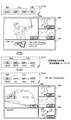
図1は、一実施形態に係るコンテンツ再生システム1の概要について説明するための説明図である。コンテンツ再生システム1は、シンク機器100、ソース機器200a、ソース機器200b、ソース機器200c及びソース機器200dを含む。シンク機器100は、ソース機器200a、ソース機器200b、ソース機器200c及びソース機器200dとの間でそれぞれ無線接続を確立する。
<1. System overview>
FIG. 1 is an explanatory diagram for explaining an overview of a content reproduction system 1 according to an embodiment. The content reproduction system 1 includes a sink device 100, a source device 200a, a source device 200b, a source device 200c, and a source device 200d. The sink device 100 establishes a wireless connection with each of the source device 200a, the source device 200b, the source device 200c, and the source device 200d.
シンク機器は、ソース機器から受信されるコンテンツを復号し、復号したコンテンツを再生する装置である。図1の例では、シンク機器100は、デジタルテレビジョン装置である。ソース機器は、コンテンツを必要に応じて符号化し、符号化したコンテンツをシンク機器へ送信する装置である。コンテンツ再生システム1において、ソース機器からシンク機器へ送信されるコンテンツは、典型的には、映像コンテンツ及び音声コンテンツの少なくとも一方を含む。図1の例では、ソース機器200aは、“DVC1”という識別子を有するデジタルビデオカメラである。ソース機器200bは、“SMP1”という識別子を有するスマートフォンである。ソース機器200cは、“VDR1”という識別子を有するコンテンツレコーダである。ソース機器200dは、“TBL1”という識別子を有するタブレットPC(Personal Computer)である。なお、本開示に係る技術は、図示された例に限定されず、例えば、デスクトップPC、ラップトップPC、PDA(Personal Digital Assistant)、携帯電話、ゲーム機器、ウェアラブルデバイス又はストレージデバイスなどの、任意の種類のシンク機器及びソース機器に適用可能である。本明細書の以下の説明において、ソース機器200a、ソース機器200b、ソース機器200c及びソース機器200dを互いに区別する必要の無い場合には、これらをソース機器200と総称する。
The sink device is a device that decrypts the content received from the source device and reproduces the decrypted content. In the example of FIG. 1, the sink device 100 is a digital television device. The source device is a device that encodes content as necessary and transmits the encoded content to the sink device. In the content reproduction system 1, the content transmitted from the source device to the sink device typically includes at least one of video content and audio content. In the example of FIG. 1, the source device 200a is a digital video camera having an identifier “DVC1”. The source device 200b is a smartphone having an identifier “SMP1”. The source device 200c is a content recorder having an identifier “VDR1”. The source device 200d is a tablet PC (Personal Computer) having an identifier “TBL1”. The technology according to the present disclosure is not limited to the illustrated example. For example, any technology such as a desktop PC, a laptop PC, a PDA (Personal Digital Assistant), a mobile phone, a game device, a wearable device, or a storage device may be used. Applicable to various types of sink devices and source devices. In the following description of this specification, when it is not necessary to distinguish the source device 200a, the source device 200b, the source device 200c, and the source device 200d from each other, these are collectively referred to as the source device 200.
シンク機器100とソース機器200との間の無線接続は、例えば、IEEE802.11a、11b、11g、11n、11ac又は11adなどの無線LAN(Local Area Network)方式、UWB(Ultra Wideband)若しくはZigbeeなどの無線PAN(Personal Area Network)方式、又はIEEE802.16などの無線MAN(Metropolitan Area Network)方式といった、任意の種類の無線通信方式に従って形成されてよい。また、シンク機器100とソース機器200との間に、無線アクセスポイントなどの中間的な機器が介在してもしなくてもよい。なお、以下の説明では、一例として、シンク機器100とソース機器200とが無線LAN方式で接続され、無線LAN接続上でWi-Fiディスプレイのメッセージング仕様に従ってコンテンツが伝送されるものとする。この場合、無線LAN接続は、Wi-Fiダイレクトを用いて、又はTDLS(Tunneled Direct Link Setup)と呼ばれる接続プロトコルを用いて、シンク機器100とソース機器200との間で確立され得る。さらに、シンク機器100とソース機器200との間で、ユーザ入力情報を交換するための制御チャネルが形成されてもよい。当該制御チャネルは、例えば、TCP/IP(Transmission Control Protocol/Internet Protocol)ベースのUIBC(User Input Back Channel)であってもよい。なお、Wi-Fiディスプレイの代わりに、例えば、VNC(Virtual Network Computing)などの他のリモートデスクトップアプリケーションを用いて、コンテンツが伝送されてもよい。
The wireless connection between the sink device 100 and the source device 200 is, for example, a wireless LAN (Local Area Network) system such as IEEE802.11a, 11b, 11g, 11n, 11ac, or 11ad, UWB (Ultra Wideband), or Zigbee. It may be formed according to any type of wireless communication method such as a wireless PAN (Personal Area Network) method or a wireless MAN (Metropolitan Area Network) method such as IEEE 802.16. Further, an intermediate device such as a wireless access point may or may not be interposed between the sink device 100 and the source device 200. In the following description, as an example, it is assumed that the sink device 100 and the source device 200 are connected by a wireless LAN system, and content is transmitted according to the Wi-Fi display messaging specification over the wireless LAN connection. In this case, the wireless LAN connection can be established between the sink device 100 and the source device 200 using Wi-Fi Direct or using a connection protocol called TDLS (Tunneled Direct Link Setup). Furthermore, a control channel for exchanging user input information may be formed between the sink device 100 and the source device 200. The control channel may be, for example, a TCP / IP (Transmission Control Protocol / Internet Protocol) -based UIBC (User Input Back Channel). Note that the content may be transmitted using another remote desktop application such as VNC (Virtual Network Computing) instead of the Wi-Fi display.
ソース機器200は、例えば、カメラで被写体を撮影することにより取得される映像コンテンツ又はマイクロフォンで実世界の音声を集音することにより取得される音声コンテンツを、シンク機器へ提供してもよい。また、ソース機器200は、リモートデバイスからネットワークを介して受信されるコンテンツを、シンク機器へ提供してもよい。また、ソース機器200は、ストレージデバイス(例えば、ハードディスクドライブ)から読み出されるコンテンツを、シンク機器へ提供してもよい。一方、本実施形態において、シンク機器100は、複数のソース機器200からコンテンツを並列的に受信し、受信したコンテンツを必要に応じて復号してそれぞれ再生する。
The source device 200 may provide, for example, video content acquired by shooting a subject with a camera or audio content acquired by collecting real-world audio with a microphone to the sink device. Further, the source device 200 may provide content received from the remote device via the network to the sink device. Further, the source device 200 may provide content read from the storage device (for example, a hard disk drive) to the sink device. On the other hand, in the present embodiment, the sink device 100 receives content from a plurality of source devices 200 in parallel, decodes the received content as necessary, and reproduces the content.
既存の手法では、通常、コンテンツの符号化及び復号の条件は、主にソース機器により制御される。しかし、シンク機器100が異なるソース機器200からそれぞれ受信される複数のコンテンツを再生しようとする場面では、そのようなソース側での制御は不都合を生じさせる。例えば、ソース機器200aがシンク機器100によりサポートされる符号化方式でコンテンツを符号化して、符号化したコンテンツをシンク機器100へ送信したものとする。これと同時に、ソース機器200b、200c又は200dもまた、同じ符号化方式で別のコンテンツを符号化して、符号化したコンテンツをシンク機器100へ送信し得る。しかし、その符号化方式でコンテンツを復号することのできる回路を1つしかシンク機器100が有しなければ(又はその符号化方式で2つのコンテンツを並列的に復号可能なプロセッサ性能をシンク機器100が有しなければ)、シンク機器は、それらソース機器から受信されるコンテンツを同時に再生することができない。このような不都合を解消し又は軽減するために、複数のソース機器が存在することを前提として、コンテンツの符号化又は復号の条件をシンク機器において制御することを可能とする仕組みが実現されることが望ましい。そうした仕組みに関連する実施形態について、次節より詳細に説明する。
In existing methods, the content encoding and decoding conditions are usually controlled mainly by the source device. However, when the sink device 100 tries to reproduce a plurality of contents received from different source devices 200, such control on the source side causes inconvenience. For example, it is assumed that the source device 200a encodes content using an encoding method supported by the sink device 100, and transmits the encoded content to the sink device 100. At the same time, the source device 200b, 200c, or 200d can also encode another content using the same encoding method, and transmit the encoded content to the sink device 100. However, if the sink device 100 has only one circuit that can decode the content by the encoding method (or the sink device 100 has a processor performance capable of decoding two contents in parallel by the encoding method). If not, the sink device cannot play back the content received from these source devices at the same time. In order to eliminate or alleviate such inconvenience, a mechanism is realized that enables the sink device to control the content encoding or decoding conditions on the premise that there are a plurality of source devices. Is desirable. Embodiments related to such a mechanism will be described in detail in the next section.
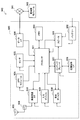
<2.シンク機器の構成例>
図2は、一実施形態に係るシンク機器100の構成の一例を示すブロック図である。図2を参照すると、シンク機器100は、無線通信部110、ストリーム取得部120、復号部130、映像再生部140、音声再生部150、再生制御部160、記憶部170及びユーザインタフェース部180を備える。
<2. Configuration example of sink device>
FIG. 2 is a block diagram illustrating an example of the configuration of the sink device 100 according to an embodiment. Referring to FIG. 2, the sink device 100 includes a wireless communication unit 110, a stream acquisition unit 120, a decoding unit 130, a video playback unit 140, an audio playback unit 150, a playback control unit 160, a storage unit 170, and a user interface unit 180. .
(1)無線通信部
無線通信部110は、シンク機器100による他の装置との間の無線通信を仲介する無線インタフェースである。本実施形態において、無線通信部110は、複数のソース機器(コンテンツを符号化する符号化装置)200との間で無線接続を確立する。そして、無線通信部110は、無線接続上でソース機器200により送信されるコンテンツデータを含む無線信号を、アンテナを介して受信する。無線通信部110は、コンテンツデータを含む受信信号をストリーム取得部120へ出力する。また、無線通信部110は、ソース機器200との間で、制御メッセージを含む無線信号をも送受信し得る。ソース機器200へ送信される制御メッセージは、後に説明する再生制御部160により生成される。また、ソース機器200から受信される制御メッセージは、再生制御部160により解釈される。
(1) Wireless Communication Unit The wireless communication unit 110 is a wireless interface that mediates wireless communication between the sink device 100 and other devices. In the present embodiment, the wireless communication unit 110 establishes a wireless connection with a plurality of source devices (encoding devices that encode content) 200. Then, the wireless communication unit 110 receives a wireless signal including content data transmitted by the source device 200 via a wireless connection via an antenna. The wireless communication unit 110 outputs a reception signal including content data to the stream acquisition unit 120. In addition, the wireless communication unit 110 can transmit and receive a wireless signal including a control message to and from the source device 200. The control message transmitted to the source device 200 is generated by the reproduction control unit 160 described later. Further, the control message received from the source device 200 is interpreted by the playback control unit 160.
無線通信部110は、伝送レートの互いに異なる複数の周波数チャネルを並列的に又は選択的に使用可能であってもよい。複数の周波数チャネルとは、例えば、2.4GHz、5GHz及び60GHzの伝送レートをそれぞれ有するチャネルであってもよい。無線通信部110は、後に説明する再生制御部160による割当てに従って、各ソース機器200からのコンテンツの受信のために使用すべき周波数チャネルを切り替え得る。典型的には、高ビットレートのコンテンツ(例えば、マルチフレームのメインウィンドウに表示されるコンテンツ)は伝送レートの高いチャネルで伝送され、低ビットレートのコンテンツ(例えば、マルチフレームのサブウィンドウに表示されるコンテンツ)は伝送レートの低いチャネルで伝送され得る。無線通信部110は、各周波数チャネルの接続品質を測定し、測定結果を示す品質指標(例えば、受信信号強度又はSNR(Signal-to-Noise Ratio)など)を再生制御部160へ出力してもよい。
The wireless communication unit 110 may be able to use a plurality of frequency channels having different transmission rates in parallel or selectively. The plurality of frequency channels may be channels having transmission rates of 2.4 GHz, 5 GHz, and 60 GHz, respectively. The radio communication unit 110 can switch the frequency channel to be used for receiving content from each source device 200 according to the assignment by the reproduction control unit 160 described later. Typically, high bit rate content (eg, content displayed in a multi-frame main window) is transmitted on a channel with a high transmission rate and low bit rate content (eg, displayed in a multi-frame sub-window). Content) can be transmitted on a channel with a low transmission rate. The wireless communication unit 110 measures the connection quality of each frequency channel and outputs a quality index (for example, received signal strength or SNR (Signal-to-Noise Ratio)) indicating the measurement result to the reproduction control unit 160. Good.
(2)ストリーム取得部
ストリーム取得部120は、無線通信部110から入力される受信信号から、再生すべきコンテンツ(例えば、映像コンテンツ又は音声コンテンツ)のビットストリームを取得する。そして、ストリーム取得部120は、再生すべきコンテンツについて取得したビットストリームを、復号部130へ出力する。
(2) Stream Acquisition Unit The stream acquisition unit 120 acquires a bit stream of content to be reproduced (for example, video content or audio content) from the received signal input from the wireless communication unit 110. Then, the stream acquisition unit 120 outputs the bit stream acquired for the content to be reproduced to the decoding unit 130.
ストリーム取得部120は、各ストリームについて無線接続の接続品質を評価するための品質指標(例えばBER(Bit Error Rate)又はPER(Packet Error Rate)など)を測定し、当該品質指標を再生制御部160へ出力してもよい。
The stream acquisition unit 120 measures a quality index (for example, BER (Bit Error Rate) or PER (Packet Error Rate)) for evaluating the connection quality of the wireless connection for each stream, and uses the quality index as the playback control unit 160. May be output.
(3)復号部
復号部130は、1つ以上のソース機器200から受信されるコンテンツのビットストリームから、コンテンツをそれぞれ復号する。復号部130は、映像コンテンツを復号した場合には、復号した映像コンテンツを映像再生部140へ出力する。また、復号部130は、音声コンテンツを復号した場合には、復号した音声コンテンツを音声再生部150へ出力する。復号部130は、複数のコンテンツを並列的に復号することができる。コンテンツが圧縮符号化されている場合には、復号部130における復号処理を通じて、当該コンテンツは伸長される。
(3) Decoding Unit The decoding unit 130 decodes each content from the bit stream of the content received from one or more source devices 200. When the video content is decoded, the decoding unit 130 outputs the decoded video content to the video reproduction unit 140. In addition, when the audio content is decoded, the decoding unit 130 outputs the decoded audio content to the audio reproduction unit 150. The decryption unit 130 can decrypt a plurality of contents in parallel. When the content is compression-encoded, the content is expanded through the decoding process in the decoding unit 130.
図3Aは、シンク機器100の復号部130の詳細な構成の第1の例を示すブロック図である。第1の例において、復号部130は、第1の映像復号回路131、第2の映像復号回路132、第3の映像復号回路133及び音声復号回路136を有する。第1の映像復号回路131は、例えば、ビデオコーデックとしてH.265/HEVCをサポートする復号回路である。第2の映像復号回路132及び第3の映像復号回路133は、例えば、ビデオコーデックとしてH.264/AVCをサポートする復号回路である。音声復号回路136は、AAC、MP3又はLPCMなどのオーディオコーデックをサポートする復号回路である。第1の例において、復号部130の実復号能力は、これら復号回路の全体としての能力(capabilities)に相当する。実復号能力は、復号回路の数、並びに各復号回路によりサポートされるコーデック種別、解像度、レート(フレームレート又はサンプリングレートなど)及び品質レベル(ビット深度又は量子化ステップなど)のうち少なくとも1つにより表現され得る。
FIG. 3A is a block diagram illustrating a first example of a detailed configuration of the decoding unit 130 of the sink device 100. In the first example, the decoding unit 130 includes a first video decoding circuit 131, a second video decoding circuit 132, a third video decoding circuit 133, and an audio decoding circuit 136. The first video decoding circuit 131 is, for example, H.264 as a video codec. It is a decoding circuit that supports H.265 / HEVC. The second video decoding circuit 132 and the third video decoding circuit 133 are, for example, H.264 as a video codec. This is a decoding circuit that supports H.264 / AVC. The audio decoding circuit 136 is a decoding circuit that supports an audio codec such as AAC, MP3, or LPCM. In the first example, the actual decoding capability of the decoding unit 130 corresponds to the overall capabilities of these decoding circuits. The actual decoding capability depends on at least one of the number of decoding circuits and the codec type, resolution, rate (such as frame rate or sampling rate) and quality level (such as bit depth or quantization step) supported by each decoding circuit. Can be expressed.
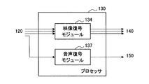
図3Bは、シンク機器100の復号部130の詳細な構成の第2の例を示すブロック図である。第2の例において、復号部130は、プロセッサにより構成され、当該プロセッサはメモリ(図示せず)から読み込まれるソフトウェアモジュールを実行する。復号部130により実行されるソフトウェアモジュールは、例えば、映像復号モジュール134及び音声復号モジュール137を含む。映像復号モジュール134は、ビデオコーデックとしてH.265/HEVC及びH.264/AVCをサポートし得る。音声復号モジュール137は、オーディオコーデックとしてAAC、MP3又はLPCMなどをサポートし得る。第2の例において、復号部130の実復号能力は、プロセッサ性能に依存する。コンテンツを復号するために要求されるプロセッサ性能は、復号されるコンテンツのコーデック種別、解像度、レート及び品質レベルなどの復号条件に依存し得る。
FIG. 3B is a block diagram illustrating a second example of a detailed configuration of the decoding unit 130 of the sink device 100. In the second example, the decoding unit 130 is configured by a processor, and the processor executes a software module read from a memory (not shown). The software modules executed by the decoding unit 130 include a video decoding module 134 and an audio decoding module 137, for example. The video decoding module 134 is an H.264 video codec. H.265 / HEVC and H.264. H.264 / AVC may be supported. The audio decoding module 137 may support AAC, MP3, LPCM, or the like as an audio codec. In the second example, the actual decoding capability of the decoding unit 130 depends on the processor performance. The processor performance required to decode the content may depend on decoding conditions such as the codec type, resolution, rate, and quality level of the content to be decoded.
なお、復号部130の構成は、上述した例に限定されない。復号部130は、より多くの又はより少ない復号回路を有していてもよい。また、復号部130は、ハードウェアとしての復号回路、並びに映像復号用及び音声復号用のソフトウェアモジュールを実行するプロセッサ、の双方を有していてもよい。また、復号部130は、上で例示したものとは異なるコーデック種別をサポートしていてもよい。
Note that the configuration of the decoding unit 130 is not limited to the above-described example. The decoding unit 130 may have more or fewer decoding circuits. Further, the decoding unit 130 may include both a decoding circuit as hardware and a processor that executes software modules for video decoding and audio decoding. Further, the decoding unit 130 may support a codec type different from that exemplified above.
(4)映像再生部
映像再生部140及び音声再生部150は、復号部130により復号される複数のコンテンツを再生するために使用される。映像再生部140は、復号部130により復号される映像コンテンツの各フレームをディスプレイへ順次出力する。複数の映像コンテンツが並列的に復号される場合、映像再生部140は、例えば、それら映像コンテンツのフレームを1つの画像へマージ(又はブレンディング)し、マルチフレームの表示画像をディスプレイへ出力し得る。
(4) Video Reproducing Unit The video reproducing unit 140 and the audio reproducing unit 150 are used for reproducing a plurality of contents decoded by the decoding unit 130. The video reproduction unit 140 sequentially outputs each frame of the video content decoded by the decoding unit 130 to the display. When a plurality of video contents are decoded in parallel, the video playback unit 140 may, for example, merge (or blend) the frames of the video contents into one image and output a multi-frame display image to the display.
図4Aは、シンク機器100の映像再生部140によりディスプレイへ出力される表示画像の構成の第1の例を示す説明図である。図4Aを参照すると、表示画像142は、メインウィンドウ145a、サブウィンドウ145b、サブウィンドウ145c及び待機機器用ウィンドウ146を含む。メインウィンドウ145aは、ユーザ入力に基づいて選択され得るメインコンテンツを表示するためのウィンドウである。サブウィンドウ145b及びサブウィンドウ145cは、メインコンテンツと並列的に復号され得るサブコンテンツをそれぞれ表示するためのウィンドウである。メインコンテンツ及びサブコンテンツは、コンテンツ再生セットを構成する。待機機器用ウィンドウ146は、再生中のコンテンツをシンク機器100へ提供していないものの、シンク機器100との間の無線接続がその時点で維持されているソース機器200のリスト(以下、待機リストという)を表示するためのウィンドウである。図4Aの例では、メインウィンドウ145aにソース機器200aから受信されたコンテンツが、サブウィンドウ145bにソース機器200bから受信されたコンテンツが、サブウィンドウ145cにソース機器200cから受信されたコンテンツがそれぞれ表示されている。一方、ソース機器200dからのコンテンツは再生されておらず、ソース機器200dのアイコン(及び当該機器を識別する識別子)が待機機器用ウィンドウ146に表示されている。
FIG. 4A is an explanatory diagram illustrating a first example of a configuration of a display image output to the display by the video reproduction unit 140 of the sink device 100. FIG. Referring to FIG. 4A, the display image 142 includes a main window 145a, a sub window 145b, a sub window 145c, and a standby device window 146. The main window 145a is a window for displaying main content that can be selected based on user input. The sub window 145b and the sub window 145c are windows for displaying sub contents that can be decoded in parallel with the main content. The main content and the sub content constitute a content reproduction set. The standby device window 146 is a list of source devices 200 (hereinafter referred to as a standby list) in which wireless connection with the sink device 100 is maintained at that time, although the content being played back is not provided to the sink device 100. ) Is a window for displaying. In the example of FIG. 4A, the content received from the source device 200a is displayed in the main window 145a, the content received from the source device 200b is displayed in the subwindow 145b, and the content received from the source device 200c is displayed in the subwindow 145c. . On the other hand, the content from the source device 200d is not reproduced, and the icon of the source device 200d (and an identifier for identifying the device) is displayed in the standby device window 146.
図4Bは、シンク機器100の映像再生部140によりディスプレイへ出力される表示画像の構成の第2の例を示す説明図である。図4Bを参照すると、第1のディスプレイへ出力される表示画像143a及び第2のディスプレイへ出力される表示画像143bが示されている。表示画像143aは、メインウィンドウ145aを含む。表示画像143bは、サブウィンドウ145b、サブウィンドウ145c及び待機機器用ウィンドウ146を含む。このように、映像再生部140は、複数のディスプレイへ別個の表示画像を出力可能であってもよい。また、これら表示画像の各々は、どういった数の及びどういった種類のウィンドウを含んでいてもよい。
FIG. 4B is an explanatory diagram illustrating a second example of a configuration of a display image output to the display by the video reproduction unit 140 of the sink device 100. Referring to FIG. 4B, a display image 143a output to the first display and a display image 143b output to the second display are shown. The display image 143a includes a main window 145a. The display image 143b includes a sub window 145b, a sub window 145c, and a standby device window 146. Thus, the video reproduction unit 140 may be able to output separate display images to a plurality of displays. Each of these display images may include any number and type of windows.
図4Cは、シンク機器100の映像再生部140によりディスプレイへ出力される表示画像の構成の第3の例を示す説明図である。図4Cを参照すると、表示画像144は、メインウィンドウ145a、サブウィンドウ145b及びサブウィンドウ145cを含む一方、図4A及び図4Bに示したような待機機器用ウィンドウ146を含まない。このように、待機機器用ウィンドウ(又は待機リスト)を表示することは必須ではない。
FIG. 4C is an explanatory diagram illustrating a third example of a configuration of a display image output to the display by the video reproduction unit 140 of the sink device 100. Referring to FIG. 4C, the display image 144 includes a main window 145a, a sub window 145b, and a sub window 145c, but does not include the standby device window 146 as illustrated in FIGS. 4A and 4B. Thus, it is not essential to display the standby device window (or standby list).
なお、ディスプレイは、シンク機器100と一体的に構成されてもよく、又は交換可能な方式でシンク機器100に接続されてもよい。映像再生部140は、所望のウィンドウ構成と出力先のディスプレイの仕様とに合わせて、再生される映像コンテンツの表示属性(例えば、フレームサイズなど)を調整し得る。ディスプレイとして、モニタ又はプロジェクタが利用されてもよい。
The display may be configured integrally with the sink device 100, or may be connected to the sink device 100 in a replaceable manner. The video playback unit 140 can adjust the display attributes (eg, frame size) of the video content to be played in accordance with the desired window configuration and the specifications of the output destination display. A monitor or projector may be used as the display.
(5)音声再生部
音声再生部150は、復号部130により復号される音声コンテンツの音声信号をスピーカへ順次出力する。音声再生部150により再生されるコンテンツは、メインコンテンツ若しくはサブコンテンツである映像コンテンツに付随する音声コンテンツであってもよく、又は映像コンテンツとは関連しない別個の音声コンテンツであってもよい。
(5) Audio Reproducing Unit The audio reproducing unit 150 sequentially outputs the audio signal of the audio content decoded by the decoding unit 130 to the speaker. The content played back by the audio playback unit 150 may be audio content associated with video content that is main content or sub-content, or may be separate audio content not related to the video content.
(6)再生制御部
再生制御部160は、映像再生部140及び音声再生部150により再生されるコンテンツのセット(コンテンツ再生セット)により要求される要求復号能力が復号部130の実復号能力を超過しないように、それらコンテンツの送信元の複数のソース機器200におけるコンテンツの符号化条件を制御する。コンテンツ再生セットは、典型的には、ユーザインタフェース部180を介して取得されるユーザ入力に基づいて、生成され及び更新され得る。再生制御部160は、最初に生成され又は更新された最新のコンテンツ再生セットについて要求復号能力を決定し、決定した要求復号能力を復号部130の実復号能力と比較する。要求復号能力が実復号能力を超過しない場合には、再生制御部160は、コンテンツ再生セット及びその符号化条件をそのまま維持し得る。要求復号能力が実復号能力を超過する場合、再生制御部160は、要求復号能力を引き下げるために、少なくとも1つのソース機器200における符号化条件を変更する。
(6) Playback Control Unit The playback control unit 160 has the requested decoding capability required by the content set (content playback set) played by the video playback unit 140 and the audio playback unit 150 exceeds the actual decoding capability of the decoding unit 130. In such a case, the content encoding conditions in the plurality of source devices 200 that are the transmission sources of the content are controlled. A content playback set may typically be generated and updated based on user input obtained via the user interface unit 180. The playback control unit 160 determines the requested decoding capability for the latest content playback set that is initially generated or updated, and compares the determined requested decoding capability with the actual decoding capability of the decoding unit 130. When the requested decoding capability does not exceed the actual decoding capability, the playback control unit 160 can maintain the content playback set and its encoding conditions as they are. When the requested decoding capability exceeds the actual decoding capability, the reproduction control unit 160 changes the encoding condition in at least one source device 200 in order to lower the requested decoding capability.
ソース機器200における符号化条件を適切に決定することを可能とするために、再生制御部160は、ソース機器200の各々の符号化能力(encoding capabilities)を予め把握する。より具体的には、再生制御部160は、無線通信部110を介してソース機器200の各々へ能力問合せメッセージを送信することにより、各ソース機器200から符号化能力情報を収集し、収集した符号化能力情報を記憶部170に記憶させる。そして、再生制御部160は、収集したソース機器200の各々の符号化能力情報により許容される範囲内で、ソース機器200における符号化条件を決定する。
In order to make it possible to appropriately determine the encoding conditions in the source device 200, the reproduction control unit 160 grasps in advance the encoding capabilities of the source device 200. More specifically, the playback control unit 160 collects encoding capability information from each source device 200 by transmitting a capability inquiry message to each of the source devices 200 via the wireless communication unit 110, and collects the collected code Information is stored in the storage unit 170. Then, the reproduction control unit 160 determines the encoding condition in the source device 200 within a range allowed by the collected encoding capability information of the source device 200.
例えば、非特許文献1において定義されたWi-Fiディスプレイの仕様は、ソース機器からシンク機器へ復号能力情報を問合せるためのメッセージを定義している一方で、シンク機器からソース機器へ符号化能力を問合せるためのメッセージを定義していない。これは、既存の手法において、通常、コンテンツの符号化及び復号の条件が、主にソース機器により制御されるためである。これに対し、本実施形態では、後に詳しく説明するように、シンク機器100からソース機器200へ符号化能力を問合せるための能力問合せメッセージが導入される。それにより、シンク機器100がマスタとして複数のソース機器200における符号化条件を統合的に制御することが可能となる。
For example, the Wi-Fi display specification defined in Non-Patent Document 1 defines a message for inquiring decoding capability information from the source device to the sink device, while the encoding capability from the sink device to the source device is defined. A message to query is not defined. This is because, in existing methods, the content encoding and decoding conditions are usually controlled mainly by the source device. On the other hand, in this embodiment, as will be described in detail later, a capability inquiry message for inquiring the encoding capability from the sink device 100 to the source device 200 is introduced. Thereby, the sink device 100 can control the encoding conditions in the plurality of source devices 200 as a master.
符号化条件は、各ソース機器200において使用されるコーデック種別、解像度、レート及び品質レベルのうち少なくとも1つに関する条件であってよい。例えば、再生制御部160は、H.265/HEVCをサポートする復号回路が要求に対して不足している一方で、H.264/AVCをサポートする復号回路に空きがある場合に、H.265/HEVCでコンテンツを符号化しているソース機器200の符号化条件をH.264/AVCに変更し得る。また、再生制御部160は、復号部130のプロセッサ性能が要求に対して不足している場合に、より低い解像度、より低いレート又はより低い品質レベルでコンテンツを符号化することをソース機器200に要求し得る。それにより、要求復号能力を実復号能力に適合させることができる。こうした符号化条件の変更は、ソース機器200が変更後の符号化条件でコンテンツを符号化し又は送信する能力を有していることを符号化能力情報が示している場合に許容される。
The encoding condition may be a condition related to at least one of the codec type, resolution, rate, and quality level used in each source device 200. For example, the playback controller 160 may While decoding circuits supporting H.265 / HEVC are lacking in demand, H.264 / AVC, when there is a vacancy in the decoding circuit. The encoding condition of the source device 200 that encodes the content with H.265 / HEVC is H.265. It can be changed to H.264 / AVC. In addition, when the processor performance of the decoding unit 130 is insufficient for the request, the reproduction control unit 160 informs the source device 200 to encode the content at a lower resolution, a lower rate, or a lower quality level. Can be requested. Thereby, the required decoding capability can be adapted to the actual decoding capability. Such a change in the encoding condition is allowed when the encoding capability information indicates that the source device 200 has the ability to encode or transmit the content with the changed encoding condition.
コーデック種別は、圧縮符号化方式のみならず、無圧縮方式を含んでもよい。無圧縮方式での伝送は、伝送されるコンテンツが高ビットレートとなるために伝送レートの高い無線接続上でしか行われないものの、圧縮符号化方式と比較するとエンコーダ及びデコーダへほとんど負荷を与えない。そこで、再生制御部160は、符号化能力情報によって許容される限りにおいて、要求復号能力が実復号能力を超過する場合に、特定のコーデック種別でコンテンツを符号化しているソース機器200に、当該コンテンツを圧縮符号化することなく送信することを要求してもよい。再生制御部160は、割当てられる周波数チャネルの伝送レート又は接続品質に応じて、ソース機器200に適用すべきコーデック種別を圧縮符号化方式と無圧縮方式との間で切り替えてもよい。
The codec type may include not only the compression encoding method but also the non-compression method. Although transmission in the uncompressed format is performed only on a wireless connection with a high transmission rate because the content to be transmitted has a high bit rate, there is almost no load on the encoder and decoder compared with the compression encoding method. . Therefore, as long as the requested decoding capability exceeds the actual decoding capability as long as permitted by the encoding capability information, the playback control unit 160 sends the content to the source device 200 that encodes the content with a specific codec type. May be requested to be transmitted without compression encoding. The playback control unit 160 may switch the codec type to be applied to the source device 200 between the compression coding method and the non-compression method according to the transmission rate or connection quality of the allocated frequency channel.
再生制御部160は、符号化条件の変更(再生の開始又は停止を含む)を決定すると、決定した符号化条件を設定するためのメッセージを、無線通信部110を介して、変更に関与するソース機器200へ送信する。上述したWi-Fiディスプレイの仕様はシンク機器からソース機器へ符号化条件の設定を求めるメッセージを定義していないのとは対照的に、本実施形態では、シンク機器100からソース機器200へ符号化条件の設定を求める設定要求メッセージが導入される。
When the reproduction control unit 160 determines the change of the encoding condition (including the start or stop of the reproduction), the reproduction control unit 160 sends a message for setting the determined encoding condition via the wireless communication unit 110 to the source involved in the change. Transmit to device 200. In contrast to the Wi-Fi display specification described above, which does not define a message for setting the encoding condition from the sink device to the source device, in this embodiment, encoding from the sink device 100 to the source device 200 is performed. A setting request message for setting conditions is introduced.
補助的な制御として、再生制御部160は、各ソース機器200との間の無線接続の接続品質に基づいて、各ソース機器200における符号化条件を制御してもよい。例えば、再生制御部160は、無線通信部110又はストリーム取得部120から入力される品質指標をモニタリングする。そして、再生制御部160は、あるソース機器200について接続品質が劣化していることが検出された場合、当該ソース機器200から受信しているコンテンツの解像度、レート又は品質レベルを引き下げる。それにより、コンテンツのビットレートが低減されるため、品質の劣化した無線接続上でコンテンツデータがロスするリスクを軽減することができる。
As an auxiliary control, the reproduction control unit 160 may control the encoding condition in each source device 200 based on the connection quality of the wireless connection with each source device 200. For example, the playback control unit 160 monitors a quality index input from the wireless communication unit 110 or the stream acquisition unit 120. Then, when it is detected that the connection quality has deteriorated for a certain source device 200, the playback control unit 160 reduces the resolution, rate, or quality level of the content received from the source device 200. As a result, the bit rate of the content is reduced, so that the risk of loss of content data over a wireless connection with degraded quality can be reduced.
また、再生制御部160は、各ソース機器200の電源状態に基づいて、各ソース機器200における符号化条件を制御してもよい。例えば、再生制御部160は、コンテンツ再生セットからいずれかのコンテンツを除外すべき状況において、バッテリ駆動している(又はバッテリ残量の少ない)ソース機器200からのコンテンツを優先的に除外してもよい。また、再生制御部160は、バッテリ駆動しているソース機器200からのコンテンツについて、その解像度、レート又は品質レベルを優先的に引き下げてもよい。再生制御部160は、バッテリ駆動しているソース機器200について、コンテンツの復号及び再符号化(又はトランスコード)が不要となるようにコーデック種別を決定してもよい。それにより、要求復号能力の引き下げと共に、システム全体としてのバッテリ消費を抑制することができる。
Further, the reproduction control unit 160 may control the encoding condition in each source device 200 based on the power supply state of each source device 200. For example, in a situation where any content is to be excluded from the content playback set, the playback control unit 160 may preferentially exclude content from the source device 200 that is battery-driven (or has a low remaining battery level). Good. Further, the playback control unit 160 may preferentially lower the resolution, rate, or quality level of content from the source device 200 that is battery-driven. The playback control unit 160 may determine the codec type of the source device 200 that is battery-driven so that content decoding and re-encoding (or transcoding) are not required. Thereby, the consumption of the battery as a whole system can be suppressed while the request decoding capability is lowered.
また、各ソース機器200は、事前のメッセージ交換手続を通じて、シンク機器100へ優先すべき符号化条件を特定する優先条件情報を提供してもよい。当該優先条件情報は、記憶部170により記憶され、再生制御部160が各ソース機器200における符号化条件を決定する際に参照され得る。こうした優先条件情報に基づいて符号化条件を制御することにより、例えば省電力化又は処理負荷の低減といった個々の機器についての制約又は(例えばユーザ設定に基づく)要件を、制御に反映させることが可能となる。
Further, each source device 200 may provide priority condition information for specifying the encoding condition to be prioritized to the sink device 100 through a prior message exchange procedure. The priority condition information is stored in the storage unit 170, and can be referred to when the reproduction control unit 160 determines the encoding condition in each source device 200. By controlling the coding conditions based on such priority condition information, it is possible to reflect restrictions or requirements (for example, based on user settings) on individual devices such as power saving or reduction of processing load in the control. It becomes.
また、再生制御部160は、ソース機器200における符号化条件に応じて、ソース機器200との間の無線接続の周波数チャネルをさらに制御してもよい。例えば、再生制御部160は、あるソース機器200から受信すべきコンテンツのビットレートが高くなることが符号化条件から認識される場合に、当該ソース機器200との間の無線接続に、より伝送レートの高い(又はより接続品質の良好な)周波数チャネルを割当てる。また、再生制御部160は、あるコンテンツについて想定されるビットレートよりも割当て可能な周波数チャネルの伝送レートが低い場合には、当該コンテンツの解像度、レート又は品質レベルを引き下げてもよい。それにより、コンテンツの安定的な伝送を確保することができる。
Also, the playback control unit 160 may further control the frequency channel of the wireless connection with the source device 200 according to the encoding condition in the source device 200. For example, when it is recognized from the encoding condition that the bit rate of the content to be received from a certain source device 200 is increased, the playback control unit 160 uses a higher transmission rate for the wireless connection with the source device 200. A frequency channel having a higher frequency (or better connection quality) is allocated. Further, when the transmission rate of the frequency channel that can be allocated is lower than the bit rate assumed for a certain content, the playback control unit 160 may lower the resolution, rate, or quality level of the content. Thereby, stable transmission of content can be ensured.
再生制御部160は、ソース機器200との間のメッセージの交換をも制御し得る。ソース機器200へ送信されるメッセージは、ソース機器200における符号化条件を制御するための、上述した能力問合せメッセージ及び設定要求メッセージを含み得る。ソース機器200から受信されるメッセージは、上述した能力問合せメッセージ及び設定要求メッセージに対するソース機器200からの応答メッセージを含み得る。さらに、再生制御部160は、コンテンツの再生に関連するコマンド(例えば、再生開始、再生停止、早送り及び巻き戻しなど)を含む制御メッセージを、機器間の制御チャネルを介して送受信してもよい。再生制御部160は、そうしたコマンドの検出に応じて、映像再生部140及び音声再生部150の動作を制御し得る。
The playback control unit 160 can also control the exchange of messages with the source device 200. The message transmitted to the source device 200 may include the above-described capability inquiry message and setting request message for controlling the encoding condition in the source device 200. The message received from the source device 200 may include a response message from the source device 200 in response to the capability inquiry message and the setting request message described above. Furthermore, the playback control unit 160 may transmit and receive a control message including commands related to content playback (for example, playback start, playback stop, fast forward, rewind, etc.) via a control channel between devices. The playback control unit 160 can control the operations of the video playback unit 140 and the audio playback unit 150 in response to detection of such a command.
(7)記憶部
記憶部170は、シンク機器100におけるコンテンツの復号及び再生を制御するためのプログラム及びデータを記憶し得る。記憶部170は、例えば、複数のソース機器200から収集される符号化能力情報、及び上述した優先条件情報を記憶し得る。また、記憶部170は、復号部130の実復号能力を示す実復号能力情報を記憶し得る。実復号能力情報は、予め固定的に定義されてもよい。その代わりに、再生制御部160は、復号部130に掛かる負荷を継続的にモニタリングして復号部130の実復号能力を動的に再計算し、実復号能力情報を更新してもよい。例えば、復号処理がソフトウェアで実装される場合には、ソフトウェアを実行するプロセッサが他の処理をも実行する可能性があるため、復号処理のために利用可能なプロセッサ性能を動的に再計算することが有益である。
(7) Storage Unit The storage unit 170 can store a program and data for controlling content decryption and reproduction in the sink device 100. The storage unit 170 can store, for example, encoding capability information collected from a plurality of source devices 200 and the above-described priority condition information. In addition, the storage unit 170 can store actual decoding capability information indicating the actual decoding capability of the decoding unit 130. The actual decoding capability information may be fixedly defined in advance. Instead, the playback control unit 160 may continuously monitor the load applied to the decoding unit 130, dynamically recalculate the actual decoding capability of the decoding unit 130, and update the actual decoding capability information. For example, if the decoding process is implemented in software, the processor that executes the software may also execute other processes, so the processor performance available for the decoding process is dynamically recalculated. It is beneficial.
(8)ユーザインタフェース部
ユーザインタフェース部180は、シンク機器100の入力デバイス(図示せず)を介して、ユーザ入力を受け付ける。シンク機器100は、例えば、リモートコントローラ、タッチパネル、キーボード、マウス、ボタン又はスイッチなどの固有のハードウェアにおいて生成される入力信号を、ユーザ入力として受け付けてもよい。また、シンク機器100は、マイクロフォンを通じて取得される音声コマンド、カメラを通じて取得されるジェスチャコマンド、又はセンサを通じて取得されるセンサコマンドを、ユーザ入力として受け付けてもよい。ユーザインタフェース部180は、受け付けたユーザ入力を再生制御部160へ出力する。
(8) User Interface Unit The user interface unit 180 receives user input via an input device (not shown) of the sink device 100. For example, the sink device 100 may accept an input signal generated in specific hardware such as a remote controller, a touch panel, a keyboard, a mouse, a button, or a switch as a user input. Further, the sink device 100 may accept a voice command acquired through a microphone, a gesture command acquired through a camera, or a sensor command acquired through a sensor as a user input. The user interface unit 180 outputs the received user input to the reproduction control unit 160.
<3.ソース機器の構成例>
図5は、一実施形態に係るソース機器200の構成の一例を示すブロック図である。図5を参照すると、ソース機器200は、無線通信部210、記憶部220、コンテンツ取得部230、符号化部240、ストリーム送信部250、符号化制御部260及びユーザインタフェース部270を備える。
<3. Source device configuration example>
FIG. 5 is a block diagram illustrating an example of the configuration of the source device 200 according to an embodiment. Referring to FIG. 5, the source device 200 includes a wireless communication unit 210, a storage unit 220, a content acquisition unit 230, an encoding unit 240, a stream transmission unit 250, an encoding control unit 260, and a user interface unit 270.
(1)無線通信部
無線通信部210は、ソース機器200による他の装置との間の無線通信を仲介する無線インタフェースである。本実施形態において、無線通信部210は、シンク機器100との間で無線接続を確立する。上述したように、シンク機器100は、複数のソース機器から受信されるコンテンツをそれぞれ復号して再生する復号装置である。無線通信部110は、ストリーム送信部250により生成されるコンテンツデータを含む無線信号を、アンテナを介して無線接続上でシンク機器100へ送信する。また、無線通信部210は、シンク機器100との間で、制御メッセージを含む無線信号をも送受信し得る。シンク機器100へ送信される制御メッセージは、後に説明する符号化制御部260により生成される。また、シンク機器100から受信される制御メッセージは、符号化制御部260により解釈される。
(1) Wireless Communication Unit The wireless communication unit 210 is a wireless interface that mediates wireless communication between the source device 200 and other devices. In the present embodiment, the wireless communication unit 210 establishes a wireless connection with the sink device 100. As described above, the sink device 100 is a decoding device that decodes and plays back content received from a plurality of source devices. The wireless communication unit 110 transmits a wireless signal including the content data generated by the stream transmission unit 250 to the sink device 100 over the wireless connection via the antenna. Further, the wireless communication unit 210 can also transmit and receive a wireless signal including a control message to and from the sink device 100. The control message transmitted to the sink device 100 is generated by the encoding control unit 260 described later. Further, the control message received from the sink device 100 is interpreted by the encoding control unit 260.
(2)記憶部
記憶部220は、ソース機器200におけるコンテンツの符号化及び送信を制御するためのプログラム及びデータを記憶し得る。記憶部220は、例えば、ソース機器200自身の符号化能力を示す符号化能力情報を予め記憶する。符号化能力情報は、例えば、符号化部240によりサポートされるコーデック種別、解像度、レート及び品質レベルのうち少なくとも1つを示し得る。符号化条件は、この符号化能力情報により示される符号化能力の範囲内で指定され得る。また、記憶部220は、ソース機器200において優先されることが望ましい符号化条件(優先条件)を特定する優先条件情報を記憶してもよい。優先条件は、ユーザにより設定され、又は符号化制御部260により動的に指定され得る。
(2) Storage Unit The storage unit 220 can store a program and data for controlling the encoding and transmission of content in the source device 200. For example, the storage unit 220 stores in advance encoding capability information indicating the encoding capability of the source device 200 itself. The encoding capability information may indicate at least one of codec type, resolution, rate, and quality level supported by the encoding unit 240, for example. The encoding condition can be specified within the range of the encoding capability indicated by the encoding capability information. Further, the storage unit 220 may store priority condition information for specifying an encoding condition (priority condition) that is preferably prioritized in the source device 200. The priority condition can be set by the user or dynamically specified by the encoding control unit 260.
記憶部220は、さらに、シンク機器100へ提供され得る任意の種類のコンテンツを記憶してもよい。例えば、記憶部220は、カメラで撮影した映像とマイクロフォンで集音した音声とを含むコンテンツ、放送局から受信され及び記録されるコンテンツ、コンテンツサーバからダウンロードされるコンテンツ、周辺機器から読み込まれるコンテンツ、又は何らかのユーザアプリケーションにより生成されるコンテンツを記憶し得る。
The storage unit 220 may further store any type of content that can be provided to the sink device 100. For example, the storage unit 220 includes content including video captured by a camera and audio collected by a microphone, content received and recorded from a broadcasting station, content downloaded from a content server, content read from a peripheral device, Or it may store content generated by some user application.
(3)コンテンツ取得部
コンテンツ取得部230は、シンク機器100へ提供すべきコンテンツを記憶部220又は他のデータソースから取得し、取得したコンテンツを符号化部240へ出力する。他のデータソースとは、例えば、ソース機器200のカメラ及びマイクロフォン、又はソース機器200によりアクセス可能なリモードデバイス(例えば、コンテンツサーバ又はマイクロフォン付きのWebカメラなど)を含み得る。シンク機器100へどのコンテンツを提供すべきかは、ユーザインタフェース部270により検出されるユーザ入力によって、又はシンク機器100から受信される制御メッセージによって指定され得る。コンテンツ取得部230は、取得したコンテンツがシンク機器100から指示された符号化条件とは異なるコーデック種別で符号化されている場合には、当該コンテンツを一旦復号した後に符号化部240へ出力してもよい。
(3) Content Acquisition Unit The content acquisition unit 230 acquires content to be provided to the sink device 100 from the storage unit 220 or another data source, and outputs the acquired content to the encoding unit 240. Other data sources may include, for example, a camera and microphone of the source device 200, or a remode device (eg, a content server or a web camera with a microphone) accessible by the source device 200. Which content is to be provided to the sink device 100 can be specified by a user input detected by the user interface unit 270 or by a control message received from the sink device 100. When the acquired content is encoded with a codec type different from the encoding condition instructed from the sink device 100, the content acquisition unit 230 once decodes the content and outputs the decoded content to the encoding unit 240. Also good.
(4)符号化部
符号化部240は、コンテンツ取得部230から入力される、シンク機器100へ送信すべきコンテンツを符号化し、コンテンツのビットストリームを生成する。そして、符号化部240は、生成したビットストリームをストリーム送信部250へ出力する。符号化部240におけるコンテンツの符号化条件は、シンク機器100から受信される制御メッセージに基づいて、符号化制御部260により制御される。例えば、映像コンテンツについての符号化条件は、使用されるビデオコーデックのコーデック種別、解像度、フレームレート及び画質レベルを含み得る。音声コンテンツについての符号化条件は、使用されるオーディオコーデックのコーデック種別、サンプリングレート及び音質レベルを含み得る。符号化部240は、コンテンツを圧縮符号化しないことが指示された場合には、コンテンツを圧縮することなく、無圧縮フォーマットでコンテンツのビットストリームを生成してもよい。
(4) Encoding Unit The encoding unit 240 encodes content to be transmitted to the sink device 100 input from the content acquisition unit 230, and generates a content bitstream. Then, the encoding unit 240 outputs the generated bit stream to the stream transmission unit 250. The encoding condition of the content in the encoding unit 240 is controlled by the encoding control unit 260 based on the control message received from the sink device 100. For example, the encoding conditions for video content may include the codec type, resolution, frame rate, and image quality level of the video codec used. The coding conditions for audio content can include the codec type, sampling rate, and sound quality level of the audio codec used. When instructed not to compress and encode the content, the encoding unit 240 may generate a bitstream of the content in an uncompressed format without compressing the content.
符号化部240は、ハードウェアとしての1つ以上の符号化回路を有していてもよい。また、符号化部240は、映像符号化用及び音声符号化用のソフトウェアモジュールを実行可能なプロセッサを有していてもよい。また、符号化部240は、ハードウェアとしての符号化回路及びソフトウェアモジュールを実行可能なプロセッサの双方を有していてもよい。符号化部240は、任意のコーデック種別をサポートし得る。
The encoding unit 240 may have one or more encoding circuits as hardware. The encoding unit 240 may include a processor that can execute software modules for video encoding and audio encoding. The encoding unit 240 may include both an encoding circuit as hardware and a processor capable of executing software modules. The encoding unit 240 can support any codec type.
(5)ストリーム送信部
ストリーム送信部250は、符号化部240から入力される符号化されたコンテンツのビットストリームを、無線通信部210を介してシンク機器100へ送信する。ストリーム送信部250は、映像コンテンツのストリーム及び音声コンテンツのストリームを多重化することによりマルチメディアストリームを生成し、生成したマルチメディアストリームを送信してもよい。
(5) Stream Transmission Unit The stream transmission unit 250 transmits the bit stream of the encoded content input from the encoding unit 240 to the sink device 100 via the wireless communication unit 210. The stream transmission unit 250 may generate a multimedia stream by multiplexing the video content stream and the audio content stream, and may transmit the generated multimedia stream.
(6)符号化制御部
符号化制御部260は、シンク機器100から受信される制御メッセージに基づいて、符号化部240におけるコンテンツの符号化条件を制御する。シンク機器100から受信される制御メッセージは、シンク機器100により再生されるコンテンツのセットにより要求される要求復号能力がシンク機器100の実復号能力を超過しないように決定された符号化条件を指定する。例えば、符号化制御部260は、シンク機器100により指定されたコーデック種別、解像度、フレームレート及び画質レベルで、映像コンテンツを符号化部240に符号化させてもよい。また、符号化制御部260は、シンク機器100により指定されたコーデック種別、サンプリングレート及び音質レベルで、音声コンテンツを符号化部240に符号化させてもよい。
(6) Encoding Control Unit The encoding control unit 260 controls the content encoding conditions in the encoding unit 240 based on the control message received from the sink device 100. The control message received from the sink device 100 specifies an encoding condition determined so that the requested decoding capability required by the set of content reproduced by the sink device 100 does not exceed the actual decoding capability of the sink device 100. . For example, the encoding control unit 260 may cause the encoding unit 240 to encode the video content with the codec type, resolution, frame rate, and image quality level specified by the sink device 100. Also, the encoding control unit 260 may cause the encoding unit 240 to encode the audio content with the codec type, sampling rate, and sound quality level specified by the sink device 100.
符号化部240における符号化条件をシンク機器100が適切に決定することを可能とするために、符号化制御部260は、符号化部240の符号化能力を示す符号化能力情報を、無線通信部210を介してシンク機器100へ送信する。例えば、符号化制御部260は、シンク機器100から受信される能力問合せメッセージへの応答として、符号化能力情報をシンク機器100へ送信してもよい。既存の手法では、ソース機器がシンク機器へ復号能力を問合せ、その結果に基づいて主にソース機器がコンテンツの符号化及び復号の条件を決定していた。これに対し、本実施形態では、シンク機器100からソース機器200へ符号化能力を問合せるための能力問合せメッセージと、当該能力問合せメッセージへの応答としてソース機器200からシンク機器100へ返送される、符号化能力情報を含む応答メッセージとが導入される。それにより、シンク機器100がマスタとして複数のソース機器200における符号化条件を統合的に制御することが可能となる。
In order to enable the sink device 100 to appropriately determine the encoding condition in the encoding unit 240, the encoding control unit 260 transmits the encoding capability information indicating the encoding capability of the encoding unit 240 to the wireless communication. The data is transmitted to the sink device 100 via the unit 210. For example, the encoding control unit 260 may transmit the encoding capability information to the sink device 100 as a response to the capability inquiry message received from the sink device 100. In the existing method, the source device inquires the sink device about the decoding capability, and the source device mainly determines the content encoding and decoding conditions based on the result. In contrast, in the present embodiment, a capability inquiry message for inquiring the encoding capability from the sink device 100 to the source device 200, and a code returned from the source device 200 to the sink device 100 as a response to the capability inquiry message. A response message including the ability information. Thereby, the sink device 100 can control the encoding conditions in the plurality of source devices 200 as a master.
シンク機器100から受信され得る別の制御メッセージは、シンク機器100へ送信された符号化能力情報により示される範囲内の符号化条件を指定する。当該制御メッセージは、上で説明した、シンク機器100からソース機器200へ符号化条件の設定を求める設定要求メッセージであってよい。符号化能力情報が許容する場合には、設定要求メッセージは、コーデック種別として無圧縮方式を指定してもよい。コーデック種別として無圧縮方式が指定されると、符号化制御部260は、コンテンツを圧縮することなく無圧縮フォーマットでコンテンツのビットストリームを生成することを、符号化部240に指示し得る。符号化制御部260は、コンテンツ取得部230により取得されるコンテンツが設定要求メッセージにおいて指定されたコーデック種別で既に符号化されている場合には、当該コンテンツの復号及び再符号化(又はトランスコード)をスキップさせてもよい。
Another control message that can be received from the sink device 100 specifies an encoding condition within the range indicated by the encoding capability information transmitted to the sink device 100. The control message may be a setting request message for requesting setting of an encoding condition from the sink device 100 to the source device 200 described above. If the coding capability information permits, the setting request message may specify a non-compression method as the codec type. When the non-compression method is designated as the codec type, the encoding control unit 260 may instruct the encoding unit 240 to generate a content bitstream in an uncompressed format without compressing the content. When the content acquired by the content acquisition unit 230 has already been encoded with the codec type specified in the setting request message, the encoding control unit 260 decodes and re-encodes (or transcodes) the content. May be skipped.
また、符号化制御部260は、ソース機器200の電源状態(例えば、バッテリ駆動しているか若しくは電源に接続されているか、又はバッテリ残量など)をシンク機器100へ通知してもよい。この場合、シンク機器100は、ソース機器200の電源状態にさらに基づいて、例えばバッテリ駆動しているソース機器200におけるバッテリ消費を抑制するために、ソース機器200における符号化条件を制御し得る。
Also, the encoding control unit 260 may notify the sink device 100 of the power state of the source device 200 (for example, whether it is battery-operated or connected to the power source, or the remaining battery level). In this case, the sink device 100 can control the encoding condition in the source device 200 in order to suppress battery consumption in the source device 200 that is battery-driven, for example, based on the power state of the source device 200.
また、符号化制御部260は、上述したように、事前のメッセージ交換手続を通じて、シンク機器100へ優先すべき符号化条件を特定する優先条件情報を送信してもよい。優先条件情報は、例えば省電力化又は処理負荷の低減といった個々の機器についての制約又は要件に基づいて定義され、シンク機器100がソース機器200における符号化条件を決定する際に参照され得る。
Also, as described above, the encoding control unit 260 may transmit priority condition information for specifying an encoding condition to be prioritized to the sink device 100 through a prior message exchange procedure. The priority condition information is defined based on restrictions or requirements for individual devices such as power saving or processing load reduction, and can be referred to when the sink device 100 determines the coding conditions in the source device 200.
また、符号化制御部260は、シンク機器100からの制御に従って、シンク機器100との間の無線接続の周波数チャネルをさらに制御してもよい。例えば、シンク機器100へ送信すべきコンテンツのビットレートが高くなることが認識される場合には、シンク機器100との間の無線接続に、より伝送レートの高い(又はより接続品質の良好な)周波数チャネルが割当てられる。符号化制御部260は、シンク機器100により割当てられた周波数チャネルを使用することを、無線通信部210に指示し得る。符号化制御部260は、シンク機器100との間の無線接続の接続品質を評価するための品質指標(例えばBER又はPERなど)を測定し、当該品質指標をシンク機器100へ送信してもよい。
Further, the encoding control unit 260 may further control the frequency channel of the wireless connection with the sink device 100 according to the control from the sink device 100. For example, when it is recognized that the bit rate of content to be transmitted to the sink device 100 is increased, the wireless connection with the sink device 100 has a higher transmission rate (or better connection quality). A frequency channel is assigned. The encoding control unit 260 can instruct the wireless communication unit 210 to use the frequency channel allocated by the sink device 100. The encoding control unit 260 may measure a quality index (for example, BER or PER) for evaluating the connection quality of the wireless connection with the sink device 100, and transmit the quality index to the sink device 100. .
符号化制御部260は、シンク機器100との間のメッセージの交換をも制御し得る。シンク機器100から受信されるメッセージは、ソース機器200における符号化条件を制御するための、上述した能力問合せメッセージ及び設定要求メッセージを含み得る。シンク機器100へ送信されるメッセージは、上述した能力問合せメッセージ及び設定要求メッセージに対する応答メッセージを含み得る。さらに、符号化制御部260は、ユーザインタフェース部270においてコンテンツの再生に関連するユーザ入力が検出された場合には、検出されたユーザ入力に対応するコマンドを含む制御メッセージを、機器間の制御チャネルを介してシンク機器100へ送信してもよい。
The encoding control unit 260 can also control the exchange of messages with the sink device 100. The message received from the sink device 100 may include the above-described capability inquiry message and setting request message for controlling the encoding condition in the source device 200. The message transmitted to the sink device 100 can include a response message to the above-described capability inquiry message and setting request message. Further, when a user input related to content reproduction is detected in the user interface unit 270, the encoding control unit 260 transmits a control message including a command corresponding to the detected user input to a control channel between devices. It may be transmitted to the sink device 100 via
例えばソース機器200が待機機器として選択された場合には、コンテンツの再生停止を指示する制御メッセージが無線通信部210により受信され得る。この場合、符号化制御部260は、ソース機器200の動作モードをスタンバイモードへ移行させ、スタンバイモードの期間中にソース機器200の各部への電力供給を部分的に停止してもよい。スタンバイモードにおいて、無線通信部210は、例えば間欠的に動作し、周期的なアクティブ期間においてシンク機器100からの制御メッセージを受信し得る。即ち、シンク機器100とソース機器200との間の無線接続は、スタンバイモードの期間中にも維持され得る。符号化制御部260は、スタンバイモードの期間中にコンテンツの再生開始を指示する制御メッセージが受信されると、ソース機器200の動作モードをアクティブモードへ復帰させ得る。
For example, when the source device 200 is selected as a standby device, the wireless communication unit 210 can receive a control message instructing to stop playback of content. In this case, the encoding control unit 260 may shift the operation mode of the source device 200 to the standby mode and partially stop the power supply to each unit of the source device 200 during the standby mode. In the standby mode, the wireless communication unit 210 operates intermittently, for example, and can receive a control message from the sink device 100 during a periodic active period. That is, the wireless connection between the sink device 100 and the source device 200 can be maintained even during the standby mode. The encoding control unit 260 may return the operation mode of the source device 200 to the active mode when a control message instructing the start of content playback is received during the standby mode.
(7)ユーザインタフェース部
ユーザインタフェース部270は、ソース機器200の入力デバイス(図示せず)を介して、ユーザ入力を受け付ける。ソース機器200は、例えば、リモートコントローラ、タッチパネル、キーボード、マウス、ボタン又はスイッチなどの固有のハードウェアにおいて生成される入力信号を、ユーザ入力として受け付けてもよい。また、ソース機器200は、マイクロフォンを通じて取得される音声コマンド、カメラを通じて取得されるジェスチャコマンド、又はセンサを通じて取得されるセンサコマンドを、ユーザ入力として受け付けてもよい。ユーザインタフェース部270は、受け付けたユーザ入力を符号化制御部260へ出力する。
(7) User Interface Unit The user interface unit 270 accepts user input via an input device (not shown) of the source device 200. For example, the source device 200 may accept an input signal generated in specific hardware such as a remote controller, a touch panel, a keyboard, a mouse, a button, or a switch as a user input. In addition, the source device 200 may accept a voice command acquired through a microphone, a gesture command acquired through a camera, or a sensor command acquired through a sensor as a user input. The user interface unit 270 outputs the received user input to the encoding control unit 260.
図5に示してはいないものの、ソース機器200もまた、映像再生部及び音声再生部を有していてもよい。
Although not shown in FIG. 5, the source device 200 may also include a video playback unit and an audio playback unit.
<4.処理の流れ>
[4-1.シンク側の処理]
(1)コンテンツ再生処理
図6は、本実施形態に係るシンク機器100により実行されるコンテンツ再生処理の流れの一例を示すフローチャートである。
<4. Flow of processing>
[4-1. Processing on the sink side]
(1) Content Reproduction Processing FIG. 6 is a flowchart showing an example of the flow of content reproduction processing executed by the sink device 100 according to this embodiment.
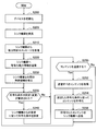
図6を参照すると、まず、シンク機器100の再生制御部160は、シンク機器100の各部を初期化する(ステップS100)。次に、再生制御部160は、無線通信部110からシンク機器100の周囲へ探索信号をブロードキャストすることにより、又はソース機器200からブロードキャストされる探索信号を検出することにより、周囲に存在する1つ以上のソース機器200を発見する(ステップS105)。次に、再生制御部160は、発見したソース機器200へ、無線通信部110から能力問合せメッセージを送信する(ステップS110)。その後、再生制御部160は、能力問合せメッセージへの応答としてソース機器200から返送される符号化能力情報を受信する(ステップS120)。そして、再生制御部160は、コンテンツを提供可能なソース機器200との間の無線接続を確立する(ステップS130)。なお、ステップS105~S130の処理は、以下に説明するコンテンツ再生制御が実行されている間にも、継続的に繰り返されてよい。シンク機器100は、新たなソース機器200が発見される都度、発見されたソース機器200との間の無線接続を確立し得る。
Referring to FIG. 6, first, the reproduction control unit 160 of the sink device 100 initializes each unit of the sink device 100 (step S100). Next, the playback control unit 160 broadcasts a search signal from the wireless communication unit 110 to the surroundings of the sink device 100 or detects a search signal broadcast from the source device 200, so that one of the surroundings is present. The above source device 200 is found (step S105). Next, the reproduction control unit 160 transmits a capability inquiry message from the wireless communication unit 110 to the discovered source device 200 (step S110). Thereafter, the playback control unit 160 receives the encoding capability information returned from the source device 200 as a response to the capability inquiry message (step S120). Then, the playback control unit 160 establishes a wireless connection with the source device 200 that can provide the content (step S130). Note that the processing in steps S105 to S130 may be repeated continuously while the content reproduction control described below is being executed. Each time a new source device 200 is discovered, the sink device 100 can establish a wireless connection with the discovered source device 200.
その後、例えばユーザ入力に応じて、コンテンツの再生がトリガされる。まず、再生制御部160は、コンテンツ再生セットを更新するかを判定する(ステップS135)。例えば、再生制御部160は、ユーザによりメインコンテンツ又はサブコンテンツとして指定されたコンテンツを、コンテンツ再生セットに追加する。コンテンツ再生セットを更新するためのステップS140における更新処理について、後により詳細に説明する。ここでの更新処理を通じて再生すべきコンテンツの符号化条件が変更された場合、再生制御部160は、符号化条件に変更のあるソース機器200へ、設定要求メッセージを送信することにより、符号化条件の設定を要求する(ステップS160)。
Then, for example, content playback is triggered according to user input. First, the playback control unit 160 determines whether to update the content playback set (step S135). For example, the playback control unit 160 adds content designated as main content or sub-content by the user to the content playback set. The update process in step S140 for updating the content reproduction set will be described in detail later. When the encoding condition of the content to be reproduced is changed through the update process here, the reproduction control unit 160 transmits the setting request message to the source device 200 whose encoding condition is changed, thereby encoding the encoding condition. Is requested (step S160).
そして、コンテンツの提供が開始されると、無線通信部110は、複数のソース機器200から、コンテンツ再生セットに含まれるコンテンツをそれぞれ受信する(ステップS170)。各コンテンツのビットストリームは、ストリーム取得部120によって受信信号から抽出され得る。次に、復号部130は、受信されたコンテンツのビットストリームから、メインコンテンツ及びサブコンテンツをそれぞれ復号する(ステップS172)。次に、映像再生部140は、復号された映像コンテンツのフレームをマルチフレームの表示画像へブレンディングする(ステップS174)。また、映像再生部140は、待機機器として選択されたソース機器200が存在する場合に、待機機器のアイコン(又はテキスト)を、表示画像に表示される待機リストに追加する(ステップS176)。そして、映像再生部140は、マルチフレームの映像をディスプレイに表示させる(ステップS178)。また。音声再生部150は、復号された音声コンテンツの音声をスピーカへ出力する(ステップS180)。
Then, when the provision of content is started, the wireless communication unit 110 receives content included in the content reproduction set from the plurality of source devices 200 (step S170). The bit stream of each content can be extracted from the received signal by the stream acquisition unit 120. Next, the decryption unit 130 decrypts the main content and the sub-content from the received content bitstream (step S172). Next, the video playback unit 140 blends the decoded video content frame into a multi-frame display image (step S174). In addition, when the source device 200 selected as the standby device exists, the video reproduction unit 140 adds the standby device icon (or text) to the standby list displayed on the display image (step S176). Then, the video reproduction unit 140 displays the multi-frame video on the display (step S178). Also. The audio reproducing unit 150 outputs the audio of the decoded audio content to the speaker (Step S180).
上述したコンテンツ再生処理の間、再生制御部160は、コンテンツ再生セットの更新に関連する制御トリガをモニタリングする(ステップS190)。ここでの制御トリガは、例えば、コンテンツ再生セットの更新を指示するユーザ入力の検出、復号部130に掛かる負荷の上昇、及び無線接続の接続品質の劣化、のうちの1つ以上を含み得る。制御トリガが検出されない場合には、上述したステップS140及びS160の処理はスキップされ、ソース機器200からのコンテンツの受信、復号及び再生が繰り返される。制御トリガが検出された場合、次に説明するコンテンツ再生セットを更新するための更新処理が実行され得る。
During the content reproduction process described above, the reproduction control unit 160 monitors a control trigger related to the update of the content reproduction set (step S190). The control trigger here may include, for example, one or more of detection of user input instructing update of the content reproduction set, increase in load applied to the decoding unit 130, and deterioration of connection quality of the wireless connection. When the control trigger is not detected, the processes of steps S140 and S160 described above are skipped, and reception, decoding, and reproduction of content from the source device 200 are repeated. When the control trigger is detected, an update process for updating the content reproduction set described below can be executed.
(2)再生セット更新処理
図7は、図6のステップS140に相当するコンテンツ再生セットを更新するための更新処理の詳細な流れの一例を示すフローチャートである。
(2) Playback Set Update Processing FIG. 7 is a flowchart showing an example of a detailed flow of update processing for updating the content playback set corresponding to step S140 in FIG.
図7に示した更新処理は、ユーザ入力の内容に依存して分岐する。例えば、メインコンテンツがユーザにより指定された場合(ステップS141)、再生制御部160は、指定されたコンテンツをメインコンテンツに設定する(ステップS142)。また、サブコンテンツがユーザにより指定された場合(ステップS143)、再生制御部160は、指定されたコンテンツをサブコンテンツに設定する(ステップS144)。また、待機機器がユーザにより指定された場合(ステップS145)、再生制御部160は、指定されソース機器200を待機機器に設定する(ステップS146)。
7 The update process shown in FIG. 7 branches depending on the contents of the user input. For example, when the main content is designated by the user (step S141), the reproduction control unit 160 sets the designated content as the main content (step S142). When the sub content is designated by the user (step S143), the reproduction control unit 160 sets the designated content as the sub content (step S144). When the standby device is designated by the user (step S145), the playback control unit 160 sets the designated source device 200 as the standby device (step S146).
次に、再生制御部160は、再生セットの要求復号能力を判定する(ステップS148)。例えば、映像コンテンツについての要求復号能力は、再生される映像コンテンツのコーデック種別、解像度、フレームレート及び画質レベルに依存し得る。音声コンテンツについての要求復号能力は、再生される音声コンテンツのコーデック種別、サンプリングレート及び音質レベルに依存し得る。要求復号能力は、必要とされる復号回路の数、又は必要とされるプロセッサ性能によって表現されてもよい。
Next, the playback control unit 160 determines the required decoding capability of the playback set (step S148). For example, the required decoding capability for video content may depend on the codec type, resolution, frame rate, and image quality level of the video content being played back. The required decoding capability for audio content may depend on the codec type, sampling rate, and sound quality level of the audio content being played back. The required decoding capability may be expressed by the number of decoding circuits required or the required processor performance.
次に、再生制御部160は、判定した要求復号能力が復号部130の実復号能力を超過するか否かを判定する(ステップS148)。要求復号能力が復号部130の実復号能力を超過する場合、再生制御部160は、コンテンツ再生セットの符号化条件を変更して、要求復号能力を引き下げる(ステップS149)。ここでの符号化条件の変更は、各ソース機器200から取得される符号化能力情報により許容される範囲内で、例えば、以下のアイテムa1)~a9)のうちの1つ以上を含んでよい。
a1)メインコンテンツのサブコンテンツへの変更
a2)メインコンテンツの再生停止(待機機器への変更)
a3)サブコンテンツの再生停止(待機機器への変更)
a4)コーデック種別の変更(軽量な圧縮符号化方式又は無圧縮方式への変更)
a5)映像コンテンツの解像度の引き下げ、
a6)映像コンテンツのフレームレートの引き下げ
a7)映像コンテンツの画質レベルの引き下げ
a8)音声コンテンツのサンプリングレートの引き下げ
a9)音声コンテンツの音質レベルの引き下げ
その後、再生制御部160は、要求復号能力の判定、及び判定した要求復号能力と実復号能力との比較を再度実行する。
Next, the playback control unit 160 determines whether or not the determined requested decoding capability exceeds the actual decoding capability of the decoding unit 130 (step S148). When the requested decoding capability exceeds the actual decoding capability of the decoding unit 130, the reproduction control unit 160 changes the encoding condition of the content reproduction set and lowers the requested decoding capability (step S149). The change of the encoding condition here may include, for example, one or more of the following items a1) to a9) within a range allowed by the encoding capability information acquired from each source device 200. .
a1) Change of main content to sub-content a2) Stop playback of main content (change to standby device)
a3) Stop playback of sub-contents (change to standby device)
a4) Change of codec type (change to lightweight compression encoding method or non-compression method)
a5) Reducing the resolution of video content,
a6) Reducing the frame rate of video content a7) Reducing the image quality level of video content a8) Reducing the sampling rate of audio content a9) Reducing the sound quality level of audio content After that, the playback control unit 160 determines the required decoding capability, Then, the comparison between the determined requested decoding capability and the actual decoding capability is executed again.
要求復号能力が復号部130の実復号能力を超過しない場合において、実復号能力に余剰分が存在するとき(ステップS150)、再生制御部160は、実復号能力を超過しない範囲で符号化条件を変更して、要求復号能力を引き上げてもよい(ステップS151)。ここでの符号化条件の変更は、各ソース機器200から取得される符号化能力情報により許容される範囲内で、例えば、以下のアイテムb1)~b9)のうちの1つ以上を含んでよい。
b1)サブコンテンツのメインコンテンツへの変更
b2)待機機器からのメインコンテンツの再生開始
b3)待機機器からのサブコンテンツの再生開始
b4)コーデック種別の変更
b5)映像コンテンツの解像度の引き上げ、
b6)映像コンテンツのフレームレートの引き上げ
b7)映像コンテンツの画質レベルの引き上げ
b8)音声コンテンツのサンプリングレートの引き上げ
b9)音声コンテンツの音質レベルの引き上げ
その後、再生制御部160は、要求復号能力の判定、及び判定した要求復号能力と実復号能力との比較を再度実行する。
When the requested decoding capability does not exceed the actual decoding capability of the decoding unit 130 and there is a surplus in the actual decoding capability (step S150), the reproduction control unit 160 sets the encoding condition within a range not exceeding the actual decoding capability. It may be changed to increase the request decoding capability (step S151). The change of the encoding condition here may include, for example, one or more of the following items b1) to b9) within a range allowed by the encoding capability information acquired from each source device 200. .
b1) Change of sub-content to main content b2) Start of playback of main content from standby device b3) Start of playback of sub-content from standby device b4) Change of codec type b5) Increase in resolution of video content,
b6) Increasing the frame rate of the video content b7) Increasing the image content level of the video content b8) Increasing the sampling rate of the audio content b9) Raising the sound quality level of the audio content After that, the playback control unit 160 determines the required decoding capability, Then, the comparison between the determined requested decoding capability and the actual decoding capability is executed again.
要求復号能力が復号部130の実復号能力を超過せず、実復号能力の余剰分の活用も求められない場合、処理はステップS152へ進む。ここで、再生制御部160は、接続品質の劣化した無線接続が存在するかを判定する(ステップS152)。例えば、ある無線接続の伝送レートが搬送すべきコンテンツのビットレートを下回る場合、その無線接続の接続品質は劣化していると判定され得る。接続品質の劣化した無線接続が存在する場合、再生制御部160は、符号化条件を変更して、対応するコンテンツのビットレートを引き下げる(ステップS153)。なお、無線接続の接続品質に応じた符号化条件の変更は、必ずしも実行されなくてもよく、又は送信側のソース機器200において実行されてもよい。
If the requested decoding capability does not exceed the actual decoding capability of the decoding unit 130 and the surplus utilization of the actual decoding capability is not required, the process proceeds to step S152. Here, the reproduction control unit 160 determines whether there is a wireless connection with deteriorated connection quality (step S152). For example, if the transmission rate of a certain wireless connection is lower than the bit rate of the content to be conveyed, it can be determined that the connection quality of that wireless connection has deteriorated. When there is a wireless connection with deteriorated connection quality, the playback control unit 160 changes the encoding condition and lowers the bit rate of the corresponding content (step S153). Note that the change of the encoding condition according to the connection quality of the wireless connection may not necessarily be executed, or may be executed in the source device 200 on the transmission side.
[4-2.ソース側の処理]
図8は、本実施形態に係るソース機器200により実行されるコンテンツ送信処理の流れの一例を示すフローチャートである。
[4-2. Source side processing]
FIG. 8 is a flowchart showing an example of the flow of content transmission processing executed by the source device 200 according to this embodiment.
図8を参照すると、まず、ソース機器200の符号化制御部260は、ソース機器200の各部を初期化する(ステップS200)。次に、符号化制御部260は、シンク機器100からブロードキャストされる探索信号を検出し又は無線通信部210から探索信号をブロードキャストすることにより、シンク機器100を発見する(ステップS205)。次に、符号化制御部260は、無線通信部210を介してシンク機器100から能力問合せメッセージを受信する(ステップS210)。すると、符号化制御部260は、能力問合せメッセージへの応答として、符号化能力情報を含む応答メッセージをシンク機器100へ送信する(ステップS220)。そして、符号化制御部260は、シンク機器100との間の無線接続を確立する(ステップS230)。
Referring to FIG. 8, first, the encoding control unit 260 of the source device 200 initializes each unit of the source device 200 (step S200). Next, the coding control unit 260 detects the sink device 100 by detecting the search signal broadcast from the sink device 100 or broadcasting the search signal from the wireless communication unit 210 (step S205). Next, the encoding control unit 260 receives a capability inquiry message from the sink device 100 via the wireless communication unit 210 (step S210). Then, the encoding control unit 260 transmits a response message including the encoding capability information to the sink device 100 as a response to the capability inquiry message (step S220). Then, the encoding control unit 260 establishes a wireless connection with the sink device 100 (step S230).
その後、符号化制御部260は、シンク機器100から符号化条件の設定が要求されると(ステップS235)、コンテンツを符号化するための符号化条件をその要求に従って設定する(ステップS240)。符号化条件は、例えば、シンク機器100から受信される設定要求メッセージに記述される。
Thereafter, when the sink device 100 requests the setting of the encoding condition (step S235), the encoding control unit 260 sets the encoding condition for encoding the content according to the request (step S240). The encoding condition is described in a setting request message received from the sink device 100, for example.
そして、例えばシンク機器100からの要求に応じて、コンテンツの送信がトリガされる(ステップS250)。まず、コンテンツ取得部230は、シンク機器100へ送信すべきコンテンツを、記憶部220又は他のデータソースから取得する(ステップS252)。次に、符号化部240は、符号化制御部260により設定された符号化条件に従って、コンテンツ取得部230から入力されるコンテンツを符号化する(ステップS254)。次に、ストリーム送信部250は、符号化部240から入力される符号化されたコンテンツのビットストリームを、無線通信部210を介してシンク機器100へ送信する(ステップS256)。
Then, for example, in response to a request from the sink device 100, content transmission is triggered (step S250). First, the content acquisition unit 230 acquires content to be transmitted to the sink device 100 from the storage unit 220 or another data source (step S252). Next, the encoding unit 240 encodes the content input from the content acquisition unit 230 in accordance with the encoding condition set by the encoding control unit 260 (step S254). Next, the stream transmission unit 250 transmits the bit stream of the encoded content input from the encoding unit 240 to the sink device 100 via the wireless communication unit 210 (step S256).
上述したコンテンツ送信処理の間、符号化制御部260は、制御トリガをモニタリングする。ここでの制御トリガは、例えば、シンク機器100からの設定要求メッセージの受信及びユーザインタフェース部270におけるユーザ入力の検出を含み得る。制御トリガが符号化条件の変更を要求している場合、符号化制御部260は、上述したステップS240において、要求に従って符号化条件を再度設定し得る。制御トリガが検出されない場合には、コンテンツの取得、符号化及び送信が繰り返される。なお、コンテンツの取得、符号化及び送信は、ソース機器200が待機機器として選択されている間は、スキップされる。
During the content transmission process described above, the encoding control unit 260 monitors a control trigger. The control trigger here may include, for example, reception of a setting request message from the sink device 100 and detection of a user input in the user interface unit 270. When the control trigger requests the change of the encoding condition, the encoding control unit 260 can set the encoding condition again according to the request in step S240 described above. If no control trigger is detected, content acquisition, encoding and transmission are repeated. Note that content acquisition, encoding, and transmission are skipped while the source device 200 is selected as a standby device.
<5.制御シナリオ>
本節では、コンテンツ再生システム1における符号化条件の制御に関連するいくつかの制御シナリオについて、図面を用いて説明する。
<5. Control scenario>
In this section, some control scenarios related to control of encoding conditions in the content reproduction system 1 will be described with reference to the drawings.
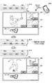
(1)第1の制御シナリオ
図9は、符号化条件の制御に関連する例示的な第1の制御シナリオについて説明するための説明図である。図9の上部には、コンテンツ再生セットRL10と、対応する表示画像とが示されている。コンテンツ再生セットRL10は、ソース機器200a(識別子“DVC1”)からのメインコンテンツと、ソース機器200b(識別子“SMP1”)及びソース機器200c(識別子“VDR1”)からの2つのサブコンテンツとを含む。ソース機器200d(識別子“TBL1”)は、待機機器である。表示画像のメインウィンドウ145aには、ソース機器200aから受信されるコンテンツが表示されている。サブウィンドウ145bには、ソース機器200bから受信されるコンテンツが表示されている。サブウィンドウ145cには、ソース機器200cから受信されるコンテンツが表示されている。待機機器用ウィンドウ146には、待機機器であるソース機器200dのアイコンが表示されている。
(1) First Control Scenario FIG. 9 is an explanatory diagram for describing an exemplary first control scenario related to control of encoding conditions. In the upper part of FIG. 9, the content reproduction set RL10 and the corresponding display image are shown. The content playback set RL10 includes main content from the source device 200a (identifier “DVC1”) and two sub-contents from the source device 200b (identifier “SMP1”) and the source device 200c (identifier “VDR1”). The source device 200d (identifier “TBL1”) is a standby device. Content received from the source device 200a is displayed in the main window 145a of the display image. Content received from the source device 200b is displayed in the sub window 145b. Content received from the source device 200c is displayed in the sub window 145c. In the standby device window 146, an icon of the source device 200d that is a standby device is displayed.
ここで、ソース機器200dからのコンテンツをメインウィンドウ145aに表示させることを、例えばユーザが画面に表示されるGUI(Graphical User Interface)を介して指示したものとする。すると、シンク機器100の再生制御部160は、コンテンツ再生セットRL10をコンテンツ再生セットRL11に更新する。コンテンツ再生セットRL11において、ソース機器200d(識別子“TBL1”)からのコンテンツがメインコンテンツに設定されている。しかし、例えば復号部130は映像コンテンツを復号することのできる復号回路を3つしか有していないため、コンテンツ再生セットRL11の要求復号能力は、復号部130の実復号能力を超過する。
Here, for example, it is assumed that the user instructs to display the content from the source device 200d on the main window 145a via a GUI (Graphical User Interface) displayed on the screen. Then, the playback control unit 160 of the sink device 100 updates the content playback set RL10 to the content playback set RL11. In the content reproduction set RL11, the content from the source device 200d (identifier “TBL1”) is set as the main content. However, for example, since the decoding unit 130 has only three decoding circuits that can decode video content, the requested decoding capability of the content reproduction set RL11 exceeds the actual decoding capability of the decoding unit 130.
そこで、再生制御部160は、例えば、コンテンツ再生セットRL11をコンテンツ再生セットRL12に更新する。コンテンツ再生セットRL12において、ソース機器200a(識別子“DVC1”)からのコンテンツは再生対象から除外され、ソース機器200aは待機機器に変更されている。結果として、コンテンツ再生セットRL12の要求復号能力は、復号部130の実復号能力を超過しない。図9の下部には、コンテンツ再生セットRL12に対応する表示画像が示されている。メインウィンドウ145aには、ソース機器200d(識別子“TBL1”)から受信されるコンテンツが表示されている。一方、待機機器用ウィンドウ146には、待機機器に変更されたソース機器200aのアイコンが表示されている。無線通信部110とソース機器200aとの間の無線接続は、このようにソース機器200aがアイコン化された後にも維持される。それにより、ソース機器200aからのコンテンツが再度再生される場合の、再生開始までの遅延時間(例えば、無線接続のセットアップに要する時間)を短縮することができる。
Therefore, the playback control unit 160 updates the content playback set RL11 to the content playback set RL12, for example. In the content playback set RL12, content from the source device 200a (identifier “DVC1”) is excluded from the playback target, and the source device 200a is changed to a standby device. As a result, the requested decryption capability of the content reproduction set RL12 does not exceed the actual decryption capability of the decryption unit 130. In the lower part of FIG. 9, a display image corresponding to the content reproduction set RL12 is shown. Content received from the source device 200d (identifier “TBL1”) is displayed in the main window 145a. On the other hand, the standby device window 146 displays an icon of the source device 200a changed to the standby device. The wireless connection between the wireless communication unit 110 and the source device 200a is maintained even after the source device 200a is iconified in this way. Thereby, when the content from the source device 200a is reproduced again, the delay time until the reproduction is started (for example, the time required for setting up the wireless connection) can be shortened.
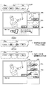
(2)第2の制御シナリオ
図10は、符号化条件の制御に関連する例示的な第2の制御シナリオについて説明するための説明図である。図10の上部には、コンテンツ再生セットRL20と、対応する表示画像とが示されている。コンテンツ再生セットRL20は、ソース機器200a(識別子“DVC1”)からのメインコンテンツと、ソース機器200b(識別子“SMP1”)及びソース機器200c(識別子“VDR1”)からの2つのサブコンテンツとを含む。ソース機器200d(識別子“TBL1”)は、待機機器である。表示画像のメインウィンドウ145aには、ソース機器200aから受信されるコンテンツが表示されている。サブウィンドウ145bには、ソース機器200bから受信されるコンテンツが表示されている。サブウィンドウ145cには、ソース機器200cから受信されるコンテンツが表示されている。待機機器用ウィンドウ146には、待機機器であるソース機器200dのアイコンが表示されている。
(2) Second Control Scenario FIG. 10 is an explanatory diagram for describing an exemplary second control scenario related to control of encoding conditions. In the upper part of FIG. 10, the content reproduction set RL20 and the corresponding display image are shown. The content reproduction set RL20 includes main content from the source device 200a (identifier “DVC1”) and two sub-contents from the source device 200b (identifier “SMP1”) and the source device 200c (identifier “VDR1”). The source device 200d (identifier “TBL1”) is a standby device. Content received from the source device 200a is displayed in the main window 145a of the display image. Content received from the source device 200b is displayed in the sub window 145b. Content received from the source device 200c is displayed in the sub window 145c. In the standby device window 146, an icon of the source device 200d that is a standby device is displayed.
ここで、ソース機器200bからのコンテンツをメインウィンドウ145aに表示させることを、例えばユーザがソース機器200bのユーザインタフェースを介して指示したものとする。すると、シンク機器100の再生制御部160は、コンテンツ再生セットRL20をコンテンツ再生セットRL21に更新する。コンテンツ再生セットRL21において、ソース機器200b(識別子“SMP1”)からのコンテンツがメインコンテンツに設定されている。しかし、高い解像度の求められる2つのメインコンテンツを同時に復号しようとすると、要求復号能力が、復号部130のプロセッサの実復号能力を超過する。一例として、メインコンテンツの受信及び復号、サブコンテンツの受信及び復号、並びに無線接続の維持には、それぞれ50%、20%及び2%のプロセッサ性能を要するものとする。この場合、2つのメインコンテンツを並列的に復号すれば、要求復号能力は100%に達し、プロセッサ性能は不足し得る。要求復号能力は、符号化条件に関連付けてこのように簡易的に計算されてもよい。
Here, for example, it is assumed that the user instructs to display the content from the source device 200b on the main window 145a via the user interface of the source device 200b. Then, the playback control unit 160 of the sink device 100 updates the content playback set RL20 to the content playback set RL21. In the content reproduction set RL21, the content from the source device 200b (identifier “SMP1”) is set as the main content. However, if two main contents requiring high resolution are to be decoded simultaneously, the required decoding capability exceeds the actual decoding capability of the processor of the decoding unit 130. As an example, it is assumed that 50%, 20%, and 2% of processor performance are required for receiving and decoding main content, receiving and decoding sub-contents, and maintaining a wireless connection, respectively. In this case, if the two main contents are decoded in parallel, the required decoding capability reaches 100% and the processor performance may be insufficient. The required decoding capability may be simply calculated in this way in association with the encoding condition.
そこで、再生制御部160は、例えば、コンテンツ再生セットRL21をコンテンツ再生セットRL22に更新する。コンテンツ再生セットRL22において、ソース機器200a(識別子“DVC1”)からのコンテンツはサブコンテンツに変更されている。結果として、コンテンツ再生セットRL22の要求復号能力は、復号部130の実復号能力を超過しない。図10の下部には、コンテンツ再生セットRL22に対応する表示画像が示されている。メインウィンドウ145aには、ソース機器200b(識別子“SMP1”)から受信されるコンテンツが表示されている。一方、サブウィンドウ145bには、ソース機器200a(識別子“DVC1”)から受信されるコンテンツが表示されている。
Therefore, for example, the reproduction control unit 160 updates the content reproduction set RL21 to the content reproduction set RL22. In the content reproduction set RL22, the content from the source device 200a (identifier “DVC1”) is changed to a sub-content. As a result, the requested decryption capability of the content reproduction set RL22 does not exceed the actual decryption capability of the decryption unit 130. In the lower part of FIG. 10, a display image corresponding to the content reproduction set RL22 is shown. In the main window 145a, content received from the source device 200b (identifier “SMP1”) is displayed. On the other hand, the content received from the source device 200a (identifier “DVC1”) is displayed in the sub window 145b.
(3)第3の制御シナリオ
図11は、符号化条件の制御に関連する例示的な第3の制御シナリオについて説明するための説明図である。図11の上部には、コンテンツ再生セットRL30と、対応する表示画像とが示されている。コンテンツ再生セットRL30は、ソース機器200a(識別子“DVC1”)からのメインコンテンツと、ソース機器200b(識別子“SMP1”)及びソース機器200c(識別子“VDR1”)からの2つのサブコンテンツとを含む。ソース機器200d(識別子“TBL1”)は、待機機器である。表示画像のメインウィンドウ145aには、ソース機器200aから受信されるコンテンツが表示されている。サブウィンドウ145bには、ソース機器200bから受信されるコンテンツが表示されている。サブウィンドウ145cには、ソース機器200cから受信されるコンテンツが表示されている。待機機器用ウィンドウ146には、待機機器であるソース機器200dのアイコンが表示されている。
(3) Third Control Scenario FIG. 11 is an explanatory diagram for describing an exemplary third control scenario related to the control of the encoding condition. In the upper part of FIG. 11, a content reproduction set RL30 and a corresponding display image are shown. The content reproduction set RL30 includes main content from the source device 200a (identifier “DVC1”) and two sub-contents from the source device 200b (identifier “SMP1”) and the source device 200c (identifier “VDR1”). The source device 200d (identifier “TBL1”) is a standby device. Content received from the source device 200a is displayed in the main window 145a of the display image. Content received from the source device 200b is displayed in the sub window 145b. Content received from the source device 200c is displayed in the sub window 145c. In the standby device window 146, an icon of the source device 200d that is a standby device is displayed.
ここで、ソース機器200dからのコンテンツをサブウィンドウ145b又は145cに表示させることを、例えばユーザが画面に表示されるGUIを介して指示したものとする。すると、シンク機器100の再生制御部160は、コンテンツ再生セットRL30をコンテンツ再生セットRL31に更新する。コンテンツ再生セットRL31において、ソース機器200d(識別子“TBL1”)からのコンテンツがサブコンテンツに設定されている。しかし、1つのメインコンテンツと3つのサブコンテンツとを既定の解像度で同時に復号しようとすると、要求復号能力が、復号部130のプロセッサの実復号能力を超過する。
Here, for example, it is assumed that the user instructs to display the content from the source device 200d on the sub-window 145b or 145c via a GUI displayed on the screen. Then, the playback control unit 160 of the sink device 100 updates the content playback set RL30 to the content playback set RL31. In the content reproduction set RL31, the content from the source device 200d (identifier “TBL1”) is set as the sub-content. However, if one main content and three sub-contents are simultaneously decoded at a predetermined resolution, the requested decoding capability exceeds the actual decoding capability of the processor of the decoding unit 130.
そこで、再生制御部160は、例えば、コンテンツ再生セットRL31をコンテンツ再生セットRL32に更新する。コンテンツ再生セットRL32において、ソース機器200b(識別子“SMP1”)及びソース機器200c(識別子“VDR1”)からのサブコンテンツの解像度が、低解像度(LD)に変更されている。結果として、コンテンツ再生セットRL32の要求復号能力は、復号部130の実復号能力を超過しない。図11の下部には、コンテンツ再生セットRL32に対応する表示画像が示されている。サブウィンドウ145b及び145cのウィンドウサイズは縮小され、これらウィンドウはそれぞれ低解像度のサブコンテンツを表示している。また、新たなサブウィンドウ145dが追加され、サブウィンドウ145dはソース機器200d(識別子“TBL1”)から受信されるコンテンツを表示している。このように、表示画像のウィンドウ構成(ウィンドウの数及びサイズなど)は、コンテンツ再生セットの符号化条件に追随して動的に変更されてもよい。
Therefore, for example, the reproduction control unit 160 updates the content reproduction set RL31 to the content reproduction set RL32. In the content reproduction set RL32, the resolution of the sub content from the source device 200b (identifier “SMP1”) and the source device 200c (identifier “VDR1”) is changed to low resolution (LD). As a result, the requested decryption capability of the content reproduction set RL32 does not exceed the actual decryption capability of the decryption unit 130. A display image corresponding to the content reproduction set RL32 is shown in the lower part of FIG. The window sizes of the sub-windows 145b and 145c are reduced, and each of these windows displays low-resolution sub-contents. In addition, a new subwindow 145d is added, and the subwindow 145d displays content received from the source device 200d (identifier “TBL1”). As described above, the window configuration (the number and size of windows) of the display image may be dynamically changed following the encoding condition of the content reproduction set.
(4)第4の制御シナリオ
図12は、符号化条件の制御に関連する例示的な第4の制御シナリオについて説明するための説明図である。図12の上部には、コンテンツ再生セットRL40と、対応する表示画像とが示されている。コンテンツ再生セットRL40は、ソース機器200a(識別子“DVC1”)からのメインコンテンツと、ソース機器200b(識別子“SMP1”)及びソース機器200c(識別子“VDR1”)からの2つのサブコンテンツとを含む。ソース機器200d(識別子“TBL1”)は、待機機器である。メインコンテンツは、ソース機器200aにおいてH.265/HEVCで符号化される。2つのサブコンテンツは、ソース機器200b及び200cにおいてH.264/AVCで符号化される。
(4) Fourth Control Scenario FIG. 12 is an explanatory diagram for describing an exemplary fourth control scenario related to the control of the encoding condition. In the upper part of FIG. 12, the content reproduction set RL40 and the corresponding display image are shown. The content reproduction set RL40 includes main content from the source device 200a (identifier “DVC1”) and two sub-contents from the source device 200b (identifier “SMP1”) and the source device 200c (identifier “VDR1”). The source device 200d (identifier “TBL1”) is a standby device. The main content is H.264 on the source device 200a. It is encoded with H.265 / HEVC. The two sub-contents are stored in the source device 200b and 200c in the H.264 format. It is encoded by H.264 / AVC.
ここで、ソース機器200dからのコンテンツをメインウィンドウ145aに表示させることを、例えばユーザが画面に表示されるGUIを介して指示したものとする。すると、シンク機器100の再生制御部160は、コンテンツ再生セットRL40をコンテンツ再生セットRL41に更新する。コンテンツ再生セットRL41において、ソース機器200d(識別子“TBL1”)からのコンテンツがメインコンテンツに設定されている。しかし、例えば復号部130は映像コンテンツを復号することのできる復号回路を3つしか有していないため、コンテンツ再生セットRL41の要求復号能力は、復号部130の実復号能力を超過する。
Here, for example, it is assumed that the user instructs to display the content from the source device 200d on the main window 145a via a GUI displayed on the screen. Then, the playback control unit 160 of the sink device 100 updates the content playback set RL40 to the content playback set RL41. In the content reproduction set RL41, content from the source device 200d (identifier “TBL1”) is set as the main content. However, for example, since the decoding unit 130 has only three decoding circuits that can decode video content, the requested decoding capability of the content reproduction set RL41 exceeds the actual decoding capability of the decoding unit 130.
そこで、再生制御部160は、コンテンツ再生セットRL41をさらにコンテンツ再生セットRL42に更新する。コンテンツ再生セットRL42において、ソース機器200a(識別子“DVC1”)からのコンテンツがサブコンテンツに設定され、ソース機器200c(識別子“VDR1”)からのコンテンツが再生対象から除外されている。ソース機器200d(識別子“TBL1”)からのメインコンテンツは、H.265/HEVCで符号化される。しかし、例えば復号部130はH.265/HEVCで映像コンテンツを復号することのできる復号回路を1つしか有していないため、コンテンツ再生セットRL42の要求復号能力は、依然として復号部130の実復号能力を超過する。
Therefore, the playback control unit 160 further updates the content playback set RL41 to the content playback set RL42. In the content playback set RL42, content from the source device 200a (identifier “DVC1”) is set as sub-content, and content from the source device 200c (identifier “VDR1”) is excluded from playback targets. The main content from the source device 200d (identifier “TBL1”) is H.264. It is encoded with H.265 / HEVC. However, for example, the decoding unit 130 is H.264. Since only one decoding circuit capable of decoding video content with H.265 / HEVC is provided, the requested decoding capability of the content reproduction set RL42 still exceeds the actual decoding capability of the decoding unit 130.
そこで、再生制御部160は、例えば、コンテンツ再生セットRL42をさらにコンテンツ再生セットRL43に更新する。コンテンツ再生セットRL43において、ソース機器200d(識別子“TBL1”)からのメインコンテンツは、H.264/AVCで符号化される。結果として、コンテンツ再生セットRL43の要求復号能力は、復号部130の実復号能力を超過しない。いずれのソース機器のコーデック種別を変更すべきかは、例えば、各ソース機器から予め収集される符号化能力情報に基づいて決定されてよい。図12の制御シナリオにおいて、ソース機器200dからのメインコンテンツのためのコーデック種別がH.264/AVCに変更された理由は、例えば、ソース機器200dがH.265/HEVC及びH.264/AVCの双方をサポートする一方で、ソース機器200aがH.265/HEVCのみをサポートしていることであってよい。
Therefore, for example, the reproduction control unit 160 further updates the content reproduction set RL42 to the content reproduction set RL43. In the content reproduction set RL43, the main content from the source device 200d (identifier “TBL1”) is H.264. It is encoded by H.264 / AVC. As a result, the requested decryption capability of the content reproduction set RL43 does not exceed the actual decryption capability of the decryption unit 130. Which source device codec type should be changed may be determined based on, for example, encoding capability information collected in advance from each source device. In the control scenario of FIG. 12, the codec type for the main content from the source device 200d is H.264. The reason for changing to H.264 / AVC is, for example, that the source device 200d is H.264. H.265 / HEVC and H.264. H.264 / AVC is supported, while the source device 200a is H.264. It may be that only H.265 / HEVC is supported.
(5)第5の制御シナリオ
図13は、符号化条件の制御に関連する例示的な第5の制御シナリオについて説明するための説明図である。図13の上部には、コンテンツ再生セットRL50と、対応する表示画像とが示されている。コンテンツ再生セットRL50は、ソース機器200a(識別子“DVC1”)からのメインコンテンツと、ソース機器200b(識別子“SMP1”)及びソース機器200c(識別子“VDR1”)からの2つのサブコンテンツとを含む。ソース機器200d(識別子“TBL1”)は、待機機器である。
(5) Fifth Control Scenario FIG. 13 is an explanatory diagram for explaining an exemplary fifth control scenario related to the control of the encoding condition. In the upper part of FIG. 13, the content reproduction set RL50 and the corresponding display image are shown. The content reproduction set RL50 includes main content from the source device 200a (identifier “DVC1”) and two sub-contents from the source device 200b (identifier “SMP1”) and the source device 200c (identifier “VDR1”). The source device 200d (identifier “TBL1”) is a standby device.
ここで、ソース機器200dからのコンテンツをメインウィンドウ145aに表示させることを、例えばユーザが画面に表示されるGUIを介して指示したものとする。すると、シンク機器100の再生制御部160は、コンテンツ再生セットRL50をコンテンツ再生セットRL51に更新する。コンテンツ再生セットRL51において、ソース機器200d(識別子“TBL1”)からのコンテンツがメインコンテンツに設定されている。しかし、例えば復号部130は映像コンテンツを復号することのできる復号回路を3つしか有さず、メインコンテンツのための既定のビデオコーデックであるH.265/HEVCでコンテンツ復号可能な復号回路は1つしか存在しないため、コンテンツ再生セットRL51の要求復号能力は、復号部130の実復号能力を超過する。
Here, for example, it is assumed that the user instructs to display the content from the source device 200d on the main window 145a via a GUI displayed on the screen. Then, the playback control unit 160 of the sink device 100 updates the content playback set RL50 to the content playback set RL51. In the content reproduction set RL51, the content from the source device 200d (identifier “TBL1”) is set as the main content. However, for example, the decoding unit 130 has only three decoding circuits capable of decoding video content, and is a default video codec for main content. Since there is only one decryption circuit capable of decrypting content by H.265 / HEVC, the requested decryption capability of the content reproduction set RL51 exceeds the actual decryption capability of the decryption unit 130.
そこで、再生制御部160は、例えば、コンテンツ再生セットRL51をコンテンツ再生セットRL52に更新する。コンテンツ再生セットRL52において、ソース機器200a(識別子“DVC1”)からのコンテンツはサブコンテンツに変更され、当該コンテンツのコーデック種別は無圧縮(NC)方式に変更されている。この場合、ソース機器200aは、コンテンツを圧縮符号化することなくシンク機器100へ送信する。シンク機器100の復号部130は、ソース機器200aから受信されるサブコンテンツを伸長するための復号処理を実行しなくてよい。結果として、コンテンツ再生セットRL52の要求復号能力は、復号部130の実復号能力を超過しない。図13の下部には、コンテンツ再生セットRL52に対応する表示画像が示されている。当該表示画像において、新たなサブウィンドウ145eが追加され、サブウィンドウ145eはソース機器200a(識別子“DVC1”)から受信されるコンテンツを表示している。
Therefore, for example, the reproduction control unit 160 updates the content reproduction set RL51 to the content reproduction set RL52. In the content reproduction set RL52, the content from the source device 200a (identifier “DVC1”) is changed to a sub-content, and the codec type of the content is changed to an uncompressed (NC) system. In this case, the source device 200a transmits the content to the sink device 100 without compression encoding. The decoding unit 130 of the sink device 100 does not have to execute a decoding process for expanding the sub-content received from the source device 200a. As a result, the requested decryption capability of the content reproduction set RL52 does not exceed the actual decryption capability of the decryption unit 130. In the lower part of FIG. 13, a display image corresponding to the content reproduction set RL52 is shown. In the display image, a new subwindow 145e is added, and the subwindow 145e displays the content received from the source device 200a (identifier “DVC1”).
<6.メッセージングシーケンス(Wi-Fiディスプレイの例)>
本節では、コンテンツ再生システム1におけるシンク機器100とソース機器200との間のメッセージングシーケンスのいくつかの例を図面を用いて説明する。なお、ここでは、限定ではなく一例として、メッセージングシーケンスはWi-Fiディスプレイの仕様に従うものとし、但し、そのシーケンスは本開示に係る技術の実現のために部分的に拡張され得る。
<6. Messaging sequence (example of Wi-Fi display)>
In this section, some examples of messaging sequences between the sink device 100 and the source device 200 in the content reproduction system 1 will be described with reference to the drawings. Here, by way of example and not limitation, the messaging sequence conforms to the specification of the Wi-Fi display, but the sequence may be partially extended to realize the technology according to the present disclosure.
[6-1.概略的な流れ]
図14は、Wi-Fiディスプレイにおける機器間のメッセージングの流れを概略的に示すシーケンス図である。なお、図中では、説明の簡明さのために、1つのソース機器と1つのシンク機器のみが示される。しかし、実際には、複数のソース機器と1つのシンク機器とが、本節で説明される手続に従ってメッセージを交換し得る。
[6-1. Schematic flow]
FIG. 14 is a sequence diagram schematically showing a flow of messaging between devices in the Wi-Fi display. In the figure, only one source device and one sink device are shown for the sake of simplicity. In practice, however, multiple source devices and a single sink device may exchange messages according to the procedure described in this section.
図14を参照すると、まず、シンク機器100とソース機器200との間で、デバイスディスカバリ手続(WFD Device Discovery)が実行される(ステップS10)。デバイスディスカバリ手続において、少なくとも一方の機器が探索信号を送信し、当該探索信号を受信した他方の機器が応答信号を返送する。それにより、シンク機器100とソース機器200とが、互いの存在を認識する。
Referring to FIG. 14, first, a device discovery procedure (WFD Device Discovery) is executed between the sink device 100 and the source device 200 (step S10). In the device discovery procedure, at least one device transmits a search signal, and the other device that has received the search signal returns a response signal. Thereby, the sink device 100 and the source device 200 recognize each other's existence.
次に、シンク機器100とソース機器200との間で、サービスディスカバリ手続(WFD Service Discovery)が実行される(ステップS15)。なお、サービスディスカバリ手続は任意的(optional)であり、シーケンスから省略されてもよい。サービスディスカバリ手続において、少なくとも一方の機器がサービス問合せ信号を送信し、当該サービス問合せ信号を受信した他方の機器がサービス応答信号を返送する。後に詳細に説明する第2の手法では、このサービスディスカバリ手続の中で、ソース機器200の符号化能力情報がシンク機器100へ提供される。
Next, a service discovery procedure (WFD Service Discovery) is executed between the sink device 100 and the source device 200 (step S15). Note that the service discovery procedure is optional and may be omitted from the sequence. In the service discovery procedure, at least one device transmits a service inquiry signal, and the other device that has received the service inquiry signal returns a service response signal. In the second method described in detail later, the coding capability information of the source device 200 is provided to the sink device 100 in the service discovery procedure.
次に、シンク機器100において、発見された機器の中から接続すべきソース機器200が選択される(ステップS20a)。ここでの機器の選択は、ユーザ入力に従って行われてもよく、又は予め記憶されるローカルポリシーに従って行われてもよい。同様に、ソース機器200においても、接続すべきシンク機器100が選択されてもよい(ステップS20b)。
Next, in the sink device 100, the source device 200 to be connected is selected from the discovered devices (step S20a). The device selection here may be performed according to a user input or may be performed according to a local policy stored in advance. Similarly, in the source device 200, the sink device 100 to be connected may be selected (step S20b).
次に、シンク機器100とソース機器200との間で、接続セットアップ手続(WFD Connection Setup)が実行される(ステップS25)。それにより、機器間のTCP接続が確立される。典型的には、シンク機器100がTCPクライアントとして接続セットアップ手続を開始し、ソース機器200はTCPサーバとして動作する。
Next, a connection setup procedure (WFD Connection Setup) is executed between the sink device 100 and the source device 200 (step S25). Thereby, a TCP connection between the devices is established. Typically, the sink device 100 starts a connection setup procedure as a TCP client, and the source device 200 operates as a TCP server.
次に、シンク機器100とソース機器200との間で、能力交渉手続(WFD Capability Negotiation)が実行される(ステップS30)。後に詳細に説明する第1の手法では、この能力交渉手続の中で、ソース機器200の符号化能力情報がシンク機器100へ提供される。能力交渉手続は、RTSP(Real Time Streaming Protocol)のM1、M2、M3及びM4メッセージ、又はそれらの拡張を用いて実装され得る。
Next, a capability negotiation procedure (WFD Capability Negotiation) is executed between the sink device 100 and the source device 200 (step S30). In the first method described in detail later, the coding capability information of the source device 200 is provided to the sink device 100 in this capability negotiation procedure. The capability negotiation procedure may be implemented using RT1, M1, M2, M3 and M4 messages of Real Time Streaming Protocol (RTSP), or extensions thereof.
次に、シンク機器100とソース機器200との間で、セッション確立手続(WFD Session Establishment)が実行される(ステップS50)。それにより、機器間のサービスセッションが確立される。セッション確立手続は、RTSPのM5、M6及びM7メッセージを用いて実装され得る。
Next, a session establishment procedure (WFD Session Establishment) is executed between the sink device 100 and the source device 200 (step S50). Thereby, a service session between the devices is established. The session establishment procedure may be implemented using RTSP M5, M6 and M7 messages.
次に、シンク機器100とソース機器200との間で、UIBCセットアップ手続が実行される(ステップS60)。なお、UIBCセットアップ手続は任意的であり、シーケンスから省略されてもよい。UIBCセットアップ手続により、機器間でユーザ入力情報を伝送するための制御チャネルが確立される。UIBCセットアップ手続は、RTSPのM3及びM4メッセージ、又はM14及びM15メッセージを用いて実装され得る。
Next, a UIBC setup procedure is executed between the sink device 100 and the source device 200 (step S60). Note that the UIBC setup procedure is optional and may be omitted from the sequence. The UIBC setup procedure establishes a control channel for transmitting user input information between devices. The UIBC setup procedure may be implemented using RTSP M3 and M4 messages, or M14 and M15 messages.
次に、シンク機器100とソース機器200との間で、コンテンツ保護セットアップ手続が実行される(ステップS65)。なお、コンテンツ保護セットアップ手続は任意的であり、シーケンスから省略されてもよい。コンテンツ保護セットアップ手続により、例えばHDCP(High-bandwidth Digital Content Protection)技術によってコンテンツを保護することが可能となる。
Next, a content protection setup procedure is executed between the sink device 100 and the source device 200 (step S65). Note that the content protection setup procedure is optional and may be omitted from the sequence. With the content protection setup procedure, for example, content can be protected by HDCP (High-bandwidth Digital Content Protection) technology.
その後、ソース機器200からシンク機器100へのコンテンツのストリーミングが実行される(ステップS70)。ここでのストリーミングは、例えば、図8のステップS252~S256及び図6のステップS170~S180の処理に相当し得る。ストリーミングの最中に何らかの制御トリガが検出された場合(ステップS75)、シンク機器100は、検出された制御トリガに応じた制御を実行する(ステップS80)。例えば、コンテンツ再生セットの更新及びそれに伴う新たな符号化条件のソース機器200への指示が、ここで行われてよい。
Thereafter, streaming of content from the source device 200 to the sink device 100 is executed (step S70). The streaming here can correspond to, for example, the processing of steps S252 to S256 in FIG. 8 and steps S170 to S180 in FIG. If any control trigger is detected during streaming (step S75), the sink device 100 executes control according to the detected control trigger (step S80). For example, the content reproduction set may be updated and an instruction to the source device 200 for a new encoding condition associated therewith may be performed here.
次に、ソース機器200が待機機器として選択された場合には、シンク機器100とソース機器200との間で、スタンバイ移行手続(WFD Source/Sink standby)が実行され得る(ステップS90)。サービスが終了される場合には、シンク機器100とソース機器200との間で、セッション切断手続(WFD Session Teardown)が実行され得る(ステップS95)。
Next, when the source device 200 is selected as a standby device, a standby transition procedure (WFD Source / Sink standby) may be executed between the sink device 100 and the source device 200 (step S90). When the service is terminated, a session disconnection procedure (WFD Session Teardown) can be executed between the sink device 100 and the source device 200 (step S95).
[6-2.既存の能力交渉手続]
図15は、図14の能力交渉手続における既存のメッセージングの流れの一例を示すシーケンス図である。非特許文献1によれば、Wi-Fiディスプレイでは、能力交渉手続(WFD Capability Negotiation)は、RTSPのM1、M2、M3及びM4メッセージを用いて実装される。
[6-2. Existing capacity negotiation procedures]
FIG. 15 is a sequence diagram showing an example of an existing messaging flow in the capability negotiation procedure of FIG. According to Non-Patent Document 1, in the Wi-Fi display, the capability negotiation procedure (WFD Capability Negotiation) is implemented using the M1, M2, M3, and M4 messages of RTSP.
まず、ソース機器は、シンク機器によりサポートされるメソッドを問合せるために、M1リクエストメッセージ(M1-RTSP OPTIONS Request)をシンク機器へ送信する(ステップS31a)。シンク機器は、M1リクエストメッセージへの応答として、M1レスポンスメッセージ(M1-RTSP OPTIONS Response)を返送する(ステップS31b)。
First, the source device transmits an M1 request message (M1-RTSP OPTIONS Request) to the sink device in order to query a method supported by the sink device (step S31a). The sink device returns an M1 response message (M1-RTSP OPTIONS Response) as a response to the M1 request message (step S31b).
次に、シンク機器は、ソース機器によりサポートされるメソッドを問合せるために、M2リクエストメッセージ(M2-RTSP OPTIONS Request)をソース機器へ送信する(ステップS33a)。ソース機器は、M2リクエストメッセージへの応答として、M2レスポンスメッセージ(M2-RTSP OPTIONS Response)を返送する(ステップS33b)。
Next, the sink device transmits an M2 request message (M2-RTSP OPTIONS Request) to the source device in order to query a method supported by the source device (step S33a). The source device returns an M2 response message (M2-RTSP OPTIONS Response) as a response to the M2 request message (step S33b).
次に、ソース機器は、シンク機器の復号能力を示すパラメータを取得するために、M3リクエストメッセージ(M3-RTSP GET_PARAMETER Request)をシンク機器へ送信する(ステップS35a)。シンク機器は、M3リクエストメッセージへの応答として、M3レスポンスメッセージ(M3-RTSP Response)を返送する(ステップS35b)。
Next, the source device transmits an M3 request message (M3-RTSP GET_PARAMETER Request) to the sink device in order to acquire a parameter indicating the decoding capability of the sink device (step S35a). The sink device returns an M3 response message (M3-RTSP Response) as a response to the M3 request message (step S35b).
次に、ソース機器は、シンク機器へ復号条件の設定を指示するために、M4リクエストメッセージ(M4-RTSP SET_PARAMETER Request)をシンク機器へ送信する(ステップS37a)。シンク機器は、M4リクエストメッセージへの応答として、M4レスポンスメッセージ(M4-RTSP Response)を返送する(ステップS37b)。
Next, the source device transmits an M4 request message (M4-RTSP SET_PARAMETER Request) to the sink device to instruct the sink device to set the decoding conditions (step S37a). The sink device returns an M4 response message (M4-RTSP Response) as a response to the M4 request message (step S37b).
このように、既存のメッセージングシーケンスでは、ソース機器がコンテンツの符号化及び復号の条件を制御するマスタとしての役割を有し、シンク機器はソース機器からの指示に従って復号条件を設定する。これに対し、本実施形態では、シンク機器100がコンテンツの符号化及び復号の条件を制御するマスタとしての役割を有する。そのための拡張されたメッセージングシーケンスの2つの例を、以下に説明する。
As described above, in the existing messaging sequence, the source device has a role as a master for controlling the encoding and decoding conditions of the content, and the sink device sets the decoding conditions according to the instruction from the source device. On the other hand, in the present embodiment, the sink device 100 has a role as a master that controls conditions for encoding and decoding contents. Two examples of extended messaging sequences for this are described below.
[6-3.拡張されたメッセージングシーケンス(第1の手法)]
(1)基本的な流れ
図16は、第1の手法に従って拡張されたシンク機器とソース機器との間のメッセージングの流れの一例を示すシーケンス図である。第1の手法では、RTSPのパラメータ取得用メッセージであるM3リクエストメッセージが拡張され、シンク機器100からソース機器200へ符号化能力情報を問合せるための能力問合せメッセージとして利用される。また、RTSPのパラメータ設定用メッセージであるM4リクエストメッセージが拡張され、シンク機器100によってソース機器200の符号化条件を設定するための設定要求メッセージとして利用される。
[6-3. Extended messaging sequence (first approach)]
(1) Basic Flow FIG. 16 is a sequence diagram illustrating an example of a flow of messaging between a sink device and a source device extended according to the first technique. In the first method, the M3 request message, which is an RTSP parameter acquisition message, is expanded and used as a capability inquiry message for inquiring encoding capability information from the sink device 100 to the source device 200. Further, the M4 request message, which is an RTSP parameter setting message, is expanded and used as a setting request message for setting the encoding condition of the source device 200 by the sink device 100.
図16のステップS31a~S33bは、図15を用いて説明したものと同様である。シンク機器100は、ソース機器200の符号化能力情報を取得するために、拡張されたM3リクエストメッセージ(M3'-RTSP GET_PARAMETER Request)をソース機器200へ送信する(ステップS36a)。拡張されたM3リクエストメッセージは、上述した能力問合せメッセージに相当する。ソース機器200は、自身の符号化能力情報を含む拡張されたM3レスポンスメッセージ(M3'-RTSP Response)を、シンク機器100へ返送する(ステップS36b)。シンク機器100は、このようにソース機器200から収集される符号化能力情報を用いて、ソース機器200に適用すべき符号化条件を決定し得る。拡張されたM3レスポンスメッセージは、ソース機器200の優先条件情報を追加的に含んでもよい。
Steps S31a to S33b in FIG. 16 are the same as those described with reference to FIG. The sink device 100 transmits an extended M3 request message (M3′-RTSP GET_PARAMETER Request) to the source device 200 in order to acquire the coding capability information of the source device 200 (step S36a). The extended M3 request message corresponds to the above-described capability inquiry message. The source device 200 returns an extended M3 response message (M3′-RTSP Response) including its own coding capability information to the sink device 100 (step S36b). The sink device 100 can determine the encoding condition to be applied to the source device 200 using the encoding capability information collected from the source device 200 in this way. The extended M3 response message may additionally include the priority condition information of the source device 200.
符号化条件が決定されると、シンク機器100は、ソース機器200へ符号化条件の設定を指示するために、拡張されたM4リクエストメッセージ(M4'-RTSP SET_PARAMETER Request)をソース機器200へ送信する(ステップS38a)。拡張されたM4リクエストメッセージは、ソース機器200がコンテンツを符号化する際に使用すべき符号化条件を指定する、上述した設定要求メッセージに相当する。ソース機器200は、拡張されたM4リクエストメッセージへの応答として、拡張されたM4レスポンスメッセージ(M4'-RTSP Response)を返送する(ステップS38b)。
When the encoding condition is determined, the sink device 100 transmits an extended M4 request message (M4′-RTSP SET_PARAMETER Request) to the source device 200 in order to instruct the source device 200 to set the encoding condition. (Step S38a). The extended M4 request message corresponds to the above-described setting request message that specifies an encoding condition to be used when the source device 200 encodes content. The source device 200 returns an extended M4 response message (M4′-RTSP Response) as a response to the extended M4 request message (step S38b).
(2)変形例
図17は、第1の手法に従って拡張されたシンク機器とソース機器との間のメッセージングの流れの他の例を示すシーケンス図である。図17の例では、シンク機器100からソース機器200へ能力問合せメッセージ、即ち拡張されたM3リクエストメッセージが送信される前に、図15を用いて説明した既存のメッセージングの流れに従って、ソース機器200からシンク機器100へ(拡張されていない)M4リクエストメッセージが送信される(ステップS37a)。シンク機器100は、このM4リクエストメッセージへの応答として、指示されたパラメータの設定を拒否することを示すM4レスポンスメッセージ(M4-RTSP Response (NG))を返送する(ステップS37b)。その後、シンク機器100とソース機器200との間で、図16を用いて説明した通りに、拡張されたM3リクエスト/レスポンスメッセージ及び拡張されたM4リクエスト/レスポンスメッセージが交換される。なお、シンク機器100は、ステップS37aにおいて指示されたパラメータが、ソース機器200に設定すべき符号化条件に適合している場合には、指示された当該パラメータの設定を受け入れてもよい。その場合、ステップS37bにおいて、指示されたパラメータの設定を受け入れることを示すM4レスポンスメッセージが返送され得る。
(2) Modified Example FIG. 17 is a sequence diagram illustrating another example of the flow of messaging between the sink device and the source device extended according to the first technique. In the example of FIG. 17, before the capability inquiry message, that is, the extended M3 request message is transmitted from the sink device 100 to the source device 200, the source device 200 follows the existing messaging flow described with reference to FIG. An M4 request message (not expanded) is transmitted to the sink device 100 (step S37a). As a response to the M4 request message, the sink device 100 returns an M4 response message (M4-RTSP Response (NG)) indicating that setting of the instructed parameter is rejected (step S37b). Thereafter, as described with reference to FIG. 16, the extended M3 request / response message and the extended M4 request / response message are exchanged between the sink device 100 and the source device 200. Note that the sink device 100 may accept the setting of the instructed parameter when the parameter instructed in step S37a matches the encoding condition to be set in the source device 200. In that case, in step S37b, an M4 response message indicating acceptance of the setting of the instructed parameter may be returned.
図18は、サービスが中断される場合のメッセージングの流れの一例を示すシーケンス図である。図18のステップS31a~S36bは、図16を用いて説明したものと同様である。シンク機器100は、ソース機器200の符号化能力情報を取得するために、拡張されたM3リクエストメッセージをソース機器200へ送信する(ステップS36a)。ソース機器200は、自身の符号化能力情報を含む拡張されたM3レスポンスメッセージを、シンク機器100へ返送する(ステップS36b)。このように収集される符号化能力情報を用いてシンク機器100がソース機器200に適用すべき符号化条件を判定した結果、シンク機器100は、ソース機器200からのサービスの提供を停止することを決定したものとする。この場合、シンク機器100は、M8リクエストメッセージ(M8-RTSP TEARDOWN Request)をソース機器200へ送信することにより、サービスの停止をソース機器200へ通知する(ステップS39a)。ソース機器200は、M8レスポンスメッセージ(M8-RTSP Response)を返送する(ステップS39b)。
FIG. 18 is a sequence diagram showing an example of the flow of messaging when the service is interrupted. Steps S31a to S36b in FIG. 18 are the same as those described with reference to FIG. The sink device 100 transmits the extended M3 request message to the source device 200 in order to acquire the coding capability information of the source device 200 (step S36a). The source device 200 returns an extended M3 response message including its own coding capability information to the sink device 100 (step S36b). As a result of determining the encoding condition that the sink device 100 should apply to the source device 200 using the encoding capability information collected in this way, the sink device 100 stops providing the service from the source device 200. It shall be decided. In this case, the sink device 100 sends a M8 request message (M8-RTSP TEARDOWN Request) to the source device 200 to notify the source device 200 of the service stop (step S39a). The source device 200 returns an M8 response message (M8-RTSP Response) (step S39b).
[6-4.拡張されたメッセージングシーケンス(第2の手法)]
図19は、第2の手法に従って拡張されたシンク機器とソース機器との間のメッセージングの流れの一例を示すシーケンス図である。第2の手法では、Wi-Fiダイレクトのサービスディスカバリリクエストメッセージが拡張され、シンク機器100からソース機器200へ符号化能力情報を問合せるための能力問合せメッセージとして利用される。符号化条件情報は、サービスディスカバリレスポンスメッセージに含められる。
[6-4. Extended messaging sequence (second approach)]
FIG. 19 is a sequence diagram illustrating an example of a messaging flow between a sink device and a source device extended according to the second technique. In the second method, the Wi-Fi Direct service discovery request message is extended and used as a capability inquiry message for inquiring coding capability information from the sink device 100 to the source device 200. The encoding condition information is included in the service discovery response message.
図19を参照すると、図14に示したサービスディスカバリ手続が詳細化されており、シンク機器100は、拡張されたサービスディスカバリリクエストメッセージをソース機器200へ送信する(ステップS15a)。拡張されたサービスディスカバリリクエストメッセージは、上述した能力問合せメッセージに相当する。ソース機器200は、サービスディスカバリリクエストメッセージへの応答として、拡張されたサービスディスカバリレスポンスメッセージをシンク機器100へ返送する(ステップS15b)。シンク機器100は、このようにソース機器200から収集される符号化能力情報を用いて、ソース機器200に適用すべき符号化条件を決定し得る。拡張されたサービスディスカバリレスポンスメッセージは、ソース機器200の優先条件情報を追加的に含んでもよい。
Referring to FIG. 19, the service discovery procedure shown in FIG. 14 is detailed, and the sink device 100 transmits an extended service discovery request message to the source device 200 (step S15a). The extended service discovery request message corresponds to the above-described capability inquiry message. The source device 200 returns the extended service discovery response message to the sink device 100 as a response to the service discovery request message (step S15b). The sink device 100 can determine the encoding condition to be applied to the source device 200 using the encoding capability information collected from the source device 200 in this way. The extended service discovery response message may additionally include the priority condition information of the source device 200.
その後、ソース機器200は、シンク機器100の復号能力を示すパラメータを取得するために、(拡張されていない)M3リクエストメッセージをシンク機器100へ送信する(ステップS35a)。シンク機器100は、M3リクエストメッセージへの応答として、M3レスポンスメッセージを返送する(ステップS35b)。このとき、シンク機器100は、ソース機器200について決定した所要の符号化条件に対応するパラメータのみを、M3レスポンスメッセージに含める。それにより、シンク機器100が決定した符号化条件をソース機器200に使用させることができる。
Thereafter, the source device 200 transmits an M3 request message (not expanded) to the sink device 100 in order to acquire a parameter indicating the decoding capability of the sink device 100 (step S35a). The sink device 100 returns an M3 response message as a response to the M3 request message (step S35b). At this time, the sink device 100 includes only the parameter corresponding to the required encoding condition determined for the source device 200 in the M3 response message. Thereby, the source device 200 can use the encoding condition determined by the sink device 100.
<7.応用例>
本開示に係る技術は、様々な製品へ応用可能である。例えば、シンク機器100及びソース機器200は、スマートフォン、タブレットPC、ノートPC、携帯型ゲーム端末若しくはデジタルカメラなどのモバイル端末、テレビジョン受像機、プリンタ、デジタルスキャナ若しくはネットワークストレージなどの固定端末、又はカーナビゲーション装置などの車載端末として実現されてもよい。また、これら端末に搭載される制御モジュール(例えば、1つのダイで構成される集積回路モジュール)が提供されてもよい。
<7. Application example>
The technology according to the present disclosure can be applied to various products. For example, the sink device 100 and the source device 200 are a smartphone, a tablet PC, a notebook PC, a mobile terminal such as a portable game terminal or a digital camera, a fixed terminal such as a television receiver, a printer, a digital scanner, or a network storage, or a car You may implement | achieve as vehicle-mounted terminals, such as a navigation apparatus. In addition, a control module (for example, an integrated circuit module including one die) mounted on these terminals may be provided.
[7-1.第1の応用例]
図20は、本開示に係る技術が適用され得るスマートフォン900の概略的な構成の一例を示すブロック図である。スマートフォン900は、プロセッサ901、メモリ902、ストレージ903、外部接続インタフェース904、カメラ906、センサ907、マイクロフォン908、入力デバイス909、表示デバイス910、スピーカ911、無線通信インタフェース913、アンテナスイッチ914、アンテナ915、バス917、バッテリー918及び補助コントローラ919を備える。
[7-1. First application example]
FIG. 20 is a block diagram illustrating an example of a schematic configuration of a smartphone 900 to which the technology according to the present disclosure may be applied. The smartphone 900 includes a processor 901, a memory 902, a storage 903, an external connection interface 904, a camera 906, a sensor 907, a microphone 908, an input device 909, a display device 910, a speaker 911, a wireless communication interface 913, an antenna switch 914, an antenna 915, A bus 917, a battery 918, and an auxiliary controller 919 are provided.
プロセッサ901は、例えばCPU(Central Processing Unit)又はSoC(System on Chip)であってよく、スマートフォン900のアプリケーションレイヤ及びその他のレイヤの機能を制御する。メモリ902は、RAM(Random Access Memory)及びROM(Read Only Memory)を含み、プロセッサ901により実行されるプログラム及びデータを記憶する。ストレージ903は、半導体メモリ又はハードディスクなどの記憶媒体を含み得る。外部接続インタフェース904は、メモリーカード又はUSB(Universal Serial Bus)デバイスなどの外付けデバイスをスマートフォン900へ接続するためのインタフェースである。
The processor 901 may be, for example, a CPU (Central Processing Unit) or a SoC (System on Chip), and controls the functions of the application layer and other layers of the smartphone 900. The memory 902 includes a RAM (Random Access Memory) and a ROM (Read Only Memory), and stores programs and data executed by the processor 901. The storage 903 can include a storage medium such as a semiconductor memory or a hard disk. The external connection interface 904 is an interface for connecting an external device such as a memory card or a USB (Universal Serial Bus) device to the smartphone 900.
カメラ906は、例えば、CCD(Charge Coupled Device)又はCMOS(Complementary Metal Oxide Semiconductor)などの撮像素子を有し、撮像画像を生成する。センサ907は、例えば、測位センサ、ジャイロセンサ、地磁気センサ及び加速度センサなどのセンサ群を含み得る。マイクロフォン908は、スマートフォン900へ入力される音声を音声信号へ変換する。入力デバイス909は、例えば、表示デバイス910の画面上へのタッチを検出するタッチセンサ、キーパッド、キーボード、ボタン又はスイッチなどを含み、ユーザからの操作又は情報入力を受け付ける。表示デバイス910は、液晶ディスプレイ(LCD)又は有機発光ダイオード(OLED)ディスプレイなどの画面を有し、スマートフォン900の出力画像を表示する。スピーカ911は、スマートフォン900から出力される音声信号を音声に変換する。
The camera 906 includes, for example, an image sensor such as a CCD (Charge Coupled Device) or a CMOS (Complementary Metal Oxide Semiconductor), and generates a captured image. The sensor 907 may include a sensor group such as a positioning sensor, a gyro sensor, a geomagnetic sensor, and an acceleration sensor. The microphone 908 converts sound input to the smartphone 900 into an audio signal. The input device 909 includes, for example, a touch sensor that detects a touch on the screen of the display device 910, a keypad, a keyboard, a button, or a switch, and receives an operation or information input from a user. The display device 910 has a screen such as a liquid crystal display (LCD) or an organic light emitting diode (OLED) display, and displays an output image of the smartphone 900. The speaker 911 converts an audio signal output from the smartphone 900 into audio.
無線通信インタフェース913は、IEEE802.11a、11b、11g、11n、11ac及び11adなどの無線LAN標準のうちの1つ以上をサポートし、無線通信を実行する。無線通信インタフェース913は、インフラストラクチャーモードにおいては、他の装置と無線LANアクセスポイントを介して通信し得る。また、無線通信インタフェース913は、アドホックモードにおいては、他の装置と直接的に通信し得る。なお、Wi-Fiダイレクトでは、アドホックモードとは異なり2つの端末の一方がアクセスポイントとして動作するが、通信はそれら端末間で直接的に行われる。無線通信インタフェース913は、典型的には、ベースバンドプロセッサ、RF(Radio Frequency)回路及びパワーアンプなどを含み得る。無線通信インタフェース913は、通信制御プログラムを記憶するメモリ、当該プログラムを実行するプロセッサ及び関連する回路を集積したワンチップのモジュールであってもよい。無線通信インタフェース913は、無線LAN方式に加えて、近距離無線通信方式、近接無線通信方式又はセルラ通信方式などの他の種類の無線通信方式をサポートしてもよい。アンテナスイッチ914は、無線通信インタフェース913に含まれる複数の回路(例えば、異なる無線通信方式のための回路)の間でアンテナ915の接続先を切り替える。アンテナ915は、単一の又は複数のアンテナ素子(例えば、MIMOアンテナを構成する複数のアンテナ素子)を有し、無線通信インタフェース913による無線信号の送信及び受信のために使用される。
The wireless communication interface 913 supports one or more wireless LAN standards such as IEEE802.11a, 11b, 11g, 11n, 11ac, and 11ad, and performs wireless communication. The wireless communication interface 913 can communicate with other devices via a wireless LAN access point in the infrastructure mode. The wireless communication interface 913 can directly communicate with other devices in the ad hoc mode. In Wi-Fi Direct, unlike the ad hoc mode, one of the two terminals operates as an access point, but communication is performed directly between the terminals. The wireless communication interface 913 can typically include a baseband processor, an RF (Radio Frequency) circuit, a power amplifier, and the like. The wireless communication interface 913 may be a one-chip module in which a memory that stores a communication control program, a processor that executes the program, and related circuits are integrated. The wireless communication interface 913 may support other types of wireless communication methods such as a short-range wireless communication method, a proximity wireless communication method, or a cellular communication method in addition to the wireless LAN method. The antenna switch 914 switches the connection destination of the antenna 915 among a plurality of circuits (for example, circuits for different wireless communication schemes) included in the wireless communication interface 913. The antenna 915 includes a single antenna element or a plurality of antenna elements (for example, a plurality of antenna elements constituting a MIMO antenna), and is used for transmission and reception of radio signals by the radio communication interface 913.
なお、図20の例に限定されず、スマートフォン900は、複数のアンテナ(例えば、無線LAN用のアンテナ及び近接無線通信方式用のアンテナ、など)を備えてもよい。その場合に、アンテナスイッチ914は、スマートフォン900の構成から省略されてもよい。
Note that the smartphone 900 is not limited to the example of FIG. 20, and may include a plurality of antennas (for example, an antenna for a wireless LAN and an antenna for a proximity wireless communication method). In that case, the antenna switch 914 may be omitted from the configuration of the smartphone 900.
バス917は、プロセッサ901、メモリ902、ストレージ903、外部接続インタフェース904、カメラ906、センサ907、マイクロフォン908、入力デバイス909、表示デバイス910、スピーカ911、無線通信インタフェース913及び補助コントローラ919を互いに接続する。バッテリー918は、図中に破線で部分的に示した給電ラインを介して、図20に示したスマートフォン900の各ブロックへ電力を供給する。補助コントローラ919は、例えば、スリープモードにおいて、スマートフォン900の必要最低限の機能を動作させる。
The bus 917 connects the processor 901, memory 902, storage 903, external connection interface 904, camera 906, sensor 907, microphone 908, input device 909, display device 910, speaker 911, wireless communication interface 913, and auxiliary controller 919 to each other. . The battery 918 supplies power to each block of the smartphone 900 illustrated in FIG. 20 through a power supply line partially illustrated by a broken line in the drawing. For example, the auxiliary controller 919 operates the minimum necessary functions of the smartphone 900 in the sleep mode.
図20に示したスマートフォン900において、シンク機器100の再生制御機能又はソース機器200の符号化制御機能は、プロセッサ901又は補助コントローラ919において実装され得る。例えば、プロセッサ901がスマートフォン900の実復号能力を超過しないように外部のソース機器からのコンテンツの受信を制御することで、スマートフォン900における複数のコンテンツの再生を円滑に実行することが可能となる。
In the smartphone 900 shown in FIG. 20, the playback control function of the sink device 100 or the encoding control function of the source device 200 can be implemented in the processor 901 or the auxiliary controller 919. For example, by controlling the reception of content from an external source device so that the processor 901 does not exceed the actual decoding capability of the smartphone 900, it is possible to smoothly reproduce a plurality of contents on the smartphone 900.
[7-2.第2の応用例]
図21は、本開示に係る技術が適用され得るカーナビゲーション装置920の概略的な構成の一例を示すブロック図である。カーナビゲーション装置920は、プロセッサ921、メモリ922、GPS(Global Positioning System)モジュール924、センサ925、データインタフェース926、コンテンツプレーヤ927、記憶媒体インタフェース928、入力デバイス929、表示デバイス930、スピーカ931、無線通信インタフェース933、アンテナスイッチ934、アンテナ935及びバッテリー938を備える。
[7-2. Second application example]
FIG. 21 is a block diagram illustrating an example of a schematic configuration of a car navigation device 920 to which the technology according to the present disclosure can be applied. The car navigation device 920 includes a processor 921, a memory 922, a GPS (Global Positioning System) module 924, a sensor 925, a data interface 926, a content player 927, a storage medium interface 928, an input device 929, a display device 930, a speaker 931, and wireless communication. An interface 933, an antenna switch 934, an antenna 935, and a battery 938 are provided.
プロセッサ921は、例えばCPU又はSoCであってよく、カーナビゲーション装置920のナビゲーション機能及びその他の機能を制御する。メモリ922は、RAM及びROMを含み、プロセッサ921により実行されるプログラム及びデータを記憶する。
The processor 921 may be a CPU or SoC, for example, and controls the navigation function and other functions of the car navigation device 920. The memory 922 includes RAM and ROM, and stores programs and data executed by the processor 921.
GPSモジュール924は、GPS衛星から受信されるGPS信号を用いて、カーナビゲーション装置920の位置(例えば、緯度、経度及び高度)を測定する。センサ925は、例えば、ジャイロセンサ、地磁気センサ及び気圧センサなどのセンサ群を含み得る。データインタフェース926は、例えば、図示しない端子を介して車載ネットワーク941に接続され、車速データなどの車両側で生成されるデータを取得する。
The GPS module 924 measures the position (for example, latitude, longitude, and altitude) of the car navigation device 920 using GPS signals received from GPS satellites. The sensor 925 may include a sensor group such as a gyro sensor, a geomagnetic sensor, and an atmospheric pressure sensor. The data interface 926 is connected to the in-vehicle network 941 through a terminal (not shown), for example, and acquires data generated on the vehicle side such as vehicle speed data.
コンテンツプレーヤ927は、記憶媒体インタフェース928に挿入される記憶媒体(例えば、CD又はDVD)に記憶されているコンテンツを再生する。入力デバイス929は、例えば、表示デバイス930の画面上へのタッチを検出するタッチセンサ、ボタン又はスイッチなどを含み、ユーザからの操作又は情報入力を受け付ける。表示デバイス930は、LCD又はOLEDディスプレイなどの画面を有し、ナビゲーション機能又は再生されるコンテンツの画像を表示する。スピーカ931は、ナビゲーション機能又は再生されるコンテンツの音声を出力する。
The content player 927 reproduces content stored in a storage medium (for example, CD or DVD) inserted into the storage medium interface 928. The input device 929 includes, for example, a touch sensor, a button, or a switch that detects a touch on the screen of the display device 930, and receives an operation or information input from the user. The display device 930 has a screen such as an LCD or an OLED display, and displays a navigation function or an image of content to be reproduced. The speaker 931 outputs the navigation function or the audio of the content to be played back.
無線通信インタフェース933は、IEEE802.11a、11b、11g、11n、11ac及び11adなどの無線LAN標準のうちの1つ以上をサポートし、無線通信を実行する。無線通信インタフェース933は、インフラストラクチャーモードにおいては、他の装置と無線LANアクセスポイントを介して通信し得る。また、無線通信インタフェース933は、アドホックモード又はWi-Fiダイレクトにおいては、他の装置と直接的に通信し得る。無線通信インタフェース933は、典型的には、ベースバンドプロセッサ、RF回路及びパワーアンプなどを含み得る。無線通信インタフェース933は、通信制御プログラムを記憶するメモリ、当該プログラムを実行するプロセッサ及び関連する回路を集積したワンチップのモジュールであってもよい。無線通信インタフェース933は、無線LAN方式に加えて、近距離無線通信方式、近接無線通信方式又はセルラ通信方式などの他の種類の無線通信方式をサポートしてもよい。アンテナスイッチ934は、無線通信インタフェース933に含まれる複数の回路の間でアンテナ935の接続先を切り替える。アンテナ935は、単一の又は複数のアンテナ素子を有し、無線通信インタフェース933による無線信号の送信及び受信のために使用される。
The wireless communication interface 933 supports one or more wireless LAN standards such as IEEE802.11a, 11b, 11g, 11n, 11ac, and 11ad, and executes wireless communication. The wireless communication interface 933 can communicate with other devices via a wireless LAN access point in the infrastructure mode. The wireless communication interface 933 can directly communicate with other devices in the ad hoc mode or Wi-Fi direct. The wireless communication interface 933 may typically include a baseband processor, an RF circuit, a power amplifier, and the like. The wireless communication interface 933 may be a one-chip module in which a memory that stores a communication control program, a processor that executes the program, and related circuits are integrated. In addition to the wireless LAN system, the wireless communication interface 933 may support other types of wireless communication systems such as a short-range wireless communication system, a proximity wireless communication system, or a cellular communication system. The antenna switch 934 switches the connection destination of the antenna 935 among a plurality of circuits included in the wireless communication interface 933. The antenna 935 includes a single antenna element or a plurality of antenna elements, and is used for transmission and reception of a radio signal by the radio communication interface 933.
なお、図21の例に限定されず、カーナビゲーション装置920は、複数のアンテナを備えてもよい。その場合に、アンテナスイッチ934は、カーナビゲーション装置920の構成から省略されてもよい。
Note that the car navigation device 920 is not limited to the example of FIG. 21, and may include a plurality of antennas. In that case, the antenna switch 934 may be omitted from the configuration of the car navigation device 920.
バッテリー938は、図中に破線で部分的に示した給電ラインを介して、図21に示したカーナビゲーション装置920の各ブロックへ電力を供給する。また、バッテリー938は、車両側から給電される電力を蓄積する。
The battery 938 supplies power to each block of the car navigation device 920 shown in FIG. 21 via a power supply line partially shown by broken lines in the drawing. Further, the battery 938 stores electric power supplied from the vehicle side.
図21に示したカーナビゲーション装置920において、シンク機器100の再生制御機能又はソース機器200の符号化制御機能は、プロセッサ921において実装され得る。例えば、プロセッサ921がカーナビゲーション装置920の実復号能力を超過しないように外部のソース機器からのコンテンツの受信を制御することで、カーナビゲーション装置920における複数のコンテンツの再生を円滑に実行することが可能となる。
21, the playback control function of the sink device 100 or the encoding control function of the source device 200 can be implemented in the processor 921 in the car navigation device 920 shown in FIG. For example, by controlling the reception of content from an external source device so that the processor 921 does not exceed the actual decoding capability of the car navigation device 920, playback of a plurality of content in the car navigation device 920 can be performed smoothly. It becomes possible.
また、本開示に係る技術は、上述したカーナビゲーション装置920の1つ以上のブロックと、車載ネットワーク941と、車両側モジュール942とを含む車載システム(又は車両)940として実現されてもよい。車両側モジュール942は、車速、エンジン回転数又は故障情報などの車両側データを生成し、生成したデータを車載ネットワーク941へ出力する。
Also, the technology according to the present disclosure may be realized as an in-vehicle system (or vehicle) 940 including one or more blocks of the car navigation device 920 described above, an in-vehicle network 941, and a vehicle side module 942. The vehicle-side module 942 generates vehicle-side data such as vehicle speed, engine speed, or failure information, and outputs the generated data to the in-vehicle network 941.
<8.まとめ>
ここまで、図1~図21を用いて、本開示に係る技術の実施形態について詳細に説明した。上述した実施形態によれば、シンク機器(復号装置)が複数のソース機器(符号化装置)から無線接続を介して受信されるコンテンツを復号して再生する状況において、再生されるコンテンツのセットにより要求される要求復号能力がシンク機器の実復号能力を超過しないように、シンク機器によって、複数のソース機器におけるコンテンツの符号化条件が制御される。よって、シンク機器の能力に応じて、複数のソース機器について符号化条件を適切にコーディネートし、最適な条件で複数のコンテンツを再生することが可能となる。
<8. Summary>
So far, the embodiments of the technology according to the present disclosure have been described in detail with reference to FIGS. 1 to 21. According to the above-described embodiment, in a situation where a sink device (decoding device) decodes and plays back content received via a wireless connection from a plurality of source devices (encoding devices), the set of content to be played back The content encoding conditions in the plurality of source devices are controlled by the sink device so that the requested decoding capability required does not exceed the actual decoding capability of the sink device. Therefore, according to the capability of the sink device, it is possible to appropriately coordinate the encoding conditions for a plurality of source devices and reproduce a plurality of contents under the optimum conditions.
また、上述した実施形態によれば、各ソース機器からシンク機器へ各ソース機器の符号化能力情報が収集され、シンク機器は、収集した符号化能力情報に基づいて各シンク機器の符号化条件を決定し得る。かかる構成によれば、既存の手法とは異なり、コンテンツの符号化及び復号の条件を中心的に制御するマスタとしての役割を、シンク機器が果たすことが可能となる。例えば、ユーザは、コンテンツの再生に関連するユーザ入力をシンク機器に与えるだけで、シンク機器の復号能力の不足を回避しつつ所望の形態で複数のコンテンツを並列的に体験することができる。
Further, according to the above-described embodiment, the encoding capability information of each source device is collected from each source device to the sink device, and the sink device sets the encoding condition of each sink device based on the collected encoding capability information. Can be determined. According to such a configuration, unlike the existing method, the sink device can play a role as a master that mainly controls the encoding and decoding conditions of the content. For example, the user can experience a plurality of contents in parallel in a desired form while avoiding a lack of the decoding capability of the sink device only by giving a user input related to content reproduction to the sink device.
また、上述した実施形態によれば、各ソース機器からシンク機器へ符号化能力情報を収集するための仕組みは、既存のプロトコルをわずかに拡張するだけで実現され得る。第1の手法において、例えば、RTSPのパラメータ取得用メッセージが拡張され、シンク機器からソース機器へ符号化能力情報を問合せるための能力問合せメッセージとして利用され得る。第2の手法において、Wi-Fiダイレクトのサービスディスカバリリクエストメッセージが拡張され、シンク機器からソース機器へ符号化能力情報を問合せるための能力問合せメッセージとして利用され得る。このような拡張が利用される場合には、より少ないコストで本開示に係る技術を実現することが可能であり、既存のプロトコルとの互換性を確保することも容易である。
Further, according to the above-described embodiment, the mechanism for collecting the coding capability information from each source device to the sink device can be realized by slightly extending an existing protocol. In the first method, for example, an RTSP parameter acquisition message is extended and can be used as a capability inquiry message for inquiring encoding capability information from a sink device to a source device. In the second method, the Wi-Fi Direct service discovery request message can be extended and used as a capability inquiry message for inquiring encoding capability information from the sink device to the source device. When such an extension is used, the technology according to the present disclosure can be realized at a lower cost, and it is easy to ensure compatibility with existing protocols.
なお、本明細書において説明した各装置による一連の制御処理は、ソフトウェア、ハードウェア、及びソフトウェアとハードウェアとの組合せのいずれを用いて実現されてもよい。ソフトウェアを構成するプログラムは、例えば、各装置の内部又は外部に設けられる記憶媒体(非一時的な媒体:non-transitory media)に予め格納される。そして、各プログラムは、例えば、実行時にRAMに読み込まれ、CPUなどのプロセッサにより実行される。
Note that a series of control processing by each device described in this specification may be realized using any of software, hardware, and a combination of software and hardware. For example, the program constituting the software is stored in advance in a storage medium (non-transitory medium) provided inside or outside each device. Each program is read into a RAM at the time of execution, for example, and executed by a processor such as a CPU.
また、本明細書においてフローチャート及びシーケンス図を用いて説明した処理は、必ずしも図示された順序で実行されなくてもよい。いくつかの処理ステップは、並列的に実行されてもよい。また、追加的な処理ステップが採用されてもよく、一部の処理ステップが省略されてもよい。
In addition, the processes described using the flowcharts and sequence diagrams in this specification do not necessarily have to be executed in the order shown. Some processing steps may be performed in parallel. Further, additional processing steps may be employed, and some processing steps may be omitted.
以上、添付図面を参照しながら本開示の好適な実施形態について詳細に説明したが、本開示の技術的範囲はかかる例に限定されない。本開示の技術分野における通常の知識を有する者であれば、特許請求の範囲に記載された技術的思想の範疇内において、各種の変更例または修正例に想到し得ることは明らかであり、これらについても、当然に本開示の技術的範囲に属するものと了解される。
The preferred embodiments of the present disclosure have been described in detail above with reference to the accompanying drawings, but the technical scope of the present disclosure is not limited to such examples. It is obvious that a person having ordinary knowledge in the technical field of the present disclosure can come up with various changes or modifications within the scope of the technical idea described in the claims. Of course, it is understood that it belongs to the technical scope of the present disclosure.
また、本明細書に記載された効果は、あくまで説明的又は例示的なものであって限定的ではない。つまり、本開示に係る技術は、上記の効果と共に、又は上記の効果に代えて、本明細書の記載から当業者には明らかな他の効果を奏し得る。
In addition, the effects described in the present specification are merely illustrative or illustrative, and are not limited. That is, the technology according to the present disclosure can exhibit other effects that are apparent to those skilled in the art from the description of the present specification, together with the above effects or instead of the above effects.
なお、以下のような構成も本開示の技術的範囲に属する。
(1)
複数の符号化装置との間で無線接続を確立する無線通信部と、
前記複数の符号化装置から前記無線通信部を介して受信されるコンテンツをそれぞれ復号する復号部と、
前記復号部により復号される複数のコンテンツを再生する再生部と、
前記再生部により再生されるコンテンツのセットにより要求される要求復号能力が前記復号部の実復号能力を超過しないように、前記複数の符号化装置におけるコンテンツの符号化条件を制御する制御部と、
を備える復号装置。
(2)
前記制御部は、前記無線通信部を介して各符号化装置から受信される当該符号化装置の符号化能力情報に基づいて、各符号化装置における前記符号化条件を決定する、前記(1)に記載の復号装置。
(3)
前記制御部は、前記無線通信部を介して各符号化装置へ能力問合せメッセージを送信することにより、各符号化装置から前記符号化能力情報を収集する、前記(2)に記載の復号装置。
(4)
前記能力問合せメッセージは、シンク機器からソース機器へ前記符号化能力情報を問合せるために拡張された、RTSP(Real Time Streaming Protocol)のパラメータ取得用メッセージである、前記(3)に記載の復号装置。
(5)
前記制御部は、シンク機器によってソース機器の前記符号化条件を設定するために拡張された、RTSPのパラメータ設定用メッセージを各符号化装置へ送信することにより、各符号化装置における前記符号化条件を制御する、前記(4)に記載の復号装置。
(6)
前記能力問合せメッセージは、Wi-Fiダイレクトのサービスディスカバリリクエストメッセージである、前記(3)に記載の復号装置。
(7)
前記要求復号能力及び前記実復号能力は、サポートされるコーデック種別、解像度、レート及び品質レベル、復号回路の数、並びにプロセッサ性能のうち少なくとも1つにより表現される、前記(1)~(6)のいずれか1項に記載の復号装置。
(8)
前記符号化条件は、各符号化装置において使用されるコーデック種別、解像度、レート及び品質レベルのうち少なくとも1つに関する条件である、前記(1)~(7)のいずれか1項に記載の復号装置。
(9)
前記制御部は、前記要求復号能力が前記実復号能力を超過する場合に、少なくとも1つのコンテンツを圧縮符号化することなく送信することを、当該少なくとも1つのコンテンツを有する前記符号化装置へ要求する、前記(1)~(8)のいずれか1項に記載の復号装置
(10)
前記制御部は、各符号化装置との間の前記無線接続の接続品質にさらに基づいて、各符号化装置における前記符号化条件を制御する、前記(1)~(9)のいずれか1項に記載の復号装置。
(11)
前記制御部は、各符号化装置の電源状態にさらに基づいて、各符号化装置における前記符号化条件を制御する、前記(1)~(10)のいずれか1項に記載の復号装置。
(12)
前記制御部は、各符号化装置から受信される、優先すべき符号化条件を特定する優先条件情報にさらに基づいて、各符号化装置における前記符号化条件を制御する、前記(1)~(11)のいずれか1項に記載の復号装置。
(13)
前記制御部は、前記複数の符号化装置における前記符号化条件に応じて、当該複数の符号化装置との間の前記無線接続の周波数チャネルをさらに制御する、前記(1)~(12)のいずれか1項に記載の復号装置。
(14)
前記制御部は、前記再生されるコンテンツの前記セットの更新を指示するユーザ入力が検出された場合に、更新後の前記セットについての前記要求復号能力を前記実復号能力と比較する、前記(1)~(13)のいずれか1項に記載の復号装置。
(15)
前記制御部は、前記復号部に掛かる負荷に基づいて動的に計算される前記実復号能力を、前記要求復号能力と比較する、前記(1)~(14)のいずれか1項に記載の復号装置。
(16)
前記制御部は、前記再生部により再生される前記複数のコンテンツを表示する画面に、前記要求復号能力に前記実復号能力を超過させないために前記セットから除外したコンテンツを有する符号化装置のリストを表示させる、前記(1)~(15)のいずれか1項に記載の復号装置。
(17)
前記制御部は、前記リスト内の前記符号化装置と前記無線通信部との間の前記無線接続を維持する、前記(16)に記載の復号装置。
(18)
復号装置により、複数の符号化装置から無線接続を介して受信されるコンテンツをそれぞれ復号することと、
復号される複数のコンテンツを再生することと、
再生されるコンテンツのセットにより要求される要求復号能力が前記復号装置の実復号能力を超過しないように、前記復号装置により、前記複数の符号化装置におけるコンテンツの符号化条件を制御することと、
を含む復号方法。
(19)
複数の装置から受信されるコンテンツをそれぞれ復号して再生する復号装置との間で無線接続を確立する無線通信部と、
前記無線通信部を介して前記復号装置へ送信すべきコンテンツを符号化する符号化部と、
前記復号装置により再生されるコンテンツのセットにより要求される要求復号能力が前記復号装置の実復号能力を超過しないように、前記復号装置から受信される制御メッセージに基づいて、前記符号化部におけるコンテンツの符号化条件を制御する制御部と、
を備える符号化装置。
(20)
複数の装置から受信されるコンテンツをそれぞれ復号して再生する復号装置へ無線接続を介してコンテンツを送信する符号化装置により、前記復号装置へ送信すべきコンテンツを符号化することと、
前記復号装置により再生されるコンテンツのセットにより要求される要求復号能力が前記復号装置の実復号能力を超過しないように、前記復号装置から受信される制御メッセージに基づいて、前記符号化装置におけるコンテンツの符号化条件を制御することと、
を含む符号化方法。
The following configurations also belong to the technical scope of the present disclosure.
(1)
A wireless communication unit for establishing a wireless connection with a plurality of encoding devices;
A decoding unit that respectively decodes content received from the plurality of encoding devices via the wireless communication unit;
A reproducing unit for reproducing a plurality of contents decoded by the decoding unit;
A control unit that controls the encoding conditions of the content in the plurality of encoding devices so that the requested decoding capability required by the set of content reproduced by the reproducing unit does not exceed the actual decoding capability of the decoding unit;
A decoding device comprising:
(2)
The control unit determines the encoding condition in each encoding device based on encoding capability information of the encoding device received from each encoding device via the wireless communication unit, (1) The decoding device according to 1.
(3)
The decoding device according to (2), wherein the control unit collects the coding capability information from each coding device by transmitting a capability inquiry message to each coding device via the wireless communication unit.
(4)
The decoding apparatus according to (3), wherein the capability inquiry message is an RTSP (Real Time Streaming Protocol) parameter acquisition message extended to inquire the encoding capability information from a sink device to a source device.
(5)
The control unit transmits the RTSP parameter setting message extended to set the coding condition of the source device by the sink device to each coding device, thereby the coding condition in each coding device. The decoding device according to (4), wherein:
(6)
The decoding device according to (3), wherein the capability inquiry message is a Wi-Fi Direct service discovery request message.
(7)
The requested decoding capability and the actual decoding capability are expressed by at least one of a supported codec type, resolution, rate and quality level, number of decoding circuits, and processor performance, (1) to (6) The decoding device according to any one of the above.
(8)
The decoding according to any one of (1) to (7), wherein the encoding condition is a condition regarding at least one of a codec type, a resolution, a rate, and a quality level used in each encoding device. apparatus.
(9)
The control unit requests the encoding device having the at least one content to transmit without compressing and encoding at least one content when the requested decoding capability exceeds the actual decoding capability. The decoding device (10) according to any one of (1) to (8)
The control unit controls the encoding condition in each encoding device based further on connection quality of the wireless connection with each encoding device, any one of (1) to (9) The decoding device according to 1.
(11)
The decoding device according to any one of (1) to (10), wherein the control unit controls the encoding condition in each encoding device based further on a power state of each encoding device.
(12)
The control unit controls the encoding condition in each encoding device based on priority condition information specifying the encoding condition to be prioritized received from each encoding device. The decoding device according to any one of 11).
(13)
The control unit further controls the frequency channel of the wireless connection with the plurality of encoding devices in accordance with the encoding conditions in the plurality of encoding devices, (1) to (12) The decoding device according to any one of claims.
(14)
The control unit compares the requested decoding capability for the updated set with the actual decoding capability when a user input instructing to update the set of the content to be reproduced is detected. The decoding device according to any one of (13) to (13).
(15)
The control unit according to any one of (1) to (14), wherein the control unit compares the actual decoding capability dynamically calculated based on a load applied to the decoding unit with the requested decoding capability. Decoding device.
(16)
The control unit displays a list of encoding devices having content excluded from the set in order to prevent the requested decoding capability from exceeding the actual decoding capability on a screen displaying the plurality of contents reproduced by the reproducing unit. The decoding device according to any one of (1) to (15), which is displayed.
(17)
The decoding unit according to (16), wherein the control unit maintains the wireless connection between the encoding device in the list and the wireless communication unit.
(18)
Respectively decoding content received via a wireless connection from a plurality of encoding devices by a decoding device;
Playing multiple content to be decrypted,
Controlling the content encoding conditions in the plurality of encoding devices by the decoding device so that the requested decoding capability required by the set of content to be played does not exceed the actual decoding capability of the decoding device;
A decoding method including:
(19)
A wireless communication unit that establishes a wireless connection with a decryption device that decrypts and reproduces content received from a plurality of devices;
An encoding unit that encodes content to be transmitted to the decoding device via the wireless communication unit;
Content in the encoding unit based on a control message received from the decoding device so that the requested decoding capability required by the set of content reproduced by the decoding device does not exceed the actual decoding capability of the decoding device A control unit for controlling the encoding conditions of
An encoding device comprising:
(20)
Encoding the content to be transmitted to the decoding device by an encoding device that transmits the content via a wireless connection to a decoding device that respectively decodes and reproduces the content received from a plurality of devices;
Content in the encoding device based on a control message received from the decoding device so that the requested decoding capability required by the set of content reproduced by the decoding device does not exceed the actual decoding capability of the decoding device Controlling the encoding conditions of
An encoding method including: