WO2015099172A1 - Terminal device and base station device - Google Patents
Terminal device and base station device Download PDFInfo
- Publication number
- WO2015099172A1 WO2015099172A1 PCT/JP2014/084688 JP2014084688W WO2015099172A1 WO 2015099172 A1 WO2015099172 A1 WO 2015099172A1 JP 2014084688 W JP2014084688 W JP 2014084688W WO 2015099172 A1 WO2015099172 A1 WO 2015099172A1
- Authority
- WO
- WIPO (PCT)
- Prior art keywords
- cqi
- control information
- mode
- rrc
- mcs
- Prior art date
Links
Images


Classifications
-
- H—ELECTRICITY
- H04—ELECTRIC COMMUNICATION TECHNIQUE
- H04L—TRANSMISSION OF DIGITAL INFORMATION, e.g. TELEGRAPHIC COMMUNICATION
- H04L1/00—Arrangements for detecting or preventing errors in the information received
- H04L1/0001—Systems modifying transmission characteristics according to link quality, e.g. power backoff
- H04L1/0023—Systems modifying transmission characteristics according to link quality, e.g. power backoff characterised by the signalling
- H04L1/0026—Transmission of channel quality indication
-
- H—ELECTRICITY
- H04—ELECTRIC COMMUNICATION TECHNIQUE
- H04W—WIRELESS COMMUNICATION NETWORKS
- H04W72/00—Local resource management
- H04W72/20—Control channels or signalling for resource management
- H04W72/23—Control channels or signalling for resource management in the downlink direction of a wireless link, i.e. towards a terminal
-
- H—ELECTRICITY
- H04—ELECTRIC COMMUNICATION TECHNIQUE
- H04B—TRANSMISSION
- H04B7/00—Radio transmission systems, i.e. using radiation field
- H04B7/02—Diversity systems; Multi-antenna system, i.e. transmission or reception using multiple antennas
- H04B7/04—Diversity systems; Multi-antenna system, i.e. transmission or reception using multiple antennas using two or more spaced independent antennas
- H04B7/06—Diversity systems; Multi-antenna system, i.e. transmission or reception using multiple antennas using two or more spaced independent antennas at the transmitting station
- H04B7/0613—Diversity systems; Multi-antenna system, i.e. transmission or reception using multiple antennas using two or more spaced independent antennas at the transmitting station using simultaneous transmission
- H04B7/0615—Diversity systems; Multi-antenna system, i.e. transmission or reception using multiple antennas using two or more spaced independent antennas at the transmitting station using simultaneous transmission of weighted versions of same signal
- H04B7/0619—Diversity systems; Multi-antenna system, i.e. transmission or reception using multiple antennas using two or more spaced independent antennas at the transmitting station using simultaneous transmission of weighted versions of same signal using feedback from receiving side
- H04B7/0621—Feedback content
- H04B7/0626—Channel coefficients, e.g. channel state information [CSI]
-
- H—ELECTRICITY
- H04—ELECTRIC COMMUNICATION TECHNIQUE
- H04L—TRANSMISSION OF DIGITAL INFORMATION, e.g. TELEGRAPHIC COMMUNICATION
- H04L1/00—Arrangements for detecting or preventing errors in the information received
- H04L1/0001—Systems modifying transmission characteristics according to link quality, e.g. power backoff
- H04L1/0002—Systems modifying transmission characteristics according to link quality, e.g. power backoff by adapting the transmission rate
- H04L1/0003—Systems modifying transmission characteristics according to link quality, e.g. power backoff by adapting the transmission rate by switching between different modulation schemes
-
- H—ELECTRICITY
- H04—ELECTRIC COMMUNICATION TECHNIQUE
- H04L—TRANSMISSION OF DIGITAL INFORMATION, e.g. TELEGRAPHIC COMMUNICATION
- H04L1/00—Arrangements for detecting or preventing errors in the information received
- H04L1/0001—Systems modifying transmission characteristics according to link quality, e.g. power backoff
- H04L1/0015—Systems modifying transmission characteristics according to link quality, e.g. power backoff characterised by the adaptation strategy
- H04L1/0016—Systems modifying transmission characteristics according to link quality, e.g. power backoff characterised by the adaptation strategy involving special memory structures, e.g. look-up tables
-
- H—ELECTRICITY
- H04—ELECTRIC COMMUNICATION TECHNIQUE
- H04L—TRANSMISSION OF DIGITAL INFORMATION, e.g. TELEGRAPHIC COMMUNICATION
- H04L1/00—Arrangements for detecting or preventing errors in the information received
- H04L1/0001—Systems modifying transmission characteristics according to link quality, e.g. power backoff
- H04L1/0023—Systems modifying transmission characteristics according to link quality, e.g. power backoff characterised by the signalling
- H04L1/0028—Formatting
-
- H—ELECTRICITY
- H04—ELECTRIC COMMUNICATION TECHNIQUE
- H04L—TRANSMISSION OF DIGITAL INFORMATION, e.g. TELEGRAPHIC COMMUNICATION
- H04L27/00—Modulated-carrier systems
- H04L27/32—Carrier systems characterised by combinations of two or more of the types covered by groups H04L27/02, H04L27/10, H04L27/18 or H04L27/26
- H04L27/34—Amplitude- and phase-modulated carrier systems, e.g. quadrature-amplitude modulated carrier systems
- H04L27/36—Modulator circuits; Transmitter circuits
- H04L27/362—Modulation using more than one carrier, e.g. with quadrature carriers, separately amplitude modulated
-
- H—ELECTRICITY
- H04—ELECTRIC COMMUNICATION TECHNIQUE
- H04L—TRANSMISSION OF DIGITAL INFORMATION, e.g. TELEGRAPHIC COMMUNICATION
- H04L5/00—Arrangements affording multiple use of the transmission path
- H04L5/003—Arrangements for allocating sub-channels of the transmission path
- H04L5/0053—Allocation of signaling, i.e. of overhead other than pilot signals
-
- H—ELECTRICITY
- H04—ELECTRIC COMMUNICATION TECHNIQUE
- H04W—WIRELESS COMMUNICATION NETWORKS
- H04W72/00—Local resource management
- H04W72/20—Control channels or signalling for resource management
- H04W72/21—Control channels or signalling for resource management in the uplink direction of a wireless link, i.e. towards the network
-
- H—ELECTRICITY
- H04—ELECTRIC COMMUNICATION TECHNIQUE
- H04W—WIRELESS COMMUNICATION NETWORKS
- H04W28/00—Network traffic management; Network resource management
- H04W28/02—Traffic management, e.g. flow control or congestion control
- H04W28/06—Optimizing the usage of the radio link, e.g. header compression, information sizing, discarding information
-
- H—ELECTRICITY
- H04—ELECTRIC COMMUNICATION TECHNIQUE
- H04W—WIRELESS COMMUNICATION NETWORKS
- H04W72/00—Local resource management
Definitions
- the present invention relates to a terminal device and a base station device.
- the LTE downlink supports QPSK (Quadrature Phase Shift Keying), 16 QAM (Quadrature Amplitude Modulation), and 64 QAM as modulation schemes.
- QPSK can transmit only 2 bits in one modulation symbol, whereas it can transmit 4 bits in 16QAM and 6 bits in 64QAM. That is, 16QAM is higher than QPSK, and 64QAM is higher in frequency utilization efficiency than 16QAM.
- eNB evolved Node B
- UE User Equipment
- LTE employs a technique called adaptive modulation that adaptively selects a modulation scheme according to the channel state between the eNB and the UE.
- the coding rate of the error correction code is adaptively changed in addition to the modulation method.
- the UE estimates the downlink channel state based on the reference signal transmitted by the base station apparatus, and notifies the eNB of the obtained channel quality information (CQI, Channel Quality Information). To do.
- CQI Channel Quality Information
- the eNB selects and selects the modulation scheme with the highest frequency utilization efficiency among the combinations of modulation scheme and coding rate (MCS) that are equal to or lower than the predetermined error rate.
- MCS modulation scheme with the highest frequency utilization efficiency among the combinations of modulation scheme and coding rate
- a pico base station also referred to as a small cell
- the pico base station does not necessarily have a function as a base station, and may be configured with an extended antenna (RRH, Remote Radio Head). Since it is assumed that a plurality of pico base stations are arranged in a cell and that sectorization is not performed, a high SINR (Signal ⁇ ⁇ to Interference plus Noise power Ratio) ) Is likely to be higher than when Rel-8.
- SINR Signal ⁇ ⁇ to Interference plus Noise power Ratio
- the CQI notified by the UE to the eNB is defined as a value assuming up to 64QAM. Therefore, even if the UE notifies the eNB of the highest CQI, the eNB judges that the channel state is bad for transmitting data to the UE by 256QAM, and regardless of the environment in which 256QAM can be transmitted without error ENB is expected to transmit data using 64QAM in the downlink.
- PDSCH Physical Downlink Share CHannel
- PDCCH Physical Downlink Control CHannel
- Non-Patent Document 1 and Non-Patent Document 2 in the specifications up to Rel-11, CQI is defined as 4 bits and MCS is defined as 5 bits, but in order to support 256QAM, It is conceivable that the amount of information is increased by 1 bit, and each CQI is 5 bits and MCS is 6 bits. However, if the number of bits is increased, the control throughput increases and the downlink throughput is lowered. In addition, the control information is increased in number, thereby changing the mechanism called blind decoding performed on the control information. The problem of need arises.
- Non-Patent Document 3 a conventional mode in which a CQI index calculated by a CQI table corresponding to up to 64QAM is notified and an MCS index is notified using an MCS table corresponding to up to 64QAM.
- 64QAM mode a CQI index calculated by a CQI table corresponding to up to 64QAM
- 256QAM mode a new mode for notifying the CQI index calculated by the CQI table corresponding to 256QAM and notifying the MCS index using the MCS table corresponding to 256QAM.
- RRC Radio Resource Control
- the MCS in the 256QAM mode can be achieved by deleting 256 MAM (that is, QPSK) from the 64QAM mode and introducing 256QAM (Method 1).
- 256 MAM that is, QPSK
- Method 2 downsampling from the MCS table in 64QAM mode, that is, a method of introducing 256QAM (method 2) while leaving QPSK to some extent is being studied.
- method 1 in which low MCS is deleted and 256 QAM is introduced, when a good channel state in which 256 QAM can be transmitted without error is suddenly changed to a poor channel state in which an error occurs unless QPSK is performed.
- the present invention has been made in view of the above problems, and an object thereof is to increase throughput without increasing control information.
- each configuration of the terminal and the base station according to the present invention is as follows.
- a transmission apparatus is a terminal apparatus including a plurality of CQI tables, and the terminal apparatus is information related to control information notified from a base station apparatus.
- a control information extraction unit that extracts information, information related to the control information, an RRC setting unit configured to associate one CQI table among the plurality of CQI tables, and the plurality of the plurality of control information based on the control information and the setting
- a CQI determination unit that sets one CQI table of the CQI tables and generates a CQI index is provided.
- the information related to the control information is control information included in the PDCCH or ePDCCH.
- a transmission apparatus is a type of search area for PDCCH or ePDCCH.
- the control information included in the PDCCH or ePDCCH is a CSI request region.
- a base station apparatus is a base station apparatus including a control information generation unit that generates control information to be notified to a terminal apparatus, and the base station apparatus The apparatus generates an RRC information generation unit that generates a setting in which one MCS table among a plurality of MCS tables is associated with the control information, and sets an MCS index based on the setting generated by the control information and the RRC information generation unit.
- An MCS determination unit to be set is provided.
- the information related to the control information is control information included in the PDCCH or ePDCCH.
- the control information included in the PDCCH or ePDCCH is a CSI request region.
- the base station apparatus allows the RRC information generation unit to be set for each CC.
- CSI Channel Information Information
- RI Rank Indicator
- PMI Precoding Matrix
- CQI Channel Quality Indicator
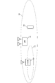
- FIG. 1 shows an example of the configuration of a wireless communication system in the present embodiment.
- the system includes a macro base station apparatus 101, a pico base station apparatus 102, and a terminal apparatus 103.
- the number of antenna ports of the device may be one or plural.
- the number of antenna ports indicates not the physical number of antennas but the logical number of antennas that can be recognized by a communicating device.
- the pico base station apparatus may not be a base station apparatus, and may be an apparatus called a cluster head when the terminal apparatus and the terminal apparatus directly communicate with each other.
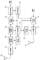
- FIG. 2 shows an example of the configuration of the macro base station apparatus 101.
- the configuration of the pico base station apparatus 102 may be the same as that shown in FIG. In FIG. 2, only the blocks necessary for the description of the present invention are shown.
- the signal transmitted from the terminal device 103 is received by the UL reception unit 202 via the reception antenna 201. Note that there are a plurality of reception antennas 201, and the reception quality may be improved by applying existing techniques such as reception diversity and adaptive array antennas.
- the UL receiving unit 202 performs processing such as down conversion and Fourier transform.
- the output of the UL reception unit 202 is input to the control information extraction unit 203.
- the control information extraction unit 203 extracts control information transmitted by the terminal device.
- control information may be included in PUCCH (Physical Uplink Control Channel) dedicated to control information, or control transmitted using PUSCH (Physical Uplink Shared CHannel) that is a channel for transmitting information data. It may be information.
- the control information extracted by the control information extraction unit 203 is input to the CQI extraction unit 204 and the RRC extraction unit 205.
- the RRC extraction unit 205 extracts information related to RRC from the control information, and sets the information in each unit in the eNB.
- the setting directly related to the present embodiment is either the 64QAM mode using the conventional CQI and MCS tables or the 256QAM mode using the table enabling 256QAM. (Referred to as modulation mode setting in this embodiment) and setting of which CC to notify CSI when eNB requests aperiodic CSI from UE (in this embodiment) , Referred to as CSI request setting).
- the 64QAM mode indicates a setting using an MCS table, a CQI table, or the like defined by LTE Rel-11, and 256QAM is not included as a modulation scheme constituting the MCS table applied to the PDSCH.
- 256QAM is included as a setting (configuration) in which the MCS table applied to the PDSCH is set (configuration) or as a modulation scheme to configure the CQI table used for feedback (configuration) configured from QPSK, 16QAM, and 64QAM. There is no setting (configuration), or the configuration (configuration) in which the modulation scheme constituting the CQI table used for feedback is configured from QPSK, 16QAM, and 64QAM.
- the 256QAM mode is different from the LTE Rel-11, and shows the setting using the MCS table, CQI table, etc. that are assumed to perform PDSCH data transmission in 256QAM and is applied to the PDSCH.
- the change between the 64QAM mode and the 256QAM mode is performed by a predetermined parameter given from an upper layer.
- the CQI extraction unit 204 extracts the CQI index transmitted by each UE from the control information input from the control information extraction unit 203.
- CQI is downlink channel quality information measured by the UE using a reference signal transmitted in the downlink.
- the eNB interprets differently even if the same CQI index is notified. Which modulation mode is set is determined by notifying the CQI extraction unit 204 that the UE has completed the modulation mode change setting from the RRC extraction unit 205 to the CQI extraction unit 204.
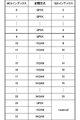
- the CQI table of FIG. 4 is obtained by reducing the index for QPSK transmission in the table of FIG. 3 and replacing the one having high frequency use efficiency among the CQIs for 64 QAM transmission with 256 QAM transmission.
- FIG. 4 is an example. The table is not assumed to be transmitted in QPSK, or the CQI in the table in FIG. 3 is deleted at equal intervals to obtain 256 QAM. Any assumed CQI table may be used.
- the CQI of each UE extracted by the CQI extraction unit 204 is input to the scheduling unit 206 and the MCS determination unit 207.
- the scheduling unit 206 allocates resources to each UE using the CQI of each UE.
- MIMO Multiple Input Multiple Output
- scheduling is performed using RI (Rank Indicator) or PMI (Precoding Matrix Indicator) notified from the UE in addition to CQI.
- the allocation information of each UE output from the scheduling unit 206 is input to the MCS determination unit 207 and the PDSCH generation unit 208.
- the resource allocation information input from the scheduling unit 206, the CQI index input from the CQI extraction unit 204, and the modulation mode input from the RRC extraction unit 205 are used.
- Estimate channel quality Based on the estimated channel quality, an MCS that provides a predetermined error rate is determined, and an MCS index is created.
- the created MCS index differs depending on the modulation mode. For example, when the 64QAM mode is set by the modulation mode setting notified by RRC, the MCS index is selected from the MCS table as shown in FIG. On the other hand, when the 256QAM mode is set by the modulation mode setting notified by RRC, the MCS index is selected from the MCS table as shown in FIG.
- the MCS table of FIG. 6 may be anything as long as it supports up to 256 QAM.
- the MCS index determined by the MCS determination unit 207 is input to the PDSCH generation unit 208 and also input to the control information generation unit 209.
- the control information generation unit 209 arranges the input MCS index on the PDCCH as a format called a DCI format together with other control information such as allocation information.
- the PDCCH is not necessarily used for transmission of control information (DCI format), and an area for control information may be secured in the PDSCH and transmitted using the channel.
- the PDSCH generation unit 208 performs encoding and modulation on the information bits addressed to each UE according to the MCS index of each UE input from the MCS determination unit 207, and each UE according to the allocation information input from the scheduling unit 206.
- the addressed signal is placed on the PDSCH.
- the arranged signal is input to the DL transmission unit 211.
- the RRC information is input to the PDSCH generation unit 208 and transmitted by the PDSCH as a data signal addressed to the UE.
- the RRC information is information notified by RRC signaling, and is CSI which is a modulation mode setting which is setting information of a modulation mode (256QAM mode and 64QAM mode) and a cell set configuration corresponding to the value of the CSI request region. Requirement settings are included.
- the DL transmission unit 211 multiplexes signals input from the PDSCH generation unit 208 and the PDCCH generation unit 211, and then performs IFFT processing, band limiting filtering processing, up-conversion, and the like.
- a signal output from the DL transmission unit 211 is transmitted to the terminal device 103 via the transmission antenna 212.
- FIG. 7 shows a configuration example of the terminal device 103.
- a signal received by the receiving antenna 700 is input to the DL receiving unit 701, and processing such as down conversion, band limiting filtering, and discrete Fourier transform is applied, and the obtained signal is input to the reference signal extracting unit 702.
- the reference signal extraction unit 702 resources to which reference signals such as CRS, CSI-RS, and DMRS transmitted by the eNB are transmitted are extracted and input to the channel estimation unit 706.
- Channel estimation section 706 estimates the channel state between the eNB and the UE using the received reception reference signal.
- the obtained channel estimation value is input to CQI determination section 707.
- a part of the obtained channel estimation value is also input to the PDSCH demodulator 704 because it is used for demodulation.
- control information extraction unit 703 extracts information related to control information (DCI format) from the received signal.
- information related to the MCS index of the PDSCH is input to the PDSCH demodulator 704.
- the present invention is characterized in that the extracted control information related to aperiodic CSI is input to the CQI determination unit 707, and the control information related to aperiodic CSI is used in the CQI determination unit 707, which will be described in detail later.
- the output of the control information extraction unit 703 is input to the PDSCH demodulation unit 704.
- PDSCH demodulator 704 demodulates PDSCH based on MCS information input from control information extractor 703.
- the MCS table to be referred to is selected based on the modulation mode setting input from the RRC setting unit 708, the MCS is determined from the selected MCS table and the notified MCS index, and used for demodulation. For example, in the RRC setting unit 708, when the 64QAM mode is set, the MCS is determined based on the MCS table of FIG. 5, and when the 256QAM mode is set, the MCS is determined based on the MCS table of FIG. Make a decision.
- the output of the PDSCH demodulator 704 is input to the RRC extractor 708.
- the RRC extraction unit 708 when RRC is included in the input signal, the RRC is extracted and input to the RRC setting unit 708.
- the RRC setting unit 708 performs processing for setting control information transmitted by the eNB by RRC in each unit of the UE. For example, when the modulation mode setting is notified by RRC signaling and the 256QAM mode is set, the PDSCH demodulation unit 704 performs demodulation in the 256QAM mode after the next transmission.
- the modulation mode setting of 64QAM mode or 256QAM mode is also input to the CQI setting unit 707. Similar to the MCS setting, the CQI table of FIG. 3 is used in the 64QAM mode, and the CQI index is determined using the CQI table of FIG. 4 in the 256QAM mode.
- the fact that control by RRC is set in each block in the UE is input to the PUSCH generation unit 710.
- Information that the setting of RRC is completed is transmitted to the eNB along with the information bits on the PUSCH, so that the eNB knows that the notified RRC information is set in the UE.
- the CQI determination unit 707 determines the CQI using the channel estimation value input from the channel estimation unit 706 and the modulation mode setting (setting of 64QAM mode or 256QAM mode) input from the RRC setting unit 708. Specifically, in the 64QAM mode, the channel estimation value is quantized using the CQI table of FIG. 4 and a CQI index that provides a predetermined error rate is input to the PUCCH generation unit 710.
- notification of CQI to eNB may be performed by PUCCH or may be performed by PUSCH.
- Periodic CSI basically uses PUCCH, while aperiodic CSI is supposed to be performed using PUSCH. That is, the CQI index may be input to the PUSCH generation unit 710 without being input to the PUCCH generation unit 709 as described above.
- the modulation mode is switched only by the modulation mode setting notified by RRC as disclosed in the past, the setting by RRC is transmitted from the eNB to the UE, and the setting of the RRC notified from the UE to the eNB is performed. It is possible to change the modulation mode by notifying that, but it takes time to exchange RRC.
- control information related to the modulation mode can be exchanged using PDCCH or the like without using RRC, the modulation mode can be changed at high speed. Therefore, even when the channel state changes rapidly, an appropriate modulation mode is selected. be able to.
- an information bit indicating modulation mode selection is added to the PDCCH, a new DCI format must be defined, and the amount of downlink control information increases, leading to a reduction in effective data throughput.
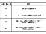
- a 2-bit area can be secured for the eNB to request A-CSI (Aperiodic CSI) from the UE.
- A-CSI Aperiodic CSI
- the information shown in FIG. 8 can be transmitted by using the two bits.
- the 2 bits are ‘10’ and ‘11’, it is specified in the current LTE system that the operation given from the upper layer is performed.
- the setting in the upper layer can be changed by the above-described RRC signaling (CSI request setting).
- the CSI request setting of the two patterns can be changed to various settings by RRC signaling. Yes.
- the specification can cope with a high-speed communication environment change with a small amount of control information.
- modulation mode information is added to the CSI request setting set by this RRC signaling.
- the UE communicates using a plurality of LTE component carriers (CCs, serving cells) called a plurality of cells, but the plurality of CCs that can be used by the UE does not necessarily belong to the same eNB. May be configured by a plurality of different eNBs.
- CCs LTE component carriers
- the macro base station configures CC # 1 and # 2
- the pico eNB configures CC # 3.
- 256QAM is arranged at a higher density than the macro eNB, it is expected that it is often applied in a pico eNB that is close to the UE.
- CQI is calculated in 64QAM mode for CC # 1
- the CQI is notified to eNB by PUSCH
- CQI is calculated in 256QAM mode for CC # 3
- PUSCH is used by PUSCH.
- the CQI is notified to the eNB.
- the 64QAM mode is applied instead of the 256QAM mode. Is preferable.
- CC # 3 is set to calculate the CQI in the 64QAM mode. Even if the SINR is rapidly deteriorated by such setting and communication cannot be performed in the 256QAM mode, the mode can be changed to the 64QAM mode at high speed by the DCI format notified by the PDCCH.
- the modulation mode is set so that the mode is fixed for each CC as shown in FIG. May be.
- the modulation mode of CC # 3 it is necessary to change the modulation mode of CC # 3 to 64QAM mode, but by changing the CSI request setting by RRC signaling, as shown in FIG.
- the reference is made when calculating the CQI index notified from the UE to the eNB by the 2-bit value of the CSI request area in the DCI format notified by the PDCCH (or ePDCCH).
- a CQI table can be set. As a result, it is possible to transmit the CQI in CC # 2 while setting the modulation mode of CC # 3 to 256QAM without setting the CQI table to be referred to by changing the modulation mode setting by RRC signaling.
- the modulation mode can be set for each CC when there are a plurality of CCs.
- a plurality of eNBs it is possible for a plurality of eNBs to communicate with a UE in a coordinated manner, and a transmission mode for performing the coordinated communication is defined.
- the UE In order to perform cooperative communication, the UE preferably notifies CSI to a plurality of eNBs, and a mechanism called a multiple CSI process is specified. In the multiple CSI process, each UE can make multiple CSI reports on each CC.
- modulation is performed for each transmission point (eNB) in cooperative communication in which a transmission station is dynamically switched by individually setting a modulation mode for a plurality of CSI report processes (hereinafter also referred to as CSI processes) in one CC.
- the mode can be changed. That is, a different CQI table can be set for each CSI process by RRC signaling, and a CQI index based on the CQI table set (configured) by RRC signaling can be reported for each CSI process.
- the UE notifies the eNB of CQI in the 64QAM mode.
- the eNB determines that the received SINR of the UE is sufficiently high based on the received CQI, and notifies the UE to set to the 256QAM mode by RRC.
- the UE that has received the RRC notifies the eNB that the setting of the 256QAM mode has been completed. Thereafter, the eNB performs transmission in the 256QAM mode.
- the modulation mode setting for each CC in the system is configured by initial setting or RRC.
- the UE notifies the eNB of the CQI in the 64QAM mode with a certain CC.
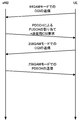
- the eNB determines that it is better to set the 256QAM mode based on the received CQI, the eNB requests the UE for CQI feedback in the 256QAM mode in the CC using the CSI request area of the PDCCH.
- a DCI format for notifying uplink data transmission that is, PUSCH resource allocation, is used.
- the UE that has received the PDCCH calculates a CQI in the CC, calculates a CQI index using a CQI table in the 256QAM mode, and transmits the CQI index using a PUSCH in a predetermined CC.
- the eNB that has received the PUSCH selects an appropriate MCS using the notified CQI in the 256QAM mode, and transmits the PDSCH in the 256QAM mode.
- the modulation mode change by RRC there is no CQI after the mode change and an appropriate MCS may not be selected.
- the modulation mode setting by RRC signaling is set for the UE.
- the modulation mode may be set in association with the value of the CSI request area. For example, in the case of “10”, the 64QAM mode may be set, and in the case of “11”, the 256QAM mode may be set.
- FIG. 12 shows an example in which when a CSI transmission request is detected in a CC in which 256QAM mode is set, the UE notifies the CQI in 256QAM mode and then receives the PDSCH transmitted in 256QAM mode from the eNB. .
- the UE may transmit the 64QAM mode. That is, the modulation mode may be switched by transmitting 256-QAM mode A-CSI.
- the MCS determination unit 207 can determine the MCS table to be referred to according to the modulation mode setting notified by the RRC, but the MCS determination unit 207 further determines the MCS to be referred to by a different method.
- a table can be selected.
- the eNB notifies the UE of the CSI request setting by RRC signaling, and the UE notifies that the CSI request setting has been applied (configured). For example, consider the case where the CSI request setting is set as shown in FIG.
- the DCI format uses the 64QAM mode in CC # 1 and the 256QAM mode in CC # 3, regardless of the modulation mode setting by RRC.
- the MCS table can be selected.
- the MCS determination unit 207 extracts the DCI format input from the control information generation unit 209, the CSI request setting generated by the RRC generation unit 210, and that the CSI request setting is applied by the UE.
- the extraction unit 205 can generate an MCS index.
- the method of changing the modulation mode at a higher speed than RRC is disclosed by the CSI request region included in the PDCCH.
- a method for changing the modulation mode at high speed using a method other than the CSI request region is disclosed.
- PUCCH has an area called USS (UE-specific Search Space) and an area called CSS (Common Search Space), and eNB places control information (assignment information, MCS, etc.) addressed to UE in USS and CSS. be able to.
- the UE checks both the USS and CSS, and checks for the presence of control information addressed to itself.
- the USS and CSS modulation modes are associated as shown in FIG. FIG. 13 is an example, and the relationship between USS and CSS may be reversed.
- the MCS index notified by the USS is set to 256QAM mode and the MCS index notified by the CSS is set to 64QAM mode
- the control information is transmitted using the USS. Notice. Since the control information addressed to the UE is included in the USS, the UE determines the MCS of the PDSCH using the notified MCS index and the MCS table in the 256QAM mode. If the eNB determines that the channel state changes abruptly and a higher throughput characteristic is obtained in the 64QAM mode than in the 256QAM mode, the control information is notified in the CSS in order to change to the 64QAM mode.
- the association between USS and CSS can be set (configured) by RRC signaling. Also good.
- the modulation mode change is not necessary when the channel state is stationary, and is necessary when the UE moves at high speed. Therefore, basically, the modulation mode is changed by RRC, and only in the transient state from when the eNB notifies the setting by RRC until the UE notifies the eNB that the setting is completed.
- the control information in the USS and CSS may be replaced.
- the modulation mode change may be performed only for the CC to which the PDCCH is transmitted, or the modulation mode change may be applied to all CCs.
- ePDCCH enhanced PDCCH
- the ePDCCH can notify the control information using a part of the PDSCH area instead of the conventional PDCCH area. Therefore, as described above, the modulation mode is not changed depending on whether the DCI format is allocated to the USS or the CSS, but the DCI format is allocated to the ePDCCH or the PDCCH (USS or CSS).
- the modulation mode may be changed based on whether or not the CQI index is fed back to the eNB using a CQI table corresponding to the changed modulation mode. Also, the modulation mode may be changed depending on whether it is allocated in the CSS of the PDCCH or the USS of the PDCCH or ePDCCH, and at least one of the CQI table or MCS table to be referred to may be selected.
- the UE changes the modulation mode depending on whether the control information is arranged in the USS of the PDCCH or the CSS.
- the modulation mode can be changed without depending on RRC.
- the modulation mode can be made to follow the change of the channel state, so that the throughput can be increased.
- the control information generation unit 209 when the eNB requests a CSI report from the UE, the control information generation unit 209 generates the PDCCH so that the DCI format including the CSI request area is arranged in the USS.
- the UE decodes the DCI format addressed to the own station arranged in the USS.
- the CQI determination unit 707 uses the CQI table in the 256QAM mode (for example, FIG. 4).
- the control information generation unit 209 arranges in the DCI format CSS including the CSI request area. In this way, the eNB can request the CQI index in different modulation modes from the UE in the control information generation unit 209 depending on whether the DCI format is allocated in the USS or the CSS. Note that the switching of the modulation mode by the arrangement of USS and CSS is not limited to the above.
- a CQI index different from the modulation mode set by RRC signaling when a CQI index different from the modulation mode set by RRC signaling is requested, a DCI format is arranged in the USS, and a CQI index by the same modulation mode is requested.
- a CQI index in a different modulation mode may be requested by arranging a DCI format in the CSS.
- the CSI request is made in a format including PUSCH resource allocation called DCI format 0 and DCI format 4.
- DCI format 0 is a format for transmitting PUSCH with a single antenna
- DCI format 4 is a format for transmitting PUSCH with multiple antennas.
- DCI formats 0 and 4 are notified from the eNB to the UE by PDCCH.
- the multi-antenna transmission can improve the SINR as compared with the single antenna transmission. That is, there is a high probability that transmission with 256QAM can be performed without error. Therefore, when the eNB generates DCI format 4 in the control information generation unit 209 and detects DCI format 4 in the control information extraction unit 703 of the UE, when a transmission request for aperiodic CSI is set in the CSI request region
- the CQI determination unit 707 generates a CQI index based on the 256QAM mode CQI table.
- the generated CQI index is input to the PUSCH generation unit 710, and is transmitted to the eNB via the UL transmission unit 711 and the transmission antenna 712.
- single antenna transmission has a lower SINR than multi-antenna transmission. That is, 256QAM has a high probability of error.
- the CQI determination is performed when a non-periodic CSI transmission request is set in the CSI request region.
- Unit 707 generates a CQI index based on the CQI table in the 64QAM mode, as in the conventional LTE system.
- the generated CQI index is input to the PUSCH generation unit 710, and is transmitted to the eNB via the UL transmission unit 711 and the transmission antenna 712.
- the CQI table to be referenced based on the type of DCI format that the eNB notifies the UE, the CQI obtained by changing the CQI table that is referred to at a higher speed than the notification by RRC can be fed back.
- a 2-bit CSI request area can be set in DCI format 4 and DCI format 0. Therefore, as in the first embodiment, the modulation mode of each CC and each CSI report is changed using a value that can be set by RRC in the 2-bit CSI request area of DCI format 0 and DCI format 4. May be.
- the CQI table to be referred to is changed depending on the area where the DCI format is arranged (USS or CSS), but the present embodiment is not limited to this.
- setting the CQI table to be referred to by the subframe number that received the DCI format or the subframe number that notifies the CQI index is also included in the present invention.
- the CQI table and the MCS table to be referred to may be set by uplink-downlink setting in dynamic TDD without being limited to the subframe number.
- the CQI table currently used in LTE is shown in FIG. 3, and the MCS table shown in FIG. 5 is used.
- CQI indexes 0 and 1 indicate the same frequency utilization efficiency. That is, when the index is 0 or 1, the same channel quality is shown even when different modulation modes are selected between the eNB and the UE.
- an index in which the channel quality indicated by the index is the same in each modulation mode is intentionally created as described above.
- FIG. 14 shows a CQI index in the 256QAM mode in this embodiment.
- the indexes surrounded by the thick lines are added in the 256QAM mode, and are indexes for requesting transmission of 256QAM.
- An index not surrounded by a thick line is a request for transmission in the same MCS as in the 64QAM mode (FIG. 3). For example, consider a case where the UE is notified of the change from the eNB to the 256QAM mode and has set the UE, but has not notified the eNB that the RRC setting has been completed because no PUSCH is assigned.
- the CQI needs to be notified from the UE to the eNB by periodic CSI or the like, but the UE is set to the 256QAM mode, but the eNB determines that the UE is still in the 64QAM mode. . In this case, it is determined that the notified CQI index has a different channel quality.
- the CQI index (that is, 0, 1, 3, 5, 7 to 12) not surrounded by the thick line in the CSI table of FIG. Is used to notify CQI.
- the eNB can select an appropriate MCS even by referring to the CQI table in the 64QAM mode, so that transmission errors due to different reference CQI tables can be limited.
- the CQI table index and information are shared by a plurality of tables, and the MCS table is also shared in the same manner, so that transmission errors due to different reference MCS tables can be eliminated.
- the 256QAM mode is arranged so that the coding rate of 256QAM is in ascending order.
- the present invention is not limited to this, and any code can be used, such as a descending order or a least square error. Good.
- the index indicating different information in a plurality of tables is set to 256 QAM with three equally spaced and three consecutive, but the present invention is not limited to this.
- the program that operates in the base station and the terminal related to the present invention is a program (a program that causes a computer to function) that controls the CPU and the like so as to realize the functions of the above-described embodiments related to the present invention.
- Information handled by these devices is temporarily stored in the RAM at the time of processing, then stored in various ROMs and HDDs, read out by the CPU, and corrected and written as necessary.
- a recording medium for storing the program a semiconductor medium (for example, ROM, nonvolatile memory card, etc.), an optical recording medium (for example, DVD, MO, MD, CD, BD, etc.), a magnetic recording medium (for example, magnetic tape, Any of a flexible disk etc. may be sufficient.
- the processing is performed in cooperation with the operating system or other application programs.
- the functions of the invention may be realized.
- the program when distributing to the market, can be stored and distributed on a portable recording medium, or transferred to a server computer connected via a network such as the Internet.
- the storage device of the server computer is also included in the present invention.
- part or all of the base station and the terminal in the above-described embodiment may be realized as an LSI that is typically an integrated circuit.
- Each functional block of the base station and the terminal may be individually chipped, or a part or all of them may be integrated into a chip.
- the method of circuit integration is not limited to LSI, and may be realized by a dedicated circuit or a general-purpose processor. When each functional block is integrated, an integrated circuit controller for controlling them is added.
- the method of circuit integration is not limited to LSI, and may be realized by a dedicated circuit or a general-purpose processor.
- an integrated circuit based on the technology can also be used.
- the terminal of the present invention is not limited to the above-described embodiment.
- the terminal of the present invention is not limited to application to a mobile station device, but is a stationary or non-movable electronic device installed indoors or outdoors, such as AV equipment, kitchen equipment, cleaning / washing equipment, Needless to say, it can be applied to air-conditioning equipment, office equipment, vending machines, and other daily life equipment.
- the present invention is suitable for use in wireless base stations, wireless terminals, wireless communication systems, and wireless communication methods.
- RRC extraction unit 706 ... channel estimation unit, 707 ... CQI determination unit, 708 ... RRC setting unit, 709 ... PUCCH Generating unit, 710 ... PUSCH generation unit, 711 ... UL transmission unit, 712 ... transmission antenna
Landscapes
- Engineering & Computer Science (AREA)
- Signal Processing (AREA)
- Computer Networks & Wireless Communication (AREA)
- Quality & Reliability (AREA)
- Mobile Radio Communication Systems (AREA)
Abstract
Description
以下、図面を参照しながら、本発明の第1の実施形態について説明する。図1は、本実施形態における無線通信システムの構成の一例を示す。該システムは、マクロ基地局装置101、ピコ基地局装置102、端末装置103から構成される。マクロ基地局装置101がカバーするエリア110とピコ基地局装置102がカバーするエリア111が存在し、端末装置は所定の条件によって、マクロ基地局装置101およびピコ基地局装置102との接続を行なう。装置のアンテナポート数は1であっても複数であってもよい。ここでアンテナポート数とは、物理的なアンテナ数ではなく、通信を行なう装置が認識できる論理的なアンテナ数を指す。またピコ基地局装置は基地局装置でなくてもよく、端末装置と端末装置が直接通信を行なう場合のクラスタヘッドと呼ばれる装置であってもよい。 [First Embodiment]
Hereinafter, a first embodiment of the present invention will be described with reference to the drawings. FIG. 1 shows an example of the configuration of a wireless communication system in the present embodiment. The system includes a macro
第1の実施形態では、PDCCHに含まれるCSI要求領域によって、RRCよりも高速に変調モードを変更する方法を開示した。本実施形態では、CSI要求領域以外の方法を用いて、高速に変調モードを変更する方法を開示する。 [Second Embodiment]
In the first embodiment, the method of changing the modulation mode at a higher speed than RRC is disclosed by the CSI request region included in the PDCCH. In this embodiment, a method for changing the modulation mode at high speed using a method other than the CSI request region is disclosed.
eNBからUEにCSI要求があった場合に、UEがeNBにフィードバックするCQIインデックスに関して、複数のCQIテーブルのいずれのCQIテーブルに基づいてCQIインデックスを生成するかについて、別の実施形態を示す。 [Third Embodiment]
Another embodiment is shown about which CQI index is generated based on which CQI table of a plurality of CQI tables with respect to the CQI index that the UE feeds back to the eNB when there is a CSI request from the eNB to the UE.
RRCによって変調モード変更を行なう場合、UEからRRCでの設定を完了したことが通知されるまでPDSCH等の通信を行なわないことが可能である。しかしながら、RRCはPUSCHによって送信されるため、アップリンクのリソース割り当てが行なわれない限り、PDSCHを送信できないことになってしまう。UEからの設定完了の通知を受信する前に、変更前の変調モード(あるいは変更後の変調モード)でPDSCHを送信することは可能であるが、UEが変調モードを変更していた場合(あるいは変更していなかった場合)、送受信で参照すべきMCSテーブルに齟齬が生じてしまい、正しくデータを復調・復号することができない。そこで本実施形態ではUEからRRCでの設定完了の通知を受ける前に、変調モード変更後のMCSでの伝送を可能とする方法を開示する。 [Fourth Embodiment]
When the modulation mode is changed by RRC, it is possible not to perform communication such as PDSCH until the UE notifies that the setting by RRC has been completed. However, since RRC is transmitted by PUSCH, PDSCH cannot be transmitted unless uplink resource allocation is performed. Before receiving the notification of the completion of setting from the UE, it is possible to transmit the PDSCH in the modulation mode before the change (or the modulation mode after the change), but the UE has changed the modulation mode (or If it has not been changed), the MCS table to be referred to in transmission / reception is wrinkled, and data cannot be demodulated / decoded correctly. Therefore, this embodiment discloses a method for enabling transmission in the MCS after changing the modulation mode before receiving notification of completion of setting in RRC from the UE.
Claims (9)
- 複数のCQIテーブルを備える端末装置であって、
前記端末装置は、基地局装置から通知される制御情報に関する情報を抽出する制御情報抽出部と、
前記制御情報に関する情報と、前記複数のCQIテーブルの中の1つのCQIテーブルを関連付けた設定を行なうRRC設定部と、
前記制御情報と前記設定に基づいて前記複数のCQIテーブルのうち1つのCQIテーブルを設定し、CQIインデックスを生成するCQI決定部と、を備えることを特徴とする端末装置。 A terminal device comprising a plurality of CQI tables,
The terminal device, a control information extraction unit that extracts information on control information notified from the base station device,
An RRC setting unit configured to associate information related to the control information and one CQI table among the plurality of CQI tables;
A terminal apparatus comprising: a CQI determination unit configured to set one CQI table among the plurality of CQI tables based on the control information and the setting and generate a CQI index. - 前記制御情報に関する情報は、PDCCHあるいはePDCCHに含まれる制御情報であることを特徴とする請求項1記載の端末装置。 The terminal apparatus according to claim 1, wherein the information related to the control information is control information included in a PDCCH or ePDCCH.
- 前記制御情報に関する情報は、PDCCHあるいはePDCCHの探索領域の種類であることを特徴とする請求項1記載の端末装置。 The terminal apparatus according to claim 1, wherein the information related to the control information is a type of a search area for PDCCH or ePDCCH.
- 前記PDCCHあるいはePDCCHに含まれる制御情報は、CSI要求領域であることを特徴とする請求項2記載の端末装置。 The terminal apparatus according to claim 2, wherein the control information included in the PDCCH or ePDCCH is a CSI request area.
- 前記RRC設定部の設定は、CC毎に設定可能とする特徴とする請求項1から請求項4のいずれかに記載の端末装置。 The terminal device according to any one of claims 1 to 4, wherein the setting of the RRC setting unit can be set for each CC.
- 端末装置へ通知される制御情報を生成する制御情報生成部を備える基地局装置であって、
前記基地局装置は、複数のMCSテーブルの中の1つのMCSテーブルと前記制御情報を関連付けた設定を生成するRRC情報生成部と、
前記制御情報と前記RRC情報生成部が生成する設定に基づいてMCSインデックスを設定するMCS決定部と、を備えることを特徴とする基地局装置。 A base station device including a control information generation unit that generates control information notified to a terminal device,
The base station device generates an RRC information generation unit that generates a setting in which one MCS table of a plurality of MCS tables and the control information are associated with each other;
An MCS determination unit configured to set an MCS index based on the control information and the setting generated by the RRC information generation unit. - 前記制御情報に関する情報は、PDCCHあるいはePDCCHに含まれる制御情報であることを特徴とする請求項6記載の基地局装置。 The base station apparatus according to claim 6, wherein the information related to the control information is control information included in PDCCH or ePDCCH.
- PDCCHあるいはePDCCHに含まれる制御情報は、CSI要求領域であることを特徴とする請求項6記載の基地局装置。 The base station apparatus according to claim 6, wherein the control information included in the PDCCH or ePDCCH is a CSI request region.
- 前記RRC情報生成部は、CC毎に設定可能とする特徴とする請求項6から請求項8のいずれかに記載の基地局装置。 The base station apparatus according to any one of claims 6 to 8, wherein the RRC information generation unit can be set for each CC.
Priority Applications (4)
| Application Number | Priority Date | Filing Date | Title |
|---|---|---|---|
| CN201480063617.6A CN105766021B (en) | 2013-12-27 | 2014-12-26 | Terminal installation and base station apparatus |
| JP2015555071A JPWO2015099172A1 (en) | 2013-12-27 | 2014-12-26 | Terminal apparatus and base station apparatus |
| US15/107,510 US10757726B2 (en) | 2013-12-27 | 2014-12-26 | Terminal device, base station device, and communication method using channel quality indicator (CQI) tables and modulation coding scheme (MCS) tables to determine modulation scheme |
| EP14875328.8A EP3089512A4 (en) | 2013-12-27 | 2014-12-26 | Terminal device and base station device |
Applications Claiming Priority (2)
| Application Number | Priority Date | Filing Date | Title |
|---|---|---|---|
| JP2013270703 | 2013-12-27 | ||
| JP2013-270703 | 2013-12-27 |
Publications (1)
| Publication Number | Publication Date |
|---|---|
| WO2015099172A1 true WO2015099172A1 (en) | 2015-07-02 |
Family
ID=53479010
Family Applications (1)
| Application Number | Title | Priority Date | Filing Date |
|---|---|---|---|
| PCT/JP2014/084688 WO2015099172A1 (en) | 2013-12-27 | 2014-12-26 | Terminal device and base station device |
Country Status (5)
| Country | Link |
|---|---|
| US (1) | US10757726B2 (en) |
| EP (1) | EP3089512A4 (en) |
| JP (2) | JPWO2015099172A1 (en) |
| CN (1) | CN105766021B (en) |
| WO (1) | WO2015099172A1 (en) |
Cited By (2)
| Publication number | Priority date | Publication date | Assignee | Title |
|---|---|---|---|---|
| JP2017510098A (en) * | 2014-01-30 | 2017-04-06 | インテル・コーポレーション | Mechanism for 256-QAM compliant user equipment that operates seamlessly with nodes |
| JP2020523913A (en) * | 2017-06-16 | 2020-08-06 | 華為技術有限公司Huawei Technologies Co.,Ltd. | Channel quality feedback method and apparatus |
Families Citing this family (17)
| Publication number | Priority date | Publication date | Assignee | Title |
|---|---|---|---|---|
| US10284349B2 (en) * | 2014-03-20 | 2019-05-07 | Sharp Kabushiki Kaisha | Terminal apparatus, base station apparatus, and integrated circuit |
| CN106063214B (en) * | 2014-03-21 | 2019-07-02 | 株式会社Kt | For sending and receiving the method and its equipment of channel state information |
| CN104202115B (en) * | 2014-05-09 | 2019-05-07 | 中兴通讯股份有限公司 | The modulation processing method and device, base station, terminal of high-order coding |
| US10230562B2 (en) * | 2014-05-23 | 2019-03-12 | Lg Electronics Inc. | Method and device for supporting 256QAM in wireless access system |
| EP3257180B1 (en) * | 2015-02-09 | 2019-10-02 | Telefonaktiebolaget LM Ericsson (publ) | Implementation of harq on pusch for multiple carriers |
| JP2018064128A (en) * | 2015-02-26 | 2018-04-19 | シャープ株式会社 | Terminal device, base station device, and communication method |
| MY182312A (en) * | 2015-06-22 | 2021-01-19 | Ericsson Telefon Ab L M | Blanking pattern indication for resource utilization in cellular radio communication |
| KR20180084735A (en) * | 2015-11-13 | 2018-07-25 | 광동 오포 모바일 텔레커뮤니케이션즈 코포레이션 리미티드 | Radio resource allocation method and apparatus |
| US10608856B2 (en) * | 2016-06-16 | 2020-03-31 | Samsung Electronics Co., Ltd. | Transmission of reference signals in a communication system |
| JP6903450B2 (en) * | 2017-02-23 | 2021-07-14 | 株式会社Nttドコモ | User terminal and cell selection method |
| US10708112B2 (en) * | 2018-01-12 | 2020-07-07 | At&T Intellectual Property I, L.P. | Dynamic indication of higher order modulation and coding scheme table |
| CN111034319A (en) * | 2018-02-23 | 2020-04-17 | Oppo广东移动通信有限公司 | Dynamic configuration method, terminal device, network device and computer storage medium |
| CN110830158B (en) * | 2018-08-10 | 2022-07-12 | 华为技术有限公司 | Method and communication device for transmitting uplink control information |
| US11742908B2 (en) * | 2019-11-04 | 2023-08-29 | Qualcomm Incorporated | Wireless device cooperative transmission schemes |
| KR102568331B1 (en) | 2020-08-24 | 2023-08-18 | 한국전자통신연구원 | Method and appratus for channel state information feedback in communication system |
| US11483203B2 (en) | 2020-10-28 | 2022-10-25 | Charter Communications Operating, Llc | Methods and apparatus for enhancing scheduler fairness in small-cell wireless systems |
| US11569931B2 (en) * | 2020-10-30 | 2023-01-31 | Charter Communications Operating, Llc | Methods and apparatus for enhancing wireless link throughput in small-cell wireless systems |
Family Cites Families (7)
| Publication number | Priority date | Publication date | Assignee | Title |
|---|---|---|---|---|
| CN101499877B (en) * | 2008-01-31 | 2011-07-06 | 展讯通信(上海)有限公司 | HSDPA medium and high order modulated downlink signaling transmission method for TD-SCDMA system |
| GB2499671B (en) * | 2012-02-27 | 2014-04-09 | Broadcom Corp | Apparatus and method for communication |
| CN103297181B (en) | 2012-03-02 | 2017-04-12 | 华为技术有限公司 | Information transmission method and device |
| US9432168B2 (en) * | 2012-12-19 | 2016-08-30 | Lg Electronics Inc. | Method and apparatus for transmitting and receiving channel status information (CSI) for supporting 256QAM in wireless access system |
| CN110224787B (en) * | 2013-03-22 | 2022-10-28 | 富士通互联科技有限公司 | User equipment and method for calculating channel quality indication index |
| WO2014194534A1 (en) * | 2013-06-08 | 2014-12-11 | 华为技术有限公司 | Channel quality indicator and notification method and device for modulation and coding scheme |
| EP3042520B1 (en) * | 2013-09-03 | 2020-12-09 | Samsung Electronics Co., Ltd | A method for the measurement and reporting of channel quality, modulation and channel coding information, and corresponding apparatus |
-
2014
- 2014-12-26 WO PCT/JP2014/084688 patent/WO2015099172A1/en active Application Filing
- 2014-12-26 US US15/107,510 patent/US10757726B2/en active Active
- 2014-12-26 EP EP14875328.8A patent/EP3089512A4/en not_active Ceased
- 2014-12-26 CN CN201480063617.6A patent/CN105766021B/en active Active
- 2014-12-26 JP JP2015555071A patent/JPWO2015099172A1/en active Pending
-
2018
- 2018-12-06 JP JP2018229408A patent/JP2019047520A/en active Pending
Non-Patent Citations (7)
| Title |
|---|
| 3RD GENERATION PARTNERSHIP PROJECT: "Evolved Universal Terrestrial Radio Access (E-UTRA); Multiplexing and channel coding", 3GPP TS36.212 |
| 3RD GENERATION PARTNERSHIP PROJECT: "Evolved Universal Terrestrial Radio Access (E-UTRA); Physical layer procedures", 3GPP TS36.213 |
| CATT: "Analysis on specification impact of higher order modulation", RL-135079,, 11 November 2013 (2013-11-11) - 15 November 2013 (2013-11-15) |
| ERICSSON: "On standard impacts to support 256QAM in downlink", 3GPP TSG RAN WG1 MEETING #75, R1- 135655, 11 November 2013 (2013-11-11), pages 1 - 3, XP050751115 * |
| HITACHI LTD.: "Views of Higher Order Modulation in Rel. 12", 3GPP TSG-RAN WG1 #75, R1-135873, 11 November 2013 (2013-11-11), pages 1 - 5, XP050751285 * |
| PANASONIC: "Specification Impact of Introducing 256QAM", RL-135395,, 11 November 2013 (2013-11-11) - 15 November 2013 (2013-11-15) |
| See also references of EP3089512A4 |
Cited By (3)
| Publication number | Priority date | Publication date | Assignee | Title |
|---|---|---|---|---|
| JP2017510098A (en) * | 2014-01-30 | 2017-04-06 | インテル・コーポレーション | Mechanism for 256-QAM compliant user equipment that operates seamlessly with nodes |
| JP2020523913A (en) * | 2017-06-16 | 2020-08-06 | 華為技術有限公司Huawei Technologies Co.,Ltd. | Channel quality feedback method and apparatus |
| US11177905B2 (en) | 2017-06-16 | 2021-11-16 | Huawei Technologies Co., Ltd. | Channel quality feedback method and apparatus |
Also Published As
| Publication number | Publication date |
|---|---|
| EP3089512A4 (en) | 2017-01-25 |
| CN105766021A (en) | 2016-07-13 |
| JPWO2015099172A1 (en) | 2017-03-23 |
| US20160323912A1 (en) | 2016-11-03 |
| CN105766021B (en) | 2019-06-04 |
| EP3089512A1 (en) | 2016-11-02 |
| JP2019047520A (en) | 2019-03-22 |
| US10757726B2 (en) | 2020-08-25 |
Similar Documents
| Publication | Publication Date | Title |
|---|---|---|
| WO2015099172A1 (en) | Terminal device and base station device | |
| US11291016B2 (en) | Downlink transmission method and user terminal equipment | |
| CN110086744B (en) | Terminal device and base station device | |
| JP6489584B2 (en) | High-order coding modulation processing method and apparatus, base station, and terminal | |
| CN106031283B (en) | Terminal device and base station device | |
| CN107079324B (en) | Base station device, terminal device, and communication method | |
| KR20150034808A (en) | Method and device for transmitting mcs indication information | |
| US20140301306A1 (en) | 256qam signal transmission/reception method and apparatus for use in mobile communication system | |
| US20090268624A1 (en) | Systems and methods for measurement and feedback of channel quality indicator information | |
| US10985863B2 (en) | Method and apparatus for transmitting transport block, and method and apparatus for receiving transport block | |
| KR20120106796A (en) | Method and apparatus for reporting a channel quality in a wireless communication system | |
| US20150312082A1 (en) | Method and apparatus for generating control information in wireless communication system | |
| JP6649268B2 (en) | Base station device, terminal device, and communication method | |
| CN104301067A (en) | DM-RS (Demodulation Reference Signal) pattern indicating method and device | |
| CN108886417B (en) | Base station device, terminal device, and communication method therefor | |
| KR20150124867A (en) | Apparatus and method for generating control information in wirelee communication systems |
Legal Events
| Date | Code | Title | Description |
|---|---|---|---|
| 121 | Ep: the epo has been informed by wipo that ep was designated in this application |
Ref document number: 14875328 Country of ref document: EP Kind code of ref document: A1 |
|
| ENP | Entry into the national phase |
Ref document number: 2015555071 Country of ref document: JP Kind code of ref document: A |
|
| WWE | Wipo information: entry into national phase |
Ref document number: 15107510 Country of ref document: US |
|
| NENP | Non-entry into the national phase |
Ref country code: DE |
|
| REEP | Request for entry into the european phase |
Ref document number: 2014875328 Country of ref document: EP |
|
| WWE | Wipo information: entry into national phase |
Ref document number: 2014875328 Country of ref document: EP |