WO2015093473A1 - Vehicle slip determination device - Google Patents
Vehicle slip determination device Download PDFInfo
- Publication number
- WO2015093473A1 WO2015093473A1 PCT/JP2014/083249 JP2014083249W WO2015093473A1 WO 2015093473 A1 WO2015093473 A1 WO 2015093473A1 JP 2014083249 W JP2014083249 W JP 2014083249W WO 2015093473 A1 WO2015093473 A1 WO 2015093473A1
- Authority
- WO
- WIPO (PCT)
- Prior art keywords
- wheel
- slip
- motor
- braking
- speed
- Prior art date
Links
- 238000000034 method Methods 0.000 description 39
- 230000008929 regeneration Effects 0.000 description 16
- 238000011069 regeneration method Methods 0.000 description 16
- 230000001133 acceleration Effects 0.000 description 13
- 230000005540 biological transmission Effects 0.000 description 10
- 238000006243 chemical reaction Methods 0.000 description 10
- 238000001514 detection method Methods 0.000 description 5
- 230000005611 electricity Effects 0.000 description 5
- 238000010586 diagram Methods 0.000 description 4
- 230000001172 regenerating effect Effects 0.000 description 3
- 230000002411 adverse Effects 0.000 description 1
- 239000000969 carrier Substances 0.000 description 1
- 238000002485 combustion reaction Methods 0.000 description 1
- 230000003247 decreasing effect Effects 0.000 description 1
- 230000009977 dual effect Effects 0.000 description 1
- 239000000446 fuel Substances 0.000 description 1
- 238000002347 injection Methods 0.000 description 1
- 239000007924 injection Substances 0.000 description 1
- 230000035939 shock Effects 0.000 description 1
Images


Classifications
-
- B—PERFORMING OPERATIONS; TRANSPORTING
- B60—VEHICLES IN GENERAL
- B60L—PROPULSION OF ELECTRICALLY-PROPELLED VEHICLES; SUPPLYING ELECTRIC POWER FOR AUXILIARY EQUIPMENT OF ELECTRICALLY-PROPELLED VEHICLES; ELECTRODYNAMIC BRAKE SYSTEMS FOR VEHICLES IN GENERAL; MAGNETIC SUSPENSION OR LEVITATION FOR VEHICLES; MONITORING OPERATING VARIABLES OF ELECTRICALLY-PROPELLED VEHICLES; ELECTRIC SAFETY DEVICES FOR ELECTRICALLY-PROPELLED VEHICLES
- B60L3/00—Electric devices on electrically-propelled vehicles for safety purposes; Monitoring operating variables, e.g. speed, deceleration or energy consumption
- B60L3/10—Indicating wheel slip ; Correction of wheel slip
- B60L3/102—Indicating wheel slip ; Correction of wheel slip of individual wheels
-
- B—PERFORMING OPERATIONS; TRANSPORTING
- B60—VEHICLES IN GENERAL
- B60W—CONJOINT CONTROL OF VEHICLE SUB-UNITS OF DIFFERENT TYPE OR DIFFERENT FUNCTION; CONTROL SYSTEMS SPECIALLY ADAPTED FOR HYBRID VEHICLES; ROAD VEHICLE DRIVE CONTROL SYSTEMS FOR PURPOSES NOT RELATED TO THE CONTROL OF A PARTICULAR SUB-UNIT
- B60W40/00—Estimation or calculation of non-directly measurable driving parameters for road vehicle drive control systems not related to the control of a particular sub unit, e.g. by using mathematical models
- B60W40/12—Estimation or calculation of non-directly measurable driving parameters for road vehicle drive control systems not related to the control of a particular sub unit, e.g. by using mathematical models related to parameters of the vehicle itself, e.g. tyre models
-
- B—PERFORMING OPERATIONS; TRANSPORTING
- B60—VEHICLES IN GENERAL
- B60K—ARRANGEMENT OR MOUNTING OF PROPULSION UNITS OR OF TRANSMISSIONS IN VEHICLES; ARRANGEMENT OR MOUNTING OF PLURAL DIVERSE PRIME-MOVERS IN VEHICLES; AUXILIARY DRIVES FOR VEHICLES; INSTRUMENTATION OR DASHBOARDS FOR VEHICLES; ARRANGEMENTS IN CONNECTION WITH COOLING, AIR INTAKE, GAS EXHAUST OR FUEL SUPPLY OF PROPULSION UNITS IN VEHICLES
- B60K1/00—Arrangement or mounting of electrical propulsion units
- B60K1/02—Arrangement or mounting of electrical propulsion units comprising more than one electric motor
-
- B—PERFORMING OPERATIONS; TRANSPORTING
- B60—VEHICLES IN GENERAL
- B60K—ARRANGEMENT OR MOUNTING OF PROPULSION UNITS OR OF TRANSMISSIONS IN VEHICLES; ARRANGEMENT OR MOUNTING OF PLURAL DIVERSE PRIME-MOVERS IN VEHICLES; AUXILIARY DRIVES FOR VEHICLES; INSTRUMENTATION OR DASHBOARDS FOR VEHICLES; ARRANGEMENTS IN CONNECTION WITH COOLING, AIR INTAKE, GAS EXHAUST OR FUEL SUPPLY OF PROPULSION UNITS IN VEHICLES
- B60K17/00—Arrangement or mounting of transmissions in vehicles
- B60K17/02—Arrangement or mounting of transmissions in vehicles characterised by arrangement, location, or kind of clutch
-
- B—PERFORMING OPERATIONS; TRANSPORTING
- B60—VEHICLES IN GENERAL
- B60K—ARRANGEMENT OR MOUNTING OF PROPULSION UNITS OR OF TRANSMISSIONS IN VEHICLES; ARRANGEMENT OR MOUNTING OF PLURAL DIVERSE PRIME-MOVERS IN VEHICLES; AUXILIARY DRIVES FOR VEHICLES; INSTRUMENTATION OR DASHBOARDS FOR VEHICLES; ARRANGEMENTS IN CONNECTION WITH COOLING, AIR INTAKE, GAS EXHAUST OR FUEL SUPPLY OF PROPULSION UNITS IN VEHICLES
- B60K17/00—Arrangement or mounting of transmissions in vehicles
- B60K17/04—Arrangement or mounting of transmissions in vehicles characterised by arrangement, location, or kind of gearing
- B60K17/06—Arrangement or mounting of transmissions in vehicles characterised by arrangement, location, or kind of gearing of change-speed gearing
- B60K17/08—Arrangement or mounting of transmissions in vehicles characterised by arrangement, location, or kind of gearing of change-speed gearing of mechanical type
-
- B—PERFORMING OPERATIONS; TRANSPORTING
- B60—VEHICLES IN GENERAL
- B60K—ARRANGEMENT OR MOUNTING OF PROPULSION UNITS OR OF TRANSMISSIONS IN VEHICLES; ARRANGEMENT OR MOUNTING OF PLURAL DIVERSE PRIME-MOVERS IN VEHICLES; AUXILIARY DRIVES FOR VEHICLES; INSTRUMENTATION OR DASHBOARDS FOR VEHICLES; ARRANGEMENTS IN CONNECTION WITH COOLING, AIR INTAKE, GAS EXHAUST OR FUEL SUPPLY OF PROPULSION UNITS IN VEHICLES
- B60K6/00—Arrangement or mounting of plural diverse prime-movers for mutual or common propulsion, e.g. hybrid propulsion systems comprising electric motors and internal combustion engines ; Control systems therefor, i.e. systems controlling two or more prime movers, or controlling one of these prime movers and any of the transmission, drive or drive units Informative references: mechanical gearings with secondary electric drive F16H3/72; arrangements for handling mechanical energy structurally associated with the dynamo-electric machine H02K7/00; machines comprising structurally interrelated motor and generator parts H02K51/00; dynamo-electric machines not otherwise provided for in H02K see H02K99/00
- B60K6/20—Arrangement or mounting of plural diverse prime-movers for mutual or common propulsion, e.g. hybrid propulsion systems comprising electric motors and internal combustion engines ; Control systems therefor, i.e. systems controlling two or more prime movers, or controlling one of these prime movers and any of the transmission, drive or drive units Informative references: mechanical gearings with secondary electric drive F16H3/72; arrangements for handling mechanical energy structurally associated with the dynamo-electric machine H02K7/00; machines comprising structurally interrelated motor and generator parts H02K51/00; dynamo-electric machines not otherwise provided for in H02K see H02K99/00 the prime-movers consisting of electric motors and internal combustion engines, e.g. HEVs
- B60K6/42—Arrangement or mounting of plural diverse prime-movers for mutual or common propulsion, e.g. hybrid propulsion systems comprising electric motors and internal combustion engines ; Control systems therefor, i.e. systems controlling two or more prime movers, or controlling one of these prime movers and any of the transmission, drive or drive units Informative references: mechanical gearings with secondary electric drive F16H3/72; arrangements for handling mechanical energy structurally associated with the dynamo-electric machine H02K7/00; machines comprising structurally interrelated motor and generator parts H02K51/00; dynamo-electric machines not otherwise provided for in H02K see H02K99/00 the prime-movers consisting of electric motors and internal combustion engines, e.g. HEVs characterised by the architecture of the hybrid electric vehicle
- B60K6/44—Series-parallel type
-
- B—PERFORMING OPERATIONS; TRANSPORTING
- B60—VEHICLES IN GENERAL
- B60K—ARRANGEMENT OR MOUNTING OF PROPULSION UNITS OR OF TRANSMISSIONS IN VEHICLES; ARRANGEMENT OR MOUNTING OF PLURAL DIVERSE PRIME-MOVERS IN VEHICLES; AUXILIARY DRIVES FOR VEHICLES; INSTRUMENTATION OR DASHBOARDS FOR VEHICLES; ARRANGEMENTS IN CONNECTION WITH COOLING, AIR INTAKE, GAS EXHAUST OR FUEL SUPPLY OF PROPULSION UNITS IN VEHICLES
- B60K6/00—Arrangement or mounting of plural diverse prime-movers for mutual or common propulsion, e.g. hybrid propulsion systems comprising electric motors and internal combustion engines ; Control systems therefor, i.e. systems controlling two or more prime movers, or controlling one of these prime movers and any of the transmission, drive or drive units Informative references: mechanical gearings with secondary electric drive F16H3/72; arrangements for handling mechanical energy structurally associated with the dynamo-electric machine H02K7/00; machines comprising structurally interrelated motor and generator parts H02K51/00; dynamo-electric machines not otherwise provided for in H02K see H02K99/00
- B60K6/20—Arrangement or mounting of plural diverse prime-movers for mutual or common propulsion, e.g. hybrid propulsion systems comprising electric motors and internal combustion engines ; Control systems therefor, i.e. systems controlling two or more prime movers, or controlling one of these prime movers and any of the transmission, drive or drive units Informative references: mechanical gearings with secondary electric drive F16H3/72; arrangements for handling mechanical energy structurally associated with the dynamo-electric machine H02K7/00; machines comprising structurally interrelated motor and generator parts H02K51/00; dynamo-electric machines not otherwise provided for in H02K see H02K99/00 the prime-movers consisting of electric motors and internal combustion engines, e.g. HEVs
- B60K6/42—Arrangement or mounting of plural diverse prime-movers for mutual or common propulsion, e.g. hybrid propulsion systems comprising electric motors and internal combustion engines ; Control systems therefor, i.e. systems controlling two or more prime movers, or controlling one of these prime movers and any of the transmission, drive or drive units Informative references: mechanical gearings with secondary electric drive F16H3/72; arrangements for handling mechanical energy structurally associated with the dynamo-electric machine H02K7/00; machines comprising structurally interrelated motor and generator parts H02K51/00; dynamo-electric machines not otherwise provided for in H02K see H02K99/00 the prime-movers consisting of electric motors and internal combustion engines, e.g. HEVs characterised by the architecture of the hybrid electric vehicle
- B60K6/48—Parallel type
-
- B—PERFORMING OPERATIONS; TRANSPORTING
- B60—VEHICLES IN GENERAL
- B60K—ARRANGEMENT OR MOUNTING OF PROPULSION UNITS OR OF TRANSMISSIONS IN VEHICLES; ARRANGEMENT OR MOUNTING OF PLURAL DIVERSE PRIME-MOVERS IN VEHICLES; AUXILIARY DRIVES FOR VEHICLES; INSTRUMENTATION OR DASHBOARDS FOR VEHICLES; ARRANGEMENTS IN CONNECTION WITH COOLING, AIR INTAKE, GAS EXHAUST OR FUEL SUPPLY OF PROPULSION UNITS IN VEHICLES
- B60K6/00—Arrangement or mounting of plural diverse prime-movers for mutual or common propulsion, e.g. hybrid propulsion systems comprising electric motors and internal combustion engines ; Control systems therefor, i.e. systems controlling two or more prime movers, or controlling one of these prime movers and any of the transmission, drive or drive units Informative references: mechanical gearings with secondary electric drive F16H3/72; arrangements for handling mechanical energy structurally associated with the dynamo-electric machine H02K7/00; machines comprising structurally interrelated motor and generator parts H02K51/00; dynamo-electric machines not otherwise provided for in H02K see H02K99/00
- B60K6/20—Arrangement or mounting of plural diverse prime-movers for mutual or common propulsion, e.g. hybrid propulsion systems comprising electric motors and internal combustion engines ; Control systems therefor, i.e. systems controlling two or more prime movers, or controlling one of these prime movers and any of the transmission, drive or drive units Informative references: mechanical gearings with secondary electric drive F16H3/72; arrangements for handling mechanical energy structurally associated with the dynamo-electric machine H02K7/00; machines comprising structurally interrelated motor and generator parts H02K51/00; dynamo-electric machines not otherwise provided for in H02K see H02K99/00 the prime-movers consisting of electric motors and internal combustion engines, e.g. HEVs
- B60K6/50—Architecture of the driveline characterised by arrangement or kind of transmission units
- B60K6/52—Driving a plurality of drive axles, e.g. four-wheel drive
-
- B—PERFORMING OPERATIONS; TRANSPORTING
- B60—VEHICLES IN GENERAL
- B60K—ARRANGEMENT OR MOUNTING OF PROPULSION UNITS OR OF TRANSMISSIONS IN VEHICLES; ARRANGEMENT OR MOUNTING OF PLURAL DIVERSE PRIME-MOVERS IN VEHICLES; AUXILIARY DRIVES FOR VEHICLES; INSTRUMENTATION OR DASHBOARDS FOR VEHICLES; ARRANGEMENTS IN CONNECTION WITH COOLING, AIR INTAKE, GAS EXHAUST OR FUEL SUPPLY OF PROPULSION UNITS IN VEHICLES
- B60K6/00—Arrangement or mounting of plural diverse prime-movers for mutual or common propulsion, e.g. hybrid propulsion systems comprising electric motors and internal combustion engines ; Control systems therefor, i.e. systems controlling two or more prime movers, or controlling one of these prime movers and any of the transmission, drive or drive units Informative references: mechanical gearings with secondary electric drive F16H3/72; arrangements for handling mechanical energy structurally associated with the dynamo-electric machine H02K7/00; machines comprising structurally interrelated motor and generator parts H02K51/00; dynamo-electric machines not otherwise provided for in H02K see H02K99/00
- B60K6/20—Arrangement or mounting of plural diverse prime-movers for mutual or common propulsion, e.g. hybrid propulsion systems comprising electric motors and internal combustion engines ; Control systems therefor, i.e. systems controlling two or more prime movers, or controlling one of these prime movers and any of the transmission, drive or drive units Informative references: mechanical gearings with secondary electric drive F16H3/72; arrangements for handling mechanical energy structurally associated with the dynamo-electric machine H02K7/00; machines comprising structurally interrelated motor and generator parts H02K51/00; dynamo-electric machines not otherwise provided for in H02K see H02K99/00 the prime-movers consisting of electric motors and internal combustion engines, e.g. HEVs
- B60K6/50—Architecture of the driveline characterised by arrangement or kind of transmission units
- B60K6/54—Transmission for changing ratio
- B60K6/547—Transmission for changing ratio the transmission being a stepped gearing
-
- B—PERFORMING OPERATIONS; TRANSPORTING
- B60—VEHICLES IN GENERAL
- B60K—ARRANGEMENT OR MOUNTING OF PROPULSION UNITS OR OF TRANSMISSIONS IN VEHICLES; ARRANGEMENT OR MOUNTING OF PLURAL DIVERSE PRIME-MOVERS IN VEHICLES; AUXILIARY DRIVES FOR VEHICLES; INSTRUMENTATION OR DASHBOARDS FOR VEHICLES; ARRANGEMENTS IN CONNECTION WITH COOLING, AIR INTAKE, GAS EXHAUST OR FUEL SUPPLY OF PROPULSION UNITS IN VEHICLES
- B60K7/00—Disposition of motor in, or adjacent to, traction wheel
- B60K7/0007—Disposition of motor in, or adjacent to, traction wheel the motor being electric
-
- B—PERFORMING OPERATIONS; TRANSPORTING
- B60—VEHICLES IN GENERAL
- B60L—PROPULSION OF ELECTRICALLY-PROPELLED VEHICLES; SUPPLYING ELECTRIC POWER FOR AUXILIARY EQUIPMENT OF ELECTRICALLY-PROPELLED VEHICLES; ELECTRODYNAMIC BRAKE SYSTEMS FOR VEHICLES IN GENERAL; MAGNETIC SUSPENSION OR LEVITATION FOR VEHICLES; MONITORING OPERATING VARIABLES OF ELECTRICALLY-PROPELLED VEHICLES; ELECTRIC SAFETY DEVICES FOR ELECTRICALLY-PROPELLED VEHICLES
- B60L15/00—Methods, circuits, or devices for controlling the traction-motor speed of electrically-propelled vehicles
- B60L15/20—Methods, circuits, or devices for controlling the traction-motor speed of electrically-propelled vehicles for control of the vehicle or its driving motor to achieve a desired performance, e.g. speed, torque, programmed variation of speed
- B60L15/2009—Methods, circuits, or devices for controlling the traction-motor speed of electrically-propelled vehicles for control of the vehicle or its driving motor to achieve a desired performance, e.g. speed, torque, programmed variation of speed for braking
-
- B—PERFORMING OPERATIONS; TRANSPORTING
- B60—VEHICLES IN GENERAL
- B60L—PROPULSION OF ELECTRICALLY-PROPELLED VEHICLES; SUPPLYING ELECTRIC POWER FOR AUXILIARY EQUIPMENT OF ELECTRICALLY-PROPELLED VEHICLES; ELECTRODYNAMIC BRAKE SYSTEMS FOR VEHICLES IN GENERAL; MAGNETIC SUSPENSION OR LEVITATION FOR VEHICLES; MONITORING OPERATING VARIABLES OF ELECTRICALLY-PROPELLED VEHICLES; ELECTRIC SAFETY DEVICES FOR ELECTRICALLY-PROPELLED VEHICLES
- B60L3/00—Electric devices on electrically-propelled vehicles for safety purposes; Monitoring operating variables, e.g. speed, deceleration or energy consumption
- B60L3/0023—Detecting, eliminating, remedying or compensating for drive train abnormalities, e.g. failures within the drive train
-
- B—PERFORMING OPERATIONS; TRANSPORTING
- B60—VEHICLES IN GENERAL
- B60L—PROPULSION OF ELECTRICALLY-PROPELLED VEHICLES; SUPPLYING ELECTRIC POWER FOR AUXILIARY EQUIPMENT OF ELECTRICALLY-PROPELLED VEHICLES; ELECTRODYNAMIC BRAKE SYSTEMS FOR VEHICLES IN GENERAL; MAGNETIC SUSPENSION OR LEVITATION FOR VEHICLES; MONITORING OPERATING VARIABLES OF ELECTRICALLY-PROPELLED VEHICLES; ELECTRIC SAFETY DEVICES FOR ELECTRICALLY-PROPELLED VEHICLES
- B60L3/00—Electric devices on electrically-propelled vehicles for safety purposes; Monitoring operating variables, e.g. speed, deceleration or energy consumption
- B60L3/10—Indicating wheel slip ; Correction of wheel slip
- B60L3/106—Indicating wheel slip ; Correction of wheel slip for maintaining or recovering the adhesion of the drive wheels
- B60L3/108—Indicating wheel slip ; Correction of wheel slip for maintaining or recovering the adhesion of the drive wheels whilst braking, i.e. ABS
-
- B—PERFORMING OPERATIONS; TRANSPORTING
- B60—VEHICLES IN GENERAL
- B60L—PROPULSION OF ELECTRICALLY-PROPELLED VEHICLES; SUPPLYING ELECTRIC POWER FOR AUXILIARY EQUIPMENT OF ELECTRICALLY-PROPELLED VEHICLES; ELECTRODYNAMIC BRAKE SYSTEMS FOR VEHICLES IN GENERAL; MAGNETIC SUSPENSION OR LEVITATION FOR VEHICLES; MONITORING OPERATING VARIABLES OF ELECTRICALLY-PROPELLED VEHICLES; ELECTRIC SAFETY DEVICES FOR ELECTRICALLY-PROPELLED VEHICLES
- B60L7/00—Electrodynamic brake systems for vehicles in general
- B60L7/10—Dynamic electric regenerative braking
-
- B—PERFORMING OPERATIONS; TRANSPORTING
- B60—VEHICLES IN GENERAL
- B60T—VEHICLE BRAKE CONTROL SYSTEMS OR PARTS THEREOF; BRAKE CONTROL SYSTEMS OR PARTS THEREOF, IN GENERAL; ARRANGEMENT OF BRAKING ELEMENTS ON VEHICLES IN GENERAL; PORTABLE DEVICES FOR PREVENTING UNWANTED MOVEMENT OF VEHICLES; VEHICLE MODIFICATIONS TO FACILITATE COOLING OF BRAKES
- B60T8/00—Arrangements for adjusting wheel-braking force to meet varying vehicular or ground-surface conditions, e.g. limiting or varying distribution of braking force
- B60T8/17—Using electrical or electronic regulation means to control braking
- B60T8/176—Brake regulation specially adapted to prevent excessive wheel slip during vehicle deceleration, e.g. ABS
- B60T8/1761—Brake regulation specially adapted to prevent excessive wheel slip during vehicle deceleration, e.g. ABS responsive to wheel or brake dynamics, e.g. wheel slip, wheel acceleration or rate of change of brake fluid pressure
- B60T8/17616—Microprocessor-based systems
-
- B—PERFORMING OPERATIONS; TRANSPORTING
- B60—VEHICLES IN GENERAL
- B60W—CONJOINT CONTROL OF VEHICLE SUB-UNITS OF DIFFERENT TYPE OR DIFFERENT FUNCTION; CONTROL SYSTEMS SPECIALLY ADAPTED FOR HYBRID VEHICLES; ROAD VEHICLE DRIVE CONTROL SYSTEMS FOR PURPOSES NOT RELATED TO THE CONTROL OF A PARTICULAR SUB-UNIT
- B60W10/00—Conjoint control of vehicle sub-units of different type or different function
- B60W10/04—Conjoint control of vehicle sub-units of different type or different function including control of propulsion units
- B60W10/08—Conjoint control of vehicle sub-units of different type or different function including control of propulsion units including control of electric propulsion units, e.g. motors or generators
-
- B—PERFORMING OPERATIONS; TRANSPORTING
- B60—VEHICLES IN GENERAL
- B60W—CONJOINT CONTROL OF VEHICLE SUB-UNITS OF DIFFERENT TYPE OR DIFFERENT FUNCTION; CONTROL SYSTEMS SPECIALLY ADAPTED FOR HYBRID VEHICLES; ROAD VEHICLE DRIVE CONTROL SYSTEMS FOR PURPOSES NOT RELATED TO THE CONTROL OF A PARTICULAR SUB-UNIT
- B60W30/00—Purposes of road vehicle drive control systems not related to the control of a particular sub-unit, e.g. of systems using conjoint control of vehicle sub-units
- B60W30/18—Propelling the vehicle
- B60W30/18172—Preventing, or responsive to skidding of wheels
-
- B—PERFORMING OPERATIONS; TRANSPORTING
- B60—VEHICLES IN GENERAL
- B60W—CONJOINT CONTROL OF VEHICLE SUB-UNITS OF DIFFERENT TYPE OR DIFFERENT FUNCTION; CONTROL SYSTEMS SPECIALLY ADAPTED FOR HYBRID VEHICLES; ROAD VEHICLE DRIVE CONTROL SYSTEMS FOR PURPOSES NOT RELATED TO THE CONTROL OF A PARTICULAR SUB-UNIT
- B60W40/00—Estimation or calculation of non-directly measurable driving parameters for road vehicle drive control systems not related to the control of a particular sub unit, e.g. by using mathematical models
- B60W40/10—Estimation or calculation of non-directly measurable driving parameters for road vehicle drive control systems not related to the control of a particular sub unit, e.g. by using mathematical models related to vehicle motion
- B60W40/105—Speed
-
- B—PERFORMING OPERATIONS; TRANSPORTING
- B60—VEHICLES IN GENERAL
- B60W—CONJOINT CONTROL OF VEHICLE SUB-UNITS OF DIFFERENT TYPE OR DIFFERENT FUNCTION; CONTROL SYSTEMS SPECIALLY ADAPTED FOR HYBRID VEHICLES; ROAD VEHICLE DRIVE CONTROL SYSTEMS FOR PURPOSES NOT RELATED TO THE CONTROL OF A PARTICULAR SUB-UNIT
- B60W50/00—Details of control systems for road vehicle drive control not related to the control of a particular sub-unit, e.g. process diagnostic or vehicle driver interfaces
- B60W50/0098—Details of control systems ensuring comfort, safety or stability not otherwise provided for
-
- B—PERFORMING OPERATIONS; TRANSPORTING
- B60—VEHICLES IN GENERAL
- B60W—CONJOINT CONTROL OF VEHICLE SUB-UNITS OF DIFFERENT TYPE OR DIFFERENT FUNCTION; CONTROL SYSTEMS SPECIALLY ADAPTED FOR HYBRID VEHICLES; ROAD VEHICLE DRIVE CONTROL SYSTEMS FOR PURPOSES NOT RELATED TO THE CONTROL OF A PARTICULAR SUB-UNIT
- B60W50/00—Details of control systems for road vehicle drive control not related to the control of a particular sub-unit, e.g. process diagnostic or vehicle driver interfaces
- B60W2050/0062—Adapting control system settings
- B60W2050/0075—Automatic parameter input, automatic initialising or calibrating means
- B60W2050/0083—Setting, resetting, calibration
- B60W2050/0088—Adaptive recalibration
-
- B—PERFORMING OPERATIONS; TRANSPORTING
- B60—VEHICLES IN GENERAL
- B60W—CONJOINT CONTROL OF VEHICLE SUB-UNITS OF DIFFERENT TYPE OR DIFFERENT FUNCTION; CONTROL SYSTEMS SPECIALLY ADAPTED FOR HYBRID VEHICLES; ROAD VEHICLE DRIVE CONTROL SYSTEMS FOR PURPOSES NOT RELATED TO THE CONTROL OF A PARTICULAR SUB-UNIT
- B60W2300/00—Indexing codes relating to the type of vehicle
- B60W2300/18—Four-wheel drive vehicles
-
- B—PERFORMING OPERATIONS; TRANSPORTING
- B60—VEHICLES IN GENERAL
- B60W—CONJOINT CONTROL OF VEHICLE SUB-UNITS OF DIFFERENT TYPE OR DIFFERENT FUNCTION; CONTROL SYSTEMS SPECIALLY ADAPTED FOR HYBRID VEHICLES; ROAD VEHICLE DRIVE CONTROL SYSTEMS FOR PURPOSES NOT RELATED TO THE CONTROL OF A PARTICULAR SUB-UNIT
- B60W2520/00—Input parameters relating to overall vehicle dynamics
- B60W2520/10—Longitudinal speed
-
- B—PERFORMING OPERATIONS; TRANSPORTING
- B60—VEHICLES IN GENERAL
- B60W—CONJOINT CONTROL OF VEHICLE SUB-UNITS OF DIFFERENT TYPE OR DIFFERENT FUNCTION; CONTROL SYSTEMS SPECIALLY ADAPTED FOR HYBRID VEHICLES; ROAD VEHICLE DRIVE CONTROL SYSTEMS FOR PURPOSES NOT RELATED TO THE CONTROL OF A PARTICULAR SUB-UNIT
- B60W2520/00—Input parameters relating to overall vehicle dynamics
- B60W2520/26—Wheel slip
-
- B—PERFORMING OPERATIONS; TRANSPORTING
- B60—VEHICLES IN GENERAL
- B60W—CONJOINT CONTROL OF VEHICLE SUB-UNITS OF DIFFERENT TYPE OR DIFFERENT FUNCTION; CONTROL SYSTEMS SPECIALLY ADAPTED FOR HYBRID VEHICLES; ROAD VEHICLE DRIVE CONTROL SYSTEMS FOR PURPOSES NOT RELATED TO THE CONTROL OF A PARTICULAR SUB-UNIT
- B60W2520/00—Input parameters relating to overall vehicle dynamics
- B60W2520/28—Wheel speed
-
- B—PERFORMING OPERATIONS; TRANSPORTING
- B60—VEHICLES IN GENERAL
- B60Y—INDEXING SCHEME RELATING TO ASPECTS CROSS-CUTTING VEHICLE TECHNOLOGY
- B60Y2200/00—Type of vehicle
- B60Y2200/90—Vehicles comprising electric prime movers
- B60Y2200/92—Hybrid vehicles
-
- Y—GENERAL TAGGING OF NEW TECHNOLOGICAL DEVELOPMENTS; GENERAL TAGGING OF CROSS-SECTIONAL TECHNOLOGIES SPANNING OVER SEVERAL SECTIONS OF THE IPC; TECHNICAL SUBJECTS COVERED BY FORMER USPC CROSS-REFERENCE ART COLLECTIONS [XRACs] AND DIGESTS
- Y02—TECHNOLOGIES OR APPLICATIONS FOR MITIGATION OR ADAPTATION AGAINST CLIMATE CHANGE
- Y02T—CLIMATE CHANGE MITIGATION TECHNOLOGIES RELATED TO TRANSPORTATION
- Y02T10/00—Road transport of goods or passengers
- Y02T10/60—Other road transportation technologies with climate change mitigation effect
- Y02T10/62—Hybrid vehicles
-
- Y—GENERAL TAGGING OF NEW TECHNOLOGICAL DEVELOPMENTS; GENERAL TAGGING OF CROSS-SECTIONAL TECHNOLOGIES SPANNING OVER SEVERAL SECTIONS OF THE IPC; TECHNICAL SUBJECTS COVERED BY FORMER USPC CROSS-REFERENCE ART COLLECTIONS [XRACs] AND DIGESTS
- Y02—TECHNOLOGIES OR APPLICATIONS FOR MITIGATION OR ADAPTATION AGAINST CLIMATE CHANGE
- Y02T—CLIMATE CHANGE MITIGATION TECHNOLOGIES RELATED TO TRANSPORTATION
- Y02T10/00—Road transport of goods or passengers
- Y02T10/60—Other road transportation technologies with climate change mitigation effect
- Y02T10/64—Electric machine technologies in electromobility
-
- Y—GENERAL TAGGING OF NEW TECHNOLOGICAL DEVELOPMENTS; GENERAL TAGGING OF CROSS-SECTIONAL TECHNOLOGIES SPANNING OVER SEVERAL SECTIONS OF THE IPC; TECHNICAL SUBJECTS COVERED BY FORMER USPC CROSS-REFERENCE ART COLLECTIONS [XRACs] AND DIGESTS
- Y02—TECHNOLOGIES OR APPLICATIONS FOR MITIGATION OR ADAPTATION AGAINST CLIMATE CHANGE
- Y02T—CLIMATE CHANGE MITIGATION TECHNOLOGIES RELATED TO TRANSPORTATION
- Y02T10/00—Road transport of goods or passengers
- Y02T10/60—Other road transportation technologies with climate change mitigation effect
- Y02T10/72—Electric energy management in electromobility
Definitions
- the present invention relates to a vehicle slip determination device that determines the occurrence of excess slip in a wheel driven or braked by an electric motor capable of generating electricity.
- Patent Document 1 As a control device for a vehicle having wheels driven or braked by an electric motor capable of generating electricity, for example, a device described in Patent Document 1 is known. This control device is applied to an electric vehicle that controls and drives wheels with an electric motor. This control device calculates the target torque of the positive (driving side) or negative (braking side) of the motor based on the detected accelerator opening and the rotational speed of the motor, and further applies a delay process to the target torque. The positive or negative command torque to the motor is calculated.
- the command torque output to the motor is set to 0 for a predetermined time thereafter. This prevents the occurrence of torque shock caused by backlash clogging in the power transmission system between the wheel and the motor when the driving / braking state of the wheel by the motor is switched, and improves drivability. ing.
- the present invention has been made to solve such a problem, and avoids erroneous determination of excess slip of the wheel at the time of switching of the driving / braking state of the wheel by the electric motor, thereby increasing the determination accuracy of excess slip.
- An object of the present invention is to provide a vehicle slip determination device that can be improved.
- the invention according to claim 1 is mechanically connected to an electric motor (first rear motor 41 and second rear motor 61 in the embodiment (hereinafter the same in this section)) and is driven by the electric motor.
- a slip determination device for a vehicle that determines whether or not an excess slip, which is a predetermined slip or more, has occurred on the braked wheels (left rear wheel WRL, right rear wheel WRR), Wheel speed parameter acquisition means (first motor rotation speed sensor 102a, second motor rotation speed sensor) for acquiring wheel speed parameters (first motor rotation speed NMOT1, second motor rotation speed NMOT2) representing one speed of the wheel and the motor.
- a basic speed parameter (wheel rotational speed NWFL, which represents at least one of the speed of the vehicle and the speed of another wheel different from the wheel
- Basic speed parameter acquisition means (wheel rotational speed sensors 101a to 101d) for acquiring WFR, NWRL, and NWRR, and a threshold value (reference rotational speed NMREF) used as a reference for determination of excess slip based on the acquired basic speed parameter )
- threshold value setting means (ECU 2, steps 25 and 26 in FIG. 8), and when the acquired wheel speed parameter reaches the set threshold value, it is determined that excessive slip has occurred in the wheel.
- Threshold changing means for changing the hardly made such longitudinal force second threshold for the time reversal, characterized in that it comprises a and (ECU 2, step 29 in FIG. 8).
- an electric motor is mechanically coupled to the wheel, and the wheel is driven or braked (braking / braking) by powering or regeneration of the electric motor.
- a wheel speed parameter representing one speed of the wheel and the electric motor is acquired.
- a basic speed parameter representing at least one of the speed of the vehicle and the speed of another wheel (wheel not connected to the electric motor) different from the wheel is acquired, and based on the acquired basic speed parameter, a predetermined value or more in the wheel is obtained.
- a threshold value is set as a criterion for determining an excess slip that is a slip of the above. And when the wheel speed parameter acquired as mentioned above reaches a threshold value, it determines with the excess slip having generate
- slip of a wheel means that the grip between the wheel and the road surface is lost, and the rotational movement distance of the outer periphery of the wheel coincides with the movement distance of the vehicle.
- This “idling” of the wheel is a phenomenon in which the vehicle does not travel a distance corresponding to one rotation of the wheel even if the wheel rotates idly with respect to the road surface, for example.
- sliding of a wheel is a phenomenon in which the wheel is locked during braking and slips on the road surface due to a decrease in frictional resistance between the wheel and the road surface.
- the threshold value is changed to a second threshold value for reversing the braking / driving force that makes it difficult for the wheel speed parameter to reach the threshold value.
- the invention according to claim 2 is mechanically connected to an electric motor (first rear motor 41 and second rear motor 61 in the embodiments (hereinafter, the same applies in this section)), and the electric motor A slip determination device for a vehicle (hybrid vehicle V) that determines whether an excess slip, which is a predetermined slip or more, has occurred on a driven or braked wheel (left rear wheel WRL, right rear wheel WRR).
- Wheel speed parameter acquisition means (first motor rotation speed sensor 102a, second motor rotation speed) for acquiring wheel speed parameters (first motor rotation speed NMOT1, second motor rotation speed NMOT2) representing one speed of the wheel and the motor.
- the slip determination means Determination prohibition means for prohibiting the determination of the excess slip by, characterized in that it comprises a and (ECU 2, step 51 in FIG. 12).
- the basic configuration of the vehicle and the slip determination device in the present invention is the same as that of the invention according to claim 1 described above. That is, in this vehicle, the wheel is mechanically connected to the electric motor, and is driven or braked (braking) by powering or regeneration of the electric motor.
- a wheel speed parameter representing one speed of the wheel and the electric motor is acquired.
- a basic speed parameter representing at least one of the speed of the vehicle and the speed of another wheel (wheel not connected to the electric motor) different from the wheel is acquired, and based on the acquired basic speed parameter, a predetermined value or more in the wheel is obtained.
- a threshold value is set as a criterion for determining an excess slip that is a slip of the above. And when the wheel speed parameter acquired as mentioned above reaches a threshold value, it determines with the excess slip having generate
- the determination of excess slip is prohibited.
- the wheel speed parameter temporarily changed due to the backlash clogging existing in the power transmission system between the electric motor and the wheel becomes the threshold value. It is possible to reliably avoid erroneous determination due to reaching and improve the determination accuracy of excess slip.
- FIG. 10 is a timing chart showing an operation example obtained by the processes of FIGS. 6 to 9.
- FIG. It is a flowchart which shows the subroutine of the calculation process of the reference
- a hybrid vehicle (hereinafter simply referred to as “vehicle”) V shown in FIG. 1 is a four-wheel vehicle having four wheels W (left and right front wheels WFL, WFR and left and right rear wheels WRL, WRR).
- the vehicle V is equipped with a front wheel drive device DFS for driving the front wheels WFL and WFR and a rear wheel drive device DRS for driving the rear wheels WRL and WRR.
- the front wheel drive device DFS is the same as that disclosed in, for example, Japanese Patent No. 5362922 by the present applicant, its configuration and operation will be briefly described below.
- the front wheel drive device DFS is an internal combustion engine (hereinafter referred to as “engine”) 3 as a power source, a front motor 4 constituted by an electric motor capable of generating electricity, and the power of the engine 3 and the front motor 4 are shifted, and the front wheels WFL, A transmission 5 for transmitting to the WFR is included.
- engine internal combustion engine
- the engine 3 is, for example, a gasoline engine, and the power of the engine 3 is controlled by controlling the intake air amount, the fuel injection amount, the ignition timing, and the like by an ECU 2 (see FIG. 3) described later.
- the front motor 4 is composed of, for example, a brushless DC motor, and has a stator and a rotor (both not shown).
- the stator is electrically connected to a chargeable / dischargeable battery 7 via a power drive unit (hereinafter referred to as “PDU”) 6.
- PDU 6 is configured by an electric circuit such as an inverter, and the operation of the front motor 4 is controlled by controlling the PDU 6 by the ECU 2.
- the vehicle V is equipped with an auxiliary machine 8 composed of an air conditioner compressor and the like, and a 12V battery (not shown).
- the auxiliary machine 8 is connected to the PDU 6 and the 12V battery is a DC / DC converter (not shown).
- the battery 7 is electrically connected.
- the transmission 5 is constituted by a so-called dual clutch transmission (DCT).
- the transmission 5 includes a first input shaft connected to the engine 3 via the first clutch, a planetary gear device disposed between the front motor 4 and the first input shaft, and a second clutch.
- a second input shaft connected to the engine 3 via the output shaft, an output shaft parallel to the first and second input shafts, a plurality of input gears rotatably provided on the first and second input shafts, and an output shaft
- a plurality of output gears meshed with the plurality of input gears one of the plurality of input gears is selectively connected to the first or second input shaft, and the input gear and the gear by the output gear meshing with the input gear It has a synchronizer that sets the stage.
- the ECU 2 controls the first and second clutches, the synchro device, etc., so that the power of the engine 3 and / or the power of the front motor 4 can be selected according to the connection / disconnection state of the first and second clutches.
- the input power is output to the output shaft while being shifted at a predetermined gear ratio by the gear set by the synchronizer, and further to the left and right via the differential 9 and the left and right front drive shafts SFL and SFR. Is transmitted to the front wheels WFL and WFR.
- the rear wheel drive device DRS includes a first rear motor 41, a first planetary gear device 51, a second rear motor 61, and a second planetary gear device 71. These components are arranged in the order of 41, 51, 71 and 61 between the left and right rear wheels WRL, WRR, and are provided coaxially with the left and right rear drive shafts SRL, SRR. One end portions of the rear drive shafts SRL and SRR are connected to the left and right rear wheels WRL and WRR, respectively.
- the first rear motor 41 is a brushless DC motor composed of an electric motor capable of generating electricity, like the front motor 4, and has a stator 42 and a rotatable rotor 43.
- the stator 42 is fixed to the casing CA and is electrically connected to the stator of the front motor 4 and the battery 7 via the PDU 6.
- the rotor 43 is provided integrally with a hollow rotary shaft 44, and this rotary shaft 44 is provided rotatably relative to the outside of the left rear drive shaft SRL.
- the electric power of the battery 7 or the electric power generated by the front motor 4 is supplied to the stator 42 by the control of the PDU 6 by the ECU 2, the electric power is converted into motive power, and the rotor 43 rotates ( Power running).
- the power of the rotor 43 is controlled according to the electric power supplied to the stator 42.
- power supply to the stator 42 is stopped, and the power is converted into electric power in a state where the rotor 43 is rotated by the input of power, and electric power is generated (regeneration), and the generated electric power is charged in the battery 7.
- the first planetary gear unit 51 is for decelerating the power of the first rear motor 41 and transmitting it to the left rear wheel WRL.
- the first sun gear 52, the first ring gear 53, the double pinion gear 54, and the first carrier 55 are used. have.
- the first sun gear 52 is provided integrally with the rotary shaft 44 described above, and rotates integrally with the rotor 43 of the first rear motor 41.
- the first ring gear 53 is integrally provided on the hollow rotating shaft 81.
- the double pinion gear 54 integrally includes a first pinion gear 54a and a second pinion gear 54b, and the number thereof is three (only two are shown).
- the double pinion gear 54 is rotatably supported by the first carrier 55, and the first pinion gear 54 a meshes with the first sun gear 52 and the second pinion gear 54 b meshes with the first ring gear 53.
- the first carrier 55 is provided integrally with the other end of the left rear drive shaft SRL, and rotates integrally therewith.
- the second rear motor 61 and the second planetary gear unit 71 are configured in the same manner as the first rear motor 41 and the first planetary gear unit 51 described above, the configuration will be briefly described below.
- the second rear motor 61 and the second planetary gear device 71 are arranged symmetrically with the first rear motor 41 and the first planetary gear device 51 around a one-way clutch 83 described later.
- the stator 62 of the second rear motor 61 is fixed to the casing CA and is electrically connected to the stator of the front motor 4, the battery 7 and the stator 42 of the first rear motor 41 via the PDU 6.
- the rotor 63 of the second rear motor 61 is provided integrally with a hollow rotary shaft 64, and the rotary shaft 64 is relatively rotatably provided outside the right rear drive shaft SRR.
- the electric power of the battery 7 or the electric power generated by the front motor 4 is supplied to the stator 62 by the control of the PDU 6 by the ECU 2, the electric power is converted into power and the rotor 63 rotates ( Power running).
- the power of the rotor 63 is controlled according to the electric power supplied to the stator 62.
- power supply to the stator 62 is stopped, and the power is converted into electric power in a state where the rotor 63 is rotated by input of power, and electric power is generated (regeneration), and the generated electric power is charged in the battery 7.
- the second planetary gear device 71 is for decelerating the power of the second rear motor 61 and transmitting it to the right rear wheel WRR.
- the second sun gear 72, the second ring gear 73, the double pinion gear 74, and the second carrier 75 are used. have.
- the number of teeth of second sun gear 72, second ring gear 73, and double pinion gear 74 is set to be the same as the number of teeth of first sun gear 52, first ring gear 53, and double pinion gear 54, respectively.
- the second sun gear 72 is provided integrally with the rotary shaft 64 described above, and rotates integrally with the rotor 63 of the second rear motor 61.
- the second ring gear 73 is integrally provided on the hollow rotary shaft 82.
- the rotating shaft 82 faces the rotating shaft 81 in the axial direction with a slight gap.
- the double pinion gear 74 is rotatably supported by the second carrier 75, and the first pinion gear 74 a meshes with the second sun gear 72 and the second pinion gear 74 b meshes with the second ring gear 73.
- the second carrier 75 is provided integrally with the other end of the right rear drive shaft SRR and rotates integrally therewith.
- the rear wheel drive device DRS further includes a one-way clutch 83 and a hydraulic brake 84.
- the one-way clutch 83 has an inner race 83a and an outer race 83b, and is disposed between the first and second planetary gear devices 51 and 71.
- the inner race 83a and the outer race 83b are drawn in the opposite direction from the actual arrangement for the purpose of illustration.
- the inner race 83a is splined to the rotary shafts 81 and 82 described above, whereby the inner race 83a, the rotary shafts 81 and 82, and the first and second ring gears 53 and 73 rotate integrally.
- the outer race 83b is fixed to the case CA.
- the one-way clutch 83 connects the rotary shafts 81 and 82 to the case CA when the power in the direction of reversing them is transmitted to the rotary shafts 81 and 82, so that the rotary shafts 81 and 82, While preventing the reverse rotation of the first and second ring gears 53 and 73, when the power in the direction of rotating them forward is transmitted to the rotary shafts 81 and 82, the rotary shafts 81 and 82 and the case CA are blocked. The forward rotation of the rotary shafts 81 and 82 and the first and second ring gears 53 and 73 is permitted.
- the hydraulic brake 84 is composed of a multi-plate clutch, is attached to the case CA and the rotating shafts 81 and 82, and is disposed on the radially outer side of the first and second planetary gear devices 51 and 71.
- the hydraulic brake 84 is controlled by the ECU 2 to select a braking operation for braking the first and second ring gears 53 and 73 and a rotation allowing operation for allowing the first and second ring gears 53 and 73 to rotate. Run it.
- the braking force of the hydraulic brake 84 is controlled by the ECU 2.
- the ECU 2 represents the wheel rotation speeds NWFL, NWFR, NWRR and NWRR which are rotation speeds of the left and right front wheels WFL, WFR and the rear wheels WRL, WRR from the wheel rotation speed sensors 101a to 101d.
- a detection signal is input.
- the ECU 2 calculates the speed (vehicle speed) VP of the vehicle V based on these detection signals and the diameter of the wheel W.
- the ECU 2 includes first and second motor rotation speed sensors 102a and 102b, and first and second motor rotation speeds NMOT1 and NMOT2, which are rotation speeds of the rotors 43 and 63 of the first and second rear motors 41 and 61. Is input as a detection signal. Further, the ECU 2 receives from the accelerator opening sensor 103 a detection signal that represents an accelerator opening AP that is a depression amount of an accelerator pedal (not shown) of the vehicle V.
- the ECU 2 is composed of a microcomputer including an I / O interface, CPU, RAM, ROM and the like.
- the ECU 2 calculates a required braking / driving force required for the vehicle V in accordance with the detection signals from the various sensors 101 to 103 described above, and based on the requested braking / driving force, the front wheel drive device DFS and the rear wheel drive are calculated. While determining the operation mode of the apparatus DRS, the required torque required for each wheel W is calculated. Based on the required torque, target torques of the engine 3, the front motor 4, the first and second rear motors 41 and 61 are set, and the operation of these components is controlled based on the set target torque. Thus, the wheel W is driven or braked to control the operation of the vehicle V.
- the ECU 2 corresponds to a threshold value setting unit, a slip determination unit, a braking / driving force acquisition unit, and a threshold value changing unit.
- the operation mode of the front wheel drive device DFS described above includes an ENG travel mode in which only the engine 3 is used as a power source for the vehicle V, an EV travel mode in which only the front motor 4 is used as a power source, and the engine 3 is assisted by the front motor 4.
- Assist travel mode charging travel mode in which the battery 7 is charged by the front motor 4 using a part of the power of the engine 3, and charging the battery 7 by the front motor 4 using travel energy during deceleration traveling of the vehicle V This includes the deceleration regeneration mode.
- the operation mode of the rear wheel drive device DRS includes a drive mode and a regeneration (braking) mode.
- these operation modes will be described in order.
- This drive mode is an operation in which the first and second rear motors 41 and 61 are powered using the electric power of the battery 7 and the left and right rear wheels WRL and WRR are driven by these powers while the vehicle V is accelerating. Mode.
- the target torques TROBJ of the first and second rear motors 41 and 61 are set to the same positive value. Then, electric power corresponding to the target torque TROBJ is supplied to the first and second rear motors 41 and 61 to cause the rotors 43 and 63 to rotate forward, and the hydraulic brake 84 brakes the first and second ring gears 53 and 73.
- the rotational speed of the first sun gear 52 is equal to the rotational speed of the first rear motor 41 (rotor 43), and the first carrier 55 Is equal to the rotation speed of the left rear wheel WRL, and the rotation speed of the first ring gear 53 is equal to the rotation speed of the second ring gear 73.
- the rotation speed of the second sun gear 72 is equal to the rotation speed of the second rear motor 61 (rotor 63), and the rotation speed of the second carrier 75 is equal to the rotation speed of the right rear wheel WRR.
- the rotation speed of the first sun gear 52, the rotation speed of the first carrier 55, and the rotation speed of the first ring gear 53 are in a collinear relationship located on one straight line in the alignment chart.
- the first sun gear 52 and the first ring gear 53 are located on both sides of the first carrier 55. The above relationship applies similarly to the second sun gear 72, the second carrier 75, and the second ring gear 73.
- TM1 is an output torque of the first rear motor 41 generated in accordance with power running (hereinafter referred to as “first rear motor power running torque”), and TM2 of the second rear motor 61 generated in accordance with power running.
- Output torque hereinafter referred to as “second rear motor power running torque”.
- RRL is the reaction torque of the left rear wheel
- RRR is the reaction torque of the right rear wheel WRR
- ROW is the reaction torque of the one-way clutch 83.
- the one-way clutch 83 is configured to prevent reverse rotation of the first and second ring gears 53 and 73.
- the first rear motor power running torque TM1 acts to cause the first sun gear 52 to rotate forward and to reverse the first ring gear 53.
- the first rear motor power running torque TM1 uses the reaction torque ROW of the one-way clutch 83 acting on the first ring gear 53 as a reaction force, and is applied to the left rear wheel WRL via the first carrier 55 and the left rear drive shaft SRL. As a result, the left rear wheel WRL is driven.
- the second rear motor power running torque TM2 uses the reaction force torque ROW of the one-way clutch 83 acting on the second ring gear 73 as a reaction force, and is applied to the right rear wheel WRR via the second carrier 75 and the right rear drive shaft SRR. As a result, the right rear wheel WRR rotates normally.
- Regeneration mode In this regenerative mode, electric power generated by performing regeneration while braking the rear wheels WRL and WRR by the first and second rear motors 41 and 61 using the travel energy of the vehicle V while the vehicle V is traveling at a reduced speed or the like. Is an operation mode in which the battery 7 is charged. In this regeneration mode, basically, the target torques TROBJ of the first and second rear motors 41 and 61 are set to the same negative value, and are regenerated by the first and second rear motors 41 and 61 according to the value. While controlling the electric power, the first and second ring gears 53 and 73 are braked by the hydraulic brake 84.
- FIG. 5 shows the rotational speed relationship and the torque balance relationship between the various rotary elements in the regeneration mode.
- BM1 is an output (braking) torque of the first rear motor 41 (hereinafter referred to as “first rear motor regeneration torque”) generated along with regeneration
- BM2 is a second rear motor 61 generated along with regeneration.
- Output (braking) torque (hereinafter referred to as “second rear motor regenerative torque”).
- TRL is the inertia torque of the left drive wheel WRL
- TRR is the inertia torque of the right drive wheel WRR
- RBR is the reaction force torque of the hydraulic brake 84.
- the first and second rear motor regenerative torques BM1 and BM2 transmitted to the first and second sun gears 52 and 53, respectively, are obtained using the reaction force torque RBR of the hydraulic brake 84 as a reaction force.
- the left and right rear wheels WRL, WRR are braked.
- step 1 motor torque determination processing is executed. This determination process is to determine the reversal of the sign of the target torque TROBJ of the first and second rear motors (hereinafter referred to as “rear motor” as appropriate) 41, 61.
- step 2 a calculation process of the reference rotational speed NMREF is executed (step 2).
- This reference rotational speed NMREF is used as a threshold value for determining the occurrence of excess slip, which is a predetermined slip or more in the rear wheels WRL, WRR.
- slip determination processing is executed using the reference rotational speed NMREF calculated in step 2 (step 3), and the processing in FIG.
- FIG. 7 shows a subroutine of the motor torque determination process described above.
- the target torque TROBJ of the rear motors 41 and 61 is calculated.
- the target torque TROBJ is set to a positive value when the rear wheel drive device DRS is in the drive mode, and is set to a negative value when the rear wheel drive device DRS is in the regeneration mode, based on the required torque required for the rear wheels WRL and WRR. Is done.
- step 12 it is determined whether or not the product of the calculated current target torque TROBJ and its previous value TROBJZ is less than 0 (negative value) (step 12).
- this answer is YES and the sign of the target torque TROBJ is reversed between the previous time and the current time, that is, when the rear motors 41 and 61 are switched between the driving state and the braking state.
- the torque reversal flag F_INV is set to “1” (step 13).
- the value TM_INV of the up-counting torque reversing timer is reset to 0 (step 14), and the target torque TROBJ is shifted as the previous value TROBJZ (step 15), and this process ends.
- step 12 If the answer to step 12 is NO and it is not when the sign of the target torque TROBJ is reversed, it is determined whether or not the value TM_INV of the torque reversing timer reset in step 14 is equal to or longer than a predetermined time TREF (step 16). When the answer is NO, the process proceeds to step 15 as it is, and this process is terminated.
- step 16 when the answer to step 16 is YES and the predetermined time TREF has elapsed after the reversal of the sign of the target torque TROBJ, the torque reversal flag F_INV is reset to “0” (step 17). Then, this process is terminated. As described above, the torque inversion flag F_INV is set to “1” until the predetermined time TREF elapses after the sign of the target torque TROBJ is inverted. Hereinafter, this period is referred to as an “inversion period” of the sign of the target torque TROBJ.
- FIG. 8 shows the subroutine.
- a basic value NWBASE of the wheel rotational speed is calculated.
- This basic value NWBASE is calculated, for example, as an average value of the detected four wheel rotation speeds NWFL, NWFR, NWRL, and NWRR.
- the basic value NMBASE of the motor speed is calculated by multiplying the calculated basic value NWBASE of the wheel speed by a predetermined gear ratio RG (step 22).
- the transmission gear ratio RG corresponds to the transmission gear ratio from the first and second rear motors 41, 61 to the left and right rear drive shafts SRL, SRR, that is, the transmission gear ratio of the first and second planetary gear units 51, 71.
- the basic value NMBASE of the motor rotational speed is obtained by converting the basic value NWBASE of the wheel rotational speed into a value corresponding to the rotational speed of the rear motors 41 and 61.
- step 23 it is determined whether or not the torque reversal flag F_INV is “1” (step 23). If the answer is NO and it is not the period of reversal of the sign of the target torque TROBJ, it is determined whether or not the target torque TROBJ of the rear motors 41 and 61 is greater than 0 (step 24).
- this answer is YES, that is, when the rear wheels WRL and WRR are in the normal driving state by the rear motors 41 and 61, the reference rotational speed of the rear motors 41 and 61 is based on the basic value NMBASE of the motor rotational speed calculated in step 22.
- KD is a predetermined margin coefficient for normal driving, and is set between a value 0 and a value 1 (0 ⁇ KD ⁇ 1).
- the reference rotational speed NMREF is set to a larger value that is increased by an amount corresponding to the margin coefficient KD with respect to the basic value NMBASE.
- KB is a predetermined margin coefficient for normal braking, and is set between a value 0 and a value 1 (0 ⁇ KB ⁇ 1).
- the reference rotational speed NMREF is set to a smaller value obtained by discounting the basic value NMBASE by an amount corresponding to the margin coefficient KB.
- step 27 it is determined whether or not the target torque TROBJ of the rear motors 41 and 61 is greater than 0 as in step 24 (step 27).
- this answer is YES, that is, when the sign of the target torque TROBJ is reversed from negative to positive, and when the rear motors 41 and 61 are switched from the braking state to the driving state, the reference rotational speed NMREF of the rear motors 41 and 61 is set. Calculation is performed by the following equation (3) (step 28), and this processing is terminated.
- NMREF NMBASE ⁇ (1 + KDINV) (3)
- KDINV is a predetermined margin coefficient for torque reversal and driving, and is set between a value 0 and a value 1 larger than the above-described normal driving margin coefficient KD (0).
- KDINV is set to a larger value than during normal driving during the inversion period of the sign of the target torque TROBJ from negative to positive.
- step 27 When the answer to step 27 is NO, that is, when the sign of the target torque TROBJ is reversed from positive to negative, and when the rear motors 41 and 61 are switched from the driving state to the braking state, the rear motors 41 and 61
- the reference rotational speed NMREF is calculated by the following equation (4) (step 29), and this process is terminated.
- NMREF NMBASE ⁇ (1-KBINV) (4)
- KBINV is a predetermined margin coefficient for torque reversal and braking, and is set between a value 0 and a value 1 larger than the above-described normal braking margin coefficient KB (0).
- the reference rotational speed NMREF is set to a value smaller than that during normal braking during the inversion period of the sign of the target torque TROBJ from positive to negative.
- FIG. 9 shows the subroutine.
- step 31 it is determined whether or not the target torque TROBJ of the rear motors 41 and 61 is greater than zero.
- the detected first motor rotational speed NMOT1 which is the rotational speed of the first rear motor 41, is the reference rotational speed calculated in step 25 or 28 of FIG. It is determined whether or not it is equal to or higher than NMREF (step 32).
- step 32 If the answer to step 32 is NO and the first motor rotation speed NMOT1 has not reached the reference rotation speed NMREF, it is determined that acceleration slip (excess slip exceeding a predetermined value during acceleration) has not occurred in the left rear wheel WRL. In order to express this, the acceleration slip flag F_ASL1 for the left rear wheel WRL is set to "0" (step 33).
- step 34 when the answer to step 32 is YES and the first motor rotation speed NMOT1 is equal to or higher than the reference rotation speed NMREF, it is determined that an acceleration slip has occurred in the left rear wheel WRL.
- the acceleration slip flag F_ASL1 for the rear wheel WRL is set to “1” (step 34).
- step 35 it is determined whether or not the detected second motor rotation speed NMOT2, which is the rotation speed of the second rear motor 61, is equal to or higher than the reference rotation speed NMREF.
- step 35 If the answer to step 35 is NO and the second motor rotational speed NMOT2 has not reached the reference rotational speed NMREF, it is determined that no acceleration slip has occurred in the right rear wheel WRR, and the acceleration slip for the right rear wheel WRR is determined.
- the flag F_ASL2 is set to “0” (step 36), and this process ends.
- step 35 If the answer to step 35 is YES and the second motor speed NMOT2 is greater than or equal to the reference speed NMREF, it is determined that acceleration slip has occurred in the right rear wheel WRR, and the acceleration slip flag F_ASL2 for the right rear wheel WRR is determined. Is set to "1" (step 37), and this process is terminated.
- step 38 whether or not the first motor rotational speed NMOT1 is equal to or lower than the reference rotational speed NMREF calculated in step 26 or 29 of FIG. Is discriminated (step 38).
- step 38 If the answer to step 38 is NO and the first motor rotational speed NMOT1 has not reached the reference rotational speed NMREF, it is determined that a deceleration slip (excess slip exceeding a predetermined value during deceleration) has not occurred in the left rear wheel WRL. In order to express this, the deceleration slip flag F_DSL1 for the left rear wheel WRL is set to “0” (step 39).
- step 40 when the answer to step 38 is YES and the first motor speed NMOT1 is equal to or lower than the reference speed NMREF, it is determined that deceleration slip has occurred in the left rear wheel WRL.
- the deceleration slip flag F_DSL1 for the rear wheel WRL is set to “1” (step 40).
- step 41 it is determined whether or not the second motor rotational speed NMOT2 is equal to or lower than the reference rotational speed NMREF.
- step 41 When the answer to step 41 is NO and the second motor rotation speed NMOT2 has not reached the reference rotation speed NMREF, it is determined that no deceleration slip has occurred in the right rear wheel WRR, and the deceleration slip for the right rear wheel WRR is determined.
- the flag F_DSL2 is set to “0” (step 42), and this process ends.
- step 41 determines whether a deceleration slip has occurred in the right rear wheel WRR, and a deceleration slip for the right rear wheel WRR is determined.
- the flag F_DSL2 is set to “1” (step 43), and this process ends.
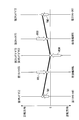
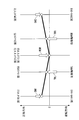
- FIG. 1 shows a case where the rear motors 41 and 61 are switched from the driving state to the braking state and further from the braking state to the driving state with the vehicle speed VP being constant.
- the first sun gear 52 of the first planetary gear device 51 disposed, for example, between the first rear motor 41 and the left rear drive shaft SRL, for example, within the reversal period of the target torque TROBJ. Even if the first motor rotational speed NMOT1 is temporarily increased due to clogging of backlash existing in the meshing portion of the double pinion gear 54 and the first ring gear 53, the changed reference rotational speed NMREF is increased. Does not reach. As a result, it is avoided that the answer to step 32 in FIG.
- the first torque is caused by, for example, clogging of backlash existing between the first rear motor 41 and the left rear drive shaft SRL within the reversal period of the target torque TROBJ. Even if the motor speed NMOT1 is temporarily reduced, the changed smaller reference speed NMREF is not reached. As a result, it is avoided that the answer to step 38 in FIG.
- the reference rotational speed NMREF which is a threshold value for determining deceleration slip.
- the reference rotational speed TMREF is changed when the sign of the target torque TROBJ of the rear motors 41 and 61 is reversed, whereas the second embodiment prohibits slip determination in the same situation. Different.
- FIGS. 11 and 12 show a subroutine for calculating the reference rotational speed and a slip determination process, which are executed in place of the processes of FIGS. 8 and 9 according to the first embodiment.
- the same number is assigned to the step having the same execution content as the processing of FIG. 8 and FIG. In the following, the description will be focused on the portions of different execution contents.
- step 21 the basic value NWBASE of the wheel rotational speed and the basic value NMBASE of the motor rotational speed are calculated in the same manner as the processing of FIG. .
- step 24 it is determined whether or not the target torque TROBJ of the rear motors 41 and 61 is greater than 0 (step 24).
- step 24 When the answer to step 24 is YES and the rear motors 41 and 61 are in a driving state, the basic value NMBASE is used to calculate the reference rotational speed NMREF for driving according to the above equation (1) (step 25). If the answer to step 24 is NO and the rear motors 41 and 61 are in a braking state, the reference rotational speed NMREF for braking is calculated by the above equation (2) (step 26), and this process is terminated.
- step 51 it is determined whether or not the torque reversal flag F_INV is “1”. If the answer is YES and the sign of the target torque TROBJ is reversed, this process is terminated. That is, in this case, slip determination using the reference rotational speed NMREF is prohibited, and slip determination is not performed.
- steps 31 to 42 are executed in the same manner as the process of FIG.
- the occurrence of acceleration slip and deceleration slip is determined for each of the left and right rear wheels WRL and WRR.
- the present invention is not limited to the above-described embodiment, and can be implemented in various modes.
- the first and second motor rotation speeds NMOT1 and NMOT2 are used as the wheel speed parameters in the present invention, and the wheel rotation speeds NWFL, NWFR, NWRL, and NWRR of the four wheels W are used as the basic speed parameters.
- the reference rotational speed NMREF converted to a value corresponding to the motor rotational speed is used as a threshold value
- the first and second motor rotational speeds NMOT1, NMOT2 are The excess slip is determined by comparing with the reference rotational speed NMREF.
- the present invention is not limited to this.
- the first and second motor rotational speeds NMOT1, NMOT2 are converted into values corresponding to the wheel rotational speeds, and the converted values are converted into the basic values NWBASE of the wheel rotational speeds according to the present embodiment.
- the excess slip may be determined by comparing with a threshold value based on the wheel rotation speed calculated based on the above.
- the left and right rear wheels WRL, WRR wheel rotation speeds NWRL, NWRR are used, and the threshold value is calculated based on the four wheel rotation speeds NWFL, NWFR, NWRL, NWRR as basic speed parameters. It is also possible to compare the wheel rotational speeds NWRL and NWRR with this threshold value.
- the basic speed parameter except for the rear wheel WRL and WRR wheel rotation speed NWRL and NWRR, only the front wheel WFL and WFR wheel rotation speed NWFL and NWFR may be used, or alternatively or in combination with them.
- the speed (vehicle speed) of the vehicle V calculated separately may be used.
- the vehicle V of the embodiment is configured such that the left and right rear wheels WRL and WRR are driven by the left and right rear motors 41 and 61, respectively.
- the present invention is not limited to this, and the wheels are controlled by an electric motor.
- the present invention can be applied as long as it is driven. Therefore, the present invention can also be applied to the case where the rear wheels WRL and WRR are controlled by a single motor.
- the present invention can also be applied to the case where the engine and the motor are disposed on the rear wheel side and the motor capable of generating power is disposed on the front wheel side in a reverse relationship to the embodiment.
- the structure of the other vehicle drive device which drives the wheel other than arranging the motor capable of generating electricity is arbitrary, and the drive source may be a vehicle composed of only the engine or only the motor, or another vehicle drive A vehicle without an apparatus may be used.
- the present invention can be applied to the front wheels and the rear wheels, respectively.
- the target torque TRLOB of the rear motors 41 and 61 is used as a parameter representing the braking / driving force of the electric motor, and the driving / braking state of the rear motors 41 and 61 is predicted to be switched when the sign is reversed.
- the reference speed is changed.
- other appropriate parameters such as the torque of the rear motors 41 and 61 may be detected and used as parameters representing the braking / driving force of the electric motor. In this case, the sign of the sign is reversed.
- the target torques TROBJ of the rear motors 41 and 61 are set to the same value.
- the present invention is not limited to this, and different braking / driving forces are set between the rear motors 41 and 61. Also applicable. In that case, the reversal of the sign of the braking / driving force such as the target torque is determined for each rear motor, and the reference rotational speed is changed according to the result. In addition, it is possible to appropriately change the detailed configuration within the scope of the gist of the present invention.
Landscapes
- Engineering & Computer Science (AREA)
- Transportation (AREA)
- Mechanical Engineering (AREA)
- Combustion & Propulsion (AREA)
- Chemical & Material Sciences (AREA)
- Power Engineering (AREA)
- Automation & Control Theory (AREA)
- Physics & Mathematics (AREA)
- Life Sciences & Earth Sciences (AREA)
- Sustainable Development (AREA)
- Sustainable Energy (AREA)
- Fluid Mechanics (AREA)
- Mathematical Physics (AREA)
- Microelectronics & Electronic Packaging (AREA)
- Human Computer Interaction (AREA)
- Electric Propulsion And Braking For Vehicles (AREA)
- Control Of Multiple Motors (AREA)
- Hybrid Electric Vehicles (AREA)
- Control Of Driving Devices And Active Controlling Of Vehicle (AREA)
- Regulating Braking Force (AREA)
Abstract
Description
この駆動モードは、車両Vの加速走行中などに、バッテリ7の電力を用いて第1及び第2リヤモータ41、61で力行を行い、それらの動力で左右の後輪WRL、WRRを駆動する動作モードである。この駆動モードでは、基本的に、第1及び第2リヤモータ41、61の目標トルクTROBJが互いに同じ正値に設定される。そして、目標トルクTROBJに応じた電力を第1及び第2リヤモータ41、61に供給し、ロータ43、63を正転させるとともに、油圧ブレーキ84で第1及び第2リングギヤ53、73を制動する。 [Drive mode]
This drive mode is an operation in which the first and second
この回生モードは、車両Vの減速走行中などに、車両Vの走行エネルギを用いて、第1及び第2リヤモータ41、61で、後輪WRL、WRRを制動しながら回生を行い、発電した電力をバッテリ7に充電する動作モードである。この回生モードでは、基本的に、第1及び第2リヤモータ41、61の目標トルクTROBJが互いに同じ負値に設定され、その値に応じて、第1及び第2リヤモータ41、61で回生される電力を制御するとともに、油圧ブレーキ84で第1及び第2リングギヤ53、73を制動する。 [Regeneration mode]
In this regenerative mode, electric power generated by performing regeneration while braking the rear wheels WRL and WRR by the first and second
NMREF=NMBASE・(1+KD) ・・・(1) Next, it is determined whether or not the torque reversal flag F_INV is “1” (step 23). If the answer is NO and it is not the period of reversal of the sign of the target torque TROBJ, it is determined whether or not the target torque TROBJ of the
NMREF = NMBASE · (1 + KD) (1)
NMREF=NMBASE・(1-KB) ・・・(2) On the other hand, when the answer to step 24 is NO, that is, when the rear wheels WRL and WRR are in the normal braking state by the
NMREF = NMBASE · (1-KB) (2)
NMREF=NMBASE・(1+KDINV) ・・・(3) On the other hand, when the answer to step 23 is YES and the sign of the target torque TROBJ is reversed, it is determined whether or not the target torque TROBJ of the
NMREF = NMBASE · (1 + KDINV) (3)
NMREF=NMBASE・(1-KBINV) ・・・(4) When the answer to step 27 is NO, that is, when the sign of the target torque TROBJ is reversed from positive to negative, and when the
NMREF = NMBASE · (1-KBINV) (4)
得手段、しきい値変更手段、判定禁止手段)
41 第1リヤモータ(電動機)
61 第2リヤモータ(電動機)
101a~101d
車輪回転数センサ(基本速度パラメータ取得手段)
102a 第1モータ回転数センサ(車輪速パラメータ取得手段)
102b 第2モータ回転数センサ(車輪速パラメータ取得手段)
V ハイブリッド車両(車両)
WRL 左後輪(車輪)
WRR 右後輪(車輪)
WFL 左前輪(他の車輪)
WFR 右前輪(他の車輪)
NMOT1 第1モータ回転数(車輪速パラメータ)
NMOT2 第2モータ回転数(車輪速パラメータ)
NWFL 左前輪の車輪回転数(基本速度パラメータ)
NWFR 右前輪の車輪回転数(基本速度パラメータ)
NWRL 左後輪の車輪回転数(基本速度パラメータ)
NWRR 右後輪の車輪回転数(基本速度パラメータ)
NMREF 基準回転数(しきい値、第2しきい値)
TROBJ リヤモータの目標トルク(電動機の制駆動力) 2 ECU (threshold setting means, slip judging means, braking / driving force obtaining means, threshold changing means, judgment prohibiting means)
41 First rear motor (electric motor)
61 Second rear motor (electric motor)
101a to 101d
Wheel speed sensor (basic speed parameter acquisition means)
102a First motor rotation speed sensor (wheel speed parameter acquisition means)
102b Second motor rotation speed sensor (wheel speed parameter acquisition means)
V Hybrid vehicle (vehicle)
WRL Left rear wheel (wheel)
WRR Right rear wheel (wheel)
WFL Front left wheel (other wheels)
WFR Right front wheel (other wheels)
NMOT1 1st motor speed (wheel speed parameter)
NMOT2 Second motor speed (wheel speed parameter)
NWFL Left front wheel speed (basic speed parameter)
NWFR Wheel speed of the right front wheel (basic speed parameter)
NWRL Wheel speed of left rear wheel (basic speed parameter)
NWRR Wheel speed of the right rear wheel (basic speed parameter)
NMREF Reference speed (threshold, second threshold)
TROBJ Rear motor target torque (motor braking / driving force)
Claims (2)
- 電動機に機械的に連結され、該電動機によって駆動又は制動される車輪に、所定以上のスリップである超過スリップが発生しているか否かを判定する車両のスリップ判定装置であって、
前記車輪及び前記電動機の一方の速度を表す車輪速パラメータを取得する車輪速パラメータ取得手段と、
前記車両の速度及び前記車輪とは異なる他の車輪の速度の少なくとも一方を表す基本速度パラメータを取得する基本速度パラメータ取得手段と、
該取得された車速パラメータに基づき、前記超過スリップの判定の基準となるしきい値を設定するしきい値設定手段と、
前記取得された車輪速パラメータが前記設定されたしきい値に達したときに、前記車輪に前記超過スリップが発生したと判定するスリップ判定手段と、
前記車輪を駆動又は制動する前記電動機の制駆動力を取得する制駆動力取得手段と、
該取得された電動機の制駆動力の符号が反転するときに、前記しきい値を、該しきい値よりも前記車輪速パラメータが達しにくくなるような制駆動力反転時用の第2しきい値に変更するしきい値変更手段と、
を備えることを特徴とする車両のスリップ判定装置。 A slip determination device for a vehicle that determines whether or not an excess slip, which is a slip greater than or equal to a predetermined slip, has occurred on a wheel that is mechanically connected to an electric motor and is driven or braked by the electric motor,
Wheel speed parameter acquisition means for acquiring a wheel speed parameter representing one speed of the wheel and the motor;
Basic speed parameter acquisition means for acquiring a basic speed parameter representing at least one of the speed of the vehicle and the speed of another wheel different from the wheel;
Threshold setting means for setting a threshold value that is a reference for determining the excess slip based on the acquired vehicle speed parameter;
Slip determining means for determining that the excess slip has occurred in the wheel when the acquired wheel speed parameter reaches the set threshold value;
Braking / driving force acquisition means for acquiring braking / driving force of the electric motor for driving or braking the wheel;
When the obtained sign of the braking / driving force of the electric motor is reversed, the threshold value is set to a second threshold for reversing the braking / driving force so that the wheel speed parameter is less likely to reach the threshold value. A threshold value changing means for changing to a value;
A vehicle slip determination apparatus comprising: - 電動機に機械的に連結され、該電動機によって駆動又は制動される車輪に、所定以上のスリップである超過スリップが発生しているか否かを判定する車両のスリップ判定装置であって、
前記車輪及び前記電動機の一方の速度を表す車輪速パラメータを取得する車輪速パラメータ取得手段と、
前記車両の速度及び前記車輪とは異なる他の車輪の速度の少なくとも一方を表す基本速度パラメータを取得する基本速度パラメータ取得手段と、
該取得された基本速度パラメータに基づき、前記超過スリップの判定の基準となるしきい値を設定するしきい値設定手段と、
前記取得された車輪速パラメータが前記設定されたしきい値に達したときに、前記車輪に前記超過スリップが発生したと判定するスリップ判定手段と、
前記車輪を駆動又は制動する前記電動機の制駆動力を取得する制駆動力取得手段と、
該取得された電動機の制駆動力の符号が反転するときに、前記スリップ判定手段による前記超過スリップの判定を禁止する判定禁止手段と、
を備えることを特徴とする車両のスリップ判定装置。 A slip determination device for a vehicle that determines whether or not an excess slip, which is a slip greater than or equal to a predetermined slip, has occurred on a wheel that is mechanically connected to an electric motor and is driven or braked by the electric motor,
Wheel speed parameter acquisition means for acquiring a wheel speed parameter representing one speed of the wheel and the motor;
Basic speed parameter acquisition means for acquiring a basic speed parameter representing at least one of the speed of the vehicle and the speed of another wheel different from the wheel;
Threshold value setting means for setting a threshold value as a criterion for determining the excess slip based on the acquired basic speed parameter;
Slip determining means for determining that the excess slip has occurred in the wheel when the acquired wheel speed parameter reaches the set threshold value;
Braking / driving force acquisition means for acquiring braking / driving force of the electric motor for driving or braking the wheel;
Determination prohibiting means for prohibiting the determination of the excess slip by the slip determination means when the sign of the braking / driving force of the acquired electric motor is reversed;
A vehicle slip determination apparatus comprising:
Priority Applications (5)
| Application Number | Priority Date | Filing Date | Title |
|---|---|---|---|
| CA2934229A CA2934229C (en) | 2013-12-17 | 2014-12-16 | Slip determination system for vehicle |
| US15/105,300 US9889745B2 (en) | 2013-12-17 | 2014-12-16 | Slip determination system for vehicle |
| EP14870995.9A EP3085595B1 (en) | 2013-12-17 | 2014-12-16 | Vehicle slip determination device |
| KR1020167019234A KR101942631B1 (en) | 2013-12-17 | 2014-12-16 | Slip determination system for vehicle |
| CN201480067833.8A CN105829186B (en) | 2013-12-17 | 2014-12-16 | The sliding decision maker of vehicle |
Applications Claiming Priority (2)
| Application Number | Priority Date | Filing Date | Title |
|---|---|---|---|
| JP2013-260397 | 2013-12-17 | ||
| JP2013260397A JP6029572B2 (en) | 2013-12-17 | 2013-12-17 | Vehicle slip determination device |
Publications (1)
| Publication Number | Publication Date |
|---|---|
| WO2015093473A1 true WO2015093473A1 (en) | 2015-06-25 |
Family
ID=53402818
Family Applications (1)
| Application Number | Title | Priority Date | Filing Date |
|---|---|---|---|
| PCT/JP2014/083249 WO2015093473A1 (en) | 2013-12-17 | 2014-12-16 | Vehicle slip determination device |
Country Status (8)
| Country | Link |
|---|---|
| US (1) | US9889745B2 (en) |
| EP (1) | EP3085595B1 (en) |
| JP (1) | JP6029572B2 (en) |
| KR (1) | KR101942631B1 (en) |
| CN (1) | CN105829186B (en) |
| CA (1) | CA2934229C (en) |
| MY (1) | MY176492A (en) |
| WO (1) | WO2015093473A1 (en) |
Families Citing this family (6)
| Publication number | Priority date | Publication date | Assignee | Title |
|---|---|---|---|---|
| KR101856364B1 (en) * | 2016-10-06 | 2018-05-09 | 현대자동차주식회사 | Method for Controlling Shift Differences and 4 Wheel Drive Vehicle thereof |
| JP6984329B2 (en) * | 2017-11-07 | 2021-12-17 | トヨタ自動車株式会社 | car |
| JP2021017096A (en) * | 2019-07-18 | 2021-02-15 | 株式会社Subaru | Slip control device for vehicle |
| CN112519591B (en) * | 2019-08-27 | 2022-01-25 | 上海汽车集团股份有限公司 | Control method and control system for power battery discharge power |
| CN111114343B (en) * | 2020-01-03 | 2021-08-06 | 东风商用车有限公司 | Vehicle energy management method and system |
| CN112776810A (en) * | 2021-01-29 | 2021-05-11 | 潍柴动力股份有限公司 | Vehicle control method and device, vehicle and storage medium |
Citations (5)
| Publication number | Priority date | Publication date | Assignee | Title |
|---|---|---|---|---|
| JPH10304509A (en) | 1997-04-23 | 1998-11-13 | Honda Motor Co Ltd | Controller for electric vehicle |
| JP2002034106A (en) * | 2000-07-14 | 2002-01-31 | Toyota Industries Corp | Device for run control of industrial vehicle |
| JP2013106390A (en) * | 2011-11-11 | 2013-05-30 | Ntn Corp | Electric vehicle |
| JP2013154729A (en) * | 2012-01-30 | 2013-08-15 | Toyota Motor Corp | Vehicle braking/driving force control device |
| JP5362792B2 (en) | 2011-09-05 | 2013-12-11 | 本田技研工業株式会社 | Control device and control method for hybrid vehicle |
Family Cites Families (7)
| Publication number | Priority date | Publication date | Assignee | Title |
|---|---|---|---|---|
| DE102010003076A1 (en) * | 2009-08-05 | 2011-08-18 | Continental Automotive GmbH, 30165 | Method for controlling a wheel brake slip and wheel brake slip control system for a vehicle with an electric drive |
| JP2012029473A (en) * | 2010-07-23 | 2012-02-09 | Nissan Motor Co Ltd | Control device for electric vehicle |
| CN102791544B (en) * | 2010-08-30 | 2015-07-01 | 丰田自动车株式会社 | Braking force control device for vehicle |
| JP5336447B2 (en) * | 2010-09-02 | 2013-11-06 | 日立建機株式会社 | Electric drive vehicle |
| CN102267459B (en) * | 2011-05-17 | 2013-07-10 | 清华大学 | Driving antiskid adjustment and control method for motor-driven vehicle |
| CN103764431B (en) * | 2011-08-29 | 2016-02-17 | 丰田自动车株式会社 | The gradual braking device of vehicle |
| WO2013035728A1 (en) | 2011-09-05 | 2013-03-14 | 本田技研工業株式会社 | Hybrid vehicle control device and control method |
-
2013
- 2013-12-17 JP JP2013260397A patent/JP6029572B2/en active Active
-
2014
- 2014-12-16 MY MYPI2016702215A patent/MY176492A/en unknown
- 2014-12-16 US US15/105,300 patent/US9889745B2/en active Active
- 2014-12-16 KR KR1020167019234A patent/KR101942631B1/en active IP Right Grant
- 2014-12-16 CN CN201480067833.8A patent/CN105829186B/en active Active
- 2014-12-16 CA CA2934229A patent/CA2934229C/en active Active
- 2014-12-16 WO PCT/JP2014/083249 patent/WO2015093473A1/en active Application Filing
- 2014-12-16 EP EP14870995.9A patent/EP3085595B1/en active Active
Patent Citations (5)
| Publication number | Priority date | Publication date | Assignee | Title |
|---|---|---|---|---|
| JPH10304509A (en) | 1997-04-23 | 1998-11-13 | Honda Motor Co Ltd | Controller for electric vehicle |
| JP2002034106A (en) * | 2000-07-14 | 2002-01-31 | Toyota Industries Corp | Device for run control of industrial vehicle |
| JP5362792B2 (en) | 2011-09-05 | 2013-12-11 | 本田技研工業株式会社 | Control device and control method for hybrid vehicle |
| JP2013106390A (en) * | 2011-11-11 | 2013-05-30 | Ntn Corp | Electric vehicle |
| JP2013154729A (en) * | 2012-01-30 | 2013-08-15 | Toyota Motor Corp | Vehicle braking/driving force control device |
Non-Patent Citations (1)
| Title |
|---|
| See also references of EP3085595A4 |
Also Published As
| Publication number | Publication date |
|---|---|
| KR20160099680A (en) | 2016-08-22 |
| JP2015116889A (en) | 2015-06-25 |
| US9889745B2 (en) | 2018-02-13 |
| EP3085595A4 (en) | 2017-08-16 |
| JP6029572B2 (en) | 2016-11-24 |
| US20160318400A1 (en) | 2016-11-03 |
| KR101942631B1 (en) | 2019-01-25 |
| EP3085595A1 (en) | 2016-10-26 |
| CA2934229C (en) | 2019-08-13 |
| EP3085595B1 (en) | 2019-07-31 |
| MY176492A (en) | 2020-08-12 |
| CN105829186A (en) | 2016-08-03 |
| CA2934229A1 (en) | 2015-06-25 |
| CN105829186B (en) | 2018-08-28 |
Similar Documents
| Publication | Publication Date | Title |
|---|---|---|
| WO2015093473A1 (en) | Vehicle slip determination device | |
| JP6666449B2 (en) | Power unit | |
| EP3246221B1 (en) | Control system, control method and recording medium for a driving device | |
| JP4196962B2 (en) | Car | |
| KR20110137312A (en) | A device for torque vectoring | |
| CN107461476B (en) | Differential assembly with axle torque vector | |
| JP2008068704A (en) | Vehicular drive source control apparatus | |
| JP6200312B2 (en) | Control device for electric motor for vehicle | |
| US11091031B2 (en) | Drive force control system for vehicle | |
| JP7284831B2 (en) | Hybrid system control method and control system | |
| JP5048692B2 (en) | Front and rear wheel drive vehicle | |
| JP6894288B2 (en) | Power regenerative device | |
| JP5792789B2 (en) | Slip control device for four-wheeled vehicle | |
| JP4165475B2 (en) | Hybrid vehicle and control method thereof | |
| JP5963738B2 (en) | Control device for hybrid vehicle | |
| JP6071954B2 (en) | Control device for hybrid vehicle | |
| JP2020059378A (en) | Control system of hybrid vehicle | |
| JP2005253222A (en) | Speed control device for hybrid car | |
| JP2017007408A (en) | Hybrid automobile |
Legal Events
| Date | Code | Title | Description |
|---|---|---|---|
| 121 | Ep: the epo has been informed by wipo that ep was designated in this application |
Ref document number: 14870995 Country of ref document: EP Kind code of ref document: A1 |
|
| ENP | Entry into the national phase |
Ref document number: 2934229 Country of ref document: CA |
|
| REEP | Request for entry into the european phase |
Ref document number: 2014870995 Country of ref document: EP |
|
| WWE | Wipo information: entry into national phase |
Ref document number: 15105300 Country of ref document: US Ref document number: 2014870995 Country of ref document: EP |
|
| NENP | Non-entry into the national phase |
Ref country code: DE |
|
| ENP | Entry into the national phase |
Ref document number: 20167019234 Country of ref document: KR Kind code of ref document: A |