WO2015087425A1 - Equipment inspection work assistance program, equipment inspection work assistance method, and equipment inspection work assistance device - Google Patents
Equipment inspection work assistance program, equipment inspection work assistance method, and equipment inspection work assistance device Download PDFInfo
- Publication number
- WO2015087425A1 WO2015087425A1 PCT/JP2013/083333 JP2013083333W WO2015087425A1 WO 2015087425 A1 WO2015087425 A1 WO 2015087425A1 JP 2013083333 W JP2013083333 W JP 2013083333W WO 2015087425 A1 WO2015087425 A1 WO 2015087425A1
- Authority
- WO
- WIPO (PCT)
- Prior art keywords
- inspection
- pointer
- pin
- map
- input screen
- Prior art date
Links
- 238000007689 inspection Methods 0.000 title claims abstract description 438
- 238000000034 method Methods 0.000 title claims description 26
- 238000012545 processing Methods 0.000 claims abstract description 13
- 238000010586 diagram Methods 0.000 description 18
- 238000003780 insertion Methods 0.000 description 10
- 230000037431 insertion Effects 0.000 description 10
- 230000006870 function Effects 0.000 description 6
- 230000005540 biological transmission Effects 0.000 description 3
- 238000004891 communication Methods 0.000 description 2
- 238000007796 conventional method Methods 0.000 description 1
- 238000012905 input function Methods 0.000 description 1
- 238000012986 modification Methods 0.000 description 1
- 230000004048 modification Effects 0.000 description 1
- 239000004065 semiconductor Substances 0.000 description 1
- XLYOFNOQVPJJNP-UHFFFAOYSA-N water Substances O XLYOFNOQVPJJNP-UHFFFAOYSA-N 0.000 description 1
Images


Classifications
-
- G—PHYSICS
- G06—COMPUTING; CALCULATING OR COUNTING
- G06F—ELECTRIC DIGITAL DATA PROCESSING
- G06F3/00—Input arrangements for transferring data to be processed into a form capable of being handled by the computer; Output arrangements for transferring data from processing unit to output unit, e.g. interface arrangements
- G06F3/01—Input arrangements or combined input and output arrangements for interaction between user and computer
- G06F3/048—Interaction techniques based on graphical user interfaces [GUI]
- G06F3/0481—Interaction techniques based on graphical user interfaces [GUI] based on specific properties of the displayed interaction object or a metaphor-based environment, e.g. interaction with desktop elements like windows or icons, or assisted by a cursor's changing behaviour or appearance
- G06F3/0482—Interaction with lists of selectable items, e.g. menus
-
- G—PHYSICS
- G06—COMPUTING; CALCULATING OR COUNTING
- G06Q—INFORMATION AND COMMUNICATION TECHNOLOGY [ICT] SPECIALLY ADAPTED FOR ADMINISTRATIVE, COMMERCIAL, FINANCIAL, MANAGERIAL OR SUPERVISORY PURPOSES; SYSTEMS OR METHODS SPECIALLY ADAPTED FOR ADMINISTRATIVE, COMMERCIAL, FINANCIAL, MANAGERIAL OR SUPERVISORY PURPOSES, NOT OTHERWISE PROVIDED FOR
- G06Q50/00—Information and communication technology [ICT] specially adapted for implementation of business processes of specific business sectors, e.g. utilities or tourism
- G06Q50/10—Services
-
- G—PHYSICS
- G06—COMPUTING; CALCULATING OR COUNTING
- G06F—ELECTRIC DIGITAL DATA PROCESSING
- G06F3/00—Input arrangements for transferring data to be processed into a form capable of being handled by the computer; Output arrangements for transferring data from processing unit to output unit, e.g. interface arrangements
- G06F3/01—Input arrangements or combined input and output arrangements for interaction between user and computer
- G06F3/048—Interaction techniques based on graphical user interfaces [GUI]
- G06F3/0484—Interaction techniques based on graphical user interfaces [GUI] for the control of specific functions or operations, e.g. selecting or manipulating an object, an image or a displayed text element, setting a parameter value or selecting a range
-
- G—PHYSICS
- G06—COMPUTING; CALCULATING OR COUNTING
- G06Q—INFORMATION AND COMMUNICATION TECHNOLOGY [ICT] SPECIALLY ADAPTED FOR ADMINISTRATIVE, COMMERCIAL, FINANCIAL, MANAGERIAL OR SUPERVISORY PURPOSES; SYSTEMS OR METHODS SPECIALLY ADAPTED FOR ADMINISTRATIVE, COMMERCIAL, FINANCIAL, MANAGERIAL OR SUPERVISORY PURPOSES, NOT OTHERWISE PROVIDED FOR
- G06Q10/00—Administration; Management
- G06Q10/04—Forecasting or optimisation specially adapted for administrative or management purposes, e.g. linear programming or "cutting stock problem"
- G06Q10/047—Optimisation of routes or paths, e.g. travelling salesman problem
-
- G—PHYSICS
- G06—COMPUTING; CALCULATING OR COUNTING
- G06Q—INFORMATION AND COMMUNICATION TECHNOLOGY [ICT] SPECIALLY ADAPTED FOR ADMINISTRATIVE, COMMERCIAL, FINANCIAL, MANAGERIAL OR SUPERVISORY PURPOSES; SYSTEMS OR METHODS SPECIALLY ADAPTED FOR ADMINISTRATIVE, COMMERCIAL, FINANCIAL, MANAGERIAL OR SUPERVISORY PURPOSES, NOT OTHERWISE PROVIDED FOR
- G06Q10/00—Administration; Management
- G06Q10/06—Resources, workflows, human or project management; Enterprise or organisation planning; Enterprise or organisation modelling
- G06Q10/063—Operations research, analysis or management
- G06Q10/0631—Resource planning, allocation, distributing or scheduling for enterprises or organisations
- G06Q10/06316—Sequencing of tasks or work
-
- G—PHYSICS
- G06—COMPUTING; CALCULATING OR COUNTING
- G06Q—INFORMATION AND COMMUNICATION TECHNOLOGY [ICT] SPECIALLY ADAPTED FOR ADMINISTRATIVE, COMMERCIAL, FINANCIAL, MANAGERIAL OR SUPERVISORY PURPOSES; SYSTEMS OR METHODS SPECIALLY ADAPTED FOR ADMINISTRATIVE, COMMERCIAL, FINANCIAL, MANAGERIAL OR SUPERVISORY PURPOSES, NOT OTHERWISE PROVIDED FOR
- G06Q50/00—Information and communication technology [ICT] specially adapted for implementation of business processes of specific business sectors, e.g. utilities or tourism
- G06Q50/08—Construction
Definitions
- the present invention relates to an equipment inspection work support program, an equipment inspection work support method, and an equipment inspection work support device that support equipment inspection work.
- An object of the present invention is to provide an equipment inspection work support program, an equipment inspection work support method, and an equipment inspection work support device that can change a predetermined inspection order.
- the pointer that indicates the inspection location is displayed on the map that indicates the arrangement of the equipment on the computer, and the pointer is a pointer in which the inspection order is registered with another pointer that indicates another inspection location.
- the inspection point the inspection corresponding to the pointer immediately preceding the pointer in the inspection order in accordance with the switching operation from the inspection result input screen to the other inspection result input screen for the inspection location indicated by the pointer Execute processing that allows screen switching control to the result input screen.
- Each of the above processes may be a functional unit that executes each of the above processes, a method that realizes each of the above processes, and a computer-readable storage medium that stores the program.
- FIG. 1 is a diagram illustrating an example of a system configuration of an equipment inspection work support system.
- the facility inspection work support system 100 includes a terminal device 200 and a server 300 connected via a network.
- the facility inspection work support system 100 supports various facility inspection operations performed by an inspection operator in a plant such as a factory or a power plant.
- the server 300 of this embodiment includes a pin definition database 310, a pin recording database 320, a route definition database 330, a route recording database 340, and a map definition database 350.
- the terminal device 200 supports the inspection work when the equipment inspection work support program is started by the inspection worker. Specifically, the terminal device 200 refers to the pin definition database 310, the route definition database 330, and the map definition database 350, and displays a pointer (hereinafter referred to as a pin) indicating an inspection location based on the inspection route. In addition, the terminal device 200 according to the present embodiment refers to the pin definition database 310, displays an input screen including an input field of items corresponding to the pins in the order of inspection, and inputs the inspection result. When the inspection result is input for all the pins included in the inspection route, the terminal device 200 according to the present embodiment transmits the inspection result to the server 300 and stores it in the pin recording database 320 and the route recording database 340.
- a pointer hereinafter referred to as a pin
- the terminal device 200 displays an input screen corresponding to the pins in the order of inspection and inputs an inspection result, thereby allowing the inspection operator to support the inspection operation by the inspection operator. Fulfills the function.
- the terminal device 200 of the present embodiment can switch the input screen according to the operation of the inspection operator, and can inspect the inspection points in an order other than the preset inspection order. That is, the terminal device 200 can change the predetermined order of inspection.
- FIG. 2 is a diagram showing an example of the pin definition database.
- the pin definition database 310 of this embodiment has pin ID, pin name, pin type, input item, map ID, map affiliation, and map coordinates as information items, and other items are associated with the pin ID. Yes.
- information on items associated with pin IDs in the pin definition database 310 is referred to as pin information.
- the pin ID is an identifier for identifying the pin.
- the pin name is the name of the pin.
- the pin type indicates the type of pin. In this embodiment, it has a hierarchy pin and an inspection pin as a kind of pin.
- the hierarchy pin is a pin indicating a hierarchy in a map (map) described later.
- An inspection pin is a pin which shows the inspection location in the map mentioned later.
- a pin whose pin type is a hierarchical pin is called a hierarchical pin
- a pin whose pin type is a check pin is called a check pin
- the input item is an item corresponding to the input field in which the inspection result in the inspection work is input. In this embodiment, it is associated with an inspection pin, and an input item is determined for each pin.
- the map ID is associated with the hierarchical pin and indicates a hierarchical map indicated by the hierarchical pin.
- the map affiliation is associated with the inspection pin and the hierarchical pin, and indicates a map including the inspection pin and the hierarchical pin.
- the map coordinates are associated with the inspection pin, and indicate the position of the inspection pin in the map including the inspection pin.
- the pin with the pin ID P0000 is a hierarchical pin with the name “inside map”.
- the hierarchical pin with the pin ID “P0000” is associated with the map ID “M0001”.
- the pin whose pin ID is P0001 is an inspection pin whose name is “facility A inspection”.
- the inspection pin with the pin ID “P0001” has “temperature” and “pressure” as input items, and is located at the coordinates (10, 10) in the map with the map ID “M0001”.
- the pin with the pin ID P0003 is a hierarchical pin with the name “facility C”.
- the hierarchical pin with the pin ID “P0003” belongs to the map with the map ID “M0001”, has coordinates (30, 20), and is associated with the map ID “M0002”. That is, the hierarchy pin “P0003” defines a hierarchy connecting from the map “M0001” to the map “M0002”.
- FIG. 3 is a diagram showing an example of the pin recording database.
- the pin record database 320 of the present embodiment stores the inspection results for each inspection pin.
- the pin record database 320 has, as information items, a pin ID, date, time, input item, input value, route ID, route record ID, and the pin ID is associated with other items.
- information on items associated with pin IDs in the pin recording database 320 is referred to as pin recording information.
- the date and time indicate the date and time when the input value is input to the input item.
- the input item is an input item corresponding to the inspection pin
- the input value is an input value input corresponding to the input item.
- the route ID is an identifier for identifying the inspection route including the inspection pin.
- the route record ID is an identifier for identifying the inspection result for each inspection route.
- the input value “0.38” is input in the input field corresponding to the input item “water pressure” at 11:28:12 on 2013/11/25 as the inspection result for the inspection pin having the pin ID P0002.
- the inspection pin with the pin ID P0002 is included in the inspection route identified by the route IDR0001, and the inspection result of the inspection pin with the pin ID P0002 is included in the route record identified by the route record IDRec0001.
- FIG. 4 is a diagram showing an example of the route definition database.
- the route definition database 330 of this embodiment has a route ID, a route name, and a pin ID as information items, and other items are associated with the route ID.
- information of items associated with the route ID in the route definition database 330 is referred to as route information.
- the route ID and the pin ID are associated with each other to indicate that the inspection route indicated by the route ID includes the pin indicated by the pin ID.
- the inspection route having the route IDR0001 and the name “route A” includes the inspection pins having the pins IDP0001, IDP0002, and IDP0004 and the hierarchical pin having the pin IDP0003.
- FIG. 5 is a diagram showing an example of a route record database.
- the route record database 340 of this embodiment has a route ID, route record ID, status, completion date, and completion time as information items, and other items are associated with the route ID.
- route record information information of items associated with the route ID in the route record database 340 is referred to as route record information.
- the status in the route record database 340 indicates the state of inspection work on the inspection route indicated by the route ID.
- the completion date and completion time are the date and time when the inspection work of the inspection route indicated by the route ID is completed.
- the inspection result of the inspection route of the route IDR0001 is completed at 11:32:30 on November 25, 2013 and is recorded as the route record IDRec0001.
- FIG. 6 is a diagram showing an example of the map definition database.
- the map definition database 350 of this embodiment has a map ID, a map name, and a file name as information items, and other items are associated with the map ID.
- map information information on items associated with map IDs in the map definition database 350 is referred to as map information.
- the map name is the name of the map
- the file name is the name of the file used when the terminal device 200 displays the map.
- the name of the map identified by the map IDM0001 is “Floor Map”, and the file used when displaying this map is “Floor Map.jpg”.
- map definition database 350 of the present embodiment for example, a file indicating the entire area of a factory to be inspected, a file indicating equipment performing inspection work, a file indicating equipment in equipment performing inspection work, and the like of different levels Has as a map.
- FIG. 7 is a diagram illustrating a map hierarchy.
- FIG. 7 (A) shows an example of a map of the first layer
- FIG. 7 (B) shows an example of a map of the second layer
- FIG. 7 (C) shows an inspection target location in the second layer. An example of an enlarged map is shown.
- the map 71 shown in FIG. 7 (A) shows the area where the equipment is arranged.
- the map 71 is a floor plan of the map “M0001” registered in the map definition database 350, for example.
- the map 71 displays a hierarchical pin P3, an inspection pin P1, and an inspection pin P2.
- a map 72 shown in FIG. 7 (B) is a map in the lower layer of the map 71, and an outline of the facility is shown in an area indicated by the layer pin P3. That is, the map 72 shows further details of the area indicated by the hierarchical pin P3 in the map 71.
- the map 72 is, for example, a facility C overview of the map “M0002” registered in the map definition database.
- an inspection pin P4 is displayed on the map 72.
- the inspection pin P4 indicates a device to be inspected in the facility displayed as the map 72.
- a map 73 shown in FIG. 7C is a map in a state where the inspection target portion is enlarged and displayed in the map 72, for example, a sketch of the inspection target device indicated by the inspection pin P4.
- each map stored in the map definition database 350 is indicated by, for example, a pin associated with each map and an inspection route including the pin.
- map file names for example, image data
- map file names for example, image data
- the file entity for displaying the map may be stored in the map definition database 350, or the file entity may be stored in another storage device.
- each map ID may be associated with information indicating the relationship between each map hierarchy.
- the map one level below the map of map IDM0001 is the map of map IDM0002. Therefore, the map IDM0002 may be associated with information such as M0001-1 indicating that it is one layer below the map IDM0001.
- FIG. 8 is a diagram illustrating an example of a hardware configuration of the terminal device.
- the terminal device 200 of the present embodiment includes a display operation device 21, a drive device 22, an auxiliary storage device 23, a memory device 24, an arithmetic processing device 25, and an interface device 26, which are mutually connected by a bus B.
- the display operation device 21 is a touch panel, for example, and has a display function and an information input function.
- the interface device 26 includes a modem, a LAN card, etc., and is used for connecting to a network.
- the equipment inspection work support program is at least a part of various programs for controlling the terminal device 200.
- the equipment inspection work support program is provided, for example, by distributing the recording medium 27 or downloading from the network.
- the recording medium 27 on which the equipment inspection work support program is recorded is a recording medium such as a CD-ROM, flexible disk, magneto-optical disk, etc. for recording information optically, electrically or magnetically, ROM, flash memory, etc.
- Various types of recording media such as a semiconductor memory that electrically records information can be used.
- the equipment inspection work support program is installed from the recording medium 27 into the auxiliary storage device 23 via the drive device 22.
- the facility inspection work support program downloaded from the network is installed in the auxiliary storage device 23 via the interface device 26.
- the auxiliary storage device 23 stores the installed equipment inspection work support program and also stores necessary files, data, and the like.
- the memory device 24 reads and stores the equipment inspection work support program from the auxiliary storage device 23 when the computer is started.
- the arithmetic processing unit 25 implements various processes as described later according to the facility inspection work support program stored in the memory device 24.
- the terminal device 200 of the present embodiment is, for example, a tablet computer.
- the server 300 of this embodiment is a general computer having an arithmetic processing device and a memory device, for example.
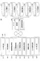
- FIG. 9 is a diagram for explaining the functions of the devices included in the equipment inspection work support system.
- the equipment inspection work support program 210 is installed in the terminal device 200 of the present embodiment.
- the process of each part mentioned later is implement
- the terminal device 200 includes an input reception unit 211, a display control unit 212, a route information acquisition unit 213, a pin information acquisition unit 214, a map information acquisition unit 215, an inspection result transmission unit 216, a hierarchy determination unit 217, and a pin position.
- a determination unit 218 and a pin insertion unit 219 are included.
- the input receiving unit 211 of this embodiment receives an input by operating the display operation device 21.
- the display control unit 212 controls display on the display operation device 21.
- the route information acquisition unit 213 acquires route information from the route definition database 330 based on the input received by the input reception unit 211.
- the pin information acquisition unit 214 acquires pin information from the pin definition database 310 based on the input received by the input reception unit 211.
- the map information acquisition unit 215 acquires map information from the map definition database 350 based on the map ID included in the pin information.
- the inspection result transmission unit 216 transmits the inspection result to the server 300 when the inspection operation of the selected inspection route is completed.
- the hierarchy determination unit 217 determines whether or not the two inspection pins are in the same hierarchy. Specifically, when the two inspection pins exist on the same map, the hierarchy determination unit 217 determines that the two inspection pins have the same hierarchy.
- the pin position determination unit 218 determines the position of the inspection pin. Specifically, the pin position determination unit 218 determines whether the inspection pin is included in the selected inspection route. When a new inspection pin is set on the map, the pin insertion unit 219 inserts the inspection pin into the inspection route.
- the server 300 of this embodiment includes a communication unit 301 and an inspection result storage unit 302.
- the communication unit 301 communicates with the terminal device 200.
- the inspection result storage unit 302 updates the route recording database 340 according to the inspection result, and stores the inspection result in the pin recording database 320.
- the inspection result storage unit 302 sets the status of the route ID corresponding to the inspection route for which the inspection work has been completed in the route record database 340 to be completed, and assigns the route record ID associated with the route ID.
- the inspection result storage unit 302 stores the value input for the input item for each inspection pin and the input date and time in the pin record database 320.
- the inspection result storage unit 302 stores the route record ID stored in the route record database 340 in association with the route ID in association with the pin ID in the pin record database 320.
- FIG. 10 is a flowchart for explaining the operation of the terminal device.
- the terminal device 200 When the inspection work is started, the terminal device 200 according to the present embodiment acquires a list of inspection routes from the route definition database 330 by the route information acquisition unit 213, and displays the list of inspection routes by the display control unit 212. (Step S101). Subsequently, the terminal device 200 receives selection of an inspection route by the input receiving unit 211 (step S102).
- the terminal device 200 displays the location to be inspected and the order of inspection by the selected inspection route (step S103).
- step S103 When the inspection route is selected, the terminal device 200 according to the present embodiment acquires the route information of the selected route from the route definition database 330 by the route information acquisition unit 213. Subsequently, the pin information acquisition unit 214 refers to the pin definition database 310 and acquires pin information corresponding to the pin ID included in the route information. Next, the map information acquisition unit 215 acquires map information corresponding to the map ID included in the pin information from the map definition database 350.
- step S103 of the present embodiment for example, among the pin IDs included in the route information, a map ID included in the pin information corresponding to the pin ID at the head is obtained, and the map is determined based on the map information corresponding to the map ID. May be displayed.
- the terminal device 200 can display a map including the inspection pin that is the first inspection location in the inspection route.
- the terminal device 200 of the present embodiment may display the order of pin IDs included in the acquired route information as the inspection order of inspection pins.
- the terminal device 200 supports the execution of the inspection by the inspection operator following step S103 (step S104).
- the terminal device 200 displays an input screen having an input field corresponding to an input item for each inspection pin, and receives an input to the input field.
- the terminal device 200 holds the received value as the value of the inspection result.
- the terminal device 200 of the present embodiment displays an input screen corresponding to the next inspection pin or an input screen corresponding to the previous inspection pin based on an instruction to switch the input screen. Furthermore, the terminal device 200 according to the present embodiment inserts the inspection pin into the inspection route when, for example, an inspection pin is set at an inspection location that is not included in the inspection route.
- the terminal device 200 determines whether or not an inspection work completion instruction has been received (step S105). When the completion instruction is not accepted in step S105, the terminal device 200 returns to step S104. When the completion instruction is received in step S105, the terminal device 200 transmits the inspection result to the server 300 (step S106).
- the inspection result storage unit 302 updates the route recording database 340 and stores the inspection result in the pin recording database 320 (step S107).
- the terminal device 200 of the present embodiment After receiving the inspection work completion notification, the terminal device 200 of the present embodiment does not switch the input screen even when receiving an instruction to switch the input screen. Further, the terminal device 200 according to the present embodiment does not accept the input of the inspection result after accepting the completion notification.
- the terminal device 200 may prohibit the transmission of the inspection result to the server 300 before accepting the completion notification.
- FIG. 11 is a diagram showing an example of a list screen of inspection routes.
- the terminal device 200 of this embodiment displays the inspection route list screen 111 shown in FIG. 11 after receiving an instruction to start the inspection work.
- the terminal device 200 acquires route information corresponding to the name of the route selected on the list screen 111.
- FIG. 12 is a diagram showing an example of a screen on which the location to be inspected and the order of inspection are displayed.
- the screen 121 shown in FIG. 12 displays a map 122 including the first pin ID among the pin IDs included in the inspection route, and an inspection order 123 of the pin IDs included in the inspection route.
- the location indicated by the inspection pin 1 whose pin name is the facility A inspection is the first inspection location
- the location indicated by the inspection pin 2 whose pin name is the facility B inspection is the next inspection. It becomes a place.
- the terminal device 200 when the inspection operator presses (touches) the inspection pin 1, the terminal device 200 according to the present embodiment regards the inspection pin 1 as an instruction to start the inspection operation and displays an input screen corresponding to the inspection pin 1. Details of the input screen will be described later.
- a completion notification button 124 indicating the completion of the inspection work is displayed on the screen 121 of the present embodiment.
- the completion notification button 124 when the completion notification button 124 is operated, it is assumed that inspection has been completed for all inspection pins displayed in the inspection order 123, and switching to the input screen is not performed.
- FIG. 13 is a flowchart for explaining processing for displaying an inspection result input screen.
- an inspection route is selected, and an inspection pin to be inspected is selected on a screen on which the location to be inspected is displayed (step S1301). Subsequently, the terminal device 200 uses the selected inspection pin as a display target inspection pin for displaying the input screen, and causes the display control unit 212 to display the corresponding input screen (step S1302).
- the display control unit 212 acquires an input item corresponding to the selected inspection pin with reference to the pin definition database 310, and includes an input screen including an input field corresponding to the input item Is displayed on the display operation device 21.
- the terminal device 200 receives an operation of switching the input screen to the inspection pin immediately before the inspection pin to be displayed or the next inspection pin in the inspection order in the inspection route by the input reception unit 211 (step S1304). ).
- the terminal device 200 refers to the route definition database 330 and determines whether there is an inspection pin immediately before the inspection pin to be displayed or the next inspection pin (step S1304). .
- step S1304 when there is no inspection pin immediately before the inspection target inspection pin, the display control unit 212 sets the inspection pin selected in step S1301 as the inspection target inspection pin and continues displaying the input screen. (Step S1305).
- step S1304 when there is an inspection pin immediately before the inspection pin to be displayed, the display control unit 212 sets the corresponding inspection pin as a display target inspection pin for displaying the input screen (step S1306). The process proceeds to S1305.
- FIG. 14 is a diagram illustrating an example of an input screen corresponding to an inspection pin.
- FIG. 14 shows an input screen 131 when the pin ID of the inspection pin 1 is P0001.
- Input items corresponding to P0001 are temperature and pressure. Therefore, the input screen 141 displays an input field 142 for inputting temperature and pressure.
- a record button 143 is displayed on the input screen 141 of the present embodiment. For example, when the record button 143 is pressed after a value is input to the input field 142, the terminal device 200 according to the present embodiment displays the value input to the input field 142 and the date and time when the record button 143 is pressed. You may transmit to 300.
- switching buttons 144 and 145 for switching the screen are displayed on the input screen 141 of this embodiment.
- the switching button 144 is pressed, the display is switched to the input screen corresponding to the inspection pin that has been inspected before the inspection pin 1 corresponding to the input screen 141.
- the display is switched to the input screen of the inspection pin that has been inspected next to the inspection pin 1 corresponding to the input screen 131.
- the display control unit 212 of the present embodiment may switch the display from the input screen 141 to the screen 121 when a flick operation is performed on the input screen 141, for example.
- the screen 121 is a screen on which a map including the inspection pin 1 corresponding to the input screen 141 is displayed.
- the input screens corresponding to the inspection pins can be displayed in an order other than the inspection order included in the inspection route. Therefore, in the present embodiment, the input order can be locally changed in the inspection route. For example, in the case where it is inconvenient if only the inspection along the inspection order is inconvenient, the inspection can be performed in a more appropriate order.
- FIG. 15 is a flowchart for explaining the process of inserting the inspection pin.
- the terminal device 200 receives the selection of the inspection pin on the map displayed on the display operation device 21 by the input receiving unit 211 (step S1501). Subsequently, the pin position determination unit 218 determines whether or not the selected inspection pin is included in the inspection route under inspection (step S1502). In step S1502, if the selected inspection pin is included in the inspection route, the display control unit 212 sets the selected inspection pin as a display target inspection pin for displaying the input screen, and displays the inspection target input pin screen. It is displayed (step S1503), and the process is terminated.
- the hierarchy determination unit 217 includes the inspection pin that is the display target of the input screen in the map including the selected inspection pin. It is determined whether or not the hierarchy is the same as the map (step S1504). Specifically, the hierarchy determination unit 217 of the present embodiment determines whether or not the selected inspection pin and the inspection pin that has been a display target are included in the same map. Note that the inspection pin that is the display target of the input screen is an inspection pin corresponding to the last recorded input screen before the map is displayed in step S1501, for example.
- step S1504 the pin insertion unit 219 inserts the selected inspection pin in front of the inspection pin that is the display target in the inspection order of the inspection route (step S1505), and the process proceeds to step S1503. .
- step S1504 the pin insertion unit 219 inserts the layer next to the layer pin indicating the map of the layer including the selected inspection pin in the inspection order of the inspection route (step S1506), and proceeds to step S1503. .
- FIG. 16 is a diagram illustrating an example of a screen on which an inspection pin is inserted.
- the pin position determination unit 218 determines whether or not the inspection pin 163 is included in the inspection route under inspection.
- the pin position determination unit 218 determines whether or not the inspection pin 163 is on the same level as the inspection pin 162.
- the inspection pin 162 and the inspection pin 163 are displayed on the same map, and it can be seen that the inspection pin 162 and the inspection pin 163 are in the same hierarchy.
- the pin insertion unit 219 performs inspection after the inspection pin 162 (equipment A inspection of inspection order 1) corresponding to the last recorded input screen before the display of the screen 161 in the inspection order of the inspection route A.
- the inspection pin 163 is inserted before the pin 164 (facility B inspection of inspection order 2).
- inspection pins that are not included in the inspection path can be included in the inspection path. Therefore, in this embodiment, for example, when a part that needs to be inspected suddenly is found during patrol in a predetermined inspection order, the inspection result can be input even if it is not included in the inspection route. Furthermore, in this embodiment, the inspection according to the original inspection order can be easily continued after the sudden inspection.
- map display processing in the terminal device 200 of the present embodiment will be described.
- the map is switched to indicate a route toward the next inspection location.
- FIG. 17 is a flowchart illustrating a process for switching the display of the map.
- the input receiving unit 211 of the present embodiment receives an instruction to switch to the input screen of the next inspection pin or the previous inspection pin in the inspection order on the input screen corresponding to a certain inspection pin (step S1701).
- the display control unit 212 switches the input screen according to the switching instruction.
- the input receiving unit 211 receives an instruction to switch display from the input screen to the map screen on the input screen after switching (step S1702).
- the terminal device 200 of the present embodiment causes the display control unit 212 to display a map so that the inspection pin corresponding to the input screen before switching is positioned at the center of the screen.
- the hierarchy determination unit 217 checks the map hierarchy including the inspection pin corresponding to the input screen displayed before the switching instruction in step S1701, and the inspection pin corresponding to the input screen displayed after the switching instruction. It is determined whether or not the hierarchy of the map including is the same (step S1703).
- the inspection pin corresponding to the input screen displayed before the switching instruction is called the inspection pin before switching, and the inspection pin corresponding to the input screen displayed after the switching instruction is switched. Called the inspection pin.
- step S1703 the display control unit 212 controls the display of the map displayed in step S1702 so that the inspection pin corresponding to the input screen displayed in step S1702 is centered (step S1704). ).
- step S1703 when the layers are different, the layer determination unit 217 refers to the pin definition database 310 and the route definition database 330, and goes through the inspection route from the inspection pin before switching to the inspection pin after switching. A list of hierarchical pins is acquired (step S1705).
- the hierarchy determining unit 217 determines whether or not there is an element (hierarchical pin) included in the list of hierarchical pins in step S1705 (step S1706).
- step S1706 If there is no element in step S1706, the terminal device 200 returns to step S1703.
- step S1706 the terminal apparatus 200 causes the display control unit 212 to display a map including the hierarchical pin at the top of the list, and deletes the hierarchical pin at the top from the list (step S1707). The process returns to step S1706.
- the route from the inspection location indicated by the inspection pin before switching to the inspection location indicated by the inspection pin after switching can be displayed following the hierarchy by the above processing.
- the inspection pin before the switching is the inspection pin with the pin ID P0002 (hereinafter referred to as the inspection pin P2) in the inspection route A, and the inspection pin after the switching is the inspection pin with the pin ID P0004. This will be specifically described as (inspection pin P4).
- the display control unit 212 of this embodiment When the display control unit 212 of this embodiment receives an instruction to switch the display to the map, the display control unit 212 displays a map including the inspection pin P2 so that the inspection pin P2 before the switching is in the center.
- FIG. 18 is a first diagram showing an example of a map display.
- map M0001 the map of the map IDM0001 (hereinafter referred to as map M0001) corresponding to the inspection pin P2 is displayed so that the inspection pin P2 before switching is in the center.
- the hierarchy determination unit 217 refers to the pin definition database 310 and determines whether or not the hierarchy of the inspection pin P2 and the inspection pin P4 is the same.
- the inspection pin P2 is included in the map M0001
- the inspection pin P4 is included in the map of the map IDM0002 (hereinafter referred to as map M0002). Therefore, it can be seen that the inspection pin P2 and the inspection pin P4 are on different maps.
- the hierarchy determination unit 217 refers to the pin definition database 310 and the route definition database 330 and acquires a list of hierarchy pins included in the route from the inspection pin P2 to the inspection pin P4.
- the corresponding hierarchical pin is the hierarchical pin of the pin IDP0003 (hereinafter referred to as hierarchical pin P3).
- the display control unit 212 displays a map (affiliation map) associated with the hierarchical pin P3 at the head of the hierarchical pin list, and deletes the hierarchical pin P3 from the list.
- the map associated with the hierarchical pin P3 is a map of map IDM0001 (hereinafter referred to as map M0001). Therefore, the display control unit 212 displays the map M0001.
- FIG. 19 is a second diagram showing an example of a map display.
- the map M0001 is displayed so that the layer pin P3 is displayed.
- the display control unit 212 of the present embodiment may display the map M0001 after the map screen 182 so that the layer pin P3 is at the center of the screen.
- FIG. 20 is a third diagram showing an example of map display.
- the map M0001 is displayed so that the layer pin P3 is at the center of the screen.
- the hierarchy determination unit 217 determines again whether or not a hierarchy pin exists in the hierarchy pin list. At this time, there is no hierarchical pin in the list.
- the display control unit 212 displays a map associated with the inspection pin P4 after switching so that the inspection pin P4 is in the center. Note that the display control unit 212 of the present embodiment may display the entire map associated with the inspection pin P4 before displaying the map with the inspection pin P4 at the center.
- FIG. 21 is a fourth diagram showing an example of map display.
- the map associated with the inspection pin P4 is a map whose map ID is M0002 (hereinafter referred to as map M0002). Therefore, the map M184 is displayed on the map screen 184.
- FIG. 22 is a fifth diagram showing an example of a map display.
- a map M0002 is displayed so that the inspection pin P4 is at the center of the screen.
- the route when moving from the inspection pin P2 to the inspection pin P4 is mapped.
- Switch to display when the inspection pin P2 and the inspection pin P4 exist in different maps, the display of the map is switched following the hierarchy.
- the inspection operator can easily be reminded of the movement route from the location indicated by the inspection pin before switching to the location indicated by the inspection pin after switching. For this reason, in this embodiment, it is possible to prevent the inspection operator from getting lost in the facility or making a detour when heading to the next inspection location, and the load of the inspection operation can be reduced.
- the names of maps displayed on the respective screens may be displayed on the screens 181 to 185.
- the inspection operator can easily grasp the location displayed on the screen.
Landscapes
- Business, Economics & Management (AREA)
- Engineering & Computer Science (AREA)
- Human Resources & Organizations (AREA)
- Theoretical Computer Science (AREA)
- Economics (AREA)
- Strategic Management (AREA)
- Physics & Mathematics (AREA)
- General Physics & Mathematics (AREA)
- Tourism & Hospitality (AREA)
- Marketing (AREA)
- General Business, Economics & Management (AREA)
- Entrepreneurship & Innovation (AREA)
- General Engineering & Computer Science (AREA)
- Development Economics (AREA)
- Health & Medical Sciences (AREA)
- General Health & Medical Sciences (AREA)
- Game Theory and Decision Science (AREA)
- Primary Health Care (AREA)
- Operations Research (AREA)
- Quality & Reliability (AREA)
- Human Computer Interaction (AREA)
- Educational Administration (AREA)
- Management, Administration, Business Operations System, And Electronic Commerce (AREA)
- General Factory Administration (AREA)
- Testing And Monitoring For Control Systems (AREA)
Abstract
Provided is an equipment inspection work assistance program in which, when a computer is made to display a pointer that indicates an inspection point on a map that indicates the arrangement of equipment and the inspection order of the pointer is registered between other pointers that indicate other inspection points, processing that allows screen switching control to an input screen for an inspection result that corresponds to a pointer that is one pointer before the aforementioned pointer in the inspection order is performed in accordance with an operation for switching from the input screen of an inspection result regarding the inspection point that is indicated by the aforementioned pointer to an input screen for another inspection result.
Description
本発明は、設備の点検作業を支援する設備点検作業支援プログラム、設備点検作業支援方法及び設備点検作業支援装置に関する。
The present invention relates to an equipment inspection work support program, an equipment inspection work support method, and an equipment inspection work support device that support equipment inspection work.
従来から、例えば工場内等で行われる設備点検作業を支援するシステムが知られている。支援の方法としては、例えば点検を行うルートに基づいて、次に点検を実施する箇所を特定する手法等が知られている。
Conventionally, systems that support equipment inspection work performed in, for example, factories are known. As a support method, for example, based on a route for performing an inspection, a method for specifying a location where an inspection is performed next is known.
従来の手法では、予め決められた順番に点検箇所を巡回して点検作業を行うことは考慮されているが、例えば点検作業において突発的に点検する順番を入れ替える場合や、点検箇所が増えた場合等については考慮されていない。
In the conventional method, it is considered to perform inspection work by visiting inspection points in a predetermined order, but for example, when the inspection order is suddenly changed in the inspection work, or when inspection points increase Etc. are not considered.
一つの側面では、予め決められた点検の順番を変更することが可能な設備点検作業支援プログラム、設備点検作業支援方法及び設備点検作業支援装置を提供することを目的としている。
An object of the present invention is to provide an equipment inspection work support program, an equipment inspection work support method, and an equipment inspection work support device that can change a predetermined inspection order.
一様態によれば、コンピュータに、設備の配置を示すマップ上に点検箇所を示すポインタを表示させ、前記ポインタが、他の点検箇所を示す他のポインタとの間で点検順が登録されたポインタである場合は、該ポインタが示す点検箇所についての点検結果の入力画面から他の点検結果の入力画面への切り替え操作に応じて、前記点検順において前記ポインタの一つ前のポインタに対応する点検結果の入力画面への画面の切り替え制御を許容する、処理を実行させる。
According to one aspect, the pointer that indicates the inspection location is displayed on the map that indicates the arrangement of the equipment on the computer, and the pointer is a pointer in which the inspection order is registered with another pointer that indicates another inspection location. In the case of the inspection point, the inspection corresponding to the pointer immediately preceding the pointer in the inspection order in accordance with the switching operation from the inspection result input screen to the other inspection result input screen for the inspection location indicated by the pointer Execute processing that allows screen switching control to the result input screen.
上記各処理は、上記各処理を実行する機能部、上記各処理を実現する方法、そのプログラムを記憶したコンピュータ読み取り可能な記憶媒体とすることもできる。
Each of the above processes may be a functional unit that executes each of the above processes, a method that realizes each of the above processes, and a computer-readable storage medium that stores the program.
予め決められた点検の順番を変更することができる。
・ The order of inspections determined in advance can be changed.
以下に図面を参照して実施形態について説明する。図1は、設備点検作業支援システムのシステム構成の一例を示す図である。
Embodiments will be described below with reference to the drawings. FIG. 1 is a diagram illustrating an example of a system configuration of an equipment inspection work support system.
設備点検作業支援システム100は、端末装置200とサーバ300とがネットワークを介して接続されている。
The facility inspection work support system 100 includes a terminal device 200 and a server 300 connected via a network.
本実施形態の設備点検作業支援システム100は、例えば工場や発電所等のプラント内において、点検作業者により行われる各種設備の点検作業を支援する。
The facility inspection work support system 100 according to the present embodiment supports various facility inspection operations performed by an inspection operator in a plant such as a factory or a power plant.
本実施形態のサーバ300は、ピン定義データベース310、ピン記録データベース320、経路定義データベース330、経路記録データベース340、マップ定義データベース350を有する。
The server 300 of this embodiment includes a pin definition database 310, a pin recording database 320, a route definition database 330, a route recording database 340, and a map definition database 350.
本実施形態の端末装置200は、点検作業者により設備点検作業支援プログラムが起動されると、点検作業の支援を行う。具体的には端末装置200は、ピン定義データベース310と、経路定義データベース330と、マップ定義データベース350とを参照し、点検経路に基づき、点検箇所を示すポインタ(以下、ピン)を表示させる。また本実施形態の端末装置200は、ピン定義データベース310を参照し、点検順に沿って、ピンに対応した項目の入力欄を含む入力画面を表示させ、点検結果を入力させる。本実施形態の端末装置200は、点検経路に含まれる全てのピンについて点検結果が入力されると、点検結果をサーバ300へ送信し、ピン記録データベース320と経路記録データベース340とに格納させる。
The terminal device 200 according to the present embodiment supports the inspection work when the equipment inspection work support program is started by the inspection worker. Specifically, the terminal device 200 refers to the pin definition database 310, the route definition database 330, and the map definition database 350, and displays a pointer (hereinafter referred to as a pin) indicating an inspection location based on the inspection route. In addition, the terminal device 200 according to the present embodiment refers to the pin definition database 310, displays an input screen including an input field of items corresponding to the pins in the order of inspection, and inputs the inspection result. When the inspection result is input for all the pins included in the inspection route, the terminal device 200 according to the present embodiment transmits the inspection result to the server 300 and stores it in the pin recording database 320 and the route recording database 340.
以上のように本実施形態の端末装置200は、点検順に沿ってピンに対応した入力画面を表示させて点検結果を入力させることで、点検作業者による点検作業を支援する設備点検作業支援装置の機能を果たす。
As described above, the terminal device 200 according to the present embodiment displays an input screen corresponding to the pins in the order of inspection and inputs an inspection result, thereby allowing the inspection operator to support the inspection operation by the inspection operator. Fulfills the function.
また本実施形態の端末装置200は、点検作業者の操作に応じて入力画面を切り替えることができ、予め設定された点検順以外の順番で点検箇所の点検を行うことができる。すなわち端末装置200では、予め決められた点検の順番を変更することができる。
Further, the terminal device 200 of the present embodiment can switch the input screen according to the operation of the inspection operator, and can inspect the inspection points in an order other than the preset inspection order. That is, the terminal device 200 can change the predetermined order of inspection.
以下に図2乃至図6を参照し、本実施形態のサーバ300の有する各データベースについて説明する。
Hereinafter, each database included in the server 300 according to the present embodiment will be described with reference to FIGS.
図2は、ピン定義データベースの一例を示す図である。
FIG. 2 is a diagram showing an example of the pin definition database.
本実施形態のピン定義データベース310は、情報の項目として、ピンID、ピン名称、ピン種別、入力項目、マップID、マップ所属、マップ座標を有し、ピンIDにその他の項目が対応付けられている。以下の本実施形態の説明では、ピン定義データベース310においてピンIDと対応付けられた項目の情報をピン情報と呼ぶ。
The pin definition database 310 of this embodiment has pin ID, pin name, pin type, input item, map ID, map affiliation, and map coordinates as information items, and other items are associated with the pin ID. Yes. In the following description of the present embodiment, information on items associated with pin IDs in the pin definition database 310 is referred to as pin information.
ピンIDは、ピンを識別するための識別子である。ピン名称は、ピンの名前である。ピン種別は、ピンの種類を示す。本実施形態では、ピンの種類として、階層ピンと点検ピンとを有する。階層ピンは、後述するマップ(地図)における階層を示すピンである。点検ピンは、後述するマップにおける点検箇所を示すピンである。
The pin ID is an identifier for identifying the pin. The pin name is the name of the pin. The pin type indicates the type of pin. In this embodiment, it has a hierarchy pin and an inspection pin as a kind of pin. The hierarchy pin is a pin indicating a hierarchy in a map (map) described later. An inspection pin is a pin which shows the inspection location in the map mentioned later.
以下の説明では、ピン種別が階層ピンであるピンを階層ピンと呼び、ピン種別が点検ピンであるピンを点検ピンと呼ぶ。
In the following description, a pin whose pin type is a hierarchical pin is called a hierarchical pin, and a pin whose pin type is a check pin is called a check pin.
入力項目は、点検作業における点検結果が入力される入力欄と対応する項目である。本実施形態では、点検ピンと対応付けられており、ピン毎に入力項目が決められている。
The input item is an item corresponding to the input field in which the inspection result in the inspection work is input. In this embodiment, it is associated with an inspection pin, and an input item is determined for each pin.
マップIDは、階層ピンと対応付けられており、階層ピンにより示される階層のマップを示す。マップ所属は、点検ピン及び階層ピンと対応付けられており、点検ピン及び階層ピンが含まれるマップを示す。マップ座標は、点検ピンと対応付けられており、点検ピンが含まれるマップにおける点検ピンの位置を示す。
The map ID is associated with the hierarchical pin and indicates a hierarchical map indicated by the hierarchical pin. The map affiliation is associated with the inspection pin and the hierarchical pin, and indicates a map including the inspection pin and the hierarchical pin. The map coordinates are associated with the inspection pin, and indicate the position of the inspection pin in the map including the inspection pin.
図2の例では、ピンIDがP0000のピンは、名称が「構内図」の階層ピンである。ピンID「P0000」の階層ピンは、マップID「M0001」と対応付けられている。また図2の例では、ピンIDがP0001のピンは、名称が「設備A点検」の点検ピンである。ピンID「P0001」の点検ピンは、入力項目として「温度」と「圧力」があり、マップID「M0001」のマップにおける座標(10,10)に位置している。
In the example of FIG. 2, the pin with the pin ID P0000 is a hierarchical pin with the name “inside map”. The hierarchical pin with the pin ID “P0000” is associated with the map ID “M0001”. In the example of FIG. 2, the pin whose pin ID is P0001 is an inspection pin whose name is “facility A inspection”. The inspection pin with the pin ID “P0001” has “temperature” and “pressure” as input items, and is located at the coordinates (10, 10) in the map with the map ID “M0001”.
また図2の例では、ピンIDがP0003のピンは、名称が「設備C」の階層ピンである。ピンID「P0003」の階層ピンは、マップID「M0001」のマップに所属し、座標が(30、20)であるとともに、マップID「M0002」と対応付けられている。即ち、階層ピン「P0003」によって、マップ「M0001」からマップ「M0002」へつながる階層が定義されていることになる。
In the example of FIG. 2, the pin with the pin ID P0003 is a hierarchical pin with the name “facility C”. The hierarchical pin with the pin ID “P0003” belongs to the map with the map ID “M0001”, has coordinates (30, 20), and is associated with the map ID “M0002”. That is, the hierarchy pin “P0003” defines a hierarchy connecting from the map “M0001” to the map “M0002”.
図3は、ピン記録データベースの一例を示す図である。
FIG. 3 is a diagram showing an example of the pin recording database.
本実施形態のピン記録データベース320は、点検ピン毎の点検結果が格納される。
The pin record database 320 of the present embodiment stores the inspection results for each inspection pin.
ピン記録データベース320は、情報の項目として、ピンID、日付、時間、入力項目、入力値、経路ID、経路記録IDを有し、ピンIDとその他の項目とが対応付けられている。以下の本実施形態の説明では、ピン記録データベース320においてピンIDと対応付けられた項目の情報をピン記録情報と呼ぶ。
The pin record database 320 has, as information items, a pin ID, date, time, input item, input value, route ID, route record ID, and the pin ID is associated with other items. In the following description of the present embodiment, information on items associated with pin IDs in the pin recording database 320 is referred to as pin recording information.
本実施形態のピン記録データベース320において、日付と時間は、入力項目に入力値が入力された日時を示す。入力項目は、点検ピンに対応する入力項目であり、入力値は、入力項目に対応して入力された入力値である。
In the pin record database 320 of this embodiment, the date and time indicate the date and time when the input value is input to the input item. The input item is an input item corresponding to the inspection pin, and the input value is an input value input corresponding to the input item.
また経路IDは、点検ピンが含まれる点検経路を識別するための識別子である。経路記録IDは、点検経路毎の点検結果を識別するための識別子である。
Also, the route ID is an identifier for identifying the inspection route including the inspection pin. The route record ID is an identifier for identifying the inspection result for each inspection route.
図3の例では、ピンIDがP0002の点検ピンに対する点検結果として、2013/11/25の11:28:12に入力項目「水圧」と対応する入力欄に入力値「0.38」が入力されている。またピンIDがP0002の点検ピンは、経路IDR0001で識別される点検経路に含まれており、ピンIDがP0002の点検ピンの点検結果は、経路記録IDRec0001で識別される経路記録に含まれる。
In the example of FIG. 3, the input value “0.38” is input in the input field corresponding to the input item “water pressure” at 11:28:12 on 2013/11/25 as the inspection result for the inspection pin having the pin ID P0002. Has been. The inspection pin with the pin ID P0002 is included in the inspection route identified by the route IDR0001, and the inspection result of the inspection pin with the pin ID P0002 is included in the route record identified by the route record IDRec0001.
図4は、経路定義データベースの一例を示す図である。
FIG. 4 is a diagram showing an example of the route definition database.
本実施形態の経路定義データベース330は、情報の項目として、経路IDと、経路名称と、ピンIDとを有し、経路IDにその他の項目が対応付けられている。以下の本実施形態の説明では、経路定義データベース330において経路IDと対応付けられた項目の情報を経路情報と呼ぶ。
The route definition database 330 of this embodiment has a route ID, a route name, and a pin ID as information items, and other items are associated with the route ID. In the following description of the present embodiment, information of items associated with the route ID in the route definition database 330 is referred to as route information.
本実施形態の経路定義データベース330では、経路IDとピンIDとが対応付けることで、経路IDで示される点検経路に、ピンIDで示されるピンが含まれることを示す。
In the route definition database 330 according to the present embodiment, the route ID and the pin ID are associated with each other to indicate that the inspection route indicated by the route ID includes the pin indicated by the pin ID.
図4の例では、経路IDR0001であり、名称が「経路イ」の点検経路には、ピンIDP0001、IDP0002、IDP0004の点検ピンと、ピンIDP0003の階層ピンとが含まれる。
In the example of FIG. 4, the inspection route having the route IDR0001 and the name “route A” includes the inspection pins having the pins IDP0001, IDP0002, and IDP0004 and the hierarchical pin having the pin IDP0003.
図5は、経路記録データベースの一例を示す図である。
FIG. 5 is a diagram showing an example of a route record database.
本実施形態の経路記録データベース340は、情報の項目として、経路ID、経路記録ID、ステータス、完了日付、完了時間を有し、経路IDにその他の項目が対応付けられている。以下の本実施形態の説明では、経路記録データベース340において経路IDと対応付けられた項目の情報を経路記録情報と呼ぶ。
The route record database 340 of this embodiment has a route ID, route record ID, status, completion date, and completion time as information items, and other items are associated with the route ID. In the following description of the present embodiment, information of items associated with the route ID in the route record database 340 is referred to as route record information.
経路記録データベース340におけるステータスは、経路IDで示される点検経路の点検作業の状態を示す。完了日付と完了時間は、経路IDで示される点検経路の点検作業が完了した日と完了した時間である。
The status in the route record database 340 indicates the state of inspection work on the inspection route indicated by the route ID. The completion date and completion time are the date and time when the inspection work of the inspection route indicated by the route ID is completed.
図5の例では、経路IDR0001の点検経路の点検結果は、2013年11月25日の11:32:30に完了し、経路記録IDRec0001として記録されている。
In the example of FIG. 5, the inspection result of the inspection route of the route IDR0001 is completed at 11:32:30 on November 25, 2013 and is recorded as the route record IDRec0001.
図6は、マップ定義データベースの一例を示す図である。
FIG. 6 is a diagram showing an example of the map definition database.
本実施形態のマップ定義データベース350は、情報の項目として、マップID、マップ名称、ファイル名を有し、マップIDにその他の項目が対応付けられている。以下の本実施形態の説明では、マップ定義データベース350においてマップIDと対応付けられた項目の情報をマップ情報と呼ぶ。
The map definition database 350 of this embodiment has a map ID, a map name, and a file name as information items, and other items are associated with the map ID. In the following description of the present embodiment, information on items associated with map IDs in the map definition database 350 is referred to as map information.
マップ名称は、マップの名前であり、ファイル名は端末装置200にマップを表示させる際に用いるファイルの名称である。
The map name is the name of the map, and the file name is the name of the file used when the terminal device 200 displays the map.
図6の例では、マップIDM0001で識別されるマップの名称は「構内図」であり、このマップを表示させる際に使用するファイルは「構内図.jpg」である。
In the example of FIG. 6, the name of the map identified by the map IDM0001 is “Floor Map”, and the file used when displaying this map is “Floor Map.jpg”.
本実施形態のマップ定義データベース350では、例えば点検対象となる工場等の全体の領域を示すファイル、点検作業を行う設備を示すファイル、点検作業を行う設備内の機器を示すファイル等を異なる階層のマップとして有している。
In the map definition database 350 of the present embodiment, for example, a file indicating the entire area of a factory to be inspected, a file indicating equipment performing inspection work, a file indicating equipment in equipment performing inspection work, and the like of different levels Has as a map.
以下に図7を参照してマップの階層について説明する。図7は、マップの階層について説明する図である。図7(A)は、第一層のマップの例を示し、図7(B)は、第二層のマップの例を示し、図7(C)は、第ニ層のうち点検対象箇所を拡大したマップの例を示す。
The map hierarchy will be described below with reference to FIG. FIG. 7 is a diagram illustrating a map hierarchy. FIG. 7 (A) shows an example of a map of the first layer, FIG. 7 (B) shows an example of a map of the second layer, and FIG. 7 (C) shows an inspection target location in the second layer. An example of an enlarged map is shown.
図7(A)に示すマップ71は、設備が配置された領域を示す。マップ71は例えば、マップ定義データベース350に登録されているマップ「M0001」の構内図である。マップ71には、階層ピンP3と、点検ピンP1、点検ピンP2が表示される。本実施形態では、階層ピン及び点検ピンをマップ上に表示させる際に、ピンの種別に応じたアイコン画像で表示させることが好ましい。
The map 71 shown in FIG. 7 (A) shows the area where the equipment is arranged. The map 71 is a floor plan of the map “M0001” registered in the map definition database 350, for example. The map 71 displays a hierarchical pin P3, an inspection pin P1, and an inspection pin P2. In the present embodiment, when displaying the hierarchical pins and the inspection pins on the map, it is preferable to display them with an icon image corresponding to the type of the pin.
図7(B)に示すマップ72は、マップ71の下の階層にあるマップであり、階層ピンP3で示される領域に設備の概略を示している。すなわちマップ72は、マップ71において階層ピンP3で示される領域のさらなる詳細を示している。マップ72は例えば、マップ定義データベースに登録されているマップ「M0002」の設備C概観図である。マップ72には、点検ピンP4が表示されている。点検ピンP4は、マップ72として表示される設備内において点検対象となる機器を示している。
A map 72 shown in FIG. 7 (B) is a map in the lower layer of the map 71, and an outline of the facility is shown in an area indicated by the layer pin P3. That is, the map 72 shows further details of the area indicated by the hierarchical pin P3 in the map 71. The map 72 is, for example, a facility C overview of the map “M0002” registered in the map definition database. On the map 72, an inspection pin P4 is displayed. The inspection pin P4 indicates a device to be inspected in the facility displayed as the map 72.
図7(C)に示すマップ73は、マップ72のうち点検対象箇所を拡大表示した状態のマップであり、例えば点検ピンP4が示している点検対象の機器の見取り図である。
A map 73 shown in FIG. 7C is a map in a state where the inspection target portion is enlarged and displayed in the map 72, for example, a sketch of the inspection target device indicated by the inspection pin P4.
すなわち本実施形態では、階層が下に行く程、点検箇所をより詳細に示した画像が端末装置200に表示されるようになる。本実施形態において、マップ定義データベース350に格納された各マップの階層の関係は、例えば各マップと対応付けられたピンと、ピンの含まれる点検経路により示される。
That is, in this embodiment, as the hierarchy goes down, an image showing the inspection location in more detail is displayed on the terminal device 200. In the present embodiment, the hierarchical relationship of each map stored in the map definition database 350 is indicated by, for example, a pin associated with each map and an inspection route including the pin.
本実施形態のマップ定義データベース350には、例えばマップ71、マップ72、マップ73のそれぞれを表示させるためのマップのファイル名(例えば画像データ等)が、マップID及びマップ名称と対応付けられて格納されている。尚本実施形態では、マップを表示させるためのファイルの実体がマップ定義データベース350内に格納されていても良いし、ファイルの実体が他の記憶装置に格納されていても良い。
In the map definition database 350 of this embodiment, for example, map file names (for example, image data) for displaying each of the map 71, the map 72, and the map 73 are stored in association with the map ID and the map name. Has been. In the present embodiment, the file entity for displaying the map may be stored in the map definition database 350, or the file entity may be stored in another storage device.
また本実施形態のマップ定義データベース350では、各マップIDと、各マップの階層の関係を示す情報が対応付けられていても良い。具体的には例えば、マップIDM0001のマップの1つ下の階層のマップは、マップIDM0002のマップである。よってマップIDM0002には、例えばマップIDM0001の1階層下であることを示すM0001-1等という情報が対応付けられていても良い。
Further, in the map definition database 350 of the present embodiment, each map ID may be associated with information indicating the relationship between each map hierarchy. Specifically, for example, the map one level below the map of map IDM0001 is the map of map IDM0002. Therefore, the map IDM0002 may be associated with information such as M0001-1 indicating that it is one layer below the map IDM0001.
次に図8を参照して本実施形態の端末装置200のハードウェア構成について説明する。図8は、端末装置のハードウェア構成の一例を示す図である。
Next, the hardware configuration of the terminal device 200 of this embodiment will be described with reference to FIG. FIG. 8 is a diagram illustrating an example of a hardware configuration of the terminal device.
本実施形態の端末装置200は、それぞれバスBで相互に接続されている表示操作装置21、ドライブ装置22、補助記憶装置23、メモリ装置24、演算処理装置25、インターフェース装置26を有する。
The terminal device 200 of the present embodiment includes a display operation device 21, a drive device 22, an auxiliary storage device 23, a memory device 24, an arithmetic processing device 25, and an interface device 26, which are mutually connected by a bus B.
表示操作装置21は、例えばタッチパネル等であり、表示機能と情報の入力の機能とを有する。インターフェース装置26は、モデム,LANカード等を含み、ネットワークに接続する為に用いられる。
The display operation device 21 is a touch panel, for example, and has a display function and an information input function. The interface device 26 includes a modem, a LAN card, etc., and is used for connecting to a network.
設備点検作業支援プログラムは、端末装置200を制御する各種プログラムの少なくとも一部である。設備点検作業支援プログラムは例えば記録媒体27の配布やネットワークからのダウンロードなどによって提供される。設備点検作業支援プログラムを記録した記録媒体27は、CD-ROM、フレキシブルディスク、光磁気ディスク等の様に情報を光学的,電気的或いは磁気的に記録する記録媒体、ROM、フラッシュメモリ等の様に情報を電気的に記録する半導体メモリ等、様々なタイプの記録媒体を用いることができる。
The equipment inspection work support program is at least a part of various programs for controlling the terminal device 200. The equipment inspection work support program is provided, for example, by distributing the recording medium 27 or downloading from the network. The recording medium 27 on which the equipment inspection work support program is recorded is a recording medium such as a CD-ROM, flexible disk, magneto-optical disk, etc. for recording information optically, electrically or magnetically, ROM, flash memory, etc. Various types of recording media such as a semiconductor memory that electrically records information can be used.
また設備点検作業支援プログラムを記録した記録媒体27がドライブ装置22にセットされると、設備点検作業支援プログラムは記録媒体27からドライブ装置22を介して補助記憶装置23にインストールされる。ネットワークからダウンロードされた設備点検作業支援プログラムは、インターフェース装置26を介して補助記憶装置23にインストールされる。
When the recording medium 27 recording the equipment inspection work support program is set in the drive device 22, the equipment inspection work support program is installed from the recording medium 27 into the auxiliary storage device 23 via the drive device 22. The facility inspection work support program downloaded from the network is installed in the auxiliary storage device 23 via the interface device 26.
補助記憶装置23は、インストールされた設備点検作業支援プログラムを格納すると共に、必要なファイル,データ等を格納する。メモリ装置24は、コンピュータの起動時に補助記憶装置23から設備点検作業支援プログラムを読み出して格納する。そして、演算処理装置25はメモリ装置24に格納された設備点検作業支援プログラムに従って、後述するような各種処理を実現している。
The auxiliary storage device 23 stores the installed equipment inspection work support program and also stores necessary files, data, and the like. The memory device 24 reads and stores the equipment inspection work support program from the auxiliary storage device 23 when the computer is started. The arithmetic processing unit 25 implements various processes as described later according to the facility inspection work support program stored in the memory device 24.
本実施形態の端末装置200は、例えばタブレット型のコンピュータである。また本実施形態のサーバ300は、例えば演算処理装置とメモリ装置とを有する一般的なコンピュータである。
The terminal device 200 of the present embodiment is, for example, a tablet computer. The server 300 of this embodiment is a general computer having an arithmetic processing device and a memory device, for example.
以下に図9を参照して本実施形態の設備点検作業支援システム100の有する各装置の機能について説明する。図9は、設備点検作業支援システムの有する各装置の機能を説明する図である。
Hereinafter, the function of each device included in the equipment inspection work support system 100 of this embodiment will be described with reference to FIG. FIG. 9 is a diagram for explaining the functions of the devices included in the equipment inspection work support system.
本実施形態の端末装置200には、設備点検作業支援プログラム210がインストールされている。本実施形態の端末装置200では、設備点検作業支援プログラム210を実行することで、後述する各部の処理を実現する。
The equipment inspection work support program 210 is installed in the terminal device 200 of the present embodiment. In the terminal device 200 of this embodiment, the process of each part mentioned later is implement | achieved by running the equipment inspection work assistance program 210. FIG.
本実施形態の端末装置200は、入力受付部211、表示制御部212、経路情報取得部213、ピン情報取得部214、マップ情報取得部215、点検結果送信部216、階層判定部217、ピン位置判定部218、ピン挿入部219を有する。
The terminal device 200 according to this embodiment includes an input reception unit 211, a display control unit 212, a route information acquisition unit 213, a pin information acquisition unit 214, a map information acquisition unit 215, an inspection result transmission unit 216, a hierarchy determination unit 217, and a pin position. A determination unit 218 and a pin insertion unit 219 are included.
本実施形態の入力受付部211は、表示操作装置21の操作による入力を受け付ける。表示制御部212は、表示操作装置21における表示を制御する。
The input receiving unit 211 of this embodiment receives an input by operating the display operation device 21. The display control unit 212 controls display on the display operation device 21.
経路情報取得部213は、入力受付部211が受け付けた入力に基づき、経路定義データベース330から経路情報を取得する。ピン情報取得部214は、入力受付部211が受け付けた入力に基づき、ピン定義データベース310からピン情報を取得する。マップ情報取得部215は、ピン情報に含まれるマップIDに基づき、マップ定義データベース350からマップ情報を取得する。
The route information acquisition unit 213 acquires route information from the route definition database 330 based on the input received by the input reception unit 211. The pin information acquisition unit 214 acquires pin information from the pin definition database 310 based on the input received by the input reception unit 211. The map information acquisition unit 215 acquires map information from the map definition database 350 based on the map ID included in the pin information.
点検結果送信部216は、選択された点検経路の点検作業が完了すると、点検結果をサーバ300へ送信する。階層判定部217は、2つの点検ピンが同じ階層にあるか否かを判定する。具体的には階層判定部217は、2つの点検ピンが同じマップ上に存在する場合、2つの点検ピンの階層が同じであると判定する。
The inspection result transmission unit 216 transmits the inspection result to the server 300 when the inspection operation of the selected inspection route is completed. The hierarchy determination unit 217 determines whether or not the two inspection pins are in the same hierarchy. Specifically, when the two inspection pins exist on the same map, the hierarchy determination unit 217 determines that the two inspection pins have the same hierarchy.
ピン位置判定部218は、点検ピンの位置を判定する。具体手にはピン位置判定部218は、点検ピンが選択された点検経路に含まれるか否かを判定する。ピン挿入部219は、マップ上で新たに点検ピンが設定された場合に、この点検ピンを点検経路に挿入する。
The pin position determination unit 218 determines the position of the inspection pin. Specifically, the pin position determination unit 218 determines whether the inspection pin is included in the selected inspection route. When a new inspection pin is set on the map, the pin insertion unit 219 inserts the inspection pin into the inspection route.
本実施形態のサーバ300は、通信部301、点検結果格納部302を有する。通信部301は、端末装置200との通信を行う。
The server 300 of this embodiment includes a communication unit 301 and an inspection result storage unit 302. The communication unit 301 communicates with the terminal device 200.
点検結果格納部302は、端末装置200から点検結果が送信されると、点検結果に応じて経路記録データベース340を更新し、点検結果をピン記録データベース320に格納する。
When the inspection result is transmitted from the terminal device 200, the inspection result storage unit 302 updates the route recording database 340 according to the inspection result, and stores the inspection result in the pin recording database 320.
具体的には点検結果格納部302は、経路記録データベース340において、点検作業が完了した点検経路と対応する経路IDのステータスを完了とし、経路IDに対応付けた経路記録IDを付与する。
Specifically, the inspection result storage unit 302 sets the status of the route ID corresponding to the inspection route for which the inspection work has been completed in the route record database 340 to be completed, and assigns the route record ID associated with the route ID.
また点検結果格納部302は、点検ピン毎の入力項目に対して入力された値と、入力された日付と時間とをピン記録データベース320へ格納する。また点検結果格納部302は、経路記録データベース340で経路IDと対応付けて格納した経路記録IDを、ピン記録データベース320のピンIDと対応させて格納する。
Further, the inspection result storage unit 302 stores the value input for the input item for each inspection pin and the input date and time in the pin record database 320. The inspection result storage unit 302 stores the route record ID stored in the route record database 340 in association with the route ID in association with the pin ID in the pin record database 320.
次に図10を参照して本実施形態の端末装置200の動作について説明する。図10は、端末装置の動作を説明するフローチャートである。
Next, the operation of the terminal device 200 according to this embodiment will be described with reference to FIG. FIG. 10 is a flowchart for explaining the operation of the terminal device.
本実施形態の端末装置200は、点検作業が開始されると、経路情報取得部213により経路定義データベース330から点検経路の一覧を取得し、表示制御部212により点検経路の一覧を表示操作装置21へ表示させる(ステップS101)。続いて端末装置200は、入力受付部211により点検経路の選択を受け付ける(ステップS102)。
When the inspection work is started, the terminal device 200 according to the present embodiment acquires a list of inspection routes from the route definition database 330 by the route information acquisition unit 213, and displays the list of inspection routes by the display control unit 212. (Step S101). Subsequently, the terminal device 200 receives selection of an inspection route by the input receiving unit 211 (step S102).
次に端末装置200は、選択さたれ点検経路により点検対象の場所と、点検順とを表示させる(ステップS103)。
Next, the terminal device 200 displays the location to be inspected and the order of inspection by the selected inspection route (step S103).
以下にステップS103について説明する。本実施形態の端末装置200は、点検経路が選択されると、経路情報取得部213により、経路定義データベース330から選択された経路の経路情報を取得する。続いてピン情報取得部214は、ピン定義データベース310を参照し、経路情報に含まれるピンIDと対応するピン情報を取得する。次にマップ情報取得部215は、マップ定義データベース350から、ピン情報に含まれるマップIDと対応するマップ情報を取得する。
Hereinafter, step S103 will be described. When the inspection route is selected, the terminal device 200 according to the present embodiment acquires the route information of the selected route from the route definition database 330 by the route information acquisition unit 213. Subsequently, the pin information acquisition unit 214 refers to the pin definition database 310 and acquires pin information corresponding to the pin ID included in the route information. Next, the map information acquisition unit 215 acquires map information corresponding to the map ID included in the pin information from the map definition database 350.
本実施形態のステップS103では、例えば経路情報に含まれるピンIDのうち、先頭にあるピンIDと対応するピン情報に含まれるマップIDを取得し、このマップIDと対応するマップ情報に基づき、マップを表示させても良い。このようにマップを表示させることで、端末装置200は、点検経路において最初の点検箇所となる点検ピンが含まれるマップを表示させることができる。
In step S103 of the present embodiment, for example, among the pin IDs included in the route information, a map ID included in the pin information corresponding to the pin ID at the head is obtained, and the map is determined based on the map information corresponding to the map ID. May be displayed. By displaying the map in this way, the terminal device 200 can display a map including the inspection pin that is the first inspection location in the inspection route.
また本実施形態の端末装置200は、取得した経路情報に含まれるピンIDの並び順を点検ピンの点検順として表示させても良い。
Further, the terminal device 200 of the present embodiment may display the order of pin IDs included in the acquired route information as the inspection order of inspection pins.
端末装置200は、ステップS103に続き、点検作業者による点検の実施を支援する(ステップS104)。
The terminal device 200 supports the execution of the inspection by the inspection operator following step S103 (step S104).
具体的には端末装置200は、点検ピン毎の入力項目に対応した入力欄を有する入力画面を表示させ、入力欄に対する入力を受け付ける。端末装置200は、受け付けた値を点検結果の値として保持する。
Specifically, the terminal device 200 displays an input screen having an input field corresponding to an input item for each inspection pin, and receives an input to the input field. The terminal device 200 holds the received value as the value of the inspection result.
また本実施形態の端末装置200は、入力画面の切り替えの指示に基づき、次の点検ピンに対応する入力画面又は1つ前の点検ピンに対応する入力画面を表示させる。さらに本実施形態の端末装置200は、例えば点検経路に含まれない点検箇所に点検ピンが設定されたとき、この点検ピンを点検経路に挿入する。
Also, the terminal device 200 of the present embodiment displays an input screen corresponding to the next inspection pin or an input screen corresponding to the previous inspection pin based on an instruction to switch the input screen. Furthermore, the terminal device 200 according to the present embodiment inserts the inspection pin into the inspection route when, for example, an inspection pin is set at an inspection location that is not included in the inspection route.
本実施形態では、上記機能を有することで、例えば予め設定された点検順による点検作業の継続に不都合が発生した場合や、全体としては点検順に従いつつも局所的に点検順を変更して点検する場合でも、点検順を変更して点検作業を継続することができる。本実施形態における入力画面の表示の処理と、点検ピンの挿入の処理の詳細は後述する。
In this embodiment, by having the above function, for example, when inconvenience occurs in continuation of inspection work by a preset inspection order, or the inspection order is locally changed while following the inspection order as a whole. Even in the case of inspection, the inspection order can be changed and the inspection operation can be continued. Details of the input screen display process and the inspection pin insertion process in this embodiment will be described later.
続いて端末装置200は、点検作業の完了指示を受け付けたか否かを判定する(ステップS105)。ステップS105において完了指示を受け付けていない場合、端末装置200かステップS104へ戻る。ステップS105において完了指示を受け付けた場合、端末装置200は、点検結果をサーバ300へ送信する(ステップS106)。
Subsequently, the terminal device 200 determines whether or not an inspection work completion instruction has been received (step S105). When the completion instruction is not accepted in step S105, the terminal device 200 returns to step S104. When the completion instruction is received in step S105, the terminal device 200 transmits the inspection result to the server 300 (step S106).
本実施形態のサーバ300は、点検結果を受信すると、点検結果格納部302により経路記録データベース340を更新し、ピン記録データベース320に点検結果を格納する(ステップS107)。
When the server 300 of this embodiment receives the inspection result, the inspection result storage unit 302 updates the route recording database 340 and stores the inspection result in the pin recording database 320 (step S107).
本実施形態の端末装置200は、点検作業の完了通知を受け付けた後は、入力画面の切り替え指示を受けた場合でも、入力画面の切り替えを行わない。また本実施形態の端末装置200は、完了通知を受け付けた後は、点検結果の入力を受け付けない。
After receiving the inspection work completion notification, the terminal device 200 of the present embodiment does not switch the input screen even when receiving an instruction to switch the input screen. Further, the terminal device 200 according to the present embodiment does not accept the input of the inspection result after accepting the completion notification.
本実施形態では、以上のように点検作業の完了通知後は点検結果の入力を禁止することで、点検結果が改ざんされること等を防止できる。
In the present embodiment, as described above, it is possible to prevent the inspection result from being falsified by prohibiting the input of the inspection result after the notification of the completion of the inspection operation.
また本実施形態の端末装置200は、完了通知を受け付ける前は、点検結果のサーバ300への送信を禁止しても良い。
Further, the terminal device 200 according to the present embodiment may prohibit the transmission of the inspection result to the server 300 before accepting the completion notification.
以下に図11乃至図13を参照して、本実施形態の端末装置200の動作について具体的に説明する。
Hereinafter, the operation of the terminal device 200 according to the present embodiment will be specifically described with reference to FIGS. 11 to 13.
図11は、点検経路の一覧画面の例を示す図である。本実施形態の端末装置200は、点検作業開始の指示を受けた後に、図11に示す点検経路の一覧画面111を表示させる。そして端末装置200は、一覧画面111において選択された経路の名称と対応する経路情報を取得する。
FIG. 11 is a diagram showing an example of a list screen of inspection routes. The terminal device 200 of this embodiment displays the inspection route list screen 111 shown in FIG. 11 after receiving an instruction to start the inspection work. The terminal device 200 acquires route information corresponding to the name of the route selected on the list screen 111.
図12は、点検対象の場所と点検順とが表示された画面の例を示す図である。図12に示す画面121には、点検経路に含まれるピンIDのうち、先頭のピンIDが含まれるマップ122と、点検経路に含まれるピンIDの点検順123とが表示される。
FIG. 12 is a diagram showing an example of a screen on which the location to be inspected and the order of inspection are displayed. The screen 121 shown in FIG. 12 displays a map 122 including the first pin ID among the pin IDs included in the inspection route, and an inspection order 123 of the pin IDs included in the inspection route.
図12の例では、ピンの名称が設備A点検である点検ピン1で示される箇所が最初の点検箇所であり、ピンの名称が設備B点検である点検ピン2で示される箇所が次の点検箇所となる。
In the example of FIG. 12, the location indicated by the inspection pin 1 whose pin name is the facility A inspection is the first inspection location, and the location indicated by the inspection pin 2 whose pin name is the facility B inspection is the next inspection. It becomes a place.
本実施形態の端末装置200は、例えば点検作業者が点検ピン1を押下(タッチ)すると、点検ピン1の点検作業の開始指示と捉え、点検ピン1に対応する入力画面を表示させる。入力画面の詳細は後述する。
For example, when the inspection operator presses (touches) the inspection pin 1, the terminal device 200 according to the present embodiment regards the inspection pin 1 as an instruction to start the inspection operation and displays an input screen corresponding to the inspection pin 1. Details of the input screen will be described later.
また本実施形態の画面121には、点検作業の完了を示す完了通知ボタン124が表示されている。本実施形態では、完了通知ボタン124が操作されると、点検順123に表示された全ての点検ピンについて点検が終了したものと捉え、入力画面への切り替えを行わない。
In addition, a completion notification button 124 indicating the completion of the inspection work is displayed on the screen 121 of the present embodiment. In the present embodiment, when the completion notification button 124 is operated, it is assumed that inspection has been completed for all inspection pins displayed in the inspection order 123, and switching to the input screen is not performed.
以下に図13を参照して、本実施形態の端末装置200による入力画面の表示の処理について説明する。図13は、点検結果の入力画面の表示の処理を説明するフローチャートである。
Hereinafter, with reference to FIG. 13, a process of displaying the input screen by the terminal device 200 of the present embodiment will be described. FIG. 13 is a flowchart for explaining processing for displaying an inspection result input screen.
本実施形態の端末装置200において、例えば点検経路が選択され、点検対象の場所が表示された画面において、点検対象の点検ピンが選択される(ステップS1301)。続いて端末装置200は、選択された点検ピンを入力画面を表示させる表示対象の点検ピンとし、表示制御部212により対応する入力画面を表示させる(ステップS1302)。
In the terminal device 200 of the present embodiment, for example, an inspection route is selected, and an inspection pin to be inspected is selected on a screen on which the location to be inspected is displayed (step S1301). Subsequently, the terminal device 200 uses the selected inspection pin as a display target inspection pin for displaying the input screen, and causes the display control unit 212 to display the corresponding input screen (step S1302).
具体的には表示制御部212は、点検ピンが選択されると、ピン定義データベース310を参照して選択された点検ピンと対応する入力項目を取得し、入力項目に対応した入力欄を含む入力画面を表示操作装置21に表示させる。
Specifically, when an inspection pin is selected, the display control unit 212 acquires an input item corresponding to the selected inspection pin with reference to the pin definition database 310, and includes an input screen including an input field corresponding to the input item Is displayed on the display operation device 21.
続いて端末装置200は、入力受付部211により、点検経路における点検順において、表示対象の点検ピンの1つ前の点検ピンか、又は次の点検ピンに入力画面を切り替える操作を受け付ける(ステップS1304)。切り替えの操作を受け付けると、端末装置200は、経路定義データベース330を参照し、表示対象の点検ピンの1つ前の点検ピン又は次の点検ピンが存在するか否かを判断する(ステップS1304)。
Subsequently, the terminal device 200 receives an operation of switching the input screen to the inspection pin immediately before the inspection pin to be displayed or the next inspection pin in the inspection order in the inspection route by the input reception unit 211 (step S1304). ). When the switching operation is received, the terminal device 200 refers to the route definition database 330 and determines whether there is an inspection pin immediately before the inspection pin to be displayed or the next inspection pin (step S1304). .
以下の説明では、表示対象の点検ピンの1つ前の点検ピンの入力画面への入力画面の切り替えの操作を受け付けたものとして説明する。
In the following explanation, it is assumed that an operation for switching the input screen to the input screen for the inspection pin immediately before the inspection pin to be displayed is accepted.
ステップS1304において、表示対象の点検ピンの1つ前の点検ピンが存在しない場合、表示制御部212は、ステップS1301で選択された点検ピンを表示対象の点検ピンとし、入力画面の表示を継続する(ステップS1305)。
In step S1304, when there is no inspection pin immediately before the inspection target inspection pin, the display control unit 212 sets the inspection pin selected in step S1301 as the inspection target inspection pin and continues displaying the input screen. (Step S1305).
ステップS1304において、表示対象の点検ピンの1つ前の点検ピンが存在する場合、表示制御部212は、該当する点検ピンを、入力画面を表示させる表示対象の点検ピンとし(ステップS1306)、ステップS1305へ進む。
In step S1304, when there is an inspection pin immediately before the inspection pin to be displayed, the display control unit 212 sets the corresponding inspection pin as a display target inspection pin for displaying the input screen (step S1306). The process proceeds to S1305.
以下に図14を参照して点検ピンと対応する入力画面について説明する。図14は、点検ピンに対応する入力画面の例を示す図である。図14では、点検ピン1のピンIDがP0001の場合の入力画面131を示す。
Hereinafter, the input screen corresponding to the inspection pin will be described with reference to FIG. FIG. 14 is a diagram illustrating an example of an input screen corresponding to an inspection pin. FIG. 14 shows an input screen 131 when the pin ID of the inspection pin 1 is P0001.
P0001に対応する入力項目は、温度と圧力である。よって入力画面141には、温度と圧力をそれぞれ入力するための入力欄142が表示されている。また本実施形態の入力画面141には記録ボタン143が表示されている。本実施形態の端末装置200は、例えば入力欄142に値が入力された後に記録ボタン143が押下されると、入力欄142に入力された値と、記録ボタン143が押下された日時とをサーバ300へ送信しても良い。
Input items corresponding to P0001 are temperature and pressure. Therefore, the input screen 141 displays an input field 142 for inputting temperature and pressure. A record button 143 is displayed on the input screen 141 of the present embodiment. For example, when the record button 143 is pressed after a value is input to the input field 142, the terminal device 200 according to the present embodiment displays the value input to the input field 142 and the date and time when the record button 143 is pressed. You may transmit to 300.
また本実施形態の入力画面141には、画面を切り替える切り替えボタン144、145が表示されている。本実施形態では、例えば切り替えボタン144が押下されると、入力画面141と対応する点検ピン1の前に点検が行われた点検ピンと対応する入力画面へ表示が切り替わる。
Also, on the input screen 141 of this embodiment, switching buttons 144 and 145 for switching the screen are displayed. In this embodiment, for example, when the switching button 144 is pressed, the display is switched to the input screen corresponding to the inspection pin that has been inspected before the inspection pin 1 corresponding to the input screen 141.
また本実施形態では、例えば切り替えボタン145が押下されると、入力画面131と対応する点検ピン1の次に点検が行われた点検ピンの入力画面へ表示が切り替わる。
In this embodiment, for example, when the switching button 145 is pressed, the display is switched to the input screen of the inspection pin that has been inspected next to the inspection pin 1 corresponding to the input screen 131.
また本実施形態の表示制御部212は、例えば入力画面141においてフリック操作が行われると、表示を入力画面141から画面121へ切り替えても良い。画面121は、入力画面141と対応する点検ピン1が含まれるマップが表示された画面である。
The display control unit 212 of the present embodiment may switch the display from the input screen 141 to the screen 121 when a flick operation is performed on the input screen 141, for example. The screen 121 is a screen on which a map including the inspection pin 1 corresponding to the input screen 141 is displayed.
以上のように、本実施形態では、点検経路に含まれる点検順以外の順で点検ピンと対応する入力画面を表示させることができる。したがって本実施形態では、点検経路において、局所的に入力順を変更することができ、例えば点検順に沿った点検のみでは不都合な場合等に、より適切な順で点検を行うことができる。
As described above, in this embodiment, the input screens corresponding to the inspection pins can be displayed in an order other than the inspection order included in the inspection route. Therefore, in the present embodiment, the input order can be locally changed in the inspection route. For example, in the case where it is inconvenient if only the inspection along the inspection order is inconvenient, the inspection can be performed in a more appropriate order.
次に、本実施形態の端末装置200における点検ピンの挿入の処理について説明する。図15は、点検ピンの挿入の処理を説明するフローチャートである。
Next, an inspection pin insertion process in the terminal device 200 of the present embodiment will be described. FIG. 15 is a flowchart for explaining the process of inserting the inspection pin.
本実施形態の端末装置200は、入力受付部211により、表示操作装置21に表示されたマップ上において、点検ピンの選択を受け付ける(ステップS1501)。続いてピン位置判定部218は、選択された点検ピンが点検中の点検経路に含まれるか否かを判断する(ステップS1502)。ステップS1502において、選択された点検ピンが点検経路に含まれる場合、表示制御部212は、選択された点検ピンを入力画面を表示させる表示対象の点検ピンとし、表示対象の点検ピンの入力画面を表示させ(ステップS1503)、処理を終了する。
The terminal device 200 according to the present embodiment receives the selection of the inspection pin on the map displayed on the display operation device 21 by the input receiving unit 211 (step S1501). Subsequently, the pin position determination unit 218 determines whether or not the selected inspection pin is included in the inspection route under inspection (step S1502). In step S1502, if the selected inspection pin is included in the inspection route, the display control unit 212 sets the selected inspection pin as a display target inspection pin for displaying the input screen, and displays the inspection target input pin screen. It is displayed (step S1503), and the process is terminated.
ステップS1502において、選択された点検ピンが点検中の点検経路に含まれない場合、階層判定部217は、選択された点検ピンを含むマップが、入力画面の表示対象となっていた点検ピンを含むマップと同じ階層か否かを判断する(ステップS1504)。具体的には本実施形態の階層判定部217は、選択された点検ピンと、表示対象となっていた点検ピンとが同一のマップに含まれるか否かを判断する。尚、入力画面の表示対象となっていた点検ピンとは、例えばステップS1501でマップが表示される前に、最後に記録された入力画面と対応する点検ピンである。
In step S1502, when the selected inspection pin is not included in the inspection route being inspected, the hierarchy determination unit 217 includes the inspection pin that is the display target of the input screen in the map including the selected inspection pin. It is determined whether or not the hierarchy is the same as the map (step S1504). Specifically, the hierarchy determination unit 217 of the present embodiment determines whether or not the selected inspection pin and the inspection pin that has been a display target are included in the same map. Note that the inspection pin that is the display target of the input screen is an inspection pin corresponding to the last recorded input screen before the map is displayed in step S1501, for example.
ステップS1504において階層が同じ場合、ピン挿入部219は、点検経路の点検順において、選択された点検ピンを、表示対象となっていた点検ピンの前に挿入し(ステップS1505)、ステップS1503へ進む。
When the hierarchy is the same in step S1504, the pin insertion unit 219 inserts the selected inspection pin in front of the inspection pin that is the display target in the inspection order of the inspection route (step S1505), and the process proceeds to step S1503. .
ステップS1504において階層が異なる場合、ピン挿入部219は、点検経路の点検順において、選択された点検ピンが含まれる階層のマップを示す階層ピンの次に挿入し(ステップS1506)、ステップS1503へ進む。
If the layers are different in step S1504, the pin insertion unit 219 inserts the layer next to the layer pin indicating the map of the layer including the selected inspection pin in the inspection order of the inspection route (step S1506), and proceeds to step S1503. .
以下に図16を参照して点検ピンの挿入についてさらに説明する。図16は、点検ピンの挿入する画面の例を示す図である。
The insertion of the inspection pin will be further described below with reference to FIG. FIG. 16 is a diagram illustrating an example of a screen on which an inspection pin is inserted.
図16に示す画面161には、例えば点検ピン162に対応する入力画面に対する入力後に表示されたマップが表示されている。この画面161において、点検ピン163が選択されると、ピン位置判定部218は、点検中の点検経路に点検ピン163が含まれるか否か判断する。
In the screen 161 shown in FIG. 16, for example, a map displayed after input on the input screen corresponding to the inspection pin 162 is displayed. When the inspection pin 163 is selected on the screen 161, the pin position determination unit 218 determines whether or not the inspection pin 163 is included in the inspection route under inspection.
図16の例では、点検経路イの点検中であり、点検ピン163は点検経路イに含まれない。そこでピン位置判定部218は、点検ピン163が、点検ピン162とが同じ階層にあるか否かを判定する。画面161では、点検ピン162と点検ピン163とは、同じマップ上に表示されており、点検ピン162と点検ピン163とが同じ階層にあることが分かる。
In the example of FIG. 16, the inspection route A is being inspected, and the inspection pin 163 is not included in the inspection route A. Therefore, the pin position determination unit 218 determines whether or not the inspection pin 163 is on the same level as the inspection pin 162. In the screen 161, the inspection pin 162 and the inspection pin 163 are displayed on the same map, and it can be seen that the inspection pin 162 and the inspection pin 163 are in the same hierarchy.
したがってピン挿入部219は、点検経路イの点検順において、画面161が表示される前の最後に記録された入力画面と対応する点検ピン162(点検順1の設備A点検)の後で、点検ピン164(点検順2の設備B点検)の前に、点検ピン163を挿入する。
Accordingly, the pin insertion unit 219 performs inspection after the inspection pin 162 (equipment A inspection of inspection order 1) corresponding to the last recorded input screen before the display of the screen 161 in the inspection order of the inspection route A. The inspection pin 163 is inserted before the pin 164 (facility B inspection of inspection order 2).
本実施形態では、以上のように点検経路に含まれない点検ピンを点検経路に含めることができる。したがって本実施形態では、例えば所定の点検順で巡回中に突発的に点検が必要な箇所が見つかった場合等には、点検経路に含まれていなくても点検結果を入力することができる。さらに本実施形態では、突発的な点検の後に、元の点検順に従った点検を容易に継続することができる。
In the present embodiment, as described above, inspection pins that are not included in the inspection path can be included in the inspection path. Therefore, in this embodiment, for example, when a part that needs to be inspected suddenly is found during patrol in a predetermined inspection order, the inspection result can be input even if it is not included in the inspection route. Furthermore, in this embodiment, the inspection according to the original inspection order can be easily continued after the sudden inspection.
次に、本実施形態の端末装置200におけるマップの表示の処理について説明する。本実施形態では、例えばある点検箇所から次の点検箇所へ移動する際、マップを切り替えて次の点検箇所へ向かう経路を示す。
Next, map display processing in the terminal device 200 of the present embodiment will be described. In the present embodiment, for example, when moving from one inspection location to the next inspection location, the map is switched to indicate a route toward the next inspection location.
図17は、マップの表示を切り替える処理を説明するフローチャートである。
FIG. 17 is a flowchart illustrating a process for switching the display of the map.
本実施形態の入力受付部211は、ある点検ピンと対応する入力画面において、点検順における次の点検ピン又は1つ前の点検ピンの入力画面への切り替えの指示を受け付ける(ステップS1701)。表示制御部212は、切り替えの指示にしたがって入力画面を切り替える。
The input receiving unit 211 of the present embodiment receives an instruction to switch to the input screen of the next inspection pin or the previous inspection pin in the inspection order on the input screen corresponding to a certain inspection pin (step S1701). The display control unit 212 switches the input screen according to the switching instruction.
続いて入力受付部211は、切り替え後の入力画面において、入力画面からマップ画面への表示の切り替えの指示を受け付ける(ステップS1702)。このとき本実施形態の端末装置200は、表示制御部212により、切り替え前の入力画面に対応する点検ピンが画面の中央に位置するようにマップを表示させる。
Subsequently, the input receiving unit 211 receives an instruction to switch display from the input screen to the map screen on the input screen after switching (step S1702). At this time, the terminal device 200 of the present embodiment causes the display control unit 212 to display a map so that the inspection pin corresponding to the input screen before switching is positioned at the center of the screen.
続いて階層判定部217は、ステップS1701の切り替えの指示の前に表示されていた入力画面と対応する点検ピンを含むマップの階層と、切り替えの指示後に表示されていた入力画面と対応する点検ピンを含むマップの階層とが同じか否か判定する(ステップS1703)。尚、以下の説明では、切り替えの指示の前に表示されていた入力画面と対応する点検ピンを切り替え前の点検ピンと呼び、切り替えの指示後に表示されていた入力画面と対応する点検ピンを切り替え後の点検ピンと呼ぶ。
Subsequently, the hierarchy determination unit 217 checks the map hierarchy including the inspection pin corresponding to the input screen displayed before the switching instruction in step S1701, and the inspection pin corresponding to the input screen displayed after the switching instruction. It is determined whether or not the hierarchy of the map including is the same (step S1703). In the following description, the inspection pin corresponding to the input screen displayed before the switching instruction is called the inspection pin before switching, and the inspection pin corresponding to the input screen displayed after the switching instruction is switched. Called the inspection pin.
ステップS1703において、階層が同じ場合、表示制御部212は、ステップS1702で表示されていた入力画面と対応する点検ピンが中心になるように、ステップS1702で表示したマップの表示を制御する(ステップS1704)。
If the hierarchy is the same in step S1703, the display control unit 212 controls the display of the map displayed in step S1702 so that the inspection pin corresponding to the input screen displayed in step S1702 is centered (step S1704). ).
ステップS1703において、階層が異なる場合、階層判定部217は、ピン定義データベース310と、経路定義データベース330と、を参照し、点検経路において、切り替え前の点検ピンから切り替え後の点検ピンまでに経由する階層ピンのリストを取得する(ステップS1705)。
In step S1703, when the layers are different, the layer determination unit 217 refers to the pin definition database 310 and the route definition database 330, and goes through the inspection route from the inspection pin before switching to the inspection pin after switching. A list of hierarchical pins is acquired (step S1705).
続いて階層判定部217は、ステップS1705において階層ピンのリストに含まれる要素(階層ピン)が存在するか否かを判断する(ステップS1706)。
Subsequently, the hierarchy determining unit 217 determines whether or not there is an element (hierarchical pin) included in the list of hierarchical pins in step S1705 (step S1706).
ステップS1706において要素が存在しない場合、端末装置200はステップS1703へ戻る。
If there is no element in step S1706, the terminal device 200 returns to step S1703.
ステップS1706において要素が存在する場合、端末装置200は、表示制御部212により、リストの先頭にある階層ピンが含まれるマップを表示させ、リストから先頭にある階層ピンを削除し(ステップS1707)、ステップS1706へ戻る。
If there is an element in step S1706, the terminal apparatus 200 causes the display control unit 212 to display a map including the hierarchical pin at the top of the list, and deletes the hierarchical pin at the top from the list (step S1707). The process returns to step S1706.
本実施形態の端末装置200では、以上の処理により、切り替え前の点検ピンが示す点検箇所から切り替え後の点検ピンが示す点検箇所までの経路を階層を辿って表示させることができる。
In the terminal device 200 of the present embodiment, the route from the inspection location indicated by the inspection pin before switching to the inspection location indicated by the inspection pin after switching can be displayed following the hierarchy by the above processing.
以下に、マップの表示の切り替えについて、点検経路イにおいて、切り替え前の点検ピンがピンIDがP0002の点検ピン(以下、点検ピンP2)とし、切り替え後の点検ピンをピンIDがP0004の点検ピン(以下、点検ピンP4)として具体的に説明する。
In the following, regarding the switching of the map display, the inspection pin before the switching is the inspection pin with the pin ID P0002 (hereinafter referred to as the inspection pin P2) in the inspection route A, and the inspection pin after the switching is the inspection pin with the pin ID P0004. This will be specifically described as (inspection pin P4).
本実施形態の表示制御部212は、マップへの表示の切り替えの指示を受けると、切り替え前の点検ピンP2が中央にくるように、点検ピンP2を含むマップを表示させる。
When the display control unit 212 of this embodiment receives an instruction to switch the display to the map, the display control unit 212 displays a map including the inspection pin P2 so that the inspection pin P2 before the switching is in the center.
図18は、マップの表示の例を示す第一の図である。図18に示すマップ画面181では、点検ピンP2と対応するマップIDM0001のマップ(以下、マップM0001)が、切り替え前の点検ピンP2が中央にくるように表示されている。
FIG. 18 is a first diagram showing an example of a map display. On the map screen 181 shown in FIG. 18, the map of the map IDM0001 (hereinafter referred to as map M0001) corresponding to the inspection pin P2 is displayed so that the inspection pin P2 before switching is in the center.
次に階層判定部217は、ピン定義データベース310を参照し、点検ピンP2と点検ピンP4の階層が同じか否かを判断する。本実施形態では、点検ピンP2はマップM0001に含まれ、点検ピンP4はマップIDM0002のマップ(以下、マップM0002)に含まれる。よって、点検ピンP2と点検ピンP4は、それぞれが階層の異なるマップ上にあることがわかる。
Next, the hierarchy determination unit 217 refers to the pin definition database 310 and determines whether or not the hierarchy of the inspection pin P2 and the inspection pin P4 is the same. In the present embodiment, the inspection pin P2 is included in the map M0001, and the inspection pin P4 is included in the map of the map IDM0002 (hereinafter referred to as map M0002). Therefore, it can be seen that the inspection pin P2 and the inspection pin P4 are on different maps.
そこで階層判定部217は、ピン定義データベース310と経路定義データベース330を参照し、点検ピンP2から点検ピンP4までの経路に含まれる階層ピンのリストを取得する。ここで該当する階層ピンは、ピンIDP0003の階層ピン(以下、階層ピンP3)である。
Therefore, the hierarchy determination unit 217 refers to the pin definition database 310 and the route definition database 330 and acquires a list of hierarchy pins included in the route from the inspection pin P2 to the inspection pin P4. The corresponding hierarchical pin is the hierarchical pin of the pin IDP0003 (hereinafter referred to as hierarchical pin P3).
次に表示制御部212は、階層ピンが存在するため、階層ピンのリストの先頭にある階層ピンP3と対応付けられたマップ(所属マップ)を表示させ、リストから階層ピンP3を削除する。
Next, since there is a hierarchical pin, the display control unit 212 displays a map (affiliation map) associated with the hierarchical pin P3 at the head of the hierarchical pin list, and deletes the hierarchical pin P3 from the list.
本実施形態において、階層ピンP3と対応付けられたマップは、マップIDM0001のマップ(以下、マップM0001)である。よって表示制御部212は、マップM0001を表示させる。
In the present embodiment, the map associated with the hierarchical pin P3 is a map of map IDM0001 (hereinafter referred to as map M0001). Therefore, the display control unit 212 displays the map M0001.
図19は、マップの表示の例を示す第二の図である。図19に示すマップ画面182では、階層ピンP3が表示されるようマップM0001が表示されている。
FIG. 19 is a second diagram showing an example of a map display. On the map screen 182 shown in FIG. 19, the map M0001 is displayed so that the layer pin P3 is displayed.
尚、本実施形態の表示制御部212は、マップ画面182の後に、階層ピンP3が画面の中央になるようにマップM0001を表示させても良い。
Note that the display control unit 212 of the present embodiment may display the map M0001 after the map screen 182 so that the layer pin P3 is at the center of the screen.
図20は、マップの表示の例を示す第三の図である。図20に示すマップ画面183では、階層ピンP3が画面の中央になるようにマップM0001が表示されている。
FIG. 20 is a third diagram showing an example of map display. On the map screen 183 shown in FIG. 20, the map M0001 is displayed so that the layer pin P3 is at the center of the screen.
次に階層判定部217は、再度階層ピンのリストに階層ピンが存在するか否かを判断する。このときリストには、階層ピンは存在しない。
Next, the hierarchy determination unit 217 determines again whether or not a hierarchy pin exists in the hierarchy pin list. At this time, there is no hierarchical pin in the list.
したがって表示制御部212は、切り替え後の点検ピンP4と対応付けられたマップを、点検ピンP4が中央にくるように表示させる。尚、本実施形態の表示制御部212は、点検ピンP4を中央にしてマップを表示させる前に、点検ピンP4と対応付けられたマップ全体を表示させても良い。
Therefore, the display control unit 212 displays a map associated with the inspection pin P4 after switching so that the inspection pin P4 is in the center. Note that the display control unit 212 of the present embodiment may display the entire map associated with the inspection pin P4 before displaying the map with the inspection pin P4 at the center.
図21は、マップの表示の例を示す第四の図である。図21に示すマップ画面184では、点検ピンP4と対応付けられたマップ全体が表示されている。本実施形態において、点検ピンP4と対応付けられたマップは、マップIDがM0002のマップ(以下、マップM0002)である。よってマップ画面184には、マップM0002が表示されている。
FIG. 21 is a fourth diagram showing an example of map display. On the map screen 184 shown in FIG. 21, the entire map associated with the inspection pin P4 is displayed. In the present embodiment, the map associated with the inspection pin P4 is a map whose map ID is M0002 (hereinafter referred to as map M0002). Therefore, the map M184 is displayed on the map screen 184.
図22は、マップの表示の例を示す第五の図である。図22に示すマップ画面185では、点検ピンP4が画面の中央にくるように、マップM0002が表示されている。
FIG. 22 is a fifth diagram showing an example of a map display. In the map screen 185 shown in FIG. 22, a map M0002 is displayed so that the inspection pin P4 is at the center of the screen.
以上のように本実施形態では、例えば入力画面を点検ピンP2の入力画面から点検P4の入力画面へ切り替え、マップの表示に切り替えると、点検ピンP2から点検ピンP4まで移動の際の経路をマップを切り替えて表示させる。また本実施形態では、点検ピンP2と点検ピンP4とがそれぞれ異なる階層のマップに存在する場合には、階層を辿ってマップの表示を切り替える。
As described above, in the present embodiment, for example, when the input screen is switched from the input screen of the inspection pin P2 to the input screen of the inspection P4 and switched to the display of the map, the route when moving from the inspection pin P2 to the inspection pin P4 is mapped. Switch to display. In the present embodiment, when the inspection pin P2 and the inspection pin P4 exist in different maps, the display of the map is switched following the hierarchy.
したがって本実施形態によれば、点検作業者に、切り替え前の点検ピンが示す箇所から、切り替え後の点検ピンが示す箇所までの移動経路を容易に思い出させることができる。このため本実施形態では、点検作業者が設備内で道に迷ったり、次の点検箇所へ向かう際に遠回りをすること等を防止でき、点検作業の負荷を軽減することができる。
Therefore, according to the present embodiment, the inspection operator can easily be reminded of the movement route from the location indicated by the inspection pin before switching to the location indicated by the inspection pin after switching. For this reason, in this embodiment, it is possible to prevent the inspection operator from getting lost in the facility or making a detour when heading to the next inspection location, and the load of the inspection operation can be reduced.
尚、図18から図22では図示していないが、画面181から画面185には、それぞれの画面に表示されているマップの名称を表示させても良い。マップの名称を表示させることで、点検作業者は画面に表示されている場所がどこか容易に把握することができる。
Although not shown in FIGS. 18 to 22, the names of maps displayed on the respective screens may be displayed on the screens 181 to 185. By displaying the name of the map, the inspection operator can easily grasp the location displayed on the screen.
本発明は、具体的に開示された実施例に限定されるものではなく、特許請求の範囲から逸脱することなく、種々の変形や変更が可能である。
The present invention is not limited to the specifically disclosed embodiments, and various modifications and changes can be made without departing from the scope of the claims.
100 設備点検作業支援システム
200 端末装置
210 設備点検作業支援プログラム
211 入力受付部
212 表示制御部
217 階層判定部
218 ピン位置判定部
219 ピン挿入部
300 サーバ
310 ピン定義データベース
320 ピン記録データベース
330 経路定義データベース
340 経路記録データベース
350 マップ定義データベース DESCRIPTION OFSYMBOLS 100 Equipment inspection work support system 200 Terminal apparatus 210 Equipment inspection work support program 211 Input reception part 212 Display control part 217 Hierarchy determination part 218 Pin position determination part 219 Pin insertion part 300 Server 310 Pin definition database 320 Pin recording database 330 Path definition database 340 Route record database 350 Map definition database
200 端末装置
210 設備点検作業支援プログラム
211 入力受付部
212 表示制御部
217 階層判定部
218 ピン位置判定部
219 ピン挿入部
300 サーバ
310 ピン定義データベース
320 ピン記録データベース
330 経路定義データベース
340 経路記録データベース
350 マップ定義データベース DESCRIPTION OF
Claims (7)
- コンピュータに、
設備の配置を示すマップ上に点検箇所を示すポインタを表示させ、
前記ポインタが、他の点検箇所を示す他のポインタとの間で点検順が登録されたポインタである場合は、該ポインタが示す点検箇所についての点検結果の入力画面から他の点検結果の入力画面への切り替え操作に応じて、前記点検順において前記ポインタの一つ前のポインタに対応する点検結果の入力画面への画面の切り替え制御を許容する、
処理を実行させることを特徴とする設備点検作業支援プログラム。 On the computer,
Display a pointer indicating the inspection location on the map showing the layout of the equipment,
When the pointer is a pointer in which the inspection order is registered with another pointer indicating another inspection location, the inspection result input screen for the inspection location indicated by the pointer is changed to another inspection result input screen. According to the switching operation to allow the screen switching control to the inspection result input screen corresponding to the pointer immediately before the pointer in the inspection order,
Equipment inspection work support program characterized by causing processing to be executed. - 前記設備の点検作業を完了する旨の指示入力を受け付け、
前記完了する旨の指示入力を受け付けた後に、前記切り替え制御を許容しない、
処理を実行させることを特徴とする請求項1に記載の設備点検作業支援プログラム。 Accepting an instruction input to complete the equipment inspection work,
The switching control is not permitted after receiving the instruction input for completion.
The facility inspection work support program according to claim 1, wherein the processing is executed. - 設備の配置を示すマップ上に点検箇所を示すポインタを表示し、
点検順として後続する点検箇所が登録された第1のポインタについての点検結果の入力途中又は入力後に、該後続する点検箇所とは異なる第2のポインタの選択を受けると、該第2のポインタが示す点検箇所についての点検結果の入力を許容し、
前記第2のポインタが示す前記点検箇所についての点検結果の入力後、前記後続する点検箇所についての点検結果の入力画面へ移行することを許容する、
処理をコンピュータに実行させることを特徴とする設備点検作業支援プログラム。 A pointer indicating the inspection location is displayed on the map showing the arrangement of the equipment,
When the second pointer different from the subsequent inspection location is selected during or after the input of the inspection result for the first pointer in which the subsequent inspection location is registered as the inspection order, the second pointer is Allow entry of inspection results for the indicated inspection points,
After entering the inspection result for the inspection location indicated by the second pointer, it is allowed to shift to the inspection result input screen for the subsequent inspection location.
An equipment inspection work support program that causes a computer to execute processing. - 前記第2のポインタが示す前記点検箇所についての点検結果の入力後、前記マップを表示する指示を受け付け、
前記マップとして、前記後続する点検箇所に対応するポインタを中心にしたマップを表示する、
処理をコンピュータに実行させることを特徴とする請求項3に記載の設備点検作業支援プログラム。 After inputting the inspection result for the inspection location indicated by the second pointer, an instruction to display the map is received,
As the map, a map centered on a pointer corresponding to the subsequent inspection location is displayed.
4. The equipment inspection work support program according to claim 3, which causes a computer to execute processing. - 前記マップには、マップ間の階層関係を示す情報が対応づけられており、
前記点検箇所を示すポインタのそれぞれは、いずれかの前記マップと対応づけられており、
前記第2のポインタと前記後続する点検箇所に対応するポインタとのそれぞれに対応付けられているマップの階層が異なる場合に、該第2のポインタから該後続する点検箇所に対応するポインタへ、前記階層を辿ってマップを切り替えて表示する、
処理をコンピュータに実行させることを特徴とする請求項3に記載の設備点検作業支援プログラム。 The map is associated with information indicating the hierarchical relationship between the maps,
Each of the pointers indicating the inspection locations is associated with one of the maps,
When the map pointers associated with the second pointer and the pointer corresponding to the subsequent inspection location are different from each other, the pointer corresponding to the subsequent inspection location is changed from the second pointer to the pointer corresponding to the subsequent inspection location. Follow the hierarchy and switch maps to display
4. The equipment inspection work support program according to claim 3, which causes a computer to execute processing. - コンピュータによる設備点検作業支援方法であって、該コンピュータが、
設備の配置を示すマップ上に点検箇所を示すポインタを表示させ、
前記ポインタが、他の点検箇所を示す他のポインタとの間で点検順が登録されたポインタである場合は、該ポインタが示す点検箇所についての点検結果の入力画面から他の点検結果の入力画面への切り替え操作に応じて、前記点検順において前記ポインタの一つ前のポインタに対応する点検結果の入力画面への画面の切り替え制御を許容する、
設備点検作業支援方法。 A method for supporting equipment inspection work by a computer, the computer comprising:
Display a pointer indicating the inspection location on the map showing the layout of the equipment,
When the pointer is a pointer in which the inspection order is registered with another pointer indicating another inspection location, the inspection result input screen for the inspection location indicated by the pointer is changed to another inspection result input screen. According to the switching operation to allow the screen switching control to the inspection result input screen corresponding to the pointer immediately before the pointer in the inspection order,
Equipment inspection work support method. - 設備の配置を示すマップ上に表示される、点検箇所を示すポインタの情報を取得するポインタ情報取得部と、
前記情報に基づき表示された前記ポインタが、他の点検箇所を示す他のポインタとの間で点検順が登録されたポインタである場合は、該ポインタが示す点検箇所についての点検結果の入力画面から他の点検結果の入力画面への切り替え操作に応じて、前記点検順において前記ポインタの一つ前のポインタに対応する点検結果の入力画面への画面の切り替え制御を許容する表示制御部と、を有することを特徴とする設備点検作業支援装置。 A pointer information acquisition unit for acquiring information on a pointer indicating an inspection location, which is displayed on a map indicating the arrangement of equipment;
When the pointer displayed based on the information is a pointer in which the inspection order is registered with another pointer indicating another inspection location, from the inspection result input screen for the inspection location indicated by the pointer A display control unit that allows screen switching control to the inspection result input screen corresponding to the pointer immediately preceding the pointer in the inspection order in response to an operation for switching to another inspection result input screen; A facility inspection work support apparatus characterized by comprising:
Priority Applications (4)
| Application Number | Priority Date | Filing Date | Title |
|---|---|---|---|
| CN201380081443.1A CN105793882A (en) | 2013-12-12 | 2013-12-12 | Equipment inspection work assistance program, equipment inspection work assistance method, and equipment inspection work assistance device |
| PCT/JP2013/083333 WO2015087425A1 (en) | 2013-12-12 | 2013-12-12 | Equipment inspection work assistance program, equipment inspection work assistance method, and equipment inspection work assistance device |
| JP2015552253A JPWO2015087425A1 (en) | 2013-12-12 | 2013-12-12 | Equipment inspection work support program, equipment inspection work support method, and equipment inspection work support device |
| US15/174,123 US20160283062A1 (en) | 2013-12-12 | 2016-06-06 | Storage medium, facility inspection support method, and facility inspection support apparatus |
Applications Claiming Priority (1)
| Application Number | Priority Date | Filing Date | Title |
|---|---|---|---|
| PCT/JP2013/083333 WO2015087425A1 (en) | 2013-12-12 | 2013-12-12 | Equipment inspection work assistance program, equipment inspection work assistance method, and equipment inspection work assistance device |
Related Child Applications (1)
| Application Number | Title | Priority Date | Filing Date |
|---|---|---|---|
| US15/174,123 Continuation US20160283062A1 (en) | 2013-12-12 | 2016-06-06 | Storage medium, facility inspection support method, and facility inspection support apparatus |
Publications (1)
| Publication Number | Publication Date |
|---|---|
| WO2015087425A1 true WO2015087425A1 (en) | 2015-06-18 |
Family
ID=53370766
Family Applications (1)
| Application Number | Title | Priority Date | Filing Date |
|---|---|---|---|
| PCT/JP2013/083333 WO2015087425A1 (en) | 2013-12-12 | 2013-12-12 | Equipment inspection work assistance program, equipment inspection work assistance method, and equipment inspection work assistance device |
Country Status (4)
| Country | Link |
|---|---|
| US (1) | US20160283062A1 (en) |
| JP (1) | JPWO2015087425A1 (en) |
| CN (1) | CN105793882A (en) |
| WO (1) | WO2015087425A1 (en) |
Cited By (5)
| Publication number | Priority date | Publication date | Assignee | Title |
|---|---|---|---|---|
| JP2018155674A (en) * | 2017-03-21 | 2018-10-04 | 株式会社東芝 | Confirmation work supporting device, confirmation work supporting system, and program |
| JP2018173859A (en) * | 2017-03-31 | 2018-11-08 | ファナック株式会社 | Component mounting position guidance device, component mounting position guidance system, and component mounting position guidance method |
| JP2019197566A (en) * | 2019-07-03 | 2019-11-14 | ファナック株式会社 | Component mounting position guidance device, component mounting position guidance system, and component mounting position guidance method |
| JP2020520012A (en) * | 2017-05-10 | 2020-07-02 | ゼネラル・エレクトリック・カンパニイ | Intelligent, automated review of industrial asset integrity data |
| WO2023199727A1 (en) * | 2022-04-15 | 2023-10-19 | 村田機械株式会社 | Data management system, and data management method |
Families Citing this family (1)
| Publication number | Priority date | Publication date | Assignee | Title |
|---|---|---|---|---|
| JP7200833B2 (en) * | 2019-06-13 | 2023-01-10 | いすゞ自動車株式会社 | Inspection support system |
Citations (6)
| Publication number | Priority date | Publication date | Assignee | Title |
|---|---|---|---|---|
| JPH0756999A (en) * | 1993-08-10 | 1995-03-03 | Fujikura Ltd | Patrol inspection supporting system |
| JP2002063294A (en) * | 2000-08-21 | 2002-02-28 | Mitsubishi Materials Corp | Facilities management server, facilities management method and recording medium with facilities management program recorded therein |
| JP2003003671A (en) * | 2001-06-19 | 2003-01-08 | Kawasaki Steel Corp | System for management of potentially dangerous place in equipment |
| JP2003081545A (en) * | 2001-07-04 | 2003-03-19 | Toshiba Elevator Co Ltd | Equipment condition display system, program, display method, and equipment condition monitor control system |
| JP2007164542A (en) * | 2005-12-14 | 2007-06-28 | Toshiba Corp | Field work support system |
| JP2011238021A (en) * | 2010-05-11 | 2011-11-24 | Mitsubishi Electric Corp | Site work management system |
Family Cites Families (2)
| Publication number | Priority date | Publication date | Assignee | Title |
|---|---|---|---|---|
| US20100162181A1 (en) * | 2008-12-22 | 2010-06-24 | Palm, Inc. | Interpreting Gesture Input Including Introduction Or Removal Of A Point Of Contact While A Gesture Is In Progress |
| US8970690B2 (en) * | 2009-02-13 | 2015-03-03 | Metaio Gmbh | Methods and systems for determining the pose of a camera with respect to at least one object of a real environment |
-
2013
- 2013-12-12 WO PCT/JP2013/083333 patent/WO2015087425A1/en active Application Filing
- 2013-12-12 CN CN201380081443.1A patent/CN105793882A/en active Pending
- 2013-12-12 JP JP2015552253A patent/JPWO2015087425A1/en active Pending
-
2016
- 2016-06-06 US US15/174,123 patent/US20160283062A1/en not_active Abandoned
Patent Citations (6)
| Publication number | Priority date | Publication date | Assignee | Title |
|---|---|---|---|---|
| JPH0756999A (en) * | 1993-08-10 | 1995-03-03 | Fujikura Ltd | Patrol inspection supporting system |
| JP2002063294A (en) * | 2000-08-21 | 2002-02-28 | Mitsubishi Materials Corp | Facilities management server, facilities management method and recording medium with facilities management program recorded therein |
| JP2003003671A (en) * | 2001-06-19 | 2003-01-08 | Kawasaki Steel Corp | System for management of potentially dangerous place in equipment |
| JP2003081545A (en) * | 2001-07-04 | 2003-03-19 | Toshiba Elevator Co Ltd | Equipment condition display system, program, display method, and equipment condition monitor control system |
| JP2007164542A (en) * | 2005-12-14 | 2007-06-28 | Toshiba Corp | Field work support system |
| JP2011238021A (en) * | 2010-05-11 | 2011-11-24 | Mitsubishi Electric Corp | Site work management system |
Cited By (7)
| Publication number | Priority date | Publication date | Assignee | Title |
|---|---|---|---|---|
| JP2018155674A (en) * | 2017-03-21 | 2018-10-04 | 株式会社東芝 | Confirmation work supporting device, confirmation work supporting system, and program |
| JP2018173859A (en) * | 2017-03-31 | 2018-11-08 | ファナック株式会社 | Component mounting position guidance device, component mounting position guidance system, and component mounting position guidance method |
| US10580320B2 (en) | 2017-03-31 | 2020-03-03 | Fanuc Corporation | Part mounting position guidance device, part mounting position guidance system, and part mounting position guidance method |
| JP2020520012A (en) * | 2017-05-10 | 2020-07-02 | ゼネラル・エレクトリック・カンパニイ | Intelligent, automated review of industrial asset integrity data |
| JP7181227B2 (en) | 2017-05-10 | 2022-11-30 | ゼネラル・エレクトリック・カンパニイ | Intelligent, automated review of industrial asset integrity data |
| JP2019197566A (en) * | 2019-07-03 | 2019-11-14 | ファナック株式会社 | Component mounting position guidance device, component mounting position guidance system, and component mounting position guidance method |
| WO2023199727A1 (en) * | 2022-04-15 | 2023-10-19 | 村田機械株式会社 | Data management system, and data management method |
Also Published As
| Publication number | Publication date |
|---|---|
| US20160283062A1 (en) | 2016-09-29 |
| JPWO2015087425A1 (en) | 2017-03-16 |
| CN105793882A (en) | 2016-07-20 |
Similar Documents
| Publication | Publication Date | Title |
|---|---|---|
| WO2015087425A1 (en) | Equipment inspection work assistance program, equipment inspection work assistance method, and equipment inspection work assistance device | |
| CN102750076B (en) | Information processing apparatus, and control method thereof | |
| US7934171B2 (en) | Method, device and computer program product for providing user information within a graphical user interface | |
| JP4077858B1 (en) | Map display device and program | |
| CN104508619A (en) | Operation interface device and operation interface method | |
| JP2003241876A (en) | Device and method for displaying remote operation equipment | |
| JP5123690B2 (en) | Screen data processing apparatus, screen data processing method, and computer program | |
| JP2008282260A (en) | Ladder diagram editing device | |
| WO2015145729A1 (en) | Inspection result update control method, inspection result storage control method, inspection result update control program, inspection result storage control program, inspection result update control system, and inspection result storage control system | |
| WO2015087452A1 (en) | Equipment inspection work assistance program, equipment inspection work assistance method, and equipment inspection work assistance device | |
| JP5708715B2 (en) | Workflow management server, workflow management server control method, program, and recording medium | |
| JP2008040666A (en) | Screen-design support device | |
| JP2007163563A (en) | Map image display program | |
| JP4875646B2 (en) | Plant monitoring device | |
| JP6853618B2 (en) | Drawing display device and drawing display system | |
| WO2016080395A1 (en) | Server, item providing system, display device, mobile terminal, and control program | |
| JP5970080B2 (en) | Programmable display, program | |
| JP7023807B2 (en) | Management system, information processing device, setting management method, and program | |
| JP2011191827A (en) | Screen control program and information processing apparatus | |
| US8195900B2 (en) | Method which utilizes a power saving function of a storage system by using pair operation information | |
| WO2008012966A1 (en) | Information processing device, user interface method, and information storage medium | |
| JP7046865B2 (en) | Program, image display device and image display method | |
| JP7046866B2 (en) | Program and image display method | |
| JP5932273B2 (en) | Display control apparatus, display control method, program, and storage medium | |
| JPWO2019244279A1 (en) | User interface device, user interface design device, user interface device control method, and user interface device screen design method |
Legal Events
| Date | Code | Title | Description |
|---|---|---|---|
| 121 | Ep: the epo has been informed by wipo that ep was designated in this application |
Ref document number: 13899015 Country of ref document: EP Kind code of ref document: A1 |
|
| ENP | Entry into the national phase |
Ref document number: 2015552253 Country of ref document: JP Kind code of ref document: A |
|
| NENP | Non-entry into the national phase |
Ref country code: DE |
|
| 122 | Ep: pct application non-entry in european phase |
Ref document number: 13899015 Country of ref document: EP Kind code of ref document: A1 |