WO2015083573A1 - Contactless power transmission system and electric transmission device - Google Patents
Contactless power transmission system and electric transmission device Download PDFInfo
- Publication number
- WO2015083573A1 WO2015083573A1 PCT/JP2014/081021 JP2014081021W WO2015083573A1 WO 2015083573 A1 WO2015083573 A1 WO 2015083573A1 JP 2014081021 W JP2014081021 W JP 2014081021W WO 2015083573 A1 WO2015083573 A1 WO 2015083573A1
- Authority
- WO
- WIPO (PCT)
- Prior art keywords
- power
- power transmission
- vehicle
- configuration
- resonance circuit
- Prior art date
Links
Images


Classifications
-
- B—PERFORMING OPERATIONS; TRANSPORTING
- B60—VEHICLES IN GENERAL
- B60L—PROPULSION OF ELECTRICALLY-PROPELLED VEHICLES; SUPPLYING ELECTRIC POWER FOR AUXILIARY EQUIPMENT OF ELECTRICALLY-PROPELLED VEHICLES; ELECTRODYNAMIC BRAKE SYSTEMS FOR VEHICLES IN GENERAL; MAGNETIC SUSPENSION OR LEVITATION FOR VEHICLES; MONITORING OPERATING VARIABLES OF ELECTRICALLY-PROPELLED VEHICLES; ELECTRIC SAFETY DEVICES FOR ELECTRICALLY-PROPELLED VEHICLES
- B60L50/00—Electric propulsion with power supplied within the vehicle
- B60L50/50—Electric propulsion with power supplied within the vehicle using propulsion power supplied by batteries or fuel cells
-
- B—PERFORMING OPERATIONS; TRANSPORTING
- B60—VEHICLES IN GENERAL
- B60L—PROPULSION OF ELECTRICALLY-PROPELLED VEHICLES; SUPPLYING ELECTRIC POWER FOR AUXILIARY EQUIPMENT OF ELECTRICALLY-PROPELLED VEHICLES; ELECTRODYNAMIC BRAKE SYSTEMS FOR VEHICLES IN GENERAL; MAGNETIC SUSPENSION OR LEVITATION FOR VEHICLES; MONITORING OPERATING VARIABLES OF ELECTRICALLY-PROPELLED VEHICLES; ELECTRIC SAFETY DEVICES FOR ELECTRICALLY-PROPELLED VEHICLES
- B60L53/00—Methods of charging batteries, specially adapted for electric vehicles; Charging stations or on-board charging equipment therefor; Exchange of energy storage elements in electric vehicles
- B60L53/10—Methods of charging batteries, specially adapted for electric vehicles; Charging stations or on-board charging equipment therefor; Exchange of energy storage elements in electric vehicles characterised by the energy transfer between the charging station and the vehicle
- B60L53/12—Inductive energy transfer
- B60L53/122—Circuits or methods for driving the primary coil, e.g. supplying electric power to the coil
-
- B—PERFORMING OPERATIONS; TRANSPORTING
- B60—VEHICLES IN GENERAL
- B60L—PROPULSION OF ELECTRICALLY-PROPELLED VEHICLES; SUPPLYING ELECTRIC POWER FOR AUXILIARY EQUIPMENT OF ELECTRICALLY-PROPELLED VEHICLES; ELECTRODYNAMIC BRAKE SYSTEMS FOR VEHICLES IN GENERAL; MAGNETIC SUSPENSION OR LEVITATION FOR VEHICLES; MONITORING OPERATING VARIABLES OF ELECTRICALLY-PROPELLED VEHICLES; ELECTRIC SAFETY DEVICES FOR ELECTRICALLY-PROPELLED VEHICLES
- B60L53/00—Methods of charging batteries, specially adapted for electric vehicles; Charging stations or on-board charging equipment therefor; Exchange of energy storage elements in electric vehicles
- B60L53/10—Methods of charging batteries, specially adapted for electric vehicles; Charging stations or on-board charging equipment therefor; Exchange of energy storage elements in electric vehicles characterised by the energy transfer between the charging station and the vehicle
- B60L53/12—Inductive energy transfer
- B60L53/126—Methods for pairing a vehicle and a charging station, e.g. establishing a one-to-one relation between a wireless power transmitter and a wireless power receiver
-
- B—PERFORMING OPERATIONS; TRANSPORTING
- B60—VEHICLES IN GENERAL
- B60L—PROPULSION OF ELECTRICALLY-PROPELLED VEHICLES; SUPPLYING ELECTRIC POWER FOR AUXILIARY EQUIPMENT OF ELECTRICALLY-PROPELLED VEHICLES; ELECTRODYNAMIC BRAKE SYSTEMS FOR VEHICLES IN GENERAL; MAGNETIC SUSPENSION OR LEVITATION FOR VEHICLES; MONITORING OPERATING VARIABLES OF ELECTRICALLY-PROPELLED VEHICLES; ELECTRIC SAFETY DEVICES FOR ELECTRICALLY-PROPELLED VEHICLES
- B60L53/00—Methods of charging batteries, specially adapted for electric vehicles; Charging stations or on-board charging equipment therefor; Exchange of energy storage elements in electric vehicles
- B60L53/30—Constructional details of charging stations
- B60L53/305—Communication interfaces
-
- B—PERFORMING OPERATIONS; TRANSPORTING
- B60—VEHICLES IN GENERAL
- B60L—PROPULSION OF ELECTRICALLY-PROPELLED VEHICLES; SUPPLYING ELECTRIC POWER FOR AUXILIARY EQUIPMENT OF ELECTRICALLY-PROPELLED VEHICLES; ELECTRODYNAMIC BRAKE SYSTEMS FOR VEHICLES IN GENERAL; MAGNETIC SUSPENSION OR LEVITATION FOR VEHICLES; MONITORING OPERATING VARIABLES OF ELECTRICALLY-PROPELLED VEHICLES; ELECTRIC SAFETY DEVICES FOR ELECTRICALLY-PROPELLED VEHICLES
- B60L53/00—Methods of charging batteries, specially adapted for electric vehicles; Charging stations or on-board charging equipment therefor; Exchange of energy storage elements in electric vehicles
- B60L53/30—Constructional details of charging stations
- B60L53/35—Means for automatic or assisted adjustment of the relative position of charging devices and vehicles
- B60L53/38—Means for automatic or assisted adjustment of the relative position of charging devices and vehicles specially adapted for charging by inductive energy transfer
-
- H—ELECTRICITY
- H02—GENERATION; CONVERSION OR DISTRIBUTION OF ELECTRIC POWER
- H02J—CIRCUIT ARRANGEMENTS OR SYSTEMS FOR SUPPLYING OR DISTRIBUTING ELECTRIC POWER; SYSTEMS FOR STORING ELECTRIC ENERGY
- H02J50/00—Circuit arrangements or systems for wireless supply or distribution of electric power
- H02J50/10—Circuit arrangements or systems for wireless supply or distribution of electric power using inductive coupling
- H02J50/12—Circuit arrangements or systems for wireless supply or distribution of electric power using inductive coupling of the resonant type
-
- H—ELECTRICITY
- H02—GENERATION; CONVERSION OR DISTRIBUTION OF ELECTRIC POWER
- H02J—CIRCUIT ARRANGEMENTS OR SYSTEMS FOR SUPPLYING OR DISTRIBUTING ELECTRIC POWER; SYSTEMS FOR STORING ELECTRIC ENERGY
- H02J50/00—Circuit arrangements or systems for wireless supply or distribution of electric power
- H02J50/80—Circuit arrangements or systems for wireless supply or distribution of electric power involving the exchange of data, concerning supply or distribution of electric power, between transmitting devices and receiving devices
-
- H—ELECTRICITY
- H02—GENERATION; CONVERSION OR DISTRIBUTION OF ELECTRIC POWER
- H02J—CIRCUIT ARRANGEMENTS OR SYSTEMS FOR SUPPLYING OR DISTRIBUTING ELECTRIC POWER; SYSTEMS FOR STORING ELECTRIC ENERGY
- H02J50/00—Circuit arrangements or systems for wireless supply or distribution of electric power
- H02J50/90—Circuit arrangements or systems for wireless supply or distribution of electric power involving detection or optimisation of position, e.g. alignment
-
- H—ELECTRICITY
- H02—GENERATION; CONVERSION OR DISTRIBUTION OF ELECTRIC POWER
- H02J—CIRCUIT ARRANGEMENTS OR SYSTEMS FOR SUPPLYING OR DISTRIBUTING ELECTRIC POWER; SYSTEMS FOR STORING ELECTRIC ENERGY
- H02J7/00—Circuit arrangements for charging or depolarising batteries or for supplying loads from batteries
- H02J7/00032—Circuit arrangements for charging or depolarising batteries or for supplying loads from batteries characterised by data exchange
- H02J7/00034—Charger exchanging data with an electronic device, i.e. telephone, whose internal battery is under charge
-
- B—PERFORMING OPERATIONS; TRANSPORTING
- B60—VEHICLES IN GENERAL
- B60L—PROPULSION OF ELECTRICALLY-PROPELLED VEHICLES; SUPPLYING ELECTRIC POWER FOR AUXILIARY EQUIPMENT OF ELECTRICALLY-PROPELLED VEHICLES; ELECTRODYNAMIC BRAKE SYSTEMS FOR VEHICLES IN GENERAL; MAGNETIC SUSPENSION OR LEVITATION FOR VEHICLES; MONITORING OPERATING VARIABLES OF ELECTRICALLY-PROPELLED VEHICLES; ELECTRIC SAFETY DEVICES FOR ELECTRICALLY-PROPELLED VEHICLES
- B60L2250/00—Driver interactions
- B60L2250/16—Driver interactions by display
-
- H—ELECTRICITY
- H02—GENERATION; CONVERSION OR DISTRIBUTION OF ELECTRIC POWER
- H02J—CIRCUIT ARRANGEMENTS OR SYSTEMS FOR SUPPLYING OR DISTRIBUTING ELECTRIC POWER; SYSTEMS FOR STORING ELECTRIC ENERGY
- H02J2310/00—The network for supplying or distributing electric power characterised by its spatial reach or by the load
- H02J2310/40—The network being an on-board power network, i.e. within a vehicle
- H02J2310/48—The network being an on-board power network, i.e. within a vehicle for electric vehicles [EV] or hybrid vehicles [HEV]
-
- Y—GENERAL TAGGING OF NEW TECHNOLOGICAL DEVELOPMENTS; GENERAL TAGGING OF CROSS-SECTIONAL TECHNOLOGIES SPANNING OVER SEVERAL SECTIONS OF THE IPC; TECHNICAL SUBJECTS COVERED BY FORMER USPC CROSS-REFERENCE ART COLLECTIONS [XRACs] AND DIGESTS
- Y02—TECHNOLOGIES OR APPLICATIONS FOR MITIGATION OR ADAPTATION AGAINST CLIMATE CHANGE
- Y02T—CLIMATE CHANGE MITIGATION TECHNOLOGIES RELATED TO TRANSPORTATION
- Y02T10/00—Road transport of goods or passengers
- Y02T10/60—Other road transportation technologies with climate change mitigation effect
- Y02T10/70—Energy storage systems for electromobility, e.g. batteries
-
- Y—GENERAL TAGGING OF NEW TECHNOLOGICAL DEVELOPMENTS; GENERAL TAGGING OF CROSS-SECTIONAL TECHNOLOGIES SPANNING OVER SEVERAL SECTIONS OF THE IPC; TECHNICAL SUBJECTS COVERED BY FORMER USPC CROSS-REFERENCE ART COLLECTIONS [XRACs] AND DIGESTS
- Y02—TECHNOLOGIES OR APPLICATIONS FOR MITIGATION OR ADAPTATION AGAINST CLIMATE CHANGE
- Y02T—CLIMATE CHANGE MITIGATION TECHNOLOGIES RELATED TO TRANSPORTATION
- Y02T10/00—Road transport of goods or passengers
- Y02T10/60—Other road transportation technologies with climate change mitigation effect
- Y02T10/7072—Electromobility specific charging systems or methods for batteries, ultracapacitors, supercapacitors or double-layer capacitors
-
- Y—GENERAL TAGGING OF NEW TECHNOLOGICAL DEVELOPMENTS; GENERAL TAGGING OF CROSS-SECTIONAL TECHNOLOGIES SPANNING OVER SEVERAL SECTIONS OF THE IPC; TECHNICAL SUBJECTS COVERED BY FORMER USPC CROSS-REFERENCE ART COLLECTIONS [XRACs] AND DIGESTS
- Y02—TECHNOLOGIES OR APPLICATIONS FOR MITIGATION OR ADAPTATION AGAINST CLIMATE CHANGE
- Y02T—CLIMATE CHANGE MITIGATION TECHNOLOGIES RELATED TO TRANSPORTATION
- Y02T90/00—Enabling technologies or technologies with a potential or indirect contribution to GHG emissions mitigation
- Y02T90/10—Technologies relating to charging of electric vehicles
- Y02T90/12—Electric charging stations
-
- Y—GENERAL TAGGING OF NEW TECHNOLOGICAL DEVELOPMENTS; GENERAL TAGGING OF CROSS-SECTIONAL TECHNOLOGIES SPANNING OVER SEVERAL SECTIONS OF THE IPC; TECHNICAL SUBJECTS COVERED BY FORMER USPC CROSS-REFERENCE ART COLLECTIONS [XRACs] AND DIGESTS
- Y02—TECHNOLOGIES OR APPLICATIONS FOR MITIGATION OR ADAPTATION AGAINST CLIMATE CHANGE
- Y02T—CLIMATE CHANGE MITIGATION TECHNOLOGIES RELATED TO TRANSPORTATION
- Y02T90/00—Enabling technologies or technologies with a potential or indirect contribution to GHG emissions mitigation
- Y02T90/10—Technologies relating to charging of electric vehicles
- Y02T90/14—Plug-in electric vehicles
-
- Y—GENERAL TAGGING OF NEW TECHNOLOGICAL DEVELOPMENTS; GENERAL TAGGING OF CROSS-SECTIONAL TECHNOLOGIES SPANNING OVER SEVERAL SECTIONS OF THE IPC; TECHNICAL SUBJECTS COVERED BY FORMER USPC CROSS-REFERENCE ART COLLECTIONS [XRACs] AND DIGESTS
- Y02—TECHNOLOGIES OR APPLICATIONS FOR MITIGATION OR ADAPTATION AGAINST CLIMATE CHANGE
- Y02T—CLIMATE CHANGE MITIGATION TECHNOLOGIES RELATED TO TRANSPORTATION
- Y02T90/00—Enabling technologies or technologies with a potential or indirect contribution to GHG emissions mitigation
- Y02T90/10—Technologies relating to charging of electric vehicles
- Y02T90/16—Information or communication technologies improving the operation of electric vehicles
Definitions
- the present invention relates to a non-contact power transmission system, and more particularly to a non-contact power transmission system that transmits power from a charging station to a vehicle in a non-contact manner and a power transmission device used therefor.
- Patent Document 1 discloses a wireless power feeding system that transmits power from a power feeding device to a power receiving device in a contactless manner.
- the power feeding device includes a power transmission element to which power generated by the power generation unit is supplied, and a first variable matching unit including an impedance matching function at a power feeding point of the power transmission element.
- the power receiving device includes a power receiving element that receives power transmitted with a magnetic field resonance relationship, and a second variable matching unit including an impedance matching function of a connection part between a load of the power transmitting element. According to this wireless power feeding system, both the power transmission side and the power receiving side impedance adjustment can be performed by the first and second variable matching units (see Patent Document 1).
- JP 2011-223739 A JP 2013-219899 A JP2013-154815A JP 2013-146154 A JP 2013-146148 A JP 2013-110822 A JP 2013-126327 A
- a resonance circuit can be used to increase the power transmission efficiency.
- a plurality of types of resonant circuit configurations have been proposed.
- a type in which a capacitor is connected in series to a coil hereinafter referred to as “S” (Series) configuration
- a type in which a capacitor is connected in parallel to a coil hereinafter referred to as “P” (Parallel) configuration
- SP a type in which a capacitor is further connected in series to a circuit of P configuration
- SP capacitor is further connected in parallel to a circuit of S configuration.
- PS Type
- variable matching unit As described in Patent Document 1 is provided, adjustment of impedance by the variable matching unit may be complicated.
- the variable matching unit is not provided, for example, when an LC filter that can function as a fixed type matcher is provided, the power transmission efficiency may be significantly reduced due to impedance mismatch between the power transmission side and the power reception side. There is.
- the present invention has been made to solve such problems, and an object of the present invention is to provide impedance mismatch between a charging station and a vehicle in a non-contact power transmission system that transmits power from the charging station to the vehicle in a non-contact manner. It is to suppress.
- the contactless power transmission system includes a charging station and a vehicle configured to be able to receive power from the charging station in a contactless manner.
- the charging station includes a power transmission unit for transmitting power to the vehicle in a non-contact manner, a first communication device that communicates with the vehicle, and a control device.
- the vehicle includes a power receiving resonance circuit for receiving power output from the power transmission unit in a contactless manner, and a second communication device that communicates with the charging station.
- the power transmission unit is configured to be capable of forming a plurality of power transmission resonance circuits having different circuit configurations.
- the second communication device transmits information related to the configuration of the power receiving resonance circuit to the first communication device.
- the control device controls the power transmission unit so that a resonance circuit is formed in the power transmission unit based on the received information.
- a resonance circuit that can obtain a more appropriate current-voltage characteristic from among a plurality of resonance circuits for power transmission can be formed in the power transmission unit based on information related to the configuration of the power reception resonance circuit. Therefore, according to this non-contact power transmission system, impedance mismatch between the charging station and the vehicle can be suppressed.
- the contactless power transmission system includes a charging station and a vehicle configured to be able to receive power from the charging station in a contactless manner.
- the charging station includes a power transmission unit for transmitting power to the vehicle in a non-contact manner, a first communication device that communicates with the vehicle, and a control device.
- the vehicle includes a power receiving resonance circuit for receiving power output from the power transmission unit in a contactless manner, and a second communication device that communicates with the charging station.
- the power transmission unit is configured to be capable of forming a plurality of power transmission resonance circuits having different circuit configurations.
- the second communication device transmits information related to the configuration of the power receiving resonance circuit to the first communication device.
- the control device is configured so that a resonance circuit having the same circuit configuration as the power reception resonance circuit is formed in the power transmission unit from among the plurality of power transmission resonance circuits. To control.
- the circuit configuration of the resonance circuit is made the same between the power transmission unit of the charging station and the power reception unit of the vehicle. Therefore, according to this non-contact power transmission system, impedance mismatch between the charging station and the vehicle due to the difference in circuit configuration of the resonance circuit between the power transmission unit and the power reception unit can be suppressed.
- the power transmission unit includes a switching circuit for selectively forming a power transmission resonance circuit of any one of an S configuration, a P configuration, an SP configuration, and a PS configuration.
- impedance mismatch between the charging station and the vehicle can be suppressed in the contactless power transmission system that transmits power from the charging station to the vehicle in a contactless manner.
- FIG. 1 is an overall configuration diagram of a contactless power transmission system according to an embodiment of the present invention. It is a figure for demonstrating a mode that a vehicle parks in the parking position in a charging station. It is the figure which showed the structural example of the resonance circuit which comprises the power receiving part of a vehicle. It is the figure which showed the other structural example of the resonance circuit which comprises the power receiving part of a vehicle. It is the figure which showed the further another structural example of the resonance circuit which comprises the power receiving part of a vehicle. It is the figure which showed the further another structural example of the resonance circuit which comprises the power receiving part of a vehicle. It is the figure which showed the structural example of the power transmission part of a power transmission apparatus.
- FIG. 9 is a timing chart showing changes in transmitted power and received voltage that change in the process of FIG. 8.
- FIG. 12 is a flowchart explaining the determination process of the propriety of electric power transmission performed in step S30, S530 shown in FIG. 12 is a flowchart for explaining processing for determining whether or not power transmission is possible in Modification 1; It is a figure for demonstrating the modification of a pairing process.
- FIG. 1 is an overall configuration diagram of a contactless power transmission system according to an embodiment of the present invention.
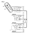
- FIG. 2 is a diagram for explaining a state in which the vehicle is parked at the parking position in the charging station. First, an outline of the present embodiment will be described with reference to FIGS.
- the non-contact power transmission system of the present embodiment includes a vehicle 10 and a charging station 90.
- Charging station 90 includes a communication unit 810, parking sections A to C, and power transmission units 700A to 700C provided in the parking sections A to C. 2 is a region where the vehicle 10 is located when the vehicle 10 stops so that any one of the power receiving unit 100 of the vehicle 10 and the power transmission units 700A to 700C of the charging station 90 face each other. Show.
- each of the power transmission units 700A and 700B of the power transmission devices 20A and 20B also has a vehicle stop region.
- the communication unit 810 can transmit a signal so as to reach the vehicle stop area R and the vehicle stop area R.
- the transmission area of communication unit 810 is, for example, in the range of a radius of 5 m to 10 m with communication unit 810 as the center.
- the communication unit 810 transmits a signal so as to reach not only the parking spaces A to C but also a position several meters away from the parking spaces A to C. If the vehicle 10 is in the parking spaces A to C or within a range of several meters from each parking space A to C, the vehicle 10 can receive a signal from the charging station 90.
- the vehicle 10 can communicate with the charging station 90 by transmitting a signal to the charging station 90 not only in the parking section but also outside the parking sections A to C (for example, a position about 5 to 10 m away).
- Unit 510 power receiving unit 100 configured to be able to receive power without contact from power transmitting units 700A to 700C, and display unit 520 for notifying the user of the relative positional relationship between power receiving unit 100 and power transmitting units 700A to 700C.
- a control unit vehicle ECU 500 that controls communication unit 510, power reception unit 100, and display unit 520.
- the charging station 90 includes sensors 21A to 21C provided in the parking areas A to C.
- the sensors 21A to 21C detect the presence / absence of a vehicle stopped in the parking sections A to C.
- the charging station 90 determines that the vehicle is not stopped in at least one parking section of the parking sections A to C based on the outputs from the sensors 21A to 21C, the charging station 90 broadcasts that the charging station 90 can transmit power. Send a signal to the surroundings.
- the charging station 90 determines that the vehicle is stopped in all of the parking sections A to C based on the outputs from the sensors 21A to 21C, the charging station 90 does not transmit the broadcast signal to the surroundings.
- the vehicle 10 is guided into the charging station 90 when the parking section is vacant.
- each of power reception unit 100 and power transmission units 700A to 700C is configured by a resonance circuit including a coil and a capacitor. Further, each of power transmission units 700A to 700C is configured to be able to form a plurality of resonance circuits having different circuit configurations.
- the charging station 90 receives the information related to the resonance circuit of the power reception unit 100
- the charging station 90 is the same as the resonance circuit of the power reception unit 100 among the plurality of resonance circuits in the power transmission unit corresponding to the parking area where the vehicle is not stopped.
- a resonant circuit having a circuit configuration is formed. Thereby, the structure of a resonance circuit can be match
- the vehicle 10 transmits to the surroundings a signal requesting output of position confirmation power for positioning the vehicle 10 with respect to the parking section.
- the position confirmation power is power output from the charging station 90 when positioning the vehicle 10 with respect to the parking area.
- the position confirmation power is the received voltage when the vehicle 10 receives the position confirmation power. Based on this, the vehicle 10 is aligned.
- the request signal is transmitted so as to reach a range of about 5 m to 10 m centering on the vehicle 10. Thereby, even if the vehicle 10 is located outside the parking sections A to C, the charging station 90 can receive the request signal.
- the charging station 90 When the charging station 90 receives the request signal, the charging station 90 supplies position confirmation power to at least the power transmission units 700A to 700C provided in the empty parking sections A to C. Then, vehicle ECU 500 causes display unit 520 to display the positional relationship between power reception unit 100 and one of power transmission units 700A to 700C based on power reception voltage VR generated by the power received by power reception unit 100. With such a configuration, power can be actually transmitted between the power transmission unit and the power reception unit, and alignment can be performed according to the result, so that the vehicle 10 can be reliably charged. Can do.
- the vehicle 10 includes a contactless charging switch 530 operated by a user, and the request signal that requests output of position confirmation power when the broadcast signal is received when the contactless charging switch 530 is ON. Send to the surroundings.
- the contactless charging switch 530 can be turned ON, so that the power receiving unit and the power transmitting unit can be aligned based on the received voltage.
- vehicle ECU 500 completes alignment of any one of power transmission units 700A to 700C of charging station 90 with power reception unit 100, which of power transmission units 700A to 700C is aligned with power reception unit 100. Is paired with the charging station 90 to identify the charging station 90 with the charging station 90. By this pairing process, even when the charging station is the charging station 90 having the plurality of power transmission units 700A to 700C, the power transmission unit that has been aligned can be specified.
- a plurality of different pattern power transmissions are transmitted from the power transmission units 700A to 700C, respectively, and a signal corresponding to the pattern power transmission received by the power reception unit 100 is transmitted from the communication unit 510 to the communication unit 810.
- the plurality of pattern power transmissions are power transmissions in which power transmission is performed at different power transmission times during a predetermined period (FIG. 9).
- the plurality of pattern power transmissions may be power transmissions that perform power transmission so as to repeat ON / OFF in different patterns during a predetermined period (FIG. 12).
- a contactless power transmission system includes a vehicle 10 equipped with a power receiving device 140 configured to be able to receive power in a non-contact manner, and a power transmission device 20A that transmits power to the power receiving unit 100 from outside the vehicle.
- the charging station 90 includes 20B and 20C.
- Vehicle 10 includes a power receiving device 140, a power storage device 300, a power generation device 400, a vehicle ECU 500, a communication unit 510, a display unit 520, and a non-contact charge switch 530.
- Power reception device 140 includes power reception unit 100, filter circuit 150, and rectification unit 200.
- Charging station 90 includes an external power supply 900, power transmission devices 20A, 20B, and 20C, a power supply ECU 800, and a communication unit 810.
- Power transmission devices 20A, 20B, and 20C include power supply units 600A, 600B, and 600C, filter circuits 610A, 610B, and 610C, and power transmission units 700A, 700B, and 700C, respectively.
- power transmission devices 20A, 20B, and 20C are provided on the ground surface or in the ground at parking positions A, B, and C, respectively, and power reception device 140 is disposed at the lower part of the vehicle body.
- the arrangement location of the power receiving device 140 is not limited thereto.
- the power receiving device 140 may be provided at the upper part of the vehicle body.
- the power receiving unit 100 includes a resonance circuit for receiving power (AC) output from any one of the power transmitting units 700A, 700B, and 700C of the power transmitting devices 20A, 20B, and 20C in a non-contact manner.
- the resonant circuit is composed of a coil and a capacitor. The configuration of the resonance circuit will be described later.
- the power receiving unit 100 outputs the received power to the rectifying unit 200.
- the rectifying unit 200 rectifies the AC power received by the power receiving unit 100 and outputs the rectified power to the power storage device 300.
- the filter circuit 150 is provided between the power reception unit 100 and the rectification unit 200, and suppresses harmonic noise generated during power reception.
- the filter circuit 150 is configured by an LC filter including an inductor and a capacitor, for example.
- the power storage device 300 is a rechargeable DC power source, and is constituted by a secondary battery such as a lithium ion battery or a nickel metal hydride battery.
- the voltage of power storage device 300 is, for example, about 200V.
- the power storage device 300 stores power output from the rectifying unit 200 and also stores power generated by the power generation device 400. Then, power storage device 300 supplies the stored power to power generation device 400. Note that a large-capacity capacitor can also be used as the power storage device 300.
- a DC-DC converter that adjusts the output voltage of the rectifying unit 200 may be provided between the rectifying unit 200 and the power storage device 300.
- the power generation device 400 generates the driving force for driving the vehicle 10 using the electric power stored in the power storage device 300.
- power generation device 400 includes, for example, an inverter that receives electric power from power storage device 300, a motor driven by the inverter, a drive wheel driven by the motor, and the like.
- Power generation device 400 may include a generator for charging power storage device 300 and an engine capable of driving the generator.
- the vehicle ECU 500 includes a CPU (Central Processing Unit), a storage device, an input / output buffer, and the like (none of which are shown), inputs signals from various sensors and outputs control signals to each device. Control each device in. As an example, vehicle ECU 500 executes traveling control of vehicle 10 and charging control of power storage device 300. In addition, vehicle ECU 500 transmits information related to the resonance circuit of power reception unit 100 to charging station 90 through communication unit 510. These controls are not limited to processing by software, but can also be processed by dedicated hardware (electronic circuit).
- a relay 210 is provided between the rectifying unit 200 and the power storage device 300.
- Relay 210 is turned on by vehicle ECU 500 when power storage device 300 is charged by power transmission devices 20A, 20B, and 20C.
- a system main relay (SMR) 310 is provided between the power storage device 300 and the power generation device 400. SMR 310 is turned on by vehicle ECU 500 when activation of power generation device 400 is requested.
- a resistor 201 is provided between the power line pair between the rectifying unit 200 and the relay 210, and the relay 202 is connected in series with the resistor 201. The voltage VR across the resistor 201 is detected by the voltage sensor 203 and sent to the vehicle ECU 500.
- the vehicle ECU 500 communicates with the communication unit 810 of the charging station 90 using the communication unit 510, and transmits information regarding the resonance circuit constituting the power receiving unit 100 to the charging station 90, as well as starting / stopping power transmission, Information such as the power reception status of the vehicle 10 is exchanged with the power supply ECU 800.
- the vehicle 10 receives power from the power transmission unit 700A of the power transmission apparatus 20A according to an in-vehicle camera (not shown), the power reception strength of the position confirmation power output from the power transmission unit 700A in the vehicle 10, and the like.
- the vehicle 10 or the charging station 90 determines whether the position of the unit 100 is correct, and the display unit 520 notifies the user. Based on the information obtained from the display unit 520, the user moves the vehicle 10 so that the positional relationship between the power receiving device 140 and the power transmitting device 20A is a favorable positional relationship for power transmission and reception.
- the user does not necessarily have to perform a steering wheel operation or an accelerator operation, and the vehicle 10 may automatically move to adjust the position, and the user may watch it on the display unit 520.
- information may be notified to the user by voice instead of the display unit 520 that visually notifies the user of the information.
- power supply units 600A, 600B, and 600C receive power from external power supply 900 such as a commercial power supply and generate AC power having a predetermined transmission frequency.
- Each of the power transmission units 700A, 700B, and 700C is configured to be capable of forming a plurality of resonance circuits having different circuit configurations.
- Each power transmission unit includes switching means for switching the circuit configuration of the resonance circuit by switching the connection configuration between the coil and the capacitor and the coil and the capacitor. The configuration of each power transmission unit will be described later. Then, power transmission units 700A, 700B, and 700C receive AC power having a transmission frequency from power supply units 600A, 600B, and 600C, respectively, and vehicle 10 through an electromagnetic field generated around power transmission units 700A, 700B, and 700C. Power is transmitted to the power receiving unit 100 in a non-contact manner.
- Filter circuits 610A, 610B, and 610C are provided between power supply units 600A, 600B, and 600C and power transmission units 700A, 700B, and 700C, and suppress harmonic noise generated from power supply units 600A, 600B, and 600C.
- Filter circuits 610A, 610B, and 610C are configured by LC filters including an inductor and a capacitor.
- the power supply ECU 800 includes a CPU, a storage device, an input / output buffer, and the like (all not shown), and inputs signals from various sensors and outputs control signals to each device. Take control. As an example, power supply ECU 800 performs switching control of power supply units 600A, 600B, and 600C so that power supply units 600A, 600B, and 600C generate AC power having a transmission frequency.
- the power supply ECU 800 when the power supply ECU 800 receives information about the resonance circuit constituting the power reception unit 100 of the vehicle 10 from the vehicle 10 by the communication unit 810, the power supply ECU 800 enters the parking area where the vehicle is not stopped.
- power transmission units 700A to 700C are controlled such that a resonance circuit having the same circuit configuration as the resonance circuit of power reception unit 100 is formed from the plurality of resonance circuits. Note that these controls are not limited to processing by software, and can be processed by dedicated hardware (electronic circuit).
- the power supply ECU 800 communicates with the communication unit 510 of the vehicle 10 using the communication unit 810 to receive information on the resonance circuit that constitutes the power reception unit 100 from the vehicle 10, start / stop of power transmission, and power reception of the vehicle 10. Information such as the situation is exchanged with the vehicle 10.
- AC power having a predetermined transmission frequency is supplied from power supply units 600A, 600B, and 600C to power transmission units 700A, 700B, and 700C through filter circuits 610A, 610B, and 610C.
- Each of power transmission units 700A, 700B, 700C and power reception unit 100 of vehicle 10 includes a coil and a capacitor, and is designed to resonate at a transmission frequency.
- the Q value indicating the resonance strength of power transmission units 700A, 700B, 700C and power reception unit 100 is preferably 100 or more.
- power transmission devices 20A, 20B, and 20C between power transmission units 700A, 700B, and 700C and power supply units 600A, 600B, and 600C (for example, power transmission units 700A, 700B, and 700C and filter circuits 610A, 610B,
- An insulation transformer may be provided between 610C and the above.
- an insulating transformer may be provided between power reception unit 100 and rectification unit 200 (for example, between power reception unit 100 and filter circuit 150).
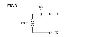
- FIGS. 3 to 6 are diagrams illustrating configuration examples of the resonance circuit constituting the power receiving unit 100 of the vehicle 10.
- the power receiving unit 100 is constituted by a resonance circuit shown in any of FIGS.
- power reception unit 100 includes a coil 110 and a capacitor 120.
- the capacitor 120 is connected to the coil 110 in series. That is, the power receiving unit 100 is configured by an S (Series) configuration resonance circuit.
- FIG. 4 another example of power reception unit 100 includes a coil 110 and a capacitor 130. Capacitor 130 is connected to coil 110 in parallel. That is, the power receiving unit 100 is configured by a resonance circuit having a P (Parallel) configuration.
- still another example of power reception unit 100 includes a coil 110 and capacitors 120 and 130.
- the capacitor 120 is connected to the coil 110 in series.
- the capacitor 130 is connected in parallel to the coil 110 on the coil 110 side of the capacitor 120. That is, the power receiving unit 100 is configured by a resonance circuit having an SP configuration.
- yet another example of power reception unit 100 includes a coil 110 and capacitors 120 and 130.
- Capacitor 130 is connected to coil 110 in parallel.
- the capacitor 120 is connected in series to the coil 110 on the coil 110 side of the capacitor 130. That is, the power receiving unit 100 is configured by a PS configuration resonance circuit.
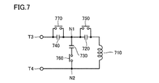
- FIG. 7 is a diagram illustrating a configuration example of the power transmission unit 700A of the power transmission device 20A.
- charging station 90 includes power transmission units 700B and 700C, but the configuration of power transmission units 700B and 700C is the same as the configuration of power transmission unit 700A.
- power transmission unit 700A includes a coil 710, capacitors 720, 730, and 740, and relays 750, 760, and 770.
- Capacitor 720 is connected between one end of coil 710 and node N1.
- Capacitor 730 is provided in parallel with coil 710, and one end of capacitor 730 is connected to node N1.
- Capacitor 740 is connected between node N1 and terminal T3 connected to filter circuit 610A (FIG. 1). That is, the capacitors 720 and 740 are provided in series with the coil 710, and the capacitor 730 is provided in parallel with the coil 710.
- Relays 750 and 770 are connected in parallel to capacitors 720 and 740, respectively.
- Relay 760 is connected in series with capacitor 730.
- Relay 760 may be provided between node N1 and capacitor 730.
- Relays 750, 760, and 770 are controlled to be turned on or off by power supply ECU 800 (FIG. 1).
- the power transmission unit 700A can form a resonance circuit of any one of the S configuration, the P configuration, the SP configuration, and the PS configuration. That is, the relay circuit 750, 760, and 770 is turned off, off, and on, respectively, thereby forming an S configuration resonance circuit. Further, when all of the relays 750, 760, and 770 are turned on, a P configuration resonance circuit is formed. Further, by turning on, off, and off relays 750, 760, and 770, a resonant circuit having an SP configuration is formed. Further, by turning the relays 750, 760, and 770 off, on, and on, respectively, a PS configuration resonance circuit is formed.
- information related to the resonance circuit of the power receiving unit 100 (specifically, the configuration type of the resonance circuit) is transmitted from the vehicle 10 to the charging station 90. Then, in power transmission units 700A to 700C where the vehicle is not stopped, by appropriately operating relays 750 to 770, a resonance circuit having the same configuration as the resonance circuit of power reception unit 100 is formed.
- each of the power transmission units 700A to 700C different types of resonance circuits are formed by switching the circuit configuration with relays 750 to 770.
- each of the power transmission units 700A to 700C has an S configuration.
- the resonance circuit itself may be switchable including the resonance circuits of the P configuration, the SP configuration, and the PS configuration.
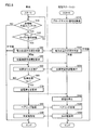
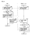
- FIG. 8 is a flowchart for explaining an outline of processing executed by the vehicle 10 and the charging station 90 when executing non-contact power transmission.
- FIG. 9 is a timing chart showing changes in transmitted power and received voltage that change in the process of FIG.
- power supply ECU 800 determines that at least one of parking sections A to C is vacant based on outputs from sensors 21A to 21C. Then, a broadcast signal notifying that the charging station 90 is in a state where power can be transmitted is transmitted to the surroundings (step S510).
- the vehicle ECU 500 determines whether or not the non-contact charging switch 530 is “ON” (step S10).
- the non-contact charging switch 530 is in an “ON” state unless operated by the user, and is turned “OFF” when operated by the user.
- contactless charging switch 530 is “OFF” (NO in step S10), vehicle ECU 500 ends the process without executing a series of subsequent processes.
- step S10 If it is determined in step S10 that contactless charging switch 530 is “ON” (YES in step S10), vehicle ECU 500 determines whether a broadcast signal has been received from charging station 90 (step S20). When the broadcast signal is not received (NO in step S20), the process returns to step S10.
- step S20 When the broadcast signal is received in vehicle 10 (YES in step S20), information related to the resonance circuit of power reception unit 100 is transmitted from vehicle 10 to charging station 90, and in vehicle ECU 500 of vehicle 10 and power supply ECU 800 of charging station 90, A determination process is performed to determine whether or not power transmission from the charging station 90 to the vehicle 10 is possible (steps S30 and S530). This determination process will be described in detail later.
- step S40 If it is determined that the power transmission from the charging station 90 to the vehicle 10 is impossible, the processing ends at the vehicle 10 and the charging station 90. On the other hand, when it is determined that power transmission from charging station 90 to vehicle 10 is possible, vehicle ECU 500 of vehicle 10 transmits a signal requesting output of position confirmation power to charging station 90 (step S40). .
- the power supply ECU 800 controls the power supply units 600A to 600C so that the position confirmation power is output from the power transmission unit in the parking area where the vehicle is not stopped (step). S550).
- power supply ECU 800 does not know in which parking section the vehicle is parked. Therefore, in this case, power supply ECU 800 causes power supply units 600A to 600C to output position confirmation power from all of the power transmission units in the parking area where full power transmission for charging power storage device 300 is not performed. Control.
- the vehicle ECU 500 When the position confirmation power is received in the vehicle 10, the vehicle ECU 500 performs alignment by automatically or manually moving the vehicle 10 based on the received voltage (step S50) (see time t1 in FIG. 9). ). At the time of alignment, the vehicle ECU 500 conducts the relay 202 and acquires the received voltage VR generated at both ends of the resistor 201 detected by the voltage sensor 203. Since the power reception voltage VR at the time of alignment is smaller than the power reception voltage (charging voltage) at the time of full-scale power transmission for charging the power storage device 300, the relay 210 is turned off so as not to be affected by the power storage device 300 at the time of voltage detection. .
- Step S70 (see time t2 in FIG. 9).
- power supply ECU 800 stops power transmission for position confirmation by power transmission devices 20A, 20B, and 20C (step S560) (see time t3 in FIG. 9).
- power reception voltage VR in vehicle 10 is between the coils of power transmission devices 20A, 20B, and 20C and the coil of power reception device 140. Varies with distance. Therefore, the relationship between the horizontal position difference between the core gravity center O1 of the coil on the power transmission side and the core gravity center O2 of the coil on the power reception side and the power reception voltage VR is measured in advance, and the core gravity center O1 and the core gravity center O2 The received voltage VR for the allowable value of the horizontal position difference is set as the threshold value TH.
- vehicle ECU 500 and power supply ECU 800 execute a pairing process that specifies which of power transmission devices 20A, 20B, and 20C has been aligned (steps S80 and S580).
- the power supply ECU 800 varies the ON duration of the transmission power for each power transmission device. That is, power transmission device 20A turns on the transmission power for TA time, power transmission device 20B turns on the transmission power for TB time, and power transmission device 20C turns on the transmission power for TC time (see time t4 in FIG. 9).
- vehicle ECU 500 notifies power supply ECU 800 of the ON duration of the received power.
- the power receiving device 140 receives the transmitted power from the power transmitting device 20A.
- Vehicle ECU 500 notifies power supply ECU 800 that the duration of on-time of the received power is TA. Thereby, power supply ECU 800 recognizes that alignment with power transmission device 20A has been performed.
- charging station 90 performs full-scale power transmission processing for charging power storage device 300 using the power transmission device that has been aligned and identified by pairing (see time t6 in FIG. 9). ).
- the power transmission device 20A performs power transmission processing.
- full-scale power reception processing for charging power storage device 300 is performed by power reception device 140, and power storage device 300 is charged with the received power. Then, when charging of power storage device 300 is completed, the processing in vehicle 10 and charging station 90 ends.
- FIG. 10 is a flowchart illustrating the power transmission availability determination process executed in steps S30 and S530 shown in FIG.
- vehicle ECU 500 transmits information related to the resonance circuit of power reception unit 100 to charging station 90 (step S100).
- the information about the resonance circuit includes at least information about whether the resonance circuit is configured by an S configuration, a P configuration, an SP configuration, or a PS configuration. Information such as size may be included.
- power supply ECU 800 determines whether power transmission from charging station 90 to vehicle 10 is possible based on the received information. (Step S104). Specifically, whether or not the power transmission units 700A to 700C can form a resonance circuit having the same circuit configuration as the resonance circuit of the power reception unit 100, and if so, whether the coil 110 of the power reception unit 100 has an appropriate size. Based on whether or not the power transmission from the charging station 90 to the vehicle 10 is possible.
- step S104 If it is determined in step S104 that power transmission from charging station 90 to vehicle 10 is possible (YES in step S104), power supply ECU 800 is power receiving unit 100 in the power transmission unit of the parking area where the vehicle is not stopped. The relays 750 to 770 are controlled so that a resonance circuit having the same circuit configuration as that of the resonance circuit is formed (step S105). Then, power supply ECU 800 transmits information related to power transmission from charging station 90 to vehicle 10 to vehicle 10 (step S106). Note that this information includes, for example, information on the range of power that can be output from the charging station 90.
- step S104 If it is determined in step S104 that power transmission from charging station 90 to vehicle 10 is not possible (NO in step S104), power supply ECU 800 displays information indicating that power transmission is impossible in vehicle 10. (Step S108).
- step S110 when information (information regarding power transmission or information indicating that power transmission is impossible) is received from charging station 90 (step S110), based on the received information, vehicle ECU 500 Then, it is determined whether or not power can be received from the charging station 90 (step S112). If it is determined that power can be received (YES in step S112), vehicle ECU 500 determines the amount of received power received from charging station 90 (step S114). If it is determined in step S112 that power cannot be received (NO in step S112), an alarm indicating that power cannot be received is output (step S116).
- each of power transmission units 700A to 700C of charging station 90 can be formed into a plurality of types of resonance circuits (S configuration, P configuration, SP configuration, PS configuration), and based on information about the resonance circuit of power reception unit 100, In the power transmission unit of the parking section where the vehicle is not stopped, a resonance circuit having the same circuit configuration as the resonance circuit of the power reception unit 100 is formed. That is, the circuit configuration of the resonance circuit is the same between the power transmission unit of the charging station 90 and the power reception unit 100 of the vehicle 10. Therefore, according to this embodiment, impedance mismatch between charging station 90 and vehicle 10 due to the circuit configuration of the resonance circuit being different between power transmission units 700A to 700C and power reception unit 100 can be suppressed.
- FIG. 11 is a flowchart for explaining the power transmission availability determination process in the first modification. This flowchart corresponds to FIG. 10, and the entire power transmission process is the same as the process in the first embodiment shown in FIG.
- power supply ECU 800 transmits information related to the resonance circuit of power transmission units 700A to 700C to vehicle 10 (step S200).
- This information includes at least information about the configuration of the resonance circuit that can be formed in power transmission units 700A to 700C, and may include information such as the capacitance of capacitors 720 to 740 and the size of coil 710.
- vehicle ECU 500 determines whether or not electric power can be transmitted from charging station 90 to vehicle 10 based on the received information. Determination is made (step S204). Specifically, whether or not the power transmission units 700A to 700C can form a resonance circuit having the same circuit configuration as the resonance circuit of the power reception unit 100, and if so, the coils 710 of the power transmission units 700A to 700C have an appropriate size. Whether or not power transmission from the charging station 90 to the vehicle 10 is possible is determined based on whether or not there is.
- vehicle ECU 500 charges information related to power transmission and information related to the resonance circuit of power reception unit 100. It transmits to the station 90 (step S206).
- the information related to power transmission includes, for example, information related to the range of power that can be received by the vehicle 10.
- the information regarding the resonance circuit of the power receiving unit 100 includes at least information on whether the resonance circuit is configured by the S configuration, the P configuration, the SP configuration, or the PS configuration, and further includes the capacitor 120 (130). Information such as the capacity and the size of the coil 110 may be included.
- step S204 If it is determined in step S204 that power transmission from charging station 90 to vehicle 10 is impossible (NO in step S204), vehicle ECU 500 displays information indicating that power transmission is impossible in charging station. 90 (step S208).
- step S212 when information (information regarding power transmission and resonance circuit, or information indicating that power transmission is impossible) is received from vehicle 10 (step S212), based on the received information, The power supply ECU 800 determines whether power can be transmitted to the vehicle 10 (step S214). If it is determined that power transmission is possible (YES in step S214), power supply ECU 800 has a resonance circuit having the same circuit configuration as the resonance circuit of power reception unit 100 in the power transmission unit of the parking section where the vehicle is not stopped. The relays 750 to 770 are controlled so as to be formed (step S216). If it is determined in step S214 that power transmission is not possible, the process ends without executing the process of step S216.
- FIG. 12 is a diagram for explaining a modification of the pairing process.
- power supply ECU 800 varies the on / off switching cycle of transmitted power for each power transmission device. That is, the power transmission device 20A switches transmission power on and off for each cycle ⁇ TA, the power transmission device 20B switches transmission power on and off for each cycle ⁇ TB, and the power transmission device 20C transmits transmission power for each cycle ⁇ TC. Switching between on and off (see times t4 to t5 in FIG. 12).
- Vehicle ECU 500 notifies power supply ECU 800 of the on / off switching cycle of the received power.
- the power receiving device 140 receives the transmitted power from the power transmitting device 20A.
- Vehicle ECU 500 notifies power supply ECU 800 that the switching cycle of the received power on and off is ⁇ TA.
- power supply ECU 800 knows that alignment with power transmission device 20A has been performed (see time t5 in FIG. 12).
- This modification 2 is a modification in which pairing is performed using transmission power, but the method of pairing processing is not limited to this. Pairing is possible with various technologies. For example, pairing is performed by using RFID (Radio Frequency IDentification) technology and providing an RFID tag and an RFID reader in the vehicle and the power transmission unit, respectively. Also good.
- RFID Radio Frequency IDentification
- the first embodiment and the modified examples 1 and 2 include a resonance circuit having a configuration in which the power receiving unit 100 of the vehicle 10 is provided, and each power transmitting unit of the charging station.
- 700A to 700C can be formed by selecting any one of a plurality of resonance circuits, but has a resonance circuit having a configuration with a power transmission unit of a charging station, and selects one of a plurality of resonance circuits in a power reception unit of a vehicle And may be formed.
- the power transmission unit of the charging station 90 is formed with the resonance circuit having the same circuit configuration as the resonance circuit of the power reception unit 100. If obtained, the circuit configuration of the power transmission unit may be different from the circuit configuration of the power reception unit 100. For example, when the power reception unit 100 is configured by a P configuration resonance circuit, an S configuration resonance circuit is formed in the power transmission unit, or when the power reception unit 100 is configured by a PS configuration resonance circuit Moreover, a resonance circuit having an SP configuration may be formed in the power transmission unit.
Landscapes
- Engineering & Computer Science (AREA)
- Power Engineering (AREA)
- Transportation (AREA)
- Mechanical Engineering (AREA)
- Computer Networks & Wireless Communication (AREA)
- Life Sciences & Earth Sciences (AREA)
- Sustainable Development (AREA)
- Sustainable Energy (AREA)
- Electric Propulsion And Braking For Vehicles (AREA)
- Charge And Discharge Circuits For Batteries Or The Like (AREA)
Abstract
An electric reception unit (100) includes a resonance circuit for contactlessly receiving electric power outputted from electric transmission units (700A-700C). The respective transmission units (700A-700C) are configured to be able to form a plurality of resonance circuits having different circuit configurations from each other. A communication unit (510) transmits data pertaining to the configuration of the resonance circuit of the electric reception unit (100) to a communication unit (810). A power source ECU (800) controls the electric transmission units (700A-700C) such that a resonance circuit, among the plurality of resonance circuits, having the same circuit configuration as the resonance circuit of the electric reception unit (100) is formed in the electric transmission units (700A-700C).
Description
この発明は、非接触電力伝送システムに関し、特に、充電ステーションから車両へ非接触で電力を伝送する非接触電力伝送システム及びにそれに用いられる送電装置に関する。
The present invention relates to a non-contact power transmission system, and more particularly to a non-contact power transmission system that transmits power from a charging station to a vehicle in a non-contact manner and a power transmission device used therefor.
特開2011-223739号公報(特許文献1)は、給電装置から受電装置へ非接触で電力を伝送するワイヤレス給電システムを開示する。このワイヤレス給電システムにおいては、給電装置は、電力生成部により生成される電力が供給される送電素子と、送電素子の給電点におけるインピーダンス整合機能を含む第1の可変整合部とを含む。受電装置は、磁界共鳴関係をもって送電された電力を受電する受電素子と、送電素子の負荷との接続部のインピーダンス整合機能を含む第2の可変整合部とを含む。このワイヤレス給電システムによれば、第1および第2の可変整合部によって、送電側および受電側の双方のインピーダンス調整を行なうことができる(特許文献1参照)。
Japanese Patent Laying-Open No. 2011-223739 (Patent Document 1) discloses a wireless power feeding system that transmits power from a power feeding device to a power receiving device in a contactless manner. In this wireless power feeding system, the power feeding device includes a power transmission element to which power generated by the power generation unit is supplied, and a first variable matching unit including an impedance matching function at a power feeding point of the power transmission element. The power receiving device includes a power receiving element that receives power transmitted with a magnetic field resonance relationship, and a second variable matching unit including an impedance matching function of a connection part between a load of the power transmitting element. According to this wireless power feeding system, both the power transmission side and the power receiving side impedance adjustment can be performed by the first and second variable matching units (see Patent Document 1).
上記のようなワイヤレス給電システムを、充電ステーションから車両へ非接触で電力を伝送する非接触電力伝送システムに適用することが検討されている。
Application of the wireless power feeding system as described above to a non-contact power transmission system that transmits power from a charging station to a vehicle in a non-contact manner is being studied.
充電ステーションの送電部および車両の受電部の各々においては、電力伝送効率を高めるために共振回路が用いられ得る。共振回路の構成については、複数のタイプが提案されており、キャパシタがコイルに直列に接続されるタイプ(以下「S」(Series)構成と称する。)、キャパシタがコイルに並列に接続されるタイプ(以下「P」(Parallel)構成と称する。)、P構成の回路にさらにキャパシタが直列に接続されるタイプ(以下「SP」構成と称する。)、S構成の回路にさらにキャパシタが並列に接続されるタイプ(以下「PS」構成と称する。)等がある。
In each of the power transmitting unit of the charging station and the power receiving unit of the vehicle, a resonance circuit can be used to increase the power transmission efficiency. A plurality of types of resonant circuit configurations have been proposed. A type in which a capacitor is connected in series to a coil (hereinafter referred to as “S” (Series) configuration), and a type in which a capacitor is connected in parallel to a coil. (Hereinafter referred to as “P” (Parallel) configuration), a type in which a capacitor is further connected in series to a circuit of P configuration (hereinafter referred to as “SP” configuration), and a capacitor is further connected in parallel to a circuit of S configuration. Type (hereinafter referred to as “PS” configuration).
送電部と受電部とで共振回路の構成が異なる場合、特許文献1に記載のような可変整合部が設けられているときは、可変整合部によるインピーダンスの調整が複雑になり得る。可変整合部が設けられていないとき、たとえば固定型の整合器として機能し得るLCフィルタが設けられているようなときは、送電側と受電側のインピーダンス不整合により電力伝送効率が著しく低下するおそれがある。
When the configuration of the resonance circuit is different between the power transmission unit and the power reception unit, when a variable matching unit as described in Patent Document 1 is provided, adjustment of impedance by the variable matching unit may be complicated. When the variable matching unit is not provided, for example, when an LC filter that can function as a fixed type matcher is provided, the power transmission efficiency may be significantly reduced due to impedance mismatch between the power transmission side and the power reception side. There is.
この発明は、かかる問題点を解決するためになされたものであり、その目的は、充電ステーションから車両へ非接触で電力を伝送する非接触電力伝送システムにおいて、充電ステーションと車両とのインピーダンス不整合を抑制することである。
The present invention has been made to solve such problems, and an object of the present invention is to provide impedance mismatch between a charging station and a vehicle in a non-contact power transmission system that transmits power from the charging station to the vehicle in a non-contact manner. It is to suppress.
この発明によれば、非接触電力伝送システムは、充電ステーションと、充電ステーションから非接触で受電可能に構成された車両とを備える。充電ステーションは、車両へ非接触で送電するための送電部と、車両と通信する第1の通信装置と、制御装置とを含む。車両は、送電部から出力される電力を非接触で受電するための受電用共振回路と、充電ステーションと通信する第2の通信装置とを含む。送電部は、互いに回路構成が異なる複数の送電用共振回路を形成可能に構成される。第2の通信装置は、受電用共振回路の構成に関する情報を第1の通信装置へ送信する。制御装置は、第1の通信装置によって上記情報が受信されると、受信された情報に基づいて送電部において共振回路が形成されるように送電部を制御する。
According to this invention, the contactless power transmission system includes a charging station and a vehicle configured to be able to receive power from the charging station in a contactless manner. The charging station includes a power transmission unit for transmitting power to the vehicle in a non-contact manner, a first communication device that communicates with the vehicle, and a control device. The vehicle includes a power receiving resonance circuit for receiving power output from the power transmission unit in a contactless manner, and a second communication device that communicates with the charging station. The power transmission unit is configured to be capable of forming a plurality of power transmission resonance circuits having different circuit configurations. The second communication device transmits information related to the configuration of the power receiving resonance circuit to the first communication device. When the information is received by the first communication device, the control device controls the power transmission unit so that a resonance circuit is formed in the power transmission unit based on the received information.
この非接触電力伝送システムにおいては、受電用共振回路の構成に関する情報に基づいて、複数の送電用共振回路の中からより適切な電流電圧特性が得られる共振回路を送電部において形成し得る。したがって、この非接触電力伝送システムによれば、充電ステーションと車両とのインピーダンス不整合を抑制することができる。
In this non-contact power transmission system, a resonance circuit that can obtain a more appropriate current-voltage characteristic from among a plurality of resonance circuits for power transmission can be formed in the power transmission unit based on information related to the configuration of the power reception resonance circuit. Therefore, according to this non-contact power transmission system, impedance mismatch between the charging station and the vehicle can be suppressed.
また、この発明によれば、非接触電力伝送システムは、充電ステーションと、充電ステーションから非接触で受電可能に構成された車両とを備える。充電ステーションは、車両へ非接触で送電するための送電部と、車両と通信する第1の通信装置と、制御装置とを含む。車両は、送電部から出力される電力を非接触で受電するための受電用共振回路と、充電ステーションと通信する第2の通信装置とを含む。送電部は、互いに回路構成が異なる複数の送電用共振回路を形成可能に構成される。第2の通信装置は、受電用共振回路の構成に関する情報を第1の通信装置へ送信する。制御装置は、第1の通信装置によって上記情報が受信されると、複数の送電用共振回路の中から受電用共振回路と同じ回路構成を有する共振回路が送電部において形成されるように送電部を制御する。
Further, according to the present invention, the contactless power transmission system includes a charging station and a vehicle configured to be able to receive power from the charging station in a contactless manner. The charging station includes a power transmission unit for transmitting power to the vehicle in a non-contact manner, a first communication device that communicates with the vehicle, and a control device. The vehicle includes a power receiving resonance circuit for receiving power output from the power transmission unit in a contactless manner, and a second communication device that communicates with the charging station. The power transmission unit is configured to be capable of forming a plurality of power transmission resonance circuits having different circuit configurations. The second communication device transmits information related to the configuration of the power receiving resonance circuit to the first communication device. When the information is received by the first communication device, the control device is configured so that a resonance circuit having the same circuit configuration as the power reception resonance circuit is formed in the power transmission unit from among the plurality of power transmission resonance circuits. To control.
この非接触電力伝送システムにおいては、充電ステーションの送電部と車両の受電部とで共振回路の回路構成が同じにされる。したがって、この非接触電力伝送システムによれば、送電部と受電部とで共振回路の回路構成が異なることによる充電ステーションと車両とのインピーダンス不整合を抑制することができる。
In this non-contact power transmission system, the circuit configuration of the resonance circuit is made the same between the power transmission unit of the charging station and the power reception unit of the vehicle. Therefore, according to this non-contact power transmission system, impedance mismatch between the charging station and the vehicle due to the difference in circuit configuration of the resonance circuit between the power transmission unit and the power reception unit can be suppressed.
好ましくは、送電部は、S構成、P構成、SP構成、及びPS構成のいずれかの送電用共振回路を選択的に形成するための切替回路を含む。
Preferably, the power transmission unit includes a switching circuit for selectively forming a power transmission resonance circuit of any one of an S configuration, a P configuration, an SP configuration, and a PS configuration.
この発明によれば、充電ステーションから車両へ非接触で電力を伝送する非接触電力伝送システムにおいて、充電ステーションと車両とのインピーダンス不整合を抑制することができる。
According to the present invention, impedance mismatch between the charging station and the vehicle can be suppressed in the contactless power transmission system that transmits power from the charging station to the vehicle in a contactless manner.
以下、本発明の実施の形態について、図面を参照しながら詳細に説明する。なお、図中同一または相当部分には同一符号を付してその説明は繰返さない。
Hereinafter, embodiments of the present invention will be described in detail with reference to the drawings. In the drawings, the same or corresponding parts are denoted by the same reference numerals and description thereof will not be repeated.
(非接触電力伝送システムの概要の説明)
図1は、本発明の実施の形態による非接触電力伝送システムの全体構成図である。図2は、車両が充電ステーション内の駐車位置に駐車する様子を説明するための図である。最初に、図1,図2を用いて本実施の形態についての概要を説明する。 (Outline of contactless power transmission system)
FIG. 1 is an overall configuration diagram of a contactless power transmission system according to an embodiment of the present invention. FIG. 2 is a diagram for explaining a state in which the vehicle is parked at the parking position in the charging station. First, an outline of the present embodiment will be described with reference to FIGS.
図1,図2を参照して、本実施の形態の非接触電力伝送システムは、車両10と、充電ステーション90とを備える。充電ステーション90は、通信部810と、駐車区画A~Cと、各駐車区画A~C内に設けられた送電部700A~700Cとを含む。図2の「車両停車領域R」は、車両10の受電部100と充電ステーション90の送電部700A~700Cのいずれかが対向するように、車両10が停車したときに車両10が位置する領域を示す。
1 and 2, the non-contact power transmission system of the present embodiment includes a vehicle 10 and a charging station 90. Charging station 90 includes a communication unit 810, parking sections A to C, and power transmission units 700A to 700C provided in the parking sections A to C. 2 is a region where the vehicle 10 is located when the vehicle 10 stops so that any one of the power receiving unit 100 of the vehicle 10 and the power transmission units 700A to 700C of the charging station 90 face each other. Show.
なお、図2においては、送電装置20Cの送電部700Cに関する車両停車領域について示したが、当然のことながら、送電装置20A,20Bの送電部700A,700Bの各々においても、車両停車領域を有する。
In FIG. 2, the vehicle stop region related to the power transmission unit 700C of the power transmission device 20C is shown, but it should be understood that each of the power transmission units 700A and 700B of the power transmission devices 20A and 20B also has a vehicle stop region.
通信部810は、車両停車領域R内および車両停車領域R外に達するように信号を発信可能とされている。具体的には、通信部810の発信エリアは、通信部810を中心として、たとえば半径5m~10mの範囲である。
The communication unit 810 can transmit a signal so as to reach the vehicle stop area R and the vehicle stop area R. Specifically, the transmission area of communication unit 810 is, for example, in the range of a radius of 5 m to 10 m with communication unit 810 as the center.
換言すれば、通信部810は、駐車区画A~C内のみならず、駐車区画A~Cから数メートル離れた位置まで達するように信号を発信する。仮に、駐車区画A~C内または各駐車区画A~Cから数メートルの範囲内に車両10があると、車両10は、充電ステーション90からの信号を受信することができる。
In other words, the communication unit 810 transmits a signal so as to reach not only the parking spaces A to C but also a position several meters away from the parking spaces A to C. If the vehicle 10 is in the parking spaces A to C or within a range of several meters from each parking space A to C, the vehicle 10 can receive a signal from the charging station 90.
車両10は、駐車区画内のみならず、駐車区画A~Cの外(たとえば5~10m程度離れた位置)から充電ステーション90に信号を送信して、充電ステーション90に受信させることが可能な通信部510と、送電部700A~700Cから非接触で受電可能に構成された受電部100と、受電部100と送電部700A~700Cとの相対的な位置関係をユーザに報知するための表示部520と、通信部510、受電部100および表示部520を制御する制御部(車両ECU500)とを備える。
The vehicle 10 can communicate with the charging station 90 by transmitting a signal to the charging station 90 not only in the parking section but also outside the parking sections A to C (for example, a position about 5 to 10 m away). Unit 510, power receiving unit 100 configured to be able to receive power without contact from power transmitting units 700A to 700C, and display unit 520 for notifying the user of the relative positional relationship between power receiving unit 100 and power transmitting units 700A to 700C. And a control unit (vehicle ECU 500) that controls communication unit 510, power reception unit 100, and display unit 520.
好ましくは、充電ステーション90は、各駐車区画内A~Cに設けられたセンサ21A~21Cを含む。センサ21A~21Cは、駐車区画A~C内に停車している車両の有無を検知する。充電ステーション90は、センサ21A~21Cからの出力に基づいて、駐車区画A~Cの少なくとも1つの駐車区画に車両が停車していないと判断すると、充電ステーション90が送電可能であることを知らせるブロードキャスト信号を周囲に発信する。その一方で、充電ステーション90は、センサ21A~21Cからの出力に基づいて、駐車区画A~Cの全てに車両が停車していると判断すると、上記ブロードキャスト信号を周囲に発信しない。これにより、駐車区画が空いているときに車両10が充電ステーション90内に案内されることになる。
Preferably, the charging station 90 includes sensors 21A to 21C provided in the parking areas A to C. The sensors 21A to 21C detect the presence / absence of a vehicle stopped in the parking sections A to C. When the charging station 90 determines that the vehicle is not stopped in at least one parking section of the parking sections A to C based on the outputs from the sensors 21A to 21C, the charging station 90 broadcasts that the charging station 90 can transmit power. Send a signal to the surroundings. On the other hand, when the charging station 90 determines that the vehicle is stopped in all of the parking sections A to C based on the outputs from the sensors 21A to 21C, the charging station 90 does not transmit the broadcast signal to the surroundings. Thus, the vehicle 10 is guided into the charging station 90 when the parking section is vacant.
車両10は、充電ステーション90から上記ブロードキャスト信号を受信すると、受電部100を構成する共振回路(具体的な構成については後述)に関する情報を周囲に発信する。すなわち、受電部100および送電部700A~700Cの各々は、コイルおよびキャパシタを含む共振回路によって構成されている。さらに、送電部700A~700Cの各々は、互いに回路構成が異なる複数の共振回路を形成可能に構成される。そして、充電ステーション90は、受電部100の共振回路に関する上記情報を受信すると、車両が停車していない駐車区画に対応する送電部において、複数の共振回路の中から受電部100の共振回路と同じ回路構成を有する共振回路が形成される。これにより、車両10が案内される駐車区画の送電部と車両10の受電部100とで共振回路の構成を合わせることができる。
When the vehicle 10 receives the broadcast signal from the charging station 90, the vehicle 10 transmits information about a resonance circuit (which will be described later in detail) constituting the power receiving unit 100 to the surroundings. That is, each of power reception unit 100 and power transmission units 700A to 700C is configured by a resonance circuit including a coil and a capacitor. Further, each of power transmission units 700A to 700C is configured to be able to form a plurality of resonance circuits having different circuit configurations. When the charging station 90 receives the information related to the resonance circuit of the power reception unit 100, the charging station 90 is the same as the resonance circuit of the power reception unit 100 among the plurality of resonance circuits in the power transmission unit corresponding to the parking area where the vehicle is not stopped. A resonant circuit having a circuit configuration is formed. Thereby, the structure of a resonance circuit can be match | combined with the power transmission part of the parking area where the vehicle 10 is guided, and the power receiving part 100 of the vehicle 10. FIG.
次いで、車両10は、駐車区画に対して車両10の位置合わせを行なうための位置確認用電力の出力を要求する信号を周囲に発信する。なお、位置確認用電力とは、駐車区画に対して車両10の位置合わせを行なう際に充電ステーション90から出力される電力であり、この位置確認用電力を車両10で受電したときの受電電圧に基づいて車両10の位置合わせが行なわれる。なお、上記の要求信号は、車両10を中心として、5m~10m程度の範囲に届くように発信される。これにより、車両10が駐車区画A~Cの外側に位置していたとしても、充電ステーション90は、要求信号を受信することができる。
Next, the vehicle 10 transmits to the surroundings a signal requesting output of position confirmation power for positioning the vehicle 10 with respect to the parking section. The position confirmation power is power output from the charging station 90 when positioning the vehicle 10 with respect to the parking area. The position confirmation power is the received voltage when the vehicle 10 receives the position confirmation power. Based on this, the vehicle 10 is aligned. The request signal is transmitted so as to reach a range of about 5 m to 10 m centering on the vehicle 10. Thereby, even if the vehicle 10 is located outside the parking sections A to C, the charging station 90 can receive the request signal.
そして、充電ステーション90が上記要求信号を受信すると、充電ステーション90は、少なくとも空いている駐車区画A~C内に設けられた送電部700A~700Cに位置確認用電力を供給する。そして、車両ECU500は、受電部100で受電された電力によって生じる受電電圧VRに基づいて、受電部100と送電部700A~700Cのいずれかとの位置関係を表示部520に表示させる。このような構成とすることにより、実際に送電部と受電部との間で電力伝送を行なわせて、その結果に応じて位置合わせを行なうことができるので、確実に車両10の充電をすることができる。
When the charging station 90 receives the request signal, the charging station 90 supplies position confirmation power to at least the power transmission units 700A to 700C provided in the empty parking sections A to C. Then, vehicle ECU 500 causes display unit 520 to display the positional relationship between power reception unit 100 and one of power transmission units 700A to 700C based on power reception voltage VR generated by the power received by power reception unit 100. With such a configuration, power can be actually transmitted between the power transmission unit and the power reception unit, and alignment can be performed according to the result, so that the vehicle 10 can be reliably charged. Can do.
好ましくは、車両10は、使用者によって操作される非接触充電スイッチ530を含み、非接触充電スイッチ530がONのときに上記ブロードキャスト信号を受信すると、位置確認用電力の出力を要求する上記要求信号を周囲に発信する。このような構成により、たとえば、使用者が充電をしたいときには、非接触充電スイッチ530をONとすることで、受電電圧に基づいて受電部と送電部との位置あわせを実施することができる。
Preferably, the vehicle 10 includes a contactless charging switch 530 operated by a user, and the request signal that requests output of position confirmation power when the broadcast signal is received when the contactless charging switch 530 is ON. Send to the surroundings. With such a configuration, for example, when the user wants to charge, the contactless charging switch 530 can be turned ON, so that the power receiving unit and the power transmitting unit can be aligned based on the received voltage.
好ましくは、車両ECU500は、充電ステーション90の送電部700A~700Cのいずれかと受電部100との位置合わせが完了すると、受電部100が位置合わせされたのが送電部700A~700Cのいずれであるかを充電ステーション90に特定させるためのペアリング処理を充電ステーション90との間で実行する。このペアリング処理によって、充電ステーションが、複数の送電部700A~700Cを有する充電ステーション90である場合でも、位置合わせを行なった送電部を特定することができる。
Preferably, when vehicle ECU 500 completes alignment of any one of power transmission units 700A to 700C of charging station 90 with power reception unit 100, which of power transmission units 700A to 700C is aligned with power reception unit 100. Is paired with the charging station 90 to identify the charging station 90 with the charging station 90. By this pairing process, even when the charging station is the charging station 90 having the plurality of power transmission units 700A to 700C, the power transmission unit that has been aligned can be specified.
好ましくは、上記のペアリング処理は、互いに異なる複数のパターン送電がそれぞれ送電部700A~700Cから送電され、受電部100が受電したパターン送電に対応した信号を通信部510から通信部810に送信する処理を含む。
Preferably, in the pairing process, a plurality of different pattern power transmissions are transmitted from the power transmission units 700A to 700C, respectively, and a signal corresponding to the pattern power transmission received by the power reception unit 100 is transmitted from the communication unit 510 to the communication unit 810. Includes processing.
より好ましくは、複数のパターン送電は、所定期間中に互いに異なる送電時間で電力送電を行なう送電である(図9)。あるいは、複数のパターン送電は、所定期間中に互いに異なるパターンでオン・オフを繰返すように電力送電を行なう送電であってもよい(図12)。
More preferably, the plurality of pattern power transmissions are power transmissions in which power transmission is performed at different power transmission times during a predetermined period (FIG. 9). Alternatively, the plurality of pattern power transmissions may be power transmissions that perform power transmission so as to repeat ON / OFF in different patterns during a predetermined period (FIG. 12).
次に、非接触電力伝送システムの各構成の詳細についてさらに説明する。
(非接触電力伝送システムの詳細な構成)
図1を参照して、本実施の形態の非接触電力伝送システムは、非接触で受電可能に構成された受電装置140を搭載する車両10と、車外から受電部100に送電する送電装置20A,20B,20Cを備えた充電ステーション90によって構成される。 Next, details of each component of the non-contact power transmission system will be further described.
(Detailed configuration of contactless power transmission system)
Referring to FIG. 1, a contactless power transmission system according to the present embodiment includes avehicle 10 equipped with a power receiving device 140 configured to be able to receive power in a non-contact manner, and a power transmission device 20A that transmits power to the power receiving unit 100 from outside the vehicle. The charging station 90 includes 20B and 20C.
(非接触電力伝送システムの詳細な構成)
図1を参照して、本実施の形態の非接触電力伝送システムは、非接触で受電可能に構成された受電装置140を搭載する車両10と、車外から受電部100に送電する送電装置20A,20B,20Cを備えた充電ステーション90によって構成される。 Next, details of each component of the non-contact power transmission system will be further described.
(Detailed configuration of contactless power transmission system)
Referring to FIG. 1, a contactless power transmission system according to the present embodiment includes a
車両10は、受電装置140と、蓄電装置300と、動力生成装置400と、車両ECU500と、通信部510と、表示部520と、非接触充電スイッチ530とを備える。受電装置140は、受電部100と、フィルタ回路150と、整流部200とを含む。
Vehicle 10 includes a power receiving device 140, a power storage device 300, a power generation device 400, a vehicle ECU 500, a communication unit 510, a display unit 520, and a non-contact charge switch 530. Power reception device 140 includes power reception unit 100, filter circuit 150, and rectification unit 200.
充電ステーション90は、外部電源900と、送電装置20A,20B,20Cと、電源ECU800と、通信部810とを含む。送電装置20A,20B,20Cは、それぞれ、電源部600A,600B,600Cと、フィルタ回路610A,610B,610Cと、送電部700A,700B,700Cとを含む。
Charging station 90 includes an external power supply 900, power transmission devices 20A, 20B, and 20C, a power supply ECU 800, and a communication unit 810. Power transmission devices 20A, 20B, and 20C include power supply units 600A, 600B, and 600C, filter circuits 610A, 610B, and 610C, and power transmission units 700A, 700B, and 700C, respectively.
たとえば、図2に示されるように、送電装置20A,20B,20Cがそれぞれ駐車位置A,B,Cの地表または地中に設けられ、受電装置140は、車体下部に配置される。なお、受電装置140の配置箇所はこれに限定されるものではない。たとえば、仮に送電装置20A,20B,20Cが車両10上方に設けられる場合には、受電装置140を車体上部に設けてもよい。
For example, as shown in FIG. 2, power transmission devices 20A, 20B, and 20C are provided on the ground surface or in the ground at parking positions A, B, and C, respectively, and power reception device 140 is disposed at the lower part of the vehicle body. Note that the arrangement location of the power receiving device 140 is not limited thereto. For example, if the power transmission devices 20A, 20B, and 20C are provided above the vehicle 10, the power receiving device 140 may be provided at the upper part of the vehicle body.
受電部100は、送電装置20A,20B,20Cの送電部700A,700B,700Cのいずれかから出力される電力(交流)を非接触で受電するための共振回路を含む。共振回路は、コイルとキャパシタとによって構成される。共振回路の構成については、後ほど説明する。受電部100は、受電した電力を整流部200へ出力する。整流部200は、受電部100によって受電された交流電力を整流して蓄電装置300へ出力する。フィルタ回路150は、受電部100と整流部200との間に設けられ、受電時に発生する高調波ノイズを抑制する。フィルタ回路150は、たとえば、インダクタおよびキャパシタを含むLCフィルタによって構成される。
The power receiving unit 100 includes a resonance circuit for receiving power (AC) output from any one of the power transmitting units 700A, 700B, and 700C of the power transmitting devices 20A, 20B, and 20C in a non-contact manner. The resonant circuit is composed of a coil and a capacitor. The configuration of the resonance circuit will be described later. The power receiving unit 100 outputs the received power to the rectifying unit 200. The rectifying unit 200 rectifies the AC power received by the power receiving unit 100 and outputs the rectified power to the power storage device 300. The filter circuit 150 is provided between the power reception unit 100 and the rectification unit 200, and suppresses harmonic noise generated during power reception. The filter circuit 150 is configured by an LC filter including an inductor and a capacitor, for example.
蓄電装置300は、再充電可能な直流電源であり、たとえばリチウムイオン電池やニッケル水素電池などの二次電池によって構成される。蓄電装置300の電圧は、たとえば200V程度である。蓄電装置300は、整流部200から出力される電力を蓄えるほか、動力生成装置400によって発電される電力も蓄える。そして、蓄電装置300は、その蓄えられた電力を動力生成装置400へ供給する。なお、蓄電装置300として大容量のキャパシタも採用可能である。特に図示しないが、整流部200と蓄電装置300との間に、整流部200の出力電圧を調整するDC-DCコンバータを設けてもよい。
The power storage device 300 is a rechargeable DC power source, and is constituted by a secondary battery such as a lithium ion battery or a nickel metal hydride battery. The voltage of power storage device 300 is, for example, about 200V. The power storage device 300 stores power output from the rectifying unit 200 and also stores power generated by the power generation device 400. Then, power storage device 300 supplies the stored power to power generation device 400. Note that a large-capacity capacitor can also be used as the power storage device 300. Although not particularly illustrated, a DC-DC converter that adjusts the output voltage of the rectifying unit 200 may be provided between the rectifying unit 200 and the power storage device 300.
動力生成装置400は、蓄電装置300に蓄えられる電力を用いて車両10の走行駆動力を発生する。特に図示しないが、動力生成装置400は、たとえば、蓄電装置300から電力を受けるインバータ、インバータによって駆動されるモータ、モータによって駆動される駆動輪等を含む。なお、動力生成装置400は、蓄電装置300を充電するための発電機と、その発電機を駆動可能なエンジンとを含んでもよい。
The power generation device 400 generates the driving force for driving the vehicle 10 using the electric power stored in the power storage device 300. Although not particularly illustrated, power generation device 400 includes, for example, an inverter that receives electric power from power storage device 300, a motor driven by the inverter, a drive wheel driven by the motor, and the like. Power generation device 400 may include a generator for charging power storage device 300 and an engine capable of driving the generator.
車両ECU500は、CPU(Central Processing Unit)、記憶装置、入出力バッファ等を含み(いずれも図示せず)、各種センサからの信号の入力や各機器への制御信号の出力を行なうとともに、車両10における各機器の制御を行なう。一例として、車両ECU500は、車両10の走行制御や、蓄電装置300の充電制御を実行する。また、車両ECU500は、受電部100の共振回路に関する情報を通信部510によって充電ステーション90へ送信する。これらの制御については、ソフトウェアによる処理に限られず、専用のハードウェア(電子回路)で処理することも可能である。
The vehicle ECU 500 includes a CPU (Central Processing Unit), a storage device, an input / output buffer, and the like (none of which are shown), inputs signals from various sensors and outputs control signals to each device. Control each device in. As an example, vehicle ECU 500 executes traveling control of vehicle 10 and charging control of power storage device 300. In addition, vehicle ECU 500 transmits information related to the resonance circuit of power reception unit 100 to charging station 90 through communication unit 510. These controls are not limited to processing by software, but can also be processed by dedicated hardware (electronic circuit).
なお、整流部200と蓄電装置300との間には、リレー210が設けられる。リレー210は、送電装置20A,20B,20Cによる蓄電装置300の充電時に車両ECU500によってオンされる。また、蓄電装置300と動力生成装置400との間には、システムメインリレー(SMR)310が設けられる。SMR310は、動力生成装置400の起動が要求されると、車両ECU500によってオンされる。さらに、整流部200とリレー210の間の電力線対間に抵抗201が設けられ、抵抗201に直列にリレー202が接続される。抵抗201の両端の電圧VRは、電圧センサ203によって検出され、車両ECU500へ送られる。
Note that a relay 210 is provided between the rectifying unit 200 and the power storage device 300. Relay 210 is turned on by vehicle ECU 500 when power storage device 300 is charged by power transmission devices 20A, 20B, and 20C. A system main relay (SMR) 310 is provided between the power storage device 300 and the power generation device 400. SMR 310 is turned on by vehicle ECU 500 when activation of power generation device 400 is requested. Further, a resistor 201 is provided between the power line pair between the rectifying unit 200 and the relay 210, and the relay 202 is connected in series with the resistor 201. The voltage VR across the resistor 201 is detected by the voltage sensor 203 and sent to the vehicle ECU 500.
なお、車両ECU500は、通信部510を用いて充電ステーション90の通信部810と通信を行ない、受電部100を構成する共振回路に関する情報を充電ステーション90へ送信するほか、電力伝送の開始/停止や車両10の受電状況等の情報を電源ECU800とやり取りする。
Note that the vehicle ECU 500 communicates with the communication unit 810 of the charging station 90 using the communication unit 510, and transmits information regarding the resonance circuit constituting the power receiving unit 100 to the charging station 90, as well as starting / stopping power transmission, Information such as the power reception status of the vehicle 10 is exchanged with the power supply ECU 800.
図1,図2を参照して、図示しない車載カメラや、送電部700Aから出力される位置確認用電力の車両10における受電強度等によって、送電装置20Aの送電部700Aに対して車両10の受電部100の位置が合っているかを車両10または充電ステーション90が判断し、表示部520によってユーザに報知される。ユーザは、表示部520から得た情報に基づいて、受電装置140と送電装置20Aとの位置関係が送受電に良好な位置関係になるように、車両10を移動させる。なお、必ずしもユーザがハンドル操作やアクセル操作をしなくてもよく、車両10が自動的に移動して位置を合わせ、ユーザがそれを表示部520で見守るようにしてもよい。なお、ユーザに視覚的に情報を報知する表示部520に代えて、音声によってユーザに情報を報知してもよい。
With reference to FIGS. 1 and 2, the vehicle 10 receives power from the power transmission unit 700A of the power transmission apparatus 20A according to an in-vehicle camera (not shown), the power reception strength of the position confirmation power output from the power transmission unit 700A in the vehicle 10, and the like. The vehicle 10 or the charging station 90 determines whether the position of the unit 100 is correct, and the display unit 520 notifies the user. Based on the information obtained from the display unit 520, the user moves the vehicle 10 so that the positional relationship between the power receiving device 140 and the power transmitting device 20A is a favorable positional relationship for power transmission and reception. Note that the user does not necessarily have to perform a steering wheel operation or an accelerator operation, and the vehicle 10 may automatically move to adjust the position, and the user may watch it on the display unit 520. Note that information may be notified to the user by voice instead of the display unit 520 that visually notifies the user of the information.
再び図1を参照して、充電ステーション90において、電源部600A,600B,600Cは、商用系統電源等の外部電源900から電力を受け、所定の伝送周波数を有する交流電力を発生する。
Referring to FIG. 1 again, in charging station 90, power supply units 600A, 600B, and 600C receive power from external power supply 900 such as a commercial power supply and generate AC power having a predetermined transmission frequency.
送電部700A,700B,700Cの各々は、互いに回路構成が異なる複数の共振回路を形成可能に構成される。各送電部は、コイルおよびキャパシタ、ならびにコイルとキャパシタとの接続構成を切替えることによって共振回路の回路構成を切替えるための切替手段を含む。各送電部の構成については、後ほど説明する。そして、送電部700A,700B,700Cは、伝送周波数を有する交流電力をそれぞれ電源部600A,600B,600Cから受け、送電部700A,700B,700Cの周囲に生成される電磁界を介して、車両10の受電部100へ非接触で送電する。
Each of the power transmission units 700A, 700B, and 700C is configured to be capable of forming a plurality of resonance circuits having different circuit configurations. Each power transmission unit includes switching means for switching the circuit configuration of the resonance circuit by switching the connection configuration between the coil and the capacitor and the coil and the capacitor. The configuration of each power transmission unit will be described later. Then, power transmission units 700A, 700B, and 700C receive AC power having a transmission frequency from power supply units 600A, 600B, and 600C, respectively, and vehicle 10 through an electromagnetic field generated around power transmission units 700A, 700B, and 700C. Power is transmitted to the power receiving unit 100 in a non-contact manner.
フィルタ回路610A,610B,610Cは、電源部600A,600B,600Cと送電部700A,700B,700Cとの間に設けられ、電源部600A,600B,600Cから発生する高調波ノイズを抑制する。フィルタ回路610A,610B,610Cは、インダクタおよびキャパシタを含むLCフィルタによって構成される。
Filter circuits 610A, 610B, and 610C are provided between power supply units 600A, 600B, and 600C and power transmission units 700A, 700B, and 700C, and suppress harmonic noise generated from power supply units 600A, 600B, and 600C. Filter circuits 610A, 610B, and 610C are configured by LC filters including an inductor and a capacitor.
電源ECU800は、CPU、記憶装置、入出力バッファ等を含み(いずれも図示せず)、各種センサからの信号の入力や各機器への制御信号の出力を行なうとともに、充電ステーション90における各機器の制御を行なう。一例として、電源ECU800は、伝送周波数を有する交流電力を電源部600A,600B,600Cが生成するように、電源部600A,600B,600Cのスイッチング制御を行なう。
The power supply ECU 800 includes a CPU, a storage device, an input / output buffer, and the like (all not shown), and inputs signals from various sensors and outputs control signals to each device. Take control. As an example, power supply ECU 800 performs switching control of power supply units 600A, 600B, and 600C so that power supply units 600A, 600B, and 600C generate AC power having a transmission frequency.
さらに、電源ECU800により実行される主要な制御として、電源ECU800は、車両10の受電部100を構成する共振回路に関する情報を通信部810によって車両10から受信すると、車両が停車していない駐車区画に対応する送電部において、複数の共振回路の中から受電部100の共振回路と同じ回路構成を有する共振回路が形成されるように、送電部700A~700Cを制御する。なお、これらの制御については、ソフトウェアによる処理に限られず、専用のハードウェア(電子回路)で処理することも可能である。
Furthermore, as main control executed by the power supply ECU 800, when the power supply ECU 800 receives information about the resonance circuit constituting the power reception unit 100 of the vehicle 10 from the vehicle 10 by the communication unit 810, the power supply ECU 800 enters the parking area where the vehicle is not stopped. In the corresponding power transmission unit, power transmission units 700A to 700C are controlled such that a resonance circuit having the same circuit configuration as the resonance circuit of power reception unit 100 is formed from the plurality of resonance circuits. Note that these controls are not limited to processing by software, and can be processed by dedicated hardware (electronic circuit).
なお、電源ECU800は、通信部810を用いて車両10の通信部510と通信を行ない、受電部100を構成する共振回路に関する情報を車両10から受けるほか、送電の開始/停止や車両10の受電状況等の情報を車両10とやり取りする。
The power supply ECU 800 communicates with the communication unit 510 of the vehicle 10 using the communication unit 810 to receive information on the resonance circuit that constitutes the power reception unit 100 from the vehicle 10, start / stop of power transmission, and power reception of the vehicle 10. Information such as the situation is exchanged with the vehicle 10.
電源部600A,600B,600Cからフィルタ回路610A,610B,610Cを介して送電部700A,700B,700Cへ、所定の伝送周波数を有する交流電力が供給される。送電部700A,700B,700Cおよび車両10の受電部100の各々は、コイルとキャパシタとを含み、伝送周波数において共振するように設計されている。送電部700A,700B,700Cおよび受電部100の共振強度を示すQ値は、100以上であることが好ましい。
AC power having a predetermined transmission frequency is supplied from power supply units 600A, 600B, and 600C to power transmission units 700A, 700B, and 700C through filter circuits 610A, 610B, and 610C. Each of power transmission units 700A, 700B, 700C and power reception unit 100 of vehicle 10 includes a coil and a capacitor, and is designed to resonate at a transmission frequency. The Q value indicating the resonance strength of power transmission units 700A, 700B, 700C and power reception unit 100 is preferably 100 or more.
電源部600A,600B,600Cから送電部700A,700B,700Cへ交流電力が供給されると、送電部700A,700B,700Cのいずれかに含まれるコイルと、受電部100のコイルとの間に形成される電磁界を通じて、送電部700A,700B,700Cのいずれかから受電部100へエネルギ(電力)が移動する。そして、受電部100へ移動したエネルギ(電力)は、フィルタ回路150および整流部200を介して蓄電装置300へ供給される。
When AC power is supplied from the power supply units 600A, 600B, and 600C to the power transmission units 700A, 700B, and 700C, it is formed between the coil included in one of the power transmission units 700A, 700B, and 700C and the coil of the power reception unit 100. The energy (electric power) moves from one of the power transmission units 700A, 700B, and 700C to the power reception unit 100 through the electromagnetic field. Then, the energy (electric power) that has moved to power reception unit 100 is supplied to power storage device 300 via filter circuit 150 and rectification unit 200.
なお、特に図示しないが、送電装置20A,20B,20Cにおいて、送電部700A,700B,700Cと電源部600A,600B,600Cとの間(たとえば送電部700A,700B,700Cとフィルタ回路610A,610B,610Cとの間)に絶縁トランスを設けてもよい。また、車両10においても、受電部100と整流部200との間(たとえば受電部100とフィルタ回路150との間)に絶縁トランスを設けてもよい。
Although not particularly illustrated, in power transmission devices 20A, 20B, and 20C, between power transmission units 700A, 700B, and 700C and power supply units 600A, 600B, and 600C (for example, power transmission units 700A, 700B, and 700C and filter circuits 610A, 610B, An insulation transformer may be provided between 610C and the above. Also in vehicle 10, an insulating transformer may be provided between power reception unit 100 and rectification unit 200 (for example, between power reception unit 100 and filter circuit 150).
(受電部の構成)
図3から図6は、車両10の受電部100を構成する共振回路の構成例を示した図である。受電部100は、図3~図6のいずれかに示される共振回路によって構成される。 (Configuration of power receiving unit)
FIGS. 3 to 6 are diagrams illustrating configuration examples of the resonance circuit constituting thepower receiving unit 100 of the vehicle 10. The power receiving unit 100 is constituted by a resonance circuit shown in any of FIGS.
図3から図6は、車両10の受電部100を構成する共振回路の構成例を示した図である。受電部100は、図3~図6のいずれかに示される共振回路によって構成される。 (Configuration of power receiving unit)
FIGS. 3 to 6 are diagrams illustrating configuration examples of the resonance circuit constituting the
図3を参照して、受電部100は、コイル110と、キャパシタ120とを含む。キャパシタ120は、コイル110に直列に接続される。すなわち、この受電部100は、S(Series)構成の共振回路によって構成される。
Referring to FIG. 3, power reception unit 100 includes a coil 110 and a capacitor 120. The capacitor 120 is connected to the coil 110 in series. That is, the power receiving unit 100 is configured by an S (Series) configuration resonance circuit.
図4を参照して、他の例の受電部100は、コイル110と、キャパシタ130とを含む。キャパシタ130は、コイル110に並列に接続される。すなわち、この受電部100は、P(Parallel)構成の共振回路によって構成される。
Referring to FIG. 4, another example of power reception unit 100 includes a coil 110 and a capacitor 130. Capacitor 130 is connected to coil 110 in parallel. That is, the power receiving unit 100 is configured by a resonance circuit having a P (Parallel) configuration.
図5を参照して、さらに他の例の受電部100は、コイル110と、キャパシタ120,130とを含む。キャパシタ120は、コイル110に直列に接続される。キャパシタ130は、キャパシタ120よりもコイル110側においてコイル110に並列に接続される。すなわち、この受電部100は、SP構成の共振回路によって構成される。
Referring to FIG. 5, still another example of power reception unit 100 includes a coil 110 and capacitors 120 and 130. The capacitor 120 is connected to the coil 110 in series. The capacitor 130 is connected in parallel to the coil 110 on the coil 110 side of the capacitor 120. That is, the power receiving unit 100 is configured by a resonance circuit having an SP configuration.
図6を参照して、さらに他の例の受電部100は、コイル110と、キャパシタ120,130とを含む。キャパシタ130は、コイル110に並列に接続される。キャパシタ120は、キャパシタ130よりもコイル110側においてコイル110に直列に接続される。すなわち、この受電部100は、PS構成の共振回路によって構成される。
Referring to FIG. 6, yet another example of power reception unit 100 includes a coil 110 and capacitors 120 and 130. Capacitor 130 is connected to coil 110 in parallel. The capacitor 120 is connected in series to the coil 110 on the coil 110 side of the capacitor 130. That is, the power receiving unit 100 is configured by a PS configuration resonance circuit.
(送電部の構成)
図7は、送電装置20Aの送電部700Aの構成例を示した図である。なお、この実施の形態では、充電ステーション90は、送電部700B,700Cを備えているが、送電部700B,700Cの構成も、送電部700Aの構成と同じである。 (Configuration of power transmission unit)
FIG. 7 is a diagram illustrating a configuration example of thepower transmission unit 700A of the power transmission device 20A. In this embodiment, charging station 90 includes power transmission units 700B and 700C, but the configuration of power transmission units 700B and 700C is the same as the configuration of power transmission unit 700A.
図7は、送電装置20Aの送電部700Aの構成例を示した図である。なお、この実施の形態では、充電ステーション90は、送電部700B,700Cを備えているが、送電部700B,700Cの構成も、送電部700Aの構成と同じである。 (Configuration of power transmission unit)
FIG. 7 is a diagram illustrating a configuration example of the
図7を参照して、送電部700Aは、コイル710と、キャパシタ720,730,740と、リレー750,760,770とを含む。キャパシタ720は、コイル710の一端とノードN1との間に接続される。キャパシタ730は、コイル710に並列に設けられ、キャパシタ730の一端は、ノードN1に接続される。キャパシタ740は、ノードN1と、フィルタ回路610A(図1)に接続される端子T3との間に接続される。すなわち、キャパシタ720,740は、コイル710に直列に設けられ、キャパシタ730は、コイル710に並列に設けられる。
Referring to FIG. 7, power transmission unit 700A includes a coil 710, capacitors 720, 730, and 740, and relays 750, 760, and 770. Capacitor 720 is connected between one end of coil 710 and node N1. Capacitor 730 is provided in parallel with coil 710, and one end of capacitor 730 is connected to node N1. Capacitor 740 is connected between node N1 and terminal T3 connected to filter circuit 610A (FIG. 1). That is, the capacitors 720 and 740 are provided in series with the coil 710, and the capacitor 730 is provided in parallel with the coil 710.
リレー750,770は、それぞれキャパシタ720,740に並列に接続される。リレー760は、キャパシタ730に直列に接続される。なお、リレー760は、ノードN1とキャパシタ730との間に設けてもよい。リレー750,760,770は、電源ECU800(図1)によってオンまたはオフに制御される。
Relays 750 and 770 are connected in parallel to capacitors 720 and 740, respectively. Relay 760 is connected in series with capacitor 730. Relay 760 may be provided between node N1 and capacitor 730. Relays 750, 760, and 770 are controlled to be turned on or off by power supply ECU 800 (FIG. 1).
このような構成とすることにより、送電部700Aは、S構成、P構成、SP構成、およびPS構成のいずれかの共振回路を形成することができる。すなわち、リレー750,760,770をそれぞれオフ,オフ,オンとすることによって、S構成の共振回路が形成される。また、リレー750,760,770を全てオンとすることによって、P構成の共振回路が形成される。また、リレー750,760,770をそれぞれオン,オン,オフとすることによって、SP構成の共振回路が形成される。また、リレー750,760,770をそれぞれオフ,オン,オンとすることによって、PS構成の共振回路が形成される。
With such a configuration, the power transmission unit 700A can form a resonance circuit of any one of the S configuration, the P configuration, the SP configuration, and the PS configuration. That is, the relay circuit 750, 760, and 770 is turned off, off, and on, respectively, thereby forming an S configuration resonance circuit. Further, when all of the relays 750, 760, and 770 are turned on, a P configuration resonance circuit is formed. Further, by turning on, off, and off relays 750, 760, and 770, a resonant circuit having an SP configuration is formed. Further, by turning the relays 750, 760, and 770 off, on, and on, respectively, a PS configuration resonance circuit is formed.
この実施の形態においては、受電部100の共振回路に関する情報(具体的には、共振回路の構成タイプ)が車両10から充電ステーション90へ送信される。そして、車両が停車していない送電部700A~700Cにおいて、リレー750~770を適宜操作することによって、受電部100の共振回路と同じ構成を有する共振回路が形成される。
In this embodiment, information related to the resonance circuit of the power receiving unit 100 (specifically, the configuration type of the resonance circuit) is transmitted from the vehicle 10 to the charging station 90. Then, in power transmission units 700A to 700C where the vehicle is not stopped, by appropriately operating relays 750 to 770, a resonance circuit having the same configuration as the resonance circuit of power reception unit 100 is formed.
なお、この実施の形態では、各送電部700A~700Cにおいて、リレー750~770により回路構成を切替えることによって異なるタイプの共振回路を形成するものとしたが、各送電部700A~700Cが、S構成、P構成、SP構成、およびPS構成の各共振回路を含んで共振回路そのものを切替可能としてもよい。
In this embodiment, in each of the power transmission units 700A to 700C, different types of resonance circuits are formed by switching the circuit configuration with relays 750 to 770. However, each of the power transmission units 700A to 700C has an S configuration. The resonance circuit itself may be switchable including the resonance circuits of the P configuration, the SP configuration, and the PS configuration.
(非接触電力伝送の手順)
図8は、非接触電力伝送を実行する際に車両10と充電ステーション90が実行する処理の概略を説明するためのフローチャートである。図9は、図8の処理の過程で変化する送電電力および受電電圧の変化を表わすタイミングチャートである。 (Procedure for contactless power transmission)
FIG. 8 is a flowchart for explaining an outline of processing executed by thevehicle 10 and the charging station 90 when executing non-contact power transmission. FIG. 9 is a timing chart showing changes in transmitted power and received voltage that change in the process of FIG.
図8は、非接触電力伝送を実行する際に車両10と充電ステーション90が実行する処理の概略を説明するためのフローチャートである。図9は、図8の処理の過程で変化する送電電力および受電電圧の変化を表わすタイミングチャートである。 (Procedure for contactless power transmission)
FIG. 8 is a flowchart for explaining an outline of processing executed by the
図1、図8、図9を参照して、充電ステーション90において、電源ECU800は、センサ21A~21Cからの出力に基づいて駐車区画A~Cの少なくとも1つの駐車区画が空いているものと判断すると、充電ステーション90が送電可能な状況であることを知らせるブロードキャスト信号を周囲に発信する(ステップS510)。
Referring to FIGS. 1, 8, and 9, in charging station 90, power supply ECU 800 determines that at least one of parking sections A to C is vacant based on outputs from sensors 21A to 21C. Then, a broadcast signal notifying that the charging station 90 is in a state where power can be transmitted is transmitted to the surroundings (step S510).
車両10では、車両ECU500は、非接触充電スイッチ530が「ON」であるか否かを判定する(ステップS10)。非接触充電スイッチ530は、使用者によって操作されなければ「ON」の状態であり、使用者によって操作されることで「OFF」となる。非接触充電スイッチ530は「OFF」であると判定されると(ステップS10においてNO)、車両ECU500は、以降の一連の処理を実行することなく処理を終了する。
In the vehicle 10, the vehicle ECU 500 determines whether or not the non-contact charging switch 530 is “ON” (step S10). The non-contact charging switch 530 is in an “ON” state unless operated by the user, and is turned “OFF” when operated by the user. When it is determined that contactless charging switch 530 is “OFF” (NO in step S10), vehicle ECU 500 ends the process without executing a series of subsequent processes.
ステップS10において非接触充電スイッチ530は「ON」であると判定されると(ステップS10においてYES)、車両ECU500は、充電ステーション90からブロードキャスト信号を受信したか否かを判定する(ステップS20)。ブロードキャスト信号が受信されていないときは(ステップS20においてNO)、ステップS10へ処理が戻される。
If it is determined in step S10 that contactless charging switch 530 is “ON” (YES in step S10), vehicle ECU 500 determines whether a broadcast signal has been received from charging station 90 (step S20). When the broadcast signal is not received (NO in step S20), the process returns to step S10.
車両10においてブロードキャスト信号が受信されると(ステップS20においてYES)、受電部100の共振回路に関する情報が車両10から充電ステーション90へ送信され、車両10の車両ECU500および充電ステーション90の電源ECU800において、充電ステーション90から車両10へ電力伝送が可能か否かを判定する判定処理が実行される(ステップS30,S530)。この判定処理については、後ほど詳しく説明する。
When the broadcast signal is received in vehicle 10 (YES in step S20), information related to the resonance circuit of power reception unit 100 is transmitted from vehicle 10 to charging station 90, and in vehicle ECU 500 of vehicle 10 and power supply ECU 800 of charging station 90, A determination process is performed to determine whether or not power transmission from the charging station 90 to the vehicle 10 is possible (steps S30 and S530). This determination process will be described in detail later.
充電ステーション90から車両10への電力伝送は不可能であると判定されると、車両10および充電ステーション90において処理が終了する。一方、充電ステーション90から車両10への電力伝送が可能であると判定されると、車両10の車両ECU500は、位置確認用電力の出力を要求する信号を充電ステーション90へ送信する(ステップS40)。
If it is determined that the power transmission from the charging station 90 to the vehicle 10 is impossible, the processing ends at the vehicle 10 and the charging station 90. On the other hand, when it is determined that power transmission from charging station 90 to vehicle 10 is possible, vehicle ECU 500 of vehicle 10 transmits a signal requesting output of position confirmation power to charging station 90 (step S40). .
充電ステーション90において上記の要求信号が受信されると、電源ECU800は、車両が停車していない駐車区画の送電部から位置確認用電力が出力されるように電源部600A~600Cを制御する(ステップS550)。なお、センサ21A~21Cが設けられていない場合には、電源ECU800は、どの駐車区画に車両が駐車しようとしているのかわからない。そこで、この場合は、電源ECU800は、蓄電装置300を充電するための本格送電を実施していない駐車区画の送電部の全てから位置確認用電力が出力されるように、電源部600A~600Cを制御する。
When the request signal is received at the charging station 90, the power supply ECU 800 controls the power supply units 600A to 600C so that the position confirmation power is output from the power transmission unit in the parking area where the vehicle is not stopped (step). S550). When sensors 21A to 21C are not provided, power supply ECU 800 does not know in which parking section the vehicle is parked. Therefore, in this case, power supply ECU 800 causes power supply units 600A to 600C to output position confirmation power from all of the power transmission units in the parking area where full power transmission for charging power storage device 300 is not performed. Control.
車両10において位置確認用電力が受電されると、車両ECU500は、受電電圧に基づいて、自動または手動で車両10を移動させることにより位置合わせを実行する(ステップS50)(図9の時刻t1参照)。位置合わせ時には、車両ECU500は、リレー202を導通させ、電圧センサ203で検出される抵抗201の両端に生じる受電電圧VRを取得する。この位置合わせ時の受電電圧VRは、蓄電装置300を充電する本格送電時の受電電圧(充電電圧)よりも小さいので、電圧検出時に蓄電装置300の影響を受けないようにリレー210はオフされる。
When the position confirmation power is received in the vehicle 10, the vehicle ECU 500 performs alignment by automatically or manually moving the vehicle 10 based on the received voltage (step S50) (see time t1 in FIG. 9). ). At the time of alignment, the vehicle ECU 500 conducts the relay 202 and acquires the received voltage VR generated at both ends of the resistor 201 detected by the voltage sensor 203. Since the power reception voltage VR at the time of alignment is smaller than the power reception voltage (charging voltage) at the time of full-scale power transmission for charging the power storage device 300, the relay 210 is turned off so as not to be affected by the power storage device 300 at the time of voltage detection. .
そして、受電電圧VRが閾値THを超えると、位置合わせが完了した旨が表示部520に表示される。その後、ユーザが車両10内のパーキングスイッチを押すことによって駐車位置がOKであると判定されると(ステップS60においてYES)、車両ECU500は、位置確認用送電の停止を要求する信号を充電ステーション90へ送信する(ステップS70)(図9の時刻t2参照)。
Then, when the received voltage VR exceeds the threshold value TH, the display unit 520 displays that alignment has been completed. Thereafter, when it is determined that the parking position is OK by the user pressing the parking switch in vehicle 10 (YES in step S60), vehicle ECU 500 sends a signal requesting stoppage of position confirmation power transmission to charging station 90. (Step S70) (see time t2 in FIG. 9).
充電ステーション90において、上記の停止要求信号が受信されると、電源ECU800は、送電装置20A,20B,20Cによる位置確認用送電を停止する(ステップS560)(図9の時刻t3参照)。
When charging station 90 receives the stop request signal, power supply ECU 800 stops power transmission for position confirmation by power transmission devices 20A, 20B, and 20C (step S560) (see time t3 in FIG. 9).
なお、一定の送電電圧(送電装置20A,20B,20Cからの出力電圧)に対して、車両10における受電電圧VRは、送電装置20A,20B,20Cのコイルと受電装置140のコイルとの間の距離に応じて変化する。そこで、送電側のコイルのコア重心O1と受電側のコイルのコア重心O2との水平方向の位置の差と、受電電圧VRとの関係を予め測定しておき、コア重心O1とコア重心O2との水平方向の位置差の許容値に対する受電電圧VRが閾値THとして設定される。
In addition, with respect to a fixed power transmission voltage (output voltage from power transmission devices 20A, 20B, and 20C), power reception voltage VR in vehicle 10 is between the coils of power transmission devices 20A, 20B, and 20C and the coil of power reception device 140. Varies with distance. Therefore, the relationship between the horizontal position difference between the core gravity center O1 of the coil on the power transmission side and the core gravity center O2 of the coil on the power reception side and the power reception voltage VR is measured in advance, and the core gravity center O1 and the core gravity center O2 The received voltage VR for the allowable value of the horizontal position difference is set as the threshold value TH.
次いで、車両ECU500および電源ECU800は、送電装置20A,20B,20Cのうちのいずれと位置合わせが行なわれたかを特定するペアリング処理を実行する(ステップS80,S580)。電源ECU800は、送電装置ごとに、送電電力のオンの継続時間を異ならせる。すなわち、送電装置20Aは、送電電力をTA時間オンにし、送電装置20Bは、送電電力をTB時間オンにし、送電装置20Cは、送電電力をTC時間オンにする(図9の時刻t4参照)。
Next, vehicle ECU 500 and power supply ECU 800 execute a pairing process that specifies which of power transmission devices 20A, 20B, and 20C has been aligned (steps S80 and S580). The power supply ECU 800 varies the ON duration of the transmission power for each power transmission device. That is, power transmission device 20A turns on the transmission power for TA time, power transmission device 20B turns on the transmission power for TB time, and power transmission device 20C turns on the transmission power for TC time (see time t4 in FIG. 9).
そして、車両ECU500は、受電電力のオンの継続時間を電源ECU800に通知する。図2の例では、受電装置140は、送電装置20Aからの送電電力を受電する。車両ECU500は、受電電力のオンの継続時間はTAである旨を電源ECU800に通知する。これによって、電源ECU800は、送電装置20Aと位置合わせが行なわれたことを認識する。
Then, vehicle ECU 500 notifies power supply ECU 800 of the ON duration of the received power. In the example of FIG. 2, the power receiving device 140 receives the transmitted power from the power transmitting device 20A. Vehicle ECU 500 notifies power supply ECU 800 that the duration of on-time of the received power is TA. Thereby, power supply ECU 800 recognizes that alignment with power transmission device 20A has been performed.
ステップS590において、充電ステーション90は、位置合わせが行なわれ、かつ、ペアリングによる特定が完了した送電装置によって、蓄電装置300を充電するための本格的な送電処理を行なう(図9の時刻t6参照)。図2の例では、送電装置20Aが送電処理を行なう。一方、車両10においては、受電装置140によって、蓄電装置300を充電するための本格的な受電処理が行なわれ、受電した電力で蓄電装置300が充電される。そして、蓄電装置300の充電が完了すると、車両10および充電ステーション90での処理が終了する。
In step S590, charging station 90 performs full-scale power transmission processing for charging power storage device 300 using the power transmission device that has been aligned and identified by pairing (see time t6 in FIG. 9). ). In the example of FIG. 2, the power transmission device 20A performs power transmission processing. On the other hand, in vehicle 10, full-scale power reception processing for charging power storage device 300 is performed by power reception device 140, and power storage device 300 is charged with the received power. Then, when charging of power storage device 300 is completed, the processing in vehicle 10 and charging station 90 ends.
(電力伝送の可否判定)
図10は、図8に示したステップS30,S530において実行される電力伝送可否の判定処理を説明するフローチャートである。図10を参照して、車両ECU500は、受電部100の共振回路に関する情報を充電ステーション90へ送信する(ステップS100)。この共振回路に関する情報には、少なくとも共振回路がS構成、P構成、SP構成、PS構成のいずれによって構成されているかについての情報が含まれ、さらに、キャパシタ120(130)の容量やコイル110のサイズ等の情報が含まれてもよい。 (Evaluation of power transmission availability)
FIG. 10 is a flowchart illustrating the power transmission availability determination process executed in steps S30 and S530 shown in FIG. Referring to FIG. 10,vehicle ECU 500 transmits information related to the resonance circuit of power reception unit 100 to charging station 90 (step S100). The information about the resonance circuit includes at least information about whether the resonance circuit is configured by an S configuration, a P configuration, an SP configuration, or a PS configuration. Information such as size may be included.
図10は、図8に示したステップS30,S530において実行される電力伝送可否の判定処理を説明するフローチャートである。図10を参照して、車両ECU500は、受電部100の共振回路に関する情報を充電ステーション90へ送信する(ステップS100)。この共振回路に関する情報には、少なくとも共振回路がS構成、P構成、SP構成、PS構成のいずれによって構成されているかについての情報が含まれ、さらに、キャパシタ120(130)の容量やコイル110のサイズ等の情報が含まれてもよい。 (Evaluation of power transmission availability)
FIG. 10 is a flowchart illustrating the power transmission availability determination process executed in steps S30 and S530 shown in FIG. Referring to FIG. 10,
充電ステーション90において、受電部100の共振回路に関する情報が受信されると(ステップS102)、電源ECU800は、その受信された情報に基づいて、充電ステーション90から車両10への電力伝送の可否を判定する(ステップS104)。具体的には、送電部700A~700Cにおいて受電部100の共振回路と同じ回路構成を有する共振回路を形成可能か否か、形成可能であれば受電部100のコイル110が適切なサイズであるか否か等に基づいて、充電ステーション90から車両10への電力伝送の可否が判定される。
When information regarding the resonance circuit of power reception unit 100 is received at charging station 90 (step S102), power supply ECU 800 determines whether power transmission from charging station 90 to vehicle 10 is possible based on the received information. (Step S104). Specifically, whether or not the power transmission units 700A to 700C can form a resonance circuit having the same circuit configuration as the resonance circuit of the power reception unit 100, and if so, whether the coil 110 of the power reception unit 100 has an appropriate size. Based on whether or not the power transmission from the charging station 90 to the vehicle 10 is possible.
ステップS104において、充電ステーション90から車両10への電力伝送が可能であると判定されると(ステップS104においてYES)、電源ECU800は、車両が停車していない駐車区画の送電部において、受電部100の共振回路と同じ回路構成を有する共振回路が形成されるようにリレー750~770を制御する(ステップS105)。そして、電源ECU800は、充電ステーション90から車両10への電力伝送に関する情報を車両10へ送信する(ステップS106)。なお、この情報には、たとえば、充電ステーション90から出力可能な電力の範囲に関する情報等が含まれる。
If it is determined in step S104 that power transmission from charging station 90 to vehicle 10 is possible (YES in step S104), power supply ECU 800 is power receiving unit 100 in the power transmission unit of the parking area where the vehicle is not stopped. The relays 750 to 770 are controlled so that a resonance circuit having the same circuit configuration as that of the resonance circuit is formed (step S105). Then, power supply ECU 800 transmits information related to power transmission from charging station 90 to vehicle 10 to vehicle 10 (step S106). Note that this information includes, for example, information on the range of power that can be output from the charging station 90.
なお、ステップS104において充電ステーション90から車両10への電力伝送が不可能であると判定されると(ステップS104においてNO)、電源ECU800は、電力伝送が不可能であることを示す情報を車両10へ送信する(ステップS108)。
If it is determined in step S104 that power transmission from charging station 90 to vehicle 10 is not possible (NO in step S104), power supply ECU 800 displays information indicating that power transmission is impossible in vehicle 10. (Step S108).
車両10では、充電ステーション90から情報(電力伝送に関する情報、または電力伝送が不可能であることを示す情報)が受信されると(ステップS110)、その受信された情報に基づいて、車両ECU500は、充電ステーション90から受電可能であるか否かを判定する(ステップS112)。そして、受電可能であると判定されると(ステップS112においてYES)、車両ECU500は、充電ステーション90から受電する受電電力の大きさを確定する(ステップS114)。なお、ステップS112において受電不可能であると判定されると(ステップS112においてNO)、受電不可能である旨のアラームが出力される(ステップS116)。
In vehicle 10, when information (information regarding power transmission or information indicating that power transmission is impossible) is received from charging station 90 (step S110), based on the received information, vehicle ECU 500 Then, it is determined whether or not power can be received from the charging station 90 (step S112). If it is determined that power can be received (YES in step S112), vehicle ECU 500 determines the amount of received power received from charging station 90 (step S114). If it is determined in step S112 that power cannot be received (NO in step S112), an alarm indicating that power cannot be received is output (step S116).
以上のように、この実施の形態においては、受電部100の共振回路に関する情報が車両10から充電ステーション90へ送信される。充電ステーション90の送電部700A~700Cの各々は、複数タイプの共振回路(S構成、P構成、SP構成、PS構成)に形成可能であり、受電部100の共振回路に関する情報に基づいて、車両が停車していない駐車区画の送電部において、受電部100の共振回路と同じ回路構成を有する共振回路が形成される。すなわち、充電ステーション90の送電部と車両10の受電部100とで共振回路の回路構成が同じにされる。したがって、この実施の形態によれば、送電部700A~700Cと受電部100とで共振回路の回路構成が異なることによる充電ステーション90と車両10とのインピーダンス不整合を抑制することができる。
As described above, in this embodiment, information related to the resonance circuit of the power reception unit 100 is transmitted from the vehicle 10 to the charging station 90. Each of power transmission units 700A to 700C of charging station 90 can be formed into a plurality of types of resonance circuits (S configuration, P configuration, SP configuration, PS configuration), and based on information about the resonance circuit of power reception unit 100, In the power transmission unit of the parking section where the vehicle is not stopped, a resonance circuit having the same circuit configuration as the resonance circuit of the power reception unit 100 is formed. That is, the circuit configuration of the resonance circuit is the same between the power transmission unit of the charging station 90 and the power reception unit 100 of the vehicle 10. Therefore, according to this embodiment, impedance mismatch between charging station 90 and vehicle 10 due to the circuit configuration of the resonance circuit being different between power transmission units 700A to 700C and power reception unit 100 can be suppressed.
[変形例1]
上記においては、図10に示したように、電力伝送の可否判定は、充電ステーション90において行なわれるものとしたが、車両10において行なわれてもよい。 [Modification 1]
In the above description, as shown in FIG. 10, whether power transmission is possible or not is determined at the chargingstation 90, but may be performed at the vehicle 10.
上記においては、図10に示したように、電力伝送の可否判定は、充電ステーション90において行なわれるものとしたが、車両10において行なわれてもよい。 [Modification 1]
In the above description, as shown in FIG. 10, whether power transmission is possible or not is determined at the charging
図11は、この変形例1における電力伝送可否の判定処理を説明するフローチャートである。なお、このフローチャートは、図10に対応するものであり、電力伝送の全体処理については、図8に示した実施の形態1における処理と同じである。
FIG. 11 is a flowchart for explaining the power transmission availability determination process in the first modification. This flowchart corresponds to FIG. 10, and the entire power transmission process is the same as the process in the first embodiment shown in FIG.
図11を参照して、充電ステーション90において、電源ECU800は、送電部700A~700Cの共振回路に関する情報を車両10へ送信する(ステップS200)。なお、この情報には、送電部700A~700Cにおいて形成可能な共振回路の構成についての情報が少なくとも含まれ、キャパシタ720~740の容量やコイル710のサイズ等の情報が含まれてもよい。
Referring to FIG. 11, in charging station 90, power supply ECU 800 transmits information related to the resonance circuit of power transmission units 700A to 700C to vehicle 10 (step S200). This information includes at least information about the configuration of the resonance circuit that can be formed in power transmission units 700A to 700C, and may include information such as the capacitance of capacitors 720 to 740 and the size of coil 710.
車両10において、送電部700A~700Cの共振回路に関する情報が受信されると(ステップS202)、車両ECU500は、その受信された情報に基づいて、充電ステーション90から車両10への電力伝送の可否を判定する(ステップS204)。具体的には、送電部700A~700Cにおいて受電部100の共振回路と同じ回路構成を有する共振回路を形成可能か否か、形成可能であれば送電部700A~700Cのコイル710が適切なサイズであるか否か等に基づいて、充電ステーション90から車両10への電力伝送の可否が判定される。
When information regarding the resonance circuits of power transmission units 700A to 700C is received in vehicle 10 (step S202), vehicle ECU 500 determines whether or not electric power can be transmitted from charging station 90 to vehicle 10 based on the received information. Determination is made (step S204). Specifically, whether or not the power transmission units 700A to 700C can form a resonance circuit having the same circuit configuration as the resonance circuit of the power reception unit 100, and if so, the coils 710 of the power transmission units 700A to 700C have an appropriate size. Whether or not power transmission from the charging station 90 to the vehicle 10 is possible is determined based on whether or not there is.
ステップS204において、充電ステーション90から車両10への電力伝送が可能であると判定されると(ステップS204においてYES)、車両ECU500は、電力伝送に関する情報、および受電部100の共振回路に関する情報を充電ステーション90へ送信する(ステップS206)。電力伝送に関する情報には、たとえば、車両10が受電可能な電力の範囲に関する情報などが含まれる。また、受電部100の共振回路に関する情報には、少なくとも共振回路がS構成、P構成、SP構成、PS構成のいずれによって構成されているかについての情報が含まれ、さらに、キャパシタ120(130)の容量やコイル110のサイズ等の情報が含まれてもよい。
If it is determined in step S204 that power transmission from charging station 90 to vehicle 10 is possible (YES in step S204), vehicle ECU 500 charges information related to power transmission and information related to the resonance circuit of power reception unit 100. It transmits to the station 90 (step S206). The information related to power transmission includes, for example, information related to the range of power that can be received by the vehicle 10. In addition, the information regarding the resonance circuit of the power receiving unit 100 includes at least information on whether the resonance circuit is configured by the S configuration, the P configuration, the SP configuration, or the PS configuration, and further includes the capacitor 120 (130). Information such as the capacity and the size of the coil 110 may be included.
なお、ステップS204において充電ステーション90から車両10への電力伝送が不可能であると判定されると(ステップS204においてNO)、車両ECU500は、電力伝送が不可能であることを示す情報を充電ステーション90へ送信する(ステップS208)。
If it is determined in step S204 that power transmission from charging station 90 to vehicle 10 is impossible (NO in step S204), vehicle ECU 500 displays information indicating that power transmission is impossible in charging station. 90 (step S208).
充電ステーション90では、車両10から情報(電力伝送および共振回路に関する情報、または電力伝送が不可能であることを示す情報)が受信されると(ステップS212)、その受信された情報に基づいて、電源ECU800は、車両10へ送電可能であるか否かを判定する(ステップS214)。そして、送電可能であると判定されると(ステップS214においてYES)、電源ECU800は、車両が停車していない駐車区画の送電部において、受電部100の共振回路と同じ回路構成を有する共振回路が形成されるようにリレー750~770を制御する(ステップS216)。なお、ステップS214において送電不可能であると判定されると、ステップS216の処理を実行することなく処理が終了する。
In charging station 90, when information (information regarding power transmission and resonance circuit, or information indicating that power transmission is impossible) is received from vehicle 10 (step S212), based on the received information, The power supply ECU 800 determines whether power can be transmitted to the vehicle 10 (step S214). If it is determined that power transmission is possible (YES in step S214), power supply ECU 800 has a resonance circuit having the same circuit configuration as the resonance circuit of power reception unit 100 in the power transmission unit of the parking section where the vehicle is not stopped. The relays 750 to 770 are controlled so as to be formed (step S216). If it is determined in step S214 that power transmission is not possible, the process ends without executing the process of step S216.
[変形例2]
この変形例2では、ペアリング処理の変形例が示される。 [Modification 2]
In the second modification, a modification of the pairing process is shown.
この変形例2では、ペアリング処理の変形例が示される。 [Modification 2]
In the second modification, a modification of the pairing process is shown.
図12は、ペアリング処理の変形例を説明するための図である。図12を参照して、電源ECU800は、送電装置ごとに、送電電力のオン/オフの切替周期を異ならせる。すなわち、送電装置20Aは、周期ΔTAごとに送電電力のオンとオフを切替え、送電装置20Bは、周期ΔTBごとに送電電力のオンとオフを切替え、送電装置20Cは、周期ΔTCごとに送電電力のオンとオフを切替える(図12の時刻t4~t5参照)。
FIG. 12 is a diagram for explaining a modification of the pairing process. Referring to FIG. 12, power supply ECU 800 varies the on / off switching cycle of transmitted power for each power transmission device. That is, the power transmission device 20A switches transmission power on and off for each cycle ΔTA, the power transmission device 20B switches transmission power on and off for each cycle ΔTB, and the power transmission device 20C transmits transmission power for each cycle ΔTC. Switching between on and off (see times t4 to t5 in FIG. 12).
車両ECU500は、受電電力のオンとオフの切替周期を電源ECU800に通知する。図12の例では、受電装置140は、送電装置20Aからの送電電力を受電する。車両ECU500は、受電電力のオンとオフの切替周期はΔTAである旨を電源ECU800に通知する。これによって、電源ECU800は、送電装置20Aと位置合わせが行なわれたことがわかる(図12の時刻t5参照)。
Vehicle ECU 500 notifies power supply ECU 800 of the on / off switching cycle of the received power. In the example of FIG. 12, the power receiving device 140 receives the transmitted power from the power transmitting device 20A. Vehicle ECU 500 notifies power supply ECU 800 that the switching cycle of the received power on and off is ΔTA. As a result, power supply ECU 800 knows that alignment with power transmission device 20A has been performed (see time t5 in FIG. 12).
この変形例2は、送電電力を用いてペアリングを行なう変形例であったが、ペアリング処理の方法はこれに限定されるものではない。ペアリングは、各種の技術で可能であり、たとえば、ペアリングは、RFID(Radio Frequency IDentification:無線周波数識別)技術を用いて、RFIDタグと、RFIDリーダを車両と送電部にそれぞれ設けて行なってもよい。
This modification 2 is a modification in which pairing is performed using transmission power, but the method of pairing processing is not limited to this. Pairing is possible with various technologies. For example, pairing is performed by using RFID (Radio Frequency IDentification) technology and providing an RFID tag and an RFID reader in the vehicle and the power transmission unit, respectively. Also good.
なお、特に図示しないが、その他の変形例として、上記の実施の形態1およびその変形例1,2では、車両10の受電部100がある構成の共振回路を有し、充電ステーションの各送電部700A~700Cにおいて複数の共振回路のいずれかを選択して形成可能としたが、充電ステーションの送電部がある構成の共振回路を有し、車両の受電部において複数の共振回路のいずれかを選択して形成可能としてもよい。
Although not particularly illustrated, as other modified examples, the first embodiment and the modified examples 1 and 2 include a resonance circuit having a configuration in which the power receiving unit 100 of the vehicle 10 is provided, and each power transmitting unit of the charging station. 700A to 700C can be formed by selecting any one of a plurality of resonance circuits, but has a resonance circuit having a configuration with a power transmission unit of a charging station, and selects one of a plurality of resonance circuits in a power reception unit of a vehicle And may be formed.
また、上記の実施の形態および各変形例では、充電ステーション90の送電部において、受電部100の共振回路と同じ回路構成を有する共振回路が形成されるものとしたが、適切な電流電圧特性が得られれば、送電部の回路構成は、受電部100の回路構成と異なってもよい。たとえば、受電部100がP構成の共振回路によって構成されている場合に、送電部においてS構成の共振回路が形成されるようにしたり、受電部100がPS構成の共振回路によって構成されている場合に、送電部においてSP構成の共振回路が形成されるようにしてもよい。
In the above embodiment and each modification, the power transmission unit of the charging station 90 is formed with the resonance circuit having the same circuit configuration as the resonance circuit of the power reception unit 100. If obtained, the circuit configuration of the power transmission unit may be different from the circuit configuration of the power reception unit 100. For example, when the power reception unit 100 is configured by a P configuration resonance circuit, an S configuration resonance circuit is formed in the power transmission unit, or when the power reception unit 100 is configured by a PS configuration resonance circuit Moreover, a resonance circuit having an SP configuration may be formed in the power transmission unit.
今回開示された各実施の形態は、適宜組合わせて実施することも予定されている。そして、今回開示された実施の形態は、すべての点で例示であって制限的なものではないと考えられるべきである。本発明の範囲は、上記した実施の形態の説明ではなくて請求の範囲によって示され、請求の範囲と均等の意味および範囲内でのすべての変更が含まれることが意図される。
The embodiments disclosed this time are also scheduled to be implemented in appropriate combinations. The embodiment disclosed this time should be considered as illustrative in all points and not restrictive. The scope of the present invention is shown not by the above description of the embodiments but by the scope of claims, and is intended to include all modifications within the meaning and scope equivalent to the scope of claims.
10 車両、20A,20B,20C 送電装置、21A,21B,21C センサ、90 充電ステーション、100 受電部、110,710 コイル、120,130,720,730,740 キャパシタ、140 受電装置、150,610A,610B,610C フィルタ回路、200 整流部、201 抵抗、202,210,310,750,760,770 リレー、203 電圧センサ、300 蓄電装置、400 動力生成装置、500 車両ECU、510,810 通信部、520 表示部、530 非接触充電スイッチ、600A,600B,600C 電源部、700,700B,700C 送電部、800 電源ECU、900 外部電源。
10 vehicle, 20A, 20B, 20C power transmission device, 21A, 21B, 21C sensor, 90 charging station, 100 power receiving unit, 110, 710 coil, 120, 130, 720, 730, 740 capacitor, 140 power receiving device, 150, 610A, 610B, 610C filter circuit, 200 rectifier, 201 resistor, 202, 210, 310, 750, 760, 770 relay, 203 voltage sensor, 300 power storage device, 400 power generation device, 500 vehicle ECU, 510, 810 communication unit, 520 Display unit, 530 non-contact charge switch, 600A, 600B, 600C power supply unit, 700, 700B, 700C power transmission unit, 800 power supply ECU, 900 external power supply.
Claims (6)
- 充電ステーションと、
前記充電ステーションから非接触で受電可能に構成された車両とを備え、
前記充電ステーションは、
前記車両へ非接触で送電するための送電部と、
前記車両と通信する第1の通信装置とを含み、
前記車両は、
前記送電部から出力される電力を非接触で受電するための受電用共振回路と、
前記充電ステーションと通信する第2の通信装置とを含み、
前記送電部は、互いに回路構成が異なる複数の送電用共振回路を形成可能に構成され、
前記第2の通信装置は、前記受電用共振回路に関する情報を前記第1の通信装置へ送信し、
前記充電ステーションは、前記第1の通信装置によって前記情報が受信されると、受信された前記情報に基づいて前記送電部において共振回路が形成されるように前記送電部を制御する制御装置をさらに含む、非接触電力伝送システム。 A charging station,
A vehicle configured to be able to receive power from the charging station in a non-contact manner,
The charging station is
A power transmission unit for transmitting power to the vehicle without contact;
A first communication device that communicates with the vehicle;
The vehicle is
A power receiving resonance circuit for receiving power output from the power transmission unit in a contactless manner;
A second communication device in communication with the charging station;
The power transmission unit is configured to be capable of forming a plurality of power transmission resonance circuits having different circuit configurations.
The second communication device transmits information related to the power receiving resonance circuit to the first communication device,
When the information is received by the first communication device, the charging station further includes a control device that controls the power transmission unit so that a resonance circuit is formed in the power transmission unit based on the received information. Including contactless power transmission system. - 前記制御装置は、前記第1の通信装置によって前記情報が受信されると、前記複数の送電用共振回路の中から前記受電用共振回路と同じ回路構成を有する共振回路が前記送電部において形成されるように前記送電部を制御する、請求項1に記載の非接触電力伝送システム。 In the control device, when the information is received by the first communication device, a resonance circuit having the same circuit configuration as the power reception resonance circuit is formed in the power transmission unit from the plurality of power transmission resonance circuits. The non-contact power transmission system according to claim 1, wherein the power transmission unit is controlled so that the power transmission unit is controlled.
- 前記送電部は、S構成、P構成、SP構成、及びPS構成のいずれかの送電用共振回路を選択的に形成するための切替回路を含む、請求項1又は請求項2に記載の非接触電力伝送システム。 The non-contact according to claim 1, wherein the power transmission unit includes a switching circuit for selectively forming a power transmission resonance circuit of any one of an S configuration, a P configuration, an SP configuration, and a PS configuration. Power transmission system.
- 車両へ非接触で送電するための送電部と、
前記車両と通信する通信装置とを備え、
前記車両は、前記送電部から出力される電力を非接触で受電するための受電用共振回路を含み、
前記送電部は、互いに回路構成が異なる複数の送電用共振回路を形成可能に構成され、
前記通信装置は、前記受電用共振回路に関する情報を前記車両から受信し、さらに
前記通信装置によって前記車両から受信した前記情報に基づいて前記送電部において共振回路が形成されるように前記送電部を制御する制御装置を備える、送電装置。 A power transmission unit for non-contact power transmission to the vehicle;
A communication device for communicating with the vehicle,
The vehicle includes a power receiving resonance circuit for receiving power output from the power transmission unit in a contactless manner,
The power transmission unit is configured to be capable of forming a plurality of power transmission resonance circuits having different circuit configurations.
The communication device receives information related to the power receiving resonance circuit from the vehicle, and further sets the power transmission unit so that a resonance circuit is formed in the power transmission unit based on the information received from the vehicle by the communication device. A power transmission device comprising a control device for controlling. - 前記制御装置は、前記通信装置によって前記車両から受信した前記情報に基づいて、前記複数の送電用共振回路の中から前記受電用共振回路と同じ回路構成を有する共振回路が前記送電部において形成されるように前記送電部を制御する、請求項4に記載の送電装置。 In the control device, based on the information received from the vehicle by the communication device, a resonance circuit having the same circuit configuration as the power reception resonance circuit among the plurality of power transmission resonance circuits is formed in the power transmission unit. The power transmission device according to claim 4, wherein the power transmission unit is controlled in such a manner.
- 前記送電部は、S構成、P構成、SP構成、及びPS構成のいずれかの送電用共振回路を選択的に形成するための切替回路を含む、請求項4又は請求項5に記載の送電装置。 The power transmission device according to claim 4 or 5, wherein the power transmission unit includes a switching circuit for selectively forming a power transmission resonance circuit of any one of an S configuration, a P configuration, an SP configuration, and a PS configuration. .
Priority Applications (3)
| Application Number | Priority Date | Filing Date | Title |
|---|---|---|---|
| EP14867255.3A EP3082223B1 (en) | 2013-12-05 | 2014-11-25 | Contactless power transmission system and electric transmission device |
| CN201480066148.3A CN105814765B (en) | 2013-12-05 | 2014-11-25 | Non-contact power transmission system and power transmission device |
| US15/038,344 US10457149B2 (en) | 2013-12-05 | 2014-11-25 | Contactless power transfer system and power transmission device |
Applications Claiming Priority (2)
| Application Number | Priority Date | Filing Date | Title |
|---|---|---|---|
| JP2013-252149 | 2013-12-05 | ||
| JP2013252149A JP5842901B2 (en) | 2013-12-05 | 2013-12-05 | Non-contact power transmission system |
Publications (1)
| Publication Number | Publication Date |
|---|---|
| WO2015083573A1 true WO2015083573A1 (en) | 2015-06-11 |
Family
ID=53273337
Family Applications (1)
| Application Number | Title | Priority Date | Filing Date |
|---|---|---|---|
| PCT/JP2014/081021 WO2015083573A1 (en) | 2013-12-05 | 2014-11-25 | Contactless power transmission system and electric transmission device |
Country Status (5)
| Country | Link |
|---|---|
| US (1) | US10457149B2 (en) |
| EP (1) | EP3082223B1 (en) |
| JP (1) | JP5842901B2 (en) |
| CN (2) | CN105814765B (en) |
| WO (1) | WO2015083573A1 (en) |
Cited By (1)
| Publication number | Priority date | Publication date | Assignee | Title |
|---|---|---|---|---|
| JP2015139345A (en) * | 2014-01-24 | 2015-07-30 | トヨタ自動車株式会社 | non-contact power transmission system |
Families Citing this family (5)
| Publication number | Priority date | Publication date | Assignee | Title |
|---|---|---|---|---|
| JP6361132B2 (en) | 2013-12-24 | 2018-07-25 | トヨタ自動車株式会社 | Contactless power transfer system, charging station, and vehicle |
| US10137794B2 (en) * | 2014-09-15 | 2018-11-27 | Stmicroelectronics, Inc. | Method and apparatus for a wireless charging system |
| JP6610503B2 (en) * | 2016-10-31 | 2019-11-27 | トヨタ自動車株式会社 | Vehicle and supply device |
| JP6527554B2 (en) * | 2017-06-22 | 2019-06-05 | 本田技研工業株式会社 | Contactless power transmission system |
| US11673480B2 (en) * | 2018-06-29 | 2023-06-13 | Brusa Elektronik Ag | Switching device for a coil |
Citations (10)
| Publication number | Priority date | Publication date | Assignee | Title |
|---|---|---|---|---|
| JPH11188113A (en) * | 1997-12-26 | 1999-07-13 | Nec Corp | Power transmission system, power transmission method and electric stimulation device provided with the power transmission system |
| JP2008206233A (en) * | 2007-02-16 | 2008-09-04 | Seiko Epson Corp | Power transmission controller, power reception controller, non-contact point power transmission system, power transmitter, power receiver, and electronic apparatus |
| JP2010130800A (en) * | 2008-11-28 | 2010-06-10 | Nagano Japan Radio Co | Non-contact power transmission system |
| JP2011223739A (en) | 2010-04-09 | 2011-11-04 | Sony Corp | Power supply device, power reception device, and wireless power supply system |
| JP2013110822A (en) | 2011-11-18 | 2013-06-06 | Toyota Motor Corp | Power transmission system, vehicle, and power supply facility |
| JP2013126327A (en) | 2011-12-15 | 2013-06-24 | Toyota Motor Corp | Power receiving apparatus, vehicle including the same, power transmission apparatus, and power transmission system |
| JP2013146154A (en) | 2012-01-16 | 2013-07-25 | Toyota Motor Corp | Power reception device, power transmission device, and power transmission system |
| JP2013146148A (en) | 2012-01-16 | 2013-07-25 | Toyota Motor Corp | Vehicle |
| JP2013154815A (en) | 2012-01-31 | 2013-08-15 | Toyota Motor Corp | Vehicle and power transmission system |
| JP2013219899A (en) | 2012-04-06 | 2013-10-24 | Toyota Industries Corp | Contactless power transmission apparatus and contactless power transmission system |
Family Cites Families (17)
| Publication number | Priority date | Publication date | Assignee | Title |
|---|---|---|---|---|
| US7296157B2 (en) * | 2002-07-10 | 2007-11-13 | Electronics For Imaging, Inc. | Methods and apparatus for secure document printing |
| WO2007008646A2 (en) | 2005-07-12 | 2007-01-18 | Massachusetts Institute Of Technology | Wireless non-radiative energy transfer |
| US7825543B2 (en) | 2005-07-12 | 2010-11-02 | Massachusetts Institute Of Technology | Wireless energy transfer |
| CN101682216B (en) | 2007-03-27 | 2013-06-26 | 麻省理工学院 | Wireless energy transfer |
| WO2009055856A1 (en) * | 2007-10-30 | 2009-05-07 | Cochlear Limited | Power link for implantable devices |
| JP2010016985A (en) * | 2008-07-03 | 2010-01-21 | Sanyo Electric Co Ltd | Method of data transmission in electric power transmission, and charging stand and battery built-in device using the method |
| US8291390B2 (en) * | 2008-07-30 | 2012-10-16 | National Instruments Corporation | Testing a graphical program intended for a programmable hardware element |
| US8598743B2 (en) * | 2008-09-27 | 2013-12-03 | Witricity Corporation | Resonator arrays for wireless energy transfer |
| EP2450920A1 (en) * | 2009-07-02 | 2012-05-09 | Toyota Jidosha Kabushiki Kaisha | Coil unit, noncontact power receiving device, noncontact power feeding device, noncontact power feeding system, and vehicle |
| JP5691458B2 (en) * | 2010-03-31 | 2015-04-01 | 日産自動車株式会社 | Non-contact power feeding apparatus and non-contact power feeding method |
| JP5307073B2 (en) * | 2010-05-14 | 2013-10-02 | 株式会社豊田自動織機 | Contactless power receiving system and contactless power transmission system |
| US9124122B2 (en) | 2011-05-18 | 2015-09-01 | Samsung Electronics Co., Ltd. | Wireless power transmission and charging system, and impedance control method thereof |
| WO2012169015A1 (en) * | 2011-06-07 | 2012-12-13 | パイオニア株式会社 | Impedance matching device and control method |
| JP2013005614A (en) * | 2011-06-17 | 2013-01-07 | Toyota Motor Corp | Power transmission equipment, power incoming equipment, vehicle, and non-contact power supply system |
| JP5649603B2 (en) * | 2012-03-21 | 2015-01-07 | 株式会社東芝 | Power transmission device and power transmission method |
| JP5747863B2 (en) * | 2012-05-11 | 2015-07-15 | トヨタ自動車株式会社 | Vehicle, power receiving device, power transmitting device, and non-contact power feeding system |
| JP6056778B2 (en) * | 2014-01-24 | 2017-01-11 | トヨタ自動車株式会社 | Non-contact power transmission system |
-
2013
- 2013-12-05 JP JP2013252149A patent/JP5842901B2/en active Active
-
2014
- 2014-11-25 WO PCT/JP2014/081021 patent/WO2015083573A1/en active Application Filing
- 2014-11-25 CN CN201480066148.3A patent/CN105814765B/en active Active
- 2014-11-25 US US15/038,344 patent/US10457149B2/en active Active
- 2014-11-25 CN CN201811023738.4A patent/CN109245186A/en active Pending
- 2014-11-25 EP EP14867255.3A patent/EP3082223B1/en active Active
Patent Citations (10)
| Publication number | Priority date | Publication date | Assignee | Title |
|---|---|---|---|---|
| JPH11188113A (en) * | 1997-12-26 | 1999-07-13 | Nec Corp | Power transmission system, power transmission method and electric stimulation device provided with the power transmission system |
| JP2008206233A (en) * | 2007-02-16 | 2008-09-04 | Seiko Epson Corp | Power transmission controller, power reception controller, non-contact point power transmission system, power transmitter, power receiver, and electronic apparatus |
| JP2010130800A (en) * | 2008-11-28 | 2010-06-10 | Nagano Japan Radio Co | Non-contact power transmission system |
| JP2011223739A (en) | 2010-04-09 | 2011-11-04 | Sony Corp | Power supply device, power reception device, and wireless power supply system |
| JP2013110822A (en) | 2011-11-18 | 2013-06-06 | Toyota Motor Corp | Power transmission system, vehicle, and power supply facility |
| JP2013126327A (en) | 2011-12-15 | 2013-06-24 | Toyota Motor Corp | Power receiving apparatus, vehicle including the same, power transmission apparatus, and power transmission system |
| JP2013146154A (en) | 2012-01-16 | 2013-07-25 | Toyota Motor Corp | Power reception device, power transmission device, and power transmission system |
| JP2013146148A (en) | 2012-01-16 | 2013-07-25 | Toyota Motor Corp | Vehicle |
| JP2013154815A (en) | 2012-01-31 | 2013-08-15 | Toyota Motor Corp | Vehicle and power transmission system |
| JP2013219899A (en) | 2012-04-06 | 2013-10-24 | Toyota Industries Corp | Contactless power transmission apparatus and contactless power transmission system |
Cited By (1)
| Publication number | Priority date | Publication date | Assignee | Title |
|---|---|---|---|---|
| JP2015139345A (en) * | 2014-01-24 | 2015-07-30 | トヨタ自動車株式会社 | non-contact power transmission system |
Also Published As
| Publication number | Publication date |
|---|---|
| CN105814765A (en) | 2016-07-27 |
| US10457149B2 (en) | 2019-10-29 |
| US20160311337A1 (en) | 2016-10-27 |
| JP5842901B2 (en) | 2016-01-13 |
| EP3082223A4 (en) | 2017-01-11 |
| EP3082223B1 (en) | 2020-04-29 |
| EP3082223A1 (en) | 2016-10-19 |
| CN105814765B (en) | 2018-10-02 |
| CN109245186A (en) | 2019-01-18 |
| JP2015109769A (en) | 2015-06-11 |
Similar Documents
| Publication | Publication Date | Title |
|---|---|---|
| JP6260262B2 (en) | Non-contact power transmission system and control method thereof | |
| JP6056778B2 (en) | Non-contact power transmission system | |
| JP5937631B2 (en) | Contactless power transmission system and charging station | |
| JP6115453B2 (en) | Non-contact power transmission system and vehicle | |
| WO2015083573A1 (en) | Contactless power transmission system and electric transmission device | |
| JP5920371B2 (en) | Non-contact power transmission system | |
| JP5910642B2 (en) | Contactless charging system | |
| US20160297305A1 (en) | Power transmitting device, and power transfer system | |
| US10899234B2 (en) | Non-contact electric power transmission system, charging station, and vehicle | |
| WO2015076290A1 (en) | Non-contact electric power transmission and reception system | |
| JP2015144529A (en) | Non-contact power transmission system and charge station | |
| JP5962687B2 (en) | Contactless power transmission system and charging station | |
| JP2015100246A (en) | Non-contact power transmission system, charging station and vehicle | |
| JP6160742B2 (en) | Non-contact power transmission system | |
| JP6179384B2 (en) | Non-contact power transmission system | |
| JP2015154603A (en) | non-contact power transmission system | |
| JP2018078793A (en) | Vehicle, power reception device and power transmission device |
Legal Events
| Date | Code | Title | Description |
|---|---|---|---|
| 121 | Ep: the epo has been informed by wipo that ep was designated in this application |
Ref document number: 14867255 Country of ref document: EP Kind code of ref document: A1 |
|
| WWE | Wipo information: entry into national phase |
Ref document number: 15038344 Country of ref document: US |
|
| REEP | Request for entry into the european phase |
Ref document number: 2014867255 Country of ref document: EP |
|
| WWE | Wipo information: entry into national phase |
Ref document number: 2014867255 Country of ref document: EP |
|
| NENP | Non-entry into the national phase |
Ref country code: DE |