以下、図面を参照して本発明の実施の形態を説明する。
Hereinafter, embodiments of the present invention will be described with reference to the drawings.
[実施形態1]
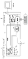
図1から図3は本発明の実施形態1を示したものであり、図1は撮像システムの構成を示すブロック図である。
[Embodiment 1]
1 to 3 show Embodiment 1 of the present invention, and FIG. 1 is a block diagram showing the configuration of an imaging system.
この撮像システムは、暗所にある被検体を観察するためのものであり、内視鏡1と、ビデオプロセッサ2と、光源装置3と、を備え、例えば内視鏡システムとして構成されたものとなっている。
This imaging system is for observing a subject in a dark place, and includes an endoscope 1, a video processor 2, and a light source device 3. For example, the imaging system is configured as an endoscope system. It has become.
内視鏡1は、結像光学系11と、撮像部12と、レンズ駆動部13と、ライトガイド14と、を備えている。
The endoscope 1 includes an imaging optical system 11, an imaging unit 12, a lens driving unit 13, and a light guide 14.
結像光学系11は、被検体の光学像を結像するものであり、フォーカスレンズ等を備えたフォーカス位置が可変な光学系となっている。なお、結像光学系11は、さらにズームレンズ等を備えたズーム位置が可変な光学系であっても構わない。
The imaging optical system 11 forms an optical image of the subject and is an optical system having a variable focus position equipped with a focus lens and the like. The imaging optical system 11 may be an optical system that further includes a zoom lens or the like and that can change the zoom position.
撮像部12は、結像光学系11により結像された光学像を撮像して画像を出力するものである。このとき、撮像部12が画像を撮像する際の露光時間は、例えば後述する制御部24の制御に基づき可変となっている。
The imaging unit 12 captures an optical image formed by the imaging optical system 11 and outputs an image. At this time, the exposure time when the imaging unit 12 captures an image is variable based on, for example, control of the control unit 24 described later.
レンズ駆動部13は、フォーカス位置等を変化させるために結像光学系11を駆動するものであり、具体的には、フォーカスレンズを駆動することによりフォーカス位置を変化させ、ズームレンズが設けられている場合にはズームレンズを駆動することによりズーム位置を変化させる。
The lens driving unit 13 drives the imaging optical system 11 to change the focus position and the like. Specifically, the lens driving unit 13 changes the focus position by driving the focus lens, and a zoom lens is provided. If so, the zoom position is changed by driving the zoom lens.
ライトガイド14は、光源装置3から供給される照明光を内視鏡1の挿入部の先端へ伝送する。こうして伝送された照明光は、内視鏡1の挿入部の先端から暗所にある被検体に対して照射される。
The light guide 14 transmits the illumination light supplied from the light source device 3 to the distal end of the insertion portion of the endoscope 1. The transmitted illumination light is irradiated from the distal end of the insertion portion of the endoscope 1 to the subject in the dark place.
ビデオプロセッサ2は、内視鏡1を制御駆動し、内視鏡1から得られた画像を処理するものであり、増幅部21と、画像処理部22と、制御部24と、コントラストAF部26と、補助AF部27と、を備えている。
The video processor 2 controls and drives the endoscope 1 and processes an image obtained from the endoscope 1, and includes an amplification unit 21, an image processing unit 22, a control unit 24, and a contrast AF unit 26. And an auxiliary AF unit 27.
増幅部21は、撮像部12から出力される画像を、設定されている増幅率に応じて信号増幅する。
The amplification unit 21 amplifies the image output from the imaging unit 12 in accordance with a set amplification factor.
画像処理部22は、増幅部21により信号増幅された画像に、色信号処理、色空間変換処理、エッジ強調処理、ノイズ低減処理、白つぶれ防止処理、ホワイトバランス処理、γ変換などの各種の画像処理を施すものである。この画像処理部22により処理された画像は、モニタや記録装置へ出力される。この画像処理部22は、さらに、画像の明るさを検出する明るさ検出部23を備えている。
The image processing unit 22 performs various images such as color signal processing, color space conversion processing, edge enhancement processing, noise reduction processing, whiteout prevention processing, white balance processing, and γ conversion on the image signal amplified by the amplification unit 21. Processing is performed. The image processed by the image processing unit 22 is output to a monitor or a recording device. The image processing unit 22 further includes a brightness detection unit 23 that detects the brightness of the image.
制御部24は、ビデオプロセッサ2内の各部を制御すると共に、内視鏡1や光源装置3を制御するものであり、例えばCPU等を含んで構成されている。すなわち、この制御部24は、増幅率を設定して増幅部21に画像を信号増幅させ、画像処理部22を制御して上述した各種の画像処理を行わせ、補助AF部27を制御して補助AFを行わせ、この補助AFの結果得られた仮合焦位置を含む範囲であって、全スキャン範囲よりも狭い範囲を、コントラストAFのスキャン範囲として設定し、設定したスキャン範囲におけるコントラストAFをコントラストAF部26に行わせる。
The control unit 24 controls each unit in the video processor 2 and also controls the endoscope 1 and the light source device 3, and includes, for example, a CPU. That is, the control unit 24 sets the amplification factor, causes the amplification unit 21 to amplify the image, controls the image processing unit 22 to perform the above-described various image processing, and controls the auxiliary AF unit 27. A range that includes the temporary in-focus position obtained as a result of the auxiliary AF and that is narrower than the entire scan range is set as the contrast AF scan range, and the contrast AF in the set scan range is performed. To the contrast AF unit 26.
この制御部24は、明るさ制御条件に基づき画像の明るさを調整する明るさ調整部25を備えている。明るさ調整部25は、明るさ検出部23により検出される画像の明るさが、例えば所定の明るさとなるように自動的に調整する。ここに、明るさ制御条件は、光源装置3が供給する照明光の光量条件、撮像部12の露光時間、増幅部21における増幅率、などである。
The control unit 24 includes a brightness adjustment unit 25 that adjusts the brightness of the image based on the brightness control condition. The brightness adjustment unit 25 automatically adjusts the brightness of the image detected by the brightness detection unit 23 to be, for example, a predetermined brightness. Here, the brightness control conditions are a light amount condition of illumination light supplied by the light source device 3, an exposure time of the imaging unit 12, an amplification factor in the amplification unit 21, and the like.
コントラストAF部26は、制御部24により設定されたスキャン範囲内でフォーカス位置を変化させながら撮像部12に複数の(一般には3以上の)画像を取得させ、取得された各画像のコントラスト評価値を算出して、コントラスト評価値がピーク値を取るようにフォーカス位置を調整する。
The contrast AF unit 26 causes the imaging unit 12 to acquire a plurality of (generally three or more) images while changing the focus position within the scan range set by the control unit 24, and the contrast evaluation value of each acquired image And the focus position is adjusted so that the contrast evaluation value takes a peak value.
補助AF部27は、画像の明るさに基づいて(必要に応じて、さらに、明るさ制御条件に基づいて)、被検体の光学像の仮合焦位置を推定する。具体的に、明るさ調整部25が画像の明るさを所定の明るさに自動調整する場合には、補助AF部27は、画像の明るさが所定の明るさであるときの明るさ制御条件に基づいて、被検体の光学像の仮合焦位置を推定することになる。
The auxiliary AF unit 27 estimates the temporary in-focus position of the optical image of the subject based on the brightness of the image (and further based on the brightness control condition if necessary). Specifically, when the brightness adjustment unit 25 automatically adjusts the brightness of the image to a predetermined brightness, the auxiliary AF unit 27 sets the brightness control condition when the brightness of the image is the predetermined brightness. Based on the above, the temporary in-focus position of the optical image of the subject is estimated.
光源装置3は、暗所にある被検体に対して照射する照明光を、例えば光量可変に供給するものであり、電源31と、電流制御部32と、光源33と、光量絞り34と、光量絞り駆動部35と、コリメータレンズ36と、を備えている。
The light source device 3 supplies illumination light for irradiating a subject in a dark place with, for example, variable light quantity, and includes a power supply 31, a current control unit 32, a light source 33, a light quantity diaphragm 34, and a light quantity. An aperture drive unit 35 and a collimator lens 36 are provided.
電源31は、光源装置3内の各部へ電流を供給するものであり、例えば電流制御部32および光量絞り駆動部35に電流を供給する。
The power supply 31 supplies a current to each part in the light source device 3, and supplies a current to the current control unit 32 and the light quantity diaphragm drive unit 35, for example.
電流制御部32は、上述した制御部24の制御に基づいて、光源33へ供給する電流を制御するものである。
The current control unit 32 controls the current supplied to the light source 33 based on the control of the control unit 24 described above.
光源33は、電流制御部32から電流の供給を受けて発光するものであり、例えば、ハロゲンランプ、キセノンランプ、メタルハライドランプ等のランプ、あるいはLED等の半導体発光素子を含んで構成されている。なお、光源33がLED等の半導体発光素子を含んで構成される場合には、上述した電流制御部32は、パルス幅制御(いわゆるPWM)により照明光の光量を制御することができるように構成される。この電流制御部32のパルス幅制御におけるパルス幅は、上述した光量条件の1つである。
The light source 33 emits light when supplied with current from the current control unit 32, and includes, for example, a lamp such as a halogen lamp, a xenon lamp, or a metal halide lamp, or a semiconductor light emitting element such as an LED. When the light source 33 includes a semiconductor light emitting element such as an LED, the above-described current control unit 32 is configured to control the amount of illumination light by pulse width control (so-called PWM). Is done. The pulse width in the pulse width control of the current control unit 32 is one of the light quantity conditions described above.
光量絞り34は、照明光の光量を制御するためのものである。この光量絞り34の絞り値は、上述した光量条件の1つである。
The light quantity diaphragm 34 is for controlling the quantity of illumination light. The aperture value of the light amount diaphragm 34 is one of the light amount conditions described above.
光量絞り駆動部35は、制御部24の制御に基づいて、光量条件により指定された絞り値となるように光量絞り34を駆動制御する。
Based on the control of the control unit 24, the light amount diaphragm drive unit 35 drives and controls the light amount diaphragm 34 so that the aperture value specified by the light amount condition is obtained.
コリメータレンズ36は、光源33から発光され、光量絞り34を介して所定の光量となった照明光を、平行光束に変換してライトガイド14の入射端へ照射する。
The collimator lens 36 converts the illumination light emitted from the light source 33 and having a predetermined light amount through the light amount diaphragm 34 into a parallel light beam and irradiates the incident end of the light guide 14.
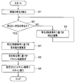
次に、図2は画像の明るさが所定の明るさになるときの明るさ制御条件に基づいてコントラストAFにおけるスキャン範囲を設定する例を示す線図、図3は撮像システムの作用を示すフローチャートである。
Next, FIG. 2 is a diagram showing an example of setting a scan range in contrast AF based on a brightness control condition when the brightness of an image becomes a predetermined brightness, and FIG. 3 is a flowchart showing an operation of the imaging system. It is.
図3に示す処理を開始すると、明るさ検出部23が画像の明るさを検出する(ステップS1)。
3 is started, the brightness detection unit 23 detects the brightness of the image (step S1).
そして、検出した明るさが所定の明るさであるか否かを制御部24が判定する(ステップS2)。
Then, the control unit 24 determines whether or not the detected brightness is a predetermined brightness (step S2).
ここで、所定の明るさでないと判定された場合には、明るさ調整部25が、明るさ制御条件に基づき画像の明るさを調整する(ステップS3)。具体的に、明るさ調整部25は、画像が所定の明るさよりも暗い場合には、光量絞り34の開口を大きく(絞り値を小さく)する、パルス幅制御のパルス幅を大きくする、撮像部12の露光時間を長くする、増幅部21における増幅率を大きくする、など内の少なくとも1つを行うことにより、画像が所定の明るさになるように調整する。また、明るさ調整部25は、画像が所定の明るさよりも明るい場合には、これらの逆の調整を行う。
Here, when it is determined that the brightness is not the predetermined brightness, the brightness adjusting unit 25 adjusts the brightness of the image based on the brightness control condition (step S3). Specifically, when the image is darker than the predetermined brightness, the brightness adjustment unit 25 increases the aperture of the light amount diaphragm 34 (decreases the aperture value) and increases the pulse width of the pulse width control. The image is adjusted to have a predetermined brightness by performing at least one of, for example, increasing the exposure time of 12 and increasing the amplification factor in the amplification unit 21. Further, the brightness adjustment unit 25 performs the reverse adjustment when the image is brighter than the predetermined brightness.
こうしてステップS2において所定の明るさであると判定された場合には、所定の明るさになったときの明るさ制御条件に基づいて、補助AF部27が、被検体の光学像の仮合焦位置を推定する(ステップS4)。
When it is determined in step S2 that the brightness is predetermined, the auxiliary AF unit 27 temporarily focuses the optical image of the subject based on the brightness control condition when the brightness reaches the predetermined brightness. The position is estimated (step S4).
ここでは具体例として、画像の明るさを調整するための明るさ制御条件が光量絞り34の絞り値であり、明るさ調整部25が絞り値を変化させることにより画像を所定の明るさに調整する場合を例に挙げて、図2を参照して説明する。ただし、明るさ制御条件が、絞り値だけでなく、上述したような、パルス幅制御におけるパルス幅、撮像部12の露光時間、増幅部21における増幅率などである場合、あるいはこれらの組み合わせである場合にも、同様の処理を行えば良い。
Here, as a specific example, the brightness control condition for adjusting the brightness of the image is the aperture value of the light amount aperture 34, and the brightness adjustment unit 25 adjusts the image to a predetermined brightness by changing the aperture value. An example of this will be described with reference to FIG. However, when the brightness control condition is not only the aperture value but the pulse width in the pulse width control, the exposure time of the imaging unit 12, the amplification factor in the amplification unit 21, and the like as described above, or a combination thereof. In this case, the same processing may be performed.
まず、光源装置3から内視鏡1へ供給する照明光の光量を一定に保つ場合に、被検体に照射される照明光の光量は、内視鏡1の挿入部の先端面から被検体までの距離に応じて変化し、一例を挙げれば、被検体距離の2乗に反比例する。従って、本実施形態の撮像システムが観察対象としている暗所にある被検体の明るさ、ひいては被検体を撮像して得られる画像の明るさは、被検体距離に応じて変化し、つまり、被検体距離は画像の明るさの関数で表される。
First, when the amount of illumination light supplied from the light source device 3 to the endoscope 1 is kept constant, the amount of illumination light irradiated to the subject is from the distal end surface of the insertion portion of the endoscope 1 to the subject. For example, it is inversely proportional to the square of the subject distance. Therefore, the brightness of the subject in the dark where the imaging system of the present embodiment is the observation target, and hence the brightness of the image obtained by imaging the subject, changes according to the subject distance. The specimen distance is expressed as a function of image brightness.
一方、撮像システムには、被検体を常に一定の明るさで撮像するための自動調光システムが、例えば備えられている。本実施形態の撮像システムにおいてこの自動調光システムの機能を担っているのは、明るさ調整部25等である。
On the other hand, the imaging system is provided with, for example, an automatic light control system for always imaging a subject with a constant brightness. In the imaging system of the present embodiment, the brightness adjusting unit 25 and the like have a function of the automatic light control system.
明るさ制御条件が光量絞り34の絞り値である場合には、絞り値が小さいと光量絞り34の開口が大きいために光源装置3から供給される照明光の光量が大きくなり、逆に、絞り値が大きいと光量絞り34の開口が小さいために光源装置3から供給される照明光の光量が小さくなる。
When the brightness control condition is the aperture value of the light quantity stop 34, the light quantity of the illumination light supplied from the light source device 3 increases because the aperture of the light quantity stop 34 is large if the aperture value is small. If the value is large, the amount of illumination light supplied from the light source device 3 is small because the aperture of the light amount diaphragm 34 is small.
従って、明るさ調整部25は、被検体が遠くにあって画像の明るさが所定の明るさよりも暗い場合には絞り値を小さくして照明光量を増大させ、被検体が近くにあって画像の明るさが所定の明るさよりも明るい場合には絞り値を大きくして照明光量を減少させる。
Accordingly, the brightness adjustment unit 25 reduces the aperture value to increase the amount of illumination light when the subject is far away and the brightness of the image is darker than the predetermined brightness, and the subject is close to the image. If the brightness is higher than the predetermined brightness, the aperture value is increased to reduce the amount of illumination light.
こうして所定の明るさになったときの絞り値を、補助AF部27は明るさ制御部24から取得する。上述したように、被検体距離は画像の明るさの関数で表され、画像の明るさは絞り値の関数で表されるために、つまり、被検体距離は絞り値の関数で表される(より一般には、上述したように、被検体距離は明るさ制御条件の多変数関数で表される)。
The auxiliary AF unit 27 obtains the aperture value when the predetermined brightness is obtained in this way from the brightness control unit 24. As described above, the object distance is expressed as a function of the image brightness, and the image brightness is expressed as a function of the aperture value. That is, the object distance is expressed as a function of the aperture value ( More generally, as described above, the object distance is expressed by a multivariable function of the brightness control condition).
絞り値と被検体距離との関数が、例えば図2の下側に示した絞り値-距離グラフに示すようになったものとする。この絞り値-距離グラフは、被検体距離が近付くほど、絞り値を大きくして(光量絞り34の開口径を小さくして)照明光量を減少させる様子を示している。
Suppose that the function of the aperture value and the subject distance is as shown in the aperture value-distance graph shown at the bottom of FIG. This aperture value-distance graph shows how the illumination light quantity is reduced by increasing the aperture value (decreasing the aperture diameter of the light quantity diaphragm 34) as the subject distance approaches.
このような絞り値と被検体距離との関係がある場合において、画像が所定の明るさになったときの絞り値に対応する距離を、補助AF部27は算出する。ここでは算出された距離がP1であったものとする。補助AF部27は、こうして算出したP1を仮合焦位置として設定する。
In such a relationship between the aperture value and the subject distance, the auxiliary AF unit 27 calculates a distance corresponding to the aperture value when the image has a predetermined brightness. Here, it is assumed that the calculated distance is P1. The auxiliary AF unit 27 sets P1 calculated in this way as a temporary in-focus position.
次に、補助AF部27は、算出した仮合焦位置P1を含むように、コントラストAFにおけるスキャン範囲を、全スキャン範囲よりも狭い例えばP2~P3として決定する(ステップS5)。
Next, the auxiliary AF unit 27 determines that the scan range in the contrast AF is narrower than the entire scan range, for example, P2 to P3 so as to include the calculated temporary in-focus position P1 (step S5).
このスキャン範囲P2~P3は、仮合焦位置P1を中心として近距離側および遠距離側に各所定範囲となるように決定しても良いが、他の条件を考慮して適応的に決定するとさらに良い。例えば画像のボケを考えた場合に、結像光学系11における絞り開口径の大きさが大きいとボケが大きくなるために、結像光学系11の絞り開口径が大きいときには所定範囲を大きく、絞り開口径が小さいときには所定範囲を小さくするようにしても良い。また、ボケの大きさは、遠距離側よりも近距離側の方が大きくなり易いために、仮合焦位置よりも近距離側の所定範囲を、仮合焦位置よりも遠距離側の所定範囲より大きくするようにしても良い。
The scan ranges P2 to P3 may be determined so as to be within a predetermined range on the near distance side and the far distance side with the provisional focus position P1 as the center, but if determined in consideration of other conditions, Even better. For example, when considering blurring of an image, blurring increases when the aperture diameter of the imaging optical system 11 is large. Therefore, when the aperture aperture diameter of the imaging optical system 11 is large, the predetermined range is increased. When the opening diameter is small, the predetermined range may be reduced. In addition, since the size of the blur tends to be larger on the short distance side than on the long distance side, the predetermined range on the short distance side from the temporary focusing position is set to a predetermined range on the long distance side from the temporary focusing position. It may be made larger than the range.
コントラストAF部26は、補助AF部27により決定されたスキャン範囲P2~P3の情報を受けて、現在のフォーカス位置P0から、スキャン範囲P2~P3内における適宜のスキャン開始位置、ここではフォーカス位置P0に最も近いP2にフォーカス位置を移動させる(ただし、スキャン開始位置への移動は補助AF部27により行い、その後に、コントラストAF部26によるスキャンを開始するようにしても構わない)。この位置P2はスキャン範囲P2~P3における最も遠距離の点であるために、スキャンは近距離側へ向けて開始され、コントラスト評価値が次第に増加していって、減少に転じたところでスキャン方向を反転させることにより、コントラスト評価値がピーク値を取る真の合焦位置P4にフォーカス位置を調整することができる(ステップS6)。
The contrast AF unit 26 receives information on the scan ranges P2 to P3 determined by the auxiliary AF unit 27, and from the current focus position P0, an appropriate scan start position within the scan ranges P2 to P3, here the focus position P0. The focus position is moved to P2 closest to the position (however, the movement to the scan start position may be performed by the auxiliary AF unit 27, and then the scan by the contrast AF unit 26 may be started). Since this position P2 is the farthest point in the scan range P2 to P3, the scan is started toward the short distance side, the contrast evaluation value gradually increases, and the scan direction is changed when it starts to decrease. By reversing, the focus position can be adjusted to the true in-focus position P4 where the contrast evaluation value takes the peak value (step S6).
こうしてスキャンを行った結果、合焦位置P4に到達したところで、この処理を終了する。
As a result of scanning, when the in-focus position P4 is reached, this process is terminated.
なお、上述したように被検体距離は画像の明るさの関数で表されるために、明るさ調整部25が画像の明るさを所定の明るさに自動調整しない場合であっても、補助AF部27は画像の明るさに基づいて仮合焦位置を推定することが可能である。従って、補助AF部27による仮合焦位置の推定は、画像が所定の明るさになったときの明るさ制御条件を用いることに限定されるものではない。
Note that since the subject distance is expressed as a function of the brightness of the image as described above, even if the brightness adjustment unit 25 does not automatically adjust the brightness of the image to a predetermined brightness, the auxiliary AF The unit 27 can estimate the temporary in-focus position based on the brightness of the image. Therefore, the estimation of the temporary in-focus position by the auxiliary AF unit 27 is not limited to using the brightness control condition when the image has a predetermined brightness.
このように、本実施形態の撮像システムが観察対象としている暗所にある被検体の場合には、画像の明るさと被検体距離とに関係性が生じるために、補助AF部27は、この関係性を利用した明るさAFともいうべきAFを行うものとなっている。
As described above, in the case of a subject in the dark place that is the observation target of the imaging system of the present embodiment, there is a relationship between the brightness of the image and the subject distance. AF that should be referred to as brightness AF using the characteristic is performed.
このような実施形態1によれば、コントラストAFを行う前に補助AF(明るさAF)を行うことにより仮合焦位置を検出し、検出した仮合焦位置に基づいてコントラストAFにおけるスキャン範囲やスキャン開始位置を決定している。ここに、決定したスキャン範囲は、全スキャン範囲よりも狭いために、コントラストAFにおいて合焦に至るまでの時間を短縮することができる。そして、最終的な合焦位置はコントラストAFにより求めているために、高精度の合焦検出が可能となる。
According to the first embodiment, the temporary focus position is detected by performing the auxiliary AF (brightness AF) before the contrast AF is performed, and the scan range or the contrast AF in the contrast AF is detected based on the detected temporary focus position. The scan start position is determined. Here, since the determined scanning range is narrower than the entire scanning range, it is possible to shorten the time until focusing in contrast AF. Since the final focus position is obtained by contrast AF, it is possible to detect the focus with high accuracy.
また、コントラストAFを行う前の補助AFとして撮像部12から取得した画像に基づく明るさAFを用いているために、例えば補助AFとして位相差AFを用いる場合のような位相差AFセンサ等の他の構成が不要であり、小型化や細径化が求められる内視鏡等の分野に適している利点がある。
In addition, since brightness AF based on an image acquired from the imaging unit 12 is used as auxiliary AF before performing contrast AF, for example, a phase difference AF sensor such as a case where phase difference AF is used as auxiliary AF. This configuration is unnecessary, and there is an advantage that it is suitable for the field of endoscopes and the like that require a reduction in size and diameter.
こうして、暗所にある被検体(大きさや形状を問わない任意の被検体)に対して、コントラストAFで合焦に至るまでの時間を短縮することが可能となる。
In this way, it is possible to shorten the time to focus on the subject in the dark place (any subject of any size or shape) with contrast AF.
ところで、結像光学系11が、フォーカスレンズおよびズームレンズを備えた、フォーカス位置およびズーム位置可変な光学系である場合には、フォーカス位置をニアー(近)側へ移動させるためのスイッチ、フォーカス位置をファー(遠)側へ移動させるためのスイッチ、ズーム位置をテレ(望遠)側へ移動させるためのスイッチ、ズーム位置をワイド(広角)側へ移動させるためのスイッチの合計4つのスイッチを、例えば内視鏡1の操作部に設ける構成が従来より採用されている。しかし、この構成ではスイッチの数が多いために、術者にとって操作が煩雑であった。また、撮像システムを使用中に、観察している画像だけからでは、現在の画像のフォーカス状態やズーム状態を把握し難く、使い勝手に向上の余地があった。
By the way, when the imaging optical system 11 is an optical system that includes a focus lens and a zoom lens and has a variable focus position and zoom position, a switch for moving the focus position to the near side, a focus position For example, there are a total of four switches: a switch for moving the lens to the far (far) side, a switch for moving the zoom position to the tele (telephoto) side, and a switch for moving the zoom position to the wide (wide angle) side. The structure provided in the operation part of the endoscope 1 has been conventionally employed. However, in this configuration, since the number of switches is large, the operation is complicated for the operator. In addition, while using the imaging system, it is difficult to grasp the focus state and zoom state of the current image only from the observed image, and there is room for improvement in usability.
そこで、これら4つのスイッチを1つのスイッチとして兼用する構成について、図4~図9を参照して説明する。
Therefore, a configuration in which these four switches are used as one switch will be described with reference to FIGS.
まず、図4は、フォーカス・ズーム兼用スイッチを備える撮像システムの構成を示す図である。
First, FIG. 4 is a diagram showing a configuration of an imaging system including a focus / zoom switch.
撮像システムは、内視鏡1と、ビデオプロセッサ2とを備えると共に、さらに、操作部4と、モニタ5とを備えており、例えば内視鏡システムとして構成されたものとなっている。ここに、図4には示さないが、光源装置3もさらに備えているものとする。
The imaging system includes an endoscope 1 and a video processor 2, and further includes an operation unit 4 and a monitor 5. For example, the imaging system is configured as an endoscope system. Here, although not shown in FIG. 4, the light source device 3 is further provided.
内視鏡1の結像光学系11は、フォーカスレンズ11aと、ズームレンズ11bと、を備えている。フォーカスレンズ11aはアクチュエータ13aにより、ズームレンズ11bはアクチュエータ13bにより、それぞれ駆動されるようになっている。また、フォーカスレンズ11aの駆動位置、ひいてはフォーカス位置は位置検出部13cにより、ズームレンズ11bの駆動位置、ひいてはズーム位置は位置検出部13dにより、それぞれ検出される。ここに、位置検出部13c,13dによるレンズ位置検出は、位置センサを用いる方法、アクチュエータ抵抗値を検出する方法、駆動パルス数のカウント値に基づく方法、など各種の方法を適宜採用することができる。
The imaging optical system 11 of the endoscope 1 includes a focus lens 11a and a zoom lens 11b. The focus lens 11a is driven by an actuator 13a, and the zoom lens 11b is driven by an actuator 13b. Further, the drive position of the focus lens 11a, and hence the focus position, are detected by the position detector 13c, and the drive position of the zoom lens 11b, and consequently the zoom position, are detected by the position detector 13d. Here, for the lens position detection by the position detection units 13c and 13d, various methods such as a method using a position sensor, a method of detecting an actuator resistance value, and a method based on a count value of the number of drive pulses can be appropriately employed. .
内視鏡1の例えば操作部には、フォーカス操作とズーム操作とを兼用するフォーカス・ズーム兼用スイッチであるスイッチ15が設けられている。このスイッチ15は、例えば、押圧操作式の押しボタンスイッチとして構成されている。
For example, an operation unit of the endoscope 1 is provided with a switch 15 that is a focus / zoom switch that performs both a focus operation and a zoom operation. The switch 15 is configured as, for example, a push operation type push button switch.
位置検出部13cにより検出されたフォーカス位置の情報、位置検出部13dにより検出されたズーム位置の情報、および、スイッチ15からのスイッチ操作の情報は、内視鏡1の例えば操作部内に設けられたスコープ情報送受信部16を介して、ビデオプロセッサ2の制御部24へ送信されるようになっている。
The focus position information detected by the position detection unit 13c, the zoom position information detected by the position detection unit 13d, and the switch operation information from the switch 15 are provided in, for example, the operation unit of the endoscope 1. It is transmitted to the control unit 24 of the video processor 2 via the scope information transmitting / receiving unit 16.
一方、ビデオプロセッサ2には、制御部24に加えて、フォーカス駆動部28およびズーム駆動部29が設けられている。
On the other hand, the video processor 2 is provided with a focus driving unit 28 and a zoom driving unit 29 in addition to the control unit 24.
フォーカス駆動部28は、フォーカス位置およびスイッチ操作の情報を得た制御部24の制御に基づいて、アクチュエータ13aを駆動しフォーカスレンズ11aを光軸方向に移動させ、フォーカス位置調整を行う。
The focus drive unit 28 adjusts the focus position by driving the actuator 13a and moving the focus lens 11a in the optical axis direction based on the control of the control unit 24 that has obtained the focus position and switch operation information.
ズーム駆動部29は、ズーム位置およびスイッチ操作の情報を得た制御部24の制御に基づいて、アクチュエータ13bを駆動しズームレンズ11bを光軸方向に移動させ、ズーム位置調整を行う。
The zoom drive unit 29 adjusts the zoom position by driving the actuator 13b and moving the zoom lens 11b in the optical axis direction based on the control of the control unit 24 that has obtained the zoom position and switch operation information.
また、操作部4は、制御部24と接続されていて、スイッチ15に係る優先モードの設定や、その他の各種操作入力を行うことができるように構成されている。ここに、スイッチ15に係る優先モードとしては、電源投入直後やスイッチ機能リセット後などの初期時のスイッチ15の機能として、フォーカス機能が優先されるフォーカス優先モードと、ズーム機能が優先されるズーム優先モードと、がある。また、本構成例のフォーカス機能は、フォーカス位置を連続的に変化させ得るシームレス動作と、フォーカス位置をニアーとノーマル(ニアーよりもファー側のあるフォーカス位置)との2点のみ切り換えるいわゆる2焦点切替と、を選択し得るようになっており、このフォーカス機能の選択も操作部4により行われる。
The operation unit 4 is connected to the control unit 24 and is configured to be able to set a priority mode related to the switch 15 and perform various other operation inputs. Here, the priority mode related to the switch 15 includes a focus priority mode in which the focus function is prioritized and a zoom priority in which the zoom function is prioritized as an initial function of the switch 15 such as immediately after power-on or after a switch function reset. There are modes. In addition, the focus function of this configuration example is a so-called two-focus switching that switches only two points, a seamless operation that can continuously change the focus position, and the focus position near and normal (a focus position that is farther than the near). And the focus function is also selected by the operation unit 4.
制御部24は、さらにモニタ5に接続されている。モニタ5は、内視鏡1から取得された画像を表示すると共に、制御部24の制御により、優先モード、フォーカス位置、およびズーム位置の各情報をさらに表示するようになっている。
The control unit 24 is further connected to the monitor 5. The monitor 5 displays an image acquired from the endoscope 1 and further displays each information of the priority mode, the focus position, and the zoom position under the control of the control unit 24.
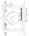
ここで図5は、モニタ5の表示例を示す図である。
Here, FIG. 5 is a diagram showing a display example of the monitor 5.
モニタ5の画面5aには、例えば中央部に内視鏡画像51が表示されている。
On the screen 5a of the monitor 5, for example, an endoscope image 51 is displayed at the center.
また、画面5aの例えば左上部には、フォーカス優先モード表示52aと、ズーム優先モード表示52bと、を含む優先モード表示52が表示されていて、この図5に示す例においては、フォーカス優先モード表示52aがハイライト表示され、スイッチ15が現在、フォーカス優先モードに設定されていることが示されている。
Further, a priority mode display 52 including a focus priority mode display 52a and a zoom priority mode display 52b is displayed on the upper left of the screen 5a, for example. In the example shown in FIG. 5, the focus priority mode display is displayed. 52a is highlighted, indicating that the switch 15 is currently set to the focus priority mode.
さらに、画面5aの例えば右上部には、ノーマルフォーカス位置表示53aと、ニアーフォーカス位置表示53bと、を含むフォーカス位置表示53が表示されていて、この図5に示す例においては、ニアーフォーカス位置表示53bがハイライト表示され、フォーカスレンズ11aが現在、ニアーフォーカス位置にあることが示されている。
Further, a focus position display 53 including a normal focus position display 53a and a near focus position display 53b is displayed on the upper right portion of the screen 5a, for example. In the example shown in FIG. 5, the near focus position display is displayed. 53b is highlighted, indicating that the focus lens 11a is currently in the near focus position.
加えて、画面5aの例えば下辺部には、ズーム位置バー54aと、ワイド位置表示54bと、テレ位置表示54cと、指標54dと、ワイド方向表示54eと、テレ方向表示54fと、を含むズーム位置表示54が表示されていて、この図5に示す例においては、指標54dがワイド位置表示54bとテレ位置表示54cとの中間ややワイド寄りに表示されて現在のズーム位置を示すと共に、ワイド方向表示54eがハイライト表示されて、ズームレンズ11bが移動する場合の移動方向が現在、ワイド方向となっていることが示されている。
In addition, a zoom position including a zoom position bar 54a, a wide position display 54b, a tele position display 54c, an index 54d, a wide direction display 54e, and a tele direction display 54f, for example, on the lower side of the screen 5a. In the example shown in FIG. 5, the indicator 54d is displayed in the middle of the wide position display 54b and the tele position display 54c slightly closer to the wide to indicate the current zoom position, and the wide direction display. 54e is highlighted, indicating that the moving direction when the zoom lens 11b moves is now the wide direction.
なお、図5に示す表示例においては、フォーカス位置としてノーマルとニアーとの2点のみを取り得るいわゆる2焦点切替である場合を想定しているが、フォーカス位置を連続的に変更し得るシームレス動作の場合には、上述したズーム位置表示54と同様の表示を行うようにしても構わない。また、表示の態様も、図5に示す例に限定されるものでないことは勿論である。
In the display example shown in FIG. 5, it is assumed that the focus position is so-called bifocal switching that can take only two points of normal and near, but a seamless operation in which the focus position can be changed continuously. In this case, display similar to the zoom position display 54 described above may be performed. Of course, the display mode is not limited to the example shown in FIG.
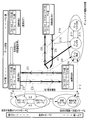
次に、図6~図9を参照して、スイッチ15の操作に応じて、画像のフォーカス状態およびズーム状態がどのように変化するかについて説明する。ここに、図6~図9においては、図面の長手方向を左右方向として見たときに、左側がワイド側、右側がテレ側、上側がノーマル側、下側がニアー側であるとして、各画像状態図を配置している。
Next, how the focus state and the zoom state of the image change according to the operation of the switch 15 will be described with reference to FIGS. Here, in FIGS. 6 to 9, when the longitudinal direction of the drawing is viewed as the left and right direction, the left side is the wide side, the right side is the tele side, the upper side is the normal side, and the lower side is the near side. The figure is arranged.
また、本構成例においては、フォーカス状態およびズーム状態に係るスイッチ15の操作として、実線矢印で示す「短押し」、太実線矢印で示す「長押し」、白抜き矢印で示す「2回連続短押し」があるものとする。さらに、点線矢印で示す「CPU処理」(制御部24の処理)によっても、フォーカス状態およびズーム状態に係る設定が行われるようになっている。
Further, in this configuration example, as the operation of the switch 15 in the focus state and the zoom state, “short press” indicated by a solid line arrow, “long press” indicated by a thick solid line arrow, “two consecutive short times” indicated by a white arrow. It is assumed that there is a “push”. Furthermore, the setting relating to the focus state and the zoom state is also performed by “CPU processing” (processing of the control unit 24) indicated by a dotted arrow.
なお、本構成例では、ズームについてはシームレス動作を行うことを前提として説明するが、これに限らず複数の焦点距離を不連続に取り得る構成等であっても構わない。
In this configuration example, the zoom is described on the assumption that a seamless operation is performed. However, the present invention is not limited to this, and a configuration in which a plurality of focal lengths can be taken discontinuously may be used.
図6は、フォーカスが2焦点切替であるときのフォーカス優先モードにおける撮像システムの動作を示す図である。
FIG. 6 is a diagram illustrating the operation of the imaging system in the focus priority mode when the focus is bifocal switching.
まず、画像状態Aは、フォーカスがノーマル端、ズームがワイド端の状態、画像状態Bは、フォーカスがニアー端、ズームがワイド端の状態、画像状態Cは、フォーカスがノーマル端、ズームがテレ端の状態、画像状態Dは、フォーカスがニアー端、ズームがテレ端の状態である。これらの内の画像状態Cは、この図6に示すような、フォーカスが2焦点切替であるときのフォーカス優先モードにおいては使用されない。
First, the image state A is the focus at the normal end and the zoom is at the wide end, the image state B is the focus at the near end, the zoom is at the wide end, and the image state C is the focus at the normal end and the zoom is at the tele end. In this state, the image state D is a state where the focus is the near end and the zoom is the tele end. Of these, the image state C is not used in the focus priority mode as shown in FIG.
撮像システムの電源をオンすると、初期状態として画像状態Aに切り替わる。この画像状態Aは、全景観察に適している。
When the imaging system is turned on, the image state A is switched to the initial state. This image state A is suitable for full-view observation.
画像状態Aにおいて、スイッチ15を短押しすると、矢印α1に示すように、画像状態Bに切り替わる。
In image state A, when switch 15 is pressed for a short time, it switches to image state B as shown by arrow α1.
また、画像状態Bにおいて、スイッチ15を短押しすると、矢印α2に示すように、画像状態Aに切り替わる。
In the image state B, when the switch 15 is pressed for a short time, the image state A is switched as indicated by the arrow α2.
一方、画像状態Aにおいて、スイッチ15を長押ししても、矢印α3に示すように、画像状態Aは変化しない。
On the other hand, even if the switch 15 is pressed and held in the image state A, the image state A does not change as indicated by the arrow α3.
画像状態Bにおいて、スイッチ15を長押しすると、矢印α4に示すように、スイッチ15の機能がズーム状態をテレ方向に変化させるズームテレ方向の機能に切り替わる。
When the switch 15 is pressed and held in the image state B, the function of the switch 15 is switched to the zoom tele direction function for changing the zoom state to the tele direction as indicated by an arrow α4.
そして、矢印α5に示すように、スイッチ15の機能がズームテレ方向である場合には、スイッチ15を長押しする間はズーム状態がテレ方向に変化する。ただし、テレ方向へのズーム状態の変化は、画像状態Dに達したところでテレ端となるために、それ以上は進行しない。
Then, as indicated by an arrow α5, when the function of the switch 15 is the zoom tele direction, the zoom state changes to the tele direction while the switch 15 is pressed and held. However, since the change of the zoom state in the tele direction becomes the tele end when the image state D is reached, it does not proceed any further.
画像状態D、または画像状態Bと画像状態Dとの間の状態において、矢印α6に示すように、スイッチ15の機能がズーム状態をワイド方向に変化させるズームワイド方向の機能である場合には、スイッチ15を長押しする間はズーム状態がワイド方向に変化する。
In the state between the image state D or the image state B and the image state D, as indicated by the arrow α6, when the function of the switch 15 is a zoom wide direction function for changing the zoom state to the wide direction, While the switch 15 is pressed and held, the zoom state changes in the wide direction.
スイッチ15の機能がズームテレ方向またはズームワイド方向である場合には、スイッチ15を短押しすると、矢印α7に示すように、ズーム方向が切り替わる。
When the function of the switch 15 is the zoom tele direction or the zoom wide direction, when the switch 15 is pressed for a short time, the zoom direction is switched as shown by an arrow α7.
すなわち、矢印α8に示すように、スイッチ15の機能は、ズームテレ方向であるときにスイッチ15を短押しするとズームワイド方向に切り替わり、ズームワイド方向であるときにスイッチ15を短押しするとズームテレ方向に切り替わる。
That is, as indicated by the arrow α8, the function of the switch 15 is switched to the zoom wide direction when the switch 15 is pressed shortly in the zoom telephoto direction, and is switched to the zoom telephoto direction when the switch 15 is short pressed in the zoom wide direction. .
矢印α6に示す操作によってズーム状態がワイド方向へ変化した結果、画像状態Bに達した場合には、矢印α9に示すように、CPU内処理によって、スイッチ15がズームスイッチとして機能するのを無効にされ、すなわち、フォーカススイッチとして機能する状態となる。
When the zoom state is changed in the wide direction by the operation indicated by the arrow α6, and the image state B is reached as a result of the operation within the CPU, the function of the switch 15 as a zoom switch is disabled as indicated by the arrow α9. In other words, it becomes a state of functioning as a focus switch.
また、画像状態B、画像状態Bと画像状態Dとの間の状態、画像状態Dの何れにある場合であっても、白抜き矢印で示す「2回連続短押し」の操作がスイッチ15で行われると、画像状態Aに戻る。従って、電源投入時と同様の全景観察を、簡単な操作で素早く行うことができる。画像状態Aに戻ったときには、矢印α10に示すように、CPU内処理によって、スイッチ15がズームスイッチとして機能するのを無効にされ、フォーカススイッチとして機能する状態となる。
In addition, in any of the image state B, the state between the image state B and the image state D, and the image state D, the operation of “two consecutive short presses” indicated by the white arrow is performed by the switch 15. Once done, return to image state A. Therefore, the same panoramic view as when the power is turned on can be quickly performed with a simple operation. When returning to the image state A, as indicated by an arrow α10, the function of the switch 15 as a zoom switch is disabled by the processing in the CPU, and the state of functioning as a focus switch is entered.
図7は、フォーカスがシームレス動作であるときのフォーカス優先モードにおける撮像システムの動作を示す図である。
FIG. 7 is a diagram illustrating the operation of the imaging system in the focus priority mode when the focus is a seamless operation.
まず、画像状態A~Cは上述と同様であり、画像状態(B)はフォーカスがノーマル端とニアー端との間にあり、ズームがワイド端の状態(画像状態Aと画像状態Bとの間の状態)、画像状態(BC)はフォーカスがノーマル端とニアー端との間にあり、ズームがテレ端の状態である。なお、画像状態Cは、この図7に示すような、フォーカスがシームレス動作であるときのフォーカス優先モードにおいても使用されない。
First, the image states A to C are the same as described above. In the image state (B), the focus is between the normal end and the near end, and the zoom is in the wide end (between the image state A and the image state B). The image state (BC) is a state in which the focus is between the normal end and the near end, and the zoom is in the tele end. The image state C is not used even in the focus priority mode when the focus is a seamless operation as shown in FIG.
撮像システムの電源をオンすると、初期状態として画像状態Aに切り替わる。
When the imaging system is turned on, the image state A is switched to the initial state.
画像状態A、または画像状態Aと画像状態Bとの間の状態において、スイッチ15の機能がフォーカス状態をニアー方向に変化させるフォーカスニアー方向の機能である場合に、スイッチ15を長押しすると、矢印β1に示すように、スイッチ15を押圧している間はフォーカス状態がニアー方向に変化する。
In the state between the image state A or the image state A and the image state B, when the function of the switch 15 is a function in the focus near direction that changes the focus state in the near direction, when the switch 15 is pressed and held, As indicated by β1, while the switch 15 is being pressed, the focus state changes in the near direction.
画像状態B、または画像状態Aと画像状態Bとの間の状態において、スイッチ15の機能がフォーカス状態をノーマル方向に変化させるフォーカスノーマル方向の機能である場合に、スイッチ15を長押しすると、矢印β2に示すように、スイッチ15を押圧している間はフォーカス状態がノーマル方向に変化する。
In the state between the image state B or the image state A and the image state B, when the function of the switch 15 is a function in the normal focus direction that changes the focus state in the normal direction, when the switch 15 is pressed and held, As indicated by β2, the focus state changes in the normal direction while the switch 15 is being pressed.
スイッチ15の機能がフォーカスニアー方向またはフォーカスノーマル方向である場合には、スイッチ15を短押しすると、矢印β3に示すように、フォーカス方向が切り替わる。
When the function of the switch 15 is the focus near direction or the focus normal direction, when the switch 15 is pressed for a short time, the focus direction is switched as shown by the arrow β3.
すなわち、矢印β4に示すように、スイッチ15の機能は、フォーカスニアー方向であるときにスイッチ15を短押しするとフォーカスノーマル方向に切り替わり、フォーカスノーマル方向であるときにスイッチ15を短押しするとフォーカスニアー方向に切り替わる。
That is, as indicated by the arrow β4, the function of the switch 15 is to switch to the focus normal direction when the switch 15 is pressed shortly in the focus near direction, and to the focus near direction when the switch 15 is pressed shortly in the focus normal direction. Switch to
そして、矢印β4で示す操作を連続2往復繰り返すと、CPU内処理によって、矢印β5に示すように、フォーカス状態が固定される。
Then, when the operation indicated by the arrow β4 is repeated twice in a row, the focus state is fixed as indicated by the arrow β5 by the processing in the CPU.
画像状態(B)または画像状態Bとなったときに、CPU内処理によって、矢印β6に示すように、スイッチ15がズームスイッチとして機能するのを無効にされる。
When the image state (B) or the image state B is reached, the function of the switch 15 as a zoom switch is disabled as shown by the arrow β6 by the processing in the CPU.
そして、画像状態(B)において、スイッチ15を長押しすると、矢印β7に示すように、スイッチ15の機能がズームテレ方向に切り替わり、テレ方向へのズームが開始される。
In the image state (B), when the switch 15 is pressed for a long time, the function of the switch 15 is switched to the zoom tele direction as indicated by the arrow β7, and zooming in the tele direction is started.
矢印β8に示すように、スイッチ15の機能がズームテレ方向である場合には、スイッチ15を長押しする間はズーム状態がテレ方向に変化する。ただし、テレ方向へのズーム状態の変化は、画像状態(BC)に達したところでテレ端となるために、それ以上は進行しない。
As shown by an arrow β8, when the function of the switch 15 is the zoom tele direction, the zoom state changes to the tele direction while the switch 15 is pressed and held. However, the change of the zoom state in the tele direction becomes the tele end when the image state (BC) is reached and does not proceed any further.
画像状態(BC)、または画像状態(B)と画像状態(BC)との間の状態において、矢印β9に示すように、スイッチ15の機能がズームワイド方向である場合には、スイッチ15を長押しする間はズーム状態がワイド方向に変化する。
When the function of the switch 15 is in the zoom wide direction as shown by the arrow β9 in the image state (BC) or between the image state (B) and the image state (BC), the switch 15 is long. While pressed, the zoom status changes in the wide direction.
スイッチ15の機能がズームテレ方向またはズームワイド方向である場合には、スイッチ15を短押しすると、矢印β10に示すように、ズーム方向が切り替わる。
When the function of the switch 15 is the zoom tele direction or the zoom wide direction, when the switch 15 is pressed for a short time, the zoom direction is switched as indicated by an arrow β10.
すなわち、矢印β11に示すように、スイッチ15の機能は、ズームテレ方向であるときにスイッチ15を短押しするとズームワイド方向に切り替わり、ズームワイド方向であるときにスイッチ15を短押しするとズームテレ方向に切り替わる。
That is, as indicated by the arrow β11, the function of the switch 15 is switched to the zoom wide direction when the switch 15 is short-pressed in the zoom telephoto direction, and is switched to the zoom telephoto direction when the switch 15 is short-pressed in the zoom wide direction. .
また、画像状態B、画像状態(B)、画像状態(BC)、画像状態(B)と画像状態(BC)との間の状態の何れにある場合であっても、白抜き矢印で示す「2回連続短押し」の操作がスイッチ15で行われると、画像状態Aに戻る。画像状態Aに戻ったときには、矢印β12に示すように、CPU内処理によって、スイッチ15がズームスイッチとして機能するのを無効にされ、フォーカス状態の固定が解除され、スイッチ15がフォーカススイッチとして機能する状態となって、フォーカススイッチ機能がフォーカスニアー方向に設定される。
Further, in any state between the image state B, the image state (B), the image state (BC), and the state between the image state (B) and the image state (BC), “ When the operation of “two consecutive short presses” is performed with the switch 15, the state returns to the image state A. When the state returns to the image state A, as indicated by an arrow β12, the CPU 15 disables the function of the switch 15 as a zoom switch, the focus state is released, and the switch 15 functions as a focus switch. The focus switch function is set in the focus near direction.
図8は、フォーカスが2焦点切替であるときのズーム優先モードにおける撮像システムの動作を示す図である。
FIG. 8 is a diagram illustrating the operation of the imaging system in the zoom priority mode when the focus is bifocal switching.
まず、画像状態A~Cは上述と同様であり、画像状態(C)はフォーカスがノーマル端にあり、ズームがワイド端とテレ端との間の状態(画像状態Aと画像状態Cとの間の状態)、画像状態(CB)はフォーカスがニアー端にあり、ズームがワイド端とテレ端との間の状態である。なお、画像状態Bは、この図8に示すような、フォーカスが2焦点切替であるときのズーム優先モードにおいては使用されない。
First, the image states A to C are the same as described above, and the image state (C) is the state where the focus is at the normal end and the zoom is between the wide end and the tele end (between the image state A and the image state C). The image state (CB) is a state where the focus is at the near end and the zoom is between the wide end and the tele end. Note that the image state B is not used in the zoom priority mode when the focus is two-focus switching as shown in FIG.
撮像システムの電源をオンすると、初期状態として画像状態Aに切り替わる。
When the imaging system is turned on, the image state A is switched to the initial state.
画像状態A、または画像状態Aと画像状態Cとの間の状態において、スイッチ15の機能がズームテレ方向である場合に、スイッチ15を長押しすると、矢印γ1に示すように、スイッチ15を押圧している間はズーム状態がテレ方向に変化する。
When the function of the switch 15 is in the zoom telephoto direction in the state between the image state A or the image state A and the image state C, when the switch 15 is pressed long, the switch 15 is pressed as shown by the arrow γ1. The zoom state changes in the tele direction while the camera is on.
画像状態C、または画像状態Aと画像状態Cとの間の状態において、スイッチ15の機能がズームワイド方向である場合に、スイッチ15を長押しすると、矢印γ2に示すように、スイッチ15を押圧している間はズーム状態がワイド方向に変化する。
When the function of the switch 15 is in the zoom wide direction in the state between the image state C or the image state A and the image state C, pressing the switch 15 causes the switch 15 to be pressed as shown by the arrow γ2. The zoom state changes in the wide direction during
スイッチ15の機能がズームテレ方向またはズームワイド方向である場合には、スイッチ15を短押しすると、矢印γ3に示すように、フォーカス方向が切り替わる。
When the function of the switch 15 is the zoom tele direction or the zoom wide direction, when the switch 15 is pressed for a short time, the focus direction is switched as shown by the arrow γ3.
すなわち、矢印γ4に示すように、スイッチ15の機能は、ズームテレ方向であるときにスイッチ15を短押しするとズームワイド方向に切り替わり、ズームワイド方向であるときにスイッチ15を短押しするとズームテレ方向に切り替わる。
That is, as indicated by an arrow γ4, the function of the switch 15 is switched to the zoom wide direction when the switch 15 is pressed shortly in the zoom telephoto direction, and switched to the zoom telephoto direction when the switch 15 is pressed shortly in the zoom wide direction. .
そして、矢印γ4で示す操作を連続2往復繰り返すと、CPU内処理によって、矢印γ5に示すように、ズーム状態が固定される。
Then, when the operation indicated by the arrow γ4 is repeated twice in a row, the zoom state is fixed as indicated by the arrow γ5 by the processing in the CPU.
また、ズーム状態が固定されているときのフォーカスがノーマル端にある画像状態(C)においては、矢印γ6に示すようにスイッチ15を長押しした場合、あるいは矢印γ7に示すようにスイッチ15を短押しした場合の何れにおいても、フォーカスがニアー端に切り替わる。
Further, in the image state (C) in which the focus is at the normal end when the zoom state is fixed, when the switch 15 is pressed for a long time as indicated by the arrow γ6, or the switch 15 is shortened as indicated by the arrow γ7. In either case, the focus is switched to the near end.
一方、ズーム状態が固定されているときのフォーカスがニアー端にある画像状態(CB)においては、矢印γ8に示すようにスイッチ15を長押しした場合、あるいは矢印γ9に示すようにスイッチ15を短押しした場合の何れにおいても、フォーカスがノーマル端に切り替わる。
On the other hand, in the image state (CB) in which the focus is at the near end when the zoom state is fixed, when the switch 15 is long pressed as indicated by the arrow γ8, or when the switch 15 is short as indicated by the arrow γ9. In either case, the focus is switched to the normal end.
画像状態(C)、画像状態C、画像状態(CB)の何れにある場合であっても、白抜き矢印で示す「2回連続短押し」の操作がスイッチ15で行われると、画像状態Aに戻る。画像状態Aに戻ったときには、矢印γ10に示すように、CPU内処理によって、ズーム状態の固定が解除され、スイッチ15がズームスイッチとして機能する状態となって、ズームスイッチ機能がズームテレ方向に設定される。なお、CPU内処理によってズーム状態が一旦固定されると、「2回連続短押し」の操作を行うことによってのみ、ズーム状態の固定が解除される。
In any of the image state (C), the image state C, and the image state (CB), if the operation of “two consecutive short presses” indicated by the white arrow is performed with the switch 15, the image state A Return to. When the state returns to the image state A, as shown by an arrow γ10, the zoom state is released by the processing in the CPU, and the switch 15 functions as a zoom switch, and the zoom switch function is set in the zoom telephoto direction. The It should be noted that once the zoom state is fixed by the processing in the CPU, the zoom state is released only by performing an operation of “two consecutive short presses”.
従って、ズーム優先モードの場合には、概略、内視鏡1による観察を行う初期の段階で画角を決定したら、決定以降は画角を変更しない使い方を採用している。
Therefore, in the zoom priority mode, when the angle of view is determined at the initial stage of observation with the endoscope 1, the method of using the angle of view is not changed after the determination.
図9は、フォーカスがシームレス動作であるときのズーム優先モードにおける撮像システムの動作を示す図である。
FIG. 9 is a diagram illustrating the operation of the imaging system in the zoom priority mode when the focus is a seamless operation.
まず、画像状態A~C,(C),(CB)は上述と同様である。なお、画像状態Bは、この図9に示すような、フォーカスがシームレス動作であるときのズーム優先モードにおいても使用されない。
First, the image states A to C, (C), and (CB) are the same as described above. Note that the image state B is not used even in the zoom priority mode when the focus is a seamless operation as shown in FIG.
撮像システムの電源をオンすると、初期状態として画像状態Aに切り替わる。
When the imaging system is turned on, the image state A is switched to the initial state.
画像状態A、または画像状態Aと画像状態Cとの間の状態において、スイッチ15の機能がズームテレ方向である場合に、スイッチ15を長押しすると、矢印δ1に示すように、スイッチ15を押圧している間はズーム状態がテレ方向に変化する。
When the function of the switch 15 is in the zoom telephoto direction in the state between the image state A or the image state A and the image state C, when the switch 15 is pressed long, the switch 15 is pressed as shown by the arrow δ1. The zoom state changes in the tele direction while the camera is on.
画像状態C、または画像状態Aと画像状態Cとの間の状態において、スイッチ15の機能がズームワイド方向である場合に、スイッチ15を長押しすると、矢印δ2に示すように、スイッチ15を押圧している間はズーム状態がワイド方向に変化する。
If the function of the switch 15 is the zoom wide direction in the state between the image state C or the image state A and the image state C, pressing the switch 15 will cause the switch 15 to be pressed as shown by the arrow δ2. The zoom state changes in the wide direction during
スイッチ15の機能がズームテレ方向またはズームワイド方向である場合には、スイッチ15を短押しすると、矢印δ3に示すように、フォーカス方向が切り替わる。
When the function of the switch 15 is the zoom telephoto direction or the zoom wide direction, when the switch 15 is pressed for a short time, the focus direction is switched as shown by the arrow δ3.
すなわち、矢印δ4に示すように、スイッチ15の機能は、ズームテレ方向であるときにスイッチ15を短押しするとズームワイド方向に切り替わり、ズームワイド方向であるときにスイッチ15を短押しするとズームテレ方向に切り替わる。
In other words, as indicated by an arrow δ4, the function of the switch 15 is switched to the zoom wide direction when the switch 15 is short-pressed in the zoom telephoto direction, and switched to the zoom telephoto direction when the switch 15 is short-pressed in the zoom wide direction. .
そして、矢印δ4で示す操作を連続2往復繰り返すと、CPU内処理によって、矢印δ5に示すように、ズーム状態が固定される。
Then, when the operation indicated by the arrow δ4 is repeated twice back and forth continuously, the zoom state is fixed as indicated by the arrow δ5 by the processing in the CPU.
また、ズーム状態が固定されているときのフォーカススイッチ機能がフォーカスニアー方向である場合には、矢印δ6に示すようにスイッチ15を長押しすると、フォーカス状態がニアー方向に変化する。
Also, when the focus switch function when the zoom state is fixed is the focus near direction, when the switch 15 is pressed long as shown by the arrow δ6, the focus state changes in the near direction.
一方、ズーム状態が固定されているときのフォーカススイッチ機能がフォーカスノーマル方向である場合には、矢印δ7に示すようにスイッチ15を長押しすると、フォーカス状態がノーマル方向に変化する。
On the other hand, when the focus switch function when the zoom state is fixed is the normal focus direction, when the switch 15 is pressed and held as indicated by the arrow δ7, the focus state changes to the normal direction.
スイッチ15の機能がフォーカスニアー方向またはフォーカスノーマル方向である場合には、スイッチ15を短押しすると、矢印δ8に示すように、フォーカス方向が切り替わる。
When the function of the switch 15 is the focus near direction or the focus normal direction, when the switch 15 is pressed for a short time, the focus direction is switched as shown by an arrow δ8.
すなわち、矢印δ9に示すように、スイッチ15の機能は、フォーカスニアー方向であるときにスイッチ15を短押しするとフォーカスノーマル方向に切り替わり、フォーカスノーマル方向であるときにスイッチ15を短押しするとフォーカスニアー方向に切り替わる。
That is, as indicated by the arrow δ9, the function of the switch 15 is to switch to the focus normal direction when the switch 15 is pressed shortly in the focus near direction, and to the focus near direction when the switch 15 is pressed shortly in the focus normal direction. Switch to
画像状態(C)、画像状態C、画像状態(C)と画像状態(CB)との間の状態、画像状態(CB)の何れにある場合であっても、白抜き矢印で示す「2回連続短押し」の操作がスイッチ15で行われると、画像状態Aに戻る。画像状態Aに戻ったときには、矢印δ10に示すように、CPU内処理によって、ズーム状態の固定が解除され、スイッチ15がズームスイッチとして機能する状態となって、ズームスイッチ機能がズームテレ方向に設定される。また、フォーカススイッチ機能はニアー方向に設定される。なお、CPU内処理によってズーム状態が一旦固定されると、「2回連続短押し」の操作を行うことによってのみ、ズーム状態の固定が解除される。
In any of the image state (C), the image state C, the state between the image state (C) and the image state (CB), and the image state (CB), “twice” indicated by the white arrow When the operation of “continuous short press” is performed with the switch 15, the state returns to the image state A. When the state returns to the image state A, as shown by an arrow δ10, the zoom state is released by the processing in the CPU, and the switch 15 functions as a zoom switch, and the zoom switch function is set in the zoom telephoto direction. The The focus switch function is set in the near direction. It should be noted that once the zoom state is fixed by the processing in the CPU, the zoom state is released only by performing an operation of “two consecutive short presses”.
従って、図8と同様に、ズーム優先モードの場合には、概略、内視鏡1による観察を行う初期の段階で画角を決定したら、決定以降は画角を変更しない使い方を採用している。
Therefore, as in FIG. 8, in the zoom priority mode, when the angle of view is determined in the initial stage of observation with the endoscope 1, the method of using the view angle after the determination is not changed is adopted. .
なお、スイッチ15が押圧力等を検出できるタイプのものである場合には、上述におけるスイッチ15の長押し/短押しの操作に替えて、例えば、スイッチ15の強押し/弱押しの操作を採用しても良い。
When the switch 15 is of a type that can detect a pressing force or the like, for example, a strong / weak push operation of the switch 15 is employed instead of the long push / short push operation of the switch 15 described above. You may do it.
図4~図9に示した構成を採用することにより、従来は4つのスイッチにより行っていた操作を1つのスイッチにより行うことができるために、複数のスイッチを操作する煩雑さを解消して、内視鏡1の操作性を向上することができる。
By adopting the configuration shown in FIG. 4 to FIG. 9, the operation conventionally performed by four switches can be performed by one switch, so the troublesome operation of a plurality of switches is eliminated, The operability of the endoscope 1 can be improved.
また、スイッチの数が少なくなることにより、内視鏡1の小型化に寄与することができる。
Also, the reduction in the number of switches can contribute to the miniaturization of the endoscope 1.
さらに、電源投入時には自動的にフォーカスがノーマル端、ズームがワイド端に設定されるために、別途の操作を要することなく、全景観察を行うことができる。
Furthermore, since the focus is automatically set to the normal end and the zoom is set to the wide end when the power is turned on, it is possible to perform a full view observation without requiring a separate operation.
そして、スイッチ15の2回連続短押しという簡単な操作を行うだけで、電源投入時と同様の全景観察を素早く行うことができる。
And just by performing a simple operation of pressing the switch 15 twice in succession, the same panoramic view as when the power is turned on can be quickly performed.
加えて、モニタ5に優先モード表示52が表示されるようにしたために、スイッチ15の状態を把握することができる。さらに、モニタ5にフォーカス位置表示53が表示されるようにしたために、フォーカス状態を常に把握することができる。加えて、モニタ5にズーム位置表示54が表示されるようにしたために、ズーム状態を常に把握することができる。こうして術者は、観察時の内視鏡1の状態を容易に把握することが可能となる。
In addition, since the priority mode display 52 is displayed on the monitor 5, the state of the switch 15 can be grasped. Further, since the focus position display 53 is displayed on the monitor 5, the focus state can be always grasped. In addition, since the zoom position display 54 is displayed on the monitor 5, the zoom state can be always grasped. Thus, the surgeon can easily grasp the state of the endoscope 1 at the time of observation.
なお、上述では主として撮像システムについて説明したが、撮像システムの作動方法であっても良いし、コンピュータに撮像システムの作動方法を実行させるための処理プログラム、該処理プログラムを記録するコンピュータにより読み取り可能な一時的でない記録媒体、等であっても構わない。
Although the imaging system has been mainly described above, an imaging system operation method may be used, a processing program for causing a computer to execute the imaging system operation method, and a computer that records the processing program can be read. It may be a recording medium that is not temporary.
なお、本発明は上述した実施形態そのままに限定されるものではなく、実施段階ではその要旨を逸脱しない範囲で構成要素を変形して具体化することができる。また、上記実施形態に開示されている複数の構成要素の適宜な組み合わせにより、種々の発明の態様を形成することができる。例えば、実施形態に示される全構成要素から幾つかの構成要素を削除しても良い。さらに、異なる実施形態にわたる構成要素を適宜組み合わせても良い。このように、発明の主旨を逸脱しない範囲内において種々の変形や応用が可能であることは勿論である。
It should be noted that the present invention is not limited to the above-described embodiment as it is, and can be embodied by modifying the constituent elements without departing from the scope of the invention in the implementation stage. In addition, various aspects of the invention can be formed by appropriately combining a plurality of components disclosed in the embodiment. For example, you may delete some components from all the components shown by embodiment. Furthermore, the constituent elements over different embodiments may be appropriately combined. Thus, it goes without saying that various modifications and applications are possible without departing from the spirit of the invention.
本出願は、2013年10月31日に日本国に出願された特願2013-227253号を優先権主張の基礎として出願するものであり、上記の開示内容は、本願明細書、請求の範囲、図面に引用されたものとする。
This application is filed on the basis of the priority claim of Japanese Patent Application No. 2013-227253 filed in Japan on October 31, 2013, and the above disclosure is disclosed in the present specification, claims, It shall be cited in the drawing.