WO2015064030A1 - Control device, control device operation method and program - Google Patents
Control device, control device operation method and program Download PDFInfo
- Publication number
- WO2015064030A1 WO2015064030A1 PCT/JP2014/005211 JP2014005211W WO2015064030A1 WO 2015064030 A1 WO2015064030 A1 WO 2015064030A1 JP 2014005211 W JP2014005211 W JP 2014005211W WO 2015064030 A1 WO2015064030 A1 WO 2015064030A1
- Authority
- WO
- WIPO (PCT)
- Prior art keywords
- imaging
- order
- examination information
- display
- radiation
- Prior art date
Links
- 238000000034 method Methods 0.000 title claims description 57
- 238000003384 imaging method Methods 0.000 claims abstract description 266
- 230000005855 radiation Effects 0.000 claims abstract description 145
- 230000008859 change Effects 0.000 claims abstract description 30
- 238000007689 inspection Methods 0.000 claims description 152
- 230000004044 response Effects 0.000 claims description 6
- 238000011017 operating method Methods 0.000 claims 3
- 230000008569 process Effects 0.000 description 43
- 238000012545 processing Methods 0.000 description 28
- 238000010586 diagram Methods 0.000 description 22
- 238000001514 detection method Methods 0.000 description 19
- 230000004048 modification Effects 0.000 description 9
- 238000012986 modification Methods 0.000 description 9
- 238000004891 communication Methods 0.000 description 8
- 210000001015 abdomen Anatomy 0.000 description 6
- KNMAVSAGTYIFJF-UHFFFAOYSA-N 1-[2-[(2-hydroxy-3-phenoxypropyl)amino]ethylamino]-3-phenoxypropan-2-ol;dihydrochloride Chemical compound Cl.Cl.C=1C=CC=CC=1OCC(O)CNCCNCC(O)COC1=CC=CC=C1 KNMAVSAGTYIFJF-UHFFFAOYSA-N 0.000 description 5
- 238000009825 accumulation Methods 0.000 description 4
- 238000002601 radiography Methods 0.000 description 4
- 238000005259 measurement Methods 0.000 description 3
- 238000006243 chemical reaction Methods 0.000 description 2
- 230000000694 effects Effects 0.000 description 2
- 230000006870 function Effects 0.000 description 2
- 239000003550 marker Substances 0.000 description 2
- 239000000725 suspension Substances 0.000 description 2
- 238000012360 testing method Methods 0.000 description 2
- 125000002066 L-histidyl group Chemical group [H]N1C([H])=NC(C([H])([H])[C@](C(=O)[*])([H])N([H])[H])=C1[H] 0.000 description 1
- 239000003086 colorant Substances 0.000 description 1
- 230000007423 decrease Effects 0.000 description 1
- 230000001678 irradiating effect Effects 0.000 description 1
- 238000012544 monitoring process Methods 0.000 description 1
- 230000008707 rearrangement Effects 0.000 description 1
- 230000009467 reduction Effects 0.000 description 1
- 238000002834 transmittance Methods 0.000 description 1
Images


Classifications
-
- A—HUMAN NECESSITIES
- A61—MEDICAL OR VETERINARY SCIENCE; HYGIENE
- A61B—DIAGNOSIS; SURGERY; IDENTIFICATION
- A61B6/00—Apparatus or devices for radiation diagnosis; Apparatus or devices for radiation diagnosis combined with radiation therapy equipment
- A61B6/54—Control of apparatus or devices for radiation diagnosis
-
- A—HUMAN NECESSITIES
- A61—MEDICAL OR VETERINARY SCIENCE; HYGIENE
- A61B—DIAGNOSIS; SURGERY; IDENTIFICATION
- A61B6/00—Apparatus or devices for radiation diagnosis; Apparatus or devices for radiation diagnosis combined with radiation therapy equipment
- A61B6/44—Constructional features of apparatus for radiation diagnosis
- A61B6/4429—Constructional features of apparatus for radiation diagnosis related to the mounting of source units and detector units
- A61B6/4464—Constructional features of apparatus for radiation diagnosis related to the mounting of source units and detector units the source unit or the detector unit being mounted to ceiling
-
- A—HUMAN NECESSITIES
- A61—MEDICAL OR VETERINARY SCIENCE; HYGIENE
- A61B—DIAGNOSIS; SURGERY; IDENTIFICATION
- A61B6/00—Apparatus or devices for radiation diagnosis; Apparatus or devices for radiation diagnosis combined with radiation therapy equipment
- A61B6/46—Arrangements for interfacing with the operator or the patient
- A61B6/461—Displaying means of special interest
- A61B6/462—Displaying means of special interest characterised by constructional features of the display
-
- A—HUMAN NECESSITIES
- A61—MEDICAL OR VETERINARY SCIENCE; HYGIENE
- A61B—DIAGNOSIS; SURGERY; IDENTIFICATION
- A61B6/00—Apparatus or devices for radiation diagnosis; Apparatus or devices for radiation diagnosis combined with radiation therapy equipment
- A61B6/46—Arrangements for interfacing with the operator or the patient
- A61B6/461—Displaying means of special interest
- A61B6/465—Displaying means of special interest adapted to display user selection data, e.g. graphical user interface, icons or menus
-
- A—HUMAN NECESSITIES
- A61—MEDICAL OR VETERINARY SCIENCE; HYGIENE
- A61B—DIAGNOSIS; SURGERY; IDENTIFICATION
- A61B6/00—Apparatus or devices for radiation diagnosis; Apparatus or devices for radiation diagnosis combined with radiation therapy equipment
- A61B6/46—Arrangements for interfacing with the operator or the patient
- A61B6/467—Arrangements for interfacing with the operator or the patient characterised by special input means
Definitions
- the present invention relates to a control device, an operation method of the control device, and a program, and more particularly to a technique for controlling operations of a radiation detector and a radiation generation unit.
- radiography is performed by irradiating a subject with radiation and detecting the intensity of the transmitted radiation with a radiation detector. Is going.
- a network is constructed in a hospital, and various medical devices are connected to the network and cooperate with a hospital information system (HIS), a radiation information system (RIS), a medical image server, and the like.
- HIS hospital information system
- RIS radiation information system
- medical image server and the like.
- a doctor When a radiography apparatus is used in a hospital, a doctor usually sends an inspection order for designating an inspection part of the subject to an inspection engineer who operates the radiography apparatus.
- the examination order includes imaging examination information including different combinations of the subject's imaging posture, imaging region, imaging direction, and the like necessary for the examination.
- the inspection order is manually input directly to the radiation imaging apparatus by an inspection engineer (operator), or the inspection order is automatically input to the radiation imaging apparatus via a network such as HIS or RIS.
- a doctor who inputs an examination order usually inputs an examination order in an order in which radiographic images are to be read, the order may be different from the order in which imaging is performed by an examination engineer.
- radiography is performed in accordance with the order of the examination order entered by the doctor, the patient is forced to change his / her posture at each imaging, and the burden on the patient may increase.
- Patent Document 1 discloses an inspection system that changes the imaging order based on a predetermined conversion table in advance before imaging.
- the appropriate imaging sequence may differ depending on the situation where the imaging is performed, for example, the laboratory technician, the imaging environment, and the physical condition of the patient.
- the labor of the inspection engineer increases and imaging efficiency decreases.
- the control device that achieves the above object is as follows. Changing means for changing the arrangement order of a plurality of imaging examination information displayed in the imaging order on the imaging control screen based on a user operation; Control means for controlling at least one of a radiation detector and a radiation generation unit related to imaging examination information to be imaged based on the order of change changed by the changing means.
- FIG. 1 is a diagram showing a schematic configuration of a radiation imaging system according to an embodiment of the present invention.
- FIG. 2A is a schematic diagram illustrating an example of a hardware configuration of a control device according to an embodiment of the present invention.
- FIG. 2B is a functional block diagram showing a software configuration of the control device according to the embodiment of the present invention.
- FIG. 2C is a schematic diagram illustrating an example of a configuration of a radiation detector according to an embodiment of the present invention.
- FIG. 3A is a diagram illustrating an example of a shooting screen according to an embodiment of the present invention.
- FIGS. 3B-A to 3B-D are diagrams showing an example of how the display order is changed by a drag-and-drop operation on the shooting screen according to an embodiment of the present invention.
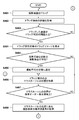
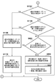
- FIG. 4A and FIG. 4B are flowcharts showing a procedure of processing in which the control device according to the embodiment of the present invention changes the display order by a drag-and-drop operation.
- FIG. 5 is a diagram illustrating a state in which imaging examination information is dragged with a mouse cursor according to an embodiment of the present invention.
- FIG. 6 is a flowchart showing a procedure of processing for changing the display order of imaging examination information by the control device according to the embodiment of the present invention.
- FIGS. 3B-A to 3B-D are diagrams showing an example of how the display order is changed by a drag-and-drop operation on the shooting screen according to an embodiment of the present invention.
- FIG. 4A and FIG. 4B are flowcharts showing a procedure of processing in which the control device according to the embodiment of
- FIGS. 8A to 8C are flowcharts showing a procedure of processing in which the control device according to the embodiment of the present invention changes the display order of imaging examination information before performing a drag operation and a drop operation.
- FIG. 9 is a flowchart showing a procedure of processing in which the control device according to the second embodiment of the present invention changes the display order of imaging examination information according to preset priority items.
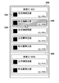
- FIG. 10 is a diagram showing an example of the display order of imaging examination information according to the priority items according to the second embodiment of the present invention.
- FIG. 11A and FIG. 11B are flowcharts showing a procedure of processing in which the control device according to the third embodiment of the present invention changes the display order of imaging examination information based on a past examination order.
- FIG. 1 is a schematic diagram illustrating an example of a schematic configuration of a radiation imaging system 100 according to an embodiment of the present invention.
- the radiation imaging system 100 includes a control device 110, radiation generators 114A and 114B, radiation detectors 115A and 115B, a radiation department information system (RIS) 130, an image server (PACS) 140, and a hospital information system ( HIS) 150.
- RIS radiation department information system
- PACS image server
- HIS hospital information system
- the control device 110 is connected to the display unit 112, the operation unit 113, the radiation generation units 114A and 114B, and the radiation detectors 115A and 115B in a wired or wireless manner, and controls the operation of each device.
- the control device 110 is connected to the radiology department information system (RIS) 130, the image server (PACS) 140, and the in-hospital information system (HIS) 150 via the network 120, and exchanges radiographic images, patient information, and the like. be able to.
- RIS radiology department information system
- PES image server
- HIS in-hospital information system
- the display unit 112 displays imaging examination information, captured radiographic images, various types of information, and the like.
- the operation unit 113 receives input information from the operator.
- the display unit 112 is a monitor, and the operation unit 113 is a keyboard or a mouse.
- the radiation generators 114A and 114B include radiation tubes that generate radiation, and irradiate the patients 1000A and 1000B, which are subjects, with radiation.
- the patient 1000A is in the standing position and 1000B is in the supine position, and the radiation generators 114A and 114B and the radiation detectors 115A and 115B are arranged at positions suitable for imaging.
- the radiation detectors 115A and 115B detect radiation emitted from the radiation generators 114A and 114B, respectively.
- the control device 110 performs image processing on the radiation image data detected and acquired by the radiation detectors 115A and 115B, and displays the radiation image on the display unit 112 as a radiation image.
- the radiation imaging system 100 is described as including a radiation department information system (RIS) 130, an image server (PACS) 140, and a hospital information system (HIS) 150. You may make it the structure which does not contain at least one part.
- RIS radiation department information system
- PACS image server
- HIS hospital information system
- the radiation generation units 114A and 114B and the radiation detectors 115A and 115B have been described as the radiation generation unit and the radiation detector.
- a further combination of the radiation generation unit and the radiation detector is a radiation imaging system 100. May be included.
- FIG. 2A is a schematic diagram illustrating an example of a hardware configuration of the control device 110.
- the control device 110 includes a CPU 201, a RAM 202, a ROM 203, an external memory 204, and a communication I / F unit 205, and they are connected to each other via a bus.
- the CPU 201 controls the operation of the control device 110 in an integrated manner, and controls each component (RAM 202 to communication I / F unit 205) shown in FIG. 2A via a bus.
- the RAM 202 functions as a main memory, work area, and the like for the CPU 201.
- the CPU 201 loads various programs 2031 and the like from the ROM 203 into the RAM 202 and executes the programs 2031 and the like, thereby realizing various functional operations.
- the ROM 203 stores a program 2031 and the like necessary for the CPU 201 to execute processing. Note that the program 2031 may be stored in the external memory 204.
- the external memory 204 stores, for example, various data and various information necessary for the CPU 201 to perform processing using the program 2031 and the like. Further, the external memory 204 stores, for example, various data and various information obtained by the CPU 201 performing processing using the program 2031 and the like.
- the communication I / F unit 205 manages communication with the outside. The bus is used to connect the CPU 201, the RAM 202, the ROM 203, the external memory 204, and the communication I / F unit 205 so that they can communicate with each other.
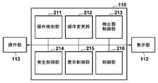
- FIG. 2B is a functional block diagram showing the software configuration of the control device 110 according to this embodiment.
- the control device 110 includes an operation detection unit 211, an order change unit 212, a detector control unit 213, a generation control unit 214, a display control unit 215, and a control unit 216.
- Each function is realized by the CPU 201 developing a program stored in the ROM 203 on the RAM 202 and executing the program.
- the operation detection unit 211 detects a user operation via the operation unit 113. Based on the user operation detected by the operation detection unit 211, the order change unit 212 changes the arrangement order of the plurality of imaging examination information displayed in the imaging order on the imaging control screen of the display unit 112.
- the imaging examination information includes the imaging position (standing position, posture, etc.), imaging site (chest, abdomen, etc.), imaging direction (front, side, etc.), and type of radiation detector used for imaging (radiation detector 115A, 115B, etc.) and at least one of the types of radiation generators used for imaging (radiation generators 114A, 114B, etc.).
- the detector control unit 213 controls the operation of the radiation detector 115A or 115B based on the order of the imaging examination information changed by the order changing unit 212. For example, the detector control unit 213 transmits a control signal in a wired or wireless manner to the radiation detectors 115A and 115B related to the first imaging examination information to be imaged in accordance with a change in the order of imaging examination information. To do.
- the imaging inspection information to be imaged is not necessarily limited to the first imaging inspection information.
- the control signal is a signal for instructing an operation according to the content of the imaging examination information that is an imaging target. For example, when the imaging examination information indicates use of the radiation detector 115B, the detector control unit 213 controls the radiation detector 115B.
- a control signal including an instruction for operating the accumulation time of radiation with an accumulation time that is three times that when imaging other parts is to be imaged is transmitted.
- a control signal including an instruction not to operate pixels, amplifiers, AD converters, etc. other than the irradiation area is transmitted.
- the detector control unit 213 performs control of the radiation detector according to the imaging examination information whose arrangement order is changed based on the user operation. Further, when the operation of the radiation detector according to the control signal is completed, a response signal indicating that the preparation for imaging is completed is received. In addition, the detector control unit 213 acquires the radiation image data acquired by being captured by the radiation detector 115A or 115B.
- the generation control unit 214 controls the operation of the radiation generation unit 114A or 114B based on the imaging examination information whose order is changed by the order change unit 212.
- the generation control unit 214 transmits a control signal in a wired or wireless manner to the radiation generation unit 114A or 114B related to the first imaging examination information to be imaged in accordance with the change in the arrangement order of the imaging examination information.
- the control signal is a signal for instructing an operation according to imaging examination information that is an imaging target.
- the imaging examination information indicates the use of the radiation generation unit 114B
- the generation control unit 214 controls the radiation generation unit 114B.
- the irradiation time of radiation may be controlled based on the imaging target region included in the imaging examination information.
- a response signal indicating that the preparation for imaging is completed is received.
- the control signal may be transmitted to only one of the radiation detector and the radiation generator.
- the display control unit 215 displays the radiographic examination information side by side on the display unit 112, displays the captured radiographic image on the display unit 112, and corresponds to a user operation via the operation unit 113 detected by the operation detection unit 211.
- the displayed display is displayed on the display unit 112.
- the control unit 216 controls the operation of each processing unit and performs various determinations and settings.
- each functional block described above is merely an example, and the control device 110 may not include a part of each functional block described above, or may include a further functional block.
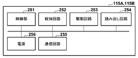
- FIG. 2C is a schematic diagram illustrating an example of the configuration of the radiation detectors 115A and 115B.
- the radiation detectors 115 ⁇ / b> A and 115 ⁇ / b> B include a control unit 251, a detection circuit 252, a drive circuit 253, a readout circuit 254, a communication circuit 255, and a power supply 256.
- the control unit 251 controls each unit in an integrated manner.
- the detection circuit 252 detects radiation irradiation by monitoring the output of the radiation sensor.
- the drive circuit 253 drives the radiation sensor in an accumulation state or a readout state. For example, based on detection of radiation irradiation by the detection circuit 252, the control unit 251 instructs the drive circuit 253 to start the accumulation state, and the drive circuit 253 drives the radiation sensor in a read state based on the instruction.
- the read circuit 254 amplifies the signal read by the drive circuit 253, performs AD conversion, and outputs radiation image data.
- the communication circuit 255 transmits radiation image data output from the readout circuit 254 and receives control signals from the control device 110.
- the power supply 256 supplies power to each component.
- the radiation detectors 115 ⁇ / b> A and 115 ⁇ / b> B control the operation according to the control signal received from the control device 110.
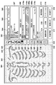
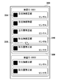
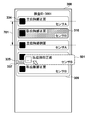
- FIG. 3A shows an example of the shooting control screen 301 displayed on the display unit 112 according to the present embodiment.
- the imaging control screen 301 includes an image display area 302, a status display area 303, a single view instruction area 304, a multiview instruction area 305, a frame view instruction area 306, a patient information display area 307, an examination display area 308, and an examination order display area 309.
- Imaging inspection information 310 Imaging inspection execution order advance instruction area 311, imaging inspection execution order reduction instruction area 312, inspection editing instruction area 313, image processing instruction area 314, measurement instruction area 315, annotation editing instruction area 316, inspection pending instruction Area 317, image output instruction area 318, inspection end instruction area 319, display annotation display switching instruction area 320, right rotation instruction area 321, left rotation instruction area 322, left / right inversion instruction area 323, up / down inversion instruction area 324, monochrome inversion instruction Region 325, L A mark placement instruction area 326, an R mark placement instruction area 327, a cutout setting instruction area 328, a mask processing instruction area 329, a re-shooting instruction area 330, a failure instruction area 331, an Undo instruction area 332, and a reset instruction area 333. ing.
- the image display area 302 displays a preview of the captured radiation image.
- the radiation image selected for preview is displayed as a preview.
- patient information, examination information, irradiation conditions, and the like are displayed as annotations according to the settings.
- no image is displayed in the initial state immediately after the start of the inspection.
- the status display area 303 is an area for distinguishing and displaying colors and characters so that the operator can easily determine the status notified from the control device 110 and the radiation detectors 115A and 115B.
- the control device 110 determines the display content based on the combination of statuses and transmits a status display switching instruction to the display unit 112. For example, if the radiation generators 114A and 114B are unable to irradiate radiation or the radiation detectors 115A and 115B are not capable of detecting radiation, “Not Ready” is displayed on the sensor status. To do.
- “Ready (display indicating imaging preparation completion state)” is displayed on the sensor status. Change the background color to a color that is easily distinguishable from the “Not Ready” display.
- the radiation detector 115A and the radiation generator 114A are a pair
- the radiation detector 115B and the radiation generator 114B are a pair. For this reason, the sensor status is displayed for the combination of the radiation detector and the radiation generation unit to be used in the current examination. “Not Ready” is changed to “Ready” in response to reception of a response signal indicating that preparation for imaging has been completed from the radiation detector and / or radiation generator.
- the single view instruction area 304 is a button for switching to a single view that displays one frame of the image selected for preview in the image display area 302. In the case of an image having a plurality of frames, another frame can be displayed and a movie can be played by operating the keyboard or mouse during preview display.
- the multi-view instruction area 305 is a button for dividing the image display area 302 into a plurality of grid-shaped display areas and switching to a multi-view that displays in parallel the group of images taken in the examination being performed. The button is disabled until two or more images are captured in the current examination, and multi-view is impossible.
- the frame view instruction area 306 is a button for dividing the image display area 302 into a plurality of grid-like display areas and switching to a frame view in which a frame image group of moving images selected for preview is displayed in parallel. If the preview selected image is not a moving image, the button is disabled and frame view is not possible.
- the patient information display area 307 is an area where patient information such as patient name, patient ID, date of birth, age, and sex is displayed.
- the inspection display area 308 displays one or a plurality of inspection order display areas 309a, 309b.
- the inspection order display areas 309a and 309b are areas in which inspection information such as inspection IDs and inspection descriptions are displayed. Also, the imaging inspection information selected in the inspection is displayed side by side in the imaging inspection information 310a, 310b, 310c, and the like.
- imaging examination information 310 imaging examination information such as the imaging examination name and the type of radiation detector, and all the taken image thumbnails 334 are displayed.
- the imaging inspection information 310 may also include a scheduled shooting thumbnail before shooting and a shot image thumbnail after shooting.
- the imaging inspection execution order advance instruction area 311 is a button for instructing to advance the imaging inspection execution order. For example, when the imaging inspection execution order advance instruction area 311 is pressed in the state where the imaging inspection information 310b is selected, the imaging inspection information 310b being selected is replaced with the imaging inspection information 310a that is one level higher in the same inspection, and is advanced. However, when the first imaging inspection information 310a is selected in the same inspection, the moving up is not performed.
- the imaging inspection execution order lowering instruction area 312 is a button for instructing to lower the imaging inspection execution scheduled order. For example, when the imaging inspection execution order lowering instruction area 312 is pressed while the imaging inspection information 310a is selected, the currently selected imaging inspection information 310a is replaced with the next imaging inspection information 310b in the same inspection. However, when the last photographing inspection information 310b is selected in the same inspection, the process is not carried forward.
- the inspection editing instruction area 313 is a button for instructing inspection editing.
- the image processing instruction area 314 is a button for instructing display / non-display switching of the image processing operation area.
- the measurement instruction area 315 is a button for instructing switching between display and non-display of the measurement operation area.
- the annotation editing instruction area 316 is a button for instructing annotation editing.
- the examination suspension instruction area 317 is a button for instructing suspension of the examination being performed.
- the image output instruction area 318 is a button for instructing image output of a captured image included in the examination being performed.
- the inspection end instruction area 319 is a button for instructing the end of the inspection being performed.
- the right rotation instruction area 321 is a button for rotating the photographed image being previewed to the right.
- the left rotation instruction area 322 is a button for rotating the captured image being previewed to the left.
- the left / right reversal instruction area 323 is a button for reversing the captured image being previewed horizontally.
- the upside down instruction area 324 is a button for turning upside down the captured image being previewed.
- the black-and-white reversal instruction area 325 is a button for reversing the window value of the captured image that is being previewed.
- the L mark placement instruction area 326 is a button for placing the side marker “L” on the photographed image being previewed.
- the button can be switched ON / OFF, “L” is arranged when ON, and “L” is deleted when OFF.
- the R mark placement instruction area 327 is a button for placing the marker “R” on the captured image being previewed.
- the button can be switched ON / OFF, “R” is arranged when ON, and “R” is deleted when OFF.
- the cutout setting instruction area 328 is a button for instructing the cutout setting of the region of interest for the captured image being previewed.
- the mask processing instruction area 329 is a button for instructing mask processing for a captured image being previewed.
- the re-photographing instruction area 330 is a button for instructing re-photographing for a photographing examination including an image whose preview is being selected.
- the re-photographing shown here refers to a process of performing a copy loss process on an image instructed to re-photograph and newly adding the same photographing test.
- the image loss instruction area 331 is a button for instructing image loss for an image whose preview is being selected. When the image loss process is performed, the image loss setting included in the image information is switched to ON.
- the undo instruction area 332 is a button for instructing an undo process for returning the history of the process for the image being selected for previewing in the newest order.
- the reset instruction area 333 is a button for instructing a reset process for discarding all the processes for the image being selected for previewing and returning to the state immediately after shooting.
- buttons may be selected and instructed by directly touching the shooting control screen 301.
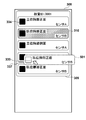
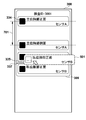
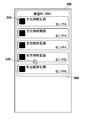
- FIGS. 3B-A to 3B-C are schematic diagrams showing details of the inspection display area 308 of FIG. 3A.
- the mouse cursor 335 can be moved by the operation of the operator's mouse (operation unit 113), and can perform drag-and-drop operation on arbitrary imaging examination information 310 (for example, the front of the chest position in FIG. 3B-A).
- the operation detection unit 211 acquires the position of the mouse cursor 335 that has performed the drag operation.
- the operation detection unit 211 determines whether or not the drag operation is valid by comparing the moving distance of the mouse cursor 335 by the drag operation with a threshold value at which the drag operation is valid.
- FIGS. 3B and 3B are diagrams showing a state in which the imaging examination information 310 is dragged with the mouse cursor 335.
- FIG. The order changing unit 212 identifies the destination 337 of the imaging inspection information 310 based on the position of the mouse cursor 335 being dragged and the center position 336 of the imaging inspection information.
- the display control unit 215 displays the mouse cursor 335 and the specified destination 337 on the display unit 112.
- 3B-C are diagrams showing a state after the drop operation is performed from the state of FIG. 3B-B.
- the operation detection unit 211 acquires the position of the mouse cursor 335 that has performed the drop operation.
- the operation detection unit 211 determines whether or not the drop operation is valid from the position of the drop operation. For example, a range in which the drop operation is effective (for example, in the same inspection order display area) is set in advance, and determination is performed based on the effective range. If the drop operation is valid, the display control unit 215 changes the display order of the imaging examination information 310. In the example of FIGS. 3B to 3C, the imaging examination information 310 is moved second from the bottom among the imaging examination information having the examination ID 0001.
- the captured image thumbnail 334 is integrally displayed in the imaging inspection information 310.
- the captured image thumbnail 334 and the imaging inspection are displayed.
- the information 310 may be displayed separately.
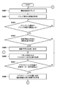
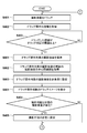
- FIG. 4A and FIG. 4B are flowcharts showing a procedure of processing in which the control device 110 according to the present embodiment changes the display order of the imaging examination information 310.
- the operation detection unit 211 acquires a signal in which arbitrary photographing inspection information is dragged.
- the operation detection unit 211 acquires the movement distance of the drag operation.
- the control unit 216 compares the movement distance with a threshold value at which the drag operation is valid, and determines whether the drag operation is valid. If the movement distance is equal to or greater than the threshold (S403; Yes), it is determined that the drag operation is valid, and the process proceeds to step S404. On the other hand, if the movement distance is less than the threshold (S403; No), it is determined that the drag operation is invalid, and the process waits until the threshold is equal to or greater than the threshold.
- step S ⁇ b> 404 the control unit 216 determines whether there is a photographing inspection in a state in which photographing can be performed in the photographing inspection list based on information held by the detector control unit 213 and the generation control unit 214. If it is determined that there is a photographing inspection in a state where photographing is possible (S404; Yes), the process proceeds to step S405. On the other hand, when it is determined that there is no imaging inspection in a state where imaging is possible (S404; No), the process proceeds to step S406.
- step S405 the control unit 216 sets the corresponding imaging inspection to a state incapable of imaging.
- step S406 the operation detection unit 211 acquires the position of the mouse cursor 335 during the drag operation.
- step S407 the control unit 216 determines whether or not the position of the mouse cursor 335 is on the inspection order display area (for example, the inspection order display area 309a). When it determines with it being on a test
- step S408 the control unit 216 acquires the display order number of the imaging examination at the position of the mouse cursor 335.
- step S409 the control unit 216 determines whether or not the position of the mouse cursor 335 during the drag operation acquired in step S406 is above the center of the imaging examination information. If it is determined that the position is above the center of the imaging examination information (S409; Yes), the process proceeds to step S410. On the other hand, when it is determined that it is not above the center of the imaging examination information (S409; No), the process proceeds to step S411.
- step S410 the control unit 216 specifies that the display order change destination is on the imaging examination information at the position of the mouse cursor 335.
- step S ⁇ b> 411 the control unit 216 specifies that the change destination of the display order is under the imaging examination information at the position of the mouse cursor 335.
- step S412 the display control unit 215 displays the change destination on the display unit 112 according to the specified change destination of the display order (for example, displays the movement destination 337).
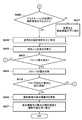
- step S413 the operation detection unit 211 detects the occurrence of the drop operation.
- the process proceeds to step S414.
- the process returns to step S406.
- step S414 the operation detection unit 211 acquires the position of the mouse cursor 335 that has performed the drop operation.
- step S415 it is determined whether or not the drop operation has been performed within the valid display area. If it is determined that the drop operation has been performed in a valid display area (S415; Yes), the process proceeds to step 416. On the other hand, if it is determined that the drop operation has been performed in an invalid display area (S415; No), the process returns to step 401.
- step S416 the order changing unit 212 updates the display order number of the imaging inspection information to change the order of the imaging inspection information.
- the display order of the imaging examination information is not changed.
- the control unit 216 sets the imaging examination information with the smallest display order number to the imaging enabled state. Specifically, the detector control unit 213 transmits a control signal to the radiation detector corresponding to the corresponding imaging examination information, and controls the radiation detector to a state where it can be used according to the contents of the imaging examination information. . Further, the generation control unit 214 transmits a control signal to the radiation generation unit associated with the radiation detector corresponding to the imaging examination information so that the radiation generation unit can be used according to the contents of the imaging examination information. Control. The detector control unit 213 and the generation control unit 214 each receive a signal indicating that the imaging is possible from the radiation detector and the radiation generation unit.
- the display control unit 215 changes the display of the status display area 303 from “Not Ready” to “Ready” in response to being ready for shooting, and easily distinguishes the background color from when “Not Ready” is displayed. Change to a possible color. Further, as shown in FIGS. 3B to 3D, the imaging examination information corresponding to the first imaging order may be displayed in a display form different from the other imaging examination information so that it is easy to visually recognize that the imaging order is the first imaging order. Good. Thus, the processes in the flowcharts of FIGS. 4A and 4B are completed.
- control device 110 is based on a plurality of pieces of photographing inspection information (for example, photographing inspection information 310) displayed in the photographing order on the photographing control screen (the photographing control screen 301).
- the arrangement order of imaging inspection information for example, imaging inspection information 310) is changed.
- the radiation detector for example, the radiation detector 115A (sensor A)
- the radiation detector 115A sensor A
- the display order can be changed by the user's drag and drop operation on the imaging control screen, and the imaging inspection information of the first imaging order can be automatically set according to the change of the display order. It is possible to improve photographing efficiency and operability.
- FIG. 5 is a diagram illustrating a state in which the imaging examination information 310 is dragged with the mouse cursor 335.
- the drag image 501 is an image showing a target being dragged set by the display control unit 215.
- the display control unit 215 may set the image of the drag image 501 to an arbitrary image (for example, shooting inspection information or a frame line to be dragged), or may set the transmittance of the image to an arbitrary numerical value. Further, the control unit 216 may set the position of coordinates necessary for specifying the display destination change destination as an arbitrary position of the drag image 501 instead of the position of the mouse cursor 335 during the drag operation.
- FIG. 6 is a flowchart showing a procedure of processing in which the control device 110 changes the display order of the imaging examination information 310. Processes similar to those in FIGS. 4A and 4B are denoted by the same reference numerals, and description thereof is omitted.
- step S403 If it is determined in step S403 that the drag operation is valid, the process proceeds to step S601.
- step S601 the image set by the display control unit 215 is displayed as the drag image 501. Thereafter, the process proceeds to step S404.
- a drag image indicating a target being dragged is used. This has the effect of making it easier to visually recognize changes in the display order.
- FIGS. 7A to 7D are diagrams showing a state in which the imaging inspection information 310 is dragged by the mouse cursor 335 and the order of the imaging inspection information is rearranged.
- FIG. 7A is a diagram showing a state in which the imaging examination information 310 is dragged with the mouse cursor 335.
- the operation detection unit 211 acquires the position of the center of either the display order number before or after the imaging examination information to be dragged.
- the imaging inspection information to be dragged is held in the external memory 204.
- the control unit 216 sets a center-to-center range 701 from the acquired center position.
- FIG. 7B is a diagram showing a state where the imaging inspection information 310 to be dragged is hidden.
- the control unit 216 determines whether or not the position of the mouse cursor 335 for the drag operation is outside the range of the center-to-center range 701. When it is determined that it is out of the range, the display control unit 215 hides the imaging inspection information 310 to be dragged.
- FIG. 7C is a diagram showing how the display order of the imaging examination information 310 is changed.
- the control unit 216 sets the display order number of the imaging examination information within the range to be changed from the imaging examination information 310 that is not displayed, and the center of the imaging examination information before and after the position of the mouse cursor 335 during the drag operation.
- a range 702 is set.
- FIG. 7D is a diagram showing a state when a drop operation is performed from the state of FIG. 7C.
- the control unit 216 determines whether or not a drop operation has occurred within the range of the center-to-center range 702. In accordance with the determination result, the control unit 216 sets a display order number in the imaging inspection information to be dragged held in the external memory 204.
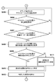
- FIGS. 8A to 8C are flowcharts showing a procedure of processing for changing the display order of the imaging examination information 310 before the control device 110 performs a drag operation and a drop operation. Processes similar to those in FIGS. 4A, 4B, and 6 are denoted by the same reference numerals, and description thereof is omitted.
- step S ⁇ b> 403 in step S ⁇ b> 801, the control unit 216 stores the dragged imaging inspection information in the external memory 204.
- step S802 the operation detection unit 211 acquires the position of the center of the imaging examination information displayed before or after the imaging examination information to be dragged. Further, the control unit 216 sets a center-to-center range from the acquired center position.
- step S803 the display control unit 215 sets the imaging examination information to be dragged to non-display. Then, the process after step S601 is performed.
- step S804 the control unit 216 determines whether the position of the mouse cursor 335 during the drag operation is outside the center-to-center range. If it is determined that the position of the mouse cursor 335 is outside the center-to-center range (S804; Yes), the process proceeds to step S407. On the other hand, when it is determined that the position of the mouse cursor 335 is within the center-to-center range (S804; No), the process returns to step S406.
- step S805 the control unit 216 acquires the imaging inspection information to be dragged and the display order number of the imaging inspection information in the specified change destination range.
- step S806 the control unit 216 updates the display order number based on the display order number of the acquired imaging examination information.
- step S807 the control unit 216 acquires the center-to-center range of the imaging examination information before and after the position of the mouse cursor 335. Then, the process after step S413 is performed.
- the display order number is automatically updated only by moving the position of the mouse cursor by the drag operation. This has the effect of making it easier to visually recognize how the display order is changed more instantaneously.
- the radiation detector that has been controlled until now may be put into a power saving state in accordance with a change in the order of the imaging examination information.
- a plurality of sensors a first sensor having a large size (for example, for photographing a chest) and a second sensor having a small size (for example, for photographing a hand or an arm)
- a first sensor having a large size for example, for photographing a chest
- a second sensor having a small size for example, for photographing a hand or an arm
- photographing inspection information corresponding to the first sensor is changed from the first to the second
- photographing with the second sensor is performed next.
- the control may be performed by determining that it is performed, and the first sensor may be in a power saving state.
- the power supply state of the radiation detector includes, for example, a power saving state in which only the communication circuit and the MPU are activated, a Ready state in which the sensor and drive circuit power supply is turned on, and a readout state in which the readout circuit is turned on. And so on.
- the senor may be activated in accordance with a change in the order of the imaging inspection information. Specifically, it is determined that imaging is started when the second imaging examination information is changed to the top in a state where three imaging examination information are arranged in order and there is no Ready protocol, and the radiation detector The sensor may be activated.
- the display order is automatically changed in accordance with the sorting priority order set in advance before shooting.
- the number of imaging inspection information input to the inspection order is large, it is necessary to search for desired imaging inspection information from among them, and it may take time to manually change the display order by the inspection engineer. Further, depending on the resolution of the monitor used for the inspection, the number of imaging inspection information displayed on the imaging control screen is reduced, and it may take time to search for desired imaging inspection information.
- the time required to search for desired imaging inspection information is reduced and imaging efficiency is further improved.
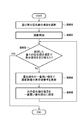
- FIG. 9 is a flowchart illustrating a processing procedure in which the control device 110 according to the present embodiment automatically changes the display order of the imaging examination information in accordance with preset priority items.
- the control unit 216 selects one or more priority items from a plurality of priority items for changing the display order based on a user operation.
- the priority items are items of imaging examination information.
- sensors radiation detectors 115A and 115B
- radiation generating units radiation generating units 114A and 114B
- imaging positions standing position and lying position
- Imaging part chest, abdomen
- imaging direction front, side
- one or more of these items may be selected.
- the position to shoot is “standing position”, 2.
- the photographing direction “front” may be selected.
- the shooting engineer A has the following priority items: The position to shoot is “standing position”, 2.
- the imaging region “abdomen” may be selected.
- the inspection orders 1001 to 1006 are arranged in the inspection order before the arrangement order change in FIG. 10, and the arrangement order is changed in accordance with the priority order items below. Instead of selecting based on a user operation, it may be set in advance, and thereafter, the set one may be used.
- step S902 shooting is started.
- step S903 the control unit 216 determines whether or not the display order has been changed for all selected priority items. If it is determined that the display order has been changed for all priority items (S902; Yes), the process is terminated. On the other hand, if it is determined that the display order has not been changed for all priority items yet (S902; No), the process proceeds to step S904.
- step S904 the display control unit 215 rearranges the display order by the priority item having the highest priority.
- the photographing room 1 “1. The posture to be photographed is standing” and “2. The photographing direction is front” is selected. First, the display order is rearranged based on “1. Standing”. In the example of the radiographer A, “1. The posture to be photographed is standing” and “2. The radiographed region is the abdomen” are selected. First, the display order is rearranged based on “1. Standing”.
- step S905 the display control unit 215 sets the priority item with one lower priority to the highest priority.
- the shooting direction is front is set to the highest priority.
- the imaging technician A “2. The imaging region is the abdomen” is set to the highest priority.
- the process returns to step S903. In this way, the processing is continued until the display order is changed for all the selected priority items, and the series of processing ends.
- imaging examination information that does not correspond to the selected priority item may be displayed in an arbitrary display order, or may be displayed in the original order.
- the photographing order is automatically rearranged in the order of inspection orders 1001, 1004, 1003, 1006, 1002, and 1005.
- the imaging order is automatically rearranged in the order of inspection orders 1001, 1003, 1006, 1004, 1002, and 1005.
- the radiation detector and the radiation generation unit corresponding to the imaging examination information in the first imaging order are controlled, and the imaging preparation is automatically performed. Become.
- the imaging inspection information is automatically rearranged based on the priority order item for imaging selected by the user. As a result, it is possible to reduce the time required to search for desired imaging inspection information and to further improve imaging efficiency.
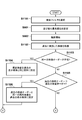
- FIG. 11A and FIG. 11B are flowcharts showing a procedure of processing in which the control device 110 according to the present embodiment automatically changes the display order of imaging inspection information based on a past inspection order. Processes similar to those in FIG. 9 are denoted by the same reference numerals and description thereof is omitted.
- step S1101 the control unit 216 selects one or more search filter items from a plurality of preset search filter items based on a user operation.
- the search filter items are, for example, a period, a laboratory technician, a subject, and the like, and one or a plurality of these items may be selected or may not be selected. Thereafter, the process proceeds to step S901.
- step S1102 the control unit 216 acquires an inspection order corresponding to the selected search filter item from inspections performed in the past.
- step S1103 the control unit 216 determines whether or not an inspection order identical to the current inspection order exists in the acquired past inspection orders. If it is determined that the same inspection order exists (S1103; Yes), the process proceeds to step S1104. On the other hand, when it is determined that the same inspection order does not exist (S1103; No), the process proceeds to step S1105.
- step S1104 the control unit 216 sets the display order number in the same display order as the display order of the past inspection orders for the current inspection order, and ends the process.
- step S1105 the control unit 216 determines whether or not the current inspection order is any subset of the past inspection orders. When it is determined that the current inspection order is any subset of the past inspection orders (S1105; Yes), the process proceeds to step S1106. On the other hand, when it is determined that the current inspection order does not become any subset of the past inspection orders (S1105; No), the process proceeds to step S1107.
- step S1106 the control unit 216 sets a display order number for the current inspection order so that the same imaging inspection information as the corresponding past inspection order has the same display order.
- step S1107 the control unit 216 determines whether any of the past inspection orders is a subset of the current inspection order. When it is determined that any of the past inspection orders is a subset of the current inspection order (S1107; Yes), the process proceeds to step S1109. On the other hand, when it is determined that none of the past inspection orders is a subset of the current inspection order (S1107; No), the process proceeds to step S1108.
- step S1108 the control unit 216 determines whether there are two or more pieces of imaging inspection information that are the same as the past inspection order. If it is determined that two or more pieces of the same imaging examination information exist (S1108; Yes), the process proceeds to step S1009. On the other hand, when it is determined that two or more pieces of the same imaging inspection information do not exist (S1108; Yes), the process proceeds to step S903, and the subsequent processing is performed.
- step S1109 the control unit 216 sets a display order number for the current inspection order so that only the same imaging inspection information as the past inspection order has the same display order.
- step S1110 the control unit 216 sets a display order number according to a preset priority item for imaging inspection information not included in the past inspection order, and ends the process.
- the current inspection order is determined in accordance with a priority item of rearrangement set in advance before photographing and / or a comparison with a past inspection order that is the same as or similar to the current inspection order.
- the display order of imaging inspection information is automatically changed. As a result, since past inspection orders can be reflected, it is possible to perform imaging that more matches the intention, and to further improve imaging efficiency.
Landscapes
- Health & Medical Sciences (AREA)
- Life Sciences & Earth Sciences (AREA)
- Engineering & Computer Science (AREA)
- Medical Informatics (AREA)
- Radiology & Medical Imaging (AREA)
- Molecular Biology (AREA)
- Biophysics (AREA)
- Nuclear Medicine, Radiotherapy & Molecular Imaging (AREA)
- Optics & Photonics (AREA)
- Pathology (AREA)
- Physics & Mathematics (AREA)
- Biomedical Technology (AREA)
- Heart & Thoracic Surgery (AREA)
- High Energy & Nuclear Physics (AREA)
- Surgery (AREA)
- Animal Behavior & Ethology (AREA)
- General Health & Medical Sciences (AREA)
- Public Health (AREA)
- Veterinary Medicine (AREA)
- Human Computer Interaction (AREA)
- Apparatus For Radiation Diagnosis (AREA)
Abstract
This control device is provided with: a change unit which, on the basis of user operations, changes the arrangement order of various imaging examination information which is displayed arranged on an imaging control screen in the order of imaging; and a control unit which, on the basis of the arrangement order changed by the change unit, controls a radiation detector and/or a radiation generating unit in relation to the imaging examination information of the imaging target.
Description
本発明は、制御装置、制御装置の動作方法およびプログラムに関し、特に放射線検出器や放射線発生部の動作を制御する技術に関する。
The present invention relates to a control device, an operation method of the control device, and a program, and more particularly to a technique for controlling operations of a radiation detector and a radiation generation unit.
従来、医療分野における放射線画像(特に、X線を使用したX線画像)の撮影では、被写体に放射線を照射し、透過した放射線の強度を放射線検出器で検出することにより、放射画像の撮影を行っている。また、一般に病院内ではネットワークが構築されており、ネットワークに各種の医療装置が接続され、病院情報システム(HIS)、放射線情報システム(RIS)、医療用画像サーバ等と連携している。
Conventionally, in radiographic imaging (especially X-ray images using X-rays) in the medical field, radiography is performed by irradiating a subject with radiation and detecting the intensity of the transmitted radiation with a radiation detector. Is going. In general, a network is constructed in a hospital, and various medical devices are connected to the network and cooperate with a hospital information system (HIS), a radiation information system (RIS), a medical image server, and the like.
病院内で放射線撮影装置が使用される場合、通常、医師から放射線撮影装置を操作する検査技師に対して、被検者の検査部位等を指定する検査オーダーが送られる。検査オーダーには、検査に必要な被検者の撮影体位、撮影部位、撮影方向等の異なる組み合わせを含む撮影検査情報が含まれている。検査オーダーは、検査技師(操作者)により手動で放射線撮影装置に直接入力されたり、あるいは、HISやRIS等のネットワークを介して放射線撮影装置に自動的に検査オーダーが入力されたりする。
When a radiography apparatus is used in a hospital, a doctor usually sends an inspection order for designating an inspection part of the subject to an inspection engineer who operates the radiography apparatus. The examination order includes imaging examination information including different combinations of the subject's imaging posture, imaging region, imaging direction, and the like necessary for the examination. The inspection order is manually input directly to the radiation imaging apparatus by an inspection engineer (operator), or the inspection order is automatically input to the radiation imaging apparatus via a network such as HIS or RIS.
例えば、ある患者に対して「1.立位胸部正面」、「2.臥位胸部正面」、「3.立位胸部側面」、「4.臥位胸部側面」という順序で撮影する検査オーダーがHISを介して入力されたとする。検査オーダーを入力する医師は、通常、放射線画像を読影しようとする順序で検査オーダーを入力するため、検査技師が行う撮影が容易な順序とは異なることがある。医師が入力した検査オーダーの順序に従って放射線撮影を実施すると、撮影の度に患者に体位変更を強いることとなり、患者への負担が大きくなることがある。
For example, an examination order for photographing a patient in the order of “1. standing chest front”, “2. supine chest front”, “3. standing chest side”, “4. Suppose that it is input via HIS. Since a doctor who inputs an examination order usually inputs an examination order in an order in which radiographic images are to be read, the order may be different from the order in which imaging is performed by an examination engineer. When radiography is performed in accordance with the order of the examination order entered by the doctor, the patient is forced to change his / her posture at each imaging, and the burden on the patient may increase.
これに対して、特許文献1では、撮影前に予め所定の変換テーブルに基づいて撮影順序を変更する検査システムが開示されている。
On the other hand, Patent Document 1 discloses an inspection system that changes the imaging order based on a predetermined conversion table in advance before imaging.
しかしながら撮影が行われる現場の状況、例えば検査技師や撮影環境、患者の身体状態等によって適切な撮影順序が異なる場合がある。このような場合に、各検査技師が状況に応じて一旦撮影を中断し、撮影前の画面に戻って撮影順序を変更するのは検査技師の手間が大きくなり撮影効率が低下してしまう。
However, the appropriate imaging sequence may differ depending on the situation where the imaging is performed, for example, the laboratory technician, the imaging environment, and the physical condition of the patient. In such a case, if each inspection engineer temporarily interrupts imaging according to the situation and returns to the screen before imaging to change the imaging order, the labor of the inspection engineer increases and imaging efficiency decreases.
さらに、撮影順序の変更によって、次に撮影する撮影検査情報が変更されると、それに従って放射線検出器や放射線発生装置を制御する必要が生じるが、手動での操作に手間がかかるだけでなく、不要な操作を行ってしまうこともあり、撮影効率が低下するという課題がある。
Furthermore, when the imaging inspection information to be imaged next is changed due to the change of the imaging order, it becomes necessary to control the radiation detector and the radiation generating apparatus accordingly, but not only manual operation takes time, Unnecessary operations may be performed, and there is a problem that photographing efficiency is lowered.
上記の課題に鑑み、本発明は、操作者の意図に沿った撮影順序での効率的な撮影を可能にすることを目的とする。
In view of the above problems, it is an object of the present invention to enable efficient shooting in the shooting order in accordance with the operator's intention.
上記の目的を達成する本発明に係る制御装置は、
撮影制御画面に撮影順に並べて表示された複数の撮影検査情報の並び順を、ユーザ操作に基づいて変更する変更手段と、
前記変更手段により変更された並び順に基づいて、撮影対象となる撮影検査情報に関連する放射線検出器又は放射線発生部の少なくとも一方を制御する制御手段と
を備えることを特徴とする。 The control device according to the present invention that achieves the above object is as follows.
Changing means for changing the arrangement order of a plurality of imaging examination information displayed in the imaging order on the imaging control screen based on a user operation;
Control means for controlling at least one of a radiation detector and a radiation generation unit related to imaging examination information to be imaged based on the order of change changed by the changing means.
本発明によれば、操作者の意図に沿った撮影順序での効率的な撮影が可能になる。
According to the present invention, it is possible to perform efficient shooting in the shooting order according to the operator's intention.
本発明のその他の特徴及び利点は、添付図面を参照とした以下の説明により明らかになるであろう。なお、添付図面においては、同じ若しくは同様の構成には、同じ参照番号を付す。
Other features and advantages of the present invention will become apparent from the following description with reference to the accompanying drawings. In the accompanying drawings, the same or similar components are denoted by the same reference numerals.
添付図面は明細書に含まれ、その一部を構成し、本発明の実施の形態を示し、その記述と共に本発明の原理を説明するために用いられる。
図1は、本発明の一実施形態に係る放射線撮影システムの概略構成を示す図である。
図2Aは、本発明の一実施形態に係る制御装置のハードウェア構成の一例を示す模式図である。
図2Bは、本発明の一実施形態に係る制御装置のソフトウェア構成を示す機能ブロック図である。
図2Cは、本発明の一実施形態に係る放射線検出器の構成の一例を示す模式図である。
図3Aは、本発明の一実施形態に係る撮影画面の一例を示す図である。
、
、
、
図3B-A~図3B-Dは、本発明の一実施形態に係る撮影画面上でドラッグアンドドロップ操作により表示順序を変更する様子の一例を示す図である。
、
図4A、図4Bは、本発明の一実施形態に係る制御装置がドラッグアンドドロップ操作により表示順序を変更する処理の手順を示すフローチャートである。
図5は、本発明の一実施形態に係る、マウスカーソルによって撮影検査情報をドラッグ操作する様子を示した図である。
図6は、本発明の一実施形態に係る制御装置が撮影検査情報の表示順序を変更する処理の手順を示すフローチャートである。
、
、
、
図7A~図7Dは、本発明の一実施形態に係る、マウスカーソルによって撮影検査情報をドラッグ操作して撮影検査情報の順序を並び替える様子を示した図である。
、
、
図8A~図8Cは、本発明の一実施形態に係る制御装置が、ドラッグ操作を行い且つドロップ操作を行う前に撮影検査情報の表示順序を変更する処理の手順を示すフローチャートである。
図9は、本発明の第2実施形態に係る制御装置が予め設定された優先順位項目に応じて撮影検査情報の表示順序を変更する処理の手順を示すフローチャートである。
図10は、本発明の第2実施形態に係る優先順位項目に従った撮影検査情報の表示順序の一例を示す図である。
、
図11A、図11Bは、本発明の第3実施形態に係る制御装置が過去の検査オーダーに基づいて撮影検査情報の表示順序を変更する処理の手順を示すフローチャートである。
The accompanying drawings are included in the specification, constitute a part thereof, show an embodiment of the present invention, and are used to explain the principle of the present invention together with the description.
FIG. 1 is a diagram showing a schematic configuration of a radiation imaging system according to an embodiment of the present invention. FIG. 2A is a schematic diagram illustrating an example of a hardware configuration of a control device according to an embodiment of the present invention. FIG. 2B is a functional block diagram showing a software configuration of the control device according to the embodiment of the present invention. FIG. 2C is a schematic diagram illustrating an example of a configuration of a radiation detector according to an embodiment of the present invention. FIG. 3A is a diagram illustrating an example of a shooting screen according to an embodiment of the present invention. , , , FIGS. 3B-A to 3B-D are diagrams showing an example of how the display order is changed by a drag-and-drop operation on the shooting screen according to an embodiment of the present invention. , FIG. 4A and FIG. 4B are flowcharts showing a procedure of processing in which the control device according to the embodiment of the present invention changes the display order by a drag-and-drop operation. FIG. 5 is a diagram illustrating a state in which imaging examination information is dragged with a mouse cursor according to an embodiment of the present invention. FIG. 6 is a flowchart showing a procedure of processing for changing the display order of imaging examination information by the control device according to the embodiment of the present invention. , , , FIGS. 7A to 7D are diagrams illustrating a state in which the imaging examination information is rearranged by dragging the imaging examination information with the mouse cursor according to an embodiment of the present invention. , , FIGS. 8A to 8C are flowcharts showing a procedure of processing in which the control device according to the embodiment of the present invention changes the display order of imaging examination information before performing a drag operation and a drop operation. FIG. 9 is a flowchart showing a procedure of processing in which the control device according to the second embodiment of the present invention changes the display order of imaging examination information according to preset priority items. FIG. 10 is a diagram showing an example of the display order of imaging examination information according to the priority items according to the second embodiment of the present invention. , FIG. 11A and FIG. 11B are flowcharts showing a procedure of processing in which the control device according to the third embodiment of the present invention changes the display order of imaging examination information based on a past examination order.
以下、添付の図面を参照しながら、本発明の実施の形態について説明する。
Hereinafter, embodiments of the present invention will be described with reference to the accompanying drawings.
(第1実施形態)
<1.放射線撮影システムの概略構成>
図1は、本発明の一実施形態に係る放射線撮影システム100の概略構成の一例を示す模式図である。放射線撮影システム100は、制御装置110と、放射線発生部114A、114Bと、放射線検出器115A、115Bと、放射線部門内情報システム(RIS)130と、画像サーバ(PACS)140と、院内情報システム(HIS)150とを備えている。 (First embodiment)
<1. General configuration of radiation imaging system>
FIG. 1 is a schematic diagram illustrating an example of a schematic configuration of aradiation imaging system 100 according to an embodiment of the present invention. The radiation imaging system 100 includes a control device 110, radiation generators 114A and 114B, radiation detectors 115A and 115B, a radiation department information system (RIS) 130, an image server (PACS) 140, and a hospital information system ( HIS) 150.
<1.放射線撮影システムの概略構成>
図1は、本発明の一実施形態に係る放射線撮影システム100の概略構成の一例を示す模式図である。放射線撮影システム100は、制御装置110と、放射線発生部114A、114Bと、放射線検出器115A、115Bと、放射線部門内情報システム(RIS)130と、画像サーバ(PACS)140と、院内情報システム(HIS)150とを備えている。 (First embodiment)
<1. General configuration of radiation imaging system>
FIG. 1 is a schematic diagram illustrating an example of a schematic configuration of a
制御装置110は、表示部112、操作部113、放射線発生部114A、114B、および放射線検出器115A、115Bと、有線または無線で接続されており、各機器の動作を制御する。また制御装置110は、放射線部門内情報システム(RIS)130、画像サーバ(PACS)140、院内情報システム(HIS)150とネットワーク120を介して接続されており、放射線画像や患者情報等をやり取りすることができる。
The control device 110 is connected to the display unit 112, the operation unit 113, the radiation generation units 114A and 114B, and the radiation detectors 115A and 115B in a wired or wireless manner, and controls the operation of each device. The control device 110 is connected to the radiology department information system (RIS) 130, the image server (PACS) 140, and the in-hospital information system (HIS) 150 via the network 120, and exchanges radiographic images, patient information, and the like. be able to.
表示部112は、撮影検査情報、撮影された放射線画像、各種の情報等を表示する。操作部113は、操作者からの入力情報を受け付ける。本実施形態では、表示部112はモニタ、操作部113はキーボードやマウスである。
The display unit 112 displays imaging examination information, captured radiographic images, various types of information, and the like. The operation unit 113 receives input information from the operator. In the present embodiment, the display unit 112 is a monitor, and the operation unit 113 is a keyboard or a mouse.
放射線発生部114A、114Bは、放射線を発生させる放射線管を具備しており、被写体である患者1000A、1000Bに対して放射線を照射する。患者1000Aは立位、1000Bは仰臥位であり、放射線発生部114A、114B、放射線検出器115A、115Bが撮影に適した位置へ配置されている。
The radiation generators 114A and 114B include radiation tubes that generate radiation, and irradiate the patients 1000A and 1000B, which are subjects, with radiation. The patient 1000A is in the standing position and 1000B is in the supine position, and the radiation generators 114A and 114B and the radiation detectors 115A and 115B are arranged at positions suitable for imaging.
放射線検出器115A、115Bは、それぞれ放射線発生部114A、114Bから照射された放射線を検出する。制御装置110は、放射線検出器115A、115Bで検出されて取得された放射線画像データに対して画像処理を施して、放射線画像として表示部112に表示する。
The radiation detectors 115A and 115B detect radiation emitted from the radiation generators 114A and 114B, respectively. The control device 110 performs image processing on the radiation image data detected and acquired by the radiation detectors 115A and 115B, and displays the radiation image on the display unit 112 as a radiation image.
なお本実施形態に係る放射線撮影システム100は、放射線部門内情報システム(RIS)130と、画像サーバ(PACS)140と、院内情報システム(HIS)150とを含むものとして説明を行うが、これらの少なくとも一部を含まない構成にしてもよい。
The radiation imaging system 100 according to the present embodiment is described as including a radiation department information system (RIS) 130, an image server (PACS) 140, and a hospital information system (HIS) 150. You may make it the structure which does not contain at least one part.
また、図1の例では、放射線発生部および放射線検出器として、放射線発生部114A、114B、放射線検出器115A、115Bについて説明したが、さらなる放射線発生部および放射線検出器の組み合わせが放射線撮影システム100に含まれていてもよい。
In the example of FIG. 1, the radiation generation units 114A and 114B and the radiation detectors 115A and 115B have been described as the radiation generation unit and the radiation detector. However, a further combination of the radiation generation unit and the radiation detector is a radiation imaging system 100. May be included.
<2.制御装置の構成>
次に、本実施形態に係る制御装置110の構成例について説明する。まず図2Aは、制御装置110のハードウェア構成の一例を示す模式図である。制御装置110は、CPU201と、RAM202と、ROM203と、外部メモリ204と、通信I/F部205とを備えており、バスを介して相互に接続されている。 <2. Configuration of control device>
Next, a configuration example of thecontrol device 110 according to the present embodiment will be described. First, FIG. 2A is a schematic diagram illustrating an example of a hardware configuration of the control device 110. The control device 110 includes a CPU 201, a RAM 202, a ROM 203, an external memory 204, and a communication I / F unit 205, and they are connected to each other via a bus.
次に、本実施形態に係る制御装置110の構成例について説明する。まず図2Aは、制御装置110のハードウェア構成の一例を示す模式図である。制御装置110は、CPU201と、RAM202と、ROM203と、外部メモリ204と、通信I/F部205とを備えており、バスを介して相互に接続されている。 <2. Configuration of control device>
Next, a configuration example of the
CPU201は、制御装置110の動作を統括的に制御するものであり、図2Aに示す各構成部(RAM202~通信I/F部205)を、バスを介して制御する。
The CPU 201 controls the operation of the control device 110 in an integrated manner, and controls each component (RAM 202 to communication I / F unit 205) shown in FIG. 2A via a bus.
RAM202は、CPU201の主メモリ、ワークエリア等として機能する。CPU201は、処理の実行に際して、ROM203から必要なプログラム2031等をRAM202にロードし、当該プログラム2031等を実行することで各種の機能動作を実現する。 ROM203には、CPU201が処理を実行するために必要なプログラム2031等が記憶されている。なお、プログラム2031は、外部メモリ204に記憶されていてもよい。
The RAM 202 functions as a main memory, work area, and the like for the CPU 201. When executing the processing, the CPU 201 loads various programs 2031 and the like from the ROM 203 into the RAM 202 and executes the programs 2031 and the like, thereby realizing various functional operations. The ROM 203 stores a program 2031 and the like necessary for the CPU 201 to execute processing. Note that the program 2031 may be stored in the external memory 204.
外部メモリ204には、例えば、CPU201がプログラム2031等を用いた処理を行う際に必要な各種のデータや各種の情報等が記憶されている。また、外部メモリ204には、例えば、CPU201がプログラム2031等を用いた処理を行うことにより得られた各種のデータや各種の情報等が記憶される。通信I/F部205は、外部との通信を司るものである。バスは、CPU201と、RAM202、ROM203、外部メモリ204及び通信I/F部205を通信可能に接続するためのものである。
The external memory 204 stores, for example, various data and various information necessary for the CPU 201 to perform processing using the program 2031 and the like. Further, the external memory 204 stores, for example, various data and various information obtained by the CPU 201 performing processing using the program 2031 and the like. The communication I / F unit 205 manages communication with the outside. The bus is used to connect the CPU 201, the RAM 202, the ROM 203, the external memory 204, and the communication I / F unit 205 so that they can communicate with each other.
また、図2Bは、本実施形態に係る制御装置110のソフトウェア構成を示す機能ブロック図である。制御装置110は、操作検出部211と、順序変更部212と、検出器制御部213と、発生制御部214と、表示制御部215と、制御部216とを備えている。各機能は、CPU201がROM203に格納されたプログラムをRAM202に展開して実行することで実現される。
FIG. 2B is a functional block diagram showing the software configuration of the control device 110 according to this embodiment. The control device 110 includes an operation detection unit 211, an order change unit 212, a detector control unit 213, a generation control unit 214, a display control unit 215, and a control unit 216. Each function is realized by the CPU 201 developing a program stored in the ROM 203 on the RAM 202 and executing the program.
操作検出部211は、操作部113を介したユーザ操作を検出する。順序変更部212は、操作検出部211により検出されたユーザ操作に基づいて、表示部112の撮影制御画面に撮影順に並べて表示された複数の撮影検査情報の並び順を変更する。撮影検査情報は、撮影体位(立位、我臥位等)、撮影部位(胸部、腹部等)、撮影方向(正面、側面等)、撮影に使用する放射線検出器の種類(放射線検出器115A、115B等)、撮影に使用する放射線発生部の種類(放射線発生部114A、114B等)等の少なくとも何れかを含む。
The operation detection unit 211 detects a user operation via the operation unit 113. Based on the user operation detected by the operation detection unit 211, the order change unit 212 changes the arrangement order of the plurality of imaging examination information displayed in the imaging order on the imaging control screen of the display unit 112. The imaging examination information includes the imaging position (standing position, posture, etc.), imaging site (chest, abdomen, etc.), imaging direction (front, side, etc.), and type of radiation detector used for imaging ( radiation detector 115A, 115B, etc.) and at least one of the types of radiation generators used for imaging ( radiation generators 114A, 114B, etc.).
検出器制御部213は、順序変更部212により変更された撮影検査情報の並び順に基づいて、放射線検出器115Aまたは115Bの動作を制御する。例えば、検出器制御部213は、撮影検査情報の並び順の変更に応じて、撮影対象となる先頭の撮影検査情報に関連する放射線検出器115A、115Bに対して制御信号を有線または無線で送信する。ただし、撮影対象となる撮影検査情報は必ずしも先頭の撮影検査情報に限定されるものではない。当該制御信号は、撮影対象である撮影検査情報の内容に応じた動作を指示するための信号である。例えば、撮影検査情報が放射線検出器115Bの使用を示す場合には、検出器制御部213は放射線検出器115Bを制御対象とする。また、撮影検査情報が腹部を撮影対象とすることを示す場合には、放射線の蓄積時間をその他の部位を撮影対象とする場合の3倍の蓄積時間で動作させる指示を含む制御信号を送信する。また、撮影検査情報が、照射領域を絞ることを示す場合には、照射領域以外の画素、アンプ、AD変換器等を動作させない指示を含む制御信号を送信する。このようにして、ユーザ操作に基づいて並び順が変更された撮影検査情報に応じた放射線検出器の制御が、検出器制御部213によって実行される。また、制御信号に応じた放射線検出器の動作が完了したら、撮影準備が完了したことを示す応答信号を受信する。また、検出器制御部213は放射線検出器115Aまたは115Bにより撮影されて取得された放射線画像データを取得する。
The detector control unit 213 controls the operation of the radiation detector 115A or 115B based on the order of the imaging examination information changed by the order changing unit 212. For example, the detector control unit 213 transmits a control signal in a wired or wireless manner to the radiation detectors 115A and 115B related to the first imaging examination information to be imaged in accordance with a change in the order of imaging examination information. To do. However, the imaging inspection information to be imaged is not necessarily limited to the first imaging inspection information. The control signal is a signal for instructing an operation according to the content of the imaging examination information that is an imaging target. For example, when the imaging examination information indicates use of the radiation detector 115B, the detector control unit 213 controls the radiation detector 115B. In addition, when the imaging examination information indicates that the abdomen is to be imaged, a control signal including an instruction for operating the accumulation time of radiation with an accumulation time that is three times that when imaging other parts is to be imaged is transmitted. . When the imaging inspection information indicates that the irradiation area is to be narrowed down, a control signal including an instruction not to operate pixels, amplifiers, AD converters, etc. other than the irradiation area is transmitted. In this manner, the detector control unit 213 performs control of the radiation detector according to the imaging examination information whose arrangement order is changed based on the user operation. Further, when the operation of the radiation detector according to the control signal is completed, a response signal indicating that the preparation for imaging is completed is received. In addition, the detector control unit 213 acquires the radiation image data acquired by being captured by the radiation detector 115A or 115B.
発生制御部214は、順序変更部212により並び順が変更された撮影検査情報に基づいて、放射線発生部114Aまたは114Bの動作を制御する。発生制御部214は、撮影検査情報の並び順の変更に応じて、撮影対象となる先頭の撮影検査情報に関連する放射線発生部114Aまたは114Bに対して制御信号を有線または無線で送信する。当該制御信号は、撮影対象である撮影検査情報に応じた動作を指示するための信号である。例えば、撮影検査情報が放射線発生部114Bの使用を示す場合には、発生制御部214は放射線発生部114Bを制御対象とする。また、撮影検査情報に含まれる撮影対象部位に基づいて放射線の照射時間を制御してもよい。また、制御信号に応じた放射線発生部の動作が完了したら、撮影準備が完了したことを示す応答信号を受信する。
The generation control unit 214 controls the operation of the radiation generation unit 114A or 114B based on the imaging examination information whose order is changed by the order change unit 212. The generation control unit 214 transmits a control signal in a wired or wireless manner to the radiation generation unit 114A or 114B related to the first imaging examination information to be imaged in accordance with the change in the arrangement order of the imaging examination information. The control signal is a signal for instructing an operation according to imaging examination information that is an imaging target. For example, when the imaging examination information indicates the use of the radiation generation unit 114B, the generation control unit 214 controls the radiation generation unit 114B. In addition, the irradiation time of radiation may be controlled based on the imaging target region included in the imaging examination information. Further, when the operation of the radiation generating unit according to the control signal is completed, a response signal indicating that the preparation for imaging is completed is received.
なお、撮影検査情報の内容次第では、すでに放射線検出器の制御は必要なく、放射線発生部のみ制御すればよい場合があり、その逆の場合もありうる。このような場合には放射線検出器または放射線発生部の一方のみに制御信号を送信するようにしてもよい。
It should be noted that depending on the contents of the imaging examination information, there is no need to control the radiation detector, only the radiation generating unit may be controlled, and vice versa. In such a case, the control signal may be transmitted to only one of the radiation detector and the radiation generator.
表示制御部215は、撮影検査情報を並べて表示部112に表示したり、撮影された放射線画像を表示部112に表示したり、操作検出部211が検出した操作部113を介したユーザ操作に対応した表示を表示部112に表示する。制御部216は、各処理部の動作を制御するとともに、各種の判定や設定を行う。
The display control unit 215 displays the radiographic examination information side by side on the display unit 112, displays the captured radiographic image on the display unit 112, and corresponds to a user operation via the operation unit 113 detected by the operation detection unit 211. The displayed display is displayed on the display unit 112. The control unit 216 controls the operation of each processing unit and performs various determinations and settings.
ここで上述の各機能ブロックはあくまでも一例であり、制御装置110は、上述の各機能ブロックの一部を含まない構成としてもよく、さらなる機能ブロックを含む構成としてもよい。
Here, each functional block described above is merely an example, and the control device 110 may not include a part of each functional block described above, or may include a further functional block.
<3.放射線検出器の構成>
次に、本実施形態に係る放射線検出器115A、115Bの構成例について説明する。図2Cは、放射線検出器115A、115Bの構成の一例を示す模式図である。 <3. Configuration of radiation detector>
Next, a configuration example of the radiation detectors 115A and 115B according to the present embodiment will be described. FIG. 2C is a schematic diagram illustrating an example of the configuration of the radiation detectors 115A and 115B.
次に、本実施形態に係る放射線検出器115A、115Bの構成例について説明する。図2Cは、放射線検出器115A、115Bの構成の一例を示す模式図である。 <3. Configuration of radiation detector>
Next, a configuration example of the
放射線検出器115A、115Bは、制御部251と、検知回路252と、駆動回路253と、読み出し回路254と、通信回路255と、電源256とを備えている。制御部251は、各部を統合的に制御する。検知回路252は、放射線センサの出力を監視して放射線の照射を検知する。駆動回路253は、放射線センサを蓄積状態または読み出し状態で駆動させる。例えば、検知回路252での放射線照射の検知に基づいて、制御部251が駆動回路253に対して蓄積状態を開始させる指示を行い、駆動回路253は当該指示に基づいて放射線センサを読み出し状態で駆動させる。
The radiation detectors 115 </ b> A and 115 </ b> B include a control unit 251, a detection circuit 252, a drive circuit 253, a readout circuit 254, a communication circuit 255, and a power supply 256. The control unit 251 controls each unit in an integrated manner. The detection circuit 252 detects radiation irradiation by monitoring the output of the radiation sensor. The drive circuit 253 drives the radiation sensor in an accumulation state or a readout state. For example, based on detection of radiation irradiation by the detection circuit 252, the control unit 251 instructs the drive circuit 253 to start the accumulation state, and the drive circuit 253 drives the radiation sensor in a read state based on the instruction. Let
読み出し回路254は、駆動回路253により読み出された信号を増幅してAD変換し、放射線画像データを出力する。通信回路255は、読み出し回路254から出力された放射線画像データの送信や、制御装置110からの制御信号の受信を行う。電源256は、各構成要素に電力を供給する。放射線検出器115A、115Bは、制御装置110から受信した制御信号にしたがって動作を制御する。
The read circuit 254 amplifies the signal read by the drive circuit 253, performs AD conversion, and outputs radiation image data. The communication circuit 255 transmits radiation image data output from the readout circuit 254 and receives control signals from the control device 110. The power supply 256 supplies power to each component. The radiation detectors 115 </ b> A and 115 </ b> B control the operation according to the control signal received from the control device 110.
<4.撮影制御画面の一例>
図3Aは、本実施形態に係る表示部112に表示される撮影制御画面301の一例を示す。撮影制御画面301は、画像表示領域302、ステータス表示領域303、シングルビュー指示領域304、マルチビュー指示領域305、フレームビュー指示領域306、患者情報表示領域307、検査表示領域308、検査オーダー表示領域309、撮影検査情報310、撮影検査実施順序繰り上げ指示領域311、撮影検査実施順序繰り下げ指示領域312、検査編集指示領域313、画像処理指示領域314、計測指示領域315、アノテーション編集指示領域316、検査保留指示領域317、画像出力指示領域318、検査終了指示領域319、表示アノテーション表示切り替え指示領域320、右回転指示領域321、左回転指示領域322、左右反転指示領域323、上下反転指示領域324、白黒反転指示領域325、Lマーク配置指示領域326、Rマーク配置指示領域327、切り出し設定指示領域328、マスク処理指示領域329、再撮影指示領域330、写損指示領域331、Undo指示領域332、リセット指示領域333を有している。 <4. Example of shooting control screen>
FIG. 3A shows an example of theshooting control screen 301 displayed on the display unit 112 according to the present embodiment. The imaging control screen 301 includes an image display area 302, a status display area 303, a single view instruction area 304, a multiview instruction area 305, a frame view instruction area 306, a patient information display area 307, an examination display area 308, and an examination order display area 309. , Imaging inspection information 310, imaging inspection execution order advance instruction area 311, imaging inspection execution order reduction instruction area 312, inspection editing instruction area 313, image processing instruction area 314, measurement instruction area 315, annotation editing instruction area 316, inspection pending instruction Area 317, image output instruction area 318, inspection end instruction area 319, display annotation display switching instruction area 320, right rotation instruction area 321, left rotation instruction area 322, left / right inversion instruction area 323, up / down inversion instruction area 324, monochrome inversion instruction Region 325, L A mark placement instruction area 326, an R mark placement instruction area 327, a cutout setting instruction area 328, a mask processing instruction area 329, a re-shooting instruction area 330, a failure instruction area 331, an Undo instruction area 332, and a reset instruction area 333. ing.
図3Aは、本実施形態に係る表示部112に表示される撮影制御画面301の一例を示す。撮影制御画面301は、画像表示領域302、ステータス表示領域303、シングルビュー指示領域304、マルチビュー指示領域305、フレームビュー指示領域306、患者情報表示領域307、検査表示領域308、検査オーダー表示領域309、撮影検査情報310、撮影検査実施順序繰り上げ指示領域311、撮影検査実施順序繰り下げ指示領域312、検査編集指示領域313、画像処理指示領域314、計測指示領域315、アノテーション編集指示領域316、検査保留指示領域317、画像出力指示領域318、検査終了指示領域319、表示アノテーション表示切り替え指示領域320、右回転指示領域321、左回転指示領域322、左右反転指示領域323、上下反転指示領域324、白黒反転指示領域325、Lマーク配置指示領域326、Rマーク配置指示領域327、切り出し設定指示領域328、マスク処理指示領域329、再撮影指示領域330、写損指示領域331、Undo指示領域332、リセット指示領域333を有している。 <4. Example of shooting control screen>
FIG. 3A shows an example of the
画像表示領域302は、撮影した放射線画像をプレビュー表示する。撮影後にプレビュー選択を切り替えた場合はプレビュー選択された放射線画像がプレビュー表示される。また、設定に応じて患者情報、検査情報、照射条件などがアノテーション表示される。なお、検査開始直後の初期状態では、画像は表示されない。
The image display area 302 displays a preview of the captured radiation image. When the preview selection is switched after imaging, the radiation image selected for preview is displayed as a preview. In addition, patient information, examination information, irradiation conditions, and the like are displayed as annotations according to the settings. In the initial state immediately after the start of the inspection, no image is displayed.
ステータス表示領域303は、制御装置110や放射線検出器115A、115Bから通知されたステータスを操作者が判別し易いように、色や文字を区別して表示する領域である。放射線検出器115A、115Bからステータス通知を受信した制御装置110は、ステータスの組み合わせによって表示内容を判定し、表示部112へステータス表示切り替え指示を送信する。例えば、放射線発生部114A、114Bが放射線照射不可である場合あるいは放射線検出器115A、115Bが放射線検出不可能である場合は、センサステータス上に「Not Ready(撮影準備状態を示す表示)」を表示する。また、放射線発生部114A、114Bが放射線照射可能であり且つ放射線検出器115A、115Bが放射線検出可能である場合は、センサステータス上に「Ready(撮影準備完了状態を示す表示)」を表示し、背景色を「Not Ready」表示時と容易に区別可能な色に変更する。なお、本実施形態では放射線検出器115Aと放射線発生部114Aとがペアであり、放射線検出器115Bと放射線発生部114Bとがペアである。そのため、現在の検査で使用する対象となる放射線検出器と放射線発生部との組み合わせについて、センサステータスを表示することになる。放射線検出器及び/又は放射線発生部から撮影準備が完了したことを示す応答信号を受信したことに応じて「Not Ready」を「Ready」に変更する。
The status display area 303 is an area for distinguishing and displaying colors and characters so that the operator can easily determine the status notified from the control device 110 and the radiation detectors 115A and 115B. Receiving the status notification from the radiation detectors 115 </ b> A and 115 </ b> B, the control device 110 determines the display content based on the combination of statuses and transmits a status display switching instruction to the display unit 112. For example, if the radiation generators 114A and 114B are unable to irradiate radiation or the radiation detectors 115A and 115B are not capable of detecting radiation, “Not Ready” is displayed on the sensor status. To do. In addition, when the radiation generation units 114A and 114B can irradiate radiation and the radiation detectors 115A and 115B can detect radiation, “Ready (display indicating imaging preparation completion state)” is displayed on the sensor status. Change the background color to a color that is easily distinguishable from the “Not Ready” display. In this embodiment, the radiation detector 115A and the radiation generator 114A are a pair, and the radiation detector 115B and the radiation generator 114B are a pair. For this reason, the sensor status is displayed for the combination of the radiation detector and the radiation generation unit to be used in the current examination. “Not Ready” is changed to “Ready” in response to reception of a response signal indicating that preparation for imaging has been completed from the radiation detector and / or radiation generator.
シングルビュー指示領域304は、画像表示領域302にプレビュー選択されている画像の1フレームを表示するシングルビューへ切り替えるボタンである。複数フレームの画像の場合、プレビュー表示中にキーボードやマウス操作によって別フレームの表示や動画再生も可能である。
The single view instruction area 304 is a button for switching to a single view that displays one frame of the image selected for preview in the image display area 302. In the case of an image having a plurality of frames, another frame can be displayed and a movie can be played by operating the keyboard or mouse during preview display.
マルチビュー指示領域305は、画像表示領域302を格子状の複数表示領域に区切り、実施中の検査内で撮影された画像群を並列表示するマルチビューへ切り替えるボタンである。実施中の検査内で2つ以上の画像が撮影されるまではボタンは無効となり、マルチビュー不可能となる。
The multi-view instruction area 305 is a button for dividing the image display area 302 into a plurality of grid-shaped display areas and switching to a multi-view that displays in parallel the group of images taken in the examination being performed. The button is disabled until two or more images are captured in the current examination, and multi-view is impossible.
フレームビュー指示領域306は、画像表示領域302を格子状の複数表示領域に区切り、プレビュー選択されている動画のフレーム画像群を並列表示するフレームビューへ切り替えるボタンである。プレビュー選択されている画像が動画像でない場合、ボタンは無効となり、フレームビュー不可能となる。
The frame view instruction area 306 is a button for dividing the image display area 302 into a plurality of grid-like display areas and switching to a frame view in which a frame image group of moving images selected for preview is displayed in parallel. If the preview selected image is not a moving image, the button is disabled and frame view is not possible.
患者情報表示領域307は、患者名、患者ID、生年月日、年齢、性別といった患者情報が表示される領域である。検査表示領域308は、一つまたは複数の検査オーダー表示領域309a、309b...を表示している。検査オーダー表示領域309a、309bとは、検査IDや検査記述といった検査情報が表示される領域である。また、検査で選択されている撮影検査情報が撮影検査情報310a、310b、310c等に並べて表示される。
The patient information display area 307 is an area where patient information such as patient name, patient ID, date of birth, age, and sex is displayed. The inspection display area 308 displays one or a plurality of inspection order display areas 309a, 309b. The inspection order display areas 309a and 309b are areas in which inspection information such as inspection IDs and inspection descriptions are displayed. Also, the imaging inspection information selected in the inspection is displayed side by side in the imaging inspection information 310a, 310b, 310c, and the like.
撮影検査情報310には、撮影検査名称、放射線検出器の種別等の撮影検査情報と、実施した全ての撮影画像サムネイル334が表示されている。また、撮影検査情報310には、撮影実施前の場合は撮影予定サムネイル、撮影実施後の場合は撮影画像サムネイルも含まれてもよい。
In the imaging examination information 310, imaging examination information such as the imaging examination name and the type of radiation detector, and all the taken image thumbnails 334 are displayed. The imaging inspection information 310 may also include a scheduled shooting thumbnail before shooting and a shot image thumbnail after shooting.
撮影検査実施順序繰り上げ指示領域311は、撮影検査の実施予定順序の繰り上げを指示するボタンである。例えば、撮影検査情報310bを選択した状態で撮影検査実施順序繰り上げ指示領域311を押下すると、選択中の撮影検査情報310bが同一検査内の1つ上の撮影検査情報310aと入れ替わって繰り上がる。ただし、同一検査内で先頭の撮影検査情報310aが選択されている場合は繰り上がらない。
The imaging inspection execution order advance instruction area 311 is a button for instructing to advance the imaging inspection execution order. For example, when the imaging inspection execution order advance instruction area 311 is pressed in the state where the imaging inspection information 310b is selected, the imaging inspection information 310b being selected is replaced with the imaging inspection information 310a that is one level higher in the same inspection, and is advanced. However, when the first imaging inspection information 310a is selected in the same inspection, the moving up is not performed.
撮影検査実施順序繰り下げ指示領域312は、撮影検査の実施予定順序の繰り下げを指示するボタンである。例えば、撮影検査情報310aを選択した状態で撮影検査実施順序繰り下げ指示領域312を押下すると、選択中の撮影検査情報310aが同一検査内の1つ下の撮影検査情報310bと入れ替わって繰り下がる。ただし、同一検査内で最後尾の撮影検査情報310bが選択されている場合は繰り下がらない。
The imaging inspection execution order lowering instruction area 312 is a button for instructing to lower the imaging inspection execution scheduled order. For example, when the imaging inspection execution order lowering instruction area 312 is pressed while the imaging inspection information 310a is selected, the currently selected imaging inspection information 310a is replaced with the next imaging inspection information 310b in the same inspection. However, when the last photographing inspection information 310b is selected in the same inspection, the process is not carried forward.
検査編集指示領域313は、検査編集を指示するボタンである。画像処理指示領域314は、画像処理操作領域の表示・非表示の切り替えを指示するボタンである。計測指示領域315は、計測操作領域の表示・非表示の切り替えを指示するボタンである。アノテーション編集指示領域316は、アノテーションの編集を指示するボタンである。検査保留指示領域317は、実施中の検査の保留を指示するボタンである。画像出力指示領域318は、実施中の検査に含まれる撮影画像の画像出力を指示するボタンである。検査終了指示領域319は、実施中の検査の終了を指示するボタンである。
The inspection editing instruction area 313 is a button for instructing inspection editing. The image processing instruction area 314 is a button for instructing display / non-display switching of the image processing operation area. The measurement instruction area 315 is a button for instructing switching between display and non-display of the measurement operation area. The annotation editing instruction area 316 is a button for instructing annotation editing. The examination suspension instruction area 317 is a button for instructing suspension of the examination being performed. The image output instruction area 318 is a button for instructing image output of a captured image included in the examination being performed. The inspection end instruction area 319 is a button for instructing the end of the inspection being performed.
右回転指示領域321は、プレビュー表示中の撮影画像を右回転させるボタンである。左回転指示領域322は、プレビュー表示中の撮影画像を左回転させるボタンである。左右反転指示領域323は、プレビュー表示中の撮影画像を左右反転させるボタンである。上下反転指示領域324は、プレビュー表示中の撮影画像を上下反転させるボタンである。白黒反転指示領域325は、プレビュー表示中の撮影画像のWindow値を反転させるボタンである。
The right rotation instruction area 321 is a button for rotating the photographed image being previewed to the right. The left rotation instruction area 322 is a button for rotating the captured image being previewed to the left. The left / right reversal instruction area 323 is a button for reversing the captured image being previewed horizontally. The upside down instruction area 324 is a button for turning upside down the captured image being previewed. The black-and-white reversal instruction area 325 is a button for reversing the window value of the captured image that is being previewed.
Lマーク配置指示領域326は、プレビュー表示中の撮影画像上に側マーカー「L」を配置させるボタンである。ボタンはON/OFF切り替え可能であり、ONで「L」を配置し、OFFで「L」を削除する。Rマーク配置指示領域327は、プレビュー表示中の撮影画像上にマーカー「R」を配置させるボタンである。ボタンはON/OFF切り替え可能であり、ONで「R」を配置し、OFFで「R」を削除する。切り出し設定指示領域328は、プレビュー表示中の撮影画像に対する関心領域の切り出し設定を指示するボタンである。マスク処理指示領域329は、プレビュー表示中の撮影画像に対するマスク処理を指示するボタンである。
The L mark placement instruction area 326 is a button for placing the side marker “L” on the photographed image being previewed. The button can be switched ON / OFF, “L” is arranged when ON, and “L” is deleted when OFF. The R mark placement instruction area 327 is a button for placing the marker “R” on the captured image being previewed. The button can be switched ON / OFF, “R” is arranged when ON, and “R” is deleted when OFF. The cutout setting instruction area 328 is a button for instructing the cutout setting of the region of interest for the captured image being previewed. The mask processing instruction area 329 is a button for instructing mask processing for a captured image being previewed.
再撮影指示領域330は、プレビュー選択中の画像を含む撮影検査に対して再撮影を指示するボタンである。ここで示す再撮影とは、再撮影を指示された画像に対して写損処理を実施し、同一撮影検査を新規で追加する処理を指す。写損指示領域331は、プレビュー選択中の画像に対して写損を指示するボタンである。写損処理が実施されると、画像情報に含まれる写損設定がONに切り替えられる。Undo指示領域332は、プレビュー選択中の画像に対する処理の履歴を新しい順に戻すUndo処理を指示するボタンである。リセット指示領域333は、プレビュー選択中の画像に対する処理を全て破棄し、撮影直後の状態に戻すリセット処理を指示するボタンである。
The re-photographing instruction area 330 is a button for instructing re-photographing for a photographing examination including an image whose preview is being selected. The re-photographing shown here refers to a process of performing a copy loss process on an image instructed to re-photograph and newly adding the same photographing test. The image loss instruction area 331 is a button for instructing image loss for an image whose preview is being selected. When the image loss process is performed, the image loss setting included in the image information is switched to ON. The undo instruction area 332 is a button for instructing an undo process for returning the history of the process for the image being selected for previewing in the newest order. The reset instruction area 333 is a button for instructing a reset process for discarding all the processes for the image being selected for previewing and returning to the state immediately after shooting.
ユーザは操作部113を介して各ボタンを選択指示することができる。あるいは表示部112がタッチパネルである場合、直接撮影制御画面301をタッチ操作することで各ボタンを選択指示してもよい。
The user can select and instruct each button via the operation unit 113. Alternatively, when the display unit 112 is a touch panel, the buttons may be selected and instructed by directly touching the shooting control screen 301.
<5.検査表示領域の一例>
次に、図3B-A~図3B-Cは、図3Aの検査表示領域308の詳細を示す模式図である。マウスカーソル335は、操作者のマウス(操作部113)の操作によって移動可能であり、任意の撮影検査情報310(例えば、図3B-Aの臥位胸部正面)をドラッグアンドドロップ操作することができる。操作検出部211は、ドラッグ操作をしたマウスカーソル335の位置を取得する。操作検出部211は、ドラッグ操作によるマウスカーソル335の移動距離と、ドラッグ操作が有効となる閾値とを比較して、ドラッグ操作が有効か否かを判定する。 <5. Example of inspection display area>
Next, FIGS. 3B-A to 3B-C are schematic diagrams showing details of theinspection display area 308 of FIG. 3A. The mouse cursor 335 can be moved by the operation of the operator's mouse (operation unit 113), and can perform drag-and-drop operation on arbitrary imaging examination information 310 (for example, the front of the chest position in FIG. 3B-A). . The operation detection unit 211 acquires the position of the mouse cursor 335 that has performed the drag operation. The operation detection unit 211 determines whether or not the drag operation is valid by comparing the moving distance of the mouse cursor 335 by the drag operation with a threshold value at which the drag operation is valid.
次に、図3B-A~図3B-Cは、図3Aの検査表示領域308の詳細を示す模式図である。マウスカーソル335は、操作者のマウス(操作部113)の操作によって移動可能であり、任意の撮影検査情報310(例えば、図3B-Aの臥位胸部正面)をドラッグアンドドロップ操作することができる。操作検出部211は、ドラッグ操作をしたマウスカーソル335の位置を取得する。操作検出部211は、ドラッグ操作によるマウスカーソル335の移動距離と、ドラッグ操作が有効となる閾値とを比較して、ドラッグ操作が有効か否かを判定する。 <5. Example of inspection display area>
Next, FIGS. 3B-A to 3B-C are schematic diagrams showing details of the
図3B-Bは、マウスカーソル335によって撮影検査情報310をドラッグ操作する様子を示した図である。順序変更部212は、ドラッグ操作中のマウスカーソル335の位置と撮影検査情報の中心位置336とに基づいて、撮影検査情報310の移動先337を特定する。表示制御部215は、マウスカーソル335や、特定された移動先337を表示部112に表示する。
FIGS. 3B and 3B are diagrams showing a state in which the imaging examination information 310 is dragged with the mouse cursor 335. FIG. The order changing unit 212 identifies the destination 337 of the imaging inspection information 310 based on the position of the mouse cursor 335 being dragged and the center position 336 of the imaging inspection information. The display control unit 215 displays the mouse cursor 335 and the specified destination 337 on the display unit 112.
そして図3B-Cは、図3B-Bの状態からドロップ操作をした後の様子を示した図である。操作検出部211は、ドロップ操作をしたマウスカーソル335の位置を取得する。操作検出部211は、ドロップ操作の位置からドロップ操作が有効か否か判定する。例えば、予めドロップ操作が有効な範囲(例えば、同一の検査オーダー表示領域内)を設定しておき、当該有効範囲に基づいて判定を行う。ドロップ操作が有効ならば、表示制御部215は、撮影検査情報310の表示順序を変更する。図3B-Cの例では、検査IDが0001の各撮影検査情報のうち下から2番目に撮影検査情報310が移動する。
3B-C are diagrams showing a state after the drop operation is performed from the state of FIG. 3B-B. The operation detection unit 211 acquires the position of the mouse cursor 335 that has performed the drop operation. The operation detection unit 211 determines whether or not the drop operation is valid from the position of the drop operation. For example, a range in which the drop operation is effective (for example, in the same inspection order display area) is set in advance, and determination is performed based on the effective range. If the drop operation is valid, the display control unit 215 changes the display order of the imaging examination information 310. In the example of FIGS. 3B to 3C, the imaging examination information 310 is moved second from the bottom among the imaging examination information having the examination ID 0001.
なお、図3B-A~図3B-Cの例では撮影画像サムネイル334が撮影検査情報310の中に一体として表示しているが、図3B-Dに示すように、撮影画像サムネイル334と撮影検査情報310とを分離して表示させてもよい。
In the example of FIGS. 3B-A to 3B-C, the captured image thumbnail 334 is integrally displayed in the imaging inspection information 310. However, as shown in FIGS. 3B-D, the captured image thumbnail 334 and the imaging inspection are displayed. The information 310 may be displayed separately.
<6.表示順序変更処理>
図4A、図4Bは、本実施形態に係る制御装置110が撮影検査情報310の表示順序を変更する処理の手順を示すフローチャートである。まず、ステップS401において、操作検出部211は、任意の撮影検査情報がドラッグされた信号を取得する。次に、ステップS402において、操作検出部211は、ドラッグ操作の移動距離を取得する。ステップS403において、制御部216は、当該移動距離と、ドラッグ操作が有効となる閾値とを比較して、ドラッグ操作が有効か否か判定する。移動距離が閾値以上であれば(S403;Yes)、ドラッグ操作が有効であると判定して、ステップS404へ進む。一方、移動距離が閾値未満であれば(S403;No)、ドラッグ操作が無効であると判定して、閾値以上になるまで待機する。 <6. Display order change processing>
FIG. 4A and FIG. 4B are flowcharts showing a procedure of processing in which thecontrol device 110 according to the present embodiment changes the display order of the imaging examination information 310. First, in step S401, the operation detection unit 211 acquires a signal in which arbitrary photographing inspection information is dragged. Next, in step S402, the operation detection unit 211 acquires the movement distance of the drag operation. In step S403, the control unit 216 compares the movement distance with a threshold value at which the drag operation is valid, and determines whether the drag operation is valid. If the movement distance is equal to or greater than the threshold (S403; Yes), it is determined that the drag operation is valid, and the process proceeds to step S404. On the other hand, if the movement distance is less than the threshold (S403; No), it is determined that the drag operation is invalid, and the process waits until the threshold is equal to or greater than the threshold.
図4A、図4Bは、本実施形態に係る制御装置110が撮影検査情報310の表示順序を変更する処理の手順を示すフローチャートである。まず、ステップS401において、操作検出部211は、任意の撮影検査情報がドラッグされた信号を取得する。次に、ステップS402において、操作検出部211は、ドラッグ操作の移動距離を取得する。ステップS403において、制御部216は、当該移動距離と、ドラッグ操作が有効となる閾値とを比較して、ドラッグ操作が有効か否か判定する。移動距離が閾値以上であれば(S403;Yes)、ドラッグ操作が有効であると判定して、ステップS404へ進む。一方、移動距離が閾値未満であれば(S403;No)、ドラッグ操作が無効であると判定して、閾値以上になるまで待機する。 <6. Display order change processing>
FIG. 4A and FIG. 4B are flowcharts showing a procedure of processing in which the
ステップS404において、制御部216は、検出器制御部213および発生制御部214が保持する情報に基づいて、撮影検査リストに撮影可能な状態の撮影検査が存在するか否かを判定する。撮影可能な状態の撮影検査が存在すると判定された場合(S404;Yes)、ステップS405へ進む。一方、撮影可能な状態の撮影検査が存在しないと判定された場合(S404;No)、ステップS406へ進む。
In step S <b> 404, the control unit 216 determines whether there is a photographing inspection in a state in which photographing can be performed in the photographing inspection list based on information held by the detector control unit 213 and the generation control unit 214. If it is determined that there is a photographing inspection in a state where photographing is possible (S404; Yes), the process proceeds to step S405. On the other hand, when it is determined that there is no imaging inspection in a state where imaging is possible (S404; No), the process proceeds to step S406.
ステップS405において、制御部216は、該当する撮影検査を撮影不可の状態に設定する。次に、ステップS406において、操作検出部211は、ドラッグ操作中のマウスカーソル335の位置を取得する。
In step S405, the control unit 216 sets the corresponding imaging inspection to a state incapable of imaging. Next, in step S406, the operation detection unit 211 acquires the position of the mouse cursor 335 during the drag operation.
ステップS407において、制御部216は、マウスカーソル335の位置が検査オーダー表示領域(例えば、検査オーダー表示領域309a)上であるか否かを判定する。検査オーダー表示領域上であると判定された場合(S407;Yes)、ステップS408へ進む。一方、検査オーダー表示領域上ではないと判定された場合(S407;No)、ステップS406に戻る。
In step S407, the control unit 216 determines whether or not the position of the mouse cursor 335 is on the inspection order display area (for example, the inspection order display area 309a). When it determines with it being on a test | inspection order display area (S407; Yes), it progresses to step S408. On the other hand, when it is determined that it is not on the inspection order display area (S407; No), the process returns to step S406.
ステップS408において、制御部216は、マウスカーソル335の位置にある撮影検査の表示順番号を取得する。次に、ステップS409において、制御部216は、ステップS406で取得されたドラッグ操作中のマウスカーソル335の位置が、撮影検査情報の中心より上にあるか否か判定する。撮影検査情報の中心より上にあると判定された場合は(S409;Yes)、ステップS410へ進む。一方、撮影検査情報の中心より上ではないと判定された場合は(S409;No)、ステップS411へ進む。
In step S408, the control unit 216 acquires the display order number of the imaging examination at the position of the mouse cursor 335. Next, in step S409, the control unit 216 determines whether or not the position of the mouse cursor 335 during the drag operation acquired in step S406 is above the center of the imaging examination information. If it is determined that the position is above the center of the imaging examination information (S409; Yes), the process proceeds to step S410. On the other hand, when it is determined that it is not above the center of the imaging examination information (S409; No), the process proceeds to step S411.
ステップS410において、制御部216は、表示順序の変更先がマウスカーソル335の位置にある撮影検査情報の上であると特定する。ステップS411において、制御部216は、表示順序の変更先がマウスカーソル335の位置にある撮影検査情報の下であると特定する。
In step S410, the control unit 216 specifies that the display order change destination is on the imaging examination information at the position of the mouse cursor 335. In step S <b> 411, the control unit 216 specifies that the change destination of the display order is under the imaging examination information at the position of the mouse cursor 335.
次に、ステップS412において、表示制御部215は、特定した表示順序の変更先に応じて、表示部112に変更先を表示する(例えば、移動先337を表示する)。
Next, in step S412, the display control unit 215 displays the change destination on the display unit 112 according to the specified change destination of the display order (for example, displays the movement destination 337).
その後、ステップS413において、操作検出部211は、ドロップ操作の発生を検出する。ドロップ操作の発生が検出された場合は(S413;Yes)、ステップS414へ進む。一方、ドロップ操作の発生が検出されていない場合は(S413;No)、ステップS406に戻る。
Thereafter, in step S413, the operation detection unit 211 detects the occurrence of the drop operation. When the occurrence of the drop operation is detected (S413; Yes), the process proceeds to step S414. On the other hand, when the occurrence of the drop operation is not detected (S413; No), the process returns to step S406.
ステップS414において、操作検出部211は、ドロップ操作をしたマウスカーソル335の位置を取得する。次に、ステップS415において、ドロップ操作が有効な表示領域の範囲内で行われたか否かを判定する。ドロップ操作が有効な表示領域で行われたと判定された場合は(S415;Yes)、ステップ416へ進む。一方、ドロップ操作が無効な表示領域で行われたと判定された場合は(S415;No)、ステップ401に戻る。
In step S414, the operation detection unit 211 acquires the position of the mouse cursor 335 that has performed the drop operation. Next, in step S415, it is determined whether or not the drop operation has been performed within the valid display area. If it is determined that the drop operation has been performed in a valid display area (S415; Yes), the process proceeds to step 416. On the other hand, if it is determined that the drop operation has been performed in an invalid display area (S415; No), the process returns to step 401.
ステップS416において、順序変更部212は、撮影検査情報の表示順番号を更新して撮影検査情報の並び順を変更する。ドロップ操作が無効な表示領域であると判定された場合は、撮影検査情報の表示順序の変更は行わない。
In step S416, the order changing unit 212 updates the display order number of the imaging inspection information to change the order of the imaging inspection information. When it is determined that the drop operation is an invalid display area, the display order of the imaging examination information is not changed.
撮影検査情報の表示順番号を更新した後、ステップS417において、制御部216は、表示順番号が最小の撮影検査情報を撮影可能状態に設定する。具体的には、検出器制御部213が、該当する撮影検査情報に対応する放射線検出器へ制御信号を送信し、放射線検出器を撮影検査情報の内容に応じた使用が可能な状態に制御する。また、発生制御部214は、撮影検査情報に対応する放射線検出器と対応付けられた放射線発生部へ制御信号を送信し、放射線発生部を撮影検査情報の内容に応じた使用が可能な状態に制御する。検出器制御部213および発生制御部214はそれぞれ、撮影可能な状態になったことを示す信号を放射線検出器および放射線発生部から受信する。表示制御部215は、撮影可能な状態になったことに応じて、ステータス表示領域303の表示を「Not Ready」から「Ready」へ変更し、背景色を「Not Ready」表示時と容易に区別可能な色に変更する。また、図3B-Dに示すように、先頭の撮影順に該当する撮影検査情報を他の撮影検査情報と異なる表示形態で表示させて、先頭の撮影順であることを視認しやすく構成してもよい。以上で図4A、図4Bのフローチャートの各処理が終了する。
After updating the display order number of the imaging examination information, in step S417, the control unit 216 sets the imaging examination information with the smallest display order number to the imaging enabled state. Specifically, the detector control unit 213 transmits a control signal to the radiation detector corresponding to the corresponding imaging examination information, and controls the radiation detector to a state where it can be used according to the contents of the imaging examination information. . Further, the generation control unit 214 transmits a control signal to the radiation generation unit associated with the radiation detector corresponding to the imaging examination information so that the radiation generation unit can be used according to the contents of the imaging examination information. Control. The detector control unit 213 and the generation control unit 214 each receive a signal indicating that the imaging is possible from the radiation detector and the radiation generation unit. The display control unit 215 changes the display of the status display area 303 from “Not Ready” to “Ready” in response to being ready for shooting, and easily distinguishes the background color from when “Not Ready” is displayed. Change to a possible color. Further, as shown in FIGS. 3B to 3D, the imaging examination information corresponding to the first imaging order may be displayed in a display form different from the other imaging examination information so that it is easy to visually recognize that the imaging order is the first imaging order. Good. Thus, the processes in the flowcharts of FIGS. 4A and 4B are completed.
以上説明したように、本実施形態に係る制御装置(制御装置110)は、撮影制御画面(撮影制御画面301)に撮影順に並べて表示された複数の撮影検査情報(例えば撮影検査情報310等)からユーザ操作(例えばドラッグアンドドロップ操作)に基づいて撮影検査情報(例えば撮影検査情報310)の並び順を変更する。そして、並び順の変更後の撮影検査情報に基づいて、例えば撮影順序が先頭の撮影検査情報に対応する放射線検出器(例えば放射線検出器115A(センサA))を制御して撮影可能状態に遷移させる。
As described above, the control device (control device 110) according to the present embodiment is based on a plurality of pieces of photographing inspection information (for example, photographing inspection information 310) displayed in the photographing order on the photographing control screen (the photographing control screen 301). Based on a user operation (for example, drag and drop operation), the arrangement order of imaging inspection information (for example, imaging inspection information 310) is changed. Then, based on the imaging examination information after the change of the arrangement order, for example, the radiation detector (for example, the radiation detector 115A (sensor A)) corresponding to the imaging examination information having the imaging order at the top is controlled to shift to the imaging enabled state. Let
これにより、撮影制御画面において、ユーザのドラッグアンドドロップ操作によって表示順序の変更が可能となり、表示順序の変更に応じて先頭の撮影順序の撮影検査情報が使用できるように自動的に設定することが可能となり、撮影効率および操作性を向上させることができる。
Accordingly, the display order can be changed by the user's drag and drop operation on the imaging control screen, and the imaging inspection information of the first imaging order can be automatically set according to the change of the display order. It is possible to improve photographing efficiency and operability.
[変形例1]
変形例1では、ドラッグ操作中の撮影検査情報に対応する画像(ドラッグイメージ)をドラッグ操作に応じて移動させて表示し、表示順序の変更の様子を視覚的により容易に認識しやすいようにする例を説明する。放射線撮影システムや制御装置等の構成は第1実施形態で説明したものと同様である。 [Modification 1]
In the first modification, an image (drag image) corresponding to the imaging examination information during the drag operation is moved and displayed in accordance with the drag operation so that the display order can be easily recognized more easily. An example will be described. The configurations of the radiation imaging system and the control device are the same as those described in the first embodiment.
図5は、マウスカーソル335によって撮影検査情報310をドラッグ操作する様子を示した図である。ドラッグイメージ501は、表示制御部215により設定されたドラッグ中の対象を示す画像である。表示制御部215は、ドラッグイメージ501の画像を任意の画像(例えば、ドラッグ対象の撮影検査情報や枠線)に設定することや、画像の透過率を任意の数値に設定してもよい。また、制御部216は、表示順序の変更先の特定に必要な座標の位置をドラッグ操作中のマウスカーソル335の位置ではなく、ドラッグイメージ501の任意の位置として設定してもよい。
FIG. 5 is a diagram illustrating a state in which the imaging examination information 310 is dragged with the mouse cursor 335. The drag image 501 is an image showing a target being dragged set by the display control unit 215. The display control unit 215 may set the image of the drag image 501 to an arbitrary image (for example, shooting inspection information or a frame line to be dragged), or may set the transmittance of the image to an arbitrary numerical value. Further, the control unit 216 may set the position of coordinates necessary for specifying the display destination change destination as an arbitrary position of the drag image 501 instead of the position of the mouse cursor 335 during the drag operation.
図6は、制御装置110が撮影検査情報310の表示順序を変更する処理の手順を示すフローチャートである。図4A、図4Bと同様の処理については同符号を付しており、説明を省略する。
FIG. 6 is a flowchart showing a procedure of processing in which the control device 110 changes the display order of the imaging examination information 310. Processes similar to those in FIGS. 4A and 4B are denoted by the same reference numerals, and description thereof is omitted.
ステップS403においてドラッグ操作が有効であると判定された場合、ステップS601へ進む。ステップS601において、表示制御部215が設定した画像をドラッグイメージ501として表示する。その後、ステップS404へ進む。
If it is determined in step S403 that the drag operation is valid, the process proceeds to step S601. In step S601, the image set by the display control unit 215 is displayed as the drag image 501. Thereafter, the process proceeds to step S404.
以上説明したように、変形例1では、ドラッグ中の対象を示すドラッグイメージを使用する。これにより、表示順序の変更を視覚的により容易に認識しやすくなるという効果がある。
As described above, in the first modification, a drag image indicating a target being dragged is used. This has the effect of making it easier to visually recognize changes in the display order.
[変形例2]
変形例2では、ドロップ操作を行う前に、表示されている撮影検査情報の順序を並び替える例を説明する。放射線撮影システムや制御装置等の構成は第1実施形態で説明したものと同様である。 [Modification 2]
In the second modification, an example will be described in which the order of the displayed imaging examination information is rearranged before performing the drop operation. The configurations of the radiation imaging system and the control device are the same as those described in the first embodiment.
ここで図7A-図7Dは、マウスカーソル335によって撮影検査情報310をドラッグ操作し、撮影検査情報の順序を並び替える様子を示した図である。
Here, FIGS. 7A to 7D are diagrams showing a state in which the imaging inspection information 310 is dragged by the mouse cursor 335 and the order of the imaging inspection information is rearranged.
図7Aは、マウスカーソル335によって撮影検査情報310をドラッグ操作する様子を示した図である。操作検出部211は、ドラッグ対象の撮影検査情報の前後または、どちらかの表示順番号の中心の位置を取得する。またドラッグ対象の撮影検査情報を外部メモリ204に保持する。制御部216は、取得した中心の位置から中心間範囲701を設定する。
FIG. 7A is a diagram showing a state in which the imaging examination information 310 is dragged with the mouse cursor 335. FIG. The operation detection unit 211 acquires the position of the center of either the display order number before or after the imaging examination information to be dragged. The imaging inspection information to be dragged is held in the external memory 204. The control unit 216 sets a center-to-center range 701 from the acquired center position.
図7Bは、ドラッグ対象の撮影検査情報310を非表示にする様子を示した図である。制御部216は、ドラッグ操作のマウスカーソル335の位置が、中心間範囲701の範囲外であるか否かを判定する。範囲外であると判定された場合、表示制御部215はドラッグ対象の撮影検査情報310を非表示にする。
FIG. 7B is a diagram showing a state where the imaging inspection information 310 to be dragged is hidden. The control unit 216 determines whether or not the position of the mouse cursor 335 for the drag operation is outside the range of the center-to-center range 701. When it is determined that it is out of the range, the display control unit 215 hides the imaging inspection information 310 to be dragged.
図7Cは、撮影検査情報310の表示順序を変更する様子を示した図である。制御部216は、非表示になった撮影検査情報310から変更先の範囲にある撮影検査情報の表示順番号を設定し、ドラッグ操作中のマウスカーソル335の位置の前後の撮影検査情報の中心間範囲702を設定する。
FIG. 7C is a diagram showing how the display order of the imaging examination information 310 is changed. The control unit 216 sets the display order number of the imaging examination information within the range to be changed from the imaging examination information 310 that is not displayed, and the center of the imaging examination information before and after the position of the mouse cursor 335 during the drag operation. A range 702 is set.
図7Dは、図7Cの状態からドロップ操作した際の様子を示した図である。制御部216は、中心間範囲702の範囲内でドロップ操作が発生したか否かを判定する。その判定結果に応じて、制御部216は、外部メモリ204に保持していたドラッグ対象の撮影検査情報に表示順番号を設定する。
FIG. 7D is a diagram showing a state when a drop operation is performed from the state of FIG. 7C. The control unit 216 determines whether or not a drop operation has occurred within the range of the center-to-center range 702. In accordance with the determination result, the control unit 216 sets a display order number in the imaging inspection information to be dragged held in the external memory 204.
図8A~図8Cは、制御装置110がドラッグ操作を行い且つドロップ操作を行う前に撮影検査情報310の表示順序を変更する処理の手順を示すフローチャートである。図4A、図4B、図6と同様の処理については同符号を付しており、説明を省略する。
8A to 8C are flowcharts showing a procedure of processing for changing the display order of the imaging examination information 310 before the control device 110 performs a drag operation and a drop operation. Processes similar to those in FIGS. 4A, 4B, and 6 are denoted by the same reference numerals, and description thereof is omitted.
ステップS403の処理の後、ステップS801において、制御部216は、外部メモリ204にドラッグ対象の撮影検査情報を記憶する。ステップS802において、操作検出部211は、ドラッグ対象の撮影検査情報の前後または、どちらかに表示されている撮影検査情報の中心の位置を取得する。また制御部216は、取得した中心の位置から中心間範囲を設定する。
After step S <b> 403, in step S <b> 801, the control unit 216 stores the dragged imaging inspection information in the external memory 204. In step S802, the operation detection unit 211 acquires the position of the center of the imaging examination information displayed before or after the imaging examination information to be dragged. Further, the control unit 216 sets a center-to-center range from the acquired center position.
ステップS803において、表示制御部215は、ドラッグ操作対象の撮影検査情報を非表示に設定する。その後、ステップS601以降の処理を行う。そして、ステップS406の処理の後、ステップS804において、制御部216は、ドラッグ操作中のマウスカーソル335の位置が中心間範囲外であるか否かを判定する。マウスカーソル335の位置が中心間範囲外であると判定された場合(S804;Yes)、ステップS407へ進む。一方、マウスカーソル335の位置が中心間範囲内であると判定された場合(S804;No)、ステップS406に戻る。
In step S803, the display control unit 215 sets the imaging examination information to be dragged to non-display. Then, the process after step S601 is performed. After step S406, in step S804, the control unit 216 determines whether the position of the mouse cursor 335 during the drag operation is outside the center-to-center range. If it is determined that the position of the mouse cursor 335 is outside the center-to-center range (S804; Yes), the process proceeds to step S407. On the other hand, when it is determined that the position of the mouse cursor 335 is within the center-to-center range (S804; No), the process returns to step S406.
そして、ステップS407-S412の処理の後、ステップS805において、制御部216は、ドラッグ操作対象の撮影検査情報と特定した変更先の範囲にある撮影検査情報の表示順番号を取得する。ステップS806において、制御部216は、取得した撮影検査情報の表示順番号に基づいて表示順番号の更新を行う。ステップS807において、制御部216は、マウスカーソル335の位置の前後の撮影検査情報の中心間範囲を取得する。その後、ステップS413以降の処理を行う。
Then, after the processing of steps S407 to S412, in step S805, the control unit 216 acquires the imaging inspection information to be dragged and the display order number of the imaging inspection information in the specified change destination range. In step S806, the control unit 216 updates the display order number based on the display order number of the acquired imaging examination information. In step S807, the control unit 216 acquires the center-to-center range of the imaging examination information before and after the position of the mouse cursor 335. Then, the process after step S413 is performed.
以上説明したように、変形例2では、ドラッグ操作によりマウスカーソルの位置を移動するだけで、自動的に表示順番号が更新される。これにより、表示順序がどのように変更されるかを視覚的により瞬時に認識しやすくなるという効果がある。
As described above, in the second modification, the display order number is automatically updated only by moving the position of the mouse cursor by the drag operation. This has the effect of making it easier to visually recognize how the display order is changed more instantaneously.
[変形例3]
第1実施形態では、ユーザ操作に基づいて変更された撮影検査情報の並び順に基づいて、撮影対象となる撮影検査情報に関連する放射線検出器又は放射線発生部の少なくとも一方を制御する例を説明した。 [Modification 3]
In 1st Embodiment, the example which controls at least one of the radiation detector or radiation generation part relevant to the imaging | photography inspection information used as imaging | photography based on the arrangement | sequence order of the imaging | photography inspection information changed based on user operation was demonstrated. .
変形例3では、放射線検出器や放射線発生部の制御内容の他の例について説明する。
In Modification 3, another example of the control contents of the radiation detector and the radiation generator will be described.
例えば、撮影検査情報の並び順の変更に応じて、これまで制御対象であった放射線検出器を省電力状態としてもよい。具体的には、一人の患者に対して複数のセンサ(サイズの大きな第1のセンサ(例えば、胸部の撮影用)、サイズの小さな第2のセンサ(例えば、手や腕の撮影用))を使用して撮影を行うために複数の撮影検査情報が並んでいた場合、第1のセンサに対応する撮影検査情報を1番目から2番目に変更した場合、第2のセンサでの撮影を次に行うと判定して制御を行うとともに、第1のセンサを省電力状態としてもよい。
For example, the radiation detector that has been controlled until now may be put into a power saving state in accordance with a change in the order of the imaging examination information. Specifically, a plurality of sensors (a first sensor having a large size (for example, for photographing a chest) and a second sensor having a small size (for example, for photographing a hand or an arm)) are provided for one patient. When there are a plurality of pieces of photographing inspection information arranged for photographing using, when the photographing inspection information corresponding to the first sensor is changed from the first to the second, photographing with the second sensor is performed next. The control may be performed by determining that it is performed, and the first sensor may be in a power saving state.
ここで、放射線検出器の電力供給状態は、例えば通信回路とMPUのみ起動すする省電力状態、これらに加えてセンサおよび駆動回路電源をONにするReady状態、さらに読み出し回路をONにする読み出し状態など複数の状態を取りうるものとする。
Here, the power supply state of the radiation detector includes, for example, a power saving state in which only the communication circuit and the MPU are activated, a Ready state in which the sensor and drive circuit power supply is turned on, and a readout state in which the readout circuit is turned on. And so on.
また、撮影検査情報の並び順の変更に応じて、センサを起動してもよい。具体的には、3つの撮影検査情報が順番に並んでいて、Readyプロトコルがない状態で、2番目の撮影検査情報を先頭に変更した場合、撮影が開始されると判定して、放射線検出器のセンサを起動してもよい。
In addition, the sensor may be activated in accordance with a change in the order of the imaging inspection information. Specifically, it is determined that imaging is started when the second imaging examination information is changed to the top in a state where three imaging examination information are arranged in order and there is no Ready protocol, and the radiation detector The sensor may be activated.
(第2実施形態)
第1実施形態では、撮影制御画面において、ユーザのドラッグアンドドロップ操作によって表示順序を変更し、表示順序の変更に応じて先頭の撮影順序の撮影検査情報が使用できるように自動的に設定する例を説明した。 (Second Embodiment)
In the first embodiment, an example in which the display order is changed by a user drag-and-drop operation on the imaging control screen and is automatically set so that the imaging examination information of the first imaging order can be used according to the change in the display order. Explained.
これに対して、第2実施形態では、撮影前に予め設定した並び替えの優先順位に従って、表示順序の変更を自動で行う例を説明する。一般に検査オーダーに入力された撮影検査情報の数が多い場合、その中から所望の撮影検査情報を探す必要があり、検査技師による手動の表示順序の変更に時間を要することもある。また、検査に使用するモニタの解像度によっては、撮影制御画面上に表示される撮影検査情報の数が少なくなり、所望の撮影検査情報を探すのに時間がかかることもある。第2実施形態では、所望の撮影検査情報を探すのに要していた時間を低減し、より撮影効率を向上させる例を説明する。
On the other hand, in the second embodiment, an example will be described in which the display order is automatically changed in accordance with the sorting priority order set in advance before shooting. In general, when the number of imaging inspection information input to the inspection order is large, it is necessary to search for desired imaging inspection information from among them, and it may take time to manually change the display order by the inspection engineer. Further, depending on the resolution of the monitor used for the inspection, the number of imaging inspection information displayed on the imaging control screen is reduced, and it may take time to search for desired imaging inspection information. In the second embodiment, an example will be described in which the time required to search for desired imaging inspection information is reduced and imaging efficiency is further improved.
なお、本実施形態に係る放射線撮影システム、制御装置等の構成は、第1実施形態と同様であるため、説明を省略する。
Note that the configurations of the radiation imaging system, the control device, and the like according to this embodiment are the same as those in the first embodiment, and a description thereof will be omitted.
図9は、本実施形態に係る制御装置110が予め設定された優先順位項目に応じて撮影検査情報の表示順序を自動で変更する処理の手順を示すフローチャートである。
FIG. 9 is a flowchart illustrating a processing procedure in which the control device 110 according to the present embodiment automatically changes the display order of the imaging examination information in accordance with preset priority items.
ステップS901において、制御部216は、表示順序を変更するための複数の優先順位項目から1以上の優先順位項目をユーザ操作に基づいて選択する。優先順位項目は撮影検査情報の各項目であり、例えば、撮影に使用するセンサ(放射線検出器115A、115B)や放射線発生部(放射線発生部114A、114B)、撮影体位(立位、臥位)、撮影部位(胸部、腹部)、撮影方向(正面、側面)等であり、これらの項目は一つないし複数選択されてもよい。例えば、図10に示すように、撮影室1に対する優先順位項目として、1.撮影する体位が「立位」、2.撮影方向「正面」を選択してもよい。また撮影技師Aは、優先順位項目として、1.撮影する体位が「立位」、2.撮影部位「腹部」を選択してもよい。図10の並び順変更前の検査オーダーには、検査オーダー1001乃至1006が並んでおり、以下ではこの並び順を優先順位項目に従って変更する。なお、ユーザ操作に基づいて選択するのではなく、予め設定しておき、以降は設定されたものを使用してもよい。
In step S901, the control unit 216 selects one or more priority items from a plurality of priority items for changing the display order based on a user operation. The priority items are items of imaging examination information. For example, sensors ( radiation detectors 115A and 115B), radiation generating units ( radiation generating units 114A and 114B) used for imaging, and imaging positions (standing position and lying position). Imaging part (chest, abdomen), imaging direction (front, side), etc., one or more of these items may be selected. For example, as shown in FIG. The position to shoot is “standing position”, 2. The photographing direction “front” may be selected. In addition, the shooting engineer A has the following priority items: The position to shoot is “standing position”, 2. The imaging region “abdomen” may be selected. The inspection orders 1001 to 1006 are arranged in the inspection order before the arrangement order change in FIG. 10, and the arrangement order is changed in accordance with the priority order items below. Instead of selecting based on a user operation, it may be set in advance, and thereafter, the set one may be used.
ステップS902において、撮影を開始する。ステップS903において、制御部216は、選択された全ての優先順位項目で表示順序を変更したか否かを判定する。全ての優先順位項目について表示順序の変更を行ったと判定された場合(S902;Yes)、処理を終了する。一方、まだ全ての優先順位項目について表示順序の変更を行っていないと判定された場合(S902;No)、ステップS904へ進む。
In step S902, shooting is started. In step S903, the control unit 216 determines whether or not the display order has been changed for all selected priority items. If it is determined that the display order has been changed for all priority items (S902; Yes), the process is terminated. On the other hand, if it is determined that the display order has not been changed for all priority items yet (S902; No), the process proceeds to step S904.
ステップS904において、表示制御部215は、優先順位が最も高い優先順位項目で表示順序を並び替える。撮影室1の例では「1.撮影する体位が立位」、「2.撮影方向が正面」を選択しているので、まずは「1.立位」を基準に表示順序を並び替える。また、撮影技師Aの例では「1.撮影する体位が立位」、「2.撮影部位が腹部」を選択しているので、まずは「1.立位」を基準に表示順序を並び替える。
In step S904, the display control unit 215 rearranges the display order by the priority item having the highest priority. In the example of the photographing room 1, “1. The posture to be photographed is standing” and “2. The photographing direction is front” is selected. First, the display order is rearranged based on “1. Standing”. In the example of the radiographer A, “1. The posture to be photographed is standing” and “2. The radiographed region is the abdomen” are selected. First, the display order is rearranged based on “1. Standing”.
次に、ステップS905において、表示制御部215は、一つ優先順位が下の優先順位項目を最も高い優先順位に設定する。撮影室1の例では「2.撮影方向が正面」を最も高い優先順位に設定する。また、撮影技師Aの例では「2.撮影部位が腹部」を最も高い優先順位に設定する。その後、ステップS903に戻る。このように、選択された全ての優先順位項目について表示順序を変更するまで処理を継続し、一連の処理を終了する。なお、撮影検査情報の並び替えの際、選択された優先順位項目に該当しない撮影検査情報については任意の表示順序で表示を行ってもよいし、元の順番に従って表示させてもよい。
Next, in step S905, the display control unit 215 sets the priority item with one lower priority to the highest priority. In the example of the shooting room 1, “2. The shooting direction is front” is set to the highest priority. In the example of the imaging technician A, “2. The imaging region is the abdomen” is set to the highest priority. Thereafter, the process returns to step S903. In this way, the processing is continued until the display order is changed for all the selected priority items, and the series of processing ends. When rearranging the imaging examination information, imaging examination information that does not correspond to the selected priority item may be displayed in an arbitrary display order, or may be displayed in the original order.
結果として、図10に示すように、撮影室1の例では、撮影順序が検査オーダー1001、1004、1003、1006、1002、1005の順に自動的に並び替えられることになる。また、撮影技師Aの例では、撮影順序が検査オーダー1001、1003、1006、1004、1002、1005の順に自動的に並び替えられることになる。
As a result, as shown in FIG. 10, in the example of the photographing room 1, the photographing order is automatically rearranged in the order of inspection orders 1001, 1004, 1003, 1006, 1002, and 1005. In the example of the imaging engineer A, the imaging order is automatically rearranged in the order of inspection orders 1001, 1003, 1006, 1004, 1002, and 1005.
この並び順の変更の後、第1実施形態で説明したように、先頭の撮影順序の撮影検査情報に対応した放射線検出器、放射線発生部が制御されて撮影準備が自動的に行われることになる。
After the change of the arrangement order, as described in the first embodiment, the radiation detector and the radiation generation unit corresponding to the imaging examination information in the first imaging order are controlled, and the imaging preparation is automatically performed. Become.
以上説明したように、本実施形態では、ユーザが選択した撮影のための優先順位項目に基づいて撮影検査情報を自動的に並び替える。これにより、所望の撮影検査情報を探すのに要していた時間を低減し、より撮影効率を向上させることが可能となる。
As described above, in this embodiment, the imaging inspection information is automatically rearranged based on the priority order item for imaging selected by the user. As a result, it is possible to reduce the time required to search for desired imaging inspection information and to further improve imaging efficiency.
(第3実施形態)
第3実施形態では、過去に実施した検査オーダーと現在の検査オーダーとを比較して表示順序の変更を自動で行う例を説明する。なお、本実施形態に係る放射線撮影システム、制御装置等の構成は、第1実施形態と同様であるため、説明を省略する。 (Third embodiment)
In the third embodiment, an example will be described in which a display order is automatically changed by comparing an inspection order executed in the past with a current inspection order. Note that the configurations of the radiation imaging system, the control device, and the like according to the present embodiment are the same as those in the first embodiment, and thus description thereof is omitted.
図11A、図11Bは、本実施形態に係る制御装置110が過去の検査オーダーに基づいて撮影検査情報の表示順序を自動で変更する処理の手順を示すフローチャートである。図9と同様の処理については同符号を付し、説明を省略する。
FIG. 11A and FIG. 11B are flowcharts showing a procedure of processing in which the control device 110 according to the present embodiment automatically changes the display order of imaging inspection information based on a past inspection order. Processes similar to those in FIG. 9 are denoted by the same reference numerals and description thereof is omitted.
ステップS1101において、制御部216は、予め設定されている複数の検索フィルタ項目から1以上の検索フィルタ項目をユーザ操作に基づいて選択する。検索フィルタ項目は、例えば、期間、検査技師、被検者等であり、これらの項目は一つないし複数選択してもよいし、あるいは選択しなくてもよい。その後、ステップS901へ進む。
In step S1101, the control unit 216 selects one or more search filter items from a plurality of preset search filter items based on a user operation. The search filter items are, for example, a period, a laboratory technician, a subject, and the like, and one or a plurality of these items may be selected or may not be selected. Thereafter, the process proceeds to step S901.
ステップS902の処理の後、ステップS1102において、制御部216は、過去に実施した検査から、選択された検索フィルタ項目に応じた検査オーダーを取得する。
After the processing in step S902, in step S1102, the control unit 216 acquires an inspection order corresponding to the selected search filter item from inspections performed in the past.
ステップS1103において、制御部216は、取得された過去の検査オーダーの中に、現在の検査オーダーと同一の検査オーダーが存在するか否か判定する。同一の検査オーダーが存在すると判定された場合(S1103;Yes)、ステップS1104へ進む。一方、同一の検査オーダーが存在しないと判定された場合(S1103;No)、ステップS1105へ進む。
In step S1103, the control unit 216 determines whether or not an inspection order identical to the current inspection order exists in the acquired past inspection orders. If it is determined that the same inspection order exists (S1103; Yes), the process proceeds to step S1104. On the other hand, when it is determined that the same inspection order does not exist (S1103; No), the process proceeds to step S1105.
ステップS1104において、制御部216は、現在の検査オーダーに対して過去の検査オーダーの表示順序と同じ表示順序に表示順番号を設定して、処理を終了する。
In step S1104, the control unit 216 sets the display order number in the same display order as the display order of the past inspection orders for the current inspection order, and ends the process.
ステップS1105において、制御部216は、現在の検査オーダーが過去の検査オーダーの何れかの部分集合となるか否かを判定する。現在の検査オーダーが過去の検査オーダーの何れかの部分集合となると判定された場合(S1105;Yes)、ステップS1106へ進む。一方、現在の検査オーダーが過去の検査オーダーの何れかの部分集合とならないと判定された場合(S1105;No)、ステップS1107へ進む。
In step S1105, the control unit 216 determines whether or not the current inspection order is any subset of the past inspection orders. When it is determined that the current inspection order is any subset of the past inspection orders (S1105; Yes), the process proceeds to step S1106. On the other hand, when it is determined that the current inspection order does not become any subset of the past inspection orders (S1105; No), the process proceeds to step S1107.
ステップS1106において、制御部216は、該当する過去の検査オーダーと同一の撮影検査情報が同一の表示順序となるように、現在の検査オーダーに対して表示順番号を設定する。
In step S1106, the control unit 216 sets a display order number for the current inspection order so that the same imaging inspection information as the corresponding past inspection order has the same display order.
ステップS1107において、制御部216は、過去の検査オーダーの何れかが、現在の検査オーダーの部分集合となるか否かを判定する。過去の検査オーダーの何れかが現在の検査オーダーの部分集合となると判定された場合(S1107;Yes)、ステップS1109へ進む。一方、過去の検査オーダーの何れも現在の検査オーダーの部分集合とならないと判定された場合(S1107;No)、ステップS1108へ進む。
In step S1107, the control unit 216 determines whether any of the past inspection orders is a subset of the current inspection order. When it is determined that any of the past inspection orders is a subset of the current inspection order (S1107; Yes), the process proceeds to step S1109. On the other hand, when it is determined that none of the past inspection orders is a subset of the current inspection order (S1107; No), the process proceeds to step S1108.
ステップS1108において、制御部216は、過去の検査オーダーと同一の撮影検査情報が2つ以上存在するか否かを判定する。同一の撮影検査情報が2つ以上存在すると判定された場合(S1108;Yes)、ステップS1009へ進む。一方、同一の撮影検査情報が2つ以上存在しないと判定された場合(S1108;Yes)、ステップS903へ進み、以降の処理を行う。
In step S1108, the control unit 216 determines whether there are two or more pieces of imaging inspection information that are the same as the past inspection order. If it is determined that two or more pieces of the same imaging examination information exist (S1108; Yes), the process proceeds to step S1009. On the other hand, when it is determined that two or more pieces of the same imaging inspection information do not exist (S1108; Yes), the process proceeds to step S903, and the subsequent processing is performed.
ステップS1109において、制御部216は、過去の検査オーダーと同一の撮影検査情報のみ同じ表示順序となるように、現在の検査オーダーに対して表示順番号を設定する。ステップS1110において、制御部216は、過去の検査オーダーに無い撮影検査情報については、予め設定した優先順位項目に従って表示順番号を設定して、処理を終了する。
In step S1109, the control unit 216 sets a display order number for the current inspection order so that only the same imaging inspection information as the past inspection order has the same display order. In step S1110, the control unit 216 sets a display order number according to a preset priority item for imaging inspection information not included in the past inspection order, and ends the process.
以上説明したように、本実施形態では、撮影前に予め設定した並び替えの優先順位項目、及び/又は、現在の検査オーダーと同一または類似する過去の検査オーダーとの比較に従って、現在の検査オーダーにおける撮影検査情報の表示順序の変更を自動で行う。これにより、過去の検査オーダーを反映させることができるため、より意図に合致した撮影を行うことが可能になり、撮影効率をさらに向上させることができる。
As described above, in the present embodiment, the current inspection order is determined in accordance with a priority item of rearrangement set in advance before photographing and / or a comparison with a past inspection order that is the same as or similar to the current inspection order. The display order of imaging inspection information is automatically changed. As a result, since past inspection orders can be reflected, it is possible to perform imaging that more matches the intention, and to further improve imaging efficiency.
本発明は上記実施の形態に制限されるものではなく、本発明の精神及び範囲から離脱することなく、様々な変更及び変形が可能である。従って、本発明の範囲を公にするために、以下の請求項を添付する。
The present invention is not limited to the above embodiment, and various changes and modifications can be made without departing from the spirit and scope of the present invention. Therefore, in order to make the scope of the present invention public, the following claims are attached.
本願は、2013年10月30日提出の日本国特許出願特願2013-225823を基礎として優先権を主張するものであり、その記載内容の全てを、ここに援用する。
This application claims priority on the basis of Japanese Patent Application No. 2013-225823 filed on Oct. 30, 2013, the entire contents of which are incorporated herein by reference.
Claims (17)
- 撮影制御画面に撮影順に並べて表示された複数の撮影検査情報の並び順を、ユーザ操作に基づいて変更する変更手段と、
前記変更手段により変更された並び順に基づいて、撮影対象となる撮影検査情報に関連する放射線検出器又は放射線発生部の少なくとも一方を制御する制御手段と
を備えることを特徴とする制御装置。 Changing means for changing the arrangement order of a plurality of imaging examination information displayed in the imaging order on the imaging control screen based on a user operation;
And a control unit that controls at least one of a radiation detector and a radiation generation unit related to imaging examination information to be imaged based on the arrangement order changed by the changing unit. - 前記制御手段は、前記変更手段による並び順の変更により、前記撮影対象となる先頭の並び順になった撮影検査情報に関連する放射線検出器又は放射線発生部の少なくとも一方を制御することを特徴とする請求項1に記載の制御装置。 The control means controls at least one of a radiation detector or a radiation generation unit related to imaging examination information in the first arrangement order to be imaged by changing the arrangement order by the changing means. The control device according to claim 1.
- 前記制御手段は、前記撮影対象となる撮影検査情報に関連する放射線検出器又は放射線発生部の少なくとも一方へ、前記撮影検査情報に基づく制御信号を送信することを特徴とする請求項1又は2に記載の制御装置。 3. The control unit according to claim 1, wherein the control unit transmits a control signal based on the imaging examination information to at least one of a radiation detector and a radiation generation unit related to the imaging examination information to be imaged. The control device described.
- 前記制御信号に対応する応答信号の受信に基づいて、撮影準備状態を示す表示から撮影準備完了状態を示す表示への変更を行う表示制御手段をさらに備えることを特徴とする請求項3に記載の制御装置。 4. The display control unit according to claim 3, further comprising display control means for changing from a display indicating a shooting preparation state to a display indicating a shooting preparation completion state based on reception of a response signal corresponding to the control signal. Control device.
- 前記表示制御手段は、前記撮影準備完了状態を示す表示を、前記撮影準備状態を示す表示とは異なる表示形態で表示させることを特徴とする請求項4に記載の制御装置。 The control device according to claim 4, wherein the display control means displays a display indicating the photographing preparation completion state in a display form different from a display indicating the photographing preparation state.
- 前記撮影対象となる撮影検査情報を他の撮影検査情報とは異なる表示形態で表示させる表示制御手段をさらに備えることを特徴とする請求項1乃至3の何れか1項に記載の制御装置。 The control apparatus according to any one of claims 1 to 3, further comprising display control means for displaying the imaging examination information to be imaged in a display form different from other imaging examination information.
- 前記ユーザ操作が前記撮影制御画面上で前記撮影検査情報をドラッグするドラッグ操作である場合、
前記変更手段は、前記ドラッグ操作に基づいて撮影検査情報の移動先を特定することを特徴とする請求項1乃至6の何れか1項に記載の制御装置。 When the user operation is a drag operation for dragging the imaging examination information on the imaging control screen,
The control device according to claim 1, wherein the changing unit specifies a movement destination of the imaging examination information based on the drag operation. - 前記ユーザ操作が前記撮影検査情報をドラッグアンドドロップする操作である場合、
前記変更手段は、前記ドラッグアンドドロップする操作に基づいて撮影検査情報の移動先を特定することを特徴とする請求項1乃至6の何れか1項に記載の制御装置。 When the user operation is an operation of dragging and dropping the imaging examination information,
The control device according to claim 1, wherein the changing unit specifies a movement destination of the imaging examination information based on the drag-and-drop operation. - 前記変更手段は、前記特定された移動先に応じて撮影検査情報の表示順序を示す番号を設定することを特徴とする請求項7又は8に記載の制御装置。 The control device according to claim 7 or 8, wherein the changing unit sets a number indicating a display order of imaging examination information according to the specified destination.
- 前記ユーザ操作が前記撮影制御画面上で前記撮影検査情報をドラッグするドラッグ操作である場合、前記ドラッグ操作に応じて、前記撮影検査情報に対応する画像を前記撮影制御画面上で移動させて表示する表示制御手段をさらに備えることを特徴とする請求項1乃至3の何れか1項に記載の制御装置。 When the user operation is a drag operation for dragging the imaging inspection information on the imaging control screen, an image corresponding to the imaging inspection information is moved and displayed on the imaging control screen according to the drag operation. The control apparatus according to claim 1, further comprising display control means.
- 前記撮影検査情報は、撮影体位、撮影部位、撮影方向、撮影に使用する放射線検出器又は放射線発生部の種類を含むことを特徴とする請求項1乃至10の何れか1項に記載の制御装置。 The control apparatus according to claim 1, wherein the imaging examination information includes an imaging position, an imaging site, an imaging direction, and a type of a radiation detector or a radiation generation unit used for imaging. .
- 撮影制御画面に並べて表示された複数の撮影検査情報の並び順を、撮影検査情報に含まれる各項目について設定された優先順位に基づいて変更する変更手段と、
前記変更手段により変更された並び順に基づいて、撮影対象となる撮影検査情報に関連する放射線検出器又は放射線発生部の少なくとも一方を制御する制御手段と
を備えることを特徴とする制御装置。 Changing means for changing the order of the plurality of imaging inspection information displayed side by side on the imaging control screen based on the priority set for each item included in the imaging inspection information;
And a control unit that controls at least one of a radiation detector and a radiation generation unit related to imaging examination information to be imaged based on the arrangement order changed by the changing unit. - 撮影制御画面に並べて表示された複数の撮影検査情報の並び順を、過去の検査で使用された撮影検査情報の並び順に基づいて変更する変更手段と、
前記変更手段により変更された並び順に基づいて、撮影対象となる撮影検査情報に関連する放射線検出器又は放射線発生部の少なくとも一方を制御する制御手段と
を備えることを特徴とする制御装置。 Changing means for changing the order of the plurality of imaging examination information displayed side by side on the imaging control screen based on the order of the imaging examination information used in the past examination,
And a control unit that controls at least one of a radiation detector and a radiation generation unit related to imaging examination information to be imaged based on the arrangement order changed by the changing unit. - 制御装置の動作方法であって、
変更手段が、撮影制御画面に撮影順に並べて表示された複数の撮影検査情報の並び順を、ユーザ操作に基づいて変更する工程と、
制御手段が、前記変更された並び順に基づいて、撮影対象となる撮影検査情報に関連する放射線検出器又は放射線発生部の少なくとも一方を制御する工程と
を有することを特徴とする動作方法。 A control device operating method, comprising:
A step of changing, based on a user operation, a change order of a plurality of pieces of shooting examination information displayed in the shooting order on the shooting control screen.
And a step of controlling at least one of a radiation detector and a radiation generation unit related to imaging examination information to be imaged based on the changed arrangement order. - 制御装置の動作方法であって、
変更手段が、撮影制御画面に並べて表示された複数の撮影検査情報の並び順を、撮影検査情報に含まれる各項目について設定された優先順位に基づいて変更する工程と、
制御手段が、前記変更された並び順に基づいて、撮影対象となる撮影検査情報に関連する放射線検出器又は放射線発生部の少なくとも一方を制御する工程と
を有することを特徴とする動作方法。 A control device operating method, comprising:
A step of changing the order of the plurality of imaging inspection information displayed side by side on the imaging control screen based on the priority set for each item included in the imaging inspection information;
And a step of controlling at least one of a radiation detector and a radiation generation unit related to imaging examination information to be imaged based on the changed arrangement order. - 制御装置の動作方法であって、
変更手段が、撮影制御画面に並べて表示された複数の撮影検査情報の並び順を、過去の検査で使用された撮影検査情報の並び順に基づいて変更すると、
制御手段が、前記変更された並び順に基づいて、撮影対象となる撮影検査情報に関連する放射線検出器又は放射線発生部の少なくとも一方を制御する工程と
を有することを特徴とする動作方法。 A control device operating method, comprising:
When the changing means changes the arrangement order of the plurality of imaging examination information displayed side by side on the imaging control screen based on the order of the imaging examination information used in the past examination,
And a step of controlling at least one of a radiation detector and a radiation generation unit related to imaging examination information to be imaged based on the changed arrangement order. - 請求項14乃至16の何れか1項に記載の制御装置の動作方法の各工程をコンピュータに実行させるためのプログラム。 A program for causing a computer to execute each step of the operation method of the control device according to any one of claims 14 to 16.
Priority Applications (1)
| Application Number | Priority Date | Filing Date | Title |
|---|---|---|---|
| US15/091,738 US10271814B2 (en) | 2013-10-30 | 2016-04-06 | Control apparatus, operation method for control apparatus, and storage medium |
Applications Claiming Priority (2)
| Application Number | Priority Date | Filing Date | Title |
|---|---|---|---|
| JP2013-225823 | 2013-10-30 | ||
| JP2013225823A JP6397178B2 (en) | 2013-10-30 | 2013-10-30 | Control device, operation method of control device, and program |
Related Child Applications (1)
| Application Number | Title | Priority Date | Filing Date |
|---|---|---|---|
| US15/091,738 Continuation US10271814B2 (en) | 2013-10-30 | 2016-04-06 | Control apparatus, operation method for control apparatus, and storage medium |
Publications (1)
| Publication Number | Publication Date |
|---|---|
| WO2015064030A1 true WO2015064030A1 (en) | 2015-05-07 |
Family
ID=53003664
Family Applications (1)
| Application Number | Title | Priority Date | Filing Date |
|---|---|---|---|
| PCT/JP2014/005211 WO2015064030A1 (en) | 2013-10-30 | 2014-10-15 | Control device, control device operation method and program |
Country Status (3)
| Country | Link |
|---|---|
| US (1) | US10271814B2 (en) |
| JP (1) | JP6397178B2 (en) |
| WO (1) | WO2015064030A1 (en) |
Families Citing this family (10)
| Publication number | Priority date | Publication date | Assignee | Title |
|---|---|---|---|---|
| JP6355317B2 (en) * | 2013-10-30 | 2018-07-11 | キヤノン株式会社 | Imaging control apparatus, X-ray imaging apparatus, imaging control method, and program |
| EP2870916B1 (en) * | 2013-11-08 | 2021-08-25 | Samsung Electronics Co., Ltd. | Medical imaging system and workstation and x-ray detector thereof |
| JP6224561B2 (en) * | 2014-09-16 | 2017-11-01 | 富士フイルム株式会社 | Portable console, portable console control method, portable console program, and radiation imaging system |
| JP6624784B2 (en) * | 2015-01-06 | 2019-12-25 | キヤノン株式会社 | Radiation imaging system and its control method, information processing apparatus and its control method, computer program |
| JP7164964B2 (en) * | 2018-04-04 | 2022-11-02 | キヤノン株式会社 | Information processing device, radiation imaging device, radiation imaging system, information processing method and program |
| JP7283920B2 (en) * | 2019-02-26 | 2023-05-30 | 富士フイルムヘルスケア株式会社 | MAGNETIC RESONANCE IMAGING APPARATUS AND CONTROL PROGRAM FOR MAGNETIC RESONANCE IMAGING APPARATUS |
| CN110226942A (en) * | 2019-05-29 | 2019-09-13 | 上海联影医疗科技有限公司 | Data display method, device, PET scan equipment and storage medium |
| JP2021118837A (en) | 2020-01-30 | 2021-08-12 | コニカミノルタ株式会社 | Radiography control device, radiography system, display control method and program |
| JP7472669B2 (en) | 2020-06-17 | 2024-04-23 | コニカミノルタ株式会社 | Radiation imaging control device, radiation exposure parameter determination method and program |
| KR102464400B1 (en) * | 2022-03-04 | 2022-11-09 | 제이피아이헬스케어 주식회사 | Medical imaging apparatus for obtaining medical image of equine and operating method thereof |
Citations (8)
| Publication number | Priority date | Publication date | Assignee | Title |
|---|---|---|---|---|
| JP2003284709A (en) * | 2002-01-28 | 2003-10-07 | Konica Corp | Image acquisition display device and radiographing condition editing method using the same, and radiographing condition arranging program |
| JP2003290200A (en) * | 2002-04-02 | 2003-10-14 | Konica Corp | Imaging control apparatus for medical image, imaging control method for medical image, and program |
| JP2007050075A (en) * | 2005-08-17 | 2007-03-01 | Toshiba Corp | Medical test system |
| JP2007275261A (en) * | 2006-04-05 | 2007-10-25 | Hitachi Medical Corp | Operation aid system for radiation equipment |
| JP2010110433A (en) * | 2008-11-05 | 2010-05-20 | Canon Inc | Radiographic system and method of controlling the same |
| JP2010220817A (en) * | 2009-03-24 | 2010-10-07 | Shimadzu Corp | X-ray imaging apparatus |
| JP2011072775A (en) * | 2009-09-03 | 2011-04-14 | Fujifilm Corp | Radiography system |
| JP2013052016A (en) * | 2011-09-01 | 2013-03-21 | Hitachi Medical Corp | Magnetic resonance imaging apparatus |
Family Cites Families (6)
| Publication number | Priority date | Publication date | Assignee | Title |
|---|---|---|---|---|
| JP2000166908A (en) | 1998-09-29 | 2000-06-20 | Canon Inc | Examination system, image processor, method, medium and imaging system |
| JP2003290186A (en) * | 2002-03-29 | 2003-10-14 | Konica Corp | Medial image apparatus, display method therein and program |
| JP2006116001A (en) * | 2004-10-20 | 2006-05-11 | Konica Minolta Medical & Graphic Inc | Radiograph detector and radiography system |
| WO2006101230A1 (en) * | 2005-03-25 | 2006-09-28 | Konica Minolta Medical & Graphic, Inc. | Radiation image acquisition system, cassette, console, radiation image communication system, and program |
| JP2009219586A (en) * | 2008-03-14 | 2009-10-01 | Konica Minolta Medical & Graphic Inc | Radiographic system |
| JP2010240184A (en) * | 2009-04-07 | 2010-10-28 | Konica Minolta Medical & Graphic Inc | Radiation image photographing system |
-
2013
- 2013-10-30 JP JP2013225823A patent/JP6397178B2/en active Active
-
2014
- 2014-10-15 WO PCT/JP2014/005211 patent/WO2015064030A1/en active Application Filing
-
2016
- 2016-04-06 US US15/091,738 patent/US10271814B2/en active Active
Patent Citations (8)
| Publication number | Priority date | Publication date | Assignee | Title |
|---|---|---|---|---|
| JP2003284709A (en) * | 2002-01-28 | 2003-10-07 | Konica Corp | Image acquisition display device and radiographing condition editing method using the same, and radiographing condition arranging program |
| JP2003290200A (en) * | 2002-04-02 | 2003-10-14 | Konica Corp | Imaging control apparatus for medical image, imaging control method for medical image, and program |
| JP2007050075A (en) * | 2005-08-17 | 2007-03-01 | Toshiba Corp | Medical test system |
| JP2007275261A (en) * | 2006-04-05 | 2007-10-25 | Hitachi Medical Corp | Operation aid system for radiation equipment |
| JP2010110433A (en) * | 2008-11-05 | 2010-05-20 | Canon Inc | Radiographic system and method of controlling the same |
| JP2010220817A (en) * | 2009-03-24 | 2010-10-07 | Shimadzu Corp | X-ray imaging apparatus |
| JP2011072775A (en) * | 2009-09-03 | 2011-04-14 | Fujifilm Corp | Radiography system |
| JP2013052016A (en) * | 2011-09-01 | 2013-03-21 | Hitachi Medical Corp | Magnetic resonance imaging apparatus |
Also Published As
| Publication number | Publication date |
|---|---|
| US10271814B2 (en) | 2019-04-30 |
| JP2015084938A (en) | 2015-05-07 |
| JP6397178B2 (en) | 2018-09-26 |
| US20160213347A1 (en) | 2016-07-28 |
Similar Documents
| Publication | Publication Date | Title |
|---|---|---|
| JP6397178B2 (en) | Control device, operation method of control device, and program | |
| JP5330090B2 (en) | Radiation imaging apparatus, display processing method thereof, and program | |
| JP6489819B2 (en) | Control device, control system, X-ray imaging system, control system, control method, and program | |
| JP5620659B2 (en) | Imaging control apparatus, imaging control method, radiation imaging apparatus, and program | |
| JP6355317B2 (en) | Imaging control apparatus, X-ray imaging apparatus, imaging control method, and program | |
| CN110338823B (en) | Information processing apparatus and method, radiographic apparatus and system, and storage medium | |
| JP2013039197A (en) | Radiographic system | |
| JP5620692B2 (en) | Radiation imaging system, control device and processing method | |
| JP2011050584A (en) | Radiographic imaging control apparatus and method | |
| JP7224857B2 (en) | Radiation imaging system, radiation imaging method, controller and program | |
| KR20100117530A (en) | Photographic information processing apparatus and photographic information processing method | |
| JP2018175216A (en) | Medical image display device and program | |
| JP2013215273A (en) | Radiation imaging system, control apparatus, and control method | |
| JP6132483B2 (en) | Radiography control apparatus and method | |
| JP7094691B2 (en) | Radiation imaging system, radiography method, control device and program | |
| JP5474249B2 (en) | Radiation image processing apparatus, radiation imaging system, control apparatus for radiation imaging system, control method for radiation image processing apparatus, control method for radiation imaging system, and program | |
| JP6558916B2 (en) | Control device, control method and program | |
| JP2021097727A (en) | Image processing device, image processing method and program | |
| JP2018180834A (en) | Medical image display device and program | |
| WO2021153355A1 (en) | Medical information processing system, medical information processing device, control method for medical information processing system, and program | |
| JP5832585B2 (en) | Control apparatus, control system, radiation imaging system, control method therefor, and program | |
| JP5894649B2 (en) | Image processing apparatus, image processing system, image processing method, and program | |
| JP2017221345A (en) | Radiographic system, control device and control method thereof, and computer program | |
| JP2021062296A (en) | Radiographic system, radiographic method, and program | |
| JP6080393B2 (en) | Radiation imaging control apparatus, radiation imaging system, and program |
Legal Events
| Date | Code | Title | Description |
|---|---|---|---|
| 121 | Ep: the epo has been informed by wipo that ep was designated in this application |
Ref document number: 14859066 Country of ref document: EP Kind code of ref document: A1 |
|
| NENP | Non-entry into the national phase |
Ref country code: DE |
|
| 122 | Ep: pct application non-entry in european phase |
Ref document number: 14859066 Country of ref document: EP Kind code of ref document: A1 |