WO2015005323A1 - User equipment, network device, and processor - Google Patents
User equipment, network device, and processor Download PDFInfo
- Publication number
- WO2015005323A1 WO2015005323A1 PCT/JP2014/068151 JP2014068151W WO2015005323A1 WO 2015005323 A1 WO2015005323 A1 WO 2015005323A1 JP 2014068151 W JP2014068151 W JP 2014068151W WO 2015005323 A1 WO2015005323 A1 WO 2015005323A1
- Authority
- WO
- WIPO (PCT)
- Prior art keywords
- user terminal
- communication
- user
- enb
- radio resource
- Prior art date
Links
Images


Classifications
-
- H—ELECTRICITY
- H04—ELECTRIC COMMUNICATION TECHNIQUE
- H04W—WIRELESS COMMUNICATION NETWORKS
- H04W8/00—Network data management
- H04W8/005—Discovery of network devices, e.g. terminals
-
- H—ELECTRICITY
- H04—ELECTRIC COMMUNICATION TECHNIQUE
- H04W—WIRELESS COMMUNICATION NETWORKS
- H04W72/00—Local resource management
- H04W72/50—Allocation or scheduling criteria for wireless resources
- H04W72/54—Allocation or scheduling criteria for wireless resources based on quality criteria
- H04W72/541—Allocation or scheduling criteria for wireless resources based on quality criteria using the level of interference
-
- H—ELECTRICITY
- H04—ELECTRIC COMMUNICATION TECHNIQUE
- H04W—WIRELESS COMMUNICATION NETWORKS
- H04W76/00—Connection management
- H04W76/10—Connection setup
- H04W76/14—Direct-mode setup
-
- H—ELECTRICITY
- H04—ELECTRIC COMMUNICATION TECHNIQUE
- H04W—WIRELESS COMMUNICATION NETWORKS
- H04W92/00—Interfaces specially adapted for wireless communication networks
- H04W92/16—Interfaces between hierarchically similar devices
- H04W92/18—Interfaces between hierarchically similar devices between terminal devices
Definitions
- the present invention relates to a user terminal, a network device, and a processor used in a mobile communication system that supports D2D communication.
- D2D communication a plurality of neighboring user terminals perform direct inter-terminal communication without going through the network.
- cellular communication which is normal communication of a mobile communication system
- a user terminal performs communication via a network.
- the user terminal in order to perform D2D communication, the user terminal periodically transmits / receives a discovery signal used for discovery of a nearby user terminal. After such a discovery process, the user terminal performs D2D communication with a nearby user terminal.
- the user terminal since the user terminal transmits and receives a discovery signal only at a preset cycle, it is difficult to start D2D communication promptly even when there is a nearby user terminal that should perform D2D communication.
- a method of setting a period for transmitting and receiving a discovery signal short in advance is also conceivable, but there is a problem that the consumption of radio resources used for transmission and reception of discovery signals increases and the utilization efficiency of radio resources decreases.
- an object of the present invention is to provide a user terminal, a network device, and a processor that can quickly start D2D communication while suppressing a decrease in utilization efficiency of radio resources.
- the user terminal transmits and receives a discovery signal for the D2D communication in a mobile communication system that supports D2D communication that is direct inter-terminal communication.
- the user terminal includes a control unit that transmits and receives periodic discovery signals using a first radio resource recognized by all user terminals in a predetermined area of the mobile communication system.
- the control unit further transmits / receives a non-periodic discovery signal using another user terminal related to the user terminal and a second radio resource recognized by the user terminal.
- the network device is included in a network of a mobile communication system that supports D2D communication that is direct inter-terminal communication.
- the network apparatus includes a control unit that controls a user terminal that transmits and receives periodic discovery signals using a first radio resource recognized by all user terminals in a predetermined area of the mobile communication system. .
- the control unit notifies the user terminal of a second radio resource for transmitting and receiving an aperiodic discovery signal between another user terminal associated with the user terminal and the user terminal.
- the processor according to the third feature is provided in a user terminal that transmits and receives a discovery signal for D2D communication in a mobile communication system that supports D2D communication that is direct inter-terminal communication.
- the processor uses a first radio resource recognized by all user terminals in a predetermined area of the mobile communication system to transmit and receive periodic discovery signals, and others related to the user terminal. And a process of transmitting and receiving an aperiodic discovery signal using the user terminal and the second radio resource recognized by the user terminal.
- the user terminal which concerns on embodiment transmits / receives the signal for a discovery for the said D2D communication in the mobile communication system which supports D2D communication which is direct communication between terminals.
- the user terminal includes a control unit that transmits and receives periodic discovery signals using a first radio resource recognized by all user terminals in a predetermined area of the mobile communication system.
- the control unit further transmits / receives a non-periodic discovery signal using another user terminal related to the user terminal and a second radio resource recognized by the user terminal.
- the second radio resource is notified from a network device included in the network of the mobile communication system.
- the control unit transmits and receives the aperiodic discovery signal using the second radio resource notified from the network device.
- the other user terminal related to the user terminal is a user terminal determined to be in the vicinity of the user terminal.
- the other user terminal related to the user terminal is a user terminal that performs cellular communication with the user terminal via the network of the mobile communication system.
- the other user terminal related to the user terminal is a user terminal determined to cause interference to the user terminal and / or to receive interference from the user terminal.
- one of the user terminals and the other user terminals related to the user terminal performs the D2D communication, and the other user terminal starts communication with the one user terminal. This is the desired user terminal.
- the network device is included in a network of a mobile communication system that supports D2D communication that is direct inter-terminal communication.
- the network apparatus includes a control unit that controls a user terminal that transmits and receives periodic discovery signals using a first radio resource recognized by all user terminals in a predetermined area of the mobile communication system. .
- the control unit notifies the user terminal of a second radio resource for transmitting and receiving an aperiodic discovery signal between another user terminal associated with the user terminal and the user terminal.
- the other user terminal related to the user terminal is a user terminal determined to be in the vicinity of the user terminal.
- the other user terminal related to the user terminal is a user terminal that performs cellular communication with the user terminal via the network.
- the other user terminal related to the user terminal is a user terminal determined to cause interference to the user terminal and / or to receive interference from the user terminal.
- one of the user terminals and the other user terminals related to the user terminal performs the D2D communication, and the other user terminal communicates with the one user terminal.
- the control unit determines that the D2D communication cannot be performed between the other user terminal associated with the user terminal and the user terminal
- the data transmission allocated to the user terminal Control is performed so that the radio resources for data transmission and the radio resources for data transmission allocated to other user terminals related to the user terminal are different.
- the processor according to the embodiment is provided in a user terminal that transmits and receives a discovery signal for D2D communication in a mobile communication system that supports D2D communication that is direct inter-terminal communication.
- the processor uses a first radio resource recognized by all user terminals in a predetermined area of the mobile communication system to transmit and receive periodic discovery signals, and others related to the user terminal. And a process of transmitting and receiving an aperiodic discovery signal using the user terminal and the second radio resource recognized by the user terminal.
- FIG. 1 is a configuration diagram of an LTE system according to the embodiment.
- the LTE system according to the embodiment includes a UE (User Equipment) 100, an E-UTRAN (Evolved-UMTS Terrestrial Radio Access Network) 10, and an EPC (Evolved Packet Core) 20.
- UE User Equipment
- E-UTRAN Evolved-UMTS Terrestrial Radio Access Network
- EPC Evolved Packet Core
- the UE 100 corresponds to a user terminal.
- the UE 100 is a mobile communication device, and performs wireless communication with a connection destination cell (serving cell).
- the configuration of the UE 100 will be described later.
- the E-UTRAN 10 corresponds to a radio access network.
- the E-UTRAN 10 includes an eNB 200 (evolved Node-B).
- the eNB 200 corresponds to a base station.
- the eNB 200 is connected to each other via the X2 interface. The configuration of the eNB 200 will be described later.
- the eNB 200 manages one or a plurality of cells and performs radio communication with the UE 100 that has established a connection with the own cell.
- the eNB 200 has a radio resource management (RRM) function, a user data routing function, a measurement control function for mobility control / scheduling, and the like.
- RRM radio resource management
- Cell is used as a term indicating a minimum unit of a radio communication area, and is also used as a term indicating a function of performing radio communication with the UE 100.
- the EPC 20 corresponds to a core network.
- the LTE system network is configured by the E-UTRAN 10 and the EPC 20.
- the EPC 20 includes an MME (Mobility Management Entity) / S-GW (Serving-Gateway) 300.
- the MME performs various mobility controls for the UE 100.
- the SGW performs user data transfer control.
- the MME / S-GW 300 is connected to the eNB 200 via the S1 interface.
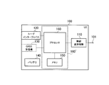
- FIG. 2 is a block diagram of the UE 100.
- the UE 100 includes a plurality of antennas 101, a radio transceiver 110, a user interface 120, a GNSS (Global Navigation Satellite System) receiver 130, a battery 140, a memory 150, and a processor 160.
- the memory 150 and the processor 160 constitute a control unit.
- the UE 100 may not have the GNSS receiver 130.
- the memory 150 may be integrated with the processor 160, and this set (that is, a chip set) may be used as the processor 160 '.
- the plurality of antennas 101 and the wireless transceiver 110 are used for transmitting and receiving wireless signals.
- the radio transceiver 110 converts the baseband signal (transmission signal) output from the processor 160 into a radio signal and transmits it from the plurality of antennas 101. Further, the radio transceiver 110 converts radio signals received by the plurality of antennas 101 into baseband signals (received signals) and outputs the baseband signals to the processor 160.
- the user interface 120 is an interface with a user who owns the UE 100, and includes, for example, a display, a microphone, a speaker, and various buttons.
- the user interface 120 receives an operation from the user and outputs a signal indicating the content of the operation to the processor 160.
- the GNSS receiver 130 receives a GNSS signal and outputs the received signal to the processor 160 in order to obtain location information indicating the geographical location of the UE 100.
- the battery 140 stores power to be supplied to each block of the UE 100.
- the memory 150 stores a program executed by the processor 160 and information used for processing by the processor 160.
- the processor 160 includes a baseband processor that modulates / demodulates and encodes / decodes a baseband signal, and a CPU (Central Processing Unit) that executes programs stored in the memory 150 and performs various processes. .
- the processor 160 may further include a codec that performs encoding / decoding of an audio / video signal.
- the processor 160 executes various processes and various communication protocols described later.
- FIG. 3 is a block diagram of the eNB 200.
- the eNB 200 includes a plurality of antennas 201, a radio transceiver 210, a network interface 220, a memory 230, and a processor 240.
- the memory 230 and the processor 240 constitute a control unit.
- the plurality of antennas 201 and the wireless transceiver 210 are used for transmitting and receiving wireless signals.
- the radio transceiver 210 converts a baseband signal (transmission signal) output from the processor 240 into a radio signal and transmits the radio signal from the plurality of antennas 201.
- the radio transceiver 210 converts radio signals received by the plurality of antennas 201 into baseband signals (reception signals) and outputs the baseband signals to the processor 240.
- the network interface 220 is connected to the neighboring eNB 200 via the X2 interface and is connected to the MME / S-GW 300 via the S1 interface.
- the network interface 220 is used for communication performed on the X2 interface and communication performed on the S1 interface.
- the memory 230 stores a program executed by the processor 240 and information used for processing by the processor 240.
- the processor 240 includes a baseband processor that performs modulation / demodulation and encoding / decoding of a baseband signal, and a CPU that executes a program stored in the memory 230 and performs various processes.
- the processor 240 executes various processes and various communication protocols described later.
- FIG. 4 is a protocol stack diagram of a radio interface in the LTE system. As shown in FIG. 4, the radio interface protocol is divided into the first to third layers of the OSI reference model, and the first layer is a physical (PHY) layer.
- the second layer includes a MAC (Medium Access Control) layer, an RLC (Radio Link Control) layer, and a PDCP (Packet Data Convergence Protocol) layer.
- the third layer includes an RRC (Radio Resource Control) layer.
- the physical layer performs encoding / decoding, modulation / demodulation, antenna mapping / demapping, and resource mapping / demapping. Between the physical layer of UE100 and the physical layer of eNB200, user data and a control signal are transmitted via a physical channel.
- the MAC layer performs data priority control, retransmission processing by hybrid ARQ (HARQ), and the like. Between the MAC layer of the UE 100 and the MAC layer of the eNB 200, user data and control signals are transmitted via a transport channel.
- the MAC layer of the eNB 200 includes a scheduler that determines an uplink / downlink transport format (transport block size, modulation / coding scheme) and an allocation resource block to the UE 100.
- the RLC layer transmits data to the RLC layer on the receiving side using the functions of the MAC layer and the physical layer. Between the RLC layer of the UE 100 and the RLC layer of the eNB 200, user data and control signals are transmitted via a logical channel.
- the PDCP layer performs header compression / decompression and encryption / decryption.
- the RRC layer is defined only in the control plane that handles control signals. Control signals (RRC messages) for various settings are transmitted between the RRC layer of the UE 100 and the RRC layer of the eNB 200.
- the RRC layer controls the logical channel, the transport channel, and the physical channel according to establishment, re-establishment, and release of the radio bearer.
- RRC connection When there is a connection (RRC connection) between the RRC of the UE 100 and the RRC of the eNB 200, the UE 100 is in a connection state (RRC connection state). Otherwise, the UE 100 is in an idle state (RRC idle state).
- the NAS (Non-Access Stratum) layer located above the RRC layer performs session management and mobility management.
- FIG. 5 is a configuration diagram of a radio frame used in the LTE system.
- OFDMA Orthogonal Frequency Division Multiplexing Access
- SC-FDMA Single Carrier Frequency Multiple
- the radio frame is composed of 10 subframes arranged in the time direction.
- Each subframe is composed of two slots arranged in the time direction.
- the length of each subframe is 1 ms, and the length of each slot is 0.5 ms.
- Each subframe includes a plurality of resource blocks (RB) in the frequency direction and includes a plurality of symbols in the time direction.
- Each resource block includes a plurality of subcarriers in the frequency direction.
- a resource element is composed of one subcarrier and one symbol.
- frequency resources are configured by resource blocks, and time resources are configured by subframes (or slots).
- the section of the first few symbols of each subframe is an area mainly used as a physical downlink control channel (PDCCH) for transmitting a control signal.
- the remaining part of each subframe is an area that can be used mainly as a physical downlink shared channel (PDSCH) for transmitting user data.
- PDCH physical downlink control channel
- PDSCH physical downlink shared channel
- both ends in the frequency direction in each subframe are regions used mainly as physical uplink control channels (PUCCH) for transmitting control signals.
- the remaining part of each subframe is an area that can be used mainly as a physical uplink shared channel (PUSCH) for transmitting user data.
- PUCCH physical uplink control channels
- D2D communication The LTE system according to the embodiment supports D2D communication that is direct terminal-to-terminal communication (UE-to-UE communication).
- UE-to-UE communication D2D communication will be described in comparison with cellular communication, which is normal communication of the LTE system.
- Cellular communication is a communication mode in which a data path passes through a network (E-UTRAN10, EPC20).
- a data path is a communication path for user data.
- D2D communication is a communication mode in which a data path set between UEs does not pass through a network.
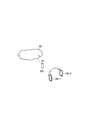
- FIG. 6 is a diagram for explaining D2D communication.
- the data path does not pass through the eNB 200.
- the UE 100-1 and the UE 100-2 that are close to each other directly perform radio communication with low transmission power in the cell of the eNB 200.
- the adjacent UE 100-1 and UE 100-2 perform radio communication directly with low transmission power, thereby reducing the power consumption of the UE 100 and reducing interference with adjacent cells compared to cellular communication. Can be reduced.
- the UE100 periodically transmits and receives discovery signals used for discovery of nearby UE100 in order to perform D2D communication. After such a discovery process, the UE 100 performs D2D communication with a nearby UE 100.
- the UE 100 transmits and receives discovery signals only in a preset cycle, it is difficult to quickly start D2D communication even when there is a nearby UE 100 that should perform D2D communication.
- a method of setting a period for transmitting and receiving a discovery signal short in advance is also conceivable, but there is a problem that the consumption of radio resources used for transmission and reception of discovery signals increases and the utilization efficiency of radio resources decreases.
- the UE 100 transmits and receives a discovery signal for D2D communication.
- the UE 100 transmits and receives periodic discovery signals using the first radio resource recognized by all the UEs 100 in a predetermined area of the mobile communication system (LTE system).
- the “predetermined area” is, for example, a cell of a mobile communication system. Alternatively, the “predetermined area” may be a service area of the mobile communication system.
- the eNB 200 controls the UE 100 that transmits and receives periodic discovery signals using the first radio resource.
- eNB200 notifies UE100 of the 2nd radio
- the UE 100 transmits and receives a non-periodic discovery signal using the second radio resource.
- the UE 100 can promptly start D2D communication by enabling transmission and reception of such aperiodic discovery signals.
- the use efficiency of radio resources can be improved as compared with a method of setting a period in a periodic discovery signal short in advance. Therefore, UE100 can start D2D communication rapidly, suppressing the fall of the utilization efficiency of a radio
- “Other UE 100 related to UE 100” is different for each assumed scenario (operation pattern).
- one UE 100 performs D2D communication among the UE 100 and another UE 100 related to the UE 100, and the other UE 100 desires to start communication with the one UE 100.
- UE100 the operation pattern 1 according to the embodiment, one UE 100 performs D2D communication among the UE 100 and another UE 100 related to the UE 100, and the other UE 100 desires to start communication with the one UE 100.
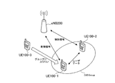
- FIG. 7 is a diagram for explaining the operation pattern 1. As shown in FIG. 7, UE 100-1 to UE 100-3 are located in the cell of eNB 200. UE100-1 and UE100-2 are performing D2D communication. UE 100-1 and UE 100-2 transmit / receive user data to / from each other, and transmit / receive control signals to / from eNB 200.
- the UE 100-3 wishes to start communication with the UE 100-1.
- UE 100-3 is UE 100 that desires to transmit user data to UE 100-1, or UE 100 that desires to participate in D2D communication performed by UE 100-1.
- the eNB 200 determines that the UE 100-3 that desires to start communication with the UE 100-1 is in the vicinity of the UE 100-1. Then, the eNB 200 notifies the UE 100-1 and the UE 100-3 of the second radio resource for transmitting and receiving the aperiodic discovery signal. The UE 100-1 and the UE 100-3 transmit and receive the aperiodic discovery signal using the second radio resource. Thereby, since the discovery process is completed between the UE 100-1 and the UE 100-3, the D2D communication can be started between the UE 100-1 and the UE 100-3.
- the other UE 100 related to the UE 100 is the UE 100 that has been determined to give interference to the UE 100 and / or to receive interference from the UE 100.
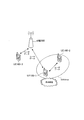
- FIG. 8 is a diagram for explaining the operation pattern 2.
- UE 100-1 to UE 100-3 are located in the cell of eNB 200.
- UE100-1 and UE100-2 are performing D2D communication.
- the UE 100-1 and the UE 100-2 transmit / receive user data to / from each other.
- the UE 100-3 performs cellular communication.
- the UE 100-3 transmits and receives user data to and from the eNB 200.
- radio resources that can be used for D2D communication are at least a part of radio resources that can be used for uplink of cellular communication (uplink radio resources).
- wireless resource which can be used for D2D communication is at least one part of the radio
- the eNB 200 determines that interference has occurred between the UE 100-1 and the UE 100-3. Then, the eNB 200 notifies the UE 100-1 and the UE 100-3 of the second radio resource for transmitting and receiving the aperiodic discovery signal. Alternatively, the occurrence of interference may be determined by the UE 100-1 or the UE 100-3. The UE 100-1 and the UE 100-3 transmit and receive the aperiodic discovery signal using the second radio resource. Thereby, since the discovery process is completed between the UE 100-1 and the UE 100-3, the D2D communication can be started between the UE 100-1 and the UE 100-3. Therefore, the interference which arises between D2D communication and cellular communication can be avoided.
- the other UE 100 related to the UE 100 is the UE 100 that performs cellular communication with the UE 100.
- FIG. 9 is a diagram for explaining the operation pattern 3.
- UE 100-1 to UE 100-3 are located in the cell of eNB 200.
- UE100-1 and UE100-2 are performing D2D communication.
- the UE 100-1 and the UE 100-2 transmit / receive user data to / from each other.
- the UE 100-3 performs cellular communication with the UE 100-1.
- UE 100-1 shares one radio transceiver 110 for cellular communication and D2D communication. Since the transmission power levels handled in the cellular communication and the D2D communication are different, it is difficult for the UE 100 to simultaneously perform the cellular communication and the D2D communication with one radio transceiver 110.
- the eNB 200 determines that the UE 100-3 is in the vicinity of the UE 100-1 that starts the cellular communication with the UE 100-3 during the D2D communication. Then, the eNB 200 notifies the UE 100-1 and the UE 100-3 of the second radio resource for transmitting and receiving the aperiodic discovery signal. The UE 100-1 and the UE 100-3 transmit and receive the aperiodic discovery signal using the second radio resource. Thereby, since the discovery process is completed between the UE 100-1 and the UE 100-3, the D2D communication can be started between the UE 100-1 and the UE 100-3. Therefore, it can be avoided that the UE 100-1 performs the cellular communication and the D2D communication at the same time.
- the UE 100-1 and the UE 100-3 transmit the aperiodic discovery signal and both receive the aperiodic discovery signal. Only one may transmit an aperiodic discovery signal and only the other may receive an aperiodic discovery signal.
- the UE 100-1 transmits an aperiodic discovery signal
- the UE 100-2 receives an aperiodic discovery signal.
- the UE 100-2 transmits an aperiodic discovery signal
- the UE 100-1 receives an aperiodic discovery signal.
- the eNB 200 receives whether to transmit the aperiodic discovery signal when notifying the second radio resource. You may also notify about what should be done.
- FIG. 10 is a sequence diagram of the operation pattern 1.
- the eNB 200 can acquire information regarding the distance between the UE 100-1 and the UE 100-3.
- the information related to the distance between the UE 100-1 and the UE 100-3 is a path loss between the UE 100-1 and the UE 100-3, or position information of each of the UE 100-1 and the UE 100-3.
- the UE 100-1 and the UE 100-2 are performing D2D communication (step S101).
- the UE 100-3 transmits a communication request to the UE 100-1 to the eNB 200 by cellular communication.
- the eNB 200 that has received the communication request to the UE 100-1 determines that the UE 100-3 desires to start communication with the UE 100-1.
- the eNB 200 checks the information on the UE 100-1 (step S103). On the other hand, when the UE 100-1 information is not held, the eNB 200 inquires and acquires the UE 100-1 information about the UE 100-1 (steps S104 and S105).
- step S106 the eNB 200 requests the UE 100-1 for D2D communication connection with the UE 100-3.
- the UE 100-1 may return a response to the request from the eNB 200 (step S107).
- step S108 the eNB 200 determines whether or not the D2D communication connection is possible between the UE 100-1 and the UE 100-3. For example, the eNB 200 determines whether or not the UE 100-1 and the UE 100-3 are close enough to perform D2D communication based on the path loss information or the position information.
- the eNB 200 transmits a second radio resource (Discovery resource) for transmitting and receiving an aperiodic discovery signal. decide.
- Discovery resource Discovery resource
- step S110 the eNB 200 notifies the UE 100-1 and the UE 100-3 of the second radio resource.
- step S111 the UE 100-1 and the UE 100-3 succeed in the discovery process by transmitting and receiving a non-periodic discovery signal using the second radio resource.
- step S112 the UE 100-1 and the UE 100-3 start D2D communication.
- the eNB 200 determines that the UE 100-3 desires to start communication with the UE 100-1 by receiving a communication request to the UE 100-1 from the UE 100-3.
- the UE 100-3 may explicitly request the eNB 200 to start D2D communication with the UE 100-1.
- (2.2) Operation pattern 2 In the operation pattern 2, when it is determined that interference has occurred between the UE 100-1 performing D2D communication and the UE 100-3 performing cellular communication, the operations after Step S108 in FIG. 10 are performed. For example, the UE 100-1 reports interference information related to interference from cellular communication to the eNB 200. Or UE100-3 reports the interference information regarding the interference from D2D communication to eNB200. Based on the reported interference information, the eNB 200 determines that interference has occurred between the UE 100-1 performing D2D communication and the UE 100-3 performing cellular communication.
- FIG. 11 is a sequence diagram in the case of avoiding interference led by the UE 100 in the operation pattern 2.
- the UE 100-1 and the UE 100-2 perform D2D communication (step S101).
- the UE 100-3 performs cellular communication with the eNB 200 (step S102).
- the UE 100-1 determines that it has received interference from the UE 100-3, and notifies the eNB 200 to that effect.
- the eNB 200 requests the UE 100-1 for D2D communication connection with the UE 100-3.
- the UE 100-1 may return a response to the request from the eNB 200.
- step S143 the UE 100-1 determines whether or not a D2D communication connection is possible with the UE 100-3.
- the UE 100-1 determines a second radio resource (Discovery resource) for transmitting and receiving an aperiodic discovery signal. .
- step S145 the UE 100-1 notifies the eNB 200 of the second radio resource.
- the eNB 200 that has received the notification of the second radio resource notifies the UE 100-3 of the second radio resource.
- step S111 the UE 100-1 and the UE 100-3 succeed in the discovery process by transmitting and receiving a non-periodic discovery signal using the second radio resource.
- step S112 the UE 100-1 and the UE 100-3 start D2D communication.
- FIG. 12 is a sequence diagram of the operation pattern 3.
- the eNB 200 can acquire information regarding the distance between the UE 100-1 and the UE 100-3.
- the information related to the distance between the UE 100-1 and the UE 100-3 is a path loss between the UE 100-1 and the UE 100-3, or position information of each of the UE 100-1 and the UE 100-3.
- the UE 100-1 and the UE 100-2 are performing D2D communication (step S101).
- steps S102-1 and S102-2 the UE 100-3 starts cellular communication with the UE 100-1 via the network.
- step S132 the UE 100-1 transmits to the eNB 200 an acknowledgment (Nack) indicating that reception has failed in cellular communication and / or D2D communication.
- Nack acknowledgment
- step S133 the eNB 200 that has received the confirmation response (Nack) investigates whether the allocation of the D2D communication and the cellular communication has occurred at the same timing for the UE 100-1.
- the eNB 200 determines whether or not D2D communication connection is possible between the UE 100-1 and the UE 100-3. For example, the eNB 200 determines whether or not the UE 100-1 and the UE 100-3 are close enough to perform D2D communication based on the path loss information or the position information.
- the eNB 200 transmits a second radio resource (Discovery resource) for transmitting and receiving an aperiodic discovery signal. decide.
- Discovery resource Discovery resource
- step S110 the eNB 200 notifies the UE 100-1 and the UE 100-3 of the second radio resource.
- step S111 the UE 100-1 and the UE 100-3 succeed in the discovery process by transmitting and receiving a non-periodic discovery signal using the second radio resource.
- step S112 the UE 100-1 and the UE 100-3 start D2D communication.
- the eNB 200 determines that the timing for simultaneously performing D2D communication and cellular communication has occurred, but the UE 100-1 detects that the timing for simultaneously performing D2D communication and cellular communication has occurred. The eNB 200 may be notified.
- this sequence is intended for simultaneous reception when performing D2D communication using uplink radio resources, but may also be targeted for simultaneous transmission when performing D2D communication using downlink radio resources. it can.
- the eNB 200 controls the UE 100 that transmits and receives periodic discovery signals using the first radio resource.
- eNB200 notifies UE100 of the 2nd radio
- the UE 100 transmits and receives a non-periodic discovery signal using the second radio resource.
- the UE 100 can promptly start D2D communication by enabling transmission and reception of such aperiodic discovery signals.
- the use efficiency of radio resources can be improved as compared with a method of setting a period in a periodic discovery signal short in advance. Therefore, UE100 can start D2D communication rapidly, suppressing the fall of the utilization efficiency of a radio
- FIG. 13 is a sequence diagram according to the first modification of the embodiment.
- FIG. 13 is a partial change of the sequence of the operation pattern 1 according to the embodiment.
- UE 100-3 is in the cell of eNB 200-1.
- UE 100-1 and UE 100-2 are located in the cell of eNB 200-2.
- the UE 100-1 and the UE 100-2 are performing D2D communication (step S101).
- the UE 100-3 transmits a communication request to the UE 100-1 to the eNB 200-1 by cellular communication.
- the eNB 200-1 that has received the communication request to the UE 100-1 determines that the UE 100-3 desires to start communication with the UE 100-1.
- the eNB 200-1 confirms with the eNB 200-2 whether or not the UE 100-1 is located (step S121).
- the eNB 200-2 may return a response (step S122).
- the eNB 200-1 transmits a D2D communication connection request for the UE 100-1 to the eNB 200-2 (step S123).
- the eNB 200-2 transmits the D2D communication connection request received from the eNB 200-1 to the UE 100-1 (Step S124).
- the UE 100-1 may return a response to the UE 100-1 via the eNB 200-2 (Steps S125 and S126).
- the eNB 200-1 determines whether or not the D2D communication connection is possible between the UE 100-1 and the UE 100-3. For example, the eNB 200-1 determines whether the UE 100-1 and the UE 100-3 are close enough to perform D2D communication based on the path loss information or the position information.
- the eNB 200 transmits a second radio resource (Discovery resource) for transmitting and receiving an aperiodic discovery signal. decide.
- the eNB 200 notifies the UE 100-3 of the second radio resource (step S110-1), and notifies the eNB 200-2 of the second radio resource (step S110-2).
- the eNB 200-2 notifies the UE 100-1 of the second radio resource (Step S110-3).
- the UE 100-1 and the UE 100-3 succeed in the discovery process by transmitting and receiving a non-periodic discovery signal using the second radio resource.
- the UE 100-1 and the UE 100-3 start D2D communication.
- FIG. 14 is a flowchart showing a connection determination operation according to the second modification of the embodiment.
- the eNB 200 determines whether or not the interference level that the UE 100-1 receives from the UE 100-3 is equal to or greater than a threshold value. If “Yes” in step S1081, in step S1082, the eNB 200-1 determines whether or not the UE 100-1 is performing D2D communication. If “No” in step S1082, the eNB 200-1 performs resource division in step S1083.
- step S1084 the eNB 200-1 determines whether or not each connection allowable number of UE 100-1 and UE 100-3 (that is, the upper limit number of radio connections that can be established) is satisfied To do. If “No” in step S1084, the eNB 200-1 performs resource division in step S1085. In the case of “Yes” in Step S1084, in Step S1086, the eNB 200-1 notifies the UE 100-1 and the UE 100-3 of the second radio resource (Discovery resource).
- FIG. 15 is a diagram for explaining resource division.
- the eNB 200-1 sets radio resources (data transmission radio resources) allocated to the UE 100-1 and radio resources (data transmission radio resources) allocated to the UE 100-3 in a time division manner.
- the time division ratio may be set based on the buffer amount, path loss, channel information, and the like of each UE 100, for example.
- the time division ratio may be updated periodically or by an event trigger.
- the operation patterns 1 to 3 according to the above-described embodiments are not limited to being performed independently and may be performed in combination with each other.
- the eNB 200 has been described as a specific example of the network device according to the present invention.
- the LTE system has been described as an example of a cellular communication system.
- the present invention is not limited to the LTE system, and the present invention may be applied to systems other than the LTE system.
- the present invention it is possible to provide a user terminal, a network device, and a processor that can quickly start D2D communication while suppressing a decrease in the utilization efficiency of radio resources.
Landscapes
- Engineering & Computer Science (AREA)
- Computer Networks & Wireless Communication (AREA)
- Signal Processing (AREA)
- Databases & Information Systems (AREA)
- Quality & Reliability (AREA)
- Mobile Radio Communication Systems (AREA)
Abstract
An eNB (200) controls UE (100) which transmits and receives a periodic discovery signal using a first radio resource. The eNB (200) notifies the UE (100) of a second radio resource for transmitting and receiving a non-periodic discovery signal between another UE (100) associated with the UE (100) and the UE (100). The UE (100) transmits and receives the non-periodic discovery signal using the second radio resource.
Description
本発明は、D2D通信をサポートする移動通信システムにおいて用いられるユーザ端末、ネットワーク装置、及びプロセッサに関する。
The present invention relates to a user terminal, a network device, and a processor used in a mobile communication system that supports D2D communication.
移動通信システムの標準化プロジェクトである3GPP(3rd Generation Partnership Project)では、リリース12以降の新機能として、端末間(Device to Device:D2D)通信の導入が検討されている(非特許文献1参照)。
In 3GPP (3rd Generation Partnership Project), a standardization project for mobile communication systems, introduction of inter-terminal (Device to Device: D2D) communication is being considered as a new function after Release 12 (see Non-Patent Document 1).
D2D通信では、近接する複数のユーザ端末がネットワークを経由せずに直接的な端末間通信を行う。一方、移動通信システムの通常の通信であるセルラ通信では、ユーザ端末がネットワークを経由して通信を行う。D2D通信を活用することにより、移動通信システムの性能改善を図ることができる。
In D2D communication, a plurality of neighboring user terminals perform direct inter-terminal communication without going through the network. On the other hand, in cellular communication, which is normal communication of a mobile communication system, a user terminal performs communication via a network. By utilizing D2D communication, it is possible to improve the performance of the mobile communication system.
ところで、ユーザ端末は、D2D通信を行うために、近傍のユーザ端末の発見に使用される発見用信号を周期的に送受信する。このような発見処理の後、ユーザ端末は、近傍のユーザ端末とのD2D通信を行う。
By the way, in order to perform D2D communication, the user terminal periodically transmits / receives a discovery signal used for discovery of a nearby user terminal. After such a discovery process, the user terminal performs D2D communication with a nearby user terminal.
しかしながら、ユーザ端末は、予め設定された周期でしか発見用信号を送受信しないため、D2D通信を行うべき近傍のユーザ端末が存在する場合であっても、D2D通信を速やかに開始することは難しい。一方で、発見用信号を送受信する周期を予め短く設定する方法も考えられるが、発見用信号の送受信に使用する無線リソースの消費量が増大し、無線リソースの利用効率が低下する問題がある。
However, since the user terminal transmits and receives a discovery signal only at a preset cycle, it is difficult to start D2D communication promptly even when there is a nearby user terminal that should perform D2D communication. On the other hand, a method of setting a period for transmitting and receiving a discovery signal short in advance is also conceivable, but there is a problem that the consumption of radio resources used for transmission and reception of discovery signals increases and the utilization efficiency of radio resources decreases.
そこで、本発明は、無線リソースの利用効率の低下を抑制しつつ、D2D通信を速やかに開始可能とするユーザ端末、ネットワーク装置、及びプロセッサを提供することを目的とする。
Therefore, an object of the present invention is to provide a user terminal, a network device, and a processor that can quickly start D2D communication while suppressing a decrease in utilization efficiency of radio resources.
第1の特徴に係るユーザ端末は、直接的な端末間通信であるD2D通信をサポートする移動通信システムにおいて、前記D2D通信のための発見用信号を送受信する。前記ユーザ端末は、前記移動通信システムの所定エリア内の全ユーザ端末で認識している第1の無線リソースを使用して、周期的な発見用信号を送受信する制御部を備える。前記制御部は、さらに、前記ユーザ端末と関連する他ユーザ端末及び前記ユーザ端末で認識している第2の無線リソースを使用して、非周期的な発見用信号を送受信する。
The user terminal according to the first feature transmits and receives a discovery signal for the D2D communication in a mobile communication system that supports D2D communication that is direct inter-terminal communication. The user terminal includes a control unit that transmits and receives periodic discovery signals using a first radio resource recognized by all user terminals in a predetermined area of the mobile communication system. The control unit further transmits / receives a non-periodic discovery signal using another user terminal related to the user terminal and a second radio resource recognized by the user terminal.
第2の特徴に係るネットワーク装置は、直接的な端末間通信であるD2D通信をサポートする移動通信システムのネットワークに含まれる。前記ネットワーク装置は、前記移動通信システムの所定エリア内の全ユーザ端末で認識している第1の無線リソースを使用して周期的な発見用信号を送受信するユーザ端末に対する制御を行う制御部を備える。前記制御部は、前記ユーザ端末と関連する他ユーザ端末と前記ユーザ端末との間で非周期的な発見用信号を送受信するための第2の無線リソースを前記ユーザ端末に通知する。
The network device according to the second feature is included in a network of a mobile communication system that supports D2D communication that is direct inter-terminal communication. The network apparatus includes a control unit that controls a user terminal that transmits and receives periodic discovery signals using a first radio resource recognized by all user terminals in a predetermined area of the mobile communication system. . The control unit notifies the user terminal of a second radio resource for transmitting and receiving an aperiodic discovery signal between another user terminal associated with the user terminal and the user terminal.
第3の特徴に係るプロセッサは、直接的な端末間通信であるD2D通信をサポートする移動通信システムにおいて、前記D2D通信のための発見用信号を送受信するユーザ端末に備えられる。前記プロセッサは、前記移動通信システムの所定エリア内の全ユーザ端末で認識している第1の無線リソースを使用して、周期的な発見用信号を送受信する処理と、前記ユーザ端末と関連する他ユーザ端末及び前記ユーザ端末で認識している第2の無線リソースを使用して、非周期的な発見用信号を送受信する処理と、を実行する。
The processor according to the third feature is provided in a user terminal that transmits and receives a discovery signal for D2D communication in a mobile communication system that supports D2D communication that is direct inter-terminal communication. The processor uses a first radio resource recognized by all user terminals in a predetermined area of the mobile communication system to transmit and receive periodic discovery signals, and others related to the user terminal. And a process of transmitting and receiving an aperiodic discovery signal using the user terminal and the second radio resource recognized by the user terminal.
[実施形態の概要]
実施形態に係るユーザ端末は、直接的な端末間通信であるD2D通信をサポートする移動通信システムにおいて、前記D2D通信のための発見用信号を送受信する。前記ユーザ端末は、前記移動通信システムの所定エリア内の全ユーザ端末で認識している第1の無線リソースを使用して、周期的な発見用信号を送受信する制御部を備える。前記制御部は、さらに、前記ユーザ端末と関連する他ユーザ端末及び前記ユーザ端末で認識している第2の無線リソースを使用して、非周期的な発見用信号を送受信する。 [Outline of Embodiment]
The user terminal which concerns on embodiment transmits / receives the signal for a discovery for the said D2D communication in the mobile communication system which supports D2D communication which is direct communication between terminals. The user terminal includes a control unit that transmits and receives periodic discovery signals using a first radio resource recognized by all user terminals in a predetermined area of the mobile communication system. The control unit further transmits / receives a non-periodic discovery signal using another user terminal related to the user terminal and a second radio resource recognized by the user terminal.
実施形態では、前記第2の無線リソースは、前記移動通信システムのネットワークに含まれるネットワーク装置から通知される。前記制御部は、前記ネットワーク装置から通知された前記第2の無線リソースを使用して、前記非周期的な発見用信号を送受信する。
In the embodiment, the second radio resource is notified from a network device included in the network of the mobile communication system. The control unit transmits and receives the aperiodic discovery signal using the second radio resource notified from the network device.
実施形態では、前記ユーザ端末と関連する他ユーザ端末とは、前記ユーザ端末の近傍であると判定されたユーザ端末である。
In the embodiment, the other user terminal related to the user terminal is a user terminal determined to be in the vicinity of the user terminal.
実施形態では、前記ユーザ端末と関連する他ユーザ端末とは、前記移動通信システムのネットワークを介して前記ユーザ端末とのセルラ通信を行うユーザ端末である。
In the embodiment, the other user terminal related to the user terminal is a user terminal that performs cellular communication with the user terminal via the network of the mobile communication system.
実施形態では、前記ユーザ端末と関連する他ユーザ端末とは、前記ユーザ端末に干渉を与える及び/又は前記ユーザ端末から干渉を受けると判定されたユーザ端末である。
In the embodiment, the other user terminal related to the user terminal is a user terminal determined to cause interference to the user terminal and / or to receive interference from the user terminal.
実施形態では、前記ユーザ端末、及び前記ユーザ端末と関連する他ユーザ端末のうち、一方のユーザ端末は前記D2D通信を行っており、他方のユーザ端末は前記一方のユーザ端末との通信の開始を希望するユーザ端末である。
In the embodiment, one of the user terminals and the other user terminals related to the user terminal performs the D2D communication, and the other user terminal starts communication with the one user terminal. This is the desired user terminal.
実施形態に係るネットワーク装置は、直接的な端末間通信であるD2D通信をサポートする移動通信システムのネットワークに含まれる。前記ネットワーク装置は、前記移動通信システムの所定エリア内の全ユーザ端末で認識している第1の無線リソースを使用して周期的な発見用信号を送受信するユーザ端末に対する制御を行う制御部を備える。前記制御部は、前記ユーザ端末と関連する他ユーザ端末と前記ユーザ端末との間で非周期的な発見用信号を送受信するための第2の無線リソースを前記ユーザ端末に通知する。
The network device according to the embodiment is included in a network of a mobile communication system that supports D2D communication that is direct inter-terminal communication. The network apparatus includes a control unit that controls a user terminal that transmits and receives periodic discovery signals using a first radio resource recognized by all user terminals in a predetermined area of the mobile communication system. . The control unit notifies the user terminal of a second radio resource for transmitting and receiving an aperiodic discovery signal between another user terminal associated with the user terminal and the user terminal.
実施形態では、前記ユーザ端末と関連する他ユーザ端末とは、前記ユーザ端末の近傍であると判定されたユーザ端末である。
In the embodiment, the other user terminal related to the user terminal is a user terminal determined to be in the vicinity of the user terminal.
実施形態では、前記ユーザ端末と関連する他ユーザ端末とは、前記ネットワークを介して前記ユーザ端末とのセルラ通信を行うユーザ端末である。
In the embodiment, the other user terminal related to the user terminal is a user terminal that performs cellular communication with the user terminal via the network.
実施形態では、前記ユーザ端末と関連する他ユーザ端末とは、前記ユーザ端末に干渉を与える及び/又は前記ユーザ端末から干渉を受けると判定されたユーザ端末である。
In the embodiment, the other user terminal related to the user terminal is a user terminal determined to cause interference to the user terminal and / or to receive interference from the user terminal.
実施形態では、前記ユーザ端末、及び前記ユーザ端末と関連する他ユーザ端末のうち、一方のユーザ端末は前記D2D通信を行っており、かつ、他方のユーザ端末は前記一方のユーザ端末との通信の開始を希望するユーザ端末である。
In the embodiment, one of the user terminals and the other user terminals related to the user terminal performs the D2D communication, and the other user terminal communicates with the one user terminal. A user terminal that wants to start.
実施形態では、前記制御部は、前記ユーザ端末と関連する他ユーザ端末と前記ユーザ端末との間で前記D2D通信を行うことが不能であると判定した場合には、前記ユーザ端末に割り当てるデータ伝送用無線リソースと、前記ユーザ端末と関連する他ユーザ端末に割り当てるデータ伝送用無線リソースと、を異ならせるよう制御する。
In the embodiment, when the control unit determines that the D2D communication cannot be performed between the other user terminal associated with the user terminal and the user terminal, the data transmission allocated to the user terminal Control is performed so that the radio resources for data transmission and the radio resources for data transmission allocated to other user terminals related to the user terminal are different.
実施形態に係るプロセッサは、直接的な端末間通信であるD2D通信をサポートする移動通信システムにおいて、前記D2D通信のための発見用信号を送受信するユーザ端末に備えられる。前記プロセッサは、前記移動通信システムの所定エリア内の全ユーザ端末で認識している第1の無線リソースを使用して、周期的な発見用信号を送受信する処理と、前記ユーザ端末と関連する他ユーザ端末及び前記ユーザ端末で認識している第2の無線リソースを使用して、非周期的な発見用信号を送受信する処理と、を実行する。
The processor according to the embodiment is provided in a user terminal that transmits and receives a discovery signal for D2D communication in a mobile communication system that supports D2D communication that is direct inter-terminal communication. The processor uses a first radio resource recognized by all user terminals in a predetermined area of the mobile communication system to transmit and receive periodic discovery signals, and others related to the user terminal. And a process of transmitting and receiving an aperiodic discovery signal using the user terminal and the second radio resource recognized by the user terminal.
[実施形態]
以下において、本発明をLTEシステムに適用する場合の実施形態を説明する。 [Embodiment]
In the following, an embodiment when the present invention is applied to an LTE system will be described.
以下において、本発明をLTEシステムに適用する場合の実施形態を説明する。 [Embodiment]
In the following, an embodiment when the present invention is applied to an LTE system will be described.
(システム構成)
図1は、実施形態に係るLTEシステムの構成図である。図1に示すように、実施形態に係るLTEシステムは、UE(User Equipment)100、E-UTRAN(Evolved-UMTS Terrestrial Radio Access Network)10、及びEPC(Evolved Packet Core)20を備える。 (System configuration)
FIG. 1 is a configuration diagram of an LTE system according to the embodiment. As shown in FIG. 1, the LTE system according to the embodiment includes a UE (User Equipment) 100, an E-UTRAN (Evolved-UMTS Terrestrial Radio Access Network) 10, and an EPC (Evolved Packet Core) 20.
UE100は、ユーザ端末に相当する。UE100は、移動型の通信装置であり、接続先のセル(サービングセル)との無線通信を行う。UE100の構成については後述する。
UE 100 corresponds to a user terminal. The UE 100 is a mobile communication device, and performs wireless communication with a connection destination cell (serving cell). The configuration of the UE 100 will be described later.
E-UTRAN10は、無線アクセスネットワークに相当する。E-UTRAN10は、eNB200(evolved Node-B)を含む。eNB200は、基地局に相当する。eNB200は、X2インターフェイスを介して相互に接続される。eNB200の構成については後述する。
E-UTRAN 10 corresponds to a radio access network. The E-UTRAN 10 includes an eNB 200 (evolved Node-B). The eNB 200 corresponds to a base station. The eNB 200 is connected to each other via the X2 interface. The configuration of the eNB 200 will be described later.
eNB200は、1又は複数のセルを管理しており、自セルとの接続を確立したUE100との無線通信を行う。eNB200は、無線リソース管理(RRM)機能、ユーザデータのルーティング機能、モビリティ制御・スケジューリングのための測定制御機能などを有する。「セル」は、無線通信エリアの最小単位を示す用語として使用される他に、UE100との無線通信を行う機能を示す用語としても使用される。
The eNB 200 manages one or a plurality of cells and performs radio communication with the UE 100 that has established a connection with the own cell. The eNB 200 has a radio resource management (RRM) function, a user data routing function, a measurement control function for mobility control / scheduling, and the like. “Cell” is used as a term indicating a minimum unit of a radio communication area, and is also used as a term indicating a function of performing radio communication with the UE 100.
EPC20は、コアネットワークに相当する。E-UTRAN10及びEPC20によりLTEシステムのネットワークが構成される。EPC20は、MME(Mobility Management Entity)/S-GW(Serving-Gateway)300を含む。MMEは、UE100に対する各種モビリティ制御などを行う。SGWは、ユーザデータの転送制御を行う。MME/S-GW300は、S1インターフェイスを介してeNB200と接続される。
The EPC 20 corresponds to a core network. The LTE system network is configured by the E-UTRAN 10 and the EPC 20. The EPC 20 includes an MME (Mobility Management Entity) / S-GW (Serving-Gateway) 300. The MME performs various mobility controls for the UE 100. The SGW performs user data transfer control. The MME / S-GW 300 is connected to the eNB 200 via the S1 interface.
図2は、UE100のブロック図である。図2に示すように、UE100は、複数のアンテナ101、無線送受信機110、ユーザインターフェイス120、GNSS(Global Navigation Satellite System)受信機130、バッテリ140、メモリ150、及びプロセッサ160を備える。メモリ150及びプロセッサ160は、制御部を構成する。UE100は、GNSS受信機130を有していなくてもよい。また、メモリ150をプロセッサ160と一体化し、このセット(すなわち、チップセット)をプロセッサ160’としてもよい。
FIG. 2 is a block diagram of the UE 100. As shown in FIG. 2, the UE 100 includes a plurality of antennas 101, a radio transceiver 110, a user interface 120, a GNSS (Global Navigation Satellite System) receiver 130, a battery 140, a memory 150, and a processor 160. The memory 150 and the processor 160 constitute a control unit. The UE 100 may not have the GNSS receiver 130. Further, the memory 150 may be integrated with the processor 160, and this set (that is, a chip set) may be used as the processor 160 '.
複数のアンテナ101及び無線送受信機110は、無線信号の送受信に用いられる。無線送受信機110は、プロセッサ160が出力するベースバンド信号(送信信号)を無線信号に変換して複数のアンテナ101から送信する。また、無線送受信機110は、複数のアンテナ101が受信する無線信号をベースバンド信号(受信信号)に変換してプロセッサ160に出力する。
The plurality of antennas 101 and the wireless transceiver 110 are used for transmitting and receiving wireless signals. The radio transceiver 110 converts the baseband signal (transmission signal) output from the processor 160 into a radio signal and transmits it from the plurality of antennas 101. Further, the radio transceiver 110 converts radio signals received by the plurality of antennas 101 into baseband signals (received signals) and outputs the baseband signals to the processor 160.
ユーザインターフェイス120は、UE100を所持するユーザとのインターフェイスであり、例えば、ディスプレイ、マイク、スピーカ、及び各種ボタンなどを含む。ユーザインターフェイス120は、ユーザからの操作を受け付けて、該操作の内容を示す信号をプロセッサ160に出力する。GNSS受信機130は、UE100の地理的な位置を示す位置情報を得るために、GNSS信号を受信して、受信した信号をプロセッサ160に出力する。バッテリ140は、UE100の各ブロックに供給すべき電力を蓄える。
The user interface 120 is an interface with a user who owns the UE 100, and includes, for example, a display, a microphone, a speaker, and various buttons. The user interface 120 receives an operation from the user and outputs a signal indicating the content of the operation to the processor 160. The GNSS receiver 130 receives a GNSS signal and outputs the received signal to the processor 160 in order to obtain location information indicating the geographical location of the UE 100. The battery 140 stores power to be supplied to each block of the UE 100.
メモリ150は、プロセッサ160により実行されるプログラム、及びプロセッサ160による処理に使用される情報を記憶する。プロセッサ160は、ベースバンド信号の変調・復調及び符号化・復号などを行うベースバンドプロセッサと、メモリ150に記憶されるプログラムを実行して各種の処理を行うCPU(Central Processing Unit)と、を含む。プロセッサ160は、さらに、音声・映像信号の符号化・復号を行うコーデックを含んでもよい。プロセッサ160は、後述する各種の処理及び各種の通信プロトコルを実行する。
The memory 150 stores a program executed by the processor 160 and information used for processing by the processor 160. The processor 160 includes a baseband processor that modulates / demodulates and encodes / decodes a baseband signal, and a CPU (Central Processing Unit) that executes programs stored in the memory 150 and performs various processes. . The processor 160 may further include a codec that performs encoding / decoding of an audio / video signal. The processor 160 executes various processes and various communication protocols described later.
図3は、eNB200のブロック図である。図3に示すように、eNB200は、複数のアンテナ201、無線送受信機210、ネットワークインターフェイス220、メモリ230、及びプロセッサ240を備える。メモリ230及びプロセッサ240は、制御部を構成する。
FIG. 3 is a block diagram of the eNB 200. As illustrated in FIG. 3, the eNB 200 includes a plurality of antennas 201, a radio transceiver 210, a network interface 220, a memory 230, and a processor 240. The memory 230 and the processor 240 constitute a control unit.
複数のアンテナ201及び無線送受信機210は、無線信号の送受信に用いられる。無線送受信機210は、プロセッサ240が出力するベースバンド信号(送信信号)を無線信号に変換して複数のアンテナ201から送信する。また、無線送受信機210は、複数のアンテナ201が受信する無線信号をベースバンド信号(受信信号)に変換してプロセッサ240に出力する。
The plurality of antennas 201 and the wireless transceiver 210 are used for transmitting and receiving wireless signals. The radio transceiver 210 converts a baseband signal (transmission signal) output from the processor 240 into a radio signal and transmits the radio signal from the plurality of antennas 201. In addition, the radio transceiver 210 converts radio signals received by the plurality of antennas 201 into baseband signals (reception signals) and outputs the baseband signals to the processor 240.
ネットワークインターフェイス220は、X2インターフェイスを介して隣接eNB200と接続され、S1インターフェイスを介してMME/S-GW300と接続される。ネットワークインターフェイス220は、X2インターフェイス上で行う通信及びS1インターフェイス上で行う通信に用いられる。
The network interface 220 is connected to the neighboring eNB 200 via the X2 interface and is connected to the MME / S-GW 300 via the S1 interface. The network interface 220 is used for communication performed on the X2 interface and communication performed on the S1 interface.
メモリ230は、プロセッサ240により実行されるプログラム、及びプロセッサ240による処理に使用される情報を記憶する。プロセッサ240は、ベースバンド信号の変調・復調及び符号化・復号などを行うベースバンドプロセッサと、メモリ230に記憶されるプログラムを実行して各種の処理を行うCPUと、を含む。プロセッサ240は、後述する各種の処理及び各種の通信プロトコルを実行する。
The memory 230 stores a program executed by the processor 240 and information used for processing by the processor 240. The processor 240 includes a baseband processor that performs modulation / demodulation and encoding / decoding of a baseband signal, and a CPU that executes a program stored in the memory 230 and performs various processes. The processor 240 executes various processes and various communication protocols described later.
図4は、LTEシステムにおける無線インターフェイスのプロトコルスタック図である。図4に示すように、無線インターフェイスプロトコルは、OSI参照モデルの第1層乃至第3層に区分されており、第1層は物理(PHY)層である。第2層は、MAC(Medium Access Control)層、RLC(Radio Link Control)層、及びPDCP(Packet Data Convergence Protocol)層を含む。第3層は、RRC(Radio Resource Control)層を含む。
FIG. 4 is a protocol stack diagram of a radio interface in the LTE system. As shown in FIG. 4, the radio interface protocol is divided into the first to third layers of the OSI reference model, and the first layer is a physical (PHY) layer. The second layer includes a MAC (Medium Access Control) layer, an RLC (Radio Link Control) layer, and a PDCP (Packet Data Convergence Protocol) layer. The third layer includes an RRC (Radio Resource Control) layer.
物理層は、符号化・復号、変調・復調、アンテナマッピング・デマッピング、及びリソースマッピング・デマッピングを行う。UE100の物理層とeNB200の物理層との間では、物理チャネルを介してユーザデータ及び制御信号が伝送される。
The physical layer performs encoding / decoding, modulation / demodulation, antenna mapping / demapping, and resource mapping / demapping. Between the physical layer of UE100 and the physical layer of eNB200, user data and a control signal are transmitted via a physical channel.
MAC層は、データの優先制御、及びハイブリッドARQ(HARQ)による再送処理などを行う。UE100のMAC層とeNB200のMAC層との間では、トランスポートチャネルを介してユーザデータ及び制御信号が伝送される。eNB200のMAC層は、上下リンクのトランスポートフォーマット(トランスポートブロックサイズ、変調・符号化方式)及びUE100への割当リソースブロックを決定するスケジューラを含む。
The MAC layer performs data priority control, retransmission processing by hybrid ARQ (HARQ), and the like. Between the MAC layer of the UE 100 and the MAC layer of the eNB 200, user data and control signals are transmitted via a transport channel. The MAC layer of the eNB 200 includes a scheduler that determines an uplink / downlink transport format (transport block size, modulation / coding scheme) and an allocation resource block to the UE 100.
RLC層は、MAC層及び物理層の機能を利用してデータを受信側のRLC層に伝送する。UE100のRLC層とeNB200のRLC層との間では、論理チャネルを介してユーザデータ及び制御信号が伝送される。
The RLC layer transmits data to the RLC layer on the receiving side using the functions of the MAC layer and the physical layer. Between the RLC layer of the UE 100 and the RLC layer of the eNB 200, user data and control signals are transmitted via a logical channel.
PDCP層は、ヘッダ圧縮・伸張、及び暗号化・復号化を行う。
The PDCP layer performs header compression / decompression and encryption / decryption.
RRC層は、制御信号を取り扱う制御プレーンでのみ定義される。UE100のRRC層とeNB200のRRC層との間では、各種設定のための制御信号(RRCメッセージ)が伝送される。RRC層は、無線ベアラの確立、再確立及び解放に応じて、論理チャネル、トランスポートチャネル、及び物理チャネルを制御する。UE100のRRCとeNB200のRRCとの間に接続(RRC接続)がある場合、UE100は接続状態(RRC接続状態)であり、そうでない場合、UE100はアイドル状態(RRCアイドル状態)である。
The RRC layer is defined only in the control plane that handles control signals. Control signals (RRC messages) for various settings are transmitted between the RRC layer of the UE 100 and the RRC layer of the eNB 200. The RRC layer controls the logical channel, the transport channel, and the physical channel according to establishment, re-establishment, and release of the radio bearer. When there is a connection (RRC connection) between the RRC of the UE 100 and the RRC of the eNB 200, the UE 100 is in a connection state (RRC connection state). Otherwise, the UE 100 is in an idle state (RRC idle state).
RRC層の上位に位置するNAS(Non-Access Stratum)層は、セッション管理及びモビリティ管理などを行う。
The NAS (Non-Access Stratum) layer located above the RRC layer performs session management and mobility management.
図5は、LTEシステムで使用される無線フレームの構成図である。LTEシステムは、下りリンク(DL)にはOFDMA(Orthogonal Frequency Division Multiplexing Access)、上りリンク(UL)にはSC-FDMA(Single Carrier Frequency Division Multiple Access)がそれぞれ適用される。
FIG. 5 is a configuration diagram of a radio frame used in the LTE system. In the LTE system, OFDMA (Orthogonal Frequency Division Multiplexing Access) is applied to the downlink (DL), and SC-FDMA (Single Carrier Frequency Multiple) is applied to the uplink (UL).
図5に示すように、無線フレームは、時間方向に並ぶ10個のサブフレームで構成される。各サブフレームは、時間方向に並ぶ2個のスロットで構成される。各サブフレームの長さは1msであり、各スロットの長さは0.5msである。各サブフレームは、周波数方向に複数個のリソースブロック(RB)を含み、時間方向に複数個のシンボルを含む。各リソースブロックは、周波数方向に複数個のサブキャリアを含む。1つのサブキャリア及び1つのシンボルによりリソースエレメントが構成される。
As shown in FIG. 5, the radio frame is composed of 10 subframes arranged in the time direction. Each subframe is composed of two slots arranged in the time direction. The length of each subframe is 1 ms, and the length of each slot is 0.5 ms. Each subframe includes a plurality of resource blocks (RB) in the frequency direction and includes a plurality of symbols in the time direction. Each resource block includes a plurality of subcarriers in the frequency direction. A resource element is composed of one subcarrier and one symbol.
UE100に割り当てられる無線リソースのうち、周波数リソースはリソースブロックにより構成され、時間リソースはサブフレーム(又はスロット)により構成される。
Among radio resources allocated to the UE 100, frequency resources are configured by resource blocks, and time resources are configured by subframes (or slots).
DLにおいて、各サブフレームの先頭数シンボルの区間は、主に制御信号を伝送するための物理下りリンク制御チャネル(PDCCH)として使用される領域である。また、各サブフレームの残りの部分は、主にユーザデータを伝送するための物理下りリンク共有チャネル(PDSCH)として使用できる領域である。
In DL, the section of the first few symbols of each subframe is an area mainly used as a physical downlink control channel (PDCCH) for transmitting a control signal. The remaining part of each subframe is an area that can be used mainly as a physical downlink shared channel (PDSCH) for transmitting user data.
ULにおいて、各サブフレームにおける周波数方向の両端部は、主に制御信号を伝送するための物理上りリンク制御チャネル(PUCCH)として使用される領域である。各サブフレームにおける残りの部分は、主にユーザデータを伝送するための物理上りリンク共有チャネル(PUSCH)として使用できる領域である。
In UL, both ends in the frequency direction in each subframe are regions used mainly as physical uplink control channels (PUCCH) for transmitting control signals. The remaining part of each subframe is an area that can be used mainly as a physical uplink shared channel (PUSCH) for transmitting user data.
(D2D通信)
実施形態に係るLTEシステムは、直接的な端末間通信(UE間通信)であるD2D通信をサポートする。ここでは、D2D通信を、LTEシステムの通常の通信であるセルラ通信と比較して説明する。セルラ通信は、データパスがネットワーク(E-UTRAN10、EPC20)を経由する通信モードである。データパスとは、ユーザデータの通信経路である。これに対し、D2D通信は、UE間に設定されるデータパスがネットワークを経由しない通信モードである。 (D2D communication)
The LTE system according to the embodiment supports D2D communication that is direct terminal-to-terminal communication (UE-to-UE communication). Here, D2D communication will be described in comparison with cellular communication, which is normal communication of the LTE system. Cellular communication is a communication mode in which a data path passes through a network (E-UTRAN10, EPC20). A data path is a communication path for user data. On the other hand, D2D communication is a communication mode in which a data path set between UEs does not pass through a network.
図6は、D2D通信を説明するための図である。図6に示すように、D2D通信は、データパスがeNB200を経由しない。相互に近接するUE100-1及びUE100-2は、eNB200のセルにおいて、低送信電力で直接的に無線通信を行う。このように、近接するUE100-1及びUE100-2が低送信電力で直接的に無線通信を行うことにより、セルラ通信と比べて、UE100の消費電力を削減し、かつ、隣接セルへの干渉を低減できる。
FIG. 6 is a diagram for explaining D2D communication. As illustrated in FIG. 6, in the D2D communication, the data path does not pass through the eNB 200. The UE 100-1 and the UE 100-2 that are close to each other directly perform radio communication with low transmission power in the cell of the eNB 200. In this way, the adjacent UE 100-1 and UE 100-2 perform radio communication directly with low transmission power, thereby reducing the power consumption of the UE 100 and reducing interference with adjacent cells compared to cellular communication. Can be reduced.
UE100は、D2D通信を行うために、近傍のUE100の発見に使用される発見用信号を周期的に送受信する。このような発見処理の後、UE100は、近傍のUE100とのD2D通信を行う。しかしながら、UE100は、予め設定された周期でしか発見用信号を送受信しないため、D2D通信を行うべき近傍のUE100が存在する場合であっても、D2D通信を速やかに開始することは難しい。一方で、発見用信号を送受信する周期を予め短く設定する方法も考えられるが、発見用信号の送受信に使用する無線リソースの消費量が増大し、無線リソースの利用効率が低下する問題がある。
UE100 periodically transmits and receives discovery signals used for discovery of nearby UE100 in order to perform D2D communication. After such a discovery process, the UE 100 performs D2D communication with a nearby UE 100. However, since the UE 100 transmits and receives discovery signals only in a preset cycle, it is difficult to quickly start D2D communication even when there is a nearby UE 100 that should perform D2D communication. On the other hand, a method of setting a period for transmitting and receiving a discovery signal short in advance is also conceivable, but there is a problem that the consumption of radio resources used for transmission and reception of discovery signals increases and the utilization efficiency of radio resources decreases.
(実施形態に係る動作)
次に、実施形態に係る動作について説明する。 (Operation according to the embodiment)
Next, operations according to the embodiment will be described.
次に、実施形態に係る動作について説明する。 (Operation according to the embodiment)
Next, operations according to the embodiment will be described.
(1)動作概要
実施形態に係るUE100は、D2D通信のための発見用信号を送受信する。UE100は、移動通信システム(LTEシステム)の所定エリア内の全UE100で認識している第1の無線リソースを使用して、周期的な発見用信号を送受信する。「所定エリア」とは、例えば移動通信システムのセルである。或いは、「所定エリア」とは、移動通信システムのサービスエリアであってもよい。 (1) Operation Overview TheUE 100 according to the embodiment transmits and receives a discovery signal for D2D communication. The UE 100 transmits and receives periodic discovery signals using the first radio resource recognized by all the UEs 100 in a predetermined area of the mobile communication system (LTE system). The “predetermined area” is, for example, a cell of a mobile communication system. Alternatively, the “predetermined area” may be a service area of the mobile communication system.
実施形態に係るUE100は、D2D通信のための発見用信号を送受信する。UE100は、移動通信システム(LTEシステム)の所定エリア内の全UE100で認識している第1の無線リソースを使用して、周期的な発見用信号を送受信する。「所定エリア」とは、例えば移動通信システムのセルである。或いは、「所定エリア」とは、移動通信システムのサービスエリアであってもよい。 (1) Operation Overview The
実施形態では、eNB200は、第1の無線リソースを使用して周期的な発見用信号を送受信するUE100に対する制御を行う。eNB200は、UE100と関連する他UE100とUE100との間で非周期的な発見用信号を送受信するための第2の無線リソースをUE100に通知する。UE100は、第2の無線リソースを使用して、非周期的な発見用信号を送受信する。
In the embodiment, the eNB 200 controls the UE 100 that transmits and receives periodic discovery signals using the first radio resource. eNB200 notifies UE100 of the 2nd radio | wireless resource for transmitting / receiving the signal for aperiodic discovery between other UE100 relevant to UE100, and UE100. The UE 100 transmits and receives a non-periodic discovery signal using the second radio resource.
このような非周期的な発見用信号を送受信可能とすることにより、UE100がD2D通信を速やかに開始できる。また、周期的な発見用信号における周期を予め短く設定する方法に比べて、無線リソースの利用効率を改善できる。従って、無線リソースの利用効率の低下を抑制しつつ、UE100がD2D通信を速やかに開始できる。
The UE 100 can promptly start D2D communication by enabling transmission and reception of such aperiodic discovery signals. In addition, the use efficiency of radio resources can be improved as compared with a method of setting a period in a periodic discovery signal short in advance. Therefore, UE100 can start D2D communication rapidly, suppressing the fall of the utilization efficiency of a radio | wireless resource.
「UE100と関連する他UE100」は、想定するシナリオ(動作パターン)ごとに異なる。実施形態に係る動作パターン1では、UE100、及びUE100と関連する他UE100のうち、一方のUE100はD2D通信を行っており、かつ、他方のUE100は当該一方のUE100との通信の開始を希望するUE100である。
“Other UE 100 related to UE 100” is different for each assumed scenario (operation pattern). In the operation pattern 1 according to the embodiment, one UE 100 performs D2D communication among the UE 100 and another UE 100 related to the UE 100, and the other UE 100 desires to start communication with the one UE 100. UE100.
図7は、動作パターン1を説明するための図である。図7に示すように、eNB200のセルには、UE100-1乃至UE100-3が在圏している。UE100-1及びUE100-2は、D2D通信を行っている。UE100-1及びUE100-2は、ユーザデータを相互に送受信し、制御信号をeNB200と送受信する。
FIG. 7 is a diagram for explaining the operation pattern 1. As shown in FIG. 7, UE 100-1 to UE 100-3 are located in the cell of eNB 200. UE100-1 and UE100-2 are performing D2D communication. UE 100-1 and UE 100-2 transmit / receive user data to / from each other, and transmit / receive control signals to / from eNB 200.
UE100-3は、UE100-1との通信の開始を希望している。具体的には、UE100-3は、UE100-1に対するユーザデータの送信を希望するUE100、又はUE100-1が行うD2D通信への参加を希望するUE100である。
The UE 100-3 wishes to start communication with the UE 100-1. Specifically, UE 100-3 is UE 100 that desires to transmit user data to UE 100-1, or UE 100 that desires to participate in D2D communication performed by UE 100-1.
動作パターン1では、eNB200は、UE100-1との通信の開始を希望するUE100-3が、UE100-1の近傍にいると判定する。そして、eNB200は、非周期的な発見用信号を送受信するための第2の無線リソースをUE100-1及びUE100-3に通知する。UE100-1及びUE100-3は、第2の無線リソースを使用して、非周期的な発見用信号を送受信する。これにより、UE100-1とUE100-3との間で発見処理が完了するため、UE100-1とUE100-3との間でD2D通信を開始できる。
In operation pattern 1, the eNB 200 determines that the UE 100-3 that desires to start communication with the UE 100-1 is in the vicinity of the UE 100-1. Then, the eNB 200 notifies the UE 100-1 and the UE 100-3 of the second radio resource for transmitting and receiving the aperiodic discovery signal. The UE 100-1 and the UE 100-3 transmit and receive the aperiodic discovery signal using the second radio resource. Thereby, since the discovery process is completed between the UE 100-1 and the UE 100-3, the D2D communication can be started between the UE 100-1 and the UE 100-3.
実施形態に係る動作パターン2では、UE100と関連する他UE100とは、UE100に干渉を与える及び/又はUE100から干渉を受けると判定されたUE100である。
In the operation pattern 2 according to the embodiment, the other UE 100 related to the UE 100 is the UE 100 that has been determined to give interference to the UE 100 and / or to receive interference from the UE 100.
図8は、動作パターン2を説明するための図である。図8に示すように、eNB200のセルには、UE100-1乃至UE100-3が在圏している。UE100-1及びUE100-2は、D2D通信を行っている。UE100-1及びUE100-2は、ユーザデータを相互に送受信する。これに対し、UE100-3は、セルラ通信を行っている。UE100-3は、ユーザデータをeNB200と送受信する。
FIG. 8 is a diagram for explaining the operation pattern 2. As shown in FIG. 8, UE 100-1 to UE 100-3 are located in the cell of eNB 200. UE100-1 and UE100-2 are performing D2D communication. The UE 100-1 and the UE 100-2 transmit / receive user data to / from each other. On the other hand, the UE 100-3 performs cellular communication. The UE 100-3 transmits and receives user data to and from the eNB 200.
動作パターン2では、無線リソースの利用効率を高めるために、D2D通信に使用可能な無線リソースの少なくとも一部は、セルラ通信に使用可能な無線リソースと重複して確保される。例えば、D2D通信に使用可能な無線リソースは、セルラ通信の上りリンクに使用可能な無線リソース(上りリンク無線リソース)の少なくとも一部である。或いは、D2D通信に使用可能な無線リソースは、セルラ通信の下りリンクに使用可能な無線リソース(下りリンク無線リソース)の少なくとも一部である。この場合、D2D通信とセルラ通信との間で干渉が生じ得る。
In operation pattern 2, at least a part of the radio resources that can be used for D2D communication is reserved in an overlapping manner with the radio resources that can be used for cellular communication in order to increase the utilization efficiency of the radio resources. For example, radio resources that can be used for D2D communication are at least a part of radio resources that can be used for uplink of cellular communication (uplink radio resources). Or the radio | wireless resource which can be used for D2D communication is at least one part of the radio | wireless resource (downlink radio | wireless resource) which can be used for the downlink of cellular communication. In this case, interference may occur between D2D communication and cellular communication.
動作パターン2では、eNB200は、UE100-1とUE100-3との間で干渉が生じたと判定する。そして、eNB200は、非周期的な発見用信号を送受信するための第2の無線リソースをUE100-1及びUE100-3に通知する。或いは、UE100-1又はUE100-3で干渉の発生を判定してもよい。UE100-1及びUE100-3は、第2の無線リソースを使用して、非周期的な発見用信号を送受信する。これにより、UE100-1とUE100-3との間で発見処理が完了するため、UE100-1とUE100-3との間でD2D通信を開始できる。従って、D2D通信とセルラ通信との間で生じる干渉を回避できる。
In operation pattern 2, the eNB 200 determines that interference has occurred between the UE 100-1 and the UE 100-3. Then, the eNB 200 notifies the UE 100-1 and the UE 100-3 of the second radio resource for transmitting and receiving the aperiodic discovery signal. Alternatively, the occurrence of interference may be determined by the UE 100-1 or the UE 100-3. The UE 100-1 and the UE 100-3 transmit and receive the aperiodic discovery signal using the second radio resource. Thereby, since the discovery process is completed between the UE 100-1 and the UE 100-3, the D2D communication can be started between the UE 100-1 and the UE 100-3. Therefore, the interference which arises between D2D communication and cellular communication can be avoided.
実施形態に係る動作パターン3では、UE100と関連する他UE100とは、UE100とのセルラ通信を行うUE100である。
In the operation pattern 3 according to the embodiment, the other UE 100 related to the UE 100 is the UE 100 that performs cellular communication with the UE 100.
図9は、動作パターン3を説明するための図である。図9に示すように、eNB200のセルには、UE100-1乃至UE100-3が在圏している。UE100-1及びUE100-2は、D2D通信を行っている。UE100-1及びUE100-2は、ユーザデータを相互に送受信する。これに対し、UE100-3は、UE100-1とのセルラ通信を行う。
FIG. 9 is a diagram for explaining the operation pattern 3. As shown in FIG. 9, UE 100-1 to UE 100-3 are located in the cell of eNB 200. UE100-1 and UE100-2 are performing D2D communication. The UE 100-1 and the UE 100-2 transmit / receive user data to / from each other. On the other hand, the UE 100-3 performs cellular communication with the UE 100-1.
UE100-1は、セルラ通信及びD2D通信で1つの無線送受信機110を共用する。セルラ通信及びD2D通信で取り扱う送信電力レベルは異なるため、UE100が1つの無線送受信機110でセルラ通信及びD2D通信を同時に行うことは困難である。
UE 100-1 shares one radio transceiver 110 for cellular communication and D2D communication. Since the transmission power levels handled in the cellular communication and the D2D communication are different, it is difficult for the UE 100 to simultaneously perform the cellular communication and the D2D communication with one radio transceiver 110.
動作パターン3では、eNB200は、D2D通信中にUE100-3とのセルラ通信を開始するUE100-1の近傍に、UE100-3がいると判定する。そして、eNB200は、非周期的な発見用信号を送受信するための第2の無線リソースをUE100-1及びUE100-3に通知する。UE100-1及びUE100-3は、第2の無線リソースを使用して、非周期的な発見用信号を送受信する。これにより、UE100-1とUE100-3との間で発見処理が完了するため、UE100-1とUE100-3との間でD2D通信を開始できる。従って、UE100-1がセルラ通信及びD2D通信を同時に行うことを回避できる。
In operation pattern 3, the eNB 200 determines that the UE 100-3 is in the vicinity of the UE 100-1 that starts the cellular communication with the UE 100-3 during the D2D communication. Then, the eNB 200 notifies the UE 100-1 and the UE 100-3 of the second radio resource for transmitting and receiving the aperiodic discovery signal. The UE 100-1 and the UE 100-3 transmit and receive the aperiodic discovery signal using the second radio resource. Thereby, since the discovery process is completed between the UE 100-1 and the UE 100-3, the D2D communication can be started between the UE 100-1 and the UE 100-3. Therefore, it can be avoided that the UE 100-1 performs the cellular communication and the D2D communication at the same time.
なお、動作パターン1乃至3において、UE100-1及びUE100-3のうち、双方が非周期的な発見用信号を送信し、かつ双方が非周期的な発見用信号を受信する場合に限らず、一方のみが非周期的な発見用信号を送信し、かつ他方のみが非周期的な発見用信号を受信してもよい。例えば、UE100-1が非周期的な発見用信号を送信し、UE100-2が非周期的な発見用信号を受信する。或いは、UE100-2が非周期的な発見用信号を送信し、UE100-1が非周期的な発見用信号を受信する。UE100-1及びUE100-3のうち一方のみが非周期的な発見用信号を送信する場合、eNB200は、第2の無線リソースを通知する際に、非周期的な発見用信号を送信すべきか受信すべきかについて併せて通知してもよい。
In the operation patterns 1 to 3, not only when both the UE 100-1 and the UE 100-3 transmit the aperiodic discovery signal and both receive the aperiodic discovery signal, Only one may transmit an aperiodic discovery signal and only the other may receive an aperiodic discovery signal. For example, the UE 100-1 transmits an aperiodic discovery signal, and the UE 100-2 receives an aperiodic discovery signal. Alternatively, the UE 100-2 transmits an aperiodic discovery signal, and the UE 100-1 receives an aperiodic discovery signal. When only one of the UE 100-1 and the UE 100-3 transmits an aperiodic discovery signal, the eNB 200 receives whether to transmit the aperiodic discovery signal when notifying the second radio resource. You may also notify about what should be done.
(2)具体例
次に、上述した動作パターン1乃至3のそれぞれの具体例について説明する。 (2) Specific Example Next, specific examples of the above-describedoperation patterns 1 to 3 will be described.
次に、上述した動作パターン1乃至3のそれぞれの具体例について説明する。 (2) Specific Example Next, specific examples of the above-described
(2.1)動作パターン1
図10は、動作パターン1のシーケンス図である。動作パターン1では、eNB200は、UE100-1とUE100-3との間の距離に関する情報を取得できることを前提としている。UE100-1とUE100-3との間の距離に関する情報とは、UE100-1とUE100-3との間のパスロス、又はUE100-1及びUE100-3のそれぞれの位置情報などである。 (2.1)Operation pattern 1
FIG. 10 is a sequence diagram of theoperation pattern 1. In the operation pattern 1, it is assumed that the eNB 200 can acquire information regarding the distance between the UE 100-1 and the UE 100-3. The information related to the distance between the UE 100-1 and the UE 100-3 is a path loss between the UE 100-1 and the UE 100-3, or position information of each of the UE 100-1 and the UE 100-3.
図10は、動作パターン1のシーケンス図である。動作パターン1では、eNB200は、UE100-1とUE100-3との間の距離に関する情報を取得できることを前提としている。UE100-1とUE100-3との間の距離に関する情報とは、UE100-1とUE100-3との間のパスロス、又はUE100-1及びUE100-3のそれぞれの位置情報などである。 (2.1)
FIG. 10 is a sequence diagram of the
図10に示すように、UE100-1及びUE100-2は、D2D通信を行っている(ステップS101)。ステップS102において、UE100-3は、セルラ通信により、UE100-1への通信要求をeNB200に送信する。UE100-1への通信要求を受信したeNB200は、UE100-3がUE100-1との通信の開始を希望していると判定する。
As shown in FIG. 10, the UE 100-1 and the UE 100-2 are performing D2D communication (step S101). In step S102, the UE 100-3 transmits a communication request to the UE 100-1 to the eNB 200 by cellular communication. The eNB 200 that has received the communication request to the UE 100-1 determines that the UE 100-3 desires to start communication with the UE 100-1.
eNB200は、UE100-1の情報を持っている場合には、UE100-1の情報を確認する(ステップS103)。これに対し、UE100-1の情報を持っていない場合には、eNB200は、UE100-1の情報をUE100-1に問い合わせて取得する(ステップS104、S105)。
If the eNB 200 has information on the UE 100-1, the eNB 200 checks the information on the UE 100-1 (step S103). On the other hand, when the UE 100-1 information is not held, the eNB 200 inquires and acquires the UE 100-1 information about the UE 100-1 (steps S104 and S105).
ステップS106において、eNB200は、UE100-3とのD2D通信接続をUE100-1に要求する。UE100-1は、eNB200からの要求に対して応答を返してもよい(ステップS107)。ステップS108において、eNB200は、UE100-1とUE100-3との間でD2D通信接続が可能か否かを判定する。例えば、eNB200は、パスロス情報又は位置情報などに基づいて、UE100-1及びUE100-3がD2D通信を行うことができる程度に近接しているか否かを判定する。
In step S106, the eNB 200 requests the UE 100-1 for D2D communication connection with the UE 100-3. The UE 100-1 may return a response to the request from the eNB 200 (step S107). In step S108, the eNB 200 determines whether or not the D2D communication connection is possible between the UE 100-1 and the UE 100-3. For example, the eNB 200 determines whether or not the UE 100-1 and the UE 100-3 are close enough to perform D2D communication based on the path loss information or the position information.
UE100-1とUE100-3との間でD2D通信接続が可能と判定した場合、ステップS109において、eNB200は、非周期的な発見用信号を送受信するための第2の無線リソース(Discoveryリソース)を決定する。
When it is determined that the D2D communication connection is possible between the UE 100-1 and the UE 100-3, in step S109, the eNB 200 transmits a second radio resource (Discovery resource) for transmitting and receiving an aperiodic discovery signal. decide.
ステップS110において、eNB200は、第2の無線リソースをUE100-1及びUE100-3に通知する。ステップS111において、UE100-1及びUE100-3は、第2の無線リソースを使用して、非周期的な発見用信号を送受信することにより、発見処理に成功する。そして、ステップS112において、UE100-1及びUE100-3は、D2D通信を開始する。
In step S110, the eNB 200 notifies the UE 100-1 and the UE 100-3 of the second radio resource. In step S111, the UE 100-1 and the UE 100-3 succeed in the discovery process by transmitting and receiving a non-periodic discovery signal using the second radio resource. In step S112, the UE 100-1 and the UE 100-3 start D2D communication.
本シーケンスでは、eNB200は、UE100-1への通信要求をUE100-3から受信することにより、UE100-3がUE100-1との通信の開始を希望していると判定している。しかしながら、UE100-3は、UE100-1とのD2D通信の開始を明示的にeNB200に要求してもよい。
In this sequence, the eNB 200 determines that the UE 100-3 desires to start communication with the UE 100-1 by receiving a communication request to the UE 100-1 from the UE 100-3. However, the UE 100-3 may explicitly request the eNB 200 to start D2D communication with the UE 100-1.
(2.2)動作パターン2
動作パターン2では、D2D通信を行っているUE100-1とセルラ通信を行っているUE100-3との間で干渉が生じたと判定された場合に、図10のステップS108以降の動作を行う。例えば、UE100-1は、セルラ通信からの干渉に関する干渉情報をeNB200に報告する。或いは、UE100-3は、D2D通信からの干渉に関する干渉情報をeNB200に報告する。eNB200は、報告された干渉情報に基づいて、D2D通信を行っているUE100-1とセルラ通信を行っているUE100-3との間で干渉が生じたと判定する。 (2.2)Operation pattern 2
In theoperation pattern 2, when it is determined that interference has occurred between the UE 100-1 performing D2D communication and the UE 100-3 performing cellular communication, the operations after Step S108 in FIG. 10 are performed. For example, the UE 100-1 reports interference information related to interference from cellular communication to the eNB 200. Or UE100-3 reports the interference information regarding the interference from D2D communication to eNB200. Based on the reported interference information, the eNB 200 determines that interference has occurred between the UE 100-1 performing D2D communication and the UE 100-3 performing cellular communication.
動作パターン2では、D2D通信を行っているUE100-1とセルラ通信を行っているUE100-3との間で干渉が生じたと判定された場合に、図10のステップS108以降の動作を行う。例えば、UE100-1は、セルラ通信からの干渉に関する干渉情報をeNB200に報告する。或いは、UE100-3は、D2D通信からの干渉に関する干渉情報をeNB200に報告する。eNB200は、報告された干渉情報に基づいて、D2D通信を行っているUE100-1とセルラ通信を行っているUE100-3との間で干渉が生じたと判定する。 (2.2)
In the
或いは、干渉の判定は、UE100-1又はUE100-3が行ってもよい。図11は、動作パターン2においてUE100主導で干渉を回避する場合のシーケンス図である。図11に示すように、UE100-1及びUE100-2は、D2D通信を行っている(ステップS101)。また、UE100-3は、eNB200とのセルラ通信を行っている(ステップS102)。ステップS141において、UE100-1は、UE100-3からの干渉を受けていると判定し、その旨をeNB200に通知する。ステップS142において、eNB200は、UE100-3とのD2D通信接続をUE100-1に要求する。UE100-1は、eNB200からの要求に対して応答を返してもよい。
Alternatively, the determination of interference may be performed by the UE 100-1 or the UE 100-3. FIG. 11 is a sequence diagram in the case of avoiding interference led by the UE 100 in the operation pattern 2. As shown in FIG. 11, the UE 100-1 and the UE 100-2 perform D2D communication (step S101). Further, the UE 100-3 performs cellular communication with the eNB 200 (step S102). In step S141, the UE 100-1 determines that it has received interference from the UE 100-3, and notifies the eNB 200 to that effect. In step S142, the eNB 200 requests the UE 100-1 for D2D communication connection with the UE 100-3. The UE 100-1 may return a response to the request from the eNB 200.
ステップS143において、UE100-1は、UE100-3との間でD2D通信接続が可能か否かを判定する。UE100-3との間でD2D通信接続が可能と判定した場合、ステップS144において、UE100-1は、非周期的な発見用信号を送受信するための第2の無線リソース(Discoveryリソース)を決定する。
In step S143, the UE 100-1 determines whether or not a D2D communication connection is possible with the UE 100-3. When it is determined that the D2D communication connection with the UE 100-3 is possible, in step S144, the UE 100-1 determines a second radio resource (Discovery resource) for transmitting and receiving an aperiodic discovery signal. .
ステップS145において、UE100-1は、第2の無線リソースをeNB200に通知する。第2の無線リソースの通知を受けたeNB200は、第2の無線リソースをUE100-3に通知する。ステップS111において、UE100-1及びUE100-3は、第2の無線リソースを使用して、非周期的な発見用信号を送受信することにより、発見処理に成功する。そして、ステップS112において、UE100-1及びUE100-3は、D2D通信を開始する。
In step S145, the UE 100-1 notifies the eNB 200 of the second radio resource. The eNB 200 that has received the notification of the second radio resource notifies the UE 100-3 of the second radio resource. In step S111, the UE 100-1 and the UE 100-3 succeed in the discovery process by transmitting and receiving a non-periodic discovery signal using the second radio resource. In step S112, the UE 100-1 and the UE 100-3 start D2D communication.
(2.3)動作パターン3
図12は、動作パターン3のシーケンス図である。動作パターン3では、eNB200は、UE100-1とUE100-3との間の距離に関する情報を取得できることを前提としている。UE100-1とUE100-3との間の距離に関する情報とは、UE100-1とUE100-3との間のパスロス、又はUE100-1及びUE100-3のそれぞれの位置情報などである。 (2.3)Operation pattern 3
FIG. 12 is a sequence diagram of theoperation pattern 3. In the operation pattern 3, it is assumed that the eNB 200 can acquire information regarding the distance between the UE 100-1 and the UE 100-3. The information related to the distance between the UE 100-1 and the UE 100-3 is a path loss between the UE 100-1 and the UE 100-3, or position information of each of the UE 100-1 and the UE 100-3.
図12は、動作パターン3のシーケンス図である。動作パターン3では、eNB200は、UE100-1とUE100-3との間の距離に関する情報を取得できることを前提としている。UE100-1とUE100-3との間の距離に関する情報とは、UE100-1とUE100-3との間のパスロス、又はUE100-1及びUE100-3のそれぞれの位置情報などである。 (2.3)
FIG. 12 is a sequence diagram of the
図12に示すように、UE100-1及びUE100-2は、D2D通信を行っている(ステップS101)。ステップS102-1及びS102-2において、UE100-3は、ネットワークを介してUE100-1とのセルラ通信を開始する。
As shown in FIG. 12, the UE 100-1 and the UE 100-2 are performing D2D communication (step S101). In steps S102-1 and S102-2, the UE 100-3 starts cellular communication with the UE 100-1 via the network.
ステップS132において、UE100-1は、セルラ通信及び/又はD2D通信で受信に失敗したことを示す確認応答(Nack)をeNB200に送信する。
In step S132, the UE 100-1 transmits to the eNB 200 an acknowledgment (Nack) indicating that reception has failed in cellular communication and / or D2D communication.
ステップS133において、確認応答(Nack)を受信したeNB200は、UE100-1に対してD2D通信及びセルラ通信のそれぞれの割り当てが同じタイミングで起こっていたかを調査する。UE100-1に対してD2D通信及びセルラ通信のそれぞれの割り当てが同じタイミングで起こっていた場合、eNB200は、UE100-1とUE100-3との間でD2D通信接続が可能か否かを判定する。例えば、eNB200は、パスロス情報又は位置情報などに基づいて、UE100-1及びUE100-3がD2D通信を行うことができる程度に近接しているか否かを判定する。
In step S133, the eNB 200 that has received the confirmation response (Nack) investigates whether the allocation of the D2D communication and the cellular communication has occurred at the same timing for the UE 100-1. When allocation of D2D communication and cellular communication to the UE 100-1 has occurred at the same timing, the eNB 200 determines whether or not D2D communication connection is possible between the UE 100-1 and the UE 100-3. For example, the eNB 200 determines whether or not the UE 100-1 and the UE 100-3 are close enough to perform D2D communication based on the path loss information or the position information.
UE100-1とUE100-3との間でD2D通信接続が可能と判定した場合、ステップS109において、eNB200は、非周期的な発見用信号を送受信するための第2の無線リソース(Discoveryリソース)を決定する。
When it is determined that the D2D communication connection is possible between the UE 100-1 and the UE 100-3, in step S109, the eNB 200 transmits a second radio resource (Discovery resource) for transmitting and receiving an aperiodic discovery signal. decide.
ステップS110において、eNB200は、第2の無線リソースをUE100-1及びUE100-3に通知する。ステップS111において、UE100-1及びUE100-3は、第2の無線リソースを使用して、非周期的な発見用信号を送受信することにより、発見処理に成功する。そして、ステップS112において、UE100-1及びUE100-3は、D2D通信を開始する。
In step S110, the eNB 200 notifies the UE 100-1 and the UE 100-3 of the second radio resource. In step S111, the UE 100-1 and the UE 100-3 succeed in the discovery process by transmitting and receiving a non-periodic discovery signal using the second radio resource. In step S112, the UE 100-1 and the UE 100-3 start D2D communication.
なお、本シーケンスでは、D2D通信とセルラ通信とを同時に行うタイミングが発生したことをeNB200において判定しているが、D2D通信とセルラ通信とを同時に行うタイミングが発生したことをUE100-1において検知してeNB200に通知する方法でもよい。
In this sequence, the eNB 200 determines that the timing for simultaneously performing D2D communication and cellular communication has occurred, but the UE 100-1 detects that the timing for simultaneously performing D2D communication and cellular communication has occurred. The eNB 200 may be notified.
また、本シーケンスでは、上りリンク無線リソースを利用してD2D通信を行う場合における同時受信を対象としているが、下りリンク無線リソースを利用してD2D通信を行う場合における同時送信も対象とすることができる。
In addition, this sequence is intended for simultaneous reception when performing D2D communication using uplink radio resources, but may also be targeted for simultaneous transmission when performing D2D communication using downlink radio resources. it can.
(実施形態のまとめ)
実施形態では、eNB200は、第1の無線リソースを使用して周期的な発見用信号を送受信するUE100に対する制御を行う。eNB200は、UE100と関連する他UE100とUE100との間で非周期的な発見用信号を送受信するための第2の無線リソースをUE100に通知する。UE100は、第2の無線リソースを使用して、非周期的な発見用信号を送受信する。 (Summary of embodiment)
In the embodiment, theeNB 200 controls the UE 100 that transmits and receives periodic discovery signals using the first radio resource. eNB200 notifies UE100 of the 2nd radio | wireless resource for transmitting / receiving the signal for aperiodic discovery between other UE100 relevant to UE100, and UE100. The UE 100 transmits and receives a non-periodic discovery signal using the second radio resource.
実施形態では、eNB200は、第1の無線リソースを使用して周期的な発見用信号を送受信するUE100に対する制御を行う。eNB200は、UE100と関連する他UE100とUE100との間で非周期的な発見用信号を送受信するための第2の無線リソースをUE100に通知する。UE100は、第2の無線リソースを使用して、非周期的な発見用信号を送受信する。 (Summary of embodiment)
In the embodiment, the
このような非周期的な発見用信号を送受信可能とすることにより、UE100がD2D通信を速やかに開始できる。また、周期的な発見用信号における周期を予め短く設定する方法に比べて、無線リソースの利用効率を改善できる。従って、無線リソースの利用効率の低下を抑制しつつ、UE100がD2D通信を速やかに開始できる。
The UE 100 can promptly start D2D communication by enabling transmission and reception of such aperiodic discovery signals. In addition, the use efficiency of radio resources can be improved as compared with a method of setting a period in a periodic discovery signal short in advance. Therefore, UE100 can start D2D communication rapidly, suppressing the fall of the utilization efficiency of a radio | wireless resource.
[実施形態の変更例1]
上述した実施形態では、UE100-1乃至UE100-3が同一のセルに在圏しているケースを想定しているが、UE100-1乃至UE100-3の一部が異なるセル(例えば隣接セル)に在圏していてもよい。 [Modification Example 1 of Embodiment]
In the above-described embodiment, it is assumed that UE 100-1 to UE 100-3 are located in the same cell, but a part of UE 100-1 to UE 100-3 is in a different cell (for example, an adjacent cell). You may be in the area.
図13は、実施形態の変更例1に係るシーケンス図である。図13は、実施形態に係る動作パターン1のシーケンスを一部変更したものである。UE100-3は、eNB200-1のセルに在圏する。これに対し、UE100-1及びUE100-2は、eNB200-2のセルに在圏する。
FIG. 13 is a sequence diagram according to the first modification of the embodiment. FIG. 13 is a partial change of the sequence of the operation pattern 1 according to the embodiment. UE 100-3 is in the cell of eNB 200-1. On the other hand, UE 100-1 and UE 100-2 are located in the cell of eNB 200-2.
図13に示すように、UE100-1及びUE100-2は、D2D通信を行っている(ステップS101)。ステップS102において、UE100-3は、セルラ通信により、UE100-1への通信要求をeNB200-1に送信する。UE100-1への通信要求を受信したeNB200-1は、UE100-3がUE100-1との通信の開始を希望していると判定する。
As shown in FIG. 13, the UE 100-1 and the UE 100-2 are performing D2D communication (step S101). In step S102, the UE 100-3 transmits a communication request to the UE 100-1 to the eNB 200-1 by cellular communication. The eNB 200-1 that has received the communication request to the UE 100-1 determines that the UE 100-3 desires to start communication with the UE 100-1.
eNB200-1は、UE100-1の情報を持っていない場合には、UE100-1が在圏しているか否かをeNB200-2に確認する(ステップS121)。eNB200-2は、応答を返してもよい(ステップS122)。eNB200-1は、UE100-1に対するD2D通信接続要求をeNB200-2に送信する(ステップS123)。eNB200-2は、eNB200-1から受信したD2D通信接続要求をUE100-1に送信する(ステップS124)。UE100-1は、eNB200-2を介してUE100-1に応答を返してもよい(ステップS125、S126)。
If the eNB 200-1 does not have the information of the UE 100-1, the eNB 200-1 confirms with the eNB 200-2 whether or not the UE 100-1 is located (step S121). The eNB 200-2 may return a response (step S122). The eNB 200-1 transmits a D2D communication connection request for the UE 100-1 to the eNB 200-2 (step S123). The eNB 200-2 transmits the D2D communication connection request received from the eNB 200-1 to the UE 100-1 (Step S124). The UE 100-1 may return a response to the UE 100-1 via the eNB 200-2 (Steps S125 and S126).
ステップS108において、eNB200-1は、UE100-1とUE100-3との間でD2D通信接続が可能か否かを判定する。例えば、eNB200-1は、パスロス情報又は位置情報などに基づいて、UE100-1及びUE100-3がD2D通信を行うことができる程度に近接しているか否かを判定する。UE100-1とUE100-3との間でD2D通信接続が可能と判定した場合、ステップS109において、eNB200は、非周期的な発見用信号を送受信するための第2の無線リソース(Discoveryリソース)を決定する。eNB200は、第2の無線リソースをUE100-3に通知し(ステップS110-1)、かつ、第2の無線リソースをeNB200-2に通知する(ステップS110-2)。eNB200-2は、第2の無線リソースをUE100-1に通知する(ステップS110-3)。ステップS111において、UE100-1及びUE100-3は、第2の無線リソースを使用して、非周期的な発見用信号を送受信することにより、発見処理に成功する。そして、ステップS112において、UE100-1及びUE100-3は、D2D通信を開始する。
In step S108, the eNB 200-1 determines whether or not the D2D communication connection is possible between the UE 100-1 and the UE 100-3. For example, the eNB 200-1 determines whether the UE 100-1 and the UE 100-3 are close enough to perform D2D communication based on the path loss information or the position information. When it is determined that the D2D communication connection is possible between the UE 100-1 and the UE 100-3, in step S109, the eNB 200 transmits a second radio resource (Discovery resource) for transmitting and receiving an aperiodic discovery signal. decide. The eNB 200 notifies the UE 100-3 of the second radio resource (step S110-1), and notifies the eNB 200-2 of the second radio resource (step S110-2). The eNB 200-2 notifies the UE 100-1 of the second radio resource (Step S110-3). In step S111, the UE 100-1 and the UE 100-3 succeed in the discovery process by transmitting and receiving a non-periodic discovery signal using the second radio resource. In step S112, the UE 100-1 and the UE 100-3 start D2D communication.
[実施形態の変更例2]
上述した動作パターン2及び3において、UE100-1とUE100-3との間でD2D通信接続が不能な場合には、UE100-1に割り当てる無線リソース(データ伝送用無線リソース)と、UE100-3に割り当てる無線リソース(データ伝送用無線リソース)と、を異ならせること(以下、「リソース分割」という。)により、干渉の問題及びセルラ・D2D同時発生の問題を解消できる。 [Modification 2 of the embodiment]
In the operation patterns 2 and 3 described above, when the D2D communication connection is not possible between the UE 100-1 and the UE 100-3, a radio resource (data transmission radio resource) allocated to the UE 100-1 and a UE 100-3 By making the allocated radio resource (data transmission radio resource) different (hereinafter referred to as “resource division”), the problem of interference and the problem of simultaneous occurrence of cellular and D2D can be solved.
上述した動作パターン2及び3において、UE100-1とUE100-3との間でD2D通信接続が不能な場合には、UE100-1に割り当てる無線リソース(データ伝送用無線リソース)と、UE100-3に割り当てる無線リソース(データ伝送用無線リソース)と、を異ならせること(以下、「リソース分割」という。)により、干渉の問題及びセルラ・D2D同時発生の問題を解消できる。 [
In the
図14は、実施形態の変更例2に係る接続判定動作を示すフロー図である。図14に示すように、ステップS1081において、eNB200は、UE100-1がUE100-3から受ける干渉レベルが閾値以上であるか否かを判定する。ステップS1081で「Yes」の場合、ステップS1082において、eNB200-1は、UE100-1がD2D通信を行っているか否かを判定する。ステップS1082で「No」の場合、ステップS1083において、eNB200-1は、リソース分割を行う。ステップS1082で「Yes」の場合、ステップS1084において、eNB200-1は、UE100-1及びUE100-3のそれぞれの接続許容数(すなわち、確立可能な無線接続の上限数)を満たすか否かを判定する。ステップS1084で「No」の場合、ステップS1085において、eNB200-1は、リソース分割を行う。ステップS1084で「Yes」の場合、ステップS1086において、eNB200-1は、UE100-1とUE100-3に対して第2の無線リソース(Discoveryリソース)を通知する。
FIG. 14 is a flowchart showing a connection determination operation according to the second modification of the embodiment. As illustrated in FIG. 14, in step S1081, the eNB 200 determines whether or not the interference level that the UE 100-1 receives from the UE 100-3 is equal to or greater than a threshold value. If “Yes” in step S1081, in step S1082, the eNB 200-1 determines whether or not the UE 100-1 is performing D2D communication. If “No” in step S1082, the eNB 200-1 performs resource division in step S1083. In the case of “Yes” in step S1082, in step S1084, the eNB 200-1 determines whether or not each connection allowable number of UE 100-1 and UE 100-3 (that is, the upper limit number of radio connections that can be established) is satisfied To do. If “No” in step S1084, the eNB 200-1 performs resource division in step S1085. In the case of “Yes” in Step S1084, in Step S1086, the eNB 200-1 notifies the UE 100-1 and the UE 100-3 of the second radio resource (Discovery resource).
図15は、リソース分割を説明するための図である。図15に示すように、eNB200-1は、UE100-1に割り当てる無線リソース(データ伝送用無線リソース)と、UE100-3に割り当てる無線リソース(データ伝送用無線リソース)と、を時分割で設定する。時分割の比率は、例えば、各UE100のバッファ量、パスロス、チャネル情報などに基づいて設定してもよい。また、時分割の比率は、周期的に又はイベントトリガで更新してもよい。
FIG. 15 is a diagram for explaining resource division. As illustrated in FIG. 15, the eNB 200-1 sets radio resources (data transmission radio resources) allocated to the UE 100-1 and radio resources (data transmission radio resources) allocated to the UE 100-3 in a time division manner. . The time division ratio may be set based on the buffer amount, path loss, channel information, and the like of each UE 100, for example. The time division ratio may be updated periodically or by an event trigger.
[その他の実施形態]
上述した実施形態に係る動作パターン1乃至3は、別個独立して実施する場合に限らず、相互に組み合わせて実施してもよい。 [Other Embodiments]
Theoperation patterns 1 to 3 according to the above-described embodiments are not limited to being performed independently and may be performed in combination with each other.
上述した実施形態に係る動作パターン1乃至3は、別個独立して実施する場合に限らず、相互に組み合わせて実施してもよい。 [Other Embodiments]
The
上述した実施形態では、本発明に係るネットワーク装置の具体例としてeNB200を説明したが、本発明に係るネットワーク装置はeNB200に限らず、eNB200の上位装置(MME300又はOAMなど)であってもよい。
In the above-described embodiment, the eNB 200 has been described as a specific example of the network device according to the present invention.
上述した各実施形態では、セルラ通信システムの一例としてLTEシステムを説明したが、LTEシステムに限定されるものではなく、LTEシステム以外のシステムに本発明を適用してもよい。
In each of the above-described embodiments, the LTE system has been described as an example of a cellular communication system. However, the present invention is not limited to the LTE system, and the present invention may be applied to systems other than the LTE system.
なお、日本国特許出願第2013-144027号(2013年7月9日出願)の全内容が、参照により、本願明細書に組み込まれている。
Note that the entire contents of Japanese Patent Application No. 2013-144027 (filed on July 9, 2013) are incorporated herein by reference.
本発明によれば、無線リソースの利用効率の低下を抑制しつつ、D2D通信を速やかに開始可能とするユーザ端末、ネットワーク装置、及びプロセッサを提供できる。
According to the present invention, it is possible to provide a user terminal, a network device, and a processor that can quickly start D2D communication while suppressing a decrease in the utilization efficiency of radio resources.
Claims (13)
- 直接的な端末間通信であるD2D通信をサポートする移動通信システムにおいて、前記D2D通信のための発見用信号を送受信するユーザ端末であって、
前記移動通信システムの所定エリア内の全ユーザ端末で認識している第1の無線リソースを使用して、周期的な発見用信号を送受信する制御部を備え、
前記制御部は、さらに、前記ユーザ端末と関連する他ユーザ端末及び前記ユーザ端末で認識している第2の無線リソースを使用して、非周期的な発見用信号を送受信することを特徴とするユーザ端末。 In a mobile communication system that supports D2D communication that is direct inter-terminal communication, a user terminal that transmits and receives a discovery signal for the D2D communication,
Using a first radio resource recognized by all user terminals in a predetermined area of the mobile communication system, and a control unit for transmitting and receiving periodic discovery signals,
The control unit further transmits / receives a non-periodic discovery signal using another user terminal related to the user terminal and a second radio resource recognized by the user terminal. User terminal. - 前記第2の無線リソースは、前記移動通信システムのネットワークに含まれるネットワーク装置から通知され、
前記制御部は、前記ネットワーク装置から通知された前記第2の無線リソースを使用して、前記非周期的な発見用信号を送受信することを特徴とする請求項1に記載のユーザ端末。 The second radio resource is notified from a network device included in the network of the mobile communication system,
The user terminal according to claim 1, wherein the control unit transmits and receives the aperiodic discovery signal using the second radio resource notified from the network device. - 前記ユーザ端末と関連する他ユーザ端末とは、前記ユーザ端末の近傍であると判定されたユーザ端末であることを特徴とする請求項1に記載のユーザ端末。 2. The user terminal according to claim 1, wherein the other user terminal related to the user terminal is a user terminal determined to be in the vicinity of the user terminal.
- 前記ユーザ端末と関連する他ユーザ端末とは、前記移動通信システムのネットワークを介して前記ユーザ端末とのセルラ通信を行うユーザ端末であることを特徴とする請求項1に記載のユーザ端末。 2. The user terminal according to claim 1, wherein the other user terminal associated with the user terminal is a user terminal that performs cellular communication with the user terminal via a network of the mobile communication system.
- 前記ユーザ端末と関連する他ユーザ端末とは、前記ユーザ端末に干渉を与える及び/又は前記ユーザ端末から干渉を受けると判定されたユーザ端末であることを特徴とする請求項1に記載のユーザ端末。 The user terminal related to the user terminal is a user terminal determined to cause interference to the user terminal and / or to receive interference from the user terminal. .
- 前記ユーザ端末、及び前記ユーザ端末と関連する他ユーザ端末のうち、一方のユーザ端末は前記D2D通信を行っており、他方のユーザ端末は前記一方のユーザ端末との通信の開始を希望するユーザ端末であることを特徴とする請求項1に記載のユーザ端末。 Among the user terminals and other user terminals associated with the user terminals, one user terminal performs the D2D communication, and the other user terminal desires to start communication with the one user terminal. The user terminal according to claim 1, wherein:
- 直接的な端末間通信であるD2D通信をサポートする移動通信システムのネットワークに含まれるネットワーク装置であって、
前記移動通信システムの所定エリア内の全ユーザ端末で認識している第1の無線リソースを使用して周期的な発見用信号を送受信するユーザ端末に対する制御を行う制御部を備え、
前記制御部は、前記ユーザ端末と関連する他ユーザ端末と前記ユーザ端末との間で非周期的な発見用信号を送受信するための第2の無線リソースを前記ユーザ端末に通知することを特徴とするネットワーク装置。 A network device included in a network of a mobile communication system that supports D2D communication that is direct terminal-to-terminal communication,
A control unit that controls a user terminal that transmits and receives periodic discovery signals using first radio resources recognized by all user terminals in a predetermined area of the mobile communication system;
The control unit notifies the user terminal of a second radio resource for transmitting and receiving an aperiodic discovery signal between the user terminal and another user terminal related to the user terminal. Network device to perform. - 前記ユーザ端末と関連する他ユーザ端末とは、前記ユーザ端末の近傍であると判定されたユーザ端末であることを特徴とする請求項7に記載のネットワーク装置。 The network device according to claim 7, wherein the other user terminal related to the user terminal is a user terminal determined to be in the vicinity of the user terminal.
- 前記ユーザ端末と関連する他ユーザ端末とは、前記ネットワークを介して前記ユーザ端末とのセルラ通信を行うユーザ端末であることを特徴とする請求項7に記載のネットワーク装置。 The network device according to claim 7, wherein the other user terminal associated with the user terminal is a user terminal that performs cellular communication with the user terminal via the network.
- 前記ユーザ端末と関連する他ユーザ端末とは、前記ユーザ端末に干渉を与える及び/又は前記ユーザ端末から干渉を受けると判定されたユーザ端末であることを特徴とする請求項7に記載のネットワーク装置。 8. The network device according to claim 7, wherein the other user terminal related to the user terminal is a user terminal determined to cause interference to the user terminal and / or to receive interference from the user terminal. .
- 前記ユーザ端末、及び前記ユーザ端末と関連する他ユーザ端末のうち、一方のユーザ端末は前記D2D通信を行っており、かつ、他方のユーザ端末は前記一方のユーザ端末との通信の開始を希望するユーザ端末であることを特徴とする請求項7に記載のネットワーク装置。 Among the user terminals and other user terminals related to the user terminals, one user terminal is performing the D2D communication, and the other user terminal desires to start communication with the one user terminal. The network device according to claim 7, wherein the network device is a user terminal.
- 前記制御部は、前記ユーザ端末と関連する他ユーザ端末と前記ユーザ端末との間で前記D2D通信を行うことが不能であると判定した場合には、前記ユーザ端末に割り当てるデータ伝送用無線リソースと、前記ユーザ端末と関連する他ユーザ端末に割り当てるデータ伝送用無線リソースと、を異ならせるよう制御することを特徴とする請求項7に記載のネットワーク装置。 When the control unit determines that the D2D communication cannot be performed between another user terminal associated with the user terminal and the user terminal, a radio resource for data transmission to be allocated to the user terminal; The network apparatus according to claim 7, wherein control is performed so that a radio resource for data transmission allocated to another user terminal related to the user terminal is different.
- 直接的な端末間通信であるD2D通信をサポートする移動通信システムにおいて、前記D2D通信のための発見用信号を送受信するユーザ端末に備えられるプロセッサであって、
前記移動通信システムの所定エリア内の全ユーザ端末で認識している第1の無線リソースを使用して、周期的な発見用信号を送受信する処理と、
前記ユーザ端末と関連する他ユーザ端末及び前記ユーザ端末で認識している第2の無線リソースを使用して、非周期的な発見用信号を送受信する処理と、
を実行することを特徴とするプロセッサ。 In a mobile communication system that supports D2D communication that is direct inter-terminal communication, a processor provided in a user terminal that transmits and receives a discovery signal for D2D communication,
A process of transmitting and receiving periodic discovery signals using first radio resources recognized by all user terminals in a predetermined area of the mobile communication system;
A process of transmitting and receiving a non-periodic discovery signal using other user terminals associated with the user terminal and a second radio resource recognized by the user terminal;
A processor characterized by executing
Priority Applications (1)
| Application Number | Priority Date | Filing Date | Title |
|---|---|---|---|
| US14/903,441 US20160157079A1 (en) | 2013-07-09 | 2014-07-08 | User terminal, network apparatus, and processor |
Applications Claiming Priority (2)
| Application Number | Priority Date | Filing Date | Title |
|---|---|---|---|
| JP2013-144027 | 2013-07-09 | ||
| JP2013144027A JP6140014B2 (en) | 2013-07-09 | 2013-07-09 | User terminal, base station, and processor |
Publications (1)
| Publication Number | Publication Date |
|---|---|
| WO2015005323A1 true WO2015005323A1 (en) | 2015-01-15 |
Family
ID=52280003
Family Applications (1)
| Application Number | Title | Priority Date | Filing Date |
|---|---|---|---|
| PCT/JP2014/068151 WO2015005323A1 (en) | 2013-07-09 | 2014-07-08 | User equipment, network device, and processor |
Country Status (3)
| Country | Link |
|---|---|
| US (1) | US20160157079A1 (en) |
| JP (1) | JP6140014B2 (en) |
| WO (1) | WO2015005323A1 (en) |
Families Citing this family (2)
| Publication number | Priority date | Publication date | Assignee | Title |
|---|---|---|---|---|
| US10091828B2 (en) * | 2013-11-08 | 2018-10-02 | Lg Electronics Inc. | Method for transmitting signal using direct communication between terminals in wireless communication system and device therefor |
| US10531504B2 (en) | 2015-06-02 | 2020-01-07 | Nec Corporation | Base station and scheduling method |
Citations (4)
| Publication number | Priority date | Publication date | Assignee | Title |
|---|---|---|---|---|
| WO2004103009A1 (en) * | 2003-05-19 | 2004-11-25 | Koninklijke Philips Electronics N.V. | A method and apparatus for supporting p2p communication in tdd cdma communication systems |
| WO2010091315A1 (en) * | 2009-02-06 | 2010-08-12 | Qualcomm Incorporated | Communications methods and apparatus for supporting communications with peers using multiple antenna patterns |
| WO2012015698A1 (en) * | 2010-07-30 | 2012-02-02 | Qualcomm Incorporated | Interference coordination for peer-to-peer (p2p) communicaiton and wide area network (wan) communication |
| US20130157656A1 (en) * | 2011-12-19 | 2013-06-20 | Renesas Mobile Corporation | Device-To-Device Discovery and Operation |
Family Cites Families (11)
| Publication number | Priority date | Publication date | Assignee | Title |
|---|---|---|---|---|
| US8923267B2 (en) * | 2006-06-30 | 2014-12-30 | Qualcomm Incorporated | System and method for high speed peer-to-peer connectivity between wireless devices |
| EP2510733A4 (en) * | 2009-12-11 | 2017-05-17 | Nokia Technologies Oy | Method, apparatus and computer program product for allocating resources in wireless communication network |
| WO2011109027A1 (en) * | 2010-03-05 | 2011-09-09 | Nokia Corporation | Handover of direct peer to peer communication |
| US8812657B2 (en) * | 2010-04-15 | 2014-08-19 | Qualcomm Incorporated | Network-assisted peer discovery |
| US9374767B2 (en) * | 2011-03-09 | 2016-06-21 | Intel Deutschland Gmbh | Communication devices and methods for network signaling |
| US8848700B2 (en) * | 2011-09-30 | 2014-09-30 | Electronics And Telecommunications Research Institute | Method for device-to-device communication based on cellular telecommunication system |
| US9609608B2 (en) * | 2011-11-29 | 2017-03-28 | Lg Electronics Inc. | Method for supporting device to device synchronization and identification in wireless access system that supports device to device communication |
| US9036546B2 (en) * | 2012-01-04 | 2015-05-19 | Futurewei Technologies, Inc. | System and method for device discovery for device-to-device communication in a cellular network |
| KR102014796B1 (en) * | 2012-02-10 | 2019-08-27 | 엘지전자 주식회사 | D2d communication method according to d2d service type as well as d2d application type, and apparatus for same |
| US10791451B2 (en) * | 2012-07-27 | 2020-09-29 | Sharp Kabushiki Kaisha | Proximity service discovery using a licensed frequency spectrum |
| US9173200B2 (en) * | 2013-02-28 | 2015-10-27 | Intel Mobile Communications GmbH | Communication terminal, network component, base station and method for communicating |
-
2013
- 2013-07-09 JP JP2013144027A patent/JP6140014B2/en active Active
-
2014
- 2014-07-08 US US14/903,441 patent/US20160157079A1/en not_active Abandoned
- 2014-07-08 WO PCT/JP2014/068151 patent/WO2015005323A1/en active Application Filing
Patent Citations (4)
| Publication number | Priority date | Publication date | Assignee | Title |
|---|---|---|---|---|
| WO2004103009A1 (en) * | 2003-05-19 | 2004-11-25 | Koninklijke Philips Electronics N.V. | A method and apparatus for supporting p2p communication in tdd cdma communication systems |
| WO2010091315A1 (en) * | 2009-02-06 | 2010-08-12 | Qualcomm Incorporated | Communications methods and apparatus for supporting communications with peers using multiple antenna patterns |
| WO2012015698A1 (en) * | 2010-07-30 | 2012-02-02 | Qualcomm Incorporated | Interference coordination for peer-to-peer (p2p) communicaiton and wide area network (wan) communication |
| US20130157656A1 (en) * | 2011-12-19 | 2013-06-20 | Renesas Mobile Corporation | Device-To-Device Discovery and Operation |
Also Published As
| Publication number | Publication date |
|---|---|
| US20160157079A1 (en) | 2016-06-02 |
| JP6140014B2 (en) | 2017-05-31 |
| JP2015019179A (en) | 2015-01-29 |
Similar Documents
| Publication | Publication Date | Title |
|---|---|---|
| JP6328132B2 (en) | Mobile communication system and user terminal | |
| JP6224861B2 (en) | User terminal, processor, and method | |
| WO2015016092A1 (en) | User terminal and base station | |
| US20160242201A1 (en) | Mobile communication system and user terminal | |
| WO2015005316A1 (en) | Network device and communication control method | |
| WO2015125716A1 (en) | Moving body communication system, base station, and user terminal | |
| JP6306006B2 (en) | Network device and user terminal | |
| WO2014208351A1 (en) | Communication control method | |
| US9991997B2 (en) | Mobile communication system, specific base station, and user terminal | |
| JP6153792B2 (en) | Network device, user terminal and processor | |
| US10004101B2 (en) | Mobile communication system, user terminal, and processor | |
| JP6302129B1 (en) | Base station and processor | |
| WO2015005323A1 (en) | User equipment, network device, and processor | |
| JP6200078B2 (en) | User terminal, processor and method | |
| JP6034956B2 (en) | Mobile communication system, base station and user terminal | |
| JP6398032B2 (en) | Mobile communication system, user terminal, base station, and processor | |
| WO2015005244A1 (en) | User terminal, network device, and processor | |
| JP6212239B2 (en) | User terminal and processor | |
| JP2014220777A (en) | Communication control method and cellular base station |
Legal Events
| Date | Code | Title | Description |
|---|---|---|---|
| 121 | Ep: the epo has been informed by wipo that ep was designated in this application |
Ref document number: 14823182 Country of ref document: EP Kind code of ref document: A1 |
|
| WWE | Wipo information: entry into national phase |
Ref document number: 14903441 Country of ref document: US |
|
| NENP | Non-entry into the national phase |
Ref country code: DE |
|
| 122 | Ep: pct application non-entry in european phase |
Ref document number: 14823182 Country of ref document: EP Kind code of ref document: A1 |