WO2014208602A1 - Separation membrane element - Google Patents
Separation membrane element Download PDFInfo
- Publication number
- WO2014208602A1 WO2014208602A1 PCT/JP2014/066851 JP2014066851W WO2014208602A1 WO 2014208602 A1 WO2014208602 A1 WO 2014208602A1 JP 2014066851 W JP2014066851 W JP 2014066851W WO 2014208602 A1 WO2014208602 A1 WO 2014208602A1
- Authority
- WO
- WIPO (PCT)
- Prior art keywords
- separation membrane
- channel material
- side channel
- permeate
- permeation
- Prior art date
Links
- 239000012528 membrane Substances 0.000 title claims abstract description 385
- 238000000926 separation method Methods 0.000 title claims abstract description 325
- 239000000463 material Substances 0.000 claims abstract description 415
- XLYOFNOQVPJJNP-UHFFFAOYSA-N water Substances O XLYOFNOQVPJJNP-UHFFFAOYSA-N 0.000 claims abstract description 130
- 230000002093 peripheral effect Effects 0.000 claims abstract description 7
- 239000012466 permeate Substances 0.000 claims description 111
- 239000013505 freshwater Substances 0.000 abstract description 4
- 229920003266 Leaf® Polymers 0.000 description 67
- 239000010410 layer Substances 0.000 description 48
- 239000012530 fluid Substances 0.000 description 41
- 239000000835 fiber Substances 0.000 description 34
- 239000002346 layers by function Substances 0.000 description 32
- 239000004745 nonwoven fabric Substances 0.000 description 30
- 230000005540 biological transmission Effects 0.000 description 29
- 239000000758 substrate Substances 0.000 description 22
- 239000002585 base Substances 0.000 description 21
- 238000000034 method Methods 0.000 description 21
- 238000004519 manufacturing process Methods 0.000 description 19
- 238000011033 desalting Methods 0.000 description 18
- 150000001875 compounds Chemical class 0.000 description 17
- 229920005989 resin Polymers 0.000 description 16
- 239000011347 resin Substances 0.000 description 16
- 239000000243 solution Substances 0.000 description 16
- 239000000470 constituent Substances 0.000 description 14
- 238000004804 winding Methods 0.000 description 14
- 239000000853 adhesive Substances 0.000 description 13
- 230000001070 adhesive effect Effects 0.000 description 13
- 229920002492 poly(sulfone) Polymers 0.000 description 12
- 238000005470 impregnation Methods 0.000 description 11
- 229920000642 polymer Polymers 0.000 description 11
- 230000000052 comparative effect Effects 0.000 description 10
- 239000011148 porous material Substances 0.000 description 10
- ZMXDDKWLCZADIW-UHFFFAOYSA-N N,N-Dimethylformamide Chemical compound CN(C)C=O ZMXDDKWLCZADIW-UHFFFAOYSA-N 0.000 description 9
- 238000010586 diagram Methods 0.000 description 9
- 239000000203 mixture Substances 0.000 description 8
- 229920000728 polyester Polymers 0.000 description 8
- 239000012943 hotmelt Substances 0.000 description 7
- 239000002344 surface layer Substances 0.000 description 7
- 239000007864 aqueous solution Substances 0.000 description 6
- 238000007665 sagging Methods 0.000 description 6
- 239000002131 composite material Substances 0.000 description 5
- 230000000694 effects Effects 0.000 description 5
- 238000010438 heat treatment Methods 0.000 description 5
- -1 polyethylene Polymers 0.000 description 5
- 239000000126 substance Substances 0.000 description 5
- 239000002253 acid Substances 0.000 description 4
- 150000001412 amines Chemical class 0.000 description 4
- 239000007788 liquid Substances 0.000 description 4
- 238000012545 processing Methods 0.000 description 4
- 150000003839 salts Chemical class 0.000 description 4
- 239000013535 sea water Substances 0.000 description 4
- 238000007789 sealing Methods 0.000 description 4
- 239000002904 solvent Substances 0.000 description 4
- 229920005992 thermoplastic resin Polymers 0.000 description 4
- 239000004952 Polyamide Substances 0.000 description 3
- 230000015572 biosynthetic process Effects 0.000 description 3
- 239000012267 brine Substances 0.000 description 3
- 239000003795 chemical substances by application Substances 0.000 description 3
- 230000007423 decrease Effects 0.000 description 3
- 230000004927 fusion Effects 0.000 description 3
- 239000007789 gas Substances 0.000 description 3
- 150000004820 halides Chemical class 0.000 description 3
- 238000005259 measurement Methods 0.000 description 3
- 229920002647 polyamide Polymers 0.000 description 3
- 238000006116 polymerization reaction Methods 0.000 description 3
- 238000011084 recovery Methods 0.000 description 3
- 238000001223 reverse osmosis Methods 0.000 description 3
- 238000009751 slip forming Methods 0.000 description 3
- HPALAKNZSZLMCH-UHFFFAOYSA-M sodium;chloride;hydrate Chemical compound O.[Na+].[Cl-] HPALAKNZSZLMCH-UHFFFAOYSA-M 0.000 description 3
- IJGRMHOSHXDMSA-UHFFFAOYSA-N Atomic nitrogen Chemical compound N#N IJGRMHOSHXDMSA-UHFFFAOYSA-N 0.000 description 2
- 239000004698 Polyethylene Substances 0.000 description 2
- 239000004743 Polypropylene Substances 0.000 description 2
- XUIMIQQOPSSXEZ-UHFFFAOYSA-N Silicon Chemical group [Si] XUIMIQQOPSSXEZ-UHFFFAOYSA-N 0.000 description 2
- 230000008901 benefit Effects 0.000 description 2
- 238000007664 blowing Methods 0.000 description 2
- 230000008859 change Effects 0.000 description 2
- 238000006243 chemical reaction Methods 0.000 description 2
- 238000005345 coagulation Methods 0.000 description 2
- 230000015271 coagulation Effects 0.000 description 2
- 238000009833 condensation Methods 0.000 description 2
- 230000005494 condensation Effects 0.000 description 2
- 229920001577 copolymer Polymers 0.000 description 2
- 238000005520 cutting process Methods 0.000 description 2
- DIOQZVSQGTUSAI-UHFFFAOYSA-N decane Chemical compound CCCCCCCCCC DIOQZVSQGTUSAI-UHFFFAOYSA-N 0.000 description 2
- 230000007547 defect Effects 0.000 description 2
- 238000009826 distribution Methods 0.000 description 2
- 239000003651 drinking water Substances 0.000 description 2
- 235000020188 drinking water Nutrition 0.000 description 2
- 238000004049 embossing Methods 0.000 description 2
- 239000003822 epoxy resin Substances 0.000 description 2
- 239000005038 ethylene vinyl acetate Substances 0.000 description 2
- 238000009730 filament winding Methods 0.000 description 2
- 238000009292 forward osmosis Methods 0.000 description 2
- 230000005484 gravity Effects 0.000 description 2
- 239000012948 isocyanate Substances 0.000 description 2
- 150000002513 isocyanates Chemical class 0.000 description 2
- 230000014759 maintenance of location Effects 0.000 description 2
- 239000000178 monomer Substances 0.000 description 2
- 238000001728 nano-filtration Methods 0.000 description 2
- 230000035699 permeability Effects 0.000 description 2
- BASFCYQUMIYNBI-UHFFFAOYSA-N platinum Chemical compound [Pt] BASFCYQUMIYNBI-UHFFFAOYSA-N 0.000 description 2
- 229920001200 poly(ethylene-vinyl acetate) Polymers 0.000 description 2
- 238000006068 polycondensation reaction Methods 0.000 description 2
- 229920000647 polyepoxide Polymers 0.000 description 2
- 229920000573 polyethylene Polymers 0.000 description 2
- 230000000379 polymerizing effect Effects 0.000 description 2
- 229920005862 polyol Polymers 0.000 description 2
- 229920000098 polyolefin Polymers 0.000 description 2
- 150000003077 polyols Chemical class 0.000 description 2
- 229920001155 polypropylene Polymers 0.000 description 2
- 238000011085 pressure filtration Methods 0.000 description 2
- 238000007639 printing Methods 0.000 description 2
- 230000009467 reduction Effects 0.000 description 2
- IREVRWRNACELSM-UHFFFAOYSA-J ruthenium(4+);tetrachloride Chemical compound Cl[Ru](Cl)(Cl)Cl IREVRWRNACELSM-UHFFFAOYSA-J 0.000 description 2
- 229910052710 silicon Inorganic materials 0.000 description 2
- 239000007787 solid Substances 0.000 description 2
- 238000005507 spraying Methods 0.000 description 2
- 238000003466 welding Methods 0.000 description 2
- 230000037303 wrinkles Effects 0.000 description 2
- WZCQRUWWHSTZEM-UHFFFAOYSA-N 1,3-phenylenediamine Chemical compound NC1=CC=CC(N)=C1 WZCQRUWWHSTZEM-UHFFFAOYSA-N 0.000 description 1
- ZAMOUSCENKQFHK-UHFFFAOYSA-N Chlorine atom Chemical compound [Cl] ZAMOUSCENKQFHK-UHFFFAOYSA-N 0.000 description 1
- LFQSCWFLJHTTHZ-UHFFFAOYSA-N Ethanol Chemical compound CCO LFQSCWFLJHTTHZ-UHFFFAOYSA-N 0.000 description 1
- JOYRKODLDBILNP-UHFFFAOYSA-N Ethyl urethane Chemical compound CCOC(N)=O JOYRKODLDBILNP-UHFFFAOYSA-N 0.000 description 1
- 238000012696 Interfacial polycondensation Methods 0.000 description 1
- 238000012695 Interfacial polymerization Methods 0.000 description 1
- FYYHWMGAXLPEAU-UHFFFAOYSA-N Magnesium Chemical compound [Mg] FYYHWMGAXLPEAU-UHFFFAOYSA-N 0.000 description 1
- IOVCWXUNBOPUCH-UHFFFAOYSA-N Nitrous acid Chemical compound ON=O IOVCWXUNBOPUCH-UHFFFAOYSA-N 0.000 description 1
- 239000002033 PVDF binder Substances 0.000 description 1
- 239000004695 Polyether sulfone Substances 0.000 description 1
- 239000004372 Polyvinyl alcohol Substances 0.000 description 1
- FAPWRFPIFSIZLT-UHFFFAOYSA-M Sodium chloride Chemical compound [Na+].[Cl-] FAPWRFPIFSIZLT-UHFFFAOYSA-M 0.000 description 1
- 229920002125 Sokalan® Polymers 0.000 description 1
- 230000001133 acceleration Effects 0.000 description 1
- 239000003513 alkali Substances 0.000 description 1
- UWCPYKQBIPYOLX-UHFFFAOYSA-N benzene-1,3,5-tricarbonyl chloride Chemical compound ClC(=O)C1=CC(C(Cl)=O)=CC(C(Cl)=O)=C1 UWCPYKQBIPYOLX-UHFFFAOYSA-N 0.000 description 1
- 230000000903 blocking effect Effects 0.000 description 1
- 238000003490 calendering Methods 0.000 description 1
- 238000005266 casting Methods 0.000 description 1
- 229920002678 cellulose Polymers 0.000 description 1
- 239000001913 cellulose Substances 0.000 description 1
- 229920002301 cellulose acetate Polymers 0.000 description 1
- 239000000460 chlorine Substances 0.000 description 1
- 229910052801 chlorine Inorganic materials 0.000 description 1
- 230000001112 coagulating effect Effects 0.000 description 1
- 230000006835 compression Effects 0.000 description 1
- 238000007906 compression Methods 0.000 description 1
- 238000012669 compression test Methods 0.000 description 1
- 229920006037 cross link polymer Polymers 0.000 description 1
- 238000010612 desalination reaction Methods 0.000 description 1
- 230000006866 deterioration Effects 0.000 description 1
- 238000000113 differential scanning calorimetry Methods 0.000 description 1
- 229920001971 elastomer Polymers 0.000 description 1
- 238000010894 electron beam technology Methods 0.000 description 1
- 238000000635 electron micrograph Methods 0.000 description 1
- 238000001704 evaporation Methods 0.000 description 1
- 238000001125 extrusion Methods 0.000 description 1
- 239000004744 fabric Substances 0.000 description 1
- 238000000445 field-emission scanning electron microscopy Methods 0.000 description 1
- 238000001914 filtration Methods 0.000 description 1
- 230000004907 flux Effects 0.000 description 1
- LNEPOXFFQSENCJ-UHFFFAOYSA-N haloperidol Chemical compound C1CC(O)(C=2C=CC(Cl)=CC=2)CCN1CCCC(=O)C1=CC=C(F)C=C1 LNEPOXFFQSENCJ-UHFFFAOYSA-N 0.000 description 1
- 239000012510 hollow fiber Substances 0.000 description 1
- 150000002500 ions Chemical class 0.000 description 1
- 238000003475 lamination Methods 0.000 description 1
- 229940018564 m-phenylenediamine Drugs 0.000 description 1
- 239000011777 magnesium Substances 0.000 description 1
- 229910052749 magnesium Inorganic materials 0.000 description 1
- 238000000691 measurement method Methods 0.000 description 1
- 238000010128 melt processing Methods 0.000 description 1
- 238000001471 micro-filtration Methods 0.000 description 1
- 238000002156 mixing Methods 0.000 description 1
- 229910052757 nitrogen Inorganic materials 0.000 description 1
- 239000003960 organic solvent Substances 0.000 description 1
- 229910052763 palladium Inorganic materials 0.000 description 1
- KDLHZDBZIXYQEI-UHFFFAOYSA-N palladium Substances [Pd] KDLHZDBZIXYQEI-UHFFFAOYSA-N 0.000 description 1
- 229910052697 platinum Inorganic materials 0.000 description 1
- 230000010287 polarization Effects 0.000 description 1
- 229920006393 polyether sulfone Polymers 0.000 description 1
- 229920000139 polyethylene terephthalate Polymers 0.000 description 1
- 239000005020 polyethylene terephthalate Substances 0.000 description 1
- 239000003505 polymerization initiator Substances 0.000 description 1
- 229920002451 polyvinyl alcohol Polymers 0.000 description 1
- 239000004800 polyvinyl chloride Substances 0.000 description 1
- 229920000915 polyvinyl chloride Polymers 0.000 description 1
- 229920002981 polyvinylidene fluoride Polymers 0.000 description 1
- 230000008569 process Effects 0.000 description 1
- 238000003672 processing method Methods 0.000 description 1
- 230000009257 reactivity Effects 0.000 description 1
- 238000012827 research and development Methods 0.000 description 1
- 150000003377 silicon compounds Chemical class 0.000 description 1
- 239000002356 single layer Substances 0.000 description 1
- 239000011780 sodium chloride Substances 0.000 description 1
- 239000007921 spray Substances 0.000 description 1
- 238000010186 staining Methods 0.000 description 1
- 238000002076 thermal analysis method Methods 0.000 description 1
- 229920001169 thermoplastic Polymers 0.000 description 1
- 229920002803 thermoplastic polyurethane Polymers 0.000 description 1
- 239000004416 thermosoftening plastic Substances 0.000 description 1
- 230000009466 transformation Effects 0.000 description 1
- 229910021642 ultra pure water Inorganic materials 0.000 description 1
- 238000000108 ultra-filtration Methods 0.000 description 1
- 239000012498 ultrapure water Substances 0.000 description 1
- 239000011800 void material Substances 0.000 description 1
- 238000004065 wastewater treatment Methods 0.000 description 1
Images


Classifications
-
- B—PERFORMING OPERATIONS; TRANSPORTING
- B01—PHYSICAL OR CHEMICAL PROCESSES OR APPARATUS IN GENERAL
- B01D—SEPARATION
- B01D63/00—Apparatus in general for separation processes using semi-permeable membranes
- B01D63/10—Spiral-wound membrane modules
- B01D63/103—Details relating to membrane envelopes
-
- B—PERFORMING OPERATIONS; TRANSPORTING
- B01—PHYSICAL OR CHEMICAL PROCESSES OR APPARATUS IN GENERAL
- B01D—SEPARATION
- B01D2313/00—Details relating to membrane modules or apparatus
- B01D2313/14—Specific spacers
- B01D2313/143—Specific spacers on the feed side
-
- B—PERFORMING OPERATIONS; TRANSPORTING
- B01—PHYSICAL OR CHEMICAL PROCESSES OR APPARATUS IN GENERAL
- B01D—SEPARATION
- B01D2313/00—Details relating to membrane modules or apparatus
- B01D2313/14—Specific spacers
- B01D2313/146—Specific spacers on the permeate side
Definitions
- the present invention relates to a separation membrane element used for separating components contained in a fluid such as liquid or gas.
- Separation membranes used in separation methods using separation membrane elements are classified into microfiltration membranes, ultrafiltration membranes, nanofiltration membranes, reverse osmosis membranes, forward osmosis membranes, and the like in terms of their pore diameter and separation function. These membranes are used, for example, in the production of drinking water from seawater, brine, or water containing harmful substances, in the production of industrial ultrapure water, wastewater treatment, recovery of valuable materials, and the like.
- the separation membrane element is supplied with raw fluid on one side of the separation membrane and obtains permeate fluid from the other side.
- the membrane area per separation membrane element can be increased, and as a result, the production amount of permeated fluid per separation membrane element can be increased.
- various forms such as a spiral type, a hollow fiber type, a plate and frame type, a rotating flat membrane type, and a flat membrane integrated type have been proposed as separation membrane elements.
- a fluid separation membrane element used for reverse osmosis filtration includes a supply-side channel material that supplies raw fluid to the surface of the separation membrane, a separation membrane that separates components contained in the raw fluid, and a supply fluid that permeates the separation membrane.
- a permeate-side channel material for guiding the permeated fluid separated from the gas to the central tube is incorporated.
- the supply-side channel material a polymer net or the like is used.
- a knitted member called a tricot having a smaller interval than the supply side channel material is used for the purpose of preventing the separation membrane from dropping and forming the permeate side channel.
- Two separation membranes are overlapped with each other via a permeate-side flow path material, and a flow path for permeate fluid is formed between the two separation membranes.
- a member composed of two separation membranes having a permeate-side flow path material therebetween and a supply-side flow path material are alternately stacked, and a predetermined portion on the opening side of the permeate-side fluid of the laminate is formed into a plurality of holes. It adheres to the outer peripheral surface of the water collection pipe
- Patent Document 1 and Patent Document 2 in order to improve the amount of water produced by the separation membrane element, by arranging a permeate-side flow path material that is not continuous in the direction of the water collecting pipe on the back side of the membrane and that has an interval. It has been proposed to reduce the flow resistance on the permeate side and increase the amount of permeate in the separation membrane element. Further, in Patent Document 3, the effective perforated area calculated by multiplying the total area of the perforated portion of the water collection pipe by the aperture ratio of one permeate-side channel material around the water collection pipe is the center pipe. Of the inner cross-sectional area of There has been proposed a method for reducing the pressure loss in the vicinity of the water collecting pipe by setting it to 0 times or more. Further, Patent Document 4 proposes a method in which a porous sheet is wrapped around a water collecting pipe and a permeation side channel material different from the permeation side channel material in the membrane leaf is used.
- Patent Document 3 describes that a net is used as the permeate-side flow path material, which can reduce the pressure loss in the vicinity of the water collecting pipe, but the permeate-side pressure loss in the membrane leaf is reduced. In other words, the pressure loss reduction effect as a whole of the separation membrane element is not large.
- Patent Document 4 describes that a porous sheet is wrapped around a water collection pipe and a permeation side channel material different from the permeation side channel material adjacent to the separation membrane is used, the permeation in the membrane leaf is described. The effect of reducing the side pressure loss is not sufficient.
- An object of the present invention is to provide a separation membrane element that can increase the amount of water produced for the separation membrane element.
- the separation membrane element of the present invention has the following configuration. Having a water collection tube and a membrane leaf wound around the water collection tube;
- the membrane leaf includes a supply-side channel material, a separation membrane, a first permeate-side channel material, and a second permeate-side channel material;
- a supply-side channel material is provided on the supply surface side of the separation membrane; Having the first permeate-side channel material on the permeate surface side of the separation membrane;
- the first permeate channel material is not continuous in the longitudinal direction of the water collection pipe;
- the second permeate-side channel material is a sheet-like material and is present at one end of the membrane leaf; the second permeate-side channel material is the most of the members constituting the membrane leaf
- a separation membrane element that is wound around the outer peripheral surface of the water collecting pipe nearby; and the second permeate side channel member is at least in contact with the end portion of the first permeate side channel member .
- the amount of water produced can be improved.
- the Y content in X is 50% by mass, 70% by mass, 80% by mass, 90% by mass. % Or more, or 95 mass% or more.
- the total amount of these components only needs to satisfy the above range.
- the membrane leaf has a supply-side channel material, a separation membrane, and a permeation-side channel material.
- the separation membrane is a membrane that separates components in the fluid supplied to the surface of the separation membrane and can obtain a permeated fluid that has permeated the separation membrane.
- a membrane leaf is formed by the separation membrane, the supply-side channel material on the supply side of the separation membrane, and the permeation-side channel material on the permeation side surface of the separation membrane.
- a first permeate-side flow path material 3 exists near the separation membrane 1 of the present embodiment.
- the separation membrane 1 has a supply-side surface 11 and a permeation-side surface 22.
- the “supply side surface” of the separation membrane means a surface on the side of the separation membrane where the raw fluid is supplied.
- the “transmission side surface” means the opposite side surface.
- the separation membrane main body includes a base material and a separation functional layer, generally, the separation functional layer is in the direction of the surface on the supply side, and the surface on the base material side is the surface on the transmission side.
- the first permeation side flow path material 3 is provided on the permeation side surface 12 so as to form a flow path. Details of each part of the separation membrane 1 will be described later.
- the 1st direction is the circumference direction of a membrane leaf, and it is length about a membrane leaf, a separation membrane, the 1st permeation side channel material, the 2nd permeation side channel material, and a supply side channel material. It is called a direction, and is the direction of the y-axis in the drawing.
- the second direction is the longitudinal direction of the water collecting pipe, and is called the width direction with respect to the membrane leaf, the separation membrane, the first permeate side channel material, the second permeate side channel material, and the supply side channel material.
- the z axis corresponds to the thickness direction of the separation membrane or separation membrane leaf.
- the separation membrane a membrane having separation performance according to the method of use, purpose and the like is used.
- the separation membrane may be a single layer or a composite membrane comprising a separation functional layer and a substrate.
- a porous support layer may be further provided between the separation functional layer and the substrate.
- the thickness of the separation functional layer is not limited to a specific value, but is preferably 5 to 3000 nm from the viewpoint of separation performance and permeation performance.
- a reverse osmosis membrane, a forward osmosis membrane, and a nanofiltration membrane preferably have a thickness of 5 to 300 nm.
- the thickness of the separation functional layer can be applied to the separation film thickness measurement method so far.
- the separation membrane is embedded with resin, and an ultrathin section is prepared by cutting the separation membrane, and the obtained section is subjected to processing such as staining. Thereafter, the thickness can be measured by observing with a transmission electron microscope.
- the separation functional layer has a pleat structure, measurement is made at intervals of, for example, 50 nm in the cross-sectional length direction of the pleat structure located above the porous support layer, and the number of pleats is measured to obtain 20 from the average. be able to.
- the separation function layer may be a layer having both a separation function and a support function, or may have only a separation function.
- the “separation function layer” refers to a layer having at least a separation function.
- the separation functional layer has both a separation function and a support function
- a layer containing a polymer selected from cellulose, polyvinylidene fluoride, polyethersulfone, and polysulfone as a main component is preferably applied as the separation functional layer.
- a crosslinked polymer is preferably used in terms of easy control of the pore diameter and excellent durability.
- a polyamide separation functional layer obtained by polycondensation of a polyfunctional amine and a polyfunctional acid halide, an organic-inorganic hybrid functional layer, or the like is preferably used in terms of excellent separation performance of components in the raw fluid.
- These separation functional layers can be formed by polycondensation of monomers on the porous support layer.
- the separation functional layer can contain polyamide as a main component.
- a film can be formed by interfacial polycondensation of a polyfunctional amine and a polyfunctional acid halide by a known method. For example, a polyfunctional amine aqueous solution is applied on the porous support layer, an excess polyfunctional amine aqueous solution is removed with an air knife or the like, and then an organic solvent solution containing a polyfunctional acid halide is applied. Condensation occurs and a polyamide separation functional layer is obtained.
- the separation functional layer may have an organic-inorganic hybrid structure having a silicon atom or the like.
- the separation functional layer having an organic-inorganic hybrid structure includes, for example, the following compounds: (A) a silicon compound in which a reactive group and a hydrolyzable group having an ethylenically unsaturated group are directly bonded to a silicon atom, and (B) a compound other than the compound (A), which has an ethylenically unsaturated group Compounds can be included.
- the separation functional layer may contain a condensate of the hydrolyzable group of the compound (A) and a polymer of the ethylenically unsaturated group of the compounds (A) and / or (B).
- the separation functional layer is A polymer formed by condensation and / or polymerization of only the compound (A), -The polymer formed by superposing
- the polymer includes a condensate.
- the compound (A) may be condensed through a hydrolyzable group.
- the hybrid structure can be formed by a known method.
- An example of a method for forming a hybrid structure is as follows.
- a reaction solution containing the compound (A) and the compound (B) is applied on the porous support layer.
- heat treatment may be performed.
- a means selected from heat treatment, electromagnetic wave irradiation, electron beam irradiation, and plasma irradiation may be performed.
- a polymerization initiator, a polymerization accelerator and the like can be added during the formation of the separation functional layer.
- the surface of the membrane may be hydrophilized with an alcohol-containing aqueous solution, an alkaline aqueous solution, or a solution containing polyvinyl alcohol or an acrylic acid polymer before use.
- the porous support layer is a layer that supports the separation functional layer, and can also be referred to as a porous resin layer when the resin is a material.
- the material used for the porous support layer and its shape are not particularly limited, but may be formed on the substrate with a porous resin, for example.
- a porous resin for example.
- the porous support layer polysulfone, cellulose acetate, polyvinyl chloride, epoxy resin or a mixture of those can be used, and the chemical, mechanical and thermal stability is high, and the pore size is controlled. It is preferable to use easy polysulfone.
- the porous support layer gives mechanical strength to the separation membrane. However, it does not have a separation performance like a separation membrane by itself for a component having a small molecular size such as ions.
- the pore size and pore distribution of the porous support layer are not particularly limited.
- the porous support layer may have uniform and fine pores, or the side on which the separation functional layer is formed. It may have a pore size distribution such that the diameter gradually increases from the surface to the other surface.
- the projected area equivalent circle diameter of the pores measured using an atomic force microscope or an electron microscope on the surface on the side where the separation functional layer is formed is 1 nm or more and 100 nm or less. preferable.
- the pores on the surface on the side where the separation functional layer is formed in the porous support layer preferably have a projected area circle equivalent diameter of 3 to 50 nm.
- the thickness of the porous support layer is not particularly limited, but is preferably in the range of 20 ⁇ m or more and 500 ⁇ m or less, more preferably 30 ⁇ m or more and 300 ⁇ m or less in order to give strength to the separation membrane.
- the morphology of the porous support layer can be observed with a scanning electron microscope, a transmission electron microscope, or an atomic microscope.
- a scanning electron microscope after peeling off the porous support layer from the substrate, it is cut by the freeze cleaving method to obtain a sample for cross-sectional observation.
- This sample is coated with platinum, platinum-palladium or ruthenium tetrachloride, preferably ruthenium tetrachloride, and is observed with a high resolution field emission scanning electron microscope (UHR-FE-SEM) at an acceleration voltage of 3 to 6 kV.
- UHR-FE-SEM high resolution field emission scanning electron microscope
- a Hitachi S-900 electron microscope can be used as the high-resolution field emission scanning electron microscope. Based on the obtained electron micrograph, the film thickness of the porous support layer and the projected area equivalent circle diameter of the surface can be measured.
- the thickness and pore diameter of the porous support layer defined here are average values, respectively.
- the thickness of the porous support layer is an average value of 20 points measured by cross-sectional observation in a direction orthogonal to the thickness direction, for example, at intervals of 20 ⁇ m.
- a hole diameter is an average value of each projected area circle equivalent diameter measured about 200 holes.
- an N, N-dimethylformamide (hereinafter referred to as DMF) solution of the above polysulfone is cast to a predetermined thickness on a substrate (for example, a densely woven polyester nonwoven fabric) described later. It can be produced by wet coagulation in water.
- DMF N, N-dimethylformamide
- the porous support layer is “Office of Saleen Water Research and Development Progress Report” No. 359 (1968).
- the polymer concentration, the temperature of the solvent, and the poor solvent can be adjusted.
- a predetermined amount of polysulfone is dissolved in DMF to prepare a polysulfone resin solution having a predetermined concentration.
- the polysulfone resin solution can be obtained by applying the polysulfone resin solution on the polyester nonwoven fabric substrate to a substantially constant thickness, removing the surface solvent in the air for a certain time, and then coagulating the polysulfone in the coagulation liquid. .
- the separation membrane may have a substrate.
- the substrate it is preferable to use a fibrous substrate in terms of strength and fluid permeability.
- a long fiber nonwoven fabric and a short fiber nonwoven fabric can be preferably used.
- the long fiber nonwoven fabric is excellent in the film forming property of the porous support layer, when the polymer solution is cast, the solution penetrates through the permeation and the porous support layer peels off. In addition, it is possible to prevent the film from becoming non-uniform due to the fluffing of the base material and the occurrence of defects such as pinholes.
- the base material is made of a long-fiber non-woven fabric composed of thermoplastic continuous filaments, the thickness of the porous support layer becomes uneven and the membrane is caused by fluffing of fibers during casting of a polymer solution compared to a short-fiber non-woven fabric. The occurrence of surface defects can be suppressed.
- tension is applied in the film forming direction, and therefore, it is preferable to use a long fiber nonwoven fabric having excellent dimensional stability as a base material.
- the fibers in the surface layer on the opposite side to the porous support layer are more vertically oriented than the fibers in the surface layer on the porous support layer side in terms of the film forming property and strength of the porous support layer. preferable. According to such a structure, the high effect which prevents a film tear etc. is implement
- the fiber orientation degree in the surface layer on the side opposite to the porous support layer of the long-fiber nonwoven fabric is preferably 0 ° to 25 °, and the fiber orientation degree in the surface layer on the porous support layer side And the orientation degree difference is preferably 10 ° to 90 °.
- the fiber orientation degree is an index indicating the direction of the fibers of the nonwoven fabric substrate. Specifically, it is the average value of the angle between the direction in which the porous support layer and the separation functional layer are continuously formed, that is, the longitudinal direction of the nonwoven fabric substrate and the fibers constituting the nonwoven fabric substrate. is there. That is, if the longitudinal direction of the fiber is parallel to the film forming direction, the fiber orientation degree is 0 °.
- the degree of orientation of the fiber is 90 °. Accordingly, the closer to 0 ° the fiber orientation, the longer the orientation, and the closer to 90 °, the lateral orientation.
- the separation membrane manufacturing process and the element manufacturing process include a heating process, but a phenomenon occurs in which the porous support layer or the separation functional layer contracts due to the heating.
- the shrinkage is remarkable in the width direction where no tension is applied in continuous film formation. Since shrinkage causes problems in dimensional stability and the like, a substrate having a small rate of thermal dimensional change is desired. If the difference between the fiber orientation degree in the layer opposite to the porous support layer and the fiber orientation degree in the surface layer on the porous support layer side of the nonwoven fabric substrate is 10 ° to 90 °, the change in the width direction due to heat is caused. It can also be suppressed, which is preferable.
- Fiber orientation can be measured as follows. First, 10 small sample samples are randomly collected from the nonwoven fabric. Next, the surface of the sample is photographed at 100 to 1000 times with a scanning electron microscope. In the photographed image, 10 samples are selected for each sample, and the angle when the longitudinal direction (longitudinal direction, film forming direction) of the nonwoven fabric is 0 ° is measured. That is, the angle is measured for a total of 100 fibers per nonwoven fabric. An average value is calculated from the angles of 100 fibers thus measured. The value obtained by rounding off the first decimal place of the obtained average value is the fiber orientation degree.
- the thickness of the base material is set so that the total thickness of the base material and the porous support layer is within the range of 0.03 to 0.3 mm, and more preferably within the range of 0.05 to 0.25 mm. Is preferred.
- the membrane leaf has a first permeation side channel material.
- the first permeation side flow path member is disposed on the permeation surface side of the separation membrane 1. That is, the first permeation side channel material exists on the permeation side of the separation membrane so as to form a permeation side flow channel.
- “Provided to form a flow path on the permeate side” means that when a membrane leaf including a separation membrane is incorporated in a separation membrane element described later, the permeated fluid that has permeated the separation membrane can reach the water collecting pipe. Thus, it means that a flow path is formed in the second permeation side flow path material described later.
- transmission side channel material is shown in figure.
- the first permeate side channel material is formed of a material different from that of the separation membrane.
- a different material means a material having a composition different from the material used in the separation membrane.
- the composition of the first permeate-side channel material is preferably different from the composition of the surface of the separation membrane on which the first permeate-side channel material is formed. It is preferable that the composition is different.
- Resin is used preferably.
- polyolefins such as ethylene vinyl acetate copolymer resin, polyethylene, and polypropylene, and copolymerized polyolefins are preferable, and polymers such as urethane resins and epoxy resins can be selected. It can be used as a mixture comprising two or more types.
- a thermoplastic resin is easy to mold, a channel material having a uniform shape can be formed.
- the first permeate-side channel material is preferably not continuous in the longitudinal direction of the water collecting pipe for the purpose of securing a permeate-side channel. “Not continuous” means that a plurality of constituent elements of the first permeate-side channel material are present at intervals. On the other hand, members such as nets, tricots, and films have an integrated and continuous shape.
- the first permeate-side channel material composed of the plurality of components 3a of the first permeate-side channel material is not continuous in the x direction (that is, the width direction). However, even if the constituent elements of the first permeate-side channel material are connected at a location far away from the water collection pipe, the permeate channel can be secured, and such an aspect is also included in the present invention.
- the component 3a of the first permeation side flow path member is provided so as to be continuous from one end to the other end of the separation membrane body 2. That is, when the membrane leaf 80 is incorporated in the separation membrane element as shown in FIG.
- the component 3a of each of the first permeate-side flow path members is inside the separation membrane 2 in the winding direction (on the left side in FIG. 3). ) To the outer end (right side in FIG. 3). The inner side in the winding direction is the side close to the water collecting pipe in the separation membrane, and the outer side in the winding direction is the side far from the water collecting pipe in the separation membrane.
- the shape of the component 3a of the first permeation side flow path material is not particularly limited, but a shape that reduces the flow resistance of the flow path and stabilizes the flow path when permeated can be selected.
- the shape of the first permeation side channel material is preferably a rectangle, trapezoid, rounded rectangle, semi-ellipse, or a combination thereof.
- the separation membrane becomes the first permeate-side channel during pressure filtration.
- the ratio of the length of the upper base to the length of the lower base is preferably 0.6 or more and 1.4 or less, and more preferably 0.8 or more and 1.2 or less in order to easily fall into the gap between the constituent elements 3a of the material. .
- the width of the xz cross section of the component 3a of the first permeate-side channel material is preferably formed to have the same width regardless of the height from the separation membrane surface, As long as the drop of the membrane due to the gap between the constituent elements of the material does not increase, it may be formed so that the width is smaller as the distance from the separation membrane surface is higher, and conversely the width is higher as the distance is higher. You may form so that it may become large.
- the processing temperature and the type of thermoplastic resin to be selected are changed, and the deformation of the thermoplastic resin is induced, thereby requiring the required separation characteristics and permeation performance conditions. So that the shape of the flow path material can be freely adjusted.
- the shape of the constituent elements of the plurality of first permeation side flow path materials observed in the y direction from the xy cross section may be, for example, linear, curvilinear, or wavy.
- transmission side channel material is mutually substantially parallel. It may be arranged. “To be arranged substantially in parallel” means that, for example, a plurality of constituent elements of the first permeation-side channel material do not intersect on the separation membrane.
- the angle formed by two adjacent first permeation-side flow path members is 0 ° or more and 30 ° or less, more preferably the angle is 0 ° or more and 15 ° or less, and further preferably the angle is 0. It is not less than 5 ° and not more than 5 °.
- the angle formed by the longitudinal direction of the constituent elements of the first permeate-side channel material and the longitudinal direction of the water collecting pipe is preferably 60 ° or more and 120 ° or less, and more preferably 75 ° or more and 105 ° or less. Preferably, it is 85 ° or more and 95 ° or less.
- the separation membrane In order to ensure a stable flow path, it is possible to suppress the separation membrane from falling into the gap of the first permeate-side flow path material when the separation membrane is pressurized from the supply side surface in the separation membrane element.
- the contact area between the separation membrane and the channel material is large, that is, the ratio of the area of the channel material to the area of the separation membrane is large.
- the ratio is small.
- the method for forming the first permeate-side channel material is not particularly limited, but the material constituting the first permeate-side channel material is arranged directly on the permeate side of the separation membrane by printing, spraying, applicator application, hot melt processing, etc. Is used.
- the thickness of the first permeate side channel material is preferably 50 ⁇ m or more and 800 ⁇ m or less, more preferably 100 ⁇ m or more and 400 ⁇ m or less, and further preferably 200 ⁇ m or more and 350 ⁇ m or less. Within this range, a stable permeate flow path can be secured.
- the thickness of the first permeate-side channel material indicates the difference in height between the surface of the separation membrane on the base material side and the highest part of the first permeate-side channel material, and the portion impregnated in the base material The thickness of is not included.
- the thickness of the first transmission side channel material can be directly measured, for example, by using a commercially available thickness measuring device, and is measured by analyzing an image taken using a scanning electron microscope or a microscope. You can also.
- the interval b between the constituent elements 3 a of the first permeate-side channel material corresponds to the width of the permeate-side channel 4.
- the interval is preferably 200 to 1500 ⁇ m, and if it is within this range, the film can be prevented from falling and the pressure loss can be reduced. More preferably, it is 300 to 1000 ⁇ m, and still more preferably 400 to 800 ⁇ m.
- the width d of the component 3a of the first permeate side channel material is large, the shape of the channel material can be maintained even when pressure is applied to the first permeate side channel material during operation of the separation membrane element.
- the permeate side flow path is stably formed. If it is small, the width of the flow path of the permeated fluid becomes relatively large, so that the flow velocity of the permeated fluid becomes small and the flow resistance can be reduced.
- the width d is preferably 10 ⁇ m or more and 1000 ⁇ m or less. When the width is 1000 ⁇ m or less, a sufficient flow path on the permeation side can be secured.
- the interval b between the constituent elements 3a of the first permeate-side channel material is calculated by an average value of the maximum value and the minimum value of the channel width. As shown in FIG.
- the component 3a of the first permeate-side channel material has a trapezoidal shape with a thin top and a thick bottom, first, the distance between the upper ends of the two adjacent first permeate-side channel members and the lower end The distance between them is measured and the average value is calculated. It is calculated for a given number of arbitrary cross-sections and expressed as their average value.
- the width d of the component 3a of the first permeate-side channel material is calculated as an average value of the maximum width and the minimum width of the component of the first permeate-side channel material.
- the width of the lower end portion of the component 3a of the first permeate-side channel material is measured, and the average value is calculated. It is calculated for a given number of arbitrary cross-sections and expressed as their average value.
- the interval b and the width d of the constituent elements 3a of the first transmission side transmission side channel material can be measured by analyzing an image taken using a scanning electron microscope or a microscope.
- the projected area ratio of the first permeate side channel material to the separation membrane surface is large, the shape of the channel material can be maintained even if pressure is applied to the first permeate side channel material during operation of the separation membrane element. Although it is possible, the flow path on the permeate side becomes narrow. If it is small, a wide flow path on the permeate side can be secured, but pressure is applied during operation of the separation membrane element, so that the shape of the flow path material cannot be maintained and is easily deformed.
- the projected area ratio of the first permeate-side channel material to the separation membrane surface is preferably 0.3 to 0.7, more preferably 0.4 to 0.6. If it is this range, the deformation
- the projected area ratio of the first permeate-side channel material to the separation membrane surface can be calculated from the interval b and the width d of the component 3a of the first permeate-side channel material (see FIG. 1). That is, the projected area ratio of the upper end portion of the flow path material is calculated by (width d of the upper end portion of the flow path material) / ((width d of the upper end portion of the flow path material) + (interval b of the upper end portion of the flow path material)).
- the projected area ratio of the lower end portion of the channel material is calculated,
- the projected area ratio of the first permeate-side channel material to the separation membrane surface is expressed by the average value thereof.
- the components of the first permeate-side channel material are provided substantially parallel to the length direction.
- the adjacent first permeation can be achieved if the width d of the constituent elements of the first permeate-side flow path material is increased. If the distance b between the components of the side channel material is reduced and the width d of the channel material 3 is reduced, the width d of the adjacent channel material 3 is increased. That is, if the width d of the flow path material 3 is reduced and the distance b between the adjacent flow path materials 3 is increased, the flow path is increased and the flow resistance is reduced, but the shape retention of the separation membrane against pressure is reduced. .
- the permeate-side flow path is connected from one end of the separation membrane to obtain a good recovery rate of the permeate fluid. It may be provided so as to be continuous up to the end.
- the flow path 4 is continuously formed in the length direction as shown in FIG.
- Such a flow path is formed by a plurality of first transmission side flow path materials being discontinuously present in the width direction (x direction).
- the first permeation side flow path material may be directly on the permeation side surface of the separation membrane main body, or the sheet provided with the first permeation side flow path material may be on the permeation side surface of the separation membrane.
- a nonwoven fabric can be used as the sheet.
- the entire thickness cannot be used as a groove.
- all the height differences of the first permeation-side channel material 3 can be utilized as a channel groove. Therefore, the thickness of the tricot and the thickness of the first permeation-side channel material 3 are the same. Is the same, the flow path in the thickness direction becomes wider and the pressure loss becomes smaller, so the amount of water produced by the separation membrane element increases. Even when the first permeation side flow path material 3 is formed on a sheet-like material such as a non-woven fabric, the same effect can be obtained by reducing the thickness of the sheet as much as possible.
- a part of the components of the first permeation side channel material may be impregnated in the separation membrane, more specifically in the base material in the separation membrane.
- the separation membrane has a substrate, a porous support layer, and a separation functional layer, it is usual to provide the first permeation side flow path material on the substrate side. Then, the impregnation of a part of the material of the first permeate-side channel material proceeds from one surface of the separation membrane to the surface in the opposite direction.
- the degree of impregnation is high, the adhesion between the first permeation side flow path material and the separation membrane becomes strong, and the first permeation side flow path material is difficult to peel off from the separation membrane even if pressure filtration is performed.
- the first permeation side flow path material is peeled from the separation membrane, it becomes difficult to secure a desired permeation side flow path.
- the material of the first permeation side flow path material destroys the separation functional layer when pressurized.
- the ratio of the thickness of the channel material to the thickness of the base material is in the range of 5 to 95%. Is preferably in the range of 10 to 80%, more preferably in the range of 20 to 60%.
- impregnation thickness means the maximum value of the thickness of the part impregnated with the material of one 1st permeation
- the impregnation thickness of the material of the first permeation side channel material can be adjusted, for example, by changing the type of the material (more specifically, the type of resin) and / or the amount of the material.
- the impregnation ratio of the first permeation side flow path material 3 is determined by observing the cross section of the separation membrane where the first permeation side flow path material 3 exists with a scanning electron microscope, a transmission electron microscope, or an atomic force microscope.
- the impregnation thickness of the material 3 and the substrate thickness can be calculated. For example, when observing with a scanning electron microscope, the separation membrane is cut in the depth direction together with the first permeation side channel material, and the cross section is observed with a scanning electron microscope to measure the impregnation thickness and the substrate thickness. And it can calculate from the ratio of the maximum impregnation thickness which the flow-path material has most impregnated with the base material, and the base material thickness.
- the “base material thickness” when calculating the impregnation depth is the thickness of the base material corresponding to the portion where the maximum impregnation thickness is measured.
- the first permeate side channel material may not reach the edge of the separation membrane. For example, at the outer end of the membrane leaf in the winding direction and the end of the permeate side membrane leaf in the longitudinal direction of the water collecting pipe, The material may not be provided.
- the membrane leaf has a supply side channel material 6 on the supply side of the separation membrane 1 (a).
- the supply-side channel material 6 may be formed so as to form a channel for supplying the raw fluid to the separation membrane. Furthermore, in order to suppress the concentration polarization of the raw fluid, it is preferable to have a shape that disturbs the flow of the raw fluid.
- the supply-side channel material may be a member having a continuous shape such as a film or a net, or a discontinuous shape showing a projected area ratio that is greater than 0 and less than 1 with respect to the separation membrane. You may have. Further, the supply-side channel material may be separable from the separation membrane or may be joined to the separation membrane.
- the material of the supply side channel material is not particularly limited, and may be the same material as the separation membrane or a different material.
- the projected area ratio of the supply-side channel material is preferably 0.03 to 0.5, more preferably 0.1 to 0.4, and still more preferably 0.15 to 0.35.
- the projected area ratio of the supply-side channel material can be calculated by analyzing an image obtained by photographing the supply-side channel material with a microscope or the like from a direction perpendicular to the surface of the supply-side channel material.
- the thickness of the supply-side channel material When the thickness of the supply-side channel material is large, the pressure loss is reduced, but when the element is made into an element, the membrane area that can be filled in the vessel is reduced. If the thickness is small, the pressure loss of the flow path will increase, and the separation characteristics and water permeation performance will deteriorate. Therefore, the fresh water generation capacity of the element is reduced, and the operation cost for increasing the fresh water generation amount is increased. Therefore, in consideration of the balance between the above-mentioned performances and the operation cost, the thickness of the supply side channel material may be 80 to 2000 ⁇ m, preferably 200 to 1000 ⁇ m.
- the thickness of the supply-side channel material can be directly measured by a commercially available thickness measuring instrument, or can be measured by analyzing an image taken using a microscope.
- the groove width is preferably 0.2 mm or more and 10 mm or less, more preferably 0.5 mm, for the same reason as in the case of the first permeation-side channel material described above.
- the pitch is preferably 3 mm or less, and the pitch is suitably designed between 1/10 times and 50 times or less of the groove width.
- the groove width is the part that sinks on the surface where the height difference exists, and the pitch is the horizontal from the highest point of the high part to the highest part of the adjacent high part on the surface where the height difference exists. It is distance [2. Separation membrane element) (2-1) Overview As shown in FIG.
- the separation membrane element 100 includes the water collecting pipe 9 and any of the above-described configurations, and includes a membrane leaf 80 wound around the water collecting pipe 9. In FIG. 3, a part of the membrane leaf is expanded.
- the separation membrane element can further include a member such as an end plate (not shown) if necessary.
- the membrane leaf includes a separation membrane having a supply-side surface and a permeation-side surface, a supply-side channel material on the supply-side surface, and a permeation side on the permeation-side surface. Channel material.
- the separation membrane 1 (b), the plurality of first permeation-side channel material components 3 a, the separation membrane 1 (a), the supply-side channel material, and the separation membrane 1 (c) are arranged in order from the top. Yes.
- the assembly of the constituent elements 3a of the first permeate-side flow path material becomes the first permeate-side flow path material.
- Reference numerals 11 (b), 11 (a), and 11 (c) denote surfaces on the supply side in each separation membrane.
- Reference numerals 12 (b), 12 (a), and 12 (c) are permeation side surfaces of the separation membranes.
- the fluid coming from the supply side channel must flow out to the permeate side channel through the separation membrane. Therefore, the side on the side of the water collection pipe is not sealed between the separation membrane 1 (b) and the separation membrane 1 (a) so that the permeate flows into the second permeation side flow path and the water collection pipe. 3 sides are sealed. As a result, it becomes an envelope shape.
- the sides of the water collecting pipe side of the separation membrane 1 (a) and the separation membrane 1 (c) are sealed.
- the sealing means include a form bonded by an adhesive, hot melt, etc., a form fused by heating or laser, and a form in which a rubber sheet is sandwiched. Sealing by adhesion is particularly preferable because it is the simplest and most effective.
- the membrane leaf is wound around the water collecting pipe, and is arranged so that the width direction is along the longitudinal direction (x direction) of the water collecting pipe 9. As a result, the membrane leaf is arranged such that the length direction is along the winding direction.
- adjacent separation membranes may have the same configuration or different configurations. That is, if at least one of the two facing separation membranes is provided with the above-described first permeation-side flow path material, the permeation-side flow path can be secured, so the first permeation-side flow path material is bonded.
- the separation membranes that are provided and the separation membranes that are not provided may be alternately stacked.
- the water collection pipe 9 may be configured so that permeated water flows therethrough, and the material, shape, size, and the like are not particularly limited.
- a cylindrical member having a side surface provided with a plurality of holes is used as the water collection pipe 9, for example.
- the second permeation side channel material of the present invention is present at the end of the membrane leaf.
- the permeate channel is formed by a first permeate channel material on the separation membrane and a second permeate channel material at the end of the membrane leaf.
- the second permeate side channel material is a sheet-like member. Due to the presence of the second permeate side channel material, a permeate channel is stably formed on the outer periphery of the water collecting pipe.
- transmission side channel material is wound around the water collection pipe over 1 round.
- the length of the second permeate-side channel material that is wound around the water collection pipe is only required to allow a permeate flow path to be formed around the water collection pipe, and is equivalent to two or more rounds. It is preferable that the length corresponds to three or more rounds, and it is more preferable that the length corresponds to four or more rounds.
- the second permeate channel material is at least in contact with the first permeate channel material at the end of the first permeate channel material to form a permeate channel. Furthermore, you may overlap in the edge part of the 1st permeation
- FIGS. 5 to 8 show configuration examples of the separation membrane element of the present invention.
- the separation membrane 1, the supply-side flow path material 6, and the first permeation-side flow path material 3 are not yet wound.
- the membrane leafs of FIGS. 5 to 8 are arranged so that the permeate-side flow path is directed toward the water collection pipe 9, that is, located inside the winding.
- the first permeation side flow path member 1 is connected to the second permeation side flow path member 5 at the permeation side surface.
- the permeation side flow path formed by the first permeation side flow path material is connected to the flow path formed around the water collection pipe 9 by the flow path of the second permeation side flow path material 5.
- transmission side channel material winds the outer peripheral surface of a water collection pipe over at least 1 round.
- transmission side flow path material has overlapped with a 1st permeation
- the second permeation side flow path member 5 is in contact with each of the plurality of first permeation side flow path members 3 at the end portions.
- the number of the second permeation side flow path material is one, but a plurality of the second permeation side flow path materials may be provided instead. In order to maintain the contact between the second permeation side channel material and the first permeation side channel material, it is preferable to bond both. In view of its ease of manufacture, in all aspects of the present invention, the number of second permeation side flow path members is preferably 1 to 5, more preferably 1 to 3, and even more preferably 1. Further, in FIG. 5, the second flow path side permeation material is in contact with all of the plurality of first permeation side flow path materials at the end, but in the present invention, it is in contact with all the first permeation side flow path materials. There is no need. In the form shown in FIG.
- the second permeation side flow path member 5 overlaps the plurality of first permeation side flow path members 3.
- the second permeation side flow path member 5 partially overlaps the plurality of first permeation side flow path members.
- the second permeate-side channel material a sheet-like material having a continuous shape such as a net, tricot, nonwoven fabric, film, or a sheet-like material in which discontinuous protrusions are formed on these sheet-like materials is used. . If these sheet-like materials are used, a bundle of membrane leaves can be easily wound around the water collecting pipe.
- the second permeation side flow path material overlaps at least the tip opening of the first permeation side flow path material, so that the first permeation side flow path material is peeled from the separation membrane main body at the opening of the permeation side membrane leaf. In addition, it is possible to suppress the membrane drop during the pressurizing operation of the separation membrane element.
- the porosity of the second permeation side channel material is preferably 30 to 80%, more preferably 40 to 80%, and further 50 to 65%. If it is these ranges, a pressure loss can be made small and the fall of a separation membrane can be suppressed.
- the porosity of the second permeation side channel material can be calculated from the specific gravity of the resin used and the thickness of the second permeation side channel material by measuring the mass per unit area.
- the thickness of the second permeation side channel material is preferably 0.01 mm to 0.4 mm, more preferably 0.04 mm or more and 0.15 mm or less, and on the other hand 0.35 mm or less.
- the thickness of the second permeate side channel material can be measured directly with a commercially available thickness measuring instrument, or otherwise observed from a direction perpendicular to the surface of the second permeate side channel material with a commercially available microscope. It can also be measured by analyzing the photographed image.
- the first permeate side channel material and the second permeate side channel material overlap as shown in FIGS. 6 to 8, if the sum of the thicknesses of the first permeate side channel material and the second permeate side channel material is large, although the pressure loss can be reduced, the membrane area that can be filled in the separation membrane element is reduced. If it is small, the membrane area that can be filled in the separation membrane element increases, but the pressure loss increases. Therefore, it is preferable that the sum of the thicknesses of the first permeate side channel material and the second permeate side channel material is 0.1 mm or greater and 0.6 mm or less.
- the density of the second permeation side channel material is preferably 0.3 g / cm 3 or more and 1.2 g / cm 3 or less.
- the apparent density of the second permeation side channel material can be calculated by measuring the mass per unit area of the second permeation side channel material and dividing by the thickness.
- the material of the second permeate-side channel material may be any material that can be easily wound around the water collecting pipe, and is preferably different from the separation membrane.
- the compression modulus of the second permeation side channel material is preferably 0.1 GPa to 5 GPa. If the elastic modulus is within this range, the second permeate-side channel material can be easily wound around the water collection pipe, and the first permeate-side channel material can be effectively peeled off from the separation membrane body. Can be suppressed.
- polyester, polyethylene, polypropylene, or the like is preferably used as the material for the second permeation side channel material.
- the elastic modulus of the second permeation side channel material can be measured, for example, by performing a compression test using an autograph and creating a stress strain diagram.
- a conventional element manufacturing apparatus can be used for manufacturing the separation membrane element. Further, as a method for producing the element, a method described in a reference document (Japanese Patent Laid-Open No. 11-226366) can be used. Details are as follows.
- Resin is dissolved in a good solvent, and the resulting resin solution is cast on a substrate and immersed in pure water to combine the porous support layer and the substrate. Thereafter, as described above, a separation functional layer is formed on the porous support layer. Furthermore, chemical treatment such as chlorine, acid, alkali, nitrous acid, etc. is performed to enhance separation performance and permeation performance as necessary, and the monomer is washed to produce a continuous sheet of the separation membrane body.
- chemical treatment such as chlorine, acid, alkali, nitrous acid, etc. is performed to enhance separation performance and permeation performance as necessary, and the monomer is washed to produce a continuous sheet of the separation membrane body.
- a supply-side channel material having a discontinuous or continuous shape can be formed. Even when the supply-side channel material is fixed to the separation membrane, the arrangement of the supply-side channel material may be regarded as a part of the method of manufacturing the separation membrane.
- the flow path may be formed by processing the separation membrane with unevenness.
- uneven processing method include methods such as embossing, hydraulic forming, and calendering.
- the embossing conditions, the embossed shape, and the like can be changed according to the required performance of the separation membrane element. This uneven processing may be regarded as a part of the method for manufacturing the separation membrane.
- the permeate-side channel is composed of the first permeate-side channel material and the collector provided on the separation membrane main body or on a sheet-like material different from the separation membrane main body. It is formed by the 2nd permeation
- the first permeate side channel material may be provided on a sheet-like material different from the separation membrane main body.
- the method for disposing the first permeate-side channel material is not particularly limited, but a roll type coater, a nozzle type hot melt applicator, a spray type hot melt applicator, a flat nozzle type hot melt applicator, a gravure method, an extrusion type coater, Printing, spraying, etc. can be used.
- the second permeate-side channel material is adhered to the water collecting pipe by tape or welding, and is further adhered to the membrane leaf by welding.
- the performance of the separation membrane element may deteriorate, but when the adhesive viscosity is 150 ps or less, wrinkles are less likely to occur when the separation membrane is wound around a water collection pipe. . Moreover, when the adhesive viscosity is 40 ps or more, the outflow of the adhesive from between the separation membranes is suppressed, and the risk that the adhesive adheres to unnecessary portions is reduced.
- the amount of the adhesive applied is preferably such that the width of the portion to which the adhesive is applied after the separation membrane is wound around the water collecting pipe is 10 mm or more and 100 mm or less. As a result, the separation membrane is securely bonded, and the inflow of the raw fluid to the permeate side is suppressed. Also, a relatively large effective membrane area can be secured.
- the viscosity of the adhesive is measured with a B-type viscometer (JIS K 6833) based on the viscosity of a mixture in which the main agent, the curing agent alone, and the blending ratio are defined in advance.
- the second permeation side channel material is substantially bonded to the first permeation side channel material and the second permeation by, for example, bonding the second permeation side channel material to the corner of the separation membrane by thermal fusion.
- a side channel material can be connected.
- the membrane leaf is wound around the water collecting pipe after the adhesive is applied.
- the membrane leaf is wound in a spiral shape.
- the permeate side channel material includes both the first permeate side channel material and the second permeate side channel material.
- the first permeate-side channel material can secure a wide permeate-side channel in the separation membrane leaf, and can reduce pressure loss.
- the second permeate-side flow path material can secure a flow path from the opening end on the permeate side of the separation membrane leaf to the hole on the surface of the water collection pipe, so that pressure loss near the water collection pipe can be reduced. . Therefore, the pressure loss of the entire permeation-side flow path can be reduced by connecting both the first permeation-side flow path material and the second permeation-side flow path material.
- the first permeate side channel material is separated from the separation membrane or pressurized to the permeation side channel by the separation membrane. Depression can be suppressed.
- the method of manufacturing a separation membrane element may include further winding a film, a filament, and the like around the wound body of the separation membrane formed as described above. Further steps such as edge cutting for aligning the end of the separation membrane in the longitudinal direction of the water collecting pipe, attachment of an end plate, and the like may be included.
- the raw fluid supplied to the separation membrane element is supplied to the supply-side surface 21 of the separation membrane 1.
- the raw fluid is separated into a permeated fluid and a concentrated fluid.
- the permeated fluid flows inside the envelope membrane, that is, between the permeate side surfaces of the two facing separation membranes, and reaches the water collecting pipe.
- the permeated fluid that has flowed through the water collection pipe is discharged from the end of the water collection pipe 9 to the outside of the separation membrane element.
- the concentrated fluid flows between the two supply-side surfaces 21 facing each other and flows out from the end of the separation membrane element.
- the separation membrane element can be used as a separation membrane module by being connected in series or in parallel and housed in a pressure vessel.
- the separation membrane element and module described above can be combined with a pump for supplying fluid to them, a device for pretreating the fluid, and the like to constitute a fluid separation device.
- a separation device for example, raw water can be separated into permeated water such as drinking water and concentrated water that has not permeated through the membrane, and water suitable for the purpose can be obtained.
- the operating pressure at the time of permeation is preferably 0.2 MPa or more and 10 MPa or less.
- the operating pressure is a so-called transmembrane pressure.
- the salt removability decreases, but as it decreases, the membrane permeation flux also decreases. Therefore, it is preferably 5 ° C. or higher and 45 ° C. or lower.
- scales such as magnesium may be generated in the case of feed water with a high salt concentration such as seawater, and there is a concern about deterioration of the membrane due to high pH operation. Is preferred.
- raw water treated by the composite semipermeable membrane examples include liquid mixtures containing 500 mg / L to 100 g / L TDS (Total Dissolved Solids) such as seawater, brine, and drainage.
- TDS Total Dissolved Solids
- mass / volume or expressed as “mass ratio” by regarding 1 L as 1 kg.
- the solution filtered through a 0.45 micron filter can be calculated from the mass of the residue by evaporating at a temperature of 39.5 to 40.5 ° C., but more simply converted from practical salt content.
- Porosity of second permeate side channel material The weight of 10 samples of the second permeation-side channel material cut into a width of 20 cm and a length of 20 cm was measured, and a value obtained by converting the average value per 1 cm 2 was defined as a basis weight (g / cm 2).
- the density (g / cm 3 ) of the second transmission side channel material was calculated by dividing the basis weight of the second transmission side channel material by the thickness of the second transmission side channel material.
- the number of peeled ends of the first permeate-side channel material is the first permeate side per membrane leaf obtained by dismantling and collecting the separation membrane element after 3000 cycles of 1-minute operation and 1-minute stop cycle The number of strips at the tip of the channel material was counted.
- Membrane sacrificing ratio is determined by disassembling the separation membrane element after 3000 cycles of 1-minute operation and 1-minute stop, and the membrane bends into the permeate-side flow path, thereby blocking the permeate-side flow path.
- the maximum height of the portion was measured using a microscope at 10 points in the width direction and 5 points in the length direction, for a total of 50 points, and the average value was taken as the film sagging amount.
- the film sagging amount was shown as a ratio when the film sagging amount when only the first permeation side channel material was used as the permeation side channel material was 100. That is, the smaller the film sagging amount ratio, the smaller the film sagging, which is preferable.
- This nonwoven fabric has a fiber diameter of about 1 dtex, a nonwoven fabric thickness of 90 ⁇ m, an air permeability (according to JISL 1096) of 1 cc / cm 2 / sec, and a fiber orientation of 40 ° in the surface layer on the porous support layer side.
- the surface layer on the side opposite to the porous support layer is 20 °.
- a 15.5% by mass DMF solution of polysulfone was cast at room temperature (25 ° C.) with a thickness of 180 ⁇ m, and immediately immersed in pure water and left for 5 minutes to reinforce with a polyester fiber with a thickness of 135 ⁇ m.
- a roll made of the reinforced polysulfone support membrane was prepared.
- the support membrane was unwound from the roll, a 4.2% by mass aqueous solution of m-phenylenediamine was applied to the polysulfone side surface of the support membrane, and nitrogen was blown from an air nozzle to remove excess aqueous solution from the surface of the support membrane. Thereafter, an n-decane solution at 25 ° C. containing 0.16% by mass of trimesic acid chloride was applied so that the surface was completely wetted. Thereafter, excess solution was removed from the membrane by air blowing, washed with hot water at 80 ° C., and drained by air blowing to obtain a separation membrane.
- the separation membrane provided with the first permeate-side flow path material is cut into 26 sheets having a length of 1.7 m and a width of 0.93 m so that the effective membrane area of the spiral separation membrane element is 37 m 2. processed. That is, the first permeation side flow path member is provided on the half of the permeation side surface of the cut separation membrane, and the first permeation side flow path material is absent on the other half.
- separation membrane leaf This structure is referred to as “separation membrane leaf”.
- One sheet of second permeation side channel material (tricot. Thickness: 0.26 mm, groove width: 0.2 mm, ridge width: 0.3 mm, groove depth: 0.105 mm, porosity: 0.5) ABS It is fixed to a water collecting pipe (width: 1020 mm, diameter: 30 mm, number of holes 40 ⁇ 1 linear line) with double-sided tape, and 26 membrane leaves are made up of the first permeation side channel material as shown in FIG.
- the inner ends of the winding direction were bonded by heat fusion so as to be connected to the second permeation side flow path member, and they were wound around the water collecting pipe. Furthermore, after winding a film around the outer periphery and fixing it with tape, an edge cut, end plate attachment, and filament winding were performed to produce an 8-inch diameter element.
- Tables 1 and 2 below collectively show the element configurations and element performances of the examples and comparative examples.
- Example 2 Except for using a tricot having a thickness of 0.4 mm, a groove width: 0.2 mm, a ridge width: 0.3 mm, a groove depth: 0.16 mm, and a porosity: 0.4 as the second permeation side channel material.
- the separation membrane element was produced and operated as shown in FIG. The amount of water produced and the desalting rate were as shown in Table 1.
- Example 3 The separation membrane element as shown in FIG. 5 was used in the same manner as in Example 1 except that a net having a thickness of 0.4 mm, a pitch of 4 mm ⁇ 4 mm, and a porosity of 0.85 was used as the second permeation side channel material. Production and operation were performed. The amount of water produced and the desalting rate were as shown in Table 1.
- Example 4 Except for using a tricot having a thickness of 0.42 mm, a groove width: 0.2 mm, a ridge width: 0.3 mm, a groove depth: 0.17 mm, and a void ratio: 0.4 as the second permeation side channel material.
- the separation membrane element was produced and operated as shown in FIG.
- the amount of water produced and the desalting rate were as shown in Table 1.
- Example 5 A separation membrane leaf was prepared in the same manner as in Example 1, and a single tricot (thickness: 0.26 mm, groove width: 0.2 mm, ridge width: 0.3 mm, groove depth) was used as the second permeation-side channel material. : 0.105 mm, porosity: 0.5), and after winding around a water collecting pipe as shown in FIG. 6, the first permeate side channel material is used as the permeate side channel material of a bundle of membrane leaves. Piled up. For the other membrane leaves, only the first permeate side channel material is the permeate side channel material. A separation membrane element was thus produced and operated. The amount of water produced and the desalting rate were as shown in Table 1.
- Example 6 A separation membrane was prepared in the same manner as in Example 1, and 26 separation membrane leaves were prepared in the same manner as in Example 1 except that the height of the first permeate-side channel material was changed to 0.22 mm.
- the second permeate side channel material a polyester long fiber nonwoven fabric having a porosity of 0.6, an apparent density of 0.6 g / cm 3 , and a thickness of 0.04 mm is used, and the second permeate side channel material is disposed around the water collecting pipe. Wound 10 times, and arrange the second permeate side channel material so as to overlap the entire first permeate side channel material in each separation membrane leaf as shown in FIG. Went.
- the amount of water produced and the desalting rate were as shown in Table 1.
- Example 7 The height of the first permeate side channel material was changed to 0.18 mm, the porosity of the second permeate side channel material was changed to 0.13, the density was changed to 1.3 g / cm 3 , and the thickness was changed to 0.08 mm. Except for the above, a separation membrane element was produced as shown in FIG. The amount of water produced and the desalting rate were as shown in Table 1.
- Example 8 The height of the first permeate side channel material was changed to 0.16 mm, the porosity of the second permeate side channel material was changed to 0.85, the density was changed to 0.2 g / cm 3 , and the thickness was changed to 0.1 mm. Except for the above, a separation membrane element was produced as shown in FIG. The amount of water produced and the desalting rate were as shown in Table 1.
- Example 9 As in the case of Example 5, as in the case of Example 5, except that a polyester permeation nonwoven fabric having a porosity of 0.8, a density of 0.3 g / cm 3 , and a thickness of 0.1 mm was used as the second permeation side channel material. A separation membrane element was produced and operated. The amount of water produced and the desalting rate were as shown in Table 2.
- Example 10 The height of the first permeation side flow path material is changed to 0.26 mm, and the second permeation side flow path material is provided only on the inner tip portion 5 cm of the first permeation side separation material in each separation membrane leaf as shown in FIG.
- a separation membrane element was produced and operated in the same manner as in Example 8 except that it was changed so as to overlap.
- the amount of water produced and the desalting rate were as shown in Table 2.
- Example 11 A separation membrane leaf was prepared in the same manner as in Example 1, and a polyester long fiber nonwoven fabric having a porosity of 0.8, a density of 0.3 g / cm 3 , and a thickness of 0.1 mm was used as the second permeation side flow path material.
- Five second permeation side flow path members are bonded to one second permeation side flow path material to obtain a total of six second permeation side flow path materials, and one second permeation side flow path material is a collecting pipe. Then, the six second permeate side channel members are used as permeate side channel members in a total of six bundles of separation membrane leaves, and the first permeate side channel member Piled up.
- Example 12 A separation membrane leaf was prepared in the same manner as in Example 11, and the same second permeate side channel material as in Example 11 was used, and 13 second permeate side channel materials were added to one second permeate side channel material. Are bonded to form a total of 14 second permeate-side flow path members, and after winding one second permeate-side flow path member around the water collecting pipe for 10 turns, a total of 14 bundles of the permeate side in the membrane leaf As the channel material, the first permeate side channel material was overlaid. For the other 12 bundles of membrane leaves, only the first permeate channel material is the permeate channel material. A separation membrane element was thus produced and operated. The amount of water produced and the desalting rate were as shown in Table 2.
- Example 13 A separation membrane element as shown in FIG. 8 was prepared in the same manner as in Example 10 except that a tricot having a thickness of 0.2 mm, a porosity of 50%, and a density of 0.4 g / cm 3 was used as the second permeation side channel material. , Drove. The amount of water produced and the desalting rate were as shown in Table 2.
- Example 1 A tricot (thickness: 0.26 mm, groove width: 0.2 mm, ridge width: 0.3 mm, groove depth: 0.105 mm, porosity: 0.5) was used as the second permeation side flow path member 5. . As shown in FIG. 9, the separation membrane leaf was removed in the same manner as in Example 1 except that the first permeation side flow passage material was not used and the second permeation side flow passage material was extended between the separation membranes 1. Produced.
- One tricot is fixed with double-sided tape to an ABS water collecting pipe (width: 1020 mm, diameter: 30 mm, number of holes 40 x 1 line), wound twice, and further connected with 25 tricots, A total of 26 tricots were used as permeate-side flow path materials for 26 bundles of membrane leaves, and were wound around the water collecting pipe as shown in FIG. Furthermore, after winding a film around the outer periphery and fixing it with tape, an edge cut, end plate attachment, and filament winding were performed to produce an 8-inch diameter element, which was then operated. The amount of water produced and the desalting rate were as shown in Table 2.
- Example 2 A membrane leaf was produced in the same manner as in Example 1 except that the second permeation side channel material was not used. In the same manner as in Example 1, the bundle of membrane leaves was wound around a water collecting pipe as shown in FIG. 10 to produce a separation membrane element and operated. The amount of water produced and the desalting rate were as shown in Table 2.
- Example 3 The supply-side channel material 6, the separation membrane 1, and the first permeation-side channel material 3 were produced in the same manner as in Example 1.
- the amount of water produced and the desalting rate were as shown in Table 2.
- Example 4 A comparison was made except that a polyester non-woven fabric (porosity: 0.72, density: 0.40 g / cm 3 , thickness: 0.26 mm) was used as the permeation side flow path material without using the first permeation side flow path material.
- a separation membrane element was prepared as shown in FIG. The amount of water produced and the desalting rate were as shown in Table 2.
- Example 5 A separation membrane leaf was prepared in the same manner as in Example 1, and a tricot (thickness: 0.26 mm, groove width: 0.2 mm, ridge width: 0.3 mm, groove depth: 0. 105 mm and porosity: 0.5) were used. A tricot is wound around the water collecting pipe twice, and a plurality of bundles composed of the supply-side channel material 6, the separation membrane 1 and the first permeation-side channel material are wound to produce a separation membrane element as shown in FIG. Drove. At this time, the first permeate side channel material and the second permeate side channel material are not in contact. The amount of water produced and the desalting rate were as shown in Table 2.
- the separation membrane element of the present invention can improve the amount of water produced by the separation membrane element.
Landscapes
- Chemical & Material Sciences (AREA)
- Chemical Kinetics & Catalysis (AREA)
- Separation Using Semi-Permeable Membranes (AREA)
Abstract
The purpose of the present invention is to provide a separation membrane element capable of increasing the fresh water generation amount. The present invention is a separation membrane element comprising a water collecting pipe having a plurality of holes, and a membrane leaf wound around the outer peripheral surface of the water collecting pipe, wherein the membrane leaf comprises a supply-side flow path material, a separation membrane, a first permeation-side flow path material, and a second permeation-side flow path material, the supply-side flow path material, the separation membrane, and the first permeation-side flow path material are disposed in this order, the first permeation-side flow path material is not continuous in the longitudinal direction of the water collecting pipe, the second permeation-side flow path material is a sheet-shaped object, and is present at one end of the membrane leaf and wound around the outer peripheral surface of the water collecting tube while being closest thereto among members constituting the membrane leaf, and the second permeation-side flow path material is in contact with at least an end of the first permeation-side flow path material.
Description
本発明は、液体、気体等の流体に含まれる成分を分離するために使用される分離膜エレメントに関する。
The present invention relates to a separation membrane element used for separating components contained in a fluid such as liquid or gas.
液体、気体等の流体に含まれる成分を分離する方法としては、様々なものがある。例えば海水、かん水などに含まれるイオン性物質を除くための技術を例にとると、近年、省エネルギーおよび省資源のためのプロセスとして、分離膜エレメントによる分離法の利用が拡大している。分離膜エレメントによる分離法に使用される分離膜は、その孔径および分離機能の点から、精密ろ過膜、限外ろ過膜、ナノろ過膜、逆浸透膜、正浸透膜などに分類される。これらの膜は、例えば海水、かん水または有害物を含んだ水などからの飲料水の製造、工業用超純水の製造、排水処理、有価物の回収などに用いられている。
There are various methods for separating components contained in fluid such as liquid and gas. For example, taking a technique for removing ionic substances contained in seawater, brine, etc. as an example, in recent years, the use of a separation method using a separation membrane element has been expanded as a process for saving energy and resources. Separation membranes used in separation methods using separation membrane elements are classified into microfiltration membranes, ultrafiltration membranes, nanofiltration membranes, reverse osmosis membranes, forward osmosis membranes, and the like in terms of their pore diameter and separation function. These membranes are used, for example, in the production of drinking water from seawater, brine, or water containing harmful substances, in the production of industrial ultrapure water, wastewater treatment, recovery of valuable materials, and the like.
分離膜エレメントは、分離膜の一方の面に原流体が供給され、他方の面から透過流体を得る。多数の分離膜を束ねて分離膜エレメントに組み込むことで、1つの分離膜エレメントあたりの膜面積を大きくすることができ、その結果、1つの分離膜エレメントあたりの透過流体の製造量を大きくすることができる。現在、分離膜エレメントとしては、スパイラル型、中空糸型、プレート・アンド・フレーム型、回転平膜型、および平膜集積型などの各種形態が提案されている。
The separation membrane element is supplied with raw fluid on one side of the separation membrane and obtains permeate fluid from the other side. By bundling a large number of separation membranes into a separation membrane element, the membrane area per separation membrane element can be increased, and as a result, the production amount of permeated fluid per separation membrane element can be increased. Can do. Currently, various forms such as a spiral type, a hollow fiber type, a plate and frame type, a rotating flat membrane type, and a flat membrane integrated type have been proposed as separation membrane elements.
例えば、逆浸透ろ過に用いられる流体分離膜エレメントには、原流体を分離膜表面へ供給する供給側流路材、原流体に含まれる成分を分離する分離膜、及び分離膜を透過し供給流体から分離された透過流体を中心管へと導くための透過側流路材が組み込まれている。供給側流路材としては、高分子製のネットなどが使用されている。また、透過側流路材としては、分離膜の落ち込みを防ぎ、かつ透過側の流路を形成させる目的で、供給側流路材よりも間隔が細かいトリコットと呼ばれる編み物部材が使用されている。2枚の分離膜が、透過側流路材を介して重ね合い、その2枚の分離膜の間が透過流体の流路を構成している。間に透過側流路材を有する2枚の分離膜からなる部材と、供給側流路材とが交互に積層され、その積層体の透過側流体の開口部側の所定部分を、複数の穴を有する集水管の外周面に接着し、さらにスパイラル状に巻回される。
For example, a fluid separation membrane element used for reverse osmosis filtration includes a supply-side channel material that supplies raw fluid to the surface of the separation membrane, a separation membrane that separates components contained in the raw fluid, and a supply fluid that permeates the separation membrane. A permeate-side channel material for guiding the permeated fluid separated from the gas to the central tube is incorporated. As the supply-side channel material, a polymer net or the like is used. Further, as the permeate side channel material, a knitted member called a tricot having a smaller interval than the supply side channel material is used for the purpose of preventing the separation membrane from dropping and forming the permeate side channel. Two separation membranes are overlapped with each other via a permeate-side flow path material, and a flow path for permeate fluid is formed between the two separation membranes. A member composed of two separation membranes having a permeate-side flow path material therebetween and a supply-side flow path material are alternately stacked, and a predetermined portion on the opening side of the permeate-side fluid of the laminate is formed into a plurality of holes. It adheres to the outer peripheral surface of the water collection pipe | tube which has and is further wound by spiral shape.
分離膜エレメントの造水量を向上させるために、特許文献1および特許文献2では、膜の裏面側に、集水管の方向には連続せず、間隔を有する透過側流路材を配することによって、透過側の流動抵抗を低減し、分離膜エレメントの透過水量を増加させることが提案されている。また、特許文献3では、集水管の有孔部の総面積にその集水管周囲の透過側流路材1枚分の開孔率を乗じて計算される有効有孔部面積が、前記中心管の内側断面積の1. 0 倍以上とすることにより、集水管近傍の圧力損失を低減する方法が提案されている。さらに特許文献4では、集水管の周りに多孔性シートを巻囲し、膜リーフの中の透過側流路材とは別の透過側流路材を使用する方法が提案されている。
In Patent Document 1 and Patent Document 2, in order to improve the amount of water produced by the separation membrane element, by arranging a permeate-side flow path material that is not continuous in the direction of the water collecting pipe on the back side of the membrane and that has an interval. It has been proposed to reduce the flow resistance on the permeate side and increase the amount of permeate in the separation membrane element. Further, in Patent Document 3, the effective perforated area calculated by multiplying the total area of the perforated portion of the water collection pipe by the aperture ratio of one permeate-side channel material around the water collection pipe is the center pipe. Of the inner cross-sectional area of There has been proposed a method for reducing the pressure loss in the vicinity of the water collecting pipe by setting it to 0 times or more. Further, Patent Document 4 proposes a method in which a porous sheet is wrapped around a water collecting pipe and a permeation side channel material different from the permeation side channel material in the membrane leaf is used.
特許文献1および2の方法により、スパイラル型分離膜エレメントの膜リーフ内の透過側圧力損失を低減することができるが、集水管近傍の圧力損失低減に関しては、十分とは言えない。特許文献3には、透過側流路材として、ネットを用いることが記載されており、これにより、集水管近傍の圧力損失を低減することができるが、膜リーフ内の透過側圧力損失は低減されず、分離膜エレメント全体としての圧力損失低減効果は大きくない。特許文献4には、集水管の周りに多孔性シートを巻囲し、分離膜と隣接する透過側流路材とは別の透過側流路材を用いる記載があるものの、膜リーフ内の透過側圧力損失の低減効果は十分とは言えない。
Although the permeation-side pressure loss in the membrane leaf of the spiral separation membrane element can be reduced by the methods of Patent Documents 1 and 2, it cannot be said that the pressure loss reduction in the vicinity of the water collecting pipe is sufficient. Patent Document 3 describes that a net is used as the permeate-side flow path material, which can reduce the pressure loss in the vicinity of the water collecting pipe, but the permeate-side pressure loss in the membrane leaf is reduced. In other words, the pressure loss reduction effect as a whole of the separation membrane element is not large. Although Patent Document 4 describes that a porous sheet is wrapped around a water collection pipe and a permeation side channel material different from the permeation side channel material adjacent to the separation membrane is used, the permeation in the membrane leaf is described. The effect of reducing the side pressure loss is not sufficient.
本発明は、分離膜エレメントについて、造水量を増加させることができる分離膜エレメントを提供することを目的とする。
An object of the present invention is to provide a separation membrane element that can increase the amount of water produced for the separation membrane element.
上記目的を達成するために、本発明の分離膜エレメントは、以下の構成を有する。
集水管および前記集水管の周りに巻回された膜リーフを有し;
前記膜リーフは、供給側流路材と、分離膜と、第1透過側流路材と、第2透過側流路材とを有し;
前記分離膜の供給面側には供給側流路材を有し;
前記分離膜の透過面側には前記第1透過側流路材を有し;
前記第1透過側流路材は、集水管の長手方向には連続しておらず;
前記第2透過側流路材は、シート状物であって、前記膜リーフのひとつの端部に存在し;前記第2透過側流路材は、前記膜リーフを構成する部材のうち、最も近く前記集水管の外周面を巻回しており;そして第2透過側流路材は前記第1透過側流路材と第1透過側流路材の端部で少なくとも接触している
分離膜エレメント。 In order to achieve the above object, the separation membrane element of the present invention has the following configuration.
Having a water collection tube and a membrane leaf wound around the water collection tube;
The membrane leaf includes a supply-side channel material, a separation membrane, a first permeate-side channel material, and a second permeate-side channel material;
A supply-side channel material is provided on the supply surface side of the separation membrane;
Having the first permeate-side channel material on the permeate surface side of the separation membrane;
The first permeate channel material is not continuous in the longitudinal direction of the water collection pipe;
The second permeate-side channel material is a sheet-like material and is present at one end of the membrane leaf; the second permeate-side channel material is the most of the members constituting the membrane leaf A separation membrane element that is wound around the outer peripheral surface of the water collecting pipe nearby; and the second permeate side channel member is at least in contact with the end portion of the first permeate side channel member .
本発明の分離膜エレメントによると、造水量を向上させることができる。
According to the separation membrane element of the present invention, the amount of water produced can be improved.
以下、本発明の実施の一形態について、詳細に説明する。
Hereinafter, an embodiment of the present invention will be described in detail.
なお、本書において、「XがYを主成分として含有する」という文言を定義するのであれば、XにおけるYの含有率が、50質量%以上、70質量%以上、80質量%以上、90質量%以上、又は95質量%以上であることを意味する。また、Yに該当する複数の成分が存在する場合は、それら複数の成分の合計量が、上述の範囲を満たせばよい。
In this document, if the term “X contains Y as a main component” is defined, the Y content in X is 50% by mass, 70% by mass, 80% by mass, 90% by mass. % Or more, or 95 mass% or more. In addition, when there are a plurality of components corresponding to Y, the total amount of these components only needs to satisfy the above range.
〔1.分離膜〕
(1-1)概要
膜リーフは、供給側流路材と、分離膜と、透過側流路材とを有している。 [1. Separation membrane)
(1-1) Outline The membrane leaf has a supply-side channel material, a separation membrane, and a permeation-side channel material.
(1-1)概要
膜リーフは、供給側流路材と、分離膜と、透過側流路材とを有している。 [1. Separation membrane)
(1-1) Outline The membrane leaf has a supply-side channel material, a separation membrane, and a permeation-side channel material.
分離膜は、分離膜表面に供給される流体中の成分を分離し、分離膜を透過した透過流体を得ることができる膜である。分離膜、分離膜の供給側にある供給側流路材、および分離膜の透過側の面にある透過側流路材によって膜リーフを形成する。
The separation membrane is a membrane that separates components in the fluid supplied to the surface of the separation membrane and can obtain a permeated fluid that has permeated the separation membrane. A membrane leaf is formed by the separation membrane, the supply-side channel material on the supply side of the separation membrane, and the permeation-side channel material on the permeation side surface of the separation membrane.
このような分離膜の例として、図1および図2に示すように、本実施形態の分離膜1の近くには、第1透過側流路材3が存在する。分離膜1は、供給側の面11と透過側の面22とを有する。
As an example of such a separation membrane, as shown in FIGS. 1 and 2, a first permeate-side flow path material 3 exists near the separation membrane 1 of the present embodiment. The separation membrane 1 has a supply-side surface 11 and a permeation-side surface 22.
本書において、分離膜の「供給側の面」とは、分離膜の2つの面のうち、原流体が供給される側の面を意味する。「透過側の面」とは、その逆側の面を意味する。後述するように、分離膜本体が基材及び分離機能層を備える場合は、一般的に、分離機能層が供給側の面の方向にあり、基材側の面が透過側の面である。
In this document, the “supply side surface” of the separation membrane means a surface on the side of the separation membrane where the raw fluid is supplied. The “transmission side surface” means the opposite side surface. As will be described later, when the separation membrane main body includes a base material and a separation functional layer, generally, the separation functional layer is in the direction of the surface on the supply side, and the surface on the base material side is the surface on the transmission side.
第1透過側流路材3は、透過側の面12上に、流路を形成するように設けられている。分離膜1の各部の詳細については後述する。
The first permeation side flow path material 3 is provided on the permeation side surface 12 so as to form a flow path. Details of each part of the separation membrane 1 will be described later.
本明細書において、第1方向とは、膜リーフの周回方向であり、膜リーフ、分離膜、第1透過側流路材、第2透過側流路材および供給側流路材に関しては長さ方向と呼び、図面では符号y軸の方向である。また第2方向とは、集水管の長手方向であり、膜リーフ、分離膜、第1透過側流路材、第2透過側流路材および供給側流路材に関して幅方向とよび、図面では符号x軸の方向である。また、z軸は、分離膜や分離膜リーフの厚さ方向に相当する。
In this specification, the 1st direction is the circumference direction of a membrane leaf, and it is length about a membrane leaf, a separation membrane, the 1st permeation side channel material, the 2nd permeation side channel material, and a supply side channel material. It is called a direction, and is the direction of the y-axis in the drawing. The second direction is the longitudinal direction of the water collecting pipe, and is called the width direction with respect to the membrane leaf, the separation membrane, the first permeate side channel material, the second permeate side channel material, and the supply side channel material. The direction of the sign x-axis. The z axis corresponds to the thickness direction of the separation membrane or separation membrane leaf.
(1-2)分離膜
<概要>
分離膜としては、使用方法、目的等に応じた分離性能を有する膜が用いられる。分離膜は、単一層であってもよいし、分離機能層と基材とを備える複合膜であってもよい。また、複合膜においては、分離機能層と基材との間に、さらに多孔性支持層があってもよい。 (1-2) Separation membrane <Overview>
As the separation membrane, a membrane having separation performance according to the method of use, purpose and the like is used. The separation membrane may be a single layer or a composite membrane comprising a separation functional layer and a substrate. In the composite membrane, a porous support layer may be further provided between the separation functional layer and the substrate.
<分離機能層>
分離機能層の厚みは具体的な数値に限定されないが、分離性能と透過性能との観点から5~3000nmであることが好ましい。特に逆浸透膜、正浸透膜、ナノろ過膜では5~300nmの厚みであることが好ましい。 <Separation function layer>
The thickness of the separation functional layer is not limited to a specific value, but is preferably 5 to 3000 nm from the viewpoint of separation performance and permeation performance. In particular, a reverse osmosis membrane, a forward osmosis membrane, and a nanofiltration membrane preferably have a thickness of 5 to 300 nm.
分離機能層の厚みは、これまでの分離膜の膜厚測定法を適用することができる。例えば、分離膜を樹脂により包埋し、それを切断することで超薄切片を作製し、得られた切片に染色などの処理を行う。その後、透過型電子顕微鏡により観察することで、厚みの測定が可能である。また、分離機能層がひだ構造を有する場合、多孔性支持層より上に位置するひだ構造の断面長さ方向に,例えば50nm間隔で測定し、ひだの数を20個測定し、その平均から求めることができる。
The thickness of the separation functional layer can be applied to the separation film thickness measurement method so far. For example, the separation membrane is embedded with resin, and an ultrathin section is prepared by cutting the separation membrane, and the obtained section is subjected to processing such as staining. Thereafter, the thickness can be measured by observing with a transmission electron microscope. Further, when the separation functional layer has a pleat structure, measurement is made at intervals of, for example, 50 nm in the cross-sectional length direction of the pleat structure located above the porous support layer, and the number of pleats is measured to obtain 20 from the average. be able to.
分離機能層は、分離機能および支持機能の両方を有する層であってもよいし、分離機能のみを備えていてもよい。なお、「分離機能層」とは、少なくとも分離機能を備える層を指す。
The separation function layer may be a layer having both a separation function and a support function, or may have only a separation function. The “separation function layer” refers to a layer having at least a separation function.
分離機能層が分離機能および支持機能の両方を有する場合、分離機能層としては、セルロース、ポリフッ化ビニリデン、ポリエーテルスルホン、およびポリスルホンから選ばれるポリマーを主成分として含有する層が好ましく適用される。
When the separation functional layer has both a separation function and a support function, a layer containing a polymer selected from cellulose, polyvinylidene fluoride, polyethersulfone, and polysulfone as a main component is preferably applied as the separation functional layer.
一方、分離機能層としては、孔径の制御が容易であり、かつ耐久性に優れるという点で架橋高分子が好ましく使用される。特に、原流体中の成分の分離性能に優れるという点で、多官能アミンと多官能酸ハロゲン化物とを重縮合させて得られるポリアミド分離機能層や、有機無機ハイブリッド機能層などが好適に用いられる。これらの分離機能層は、多孔性支持層上でモノマーを重縮合することによって形成可能である。
On the other hand, as the separation functional layer, a crosslinked polymer is preferably used in terms of easy control of the pore diameter and excellent durability. In particular, a polyamide separation functional layer obtained by polycondensation of a polyfunctional amine and a polyfunctional acid halide, an organic-inorganic hybrid functional layer, or the like is preferably used in terms of excellent separation performance of components in the raw fluid. . These separation functional layers can be formed by polycondensation of monomers on the porous support layer.
例えば、分離機能層は、ポリアミドを主成分として含有することができる。このような膜は、公知の方法により、多官能アミンと多官能酸ハロゲン化物とを界面重縮合することで形成できる。例えば、多孔性支持層上に多官能アミン水溶液を塗布し、余分な多官能アミン水溶液をエアーナイフなどで除去し、その後、多官能酸ハロゲン化物を含有する有機溶媒溶液を塗布することで、重縮合がおきポリアミド分離機能層が得られる。
For example, the separation functional layer can contain polyamide as a main component. Such a film can be formed by interfacial polycondensation of a polyfunctional amine and a polyfunctional acid halide by a known method. For example, a polyfunctional amine aqueous solution is applied on the porous support layer, an excess polyfunctional amine aqueous solution is removed with an air knife or the like, and then an organic solvent solution containing a polyfunctional acid halide is applied. Condensation occurs and a polyamide separation functional layer is obtained.
また、分離機能層は、ケイ素原子などを有する有機-無機ハイブリッド構造を有してもよい。有機無機ハイブリッド構造を有する分離機能層は、例えば、以下の化合物、
(A)エチレン性不飽和基を有する反応性基および加水分解性基がケイ素原子に直接結合したケイ素化合物、ならびに
(B)前記化合物(A)以外の化合物であってエチレン性不飽和基を有する化合物を含有することができる。具体的には、分離機能層は、化合物(A)の加水分解性基の縮合物ならびに化合物(A)および/または(B)のエチレン性不飽和基の重合物を含有してもよい。すなわち、分離機能層は、
・化合物(A)のみが縮合および/または重合することで形成された重合物、
・化合物(B)のみが重合して形成された重合物、並びに
・化合物(A)と化合物(B)との共重合物
のうちの少なくとも1種の重合物を含有することができる。なお、重合物には縮合物が含まれる。また、化合物(A)と化合物(B)との共重合体中で、化合物(A)は加水分解性基を介して縮合していてもよい。 Further, the separation functional layer may have an organic-inorganic hybrid structure having a silicon atom or the like. The separation functional layer having an organic-inorganic hybrid structure includes, for example, the following compounds:
(A) a silicon compound in which a reactive group and a hydrolyzable group having an ethylenically unsaturated group are directly bonded to a silicon atom, and (B) a compound other than the compound (A), which has an ethylenically unsaturated group Compounds can be included. Specifically, the separation functional layer may contain a condensate of the hydrolyzable group of the compound (A) and a polymer of the ethylenically unsaturated group of the compounds (A) and / or (B). That is, the separation functional layer is
A polymer formed by condensation and / or polymerization of only the compound (A),
-The polymer formed by superposing | polymerizing only a compound (B),-At least 1 sort (s) of a polymer of the copolymer of a compound (A) and a compound (B) can be contained. The polymer includes a condensate. In the copolymer of the compound (A) and the compound (B), the compound (A) may be condensed through a hydrolyzable group.
ハイブリッド構造は、公知の方法で形成可能である。ハイブリッド構造の形成方法の一例は次のとおりである。化合物(A)および化合物(B)を含有する反応液を多孔性支持層上に塗布する。余分な反応液を除去した後、加水分解性基を縮合させるためには、加熱処理すればよい。化合物(A)および化合物(B)のエチレン性不飽和基の重合方法としては、熱処理、電磁波照射、電子線照射、プラズマ照射から選ばれる手段を行えばよい。重合速度を速める目的で分離機能層形成の際に重合開始剤、重合促進剤等を添加することができる。
The hybrid structure can be formed by a known method. An example of a method for forming a hybrid structure is as follows. A reaction solution containing the compound (A) and the compound (B) is applied on the porous support layer. In order to condense the hydrolyzable group after removing the excess reaction solution, heat treatment may be performed. As a method for polymerizing the ethylenically unsaturated groups of the compound (A) and the compound (B), a means selected from heat treatment, electromagnetic wave irradiation, electron beam irradiation, and plasma irradiation may be performed. For the purpose of increasing the polymerization rate, a polymerization initiator, a polymerization accelerator and the like can be added during the formation of the separation functional layer.
なお、いずれの分離機能層についても、使用前に、例えばアルコール含有水溶液、アルカリ水溶液、またはポリビニルアルコールやアクリル酸系ポリマーを含有する溶液によって、膜の表面を親水化させてもよい。
For any separation functional layer, the surface of the membrane may be hydrophilized with an alcohol-containing aqueous solution, an alkaline aqueous solution, or a solution containing polyvinyl alcohol or an acrylic acid polymer before use.
<多孔性支持層>
多孔性支持層は、分離機能層を支持する層であり、樹脂が素材の場合多孔性樹脂層とも言い換えることができる。 <Porous support layer>
The porous support layer is a layer that supports the separation functional layer, and can also be referred to as a porous resin layer when the resin is a material.
多孔性支持層は、分離機能層を支持する層であり、樹脂が素材の場合多孔性樹脂層とも言い換えることができる。 <Porous support layer>
The porous support layer is a layer that supports the separation functional layer, and can also be referred to as a porous resin layer when the resin is a material.
多孔性支持層に使用される材料や、その形状は特に限定されないが、例えば、多孔性樹脂によって基板上に形成されてもよい。多孔性支持層としては、ポリスルホン、酢酸セルロース、ポリ塩化ビニル、エポキシ樹脂あるいはそれらを混合したものを積層したものが使用でき、化学的、機械的、熱的に安定性が高く、孔径が制御しやすいポリスルホンを使用することが好ましい。
The material used for the porous support layer and its shape are not particularly limited, but may be formed on the substrate with a porous resin, for example. As the porous support layer, polysulfone, cellulose acetate, polyvinyl chloride, epoxy resin or a mixture of those can be used, and the chemical, mechanical and thermal stability is high, and the pore size is controlled. It is preferable to use easy polysulfone.
多孔性支持層は、分離膜に機械的強度を与えるものである。しかし単独では、イオン等の小さな分子サイズの成分に対しては、分離膜のような分離性能を有さない。多孔性支持層の有する孔のサイズおよび孔の分布は、特に限定されないが、例えば、多孔性支持層は、均一で微細な孔を有してもよいし、あるいは分離機能層が形成される側の表面からもう一方の面にかけて、径が徐々に大きくなるような孔径の分布を有してもよい。また、いずれの場合でも、分離機能層が形成される側の表面で原子間力顕微鏡または電子顕微鏡などを用いて測定された細孔の投影面積円相当径は、1nm以上100nm以下であることが好ましい。特に界面重合反応性および分離機能層の保持性の点で、多孔性支持層において分離機能層が形成される側の表面における孔は、3~50nmの投影面積円相当径を有することが好ましい。
The porous support layer gives mechanical strength to the separation membrane. However, it does not have a separation performance like a separation membrane by itself for a component having a small molecular size such as ions. The pore size and pore distribution of the porous support layer are not particularly limited. For example, the porous support layer may have uniform and fine pores, or the side on which the separation functional layer is formed. It may have a pore size distribution such that the diameter gradually increases from the surface to the other surface. In any case, the projected area equivalent circle diameter of the pores measured using an atomic force microscope or an electron microscope on the surface on the side where the separation functional layer is formed is 1 nm or more and 100 nm or less. preferable. In particular, from the viewpoint of interfacial polymerization reactivity and retention of the separation functional layer, the pores on the surface on the side where the separation functional layer is formed in the porous support layer preferably have a projected area circle equivalent diameter of 3 to 50 nm.
多孔性支持層の厚みは特に限定されないが、分離膜に強度を与えるためにから、20μm以上500μm以下の範囲にあることが好ましく、より好ましくは30μm以上300μm以下である。
The thickness of the porous support layer is not particularly limited, but is preferably in the range of 20 μm or more and 500 μm or less, more preferably 30 μm or more and 300 μm or less in order to give strength to the separation membrane.
多孔性支持層の形態は、走査型電子顕微鏡や透過型電子顕微鏡、原子間顕微鏡により観察できる。例えば走査型電子顕微鏡で観察するのであれば、基材から多孔性支持層を剥がした後、これを凍結割断法で切断して断面観察のサンプルとする。このサンプルに白金、白金-パラジウムまたは四塩化ルテニウム、中でも好ましくは四塩化ルテニウムを、薄くコーティングして3~6kVの加速電圧で、高分解能電界放射型走査電子顕微鏡(UHR-FE-SEM)で観察する。高分解能電界放射型走査電子顕微鏡としては、日立製S-900型電子顕微鏡が使用できる。得られた電子顕微鏡写真に基づいて、多孔性支持層の膜厚、表面の投影面積円相当径を測定することができる。
The morphology of the porous support layer can be observed with a scanning electron microscope, a transmission electron microscope, or an atomic microscope. For example, when observing with a scanning electron microscope, after peeling off the porous support layer from the substrate, it is cut by the freeze cleaving method to obtain a sample for cross-sectional observation. This sample is coated with platinum, platinum-palladium or ruthenium tetrachloride, preferably ruthenium tetrachloride, and is observed with a high resolution field emission scanning electron microscope (UHR-FE-SEM) at an acceleration voltage of 3 to 6 kV. To do. A Hitachi S-900 electron microscope can be used as the high-resolution field emission scanning electron microscope. Based on the obtained electron micrograph, the film thickness of the porous support layer and the projected area equivalent circle diameter of the surface can be measured.
ここで定義する多孔性支持層の厚みおよび孔径はそれぞれ平均値である。多孔性支持層の厚みは、断面観察で厚み方向に直交する方向に例えば20μm間隔で測定し、20点測定の平均値である。また、孔径は、200個の孔について測定された、各投影面積円相当径の平均値である。
The thickness and pore diameter of the porous support layer defined here are average values, respectively. The thickness of the porous support layer is an average value of 20 points measured by cross-sectional observation in a direction orthogonal to the thickness direction, for example, at intervals of 20 μm. Moreover, a hole diameter is an average value of each projected area circle equivalent diameter measured about 200 holes.
次に、多孔性支持層の形成方法について説明する。多孔性支持層は、例えば、上記ポリスルホンのN,N-ジメチルホルムアミド(以降、DMFという)溶液を、後述する基材(例えば密に織ったポリエステル不織布)の上に一定の厚さに注型し、それを水中で湿式凝固させることによって、製造することができる。
Next, a method for forming the porous support layer will be described. For example, an N, N-dimethylformamide (hereinafter referred to as DMF) solution of the above polysulfone is cast to a predetermined thickness on a substrate (for example, a densely woven polyester nonwoven fabric) described later. It can be produced by wet coagulation in water.
多孔性支持層は、”オフィス・オブ・セイリーン・ウォーター・リサーチ・アンド・ディベロップメント・プログレス・レポート”No.359(1968)に記載された方法に従って形成できる。なお、所望の形態を得るために、ポリマー濃度、溶媒の温度、貧溶媒は調整可能である。
The porous support layer is “Office of Saleen Water Research and Development Progress Report” No. 359 (1968). In addition, in order to obtain a desired form, the polymer concentration, the temperature of the solvent, and the poor solvent can be adjusted.
例えば、所定量のポリスルホンをDMFに溶解し、所定濃度のポリスルホン樹脂溶液を調製する。次いで、このポリスルホン樹脂溶液をポリエステル不織布基材上に略一定の厚さに塗布した後、一定時間空気中で表面の溶媒を除去した後、凝固液中でポリスルホンを凝固させることによって得ることができる。
For example, a predetermined amount of polysulfone is dissolved in DMF to prepare a polysulfone resin solution having a predetermined concentration. Next, the polysulfone resin solution can be obtained by applying the polysulfone resin solution on the polyester nonwoven fabric substrate to a substantially constant thickness, removing the surface solvent in the air for a certain time, and then coagulating the polysulfone in the coagulation liquid. .
<基材>
分離膜の強度、寸法安定性等の観点から、分離膜は基材を有してもよい。基材としては、強度、流体透過性の点で繊維状の基材を用いることが好ましい。 <Base material>
From the viewpoint of the strength and dimensional stability of the separation membrane, the separation membrane may have a substrate. As the substrate, it is preferable to use a fibrous substrate in terms of strength and fluid permeability.
基材としては、長繊維不織布及び短繊維不織布それぞれが好ましく用いることができる。特に、長繊維不織布は、多孔性支持層の製膜性に優れるので、高分子重合体の溶液を流延した際に、その溶液が過浸透により裏抜けすること、多孔性支持層が剥離すること、さらには基材の毛羽立ち等により膜が不均一化すること、及びピンホール等の欠点が生じることを抑制できる。また、基材が熱可塑性連続フィラメントより構成される長繊維不織布からなることにより、短繊維不織布と比べて、高分子溶液流延時に繊維の毛羽立ちによって起きる多孔性支持層の厚み不均一化および膜表面欠点の発生を抑制することができる。さらに、分離膜は、連続製膜される場合に、製膜方向に対し張力がかけられるので、寸法安定性に優れる長繊維不織布を基材として用いることが好ましい。
As the substrate, a long fiber nonwoven fabric and a short fiber nonwoven fabric can be preferably used. In particular, since the long fiber nonwoven fabric is excellent in the film forming property of the porous support layer, when the polymer solution is cast, the solution penetrates through the permeation and the porous support layer peels off. In addition, it is possible to prevent the film from becoming non-uniform due to the fluffing of the base material and the occurrence of defects such as pinholes. In addition, since the base material is made of a long-fiber non-woven fabric composed of thermoplastic continuous filaments, the thickness of the porous support layer becomes uneven and the membrane is caused by fluffing of fibers during casting of a polymer solution compared to a short-fiber non-woven fabric. The occurrence of surface defects can be suppressed. Further, when the separation membrane is continuously formed, tension is applied in the film forming direction, and therefore, it is preferable to use a long fiber nonwoven fabric having excellent dimensional stability as a base material.
長繊維不織布は、多孔性支持層の製膜性、強度の点で、多孔性支持層とは反対側の表層における繊維が、多孔性支持層側の表層の繊維よりも縦配向であることが好ましい。そのような構造によれば、強度を保つことで膜破れ等を防ぐ高い効果が実現される。
In the long-fiber nonwoven fabric, the fibers in the surface layer on the opposite side to the porous support layer are more vertically oriented than the fibers in the surface layer on the porous support layer side in terms of the film forming property and strength of the porous support layer. preferable. According to such a structure, the high effect which prevents a film tear etc. is implement | achieved by maintaining intensity | strength.
より具体的には、長繊維不織布の、多孔性支持層とは反対側の表層における繊維配向度は、0°~25°であることが好ましく、また、多孔性支持層側表層における繊維配向度との配向度差が10°~90°であることが好ましい。繊維配向度とは、不織布基材の繊維の向きを示す指標である。具体的には、多孔性支持層や分離機能層を連続的に製膜を行う際の方向、つまり不織布基材の長手方向と、不織布基材を構成する繊維との間の角度の平均値である。つまり、繊維の長手方向が製膜方向と平行であれば、繊維配向度は0°である。また、繊維の長手方向が製膜方向に直角であれば、すなわち不織布基材の幅方向に平行であれば、その繊維の配向度は90°である。よって、繊維配向度が0°に近いほど縦配向であり、90°に近いほど横配向であることを示す。
More specifically, the fiber orientation degree in the surface layer on the side opposite to the porous support layer of the long-fiber nonwoven fabric is preferably 0 ° to 25 °, and the fiber orientation degree in the surface layer on the porous support layer side And the orientation degree difference is preferably 10 ° to 90 °. The fiber orientation degree is an index indicating the direction of the fibers of the nonwoven fabric substrate. Specifically, it is the average value of the angle between the direction in which the porous support layer and the separation functional layer are continuously formed, that is, the longitudinal direction of the nonwoven fabric substrate and the fibers constituting the nonwoven fabric substrate. is there. That is, if the longitudinal direction of the fiber is parallel to the film forming direction, the fiber orientation degree is 0 °. If the longitudinal direction of the fiber is perpendicular to the film forming direction, that is, if it is parallel to the width direction of the nonwoven fabric substrate, the degree of orientation of the fiber is 90 °. Accordingly, the closer to 0 ° the fiber orientation, the longer the orientation, and the closer to 90 °, the lateral orientation.
分離膜の製造工程やエレメントの製造工程においては加熱する工程が含まれるが、加熱によって多孔性支持層または分離機能層が収縮する現象が起きる。特に連続製膜において張力が付与されていない幅方向において、収縮は顕著である。収縮することにより、寸法安定性等に問題が生じるため、基材としては熱寸法変化率が小さいものが望まれる。不織布の基材において多孔性支持層とは反対側の層における繊維配向度と多孔性支持層側表層における繊維配向度との差が10°~90°であると、熱による幅方向の変化を抑制することもでき、好ましい。
The separation membrane manufacturing process and the element manufacturing process include a heating process, but a phenomenon occurs in which the porous support layer or the separation functional layer contracts due to the heating. In particular, the shrinkage is remarkable in the width direction where no tension is applied in continuous film formation. Since shrinkage causes problems in dimensional stability and the like, a substrate having a small rate of thermal dimensional change is desired. If the difference between the fiber orientation degree in the layer opposite to the porous support layer and the fiber orientation degree in the surface layer on the porous support layer side of the nonwoven fabric substrate is 10 ° to 90 °, the change in the width direction due to heat is caused. It can also be suppressed, which is preferable.
繊維配向度は以下のように測定できる。まず、不織布から無作為に小片サンプル10個を採取する。次に、そのサンプルの表面を走査型電子顕微鏡で100~1000倍で撮影する。撮影像の中で、各サンプルあたり10本を選び、不織布の長手方向(縦方向、製膜方向)を0°としたときの角度を測定する。つまり1つの不織布あたり計100本の繊維について、角度の測定が行われる。こうして測定された100本の繊維についての角度から平均値を算出する。得られた平均値の小数点以下第一位を四捨五入して得られる値が、繊維配向度である。
Fiber orientation can be measured as follows. First, 10 small sample samples are randomly collected from the nonwoven fabric. Next, the surface of the sample is photographed at 100 to 1000 times with a scanning electron microscope. In the photographed image, 10 samples are selected for each sample, and the angle when the longitudinal direction (longitudinal direction, film forming direction) of the nonwoven fabric is 0 ° is measured. That is, the angle is measured for a total of 100 fibers per nonwoven fabric. An average value is calculated from the angles of 100 fibers thus measured. The value obtained by rounding off the first decimal place of the obtained average value is the fiber orientation degree.
基材の厚みは、基材と多孔性支持層との厚みの合計が、0.03~0.3mmの範囲内、さらに0.05~0.25mmの範囲内となる程度に設定されることが好ましい。
The thickness of the base material is set so that the total thickness of the base material and the porous support layer is within the range of 0.03 to 0.3 mm, and more preferably within the range of 0.05 to 0.25 mm. Is preferred.
(1-3)第1透過側流路材
膜リーフは、第1透過側流路材を有する。そして、図1および図2に示すように第1透過側流路材は、分離膜1の透過面側に配置されている。すなわち分離膜の透過側に、透過側流路を形成するように第1透過側流路材が存在する。「透過側の流路を形成するように設けられる」とは、分離膜を含む膜リーフが後述の分離膜エレメントに組み込まれたときに、分離膜を透過した透過流体が、集水管に到達できるように、後述の第2透過側流路材へ流路が形成されていることを意味する。なお、図1および図2では第1透過側流路材の構成要素3aを図示している。 (1-3) First Permeation Side Channel Material The membrane leaf has a first permeation side channel material. As shown in FIGS. 1 and 2, the first permeation side flow path member is disposed on the permeation surface side of theseparation membrane 1. That is, the first permeation side channel material exists on the permeation side of the separation membrane so as to form a permeation side flow channel. “Provided to form a flow path on the permeate side” means that when a membrane leaf including a separation membrane is incorporated in a separation membrane element described later, the permeated fluid that has permeated the separation membrane can reach the water collecting pipe. Thus, it means that a flow path is formed in the second permeation side flow path material described later. In addition, in FIG. 1 and FIG. 2, the component 3a of the 1st permeation | transmission side channel material is shown in figure.
膜リーフは、第1透過側流路材を有する。そして、図1および図2に示すように第1透過側流路材は、分離膜1の透過面側に配置されている。すなわち分離膜の透過側に、透過側流路を形成するように第1透過側流路材が存在する。「透過側の流路を形成するように設けられる」とは、分離膜を含む膜リーフが後述の分離膜エレメントに組み込まれたときに、分離膜を透過した透過流体が、集水管に到達できるように、後述の第2透過側流路材へ流路が形成されていることを意味する。なお、図1および図2では第1透過側流路材の構成要素3aを図示している。 (1-3) First Permeation Side Channel Material The membrane leaf has a first permeation side channel material. As shown in FIGS. 1 and 2, the first permeation side flow path member is disposed on the permeation surface side of the
第1透過側流路材は、分離膜とは異なる素材で形成されることが好ましい。異なる素材とは、分離膜で使用される材料とは異なる組成を有する材料を意味する。特に、第1透過側流路材の組成は、分離膜のうち、第1透過側流路材が形成されている面の組成とは異なることが好ましく、また分離膜を形成するいずれの層の組成とも異なることが好ましい。
It is preferable that the first permeate side channel material is formed of a material different from that of the separation membrane. A different material means a material having a composition different from the material used in the separation membrane. In particular, the composition of the first permeate-side channel material is preferably different from the composition of the surface of the separation membrane on which the first permeate-side channel material is formed. It is preferable that the composition is different.
第1透過側流路材を構成する成分としては特に限定されないが、樹脂が好ましく用いられる。具体的には、耐薬品性の点で、エチレン酢酸ビニル共重合体樹脂、ポリエチレン、ポリプロピレンなどのポリオレフィンや共重合ポリオレフィンなどが好ましく、ウレタン樹脂、エポキシ樹脂などのポリマーも選択でき、これらを単独もしくは2種類以上からなる混合物として用いることができる。特に、熱可塑性樹脂は成形が容易であるため、均一な形状の流路材を形成することができる。
Although it does not specifically limit as a component which comprises a 1st permeation | transmission side channel material, Resin is used preferably. Specifically, from the viewpoint of chemical resistance, polyolefins such as ethylene vinyl acetate copolymer resin, polyethylene, and polypropylene, and copolymerized polyolefins are preferable, and polymers such as urethane resins and epoxy resins can be selected. It can be used as a mixture comprising two or more types. In particular, since a thermoplastic resin is easy to mold, a channel material having a uniform shape can be formed.
第1透過側流路材は、透過側の流路を確保すると言う目的で、集水管の長手方向に連続していないことが好ましい。「連続していない」とは、複数の第1透過側流路材の構成要素が間隔をおいて存在していることを意味する。これに対して、ネット、トリコットおよびフィルム等の部材は、一体となっており連続している形状を有する。
The first permeate-side channel material is preferably not continuous in the longitudinal direction of the water collecting pipe for the purpose of securing a permeate-side channel. “Not continuous” means that a plurality of constituent elements of the first permeate-side channel material are present at intervals. On the other hand, members such as nets, tricots, and films have an integrated and continuous shape.
図1に示す例では、第1透過側流路材の複数の構成要素3aから構成される第1透過側流路材は、x方向(すなわち幅方向)においては連続していない。ただ、第1透過側流路材の構成要素が集水管からかなり離れたところで繋がっていても、透過水流路は確保できるので、このような態様も本発明に含まれる。一方、y方向(すなわち長さ方向)において、第1透過側流路材の構成要素3aは分離膜本体2の一端から他端まで連続するように設けられている。つまり、図3のように分離膜エレメントに膜リーフ80が組み込まれたときに、それぞれの第1透過側流路材の構成要素3aは、巻回方向における分離膜2の内側(図3では左側)の端部から外側(図3では右側)の端部まで連続するように配置される。巻回方向の内側とは、分離膜において集水管に近い側であり、巻回方向の外側とは、分離膜において集水管から遠い側である。
In the example shown in FIG. 1, the first permeate-side channel material composed of the plurality of components 3a of the first permeate-side channel material is not continuous in the x direction (that is, the width direction). However, even if the constituent elements of the first permeate-side channel material are connected at a location far away from the water collection pipe, the permeate channel can be secured, and such an aspect is also included in the present invention. On the other hand, in the y direction (that is, the length direction), the component 3a of the first permeation side flow path member is provided so as to be continuous from one end to the other end of the separation membrane body 2. That is, when the membrane leaf 80 is incorporated in the separation membrane element as shown in FIG. 3, the component 3a of each of the first permeate-side flow path members is inside the separation membrane 2 in the winding direction (on the left side in FIG. 3). ) To the outer end (right side in FIG. 3). The inner side in the winding direction is the side close to the water collecting pipe in the separation membrane, and the outer side in the winding direction is the side far from the water collecting pipe in the separation membrane.
第1透過側流路材の構成要素3aの形状は特に限定されないが、流路の流動抵抗を少なくし、透過させた際の流路を安定化させるような形状が選択され得る。これらの点で、分離膜の面方向に垂直な断面(xz断面)において、第1透過側流路材の形状は、長方形や台形、角丸長方形、半楕円あるいはそれらの組み合わせが好ましい。
The shape of the component 3a of the first permeation side flow path material is not particularly limited, but a shape that reduces the flow resistance of the flow path and stabilizes the flow path when permeated can be selected. In these respects, in the cross section (xz cross section) perpendicular to the surface direction of the separation membrane, the shape of the first permeation side channel material is preferably a rectangle, trapezoid, rounded rectangle, semi-ellipse, or a combination thereof.
例えば、第1透過側流路材の構成要素3aのxz断面形状が台形の場合、上底と下底の長さの差が大きすぎると、加圧ろ過時に分離膜が第1透過側流路材の構成要素3aの間隙に落込みやすくなるため、下底の長さに対する上底の長さの比率は0.6以上1.4以下が好ましく、0.8以上1.2以下がさらに好ましい。
For example, when the xz cross-sectional shape of the component 3a of the first permeate-side channel material is trapezoidal, if the difference between the lengths of the upper base and the lower base is too large, the separation membrane becomes the first permeate-side channel during pressure filtration. The ratio of the length of the upper base to the length of the lower base is preferably 0.6 or more and 1.4 or less, and more preferably 0.8 or more and 1.2 or less in order to easily fall into the gap between the constituent elements 3a of the material. .
第1透過側流路材の構成要素3aのxz断面の幅は、分離膜表面からの高さによらず、同じ幅を有するように形成されていることが好ましいが、第1透過側流路材の構成要素間の間隙による膜の落ち込みが大きくならない範囲であれば、分離膜表面からの距離が高い箇所ほど幅が小さくなるように形成されていてもよいし、逆に高い箇所ほど幅が広くなるように形成されていてもよい。
Although the width of the xz cross section of the component 3a of the first permeate-side channel material is preferably formed to have the same width regardless of the height from the separation membrane surface, As long as the drop of the membrane due to the gap between the constituent elements of the material does not increase, it may be formed so that the width is smaller as the distance from the separation membrane surface is higher, and conversely the width is higher as the distance is higher. You may form so that it may become large.
第1透過側流路材が熱可塑性樹脂であれば、処理温度および選択する熱可塑性樹脂の種類を変更し、熱可塑性樹脂の変形を誘導することで、要求される分離特性や透過性能の条件を満足できるように自由に流路材の形状を調整することができる。
If the first permeate-side channel material is a thermoplastic resin, the processing temperature and the type of thermoplastic resin to be selected are changed, and the deformation of the thermoplastic resin is induced, thereby requiring the required separation characteristics and permeation performance conditions. So that the shape of the flow path material can be freely adjusted.
また、複数の第1透過側流路材の構成要素をxy断面からy方向に観察した形状は、例えば、直線状であってもよく、曲線状、波線状であってもよい。
Further, the shape of the constituent elements of the plurality of first permeation side flow path materials observed in the y direction from the xy cross section may be, for example, linear, curvilinear, or wavy.
また、複数の第1透過側流路材の構成要素をxy断面からy方向に観察した形状が直線状である場合、隣り合う第1透過側流路材の構成要素同士は、互いに略平行に配置されていてもよい。「略平行に配置される」とは、例えば、複数の第1透過側流路材の構成要素が分離膜上で交差しなければよい。好ましくは隣り合う2つの第1透過側流路材のなす角度が0°以上30°以下であること、より好ましくは上記角度が0°以上15°以下であること、さらに好ましくは上記角度が0°以上5°以下である。
Moreover, when the shape which observed the component of the some 1st permeation | transmission side channel material in the y direction from the xy cross section is linear, the component of the adjacent 1st permeation | transmission side channel material is mutually substantially parallel. It may be arranged. “To be arranged substantially in parallel” means that, for example, a plurality of constituent elements of the first permeation-side channel material do not intersect on the separation membrane. Preferably, the angle formed by two adjacent first permeation-side flow path members is 0 ° or more and 30 ° or less, more preferably the angle is 0 ° or more and 15 ° or less, and further preferably the angle is 0. It is not less than 5 ° and not more than 5 °.
また、第1透過側流路材の構成要素の長手方向と集水管の長手方向との成す角度は、60°以上120°以下であることが好ましく、75°以上105°以下であることがより好ましく、85°以上95°以下であることがさらに好ましい。第1透過側流路材の構成要素の長手方向と集水管の長手方向との成す角度が上記範囲であることで、透過水が効率良く集水管に集められる。
In addition, the angle formed by the longitudinal direction of the constituent elements of the first permeate-side channel material and the longitudinal direction of the water collecting pipe is preferably 60 ° or more and 120 ° or less, and more preferably 75 ° or more and 105 ° or less. Preferably, it is 85 ° or more and 95 ° or less. When the angle formed by the longitudinal direction of the constituent elements of the first permeate-side channel material and the longitudinal direction of the water collecting pipe is within the above range, the permeated water is efficiently collected in the water collecting pipe.
流路を安定して確保するには、分離膜エレメントにおいて分離膜が供給側の面から加圧されたとき分離膜が第1透過側流路材の間隙へ落ち込みを抑制できるようにすることが好ましい。そのためには、分離膜と流路材との接触面積が大きいこと、つまり分離膜の面積に対する流路材の面積の比率が大きいことが好ましい。一方で、圧力損失を低減させるには、その比率が小さいことが好ましい。
In order to ensure a stable flow path, it is possible to suppress the separation membrane from falling into the gap of the first permeate-side flow path material when the separation membrane is pressurized from the supply side surface in the separation membrane element. preferable. For this purpose, it is preferable that the contact area between the separation membrane and the channel material is large, that is, the ratio of the area of the channel material to the area of the separation membrane is large. On the other hand, in order to reduce pressure loss, it is preferable that the ratio is small.
第1透過側流路材の形成方法としては特に限定されないが、第1透過側流路材を構成する材料を分離膜の透過側に直接、印刷、噴霧、アプリケーター塗布、ホットメルト加工などにより配置する方法が用いられる。
The method for forming the first permeate-side channel material is not particularly limited, but the material constituting the first permeate-side channel material is arranged directly on the permeate side of the separation membrane by printing, spraying, applicator application, hot melt processing, etc. Is used.
第1透過側流路材の厚みは、大きければ透過側流路の流動抵抗は小さくなるものの、巻回可能な膜面積が減少してしまう。小さければ巻回可能な膜リーフの面積は増加するものの、透過側流路での流動抵抗が大きくなってしまう。第1透過側流路材の厚みは、50μm以上800μm以下であることが好ましく、より好ましくは、100μm以上400μm以下であり、さらに好ましくは200μm以上350μm以下である。この範囲であれば安定した透過流体の流路を確保することができる。
If the thickness of the first permeate-side channel material is large, the flow resistance of the permeate-side channel is reduced, but the membrane area that can be wound is reduced. If it is small, the area of the membrane leaf that can be wound increases, but the flow resistance in the permeate-side channel increases. The thickness of the first permeate side channel material is preferably 50 μm or more and 800 μm or less, more preferably 100 μm or more and 400 μm or less, and further preferably 200 μm or more and 350 μm or less. Within this range, a stable permeate flow path can be secured.
第1透過側流路材の厚みとは、分離膜の基材側の面と第1透過側流路材の最も高い箇所との高低差を示しており、基材中に含浸している部分の厚みは含まれない。
The thickness of the first permeate-side channel material indicates the difference in height between the surface of the separation membrane on the base material side and the highest part of the first permeate-side channel material, and the portion impregnated in the base material The thickness of is not included.
第1透過側流路材の厚みは、例えば、市販の厚み測定器を用いることによって直接測定することもでき、走査型電子顕微鏡、マイクロスコープを用いて撮影した画像を解析することにより測定することもできる。
The thickness of the first transmission side channel material can be directly measured, for example, by using a commercially available thickness measuring device, and is measured by analyzing an image taken using a scanning electron microscope or a microscope. You can also.
図1に示すように、第1透過側流路材の構成要素3a同士の間隔bは、透過側流路4の幅に相当する。間隔が大きいと、流路が広くなるため、圧力損失は小さくなるという利点がある。その一方で、間隔が小さいと、膜落ち込みが生じにくくなるという利点がある。それらのバランスから、間隔は200~1500μmであることが好ましく、この範囲であれば、膜落ち込みを防止できるうえに、圧力損失を小さくすることができる。より好ましくは300~1000μmであり、さらに好ましくは400~800μmである。
As shown in FIG. 1, the interval b between the constituent elements 3 a of the first permeate-side channel material corresponds to the width of the permeate-side channel 4. When the interval is large, the flow path becomes wide, and there is an advantage that the pressure loss becomes small. On the other hand, if the interval is small, there is an advantage that film drop hardly occurs. From these balances, the interval is preferably 200 to 1500 μm, and if it is within this range, the film can be prevented from falling and the pressure loss can be reduced. More preferably, it is 300 to 1000 μm, and still more preferably 400 to 800 μm.
第1透過側流路材の構成要素3aの幅dは大きいと、分離膜エレメントの運転時に第1透過側流路材に圧力がかかっても、流路材の形状を保持することができ、透過側流路が安定的に形成される。小さいと、透過流体の流路となる幅が相対的に大きくなるために、透過流体の流速が小さくなり、流動抵抗を小さくすることができる。幅dは、好ましくは10μm以上1000μm以下である。幅が1000μm以下であることで、透過側の流路を十分確保することができる。
If the width d of the component 3a of the first permeate side channel material is large, the shape of the channel material can be maintained even when pressure is applied to the first permeate side channel material during operation of the separation membrane element. The permeate side flow path is stably formed. If it is small, the width of the flow path of the permeated fluid becomes relatively large, so that the flow velocity of the permeated fluid becomes small and the flow resistance can be reduced. The width d is preferably 10 μm or more and 1000 μm or less. When the width is 1000 μm or less, a sufficient flow path on the permeation side can be secured.
第1透過側流路材の構成要素3a同士の間隔bは、流路の幅の最大値と最小値の平均値にて算出する。図2に示すように。第1透過側流路材の構成要素3aが、上が細く下が太い台形状を示す場合、まず、隣接する2つの第1透過側流路材の構成要素の上端部間の距離と下端部間の距離を測定して、その平均値を算出する。それを所定の数の任意の断面に関して算出し、それらの平均値にて表す。
The interval b between the constituent elements 3a of the first permeate-side channel material is calculated by an average value of the maximum value and the minimum value of the channel width. As shown in FIG. When the component 3a of the first permeate-side channel material has a trapezoidal shape with a thin top and a thick bottom, first, the distance between the upper ends of the two adjacent first permeate-side channel members and the lower end The distance between them is measured and the average value is calculated. It is calculated for a given number of arbitrary cross-sections and expressed as their average value.
第1透過側流路材の構成要素3aの幅dは、第1透過側流路材の構成要素の最大幅と最小幅の平均値にて算出する。図2に示すように、第1透過側流路材の構成要素3aの断面が、上が細く下が太い台形状を示す場合、第1透過側流路材の構成要素3aの下端部の幅と上端部の幅を測定し、その平均値を算出する。それを所定の数の任意の断面に関して算出し、それらの平均値にて表す。
The width d of the component 3a of the first permeate-side channel material is calculated as an average value of the maximum width and the minimum width of the component of the first permeate-side channel material. As shown in FIG. 2, when the cross section of the component 3a of the first permeate-side channel material shows a trapezoidal shape with a narrow top and a thick bottom, the width of the lower end portion of the component 3a of the first permeate-side channel material And the width of the upper end is measured, and the average value is calculated. It is calculated for a given number of arbitrary cross-sections and expressed as their average value.
第1透過側透過側流路材の構成要素3aの間隔bや幅dは、走査型電子顕微鏡やマイクロスコープを用いて撮影した画像を解析することにより測定できる。
The interval b and the width d of the constituent elements 3a of the first transmission side transmission side channel material can be measured by analyzing an image taken using a scanning electron microscope or a microscope.
第1透過側流路材の分離膜表面に対する投影面積比は、大きいと、分離膜エレメントの運転時に第1透過側流路材に圧力がかかっても、流路材の形状を保持することができるが、透過側の流路が狭くなってしまう。小さいと、透過側の流路を広く確保できるものの、分離膜エレメントの運転時に圧力がかかることにより、流路材の形状を保持できなく、変形しやすくなる。第1透過側流路材の分離膜表面に対する投影面積比は、0.3~0.7であることが好ましく、より好ましくは0.4~0.6である。この範囲であれば、第1透過側流路材の変形を抑制できるうえ、透過側の流路を確保することができる。
If the projected area ratio of the first permeate side channel material to the separation membrane surface is large, the shape of the channel material can be maintained even if pressure is applied to the first permeate side channel material during operation of the separation membrane element. Although it is possible, the flow path on the permeate side becomes narrow. If it is small, a wide flow path on the permeate side can be secured, but pressure is applied during operation of the separation membrane element, so that the shape of the flow path material cannot be maintained and is easily deformed. The projected area ratio of the first permeate-side channel material to the separation membrane surface is preferably 0.3 to 0.7, more preferably 0.4 to 0.6. If it is this range, the deformation | transformation of the 1st permeation | transmission side channel material can be suppressed, and the permeation | transmission side flow path can be ensured.
第1透過側流路材の分離膜表面に対する投影面積比は、第1透過側流路材の構成要素3aの間隔bと幅dから算出できる(図1参照)。すなわち、(流路材上端部の幅d)/((流路材上端部の幅d)+(流路材上端部の間隔b))にて流路材上端部の投影面積比を算出し、(流路材下端部の幅d)/((流路材下端部の幅d)+(流路材下端部の間隔b))にて流路材下端部の投影面積比を算出し、それらの平均値にて、第1透過側流路材の分離膜表面に対する投影面積比を表す。
The projected area ratio of the first permeate-side channel material to the separation membrane surface can be calculated from the interval b and the width d of the component 3a of the first permeate-side channel material (see FIG. 1). That is, the projected area ratio of the upper end portion of the flow path material is calculated by (width d of the upper end portion of the flow path material) / ((width d of the upper end portion of the flow path material) + (interval b of the upper end portion of the flow path material)). , (The width d of the lower end portion of the channel material) / ((the width d of the lower end portion of the channel material) + (the interval b of the lower end portion of the channel material)), the projected area ratio of the lower end portion of the channel material is calculated, The projected area ratio of the first permeate-side channel material to the separation membrane surface is expressed by the average value thereof.
上述のとおり第1透過側流路材の構成要素は、長さ方向に対して略平行に設けられている。第1透過側流路材の構成要素が、長さ方向に対して略平行に設けられている場合、第1透過側流路材の構成要素の幅dが大きくなれば、隣り合う第1透過側流路材の構成要素同士の間隔bが小さくなり、流路材3の幅dが小さくなれば、隣り合う流路材3の幅dが大きくなる。すなわち、流路材3の幅dが小さくなり、隣り合う流路材3の間隔bが大きくなれば、流路が大きくなり流動抵抗は小さくなるものの、圧力に対する分離膜の形状保持性が低下する。
As described above, the components of the first permeate-side channel material are provided substantially parallel to the length direction. In the case where the constituent elements of the first permeate-side flow path material are provided substantially parallel to the length direction, the adjacent first permeation can be achieved if the width d of the constituent elements of the first permeate-side flow path material is increased. If the distance b between the components of the side channel material is reduced and the width d of the channel material 3 is reduced, the width d of the adjacent channel material 3 is increased. That is, if the width d of the flow path material 3 is reduced and the distance b between the adjacent flow path materials 3 is increased, the flow path is increased and the flow resistance is reduced, but the shape retention of the separation membrane against pressure is reduced. .
透過側に設けられた第1透過側流路材が、分離膜エレメントに組み込まれたときに、透過流体の良好な回収率を得るために、透過側の流路は、分離膜の一端から他端までの上に連続するように設けられていてもよい。このような構成の一例として、流路4は図1に示すように長さ方向において連続的に形成されている。このような流路は、複数の第1透過側流路材が幅方向(x方向)において不連続に存在していることによって形成される。
When the first permeate-side flow path material provided on the permeate side is incorporated into the separation membrane element, the permeate-side flow path is connected from one end of the separation membrane to obtain a good recovery rate of the permeate fluid. It may be provided so as to be continuous up to the end. As an example of such a configuration, the flow path 4 is continuously formed in the length direction as shown in FIG. Such a flow path is formed by a plurality of first transmission side flow path materials being discontinuously present in the width direction (x direction).
第1透過側流路材は、分離膜本体の透過側の面に直接あってもよく、第1透過側流路材が設けられたシートが分離膜の透過側の面にあってもよい。シートとしては、例えば不織布を用いることができる。
The first permeation side flow path material may be directly on the permeation side surface of the separation membrane main body, or the sheet provided with the first permeation side flow path material may be on the permeation side surface of the separation membrane. As the sheet, for example, a nonwoven fabric can be used.
従来のトリコットのような編み物を、膜リーフ内で分離膜に隣接させて透過側流路材として用いると、その厚み全てを溝として活用できない。本発明の第1透過側流路材においては、第1透過側流路材3の高低差の全てが流路の溝として活用できるため、トリコットの厚みと第1透過側流路材3の厚みとが同じであっても厚み方向の流路が広くなり、圧力損失が小さくなるため、分離膜エレメントの造水量が増加する。不織布のようなシート状物に第1透過側流路材3が形成される場合でも、シートの厚みをできるだけ薄くすることによって、同様な効果が得られる。
If a knitted fabric such as a conventional tricot is used as a permeate-side channel material in the membrane leaf adjacent to the separation membrane, the entire thickness cannot be used as a groove. In the first permeation-side channel material of the present invention, all the height differences of the first permeation-side channel material 3 can be utilized as a channel groove. Therefore, the thickness of the tricot and the thickness of the first permeation-side channel material 3 are the same. Is the same, the flow path in the thickness direction becomes wider and the pressure loss becomes smaller, so the amount of water produced by the separation membrane element increases. Even when the first permeation side flow path material 3 is formed on a sheet-like material such as a non-woven fabric, the same effect can be obtained by reducing the thickness of the sheet as much as possible.
第1透過側流路材の成分の一部は、分離膜中に、より具体的には分離膜にある基材中に、含浸していてもよい。分離膜が基材、多孔性支持層および分離機能層を有する場合には、第1透過側流路材を基材側に設けることが通常である。すると分離膜のひとつの表面から反対方向の表面に向かって第1透過側流路材の材料の一部の含浸が進行する。含浸の程度が高いと第1透過側流路材と分離膜との接着が強固になり、加圧ろ過しても第1透過側流路材が分離膜から剥離しにくくなる。第1透過側流路材が分離膜から剥離すると、所望の透過側流路が確保しにくくなる。
A part of the components of the first permeation side channel material may be impregnated in the separation membrane, more specifically in the base material in the separation membrane. When the separation membrane has a substrate, a porous support layer, and a separation functional layer, it is usual to provide the first permeation side flow path material on the substrate side. Then, the impregnation of a part of the material of the first permeate-side channel material proceeds from one surface of the separation membrane to the surface in the opposite direction. When the degree of impregnation is high, the adhesion between the first permeation side flow path material and the separation membrane becomes strong, and the first permeation side flow path material is difficult to peel off from the separation membrane even if pressure filtration is performed. When the first permeation side flow path material is peeled from the separation membrane, it becomes difficult to secure a desired permeation side flow path.
ただし、第1透過側流路材の成分が分離膜に浸透し、分離機能層の近くまで含浸していると、加圧した際に第1透過側流路材の材料が分離機能層を破壊することがある。そのため、第1透過側流路材の成分が分離膜に含浸している場合、基材の厚みに対する流路材の含浸厚みの割合(すなわち含浸率)は、5~95%の範囲であることが好ましく、10~80%の範囲であることがより好ましく、20~60%の範囲であることがさらに好ましい。なお、含浸厚みとは、断面ひとつを観察した場合において、1つの第1透過側流路材の材料が含浸した部分の厚みの最大値を意味する。
However, if the component of the first permeation side flow path material penetrates the separation membrane and is impregnated to the vicinity of the separation functional layer, the material of the first permeation side flow path material destroys the separation functional layer when pressurized. There are things to do. Therefore, when the separation membrane is impregnated with the component of the first permeation side channel material, the ratio of the thickness of the channel material to the thickness of the base material (that is, the impregnation rate) is in the range of 5 to 95%. Is preferably in the range of 10 to 80%, more preferably in the range of 20 to 60%. In addition, impregnation thickness means the maximum value of the thickness of the part impregnated with the material of one 1st permeation | transmission side channel material, when one cross section is observed.
第1透過側流路材の材料の含浸厚みは、例えば、その材料の種類(より具体的には樹脂の種類)および/または材料の量を変更することで、調整可能である。
The impregnation thickness of the material of the first permeation side channel material can be adjusted, for example, by changing the type of the material (more specifically, the type of resin) and / or the amount of the material.
なお、第1透過側流路材の材料が含浸した基材を、示差走査熱量測定等の熱分析に供することにより、基材とは別に第1透過側流路材の成分に起因するピークが得られれば、第1透過側流路材が基材に含浸していることを確認することができる。
In addition, by subjecting the base material impregnated with the material of the first permeation side flow path material to thermal analysis such as differential scanning calorimetry, a peak due to the component of the first permeation side flow path material is separated from the base material. If it is obtained, it can be confirmed that the first permeation-side channel material is impregnated in the base material.
第1透過側流路材3の含浸率は、走査型電子顕微鏡や透過型電子顕微鏡、原子間力顕微鏡により、第1透過側流路材3が存在する分離膜の断面を観察して流路材3の含浸厚みと基材厚みを算出することができる。例えば走査型電子顕微鏡で観察するのであれば分離膜を第1透過側流路材と共に深さ方向に切断し、断面を走査型電子顕微鏡で観察して、含浸厚みと基材厚みを測定する。そして、基材で流路材が最も含浸している最大含浸厚みと基材厚みとの比から算出できる。なお、含浸深さを算出する場合の「基材厚み」とは、最大含浸厚みを測定した部分に対応する基材の厚みである。第1透過側流路材は分離膜の縁まで達していなくてもよく、例えば、巻回方向における膜リーフの外側端部、及び集水管長手方向における透過側膜リーフの端部では、流路材が設けられていなくてもよい。
The impregnation ratio of the first permeation side flow path material 3 is determined by observing the cross section of the separation membrane where the first permeation side flow path material 3 exists with a scanning electron microscope, a transmission electron microscope, or an atomic force microscope. The impregnation thickness of the material 3 and the substrate thickness can be calculated. For example, when observing with a scanning electron microscope, the separation membrane is cut in the depth direction together with the first permeation side channel material, and the cross section is observed with a scanning electron microscope to measure the impregnation thickness and the substrate thickness. And it can calculate from the ratio of the maximum impregnation thickness which the flow-path material has most impregnated with the base material, and the base material thickness. The “base material thickness” when calculating the impregnation depth is the thickness of the base material corresponding to the portion where the maximum impregnation thickness is measured. The first permeate side channel material may not reach the edge of the separation membrane. For example, at the outer end of the membrane leaf in the winding direction and the end of the permeate side membrane leaf in the longitudinal direction of the water collecting pipe, The material may not be provided.
(1-4)供給側流路材
図4に示すように膜リーフは、分離膜1(a)の供給側に供給側流路材6を有する。供給側流路材6は、分離膜に原流体を供給する流路を形成するように形成されていればよい。さらに原流体の濃度分極を抑制するために、原流体の流れを乱すような形状になっていることが好ましい。 (1-4) Supply Side Channel Material As shown in FIG. 4, the membrane leaf has a supplyside channel material 6 on the supply side of the separation membrane 1 (a). The supply-side channel material 6 may be formed so as to form a channel for supplying the raw fluid to the separation membrane. Furthermore, in order to suppress the concentration polarization of the raw fluid, it is preferable to have a shape that disturbs the flow of the raw fluid.
図4に示すように膜リーフは、分離膜1(a)の供給側に供給側流路材6を有する。供給側流路材6は、分離膜に原流体を供給する流路を形成するように形成されていればよい。さらに原流体の濃度分極を抑制するために、原流体の流れを乱すような形状になっていることが好ましい。 (1-4) Supply Side Channel Material As shown in FIG. 4, the membrane leaf has a supply
供給側流路材は、フィルムやネットのような連続形状を有している部材であってもよいし、あるいは分離膜に対して0より大きく1未満である投影面積比を示す不連続形状を有するものであってもよい。また、供給側流路材は分離膜と分離可能であってもよいし、分離膜と接合していてもよい。
The supply-side channel material may be a member having a continuous shape such as a film or a net, or a discontinuous shape showing a projected area ratio that is greater than 0 and less than 1 with respect to the separation membrane. You may have. Further, the supply-side channel material may be separable from the separation membrane or may be joined to the separation membrane.
なお、供給側流路材の素材は特に限定されず、分離膜と同素材であっても異素材であっても良い。
The material of the supply side channel material is not particularly limited, and may be the same material as the separation membrane or a different material.
供給側流路では、流路を安定に形成することも重要であるが、通過する流体が透過側流路よりも多量であるため圧力損失を低減することも重要である。そのため、供給側流路材の投影面積比は0.03~0.5であることが好ましく、より好ましくは0.1~0.4、さらに好ましくは、0.15~0.35である。
In the supply side flow path, it is important to form the flow path stably, but it is also important to reduce the pressure loss because the passing fluid is more than the permeate side flow path. Therefore, the projected area ratio of the supply-side channel material is preferably 0.03 to 0.5, more preferably 0.1 to 0.4, and still more preferably 0.15 to 0.35.
供給側流路材の投影面積比は、供給側流路材を供給側流路材の面に垂直な方向からマイクロスコープなどによって撮影した画像を解析することによって算出することができる。
The projected area ratio of the supply-side channel material can be calculated by analyzing an image obtained by photographing the supply-side channel material with a microscope or the like from a direction perpendicular to the surface of the supply-side channel material.
供給側流路材の厚みが大きいと圧力損失が小さくなるが、エレメント化した場合にベッセルに充填できる膜面積が小さくなる。厚みが小さいと流路の圧力損失が大きくなり、分離特性や水透過性能が低下してしまう。そのため、エレメントの造水能力が低下し、造水量を増加させるための運転コストが高くなる。従って、上述した各性能のバランスや運転コストを考慮すると、供給側流路材の厚みは80~2000μmであってもよく、好ましくは200~1000μmである。
When the thickness of the supply-side channel material is large, the pressure loss is reduced, but when the element is made into an element, the membrane area that can be filled in the vessel is reduced. If the thickness is small, the pressure loss of the flow path will increase, and the separation characteristics and water permeation performance will deteriorate. Therefore, the fresh water generation capacity of the element is reduced, and the operation cost for increasing the fresh water generation amount is increased. Therefore, in consideration of the balance between the above-mentioned performances and the operation cost, the thickness of the supply side channel material may be 80 to 2000 μm, preferably 200 to 1000 μm.
供給側流路材の厚みは、市販の厚み測定器により直接測定することもできるし、あるいはマイクロスコープを用いて撮影した画像を解析することによって測定することもできる。
The thickness of the supply-side channel material can be directly measured by a commercially available thickness measuring instrument, or can be measured by analyzing an image taken using a microscope.
供給側流路材が不連続形状である場合、上述の第1透過側流路材の場合と同様の理由から、溝幅は好ましくは0.2mm以上10mm以下であり、より好ましくは0.5mm以上3mm以下であり、ピッチは溝幅の10分の1倍以上50倍以下の間で適宜設計すると良い。溝幅とは高低差が存在する表面で沈下している部位のことであり、ピッチとは、高低差が存在する表面における高い箇所の最も高いところから近接する高い箇所の最も高い箇所までの水平距離のことである
〔2.分離膜エレメント〕
(2-1)概要
図3に示すように、分離膜エレメント100は、集水管9と、上述したいずれかの構成を備え、集水管9の周囲に巻回された膜リーフ80を備える。なお図3では膜リーフの一部を展開している。また、分離膜エレメントは、必要があれば図示しないが端板等の部材をさらに備えることができる。 When the supply-side channel material has a discontinuous shape, the groove width is preferably 0.2 mm or more and 10 mm or less, more preferably 0.5 mm, for the same reason as in the case of the first permeation-side channel material described above. The pitch is preferably 3 mm or less, and the pitch is suitably designed between 1/10 times and 50 times or less of the groove width. The groove width is the part that sinks on the surface where the height difference exists, and the pitch is the horizontal from the highest point of the high part to the highest part of the adjacent high part on the surface where the height difference exists. It is distance [2. Separation membrane element)
(2-1) Overview As shown in FIG. 3, theseparation membrane element 100 includes the water collecting pipe 9 and any of the above-described configurations, and includes a membrane leaf 80 wound around the water collecting pipe 9. In FIG. 3, a part of the membrane leaf is expanded. In addition, the separation membrane element can further include a member such as an end plate (not shown) if necessary.
〔2.分離膜エレメント〕
(2-1)概要
図3に示すように、分離膜エレメント100は、集水管9と、上述したいずれかの構成を備え、集水管9の周囲に巻回された膜リーフ80を備える。なお図3では膜リーフの一部を展開している。また、分離膜エレメントは、必要があれば図示しないが端板等の部材をさらに備えることができる。 When the supply-side channel material has a discontinuous shape, the groove width is preferably 0.2 mm or more and 10 mm or less, more preferably 0.5 mm, for the same reason as in the case of the first permeation-side channel material described above. The pitch is preferably 3 mm or less, and the pitch is suitably designed between 1/10 times and 50 times or less of the groove width. The groove width is the part that sinks on the surface where the height difference exists, and the pitch is the horizontal from the highest point of the high part to the highest part of the adjacent high part on the surface where the height difference exists. It is distance [2. Separation membrane element)
(2-1) Overview As shown in FIG. 3, the
(2-2)膜リーフ
膜リーフは、供給側の面と透過側の面とを有する分離膜と、前記供給側の面にある供給側流路材と、前記透過側の面にある透過側流路材とを有する。 (2-2) Membrane leaf The membrane leaf includes a separation membrane having a supply-side surface and a permeation-side surface, a supply-side channel material on the supply-side surface, and a permeation side on the permeation-side surface. Channel material.
膜リーフは、供給側の面と透過側の面とを有する分離膜と、前記供給側の面にある供給側流路材と、前記透過側の面にある透過側流路材とを有する。 (2-2) Membrane leaf The membrane leaf includes a separation membrane having a supply-side surface and a permeation-side surface, a supply-side channel material on the supply-side surface, and a permeation side on the permeation-side surface. Channel material.
ここで膜リーフの構造を、図4を用いて説明する。図4の膜リーフには第2透過側流路材を図示していない。図4では上から順に分離膜1(b)、複数の第1透過側流路材の構成要素3a、分離膜1(a)、供給側流路材、および分離膜1(c)が並んでいる。ここで第1透過側流路材の構成要素3aの集合が第1透過側流路材となる。11(b)、11(a)および11(c)は各分離膜における供給側の面である。12(b)、12(a)および12(c)は各分離膜における透過側の面である。
Here, the structure of the membrane leaf will be described with reference to FIG. The second permeation side channel material is not shown in the membrane leaf of FIG. In FIG. 4, the separation membrane 1 (b), the plurality of first permeation-side channel material components 3 a, the separation membrane 1 (a), the supply-side channel material, and the separation membrane 1 (c) are arranged in order from the top. Yes. Here, the assembly of the constituent elements 3a of the first permeate-side flow path material becomes the first permeate-side flow path material. Reference numerals 11 (b), 11 (a), and 11 (c) denote surfaces on the supply side in each separation membrane. Reference numerals 12 (b), 12 (a), and 12 (c) are permeation side surfaces of the separation membranes.
供給側流路からきた流体が分離膜を経て透過側流路に流出するようにしなくてはならない。そこで、透過水が、第2透過側流路および集水管に流れていくように分離膜1(b)と分離膜1(a)との間は、集水管側の辺は封止せず、残りの3辺を封止する。その結果、封筒型の形状となる。一方、原流体が集水管側に直接流出することを防止するために、分離膜1(a)と分離膜1(c)とは集水管側の辺が封止される。
封止の手段としては、接着剤、ホットメルトなどにより接着されている形態、加熱またはレーザなどにより融着されている形態、およびゴム製シートが挟みこまれている形態が挙げられる。接着による封止は、最も簡便で効果が高いために特に好ましい。 The fluid coming from the supply side channel must flow out to the permeate side channel through the separation membrane. Therefore, the side on the side of the water collection pipe is not sealed between the separation membrane 1 (b) and the separation membrane 1 (a) so that the permeate flows into the second permeation side flow path and the water collection pipe. 3 sides are sealed. As a result, it becomes an envelope shape. On the other hand, in order to prevent the raw fluid from directly flowing out to the water collecting pipe side, the sides of the water collecting pipe side of the separation membrane 1 (a) and the separation membrane 1 (c) are sealed.
Examples of the sealing means include a form bonded by an adhesive, hot melt, etc., a form fused by heating or laser, and a form in which a rubber sheet is sandwiched. Sealing by adhesion is particularly preferable because it is the simplest and most effective.
膜リーフは、集水管の周囲に巻回されており、幅方向が集水管9の長手方向(x方向)に沿うように配置される。その結果、膜リーフは、長さ方向が巻回方向に沿うように配置される。
The membrane leaf is wound around the water collecting pipe, and is arranged so that the width direction is along the longitudinal direction (x direction) of the water collecting pipe 9. As a result, the membrane leaf is arranged such that the length direction is along the winding direction.
なお、隣り合う分離膜は、同じ構成を備えてもよいし、異なる構成を備えてもよい。すなわち、向かい合う2枚の分離膜のうち、少なくとも一方の膜に上述の第1透過側流路材が設けられていれば、透過側流路が確保できるので、第1透過側流路材が接着している分離膜と、備えない分離膜とが交互に重ねられていてもよい。
Note that adjacent separation membranes may have the same configuration or different configurations. That is, if at least one of the two facing separation membranes is provided with the above-described first permeation-side flow path material, the permeation-side flow path can be secured, so the first permeation-side flow path material is bonded. The separation membranes that are provided and the separation membranes that are not provided may be alternately stacked.
(2-3)集水管
図3において、集水管9は、その中を透過水が流れるように構成されていればよく、材質、形状、大きさ等は特に限定されない。集水管9としては、例えば、複数の孔が設けられた側面を有する円筒状の部材が用いられる。 (2-3) Water Collection Pipe In FIG. 3, thewater collection pipe 9 may be configured so that permeated water flows therethrough, and the material, shape, size, and the like are not particularly limited. As the water collection pipe 9, for example, a cylindrical member having a side surface provided with a plurality of holes is used.
図3において、集水管9は、その中を透過水が流れるように構成されていればよく、材質、形状、大きさ等は特に限定されない。集水管9としては、例えば、複数の孔が設けられた側面を有する円筒状の部材が用いられる。 (2-3) Water Collection Pipe In FIG. 3, the
(2-4)第2透過側流路材
本発明の第2透過側流路材は、膜リーフの端部に存在している。透過側流路は、分離膜の上にある第1透過側流路材と、膜リーフの端部にある第2透過側流路材とによって形成される。第2透過側流路材はシート状部材である。第2透過側流路材の存在によって、集水管の外周部に、透過水の流路が安定的に形成される。なお、第2透過側流路材は、集水管の周りを、1周分を越えて巻回している。 (2-4) Second Permeation Side Channel Material The second permeation side channel material of the present invention is present at the end of the membrane leaf. The permeate channel is formed by a first permeate channel material on the separation membrane and a second permeate channel material at the end of the membrane leaf. The second permeate side channel material is a sheet-like member. Due to the presence of the second permeate side channel material, a permeate channel is stably formed on the outer periphery of the water collecting pipe. In addition, the 2nd permeation | transmission side channel material is wound around the water collection pipe over 1 round.
本発明の第2透過側流路材は、膜リーフの端部に存在している。透過側流路は、分離膜の上にある第1透過側流路材と、膜リーフの端部にある第2透過側流路材とによって形成される。第2透過側流路材はシート状部材である。第2透過側流路材の存在によって、集水管の外周部に、透過水の流路が安定的に形成される。なお、第2透過側流路材は、集水管の周りを、1周分を越えて巻回している。 (2-4) Second Permeation Side Channel Material The second permeation side channel material of the present invention is present at the end of the membrane leaf. The permeate channel is formed by a first permeate channel material on the separation membrane and a second permeate channel material at the end of the membrane leaf. The second permeate side channel material is a sheet-like member. Due to the presence of the second permeate side channel material, a permeate channel is stably formed on the outer periphery of the water collecting pipe. In addition, the 2nd permeation | transmission side channel material is wound around the water collection pipe over 1 round.
なお、集水管の周りを巻回する第2透過側流路材の長さは、集水管の周囲に透過水の流路を作ることができる程度であればよく、2周以上に相当する長さであることが好ましく、3周以上に相当する長さであることがより好ましく、4周以上に相当する長さであることがさらに好ましい。第2透過側流路材は、透過水流路を形成するために、第1透過側流路材と、第1透過側流路材の端部で少なくとも接触している。さらに第1透過側流路材の端部で重なっていてもよい。
The length of the second permeate-side channel material that is wound around the water collection pipe is only required to allow a permeate flow path to be formed around the water collection pipe, and is equivalent to two or more rounds. It is preferable that the length corresponds to three or more rounds, and it is more preferable that the length corresponds to four or more rounds. The second permeate channel material is at least in contact with the first permeate channel material at the end of the first permeate channel material to form a permeate channel. Furthermore, you may overlap in the edge part of the 1st permeation | transmission side channel material.
図5~図8に、本発明の分離膜エレメントの構成例を示す。これらの図の分離膜エレメントは、分離膜1、供給側流路材6、および第1透過側流路材3はまだ巻回されていない状態である。図5~図8の膜リーフは、透過側流路が集水管9に向かうように、すなわち巻回の内側に位置するように、配置される。また、これらの図に示す分離膜エレメントでは、第1透過側流路材1は、透過側面で、第2透過側流路材5に接続される。これによって、第1透過側流路材によって形成された透過側流路が、第2透過側流路材5の流路によって集水管9の周囲に形成された流路に接続される。さらに第2透過側流路材は、集水管の外周面を少なくとも1周を超えて巻回していることが好ましい。また第2透過側流路材の一部は、第1透過側流路材と、第一透過側流路材の一部と重なっていることが好ましい。
5 to 8 show configuration examples of the separation membrane element of the present invention. In the separation membrane element shown in these drawings, the separation membrane 1, the supply-side flow path material 6, and the first permeation-side flow path material 3 are not yet wound. The membrane leafs of FIGS. 5 to 8 are arranged so that the permeate-side flow path is directed toward the water collection pipe 9, that is, located inside the winding. Moreover, in the separation membrane element shown in these drawings, the first permeation side flow path member 1 is connected to the second permeation side flow path member 5 at the permeation side surface. As a result, the permeation side flow path formed by the first permeation side flow path material is connected to the flow path formed around the water collection pipe 9 by the flow path of the second permeation side flow path material 5. Furthermore, it is preferable that the 2nd permeation | transmission side channel material winds the outer peripheral surface of a water collection pipe over at least 1 round. Moreover, it is preferable that a part of 2nd permeation | transmission side flow path material has overlapped with a 1st permeation | transmission side flow path material and a part of 1st permeation | transmission side flow path material.
図5に示す形態では、第2透過側流路材5は、複数ある第1透過側流路材3それぞれと端部で接触している。
In the form shown in FIG. 5, the second permeation side flow path member 5 is in contact with each of the plurality of first permeation side flow path members 3 at the end portions.
図5の形態では第2透過側流路材は1枚であるが、それに代えて第2透過側流路材が複数枚あってもいい。第2透過側流路材と第1透過側流路材の接触を維持するためには、両者を接着することが好ましい。その製造の容易さから、本発明のすべての態様において、第2透過側流路材は好ましくは1~5枚であり、より好ましくは1~3枚、さらに好ましくは1枚である。また第2流路側透過材は、図5では複数の第1透過側流路材のすべてと端部で接触しているが、本発明ではすべての第1透過側流路材と接触している必要はない。
図6に示す形態では、集水管9に巻回された第2透過側流路材5が、それぞれ複数ある、分離膜1、第1透過側流路材および供給側流路材6からなる群の下の方に配置される。図6の状態から、さらに膜リーフを巻回すると、第2透過側流路材は複数ある第1透過側流路材のうち、図6では最も上にある第1透過側流路材3と接触することになる。 In the form of FIG. 5, the number of the second permeation side flow path material is one, but a plurality of the second permeation side flow path materials may be provided instead. In order to maintain the contact between the second permeation side channel material and the first permeation side channel material, it is preferable to bond both. In view of its ease of manufacture, in all aspects of the present invention, the number of second permeation side flow path members is preferably 1 to 5, more preferably 1 to 3, and even more preferably 1. Further, in FIG. 5, the second flow path side permeation material is in contact with all of the plurality of first permeation side flow path materials at the end, but in the present invention, it is in contact with all the first permeation side flow path materials. There is no need.
In the form shown in FIG. 6, there are a plurality of second permeation-sideflow path members 5 wound around the water collection pipe 9, each of which includes a separation membrane 1, a first permeation-side flow path member, and a supply-side flow path member 6. Located at the bottom of When the membrane leaf is further wound from the state of FIG. 6, among the plurality of first permeation side flow path materials, the second permeation side flow path material and the first permeation side flow path material 3 at the top in FIG. Will be in contact.
図6に示す形態では、集水管9に巻回された第2透過側流路材5が、それぞれ複数ある、分離膜1、第1透過側流路材および供給側流路材6からなる群の下の方に配置される。図6の状態から、さらに膜リーフを巻回すると、第2透過側流路材は複数ある第1透過側流路材のうち、図6では最も上にある第1透過側流路材3と接触することになる。 In the form of FIG. 5, the number of the second permeation side flow path material is one, but a plurality of the second permeation side flow path materials may be provided instead. In order to maintain the contact between the second permeation side channel material and the first permeation side channel material, it is preferable to bond both. In view of its ease of manufacture, in all aspects of the present invention, the number of second permeation side flow path members is preferably 1 to 5, more preferably 1 to 3, and even more preferably 1. Further, in FIG. 5, the second flow path side permeation material is in contact with all of the plurality of first permeation side flow path materials at the end, but in the present invention, it is in contact with all the first permeation side flow path materials. There is no need.
In the form shown in FIG. 6, there are a plurality of second permeation-side
図7に示す形態では、第2透過側流路材5が、複数の第1透過側流路材3と重なっている。
In the form shown in FIG. 7, the second permeation side flow path member 5 overlaps the plurality of first permeation side flow path members 3.
図8に示す形態では、第2透過側流路材5が、複数の第1透過側流路材と一部重なっている。
In the form shown in FIG. 8, the second permeation side flow path member 5 partially overlaps the plurality of first permeation side flow path members. *
第2透過側流路材としては、ネット、トリコット、不織布、フィルムなどの連続形状を有しているシート状物あるいはこれらのシート状物に不連続な突起物を形成したシート状物が用いられる。これらのシート状物を用いれば、膜リーフの束を集水管に容易に巻回することができる。また、第2透過側流路材が第1透過側流路材の少なくとも先端開口部に重なることにより、第1透過側流路材が透過側膜リーフの開口部で分離膜本体から剥離するのを抑制することができるうえ、分離膜エレメントを加圧運転時の膜落ち込みを抑制することができる。
As the second permeate-side channel material, a sheet-like material having a continuous shape such as a net, tricot, nonwoven fabric, film, or a sheet-like material in which discontinuous protrusions are formed on these sheet-like materials is used. . If these sheet-like materials are used, a bundle of membrane leaves can be easily wound around the water collecting pipe. In addition, the second permeation side flow path material overlaps at least the tip opening of the first permeation side flow path material, so that the first permeation side flow path material is peeled from the separation membrane main body at the opening of the permeation side membrane leaf. In addition, it is possible to suppress the membrane drop during the pressurizing operation of the separation membrane element.
第2透過側流路材の空隙率は、大きければ圧力損失を小さくすることができるものの、加圧時に分離膜が透過側流路材に落ち込みやすくなってしまう。空隙率が小さければ圧力損失は大きくなるものの、加圧時の分離膜の落ち込みは抑制することが出来るが、圧力損失は大きくなってしまう。第2透過側流路材の空隙率は、好ましくは30~80%であり、より好ましくは40~80%であり、さらには50~65%である。これらの範囲であれば、圧力損失を小さくでき、かつ、分離膜の落ち込みを抑制することができる。
Although the pressure loss can be reduced if the porosity of the second permeation side channel material is large, the separation membrane tends to fall into the permeation side channel material during pressurization. If the porosity is small, the pressure loss increases, but the drop of the separation membrane during pressurization can be suppressed, but the pressure loss increases. The porosity of the second permeation side channel material is preferably 30 to 80%, more preferably 40 to 80%, and further 50 to 65%. If it is these ranges, a pressure loss can be made small and the fall of a separation membrane can be suppressed.
第2透過側流路材の空隙率は、単位面積あたりの質量を測定し、用いられている樹脂の比重および第2透過側流路材の厚みから、算出することができる。
The porosity of the second permeation side channel material can be calculated from the specific gravity of the resin used and the thickness of the second permeation side channel material by measuring the mass per unit area.
第2透過側流路材の厚みは、厚ければ圧力損失を小さくすることができるものの、分離膜エレメントの容器に充填できる膜面積が減少してしまう。薄ければ、分離膜エレメントに充填可能な膜面積は大きくなるものの、圧力損失は大きくなってしまう。第2透過側流路材の厚みは、好ましくは0.01mm~0.4mmであり、より好ましくは0.04mm以上、0.15mm以下、一方0.35mm以下である。
Although the pressure loss can be reduced if the thickness of the second permeate-side channel material is large, the membrane area that can be filled in the container of the separation membrane element is reduced. If it is thin, the membrane area that can be filled in the separation membrane element increases, but the pressure loss increases. The thickness of the second permeation side channel material is preferably 0.01 mm to 0.4 mm, more preferably 0.04 mm or more and 0.15 mm or less, and on the other hand 0.35 mm or less.
第2透過側流路材の厚みは、市販の厚み測定器により直接測定することもできるし、他には市販のマイクロスコープなどにより第2透過側流路材の面に垂直な方向から観察し、撮影した画像を解析することによって測定することもできる。
The thickness of the second permeate side channel material can be measured directly with a commercially available thickness measuring instrument, or otherwise observed from a direction perpendicular to the surface of the second permeate side channel material with a commercially available microscope. It can also be measured by analyzing the photographed image.
図6~図8のように第1透過側流路材と第2透過側流路材が重なる場合、第1透過側流路材と第2透過側流路材の厚みの和は、大きければ圧力損失を小さくすることができるものの、分離膜エレメントに充填できる膜面積が減少してしまう。小さければ、分離膜エレメントに充填可能な膜面積は大きくなるものの、圧力損失は大きくなってしまう。したがって、第1透過側流路材と第2透過側流路材の厚みの和は、0.1mm以上0.6mm以下であることが好ましい。
When the first permeate side channel material and the second permeate side channel material overlap as shown in FIGS. 6 to 8, if the sum of the thicknesses of the first permeate side channel material and the second permeate side channel material is large, Although the pressure loss can be reduced, the membrane area that can be filled in the separation membrane element is reduced. If it is small, the membrane area that can be filled in the separation membrane element increases, but the pressure loss increases. Therefore, it is preferable that the sum of the thicknesses of the first permeate side channel material and the second permeate side channel material is 0.1 mm or greater and 0.6 mm or less.
第2透過側流路材の見掛け密度は、大きければ圧力損失が大きくなるものの、第2透過側流路材の剛性を大きくすることができるため、複数の分離膜リーフ束巻回の容易性を向上することができる。小さければ圧力損失は小さくなるものの、第2透過側流路材の剛性が小さくなるため、分離膜リーフ束巻回の容易性の向上効果は小さい。第2透過側流路材の密度は、好ましくは0.3g/cm3以上、1.2g/cm3以下であることが好ましい。
If the apparent density of the second permeate side channel material is large, the pressure loss increases, but the rigidity of the second permeate side channel material can be increased, so that it is easy to wind a plurality of separation membrane leaf bundles. Can be improved. If it is small, the pressure loss is small, but the rigidity of the second permeate-side channel material is small, so the effect of improving the ease of winding the separation membrane leaf bundle is small. The density of the second permeation side channel material is preferably 0.3 g / cm 3 or more and 1.2 g / cm 3 or less.
第2透過側流路材の見掛け密度は、第2透過側流路材の単位面積あたりの質量を測定し、厚みで割ることにより、算出することができる。
The apparent density of the second permeation side channel material can be calculated by measuring the mass per unit area of the second permeation side channel material and dividing by the thickness.
第2透過側流路材の素材は、集水管に容易に巻回できるものであればよく、分離膜と異なることが好ましい。第2透過側流路材の圧縮弾性率は、0.1GPa~5GPaであることが好ましい。弾性率がこの範囲内であれば、第2透過側流路材を集水管に容易に巻回することができ、また、第1透過側流路材の分離膜本体からの剥離を効果的に抑制することができる。第2透過側流路材の素材としては、具体的には、ポリエステル、ポリエチレン、ポリプロピレンなどが好ましく用いられる。
The material of the second permeate-side channel material may be any material that can be easily wound around the water collecting pipe, and is preferably different from the separation membrane. The compression modulus of the second permeation side channel material is preferably 0.1 GPa to 5 GPa. If the elastic modulus is within this range, the second permeate-side channel material can be easily wound around the water collection pipe, and the first permeate-side channel material can be effectively peeled off from the separation membrane body. Can be suppressed. Specifically, polyester, polyethylene, polypropylene, or the like is preferably used as the material for the second permeation side channel material.
第2透過側流路材の弾性率は、例えば、オートグラフを用いて圧縮試験を行い、応力ひずみ線図を作成することにより、測定することができる。
The elastic modulus of the second permeation side channel material can be measured, for example, by performing a compression test using an autograph and creating a stress strain diagram.
〔3.分離膜エレメントの製造方法〕
分離膜エレメントの製造には、従来のエレメント製作装置を用いることができる。また、エレメント作製方法としては、参考文献(特開平11-226366)に記載される方法を用いることができる。詳細には以下のとおりである。 [3. Method for manufacturing separation membrane element]
A conventional element manufacturing apparatus can be used for manufacturing the separation membrane element. Further, as a method for producing the element, a method described in a reference document (Japanese Patent Laid-Open No. 11-226366) can be used. Details are as follows.
(3-1)分離膜本体の製造
分離膜本体の製造方法については上述したが、簡単にまとめると以下のとおりである。 (3-1) Production of Separation Membrane Body The method for producing the separation membrane body has been described above, but a brief summary is as follows.
分離膜本体の製造方法については上述したが、簡単にまとめると以下のとおりである。 (3-1) Production of Separation Membrane Body The method for producing the separation membrane body has been described above, but a brief summary is as follows.
良溶媒に樹脂を溶解し、得られた樹脂溶液を基材にキャストして純水中に浸漬して多孔性支持層と基材を複合させる。その後、上述したように、多孔性支持層上に分離機能層を形成する。さらに、必要に応じて分離性能、透過性能を高めるべく、塩素、酸、アルカリ、亜硝酸などの化学処理を施し、さらにモノマー等を洗浄し分離膜本体の連続シートを作製する。
Resin is dissolved in a good solvent, and the resulting resin solution is cast on a substrate and immersed in pure water to combine the porous support layer and the substrate. Thereafter, as described above, a separation functional layer is formed on the porous support layer. Furthermore, chemical treatment such as chlorine, acid, alkali, nitrous acid, etc. is performed to enhance separation performance and permeation performance as necessary, and the monomer is washed to produce a continuous sheet of the separation membrane body.
(3-2)供給側流路材の配置
供給側流路材が、ネット等の連続的な形状の部材である場合は、分離膜と供給側流路材とを重ね合わせることで、供給側流路を形成することができる。 (3-2) Arrangement of supply-side channel material When the supply-side channel material is a member having a continuous shape such as a net, the supply side channel material is overlapped with the separation membrane and the supply-side channel material. A flow path can be formed.
供給側流路材が、ネット等の連続的な形状の部材である場合は、分離膜と供給側流路材とを重ね合わせることで、供給側流路を形成することができる。 (3-2) Arrangement of supply-side channel material When the supply-side channel material is a member having a continuous shape such as a net, the supply side channel material is overlapped with the separation membrane and the supply-side channel material. A flow path can be formed.
また、分離膜に樹脂を直接塗布することで、不連続な、または連続な形状を有する供給側流路材を形成することができる。分離膜に固着された供給側流路材によって形成される場合も、供給側流路材の配置が分離膜の製造方法の一部と見なしてもよい。
In addition, by directly applying the resin to the separation membrane, a supply-side channel material having a discontinuous or continuous shape can be formed. Even when the supply-side channel material is fixed to the separation membrane, the arrangement of the supply-side channel material may be regarded as a part of the method of manufacturing the separation membrane.
また、分離膜を凹凸加工することで、流路を形成してもよい。凹凸加工法としては、エンボス成形、水圧成形、カレンダ加工などの方法が挙げられる。エンボス加工の条件、エンボス加工形状等は、求められる分離膜エレメントの性能等に応じて変更可能である。この凹凸加工は、分離膜の製造方法の一部と見なしてもよい。
Further, the flow path may be formed by processing the separation membrane with unevenness. Examples of the uneven processing method include methods such as embossing, hydraulic forming, and calendering. The embossing conditions, the embossed shape, and the like can be changed according to the required performance of the separation membrane element. This uneven processing may be regarded as a part of the method for manufacturing the separation membrane.
(3-3)透過側流路の形成
上述したように、透過側流路は、分離膜本体上あるいは分離膜本体とは別のシート状物に設けられた第1透過側流路材および集水管の外周面に巻回される第2透過側流路材によって形成される。なお第1透過側流路材は、分離膜本体とは別のシート状物に設けていてもよい。 (3-3) Formation of Permeate-side Channel As described above, the permeate-side channel is composed of the first permeate-side channel material and the collector provided on the separation membrane main body or on a sheet-like material different from the separation membrane main body. It is formed by the 2nd permeation | transmission side channel material wound around the outer peripheral surface of a water pipe. The first permeate side channel material may be provided on a sheet-like material different from the separation membrane main body.
上述したように、透過側流路は、分離膜本体上あるいは分離膜本体とは別のシート状物に設けられた第1透過側流路材および集水管の外周面に巻回される第2透過側流路材によって形成される。なお第1透過側流路材は、分離膜本体とは別のシート状物に設けていてもよい。 (3-3) Formation of Permeate-side Channel As described above, the permeate-side channel is composed of the first permeate-side channel material and the collector provided on the separation membrane main body or on a sheet-like material different from the separation membrane main body. It is formed by the 2nd permeation | transmission side channel material wound around the outer peripheral surface of a water pipe. The first permeate side channel material may be provided on a sheet-like material different from the separation membrane main body.
第1透過側流路材を配置する方法は特に限定されないが、ロール型コーター、ノズル型のホットメルトアプリケーター、スプレー型のホットメルトアプリケーター、フラットノズル型のホットメルトアプリケーター、グラビア法、押出型コーター、印刷、噴霧などを用いることができる。
The method for disposing the first permeate-side channel material is not particularly limited, but a roll type coater, a nozzle type hot melt applicator, a spray type hot melt applicator, a flat nozzle type hot melt applicator, a gravure method, an extrusion type coater, Printing, spraying, etc. can be used.
第2透過側流路材は、集水管にテープあるいは溶着により接着し、さらに膜リーフとは溶着により接着する。
The second permeate-side channel material is adhered to the water collecting pipe by tape or welding, and is further adhered to the membrane leaf by welding.
(3-4)分離膜の積層および巻回
上の「(2-2)膜リーフ」の欄で説明したとおり、透過水が第2透過側流路および集水管に流れていくように分離膜1(b)と分離膜1(a)との間は、集水管側の辺は封止せず、残りの3辺を封止し、封筒状の形態とする。
封止は、接着剤またはホットメルト等による接着、熱またはレーザによる融着等により実行できる。封止に用いられる接着剤は、粘度が40ps以上150ps以下の範囲内であることが好ましく、さらに50ps以上120ps以下がより好ましい。分離膜にしわが発生すると、分離膜エレメントの性能が低下することがあるが、接着剤粘度が、150ps以下であることで、分離膜を集水管に巻回するときに、しわが発生しにくくなる。また、接着剤粘度が40ps以上である場合、分離膜間からの接着剤の流出が抑制され、不要な部分に接着剤が付着する危険性が低下する。 (3-4) Lamination and winding of separation membrane As described in the section “(2-2) Membrane leaf” above, the separation membrane so that the permeate flows to the second permeate side flow path and the water collecting pipe. Between 1 (b) and separation membrane 1 (a), the side on the water collecting pipe side is not sealed, and the remaining three sides are sealed to form an envelope.
Sealing can be performed by bonding with an adhesive or hot melt, or by fusion with heat or laser. The adhesive used for sealing preferably has a viscosity in the range of 40 ps to 150 ps, and more preferably 50 ps to 120 ps. When wrinkles occur in the separation membrane, the performance of the separation membrane element may deteriorate, but when the adhesive viscosity is 150 ps or less, wrinkles are less likely to occur when the separation membrane is wound around a water collection pipe. . Moreover, when the adhesive viscosity is 40 ps or more, the outflow of the adhesive from between the separation membranes is suppressed, and the risk that the adhesive adheres to unnecessary portions is reduced.
接着剤の塗布量は、分離膜が集水管に巻回された後に、接着剤が塗布される部分の幅が10mm以上100mm以下であるような量であることが好ましい。これによって、分離膜が確実に接着されるので、原流体の透過側への流入が抑制される。また、有効膜面積も比較的大きく確保することができる。
The amount of the adhesive applied is preferably such that the width of the portion to which the adhesive is applied after the separation membrane is wound around the water collecting pipe is 10 mm or more and 100 mm or less. As a result, the separation membrane is securely bonded, and the inflow of the raw fluid to the permeate side is suppressed. Also, a relatively large effective membrane area can be secured.
接着剤としてはウレタン系接着剤が好ましく、粘度を40ps以上150ps以下の範囲とするには、主剤のイソシアネートと硬化剤のポリオールとが、イソシアネート:ポリオール=1:1~1:5の割合で混合されたものが好ましい。接着剤の粘度は、予め主剤、硬化剤単体、及び配合割合を規定した混合物の粘度をB型粘度計(JIS K 6833)で測定される。
The adhesive is preferably a urethane-based adhesive, and in order to make the viscosity in the range of 40 ps to 150 ps, the main component isocyanate and the curing agent polyol are mixed in a ratio of isocyanate: polyol = 1: 1 to 1: 5. The ones made are preferred. The viscosity of the adhesive is measured with a B-type viscometer (JIS K 6833) based on the viscosity of a mixture in which the main agent, the curing agent alone, and the blending ratio are defined in advance.
また、第2透過側流路材は、例えば、第2透過側流路材を分離膜の角部に熱融着により接着させることで、実質的に第1透過側流路材と第2透過側流路材とを接続することができる。
In addition, the second permeation side channel material is substantially bonded to the first permeation side channel material and the second permeation by, for example, bonding the second permeation side channel material to the corner of the separation membrane by thermal fusion. A side channel material can be connected.
こうして膜リーフは、接着材が塗布されて集水管の周囲に巻きつけられる。こうして、膜リーフがスパイラル状に巻回される。
Thus, the membrane leaf is wound around the water collecting pipe after the adhesive is applied. Thus, the membrane leaf is wound in a spiral shape.
本発明において、透過側流路材は第1透過側流路材と第2透過側流路材の両方を備える。第1透過側流路材は、分離膜リーフ内透過側の流路を広く確保することができ、圧力損失を小さくすることができる。一方、第2透過側流路材は、分離膜リーフ透過側の開口端部~集水管表面の孔への流路を確保することができるため、集水管近傍の圧力損失を低減することができる。したがって、第1透過側流路材と第2透過側流路材の両方を接続することにより、透過側流路全体の圧力損失を低減することができる。
また、第2透過側流路材を第1透過側流路材の上に重ねることによって、第1透過側流路材の分離膜からの剥離や分離膜の加圧による透過側流路への落ち込みを抑制することができる。 In the present invention, the permeate side channel material includes both the first permeate side channel material and the second permeate side channel material. The first permeate-side channel material can secure a wide permeate-side channel in the separation membrane leaf, and can reduce pressure loss. On the other hand, the second permeate-side flow path material can secure a flow path from the opening end on the permeate side of the separation membrane leaf to the hole on the surface of the water collection pipe, so that pressure loss near the water collection pipe can be reduced. . Therefore, the pressure loss of the entire permeation-side flow path can be reduced by connecting both the first permeation-side flow path material and the second permeation-side flow path material.
In addition, by overlapping the second permeate side channel material on the first permeate side channel material, the first permeate side channel material is separated from the separation membrane or pressurized to the permeation side channel by the separation membrane. Depression can be suppressed.
(3-5)その他の工程
分離膜エレメントの製造方法は、上述のように形成された分離膜の巻回体の外側に、フィルムおよびフィラメント等をさらに巻きつけることを含んでいてもよいし、集水管の長手方向における分離膜の端を切りそろえるエッジカット、端板の取り付け等のさらなる工程を含んでいてもよい。 (3-5) Other steps The method of manufacturing a separation membrane element may include further winding a film, a filament, and the like around the wound body of the separation membrane formed as described above. Further steps such as edge cutting for aligning the end of the separation membrane in the longitudinal direction of the water collecting pipe, attachment of an end plate, and the like may be included.
分離膜エレメントの製造方法は、上述のように形成された分離膜の巻回体の外側に、フィルムおよびフィラメント等をさらに巻きつけることを含んでいてもよいし、集水管の長手方向における分離膜の端を切りそろえるエッジカット、端板の取り付け等のさらなる工程を含んでいてもよい。 (3-5) Other steps The method of manufacturing a separation membrane element may include further winding a film, a filament, and the like around the wound body of the separation membrane formed as described above. Further steps such as edge cutting for aligning the end of the separation membrane in the longitudinal direction of the water collecting pipe, attachment of an end plate, and the like may be included.
4.分離膜エレメントの利用
分離膜エレメントに供給された原流体は、分離膜1の供給側の面21に供給される。原流体の一部が分離膜1を透過することで、原流体は透過流体と濃縮流体とに分離される。透過流体は、封筒状膜の内側、つまり向かい合う2つの分離膜がそれぞれ有する透過側の面の間を流れて、集水管に到達する。集水管内を流れた透過流体は集水管9の端部から分離膜エレメントの外に排出される。濃縮流体は、向かい合う2つの供給側の面21の間を流れ、分離膜エレメントの端部から流出する。 4). Use of Separation Membrane Element The raw fluid supplied to the separation membrane element is supplied to the supply-side surface 21 of theseparation membrane 1. When a part of the raw fluid permeates the separation membrane 1, the raw fluid is separated into a permeated fluid and a concentrated fluid. The permeated fluid flows inside the envelope membrane, that is, between the permeate side surfaces of the two facing separation membranes, and reaches the water collecting pipe. The permeated fluid that has flowed through the water collection pipe is discharged from the end of the water collection pipe 9 to the outside of the separation membrane element. The concentrated fluid flows between the two supply-side surfaces 21 facing each other and flows out from the end of the separation membrane element.
分離膜エレメントに供給された原流体は、分離膜1の供給側の面21に供給される。原流体の一部が分離膜1を透過することで、原流体は透過流体と濃縮流体とに分離される。透過流体は、封筒状膜の内側、つまり向かい合う2つの分離膜がそれぞれ有する透過側の面の間を流れて、集水管に到達する。集水管内を流れた透過流体は集水管9の端部から分離膜エレメントの外に排出される。濃縮流体は、向かい合う2つの供給側の面21の間を流れ、分離膜エレメントの端部から流出する。 4). Use of Separation Membrane Element The raw fluid supplied to the separation membrane element is supplied to the supply-side surface 21 of the
分離膜エレメントは、直列または並列に接続されて圧力容器に収納されることで、分離膜モジュールとして使用可能である。
The separation membrane element can be used as a separation membrane module by being connected in series or in parallel and housed in a pressure vessel.
また、上記の分離膜エレメント、モジュールは、それらに流体を供給するポンプや、その流体を前処理する装置などと組み合わせて、流体分離装置を構成することができる。この分離装置を用いることにより、例えば原水を飲料水などの透過水と膜を透過しなかった濃縮水とに分離して、目的にあった水を得ることができる。
Also, the separation membrane element and module described above can be combined with a pump for supplying fluid to them, a device for pretreating the fluid, and the like to constitute a fluid separation device. By using this separation device, for example, raw water can be separated into permeated water such as drinking water and concentrated water that has not permeated through the membrane, and water suitable for the purpose can be obtained.
流体分離装置の運転圧力は高い方が塩除去性は向上するが、運転に必要なエネルギーも増加すること、また、複合半透膜の耐久性を考慮すると、複合半透膜に被処理水を透過する際の運転圧力は、0.2MPa以上、10MPa以下が好ましい。なお、運転圧力とはいわゆる膜間圧力差(trans membrane pressure)である。供給水温度は、高くなると塩除去性が低下するが、低くなるにしたがい膜透過流束も減少するので、5℃以上、45℃以下が好ましい。また、供給水pHは、高くなると海水などの高塩濃度の供給水の場合、マグネシウムなどのスケールが発生する恐れがあり、また、高pH運転による膜の劣化が懸念されるため、中性領域での運転が好ましい。
The higher the operating pressure of the fluid separator, the better the salt removal, but the energy required for operation also increases, and considering the durability of the composite semipermeable membrane, water to be treated is added to the composite semipermeable membrane. The operating pressure at the time of permeation is preferably 0.2 MPa or more and 10 MPa or less. The operating pressure is a so-called transmembrane pressure. As the feed water temperature increases, the salt removability decreases, but as it decreases, the membrane permeation flux also decreases. Therefore, it is preferably 5 ° C. or higher and 45 ° C. or lower. In addition, when the pH of the feed water becomes high, scales such as magnesium may be generated in the case of feed water with a high salt concentration such as seawater, and there is a concern about deterioration of the membrane due to high pH operation. Is preferred.
複合半透膜によって処理される原水としては、海水、かん水、排水等の500mg/L~100g/LのTDS(TotalDissolved Solids:総溶解固形分)を含有する液状混合物が挙げられる。一般に、TDSは総溶解固形分量を指し、「質量÷体積」で表されるか、1Lを1kgと見なして「質量比」で表される。定義によれば、0.45ミクロンのフィルターで濾過した溶液を39.5~40.5℃の温度で蒸発させ残留物の質量から算出できるが、より簡便には実用塩分から換算する。
Examples of raw water treated by the composite semipermeable membrane include liquid mixtures containing 500 mg / L to 100 g / L TDS (Total Dissolved Solids) such as seawater, brine, and drainage. Generally, TDS refers to the total amount of dissolved solids and is expressed as “mass / volume”, or expressed as “mass ratio” by regarding 1 L as 1 kg. According to the definition, the solution filtered through a 0.45 micron filter can be calculated from the mass of the residue by evaporating at a temperature of 39.5 to 40.5 ° C., but more simply converted from practical salt content.
以下に実施例によって本発明をさらに詳細に説明するが、本発明はこれらの実施例によってなんら限定されるものではない。
Hereinafter, the present invention will be described in more detail with reference to examples, but the present invention is not limited to these examples.
(第1透過側流路材の厚み)
走査型電子顕微鏡(S-800)(日立製作所製)を用いて、分離膜幅方向に均等に20箇所の任意の第1透過側流路材の断面に関して、分離膜長さ方向に均等に20箇所の任意の断面を倍率500倍で撮影した。撮影された画像を解析することにより厚みを測定し、測定箇所の平均値で表した。 (Thickness of the first permeate side channel material)
Using a scanning electron microscope (S-800) (manufactured by Hitachi, Ltd.), with respect to the cross section of any 20 first permeation-side flow path materials uniformly in the separation membrane width direction, the separation membrane length direction is evenly 20 An arbitrary cross section of the part was photographed at a magnification of 500 times. The thickness was measured by analyzing the photographed image and represented by the average value of the measurement points.
(第1透過側流路材の幅、間隔)
走査型電子顕微鏡(S-800)(日立製作所製)を用いて、分離膜幅方向に均等に20箇所の任意の第1透過側流路材の断面に関して、分離膜長さ方向に均等に20箇所の任意の断面を倍率500倍で撮影した。撮影された画像を解析することにより、第1透過側流路材の上端部の幅、間隔および下端部の幅、間隔を測定し、測定箇所の平均値を算出した。幅、間隔ともに上端部と下端部の平均値を算出することにより、第1透過側流路材の幅および間隔を表した。 (Width and spacing of the first permeate side channel material)
Using a scanning electron microscope (S-800) (manufactured by Hitachi, Ltd.), with respect to the cross section of any 20 first permeation-side flow path materials uniformly in the separation membrane width direction, the separation membrane length direction is evenly 20 An arbitrary cross section of the part was photographed at a magnification of 500 times. By analyzing the photographed image, the width and interval of the upper end portion and the width and interval of the lower end portion of the first transmission side channel material were measured, and the average value of the measurement locations was calculated. By calculating the average value of the upper end portion and the lower end portion for both the width and the interval, the width and interval of the first permeation-side channel material were expressed.
(第1透過側流路材の投影面積比)
上述のとおり測定された第1透過側流路材の幅および間隔に関して、(上端部の幅)/((上端部の幅)+(上端部の間隔))にて流路材上端部の投影面積比を算出し、(下端部の幅)/((下端部の幅)+(下端部の間隔))にて流路材下端部の投影面積比を算出し、それらの平均値にて、第1透過側流路材の分離膜表面に対する投影面積比を表した。 (Projected area ratio of the first permeate side channel material)
Regarding the width and interval of the first permeation-side channel material measured as described above, the projection of the channel material upper end portion at (upper end width) / ((upper end width) + (upper end interval)). Calculate the area ratio, calculate the projected area ratio of the lower end of the channel material by (width of the lower end) / ((width of the lower end) + (interval of the lower end)), and the average value thereof, The projected area ratio of the first permeate-side channel material to the separation membrane surface is shown.
(第2透過側流路材の厚み)
市販の厚み測定器を用いて第2透過側流路材で無作為に選択した30箇所の厚みを測定した。 (Thickness of second permeate side channel material)
Using commercially available thickness measuring instruments, the thicknesses of 30 locations randomly selected from the second permeate side channel material were measured.
市販の厚み測定器を用いて第2透過側流路材で無作為に選択した30箇所の厚みを測定した。 (Thickness of second permeate side channel material)
Using commercially available thickness measuring instruments, the thicknesses of 30 locations randomly selected from the second permeate side channel material were measured.
(第2透過側流路材の空隙率)
幅20cm×長さ20cmに切断した第2透過側流路材10個分の試料の重量を測定し、その平均値を1cm2あたりに換算した値を目付け量(g/cm2)とした。以下の式により、空隙率を算出した。空隙率(%)=100×(1-目付け量/比重/厚み)
(第2透過側流路材の密度)
第2透過側流路材の密度(g/cm3)は、第2透過側流路材の目付け量を第2透過側流路材の厚みで除して算出した。 (Porosity of second permeate side channel material)
The weight of 10 samples of the second permeation-side channel material cut into a width of 20 cm and a length of 20 cm was measured, and a value obtained by converting the average value per 1cm 2 was defined as a basis weight (g / cm 2). The porosity was calculated by the following formula. Porosity (%) = 100 × (1−weight per unit area / specific gravity / thickness)
(Density of second permeate side channel material)
The density (g / cm 3 ) of the second transmission side channel material was calculated by dividing the basis weight of the second transmission side channel material by the thickness of the second transmission side channel material.
幅20cm×長さ20cmに切断した第2透過側流路材10個分の試料の重量を測定し、その平均値を1cm2あたりに換算した値を目付け量(g/cm2)とした。以下の式により、空隙率を算出した。空隙率(%)=100×(1-目付け量/比重/厚み)
(第2透過側流路材の密度)
第2透過側流路材の密度(g/cm3)は、第2透過側流路材の目付け量を第2透過側流路材の厚みで除して算出した。 (Porosity of second permeate side channel material)
The weight of 10 samples of the second permeation-side channel material cut into a width of 20 cm and a length of 20 cm was measured, and a value obtained by converting the average value per 1
(Density of second permeate side channel material)
The density (g / cm 3 ) of the second transmission side channel material was calculated by dividing the basis weight of the second transmission side channel material by the thickness of the second transmission side channel material.
(第1透過側流路材先端の剥離本数)
第1透過側流路材先端の剥離本数は、1分間の運転と1分間の停止のサイクルを3000回繰り返した後の分離膜エレメントを解体し採取した、膜リーフ1枚あたりの第1透過側流路材先端の剥離本数をカウントした。 (Number of strips at the tip of the first permeate side channel material)
The number of peeled ends of the first permeate-side channel material is the first permeate side per membrane leaf obtained by dismantling and collecting the separation membrane element after 3000 cycles of 1-minute operation and 1-minute stop cycle The number of strips at the tip of the channel material was counted.
(膜落ち込み量比)
膜落ち込み量比は、1分間の運転と1分間の停止のサイクルを3000回繰り返した後の分離膜エレメントを解体し、膜が透過側の流路にたわむことにより、透過側流路を閉塞している部分の最大高さを、マイクロスコープを用いて幅方向に10箇所、長さ方向に5箇所の計50点測定し、その平均値を膜落ち込み量とした。透過側流路材として第1透過側流路材のみを用いた場合の膜落ち込み量を100とした場合の比で膜落ち込み量を示した。すなわち、膜落ち込み量比が小さいほど膜落ち込みが少なく、好ましい。 (Membrane sagging ratio)
Membrane sacrificing ratio is determined by disassembling the separation membrane element after 3000 cycles of 1-minute operation and 1-minute stop, and the membrane bends into the permeate-side flow path, thereby blocking the permeate-side flow path. The maximum height of the portion was measured using a microscope at 10 points in the width direction and 5 points in the length direction, for a total of 50 points, and the average value was taken as the film sagging amount. The film sagging amount was shown as a ratio when the film sagging amount when only the first permeation side channel material was used as the permeation side channel material was 100. That is, the smaller the film sagging amount ratio, the smaller the film sagging, which is preferable.
(造水量)
供給水として、濃度2000mg/LかつpH6.5の食塩水を用い、運転圧力1.55MPa、運転温度25℃の条件下で運転を行ったときの、1つの分離膜エレメントにより得られた1日あたりの透水量を、造水量(m3/日)として表した。 (Water production)
One day obtained by one separation membrane element when operating under conditions of an operating pressure of 1.55 MPa and an operating temperature of 25 ° C. using saline with a concentration of 2000 mg / L and pH 6.5 as the feed water The permeated water amount was expressed as a water production amount (m 3 / day).
(脱塩率(TDS除去率))
上記造水量の測定時と同様の操作によって得られた透過水の電気伝導度を測定し、TDS濃度を算出した。この透過水のTDS濃度と、供給水のTDS濃度を、下記式に当てはめることで、TDS除去率を算出した。
TDS除去率(%)=100×{1-(透過水中のTDS濃度/供給水中のTDS濃度)}
(実施例1)
ポリエチレンテレフタレート繊維から抄紙法で得られた不織布を、支持膜として準備した。この不織布は、その構成繊維の糸径は約1デシテックス、不織布の厚みは90μm、通気度(JISL 1096による)1cc/cm2/sec、繊維配向度は多孔性支持層側表層で40°であり、多孔性支持層とは反対側の表層で20°である。その上にポリスルホンの15.5質量%DMF溶液を180μmの厚みで室温(25℃)にてキャストし、ただちに純水中に浸漬して5分間放置することによって、厚さ135μmのポリエステル繊維で補強された補強ポリスルホン支持膜からなるロールを作製した。 (Desalination rate (TDS removal rate))
The electric conductivity of the permeated water obtained by the same operation as that for measuring the amount of water produced was measured, and the TDS concentration was calculated. The TDS removal rate was calculated by applying the TDS concentration of the permeated water and the TDS concentration of the feed water to the following equation.
TDS removal rate (%) = 100 × {1− (TDS concentration in permeated water / TDS concentration in feed water)}
(Example 1)
A nonwoven fabric obtained from polyethylene terephthalate fiber by a papermaking method was prepared as a support film. This nonwoven fabric has a fiber diameter of about 1 dtex, a nonwoven fabric thickness of 90 μm, an air permeability (according to JISL 1096) of 1 cc / cm 2 / sec, and a fiber orientation of 40 ° in the surface layer on the porous support layer side. The surface layer on the side opposite to the porous support layer is 20 °. A 15.5% by mass DMF solution of polysulfone was cast at room temperature (25 ° C.) with a thickness of 180 μm, and immediately immersed in pure water and left for 5 minutes to reinforce with a polyester fiber with a thickness of 135 μm. A roll made of the reinforced polysulfone support membrane was prepared.
その後、ロールから支持膜を巻き出し、支持膜のポリスルホン側表面に、m-フェニレンジアミンの4.2質量%水溶液を塗布し、エアーノズルから窒素を吹き付け支持膜表面から余分な水溶液を取り除いた。その後トリメシン酸クロリド0.16質量%を含む25℃のn-デカン溶液を表面が完全に濡れるように塗布した。その後、膜から余分な溶液をエアブローで除去し、80℃の熱水で洗浄して、エアブローで液切りして分離膜を得た。
Thereafter, the support membrane was unwound from the roll, a 4.2% by mass aqueous solution of m-phenylenediamine was applied to the polysulfone side surface of the support membrane, and nitrogen was blown from an air nozzle to remove excess aqueous solution from the surface of the support membrane. Thereafter, an n-decane solution at 25 ° C. containing 0.16% by mass of trimesic acid chloride was applied so that the surface was completely wetted. Thereafter, excess solution was removed from the membrane by air blowing, washed with hot water at 80 ° C., and drained by air blowing to obtain a separation membrane.
次いで、分離膜の透過側面に長さ方向(y方向)、0.85m毎に、第1透過側流路材の塗布、非塗布を繰り返した。塗布する場合には、鹸化エチレン酢酸ビニル共重合体樹脂(商品名:“メルセン”(登録商標)6822X、東ソー社製)を、溝幅および線幅がそれぞれ0.38mmである櫛形シムを装填したホットメルトアプリケーターを用いて、樹脂温度160℃、走行速度3m/minで、長さ0.85mごとに分離膜の透過側の面に塗布した。集水管長手方向から観察した各構成要素の断面の形状が台形状であり、厚みが0.26mmである第1透過側流路材を得た。
Next, application and non-application of the first permeate-side channel material were repeated on the permeation side surface of the separation membrane every 0.85 m in the length direction (y direction). In the case of application, a saponified ethylene vinyl acetate copolymer resin (trade name: “Mersen” (registered trademark) 6822X, manufactured by Tosoh Corporation) was loaded with comb-shaped shims each having a groove width and a line width of 0.38 mm. Using a hot melt applicator, it was applied to the permeation side surface of the separation membrane every 0.85 m in length at a resin temperature of 160 ° C. and a running speed of 3 m / min. A first permeate-side flow path material having a trapezoidal cross section of each component observed from the longitudinal direction of the water collecting pipe and a thickness of 0.26 mm was obtained.
次に、第1透過側流路材を設けた分離膜を、スパイラル型分離膜エレメントでの有効膜面積が37m2になるように、長さ:1.7m、幅0.93mに26枚断裁加工した。即ち裁断した分離膜の透過側の面の半分には、第1透過側流路材が設けられ、他の半分には第1透過側流路材がない。
Next, the separation membrane provided with the first permeate-side flow path material is cut into 26 sheets having a length of 1.7 m and a width of 0.93 m so that the effective membrane area of the spiral separation membrane element is 37 m 2. processed. That is, the first permeation side flow path member is provided on the half of the permeation side surface of the cut separation membrane, and the first permeation side flow path material is absent on the other half.
そして、供給側の面が対向するように分離膜を折り畳み、さらにネット(厚み:0.8mm、ピッチ:5mm×5mm、繊維径:0.38mm)を供給側流路材として、折り畳んだ分離膜の間に挟み込んだ。以下この構造体を「分離膜リーフ」と言う。
Then, the separation membrane is folded so that the supply-side surfaces face each other, and further the separation membrane is folded using the net (thickness: 0.8 mm, pitch: 5 mm × 5 mm, fiber diameter: 0.38 mm) as the supply-side flow path material. Between them. Hereinafter, this structure is referred to as “separation membrane leaf”.
1枚の第2透過側流路材(トリコット。厚み:0.26mm、溝幅:0.2mm、畦幅:0.3mm、溝深さ:0.105mm、空隙率:0.5)をABS製集水管(幅:1020mm、径:30mm、孔数40個×直線状1列)に両面テープで固定し、さらに26枚の膜リーフを、図5のように第1透過側流路材の巻回方向内側端部が第2透過側流路材に連結するように熱融着によって接着し、それらを集水管の周りに巻回した。さらに、外周にフィルムを巻き付け、テープで固定した後に、エッジカット、端板の取りつけ、フィラメントワインディングを行うことで、8インチ径のエレメントを作製した。
One sheet of second permeation side channel material (tricot. Thickness: 0.26 mm, groove width: 0.2 mm, ridge width: 0.3 mm, groove depth: 0.105 mm, porosity: 0.5) ABS It is fixed to a water collecting pipe (width: 1020 mm, diameter: 30 mm, number of holes 40 × 1 linear line) with double-sided tape, and 26 membrane leaves are made up of the first permeation side channel material as shown in FIG. The inner ends of the winding direction were bonded by heat fusion so as to be connected to the second permeation side flow path member, and they were wound around the water collecting pipe. Furthermore, after winding a film around the outer periphery and fixing it with tape, an edge cut, end plate attachment, and filament winding were performed to produce an 8-inch diameter element.
このエレメントを圧力容器に入れて、上述の条件で運転したところ、造水量および脱塩率は、表1に示すとおりであったであった。なお、上記運転の回収率((造水量)/(原流体の供給流量)×100)は15%であった。
When this element was put in a pressure vessel and operated under the above-mentioned conditions, the amount of water produced and the desalting rate were as shown in Table 1. The recovery rate of the above operation ((fresh water production) / (raw fluid supply flow rate) × 100) was 15%.
以下、表1および表2に、実施例ならびに比較例のエレメント構成、およびエレメント性能をまとめて示す。
Tables 1 and 2 below collectively show the element configurations and element performances of the examples and comparative examples.
(実施例2)
第2透過側流路材として、厚み:0.4mm、溝幅:0.2mm、畦幅:0.3mm、溝深さ:0.16mm、空隙率:0.4のトリコットを用いた以外は、実施例1と同様にして図5のように分離膜エレメントの作製、運転を行った。造水量および脱塩率は表1に示すとおりであった。 (Example 2)
Except for using a tricot having a thickness of 0.4 mm, a groove width: 0.2 mm, a ridge width: 0.3 mm, a groove depth: 0.16 mm, and a porosity: 0.4 as the second permeation side channel material. In the same manner as in Example 1, the separation membrane element was produced and operated as shown in FIG. The amount of water produced and the desalting rate were as shown in Table 1.
(実施例3)
第2透過側流路材として、厚み:0.4mm、ピッチ:4mm×4mm、空隙率:0.85のネットを用いた以外は実施例1と同様にして図5のように分離膜エレメントの作製、運転を行った。造水量および脱塩率は表1に示すとおりであった。 (Example 3)
The separation membrane element as shown in FIG. 5 was used in the same manner as in Example 1 except that a net having a thickness of 0.4 mm, a pitch of 4 mm × 4 mm, and a porosity of 0.85 was used as the second permeation side channel material. Production and operation were performed. The amount of water produced and the desalting rate were as shown in Table 1.
(実施例4)
第2透過側流路材として、厚み:0.42mm、溝幅:0.2mm、畦幅:0.3mm、溝深さ:0.17mm、空隙率:0.4のトリコットを用いた以外は、実施例1と同様にして図5のように分離膜エレメントの作製、運転を行った。造水量および脱塩率は表1に示すとおりであった。 Example 4
Except for using a tricot having a thickness of 0.42 mm, a groove width: 0.2 mm, a ridge width: 0.3 mm, a groove depth: 0.17 mm, and a void ratio: 0.4 as the second permeation side channel material. In the same manner as in Example 1, the separation membrane element was produced and operated as shown in FIG. The amount of water produced and the desalting rate were as shown in Table 1.
(実施例5)
分離膜リーフを実施例1と同様に作製し、第2透過側流路材として、1枚のトリコット(厚み:0.26mm、溝幅:0.2mm、畦幅:0.3mm、溝深さ:0.105mm、空隙率:0.5)を用い、図6のように集水管に巻回したのちに、1束の膜リーフの透過側流路材として、第1透過側流路材に重ねた。それ以外の膜リーフに関しては第1透過側流路材のみが透過側流路材である。こうして分離膜エレメントを作製し、運転を行った。造水量および脱塩率は表1に示すとおりであった。 (Example 5)
A separation membrane leaf was prepared in the same manner as in Example 1, and a single tricot (thickness: 0.26 mm, groove width: 0.2 mm, ridge width: 0.3 mm, groove depth) was used as the second permeation-side channel material. : 0.105 mm, porosity: 0.5), and after winding around a water collecting pipe as shown in FIG. 6, the first permeate side channel material is used as the permeate side channel material of a bundle of membrane leaves. Piled up. For the other membrane leaves, only the first permeate side channel material is the permeate side channel material. A separation membrane element was thus produced and operated. The amount of water produced and the desalting rate were as shown in Table 1.
(実施例6)
実施例1と同様に分離膜を作製し、第1透過側流路材の高さを0.22mmに変更した以外は実施例1と同様に、26枚の分離膜リーフを作成した。第2透過側流路材として、空隙率0.6、見掛け密度0.6g/cm3、厚み0.04mmのポリエステル製長繊維不織布を用い、第2透過側流路材を集水管の周りに10周分巻回し、さらに第2透過側流路材を図7のようにそれぞれの分離膜リーフ内の第1透過側流路材全体に重なるように配置し、分離膜エレメントを作製し、運転を行った。造水量および脱塩率は表1に示すとおりであった。 (Example 6)
A separation membrane was prepared in the same manner as in Example 1, and 26 separation membrane leaves were prepared in the same manner as in Example 1 except that the height of the first permeate-side channel material was changed to 0.22 mm. As the second permeate side channel material, a polyester long fiber nonwoven fabric having a porosity of 0.6, an apparent density of 0.6 g / cm 3 , and a thickness of 0.04 mm is used, and the second permeate side channel material is disposed around the water collecting pipe. Wound 10 times, and arrange the second permeate side channel material so as to overlap the entire first permeate side channel material in each separation membrane leaf as shown in FIG. Went. The amount of water produced and the desalting rate were as shown in Table 1.
(実施例7)
第1透過側流路材の高さを0.18mmに変更し、第2透過側流路材の空隙率を0.13、密度を1.3g/cm3、厚みを0.08mmに変更した以外は、実施例6と同様に図7のように分離膜エレメントを作製し、運転を行った。造水量および脱塩率は表1に示すとおりであった。 (Example 7)
The height of the first permeate side channel material was changed to 0.18 mm, the porosity of the second permeate side channel material was changed to 0.13, the density was changed to 1.3 g / cm 3 , and the thickness was changed to 0.08 mm. Except for the above, a separation membrane element was produced as shown in FIG. The amount of water produced and the desalting rate were as shown in Table 1.
(実施例8)
第1透過側流路材の高さを0.16mmに変更し、第2透過側流路材の空隙率を0.85、密度を0.2g/cm3、厚みを0.1mmに変更した以外は、実施例6と同様に図7のように分離膜エレメントを作製し、運転を行った。造水量および脱塩率は表1に示すとおりであった。 (Example 8)
The height of the first permeate side channel material was changed to 0.16 mm, the porosity of the second permeate side channel material was changed to 0.85, the density was changed to 0.2 g / cm 3 , and the thickness was changed to 0.1 mm. Except for the above, a separation membrane element was produced as shown in FIG. The amount of water produced and the desalting rate were as shown in Table 1.
(実施例9)
第2透過側流路材として、空隙率0.8、密度0.3g/cm3、厚み0.1mmのポリエステル製長繊維不織布を用いた以外は、実施例5と同様に図6のように分離膜エレメントを作製し、運転を行った。造水量および脱塩率は表2に示すとおりであった。 Example 9
As in the case of Example 5, as in the case of Example 5, except that a polyester permeation nonwoven fabric having a porosity of 0.8, a density of 0.3 g / cm 3 , and a thickness of 0.1 mm was used as the second permeation side channel material. A separation membrane element was produced and operated. The amount of water produced and the desalting rate were as shown in Table 2.
(実施例10)
第1透過側流路材の高さを0.26mmに変更し、第2透過側流路材を図8のように各分離膜リーフ内の第1透過側分離材の内側先端部分5cmのみに重ねるように変更した以外は、実施例8と同様に分離膜エレメントを作製し、運転を行った。造水量および脱塩率は表2に示すとおりであった。 (Example 10)
The height of the first permeation side flow path material is changed to 0.26 mm, and the second permeation side flow path material is provided only on theinner tip portion 5 cm of the first permeation side separation material in each separation membrane leaf as shown in FIG. A separation membrane element was produced and operated in the same manner as in Example 8 except that it was changed so as to overlap. The amount of water produced and the desalting rate were as shown in Table 2.
第1透過側流路材の高さを0.26mmに変更し、第2透過側流路材を図8のように各分離膜リーフ内の第1透過側分離材の内側先端部分5cmのみに重ねるように変更した以外は、実施例8と同様に分離膜エレメントを作製し、運転を行った。造水量および脱塩率は表2に示すとおりであった。 (Example 10)
The height of the first permeation side flow path material is changed to 0.26 mm, and the second permeation side flow path material is provided only on the
(実施例11)
分離膜リーフを実施例1と同様に作製し、第2透過側流路材として、空隙率0.8、密度0.3g/cm3、厚み0.1mmのポリエステル製長繊維不織布を用い、1枚の第2透過側流路材に5枚の第2透過側流路材を接着させ、合計6枚の第2透過側流路材とし、1枚の第2透過側流路材を集水管に10周分巻回したのちに、6枚の第2透過側流路材を、計6束の分離膜リーフに1枚ずつ内の透過側流路材として、第1透過側流路材に重ねた。すなわち、26束の分離膜リーフのうち、第1透過側流路材と第2透過側流路材の両方を有する分離膜リーフが6束であり、第1透過側流路材のみを有する分離膜リーフが20束である。こうして分離膜エレメントを作製し、運転を行った。造水量および脱塩率は表2に示すとおりであった。 (Example 11)
A separation membrane leaf was prepared in the same manner as in Example 1, and a polyester long fiber nonwoven fabric having a porosity of 0.8, a density of 0.3 g / cm 3 , and a thickness of 0.1 mm was used as the second permeation side flow path material. Five second permeation side flow path members are bonded to one second permeation side flow path material to obtain a total of six second permeation side flow path materials, and one second permeation side flow path material is a collecting pipe. Then, the six second permeate side channel members are used as permeate side channel members in a total of six bundles of separation membrane leaves, and the first permeate side channel member Piled up. That is, among the 26 bundles of separation membrane leaves, there are 6 separation membrane leaves having both the first permeation side flow path material and the second permeation side flow path material, and the separation having only the first permeation side flow path material. There are 20 membrane leaves. A separation membrane element was thus produced and operated. The amount of water produced and the desalting rate were as shown in Table 2.
(実施例12)
実施例11と同様に分離膜リーフを作製し、実施例11と同様な第2透過側流路材を用い、1枚の第2透過側流路材に13枚の第2透過側流路材を接着させ、合計14枚の第2透過側流路材とし、1枚の第2透過側流路材を集水管に10周分巻回したのちに、計14束の膜リーフ内の透過側流路材として、第1透過側流路材に重ねた。それ以外の12束の膜リーフに関しては第1透過側流路材のみが透過側流路材である。こうして分離膜エレメントを作製し、運転を行った。造水量および脱塩率は表2に示すとおりであった。 Example 12
A separation membrane leaf was prepared in the same manner as in Example 11, and the same second permeate side channel material as in Example 11 was used, and 13 second permeate side channel materials were added to one second permeate side channel material. Are bonded to form a total of 14 second permeate-side flow path members, and after winding one second permeate-side flow path member around the water collecting pipe for 10 turns, a total of 14 bundles of the permeate side in the membrane leaf As the channel material, the first permeate side channel material was overlaid. For the other 12 bundles of membrane leaves, only the first permeate channel material is the permeate channel material. A separation membrane element was thus produced and operated. The amount of water produced and the desalting rate were as shown in Table 2.
(実施例13)
第2透過側流路材として、厚み0.2mm、空隙率50%、密度0.4g/cm3のトリコットを用いた以外は実施例10と同様に図8のように分離膜エレメントを作製し、運転を行った。造水量および脱塩率は表2に示すとおりであった。 (Example 13)
A separation membrane element as shown in FIG. 8 was prepared in the same manner as in Example 10 except that a tricot having a thickness of 0.2 mm, a porosity of 50%, and a density of 0.4 g / cm 3 was used as the second permeation side channel material. , Drove. The amount of water produced and the desalting rate were as shown in Table 2.
(比較例1)
第2透過側流路材5として、トリコット(厚み:0.26mm、溝幅:0.2mm、畦幅:0.3mm、溝深さ:0.105mm、空隙率:0.5)を用いた。図9に示すように、第1透過側流路材を使用しないことと、第2透過側流路材を、分離膜1の間まで広げたこと以外は実施例1と同様に分離膜リーフを作製した。
ABS製集水管(幅:1020mm、径:30mm、孔数40個×直線状1列)に1枚のトリコットを両面テープで固定し、2周分巻回し、さらに25枚のトリコットを連結させ、計26枚のトリコットを26束の膜リーフの透過側流路材として用い、図9のように集水管の周りに巻回した。さらに、外周にフィルムを巻き付け、テープで固定した後に、エッジカット、端板の取りつけ、フィラメントワインディングを行うことで、8インチ径のエレメントを作製し、運転を行った。造水量および脱塩率は表2に示すとおりであった。 (Comparative Example 1)
A tricot (thickness: 0.26 mm, groove width: 0.2 mm, ridge width: 0.3 mm, groove depth: 0.105 mm, porosity: 0.5) was used as the second permeation sideflow path member 5. . As shown in FIG. 9, the separation membrane leaf was removed in the same manner as in Example 1 except that the first permeation side flow passage material was not used and the second permeation side flow passage material was extended between the separation membranes 1. Produced.
One tricot is fixed with double-sided tape to an ABS water collecting pipe (width: 1020 mm, diameter: 30 mm, number of holes 40 x 1 line), wound twice, and further connected with 25 tricots, A total of 26 tricots were used as permeate-side flow path materials for 26 bundles of membrane leaves, and were wound around the water collecting pipe as shown in FIG. Furthermore, after winding a film around the outer periphery and fixing it with tape, an edge cut, end plate attachment, and filament winding were performed to produce an 8-inch diameter element, which was then operated. The amount of water produced and the desalting rate were as shown in Table 2.
第2透過側流路材5として、トリコット(厚み:0.26mm、溝幅:0.2mm、畦幅:0.3mm、溝深さ:0.105mm、空隙率:0.5)を用いた。図9に示すように、第1透過側流路材を使用しないことと、第2透過側流路材を、分離膜1の間まで広げたこと以外は実施例1と同様に分離膜リーフを作製した。
ABS製集水管(幅:1020mm、径:30mm、孔数40個×直線状1列)に1枚のトリコットを両面テープで固定し、2周分巻回し、さらに25枚のトリコットを連結させ、計26枚のトリコットを26束の膜リーフの透過側流路材として用い、図9のように集水管の周りに巻回した。さらに、外周にフィルムを巻き付け、テープで固定した後に、エッジカット、端板の取りつけ、フィラメントワインディングを行うことで、8インチ径のエレメントを作製し、運転を行った。造水量および脱塩率は表2に示すとおりであった。 (Comparative Example 1)
A tricot (thickness: 0.26 mm, groove width: 0.2 mm, ridge width: 0.3 mm, groove depth: 0.105 mm, porosity: 0.5) was used as the second permeation side
One tricot is fixed with double-sided tape to an ABS water collecting pipe (width: 1020 mm, diameter: 30 mm, number of holes 40 x 1 line), wound twice, and further connected with 25 tricots, A total of 26 tricots were used as permeate-side flow path materials for 26 bundles of membrane leaves, and were wound around the water collecting pipe as shown in FIG. Furthermore, after winding a film around the outer periphery and fixing it with tape, an edge cut, end plate attachment, and filament winding were performed to produce an 8-inch diameter element, which was then operated. The amount of water produced and the desalting rate were as shown in Table 2.
(比較例2)
第2透過側流路材を使用しなかったこと以外は、膜リーフを実施例1と同様に作製した。集水管に実施例1と同様に前記膜リーフの束を図10のように巻回し、分離膜エレメントを作製し、運転を行った。造水量および脱塩率は表2に示すとおりであった。 (Comparative Example 2)
A membrane leaf was produced in the same manner as in Example 1 except that the second permeation side channel material was not used. In the same manner as in Example 1, the bundle of membrane leaves was wound around a water collecting pipe as shown in FIG. 10 to produce a separation membrane element and operated. The amount of water produced and the desalting rate were as shown in Table 2.
(比較例3)
供給側流路材6、分離膜1および第1透過側流路材3を実施例1と同様に作製した。厚み0.40mm、空隙率60%、密度0.6g/cm3の不織布7を、複数ある第1透過側流路材3それぞれの上に重なるように配置したこと、および第2透過側流路材を使用しなかったこと以外は、実施例1と同様に分離膜リーフを作製し、分離膜リーフを直接集水管に巻回し、図11のように分離膜エレメントを作製し、運転を行った。造水量および脱塩率は表2に示すとおりであった。 (Comparative Example 3)
The supply-side channel material 6, the separation membrane 1, and the first permeation-side channel material 3 were produced in the same manner as in Example 1. The non-woven fabric 7 having a thickness of 0.40 mm, a porosity of 60%, and a density of 0.6 g / cm 3 was disposed so as to overlap each of the plurality of first permeation side flow path materials 3, and the second permeation side flow path A separation membrane leaf was produced in the same manner as in Example 1 except that no material was used, and the separation membrane leaf was directly wound around a water collecting pipe to produce a separation membrane element as shown in FIG. . The amount of water produced and the desalting rate were as shown in Table 2.
供給側流路材6、分離膜1および第1透過側流路材3を実施例1と同様に作製した。厚み0.40mm、空隙率60%、密度0.6g/cm3の不織布7を、複数ある第1透過側流路材3それぞれの上に重なるように配置したこと、および第2透過側流路材を使用しなかったこと以外は、実施例1と同様に分離膜リーフを作製し、分離膜リーフを直接集水管に巻回し、図11のように分離膜エレメントを作製し、運転を行った。造水量および脱塩率は表2に示すとおりであった。 (Comparative Example 3)
The supply-
(比較例4)
第1透過側流路材を用いず、透過側流路材として、ポリエステル製不織布(空隙率:0.72、密度:0.40g/cm3、厚み:0.26mm)を用いた以外は比較例1と同様に図9のように分離膜エレメントを作製し、運転を行った。造水量および脱塩率は表2に示すとおりであった。 (Comparative Example 4)
A comparison was made except that a polyester non-woven fabric (porosity: 0.72, density: 0.40 g / cm 3 , thickness: 0.26 mm) was used as the permeation side flow path material without using the first permeation side flow path material. As in Example 1, a separation membrane element was prepared as shown in FIG. The amount of water produced and the desalting rate were as shown in Table 2.
(比較例5)
実施例1と同様に分離膜リーフを作製し、第2透過側流路材として、トリコット(厚み:0.26mm、溝幅:0.2mm、畦幅:0.3mm、溝深さ:0.105mm、空隙率:0.5)を用いた。集水管にトリコットを2周分巻回し、さらに供給側流路材6、分離膜1および第1透過側流路材からなる複数の束を巻回し、図12のように分離膜エレメントを作製、運転を行った。この際第1透過側流路材と第2透過側流路材とは接触していない。造水量および脱塩率は表2に示すとおりであった。 (Comparative Example 5)
A separation membrane leaf was prepared in the same manner as in Example 1, and a tricot (thickness: 0.26 mm, groove width: 0.2 mm, ridge width: 0.3 mm, groove depth: 0. 105 mm and porosity: 0.5) were used. A tricot is wound around the water collecting pipe twice, and a plurality of bundles composed of the supply-side channel material 6, the separation membrane 1 and the first permeation-side channel material are wound to produce a separation membrane element as shown in FIG. Drove. At this time, the first permeate side channel material and the second permeate side channel material are not in contact. The amount of water produced and the desalting rate were as shown in Table 2.
実施例1と同様に分離膜リーフを作製し、第2透過側流路材として、トリコット(厚み:0.26mm、溝幅:0.2mm、畦幅:0.3mm、溝深さ:0.105mm、空隙率:0.5)を用いた。集水管にトリコットを2周分巻回し、さらに供給側流路材6、分離膜1および第1透過側流路材からなる複数の束を巻回し、図12のように分離膜エレメントを作製、運転を行った。この際第1透過側流路材と第2透過側流路材とは接触していない。造水量および脱塩率は表2に示すとおりであった。 (Comparative Example 5)
A separation membrane leaf was prepared in the same manner as in Example 1, and a tricot (thickness: 0.26 mm, groove width: 0.2 mm, ridge width: 0.3 mm, groove depth: 0. 105 mm and porosity: 0.5) were used. A tricot is wound around the water collecting pipe twice, and a plurality of bundles composed of the supply-
表1、表2から分かるように、本発明の分離膜エレメントによって、分離膜エレメントの造水量を向上させることができる。
As can be seen from Tables 1 and 2, the separation membrane element of the present invention can improve the amount of water produced by the separation membrane element.


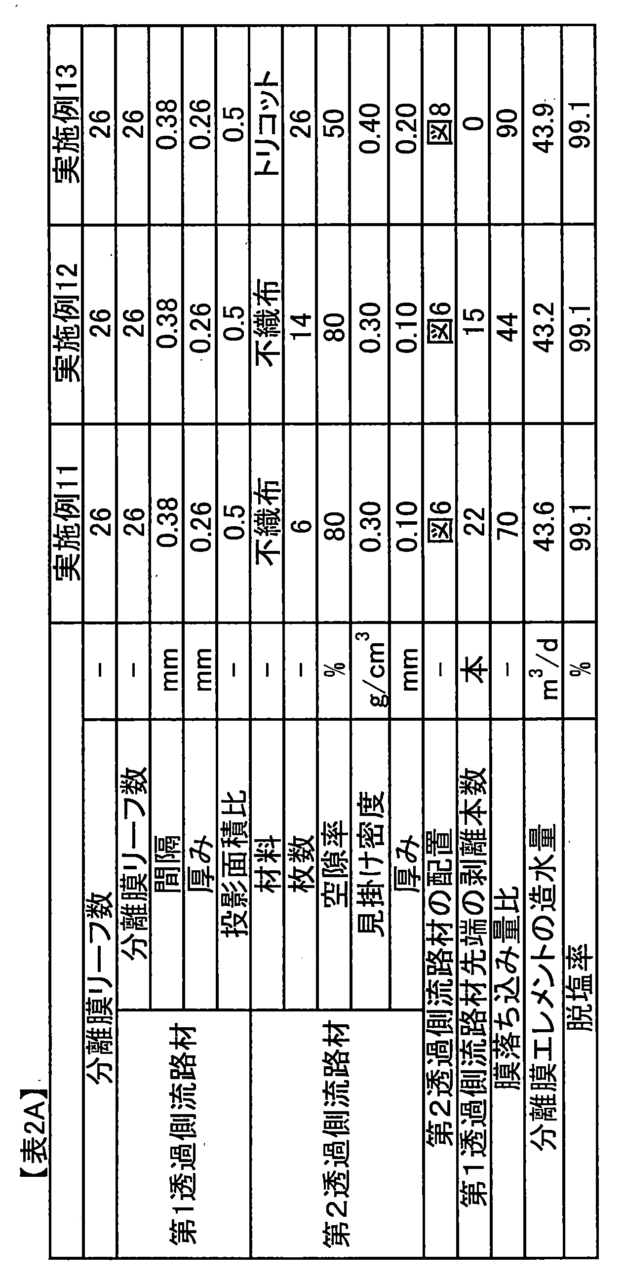

1 分離膜
11 供給側の面
12 透過側の面
3 第1透過側流路材
3a 第1透過側流路材の構成要素
4 第1透過側流路
5 第2透過側流路材
6 供給側流路材
7 不織布
80 膜リーフ
9 集水管
100 分離膜エレメント
b 隣り合う第1透過側流路材の構成要素の間隔
d 第1透過側流路材の構成要素の幅
x 第2方向(集水管の長手方向)
y 第1方向(膜リーフの周回方向) DESCRIPTION OFSYMBOLS 1 Separation membrane 11 Supply side surface 12 Permeation side surface 3 First permeation side flow path material 3a Component of first permeation side flow path material 4 First permeation side flow path 5 Second permeation side flow path material 6 Supply side Channel material 7 Non-woven fabric 80 Membrane leaf 9 Water collecting pipe 100 Separation membrane element b Spacing between adjacent first permeate side channel material d Width of first permeate side channel material x Second direction (collection pipe In the longitudinal direction)
y First direction (around direction of membrane leaf)
11 供給側の面
12 透過側の面
3 第1透過側流路材
3a 第1透過側流路材の構成要素
4 第1透過側流路
5 第2透過側流路材
6 供給側流路材
7 不織布
80 膜リーフ
9 集水管
100 分離膜エレメント
b 隣り合う第1透過側流路材の構成要素の間隔
d 第1透過側流路材の構成要素の幅
x 第2方向(集水管の長手方向)
y 第1方向(膜リーフの周回方向) DESCRIPTION OF
y First direction (around direction of membrane leaf)
Claims (8)
- 集水管および前記集水管の周りに巻回された膜リーフを有し;
前記膜リーフは、供給側流路材と、分離膜と、第1透過側流路材と、第2透過側流路材とを有し;
前記分離膜の供給面側には給側流路材を有し;
前記分離膜の透過面側には前記第1透過側流路材を有し;
前記第1透過側流路材は、集水管の長手方向には連続しておらず;
前記第2透過側流路材は、シート状物であって、前記膜リーフのひとつの端部に存在し;前記第2透過側流路材は、前記膜リーフを構成する部材のうち、最も近く前記集水管の外周面を巻回しており;そして第2透過側流路材は前記第1透過側流路材と第1透過側流路材の端部で少なくとも接触している
分離膜エレメント。 Having a water collection tube and a membrane leaf wound around the water collection tube;
The membrane leaf includes a supply-side channel material, a separation membrane, a first permeate-side channel material, and a second permeate-side channel material;
A supply-side channel material is provided on the supply surface side of the separation membrane;
Having the first permeate-side channel material on the permeate surface side of the separation membrane;
The first permeate channel material is not continuous in the longitudinal direction of the water collection pipe;
The second permeate-side channel material is a sheet-like material and is present at one end of the membrane leaf; the second permeate-side channel material is the most of the members constituting the membrane leaf A separation membrane element that is wound around the outer peripheral surface of the water collecting pipe nearby; and the second permeate side channel member is at least in contact with the end portion of the first permeate side channel member . - 前記第2透過側流路材は前記第1透過側流路材と第1透過側流路材の少なくとも端部で重なっている、
請求項1に記載の分離膜エレメント。 The second permeate side channel material overlaps at least the end of the first permeate side channel material and the first permeate side channel material;
The separation membrane element according to claim 1. - 前記第2透過側流路材の厚み方向の断面における空隙率が30~80%である、請求項1または2に記載の分離膜エレメント。 The separation membrane element according to claim 1 or 2, wherein a porosity in a cross section in the thickness direction of the second permeation side channel material is 30 to 80%.
- 前記第2透過側流路材の厚みが0.01~0.4mmである、請求項1~3のいずれかに記載の分離膜エレメント。 The separation membrane element according to any one of claims 1 to 3, wherein a thickness of the second permeation side channel material is 0.01 to 0.4 mm.
- 前記第2透過側流路材の見掛け密度が0.3~1.2g/cm3である、
請求項1~4のいずれかに記載の分離膜エレメント。 The apparent density of the second permeation side channel material is 0.3 to 1.2 g / cm 3 .
The separation membrane element according to any one of claims 1 to 4. - 前記第1透過側流路材の厚みが0.05mm以上0.8mm以下である、
請求項1~5のいずれかに記載の分離膜エレメント。 The thickness of the first permeate side channel material is 0.05 mm or more and 0.8 mm or less,
The separation membrane element according to any one of claims 1 to 5. - 前記第1透過側流路材が、
前記集水管の長手方向において200~1500μmの間隔で設けられている、
請求項1~6のいずれかに記載の分離膜エレメント。 The first permeate side channel material is
Provided at intervals of 200 to 1500 μm in the longitudinal direction of the water collecting pipe,
The separation membrane element according to any one of claims 1 to 6. - 前記第1透過側流路材の前記分離膜に対する投影面積比が0.3以上0.7以下である、請求項1~7のいずれかに記載の分離膜エレメント。 The separation membrane element according to any one of claims 1 to 7, wherein a projected area ratio of the first permeate-side channel material to the separation membrane is 0.3 or more and 0.7 or less.
Priority Applications (1)
| Application Number | Priority Date | Filing Date | Title |
|---|---|---|---|
| JP2014536451A JPWO2014208602A1 (en) | 2013-06-28 | 2014-06-25 | Separation membrane element |
Applications Claiming Priority (2)
| Application Number | Priority Date | Filing Date | Title |
|---|---|---|---|
| JP2013-136006 | 2013-06-28 | ||
| JP2013136006 | 2013-06-28 |
Publications (1)
| Publication Number | Publication Date |
|---|---|
| WO2014208602A1 true WO2014208602A1 (en) | 2014-12-31 |
Family
ID=52141934
Family Applications (1)
| Application Number | Title | Priority Date | Filing Date |
|---|---|---|---|
| PCT/JP2014/066851 WO2014208602A1 (en) | 2013-06-28 | 2014-06-25 | Separation membrane element |
Country Status (2)
| Country | Link |
|---|---|
| JP (1) | JPWO2014208602A1 (en) |
| WO (1) | WO2014208602A1 (en) |
Cited By (4)
| Publication number | Priority date | Publication date | Assignee | Title |
|---|---|---|---|---|
| JP2016144794A (en) * | 2015-01-29 | 2016-08-12 | 東レ株式会社 | Composite semipermeable membrane and composite semipermeable element |
| WO2017000653A1 (en) * | 2015-06-30 | 2017-01-05 | 佛山市美的清湖净水设备有限公司 | Reverse osmosis membrane assembly and manufacturing method therefor |
| WO2018052124A1 (en) * | 2016-09-16 | 2018-03-22 | 日東電工株式会社 | Spiral membrane element |
| CN114025866A (en) * | 2019-06-27 | 2022-02-08 | 东丽株式会社 | Separation membrane element, method for using same, and water treatment apparatus |
Citations (5)
| Publication number | Priority date | Publication date | Assignee | Title |
|---|---|---|---|---|
| JPH11114381A (en) * | 1997-10-16 | 1999-04-27 | Nitto Denko Corp | Spiral type membrane element |
| JP2003275547A (en) * | 2002-03-22 | 2003-09-30 | Nitto Denko Corp | Spiral type membrane element and manufacturing method therefor |
| JP2004174365A (en) * | 2002-11-27 | 2004-06-24 | Toray Ind Inc | Method for manufacturing element of fluid separation membrane |
| JP2004305823A (en) * | 2003-04-03 | 2004-11-04 | Nitto Denko Corp | Spiral type separation membrane element |
| WO2013005826A1 (en) * | 2011-07-07 | 2013-01-10 | 東レ株式会社 | Separation membrane, separation membrane element, and method for producing separation membrane |
-
2014
- 2014-06-25 JP JP2014536451A patent/JPWO2014208602A1/en active Pending
- 2014-06-25 WO PCT/JP2014/066851 patent/WO2014208602A1/en active Application Filing
Patent Citations (5)
| Publication number | Priority date | Publication date | Assignee | Title |
|---|---|---|---|---|
| JPH11114381A (en) * | 1997-10-16 | 1999-04-27 | Nitto Denko Corp | Spiral type membrane element |
| JP2003275547A (en) * | 2002-03-22 | 2003-09-30 | Nitto Denko Corp | Spiral type membrane element and manufacturing method therefor |
| JP2004174365A (en) * | 2002-11-27 | 2004-06-24 | Toray Ind Inc | Method for manufacturing element of fluid separation membrane |
| JP2004305823A (en) * | 2003-04-03 | 2004-11-04 | Nitto Denko Corp | Spiral type separation membrane element |
| WO2013005826A1 (en) * | 2011-07-07 | 2013-01-10 | 東レ株式会社 | Separation membrane, separation membrane element, and method for producing separation membrane |
Cited By (21)
| Publication number | Priority date | Publication date | Assignee | Title |
|---|---|---|---|---|
| JP2016144794A (en) * | 2015-01-29 | 2016-08-12 | 東レ株式会社 | Composite semipermeable membrane and composite semipermeable element |
| WO2017000653A1 (en) * | 2015-06-30 | 2017-01-05 | 佛山市美的清湖净水设备有限公司 | Reverse osmosis membrane assembly and manufacturing method therefor |
| US20190255487A1 (en) * | 2016-09-16 | 2019-08-22 | Nitto Denko Corporation | Spiral membrane element |
| EP3513868A4 (en) * | 2016-09-16 | 2020-05-06 | Nitto Denko Corporation | Spiral membrane element |
| JP2018047455A (en) * | 2016-09-16 | 2018-03-29 | 日東電工株式会社 | Spiral type membrane element |
| JP2018047456A (en) * | 2016-09-16 | 2018-03-29 | 日東電工株式会社 | Spiral type membrane element |
| CN109715274A (en) * | 2016-09-16 | 2019-05-03 | 日东电工株式会社 | Screw type membrane module |
| CN109715273A (en) * | 2016-09-16 | 2019-05-03 | 日东电工株式会社 | Screw type membrane module |
| KR20190049848A (en) * | 2016-09-16 | 2019-05-09 | 닛토덴코 가부시키가이샤 | Spiral membrane element |
| KR20190049847A (en) * | 2016-09-16 | 2019-05-09 | 닛토덴코 가부시키가이샤 | Spiral membrane element |
| WO2018052124A1 (en) * | 2016-09-16 | 2018-03-22 | 日東電工株式会社 | Spiral membrane element |
| WO2018052122A1 (en) * | 2016-09-16 | 2018-03-22 | 日東電工株式会社 | Spiral membrane element |
| EP3513869A4 (en) * | 2016-09-16 | 2020-05-13 | Nitto Denko Corporation | Spiral membrane element |
| US10987632B2 (en) | 2016-09-16 | 2021-04-27 | Nitto Denko Corporation | Spiral membrane element |
| US11433356B2 (en) | 2016-09-16 | 2022-09-06 | Nitto Denko Corporation | Spiral membrane element |
| JP7037306B2 (en) | 2016-09-16 | 2022-03-16 | 日東電工株式会社 | Spiral type membrane element |
| JP7089352B2 (en) | 2016-09-16 | 2022-06-22 | 日東電工株式会社 | Spiral type membrane element |
| KR102430207B1 (en) * | 2016-09-16 | 2022-08-05 | 닛토덴코 가부시키가이샤 | Spiral Membrane Element |
| KR102430206B1 (en) * | 2016-09-16 | 2022-08-05 | 닛토덴코 가부시키가이샤 | Spiral Membrane Element |
| CN114025866A (en) * | 2019-06-27 | 2022-02-08 | 东丽株式会社 | Separation membrane element, method for using same, and water treatment apparatus |
| CN114025866B (en) * | 2019-06-27 | 2023-10-31 | 东丽株式会社 | Separation membrane element, method for using same, and water treatment device |
Also Published As
| Publication number | Publication date |
|---|---|
| JPWO2014208602A1 (en) | 2017-02-23 |
Similar Documents
| Publication | Publication Date | Title |
|---|---|---|
| JP6179402B2 (en) | Separation membrane element | |
| JP6111668B2 (en) | Separation membrane element and method for producing separation membrane element | |
| JP6136269B2 (en) | Separation membrane element for water treatment | |
| JP6485044B2 (en) | Separation membrane element | |
| US20140251896A1 (en) | Separation membrane, separation membrane element and method for producing separation membrane | |
| JP6206185B2 (en) | Separation membrane and separation membrane element | |
| JP6179403B2 (en) | Separation membrane and separation membrane element | |
| JP2017047417A (en) | Separation membrane module, separation membrane element and telescope prevention sheet | |
| WO2014208602A1 (en) | Separation membrane element | |
| JP2013071098A (en) | Separation membrane element | |
| JP2014064973A (en) | Separation membrane and separation membrane element | |
| JP2015142911A (en) | Separation membrane and separation membrane element | |
| JP2014193459A (en) | Separation membrane element | |
| JP2021020204A (en) | Separation membrane element | |
| JP2014193460A (en) | Separation membrane and separation membrane element | |
| JP2016068081A (en) | Separation membrane element | |
| JP6973650B2 (en) | Separation membrane element and its usage, as well as water treatment equipment | |
| JP2015091574A (en) | Separation film element | |
| JP2015142899A (en) | separation membrane element | |
| JP2015085322A (en) | Separation membrane element | |
| JP2015142894A (en) | separation membrane element | |
| JP2017013055A (en) | Separation membrane element |
Legal Events
| Date | Code | Title | Description |
|---|---|---|---|
| ENP | Entry into the national phase |
Ref document number: 2014536451 Country of ref document: JP Kind code of ref document: A |
|
| 121 | Ep: the epo has been informed by wipo that ep was designated in this application |
Ref document number: 14817249 Country of ref document: EP Kind code of ref document: A1 |
|
| NENP | Non-entry into the national phase |
Ref country code: DE |
|
| 122 | Ep: pct application non-entry in european phase |
Ref document number: 14817249 Country of ref document: EP Kind code of ref document: A1 |