WO2014203746A1 - Reproduction device, reproduction method, and recording medium - Google Patents
Reproduction device, reproduction method, and recording medium Download PDFInfo
- Publication number
- WO2014203746A1 WO2014203746A1 PCT/JP2014/065053 JP2014065053W WO2014203746A1 WO 2014203746 A1 WO2014203746 A1 WO 2014203746A1 JP 2014065053 W JP2014065053 W JP 2014065053W WO 2014203746 A1 WO2014203746 A1 WO 2014203746A1
- Authority
- WO
- WIPO (PCT)
- Prior art keywords
- video
- luminance
- information
- hdr
- encoded data
- Prior art date
Links
Images


Classifications
-
- G—PHYSICS
- G09—EDUCATION; CRYPTOGRAPHY; DISPLAY; ADVERTISING; SEALS
- G09G—ARRANGEMENTS OR CIRCUITS FOR CONTROL OF INDICATING DEVICES USING STATIC MEANS TO PRESENT VARIABLE INFORMATION
- G09G5/00—Control arrangements or circuits for visual indicators common to cathode-ray tube indicators and other visual indicators
- G09G5/10—Intensity circuits
-
- H—ELECTRICITY
- H04—ELECTRIC COMMUNICATION TECHNIQUE
- H04N—PICTORIAL COMMUNICATION, e.g. TELEVISION
- H04N5/00—Details of television systems
- H04N5/76—Television signal recording
- H04N5/91—Television signal processing therefor
- H04N5/92—Transformation of the television signal for recording, e.g. modulation, frequency changing; Inverse transformation for playback
- H04N5/9201—Transformation of the television signal for recording, e.g. modulation, frequency changing; Inverse transformation for playback involving the multiplexing of an additional signal and the video signal
-
- G—PHYSICS
- G11—INFORMATION STORAGE
- G11B—INFORMATION STORAGE BASED ON RELATIVE MOVEMENT BETWEEN RECORD CARRIER AND TRANSDUCER
- G11B20/00—Signal processing not specific to the method of recording or reproducing; Circuits therefor
- G11B20/10—Digital recording or reproducing
-
- G—PHYSICS
- G11—INFORMATION STORAGE
- G11B—INFORMATION STORAGE BASED ON RELATIVE MOVEMENT BETWEEN RECORD CARRIER AND TRANSDUCER
- G11B27/00—Editing; Indexing; Addressing; Timing or synchronising; Monitoring; Measuring tape travel
- G11B27/10—Indexing; Addressing; Timing or synchronising; Measuring tape travel
- G11B27/102—Programmed access in sequence to addressed parts of tracks of operating record carriers
- G11B27/105—Programmed access in sequence to addressed parts of tracks of operating record carriers of operating discs
-
- G—PHYSICS
- G11—INFORMATION STORAGE
- G11B—INFORMATION STORAGE BASED ON RELATIVE MOVEMENT BETWEEN RECORD CARRIER AND TRANSDUCER
- G11B27/00—Editing; Indexing; Addressing; Timing or synchronising; Monitoring; Measuring tape travel
- G11B27/10—Indexing; Addressing; Timing or synchronising; Measuring tape travel
- G11B27/19—Indexing; Addressing; Timing or synchronising; Measuring tape travel by using information detectable on the record carrier
- G11B27/28—Indexing; Addressing; Timing or synchronising; Measuring tape travel by using information detectable on the record carrier by using information signals recorded by the same method as the main recording
- G11B27/32—Indexing; Addressing; Timing or synchronising; Measuring tape travel by using information detectable on the record carrier by using information signals recorded by the same method as the main recording on separate auxiliary tracks of the same or an auxiliary record carrier
- G11B27/327—Table of contents
- G11B27/329—Table of contents on a disc [VTOC]
-
- H—ELECTRICITY
- H04—ELECTRIC COMMUNICATION TECHNIQUE
- H04N—PICTORIAL COMMUNICATION, e.g. TELEVISION
- H04N19/00—Methods or arrangements for coding, decoding, compressing or decompressing digital video signals
- H04N19/10—Methods or arrangements for coding, decoding, compressing or decompressing digital video signals using adaptive coding
- H04N19/169—Methods or arrangements for coding, decoding, compressing or decompressing digital video signals using adaptive coding characterised by the coding unit, i.e. the structural portion or semantic portion of the video signal being the object or the subject of the adaptive coding
- H04N19/184—Methods or arrangements for coding, decoding, compressing or decompressing digital video signals using adaptive coding characterised by the coding unit, i.e. the structural portion or semantic portion of the video signal being the object or the subject of the adaptive coding the unit being bits, e.g. of the compressed video stream
-
- H—ELECTRICITY
- H04—ELECTRIC COMMUNICATION TECHNIQUE
- H04N—PICTORIAL COMMUNICATION, e.g. TELEVISION
- H04N19/00—Methods or arrangements for coding, decoding, compressing or decompressing digital video signals
- H04N19/30—Methods or arrangements for coding, decoding, compressing or decompressing digital video signals using hierarchical techniques, e.g. scalability
-
- H—ELECTRICITY
- H04—ELECTRIC COMMUNICATION TECHNIQUE
- H04N—PICTORIAL COMMUNICATION, e.g. TELEVISION
- H04N19/00—Methods or arrangements for coding, decoding, compressing or decompressing digital video signals
- H04N19/44—Decoders specially adapted therefor, e.g. video decoders which are asymmetric with respect to the encoder
-
- H—ELECTRICITY
- H04—ELECTRIC COMMUNICATION TECHNIQUE
- H04N—PICTORIAL COMMUNICATION, e.g. TELEVISION
- H04N19/00—Methods or arrangements for coding, decoding, compressing or decompressing digital video signals
- H04N19/46—Embedding additional information in the video signal during the compression process
-
- H—ELECTRICITY
- H04—ELECTRIC COMMUNICATION TECHNIQUE
- H04N—PICTORIAL COMMUNICATION, e.g. TELEVISION
- H04N19/00—Methods or arrangements for coding, decoding, compressing or decompressing digital video signals
- H04N19/70—Methods or arrangements for coding, decoding, compressing or decompressing digital video signals characterised by syntax aspects related to video coding, e.g. related to compression standards
-
- H—ELECTRICITY
- H04—ELECTRIC COMMUNICATION TECHNIQUE
- H04N—PICTORIAL COMMUNICATION, e.g. TELEVISION
- H04N9/00—Details of colour television systems
- H04N9/79—Processing of colour television signals in connection with recording
- H04N9/87—Regeneration of colour television signals
-
- G—PHYSICS
- G09—EDUCATION; CRYPTOGRAPHY; DISPLAY; ADVERTISING; SEALS
- G09G—ARRANGEMENTS OR CIRCUITS FOR CONTROL OF INDICATING DEVICES USING STATIC MEANS TO PRESENT VARIABLE INFORMATION
- G09G2320/00—Control of display operating conditions
- G09G2320/02—Improving the quality of display appearance
- G09G2320/0271—Adjustment of the gradation levels within the range of the gradation scale, e.g. by redistribution or clipping
- G09G2320/0276—Adjustment of the gradation levels within the range of the gradation scale, e.g. by redistribution or clipping for the purpose of adaptation to the characteristics of a display device, i.e. gamma correction
-
- G—PHYSICS
- G11—INFORMATION STORAGE
- G11B—INFORMATION STORAGE BASED ON RELATIVE MOVEMENT BETWEEN RECORD CARRIER AND TRANSDUCER
- G11B2220/00—Record carriers by type
- G11B2220/20—Disc-shaped record carriers
- G11B2220/25—Disc-shaped record carriers characterised in that the disc is based on a specific recording technology
- G11B2220/2537—Optical discs
- G11B2220/2541—Blu-ray discs; Blue laser DVR discs
Definitions
- the present technology relates to a playback device, a playback method, and a recording medium, and more particularly, to a playback device, a playback method, and a recording medium that can display content with a wide dynamic dynamic range with appropriate brightness.
- BD Blu-ray (registered trademark) Disc
- the master video was taken with a high-quality camera and has a dynamic range that is greater than the dynamic range that can be displayed on a standard luminance monitor. By compressing, the dynamic range of the master video is naturally lost.
- monitors that are brighter than the standard, such as 500 nit and 1000 nit, are on the market. There is a demand for content that makes use of the performance of a monitor having such a wide dynamic range.
- the present technology has been made in view of such a situation, and enables content with a wide dynamic range of brightness to be displayed with appropriate brightness.
- a playback device includes encoded data of extended video, which is a video having a second luminance range wider than the first luminance range, luminance characteristic information indicating luminance characteristics of the extended video, and the extended
- the encoded data, the luminance characteristic information, and the luminance conversion definition are recorded from a recording medium that records luminance conversion definition information used when performing luminance conversion from video to standard video that is video in the first luminance range.
- a reading unit that reads information; a decoding unit that decodes the encoded data; and a conversion unit that converts the extended video obtained by decoding the encoded data into the standard video based on the luminance conversion definition information
- a display device capable of displaying the extended video, outputting the extended video data and the luminance characteristic information, and displaying the extended video.
- the apparatus and an output unit for outputting the data of the standard video.
- the luminance characteristic information and the luminance conversion definition information can be inserted into a stream including the encoded data as auxiliary information of the encoded data and recorded on the recording medium.
- the encoded data may be HEVC encoded data, and the luminance characteristic information and the luminance conversion definition information may be SEI of the HEVC stream.
- the luminance conversion definition information is first Tone mapping information in which one of 0, 2, and 3 is set as the value of tone_map_model_id, and 4 is set as the value of tone_map_model_id in the luminance characteristic information
- the second Tone ⁇ ⁇ mapping information is first Tone mapping information in which one of 0, 2, and 3 is set as the value of tone_map_model_id, and 4 is set as the value of tone_map_model_id in the luminance characteristic information.
- the same value representing the recording mode of the recording medium can be set in tone_map_model_id of the first Tone mapping information and the second Tone mapping information.
- the recording medium further includes information related to reproduction of the encoded data including a flag indicating whether or not recording with the extended video as a master is performed, and the decoding unit includes the extended data When the flag indicates that recording with video as a master is performed, the encoded data can be decoded.
- the recording medium is a Blu-ray disc, and the flag can be included in a Clip Information file as information related to the reproduction.
- the recording medium is a Blu-ray disc, and the flag can be included in a PlayList file as information related to the reproduction.
- the extended video encoded data which is a video having a second luminance range wider than the first luminance range
- luminance characteristic information indicating luminance characteristics of the extended video
- the extended video The encoded data, the luminance characteristic information, and the luminance conversion definition information are recorded from a recording medium that records luminance conversion definition information used when performing luminance conversion to a standard video that is a video in the first luminance range. Read out. Further, the encoded data is decoded, and the extended video obtained by decoding the encoded data is converted into the standard video based on the luminance conversion definition information. The extended video data and the luminance characteristic information are output to the display device that can display the extended video, and the standard video data is output to the display device that cannot display the extended video. Is output.
- a playback device is a standard that is a video in the first luminance range obtained by performing luminance conversion of an extended video that is a video in a second luminance range wider than the first luminance range.
- a recording medium that records encoded data of video, luminance characteristic information indicating luminance characteristics of the extended video, and luminance conversion definition information used when performing luminance conversion from the standard video to the extended video, Obtained by decoding the encoded data based on the reading unit that reads out the encoded data, the luminance characteristic information, and the luminance conversion definition information, the decoding unit that decodes the encoded data, and the luminance conversion definition information.
- the converted standard video is converted into the extended video, and the extended video data and the luminance characteristic information are output to a display device capable of displaying the extended video.
- a display device capable of displaying the extended video.
- To the expanded video can not be displayed the display device, and an output unit for outputting the data of the standard video.
- the luminance characteristic information and the luminance conversion definition information may be inserted into the stream including the encoded data as auxiliary information of the encoded data and recorded on the recording medium.
- the encoded data may be HEVC encoded data, and the luminance characteristic information and the luminance conversion definition information may be SEI of the HEVC stream.
- the luminance conversion definition information is first Tone mapping information in which one of 0, 2, and 3 is set as the value of tone_map_model_id, and 4 is set as the value of tone_map_model_id in the luminance characteristic information
- the second Tone ⁇ ⁇ mapping information is first Tone mapping information in which one of 0, 2, and 3 is set as the value of tone_map_model_id, and 4 is set as the value of tone_map_model_id in the luminance characteristic information.
- the same value representing the recording mode of the recording medium can be set in tone_map_model_id of the first Tone mapping information and the second Tone mapping information.
- the recording medium further includes information related to reproduction of the encoded data including a flag indicating whether or not recording with the extended video as a master is performed, and the decoding unit includes the extended data When the flag indicates that recording with video as a master is performed, the encoded data can be decoded.
- the recording medium is a Blu-ray disc, and the flag can be included in a Clip Information file as information related to the reproduction.
- the recording medium is a Blu-ray disc, and the flag can be included in a PlayList file as information related to the reproduction.
- a standard video that is a video in the first luminance range obtained by performing luminance conversion of an extended video that is a video in a second luminance range wider than the first luminance range.
- the encoding from a recording medium recording encoded data, luminance characteristic information indicating the luminance characteristics of the extended video, and luminance conversion definition information used when performing luminance conversion from the standard video to the extended video Data, the luminance characteristic information, and the luminance conversion definition information are read out.
- the encoded data is decoded, and the standard video obtained by decoding the encoded data is converted into the extended video based on the luminance conversion definition information.
- the extended video data and the luminance characteristic information are output to the display device that can display the extended video, and the standard video data is output to the display device that cannot display the extended video. Is output.
- FIG. 19 is a diagram illustrating the syntax of StreamCodingInfo in FIG. 18. It is a block diagram which shows the structural example of a recording device. It is a block diagram which shows the structural example of the encoding process part of FIG. It is a figure which shows the example of the signal processing by a HDR-STD conversion part. It is a figure which shows the example of tone mapping. It is a block diagram which shows the structural example of the reproducing
- FIG. 17 is a diagram illustrating an example of syntax of AppInfoPlayList () included in the PlayList file of FIG.
- FIG. 17 is a diagram illustrating the syntax of PlayList () included in the PlayList file of Fig. 16.
- FIG. 37 is a diagram illustrating the syntax of PlayItem () of FIG. 36.
- FIG. 38 is a diagram illustrating the syntax of STN_table () of FIG. 37.
- FIG. 39 is a diagram illustrating the syntax of stream_attributes () in FIG. 38. It is a figure which shows the example of allocation of PSR. It is a figure which shows the example of the signal processing in mode-i when adjustment of the brightness
- FIG. 26 is a block diagram illustrating a configuration example of an HDR video output unit in FIG. 25. It is a flowchart explaining the decoding process in mode-i performed in step S44 of FIG. It is a flowchart explaining the decoding process in mode-ii performed in step S45 of FIG. It is a flowchart explaining the display process of a display apparatus. It is a figure which shows the example of the recognition based on the information transmitted / received via HDMI. It is a figure which shows the other example of recognition based on the information transmitted / received via HDMI.
- FIG. 53 is a flowchart for describing HDR / raw output processing performed in step S227 of FIG. 52.
- 53 is a flowchart for describing HDR / cooked output processing performed in step S228 of FIG. 52.
- FIG. 53 is a flowchart for describing STD output processing performed in step S229 of FIG. 52.
- FIG. It is a flowchart explaining the display process of a display apparatus. It is a block diagram which shows the structural example of a computer.
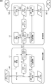
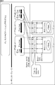
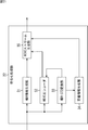
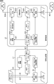
- FIG. 1 is a diagram illustrating a configuration example of a recording / reproducing system according to an embodiment of the present technology.
- the recording / reproducing system in FIG. 1 includes a recording device 1, a reproducing device 2, and a display device 3.
- the playback device 2 and the display device 3 are connected via an HDMI (registered trademark) (High Definition Multimedia Interface) cable 4.
- the playback device 2 and the display device 3 may be connected via a cable of another standard, or may be connected via wireless communication.
- Recording device 1 records content, and playback device 2 plays back the content.
- Content is provided from the recording device 1 to the playback device 2 using the optical disc 11.
- the optical disc 11 is a disc on which content is recorded, for example, in a BD-ROM (Blu-ray (registered trademark) Disc Read-Only) format.
- Recording content on the optical disc 11 may be performed in other formats such as BD-R and -RE.
- provision of content from the recording device 1 to the playback device 2 may be performed using a removable medium other than the optical disk, such as a memory card equipped with a flash memory.
- the recording device 1 is, for example, a device used by a content author. In the following description, it is assumed that the optical disc 11 on which content is recorded by the recording device 1 is provided to the playback device 2 as appropriate. However, in practice, the optical disc is copied based on the master disk on which the content is recorded by the recording device 1. Then, the optical disc 11 as one of them is provided to the playback device 2.
- An HDR (High Dynamic Range) video that is a video having a dynamic range greater than or equal to a dynamic range (luminance range) that can be displayed on a standard luminance monitor is input to the recording apparatus 1.
- the recording device 1 records the input master HDR video on the optical disc 11 as an HDR video, that is, as a video having a dynamic range higher than the dynamic range that can be displayed on a monitor having a standard luminance.
- information indicating the luminance characteristics of the master HDR video and information used when converting the HDR video into the STD video are also recorded on the optical disc 11.
- STD video (standard video) is a dynamic range video that can be displayed on a monitor with standard brightness.
- the dynamic range of STD video is 0-100%
- the dynamic range of HDR video is expressed as a range from 0% to 101% or more, such as 0-500%, 0-1000%.
- the recording device 1 converts the input master HDR video into STD video, that is, converts it into a video having a dynamic range that can be displayed on a monitor having a standard luminance, and records it on the optical disc 11.
- information indicating the luminance characteristics of the master HDR video and information used when converting the STD video into the HDR video are also recorded on the optical disc 11.
- the HDR video recorded by the recording device 1 or the STD video obtained by converting the HDR video is, for example, a so-called 4K resolution video having horizontal and vertical resolutions of 4096 ⁇ 2160, 3840 ⁇ 2160 pixels, and the like.
- HEVC High Efficiency Video Coding
- SEI Supplemental Enhancement Information
- the playback device 2 communicates with the display device 3 via the HDMI cable 4 and acquires information regarding the display performance of the display device 3.
- the playback device 2 identifies whether the display device 3 is a device having an HDR monitor that is a monitor capable of displaying HDR video or a device having an STD monitor that is a monitor capable of only displaying STD video.
- the playback device 2 drives the drive to read and decode the HEVC stream recorded on the optical disc 11.
- the playback device 2 displays the HDR video data obtained by decoding the HEVC stream on the display device 3. Output to.
- the playback device 2 outputs information indicating the luminance characteristics of the master HDR video to the display device 3 together with the HDR video data.
- the playback device 2 converts the HDR video obtained by decoding the HEVC stream into STD video. , Output STD video data.
- the conversion of the HDR video into the STD video is performed using information that is recorded on the optical disc 11 and used when converting the HDR video into the STD video.
- the playback device 2 converts the STD video obtained by decoding the HEVC stream into HDR video, and the HDR Video data is output to the display device 3.
- the conversion of the STD video into the HDR video is performed using information used when converting the STD video into the HDR video recorded on the optical disc 11.
- the playback device 2 outputs information indicating the luminance characteristics of the master HDR video to the display device 3 together with the HDR video.
- the playback device 2 displays the STD video data obtained by decoding the HEVC stream on the display device 3. Output to.
- the display device 3 receives the video data transmitted from the playback device 2 and displays the content video on the monitor. Audio data of content is also transmitted from the playback device 2. The display device 3 outputs the audio of the content from the speaker based on the audio data transmitted from the playback device 2.
- the display device 3 recognizes that the video data transmitted from the playback device 2 is HDR video data. As described above, information indicating the luminance characteristics of the master HDR video is transmitted together with the HDR video data to the display device 3 having the HDR monitor.
- the display device 3 displays the HDR video image according to the characteristics specified by the information indicating the brightness characteristics of the master HDR video.
- the display device 3 is a monitor whose own monitor has a dynamic range of 0-500%.
- the display device 3 Based on the information indicating the luminance characteristics of the master HDR video, the display device 3 has a predetermined HDR video dynamic range of 0-500%. If it is designated as a characteristic, the video is displayed with the brightness adjusted in the range of 0-500% according to the predetermined characteristic.
- the content author By enabling the specification of the luminance characteristics of the master HDR video, the content author (Author) can display the video with the intended luminance.
- a display device such as a TV recognizes an externally input video as a video having a dynamic range of 0-100%. Further, when the monitor of the display device has a wider dynamic range, the display device expands the luminance itself according to the characteristics of the monitor and displays the video. By designating the luminance characteristic and adjusting the luminance of the HDR video according to the designated characteristic, it is possible to prevent the luminance adjustment not intended by the author from being performed on the display device side.
- a playback device that outputs video to a display device such as a TV usually outputs the video after converting the luminance according to the characteristics of the transmission path.
- the display device that has received the video converts the luminance of the received video in accordance with the characteristics of the monitor and displays the video.
- the display device 3 displays the STD video image.
- STD video is transmitted from the playback device 2
- the display device 3 is a device having an STD monitor.
- mode-i the mode in which the master HDR video is recorded on the optical disc 11 as the HDR video is referred to as mode-i.
- mode-i information indicating the luminance characteristics of the master HDR video and information used when converting the HDR video into STD video are recorded on the optical disc 11.
- mode-ii the mode in which the master HDR video is converted to STD video and recorded on the optical disc 11 is called mode-ii.
- mode-ii information indicating the luminance characteristics of the master HDR video and information used when converting the STD video into the HDR video are recorded on the optical disc 11.
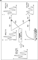
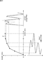
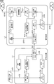
- FIG. 2 is a diagram illustrating an example of signal processing in mode-i.
- the process on the left side indicated by the solid line L1 indicates the encoding process performed in the recording apparatus 1, and the process on the right side indicated by the solid line L2 indicates the decoding process performed in the reproduction apparatus 2.
- the recording apparatus 1 detects the brightness of the master HDR video and, as indicated by the tip of arrow # 1, HDR information that is information indicating the brightness characteristics of the master HDR video Is generated. Also, the recording device 1 encodes the master HDR video with HEVC as indicated by the tip of arrow # 2.
- the recording device 1 converts the master HDR video into STD video as indicated by the tip of arrow # 3.
- the video of the STD video obtained by the conversion is displayed on a monitor (not shown).
- the conversion of the HDR video to the STD video is appropriately performed while the author visually confirms the video of the converted STD video and adjusts the conversion parameters.
- the recording device 1 Based on the adjustment by the author, the recording device 1 generates tone-mapping definition information for HDR-STD conversion, which is information used when converting HDR video to STD video, as indicated by the tip of arrow # 4. .
- the tone mapping definition information includes each pixel value indicating the brightness of a dynamic range such as 0-400%, which is wider than the standard dynamic range, and each pixel indicating the brightness of the dynamic range of 0-100%, which is the standard dynamic range. This information defines the correspondence between values.
- the recording device 1 inserts the HDR information and tone mapping definition information as SEI into HEVC encoded data as shown at the tip of arrow # 5, and generates a HEVC stream.
- the recording device 1 records the generated HEVC stream on the optical disc 11 in the BD format and provides it to the playback device 2 as indicated by arrow # 11.
- the information indicating the luminance characteristics of the master HDR video and the information used when converting the HDR video into the STD video are provided to the playback device 2 by inserting into the stream using the SEI of HEVC. Is done.
- the playback device 2 reads the HEVC stream from the optical disc 11, and extracts the HDR information and tone mapping definition information from the SEI of the HEVC stream as indicated by arrows # 21 and # 22.
- the playback device 2 decodes the HEVC encoded data as indicated by the tip of arrow # 23.
- the playback device 2 adds the HDR information to the HDR video data obtained by decoding the encoded data, as indicated by the tip of the arrow # 24. Output to the display device 3 as shown above.
- the playback device 2 uses the tone-mapping definition information for HDR-STD conversion extracted from the HEVC stream, as indicated by the tip of arrow # 26, to generate encoded data.
- the HDR video obtained by decoding is converted to STD video.
- the playback device 2 outputs the STD video data obtained by the conversion to the display device 3 as indicated by the tip of arrow # 27.
- HDR video data obtained by decoding HEVC encoded data is output to the display device 3 having an HDR monitor together with the HDR information. Also, HDR video data obtained by decoding HEVC encoded data is converted into STD video, and then output to a display device 3 having an STD monitor.
- FIG. 3 is a diagram showing a flow of processing from when the master HDR video is input to the recording device 1 to when video data is output from the playback device 2.
- the master HDR video is transferred to the playback device 2 together with the HDR information generated in the recording device 1 based on the master HDR video and tone-mapping definition information for HDR-STD conversion, as indicated by the tip of the white arrow # 51.
- the HDR information includes information indicating that the dynamic range is extended to a range of 0 to 400%.
- the playback device 2 adds HDR information to the HDR video data obtained by decoding the HEVC encoded data, as indicated by the arrows # 52 and # 53. Is done. Also, the HDR video data to which the HDR information is added is output to the display device 3 as indicated by the tip of arrow # 54.
- the playback device 2 converts the HDR video obtained by decoding the HEVC encoded data into HDR-STD conversion as indicated by the arrows # 55 and # 56. Is converted into STD video using tone mapping definition information. Also, the STD video data obtained by the conversion is output to the display device 3 as indicated by the tip of arrow # 57.
- the amplitude of the waveform indicating the HDR video and the amplitude of the waveform indicating the STD video each indicate a dynamic range.
- the master HDR video is recorded on the optical disc 11 as the HDR video. Also, depending on the performance of the display device 3 as the output destination, the HDR video obtained by decoding the encoded data is output with the HDR information added as it is, or the HDR video is converted into the STD video and output. Can be switched.
- FIG. 4 is a diagram illustrating an example of signal processing in mode-ii.
- the recording apparatus 1 detects the brightness of the master HDR video and generates HDR information as indicated by the tip of arrow # 71.
- Recording device 1 converts the master HDR video into STD video as indicated by the tip of arrow # 72.
- the video of the STD video obtained by the conversion is displayed on a monitor (not shown).
- the recording device 1 Based on the adjustment by the author, the recording device 1 generates tone mapping definition information for STD-HDR conversion, which is information used when converting STD video to HDR video, as indicated by the tip of arrow # 73. .
- the recording apparatus 1 encodes the STD video obtained by converting the master HDR video by HEVC.
- Recording device 1 inserts HDR information and tone mapping definition information as SEI into HEVC encoded data as shown at the tip of arrow # 75, and generates a HEVC stream.
- the recording device 1 records the generated HEVC stream on the optical disc 11 in the BD format and provides it to the playback device 2 as indicated by arrow # 91.
- the playback device 2 reads out the HEVC stream from the optical disc 11, and extracts the HDR information and tone mapping definition information from the SEI of the HEVC stream as indicated by arrows # 101 and # 102.
- the playback device 2 decodes the HEVC encoded data as indicated by the tip of arrow # 103.
- the playback device 2 outputs the STD video data obtained by decoding the encoded data to the display device 3 as indicated by the tip of arrow # 104.
- the playback device 2 uses the tone mapping definition information for STD-HDR conversion extracted from the HEVC stream, as indicated by the tip of arrow # 105, to generate encoded data.
- STD video obtained by decoding is converted to HDR video.
- the playback device 2 adds the HDR information to the HDR video data obtained by the conversion as indicated by the tip of the arrow # 106, and outputs it to the display device 3 as indicated by the tip of the arrow # 107.
- the STD video data obtained by decoding the HEVC encoded data is converted into HDR video and then output to the display device 3 having the HDR monitor together with the HDR information. Also, STD video data obtained by decoding HEVC encoded data is output as it is to the display device 3 having an STD monitor.
- FIG. 5 is a diagram showing the flow of processing from when the master HDR video is input to the recording device 1 to when the video data is output from the playback device 2.
- the master HDR video is converted into STD video as shown by the white arrow # 121, and then the HDR information generated in the recording device 1 based on the master HDR video and the tone for STD-HDR conversion are displayed. It is provided to the playback device 2 together with the mapping definition information.
- the STD video obtained by decoding the HEVC encoded data is used for STD-HDR conversion, as indicated by arrows # 122 and # 123. It is converted into HDR video using tone mapping definition information. Further, as indicated by the tip of arrows # 124 and # 125, the HDR information is added to the HDR video data obtained by converting the STD video, and is output to the display device 3 as indicated by the tip of arrow # 126.
- the playback device 2 outputs the STD video obtained by decoding the HEVC encoded data to the display device 3 as indicated by the tip of arrow # 127. .
- the master HDR video is converted to STD video and recorded on the optical disc 11. Also, depending on the performance of the display device 3 serving as the output destination, the STD video obtained by decoding the encoded data is converted into HDR video, and is output with the addition of HDR information, or the STD video is output as it is. Can be switched.
- FIG. 6 is a diagram showing the configuration of the HEVC access unit.
- the HEVC stream is composed of access units that are a collection of NAL (Network Abstraction Layer) units.
- One access unit includes one picture of video data.
- one access unit includes AU delimiter (Access Unit delimiter), VPS (Video Parameter Set), SPS (Sequence Parameter Set), PPS (Picture Parameter Set), SEI, VCL (Video Coding Layer) , EOS (End of Sequence), and EOS (End of Stream).
- AU delimiter Access Unit delimiter
- VPS Video Parameter Set
- SPS Sequence Parameter Set
- PPS Picture Parameter Set
- SEI Supplemental Coding Layer
- VCL Video Coding Layer
- EOS End of Sequence
- EOS End of Stream
- VPS includes metadata representing the contents of the bitstream.
- the SPS includes information that the HEVC decoder needs to refer to through a sequence decoding process, such as a picture size and a CTB (Coding Tree Block) size.
- the PPS includes information that the HEVC decoder needs to refer to in order to execute a picture decoding process.
- VPS, SPS, and PPS are used as header information.
- SEI is auxiliary information including timing information of each picture and information on random access. HDR information and tone mapping definition information are included in Tone mapping information which is one of SEI.
- VCL is one picture data.
- EOS End of Sequence
- EOS End of Stream
- FIG. 7 is a diagram showing the syntax of Tone mapping information.
- Tone mapping information the brightness and color of the picture obtained by decoding are converted according to the performance of the monitor that is the output destination of the picture. Note that the line numbers and colons (:) on the left side of FIG. 7 are shown for convenience of explanation, and are not information included in Tone mapping information. The main information included in Tone mapping information is explained.
- the tone_map_id on the second line is identification information of Tone mapping information.
- the purpose of Tone mapping information is identified by tone_map_id.
- an ID for mode-i and an ID for mode-ii are secured.
- an ID for mode-i is set in tone_map_id of Tone mapping information inserted in SEI of the encoded data of HDR video.
- an ID for mode-ii is set in tone_map_id of Tone mapping information inserted in the SEI of the encoded data of STD video.
- either one of the ID for mode-i and the ID for mode-ii is set in tone_map_id.
- the tone_map_model_id on the 8th line represents a tone map model used for conversion of coded data (coded data).
- tone_map_model_id In the recording apparatus 1, one Tone mapping information in which one of 0, 2, and 3 is set as tone_map_model_id and one Tone mapping information in which a value of 4 is set as tone_map_model_id are generated.
- Tone mapping information in which one of 0, 2, and 3 is set as tone_map_model_id is used as tone mapping definition information for HDR-STD conversion or STD-HDR conversion. Further, information included in Tone mapping information in which a value of 4 is set as tone_map_model_id is used as HDR information.
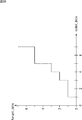
- tone_map_model_id 0.
- min_value and max_value are described.
- the horizontal axis indicates coded_data (RGB value before conversion), and the vertical axis indicates target_data (RGB value after conversion).
- the tone curve of FIG. 9 the RGB values below the encoded data D1 are converted into RGB values indicated by min_value, as indicated by white arrow # 151.
- the RGB value of the encoded data D2 or higher is converted into an RGB value indicated by max_value as indicated by a white arrow # 152.
- tone_map_model_id 2
- start_of_coded_interval [i] having the same number as max_target_data representing the step function is described.
- tone_map_model_id 3
- num_pivots 3
- Tone mapping information in which any value of 0,2,3 is set as tone_map_model_id is used as tone mapping definition information for STD-HDR conversion or HDR-STD conversion, and reproduced from the recording device 1 Is transmitted to the device 2.
- tone_map_model_id 4
- ref_screen_luminance_white 4
- extended_range_white_level 4
- nominal_black_level_code_value 2
- nominal_white_level_code_value 3
- extended_white_level_code_value 3
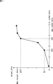
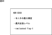
- FIG. 12 is a diagram illustrating an example of each piece of information included in the HDR information.
- the horizontal axis of FIG. 12 shows each pixel value of RGB. When the bit length is 10 bits, each pixel value is 0-1023.
- the vertical axis in FIG. 12 indicates brightness (luminance).
- a curve L11 shows the relationship between the pixel value and the brightness in a standard luminance monitor. The dynamic range of a standard luminance monitor is 0-100%.
- ref_screen_luminance_white indicates the brightness (cd / m 2 ) of the standard monitor.
- extended_range_white_level indicates the maximum value of the dynamic range brightness after extension. In the example of FIG. 12, 400 is set as the value of extended_range_white_level.
- Nominal_black_level_code_value indicates a pixel value of black (brightness 0%)
- nominal_white_level_code_value indicates a pixel value of white (brightness 100%) in a standard luminance monitor.
- extended_white_level_code_value indicates a white pixel value in the extended dynamic range.
- the dynamic range of 0-100% is expanded to the dynamic range of 0-400% according to the value of extended_range_white_level.
- a pixel value corresponding to 400% brightness is specified by extended_white_level_code_value.
- the luminance characteristics of the HDR video are characteristics indicated by a curve L12 in which the values of nominal_black_level_code_value, nominal_white_level_code_value, and extended_white_level_code_value are 0%, 100%, and 400%, respectively.
- Tone mapping information in which a value of 4 is set as tone_map_model_id, and transmitted from the recording device 1 to the playback device 2.
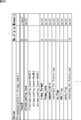
- FIG. 13 is a diagram illustrating an example of an AV stream management structure in the BD-ROM format.
- AV streams including HEVC streams is performed using two layers, PlayList and Clip.
- the AV stream may be recorded not only on the optical disc 11 but also on the local storage of the playback device 2.
- One AV stream and Clip Information which is information accompanying it are managed as one object.
- a pair of AV stream and ClipCInformation is called Clip.
- the AV stream is developed on the time axis, and the access point of each Clip is mainly designated in the PlayList with a time stamp. Clip Information is used to find the address where decoding in the AV stream should start.
- PlayList is a collection of AV stream playback sections.
- One playback section in the AV stream is called PlayItem.
- PlayItem is represented by a pair of IN point and OUT point of the playback section on the time axis. As shown in FIG. 13, the PlayList is composed of one or a plurality of PlayItems.
- the first PlayList from the left in FIG. 13 is composed of two PlayItems, and the two PlayItems refer to the first half and the second half of the AV stream included in the left Clip, respectively.
- the second PlayList from the left is composed of one PlayItem, so that the entire AV stream included in the right Clip is referenced.
- the third PlayList from the left is made up of two PlayItems, and the two PlayItems refer to a part of the AV stream included in the left Clip and a part of the AV stream included in the right Clip, respectively.
- the PlayList is used as playback management information for managing playback of AV streams.
- a playback path created by an array of one or more PlayItems in a PlayList is called a main path.
- a playback path created by an arrangement of one or more SubPlayItems in parallel with the Main Path is called a sub path (Sub Path).
- FIG. 14 is a diagram showing the structure of the main path and the sub path.
- the PlayList has one Main path and one or more Sub paths.
- the PlayList in FIG. 14 has one Main Path and three Sub Paths created from a sequence of three PlayItems.
- the PlayItems that make up the Main Path are set with IDs in order from the top.
- the AV stream referred to by one PlayItem includes at least a video stream (main image data).
- the AV stream may or may not include one or more audio streams that are played back at the same timing (synchronously) as the video stream included in the AV stream.
- the AV stream may or may not include one or more bitmap subtitle data (PG (Presentation Graphic)) streams that are reproduced in synchronization with the video stream included in the AV stream. .
- PG Presentation Graphic
- the AV stream may or may not include one or more IG (Interactive Graphic) streams that are played back in synchronization with the video stream included in the AV stream file.
- the IG stream is used to display graphics such as buttons operated by the user.
- a video stream and an audio stream, a PG stream, and an IG stream that are reproduced in synchronization with the AV stream referred to by one PlayItem are multiplexed.
- one SubPlayItem refers to a video stream, an audio stream, a PG stream, and the like, which are different from the AV stream referred to by the PlayItem.
- PlayList and Clip Information including information related to playback of the AV stream are appropriately referred to as Data ⁇ Base information.
- FIG. 15 is a diagram illustrating an example of a management structure of files recorded on the optical disc 11.
- Each file recorded on the optical disc 11 is hierarchically managed by the directory structure.
- One root directory is created on the optical disc 11.
- BDMV directory is placed under the root directory.
- an Index file that is a file with the name “Index.bdmv” and a MovieObject file that is a file with the name “MovieObject.bdmv” are stored.
- PLAYLIST directory CLIPINF directory, STREAM directory, etc. are provided under the BDMV directory.
- the PLAYLIST directory stores a PlayList file that describes the PlayList.
- Each PlayList file has a name that is a combination of a 5-digit number and an extension “.mpls”.
- a single PlayList file shown in FIG. 15 has a file name “00000.mpls”.
- the Clip Information file is stored in the CLIPINF directory. Each Clip Information file is set with a name combining a five-digit number and the extension “.clpi”. File names “00001.clpi”, “00002.clpi”, and “00003.clpi” are set in the three Clip Information files in FIG.
- Stream file is stored in STREAM directory.
- Each stream file has a name that is a combination of a 5-digit number and an extension “.m2ts”.
- file names “00001.m2ts”, “00002.m2ts”, and “00003.m2ts” are set, respectively.
- the clip information file in which the same 5-digit number is set as the file name and the stream file constitute a single clip.
- the “00001.m2ts” stream file is played, the “00001.clpi” ClipCInformation file is used, and when the “00002.m2ts” stream file is played, the “00002.clpi” Clip Information file is used.
- the Clip Information file used for playback of the AV stream including the HEVC stream includes information related to processing of the HDR video.
- FIG. 16 is a diagram showing the syntax of the PlayList file.
- the PlayList file is a file with the extension “.mpls” stored in the PLAYLIST directory of FIG.
- AppInfoPlayList stores parameters related to playback control of the PlayList, such as playback restrictions.
- PlayList stores parameters related to Main Path and Sub Path.
- PlayListMark stores PlayList mark information, that is, information about a mark that is a jump destination (jump point) in a user operation or command that commands chapter jump or the like.
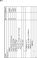
- FIG. 17 is a diagram showing the syntax of the Clip® Information file.
- the Clip Information file is a file with an extension “.clpi” stored in the CLIPINF directory of FIG.
- ClipInfo stores information indicating the type of AV stream constituting the Clip, information indicating the recording rate of the AV stream, and the like.
- the SequenceInfo () includes information indicating the position on the time axis of the source packet constituting the AV stream, information indicating the display time, and the like.
- ProgramInfo includes information such as the PID of the AV stream that constitutes the Clip and the encoding of the AV stream.
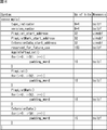
- FIG. 18 is a diagram showing the syntax of ProgramInfo () in FIG.
- “Number_of_program_sequences” indicates the number of program sequences described in ProgramInfo ().
- the program sequence is composed of a sequence of source packets constituting the program.
- SPN_program_sequence_start [i] indicates the number of the source packet at the beginning of the program sequence (source packet number).
- StreamCodingInfo includes information related to encoding of the AV stream constituting the Clip.
- FIG. 19 is a diagram showing the syntax of StreamCodingInfo in FIG.
- Stream_coding_type indicates the encoding method of elementary stream included in the AV stream. For example, in StreamCodingInfo of Clip
- Video_format indicates a video scanning method.
- a value indicating a 4K scanning method such as 2160p (2160 line progressive) is set as the stream_coding_type.
- “Frame_rate” indicates the frame rate of the video stream.
- Aspect_ratio indicates the aspect ratio of the video.
- Cc_flag is a 1-bit flag and indicates whether or not closed caption data is included in the video stream.
- Mode_flag is a 1-bit flag indicating the recording mode of the HEVC stream.
- the flag indicating whether or not the HEVC stream included in the AV stream to be played back using the Clip Information is a stream in which the master is an HDR video, and the recording mode of the HEVC stream are set.
- a flag to indicate is included.
- the playback device 2 can identify whether the master video is an HDR video or the like without actually analyzing the HEVC stream by referring to the flag included in Clip Information.
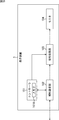
- FIG. 20 is a block diagram illustrating a configuration example of the recording apparatus 1.
- the recording apparatus 1 includes a controller 21, an encoding processing unit 22, and a disk drive 23.
- the master HDR video is input to the encoding processing unit 22.
- the controller 21 includes a CPU (Central Processing Unit), ROM (Read Only Memory), RAM (Random Access Memory), and the like.
- the controller 21 executes a predetermined program and controls the overall operation of the recording apparatus 1.
- a Data Base information generation unit 21A is realized by executing a predetermined program.
- the Data Base information generation unit 21 ⁇ / b> A generates a PlayList and Clip Information that are Data Base information, and outputs them to the disk drive 23.
- the encoding processing unit 22 encodes the master HDR video.
- the encoding processing unit 22 outputs the HEVC stream obtained by encoding the master HDR video to the disk drive 23.
- the disk drive 23 records the file storing the PlayList, Clip Information supplied from the controller 21 and the HEVC stream supplied from the encoding processing unit 22 on the optical disk 11 according to the directory structure of FIG.
- FIG. 21 is a block diagram illustrating a configuration example of the encoding processing unit 22 in FIG.
- the encoding processing unit 22 includes an HDR information generation unit 31, an HEVC encoder 32, an HDR-STD conversion unit 33, a definition information generation unit 34, and an HEVC stream generation unit 35.
- the HDR information generation unit 31 detects the luminance of the input master HDR video, and generates HDR information including each piece of information described with reference to FIG.
- the HDR information generation unit 31 outputs the generated HDR information to the HEVC stream generation unit 35.
- the HEVC encoder 32 When the recording mode is mode-i, the HEVC encoder 32 encodes the input master HDR video with HEVC. In addition, when the recording mode is mode-ii, the HEVC encoder 32 encodes the STD video supplied from the HDR-STD conversion unit 33 with HEVC. The HEVC encoder 32 outputs the encoded data of the HDR video or the encoded data of the STD video to the HEVC stream generation unit 35.
- the HDR-STD conversion unit 33 converts the input master HDR video into STD video.
- the conversion by the HDR-STD conversion unit 33 is appropriately performed according to the conversion parameter input by the author.
- the HDR-STD conversion unit 33 outputs to the definition information generation unit 34 information indicating a correspondence relationship between input data and output data, where the HDR video RGB signal is input data and the STD video RGB signal is output data.
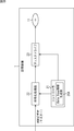
- FIG. 22 is a diagram illustrating an example of signal processing by the HDR-STD conversion unit 33.
- the HDR-STD conversion unit 33 converts the input YCRCb signal of the master HDR video into an RGB signal, and converts each RGB signal of the STD video to each RGB signal. Convert to (tone mapping).
- the HDR-STD conversion unit 33 outputs to the definition information generation unit 34 information indicating the correspondence between the RGB signal of the HDR video as input data and the RGB signal of the STD video as output data.
- the information output to the definition information generation unit 34 is used to generate tone mapping definition information as indicated by the tip of arrow # 202.
- the HDR-STD conversion unit 33 converts the RGB signal of the STD video into a YCrCb signal and outputs it as indicated by the tip of arrow # 203.
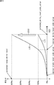
- FIG. 23 is a diagram illustrating an example of tone mapping.
- the HDR video RGB signal is converted into an STD video RGB signal by compressing a high luminance component and expanding a middle / low frequency luminance component.
- Information indicating a function F that associates the RGB signal of the HDR video and the RGB signal of the STD video as illustrated in FIG. 23 is generated by the definition information generation unit 34.
- the HDR-STD conversion unit 33 outputs the STD video obtained by converting the HDR video to the HEVC encoder 32 when the recording mode is mode-ii.
- the definition information generation unit 34 generates tone-mapping definition information for HDR-STD conversion based on the information supplied from the HDR-STD conversion unit 33.
- tone_map_model_id 0
- tone_map_model_id 2
- the definition information generation unit 34 generates Tone mapping information including start_of_coded_interval [i] in FIG. 10 as tone mapping definition information for HDR-STD conversion.
- tone_map_model_id 3
- the definition information generation unit 34 converts Tone mapping information including the number of coded_pivot_value [i] and target_pivot_value [i] specified by num_pivots in FIG. 11 to tone mapping for HDR-STD conversion. Generate as definition information.
- the HEVC stream generation unit 35 sets the tone_map_id of Tone mapping information including the HDR information supplied from the HDR information generation unit 31 and tone_map_id of the tone mapping information including the tone mapping definition information supplied from the definition information generation unit 34 to the recording mode. Set the same value accordingly. Also, the HEVC stream generation unit 35 inserts Tone mapping information including HDR information and Tone mapping information including tone mapping definition information into the encoded data as SEI, and generates an HEVC stream. The HEVC stream generation unit 35 outputs the generated HEVC stream to the disk drive 23.
- FIG. 24 is a block diagram illustrating a configuration example of the playback device 2.
- the playback device 2 includes a controller 51, a disk drive 52, a memory 53, a local storage 54, a network interface 55, a decryption processing unit 56, an operation input unit 57, and an HDMI communication unit 58.
- the controller 51 includes a CPU, a ROM, a RAM, and the like.
- the controller 51 executes a predetermined program and controls the overall operation of the playback device 2.
- the disk drive 52 reads data from the optical disk 11 and outputs the read data to the controller 51, the memory 53, or the decryption processing unit 56.
- the disk drive 52 outputs Data Base information read from the optical disk 11 to the controller 51 and outputs the HEVC stream to the decoding processing unit 56.
- the memory 53 stores data necessary for the controller 51 to execute various processes.
- a register 53A which is a PSR (Player Status Register) is formed.
- the register 53A stores various types of information that the playback device 2 that is a BD player refers to when the optical disc 11 is played back.
- the local storage 54 is composed of, for example, an HDD (Hard Disk Drive). In the local storage 54, a stream downloaded from the server is recorded.
- HDD Hard Disk Drive
- the network interface 55 communicates with a server via a network such as the Internet, and supplies data downloaded from the server to the local storage 54.
- the decoding processing unit 56 decodes the HEVC stream supplied from the disk drive 52, and outputs HDR video or STD video data to the HDMI communication unit 58. When outputting the HDR video, the decoding processing unit 56 outputs the HDR information together with the HDR video data to the HDMI communication unit 58.
- the operation input unit 57 includes input devices such as buttons, keys, and a touch panel, and a receiving unit that receives signals such as infrared rays transmitted from a predetermined remote commander.
- the operation input unit 57 detects a user operation and supplies a signal representing the content of the detected operation to the controller 51.
- the HDMI communication unit 58 communicates with the display device 3 via the HDMI cable 4. For example, the HDMI communication unit 58 acquires information regarding the performance of the monitor included in the display device 3 and outputs the information to the controller 51. Further, the HDMI communication unit 58 outputs the HDR video or STD video data supplied from the decoding processing unit 56 to the display device 3.
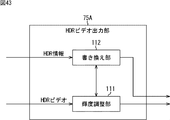
- FIG. 25 is a block diagram illustrating a configuration example of the decoding processing unit 56 of FIG.
- the decoding processing unit 56 includes a parameter extraction unit 71, an HEVC decoder 72, an HDR-STD conversion unit 73, an STD-HDR conversion unit 74, and an output unit 75.
- the output unit 75 includes an HDR video output unit 75A and an STD video output unit 75B.
- the HEVC stream read by the disk drive 52 is input to the parameter extraction unit 71.
- the decoding processing unit 56 for example, the information indicating the recording mode specified by mode_flag included in ClipCInformation and the performance of the monitor included in the display device 3 specified by information acquired from the display device 3. Information is supplied from the controller 51.
- the parameter extraction unit 71 extracts the HDR information and tone mapping definition information from the SEI of the HEVC stream. For example, when the recording mode is mode-i and the HDR video is output to the display device 3, the parameter extraction unit 71 outputs the HDR information to the HDR video output unit 75A. Further, when the recording mode is mode-i and the STD video is output to the display device 3, the parameter extraction unit 71 outputs tone-mapping definition information for HDR-STD conversion to the HDR-STD conversion unit 73.
- the parameter extraction unit 71 outputs the HDR information to the HDR video output unit 75A and defines the tone mapping definition for STD-HDR conversion. Information is output to the STD-HDR converter 74.
- the recording mode is mode-ii and STD video is output to the display device 3
- the extracted HDR information and tone mapping definition information are not used.
- the parameter extraction unit 71 outputs the encoded data included in the HEVC stream to the HEVC decoder 72.
- the HEVC decoder 72 decodes the HEVC encoded data supplied from the parameter extraction unit 71.
- the HEVC decoder 72 outputs the HDR video obtained by decoding to the HDR-STD conversion unit 73 and the HDR video output unit 75A.
- the HEVC decoder 72 outputs the STD video obtained by decoding to the STD-HDR conversion unit 74 and the STD video output unit 75B.
- the HDR-STD conversion unit 73 converts the HDR video supplied from the HEVC decoder 72 into STD video based on tone-mapping definition information for HDR-STD conversion supplied from the parameter extraction unit 71.
- the HDR-STD conversion unit 73 outputs the STD video obtained by the conversion to the STD video output unit 75B.
- the STD-HDR conversion unit 74 converts the STD video supplied from the HEVC decoder 72 into an HDR video based on the tone map mapping definition information for STD-HDR conversion supplied from the parameter extraction unit 71.
- the STD-HDR conversion unit 74 outputs the HDR video obtained by the conversion to the HDR video output unit 75A.
- the HDR video output unit 75A of the output unit 75 When the HDR video output unit 75A of the output unit 75 outputs the HDR video to the display device 3, the HDR video output from the HEVC decoder 72 or the HDR video supplied from the STD-HDR conversion unit 74 71 together with the HDR information supplied from 71.
- the STD video output unit 75B outputs the STD video supplied from the HEVC decoder 72 or the STD video supplied from the HDR-STD conversion unit 73 when outputting the STD video to the display device 3.
- the data output from the HDR video output unit 75A and the STD video output unit 75B is transmitted to the display device 3 by the HDMI communication unit 58.
- FIG. 26 is a block diagram illustrating a configuration example of the display device 3.
- the display device 3 includes a controller 101, an HDMI communication unit 102, a signal processing unit 103, and a monitor 104.
- the controller 101 has a memory 101A.
- the controller 101 includes a CPU, a ROM, a RAM, and the like.
- the controller 101 executes a predetermined program and controls the overall operation of the display device 3.
- the controller 101 stores and manages EDID (Extended display identification data) representing the performance of the monitor 104 in the memory 101A.
- EDID Extended display identification data
- the controller 101 outputs the EDID stored in the memory 101 ⁇ / b> A to the HDMI communication unit 102 and causes the playback apparatus 2 to transmit the EDID.
- the playback device 2 specifies the performance of the monitor 104 of the display device 3.
- the HDMI communication unit 102 communicates with the playback device 2 via the HDMI cable 4.
- the HDMI communication unit 102 receives the video data transmitted from the playback device 2 and outputs it to the signal processing unit 103. Further, the HDMI communication unit 102 transmits the EDID supplied from the controller 101 to the playback device 2.
- the signal processing unit 103 processes the video data supplied from the HDMI communication unit 102 and displays the video on the monitor 104.
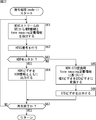
- step S1 the controller 21 of the recording apparatus 1 determines whether or not the recording mode is mode-i.
- the recording mode is set by the author, for example.
- step S2 If it is determined in step S1 that the recording mode is mode-i, in step S2, the encoding processing unit 22 performs an encoding process in mode-i.
- the HEVC stream generated by the encoding process in mode-i is supplied to the disk drive 23.
- step S1 when it is determined in step S1 that the recording mode is mode-ii, the encoding processing unit 22 performs the encoding process in mode-ii in step S3.
- the HEVC stream generated by the encoding process in mode-ii is supplied to the disk drive 23.
- step S4 the Data Base information generation unit 21A performs Data Base information generation processing.
- the PlayList file and Clip Information file generated by the Data Base information generation process are supplied to the disk drive 23.
- step S5 the disc drive 23 records the PlayList file, Clip Information file, and stream file storing the HEVC stream on the optical disc 11. Thereafter, the process is terminated.
- step S11 the HDR information generating unit 31 of the encoding processing unit 22 detects the luminance of the master HDR video and generates HDR information.
- step S12 the HEVC encoder 32 performs encoding by HEVC on the master HDR video, and generates encoded data of the HDR video.
- step S13 the HDR-STD conversion unit 33 converts the input master HDR video into STD video.
- Information indicating the correspondence between input data and output data in which the RGB signal of the HDR video is input data and the RGB signal of the STD video is output ⁇ ⁇ ⁇ data is supplied to the definition information generation unit 34.
- step S14 the definition information generation unit 34 generates tone-mapping definition information for HDR-STD conversion based on the information supplied from the HDR-STD conversion unit 33.
- step S15 the HEVC stream generation unit 35 sets tone_map_id of Tone mapping information including the HDR information generated by the HDR information generation unit 31 and tone mapping information including the tone mapping definition information generated by the definition information generation unit 34. Set the ID for mode-i. Moreover, the HEVC stream generation unit 35 inserts Tone mapping information including HDR information and Tone mapping information including tone mapping definition information into the encoded data, and generates an HEVC stream. Thereafter, the process returns to step S2 in FIG. 27, and the subsequent processing is performed.
- step S21 the HDR information generating unit 31 of the encoding processing unit 22 detects the luminance of the master HDR video and generates HDR information.
- step S22 the HDR-STD conversion unit 33 converts the input master HDR video into STD video.
- Information indicating the correspondence between input data and output data in which the RGB signal of HDR video is input data and the RGB signal of STD video is output data is supplied to the definition information generation unit 34.
- step S23 the definition information generation unit 34 generates tone mapping definition information for STD-HDR conversion based on the information supplied from the HDR-STD conversion unit 33.
- step S24 the HEVC encoder 32 performs encoding by HEVC on the STD video obtained by converting the master HDR video, and generates encoded data of the STD video.
- step S25 the HEVC stream generating unit 35 sets tone_map_id of Tone mapping information including the HDR information generated by the HDR information generating unit 31 and tone mapping information including the tone mapping definition information generated by the definition information generating unit 34. Set the ID for mode-ii. Moreover, the HEVC stream generation unit 35 inserts Tone mapping information including HDR information and Tone mapping information including tone mapping definition information into the encoded data, and generates an HEVC stream. Thereafter, the process returns to step S3 in FIG. 27, and the subsequent processing is performed.
- step S31 the Data Base information generation unit 21A of the controller 21 generates a PlayList including each piece of information described with reference to FIG.
- the PlayList generated by the Data Base information generation unit 21A includes information related to PlayItem that specifies the HEVC stream as a playback section.
- step S32 the Data Base information generation unit 21A generates Clip Information including HDR_flag and mode_flag in StreamCodingInfo of ProgramInfo ().
- the Data Base information generation unit 21 ⁇ / b> A sets 1 as a value indicating the HDR_flag.
- Data Base information generation unit 21A is a value indicating that the recording mode is mode-i as the value of mode_flag. 1 is set.
- the Data Base information generation unit 21A is a value indicating that the recording mode is mode-ii as the value of mode_flag when the encoding process in mode-ii is performed in step S3 of FIG. Set to 0. Thereafter, the process returns to step S4 in FIG. 27, and the subsequent processing is performed.
- the HEVC stream and Data Base information generated by the above processing are recorded on the optical disc 11.
- the controller 51 of the reproduction device 2 controls the HDMI communication unit 58 to communicate with the display device 3 and reads the EDID from the memory 101A of the display device 3.
- the controller 51 stores and manages information indicating the performance of the monitor included in the display device 3 in the register 53A.
- step S41 the controller 51 controls the disc drive 52 to read out the PlayList and ClipCInformation that are Data Base information from the optical disc 11. Further, the controller 51 identifies the HEVC stream to be reproduced based on the information included in the PlayList, and reads the AV stream including the identified HEVC stream from the optical disc 11 by controlling the disc drive 52.
- step S42 the controller 51 refers to HDR_flag and mode_flag included in Clip ⁇ Information.
- the HDR_flag is set to a value indicating that recording using the HDR as the master is being performed. Thereby, the state of the playback device 2 becomes a state of playing back the HDR video or the STD video obtained by converting the HDR video.
- step S43 the controller 51 determines whether or not the recording mode is mode-i based on the value of mode_flag.
- step S44 the decoding processing unit 56 performs a decoding process in mode-i.
- step S45 the decoding processing unit 56 performs decoding processing in mode-ii.
- step S44 or step S45 the process ends.
- the determination whether the recording mode is mode-i is made based on the value of mode_flag, but it seems to be made based on tone_map_id of Tone mapping information inserted in the HEVC stream It may be.
- step S61 the parameter extraction unit 71 of the decoding processing unit 56 extracts HDR information and tone mapping definition information from the SEI of the HEVC stream.
- the parameter extraction unit 71 outputs the HEVC encoded data included in the HEVC stream to the HEVC decoder 72.
- step S62 the HEVC decoder 72 decodes the HEVC encoded data, and outputs the HDR video obtained by the decoding to the HDR-STD conversion unit 73 and the HDR video output unit 75A.
- step S63 the controller 51 determines whether the monitor of the display device 3 is an HDR monitor based on the information stored in the register 53A.
- the register 53A stores information related to the performance of the monitor included in the display device 3 based on the HDMI EDID read from the display device 3.
- the HDR video output unit 75A receives the HDR video supplied from the HEVC decoder 72 from the parameter extraction unit 71 in step S64. Output with HDR information.
- step S65 the HDR-STD conversion unit 73 converts the HDR video supplied from the HEVC decoder 72, Based on tone-mapping definition information for HDR-STD conversion supplied from the parameter extraction unit 71, the video is converted into STD video.
- step S66 the STD video output unit 75B outputs the STD video obtained by the conversion by the HDR-STD conversion unit 73.
- step S67 the controller 51 determines whether or not the reproduction is finished.
- step S67 If it is determined in step S67 that the reproduction has not ended, the controller 51 returns to step S61 and repeats the above processing. If it is determined in step S67 that the reproduction has ended, the process returns to step S44 in FIG. 31, and the subsequent processing is performed.
- step S81 the parameter extraction unit 71 of the decoding processing unit 56 extracts the HDR information and tone mapping definition information from the SEI of the HEVC stream.
- the parameter extraction unit 71 outputs HEVC encoded data included in the HEVC stream to the HEVC decoder 72.
- step S82 the HEVC decoder 72 decodes the HEVC encoded data, and outputs the STD video obtained by the decoding to the STD-HDR conversion unit 74 and the STD video output unit 75B.
- step S83 the controller 51 determines whether or not the monitor included in the display device 3 is an HDR monitor based on the information stored in the register 53A.
- the STD-HDR conversion unit 74 is supplied with the STD video supplied from the HEVC decoder 72 from the parameter extraction unit 71 in step S84. Based on tone mapping definition information for STD-HDR conversion, it is converted to HDR video.
- step S85 the HDR video output unit 75A outputs the HDR video obtained by the conversion by the STD-HDR conversion unit 74 together with the HDR information supplied from the parameter extraction unit 71.
- step S83 if it is determined in step S83 that the monitor included in the display device 3 is an STD monitor, the STD video output unit 75B outputs the STD video supplied from the HEVC decoder 72 in step S86.
- step S87 the controller 51 determines whether or not the reproduction is finished.
- step S87 If it is determined in step S87 that the reproduction has not ended, the controller 51 returns to step S81 and repeats the above processing. If it is determined in step S87 that the reproduction has ended, the process returns to step S45 in FIG. 31, and the subsequent processing is performed.
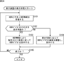
- the monitor 104 included in the display device 3 is an HDR monitor will be described.
- the HDR video to which the HDR information is added is transmitted from the playback device 2.
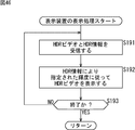
- step S101 the HDMI communication unit 102 of the display device 3 receives the HDR video and the HDR information transmitted from the playback device 2.
- step S102 the controller 101 refers to the HDR information and determines whether the HDR video transmitted from the playback device 2 can be displayed as it is.
- the HDR information includes information indicating the luminance characteristics of the master HDR video, that is, the HDR video transmitted from the playback device 2.
- the determination in step S102 is performed by comparing the brightness characteristics of the HDR video specified by the HDR information with the display performance of the monitor 104.
- the dynamic range of the HDR video specified by the HDR information is 0-400%
- the dynamic range of the monitor 104 is 0-500% (for example, if the brightness of 100% is 100 cd / m 2 , 500 cd / m 2 ) If it is, it is determined that the HDR video can be displayed as it is.
- the dynamic range of the HDR video specified by the HDR information is 0-400% and the dynamic range of the monitor 104 is 0-300%, it is determined that the HDR video cannot be displayed as it is.
- step S103 the signal processing unit 103 displays the video of the HDR video on the monitor 104 according to the luminance specified by the HDR information. For example, when the luminance characteristic indicated by the curve L12 in FIG. 12 is specified by the HDR information, each pixel value represents the brightness in the range of 0 to 400% indicated by the curve L12.
- step S104 the signal processing unit 103 adjusts the luminance according to the display performance of the monitor 104, and the HDR video with the adjusted luminance is displayed.
- Display video For example, when the luminance characteristic indicated by the curve L12 in FIG. 12 is specified by the HDR information and the dynamic range of the monitor 104 is 0-300%, each pixel value represents the brightness in the range of 0-300%. So that it is compressed.
- step S105 the controller 101 determines whether or not to end the display. If it is determined that the display is not to be ended, the processing from step S101 is repeated. . If it is determined in step S105 that the display is to be ended, the controller 101 ends the process.
- the recording apparatus 1 can record the master HDR video on the optical disc 11 as the HDR video, and cause the playback apparatus 2 to play back the HDR video image on the display apparatus 3.
- the recording device 1 can convert the master HDR video into the STD video, record it on the optical disc 11, restore the HDR video to the playback device 2, and display the HDR video on the display device 3.
- the content author can display the HDR video image at the intended brightness. It becomes possible.
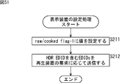
- HDR_flag and mode_flag are stored in Clip Information, but may be stored in PlayList.
- FIG. 35 is a diagram illustrating an example of the syntax of AppInfoPlayList () included in the PlayList file in FIG.
- AppInfoPlayList stores parameters relating to playback control of the PlayList, such as playback restrictions.
- HDR_flag and mode_flag are described following MVC_Base_view_R_flag.
- HDR_flag and mode_flag can be described in AppInfoPlayList () of the PlayList file.
- FIG. 36 is a diagram illustrating the syntax of PlayList () included in the PlayList file of FIG.
- “Number_of_PlayItems” indicates the number of PlayItems in the PlayList. In the example of FIG. 14, the number of PlayItems is 3. The value of PlayItem_id is assigned from 0 in the order in which PlayItem () appears in the PlayList.
- “Number_of_SubPaths” indicates the number of Sub-Paths in the PlayList.
- the number of Sub-Paths is 3.
- the value of SubPath_id is assigned from 0 in the order in which SubPath () appears in the PlayList.
- PlayList describes PlayItem () for the number of PlayItems, and SubPath () for the number of Sub-Paths.
- FIG. 37 shows the syntax of PlayItem () in FIG.
- Clip_Information_file_name [0] represents the name of the Clip Information file of the Clip referred to by PlayItem.
- Clip_codec_identifier [0] represents the codec system of Clip.
- IN_time represents the start position of the PlayItem playback section
- OUT_time represents the end position.
- UO_mask_table (), PlayItem_random_access_mode, and still_mode are included.
- STN_table includes AV stream information referenced by PlayItem.
- AV stream information referenced by PlayItem When there is a Sub-Path that is played in association with a PlayItem, information on the AV stream that is referenced by the SubPlayItem that constitutes the Sub-Path is also included.
- FIG. 38 is a diagram illustrating the syntax of STN_table () in FIG.
- Number_of_video_stream_entries represents the number of video streams entered (registered) in STN_table ().
- number_of_audio_stream_entries represents the number of streams of the 1st audio stream entered in STN_table ().
- number_of_audio_stream2_entries represents the number of streams of the 2nd audio stream entered in STN_table ().
- “Number_of_PG_textST_stream_entries” represents the number of PG_textST streams entered in STN_table ().
- the PG_textST stream is a PG (Presentation Graphics) stream and a text subtitle file (textST) obtained by run-length encoding a bitmap subtitle.
- number_of_IG_stream_entries represents the number of IG (Interactive Graphics) streams entered in STN_table ().
- STN_table describes stream_entry () and stream_attributes () which are information of each video stream, 1st audio stream, 2nd audio stream, PG_textST stream, and IG stream.
- stream_entry () includes the PID of the stream
- stream_attributes () includes the attribute information of the stream.
- FIG. 39 is a diagram illustrating an example of a description relating to a video stream in the description of the stream_attributes () in FIG.
- stream_coding_type indicates the video stream encoding method
- video_format indicates the video format
- frame_rate indicates the frame rate of the video.
- HDR_flag and mode_flag can be described at positions in the PlayList file other than AppInfoPlayList () and STN_table ().
- HDR_flag and mode_flag can be described at positions in the Clip Information file other than StreamCodingInfo described with reference to FIG.
- HDR_flag and mode_flag are arbitrary, such that one of HDR_flag and mode_flag is described in the Clip Information file and the other is described in the PlayList file.
- FIG. 40 is a diagram illustrating an example of PSR allocation.
- the register 53A of the playback device 2 is used as a PSR.
- PSR number is assigned to PSR, and the usage of each PSR is defined.
- the HDR_capability_flag is stored in PSR29, which is PSR with PSR number of 29. For example, the value of HDR_capability_flag of PSR29 being 1 indicates that the playback device 2 supports playback of HDR video. Further, the value of HDR_capability_flag of PSR29 being 0 indicates that the playback device 2 does not support playback of HDR video.
- the HDR_capability_flag is referred to by the controller 51 that executes the disc navigation program when an optical disc in which the HDR_flag value of Clip Information is set to 1, that is, an optical disc that has been recorded with HDR as the master is inserted.
- 0 is set as the value of HDR_capability_flag, a message requesting to connect a display device that supports HDR video processing to the playback device 2 is displayed.
- PSR25 which is a PSR with a PSR number of 25, is used as a PSR that records information indicating the HDR video compatibility status of the connected monitor.
- information indicating the performance of the monitor included in the display device 3 indicated by the EDID acquired from the display device 3 is stored in the PSR 25.
- HDR_display_capability_flag and information indicating the luminance specification are stored in the PSR25 for HDR ⁇ Capability usage.
- a value of HDR_display_capability_flag of 1 indicates that the connected monitor can display HDR video.
- the value of HDR_display_capability_flag being 0 indicates that the connected monitor cannot display the HDR video.
- information indicating the luminance specification for example, information indicating how much brightness can be displayed is stored.
- PSR25 As an HDR Display Capability application, information indicating HDR_display_capability_flag and luminance specification may be stored in PSR23, which is a PSR for Display Capability application.
- Example of adjusting brightness on playback device> when the HDR video transmitted from the playback device 2 cannot be displayed as it is, the display device 3 adjusts the brightness by itself, but the playback device 2 adjusts the brightness of the HDR video. You may do it.
- the display device 3 receives the HDR video whose luminance has been adjusted by the playback device 2 and displays the HDR video image.
- FIG. 41 is a diagram illustrating an example of signal processing in mode-i when adjustment of the brightness of the HDR video is performed by the playback device 2.
- the processing performed by the recording device 1 and the processing related to STD video output performed by the playback device 2 are the same as the processing described with reference to FIG. The overlapping description will be omitted as appropriate. It is assumed that the register 53A of the playback device 2 stores the above-described HDR_display_capability_flag and information indicating the luminance specification.
- the playback device 2 reads the HEVC stream from the optical disc 11, and extracts the HDR information and tone mapping definition information from the SEI of the HEVC stream as indicated by arrows # 21 and # 22.
- the playback device 2 decodes the HEVC encoded data as indicated by the tip of arrow # 23.
- the playback device 2 has the HDR obtained by decoding the encoded data as indicated by the tip of arrow # 301. Adjust the video brightness.
- the dynamic range of the HDR video indicated by the HDR information is 0-400%, and the information indicating the luminance specification stored in the register 53A indicates that the dynamic range of the monitor 104 is 0-300%. If so, the playback device 2 adjusts the brightness. In this case, the brightness of each pixel value is compressed to a range of 0-300%.
- the playback device 2 When adjusting the brightness of the HDR video, the playback device 2 rewrites the HDR information as indicated by the tip of arrow # 302.
- the rewritten HDR information is information indicating the luminance characteristics of the HDR video after luminance adjustment.
- the playback device 2 adds the HDR information to the HDR video data after the brightness adjustment, and outputs it to the display device 3 as indicated by the tip of arrow # 304.
- FIG. 42 is a diagram illustrating an example of signal processing in mode-ii when adjustment of the brightness of the HDR video is performed by the playback device 2.
- the processing performed by the recording device 1 and the processing related to STD video output performed by the playback device 2 are the same as the processing described with reference to FIG. The overlapping description will be omitted as appropriate.
- the playback device 2 reads out the HEVC stream from the optical disc 11, and extracts the HDR information and tone mapping definition information from the SEI of the HEVC stream as indicated by arrows # 101 and # 102.
- the playback device 2 decodes the HEVC encoded data as indicated by the tip of arrow # 103.
- the playback device 2 decodes the encoded data using tone mapping definition information for STD-HDR conversion extracted from the HEVC stream, as indicated by the tip of arrow # 105.
- the STD video obtained in this way is converted to HDR video.
- the playback device 2 adjusts the brightness of the HDR video as indicated by the tip of the arrow # 311 and the arrow # 312. As described above, the HDR information is rewritten.
- the playback device 2 adds the HDR information to the HDR video data after brightness adjustment, and outputs the HDR information to the display device 3 as indicated by the tip of arrow # 314.
- the HDR information is rewritten so as to represent the adjusted luminance characteristics, and transmitted to the display device 3 together with the HDR video data.
- the display device 3 recognizes that the HDR video is transmitted based on the HDR information, and can display the video of the HDR video on the monitor 104 according to the luminance specified by the rewritten HDR information.
- FIG. 43 is a block diagram illustrating a configuration example of the HDR video output unit 75A of FIG.
- the HDR video output unit 75A includes a luminance adjustment unit 111 and a rewrite unit 112.
- the HDR video supplied from the HEVC decoder 72 or from the STD-HDR conversion unit 74 is input to the luminance adjustment unit 111.
- the HDR information supplied from the parameter extraction unit 71 is input to the rewriting unit 112.
- the brightness adjustment unit 111 adjusts the brightness of the HDR video and outputs the HDR video after brightness adjustment.
- the rewriting unit 112 rewrites the HDR information based on the adjustment result by the luminance adjusting unit 111 so as to represent the adjusted luminance characteristics.
- the rewritten HDR information is added to the brightness-adjusted HDR video and transmitted to the display device 3.
- steps S151 through S153 and S158 through S160 are the same as the processes in steps S61 through S63 and S65 through S67 in FIG. 32, respectively.
- the overlapping description will be omitted as appropriate.
- step S151 the parameter extraction unit 71 of the decoding processing unit 56 extracts HDR information and tone mapping definition information from the SEI of the HEVC stream.
- step S152 the HEVC decoder 72 decodes the HEVC encoded data, and outputs the HDR video obtained by the decoding.
- step S153 the controller 51 determines whether or not the monitor included in the display device 3 is an HDR monitor.
- step S154 the controller 51 determines whether or not the HDR video can be displayed as it is on the monitor 104 of the display device 3.
- the luminance adjustment unit 111 of the HDR video output unit 75A determines the luminance of the HDR video decoded by the HEVC decoder 72 in step S155. Adjust according to.
- step S156 the rewriting unit 112 rewrites the HDR information based on the brightness adjustment result.
- step S157 the HDR video output unit 75A outputs the HDR video after brightness adjustment together with the HDR information after rewriting.
- step S154 If it is determined in step S154 that the HDR video can be displayed as it is, the processing in steps S155 and S156 is skipped.
- step S157 the HDR video output unit 75A outputs the HDR video decoded by the HEVC decoder 72 together with the HDR information extracted by the parameter extraction unit 71.
- step S160 it is determined whether or not the reproduction is completed. If it is determined that the reproduction is completed, the process is terminated. Thereafter, the process returns to step S44 in FIG. 31, and the subsequent processing is performed.
- step S45 the decoding process in mode-ii performed in step S45 in FIG. 31 will be described with reference to the flowchart in FIG. In the process of FIG. 45, the brightness of the HDR video is adjusted as appropriate.
- steps S171 to S174, S179, and S180 are the same as the processes in steps S81 to S84, S86, and S87 in FIG. 33, respectively.
- the overlapping description will be omitted as appropriate.
- step S171 the parameter extraction unit 71 of the decoding processing unit 56 extracts the HDR information and tone mapping definition information from the SEI of the HEVC stream.
- step S172 the HEVC decoder 72 decodes the HEVC encoded data and outputs the STD video obtained by decoding.
- step S173 the controller 51 determines whether or not the monitor included in the display device 3 is an HDR monitor.
- step S174 the STD-HDR conversion unit 74 converts the decoded STD video into tone mapping definition information for STD-HDR conversion. Convert to HDR video based on
- step S175 the controller 51 determines whether or not the HDR video obtained by converting the STD video can be displayed as it is on the monitor 104 of the display device 3.
- step S176 the luminance adjusting unit 111 of the HDR video output unit 75A monitors the luminance of the HDR video obtained by converting the STD video. Adjust according to the display performance.
- step S177 the rewriting unit 112 rewrites the HDR information based on the brightness adjustment result.
- step S178 the HDR video output unit 75A outputs the HDR video after brightness adjustment together with the HDR information after rewriting.
- step S175 If it is determined in step S175 that the HDR video can be displayed as it is, the processing in steps S176 and S177 is skipped.
- step S178 the HDR video output unit 75A outputs the HDR video obtained by converting the STD video together with the HDR information extracted by the parameter extraction unit 71.
- step S180 it is determined whether or not the reproduction is completed. If it is determined that the reproduction is completed, the process is terminated. Thereafter, the process returns to step S45 in FIG. 31, and the subsequent processing is performed.
- the processing in FIG. 46 is performed after the processing in FIG. 44 or 45 by the playback device 2.
- the original HDR video that has not been subjected to luminance adjustment or the HDR video that has undergone luminance adjustment is transmitted from the reproduction device 2.
- step S191 the HDMI communication unit 102 of the display device 3 receives the HDR video and the HDR information transmitted from the playback device 2.
- step S192 the signal processing unit 103 displays the HDR video image on the monitor 104 in accordance with the luminance specified by the HDR information.
- step S193 the controller 101 determines whether or not to end the display. If it is determined not to end the display, the controller 101 repeats the processes in and after step S191. When it is determined in step S193 that the display is to be ended, the controller 101 ends the process.
- the display device 3 does not need to determine whether or not the HDR video transmitted from the playback device 2 can be displayed as it is. Further, the display device 3 does not need to adjust the brightness of the HDR video by itself.
- the user of the playback device 2 may be able to set whether the brightness is adjusted on the playback device 2 side or the display device 3 side.
- the display device 3 notifies the playback device 2 whether the luminance adjustment is performed on the playback device 2 side or the display device 3 side, and processing performed in the playback device 2 is switched in response to the notification. You may be made to do. For example, when the display device 3 has an HDR video brightness adjustment function, it is notified that the brightness adjustment is performed on the display device 3 side, and when the display device 3 does not have an HDR video brightness adjustment function, Is notified on the playback device 2 side.
- the playback device 2 When it is notified from the display device 3 that the luminance adjustment is to be performed on the playback device 2 side, the playback device 2 performs the process of FIG. 44 or FIG. 45 as the decoding process. Further, when the display device 3 notifies that the brightness adjustment is to be performed on the display device 3 side, the playback device 2 performs the process of FIG. 32 or FIG. 33 as the decoding process.
- the brightness adjustment performed by the playback device 2 and the brightness adjustment performed by the display device 3 may differ in parameters used for the adjustment. In this case, it may be desirable from the viewpoint of image quality that the display device 3 that has the monitor 104 and can perform adjustment more suitable for the characteristics of the monitor 104 adjust the luminance.
- the notification of whether the HDR video brightness adjustment is performed on the playback device 2 side or the display device 3 side can be realized using HDMI EDID.
- FIG. 47 is a diagram illustrating an example of recognition based on information transmitted / received via HDMI.
- the playback device 2 which is a BD player that supports 4K resolution HDR video processing, reads the EDID stored in the memory 101A of the display device 3.
- the memory 101 ⁇ / b> A of the display device 3 a plurality of EDIDs such as EDID representing the performance of the monitor 104 of the display device 3 are stored.
- the playback device 2 is a device having the HDR monitor, and can output HDR video to the display device 3. Recognize.
- HDR EDID contains information related to the output of HDR video. Notification of whether to adjust the brightness of the HDR video on the playback device 2 side or on the display device 3 side is performed using HDR EDID.
- the playback device 2 adds the HDR InfoFrame to the data of each frame of the HDR video output to the display device 3.
- InfoFrame is added to each frame of video.
- the video InfoFrame includes information about video specifications such as information indicating whether the video data is RGB data or YCbCr data, and information indicating the aspect ratio.
- HDR FrameInfoFrame is an InfoFrame that contains information related to HDR video specifications. Transmission of HDR information indicating the luminance characteristics of the HDR video is performed using HDR-InfoFrame.
- the playback device 2 outputs the HDR video data to which the HDR-InfoFrame is added to the display device 3.
- the display device 3 When the HDR InfoFrame is added to the video data transmitted from the playback device 2, the display device 3 recognizes that the video data transmitted from the playback device 2 is HDR video data. Thereafter, the display device 3 displays the HDR video image on the HDR monitor.
- FIG. 48 is a diagram showing another example of recognition based on information transmitted / received via HDMI.
- the playback device 2 recognizes that the display device 3 is a device that does not have an HDR monitor. . In this case, the playback device 2 outputs only STD video data to the display device 3. The HDR-InfoFrame is not added to the STD video data output from the playback apparatus 2.
- the display device 3 uses the STD video as the video data transmitted from the playback device 2. Recognize it as data. Thereafter, the display device 3 displays the video of the STD video on the STD monitor.
- HDMI InfoFrame it is possible to transmit HDR information from the playback device 2 to the display device 3 using an HDMI InfoFrame. Further, it is possible to notify the playback device 2 from the display device 3 whether to adjust the brightness of the HDR video on the playback device 2 side or on the display device 3 side, using HDMI EDID.
- FIG. 49 is a diagram illustrating an example of HDR ⁇ EDID.
- HDR EDID information indicating the maximum luminance of the monitor, information indicating the maximum extension level, and raw / cooked flag-1 are included.
- the raw / cooked flag-1 indicates whether the HDR video is to be output unprocessed or, if necessary, the HDR video brightness is adjusted before output.
- the display device 3 indicates that the HDR video is output raw, that is, the HDR video is output without adjusting the luminance on the playback device 2 side. Indicates that you are requesting.
- the playback device 2 outputs the HDR video without adjusting the luminance even when the dynamic range of the HDR video exceeds the display performance of the monitor 104. .
- 1 is set as the value of raw / cooked flag-1.
- the display device 3 requests that the playback of the HDR video is adjusted on the playback device 2 side if necessary. Represents.
- the playback device 2 adjusts the brightness of the HDR video according to the display performance of the monitor 104 when the dynamic range of the HDR video exceeds the display performance of the monitor 104, Output the adjusted HDR video.
- the display device 3 does not have a function of adjusting the brightness of the HDR video, for example, 0 is set as the value of raw / cooked flag-1.
- the decoding process of FIG. 32 or 33 performed on the display device 3 side without adjusting the luminance on the playback device 2 side corresponds to a process when the value of raw / cooked flag-1 is 1. Also, the decoding process in FIG. 44 or 45 in which the luminance adjustment is performed on the playback device 2 side corresponds to a process in the case where the value of raw / cookedokflag-1 is 0.
- the playback device 2 when the playback device 2 outputs the HDR video without processing as appropriate, it is referred to as raw output.
- the playback apparatus 2 adjusts the brightness of the HDR video when necessary, the output is called cooked output.
- FIG. 50 is a diagram showing an example of HDR InfoFrame.
- the HDR InfoFrame includes HDR information parameters ref_screen_luminance_white, extended_range_white_level, nominal_black_level_code_value, nominal_white_level_code_value, extended_white_level_code_value, and raw / cooked flag-2.
- HDRHInfoFrame includes raw / cooked flag-2.
- the raw / cooked flag-2 represents whether the HDR video to be output is a raw HDR video that has not been subjected to luminance adjustment or an HDR video that has undergone luminance adjustment.
- the value of raw / cooked flag-2 indicates that the output HDR video is a raw HDR video that has not been subjected to brightness adjustment on the playback device 2 side. For example, when the value of raw / cooked flag-1 included in the HDR EDID is 1, the playback device 2 adds an HDR InfoFrame in which 1 is set as the value of raw / cooked flag-2 to the data of the HDR video Output.
- a raw / cooked flag-2 value of 0 indicates that the HDR video to be output is an HDR video after brightness adjustment.
- the playback device 2 adjusts the luminance and performs raw / cooked Set 0 as the value of flag-2.
- the playback device 2 adds the HDR-InfoFrame in which 0 is set as the value of raw / cooked-flag-2 to the HDR video data after the luminance adjustment, and outputs the data.
- a value of 1 is set in raw / cooked flag-2 of the HDR InfoFrame.
- a value of 0 may be set in the raw / cooked flag-2 of the HDR InfoFrame.
- step S211 the controller 101 of the display device 3 sets a value of 1 or 0 to raw / cooked flag-1, information indicating the maximum luminance of the monitor, information indicating the maximum expansion level, and raw / cooked flag-1 Is stored in the memory 101A.
- step S212 the HDMI communication unit 102 reads a plurality of EDIDs including the HDR-EDID from the memory 101A in response to a request from the playback device 2, and transmits the read EDID to the playback device 2.
- FIG. 52 is started after the process of FIG. 51 is performed on the display device 3, for example.
- step S221 the controller 51 controls the disk drive 52 to read PlayList and Clip Information that are Data Base information from the optical disk 11. Further, the controller 51 identifies the HEVC stream to be reproduced based on the information included in the PlayList, and reads the AV stream including the identified HEVC stream from the optical disc 11 by controlling the disc drive 52.
- step S222 the controller 51 refers to HDR_flag and mode_flag included in Clip ⁇ Information.
- the HDR_flag is set to a value indicating that recording using the HDR as the master is being performed.
- step S223 the controller 51 controls the HDMI communication unit 58 and reads the EDID from the display device 3.
- the HDMI communication unit 58 requests the HDMI communication unit 102 of the playback device 2 to read out the EDID, and the HDMI communication unit 58 acquires a plurality of EDIDs transmitted in response to the request.
- step S224 the controller 51 determines whether or not the HDR EDID is included in the EDID read from the display device 3.
- the controller 51 When it is determined in step S224 that the HDR EDID is included, the controller 51 recognizes that it is possible to output the HDR video to the display device 3, and indicates the display performance of the monitor 104 in step S225. Information is stored in the register 53A. For example, the controller 51 causes the PSR 25 to store information indicating the maximum luminance of the monitor and information indicating the maximum expansion level included in the HDR-EDID as information indicating the luminance specification of the monitor. Further, the controller 51 sets a value indicating that the monitor 104 can display the HDR video in the HDR_display_capability_flag of the PSR 25.
- step S226 the controller 51 determines whether a raw output is requested from the display device 3 based on the raw / cooked flag flag-1 included in the HDR EDID. In the case of the above-described example, the controller 51 determines that raw output is requested when the value of raw / cooked flag-1 is 1, and determines that cooked output is requested when the value is 0. judge.
- step S227 the controller 51 performs HDR / raw output processing, which is processing for raw output of HDR video.
- step S226 If it is determined in step S226 that raw output is not requested, in step S228, the controller 51 performs HDR / cooked output processing, which is processing to output the HDR video.
- step S229 the controller 51 performs STD output processing that is processing for outputting STD video.
- the output destination of the STD video by the STD output process is a display device that is different from the display device 3 and does not have an HDR monitor.
- step S241 the parameter extraction unit 71 of the decoding processing unit 56 extracts the HDR information and tone mapping definition information from the SEI of the HEVC stream.
- the parameter extraction unit 71 outputs the HEVC encoded data included in the HEVC stream to the HEVC decoder 72.
- step S242 the HEVC decoder 72 decodes the HEVC encoded data.
- HDR video data obtained by decoding the encoded data is supplied to the HDR video output unit 75A.
- STD video data obtained by decoding the encoded data is supplied to the STD-HDR conversion unit 74.
- step S243 the controller 51 determines whether or not the recording mode is mode-i based on the value of mode_flag.
- step S244 converts the STD video supplied from the HEVC decoder 72 into the STD- supplied from the parameter extraction unit 71. Convert to HDR video based on tone mapping definition information for HDR conversion. If it is determined in step S243 that the recording mode is mode-i, the process in step S244 is skipped.
- step S245 the HDR video output unit 75A sets a value of 1 indicating that the HDR video is an unprocessed HDR video that has not been adjusted in luminance to raw / cooked flag-2. Also, the HDR video output unit 75A generates an HDR InfoFrame including each parameter of the HDR information extracted by the parameter extraction unit 71 and raw / cooked flag-2.
- step S246 the HDR video output unit 75A adds the HDR-InfoFrame to the data of each frame of the HDR video and outputs it to the display device 3.
- step S247 the controller 51 determines whether or not the reproduction has ended. If it is determined that the reproduction has not ended, the controller 51 returns to step S241 and repeats the above processing. If it is determined in step S247 that the reproduction has ended, the process returns to step S227 in FIG. 52, and the subsequent processing is performed.
- step S261 the parameter extraction unit 71 of the decoding processing unit 56 extracts the HDR information and tone mapping definition information from the SEI of the HEVC stream.
- the parameter extraction unit 71 outputs the HEVC encoded data included in the HEVC stream to the HEVC decoder 72.
- step S262 the HEVC decoder 72 decodes the HEVC encoded data.
- HDR video data obtained by decoding the encoded data is supplied to the HDR video output unit 75A.
- STD video data obtained by decoding the encoded data is supplied to the STD-HDR conversion unit 74.
- step S263 the controller 51 determines whether or not the recording mode is mode-i based on the value of mode_flag.
- step S264 When it is determined in step S263 that the recording mode is mode-ii, in step S264, the STD-HDR conversion unit 74 converts the STD video supplied from the HEVC decoder 72 into the STD- supplied from the parameter extraction unit 71. Convert to HDR video based on tone mapping definition information for HDR conversion. If it is determined in step S263 that the recording mode is mode-i, the process of step S264 is skipped.
- step S265 the controller 51 can compare the brightness characteristics of the HDR video indicated by the HDR information with the performance of the monitor 104 indicated by the information included in the HDR-EDID, and display the HDR video on the monitor 104 as it is. It is determined whether or not.
- step S265 If it is determined in step S265 that the HDR video cannot be displayed as it is, the luminance adjustment unit 111 of the HDR video output unit 75A adjusts the luminance of the HDR video according to the display performance of the monitor 104 in step S266.
- step S267 the rewriting unit 112 rewrites the HDR information based on the brightness adjustment result. If it is determined in step S265 that the HDR video can be displayed as it is, the processing in steps S266 and S267 is skipped.
- step S268 the HDR video output unit 75A sets a predetermined value in raw / cooked flag-2 and generates an HDR InfoFrame including each parameter of the HDR information.
- the HDR video output unit 75A sets a value of 1 indicating this to raw / cooked flag-2, raw / cooked flag-2, and parameter extraction unit 71
- An HDR-InfoFrame including each parameter of the HDR information extracted by the above is generated.
- the HDR video output unit 75A sets a value of 0 indicating that to raw / cooked flag-2, and the raw / cooked-2flag-2 and the rewritten HDR information Generate HDR Frame InfoFrame including each parameter.
- step S269 the HDR video output unit 75A adds the HDR-InfoFrame to the data of each frame of the HDR video and outputs it to the display device 3.
- step S270 the controller 51 determines whether or not the reproduction has ended. If it is determined that the reproduction has not ended, the controller 51 returns to step S261 and repeats the above processing. If it is determined in step S270 that the reproduction has ended, the process returns to step S228 in FIG. 52, and the subsequent processing is performed.
- the processing in FIG. 55 is processing for outputting video data to a display device that does not have an HDR monitor, which is different from the display device 3.
- step S281 the parameter extraction unit 71 of the decoding processing unit 56 extracts HDR information and tone mapping definition information from the SEI of the HEVC stream.
- the parameter extraction unit 71 outputs the HEVC encoded data included in the HEVC stream to the HEVC decoder 72.
- step S282 the HEVC decoder 72 decodes the HEVC encoded data.
- the recording mode is mode-i
- the HDR video data obtained by decoding the encoded data is supplied to the HDR-STD conversion unit 73.
- STD video data obtained by decoding the encoded data is supplied to the STD video output unit 75B.
- step S283 the controller 51 determines whether or not the recording mode is mode-i based on the value of mode_flag.
- step S283 When it is determined in step S283 that the recording mode is mode-i, the HDR-STD conversion unit 73 converts the HDR video supplied from the HEVC decoder 72 into the HDR- supplied from the parameter extraction unit 71 in step S284. Converts to STD video based on tone mapping definition information for STD conversion.
- step S284 the process of step S284 is skipped.
- step S285 the STD video output unit 75B outputs the STD video supplied from the HEVC decoder 72 or the STD video data supplied from the HDR-STD conversion unit 73.
- step S286 the controller 51 determines whether or not the reproduction has ended. If it is determined that the reproduction has not ended, the controller 51 returns to step S281 and repeats the above processing. If it is determined in step S286 that the reproduction has ended, the process returns to step S229 in FIG. 52, and the subsequent processing is performed.
- the HDR InfoFrame is added to the video data transmitted from the playback device 2 to the display device 3 having an HDR monitor.
- the controller 101 of the display device 3 recognizes that the video data transmitted from the playback device 2 is HDR video data based on the HDR-InfoFrame.
- step S301 the HDMI communication unit 102 of the display device 3 receives the HDR video data transmitted from the playback device 2.
- HDR InfoFrame is added to the data of each frame of the HDR video.
- step S302 the controller 101 determines whether or not the HDR video data is raw output data, based on the raw / cooked flag-2 included in the HDR InfoFrame.
- the controller 101 determines that the HDR video data is data that has been output raw. If the value of 0 is set in raw / cooked flag-2, the controller 101 determines that the HDR video data is cooked output data.
- step S303 the signal processing unit 103 refers to the HDR information included in the HDR InfoFrame.
- the signal processing unit 103 appropriately adjusts the brightness of the HDR video and causes the monitor 104 to display the HDR video image after the brightness adjustment.
- step S304 the signal processing unit 103 sends the HDR video image to the monitor 104 according to the HDR information included in the HDR-InfoFrame. Display.
- step S305 the controller 101 determines whether or not to end the display of the HDR video. Repeat the process. When it is determined in step S305 that the display is to be ended, the controller 101 ends the process.
- the playback device 2 can transmit the HDR information to the display device 3 using the HDMI InfoFrame. Further, the display device 3 can request whether the brightness of the HDR video is adjusted on the playback device 2 side or the display device 3 side using the HDMI EDID.
- HDR video data is transmitted from the playback device 2 to the display device 3, the HDR information is added and transmitted.
- the HDR video data may be transmitted without adding the HDR information.
- the playback device 2 is a BD player
- the above-described functions of the playback device 2 may be installed in a mobile terminal.
- the portable terminal has a role as the playback device 2.
- the playback device 2 receives the content transmitted from a server connected via a network such as the Internet, plays it, and outputs the HDR video to the display device 3.
- FIG. 57 is a block diagram showing an example of the hardware configuration of a computer that executes the above-described series of processing by a program.
- the CPU 501, the ROM 502, and the RAM 503 are connected to each other by a bus 504.
- An input / output interface 505 is further connected to the bus 504.
- the input / output interface 505 is connected to an input unit 506 including a keyboard and a mouse, and an output unit 507 including a display and a speaker.
- the input / output interface 505 is connected to a storage unit 508 including a hard disk and a non-volatile memory, a communication unit 509 including a network interface, and a drive 510 that drives a removable medium 511.
- the CPU 501 loads the program stored in the storage unit 508 to the RAM 503 via the input / output interface 505 and the bus 504 and executes the program, for example. Is done.
- the program executed by the CPU 501 is recorded on the removable medium 511 or provided via a wired or wireless transmission medium such as a local area network, the Internet, or digital broadcasting, and is installed in the storage unit 508.
- the program executed by the computer may be a program that is processed in time series in the order described in this specification, or in parallel or at a necessary timing such as when a call is made. It may be a program for processing.
- Embodiments of the present technology are not limited to the above-described embodiments, and various modifications can be made without departing from the gist of the present technology.
- the system means a set of a plurality of components (devices, modules (parts), etc.), and it does not matter whether all the components are in the same housing. Accordingly, a plurality of devices housed in separate housings and connected via a network and a single device housing a plurality of modules in one housing are all systems. .
- a read unit that reads out the encoded data, the luminance characteristic information, and the luminance conversion definition information from a recording medium that records luminance conversion definition information used when performing luminance conversion to the standard video.
- the extended video data and the luminance characteristic information are output to a display device that can display the extended video, and the standard video data is output to a display device that cannot display the extended video.
- a playback device comprising: an output unit.
- the luminance conversion definition information is first Tone mapping information in which any value of 0, 2, and 3 is set as a value of tone_map_model_id,
- the reproduction apparatus according to (3), wherein the luminance characteristic information is second Tone mapping information in which 4 is set as a value of tone_map_model_id.
- the recording medium further includes information related to reproduction of the encoded data, including a flag indicating whether or not recording with the extended video as a master is performed,
- the decoding unit according to any one of (1) to (5), wherein the encoded data is decoded when the flag indicates that the recording using the extended video as a master is performed. Playback device.
- the recording medium is a Blu-ray disc;
- the recording medium is a Blu-ray disc;
- (9) Encoded data of extended video that is a video with a second luminance range wider than the first luminance range, luminance characteristic information indicating the luminance characteristics of the extended video, and video of the first luminance range from the extended video
- the encoded data, the luminance characteristic information, and the luminance conversion definition information are read from a recording medium that records luminance conversion definition information used when performing luminance conversion to standard video.
- Decoding the encoded data Based on the luminance conversion definition information, the extended video obtained by decoding the encoded data is converted into the standard video, Output the extended video data and the luminance characteristic information to a display device capable of displaying the extended video,
- a playback method comprising: outputting the standard video data to a display device that cannot display the extended video.
- Encoded data of extended video which is a video in a second luminance range wider than the first luminance range; Luminance characteristic information indicating luminance characteristics of the extended video; A luminance conversion definition information used when performing luminance conversion from the extended video to a standard video that is a video in the first luminance range;
- a playback device for playing back the recording medium Reading the encoded data, the luminance characteristic information, and the luminance conversion definition information from the recording medium, Decoding the encoded data; Based on the luminance conversion definition information, the extended video obtained by decoding the encoded data is converted into the standard video, Output the extended video data and the luminance characteristic information to a display device capable of displaying the extended video, A recording medium on which processing for outputting the data of the standard video is performed to a display device that cannot display the extended video.
- the encoded data of the standard video which is the video in the first luminance range, obtained by performing the luminance conversion of the extended video, which is the video in the second luminance range wider than the first luminance range, the luminance of the extended video
- the recording medium recording the luminance conversion definition information used when performing luminance conversion from the standard video to the extended video, the encoded data, the luminance characteristic information, and the A reading unit for reading the luminance conversion definition information
- a decoding unit for decoding the encoded data A conversion unit that converts the standard video obtained by decoding the encoded data into the extended video based on the luminance conversion definition information;
- the extended video data and the luminance characteristic information are output to a display device that can display the extended video, and the standard video data is output to a display device that cannot display the extended video.
- a playback device comprising: an output unit.
- the luminance conversion definition information is first Tone mapping information in which any value of 0, 2, and 3 is set as a value of tone_map_model_id,
- the reproduction apparatus according to (13), wherein the luminance characteristic information is second Tone mapping information in which 4 is set as a value of tone_map_model_id.
- the recording medium further includes information related to reproduction of the encoded data, including a flag indicating whether or not recording with the extended video as a master is performed,
- the decoding unit according to any one of (11) to (15), wherein the encoded data is decoded when the flag indicates that recording using the extended video as a master is being performed. Playback device.
- the recording medium is a Blu-ray disc;
- the recording medium is a Blu-ray disc;
- the encoded data of the standard video which is the video in the first luminance range, obtained by performing the luminance conversion of the extended video, which is the video in the second luminance range wider than the first luminance range, the luminance of the extended video
- the recording medium recording the luminance conversion definition information used when performing luminance conversion from the standard video to the extended video, the encoded data, the luminance characteristic information, and the Read brightness conversion definition information, Decoding the encoded data; Based on the luminance conversion definition information, the standard video obtained by decoding the encoded data is converted into the extended video, Output the extended video data and the luminance characteristic information to a display device capable of displaying the extended video,
- a playback method comprising: outputting the standard video data to a display device that cannot display the extended video.
- Encoded data of a standard video which is a video of the first luminance range, obtained by performing luminance conversion of an extended video that is a video of a second luminance range wider than the first luminance range; Luminance characteristic information indicating luminance characteristics of the extended video; A luminance conversion definition information used when performing luminance conversion from the standard video to the extended video;
- a playback device for playing back the recording medium Reading the encoded data, the luminance characteristic information, and the luminance conversion definition information from the recording medium, Decoding the encoded data; Based on the luminance conversion definition information, the standard video obtained by decoding the encoded data is converted into the extended video, Output the extended video data and the luminance characteristic information to a display device capable of displaying the extended video, A recording medium on which processing for outputting the data of the standard video is performed to a display device that cannot display the extended video.
Landscapes
- Engineering & Computer Science (AREA)
- Signal Processing (AREA)
- Multimedia (AREA)
- Theoretical Computer Science (AREA)
- Computer Hardware Design (AREA)
- General Physics & Mathematics (AREA)
- Physics & Mathematics (AREA)
- Television Signal Processing For Recording (AREA)
- Two-Way Televisions, Distribution Of Moving Picture Or The Like (AREA)
- Signal Processing For Digital Recording And Reproducing (AREA)
- Compression Or Coding Systems Of Tv Signals (AREA)
- Transforming Electric Information Into Light Information (AREA)
- Controls And Circuits For Display Device (AREA)
- Television Receiver Circuits (AREA)
Abstract
Description
1.記録・再生システムについて
2.HEVCについて
3.BDフォーマットについて
4.各装置の構成について
5.各装置の動作について
6.変形例
7.再生装置側で輝度を調整する場合の例
8.HDMIに適用した例
9.他の変形例 Hereinafter, embodiments for carrying out the present technology will be described. The description will be made in the following order.
1. 1. Recording / playback system About HEVC
図1は、本技術の一実施形態に係る記録・再生システムの構成例を示す図である。 <1. About recording and playback system>
FIG. 1 is a diagram illustrating a configuration example of a recording / reproducing system according to an embodiment of the present technology.
図2は、mode-iにおける信号処理の例を示す図である。 [Signal processing in mode-i]
FIG. 2 is a diagram illustrating an example of signal processing in mode-i.
図4は、mode-iiにおける信号処理の例を示す図である。 [Signal processing in mode-ii]
FIG. 4 is a diagram illustrating an example of signal processing in mode-ii.
ここで、HEVCについて説明する。 <2. About HEVC>
Here, HEVC will be described.
ここで、BD-ROMフォーマットについて説明する。 <3. About BD format>
Here, the BD-ROM format will be described.
図13は、BD-ROMフォーマットにおけるAVストリームの管理構造の例を示す図である。 [Data management structure]
FIG. 13 is a diagram illustrating an example of an AV stream management structure in the BD-ROM format.
図15は、光ディスク11に記録されるファイルの管理構造の例を示す図である。 [Directory structure]
FIG. 15 is a diagram illustrating an example of a management structure of files recorded on the
ここで、各ファイルのシンタクスの主な記述について説明する。 [Syntax of each file]
Here, the main description of the syntax of each file will be described.
ここで、各装置の構成について説明する。 <4. About the configuration of each device>
Here, the configuration of each apparatus will be described.
図20は、記録装置1の構成例を示すブロック図である。 [Configuration of Recording Apparatus 1]
FIG. 20 is a block diagram illustrating a configuration example of the
図24は、再生装置2の構成例を示すブロック図である。 [Configuration of Playback Device 2]
FIG. 24 is a block diagram illustrating a configuration example of the
図26は、表示装置3の構成例を示すブロック図である。 [Configuration of Display Device 3]
FIG. 26 is a block diagram illustrating a configuration example of the
ここで、以上のような構成を有する各装置の動作について説明する。 <5. About the operation of each device>
Here, the operation of each apparatus having the above configuration will be described.
はじめに、図27のフローチャートを参照して、記録装置1の記録処理について説明する。図27の処理は、マスターのHDRビデオが記録装置1に入力されたときに開始される。 [Recording process]
First, the recording process of the
次に、図31のフローチャートを参照して、再生装置2の再生処理について説明する。 [Playback processing]
Next, the reproduction process of the
次に、図34のフローチャートを参照して、表示装置3の表示処理について説明する。 [Display processing]
Next, display processing of the
[フラグの格納位置]
以上においては、HDR_flagとmode_flagがClip Information中に格納されるものとしたが、PlayList中に格納されるようにしてもよい。 <6. Modification>
[Flag storage location]
In the above description, HDR_flag and mode_flag are stored in Clip Information, but may be stored in PlayList.
図35は、図16のPlayListファイルに含まれるAppInfoPlayList()のシンタクスの例を示す図である。 First Example of Storage Location FIG. 35 is a diagram illustrating an example of the syntax of AppInfoPlayList () included in the PlayList file in FIG.
図36は、図16のPlayListファイルに含まれるPlayList()のシンタクスを示す図である。 Second Example of Storage Location FIG. 36 is a diagram illustrating the syntax of PlayList () included in the PlayList file of FIG.
図40は、PSRの割り当ての例を示す図である。 [PSR]
FIG. 40 is a diagram illustrating an example of PSR allocation.
以上においては、再生装置2から送信されてきたHDRビデオをそのまま表示させることができない場合、表示装置3が自ら輝度を調整するものとしたが、HDRビデオの輝度の調整が再生装置2により行われるようにしてもよい。表示装置3は、再生装置2により輝度が調整されたHDRビデオを受信し、HDRビデオの映像を表示させることになる。 <7. Example of adjusting brightness on playback device>
In the above description, when the HDR video transmitted from the
図41は、HDRビデオの輝度の調整が再生装置2により行われる場合のmode-iにおける信号処理の例を示す図である。 [Signal processing in mode-i]
FIG. 41 is a diagram illustrating an example of signal processing in mode-i when adjustment of the brightness of the HDR video is performed by the
図42は、HDRビデオの輝度の調整が再生装置2により行われた場合のmode-iiにおける信号処理の例を示す図である。 [Signal processing in mode-ii]
FIG. 42 is a diagram illustrating an example of signal processing in mode-ii when adjustment of the brightness of the HDR video is performed by the
図43は、図25のHDRビデオ出力部75Aの構成例を示すブロック図である。 [Configuration of Playback Device 2]
FIG. 43 is a block diagram illustrating a configuration example of the HDR
ここで、図44のフローチャートを参照して、図31のステップS44において行われるmode-iでの復号処理について説明する。図44の処理においては、適宜、HDRビデオの輝度の調整が行われる。 [Decoding process of playback device 2]
Here, with reference to the flowchart of FIG. 44, the decoding process in mode-i performed in step S44 of FIG. 31 will be described. In the process of FIG. 44, the brightness of the HDR video is adjusted as appropriate.
次に、図46のフローチャートを参照して、表示装置3の表示処理について説明する。 [Display Process of Display Device 3]
Next, display processing of the
[HDR EDIDとHDR InfoFrame]
図47は、HDMI経由で送受信される情報に基づく認識の例を示す図である。 <8. Example applied to HDMI>
[HDR EDID and HDR InfoFrame]
FIG. 47 is a diagram illustrating an example of recognition based on information transmitted / received via HDMI.
ここで、HDR EDIDとHDR InfoFrameを用いた再生装置2と表示装置3の処理について説明する。 [Processing of
Here, processing of the
HDRビデオのデータを再生装置2から表示装置3に送信する場合、HDR情報を付加して送信するものとしたが、HDR情報を付加しないで送信するようにしてもよい。 <9. Other variations>
When HDR video data is transmitted from the
上述した一連の処理は、ハードウェアにより実行することもできるし、ソフトウェアにより実行することもできる。一連の処理をソフトウェアにより実行する場合には、そのソフトウェアを構成するプログラムが、専用のハードウェアに組み込まれているコンピュータ、または汎用のパーソナルコンピュータなどに、プログラム記録媒体からインストールされる。 [Computer configuration example]
The series of processes described above can be executed by hardware or can be executed by software. When a series of processing is executed by software, a program constituting the software is installed from a program recording medium into a computer incorporated in dedicated hardware or a general-purpose personal computer.
本技術は、以下のような構成をとることもできる。 [Configuration example]
This technology can also take the following composition.
第1の輝度範囲より広い第2の輝度範囲のビデオである拡張ビデオの符号化データ、前記拡張ビデオの輝度の特性を示す輝度特性情報、および、前記拡張ビデオから前記第1の輝度範囲のビデオである標準ビデオへの輝度変換を行うときに用いられる輝度変換定義情報を記録した記録媒体から、前記符号化データ、前記輝度特性情報、および前記輝度変換定義情報を読み出す読み出し部と、
前記符号化データを復号する復号部と、
前記輝度変換定義情報に基づいて、前記符号化データを復号して得られた前記拡張ビデオを前記標準ビデオに変換する変換部と、
前記拡張ビデオを表示可能な表示装置に対して、前記拡張ビデオのデータと前記輝度特性情報を出力し、前記拡張ビデオを表示することができない表示装置に対して、前記標準ビデオのデータを出力する出力部と
を備える再生装置。 (1)
Encoded data of extended video that is a video with a second luminance range wider than the first luminance range, luminance characteristic information indicating the luminance characteristics of the extended video, and video of the first luminance range from the extended video A read unit that reads out the encoded data, the luminance characteristic information, and the luminance conversion definition information from a recording medium that records luminance conversion definition information used when performing luminance conversion to the standard video.
A decoding unit for decoding the encoded data;
A conversion unit for converting the extended video obtained by decoding the encoded data into the standard video based on the luminance conversion definition information;
The extended video data and the luminance characteristic information are output to a display device that can display the extended video, and the standard video data is output to a display device that cannot display the extended video. A playback device comprising: an output unit.
前記輝度特性情報と前記輝度変換定義情報は、前記符号化データを含むストリームに前記符号化データの補助情報として挿入され、前記記録媒体に記録される
前記(1)に記載の再生装置。 (2)
The reproduction apparatus according to (1), wherein the luminance characteristic information and the luminance conversion definition information are inserted into a stream including the encoded data as auxiliary information of the encoded data and recorded on the recording medium.
前記符号化データはHEVCの符号化データであり、前記輝度特性情報と前記輝度変換定義情報はHEVCストリームのSEIである
前記(2)に記載の再生装置。 (3)
The playback apparatus according to (2), wherein the encoded data is HEVC encoded data, and the luminance characteristic information and the luminance conversion definition information are SEI of an HEVC stream.
前記輝度変換定義情報は、tone_map_model_idの値として0,2,3のうちのいずれかの値が設定された第1のTone mapping informationであり、
前記輝度特性情報は、tone_map_model_idの値として4が設定された第2のTone mapping informationである
前記(3)に記載の再生装置。 (4)
The luminance conversion definition information is first Tone mapping information in which any value of 0, 2, and 3 is set as a value of tone_map_model_id,
The reproduction apparatus according to (3), wherein the luminance characteristic information is second Tone mapping information in which 4 is set as a value of tone_map_model_id.
前記第1のTone mapping informationと前記第2のTone mapping informationのtone_map_model_idには、前記記録媒体の記録モードを表す同じ値が設定される
前記(4)に記載の再生装置。 (5)
The playback device according to (4), wherein the same value indicating the recording mode of the recording medium is set in tone_map_model_id of the first Tone mapping information and the second Tone mapping information.
前記記録媒体には、前記拡張ビデオをマスターとした記録が行われているか否かを示すフラグを含む、前記符号化データの再生に関する情報がさらに記録されており、
前記復号部は、前記拡張ビデオをマスターとした記録が行われていることが前記フラグにより示される場合に、前記符号化データの復号を行う
前記(1)乃至(5)のいずれかに記載の再生装置。 (6)
The recording medium further includes information related to reproduction of the encoded data, including a flag indicating whether or not recording with the extended video as a master is performed,
The decoding unit according to any one of (1) to (5), wherein the encoded data is decoded when the flag indicates that the recording using the extended video as a master is performed. Playback device.
前記記録媒体はブルーレイディスクであり、
前記フラグは、前記再生に関する情報としてのClip Informationファイルに含まれる
前記(6)に記載の再生装置。 (7)
The recording medium is a Blu-ray disc;
The playback device according to (6), wherein the flag is included in a Clip Information file as information regarding the playback.
前記記録媒体はブルーレイディスクであり、
前記フラグは、前記再生に関する情報としてのPlayListファイルに含まれる
前記(6)に記載の再生装置。 (8)
The recording medium is a Blu-ray disc;
The playback apparatus according to (6), wherein the flag is included in a PlayList file as information regarding the playback.
第1の輝度範囲より広い第2の輝度範囲のビデオである拡張ビデオの符号化データ、前記拡張ビデオの輝度の特性を示す輝度特性情報、および、前記拡張ビデオから前記第1の輝度範囲のビデオである標準ビデオへの輝度変換を行うときに用いられる輝度変換定義情報を記録した記録媒体から、前記符号化データ、前記輝度特性情報、および前記輝度変換定義情報を読み出し、
前記符号化データを復号し、
前記輝度変換定義情報に基づいて、前記符号化データを復号して得られた前記拡張ビデオを前記標準ビデオに変換し、
前記拡張ビデオを表示可能な表示装置に対して、前記拡張ビデオのデータと前記輝度特性情報を出力し、
前記拡張ビデオを表示することができない表示装置に対して、前記標準ビデオのデータを出力する
ステップを含む再生方法。 (9)
Encoded data of extended video that is a video with a second luminance range wider than the first luminance range, luminance characteristic information indicating the luminance characteristics of the extended video, and video of the first luminance range from the extended video The encoded data, the luminance characteristic information, and the luminance conversion definition information are read from a recording medium that records luminance conversion definition information used when performing luminance conversion to standard video.
Decoding the encoded data;
Based on the luminance conversion definition information, the extended video obtained by decoding the encoded data is converted into the standard video,
Output the extended video data and the luminance characteristic information to a display device capable of displaying the extended video,
A playback method comprising: outputting the standard video data to a display device that cannot display the extended video.
第1の輝度範囲より広い第2の輝度範囲のビデオである拡張ビデオの符号化データと、
前記拡張ビデオの輝度の特性を示す輝度特性情報と、
前記拡張ビデオから前記第1の輝度範囲のビデオである標準ビデオへの輝度変換を行うときに用いられる輝度変換定義情報と
を記録した記録媒体であって、
前記記録媒体を再生する再生装置においては、
前記符号化データ、前記輝度特性情報、および前記輝度変換定義情報を前記記録媒体から読み出し、
前記符号化データを復号し、
前記輝度変換定義情報に基づいて、前記符号化データを復号して得られた前記拡張ビデオを前記標準ビデオに変換し、
前記拡張ビデオを表示可能な表示装置に対して、前記拡張ビデオのデータと前記輝度特性情報を出力し、
前記拡張ビデオを表示することができない表示装置に対して、前記標準ビデオのデータを出力する
処理が行われる記録媒体。 (10)
Encoded data of extended video, which is a video in a second luminance range wider than the first luminance range;
Luminance characteristic information indicating luminance characteristics of the extended video;
A luminance conversion definition information used when performing luminance conversion from the extended video to a standard video that is a video in the first luminance range;
In a playback device for playing back the recording medium,
Reading the encoded data, the luminance characteristic information, and the luminance conversion definition information from the recording medium,
Decoding the encoded data;
Based on the luminance conversion definition information, the extended video obtained by decoding the encoded data is converted into the standard video,
Output the extended video data and the luminance characteristic information to a display device capable of displaying the extended video,
A recording medium on which processing for outputting the data of the standard video is performed to a display device that cannot display the extended video.
第1の輝度範囲より広い第2の輝度範囲のビデオである拡張ビデオの輝度変換を行って得られた、前記第1の輝度範囲のビデオである標準ビデオの符号化データ、前記拡張ビデオの輝度の特性を示す輝度特性情報、および、前記標準ビデオから前記拡張ビデオへの輝度変換を行うときに用いられる輝度変換定義情報を記録した記録媒体から、前記符号化データ、前記輝度特性情報、および前記輝度変換定義情報を読み出す読み出し部と、
前記符号化データを復号する復号部と、
前記輝度変換定義情報に基づいて、前記符号化データを復号して得られた前記標準ビデオを前記拡張ビデオに変換する変換部と、
前記拡張ビデオを表示可能な表示装置に対して、前記拡張ビデオのデータと前記輝度特性情報を出力し、前記拡張ビデオを表示することができない表示装置に対して、前記標準ビデオのデータを出力する出力部と
を備える再生装置。 (11)
The encoded data of the standard video, which is the video in the first luminance range, obtained by performing the luminance conversion of the extended video, which is the video in the second luminance range wider than the first luminance range, the luminance of the extended video And from the recording medium recording the luminance conversion definition information used when performing luminance conversion from the standard video to the extended video, the encoded data, the luminance characteristic information, and the A reading unit for reading the luminance conversion definition information;
A decoding unit for decoding the encoded data;
A conversion unit that converts the standard video obtained by decoding the encoded data into the extended video based on the luminance conversion definition information;
The extended video data and the luminance characteristic information are output to a display device that can display the extended video, and the standard video data is output to a display device that cannot display the extended video. A playback device comprising: an output unit.
前記輝度特性情報と前記輝度変換定義情報は、前記符号化データを含むストリームに前記符号化データの補助情報として挿入され、前記記録媒体に記録される
前記(11)に記載の再生装置。 (12)
The reproduction apparatus according to (11), wherein the luminance characteristic information and the luminance conversion definition information are inserted into a stream including the encoded data as auxiliary information of the encoded data and recorded on the recording medium.
前記符号化データはHEVCの符号化データであり、前記輝度特性情報と前記輝度変換定義情報はHEVCストリームのSEIである
前記(12)に記載の再生装置。 (13)
The playback apparatus according to (12), wherein the encoded data is HEVC encoded data, and the luminance characteristic information and the luminance conversion definition information are SEI of an HEVC stream.
前記輝度変換定義情報は、tone_map_model_idの値として0,2,3のうちのいずれかの値が設定された第1のTone mapping informationであり、
前記輝度特性情報は、tone_map_model_idの値として4が設定された第2のTone mapping informationである
前記(13)に記載の再生装置。 (14)
The luminance conversion definition information is first Tone mapping information in which any value of 0, 2, and 3 is set as a value of tone_map_model_id,
The reproduction apparatus according to (13), wherein the luminance characteristic information is second Tone mapping information in which 4 is set as a value of tone_map_model_id.
前記第1のTone mapping informationと前記第2のTone mapping informationのtone_map_model_idには、前記記録媒体の記録モードを表す同じ値が設定される
前記(14)に記載の再生装置。 (15)
The playback device according to (14), wherein the same value indicating the recording mode of the recording medium is set in tone_map_model_id of the first Tone mapping information and the second Tone mapping information.
前記記録媒体には、前記拡張ビデオをマスターとした記録が行われているか否かを示すフラグを含む、前記符号化データの再生に関する情報がさらに記録されており、
前記復号部は、前記拡張ビデオをマスターとした記録が行われていることが前記フラグにより示される場合に、前記符号化データの復号を行う
前記(11)乃至(15)のいずれかに記載の再生装置。 (16)
The recording medium further includes information related to reproduction of the encoded data, including a flag indicating whether or not recording with the extended video as a master is performed,
The decoding unit according to any one of (11) to (15), wherein the encoded data is decoded when the flag indicates that recording using the extended video as a master is being performed. Playback device.
前記記録媒体はブルーレイディスクであり、
前記フラグは、前記再生に関する情報としてのClip Informationファイルに含まれる
前記(16)に記載の再生装置。 (17)
The recording medium is a Blu-ray disc;
The playback device according to (16), wherein the flag is included in a Clip Information file as information related to the playback.
前記記録媒体はブルーレイディスクであり、
前記フラグは、前記再生に関する情報としてのPlayListファイルに含まれる
前記(16)に記載の再生装置。 (18)
The recording medium is a Blu-ray disc;
The playback device according to (16), wherein the flag is included in a PlayList file as information regarding the playback.
第1の輝度範囲より広い第2の輝度範囲のビデオである拡張ビデオの輝度変換を行って得られた、前記第1の輝度範囲のビデオである標準ビデオの符号化データ、前記拡張ビデオの輝度の特性を示す輝度特性情報、および、前記標準ビデオから前記拡張ビデオへの輝度変換を行うときに用いられる輝度変換定義情報を記録した記録媒体から、前記符号化データ、前記輝度特性情報、および前記輝度変換定義情報を読み出し、
前記符号化データを復号し、
前記輝度変換定義情報に基づいて、前記符号化データを復号して得られた前記標準ビデオを前記拡張ビデオに変換し、
前記拡張ビデオを表示可能な表示装置に対して、前記拡張ビデオのデータと前記輝度特性情報を出力し、
前記拡張ビデオを表示することができない表示装置に対して、前記標準ビデオのデータを出力する
ステップを含む再生方法。 (19)
The encoded data of the standard video, which is the video in the first luminance range, obtained by performing the luminance conversion of the extended video, which is the video in the second luminance range wider than the first luminance range, the luminance of the extended video And from the recording medium recording the luminance conversion definition information used when performing luminance conversion from the standard video to the extended video, the encoded data, the luminance characteristic information, and the Read brightness conversion definition information,
Decoding the encoded data;
Based on the luminance conversion definition information, the standard video obtained by decoding the encoded data is converted into the extended video,
Output the extended video data and the luminance characteristic information to a display device capable of displaying the extended video,
A playback method comprising: outputting the standard video data to a display device that cannot display the extended video.
第1の輝度範囲より広い第2の輝度範囲のビデオである拡張ビデオの輝度変換を行って得られた、前記第1の輝度範囲のビデオである標準ビデオの符号化データと、
前記拡張ビデオの輝度の特性を示す輝度特性情報と、
前記標準ビデオから前記拡張ビデオへの輝度変換を行うときに用いられる輝度変換定義情報と
を記録した記録媒体であって、
前記記録媒体を再生する再生装置においては、
前記符号化データ、前記輝度特性情報、および前記輝度変換定義情報を前記記録媒体から読み出し、
前記符号化データを復号し、
前記輝度変換定義情報に基づいて、前記符号化データを復号して得られた前記標準ビデオを前記拡張ビデオに変換し、
前記拡張ビデオを表示可能な表示装置に対して、前記拡張ビデオのデータと前記輝度特性情報を出力し、
前記拡張ビデオを表示することができない表示装置に対して、前記標準ビデオのデータを出力する
処理が行われる記録媒体。 (20)
Encoded data of a standard video, which is a video of the first luminance range, obtained by performing luminance conversion of an extended video that is a video of a second luminance range wider than the first luminance range;
Luminance characteristic information indicating luminance characteristics of the extended video;
A luminance conversion definition information used when performing luminance conversion from the standard video to the extended video;
In a playback device for playing back the recording medium,
Reading the encoded data, the luminance characteristic information, and the luminance conversion definition information from the recording medium,
Decoding the encoded data;
Based on the luminance conversion definition information, the standard video obtained by decoding the encoded data is converted into the extended video,
Output the extended video data and the luminance characteristic information to a display device capable of displaying the extended video,
A recording medium on which processing for outputting the data of the standard video is performed to a display device that cannot display the extended video.
Claims (20)
- 第1の輝度範囲より広い第2の輝度範囲のビデオである拡張ビデオの符号化データ、前記拡張ビデオの輝度の特性を示す輝度特性情報、および、前記拡張ビデオから前記第1の輝度範囲のビデオである標準ビデオへの輝度変換を行うときに用いられる輝度変換定義情報を記録した記録媒体から、前記符号化データ、前記輝度特性情報、および前記輝度変換定義情報を読み出す読み出し部と、
前記符号化データを復号する復号部と、
前記輝度変換定義情報に基づいて、前記符号化データを復号して得られた前記拡張ビデオを前記標準ビデオに変換する変換部と、
前記拡張ビデオを表示可能な表示装置に対して、前記拡張ビデオのデータと前記輝度特性情報を出力し、前記拡張ビデオを表示することができない表示装置に対して、前記標準ビデオのデータを出力する出力部と
を備える再生装置。 Encoded data of extended video that is a video with a second luminance range wider than the first luminance range, luminance characteristic information indicating the luminance characteristics of the extended video, and video of the first luminance range from the extended video A read unit that reads out the encoded data, the luminance characteristic information, and the luminance conversion definition information from a recording medium that records luminance conversion definition information used when performing luminance conversion to the standard video.
A decoding unit for decoding the encoded data;
A conversion unit for converting the extended video obtained by decoding the encoded data into the standard video based on the luminance conversion definition information;
The extended video data and the luminance characteristic information are output to a display device that can display the extended video, and the standard video data is output to a display device that cannot display the extended video. A playback device comprising: an output unit. - 前記輝度特性情報と前記輝度変換定義情報は、前記符号化データを含むストリームに前記符号化データの補助情報として挿入され、前記記録媒体に記録される
請求項1に記載の再生装置。 The reproducing apparatus according to claim 1, wherein the luminance characteristic information and the luminance conversion definition information are inserted as auxiliary information of the encoded data into a stream including the encoded data and recorded on the recording medium. - 前記符号化データはHEVCの符号化データであり、前記輝度特性情報と前記輝度変換定義情報はHEVCストリームのSEIである
請求項2に記載の再生装置。 The playback device according to claim 2, wherein the encoded data is HEVC encoded data, and the luminance characteristic information and the luminance conversion definition information are SEI of a HEVC stream. - 前記輝度変換定義情報は、tone_map_model_idの値として0,2,3のうちのいずれかの値が設定された第1のTone mapping informationであり、
前記輝度特性情報は、tone_map_model_idの値として4が設定された第2のTone mapping informationである
請求項3に記載の再生装置。 The luminance conversion definition information is first Tone mapping information in which any value of 0, 2, and 3 is set as a value of tone_map_model_id,
The playback device according to claim 3, wherein the luminance characteristic information is second Tone mapping information in which 4 is set as a value of tone_map_model_id. - 前記第1のTone mapping informationと前記第2のTone mapping informationのtone_map_model_idには、前記記録媒体の記録モードを表す同じ値が設定される
請求項4に記載の再生装置。 The playback device according to claim 4, wherein the same value indicating the recording mode of the recording medium is set in tone_map_model_id of the first Tone mapping information and the second Tone mapping information. - 前記記録媒体には、前記拡張ビデオをマスターとした記録が行われているか否かを示すフラグを含む、前記符号化データの再生に関する情報がさらに記録されており、
前記復号部は、前記拡張ビデオをマスターとした記録が行われていることが前記フラグにより示される場合に、前記符号化データの復号を行う
請求項1に記載の再生装置。 The recording medium further includes information related to reproduction of the encoded data, including a flag indicating whether or not recording with the extended video as a master is performed,
The playback device according to claim 1, wherein the decoding unit decodes the encoded data when the flag indicates that recording with the extended video as a master is being performed. - 前記記録媒体はブルーレイディスクであり、
前記フラグは、前記再生に関する情報としてのClip Informationファイルに含まれる
請求項6に記載の再生装置。 The recording medium is a Blu-ray disc;
The playback apparatus according to claim 6, wherein the flag is included in a Clip Information file as information related to the playback. - 前記記録媒体はブルーレイディスクであり、
前記フラグは、前記再生に関する情報としてのPlayListファイルに含まれる
請求項6に記載の再生装置。 The recording medium is a Blu-ray disc;
The playback apparatus according to claim 6, wherein the flag is included in a PlayList file as information related to the playback. - 第1の輝度範囲より広い第2の輝度範囲のビデオである拡張ビデオの符号化データ、前記拡張ビデオの輝度の特性を示す輝度特性情報、および、前記拡張ビデオから前記第1の輝度範囲のビデオである標準ビデオへの輝度変換を行うときに用いられる輝度変換定義情報を記録した記録媒体から、前記符号化データ、前記輝度特性情報、および前記輝度変換定義情報を読み出し、
前記符号化データを復号し、
前記輝度変換定義情報に基づいて、前記符号化データを復号して得られた前記拡張ビデオを前記標準ビデオに変換し、
前記拡張ビデオを表示可能な表示装置に対して、前記拡張ビデオのデータと前記輝度特性情報を出力し、
前記拡張ビデオを表示することができない表示装置に対して、前記標準ビデオのデータを出力する
ステップを含む再生方法。 Encoded data of extended video that is a video with a second luminance range wider than the first luminance range, luminance characteristic information indicating the luminance characteristics of the extended video, and video of the first luminance range from the extended video The encoded data, the luminance characteristic information, and the luminance conversion definition information are read from a recording medium that records luminance conversion definition information used when performing luminance conversion to standard video.
Decoding the encoded data;
Based on the luminance conversion definition information, the extended video obtained by decoding the encoded data is converted into the standard video,
Output the extended video data and the luminance characteristic information to a display device capable of displaying the extended video,
A playback method comprising: outputting the standard video data to a display device that cannot display the extended video. - 第1の輝度範囲より広い第2の輝度範囲のビデオである拡張ビデオの符号化データと、
前記拡張ビデオの輝度の特性を示す輝度特性情報と、
前記拡張ビデオから前記第1の輝度範囲のビデオである標準ビデオへの輝度変換を行うときに用いられる輝度変換定義情報と
を記録した記録媒体であって、
前記記録媒体を再生する再生装置においては、
前記符号化データ、前記輝度特性情報、および前記輝度変換定義情報を前記記録媒体から読み出し、
前記符号化データを復号し、
前記輝度変換定義情報に基づいて、前記符号化データを復号して得られた前記拡張ビデオを前記標準ビデオに変換し、
前記拡張ビデオを表示可能な表示装置に対して、前記拡張ビデオのデータと前記輝度特性情報を出力し、
前記拡張ビデオを表示することができない表示装置に対して、前記標準ビデオのデータを出力する
処理が行われる記録媒体。 Encoded data of extended video, which is a video in a second luminance range wider than the first luminance range;
Luminance characteristic information indicating luminance characteristics of the extended video;
A luminance conversion definition information used when performing luminance conversion from the extended video to a standard video that is a video in the first luminance range;
In a playback device for playing back the recording medium,
Reading the encoded data, the luminance characteristic information, and the luminance conversion definition information from the recording medium,
Decoding the encoded data;
Based on the luminance conversion definition information, the extended video obtained by decoding the encoded data is converted into the standard video,
Output the extended video data and the luminance characteristic information to a display device capable of displaying the extended video,
A recording medium on which processing for outputting the data of the standard video is performed to a display device that cannot display the extended video. - 第1の輝度範囲より広い第2の輝度範囲のビデオである拡張ビデオの輝度変換を行って得られた、前記第1の輝度範囲のビデオである標準ビデオの符号化データ、前記拡張ビデオの輝度の特性を示す輝度特性情報、および、前記標準ビデオから前記拡張ビデオへの輝度変換を行うときに用いられる輝度変換定義情報を記録した記録媒体から、前記符号化データ、前記輝度特性情報、および前記輝度変換定義情報を読み出す読み出し部と、
前記符号化データを復号する復号部と、
前記輝度変換定義情報に基づいて、前記符号化データを復号して得られた前記標準ビデオを前記拡張ビデオに変換する変換部と、
前記拡張ビデオを表示可能な表示装置に対して、前記拡張ビデオのデータと前記輝度特性情報を出力し、前記拡張ビデオを表示することができない表示装置に対して、前記標準ビデオのデータを出力する出力部と
を備える再生装置。 The encoded data of the standard video, which is the video in the first luminance range, obtained by performing the luminance conversion of the extended video, which is the video in the second luminance range wider than the first luminance range, the luminance of the extended video And from the recording medium recording the luminance conversion definition information used when performing luminance conversion from the standard video to the extended video, the encoded data, the luminance characteristic information, and the A reading unit for reading the luminance conversion definition information;
A decoding unit for decoding the encoded data;
A conversion unit that converts the standard video obtained by decoding the encoded data into the extended video based on the luminance conversion definition information;
The extended video data and the luminance characteristic information are output to a display device that can display the extended video, and the standard video data is output to a display device that cannot display the extended video. A playback device comprising: an output unit. - 前記輝度特性情報と前記輝度変換定義情報は、前記符号化データを含むストリームに前記符号化データの補助情報として挿入され、前記記録媒体に記録される
請求項11に記載の再生装置。 The reproducing apparatus according to claim 11, wherein the luminance characteristic information and the luminance conversion definition information are inserted as auxiliary information of the encoded data into a stream including the encoded data and are recorded on the recording medium. - 前記符号化データはHEVCの符号化データであり、前記輝度特性情報と前記輝度変換定義情報はHEVCストリームのSEIである
請求項12に記載の再生装置。 The reproduction apparatus according to claim 12, wherein the encoded data is HEVC encoded data, and the luminance characteristic information and the luminance conversion definition information are SEI of a HEVC stream. - 前記輝度変換定義情報は、tone_map_model_idの値として0,2,3のうちのいずれかの値が設定された第1のTone mapping informationであり、
前記輝度特性情報は、tone_map_model_idの値として4が設定された第2のTone mapping informationである
請求項13に記載の再生装置。 The luminance conversion definition information is first Tone mapping information in which any value of 0, 2, and 3 is set as a value of tone_map_model_id,
The playback device according to claim 13, wherein the luminance characteristic information is second Tone mapping information in which 4 is set as a value of tone_map_model_id. - 前記第1のTone mapping informationと前記第2のTone mapping informationのtone_map_model_idには、前記記録媒体の記録モードを表す同じ値が設定される
請求項14に記載の再生装置。 The playback device according to claim 14, wherein the same value indicating the recording mode of the recording medium is set in tone_map_model_id of the first Tone mapping information and the second Tone mapping information. - 前記記録媒体には、前記拡張ビデオをマスターとした記録が行われているか否かを示すフラグを含む、前記符号化データの再生に関する情報がさらに記録されており、
前記復号部は、前記拡張ビデオをマスターとした記録が行われていることが前記フラグにより示される場合に、前記符号化データの復号を行う
請求項11に記載の再生装置。 The recording medium further includes information related to reproduction of the encoded data, including a flag indicating whether or not recording with the extended video as a master is performed,
The playback device according to claim 11, wherein the decoding unit decodes the encoded data when the flag indicates that recording with the extended video as a master is being performed. - 前記記録媒体はブルーレイディスクであり、
前記フラグは、前記再生に関する情報としてのClip Informationファイルに含まれる
請求項16に記載の再生装置。 The recording medium is a Blu-ray disc;
The playback apparatus according to claim 16, wherein the flag is included in a Clip Information file as information related to the playback. - 前記記録媒体はブルーレイディスクであり、
前記フラグは、前記再生に関する情報としてのPlayListファイルに含まれる
請求項16に記載の再生装置。 The recording medium is a Blu-ray disc;
The playback apparatus according to claim 16, wherein the flag is included in a PlayList file as information related to the playback. - 第1の輝度範囲より広い第2の輝度範囲のビデオである拡張ビデオの輝度変換を行って得られた、前記第1の輝度範囲のビデオである標準ビデオの符号化データ、前記拡張ビデオの輝度の特性を示す輝度特性情報、および、前記標準ビデオから前記拡張ビデオへの輝度変換を行うときに用いられる輝度変換定義情報を記録した記録媒体から、前記符号化データ、前記輝度特性情報、および前記輝度変換定義情報を読み出し、
前記符号化データを復号し、
前記輝度変換定義情報に基づいて、前記符号化データを復号して得られた前記標準ビデオを前記拡張ビデオに変換し、
前記拡張ビデオを表示可能な表示装置に対して、前記拡張ビデオのデータと前記輝度特性情報を出力し、
前記拡張ビデオを表示することができない表示装置に対して、前記標準ビデオのデータを出力する
ステップを含む再生方法。 The encoded data of the standard video, which is the video in the first luminance range, obtained by performing the luminance conversion of the extended video, which is the video in the second luminance range wider than the first luminance range, the luminance of the extended video And from the recording medium recording the luminance conversion definition information used when performing luminance conversion from the standard video to the extended video, the encoded data, the luminance characteristic information, and the Read brightness conversion definition information,
Decoding the encoded data;
Based on the luminance conversion definition information, the standard video obtained by decoding the encoded data is converted into the extended video,
Output the extended video data and the luminance characteristic information to a display device capable of displaying the extended video,
A playback method comprising: outputting the standard video data to a display device that cannot display the extended video. - 第1の輝度範囲より広い第2の輝度範囲のビデオである拡張ビデオの輝度変換を行って得られた、前記第1の輝度範囲のビデオである標準ビデオの符号化データと、
前記拡張ビデオの輝度の特性を示す輝度特性情報と、
前記標準ビデオから前記拡張ビデオへの輝度変換を行うときに用いられる輝度変換定義情報と
を記録した記録媒体であって、
前記記録媒体を再生する再生装置においては、
前記符号化データ、前記輝度特性情報、および前記輝度変換定義情報を前記記録媒体から読み出し、
前記符号化データを復号し、
前記輝度変換定義情報に基づいて、前記符号化データを復号して得られた前記標準ビデオを前記拡張ビデオに変換し、
前記拡張ビデオを表示可能な表示装置に対して、前記拡張ビデオのデータと前記輝度特性情報を出力し、
前記拡張ビデオを表示することができない表示装置に対して、前記標準ビデオのデータを出力する
処理が行われる記録媒体。 Encoded data of a standard video, which is a video of the first luminance range, obtained by performing luminance conversion of an extended video that is a video of a second luminance range wider than the first luminance range;
Luminance characteristic information indicating luminance characteristics of the extended video;
A luminance conversion definition information used when performing luminance conversion from the standard video to the extended video;
In a playback device for playing back the recording medium,
Reading the encoded data, the luminance characteristic information, and the luminance conversion definition information from the recording medium,
Decoding the encoded data;
Based on the luminance conversion definition information, the standard video obtained by decoding the encoded data is converted into the extended video,
Output the extended video data and the luminance characteristic information to a display device capable of displaying the extended video,
A recording medium on which processing for outputting the data of the standard video is performed to a display device that cannot display the extended video.
Priority Applications (18)
| Application Number | Priority Date | Filing Date | Title |
|---|---|---|---|
| CN201480033681.XA CN105284106B8 (en) | 2013-06-20 | 2014-06-06 | Reproduction device and reproduction method |
| KR1020157034241A KR102294106B1 (en) | 2013-06-20 | 2014-06-06 | Reproduction device, reproduction method, and recording medium |
| RU2015152131A RU2656880C2 (en) | 2013-06-20 | 2014-06-06 | Reproducing device, reproduction method and recording medium |
| JP2015522747A JP6464083B2 (en) | 2013-06-20 | 2014-06-06 | Playback device and playback method |
| BR112015030507-5A BR112015030507B1 (en) | 2013-06-20 | 2014-06-06 | REPRODUCTION DEVICE AND METHOD, RECORDING MEDIUM, AND COMPUTER READABLE MEDIA |
| EP14813229.3A EP3013040A4 (en) | 2013-06-20 | 2014-06-06 | Reproduction device, reproduction method, and recording medium |
| EP21174743.1A EP3896959A1 (en) | 2013-06-20 | 2014-06-06 | Device for displaying hdr video content |
| US14/896,041 US9774819B2 (en) | 2013-06-20 | 2014-06-06 | Reproduction device, reproduction method, and recording medium |
| CA2914978A CA2914978C (en) | 2013-06-20 | 2014-06-06 | Reproduction device, reproduction method, and recording medium |
| AU2014282416A AU2014282416B2 (en) | 2013-06-20 | 2014-06-06 | Reproduction device, reproduction method, and recording medium |
| MX2015017079A MX353125B (en) | 2013-06-20 | 2014-06-06 | Reproduction device, reproduction method, and recording medium. |
| PH12015502736A PH12015502736A1 (en) | 2013-06-20 | 2015-12-07 | Reproduction device, reproduction method, and recording medium |
| US15/160,642 US10070097B2 (en) | 2013-06-20 | 2016-05-20 | Reproduction device, reproduction method, and recording medium |
| HK16106387.0A HK1218479A1 (en) | 2013-06-20 | 2016-06-03 | Reproduction device, reproduction method, and recording medium |
| US16/047,253 US10638085B2 (en) | 2013-06-20 | 2018-07-27 | Reproduction device, reproduction method, and recording medium |
| US16/828,492 US11089260B2 (en) | 2013-06-20 | 2020-03-24 | Reproduction device, reproduction method, and recording medium |
| US17/363,804 US11516428B2 (en) | 2013-06-20 | 2021-06-30 | Reproduction device, reproduction method, and recording medium |
| US17/966,994 US20230040490A1 (en) | 2013-06-20 | 2022-10-17 | Reproduction device, reproduction method, and recording medium |
Applications Claiming Priority (2)
| Application Number | Priority Date | Filing Date | Title |
|---|---|---|---|
| JP2013-129993 | 2013-06-20 | ||
| JP2013129993 | 2013-06-20 |
Related Child Applications (2)
| Application Number | Title | Priority Date | Filing Date |
|---|---|---|---|
| US14/896,041 A-371-Of-International US9774819B2 (en) | 2013-06-20 | 2014-06-06 | Reproduction device, reproduction method, and recording medium |
| US15/160,642 Continuation US10070097B2 (en) | 2013-06-20 | 2016-05-20 | Reproduction device, reproduction method, and recording medium |
Publications (1)
| Publication Number | Publication Date |
|---|---|
| WO2014203746A1 true WO2014203746A1 (en) | 2014-12-24 |
Family
ID=52104485
Family Applications (1)
| Application Number | Title | Priority Date | Filing Date |
|---|---|---|---|
| PCT/JP2014/065053 WO2014203746A1 (en) | 2013-06-20 | 2014-06-06 | Reproduction device, reproduction method, and recording medium |
Country Status (14)
| Country | Link |
|---|---|
| US (6) | US9774819B2 (en) |
| EP (2) | EP3013040A4 (en) |
| JP (5) | JP6464083B2 (en) |
| KR (1) | KR102294106B1 (en) |
| CN (2) | CN110867198B (en) |
| AU (1) | AU2014282416B2 (en) |
| CA (1) | CA2914978C (en) |
| HK (1) | HK1218479A1 (en) |
| MX (1) | MX353125B (en) |
| MY (1) | MY178948A (en) |
| PH (1) | PH12015502736A1 (en) |
| RU (1) | RU2656880C2 (en) |
| TW (1) | TWI607652B (en) |
| WO (1) | WO2014203746A1 (en) |
Cited By (16)
| Publication number | Priority date | Publication date | Assignee | Title |
|---|---|---|---|---|
| JP2016039627A (en) * | 2014-08-07 | 2016-03-22 | パナソニック インテレクチュアル プロパティ コーポレーション オブアメリカPanasonic Intellectual Property Corporation of America | Reproducing device, reproducing method and recording medium |
| EP3121815A4 (en) * | 2014-09-12 | 2017-08-02 | Panasonic Intellectual Property Corporation of America | Recording medium, playback device, and playback method |
| WO2017141745A1 (en) * | 2016-02-19 | 2017-08-24 | ソニー株式会社 | Image processing device, image processing method, and program |
| WO2017145722A1 (en) * | 2016-02-26 | 2017-08-31 | ソニー株式会社 | Information processing apparatus, display apparatus, information recording medium, information processing method, and program |
| JPWO2016072051A1 (en) * | 2014-11-04 | 2017-08-31 | パナソニック インテレクチュアル プロパティ コーポレーション オブ アメリカPanasonic Intellectual Property Corporation of America | REPRODUCTION METHOD, REPRODUCTION DEVICE, AND PROGRAM |
| EP3118854A4 (en) * | 2014-09-10 | 2017-10-25 | Panasonic Intellectual Property Corporation of America | Recording medium, playback device, and playback method |
| CN107409190A (en) * | 2015-03-27 | 2017-11-28 | 松下知识产权经营株式会社 | Signal processing apparatus, display device, signal processing method and program |
| JP2018007194A (en) * | 2016-07-08 | 2018-01-11 | 三菱電機株式会社 | Video recording device and video reproducing device |
| US20180041784A1 (en) * | 2015-04-23 | 2018-02-08 | Lg Electronics Inc. | Method and apparatus for transmitting or receiving broadcast signal |
| JPWO2016167082A1 (en) * | 2015-04-15 | 2018-02-08 | ソニー株式会社 | Information processing apparatus, information recording medium, information processing method, and program |
| CN107925789A (en) * | 2015-09-18 | 2018-04-17 | 夏普株式会社 | Reception device, method of reseptance, program |
| EP3196880A4 (en) * | 2014-09-12 | 2018-05-16 | Sony Corporation | Playback device, playback method, information processing device, information processing method, program, and recording medium |
| EP3439312A4 (en) * | 2016-03-31 | 2019-02-06 | Sharp Kabushiki Kaisha | Content processing device, television reception device, method of processing information in content processing device, and program |
| JP2020022179A (en) * | 2014-11-04 | 2020-02-06 | パナソニック インテレクチュアル プロパティ コーポレーション オブ アメリカPanasonic Intellectual Property Corporation of America | Reproduction method, program and reproducer |
| JP2021048510A (en) * | 2019-09-19 | 2021-03-25 | 日本放送協会 | Video conversion device and program of the same |
| US11335382B2 (en) | 2014-08-07 | 2022-05-17 | Panasonic Intellectual Property Corporation Of America | Playback device, playback method, and recording medium |
Families Citing this family (28)
| Publication number | Priority date | Publication date | Assignee | Title |
|---|---|---|---|---|
| KR102294106B1 (en) | 2013-06-20 | 2021-08-27 | 소니그룹주식회사 | Reproduction device, reproduction method, and recording medium |
| JP2015008360A (en) * | 2013-06-24 | 2015-01-15 | ソニー株式会社 | Reproducing apparatuses, reproducing method and recording medium |
| CA2914986A1 (en) * | 2013-06-24 | 2014-12-31 | Sony Corporation | Reproduction device, reproduction method, and recording medium |
| MY173495A (en) * | 2013-07-12 | 2020-01-29 | Sony Corp | Reproduction device, reproduction method, and recording medium |
| KR102285049B1 (en) * | 2013-09-27 | 2021-08-04 | 소니그룹주식회사 | Reproduction device and reproduction method |
| CN110460897B (en) * | 2014-06-16 | 2021-11-26 | 松下知识产权经营株式会社 | Display device, display method, reproduction device, and reproduction method |
| MX357793B (en) * | 2014-06-23 | 2018-07-25 | Panasonic Ip Man Co Ltd | Conversion method and conversion apparatus. |
| WO2016072347A1 (en) * | 2014-11-07 | 2016-05-12 | ソニー株式会社 | Transmission device, transmission method, reception device, and reception method |
| WO2016108268A1 (en) * | 2014-12-29 | 2016-07-07 | ソニー株式会社 | Transmitting device, transmitting method, receiving device and receiving method |
| US10390057B2 (en) * | 2015-02-17 | 2019-08-20 | Sony Corporation | Transmission apparatus, transmission method, reception apparatus, and reception method |
| WO2016140293A1 (en) | 2015-03-05 | 2016-09-09 | ソニー株式会社 | Transmission device, transmission method, receiving device, and receiving method |
| KR102337159B1 (en) * | 2015-05-21 | 2021-12-08 | 삼성전자주식회사 | Apparatus and method for outputting content, and display apparatus |
| WO2017033811A1 (en) * | 2015-08-24 | 2017-03-02 | シャープ株式会社 | Reception device, broadcast system, reception method, and program |
| US10200690B2 (en) * | 2015-09-22 | 2019-02-05 | Qualcomm Incorporated | Video decoder conformance for high dynamic range (HDR) video coding using a core video standard |
| WO2017051808A1 (en) * | 2015-09-25 | 2017-03-30 | 日立マクセル株式会社 | Broadcast receiving device |
| US10587852B2 (en) * | 2015-10-06 | 2020-03-10 | Lg Electronics Inc. | Broadcast signal transmission device, broadcast signal reception device, broadcast signal transmission method, and broadcast signal reception method |
| US20170353704A1 (en) * | 2016-06-01 | 2017-12-07 | Apple Inc. | Environment-Aware Supervised HDR Tone Mapping |
| EP3522527B1 (en) * | 2016-09-29 | 2023-09-06 | Panasonic Intellectual Property Management Co., Ltd. | Reproduction method, creation method, reproduction device, and creation device |
| US10218952B2 (en) | 2016-11-28 | 2019-02-26 | Microsoft Technology Licensing, Llc | Architecture for rendering high dynamic range video on enhanced dynamic range display devices |
| US10176561B2 (en) | 2017-01-27 | 2019-01-08 | Microsoft Technology Licensing, Llc | Content-adaptive adjustments to tone mapping operations for high dynamic range content |
| US10104334B2 (en) | 2017-01-27 | 2018-10-16 | Microsoft Technology Licensing, Llc | Content-adaptive adjustment of display device brightness levels when rendering high dynamic range content |
| CN109691119B (en) * | 2017-06-21 | 2022-04-19 | 松下知识产权经营株式会社 | Image display system and image display method |
| CN111344787B (en) * | 2017-11-17 | 2021-12-17 | 索尼公司 | Information processing apparatus and method, storage medium, playback apparatus, and playback method |
| TW201946474A (en) * | 2018-04-30 | 2019-12-01 | 圓剛科技股份有限公司 | Video recording method |
| TWI808970B (en) * | 2018-04-30 | 2023-07-21 | 圓剛科技股份有限公司 | Video signal conversion device |
| US10957024B2 (en) | 2018-10-30 | 2021-03-23 | Microsoft Technology Licensing, Llc | Real time tone mapping of high dynamic range image data at time of playback on a lower dynamic range display |
| EP4092132A4 (en) | 2020-01-16 | 2024-03-20 | Ricoh Co Ltd | Sample for evaluating performance of genetic testing apparatus, method for preparing said sample, and device for evaluating performance, method for evaluating performance, program for evaluating performance, and apparatus for evaluating performance of genetic testing apparatus |
| CN114827484B (en) * | 2022-04-22 | 2023-10-20 | 咪咕视讯科技有限公司 | Video image quality enhancement method, device, equipment and storage medium |
Citations (6)
| Publication number | Priority date | Publication date | Assignee | Title |
|---|---|---|---|---|
| JP2006013750A (en) * | 2004-06-24 | 2006-01-12 | Canon Inc | Method and device of processing video image |
| JP2007534238A (en) * | 2004-04-23 | 2007-11-22 | ブライトサイド テクノロジーズ インコーポレイテッド | Encoding, decoding and representation of high dynamic range images |
| JP2009058692A (en) | 2007-08-30 | 2009-03-19 | Sony Corp | Display, its drive method, and electronic device |
| JP2009089209A (en) | 2007-10-02 | 2009-04-23 | Sony Computer Entertainment Inc | Transmission device, image data transmitting method, reception device, and image display method of reception device |
| JP2010114557A (en) * | 2008-11-05 | 2010-05-20 | Sony Corp | Image processing apparatus, image processing method, and communication system |
| WO2012147010A1 (en) * | 2011-04-28 | 2012-11-01 | Koninklijke Philips Electronics N.V. | Method and apparatus for generating an image coding signal |
Family Cites Families (26)
| Publication number | Priority date | Publication date | Assignee | Title |
|---|---|---|---|---|
| US5933567A (en) * | 1993-01-13 | 1999-08-03 | Hitachi America, Ltd. | Method and apparatus for controlling the position of the heads of a digital video tape recorder during trick play operation and for recording digital data on a tape |
| US20030128970A1 (en) | 2002-01-10 | 2003-07-10 | Koninklijke Philips Electronics N.V. | System and method for providing high definition material on a standard definition compatible medium |
| JP2004102063A (en) * | 2002-09-11 | 2004-04-02 | Canon Inc | Image display device, its control method and multi-display system |
| US20080101770A1 (en) * | 2003-09-04 | 2008-05-01 | Digital Networks North America, Inc. | Method and Apparatus for Remotely Controlling a Receiver According to Content and User Selection |
| EP1671481A1 (en) * | 2003-09-29 | 2006-06-21 | Koninklijke Philips Electronics N.V. | System and method for transmitting data in a video signal by modulating a video signal brightness level |
| CN101027726A (en) * | 2004-08-17 | 2007-08-29 | Lg电子株式会社 | Method and apparatus of reproducing data recorded on recording medium and local storage |
| CN101248678B (en) * | 2005-08-26 | 2010-08-11 | 松下电器产业株式会社 | Multiplexing method and recording medium |
| US8014445B2 (en) * | 2006-02-24 | 2011-09-06 | Sharp Laboratories Of America, Inc. | Methods and systems for high dynamic range video coding |
| JP4208001B2 (en) * | 2006-08-22 | 2009-01-14 | 船井電機株式会社 | Moving picture reproducing apparatus and DVD player |
| JP5142554B2 (en) * | 2007-02-26 | 2013-02-13 | キヤノン株式会社 | RECORDING CONTROL DEVICE AND RECORDING CONTROL DEVICE CONTROL METHOD |
| US8135230B2 (en) * | 2007-07-30 | 2012-03-13 | Dolby Laboratories Licensing Corporation | Enhancing dynamic ranges of images |
| WO2010109900A1 (en) * | 2009-03-26 | 2010-09-30 | パナソニック株式会社 | Video processor, video processing method, integrated circuit for video processing, video playback device |
| JP4915459B2 (en) * | 2009-04-03 | 2012-04-11 | ソニー株式会社 | Information processing apparatus, information processing method, and program |
| JP4984181B2 (en) * | 2009-06-22 | 2012-07-25 | ソニー株式会社 | Playback apparatus and playback method |
| JP5509892B2 (en) * | 2010-02-04 | 2014-06-04 | ヤマハ株式会社 | Audio / video equipment |
| JP5577415B2 (en) * | 2010-02-22 | 2014-08-20 | ドルビー ラボラトリーズ ライセンシング コーポレイション | Video display with rendering control using metadata embedded in the bitstream |
| JP5594002B2 (en) | 2010-04-06 | 2014-09-24 | ソニー株式会社 | Image data transmitting apparatus, image data transmitting method, and image data receiving apparatus |
| JP5577805B2 (en) * | 2010-04-08 | 2014-08-27 | ソニー株式会社 | Information processing apparatus, information recording medium, information processing method, and program |
| US20110274156A1 (en) * | 2010-05-05 | 2011-11-10 | Cavium Networks | System and method for transmitting multimedia stream |
| CN103180891B (en) * | 2010-07-22 | 2015-09-02 | 杜比实验室特许公司 | Display management server |
| US8901591B2 (en) | 2010-07-26 | 2014-12-02 | Sharp Kabushiki Kaisha | Light-emitting device |
| USRE49692E1 (en) * | 2011-05-10 | 2023-10-10 | Koninklijke Philips N.V. | High dynamic range image signal generation and processing |
| RU2605435C2 (en) * | 2011-06-14 | 2016-12-20 | Конинклейке Филипс Н.В. | Graphics processing for high dynamic range video |
| RU2643485C2 (en) * | 2011-09-27 | 2018-02-01 | Конинклейке Филипс Н.В. | Device and method for conversion of dynamic range of images |
| KR102294106B1 (en) * | 2013-06-20 | 2021-08-27 | 소니그룹주식회사 | Reproduction device, reproduction method, and recording medium |
| CN116320394A (en) * | 2014-02-25 | 2023-06-23 | 苹果公司 | Adaptive transfer function for video encoding and decoding |
-
2014
- 2014-06-06 KR KR1020157034241A patent/KR102294106B1/en active IP Right Grant
- 2014-06-06 EP EP14813229.3A patent/EP3013040A4/en not_active Ceased
- 2014-06-06 JP JP2015522747A patent/JP6464083B2/en active Active
- 2014-06-06 EP EP21174743.1A patent/EP3896959A1/en active Pending
- 2014-06-06 WO PCT/JP2014/065053 patent/WO2014203746A1/en active Application Filing
- 2014-06-06 TW TW103119753A patent/TWI607652B/en active
- 2014-06-06 RU RU2015152131A patent/RU2656880C2/en active
- 2014-06-06 CA CA2914978A patent/CA2914978C/en active Active
- 2014-06-06 MY MYPI2015704340A patent/MY178948A/en unknown
- 2014-06-06 CN CN201910754661.6A patent/CN110867198B/en active Active
- 2014-06-06 US US14/896,041 patent/US9774819B2/en active Active
- 2014-06-06 MX MX2015017079A patent/MX353125B/en active IP Right Grant
- 2014-06-06 AU AU2014282416A patent/AU2014282416B2/en active Active
- 2014-06-06 CN CN201480033681.XA patent/CN105284106B8/en active Active
-
2015
- 2015-12-07 PH PH12015502736A patent/PH12015502736A1/en unknown
-
2016
- 2016-05-20 US US15/160,642 patent/US10070097B2/en active Active
- 2016-06-03 HK HK16106387.0A patent/HK1218479A1/en unknown
-
2018
- 2018-07-27 US US16/047,253 patent/US10638085B2/en active Active
- 2018-11-19 JP JP2018216198A patent/JP6598966B2/en active Active
-
2019
- 2019-10-01 JP JP2019181459A patent/JP7458736B2/en active Active
-
2020
- 2020-03-24 US US16/828,492 patent/US11089260B2/en active Active
-
2021
- 2021-06-30 US US17/363,804 patent/US11516428B2/en active Active
-
2022
- 2022-01-27 JP JP2022010704A patent/JP2022051787A/en active Pending
- 2022-10-17 US US17/966,994 patent/US20230040490A1/en active Pending
-
2024
- 2024-02-02 JP JP2024014890A patent/JP2024042071A/en active Pending
Patent Citations (6)
| Publication number | Priority date | Publication date | Assignee | Title |
|---|---|---|---|---|
| JP2007534238A (en) * | 2004-04-23 | 2007-11-22 | ブライトサイド テクノロジーズ インコーポレイテッド | Encoding, decoding and representation of high dynamic range images |
| JP2006013750A (en) * | 2004-06-24 | 2006-01-12 | Canon Inc | Method and device of processing video image |
| JP2009058692A (en) | 2007-08-30 | 2009-03-19 | Sony Corp | Display, its drive method, and electronic device |
| JP2009089209A (en) | 2007-10-02 | 2009-04-23 | Sony Computer Entertainment Inc | Transmission device, image data transmitting method, reception device, and image display method of reception device |
| JP2010114557A (en) * | 2008-11-05 | 2010-05-20 | Sony Corp | Image processing apparatus, image processing method, and communication system |
| WO2012147010A1 (en) * | 2011-04-28 | 2012-11-01 | Koninklijke Philips Electronics N.V. | Method and apparatus for generating an image coding signal |
Non-Patent Citations (1)
| Title |
|---|
| DAVID FLYNN ET AL.: "High Efficiency Video Coding (HEVC) Range Extensions text specification: Draft 2 (for PDAM", JOINT COLLABORATIVE TEAM ON VIDEO CODING (JCT-VC) OF ITU-T SG 16 WP3 AND ISO/IEC JTC1/SC29/WG11 12TH MEETING: GENEVA, CH , JCTVC-L1005_V4, 6 April 2013 (2013-04-06), pages 241,268, XP055326825 * |
Cited By (47)
| Publication number | Priority date | Publication date | Assignee | Title |
|---|---|---|---|---|
| US11538502B2 (en) | 2014-08-07 | 2022-12-27 | Panasonic Intellectual Property Corporation Of America | Playback device, playback method, and recording medium |
| CN105580081A (en) * | 2014-08-07 | 2016-05-11 | 松下电器(美国)知识产权公司 | Reproduction device, reproduction method, and recording medium |
| EP3107100A4 (en) * | 2014-08-07 | 2017-05-31 | Panasonic Intellectual Property Corporation of America | Reproduction device, reproduction method, and recording medium |
| US10832737B2 (en) | 2014-08-07 | 2020-11-10 | Panasonic Intellectual Property Corporation Of America | Playback device, playback method, and recording medium |
| JP2019075819A (en) * | 2014-08-07 | 2019-05-16 | パナソニック インテレクチュアル プロパティ コーポレーション オブ アメリカPanasonic Intellectual Property Corporation of America | Decoder system and decoding method |
| US11929102B2 (en) | 2014-08-07 | 2024-03-12 | Panasonic Intellectual Property Corporation Of America | Playback device, playback method, and recording medium |
| US10255951B2 (en) | 2014-08-07 | 2019-04-09 | Panasonic Intellectual Property Corporation Of America | Playback device, playback method, and recording medium |
| US11335382B2 (en) | 2014-08-07 | 2022-05-17 | Panasonic Intellectual Property Corporation Of America | Playback device, playback method, and recording medium |
| JP2016039627A (en) * | 2014-08-07 | 2016-03-22 | パナソニック インテレクチュアル プロパティ コーポレーション オブアメリカPanasonic Intellectual Property Corporation of America | Reproducing device, reproducing method and recording medium |
| EP3118854A4 (en) * | 2014-09-10 | 2017-10-25 | Panasonic Intellectual Property Corporation of America | Recording medium, playback device, and playback method |
| US10535374B2 (en) | 2014-09-12 | 2020-01-14 | Panasonic Intellectual Property Corporation Of America | Recording medium, playback device, and playback method |
| US9852775B2 (en) | 2014-09-12 | 2017-12-26 | Panasonic Intellectual Property Corporation Of America | Recording medium, playback device, and playback method |
| US10910017B2 (en) | 2014-09-12 | 2021-02-02 | Sony Corporation | Reproducing device, reproducing method, information processing device, information processing method, program, and recording medium |
| EP3121815A4 (en) * | 2014-09-12 | 2017-08-02 | Panasonic Intellectual Property Corporation of America | Recording medium, playback device, and playback method |
| US10789988B2 (en) | 2014-09-12 | 2020-09-29 | Panasonic Intellectual Property Corporation Of America | Recording medium, playback device, and playback method |
| US10741219B2 (en) | 2014-09-12 | 2020-08-11 | Panasonic Intellectual Property Corporation Of America | Recording medium, playback device, and playback method |
| US11133035B2 (en) | 2014-09-12 | 2021-09-28 | Panasonic Intellectual Property Corporation Of America | Recording medium, playback device, and playback method |
| US10535373B2 (en) | 2014-09-12 | 2020-01-14 | Panasonic Intellectual Property Corporation Of America | Recording medium, playback device, and playback method |
| EP3196880A4 (en) * | 2014-09-12 | 2018-05-16 | Sony Corporation | Playback device, playback method, information processing device, information processing method, program, and recording medium |
| US10482924B2 (en) | 2014-09-12 | 2019-11-19 | Panasonic Intellectual Property Corporation Of America | Recording medium, playback device, and playback method |
| US10482923B2 (en) | 2014-09-12 | 2019-11-19 | Panasonic Intellectual Property Corporation Of America | Recording medium, playback device, and playback method |
| JPWO2016072051A1 (en) * | 2014-11-04 | 2017-08-31 | パナソニック インテレクチュアル プロパティ コーポレーション オブ アメリカPanasonic Intellectual Property Corporation of America | REPRODUCTION METHOD, REPRODUCTION DEVICE, AND PROGRAM |
| US10116908B2 (en) | 2014-11-04 | 2018-10-30 | Panasonic Intellectual Property Corporation Of America | Playback method, playback device, and non-transitory computer-readable recording medium storing program |
| EP3217656A4 (en) * | 2014-11-04 | 2018-03-07 | Panasonic Intellectual Property Corporation of America | Reproduction method, reproduction device, and program |
| JP2020022179A (en) * | 2014-11-04 | 2020-02-06 | パナソニック インテレクチュアル プロパティ コーポレーション オブ アメリカPanasonic Intellectual Property Corporation of America | Reproduction method, program and reproducer |
| CN107409190B (en) * | 2015-03-27 | 2020-04-03 | 松下知识产权经营株式会社 | Signal processing device, display device, signal processing method, and storage medium |
| CN107409191A (en) * | 2015-03-27 | 2017-11-28 | 松下知识产权经营株式会社 | Signal processing apparatus, recording/reproducing, signal processing method and program |
| US10097886B2 (en) | 2015-03-27 | 2018-10-09 | Panasonic Intellectual Property Management Co., Ltd. | Signal processing device, record/replay device, signal processing method, and program |
| US10057104B2 (en) | 2015-03-27 | 2018-08-21 | Panasonic Intellectual Property Management Co., Ltd. | Signal processing device, display device, signal processing method, and program |
| EP3276948A4 (en) * | 2015-03-27 | 2018-04-25 | Panasonic Intellectual Property Management Co., Ltd. | Signal processing device, display device, signal processing method, and program |
| EP3276949A4 (en) * | 2015-03-27 | 2018-04-25 | Panasonic Intellectual Property Management Co., Ltd. | Signal processing device, record/replay device, signal processing method, and program |
| CN107409190A (en) * | 2015-03-27 | 2017-11-28 | 松下知识产权经营株式会社 | Signal processing apparatus, display device, signal processing method and program |
| CN107409191B (en) * | 2015-03-27 | 2020-03-27 | 松下知识产权经营株式会社 | Signal processing device, video recording/reproducing device, signal processing method, and storage medium |
| JPWO2016167082A1 (en) * | 2015-04-15 | 2018-02-08 | ソニー株式会社 | Information processing apparatus, information recording medium, information processing method, and program |
| US10616617B2 (en) * | 2015-04-23 | 2020-04-07 | Lg Electronics Inc. | Method and apparatus for transmitting or receiving broadcast signal |
| US20180041784A1 (en) * | 2015-04-23 | 2018-02-08 | Lg Electronics Inc. | Method and apparatus for transmitting or receiving broadcast signal |
| CN107925789A (en) * | 2015-09-18 | 2018-04-17 | 夏普株式会社 | Reception device, method of reseptance, program |
| WO2017141745A1 (en) * | 2016-02-19 | 2017-08-24 | ソニー株式会社 | Image processing device, image processing method, and program |
| JPWO2017141745A1 (en) * | 2016-02-19 | 2018-12-13 | ソニー株式会社 | Information processing apparatus, information processing method, and program |
| US10566027B2 (en) | 2016-02-19 | 2020-02-18 | Sony Corporation | Information processing apparatus and information processing method |
| JPWO2017145722A1 (en) * | 2016-02-26 | 2018-12-13 | ソニー株式会社 | Information processing device, display device, information recording medium, information processing method, and program |
| JP6992740B2 (en) | 2016-02-26 | 2022-01-13 | ソニーグループ株式会社 | Information processing equipment, display devices, information recording media, information processing methods, and programs |
| WO2017145722A1 (en) * | 2016-02-26 | 2017-08-31 | ソニー株式会社 | Information processing apparatus, display apparatus, information recording medium, information processing method, and program |
| EP3439312A4 (en) * | 2016-03-31 | 2019-02-06 | Sharp Kabushiki Kaisha | Content processing device, television reception device, method of processing information in content processing device, and program |
| JP2018007194A (en) * | 2016-07-08 | 2018-01-11 | 三菱電機株式会社 | Video recording device and video reproducing device |
| JP2021048510A (en) * | 2019-09-19 | 2021-03-25 | 日本放送協会 | Video conversion device and program of the same |
| JP7369574B2 (en) | 2019-09-19 | 2023-10-26 | 日本放送協会 | Video conversion device and its program |
Also Published As
Similar Documents
| Publication | Publication Date | Title |
|---|---|---|
| JP6598966B2 (en) | Display device and display control method | |
| KR102266224B1 (en) | Reproduction device, reproduction method, and recording medium | |
| JP6617940B2 (en) | Playback device and playback method | |
| WO2015005189A1 (en) | Player device, play method, and recording medium | |
| WO2014208346A1 (en) | Playback device, playback method, and recording medium | |
| JP6528682B2 (en) | Reproducing apparatus, reproducing method | |
| WO2014208345A1 (en) | Playback device, playback method, and recording medium | |
| WO2015025726A1 (en) | Reproduction device, reproduction method, and recording medium | |
| WO2014208347A1 (en) | Playback device, playback method, and recording medium |
Legal Events
| Date | Code | Title | Description |
|---|---|---|---|
| WWE | Wipo information: entry into national phase |
Ref document number: 201480033681.X Country of ref document: CN |
|
| 121 | Ep: the epo has been informed by wipo that ep was designated in this application |
Ref document number: 14813229 Country of ref document: EP Kind code of ref document: A1 |
|
| ENP | Entry into the national phase |
Ref document number: 2015522747 Country of ref document: JP Kind code of ref document: A |
|
| WWE | Wipo information: entry into national phase |
Ref document number: IDP00201507930 Country of ref document: ID |
|
| ENP | Entry into the national phase |
Ref document number: 20157034241 Country of ref document: KR Kind code of ref document: A |
|
| ENP | Entry into the national phase |
Ref document number: 2015152131 Country of ref document: RU Kind code of ref document: A |
|
| WWE | Wipo information: entry into national phase |
Ref document number: 14896041 Country of ref document: US |
|
| WWE | Wipo information: entry into national phase |
Ref document number: 12015502736 Country of ref document: PH Ref document number: 2014813229 Country of ref document: EP |
|
| ENP | Entry into the national phase |
Ref document number: 2914978 Country of ref document: CA |
|
| WWE | Wipo information: entry into national phase |
Ref document number: MX/A/2015/017079 Country of ref document: MX |
|
| REG | Reference to national code |
Ref country code: BR Ref legal event code: B01A Ref document number: 112015030507 Country of ref document: BR |
|
| NENP | Non-entry into the national phase |
Ref country code: DE |
|
| ENP | Entry into the national phase |
Ref document number: 2014282416 Country of ref document: AU Date of ref document: 20140606 Kind code of ref document: A |
|
| ENP | Entry into the national phase |
Ref document number: 112015030507 Country of ref document: BR Kind code of ref document: A2 Effective date: 20151204 |