WO2014203438A1 - Image display control device, image display system, image display control method and program - Google Patents

Image display control device, image display system, image display control method and program Download PDF

Info

Publication number
WO2014203438A1
WO2014203438A1 PCT/JP2014/002072 JP2014002072W WO2014203438A1 WO 2014203438 A1 WO2014203438 A1 WO 2014203438A1 JP 2014002072 W JP2014002072 W JP 2014002072W WO 2014203438 A1 WO2014203438 A1 WO 2014203438A1
Authority
WO
WIPO (PCT)
Prior art keywords
mode
image
image display
display control
displayed
Prior art date
Application number
PCT/JP2014/002072
Other languages
French (fr)
Japanese (ja)
Inventor
竜正 近藤
Original Assignee
ソニー株式会社
Priority date (The priority date is an assumption and is not a legal conclusion. Google has not performed a legal analysis and makes no representation as to the accuracy of the date listed.)
Filing date
Publication date
Application filed by ソニー株式会社 filed Critical ソニー株式会社
Priority to JP2015522484A priority Critical patent/JPWO2014203438A1/en
Priority to US14/786,294 priority patent/US9953564B2/en
Priority to CN201480033009.0A priority patent/CN105393297B/en
Priority to EP14813345.7A priority patent/EP3012826A4/en
Publication of WO2014203438A1 publication Critical patent/WO2014203438A1/en
Priority to US15/926,600 priority patent/US20180218672A1/en

Links

Images

Classifications

    • GPHYSICS
    • G09EDUCATION; CRYPTOGRAPHY; DISPLAY; ADVERTISING; SEALS
    • G09GARRANGEMENTS OR CIRCUITS FOR CONTROL OF INDICATING DEVICES USING STATIC MEANS TO PRESENT VARIABLE INFORMATION
    • G09G3/00Control arrangements or circuits, of interest only in connection with visual indicators other than cathode-ray tubes
    • G09G3/20Control arrangements or circuits, of interest only in connection with visual indicators other than cathode-ray tubes for presentation of an assembly of a number of characters, e.g. a page, by composing the assembly by combination of individual elements arranged in a matrix no fixed position being assigned to or needed to be assigned to the individual characters or partial characters
    • G09G3/22Control arrangements or circuits, of interest only in connection with visual indicators other than cathode-ray tubes for presentation of an assembly of a number of characters, e.g. a page, by composing the assembly by combination of individual elements arranged in a matrix no fixed position being assigned to or needed to be assigned to the individual characters or partial characters using controlled light sources
    • G09G3/30Control arrangements or circuits, of interest only in connection with visual indicators other than cathode-ray tubes for presentation of an assembly of a number of characters, e.g. a page, by composing the assembly by combination of individual elements arranged in a matrix no fixed position being assigned to or needed to be assigned to the individual characters or partial characters using controlled light sources using electroluminescent panels
    • G09G3/32Control arrangements or circuits, of interest only in connection with visual indicators other than cathode-ray tubes for presentation of an assembly of a number of characters, e.g. a page, by composing the assembly by combination of individual elements arranged in a matrix no fixed position being assigned to or needed to be assigned to the individual characters or partial characters using controlled light sources using electroluminescent panels semiconductive, e.g. using light-emitting diodes [LED]
    • G09G3/3208Control arrangements or circuits, of interest only in connection with visual indicators other than cathode-ray tubes for presentation of an assembly of a number of characters, e.g. a page, by composing the assembly by combination of individual elements arranged in a matrix no fixed position being assigned to or needed to be assigned to the individual characters or partial characters using controlled light sources using electroluminescent panels semiconductive, e.g. using light-emitting diodes [LED] organic, e.g. using organic light-emitting diodes [OLED]
    • GPHYSICS
    • G06COMPUTING; CALCULATING OR COUNTING
    • G06FELECTRIC DIGITAL DATA PROCESSING
    • G06F3/00Input arrangements for transferring data to be processed into a form capable of being handled by the computer; Output arrangements for transferring data from processing unit to output unit, e.g. interface arrangements
    • G06F3/14Digital output to display device ; Cooperation and interconnection of the display device with other functional units
    • G06F3/1423Digital output to display device ; Cooperation and interconnection of the display device with other functional units controlling a plurality of local displays, e.g. CRT and flat panel display
    • GPHYSICS
    • G09EDUCATION; CRYPTOGRAPHY; DISPLAY; ADVERTISING; SEALS
    • G09GARRANGEMENTS OR CIRCUITS FOR CONTROL OF INDICATING DEVICES USING STATIC MEANS TO PRESENT VARIABLE INFORMATION
    • G09G2320/00Control of display operating conditions
    • G09G2320/02Improving the quality of display appearance
    • G09G2320/0233Improving the luminance or brightness uniformity across the screen
    • GPHYSICS
    • G09EDUCATION; CRYPTOGRAPHY; DISPLAY; ADVERTISING; SEALS
    • G09GARRANGEMENTS OR CIRCUITS FOR CONTROL OF INDICATING DEVICES USING STATIC MEANS TO PRESENT VARIABLE INFORMATION
    • G09G2320/00Control of display operating conditions
    • G09G2320/02Improving the quality of display appearance
    • G09G2320/0257Reduction of after-image effects
    • GPHYSICS
    • G09EDUCATION; CRYPTOGRAPHY; DISPLAY; ADVERTISING; SEALS
    • G09GARRANGEMENTS OR CIRCUITS FOR CONTROL OF INDICATING DEVICES USING STATIC MEANS TO PRESENT VARIABLE INFORMATION
    • G09G2320/00Control of display operating conditions
    • G09G2320/04Maintaining the quality of display appearance
    • G09G2320/043Preventing or counteracting the effects of ageing
    • G09G2320/046Dealing with screen burn-in prevention or compensation of the effects thereof
    • GPHYSICS
    • G09EDUCATION; CRYPTOGRAPHY; DISPLAY; ADVERTISING; SEALS
    • G09GARRANGEMENTS OR CIRCUITS FOR CONTROL OF INDICATING DEVICES USING STATIC MEANS TO PRESENT VARIABLE INFORMATION
    • G09G2320/00Control of display operating conditions
    • G09G2320/06Adjustment of display parameters
    • G09G2320/0606Manual adjustment
    • GPHYSICS
    • G09EDUCATION; CRYPTOGRAPHY; DISPLAY; ADVERTISING; SEALS
    • G09GARRANGEMENTS OR CIRCUITS FOR CONTROL OF INDICATING DEVICES USING STATIC MEANS TO PRESENT VARIABLE INFORMATION
    • G09G2320/00Control of display operating conditions
    • G09G2320/06Adjustment of display parameters
    • G09G2320/0613The adjustment depending on the type of the information to be displayed
    • GPHYSICS
    • G09EDUCATION; CRYPTOGRAPHY; DISPLAY; ADVERTISING; SEALS
    • G09GARRANGEMENTS OR CIRCUITS FOR CONTROL OF INDICATING DEVICES USING STATIC MEANS TO PRESENT VARIABLE INFORMATION
    • G09G2320/00Control of display operating conditions
    • G09G2320/06Adjustment of display parameters
    • G09G2320/0626Adjustment of display parameters for control of overall brightness
    • GPHYSICS
    • G09EDUCATION; CRYPTOGRAPHY; DISPLAY; ADVERTISING; SEALS
    • G09GARRANGEMENTS OR CIRCUITS FOR CONTROL OF INDICATING DEVICES USING STATIC MEANS TO PRESENT VARIABLE INFORMATION
    • G09G2320/00Control of display operating conditions
    • G09G2320/06Adjustment of display parameters
    • G09G2320/0686Adjustment of display parameters with two or more screen areas displaying information with different brightness or colours
    • GPHYSICS
    • G09EDUCATION; CRYPTOGRAPHY; DISPLAY; ADVERTISING; SEALS
    • G09GARRANGEMENTS OR CIRCUITS FOR CONTROL OF INDICATING DEVICES USING STATIC MEANS TO PRESENT VARIABLE INFORMATION
    • G09G2330/00Aspects of power supply; Aspects of display protection and defect management
    • G09G2330/02Details of power systems and of start or stop of display operation
    • G09G2330/025Reduction of instantaneous peaks of current
    • GPHYSICS
    • G09EDUCATION; CRYPTOGRAPHY; DISPLAY; ADVERTISING; SEALS
    • G09GARRANGEMENTS OR CIRCUITS FOR CONTROL OF INDICATING DEVICES USING STATIC MEANS TO PRESENT VARIABLE INFORMATION
    • G09G2330/00Aspects of power supply; Aspects of display protection and defect management
    • G09G2330/02Details of power systems and of start or stop of display operation
    • G09G2330/026Arrangements or methods related to booting a display
    • GPHYSICS
    • G09EDUCATION; CRYPTOGRAPHY; DISPLAY; ADVERTISING; SEALS
    • G09GARRANGEMENTS OR CIRCUITS FOR CONTROL OF INDICATING DEVICES USING STATIC MEANS TO PRESENT VARIABLE INFORMATION
    • G09G2380/00Specific applications
    • G09G2380/08Biomedical applications
    • GPHYSICS
    • G09EDUCATION; CRYPTOGRAPHY; DISPLAY; ADVERTISING; SEALS
    • G09GARRANGEMENTS OR CIRCUITS FOR CONTROL OF INDICATING DEVICES USING STATIC MEANS TO PRESENT VARIABLE INFORMATION
    • G09G5/00Control arrangements or circuits for visual indicators common to cathode-ray tube indicators and other visual indicators
    • G09G5/14Display of multiple viewports

Landscapes

  • Engineering & Computer Science (AREA)
  • Theoretical Computer Science (AREA)
  • Physics & Mathematics (AREA)
  • General Physics & Mathematics (AREA)
  • Computer Hardware Design (AREA)
  • Human Computer Interaction (AREA)
  • General Engineering & Computer Science (AREA)
  • Control Of Indicators Other Than Cathode Ray Tubes (AREA)
  • Controls And Circuits For Display Device (AREA)
  • Transforming Electric Information Into Light Information (AREA)
  • Control Of El Displays (AREA)
  • Electroluminescent Light Sources (AREA)

Abstract

[Problem] To provide a technique capable of accurately relieving a problem caused by screen burn-in. [Solution] An image display control device according to the present technique includes a control unit. The control unit switches between a first mode for reducing the luminance of an image fixedly displayed in a specific region on a screen without inverting the luminance of the image and a second mode for inverting the luminance of the image and reducing the inverted luminance of the image, and controls the display of the image so that the image is displayed in the region on the screen in accordance with the switched mode.

Description

画像表示制御装置、画像表示システム、画像表示制御方法及びプログラムImage display control apparatus, image display system, image display control method, and program
 本技術は、ディスプレイ上に固定的に表示される画像の輝度を調整する画像表示制御装置等の技術に関する。 This technology relates to a technology such as an image display control device that adjusts the brightness of an image fixedly displayed on a display.
 従来から、画像を表示するディスプレイとして、液晶ディスプレイや、有機ELディスプレイ(EL:Electro-Luminescence)等のディスプレイが広く知られている。 Conventionally, displays such as liquid crystal displays and organic EL displays (EL: Electro-Luminescence) are widely known as displays for displaying images.
 有機ELディスプレイは、自発光型の発光素子がマトリクス状に配置されて構成される。有機ELディスプレイは、バックライトを必要とする液晶ディスプレイに比べて、薄型化が容易であるといった特長を有しており、また、高いコントラストを実現可能であるといった特長を有している。 An organic EL display is composed of self-luminous light emitting elements arranged in a matrix. The organic EL display has a feature that it is easy to reduce the thickness as compared with a liquid crystal display that requires a backlight, and also has a feature that a high contrast can be realized.
 有機ELディスプレイは、高いコントラストを実現可能であるため、暗い画像であっても正確にその画像を表現することができる。このため、有機ELディスプレイは、例えば、X線画像、CT画像(CT:Computed Tomography)、MRI画像(MRI:Magnetic Resonance Imaging)等の画像を表示するディスプレイとして用いられる場合がある。すなわち、有機ELディスプレイは、画像診断に用いられるディスプレイとして用いられる場合がある。 Since the organic EL display can realize high contrast, even a dark image can be accurately represented. For this reason, an organic EL display may be used as a display which displays images, such as an X-ray image, CT image (CT: Computed Tomography), MRI image (MRI: Magnetic Resonance Imaging), for example. That is, the organic EL display may be used as a display used for image diagnosis.
 有機ELディスプレイを構成する各発光素子は、発光に伴って経時的に劣化するといった特性を有している。このため、画面上に同じ画像を長時間表示し続けると、相対的に高い輝度で発光している発光素子は、相対的に低い輝度で発光している発光素子に比べて、劣化の進行速度が速まってしまう。これにより、各発光素子において劣化の進行速度にバラつきが生じてしまい、画面上で同じ輝度で表示を行おうとしても、同じ輝度で表示を行うことができないといった問題がある。つまり、画面上で同じ輝度で表示を行おうとしたときに、劣化のバラつきに応じて、文字や記号などが浮かび上がって見えてしまうといった問題がある。この現象は、一般的に、「焼きつき」と呼ばれる。 Each light emitting element constituting the organic EL display has a characteristic that it deteriorates with time as light is emitted. For this reason, if the same image is continuously displayed on the screen for a long time, the light emitting element emitting light with a relatively high luminance is more deteriorated than the light emitting element emitting light with a relatively low luminance. Will speed up. As a result, there is a variation in the progress speed of deterioration in each light emitting element, and there is a problem in that display cannot be performed with the same luminance even if display is performed with the same luminance on the screen. That is, there is a problem that when displaying on the screen with the same luminance, characters, symbols, and the like appear depending on the variation in deterioration. This phenomenon is generally called “burn-in”.
 このような問題に関連する技術として、下記特許文献1が開示されている。 The following Patent Document 1 is disclosed as a technique related to such a problem.
特開2000-221908号公報JP 2000-221908 A
 焼きつきは、ユーザの視認性を悪化させてしまうため、このような焼きつきの問題をさらに精度良く緩和することができる技術が望まれている。 Since burn-in deteriorates the visibility of the user, a technique that can alleviate such a burn-in problem with higher accuracy is desired.
 以上のような事情に鑑み、本技術の目的は、精度良く焼きつきによる問題を緩和することができる技術を提供することにある。 In view of the circumstances as described above, an object of the present technology is to provide a technology that can alleviate the problem caused by burn-in with high accuracy.
 本技術に係る画像表示制御装置は、制御部を具備する。
 前記制御部は、前記画面上の特定の領域に固定的に表示される画像の輝度を反転せずに、前記画像の輝度を低減する第1のモードと、前記画像の輝度を反転し、反転された前記画像の輝度を低減する第2のモードとを切り換え、かつ、切り換えられたモードに応じて、前記画面上の前記領域に前記画像を表示させるように表示を制御する。
The image display control device according to the present technology includes a control unit.
The control unit reverses the luminance of the first mode for reducing the luminance of the image without inverting the luminance of the image fixedly displayed in a specific area on the screen, and reverses the luminance of the image. The second mode for reducing the luminance of the image that has been reduced is switched, and the display is controlled so that the image is displayed in the region on the screen in accordance with the switched mode.
 本技術では、第1のモードと第2のモードとでは、画面上の特定の領域に固定的に表示される画像の輝度が反転される。これにより、相対的に高い輝度で表示される部分と、相対的に低い輝度で表示される部分とを第1のモード及び第2のモードで反転することができる。従って、画像が固定的に表示される領域内における発光素子の劣化の進行速度を均一化することができるため、例えば、焼きつきによる問題を緩和することができる。 In the present technology, in the first mode and the second mode, the luminance of an image fixedly displayed in a specific area on the screen is inverted. Thereby, the part displayed with relatively high brightness and the part displayed with relatively low brightness can be reversed in the first mode and the second mode. Therefore, since the progress speed of deterioration of the light emitting element in the region where the image is fixedly displayed can be made uniform, for example, the problem due to burn-in can be alleviated.
 さらに、本技術では、第1のモード及び第2のモードの両方のモードにおいて、画面上の特定の領域に固定的に表示される画像の輝度が低減される。これにより、相対的に高い輝度で表示される部分と、相対的に低い輝度で表示される部分との間で劣化の進行速度の差を小さくすることができる。従って、更に精度良く例えば焼きつきによる問題を緩和することができる。 Furthermore, in the present technology, in both the first mode and the second mode, the luminance of an image fixedly displayed in a specific area on the screen is reduced. Thereby, it is possible to reduce a difference in deterioration progress speed between a portion displayed with a relatively high luminance and a portion displayed with a relatively low luminance. Therefore, for example, problems due to image sticking can be alleviated with higher accuracy.
 上記画像表示制御装置において、前記制御部は、前記第1のモードにおいて相対的に高い輝度で表示され、前記第2のモードにおいて相対的に低い輝度で表示される、前記領域内の第1の部分についての第1の劣化度と、前記第1のモードにおいて相対的に低い輝度で表示され、前記第2のモードにおいて相対的に高い輝度で表示される、前記領域内の第2の部分についての第2の劣化度とを測定し、測定された前記第1の劣化度及び前記第2の劣化度に基づいて、前記第1のモード及び前記第2のモードを切り換えてもよい。 In the image display control device, the control unit displays the first in the region displayed with relatively high luminance in the first mode and displayed with relatively low luminance in the second mode. A first degradation degree for a portion and a second portion in the region that is displayed with a relatively low luminance in the first mode and a relatively high luminance in the second mode. The second degradation degree may be measured, and the first mode and the second mode may be switched based on the measured first degradation degree and the second degradation degree.
 このように、第1の劣化度と、第2の劣化度に基づいて、第1のモードと第2のモードとを反転させることで、適切なタイミングで第1のモードと第2のモードを切り換えることができる。 Thus, by inverting the first mode and the second mode based on the first deterioration degree and the second deterioration degree, the first mode and the second mode can be switched at an appropriate timing. Can be switched.
 上記画像表示制御装置において、前記制御部は、前記第1の劣化度と、前記第2の劣化度との差を算出し、前記差が所定の閾値を超えたときに、前記第1のモード及び前記第2のモードを切り換え可能な状態としてもよい。 In the image display control device, the control unit calculates a difference between the first deterioration degree and the second deterioration degree, and when the difference exceeds a predetermined threshold, the first mode The second mode may be switched.
 この閾値は、モードを反転する周期を決定するパラメータである。つまり、閾値が小さければモードが反転される周期は短くなり、一方で閾値が大きければモードが反転される周期は長くなる。 This threshold is a parameter that determines the cycle for inverting the mode. That is, if the threshold value is small, the cycle in which the mode is inverted becomes short, while if the threshold value is large, the cycle in which the mode is inverted becomes long.
 上記画像表示制御装置において、前記制御部は、輝度が高いほど高い値を取る値である劣化係数に基づいて前記第1の劣化度及び前記第2の劣化度を測定してもよい。 In the image display control device, the control unit may measure the first deterioration degree and the second deterioration degree based on a deterioration coefficient that is a value that takes a higher value as the luminance increases.
 このような劣化係数を用いることで、第1の劣化度及び第2の劣化度を適切に測定することができる。 By using such a deterioration coefficient, the first deterioration degree and the second deterioration degree can be appropriately measured.
 上記画像表示制御装置において、前記制御部は、前記画像表示制御装置の起動時に、前記第1のモード及び前記第2のモードのうち、どちらのモードを実行するかを決定することによって、前記第1のモード及び前記第2のモードを切り換えてもよい。 In the image display control device, the control unit determines the mode to be executed between the first mode and the second mode when the image display control device is started up. One mode and the second mode may be switched.
 これにより、ユーザに違和感を与えない適切なタイミングで第1のモード及び第2のモードを切り換えることができる。 This makes it possible to switch between the first mode and the second mode at an appropriate timing that does not give the user a sense of incongruity.
 上記画像表示制御装置において、前記制御部は、画像表示制御装置の起動時において選択されたモードを、次の起動時まで継続して実行してもよい。 In the image display control device, the control unit may continuously execute the mode selected at the time of starting the image display control device until the next start-up.
 これにより、ユーザに違和感を与えない適切なタイミングで第1のモード及び第2のモードを切り換えることができる。 This makes it possible to switch between the first mode and the second mode at an appropriate timing that does not give the user a sense of incongruity.
 上記画像表示制御装置において、前記制御部は、前記画像が固定的に表示される領域以外の領域に診断用の画像を表示させてもよい。 In the image display control device, the control unit may display a diagnostic image in a region other than a region where the image is fixedly displayed.
 上記画像表示制御装置において、前記画面上の特定の領域に固定的に表示される、輝度が低減される画像は、前記診断用の画像の周囲の領域に表示されてもよい。 In the image display control device, an image with a reduced brightness that is fixedly displayed in a specific area on the screen may be displayed in an area around the diagnostic image.
 これにより、ユーザ(医師)が画像診断を行うときの視認性が向上する。 This improves the visibility when the user (doctor) performs image diagnosis.
 上記画像表示制御装置において、前記制御部は、前記画面上に全体的に表示される画像を解析することによって、第1のモードと、第2のモードとで輝度が反転される、前記画面上の特定の領域に固定的に表示される画像の領域を判定してもよい。 In the image display control device, the control unit analyzes the image displayed on the screen as a whole, and thereby the luminance is inverted between the first mode and the second mode. An area of an image fixedly displayed in the specific area may be determined.
 上記画像表示制御装置において、前記制御部は、複数の前記画面上で実行される各モードが同じモードとなるように、前記複数の画面上において、それぞれ、前記第1のモードと第2のモードとを切り換えてもよい。 In the above-described image display control device, the control unit has the first mode and the second mode, respectively, on the plurality of screens so that the modes executed on the plurality of screens are the same mode. And may be switched.
 これにより、複数の画面上で実行されるモードが共通のモードとなるため、ユーザが複数の画面をモニタリングするときの視認性を向上させることができる。 Thereby, since the mode executed on the plurality of screens becomes a common mode, the visibility when the user monitors the plurality of screens can be improved.
 上記画像表示制御装置において、前記制御部は、前記複数の画面において、それぞれ、前記領域における劣化度を測定し、測定された各劣化度に基づいて、前記劣化度が最大である画面を判定し、前記劣化度が最大である画面でのモードの切り換えに合わせるように、他の画面のモードを切り換えてもよい。 In the image display control device, the control unit measures the degree of deterioration in the region on each of the plurality of screens, and determines a screen having the maximum degree of deterioration based on each measured degree of deterioration. The mode of another screen may be switched so as to match the mode switching on the screen having the maximum deterioration degree.
 これにより、複数の画面において、それぞれ適切に焼きつきの問題を緩和することができる。 This makes it possible to alleviate the problem of burn-in appropriately on multiple screens.
 上記画像表示制御装置において、前記制御部は、前記複数の画面上で実行される各モードでの輝度の低減のレベルが同じレベルとなるように、低減レベルを設定してもよい。 In the image display control device, the control unit may set the reduction level so that the brightness reduction level is the same in each mode executed on the plurality of screens.
 これにより、複数の画面における輝度の低減レベル(つまり、明るさ)が共通となるため、ユーザが複数の画面をモニタリングするときの視認性を向上させることができる。 Thereby, since the reduction level (that is, the brightness) of the luminance in the plurality of screens becomes common, the visibility when the user monitors the plurality of screens can be improved.
 本技術に係る画像表示システムは、表示部と、制御部とを具備する。
 前記制御部は、前記表示部の特定の領域に固定的に表示される画像の輝度を反転せずに、前記画像の輝度を低減する第1のモードと、前記画像の輝度を反転し、反転された前記画像の輝度を低減する第2のモードとを切り換える。
The image display system according to the present technology includes a display unit and a control unit.
The control unit reverses the luminance of the image and the first mode for reducing the luminance of the image without inverting the luminance of the image fixedly displayed in a specific area of the display unit. The second mode for reducing the brightness of the image is switched.
 上記画像表示システムにおいて、前記表示部は、複数であってもよい。この場合、前記制御部は、複数の表示部で実行される各モードが同じモードとなるように、前記複数の表示部において、それぞれ、前記第1のモードと前記第2のモードとを切り換えてもよい。 In the image display system, a plurality of display units may be provided. In this case, the control unit switches between the first mode and the second mode in each of the plurality of display units so that each mode executed in the plurality of display units is the same mode. Also good.
 本技術に係る画像表示制御方法は、画面上の特定の領域に固定的に表示される画像の輝度を反転せずに、前記画像の輝度を低減する第1のモードと、前記画像の輝度を反転し、反転された前記画像の輝度を低減する第2のモードとを切り換えることを含む。
 切り換えられたモードに応じて、前記画面上の前記領域に前記画像を表示させるように表示が制御される。
The image display control method according to the present technology includes a first mode for reducing the luminance of the image without inverting the luminance of the image fixedly displayed in a specific area on the screen, and the luminance of the image. And switching to a second mode for reducing the brightness of the inverted image.
The display is controlled to display the image in the area on the screen in accordance with the switched mode.
 本技術に係るプログラムは、画像表示制御装置に、画面上の特定の領域に固定的に表示される画像の輝度を反転せずに、前記画像の輝度を低減する第1のモードと、前記画像の輝度を反転し、反転された前記画像の輝度を低減する第2のモードとを切り換えるステップと、
 切り換えられたモードに応じて、前記画面上の前記領域に前記画像を表示させるように表示を制御するステップと
 を実行させる。
The program according to the present technology includes a first mode for reducing the luminance of the image without inverting the luminance of the image fixedly displayed in a specific area on the screen on the image display control device, and the image Switching between a second mode for inverting the brightness of the image and reducing the brightness of the inverted image;
And controlling the display so that the image is displayed in the area on the screen according to the switched mode.
 以上のように、本技術によれば、精度良く焼きつきによる問題を緩和することができる技術を提供することができる。 As described above, according to the present technology, it is possible to provide a technology that can alleviate the problem caused by burn-in with high accuracy.
本技術の一実施形態に係る画像表示システムを示す図である。It is a figure showing an image display system concerning one embodiment of this art. 本技術に係る処理が実行される前の画像の一例を示す図である。It is a figure which shows an example of the image before the process which concerns on this technique is performed. メニューバー及びツールバーを示す拡大図である。It is an enlarged view which shows a menu bar and a tool bar. 本技術の一実施形態に係る画像表示制御装置の処理を示すフローチャートである。7 is a flowchart illustrating processing of an image display control device according to an embodiment of the present technology. 本技術の一実施形態に係る画像表示制御装置の処理を示すフローチャートである。7 is a flowchart illustrating processing of an image display control device according to an embodiment of the present technology. 第1のモードが実行されたときに画面上に表示される画像の一例を示す図である。It is a figure which shows an example of the image displayed on a screen when a 1st mode is performed. 第1のモードにおけるメニューバー及びツールバーの拡大図である。It is an enlarged view of a menu bar and a tool bar in the first mode. 第2のモードが実行されたときに画面上に表示される画像の一例を示す図である。It is a figure which shows an example of the image displayed on a screen when 2nd mode is performed. 第2のモードにおけるメニューバー及びツールバーの拡大図である。It is an enlarged view of a menu bar and a tool bar in the second mode. 画像の表示時間と、第1の部分についての第1の劣化度及び第2の部分についての第2の劣化度との関係を示す図である。It is a figure which shows the relationship between the display time of an image, and the 1st degradation degree about a 1st part, and the 2nd degradation degree about a 2nd part. どちらのモードを実行するかを決定するときの処理を示すフローチャートある。It is a flowchart which shows a process when deciding which mode is performed. 診断用の画像が見やすくなる理由を説明するための図である。It is a figure for demonstrating the reason which becomes easy to see the image for diagnosis. 本技術の他の実施形態に係る画像表示制御装置によって実行される処理を示すフローチャートである。10 is a flowchart illustrating processing executed by an image display control device according to another embodiment of the present technology.
<第1実施形態>
 以下、本技術に係る実施形態を、図面を参照しながら説明する。
<First Embodiment>
Hereinafter, embodiments according to the present technology will be described with reference to the drawings.
[画像表示システム10の全体構成及び各部の構成]
 図1は、本技術に係る画像表示システム10を示す図である。図1に示すように、本技術に係る画像表示システム10は、画像表示制御装置9と、表示装置5(表示部5)とを備えている。画像表示制御装置9は、制御部1と、記憶部2と、入力部3と、通信部4と有する。
[Overall Configuration of Image Display System 10 and Configuration of Each Unit]
FIG. 1 is a diagram illustrating an image display system 10 according to the present technology. As illustrated in FIG. 1, the image display system 10 according to the present technology includes an image display control device 9 and a display device 5 (display unit 5). The image display control device 9 includes a control unit 1, a storage unit 2, an input unit 3, and a communication unit 4.
 本技術の説明においては、一例として、画像表示制御装置9(画像表示システム10)が、X線画像、CT画像、MRI画像等の画像を表示させる画像表示制御装置(画像表示システム)として用いられる場合について説明する。すなわち、画像表示制御装置9(画像表示システム10)が、画像診断に用いられる場合について説明する。 In the description of the present technology, as an example, the image display control device 9 (image display system 10) is used as an image display control device (image display system) that displays an image such as an X-ray image, CT image, or MRI image. The case will be described. That is, a case where the image display control device 9 (image display system 10) is used for image diagnosis will be described.
 なお、本技術に係る画像表示制御装置9(画像表示システム10)は、画像診断に用いられる場合に限られず、他の様々な用途にも用いることができる。典型的には、画面上の特定の領域に画像が固定的に表示されるような場合であれば、本技術に係る画像表示方法を適用可能である。 Note that the image display control device 9 (image display system 10) according to the present technology is not limited to being used for image diagnosis, and can be used for various other purposes. Typically, if an image is fixedly displayed in a specific area on the screen, the image display method according to the present technology can be applied.
 制御部1は、CPU(Central Processing Unit)等により構成される。制御部1は、記憶部2に記憶された各種のプログラムに基づいて、種々の演算を実行する。典型的には、制御部1は、表示部5の画面上に表示される画像のうち、画面上に固定的に表示される画像の輝度を反転したり、画面上に固定的に表示される画像の輝度を低減したりする。制御部1の処理についての詳細は後述する。 The control unit 1 is constituted by a CPU (Central Processing Unit) or the like. The control unit 1 executes various calculations based on various programs stored in the storage unit 2. Typically, among the images displayed on the screen of the display unit 5, the control unit 1 inverts the brightness of an image that is fixedly displayed on the screen or is fixedly displayed on the screen. Reduce the brightness of the image. Details of the processing of the control unit 1 will be described later.
 記憶部2は、揮発性のメモリと、不揮発のメモリとを含む。揮発性のメモリは、例えば、RAM(Random Access Memory)により構成される。揮発性のメモリは、制御部1の作業領域として用いられ、制御部1の処理に用いられるプログラムや、演算結果などを一時的に記憶する。 The storage unit 2 includes a volatile memory and a nonvolatile memory. The volatile memory is composed of, for example, a RAM (Random Access Memory). The volatile memory is used as a work area of the control unit 1 and temporarily stores a program used for processing of the control unit 1 and a calculation result.
 不揮発性のメモリは、例えば、HD(Hard Disc)、フラッシュメモリなどの半導体メモリ、或いは、これらの組み合わせにより構成される。不揮発性のメモリは、制御部1の処理に必要な各種のプログラムを記憶する。これらのプログラムは、光ディスク、半導体メモリ等の可搬性の記録媒体から読み取られてもよい。 The non-volatile memory is configured by, for example, a semiconductor memory such as an HD (Hard Disc) or a flash memory, or a combination thereof. The nonvolatile memory stores various programs necessary for the processing of the control unit 1. These programs may be read from a portable recording medium such as an optical disk or a semiconductor memory.
 また、不揮発性のメモリには、診断に用いられるX線画像等の画像11(図2参照)が固定的に記憶される。画像データ11は、画像表示制御装置9(画像表示システム10)以外の装置、例えば、サーバ装置等に記憶されていてもよい。この場合、画像データ11は、通信部4を介して画像表示制御装置9(画像表示システム10)に取得される。 Further, an image 11 (see FIG. 2) such as an X-ray image used for diagnosis is fixedly stored in the nonvolatile memory. The image data 11 may be stored in a device other than the image display control device 9 (image display system 10), such as a server device. In this case, the image data 11 is acquired by the image display control device 9 (image display system 10) via the communication unit 4.
 入力部3は、例えば、キーボードや、マウスなどを含む。入力部3は、ユーザからの各種の指示を入力し、制御部1へ出力する。通信部4は、他の装置へ情報を送信したり、他の装置から情報を受信したりする。 The input unit 3 includes, for example, a keyboard and a mouse. The input unit 3 inputs various instructions from the user and outputs them to the control unit 1. The communication unit 4 transmits information to other devices and receives information from other devices.
 表示部5は、自発光型の発光素子がマトリクス状に配置された有機ELディスプレイにより構成される。有機ELディスプレイは、カラー表示型の有機ELディスプレイであってもよいし、モノクロ表示型の有機ELディスプレイであってもよい。 The display unit 5 is composed of an organic EL display in which self-luminous light emitting elements are arranged in a matrix. The organic EL display may be a color display type organic EL display or a monochrome display type organic EL display.
 表示部5は、制御部1や記憶部2とは別体で形成されていてもよく(例えば、表示部5と、PC(Personal computer)とが別体である場合)、これらと一体的に形成されていてもよい(例えば、表示部一体型のPC)。 The display unit 5 may be formed separately from the control unit 1 and the storage unit 2 (for example, when the display unit 5 and a personal computer (PC) are separate units), and integrally therewith. It may be formed (for example, a display unit integrated PC).
 表示部5は、制御部1の制御に応じて、例えば、X線画像、CT画像、MRI画像等の診断に用いられる画像11を画面上に表示する。この意味で、表示部5は、医師による画像診断(読影と呼ばれる)に用いられるディスプレイである。なお、有機ELディスプレイは、高いコントラストを実現可能であるため、X線画像、CT画像、MRI画像などの暗い画像を正確に表現することに優れている。 The display unit 5 displays an image 11 used for diagnosis such as an X-ray image, a CT image, and an MRI image on the screen under the control of the control unit 1. In this sense, the display unit 5 is a display used for image diagnosis (called image interpretation) by a doctor. In addition, since an organic EL display can implement | achieve high contrast, it is excellent in expressing dark images, such as an X-ray image, CT image, and MRI image correctly.
 [本技術に係る処理が実行される前の画像の一例]
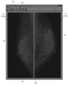
 図2は、本技術に係る処理が実行される前の画像の一例を示す図である。図2に示される画像は、画面上の特定の領域に固定的に表示される画像の輝度が反転されてもいないし低減されてもいない。
[Example of image before processing according to the present technology is executed]
FIG. 2 is a diagram illustrating an example of an image before the processing according to the present technology is executed. In the image shown in FIG. 2, the luminance of an image fixedly displayed in a specific area on the screen is not inverted or reduced.
 図2に示す画像は、大別して、診断用の画像11と、診断用の画像11を囲む枠14と、診断用の画像11の上部に位置するメニューバー12及びツールバー13とを含む。 The image shown in FIG. 2 roughly includes a diagnostic image 11, a frame 14 surrounding the diagnostic image 11, and a menu bar 12 and a tool bar 13 positioned above the diagnostic image 11.
 図2に示す画像は、表示部5の画面全体に亘って表示される場合が多い。すなわち、図2に示す画像は、フルスクリーンモードで表示される場合が多い。これは、画像診断(読影)においては、診断用の画像11をなるべく大きく表示する必要があるためである。 The image shown in FIG. 2 is often displayed over the entire screen of the display unit 5. That is, the image shown in FIG. 2 is often displayed in the full screen mode. This is because in diagnostic imaging (interpretation), it is necessary to display the diagnostic image 11 as large as possible.
 図2に示す例では、画面上の左側の領域に、左右の乳房のうちの一方の乳房のX線画像11aが表示され、右側の領域に、他方の乳房のX線画像11bが表示される場合の一例が示されている。図2において一例として示すX線画像11は、乳房を側方から撮像した場合の画像である。医師は、これらの2つの乳房のX線画像11を視認(読影)することによって、乳癌を早期に発見する。このような診断は、一般的に、マンモグラフィー診断と呼ばれる。 In the example shown in FIG. 2, the X-ray image 11a of one of the left and right breasts is displayed in the left area on the screen, and the X-ray image 11b of the other breast is displayed in the right area. An example of the case is shown. An X-ray image 11 shown as an example in FIG. 2 is an image when the breast is imaged from the side. The doctor detects breast cancer early by visually recognizing (interpreting) these two X-ray images 11 of the breast. Such a diagnosis is generally called a mammographic diagnosis.
 ここでの説明では、一例として、乳房のX線画像11が画面上に表示される場合について説明するが、他の体の部分(骨、歯、臓器、血管等)のX線画像、CT画像、MRI画像が画面上に表示されてもよい。 In this description, the case where the X-ray image 11 of the breast is displayed on the screen will be described as an example. However, X-ray images and CT images of other body parts (bones, teeth, organs, blood vessels, etc.) An MRI image may be displayed on the screen.
 左側に表示されるX線画像11aと、右側に表示されるX線画像11bとの間の境目には、境目を示すライン15が縦方向に表示される。ここでの例では、ライン15は、白とされている(つまり、輝度が高い)。図2に示す例では、X線画像11を表示する領域が、左右で2分割されている場合の一例が示されているが、X線画像11を表示する領域が上下左右で4分割される場合もある。 The line 15 indicating the boundary is displayed in the vertical direction at the boundary between the X-ray image 11a displayed on the left side and the X-ray image 11b displayed on the right side. In this example, the line 15 is white (that is, the luminance is high). In the example shown in FIG. 2, an example in which the region displaying the X-ray image 11 is divided into two parts on the left and right is shown, but the region displaying the X-ray image 11 is divided into four parts on the top, bottom, left and right. In some cases.
 4分割の場合、2つの乳房を側方から撮像した2枚のX線画像11と、2つの乳房を正面(或いは上方)から撮像した2枚のX線画像11との合計で4枚のX線画像11が画面上に表示される。この場合、X線画像11の境目を示す縦方向のライン15と、横方向のラインが画面上に表示される。また、6分割や、8分割、或いはそれ以上の分割数でX線画像11が画面上に表示される場合もあり、この場合、分割数に応じて縦方向のライン15や、横方向のラインが増加される。 In the case of four divisions, a total of four X-ray images 11 including two X-ray images 11 obtained by imaging two breasts from the side and two X-ray images 11 obtained by imaging two breasts from the front (or above). A line image 11 is displayed on the screen. In this case, a vertical line 15 indicating the boundary of the X-ray image 11 and a horizontal line are displayed on the screen. Further, the X-ray image 11 may be displayed on the screen with the number of divisions of 6 divisions, 8 divisions, or more. In this case, the vertical line 15 or the horizontal direction line is selected according to the division number. Is increased.
 図2では、画面上において、2枚のX線画像11を囲む枠14の画像が表示される。ここでの例では、枠14は、白とされている(つまり、輝度が高い)。また、2枚のX線画像11の上部には、メニューバー12及びツールバー13の画像が表示される。 In FIG. 2, the image of the frame 14 surrounding the two X-ray images 11 is displayed on the screen. In this example, the frame 14 is white (that is, the luminance is high). In addition, images of the menu bar 12 and the tool bar 13 are displayed above the two X-ray images 11.
 図3は、メニューバー12及びツールバー13を示す拡大図である。図3に示すように、メニューバー12は、白ベースであり、白ベース対して黒で「ファイル」、「編集」、「表示」等の文字が表示される。ツールバー13もメニューバー12と同様に、白ベースであり、白ベースに対して、黒で「開く」、「閉じる」、「全閉」等の文字が表示され、また、黒で、上記文字を連想させる図形が表示される。また、メニューバー12とツールバー13の間や、ツールバー13内には、黒のラインが表示される。 FIG. 3 is an enlarged view showing the menu bar 12 and the tool bar 13. As shown in FIG. 3, the menu bar 12 is white-based, and characters such as “file”, “edit”, and “display” are displayed in black with respect to the white base. Similarly to the menu bar 12, the toolbar 13 is also white-based, and characters such as “open”, “close”, “fully closed”, etc. are displayed in black with respect to the white base, and the above characters are displayed in black. A figure that reminds you of it is displayed. In addition, a black line is displayed between the menu bar 12 and the tool bar 13 or in the tool bar 13.
 上記したように、図2に示すような画像は、その性質上、フルスクリーンモードで表示される場合が多い。この場合、X線画像などの診断用の画像11は、医師の診断が終われば、その都度切り換えられるが、メニューバー12、ツールバー13、枠14、及び診断用の画像11を区切るライン15は、画面上の同じ位置に長時間表示され続けてしまう。 As described above, the image shown in FIG. 2 is often displayed in the full screen mode due to its nature. In this case, the diagnostic image 11 such as an X-ray image is switched each time the doctor's diagnosis is completed, but the menu bar 12, the tool bar 13, the frame 14, and the line 15 separating the diagnostic image 11 are Displayed at the same position on the screen for a long time.
 ELディスプレイを構成する発光素子は、それぞれ経時的に劣化するといった特性を有しているため、同じ画像が長時間同じ位置に表示され続けると、いわゆる「焼きつき」の現象が発生してしまう。 Since each light emitting element constituting an EL display has a characteristic that it deteriorates with time, if the same image is displayed at the same position for a long time, a so-called “burn-in” phenomenon occurs.
 メニューバー12及びツールバー13の部分について説明すると、白いベースの部分に対応する発光素子は、相対的に高い輝度で発光し続けることから劣化の進行速度が速い。一方で、黒で表示される文字や、図形、黒のラインなどの部分に対応する発光素子は、相対的に低い輝度で発光し続けることか劣化の進行速度が遅い。この劣化のバラつきに起因して焼きつきが生じてしまう。 Describing the menu bar 12 and the toolbar 13 portions, the light emitting elements corresponding to the white base portion continue to emit light with relatively high luminance, and thus the deterioration speed is high. On the other hand, light-emitting elements corresponding to characters such as characters displayed in black, graphics, and black lines continue to emit light at relatively low luminance or have a slow deterioration rate. The burn-in occurs due to the variation in deterioration.
 メニューバー12及びツールバー13の白ベースの部分、白い枠14の部分、診断用の画像11を区切る白いライン15の部分と、暗い診断用の画像11の部分との関係について説明する。 The relationship between the white base portion of the menu bar 12 and the toolbar 13, the white frame portion 14, the white line 15 portion that separates the diagnostic image 11, and the dark diagnostic image 11 portion will be described.
 メニューバー12及びツールバー13の白ベースの部分、白い枠14の部分、診断用の画像11を区切る白いライン15の部分に対応する発光素子は、相対的に高い輝度で発光し続けることから劣化の進行速度が速い。一方で、診断用の画像11は、順次切り換えられるものの、基本的には全体が暗い画像であるため、診断用の画像11の部分に対応する発光素子は、劣化の進行速度が遅い。従って、劣化のバラつきに起因して焼きつきが生じてしまう(特に、白い枠14、白いライン15と、診断用画像との境界部分)。 The light emitting elements corresponding to the white base portion of the menu bar 12 and the tool bar 13, the white frame portion 14, and the white line 15 portion that separates the diagnostic image 11 continue to emit light with relatively high luminance, and thus deteriorate. Progression speed is fast. On the other hand, although the diagnostic image 11 is sequentially switched, the entire image is basically a dark image. Therefore, the light emitting element corresponding to the diagnostic image 11 has a slow deterioration rate. Accordingly, burn-in occurs due to the variation in deterioration (particularly, the boundary between the white frame 14, the white line 15, and the diagnostic image).
 この焼きつきを緩和するために、発光素子の劣化の進行状況に応じて輝度の補正をかける方法が採用される場合もある。しかし、発光素子は、劣化とともに色度が変化するため、輝度の補正をかけても色むらが発生する。特に、モノクロ表示型の有機ELディスプレイの場合、この色むらが発生する可能性が高い。 In order to alleviate this burn-in, there is a case where a method of correcting the luminance according to the progress of deterioration of the light emitting element is sometimes employed. However, since the chromaticity of the light emitting element changes with deterioration, color unevenness occurs even when the luminance is corrected. In particular, in the case of a monochrome display type organic EL display, there is a high possibility that this color unevenness will occur.
 そこで、本実施形態に係る画像表示制御装置9(画像表示システム10)では、画面上に固定的に表示される画像の輝度を反転したり、輝度を低減したりすることによって、焼きつきや、色むらを緩和する処理を実行する。 Therefore, in the image display control device 9 (image display system 10) according to the present embodiment, by inverting the luminance of the image fixedly displayed on the screen or reducing the luminance, Execute processing to reduce uneven color.
 [動作説明]
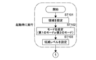
 次に、本実施形態に係る画像表示制御装置9(画像表示システム10)の処理について説明する。図4及び図5は、本実施形態に係る画像表示制御装置9の処理を示すフローチャートである。
[Description of operation]
Next, processing of the image display control device 9 (image display system 10) according to the present embodiment will be described. 4 and 5 are flowcharts showing processing of the image display control device 9 according to the present embodiment.
 本実施形態では、制御部1は、図4及び図5に示す処理を実行することによって、第1のモードと、第2のモードとを切り換える処理を実行する。第1のモードは、画面上の特定の領域に固定的に表示される画像の輝度を反転せずに、画像の輝度を低減するモードである。第2のモードは、画像の輝度を反転し、反転された画像の輝度を低減するモードである。 In the present embodiment, the control unit 1 executes a process for switching between the first mode and the second mode by executing the processes shown in FIGS. 4 and 5. The first mode is a mode for reducing the luminance of the image without inverting the luminance of the image fixedly displayed in a specific area on the screen. The second mode is a mode for inverting the luminance of the image and reducing the luminance of the inverted image.
 図6は、第1のモードが実行されたときに画面上に表示される画像の一例を示す図である。図7は、第1のモードにおけるメニューバー12及びツールバー13の拡大図である。 FIG. 6 is a diagram illustrating an example of an image displayed on the screen when the first mode is executed. FIG. 7 is an enlarged view of the menu bar 12 and the tool bar 13 in the first mode.
 図8は、第2のモードが実行されたときに画面上に表示される画像の一例を示す図である。図9は、第2のモードにおけるメニューバー12及びツールバー13の拡大図である。 FIG. 8 is a diagram illustrating an example of an image displayed on the screen when the second mode is executed. FIG. 9 is an enlarged view of the menu bar 12 and the tool bar 13 in the second mode.
 図6及び図7並びに図8及び図9に示す画像は、画面上の特定の領域に固定的に表示される画像の輝度が反転されたり、画像の輝度が低減されたりする点を除いて、図2及び図3に示す画像と同様である。すなわち、図6、図8に示す画像は、フルスクリーンモードで表示される。また、図6、図8に示す画像は、診断用の画像11と、診断用の画像11を囲む枠14と、診断用の画像11の上部に位置するメニューバー12及びツールバー13とを含む。 The images shown in FIGS. 6, 7, 8, and 9, except that the brightness of the image fixedly displayed in a specific area on the screen is inverted or the brightness of the image is reduced. It is the same as the image shown in FIG.2 and FIG.3. That is, the images shown in FIGS. 6 and 8 are displayed in the full screen mode. The images shown in FIGS. 6 and 8 include a diagnostic image 11, a frame 14 surrounding the diagnostic image 11, and a menu bar 12 and a tool bar 13 positioned above the diagnostic image 11.
 図6、図8に示す例では、画面上に固定的に表示される画像は、診断用の画像11の上部に位置するメニューバー12及びツールバー13と、診断用の画像11を囲む枠14と、診断用の画像11を区切るライン15とを含む。 In the example shown in FIGS. 6 and 8, the images that are fixedly displayed on the screen are a menu bar 12 and a toolbar 13 that are located above the diagnostic image 11, and a frame 14 that surrounds the diagnostic image 11. , And a line 15 that divides the diagnostic image 11.
 図4を参照して、画像表示制御装置9(画像表示システム10)が起動されると、まず、制御部1は、画面上の領域のうち、輝度を反転したり、輝度を低減したりする領域を設定する(ステップ101)。輝度を反転したり、輝度を低減したりする領域とは、つまり、同じ画像が固定的に表示される画面上の領域である。 Referring to FIG. 4, when image display control device 9 (image display system 10) is activated, first, control unit 1 inverts the luminance or reduces the luminance in the area on the screen. An area is set (step 101). The area where the luminance is inverted or the luminance is reduced is an area on the screen where the same image is fixedly displayed.
 領域を設定する方法としては、2つの方法がある。1つ目の方法では、まず、オペレータが、準備作業として、同じ画像が固定的に表示される画面上の領域を手動によって入力することによって、この領域を記憶部2に予め記憶しておく。 There are two methods for setting the area. In the first method, first, as a preparatory work, an operator manually inputs an area on the screen where the same image is fixedly displayed, and this area is stored in the storage unit 2 in advance.
 例えば、オペレータは、図2に示す画像を表示部5に表示させた後、診断用の画像11を囲む枠14と、メニューバー12及びツールバー13と、診断用の画像11を区切るライン15とが表示されている位置を入力部3を介して指定する。なお、診断用の画像11を区切るライン15が複数ある場合には、その複数のライン15が指定される。 For example, after the image shown in FIG. 2 is displayed on the display unit 5, the operator has a frame 14 that surrounds the diagnostic image 11, a menu bar 12 and a toolbar 13, and a line 15 that separates the diagnostic image 11. The displayed position is designated via the input unit 3. If there are a plurality of lines 15 that divide the diagnostic image 11, the plurality of lines 15 are designated.
 これにより、同じ画像が固定的に表示される画面上の領域、つまり、画面上の領域のうち、輝度を低減したり、輝度を反転させたりする領域が予め記憶部2に記憶される。そして、制御部1は、起動時にこの領域を記憶部2から読み出すことによって、輝度を低減したり輝度を反転させたりする領域を設定する。 Thereby, an area on the screen where the same image is fixedly displayed, that is, an area on the screen where the luminance is reduced or the luminance is inverted is stored in the storage unit 2 in advance. And the control part 1 sets the area | region which reduces a brightness | luminance or inverts a brightness | luminance by reading this area | region from the memory | storage part 2 at the time of starting.
 2つ目は、同じ画像が固定的に表示される画面上の領域を制御部1が、画像表示制御装置9(画像表示システム10)の起動時に自動的に判断することによって、輝度を低減したり、輝度を反転させたりする領域を設定する方法である。この場合、制御部1は、例えば、図2に示すような画面上に全体的な画像を画像解析することによって、診断用の画像11を囲む枠14と、メニューバー12及びツールバー13と、診断用の画像11を区切る1以上のライン15とが表示されている位置を自動的に判定すればよい。 Second, the control unit 1 automatically determines the area on the screen where the same image is fixedly displayed when the image display control device 9 (image display system 10) is activated, thereby reducing the luminance. Or a region where the luminance is inverted. In this case, the control unit 1 performs, for example, image analysis of the entire image on a screen as shown in FIG. 2, so that the frame 14 surrounding the diagnostic image 11, the menu bar 12 and the toolbar 13, and the diagnosis What is necessary is just to determine automatically the position where the one or more line 15 which divides | segments the image 11 for use is displayed.
 次に、制御部1は、第1のモード及び第2のモードのうち、どちらのモードを実行するかを決定し、モードを設定する(ステップ102)。どちらのモードを実行するかを制御部1がどのようにして決定するかについての詳細は、後述する。 Next, the control unit 1 determines which one of the first mode and the second mode is to be executed, and sets the mode (step 102). Details of how the control unit 1 determines which mode to execute will be described later.
 どちらのモードが実行されるかは、画像表示制御装置9(画像表示システム10)の起動時に制御部1によって決定され、決定されたモードは、次の起動時まで継続して実行される。つまり、第1のモードと第2のモードの切り換えタイミングは、画像表示制御装置9(画像表示システム10)の起動時のうち何れかのタイミングとなり、画像表示制御装置9(画像表示システム10)の起動後においては、第1のモードと第2のモードとは切り換えられない。 Which mode is executed is determined by the control unit 1 when the image display control device 9 (image display system 10) is activated, and the determined mode is continuously executed until the next activation. That is, the timing for switching between the first mode and the second mode is one of the timings when the image display control device 9 (image display system 10) is activated, and the image display control device 9 (image display system 10) After startup, the first mode and the second mode cannot be switched.
 これにより、ユーザ(医師)に違和感を与えない適切なタイミングで第1のモード及び第2のモードを切り換えることができる。但し、画像表示制御装置9(画像表示システム10)の起動後において、第1のモードと第2のモードとは切り換えることも可能である。 Thereby, the first mode and the second mode can be switched at an appropriate timing that does not give the user (doctor) a sense of incongruity. However, the first mode and the second mode can be switched after the image display control device 9 (image display system 10) is activated.
 制御部1は、モードを設定すると、次に、記憶部2に記憶されている低減レベルを読み込んで低減レベルを設定する(ステップ103)。低減レベルとは、同じ画像が固定的に表示される画面上の領域において、どの程度輝度レベルを低減させるかを示す値である。低減レベルは、例えば、入力部3を介した入力によって予め記憶部2に記憶されている。低減レベルは、ユーザ(医師)による視認性を考慮して決定される。この低減レベルは、入力部3を介して変更可能であってもよい。 When the control unit 1 sets the mode, the control unit 1 next reads the reduction level stored in the storage unit 2 and sets the reduction level (step 103). The reduction level is a value indicating how much the luminance level is reduced in an area on the screen where the same image is fixedly displayed. The reduction level is stored in advance in the storage unit 2 by, for example, input through the input unit 3. The reduction level is determined in consideration of visibility by the user (doctor). This reduction level may be changeable via the input unit 3.
 第1のモードにおける第1の低減レベルと、第2のモードにおける第2の低減レベルとは、典型的には、同じ値が用いられる。図6及び図7、並びに、図8及び図9は、第1の低減レベルと、第2の低減レベルとが同じ値である場合の一例である。 The same value is typically used for the first reduction level in the first mode and the second reduction level in the second mode. FIGS. 6 and 7 and FIGS. 8 and 9 are examples of cases where the first reduction level and the second reduction level have the same value.
 図5を参照して、次に、制御部1は、例えば、図2に示すような画像について、1画素分の画像データを入力する(ステップ104)。次に、制御部1は、その画素が、ステップ101において設定された領域内の画素であるか否かを判定する(ステップ105)。つまり、制御部1は、その画素が、同じ画像が固定的に表示される画面上の領域内の画素であるかどうかを判定する。 Referring to FIG. 5, next, control unit 1 inputs image data for one pixel, for example, for an image as shown in FIG. 2 (step 104). Next, the control unit 1 determines whether or not the pixel is a pixel in the region set in Step 101 (Step 105). That is, the control unit 1 determines whether the pixel is a pixel in an area on the screen where the same image is fixedly displayed.
 画素が上記領域内の画素である場合(ステップ105のYES)、制御部1は、現在のモードが第1のモードであるかどうかを判定する(ステップ106)。 When the pixel is a pixel in the above region (YES in Step 105), the control unit 1 determines whether or not the current mode is the first mode (Step 106).
 現在のモードが第1のモードである場合(ステップ106のYES)、制御部1は、その画素について、輝度を反転させずに、輝度を低減させる処理を実行する(ステップ108)。ステップ108では、制御部1は、ステップ103において設定された低減レベルに応じてその画素の輝度を低減させる処理を実行する。 If the current mode is the first mode (YES in step 106), the control unit 1 executes a process for reducing the luminance of the pixel without inverting the luminance (step 108). In step 108, the control unit 1 executes processing for reducing the luminance of the pixel according to the reduction level set in step 103.
 輝度を低減させるときの処理は、以下の式(1)によって表される。 Processing to reduce the brightness is expressed by the following formula (1).
 LVdwn-out=低減レベル×LVdwn-in・・・(1) LVdwn-out = reduction level × LVdwn-in (1)
 式(1)中、LVdwn-outは、輝度を低減させて出力するときの輝度のレベルを表している。また、LVdwn-inは、輝度を低減させるべき、輝度の入力値を表している。 In Equation (1), LVdwn-out represents the level of luminance when the luminance is reduced and output. Further, LVdwn-in represents a luminance input value that should be reduced in luminance.
 制御部1は、輝度を反転させずに輝度を低減させると、次のステップ109へ進む。 The control unit 1 proceeds to the next step 109 when the luminance is reduced without inverting the luminance.
 ステップ106において、現在のモードが第1のモードでない場合(ステップ106のNO)、つまり、現在のモードが第2のモードである場合、制御部1は、その画素の輝度を反転させる(ステップ107)。 In step 106, when the current mode is not the first mode (NO in step 106), that is, when the current mode is the second mode, the control unit 1 inverts the luminance of the pixel (step 107). ).
 輝度を反転させるときの処理は、以下の式(2)によって表される。 The processing when reversing the luminance is expressed by the following equation (2).
 LVrvs-out=輝度の最大レベル-LVrvs-in・・・(2) LVrvs-out = maximum level of brightness-LVrvs-in (2)
 式(2)中、LVrvs-outは、輝度を反転させて出力するときの輝度のレベルを表している。また、輝度の最大レベルは、256階調の場合は、255である。また、LVrvs-inは、輝度を反転させるべき、輝度の入力値を表している。 In Expression (2), LVrvs-out represents the level of luminance when the luminance is inverted and output. In addition, the maximum luminance level is 255 in the case of 256 gradations. Further, LVrvs-in represents an input value of luminance that should be inverted.
 画素の輝度を反転させると、次に、制御部1は、その画素の輝度を上記式(1)を使用して低減させる(ステップ108)。 When the luminance of the pixel is inverted, the control unit 1 then reduces the luminance of the pixel using the above equation (1) (step 108).
 その画素の輝度を反転させ、かつ、輝度を低減させると、制御部1は、次のステップ109へ進む。 When the luminance of the pixel is inverted and the luminance is reduced, the control unit 1 proceeds to the next step 109.
 ステップ105において、その画素が同じ画像が固定的に表示される画面上の領域内の画素ではない場合(ステップ105のNO)、制御部1は、輝度を反転したり、輝度を低減したりする処理を実行せずに、次のステップ109へ進む。例えば、診断用の画像11が表示される位置に対応する画素は、上記領域内にはないと判定され、輝度を反転させたり、輝度を低減したりする処理が実行されない。 In step 105, when the pixel is not a pixel in an area on the screen where the same image is fixedly displayed (NO in step 105), the control unit 1 inverts the luminance or reduces the luminance. The process proceeds to the next step 109 without executing the process. For example, it is determined that the pixel corresponding to the position where the diagnostic image 11 is displayed is not within the region, and the process of inverting the brightness or reducing the brightness is not executed.
 ステップ109では、制御部1は、劣化係数を画素毎にカウントする。劣化係数は、輝度が高いほど高い値を取る値である。劣化係数をカウントすることによって、制御部1は、第1のモードにおいて相対的に高い輝度で表示され、第2のモードにおいて相対的に低い輝度で表示される、上記領域内の第1の部分についての第1の劣化度を測定している。また、制御部1は、第1のモードにおいて相対的に低い輝度で表示され、第2のモードにおいて相対的に高い輝度で表示される、領域内の第2の部分についての第2の劣化度とを測定している。 In step 109, the control unit 1 counts the deterioration coefficient for each pixel. The deterioration coefficient is a value that takes a higher value as the luminance is higher. By counting the deterioration coefficient, the control unit 1 displays the first part in the region displayed with relatively high luminance in the first mode and displayed with relatively low luminance in the second mode. The first deterioration degree is measured. In addition, the control unit 1 displays the second degree of deterioration of the second portion in the region that is displayed with relatively low luminance in the first mode and displayed with relatively high luminance in the second mode. And measure.
 図6、図8に示す例の場合、第1の部分は、メニューバー12及びツールバー13のベースの部分、枠14の部分、診断用の画像11を区切るライン15の部分である。第2の部分は、メニューバー12及びツールバー13内における文字、図形、ライン等の部分である。 6 and 8, the first part is the base part of the menu bar 12 and the tool bar 13, the part of the frame 14, and the part of the line 15 that divides the diagnostic image 11. In the example shown in FIG. The second portion is a portion of characters, figures, lines, etc. in the menu bar 12 and the tool bar 13.
 図10には、画像の表示時間と、第1の部分についての第1の劣化度及び第2の部分についての第2の劣化度との関係が示されている。図10において、第1の劣化度は、細線の一点差線で表され、第2の劣化度は、太線の一点鎖線で表されている。制御部1は、劣化係数をカウントすることによって、図10に示すような第1の劣化度及び第2の劣化度を測定する。なお、劣化係数は、第1の劣化度及び第2の劣化度を示す直線の傾きに相当する。 FIG. 10 shows the relationship between the image display time, the first deterioration degree for the first portion, and the second deterioration degree for the second portion. In FIG. 10, the first deterioration degree is represented by a one-point difference line of a thin line, and the second deterioration degree is represented by a one-dot chain line of a thick line. The control unit 1 measures the first deterioration degree and the second deterioration degree as shown in FIG. 10 by counting the deterioration coefficients. The deterioration coefficient corresponds to the slope of a straight line indicating the first deterioration degree and the second deterioration degree.
 測定された第1の劣化度及び第2の劣化度は、制御部1が第1のモード及び第2のモードのうち、どちらのモードを実行するかを決定するときに用いられる。 The measured first deterioration degree and second deterioration degree are used when the control unit 1 determines which of the first mode and the second mode to execute.
 なお、劣化度は、同じ画像が固定的に表示される画面上の領域に対応する画素(発光素子)の劣化度だけでなく、それ以外の領域(診断用画像11が表示される領域)に対応する画素(発光素子)の劣化度も測定される(ステップ105のNO→ステップ109参照)。この劣化度と、第1の劣化度及び第2の劣化度は、制御部1によって輝度の補正をかけるときに使用される。なお、これらの劣化度は、リフレッシュレート毎に測定(カウント)されており、測定された劣化度は記憶部2に記憶される。 The degree of deterioration is not limited to the degree of deterioration of pixels (light emitting elements) corresponding to the area on the screen where the same image is fixedly displayed, but also to other areas (area where the diagnostic image 11 is displayed). The degree of deterioration of the corresponding pixel (light emitting element) is also measured (see NO at step 105 → step 109). The degree of deterioration, the first degree of deterioration, and the second degree of deterioration are used when the control unit 1 performs luminance correction. The degree of deterioration is measured (counted) for each refresh rate, and the measured degree of deterioration is stored in the storage unit 2.
 劣化係数をカウントすると、次に、制御部1は、その1画素分の画像データを出力する(ステップ110)。次に、制御部1は、1枚の画像データに含まれる全ての画素について、ステップ104~ステップ110の処理が完了したかどうかを判定する(ステップ111)。処理が完了していない画素が残っている場合(ステップ111のNO)、制御部1は、次の画素にステップを進め(ステップ112)、次の画素について、ステップ104~110の処理を実行する。 When the deterioration coefficient is counted, the control unit 1 next outputs the image data for one pixel (step 110). Next, the control unit 1 determines whether or not the processing from step 104 to step 110 has been completed for all the pixels included in one piece of image data (step 111). When pixels that have not been processed remain (NO in step 111), the control unit 1 advances the step to the next pixel (step 112), and executes the processes of steps 104 to 110 for the next pixel. .
 1枚の画像データに含まれる全ての画素について、ステップ104~ステップ110の処理が完了した場合(ステップ111のYES)、制御部1は、次の画像データにステップを進める(ステップ113)。そして、制御部1は、次の画像データについて、ステップ104~ステップ111の処理を繰り返す。 When the processing from step 104 to step 110 is completed for all pixels included in one piece of image data (YES in step 111), the control unit 1 advances the step to the next image data (step 113). Then, the control unit 1 repeats the processing from step 104 to step 111 for the next image data.
 このような処理により、第1のモードでは、画面上に図6に示すような画像が表示される。また、第2のモードでは、画面上に図8に示すような画像が表示される。 By such processing, an image as shown in FIG. 6 is displayed on the screen in the first mode. In the second mode, an image as shown in FIG. 8 is displayed on the screen.
 図6に示すように、第1のモードにおいては、図2に示す元の画像データに対して、同じ画像が固定的に表示される画面上の領域に対応する画素(発光素子)の輝度が低減されている。なお、第1のモードにおいては、図2に示す元の画像データに対して、輝度は反転されていない。 As shown in FIG. 6, in the first mode, with respect to the original image data shown in FIG. 2, the luminance of the pixel (light emitting element) corresponding to the area on the screen where the same image is fixedly displayed is displayed. Has been reduced. In the first mode, the luminance is not inverted with respect to the original image data shown in FIG.
 具体的には、メニューバー12及びツールバー13のベースの部分、枠14の部分、診断用の画像11を区切るライン15の部分の輝度が低減され、グレーに変更されている。なお、メニューバー12及びツールバー13内の文字、図形、ライン等の輝度も多少低減されているが、これらについては、図2における元の画像データにおいて元々暗い部分であるので、低減のレベルは視認することができない程度である。あるいは、元の画像データでの輝度がゼロである場合には、変化はない。 Specifically, the luminance of the base portion of the menu bar 12 and the tool bar 13, the portion of the frame 14, and the portion of the line 15 that delimits the diagnostic image 11 is reduced and changed to gray. Note that the luminance of characters, figures, lines, etc. in the menu bar 12 and the tool bar 13 is somewhat reduced, but these are originally dark portions in the original image data in FIG. It is not possible to do. Alternatively, when the luminance in the original image data is zero, there is no change.
 図8に示すように、第2のモードにおいては、図2に示す元の画像データに対して、同じ画像が固定的に表示される画面上の領域に対応する画素(発光素子)の輝度が反転されており、反転された輝度が低減されている。 As shown in FIG. 8, in the second mode, with respect to the original image data shown in FIG. 2, the luminance of the pixel (light emitting element) corresponding to the area on the screen where the same image is fixedly displayed is displayed. Inverted and the inverted brightness is reduced.
 具体的には、メニューバー12及びツールバー13のベースの部分、枠14の部分、診断用の画像11を区切るライン15の部分の輝度が反転及び低減され、黒に変更されている。また、メニューバー12及びツールバー13内の文字、図形、ライン等の部分の輝度が反転及び低減され、グレーに変更されている。 Specifically, the luminance of the base portion of the menu bar 12 and the toolbar 13, the portion of the frame 14, and the portion of the line 15 that delimits the diagnostic image 11 is inverted and reduced, and is changed to black. In addition, the luminance of characters, figures, lines, and the like in the menu bar 12 and the toolbar 13 is inverted and reduced, and is changed to gray.
 (第1のモード及び第2のモードの切り換え)
 次に、制御部1が、起動時において、第1のモード及び第2のモードのうち、どちらのモードを実行するかを決定するときの処理について説明する。
(Switching between the first mode and the second mode)
Next, processing when the control unit 1 determines which mode to execute between the first mode and the second mode at the time of activation will be described.
 図11は、どちらのモードを実行するかを決定するときの処理を示すフローチャートある。なお、図11の説明においては、図10も参照される。 FIG. 11 is a flowchart showing processing when determining which mode to execute. In the description of FIG. 11, FIG. 10 is also referred to.
 図10には、図11に示す処理によってモードが切り換えられたときの、第1の劣化度(細線の一点鎖線参照)と、第2の劣化度(太線の一点鎖線参照)の推移が示されている。なお、図10には、第1の劣化度及び第2の劣化度の平均が実線で示されている。 FIG. 10 shows the transition of the first deterioration level (refer to the dashed line in the thin line) and the second deterioration level (refer to the dashed line in the thick line) when the mode is switched by the process shown in FIG. ing. In FIG. 10, the average of the first deterioration degree and the second deterioration degree is shown by a solid line.
 第1の劣化度は、例えば、メニューバー12及びツールバー13のベースの部分、枠14の部分、診断用の画像11を区切るライン15の部分(第1の部分)の画素(発光素子)についての劣化度である。一方、第2の劣化度は、例えば、メニューバー12及びツールバー13内の文字、図形、ライン等の部分(第2の部分)の画素(発光素子)についての劣化度である。 The first degree of deterioration is, for example, for pixels (light emitting elements) in the base part of the menu bar 12 and the tool bar 13, the part of the frame 14, and the part of the line 15 (first part) that separates the diagnostic image 11. Degree of degradation. On the other hand, the second degree of deterioration is, for example, the degree of deterioration of a pixel (light emitting element) in a portion (second portion) such as a character, a figure, or a line in the menu bar 12 and the toolbar 13.
 まず、制御部1は、起動時において、今回の起動が、本技術に係るプログラムがインストールされてから初回の起動であるかどうかを判定する(ステップ201)。初回の起動である場合、制御部1は、その起動時においては、第1のモード及び第2のモードのうち予め設定されたモードを設定する(ステップ202)。ここでの説明では、初回の起動時に第1のモードが設定されたとする。ステップ202において、モードを第1のモードに設定すると、制御部1は、処理を終了する。 First, at the time of activation, the control unit 1 determines whether or not this activation is the first activation after the program according to the present technology is installed (step 201). In the case of the first activation, the control unit 1 sets a preset mode among the first mode and the second mode at the activation (step 202). In the description here, it is assumed that the first mode is set at the first activation. In step 202, when the mode is set to the first mode, the control unit 1 ends the process.
 今回の起動が、初回の起動ではない場合(ステップ201のNO)、制御部1は、第1の劣化度と第2の劣化度との差を算出し、この差の絶対値が閾値Thを超えるかどうかを判定する(ステップ203)。この閾値は、モードを切り換える周期を決定するパラメータである。つまり、閾値が小さければモードが切り換えられる周期は短くなり、一方で閾値が大きければモードが切り換えられる周期は長くなる。モードが切り換えられる周期は、1日周期、1週間周期、1ヶ月周期など様々な周期とすることができる(例えば、1日10時間使用した場合)。 When the current activation is not the first activation (NO in step 201), the control unit 1 calculates the difference between the first deterioration degree and the second deterioration degree, and the absolute value of this difference sets the threshold Th. It is determined whether or not it exceeds (step 203). This threshold is a parameter that determines a cycle for switching modes. That is, if the threshold is small, the mode switching period is short, while if the threshold is large, the mode switching period is long. The cycle in which the mode is switched can be various cycles such as a daily cycle, a week cycle, and a month cycle (for example, when used for 10 hours a day).
 第1の劣化度と第2の劣化度との差の絶対値が閾値Th以下である場合(ステップ203のNO)、制御部1は、今回のモードを、前回のモードと同じモードに設定する(ステップ206)。 When the absolute value of the difference between the first deterioration degree and the second deterioration degree is equal to or less than the threshold Th (NO in step 203), the control unit 1 sets the current mode to the same mode as the previous mode. (Step 206).
 第1の劣化度と第2の劣化度との差の絶対値が閾値Thを超える場合(ステップ203のYES)、制御部1は、次のステップ204へ進む。なお、第1の劣化度と第2の劣化度との差の絶対値が閾値Thを超えることで、モードが切り換え可能な状態となる。ステップ204では、制御部1は、前回のモード切り換え時から現在までの間に、第1の劣化度と第2の劣化度とが逆転しているかどうかを判定する。 When the absolute value of the difference between the first deterioration degree and the second deterioration degree exceeds the threshold Th (YES in Step 203), the control unit 1 proceeds to the next Step 204. Note that when the absolute value of the difference between the first deterioration degree and the second deterioration degree exceeds the threshold Th, the mode can be switched. In step 204, the control unit 1 determines whether the first deterioration degree and the second deterioration degree are reversed between the previous mode switching and the present time.
 前回のモード切り換え時から現在までの間に、第1の劣化度と第2の劣化度とが逆転していない場合(ステップ204のNO)、制御部1は、今回のモードを、前回のモードと同じモードに設定する(ステップ206)。 If the first deterioration degree and the second deterioration degree are not reversed between the previous mode switching and the present time (NO in step 204), the control unit 1 changes the current mode to the previous mode. The same mode is set (step 206).
 一方、前回のモード切り換え時から現在までの間に、第1の劣化度と第2の劣化度とが逆転している場合(ステップ204のYES)、今回のモードを、前回のモードとは異なるモードに設定する(ステップ205)。なお、初回に設定されたモードが未だ他のモードに切り換えられていない場合には、制御部1は、ステップ203の結果が肯定的であれば、ステップ204の処理を実行せずに、ステップ205へ進む。そして、制御部1は、初回に設定されたモードを他のモードに切り換える。 On the other hand, if the first deterioration degree and the second deterioration degree are reversed between the previous mode switching and the present time (YES in step 204), the current mode is different from the previous mode. The mode is set (step 205). If the mode set for the first time has not yet been switched to another mode, if the result of step 203 is affirmative, the control unit 1 does not execute the process of step 204 but performs step 205. Proceed to Then, the control unit 1 switches the mode set for the first time to another mode.
 図10を参照して、初回の起動時においては、第1のモードが設定される。従って、初回起動後は、図6に示すような画像が画面上に表示される。画面上に画像が表示されている間は、図5に示すような処理によって、第1の劣化度と、第2の劣化度が測定される。 Referring to FIG. 10, the first mode is set at the first startup. Therefore, after the first activation, an image as shown in FIG. 6 is displayed on the screen. While the image is displayed on the screen, the first deterioration degree and the second deterioration degree are measured by the process as shown in FIG.
 第2回目、第3回目の起動時においては、第1の劣化度と第2の劣化度との差の絶対値が閾値Thを超えていない。従って、第2回目、第3回目の起動時においては、前回のモード(第1のモード)と同じモードが設定される。 The absolute value of the difference between the first deterioration degree and the second deterioration degree does not exceed the threshold Th at the second and third start-up times. Therefore, the same mode as the previous mode (first mode) is set at the second and third activations.
 第4回目の起動時においては、初回に設定されたモードが未だ他のモードに切り換えられておらず、かつ、第1の劣化度と第2の劣化度との差の絶対値が閾値Thを超えているため、初回に設定された第1のモードが第2のモードへ切り換えられる。従って、第4回目の起動後は、図8に示すような画像が画面上に表示される。第1のモードと、第2のモードとでは、輝度が反転されることから、第1の劣化度及び第2の劣化度の傾きが逆になる。 At the time of the fourth start-up, the mode set for the first time has not yet been switched to another mode, and the absolute value of the difference between the first deterioration degree and the second deterioration degree is the threshold Th. Since it exceeds, the first mode set for the first time is switched to the second mode. Therefore, after the fourth activation, an image as shown in FIG. 8 is displayed on the screen. Since the luminance is inverted between the first mode and the second mode, the slopes of the first deterioration degree and the second deterioration degree are reversed.
 第5回目~第7回目の起動時においては、第1の劣化度と第2の劣化度との差の絶対値が閾値Thを超えていない。また、第5回目~第7回目の起動時においては、前回のモード切り換え時から現在までの間に、第1の劣化度と第2の劣化度とが逆転してもいない。従って、第5回目~第7回目の起動時においては、前回のモードが参照されて、前回のモードと同じ第2のモードが設定される。 The absolute value of the difference between the first degradation level and the second degradation level does not exceed the threshold Th during the fifth to seventh activations. In addition, at the time of starting from the fifth time to the seventh time, the first deterioration degree and the second deterioration degree are not reversed between the previous mode switching and the present time. Accordingly, at the time of the fifth to seventh activation, the previous mode is referred to and the second mode that is the same as the previous mode is set.
 第8回目~第9回目の起動時においては、前回のモード切り換え時から現在までの間に、第1の劣化度と第2の劣化度とが逆転しているものの、第1の劣化度と第2の劣化度との差の絶対値が閾値Thを超えていない。従って、第8回目~第9回目の起動時においては、前回のモードが参照されて、前回のモードと同じ第2のモードが設定される。 At the time of starting from the 8th time to the 9th time, although the first deterioration degree and the second deterioration degree are reversed between the previous mode switching and the present time, The absolute value of the difference from the second deterioration level does not exceed the threshold Th. Accordingly, at the time of the eighth to ninth activations, the previous mode is referred to, and the second mode that is the same as the previous mode is set.
 第10回目の起動時においては、第1の劣化度と第2の劣化度との差の絶対値が閾値Thを超えている。また、第10回目の起動時においては、前回のモード切り換え時から現在までの間に、第1の劣化度と第2の劣化度とが逆転している。従って、第10回目の起動時においては、前回のモードが切り換えられて、第1のモードが設定される。 At the 10th start-up, the absolute value of the difference between the first deterioration degree and the second deterioration degree exceeds the threshold Th. Further, at the time of the tenth activation, the first deterioration degree and the second deterioration degree are reversed between the previous mode switching and the present time. Accordingly, at the time of the tenth activation, the previous mode is switched and the first mode is set.
 このように、第1の劣化度と、第2の劣化度とに基づいて、モードを切り換えることによって、適切なタイムミングでモードを切り換えることが可能となる。 Thus, by switching the mode based on the first degradation degree and the second degradation degree, it becomes possible to switch the mode with appropriate timing.
[作用等]
 以上説明したように、本実施形態では、第1のモードと第2のモードとでは、画面上の特定の領域に固定的に表示される画像の輝度が反転される。これにより、相対的に高い輝度で表示される部分と、相対的に低い輝度で表示される部分とを第1のモード及び第2のモードで反転することができる。従って、画像が固定的に表示される領域内における発光素子の劣化の進行速度を均一化することができるため(図9参照)、例えば、焼きつきや、色むらによる問題を緩和することができる。
[Action etc.]
As described above, in the present embodiment, in the first mode and the second mode, the luminance of an image fixedly displayed in a specific area on the screen is inverted. Thereby, the part displayed with relatively high brightness and the part displayed with relatively low brightness can be reversed in the first mode and the second mode. Therefore, since the progress speed of the deterioration of the light emitting element in the region where the image is fixedly displayed can be made uniform (see FIG. 9), for example, problems due to burn-in and color unevenness can be alleviated. .
 さらに、本実施形態では、第1のモード及び第2のモードの両方のモードにおいて、画面上の特定の領域に固定的に表示される画像の輝度が低減される。これにより、相対的に高い輝度で表示される部分と、相対的に低い輝度で表示される部分との間で劣化の進行速度の差を小さくすることができる。従って、更に精度良く焼きつきや、色むらによる問題を緩和することができる。また、画面上の特定の領域に固定的に表示される画像の輝度が低減されるため、発光素子の劣化の進行速度を低くすることができる。 Furthermore, in the present embodiment, the luminance of an image fixedly displayed in a specific area on the screen is reduced in both the first mode and the second mode. Thereby, it is possible to reduce a difference in deterioration progress speed between a portion displayed with a relatively high luminance and a portion displayed with a relatively low luminance. Accordingly, it is possible to alleviate the problem of image sticking and color unevenness with higher accuracy. In addition, since the luminance of an image fixedly displayed in a specific area on the screen is reduced, the progress rate of deterioration of the light emitting element can be reduced.
 さらに、本実施形態では、メニューバー12や、ツールバー13、枠14などの、診断用の画像11の周囲に表示される画像の輝度が低減される。このように、診断用の画像11の周囲に位置する画像の輝度が低減されるため、診断用の画像11が見やすくなるといった効果もある。以降では、これについて説明する。 Furthermore, in the present embodiment, the brightness of images displayed around the diagnostic image 11 such as the menu bar 12, the toolbar 13, and the frame 14 is reduced. Thus, since the brightness of the image located around the diagnostic image 11 is reduced, there is also an effect that the diagnostic image 11 is easy to see. This will be described below.
 図12は、診断用の画像11が見やすくなる理由を説明するための図である。図12の上側の図面では、高輝度の部分に取り囲まれた黒い円が表されている。黒い円の内部には、グレーの5つの円が存在している。図12の上の図から分かるように、黒い円の内部に存在するグレーの5つの円は、非常に見分けにくい。これは、低輝度領域において差を見分けるためには、瞳孔を開く必要があるのに対して、黒い円の周囲に存在する高輝度の部分によって瞳孔が開いてしまうためである。 FIG. 12 is a diagram for explaining the reason why the diagnostic image 11 is easy to see. In the upper drawing of FIG. 12, a black circle surrounded by a high-luminance portion is shown. There are five gray circles inside the black circle. As can be seen from the upper diagram of FIG. 12, the five gray circles existing inside the black circle are very difficult to distinguish. This is because the pupil needs to be opened in order to distinguish the difference in the low luminance region, whereas the pupil is opened by the high luminance part existing around the black circle.
 図12の下側の図においては、図12の上側の図面と同じ位置に同じ輝度の5つのグレーの円が存在している。図12の下側の図においては、周囲が低輝度であるため、瞳孔を開いた状態で視認可能である。従って、図12の下側の図では、図12の上の図に比べて、グレーの5つの円を見分けやすい。 In the lower diagram of FIG. 12, there are five gray circles having the same brightness at the same position as the upper diagram of FIG. In the lower diagram of FIG. 12, the surrounding area is low in luminance, so that it can be viewed with the pupil open. Therefore, in the lower diagram of FIG. 12, it is easier to distinguish the five gray circles than the upper diagram of FIG.
 図12の上側の図面は、図2に示す画像に対応している。一方、図12の下側の図面は、図6及び図8に示す画像に対応している。つまり、本実施形態では、メニューバー12、ツールバー13、枠14などの、診断用画像の周囲に存在する画像の輝度が低減されているため、ユーザ(医師)が画像診断を行うとき、診断用画像における低輝度領域の差を見分け易い。これは、診断の精度の向上に繋がる。 The upper drawing in FIG. 12 corresponds to the image shown in FIG. On the other hand, the lower drawing of FIG. 12 corresponds to the images shown in FIGS. That is, in this embodiment, since the brightness of images around the diagnostic image such as the menu bar 12, the toolbar 13, and the frame 14 is reduced, when the user (doctor) performs image diagnosis, It is easy to distinguish the difference in the low luminance area in the image. This leads to an improvement in diagnosis accuracy.
<第2実施形態>
 次に、本技術の第2実施形態について説明する。なお、第2実施形態の説明では、上述の第1実施形態と同様の構成及び機能を有する部分については、同一符号を付し、説明を省略又は簡略化する。
Second Embodiment
Next, a second embodiment of the present technology will be described. In the description of the second embodiment, parts having the same configurations and functions as those of the above-described first embodiment are denoted by the same reference numerals, and description thereof is omitted or simplified.
 第2実施形態では、表示部5の数が2以上の場合が想定される。このような場合、ある特定の表示部5で実行されるモードが、他の表示部5で実行されるモードと異なると、視認性が悪化する恐れがある。例えば、或る特定の表示部5では、図6に示す画像が表示されており、他の表示部5において、図8に示す画像が表示されていると、視認性が悪化する恐れがある。 In the second embodiment, it is assumed that the number of the display units 5 is two or more. In such a case, if a mode executed on a specific display unit 5 is different from a mode executed on another display unit 5, the visibility may be deteriorated. For example, the image shown in FIG. 6 is displayed on a specific display unit 5, and if the image shown in FIG. 8 is displayed on another display unit 5, the visibility may deteriorate.
 そこで、第2実施形態では、制御部1は、2以上の表示部5で実行される各モードが同じモードとなるように、2以上の表示部5において、それぞれ、第1のモードと第2のモードとを切り換える処理を実行する。 Therefore, in the second embodiment, the control unit 1 controls the first mode and the second mode in the two or more display units 5 so that the modes executed in the two or more display units 5 are the same mode. The process for switching between the modes is executed.
 図13は、第2実施形態に係る画像表示制御装置9(画像表示システム10)によって実行される処理を示すフローチャートである。 FIG. 13 is a flowchart showing processing executed by the image display control device 9 (image display system 10) according to the second embodiment.
 まず、制御部1は、表示部5の個数を判定する(ステップ301)。表示部5の個数は、2つ、3つ、あるいは、それ以上である場合がある。 First, the control unit 1 determines the number of display units 5 (step 301). The number of display units 5 may be two, three, or more.
 次に、制御部1は、各表示部5について、それぞれ、輝度を反転したり輝度を低減したりする領域(つまり、同じ画像が画面上に固定的に表示される領域)を設定する(ステップ302)。この領域の設定方法については、上述の第1実施形態と同様である。なお、各表示部5で異なる画像が表示される場合もある。従って、上記領域が各表示部5で異なる場合もある。 Next, the control unit 1 sets, for each display unit 5, a region where the luminance is reversed or the luminance is reduced (that is, a region where the same image is fixedly displayed on the screen) (Step S 1). 302). The method for setting this area is the same as that in the first embodiment. Note that different images may be displayed on each display unit 5. Therefore, the area may be different in each display unit 5.
 次に、制御部1は、第1のモード及び第2のモードのうちどちらのモードを実行するかを決定し、モードを設定する(ステップ303)。各表示部5において設定されるモードは、共通とされる。これにより、ユーザ(医師)が2以上の表示部5をモニタリングするときの視認性を向上させることができる。 Next, the control unit 1 determines which of the first mode and the second mode is to be executed, and sets the mode (step 303). The mode set in each display unit 5 is common. Thereby, visibility when a user (doctor) monitors two or more display parts 5 can be improved.
 なお、ステップ303においては、制御部1は、劣化度が最大である表示部5を判定し、劣化度が最大である表示部5でのモードの切り換えに合わせるように、他の表示部5のモードを切り換えてもよい。 In step 303, the control unit 1 determines the display unit 5 having the maximum deterioration level, and adjusts the switching of the mode on the display unit 5 having the maximum deterioration level. The mode may be switched.
 すなわち、制御部1は、2以上の表示部5について、それぞれ、同じ画像が画面上に固定的に表示される領域における画素(発光素子)の劣化度を測定する。なお、ここでの劣化度としては、例えば、図10に示す第1の劣化度及び第2の劣化度の平均値が用いられる。そして、制御部1は、測定された各劣化度に基づいて、劣化度が最大である表示部5を判定する。 That is, the control unit 1 measures the degree of deterioration of pixels (light emitting elements) in an area where the same image is fixedly displayed on the screen for each of the two or more display units 5. In addition, as a deterioration degree here, the average value of the 1st deterioration degree shown in FIG. 10 and the 2nd deterioration degree is used, for example. And the control part 1 determines the display part 5 with the largest degradation degree based on each measured degradation degree.
 その後、制御部1は、劣化度が最大である表示部5でのモードの切り換えに合わせるように、他の表示部5のモードを切り換える。劣化度が最大である表示部5におけるモードの切り換え方法については、上述の第1実施形態と同様である(図10、11参照)。 Thereafter, the control unit 1 switches the mode of the other display unit 5 so as to match the switching of the mode on the display unit 5 having the maximum deterioration degree. The mode switching method in the display unit 5 having the maximum degree of deterioration is the same as that in the first embodiment (see FIGS. 10 and 11).
 ここで、2以上の表示部5の使用の開始が同時である場合については、その2以上の表示部5の各画素(発光素子)の劣化度は略同じであると考えられる。一方、ある表示部5が既に使用されており、その後に、他の表示部5(新品である場合が多い)が増設される場合もある。このような場合、劣化度が最大である表示部5でのモードの切り換えに合わせる方法が採用されると有効である。 Here, when the use of two or more display units 5 is started at the same time, it is considered that the deterioration degree of each pixel (light emitting element) of the two or more display units 5 is substantially the same. On the other hand, there is a case where a certain display unit 5 has already been used, and another display unit 5 (which is often new) is added thereafter. In such a case, it is effective to adopt a method that matches the mode switching in the display unit 5 having the maximum deterioration degree.
 つまり、劣化度が最大である表示部5のモードの切り換えに他の表示部5のモードの切り換えを合わせることで、劣化度が最大である表示部5の焼きつきや、色むらが緩和される。後から増設された新たな表示部5については、劣化度が最大である表示部5のモードの切り換えに応じてモードが切り換えられたとしても、モードの切り換え周期は、基本的に一定であるため、焼きつきや色むらの問題なく適切にモードの切り換えが可能である。 That is, by combining the switching of the mode of the other display unit 5 with the switching of the mode of the display unit 5 having the maximum deterioration degree, the burn-in and the color unevenness of the display unit 5 having the maximum deterioration degree are alleviated. . For the new display unit 5 added later, the mode switching cycle is basically constant even if the mode is switched according to the mode switching of the display unit 5 having the maximum deterioration degree. Therefore, it is possible to switch the mode appropriately without problems of image sticking and color unevenness.
 モードを設定すると、次に、制御部1は、2以上の表示部5で実行される各モードでの輝度の低減のレベルが同じレベルとなるように、低減レベルを設定する。これにより、2以上の表示部5での輝度の低減レベル(つまり、明るさ)が共通となるため、ユーザ(医師)が2以上の表示部5をモニタリングするときの視認性を向上させることができる。 When the mode is set, next, the control unit 1 sets the reduction level so that the luminance reduction level in each mode executed by the two or more display units 5 becomes the same level. Thereby, since the reduction level (that is, brightness) of the brightness in the two or more display units 5 is common, the visibility when the user (doctor) monitors the two or more display units 5 can be improved. it can.
 なお、劣化度が最大である表示部5における輝度の低減レベルに合わせるように、他の表示部5における輝度の低減レベルを設定してもよい。 It should be noted that the luminance reduction level in the other display units 5 may be set so as to match the luminance reduction level in the display unit 5 having the maximum degree of deterioration.
 低減レベルを設定すると、制御部1は、図5に示す処理を各表示部5について実行する。 When the reduction level is set, the control unit 1 executes the processing shown in FIG.
<各種変形例> <Various modifications>
 上述の説明では、第1の劣化度及び第2の劣化度に基づいて、第1のモードと第2のモードとを切り換える場合について説明したが、時間に基づいて第1のモードと第2のモードと切り換える処理が実行されてもよい。この場合、画面上に画像が表示されている時間が所定の時間に達したときに一方のモードが他のモードに切り換えられる。 In the above description, the case where the first mode and the second mode are switched based on the first deterioration degree and the second deterioration degree has been described. However, the first mode and the second mode are changed based on time. Processing for switching to the mode may be executed. In this case, when the time during which an image is displayed on the screen reaches a predetermined time, one mode is switched to the other mode.
 上述の説明では、第1のモードにおける第1の低減レベルと、第2のモードにおける第2の低減レベルとが同じ場合について説明したが、第1の低減レベルと、第2の低減レベルとは異なっていてもよい。例えば、図7に示すようなグレーのベース上に黒の文字や図形が表示されている場合の方が、図9に示すような黒のベースにグレーの文字や図形が表示されている場合に比べて視認性がよい。従って、第1の低減レベルを第2の低減レベルよりも大きくすることが考えられる。 In the above description, the case where the first reduction level in the first mode is the same as the second reduction level in the second mode has been described, but the first reduction level and the second reduction level are May be different. For example, when black characters and figures are displayed on a gray base as shown in FIG. 7, when gray letters and figures are displayed on a black base as shown in FIG. The visibility is better than that. Therefore, it is conceivable to make the first reduction level larger than the second reduction level.
 本技術は、以下の構成をとることもできる。
(1) 前記画面上の特定の領域に固定的に表示される画像の輝度を反転せずに、前記画像の輝度を低減する第1のモードと、前記画像の輝度を反転し、反転された前記画像の輝度を低減する第2のモードとを切り換え、かつ、切り換えられたモードに応じて、前記画面上の前記領域に前記画像を表示させるように表示を制御する制御部
 を具備する画像表示制御装置。
(2) 上記(1)に記載の画像表示制御装置であって、
 前記制御部は、前記第1のモードにおいて相対的に高い輝度で表示され、前記第2のモードにおいて相対的に低い輝度で表示される、前記領域内の第1の部分についての第1の劣化度と、前記第1のモードにおいて相対的に低い輝度で表示され、前記第2のモードにおいて相対的に高い輝度で表示される、前記領域内の第2の部分についての第2の劣化度とを測定し、測定された前記第1の劣化度及び前記第2の劣化度に基づいて、前記第1のモード及び前記第2のモードを切り換える
 画像表示制御装置。
(3) 上記(2)に記載の画像表示制御装置であって、
 前記制御部は、前記第1の劣化度と、前記第2の劣化度との差を算出し、前記差が所定の閾値を超えたときに、前記第1のモード及び前記第2のモードを切り換え可能な状態とする
 画像表示制御装置。
(4) 上記(2)又は(3)に記載の画像表示制御装置であって、
 前記制御部は、輝度が高いほど高い値を取る値である劣化係数に基づいて前記第1の劣化度及び前記第2の劣化度を測定する
 画像表示制御装置。
(5) 上記(1)乃至(4)のうちいずれか1つに記載の画像表示制御装置であって、
 前記制御部は、前記画像表示制御装置の起動時に、前記第1のモード及び前記第2のモードのうち、どちらのモードを実行するかを決定することによって、前記第1のモード及び前記第2のモードを切り換える
 画像表示制御装置。
(6) 上記(5)に記載の画像表示制御装置であって、
 前記制御部は、前記画像表示制御装置の起動時において決定されたモードを、次の起動時まで継続して実行する
 画像表示制御装置。
(7) 上記(1)乃至(6)のうち何れか1つに記載の画像表示制御装置であって、
 前記制御部は、前記画像が固定的に表示される領域以外の領域に診断用の画像を表示させる
 画像表示制御装置。
(8) 上記(7)に記載の画像表示制御装置であって、
 前記画面上の特定の領域に固定的に表示される、輝度が低減される画像は、前記診断用の画像の周囲の領域に表示される
 画像表示制御装置。
(9) 請求項(1)乃至(8)のうち何れか1つに記載の画像表示制御装置であって、
 前記制御部は、前記画面上に全体的に表示される画像を解析することによって、第1のモードと、第2のモードとで輝度が反転される、前記画面上の特定の領域に固定的に表示される画像の領域を判定する
 画像表示制御装置。
(10) 上記(1)乃至(9)のうちいずれか1つに記載の画像表示制御装置であって、
 前記制御部は、複数の前記画面上で実行される各モードが同じモードとなるように、前記複数の画面上において、それぞれ、前記第1のモードと第2のモードとを切り換える
 画像表示制御装置。
(11) 上記(10)に記載の画像表示制御装置であって、
 前記制御部は、前記複数の画面において、それぞれ、前記領域における劣化度を測定し、測定された各劣化度に基づいて、前記劣化度が最大である画面を判定し、前記劣化度が最大である画面でのモードの切り換えに合わせるように、他の画面のモードを切り換える
 画像表示制御装置。
(12) 上記(10)又は(11)に記載の画像表示制御装置であって、
 前記制御部は、前記複数の画面上で実行される各モードでの輝度の低減のレベルが同じレベルとなるように、低減レベルを設定する
 画像表示制御装置。
(13) 表示部と、
 前記表示部の特定の領域に固定的に表示される画像の輝度を反転せずに、前記画像の輝度を低減する第1のモードと、前記画像の輝度を反転し、反転された前記画像の輝度を低減する第2のモードとを切り換える制御部と
 を具備する画像表示システム。
(14) 上記(13)に記載の画像表示システムであって、
 前記表示部は、複数であり、
 前記制御部は、複数の表示部で実行される各モードが同じモードとなるように、前記複数の表示部において、それぞれ、前記第1のモードと前記第2のモードとを切り換える
 画像表示システム。
(15) 画面上の特定の領域に固定的に表示される画像の輝度を反転せずに、前記画像の輝度を低減する第1のモードと、前記画像の輝度を反転し、反転された前記画像の輝度を低減する第2のモードとを切り換え、
 切り換えられたモードに応じて、前記画面上の前記領域に前記画像を表示させるように表示を制御する
 画像表示制御方法。
(14) 画像表示制御装置に、
 画面上の特定の領域に固定的に表示される画像の輝度を反転せずに、前記画像の輝度を低減する第1のモードと、前記画像の輝度を反転し、反転された前記画像の輝度を低減する第2のモードとを切り換えるステップと、
 切り換えられたモードに応じて、前記画面上の前記領域に前記画像を表示させるように表示を制御するステップと
 を実行させるプログラム。
This technique can also take the following composition.
(1) The first mode for reducing the brightness of the image without inverting the brightness of the image fixedly displayed in the specific area on the screen, and the brightness of the image is inverted and inverted. An image display comprising: a control unit that switches between a second mode for reducing the brightness of the image and controls display so that the image is displayed in the region on the screen according to the switched mode. Control device.
(2) The image display control device according to (1) above,
The control unit displays a first deterioration of the first portion in the region that is displayed with a relatively high luminance in the first mode and is displayed with a relatively low luminance in the second mode. And a second degree of degradation for a second portion in the region that is displayed at a relatively low brightness in the first mode and is displayed at a relatively high brightness in the second mode. An image display control device that switches between the first mode and the second mode based on the measured first degradation level and the second degradation level.
(3) The image display control device according to (2) above,
The control unit calculates a difference between the first deterioration degree and the second deterioration degree, and when the difference exceeds a predetermined threshold, the control unit sets the first mode and the second mode. An image display control device that can be switched.
(4) The image display control device according to (2) or (3) above,
The said control part is an image display control apparatus which measures the said 1st degradation degree and the said 2nd degradation degree based on the degradation coefficient which is a value which takes a high value, so that brightness | luminance is high.
(5) The image display control device according to any one of (1) to (4),
The control unit determines which one of the first mode and the second mode is to be executed when the image display control device is activated, thereby allowing the first mode and the second mode to be executed. The image display control device that switches the mode.
(6) The image display control device according to (5) above,
The said control part is an image display control apparatus which performs the mode determined at the time of starting of the said image display control apparatus continuously until the next starting time.
(7) The image display control device according to any one of (1) to (6),
The image display control apparatus, wherein the control unit displays a diagnostic image in an area other than an area where the image is fixedly displayed.
(8) The image display control device according to (7) above,
The image display control apparatus, wherein an image that is fixedly displayed in a specific area on the screen and has reduced luminance is displayed in an area around the diagnostic image.
(9) The image display control device according to any one of claims (1) to (8),
The control unit is fixed to a specific area on the screen where the luminance is inverted between the first mode and the second mode by analyzing an image displayed on the screen as a whole. An image display control apparatus for determining an area of an image displayed on the screen.
(10) The image display control device according to any one of (1) to (9),
The control unit switches between the first mode and the second mode on the plurality of screens so that each mode executed on the plurality of screens is the same mode. .
(11) The image display control device according to (10) above,
The control unit measures the degree of deterioration in the region in each of the plurality of screens, determines a screen having the maximum degree of deterioration based on each measured degree of deterioration, and the degree of deterioration is the maximum. An image display control device that switches the mode of another screen to match the switching of the mode on one screen.
(12) The image display control device according to (10) or (11) above,
The image display control apparatus, wherein the control unit sets a reduction level so that a reduction level of brightness in each mode executed on the plurality of screens is the same level.
(13) a display unit;
A first mode for reducing the luminance of the image without inverting the luminance of the image fixedly displayed in the specific area of the display unit; and the luminance of the image is inverted, An image display system comprising: a control unit that switches between a second mode for reducing luminance.
(14) The image display system according to (13) above,
The display section is plural,
The image display system in which the control unit switches the first mode and the second mode in the plurality of display units, respectively, so that the modes executed in the plurality of display units become the same mode.
(15) A first mode for reducing the luminance of the image without inverting the luminance of the image fixedly displayed in a specific area on the screen, and the inverted luminance of the image. Switch to the second mode to reduce the brightness of the image,
An image display control method for controlling display so that the image is displayed in the area on the screen in accordance with the switched mode.
(14) In the image display control device,
A first mode for reducing the brightness of the image without inverting the brightness of the image fixedly displayed in a specific area on the screen; and the brightness of the image that is inverted by inverting the brightness of the image Switching to a second mode for reducing
And a step of controlling the display so that the image is displayed in the area on the screen according to the switched mode.
 1…制御部
 2…記憶部
 3…入力部
 4…通信部
 5…表示部
 9…画像表示制御装置
 10…画像表示システム
 11…診断用画像(X線画像)
 12…メニューバー
 13…ツールバー
 14…枠
 15…ライン
DESCRIPTION OF SYMBOLS 1 ... Control part 2 ... Memory | storage part 3 ... Input part 4 ... Communication part 5 ... Display part 9 ... Image display control apparatus 10 ... Image display system 11 ... Diagnosis image (X-ray image)
12 ... Menu bar 13 ... Tool bar 14 ... Frame 15 ... Line

Claims (16)

  1.  画面上の特定の領域に固定的に表示される画像の輝度を反転せずに、前記画像の輝度を低減する第1のモードと、前記画像の輝度を反転し、反転された前記画像の輝度を低減する第2のモードとを切り換え、かつ、切り換えられたモードに応じて、前記画面上の前記領域に前記画像を表示させるように表示を制御する制御部
     を具備する画像表示制御装置。
    A first mode for reducing the brightness of the image without inverting the brightness of the image fixedly displayed in a specific area on the screen; and the brightness of the image that is inverted by inverting the brightness of the image An image display control device comprising: a control unit that switches between a second mode for reducing image quality and controls display so that the image is displayed in the area on the screen according to the switched mode.
  2.  請求項1に記載の画像表示制御装置であって、
     前記制御部は、前記第1のモードにおいて相対的に高い輝度で表示され、前記第2のモードにおいて相対的に低い輝度で表示される、前記領域内の第1の部分についての第1の劣化度と、前記第1のモードにおいて相対的に低い輝度で表示され、前記第2のモードにおいて相対的に高い輝度で表示される、前記領域内の第2の部分についての第2の劣化度とを測定し、測定された前記第1の劣化度及び前記第2の劣化度に基づいて、前記第1のモード及び前記第2のモードを切り換える
     画像表示制御装置。
    The image display control device according to claim 1,
    The control unit displays a first deterioration of the first portion in the region that is displayed with a relatively high luminance in the first mode and is displayed with a relatively low luminance in the second mode. And a second degree of degradation for a second portion in the region that is displayed at a relatively low brightness in the first mode and is displayed at a relatively high brightness in the second mode. An image display control device that switches between the first mode and the second mode based on the measured first degradation level and the second degradation level.
  3.  請求項2に記載の画像表示制御装置であって、
     前記制御部は、前記第1の劣化度と、前記第2の劣化度との差を算出し、前記差が所定の閾値を超えたときに、前記第1のモード及び前記第2のモードを切り換え可能な状態とする
     画像表示制御装置。
    The image display control device according to claim 2,
    The control unit calculates a difference between the first deterioration degree and the second deterioration degree, and when the difference exceeds a predetermined threshold, the control unit sets the first mode and the second mode. An image display control device that can be switched.
  4.  請求項2に記載の画像表示制御装置であって、
     前記制御部は、輝度が高いほど高い値を取る値である劣化係数に基づいて前記第1の劣化度及び前記第2の劣化度を測定する
     画像表示制御装置。
    The image display control device according to claim 2,
    The said control part is an image display control apparatus which measures the said 1st degradation degree and the said 2nd degradation degree based on the degradation coefficient which is a value which takes a high value, so that brightness | luminance is high.
  5.  請求項1に記載の画像表示制御装置であって、
     前記制御部は、前記画像表示制御装置の起動時に、前記第1のモード及び前記第2のモードのうち、どちらのモードを実行するかを決定することによって、前記第1のモード及び前記第2のモードを切り換える
     画像表示制御装置。
    The image display control device according to claim 1,
    The control unit determines which one of the first mode and the second mode is to be executed when the image display control device is activated, thereby allowing the first mode and the second mode to be executed. The image display control device that switches the mode.
  6.  請求項5に記載の画像表示制御装置であって、
     前記制御部は、前記画像表示制御装置の起動時において決定されたモードを、次の起動時まで継続して実行する
     画像表示制御装置。
    The image display control device according to claim 5,
    The said control part is an image display control apparatus which performs the mode determined at the time of starting of the said image display control apparatus continuously until the next starting time.
  7.  請求項1に記載の画像表示制御装置であって、
     前記制御部は、前記画像が固定的に表示される領域以外の領域に診断用の画像を表示させる
     画像表示制御装置。
    The image display control device according to claim 1,
    The image display control apparatus, wherein the control unit displays a diagnostic image in an area other than an area where the image is fixedly displayed.
  8.  請求項7に記載の画像表示制御装置であって、
     前記制御部は、前記画面上の特定の領域に固定的に表示される、輝度が低減される画像を、前記診断用の画像の周囲の領域に表示させる
     画像表示制御装置。
    The image display control device according to claim 7,
    The image display control apparatus, wherein the control unit displays an image with a reduced brightness, which is fixedly displayed in a specific area on the screen, in an area around the diagnostic image.
  9.  請求項1に記載の画像表示制御装置であって、
     前記制御部は、前記画面上に全体的に表示される画像を解析することによって、第1のモードと、第2のモードとで輝度が反転される、前記画面上の特定の領域に固定的に表示される画像の領域を判定する
     画像表示制御装置。
    The image display control device according to claim 1,
    The control unit is fixed to a specific area on the screen where the luminance is inverted between the first mode and the second mode by analyzing an image displayed on the screen as a whole. An image display control apparatus for determining an area of an image displayed on the screen.
  10.  請求項1に記載の画像表示制御装置であって、
     前記制御部は、複数の前記画面上で実行される各モードが同じモードとなるように、前記複数の画面上において、それぞれ、前記第1のモードと前記第2のモードとを切り換える
     画像表示制御装置。
    The image display control device according to claim 1,
    The control unit switches the first mode and the second mode on the plurality of screens so that the modes executed on the plurality of screens are the same mode. Image display control apparatus.
  11.  請求項10に記載の画像表示制御装置であって、
     前記制御部は、前記複数の画面において、それぞれ、前記領域における劣化度を測定し、測定された各劣化度に基づいて、前記劣化度が最大である画面を判定し、前記劣化度が最大である画面でのモードの切り換えに合わせるように、他の画面のモードを切り換える
     画像表示制御装置。
    The image display control device according to claim 10,
    The control unit measures the degree of deterioration in the region in each of the plurality of screens, determines a screen having the maximum degree of deterioration based on each measured degree of deterioration, and the degree of deterioration is the maximum. An image display control device that switches the mode of another screen to match the switching of the mode on one screen.
  12.  請求項10に記載の画像表示制御装置であって、
     前記制御部は、前記複数の画面上で実行される各モードでの輝度の低減のレベルが同じレベルとなるように、低減レベルを設定する
     画像表示制御装置。
    The image display control device according to claim 10,
    The image display control apparatus, wherein the control unit sets a reduction level so that a reduction level of brightness in each mode executed on the plurality of screens is the same level.
  13.  表示部と、
     前記表示部の特定の領域に固定的に表示される画像の輝度を反転せずに、前記画像の輝度を低減する第1のモードと、前記画像の輝度を反転し、反転された前記画像の輝度を低減する第2のモードとを切り換える制御部と
     を具備する画像表示システム。
    A display unit;
    A first mode for reducing the luminance of the image without inverting the luminance of the image fixedly displayed in the specific area of the display unit; and the luminance of the image is inverted, An image display system comprising: a control unit that switches between a second mode for reducing luminance.
  14.  請求項13に記載の画像表示システムであって、
     前記表示部は、複数であり、
     前記制御部は、複数の表示部で実行される各モードが同じモードとなるように、前記複数の表示部において、それぞれ、前記第1のモードと前記第2のモードとを切り換える
     画像表示システム。
    The image display system according to claim 13,
    The display section is plural,
    The image display system in which the control unit switches the first mode and the second mode in the plurality of display units, respectively, so that the modes executed in the plurality of display units become the same mode.
  15.  画面上の特定の領域に固定的に表示される画像の輝度を反転せずに、前記画像の輝度を低減する第1のモードと、前記画像の輝度を反転し、反転された前記画像の輝度を低減する第2のモードとを切り換え、
     切り換えられたモードに応じて、前記画面上の前記領域に前記画像を表示させるように表示を制御する
     画像表示制御方法。
    A first mode for reducing the brightness of the image without inverting the brightness of the image fixedly displayed in a specific area on the screen; and the brightness of the image that is inverted by inverting the brightness of the image Switch to the second mode to reduce
    An image display control method for controlling display so that the image is displayed in the area on the screen in accordance with the switched mode.
  16.  画像表示制御装置に、
     画面上の特定の領域に固定的に表示される画像の輝度を反転せずに、前記画像の輝度を低減する第1のモードと、前記画像の輝度を反転し、反転された前記画像の輝度を低減する第2のモードとを切り換えるステップと、
     切り換えられたモードに応じて、前記画面上の前記領域に前記画像を表示させるように表示を制御するステップと
     を実行させるプログラム。
    In the image display control device,
    A first mode for reducing the brightness of the image without inverting the brightness of the image fixedly displayed in a specific area on the screen; and the brightness of the image that is inverted by inverting the brightness of the image Switching to a second mode for reducing
    And a step of controlling the display so that the image is displayed in the area on the screen according to the switched mode.
PCT/JP2014/002072 2013-06-17 2014-04-10 Image display control device, image display system, image display control method and program WO2014203438A1 (en)

Priority Applications (5)

Application Number Priority Date Filing Date Title
JP2015522484A JPWO2014203438A1 (en) 2013-06-17 2014-04-10 Image display control apparatus, image display system, image display control method, and program
US14/786,294 US9953564B2 (en) 2013-06-17 2014-04-10 Image display control apparatus, image display system, image display control method and program
CN201480033009.0A CN105393297B (en) 2013-06-17 2014-04-10 The method that image display control apparatus, image display system and control image are shown
EP14813345.7A EP3012826A4 (en) 2013-06-17 2014-04-10 Image display control device, image display system, image display control method and program
US15/926,600 US20180218672A1 (en) 2013-06-17 2018-03-20 Image display control apparatus, image display system, image display control method and program

Applications Claiming Priority (2)

Application Number Priority Date Filing Date Title
JP2013126982 2013-06-17
JP2013-126982 2013-06-17

Related Child Applications (2)

Application Number Title Priority Date Filing Date
US14/786,294 A-371-Of-International US9953564B2 (en) 2013-06-17 2014-04-10 Image display control apparatus, image display system, image display control method and program
US15/926,600 Continuation US20180218672A1 (en) 2013-06-17 2018-03-20 Image display control apparatus, image display system, image display control method and program

Publications (1)

Publication Number Publication Date
WO2014203438A1 true WO2014203438A1 (en) 2014-12-24

Family

ID=52104194

Family Applications (1)

Application Number Title Priority Date Filing Date
PCT/JP2014/002072 WO2014203438A1 (en) 2013-06-17 2014-04-10 Image display control device, image display system, image display control method and program

Country Status (5)

Country Link
US (2) US9953564B2 (en)
EP (1) EP3012826A4 (en)
JP (1) JPWO2014203438A1 (en)
CN (1) CN105393297B (en)
WO (1) WO2014203438A1 (en)

Cited By (1)

* Cited by examiner, † Cited by third party
Publication number Priority date Publication date Assignee Title
US11417267B2 (en) 2018-02-07 2022-08-16 Samsung Electronics Co., Ltd. Electronic device for controlling display of content on basis of brightness information and operation method therefor

Families Citing this family (6)

* Cited by examiner, † Cited by third party
Publication number Priority date Publication date Assignee Title
WO2014203438A1 (en) * 2013-06-17 2014-12-24 ソニー株式会社 Image display control device, image display system, image display control method and program
KR20150003560A (en) * 2013-07-01 2015-01-09 삼성전자주식회사 The method and apparatus for changing user interface based on user motion information
CN107086027A (en) * 2017-06-23 2017-08-22 青岛海信移动通信技术股份有限公司 Character displaying method and device, mobile terminal and storage medium
CN111048056A (en) * 2019-12-19 2020-04-21 惠州Tcl移动通信有限公司 Terminal equipment brightness adjusting method and system, storage medium and terminal equipment
KR20230064703A (en) * 2021-11-03 2023-05-11 삼성디스플레이 주식회사 Display device
WO2023211453A1 (en) * 2022-04-28 2023-11-02 Hewlett-Packard Development Company, L.P. Decay rates and luminance values of display panels

Citations (4)

* Cited by examiner, † Cited by third party
Publication number Priority date Publication date Assignee Title
JP2000214838A (en) * 1999-01-27 2000-08-04 Fuji Photo Film Co Ltd Display
JP2002221908A (en) 2000-11-21 2002-08-09 Nikken Kogyo Kk Price display appliance
JP2003186434A (en) * 2001-12-19 2003-07-04 Matsushita Electric Ind Co Ltd Display device and portable equipment
JP2012123414A (en) * 2005-08-12 2012-06-28 Semiconductor Energy Lab Co Ltd Display device

Family Cites Families (42)

* Cited by examiner, † Cited by third party
Publication number Priority date Publication date Assignee Title
AT347258B (en) * 1975-01-24 1978-12-27 Eumig MOVEMENT CAMERA
JPH06102845A (en) 1992-09-22 1994-04-15 Komatsu Ltd Picture display control device
US5986662A (en) * 1996-10-16 1999-11-16 Vital Images, Inc. Advanced diagnostic viewer employing automated protocol selection for volume-rendered imaging
DE69842020D1 (en) * 1997-01-31 2011-01-05 Hitachi Ltd Image display system with the predisposition for modifying display properties in a specific display area
US6809776B1 (en) * 1997-04-23 2004-10-26 Thomson Licensing S.A. Control of video level by region and content of information displayed
US6151008A (en) * 1997-08-01 2000-11-21 Compaq Computer Corporation Method and apparatus for controlling the brightness of a display screen
WO1999053472A1 (en) * 1998-04-15 1999-10-21 Cambridge Display Technology Ltd. Display control device with modes for reduced power consumption
JP2000221908A (en) 1999-02-03 2000-08-11 Alpine Electronics Inc Image displaying method for image display device
US6235455B1 (en) * 1999-04-26 2001-05-22 Konica Corporation Silver halide color photographic light sensitive material and image forming method by use thereof
US6536907B1 (en) * 2000-02-08 2003-03-25 Hewlett-Packard Development Company, L.P. Aberration compensation in image projection displays
ITRM20010280A1 (en) * 2001-05-23 2002-11-25 C N R Consiglio Naz Delle Ri C MODULAR HIGH-RESOLUTION MODULAR SCINTIGRAPHIC DEVICE FOR MULTIPLE INDEPENDENT PHOTOMULTIPLIERS AND WITH EXTENDED DISPLAY AREA
KR100472359B1 (en) * 2001-11-28 2005-02-21 엘지전자 주식회사 Setting method of average picture level
JP2004242143A (en) * 2003-02-07 2004-08-26 Fuji Photo Film Co Ltd Multi-display system
JP4628770B2 (en) * 2004-02-09 2011-02-09 株式会社日立製作所 Image display device having illumination device and image display method
JP2005283908A (en) 2004-03-29 2005-10-13 Sanyo Electric Co Ltd Method for extending sticking life of display
GB0422347D0 (en) * 2004-10-08 2004-11-10 Koninkl Philips Electronics Nv Transflective liquid crystal display device
US7796179B2 (en) * 2005-02-03 2010-09-14 Nikon Corporation Display device, electronic apparatus and camera
US8208081B2 (en) * 2006-08-24 2012-06-26 Sharp Kabushiki Kaisha Liquid crystal display having pixel including multiple subpixels
US7924306B2 (en) * 2006-09-15 2011-04-12 Hewlett-Packard Development Company, L.P. Videoconferencing with enhanced illusion of physical presence in a common space
US8401256B2 (en) * 2006-11-13 2013-03-19 General Electric Company Systems and methods for an interactive PACS image display test image
US20090046089A1 (en) 2007-08-16 2009-02-19 Motorola, Inc. Burn-in compensation for display
US8294387B2 (en) * 2007-09-26 2012-10-23 Sharp Kabushiki Kaisha Backlight device and display device using the same for adjusting color tone of illumination light
WO2009154438A1 (en) * 2008-06-16 2009-12-23 Optelec Development B.V. Method and apparatus for automatically magnifying a text based image of an object
JP5307503B2 (en) * 2008-07-01 2013-10-02 株式会社日立ハイテクサイエンス X-ray analyzer and X-ray analysis method
CN102549623B (en) * 2009-06-10 2014-11-19 皇家飞利浦电子股份有限公司 Visualization apparatus for visualizing an image data set
JP2011169821A (en) * 2010-02-19 2011-09-01 Sii Nanotechnology Inc X-ray analyzer and mapping method for x-ray analysis
JP2011203659A (en) * 2010-03-26 2011-10-13 Sony Corp Display device and electronic equipment
US8836723B2 (en) * 2010-06-18 2014-09-16 Vantage Surgical Systems, Inc. Augmented reality methods and systems including optical merging of a plurality of component optical images
US8641206B2 (en) * 2010-06-22 2014-02-04 Seiko Epson Corporation Projector having a movable tilted aperture and cut filter
EP2443992A2 (en) * 2010-10-25 2012-04-25 Fujifilm Corporation Diagnosis support apparatus, diagnosis support method, lesioned part detection apparatus, and lesioned part detection method
JP5509173B2 (en) * 2011-10-19 2014-06-04 Eizo株式会社 Display device and display method
CN103505240B (en) * 2012-06-29 2018-05-22 通用电气公司 Supersonic imaging apparatus and the device and method for adjust automatically user interface layout
US9652589B2 (en) * 2012-12-27 2017-05-16 General Electric Company Systems and methods for using a touch-sensitive display unit to analyze a medical image
US10482216B2 (en) * 2013-03-28 2019-11-19 Iconic Data Inc. Protected health information image capture, processing and submission from a client device
US10492062B2 (en) * 2013-03-28 2019-11-26 Iconic Data Inc. Protected health information image capture, processing and submission from a mobile device
US10811123B2 (en) * 2013-03-28 2020-10-20 David Laborde Protected health information voice data and / or transcript of voice data capture, processing and submission
WO2014203438A1 (en) * 2013-06-17 2014-12-24 ソニー株式会社 Image display control device, image display system, image display control method and program
JP6198512B2 (en) * 2013-08-06 2017-09-20 キヤノン株式会社 Image display apparatus, control method therefor, and image display system
JP6346036B2 (en) * 2014-09-09 2018-06-20 株式会社日立ハイテクサイエンス X-ray fluorescence analyzer and method for adjusting measurement position thereof
US9933926B2 (en) * 2015-09-25 2018-04-03 Synaptive Medical (Barbados) Inc. Method and system for medical data display
US10383583B2 (en) * 2015-10-16 2019-08-20 Canon Medical Systems Corporation X-ray CT apparatus
US20170173262A1 (en) * 2017-03-01 2017-06-22 François Paul VELTZ Medical systems, devices and methods

Patent Citations (4)

* Cited by examiner, † Cited by third party
Publication number Priority date Publication date Assignee Title
JP2000214838A (en) * 1999-01-27 2000-08-04 Fuji Photo Film Co Ltd Display
JP2002221908A (en) 2000-11-21 2002-08-09 Nikken Kogyo Kk Price display appliance
JP2003186434A (en) * 2001-12-19 2003-07-04 Matsushita Electric Ind Co Ltd Display device and portable equipment
JP2012123414A (en) * 2005-08-12 2012-06-28 Semiconductor Energy Lab Co Ltd Display device

Non-Patent Citations (1)

* Cited by examiner, † Cited by third party
Title
See also references of EP3012826A4 *

Cited By (1)

* Cited by examiner, † Cited by third party
Publication number Priority date Publication date Assignee Title
US11417267B2 (en) 2018-02-07 2022-08-16 Samsung Electronics Co., Ltd. Electronic device for controlling display of content on basis of brightness information and operation method therefor

Also Published As

Publication number Publication date
EP3012826A1 (en) 2016-04-27
US20180218672A1 (en) 2018-08-02
EP3012826A4 (en) 2017-02-15
US20160063917A1 (en) 2016-03-03
JPWO2014203438A1 (en) 2017-02-23
CN105393297B (en) 2018-08-10
CN105393297A (en) 2016-03-09
US9953564B2 (en) 2018-04-24

Similar Documents

Publication Publication Date Title
WO2014203438A1 (en) Image display control device, image display system, image display control method and program
US9280943B2 (en) Devices and methods for reducing artefacts in display devices by the use of overdrive
US9336576B2 (en) Method and system for improving the visibility of features of an image
KR101783497B1 (en) Enhancement of images for display on liquid crystal displays
US9990722B2 (en) Electronic device providing a bioeffect image
US8791885B2 (en) Self-light-emitting display device, power consumption reduction method, and program
JP6187932B2 (en) Video signal processing circuit, video display device, video signal processing method, and program thereof
JP2021536031A (en) Display rescan
JP5337310B2 (en) Image processing apparatus, display apparatus, and image processing method
US11307746B2 (en) Image manipulation
CN108573678B (en) Display method and device
US10212312B2 (en) Image colour calibration with multiple colour scales
US9454811B2 (en) Image processing apparatus, image processing method and computer-readable storage medium storing program
JP2016212195A (en) Image display device, image display system, and method for controlling them
US9437162B2 (en) Image output apparatus, control method therefor, image display apparatus, control method therefor, and storage medium
US11303868B1 (en) Image quality detection and correction system
RU2715548C2 (en) Device, method and system for graphical representation of signals depending on resolution
US20190269380A1 (en) Blood flow displaying method, apparatus and device for ultrasonic system
WO2014162555A1 (en) Display device, greyscale correction device, greyscale correction method, and greyscale correction program
JP7481828B2 (en) Display device and control method
US20240005890A1 (en) Real-Time Peak Luminance Control for Pulsed Electronic Display
US20150206316A1 (en) Image-processing apparatus and image-processing method
TWI574251B (en) Pixel display drive system and sub-pixel display drive process
CN117918769A (en) Adaptive control method and device for endoscope, endoscope and storage medium
Guarnieri et al. Gray-level mapping in advanced medical displays: Determining the collective and individual visual response of the users

Legal Events

Date Code Title Description
WWE Wipo information: entry into national phase

Ref document number: 201480033009.0

Country of ref document: CN

121 Ep: the epo has been informed by wipo that ep was designated in this application

Ref document number: 14813345

Country of ref document: EP

Kind code of ref document: A1

WWE Wipo information: entry into national phase

Ref document number: 14786294

Country of ref document: US

ENP Entry into the national phase

Ref document number: 2015522484

Country of ref document: JP

Kind code of ref document: A

WWE Wipo information: entry into national phase

Ref document number: 2014813345

Country of ref document: EP

NENP Non-entry into the national phase

Ref country code: DE