WO2014189059A1 - Road surface condition estimating device - Google Patents
Road surface condition estimating device Download PDFInfo
- Publication number
- WO2014189059A1 WO2014189059A1 PCT/JP2014/063388 JP2014063388W WO2014189059A1 WO 2014189059 A1 WO2014189059 A1 WO 2014189059A1 JP 2014063388 W JP2014063388 W JP 2014063388W WO 2014189059 A1 WO2014189059 A1 WO 2014189059A1
- Authority
- WO
- WIPO (PCT)
- Prior art keywords
- road surface
- reflection intensity
- surface state
- intensity value
- acquired
- Prior art date
Links
- 238000010801 machine learning Methods 0.000 claims abstract description 18
- 230000003746 surface roughness Effects 0.000 claims description 45
- 238000004458 analytical method Methods 0.000 claims description 16
- 238000013528 artificial neural network Methods 0.000 claims description 5
- 230000001419 dependent effect Effects 0.000 abstract 1
- 230000001678 irradiating effect Effects 0.000 abstract 1
- 239000010426 asphalt Substances 0.000 description 46
- 238000000034 method Methods 0.000 description 19
- 238000005259 measurement Methods 0.000 description 15
- 238000000354 decomposition reaction Methods 0.000 description 14
- XLYOFNOQVPJJNP-UHFFFAOYSA-N water Substances O XLYOFNOQVPJJNP-UHFFFAOYSA-N 0.000 description 13
- 238000012545 processing Methods 0.000 description 10
- 238000005516 engineering process Methods 0.000 description 9
- 238000012360 testing method Methods 0.000 description 9
- 238000004364 calculation method Methods 0.000 description 6
- 238000011161 development Methods 0.000 description 5
- 238000010521 absorption reaction Methods 0.000 description 4
- 230000008859 change Effects 0.000 description 4
- 238000001514 detection method Methods 0.000 description 4
- 230000018109 developmental process Effects 0.000 description 4
- 238000010586 diagram Methods 0.000 description 4
- 230000007423 decrease Effects 0.000 description 3
- 230000000694 effects Effects 0.000 description 3
- 230000006870 function Effects 0.000 description 3
- 239000002245 particle Substances 0.000 description 3
- 238000013459 approach Methods 0.000 description 2
- 239000011324 bead Substances 0.000 description 2
- 239000011521 glass Substances 0.000 description 2
- 230000007774 longterm Effects 0.000 description 2
- 239000000463 material Substances 0.000 description 2
- 230000009467 reduction Effects 0.000 description 2
- 238000005070 sampling Methods 0.000 description 2
- 238000003860 storage Methods 0.000 description 2
- 230000032683 aging Effects 0.000 description 1
- 230000015556 catabolic process Effects 0.000 description 1
- 238000010276 construction Methods 0.000 description 1
- 238000013500 data storage Methods 0.000 description 1
- 238000003066 decision tree Methods 0.000 description 1
- 238000006731 degradation reaction Methods 0.000 description 1
- 230000006866 deterioration Effects 0.000 description 1
- 238000006073 displacement reaction Methods 0.000 description 1
- 238000009826 distribution Methods 0.000 description 1
- 238000003708 edge detection Methods 0.000 description 1
- 230000007613 environmental effect Effects 0.000 description 1
- 238000011156 evaluation Methods 0.000 description 1
- 238000002474 experimental method Methods 0.000 description 1
- 238000013213 extrapolation Methods 0.000 description 1
- 239000000446 fuel Substances 0.000 description 1
- 238000009434 installation Methods 0.000 description 1
- 230000031700 light absorption Effects 0.000 description 1
- 238000007477 logistic regression Methods 0.000 description 1
- 238000005461 lubrication Methods 0.000 description 1
- 238000004519 manufacturing process Methods 0.000 description 1
- 230000003287 optical effect Effects 0.000 description 1
- 238000002310 reflectometry Methods 0.000 description 1
- 238000011160 research Methods 0.000 description 1
- 230000004044 response Effects 0.000 description 1
- 238000012552 review Methods 0.000 description 1
- 238000004904 shortening Methods 0.000 description 1
- 238000012706 support-vector machine Methods 0.000 description 1
- 238000012549 training Methods 0.000 description 1
Images


Classifications
-
- B—PERFORMING OPERATIONS; TRANSPORTING
- B60—VEHICLES IN GENERAL
- B60W—CONJOINT CONTROL OF VEHICLE SUB-UNITS OF DIFFERENT TYPE OR DIFFERENT FUNCTION; CONTROL SYSTEMS SPECIALLY ADAPTED FOR HYBRID VEHICLES; ROAD VEHICLE DRIVE CONTROL SYSTEMS FOR PURPOSES NOT RELATED TO THE CONTROL OF A PARTICULAR SUB-UNIT
- B60W40/00—Estimation or calculation of non-directly measurable driving parameters for road vehicle drive control systems not related to the control of a particular sub unit, e.g. by using mathematical models
- B60W40/02—Estimation or calculation of non-directly measurable driving parameters for road vehicle drive control systems not related to the control of a particular sub unit, e.g. by using mathematical models related to ambient conditions
- B60W40/06—Road conditions
- B60W40/068—Road friction coefficient
-
- B—PERFORMING OPERATIONS; TRANSPORTING
- B60—VEHICLES IN GENERAL
- B60W—CONJOINT CONTROL OF VEHICLE SUB-UNITS OF DIFFERENT TYPE OR DIFFERENT FUNCTION; CONTROL SYSTEMS SPECIALLY ADAPTED FOR HYBRID VEHICLES; ROAD VEHICLE DRIVE CONTROL SYSTEMS FOR PURPOSES NOT RELATED TO THE CONTROL OF A PARTICULAR SUB-UNIT
- B60W40/00—Estimation or calculation of non-directly measurable driving parameters for road vehicle drive control systems not related to the control of a particular sub unit, e.g. by using mathematical models
- B60W40/02—Estimation or calculation of non-directly measurable driving parameters for road vehicle drive control systems not related to the control of a particular sub unit, e.g. by using mathematical models related to ambient conditions
- B60W40/06—Road conditions
- B60W40/064—Degree of grip
-
- G—PHYSICS
- G01—MEASURING; TESTING
- G01N—INVESTIGATING OR ANALYSING MATERIALS BY DETERMINING THEIR CHEMICAL OR PHYSICAL PROPERTIES
- G01N21/00—Investigating or analysing materials by the use of optical means, i.e. using sub-millimetre waves, infrared, visible or ultraviolet light
- G01N21/17—Systems in which incident light is modified in accordance with the properties of the material investigated
- G01N21/55—Specular reflectivity
-
- G—PHYSICS
- G01—MEASURING; TESTING
- G01S—RADIO DIRECTION-FINDING; RADIO NAVIGATION; DETERMINING DISTANCE OR VELOCITY BY USE OF RADIO WAVES; LOCATING OR PRESENCE-DETECTING BY USE OF THE REFLECTION OR RERADIATION OF RADIO WAVES; ANALOGOUS ARRANGEMENTS USING OTHER WAVES
- G01S17/00—Systems using the reflection or reradiation of electromagnetic waves other than radio waves, e.g. lidar systems
- G01S17/88—Lidar systems specially adapted for specific applications
-
- G—PHYSICS
- G01—MEASURING; TESTING
- G01S—RADIO DIRECTION-FINDING; RADIO NAVIGATION; DETERMINING DISTANCE OR VELOCITY BY USE OF RADIO WAVES; LOCATING OR PRESENCE-DETECTING BY USE OF THE REFLECTION OR RERADIATION OF RADIO WAVES; ANALOGOUS ARRANGEMENTS USING OTHER WAVES
- G01S7/00—Details of systems according to groups G01S13/00, G01S15/00, G01S17/00
- G01S7/48—Details of systems according to groups G01S13/00, G01S15/00, G01S17/00 of systems according to group G01S17/00
- G01S7/4802—Details of systems according to groups G01S13/00, G01S15/00, G01S17/00 of systems according to group G01S17/00 using analysis of echo signal for target characterisation; Target signature; Target cross-section
-
- G—PHYSICS
- G01—MEASURING; TESTING
- G01S—RADIO DIRECTION-FINDING; RADIO NAVIGATION; DETERMINING DISTANCE OR VELOCITY BY USE OF RADIO WAVES; LOCATING OR PRESENCE-DETECTING BY USE OF THE REFLECTION OR RERADIATION OF RADIO WAVES; ANALOGOUS ARRANGEMENTS USING OTHER WAVES
- G01S7/00—Details of systems according to groups G01S13/00, G01S15/00, G01S17/00
- G01S7/48—Details of systems according to groups G01S13/00, G01S15/00, G01S17/00 of systems according to group G01S17/00
- G01S7/481—Constructional features, e.g. arrangements of optical elements
- G01S7/4817—Constructional features, e.g. arrangements of optical elements relating to scanning
-
- B60W2420/408—
Definitions
- the present invention relates to a road surface state estimating device for estimating the state of a road surface on which a vehicle travels.
- Patent Document 1 As part of the development of energy-saving technology, the Energy ITS (Intelligent Transportation Systems) project is underway, and one of them is the technology development of automatic platooning (Patent Document 1, Non-Patent Documents 1 to 3).
- the purpose of this project is to reduce air resistance and save energy by shortening the inter-vehicle distance in platooning.
- the white line recognition algorithm (Patent Document 1, Non-Patent Document 2) in this project is used to control the lateral displacement of the front and rear vehicles in the platoon within a predetermined range in order to obtain fuel saving efficiency with a short inter-vehicle distance. .
- braking control corresponding to sudden changes in road surface conditions is required.
- automatic platooning for example, a control gain tuned according to the road surface condition is created, and when the driving environment changes from a dry road surface to a wet, flooded, frozen road surface, etc. It is useful for ensuring safety to change the control gain instantaneously in response to the change.
- the driving force, braking force, and steering force of vehicles such as automobiles depend on the friction between the road surface and tires, and estimating the road surface condition is a useful technique for ensuring driving performance and improving safety.
- various methods have been proposed so far, for example, a method utilizing laser radar reflection intensity, a method utilizing camera image, and the like (Non-Patent Documents 4 to 7).
- a method suitable for an autonomous driving vehicle has not been established.
- the present inventors have developed a new road surface state estimation technique using a laser radar used for white line recognition in automatic driving and platooning.
- the conventional road surface state estimation method using a laser radar employs a method that uses only the reflection intensity
- the present invention uses a multipoint reflection intensity value to determine the positional relationship and the road surface state of laser light reflection.
- the mechanical properties that depend on The present invention was created in connection with the white line recognition technology, but the technical idea according to the present invention is not limited to automatic platooning or white line recognition technology, but is generalized as road surface state estimation technology. It can be applied to general estimation of road surface conditions.
- the present invention provides a new road surface state estimation apparatus using machine learning.
- One of the objects of the present invention is to provide a road surface state estimation device that can be satisfactorily applied to an autonomous driving vehicle.
- Other objects and more specific objects of the present invention will become apparent from the description of the present specification and the drawings.
- the road surface state estimation device adopted by the present invention includes a light projecting unit that irradiates a laser beam so as to scan the road surface, a light receiving unit that acquires a reflection intensity value corresponding to each irradiation point on the road surface, and a reflection intensity value And a road surface state discriminator that discriminates the road surface state using A set of reflection intensity values acquired corresponding to each irradiation point on the road surface (referred to as a “multi-point reflection intensity value set”) is the irradiation position and reflection in the perspective direction based on the light projecting part depending on the road surface condition. Defines the relationship with intensity values.
- the road surface state discriminator is generated by machine learning using a plurality of multipoint reflection intensity value sets respectively acquired for a plurality of road surfaces having different known road surface states as learning data.
- the road surface condition discriminator discriminates and outputs a road surface condition with a multipoint reflection intensity value set acquired for a road surface whose road surface condition is unknown as an input.
- the road surface state estimation device is mounted on a vehicle traveling on a road surface, and the laser light crosses the road surface. Irradiated to scan in the direction.
- the irradiation range of the laser beam includes a lane marking (white line in a typical example) extending in the traveling direction of the road surface, and the multipoint reflection intensity value acquired for a road surface whose road surface state is unknown.
- the set includes a reflection intensity value corresponding to the lane line, and the road surface state discriminator is a reflection obtained by removing the reflection intensity value corresponding to the lane line from the acquired multipoint reflection intensity value set.
- the road surface condition is determined using the intensity value set. In this case, in one aspect, the determination is performed after the removed data is interpolated. Since data interpolation methods (interpolation, extrapolation) are known to those skilled in the art, description thereof is omitted. Alternatively, the road surface condition may be determined while the removed data is missing. Further, a feature amount obtained from the reflection intensity value corresponding to the lane marking (for example, a difference in reflection intensity value between a white line portion and a portion other than the white line, a road surface roughness index in the white line portion, etc.) may be used. .
- an analysis unit acquires a road surface roughness index depending on a road surface state by performing the multipoint reflection intensity value set analysis.
- the learning data includes a plurality of road surface roughness indices respectively acquired for a plurality of road surfaces having different known road surface conditions.
- the road surface state discriminator receives the multipoint reflection intensity value set and road surface roughness index acquired for a road surface whose road surface state is unknown, and determines and outputs the road surface state.
- the analysis means is a discrete wavelet analysis. Although the processing speed is slower than that of discrete wavelet analysis, it is possible to use continuous wavelet analysis. Further, the road surface roughness index may be acquired by Fourier analysis.
- the “multi-point reflection intensity value set” is used as the first feature quantity and the “road surface roughness index” is used as the second feature quantity.
- the second feature quantity is preferable optional information. However, it is not essential information. It is not prohibited to use an index other than the road surface roughness index as the second feature amount depending on the road surface state. That is, as the second feature amount, the type and number of information can be arbitrarily selected, and a plurality of feature amounts may be adopted as the second feature amount.
- the road surface state estimation technique has been studied for many years, various knowledge has been obtained, and it is optional to combine other estimation means and knowledge with the present invention.
- the road surface state discriminator is composed of a naive Bayes estimator. In one aspect, the said road surface state discriminator is comprised from the neural network.
- machine learning that can be applied to the road surface state discriminator of the present invention, any method of “machine learning with a teacher signal” can be applied. For example, clustering, discriminant analysis (linear discriminant function or Mahalanobis distance), logistic Regression analysis, support vector machines, decision trees, etc. are applicable.
- the road surface state discriminator discriminates at least a dry state and a wet state. In one aspect, the road surface condition discriminator further discriminates a flood condition. In one aspect, the said road surface state discriminator further discriminate
- the road surface is an asphalt pavement surface. The road surface state and the road surface material that are the subject of the present invention are not limited to these. Since the present invention uses a road surface state discriminator generated by machine learning, the road surface state discriminator is not limited to the kind of road surface state and the material of the road surface, and the road surface state discriminator is obtained using learning data acquired for a road surface in a certain state. It only has to be generated.
- the present invention provides a new road surface state estimation apparatus using machine learning.
- the road surface state estimation device can be mounted on a vehicle, can estimate a road surface state in real time while acquiring reflection intensity data while the vehicle is traveling, and can be applied well to an autonomous driving vehicle. is there.
- the state depending on the coefficient can be determined using the reflection intensity acquired by the laser radar.
- the present invention can also estimate a road surface condition by using an output of a white line detecting laser radar device in a vehicle that recognizes a white line with a laser radar and performs automatic traveling.
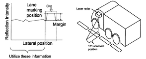
- the figure on the left shows the relationship between reflection intensity and lateral distance.
- the right figure is a figure which shows the aspect of laser beam irradiation. It is the schematic which shows the flow of the whole road surface state estimation apparatus which concerns on this embodiment. It is a block diagram which shows the production
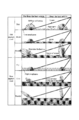
- FIG. 8 is a graph showing the relationship between the reflection intensity and the scanning position (position of each irradiation point) in FIG. It is a figure explaining decomposition
- A is a low frequency signal and D is a high frequency signal.
- Fig. 4 shows multi-stage signal decomposition using a filter bank. The frequency bands separated in each decomposition stage are shown. It is a figure explaining decomposition
- a road surface state estimation apparatus is a light projecting unit that irradiates a laser beam so as to scan on a road surface, and a light receiving unit that acquires a reflection intensity value corresponding to each irradiation point on the road surface. And a road surface state discriminator that discriminates the road surface state using the reflection intensity value.
- the road surface state estimation apparatus includes a two-dimensional scan type laser radar (LIDAR), a computer (an input unit, an output unit, a storage unit such as a RAM and a ROM, a processing unit mainly composed of a CPU) and the like as hardware configurations. ) And.
- the laser radar includes a light projecting unit and a light receiving unit.
- the light projecting unit includes a laser diode, a driving unit for emitting laser light from the laser diode, and an optical system for scanning (such as a mirror).
- the light receiving unit includes a photodetector (photodiode) that detects reflected light from the measurement target (road surface), and the reflection intensity is acquired from the output of the photodiode. Since the configuration of the laser radar itself is well known to those skilled in the art, a detailed description thereof will be omitted.
- the road surface state discriminator can be composed of a computer.
- the road surface state discriminator is generated by machine learning using multiple multipoint reflection intensity value sets acquired for multiple road surfaces with different known road surface states as learning data, and acquired for road surfaces with unknown road surface states Using the set multi-point reflection intensity value as an input, the road surface condition is determined and output.
- the multipoint reflection intensity value set (in the embodiment described later, the reflection intensity value at 171 points) is the irradiation position and reflection intensity in the perspective direction (along the scanning line) with reference to the light projecting portion depending on the road surface state. Defines the relationship with the value.
- a large number of reflection intensity values (multi-point reflection intensity value sets) at a large number of irradiation points are used for machine learning, and measurement data comprising the same multi-point reflection intensity value set is used as an input to classify road surface conditions.
- a laser radar is mounted on the vehicle, and the road surface is irradiated while scanning the laser beam obliquely downward in the lateral width direction of the vehicle from the light projecting unit.
- the laser beam is scanned and transmitted over a predetermined range including the width of the white line in a direction crossing the road surface toward the side of the vehicle.
- the laser reflected light reflected by the road surface is received by the light receiving unit, and the reflection intensity corresponding to each irradiation position of the laser light is acquired.
- white line recognition is performed by measuring the reflection intensity of a white line using a laser radar (Patent Document 1, Non-Patent Document 2).
- This white line recognition uses a difference in reflection intensity to detect a white line because the white line and road asphalt have different reflectivities. Since the white line is mixed with glass beads, the reflection intensity of the white line part is larger than the reflection intensity of the asphalt part due to retroreflection of the glass beads. Therefore, when the horizontal distance is taken along the horizontal axis (scanning direction) and the reflection intensity is taken along the vertical axis, the left side of FIG. 1 is obtained.
- Patent Literature 1 and Non-Patent Literature 2 can be referred to.
- the road surface state can be estimated simultaneously using information acquired in white line recognition, and no new device or component is required.
- the road surface state estimation method uses a laser radar reflection intensity and a road surface roughness component extracted from the reflection intensity, and wavelet decomposition is used to extract the road surface roughness component.
- the machine learning is used for road surface discrimination. Aiming to distinguish six types of road surface conditions: dry, wet, and submerged, and two types of road surface quality: new asphalt and aged asphalt. An overall view of a road surface state discriminator using machine learning is shown in FIG.
- the road surface state estimation method considers the positional relationship and the mechanical properties of laser light reflection by using multipoint reflection intensity values included in the measurement range. Depending on the road surface condition, it is conceivable that the reflection intensity value approaches at different places between different road surfaces. Therefore, the feature amount is further increased using the road surface roughness component as an index, and this road surface roughness index is classified by the spatial frequency of the road surface. Therefore, what was calculated using wavelet was defined.
- the road surface state is estimated by using a naive Bayes estimator as a machine learning method for the feature quantity prepared in this way. While traveling, the number of feature values of multipoint reflection intensity values used for road surface state estimation may differ depending on the presence or absence of a white line (if there is a white line, feature quantity data corresponding to the white line is removed, as will be described later) ) The naive Bayes estimator can be applied well even if there is a partial loss of feature data.
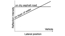
- the reflection characteristics of a laser beam by a water film will be described.
- the laser light is reflected in all directions by the scattering effect, but on the road surface covered with the water film, the reflected light has directionality due to regular reflection in addition to the scattering effect. Therefore, although the reflection intensity is low at the distal side (the side far from the light source), strong laser light reflection due to regular reflection occurs at the proximal side (side near the light source). This reflection intensity characteristic is shown in FIG.
- Reflection intensity is high because there is no absorption into the water film on the dry road surface.
- laser light is absorbed into the water film regardless of whether it is distal or proximal.
- the reflection intensity is lower than that of the road surface. This reflection intensity characteristic is shown in FIG.
- the reflection state varies depending on the mechanical properties of the road surface.
- For aged asphalt and new asphalt organize in dry, wet, submerged, and vehicle distal and vehicle proximal areas.
- the new asphalt has a higher reflection intensity than the aged asphalt.
- the wet road surface absorbs laser light into the water film, resulting in a decrease in reflection intensity.However, when the water film becomes thicker and becomes a flooded road surface, the reflection intensity approaches that of regular road reflection. To rise. In addition to these characteristics, the reflection intensity tends to gradually decrease as the distance from the laser beam emitting portion of the laser radar increases.
- FIG. 8 is a graph showing the relationship between the reflection intensity and the scanning position.
- the farthest data within the effective data range is taken as the origin, and the range up to the laser radar position is taken as the range of the horizontal axis.
- the reflection intensity can be expressed as a function of position by the mechanical properties of the road surface.
- the reflection intensity value also includes a wavelength component corresponding to the road surface wavelength in the scanning direction. More specifically, scanning is performed according to the characteristics of the spatial frequency (with the addition of laser reflection characteristics): “The larger the macro, the greater the undulation of the entire road surface”, and “The smaller the surface, the micro (particle) unevenness of the road surface”. It is measured as the difference in size of the reflection intensity value in the direction (see FIG. 15).
- This wavelength component is extracted by subjecting the reflection intensity value to discrete wavelet decomposition (FIGS. 9A to 9D). It is also possible to acquire a road surface roughness index using continuous wavelet analysis. By using discrete wavelet analysis, the amount of calculation can be reduced compared to continuous wavelet analysis. The reduction in the calculation amount leads to a reduction in processing cost. In the discrete wavelet analysis according to the present embodiment, the Mallat algorithm is used.
- FIG. 9A is a diagram for explaining signal decomposition.
- A is a low frequency signal and D is a high frequency signal.
- FIG. 9B shows multistage signal decomposition using a filter bank. At each stage, the low frequency component and the high frequency component are separated.
- FIG. 9C shows the frequency bands that are separated at each decomposition stage when the original wavelet is separated three times.
- f n is the center frequency of the mother wavelet.
- the wavelet frequency is usually calculated from a pseudo frequency corresponding to the scale.
- the relationship between frequency and scale is as follows. Fa: pseudo frequency, Fn: center frequency of wavelet (0.66667 Hz in 'db2'), a: scale, ⁇ : sampling period (distance between scanning positions is 0.0045 m).
- FIG. 9A is a diagram for explaining signal decomposition.
- A is a low frequency signal and D is a high frequency signal.
- FIG. 9B shows multistage signal decomposition using a filter bank. At each stage,
- 9D shows decomposition of the reflection intensity (dry state) by the discrete wavelet analysis according to this embodiment.
- the decomposition is performed five times.
- Signal D1 represents road roughness at fine details and signal D5 represents road roughness at low resolution.
- the spatial frequencies included in each high frequency signal are shown in Table 3 (described later).
- the road surface roughness index is obtained by taking the sum of the wavelength bands to be included as the road surface roughness. Therefore, data with n reflection intensity values can be obtained in each scan, whereas one data with road surface roughness can be obtained.
- this road surface roughness index as a road surface feature amount as a variable after the multipoint reflection intensity value, the road surface state estimation accuracy is improved.
- Table 1 summarizes laser light absorption, total reflection, and road surface roughness indices for six road surface conditions. In Table 1, ⁇ indicates strong, X indicates weak, and ⁇ indicates an intermediate value.
- naive Bayes estimator is used as supervised machine learning, and is effective when data according to the Bayes distribution is obtained for each class to be distinguished. It is a technique.
- a reflection intensity value and a road surface roughness index obtained as a result of discrete wavelet decomposition are calculated from the obtained laser radar data.
- n is the number of reflection intensities
- m is the number of road surface roughness indices
- the multipoint reflection intensity value of 171 points expresses the scanning position and reflection intensity from the distal to the proximal as function values.
- the time when the white line is not included in the scanning range is 171 data, and when the white line is included in the scanning range, the processing removes the white line intensity at the scanning position corresponding to the white line from the estimated range. Since the number of feature variables can be changed in this way, a naive Bayes estimator is used as a machine learning method that can cope with the change. Furthermore, it aims at improving estimation accuracy by adding a road surface roughness index after the multipoint reflection intensity value.
- the measurement road surfaces are classified by calculating equations (1) and (2) in real time.
- the position of the white line is recognized based on the road surface obtained from the laser radar and the white line reflection intensity value (see Patent Document 1 and Non-Patent Document 2).
- the white line portion is excluded from the road surface state estimation region based on the white line position information obtained by white line detection based on Patent Document 1 and Non-Patent Document 2. Specifically, from the number of data included in the current scanning range (171 points of data), if a white line is included, the number of data for the white line region (l) is subtracted. The number of multipoint reflection intensity values determined as a result is first set as the number of feature amounts defined at that time.
- a reflection intensity value (n ⁇ 1, where l is the number of data on the white line) and a road surface roughness index (m) based on the reflection intensity value are calculated from the measurement data.
- the road surface is classified by the naive Bayes estimator.
- the data processing apparatus can be configured by a computer (including a hardware configuration such as an input unit, an output unit, a storage unit, and a calculation unit, and predetermined software).
- the test mainly serves as a data storage device that stores various data.
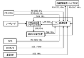
- a laser radar road surface state estimation system and a data logger device for collecting these data were mounted on a trailer type truck, and measurements were taken during business travel.
- Laser radar used for white line recognition and road surface condition estimation is installed on the ceiling of the truck.
- a GPS receiver, a weather recording camera, and a temperature / humidity sensor are installed for environmental recording when performing long-term measurement, and these data are recorded in a data logger.
- the laser radar As the laser radar, a scanning laser radar manufactured by Denso Corporation was used.
- the specifications of the laser radar are as follows. It should be noted that these specifications are only examples of laser radars that can be used in the present invention.
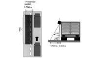
- the number of scanning points on one scanning line in the maximum detection area ( ⁇ 18 [deg]) of the laser radar is 451 points.
- 17.02-3.42 Data of 171 points corresponding to the irradiation angle of [deg] is acquired.
- the distance in the horizontal direction corresponding to 171 points is 0.7641 m.
- the reflected light corresponding to each of the 171 points (irradiation positions) is received, and the reflection intensity at 171 points is acquired.
- the measurement vehicle travels on the road surface at 50-60 km / h, and the sampling frequency of the laser radar is 10 Hz.
- An example of the reflection intensity result obtained by measuring the road surface with the laser radar at this time is shown in FIG.
- the horizontal axis is the horizontal distance, and the vertical axis is the time.
- the reflection intensity is actually displayed in a color scale (luminance value), it is in gray scale due to limitations of the patent drawing.
- FIG. 13 is a reflection intensity map obtained by 100 scans acquired during a 10-second run on an aged asphalt / dry road surface. The portion with high density represents the reflection intensity from the white line portion.
- the six conditions estimated in this test are “Aged asphalt / dry road surface”, “Aged asphalt / wet road surface”, “Aged asphalt / submersion road surface”, “New asphalt / dry road surface”, “New asphalt / wet road surface”. There are six types of "new asphalt / flooding surface”.
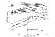
- FIG. 14 shows the reflection intensities obtained as shown in FIG. 13 in which the horizontal axis represents the scan position and the vertical axis represents the reflection intensity.
- the reflection intensity on the road surface under the six conditions shows such a value with respect to the scan position.
- the reflection intensity of dry / new asphalt and wet / aged asphalt, and the reflection intensity of wet / new asphalt and submersion / new asphalt show similar values, but it can be confirmed that they are separated under other conditions.
- wet and aged asphalt had a low recognition rate of 27.26% and submerged and new asphalt were 21.86%, which combined the reflection intensity value and the road surface roughness index.
- the recognition rate was greatly improved, with 93.21% wet and aged asphalt and 56.43% flooded and new asphalt, confirming the effect of adding road surface roughness index as road surface feature amount.
- the discrimination between dry and wet which was the object of this embodiment, was a recognition rate of 92% or more.
- the recognition rate was over 92% for new asphalt and over 93% for aged asphalt.
- the recognition rate of submergence and new asphalt is low, but this is because the correct data of the road surface condition is determined from the weather camera data, so there is a deviation from the actual in the determination of the water film thickness when switching from wet to submersion This is thought to have occurred.
- the data processing time at this time is 0.06 [sec / scanned data]
- this embodiment aims to develop road surface state estimation technology using laser radar that is used for white line recognition in automatic driving and platooning, and uses laser radar reflection intensity and road surface roughness index to We developed an algorithm to determine road dry / wet by using a naive Bayes estimator for learning.
- the road surface state estimation method using the conventional laser radar uses only the reflection intensity, whereas the multipoint reflection intensity value included in the measurement range is used to determine the positional relationship and the laser. For example, the mechanical properties of light reflection can be considered.
- the feature amount is increased using the road surface roughness component as an index, and wavelet decomposition is used to calculate the swell component related to the road surface roughness in order to classify the road surface roughness index by the spatial frequency of the road surface.
- the road surface state is estimated by using a naive Bayes estimator as a machine learning method for the feature quantity prepared in this way.
- a naive Bayes estimator was selected as a machine learning method that can also be applied to estimation objects whose number of features can change.
- the road surface information required for platooning is Dry / Wet information of asphalt, but using the results obtained by actual vehicle measurements, the conditions of the road surface are not only dry / wet but also dry / wet / flooded and asphalt old and new Road surface discrimination was performed on the expanded six road surfaces. As a result, a recognition rate of 92% or higher was obtained for the dry / wet discrimination required in this project. It was also confirmed that the quality of asphalt can be distinguished from old and new.
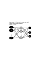
- the road surface state discriminator may be configured from a neural network. As shown in FIG. 16, the neural network includes 171 input nodes (171 multipoint reflection intensity values), output nodes that label three classes (road surface conditions), and 10 hidden nodes. I have.
Abstract
The present invention is provided with a light irradiation unit for irradiating laser light so as to scan a road surface, a light reception unit for acquiring reflection intensity values corresponding to each irradiated point on the road surface, and a road surface condition determination device for determining a road surface condition using the reflection intensity values. A set of reflection intensity values acquired for each irradiated point on a road surface (hereafter referred to as a "multipoint reflection intensity value set") defines the relationship between the irradiation positions in the far-near direction from the light irradiation unit and the reflection intensity values, which are dependent on the road condition. The road surface condition determination device is created through machine learning using, as learned data, a plurality of multipoint reflection intensity value sets acquired for a plurality of road surfaces having different known road surface conditions and determines and outputs a road surface condition using, as input, a multipoint reflection intensity value set acquired for a road surface having an unknown road surface condition.
Description
本発明は、車両が走行する路面の状態を推定する路面状態推定装置に関するものである。
The present invention relates to a road surface state estimating device for estimating the state of a road surface on which a vehicle travels.
省エネルギー技術の開発の一環として、エネルギーITS(Intelligent Transportation Systems)プロジェクトが進められており、その中の一つに自動隊列走行の技術開発がある(特許文献1、非特許文献1~3)。本プロジェクトは、隊列走行における車間距離を短くすることにより、空気抵抗を減少させ、省エネルギー化を図ることを目的としている。本プロジェクトにおける白線認識アルゴリズム(特許文献1、非特許文献2)は、短い車間距離による省燃費効率を得るために、隊列における前後車両の横位置ずれを所定範囲内に制御すること等に用いられる。
As part of the development of energy-saving technology, the Energy ITS (Intelligent Transportation Systems) project is underway, and one of them is the technology development of automatic platooning (Patent Document 1, Non-Patent Documents 1 to 3). The purpose of this project is to reduce air resistance and save energy by shortening the inter-vehicle distance in platooning. The white line recognition algorithm (Patent Document 1, Non-Patent Document 2) in this project is used to control the lateral displacement of the front and rear vehicles in the platoon within a predetermined range in order to obtain fuel saving efficiency with a short inter-vehicle distance. .
自動操舵や自動速度制御を伴う自動隊列走行における車間距離制御の実用化において、路面状態の急変に対応した制動制御が必要となる。自動隊列走行において、例えば、路面状態に応じてチューニングした制御ゲインを作成しておき、トンネルから出た際に、走行環境が乾燥路面から湿潤・冠水・凍結路面などに変化した場合に路面状態の変化に対応して制御ゲインを瞬時に変更することは、安全確保上有用である。
In practical application of inter-vehicle distance control in automatic platooning with automatic steering and automatic speed control, braking control corresponding to sudden changes in road surface conditions is required. In automatic platooning, for example, a control gain tuned according to the road surface condition is created, and when the driving environment changes from a dry road surface to a wet, flooded, frozen road surface, etc. It is useful for ensuring safety to change the control gain instantaneously in response to the change.
一般に、自動車などの車両の駆動力・制動力や操舵力は路面とタイヤの摩擦に依存しており、路面状態を推定することは、走行性能の確保や安全性の向上にとって有益な技術である。路面状態推定技術としては、これまでに様々な手法、例えば、レーザレーダ反射強度を活用する方法、カメラ画像を活用する方法などが提案されている(非特許文献4~7)。しかしながら、特に、自動運転走行車両に適切な手法は確立されていなかった。
In general, the driving force, braking force, and steering force of vehicles such as automobiles depend on the friction between the road surface and tires, and estimating the road surface condition is a useful technique for ensuring driving performance and improving safety. . As a road surface state estimation technique, various methods have been proposed so far, for example, a method utilizing laser radar reflection intensity, a method utilizing camera image, and the like (Non-Patent Documents 4 to 7). However, in particular, a method suitable for an autonomous driving vehicle has not been established.
本発明者らは、自動運転・隊列走行における白線認識に用いられるレーザレーダを活用した新しい路面状態推定技術の開発を行った。従来レーザレーダを用いた路面状態推定法は反射強度のみを利用する手法が採用されているのに対して、本発明は、多点反射強度値を用いることで位置関係とレーザ光反射の路面状態に依存する機械的性質を考慮するものである。本発明は、白線認識技術に関連して創案されたものであるが、本発明に係る技術思想は、自動隊列走行や白線認識技術に限定されるものではなく、路面状態推定技術として一般化され、路面状態の推定全般に適用され得るものである。
The present inventors have developed a new road surface state estimation technique using a laser radar used for white line recognition in automatic driving and platooning. Whereas the conventional road surface state estimation method using a laser radar employs a method that uses only the reflection intensity, the present invention uses a multipoint reflection intensity value to determine the positional relationship and the road surface state of laser light reflection. The mechanical properties that depend on The present invention was created in connection with the white line recognition technology, but the technical idea according to the present invention is not limited to automatic platooning or white line recognition technology, but is generalized as road surface state estimation technology. It can be applied to general estimation of road surface conditions.
本発明は、機械学習を用いた新しい路面状態推定装置を提供するものである。
本発明の目的の1つは、自動運転走行車両に良好に適用し得る路面状態推定装置を提供することになる。
本発明の他の目的やより具体的な目的は、本明細書の記載および図面から明らかとなる。 The present invention provides a new road surface state estimation apparatus using machine learning.
One of the objects of the present invention is to provide a road surface state estimation device that can be satisfactorily applied to an autonomous driving vehicle.
Other objects and more specific objects of the present invention will become apparent from the description of the present specification and the drawings.
本発明が採用した路面状態推定装置は、路面上を走査するようにレーザ光を照射する投光部と、路面上の各照射点に対応する反射強度値を取得する受光部と、反射強度値を用いて路面状態を判別する路面状態判別器と、を備えている。路面上の各照射点に対応して取得された反射強度値のセット(「多点反射強度値セット」という)は、路面状態に依存する投光部を基準とした遠近方向の照射位置と反射強度値との関係を規定している。前記路面状態判別器は、既知の異なる路面状態を備えた複数の路面についてそれぞれ取得された複数の多点反射強度値セットを学習データとして用いた機械学習により生成されている。前記路面状態判別器は、路面状態が未知の路面について取得された多点反射強度値セットを入力として、路面状態を判別して出力する。
The road surface state estimation device adopted by the present invention includes a light projecting unit that irradiates a laser beam so as to scan the road surface, a light receiving unit that acquires a reflection intensity value corresponding to each irradiation point on the road surface, and a reflection intensity value And a road surface state discriminator that discriminates the road surface state using A set of reflection intensity values acquired corresponding to each irradiation point on the road surface (referred to as a “multi-point reflection intensity value set”) is the irradiation position and reflection in the perspective direction based on the light projecting part depending on the road surface condition. Defines the relationship with intensity values. The road surface state discriminator is generated by machine learning using a plurality of multipoint reflection intensity value sets respectively acquired for a plurality of road surfaces having different known road surface states as learning data. The road surface condition discriminator discriminates and outputs a road surface condition with a multipoint reflection intensity value set acquired for a road surface whose road surface condition is unknown as an input.
本発明の原理上、レーザ光の照射・走査方向は限定されないが、1つの態様では、前記路面状態推定装置は、路面上を走行する車両に搭載されており、前記レーザ光は、路面を横切る方向に走査するように照射される。
1つの態様では、レーザ光の照射範囲には、路面の走行方向に延びる区画線(典型的な例では白線)が含まれており、路面状態が未知の路面について取得された多点反射強度値セットには、前記区画線に対応する反射強度値が含まれており、前記路面状態判別器は、前記取得された多点反射強度値セットから前記区画線に対応する反射強度値を除いた反射強度値セットを用いて路面状態の判別を行う。
この場合、1つの態様では、除去したデータを補間した上で、判別を行う。データ補間法(内挿、外挿)は当業者に既知であるため、説明は省略する。あるいは、除去したデータが欠落したままで路面状態の判別を行ってもよい。
また、前記区画線に対応する反射強度値から得られた特徴量(例えば、白線部分と白線以外の部分との反射強度値の差、白線部分における路面粗さ指標等)を利用してもよい。 Although the laser beam irradiation / scanning direction is not limited based on the principle of the present invention, in one aspect, the road surface state estimation device is mounted on a vehicle traveling on a road surface, and the laser light crosses the road surface. Irradiated to scan in the direction.
In one aspect, the irradiation range of the laser beam includes a lane marking (white line in a typical example) extending in the traveling direction of the road surface, and the multipoint reflection intensity value acquired for a road surface whose road surface state is unknown. The set includes a reflection intensity value corresponding to the lane line, and the road surface state discriminator is a reflection obtained by removing the reflection intensity value corresponding to the lane line from the acquired multipoint reflection intensity value set. The road surface condition is determined using the intensity value set.
In this case, in one aspect, the determination is performed after the removed data is interpolated. Since data interpolation methods (interpolation, extrapolation) are known to those skilled in the art, description thereof is omitted. Alternatively, the road surface condition may be determined while the removed data is missing.
Further, a feature amount obtained from the reflection intensity value corresponding to the lane marking (for example, a difference in reflection intensity value between a white line portion and a portion other than the white line, a road surface roughness index in the white line portion, etc.) may be used. .
1つの態様では、前記多点反射強度値セット解析することで路面状態に依存した路面粗さ指標を取得する解析手段を備えている。前記学習データには、既知の異なる路面状態を備えた複数の路面についてそれぞれ取得された複数の路面粗さ指標が含まれている。前記路面状態判別器は、路面状態が未知の路面について取得された多点反射強度値セット及び路面粗さ指標を入力として、路面状態を判別して出力する。
1つの態様では、前記解析手段は、離散ウェーブレット解析である。
離散ウェーブレット解析に比べて処理速度が遅いものの、連続ウェーブレット解析を用いることも可能である。また、フーリエ解析によって路面粗さ指標を取得してもよい。
このように、1つの態様では、第1特徴量として「多点反射強度値セット」、第2特徴量として「路面粗さ指標」を用いるが、本発明において、第2特徴量は好ましい任意情報であって、必須情報ではない。路面状態に依存した第2特徴量として路面粗さ指標以外の指標を用いることは妨げない。すなわち、第2特徴量は、情報の種類・数を任意に選択することが可能であり、複数の特徴量を第2特徴量として採用してもよい。
また、路面状態推定技術は長年に亘って研究されていることから様々な知見が得られており、本発明に対して他の推定手段や知見を組み合わせることは任意である。 In one aspect, an analysis unit is provided that acquires a road surface roughness index depending on a road surface state by performing the multipoint reflection intensity value set analysis. The learning data includes a plurality of road surface roughness indices respectively acquired for a plurality of road surfaces having different known road surface conditions. The road surface state discriminator receives the multipoint reflection intensity value set and road surface roughness index acquired for a road surface whose road surface state is unknown, and determines and outputs the road surface state.
In one aspect, the analysis means is a discrete wavelet analysis.
Although the processing speed is slower than that of discrete wavelet analysis, it is possible to use continuous wavelet analysis. Further, the road surface roughness index may be acquired by Fourier analysis.
As described above, in one aspect, the “multi-point reflection intensity value set” is used as the first feature quantity and the “road surface roughness index” is used as the second feature quantity. In the present invention, the second feature quantity is preferable optional information. However, it is not essential information. It is not prohibited to use an index other than the road surface roughness index as the second feature amount depending on the road surface state. That is, as the second feature amount, the type and number of information can be arbitrarily selected, and a plurality of feature amounts may be adopted as the second feature amount.
Moreover, since the road surface state estimation technique has been studied for many years, various knowledge has been obtained, and it is optional to combine other estimation means and knowledge with the present invention.
1つの態様では、前記路面状態判別器は、ナイーブ・ベイズ推定器から構成されている。
1つの態様では、前記路面状態判別器は、ニューラルネットワークから構成されている。
本発明の路面状態判別器に適用し得る機械学習としては、「教師信号つき機械学習」の手法であれば、適用可能であり、例えば、クラスタリング、判別分析(線形判別関数やマハラノビス距離)、ロジスティック回帰分析、サポートベクターマシン、決定木などが適用可能である。 In one aspect, the road surface state discriminator is composed of a naive Bayes estimator.
In one aspect, the said road surface state discriminator is comprised from the neural network.
As machine learning that can be applied to the road surface state discriminator of the present invention, any method of “machine learning with a teacher signal” can be applied. For example, clustering, discriminant analysis (linear discriminant function or Mahalanobis distance), logistic Regression analysis, support vector machines, decision trees, etc. are applicable.
1つの態様では、前記路面状態判別器は、少なくとも、乾燥状態と、湿潤状態と、を判別する。
1つの態様では、前記路面状態判別器は、さらに、冠水状態を判別する。
1つの態様では、前記路面状態判別器は、さらに、路面の劣化状態を判別する。
1つの態様では、上記状態の組み合わせてなる6つの路面状態を判別する。
典型的な態様では、前記路面はアスファルト舗装面である。
本発明の対象となる路面状態や路面の材質は、これらのものに限定されない。本発明は、機械学習により生成される路面状態判別器を用いるので、路面状態の種類や路面の材質に限定されずに、ある状態のある路面について取得した学習データを用いて路面状態判別器を生成すればよい。 In one aspect, the road surface state discriminator discriminates at least a dry state and a wet state.
In one aspect, the road surface condition discriminator further discriminates a flood condition.
In one aspect, the said road surface state discriminator further discriminate | determines the degradation state of a road surface.
In one aspect, six road surface states that are combinations of the above states are determined.
In a typical embodiment, the road surface is an asphalt pavement surface.
The road surface state and the road surface material that are the subject of the present invention are not limited to these. Since the present invention uses a road surface state discriminator generated by machine learning, the road surface state discriminator is not limited to the kind of road surface state and the material of the road surface, and the road surface state discriminator is obtained using learning data acquired for a road surface in a certain state. It only has to be generated.
本発明は、機械学習を用いた新しい路面状態推定装置を提供するものである。
本発明に係る路面状態推定装置は車両に搭載することができ、車両走行中に反射強度データを取得ながらリアルタイムで路面状態を推定することができ、自動運転走行車両に良好に適用し得るものである。
本発明では、所定の路面状態の学習データを取得して路面状態判別器を生成することで、後述する実施形態のように、アスファルト路面の劣化状況、水による潤滑状況、水膜の存在といった摩擦係数に依存する状態を、レーザレーダによって取得した反射強度を用いて判別することができる。
本発明はまた、白線をレーザレーダで認識し、自動走行を行う車両において、白線検出用のレーザレーダ装置の出力を利用して、路面状態を推定することができる。 The present invention provides a new road surface state estimation apparatus using machine learning.
The road surface state estimation device according to the present invention can be mounted on a vehicle, can estimate a road surface state in real time while acquiring reflection intensity data while the vehicle is traveling, and can be applied well to an autonomous driving vehicle. is there.
In the present invention, by acquiring learning data of a predetermined road surface state and generating a road surface state discriminator, as in an embodiment described later, friction such as asphalt road surface deterioration state, water lubrication state, water film presence, etc. The state depending on the coefficient can be determined using the reflection intensity acquired by the laser radar.
The present invention can also estimate a road surface condition by using an output of a white line detecting laser radar device in a vehicle that recognizes a white line with a laser radar and performs automatic traveling.
[A]本発明の概要
本発明に係る路面状態推定装置は、路面上を走査するようにレーザ光を照射する投光部と、路面上の各照射点に対応する反射強度値を取得する受光部と、反射強度値を用いて路面状態を判別する路面状態判別器と、を備えている。路面状態推定装置は、ハードウェア構成としては、2次元スキャン式のレーザレーダ(LIDAR)と、コンピュータ(入力部、出力部、RAM、ROM等の記憶部、CPUを主体とする処理部等を備える)と、から構成することができる。 [A] Outline of the Present Invention A road surface state estimation apparatus according to the present invention is a light projecting unit that irradiates a laser beam so as to scan on a road surface, and a light receiving unit that acquires a reflection intensity value corresponding to each irradiation point on the road surface. And a road surface state discriminator that discriminates the road surface state using the reflection intensity value. The road surface state estimation apparatus includes a two-dimensional scan type laser radar (LIDAR), a computer (an input unit, an output unit, a storage unit such as a RAM and a ROM, a processing unit mainly composed of a CPU) and the like as hardware configurations. ) And.
本発明に係る路面状態推定装置は、路面上を走査するようにレーザ光を照射する投光部と、路面上の各照射点に対応する反射強度値を取得する受光部と、反射強度値を用いて路面状態を判別する路面状態判別器と、を備えている。路面状態推定装置は、ハードウェア構成としては、2次元スキャン式のレーザレーダ(LIDAR)と、コンピュータ(入力部、出力部、RAM、ROM等の記憶部、CPUを主体とする処理部等を備える)と、から構成することができる。 [A] Outline of the Present Invention A road surface state estimation apparatus according to the present invention is a light projecting unit that irradiates a laser beam so as to scan on a road surface, and a light receiving unit that acquires a reflection intensity value corresponding to each irradiation point on the road surface. And a road surface state discriminator that discriminates the road surface state using the reflection intensity value. The road surface state estimation apparatus includes a two-dimensional scan type laser radar (LIDAR), a computer (an input unit, an output unit, a storage unit such as a RAM and a ROM, a processing unit mainly composed of a CPU) and the like as hardware configurations. ) And.
レーザレーダは、投光部と受光部とを備える。投光部は、レーザダイオード、レーザダイオードからレーザ光を出射させるための駆動部、走査用の光学系(ミラー等)、を備える。受光部は、測定対象(路面)からの反射光を検出する光検出器(フォトダイオード)を備え、フォトダイオードの出力から反射強度が取得される。レーザレーダ自体の構成は、当業者によく知られているので、詳細な説明は省略する。
The laser radar includes a light projecting unit and a light receiving unit. The light projecting unit includes a laser diode, a driving unit for emitting laser light from the laser diode, and an optical system for scanning (such as a mirror). The light receiving unit includes a photodetector (photodiode) that detects reflected light from the measurement target (road surface), and the reflection intensity is acquired from the output of the photodiode. Since the configuration of the laser radar itself is well known to those skilled in the art, a detailed description thereof will be omitted.
路面状態判別器はコンピュータから構成することができる。路面状態判別器は、既知の異なる路面状態を備えた複数の路面についてそれぞれ取得された複数の多点反射強度値セットを学習データとして用いた機械学習により生成され、路面状態が未知の路面について取得された多点反射強度値セットを入力として、路面状態を判別して出力する。
The road surface state discriminator can be composed of a computer. The road surface state discriminator is generated by machine learning using multiple multipoint reflection intensity value sets acquired for multiple road surfaces with different known road surface states as learning data, and acquired for road surfaces with unknown road surface states Using the set multi-point reflection intensity value as an input, the road surface condition is determined and output.
路面上の連続状の各照射点(後述する実施形態での走査間隔は0.0045mである。さらに細かくして分解能を上げてもよい)に対応して取得された連続状の反射強度値からなる多点反射強度値セット(後述する実施形態では、171点における反射強度値)は、路面状態に依存する投光部を基準とした遠近方向(走査線に沿った)の照射位置と反射強度値との関係を規定している。本発明においては、多数の照射点における多数の反射強度値(多点反射強度値セット)を機械学習に用いて、同じく多点反射強度値セットからなる計測データを入力として、路面状態のクラス分けを行う点に特徴の一つがある。
From the continuous reflection intensity values acquired corresponding to each continuous irradiation point on the road surface (the scanning interval in the embodiment described later is 0.0045 m. The resolution may be further increased). The multipoint reflection intensity value set (in the embodiment described later, the reflection intensity value at 171 points) is the irradiation position and reflection intensity in the perspective direction (along the scanning line) with reference to the light projecting portion depending on the road surface state. Defines the relationship with the value. In the present invention, a large number of reflection intensity values (multi-point reflection intensity value sets) at a large number of irradiation points are used for machine learning, and measurement data comprising the same multi-point reflection intensity value set is used as an input to classify road surface conditions. One of the features is that
[B]レーザレーダを利用した路面状態の推定
[B-1]路面状態推定手法の概要
本発明の一実施形態について詳細に説明する。本実施形態は、リアルタイムで乾燥・湿潤判定を行うことを目的とし、自動運転・隊列走行における白線認識に用いるレーザレーダを活用して路面状態を推定するものである。本実施形態では、レーザレーダ反射強度および反射強度の路面粗さ成分情報を用いて機械学習により路面の乾燥・湿潤を判定する路面状態推定アルゴリズムを提案し、このアルゴリズムを用いて路面状態推定実験を行った。 [B] Road Surface State Estimation Using Laser Radar [B-1] Outline of Road Surface State Estimation Method An embodiment of the present invention will be described in detail. The purpose of this embodiment is to perform dry / wet determination in real time, and to estimate the road surface condition using a laser radar used for white line recognition in automatic driving and platooning. In the present embodiment, a road surface state estimation algorithm for determining dryness and wetness of a road surface by machine learning using laser radar reflection intensity and road surface roughness component information of the reflection intensity is proposed, and a road surface state estimation experiment is performed using this algorithm. went.
図1右図に示すように、レーザレーダを車両に搭載し、投光部から車両の横幅方向に斜め下方に向けてレーザ光を走査させながら路面に照射する。レーザ光は、車両の側方に向かって路面を横切る方向に、白線の幅を含む所定範囲に亘ってスキャン送信される。路面で反射されたレーザ反射光は受光部によって受光され、レーザ光の各照射位置に対応する反射強度が取得される。この反射強度情報を活用することで白線認識と路面認識の双方を行う統合システムを構築する。
As shown in the figure on the right side of FIG. 1, a laser radar is mounted on the vehicle, and the road surface is irradiated while scanning the laser beam obliquely downward in the lateral width direction of the vehicle from the light projecting unit. The laser beam is scanned and transmitted over a predetermined range including the width of the white line in a direction crossing the road surface toward the side of the vehicle. The laser reflected light reflected by the road surface is received by the light receiving unit, and the reflection intensity corresponding to each irradiation position of the laser light is acquired. By utilizing this reflection intensity information, an integrated system that performs both white line recognition and road surface recognition is constructed.
自動運転隊列走行の技術開発において、レーザレーダを用いて白線の反射強度を計測することで白線認識を実施している(特許文献1、非特許文献2)。この白線認識は、白線と道路アスファルトでは反射率が異なるため、反射強度の差を利用して白線を検知するものである。白線はガラスビーズが混入されているためガラスビーズの再帰性反射により白線部分の反射強度は、アスファルト部分の反射強度よりも大きくなる。したがって、横軸に横方向距離(走査方向)、縦軸に反射強度をとると、図1左図のようになる。なお、横方向距離Xは、レーザレーダ設置高さをHとしたとき、X=H*tan(レーザレーダ取付角+スキャン角度)で計算できる。白線認識の詳細については、特許文献1、非特許文献2を参照することができる。本実施形態においては、白線認識において取得された情報を用いて、同時に路面状態の推定を行うことができ、新たな装置や部品を必要としない。
In the technical development of automated driving platooning, white line recognition is performed by measuring the reflection intensity of a white line using a laser radar (Patent Document 1, Non-Patent Document 2). This white line recognition uses a difference in reflection intensity to detect a white line because the white line and road asphalt have different reflectivities. Since the white line is mixed with glass beads, the reflection intensity of the white line part is larger than the reflection intensity of the asphalt part due to retroreflection of the glass beads. Therefore, when the horizontal distance is taken along the horizontal axis (scanning direction) and the reflection intensity is taken along the vertical axis, the left side of FIG. 1 is obtained. The lateral distance X can be calculated by X = H * tan (laser radar mounting angle + scanning angle) where the laser radar installation height is H. For details of white line recognition, Patent Literature 1 and Non-Patent Literature 2 can be referred to. In this embodiment, the road surface state can be estimated simultaneously using information acquired in white line recognition, and no new device or component is required.
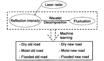
図2に示すように、本実施形態に係る路面状態推定手法は、レーザレーダ反射強度およびその反射強度から抽出した路面粗さ成分を活用するものであり、路面粗さ成分の抽出にはウェーブレット分解を、路面判別には機械学習を用いる。路面状態として乾燥・湿潤・冠水の3種類、路面の質として新アスファルト・経年アスファルトの2種類、計6種類の判別を目指す。機械学習を用いた路面状態判別器の全体図を図3に示す。
As shown in FIG. 2, the road surface state estimation method according to the present embodiment uses a laser radar reflection intensity and a road surface roughness component extracted from the reflection intensity, and wavelet decomposition is used to extract the road surface roughness component. The machine learning is used for road surface discrimination. Aiming to distinguish six types of road surface conditions: dry, wet, and submerged, and two types of road surface quality: new asphalt and aged asphalt. An overall view of a road surface state discriminator using machine learning is shown in FIG.
本実施形態に係る路面状態推定手法は、計測範囲に含まれる多点反射強度値を用いることで位置関係とレーザ光反射の機械的性質を考慮するものである。路面状態によっては、異なる路面間で、複数個所で反射強度値が近づくことが考えられるため、さらに路面粗さ成分を指標として特徴量を増やし、この路面粗さ指標として、路面の空間周波数で分類するためウェーブレットを用いて算出したものを定義した。
The road surface state estimation method according to the present embodiment considers the positional relationship and the mechanical properties of laser light reflection by using multipoint reflection intensity values included in the measurement range. Depending on the road surface condition, it is conceivable that the reflection intensity value approaches at different places between different road surfaces. Therefore, the feature amount is further increased using the road surface roughness component as an index, and this road surface roughness index is classified by the spatial frequency of the road surface. Therefore, what was calculated using wavelet was defined.
このようにして用意された特徴量に対して、機械学習法としてナイーブ・ベイズ推定器を用いることで路面状態推定を行う。走行中、白線の有無によって路面状態推定に用いる多点反射強度値の特徴量のデータ数が異なり得るが(後述するように、白線がある場合には、白線に対応する特徴量データが取り除かれる)、ナイーブ・ベイズ推定器は特徴量データの部分的な欠落があっても良好に適用され得る。
The road surface state is estimated by using a naive Bayes estimator as a machine learning method for the feature quantity prepared in this way. While traveling, the number of feature values of multipoint reflection intensity values used for road surface state estimation may differ depending on the presence or absence of a white line (if there is a white line, feature quantity data corresponding to the white line is removed, as will be described later) ) The naive Bayes estimator can be applied well even if there is a partial loss of feature data.
[B-2]路面状態推定特徴量
(1)レーザレーダ反射強度(第1特徴量)
レーザレーダ反射強度は、路面の質・状態や路面への入射角度によって異なることが知られている。そこでまずレーザレーダ反射強度の機械的性質について整理する。レーザレーダは車両の進行方向に対して横方向下向きに路面をスキャンする。このときのレーザ光の水膜による反射、水膜への吸収、路面の新旧による反射の3点から考察する。 [B-2] Road surface state estimation feature quantity (1) Laser radar reflection intensity (first feature quantity)
It is known that the laser radar reflection intensity varies depending on the road surface quality / state and the incident angle on the road surface. First, the mechanical properties of the laser radar reflection intensity are summarized. The laser radar scans the road surface downward in the lateral direction with respect to the traveling direction of the vehicle. We consider three points: reflection of the laser beam by the water film, absorption by the water film, and reflection by the road surface.
第1に、レーザ光の水膜による反射特性について述べる。乾燥路面においては、レーザ光は散乱効果により全方位に反射するが、水膜に覆われた路面においては散乱効果に加えて正反射が加わることで反射光は方向性を持つ。したがって遠位(光源から遠い側)において反射強度は低くなるが、近位(光源に近い側)においては正反射による強いレーザ光反射が生じる。この反射強度特性を図4に示す。
First, the reflection characteristics of a laser beam by a water film will be described. On the dry road surface, the laser light is reflected in all directions by the scattering effect, but on the road surface covered with the water film, the reflected light has directionality due to regular reflection in addition to the scattering effect. Therefore, although the reflection intensity is low at the distal side (the side far from the light source), strong laser light reflection due to regular reflection occurs at the proximal side (side near the light source). This reflection intensity characteristic is shown in FIG.
第2に、水膜への吸収反射特性について述べる。乾燥路面においては水膜への吸収はないため反射強度は高い値を示すが、水膜に覆われた路面においては遠位および近位を問わずレーザ光が水膜へ吸収されるため、乾燥路面よりも反射強度は低い値を示す。この反射強度特性を図5に示す。
Second, the absorption and reflection characteristics to the water film will be described. Reflection intensity is high because there is no absorption into the water film on the dry road surface. However, on the road surface covered with the water film, laser light is absorbed into the water film regardless of whether it is distal or proximal. The reflection intensity is lower than that of the road surface. This reflection intensity characteristic is shown in FIG.
第3に、路面の新旧による反射特性について述べる。アスファルト敷設当初は粒子が大きく路面の凹凸が存在していたものが、車両走行を経ることでアスファルト粒子の凹凸が均されてゆく。それに伴い、アスファルト敷設当初は凹凸によってレーザ光が散逸して反射強度が低いものが、経年アスファルトになることによって凹凸によるレーザ光散逸が減ることで反射強度が高くなる。この反射強度特性を図6に示す。
Thirdly, the reflection characteristics of the road surface will be described. At the beginning of asphalt laying, the particles were large and the road surface was uneven, but the asphalt particle unevenness was leveled as the vehicle traveled. Along with this, the laser light is diffused by unevenness at the beginning of asphalt laying and the reflection intensity is low, but the reflection intensity is increased by reducing the laser light dissipation due to the unevenness by becoming asphalt over time. This reflection intensity characteristic is shown in FIG.
このように路面の機械的性質によって反射状態が異なる。経年アスファルト、新アスファルトのそれぞれに対して、乾燥、湿潤、冠水、また車両遠位領域および車両近位領域で整理する。先ず、新アスファルトと経年アスファルトを比較すると、上述のように、経年アスファルトに対して新アスファルトの方が、反射強度が高くなる。また、乾燥路面に比べて湿潤路面では、水膜へのレーザの吸収が生ずるため反射強度は低下するが、さらに水膜が厚くなり冠水路面となると正反射に近づくため湿潤路面よりも反射強度が上昇する。また、これらの特性に加えて、基本的にレーザレーダのレーザ光の出射部から遠方になるほど反射強度が緩やかに低下する傾向となるが、正反射に近づく路面状態(冠水・経年アスファルト、湿潤・新アスファルト、冠水・新アスファルト)では遠方になるほど反射強度の低下は顕著となる。これらの関係をまとめたものが図7である。これを反射強度とスキャニング位置との関係をグラフに整理したものが図8である。この図8において有効データ範囲内で最も遠位のデータを原点にとり、レーザレーダ位置までを横軸の範囲とする。このように反射強度は路面の機械的性質により位置の関数として表現することが可能である。
反射 Thus, the reflection state varies depending on the mechanical properties of the road surface. For aged asphalt and new asphalt, organize in dry, wet, submerged, and vehicle distal and vehicle proximal areas. First, when comparing a new asphalt and an aged asphalt, as described above, the new asphalt has a higher reflection intensity than the aged asphalt. Also, compared to dry road surfaces, the wet road surface absorbs laser light into the water film, resulting in a decrease in reflection intensity.However, when the water film becomes thicker and becomes a flooded road surface, the reflection intensity approaches that of regular road reflection. To rise. In addition to these characteristics, the reflection intensity tends to gradually decrease as the distance from the laser beam emitting portion of the laser radar increases. However, the road surface condition (flooding / aging asphalt, wet / In the case of new asphalt, submersion / new asphalt), the farther away, the more the reflection intensity decreases. FIG. 7 summarizes these relationships. FIG. 8 is a graph showing the relationship between the reflection intensity and the scanning position. In FIG. 8, the farthest data within the effective data range is taken as the origin, and the range up to the laser radar position is taken as the range of the horizontal axis. Thus, the reflection intensity can be expressed as a function of position by the mechanical properties of the road surface.
(2)路面粗さ指標(第2特徴量)
路面粗さの凹凸によってレーザ反射角度に差が生じ、結果として反射強度値にも、スキャニング方向に向かって路面波長に応じた波長成分が含まれることになる。より具体的には、「マクロになる程、路面全体のうねり」、「ミクロになる程、路面のミクロな(粒子)凹凸」という空間周波数の特徴によって(さらレーザ反射特性も加わって)、スキャニング方向に反射強度値の凸凹の大きさの違いとして計測される(図15参照)。この波長成分は反射強度値を離散ウェーブレット分解することによって抽出される(図9A~D)。連続ウェーブレット解析を用いて路面粗さ指標を取得することも可能であり、離散ウェーブレット解析を用いることで、連続ウェーブレット解析に比べて計算量を低減することができる。計算量の低減は、処理コストの低減をもたらす。本実施形態に係る離散ウェーブレット解析ではMallatアルゴリズムが用いられる。 (2) Road surface roughness index (second feature value)
The difference in the laser reflection angle is caused by the unevenness of the road surface roughness, and as a result, the reflection intensity value also includes a wavelength component corresponding to the road surface wavelength in the scanning direction. More specifically, scanning is performed according to the characteristics of the spatial frequency (with the addition of laser reflection characteristics): “The larger the macro, the greater the undulation of the entire road surface”, and “The smaller the surface, the micro (particle) unevenness of the road surface”. It is measured as the difference in size of the reflection intensity value in the direction (see FIG. 15). This wavelength component is extracted by subjecting the reflection intensity value to discrete wavelet decomposition (FIGS. 9A to 9D). It is also possible to acquire a road surface roughness index using continuous wavelet analysis. By using discrete wavelet analysis, the amount of calculation can be reduced compared to continuous wavelet analysis. The reduction in the calculation amount leads to a reduction in processing cost. In the discrete wavelet analysis according to the present embodiment, the Mallat algorithm is used.
図9Aは、信号の分解を説明する図である。Aは低周波数信号、Dは高周波数信号である。図9Bは、フィルタバンクを用いた多段信号分解を示す。各段階において、低周波成分と高周波成分が分離される。オリジナルのウェーブレットが3回分離された時の各分解段階において分離される周波数帯を図9Cに示す。fnは、マザーウェーブレットの中心周波数である。ウェーブレット周波数は、通常、スケールに応じた疑似周波数から計算される。周波数とスケールの関係は以下の通りである。
 Fa:疑似周波数、Fn:ウェーブレットの中心周波数(‘db2’では0.66667Hz)、a:スケール、Δ:サンプリング周期(各走査位置間の距離は0.0045m)、である。
図9Dに、本実施形態に係る離散ウェーブレット解析による反射強度(乾燥状態)の分解を示す。ここでは、5回の分解を行う。信号D1は、細かい詳細における路面粗さを表し、信号D5は低い分解能における路面粗さを表す。各高周波数信号に含まれる空間周波数を表3(後述する)に示す。
なお、ウェーブレット分解されたデータを路面粗さ指標算出に用いるだけでなく、白線のエッジ検出に利用することで、この一連の計測によって白線検知も統合することが可能である。 FIG. 9A is a diagram for explaining signal decomposition. A is a low frequency signal and D is a high frequency signal. FIG. 9B shows multistage signal decomposition using a filter bank. At each stage, the low frequency component and the high frequency component are separated. FIG. 9C shows the frequency bands that are separated at each decomposition stage when the original wavelet is separated three times. f n is the center frequency of the mother wavelet. The wavelet frequency is usually calculated from a pseudo frequency corresponding to the scale. The relationship between frequency and scale is as follows.
Fa: pseudo frequency, Fn: center frequency of wavelet (0.66667 Hz in 'db2'), a: scale, Δ: sampling period (distance between scanning positions is 0.0045 m).
FIG. 9D shows decomposition of the reflection intensity (dry state) by the discrete wavelet analysis according to this embodiment. Here, the decomposition is performed five times. Signal D1 represents road roughness at fine details and signal D5 represents road roughness at low resolution. The spatial frequencies included in each high frequency signal are shown in Table 3 (described later).
In addition to using the wavelet-decomposed data for road surface roughness index calculation, it is also possible to integrate white line detection by this series of measurements by using it for white line edge detection.
図9Dに、本実施形態に係る離散ウェーブレット解析による反射強度(乾燥状態)の分解を示す。ここでは、5回の分解を行う。信号D1は、細かい詳細における路面粗さを表し、信号D5は低い分解能における路面粗さを表す。各高周波数信号に含まれる空間周波数を表3(後述する)に示す。
なお、ウェーブレット分解されたデータを路面粗さ指標算出に用いるだけでなく、白線のエッジ検出に利用することで、この一連の計測によって白線検知も統合することが可能である。 FIG. 9A is a diagram for explaining signal decomposition. A is a low frequency signal and D is a high frequency signal. FIG. 9B shows multistage signal decomposition using a filter bank. At each stage, the low frequency component and the high frequency component are separated. FIG. 9C shows the frequency bands that are separated at each decomposition stage when the original wavelet is separated three times. f n is the center frequency of the mother wavelet. The wavelet frequency is usually calculated from a pseudo frequency corresponding to the scale. The relationship between frequency and scale is as follows.
FIG. 9D shows decomposition of the reflection intensity (dry state) by the discrete wavelet analysis according to this embodiment. Here, the decomposition is performed five times. Signal D1 represents road roughness at fine details and signal D5 represents road roughness at low resolution. The spatial frequencies included in each high frequency signal are shown in Table 3 (described later).
In addition to using the wavelet-decomposed data for road surface roughness index calculation, it is also possible to integrate white line detection by this series of measurements by using it for white line edge detection.
本実施形態では路面粗さとして含まれるべき波長帯の総和を取ることで路面粗さ指標とした。したがって各スキャンで反射強度値がn個のデータが得られるのに対して、路面粗さは1個のデータが得られることになる。路面特徴量としてこの路面粗さ指標を多点反射強度値の後の変数として加えることで路面状態推定精度向上を図る。表1に、6つの路面状態についてのレーザ光の吸収、全反射、路面粗さ指標をまとめる。なお、表1において、○は強、×は弱、そして△はその中間を示す。

In this embodiment, the road surface roughness index is obtained by taking the sum of the wavelength bands to be included as the road surface roughness. Therefore, data with n reflection intensity values can be obtained in each scan, whereas one data with road surface roughness can be obtained. By adding this road surface roughness index as a road surface feature amount as a variable after the multipoint reflection intensity value, the road surface state estimation accuracy is improved. Table 1 summarizes laser light absorption, total reflection, and road surface roughness indices for six road surface conditions. In Table 1, ◯ indicates strong, X indicates weak, and Δ indicates an intermediate value.
[B-3]ナイーブ・ベイズ推定器による路面認識
ナイーブ・ベイズ推定器は教師あり機械学習として用いられているものであり、判別すべきクラスごとでベイズ分布に従うデータが得られるときに有効な推定手法である。 [B-3] Road surface recognition by naive Bayes estimator The naive Bayes estimator is used as supervised machine learning, and is effective when data according to the Bayes distribution is obtained for each class to be distinguished. It is a technique.
ナイーブ・ベイズ推定器は教師あり機械学習として用いられているものであり、判別すべきクラスごとでベイズ分布に従うデータが得られるときに有効な推定手法である。 [B-3] Road surface recognition by naive Bayes estimator The naive Bayes estimator is used as supervised machine learning, and is effective when data according to the Bayes distribution is obtained for each class to be distinguished. It is a technique.
まず教師データを作成するために下記の手順を取る。
(1)得られたレーザレーダデータより反射強度値とそれを離散ウェーブレット分解した結果得られる路面粗さ指標を算出する。
(2)分類すべき6つのクラスのそれぞれに対して、特徴変数(fi)の平均値μiと標準偏差σiを算出する(i=1~N,N=n+m)。このとき、nは反射強度数、mは路面粗さ指標数であり、今回はそれぞれn=171,m=1である。このとき171点の多点反射強度値は遠位から近位までのスキャニング位置と反射強度を関数値として表現している。なおスキャニング範囲内に白線が含まれない時が171データであり、スキャニング範囲内に白線が含まれた場合には白線に該当するスキャニング位置の白線強度を推定範囲から外す処理を行う。このように特徴変数の数が変更し得ることから、それに対応しうる機械学習法としてナイーブ・ベイズ推定器を用いた。さらに、多点反射強度値の後に路面粗さ指標を加えることで推定精度向上を目指す。 First, take the following steps to create teacher data.
(1) A reflection intensity value and a road surface roughness index obtained as a result of discrete wavelet decomposition are calculated from the obtained laser radar data.
(2) For each of the six classes to be classified, the average value μ i and the standard deviation σ i of the feature variables (f i ) are calculated (i = 1 to N, N = n + m). At this time, n is the number of reflection intensities, m is the number of road surface roughness indices, and this time, n = 171 and m = 1, respectively. At this time, the multipoint reflection intensity value of 171 points expresses the scanning position and reflection intensity from the distal to the proximal as function values. The time when the white line is not included in the scanning range is 171 data, and when the white line is included in the scanning range, the processing removes the white line intensity at the scanning position corresponding to the white line from the estimated range. Since the number of feature variables can be changed in this way, a naive Bayes estimator is used as a machine learning method that can cope with the change. Furthermore, it aims at improving estimation accuracy by adding a road surface roughness index after the multipoint reflection intensity value.
以上のように得られた教師データを用い、リアルタイムで式(1)、(2)を算出することにより計測路面が分類される。
 Using the teacher data obtained as described above, the measurement road surfaces are classified by calculating equations (1) and (2) in real time.
[B-4]路面状態推定システム
路面状態推定は各スキャンデータを用いてリアルタイムに行う。データ処理の流れを図10に示す。 [B-4] Road surface state estimation system Road surface state estimation is performed in real time using each scan data. The flow of data processing is shown in FIG.
路面状態推定は各スキャンデータを用いてリアルタイムに行う。データ処理の流れを図10に示す。 [B-4] Road surface state estimation system Road surface state estimation is performed in real time using each scan data. The flow of data processing is shown in FIG.
(1)まずレーザレーダより得られた路面および白線反射強度値を元に白線位置を認識する(特許文献1、非特許文献2参照)。
(2)特許文献1、非特許文献2に基づく白線検知によって得られた白線位置情報を元に白線部分を路面状態推定領域から除外する。具体的には今回のスキャニング範囲に含まれるデータ数(171点のデータ)から、白線が含まれる場合には白線領域分のデータ数(l個)分を引いておく。その結果決定された多点反射強度値の数が、まずその時刻において定義される特徴量数とする。
(3)計測データより反射強度値(n-l個,ここにlは白線上のデータ数)と、それを元にした路面粗さ指標(m)と、を算出する。
(4)最後にナイーブ・ベイズ推定器によって路面の分類が行われる。 (1) First, the position of the white line is recognized based on the road surface obtained from the laser radar and the white line reflection intensity value (seePatent Document 1 and Non-Patent Document 2).
(2) The white line portion is excluded from the road surface state estimation region based on the white line position information obtained by white line detection based onPatent Document 1 and Non-Patent Document 2. Specifically, from the number of data included in the current scanning range (171 points of data), if a white line is included, the number of data for the white line region (l) is subtracted. The number of multipoint reflection intensity values determined as a result is first set as the number of feature amounts defined at that time.
(3) A reflection intensity value (n−1, where l is the number of data on the white line) and a road surface roughness index (m) based on the reflection intensity value are calculated from the measurement data.
(4) Finally, the road surface is classified by the naive Bayes estimator.
(2)特許文献1、非特許文献2に基づく白線検知によって得られた白線位置情報を元に白線部分を路面状態推定領域から除外する。具体的には今回のスキャニング範囲に含まれるデータ数(171点のデータ)から、白線が含まれる場合には白線領域分のデータ数(l個)分を引いておく。その結果決定された多点反射強度値の数が、まずその時刻において定義される特徴量数とする。
(3)計測データより反射強度値(n-l個,ここにlは白線上のデータ数)と、それを元にした路面粗さ指標(m)と、を算出する。
(4)最後にナイーブ・ベイズ推定器によって路面の分類が行われる。 (1) First, the position of the white line is recognized based on the road surface obtained from the laser radar and the white line reflection intensity value (see
(2) The white line portion is excluded from the road surface state estimation region based on the white line position information obtained by white line detection based on
(3) A reflection intensity value (n−1, where l is the number of data on the white line) and a road surface roughness index (m) based on the reflection intensity value are calculated from the measurement data.
(4) Finally, the road surface is classified by the naive Bayes estimator.
[C]宇部興産専用道における路面状態推定試験
[C-1]計測環境の構築
エネルギーITSプロジェクトにおけるセンサ系評価のため宇部興産専用道において約6か月間にわたる計測試験を実施した(非特許文献3)。その中で、レーザレーダによる路面状態推定試験を実施した。試験装置の全体構成図を図11に示す。フェールセーフECU(FS-ECU)からの情報、レーザレーダを用いた白線認識装置(アクティブ方式)からの情報、レーザデータを用いた路面状態推定装置からの情報、画像処理を用いた白線認識装置(パッシブ方式)からの情報、GPSからの情報、WEBカメラからの情報、温湿度計からの情報、がデータ処理装置に入力される。データ処理装置はコンピュータ(入力部、出力部、記憶部、演算部等のハードウェア構成と、所定のソフトウェアを備える)から構成することができる。試験では、以下に述べるように、主として各種データを記憶するデータ記憶装置としての役割を有する。試験では、図12に示すように、レーザレーダ路面状態推定システムとこれらデータを収集するデータロガー装置をトレーラ型トラックに搭載し、営業走行中の計測を実施した。白線認識および路面状態推定に用いられるレーザレーダはトラックの天井部分に設置されている。また長期計測を行うにあたっての環境記録用にGPS受信機、気象記録用カメラ、温湿度センサを設置してこれらデータをデータロガーに記録する。 [C] Road surface condition estimation test on Ube Industries private road [C-1] Construction of measurement environment Measurement tests were carried out on Ube Industries private road for about 6 months for sensor system evaluation in the Energy ITS Project (Non-patent Document 3) ). Among them, a road surface condition estimation test was conducted by laser radar. An overall configuration diagram of the test apparatus is shown in FIG. Information from a fail-safe ECU (FS-ECU), information from a white line recognition device using laser radar (active method), information from a road surface state estimation device using laser data, white line recognition device using image processing ( Information from the passive system), information from the GPS, information from the WEB camera, and information from the thermohygrometer are input to the data processing device. The data processing apparatus can be configured by a computer (including a hardware configuration such as an input unit, an output unit, a storage unit, and a calculation unit, and predetermined software). As described below, the test mainly serves as a data storage device that stores various data. In the test, as shown in FIG. 12, a laser radar road surface state estimation system and a data logger device for collecting these data were mounted on a trailer type truck, and measurements were taken during business travel. Laser radar used for white line recognition and road surface condition estimation is installed on the ceiling of the truck. In addition, a GPS receiver, a weather recording camera, and a temperature / humidity sensor are installed for environmental recording when performing long-term measurement, and these data are recorded in a data logger.
レーザレーダは、株式会社デンソー製のスキャン式のレーザレーダを用いた。レーザレーダの仕様は以下の通りである。これらの仕様は、本発明に用いられ得るレーザレーダの一例に過ぎないことに留意されたい。

レーザレーダの最大検知エリア(±18[deg])の1本の走査線上の走査点の数は451点であるが、本実施形態では、図12に示すように、17.02-3.42[deg]の照射角度に対応する171点のデータが取得される。171点に対応する横方向の距離は0.7641mである。171点の各点(照射位置)に対応する反射光が受光され、171点の反射強度が取得される。
As the laser radar, a scanning laser radar manufactured by Denso Corporation was used. The specifications of the laser radar are as follows. It should be noted that these specifications are only examples of laser radars that can be used in the present invention.
The number of scanning points on one scanning line in the maximum detection area (± 18 [deg]) of the laser radar is 451 points. In this embodiment, as shown in FIG. 12, 17.02-3.42 Data of 171 points corresponding to the irradiation angle of [deg] is acquired. The distance in the horizontal direction corresponding to 171 points is 0.7641 m. The reflected light corresponding to each of the 171 points (irradiation positions) is received, and the reflection intensity at 171 points is acquired.
計測車両は上記路面を50-60km/hで走行し、レーザレーダのサンプリング周波数は10Hzである。このときレーザレーダにより路面を計測した反射強度結果の例を図13に示す。横軸は横方向距離、縦軸は時間である。反射強度は実際にはカラースケール(輝度値)で表示されているが、特許図面の限界からグレースケールとなっている。図13は、経年アスファルト・乾燥路面上での10秒間の走行中に取得された100回の走査で得られた反射強度マップである。濃度の高い部分が白線部分からの反射強度を表している。
The measurement vehicle travels on the road surface at 50-60 km / h, and the sampling frequency of the laser radar is 10 Hz. An example of the reflection intensity result obtained by measuring the road surface with the laser radar at this time is shown in FIG. The horizontal axis is the horizontal distance, and the vertical axis is the time. Although the reflection intensity is actually displayed in a color scale (luminance value), it is in gray scale due to limitations of the patent drawing. FIG. 13 is a reflection intensity map obtained by 100 scans acquired during a 10-second run on an aged asphalt / dry road surface. The portion with high density represents the reflection intensity from the white line portion.
今回の試験において推定する路面6条件は、「経年アスファルト・乾燥路面」、「経年アスファルト・湿潤路面」、「経年アスファルト・冠水路面」、「新アスファルト・乾燥路面」、「新アスファルト・湿潤路面」、「新アスファルト・冠水路面」の6種類である。
The six conditions estimated in this test are “Aged asphalt / dry road surface”, “Aged asphalt / wet road surface”, “Aged asphalt / submersion road surface”, “New asphalt / dry road surface”, “New asphalt / wet road surface”. There are six types of "new asphalt / flooding surface".
(1)反射強度
図13のようにして得られた反射強度を横軸にスキャン位置・縦軸に反射強度にまとめたものを図14に示す。6条件の路面における反射強度はスキャン位置に対してこのような値を示している。乾燥・新アスファルトと湿潤・経年アスファルトの反射強度、および湿潤・新アスファルトと冠水・新アスファルトの反射強度が近い値を示しているが、それ以外の条件では分離されていることが確認できる。 (1) Reflection Intensity FIG. 14 shows the reflection intensities obtained as shown in FIG. 13 in which the horizontal axis represents the scan position and the vertical axis represents the reflection intensity. The reflection intensity on the road surface under the six conditions shows such a value with respect to the scan position. The reflection intensity of dry / new asphalt and wet / aged asphalt, and the reflection intensity of wet / new asphalt and submersion / new asphalt show similar values, but it can be confirmed that they are separated under other conditions.
図13のようにして得られた反射強度を横軸にスキャン位置・縦軸に反射強度にまとめたものを図14に示す。6条件の路面における反射強度はスキャン位置に対してこのような値を示している。乾燥・新アスファルトと湿潤・経年アスファルトの反射強度、および湿潤・新アスファルトと冠水・新アスファルトの反射強度が近い値を示しているが、それ以外の条件では分離されていることが確認できる。 (1) Reflection Intensity FIG. 14 shows the reflection intensities obtained as shown in FIG. 13 in which the horizontal axis represents the scan position and the vertical axis represents the reflection intensity. The reflection intensity on the road surface under the six conditions shows such a value with respect to the scan position. The reflection intensity of dry / new asphalt and wet / aged asphalt, and the reflection intensity of wet / new asphalt and submersion / new asphalt show similar values, but it can be confirmed that they are separated under other conditions.
(2)路面粗さ指標
図14のように反射強度のみでは路面条件間の判別が困難な場合があることから、路面粗さ指標を追加することでより精確な判別を行えるようにする。今回、路面粗さ指標は1つとし、n個の反射強度値に追加する。この路面粗さ指標は各スキャンにより得られる生データからリアルタイムで算出する。各スキャンにおける粗さデータを、離散ウェーブレット分解によって抽出し、粗さ指標を算出する。このときの路面粗さ波長はD1~D4に相当するものを採用し、これらの総和を取ることで路面粗さ指標とした。D1~D4の総和として算出された結果を図15に示す。路面粗さ指標はこの図15における横方向に総和を取るものであり、反射強度のばらつきの面積を取ることに相当する。

(2) Road Surface Roughness Index Since it may be difficult to discriminate between road surface conditions only with the reflection intensity as shown in FIG. 14, a more accurate discrimination can be performed by adding a road surface roughness index. This time, there is one road surface roughness index, and it is added to the n reflection intensity values. This road surface roughness index is calculated in real time from raw data obtained by each scan. Roughness data in each scan is extracted by discrete wavelet decomposition, and a roughness index is calculated. At this time, road surface roughness wavelengths corresponding to D1 to D4 were adopted, and the sum of these was taken as a road surface roughness index. FIG. 15 shows the result calculated as the sum of D1 to D4. The road surface roughness index is a sum in the horizontal direction in FIG. 15 and corresponds to taking an area of variation in reflection intensity.
図14のように反射強度のみでは路面条件間の判別が困難な場合があることから、路面粗さ指標を追加することでより精確な判別を行えるようにする。今回、路面粗さ指標は1つとし、n個の反射強度値に追加する。この路面粗さ指標は各スキャンにより得られる生データからリアルタイムで算出する。各スキャンにおける粗さデータを、離散ウェーブレット分解によって抽出し、粗さ指標を算出する。このときの路面粗さ波長はD1~D4に相当するものを採用し、これらの総和を取ることで路面粗さ指標とした。D1~D4の総和として算出された結果を図15に示す。路面粗さ指標はこの図15における横方向に総和を取るものであり、反射強度のばらつきの面積を取ることに相当する。
[C-2]路面状態認識結果
路面状態認識は1000[sec]の走行データを用い、6つの路面状態の認識を行った。路面状態は、カメラ画像から取得した。各クラスにおける平均値及び標準偏差は、クラスごとに1000個の訓練データから計算した。路面特徴量として多点反射強度値(171点の反射強度値)のみを用いてナイーブ・ベイズ推定器による路面認識した結果を表4に示す。判別に用いた計算式は以下の通りである。
 多点反射強度値(171点の反射強度値)に路面粗さ指標を加えたパラメータを路面特徴量としてナイーブ・ベイズ推定器による路面認識した結果を表5に示す。判別に用いた計算式は以下の通りである。
 上記式において、RI1-171:各反射強度値、F:路面粗さ指標、Class:路面状態、Z:定数、である。


[C-2] Road surface state recognition results Road surface state recognition was performed using 1000 [sec] travel data and six road surface states were recognized. The road surface condition was acquired from the camera image. Average values and standard deviations in each class were calculated from 1000 training data for each class. Table 4 shows the result of road surface recognition by the naive Bayes estimator using only the multipoint reflection intensity value (171 reflection intensity values) as the road surface feature amount. The calculation formula used for discrimination is as follows.
Table 5 shows the results of road surface recognition by a naive Bayes estimator using a road surface roughness index as a parameter obtained by adding a road surface roughness index to multipoint reflection intensity values (171 reflection intensity values). The calculation formula used for discrimination is as follows.
In the above formula, RI 1-171 : each reflection intensity value, F: road surface roughness index, Class: road surface state, Z: constant.
路面状態認識は1000[sec]の走行データを用い、6つの路面状態の認識を行った。路面状態は、カメラ画像から取得した。各クラスにおける平均値及び標準偏差は、クラスごとに1000個の訓練データから計算した。路面特徴量として多点反射強度値(171点の反射強度値)のみを用いてナイーブ・ベイズ推定器による路面認識した結果を表4に示す。判別に用いた計算式は以下の通りである。
反射強度値のみを用いた場合には湿潤・経年アスファルトが27.26%、冠水・新アスファルトが21.86%と低認識率であったものが、反射強度値と路面粗さ指標を組み合わせた場合には湿潤・経年アスファルトが93.21%,冠水・新アスファルトが56.43%と大幅に認識率が向上しており、路面特徴量として路面粗さ指標を加える効果が確認できた。
When only the reflection intensity value was used, wet and aged asphalt had a low recognition rate of 27.26% and submerged and new asphalt were 21.86%, which combined the reflection intensity value and the road surface roughness index. In this case, the recognition rate was greatly improved, with 93.21% wet and aged asphalt and 56.43% flooded and new asphalt, confirming the effect of adding road surface roughness index as road surface feature amount.
その結果、本実施形態で目的とされていた乾燥・湿潤の判別は92%以上の認識率であることが確認された。さらに路面の質まで考慮した場合には新アスファルトで92%以上、経年アスファルトで93%以上の認識率であることが確認された。冠水・新アスファルトの認識率が低くなっているが、これは路面状態の正解データの判別を天候カメラデータから行ったため、湿潤から冠水への切り替わりにおける水膜厚さの判別に実際とのずれが生じたためと考えられる。また、この時のデータ処理時間として0.06[sec/scanned data]であることから、リアルタイム処理としても問題なく行えることが確認された。
As a result, it was confirmed that the discrimination between dry and wet, which was the object of this embodiment, was a recognition rate of 92% or more. Furthermore, when considering the road surface quality, it was confirmed that the recognition rate was over 92% for new asphalt and over 93% for aged asphalt. The recognition rate of submergence and new asphalt is low, but this is because the correct data of the road surface condition is determined from the weather camera data, so there is a deviation from the actual in the determination of the water film thickness when switching from wet to submersion This is thought to have occurred. In addition, since the data processing time at this time is 0.06 [sec / scanned data], it was confirmed that real-time processing can be performed without any problem.
以上述べたように、本実施形態では自動運転・隊列走行における白線認識に活用しているレーザレーダを活用した路面状態推定技術の開発を目指し、レーザレーダ反射強度および路面粗さ指標を用い、機械学習としてナイーブ・ベイズ推定器を用いることで路面のDry/Wetを判定するアルゴリズム開発を行った。本手法の特徴として、第1に従来レーザレーダを用いた路面状態推定法は反射強度のみを利用しているのに対し、計測範囲に含まれる多点反射強度値を用いることで位置関係とレーザ光反射の機械的性質が考慮できるようにしたことが挙げられる。第2に推定精度向上のため路面粗さ成分を指標として特徴量を増やし、この路面粗さ指標に路面の空間周波数で分類するためウェーブレット分解を用い路面粗さに関係するうねり成分を算出した。このようにして用意された特徴量に対して、機械学習法としてナイーブ・ベイズ推定器を用いることで路面状態推定を行うことにする。走行中、白線の有無によって路面状態推定に用いる多点反射強度値の特徴量数が異なってくる。このように特徴量数が変化し得る推定対象にも適用できる機械学習法としてナイーブ・ベイズ推定器を選定した。隊列走行に必要とされる路面情報はアスファルトのDry/Wet情報であるが、実車計測により得られた結果を用い、路面をDry/Wetだけではなく乾燥・湿潤・冠水およびアスファルトの新旧まで条件を拡大した6路面にて路面判別を実施した。その結果、本プロジェクトで必要とされる乾燥・湿潤の判別は92%以上の認識率という結果が得られた。さらにアスファルトの新旧という質まで判別が行えることも確認できた。
なお、上述した例では路面状態判別器としてナイーブ・ベイズ推定器から構成されている例を示したが、路面状態判別器は、ニューラルネットワークから構成されてもよい。ニューラルネットワークは、図16に示すように、171個の入力ノード(171個の多点反射強度値)と、3つのクラス(路面状態)をラベリングする出力ノードと、10個の隠れノードと、を備えている。 As described above, this embodiment aims to develop road surface state estimation technology using laser radar that is used for white line recognition in automatic driving and platooning, and uses laser radar reflection intensity and road surface roughness index to We developed an algorithm to determine road dry / wet by using a naive Bayes estimator for learning. As a feature of this method, first, the road surface state estimation method using the conventional laser radar uses only the reflection intensity, whereas the multipoint reflection intensity value included in the measurement range is used to determine the positional relationship and the laser. For example, the mechanical properties of light reflection can be considered. Second, in order to improve estimation accuracy, the feature amount is increased using the road surface roughness component as an index, and wavelet decomposition is used to calculate the swell component related to the road surface roughness in order to classify the road surface roughness index by the spatial frequency of the road surface. The road surface state is estimated by using a naive Bayes estimator as a machine learning method for the feature quantity prepared in this way. During traveling, the number of feature quantities of the multipoint reflection intensity value used for road surface state estimation varies depending on the presence or absence of a white line. A naive Bayes estimator was selected as a machine learning method that can also be applied to estimation objects whose number of features can change. The road surface information required for platooning is Dry / Wet information of asphalt, but using the results obtained by actual vehicle measurements, the conditions of the road surface are not only dry / wet but also dry / wet / flooded and asphalt old and new Road surface discrimination was performed on the expanded six road surfaces. As a result, a recognition rate of 92% or higher was obtained for the dry / wet discrimination required in this project. It was also confirmed that the quality of asphalt can be distinguished from old and new.
In the above-described example, an example in which the road surface state discriminator is configured from a naive Bayes estimator has been described. However, the road surface state discriminator may be configured from a neural network. As shown in FIG. 16, the neural network includes 171 input nodes (171 multipoint reflection intensity values), output nodes that label three classes (road surface conditions), and 10 hidden nodes. I have.
上記実施形態は、本発明を具現化する構成を例示する態様に過ぎず、本発明の技術思想を逸脱しない範囲で、各種変更、改良が可能であることが当業者に理解される。
It will be understood by those skilled in the art that the above-described embodiment is merely an example illustrating a configuration embodying the present invention, and various changes and improvements can be made without departing from the technical idea of the present invention.
It will be understood by those skilled in the art that the above-described embodiment is merely an example illustrating a configuration embodying the present invention, and various changes and improvements can be made without departing from the technical idea of the present invention.
Claims (8)
- 路面上を走査するようにレーザ光を照射する投光部と、
路面上の各照射点に対応する反射強度値を取得する受光部と、
反射強度値を用いて路面状態を判別する路面状態判別器と、を備え、
路面上の各照射点に対応して取得された反射強度値のセット(「多点反射強度値セット」という)は、路面状態に依存する投光部を基準とした遠近方向の照射位置と反射強度値との関係を規定しており、
前記路面状態判別器は、既知の異なる路面状態を備えた複数の路面についてそれぞれ取得された複数の多点反射強度値セットを学習データとして用いた機械学習により生成され、
前記路面状態判別器は、路面状態が未知の路面について取得された多点反射強度値セットを入力として、路面状態を判別して出力する、
路面状態推定装置。 A light projecting unit that emits laser light so as to scan the road surface;
A light receiving unit for obtaining a reflection intensity value corresponding to each irradiation point on the road surface;
A road surface state discriminator for determining the road surface state using the reflection intensity value,
A set of reflection intensity values acquired corresponding to each irradiation point on the road surface (referred to as a “multi-point reflection intensity value set”) is the irradiation position and reflection in the perspective direction based on the light projecting part depending on the road surface condition. Regulates the relationship with intensity values,
The road surface state discriminator is generated by machine learning using a plurality of multipoint reflection intensity value sets respectively acquired for a plurality of road surfaces having different known road surface states as learning data,
The road surface state discriminator receives a multipoint reflection intensity value set acquired for a road surface whose road surface state is unknown, and determines and outputs the road surface state.
Road surface state estimation device. - 前記路面状態推定装置は、路面上を走行する車両に搭載されており、
前記レーザ光は、路面を横切る方向に走査するように照射される、請求項1に記載の路面状態推定装置。 The road surface state estimating device is mounted on a vehicle traveling on the road surface,
The road surface state estimation device according to claim 1, wherein the laser light is irradiated so as to scan in a direction across the road surface. - レーザ光の照射範囲には、路面の走行方向に延びる区画線が含まれており、
路面状態が未知の路面について取得された多点反射強度値セットには、前記区画線に対応する反射強度値が含まれており、
前記路面状態判別器は、前記取得された多点反射強度値セットから前記区画線に対応する反射強度値を除いた反射強度値セットを用いて路面状態の判別を行う、
請求項2に記載の路面状態推定装置。 The laser light irradiation range includes a lane marking extending in the traveling direction of the road surface,
The multipoint reflection intensity value set acquired for a road surface whose road surface state is unknown includes a reflection intensity value corresponding to the lane marking,
The road surface state discriminator performs road surface state determination using a reflection intensity value set obtained by removing a reflection intensity value corresponding to the lane marking from the acquired multipoint reflection intensity value set.
The road surface state estimation apparatus according to claim 2. - 前記多点反射強度値セットを解析することで路面状態に依存した路面粗さ指標を取得する解析手段を備え、
前記学習データには、既知の異なる路面状態を備えた複数の路面についてそれぞれ取得された複数の路面粗さ指標が含まれており、
前記路面状態判別器は、路面状態が未知の路面について取得された多点反射強度値セット及び路面粗さ指標を入力として、路面状態を判別して出力する、
請求項1~3いずれか1項に記載の路面状態推定装置。 Analyzing means for obtaining a road surface roughness index depending on the road surface state by analyzing the multipoint reflection intensity value set,
The learning data includes a plurality of road surface roughness indices respectively acquired for a plurality of road surfaces having different known road surface conditions,
The road surface state discriminator receives a multipoint reflection intensity value set and road surface roughness index acquired for a road surface whose road surface state is unknown, and determines and outputs the road surface state.
The road surface state estimating device according to any one of claims 1 to 3. - 前記解析手段は、離散ウェーブレット解析である、請求項4に記載の路面状態推定装置。 The road surface state estimating apparatus according to claim 4, wherein the analysis means is discrete wavelet analysis.
- 前記路面状態判別器は、ナイーブ・ベイズ推定器から構成されている、請求項1~5いずれか1項に記載の路面状態推定装置。 The road surface state estimation device according to any one of claims 1 to 5, wherein the road surface state discriminator comprises a naive Bayes estimator.
- 前記路面状態判別器は、ニューラルネットワークから構成されている、請求項1~5いずれか1項に記載の路面状態推定装置。 The road surface state estimation device according to any one of claims 1 to 5, wherein the road surface state discriminator is constituted by a neural network.
- 前記路面状態判別器は、少なくとも、乾燥状態と、湿潤状態と、を判別する、請求項1~7いずれか1項に記載の路面状態推定装置。 The road surface state estimating device according to any one of claims 1 to 7, wherein the road surface state discriminator discriminates at least a dry state and a wet state.
Applications Claiming Priority (2)
| Application Number | Priority Date | Filing Date | Title |
|---|---|---|---|
| JP2013-105920 | 2013-05-20 | ||
| JP2013105920A JP6040096B2 (en) | 2013-05-20 | 2013-05-20 | Road surface condition estimation device |
Publications (1)
| Publication Number | Publication Date |
|---|---|
| WO2014189059A1 true WO2014189059A1 (en) | 2014-11-27 |
Family
ID=51933612
Family Applications (1)
| Application Number | Title | Priority Date | Filing Date |
|---|---|---|---|
| PCT/JP2014/063388 WO2014189059A1 (en) | 2013-05-20 | 2014-05-20 | Road surface condition estimating device |
Country Status (2)
| Country | Link |
|---|---|
| JP (1) | JP6040096B2 (en) |
| WO (1) | WO2014189059A1 (en) |
Cited By (23)
| Publication number | Priority date | Publication date | Assignee | Title |
|---|---|---|---|---|
| WO2016199285A1 (en) * | 2015-06-12 | 2016-12-15 | 三菱電機株式会社 | Drive assistance device and drive assistance method |
| JP2016223780A (en) * | 2015-05-27 | 2016-12-28 | いすゞ自動車株式会社 | Method for determining discriminant, and discrimination device |
| JP2017100656A (en) * | 2015-12-04 | 2017-06-08 | 株式会社デンソー | Travel control device |
| CN107784261A (en) * | 2016-08-31 | 2018-03-09 | 北京万集科技股份有限公司 | A kind of pavement state detection method and device |
| CN107901912A (en) * | 2016-10-04 | 2018-04-13 | 现代自动车株式会社 | The method that road surface is determined based on vehicle data |
| KR20180093369A (en) * | 2017-02-13 | 2018-08-22 | 공주대학교 산학협력단 | Apparatus and method for scanning the road surface with line type |
| EP3536574A1 (en) * | 2018-03-06 | 2019-09-11 | Pablo Alvarez Troncoso | Vehicle control system |
| US10460053B2 (en) | 2017-04-24 | 2019-10-29 | Toyota Research Institute, Inc. | Systems and methods for surface property identification using waveform classification |
| WO2020022473A1 (en) * | 2018-07-26 | 2020-01-30 | 国立大学法人 東京大学 | Measurement device, measurement system, measurement program, and measurement method |
| CN111114550A (en) * | 2018-10-30 | 2020-05-08 | 长城汽车股份有限公司 | Vehicle control method and control device, vehicle and storage medium |
| JP2020106443A (en) * | 2018-12-28 | 2020-07-09 | スタンレー電気株式会社 | Road surface state detection system and road surface state detection method |
| CN111448477A (en) * | 2017-10-13 | 2020-07-24 | 密歇根大学董事会 | Material sensing type light imaging, detecting and distance measuring (L IDAR) system |
| WO2021007038A1 (en) | 2019-07-09 | 2021-01-14 | Waymo Llc | Laser waveform embedding |
| JPWO2020105166A1 (en) * | 2018-11-22 | 2021-02-15 | 三菱電機株式会社 | Obstacle detector |
| CN112841742A (en) * | 2021-01-18 | 2021-05-28 | 河南中烟工业有限责任公司 | Heating enabling control method based on pre-suction motion capture |
| CN113311444A (en) * | 2021-06-22 | 2021-08-27 | 山东高速建设管理集团有限公司 | Water film identification and treatment device and use method thereof |
| US20210283973A1 (en) * | 2020-03-12 | 2021-09-16 | Deere & Company | Method and system for estimating surface roughness of ground for an off-road vehicle to control steering |
| US11678599B2 (en) | 2020-03-12 | 2023-06-20 | Deere & Company | Method and system for estimating surface roughness of ground for an off-road vehicle to control steering |
| US11684005B2 (en) | 2020-03-06 | 2023-06-27 | Deere & Company | Method and system for estimating surface roughness of ground for an off-road vehicle to control an implement |
| US11685381B2 (en) | 2020-03-13 | 2023-06-27 | Deere & Company | Method and system for estimating surface roughness of ground for an off-road vehicle to control ground speed |
| US11718304B2 (en) | 2020-03-06 | 2023-08-08 | Deere & Comoanv | Method and system for estimating surface roughness of ground for an off-road vehicle to control an implement |
| US11753016B2 (en) | 2020-03-13 | 2023-09-12 | Deere & Company | Method and system for estimating surface roughness of ground for an off-road vehicle to control ground speed |
| US11772647B2 (en) * | 2016-06-24 | 2023-10-03 | Jaguar Land Rover Limited | Control system for a vehicle |
Families Citing this family (10)
| Publication number | Priority date | Publication date | Assignee | Title |
|---|---|---|---|---|
| JP6830212B2 (en) * | 2016-09-13 | 2021-02-17 | パナソニックIpマネジメント株式会社 | Road surface condition prediction system, driving support system, road surface condition prediction method and data distribution method |
| WO2018180081A1 (en) * | 2017-03-29 | 2018-10-04 | パイオニア株式会社 | Deteriorated ground-based object identification device, deteriorated ground-based object identification system, deteriorated ground-based object identification method, deteriorated ground-based object identification program and computer-readable recording medium having deteriorated ground-based object identification program recorded therein |
| KR101958931B1 (en) * | 2017-10-24 | 2019-07-02 | 인천대학교 산학협력단 | Apparatus for identifying road state using radar detection data and operating method thereof |
| JPWO2019107353A1 (en) * | 2017-11-30 | 2020-12-17 | パイオニア株式会社 | Data structure of map data |
| WO2019216393A1 (en) * | 2018-05-10 | 2019-11-14 | パナソニックIpマネジメント株式会社 | Road surface state estimating method, road surface state estimating device, and road surface state estimating system |
| CN110441269A (en) * | 2019-08-13 | 2019-11-12 | 江苏东交工程检测股份有限公司 | The reflective detection method of graticule, device, equipment and storage medium |
| JP7383247B2 (en) | 2019-11-28 | 2023-11-20 | 国立研究開発法人宇宙航空研究開発機構 | Information processing system, information processing device, information processing method, and program |
| JP7021798B1 (en) | 2020-12-04 | 2022-02-17 | 国立研究開発法人土木研究所 | Trained model generation method, road surface slip friction coefficient estimation device, road surface slip friction coefficient estimation program and road surface slip friction coefficient estimation method |
| KR102593030B1 (en) * | 2021-01-25 | 2023-10-23 | 한남대학교 산학협력단 | Road surface identification system using artificial neural networks |
| WO2023192515A1 (en) * | 2022-03-31 | 2023-10-05 | Zoox, Inc. | Ground profile estimation for sensor data |
Citations (5)
| Publication number | Priority date | Publication date | Assignee | Title |
|---|---|---|---|---|
| JPH0454600A (en) * | 1990-06-21 | 1992-02-21 | Mazda Motor Corp | Car alarm device |
| JP2009199154A (en) * | 2008-02-19 | 2009-09-03 | Ihi Corp | Puddle detection device, unmanned traveling vehicle, and puddle detection method |
| WO2011095605A1 (en) * | 2010-02-04 | 2011-08-11 | Delta Dansk Elektronik, Lys & Akustik | Apparatus and method for measuring retroreflectivity of a surface |
| JP2011174794A (en) * | 2010-02-24 | 2011-09-08 | Kyushu Institute Of Technology | Device and method for detecting state of road surface |
| WO2011158306A1 (en) * | 2010-06-18 | 2011-12-22 | 本田技研工業株式会社 | System for classification of road surface reflectances |
-
2013
- 2013-05-20 JP JP2013105920A patent/JP6040096B2/en active Active
-
2014
- 2014-05-20 WO PCT/JP2014/063388 patent/WO2014189059A1/en active Application Filing
Patent Citations (5)
| Publication number | Priority date | Publication date | Assignee | Title |
|---|---|---|---|---|
| JPH0454600A (en) * | 1990-06-21 | 1992-02-21 | Mazda Motor Corp | Car alarm device |
| JP2009199154A (en) * | 2008-02-19 | 2009-09-03 | Ihi Corp | Puddle detection device, unmanned traveling vehicle, and puddle detection method |
| WO2011095605A1 (en) * | 2010-02-04 | 2011-08-11 | Delta Dansk Elektronik, Lys & Akustik | Apparatus and method for measuring retroreflectivity of a surface |
| JP2011174794A (en) * | 2010-02-24 | 2011-09-08 | Kyushu Institute Of Technology | Device and method for detecting state of road surface |
| WO2011158306A1 (en) * | 2010-06-18 | 2011-12-22 | 本田技研工業株式会社 | System for classification of road surface reflectances |
Non-Patent Citations (1)
| Title |
|---|
| MITSUYASU MATSUURA ET AL.: "Tairetsu Soko ni Okeru Laser Radar Hakusen Kenchi System (2nd report", PREPRINTS OF MEETING ON AUTOMOTIVE ENGINEERS, 29 September 2010 (2010-09-29), pages 1 - 4 * |
Cited By (38)
| Publication number | Priority date | Publication date | Assignee | Title |
|---|---|---|---|---|
| JP2016223780A (en) * | 2015-05-27 | 2016-12-28 | いすゞ自動車株式会社 | Method for determining discriminant, and discrimination device |
| JPWO2016199285A1 (en) * | 2015-06-12 | 2017-10-19 | 三菱電機株式会社 | Driving support device and driving support method |
| CN107615348A (en) * | 2015-06-12 | 2018-01-19 | 三菱电机株式会社 | Drive assistance device and driving assistance method |
| WO2016199285A1 (en) * | 2015-06-12 | 2016-12-15 | 三菱電機株式会社 | Drive assistance device and drive assistance method |
| JP2017100656A (en) * | 2015-12-04 | 2017-06-08 | 株式会社デンソー | Travel control device |
| US11772647B2 (en) * | 2016-06-24 | 2023-10-03 | Jaguar Land Rover Limited | Control system for a vehicle |
| CN107784261B (en) * | 2016-08-31 | 2020-04-28 | 北京万集科技股份有限公司 | Road surface state detection method and device |
| CN107784261A (en) * | 2016-08-31 | 2018-03-09 | 北京万集科技股份有限公司 | A kind of pavement state detection method and device |
| CN107901912A (en) * | 2016-10-04 | 2018-04-13 | 现代自动车株式会社 | The method that road surface is determined based on vehicle data |
| CN107901912B (en) * | 2016-10-04 | 2021-07-13 | 现代自动车株式会社 | Method for determining a road surface based on vehicle data |
| KR20180093369A (en) * | 2017-02-13 | 2018-08-22 | 공주대학교 산학협력단 | Apparatus and method for scanning the road surface with line type |
| KR101961776B1 (en) | 2017-02-13 | 2019-07-17 | 공주대학교 산학협력단 | Apparatus and method for scanning the road surface with line type |
| US10460053B2 (en) | 2017-04-24 | 2019-10-29 | Toyota Research Institute, Inc. | Systems and methods for surface property identification using waveform classification |
| CN111448477A (en) * | 2017-10-13 | 2020-07-24 | 密歇根大学董事会 | Material sensing type light imaging, detecting and distance measuring (L IDAR) system |
| CN111448477B (en) * | 2017-10-13 | 2024-01-05 | 密歇根大学董事会 | Material sensing type light imaging, detecting and ranging system |
| WO2019170940A3 (en) * | 2018-03-06 | 2019-10-31 | Pablo Alvarez Troncoso | Vehicle control system |
| EP3536574A1 (en) * | 2018-03-06 | 2019-09-11 | Pablo Alvarez Troncoso | Vehicle control system |
| WO2020022473A1 (en) * | 2018-07-26 | 2020-01-30 | 国立大学法人 東京大学 | Measurement device, measurement system, measurement program, and measurement method |
| US11874225B2 (en) | 2018-07-26 | 2024-01-16 | The University Of Tokyo | Measurement device, measurement system, measurement program, and measurement method |
| CN112771367A (en) * | 2018-07-26 | 2021-05-07 | 国立大学法人东京大学 | Measurement device, measurement system, measurement program, and measurement method |
| JPWO2020022473A1 (en) * | 2018-07-26 | 2021-08-02 | 国立大学法人 東京大学 | Measuring devices, measuring systems, measuring programs, and measuring methods. |
| CN111114550A (en) * | 2018-10-30 | 2020-05-08 | 长城汽车股份有限公司 | Vehicle control method and control device, vehicle and storage medium |
| CN111114550B (en) * | 2018-10-30 | 2021-11-23 | 长城汽车股份有限公司 | Vehicle control method and control device, vehicle and storage medium |
| JPWO2020105166A1 (en) * | 2018-11-22 | 2021-02-15 | 三菱電機株式会社 | Obstacle detector |
| JP2020106443A (en) * | 2018-12-28 | 2020-07-09 | スタンレー電気株式会社 | Road surface state detection system and road surface state detection method |
| JP7273505B2 (en) | 2018-12-28 | 2023-05-15 | スタンレー電気株式会社 | ROAD CONDITION DETECTION SYSTEM AND ROAD CONDITION DETECTION METHOD |
| WO2021007038A1 (en) | 2019-07-09 | 2021-01-14 | Waymo Llc | Laser waveform embedding |
| EP3994486A4 (en) * | 2019-07-09 | 2023-07-05 | Waymo LLC | Laser waveform embedding |
| US11684005B2 (en) | 2020-03-06 | 2023-06-27 | Deere & Company | Method and system for estimating surface roughness of ground for an off-road vehicle to control an implement |
| US11718304B2 (en) | 2020-03-06 | 2023-08-08 | Deere & Comoanv | Method and system for estimating surface roughness of ground for an off-road vehicle to control an implement |
| US11667171B2 (en) | 2020-03-12 | 2023-06-06 | Deere & Company | Method and system for estimating surface roughness of ground for an off-road vehicle to control steering |
| US11678599B2 (en) | 2020-03-12 | 2023-06-20 | Deere & Company | Method and system for estimating surface roughness of ground for an off-road vehicle to control steering |
| US20210283973A1 (en) * | 2020-03-12 | 2021-09-16 | Deere & Company | Method and system for estimating surface roughness of ground for an off-road vehicle to control steering |
| US11685381B2 (en) | 2020-03-13 | 2023-06-27 | Deere & Company | Method and system for estimating surface roughness of ground for an off-road vehicle to control ground speed |
| US11753016B2 (en) | 2020-03-13 | 2023-09-12 | Deere & Company | Method and system for estimating surface roughness of ground for an off-road vehicle to control ground speed |
| CN112841742A (en) * | 2021-01-18 | 2021-05-28 | 河南中烟工业有限责任公司 | Heating enabling control method based on pre-suction motion capture |
| CN112841742B (en) * | 2021-01-18 | 2023-11-21 | 河南中烟工业有限责任公司 | Heating enabling control method based on pre-suction motion capture |
| CN113311444A (en) * | 2021-06-22 | 2021-08-27 | 山东高速建设管理集团有限公司 | Water film identification and treatment device and use method thereof |
Also Published As
| Publication number | Publication date |
|---|---|
| JP2014228300A (en) | 2014-12-08 |
| JP6040096B2 (en) | 2016-12-07 |
Similar Documents
| Publication | Publication Date | Title |
|---|---|---|
| JP6040096B2 (en) | Road surface condition estimation device | |
| CN105717514B (en) | It is detected using the road reflection of laser radar sensor | |
| US11340332B2 (en) | Method and apparatus for processing radar data | |
| EP2118818B1 (en) | Video-based road departure warning | |
| Aki et al. | Road surface recognition using laser radar for automatic platooning | |
| KR101762504B1 (en) | Method for detecting floor obstacle using laser range finder | |
| CN101975940B (en) | Segmentation combination-based adaptive constant false alarm rate target detection method for SAR image | |
| US7466860B2 (en) | Method and apparatus for classifying an object | |
| JP6750967B2 (en) | Vehicle type identification device and vehicle type identification method | |
| CN103886757A (en) | Method For Automatically Classifying Moving Vehicles | |
| Vatani Nezafat et al. | Transfer learning using deep neural networks for classification of truck body types based on side-fire lidar data | |
| CN103116988B (en) | Traffic flow and vehicle type detecting method based on TOF (time of flight) camera | |
| CN105184263A (en) | Vision-based Wet Road Surface Detection Using Texture Analysis | |
| Akita et al. | Object tracking and classification using millimeter-wave radar based on LSTM | |
| Cai et al. | Measurement of vehicle queue length based on video processing in intelligent traffic signal control system | |
| KR102401382B1 (en) | Road surface detection system using Lidar and road surface detection method using the same | |
| Vaibhav et al. | Real-time fog visibility range estimation for autonomous driving applications | |
| Mori et al. | Recognition of foggy conditions by in-vehicle camera and millimeter wave radar | |
| CN102589515A (en) | Foggy-weather distance measurement method and device thereof as well as distance pre-warning method and device thereof | |
| Lei et al. | Identifying and correcting the errors of vehicle trajectories from roadside millimetre‐wave radars | |
| CN116587978A (en) | Collision early warning method and system based on vehicle-mounted display screen | |
| JP6851111B2 (en) | Railroad crossing obstacle detection device | |
| Yasin et al. | Travel time measurement in real-time using automatic number plate recognition for Malaysian environment | |
| CN112014822B (en) | Vehicle-mounted radar measurement data identification method and device, medium and electronic device | |
| Segawa et al. | Preceding vehicle detection using stereo images and non-scanning millimeter-wave radar |
Legal Events
| Date | Code | Title | Description |
|---|---|---|---|
| 121 | Ep: the epo has been informed by wipo that ep was designated in this application |
Ref document number: 14800555 Country of ref document: EP Kind code of ref document: A1 |
|
| NENP | Non-entry into the national phase |
Ref country code: DE |
|
| 122 | Ep: pct application non-entry in european phase |
Ref document number: 14800555 Country of ref document: EP Kind code of ref document: A1 |