WO2014181669A1 - Contactless power supply system - Google Patents
Contactless power supply system Download PDFInfo
- Publication number
- WO2014181669A1 WO2014181669A1 PCT/JP2014/061149 JP2014061149W WO2014181669A1 WO 2014181669 A1 WO2014181669 A1 WO 2014181669A1 JP 2014061149 W JP2014061149 W JP 2014061149W WO 2014181669 A1 WO2014181669 A1 WO 2014181669A1
- Authority
- WO
- WIPO (PCT)
- Prior art keywords
- power
- coil
- bag body
- power feeding
- power supply
- Prior art date
Links
Images


Classifications
-
- B—PERFORMING OPERATIONS; TRANSPORTING
- B60—VEHICLES IN GENERAL
- B60L—PROPULSION OF ELECTRICALLY-PROPELLED VEHICLES; SUPPLYING ELECTRIC POWER FOR AUXILIARY EQUIPMENT OF ELECTRICALLY-PROPELLED VEHICLES; ELECTRODYNAMIC BRAKE SYSTEMS FOR VEHICLES IN GENERAL; MAGNETIC SUSPENSION OR LEVITATION FOR VEHICLES; MONITORING OPERATING VARIABLES OF ELECTRICALLY-PROPELLED VEHICLES; ELECTRIC SAFETY DEVICES FOR ELECTRICALLY-PROPELLED VEHICLES
- B60L53/00—Methods of charging batteries, specially adapted for electric vehicles; Charging stations or on-board charging equipment therefor; Exchange of energy storage elements in electric vehicles
- B60L53/10—Methods of charging batteries, specially adapted for electric vehicles; Charging stations or on-board charging equipment therefor; Exchange of energy storage elements in electric vehicles characterised by the energy transfer between the charging station and the vehicle
- B60L53/12—Inductive energy transfer
- B60L53/124—Detection or removal of foreign bodies
-
- B—PERFORMING OPERATIONS; TRANSPORTING
- B60—VEHICLES IN GENERAL
- B60L—PROPULSION OF ELECTRICALLY-PROPELLED VEHICLES; SUPPLYING ELECTRIC POWER FOR AUXILIARY EQUIPMENT OF ELECTRICALLY-PROPELLED VEHICLES; ELECTRODYNAMIC BRAKE SYSTEMS FOR VEHICLES IN GENERAL; MAGNETIC SUSPENSION OR LEVITATION FOR VEHICLES; MONITORING OPERATING VARIABLES OF ELECTRICALLY-PROPELLED VEHICLES; ELECTRIC SAFETY DEVICES FOR ELECTRICALLY-PROPELLED VEHICLES
- B60L53/00—Methods of charging batteries, specially adapted for electric vehicles; Charging stations or on-board charging equipment therefor; Exchange of energy storage elements in electric vehicles
- B60L53/10—Methods of charging batteries, specially adapted for electric vehicles; Charging stations or on-board charging equipment therefor; Exchange of energy storage elements in electric vehicles characterised by the energy transfer between the charging station and the vehicle
- B60L53/12—Inductive energy transfer
- B60L53/126—Methods for pairing a vehicle and a charging station, e.g. establishing a one-to-one relation between a wireless power transmitter and a wireless power receiver
-
- B—PERFORMING OPERATIONS; TRANSPORTING
- B60—VEHICLES IN GENERAL
- B60L—PROPULSION OF ELECTRICALLY-PROPELLED VEHICLES; SUPPLYING ELECTRIC POWER FOR AUXILIARY EQUIPMENT OF ELECTRICALLY-PROPELLED VEHICLES; ELECTRODYNAMIC BRAKE SYSTEMS FOR VEHICLES IN GENERAL; MAGNETIC SUSPENSION OR LEVITATION FOR VEHICLES; MONITORING OPERATING VARIABLES OF ELECTRICALLY-PROPELLED VEHICLES; ELECTRIC SAFETY DEVICES FOR ELECTRICALLY-PROPELLED VEHICLES
- B60L53/00—Methods of charging batteries, specially adapted for electric vehicles; Charging stations or on-board charging equipment therefor; Exchange of energy storage elements in electric vehicles
- B60L53/30—Constructional details of charging stations
- B60L53/35—Means for automatic or assisted adjustment of the relative position of charging devices and vehicles
- B60L53/36—Means for automatic or assisted adjustment of the relative position of charging devices and vehicles by positioning the vehicle
-
- B—PERFORMING OPERATIONS; TRANSPORTING
- B60—VEHICLES IN GENERAL
- B60L—PROPULSION OF ELECTRICALLY-PROPELLED VEHICLES; SUPPLYING ELECTRIC POWER FOR AUXILIARY EQUIPMENT OF ELECTRICALLY-PROPELLED VEHICLES; ELECTRODYNAMIC BRAKE SYSTEMS FOR VEHICLES IN GENERAL; MAGNETIC SUSPENSION OR LEVITATION FOR VEHICLES; MONITORING OPERATING VARIABLES OF ELECTRICALLY-PROPELLED VEHICLES; ELECTRIC SAFETY DEVICES FOR ELECTRICALLY-PROPELLED VEHICLES
- B60L53/00—Methods of charging batteries, specially adapted for electric vehicles; Charging stations or on-board charging equipment therefor; Exchange of energy storage elements in electric vehicles
- B60L53/30—Constructional details of charging stations
- B60L53/35—Means for automatic or assisted adjustment of the relative position of charging devices and vehicles
- B60L53/38—Means for automatic or assisted adjustment of the relative position of charging devices and vehicles specially adapted for charging by inductive energy transfer
-
- H—ELECTRICITY
- H01—ELECTRIC ELEMENTS
- H01F—MAGNETS; INDUCTANCES; TRANSFORMERS; SELECTION OF MATERIALS FOR THEIR MAGNETIC PROPERTIES
- H01F38/00—Adaptations of transformers or inductances for specific applications or functions
- H01F38/14—Inductive couplings
-
- H—ELECTRICITY
- H02—GENERATION; CONVERSION OR DISTRIBUTION OF ELECTRIC POWER
- H02J—CIRCUIT ARRANGEMENTS OR SYSTEMS FOR SUPPLYING OR DISTRIBUTING ELECTRIC POWER; SYSTEMS FOR STORING ELECTRIC ENERGY
- H02J50/00—Circuit arrangements or systems for wireless supply or distribution of electric power
- H02J50/10—Circuit arrangements or systems for wireless supply or distribution of electric power using inductive coupling
- H02J50/12—Circuit arrangements or systems for wireless supply or distribution of electric power using inductive coupling of the resonant type
-
- H—ELECTRICITY
- H02—GENERATION; CONVERSION OR DISTRIBUTION OF ELECTRIC POWER
- H02J—CIRCUIT ARRANGEMENTS OR SYSTEMS FOR SUPPLYING OR DISTRIBUTING ELECTRIC POWER; SYSTEMS FOR STORING ELECTRIC ENERGY
- H02J50/00—Circuit arrangements or systems for wireless supply or distribution of electric power
- H02J50/50—Circuit arrangements or systems for wireless supply or distribution of electric power using additional energy repeaters between transmitting devices and receiving devices
-
- H—ELECTRICITY
- H02—GENERATION; CONVERSION OR DISTRIBUTION OF ELECTRIC POWER
- H02J—CIRCUIT ARRANGEMENTS OR SYSTEMS FOR SUPPLYING OR DISTRIBUTING ELECTRIC POWER; SYSTEMS FOR STORING ELECTRIC ENERGY
- H02J50/00—Circuit arrangements or systems for wireless supply or distribution of electric power
- H02J50/60—Circuit arrangements or systems for wireless supply or distribution of electric power responsive to the presence of foreign objects, e.g. detection of living beings
-
- H—ELECTRICITY
- H02—GENERATION; CONVERSION OR DISTRIBUTION OF ELECTRIC POWER
- H02J—CIRCUIT ARRANGEMENTS OR SYSTEMS FOR SUPPLYING OR DISTRIBUTING ELECTRIC POWER; SYSTEMS FOR STORING ELECTRIC ENERGY
- H02J50/00—Circuit arrangements or systems for wireless supply or distribution of electric power
- H02J50/70—Circuit arrangements or systems for wireless supply or distribution of electric power involving the reduction of electric, magnetic or electromagnetic leakage fields
-
- H—ELECTRICITY
- H02—GENERATION; CONVERSION OR DISTRIBUTION OF ELECTRIC POWER
- H02J—CIRCUIT ARRANGEMENTS OR SYSTEMS FOR SUPPLYING OR DISTRIBUTING ELECTRIC POWER; SYSTEMS FOR STORING ELECTRIC ENERGY
- H02J50/00—Circuit arrangements or systems for wireless supply or distribution of electric power
- H02J50/90—Circuit arrangements or systems for wireless supply or distribution of electric power involving detection or optimisation of position, e.g. alignment
-
- B—PERFORMING OPERATIONS; TRANSPORTING
- B60—VEHICLES IN GENERAL
- B60L—PROPULSION OF ELECTRICALLY-PROPELLED VEHICLES; SUPPLYING ELECTRIC POWER FOR AUXILIARY EQUIPMENT OF ELECTRICALLY-PROPELLED VEHICLES; ELECTRODYNAMIC BRAKE SYSTEMS FOR VEHICLES IN GENERAL; MAGNETIC SUSPENSION OR LEVITATION FOR VEHICLES; MONITORING OPERATING VARIABLES OF ELECTRICALLY-PROPELLED VEHICLES; ELECTRIC SAFETY DEVICES FOR ELECTRICALLY-PROPELLED VEHICLES
- B60L2200/00—Type of vehicles
- B60L2200/32—Waterborne vessels
-
- B—PERFORMING OPERATIONS; TRANSPORTING
- B60—VEHICLES IN GENERAL
- B60M—POWER SUPPLY LINES, AND DEVICES ALONG RAILS, FOR ELECTRICALLY- PROPELLED VEHICLES
- B60M7/00—Power lines or rails specially adapted for electrically-propelled vehicles of special types, e.g. suspension tramway, ropeway, underground railway
- B60M7/003—Power lines or rails specially adapted for electrically-propelled vehicles of special types, e.g. suspension tramway, ropeway, underground railway for vehicles using stored power (e.g. charging stations)
-
- Y—GENERAL TAGGING OF NEW TECHNOLOGICAL DEVELOPMENTS; GENERAL TAGGING OF CROSS-SECTIONAL TECHNOLOGIES SPANNING OVER SEVERAL SECTIONS OF THE IPC; TECHNICAL SUBJECTS COVERED BY FORMER USPC CROSS-REFERENCE ART COLLECTIONS [XRACs] AND DIGESTS
- Y02—TECHNOLOGIES OR APPLICATIONS FOR MITIGATION OR ADAPTATION AGAINST CLIMATE CHANGE
- Y02T—CLIMATE CHANGE MITIGATION TECHNOLOGIES RELATED TO TRANSPORTATION
- Y02T10/00—Road transport of goods or passengers
- Y02T10/60—Other road transportation technologies with climate change mitigation effect
- Y02T10/70—Energy storage systems for electromobility, e.g. batteries
-
- Y—GENERAL TAGGING OF NEW TECHNOLOGICAL DEVELOPMENTS; GENERAL TAGGING OF CROSS-SECTIONAL TECHNOLOGIES SPANNING OVER SEVERAL SECTIONS OF THE IPC; TECHNICAL SUBJECTS COVERED BY FORMER USPC CROSS-REFERENCE ART COLLECTIONS [XRACs] AND DIGESTS
- Y02—TECHNOLOGIES OR APPLICATIONS FOR MITIGATION OR ADAPTATION AGAINST CLIMATE CHANGE
- Y02T—CLIMATE CHANGE MITIGATION TECHNOLOGIES RELATED TO TRANSPORTATION
- Y02T10/00—Road transport of goods or passengers
- Y02T10/60—Other road transportation technologies with climate change mitigation effect
- Y02T10/7072—Electromobility specific charging systems or methods for batteries, ultracapacitors, supercapacitors or double-layer capacitors
-
- Y—GENERAL TAGGING OF NEW TECHNOLOGICAL DEVELOPMENTS; GENERAL TAGGING OF CROSS-SECTIONAL TECHNOLOGIES SPANNING OVER SEVERAL SECTIONS OF THE IPC; TECHNICAL SUBJECTS COVERED BY FORMER USPC CROSS-REFERENCE ART COLLECTIONS [XRACs] AND DIGESTS
- Y02—TECHNOLOGIES OR APPLICATIONS FOR MITIGATION OR ADAPTATION AGAINST CLIMATE CHANGE
- Y02T—CLIMATE CHANGE MITIGATION TECHNOLOGIES RELATED TO TRANSPORTATION
- Y02T90/00—Enabling technologies or technologies with a potential or indirect contribution to GHG emissions mitigation
- Y02T90/10—Technologies relating to charging of electric vehicles
- Y02T90/12—Electric charging stations
-
- Y—GENERAL TAGGING OF NEW TECHNOLOGICAL DEVELOPMENTS; GENERAL TAGGING OF CROSS-SECTIONAL TECHNOLOGIES SPANNING OVER SEVERAL SECTIONS OF THE IPC; TECHNICAL SUBJECTS COVERED BY FORMER USPC CROSS-REFERENCE ART COLLECTIONS [XRACs] AND DIGESTS
- Y02—TECHNOLOGIES OR APPLICATIONS FOR MITIGATION OR ADAPTATION AGAINST CLIMATE CHANGE
- Y02T—CLIMATE CHANGE MITIGATION TECHNOLOGIES RELATED TO TRANSPORTATION
- Y02T90/00—Enabling technologies or technologies with a potential or indirect contribution to GHG emissions mitigation
- Y02T90/10—Technologies relating to charging of electric vehicles
- Y02T90/14—Plug-in electric vehicles
Definitions
- the present invention relates to a non-contact power feeding system.
- This application is filed in Japanese Patent Application No. 2013-100739 filed in Japan on May 10, 2013, Japanese Patent Application No. 2013-101699 filed in Japan on May 13, 2013, and in Japan on May 16, 2013. Claiming priority based on Japanese Patent Application No. 2013-104390 filed and Japanese Patent Application No. 2013-143684 filed in Japan on July 9, 2013, the contents of which are incorporated herein.
- a non-contact power feeding system that can perform power feeding from the power feeding side to the power receiving side in a non-contact manner without connecting the power feeding side and the power receiving side with a wiring (cable) has been used in various applications.
- a non-contact power supply system uses power for charging a battery mounted on a vehicle such as an electric vehicle (EV) or a hybrid vehicle (HV) or a consumer device such as a household appliance. It is used for the purpose of supplying (see, for example, Patent Document 1).
- a power feeding coil (primary coil) provided on the power feeding side
- a power receiving coil (secondary coil) provided on the power receiving side
- the relative positions of the power receiving coil and the power feeding coil provided in the vehicle are appropriately set according to the stop position of the vehicle. It is necessary to.
- Patent Literature 2 a relay device housed in a vertically movable housing portion is arranged between a power feeding coil and a power receiving coil, and the relay device is moved according to the relative position between the power feeding coil and the power receiving coil.
- Patent Document 2 also discloses a technique for providing a foreign matter removing operation unit that removes foreign matter in the vicinity of a power transmission path during power transmission and avoiding adverse effects during power transmission caused by foreign matter different from the power supply target. ing.
- Patent Document 3 discloses a power reception support device that can perform appropriate support regarding correction of the position of a vehicle when receiving power from a power feeding device.
- the power receiving support device adjusts the vehicle height when the power receiving efficiency specifying unit that specifies the power receiving efficiency of the power receiving unit at the current position of the vehicle and the power receiving efficiency specified by the power receiving efficiency specifying unit is less than a threshold value. It is determined whether or not the power receiving efficiency is equal to or higher than a threshold value, and when it is determined that the power receiving efficiency is equal to or higher than the threshold value, a support unit that performs support for adjusting the vehicle height is provided.
- Patent Document 4 discloses a vehicle resonance that can efficiently supply power from the power supply side to the power receiving side by using the vehicle height adjustment function when performing non-contact power supply to an electric vehicle having a vehicle height adjustment function.
- a type non-contact power feeding system is disclosed.
- the vehicle resonance type non-contact power feeding system includes a power feeding side facility including a high frequency power source and a primary side resonance coil, a power receiving facility including a secondary side resonance coil for receiving power from the primary side resonance coil, and a vehicle. And an electric vehicle equipped with a high adjustment device.
- the power receiving facility uses a rectifier that rectifies the power received by the secondary resonance coil, a secondary battery that is supplied with the power rectified by the rectifier, and a vehicle height adjustment device that is used when charging the secondary battery.
- a control device that performs impedance adjustment of a resonance system including a secondary resonance coil and a secondary resonance coil.
- Patent Document 5 is provided in a vehicle capable of receiving and storing electric power from an external power transmission unit in a non-contact manner by a power receiving unit, so that the driver can easily charge and perform charging.
- a parking assistance device that can reduce the feeling of complexity is disclosed.
- the parking assist device includes a vehicle control unit that controls the vehicle so that the power transmission unit and the power reception unit are aligned based on the power reception status of the power reception unit, and a height sensor that detects a change in the vehicle height of the vehicle.
- the vehicle control unit uses the relationship between the power reception status and the distance between the power transmission unit and the power reception unit, which is determined in advance according to the height sensor output, to perform alignment based on the height sensor output and the power reception status. Do.
- Patent Document 6 discloses a technique for filling a space between a power transmission unit and a power reception unit with a bag body and preventing foreign matter from entering the space. Furthermore, Patent Document 7 discloses a technique for detecting and eliminating foreign matter that has entered between a power transmission coil and a power reception coil.
- Japanese Unexamined Patent Publication No. 2010-87353 Japanese Unexamined Patent Publication No. 2013-21886 Japanese Unexamined Patent Publication No. 2010-233394 Japanese Unexamined Patent Publication No. 2012-34468 Japanese Patent No. 4,868,093 Japanese Unexamined Patent Publication No. 2012-196015 Japanese Unexamined Patent Publication No. 2013-59239
- the constants of the coils and capacitors forming the resonator are devised. It is necessary to increase the Q value.
- the distance in which electric power can be transmitted in a non-contact manner is about half of the coil diameter, and thus it is necessary to use a large coil in order to realize long distance transmission.
- the relay device in the power feeding using the relay device, there is an appropriate position of the relay device for efficient non-contact power feeding.
- the distance between the relay coil and the power receiving coil changes. If the device is buried and fixed in the ground, it is not possible to efficiently perform non-contact power feeding from the power feeding device to the power receiving device.
- the withstand voltage level of components used for a power supply or the like is limited, it is limited to the withstand voltage level of the components, and it becomes difficult to sufficiently increase the power supply voltage on the power transmission side. For this reason, when the transmission distance of electric power is long, it is difficult to transmit much electric power in a short time.
- the present invention has been made in view of the above circumstances, and an object thereof is to provide a non-contact power feeding system capable of realizing long-distance transmission of electric power without causing an increase in cost and size. It is another object of the present invention to provide a non-contact power feeding system that can perform non-contact power feeding more efficiently than in the past.
- the present invention reduces the price of the vehicle and simplifies the configuration by not providing a vehicle height adjustment mechanism by disposing the feeding coil and the receiving coil at an appropriate distance with high power transmission efficiency.
- An object of the present invention is to eliminate the possibility that the height sensor is soiled or broken by foreign matters such as sludge and stones without being provided with the height sensor.
- Another object of the present invention is to enable a large amount of power to be transmitted even when the distance between the power feeding coil and the power receiving coil is long by appropriately adjusting the impedance of the system in the non-contact power feeding system.
- a first aspect of the non-contact power feeding system of the present invention includes a power feeding coil disposed on the ground, and a power receiving coil that is disposed above the power feeding coil from the power feeding coil.
- the power supply coil is mounted, and a first bag body capable of adjusting a vertical position of the power supply coil by expanding or contracting, the power supply coil, and the first And a second bag that occupies a space between the power feeding coil and the power receiving coil by being inflated.
- the 2nd aspect which concerns on the non-contact electric power feeding system of this invention is a 1st aspect.
- the 3rd aspect which concerns on the non-contact electric power feeding system of this invention is a 2nd aspect.
- WHEREIN The quantity of the gas which the said air supply / exhaust apparatus supplies to the said 1st bag body, and exhausts from the said 1st bag body. By finely adjusting the amount of gas, the vertical position of the feeding coil is finely adjusted.
- the 4th aspect which concerns on the non-contact electric power feeding system of this invention is a 2nd or 3rd aspect.
- the said air supply / exhaust apparatus expands the said 1st bag body, it is with respect to the said 2nd bag body.
- the first bag body is started after the start of gas exhaust from the first bag body. 2.
- the power supply coil is in contact with the periphery of the first bag body to expand or contract.
- An auxiliary bag body capable of adjusting the position in the horizontal plane is provided.
- a storage mechanism is provided for causing the auxiliary bag body stored in the ground to appear on the ground.
- a seventh aspect of the non-contact power feeding system includes a power feeding device having a power feeding coil, a power receiving device having a power receiving coil, and a relay coil positioned between the power feeding coil and the power receiving coil.
- a non-contact power feeding system that performs non-contact power feeding from the power feeding coil to the power receiving coil via the relay coil, and supports the relay coil and expands or contracts the relay coil to the power feeding coil and the power feeding coil.
- a first bag body moved between the power receiving coil and a gas supply means for supplying gas to the first bag body is provided.
- the eighth aspect includes a second bag body that expands or contracts between the power supply coil and the power reception coil, and the gas supply unit includes: Gas is supplied to the second bag.
- the relay coil is expanded or contracted in a direction orthogonal to a direction connecting the power feeding coil and the power receiving coil.
- a third bag body to be moved is provided, and the gas supply means supplies gas to the third bag body.
- the inside of the first bag body is viewed from a direction connecting the power feeding coil and the power receiving coil.
- the gas supply means supplies gas separately to each divided region of the first bag body.
- An eleventh aspect of the non-contact power feeding system of the present invention includes a power feeding device having a power feeding coil and a power receiving device having a power receiving coil, and performs non-contact power feeding from the power feeding coil to the power receiving coil.
- a power feeding device having a power feeding coil and a power receiving device having a power receiving coil, and performs non-contact power feeding from the power feeding coil to the power receiving coil.
- a first bag body that supports the power supply coil and moves the power supply coil toward the power reception coil by expanding, and a power supply coil supported by the power supply coil and in contact with the power reception device.
- a power supply coil that supplies gas to the first bag body.
- the spacer contacts the power receiving coil of the power receiving device.
- the power receiving device is a vehicle
- the power receiving coil is provided on the bottom surface
- the spacer is a flat top surface.
- the power feeding coil and the first bag body are provided in a recess provided on the ground side where the vehicle can stop. Is provided.
- the fifteenth aspect further includes a movement restricting portion that is provided in the recess and restricts movement of the power feeding coil.
- the spacer is detachable from the power feeding coil.
- a non-contact power feeding coil provided on the ground and a power receiving coil that is mounted on a moving body and that is supplied with power non-contactly from the power feeding coil.
- the second bag body that is provided on the ground side or the moving body side and is inflated between the power supply coil and the power receiving coil during power supply, and the inside of the inflated second bag body, A magnetic body disposed in the middle of a magnetic path formed between the power feeding coil and the power receiving coil.
- the magnetic body is made of powder, and is disposed in the middle of the magnetic path when the second bag body is expanded. And a magnetic material container that can accommodate the magnetic material, and a magnetic material supply device that supplies the magnetic material to the magnetic material container.
- the nineteenth aspect includes recovery means for recovering the magnetic body accommodated in the magnetic body accommodating portion to the magnetic body supply device.
- the magnetic substance accommodating portion is formed of a magnetic substance accommodating bag body that is expanded and contracted together with the second bag body.
- the second bag body is inflated to occupy the space between the power feeding coil and the power receiving coil, and the first bag body is inflated to bring the power feeding coil close to the power receiving coil. Therefore, long-distance transmission of power can be realized without increasing the cost and size of the non-contact power feeding system.
- the first bag body is expanded or contracted by supplying gas, and the relay coil is moved between the power feeding coil and the power receiving coil. It becomes possible to do.
- the power feeding coil and the power receiving coil are connected to each other through the spacer to transfer power between them (hereinafter referred to as “transmission efficiency”). (They may be abbreviated in some cases) and can be arranged to face each other with a distance that increases.
- transmission efficiency the spacer to transfer power between them
- the height sensor since the height sensor is not provided, the height sensor is not soiled or damaged by foreign matter such as splashed mud or stone.
- the non-contact electric power feeding system of this invention is equipped with the magnetic body arrange
- This magnetic body is magnetized by being installed in the middle of the magnetic path, and produces a region having a lower magnetic permeability than air. This region reduces the magnetic resistance between the feeding coil and the receiving coil. Therefore, according to the present invention, by appropriately adjusting the impedance of the non-contact power feeding system, it is possible to transmit a large amount of power even when the distance between the power feeding coil and the power receiving coil is long. Become.
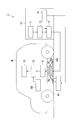
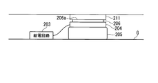
- FIG. 1 is a block diagram showing a configuration of a main part of the contactless power feeding system according to the first embodiment of the present invention.
- the non-contact power supply system 1 includes a power supply device 10, a power supply coil 20, an inner balloon 30a (first bag), an outer balloon 30b (second bag), and a power supply gas supply / exhaust device 40 ( A power supply / exhaust device) for supplying power to the vehicle M on which the battery 53 is mounted in a non-contact manner.
- the non-contact power supply system 1 is installed in, for example, a power supply station or a parking lot, and supplies power to the parked vehicle M without contact.
- the power supply device 10 includes a power source 11, a rectifier circuit 12, a power supply circuit 13, and a power supply control unit 14, generates electric power suitable for non-contact power supply to the vehicle M, and performs non-contact power supply to the vehicle M.
- Various controls necessary for the above are performed.
- the power supply device 10 is described as being installed on the ground. However, the power supply device 10 may be installed in the basement or may be installed above the vehicle M (for example, the ceiling). good.
- the output end of the power source 11 is connected to the input end of the rectifier circuit 12, and the power source 11 supplies the rectifier circuit 12 with AC power necessary for power feeding to the vehicle M.
- the power source 11 is a system power source that supplies three-phase AC power, such as 200 V or 400 V, or single-phase AC power of 100 V, for example.
- the input terminal of the rectifier circuit 12 is connected to the power supply 11 and the output terminal is connected to the power supply circuit 13.
- the rectifier circuit 12 rectifies and converts the AC power supplied from the power supply 11 into DC power.
- the direct current power is output to the power feeding circuit 13.
- the input end of the power supply circuit 13 is connected to the rectifier circuit 12 and the output end is connected to both ends of the power supply coil 20.
- the power supply circuit 13 converts the DC power from the rectifier circuit 12 into AC power and converts it. AC power is output to the feeding coil 20.
- the power supply circuit 13 includes a resonance capacitor that forms a power supply side resonance circuit together with the power supply coil 20. Under the control of the power supply control unit 14, the DC power from the rectifier circuit 12 is supplied to the power supply 11. The power is converted into AC power (high frequency power) having a frequency higher than that of AC power and output to the feeding coil 20.
- the power supply control unit 14 controls the power supply circuit 13 to generate power to be supplied to the vehicle M, and controls the power supply gas supply / exhaust device 40 to expand or contract the inner balloon 30a and the outer balloon 30b. .
- the power supply control unit 14 controls the power supply gas supply / exhaust device 40 to finely adjust the amount of gas supplied to the inner balloon 30a and the amount of gas exhausted from the inner balloon 30a. Then, the position of the feeding coil 20 in the vertical direction (vertical direction) is finely adjusted.
- the power supply control unit 14 includes a CPU (central processing unit), a memory, and the like, and performs the above-described various controls based on a power supply control program prepared in advance.
- As the gas for example, air can be used.
- the power supply coil 20 is a solenoid type coil, and supplies power to the vehicle M in a non-contact manner by generating a magnetic field corresponding to the high frequency power supplied from the power supply circuit 13. Both ends of the feeding coil 20 are connected to the output end of the feeding circuit 13, and the feeding coil 20 is coiled on the inner balloon 30a in an exposed state or molded with a nonmagnetic and nonconductive material such as plastic. It is mounted so that the shaft is substantially horizontal. When the coil type is a circular type, the coil axis is mounted so as to be substantially vertical.
- the inner balloon 30a is a kind of balloon in which a stretchable elastic material such as rubber is formed in a film shape, and is provided for adjusting the vertical position of the feeding coil 20.
- the inner balloon 30a is installed on the ground with the power supply coil 20 mounted on the center upper portion thereof, and is inflated or exhausted by gas supply or exhaust by the power supply gas supply / exhaust device 40. Shrink.
- the feeding coil 20 moves upward due to the expansion of the inner balloon 30a, and the feeding coil 20 moves downward due to the contraction of the inner balloon 30a.
- the planar view shape of the inner side balloon 30a is arbitrary, it is circular or a rectangular shape, for example.
- the outer balloon 30b is formed of a stretchable, non-magnetic and non-conductive elastic material such as rubber in the form of a film, and a central portion of the upper surface (a portion in contact with a power receiving coil 50 described later and a surrounding magnetic flux passing therethrough).
- This is a kind of balloon in which a powder made of a paramagnetic material such as aluminum powder or copper powder is attached to a portion other than a region where the efficiency of non-contact power feeding greatly decreases when affected.
- the central part of the upper surface has both magnetic permeability and expansion / contraction performance, and the remaining part where the paramagnetic powder is mixed and adhered has both the magnetic flux leakage reduction performance and expansion / contraction performance. ing.
- This outer balloon 30b prevents foreign matter from entering the space between the power feeding coil 20 and the power receiving coil 50 provided in the vehicle M, and is a part other than the end face (upper surface) of the power feeding coil 20 facing the power receiving coil 50 side. Provided in order to reduce the magnetic flux (leakage magnetic flux) radiated from.
- the outer balloon 30b is installed on the ground so as to cover (include) both the power supply coil 20 and the inner balloon 30a, and is inflated or exhausted by gas supply or exhaust by the power supply gas supply / exhaust device 40. Shrink. When the outer balloon 30b is inflated, the space between the power feeding coil 20 and the power receiving coil 50 is occupied by the outer balloon 30b. Note that the shape of the outer balloon 30b in plan view is arbitrary as in the case of the inner balloon 30a, but is, for example, circular or rectangular.
- the gas supply / exhaust device for power supply 40 supplies and exhausts gas to and from the inner balloon 30a and the outer balloon 30b under the control of the power supply control unit.
- This power supply gas supply / exhaust device 40 individually supplies gas to the inner balloon 30a, supplies gas to the outer balloon 30b, exhausts gas from the inner balloon 30a, and exhausts gas from the outer balloon 30b. It is possible. For this reason, one or both of the inner balloon 30a and the outer balloon 30b can be easily inflated or deflated.
- the power supply gas supply / exhaust device 40 includes a supply / exhaust pipe communicating with the inner balloon 30a and a supply / exhaust pipe communicating with the outer balloon 30b. In addition, gas is supplied to and exhausted from the outer balloon 30b.
- Vehicle M is an automobile that is driven by a driver and travels on a road, and is, for example, an electric car or a hybrid car that includes a travel motor as a power generation source. As shown in FIG. 1, the vehicle M includes a power receiving coil 50, a power receiving circuit 51, a charging circuit 52, a battery 53, and a power receiving control unit 54. Although omitted in FIG. 1, the vehicle M has a configuration necessary for traveling, such as an engine, the traveling motor, the operation handle, and a brake.
- the power receiving coil 50 is a solenoid-type coil, and is provided at the bottom of the vehicle M in a posture that enables non-contact power feeding with the power feeding coil 20 with high efficiency. Both ends of the power receiving coil 50 are connected to the input ends of the power receiving circuit 51, and the power receiving coil 50 generates an electromotive force by electromagnetic induction when the magnetic field of the power feeding coil 20 acts, and the generated electromotive force is sent to the power receiving circuit 51. Output.
- the sizes and shapes of the power feeding coil 20 and the power receiving coil 50 may be the same or different as long as highly efficient non-contact power feeding is possible.
- the input terminal of the power receiving circuit 51 is connected to both ends of the power receiving coil 50 and the output terminal is connected to the input terminal of the charging circuit 52.
- the power receiving circuit 51 converts the AC power supplied from the power receiving coil 50 into DC power.
- the converted DC power is output to the charging circuit 52.
- the power receiving circuit 51 includes a resonance capacitor that constitutes a power receiving resonance circuit together with the power receiving coil 50.
- the capacitance of the resonance capacitor of the power receiving circuit 51 is set so that the resonance frequency of the power receiving side resonance circuit is the same as the resonance frequency of the power feeding side resonance circuit described above.
- the input terminal of the charging circuit 52 is connected to the output terminal of the power receiving circuit 51 and the output terminal is connected to the input terminal of the battery 53.
- the charging circuit 52 uses the power (DC power) from the power receiving circuit 51 to the battery 53.
- the battery 53 is a rechargeable battery (for example, a secondary battery such as a lithium ion battery or a nickel metal hydride battery) mounted on the vehicle M, and supplies power to a travel motor (not shown).
- the power reception control unit 54 includes a CPU, a memory, and the like, and controls the charging circuit 52 based on a power reception control program prepared in advance.
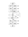
- FIG. 2 is a flowchart showing an example of the operation of the contactless power feeding system according to the first embodiment of the present invention
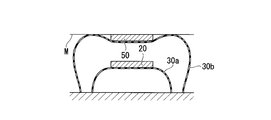
- FIGS. 3A to 3C are side sectional views for explaining the operation.
- operations of the vehicle M and the power supply apparatus 10 at the time of non-power supply will be briefly described, and then operations at the time of power supply in which the power supply apparatus 10 supplies power to the vehicle M in a non-contact manner will be described.
- the vehicle M When power is not supplied (for example, during normal operation of the vehicle M by the driver), the vehicle M is controlled by the power receiving control unit 54 to stop the charging circuit 52.
- the power supply device 10 stops the power supply circuit 13 and also includes the inner balloon 30a and the outer balloon 30b.
- the power supply control unit 14 performs control to exhaust the gas to the power supply gas supply / exhaust device 40 so that the gas is completely contracted.
- the installation position of the feeding coil 20 is grasped by the power receiving control unit 54.
- ascertaining from the output of position sensors such as a sound wave sensor not shown, or an optical sensor, is mentioned, for example.
- the position of the vehicle M is grasped by the power supply control unit 14 from the output of a position sensor such as a sound wave sensor or an optical sensor (not shown).
- a position sensor such as a sound wave sensor or an optical sensor (not shown).
- gas is first supplied to the power supply gas supply / exhaust device 40 until the outer balloon 30b is completely inflated.
- the control to be performed is performed by the power supply control unit 14 (step S11). That is, as shown in FIG. 3A, control is performed to completely inflate only the outer balloon 30b out of the inner balloon 30a and the outer balloon 30b in a completely deflated state.
- the inner balloon 30a is in a completely deflated state, but the outer balloon 30b is in a completely inflated state, and the gap between the feeding coil 20 and the receiving coil 50 is increased.
- the space is occupied by the fully inflated outer balloon 30b. That is, the outer balloon 30b covers the power receiving coil 50 so as to come into contact with the lower surface and the side surface of the power receiving coil 50 exposed from the bottom surface of the vehicle M by being inflated. This prevents foreign matter from entering the space between the power feeding coil 20 and the power receiving coil 50.
- the power supply control unit 14 performs control to supply gas from the power supply gas supply / exhaust device 40 to the inner balloon 30a to inflate the inner balloon 30a (step S12). That is, as shown in FIG. 3B, control is performed to inflate the inner balloon 30a in the fully deflated state contained in the outer balloon 30b in the completely inflated state. When the inner balloon 30a is inflated, the gas may be exhausted from the outer balloon 30b by the amount of gas supplied to the inner balloon 30a in accordance with the inflation of the inner balloon 30a.
- the inner balloon 30a is inflated in the outer balloon 30b, and the power supply coil 20 mounted on the inner balloon 30a moves upward. Accordingly, the feeding coil 20 is disposed in the vicinity of the power receiving coil 50 while preventing foreign matter from entering the space between the power feeding coil 20 and the power receiving coil 50 by the outer balloon 30b.
- step S13 the power supply gas supply / exhaust device 40 is controlled by the power supply control unit 14, and the position of the power supply coil 20 with respect to the power reception coil 50 is finely adjusted (step S13).
- the amount of gas supplied to the inner balloon 30 a and the amount of gas exhausted from the inner balloon 30 a are finely adjusted by the power supply gas supply / exhaust device 40 under the control of the power supply control unit 14.
- the position of the feeding coil 20 in the vertical direction is finely adjusted.
- the position of the power feeding coil 20 in the vertical direction is finely adjusted so that the amount of power supplied to the vehicle M is increased, for example. If it is not necessary to finely adjust the position of the feeding coil 20, step S13 may be omitted.
- the power supply circuit 13 of the power supply apparatus 10 is controlled by the power supply control unit 14 to start the power supply operation. Thereby, electric power is supplied from the power feeding coil 20 to the power receiving coil 50 of the vehicle M in a non-contact manner (step S14).
- the power reception control unit 54 controls the charging circuit 52 while monitoring the charging state of the battery 53 to charge the battery 53.
- the power receiving control unit 54 When the power receiving control unit 54 detects that the battery 53 is fully charged, the power receiving control unit 54 performs control to stop the charging circuit 52 and also displays an indicator (not shown) or the like (for example, charging the battery 53 provided in the driver's seat). Status indicator) is notified that the battery 53 is fully charged. With this notification, the driver can recognize that the battery 53 is fully charged.
- the power supply control unit 14 of the power supply apparatus 10 determines whether or not the power supply is completed while the noncontact power supply is being performed (step S15).
- the determination as to whether or not the power supply has ended can be made based on, for example, whether or not the amount of power supplied to the vehicle M has suddenly decreased.
- the power supply control unit 14 controls the power supply circuit 13 to continue the non-contact power supply (step). S14).
- the power supply control unit 14 controls the power supply circuit 13 to stop the power supply operation.
- the power supply control unit 14 When the power supply operation is stopped, the power supply control unit 14 performs control to exhaust the gas supplied to the inner balloon 30a to the power supply gas supply / exhaust device 40 and contract the inner balloon 30a (step S16). Subsequently, the power supply control unit 14 performs control to exhaust the gas supplied to the outer balloon 30b to the power supply gas supply / exhaust device 40 and contract the outer balloon 30b (step S17).
- the inner balloon 30a and the outer balloon 30b are deflated, the state shown in FIG. 3A is obtained, and the driver can drive the vehicle M and move from the place where the feeding coil 20 is installed.
- the inner balloon 30a and the outer balloon 30b are provided, and the outer balloon 30b is inflated to prevent foreign matter from entering the space between the power feeding coil 20 and the power receiving coil 50.
- the feeding coil 20 is brought close to the power receiving coil 50 by inflating the inner balloon 30a.
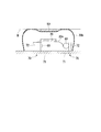
- FIG. 4 is a side sectional view showing a configuration of a main part of the non-contact power feeding system according to the second embodiment of the present invention.
- the whole structure of the non-contact electric power feeding system of this embodiment is as substantially the same as the non-contact electric power feeding system 1 shown in FIG.
- the non-contact power feeding system of this embodiment includes a plurality of auxiliary balloons 60 (auxiliary bag bodies) and a plurality of storage mechanisms 70 inside the outer balloon 30 b (however, outside the inner balloon 30 a). This is an added configuration.
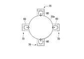
- FIGS. 5A to 5C are diagrams showing an auxiliary balloon and a storage mechanism in the second embodiment of the present invention.
- FIGS. 5A and 5B are plan views showing their arrangement, and FIG. 5C shows their appearance. It is a perspective view.
- the auxiliary balloon 60 and the accommodation mechanism 70 are arranged at equal intervals at three or four locations around the inner balloon 30a with the inner balloon 30a as the center.
- the three auxiliary balloons 60 are in contact with three different locations of the inner balloon 30a
- the four auxiliary balloons 60 are in four different locations of the inner balloon 30a. Each is in contact.
- the auxiliary balloon 60 is a kind of balloon in which a stretchable elastic material such as rubber is formed in a film like the inner balloon 30a described above, and is provided to adjust the position of the power feeding coil 20 in the horizontal plane. That is, when the auxiliary balloon 60 is inflated or contracted, the position of the abutting inner balloon 30a in the horizontal plane is adjusted, thereby adjusting the position of the feeding coil 20 mounted on the inner balloon 30a in the horizontal plane.
- a stretchable elastic material such as rubber
- the accommodating mechanism 70 accommodates the auxiliary balloon 60 in the ground, or causes the auxiliary balloon 60 accommodated in the ground to appear on the ground. Specifically, the accommodation mechanism 70 accommodates the auxiliary balloon 60 in the ground when the inner balloon 30a is deflated under the control of the power supply control unit 14, and when the inner balloon 30a is inflated. The auxiliary balloon 60 appears on the ground.
- the accommodation mechanism 70 includes an accommodation hole 71 and a flap 72.
- the accommodation hole 71 is a hole having a rectangular shape in plan view formed on the ground surface in order to accommodate the auxiliary balloon 60 in the ground.
- the flap 72 is a flat plate member having the same shape as the plan view of the accommodation hole 71 and is configured to be swingable around one end. The flap 72 is in a collapsed state when the auxiliary balloon 60 is housed in the ground, and is brought upright when the auxiliary balloon 60 appears on the ground. In addition, when the flap 72 is brought into a fallen state, the accommodation hole 71 is covered with the flap 72.
- An auxiliary balloon 60 is attached to one surface of the flap 72 (the surface facing the bottom surface of the receiving hole 71 when the flap 72 is in a collapsed state), and the air supply / exhaust air communicating with the auxiliary balloon 60 is provided inside the flap 72.
- a path 73 is formed.
- the air supply / exhaust path 73 is a flow path for gas supplied to the auxiliary balloon 60 and exhausted from the auxiliary balloon 60.
- the gas is supplied from, for example, a power supply gas supply / exhaust device 40 or exhausted toward the power supply gas supply / exhaust device 40.
- As the gas for example, air can be used.
- the contactless power feeding system according to the present embodiment also basically performs the operation according to the flowchart of FIG. That is, after the operation of inflating the outer balloon 30b (step S11), the operation of inflating the inner balloon 30a (step S12), and the operation of adjusting the position of the coil (step S13) are sequentially performed, non-contact power feeding is performed. Is performed (step S14).
- the flap 72 is in a collapsed state.
- the flap 72 is upright. Control to bring it into a state is performed.
- movement which adjusts the position of the coil of step S13 is performed, the operation
- the auxiliary balloon 60 when the auxiliary balloon 60 is inflated to bring each of the auxiliary balloons 60 into contact with the inner balloon 30a, and the auxiliary balloon 60 is inflated or deflated in this state, the force indicated by the arrows in FIGS. Acts on the balloon 30a. Then, the position of the inner balloon 30a in the horizontal plane is adjusted by the resultant force, and thereby the position of the feeding coil 20 in the horizontal plane is adjusted. The position of the inner balloon 30a in the horizontal plane is adjusted so that the amount of power supplied to the vehicle M is increased, for example.
- step S16 an operation for contracting the inner balloon 30a (step S16) and an operation for contracting the outer balloon 30b (step S17) are sequentially performed.
- the auxiliary balloon 60 is also deflated, and after the inner balloon 30a is deflated, an operation of accommodating the auxiliary balloon 60 in the accommodating hole 71 is performed with the flap 72 in a collapsed state.
- the inner balloon 30a and the outer balloon 30b are provided, and the outer balloon 30b is inflated to prevent entry of foreign matter into the space between the power feeding coil 20 and the power receiving coil 50.
- the power supply coil 20 is brought close to the power reception coil 50 by inflating the inner balloon 30a. For this reason, similarly to the first embodiment, it is possible to realize long-distance transmission of electric power without increasing the cost and size of the non-contact power feeding system, and leakage of leakage magnetic flux radiated from the power feeding coil 20 Can also be blocked.
- the auxiliary balloon 60 is provided to adjust the position of the inner balloon 30a (power feeding coil 20) in the horizontal plane. Therefore, even if the vehicle M parks and stops in a state where the power supply coil 20 and the power receiving coil 50 are displaced in the horizontal plane, the electric power can be transmitted efficiently.
- the present invention is not limited to the above embodiment, and can be freely changed within the scope of the present invention.
- the example in which the inner balloon 30a is inflated after the outer balloon 30b is inflated and the outer balloon 30b is deflated after the inner balloon 30a is deflated has been described.
- the method of inflating and contracting the inner balloon 30a and the outer balloon 30b is not limited to this, and any method can be used.
- the magnetic field resonance method is adopted as a method for contactless power feeding, but an electromagnetic induction method may be adopted.
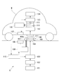
- the non-contact power feeding system includes a ground power feeding device S embedded in the ground and a vehicle M (power receiving device) that receives power from the ground power feeding device S.
- This non-contact power feeding system performs non-contact power feeding from the ground power feeding device S to the vehicle M based on a magnetic field resonance method which is one of the non-contact power feeding methods.
- the ground power supply device S is embedded in, for example, a stop position at an intersection or railroad crossing, or a parking / parking position of a parking lot, and performs non-contact power feeding to the vehicle M parked and parked at the parking / stopping position.
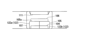
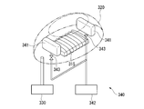
- the ground power supply device S includes a power source 101, a rectifier circuit 102, a power supply circuit 103, a power supply coil 104, a first bag body 105, a relay coil 106, a second bag body 107, and a gas supply / exhaust mechanism 108.
- the wireless communication unit 109 and the power supply control unit 110 are provided.
- the gas supply / exhaust mechanism 108 is a gas supply unit in the present embodiment.
- the power source 101 is an AC power source that supplies AC power necessary for power supply to the vehicle M to the rectifier circuit 102, and an output terminal of the power source 101 is connected to an input terminal of the rectifier circuit 102.
- the power source 101 is a system power source or a power generator that supplies three-phase AC power such as 200 V or 400 V or single-phase AC power of 100 V, for example.
- the input terminal of the rectifier circuit 102 is connected to the power supply 101, and the output terminal is connected to the power supply circuit 103.
- the rectifier circuit 102 rectifies AC power supplied from the power source 101 and converts it into DC power, and outputs the DC power to the power supply circuit 103.
- a DC power source such as a solar cell may be used as the power source 101, and the rectifier circuit 102 may be omitted (that is, DC power is supplied from the DC power source to the power feeding circuit 103).
- the power supply circuit 103 includes a power supply coil 104 and a resonance capacitor that forms a power supply side resonance circuit, and the DC power supplied from the rectifier circuit 102 based on a control command input from the power supply control unit 110 is supplied to the power supply 101.
- This is a type of inverter that converts AC power (high frequency power) having a frequency higher than that of AC power and supplies the power to the feeding coil 104.
- the feeding coil 104 is a circular coil or a solenoid coil, and in the case of a circular coil, the coil axis is in the vertical direction (vertical direction), and in the case of a solenoid coil, the coil axis is in the horizontal direction. And it is installed at the parking / stopping position in a state exposed on the ground surface or molded with a nonmagnetic and nonconductive material such as plastics, fiber reinforced plastics, ceramics or a composite material thereof. Both ends of the power supply coil 104 are connected to the output terminal of the power supply circuit 103.
- the feeding coil 104 feeds the vehicle M in a non-contact manner by generating a magnetic field when high-frequency power is supplied from the feeding circuit 103.
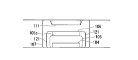
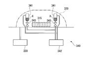
- the first bag 105 is a kind of balloon formed by forming a stretchable elastic material such as rubber into a film shape, and is installed on the ground in a state of including the power feeding coil 104. Moreover, the 1st bag body 105 is supporting the relay coil 106 by providing the relay coil 106 in contact with the one end surface (lower surface) on the upper side 105a (refer FIG.6 and FIG.7 A, 7B).
- the first bag body 105 is hermetically sealed. When gas (for example, air) is supplied from the gas supply / exhaust mechanism 108, the first bag body 105 expands and lifts the relay coil 106 upward, whereby the relay coil 106 will be described later. It moves toward the power receiving coil 111 of the vehicle M.
- gas for example, air
- the first bag body 105 is a kind in which a powder made of a paramagnetic flux shielding material such as aluminum powder or copper powder is attached to a portion other than the central portion of the upper surface (the portion facing the power receiving coil 111 described later).
- the central portion of the upper surface has both transmission performance against magnetic flux and expansion / contraction performance, and the remaining portion where the powder made of magnetic flux shielding material is mixed and adhered has both shielding performance against magnetic flux and expansion / contraction performance.
- the relay coil 106 includes a circular type coil or a solenoid type coil.
- the posture is such that the coil axis is in the vertical direction (vertical direction), and in the case of a solenoid type coil, the posture is such that the coil axis is in the horizontal direction.
- the first bag body 105 in an exposed state or in a state molded with a nonmagnetic and nonconductive material such as plastics, fiber reinforced plastics, ceramics, or a composite material thereof (see FIGS. 6 and 6). (See FIGS. 7A and 7B).
- the relay coil 106 includes a resonance circuit including a resonance capacitor and a resonance coil (the circular type coil or the solenoid type coil), and performs non-contact power supply from the power supply coil 104 to the power reception coil 111 of the vehicle M described later. Relay. Note that the resonance frequency of the resonance circuit of the relay coil 106 is set to be the same as the resonance frequency of the power feeding side resonance circuit.
- the second bag body 107 is a kind of balloon in which a stretchable elastic material such as rubber is formed into a film shape, and is installed on the ground in a state including the first bag body 105 and the relay coil 106.
- the second bag body 107 is sealed, and expands around the first bag body 105 and the relay coil 106 when gas (for example, air) is supplied from the gas supply / exhaust mechanism 108 (see FIG. 7A).
- the second bag body 107 is a kind in which a powder made of a paramagnetic flux shielding material such as aluminum powder or copper powder is attached to a portion other than the central portion of the upper surface (the portion facing the power receiving coil 111 described later).
- the central portion of the upper surface has both transmission performance against magnetic flux and expansion / contraction performance, and the remaining portion where the powder made of magnetic flux shielding material is mixed and adhered has both shielding performance against magnetic flux and expansion / contraction performance.
- the gas supply / exhaust mechanism 108 supplies gas into the first bag body 105 or the second bag body 107 on the basis of a control command input from the power supply control unit 110 and at the same time the first bag body 105 or the second bag body 107. It is a kind of pump that exhausts gas from.
- the gas supply / exhaust mechanism 108 has two supply / exhaust pipes respectively connected to the first bag body 105 and the second bag body 107.
- the wireless communication unit 109 can perform wireless communication of various types of information with a wireless communication unit 117 provided in the vehicle M, which will be described later. For example, the wireless communication unit 109 receives a power amount notification output from the wireless communication unit 117 of the vehicle M. The wireless communication unit 109 can communicate with the wireless communication unit 117 when the wireless communication unit 117 of the vehicle M is located in an area having a radius of about several meters centered on the installation position.
- the power supply control unit 110 includes a microprocessor, a memory, and the like, and is a power supply control program and a software-type control device that functions.
- the power supply circuit 103 is based on the power supply control program and a signal received by the wireless communication unit 109. And the gas supply / exhaust mechanism 108 is controlled. Details of the processing of the power supply control unit 110 will be described later.
- the vehicle M is an automobile that is driven by a driver and travels on a road.
- the vehicle M is an electric car or a hybrid car that travels using electric power as a power source.
- the vehicle M includes a power receiving coil 111, a power receiving circuit 112, a charging circuit 113, a battery 114, a voltage sensor 115, a current sensor 116, a wireless communication unit 117, and a power receiving calculation control unit 118.
- the vehicle M naturally includes components necessary for traveling, such as an engine, a traveling motor, an operation handle, and a brake.
- the power receiving coil 111 is a circular type coil or a solenoid type coil, and is a circular type so as to face the power supply coil 104 and the relay coil 106 and to perform highly efficient non-contact power supply via the power supply coil 104 and the relay coil 106.
- the coil axis is provided at the bottom of the vehicle M in such a posture that the coil axis is in the vertical direction (vertical direction). Yes.
- Both ends of the power receiving coil 111 are connected to the input ends of the power receiving circuit 112.
- the power receiving coil 111 generates an electromotive force by electromagnetic induction when the magnetic field of the power feeding coil 104 or the relay coil 106 acts, and receives this electromotive force. Output to the circuit 112.
- the power supply coil 104, the relay coil 106, and the power reception coil 111 are all the same type, that is, either a circular type coil or a solenoid type coil.
- the size and shape of 106 and the power receiving coil 111 may be the same or different as long as highly efficient non-contact power feeding is possible.
- the input terminal of the power receiving circuit 112 is connected to both ends of the power receiving coil 111, and the output terminal is connected to the input terminal of the charging circuit 113.
- This power receiving circuit 112 is a kind of rectifier circuit that includes a power receiving coil 111 and a resonance capacitor that constitutes a power receiving side resonance circuit, and converts AC power supplied from the power receiving coil 111 into DC power and supplies it to the charging circuit 113. is there.
- the capacitance of the resonance capacitor of the power reception circuit 112 is set so that the resonance frequency of the power supply side resonance circuit and the resonance frequency of the power reception side resonance circuit are the same frequency.
- the input terminal of the charging circuit 113 is connected to the output terminal of the power receiving circuit 112, the output terminal is connected to the input terminal of the battery 114, and the charging circuit 113 supplies power (DC power) supplied from the power receiving circuit 112 to the battery.
- the battery 114 is a rechargeable battery (for example, a secondary battery such as a lithium ion battery or a nickel metal hydride battery) mounted on the vehicle M, and supplies driving power to a travel motor (not shown).
- the voltage sensor 115 is provided between the power receiving circuit 112 and the charging circuit 113, detects a voltage value of power supplied from the power receiving circuit 112 to the charging circuit 113, and receives a voltage detection signal indicating the voltage value for power receiving calculation control.
- the current sensor 116 is provided between the power receiving circuit 112 and the charging circuit 113, detects the current value of the power supplied from the power receiving circuit 112 to the charging circuit 113, and receives a current detection signal indicating the current value for power receiving calculation control. To the unit 118.
- the wireless communication unit 117 is capable of wireless communication of various types of information with the wireless communication unit 109 provided in the ground power supply apparatus S. For example, a power amount notification indicating the received power amount under the control of the power reception calculation control unit 118 Send.
- the wireless communication unit 117 can communicate with the wireless communication unit 109 when the wireless communication unit 109 of the ground power supply apparatus S is located in an area having a radius of about several meters with the wireless communication unit 117 as a center.
- the power reception calculation control unit 118 includes a microprocessor, a memory, and the like, and is a software-type control device that functions based on a power reception control program.
- the power reception calculation control unit 118 performs a calculation process of power reception power based on the power reception calculation control program.
- the charging circuit 113 is controlled.
- the power receiving calculation control unit 118 calculates the amount of power output from the power receiving circuit 112 based on the voltage detection signal input from the voltage sensor 115 and the current detection signal input from the current sensor 116, that is, the voltage sensor.
- the amount of power output from the power receiving circuit 112 is calculated by multiplying the voltage value detected by 115 by the current value detected by the current sensor 116.
- the power reception calculation control unit 118 of the vehicle M stops the charging circuit 113 when power is not supplied (for example, during normal operation of the vehicle M by the driver).
- the power supply control unit 110 of the ground power supply device S stops the power supply circuit 103 when no power is supplied, that is, when the vehicle M to be supplied is not stopped at the parking / stopping position,
- the gas supply / exhaust mechanism 108 is made to exhaust the gas in the 1st bag body 105 and the 2nd bag body 107 so that the 2nd bag body 107 may shrink
- the power receiving calculation control unit 118 of the vehicle M is based on the result of communication with the wireless communication unit 109 of the ground power supply device S by the wireless communication unit 117 (or the output of a position sensor such as a sound wave sensor or an optical sensor not shown).
- the installation position of the power feeding device S is grasped.
- the power reception calculation control unit 118 grasps the installation position of the ground power supply device S based on the strength of the signal received by the wireless communication unit 117 from the wireless communication unit 109 of the ground power supply device S.
- the charging circuit 113 starts the charging operation.
- the power supply control unit 110 of the ground power supply device S is connected to the wireless communication unit 109 of the ground power supply device S by the wireless communication unit 117 (or a position sensor such as a sound sensor or an optical sensor not shown).
- the position of the vehicle M is grasped on the basis of the output.
- the power supply control unit 110 causes the gas supply / exhaust mechanism 108 to supply gas so that the second bag body 107 is completely expanded. 7A, the second bag body 107 of the ground power feeding device S comes into contact with the power receiving coil 111 of the vehicle M.
- the power supply control unit 110 determines whether the second bag body 107 is completely inflated by providing a gas supply time by the gas supply / exhaust mechanism 108 or a supply port of the pump (not shown) to the second bag body 107. Judgment is made based on the detected result of the pressure gauge.
- the power supply control unit 110 starts the supply of gas to the first bag body 105 by the gas supply / exhaust mechanism 108 and supplies a small amount of power to the power supply circuit 103. Start operation. Note that the minute power is set to a power value smaller than the large power for charging supplied later by the ground power supply apparatus S.
- the power reception calculation control unit 118 of the vehicle M multiplies the voltage value detected by the voltage sensor 115 and the current value detected by the current sensor 116 and outputs the minute power output from the power reception circuit 112.
- the wireless communication unit 117 is caused to transmit a power amount notification for notifying the power amount.
- the power supply control unit 110 of the ground power supply apparatus S determines whether or not the amount of power indicated by the power amount notification received by the wireless communication unit 109 has increased. The supply of gas to the first bag body 105 by the exhaust mechanism 108 is continued. Then, the power supply control unit 110 determines whether or not the amount of power has increased again. If it is determined that the amount of power has increased, the gas supply / exhaust mechanism 108 continues to supply gas to the first bag body 105. . On the other hand, the power supply control unit 110 stops the gas supply to the first bag body 105 by the gas supply / exhaust mechanism 108 when it is determined that the increase in the electric energy has stopped.
- the gas supply / exhaust mechanism 108 stops the supply of gas to the first bag body 105, and the gas supply / exhaust mechanism 108 receives the first power supply. Gas is exhausted from the bag body 105. Then, the power supply control unit 110 determines whether or not the amount of minute power received by the vehicle M has risen again. If it is determined that the amount has increased, the first bag body by the gas supply / exhaust mechanism 108 is determined. The exhaust of gas from 105 is continued. On the other hand, when the power supply control unit 110 determines that the increase in the amount of power has stopped, the gas supply / exhaust mechanism 108 stops the gas exhaust from the first bag body 105.
- the power supply control unit 110 controls the gas supply / exhaust mechanism 108 to expand or contract the first bag body 105 based on the power amount notification received by the wireless communication unit 109. Accordingly, the relay coil 106 moves between the power supply coil 104 and the power reception coil 111 of the vehicle M by the first bag body 105, and the power supply coil 104 and the power reception coil are stopped by the expansion or contraction of the first bag body 105. 111 stops at a position where the transmission efficiency with respect to 111 is optimal.
- the power supply control unit 110 causes the power supply circuit 103 to start a power supply operation.
- the relay coil 106 is at a position where the transmission efficiency between the power feeding coil 104 and the power receiving coil 111 is optimal, power is supplied from the power feeding coil 104 to the power receiving coil 111 with high transmission efficiency.
- the space between the power feeding coil 104 and the power receiving coil 111 is occupied by the second bag body 107, foreign matter can be prevented from entering between the power feeding coil 104 and the power receiving coil 111.
- a portion that is directly above the end face (upper surface) of the relay coil 106 transmits a magnetic flux (for example, a highly transparent material such as ferrite on the surface of the film-like elastic material). It was formed as a magnetic material powder adhering to it, and the other part was a magnetic flux shielding part (paramagnetic powder made of magnetic flux shielding material such as aluminum powder or copper powder was adhered to the surface of the film-like elastic material) Since the leakage magnetic flux is prevented from leaking to the outside of the second bag body 107, the leakage magnetic flux can be reduced as compared with the conventional case.
- the power reception calculation control unit 118 of the vehicle M appropriately charges the battery 114 by controlling the charging circuit 113 while monitoring the charging state of the battery 114.
- the power receiving calculation control unit 118 notifies the battery 114 that the battery 114 is fully charged by a display unit (not shown) or the like. Then, when the driver recognizes that the battery is fully charged by an indicator (not shown) or the like, the driver drives the vehicle M and moves from the place where the ground power supply device S is installed.
- the power supply control unit 110 of the ground power supply apparatus S uses the wireless communication unit 109 to communicate with the wireless communication unit 117 of the vehicle M (or the output of a position sensor such as a sound sensor or an optical sensor (not shown)). Is detected, the control of the power feeding circuit 103 is stopped, and the gas supply / exhaust mechanism 108 is controlled to completely contract the first bag body 105 and the second bag body 107.
- the first bag body 105 is expanded or contracted by supplying gas, and the relay coil 106 is moved between the power supply coil 104 and the power reception coil 111, so that it is more efficient than before. Non-contact power feeding becomes possible. Further, according to the present embodiment, since the space between the power feeding coil 104 and the power receiving coil 111 is occupied by the second bag body 107, foreign matter can be prevented from entering between the power feeding coil 104 and the power receiving coil 111. can do.
- a portion that coincides with the upper surface of the end surface (upper surface) of the relay coil 106 is formed as a magnetic flux transmitting portion that transmits magnetic flux, and other portions. Is formed as a magnetic flux shielding part, the leakage magnetic flux is prevented from leaking to the outside of the second bag body 107, so that the leakage magnetic flux can be reduced as compared with the conventional case.
- the non-contact electric power feeding system which concerns on 4th Embodiment is demonstrated.
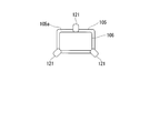
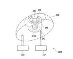
- the non-contact power feeding system according to the fourth embodiment includes a third bag body 121 (shown in FIGS. 8A and 8B), and the third bag body 121 is supplied with gas from the gas supply / exhaust mechanism 108. This is different from the third embodiment.
- Other components are the same as those in the third embodiment. Therefore, in the second embodiment, description of the same components as those in the third embodiment is omitted.
- three third bag bodies 121 are installed on the ground around the first bag body 105.
- the third bag body 121 is hermetically sealed, and is formed so that its tip comes into contact with the peripheral surface of the relay coil 106 when gas (for example, air) is supplied from the gas supply / exhaust mechanism 108. Yes.
- gas for example, air
- the gas supply / exhaust mechanism 108 supplies gas into the third bag body 121 and exhausts gas from the third bag body 121. That is, the gas supply / exhaust mechanism 108 has three supply / exhaust pipes connected to the third bag body 121 in addition to the first bag body 105 and the second bag body 107.
- the power supply control unit 110 of the ground power supply apparatus S completes the gas supply to each third bag body 121 by the gas supply / exhaust mechanism 108. Start supplying.
- the power supply control unit 110 controls the gas supply / exhaust mechanism 108 so as to expand or contract each third bag body 121 based on the power amount notification received by the wireless communication unit 109. That is, the power supply control unit 110 controls the gas supply / exhaust mechanism 108 to inflate or contract each third bag body 121 until the increase in the electric energy indicated by the electric energy notification stops.
- the relay coil 106 moves in the horizontal direction (the feeding coil 104 and the receiving coil depending on the degree of contact by each third bag body 121. 111 in a direction orthogonal to the direction connecting 111). That is, the relay coil 106 moves in the horizontal direction according to the amount of gas supplied to each third bag body 121 by the gas supply / exhaust mechanism 108, and transmission efficiency is improved by stopping the expansion or contraction of the third bag body 121. Stop at the optimal position.
- the power supply control unit 110 causes the power supply circuit 103 to start a power supply operation.
- the relay coil 106 is at a position where the transmission efficiency between the power feeding coil 104 and the power receiving coil 111 is optimal, power is supplied from the power feeding coil 104 to the power receiving coil 111 with high transmission efficiency.
- the power reception calculation control unit 118 of the vehicle M appropriately charges the battery 114 by controlling the charging circuit 113 while monitoring the charging state of the battery 114.
- the power receiving calculation control unit 118 notifies the battery 114 that the battery 114 is fully charged by a display unit (not shown) or the like. Then, when the driver recognizes that the battery is fully charged by an indicator (not shown) or the like, the driver drives the vehicle M and moves from the place where the ground power supply device S is installed.
- the power supply control unit 110 of the ground power supply apparatus S uses the wireless communication unit 109 to communicate with the wireless communication unit 117 of the vehicle M (or the output of a position sensor such as a sound sensor or an optical sensor (not shown)). Is detected, the control of the power feeding circuit 103 is stopped, and the gas supply / exhaust mechanism 108 is controlled to add the first bag body 105 and the second bag body 107, and the third bag body 121 is completely removed. Shrink.
- the third bag body 121 is expanded or contracted by supplying gas, and the relay coil 106 is moved in the horizontal direction, so that non-contact power feeding can be performed more efficiently than in the past. Become.
- the non-contact electric power feeding system which concerns on 5th Embodiment is demonstrated.
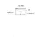
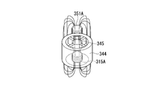
- the first bag body 122 instead of the first bag body 105, the first bag body 122 (FIG. 9A and FIG. 9A and FIG. 9A) divided as viewed from the direction connecting the power feeding coil 104 and the power receiving coil 111. 9B), and is different from the third embodiment in that gas is supplied from the gas supply / exhaust mechanism 108 to the divided regions 122a, 122b, 122c of the first bag body 122.
- Other components are the same as those in the third embodiment. Therefore, in the fifth embodiment, description of the same components as those in the third embodiment is omitted.
- the first bag body 122 is divided into, for example, three (divided regions 122a, 122b, and 122c) when viewed from the direction connecting the power feeding coil 104 and the power receiving coil 111. Further, each divided region 122a, 122b, 122c of the first bag body 122 is sealed, and when gas (for example, air) is supplied from the gas supply / exhaust mechanism 108, the first bag body 122 expands to move the relay coil 106 upward. While lifting, the inclination of the relay coil 106 is changed by the difference in expansion.
- gas for example, air
- the gas supply / exhaust mechanism 108 supplies gas into the respective divided regions 122a, 122b, 122c and the second bag body 107 of the first bag body 122 and at the same time the respective divided regions 122a, 122b, 122c and the first bag body 122 of the first bag body 122.
- the gas is exhausted from the two bag bodies 107. That is, the gas supply / exhaust mechanism 108 has four supply / exhaust pipes connected to the divided regions 122a, 122b, 122c of the first bag body 122 and the second bag body 107, respectively.
- the power supply control unit 110 starts the gas supply to the divided regions 122a, 122b, 122c of the first bag body 122 by the gas supply / exhaust mechanism 108, and the power supply circuit 103 starts a power supply operation of minute electric power.
- the power supply control unit 110 controls the gas supply / exhaust mechanism 108 to expand or contract each of the divided regions 122a, 122b, 122c of the first bag body 122 based on the power amount notification received by the wireless communication unit 109. To do. That is, the power supply control unit 110 controls the gas supply / exhaust mechanism 108 to inflate or contract each third bag body 121 until the increase in the electric energy indicated by the electric energy notification stops.
- the relay coil 106 moves between the power feeding coil 104 and the power receiving coil 111 of the vehicle M by the divided regions 122a, 122b, and 122c, and the relay coil 106 is caused by a difference in expansion between the divided regions 122a, 122b, and 122c. Is changed, and the third bag body 121 stops at a position where the transmission efficiency is optimal by stopping the expansion or contraction of the third bag body 121.
- the power supply control unit 110 causes the power supply circuit 103 to start a power supply operation.
- the relay coil 106 is at a position where the transmission efficiency between the power feeding coil 104 and the power receiving coil 111 is optimal, power is supplied from the power feeding coil 104 to the power receiving coil 111 with high transmission efficiency.
- the power reception calculation control unit 118 of the vehicle M appropriately charges the battery 114 by controlling the charging circuit 113 while monitoring the charging state of the battery 114.
- the power receiving calculation control unit 118 notifies the battery 114 that the battery 114 is fully charged by a display unit (not shown) or the like. Then, when the driver recognizes that the battery is fully charged by an indicator (not shown) or the like, the driver drives the vehicle M and moves from the place where the ground power supply device S is installed.
- the power supply control unit 110 of the ground power supply apparatus S uses the wireless communication unit 109 to communicate with the wireless communication unit 117 of the vehicle M (or the output of a position sensor such as a sound sensor or an optical sensor (not shown)). Is detected, the control of the power supply circuit 103 is stopped and the gas supply / exhaust mechanism 108 is controlled to completely separate the divided regions 122a, 122b, 122c of the first bag body 122 and the second bag body 107. Shrink.
- each divided region 122a, 122b, 122c of the first bag body 122 is expanded or contracted, and the inclination of the relay coil 106 is changed.
- Non-contact power feeding becomes possible.
- the present invention is not limited to the above-described embodiment, and for example, the following modifications can be considered.
- the first bag body 105, the relay coil 106, the second bag body 107, the gas supply / exhaust mechanism 108, the third bag body 121, and the first bag body 122 are ground-fed. Although attached to the device S, it may be attached to the vehicle M.
- the present invention is not limited to this.
- the plurality of relay coils 106 are connected to the power feeding coil 104 and the power receiving coil 111. You may arrange
- the present invention is applied to the non-contact power feeding system in which the power feeding coil 104, the relay coil 106, and the power receiving coil 111 are provided with the coil axis in the vertical direction.
- the present invention is not limited to this.
- the present invention may be applied to a non-contact power feeding system in which the power feeding coil 104, the relay coil 106, and the power receiving coil 111 are provided in a posture (horizontal posture) in which the coil axis is a horizontal direction or an inclined posture.
- the power feeding device is the ground power feeding device S embedded in the ground, and the power receiving device is the vehicle M traveling on the ground.
- the power feeding device may be an underwater power feeding device installed underwater, and the power receiving device may be an underwater vehicle that moves underwater.
- the underwater vehicle must take out water quality data when investigating the water quality in the water.
- a communication antenna is provided in any one of the first bag body 105, the second bag body 107, the third bag body 121, and the first bag body 122 provided in the underwater vehicle and the underwater power feeding device. Water quality data may be taken out via the.
- the underwater power supply device is wired to a ground water quality data management device or the like via a communication cable, and the water quality data is transmitted via the communication antenna when the underwater vehicle is transmitting power (when the battery 114 is charged).
- the water quality data received from the underwater vehicle via the communication antenna may be wired to the water quality data management device or the like.
- the fluid supplied into the 1st bag body 105, the 2nd bag body 107, the 3rd bag body 121, or the 1st bag body 122 may be liquid other than a gas body.
- this liquid may be an ionic liquid (for example, salt water), distilled water, alcohol, or the like as long as it does not damage the coil and each bag.
- the specific gravity of the gas and the liquid is different, the balance of the weights of the power feeding device and the power receiving device can be adjusted by using the gas and the liquid together.
- the non-contact power feeding system includes a ground power feeding device S (power feeding device) embedded in the ground G and a vehicle M (power receiving device) that receives power from the ground power feeding device S. I have.
- This non-contact power feeding system performs non-contact power feeding from the ground power feeding device S to the vehicle M based on a magnetic field resonance method which is one of the non-contact power feeding methods.
- the ground power supply device S is embedded in, for example, a stop position at an intersection or railroad crossing, or a parking / parking position of a parking lot, and performs non-contact power feeding to the vehicle M parked and parked at the parking / stopping position.
- the ground power supply device S includes a power source 201, a rectifier circuit 202, a power supply circuit 203, a power supply coil 204, a bag body (first bag body) 205, a spacer 206, a gas supply / exhaust mechanism 207, and a power supply unit.
- a control unit 208 is provided.
- the gas supply / exhaust mechanism 207 is a gas supply unit in the present embodiment.
- the power source 201 is an AC power source that supplies AC power necessary for power supply to the vehicle M to the rectifier circuit 202, and an output end of the power source 201 is connected to an input end of the rectifier circuit 202.
- the power source 201 is a system power source or a power generator that supplies three-phase AC power such as 200 V or 400 V or single-phase AC power of 100 V, for example.
- the input terminal of the rectifier circuit 202 is connected to the power supply 201, and the output terminal is connected to the power supply circuit 203.
- the rectifier circuit 202 rectifies AC power supplied from the power source 201 and converts it into DC power, and outputs the DC power to the power feeding circuit 203.
- a DC power source such as a solar battery may be used as the power source 201, and the rectifier circuit 202 may be omitted (that is, DC power is supplied from the DC power source to the power feeding circuit 203).
- the power source 201 and the rectifier circuit 202 may be separated from the power feeding circuit 203 and installed without being embedded in the ground G.
- the power supply circuit 203 includes a power supply coil 204 and a resonance capacitor that forms a power supply side resonance circuit, and the DC power supplied from the rectifier circuit 202 based on a control command input from the power supply control unit 208 is supplied to the power supply 201.
- This is a kind of inverter that converts AC power (high frequency power) having a frequency higher than that of AC power and supplies the power to the feeding coil 204.
- the power feeding circuit 203 is installed on the ground G at the parking / stopping position, and is connected to the power feeding coil 204 by a flexible electric cable. Note that the power feeding circuit 203 may be embedded in the ground G instead of on the ground G, or a flexible electrical cable may be extended to install the power feeding circuit 203 away from the ground G. .
- the feeding coil 204 is a circular type coil or a solenoid type coil.
- the coil axis is set in a vertical direction (vertical direction), and in the case of a solenoid type coil, the coil axis is set in a horizontal direction.
- the bag body 205 in an exposed state or in a state molded with a nonmagnetic and nonconductive material such as plastics, fiber reinforced plastics, ceramics or a composite material thereof (FIGS. 11A and 11B). And FIG. 12).
- Both ends of the power supply coil 204 are connected to the output terminal of the power supply circuit 203, and the power supply coil 204 generates a magnetic field by being supplied with high-frequency power from the power supply circuit 203, so that it does not contact the vehicle M. Supply power.
- the bag body 205 is a kind of balloon in which a stretchable elastic material such as rubber is formed into a film shape, and is installed on the ground G.
- the bag body 205 supports the power supply coil 204 by installing the power supply coil 204 in contact with one end face (lower surface) of the upper side 205a (see FIGS. 11A, 11B, and 12).
- the bag body 205 is sealed, and when gas (for example, air) is supplied from the gas supply / exhaust mechanism 207, the bag body 205 expands and lifts the power supply coil 204 upward, thereby causing the power supply coil 204 to be described later. It moves toward the receiving coil 211.
- gas for example, air
- the spacer 206 is a plate-like member having a specific hardness that does not decrease the efficiency of non-magnetic and non-conductive non-contact power feeding, such as plastic, and is disposed on the other end surface (upper surface) of the power feeding coil 204. And is supported by the feeding coil 204 (see FIGS. 11A, 11B, and 12).
- the specific hardness means a hardness that hardly deforms when the bag 205 expands and presses the spacer 206 against the power receiving coil 211.
- the spacer 206 is formed to have a thickness equivalent to the distance at which the transmission efficiency of non-contact power feeding between the power feeding coil 204 and the power receiving coil 211 of the vehicle M is optimal.
- the upper surface 206a of the spacer 206 is formed flat so that the posture is stable when coming into contact with the power receiving coil 211 and does not get in the way when the vehicle M passes over the upper surface 206a.
- the gas supply / exhaust mechanism 207 is a type of pump that supplies gas into the bag body 205 and exhausts gas from the bag body 205 based on a control command input from the power supply control unit 208.
- a pressure gauge is provided at a supply port of a pump that supplies gas to the bag body 205, and a detection result (detection signal) by the pressure gauge is output to the power supply control unit 208.
- the gas supply / exhaust mechanism 207 has a valve that can be opened and closed by a command from the power supply control unit 208 to exhaust gas, for example, a valve that can be opened and closed by an electric signal.
- the power supply control unit 208 includes a microprocessor, a memory, and the like, and is a software type control device that functions based on a power supply control program, and controls the power supply circuit 203 and the gas supply / exhaust mechanism 207. Details of the processing of the power supply control unit 208 will be described later.
- the vehicle M is an automobile that is driven by a driver and travels on a road.
- the vehicle M is an electric car or a hybrid car that travels using a battery as a power source.
- the vehicle M includes a power receiving coil 211, a power receiving circuit 212, a charging circuit 213, a battery 214, and a power receiving control unit 215.
- the vehicle M naturally includes components necessary for traveling such as a traveling motor, an operation handle, a brake, and an engine in the case of a hybrid vehicle.
- the power receiving coil 211 is a circular type coil or a solenoid type coil.
- the power receiving coil 211 is a circular type coil or a solenoid type coil. It is provided at the bottom of the vehicle M in such a posture that the axis is in the vertical direction (vertical direction), and in the case of a solenoid type coil, the coil axis is horizontal and parallel to the coil axis of the power feeding coil 204. Both ends of the power receiving coil 211 are connected to the input terminals of the power receiving circuit 212.
- the magnetic field of the power feeding coil 204 acts, an electromotive force is generated by electromagnetic induction, and the electromotive force is output to the power receiving circuit 212.
- the feeding coil 204 and the receiving coil 211 are both of the same type, that is, either a circular coil or a solenoid coil, but the sizes of the feeding coil 204 and the receiving coil 211 are the same.
- the shape may be the same or different as long as highly efficient non-contact power feeding is possible.
- the input terminal of the power receiving circuit 212 is connected to both ends of the power receiving coil 211, and the output terminal is connected to the input terminal of the charging circuit 213.
- This power receiving circuit 212 is a kind of rectifier circuit that includes a power receiving coil 211 and a resonance capacitor that constitutes a power receiving side resonance circuit, and converts AC power supplied from the power receiving coil 211 into DC power and supplies it to the charging circuit 213. is there.
- the capacitance of the resonance capacitor of the power reception circuit 212 is equal to or substantially the same as the resonance frequency of the power supply side resonance circuit and the resonance frequency of the power reception side resonance circuit so that highly efficient non-contact power supply is possible. It is set to be.
- the charging circuit 213 is a kind of DC-DC converter that converts the power (DC power) supplied from the power receiving circuit 212 into a voltage suitable for charging the battery 214 and charges the battery 214, and its input terminal is the power receiving circuit 212. The output terminal is connected to the input terminal of the battery 214.
- the battery 214 is a rechargeable battery (for example, a secondary battery such as a lithium ion battery or a nickel metal hydride battery) mounted on the vehicle M, and supplies driving power to a travel motor or the like (not shown).
- the power reception control unit 215 is a software-type control device that includes a microprocessor, a memory, and the like and functions based on a power reception control program, and controls the charging circuit 213.
- the power reception control unit 215 of the vehicle M stops the charging circuit 213 when power is not supplied (for example, during normal operation of the vehicle M by the driver).
- the power supply control unit 208 of the ground power supply apparatus S stops the power supply circuit 203 when the power is not supplied, that is, when the vehicle M to be supplied is not parked at the parking position, and the bag body 205 is completely
- the gas supply / exhaust mechanism 207 exhausts the gas in the bag body 205 so as to contract. This can be realized by opening an openable / closable valve for gas exhaust.
- the power reception control unit 215 of the vehicle M grasps the installation position of the ground power supply apparatus S from the output of a position sensor such as a sound wave sensor or an optical sensor (not shown).
- a position sensor such as a sound wave sensor or an optical sensor (not shown).
- the charging circuit 213 starts the charging operation.
- the output of the charging circuit 213 is also zero, and no power is supplied to the battery 214.
- the power supply control unit 208 of the ground power supply apparatus S grasps the position of the vehicle M from the output of a position sensor such as a sound wave sensor or an optical sensor (not shown) as with the vehicle M.
- a position sensor such as a sound wave sensor or an optical sensor (not shown)
- the power supply control unit 208 detects that the vehicle M has moved above the ground power supply device S from the output of a position sensor such as a sound wave sensor or an optical sensor
- the gas supply / exhaust mechanism 207 so that the bag 205 expands.
- the openable / closable valve for exhausting the gas is closed.
- the power supply control unit 208 controls the gas supply / exhaust mechanism 207 based on a detection signal input from the pressure gauge of the gas supply / exhaust mechanism 207. That is, the power supply control unit 208 causes the gas supply / exhaust mechanism 207 to supply gas until the detection result by the pressure gauge reaches a specific pressure. Accordingly, the power feeding coil 204 is lifted upward by the inflated bag body 205 and moves toward the power receiving coil 211.
- the power supply control unit 208 stops the gas supply when a specific pressure is reached.
- the specific pressure is a pressure determined by the elastic modulus of the material of the bag body 205. If the bag body 205 is not deformed and the gas is continuously supplied, the elastic limit of the bag body 205 is exceeded and breakage occurs. The pressure is such that As a result, as shown in FIG. 12, the upper surface 206 a of the spacer 206 is in contact with the power receiving coil 211 of the vehicle M, and the power feeding coil 204 and the power receiving coil 211 are arranged to face each other with the spacer 206 therebetween. That is, the power feeding coil 204 and the power receiving coil 211 are arranged to face each other with a distance that optimizes the transmission efficiency in the magnetic field resonance method.
- the power supply control unit 208 causes the power supply circuit 203 to start a power supply operation.
- the power feeding coil 204 and the power receiving coil 211 are arranged to face each other with a distance such that the transmission efficiency in the magnetic field resonance method is optimal, power is transferred from the power feeding coil 204 to the power receiving coil 211 with high transmission efficiency. Is supplied.
- power is output from the power receiving circuit 212, the charging circuit 213 starts supplying power to the battery 214, and charging of the battery is started.
- the power reception control unit 215 of the vehicle M appropriately charges the battery 214 by controlling the charging circuit 213 while monitoring the charging state of the battery 214.
- the power reception control unit 215 notifies the battery 214 that the battery 214 is fully charged by a display unit (not shown) or the like.
- the power supply control unit 208 of the ground power supply apparatus S stops the control of the power supply circuit 203 and controls the gas supply / exhaust mechanism 207 to completely contract the bag body 205. For example, by stopping the pump and opening an openable / closable valve for exhausting the gas, the gas in the bag body 205 is extracted and completely contracted.
- an indicator not shown
- the power supply control unit 208 of the ground power supply device S includes a sound wave sensor (not shown).
- the control of the power feeding circuit 203 is stopped, and the gas supply / exhaust mechanism 207 is controlled to completely contract the bag body 205, so that the spacer 206 And the power receiving coil 211 are prevented from coming into contact with each other.
- the gas in the bag body 205 is extracted and completely contracted.
- the bag body 205 is inflated, so that the power feeding coil 204 and the power receiving coil 211 are arranged in contact with each other with a distance such that the transmission efficiency is optimal via the spacer 206. Power can be supplied.
- the gas in the bag body 205 is also elastic and allows deformation of the bag body 205, so that the spacer 206, the power feeding coil 204, and the power receiving coil 211 are used. It is possible to prevent mechanical damage from being applied due to excessive force.
- the present embodiment it is possible to reduce the price of the vehicle M and simplify the configuration by not providing the vehicle height adjustment mechanism, and it is also possible to reduce the amount of splashed mud, stone, etc. because no height sensor is provided.
- the height sensor is not soiled or damaged by foreign matter.
- the non-contact electric power feeding system which concerns on 7th Embodiment is demonstrated.
- the non-contact power feeding system according to the seventh embodiment includes a point where the power feeding circuit 203 is embedded in the ground G, and a position where the bag body 205 is parked and stopped (where the vehicle M can stop). )
- the ground G instead of the ground G, that is, the feeding coil 204, the bag 205 and the spacer 206 are accommodated in the concave C, and a new movement restricting portion.
- the second embodiment is different from the sixth embodiment in that 209 is provided in the recess C.
- Other components are the same as those in the sixth embodiment. Therefore, in the seventh embodiment, the description of the same components as in the sixth embodiment is omitted.
- the power feeding circuit 203 converts the DC power supplied from the rectifier circuit 202 into AC power (high frequency power) based on a control command input from the power feeding control unit 208 and converts it to the power feeding coil 204. It is a kind of inverter to be supplied, and is connected to the feeding coil 204 by a flexible electric cable. Further, unlike the sixth embodiment, the power feeding circuit 203 is embedded in the ground G near the recess C.
- the power supply coil 204 is a circular coil or a solenoid type coil that supplies power to the vehicle M in a non-contact manner by generating a magnetic field when high-frequency power is supplied from the power supply circuit 203. . Further, unlike the sixth embodiment, the power supply coil 204 is accommodated in the recess C when the bag body 205 contracts.
- the bag body 205 supports the power supply coil 204 by arranging the power supply coil 204 in contact with the upper surface 205a so that one end surface (lower surface) thereof is in contact with the upper surface 205a.
- the bag body 205 expands and lifts the power supply coil 204 upward, thereby moving the power supply coil 204 toward the power reception coil 211.
- the bag body 205 is installed at the bottom of the recess C instead of the ground G.
- the spacer 206 is disposed on the other end surface (upper surface) of the power feeding coil 204 and has the same thickness as the distance at which the transmission efficiency between the power feeding coil 204 and the power receiving coil 211 of the vehicle M is optimal. Is formed. Further, unlike the sixth embodiment, the spacer 206 is accommodated in the recess C when the bag body 205 contracts.
- the movement restricting unit 209 is installed on the inner side surface of the recess C facing the peripheral surface of the power supply coil 204, and restricts the movement of the power supply coil 204 accommodated in the recess C in the horizontal direction.
- the power supply coil 204 is dragged by the vehicle M and moves in the recess C when the wheel contacts the spacer 206.
- the movement restricting unit 209 restricts the power feeding coil 204 from being dragged and moved by the vehicle M in this way.
- the movement restricting portion 209 is made of an elastic member such as rubber or sponge.
- the operation of the seventh embodiment configured as described above will be described. Note that description of operations similar to those of the sixth embodiment is omitted.
- the power supply control unit 208 of the ground power supply device S detects that the vehicle M has moved above the ground power supply device S from the output of a position sensor such as a sound wave sensor or an optical sensor (not shown), the bag body 205 is completely removed. Gas is supplied to the gas supply / exhaust mechanism 207 so as to expand.
- the power supply control unit 208 controls the gas supply / exhaust mechanism 207 based on a detection signal input from the pressure gauge of the gas supply / exhaust mechanism 207. That is, the power supply control unit 208 causes the gas supply / exhaust mechanism 207 to supply gas until the detection result by the pressure gauge reaches a specific pressure. Accordingly, the power feeding coil 204 is lifted upward by the inflated bag body 205 and moves toward the power receiving coil 211.
- the power supply control unit 208 stops the gas supply when a specific pressure is reached.
- the upper surface 206 a of the spacer 206 is in contact with the power receiving coil 211 of the vehicle M, and the power feeding coil 204 and the power receiving coil 211 are arranged to face each other with the spacer 206 therebetween. That is, the power feeding coil 204 and the power receiving coil 211 are arranged to face each other with a distance at which the transmission efficiency in the magnetic field resonance method is optimal.
- the power supply control unit 208 causes the power supply circuit 203 to start a power supply operation.
- the power feeding coil 204 and the power receiving coil 211 are arranged to face each other with a distance at which the transmission efficiency in the magnetic field resonance method is optimal, power is supplied from the power feeding coil 204 to the power receiving coil 211 with high transmission efficiency. .
- the power reception control unit 215 of the vehicle M appropriately charges the battery 214 by controlling the charging circuit 213 while monitoring the charging state of the battery 214.
- the power reception control unit 215 notifies the battery 214 that the battery 214 is fully charged by a display unit (not shown) or the like. Then, when the driver recognizes that the battery is fully charged by an indicator (not shown) or the like, the driver drives the vehicle M and moves from the place where the ground power supply device S is installed.
- the power supply circuit 203 is embedded in the ground G, and the power supply coil 204, the bag body 205, and the spacer 206 are accommodated in the recess C, the wheels of the vehicle M are connected to the power supply circuit 203, the power supply coil 204, the bag. Colliding with the body 205 and the spacer 206 can be avoided. Even when the wheel of the vehicle M passes over the recess C, the movement restriction unit 209 restricts the movement of the power supply coil 204 in the horizontal direction, so that the power supply coil 204 can be prevented from being dragged by the vehicle M. .
- the power feeding coil 204 and the power receiving coil 211 can be opposed to each other with a distance at which the transmission efficiency is optimal via the spacer 206. Further, according to the present embodiment, it is possible to reduce the price of the vehicle and simplify the configuration by not providing the vehicle height adjustment mechanism, and since no height sensor is provided, foreign matter such as splashed mud or stone As a result, the height sensor is not soiled or damaged.
- the power supply circuit 203 is embedded in the ground G, and the power supply coil 204, the bag body 205, and the spacer 206 are accommodated in the recess C, so that the wheels of the vehicle M and the like can be connected to the power supply circuit 203. Since it can avoid colliding with the feeding coil 204, the bag body 205, and the spacer 206, it does not interfere with the traveling of the vehicle M. In addition, according to the present embodiment, even when the wheel of the vehicle M passes over the recess C, the movement restriction unit 209 restricts the movement of the power supply coil 204 in the horizontal direction. Can be avoided.
- the spacer 206 may be detachable.
- the spacer 206 may be detachable in magnetic field resonance type non-contact power feeding, when there are a plurality of standards having different transmission efficiency distances between the power feeding coil 204 and the power receiving coil 211 (for example, when the size and shape of the power receiving coil 211 differ depending on the standard).
- the spacers 206 having different thicknesses may be replaced according to the standard.
- the present invention is applied to the non-contact power feeding system provided with the ground power feeding device S provided, the present invention is not limited to this.
- the present invention is applied to a non-contact power supply system including a ground power supply device S provided in a posture (horizontal posture) or an inclined posture with a coil axis as a horizontal direction. Also good.
- the spacer 206 is installed on one end face of the feeding coil 204 in a horizontal posture or an inclined posture, and the bag body 205 is placed between the wall for attaching the feeding coil 204 and the other end face of the feeding coil 204. Also good.
- the spacer 206 is a plate-like member, but the present invention is not limited to this.
- the spacer 206 may be a bar-like member having the same height as the distance at which the transmission efficiency between the power feeding coil 204 and the power receiving coil 211 of the vehicle M is optimal.
- the spacer 206 is in contact with the power receiving coil 211 when the bag body 205 is inflated, but the spacer 206 may be in contact with the bottom surface of the vehicle M.
- the distance between the power supply coil 204 and the power reception coil 211 that optimizes transmission efficiency. You may make it the state arrange
- the power feeding device is the ground power feeding device S embedded in the ground, and the power receiving device is the vehicle M traveling on the ground.
- the power feeding device may be an underwater power feeding device installed underwater, and the power receiving device may be an underwater vehicle that moves underwater.
- the underwater vehicle must take out water quality data when investigating the water quality in the water.
- a communication antenna may be provided inside the bag body 205 provided in the underwater power feeding device, and water quality data may be taken out via the communication antenna.
- the underwater power supply device is wired to a ground water quality data management device or the like via a communication cable, and the water quality data is transmitted via the communication antenna when the underwater vehicle is transmitting power (when the battery 214 is charged).
- the water quality data received from the underwater vehicle via the communication antenna may be wired to the water quality data management device or the like.
- the fluid supplied into the bag body 205 may be a liquid other than the gas body.
- this liquid may be an ionic liquid (for example, salt water) as long as it does not damage the bag body 205, or may be distilled water or alcohol.
- the specific gravity of the gas and the liquid is different, the balance of the weight of the power feeding device can be adjusted by using the gas and the liquid together.
- FIG. 14 is a block diagram showing a main configuration of a non-contact power feeding system 301 according to the eighth embodiment of the present invention. As shown in FIG.
- the non-contact power supply system 301 includes a power supply device 310 installed on the ground side, a balloon 320 corresponding to the second bag body in the first to fifth embodiments, a power supply gas supply / exhaust device 330, and A magnetic body unit 340 and a power receiving device 350 mounted on the vehicle M (moving body) side are provided, and power is supplied from the power feeding device 310 to the power receiving device 350 in a non-contact manner.
- the power feeding device 310 includes a power source 311, a rectifier circuit 312, a power feeding circuit 313, a power feeding control unit 314, and a power feeding coil 315, and generates power suitable for non-contact power feeding to the power receiving device 350 and also to the power receiving device 350.
- Various controls necessary for contactless power feeding are performed.
- the power supply apparatus 310 is described as being installed on the ground. However, the power supply apparatus 310 may be installed in the basement, and is installed above the vehicle M (for example, the ceiling). Also good.
- the output terminal of the power source 311 is connected to the input terminal of the rectifier circuit 312, and the power source 311 supplies AC power necessary for power feeding to the power receiving device 350 to the rectifier circuit 312.
- the power source 311 is a system power source that supplies three-phase AC power such as 200 V or 400 V or single-phase AC power of 100 V, for example.
- the input terminal of the rectifier circuit 312 is connected to the power supply 311 and the output terminal is connected to the power supply circuit 13.
- the rectifier circuit 312 rectifies and converts AC power supplied from the power supply 311 into DC power. The direct current power thus output is output to the power feeding circuit 313.
- the input terminal of the power supply circuit 313 is connected to the rectifier circuit 312 and the output terminal is connected to both ends of the power supply coil 315.
- the power supply circuit 313 converts the DC power from the rectifier circuit 312 into AC power and converts it. AC power is output to the feeding coil 315.
- the power supply circuit 313 includes a resonance capacitor that forms a power supply side resonance circuit together with the power supply coil 315, and direct current power from the rectifier circuit 312 is supplied to the power supply 311 under the control of the power supply control unit 314. It is converted into AC power (high frequency power) having a frequency higher than that of AC power, and is output to the feeding coil 315.
- the power feeding control unit 314 controls the power feeding circuit 313 to generate power to be supplied to the power receiving device 350.
- the power supply control unit 314 includes a CPU (Central Processing Unit), a memory, and the like, and performs the above-described various controls based on a control program prepared in advance.
- the power supply control unit 314 controls the power supply gas supply / exhaust device 330 to inflate or deflate the balloon 320. Further, the power supply control unit 314 also controls the magnetic unit 340.
- the feeding coil 315 is a helical coil having a coil shape dimension defined in advance.
- the power feeding coil 315 may be provided integrally with a cover formed of a nonmagnetic material such as plastic that molds the power feeding coil 315.
- the power supply coil 315 supplies power to the power receiving device 350 in a non-contact manner by generating a magnetic field corresponding to the high frequency power supplied from the power supply circuit 313.
- the feeding coil 315 is a so-called solenoid type coil in which the winding axis direction is in the horizontal direction.
- the balloon 320 is fixed to the ground side so as to cover the power supply coil 315, and expands (swells) when gas is supplied from the power supply gas supply / exhaust device 330 to the inside, and the supplied gas is also supplied with power.
- the gas supply / exhaust device 330 contracts (shrinks) when sucked.
- the balloon 320 is made of, for example, a rubber material having elasticity. Note that the balloon 320 may be formed using rubber obtained by synthesizing aluminum powder or copper powder, except for a magnetic path connecting the power feeding coil 315 and the power receiving coil 351. Thereby, the leakage electromagnetic field can be reduced.
- the power supply gas supply / exhaust device 330 supplies and exhausts gas to / from the balloon 320 under the control of the power supply control unit 314. As shown in FIG. 14, the power supply gas supply / exhaust device 330 is connected to the balloon 320 via a supply / exhaust pipe, and supplies / exhausts gas to / from the balloon 320 via the supply / exhaust pipe.
- FIGS. 15A and 15B are enlarged schematic views including the magnetic unit 340, FIG. 15A is a perspective view, and FIG. 15B is a side view.
- the magnetic body unit 340 is installed on the ground side, and as shown in FIGS. 15A and 15B, a magnetic body housing part 341 (magnetic body housing bag), a magnetic body supply device 342, and a recovery valve 343 (recovery valve 343) Means).
- the magnetic body accommodating portion 341 is a member that expands or contracts when the air is supplied / exhausted from the magnetic body supply device 342, and is connected to the magnetic body supply device 342.
- the magnetic body accommodating portion 341 is provided so as to be disposed on both sides of the power feeding coil 315 and in the middle of a magnetic path formed between the power feeding coil 315 and the power receiving coil 351 when expanded. . Further, when the magnetic material accommodating portion 341 is contracted, it is disposed so as not to disturb the contraction of the balloon 320 as shown in FIG.
- These magnetic body accommodation portions 341 can accommodate the powdered magnetic body X supplied from the magnetic body supply device 342 when expanded. Note that an exhaust path having a filter (not shown) is connected to the magnetic body accommodating portion 341, and the magnetic body X can be supplied even when it is expanded.
- the magnetic substance supply device 342 is connected to the magnetic substance accommodating part 341, and supplies the powdery magnetic substance X and gas to the magnetic substance accommodating part 341 under the control of the power supply control part 314.
- the magnetic body housing part 341 expands and the magnetic body X is supplied to the magnetic body housing part 341.
- the magnetic body storage unit 341 adjusts the amount of the magnetic body X supplied to the magnetic body storage unit 341 under the control of the power supply control unit 314. Further, the magnetic body housing part 341 contracts the magnetic body housing part 341 by sucking the gas supplied to the magnetic body housing part 341.
- the recovery valve 343 is installed below each magnetic material storage unit 341. When the recovery valve 343 is opened, the magnetic material X stored in the magnetic material storage unit 341 is dropped and recovered in the magnetic material supply device 342.
- the magnetic body unit 340 when a magnetic path is formed between the power feeding coil 315 and the power receiving coil 351 in a state where the magnetic body X is housed in the magnetic body housing portion 341, as shown in FIG.
- the body accommodating portion 341 is disposed in the middle of the magnetic path.
- the magnetic body X accommodated in the magnetic body accommodating portion 341 is magnetized, and an area having a lower magnetic permeability than air is generated.
- the magnetic resistance between the power feeding coil 315 and the power receiving coil 351 is reduced.
- the vehicle M is an automobile that is driven by a driver and travels on a road.
- the vehicle M is an electric car or a hybrid car that includes a travel motor as a power generation source.
- the vehicle M includes a power receiving device 350 as shown in FIG. Although omitted in FIG. 14, the vehicle M has a configuration necessary for traveling, such as an engine, the traveling motor, the operation handle, and a brake.
- the power receiving device 350 includes a power receiving coil 351, a power receiving circuit 352, a charging circuit 353, a battery 354, and a power receiving control unit 355.
- the power receiving coil 351 is formed of a helical coil having substantially the same coil diameter as that of the power feeding coil 315 described above.
- the power receiving coil 351 may be provided integrally with a cover formed of a nonmagnetic material such as plastic that molds the power receiving coil 351.
- the power receiving coil 351 is provided at the bottom of the vehicle M so that the coil axis is in the vertical direction (vertical direction) so that the power receiving coil 315 can face the power feeding coil 315.
- the power receiving coil 351 is connected at both ends to the input terminal of the power receiving circuit 352, generates an electromotive force when the magnetic field of the power feeding coil 315 acts, and outputs the generated electromotive force to the power receiving circuit 352.
- the power receiving coil 351 is a so-called solenoid type coil in which the winding axis direction is in the horizontal direction.
- the input terminal of the power receiving circuit 352 is connected to both ends of the power receiving coil 351 and the output terminal is connected to the input terminal of the charging circuit 353.
- the power receiving circuit 352 converts the AC power supplied from the power receiving coil 351 into DC power.
- the converted DC power is output to the charging circuit 353.
- the power reception circuit 352 includes a resonance capacitor that constitutes a power reception resonance circuit together with the power reception coil 351. Note that the capacitance of the resonance capacitor of the power reception circuit 352 is set so that the resonance frequency of the power reception side resonance circuit is the same as the resonance frequency of the power supply side resonance circuit described above.
- the input terminal of the charging circuit 353 is connected to the output terminal of the power receiving circuit 352 and the output terminal is connected to the input terminal of the battery 354, and the charging circuit 353 supplies the power (DC power) from the power receiving circuit 352 to the battery 354.
- the battery 354 is a rechargeable battery (for example, a secondary battery such as a lithium ion battery or a nickel metal hydride battery) mounted on the vehicle M, and supplies power to a travel motor (not shown).
- the power reception control unit 355 includes a CPU, a memory, and the like, and controls the charging circuit 353 based on a power reception control program prepared in advance.
- the power receiving control unit 355 controls the power receiving device 350 to stop the charging circuit 353 at the time of non-power feeding (for example, during normal operation of the vehicle M by the driver). Is called.
- the power feeding control unit 314 performs control to stop the power feeding circuit 313 when power is not supplied (that is, when the vehicle M to be fed is not parked at the parking / stopping position).
- the installation position of the power supply coil 315 is grasped by the power reception control unit 355.
- ascertaining the installation position of the feed coil 315 is mentioned, for example.
- the position of the vehicle M is grasped by the power supply control unit 314 from the output of a position sensor such as a sound wave sensor or an optical sensor (not shown).
- a position sensor such as a sound wave sensor or an optical sensor (not shown).
- the power supply control unit 314 performs control to supply gas from the power supply gas supply / exhaust device 330 to the balloon 320.
- the balloon 320 is inflated.
- the power supply control unit 314 performs control to supply the gas and the magnetic material X from the magnetic material supply device 342 to the magnetic material storage unit 341.
- the magnetic body accommodating portion 341 expands, and the magnetic body X made of powder is accommodated in the magnetic body accommodating portion 341.
- the power supply circuit 313 of the power supply apparatus 310 is controlled by the power supply control unit 314 to start the power supply operation. Thereby, electric power is supplied from the power feeding coil 315 to the power receiving coil 351 installed in the vehicle M without contact.
- the power reception control unit 355 controls the charging circuit 353 while monitoring the charging state of the battery 354, thereby charging the battery 354.
- the power reception control unit 355 When the power reception control unit 355 detects that the battery 354 is fully charged, it performs control to stop the charging circuit 353 and, at the same time, an indicator (not shown) or the like (for example, charging the battery 354 provided in the driver's seat). Status indicator) that the battery 354 is fully charged. With this notification, the driver can recognize that the battery 354 is fully charged.
- the power supply control unit 314 of the power supply apparatus 310 determines whether or not the power supply is completed while the non-contact power supply is performed.
- the determination as to whether or not the power supply has ended can be made based on, for example, whether or not the amount of power supplied to the vehicle M has suddenly decreased. If it is determined that the power supply has not been completed, the power supply control unit 314 controls the power supply circuit 313 to continue the non-contact power supply. On the other hand, when it is determined that the power supply has been completed, the power supply control unit 314 controls the power supply circuit 313 to stop the power supply operation.
- the power supply control unit 314 opens the recovery valve 343 to recover the magnetic body X, and exhausts the gas supplied into the magnetic body storage unit 341 to the magnetic body supply device 342 so that the magnetic body is discharged.
- the accommodating part 341 is contracted.
- the power supply control unit 314 causes the gas supplied into the balloon 320 to be exhausted to the power supply gas supply / exhaust device 330 to contract the balloon 320. Accordingly, the driver can drive the vehicle M and move from the place where the feeding coil 315 is installed.
- the non-contact power feeding system 301 of the present embodiment as described above includes the magnetic body X disposed in the middle of a magnetic path formed between the power feeding coil 315 and the power receiving coil 351.
- the magnetic body X is magnetized by being placed in the middle of the magnetic path, and forms a region having a lower magnetic permeability than air. Due to this region, the magnetic resistance between the feeding coil 315 and the receiving coil 351 is lowered. Therefore, according to the non-contact power feeding system 301 of the present embodiment, a large amount of power can be transmitted even when the distance between the power feeding coil 315 and the power receiving coil 351 is long by appropriately adjusting the impedance of the system. It becomes possible.
- the magnetic body X is made of powder, and is disposed in the middle of the magnetic path when the balloon 320 is inflated and can store the magnetic body X. 341 and a magnetic material supply device 342 that supplies the magnetic material X to the magnetic material accommodating portion 341. For this reason, the supply amount of the magnetic body X from the magnetic body supply device 342 to the magnetic body accommodating portion 341 can be adjusted, and the magnetic resistance between the power feeding coil 315 and the power receiving coil 351 can be optimally adjusted. .
- the non-contact power supply system 301 of the present embodiment includes a recovery valve 343. For this reason, it is possible to collect or reduce the magnetic material X accommodated in the magnetic material accommodating portion 341.
- the non-contact power feeding system 301 is a bag body (magnetic body housing bag body) in which the magnetic body housing portion 341 is expanded and contracted together with the balloon 320. For this reason, it can prevent that the magnetic body accommodating part 341 inhibits expansion
- FIG. 1 magnetic body housing bag body
- FIG. 17A is an enlarged schematic view including a magnetic body unit 340A included in the non-contact power feeding system of this embodiment.
- a feeding coil 315A made of a so-called circular type coil is installed in which the winding axis direction is the vertical direction.
- the magnetic unit 340 includes a first magnetic body accommodating portion 344 that stands up so as to surround the power supply coil 315A when expanded, and a first magnetic body unit 340 disposed above the power supply coil 315A when expanded. 2 magnetic body accommodation part 345, and connection part 346 which connects these 1st magnetic body accommodation part 344 and 2nd magnetic body accommodation part 345 are provided.
- the inside of the 1st magnetic body accommodating part 344 and the 2nd magnetic body accommodating part 345 is connected via the inside of the connection part 346.
- FIG. 17B the power receiving coil 351A mounted on the vehicle M is also a so-called circular type coil in which the winding axis direction is the vertical direction.
- the first magnetic body accommodating portion 344 is located in the middle of the magnetic path formed between the power feeding coil 315A and the power receiving coil 351A.
- the second magnetic body accommodating portion 345 are disposed.
- the magnetic body X is supplied from the magnetic body supply device 342 to the first magnetic body housing portion 344 and the second magnetic body housing portion 345.
- a balloon and an air supply / exhaust device may be further provided on the power supply coil 315 side.
- a communication antenna may be installed in the balloon 320.
- the balloon 320 and the power receiving coil 351 or the power receiving coil 351A may be firmly fixed by a jamming transition phenomenon by supplying powder into the inflated balloon 320 and then sucking the gas in the balloon 320.
- the structure whose mobile body of this invention is a vehicle was demonstrated.
- the present invention is not limited to this, and the moving body of the present invention may be an underwater moving body.
- ADVANTAGE OF THE INVENTION it is possible to implement
- non-contact power feeding can be performed more efficiently than in the past.
- the feeding coil and the receiving coil can be arranged to face each other with a high transmission efficiency.
- the height sensor is not soiled or damaged by foreign matter such as splashed mud or stone.
- by appropriately adjusting the impedance of the non-contact power feeding system it is possible to transmit a large amount of power even when the distance between the power feeding coil and the power receiving coil is long.
- Non-contact electric power feeding system 20,104,204,315 Feed coil 30a Inner balloon (1st bag body) 30b Outer balloon (second bag) 40 Power supply / exhaust device 50, 111, 211, 351 Power supply coil 60 Auxiliary balloon 70 Housing mechanism 105 First bag body 106 Relay coil 107 Second bag body 108, 207 Gas supply / exhaust mechanism 121 Third bag body 205 Bag body (First bag) 206 Spacer 206a Upper surface 209 of the spacer Movement restriction part 320 Balloon (second bag) 341 Magnetic body housing part (magnetic body housing bag) 342 Magnetic body supply device 343 Recovery valve (recovery means) C Concavity M Vehicle (power receiving device, moving body) S Ground feeder X Magnetic body
Landscapes
- Engineering & Computer Science (AREA)
- Power Engineering (AREA)
- Computer Networks & Wireless Communication (AREA)
- Transportation (AREA)
- Mechanical Engineering (AREA)
- Physics & Mathematics (AREA)
- Electromagnetism (AREA)
- Electric Propulsion And Braking For Vehicles (AREA)
- Charge And Discharge Circuits For Batteries Or The Like (AREA)
Abstract
A contactless power supply system (1): comprises a power supply coil (20) installed on the ground, an inner balloon (30a) having the power supply coil mounted thereon and capable of expanding and contracting to adjust the vertical position of the power supply coil, and an outer balloon (30b) which is provided so as to cover both the power supply coil and the inner balloon and expands to occupy the space between the power supply coil and a power receiving coil (50); and contactlessly supplies power from the power supply coil to the power receiving coil. Thereby, it is possible to provide a contactless power supply system enabling a long-distance transmission of power without increasing the price of the system and enlarging the system.
Description
本発明は、非接触給電システムに関する。
本願は、2013年5月10日に日本に出願された特願2013-100739号、2013年5月13日に日本に出願された特願2013-101699号、2013年5月16日に日本に出願された特願2013-104390号、及び2013年7月9日に日本に出願された特願2013-143674号、に基づき優先権を主張し、それらの内容をここに援用する。 The present invention relates to a non-contact power feeding system.
This application is filed in Japanese Patent Application No. 2013-100739 filed in Japan on May 10, 2013, Japanese Patent Application No. 2013-101699 filed in Japan on May 13, 2013, and in Japan on May 16, 2013. Claiming priority based on Japanese Patent Application No. 2013-104390 filed and Japanese Patent Application No. 2013-143684 filed in Japan on July 9, 2013, the contents of which are incorporated herein.
近年、給電側と受電側とを配線(ケーブル)で接続することなく、給電側から受電側への給電を非接触で行うことが可能な非接触給電システムが様々な用途で用いられている。
例えば、非接触給電システムは、電気自動車(EV)やハイブリッド自動車(HV)等の車両に搭載されたバッテリや、家庭用電化製品等の民生用機器に設けられたバッテリを充電するための電力を供給する用途に用いられている(例えば特許文献1参照)。 In recent years, a non-contact power feeding system that can perform power feeding from the power feeding side to the power receiving side in a non-contact manner without connecting the power feeding side and the power receiving side with a wiring (cable) has been used in various applications.
For example, a non-contact power supply system uses power for charging a battery mounted on a vehicle such as an electric vehicle (EV) or a hybrid vehicle (HV) or a consumer device such as a household appliance. It is used for the purpose of supplying (see, for example, Patent Document 1).
このような非接触給電システムにおいて、電力を非接触で効率的に伝送するには、給電側に設けられる給電コイル(一次側コイル)と、受電側に設けられる受電コイル(二次側コイル)との相対的な位置関係を適切にする必要がある。例えば、上記の電気自動車やハイブリッド自動車等の車両に設けられたバッテリを充電する場合には、車両の停車位置に応じて、車両に設けられた受電コイルと給電コイルとの相対的な位置を適切にする必要がある。
In such a non-contact power feeding system, in order to efficiently transmit power in a non-contact manner, a power feeding coil (primary coil) provided on the power feeding side, and a power receiving coil (secondary coil) provided on the power receiving side, It is necessary to make the relative positional relationship of the appropriate. For example, when charging a battery provided in a vehicle such as the above-described electric vehicle or hybrid vehicle, the relative positions of the power receiving coil and the power feeding coil provided in the vehicle are appropriately set according to the stop position of the vehicle. It is necessary to.
特許文献2には、給電コイルと受電コイルとの間に、上下動可能な収容部に収容された中継デバイスを配置し、給電コイルと受電コイルとの相対位置に応じて中継デバイスを移動させることで、給電コイルと受電コイルとの相対的な位置ずれに起因する、電力の伝送効率の低下を防止する非接触給電システムが開示されている。また、特許文献2には、電力伝送の際の送電経路付近における異物を排除する異物排除動作部を設け、給電対象とは異なる異物に起因した電力伝送の際の悪影響を回避する技術も開示されている。
In Patent Literature 2, a relay device housed in a vertically movable housing portion is arranged between a power feeding coil and a power receiving coil, and the relay device is moved according to the relative position between the power feeding coil and the power receiving coil. Thus, a non-contact power feeding system that prevents a reduction in power transmission efficiency due to relative displacement between the power feeding coil and the power receiving coil is disclosed. Patent Document 2 also discloses a technique for providing a foreign matter removing operation unit that removes foreign matter in the vicinity of a power transmission path during power transmission and avoiding adverse effects during power transmission caused by foreign matter different from the power supply target. ing.
また、特許文献3には、給電装置からの受電を行う場合の車両の位置の修正に関して適切な支援を行うことができる受電支援装置が開示されている。上記受電支援装置は、車両の現在位置における受電部の受電効率を特定する受電効率特定部と、受電効率特定部が特定した受電効率が閾値未満の場合において、車両の車高を調整することにより受電効率が閾値以上になるか否かを判定し、受電効率が閾値以上になると判定した場合は車両の車高を調整する支援を行う支援部とを備える。
Patent Document 3 discloses a power reception support device that can perform appropriate support regarding correction of the position of a vehicle when receiving power from a power feeding device. The power receiving support device adjusts the vehicle height when the power receiving efficiency specifying unit that specifies the power receiving efficiency of the power receiving unit at the current position of the vehicle and the power receiving efficiency specified by the power receiving efficiency specifying unit is less than a threshold value. It is determined whether or not the power receiving efficiency is equal to or higher than a threshold value, and when it is determined that the power receiving efficiency is equal to or higher than the threshold value, a support unit that performs support for adjusting the vehicle height is provided.
また、特許文献4には、車高調整機能を備えた電動車両に対して非接触給電を行う時、車高調整機能を利用して給電側から電力を効率良く受電側に供給できる車両用共鳴型非接触給電システムが開示されている。上記車両用共鳴型非接触給電システムは、高周波電源及び1次側共鳴コイルを備えた給電側設備と、1次側共鳴コイルからの電力を受電する2次側共鳴コイルを備えた受電設備及び車高調整装置を搭載した電動車両とを備える。
受電設備は、2次側共鳴コイルが受電した電力を整流する整流器と、整流器により整流された電力が供給される2次電池と、2次電池の充電時に、車高調整装置を使用して1次側共鳴コイル及び2次側共鳴コイルを含む共鳴系のインピーダンス調整を行う制御装置とを備える。 Patent Document 4 discloses a vehicle resonance that can efficiently supply power from the power supply side to the power receiving side by using the vehicle height adjustment function when performing non-contact power supply to an electric vehicle having a vehicle height adjustment function. A type non-contact power feeding system is disclosed. The vehicle resonance type non-contact power feeding system includes a power feeding side facility including a high frequency power source and a primary side resonance coil, a power receiving facility including a secondary side resonance coil for receiving power from the primary side resonance coil, and a vehicle. And an electric vehicle equipped with a high adjustment device.
The power receiving facility uses a rectifier that rectifies the power received by the secondary resonance coil, a secondary battery that is supplied with the power rectified by the rectifier, and a vehicle height adjustment device that is used when charging the secondary battery. And a control device that performs impedance adjustment of a resonance system including a secondary resonance coil and a secondary resonance coil.
また、特許文献5には、外部の送電ユニットからの電力を受電ユニットにより非接触で受電して蓄電可能な車両に設けられ、運転者が簡便に充電を行なうことが可能となり、充電を行なうことに対する煩雑感を減らせる駐車支援装置が開示されている。上記駐車支援装置は、受電ユニットの受電状況に基づいて送電ユニットと受電ユニットとの位置合わせするように車両を制御する車両制御部と、車両の車高の変化を検知するためのハイトセンサとを備え、車両制御部は、ハイトセンサの出力に応じて予め定められた、受電状況と送電ユニット及び受電ユニット間の距離との関係を用いて、ハイトセンサの出力及び受電状況に基づいて位置合わせを行なう。
Further, Patent Document 5 is provided in a vehicle capable of receiving and storing electric power from an external power transmission unit in a non-contact manner by a power receiving unit, so that the driver can easily charge and perform charging. A parking assistance device that can reduce the feeling of complexity is disclosed. The parking assist device includes a vehicle control unit that controls the vehicle so that the power transmission unit and the power reception unit are aligned based on the power reception status of the power reception unit, and a height sensor that detects a change in the vehicle height of the vehicle. The vehicle control unit uses the relationship between the power reception status and the distance between the power transmission unit and the power reception unit, which is determined in advance according to the height sensor output, to perform alignment based on the height sensor output and the power reception status. Do.
また、特許文献6には、送電ユニットと受電ユニットとの間の空間を袋体で埋め、上記空間への異物の侵入を防止する技術が開示されている。さらに、特許文献7には、送電コイルと受電コイルとの間に侵入した異物を検知し、排除する技術が開示されている。
Patent Document 6 discloses a technique for filling a space between a power transmission unit and a power reception unit with a bag body and preventing foreign matter from entering the space. Furthermore, Patent Document 7 discloses a technique for detecting and eliminating foreign matter that has entered between a power transmission coil and a power reception coil.
ところで、従来の非接触給電システムにおいて、電力の長距離伝送(例えば、数十センチメートル~数メートル程度)を実現するためには、共振器をなすコイル及びコンデンサの定数を工夫して共振器のQ値を大きくする必要がある。また、一般的に、電力を非接触で伝送可能な距離はコイル径の半分程度であるため、長距離伝送を実現するためには大きなコイルを用いる必要がある。
By the way, in a conventional non-contact power feeding system, in order to realize long-distance transmission of electric power (for example, about several tens of centimeters to several meters), the constants of the coils and capacitors forming the resonator are devised. It is necessary to increase the Q value. In general, the distance in which electric power can be transmitted in a non-contact manner is about half of the coil diameter, and thus it is necessary to use a large coil in order to realize long distance transmission.
しかしながら、Q値が大きな共振器を実現しようとすると、大きなインダクタンスを有するコイルと大容量のコンデンサとが必要になるため、非接触給電システムが高額になる。また、上述の通り、長距離伝送を実現するには大きなコイルが必要になるため、共振器が大型化する。上述した特許文献2に開示された技術を用いれば、給電側から受電側に供給される電力が中継デバイスで中継される。そのため、さほど大きなコイルを用いなくとも、ある程度の長距離伝送が実現可能であると考えられる。しかしながら、受電コイルに加えて中継デバイスが必要になるため、非接触給電システムが高額になる。また、給電コイルと受電コイルとの位置を考慮して中継デバイスを移動させる必要があるため、中継デバイスの移動には複雑な制御が必要になる。
However, if a resonator having a large Q value is to be realized, a coil having a large inductance and a large-capacitance capacitor are required, and the non-contact power feeding system becomes expensive. Further, as described above, since a large coil is required to realize long-distance transmission, the resonator is enlarged. If the technique disclosed in Patent Document 2 described above is used, the power supplied from the power feeding side to the power receiving side is relayed by the relay device. For this reason, it is considered that long-distance transmission can be achieved to some extent without using a large coil. However, since a relay device is required in addition to the power receiving coil, the non-contact power feeding system becomes expensive. In addition, since it is necessary to move the relay device in consideration of the positions of the power feeding coil and the power receiving coil, complicated control is required for the movement of the relay device.
また、上記中継デバイスを用いた給電では、効率良く非接触給電するための中継デバイスの適切な位置が存在するが、車両の車高によっては、中継コイルと受電コイルとの距離が変わるので、中継デバイスが地中に埋設され固定されていると、給電装置から受電装置に効率良く非接触給電することができない。
In addition, in the power feeding using the relay device, there is an appropriate position of the relay device for efficient non-contact power feeding. However, depending on the vehicle height, the distance between the relay coil and the power receiving coil changes. If the device is buried and fixed in the ground, it is not possible to efficiently perform non-contact power feeding from the power feeding device to the power receiving device.
また、上記特許文献3及び4に記載される装置は、車高調整機構を備える必要があるので、車両が高価になると共に構成が複雑になるという問題がある。また、文献5に記載される装置は、ハイトセンサを車両の底面に設けているが、はねた泥や石等の異物によってハイトセンサが汚損あるいは破損する可能性がある。
Moreover, since the apparatus described in the said patent documents 3 and 4 needs to be provided with a vehicle height adjustment mechanism, there exists a problem that a vehicle becomes expensive and a structure becomes complicated. Moreover, although the apparatus described in the literature 5 has provided the height sensor in the bottom face of the vehicle, there is a possibility that the height sensor is soiled or damaged by foreign matters such as splashed mud and stone.
また、非接触給電システムにおいては、電力の電送距離が長距離となるとインピーダンスが高くなり、送電側の電源電圧を高くする必要がある。しかしながら、電源等に使用される部品の耐圧レベルは有限であることから、部品の耐圧レベルに制限され、送電側の電源電圧を十分に高くすることが困難となる。このため、電力の電送距離が長い場合には、短期間に多くの電力を送電することが難しい。
Further, in the non-contact power supply system, when the power transmission distance is long, the impedance becomes high, and it is necessary to increase the power supply voltage on the power transmission side. However, since the withstand voltage level of components used for a power supply or the like is limited, it is limited to the withstand voltage level of the components, and it becomes difficult to sufficiently increase the power supply voltage on the power transmission side. For this reason, when the transmission distance of electric power is long, it is difficult to transmit much electric power in a short time.
本発明は、上記事情に鑑みてなされたものであり、高額化及び大型化を招くことなく電力の長距離伝送を実現することが可能な非接触給電システムの提供を目的とする。
また、本発明は、従来よりも効率良く非接触給電することが可能な非接触給電システムの提供を目的とする。 The present invention has been made in view of the above circumstances, and an object thereof is to provide a non-contact power feeding system capable of realizing long-distance transmission of electric power without causing an increase in cost and size.
It is another object of the present invention to provide a non-contact power feeding system that can perform non-contact power feeding more efficiently than in the past.
また、本発明は、給電コイルと受電コイルとを、電力の伝送効率の高い適切な距離に対向配置させることにより、車高調整機構を設けないことで車両の低価化及び構成の簡潔化を可能とし、ハイトセンサを設けないことではねた泥や石等の異物によってハイトセンサが汚損あるいは破損する可能性をなくすことを目的とする。
In addition, the present invention reduces the price of the vehicle and simplifies the configuration by not providing a vehicle height adjustment mechanism by disposing the feeding coil and the receiving coil at an appropriate distance with high power transmission efficiency. An object of the present invention is to eliminate the possibility that the height sensor is soiled or broken by foreign matters such as sludge and stones without being provided with the height sensor.
また、本発明は、非接触給電システムにおいて、システムのインピーダンスを適切に調整することにより、給電コイルと受電コイルとの距離が長いときであっても、多くの電力を送電可能とすることを目的とする。
Another object of the present invention is to enable a large amount of power to be transmitted even when the distance between the power feeding coil and the power receiving coil is long by appropriately adjusting the impedance of the system in the non-contact power feeding system. And
上記課題を解決するために、本発明の非接触給電システムに係る第一の態様は、地上に配置された給電コイルを備え、前記給電コイルから前記給電コイルの上方に配置される受電コイに非接触で電力の供給を行う非接触給電システムにおいて、前記給電コイルが搭載され、膨張又は収縮することによって前記給電コイルの上下方向の位置を調整可能な第1袋体と、前記給電コイル及び前記第1袋体の双方を覆うように設けられ、膨張することによって前記給電コイルと前記受電コイルとの間の空間を占拠する第2袋体とを備える。
また、本発明の非接触給電システムに係る第二の態様は、第一の態様において、前記第1袋体に対するガスの給気、前記第2袋体に対するガスの給気、前記第1袋体からのガスの排気、及び前記第2袋体からのガスの排気を個別に行うことが可能な給排気装置を備える。
また、本発明の非接触給電システムに係る第三の態様は、第二の態様において、前記給排気装置が、前記第1袋体に給気するガスの量及び前記第1袋体から排気するガスの量を微調整することにより、前記給電コイルの上下方向の位置を微調整する。
また、本発明の非接触給電システムに係る第四の態様は、第二または第三の態様において、前記給排気装置が、前記第1袋体を膨張させる場合には、前記第2袋体に対するガスの給気の開始以後に前記第1袋体に対するガスの給気を開始し、前記第1袋体を収縮させる場合には、前記第1袋体からのガスの排気の開始以後に前記第2袋体からのガスの排気を開始する。
また、本発明の非接触給電システムに係る第五の態様は、第一ないし第四のいずれかの態様において、前記第1袋体の周囲に当接し、膨張又は収縮することによって前記給電コイルの水平面内の位置を調整可能な補助袋体を備える。
また、本発明の非接触給電システムに係る第六の態様は、第五の態様において、前記第1袋体が収縮している場合には前記補助袋体を地中に収容し、前記第1袋体が膨張する場合には地中に収容している前記補助袋体を地上に出現させる収容機構を備える。 In order to solve the above-described problem, a first aspect of the non-contact power feeding system of the present invention includes a power feeding coil disposed on the ground, and a power receiving coil that is disposed above the power feeding coil from the power feeding coil. In a non-contact power supply system for supplying power by contact, the power supply coil is mounted, and a first bag body capable of adjusting a vertical position of the power supply coil by expanding or contracting, the power supply coil, and the first And a second bag that occupies a space between the power feeding coil and the power receiving coil by being inflated.
Moreover, the 2nd aspect which concerns on the non-contact electric power feeding system of this invention is a 1st aspect. The gas supply with respect to the said 1st bag body, the gas supply with respect to the said 2nd bag body, The said 1st bag body And an air supply / exhaust device capable of individually exhausting gas from the second bag body and exhausting gas from the second bag body.
Moreover, the 3rd aspect which concerns on the non-contact electric power feeding system of this invention is a 2nd aspect. WHEREIN: The quantity of the gas which the said air supply / exhaust apparatus supplies to the said 1st bag body, and exhausts from the said 1st bag body. By finely adjusting the amount of gas, the vertical position of the feeding coil is finely adjusted.
Moreover, the 4th aspect which concerns on the non-contact electric power feeding system of this invention is a 2nd or 3rd aspect. WHEREIN: When the said air supply / exhaust apparatus expands the said 1st bag body, it is with respect to the said 2nd bag body. In the case where gas supply to the first bag body is started after the start of gas supply and the first bag body is contracted, the first bag body is started after the start of gas exhaust from the first bag body. 2. Begin exhausting gas from the bag.
According to a fifth aspect of the non-contact power feeding system of the present invention, in any one of the first to fourth aspects, the power supply coil is in contact with the periphery of the first bag body to expand or contract. An auxiliary bag body capable of adjusting the position in the horizontal plane is provided.
According to a sixth aspect of the non-contact power feeding system of the present invention, in the fifth aspect, when the first bag body is contracted, the auxiliary bag body is accommodated in the ground, and the first When the bag body expands, a storage mechanism is provided for causing the auxiliary bag body stored in the ground to appear on the ground.
また、本発明の非接触給電システムに係る第七の態様は、給電コイルを有する給電装置と、受電コイルを有する受電装置と、前記給電コイルと前記受電コイルとの間に位置する中継コイルとを具備し、前記中継コイルを介して前記給電コイルから前記受電コイルに非接触給電を行う非接触給電システムにおいて、前記中継コイルを支持し、膨張あるいは収縮することによって前記中継コイルを前記給電コイルと前記受電コイルとの間で移動させる第1袋体と、前記第1袋体にガスを供給するガス供給手段とを備える。
A seventh aspect of the non-contact power feeding system according to the present invention includes a power feeding device having a power feeding coil, a power receiving device having a power receiving coil, and a relay coil positioned between the power feeding coil and the power receiving coil. A non-contact power feeding system that performs non-contact power feeding from the power feeding coil to the power receiving coil via the relay coil, and supports the relay coil and expands or contracts the relay coil to the power feeding coil and the power feeding coil. A first bag body moved between the power receiving coil and a gas supply means for supplying gas to the first bag body is provided.
本発明の非接触給電システムに係る第八の態様は、第七の態様において、前記給電コイルと前記受電コイルとの間で膨張あるいは収縮する第2袋体を具備し、前記ガス供給手段は、前記第2袋体にガスを供給する。
According to an eighth aspect of the non-contact power supply system of the present invention, in the seventh aspect, the eighth aspect includes a second bag body that expands or contracts between the power supply coil and the power reception coil, and the gas supply unit includes: Gas is supplied to the second bag.
本発明の非接触給電システムに係る第九の態様は、第七または第八の態様において、膨張あるいは収縮することによって前記中継コイルを前記給電コイルと前記受電コイルとを結ぶ方向と直交する方向に移動させる第3袋体を具備し、前記ガス供給手段は、前記第3袋体にガスを供給する。
According to a ninth aspect of the non-contact power feeding system of the present invention, in the seventh or eighth aspect, the relay coil is expanded or contracted in a direction orthogonal to a direction connecting the power feeding coil and the power receiving coil. A third bag body to be moved is provided, and the gas supply means supplies gas to the third bag body.
本発明の非接触給電システムに係る第十の態様は、第七ないし第九のいずれかの態様において、前記第1袋体の内部は、前記給電コイルと前記受電コイルとを結ぶ方向から見て分割されており、前記ガス供給手段は、前記第1袋体の各分割領域に対して個別にガスを供給する。
According to a tenth aspect of the non-contact power feeding system of the present invention, in any one of the seventh to ninth aspects, the inside of the first bag body is viewed from a direction connecting the power feeding coil and the power receiving coil. The gas supply means supplies gas separately to each divided region of the first bag body.
本発明の非接触給電システムに係る第十一の態様は、給電コイルを有する給電装置と、受電コイルを有する受電装置とを具備し、前記給電コイルから前記受電コイルに非接触給電を行う非接触給電システムにおいて、前記給電コイルを支持し、膨張することによって前記給電コイルを前記受電コイルに向けて移動させる第1袋体と、前記給電コイルに支持され、前記受電装置に当接して前記給電コイルと前記受電コイルとを距離を空けて対向配置させるスペーサと、前記第1袋体にガスを供給するガス供給手段とを備える。
An eleventh aspect of the non-contact power feeding system of the present invention includes a power feeding device having a power feeding coil and a power receiving device having a power receiving coil, and performs non-contact power feeding from the power feeding coil to the power receiving coil. In the power supply system, a first bag body that supports the power supply coil and moves the power supply coil toward the power reception coil by expanding, and a power supply coil supported by the power supply coil and in contact with the power reception device. And a power supply coil that supplies gas to the first bag body.
本発明の非接触給電システムに係る第十二の態様は、第十一の態様において、前記スペーサが、前記受電装置の受電コイルに当接する。
According to a twelfth aspect of the non-contact power feeding system of the present invention, in the eleventh aspect, the spacer contacts the power receiving coil of the power receiving device.
本発明の非接触給電システムに係る第十三の態様は、第十一または十二の態様において、前記受電装置が車両で、その底面に前記受電コイルが設けられ、前記スペーサが、平らな上面を有する。
According to a thirteenth aspect of the contactless power feeding system of the present invention, in the eleventh or twelfth aspect, the power receiving device is a vehicle, the power receiving coil is provided on the bottom surface, and the spacer is a flat top surface. Have
本発明の非接触給電システムに係る第十四の態様は、第十三の態様において、前記車両が停車し得る場所の地上側に設けられた凹部内に、前記給電コイル及び前記第1袋体が設けられている。
According to a fourteenth aspect of the contactless power feeding system of the present invention, in the thirteenth aspect, the power feeding coil and the first bag body are provided in a recess provided on the ground side where the vehicle can stop. Is provided.
本発明の非接触給電システムに係る第十五の態様は、第十四の態様において、前記凹部内に設けられ、前記給電コイルの移動を規制する移動規制部をさらに備える。
According to a fifteenth aspect of the contactless power feeding system of the present invention, in the fourteenth aspect, the fifteenth aspect further includes a movement restricting portion that is provided in the recess and restricts movement of the power feeding coil.
本発明の非接触給電システムに係る第十六の態様は、第十一ないし第十五のいずれかの態様において、前記スペーサは、前記給電コイルに対して着脱可能である。
According to a sixteenth aspect of the non-contact power feeding system of the present invention, in any one of the eleventh to fifteenth aspects, the spacer is detachable from the power feeding coil.
本発明の非接触給電システムに係る第十七の態様は、地上に配置された給電コイルと、移動体に搭載されると共に前記給電コイルから非接触で電力が供給される受電コイルとを備える非接触給電システムにおいて、前記地面側あるいは移動体側に設けられると共に給電時に前記給電コイルと前記受電コイルとの間で膨張される第2袋体と、膨張された前記第2袋体の内部にて、前記給電コイルと前記受電コイルとの間に形成される磁路の途中に配置される磁性体とを備える。
According to a seventeenth aspect of the non-contact power feeding system of the present invention, a non-contact power feeding coil provided on the ground and a power receiving coil that is mounted on a moving body and that is supplied with power non-contactly from the power feeding coil. In the contact power supply system, the second bag body that is provided on the ground side or the moving body side and is inflated between the power supply coil and the power receiving coil during power supply, and the inside of the inflated second bag body, A magnetic body disposed in the middle of a magnetic path formed between the power feeding coil and the power receiving coil.
本発明の非接触給電システムに係る第十八の態様は、第十七の態様において、前記磁性体が粉体からなり、前記第2袋体が膨張されたときに前記磁路の途中に配置されると共に前記磁性体を収容可能な磁性体収容部と、この磁性体収容部に前記磁性体を供給する磁性体供給装置とを備える。
According to an eighteenth aspect of the non-contact power feeding system of the present invention, in the seventeenth aspect, the magnetic body is made of powder, and is disposed in the middle of the magnetic path when the second bag body is expanded. And a magnetic material container that can accommodate the magnetic material, and a magnetic material supply device that supplies the magnetic material to the magnetic material container.
本発明の非接触給電システムに係る第十九の態様は、第十八の態様において、前記磁性体収容部に収容された磁性体を前記磁性体供給装置に回収する回収手段を備える。
According to a nineteenth aspect of the wireless power supply system of the present invention, in the eighteenth aspect, the nineteenth aspect includes recovery means for recovering the magnetic body accommodated in the magnetic body accommodating portion to the magnetic body supply device.
本発明の非接触給電システムに係る第二十の態様は、第十八の態様において、前記磁性体収容部が、前記第2袋体とともに膨張及び収縮される、磁性体収容用袋体からなる。
According to a twentieth aspect of the non-contact power feeding system of the present invention, in the eighteenth aspect, the magnetic substance accommodating portion is formed of a magnetic substance accommodating bag body that is expanded and contracted together with the second bag body. .
本発明によれば、第2袋体を膨張させることにより給電コイルと受電コイルとの間の空間を占拠するとともに、第1袋体を膨張させることにより給電コイルを受電コイルに近接させている。そのため、非接触給電システムの高額化及び大型化を招くことなく電力の長距離伝送を実現することが可能である。
According to the present invention, the second bag body is inflated to occupy the space between the power feeding coil and the power receiving coil, and the first bag body is inflated to bring the power feeding coil close to the power receiving coil. Therefore, long-distance transmission of power can be realized without increasing the cost and size of the non-contact power feeding system.
また、本発明によれば、ガスを供給することにより第1袋体を膨張あるいは収縮させて、中継コイルを給電コイルと受電コイルとの間で移動させることによって、従来よりも効率良く非接触給電することが可能になる。
In addition, according to the present invention, the first bag body is expanded or contracted by supplying gas, and the relay coil is moved between the power feeding coil and the power receiving coil. It becomes possible to do.
また、本発明によれば、ガスを供給して第1袋体を膨張させることで、スペーサを介して給電コイルと受電コイルとを、両者間における電力の伝送効率(以下、「伝送効率」と略称する場合がある)が高くなるような距離を空けて対向配置させることができる。また、本発明によれば、車高調整機構を設けないことで車両の低価化及び構成の簡潔化が可能である。また、ハイトセンサを設けないため、はねた泥や石等の異物によってハイトセンサが汚損あるいは破損することもない。
In addition, according to the present invention, by supplying gas and inflating the first bag body, the power feeding coil and the power receiving coil are connected to each other through the spacer to transfer power between them (hereinafter referred to as “transmission efficiency”). (They may be abbreviated in some cases) and can be arranged to face each other with a distance that increases. Further, according to the present invention, it is possible to reduce the price of the vehicle and simplify the configuration by not providing the vehicle height adjusting mechanism. Further, since the height sensor is not provided, the height sensor is not soiled or damaged by foreign matter such as splashed mud or stone.
また、本発明の非接触給電システムは、給電コイルと受電コイルとの間に形成される磁路の途中に配置される磁性体を備える。この磁性体は、磁路の途中に設置されることによって磁化され、空気よりも透磁率の低い領域を生み出す。この領域によって、給電コイルと受電コイルとの間の磁気抵抗が低下する。したがって、本発明によれば、非接触給電システムのインピーダンスを適切に調整することにより、給電コイルと受電コイルとの距離が長いときであっても、多くの電力を送電可能とすることが可能となる。
Moreover, the non-contact electric power feeding system of this invention is equipped with the magnetic body arrange | positioned in the middle of the magnetic path formed between a feeding coil and a receiving coil. This magnetic body is magnetized by being installed in the middle of the magnetic path, and produces a region having a lower magnetic permeability than air. This region reduces the magnetic resistance between the feeding coil and the receiving coil. Therefore, according to the present invention, by appropriately adjusting the impedance of the non-contact power feeding system, it is possible to transmit a large amount of power even when the distance between the power feeding coil and the power receiving coil is long. Become.
以下、図面を参照して本発明の実施形態による非接触給電システムについて詳細に説明する。なお、以下の図面において、各部材を認識可能な大きさとするために、各部材の縮尺を適宜変更している。
Hereinafter, a non-contact power feeding system according to an embodiment of the present invention will be described in detail with reference to the drawings. In the following drawings, the scale of each member is appropriately changed in order to make each member a recognizable size.
〔第1実施形態〕
図1は、本発明の第1実施形態による非接触給電システムの要部の構成を示すブロック図である。図1に示す通り、非接触給電システム1は、給電装置10、給電コイル20、内側バルーン30a(第1袋体)、外側バルーン30b(第2袋体)、及び給電用ガス給排気装置40(給排気装置)を備えており、バッテリ53を搭載した車両Mに対して非接触で給電を行う。この非接触給電システム1は、例えば給電ステーションや駐車場等に設置され、駐停車した車両Mに対して非接触で給電を行う。 [First Embodiment]
FIG. 1 is a block diagram showing a configuration of a main part of the contactless power feeding system according to the first embodiment of the present invention. As shown in FIG. 1, the non-contactpower supply system 1 includes a power supply device 10, a power supply coil 20, an inner balloon 30a (first bag), an outer balloon 30b (second bag), and a power supply gas supply / exhaust device 40 ( A power supply / exhaust device) for supplying power to the vehicle M on which the battery 53 is mounted in a non-contact manner. The non-contact power supply system 1 is installed in, for example, a power supply station or a parking lot, and supplies power to the parked vehicle M without contact.
図1は、本発明の第1実施形態による非接触給電システムの要部の構成を示すブロック図である。図1に示す通り、非接触給電システム1は、給電装置10、給電コイル20、内側バルーン30a(第1袋体)、外側バルーン30b(第2袋体)、及び給電用ガス給排気装置40(給排気装置)を備えており、バッテリ53を搭載した車両Mに対して非接触で給電を行う。この非接触給電システム1は、例えば給電ステーションや駐車場等に設置され、駐停車した車両Mに対して非接触で給電を行う。 [First Embodiment]
FIG. 1 is a block diagram showing a configuration of a main part of the contactless power feeding system according to the first embodiment of the present invention. As shown in FIG. 1, the non-contact
給電装置10は、電源11、整流回路12、給電回路13、及び給電用制御部14を備えており、車両Mに対する非接触給電に適した電力を生成するとともに、車両Mに対する非接触給電を行う上で必要となる各種制御(詳細は後述する)を行う。尚、本実施形態では、給電装置10が地上に設置されているとして説明するが、給電装置10は、地下に設置されていても良く、車両Mの上方(例えば、天井)に設置されても良い。
The power supply device 10 includes a power source 11, a rectifier circuit 12, a power supply circuit 13, and a power supply control unit 14, generates electric power suitable for non-contact power supply to the vehicle M, and performs non-contact power supply to the vehicle M. Various controls necessary for the above (details will be described later) are performed. In the present embodiment, the power supply device 10 is described as being installed on the ground. However, the power supply device 10 may be installed in the basement or may be installed above the vehicle M (for example, the ceiling). good.
電源11の出力端は整流回路12の入力端に接続されており、電源11は、車両Mへの給電に必要となる交流電力を整流回路12に供給する。この電源11は、例えば200V又は400V等の三相交流電力、或いは100Vの単相交流電力を供給する系統電源である。整流回路12の入力端は電源11に接続されるとともに出力端は給電回路13に接続されており、整流回路12は、電源11から供給される交流電力を整流して直流電力に変換し、変換した直流電力を給電回路13に出力する。
The output end of the power source 11 is connected to the input end of the rectifier circuit 12, and the power source 11 supplies the rectifier circuit 12 with AC power necessary for power feeding to the vehicle M. The power source 11 is a system power source that supplies three-phase AC power, such as 200 V or 400 V, or single-phase AC power of 100 V, for example. The input terminal of the rectifier circuit 12 is connected to the power supply 11 and the output terminal is connected to the power supply circuit 13. The rectifier circuit 12 rectifies and converts the AC power supplied from the power supply 11 into DC power. The direct current power is output to the power feeding circuit 13.
給電回路13の入力端は整流回路12に接続されるとともに出力端は給電コイル20の両端に接続されており、給電回路13は、整流回路12からの直流電力を交流電力に変換し、変換した交流電力を給電コイル20に出力する。具体的に、給電回路13は、給電コイル20とともに給電側共振回路を構成する共振用コンデンサを備えており、給電用制御部14の制御の下で、整流回路12からの直流電力を電源11の交流電力よりも周波数が高い交流電力(高周波電力)に変換して給電コイル20に出力する。
The input end of the power supply circuit 13 is connected to the rectifier circuit 12 and the output end is connected to both ends of the power supply coil 20. The power supply circuit 13 converts the DC power from the rectifier circuit 12 into AC power and converts it. AC power is output to the feeding coil 20. Specifically, the power supply circuit 13 includes a resonance capacitor that forms a power supply side resonance circuit together with the power supply coil 20. Under the control of the power supply control unit 14, the DC power from the rectifier circuit 12 is supplied to the power supply 11. The power is converted into AC power (high frequency power) having a frequency higher than that of AC power and output to the feeding coil 20.
給電用制御部14は、給電回路13を制御して車両Mに供給すべき電力を生成させるとともに、給電用ガス給排気装置40を制御して内側バルーン30a及び外側バルーン30bを膨張させ或いは収縮させる。ここで、給電用制御部14は、給電用ガス給排気装置40を制御して、内側バルーン30aに給気されるガスの量及び内側バルーン30aから排気されるガスの量を微調整することにより、給電コイル20の上下方向(垂直方向)の位置の微調整を行う。この給電用制御部14は、CPU(中央処理装置)やメモリ等を備えており、予め用意された給電用制御プログラムに基づいて上記の各種制御を行う。また、ガスとしては、例えば空気を使用することができる。
The power supply control unit 14 controls the power supply circuit 13 to generate power to be supplied to the vehicle M, and controls the power supply gas supply / exhaust device 40 to expand or contract the inner balloon 30a and the outer balloon 30b. . Here, the power supply control unit 14 controls the power supply gas supply / exhaust device 40 to finely adjust the amount of gas supplied to the inner balloon 30a and the amount of gas exhausted from the inner balloon 30a. Then, the position of the feeding coil 20 in the vertical direction (vertical direction) is finely adjusted. The power supply control unit 14 includes a CPU (central processing unit), a memory, and the like, and performs the above-described various controls based on a power supply control program prepared in advance. As the gas, for example, air can be used.
給電コイル20は、ソレノイド型コイルであり、給電回路13から供給される高周波電力に応じた磁界を発生することによって車両Mに対して非接触で給電を行う。この給電コイル20の両端は給電回路13の出力端に接続されており、給電コイル20は、露出した状態或いはプラスチック等の非磁性かつ非導電性材料によってモールドされた状態で内側バルーン30a上にコイル軸が略水平となるように搭載されている。尚、コイル形式がサーキュラー型の場合は、コイル軸は略垂直となるように搭載されている。
The power supply coil 20 is a solenoid type coil, and supplies power to the vehicle M in a non-contact manner by generating a magnetic field corresponding to the high frequency power supplied from the power supply circuit 13. Both ends of the feeding coil 20 are connected to the output end of the feeding circuit 13, and the feeding coil 20 is coiled on the inner balloon 30a in an exposed state or molded with a nonmagnetic and nonconductive material such as plastic. It is mounted so that the shaft is substantially horizontal. When the coil type is a circular type, the coil axis is mounted so as to be substantially vertical.
内側バルーン30aは、ゴム等の伸縮自在な弾性材を膜状に形成した一種の風船であり、給電コイル20の上下方向の位置を調整するために設けられる。具体的に、内側バルーン30aは、その中央上部に給電コイル20が搭載された状態で地面に設置されており、給電用ガス給排気装置40によるガスの給気又は排気が行われることにより膨張又は収縮する。内側バルーン30aの膨張により給電コイル20が上方向に移動し、内側バルーン30aの収縮により給電コイル20が下方向に移動する。尚、内側バルーン30aの平面視形状は任意であるが、例えば円形又は矩形形状である。
The inner balloon 30a is a kind of balloon in which a stretchable elastic material such as rubber is formed in a film shape, and is provided for adjusting the vertical position of the feeding coil 20. Specifically, the inner balloon 30a is installed on the ground with the power supply coil 20 mounted on the center upper portion thereof, and is inflated or exhausted by gas supply or exhaust by the power supply gas supply / exhaust device 40. Shrink. The feeding coil 20 moves upward due to the expansion of the inner balloon 30a, and the feeding coil 20 moves downward due to the contraction of the inner balloon 30a. In addition, although the planar view shape of the inner side balloon 30a is arbitrary, it is circular or a rectangular shape, for example.
外側バルーン30bは、ゴム等の伸縮自在かつ非磁性かつ非導電性の弾性材を膜状に形成し、上面中央部(後述する受電コイル50に接する部分及びその周囲の、そこを透過する磁束が影響を受けると非接触給電の効率が大きく低下する領域)以外の部分にアルミニウム粉や銅粉等の常磁性体からなる粉体を付着させた一種の風船である。上面中央部は、磁束に対する透過性能と伸縮性能とを併せ持っており、常磁性体からなる粉体が混合・付着している残りの部分は、磁束の漏れを低減する性能と伸縮性能とを併せ持っている。
この外側バルーン30bは、給電コイル20と車両Mに設けられた受電コイル50との間の空間への異物侵入を防止するとともに、給電コイル20の受電コイル50側を向く端面(上面)以外の部位から放射される磁束(漏れ磁束)を低減するために設けられる。 Theouter balloon 30b is formed of a stretchable, non-magnetic and non-conductive elastic material such as rubber in the form of a film, and a central portion of the upper surface (a portion in contact with a power receiving coil 50 described later and a surrounding magnetic flux passing therethrough). This is a kind of balloon in which a powder made of a paramagnetic material such as aluminum powder or copper powder is attached to a portion other than a region where the efficiency of non-contact power feeding greatly decreases when affected. The central part of the upper surface has both magnetic permeability and expansion / contraction performance, and the remaining part where the paramagnetic powder is mixed and adhered has both the magnetic flux leakage reduction performance and expansion / contraction performance. ing.
Thisouter balloon 30b prevents foreign matter from entering the space between the power feeding coil 20 and the power receiving coil 50 provided in the vehicle M, and is a part other than the end face (upper surface) of the power feeding coil 20 facing the power receiving coil 50 side. Provided in order to reduce the magnetic flux (leakage magnetic flux) radiated from.
この外側バルーン30bは、給電コイル20と車両Mに設けられた受電コイル50との間の空間への異物侵入を防止するとともに、給電コイル20の受電コイル50側を向く端面(上面)以外の部位から放射される磁束(漏れ磁束)を低減するために設けられる。 The
This
外側バルーン30bは、給電コイル20及び内側バルーン30aの双方を覆う(内包する)状態で地面に設置されており、給電用ガス給排気装置40によるガスの給気又は排気が行われることにより膨張又は収縮する。外側バルーン30bが膨張すると、給電コイル20と受電コイル50との間の空間が外側バルーン30bによって占拠された状態になる。尚、外側バルーン30bの平面視形状は、内側バルーン30aと同様に任意であるが、例えば円形又は矩形形状である。
The outer balloon 30b is installed on the ground so as to cover (include) both the power supply coil 20 and the inner balloon 30a, and is inflated or exhausted by gas supply or exhaust by the power supply gas supply / exhaust device 40. Shrink. When the outer balloon 30b is inflated, the space between the power feeding coil 20 and the power receiving coil 50 is occupied by the outer balloon 30b. Note that the shape of the outer balloon 30b in plan view is arbitrary as in the case of the inner balloon 30a, but is, for example, circular or rectangular.
給電用ガス給排気装置40は、給電用制御部14の制御の下で、内側バルーン30a及び外側バルーン30bに対するガスの給排気を行う。この給電用ガス給排気装置40は、内側バルーン30aに対するガスの給気、外側バルーン30bに対するガスの給気、内側バルーン30aからのガスの排気、及び外側バルーン30bからのガスの排気を個別に行うことが可能である。このため、内側バルーン30a及び外側バルーン30bの一方または双方を容易に膨張又は収縮させることができる。給電用ガス給排気装置40は、図1に示す通り、内側バルーン30aに連通する給排気管と外側バルーン30bに連通する給排気管とを備えており、これら給排気管を介して内側バルーン30a及び外側バルーン30bに対するガスの給排気を行う。
The gas supply / exhaust device for power supply 40 supplies and exhausts gas to and from the inner balloon 30a and the outer balloon 30b under the control of the power supply control unit. This power supply gas supply / exhaust device 40 individually supplies gas to the inner balloon 30a, supplies gas to the outer balloon 30b, exhausts gas from the inner balloon 30a, and exhausts gas from the outer balloon 30b. It is possible. For this reason, one or both of the inner balloon 30a and the outer balloon 30b can be easily inflated or deflated. As shown in FIG. 1, the power supply gas supply / exhaust device 40 includes a supply / exhaust pipe communicating with the inner balloon 30a and a supply / exhaust pipe communicating with the outer balloon 30b. In addition, gas is supplied to and exhausted from the outer balloon 30b.
車両Mは、運転者によって運転されて道路上を走行する自動車であり、例えば動力発生源として走行モータを備える電気自動車やハイブリッド自動車である。この車両Mは、図1に示す通り、受電コイル50、受電回路51、充電回路52、バッテリ53、及び受電用制御部54を備える。尚、図1では省略しているが、車両Mは、エンジン、上記走行モータ、操作ハンドル、及びブレーキ等の走行に必要な構成を備えている。
Vehicle M is an automobile that is driven by a driver and travels on a road, and is, for example, an electric car or a hybrid car that includes a travel motor as a power generation source. As shown in FIG. 1, the vehicle M includes a power receiving coil 50, a power receiving circuit 51, a charging circuit 52, a battery 53, and a power receiving control unit 54. Although omitted in FIG. 1, the vehicle M has a configuration necessary for traveling, such as an engine, the traveling motor, the operation handle, and a brake.
受電コイル50は、ソレノイド型コイルであり、給電コイル20との間で高効率で非接触給電が可能となる姿勢で車両Mの底部に設けられている。この受電コイル50の両端は受電回路51の入力端に接続されており、受電コイル50は、給電コイル20の磁界が作用すると電磁誘導によって起電力を発生し、発生した起電力を受電回路51に出力する。給電コイル20と受電コイル50の大きさ、形状は、高効率な非接触給電が可能であれば、同一であっても異なっていてもよい。
The power receiving coil 50 is a solenoid-type coil, and is provided at the bottom of the vehicle M in a posture that enables non-contact power feeding with the power feeding coil 20 with high efficiency. Both ends of the power receiving coil 50 are connected to the input ends of the power receiving circuit 51, and the power receiving coil 50 generates an electromotive force by electromagnetic induction when the magnetic field of the power feeding coil 20 acts, and the generated electromotive force is sent to the power receiving circuit 51. Output. The sizes and shapes of the power feeding coil 20 and the power receiving coil 50 may be the same or different as long as highly efficient non-contact power feeding is possible.
受電回路51の入力端は受電コイル50の両端に接続されるとともに出力端は充電回路52の入力端に接続されており、受電回路51は、受電コイル50から供給された交流電力を直流電力に変換し、変換した直流電力を充電回路52に出力する。この受電回路51は、受電コイル50とともに受電側共振回路を構成する共振用コンデンサを備えている。尚、受電回路51の共振用コンデンサの静電容量は、受電側共振回路の共振周波数が前述した給電側共振回路の共振周波数と同一周波数になるように設定されている。
The input terminal of the power receiving circuit 51 is connected to both ends of the power receiving coil 50 and the output terminal is connected to the input terminal of the charging circuit 52. The power receiving circuit 51 converts the AC power supplied from the power receiving coil 50 into DC power. The converted DC power is output to the charging circuit 52. The power receiving circuit 51 includes a resonance capacitor that constitutes a power receiving resonance circuit together with the power receiving coil 50. The capacitance of the resonance capacitor of the power receiving circuit 51 is set so that the resonance frequency of the power receiving side resonance circuit is the same as the resonance frequency of the power feeding side resonance circuit described above.
充電回路52の入力端は受電回路51の出力端に接続されるとともに出力端はバッテリ53の入力端に接続されており、充電回路52は、受電回路51からの電力(直流電力)をバッテリ53に充電する。バッテリ53は、車両Mに搭載された再充電が可能な電池(例えば、リチウムイオン電池やニッケル水素電池等の二次電池)であり、図示しない走行モータ等に電力を供給する。受電用制御部54は、CPUやメモリ等を備えており、予め用意された受電用制御プログラムに基づいて充電回路52を制御する。
The input terminal of the charging circuit 52 is connected to the output terminal of the power receiving circuit 51 and the output terminal is connected to the input terminal of the battery 53. The charging circuit 52 uses the power (DC power) from the power receiving circuit 51 to the battery 53. To charge. The battery 53 is a rechargeable battery (for example, a secondary battery such as a lithium ion battery or a nickel metal hydride battery) mounted on the vehicle M, and supplies power to a travel motor (not shown). The power reception control unit 54 includes a CPU, a memory, and the like, and controls the charging circuit 52 based on a power reception control program prepared in advance.
次に、上記構成における非接触給電システム1の動作について説明する。図2は、本発明の第1実施形態による非接触給電システムの動作の一例を示すフローチャートであり、図3A~図3Cは、同動作を説明するための側断面図である。尚、以下では、最初に非給電時における車両M及び給電装置10の動作を簡単に説明し、次いで給電装置10から車両Mに対して非接触で給電する給電時の動作について説明する。
Next, the operation of the non-contact power feeding system 1 having the above configuration will be described. FIG. 2 is a flowchart showing an example of the operation of the contactless power feeding system according to the first embodiment of the present invention, and FIGS. 3A to 3C are side sectional views for explaining the operation. In the following, first, operations of the vehicle M and the power supply apparatus 10 at the time of non-power supply will be briefly described, and then operations at the time of power supply in which the power supply apparatus 10 supplies power to the vehicle M in a non-contact manner will be described.
非給電時(例えば、運転者による車両Mの通常運転時)に、車両Mでは、充電回路52を停止させる制御が受電用制御部54によって行われる。これに対し、非給電時(つまり、給電対象である車両Mが駐停車位置に駐停車していない時)に、給電装置10では、給電回路13を停止させるとともに、内側バルーン30a及び外側バルーン30bが完全に収縮するようにガスを給電用ガス給排気装置40に排気させる制御が給電用制御部14によって行われる。
When power is not supplied (for example, during normal operation of the vehicle M by the driver), the vehicle M is controlled by the power receiving control unit 54 to stop the charging circuit 52. On the other hand, when power is not supplied (that is, when the vehicle M to be supplied is not parked at the parking / stopping position), the power supply device 10 stops the power supply circuit 13 and also includes the inner balloon 30a and the outer balloon 30b. The power supply control unit 14 performs control to exhaust the gas to the power supply gas supply / exhaust device 40 so that the gas is completely contracted.
その後、運転者が車両Mを運転し、給電コイル20が設置された場所まで車両Mを移動させて停車させると、給電コイル20の設置位置が受電用制御部54によって把握される。尚、給電コイル20の設置位置を把握する方法としては、例えば不図示の音波センサ或いは光センサ等の位置センサの出力から把握する方法が挙げられる。把握した給電コイル20の設置位置から、車両Mの受電コイル50が、給電コイル20の上方に配置されたことを検知すると、充電回路52にバッテリ53を充電させる制御が受電用制御部54によって開始される。
Thereafter, when the driver drives the vehicle M and moves the vehicle M to a place where the feeding coil 20 is installed and stops the vehicle, the installation position of the feeding coil 20 is grasped by the power receiving control unit 54. In addition, as a method of grasping | ascertaining the installation position of the feeding coil 20, the method of grasping | ascertaining from the output of position sensors, such as a sound wave sensor not shown, or an optical sensor, is mentioned, for example. When it is detected that the power receiving coil 50 of the vehicle M is disposed above the power feeding coil 20 from the grasped installation position of the power feeding coil 20, the control for charging the battery 53 in the charging circuit 52 is started by the power receiving control unit 54. Is done.
他方、給電装置10の給電用制御部14においても、同じく不図示の音波センサ或いは光センサ等の位置センサの出力から車両Mの位置が給電用制御部14によって把握される。把握した車両Mの位置から、給電コイル20の上方に車両Mの受電コイル50が配置されたことを検知すると、まず外側バルーン30bが完全に膨張するまで給電用ガス給排気装置40にガスを給気させる制御が給電用制御部14によって行われる(ステップS11)。つまり、図3Aに示す通り、完全に収縮した状態にある内側バルーン30a及び外側バルーン30bのうち、外側バルーン30bのみを完全に膨張させる制御が行われる。
On the other hand, also in the power supply control unit 14 of the power supply apparatus 10, the position of the vehicle M is grasped by the power supply control unit 14 from the output of a position sensor such as a sound wave sensor or an optical sensor (not shown). When it is detected from the grasped position of the vehicle M that the power receiving coil 50 of the vehicle M is disposed above the power supply coil 20, gas is first supplied to the power supply gas supply / exhaust device 40 until the outer balloon 30b is completely inflated. The control to be performed is performed by the power supply control unit 14 (step S11). That is, as shown in FIG. 3A, control is performed to completely inflate only the outer balloon 30b out of the inner balloon 30a and the outer balloon 30b in a completely deflated state.
この制御が行われることにより、図3Bに示す通り、内側バルーン30aは完全に収縮した状態にあるものの、外側バルーン30bは完全に膨張した状態になり、給電コイル20と受電コイル50との間の空間が完全に膨張した外側バルーン30bによって占拠される。つまり、外側バルーン30bは、膨張することによって車両Mの底面から露出する受電コイル50の下面及び側面に当接するように受電コイル50を覆う。これにより、給電コイル20と受電コイル50との間の空間への異物の侵入が防止される。
As a result of this control, as shown in FIG. 3B, the inner balloon 30a is in a completely deflated state, but the outer balloon 30b is in a completely inflated state, and the gap between the feeding coil 20 and the receiving coil 50 is increased. The space is occupied by the fully inflated outer balloon 30b. That is, the outer balloon 30b covers the power receiving coil 50 so as to come into contact with the lower surface and the side surface of the power receiving coil 50 exposed from the bottom surface of the vehicle M by being inflated. This prevents foreign matter from entering the space between the power feeding coil 20 and the power receiving coil 50.
次に、給電用ガス給排気装置40から内側バルーン30aにガスを給気させて、内側バルーン30aを膨張させる制御が給電用制御部14によって行われる(ステップS12)。つまり、図3Bに示す通り、完全に膨張した状態にある外側バルーン30bに内包されている完全に収縮した状態にある内側バルーン30aを膨張させる制御が行われる。
尚、内側バルーン30aを膨張させる場合には、内側バルーン30aの膨張に合わせて、内側バルーン30aに給気したガスの分だけ、外側バルーン30bからガスを排気しても良い。 Next, the powersupply control unit 14 performs control to supply gas from the power supply gas supply / exhaust device 40 to the inner balloon 30a to inflate the inner balloon 30a (step S12). That is, as shown in FIG. 3B, control is performed to inflate the inner balloon 30a in the fully deflated state contained in the outer balloon 30b in the completely inflated state.
When theinner balloon 30a is inflated, the gas may be exhausted from the outer balloon 30b by the amount of gas supplied to the inner balloon 30a in accordance with the inflation of the inner balloon 30a.
尚、内側バルーン30aを膨張させる場合には、内側バルーン30aの膨張に合わせて、内側バルーン30aに給気したガスの分だけ、外側バルーン30bからガスを排気しても良い。 Next, the power
When the
この制御が行われることにより、図3Cに示す通り、外側バルーン30b内において内側バルーン30aが膨張した状態になり、内側バルーン30aに搭載されている給電コイル20が上方向に移動する。これにより、外側バルーン30bによる給電コイル20と受電コイル50との間の空間への異物の侵入が防止されたまま、給電コイル20は受電コイル50に近接して配置される。
By performing this control, as shown in FIG. 3C, the inner balloon 30a is inflated in the outer balloon 30b, and the power supply coil 20 mounted on the inner balloon 30a moves upward. Accordingly, the feeding coil 20 is disposed in the vicinity of the power receiving coil 50 while preventing foreign matter from entering the space between the power feeding coil 20 and the power receiving coil 50 by the outer balloon 30b.
次いで、給電用制御部14によって給電用ガス給排気装置40が制御され、受電コイル50に対する給電コイル20の位置が微調整される(ステップS13)。具体的には、給電用制御部14の制御の下で、内側バルーン30aに給気されるガスの量及び内側バルーン30aから排気されるガスの量が給電用ガス給排気装置40によって微調整され、これにより給電コイル20の上下方向の位置が微調整される。ここで、給電コイル20の上下方向の位置は、例えば車両Mへの給電量が増加するように微調整される。尚、給電コイル20の位置を微調整する必要がなければ、ステップS13を省略しても良い。
Next, the power supply gas supply / exhaust device 40 is controlled by the power supply control unit 14, and the position of the power supply coil 20 with respect to the power reception coil 50 is finely adjusted (step S13). Specifically, the amount of gas supplied to the inner balloon 30 a and the amount of gas exhausted from the inner balloon 30 a are finely adjusted by the power supply gas supply / exhaust device 40 under the control of the power supply control unit 14. Thereby, the position of the feeding coil 20 in the vertical direction is finely adjusted. Here, the position of the power feeding coil 20 in the vertical direction is finely adjusted so that the amount of power supplied to the vehicle M is increased, for example. If it is not necessary to finely adjust the position of the feeding coil 20, step S13 may be omitted.
以上の動作が終了すると、給電装置10の給電回路13が給電用制御部14によって制御されて給電動作が開始される。これにより、給電コイル20から車両Mの受電コイル50に対して非接触で電力が供給される(ステップS14)。非接触での給電が行われると、車両Mでは、受電用制御部54が、バッテリ53の充電状態を監視しながら充電回路52を制御することによりバッテリ53の充電を行う。
When the above operation is completed, the power supply circuit 13 of the power supply apparatus 10 is controlled by the power supply control unit 14 to start the power supply operation. Thereby, electric power is supplied from the power feeding coil 20 to the power receiving coil 50 of the vehicle M in a non-contact manner (step S14). When non-contact power feeding is performed, in the vehicle M, the power reception control unit 54 controls the charging circuit 52 while monitoring the charging state of the battery 53 to charge the battery 53.
受電用制御部54は、バッテリ53が満充電状態となったことを検知すると、充電回路52を停止させる制御を行うとともに、図示しない表示器等(例えば、運転席に設けられたバッテリ53の充電状態を示す表示器)に対して、バッテリ53が満充電状態になった旨を通知する。かかる通知により、運転者は、バッテリ53が満充電状態となったことを認識することができる。
When the power receiving control unit 54 detects that the battery 53 is fully charged, the power receiving control unit 54 performs control to stop the charging circuit 52 and also displays an indicator (not shown) or the like (for example, charging the battery 53 provided in the driver's seat). Status indicator) is notified that the battery 53 is fully charged. With this notification, the driver can recognize that the battery 53 is fully charged.
給電装置10の給電用制御部14は、非接触での給電が行われている間、給電が終了したか否かを判断する(ステップS15)。ここで、給電が終了したか否かの判断は、例えば車両Mへの給電量が急激に低下したか否かに基づいて行うことが可能である。給電が終了していないと判断した場合(ステップS15の判断結果が「NO」の場合)には、給電用制御部14は、給電回路13を制御して非接触での給電を継続させる(ステップS14)。これに対し、給電が終了したと判断した場合(ステップS15の判断結果が「YES」の場合)には、給電用制御部14は、給電回路13を制御して給電動作を停止させる。
The power supply control unit 14 of the power supply apparatus 10 determines whether or not the power supply is completed while the noncontact power supply is being performed (step S15). Here, the determination as to whether or not the power supply has ended can be made based on, for example, whether or not the amount of power supplied to the vehicle M has suddenly decreased. When it is determined that the power supply has not been completed (when the determination result in step S15 is “NO”), the power supply control unit 14 controls the power supply circuit 13 to continue the non-contact power supply (step). S14). On the other hand, when it is determined that the power supply is completed (when the determination result of step S15 is “YES”), the power supply control unit 14 controls the power supply circuit 13 to stop the power supply operation.
給電動作が停止すると、内側バルーン30aに給気されたガスを給電用ガス給排気装置40に排気させて、内側バルーン30aを収縮させる制御が給電用制御部14によって行われる(ステップS16)。続いて、外側バルーン30bに給気されたガスを給電用ガス給排気装置40に排気させて、外側バルーン30bを収縮させる制御が給電用制御部14によって行われる(ステップS17)。内側バルーン30a及び外側バルーン30bが収縮すると、図3Aに示す状態になり、運転者は車両Mを運転して、給電コイル20の設置場所から移動することが可能になる。
When the power supply operation is stopped, the power supply control unit 14 performs control to exhaust the gas supplied to the inner balloon 30a to the power supply gas supply / exhaust device 40 and contract the inner balloon 30a (step S16). Subsequently, the power supply control unit 14 performs control to exhaust the gas supplied to the outer balloon 30b to the power supply gas supply / exhaust device 40 and contract the outer balloon 30b (step S17). When the inner balloon 30a and the outer balloon 30b are deflated, the state shown in FIG. 3A is obtained, and the driver can drive the vehicle M and move from the place where the feeding coil 20 is installed.
以上の通り、本実施形態では、内側バルーン30aと外側バルーン30bとを設け、外側バルーン30bを膨張させることにより給電コイル20と受電コイル50との間の空間への異物の侵入を防止するとともに、内側バルーン30aを膨張させることにより給電コイル20を受電コイル50に近接させている。これにより、給電コイル20と受電コイル50との間に異物が存在せず、且つ給電コイル20と受電コイル50とが近接した状態で給電を行うことができるため、非接触給電システム1の高額化及び大型化を招くことなく電力の長距離伝送を実現することが可能である。また、給電コイル20から放射される漏れ磁束の漏洩(外側バルーン30b外への漏洩)を遮断することもできる。
As described above, in the present embodiment, the inner balloon 30a and the outer balloon 30b are provided, and the outer balloon 30b is inflated to prevent foreign matter from entering the space between the power feeding coil 20 and the power receiving coil 50. The feeding coil 20 is brought close to the power receiving coil 50 by inflating the inner balloon 30a. Thereby, since no foreign matter exists between the power feeding coil 20 and the power receiving coil 50 and power feeding can be performed in a state where the power feeding coil 20 and the power receiving coil 50 are close to each other, the non-contact power feeding system 1 is expensive. In addition, long-distance transmission of electric power can be realized without causing an increase in size. Further, leakage of leakage magnetic flux radiated from the feeding coil 20 (leakage outside the outer balloon 30b) can be blocked.
〔第2実施形態〕
図4は、本発明の第2実施形態による非接触給電システムの要部の構成を示す側断面図である。尚、本実施形態の非接触給電システムの全体構成は、図1に示す非接触給電システム1とほぼ同様である。図4に示す通り、本実施形態の非接触給電システムは、外側バルーン30bの内部(但し、内側バルーン30aの外部)に、複数の補助バルーン60(補助袋体)と複数の収容機構70とを追加した構成である。 [Second Embodiment]
FIG. 4 is a side sectional view showing a configuration of a main part of the non-contact power feeding system according to the second embodiment of the present invention. In addition, the whole structure of the non-contact electric power feeding system of this embodiment is as substantially the same as the non-contact electricpower feeding system 1 shown in FIG. As shown in FIG. 4, the non-contact power feeding system of this embodiment includes a plurality of auxiliary balloons 60 (auxiliary bag bodies) and a plurality of storage mechanisms 70 inside the outer balloon 30 b (however, outside the inner balloon 30 a). This is an added configuration.
図4は、本発明の第2実施形態による非接触給電システムの要部の構成を示す側断面図である。尚、本実施形態の非接触給電システムの全体構成は、図1に示す非接触給電システム1とほぼ同様である。図4に示す通り、本実施形態の非接触給電システムは、外側バルーン30bの内部(但し、内側バルーン30aの外部)に、複数の補助バルーン60(補助袋体)と複数の収容機構70とを追加した構成である。 [Second Embodiment]
FIG. 4 is a side sectional view showing a configuration of a main part of the non-contact power feeding system according to the second embodiment of the present invention. In addition, the whole structure of the non-contact electric power feeding system of this embodiment is as substantially the same as the non-contact electric
図5A~図5Cは、本発明の第2実施形態における補助バルーン及び収容機構を示す図であって、図5A及び5Bはこれらの配置を示す平面図であり、図5Cはこれらの外観を示す斜視図である。補助バルーン60及び収容機構70は、例えば図5A及び5Bに示す通り、内側バルーン30aを中心として内側バルーン30aの周囲の3箇所又は4箇所に等間隔をもって配置される。図5Aに示す例では、3つの補助バルーン60が、内側バルーン30aの異なる3箇所にそれぞれ当接しており、図5Bに示す例では、4つの補助バルーン60が、内側バルーン30aの異なる4箇所にそれぞれ当接している。
FIGS. 5A to 5C are diagrams showing an auxiliary balloon and a storage mechanism in the second embodiment of the present invention. FIGS. 5A and 5B are plan views showing their arrangement, and FIG. 5C shows their appearance. It is a perspective view. For example, as shown in FIGS. 5A and 5B, the auxiliary balloon 60 and the accommodation mechanism 70 are arranged at equal intervals at three or four locations around the inner balloon 30a with the inner balloon 30a as the center. In the example shown in FIG. 5A, the three auxiliary balloons 60 are in contact with three different locations of the inner balloon 30a, and in the example shown in FIG. 5B, the four auxiliary balloons 60 are in four different locations of the inner balloon 30a. Each is in contact.
補助バルーン60は、前述した内側バルーン30aと同様に、ゴム等の伸縮自在な弾性材を膜状に形成した一種の風船であり、給電コイル20の水平面内の位置を調整するために設けられる。つまり、補助バルーン60が膨張又は収縮することにより、当接している内側バルーン30aの水平面内の位置が調整され、これにより内側バルーン30aに搭載されている給電コイル20の水平面内における位置が調整される。
The auxiliary balloon 60 is a kind of balloon in which a stretchable elastic material such as rubber is formed in a film like the inner balloon 30a described above, and is provided to adjust the position of the power feeding coil 20 in the horizontal plane. That is, when the auxiliary balloon 60 is inflated or contracted, the position of the abutting inner balloon 30a in the horizontal plane is adjusted, thereby adjusting the position of the feeding coil 20 mounted on the inner balloon 30a in the horizontal plane. The
収容機構70は、補助バルーン60を地中に収容し、或いは地中に収容している補助バルーン60を地上に出現させるものである。具体的に、収容機構70は、給電用制御部14の制御の下で、内側バルーン30aが収縮している場合には補助バルーン60を地中に収容し、内側バルーン30aが膨張する場合には補助バルーン60を地上に出現させる。この収容機構70は、収容孔71及びフラップ72を備える。
The accommodating mechanism 70 accommodates the auxiliary balloon 60 in the ground, or causes the auxiliary balloon 60 accommodated in the ground to appear on the ground. Specifically, the accommodation mechanism 70 accommodates the auxiliary balloon 60 in the ground when the inner balloon 30a is deflated under the control of the power supply control unit 14, and when the inner balloon 30a is inflated. The auxiliary balloon 60 appears on the ground. The accommodation mechanism 70 includes an accommodation hole 71 and a flap 72.
収容孔71は、補助バルーン60を地中に収容するために地表面に形成された平面視形状が矩形形状である孔である。フラップ72は、収容孔71の平面視形状と同じ形状にされた平板状の部材であり、一端を軸として揺動可能に構成されている。このフラップ72は、補助バルーン60を地中に収容する場合には倒れた状態にされ、補助バルーン60を地上に出現させる場合には直立状態にされる。尚、フラップ72が倒れた状態にされると、収容孔71はフラップ72で覆われた状態になる。
The accommodation hole 71 is a hole having a rectangular shape in plan view formed on the ground surface in order to accommodate the auxiliary balloon 60 in the ground. The flap 72 is a flat plate member having the same shape as the plan view of the accommodation hole 71 and is configured to be swingable around one end. The flap 72 is in a collapsed state when the auxiliary balloon 60 is housed in the ground, and is brought upright when the auxiliary balloon 60 appears on the ground. In addition, when the flap 72 is brought into a fallen state, the accommodation hole 71 is covered with the flap 72.
フラップ72の一面(倒れた状態にされたときに、収容孔71の底面を向く面)には、補助バルーン60が取り付けられており、フラップ72の内部には、補助バルーン60に連通する給排気路73が形成されている。給排気路73は、補助バルーン60に給気されるとともに補助バルーン60から排気されるガスの流路である。尚、このガスは、例えば給電用ガス給排気装置40から給気され、或いは給電用ガス給排気装置40に向けて排気される。また、ガスとしては、例えば空気を使用することができる。
An auxiliary balloon 60 is attached to one surface of the flap 72 (the surface facing the bottom surface of the receiving hole 71 when the flap 72 is in a collapsed state), and the air supply / exhaust air communicating with the auxiliary balloon 60 is provided inside the flap 72. A path 73 is formed. The air supply / exhaust path 73 is a flow path for gas supplied to the auxiliary balloon 60 and exhausted from the auxiliary balloon 60. The gas is supplied from, for example, a power supply gas supply / exhaust device 40 or exhausted toward the power supply gas supply / exhaust device 40. As the gas, for example, air can be used.
次に、本実施形態による非接触給電システムの動作について説明する。尚、本実施形態による非接触給電システムにおいても、基本的には図2のフローチャートに従った動作が行われる。つまり、外側バルーン30bを膨張させる動作(ステップS11)、内側バルーン30aを膨張させる動作(ステップS12)、及びコイルの位置を調整する動作(ステップS13)が順に行われた後に、非接触での給電が行われる(ステップS14)。
Next, the operation of the non-contact power feeding system according to this embodiment will be described. Note that the contactless power feeding system according to the present embodiment also basically performs the operation according to the flowchart of FIG. That is, after the operation of inflating the outer balloon 30b (step S11), the operation of inflating the inner balloon 30a (step S12), and the operation of adjusting the position of the coil (step S13) are sequentially performed, non-contact power feeding is performed. Is performed (step S14).
但し、外側バルーン30bを膨張させる動作が行われている間は、フラップ72は倒れた状態にされているが、内側バルーン30aを膨張させるとき(ステップS12が開始させるとき)に、フラップ72を直立状態にさせる制御が行われる。そして、ステップS13のコイルの位置を調整する動作が行われるときに、内側バルーン30a(給電コイル20)の水平面内の位置を調整する動作も行われる。
However, while the operation for inflating the outer balloon 30b is performed, the flap 72 is in a collapsed state. However, when the inner balloon 30a is inflated (when step S12 is started), the flap 72 is upright. Control to bring it into a state is performed. And when the operation | movement which adjusts the position of the coil of step S13 is performed, the operation | movement which adjusts the position in the horizontal surface of the inner side balloon 30a (power feeding coil 20) is also performed.
つまり、補助バルーン60を膨張させて補助バルーン60の各々を内側バルーン30aに当接させた状態にし、この状態で補助バルーン60を膨張又は収縮させると、図5A及び5Bに矢印で示す力が内側バルーン30aに作用する。すると、作用する力の合力によって内側バルーン30aの水平面内の位置が調整され、これにより給電コイル20の水平面内の位置が調整される。尚、内側バルーン30aの水平面内の位置は、例えば車両Mへの給電量が増加するように調整される。
That is, when the auxiliary balloon 60 is inflated to bring each of the auxiliary balloons 60 into contact with the inner balloon 30a, and the auxiliary balloon 60 is inflated or deflated in this state, the force indicated by the arrows in FIGS. Acts on the balloon 30a. Then, the position of the inner balloon 30a in the horizontal plane is adjusted by the resultant force, and thereby the position of the feeding coil 20 in the horizontal plane is adjusted. The position of the inner balloon 30a in the horizontal plane is adjusted so that the amount of power supplied to the vehicle M is increased, for example.
そして、給電が終了すると、内側バルーン30aを収縮させる動作(ステップS16)、及び外側バルーン30bを収縮させる動作(ステップS17)が順に行われる。但し、内側バルーン30aを収縮させるときに補助バルーン60も収縮させ、内側バルーン30aが収縮した後に、フラップ72を倒れた状態にして、補助バルーン60を収容孔71に収容する動作が行われる。
When the power supply is completed, an operation for contracting the inner balloon 30a (step S16) and an operation for contracting the outer balloon 30b (step S17) are sequentially performed. However, when the inner balloon 30a is deflated, the auxiliary balloon 60 is also deflated, and after the inner balloon 30a is deflated, an operation of accommodating the auxiliary balloon 60 in the accommodating hole 71 is performed with the flap 72 in a collapsed state.
以上の通り、本実施形態においても、内側バルーン30aと外側バルーン30bとを設け、外側バルーン30bを膨張させることにより給電コイル20と受電コイル50との間の空間への異物の侵入を防止するとともに、内側バルーン30aを膨張させることにより給電コイル20を受電コイル50に近接させている。このため、第1実施形態と同様に、非接触給電システムの高額化及び大型化を招くことなく電力の長距離伝送を実現することが可能であり、給電コイル20から放射される漏れ磁束の漏洩を遮断することもできる。
As described above, also in this embodiment, the inner balloon 30a and the outer balloon 30b are provided, and the outer balloon 30b is inflated to prevent entry of foreign matter into the space between the power feeding coil 20 and the power receiving coil 50. The power supply coil 20 is brought close to the power reception coil 50 by inflating the inner balloon 30a. For this reason, similarly to the first embodiment, it is possible to realize long-distance transmission of electric power without increasing the cost and size of the non-contact power feeding system, and leakage of leakage magnetic flux radiated from the power feeding coil 20 Can also be blocked.
また、本実施形態においては、補助バルーン60を設けて、内側バルーン30a(給電コイル20)の水平面内における位置を調整している。これにより、給電コイル20と受電コイル50との水平面内における位置ずれが生じた状態で車両Mが駐停車したとしても、効率良く電力を伝送することができる。
In the present embodiment, the auxiliary balloon 60 is provided to adjust the position of the inner balloon 30a (power feeding coil 20) in the horizontal plane. Thereby, even if the vehicle M parks and stops in a state where the power supply coil 20 and the power receiving coil 50 are displaced in the horizontal plane, the electric power can be transmitted efficiently.
なお、本発明は上記実施形態に制限されず、本発明の範囲内で自由に変更が可能である。例えば、上記実施形態では、外側バルーン30bを膨張させた後に内側バルーン30aを膨張させ、内側バルーン30aを収縮させた後に外側バルーン30bを収縮させる例について説明した。しかしながら、内側バルーン30a及び外側バルーン30bの膨張・収縮のさせ方はこれに限らず、任意の方法を用いることができる。
The present invention is not limited to the above embodiment, and can be freely changed within the scope of the present invention. For example, in the above-described embodiment, the example in which the inner balloon 30a is inflated after the outer balloon 30b is inflated and the outer balloon 30b is deflated after the inner balloon 30a is deflated has been described. However, the method of inflating and contracting the inner balloon 30a and the outer balloon 30b is not limited to this, and any method can be used.
更に、上記実施形態では、非接触給電する方法として磁界共鳴方式を採用したが、電磁誘導方式を採用してもよい。
Furthermore, in the above embodiment, the magnetic field resonance method is adopted as a method for contactless power feeding, but an electromagnetic induction method may be adopted.
〔第3実施形態〕
本第3実施形態に係る非接触給電システムは、図6に示すように、地面に埋設された地上給電装置S及び地上給電装置Sから給電を受ける車両M(受電装置)を備えている。この非接触給電システムは、非接触給電方式の1つである磁界共鳴方式に基づいて地上給電装置Sから車両Mに電力を非接触給電する。 [Third Embodiment]
As shown in FIG. 6, the non-contact power feeding system according to the third embodiment includes a ground power feeding device S embedded in the ground and a vehicle M (power receiving device) that receives power from the ground power feeding device S. This non-contact power feeding system performs non-contact power feeding from the ground power feeding device S to the vehicle M based on a magnetic field resonance method which is one of the non-contact power feeding methods.
地上給電装置Sは、例えば交差点または踏切における停車位置、あるいは駐車場の駐停車位置等に埋設され、これら駐停車位置に駐停車した車両Mに対して非接触給電を行う。この地上給電装置Sは、図6に示すように、電源101、整流回路102、給電回路103、給電コイル104、第1袋体105、中継コイル106、第2袋体107、ガス給排気機構108、無線通信部109及び給電用制御部110を備えている。なお、ガス給排気機構108は、本実施形態におけるガス供給手段である。
The ground power supply device S is embedded in, for example, a stop position at an intersection or railroad crossing, or a parking / parking position of a parking lot, and performs non-contact power feeding to the vehicle M parked and parked at the parking / stopping position. As shown in FIG. 6, the ground power supply device S includes a power source 101, a rectifier circuit 102, a power supply circuit 103, a power supply coil 104, a first bag body 105, a relay coil 106, a second bag body 107, and a gas supply / exhaust mechanism 108. The wireless communication unit 109 and the power supply control unit 110 are provided. The gas supply / exhaust mechanism 108 is a gas supply unit in the present embodiment.
電源101は、車両Mへの給電に必要となる交流電力を整流回路102に供給する交流電源で、電源101の出力端は整流回路102の入力端に接続されている。この電源101は、例えば200Vまたは400V等の三相交流電力、あるいは100Vの単相交流電力を供給する系統電源や発電装置である。
The power source 101 is an AC power source that supplies AC power necessary for power supply to the vehicle M to the rectifier circuit 102, and an output terminal of the power source 101 is connected to an input terminal of the rectifier circuit 102. The power source 101 is a system power source or a power generator that supplies three-phase AC power such as 200 V or 400 V or single-phase AC power of 100 V, for example.
整流回路102の入力端は電源101に接続され、出力端は給電回路103に接続されている。この整流回路102は、電源101から供給される交流電力を整流して直流電力に変換し、この直流電力を給電回路103に出力する。なお、電源101として太陽電池等の直流電源を使用し、整流回路102を省略(つまり直流電源から給電回路103に直流電力を供給)してもよい。
The input terminal of the rectifier circuit 102 is connected to the power supply 101, and the output terminal is connected to the power supply circuit 103. The rectifier circuit 102 rectifies AC power supplied from the power source 101 and converts it into DC power, and outputs the DC power to the power supply circuit 103. Note that a DC power source such as a solar cell may be used as the power source 101, and the rectifier circuit 102 may be omitted (that is, DC power is supplied from the DC power source to the power feeding circuit 103).
給電回路103の入力端は整流回路102に接続され、出力端は給電コイル104の両端に接続されている。この給電回路103は、給電コイル104と給電側共振回路を構成する共振用コンデンサを備え、給電用制御部110から入力される制御指令に基づいて整流回路102から供給された直流電力を電源101の交流電力よりも周波数が高い交流電力(高周波電力)に変換して給電コイル104に供給する一種のインバータである。
An input end of the power supply circuit 103 is connected to the rectifier circuit 102, and an output end is connected to both ends of the power supply coil 104. The power supply circuit 103 includes a power supply coil 104 and a resonance capacitor that forms a power supply side resonance circuit, and the DC power supplied from the rectifier circuit 102 based on a control command input from the power supply control unit 110 is supplied to the power supply 101. This is a type of inverter that converts AC power (high frequency power) having a frequency higher than that of AC power and supplies the power to the feeding coil 104.
給電コイル104は、サーキュラー型コイルあるいはソレノイド型コイルであり、サーキュラー型コイルの場合にはコイル軸を上下方向(垂直方向)とした姿勢、ソレノイド型コイルの場合にはコイル軸を水平方向とした姿勢、かつ、地表面上に露出した状態あるいはプラスチックス、繊維強化プラスチックス、セラミックスまたはこれらの複合材等の非磁性かつ非導電性材料によってモールドされた状態で駐停車位置に設置されている。この給電コイル104の両端は給電回路103の出力端に接続されている。給電コイル104は給電回路103から高周波電力が供給されることにより磁界を発生することによって車両Mに対して非接触で給電を行う。
The feeding coil 104 is a circular coil or a solenoid coil, and in the case of a circular coil, the coil axis is in the vertical direction (vertical direction), and in the case of a solenoid coil, the coil axis is in the horizontal direction. And it is installed at the parking / stopping position in a state exposed on the ground surface or molded with a nonmagnetic and nonconductive material such as plastics, fiber reinforced plastics, ceramics or a composite material thereof. Both ends of the power supply coil 104 are connected to the output terminal of the power supply circuit 103. The feeding coil 104 feeds the vehicle M in a non-contact manner by generating a magnetic field when high-frequency power is supplied from the feeding circuit 103.
第1袋体105は、ゴム等の伸縮自在な弾性材を膜状に成形した一種の風船であり、給電コイル104を内包する状態で地面に設置されている。また、第1袋体105は、上側105aに中継コイル106をその一方の端面(下面)を接するように設けることにより、中継コイル106を支持している(図6及び図7A、7B参照)。この第1袋体105は、密閉されており、ガス給排気機構108からガス(例えば空気)が供給されると、膨張して中継コイル106を上方向に持ち上げることによって、中継コイル106を後述する車両Mの受電コイル111に向けて移動させる。また、第1袋体105は、上面中央部(後述する受電コイル111に面する部分)以外の部分にアルミニウム粉や銅粉等の常磁性体の磁束遮蔽材からなる粉体を付着させた一種の風船である。上面中央部は、磁束に対する透過性能と伸縮性能とを併せ持っており、磁束遮蔽材からなる粉体が混合・付着している残りの部分は、磁束に対する遮蔽性能と伸縮性能とを併せ持っている。
The first bag 105 is a kind of balloon formed by forming a stretchable elastic material such as rubber into a film shape, and is installed on the ground in a state of including the power feeding coil 104. Moreover, the 1st bag body 105 is supporting the relay coil 106 by providing the relay coil 106 in contact with the one end surface (lower surface) on the upper side 105a (refer FIG.6 and FIG.7 A, 7B). The first bag body 105 is hermetically sealed. When gas (for example, air) is supplied from the gas supply / exhaust mechanism 108, the first bag body 105 expands and lifts the relay coil 106 upward, whereby the relay coil 106 will be described later. It moves toward the power receiving coil 111 of the vehicle M. The first bag body 105 is a kind in which a powder made of a paramagnetic flux shielding material such as aluminum powder or copper powder is attached to a portion other than the central portion of the upper surface (the portion facing the power receiving coil 111 described later). The balloons. The central portion of the upper surface has both transmission performance against magnetic flux and expansion / contraction performance, and the remaining portion where the powder made of magnetic flux shielding material is mixed and adhered has both shielding performance against magnetic flux and expansion / contraction performance.
中継コイル106は、サーキュラー型コイルあるいはソレノイド型コイルからなり、サーキュラー型コイルの場合にはコイル軸を上下方向(垂直方向)とした姿勢、ソレノイド型コイルの場合にはコイル軸を水平方向とした姿勢、かつ、露出した状態あるいはプラスチックス、繊維強化プラスチックス、セラミックスまたはこれらの複合材等の非磁性かつ非導電性材料によってモールドされた状態で第1袋体105によって支持されている(図6及び図7A、7B参照)。この中継コイル106は、共振用コンデンサと共振用コイル(上記サーキュラー型コイルあるいはソレノイド型コイル)とからなる共振回路から構成され、給電コイル104から後述する車両Mの受電コイル111への非接触給電を中継する。なお、中継コイル106の共振回路の共振周波数は、上記給電側共振回路の共振周波数と同一周波数になるように設定されている。
The relay coil 106 includes a circular type coil or a solenoid type coil. In the case of a circular type coil, the posture is such that the coil axis is in the vertical direction (vertical direction), and in the case of a solenoid type coil, the posture is such that the coil axis is in the horizontal direction. And is supported by the first bag body 105 in an exposed state or in a state molded with a nonmagnetic and nonconductive material such as plastics, fiber reinforced plastics, ceramics, or a composite material thereof (see FIGS. 6 and 6). (See FIGS. 7A and 7B). The relay coil 106 includes a resonance circuit including a resonance capacitor and a resonance coil (the circular type coil or the solenoid type coil), and performs non-contact power supply from the power supply coil 104 to the power reception coil 111 of the vehicle M described later. Relay. Note that the resonance frequency of the resonance circuit of the relay coil 106 is set to be the same as the resonance frequency of the power feeding side resonance circuit.
第2袋体107は、ゴム等の伸縮自在な弾性材を膜状に成形した一種の風船であり、第1袋体105及び中継コイル106を内包する状態で地面に設置されている。また、第2袋体107は、密閉されており、ガス給排気機構108からガス(例えば空気)が供給されると、第1袋体105及び中継コイル106の周囲で膨張する(図7A参照)。また、第2袋体107は、上面中央部(後述する受電コイル111に面する部分)以外の部分にアルミニウム粉や銅粉等の常磁性体の磁束遮蔽材からなる粉体を付着させた一種の風船である。上面中央部は、磁束に対する透過性能と伸縮性能とを併せ持っており、磁束遮蔽材からなる粉体が混合・付着している残りの部分は、磁束に対する遮蔽性能と伸縮性能とを併せ持っている。
The second bag body 107 is a kind of balloon in which a stretchable elastic material such as rubber is formed into a film shape, and is installed on the ground in a state including the first bag body 105 and the relay coil 106. The second bag body 107 is sealed, and expands around the first bag body 105 and the relay coil 106 when gas (for example, air) is supplied from the gas supply / exhaust mechanism 108 (see FIG. 7A). . The second bag body 107 is a kind in which a powder made of a paramagnetic flux shielding material such as aluminum powder or copper powder is attached to a portion other than the central portion of the upper surface (the portion facing the power receiving coil 111 described later). The balloons. The central portion of the upper surface has both transmission performance against magnetic flux and expansion / contraction performance, and the remaining portion where the powder made of magnetic flux shielding material is mixed and adhered has both shielding performance against magnetic flux and expansion / contraction performance.
ガス給排気機構108は、給電用制御部110から入力される制御指令に基づいて第1袋体105あるいは第2袋体107内にガスを供給すると共に第1袋体105あるいは第2袋体107からガスを排気する一種のポンプである。このガス給排気機構108は、第1袋体105と第2袋体107にそれぞれ接続されている2本の給排気管を有している。
The gas supply / exhaust mechanism 108 supplies gas into the first bag body 105 or the second bag body 107 on the basis of a control command input from the power supply control unit 110 and at the same time the first bag body 105 or the second bag body 107. It is a kind of pump that exhausts gas from. The gas supply / exhaust mechanism 108 has two supply / exhaust pipes respectively connected to the first bag body 105 and the second bag body 107.
無線通信部109は、後述する車両Mに設けられた無線通信部117と各種情報の無線通信が可能であり、例えば、車両Mの無線通信部117が出力する電力量通知を受信する。なお、無線通信部109は、その設置位置を中心として半径が数メートル程度のエリア内に車両Mの無線通信部117が位置する場合に、無線通信部117と通信可能である。
The wireless communication unit 109 can perform wireless communication of various types of information with a wireless communication unit 117 provided in the vehicle M, which will be described later. For example, the wireless communication unit 109 receives a power amount notification output from the wireless communication unit 117 of the vehicle M. The wireless communication unit 109 can communicate with the wireless communication unit 117 when the wireless communication unit 117 of the vehicle M is located in an area having a radius of about several meters centered on the installation position.
給電用制御部110は、マイクロプロセッサやメモリ等を備え、給電用制御プログラムや機能するソフトウエア型制御装置であり、上記給電用制御プログラムや無線通信部109が受信した信号に基づいて給電回路103及びガス給排気機構108を制御する。この給電用制御部110の処理の詳細については後述する。
The power supply control unit 110 includes a microprocessor, a memory, and the like, and is a power supply control program and a software-type control device that functions. The power supply circuit 103 is based on the power supply control program and a signal received by the wireless communication unit 109. And the gas supply / exhaust mechanism 108 is controlled. Details of the processing of the power supply control unit 110 will be described later.
車両Mは、運転者によって運転されて道路上を走行する自動車であり、例えば電力を動力源として走行する電気自動車やハイブリッド自動車である。この車両Mは、図6に示すように、受電コイル111、受電回路112、充電回路113、バッテリ114、電圧センサ115、電流センサ116及び無線通信部117及び受電用演算制御部118を備えている。なお、図6では省略しているが、車両Mは、エンジン、走行モータ、操作ハンドル及びブレーキ等の走行に必要な構成要素を当然に具備する。
The vehicle M is an automobile that is driven by a driver and travels on a road. For example, the vehicle M is an electric car or a hybrid car that travels using electric power as a power source. As shown in FIG. 6, the vehicle M includes a power receiving coil 111, a power receiving circuit 112, a charging circuit 113, a battery 114, a voltage sensor 115, a current sensor 116, a wireless communication unit 117, and a power receiving calculation control unit 118. . Although omitted in FIG. 6, the vehicle M naturally includes components necessary for traveling, such as an engine, a traveling motor, an operation handle, and a brake.
受電コイル111は、サーキュラー型コイルあるいはソレノイド型コイルであり、給電コイル104や中継コイル106と対向し、かつ給電コイル104と中継コイル106を介して高効率な非接触給電が可能なようにサーキュラー型コイルの場合にはコイル軸が上下方向(垂直方向)となる姿勢、ソレノイド型コイルの場合にはコイル軸が水平かつ給電コイル104のコイル軸と平行になる姿勢で車両Mの底部に設けられている。この受電コイル111の両端は受電回路112の入力端に接続されており、受電コイル111は、給電コイル104あるいは中継コイル106の磁界が作用すると電磁誘導によって起電力を発生し、この起電力を受電回路112に出力する。給電コイル104と中継コイル106と受電コイル111は、いずれも同一形式、すなわち、いずれもサーキュラー型コイルとするか、いずれもソレノイド型コイルとするか、のいずれかとするが、給電コイル104と中継コイル106と受電コイル111の大きさ、形状は、高効率な非接触給電が可能であれば、同一でも異なっていてもよい。
The power receiving coil 111 is a circular type coil or a solenoid type coil, and is a circular type so as to face the power supply coil 104 and the relay coil 106 and to perform highly efficient non-contact power supply via the power supply coil 104 and the relay coil 106. In the case of a coil, the coil axis is provided at the bottom of the vehicle M in such a posture that the coil axis is in the vertical direction (vertical direction). Yes. Both ends of the power receiving coil 111 are connected to the input ends of the power receiving circuit 112. The power receiving coil 111 generates an electromotive force by electromagnetic induction when the magnetic field of the power feeding coil 104 or the relay coil 106 acts, and receives this electromotive force. Output to the circuit 112. The power supply coil 104, the relay coil 106, and the power reception coil 111 are all the same type, that is, either a circular type coil or a solenoid type coil. The size and shape of 106 and the power receiving coil 111 may be the same or different as long as highly efficient non-contact power feeding is possible.
受電回路112の入力端は受電コイル111の両端に接続され、出力端は充電回路113の入力端に接続されている。この受電回路112は、受電コイル111と受電側共振回路を構成する共振用コンデンサを備え、受電コイル111から供給された交流電力を直流電力に変換して充電回路113に供給する一種の整流回路である。なお、受電回路112の共振用コンデンサの静電容量は、上記給電側共振回路の共振周波数と受電側共振回路の共振周波数とが同一周波数になるように設定されている。
The input terminal of the power receiving circuit 112 is connected to both ends of the power receiving coil 111, and the output terminal is connected to the input terminal of the charging circuit 113. This power receiving circuit 112 is a kind of rectifier circuit that includes a power receiving coil 111 and a resonance capacitor that constitutes a power receiving side resonance circuit, and converts AC power supplied from the power receiving coil 111 into DC power and supplies it to the charging circuit 113. is there. The capacitance of the resonance capacitor of the power reception circuit 112 is set so that the resonance frequency of the power supply side resonance circuit and the resonance frequency of the power reception side resonance circuit are the same frequency.
充電回路113の入力端は受電回路112の出力端に接続され、出力端はバッテリ114の入力端に接続されており、充電回路113は、受電回路112から供給される電力(直流電力)をバッテリ114に充電する。バッテリ114は、車両Mに搭載された再充電が可能な電池(例えば、リチウムイオン電池やニッケル水素電池等の二次電池)であり、図示しない走行モータ等に駆動電力を供給する。
The input terminal of the charging circuit 113 is connected to the output terminal of the power receiving circuit 112, the output terminal is connected to the input terminal of the battery 114, and the charging circuit 113 supplies power (DC power) supplied from the power receiving circuit 112 to the battery. 114 is charged. The battery 114 is a rechargeable battery (for example, a secondary battery such as a lithium ion battery or a nickel metal hydride battery) mounted on the vehicle M, and supplies driving power to a travel motor (not shown).
電圧センサ115は、受電回路112と充電回路113との間に設けられ、受電回路112から充電回路113に供給する電力の電圧値を検出し、この電圧値を示す電圧検出信号を受電用演算制御部118に出力する。
電流センサ116は、受電回路112と充電回路113との間に設けられ、受電回路112から充電回路113に供給する電力の電流値を検出し、この電流値を示す電流検出信号を受電用演算制御部118に出力する。 Thevoltage sensor 115 is provided between the power receiving circuit 112 and the charging circuit 113, detects a voltage value of power supplied from the power receiving circuit 112 to the charging circuit 113, and receives a voltage detection signal indicating the voltage value for power receiving calculation control. To the unit 118.
The current sensor 116 is provided between the power receiving circuit 112 and the chargingcircuit 113, detects the current value of the power supplied from the power receiving circuit 112 to the charging circuit 113, and receives a current detection signal indicating the current value for power receiving calculation control. To the unit 118.
電流センサ116は、受電回路112と充電回路113との間に設けられ、受電回路112から充電回路113に供給する電力の電流値を検出し、この電流値を示す電流検出信号を受電用演算制御部118に出力する。 The
The current sensor 116 is provided between the power receiving circuit 112 and the charging
無線通信部117は、地上給電装置Sに設けられた無線通信部109と各種情報の無線通信が可能であり、例えば、受電用演算制御部118による制御の下、受電電力量を示す電力量通知を送信する。なお、無線通信部117は、無線通信部117を中心として半径が数メートル程度のエリア内に地上給電装置Sの無線通信部109が位置する場合に無線通信部109との通信が可能である。
The wireless communication unit 117 is capable of wireless communication of various types of information with the wireless communication unit 109 provided in the ground power supply apparatus S. For example, a power amount notification indicating the received power amount under the control of the power reception calculation control unit 118 Send. The wireless communication unit 117 can communicate with the wireless communication unit 109 when the wireless communication unit 109 of the ground power supply apparatus S is located in an area having a radius of about several meters with the wireless communication unit 117 as a center.
受電用演算制御部118は、マイクロプロセッサやメモリ等を備え、受電用制御プログラムに基づいて機能するソフトウエア型制御装置であり、上記受電用演算制御プログラムに基づいて受電電力量の演算処理を行うと共に充電回路113を制御する。例えば、受電用演算制御部118は、電圧センサ115から入力される電圧検出信号及び電流センサ116から入力される電流検出信号に基づいて受電回路112から出力される電力量を算出、つまり、電圧センサ115によって検出された電圧値と、電流センサ116によって検出された電流値とを乗算して受電回路112から出力される電力量を算出する。
The power reception calculation control unit 118 includes a microprocessor, a memory, and the like, and is a software-type control device that functions based on a power reception control program. The power reception calculation control unit 118 performs a calculation process of power reception power based on the power reception calculation control program. At the same time, the charging circuit 113 is controlled. For example, the power receiving calculation control unit 118 calculates the amount of power output from the power receiving circuit 112 based on the voltage detection signal input from the voltage sensor 115 and the current detection signal input from the current sensor 116, that is, the voltage sensor. The amount of power output from the power receiving circuit 112 is calculated by multiplying the voltage value detected by 115 by the current value detected by the current sensor 116.
次に、このように構成された本非接触給電システムの動作について説明する。
最初に、非給電時における車両M及び地上給電装置Sの動作について説明する。車両Mの受電用演算制御部118は、非給電時(例えば運転者による車両Mの通常運転時)に、充電回路113を停止させる。一方、地上給電装置Sの給電用制御部110は、非給電時、つまり給電対象である車両Mが駐停車位置に停車していない時に、給電回路103を停止すると共に、第1袋体105及び第2袋体107が完全に収縮するようにガス給排気機構108に第1袋体105及び第2袋体107内のガスを排気させる。 Next, the operation of the non-contact power feeding system configured as described above will be described.
First, operations of the vehicle M and the ground power supply device S at the time of non-power supply will be described. The power receptioncalculation control unit 118 of the vehicle M stops the charging circuit 113 when power is not supplied (for example, during normal operation of the vehicle M by the driver). On the other hand, the power supply control unit 110 of the ground power supply device S stops the power supply circuit 103 when no power is supplied, that is, when the vehicle M to be supplied is not stopped at the parking / stopping position, The gas supply / exhaust mechanism 108 is made to exhaust the gas in the 1st bag body 105 and the 2nd bag body 107 so that the 2nd bag body 107 may shrink | contract completely.
最初に、非給電時における車両M及び地上給電装置Sの動作について説明する。車両Mの受電用演算制御部118は、非給電時(例えば運転者による車両Mの通常運転時)に、充電回路113を停止させる。一方、地上給電装置Sの給電用制御部110は、非給電時、つまり給電対象である車両Mが駐停車位置に停車していない時に、給電回路103を停止すると共に、第1袋体105及び第2袋体107が完全に収縮するようにガス給排気機構108に第1袋体105及び第2袋体107内のガスを排気させる。 Next, the operation of the non-contact power feeding system configured as described above will be described.
First, operations of the vehicle M and the ground power supply device S at the time of non-power supply will be described. The power reception
その後、運転者は、車両Mを運転して、地上給電装置Sの設置場所まで車両Mを移動させて停車させる。車両Mの受電用演算制御部118は、無線通信部117による地上給電装置Sの無線通信部109との通信結果(あるいは不図示の音波センサや光センサ等の位置センサの出力)に基づいて地上給電装置Sの設置位置を把握する。例えば、受電用演算制御部118は、無線通信部117が地上給電装置Sの無線通信部109から受信する信号の強度に基づいて地上給電装置Sの設置位置を把握する。続いて、受電用演算制御部118は、地上給電装置Sの上方まで移動したことを検知すると、充電回路113に充電動作を開始させる。
Thereafter, the driver drives the vehicle M, moves the vehicle M to a place where the ground power feeding device S is installed, and stops the vehicle. The power receiving calculation control unit 118 of the vehicle M is based on the result of communication with the wireless communication unit 109 of the ground power supply device S by the wireless communication unit 117 (or the output of a position sensor such as a sound wave sensor or an optical sensor not shown). The installation position of the power feeding device S is grasped. For example, the power reception calculation control unit 118 grasps the installation position of the ground power supply device S based on the strength of the signal received by the wireless communication unit 117 from the wireless communication unit 109 of the ground power supply device S. Subsequently, when detecting that the power reception calculation control unit 118 has moved to above the ground power supply device S, the charging circuit 113 starts the charging operation.
一方、地上給電装置Sの給電用制御部110は、車両Mと同じく無線通信部117による地上給電装置Sの無線通信部109との通信結果(あるいは不図示の音波センサや光センサ等の位置センサの出力)に基づいて車両Mの位置を把握する。給電用制御部110は、地上給電装置Sの上方に車両Mが移動してきたことを検知すると、第2袋体107が完全に膨張するようにガス給排気機構108にガスを供給させる。上記動作によって、図7Aに示すように、地上給電装置Sの第2袋体107が車両Mの受電コイル111を覆うように接触する。なお、給電用制御部110は、第2袋体107が完全に膨張したかについては、ガス給排気機構108によるガスの供給時間や、図示しないポンプの第2袋体107への供給口に設けられた圧力計の検出結果に基づいて判断する。
On the other hand, the power supply control unit 110 of the ground power supply device S is connected to the wireless communication unit 109 of the ground power supply device S by the wireless communication unit 117 (or a position sensor such as a sound sensor or an optical sensor not shown). The position of the vehicle M is grasped on the basis of the output. When detecting that the vehicle M has moved above the ground power supply device S, the power supply control unit 110 causes the gas supply / exhaust mechanism 108 to supply gas so that the second bag body 107 is completely expanded. 7A, the second bag body 107 of the ground power feeding device S comes into contact with the power receiving coil 111 of the vehicle M. Note that the power supply control unit 110 determines whether the second bag body 107 is completely inflated by providing a gas supply time by the gas supply / exhaust mechanism 108 or a supply port of the pump (not shown) to the second bag body 107. Judgment is made based on the detected result of the pressure gauge.
続いて、給電用制御部110は、第2袋体107が完全に膨張すると、ガス給排気機構108による第1袋体105へのガスの供給を開始させると共に、給電回路103に微小電力の給電動作を開始させる。なお、微小電力は、後に地上給電装置Sによって供給される充電用の大電力より小さい電力値に設定されている。
Subsequently, when the second bag body 107 is completely inflated, the power supply control unit 110 starts the supply of gas to the first bag body 105 by the gas supply / exhaust mechanism 108 and supplies a small amount of power to the power supply circuit 103. Start operation. Note that the minute power is set to a power value smaller than the large power for charging supplied later by the ground power supply apparatus S.
これに対して、車両Mの受電用演算制御部118は、電圧センサ115によって検出された電圧値と、電流センサ116によって検出された電流値とを乗算して受電回路112から出力される微小電力の電力量を算出し、この電力量を通知するための電力量通知を無線通信部117に送信させる。
On the other hand, the power reception calculation control unit 118 of the vehicle M multiplies the voltage value detected by the voltage sensor 115 and the current value detected by the current sensor 116 and outputs the minute power output from the power reception circuit 112. The wireless communication unit 117 is caused to transmit a power amount notification for notifying the power amount.
一方、地上給電装置Sの給電用制御部110は、無線通信部109が受信した電力量通知によって示される電力量が上昇したか否かを判断し、上昇したと判断した場合には、ガス給排気機構108による第1袋体105へのガスの供給を継続させる。そして、給電用制御部110は、再び電力量が上昇したか否かを判断し、上昇したと判断した場合には、ガス給排気機構108による第1袋体105へのガスの供給を継続させる。これに対し、給電用制御部110は、電力量の上昇が停止したと判断した場合には、ガス給排気機構108による第1袋体105へのガスの供給を停止させる。
On the other hand, the power supply control unit 110 of the ground power supply apparatus S determines whether or not the amount of power indicated by the power amount notification received by the wireless communication unit 109 has increased. The supply of gas to the first bag body 105 by the exhaust mechanism 108 is continued. Then, the power supply control unit 110 determines whether or not the amount of power has increased again. If it is determined that the amount of power has increased, the gas supply / exhaust mechanism 108 continues to supply gas to the first bag body 105. . On the other hand, the power supply control unit 110 stops the gas supply to the first bag body 105 by the gas supply / exhaust mechanism 108 when it is determined that the increase in the electric energy has stopped.
一方、給電用制御部110は、電力量が下降したと判断した場合には、ガス給排気機構108による第1袋体105へのガスの供給を停止して、ガス給排気機構108に第1袋体105からガスを排気させる。そして、給電用制御部110は、再び車両Mに受電された微小電力の電力量が上昇したか否かを判断し、上昇したと判断した場合には、ガス給排気機構108による第1袋体105からのガスの排気を継続させる。これに対し、給電用制御部110は、電力量の上昇が停止したと判断した場合には、ガス給排気機構108による第1袋体105からのガスの排気を停止させる。
On the other hand, when the power supply control unit 110 determines that the amount of electric power has decreased, the gas supply / exhaust mechanism 108 stops the supply of gas to the first bag body 105, and the gas supply / exhaust mechanism 108 receives the first power supply. Gas is exhausted from the bag body 105. Then, the power supply control unit 110 determines whether or not the amount of minute power received by the vehicle M has risen again. If it is determined that the amount has increased, the first bag body by the gas supply / exhaust mechanism 108 is determined. The exhaust of gas from 105 is continued. On the other hand, when the power supply control unit 110 determines that the increase in the amount of power has stopped, the gas supply / exhaust mechanism 108 stops the gas exhaust from the first bag body 105.
すなわち、給電用制御部110は、無線通信部109が受信した電力量通知に基づいて第1袋体105を膨張あるいは収縮するようにガス給排気機構108を制御する。これにより、中継コイル106は、第1袋体105によって給電コイル104と車両Mの受電コイル111との間で移動し、第1袋体105の膨張あるいは収縮の停止によって、給電コイル104と受電コイル111との間の伝送効率が最適となる位置で停止する。
That is, the power supply control unit 110 controls the gas supply / exhaust mechanism 108 to expand or contract the first bag body 105 based on the power amount notification received by the wireless communication unit 109. Accordingly, the relay coil 106 moves between the power supply coil 104 and the power reception coil 111 of the vehicle M by the first bag body 105, and the power supply coil 104 and the power reception coil are stopped by the expansion or contraction of the first bag body 105. 111 stops at a position where the transmission efficiency with respect to 111 is optimal.
続いて、給電用制御部110は、給電回路103に給電動作を開始させる。ここで、中継コイル106が給電コイル104と受電コイル111との間の伝送効率が最適となる位置にあるので、給電コイル104から受電コイル111に高い伝送効率で電力が供給される。また、給電コイル104と受電コイル111との間の空間が第2袋体107によって占められるので、給電コイル104と受電コイル111との間に異物が侵入することを防止することができる。
Subsequently, the power supply control unit 110 causes the power supply circuit 103 to start a power supply operation. Here, since the relay coil 106 is at a position where the transmission efficiency between the power feeding coil 104 and the power receiving coil 111 is optimal, power is supplied from the power feeding coil 104 to the power receiving coil 111 with high transmission efficiency. In addition, since the space between the power feeding coil 104 and the power receiving coil 111 is occupied by the second bag body 107, foreign matter can be prevented from entering between the power feeding coil 104 and the power receiving coil 111.
また、第2袋体107が、膨張した状態において中継コイル106の端面(上面)の直上に符合する部位が磁束を透過する磁束透過部(例えば、膜状弾性材の表面にフェライト等の高透磁率材料の粉体付着させたもの)として形成され、これ以外の部位が磁束遮蔽部(膜状弾性材の表面にアルミニウム粉や銅粉等の磁束遮蔽材からなる常磁性粉体を付着させたもの)として形成されている場合には、漏れ磁束は、第2袋体107の外部へ漏れることが防止されるので、漏れ磁束を従来よりも低減することができる。
In addition, when the second bag body 107 is inflated, a portion that is directly above the end face (upper surface) of the relay coil 106 transmits a magnetic flux (for example, a highly transparent material such as ferrite on the surface of the film-like elastic material). It was formed as a magnetic material powder adhering to it, and the other part was a magnetic flux shielding part (paramagnetic powder made of magnetic flux shielding material such as aluminum powder or copper powder was adhered to the surface of the film-like elastic material) Since the leakage magnetic flux is prevented from leaking to the outside of the second bag body 107, the leakage magnetic flux can be reduced as compared with the conventional case.
一方、車両Mの受電用演算制御部118は、バッテリ114の充電状態を監視しながら充電回路113を制御することにより、バッテリ114を適切に充電する。受電用演算制御部118は、バッテリ114が満充電状態となったことを検知すると、図示しない表示器等によってバッテリ114が満充電状態になったことを通知する。そして、運転者は、図示しない表示器等により満充電状態となったことを認識すると、車両Mを運転して、地上給電装置Sの設置場所から移動する。
On the other hand, the power reception calculation control unit 118 of the vehicle M appropriately charges the battery 114 by controlling the charging circuit 113 while monitoring the charging state of the battery 114. When detecting that the battery 114 is fully charged, the power receiving calculation control unit 118 notifies the battery 114 that the battery 114 is fully charged by a display unit (not shown) or the like. Then, when the driver recognizes that the battery is fully charged by an indicator (not shown) or the like, the driver drives the vehicle M and moves from the place where the ground power supply device S is installed.
一方、地上給電装置Sの給電用制御部110は、無線通信部109による車両Mの無線通信部117との通信結果(あるいは不図示の音波センサや光センサ等の位置センサの出力)から車両Mが移動したことを検知すると、給電回路103の制御を停止すると共に、ガス給排気機構108を制御して第1袋体105及び第2袋体107を完全に収縮させる。
On the other hand, the power supply control unit 110 of the ground power supply apparatus S uses the wireless communication unit 109 to communicate with the wireless communication unit 117 of the vehicle M (or the output of a position sensor such as a sound sensor or an optical sensor (not shown)). Is detected, the control of the power feeding circuit 103 is stopped, and the gas supply / exhaust mechanism 108 is controlled to completely contract the first bag body 105 and the second bag body 107.
本実施形態によれば、ガスを供給することにより第1袋体105を膨張あるいは収縮させて、中継コイル106を給電コイル104と受電コイル111との間で移動させることによって、従来よりも効率良く非接触給電することが可能になる。また、本実施形態によれば、給電コイル104と受電コイル111との間の空間が第2袋体107によって占められるので、給電コイル104と受電コイル111との間に異物が侵入することを防止することができる。
According to the present embodiment, the first bag body 105 is expanded or contracted by supplying gas, and the relay coil 106 is moved between the power supply coil 104 and the power reception coil 111, so that it is more efficient than before. Non-contact power feeding becomes possible. Further, according to the present embodiment, since the space between the power feeding coil 104 and the power receiving coil 111 is occupied by the second bag body 107, foreign matter can be prevented from entering between the power feeding coil 104 and the power receiving coil 111. can do.
また、本実施形態によれば、第2袋体107が、膨張した状態において中継コイル106の端面(上面)の直上に符合する部位が磁束を透過する磁束透過部として形成され、これ以外の部位が磁束遮蔽部として形成されている場合には、漏れ磁束は、第2袋体107の外部へ漏れることが防止されるので、漏れ磁束を従来よりも低減することができる。
Further, according to the present embodiment, when the second bag body 107 is inflated, a portion that coincides with the upper surface of the end surface (upper surface) of the relay coil 106 is formed as a magnetic flux transmitting portion that transmits magnetic flux, and other portions. Is formed as a magnetic flux shielding part, the leakage magnetic flux is prevented from leaking to the outside of the second bag body 107, so that the leakage magnetic flux can be reduced as compared with the conventional case.
〔第4実施形態〕
次に、第4実施形態に係る非接触給電システムについて説明する。
本第4実施形態に係る非接触給電システムは、第3袋体121(図8A及び8Bに示す)を備え、第3袋体121にガス給排気機構108からガスを供給する点において、上記第3実施形態と相違する。これ以外の構成要素については第3実施形態と同様である。よって、第2実施形態において第3実施形態と同様の構成要素については説明を省略する。 [Fourth Embodiment]
Next, the non-contact electric power feeding system which concerns on 4th Embodiment is demonstrated.
The non-contact power feeding system according to the fourth embodiment includes a third bag body 121 (shown in FIGS. 8A and 8B), and thethird bag body 121 is supplied with gas from the gas supply / exhaust mechanism 108. This is different from the third embodiment. Other components are the same as those in the third embodiment. Therefore, in the second embodiment, description of the same components as those in the third embodiment is omitted.
次に、第4実施形態に係る非接触給電システムについて説明する。
本第4実施形態に係る非接触給電システムは、第3袋体121(図8A及び8Bに示す)を備え、第3袋体121にガス給排気機構108からガスを供給する点において、上記第3実施形態と相違する。これ以外の構成要素については第3実施形態と同様である。よって、第2実施形態において第3実施形態と同様の構成要素については説明を省略する。 [Fourth Embodiment]
Next, the non-contact electric power feeding system which concerns on 4th Embodiment is demonstrated.
The non-contact power feeding system according to the fourth embodiment includes a third bag body 121 (shown in FIGS. 8A and 8B), and the
第3袋体121は、図8Bに示すように、第1袋体105の周囲の地面に例えば3つ設置されている。また、第3袋体121は、密閉されており、ガス給排気機構108からガス(例えば空気)が供給されると、先端が中継コイル106の周面に当接する形状となるように形成されている。なお、第3袋体121の数については、3つ以上であることが望ましい。
As shown in FIG. 8B, for example, three third bag bodies 121 are installed on the ground around the first bag body 105. The third bag body 121 is hermetically sealed, and is formed so that its tip comes into contact with the peripheral surface of the relay coil 106 when gas (for example, air) is supplied from the gas supply / exhaust mechanism 108. Yes. In addition, about the number of the 3rd bag bodies 121, it is desirable that it is three or more.
ガス給排気機構108は、第1袋体105及び第2袋体107に加えて、第3袋体121内にガスを供給すると共に第3袋体121からガスを排気する。つまり、ガス給排気機構108は、第1袋体105及び第2袋体107に加えて、第3袋体121にそれぞれ接続されている3本の給排気管を有している。
In addition to the first bag body 105 and the second bag body 107, the gas supply / exhaust mechanism 108 supplies gas into the third bag body 121 and exhausts gas from the third bag body 121. That is, the gas supply / exhaust mechanism 108 has three supply / exhaust pipes connected to the third bag body 121 in addition to the first bag body 105 and the second bag body 107.
次に、このように構成された本第4実施形態の動作について説明する。なお、第3実施形態と同様の動作については説明を省略する。
地上給電装置Sの給電用制御部110は、第1袋体105を膨張あるいは収縮するためのガス給排気機構108の制御が完了すると、ガス給排気機構108による各第3袋体121へのガスの供給を開始させる。 Next, the operation of the fourth embodiment configured as described above will be described. Note that description of operations similar to those of the third embodiment is omitted.
When the control of the gas supply /exhaust mechanism 108 for expanding or contracting the first bag body 105 is completed, the power supply control unit 110 of the ground power supply apparatus S completes the gas supply to each third bag body 121 by the gas supply / exhaust mechanism 108. Start supplying.
地上給電装置Sの給電用制御部110は、第1袋体105を膨張あるいは収縮するためのガス給排気機構108の制御が完了すると、ガス給排気機構108による各第3袋体121へのガスの供給を開始させる。 Next, the operation of the fourth embodiment configured as described above will be described. Note that description of operations similar to those of the third embodiment is omitted.
When the control of the gas supply /
ここで、給電用制御部110は、無線通信部109が受信した電力量通知に基づいて各第3袋体121を膨張あるいは収縮するようにガス給排気機構108を制御する。つまり、給電用制御部110は、電力量通知によって示される電力量の上昇が停止するまで、各第3袋体121を膨張あるいは収縮するようにガス給排気機構108を制御する。
Here, the power supply control unit 110 controls the gas supply / exhaust mechanism 108 so as to expand or contract each third bag body 121 based on the power amount notification received by the wireless communication unit 109. That is, the power supply control unit 110 controls the gas supply / exhaust mechanism 108 to inflate or contract each third bag body 121 until the increase in the electric energy indicated by the electric energy notification stops.
膨張状態の第3袋体121の先端が中継コイル106の周面に当接すると、中継コイル106は、各第3袋体121による当接の程度に応じて水平方向(給電コイル104と受電コイル111とを結ぶ方向と直交する方向)に移動する。つまり、中継コイル106は、ガス給排気機構108による各第3袋体121へのガスの供給量に応じて水平方向に移動し、第3袋体121の膨張あるいは収縮の停止によって、伝送効率が最適となる位置で停止する。
When the tip of the inflated third bag body 121 comes into contact with the peripheral surface of the relay coil 106, the relay coil 106 moves in the horizontal direction (the feeding coil 104 and the receiving coil depending on the degree of contact by each third bag body 121. 111 in a direction orthogonal to the direction connecting 111). That is, the relay coil 106 moves in the horizontal direction according to the amount of gas supplied to each third bag body 121 by the gas supply / exhaust mechanism 108, and transmission efficiency is improved by stopping the expansion or contraction of the third bag body 121. Stop at the optimal position.
続いて、給電用制御部110は、給電回路103に給電動作を開始させる。ここで、中継コイル106が給電コイル104と受電コイル111との間の伝送効率が最適となる位置にあるので、給電コイル104から受電コイル111に高い伝送効率で電力が供給される。
Subsequently, the power supply control unit 110 causes the power supply circuit 103 to start a power supply operation. Here, since the relay coil 106 is at a position where the transmission efficiency between the power feeding coil 104 and the power receiving coil 111 is optimal, power is supplied from the power feeding coil 104 to the power receiving coil 111 with high transmission efficiency.
一方、車両Mの受電用演算制御部118は、バッテリ114の充電状態を監視しながら充電回路113を制御することにより、バッテリ114を適切に充電する。受電用演算制御部118は、バッテリ114が満充電状態となったことを検知すると、図示しない表示器等によってバッテリ114が満充電状態になったことを通知する。そして、運転者は、図示しない表示器等により満充電状態となったことを認識すると、車両Mを運転して、地上給電装置Sの設置場所から移動する。
On the other hand, the power reception calculation control unit 118 of the vehicle M appropriately charges the battery 114 by controlling the charging circuit 113 while monitoring the charging state of the battery 114. When detecting that the battery 114 is fully charged, the power receiving calculation control unit 118 notifies the battery 114 that the battery 114 is fully charged by a display unit (not shown) or the like. Then, when the driver recognizes that the battery is fully charged by an indicator (not shown) or the like, the driver drives the vehicle M and moves from the place where the ground power supply device S is installed.
一方、地上給電装置Sの給電用制御部110は、無線通信部109による車両Mの無線通信部117との通信結果(あるいは不図示の音波センサや光センサ等の位置センサの出力)から車両Mが移動したことを検知すると、給電回路103の制御を停止すると共に、ガス給排気機構108を制御して第1袋体105及び第2袋体107に加えて、第3袋体121を完全に収縮させる。
On the other hand, the power supply control unit 110 of the ground power supply apparatus S uses the wireless communication unit 109 to communicate with the wireless communication unit 117 of the vehicle M (or the output of a position sensor such as a sound sensor or an optical sensor (not shown)). Is detected, the control of the power feeding circuit 103 is stopped, and the gas supply / exhaust mechanism 108 is controlled to add the first bag body 105 and the second bag body 107, and the third bag body 121 is completely removed. Shrink.
本実施形態によれば、ガスを供給することにより第3袋体121を膨張あるいは収縮させて、中継コイル106を水平方向に移動させることによって、従来よりも効率良く非接触給電することが可能になる。
According to the present embodiment, the third bag body 121 is expanded or contracted by supplying gas, and the relay coil 106 is moved in the horizontal direction, so that non-contact power feeding can be performed more efficiently than in the past. Become.
〔第5実施形態〕
次に、第5実施形態に係る非接触給電システムについて説明する。
本第5実施形態に係る非接触給電システムは、第1袋体105に代わって、内部が給電コイル104と受電コイル111とを結ぶ方向から見て分割された第1袋体122(図9A及び9B参照)を備え、第1袋体122の各分割領域122a、122b、122cに対してガス給排気機構108からガスを供給する点において、上記第3実施形態と相違する。これ以外の構成要素については第3実施形態と同様である。よって、第5実施形態において第3実施形態と同様の構成要素については説明を省略する。 [Fifth Embodiment]
Next, the non-contact electric power feeding system which concerns on 5th Embodiment is demonstrated.
In the non-contact power feeding system according to the fifth embodiment, instead of thefirst bag body 105, the first bag body 122 (FIG. 9A and FIG. 9A and FIG. 9A) divided as viewed from the direction connecting the power feeding coil 104 and the power receiving coil 111. 9B), and is different from the third embodiment in that gas is supplied from the gas supply / exhaust mechanism 108 to the divided regions 122a, 122b, 122c of the first bag body 122. Other components are the same as those in the third embodiment. Therefore, in the fifth embodiment, description of the same components as those in the third embodiment is omitted.
次に、第5実施形態に係る非接触給電システムについて説明する。
本第5実施形態に係る非接触給電システムは、第1袋体105に代わって、内部が給電コイル104と受電コイル111とを結ぶ方向から見て分割された第1袋体122(図9A及び9B参照)を備え、第1袋体122の各分割領域122a、122b、122cに対してガス給排気機構108からガスを供給する点において、上記第3実施形態と相違する。これ以外の構成要素については第3実施形態と同様である。よって、第5実施形態において第3実施形態と同様の構成要素については説明を省略する。 [Fifth Embodiment]
Next, the non-contact electric power feeding system which concerns on 5th Embodiment is demonstrated.
In the non-contact power feeding system according to the fifth embodiment, instead of the
第1袋体122は、内部が給電コイル104と受電コイル111とを結ぶ方向から見て例えば3つ(分割領域122a、122b、122c)に分割されている。また、第1袋体122の各分割領域122a、122b、122cは、密閉されており、ガス給排気機構108からガス(例えば空気)が供給されると、膨張して中継コイル106を上方向に持ち上げると共に、膨張の違いによって中継コイル106の傾きを変化させる。
The first bag body 122 is divided into, for example, three (divided regions 122a, 122b, and 122c) when viewed from the direction connecting the power feeding coil 104 and the power receiving coil 111. Further, each divided region 122a, 122b, 122c of the first bag body 122 is sealed, and when gas (for example, air) is supplied from the gas supply / exhaust mechanism 108, the first bag body 122 expands to move the relay coil 106 upward. While lifting, the inclination of the relay coil 106 is changed by the difference in expansion.
ガス給排気機構108は、第1袋体122の各分割領域122a、122b、122c及び第2袋体107内にガスを供給すると共に第1袋体122の各分割領域122a、122b、122c及び第2袋体107からガスを排気する。つまり、ガス給排気機構108は、第1袋体122の各分割領域122a、122b、122c及び第2袋体107にそれぞれ接続されている4本の給排気管を有している。
The gas supply / exhaust mechanism 108 supplies gas into the respective divided regions 122a, 122b, 122c and the second bag body 107 of the first bag body 122 and at the same time the respective divided regions 122a, 122b, 122c and the first bag body 122 of the first bag body 122. The gas is exhausted from the two bag bodies 107. That is, the gas supply / exhaust mechanism 108 has four supply / exhaust pipes connected to the divided regions 122a, 122b, 122c of the first bag body 122 and the second bag body 107, respectively.
次に、このように構成された本第5実施形態の動作について説明する。なお、第3実施形態と同様の動作については説明を省略する。
給電用制御部110は、第2袋体107が完全に膨張すると、ガス給排気機構108による第1袋体122の各分割領域122a、122b、122cへのガスの供給を開始させると共に、給電回路103に微小電力の給電動作を開始させる。 Next, the operation of the fifth embodiment configured as described above will be described. Note that description of operations similar to those of the third embodiment is omitted.
When thesecond bag body 107 is completely inflated, the power supply control unit 110 starts the gas supply to the divided regions 122a, 122b, 122c of the first bag body 122 by the gas supply / exhaust mechanism 108, and the power supply circuit 103 starts a power supply operation of minute electric power.
給電用制御部110は、第2袋体107が完全に膨張すると、ガス給排気機構108による第1袋体122の各分割領域122a、122b、122cへのガスの供給を開始させると共に、給電回路103に微小電力の給電動作を開始させる。 Next, the operation of the fifth embodiment configured as described above will be described. Note that description of operations similar to those of the third embodiment is omitted.
When the
そして、給電用制御部110は、無線通信部109が受信した電力量通知に基づいて第1袋体122の各分割領域122a、122b、122cを膨張あるいは収縮するようにガス給排気機構108を制御する。つまり、給電用制御部110は、電力量通知によって示される電力量の上昇が停止するまで、各第3袋体121を膨張あるいは収縮するようにガス給排気機構108を制御する。
Then, the power supply control unit 110 controls the gas supply / exhaust mechanism 108 to expand or contract each of the divided regions 122a, 122b, 122c of the first bag body 122 based on the power amount notification received by the wireless communication unit 109. To do. That is, the power supply control unit 110 controls the gas supply / exhaust mechanism 108 to inflate or contract each third bag body 121 until the increase in the electric energy indicated by the electric energy notification stops.
これにより、中継コイル106は、分割領域122a、122b、122cによって給電コイル104と車両Mの受電コイル111との間で移動すると共に、各分割領域122a、122b、122cの膨張の違いによって中継コイル106の傾きが変化して、第3袋体121の膨張あるいは収縮の停止によって、伝送効率が最適となる位置で停止する。
Accordingly, the relay coil 106 moves between the power feeding coil 104 and the power receiving coil 111 of the vehicle M by the divided regions 122a, 122b, and 122c, and the relay coil 106 is caused by a difference in expansion between the divided regions 122a, 122b, and 122c. Is changed, and the third bag body 121 stops at a position where the transmission efficiency is optimal by stopping the expansion or contraction of the third bag body 121.
続いて、給電用制御部110は、給電回路103に給電動作を開始させる。ここで、中継コイル106が給電コイル104と受電コイル111との間の伝送効率が最適となる位置にあるので、給電コイル104から受電コイル111に高い伝送効率で電力が供給される。
Subsequently, the power supply control unit 110 causes the power supply circuit 103 to start a power supply operation. Here, since the relay coil 106 is at a position where the transmission efficiency between the power feeding coil 104 and the power receiving coil 111 is optimal, power is supplied from the power feeding coil 104 to the power receiving coil 111 with high transmission efficiency.
一方、車両Mの受電用演算制御部118は、バッテリ114の充電状態を監視しながら充電回路113を制御することにより、バッテリ114を適切に充電する。受電用演算制御部118は、バッテリ114が満充電状態となったことを検知すると、図示しない表示器等によってバッテリ114が満充電状態になったことを通知する。そして、運転者は、図示しない表示器等により満充電状態となったことを認識すると、車両Mを運転して、地上給電装置Sの設置場所から移動する。
On the other hand, the power reception calculation control unit 118 of the vehicle M appropriately charges the battery 114 by controlling the charging circuit 113 while monitoring the charging state of the battery 114. When detecting that the battery 114 is fully charged, the power receiving calculation control unit 118 notifies the battery 114 that the battery 114 is fully charged by a display unit (not shown) or the like. Then, when the driver recognizes that the battery is fully charged by an indicator (not shown) or the like, the driver drives the vehicle M and moves from the place where the ground power supply device S is installed.
一方、地上給電装置Sの給電用制御部110は、無線通信部109による車両Mの無線通信部117との通信結果(あるいは不図示の音波センサや光センサ等の位置センサの出力)から車両Mが移動したことを検知すると、給電回路103の制御を停止すると共に、ガス給排気機構108を制御して第1袋体122の各分割領域122a、122b、122c及び第2袋体107を完全に収縮させる。
On the other hand, the power supply control unit 110 of the ground power supply apparatus S uses the wireless communication unit 109 to communicate with the wireless communication unit 117 of the vehicle M (or the output of a position sensor such as a sound sensor or an optical sensor (not shown)). Is detected, the control of the power supply circuit 103 is stopped and the gas supply / exhaust mechanism 108 is controlled to completely separate the divided regions 122a, 122b, 122c of the first bag body 122 and the second bag body 107. Shrink.
本実施形態によれば、ガスを供給することにより第1袋体122の各分割領域122a、122b、122cを膨張あるいは収縮させて、中継コイル106の傾きを変化させることによって、従来よりも効率良く非接触給電することが可能になる。
According to the present embodiment, by supplying gas, each divided region 122a, 122b, 122c of the first bag body 122 is expanded or contracted, and the inclination of the relay coil 106 is changed. Non-contact power feeding becomes possible.
なお、本発明は上記実施形態に限定されることなく、例えば以下のような変形が考えられる。
(1)上記第3~第5実施形態において、第1袋体105、中継コイル106、第2袋体107、ガス給排気機構108、第3袋体121及び第1袋体122は、地上給電装置Sに付属しているが、車両Mに付属するようにしてもよい。 The present invention is not limited to the above-described embodiment, and for example, the following modifications can be considered.
(1) In the third to fifth embodiments, thefirst bag body 105, the relay coil 106, the second bag body 107, the gas supply / exhaust mechanism 108, the third bag body 121, and the first bag body 122 are ground-fed. Although attached to the device S, it may be attached to the vehicle M.
(1)上記第3~第5実施形態において、第1袋体105、中継コイル106、第2袋体107、ガス給排気機構108、第3袋体121及び第1袋体122は、地上給電装置Sに付属しているが、車両Mに付属するようにしてもよい。 The present invention is not limited to the above-described embodiment, and for example, the following modifications can be considered.
(1) In the third to fifth embodiments, the
(2)上記第3~第5実施形態において、中継コイル106は1つであるが、本発明はこれに限定されない。例えば、給電コイル104と受電コイル111との間が遠く、1つの中継コイル106では十分に非接触給電することができない距離である場合には、複数の中継コイル106を給電コイル104と受電コイル111とを結ぶ方向に連ねて配置してもよい。その場合には、各中継コイル106に対して第1袋体105、第3袋体121あるいは第1袋体122を設ける。
(2) In the third to fifth embodiments, there is one relay coil 106, but the present invention is not limited to this. For example, when the distance between the power feeding coil 104 and the power receiving coil 111 is far and the distance between the power feeding coil 104 and the power receiving coil 111 cannot be sufficiently contactlessly fed, the plurality of relay coils 106 are connected to the power feeding coil 104 and the power receiving coil 111. You may arrange | position so that it may continue in the direction which connects. In that case, the first bag body 105, the third bag body 121, or the first bag body 122 is provided for each relay coil 106.
(3)上記第3~第5実施形態では、給電コイル104、中継コイル106及び受電コイル111がコイル軸を上下方向とした姿勢で設けられた非接触給電システムに本発明を適用しているが、本発明はこれに限定されない。例えば、給電コイル104、中継コイル106及び受電コイル111がコイル軸を水平方向とした姿勢(水平姿勢)あるいは傾斜した姿勢で設けられた非接触給電システムに本発明を適用してもよい。
(3) In the third to fifth embodiments, the present invention is applied to the non-contact power feeding system in which the power feeding coil 104, the relay coil 106, and the power receiving coil 111 are provided with the coil axis in the vertical direction. However, the present invention is not limited to this. For example, the present invention may be applied to a non-contact power feeding system in which the power feeding coil 104, the relay coil 106, and the power receiving coil 111 are provided in a posture (horizontal posture) in which the coil axis is a horizontal direction or an inclined posture.
(4)上記第3~第5実施形態では、給電装置が地面に埋設された地上給電装置Sであり、受電装置が地上を走行する車両Mである。しかしながら、本発明はこれに限定されない。例えば、給電装置が水中に設置された水中給電装置であり、受電装置が水中を移動する水中航走体であってもよい。また、上記水中航走体は、水中の水質などを調査する場合には、水質データを外部に取り出さなければならない。この場合、水中航走体及び水中給電装置に設けられた第1袋体105、第2袋体107、第3袋体121及び第1袋体122いずれかの内部に通信アンテナを設け、通信アンテナを介して水質データを外部に取り出してもよい。
(4) In the third to fifth embodiments, the power feeding device is the ground power feeding device S embedded in the ground, and the power receiving device is the vehicle M traveling on the ground. However, the present invention is not limited to this. For example, the power feeding device may be an underwater power feeding device installed underwater, and the power receiving device may be an underwater vehicle that moves underwater. The underwater vehicle must take out water quality data when investigating the water quality in the water. In this case, a communication antenna is provided in any one of the first bag body 105, the second bag body 107, the third bag body 121, and the first bag body 122 provided in the underwater vehicle and the underwater power feeding device. Water quality data may be taken out via the.
つまり、通信ケーブルを介して水中給電装置を地上の水質データ管理装置等に有線接続し、水中航走体が電力伝送時(バッテリ114の充電時)に通信アンテナを介して水質データを水中給電装置へ無線送信し、水中給電装置が通信アンテナを介して水中航走体から受信した水質データを水質データ管理装置等へ有線送信してもよい。また、第1袋体105、第2袋体107、第3袋体121あるいは第1袋体122内に供給する流体は、ガス体以外に液体でもよい。特に磁界共鳴方式の場合、この液体はコイルや各袋体を傷めない性質のものであればイオン性のある液体(例えば塩水)でもよく、蒸留水やアルコール等でもよい。特にガスと液体の比重が異なるので、ガスと液体とを併用することで、給電装置や受電装置の重量のバランスを調節することができる。
In other words, the underwater power supply device is wired to a ground water quality data management device or the like via a communication cable, and the water quality data is transmitted via the communication antenna when the underwater vehicle is transmitting power (when the battery 114 is charged). The water quality data received from the underwater vehicle via the communication antenna may be wired to the water quality data management device or the like. Moreover, the fluid supplied into the 1st bag body 105, the 2nd bag body 107, the 3rd bag body 121, or the 1st bag body 122 may be liquid other than a gas body. Particularly in the case of the magnetic field resonance method, this liquid may be an ionic liquid (for example, salt water), distilled water, alcohol, or the like as long as it does not damage the coil and each bag. In particular, since the specific gravity of the gas and the liquid is different, the balance of the weights of the power feeding device and the power receiving device can be adjusted by using the gas and the liquid together.
〔第6実施形態〕
本第6実施形態に係る非接触給電システムは、図10に示すように、地面Gに埋設された地上給電装置S(給電装置)及び地上給電装置Sから給電を受ける車両M(受電装置)を備えている。この非接触給電システムは、非接触給電方式の1つである磁界共鳴方式に基づいて地上給電装置Sから車両Mに電力を非接触給電する。 [Sixth Embodiment]
As shown in FIG. 10, the non-contact power feeding system according to the sixth embodiment includes a ground power feeding device S (power feeding device) embedded in the ground G and a vehicle M (power receiving device) that receives power from the ground power feeding device S. I have. This non-contact power feeding system performs non-contact power feeding from the ground power feeding device S to the vehicle M based on a magnetic field resonance method which is one of the non-contact power feeding methods.
地上給電装置Sは、例えば交差点または踏切における停車位置、あるいは駐車場の駐停車位置等に埋設され、これら駐停車位置に駐停車した車両Mに対して非接触給電を行う。この地上給電装置Sは、図10に示すように、電源201、整流回路202、給電回路203、給電コイル204、袋体(第1袋体)205、スペーサ206、ガス給排気機構207及び給電用制御部208を備えている。なお、ガス給排気機構207は、本実施形態におけるガス供給手段である。
The ground power supply device S is embedded in, for example, a stop position at an intersection or railroad crossing, or a parking / parking position of a parking lot, and performs non-contact power feeding to the vehicle M parked and parked at the parking / stopping position. As shown in FIG. 10, the ground power supply device S includes a power source 201, a rectifier circuit 202, a power supply circuit 203, a power supply coil 204, a bag body (first bag body) 205, a spacer 206, a gas supply / exhaust mechanism 207, and a power supply unit. A control unit 208 is provided. The gas supply / exhaust mechanism 207 is a gas supply unit in the present embodiment.
電源201は、車両Mへの給電に必要となる交流電力を整流回路202に供給する交流電源で、電源201の出力端は整流回路202の入力端に接続されている。この電源201は、例えば200Vまたは400V等の三相交流電力、あるいは100Vの単相交流電力を供給する系統電源や発電装置である。
The power source 201 is an AC power source that supplies AC power necessary for power supply to the vehicle M to the rectifier circuit 202, and an output end of the power source 201 is connected to an input end of the rectifier circuit 202. The power source 201 is a system power source or a power generator that supplies three-phase AC power such as 200 V or 400 V or single-phase AC power of 100 V, for example.
整流回路202の入力端は電源201に接続され、出力端は給電回路203に接続されている。この整流回路202は、電源201から供給される交流電力を整流して直流電力に変換し、直流電力を給電回路203に出力する。なお、電源201として太陽電池等の直流電源を使用し、整流回路202を省略(つまり直流電源から給電回路203に直流電力を供給)してもよい。なお、電源201及び整流回路202を給電回路203から離し、地面Gに埋設せず設置してもよい。
The input terminal of the rectifier circuit 202 is connected to the power supply 201, and the output terminal is connected to the power supply circuit 203. The rectifier circuit 202 rectifies AC power supplied from the power source 201 and converts it into DC power, and outputs the DC power to the power feeding circuit 203. Note that a DC power source such as a solar battery may be used as the power source 201, and the rectifier circuit 202 may be omitted (that is, DC power is supplied from the DC power source to the power feeding circuit 203). The power source 201 and the rectifier circuit 202 may be separated from the power feeding circuit 203 and installed without being embedded in the ground G.
給電回路203の入力端は整流回路202に接続され、出力端は給電コイル204の両端に接続されている。この給電回路203は、給電コイル204と給電側共振回路を構成する共振用コンデンサを備え、給電用制御部208から入力される制御指令に基づいて整流回路202から供給された直流電力を電源201の交流電力よりも周波数が高い交流電力(高周波電力)に変換して給電コイル204に供給する一種のインバータである。また、給電回路203は、駐停車位置の地面Gの上に設置され、可撓性を有する電気ケーブルによって給電コイル204と接続されている。なお、給電回路203は、地面Gの上ではなく、地面Gに埋設されていてもよいし、可撓性を有する電気ケーブルを延長して給電回路203を地面Gから離して設置してもよい。
An input end of the power supply circuit 203 is connected to the rectifier circuit 202, and an output end is connected to both ends of the power supply coil 204. The power supply circuit 203 includes a power supply coil 204 and a resonance capacitor that forms a power supply side resonance circuit, and the DC power supplied from the rectifier circuit 202 based on a control command input from the power supply control unit 208 is supplied to the power supply 201. This is a kind of inverter that converts AC power (high frequency power) having a frequency higher than that of AC power and supplies the power to the feeding coil 204. The power feeding circuit 203 is installed on the ground G at the parking / stopping position, and is connected to the power feeding coil 204 by a flexible electric cable. Note that the power feeding circuit 203 may be embedded in the ground G instead of on the ground G, or a flexible electrical cable may be extended to install the power feeding circuit 203 away from the ground G. .
給電コイル204は、サーキュラー型コイルあるいはソレノイド型コイルであり、サーキュラー型コイルの場合にはコイル軸を上下方向(垂直方向)とした姿勢、ソレノイド型コイルの場合にはコイル軸を水平方向とした姿勢、かつ、露出した状態あるいはプラスチックス、繊維強化プラスチックス、セラミックスまたはこれらの複合材等の非磁性かつ非導電性材料によってモールドされた状態で袋体205によって支持されている(図11A、図11B及び図12参照)。この給電コイル204の両端は給電回路203の出力端に接続されており、給電コイル204は、給電回路203から高周波電力が供給されることにより磁界を発生することによって車両Mに対して非接触で給電を行う。
The feeding coil 204 is a circular type coil or a solenoid type coil. In the case of a circular type coil, the coil axis is set in a vertical direction (vertical direction), and in the case of a solenoid type coil, the coil axis is set in a horizontal direction. And it is supported by the bag body 205 in an exposed state or in a state molded with a nonmagnetic and nonconductive material such as plastics, fiber reinforced plastics, ceramics or a composite material thereof (FIGS. 11A and 11B). And FIG. 12). Both ends of the power supply coil 204 are connected to the output terminal of the power supply circuit 203, and the power supply coil 204 generates a magnetic field by being supplied with high-frequency power from the power supply circuit 203, so that it does not contact the vehicle M. Supply power.
袋体205は、ゴム等の伸縮自在な弾性材を膜状に成形した一種の風船であり、地面Gの上に設置されている。また、袋体205は、上側205aに給電コイル204をその一方の端面(下面)を接するように設置することにより、給電コイル204を支持している(図11A、図11B及び図12参照)。この袋体205は、密閉されており、ガス給排気機構207からガス(例えば空気)が供給されると、膨張して給電コイル204を上方向に持ち上げることによって、給電コイル204を後述する車両Mの受電コイル211に向けて移動させる。
The bag body 205 is a kind of balloon in which a stretchable elastic material such as rubber is formed into a film shape, and is installed on the ground G. The bag body 205 supports the power supply coil 204 by installing the power supply coil 204 in contact with one end face (lower surface) of the upper side 205a (see FIGS. 11A, 11B, and 12). The bag body 205 is sealed, and when gas (for example, air) is supplied from the gas supply / exhaust mechanism 207, the bag body 205 expands and lifts the power supply coil 204 upward, thereby causing the power supply coil 204 to be described later. It moves toward the receiving coil 211.
スペーサ206は、例えばプラスチック等の非磁性かつ非導電性の非接触給電の効率を低下させない特定の硬さを有する板状の部材であり、給電コイル204の他方の端面(上面)の上に配置され、給電コイル204によって支持されている(図11A、図11B及び図12参照)。ここで、特定の硬さとは、袋体205が膨張してスペーサ206を受電コイル211に押しつけているときに、ほとんど変形しない程度の硬さを意味する。スペーサ206は、給電コイル204と車両Mの受電コイル211との間の非接触給電の伝送効率が最適となる距離と同等の厚さに形成されている。
また、受電コイル211に当接したときに姿勢が安定し、かつ上面206a上を車両Mが通過する際に邪魔とならないように、スペーサ206の上面206aは平らに形成されている。 Thespacer 206 is a plate-like member having a specific hardness that does not decrease the efficiency of non-magnetic and non-conductive non-contact power feeding, such as plastic, and is disposed on the other end surface (upper surface) of the power feeding coil 204. And is supported by the feeding coil 204 (see FIGS. 11A, 11B, and 12). Here, the specific hardness means a hardness that hardly deforms when the bag 205 expands and presses the spacer 206 against the power receiving coil 211. The spacer 206 is formed to have a thickness equivalent to the distance at which the transmission efficiency of non-contact power feeding between the power feeding coil 204 and the power receiving coil 211 of the vehicle M is optimal.
Further, theupper surface 206a of the spacer 206 is formed flat so that the posture is stable when coming into contact with the power receiving coil 211 and does not get in the way when the vehicle M passes over the upper surface 206a.
また、受電コイル211に当接したときに姿勢が安定し、かつ上面206a上を車両Mが通過する際に邪魔とならないように、スペーサ206の上面206aは平らに形成されている。 The
Further, the
ガス給排気機構207は、給電用制御部208から入力される制御指令に基づいて袋体205内にガスを供給すると共に袋体205からガスを排気する一種のポンプである。このガス給排気機構207では、袋体205にガスを供給するポンプの供給口に圧力計が設けられており、圧力計による検出結果(検出信号)を給電用制御部208に出力する。また、ガス給排気機構207は、ガスを排気するために給電用制御部208からの指令により開閉可能なバルブ、たとえば電気信号により開閉可能なバルブを有する。
The gas supply / exhaust mechanism 207 is a type of pump that supplies gas into the bag body 205 and exhausts gas from the bag body 205 based on a control command input from the power supply control unit 208. In the gas supply / exhaust mechanism 207, a pressure gauge is provided at a supply port of a pump that supplies gas to the bag body 205, and a detection result (detection signal) by the pressure gauge is output to the power supply control unit 208. Further, the gas supply / exhaust mechanism 207 has a valve that can be opened and closed by a command from the power supply control unit 208 to exhaust gas, for example, a valve that can be opened and closed by an electric signal.
給電用制御部208は、マイクロプロセッサやメモリ等を備え、給電用制御プログラムに基づいて機能するソフトウエア型制御装置であり、給電回路203及びガス給排気機構207を制御する。この給電用制御部208の処理の詳細については後述する。
The power supply control unit 208 includes a microprocessor, a memory, and the like, and is a software type control device that functions based on a power supply control program, and controls the power supply circuit 203 and the gas supply / exhaust mechanism 207. Details of the processing of the power supply control unit 208 will be described later.
車両Mは、運転者によって運転されて道路上を走行する自動車であり、例えばバッテリを動力源として走行する電気自動車やハイブリッド自動車である。この車両Mは、図10に示すように、受電コイル211、受電回路212、充電回路213、バッテリ214及び受電用制御部215を備えている。なお、図10では省略しているが、車両Mは、走行モータ、操作ハンドル及びブレーキ等、またハイブリッド自動車の場合にはエンジンといった走行に必要な構成要素を当然に具備する。
The vehicle M is an automobile that is driven by a driver and travels on a road. For example, the vehicle M is an electric car or a hybrid car that travels using a battery as a power source. As shown in FIG. 10, the vehicle M includes a power receiving coil 211, a power receiving circuit 212, a charging circuit 213, a battery 214, and a power receiving control unit 215. Although omitted in FIG. 10, the vehicle M naturally includes components necessary for traveling such as a traveling motor, an operation handle, a brake, and an engine in the case of a hybrid vehicle.
受電コイル211は、サーキュラー型コイルあるいはソレノイド型コイルであり、給電コイル204と対向し、かつ給電コイル204との間で高効率な非接触給電が可能なように、サーキュラー型コイルの場合にはコイル軸が上下方向(垂直方向)となる姿勢、ソレノイド型コイルの場合にはコイル軸が水平かつ給電コイル204のコイル軸と平行になる姿勢で車両Mの底部に設けられている。この受電コイル211の両端は受電回路212の入力端に接続されており、給電コイル204の磁界が作用すると電磁誘導によって起電力を発生し、この起電力を受電回路212に出力する。給電コイル204と受電コイル211は、いずれも同一形式、すなわち、いずれもサーキュラー型コイルとするか、いずれもソレノイド型コイルとするか、のいずれかとするが、給電コイル204と受電コイル211の大きさ、形状は、高効率な非接触給電が可能であれば、同一でも異なっていてもよい。
The power receiving coil 211 is a circular type coil or a solenoid type coil. In the case of a circular type coil, the power receiving coil 211 is a circular type coil or a solenoid type coil. It is provided at the bottom of the vehicle M in such a posture that the axis is in the vertical direction (vertical direction), and in the case of a solenoid type coil, the coil axis is horizontal and parallel to the coil axis of the power feeding coil 204. Both ends of the power receiving coil 211 are connected to the input terminals of the power receiving circuit 212. When the magnetic field of the power feeding coil 204 acts, an electromotive force is generated by electromagnetic induction, and the electromotive force is output to the power receiving circuit 212. The feeding coil 204 and the receiving coil 211 are both of the same type, that is, either a circular coil or a solenoid coil, but the sizes of the feeding coil 204 and the receiving coil 211 are the same. The shape may be the same or different as long as highly efficient non-contact power feeding is possible.
受電回路212の入力端は受電コイル211の両端に接続され、出力端は充電回路213の入力端に接続されている。この受電回路212は、受電コイル211と受電側共振回路を構成する共振用コンデンサを備え、受電コイル211から供給された交流電力を直流電力に変換して充電回路213に供給する一種の整流回路である。なお、高効率な非接触給電が可能なように、受電回路212の共振用コンデンサの静電容量は、上記給電側共振回路の共振周波数と受電側共振回路の共振周波数とが同一もしくはほぼ同一周波数になるように設定されている。
The input terminal of the power receiving circuit 212 is connected to both ends of the power receiving coil 211, and the output terminal is connected to the input terminal of the charging circuit 213. This power receiving circuit 212 is a kind of rectifier circuit that includes a power receiving coil 211 and a resonance capacitor that constitutes a power receiving side resonance circuit, and converts AC power supplied from the power receiving coil 211 into DC power and supplies it to the charging circuit 213. is there. Note that the capacitance of the resonance capacitor of the power reception circuit 212 is equal to or substantially the same as the resonance frequency of the power supply side resonance circuit and the resonance frequency of the power reception side resonance circuit so that highly efficient non-contact power supply is possible. It is set to be.
充電回路213は、受電回路212から供給される電力(直流電力)をバッテリ214の充電に適した電圧に変換してバッテリ214に充電する一種のDC‐DCコンバータで、その入力端は受電回路212の出力端に接続され、出力端はバッテリ214の入力端に接続されている。バッテリ214は、車両Mに搭載された再充電が可能な電池(例えば、リチウムイオン電池やニッケル水素電池等の二次電池)であり、図示しない走行モータ等に駆動電力を供給する。受電用制御部215は、マイクロプロセッサやメモリ等を備え、受電用制御プログラムに基づいて機能するソフトウエア型制御装置であり、充電回路213を制御する。
The charging circuit 213 is a kind of DC-DC converter that converts the power (DC power) supplied from the power receiving circuit 212 into a voltage suitable for charging the battery 214 and charges the battery 214, and its input terminal is the power receiving circuit 212. The output terminal is connected to the input terminal of the battery 214. The battery 214 is a rechargeable battery (for example, a secondary battery such as a lithium ion battery or a nickel metal hydride battery) mounted on the vehicle M, and supplies driving power to a travel motor or the like (not shown). The power reception control unit 215 is a software-type control device that includes a microprocessor, a memory, and the like and functions based on a power reception control program, and controls the charging circuit 213.
次に、このように構成された本非接触給電システムの動作について説明する。
最初に、非給電時における車両M及び地上給電装置Sの動作について説明する。車両Mの受電用制御部215は、非給電時(例えば運転者による車両Mの通常運転時)に、充電回路213を停止させる。一方、地上給電装置Sの給電用制御部208は、非給電時、つまり給電対象である車両Mが駐停車位置に停車していない時に、給電回路203を停止すると共に、袋体205が完全に収縮するようにガス給排気機構207に袋体205内のガスを排気させる。これは、ガス排気用の開閉可能なバルブを開くことで実現できる。 Next, the operation of the non-contact power feeding system configured as described above will be described.
First, operations of the vehicle M and the ground power supply device S at the time of non-power supply will be described. The powerreception control unit 215 of the vehicle M stops the charging circuit 213 when power is not supplied (for example, during normal operation of the vehicle M by the driver). On the other hand, the power supply control unit 208 of the ground power supply apparatus S stops the power supply circuit 203 when the power is not supplied, that is, when the vehicle M to be supplied is not parked at the parking position, and the bag body 205 is completely The gas supply / exhaust mechanism 207 exhausts the gas in the bag body 205 so as to contract. This can be realized by opening an openable / closable valve for gas exhaust.
最初に、非給電時における車両M及び地上給電装置Sの動作について説明する。車両Mの受電用制御部215は、非給電時(例えば運転者による車両Mの通常運転時)に、充電回路213を停止させる。一方、地上給電装置Sの給電用制御部208は、非給電時、つまり給電対象である車両Mが駐停車位置に停車していない時に、給電回路203を停止すると共に、袋体205が完全に収縮するようにガス給排気機構207に袋体205内のガスを排気させる。これは、ガス排気用の開閉可能なバルブを開くことで実現できる。 Next, the operation of the non-contact power feeding system configured as described above will be described.
First, operations of the vehicle M and the ground power supply device S at the time of non-power supply will be described. The power
その後、運転者は、車両Mを運転して、地上給電装置Sの設置場所まで車両Mを移動させて停車させる。車両Mの受電用制御部215は、不図示の音波センサあるいは光センサ等の位置センサの出力から地上給電装置Sの設置位置を把握する。受電用制御部215は、上記のように音波センサあるいは光センサ等の位置センサの出力から地上給電装置Sの上方まで移動したことを検知すると、充電回路213に充電動作を開始させる。ただし、非接触給電が開始されておらず、受電回路212からの出力はゼロなので、充電回路213の出力もゼロであり、バッテリ214に電力は供給されない。
Thereafter, the driver drives the vehicle M, moves the vehicle M to a place where the ground power feeding device S is installed, and stops the vehicle. The power reception control unit 215 of the vehicle M grasps the installation position of the ground power supply apparatus S from the output of a position sensor such as a sound wave sensor or an optical sensor (not shown). When detecting that the power reception control unit 215 has moved from the output of the position sensor such as the sound wave sensor or the optical sensor to above the ground power supply device S as described above, the charging circuit 213 starts the charging operation. However, since non-contact power feeding has not been started and the output from the power receiving circuit 212 is zero, the output of the charging circuit 213 is also zero, and no power is supplied to the battery 214.
一方、地上給電装置Sの給電用制御部208は、車両Mと同じく不図示の音波センサあるいは光センサ等の位置センサの出力から車両Mの位置を把握する。給電用制御部208は、音波センサあるいは光センサ等の位置センサの出力から地上給電装置Sの上方に車両Mが移動してきたことを検知すると、袋体205が膨張するようにガス給排気機構207にガスを供給させる。なお、ガスを排気するための開閉可能なバルブは閉じておく。
On the other hand, the power supply control unit 208 of the ground power supply apparatus S grasps the position of the vehicle M from the output of a position sensor such as a sound wave sensor or an optical sensor (not shown) as with the vehicle M. When the power supply control unit 208 detects that the vehicle M has moved above the ground power supply device S from the output of a position sensor such as a sound wave sensor or an optical sensor, the gas supply / exhaust mechanism 207 so that the bag 205 expands. To supply gas. Note that the openable / closable valve for exhausting the gas is closed.
ここで、給電用制御部208は、ガス給排気機構207の圧力計から入力される検出信号に基づいてガス給排気機構207を制御する。つまり、給電用制御部208は、圧力計による検出結果が特定の圧力となるまで、ガス給排気機構207にガスを供給させる。これにより、給電コイル204は、膨張した袋体205によって上方向に持ち上げられて、受電コイル211に向かって移動する。
Here, the power supply control unit 208 controls the gas supply / exhaust mechanism 207 based on a detection signal input from the pressure gauge of the gas supply / exhaust mechanism 207. That is, the power supply control unit 208 causes the gas supply / exhaust mechanism 207 to supply gas until the detection result by the pressure gauge reaches a specific pressure. Accordingly, the power feeding coil 204 is lifted upward by the inflated bag body 205 and moves toward the power receiving coil 211.
そして、給電用制御部208は、特定の圧力となると、ガスの供給を停止する。ここで、特定の圧力とは、袋体205の材料の弾性率で決まる圧力であり、袋体205が変形せず、継続してガスを供給し続けると袋体205の弾性限界を超え、破損してしまうような圧力である。この結果、図12に示すように、スペーサ206の上面206aが車両Mの受電コイル211に当接した状態となり、給電コイル204と受電コイル211とは、スペーサ206を隔てて対向配置される。つまり、給電コイル204と受電コイル211とは、磁界共鳴方式における伝送効率が最適となるような距離を空けて対向配置された状態となる。
Then, the power supply control unit 208 stops the gas supply when a specific pressure is reached. Here, the specific pressure is a pressure determined by the elastic modulus of the material of the bag body 205. If the bag body 205 is not deformed and the gas is continuously supplied, the elastic limit of the bag body 205 is exceeded and breakage occurs. The pressure is such that As a result, as shown in FIG. 12, the upper surface 206 a of the spacer 206 is in contact with the power receiving coil 211 of the vehicle M, and the power feeding coil 204 and the power receiving coil 211 are arranged to face each other with the spacer 206 therebetween. That is, the power feeding coil 204 and the power receiving coil 211 are arranged to face each other with a distance that optimizes the transmission efficiency in the magnetic field resonance method.
続いて、給電用制御部208は、給電回路203に給電動作を開始させる。ここで、給電コイル204と受電コイル211とが磁界共鳴方式における伝送効率が最適となるような距離を空けて対向配置された状態であるので、給電コイル204から受電コイル211に高い伝送効率で電力が供給される。その結果、受電回路212から電力が出力されるようになり、充電回路213はバッテリ214へ電力供給を開始し、バッテリの充電が開始される。
Subsequently, the power supply control unit 208 causes the power supply circuit 203 to start a power supply operation. Here, since the power feeding coil 204 and the power receiving coil 211 are arranged to face each other with a distance such that the transmission efficiency in the magnetic field resonance method is optimal, power is transferred from the power feeding coil 204 to the power receiving coil 211 with high transmission efficiency. Is supplied. As a result, power is output from the power receiving circuit 212, the charging circuit 213 starts supplying power to the battery 214, and charging of the battery is started.
一方、車両Mの受電用制御部215は、バッテリ214の充電状態を監視しながら充電回路213を制御することにより、バッテリ214を適切に充電する。受電用制御部215は、バッテリ214が満充電状態となったことを検知すると、図示しない表示器等によってバッテリ214が満充電状態になったことを通知する。すると、地上給電装置Sの給電用制御部208は、給電回路203の制御を停止すると共に、ガス給排気機構207を制御して袋体205を完全に収縮させる。たとえば、ポンプを停止し、かつ、ガス排気用の開閉可能なバルブを開くことにより、袋体205内のガスを抜き、完全に収縮させる。運転者は、図示しない表示器等により満充電状態となり、かつ袋体205が完全に収縮したことを認識すると、車両Mを運転して、地上給電装置Sの設置場所から移動する。
On the other hand, the power reception control unit 215 of the vehicle M appropriately charges the battery 214 by controlling the charging circuit 213 while monitoring the charging state of the battery 214. When detecting that the battery 214 is fully charged, the power reception control unit 215 notifies the battery 214 that the battery 214 is fully charged by a display unit (not shown) or the like. Then, the power supply control unit 208 of the ground power supply apparatus S stops the control of the power supply circuit 203 and controls the gas supply / exhaust mechanism 207 to completely contract the bag body 205. For example, by stopping the pump and opening an openable / closable valve for exhausting the gas, the gas in the bag body 205 is extracted and completely contracted. When the driver recognizes that the battery is fully charged and the bag 205 is completely contracted by an indicator (not shown) or the like, the driver operates the vehicle M and moves from the place where the ground power feeding device S is installed.
一方、袋体205が膨張した状態で運転者が車両Mを運転して地上給電装置Sの設置場所から移動した場合には、地上給電装置Sの給電用制御部208は、不図示の音波センサあるいは光センサ等の位置センサの出力から車両Mが移動したことを検知すると、給電回路203の制御を停止すると共に、ガス給排気機構207を制御して袋体205を完全に収縮させ、スペーサ206と受電コイル211との当接を防止する。例えば、ポンプを停止し、かつ、ガス排気用の開閉可能なバルブを開くことにより、袋体205内のガスを抜き、完全に収縮させる。これにより、給電回路203や受電回路212の電気的損傷、袋体205や給電コイル204や受電コイル211の機械的損傷が防止される。
On the other hand, when the driver drives the vehicle M and moves from the installation location of the ground power supply device S with the bag body 205 inflated, the power supply control unit 208 of the ground power supply device S includes a sound wave sensor (not shown). Alternatively, when it is detected that the vehicle M has moved from the output of a position sensor such as an optical sensor, the control of the power feeding circuit 203 is stopped, and the gas supply / exhaust mechanism 207 is controlled to completely contract the bag body 205, so that the spacer 206 And the power receiving coil 211 are prevented from coming into contact with each other. For example, by stopping the pump and opening an openable / closable valve for gas exhaust, the gas in the bag body 205 is extracted and completely contracted. Thereby, electrical damage to the power feeding circuit 203 and the power receiving circuit 212 and mechanical damage to the bag body 205, the power feeding coil 204, and the power receiving coil 211 are prevented.
本実施形態によれば、袋体205を膨張させることで、スペーサ206を介して給電コイル204と受電コイル211とを伝送効率が最適となるような距離を空けて対向配置された状態で非接触給電することができる。しかも、車両Mがサスペンションを有し、充電中に上下動した場合でも、袋体205内のガスも弾性を有し袋体205の変形を許容するため、スペーサ206や給電コイル204や受電コイル211に過大な力が加わり機械的に損傷することが防止される。また、本実施形態によれば、車高調整機構を設けないことで車両Mの低価化及び構成の簡潔化が可能であり、またハイトセンサを設けないため、はねた泥や石等の異物によってハイトセンサが汚損あるいは破損することもない。
According to the present embodiment, the bag body 205 is inflated, so that the power feeding coil 204 and the power receiving coil 211 are arranged in contact with each other with a distance such that the transmission efficiency is optimal via the spacer 206. Power can be supplied. In addition, even when the vehicle M has a suspension and moves up and down during charging, the gas in the bag body 205 is also elastic and allows deformation of the bag body 205, so that the spacer 206, the power feeding coil 204, and the power receiving coil 211 are used. It is possible to prevent mechanical damage from being applied due to excessive force. In addition, according to the present embodiment, it is possible to reduce the price of the vehicle M and simplify the configuration by not providing the vehicle height adjustment mechanism, and it is also possible to reduce the amount of splashed mud, stone, etc. because no height sensor is provided. The height sensor is not soiled or damaged by foreign matter.
〔第7実施形態〕
次に、第7実施形態に係る非接触給電システムについて説明する。
本第7実施形態に係る非接触給電システムは、図13A及び13Bに示すように、給電回路203が地面Gに埋設される点と、袋体205が駐停車位置(車両Mが停車し得る場所)の地面Gの上に代えて地面Gに設けられた凹部C内に設置される、つまり給電コイル204、袋体205及びスペーサ206が凹部C内に収容される点と、新たに移動規制部209を凹部C内に備えた点において、上記第6実施形態と相違する。これ以外の構成要素については第6実施形態と同様である。よって、第7実施形態において第6実施形態と同様の構成要素については説明を省略する。 [Seventh Embodiment]
Next, the non-contact electric power feeding system which concerns on 7th Embodiment is demonstrated.
As shown in FIGS. 13A and 13B, the non-contact power feeding system according to the seventh embodiment includes a point where thepower feeding circuit 203 is embedded in the ground G, and a position where the bag body 205 is parked and stopped (where the vehicle M can stop). ) In place of the ground G instead of the ground G, that is, the feeding coil 204, the bag 205 and the spacer 206 are accommodated in the concave C, and a new movement restricting portion. The second embodiment is different from the sixth embodiment in that 209 is provided in the recess C. Other components are the same as those in the sixth embodiment. Therefore, in the seventh embodiment, the description of the same components as in the sixth embodiment is omitted.
次に、第7実施形態に係る非接触給電システムについて説明する。
本第7実施形態に係る非接触給電システムは、図13A及び13Bに示すように、給電回路203が地面Gに埋設される点と、袋体205が駐停車位置(車両Mが停車し得る場所)の地面Gの上に代えて地面Gに設けられた凹部C内に設置される、つまり給電コイル204、袋体205及びスペーサ206が凹部C内に収容される点と、新たに移動規制部209を凹部C内に備えた点において、上記第6実施形態と相違する。これ以外の構成要素については第6実施形態と同様である。よって、第7実施形態において第6実施形態と同様の構成要素については説明を省略する。 [Seventh Embodiment]
Next, the non-contact electric power feeding system which concerns on 7th Embodiment is demonstrated.
As shown in FIGS. 13A and 13B, the non-contact power feeding system according to the seventh embodiment includes a point where the
給電回路203は、第6実施形態と同様、給電用制御部208から入力される制御指令に基づいて整流回路202から供給された直流電力を交流電力(高周波電力)に変換して給電コイル204に供給する一種のインバータであり、可撓性を有する電気ケーブルによって給電コイル204に接続されている。また、給電回路203は、第6実施形態と異なり、凹部C近傍の地面Gに埋設されている。
Similarly to the sixth embodiment, the power feeding circuit 203 converts the DC power supplied from the rectifier circuit 202 into AC power (high frequency power) based on a control command input from the power feeding control unit 208 and converts it to the power feeding coil 204. It is a kind of inverter to be supplied, and is connected to the feeding coil 204 by a flexible electric cable. Further, unlike the sixth embodiment, the power feeding circuit 203 is embedded in the ground G near the recess C.
給電コイル204は、第6実施形態と同様、給電回路203から高周波電力が供給されることにより磁界を発生することによって車両Mに対して非接触で給電を行うサーキュラー型コイルあるいはソレノイド型コイルである。また、給電コイル204は、第6実施形態と異なり、袋体205の収縮時に凹部C内に収容される。
Similarly to the sixth embodiment, the power supply coil 204 is a circular coil or a solenoid type coil that supplies power to the vehicle M in a non-contact manner by generating a magnetic field when high-frequency power is supplied from the power supply circuit 203. . Further, unlike the sixth embodiment, the power supply coil 204 is accommodated in the recess C when the bag body 205 contracts.
袋体205は、第6実施形態と同様、上側205aに給電コイル204がその一方の端面(下面)を接するように配置することにより、給電コイル204を支持している。そして、ガス給排気機構207からガスが供給されると、袋体205が膨張して給電コイル204を上方向に持ち上げることによって、給電コイル204を受電コイル211に向けて移動させる。また、袋体205は、第6実施形態と異なり、地面Gに代わって、凹部Cの底に設置されている。
Similarly to the sixth embodiment, the bag body 205 supports the power supply coil 204 by arranging the power supply coil 204 in contact with the upper surface 205a so that one end surface (lower surface) thereof is in contact with the upper surface 205a. When gas is supplied from the gas supply / exhaust mechanism 207, the bag body 205 expands and lifts the power supply coil 204 upward, thereby moving the power supply coil 204 toward the power reception coil 211. Further, unlike the sixth embodiment, the bag body 205 is installed at the bottom of the recess C instead of the ground G.
スペーサ206は、第6実施形態と同様、給電コイル204の他方の端面(上面)の上に配置され、給電コイル204と車両Mの受電コイル211との伝送効率が最適となる距離と同じ厚さに形成されている。また、スペーサ206は、第6実施形態と異なり、袋体205の収縮時に凹部C内に収容される。
As in the sixth embodiment, the spacer 206 is disposed on the other end surface (upper surface) of the power feeding coil 204 and has the same thickness as the distance at which the transmission efficiency between the power feeding coil 204 and the power receiving coil 211 of the vehicle M is optimal. Is formed. Further, unlike the sixth embodiment, the spacer 206 is accommodated in the recess C when the bag body 205 contracts.
移動規制部209は、給電コイル204の周面に対向する凹部Cの内側面に設置され、凹部C内に収容される給電コイル204の水平方向への移動を規制する。給電コイル204は、車両Mの車輪が凹部C上を通過する際、車輪がスペーサ206に当接することで車両Mに引きずられて凹部C内を移動する。移動規制部209は、このように給電コイル204が車両Mに引きずられて移動することを規制する。この移動規制部209は、例えばゴムやスポンジ等の弾性部材からなる。
The movement restricting unit 209 is installed on the inner side surface of the recess C facing the peripheral surface of the power supply coil 204, and restricts the movement of the power supply coil 204 accommodated in the recess C in the horizontal direction. When the wheel of the vehicle M passes over the recess C, the power supply coil 204 is dragged by the vehicle M and moves in the recess C when the wheel contacts the spacer 206. The movement restricting unit 209 restricts the power feeding coil 204 from being dragged and moved by the vehicle M in this way. The movement restricting portion 209 is made of an elastic member such as rubber or sponge.
次に、このように構成された本第7実施形態の動作について説明する。なお、第6実施形態と同様の動作については説明を省略する。
地上給電装置Sの給電用制御部208は、不図示の音波センサあるいは光センサ等の位置センサの出力から地上給電装置Sの上方に車両Mが移動してきたことを検知すると、袋体205が完全に膨張するようにガス給排気機構207にガスを供給させる。 Next, the operation of the seventh embodiment configured as described above will be described. Note that description of operations similar to those of the sixth embodiment is omitted.
When the powersupply control unit 208 of the ground power supply device S detects that the vehicle M has moved above the ground power supply device S from the output of a position sensor such as a sound wave sensor or an optical sensor (not shown), the bag body 205 is completely removed. Gas is supplied to the gas supply / exhaust mechanism 207 so as to expand.
地上給電装置Sの給電用制御部208は、不図示の音波センサあるいは光センサ等の位置センサの出力から地上給電装置Sの上方に車両Mが移動してきたことを検知すると、袋体205が完全に膨張するようにガス給排気機構207にガスを供給させる。 Next, the operation of the seventh embodiment configured as described above will be described. Note that description of operations similar to those of the sixth embodiment is omitted.
When the power
ここで、給電用制御部208は、ガス給排気機構207の圧力計から入力される検出信号に基づいてガス給排気機構207を制御する。つまり、給電用制御部208は、圧力計による検出結果が特定の圧力となるまで、ガス給排気機構207にガスを供給させる。これにより、給電コイル204は、膨張した袋体205によって上方向に持ち上げられて、受電コイル211に向かって移動する。
Here, the power supply control unit 208 controls the gas supply / exhaust mechanism 207 based on a detection signal input from the pressure gauge of the gas supply / exhaust mechanism 207. That is, the power supply control unit 208 causes the gas supply / exhaust mechanism 207 to supply gas until the detection result by the pressure gauge reaches a specific pressure. Accordingly, the power feeding coil 204 is lifted upward by the inflated bag body 205 and moves toward the power receiving coil 211.
そして、給電用制御部208は、特定の圧力となると、ガスの供給を停止する。この結果、図13Bに示すように、スペーサ206の上面206aが車両Mの受電コイル211に当接した状態となり、給電コイル204と受電コイル211とは、スペーサ206を隔てて対向配置される。つまり、給電コイル204と受電コイル211とは、磁界共鳴方式における伝送効率が最適となる距離を空けて対向配置される。
Then, the power supply control unit 208 stops the gas supply when a specific pressure is reached. As a result, as shown in FIG. 13B, the upper surface 206 a of the spacer 206 is in contact with the power receiving coil 211 of the vehicle M, and the power feeding coil 204 and the power receiving coil 211 are arranged to face each other with the spacer 206 therebetween. That is, the power feeding coil 204 and the power receiving coil 211 are arranged to face each other with a distance at which the transmission efficiency in the magnetic field resonance method is optimal.
続いて、給電用制御部208は、給電回路203に給電動作を開始させる。ここで、給電コイル204と受電コイル211とが磁界共鳴方式における伝送効率が最適となる距離を空けて対向配置されているので、給電コイル204から受電コイル211に高い伝送効率で電力が供給される。
Subsequently, the power supply control unit 208 causes the power supply circuit 203 to start a power supply operation. Here, since the power feeding coil 204 and the power receiving coil 211 are arranged to face each other with a distance at which the transmission efficiency in the magnetic field resonance method is optimal, power is supplied from the power feeding coil 204 to the power receiving coil 211 with high transmission efficiency. .
一方、車両Mの受電用制御部215は、バッテリ214の充電状態を監視しながら充電回路213を制御することにより、バッテリ214を適切に充電する。受電用制御部215は、バッテリ214が満充電状態となったことを検知すると、図示しない表示器等によってバッテリ214が満充電状態になったことを通知する。そして、運転者は、図示しない表示器等により満充電状態となったことを認識すると、車両Mを運転して、地上給電装置Sの設置場所から移動する。
On the other hand, the power reception control unit 215 of the vehicle M appropriately charges the battery 214 by controlling the charging circuit 213 while monitoring the charging state of the battery 214. When detecting that the battery 214 is fully charged, the power reception control unit 215 notifies the battery 214 that the battery 214 is fully charged by a display unit (not shown) or the like. Then, when the driver recognizes that the battery is fully charged by an indicator (not shown) or the like, the driver drives the vehicle M and moves from the place where the ground power supply device S is installed.
ここで、給電回路203が地面Gに埋設され、かつ給電コイル204、袋体205及びスペーサ206が凹部C内に収容されているので、車両Mの車輪等が給電回路203、給電コイル204、袋体205及びスペーサ206に衝突することを回避できる。また、車両Mの車輪が凹部C上を通過した場合でも、移動規制部209によって給電コイル204の水平方向への移動が規制されているので、給電コイル204が車両Mによって引きずられることを回避できる。
Here, since the power supply circuit 203 is embedded in the ground G, and the power supply coil 204, the bag body 205, and the spacer 206 are accommodated in the recess C, the wheels of the vehicle M are connected to the power supply circuit 203, the power supply coil 204, the bag. Colliding with the body 205 and the spacer 206 can be avoided. Even when the wheel of the vehicle M passes over the recess C, the movement restriction unit 209 restricts the movement of the power supply coil 204 in the horizontal direction, so that the power supply coil 204 can be prevented from being dragged by the vehicle M. .
本実施形態によれば、袋体205を膨張させることで、スペーサ206を介して給電コイル204と受電コイル211とを伝送効率が最適となる距離を空けて対向配置できる。また、本実施形態によれば、車高調整機構を設けないことで車両の低価化及び構成の簡潔化が可能であり、またハイトセンサを設けないため、はねた泥や石等の異物によってハイトセンサが汚損あるいは破損することもない。
According to the present embodiment, by inflating the bag body 205, the power feeding coil 204 and the power receiving coil 211 can be opposed to each other with a distance at which the transmission efficiency is optimal via the spacer 206. Further, according to the present embodiment, it is possible to reduce the price of the vehicle and simplify the configuration by not providing the vehicle height adjustment mechanism, and since no height sensor is provided, foreign matter such as splashed mud or stone As a result, the height sensor is not soiled or damaged.
また、本実施形態によれば、給電回路203が地面Gに埋設され、かつ給電コイル204、袋体205及びスペーサ206が凹部C内に収容されることによって、車両Mの車輪等が給電回路203、給電コイル204、袋体205及びスペーサ206に衝突することを回避できるので、車両Mの走行の邪魔にならない。また、本実施形態によれば、車両Mの車輪が凹部C上を通過した場合でも、移動規制部209によって給電コイル204の水平方向への移動が規制されているので、給電コイル204が車両Mによって引きずられることを回避できる。
Further, according to the present embodiment, the power supply circuit 203 is embedded in the ground G, and the power supply coil 204, the bag body 205, and the spacer 206 are accommodated in the recess C, so that the wheels of the vehicle M and the like can be connected to the power supply circuit 203. Since it can avoid colliding with the feeding coil 204, the bag body 205, and the spacer 206, it does not interfere with the traveling of the vehicle M. In addition, according to the present embodiment, even when the wheel of the vehicle M passes over the recess C, the movement restriction unit 209 restricts the movement of the power supply coil 204 in the horizontal direction. Can be avoided.
なお、本発明は上記実施形態に限定されることなく、例えば以下のような変形が考えられる。
(1)上記第6、第7実施形態において、スペーサ206を着脱可能にしてもよい。例えば、磁界共鳴方式の非接触給電において、給電コイル204と受電コイル211との伝送効率の高い距離が異なる複数の規格が存在する場合(たとえば、受電コイル211の大きさや形状が規格によって異なる場合)、規格に応じて厚さの異なるスペーサ206に取り換えてもよい。 The present invention is not limited to the above-described embodiment, and for example, the following modifications can be considered.
(1) In the sixth and seventh embodiments, thespacer 206 may be detachable. For example, in magnetic field resonance type non-contact power feeding, when there are a plurality of standards having different transmission efficiency distances between the power feeding coil 204 and the power receiving coil 211 (for example, when the size and shape of the power receiving coil 211 differ depending on the standard). The spacers 206 having different thicknesses may be replaced according to the standard.
(1)上記第6、第7実施形態において、スペーサ206を着脱可能にしてもよい。例えば、磁界共鳴方式の非接触給電において、給電コイル204と受電コイル211との伝送効率の高い距離が異なる複数の規格が存在する場合(たとえば、受電コイル211の大きさや形状が規格によって異なる場合)、規格に応じて厚さの異なるスペーサ206に取り換えてもよい。 The present invention is not limited to the above-described embodiment, and for example, the following modifications can be considered.
(1) In the sixth and seventh embodiments, the
(2)上記第6、第7実施形態は、給電コイル204がサーキュラー型コイルの場合にはコイル軸を上下方向とした姿勢で、ソレノイド型コイルの場合にはコイル軸を水平方向とした姿勢で設けられた地上給電装置Sを備えた非接触給電システムに本発明を適用したものであるが、本発明はこれに限定されない。例えば、給電コイル204がサーキュラー型コイルの場合に、コイル軸を水平方向とした姿勢(水平姿勢)あるいは傾斜した姿勢で設けられた地上給電装置Sを備える非接触給電システムに本発明を適用してもよい。つまり、水平姿勢あるいは傾斜した姿勢の給電コイル204の一方の端面にスペーサ206を設置し、給電コイル204を取り付けるための壁と給電コイル204の他方の端面との間に袋体205を設置してもよい。
(2) In the sixth and seventh embodiments, when the feeding coil 204 is a circular coil, the coil axis is in the vertical direction, and in the case of a solenoid coil, the coil axis is in the horizontal direction. Although the present invention is applied to the non-contact power feeding system provided with the ground power feeding device S provided, the present invention is not limited to this. For example, when the power supply coil 204 is a circular coil, the present invention is applied to a non-contact power supply system including a ground power supply device S provided in a posture (horizontal posture) or an inclined posture with a coil axis as a horizontal direction. Also good. That is, the spacer 206 is installed on one end face of the feeding coil 204 in a horizontal posture or an inclined posture, and the bag body 205 is placed between the wall for attaching the feeding coil 204 and the other end face of the feeding coil 204. Also good.
(3)上記第6、第7実施形態では、スペーサ206は、板状部材であるが、本発明これに限定されない。例えば、スペーサ206は、給電コイル204と車両Mの受電コイル211との伝送効率が最適となる距離と同じ高さの棒状部材であってもよい。また、上記第6、第7実施形態では、袋体205が膨張した際、スペーサ206が受電コイル211に当接しているが、スペーサ206が車両Mの底面に当接してもよい。例えば、給電コイル204の周面に棒状のスペーサ206を垂直姿勢で設置し、スペーサ206が車両Mの底面に当接した際に、給電コイル204と受電コイル211とが伝送効率が最適となる距離を空けて対向配置された状態にしてもよい。
(3) In the sixth and seventh embodiments, the spacer 206 is a plate-like member, but the present invention is not limited to this. For example, the spacer 206 may be a bar-like member having the same height as the distance at which the transmission efficiency between the power feeding coil 204 and the power receiving coil 211 of the vehicle M is optimal. In the sixth and seventh embodiments, the spacer 206 is in contact with the power receiving coil 211 when the bag body 205 is inflated, but the spacer 206 may be in contact with the bottom surface of the vehicle M. For example, when a bar-shaped spacer 206 is installed in a vertical posture on the peripheral surface of the power supply coil 204 and the spacer 206 comes into contact with the bottom surface of the vehicle M, the distance between the power supply coil 204 and the power reception coil 211 that optimizes transmission efficiency. You may make it the state arrange | positioned facing each other.
(4)上記第6、第7実施形態では、給電装置が地面に埋設された地上給電装置Sであり、受電装置が地上を走行する車両Mである。本発明はこれに限定されない。例えば、給電装置が水中に設置された水中給電装置であり、受電装置が水中を移動する水中航走体であってもよい。また、上記水中航走体は、水中の水質などを調査する場合には、水質データを外部に取り出さなければならない。この場合、水中給電装置に設けられた袋体205の内部に通信アンテナを設け、通信アンテナを介して水質データを外部に取り出してもよい。
(4) In the sixth and seventh embodiments, the power feeding device is the ground power feeding device S embedded in the ground, and the power receiving device is the vehicle M traveling on the ground. The present invention is not limited to this. For example, the power feeding device may be an underwater power feeding device installed underwater, and the power receiving device may be an underwater vehicle that moves underwater. The underwater vehicle must take out water quality data when investigating the water quality in the water. In this case, a communication antenna may be provided inside the bag body 205 provided in the underwater power feeding device, and water quality data may be taken out via the communication antenna.
つまり、通信ケーブルを介して水中給電装置を地上の水質データ管理装置等に有線接続し、水中航走体が電力伝送時(バッテリ214の充電時)に通信アンテナを介して水質データを水中給電装置へ無線送信し、水中給電装置が通信アンテナを介して水中航走体から受信した水質データを水質データ管理装置等へ有線送信してもよい。また、袋体205内に供給する流体は、ガス体以外に液体でもよい。特に磁界共鳴方式の場合、この液体は袋体205を傷めない性質のものであればイオン性のある液体(例えば塩水)でもよく、蒸留水やアルコール等でもよい。特にガスと液体の比重が異なるので、ガスと液体とを併用することで、給電装置の重量のバランスを調節することができる。
In other words, the underwater power supply device is wired to a ground water quality data management device or the like via a communication cable, and the water quality data is transmitted via the communication antenna when the underwater vehicle is transmitting power (when the battery 214 is charged). The water quality data received from the underwater vehicle via the communication antenna may be wired to the water quality data management device or the like. Further, the fluid supplied into the bag body 205 may be a liquid other than the gas body. In particular, in the case of the magnetic field resonance method, this liquid may be an ionic liquid (for example, salt water) as long as it does not damage the bag body 205, or may be distilled water or alcohol. In particular, since the specific gravity of the gas and the liquid is different, the balance of the weight of the power feeding device can be adjusted by using the gas and the liquid together.
上記の各実施形態で説明した技術に加え、以下の第8及び第9実施形態で説明する技術を適用し、短期間に多くの電力を送電可能とすることにより、非接触給電システムにおける、給電コイルと受電コイル間の伝送効率をさらに向上させることも可能である。
(第8実施形態)
図14は、本発明の第8実施形態による非接触給電システム301の要部構成を示すブロック図である。図14に示す通り、非接触給電システム301は、地面側に設置される給電装置310、上記第1~第5実施形態における第2袋体に該当するバルーン320、給電用ガス給排気装置330及び磁性体ユニット340と、車両M(移動体)側に搭載される受電装置350を備えており、給電装置310から受電装置350に対して非接触で給電を行う。 In addition to the technology described in each of the above embodiments, the technology described in the following eighth and ninth embodiments is applied so that a large amount of power can be transmitted in a short period of time. It is also possible to further improve the transmission efficiency between the coil and the power receiving coil.
(Eighth embodiment)
FIG. 14 is a block diagram showing a main configuration of a non-contactpower feeding system 301 according to the eighth embodiment of the present invention. As shown in FIG. 14, the non-contact power supply system 301 includes a power supply device 310 installed on the ground side, a balloon 320 corresponding to the second bag body in the first to fifth embodiments, a power supply gas supply / exhaust device 330, and A magnetic body unit 340 and a power receiving device 350 mounted on the vehicle M (moving body) side are provided, and power is supplied from the power feeding device 310 to the power receiving device 350 in a non-contact manner.
(第8実施形態)
図14は、本発明の第8実施形態による非接触給電システム301の要部構成を示すブロック図である。図14に示す通り、非接触給電システム301は、地面側に設置される給電装置310、上記第1~第5実施形態における第2袋体に該当するバルーン320、給電用ガス給排気装置330及び磁性体ユニット340と、車両M(移動体)側に搭載される受電装置350を備えており、給電装置310から受電装置350に対して非接触で給電を行う。 In addition to the technology described in each of the above embodiments, the technology described in the following eighth and ninth embodiments is applied so that a large amount of power can be transmitted in a short period of time. It is also possible to further improve the transmission efficiency between the coil and the power receiving coil.
(Eighth embodiment)
FIG. 14 is a block diagram showing a main configuration of a non-contact
給電装置310は、電源311、整流回路312、給電回路313、給電用制御部314及び給電コイル315を備えており、受電装置350に対する非接触給電に適した電力を生成するとともに、受電装置350に対する非接触給電を行う上で必要となる各種制御を行う。なお、本実施形態では、給電装置310が地上に設置されているものとして説明するが、給電装置310は、地下に設置されていても良く、車両Mの上方(例えば、天井)に設置されても良い。
The power feeding device 310 includes a power source 311, a rectifier circuit 312, a power feeding circuit 313, a power feeding control unit 314, and a power feeding coil 315, and generates power suitable for non-contact power feeding to the power receiving device 350 and also to the power receiving device 350. Various controls necessary for contactless power feeding are performed. In the present embodiment, the power supply apparatus 310 is described as being installed on the ground. However, the power supply apparatus 310 may be installed in the basement, and is installed above the vehicle M (for example, the ceiling). Also good.
電源311の出力端は整流回路312の入力端に接続されており、電源311は、受電装置350への給電に必要となる交流電力を整流回路312に供給する。この電源311は、例えば200V又は400V等の三相交流電力、或いは100Vの単相交流電力を供給する系統電源である。
整流回路312の入力端は電源311に接続されるとともに出力端は給電回路13に接続されており、整流回路312は、電源311から供給される交流電力を整流して直流電力に変換し、変換した直流電力を給電回路313に出力する。 The output terminal of thepower source 311 is connected to the input terminal of the rectifier circuit 312, and the power source 311 supplies AC power necessary for power feeding to the power receiving device 350 to the rectifier circuit 312. The power source 311 is a system power source that supplies three-phase AC power such as 200 V or 400 V or single-phase AC power of 100 V, for example.
The input terminal of therectifier circuit 312 is connected to the power supply 311 and the output terminal is connected to the power supply circuit 13. The rectifier circuit 312 rectifies and converts AC power supplied from the power supply 311 into DC power. The direct current power thus output is output to the power feeding circuit 313.
整流回路312の入力端は電源311に接続されるとともに出力端は給電回路13に接続されており、整流回路312は、電源311から供給される交流電力を整流して直流電力に変換し、変換した直流電力を給電回路313に出力する。 The output terminal of the
The input terminal of the
給電回路313の入力端は整流回路312に接続されるとともに出力端は給電コイル315の両端に接続されており、給電回路313は、整流回路312からの直流電力を交流電力に変換し、変換した交流電力を給電コイル315に出力する。具体的に、給電回路313は、給電コイル315とともに給電側共振回路を構成する共振用コンデンサを備えており、給電用制御部314の制御の下で、整流回路312からの直流電力を電源311の交流電力よりも周波数が高い交流電力(高周波電力)に変換して給電コイル315に出力する。
給電用制御部314は、給電回路313を制御して受電装置350に供給すべき電力を生成させる。この給電用制御部314は、CPU(中央処理装置)やメモリ等を備えており、予め用意された制御プログラムに基づいて上記の各種制御を行う。また、給電用制御部314は、給電用ガス給排気装置330を制御してバルーン320を膨張させあるいは収縮させる。さらに給電用制御部314は、磁性体ユニット340の制御も行う。 The input terminal of thepower supply circuit 313 is connected to the rectifier circuit 312 and the output terminal is connected to both ends of the power supply coil 315. The power supply circuit 313 converts the DC power from the rectifier circuit 312 into AC power and converts it. AC power is output to the feeding coil 315. Specifically, the power supply circuit 313 includes a resonance capacitor that forms a power supply side resonance circuit together with the power supply coil 315, and direct current power from the rectifier circuit 312 is supplied to the power supply 311 under the control of the power supply control unit 314. It is converted into AC power (high frequency power) having a frequency higher than that of AC power, and is output to the feeding coil 315.
The power feeding control unit 314 controls thepower feeding circuit 313 to generate power to be supplied to the power receiving device 350. The power supply control unit 314 includes a CPU (Central Processing Unit), a memory, and the like, and performs the above-described various controls based on a control program prepared in advance. The power supply control unit 314 controls the power supply gas supply / exhaust device 330 to inflate or deflate the balloon 320. Further, the power supply control unit 314 also controls the magnetic unit 340.
給電用制御部314は、給電回路313を制御して受電装置350に供給すべき電力を生成させる。この給電用制御部314は、CPU(中央処理装置)やメモリ等を備えており、予め用意された制御プログラムに基づいて上記の各種制御を行う。また、給電用制御部314は、給電用ガス給排気装置330を制御してバルーン320を膨張させあるいは収縮させる。さらに給電用制御部314は、磁性体ユニット340の制御も行う。 The input terminal of the
The power feeding control unit 314 controls the
給電コイル315は、予め規定されたコイル形状寸法を有するヘリカルコイルからなる。なお、給電コイル315は、この給電コイル315をモールドするプラスチック等の非磁性材料によって形成されるカバーと一体的に設けられていても良い。この給電コイル315は、給電回路313から供給される高周波電力に応じた磁界を発生することによって受電装置350に対して非接触で給電を行う。なお、本実施形態において給電コイル315は、巻軸方向が水平方向を向いた、いわゆるソレノイドタイプのコイルとされている。
The feeding coil 315 is a helical coil having a coil shape dimension defined in advance. The power feeding coil 315 may be provided integrally with a cover formed of a nonmagnetic material such as plastic that molds the power feeding coil 315. The power supply coil 315 supplies power to the power receiving device 350 in a non-contact manner by generating a magnetic field corresponding to the high frequency power supplied from the power supply circuit 313. In the present embodiment, the feeding coil 315 is a so-called solenoid type coil in which the winding axis direction is in the horizontal direction.
バルーン320は、給電コイル315を覆うようにして地面側に固定されており、給電用ガス給排気装置330から内部にガスが供給されることによって膨張し(膨らみ)、供給されたガスが同じく給電用ガス給排気装置330に吸引されることによって収縮する(萎む)。
このバルーン320は、例えば伸縮性を有するゴム材料等で形成されている。なお、バルーン320は、給電コイル315と受電コイル351とを繋ぐ磁路を除けば、アルミニウム粉や銅粉を合成したゴムを用いて形成しても良い。これによって、漏洩電磁界を低減することができる。 Theballoon 320 is fixed to the ground side so as to cover the power supply coil 315, and expands (swells) when gas is supplied from the power supply gas supply / exhaust device 330 to the inside, and the supplied gas is also supplied with power. The gas supply / exhaust device 330 contracts (shrinks) when sucked.
Theballoon 320 is made of, for example, a rubber material having elasticity. Note that the balloon 320 may be formed using rubber obtained by synthesizing aluminum powder or copper powder, except for a magnetic path connecting the power feeding coil 315 and the power receiving coil 351. Thereby, the leakage electromagnetic field can be reduced.
このバルーン320は、例えば伸縮性を有するゴム材料等で形成されている。なお、バルーン320は、給電コイル315と受電コイル351とを繋ぐ磁路を除けば、アルミニウム粉や銅粉を合成したゴムを用いて形成しても良い。これによって、漏洩電磁界を低減することができる。 The
The
給電用ガス給排気装置330は、給電用制御部314の制御の下で、バルーン320に対するガスの給排気を行う。この給電用ガス給排気装置330は、図14に示す通り、給排気管を介してバルーン320と接続されており、給排気管を介してバルーン320に対するガスの給排気を行う。
The power supply gas supply / exhaust device 330 supplies and exhausts gas to / from the balloon 320 under the control of the power supply control unit 314. As shown in FIG. 14, the power supply gas supply / exhaust device 330 is connected to the balloon 320 via a supply / exhaust pipe, and supplies / exhausts gas to / from the balloon 320 via the supply / exhaust pipe.
図15A及び15Bは、磁性体ユニット340を含む拡大模式図であり、図15Aが斜視図であり、図15Bが側面図である。磁性体ユニット340は、地面側に設置されており、図15A及び15Bに示すように、磁性体収容部341(磁性体収容用袋体)と、磁性体供給装置342と、回収バルブ343(回収手段)とを有している。
15A and 15B are enlarged schematic views including the magnetic unit 340, FIG. 15A is a perspective view, and FIG. 15B is a side view. The magnetic body unit 340 is installed on the ground side, and as shown in FIGS. 15A and 15B, a magnetic body housing part 341 (magnetic body housing bag), a magnetic body supply device 342, and a recovery valve 343 (recovery valve 343) Means).
磁性体収容部341は、磁性体供給装置342から給排気が行われることにより、バルーン320と同様に、膨張あるいは収縮する部材であり、磁性体供給装置342と接続されている。この磁性体収容部341は、膨張したときに、給電コイル315の両側であって、給電コイル315と受電コイル351との間に形成される磁路の途中に配置されるように設けられている。また、磁性体収容部341は、収縮されたときには、図14に示すように、バルーン320の収縮を邪魔しないように配置されている。これらの磁性体収容部341は、膨張されたときに、磁性体供給装置342から供給される粉末状の磁性体Xを収容可能とされている。なお、磁性体収容部341には、不図示のフィルタを有する排気路が接続されており、膨張した場合であっても磁性体Xを供給可能に構成されている。
The magnetic body accommodating portion 341 is a member that expands or contracts when the air is supplied / exhausted from the magnetic body supply device 342, and is connected to the magnetic body supply device 342. The magnetic body accommodating portion 341 is provided so as to be disposed on both sides of the power feeding coil 315 and in the middle of a magnetic path formed between the power feeding coil 315 and the power receiving coil 351 when expanded. . Further, when the magnetic material accommodating portion 341 is contracted, it is disposed so as not to disturb the contraction of the balloon 320 as shown in FIG. These magnetic body accommodation portions 341 can accommodate the powdered magnetic body X supplied from the magnetic body supply device 342 when expanded. Note that an exhaust path having a filter (not shown) is connected to the magnetic body accommodating portion 341, and the magnetic body X can be supplied even when it is expanded.
磁性体供給装置342は、磁性体収容部341と接続されており、給電用制御部314の制御の下、磁性体収容部341に粉末状の磁性体Xとガスを供給する。これによって、磁性体収容部341が膨張すると共に磁性体収容部341に磁性体Xが供給される。また、磁性体収容部341は、給電用制御部314の制御の下、磁性体収容部341に供給する磁性体Xの量を調整する。さらに、磁性体収容部341は、磁性体収容部341に供給されたガスを吸引することによって磁性体収容部341を収縮させる。
The magnetic substance supply device 342 is connected to the magnetic substance accommodating part 341, and supplies the powdery magnetic substance X and gas to the magnetic substance accommodating part 341 under the control of the power supply control part 314. As a result, the magnetic body housing part 341 expands and the magnetic body X is supplied to the magnetic body housing part 341. In addition, the magnetic body storage unit 341 adjusts the amount of the magnetic body X supplied to the magnetic body storage unit 341 under the control of the power supply control unit 314. Further, the magnetic body housing part 341 contracts the magnetic body housing part 341 by sucking the gas supplied to the magnetic body housing part 341.
回収バルブ343は、各磁性体収容部341の下方に設置されており、開放することにより、磁性体収容部341に収容された磁性体Xを落下させて磁性体供給装置342に回収する。
The recovery valve 343 is installed below each magnetic material storage unit 341. When the recovery valve 343 is opened, the magnetic material X stored in the magnetic material storage unit 341 is dropped and recovered in the magnetic material supply device 342.
この磁性体ユニット340では、磁性体収容部341に磁性体Xが収容された状態で、給電コイル315と受電コイル351との間に磁路が形成されると、図16に示すように、磁性体収容部341が磁路の途中に配置される。これによって、磁性体収容部341に収容された磁性体Xが磁化し、空気よりも透磁率の低い領域を生み出す。この結果、給電コイル315と受電コイル351との間の磁気抵抗が低下する。
In the magnetic body unit 340, when a magnetic path is formed between the power feeding coil 315 and the power receiving coil 351 in a state where the magnetic body X is housed in the magnetic body housing portion 341, as shown in FIG. The body accommodating portion 341 is disposed in the middle of the magnetic path. As a result, the magnetic body X accommodated in the magnetic body accommodating portion 341 is magnetized, and an area having a lower magnetic permeability than air is generated. As a result, the magnetic resistance between the power feeding coil 315 and the power receiving coil 351 is reduced.
車両Mは、運転者によって運転されて道路上を走行する自動車であり、例えば動力発生源として走行モータを備える電気自動車やハイブリッド自動車である。この車両Mは、図14に示す通り、受電装置350を備えている。なお、図14では省略しているが、車両Mは、エンジン、上記走行モータ、操作ハンドル、及びブレーキ等の走行に必要な構成を備えている。
The vehicle M is an automobile that is driven by a driver and travels on a road. For example, the vehicle M is an electric car or a hybrid car that includes a travel motor as a power generation source. The vehicle M includes a power receiving device 350 as shown in FIG. Although omitted in FIG. 14, the vehicle M has a configuration necessary for traveling, such as an engine, the traveling motor, the operation handle, and a brake.
受電装置350は、受電コイル351、受電回路352、充電回路353、バッテリ354、及び受電用制御部355を備える。受電コイル351は、上述した給電コイル315とほぼ同じコイル径を有するヘリカルコイルからなる。なお、受電コイル351は、この受電コイル351をモールドするプラスチック等の非磁性材料によって形成されるカバーと一体的に設けられていても良い。この受電コイル351は、給電コイル315と対向可能なようにコイル軸が上下方向(垂直方向)となる姿勢で車両Mの底部に設けられている。この受電コイル351は、両端が受電回路352の入力端に接続されており、給電コイル315の磁界が作用すると起電力を発生し、発生した起電力を受電回路352に出力する。なお、本実施形態において受電コイル351は、巻軸方向が水平方向を向いた、いわゆるソレノイドタイプのコイルとされている。
The power receiving device 350 includes a power receiving coil 351, a power receiving circuit 352, a charging circuit 353, a battery 354, and a power receiving control unit 355. The power receiving coil 351 is formed of a helical coil having substantially the same coil diameter as that of the power feeding coil 315 described above. The power receiving coil 351 may be provided integrally with a cover formed of a nonmagnetic material such as plastic that molds the power receiving coil 351. The power receiving coil 351 is provided at the bottom of the vehicle M so that the coil axis is in the vertical direction (vertical direction) so that the power receiving coil 315 can face the power feeding coil 315. The power receiving coil 351 is connected at both ends to the input terminal of the power receiving circuit 352, generates an electromotive force when the magnetic field of the power feeding coil 315 acts, and outputs the generated electromotive force to the power receiving circuit 352. In the present embodiment, the power receiving coil 351 is a so-called solenoid type coil in which the winding axis direction is in the horizontal direction.
受電回路352の入力端は受電コイル351の両端に接続されるとともに出力端は充電回路353の入力端に接続されており、受電回路352は、受電コイル351から供給された交流電力を直流電力に変換し、変換した直流電力を充電回路353に出力する。この受電回路352は、受電コイル351とともに受電側共振回路を構成する共振用コンデンサを備えている。なお、受電回路352の共振用コンデンサの静電容量は、受電側共振回路の共振周波数が前述した給電側共振回路の共振周波数と同一周波数になるように設定されている。
The input terminal of the power receiving circuit 352 is connected to both ends of the power receiving coil 351 and the output terminal is connected to the input terminal of the charging circuit 353. The power receiving circuit 352 converts the AC power supplied from the power receiving coil 351 into DC power. The converted DC power is output to the charging circuit 353. The power reception circuit 352 includes a resonance capacitor that constitutes a power reception resonance circuit together with the power reception coil 351. Note that the capacitance of the resonance capacitor of the power reception circuit 352 is set so that the resonance frequency of the power reception side resonance circuit is the same as the resonance frequency of the power supply side resonance circuit described above.
充電回路353の入力端は受電回路352の出力端に接続されるとともに出力端はバッテリ354の入力端に接続されており、充電回路353は、受電回路352からの電力(直流電力)をバッテリ354に充電する。バッテリ354は、車両Mに搭載された再充電が可能な電池(例えば、リチウムイオン電池やニッケル水素電池等の二次電池)であり、図示しない走行モータ等に電力を供給する。受電用制御部355は、CPUやメモリ等を備えており、予め用意された受電用制御プログラムに基づいて充電回路353を制御する。
The input terminal of the charging circuit 353 is connected to the output terminal of the power receiving circuit 352 and the output terminal is connected to the input terminal of the battery 354, and the charging circuit 353 supplies the power (DC power) from the power receiving circuit 352 to the battery 354. To charge. The battery 354 is a rechargeable battery (for example, a secondary battery such as a lithium ion battery or a nickel metal hydride battery) mounted on the vehicle M, and supplies power to a travel motor (not shown). The power reception control unit 355 includes a CPU, a memory, and the like, and controls the charging circuit 353 based on a power reception control program prepared in advance.
本実施形態の非接触給電システム301では、非給電時(例えば、運転者による車両Mの通常運転時)に、受電装置350にて、充電回路353を停止させる制御が受電用制御部355によって行われる。また、非給電時(つまり、給電対象である車両Mが駐停車位置に駐停車していない時)に、給電装置310では、給電回路313を停止させる制御が給電用制御部314によって行われる。
In the non-contact power feeding system 301 of the present embodiment, the power receiving control unit 355 controls the power receiving device 350 to stop the charging circuit 353 at the time of non-power feeding (for example, during normal operation of the vehicle M by the driver). Is called. In the power feeding device 310, the power feeding control unit 314 performs control to stop the power feeding circuit 313 when power is not supplied (that is, when the vehicle M to be fed is not parked at the parking / stopping position).
その後、運転者が車両Mを運転し、給電コイル315が設置された場所まで車両Mを移動させて停車させると、給電コイル315の設置位置が受電用制御部355によって把握される。なお、給電コイル315の設置位置を把握する方法としては、例えば不図示の音波センサ或いは光センサ等の位置センサの出力から把握する方法が挙げられる。
After that, when the driver drives the vehicle M and moves the vehicle M to a place where the power supply coil 315 is installed and stops the vehicle M, the installation position of the power supply coil 315 is grasped by the power reception control unit 355. In addition, as a method of grasping | ascertaining the installation position of the feed coil 315, the method of grasping | ascertaining from the output of position sensors, such as an unillustrated sound wave sensor or an optical sensor, is mentioned, for example.
他方、給電装置310の給電用制御部314においても、車両Mと同じく不図示の音波センサ或いは光センサ等の位置センサの出力から車両Mの位置が給電用制御部314によって把握される。受電コイル351が、給電コイル315の上方に配置されたことを検知すると、給電用制御部314によって、給電用ガス給排気装置330からバルーン320にガスを供給する制御が行われる。これによって、バルーン320が膨張する。さらに、給電用制御部314によって、磁性体供給装置342から磁性体収容部341にガス及び磁性体Xを供給する制御が行われる。これによって、磁性体収容部341が膨張し、この磁性体収容部341に粉体からなる磁性体Xが収容される。
On the other hand, also in the power supply control unit 314 of the power supply apparatus 310, the position of the vehicle M is grasped by the power supply control unit 314 from the output of a position sensor such as a sound wave sensor or an optical sensor (not shown). When it is detected that the power receiving coil 351 is disposed above the power supply coil 315, the power supply control unit 314 performs control to supply gas from the power supply gas supply / exhaust device 330 to the balloon 320. As a result, the balloon 320 is inflated. Further, the power supply control unit 314 performs control to supply the gas and the magnetic material X from the magnetic material supply device 342 to the magnetic material storage unit 341. As a result, the magnetic body accommodating portion 341 expands, and the magnetic body X made of powder is accommodated in the magnetic body accommodating portion 341.
以上の動作が終了すると、給電装置310の給電回路313が給電用制御部314によって制御されて給電動作が開始される。これにより、給電コイル315から車両Mに設置された受電コイル351に対して非接触で電力が供給される。非接触での給電が行われると、受電装置350では、受電用制御部355が、バッテリ354の充電状態を監視しながら充電回路353を制御することによりバッテリ354の充電を行う。
When the above operation ends, the power supply circuit 313 of the power supply apparatus 310 is controlled by the power supply control unit 314 to start the power supply operation. Thereby, electric power is supplied from the power feeding coil 315 to the power receiving coil 351 installed in the vehicle M without contact. When non-contact power feeding is performed, in the power receiving device 350, the power reception control unit 355 controls the charging circuit 353 while monitoring the charging state of the battery 354, thereby charging the battery 354.
受電用制御部355は、バッテリ354が満充電状態となったことを検知すると、充電回路353を停止させる制御を行うとともに、図示しない表示器等(例えば、運転席に設けられたバッテリ354の充電状態を示す表示器)に対して、バッテリ354が満充電状態になった旨を通知する。かかる通知により、運転者は、バッテリ354が満充電状態となったことを認識することができる。
When the power reception control unit 355 detects that the battery 354 is fully charged, it performs control to stop the charging circuit 353 and, at the same time, an indicator (not shown) or the like (for example, charging the battery 354 provided in the driver's seat). Status indicator) that the battery 354 is fully charged. With this notification, the driver can recognize that the battery 354 is fully charged.
給電装置310の給電用制御部314は、非接触での給電が行われている間、給電が終了したか否かを判断する。ここで、給電が終了したか否かの判断は、例えば車両Mへの給電量が急激に低下したか否かに基づいて行うことが可能である。給電が終了していないと判断した場合には、給電用制御部314は、給電回路313を制御して非接触での給電を継続させる。これに対し、給電が終了したと判断した場合には、給電用制御部314は、給電回路313を制御して給電動作を停止させる。
The power supply control unit 314 of the power supply apparatus 310 determines whether or not the power supply is completed while the non-contact power supply is performed. Here, the determination as to whether or not the power supply has ended can be made based on, for example, whether or not the amount of power supplied to the vehicle M has suddenly decreased. If it is determined that the power supply has not been completed, the power supply control unit 314 controls the power supply circuit 313 to continue the non-contact power supply. On the other hand, when it is determined that the power supply has been completed, the power supply control unit 314 controls the power supply circuit 313 to stop the power supply operation.
給電動作が停止すると、給電用制御部314は、回収バルブ343を開放して磁性体Xを回収するとともに磁性体収容部341内に供給されたガスを磁性体供給装置342に排気させて磁性体収容部341を収縮させる。また、給電用制御部314は、バルーン320内に給気されたガスを給電用ガス給排気装置330に排気させてバルーン320を収縮させる。これによって、運転者は車両Mを運転して、給電コイル315の設置場所から移動することが可能になる
When the power supply operation is stopped, the power supply control unit 314 opens the recovery valve 343 to recover the magnetic body X, and exhausts the gas supplied into the magnetic body storage unit 341 to the magnetic body supply device 342 so that the magnetic body is discharged. The accommodating part 341 is contracted. The power supply control unit 314 causes the gas supplied into the balloon 320 to be exhausted to the power supply gas supply / exhaust device 330 to contract the balloon 320. Accordingly, the driver can drive the vehicle M and move from the place where the feeding coil 315 is installed.
以上のような本実施形態の非接触給電システム301は、給電コイル315と受電コイル351との間に形成される磁路の途中に配置される磁性体Xを備える。この磁性体Xは、磁路の途中に設置されることによって磁化され、空気よりも透磁率の低い領域を形成する。この領域によって、給電コイル315と受電コイル351との間の磁気抵抗が低下する。したがって、本実施形態の非接触給電システム301によれば、システムのインピーダンスを適切に調整することにより、給電コイル315と受電コイル351との距離が長いときであっても、多くの電力を送電可能とすることが可能となる。
The non-contact power feeding system 301 of the present embodiment as described above includes the magnetic body X disposed in the middle of a magnetic path formed between the power feeding coil 315 and the power receiving coil 351. The magnetic body X is magnetized by being placed in the middle of the magnetic path, and forms a region having a lower magnetic permeability than air. Due to this region, the magnetic resistance between the feeding coil 315 and the receiving coil 351 is lowered. Therefore, according to the non-contact power feeding system 301 of the present embodiment, a large amount of power can be transmitted even when the distance between the power feeding coil 315 and the power receiving coil 351 is long by appropriately adjusting the impedance of the system. It becomes possible.
また、本実施形態の非接触給電システム301は、磁性体Xが粉体からなり、バルーン320が膨張されたときに磁路の途中に配置されると共に磁性体Xを収容可能な磁性体収容部341と、磁性体収容部341に磁性体Xを供給する磁性体供給装置342とを備えている。このため、磁性体供給装置342から磁性体収容部341への磁性体Xの供給量を調整することができ、給電コイル315と受電コイル351との間の磁気抵抗を最適に調整することができる。
In the non-contact power feeding system 301 of the present embodiment, the magnetic body X is made of powder, and is disposed in the middle of the magnetic path when the balloon 320 is inflated and can store the magnetic body X. 341 and a magnetic material supply device 342 that supplies the magnetic material X to the magnetic material accommodating portion 341. For this reason, the supply amount of the magnetic body X from the magnetic body supply device 342 to the magnetic body accommodating portion 341 can be adjusted, and the magnetic resistance between the power feeding coil 315 and the power receiving coil 351 can be optimally adjusted. .
また、本実施形態の非接触給電システム301は、回収バルブ343を備えている。このため、磁性体収容部341に収容された磁性体Xを回収あるいは減少させることが可能となっている。
Further, the non-contact power supply system 301 of the present embodiment includes a recovery valve 343. For this reason, it is possible to collect or reduce the magnetic material X accommodated in the magnetic material accommodating portion 341.
また、本実施形態の非接触給電システム301は、磁性体収容部341がバルーン320とともに膨張及び収縮される袋体(磁性体収容用袋体)となっている。このため、磁性体収容部341がバルーン320の膨張及び収縮を阻害することを防止できる。
Further, the non-contact power feeding system 301 according to the present embodiment is a bag body (magnetic body housing bag body) in which the magnetic body housing portion 341 is expanded and contracted together with the balloon 320. For this reason, it can prevent that the magnetic body accommodating part 341 inhibits expansion | swelling and shrinkage | contraction of the balloon 320. FIG.
(第9実施形態)
次に、本発明の第9実施形態について説明する。なお、本第9実施形態の説明において、上記第8実施形態と同様の部分については、その説明を省略あるいは簡略化する。 (Ninth embodiment)
Next, a ninth embodiment of the present invention will be described. In the description of the ninth embodiment, the description of the same parts as those of the eighth embodiment will be omitted or simplified.
図17Aは、本実施形態の非接触給電システムが備える磁性体ユニット340Aを含む拡大模式図である。本実施形態においては、巻軸方向が鉛直方向を向いた、いわゆるサーキュラータイプのコイルからなる給電コイル315Aが設置されている。また、本実施形態において、磁性体ユニット340は、膨張したときに給電コイル315Aを囲うように立設する第1磁性体収容部344と、膨張したときに給電コイル315Aの上方に配置される第2磁性体収容部345と、これらの第1磁性体収容部344と第2磁性体収容部345とを接続する接続部346とを備えている。なお、第1磁性体収容部344と第2磁性体収容部345との内部は、接続部346の内部を介して連通されている。なお、本実施形態においては、図17Bに示すように、車両Mに搭載される受電コイル351Aも、巻軸方向が鉛直方向を向いた、いわゆるサーキュラータイプのコイルからなる。
FIG. 17A is an enlarged schematic view including a magnetic body unit 340A included in the non-contact power feeding system of this embodiment. In the present embodiment, a feeding coil 315A made of a so-called circular type coil is installed in which the winding axis direction is the vertical direction. In the present embodiment, the magnetic unit 340 includes a first magnetic body accommodating portion 344 that stands up so as to surround the power supply coil 315A when expanded, and a first magnetic body unit 340 disposed above the power supply coil 315A when expanded. 2 magnetic body accommodation part 345, and connection part 346 which connects these 1st magnetic body accommodation part 344 and 2nd magnetic body accommodation part 345 are provided. In addition, the inside of the 1st magnetic body accommodating part 344 and the 2nd magnetic body accommodating part 345 is connected via the inside of the connection part 346. FIG. In the present embodiment, as shown in FIG. 17B, the power receiving coil 351A mounted on the vehicle M is also a so-called circular type coil in which the winding axis direction is the vertical direction.
このような構成を有する本実施形態の非接触給電システムにおいては、図17Bに示すように、給電コイル315Aと受電コイル351Aとの間に形成される磁路の途中に第1磁性体収容部344と第2磁性体収容部345とが配置される。これらの第1磁性体収容部344と第2磁性体収容部345には、磁性体供給装置342から磁性体Xが供給される。このため、本実施形態の非接触給電システムも、上記第8実施形態と同様に、給電コイル315Aと受電コイル351Aとの間の磁気抵抗が低下し、給電コイル315Aと受電コイル351Aとの距離が長いときであっても、多くの電力を送電可能とすることが可能となる。
In the non-contact power feeding system of the present embodiment having such a configuration, as shown in FIG. 17B, the first magnetic body accommodating portion 344 is located in the middle of the magnetic path formed between the power feeding coil 315A and the power receiving coil 351A. And the second magnetic body accommodating portion 345 are disposed. The magnetic body X is supplied from the magnetic body supply device 342 to the first magnetic body housing portion 344 and the second magnetic body housing portion 345. For this reason, also in the non-contact power feeding system of this embodiment, the magnetic resistance between the power feeding coil 315A and the power receiving coil 351A is reduced, and the distance between the power feeding coil 315A and the power receiving coil 351A is the same as in the eighth embodiment. Even when it is long, a large amount of power can be transmitted.
上記第8及び第9実施形態において、さらに給電コイル315側にもバルーン及び給排気装置を設けても良い。また、バルーン320内に通信用のアンテナを設置しても良い。また、膨張したバルーン320内に粉末を供給し、その後バルーン320内のガスを吸引することで、ジャミング転移現象によってバルーン320と受電コイル351あるいは受電コイル351Aとを強固に固定しても良い。
In the eighth and ninth embodiments, a balloon and an air supply / exhaust device may be further provided on the power supply coil 315 side. In addition, a communication antenna may be installed in the balloon 320. Alternatively, the balloon 320 and the power receiving coil 351 or the power receiving coil 351A may be firmly fixed by a jamming transition phenomenon by supplying powder into the inflated balloon 320 and then sucking the gas in the balloon 320.
また、上記第8及び第9実施形態においては、本発明の移動体が車両である構成について説明した。しかしながら、本発明はこれに限定されるものではなく、本発明の移動体が水中移動体であっても良い。
Moreover, in the said 8th and 9th embodiment, the structure whose mobile body of this invention is a vehicle was demonstrated. However, the present invention is not limited to this, and the moving body of the present invention may be an underwater moving body.
以上、図面を参照しながら本発明の好適な実施形態について説明したが、本発明は上記実施形態に限定されないことは言うまでもない。上述した実施形態において示した各構成部材の諸形状や組み合わせ等は一例であって、本発明の趣旨から逸脱しない範囲において設計要求等に基づき種々変更可能である。
As mentioned above, although preferred embodiment of this invention was described referring drawings, it cannot be overemphasized that this invention is not limited to the said embodiment. Various shapes, combinations, and the like of the constituent members shown in the above-described embodiments are examples, and various modifications can be made based on design requirements and the like without departing from the spirit of the present invention.
本発明によれば、非接触給電システムの高額化及び大型化を招くことなく電力の長距離伝送を実現することが可能である。
また、従来よりも効率良く非接触給電することが可能になる。
また、給電コイルと受電コイルとを伝送効率の高い距離を空けて対向配置させることができる。また、車高調整機構を設けないことで車両の低価化及び構成の簡潔化が可能である。また、はねた泥や石等の異物によってハイトセンサが汚損あるいは破損することもない。
また、非接触給電システムのインピーダンスを適切に調整することにより、給電コイルと受電コイルとの距離が長いときであっても、多くの電力を送電可能とすることが可能となる。 ADVANTAGE OF THE INVENTION According to this invention, it is possible to implement | achieve long-distance transmission of electric power, without causing the expensiveness and enlargement of a non-contact electric power feeding system.
Further, non-contact power feeding can be performed more efficiently than in the past.
Further, the feeding coil and the receiving coil can be arranged to face each other with a high transmission efficiency. Further, by not providing a vehicle height adjustment mechanism, it is possible to reduce the price of the vehicle and simplify the configuration. Further, the height sensor is not soiled or damaged by foreign matter such as splashed mud or stone.
Further, by appropriately adjusting the impedance of the non-contact power feeding system, it is possible to transmit a large amount of power even when the distance between the power feeding coil and the power receiving coil is long.
1 非接触給電システム
20,104,204,315 給電コイル
30a 内側バルーン(第1袋体)
30b 外側バルーン(第2袋体)
40 給電用ガス給排気装置
50,111,211,351 受電コイル
60 補助バルーン
70 収容機構
105 第1袋体
106 中継コイル
107 第2袋体
108,207 ガス給排気機構
121 第3袋体
205 袋体(第1袋体)
206 スペーサ
206a スペーサの上面
209 移動規制部
320 バルーン(第2袋体)
341 磁性体収容部(磁性体収容用袋体)
342 磁性体供給装置
343 回収バルブ(回収手段)
C 凹部
M 車両(受電装置,移動体)
S 地上給電装置
X 磁性体 DESCRIPTION OFSYMBOLS 1 Non-contact electric power feeding system 20,104,204,315 Feed coil 30a Inner balloon (1st bag body)
30b Outer balloon (second bag)
40 Power supply / exhaust device 50, 111, 211, 351 Power supply coil 60 Auxiliary balloon 70 Housing mechanism 105 First bag body 106 Relay coil 107 Second bag body 108, 207 Gas supply / exhaust mechanism 121 Third bag body 205 Bag body (First bag)
206Spacer 206a Upper surface 209 of the spacer Movement restriction part 320 Balloon (second bag)
341 Magnetic body housing part (magnetic body housing bag)
342 Magneticbody supply device 343 Recovery valve (recovery means)
C Concavity M Vehicle (power receiving device, moving body)
S Ground feeder X Magnetic body
20,104,204,315 給電コイル
30a 内側バルーン(第1袋体)
30b 外側バルーン(第2袋体)
40 給電用ガス給排気装置
50,111,211,351 受電コイル
60 補助バルーン
70 収容機構
105 第1袋体
106 中継コイル
107 第2袋体
108,207 ガス給排気機構
121 第3袋体
205 袋体(第1袋体)
206 スペーサ
206a スペーサの上面
209 移動規制部
320 バルーン(第2袋体)
341 磁性体収容部(磁性体収容用袋体)
342 磁性体供給装置
343 回収バルブ(回収手段)
C 凹部
M 車両(受電装置,移動体)
S 地上給電装置
X 磁性体 DESCRIPTION OF
30b Outer balloon (second bag)
40 Power supply /
206
341 Magnetic body housing part (magnetic body housing bag)
342 Magnetic
C Concavity M Vehicle (power receiving device, moving body)
S Ground feeder X Magnetic body
Claims (20)
- 地上に配置された給電コイルを備え、前記給電コイルから前記給電コイルの上方に配置される受電コイルに非接触で電力の供給を行う非接触給電システムにおいて、
前記給電コイルが搭載され、膨張又は収縮することによって前記給電コイルの上下方向の位置を調整可能な第1袋体と、
前記給電コイル及び前記第1袋体の双方を覆うように設けられ、膨張することによって前記給電コイルと前記受電コイルとの間の空間を占拠する第2袋体と
を備える非接触給電システム。 In a non-contact power feeding system that includes a power feeding coil disposed on the ground and performs power supply in a non-contact manner from the power feeding coil to a power receiving coil disposed above the power feeding coil.
A first bag body on which the feeding coil is mounted and which can adjust the vertical position of the feeding coil by expanding or contracting;
A non-contact power feeding system comprising: a second bag body provided so as to cover both the power feeding coil and the first bag body and occupying a space between the power feeding coil and the power receiving coil by being expanded. - 前記第1袋体に対するガスの給気、前記第2袋体に対するガスの給気、前記第1袋体からのガスの排気、及び前記第2袋体からのガスの排気を個別に行うことが可能な給排気装置を備える請求項1に記載の非接触給電システム。 The gas supply to the first bag body, the gas supply to the second bag body, the gas exhaust from the first bag body, and the gas exhaust from the second bag body are performed individually. The non-contact electric power feeding system of Claim 1 provided with the possible air supply / exhaust device.
- 前記給排気装置は、前記第1袋体に給気するガスの量及び前記第1袋体から排気するガスの量を微調整することにより、前記給電コイルの上下方向の位置を微調整する請求項2に記載の非接触給電システム。 The air supply / exhaust device finely adjusts the vertical position of the power feeding coil by finely adjusting the amount of gas supplied to the first bag body and the amount of gas exhausted from the first bag body. Item 3. The non-contact power feeding system according to Item 2.
- 前記給排気装置は、前記第1袋体を膨張させる場合には、前記第2袋体に対するガスの給気の開始以後に前記第1袋体に対するガスの給気を開始し、前記第1袋体を収縮させる場合には、前記第1袋体からのガスの排気の開始以後に前記第2袋体からのガスの排気を開始する請求項2に記載の非接触給電システム。 When the first bag body is inflated, the air supply / exhaust device starts the gas supply to the first bag body after the start of the gas supply to the second bag body, and the first bag body 3. The non-contact power feeding system according to claim 2, wherein when the body is contracted, the exhaust of gas from the second bag body is started after the start of exhaust of gas from the first bag body.
- 前記第1袋体の周囲に当接し、膨張又は収縮することによって前記給電コイルの水平面内の位置を調整可能な補助袋体を備える請求項1に記載の非接触給電システム。 The non-contact power feeding system according to claim 1, further comprising an auxiliary bag body that is capable of adjusting a position of the power feeding coil in a horizontal plane by abutting around the first bag body and expanding or contracting.
- 前記第1袋体が収縮している場合には前記補助袋体を地中に収容し、前記第1袋体が膨張する場合には地中に収容している前記補助袋体を地上に出現させる収容機構を備える請求項5に記載の非接触給電システム。 When the first bag body is contracted, the auxiliary bag body is accommodated in the ground, and when the first bag body is expanded, the auxiliary bag body accommodated in the ground appears on the ground. The non-contact electric power feeding system of Claim 5 provided with the accommodating mechanism to be made.
- 給電コイルを有する給電装置と、受電コイルを有する受電装置と、前記給電コイルと前記受電コイルとの間に位置する中継コイルとを具備し、前記中継コイルを介して前記給電コイルから前記受電コイルに非接触給電を行う非接触給電システムにおいて、
前記中継コイルを支持し、膨張あるいは収縮することによって前記中継コイルを前記給電コイルと前記受電コイルとの間で移動させる第1袋体と、
前記第1袋体にガスを供給するガス供給手段とを備える非接触給電システム。 A power supply device having a power supply coil; a power reception device having a power reception coil; and a relay coil positioned between the power supply coil and the power reception coil, and the power supply coil to the power reception coil via the relay coil. In a contactless power supply system that performs contactless power supply,
A first bag that supports the relay coil and moves the relay coil between the power feeding coil and the power receiving coil by expanding or contracting;
A non-contact power supply system comprising a gas supply means for supplying gas to the first bag body. - 前記給電コイルと前記受電コイルとの間で膨張あるいは収縮する第2袋体を具備し、
前記ガス供給手段は、前記第2袋体にガスを供給する請求項7に記載の非接触給電システム。 Comprising a second bag body that expands or contracts between the feeding coil and the receiving coil;
The non-contact power feeding system according to claim 7, wherein the gas supply means supplies gas to the second bag body. - 膨張あるいは収縮することによって前記中継コイルを前記給電コイルと前記受電コイルとを結ぶ方向と直交する方向に移動させる第3袋体を具備し、
前記ガス供給手段は、前記第3袋体にガスを供給することを特徴とする請求項7に記載の非接触給電システム。 A third bag for moving the relay coil in a direction orthogonal to a direction connecting the power feeding coil and the power receiving coil by expanding or contracting;
The non-contact power feeding system according to claim 7, wherein the gas supply unit supplies gas to the third bag body. - 前記第1袋体の内部は、前記給電コイルと前記受電コイルとを結ぶ方向から見て分割されており、
前記ガス供給手段は、前記第1袋体の各分割領域に対して個別にガスを供給することを特徴とする請求項7に記載の非接触給電システム。 The inside of the first bag body is divided as viewed from the direction connecting the power feeding coil and the power receiving coil,
The contactless power feeding system according to claim 7, wherein the gas supply unit individually supplies gas to each divided region of the first bag body. - 給電コイルを有する給電装置と、受電コイルを有する受電装置とを具備し、前記給電コイルから前記受電コイルに非接触給電を行う非接触給電システムにおいて、
前記給電コイルを支持し、膨張することによって前記給電コイルを前記受電コイルに向けて移動させる第1袋体と、
前記給電コイルに支持され、前記受電装置に当接して前記給電コイルと前記受電コイルとを距離を空けて対向配置させるスペーサと、
前記第1袋体にガスを供給するガス供給手段とを備える非接触給電システム。 In a non-contact power feeding system comprising a power feeding device having a power feeding coil and a power receiving device having a power receiving coil, and performing non-contact power feeding from the power feeding coil to the power receiving coil,
A first bag that supports the power supply coil and moves the power supply coil toward the power reception coil by expanding;
A spacer that is supported by the power feeding coil, abuts against the power receiving device, and places the power feeding coil and the power receiving coil opposite to each other at a distance;
A non-contact power supply system comprising a gas supply means for supplying gas to the first bag body. - 前記スペーサが、前記受電装置の受電コイルに当接する請求項11に記載の非接触給電システム。 The contactless power feeding system according to claim 11, wherein the spacer is in contact with a power receiving coil of the power receiving device.
- 前記受電装置が車両であると共に底面に前記受電コイルが設けられ、
前記スペーサが、平らな上面を有する請求項11に記載の非接触給電システム。 The power receiving device is a vehicle and the power receiving coil is provided on the bottom surface,
The contactless power feeding system according to claim 11, wherein the spacer has a flat upper surface. - 前記車両が停車し得る場所の地上側に設けられた凹部内に、前記給電コイル及び前記第1袋体が設けられている請求項13に記載の非接触給電システム。 The contactless power feeding system according to claim 13, wherein the power feeding coil and the first bag body are provided in a recess provided on the ground side where the vehicle can stop.
- 前記凹部内に設けられ、前記給電コイルの移動を規制する移動規制部をさらに備える請求項14に記載の非接触給電システム。 The contactless power feeding system according to claim 14, further comprising a movement restricting portion that is provided in the recess and restricts movement of the power feeding coil.
- 前記スペーサが、前記給電コイルに対して着脱可能である請求項11に記載の非接触給電システム。 The contactless power supply system according to claim 11, wherein the spacer is detachable from the power supply coil.
- 地上に配置された給電コイルと、移動体に搭載されると共に前記給電コイルから非接触で電力が供給される受電コイルとを備える非接触給電システムにおいて、
前記地上側あるいは移動体側に設けられると共に給電時に前記給電コイルと前記受電コイルとの間で膨張される第2袋体と、
膨張された前記第2袋体の内部にて、前記給電コイルと前記受電コイルとの間に形成される磁路の途中に配置される磁性体と
を備える非接触給電システム。 In a non-contact power feeding system including a power feeding coil arranged on the ground and a power receiving coil that is mounted on a moving body and is supplied with power from the power feeding coil in a non-contact manner,
A second bag body provided on the ground side or the moving body side and inflated between the power feeding coil and the power receiving coil during power feeding;
A non-contact power feeding system including a magnetic body disposed in the middle of a magnetic path formed between the power feeding coil and the power receiving coil inside the inflated second bag body. - 前記磁性体が粉体からなり、
前記第2袋体が膨張されたときに前記磁路の途中に配置されると共に前記磁性体を収容可能な磁性体収容部と、
前記磁性体収容部に前記磁性体を供給する磁性体供給装置と
を備える請求項17記載の非接触給電システム。 The magnetic body is made of powder,
A magnetic material container that is disposed in the middle of the magnetic path when the second bag body is inflated and can accommodate the magnetic material;
The non-contact electric power feeding system of Claim 17 provided with the magnetic body supply apparatus which supplies the said magnetic body to the said magnetic body accommodating part. - 前記磁性体収容部に収容された磁性体を前記磁性体供給装置に回収する回収手段を備える請求項18記載の非接触給電システム。 The non-contact power feeding system according to claim 18, further comprising a recovery unit that recovers the magnetic material stored in the magnetic material storage unit to the magnetic material supply device.
- 前記磁性体収容部は、前記第2袋体とともに膨張及び収縮される、磁性体収容用袋体からなる請求項18に記載の非接触給電システム。 The non-contact power feeding system according to claim 18, wherein the magnetic body housing portion is a magnetic body housing bag that is inflated and contracted together with the second bag body.
Priority Applications (4)
| Application Number | Priority Date | Filing Date | Title |
|---|---|---|---|
| EP14794599.2A EP2996221B1 (en) | 2013-05-10 | 2014-04-21 | Contactless power supply system |
| CN201480025781.8A CN105191064B (en) | 2013-05-10 | 2014-04-21 | Contactless power supply system |
| US14/858,272 US9997964B2 (en) | 2013-05-10 | 2015-09-18 | Wireless power supply system |
| US15/962,787 US10263478B2 (en) | 2013-05-10 | 2018-04-25 | Wireless power supply system |
Applications Claiming Priority (8)
| Application Number | Priority Date | Filing Date | Title |
|---|---|---|---|
| JP2013100739A JP6146116B2 (en) | 2013-05-10 | 2013-05-10 | Non-contact power supply system and bag system |
| JP2013-100739 | 2013-05-10 | ||
| JP2013101699A JP6146119B2 (en) | 2013-05-13 | 2013-05-13 | Non-contact power supply system and bag system |
| JP2013-101699 | 2013-05-13 | ||
| JP2013104390A JP6146124B2 (en) | 2013-05-16 | 2013-05-16 | Non-contact power supply system and system |
| JP2013-104390 | 2013-05-16 | ||
| JP2013-143674 | 2013-07-09 | ||
| JP2013143674A JP6209882B2 (en) | 2013-07-09 | 2013-07-09 | Non-contact power supply system and power supply device |
Related Parent Applications (1)
| Application Number | Title | Priority Date | Filing Date |
|---|---|---|---|
| US14/858,272 Division US9997964B2 (en) | 2013-05-10 | 2015-09-18 | Wireless power supply system |
Related Child Applications (2)
| Application Number | Title | Priority Date | Filing Date |
|---|---|---|---|
| US14/858,272 Continuation US9997964B2 (en) | 2013-05-10 | 2015-09-18 | Wireless power supply system |
| US15/962,787 Continuation US10263478B2 (en) | 2013-05-10 | 2018-04-25 | Wireless power supply system |
Publications (1)
| Publication Number | Publication Date |
|---|---|
| WO2014181669A1 true WO2014181669A1 (en) | 2014-11-13 |
Family
ID=51867151
Family Applications (1)
| Application Number | Title | Priority Date | Filing Date |
|---|---|---|---|
| PCT/JP2014/061149 WO2014181669A1 (en) | 2013-05-10 | 2014-04-21 | Contactless power supply system |
Country Status (4)
| Country | Link |
|---|---|
| US (2) | US9997964B2 (en) |
| EP (1) | EP2996221B1 (en) |
| CN (1) | CN105191064B (en) |
| WO (1) | WO2014181669A1 (en) |
Cited By (1)
| Publication number | Priority date | Publication date | Assignee | Title |
|---|---|---|---|---|
| CN105722380A (en) * | 2014-12-18 | 2016-06-29 | 福特全球技术公司 | Protective shield for an electric vehicle inductive charging pad |
Families Citing this family (23)
| Publication number | Priority date | Publication date | Assignee | Title |
|---|---|---|---|---|
| JP6111583B2 (en) * | 2012-10-01 | 2017-04-12 | 株式会社Ihi | Contactless power supply system |
| JP6149499B2 (en) * | 2013-05-14 | 2017-06-21 | 株式会社Ihi | Contactless power supply system |
| CN107005064B (en) * | 2014-10-03 | 2020-03-03 | 罗伯特·博世有限公司 | Inductive charging sleeve for electric tool |
| JP6531942B2 (en) | 2015-07-21 | 2019-06-19 | パナソニックIpマネジメント株式会社 | Power transmission device |
| US20170182903A1 (en) * | 2015-12-26 | 2017-06-29 | Intel Corporation | Technologies for wireless charging of electric vehicles |
| DE102016205352A1 (en) | 2016-03-31 | 2017-10-05 | Bayerische Motoren Werke Aktiengesellschaft | Primary coil unit |
| JP6737648B2 (en) * | 2016-06-30 | 2020-08-12 | パナソニック株式会社 | Power transmission equipment |
| US10464442B2 (en) * | 2016-10-11 | 2019-11-05 | Honda Motor Co., Ltd. | Non-contact power supply system and power transmission apparatus, and designing method and installing method of power transmission apparatus |
| JP6927688B2 (en) | 2016-10-28 | 2021-09-01 | パナソニック株式会社 | Power transmission system |
| US10228631B2 (en) | 2016-12-15 | 2019-03-12 | Brother Kogyo Kabushiki Kaisha | Image forming apparatus, drum unit, and manufacturing method for the image forming apparatus |
| DE102017202138A1 (en) | 2017-02-10 | 2018-08-16 | Volkswagen Aktiengesellschaft | Inductive charging device for motor vehicles |
| JP6568133B2 (en) | 2017-03-30 | 2019-08-28 | パナソニック株式会社 | Transmission coil and power transmission device |
| JP6527554B2 (en) * | 2017-06-22 | 2019-06-05 | 本田技研工業株式会社 | Contactless power transmission system |
| TWI646749B (en) * | 2017-12-01 | 2019-01-01 | 林久晃 | Wireless automatic charging system for electric vehicles |
| DE102018200252A1 (en) * | 2018-01-10 | 2019-07-11 | Audi Ag | Inductive charging arrangement for a vehicle accumulator |
| JP7063002B2 (en) * | 2018-02-23 | 2022-05-09 | 株式会社Ihi | Coil device |
| JP7156375B2 (en) * | 2018-06-29 | 2022-10-19 | 日産自動車株式会社 | Contactless power supply system for vehicles |
| JP7137989B2 (en) * | 2018-07-24 | 2022-09-15 | 株式会社ダイヘン | transmission equipment |
| JP7115927B2 (en) * | 2018-07-24 | 2022-08-09 | 株式会社ダイヘン | Power transmission device, control method and computer program |
| TWI699941B (en) * | 2018-09-28 | 2020-07-21 | 威剛科技股份有限公司 | Wireless charging device with heat dissipation function |
| CN117162818A (en) * | 2018-10-17 | 2023-12-05 | 合芯磁导科技(无锡)有限公司 | Telescopic safety guard rail for wireless charging transmitter of electric automobile |
| JP7172900B2 (en) * | 2019-07-26 | 2022-11-16 | 株式会社デンソー | Power supply system while driving |
| JP2022134313A (en) | 2021-03-03 | 2022-09-15 | 株式会社Ihi | Power supply device and power supply system |
Citations (13)
| Publication number | Priority date | Publication date | Assignee | Title |
|---|---|---|---|---|
| JP2009095072A (en) * | 2007-10-04 | 2009-04-30 | Oki Electric Ind Co Ltd | Efficient non-contact power supply system, power supply device, power receiving device, electronic apparatus |
| JP2010087353A (en) | 2008-10-01 | 2010-04-15 | Toyota Motor Corp | Noncontact power transmission device, method of manufacturing same, and vehicle including same device |
| JP2010098807A (en) * | 2008-10-15 | 2010-04-30 | Toyota Motor Corp | Noncontact power supply system |
| JP2010233394A (en) | 2009-03-27 | 2010-10-14 | Aisin Aw Co Ltd | Apparatus, method and program for support of receiving power |
| JP4868093B2 (en) | 2010-04-21 | 2012-02-01 | トヨタ自動車株式会社 | Vehicle parking assist device and electric vehicle including the same |
| JP2012034468A (en) | 2010-07-29 | 2012-02-16 | Toyota Industries Corp | Resonance type non-contact power feeding system for vehicle |
| JP2012055096A (en) * | 2010-09-01 | 2012-03-15 | Nok Corp | Non contact power feeding apparatus |
| JP2012152075A (en) * | 2011-01-21 | 2012-08-09 | Hitachi Kokusai Electric Inc | Power transmission device |
| JP2012174727A (en) * | 2011-02-17 | 2012-09-10 | Fujitsu Ltd | Wireless transmission device and wireless transmission system |
| JP2012196015A (en) | 2011-03-15 | 2012-10-11 | Nagano Japan Radio Co | Noncontact type power transmission device |
| WO2012169197A1 (en) * | 2011-06-08 | 2012-12-13 | パナソニック株式会社 | Non-contact power supply device |
| JP2013021886A (en) | 2011-07-14 | 2013-01-31 | Sony Corp | Power supply apparatus, power supply system, vehicle, and electronic apparatus |
| JP2013059239A (en) | 2011-09-09 | 2013-03-28 | Saitama Univ | Mobile non-contact power feeding device |
Family Cites Families (10)
| Publication number | Priority date | Publication date | Assignee | Title |
|---|---|---|---|---|
| CN2173231Y (en) * | 1993-11-29 | 1994-08-03 | 杭州铁路分局杭州机务段 | Air bag lifting, moving device |
| JP4743244B2 (en) * | 2008-09-18 | 2011-08-10 | トヨタ自動車株式会社 | Non-contact power receiving device |
| US9601261B2 (en) * | 2008-09-27 | 2017-03-21 | Witricity Corporation | Wireless energy transfer using repeater resonators |
| US9496721B2 (en) * | 2009-10-14 | 2016-11-15 | Ud Trucks Corporation | Power storage apparatus |
| EP2620960B1 (en) * | 2010-09-21 | 2019-11-27 | Panasonic Intellectual Property Management Co., Ltd. | Contactless power feeding apparatus |
| US9184633B2 (en) * | 2011-02-03 | 2015-11-10 | Denso Corporation | Non-contact power supply control device, non-contact power supply system, and non-contact power charge system |
| KR101212205B1 (en) * | 2011-05-04 | 2012-12-18 | 삼성에스디아이 주식회사 | Charging apparatus for electric motorcar |
| US9327608B2 (en) * | 2011-08-04 | 2016-05-03 | Schneider Electric USA, Inc. | Extendable and deformable carrier for a primary coil of a charging system |
| WO2013024395A2 (en) * | 2011-08-16 | 2013-02-21 | Koninklijke Philips Electronics N.V. | Receiver electrodes of a capacitive wireless powering system |
| EP2765584A4 (en) * | 2011-10-04 | 2015-08-12 | Toyota Motor Co Ltd | Power reception device, power transmission device, and power transmission system |
-
2014
- 2014-04-21 CN CN201480025781.8A patent/CN105191064B/en active Active
- 2014-04-21 WO PCT/JP2014/061149 patent/WO2014181669A1/en active Application Filing
- 2014-04-21 EP EP14794599.2A patent/EP2996221B1/en active Active
-
2015
- 2015-09-18 US US14/858,272 patent/US9997964B2/en active Active
-
2018
- 2018-04-25 US US15/962,787 patent/US10263478B2/en active Active
Patent Citations (13)
| Publication number | Priority date | Publication date | Assignee | Title |
|---|---|---|---|---|
| JP2009095072A (en) * | 2007-10-04 | 2009-04-30 | Oki Electric Ind Co Ltd | Efficient non-contact power supply system, power supply device, power receiving device, electronic apparatus |
| JP2010087353A (en) | 2008-10-01 | 2010-04-15 | Toyota Motor Corp | Noncontact power transmission device, method of manufacturing same, and vehicle including same device |
| JP2010098807A (en) * | 2008-10-15 | 2010-04-30 | Toyota Motor Corp | Noncontact power supply system |
| JP2010233394A (en) | 2009-03-27 | 2010-10-14 | Aisin Aw Co Ltd | Apparatus, method and program for support of receiving power |
| JP4868093B2 (en) | 2010-04-21 | 2012-02-01 | トヨタ自動車株式会社 | Vehicle parking assist device and electric vehicle including the same |
| JP2012034468A (en) | 2010-07-29 | 2012-02-16 | Toyota Industries Corp | Resonance type non-contact power feeding system for vehicle |
| JP2012055096A (en) * | 2010-09-01 | 2012-03-15 | Nok Corp | Non contact power feeding apparatus |
| JP2012152075A (en) * | 2011-01-21 | 2012-08-09 | Hitachi Kokusai Electric Inc | Power transmission device |
| JP2012174727A (en) * | 2011-02-17 | 2012-09-10 | Fujitsu Ltd | Wireless transmission device and wireless transmission system |
| JP2012196015A (en) | 2011-03-15 | 2012-10-11 | Nagano Japan Radio Co | Noncontact type power transmission device |
| WO2012169197A1 (en) * | 2011-06-08 | 2012-12-13 | パナソニック株式会社 | Non-contact power supply device |
| JP2013021886A (en) | 2011-07-14 | 2013-01-31 | Sony Corp | Power supply apparatus, power supply system, vehicle, and electronic apparatus |
| JP2013059239A (en) | 2011-09-09 | 2013-03-28 | Saitama Univ | Mobile non-contact power feeding device |
Non-Patent Citations (1)
| Title |
|---|
| See also references of EP2996221A4 |
Cited By (1)
| Publication number | Priority date | Publication date | Assignee | Title |
|---|---|---|---|---|
| CN105722380A (en) * | 2014-12-18 | 2016-06-29 | 福特全球技术公司 | Protective shield for an electric vehicle inductive charging pad |
Also Published As
| Publication number | Publication date |
|---|---|
| US10263478B2 (en) | 2019-04-16 |
| CN105191064A (en) | 2015-12-23 |
| CN105191064B (en) | 2018-07-24 |
| EP2996221A4 (en) | 2017-01-11 |
| US20160013664A1 (en) | 2016-01-14 |
| EP2996221B1 (en) | 2017-10-04 |
| EP2996221A1 (en) | 2016-03-16 |
| US9997964B2 (en) | 2018-06-12 |
| US20180241259A1 (en) | 2018-08-23 |
Similar Documents
| Publication | Publication Date | Title |
|---|---|---|
| WO2014181669A1 (en) | Contactless power supply system | |
| US9345177B2 (en) | Wireless power supply system | |
| WO2014185380A1 (en) | Power-feeding device, contactless power-feeding system, and sac unit | |
| US10476314B2 (en) | Wireless power-supplying system | |
| JP6149499B2 (en) | Contactless power supply system | |
| JP5077340B2 (en) | Non-contact power receiving apparatus and manufacturing method thereof | |
| EP2571716B1 (en) | Adaptive wireless energy transfer system | |
| JP5700133B2 (en) | Non-contact power receiving device, non-contact power transmission device and non-contact power transmission / reception system | |
| JP5884830B2 (en) | Non-contact power receiving device, non-contact power transmission device and non-contact power transmission / reception system | |
| JP6146119B2 (en) | Non-contact power supply system and bag system | |
| EP3032700B1 (en) | Shield device and contactless power supply system | |
| EP2450920A1 (en) | Coil unit, noncontact power receiving device, noncontact power feeding device, noncontact power feeding system, and vehicle | |
| US20120326499A1 (en) | Power transmission system and power supply device for vehicles | |
| CN103249592A (en) | Wireless energy transfer via coupled parasitic resonators | |
| JP5737417B2 (en) | Power supply apparatus and power supply method | |
| JP6209882B2 (en) | Non-contact power supply system and power supply device | |
| JP6146124B2 (en) | Non-contact power supply system and system | |
| KR102437154B1 (en) | pad Assembly for send and receive using wireless battery charge | |
| JP6146116B2 (en) | Non-contact power supply system and bag system | |
| JP6885213B2 (en) | vehicle |
Legal Events
| Date | Code | Title | Description |
|---|---|---|---|
| WWE | Wipo information: entry into national phase |
Ref document number: 201480025781.8 Country of ref document: CN |
|
| 121 | Ep: the epo has been informed by wipo that ep was designated in this application |
Ref document number: 14794599 Country of ref document: EP Kind code of ref document: A1 |
|
| REEP | Request for entry into the european phase |
Ref document number: 2014794599 Country of ref document: EP |
|
| WWE | Wipo information: entry into national phase |
Ref document number: 2014794599 Country of ref document: EP |
|
| NENP | Non-entry into the national phase |
Ref country code: DE |