WO2014181462A1 - Charging battery, charging system, and electronic device - Google Patents
Charging battery, charging system, and electronic device Download PDFInfo
- Publication number
- WO2014181462A1 WO2014181462A1 PCT/JP2013/063149 JP2013063149W WO2014181462A1 WO 2014181462 A1 WO2014181462 A1 WO 2014181462A1 JP 2013063149 W JP2013063149 W JP 2013063149W WO 2014181462 A1 WO2014181462 A1 WO 2014181462A1
- Authority
- WO
- WIPO (PCT)
- Prior art keywords
- receiving coil
- power receiving
- battery
- rechargeable battery
- outer peripheral
- Prior art date
Links
- 230000005540 biological transmission Effects 0.000 claims description 40
- 230000002093 peripheral effect Effects 0.000 claims description 36
- 239000003990 capacitor Substances 0.000 claims description 12
- 239000002184 metal Substances 0.000 claims description 9
- 229910052751 metal Inorganic materials 0.000 claims description 9
- 230000005484 gravity Effects 0.000 claims description 7
- WABPQHHGFIMREM-UHFFFAOYSA-N lead(0) Chemical compound [Pb] WABPQHHGFIMREM-UHFFFAOYSA-N 0.000 claims 2
- 238000005096 rolling process Methods 0.000 description 50
- 238000010586 diagram Methods 0.000 description 24
- 238000000034 method Methods 0.000 description 22
- 230000005674 electromagnetic induction Effects 0.000 description 15
- 238000009774 resonance method Methods 0.000 description 14
- 230000007423 decrease Effects 0.000 description 11
- 238000004088 simulation Methods 0.000 description 10
- 230000004907 flux Effects 0.000 description 9
- 230000000052 comparative effect Effects 0.000 description 8
- 230000001965 increasing effect Effects 0.000 description 8
- 239000004020 conductor Substances 0.000 description 4
- 238000010168 coupling process Methods 0.000 description 4
- 238000004804 winding Methods 0.000 description 4
- 230000008878 coupling Effects 0.000 description 3
- 238000005859 coupling reaction Methods 0.000 description 3
- 230000006698 induction Effects 0.000 description 3
- RYGMFSIKBFXOCR-UHFFFAOYSA-N Copper Chemical compound [Cu] RYGMFSIKBFXOCR-UHFFFAOYSA-N 0.000 description 2
- 210000005056 cell body Anatomy 0.000 description 2
- 230000008859 change Effects 0.000 description 2
- 238000011835 investigation Methods 0.000 description 2
- 239000000696 magnetic material Substances 0.000 description 2
- 238000001646 magnetic resonance method Methods 0.000 description 2
- 238000004519 manufacturing process Methods 0.000 description 2
- 239000000463 material Substances 0.000 description 2
- 230000000149 penetrating effect Effects 0.000 description 2
- 229910000859 α-Fe Inorganic materials 0.000 description 2
- 230000008901 benefit Effects 0.000 description 1
- 230000003247 decreasing effect Effects 0.000 description 1
- 239000003792 electrolyte Substances 0.000 description 1
- 230000006872 improvement Effects 0.000 description 1
- 230000001939 inductive effect Effects 0.000 description 1
- 230000005855 radiation Effects 0.000 description 1
- 230000009467 reduction Effects 0.000 description 1
- 230000002040 relaxant effect Effects 0.000 description 1
Images


Classifications
-
- H—ELECTRICITY
- H01—ELECTRIC ELEMENTS
- H01M—PROCESSES OR MEANS, e.g. BATTERIES, FOR THE DIRECT CONVERSION OF CHEMICAL ENERGY INTO ELECTRICAL ENERGY
- H01M10/00—Secondary cells; Manufacture thereof
- H01M10/42—Methods or arrangements for servicing or maintenance of secondary cells or secondary half-cells
- H01M10/46—Accumulators structurally combined with charging apparatus
-
- H—ELECTRICITY
- H01—ELECTRIC ELEMENTS
- H01M—PROCESSES OR MEANS, e.g. BATTERIES, FOR THE DIRECT CONVERSION OF CHEMICAL ENERGY INTO ELECTRICAL ENERGY
- H01M50/00—Constructional details or processes of manufacture of the non-active parts of electrochemical cells other than fuel cells, e.g. hybrid cells
- H01M50/10—Primary casings; Jackets or wrappings
- H01M50/102—Primary casings; Jackets or wrappings characterised by their shape or physical structure
- H01M50/107—Primary casings; Jackets or wrappings characterised by their shape or physical structure having curved cross-section, e.g. round or elliptic
-
- H—ELECTRICITY
- H02—GENERATION; CONVERSION OR DISTRIBUTION OF ELECTRIC POWER
- H02J—CIRCUIT ARRANGEMENTS OR SYSTEMS FOR SUPPLYING OR DISTRIBUTING ELECTRIC POWER; SYSTEMS FOR STORING ELECTRIC ENERGY
- H02J50/00—Circuit arrangements or systems for wireless supply or distribution of electric power
- H02J50/10—Circuit arrangements or systems for wireless supply or distribution of electric power using inductive coupling
- H02J50/12—Circuit arrangements or systems for wireless supply or distribution of electric power using inductive coupling of the resonant type
-
- H—ELECTRICITY
- H02—GENERATION; CONVERSION OR DISTRIBUTION OF ELECTRIC POWER
- H02J—CIRCUIT ARRANGEMENTS OR SYSTEMS FOR SUPPLYING OR DISTRIBUTING ELECTRIC POWER; SYSTEMS FOR STORING ELECTRIC ENERGY
- H02J50/00—Circuit arrangements or systems for wireless supply or distribution of electric power
- H02J50/70—Circuit arrangements or systems for wireless supply or distribution of electric power involving the reduction of electric, magnetic or electromagnetic leakage fields
-
- H—ELECTRICITY
- H02—GENERATION; CONVERSION OR DISTRIBUTION OF ELECTRIC POWER
- H02J—CIRCUIT ARRANGEMENTS OR SYSTEMS FOR SUPPLYING OR DISTRIBUTING ELECTRIC POWER; SYSTEMS FOR STORING ELECTRIC ENERGY
- H02J7/00—Circuit arrangements for charging or depolarising batteries or for supplying loads from batteries
- H02J7/0042—Circuit arrangements for charging or depolarising batteries or for supplying loads from batteries characterised by the mechanical construction
-
- H—ELECTRICITY
- H02—GENERATION; CONVERSION OR DISTRIBUTION OF ELECTRIC POWER
- H02J—CIRCUIT ARRANGEMENTS OR SYSTEMS FOR SUPPLYING OR DISTRIBUTING ELECTRIC POWER; SYSTEMS FOR STORING ELECTRIC ENERGY
- H02J7/00—Circuit arrangements for charging or depolarising batteries or for supplying loads from batteries
- H02J7/02—Circuit arrangements for charging or depolarising batteries or for supplying loads from batteries for charging batteries from ac mains by converters
-
- H—ELECTRICITY
- H01—ELECTRIC ELEMENTS
- H01M—PROCESSES OR MEANS, e.g. BATTERIES, FOR THE DIRECT CONVERSION OF CHEMICAL ENERGY INTO ELECTRICAL ENERGY
- H01M2220/00—Batteries for particular applications
- H01M2220/30—Batteries in portable systems, e.g. mobile phone, laptop
-
- Y—GENERAL TAGGING OF NEW TECHNOLOGICAL DEVELOPMENTS; GENERAL TAGGING OF CROSS-SECTIONAL TECHNOLOGIES SPANNING OVER SEVERAL SECTIONS OF THE IPC; TECHNICAL SUBJECTS COVERED BY FORMER USPC CROSS-REFERENCE ART COLLECTIONS [XRACs] AND DIGESTS
- Y02—TECHNOLOGIES OR APPLICATIONS FOR MITIGATION OR ADAPTATION AGAINST CLIMATE CHANGE
- Y02E—REDUCTION OF GREENHOUSE GAS [GHG] EMISSIONS, RELATED TO ENERGY GENERATION, TRANSMISSION OR DISTRIBUTION
- Y02E60/00—Enabling technologies; Technologies with a potential or indirect contribution to GHG emissions mitigation
- Y02E60/10—Energy storage using batteries
Definitions
- the present invention relates to a rechargeable battery, a charging system, and an electronic device.
- the charging method for the rechargeable battery includes a method for charging the rechargeable battery via a metal contact and a wireless charging method for charging the battery without using a metal contact or the like.
- the wireless charging method can contribute to the convenience of the user because there is no inconvenience of contacting the battery with the metal contact of the charger.
- a magnetic field is generated by supplying power from a power source to a power transmission coil, and an induced electromotive force is generated in the power receiving coil by the magnetic field.
- the power receiving coil is built in the battery, and the battery is charged by the induced electromotive force.
- the wireless charging method can be divided into an electromagnetic induction method and a magnetic resonance method. Both are distinguished according to the coupling coefficient and the Q value between the power transmission coil and the receiving coil, and those with a small Q value and a large coupling coefficient are called electromagnetic induction methods. Conversely, the Q value is large and the coupling coefficient is small. This is often called a magnetic resonance method.
- the power receiving coil and the power transmitting coil In the electromagnetic induction method, in order to increase the transmission efficiency of power, the power receiving coil and the power transmitting coil must face each other, which is inconvenient because the positional relationship between the power receiving coil and the power transmitting coil is limited.
- a battery body having a cylindrical outer peripheral side surface, and a power receiving coil that is wound at most on the outer peripheral side surface and electrically connected to the battery main body,
- a rechargeable battery in which a coil is spirally wound around the outer peripheral side surface while opening a gap where the outer peripheral side surface is exposed.
- a charging system is provided that is spirally wound around the outer peripheral side surface while opening a gap where the outer peripheral side surface is exposed.
- the battery includes a battery body having a cylindrical outer peripheral side surface and a power receiving coil that is wound at most on the outer peripheral side surface and electrically connected to the battery main body.
- a battery body having a cylindrical outer peripheral side surface and a power receiving coil that is wound at most on the outer peripheral side surface and electrically connected to the battery main body.
- an electronic apparatus having a battery, wherein the power receiving coil is spirally wound around the outer peripheral side surface while opening a gap where the outer peripheral side surface is exposed.
- the power receiving coil is wound in a spiral shape with a gap that exposes the outer peripheral side surface of the battery body.
- FIG. 1 is a schematic diagram of a charging system using an electromagnetic induction method.
- FIG. 2 is a schematic cross-sectional view of a jig used for positioning the power transmission coil and the battery body.
- FIG. 3 is a schematic diagram of a charging system using a magnetic field resonance method.
- FIG. 4 is a developed view of a power receiving coil used in the magnetic field resonance method.
- FIG. 5 is a side view of the rechargeable battery viewed from the bottom of the battery body.
- FIG. 6 is a side view of the rechargeable battery used for the study.
- FIG. 7 is a diagram obtained by simulating the relationship between the rolling angle of the rechargeable battery used in the study and the efficiency of power transfer.
- FIG. 1 is a schematic diagram of a charging system using an electromagnetic induction method.
- FIG. 2 is a schematic cross-sectional view of a jig used for positioning the power transmission coil and the battery body.
- FIG. 3 is a schematic diagram of a charging system using a
- FIG. 8 is a cross-sectional view of a rechargeable battery studied in order to suppress cancellation of induced currents.
- 9 is a cross-sectional view of the rechargeable battery of FIG. 8 when the rolling angle is 0 °.
- FIG. 10 is a diagram obtained by simulating the relationship between the rolling angle of the rechargeable battery and the efficiency of power transfer.
- FIG. 11 is a perspective view of a charging system using the magnetic field resonance method according to the first embodiment.
- FIG. 12 is a perspective view of the rechargeable battery according to the first embodiment.
- FIG. 13 is a side view of the rechargeable battery according to the first embodiment viewed from a direction parallel to the second axis.
- FIG. 14 is a side view of the rechargeable battery according to the first embodiment.
- FIG. 15 is a side view for explaining the rolling angle in the first embodiment.
- FIG. 16 is a diagram showing conditions used for the simulation.
- FIG. 17 is a diagram obtained by simulating the relationship between the rolling angle and the efficiency of the rechargeable battery according to the first embodiment.
- FIG. 18 is a diagram obtained by simulating the relationship between the rolling angle and efficiency of the rechargeable battery according to the comparative example.
- FIG. 19 is a graph obtained by investigating the relationship between the number of turns of the power receiving coil and efficiency in the first embodiment.
- FIG. 20A is a side view of the rechargeable battery according to the first embodiment
- FIG. 20B is a side view of the rechargeable battery according to the comparative example.
- FIG. 21A and 21B are side views of a rechargeable battery for explaining the reason why the efficiency varies depending on the rolling angle in the second embodiment.
- FIG. 22 is a cross-sectional view of the rechargeable battery according to the first example of the second embodiment.
- FIG. 23 is a cross-sectional view of a rechargeable battery according to a second example of the second embodiment.
- FIG. 24 is a cross-sectional view of a rechargeable battery according to a third example of the second embodiment.
- FIG. 25 is a cross-sectional view of a rechargeable battery according to a fourth example of the second embodiment.
- FIG. 26 is a cross-sectional view of the electronic apparatus according to the first example of the second embodiment.
- FIG. 22 is a cross-sectional view of the rechargeable battery according to the first example of the second embodiment.
- FIG. 23 is a cross-sectional view of a rechargeable battery according to a second example of the second embodiment.
- FIG. 24 is a cross-sectional view of a
- FIG. 27 is a cross-sectional view of an electronic apparatus according to a second example of the second embodiment.
- FIG. 28 is a cross-sectional view of an electronic apparatus according to a third example of the second embodiment.
- FIG. 29 is a cross-sectional view of an electronic apparatus according to a fourth example of the second embodiment.
- FIG. 30 is a schematic diagram of a charging system according to a first example of the third embodiment.
- FIG. 31 is a schematic diagram of a charging system according to a second example of the third embodiment.
- FIG. 32 is a perspective view showing an example of how to wind the second resonance coil in the third embodiment.
- FIG. 33 is a schematic diagram of a charging system according to a third example of the third embodiment.
- FIG. 34 is a circuit diagram of a rechargeable battery according to a first example of the fourth embodiment.
- FIG. 35 is a circuit diagram of a rechargeable battery according to a second example of the fourth embodiment.
- FIG. 36 is a circuit diagram of a rechargeable battery according to a third example of the fourth embodiment.
- FIG. 37 is a schematic diagram illustrating a method for charging a rechargeable battery according to another embodiment.
- FIG. 38 is a cross-sectional view of a battery pack according to another embodiment.
- the wireless charging method includes an electromagnetic induction method and a magnetic field resonance method.
- FIG. 1 is a schematic diagram of a charging system using an electromagnetic induction method.
- the charging system 1 includes a rechargeable battery 5 to be charged and a power transmission coil 2 for transmitting power to the rechargeable battery 5 wirelessly.
- An AC power supply 6 is connected to the power transmission coil 2, and a magnetic field H is generated around the power transmission coil 2 by a current supplied from the AC power supply 6 to the power transmission coil 2.
- the rechargeable battery 5 includes a battery body 4 and a power receiving coil 3 wound around the outer peripheral side surface thereof.
- An induced electromotive force is generated in the power receiving coil 3 by the magnetic field H, and the battery body 4 is charged by the induced electromotive force.
- the above-mentioned induced electromotive force is proportional to the number of turns of the receiving coil 3. For this reason, in this charging system 1, the power receiving coil 3 is wound around the outer peripheral side surface of the battery main body 4 without gaps, and the number of turns of the power receiving coil 3 is increased. It can be charged efficiently.
- the central axis C of the battery body 4 is tilted from the coil surface 2a of the power transmission coil 2, the interlinkage magnetic flux passing through the power reception coil 3 is reduced and the electromotive force of the power reception coil 3 is reduced. It is preferable to align the battery body 4 with the battery body 4 in advance.
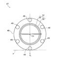
- FIG. 2 is a schematic cross-sectional view of a jig used for such alignment.
- the jig 7 is used to charge a plurality of rechargeable batteries 5 at the same time by electromagnetic induction.
- the jig 7 incorporates the above-described power transmission coil 2 and accommodates the rechargeable batteries 5 inside.
- Housing 7a The bottom surface of the housing 7a is provided with a plurality of recesses 7b into which the rechargeable battery 5 standing vertically upward is fitted.
- the center axis C of the rechargeable battery 5 is oriented in the vertical direction by fitting the rechargeable battery 5 in the recess 7b, the center axis C is prevented from being inclined from the coil surface 2a, and the power receiving coil 3 is It can suppress that the interlinkage magnetic flux which penetrates can reduce.
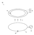
- FIG. 3 is a schematic diagram of a charging system using a magnetic field resonance method.
- the charging system 10 includes a rechargeable battery 15 to be charged, and a power transmission coil 11 for transmitting power to the rechargeable battery 15 wirelessly.
- An AC power supply 12 and a resonance first capacitor 16 are connected to the power transmission coil 11, and a magnetic field H is generated around the power transmission coil 11 by a current supplied from the AC power supply 12 to the power transmission coil 11.
- the rechargeable battery 15 has a battery main body 14 and a power receiving coil 13 wound around the outer peripheral side surface thereof.
- the battery body 14 has an electrolyte and an electrode (not shown) inside a metal cylinder, and is charged by an electromotive force generated in the receiving coil 13 by receiving the magnetic field H.
- FIG. 4 is a developed view of the power receiving coil 13.
- the power receiving coil 13 is developed in a substantially rectangular shape, and has a first end portion 13a and a second end portion 13b. Under actual use, the end portions 13 a and 13 b are connected to the positive electrode and the negative electrode of the battery body 14, so that the induced electromotive force generated in the power receiving coil 13 can be supplied to the battery body 14.
- the power receiving coil 13 is also provided with a second capacitor 17 for resonance.
- the magnetic field resonance method relaxes the alignment of the coils 11 and 13 by increasing the Q value of the power receiving coil 13, but it is known that the Q value is given by the following equation (1). As the resistance R ohm of the power receiving coil 13 increases, the Q value decreases.
- Equation (1) ⁇ is the angular frequency of the current flowing through the power receiving coil 13, and L is the inductance of the power receiving coil 13.
- R rad is a radiation resistance representing the electromagnetic wave radiated from the power receiving coil 13.
- the rectangular receiving coil 13 has a shorter coil length than the closely wound receiving coil 3 as shown in FIG. 1, its resistance R ohm is small, and the Q value can be increased by equation (1).
- the developed shape of the power receiving coil 13 is thus rectangular, so that the outer peripheral side surface of the battery body 14 is largely exposed from the power receiving coil 13 as shown in FIG. 3 and the interlinkage magnetic flux penetrates the inside of the power receiving coil 13. Can be increased.
- FIG. 5 is a side view of the rechargeable battery 15 as viewed from the bottom surface of the cylindrical battery body 14.
- the magnetic field H penetrating the inside of the power receiving coil 13 reaches the battery body 14.
- the battery body 14 has a metal cylinder, an eddy current is generated in the cylinder by the magnetic field H, and the energy of the magnetic field H is used to generate the eddy current.
- this method has an advantage of being able to charge the rechargeable battery 15 lying in a horizontal plane as shown in FIG. 3, energy transfer between the power transmission coil 11 and the power reception coil 13 is not efficient. There's a problem.
- FIG. 6 is a side view of the rechargeable battery 15 studied in order to solve this problem.
- a magnetic sheet 18 containing ferrite or a soft magnetic material is wound around the side surface of the battery body 14.
- the developed shape of the power receiving coil 13 is a rectangular shape as in FIG.
- the magnetic sheet 18 has the property of taking in the magnetic field H therein. Therefore, according to this structure, it is possible to prevent the magnetic field H from reaching the battery body 14, suppress the wasteful consumption of the energy of the magnetic field H to generate eddy currents on the surface of the battery body 14, and It is considered that the energy of H can be effectively utilized for the electromotive force of the power receiving coil 13.
- a part of the magnetic field H taken into the magnetic sheet 18 in this way leaks out above the battery body 14 and generates an induced current I 1 in the power receiving coil 13.
- the direction of the induced current I 1 is opposite to that of the induced current I 2 generated by the magnetic field H in the power receiving coil 13 below the battery body 14.
- the inventor of the present application simulated the relationship between the rolling angle ⁇ of the rechargeable battery 15 in the horizontal plane and the power transfer efficiency E.
- the rolling angle ⁇ is an angle between a direction D1 from the central axis C of the battery main body 14 toward the portion where the power receiving coil 13 is not present and a direction D2 of the magnetic field H in a side view, and the counterclockwise rotation about the central axis C.
- the direction of turning to the positive direction was taken as the positive direction.
- the efficiency E was defined as the ratio of the power of the AC power supply 12 and the power induced in the power receiving coil 13.
- an additional resistance that simulates the internal resistance of the rechargeable battery 15 is connected in series to the power receiving coil 13 and the load resistance is calculated for each of 0.1 ⁇ , 0.2 ⁇ , and 0.3 ⁇ .
- the efficiency E is less than 10% at almost all rolling angles ⁇ . Practically, it is preferable that the efficiency E is 50% or more. Therefore, it was found that the rechargeable battery 15 cannot withstand actual use.
- FIG. 8 is a cross-sectional view of the rechargeable battery 15 studied in order to prevent the induced currents from canceling each other as described above.
- the receiving coil 13 having a rectangular developed shape as shown in FIG.
- the rolling angle ⁇ in this example is an angle between the direction D3 from the central axis C of the battery body 14 toward the end of the power receiving coil 13 and the direction D2 of the magnetic field H in a side view, and the central axis C is The direction that turns counterclockwise is defined as the positive direction.
- the power receiving coil 13 is not exposed to the magnetic field H leaking upward from the battery body 14, and the induced current is offset between the upper side and the lower side of the battery body 14. I can suppress it.
- FIG. 9 is a side view of the rechargeable battery 15 when the rolling angle ⁇ is 0 °.
- FIG. 10 is a diagram obtained by simulating the relationship between the rolling angle ⁇ of the rechargeable battery 15 shown in FIGS. 8 and 9 and the power transfer efficiency E.
- FIG. 10 is a diagram obtained by simulating the relationship between the rolling angle ⁇ of the rechargeable battery 15 shown in FIGS. 8 and 9 and the power transfer efficiency E.
- the rolling angle ⁇ at which an efficiency E of 50% or more that can withstand practical use is obtained is limited to a range of ⁇ 40 ° centering on ⁇ 90 °, and the efficiency E that can withstand practical use is obtained in the remaining regions. Absent.
- the rolling angle ⁇ at which the efficiency E is less than 50% is referred to as a blind spot.
- the possibility that the rolling angle ⁇ enters the blind spot when the rechargeable battery 15 is laid in a horizontal plane increases, and the rechargeable battery 15 may not be sufficiently charged.
- FIG. 11 is a perspective view of a charging system using the magnetic field resonance method according to the present embodiment.
- the charging system 30 includes a power transmission coil 31 and a rechargeable battery 32.
- the power transmission coil 31 is wound around a first axis X1 oriented in the vertical direction, and generates a magnetic field H parallel to the first axis X1 by the current supplied from the AC power supply 33.
- a first capacitor 34 that forms an LC resonance circuit in cooperation with the power transmission coil 31 is provided between the power transmission coil 31 and the AC power supply 33.
- the power transmission coil 31 for example, a copper wire having good conductivity can be used.
- the rechargeable battery 32 has a cylindrical shape with the second axis X2 as a longitudinal direction and is exposed to the magnetic field H described above.
- the second axis X2 is not particularly limited, but in the following, the second axis X2 is provided in the horizontal plane, so that the cylindrical rechargeable battery 32 is placed in the horizontal plane.
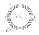
- FIG. 12 is a perspective view of the rechargeable battery 32.
- the rechargeable battery 32 includes a battery main body 35 and a power receiving coil 36.
- the battery body 35 includes a cylindrical outer peripheral side surface 35a, and a power receiving coil 36 is wound around the outer peripheral side surface 35a in a spiral shape.
- the power receiving coil 36 is, for example, a copper wire, and has a first end portion 36a and a second end portion 36b. And between the 1st end part 36a and the 2nd end part 36b, it extends along the longitudinal direction of the battery main body 35, and the linear conducting wire 40 which electrically connects each end part 36a, 36b. Is provided.
- the power receiving coil 36 according to the present embodiment is loosely wound around the battery main body 35, and the battery main body is between adjacent power receiving coils 36. There is a gap S in which 35 is greatly exposed.
- the power receiving coil 36 is represented by a continuous shape without interruption. However, in reality, the power receiving coil 36 is interrupted in the middle, and the power receiving coil 36 is electrically connected to the positive electrode and the negative electrode of the battery body 35 at the point of the interruption.
- the receiving coil 36 generates an electromotive force by being exposed to the magnetic field H, and the battery body 35 is charged by the electromotive force.
- FIG. 13 is a side view of the rechargeable battery 30 viewed from a direction parallel to the second axis X2 (see FIG. 10).
- the battery body 35 includes a metal cylindrical tube 38 and a magnetic sheet 39 surrounding the metal cylinder 38, and an outer peripheral side surface 35 a of the battery body 35 is defined by the surface of the magnetic sheet 39.
- the material of the magnetic sheet 39 is not particularly limited, but here, ferrite or soft magnetic material is used as the material of the magnetic sheet 39.
- the magnetic sheet 39 prevents the magnetic field H from reaching the cylindrical body 38 by taking the magnetic field H into itself. Thereby, generation
- FIG. 14 is a side view of the rechargeable battery 30.
- a second capacitor 41 that forms an LC resonance circuit in cooperation with the power receiving coil 36 is provided in the middle of the conducting wire 40.
- the battery body 35 is cylindrical, when the battery body 35 is rotated around the central axis C, a part of the power receiving coil 36 and the conductive wire 40 are hidden behind the battery body 35.
- the magnetic field H that penetrates the inside of the closed region R is provided as an interlinkage magnetic flux that penetrates the inside of the power receiving coil 36, and generates an induced current I in the power receiving coil 36.
- the magnetic field H passing outside the closed region R does not contribute to the interlinkage magnetic flux penetrating the power receiving coil 36, and therefore does not generate the induced current I in the power receiving coil 36.
- a closed region R through which the interlinkage magnetic flux penetrates is formed by spirally winding the power receiving coil 36 around the battery body 35, and the induced current I flows along the contour of the closed region R.
- the gap S in which the outer peripheral side surface 35a of the battery body 35 is exposed is provided by winding the power receiving coil 36 as sparsely as possible to increase the area of each closed region R when viewed from the side.
- the blind spot is defined as the rolling angle ⁇ at which the efficiency E of the power exchanged between the power transmission coil 31 and the power reception coil 36 is less than 50%.
- FIG. 15 is a side view for explaining the rolling angle ⁇ .
- the rolling angle ⁇ is an angle between the direction D4 from the central axis C toward the conductor 40 in the side view and the first axis X1 facing vertically upward, and the central axis C is counterclockwise.
- the direction of turning to the positive direction was taken as the positive direction.
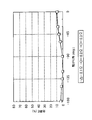
- the inventor of the present application obtained the relationship between the rolling angle ⁇ and the efficiency E by simulation using the conditions shown in FIG.
- an additional resistance that simulates the internal resistance of the rechargeable battery 32 is connected in series to the power receiving coil 36, and the load resistance is calculated for each of 0.1 ⁇ , 0.2 ⁇ , and 0.3 ⁇ .
- the dead angle of the rolling angle ⁇ where the efficiency E is less than 50% is limited to the range of ⁇ 180 ° to 150 ° and ⁇ 30 ° to 0 °, and the angular region of the rolling angle ⁇ that does not become the dead angle. Reaches 120 °.
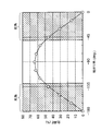
- FIG. 18 is a diagram showing a result obtained by performing the same simulation as in FIG. 17 for the comparative example using the power receiving coil 13 having a rectangular developed shape as shown in FIG.
- the diameter of the battery body 35 was 10 mm, and the diameter of the cross section of the power receiving coil 13 was 0.5 mm.
- the capacitance of the second capacitor 17 (see FIG. 4) connected to the power receiving coil 13 was 3470 pF.
- the range of angles that do not become blind spots is limited to 80 °, and the range that becomes blind spots becomes wider than in the present embodiment of FIG.
- the blind spot is thus reduced because the closed region R (see FIG. 14) in which the interlinkage magnetic flux penetrates the gap of the power receiving coil 36 when viewed from the side even when the battery body 35 is rotated around the central axis C. It is thought that it is formed.
- the blind spot is reduced, the possibility that the rolling angle ⁇ enters the blind spot when the user rolls the rechargeable battery 32 on the horizontal plane is reduced. Thereby, the positional relationship between the power transmission coil 31 and the power reception coil 13 for increasing the efficiency of power transfer from the power transmission coil 31 to the power reception coil 13 is relaxed, which can contribute to the convenience of the user.
- the number of turns of the power receiving coil 36 is not particularly limited. However, if the number of turns is large, the resistance R ohm of the power receiving coil 36 increases, so that the induced current I induced in the power receiving coil 36 is reduced. The efficiency E of power exchanged between the two decreases.
- the Q value decreases as the resistance R ohm of the power receiving coil 36 increases. Since the efficiency E is also reduced by a decrease in the Q value, in order to prevent the efficiency E from being decreased due to the decrease in the Q value, the number of turns of the power receiving coil 36 is reduced as much as possible to reduce the resistance R ohm . It is considered preferable to make it smaller.
- FIG. 19 is a graph obtained by investigating the relationship between the number of turns of the receiving coil 36 and the efficiency E by simulation.
- graphs A and B for the magnetic resonance type power receiving coil 36 graphs C and D for the electromagnetic induction type coil were also obtained for comparison.
- the second capacitor 41 (see FIG. 14) is provided in the magnetic resonance type power receiving coil 36. However, in this simulation, no capacitor is provided in the electromagnetic induction type coil.
- Graphs A and D are graphs obtained when the longitudinal direction of the battery body 35 is parallel to the coil surface of the power transmission coil 31.
- Graphs B and C are graphs obtained when the longitudinal direction of the battery body is perpendicular to the coil surface of the power transmission coil 31.
- the highest efficiency is obtained when the number of turns is 1.5.
- the efficiency decreases when the number of turns is less than 1.5. This is because when the number of turns is reduced, the resistance R ohm of the power receiving coil 36 is reduced as compared with the case where the number of turns is 1.5, but the total area of each closed region R is insufficient and the linkage flux is reduced. This is thought to be due to a decrease in efficiency E.
- the efficiency also decreases when the number of turns is more than 1.5. This is presumably because the Q value is lowered due to the increase in the resistance R ohm .
- the resistance R ohm of the power receiving coil 36 increases as the number of turns increases, and the efficiency E and Q value decrease as described above.
- FIG. 20A is a side view of the rechargeable battery 32 according to the present embodiment.
- the first pitch P1 for one turn of the power receiving coil 36 is larger than the second pitch P2 for a half turn of the power receiving coil 32.
- the angle between the induction current I f flowing through the power receiving coil 32 of the portions seen without hiding cell body 35, the induced current I b flowing through the power receiving coil 32 of the portion hidden behind the battery body 35 alpha Can be increased.
- the directions of the induced currents I f and I b are hardly anti-parallel to each other, so that the induced currents I f and I b can be prevented from canceling each other, and a large induced current is induced in the power receiving coil 32. Can do.
- FIG. 20B is a side view of the rechargeable battery 37 according to the comparative example.
- the power receiving coil 32 is spirally wound around the battery body 35 as in the present embodiment.
- the first pitch P1 for one turn of the power receiving coil 32 is set to be equal to or smaller than the second pitch P2 for a half turn of the power receiving coil 32.
- the first pitch P1 is larger than the second pitch P2.
- the aspect ratio is defined as L / R where L is the length in the longitudinal direction of the cylindrical battery body 35 and R is the diameter.
- the inventor of the present application investigated the relationship between the aspect ratio of each of the AAA to AAA batteries and the above-mentioned efficiency E.
- the survey results are shown in Table 1.
- the number of turns of the power receiving coil 36 was set to 1.5 in any of the batteries 1 to 4.
- AA to AAA batteries the ones with the highest market demand are AA batteries and AAA batteries. According to Table 1, the aspect ratios of both AA batteries and AAA batteries are 3.5 or more. Therefore, by winding the power receiving coil 36 around the battery body 35 having an aspect ratio of 3.5 or more, a rechargeable battery that is easily accepted by the market can be provided.
- the efficiency E is highest when the rolling angle ⁇ is ⁇ 90 °, and the efficiency is 0 when the rolling angle ⁇ is ⁇ 180 ° and 0 °. Obviously.
- FIG. 21A is a side view of the rechargeable battery 32 as viewed from the line-of-sight direction parallel to the magnetic field H when the rolling angle ⁇ is 0 °.
- the directions of the induced currents I1 to I3 in the portion flowing through the conductor 40 are not the same in all the closed regions R1 to R3, and the direction of the induced current I2 is different from the directions of the induced currents I1 and I3. Therefore, when the rolling angle ⁇ is 0 °, the currents I1 to I3 cancel each other and the efficiency becomes zero.
- the induced current I1 and the induced current I2 have different directions because the receiving coil 36 of the portion hidden behind the battery body 35 at the contact point A of the closed regions R1 and R2 through which the induced currents I1 and I2 flow. Is considered to be caused by the crossing of the conductor 40.
- FIG. 21B is a side view of the rechargeable battery 32 as viewed from the viewing direction parallel to the magnetic field H when the rolling angle ⁇ is ⁇ 90 °.
- the reason for the difference in efficiency depending on the rolling angle ⁇ is that the contact point A between the power receiving coil 36 and the conductor 40 hidden behind the battery body 35 may or may not appear depending on the direction of the line of sight. It is in.
- first direction D 0 the line-of-sight direction in which the contact point A does not appear as shown in FIG. 21B is referred to as a first direction D 0 .
- the efficiency E is maximized as follows.
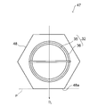
- FIG. 22 is a cross-sectional view of the rechargeable battery 32 according to the first example of the present embodiment.
- the rechargeable battery 32 includes a case 45 that houses the battery main body 35 and the power receiving coil 36 described in the first embodiment.
- Case 45 is a cross-sectional shape is a polygon, and a flat surface 45a perpendicular to the first direction D 0.
- FIG. 23 is a cross-sectional view of the rechargeable battery 32 according to the second example of the present embodiment.
- the rechargeable battery 32 has a case 45 that houses the battery main body 35 and the power receiving coil 36 described in the first embodiment.
- the case 45 has a cylindrical shape and houses a plurality of weights 49 inside thereof.
- the way of arranging the weight 49 is not particularly limited.
- six weights 49 are arranged on the inner surface of the case 45 at every 60 ° angle about the central axis C of the battery body 35. At least one of the six weights 49, is positioned in the first direction D 0.
- the posture of the rechargeable battery 32 is stable with the first direction D 0 oriented vertically downward, and the rolling angle ⁇ is ⁇ 90 ° and the efficiency E is maximized without the user being aware of the rolling angle ⁇ .
- FIG. 24 is a cross-sectional view of the rechargeable battery 32 according to the third example of the present embodiment.
- a plurality of weights 49 are provided on the rechargeable battery 32 as in the second example of FIG.
- the sum of the moments of gravity acting on Kakutsumu 49 becomes 0 when facing the first direction D 0 vertically downward Like that.
- the posture of the rechargeable battery 32 is stabilized in a state where the first direction D 0 is directed vertically downward, and the efficiency E becomes the maximum value.
- FIG. 25 is a cross-sectional view of the rechargeable battery 32 according to the fourth example of the present embodiment.
- the rechargeable battery 32 has a cylindrical case 45 that houses the battery main body 35 and the power receiving coil 36 described in the first embodiment.
- the central axis C of the battery body 35 offset from the center axis C1 of the case 45 in a first direction D 0.
- the center of gravity of the rechargeable battery 32 is shifted in the first direction D 0 , when the rechargeable battery 32 is placed on the horizontal plane P, the posture of the rechargeable battery 32 is stabilized in a state where the first direction D 0 is directed vertically downward. It becomes like this. Therefore, even if the user is not aware of the rolling angle ⁇ , the rolling angle ⁇ is automatically ⁇ 90 °, and the efficiency E can be maximized.
- the rechargeable battery 32 has been described. However, these examples are applied to electronic devices such as smartphones, tablet PCs (Personal Computers), TV remote controllers, and home game machines as follows. It can also be applied.
- electronic devices such as smartphones, tablet PCs (Personal Computers), TV remote controllers, and home game machines as follows. It can also be applied.
- 26 to 29 are cross-sectional views of the electronic apparatus according to the present embodiment.
- FIG. 26 is a cross-sectional view of the electronic device 47 according to the first example of the present embodiment.
- the electronic device 47 includes a housing 48 that houses the rechargeable battery 32 of the first embodiment. Similar to the case 45 in FIG. 22, the casing 48 has a polygonal cross-sectional shape and includes a flat surface 48 a orthogonal to the first direction D 0 .
- FIG. 27 is a cross-sectional view of an electronic device 47 according to a second example of the present embodiment.
- the electronic apparatus 47 includes a cylindrical casing 48 that houses the rechargeable battery 32 of the first embodiment, and includes a plurality of weights 49 inside the casing 48.
- Each weight 49 is arranged in the same manner as in the example of FIG. 23, and the sum of the moments of gravity acting on each weight 49 when the center axis C3 of the cylindrical casing 48 is used as a reference is zero. Therefore, as described with reference to FIG. 23, the posture of the rechargeable battery 32 even in a state where the first direction D 0 is directed vertically downwards in the electronic apparatus 47 is stabilized. Therefore, even if the user is not aware of the rolling angle ⁇ of the rechargeable battery 32, the rolling angle ⁇ can be ⁇ 90 ° and the efficiency E can be maximized.
- FIG. 28 is a cross-sectional view of an electronic device 47 according to a third example of the present embodiment.
- a plurality of weights 49 are provided in a plurality of electronic devices 47 as in the second example of FIG.
- each weight 49 is the same as that described with reference to FIG. Therefore, in this case as well, since the sum of the moments of gravity acting on each weight 49 is 0, the rolling angle ⁇ is ⁇ 90 ° and the efficiency E is maximized without the user being aware of the rolling angle ⁇ . be able to.
- FIG. 29 is a cross-sectional view of an electronic device 47 according to a fourth example of this embodiment.
- This electronic device 47 has a cylindrical casing 48 that houses the rechargeable battery 32 of the first embodiment.
- the central axis C of the cell body 35 in the present embodiment offset from the center axis C3 of the housing 48 in a first direction D 0.
- the orientation of the rechargeable battery 32 is stabilized in a state where the angle direction D 0 is vertically downward, so that the rolling angle ⁇ is automatically set to ⁇ 90 °.
- the efficiency E can be maximized.
- a resonance coil is used together with the power transmission coil 31 and the power reception coil 36. According to the position where the resonance coil is provided, the present embodiment is roughly divided into the following first to third examples.
- FIG. 30 is a schematic diagram of the charging system according to the first example of the present embodiment.
- the first resonance coil 51 is provided in parallel with the power transmission coil 31, and the resonance first capacitor 34 is provided in the first resonance coil 51.
- the overall impedance of the charging system 55 varies as the internal resistance of the battery body 35 changes.
- the internal resistance of the battery main body 35 changes as a factor which changes the internal resistance of the battery main body 35.
- a temperature change of the battery main body 35 for example.
- an impedance matching device is provided in the power transmission coil 31 to prevent a change in impedance of the entire system.
- the width of the impedance that can be adjusted in the impedance matching unit is increased as compared with the case where there are only two coils, which can contribute to the convenience of the user.
- FIG. 31 is a schematic diagram of a charging system according to a second example of the present embodiment.
- FIG. 31 the same elements as those described in FIG. 30 are denoted by the same reference numerals as those in FIG. 30, and description thereof will be omitted below.
- the second resonance coil 52 is provided in parallel with the power receiving coil 36, and the second capacitor 41 is provided in the second resonance coil 52.
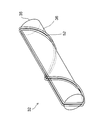
- FIG. 32 is a perspective view showing an example of how to wind the second resonance coil 36.
- the second resonant coil 52 is spirally wound around the battery body 35 in the same manner as the power receiving coil 36.
- FIG. 33 is a schematic diagram of a charging system according to a third example of the present embodiment.
- the charging system 57 is a combination of the first example and the second example, and uses the first resonance coil 51 and the second resonance coil 52 in combination. Use a coil.
- the range in which the impedance of the entire system can be adjusted can be further increased as compared with the first and second examples having three coils.
- the induced current is converted into direct current using a rectifier circuit as follows, and the rechargeable battery is charged with the direct current.
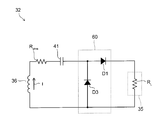
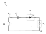
- FIG. 34 is a circuit diagram of the rechargeable battery 32 according to the first example of the present embodiment.
- the rechargeable battery 32 includes the battery main body 35, the power receiving coil 36, the second capacitor 41, and the rectifier circuit 60 described in the first embodiment.
- the resistance R ohm is the resistance of the power receiving coil 36
- the resistance R L is the internal resistance of the battery body 35.
- the rectifier circuit 60 is a full-wave rectifier circuit formed by bridge-connecting the first to fourth diodes D1 to D4, and has a function of limiting the induced current I flowing through the power receiving coil 36 in one direction.
- FIG. 35 is a circuit diagram of the rechargeable battery 32 according to the second example of the present embodiment.
- the second diode D2 and the fourth diode D4 are omitted from the rectifier circuit 60 in the first example (see FIG. 34), and the rectifier circuit 60 is a half-wave rectifier circuit.
- FIG. 36 is a circuit diagram of the rechargeable battery 32 according to the third example of the present embodiment.
- the first diode D1 is used as the rectifier circuit 60, and the direction in which the induced current I flows is limited to the forward direction of the first diode D1.
- the battery body 35 can be charged with the direct current.
- a diode is used for the rectifier circuit 60.
- rectifier circuit 60 according to the first to third examples may be used in combination with each of the first to third examples of the third embodiment.
- Table 2 is a table showing combinations of the number of coils on the battery body 35 side and the first to third examples of the present embodiment.
- the third example in which the number of coils on the battery main body 35 side is 2 and only one diode is applied is the viewpoint of reducing the cost of the rechargeable battery 32. To most preferred.
- the charging method of the rechargeable battery 32 is not limited to the first to fourth embodiments described above.
- FIG. 11 illustrates the case where one rechargeable battery 32 is charged by the magnetic field resonance method
- a plurality of rechargeable batteries 32 may be charged at a time as shown in FIG.
- the power transmission coil 31 is provided on the charging stand 70 parallel to the horizontal plane, and a plurality of rechargeable batteries 32 may be rolled on the charging stand 70. Since the blind spot of the rechargeable battery 32 is reduced as described above, even if a plurality of rechargeable batteries 32 are rolled in this manner, the possibility that the rolling angle of each rechargeable battery 32 enters the blind spot is reduced. It can be charged efficiently.
- the method of using the rechargeable battery 32 is not limited to the first to fourth embodiments described above.
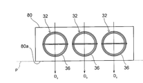
- FIG. 38 is a cross-sectional view showing an example of how to use the rechargeable battery 32.
- a plurality of rechargeable batteries 32 are used as the battery pack 80.
- the cross-sectional shape of the battery pack 80 is, for example, a rectangular shape.
Landscapes
- Engineering & Computer Science (AREA)
- Power Engineering (AREA)
- General Chemical & Material Sciences (AREA)
- Chemical & Material Sciences (AREA)
- Chemical Kinetics & Catalysis (AREA)
- Electrochemistry (AREA)
- Computer Networks & Wireless Communication (AREA)
- Manufacturing & Machinery (AREA)
- Electromagnetism (AREA)
- Physics & Mathematics (AREA)
- Charge And Discharge Circuits For Batteries Or The Like (AREA)
- Secondary Cells (AREA)
- Battery Mounting, Suspending (AREA)
Abstract
[Problem] To relax the positional relationship between a power receiving coil and a power transmitting coil in a charging battery, a charging system, and an electronic device.
[Solution] A charging battery has: a battery main body (35), the outer circumferential side surface (35a) of which is cylindrical; and a power receiving coil (36) wound at most one turn around the outer circumferential side surface (35a) and electrically connected to the battery main body (35). In the charging battery, the power receiving coil (36) is wound around the outer circumferential side surface (35a) in a helical manner while giving space for exposing the outer circumferential side surface (35a).
Description
本発明は、充電池、充電システム、及び電子機器に関する。
The present invention relates to a rechargeable battery, a charging system, and an electronic device.
携帯端末等の電子機器には繰り返して充電することが可能な充電池が使用される。充電池の充電方式には、金属接点を介して充電池に充電を行う方式と、金属接点等を介さずに電池に充電を行うワイヤレス充電方式とがある。このうち、ワイヤレス充電方式は、充電器の金属接点に電池を接触させる煩わしさがないためユーザの便宜に資することができる。
Rechargeable batteries that can be repeatedly charged are used for electronic devices such as mobile terminals. The charging method for the rechargeable battery includes a method for charging the rechargeable battery via a metal contact and a wireless charging method for charging the battery without using a metal contact or the like. Among these, the wireless charging method can contribute to the convenience of the user because there is no inconvenience of contacting the battery with the metal contact of the charger.
ワイヤレス充電方式においては、電源から送電コイルに電力を供給することで磁界を生成し、その磁界によって受電コイルに誘導起電力を生じさせる。受電コイルは電池に内蔵されており、その誘導起電力によって電池が充電されることになる。
In the wireless charging method, a magnetic field is generated by supplying power from a power source to a power transmission coil, and an induced electromotive force is generated in the power receiving coil by the magnetic field. The power receiving coil is built in the battery, and the battery is charged by the induced electromotive force.
ワイヤレス充電方式は、電磁誘導方式と磁界共鳴方式とに分けられる。両者は、送電コイルと受電コイルとの結合係数やQ値に応じて区別され、Q値が小さく結合係数が大きいものを電磁誘導方式と呼び、これとは逆にQ値が大きく結合係数が小さいものを磁界共鳴方式と呼ぶことが多い。
The wireless charging method can be divided into an electromagnetic induction method and a magnetic resonance method. Both are distinguished according to the coupling coefficient and the Q value between the power transmission coil and the receiving coil, and those with a small Q value and a large coupling coefficient are called electromagnetic induction methods. Conversely, the Q value is large and the coupling coefficient is small. This is often called a magnetic resonance method.
電磁誘導方式においては、電力の伝送効率を高めるために受電コイルと送電コイルとを正対させなければならず、受電コイルと送電コイルとの位置関係に制約が生じて不便である。
In the electromagnetic induction method, in order to increase the transmission efficiency of power, the power receiving coil and the power transmitting coil must face each other, which is inconvenient because the positional relationship between the power receiving coil and the power transmitting coil is limited.
一方、磁界共鳴方式においては、受電コイルが送電コイルに正対していなくても十分な伝送効率が得られることが知られており、電磁誘導方式と比べて便利な充電方式である。
On the other hand, in the magnetic field resonance method, it is known that sufficient transmission efficiency can be obtained even if the power receiving coil is not directly facing the power transmission coil, and is a convenient charging method compared with the electromagnetic induction method.
そのような磁界共鳴方式を用いたワイヤレス充電では、受電コイルと送電コイルとの位置関係を更に緩和するという点で改善の余地がある。
In wireless charging using such a magnetic field resonance method, there is room for improvement in terms of further relaxing the positional relationship between the power receiving coil and the power transmitting coil.
充電池、充電システム、及び電子機器において、受電コイルと送電コイルとの位置関係を緩和すること。
Relieving the positional relationship between the power receiving coil and power transmitting coil in rechargeable batteries, charging systems, and electronic devices.
以下の開示の一観点によれば、外周側面が円筒状の電池本体と、前記外周側面に高々1重に巻かれ、前記電池本体と電気的に接続された受電コイルとを有し、前記受電コイルが、前記外周側面が露出する隙間を開けつつ、該外周側面に螺旋状に巻かれた充電池が提供される。
According to one aspect of the disclosure below, a battery body having a cylindrical outer peripheral side surface, and a power receiving coil that is wound at most on the outer peripheral side surface and electrically connected to the battery main body, There is provided a rechargeable battery in which a coil is spirally wound around the outer peripheral side surface while opening a gap where the outer peripheral side surface is exposed.
また、その開示の別の観点によれば、第1の軸を中心にして巻かれた送信コイルと、円筒状の外周側面を備え、第2の軸を長手方向とする電池本体と、前記外周側面に高々1重に巻かれ、前記電池本体と電気的に接続された受電コイルとを有し、前記第2の軸が前記第1の軸に対して垂直であり、前記受電コイルが、前記外周側面が露出する隙間を開けつつ、該外周側面に螺旋状に巻かれた充電システムが提供される。
According to another aspect of the disclosure, a transmission coil wound around a first axis, a battery body having a cylindrical outer peripheral side surface and having a second axis as a longitudinal direction, and the outer periphery A power receiving coil which is wound at most on a side surface and electrically connected to the battery body, the second axis is perpendicular to the first axis, and the power receiving coil is A charging system is provided that is spirally wound around the outer peripheral side surface while opening a gap where the outer peripheral side surface is exposed.
更に、その開示の他の観点によれば、外周側面が円筒状の電池本体と、前記外周側面に高々1重に巻かれて前記電池本体と電気的に接続された受電コイルとを備えた充電池を有し、前記受電コイルが、前記外周側面が露出する隙間を開けつつ、該外周側面に螺旋状に巻かれた電子機器が提供される。
Further, according to another aspect of the disclosure, the battery includes a battery body having a cylindrical outer peripheral side surface and a power receiving coil that is wound at most on the outer peripheral side surface and electrically connected to the battery main body. There is provided an electronic apparatus having a battery, wherein the power receiving coil is spirally wound around the outer peripheral side surface while opening a gap where the outer peripheral side surface is exposed.
開示の充電池によれば、電池本体の外周側面が露出する隙間を開けながら螺旋状に受電コイルを巻く。これにより、水平面に充電池を転がしたときに、水平面に平行に設けられた送電コイルと受電コイルとの間における電力の授受の効率が低下する可能性が減り、受電コイルと送電コイルとの位置関係を緩和できることが明らかとなった。
According to the disclosed rechargeable battery, the power receiving coil is wound in a spiral shape with a gap that exposes the outer peripheral side surface of the battery body. As a result, when the rechargeable battery is rolled on the horizontal plane, the possibility that the efficiency of power transfer between the power transmission coil and the power reception coil provided in parallel to the horizontal plane is reduced is reduced, and the position of the power reception coil and the power transmission coil is reduced. It became clear that the relationship could be relaxed.
本実施形態の説明に先立ち、本願発明者が行った検討事項について説明する。
Prior to the description of this embodiment, considerations made by the inventors of the present application will be described.
前述のようにワイヤレス充電方式には電磁誘導方式と磁界共鳴方式とがある。
As described above, the wireless charging method includes an electromagnetic induction method and a magnetic field resonance method.
これらのうち、電磁誘導方式について図1を参照して説明する。図1は、電磁誘導方式を用いた充電システムの模式図である。
Of these, the electromagnetic induction method will be described with reference to FIG. FIG. 1 is a schematic diagram of a charging system using an electromagnetic induction method.
この充電システム1は、充電の対象となる充電池5と、ワイヤレスで充電池5に電力を送るための送電コイル2とを有する。
The charging system 1 includes a rechargeable battery 5 to be charged and a power transmission coil 2 for transmitting power to the rechargeable battery 5 wirelessly.
送電コイル2には交流電源6が接続されており、交流電源6から送電コイル2に供給された電流によって送電コイル2の周囲に磁界Hが生じる。
An AC power supply 6 is connected to the power transmission coil 2, and a magnetic field H is generated around the power transmission coil 2 by a current supplied from the AC power supply 6 to the power transmission coil 2.
一方、充電池5は、電池本体4とその外周側面に巻かれた受電コイル3とを有する。上記の磁界Hによって受電コイル3には誘導起電力が生じ、その誘導起電力で電池本体4が充電される。
On the other hand, the rechargeable battery 5 includes a battery body 4 and a power receiving coil 3 wound around the outer peripheral side surface thereof. An induced electromotive force is generated in the power receiving coil 3 by the magnetic field H, and the battery body 4 is charged by the induced electromotive force.
上記の誘導起電力は受電コイル3の巻き数に比例する。そのため、この充電システム1においては、電池本体4の外周側面に受電コイル3を隙間なく巻いて受電コイル3の巻き数を増やすことで、受電コイル3で発生した高い誘導起電力により電池本体4を効率的に充電することができる。
The above-mentioned induced electromotive force is proportional to the number of turns of the receiving coil 3. For this reason, in this charging system 1, the power receiving coil 3 is wound around the outer peripheral side surface of the battery main body 4 without gaps, and the number of turns of the power receiving coil 3 is increased. It can be charged efficiently.
但し、電池本体4の中心軸Cが送電コイル2のコイル面2aから傾いていると、受電コイル3を貫く鎖交磁束が減って受電コイル3の起電力が低下してしまうので、送電コイル2と電池本体4とを事前に位置合わせしてくのが好ましい。
However, if the central axis C of the battery body 4 is tilted from the coil surface 2a of the power transmission coil 2, the interlinkage magnetic flux passing through the power reception coil 3 is reduced and the electromotive force of the power reception coil 3 is reduced. It is preferable to align the battery body 4 with the battery body 4 in advance.
図2は、そのような位置合わせに使用される治具の模式断面図である。
FIG. 2 is a schematic cross-sectional view of a jig used for such alignment.
治具7は、複数の充電池5に対して電磁誘導方式で同時に充電をするのに使用されるものであって、前述の送電コイル2を内蔵すると共に、複数の充電池5を内側に収容するハウジング7aを有する。ハウジング7aの底面には、鉛直上向きに立てられた充電池5が嵌る複数の凹部7bが設けられる。
The jig 7 is used to charge a plurality of rechargeable batteries 5 at the same time by electromagnetic induction. The jig 7 incorporates the above-described power transmission coil 2 and accommodates the rechargeable batteries 5 inside. Housing 7a. The bottom surface of the housing 7a is provided with a plurality of recesses 7b into which the rechargeable battery 5 standing vertically upward is fitted.
これによれば、凹部7bに充電池5を嵌めることで充電池5の中心軸Cが鉛直方向を向くようになるため、中心軸Cがコイル面2aから傾くのが防止され、受電コイル3を貫く鎖交磁束が低減するのを抑制することができる。
According to this, since the center axis C of the rechargeable battery 5 is oriented in the vertical direction by fitting the rechargeable battery 5 in the recess 7b, the center axis C is prevented from being inclined from the coil surface 2a, and the power receiving coil 3 is It can suppress that the interlinkage magnetic flux which penetrates can reduce.
しかしながら、この方法では、ユーザが自ら治具7と充電池5とを位置合わせして各凹部7bに電池5を嵌めなければならず不便である。
However, this method is inconvenient because the user must align the jig 7 and the rechargeable battery 5 and fit the battery 5 in each recess 7b.
このような位置合わせの手間を減らすために以下のように磁界共鳴方式を用いた充電システムを考える。
Suppose a charging system using the magnetic field resonance method as described below to reduce the time required for such alignment.
図3は、磁界共鳴方式を用いた充電システムの模式図である。
FIG. 3 is a schematic diagram of a charging system using a magnetic field resonance method.
この充電システム10は、充電の対象となる充電池15と、ワイヤレスで充電池15に電力を送るための送電コイル11とを有する。
The charging system 10 includes a rechargeable battery 15 to be charged, and a power transmission coil 11 for transmitting power to the rechargeable battery 15 wirelessly.
送電コイル11には交流電源12と共振用の第1のキャパシタ16とが接続されており、交流電源12から送電コイル11に供給された電流によって送電コイル11の周囲に磁界Hが生じる。
An AC power supply 12 and a resonance first capacitor 16 are connected to the power transmission coil 11, and a magnetic field H is generated around the power transmission coil 11 by a current supplied from the AC power supply 12 to the power transmission coil 11.
一方、充電池15は、電池本体14とその外周側面に巻かれた受電コイル13とを有する。
On the other hand, the rechargeable battery 15 has a battery main body 14 and a power receiving coil 13 wound around the outer peripheral side surface thereof.
電池本体14は、金属製の筒体の内部に不図示の電解質や電極を有しており、上記の磁界Hを受けて受電コイル13で生じた起電力によって充電される。
The battery body 14 has an electrolyte and an electrode (not shown) inside a metal cylinder, and is charged by an electromotive force generated in the receiving coil 13 by receiving the magnetic field H.
図4は、受電コイル13の展開図である。
FIG. 4 is a developed view of the power receiving coil 13.
図4に示すように、受電コイル13は、その展開形状が概略矩形状であって、第1の端部13aと第2の端部13bを有する。実使用下においてはこれらの端部13a、13bを電池本体14の正極と負極の各々に接続することで、受電コイル13に生じた誘導起電力を電池本体14に供給することができる。
As shown in FIG. 4, the power receiving coil 13 is developed in a substantially rectangular shape, and has a first end portion 13a and a second end portion 13b. Under actual use, the end portions 13 a and 13 b are connected to the positive electrode and the negative electrode of the battery body 14, so that the induced electromotive force generated in the power receiving coil 13 can be supplied to the battery body 14.
また、その受電コイル13には共振用の第2のキャパシタ17も設けられる。
The power receiving coil 13 is also provided with a second capacitor 17 for resonance.
磁界共鳴方式は、受電コイル13のQ値を高めることで各コイル11、13同士の位置合わせを緩和するものであるが、そのQ値は以下の式(1)で与えられることが知られており、受電コイル13の抵抗Rohmが増えるとQ値が低下してしまう。
The magnetic field resonance method relaxes the alignment of the coils 11 and 13 by increasing the Q value of the power receiving coil 13, but it is known that the Q value is given by the following equation (1). As the resistance R ohm of the power receiving coil 13 increases, the Q value decreases.

なお、式(1)においてωは受電コイル13を流れる電流の角周波数であり、Lは受電コイル13のインダクタンスである。また、Rradは、受電コイル13から放射される電磁波を表す放射抵抗である。
In Equation (1), ω is the angular frequency of the current flowing through the power receiving coil 13, and L is the inductance of the power receiving coil 13. R rad is a radiation resistance representing the electromagnetic wave radiated from the power receiving coil 13.
矩形状の受電コイル13は、図1のように密に巻かれた受電コイル3よりもコイル長が短いためその抵抗Rohmが小さく、式(1)によってQ値を高めることが可能となる。
Since the rectangular receiving coil 13 has a shorter coil length than the closely wound receiving coil 3 as shown in FIG. 1, its resistance R ohm is small, and the Q value can be increased by equation (1).
更に、このように受電コイル13の展開形状を矩形状としたことで、図3に示すように電池本体14の外周側面が受電コイル13から大きく露出し、受電コイル13の内側を貫く鎖交磁束を大きくすることができる。
Further, the developed shape of the power receiving coil 13 is thus rectangular, so that the outer peripheral side surface of the battery body 14 is largely exposed from the power receiving coil 13 as shown in FIG. 3 and the interlinkage magnetic flux penetrates the inside of the power receiving coil 13. Can be increased.
その結果、充電池15が水平面内に寝た状態でも受電コイル13に十分な起電力が生じると考えられ、充電時に図1や図2のように充電池を立たせる必要がなくなり、ユーザの便宜に資することができるとも考えられる。
As a result, it is considered that a sufficient electromotive force is generated in the power receiving coil 13 even when the rechargeable battery 15 is lying in a horizontal plane, and it is not necessary to stand the rechargeable battery as shown in FIGS. It is thought that it can contribute to.
図5は、円筒状の電池本体14の底面から見た充電池15の側面図である。
FIG. 5 is a side view of the rechargeable battery 15 as viewed from the bottom surface of the cylindrical battery body 14.
図5に示すように、受電コイル13の内側を貫いた磁界Hは電池本体14に至る。前述のように電池本体14は金属製の筒体を有するため、磁界Hによってその筒体に渦電流が生じ、磁界Hのエネルギが渦電流の生成に使用されてしまう。
As shown in FIG. 5, the magnetic field H penetrating the inside of the power receiving coil 13 reaches the battery body 14. As described above, since the battery body 14 has a metal cylinder, an eddy current is generated in the cylinder by the magnetic field H, and the energy of the magnetic field H is used to generate the eddy current.
よって、この方法には、図3のように水平面内に寝た状態の充電池15を充電できるという利点はあるものの、送電コイル11と受電コイル13との間におけるエネルギの授受が効率的でないという問題がある。
Therefore, although this method has an advantage of being able to charge the rechargeable battery 15 lying in a horizontal plane as shown in FIG. 3, energy transfer between the power transmission coil 11 and the power reception coil 13 is not efficient. There's a problem.
図6は、この問題を解消するために検討された充電池15の側面図である。
FIG. 6 is a side view of the rechargeable battery 15 studied in order to solve this problem.
この例では、電池本体14の側面にフェライトや軟磁性材料を含む磁性シート18を巻く。なお、受電コイル13の展開形状は、図4と同様に矩形状である。
In this example, a magnetic sheet 18 containing ferrite or a soft magnetic material is wound around the side surface of the battery body 14. The developed shape of the power receiving coil 13 is a rectangular shape as in FIG.
磁性シート18は磁界Hをその内部に取り込む性質がある。よって、この構造によれば、電池本体14に磁界Hが至るのを防止して、電池本体14の表面での渦電流の生成に磁界Hのエネルギが無駄に消費されるのを抑制し、磁界Hのエネルギを受電コイル13の起電力に有効活用することができると考えられる。
The magnetic sheet 18 has the property of taking in the magnetic field H therein. Therefore, according to this structure, it is possible to prevent the magnetic field H from reaching the battery body 14, suppress the wasteful consumption of the energy of the magnetic field H to generate eddy currents on the surface of the battery body 14, and It is considered that the energy of H can be effectively utilized for the electromotive force of the power receiving coil 13.
但し、このように磁性シート18に取り込まれた磁界Hの一部は、電池本体14の上方に漏れ出し、受電コイル13に誘導電流I1を生成する。その誘導電流I1は、電池本体14の下方において磁界Hが受電コイル13に生成する誘導電流I2と向きが逆である。
However, a part of the magnetic field H taken into the magnetic sheet 18 in this way leaks out above the battery body 14 and generates an induced current I 1 in the power receiving coil 13. The direction of the induced current I 1 is opposite to that of the induced current I 2 generated by the magnetic field H in the power receiving coil 13 below the battery body 14.
よって、このように単に磁性シート18を設けたのでは、各誘導電流I1、I2同士が相殺し合ってしまうため、十分な量の電流を電池本体14に供給することができない。
Therefore, if the magnetic sheet 18 is simply provided in this way, the induced currents I 1 and I 2 cancel each other, so that a sufficient amount of current cannot be supplied to the battery body 14.
本願発明者は、充電池15の水平面内での転がり角θと、電力の授受の効率Eとの関係をシミュレーションした。
The inventor of the present application simulated the relationship between the rolling angle θ of the rechargeable battery 15 in the horizontal plane and the power transfer efficiency E.
なお、転がり角θは、側面視で電池本体14の中心軸Cから受電コイル13がない部分に向かう方向D1と磁界Hの方向D2との間の角度であって、中心軸Cを反時計回りに回る方向を正の方向とした。
The rolling angle θ is an angle between a direction D1 from the central axis C of the battery main body 14 toward the portion where the power receiving coil 13 is not present and a direction D2 of the magnetic field H in a side view, and the counterclockwise rotation about the central axis C. The direction of turning to the positive direction was taken as the positive direction.
また、効率Eは、交流電源12の電力と、受電コイル13に誘起される電力との比として定義した。
The efficiency E was defined as the ratio of the power of the AC power supply 12 and the power induced in the power receiving coil 13.
このシミュレーションの結果を図7に示す。
The result of this simulation is shown in FIG.
なお、このシミュレーションでは、充電池15の内部抵抗を模擬する付加抵抗を受電コイル13に直列に接続し、その負荷抵抗が0.1Ω、0.2Ω、0.3Ωの各々について計算した。
In this simulation, an additional resistance that simulates the internal resistance of the rechargeable battery 15 is connected in series to the power receiving coil 13 and the load resistance is calculated for each of 0.1Ω, 0.2Ω, and 0.3Ω.
図7に示すように、略全ての転がり角θにおいて効率Eは10%を下回っている。実用的には効率Eは50%以上であるのが好ましいため、この充電池15では実使用に耐えないことが分かった。
As shown in FIG. 7, the efficiency E is less than 10% at almost all rolling angles θ. Practically, it is preferable that the efficiency E is 50% or more. Therefore, it was found that the rechargeable battery 15 cannot withstand actual use.
図8は、上記のように誘導電流同士が相殺するのを抑制するために検討された充電池15の断面図である。
FIG. 8 is a cross-sectional view of the rechargeable battery 15 studied in order to prevent the induced currents from canceling each other as described above.
この例では、図4に示したような展開形状が矩形状の受電コイル13を、円筒形状の電池本体14の半周部分のみに巻く。
In this example, the receiving coil 13 having a rectangular developed shape as shown in FIG.
なお、この例における転がり角θは、側面視で電池本体14の中心軸Cから受電コイル13の端部に向かう方向D3と磁界Hの方向D2との間の角度であって、中心軸Cを反時計回りに回る方向を正の方向と定義する。
Note that the rolling angle θ in this example is an angle between the direction D3 from the central axis C of the battery body 14 toward the end of the power receiving coil 13 and the direction D2 of the magnetic field H in a side view, and the central axis C is The direction that turns counterclockwise is defined as the positive direction.
このようにすると、転がり角θが-90°の場合においては、電池本体14の上方に漏れ出した磁界Hに受電コイル13が曝されなくなり、電池本体14の上方と下方とで誘導電流が相殺し合うのを抑制できる。
In this way, when the rolling angle θ is −90 °, the power receiving coil 13 is not exposed to the magnetic field H leaking upward from the battery body 14, and the induced current is offset between the upper side and the lower side of the battery body 14. I can suppress it.
一方、図9は、転がり角θが0°のときの充電池15の側面図である。
On the other hand, FIG. 9 is a side view of the rechargeable battery 15 when the rolling angle θ is 0 °.
この場合には、充電池15の上方と下方の各々において磁界Hに受電コイル13が曝されるようになるため、図6の場合と同様に受電コイル13を流れる誘導電流同士I1、I2が相殺し合う状況となる。
In this case, since the receiving coil 13 is exposed to the magnetic field H above and below the rechargeable battery 15, the induced currents I 1 and I 2 flowing through the receiving coil 13 are the same as in the case of FIG. Will cancel each other out.
図10は、図8と図9に示した充電池15の転がり角θと、電力の授受の効率Eとの関係をシミュレーションして得られた図である。
FIG. 10 is a diagram obtained by simulating the relationship between the rolling angle θ of the rechargeable battery 15 shown in FIGS. 8 and 9 and the power transfer efficiency E. FIG.
図10に示すように、転がり角θが-90°の場合には前述のように誘導電流同士が相殺するのを防止できるため60%程度の高い効率Eが得られるものの、転がり角θが0°の場合は誘導電流の相殺が原因で効率Eが0%となってしまう。
As shown in FIG. 10, when the rolling angle θ is −90 °, it is possible to prevent the induced currents from canceling each other as described above, so that a high efficiency E of about 60% is obtained, but the rolling angle θ is 0 In the case of °, the efficiency E becomes 0% due to cancellation of the induced current.
しかも、実用に耐え得る50%以上の効率Eが得られる転がり角θは-90°を中心にして±40°の領域に限られ、残りの領域では実用に耐え得る程度の効率Eが得られない。以下では、効率Eが50%未満となる転がり角θを死角と呼ぶ。
In addition, the rolling angle θ at which an efficiency E of 50% or more that can withstand practical use is obtained is limited to a range of ± 40 ° centering on −90 °, and the efficiency E that can withstand practical use is obtained in the remaining regions. Absent. Hereinafter, the rolling angle θ at which the efficiency E is less than 50% is referred to as a blind spot.
図10のように死角が多いと、充電池15を水平面内に寝かせたときに転がり角θが死角に入る可能性が高まり、充電池15を十分に充電できないおそれがある。
If there are many blind spots as shown in FIG. 10, the possibility that the rolling angle θ enters the blind spot when the rechargeable battery 15 is laid in a horizontal plane increases, and the rechargeable battery 15 may not be sufficiently charged.
更に、転がり角θが死角に入って効率Eが低下した場合、受電コイル13に伝送されなかった電力は送電コイル11においてジュール熱として消費されるため、送電コイル11が発熱して安全面でも問題がある。
Further, when the rolling angle θ enters the blind spot and the efficiency E decreases, the power that has not been transmitted to the power receiving coil 13 is consumed as Joule heat in the power transmitting coil 11, so that the power transmitting coil 11 generates heat and there is a problem in terms of safety. There is.
以下に、磁界共鳴方式で充電池を充電するときに上記のような死角を低減することができる各実施形態について説明する。
Hereinafter, each embodiment capable of reducing the blind spot as described above when the rechargeable battery is charged by the magnetic field resonance method will be described.
(第1実施形態)
図11は、本実施形態に係る磁界共鳴方式を用いた充電システムの斜視図である。 (First embodiment)
FIG. 11 is a perspective view of a charging system using the magnetic field resonance method according to the present embodiment.
図11は、本実施形態に係る磁界共鳴方式を用いた充電システムの斜視図である。 (First embodiment)
FIG. 11 is a perspective view of a charging system using the magnetic field resonance method according to the present embodiment.
本実施形態に係る充電システム30は、送電コイル31と充電池32とを有する。送電コイル31は、鉛直方向を向いた第1の軸X1を中心にして複数巻かれており、交流電源33から供給された電流により第1の軸X1に平行な磁界Hを生成する。なお、送電コイル31と交流電源33との間には、送電コイル31と協働してLC共振回路を形成する第1のキャパシタ34が設けられる。
The charging system 30 according to the present embodiment includes a power transmission coil 31 and a rechargeable battery 32. The power transmission coil 31 is wound around a first axis X1 oriented in the vertical direction, and generates a magnetic field H parallel to the first axis X1 by the current supplied from the AC power supply 33. A first capacitor 34 that forms an LC resonance circuit in cooperation with the power transmission coil 31 is provided between the power transmission coil 31 and the AC power supply 33.
また、送電コイル31としては、例えば導電性が良好な銅線を使用し得る。
Further, as the power transmission coil 31, for example, a copper wire having good conductivity can be used.
一方、充電池32は、第2の軸X2を長手方向とする円筒状であって、上記の磁界Hに曝される。第2の軸X2は特に限定されないが、以下では水平面内に第2の軸X2を設けることで、円筒状の充電池32を水平面内に寝た状態とする。
On the other hand, the rechargeable battery 32 has a cylindrical shape with the second axis X2 as a longitudinal direction and is exposed to the magnetic field H described above. The second axis X2 is not particularly limited, but in the following, the second axis X2 is provided in the horizontal plane, so that the cylindrical rechargeable battery 32 is placed in the horizontal plane.
図12は、充電池32の斜視図である。
FIG. 12 is a perspective view of the rechargeable battery 32.
充電池32は、電池本体35と受電コイル36とを有する。電池本体35は円筒状の外周側面35aを備え、その外周側面35aの周りに受電コイル36が螺旋状に巻かれる。
The rechargeable battery 32 includes a battery main body 35 and a power receiving coil 36. The battery body 35 includes a cylindrical outer peripheral side surface 35a, and a power receiving coil 36 is wound around the outer peripheral side surface 35a in a spiral shape.
受電コイル36は、例えば銅線であって、第1の端部36aと第2の端部36bとを有する。そして、第1の端部36aと第2の端部36bとの間には、電池本体35の長手方向に沿って延びて各端部36a、36b同士を電気的に接続する直線状の導線40が設けられる。
The power receiving coil 36 is, for example, a copper wire, and has a first end portion 36a and a second end portion 36b. And between the 1st end part 36a and the 2nd end part 36b, it extends along the longitudinal direction of the battery main body 35, and the linear conducting wire 40 which electrically connects each end part 36a, 36b. Is provided.
また、図1の電磁誘導方式に使用される受電コイル3とは異なり、本実施形態に係る受電コイル36は電池本体35に疎に巻かれており、隣接する受電コイル36の間には電池本体35が大きく露出する隙間Sが設けられる。
In addition, unlike the power receiving coil 3 used in the electromagnetic induction method of FIG. 1, the power receiving coil 36 according to the present embodiment is loosely wound around the battery main body 35, and the battery main body is between adjacent power receiving coils 36. There is a gap S in which 35 is greatly exposed.
なお、図12では受電コイル36の形状を理解し易くするために、受電コイル36を途切れのない連続した形状で表している。但し、実際には受電コイル36は途中で途切れており、途切れた点において受電コイル36は電池本体35の正極や負極に電気的に接続される。
In FIG. 12, in order to facilitate understanding of the shape of the power receiving coil 36, the power receiving coil 36 is represented by a continuous shape without interruption. However, in reality, the power receiving coil 36 is interrupted in the middle, and the power receiving coil 36 is electrically connected to the positive electrode and the negative electrode of the battery body 35 at the point of the interruption.
その受電コイル36は磁界Hに曝されることで起電力を生成し、その起電力によって電池本体35が充電される。
The receiving coil 36 generates an electromotive force by being exposed to the magnetic field H, and the battery body 35 is charged by the electromotive force.
図13は、第2の軸X2(図10参照)に平行な方向から見た充電池30の側面図である。
FIG. 13 is a side view of the rechargeable battery 30 viewed from a direction parallel to the second axis X2 (see FIG. 10).
図13に示すように、電池本体35は、金属製の円筒状の筒体38とこれを囲う磁性シート39とを有し、その磁性シート39の表面によって電池本体35の外周側面35aが画定される。
As shown in FIG. 13, the battery body 35 includes a metal cylindrical tube 38 and a magnetic sheet 39 surrounding the metal cylinder 38, and an outer peripheral side surface 35 a of the battery body 35 is defined by the surface of the magnetic sheet 39. The
磁性シート39の材料は特に限定されないが、ここではフェライトや軟磁性材料を磁性シート39の材料として使用する。
The material of the magnetic sheet 39 is not particularly limited, but here, ferrite or soft magnetic material is used as the material of the magnetic sheet 39.
磁性シート39は、磁界Hを自身の内部に取り込むことで筒体38に磁界Hが至るのを防止する。これにより、磁界Hが原因で金属製の筒体38の表面に渦電流が生成されるのが抑制され、渦電流の生成に磁界Hのエネルギが無駄に消費されるのを抑制できる。
The magnetic sheet 39 prevents the magnetic field H from reaching the cylindrical body 38 by taking the magnetic field H into itself. Thereby, generation | occurrence | production of an eddy current on the surface of the metal cylinder 38 by the magnetic field H is suppressed, and it can suppress that the energy of the magnetic field H is wastefully consumed for generation | occurrence | production of an eddy current.
図14は、充電池30の側面図である。
FIG. 14 is a side view of the rechargeable battery 30.
図14に示すように、導線40の途中には、受電コイル36と協働してLC共振回路を形成する第2のキャパシタ41が設けられる。
As shown in FIG. 14, a second capacitor 41 that forms an LC resonance circuit in cooperation with the power receiving coil 36 is provided in the middle of the conducting wire 40.
次に、図14を参照しながら、この受電コイル36に生じる誘導電流について説明する。
Next, the induced current generated in the power receiving coil 36 will be described with reference to FIG.
前述のように電池本体35は円筒状であるため、その中心軸Cを中心にして電池本体35を回転させると、受電コイル36の一部や導線40が電池本体35の背後に隠れる。
As described above, since the battery body 35 is cylindrical, when the battery body 35 is rotated around the central axis C, a part of the power receiving coil 36 and the conductive wire 40 are hidden behind the battery body 35.
受電コイル36のどの部分が隠れるかは転がり角によるが、どのような転がり角であっても電池本体35を透視すれば受電コイル36と導線40とで閉領域Rが形成される。
Which part of the power receiving coil 36 is hidden depends on the rolling angle, but the closed region R is formed by the power receiving coil 36 and the conductive wire 40 if the battery body 35 is seen through at any rolling angle.
その閉領域Rの内側を貫く磁界Hは、受電コイル36の内側を貫く鎖交磁束として供され、受電コイル36に誘導電流Iを生成する。一方、閉領域Rの外側を通る磁界Hは、受電コイル36を貫く鎖交磁束に寄与しないため、受電コイル36に誘導電流Iを生成することはない。
The magnetic field H that penetrates the inside of the closed region R is provided as an interlinkage magnetic flux that penetrates the inside of the power receiving coil 36, and generates an induced current I in the power receiving coil 36. On the other hand, the magnetic field H passing outside the closed region R does not contribute to the interlinkage magnetic flux penetrating the power receiving coil 36, and therefore does not generate the induced current I in the power receiving coil 36.
このように、本実施形態では電池本体35に受電コイル36を螺旋状に巻くことで鎖交磁束が貫く閉領域Rが形成され、その閉領域Rの輪郭に沿って誘導電流Iが流れる。
Thus, in the present embodiment, a closed region R through which the interlinkage magnetic flux penetrates is formed by spirally winding the power receiving coil 36 around the battery body 35, and the induced current I flows along the contour of the closed region R.
磁界共鳴方式において電池本体35を充電するのに十分な大きさの誘導電流Iを得るには、閉領域Rをなるべく広くすることで各閉領域Rを貫く鎖交磁束を増加させるのが好ましい。そのため、この例では受電コイル36をなるべく疎に巻くことで電池本体35の外周側面35aが露出する隙間Sを設け、側面視したときの各閉領域Rの面積を増加させる。
In order to obtain an induced current I large enough to charge the battery body 35 in the magnetic field resonance method, it is preferable to increase the flux linkage through each closed region R by making the closed region R as wide as possible. Therefore, in this example, the gap S in which the outer peripheral side surface 35a of the battery body 35 is exposed is provided by winding the power receiving coil 36 as sparsely as possible to increase the area of each closed region R when viewed from the side.
次に、本実施形態に係る充電池32の死角について説明する。
Next, the blind spot of the rechargeable battery 32 according to this embodiment will be described.
前述のように、死角は、送電コイル31と受電コイル36との間で授受される電力の効率Eが50%未満となる転がり角θとして定義される。
As described above, the blind spot is defined as the rolling angle θ at which the efficiency E of the power exchanged between the power transmission coil 31 and the power reception coil 36 is less than 50%.
図15は、その転がり角θについて説明するための側面図である。
FIG. 15 is a side view for explaining the rolling angle θ.
この例では、転がり角θは、側面視で中心軸Cから導線40に向かう方向D4と、鉛直上向きを向いた第1の軸X1との間の角度であって、中心軸Cを反時計回りに回る方向を正の方向とした。
In this example, the rolling angle θ is an angle between the direction D4 from the central axis C toward the conductor 40 in the side view and the first axis X1 facing vertically upward, and the central axis C is counterclockwise. The direction of turning to the positive direction was taken as the positive direction.
本願発明者は、図16に示す条件を用いて、転がり角θと効率Eとの関係をシミュレーションにより求めた。
The inventor of the present application obtained the relationship between the rolling angle θ and the efficiency E by simulation using the conditions shown in FIG.
このシミュレーションの結果を図17に示す。
The result of this simulation is shown in FIG.
なお、このシミュレーションでは、充電池32の内部抵抗を模擬する付加抵抗を受電コイル36に直列に接続し、その負荷抵抗が0.1Ω、0.2Ω、0.3Ωの各々について計算した。
In this simulation, an additional resistance that simulates the internal resistance of the rechargeable battery 32 is connected in series to the power receiving coil 36, and the load resistance is calculated for each of 0.1Ω, 0.2Ω, and 0.3Ω.
図17に示すように、効率Eが50%未満となる転がり角θの死角は-180°~150°と-30°~0°の範囲のみに限られ、死角とならない転がり角θの角度領域が120°にも達する。
As shown in FIG. 17, the dead angle of the rolling angle θ where the efficiency E is less than 50% is limited to the range of −180 ° to 150 ° and −30 ° to 0 °, and the angular region of the rolling angle θ that does not become the dead angle. Reaches 120 °.
一方、図18は、図4のように展開形状が矩形状の受電コイル13を用いた比較例について、図17と同じシミュレーションを行って得られた結果を示す図である。
On the other hand, FIG. 18 is a diagram showing a result obtained by performing the same simulation as in FIG. 17 for the comparative example using the power receiving coil 13 having a rectangular developed shape as shown in FIG.
なお、この比較例では、電池本体35の直径を10mmとし、受電コイル13の断面の直径を0.5mmとした。また、受電コイル13に接続される第2のキャパシタ17(図4参照)の容量は3470pFとした。
In this comparative example, the diameter of the battery body 35 was 10 mm, and the diameter of the cross section of the power receiving coil 13 was 0.5 mm. The capacitance of the second capacitor 17 (see FIG. 4) connected to the power receiving coil 13 was 3470 pF.
図18に示すように、比較例では死角とならない角度の範囲が80°に限られ、図17の本実施形態よりも死角となる範囲が広がってしまう。
As shown in FIG. 18, in the comparative example, the range of angles that do not become blind spots is limited to 80 °, and the range that becomes blind spots becomes wider than in the present embodiment of FIG.
この結果より、上記のように受電コイル36を螺旋状に巻きつつ、受電コイル36の間に電池本体35の表面が露出する隙間を設けることが、死角となる角度領域を大幅に低減するのに有効であることが確認できた。
As a result, providing the gap where the surface of the battery body 35 is exposed between the power receiving coils 36 while spirally winding the power receiving coil 36 as described above can greatly reduce the angle region that becomes a blind spot. It was confirmed that it was effective.
このように死角が減ったのは、中心軸Cを中心に電池本体35を回転させても、側面視したときに受電コイル36の隙間に鎖交磁束が貫く閉領域R(図14参照)が形成されるためと考えられる。
The blind spot is thus reduced because the closed region R (see FIG. 14) in which the interlinkage magnetic flux penetrates the gap of the power receiving coil 36 when viewed from the side even when the battery body 35 is rotated around the central axis C. It is thought that it is formed.
上記のように死角が低減することで、ユーザが水平面に充電池32を転がしたときに転がり角θが死角に入る可能性が低くなる。これにより、送電コイル31から受電コイル13への電力の授受の効率を高めるための送電コイル31と受電コイル13との位置関係が緩和され、ユーザの便宜に資することができる。
As described above, since the blind spot is reduced, the possibility that the rolling angle θ enters the blind spot when the user rolls the rechargeable battery 32 on the horizontal plane is reduced. Thereby, the positional relationship between the power transmission coil 31 and the power reception coil 13 for increasing the efficiency of power transfer from the power transmission coil 31 to the power reception coil 13 is relaxed, which can contribute to the convenience of the user.
次に、本願発明者が行った様々な調査について説明する。
Next, various investigations conducted by the inventor will be described.
まず、受電コイル36の好適な巻き数について説明する。
First, a suitable number of turns of the power receiving coil 36 will be described.
受電コイル36の巻き数は特に限定されないが、巻き数が多いと受電コイル36の抵抗Rohmが増えるため、受電コイル36に誘起される誘導電流Iが低減し、送電コイル31と受電コイル36との間で授受される電力の効率Eが低下する。
The number of turns of the power receiving coil 36 is not particularly limited. However, if the number of turns is large, the resistance R ohm of the power receiving coil 36 increases, so that the induced current I induced in the power receiving coil 36 is reduced. The efficiency E of power exchanged between the two decreases.
また、前述の式(1)に示したように、Q値は受電コイル36の抵抗Rohmが増えると低下する。効率Eは、Q値の低下によっても低減してしまうため、Q値の低下が原因で効率Eが減少するのを防止するためにも、受電コイル36の巻き数をなるべく減らして抵抗Rohmを小さくするのが好ましいと考えられる。
Further, as shown in the above-described equation (1), the Q value decreases as the resistance R ohm of the power receiving coil 36 increases. Since the efficiency E is also reduced by a decrease in the Q value, in order to prevent the efficiency E from being decreased due to the decrease in the Q value, the number of turns of the power receiving coil 36 is reduced as much as possible to reduce the resistance R ohm . It is considered preferable to make it smaller.
図19は、受電コイル36の巻き数と効率Eとの関係をシミュレーションにより調査して得られたグラフである。
FIG. 19 is a graph obtained by investigating the relationship between the number of turns of the receiving coil 36 and the efficiency E by simulation.
その調査では、磁界共鳴方式用の受電コイル36についてのグラフA、Bの他に、比較のために電磁誘導方式用のコイルについてのグラフC、Dも取得した。
In the survey, in addition to graphs A and B for the magnetic resonance type power receiving coil 36, graphs C and D for the electromagnetic induction type coil were also obtained for comparison.
前述のように磁界共鳴方式用の受電コイル36には第2のキャパシタ41(図14参照)が設けられているが、このシミュレーションでは電磁誘導方式用のコイルにキャパシタを設けていない。
As described above, the second capacitor 41 (see FIG. 14) is provided in the magnetic resonance type power receiving coil 36. However, in this simulation, no capacitor is provided in the electromagnetic induction type coil.
また、グラフA、Dは、電池本体35の長手方向を送電コイル31のコイル面に平行にした場合に得られたグラフである。そして、グラフB、Cは、電池本体の長手方向を送電コイル31のコイル面に垂直にした場合に得られたグラフである。
Graphs A and D are graphs obtained when the longitudinal direction of the battery body 35 is parallel to the coil surface of the power transmission coil 31. Graphs B and C are graphs obtained when the longitudinal direction of the battery body is perpendicular to the coil surface of the power transmission coil 31.
更に、グラフA~Dの取得に際しては、電池の内部抵抗を模擬する0.2Ωの付加抵抗を各コイルに直列に接続してシミュレーションを行った。
Furthermore, when acquiring graphs A to D, a simulation was performed by connecting an additional resistance of 0.2Ω, which simulates the internal resistance of the battery, to each coil in series.
本実施形態に係るグラフAにおいては、巻き数が1.5のときに最も高い効率が得られる。
In the graph A according to the present embodiment, the highest efficiency is obtained when the number of turns is 1.5.
更に、グラフAに示されるように、巻き数が1.5よりも少なくなると効率が低下する。これは、巻き数が少なくなると、巻き数が1.5の場合と比較して受電コイル36の抵抗Rohmは低下するものの、各閉領域Rの合計面積が不足して鎖交磁束が減少し、効率Eが低下するためと考えられる。
Furthermore, as shown in graph A, the efficiency decreases when the number of turns is less than 1.5. This is because when the number of turns is reduced, the resistance R ohm of the power receiving coil 36 is reduced as compared with the case where the number of turns is 1.5, but the total area of each closed region R is insufficient and the linkage flux is reduced. This is thought to be due to a decrease in efficiency E.
また、グラフAにおいては、巻き数が1.5よりも多い場合にも効率が低下する。これは、抵抗Rohmの増大によって上記のQ値が低下してしまうためと考えられる。
In the graph A, the efficiency also decreases when the number of turns is more than 1.5. This is presumably because the Q value is lowered due to the increase in the resistance R ohm .
以上により、受電コイル36の巻き数を1.5とすることが、効率Eを高い値に維持し得るという点で最も好適であることが明らかとなった。
From the above, it has become clear that setting the number of turns of the power receiving coil 36 to 1.5 is most preferable in that the efficiency E can be maintained at a high value.
なお、グラフC、Dに示されるように、キャパシタがない電磁誘導用のコイルにおいて巻き数を1.5巻きとしたのでは効率が0%に近い極めて低い値しか得られないことも分かった。
As shown in graphs C and D, it was also found that when the number of turns was 1.5 in an electromagnetic induction coil without a capacitor, the efficiency was very low, close to 0%.
次に、受電コイル36の好適な層数について説明する。
Next, a suitable number of layers of the power receiving coil 36 will be described.
受電コイル36を2重以上に巻くと、巻き数を増やすのと同様に受電コイル36の抵抗Rohmが増大し、上記のように効率EやQ値が低下してしまう。
When the power receiving coil 36 is wound more than twice, the resistance R ohm of the power receiving coil 36 increases as the number of turns increases, and the efficiency E and Q value decrease as described above.
よって、効率EとQ値を高い値に維持するという観点からすると、受電コイル36を高々1重に巻くのが好ましい。
Therefore, from the viewpoint of maintaining the efficiency E and the Q value at a high value, it is preferable to wind the power receiving coil 36 at most once.
次に、受電コイル36の巻き方について説明する。
Next, how to wind the power receiving coil 36 will be described.
図20(a)は、本実施形態に係る充電池32の側面図である。
FIG. 20A is a side view of the rechargeable battery 32 according to the present embodiment.
図20(a)に示すように、本実施形態では、受電コイルの36の一周分の第1のピッチP1は、受電コイル32の半周分の第2のピッチP2よりも大きい。このようにすると、電池本体35に隠れずに見える部分の受電コイル32を流れる誘導電流Ifと、電池本体35の背後に隠れる部分の受電コイル32を流れる誘導電流Ibとの間の角度αを大きくすることができる。その結果、各誘導電流If、Ibの向きが互いに反平行になり難くなるため、誘導電流If、Ib同士が打ち消しあうのを抑制でき、受電コイル32に大きな誘導電流を誘起することができる。
As shown in FIG. 20A, in the present embodiment, the first pitch P1 for one turn of the power receiving coil 36 is larger than the second pitch P2 for a half turn of the power receiving coil 32. In this way, the angle between the induction current I f flowing through the power receiving coil 32 of the portions seen without hiding cell body 35, the induced current I b flowing through the power receiving coil 32 of the portion hidden behind the battery body 35 alpha Can be increased. As a result, the directions of the induced currents I f and I b are hardly anti-parallel to each other, so that the induced currents I f and I b can be prevented from canceling each other, and a large induced current is induced in the power receiving coil 32. Can do.
一方、図20(b)は、比較例に係る充電池37の側面図である。
On the other hand, FIG. 20B is a side view of the rechargeable battery 37 according to the comparative example.
この比較例においても、本実施形態と同様に電池本体35に螺旋状に受電コイル32を巻く。
Also in this comparative example, the power receiving coil 32 is spirally wound around the battery body 35 as in the present embodiment.
但し、比較例では、受電コイルの32の一周分の第1のピッチP1を、受電コイル32の半周分の第2のピッチP2以下とする。
However, in the comparative example, the first pitch P1 for one turn of the power receiving coil 32 is set to be equal to or smaller than the second pitch P2 for a half turn of the power receiving coil 32.
このようにすると、前述の誘導電流Ifと誘導電流Ibとの間の角度αが本実施形態よりも小さくなる。よって、各誘導電流If、Ibの向きが反平行に近づくようになるため、誘導電流If、Ib同士が打ち消しあって受電コイル32に流れる全誘導電流が小さくなってしまう。
In this way, smaller than the angle α is the embodiment between the induced current I b and the induction current I f of the foregoing. Therefore, the induced currents I f, since the direction of I b becomes closer antiparallel, the induced current I f, the total induced current to flow in the receiving coil 32 cancel each other I b together decreases.
以上のように、受電コイル32に大きな誘導電流を誘起させるという観点からすると、前述の第1のピッチP1を第2のピッチP2よりも大きくするのが好ましい。
As described above, from the viewpoint of inducing a large induced current in the power receiving coil 32, it is preferable that the first pitch P1 is larger than the second pitch P2.
次に、電池本体35の好適なアスペクト比について説明する。
Next, a preferred aspect ratio of the battery body 35 will be described.
アスペクト比は、円筒状の電池本体35の長手方向の長さをL、直径をRとしたとき、L/Rで定義される。
The aspect ratio is defined as L / R where L is the length in the longitudinal direction of the cylindrical battery body 35 and R is the diameter.
本願発明者は、単1~単4電池の各々のアスペクト比と上記の効率Eとの関係について調査した。その調査結果を表1に示す。
The inventor of the present application investigated the relationship between the aspect ratio of each of the AAA to AAA batteries and the above-mentioned efficiency E. The survey results are shown in Table 1.

この調査では、単1~単4のいずれの電池においても受電コイル36の巻き数を1.5とした。
In this investigation, the number of turns of the power receiving coil 36 was set to 1.5 in any of the batteries 1 to 4.
表1に示されるように、単1~単4のいずれの電池であっても70%以上の高い効率Eを達成できることが分かった。
As shown in Table 1, it was found that a high efficiency E of 70% or more can be achieved with any of single 1 to single 4 batteries.
なお、単1~単4の電池のうち、市場における需要が高いのは単3電池と単4電池である。表1によれば、単3電池と単4電池のアスペクト比はいずれも3.5以上である。よって、アスペクト比が3.5以上の電池本体35に受電コイル36を巻くことにより、市場に受け入れられやすい充電池を提供することができる。
Of AA to AAA batteries, the ones with the highest market demand are AA batteries and AAA batteries. According to Table 1, the aspect ratios of both AA batteries and AAA batteries are 3.5 or more. Therefore, by winding the power receiving coil 36 around the battery body 35 having an aspect ratio of 3.5 or more, a rechargeable battery that is easily accepted by the market can be provided.
(第2実施形態)
第1実施形態では、図17に示したように、効率Eが最も高くなるのは転がり角θが-90°のときであり、転がり角θが-180°と0°のときには効率が0となる。 (Second Embodiment)
In the first embodiment, as shown in FIG. 17, the efficiency E is highest when the rolling angle θ is −90 °, and the efficiency is 0 when the rolling angle θ is −180 ° and 0 °. Become.
第1実施形態では、図17に示したように、効率Eが最も高くなるのは転がり角θが-90°のときであり、転がり角θが-180°と0°のときには効率が0となる。 (Second Embodiment)
In the first embodiment, as shown in FIG. 17, the efficiency E is highest when the rolling angle θ is −90 °, and the efficiency is 0 when the rolling angle θ is −180 ° and 0 °. Become.
このように転がり角θによって効率に差異が生じる理由について、図21(a)、(b)を参照しながら説明する。
The reason why the efficiency varies depending on the rolling angle θ will be described with reference to FIGS. 21 (a) and 21 (b).
図21(a)は、転がり角θが0°のときに、磁界Hに平行な視線方向から見た充電池32の側面図である。
FIG. 21A is a side view of the rechargeable battery 32 as viewed from the line-of-sight direction parallel to the magnetic field H when the rolling angle θ is 0 °.
この場合、電池本体35を透かして見れば、受電コイル36と導線40とで輪郭が画定される閉領域R1~R3が存在し、各閉領域R1~R3には誘導電流I1~I3が図の矢印の向きに流れようとする。
In this case, when the battery main body 35 is seen through, closed regions R1 to R3 whose outlines are defined by the power receiving coil 36 and the conductive wire 40 exist, and the induction currents I1 to I3 are shown in the respective closed regions R1 to R3. Try to flow in the direction of the arrow.
但し、導線40を流れる部分の誘導電流I1~I3の向きは全ての閉領域R1~R3で同一とはならならず、誘導電流I2の向きは誘導電流I1、I3の向きとは異なる。よって、転がり角θが0°のときには電流I1~I3が相殺し合って効率が0となる。
However, the directions of the induced currents I1 to I3 in the portion flowing through the conductor 40 are not the same in all the closed regions R1 to R3, and the direction of the induced current I2 is different from the directions of the induced currents I1 and I3. Therefore, when the rolling angle θ is 0 °, the currents I1 to I3 cancel each other and the efficiency becomes zero.
このように誘導電流I1と誘導電流I2とで向きが異なるのは、これらの誘導電流I1、I2が流れる閉領域R1、R2の接点Aにおいて、電池本体35の背後に隠れた部分の受電コイル36が導線40と交差することに原因があると考えられる。
Thus, the induced current I1 and the induced current I2 have different directions because the receiving coil 36 of the portion hidden behind the battery body 35 at the contact point A of the closed regions R1 and R2 through which the induced currents I1 and I2 flow. Is considered to be caused by the crossing of the conductor 40.
一方、図21(b)は、転がり角θが-90°のときに、磁界Hに平行な視線方向から見た充電池32の側面図である。
On the other hand, FIG. 21B is a side view of the rechargeable battery 32 as viewed from the viewing direction parallel to the magnetic field H when the rolling angle θ is −90 °.
この場合、電池本体35を透して見れば、受電コイル36と導線40とで輪郭が画定される閉領域R4、R5が存在し、各閉領域R4、R5には誘導電流I4、I5が図の矢印の向きに流れる。
In this case, when viewed through the battery body 35, there are closed regions R4 and R5 whose outline is defined by the power receiving coil 36 and the conductive wire 40, and the induced currents I4 and I5 are shown in the closed regions R4 and R5. It flows in the direction of the arrow.
図21(a)の場合と異なり、転がり角θが-90°のときには、電池本体32の背後に隠れた部分の受電コイル36と導線40とが交差しないため、誘導電流I4、I5は同一の方向となる。よって、この場合には誘導電流I4、I5は相殺せず、図17のように高い効率が得られることになる。
Unlike the case of FIG. 21 (a), when the rolling angle θ is −90 °, the receiving coil 36 and the conductive wire 40 in the portion hidden behind the battery body 32 do not intersect with each other, so that the induced currents I4 and I5 are the same. Direction. Therefore, in this case, the induced currents I4 and I5 are not canceled out, and high efficiency is obtained as shown in FIG.
このように、転がり角θによって効率に差異が生じた原因は、電池本体35の背後に隠れた部分の受電コイル36と導線40との接点Aが、視線の方向によって現れたり現れなかったりすることにある。
As described above, the reason for the difference in efficiency depending on the rolling angle θ is that the contact point A between the power receiving coil 36 and the conductor 40 hidden behind the battery body 35 may or may not appear depending on the direction of the line of sight. It is in.
以下では、図21(b)のように上記の接点Aが現れない視線方向を第1の方向D0と呼ぶことにする。
Hereinafter, the line-of-sight direction in which the contact point A does not appear as shown in FIG. 21B is referred to as a first direction D 0 .
本実施形態では、その第1の方向D0を利用することにより以下のようにして効率Eが最大になるようにする。
In this embodiment, by using the first direction D 0 , the efficiency E is maximized as follows.
図22は、本実施形態の第1例に係る充電池32の断面図である。
FIG. 22 is a cross-sectional view of the rechargeable battery 32 according to the first example of the present embodiment.
この充電池32は、第1実施形態で説明した電池本体35と受電コイル36とを収容するケース45を有する。ケース45は、断面形状が多角形であって、第1の方向D0に直交する平坦面45aを備える。
The rechargeable battery 32 includes a case 45 that houses the battery main body 35 and the power receiving coil 36 described in the first embodiment. Case 45 is a cross-sectional shape is a polygon, and a flat surface 45a perpendicular to the first direction D 0.
平坦面35aを下にして水平面Pに充電池32を置くと、この状態で充電池32の姿勢が安定するため、ユーザが転がり角θを意識しなくても転がり角θが-90°となって効率Eが最大値となる。
When the rechargeable battery 32 is placed on the horizontal surface P with the flat surface 35a facing down, the posture of the rechargeable battery 32 is stabilized in this state, so that the rolling angle θ becomes −90 ° without the user being aware of the rolling angle θ. The efficiency E becomes the maximum value.
図23は、本実施形態の第2例に係る充電池32の断面図である。
FIG. 23 is a cross-sectional view of the rechargeable battery 32 according to the second example of the present embodiment.
図23に示すように、この充電池32は、第1実施形態で説明した電池本体35と受電コイル36とを収容するケース45を有する。ケース45は円筒状であって、その内側に複数の錘49を収容する。
As shown in FIG. 23, the rechargeable battery 32 has a case 45 that houses the battery main body 35 and the power receiving coil 36 described in the first embodiment. The case 45 has a cylindrical shape and houses a plurality of weights 49 inside thereof.
その錘49の配置の仕方は特に限定されない。この例では、電池本体35の中心軸Cを中心にして60°の角度ごとにケース45の内面に6個の錘49を配する。また、6個の錘49のうちの少なくとも一つは、第1の方向D0に位置させる。
The way of arranging the weight 49 is not particularly limited. In this example, six weights 49 are arranged on the inner surface of the case 45 at every 60 ° angle about the central axis C of the battery body 35. At least one of the six weights 49, is positioned in the first direction D 0.
これにより、第1の方向D0を鉛直下方に向けたとき、中心軸Cを基準にしたときにおける各錘49に作用する重力のモーメントの総和が0となる。そのため、第1の方向D0が鉛直下方に向いた状態で充電池32の姿勢が安定し、ユーザが転がり角θを意識しなくても転がり角θが-90°となって効率Eを最大値にすることができる。
As a result, when the first direction D 0 is directed vertically downward, the sum of the moments of gravity acting on each weight 49 when the central axis C is used as a reference is zero. Therefore, the posture of the rechargeable battery 32 is stable with the first direction D 0 oriented vertically downward, and the rolling angle θ is −90 ° and the efficiency E is maximized without the user being aware of the rolling angle θ. Can be a value.
図24は、本実施形態の第3例に係る充電池32の断面図である。
FIG. 24 is a cross-sectional view of the rechargeable battery 32 according to the third example of the present embodiment.
本例でも図23の第2例と同様に充電池32に複数の錘49を設ける。但し、本例では、第1の方向D0に錘49を位置させないことにより、第1の方向D0を鉛直下方に向けたときに各錘49に作用する重力のモーメントの総和が0となるようにする。
Also in this example, a plurality of weights 49 are provided on the rechargeable battery 32 as in the second example of FIG. However, in this embodiment, by the first direction D 0 does not position the weight 49, the sum of the moments of gravity acting on Kakutsumu 49 becomes 0 when facing the first direction D 0 vertically downward Like that.
このようにしても、第2例と同じ理由によって、第1の方向D0が鉛直下方に向いた状態で充電池32の姿勢が安定し、効率Eが最大値となる。
Even in this case, for the same reason as in the second example, the posture of the rechargeable battery 32 is stabilized in a state where the first direction D 0 is directed vertically downward, and the efficiency E becomes the maximum value.
図25は、本実施形態の第4例に係る充電池32の断面図である。
FIG. 25 is a cross-sectional view of the rechargeable battery 32 according to the fourth example of the present embodiment.
この充電池32は、第1実施形態で説明した電池本体35と受電コイル36とを収容する円筒状のケース45を有する。
The rechargeable battery 32 has a cylindrical case 45 that houses the battery main body 35 and the power receiving coil 36 described in the first embodiment.
本例では、電池本体35の中心軸Cを、ケース45の中心軸C1から第1の方向D0にずらす。
In this example, the central axis C of the battery body 35, offset from the center axis C1 of the case 45 in a first direction D 0.
これにより、充電池32の重心が第1の方向D0にずれるため、水平面Pに充電池32を置くと第1の方向D0が鉛直下方に向いた状態で充電池32の姿勢が安定するようになる。よって、ユーザが転がり角θを意識しなくても、転がり角θが自動的に-90°となって効率Eを最大値にすることができる。
Thereby, since the center of gravity of the rechargeable battery 32 is shifted in the first direction D 0 , when the rechargeable battery 32 is placed on the horizontal plane P, the posture of the rechargeable battery 32 is stabilized in a state where the first direction D 0 is directed vertically downward. It becomes like this. Therefore, even if the user is not aware of the rolling angle θ, the rolling angle θ is automatically −90 °, and the efficiency E can be maximized.
上記した図22~図25の各例では充電池32について説明したが、これらの例を以下のようにスマートフォン、タブレットPC(Personal Computer)、テレビ用リモコン、及び家庭用ゲーム機等の電子機器に適用することもできる。
In each of the examples in FIGS. 22 to 25 described above, the rechargeable battery 32 has been described. However, these examples are applied to electronic devices such as smartphones, tablet PCs (Personal Computers), TV remote controllers, and home game machines as follows. It can also be applied.
図26~図29は、本実施形態に係る電子機器の断面図である。
26 to 29 are cross-sectional views of the electronic apparatus according to the present embodiment.
図26は、本実施形態の第1例に係る電子機器47の断面図である。
FIG. 26 is a cross-sectional view of the electronic device 47 according to the first example of the present embodiment.
この電子機器47は、第1実施形態の充電池32を収容した筐体48を有する。図22のケース45と同様に、筐体48は断面形状が多角形であって、第1の方向D0に直交する平坦面48aを備える。
The electronic device 47 includes a housing 48 that houses the rechargeable battery 32 of the first embodiment. Similar to the case 45 in FIG. 22, the casing 48 has a polygonal cross-sectional shape and includes a flat surface 48 a orthogonal to the first direction D 0 .
よって、図22を参照して説明したのと同じ理由により、転がり角θが-90°のときに電子機器47の姿勢が安定し、充電池32の効率Eが最大値となる。
Therefore, for the same reason as described with reference to FIG. 22, when the rolling angle θ is −90 °, the posture of the electronic device 47 is stabilized, and the efficiency E of the rechargeable battery 32 becomes the maximum value.
図27は、本実施形態の第2例に係る電子機器47の断面図である。
FIG. 27 is a cross-sectional view of an electronic device 47 according to a second example of the present embodiment.
本例に係る電子機器47は、第1実施形態の充電池32を収容した円筒状の筐体48を有しており、その筐体48の内側に複数の錘49を備える。
The electronic apparatus 47 according to this example includes a cylindrical casing 48 that houses the rechargeable battery 32 of the first embodiment, and includes a plurality of weights 49 inside the casing 48.
各錘49は図23の例と同じように配置されており、円筒状の筐体48の中心軸C3を基準にしたときにおける各錘49に作用する重力のモーメントの総和が0となる。よって、図23を参照して説明したように、この電子機器47においても第1の方向D0が鉛直下方に向いた状態で充電池32の姿勢が安定する。そのため、ユーザが充電池32の転がり角θを意識しなくても、転がり角θが-90°となって効率Eを最大値にすることができる。
Each weight 49 is arranged in the same manner as in the example of FIG. 23, and the sum of the moments of gravity acting on each weight 49 when the center axis C3 of the cylindrical casing 48 is used as a reference is zero. Therefore, as described with reference to FIG. 23, the posture of the rechargeable battery 32 even in a state where the first direction D 0 is directed vertically downwards in the electronic apparatus 47 is stabilized. Therefore, even if the user is not aware of the rolling angle θ of the rechargeable battery 32, the rolling angle θ can be −90 ° and the efficiency E can be maximized.
図28は、本実施形態の第3例に係る電子機器47の断面図である。
FIG. 28 is a cross-sectional view of an electronic device 47 according to a third example of the present embodiment.
本例でも、図27の第2例と同様に複数の電子機器47に複数の錘49を設ける。
Also in this example, a plurality of weights 49 are provided in a plurality of electronic devices 47 as in the second example of FIG.
各錘49の配置の仕方は図24で説明したのと同様である。よって、この場合も各錘49に作用する重力のモーメントの総和が0となるため、ユーザが転がり角θを意識しなくても転がり角θが-90°となって効率Eを最大値にすることができる。
The arrangement of each weight 49 is the same as that described with reference to FIG. Therefore, in this case as well, since the sum of the moments of gravity acting on each weight 49 is 0, the rolling angle θ is −90 ° and the efficiency E is maximized without the user being aware of the rolling angle θ. be able to.
図29は、本実施形態の第4例に係る電子機器47の断面図である。
FIG. 29 is a cross-sectional view of an electronic device 47 according to a fourth example of this embodiment.
この電子機器47は、第1実施形態の充電池32を収容した円筒状の筐体48を有する。
This electronic device 47 has a cylindrical casing 48 that houses the rechargeable battery 32 of the first embodiment.
図25の例と同様に、本例においても電池本体35の中心軸Cを筐体48の中心軸C3から第1の方向D0にずらす。これにより、図25を参照して説明したのと同じ理由により、角度方向D0が鉛直下方に向いた状態で充電池32の姿勢が安定するため、転がり角θが自動的に-90°となって効率Eを最大値にすることができる。
As in the example of FIG. 25, the central axis C of the cell body 35 in the present embodiment offset from the center axis C3 of the housing 48 in a first direction D 0. Thus, for the same reason as described with reference to FIG. 25, the orientation of the rechargeable battery 32 is stabilized in a state where the angle direction D 0 is vertically downward, so that the rolling angle θ is automatically set to −90 °. Thus, the efficiency E can be maximized.
(第3実施形態)
第1~第2実施形態では、送電コイル31と受電コイル36のみで電力の授受を行った。 (Third embodiment)
In the first and second embodiments, power is transferred only by thepower transmission coil 31 and the power reception coil 36.
第1~第2実施形態では、送電コイル31と受電コイル36のみで電力の授受を行った。 (Third embodiment)
In the first and second embodiments, power is transferred only by the
これに対し、本実施形態では、送電コイル31や受電コイル36と共に共振コイルを用いる。その共振コイルを設ける位置に応じ、本実施形態は以下の第1~第3例に大別される。
In contrast, in this embodiment, a resonance coil is used together with the power transmission coil 31 and the power reception coil 36. According to the position where the resonance coil is provided, the present embodiment is roughly divided into the following first to third examples.
図30は、本実施形態の第1例に係る充電システムの模式図である。
FIG. 30 is a schematic diagram of the charging system according to the first example of the present embodiment.
なお、図30において第1実施形態や第2実施形態で説明したのと同じ要素にはこれらの実施形態におけるのと同じ符号を付し、以下ではその説明を省略する。
In FIG. 30, the same elements as those described in the first embodiment and the second embodiment are denoted by the same reference numerals as those in these embodiments, and the description thereof is omitted below.
本例に係る充電システム55においては、送電コイル31と並行するように第1の共振コイル51を設けると共に、その第1の共振コイル51に共振用の第1のキャパシタ34を設ける。
In the charging system 55 according to the present example, the first resonance coil 51 is provided in parallel with the power transmission coil 31, and the resonance first capacitor 34 is provided in the first resonance coil 51.
この構成によれば、送電コイル31と第1の共振コイル51との間で電磁誘導現象によって電力の授受が行われる。そして、第1の共振コイル51と受電コイル36との間においては磁界共鳴現象によって電力の授受が行われる。
According to this configuration, power is transferred between the power transmission coil 31 and the first resonance coil 51 by an electromagnetic induction phenomenon. Then, power is transferred between the first resonance coil 51 and the power receiving coil 36 by a magnetic field resonance phenomenon.
ここで、充電システム55の全体のインピーダンスは、電池本体35の内部抵抗が変化することによって変動する。このように電池本体35の内部抵抗を変化させる要因としては、例えば、電池本体35の温度変化がある。
Here, the overall impedance of the charging system 55 varies as the internal resistance of the battery body 35 changes. Thus, as a factor which changes the internal resistance of the battery main body 35, there exists a temperature change of the battery main body 35, for example.
充電システム55のインピーダンスが変化すると、送電コイル31と受電コイル36との間における電力の授受の効率も変化する。その効率を高い値に維持するには送電コイル31にインピーダンス整合器を設けてシステム全体のインピーダンスの変化を防止すればよい。
When the impedance of the charging system 55 changes, the efficiency of power transfer between the power transmission coil 31 and the power reception coil 36 also changes. In order to maintain the efficiency at a high value, an impedance matching device is provided in the power transmission coil 31 to prevent a change in impedance of the entire system.
本例のようにシステム全体で三つのコイルを用いると、コイルが二つのみの場合と比較して、そのインピーダンス整合器において調整し得るインピーダンスの幅が増え、ユーザの便宜に資することができる。
When three coils are used in the entire system as in this example, the width of the impedance that can be adjusted in the impedance matching unit is increased as compared with the case where there are only two coils, which can contribute to the convenience of the user.
図31は、本実施形態の第2例に係る充電システムの模式図である。
FIG. 31 is a schematic diagram of a charging system according to a second example of the present embodiment.
なお、図31において、図30で説明したのと同じ要素には図30におけるのと同じ符号を付し、以下ではその説明を省略する。
In FIG. 31, the same elements as those described in FIG. 30 are denoted by the same reference numerals as those in FIG. 30, and description thereof will be omitted below.
本例に係る充電システム56においては、受電コイル36と並行するように第2の共振コイル52を設けると共に、その第2の共振コイル52に第2のキャパシタ41を設ける。
In the charging system 56 according to this example, the second resonance coil 52 is provided in parallel with the power receiving coil 36, and the second capacitor 41 is provided in the second resonance coil 52.
図32は、第2の共振コイル36の巻き方の一例を示す斜視図である。
FIG. 32 is a perspective view showing an example of how to wind the second resonance coil 36.
図32に示すように、第2の共振コイル52は、受電コイル36と同様に電池本体35に螺旋状に巻かれる。
32, the second resonant coil 52 is spirally wound around the battery body 35 in the same manner as the power receiving coil 36.
再び図31を参照する。
Refer to FIG. 31 again.
このような充電システム56においては、受電コイル36と第2の共振コイル52との間で電磁誘導現象によって電力の授受が行われる。そして、送電コイル31と第2の共振コイル52との間においては磁界共鳴現象によって電力の授受が行われる。
In such a charging system 56, power is transferred between the power receiving coil 36 and the second resonance coil 52 by an electromagnetic induction phenomenon. Power is transferred between the power transmission coil 31 and the second resonance coil 52 by a magnetic field resonance phenomenon.
このようにコイルを3つ使用することで、第1例(図30参照)で説明したのと同じ理由によりシステム全体のインピーダンスの調整の幅を広げることができる。
By using three coils in this way, the range of adjustment of the impedance of the entire system can be expanded for the same reason as described in the first example (see FIG. 30).
図33は、本実施形態の第3例に係る充電システムの模式図である。
FIG. 33 is a schematic diagram of a charging system according to a third example of the present embodiment.
なお、図33において、図30や図31で説明したのと同じ要素にはこれらの図におけるのと同じ符号を付し、以下ではその説明を省略する。
33, the same elements as those described in FIGS. 30 and 31 are denoted by the same reference numerals as those in FIGS. 30 and 31, and the description thereof is omitted below.
本例に係る充電システム57は、第1例と第2例とを組み合わせたものであって、前述の第1の共振コイル51と第2の共振コイル52とを併用し、システム全体で四つのコイルを使用する。
The charging system 57 according to the present example is a combination of the first example and the second example, and uses the first resonance coil 51 and the second resonance coil 52 in combination. Use a coil.
この場合は、第1の共振コイル51と第2の共振コイル52との間において磁界共鳴現象によって電力の授受が行われる。
In this case, power is transferred between the first resonance coil 51 and the second resonance coil 52 by the magnetic field resonance phenomenon.
このようにコイルを4つ使用することで、コイル数が3つの第1例や第2例と比較して、システム全体のインピーダンスを調整し得る幅を更に増やすことができる。
By using four coils in this way, the range in which the impedance of the entire system can be adjusted can be further increased as compared with the first and second examples having three coils.
(第4実施形態)
第1~第3実施形態で説明した磁界共鳴方式では、磁界を生成するために送電コイルに交流電流を供給したため、受電コイルに誘起される誘導電流も交流となる。 (Fourth embodiment)
In the magnetic field resonance method described in the first to third embodiments, since an alternating current is supplied to the power transmission coil to generate a magnetic field, the induced current induced in the power receiving coil is also an alternating current.
本実施形態では、以下のように整流回路を用いて誘導電流を直流に変換し、その直流で充電池を充電する。
In this embodiment, the induced current is converted into direct current using a rectifier circuit as follows, and the rechargeable battery is charged with the direct current.
図34は、本実施形態の第1例に係る充電池32の回路図である。
FIG. 34 is a circuit diagram of the rechargeable battery 32 according to the first example of the present embodiment.
この充電池32は、第1実施形態で説明した電池本体35、受電コイル36、第2のキャパシタ41、及び整流回路60を有する。なお、抵抗Rohmは受電コイル36の抵抗であり、抵抗RLは電池本体35の内部抵抗である。
The rechargeable battery 32 includes the battery main body 35, the power receiving coil 36, the second capacitor 41, and the rectifier circuit 60 described in the first embodiment. The resistance R ohm is the resistance of the power receiving coil 36, and the resistance R L is the internal resistance of the battery body 35.
整流回路60は、第1~第4のダイオードD1~D4をブリッジ接続してなる全波整流回路であって、受電コイル36を流れる誘導電流Iを一方向に制限する機能を有する。
The rectifier circuit 60 is a full-wave rectifier circuit formed by bridge-connecting the first to fourth diodes D1 to D4, and has a function of limiting the induced current I flowing through the power receiving coil 36 in one direction.
図35は、本実施形態の第2例に係る充電池32の回路図である。
FIG. 35 is a circuit diagram of the rechargeable battery 32 according to the second example of the present embodiment.
なお、図35において図34で説明したのと同じ要素には図34におけるのと同じ符号を付し、以下ではその説明を省略する。
35, the same elements as those described in FIG. 34 are denoted by the same reference numerals as those in FIG. 34, and description thereof is omitted below.
本例においては、第1例(図34参照)における整流回路60から第2のダイオードD2と第4のダイオードD4とを省略し、整流回路60を半波整流回路とする。
In this example, the second diode D2 and the fourth diode D4 are omitted from the rectifier circuit 60 in the first example (see FIG. 34), and the rectifier circuit 60 is a half-wave rectifier circuit.
図36は、本実施形態の第3例に係る充電池32の回路図である。
FIG. 36 is a circuit diagram of the rechargeable battery 32 according to the third example of the present embodiment.
なお、図36において図34や図35で説明したのと同じ要素にはこれらの図におけるのと同じ符号を付し、以下ではその説明を省略する。
36, the same elements as those described in FIGS. 34 and 35 are denoted by the same reference numerals as those in FIGS.
本例においては、整流回路60として第1のダイオードD1のみを用い、誘導電流Iが流れる方向を第1のダイオードD1の順方向に制限する。
In this example, only the first diode D1 is used as the rectifier circuit 60, and the direction in which the induced current I flows is limited to the forward direction of the first diode D1.
上記した第1~第3例のいずれにおいても整流回路60によって誘導電流Iが直流に整流されるため、直流電流で電池本体35を充電することが可能となる。
In any of the first to third examples described above, since the induced current I is rectified to a direct current by the rectifier circuit 60, the battery body 35 can be charged with the direct current.
ここで、第1~第3例では整流回路60にダイオードを用いているが、充電池32のコストを下げるにはダイオードの個数をなるべく減らすのが好ましい。コスト低減という観点からすると、ダイオードを一つのみ使用する第3例(図36参照)が最も好ましい。
Here, in the first to third examples, a diode is used for the rectifier circuit 60. However, in order to reduce the cost of the rechargeable battery 32, it is preferable to reduce the number of diodes as much as possible. From the viewpoint of cost reduction, the third example (see FIG. 36) using only one diode is most preferable.
また、第1~第3例に係る整流回路60を、第3実施形態の第1~第3例の各々と組み合わせて使用してもよい。
Further, the rectifier circuit 60 according to the first to third examples may be used in combination with each of the first to third examples of the third embodiment.
第3実施形態の第1~第3例は、電池本体35側に二つのコイルがある場合(図31、図33)と、電池本体35側に一つのコイルがある場合(図30)とに分けられる。
In the first to third examples of the third embodiment, there are two coils on the battery body 35 side (FIGS. 31 and 33) and one coil on the battery body 35 side (FIG. 30). Divided.
次の表2は、電池本体35側のコイル数と、本実施形態の第1~第3例との組み合わせの態様を示す表である。
The following Table 2 is a table showing combinations of the number of coils on the battery body 35 side and the first to third examples of the present embodiment.

なお、表2において「×」が付された組み合わせは、磁界結合方式で電力の供給が行えないことを示す。
In Table 2, combinations marked with “x” indicate that power cannot be supplied by the magnetic field coupling method.
前述のようにダイオードの数が少ないほど充電池32の低廉化を実現できる。よって、表2に「◎」で示したように、電池本体35側のコイル数が2の構成に、ダイオードが一つのみの第3例を適用するのが充電池32の低コスト化という観点から最も好ましい。
As described above, the smaller the number of diodes, the lower the cost of the rechargeable battery 32 can be realized. Therefore, as indicated by “◎” in Table 2, the third example in which the number of coils on the battery main body 35 side is 2 and only one diode is applied is the viewpoint of reducing the cost of the rechargeable battery 32. To most preferred.
(その他の実施形態)
充電池32の充電方法は上記した第1~第4実施形態に限定されない。 (Other embodiments)
The charging method of therechargeable battery 32 is not limited to the first to fourth embodiments described above.
充電池32の充電方法は上記した第1~第4実施形態に限定されない。 (Other embodiments)
The charging method of the
例えば、図11では磁界共鳴方式で一つの充電池32を充電する場合を例示したが、図37のように複数の充電池32を一度に充電するようにしてもよい。この場合は、水平面に平行な充電台70に送電コイル31を設け、その充電台70の上に複数の充電池32を転がせばよい。前述のように充電池32の死角が低減されているので、このように複数の充電池32を転がしても、各充電池32の転がり角が死角に入る可能性が減り、各充電池32を効率的に充電できる。
For example, although FIG. 11 illustrates the case where one rechargeable battery 32 is charged by the magnetic field resonance method, a plurality of rechargeable batteries 32 may be charged at a time as shown in FIG. In this case, the power transmission coil 31 is provided on the charging stand 70 parallel to the horizontal plane, and a plurality of rechargeable batteries 32 may be rolled on the charging stand 70. Since the blind spot of the rechargeable battery 32 is reduced as described above, even if a plurality of rechargeable batteries 32 are rolled in this manner, the possibility that the rolling angle of each rechargeable battery 32 enters the blind spot is reduced. It can be charged efficiently.
更に、充電池32の使用方法も上記した第1~第4実施形態に限定されない。
Furthermore, the method of using the rechargeable battery 32 is not limited to the first to fourth embodiments described above.
図38は、充電池32の使用方法の例を示す断面図である。この例では、複数の充電池32を電池パック80として使用する。その電池パック80の断面形状は、例えば矩形状である。
FIG. 38 is a cross-sectional view showing an example of how to use the rechargeable battery 32. In this example, a plurality of rechargeable batteries 32 are used as the battery pack 80. The cross-sectional shape of the battery pack 80 is, for example, a rectangular shape.
また、複数の充電池32の各々の第1の方向D0に直交するように電池パック80に平坦面80aを設けてもよい。このようにすると、第2実施形態で説明したように、平坦面80aを下にして水平面Pに電池パック80を置くことにより各充電池32の効率Eを最大にすることができる。
It is also possible to provide aflat surface 80a in the battery pack 80 so as to be perpendicular to the first direction D 0 of each of the plurality of the rechargeable battery 32. In this way, as described in the second embodiment, the efficiency E of each rechargeable battery 32 can be maximized by placing the battery pack 80 on the horizontal plane P with the flat surface 80a facing down.
It is also possible to provide a
Claims (19)
- 外周側面が円筒状の電池本体と、
前記外周側面に高々1重に巻かれ、前記電池本体と電気的に接続された受電コイルとを有し、
前記受電コイルが、前記外周側面が露出する隙間を開けつつ、該外周側面に螺旋状に巻かれたことを特徴とする充電池。 A battery body having a cylindrical outer peripheral side surface;
A power receiving coil that is wound at most on the outer peripheral side surface and electrically connected to the battery body;
A rechargeable battery, wherein the power receiving coil is spirally wound around the outer peripheral side surface while opening a gap where the outer peripheral side surface is exposed. - 前記受電コイルの巻き数は1.5であることを特徴とする請求項1に記載の充電池。 The rechargeable battery according to claim 1, wherein the number of turns of the power receiving coil is 1.5.
- 前記電池本体の長手方向の長さと直径との比が3.5以上であることを特徴とする請求項1又は請求項2に記載の充電池。 The rechargeable battery according to claim 1 or 2, wherein a ratio of a length in a longitudinal direction of the battery body to a diameter is 3.5 or more.
- 前記受電コイルの一周分の第1のピッチは、前記受電コイルの半周分の第2のピッチよりも大きいことを特徴とする請求項1乃至請求項3のいずれか1項に記載の充電池。 The rechargeable battery according to any one of claims 1 to 3, wherein a first pitch for one turn of the power receiving coil is larger than a second pitch for a half turn of the power receiving coil.
- 前記受電コイルは、第1の端部と第2の端部とを有し、
前記外周側面に設けられ、前記電池本体の長手方向に沿って延び、前記第1の端部と前記第2の端部とを電気的に接続する導線を更に有することを特徴とする請求項1乃至請求項4のいずれか1項に記載の充電池。 The power receiving coil has a first end and a second end,
The lead wire is further provided on the outer peripheral side surface, extending along the longitudinal direction of the battery body, and electrically connecting the first end portion and the second end portion. The rechargeable battery according to any one of claims 4 to 4. - 前記電池本体を透して見る複数の視線方向の中に、前記導線と前記電池本体の背後に隠れた部分の前記受電コイルとが交差しない第1の方向が存在することを特徴とする請求項1乃至請求項5のいずれか1項に記載の充電池。 The first direction in which the conducting wire and a portion of the power receiving coil hidden behind the battery main body do not intersect each other exists in a plurality of line-of-sight directions seen through the battery main body. The rechargeable battery according to any one of claims 1 to 5.
- 前記電池本体と前記受電コイルとを収容するケースを更に有し、
前記ケースが、前記第1の方向と直交する平坦面を備えたことを特徴とする請求項6に記載の充電池。 A case for accommodating the battery body and the power receiving coil;
The rechargeable battery according to claim 6, wherein the case includes a flat surface orthogonal to the first direction. - 前記電池本体と前記受電コイルとを収容する円筒状のケースを更に有し、
前記電池本体の中心軸を、前記ケースの中心軸から前記第1の方向にずらしたことを特徴とする請求項6に記載の充電池。 A cylindrical case for accommodating the battery body and the power receiving coil;
The rechargeable battery according to claim 6, wherein a central axis of the battery body is shifted in the first direction from a central axis of the case. - 複数の錘を更に有し、
前記第1の方向を鉛直下方に向けたとき、前記電池本体の中心軸を基準にしたときにおける複数の前記錘の各々に作用する重力のモーメントの総和が0となることを特徴とする請求項6に記載の充電池。 A plurality of weights;
The sum of the moments of gravity acting on each of the plurality of weights when the first direction is directed vertically downward with respect to the central axis of the battery body is 0. 6. The rechargeable battery according to 6. - 前記電池本体は、金属製の筒体と、該筒体を囲う磁性シートとを有し、
前記外周側面は、前記磁性シートの表面であることを特徴とする請求項1乃至請求項9のいずれか1項に記載の充電池。 The battery body has a metal cylinder and a magnetic sheet surrounding the cylinder,
The rechargeable battery according to claim 1, wherein the outer peripheral side surface is a surface of the magnetic sheet. - 前記受電コイルに沿って前記外周側面に設けられた共振コイルと、
前記電池本体と前記受電コイルとの間に設けられ、前記受電コイルを流れる電流を一方向に制限する整流回路とを更に有し、
前記整流回路が、前記一方向を順方向とするダイオードを一つのみ有することを特徴とする請求項1乃至請求項10のいずれか1項に記載の充電池。 A resonant coil provided on the outer peripheral side surface along the power receiving coil;
A rectifier circuit provided between the battery main body and the power receiving coil and restricting a current flowing through the power receiving coil in one direction;
The rechargeable battery according to any one of claims 1 to 10, wherein the rectifier circuit includes only one diode whose forward direction is the one direction. - 前記電池本体と前記受電コイルとの間に設けられ、前記受電コイルと協働してLC共振回路を形成するキャパシタを更に有することを特徴とする請求項1乃至請求項11のいずれか1項に記載の充電池。 12. The device according to claim 1, further comprising a capacitor provided between the battery body and the power receiving coil and forming an LC resonance circuit in cooperation with the power receiving coil. The rechargeable battery described.
- 第1の軸を中心にして巻かれた送信コイルと、
円筒状の外周側面を備え、第2の軸を長手方向とする電池本体と、
前記外周側面に高々1重に巻かれ、前記電池本体と電気的に接続された受電コイルとを有し、
前記第2の軸が前記第1の軸に対して垂直であり、
前記受電コイルが、前記外周側面が露出する隙間を開けつつ、該外周側面に螺旋状に巻かれたことを特徴とする充電システム。 A transmission coil wound around a first axis;
A battery body having a cylindrical outer peripheral side surface and having a second axis as a longitudinal direction;
A power receiving coil that is wound at most on the outer peripheral side surface and electrically connected to the battery body;
The second axis is perpendicular to the first axis;
The charging system, wherein the power receiving coil is spirally wound around the outer peripheral side surface while opening a gap where the outer peripheral side surface is exposed. - 外周側面が円筒状の電池本体と、前記外周側面に高々1重に巻かれて前記電池本体と電気的に接続された受電コイルとを備えた充電池を有し、
前記受電コイルが、前記外周側面が露出する隙間を開けつつ、該外周側面に螺旋状に巻かれたことを特徴とする電子機器。 A rechargeable battery comprising: a battery body having a cylindrical outer peripheral side surface; and a power receiving coil electrically wound on the outer peripheral side surface and wound electrically at most.
An electronic apparatus, wherein the power receiving coil is spirally wound around the outer peripheral side surface while opening a gap where the outer peripheral side surface is exposed. - 前記受電コイルは、第1の端部と第2の端部とを有し、
前記外周側面に設けられ、前記電池本体の前記長手方向に沿って延び、前記第1の端部と前記第2の端部とを電気的に接続する導線を更に有することを特徴とする請求項14に記載の電子機器。 The power receiving coil has a first end and a second end,
The lead wire further provided on the outer peripheral side surface, extending along the longitudinal direction of the battery body, and electrically connecting the first end portion and the second end portion. 14. The electronic device according to 14. - 前記電池本体を透して見る複数の視線方向の中に、前記導線と前記電池本体の背後に隠れた部分の前記受電コイルとが交差しない第1の方向が存在することを特徴とする請求項15に記載の電子機器。 The first direction in which the conducting wire and a portion of the power receiving coil hidden behind the battery main body do not intersect each other exists in a plurality of line-of-sight directions seen through the battery main body. 15. The electronic device according to 15.
- 前記充電池を収容した筐体を更に有し、
前記筐体が、前記第1の方向と直交する平坦面を備えたことを特徴とする請求項16に記載の電子機器。 It further has a housing containing the rechargeable battery,
The electronic apparatus according to claim 16, wherein the housing includes a flat surface orthogonal to the first direction. - 前記充電池を収容した円筒状の筐体を更に有し、
前記電池本体の中心軸を、前記筐体の中心軸から前記第1の方向にずらしたことを特徴とする請求項16に記載の電子機器。 It further has a cylindrical housing containing the rechargeable battery,
The electronic apparatus according to claim 16, wherein a central axis of the battery main body is shifted in the first direction from a central axis of the casing. - 複数の錘を更に有し、
前記第1の方向を鉛直下方に向けたとき、前記筐体の中心軸を基準にしたときにおける複数の前記錘の各々に作用する重力のモーメントの総和が0となることを特徴とする請求項16に記載の電子機器。
A plurality of weights;
The sum of the moments of gravity acting on each of the plurality of weights with respect to the central axis of the housing when the first direction is directed vertically downward is 0. 16. The electronic device according to 16.
Priority Applications (3)
| Application Number | Priority Date | Filing Date | Title |
|---|---|---|---|
| JP2015515729A JP6337889B2 (en) | 2013-05-10 | 2013-05-10 | Rechargeable battery and charging system |
| PCT/JP2013/063149 WO2014181462A1 (en) | 2013-05-10 | 2013-05-10 | Charging battery, charging system, and electronic device |
| US14/926,743 US10276900B2 (en) | 2013-05-10 | 2015-10-29 | Rechargeable battery, charging system, and electronic device |
Applications Claiming Priority (1)
| Application Number | Priority Date | Filing Date | Title |
|---|---|---|---|
| PCT/JP2013/063149 WO2014181462A1 (en) | 2013-05-10 | 2013-05-10 | Charging battery, charging system, and electronic device |
Related Child Applications (1)
| Application Number | Title | Priority Date | Filing Date |
|---|---|---|---|
| US14/926,743 Continuation US10276900B2 (en) | 2013-05-10 | 2015-10-29 | Rechargeable battery, charging system, and electronic device |
Publications (1)
| Publication Number | Publication Date |
|---|---|
| WO2014181462A1 true WO2014181462A1 (en) | 2014-11-13 |
Family
ID=51866963
Family Applications (1)
| Application Number | Title | Priority Date | Filing Date |
|---|---|---|---|
| PCT/JP2013/063149 WO2014181462A1 (en) | 2013-05-10 | 2013-05-10 | Charging battery, charging system, and electronic device |
Country Status (3)
| Country | Link |
|---|---|
| US (1) | US10276900B2 (en) |
| JP (1) | JP6337889B2 (en) |
| WO (1) | WO2014181462A1 (en) |
Families Citing this family (5)
| Publication number | Priority date | Publication date | Assignee | Title |
|---|---|---|---|---|
| US10516304B2 (en) * | 2015-12-22 | 2019-12-24 | Intel Corporation | Wireless charging coil placement for reduced field exposure |
| US10411492B2 (en) | 2015-12-23 | 2019-09-10 | Intel Corporation | Wireless power transmitter shield with capacitors |
| CN109314287B (en) * | 2016-11-01 | 2022-05-27 | Tdk株式会社 | Portable electronic device and wireless power transmission device |
| JP7272420B2 (en) * | 2019-03-18 | 2023-05-12 | 株式会社村田製作所 | Power receiver for wireless power supply system |
| DE102020205153A1 (en) * | 2020-04-23 | 2021-10-28 | Sivantos Pte. Ltd. | Battery module and hearing aid |
Citations (3)
| Publication number | Priority date | Publication date | Assignee | Title |
|---|---|---|---|---|
| JP2005117748A (en) * | 2003-10-06 | 2005-04-28 | Keisuke Goto | Non-contact rechargeable battery and its charger |
| JP2005124324A (en) * | 2003-10-17 | 2005-05-12 | Kami Electronics Ind Co Ltd | Non-contact type dry battery type charger |
| JP2013038967A (en) * | 2011-08-09 | 2013-02-21 | Fdk Corp | Non-contact charging type secondary battery and non-contact charger |
Family Cites Families (22)
| Publication number | Priority date | Publication date | Assignee | Title |
|---|---|---|---|---|
| US5212026A (en) * | 1991-10-04 | 1993-05-18 | Mitchell Danny E | Circular battery for flywheel |
| AU3046297A (en) * | 1997-06-16 | 1999-01-04 | Yehuda Binder | Battery substitute pack |
| GB0120697D0 (en) * | 2001-08-24 | 2001-10-17 | Coated Conductors Consultancy | Superconducting coil fabrication |
| GB2388716B (en) * | 2002-05-13 | 2004-10-20 | Splashpower Ltd | Improvements relating to contact-less power transfer |
| JPWO2004019352A1 (en) * | 2002-08-26 | 2005-12-15 | 松下電器産業株式会社 | Multi-phase magnetic element and manufacturing method thereof |
| US7456606B1 (en) * | 2008-04-23 | 2008-11-25 | International Business Machines Corporation | Battery label with wireless battery charging circuit |
| JP2010021388A (en) * | 2008-07-11 | 2010-01-28 | Fujitsu Microelectronics Ltd | Semiconductor device and method of manufacturing the same |
| JP4911148B2 (en) * | 2008-09-02 | 2012-04-04 | ソニー株式会社 | Contactless power supply |
| JP5114364B2 (en) * | 2008-11-04 | 2013-01-09 | 株式会社豊田自動織機 | Non-contact power transmission device and design method thereof |
| US8970166B2 (en) * | 2008-12-16 | 2015-03-03 | Eveready Battery Company, Inc. | Inductive battery systems and methods of operation |
| JP2010193701A (en) * | 2009-01-22 | 2010-09-02 | Sanyo Electric Co Ltd | Noncontact charger |
| JP2010183706A (en) | 2009-02-04 | 2010-08-19 | Sanyo Electric Co Ltd | Charging cradle |
| JP2010246219A (en) * | 2009-04-03 | 2010-10-28 | Sanyo Electric Co Ltd | Secondary-battery housing device |
| JP2011045236A (en) * | 2009-07-21 | 2011-03-03 | Sanyo Electric Co Ltd | Non-contact charger |
| JP5425571B2 (en) * | 2009-09-14 | 2014-02-26 | 三洋電機株式会社 | Cylindrical battery unit |
| US8335572B2 (en) * | 2009-10-08 | 2012-12-18 | Cardiac Pacemakers, Inc. | Medical device lead including a flared conductive coil |
| US8460816B2 (en) * | 2009-10-08 | 2013-06-11 | Etymotic Research, Inc. | Rechargeable battery assemblies and methods of constructing rechargeable battery assemblies |
| JP2011142748A (en) | 2010-01-07 | 2011-07-21 | Sony Corp | Wireless power supply system |
| US8744098B2 (en) * | 2010-02-04 | 2014-06-03 | Apple Inc. | Using an audio cable as an inductive charging coil |
| JP5640530B2 (en) * | 2010-07-30 | 2014-12-17 | ソニー株式会社 | Wireless power supply system |
| US9812730B2 (en) * | 2011-08-02 | 2017-11-07 | Johnson & Johnson Vision Care, Inc. | Biocompatible wire battery |
| JP5854687B2 (en) * | 2011-08-03 | 2016-02-09 | 株式会社東芝 | Solar power system |
-
2013
- 2013-05-10 WO PCT/JP2013/063149 patent/WO2014181462A1/en active Application Filing
- 2013-05-10 JP JP2015515729A patent/JP6337889B2/en active Active
-
2015
- 2015-10-29 US US14/926,743 patent/US10276900B2/en active Active
Patent Citations (3)
| Publication number | Priority date | Publication date | Assignee | Title |
|---|---|---|---|---|
| JP2005117748A (en) * | 2003-10-06 | 2005-04-28 | Keisuke Goto | Non-contact rechargeable battery and its charger |
| JP2005124324A (en) * | 2003-10-17 | 2005-05-12 | Kami Electronics Ind Co Ltd | Non-contact type dry battery type charger |
| JP2013038967A (en) * | 2011-08-09 | 2013-02-21 | Fdk Corp | Non-contact charging type secondary battery and non-contact charger |
Also Published As
| Publication number | Publication date |
|---|---|
| US10276900B2 (en) | 2019-04-30 |
| JPWO2014181462A1 (en) | 2017-02-23 |
| JP6337889B2 (en) | 2018-06-06 |
| US20160049698A1 (en) | 2016-02-18 |
Similar Documents
| Publication | Publication Date | Title |
|---|---|---|
| US10340705B2 (en) | Wirelessly rechargeable battery and components thereof | |
| JP6337889B2 (en) | Rechargeable battery and charging system | |
| JP3226466U (en) | Coil module and wireless electric energy transmission circuit using the same | |
| CN100550570C (en) | Electric energy transmission system and the primary device of using therein | |
| US20130257367A1 (en) | Contactless charging system and charging device | |
| WO2017151933A1 (en) | Receiver coil arrangements for inductive wireless power transfer for portable devices | |
| JP2008301645A (en) | Non-contact power receiving apparatus and electronic apparatus therewith | |
| CN101714767A (en) | Contact-less power transfer device and method | |
| WO2020023284A1 (en) | Wireless power transmitting devices | |
| JP5952091B2 (en) | Wireless power feeding device, wireless power receiving device, wireless power feeding system, and electrical equipment | |
| JP5490626B2 (en) | Charger | |
| JP5168438B2 (en) | Power transmission system and power receiving jacket | |
| JPWO2013111344A1 (en) | Power receiving apparatus, power transmission system, and power transmission method | |
| JP6370558B2 (en) | Coil unit and power supply system having the same | |
| US20180062441A1 (en) | Segmented and Longitudinal Receiver Coil Arrangements for Wireless Power Transfer | |
| JP2019004628A (en) | Non-contact power supply device | |
| JP2014039437A (en) | Charge and discharge device | |
| JP6498376B1 (en) | Power receiving device | |
| JP7272420B2 (en) | Power receiver for wireless power supply system | |
| CN104578444B (en) | Contactless power supply mechanism and contactless power supply mechanism secondary coil | |
| KR20150110166A (en) | Wireless charging device | |
| KR20170111308A (en) | Three Axis Wireless Power Receiver and Manufacturing Method Thereof | |
| KR102102567B1 (en) | Wirelessly rechargeable battery and components thereof |
Legal Events
| Date | Code | Title | Description |
|---|---|---|---|
| 121 | Ep: the epo has been informed by wipo that ep was designated in this application |
Ref document number: 13883986 Country of ref document: EP Kind code of ref document: A1 |
|
| ENP | Entry into the national phase |
Ref document number: 2015515729 Country of ref document: JP Kind code of ref document: A |
|
| NENP | Non-entry into the national phase |
Ref country code: DE |
|
| 122 | Ep: pct application non-entry in european phase |
Ref document number: 13883986 Country of ref document: EP Kind code of ref document: A1 |