WO2014125757A1 - 車両用運転支援システム及び運転支援実行方法 - Google Patents
車両用運転支援システム及び運転支援実行方法 Download PDFInfo
- Publication number
- WO2014125757A1 WO2014125757A1 PCT/JP2014/000074 JP2014000074W WO2014125757A1 WO 2014125757 A1 WO2014125757 A1 WO 2014125757A1 JP 2014000074 W JP2014000074 W JP 2014000074W WO 2014125757 A1 WO2014125757 A1 WO 2014125757A1
- Authority
- WO
- WIPO (PCT)
- Prior art keywords
- vehicle
- driving support
- determined
- road
- map matching
- Prior art date
Links
Images
Classifications
-
- G—PHYSICS
- G01—MEASURING; TESTING
- G01C—MEASURING DISTANCES, LEVELS OR BEARINGS; SURVEYING; NAVIGATION; GYROSCOPIC INSTRUMENTS; PHOTOGRAMMETRY OR VIDEOGRAMMETRY
- G01C21/00—Navigation; Navigational instruments not provided for in groups G01C1/00 - G01C19/00
- G01C21/26—Navigation; Navigational instruments not provided for in groups G01C1/00 - G01C19/00 specially adapted for navigation in a road network
- G01C21/28—Navigation; Navigational instruments not provided for in groups G01C1/00 - G01C19/00 specially adapted for navigation in a road network with correlation of data from several navigational instruments
- G01C21/30—Map- or contour-matching
-
- B—PERFORMING OPERATIONS; TRANSPORTING
- B60—VEHICLES IN GENERAL
- B60W—CONJOINT CONTROL OF VEHICLE SUB-UNITS OF DIFFERENT TYPE OR DIFFERENT FUNCTION; CONTROL SYSTEMS SPECIALLY ADAPTED FOR HYBRID VEHICLES; ROAD VEHICLE DRIVE CONTROL SYSTEMS FOR PURPOSES NOT RELATED TO THE CONTROL OF A PARTICULAR SUB-UNIT
- B60W10/00—Conjoint control of vehicle sub-units of different type or different function
- B60W10/04—Conjoint control of vehicle sub-units of different type or different function including control of propulsion units
-
- B—PERFORMING OPERATIONS; TRANSPORTING
- B60—VEHICLES IN GENERAL
- B60W—CONJOINT CONTROL OF VEHICLE SUB-UNITS OF DIFFERENT TYPE OR DIFFERENT FUNCTION; CONTROL SYSTEMS SPECIALLY ADAPTED FOR HYBRID VEHICLES; ROAD VEHICLE DRIVE CONTROL SYSTEMS FOR PURPOSES NOT RELATED TO THE CONTROL OF A PARTICULAR SUB-UNIT
- B60W10/00—Conjoint control of vehicle sub-units of different type or different function
- B60W10/18—Conjoint control of vehicle sub-units of different type or different function including control of braking systems
-
- B—PERFORMING OPERATIONS; TRANSPORTING
- B60—VEHICLES IN GENERAL
- B60W—CONJOINT CONTROL OF VEHICLE SUB-UNITS OF DIFFERENT TYPE OR DIFFERENT FUNCTION; CONTROL SYSTEMS SPECIALLY ADAPTED FOR HYBRID VEHICLES; ROAD VEHICLE DRIVE CONTROL SYSTEMS FOR PURPOSES NOT RELATED TO THE CONTROL OF A PARTICULAR SUB-UNIT
- B60W10/00—Conjoint control of vehicle sub-units of different type or different function
- B60W10/20—Conjoint control of vehicle sub-units of different type or different function including control of steering systems
-
- B—PERFORMING OPERATIONS; TRANSPORTING
- B62—LAND VEHICLES FOR TRAVELLING OTHERWISE THAN ON RAILS
- B62D—MOTOR VEHICLES; TRAILERS
- B62D15/00—Steering not otherwise provided for
- B62D15/02—Steering position indicators ; Steering position determination; Steering aids
- B62D15/025—Active steering aids, e.g. helping the driver by actively influencing the steering system after environment evaluation
-
- G—PHYSICS
- G08—SIGNALLING
- G08G—TRAFFIC CONTROL SYSTEMS
- G08G1/00—Traffic control systems for road vehicles
- G08G1/01—Detecting movement of traffic to be counted or controlled
- G08G1/056—Detecting movement of traffic to be counted or controlled with provision for distinguishing direction of travel
-
- G—PHYSICS
- G08—SIGNALLING
- G08G—TRAFFIC CONTROL SYSTEMS
- G08G1/00—Traffic control systems for road vehicles
- G08G1/16—Anti-collision systems
-
- G—PHYSICS
- G08—SIGNALLING
- G08G—TRAFFIC CONTROL SYSTEMS
- G08G1/00—Traffic control systems for road vehicles
- G08G1/16—Anti-collision systems
- G08G1/167—Driving aids for lane monitoring, lane changing, e.g. blind spot detection
Definitions
- the present disclosure relates to a vehicle driving support system and a driving support execution method provided with assist means for supporting driving of a driver based on the position of the host vehicle and map data determined by map matching processing.
- map-based ADAS Advanced Driver Assistance Systems
- map utilization ADAS there is a function called “intelligent pedal”. This function predicts the approach of a curve by prefetching the road map shape ahead of the vehicle in the running direction, and alerts the driver by pushing back the accelerator pedal when the speed is excessive.
- map matching technology is indispensable. That is, in order to prefetch the road map shape ahead, it is necessary to accurately detect (determine) where the vehicle is located on the road map by map matching processing, and the map use ADAS operates. In this case, it is assumed that the map matching process is correctly executed.
- a technique related to the map matching process there is a technique disclosed in Patent Document 1.
- the present disclosure provides driving support based on the position of the host vehicle determined by the map matching process, and prevents inappropriate support control due to the host vehicle traveling backward on the road.
- An object of the present invention is to provide a vehicle driving support system and a driving support execution method.
- the vehicle driving support system includes a position detection unit that detects a position of the host vehicle based on a detection signal of at least one in-vehicle sensor, a map data acquisition unit that acquires map data, Based on the detection position by the position detection means and map data, the map matching means for determining the position of the host vehicle on the road by map matching processing, the determined position of the host vehicle by the map matching means, and the map data are shown.
- the assist means for assisting the driver and the vehicle determines whether or not the vehicle is traveling backward on a road whose traveling direction is determined to be one direction.
- a stopping means for stopping the driving support by the assist means when it is determined that there is a possibility of reverse running by the determining means.
- a method for performing driving assistance in a vehicle including assist means for assisting driving of a driver detects the position of the host vehicle based on a detection signal of at least one in-vehicle sensor.
- the map data is acquired, and based on the detected position and the map data, the position of the host vehicle on the road is determined by map matching processing, and the determined position of the host vehicle and the travel direction ahead indicated by the map data are determined.
- the driver assists the driver with the assist means, and determines whether or not the host vehicle may run backward on a road whose traveling direction is determined in one direction. Stopping the driving support by the assist means when it is determined that there is a possibility.
- driving support is performed based on the position of the host vehicle determined by the map matching process, and improper support control due to the host vehicle traveling backward on the road is performed beforehand. Can be prevented.
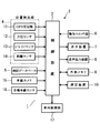
- FIG. 1 shows an embodiment of the present disclosure, and is a block diagram schematically showing a hardware configuration of a driving support system.
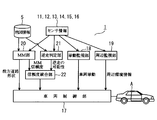
- FIG. 2 is a functional block diagram schematically showing the configuration of the driving support system.
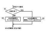
- FIG. 3 is a flowchart showing a processing procedure in the reliability integration unit.
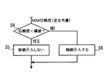
- FIG. 4 is a flowchart showing a procedure of determination processing for determining whether or not control can be performed in the vehicle control unit.
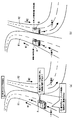
- FIG. 5A is a diagram for explaining a specific example of the map use ADAS
- FIG. 5B is a diagram illustrating an example of map matching processing in the case of reverse running.
- the conventional map matching technology can be obtained and the vehicle position is matched to the wrong road. For example, in a place where two roads are parallel after a narrow-angle branch, it is difficult in principle to determine which road the vehicle has entered, and there is a risk of matching the wrong road. Is big. If vehicle control using an incorrect matching result is performed in this way, it will lead to inappropriate driving support, so it is necessary to carefully monitor whether the map matching result is reliable.
- FIGS. 5 (a) and 5 (b) there is a one-way road R1 in the direction of arrow W1 and a one-way road R2 in the direction of arrow W2 opposite thereto. It shall be next to each other.
- FIG. 5 (a) when the vehicle A is traveling on the road R1 in the normal arrow a direction, when the driving support system detects a curve ahead of the road R1, Then, it is determined whether or not the vehicle speed of the current vehicle A is too fast. If it is determined that the vehicle speed is too fast, control (assist) is performed to forcibly decelerate.
- FIG. 5 (b) when the vehicle A runs backward on the road R1 in the direction of the arrow b, in the map matching process, the vehicle B moves along the road R2 in the normal direction. It will be judged that it is driving in the direction.
- the possibility that the host vehicle is running backward is not limited to the case where it is detected that the host vehicle is running backward. It is a concept that includes the case (there is a suspicion of reverse running).
- FIG. 1 schematically shows a hardware configuration of a vehicle driving support system 1 according to the present embodiment mounted on a vehicle A (see FIG. 2).
- the driving support system 1 includes A system including the car navigation device 2 is configured.
- FIG. 2 is a functional block diagram schematically showing a configuration related to execution of driving support processing (driving support method according to the present embodiment) of the driving support system 1.
- the car navigation device 2 includes a control device (navigator ECU) 3 and is connected to the control device 3, a position detection unit 4, a map database 5, an operation switch unit 6, and a display device 7. , An audio output device 8, an external memory 9, a communication device 10 and the like.
- the control device 3 is mainly composed of a computer having a CPU, a ROM, a RAM, and the like, and controls the entire car navigation device 2 according to a program stored in the ROM or the like.
- the position detection unit 4 includes a GPS receiver 11 that receives transmission radio waves from an artificial satellite for GPS (Global Positioning System) for vehicle position measurement by radio navigation.
- the position detection unit 4 includes an azimuth sensor 12 that detects the azimuth of the vehicle A, a gyro sensor 13 that detects the turning angle of the vehicle A, and a travel distance of the vehicle A.
- a distance sensor 14 is detected.
- the control device 3 detects the current position (absolute position), traveling direction, speed, travel distance, current time, and the like of the host vehicle based on inputs from the sensors 11 to 14 constituting the position detection unit 4. It is like that.
- position detecting means is configured.
- the map database 5 stores, for example, road map data all over Japan, destination data such as various facilities and stores, map matching data, and the like, which are associated therewith, and functions as map data acquisition means.
- the road map data consists of a road network in which roads on the map are represented by lines, and is given as link data in which intersections, branch points, etc. are divided into a plurality of parts as nodes and the parts between the nodes are defined as links. .
- This link data includes link-specific link ID (identifier), link length, link start point, end point (node) position data (longitude, latitude), angle (direction) data, road width, road type, road attribute, etc. Consists of data. Data for reproducing (drawing) the road map on the screen of the display device 7 is also included.
- the operation switch unit 6 includes a mechanical switch arranged around the touch panel provided on the screen of the display device 7.
- the display device 7 is composed of, for example, a liquid crystal display capable of color display, and is provided, for example, at the center of an instrument panel in a passenger compartment. On the screen of the display device 7, for example, a menu screen or a map screen when using the navigation function is displayed.
- the audio output device 8 includes a speaker or the like, and outputs music, guide audio, and the like.
- the communication device 10 transmits / receives data to / from an external information center via the Internet, for example.
- the navigation device 2 displays the detected position of the vehicle A together with the road map on the screen of the display device 7 or the destination designated by the user.
- the navigation processing such as a route guidance function for searching for and guiding an appropriate route is executed.
- the location function in order to realize the location function, in order to place the position of the own vehicle A on the road on the electronic map to be displayed, the movement locus of the own vehicle A and the road shape in the road map data
- a map matching process is performed to compare and collate with the error taken into account, and to estimate the road that is currently running.
- the route search is performed using, for example, a well-known Dijkstra method.
- the route guidance is performed by outputting necessary guidance voice by the voice output device 8 together with the screen display of the display device 7.
- the driving support system 1 includes an in-vehicle camera 15, various in-vehicle sensors 16, a vehicle control unit 17, and the like connected to the control device 3 via a CAN (Car ⁇ ⁇ ⁇ Area Network) not shown.
- the vehicle-mounted camera 15 captures, for example, an image ahead of the vehicle A, images other vehicles and obstacles on the road ahead, road markings, road signs, and the like, and performs image recognition processing from the captured image. In addition, the acquisition of the surrounding environment information and the determination of the possibility of reverse running are performed, which will be described later.
- the various vehicle-mounted sensors 16 include other various vehicle-mounted sensors for detecting the behavior of the vehicle A.
- a speed sensor that detects the speed of the vehicle A
- an acceleration sensor that detects the longitudinal and / or lateral acceleration of the vehicle A
- a wheel speed sensor that detects the rotational speed of the wheel
- a rotation angle (rotational speed) of the steering wheel Steering sensor to detect accelerator sensor to detect the amount of operation of the accelerator
- brake sensor to detect the amount of operation of the brake
- turn signal sensor to detect the operation of the left and right turn signals
- angular velocity sensor to detect the angular velocity accompanying turning of the vehicle A, etc. included.
- the vehicle control unit 17 includes a computer, and is determined from the determined position of the host vehicle A and map data determined by the map matching process, and a behavior monitoring unit 18 and a surrounding monitoring unit 19 (see FIG. 2) described later. Based on the monitoring information and the like, the control object in the vehicle A, for example, an accelerator, a brake, a steering, and the like are controlled, and the map use ADAS that supports the driving of the driver is executed. Therefore, this vehicle control unit 17 functions as an assist means. At this time, as will be described in detail later, the vehicle control unit 17 compares the reliability of the map matching with a threshold value, and executes the vehicle control (driving support) operation on the condition that the reliability is equal to or higher than the threshold value. (Vehicle control is not executed when the reliability is below the threshold).
- the control device 3 includes a map matching unit 20, a reverse running determination unit 21, a reliability integration unit 22, the behavior monitoring unit 18, and a surroundings monitoring unit 19 mainly due to its software configuration.
- the behavior monitoring unit 18 monitors the behavior of the own vehicle A from the detection signals of the sensors 11 to 14 of the position detection unit 4, and further the in-vehicle camera 15 and various in-vehicle sensors 16, and monitoring information necessary for vehicle control. Is output to the vehicle control unit 17.
- the surroundings monitoring unit 19 monitors the surroundings of the host vehicle A (status of other vehicles, etc.) from the sensor information and the map data, and outputs surrounding environment information necessary for vehicle control to the vehicle control unit 17. .
- the map matching unit 20 executes a well-known map matching process based on the detection position of the host vehicle A by the position detection unit 4 and the map data, and determines (corrects) the position of the host vehicle A on the road. ) At the same time, the map matching unit 20 calculates a reliability representing the reliability of the map matching process. The map matching process and the calculation of the reliability are repeatedly executed continuously at predetermined time intervals. Therefore, the map matching unit 20 has functions as map matching means and reliability calculation means.
- the traveling locus of the host vehicle A is obtained based on the detected position (absolute position and traveling direction) by the position detector 4 (radio wave navigation and autonomous navigation).
- a road belonging to a predetermined range is searched from the map data around the detection position of the host vehicle A, and a candidate road is selected.
- searching for candidate roads it is assumed that the host vehicle A is traveling in accordance with laws and regulations, and roads in which the detected direction of the host vehicle A does not match the determined traveling direction are , Excluded from the candidate.
- the shape of the selected candidate road is compared with the travel locus to quantify the level of similarity (correlation), and the candidate road with the highest similarity is determined as the road on which the vehicle A is traveling. Then, the position and direction of the host vehicle are determined (detection position detected by the position detection unit 4 is corrected). The determined position (position and direction) as a result of the map matching process is output to the vehicle control unit 16. Further, as described above, the map matching result is used for executing the location function of the car navigation device 2.
- the calculation of the reliability of the map matching process is performed based on, for example, executing the following plurality of determination processes. That is, sensor state determination processing for determining whether the sensors 12 to 14 of the position detection unit 4 are operating normally, positioning status determination processing for determining the positioning status by the GPS receiver 11, and the accuracy of the sensors 12 to 14 Sensor accuracy determination processing for determining, orientation deviation determination processing for determining a difference between the detected traveling direction of the vehicle A and the direction of the road link, error range determination processing for determining a detection error regarding the direction of the own vehicle A, own vehicle A Continuity to determine the magnitude of displacement from the detected position in the results of the shape correlation determination process for determining the correlation between the shape of the running trajectory and the map data, the candidate number determination process for determining the number of candidate roads, and the map matching process
- the determination process is executed. Thereafter, the reliability is obtained by adding a weight to the determination result of each process.
- the calculation result of the reliability is output to the reliability integration unit 22.
- the reverse running determination unit 21 automatically detects from the sensors 11 to 14 of the position detection unit 4, the sensor information of the in-vehicle camera 15 and various in-vehicle sensors 16, and the map data of the map database 5.
- the vehicle A determines whether or not there is a possibility of traveling backward on a road whose traveling direction is determined in one direction. Whether or not the reverse running possibility is determined is also repeatedly executed continuously at predetermined time intervals.
- the reverse running determination unit 21 functions as a determination unit. In this case, the presence or absence of the possibility of reverse running is determined without using the determined position (map matching result) of the host vehicle A obtained by the map matching unit 20.
- the reverse running determination unit 21 determines that the own vehicle A has entered the service area or the parking area through the approach road while traveling on the highway based on the detection position of the position detection unit 4, and then exits. If it is determined that the vehicle has returned to the approach road again without going to the road, it is determined that there is a possibility of reverse running. Further, the reverse running determination unit 21 is based on the sensor information of each of the sensors 11 to 14 of the position detection unit 4, the in-vehicle camera 15 and the various in-vehicle sensors 16, while driving on the highway (or the intersection of the roads on one side multiple lanes). When it is determined that the host vehicle A has made a U-turn (at a place other than the above), it is determined that there is a possibility of reverse running.
- the reverse running determination unit 21 captures the front of the in-vehicle camera 15 when there is a road whose traveling direction is determined in one direction around the host vehicle A. Based on the image, it is determined whether or not there is a possibility of reverse running. More specifically, when it is determined that the vehicle is traveling in the opposite direction even though the entry-prohibited (or one-way) road sign is photographed by the in-vehicle camera 15, the road sign photographed by the in-vehicle camera 15 is taken. However, if they are all facing the opposite side (facing backwards), they are shooting a number of oncoming vehicles (the other vehicles are approaching from the front) even though they are traveling on a one-way street. In some cases, it is determined that there is a possibility of reverse running.
- the reverse running determination unit 21 determines that there is a possibility of reverse running of the host vehicle A
- the reverse running determination unit 21 outputs the determination result to the reliability integration unit 22.
- the reliability integration unit 22 normally outputs the reliability from the map matching unit 20 to the vehicle control unit 17 as it is.
- the numerical value of the reliability is forcibly made smaller than the threshold value and is output to the vehicle control unit 17.
- the reliability integration unit 22 and the vehicle control unit 17 Etc. constitute the stopping means.
- the steering is forcibly operated to the opposite side (the side returning to the lane)
- the steering is controlled according to the curvature of the curve.
- assistance such as forcibly operating the brake to prevent a collision (a rear-end collision) is also provided.
- a position detection step for detecting the position of the host vehicle A based on the detection signals of the sensors 11 to 14 of the position detection unit 4 is executed.
- a map data acquisition step of reading map data in the vicinity of the host vehicle A from the map database 5 is executed.
- the map matching unit 20 executes a map matching step for determining the position of the vehicle A on the road by the map matching process based on the detected position and the map data in the position detecting step. At the same time, the map matching unit 20 also executes a calculation step for calculating the reliability of the map matching result. Then, the vehicle control unit 17 determines the position of the host vehicle A in the map matching step and the road shape ahead of the traveling direction indicated in the map data, monitoring information from the behavior monitoring unit 18, and surrounding environment information from the surrounding monitoring unit 19. Is used to assist the driver in driving.
- a determination step for determining whether or not the host vehicle A is reverse running is always executed in parallel with the map matching step of the map matching unit 20.
- a stop step for stopping driving support by the vehicle control unit 17 is executed as follows.
- the reverse running determination unit 21 detects the position of the vehicle A from the position detection of the position detection unit 4, the sensor information of the in-vehicle camera 15 and various in-vehicle sensors 16, the map data of the map database 5, and the like. Then, it is determined whether or not there is a possibility that the vehicle is traveling backward on a road whose traveling direction is determined in one direction. If it is determined that there is a possibility of reverse running, a determination result indicating the possibility of reverse running is output to the reliability integration unit 22. In the reliability integration unit 22, map matching reliability data is input from the map matching unit 20. When a signal indicating the possibility of reverse running is input from the reverse running determination unit 21, The numerical value is forcibly made smaller than the threshold value and output to the vehicle control unit 17.
- step S1 it is determined whether or not a signal indicating the possibility of reverse running has been input. If a signal indicating the possibility of reverse running is not input (No in step S1), the reliability is output to the vehicle control unit 17 as it is in the next step S2. On the other hand, when a signal indicating the possibility of reverse running is input (Yes in step S1), the reliability input from the map matching unit 20 is lowered to the minimum in step S3, and then the vehicle Output to the control unit 17.
- the vehicle control unit 17 compares the input map matching reliability with a threshold value, executes vehicle control when the reliability is equal to or higher than the threshold value, and when the reliability is lower than the threshold value, Decide to stop execution of vehicle control.
- step S4 shows a processing procedure for determining whether or not to perform the vehicle control executed by the vehicle control unit 17. That is, in step S4, it is determined whether or not the numerical value of the reliability input from the reliability integration unit 22 is smaller than the threshold value. If the reliability is smaller than the threshold value (Yes in step S4), it is determined in step S5 that vehicle control is not performed (intervention), that is, driving support is stopped. On the other hand, if the reliability is equal to or higher than the threshold value (No in step S4), it is determined in step S6 that the vehicle control is to be executed (intervened).
- the vehicle control unit 17 provides driving assistance to the driver using the determined position of the host vehicle A by the map matching unit 20 and the road shape ahead in the traveling direction indicated in the map data.
- the reverse running determination unit 21 determines whether there is a possibility that the host vehicle is running backward on a road whose traveling direction is determined to be one direction, Based on the fact that the reliability of the map matching is lowered to the lowest level by the integration unit 22, the driving support by the vehicle control 17 is stopped.
- the road R1 that is one-way in the direction of the arrow W1 and the road R2 that is one-way in the direction of the arrow W2 opposite thereto are adjacent to each other.
- the vehicle A may run backward on the road R1 in the direction of arrow b.
- the reverse running determination unit 21 It is determined that there is a possibility of reverse running. For this reason, vehicle control (driving support) by the vehicle control unit 17 is stopped, and inappropriate vehicle control is prevented from being performed in advance.
- the reverse running determination unit 21 determines the possibility of reverse running of the host vehicle A, after that, when the possibility of reverse running is resolved, the reliability is a numerical value calculated by the map matching unit 20. Return to. As a result, execution of vehicle control by the vehicle control unit 17 is permitted (resumed).
- the reverse running determination unit 21 determines that the host vehicle A is running backward, a warning message for reverse running is displayed on the display device 7 for the driver, or the voice output device 8 outputs the sound in a voice. You can also.
- the driving support is performed based on the position of the host vehicle determined by the map matching process.
- the reliability input from the map matching unit 20 is lowered to the lowest level by the reliability integration unit 22, and vehicle control (driving support) is performed by the vehicle control unit 17. ) Is canceled.
- vehicle control driving support
- the reliability of the map matching is used as a method of stopping the vehicle control of the vehicle control unit 17 when there is a possibility of reverse running.
- a stop signal may be output to stop the operation.
- the case of controlling the accelerator, the brake, and the steering is exemplified as the vehicle control (driving support), but other than that, as the object of the vehicle control based on prefetching the road shape, Various things such as control of an automatic transmission, control of an optical axis of a light (headlight), control of a car air conditioner, control of a mirror, control of a drive source in a hybrid vehicle are possible.
- each section is expressed as, for example, S1. Further, each section can be divided into a plurality of subsections, while a plurality of sections can be combined into one section. Further, each section configured in this manner can be referred to as a device, module, or means.
Landscapes
- Engineering & Computer Science (AREA)
- Radar, Positioning & Navigation (AREA)
- Remote Sensing (AREA)
- Physics & Mathematics (AREA)
- General Physics & Mathematics (AREA)
- Combustion & Propulsion (AREA)
- Chemical & Material Sciences (AREA)
- Mechanical Engineering (AREA)
- Transportation (AREA)
- Automation & Control Theory (AREA)
- Navigation (AREA)
- Traffic Control Systems (AREA)
- Control Of Driving Devices And Active Controlling Of Vehicle (AREA)
Abstract
Description
Claims (10)
- 少なくとも一つの車載センサ(11~14)の検出信号に基づいて自車両(A)の位置を検出する位置検出手段(4)と、
地図データを取得する地図データ取得手段(5)と、
前記位置検出手段(4)による検出位置と地図データとに基づいて、マップマッチング処理により自車両(A)の道路上の位置を確定するマップマッチング手段(20)と、
前記マップマッチング手段(20)による自車両(A)の確定位置及び前記地図データに示される走行方向前方の道路形状を用いて、ドライバの運転を支援するアシスト手段(17)と、
自車両(A)が、走行方向が一方向に決められている道路を逆走している可能性の有無を判定する判定手段(21)と、
この判定手段(21)により逆走の可能性があると判定されたときに、前記アシスト手段(17)による運転支援を中止する中止手段(22)とを具備する車両用運転支援システム。 - 前記マップマッチング手段(20)は、自らが特定した自車両の確定位置の信頼性を推定する信頼度算出手段を備えており、
前記アシスト手段(17)は、前記信頼度がしきい値以上である場合に運転支援を実行するものであって、
前記中止手段(22)は、前記判定手段(21)により逆走の可能性があると判定されたときに、前記信頼度の数値を、強制的にしきい値よりも小さくする請求項1記載の車両用運転支援システム。 - 前記中止手段(22)による運転支援の中止後に、前記判定手段(21)が自車両(A)の逆走の可能性が無いと判定したときに、該中止手段(22)による中止が解除され、前記アシスト手段(17)による運転支援が再開される請求項1又は2記載の車両用運転支援システム。
- 前記判定手段(21)は、前記位置検出手段(4)の検出位置に基づき、自車両(A)が高速道路走行中に、進入路を通ってサービスエリア又はパーキングエリアに進入したことを判断し、
前記判定手段(21)が、自車両(A)がサービスエリア又はパーキングエリアに進入したと判断した後、前記判定手段(21)が、自車両(A)が再び進入路に戻ったと判断した場合に、逆走の可能性があると判定する請求項1から3のいずれか一項に記載の車両用運転支援システム。 - 前記判定手段(21)は、前記車載センサ(11~16)の検出信号に基づき、高速道路走行中に自車両(A)がUターンしたと判断した場合に、逆走の可能性があると判定する請求項1から4のいずれか一項に記載の車両用運転支援システム。
- 自車両(A)の周辺を撮影する車載カメラ(15)をさらに備え、
前記判定手段(21)は、前記位置検出手段(4)の検出位置に基づき自車両(A)の周辺に走行方向が一方向に決められている道路が存在する場合に、前記車載カメラ(15)の撮影画像に基づいて逆走の可能性の有無を判定する請求項1から5のいずれか一項に記載の車両用運転支援システム。 - 前記アシスト手段(17)は、走行方向前方の道路形状により、カーブの接近を予見し、速度が過剰の場合にアクセルペダルを押し戻すことで、ドライバに注意を喚起するという、ドライバの運転を支援する請求項1から6のいずれか一項に記載の車両用運転支援システム。
- 前記アシスト手段(17)は、車両(A)が現在走行しているレーンから路肩側にはみ出す虞がある場合に、ステアリングを強制的に車線に戻る側に動作させることで、ドライバの運転を支援する請求項1から7のいずれか一項に記載の車両用運転支援システム。
- 前記アシスト手段(17)は、前方に障害物や先行車両がある場合に、ブレーキを強制的に動作させて衝突を防止することで、ドライバの運転を支援する請求項1から8のいずれか一項に記載の車両用運転支援システム。
- ドライバの運転を支援するアシスト手段(17)を備えた車両(A)における、運転支援を実行する法であって、
少なくとも一つの車載センサ(11~14)の検出信号に基づいて、自車両(A)の位置を検出し、
地図データを取得し、
前記検出位置と前記地図データとに基づいて、マップマッチング処理により自車両(A)の道路上の位置を確定し、
自車両(A)の確定位置及び前記地図データに示される走行方向先方の道路形状を用いて、前記アシスト手段(17)によりドライバの運転を支援し、
自車両(A)が、走行方向が一方向に決められている道路を逆走している可能性の有無を判定し、
逆走の可能性があると判定されたときに、前記アシスト手段(17)による運転支援を中止することを含む車両用運転支援実行方法。
Priority Applications (2)
| Application Number | Priority Date | Filing Date | Title |
|---|---|---|---|
| DE112014000819.2T DE112014000819B4 (de) | 2013-02-14 | 2014-01-10 | Fahrzeugfahrunterstützungssystem und Fahrunterstützungsimplementierungsverfahren |
| US14/767,502 US9638532B2 (en) | 2013-02-14 | 2014-01-10 | Vehicle drive assist system, and drive assist implementation method |
Applications Claiming Priority (2)
| Application Number | Priority Date | Filing Date | Title |
|---|---|---|---|
| JP2013-026541 | 2013-02-14 | ||
| JP2013026541A JP6036371B2 (ja) | 2013-02-14 | 2013-02-14 | 車両用運転支援システム及び運転支援方法 |
Publications (1)
| Publication Number | Publication Date |
|---|---|
| WO2014125757A1 true WO2014125757A1 (ja) | 2014-08-21 |
Family
ID=51353775
Family Applications (1)
| Application Number | Title | Priority Date | Filing Date |
|---|---|---|---|
| PCT/JP2014/000074 WO2014125757A1 (ja) | 2013-02-14 | 2014-01-10 | 車両用運転支援システム及び運転支援実行方法 |
Country Status (4)
| Country | Link |
|---|---|
| US (1) | US9638532B2 (ja) |
| JP (1) | JP6036371B2 (ja) |
| DE (1) | DE112014000819B4 (ja) |
| WO (1) | WO2014125757A1 (ja) |
Cited By (1)
| Publication number | Priority date | Publication date | Assignee | Title |
|---|---|---|---|---|
| WO2019155873A1 (ja) * | 2018-02-06 | 2019-08-15 | オムロン株式会社 | 評価装置、動作制御装置、評価方法、及び評価プログラム |
Families Citing this family (22)
| Publication number | Priority date | Publication date | Assignee | Title |
|---|---|---|---|---|
| JP6036371B2 (ja) * | 2013-02-14 | 2016-11-30 | 株式会社デンソー | 車両用運転支援システム及び運転支援方法 |
| JP6237214B2 (ja) * | 2013-12-24 | 2017-11-29 | 株式会社デンソー | 逆走検出装置 |
| US9437111B2 (en) | 2014-05-30 | 2016-09-06 | Ford Global Technologies, Llc | Boundary detection system |
| US9676386B2 (en) | 2015-06-03 | 2017-06-13 | Ford Global Technologies, Llc | System and method for controlling vehicle components based on camera-obtained image information |
| JP6207553B2 (ja) * | 2015-07-16 | 2017-10-04 | 本田技研工業株式会社 | 運転支援装置、運転支援方法 |
| JP6520728B2 (ja) * | 2016-01-14 | 2019-05-29 | 株式会社デンソー | 運転支援装置 |
| DE102016210023A1 (de) * | 2016-06-07 | 2017-12-07 | Robert Bosch Gmbh | Verfahren Vorrichtung und System zur Falschfahrererkennung |
| EP3614106B1 (en) * | 2016-06-27 | 2021-10-27 | Mobileye Vision Technologies Ltd. | Controlling host vehicle based on detected parked vehicle characteristics |
| DE102016009763A1 (de) * | 2016-08-11 | 2018-02-15 | Trw Automotive Gmbh | Steuerungssystem und Steuerungsverfahren zum Bestimmen einer Trajektorie und zum Erzeugen von zugehörigen Signalen oder Steuerbefehlen |
| JP2018088188A (ja) * | 2016-11-29 | 2018-06-07 | 三菱自動車工業株式会社 | 運転支援装置 |
| JP6583252B2 (ja) * | 2016-12-27 | 2019-10-02 | トヨタ自動車株式会社 | 運転支援装置 |
| US10289115B2 (en) * | 2017-06-01 | 2019-05-14 | Aptiv Technologies Limited | Automated vehicle map localization based on observed geometries of roadways |
| WO2019069437A1 (ja) * | 2017-10-06 | 2019-04-11 | 本田技研工業株式会社 | 車両制御装置 |
| DE102017222753A1 (de) * | 2017-12-14 | 2019-06-19 | Robert Bosch Gmbh | Verfahren und System zum Warnen von Verkehrsteilnehmern vor einer Falschfahrt eines Fahrzeugs unter Vermeidung einer Falschmeldung |
| CN108284838A (zh) * | 2018-03-27 | 2018-07-17 | 杭州欧镭激光技术有限公司 | 一种用于检测车辆外部环境信息的检测系统及检测方法 |
| KR102602984B1 (ko) * | 2018-07-23 | 2023-11-16 | 현대자동차주식회사 | 후진기어를 포함하지 않는 모터 구동 차량의 전력충전량 제어방법 |
| JP7138133B2 (ja) * | 2020-03-16 | 2022-09-15 | 本田技研工業株式会社 | 車両制御装置、車両、車両制御装置の動作方法およびプログラム |
| US11501642B2 (en) * | 2020-10-29 | 2022-11-15 | GM Global Technology Operations LLC | Method and system of detecting a wrong-way driving vehicle |
| US11335192B1 (en) | 2020-12-02 | 2022-05-17 | Here Global B.V. | System, method, and computer program product for detecting a driving direction |
| CN112896181B (zh) * | 2021-01-14 | 2022-07-08 | 重庆长安汽车股份有限公司 | 电子围栏控制方法、系统、车辆及存储介质 |
| JP7461313B2 (ja) | 2021-02-08 | 2024-04-03 | 日立Astemo株式会社 | 逆走検出装置 |
| US11891035B2 (en) * | 2021-07-22 | 2024-02-06 | Aptiv Technologies AG | Autonomous emergency braking (AEB) based on vehicle turn state |
Citations (7)
| Publication number | Priority date | Publication date | Assignee | Title |
|---|---|---|---|---|
| JP2005173909A (ja) * | 2003-12-10 | 2005-06-30 | Toyota Motor Corp | 車両用速度制御装置 |
| JP2007015558A (ja) * | 2005-07-07 | 2007-01-25 | Toyota Motor Corp | 走行制御装置の操作スイッチ |
| JP2007140883A (ja) * | 2005-11-18 | 2007-06-07 | Alpine Electronics Inc | カメラ利用逆走検出装置 |
| JP2009210510A (ja) * | 2008-03-06 | 2009-09-17 | Hitachi Ltd | 車両運転支援システムおよび車両運転支援方法 |
| JP2011095929A (ja) * | 2009-10-28 | 2011-05-12 | Fuji Heavy Ind Ltd | 車両用運転支援装置 |
| JP2012058948A (ja) * | 2010-09-08 | 2012-03-22 | Denso Corp | 車両の逆走検知装置 |
| JP2012189343A (ja) * | 2011-03-09 | 2012-10-04 | Aisin Aw Co Ltd | 運転支援装置、運転支援方法及びコンピュータプログラム |
Family Cites Families (23)
| Publication number | Priority date | Publication date | Assignee | Title |
|---|---|---|---|---|
| US6707421B1 (en) * | 1997-08-19 | 2004-03-16 | Siemens Vdo Automotive Corporation | Driver information system |
| US7366595B1 (en) * | 1999-06-25 | 2008-04-29 | Seiko Epson Corporation | Vehicle drive assist system |
| US20020105423A1 (en) * | 2000-12-05 | 2002-08-08 | Rast Rodger H. | Reaction advantage anti-collision systems and methods |
| JP4169491B2 (ja) * | 2001-05-11 | 2008-10-22 | 三菱電機株式会社 | 移動体用ナビゲーション装置 |
| JP4202872B2 (ja) * | 2003-09-12 | 2008-12-24 | 株式会社ジェイテクト | 車両用操舵装置 |
| JP2005189983A (ja) * | 2003-12-24 | 2005-07-14 | Denso Corp | 車両運転支援装置 |
| DE102004028591A1 (de) | 2004-06-12 | 2005-12-29 | Daimlerchrysler Ag | Verfahren zum Bereitstellen von fahrstreckenabhängigen Informationen |
| JP5028851B2 (ja) | 2006-04-24 | 2012-09-19 | 株式会社デンソー | 道路情報検出装置及びプログラム |
| JP4810405B2 (ja) * | 2006-11-13 | 2011-11-09 | クラリオン株式会社 | ナビゲーション装置、車両用安全支援システム |
| US20100292895A1 (en) * | 2007-04-27 | 2010-11-18 | Aisin Aw Co. Ltd | Driving support device |
| WO2009013815A1 (ja) * | 2007-07-24 | 2009-01-29 | Nissan Motor Co., Ltd. | 車両用運転支援装置および車両用運転支援装置を備える車両 |
| JP2010003013A (ja) * | 2008-06-18 | 2010-01-07 | Aisin Aw Co Ltd | 運転支援装置、運転支援方法および運転支援プログラム |
| JP5286027B2 (ja) * | 2008-10-28 | 2013-09-11 | 株式会社アドヴィックス | 車両安定化制御装置 |
| JP5200926B2 (ja) * | 2008-12-26 | 2013-06-05 | トヨタ自動車株式会社 | 運転支援装置 |
| US20100209891A1 (en) * | 2009-02-18 | 2010-08-19 | Gm Global Technology Operations, Inc. | Driving skill recognition based on stop-and-go driving behavior |
| JP5443086B2 (ja) * | 2009-07-28 | 2014-03-19 | トヨタ自動車株式会社 | 運転支援システム |
| JP5229293B2 (ja) * | 2010-10-01 | 2013-07-03 | 株式会社デンソー | 車両用運転支援装置 |
| US9238483B2 (en) * | 2011-04-19 | 2016-01-19 | Ford Global Technologies, Llc | Trailer backup assist system with trajectory planner for multiple waypoints |
| US9164955B2 (en) * | 2013-02-04 | 2015-10-20 | Ford Global Technologies | Trailer active back-up assist with object avoidance |
| DE102011117297A1 (de) * | 2011-11-01 | 2013-05-02 | Volkswagen Aktiengesellschaft | Verfahren zum Betreiben eines Fahrerassistenzsystems und dazugehöriges Fahrerassistenzsystem |
| CN104221066B (zh) * | 2012-03-30 | 2016-08-31 | 丰田自动车株式会社 | 驾驶辅助装置 |
| JP6036371B2 (ja) * | 2013-02-14 | 2016-11-30 | 株式会社デンソー | 車両用運転支援システム及び運転支援方法 |
| KR101551215B1 (ko) * | 2014-05-28 | 2015-09-18 | 엘지전자 주식회사 | 차량 운전 보조 장치 및 이를 구비한 차량 |
-
2013
- 2013-02-14 JP JP2013026541A patent/JP6036371B2/ja active Active
-
2014
- 2014-01-10 US US14/767,502 patent/US9638532B2/en not_active Expired - Fee Related
- 2014-01-10 DE DE112014000819.2T patent/DE112014000819B4/de active Active
- 2014-01-10 WO PCT/JP2014/000074 patent/WO2014125757A1/ja active Application Filing
Patent Citations (7)
| Publication number | Priority date | Publication date | Assignee | Title |
|---|---|---|---|---|
| JP2005173909A (ja) * | 2003-12-10 | 2005-06-30 | Toyota Motor Corp | 車両用速度制御装置 |
| JP2007015558A (ja) * | 2005-07-07 | 2007-01-25 | Toyota Motor Corp | 走行制御装置の操作スイッチ |
| JP2007140883A (ja) * | 2005-11-18 | 2007-06-07 | Alpine Electronics Inc | カメラ利用逆走検出装置 |
| JP2009210510A (ja) * | 2008-03-06 | 2009-09-17 | Hitachi Ltd | 車両運転支援システムおよび車両運転支援方法 |
| JP2011095929A (ja) * | 2009-10-28 | 2011-05-12 | Fuji Heavy Ind Ltd | 車両用運転支援装置 |
| JP2012058948A (ja) * | 2010-09-08 | 2012-03-22 | Denso Corp | 車両の逆走検知装置 |
| JP2012189343A (ja) * | 2011-03-09 | 2012-10-04 | Aisin Aw Co Ltd | 運転支援装置、運転支援方法及びコンピュータプログラム |
Cited By (3)
| Publication number | Priority date | Publication date | Assignee | Title |
|---|---|---|---|---|
| WO2019155873A1 (ja) * | 2018-02-06 | 2019-08-15 | オムロン株式会社 | 評価装置、動作制御装置、評価方法、及び評価プログラム |
| JP2019139277A (ja) * | 2018-02-06 | 2019-08-22 | オムロン株式会社 | 評価装置、動作制御装置、評価方法、及び評価プログラム |
| JP7020156B2 (ja) | 2018-02-06 | 2022-02-16 | オムロン株式会社 | 評価装置、動作制御装置、評価方法、及び評価プログラム |
Also Published As
| Publication number | Publication date |
|---|---|
| US20160003630A1 (en) | 2016-01-07 |
| JP2014157395A (ja) | 2014-08-28 |
| US9638532B2 (en) | 2017-05-02 |
| JP6036371B2 (ja) | 2016-11-30 |
| DE112014000819B4 (de) | 2019-07-11 |
| DE112014000819T5 (de) | 2015-10-29 |
Similar Documents
| Publication | Publication Date | Title |
|---|---|---|
| JP6036371B2 (ja) | 車両用運転支援システム及び運転支援方法 | |
| US11597396B2 (en) | Vehicle control device | |
| CN107339997B (zh) | 自主车辆的路径规划装置及方法 | |
| JP4446204B2 (ja) | 車両用ナビゲーション装置及び車両用ナビゲーションプログラム | |
| CN107532916B (zh) | 路径搜索装置及路径搜索方法 | |
| JP4792866B2 (ja) | ナビゲーションシステム | |
| US7930096B2 (en) | Navigation systems, methods, and programs | |
| CN110998691B (zh) | 行驶辅助方法及行驶辅助装置 | |
| JP5229293B2 (ja) | 車両用運転支援装置 | |
| US20100315217A1 (en) | Driving support device and program | |
| US20200174470A1 (en) | System and method for supporting autonomous vehicle | |
| JP6477888B2 (ja) | 経路誘導装置及び経路誘導方法 | |
| JP6512194B2 (ja) | 自動運転車両の制御システム及び制御方法 | |
| EP3816966B1 (en) | Driving assistance method and driving assistance device | |
| JP6954469B2 (ja) | 運転支援方法及び運転支援装置 | |
| JP6364869B2 (ja) | 運転支援装置 | |
| JP2008040795A (ja) | 車両の運転支援制御装置および方法 | |
| WO2019021437A1 (ja) | 走行支援方法及び走行支援装置 | |
| JP2022117882A (ja) | 自動運転支援システム | |
| JP2008139104A (ja) | 退出検出装置 | |
| JP2008090654A (ja) | 運転操作支援装置 | |
| JP2011232271A (ja) | ナビゲーション装置、車載センサの精度推定方法、および、プログラム | |
| JP2005189009A (ja) | ナビゲーション装置及びナビゲーションシステム | |
| JP2008305101A (ja) | 車両右左折時警告装置 | |
| KR101543073B1 (ko) | 차량의 주행안내 장치 및 방법 |
Legal Events
| Date | Code | Title | Description |
|---|---|---|---|
| 121 | Ep: the epo has been informed by wipo that ep was designated in this application |
Ref document number: 14751350 Country of ref document: EP Kind code of ref document: A1 |
|
| WWE | Wipo information: entry into national phase |
Ref document number: 14767502 Country of ref document: US |
|
| WWE | Wipo information: entry into national phase |
Ref document number: 112014000819 Country of ref document: DE Ref document number: 1120140008192 Country of ref document: DE |
|
| 122 | Ep: pct application non-entry in european phase |
Ref document number: 14751350 Country of ref document: EP Kind code of ref document: A1 |