WO2014112426A1 - Liquid dispenser - Google Patents
Liquid dispenser Download PDFInfo
- Publication number
- WO2014112426A1 WO2014112426A1 PCT/JP2014/050246 JP2014050246W WO2014112426A1 WO 2014112426 A1 WO2014112426 A1 WO 2014112426A1 JP 2014050246 W JP2014050246 W JP 2014050246W WO 2014112426 A1 WO2014112426 A1 WO 2014112426A1
- Authority
- WO
- WIPO (PCT)
- Prior art keywords
- outer cylinder
- administration device
- cover member
- liquid administration
- liquid
- Prior art date
Links
Images


Classifications
-
- A—HUMAN NECESSITIES
- A61—MEDICAL OR VETERINARY SCIENCE; HYGIENE
- A61M—DEVICES FOR INTRODUCING MEDIA INTO, OR ONTO, THE BODY; DEVICES FOR TRANSDUCING BODY MEDIA OR FOR TAKING MEDIA FROM THE BODY; DEVICES FOR PRODUCING OR ENDING SLEEP OR STUPOR
- A61M5/00—Devices for bringing media into the body in a subcutaneous, intra-vascular or intramuscular way; Accessories therefor, e.g. filling or cleaning devices, arm-rests
- A61M5/178—Syringes
- A61M5/31—Details
- A61M5/315—Pistons; Piston-rods; Guiding, blocking or restricting the movement of the rod or piston; Appliances on the rod for facilitating dosing ; Dosing mechanisms
- A61M5/31501—Means for blocking or restricting the movement of the rod or piston
- A61M5/31505—Integral with the syringe barrel, i.e. connected to the barrel so as to make up a single complete piece or unit
-
- A—HUMAN NECESSITIES
- A61—MEDICAL OR VETERINARY SCIENCE; HYGIENE
- A61M—DEVICES FOR INTRODUCING MEDIA INTO, OR ONTO, THE BODY; DEVICES FOR TRANSDUCING BODY MEDIA OR FOR TAKING MEDIA FROM THE BODY; DEVICES FOR PRODUCING OR ENDING SLEEP OR STUPOR
- A61M5/00—Devices for bringing media into the body in a subcutaneous, intra-vascular or intramuscular way; Accessories therefor, e.g. filling or cleaning devices, arm-rests
- A61M5/178—Syringes
- A61M5/20—Automatic syringes, e.g. with automatically actuated piston rod, with automatic needle injection, filling automatically
- A61M5/2033—Spring-loaded one-shot injectors with or without automatic needle insertion
-
- A—HUMAN NECESSITIES
- A61—MEDICAL OR VETERINARY SCIENCE; HYGIENE
- A61M—DEVICES FOR INTRODUCING MEDIA INTO, OR ONTO, THE BODY; DEVICES FOR TRANSDUCING BODY MEDIA OR FOR TAKING MEDIA FROM THE BODY; DEVICES FOR PRODUCING OR ENDING SLEEP OR STUPOR
- A61M5/00—Devices for bringing media into the body in a subcutaneous, intra-vascular or intramuscular way; Accessories therefor, e.g. filling or cleaning devices, arm-rests
- A61M5/178—Syringes
- A61M5/31—Details
- A61M5/315—Pistons; Piston-rods; Guiding, blocking or restricting the movement of the rod or piston; Appliances on the rod for facilitating dosing ; Dosing mechanisms
- A61M5/31511—Piston or piston-rod constructions, e.g. connection of piston with piston-rod
- A61M5/31513—Piston constructions to improve sealing or sliding
-
- A—HUMAN NECESSITIES
- A61—MEDICAL OR VETERINARY SCIENCE; HYGIENE
- A61M—DEVICES FOR INTRODUCING MEDIA INTO, OR ONTO, THE BODY; DEVICES FOR TRANSDUCING BODY MEDIA OR FOR TAKING MEDIA FROM THE BODY; DEVICES FOR PRODUCING OR ENDING SLEEP OR STUPOR
- A61M5/00—Devices for bringing media into the body in a subcutaneous, intra-vascular or intramuscular way; Accessories therefor, e.g. filling or cleaning devices, arm-rests
- A61M5/178—Syringes
- A61M5/31—Details
- A61M5/32—Needles; Details of needles pertaining to their connection with syringe or hub; Accessories for bringing the needle into, or holding the needle on, the body; Devices for protection of needles
- A61M5/3202—Devices for protection of the needle before use, e.g. caps
-
- A—HUMAN NECESSITIES
- A61—MEDICAL OR VETERINARY SCIENCE; HYGIENE
- A61M—DEVICES FOR INTRODUCING MEDIA INTO, OR ONTO, THE BODY; DEVICES FOR TRANSDUCING BODY MEDIA OR FOR TAKING MEDIA FROM THE BODY; DEVICES FOR PRODUCING OR ENDING SLEEP OR STUPOR
- A61M5/00—Devices for bringing media into the body in a subcutaneous, intra-vascular or intramuscular way; Accessories therefor, e.g. filling or cleaning devices, arm-rests
- A61M5/178—Syringes
- A61M5/31—Details
- A61M5/32—Needles; Details of needles pertaining to their connection with syringe or hub; Accessories for bringing the needle into, or holding the needle on, the body; Devices for protection of needles
- A61M5/3205—Apparatus for removing or disposing of used needles or syringes, e.g. containers; Means for protection against accidental injuries from used needles
- A61M5/321—Means for protection against accidental injuries by used needles
- A61M5/3243—Means for protection against accidental injuries by used needles being axially-extensible, e.g. protective sleeves coaxially slidable on the syringe barrel
- A61M5/326—Fully automatic sleeve extension, i.e. in which triggering of the sleeve does not require a deliberate action by the user
-
- A—HUMAN NECESSITIES
- A61—MEDICAL OR VETERINARY SCIENCE; HYGIENE
- A61M—DEVICES FOR INTRODUCING MEDIA INTO, OR ONTO, THE BODY; DEVICES FOR TRANSDUCING BODY MEDIA OR FOR TAKING MEDIA FROM THE BODY; DEVICES FOR PRODUCING OR ENDING SLEEP OR STUPOR
- A61M5/00—Devices for bringing media into the body in a subcutaneous, intra-vascular or intramuscular way; Accessories therefor, e.g. filling or cleaning devices, arm-rests
- A61M5/178—Syringes
- A61M5/20—Automatic syringes, e.g. with automatically actuated piston rod, with automatic needle injection, filling automatically
- A61M2005/2006—Having specific accessories
- A61M2005/2013—Having specific accessories triggering of discharging means by contact of injector with patient body
-
- A—HUMAN NECESSITIES
- A61—MEDICAL OR VETERINARY SCIENCE; HYGIENE
- A61M—DEVICES FOR INTRODUCING MEDIA INTO, OR ONTO, THE BODY; DEVICES FOR TRANSDUCING BODY MEDIA OR FOR TAKING MEDIA FROM THE BODY; DEVICES FOR PRODUCING OR ENDING SLEEP OR STUPOR
- A61M5/00—Devices for bringing media into the body in a subcutaneous, intra-vascular or intramuscular way; Accessories therefor, e.g. filling or cleaning devices, arm-rests
- A61M5/178—Syringes
- A61M5/20—Automatic syringes, e.g. with automatically actuated piston rod, with automatic needle injection, filling automatically
- A61M2005/2026—Semi-automatic, e.g. user activated piston is assisted by additional source of energy
-
- A—HUMAN NECESSITIES
- A61—MEDICAL OR VETERINARY SCIENCE; HYGIENE
- A61M—DEVICES FOR INTRODUCING MEDIA INTO, OR ONTO, THE BODY; DEVICES FOR TRANSDUCING BODY MEDIA OR FOR TAKING MEDIA FROM THE BODY; DEVICES FOR PRODUCING OR ENDING SLEEP OR STUPOR
- A61M5/00—Devices for bringing media into the body in a subcutaneous, intra-vascular or intramuscular way; Accessories therefor, e.g. filling or cleaning devices, arm-rests
- A61M5/178—Syringes
- A61M5/20—Automatic syringes, e.g. with automatically actuated piston rod, with automatic needle injection, filling automatically
- A61M2005/206—With automatic needle insertion
-
- A—HUMAN NECESSITIES
- A61—MEDICAL OR VETERINARY SCIENCE; HYGIENE
- A61M—DEVICES FOR INTRODUCING MEDIA INTO, OR ONTO, THE BODY; DEVICES FOR TRANSDUCING BODY MEDIA OR FOR TAKING MEDIA FROM THE BODY; DEVICES FOR PRODUCING OR ENDING SLEEP OR STUPOR
- A61M5/00—Devices for bringing media into the body in a subcutaneous, intra-vascular or intramuscular way; Accessories therefor, e.g. filling or cleaning devices, arm-rests
- A61M5/178—Syringes
- A61M5/31—Details
- A61M2005/3103—Leak prevention means for distal end of syringes, i.e. syringe end for mounting a needle
-
- A—HUMAN NECESSITIES
- A61—MEDICAL OR VETERINARY SCIENCE; HYGIENE
- A61M—DEVICES FOR INTRODUCING MEDIA INTO, OR ONTO, THE BODY; DEVICES FOR TRANSDUCING BODY MEDIA OR FOR TAKING MEDIA FROM THE BODY; DEVICES FOR PRODUCING OR ENDING SLEEP OR STUPOR
- A61M5/00—Devices for bringing media into the body in a subcutaneous, intra-vascular or intramuscular way; Accessories therefor, e.g. filling or cleaning devices, arm-rests
- A61M5/178—Syringes
- A61M5/31—Details
- A61M5/32—Needles; Details of needles pertaining to their connection with syringe or hub; Accessories for bringing the needle into, or holding the needle on, the body; Devices for protection of needles
- A61M5/3205—Apparatus for removing or disposing of used needles or syringes, e.g. containers; Means for protection against accidental injuries from used needles
- A61M5/321—Means for protection against accidental injuries by used needles
- A61M5/3243—Means for protection against accidental injuries by used needles being axially-extensible, e.g. protective sleeves coaxially slidable on the syringe barrel
- A61M5/326—Fully automatic sleeve extension, i.e. in which triggering of the sleeve does not require a deliberate action by the user
- A61M2005/3267—Biased sleeves where the needle is uncovered by insertion of the needle into a patient's body
-
- A—HUMAN NECESSITIES
- A61—MEDICAL OR VETERINARY SCIENCE; HYGIENE
- A61M—DEVICES FOR INTRODUCING MEDIA INTO, OR ONTO, THE BODY; DEVICES FOR TRANSDUCING BODY MEDIA OR FOR TAKING MEDIA FROM THE BODY; DEVICES FOR PRODUCING OR ENDING SLEEP OR STUPOR
- A61M5/00—Devices for bringing media into the body in a subcutaneous, intra-vascular or intramuscular way; Accessories therefor, e.g. filling or cleaning devices, arm-rests
- A61M5/178—Syringes
- A61M5/31—Details
- A61M5/32—Needles; Details of needles pertaining to their connection with syringe or hub; Accessories for bringing the needle into, or holding the needle on, the body; Devices for protection of needles
- A61M5/3205—Apparatus for removing or disposing of used needles or syringes, e.g. containers; Means for protection against accidental injuries from used needles
- A61M5/321—Means for protection against accidental injuries by used needles
- A61M5/3243—Means for protection against accidental injuries by used needles being axially-extensible, e.g. protective sleeves coaxially slidable on the syringe barrel
- A61M5/3271—Means for protection against accidental injuries by used needles being axially-extensible, e.g. protective sleeves coaxially slidable on the syringe barrel with guiding tracks for controlled sliding of needle protective sleeve from needle exposing to needle covering position
- A61M5/3272—Means for protection against accidental injuries by used needles being axially-extensible, e.g. protective sleeves coaxially slidable on the syringe barrel with guiding tracks for controlled sliding of needle protective sleeve from needle exposing to needle covering position having projections following labyrinth paths
Definitions
- the present invention relates to a liquid administration device.
- the prefilled syringe is a syringe outer cylinder having a mouth part for discharging a chemical solution, a needle tube provided at the mouth part of the syringe outer cylinder and having a sharp needle tip at the tip, a gasket capable of sliding in the syringe outer cylinder, A chemical solution filled in a space surrounded by the syringe outer cylinder and the gasket, and a plunger connected to the proximal end side of the gasket and pressing the gasket toward the distal end to discharge the chemical solution from the mouth.
- the needle tube is punctured into the living body, and the plunger is pressed in this punctured state.
- medical solution will be discharged from a mouth part with a gasket, Therefore The said chemical
- the prefilled syringe can press the plunger at any timing of the user, there is a possibility that the plunger is erroneously pressed before the living body is punctured with the needle tube. In this case, the chemical solution leaks involuntarily from the needle tube, or the amount of the chemical solution is insufficient, and it may be difficult to administer a sufficient amount of the chemical solution to the living body.
- Patent Document 1 discloses a liquid equipped with a mechanism that prevents the plunger from being pressed by the movement of the plunger by the coupling element.
- An administration device is disclosed. According to this liquid administration device, when the plunger is pressed with a force stronger than a predetermined threshold, the coupling element moves in the distal direction and comes into contact with a predetermined site in the syringe outer cylinder. The state where the movement of the plunger is blocked is released, and the plunger can be pressed.
- An object of the present invention is to provide a liquid administration device that can reliably prevent an operation member from operating erroneously.
- a cylinder having a bottom at the distal end and an opening at the proximal end, and capable of being filled with a liquid, and attached to the distal end of the cylinder and having a sharp needle tip at the distal end.
- An inner structure comprising a needle tube whose end can communicate with the inside of the cylindrical body, and a gasket that is installed in the cylindrical body and that can slide along the axial direction of the cylindrical body;
- An operation member that has a pusher that presses the gasket, and that performs a push operation of pushing and moving the pusher toward the distal end with respect to the cylindrical body;
- a first engagement portion provided on one of the inner structure and the operation member; and a second engagement portion provided on the other, wherein the first engagement portion and the first engagement portion
- An engagement portion that takes an engagement state that prevents the pressing operation when the two engagement portions are engaged, and takes a release state that enables the pressing operation when the engagement state is released.
- the pusher has a plate-like portion having a longitudinal shape
- Said 1st engaging part is a liquid administration device as described in said (1) or (2) which has at least 1 level
- the cylindrical body has an opening at a base end portion, and is arranged concentrically with the inner cylinder on the outer peripheral side of the inner cylinder and an inner cylinder that can be filled with a liquid.
- the liquid administration device according to any one of the above (1) to (5), further comprising an outer cylinder that is rotatably installed around its central axis.
- the rotating portion is provided in the second engaging portion, and has an inclined surface with which the first engaging portion abuts.
- the outer cylinder moves about the central axis of the outer cylinder with respect to the operation member by moving the first engaging part relative to the second engaging part along the inclined surface.
- the engagement portion takes the engagement state when the cover member is in the position (A), and when the cover member moves to the position (B), the engagement state is
- the liquid administration device according to (8) which is configured to be released and take the released state.
- the rotating portion includes a protrusion provided on one of the cover member and the outer cylinder, and an inclined first groove provided on the other and into which the protrusion is inserted, As the projection moves relative to the cover member along the first groove, the outer cylinder rotates relative to the cover member around the central axis, thereby
- the rotating portion may be a third attachment that biases one of the first engaging portion and the second engaging portion relative to the other in the rotational direction around the central axis of the inner structure.
- the liquid administration device according to any one of (1) to (10), wherein the liquid administration device has a force member.
- the cover member in the engaged state, can be relatively moved in the axial direction of the inner structure with respect to the inner structure, and the first engagement portion and the second engagement portion can be moved.
- a rotation preventing portion for preventing relative rotation around the central axis of the inner structure with the engaging portion of The rotation preventing portion has a second groove that communicates with one end of the first groove and extends in the axial direction of the outer cylinder, When the cover member is in the position (A), the protrusion is inserted into the second groove, whereby the outer cylinder rotates relative to the cover member around the central axis. It is preferable that the outer cylinder is prevented from rotating relative to the operation member.
- the cover member moves in the proximal direction relative to the operation member.
- the outer cylinder moves relative to the cover member in the axial direction, and at this time, the protrusion moves relative to the cover member along the second groove. It is preferable that
- the groove has a third groove that communicates with the other end of the first groove and extends in the axial direction of the outer cylinder. It is preferable that the cover member is configured to move relative to the outer cylinder in the axial direction after the discharge is completed.
- the inclined surface is centered on the central axis of the inner structure and faces a tangential direction of a circle passing through the inclined surface in plan view.
- the first engaging portion and the second engaging portion in the engaged state are relatively rotated around the central axis of the inner structure to be in the released state,
- the direction of relative displacement between the first engaging portion and the second engaging portion when doing so is different from the direction of the pressing operation of the operating member, and this causes the release state unintentionally. It is possible to prevent the liquid from inadvertently leaking from the needle tube before or during the puncturing of the needle tube.
- FIG. 1 is a side view showing a first embodiment of the liquid administration device of the present invention.
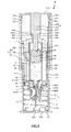
- FIG. 2 is a longitudinal sectional view of the liquid administration device shown in FIG.
- FIG. 3 is a perspective view of the proximal end member of the outer cylinder of the cylinder of the liquid administration device shown in FIG.
- FIG. 4 is a perspective view of the distal end side member of the outer cylinder of the cylinder of the liquid administration device shown in FIG.
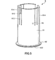
- FIG. 5 is a perspective view of a pusher of the liquid administration device shown in FIG.
- FIG. 6 is a perspective view of a cover member of the liquid administration device shown in FIG.
- FIG. 7 is a side view sequentially illustrating an operating state when the liquid administration device shown in FIG. 1 is used.
- FIG. 1 is a side view showing a first embodiment of the liquid administration device of the present invention.
- FIG. 2 is a longitudinal sectional view of the liquid administration device shown in FIG.
- FIG. 3 is a perspective view of the proxi
- FIG. 8 is a longitudinal sectional view for sequentially illustrating the operating state when the liquid administration device shown in FIG. 1 is used.
- FIG. 9 is a side view sequentially illustrating the operating state when the liquid administration device shown in FIG. 1 is used.
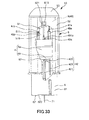
- FIG. 10 is a longitudinal cross-sectional view sequentially illustrating operating states when the liquid administration device shown in FIG. 1 is used.
- FIG. 11 is a side view sequentially illustrating an operating state when the liquid administration device shown in FIG. 1 is used.
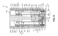
- FIG. 12 is a longitudinal cross-sectional view sequentially illustrating operating states when the liquid administration device shown in FIG. 1 is used.
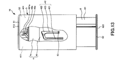
- FIG. 13 is a side view sequentially illustrating an operating state when the liquid administration device shown in FIG. 1 is used.
- FIG. 14 is a longitudinal cross-sectional view sequentially illustrating operating states when the liquid administration device shown in FIG. 1 is used.
- FIG. 15 is a longitudinal cross-sectional view sequentially showing the operating state when the liquid administration device shown in FIG. 1 is used.
- FIG. 16 is a longitudinal sectional view showing a second embodiment of the liquid administration device of the present invention.
- FIG. 17 is a side view showing a third embodiment of the liquid administration device of the present invention.
- 18 is a cross-sectional view of the liquid administration device shown in FIG.
- FIG. 19 is a side view showing a third embodiment of the liquid administration device of the present invention.
- 20 is a cross-sectional view of the liquid administration device shown in FIG.
- FIG. 21 is a longitudinal sectional view showing a fourth embodiment of the liquid administration device of the present invention.
- FIG. 22 is a perspective view of the base end side member of the outer cylinder of the cylinder of the liquid administration device shown in FIG.
- FIG. 23 is a perspective view of the pusher of the liquid administration device shown in FIG.
- FIG. 24 is a side view showing a fifth embodiment of the liquid administration device of the present invention.
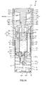
- 25 is a longitudinal sectional view of the liquid administration device shown in FIG.
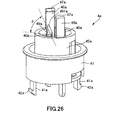
- FIG. 26 is a perspective view of the proximal end member of the outer cylinder of the cylinder of the liquid administration device shown in FIG.
- FIG. 27 is a perspective view of the distal end side member of the outer cylinder of the cylindrical body of the liquid administration device shown in FIG. FIG.
- FIG. 28 is a perspective view of the distal end side member of the outer cylinder of the cylinder of the liquid administration device shown in FIG.
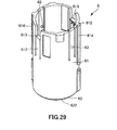
- FIG. 29 is a perspective view of a cover member of the liquid administration device shown in FIG. 30 is a perspective view of the pusher of the liquid administration device shown in FIG.
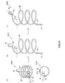
- FIG. 31 is a perspective view of a coil spring of the liquid administration device shown in FIG.
- FIG. 32 is a perspective view of the head of the operation member of the liquid administration device shown in FIG.
- FIG. 33 is a side view sequentially illustrating the operating state when the liquid administration device shown in FIG. 24 is used.
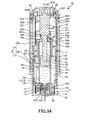
- FIG. 34 is a longitudinal sectional view for sequentially illustrating the operating state when the liquid administration device shown in FIG. 24 is used.
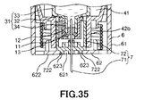
- FIG. 35 is a cross-sectional view of the distal end portion of the liquid administration device shown in FIG. 34 at another cross-section.
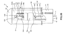
- FIG. 36 is a side view sequentially illustrating the operating state when the liquid administration device shown in FIG. 24 is used.
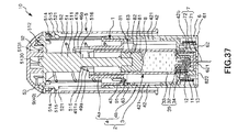
- FIG. 37 is a longitudinal sectional view for sequentially illustrating the operating state when the liquid administration device shown in FIG. 24 is used.
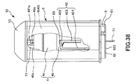
- FIG. 38 is a side view sequentially illustrating operating states when the liquid administration device shown in FIG. 24 is used.
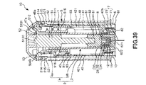
- FIG. 39 is a longitudinal sectional view for sequentially illustrating the operating state when the liquid administration device shown in FIG. 24 is used.
- FIG. 40 is a side view sequentially illustrating operating states when the liquid administration device shown in FIG. 24 is used.
- FIG. 41 is a longitudinal sectional view for sequentially illustrating the operating state when the liquid administration device shown in FIG. 24 is used.
- FIG. 42 is a longitudinal sectional view for sequentially illustrating the operating state when the liquid administration device shown in FIG. 24 is used.
- FIG. 43 is a side view showing a sixth embodiment of the liquid administration device of the present invention.
- FIG. 44 is a side view of the liquid administration device shown in FIG.
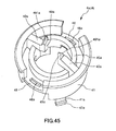
- FIG. 45 is a perspective view of the proximal end side member of the outer cylinder of the cylindrical body according to the seventh embodiment of the liquid administration device of the present invention.
- liquid administration device of the present invention will be described in detail based on preferred embodiments shown in the accompanying drawings.
- FIG. 1 is a side view showing a first embodiment of the liquid administration device of the present invention.
- FIG. 2 is a longitudinal sectional view of the liquid administration device shown in FIG.
- FIG. 3 is a perspective view of the proximal end member of the outer cylinder of the cylinder of the liquid administration device shown in FIG.
- FIG. 4 is a perspective view of the distal end side member of the outer cylinder of the cylinder of the liquid administration device shown in FIG.
- FIG. 5 is a perspective view of a pusher of the liquid administration device shown in FIG.
- FIG. 6 is a perspective view of a cover member of the liquid administration device shown in FIG. 7, 9, 11, and 13 are side views sequentially showing the operating state when the liquid administration device shown in FIG. 1 is used. 8
- FIG. 8 is a perspective view showing a first embodiment of the liquid administration device of the present invention.
- FIG. 2 is a longitudinal sectional view of the liquid administration device shown in FIG.
- FIG. 3 is a perspective view of the proximal end
- FIG. 12, FIG. 14 and FIG. 15 are longitudinal sectional views sequentially showing the operating state when the liquid administration device shown in FIG. 1 is used.
- the upper side in FIGS. 1 to 15 is “base end (rear end)” or “upper (upper)”
- the lower side is “tip” or “lower (lower)”
- the vertical direction is “axial direction”. “Or” longitudinal direction ".
- the liquid administration device 10 shown in FIGS. 1, 2, and 7 to 15 is a medical instrument used when administering (injecting) a liquid into a living body.
- the liquid is appropriately selected according to the purpose of use.
- hematopoietic agents, vaccines, hormone preparations, anti-rheumatic agents, anti-cancer agents, anesthetics, anticoagulants, etc. are mainly injected subcutaneously. Chemicals.
- the liquid administration device 10 includes an inner structure (structure) 1, an operation member 5, a cover member 6 disposed on the outer peripheral side of the inner structure 1, and a first member that urges the cover member 6 toward the distal direction. 1 is provided with a coil spring 13 as an urging member 1 and an auxiliary mechanism (auxiliary part) 40.
- the inner structure 1 includes a cylindrical body 2 constituted by an inner cylinder 3 and an outer cylinder 4, a puncture needle 7 constituted by a double-ended needle (needle tube) 71 and a support member 72, A gasket 8 is provided in the inner cylinder 3 (tubular body 2) and can slide along the axial direction of the inner cylinder 3.
- the inner cylinder 3 has an inner cylinder body 31.
- the inner cylinder main body 31 is composed of a bottom portion 32 at a distal end portion, a side wall 33 standing from an edge of the bottom portion 32, and a member having an opening portion at a proximal end portion, that is, a member having a bottomed cylindrical shape.
- the inner cylinder 3 can be filled with liquid.
- the front end portion of the inner cylinder main body 31, that is, the central portion of the bottom portion 32 is integrally formed with a mouth portion 34 that is reduced in diameter relative to the portion of the side wall 33 of the inner cylinder main body 31 and through which the liquid passes. Yes. From the mouth portion 34, liquid is sucked or discharged.
- the inner cylinder 3 has a sealing member (sealing part) 11 for liquid-tightly sealing the mouth part 34 of the inner cylinder main body 31 and a fixing member 12 for fixing the sealing member 11 from the distal end side. is doing.
- the sealing member 11 is made of an elastic body, and has a convex portion formed on the base end surface thereof. By fitting the convex portion into the mouth portion 34 in a liquid-tight manner, the mouth portion 34 is sealed in a liquid-tight manner. is doing.
- the fixing member 12 is a cylindrical member.
- the fixing member 12 is fitted from the outer peripheral side of the sealing member 11 and the mouth portion 34, and fixes the sealing member 11 to the inner cylinder main body 31. Thereby, the detachment
- a fixing method of the fixing member 12 a method by adhesion or a method by welding may be used.
- polyvinyl chloride polyethylene, polypropylene, cyclic polyolefin, Polystyrene such as polystyrene, poly- (4-methylpentene-1), polycarbonate, acrylic resin, acrylonitrile-butadiene-styrene copolymer, polyethylene terephthalate, polyethylene naphthalate, butadiene-styrene copolymer, polyamide (for example, nylon) 6, various types of resins such as nylon 6,6, nylon 6,10, nylon 12).
- polypropylene, cyclic polyolefin, polyester, poly- (4-methyl) are easy to mold. Resins such as pentene-1) Preferred.
- the elastic material constituting the sealing member 11 and the gasket 8 is not particularly limited.
- various rubber materials such as natural rubber, butyl rubber, isoprene rubber, butadiene rubber, styrene-butadiene rubber, silicone rubber
- elastic materials such as various thermoplastic elastomers such as polyurethane, polyester, polyamide, olefin, and styrene, and mixtures thereof.
- the outer cylinder 4 is arranged concentrically with the inner cylinder 3 on the outer peripheral side of the inner cylinder 3. As shown in FIGS. 2 to 4, the outer cylinder 4 has a cylindrical shape with both ends opened and its length is longer than that of the inner cylinder 3. The outer cylinder 4 is rotatable with respect to the inner cylinder 3 about its axis.
- the outer cylinder 4 includes a proximal end member 4a shown in FIG. 3 disposed on the proximal end side and a distal end side member 4b shown in FIG. 4 disposed on the distal end side.
- a pair of hole portions 41b arranged to face each other is formed on the proximal end side of the distal end side member 4b.
- a pair of arm portions 41a which are elastic and are arranged so as to face each other are formed on the distal end side of the base end side member 4a so as to protrude in the distal end direction.
- Each has a claw 42a projecting outward.
- Each claw 42a is inserted into each hole 41b from the inside on the proximal end side of the distal end side member 4b, and each claw 42a and each hole 41b are engaged, and the proximal end side member 4a and the distal end side member 4b are engaged with each other. It is connected.
- the method of connecting the base end side member 4a and the front end side member 4b is not limited to this,
- bonding such as adhesion
- the outer cylinder 4 is formed at the body portion 41, the distal end side of the body portion 41, the reduced diameter portion 42b having a diameter reduced with respect to the body portion 41, and the base end portion of the body portion 41, A diameter-reduced portion 45 a having a diameter reduced with respect to the body portion 41 is provided.
- a stepped portion 421b is formed on the inner peripheral portion of the reduced diameter portion 42b. Further, four grooves 422b are formed in the inner peripheral portion of the reduced diameter portion 42b (see FIG. 2). The grooves 422b are arranged in parallel at equal angular intervals along the circumferential direction of the reduced diameter portion 42b. In the present embodiment, the reduced diameter portion 45a is formed, but the reduced diameter portion 45a may not be formed.
- a pair of long holes 43b and a pair of 44b penetrating through the body part 41 are formed in the body part 41 of the distal end side member 4b.
- the long holes 43b are arranged to face each other, and similarly, the long holes 44b are also arranged to face each other.
- each long hole 43b is the same shape, hereafter, one long hole 43b is demonstrated typically.
- each of the long holes 44b has the same shape, and therefore, one of the long holes 44b will be typically described below.
- the long hole 43b has penetrated in this embodiment, it may be recessed without penetrating, and the same effect is acquired also in this case (not shown).
- the long holes 43 b and 44 b are arranged side by side along the circumferential direction of the body portion 41.
- the long hole 43b is disposed on the left side of the long hole 44b.
- the long holes 43b and 44b extend along the axis of the trunk portion 41, respectively.
- the end surface of the base end side of the long hole 43b is located in the front end side rather than the end surface of the base end side of the long hole 44b.
- the end surface on the proximal end side of the long hole 43 b is an inclined surface that is inclined at a predetermined angle with respect to the axis of the body portion 41.
- the end surface on the base end side of the long hole 44 b is set perpendicular to the axis of the body portion 41.
- a pair of projecting portions 40a arranged to face each other is formed on the base end side of the body portion 41 of the base end side member 4a.
- Each protrusion 40a is formed to protrude inward from the inner peripheral surface of the body 41, that is, toward the central axis.
- a protrusion (second engagement portion) 49a is formed to protrude toward the proximal direction at the end portion (tip portion) on the center axis side of each protrusion portion 40a.
- Each protrusion 49a has an inclined surface 491a with which each step part 516 described later comes into contact as a rotation mechanism (rotating part).
- the rotating mechanism rotates the stepped portion 516 and the protrusion 49a that are in an engaged state relatively around the central axis of the inner structure 1 to be in a released state.
- the inclined surface 491a is a flat surface in the illustrated configuration.
- the inclined surface 491a is centered on the central axis of the inner structure 1 in a plan view and faces the tangential direction of a circle passing through the inclined surface 491a.
- the step portion 516 moves relative to the protrusion 49a along the inclined surface 491a, so that the outer cylinder 4 rotates relative to the operation member 5 around the central axis of the outer cylinder 4. .
- the inclination angle ⁇ of the inclined surface 491a is not particularly limited and is appropriately set according to various conditions, but is preferably 5 to 85 °, more preferably 20 to 70 °. .
- the shape of the inclined surface 491a is not limited to a flat surface, and may be a curved surface.
- the number of the protrusions 40a and each protrusion 40a is not limited to two, but may be one, for example, or three or more.
- the inner cylinder 3 is installed between each protruding portion 40a of the outer cylinder 4 and the reduced diameter portion 42b. As shown in FIG. 10, a pair of flanges (projection pieces) 35 of the inner cylinder 3 are The shaft of the inner cylinder 3 relative to the outer cylinder 4 is sandwiched from above and below by the upper end surface inside the distal end side of the base end side member 4a of the outer cylinder 4 and the upper end surface of the vertical rib 48b inside the distal end side member 4b of the outer cylinder 4. Directional movement is prevented. In FIG. 10, only one of the pair of flanges 35 of the inner cylinder 3 is shown.
- each cam groove 42 is formed so as to penetrate the wall portion of the trunk portion 41, but is not limited thereto, and may not penetrate the wall portion of the trunk portion 41. Since each cam groove 42 is the same, one cam groove 42 will be described below representatively.
- the cam groove 42 extends in the axial direction of the outer cylinder 4 on the outer peripheral surface of the body 41, and is linear with respect to the linear groove (second groove) 421 formed in a straight line and the axis of the outer cylinder 4.
- An inclined groove (first groove) 422 formed so as to be inclined at an angle, and a linear groove (third groove) 423 extending in the axial direction of the outer cylinder 4 and formed in a linear shape.
- the distal end portion of the linear groove 423 is located on the proximal end side with respect to the distal end portion of the linear groove 421, and the proximal end portion of the linear groove 423 is located on the proximal end side with respect to the proximal end portion of the linear groove 421.
- the inclined groove 422 is formed shorter than one round.
- linear grooves 421, inclined grooves 422, and linear grooves 423 are continuously formed from the left side to the right side in FIG.
- the base end portion of the linear groove 421 and the tip end portion (left end portion in FIG. 1) of the inclined groove 422 communicate with each other, and the base end portion (right end portion in FIG. 1) of the inclined groove 422
- the base end of the linear groove 423 communicates.
- the protrusion 63 is inserted into the linear groove 421, whereby the outer cylinder 4 rotates relative to the cover member 6 around the central axis. This prevents the outer cylinder 4 from rotating relative to the operating member 5. Accordingly, the protrusion 63 and the linear groove 421 are relatively engaged around the central axis of the inner structure 1 between the stepped portion (first engaging portion) 516 and the protrusion (second engaging portion) 49a in the engaged state.
- a rotation prevention mechanism rotation prevention unit that prevents proper rotation is configured.
- the groove may be provided in the cover member 6, and the protrusion may be provided in the outer cylinder 4.
- a puncture needle 7 is disposed at the distal end of the cylinder 2.
- the puncture needle 7 includes a double-ended needle 71 and a support member 72 that supports and fixes the double-ended needle 71.
- the double-ended needle 71 is a hollow needle tube, and has a sharp distal needle tip at the distal end and a sharp proximal needle tip at the proximal end.
- the double-ended needle 71 can puncture a living body with the distal end side needle tip, and can pierce the sealing member 11 of the inner cylinder 3 with the proximal end side needle tip.
- the lumen portion (hollow portion) of the double-ended needle 71 communicates with the inner cylinder 3 in a state where the proximal needle tip penetrates the sealing member 11 of the inner cylinder 3, and the liquid from the inner cylinder 3 It functions as a passage for passing through.
- the proximal end needle tip pierces the sealing member 11 of the inner cylinder 3, and passes through the flow path of the double-ended needle 71 into the body. Liquid is injected.
- constituent material of the double-ended needle 71 is not particularly limited, and examples thereof include metal materials such as stainless steel, aluminum or aluminum alloy, titanium or titanium alloy.
- the double-ended needle 71 having such a configuration is attached to the distal end portion of the outer cylinder 4 (tubular body 2), that is, the reduced diameter portion 42b via the support member 72 so as to be movable along the axial direction of the outer cylinder 4. ing.
- the support member 72 supports the double-ended needle 71 movably along the axial direction with respect to the outer cylinder 4.
- the support member 72 has a bottomed cylindrical shape.
- the double-ended needle 71 is supported and fixed to the bottom portion of the support member 72 at an intermediate position.
- protrusions 721 are arranged in parallel at equiangular intervals along the circumferential direction of the base end portion of the support member 72 (see FIGS. 8 and 10). Further, one or a plurality of elongated holes (not shown) extending in the axial direction of the support member 72 and opening in the proximal direction are formed between the adjacent protrusions 721 of the support member 72. Has been. Thereby, the site
- the protrusions 721 are engaged with the step portions 421b of the reduced diameter portion 42b on the distal end side of the outer cylinder 4, so that the puncture needle 7 is prevented from being detached from the distal end portion of the cylindrical body 2.
- each protrusion 721 is inserted into each groove 422b of the reduced diameter portion 42b on the distal end side of the outer cylinder 4, and engages with the groove 422b.
- the puncture needle 7 is supported by the outer cylinder 4 via the support member 72 so as to be movable along the axial direction thereof.
- the puncture needle 7 includes the separated state shown in FIG. 2 in which the proximal end needle tip of the double-ended needle 71 is separated from the sealing member 11 of the cylindrical body 2, and the proximal end needle tip of the double-ended needle 71 is the sealing member.
- the piercing state shown in FIG. 8 and FIG. Therefore, unintentional leakage of the liquid from the double-ended needle 71 is prevented until the piercing state is reached.
- the cover member 6 is disposed on the outer peripheral side of the outer cylinder 4 (tubular body 2).
- the cover member 6 is supported so as to be movable along the axial direction with respect to the outer cylinder 4 (tubular body 2) similarly to the puncture needle 7. As a result, after the distal end surface 622 of the cover member 6 comes into contact with the living body, the distal end needle tip of the double-ended needle 71 is punctured from the skin to a predetermined depth of the living body.
- the cover member 6 takes five stages (positions) as described later between before use and after use. These five positions are the first position (position (A)) (see FIGS. 1 and 2) in which the cover member 6 protrudes from the distal end side needle tip of the double-ended needle 71 to the distal end side before use.
- the second position (see FIGS. 7 and 8) before the cover member 6 is retracted in the proximal direction from the position 1 and the outer cylinder 4 is rotated with respect to the cover member 6 and the inner cylinder 3, and the outer cylinder 4 Is rotated at a predetermined angle with respect to the cover member 6 and the inner cylinder 3 (see FIGS.
- the cover member 6 moves in the distal direction from the position 4 (FIGS. 11 and 12) and the fourth position (third position), and the cover member 6 moves from the distal end needle tip of the double-ended needle 71 to the distal end side. This is the fifth position (see FIGS. 13 to 15) in which it protrudes and the safety mechanism after the administration is activated.
- the cover member 6 when the cover member 6 is in the first position, the front end surface 622 of the cover member 6 protrudes from the front end side of the front end side of the double-ended needle 71 to the front end side. The tip of the needle is covered.
- the distal end needle tip of the double-ended needle 71 since the distal end needle tip of the double-ended needle 71 is not exposed until the cover member 6 moves from the first position to the proximal end side, the user may make an error with the distal end needle tip of the double-ended needle 71 before puncturing. It is possible to prevent the needle from being punctured and from damaging the tip side needle tip.
- the cover member 6 when the cover member 6 is in the second to fourth positions (position (B)), the tip side needle tip of the double-ended needle 71 is exposed from the tip of the cover member 6.
- the puncture needle 7 described above is in a separated state where the cover member 6 is located on the proximal side from the distal end portion of the cover member 6 when the cover member 6 is in the first position.
- the cover member 6 presses and moves the double-ended needle 71 (the double-ended needle 71 together with the support member 72) toward the proximal direction.
- the side needle tip penetrates the sealing member 11 of the cylindrical body 2, and the tip side needle tip of the double-ended needle 71 is punctured by a living body.
- the cover member 6 includes a plate-like distal end wall portion 62 disposed at the distal end portion and a side wall 61 erected in the proximal direction from the distal end wall portion 62, that is, has a bottomed cylindrical shape. It is composed of members.
- the cover member 6 has a tip surface 622 at the tip.
- an opening 621 that passes through the center is formed. As shown in FIGS. 6 to 9, when the cover member 6 is in the second to fourth positions, the tip end of the double-ended needle 71 protrudes (exposes) from the opening 621.
- the side wall 61 has a cylindrical shape.
- a pair of ribs 614 are formed on the outer peripheral surface of the base end portion of the side wall 61 so as to protrude outward and to face each other.
- Each rib 614 extends in the axial direction of the cover member 6.
- a pair of arm portions 612 having elasticity and arranged so as to face each other are formed to protrude in the proximal direction, and at the proximal end portion of each arm portion 612, Protrusions 613 projecting inward are formed.
- Each protrusion 613 is disposed on the distal end side of the base end of the side wall 61.
- the arm portion 612, the protrusion 613, and the rib 614 are arranged at substantially equal angular intervals along the circumferential direction of the cover member 6.
- a pair of protrusions 63 are formed on the inner peripheral surface of the base end portion of the side wall 61 so as to protrude inward and to be opposed to each other (see FIG. 1).
- Each protrusion 63 is inserted into each cam groove 42 of the outer cylinder 4, that is, engages with each cam groove 42. The relationship between the protrusion 63 and the cam grooves 42 of the outer cylinder 4 in a series of operations will be described later.
- each projection 613 of the cover member 6 is inserted into each long hole 43b of the outer cylinder 4 respectively.
- the cover member 6 moves in the axial direction of the outer cylinder 4 and the outer cylinder 4 rotates by a predetermined angle with respect to the cover member 6 by the cam groove 42 of the outer cylinder 4 and the protrusion 63 of the cover member 6, the cover member 6
- Each of the projections 613 moves on the surface of the base end side of the body portion 41 of each elongated hole 44b of the outer cylinder 4.
- a coil spring (compression coil spring) 13 is housed in a compressed state inside the cover member 6.
- the coil spring 13 has a distal end in contact with the distal end wall portion 62 inside the cover member 6, and a proximal end portion of the coil spring 13 is in contact with the distal end side inside of the body portion 41 of the outer cylinder 4.
- the compressed state in the unused state is such that the coil spring 13 is compressed by the weight applied to the tip of the outer cylinder 4.
- the coil spring 13 is configured so that the distal end portion of the coil spring 13 is in contact with the distal end wall portion 62 inside the cover member 6 and the proximal end portion of the coil spring 13 is in contact with the distal end side inside of the body portion 41 of the outer cylinder 4.
- the cover member 6 can be urged in the direction from the second position toward the first position (ie, urged toward the distal end direction).
- the distal end surface 622 of the cover member 6 can be protruded from the distal end side needle tip of the double-ended needle 71 until the liquid administration device 10 is used. It is possible to reliably prevent erroneous puncture by the distal needle tip.
- the constituent material of the coil spring 13 is not particularly limited, and for example, a metal material such as stainless steel or copper can be used.
- the gasket 8 is accommodated in the inner cylinder 3 (cylinder body 2) so as to be slidable along the axial direction of the inner cylinder 3.
- the space surrounded by the gasket 8 and the inner cylinder 3 is preliminarily filled with liquid. Then, by moving the gasket 8 toward the distal direction, the liquid in the inner cylinder 3 can be pushed out from the double-ended needle 71 in a state communicating with the inner cylinder 3.
- the gasket 8 has a cylindrical outer shape, and four protrusions 81 are formed on the outer periphery thereof. Adjacent protrusion 81 and protrusion 81 are separated along the axial direction of gasket 8. Each protrusion 81 has a ring shape along the circumferential direction of the gasket 8, and its outer diameter is slightly larger than the inner diameter of the inner cylinder 3 in a natural state where no external force is applied. Accordingly, each protrusion 81 can slide while being in close contact with the inner peripheral portion of the side wall 33 of the inner cylinder 3, so that liquid-tightness is reliably maintained and slidability is improved. Can be planned.
- a recess 82 is opened on the base end surface of the gasket 8 to which the main body portion 511 of the pusher 51 of the operation member 5 is inserted (fitted) and connected.
- the operation member 5 is connected to the proximal end side of the gasket 8, and a pusher 51 that presses the gasket 8 toward the distal end, an outermost cylinder (outer cylinder) (gripping part) 52, and have.
- the pusher 51 and the outermost cylinder 52 are connected.
- the operation member 5 moves the pusher 51 in the distal direction, thereby moving the gasket 8 toward the distal direction, thereby ejecting the liquid in the inner cylinder 3 from the double-ended needle 71 (discharge operation). It is a member which performs.
- the pusher 51 has a rod-like main body portion 511 whose cross section is, for example, a cross shape or a circular shape, and the gasket 8 is fixed to the tip of the main body portion 511. ing.
- a disc-shaped flange 512 is formed at the base end of the main body 511.
- a connecting portion 513 corresponding to the shape of the concave portion 82 of the gasket 8 is formed at the tip of the main body portion 511.
- the pusher 51 (operation member 5) and the gasket 8 are connected.
- the method of fixing the gasket 8 to the main body 511 is not limited to this.
- a male screw is formed on the main body 511 and a female screw is formed on the gasket 8 to be screwed to the male screw. And a method of screwing the two together.
- the operation member 5 is connected to the base end side of the gasket 8, but may not be connected.
- a pair of arm portions 514 that are elastic and are disposed so as to face each other are formed on the proximal end surface of the flange 512 of the pusher 51 so as to protrude in the distal direction, and the distal end portion of each arm portion 514 Each has a claw 515 protruding outward.
- the pusher 51 has a plate-like portion having a longitudinal shape, and the plate-like portion as a first engagement portion that can engage with a pair of protrusions (second engagement portions) 49a.
- stepped portions (first engaging portions) 516 is not limited to two, but may be one, for example, or may be three or more.
- step portion first engagement portion
- the protrusion second engagement portion
- each step portion 516 of the pusher 51 is engaged with or can be engaged with each protrusion 49 a of the outer cylinder 4, whereby the tip of the pusher 51 with respect to the cylindrical body 2. Movement in the direction is blocked. Then, when the cover member 6 moves in the axial direction of the outer cylinder 4 and the outer cylinder 4 moves to a position where the outer cylinder 4 can rotate by a predetermined angle with respect to the cover member 6 by the cam groove 42 of the outer cylinder 4 and the protrusion 63 of the cover member 6. The step portions 516 of the pusher 51 move to positions shifted from the projections 49a of the outer cylinder 4, and the engagement between the step portions 516 and the projections 49a is released. 51 can be moved in the distal direction.
- the outermost cylinder 52 is disposed on the outer peripheral side of the inner structure 1 and the cover member 6.
- the outermost cylinder 52 has a cylindrical shape and functions as a grip portion when gripping the operation member 5.
- a pair of hole portions 521 are formed at the base end portion of the outermost cylinder 52 so as to face each other. And each nail
- the auxiliary mechanism 40 has a function of generating an auxiliary force that presses the gasket 8 via the pusher 51 of the operation member 5.
- the auxiliary mechanism 40 includes a pair of coil springs (tensile coil spring: second urging member) 401.
- Each coil spring 401 is in an extended state, and has a base end portion fixed to the base end portion of the pusher 51 and a tip end portion fixed to the base end side member 4 a of the outer cylinder 4.
- each coil spring 401 urges the inner structure 1 and the operation member 5 in a direction in which they approach each other. That is, each coil spring 401 generates an auxiliary force that presses the gasket 8 in the distal direction via the pusher 51 of the operation member 5.
- the operation member 5 can be easily moved in the distal direction.
- each coil spring 401 does not specifically limit as a constituent material of each coil spring 401,
- the material similar to the constituent material of the coil spring 13 can be used.
- each groove extends along the axial direction of the outermost cylinder 52.
- each rib 614 of the cover member 6 is inserted in each groove. Thereby, rotation of the cover member 6 with respect to the outermost cylinder 52 is prevented.
- FIG. 1 a method of using the liquid administration device 10 and an operating state at the time of use will be described with reference to FIGS. 1, 2, and 7 to 15.
- FIG. 1 a method of using the liquid administration device 10 and an operating state at the time of use will be described with reference to FIGS. 1, 2, and 7 to 15.
- a liquid administration device 10 in an unused state is prepared.
- the cover member 6 is in the first position and covers the tip end of the double-ended needle 71.
- the state in which the tip of the double-ended needle 71 is covered with the cover member 6 by the urging force of the coil spring 13 is maintained. Thereby, the erroneous puncture by the front end side needle tip of the double-ended needle 71 can be reliably prevented.
- the proximal needle tip of the double-ended needle 71 is separated from the sealing member 11 of the inner cylinder 3 of the cylindrical body 2, and the sealing member 11 has not yet been pierced. Thereby, the aseptic state of the liquid can be maintained until the administration of the drug solution is started.
- each protrusion 63 of the cover member 6 is located at a position shown in FIG.
- each protrusion 613 of the cover member 6 is located on the proximal end side of the long hole 43 b at the distal end portion of the outer cylinder 4.
- each step portion 516 of the pusher 51 is in contact with or in contact with the inclined surface 491a of each projection 49a of the outer cylinder 4 (may be separated before use), that is, engaged with each projection 49a. Or it exists in the position which can be engaged, and the movement to the front-end
- the protrusion 63 is inserted into the linear groove 421, thereby preventing the outer cylinder 4 from rotating with respect to the cover member 6, whereby the outer cylinder 4 is prevented from rotating with respect to the operation member 5. Rotation is prevented.
- the operation member 5 of the liquid administration device 10 in an unused state is gripped, and the distal end wall portion 62 of the cover member 6 is brought into contact with the living body to operate the operation member. 5 is pressed toward the tip. Thereby, the cover member 6 moves against the operating member 5 and the inner structure 1 in the proximal direction, that is, from the first position to the second position against the urging force of the coil spring 13. Further, in the movement process, the distal end wall portion 62 of the cover member 6 moves the support member 72 of the puncture needle 7 to the proximal end portion side.
- the distal needle tip of the double-ended needle 71 protrudes from the opening 621 of the distal wall 62 of the cover member 6, and the living body is punctured with the distal needle tip. Further, the distal end wall portion 62 presses the support member 72 of the puncture needle 7 toward the proximal direction. Thereby, the sealing member 11 of the inner cylinder 3 can be pierced by the proximal end needle tip of the double-ended needle 71, and thus the double-ended needle 71 punctured with a living body and the inner cylinder 3 communicate with each other.
- the protrusion 63 of the cover member 6 moves in the proximal direction relative to the outer cylinder 4 along the linear groove 421.
- the protrusion 63 of the cover member 6 is located at the position shown in FIG.
- the projections 613 of the cover member 6 move in the proximal direction along the long holes 43b of the outer cylinder 4, and the protrusions 613 of the cover member 6 are moved from the proximal ends of the long holes 43b to ( It is in a state where it rides on the body 41 of the outer cylinder 4 while being bent outward (from the central axis) and further moves to the base end side.
- the projection 63 is located at the base end portion of the linear groove 421, whereby the outer cylinder 4 can be rotated with respect to the cover member 6, whereby the outer cylinder 4 is moved to the operation member 5. It becomes possible to rotate.
- the stepped portion 516 of the pusher 51 moves along the inclined surface 491a of the protrusion 49a, and at this time, the outer cylinder 4 obtains a propulsive force in the rotational direction. Thereby, the outer cylinder 4 can be rotated easily.
- each step portion 516 of the pusher 51 is moved to a position shifted from each projection 49a of the outer cylinder 4, and the engagement between each step portion 516 and each projection 49a is released.
- the operation member 5 can move in the distal direction relative to the cylindrical body 2. Thereafter, the state in which the engagement between each stepped portion 516 and each projection 49a is disengaged is maintained, and thus the following description is omitted.
- the puncture operation of the double-ended needle 71 into the living body, the rotation operation of the outer cylinder 4, and the pressing operation of the operation member 5 described later can be performed smoothly.
- the protrusion 63 of the cover member 6 moves obliquely upward relative to the outer cylinder 4 along the inclined groove 422.
- the protrusion 63 of the cover member 6 is located at the position shown in FIG.
- the protrusions 613 of the cover member 6 rotate while the protrusions 613 of the cover member 6 are bent (outward from the central axis), and the base end portions of the body portions 41 of the long holes 44b are rotated. It is the state which moved on the side surface.
- the operating member 5 is moved in the distal direction by the urging force of the coil spring 401, that is, the auxiliary force, with the cover member 6 positioned at the third position.
- the gasket 8 it becomes possible for the gasket 8 to move toward the front end direction. That is, the above-described pressing operation is performed, so that liquid can be administered.
- the gasket 8 comes into contact with the bottom 32 of the inner cylinder 3, the liquid administration is completed, and the cover member 6 is located at the fourth position.
- the protrusions 613 of the cover member 6 are also formed on the base end surface of the body 41 of the long holes 44b in a state where the protrusions 613 of the cover member 6 are bent (outward from the central axis). Remains in position.
- the cover member 6 is moved in the distal direction by the urging force of the coil spring 13, that is, the cover member 6 is moved to the fifth position, and the distal needle tip of the double-ended needle 71 is covered with the cover member.
- the projections 613 of the cover member 6 are engaged with the base end portion of the long hole 44 b, so that the cover member 6 is prevented from moving in the base end direction with respect to the outer cylinder 4.
- the state where the tip side of the double-ended needle 71 is covered is maintained.
- the cover member 6 since the cover member 6 cannot move in the proximal direction, it functions as a safety mechanism for preventing a needle stick accident after use.
- the outer cylinder 4 rotates relative to the cover member 6 so that the projections 613 of the cover member 6 are engaged with the long holes 44b from the long holes 43b (initial state) of the outer cylinder 4, and the safety mechanism functions.
- the used liquid administration device 10 can be safely and securely discarded without making a mistake with the liquid administration device 10 before use.
- the projection 63 of the cover member 6 moves in the distal direction relative to the cover member 6 along the linear groove 423, and when the cover member 6 is in the fifth position, the projection 63 of the cover member 6 Is located at a position shown in FIG.
- the stepped portion 516 and the protrusion 49 a in the engaged state are rotated around the central axis of the inner structure 1 to be in the released state.
- the direction of relative displacement between the stepped portion 516 and the projection 49a is different from the direction of the pressing operation of the operation member 5, thereby preventing the release state from being unintentionally released.
- the liquid can be prevented from leaking unintentionally from the double-ended needle 71 before or during the puncturing of the double-ended needle 71.
- the puncturing operation of the double-ended needle 71 into the living body, the rotating operation of the outer cylinder 4, and the pressing operation of the operating member 5 can be performed smoothly.
- the outer cylinder 4 when the outer cylinder 4 is brought into the released state, the outer cylinder 4 obtains a propulsive force in the rotational direction by the inclined surface 491a, and thus the outer cylinder 4 can be easily rotated.
- the biasing force of the coil spring 401 can assist the movement of the operation member 5 in the distal direction or move the operation member 5 in the distal direction.
- the puncture needle has a needle tube that is a double-ended needle, but in the present invention, the puncture needle is not limited to this, and has a needle tube in which the proximal end needle tip is omitted. Also good. In this case, the needle tube communicates with the inner cylinder in advance (already in an unused state).
- FIG. 16 is a longitudinal sectional view showing a second embodiment of the liquid administration device of the present invention.
- the upper side in FIG. 16 is “base end (rear end)” or “upper (upper)”
- the lower side is “tip” or “lower (lower)”
- the vertical direction is “axial” or “ The description will be given as “longitudinal direction”.
- the auxiliary mechanism 40 has one coil spring (second urging member) 402.
- the coil spring 402 biases one of the stepped portion (first engaging portion) 516 and the protrusion a (second engaging portion) in the rotational direction around the central axis of the inner structure 1 with respect to the other.
- the coil spring 402 biases one of the stepped portion (first engaging portion) 516 and the protrusion a (second engaging portion) in the rotational direction around the central axis of the inner structure 1 with respect to the other. Also serves as a third urging member.
- FIGS. 17 and 19 are side views showing a third embodiment of the liquid administration device of the present invention, respectively.
- 18 and 20 are cross-sectional views of the liquid administration device shown in FIGS. 17 and 19, respectively.
- the upper side in FIG. 17 and FIG. 19 is “base end (rear end)” or “upper (upper)”
- the lower side is “tip” or “lower (lower)”
- the vertical direction is “axial direction”. "Or" longitudinal direction ".
- the cover member 6 is omitted in the liquid administration device 10 of the third embodiment.
- the cam groove 42 is changed to straight grooves 423 and 424.
- the straight groove 424 is formed on the outer peripheral surface of the body portion 41 and extends in a direction perpendicular to the axis of the outer cylinder 4.
- the straight groove 424 is formed shorter than one round.
- the straight groove 423 is formed linearly on the outer peripheral surface of the body portion 41 and extends in the axial direction of the outer cylinder 4. And the edge part of the right side in FIG. 17 of the linear groove 424 and the base end part of the linear groove 423 are connecting.
- the protrusion 63 is formed on the inner peripheral surface of the outermost cylinder 52.
- the protruding portion 40a of the outer cylinder 4 does not have the protrusion 49a, and in the engaged state, the stepped portion 516 of the pusher 51 is engaged with the end portion (tip portion) on the central axis side of the protruding portion 40a. Match.
- the protrusion 63 of the cover member 6 is positioned at the position shown in FIGS. 17 and 18 with respect to the outer cylinder 4 in an unused state (initial state). is doing. Further, the step portion 516 of the pusher 51 is engaged with the end portion on the central axis side of the protruding portion 40a.
- the operating member 5 is rotated with respect to the outer cylinder 4 by manual operation during use.
- the protrusion 63 of the cover member 6 moves to the position shown in FIGS. 19 and 20 with respect to the outer cylinder 4.
- the engagement between the stepped portion 516 of the pusher 51 and the end portion on the central axis side of the protruding portion 40a is released, and a released state is obtained.
- FIG. 21 is a longitudinal sectional view showing a fourth embodiment of the liquid administration device of the present invention.
- FIG. 22 is a perspective view of the base end side member of the outer cylinder of the cylinder of the liquid administration device shown in FIG.
- FIG. 23 is a perspective view of the pusher of the liquid administration device shown in FIG.
- the upper side in FIGS. 21 to 23 is “base end (rear end)” or “upper (upper)”
- the lower side is “tip” or “lower (lower)”
- the vertical direction is “axial direction”.
- “Or" longitudinal direction is “.
- the puncture needle 7 is configured by a needle tube 73 that is fixed to the mouth 34 of the inner cylinder 3 and has a sharp needle tip at the tip. .
- the liquid administration device 10 also has a cap 18 that is detachably attached to the cover member 6 and a needle tip side cap 15 that is detachably attached to the mouth 34 of the inner cylinder 3.
- the needle tip side cap 15 includes a bottomed tubular housing 16 and an elastic body 17 installed on the inner peripheral surface of the housing 16. In a state where the needle tip side cap 15 is attached to the mouth portion 34 of the inner cylinder 3, the needle tip of the needle tube 73 is protected by contact with the elastic body 17, and the distal end opening of the needle tube 73 is sealed by the elastic body 17. Yes.
- the operation member 5 includes a head 53, an outermost cylinder 52, and a pusher 51, and the head 53, the pusher 51, and the outermost cylinder 52 are connected.
- a pair of engaging portions 5101 that can be engaged with a pair of claws 47a of a base end side member 4a of the outer cylinder 4 to be described later are formed in the middle of the main body portion 511 of the pusher 51.
- the engaging portion 5101 is constituted by an end portion of a plate-like portion 5102 on the tip end side of a notch portion 5103 provided in the middle of a longitudinal-like plate-like portion 5102 extending in the axial direction of the pusher 51,
- the claw 47a can be engaged along the axial direction of the pusher 51 and the outer cylinder 4 (see FIG. 21A).
- the engaging portion 5101 is disposed on the base end side of the step portion 516.
- a pair of arm portions 46 a that are elastic and are arranged to face each other are provided on the proximal end side of the reduced diameter portion 45 a of the proximal end side member 4 a of the outer cylinder 4. Projecting in the proximal direction. At the tip of each arm portion 46a, a claw 47a that protrudes toward the opposite side is formed.
- one coil spring 402 is provided as in the second embodiment.
- each claw 47a and each cap As shown in FIG. 21B, in the state where the needle tip side cap 15 and the cap 18 are removed and the outer cylinder 4 is rotated with respect to the cover member 6, the inner cylinder 3 and the operation member 5, each claw 47a and each cap The engagement with the engagement portion 5101 is disengaged, and each engagement portion 5101 is retracted outward from each plate-like portion 5102 (main body portion 511) when viewed from the axial direction of the pusher 51. As a result, the pusher 51 can move in the distal direction without interfering with the claws 47a.
- the claws 47a of the outer cylinder 4 and the engaging portions 5101 of the pusher 51 are engaged, and the outer cylinder 4 is in the distal direction with respect to the pusher 51. Since the movement is prevented, it is possible to prevent the cover member 6, the inner cylinder 3, and the outer cylinder 4 from moving together with the cap 18 in the distal direction when the cap 18 is removed.
- claw 47a of the outer cylinder 4 and each engaging part 5101 of the pusher 51 are engaging, even when an impact is added to the liquid administration tool 10 by dropping the liquid administration tool 10, etc. It is possible to reliably prevent the stepped portions 516 of the pusher 51 from engaging with or being displaced from the inclined surfaces 491a of the protrusions 49a of the outer cylinder 4.
- FIG. 24 is a side view showing a fifth embodiment of the liquid administration device of the present invention.
- 25 is a longitudinal sectional view of the liquid administration device shown in FIG.
- FIG. 26 is a perspective view of the proximal end member of the outer cylinder of the cylinder of the liquid administration device shown in FIG. 27 and 28 are perspective views of the distal end side member of the outer cylinder of the cylinder of the liquid administration device shown in FIG. 24, respectively.
- 29 is a perspective view of a cover member of the liquid administration device shown in FIG. 30 is a perspective view of the pusher of the liquid administration device shown in FIG.
- FIG. 31 is a perspective view of a coil spring of the liquid administration device shown in FIG. FIG.
- FIG. 32 is a perspective view of the head of the operation member of the liquid administration device shown in FIG. 33
- FIG. 36, FIG. 38, and FIG. 40 are side views sequentially showing the operating state when the liquid administration device shown in FIG. 24 is used.
- 34, FIG. 37, FIG. 39, FIG. 41, and FIG. 42 are longitudinal sectional views sequentially showing the operating state when the liquid administration device shown in FIG. 24 is used.
- 35 is a cross-sectional view of the distal end portion of the liquid administration device shown in FIG. 34 at another cross-section.
- the upper side in FIGS. 24 to 42 is “base end (rear end)” or “upper (upper)”
- the lower side is “tip” or “lower (lower)”
- the vertical direction is “axial direction”. "Or" longitudinal direction ".
- the outer cylinder 4 is disposed on the distal end side with the proximal end member 4a illustrated in FIG. 26 disposed on the proximal end side. It is comprised by the front end side member 4b shown to FIG. 27 and FIG.
- grooves 422b are formed in the inner peripheral portion of the reduced diameter portion 42b of the distal end side member 4b, and four step portions 421b are formed by the grooves 422b (see FIGS. 25 and 42).
- the grooves 422b and the step portions 421b are arranged in parallel at equal angular intervals along the circumferential direction of the reduced diameter portion 42b.
- a space 423b communicating with the groove 422b is formed on the proximal end side of the groove 422b on the inner peripheral portion of the reduced diameter portion 42b (see FIGS. 25 and 42).
- the space 423b prevents each projection 721 of the support member 72 of the puncture needle 7 described later from interfering with the reduced diameter portion 42b.
- the reduced diameter portion 45a is formed, but the reduced diameter portion 45a may not be formed.
- a pair of grooves 46b and a pair of long holes 44b penetrating the trunk portion 41 are formed in the trunk portion 41 of the distal end side member 4b.
- the grooves 46b are arranged to face each other, and similarly, the long holes 44b are also arranged to face each other. Since each groove 46b has the same shape, one groove 46b will be typically described below. Similarly, each of the long holes 44b has the same shape, and therefore, one of the long holes 44b will be typically described below.
- the groove 46b has a bottom, but may penetrate the trunk portion 41. In this case, the same effect is obtained (not shown). Further, in the present embodiment, the long hole 44b penetrates the body portion 41, but it may be recessed without penetrating, and the same effect is obtained in this case (not shown).
- the groove 46 b and the long hole 44 b are arranged side by side along the circumferential direction of the body portion 41. In this embodiment, as shown in FIG. 28, the groove 46b is disposed on the left side of the long hole 44b.
- the groove 46b and the long hole 44b extend along the axis of the body portion 41, respectively.
- channel 46b is formed from the front-end
- the end face on the base end side of the long hole 44b is positioned on the front end side with respect to the base end of the groove 46b, and the end face on the base end side of the long hole 44b is set to be perpendicular to the axis of the trunk portion 41. ing.
- a space 45b is formed in a portion of the trunk portion 41 on the base end side of the groove 46b and the long hole 44b.
- the thickness of the portion between the long hole 44b and the space 45b of the trunk portion 41 is gradually reduced from the distal end side toward the proximal end side, whereby a tapered surface is formed on the outer peripheral surface of the trunk portion 41. Is formed. Thereby, the protrusion 613 of the cover member 6 can smoothly move from the space 45b to the long hole 44b.
- a pair of projecting portions 40a arranged to face each other is formed on the proximal end side of the reduced diameter portion 45a of the proximal end side member 4a.
- Each protrusion 40a is formed to protrude inward from the inner peripheral surface of the reduced diameter portion 45a, that is, toward the central axis.
- a protrusion (second engagement portion) 49a is formed to protrude toward the proximal direction at the end portion (tip portion) on the center axis side of each protrusion portion 40a.
- Each protrusion 49a has an inclined surface 491a with which each stepped portion 516 abuts as a rotating mechanism (rotating portion).
- the shape of the inclined surface 491a is not limited to a flat surface, and may be a curved surface. Further, a flat surface may be used instead of the inclined surface 491a.
- a pair of arm portions 46a having elasticity and arranged so as to face each other are formed to protrude in the proximal direction, A claw 47a that protrudes inward is formed at the tip of the arm portion 46a.
- the inner cylinder 3 is installed between each protrusion part 40a of the outer cylinder 4, and the reduced diameter part 42b, and is pinched
- protrusions 722 that protrude in the distal direction are arranged in parallel at equal angular intervals along the circumferential direction on the distal end surface of the support member 72 of the puncture needle 7 (FIGS. 25 and 35). reference).
- the cover member 6 is disposed on the outer peripheral side of the outer cylinder 4 (tubular body 2).
- each hole 623 is arranged at a position corresponding to each projection 722 of the support member 72 of the puncture needle 7 in a plan view of the cover member 6 so that each projection 722 can be inserted.
- FIG. 35 in the state where the tip side needle tip of the double-ended needle 71 is punctured into the living body, each projection 722 is inserted into each hole 623, and thus when the liquid is being administered, the puncture needle 7 can be prevented from rotating in the circumferential direction.
- each projection 613 of the cover member 6 is inserted into each groove 46b of the outer cylinder 4 respectively.
- the cover member 6 moves in the axial direction of the outer cylinder 4 and the outer cylinder 4 rotates by a predetermined angle with respect to the cover member 6 by the cam groove 42 of the outer cylinder 4 and the protrusion 63 of the cover member 6, the cover member 6
- Each projection 613 moves to a position on the proximal end side of each long hole 44b in each space 45b of the outer cylinder 4.
- the operation member 5 is connected to the head 53, the outermost cylinder (gripping part) 52, and the proximal end side of the gasket 8, and presses the gasket 8 toward the distal direction. And a pusher 51.
- the head 53, the pusher 51, and the outermost cylinder 52 are connected.
- the operation member 5 moves the pusher 51 in the distal direction, thereby moving the gasket 8 toward the distal direction, thereby ejecting the liquid in the inner cylinder 3 from the double-ended needle 71 (discharge operation). It is a member which performs.
- the pusher 51 has a bar-shaped main body portion 511 whose cross section is, for example, a cross or circular shape, and the gasket 8 is fixed to the tip of the main body portion 511. ing.
- a disc-shaped flange 512 is formed at the base end of the main body 511.
- the distal end of the main body 511 has a shape corresponding to the shape of the recess 82 of the gasket 8, and the distal end of the body 511 is inserted into the recess 82 of the gasket 8, whereby the pusher 51 (operation member 5) and The gasket 8 is connected.
- the flange 512 of the pusher 51 has a pair of hole portions 517 arranged so as to face each other through the center thereof, and a pair of hole portions 518 arranged so as to face each other via the center. Is formed. Further, the holes 517 and the holes 518 are alternately arranged.
- a rib 5130 extending in the radial direction of the flange 512 is formed at the central portion on the proximal end side of the flange 512. Grooves 5131 are formed at both ends of the rib.
- the head 53 is installed on the base end side of the outermost cylinder 52 and the flange 512 of the pusher 51. As shown in FIGS. 25 and 32, the head 53 has a mortar shape. And the base end surface of the head 53, that is, the outer surface, is flat so that the center portion is flat, and the periphery thereof is curved so that the base end side is convex. Since the head 53 has a curved surface, the operation member 5 can be easily grasped with one hand. In addition, since a flat surface is formed at the center of the head 53, when the pressing operation is performed with both hands, the pressing operation can be easily performed.
- a pair of arm portions 531 which are elastic and are arranged so as to face each other are formed on the distal end surface of the head 53, that is, the outer peripheral portion of the inner surface, so as to protrude in the distal end direction. Claws 532 projecting inward are formed at the respective tip portions.
- each claw 532 of each arm portion 531 of the head 53 is inserted into each hole 518, and each claw 532 and each hole 518 are engaged, whereby the head 53 and the pusher 51 are connected. ing.
- the auxiliary mechanism 40 has a function of generating an auxiliary force (pressing force) that presses the gasket 8 via the pusher 51 of the operation member 5.
- the auxiliary mechanism 40 is configured by a single coil spring 9.
- the coil spring 9 is a tension spring used in an extended state.
- the coil spring 9 is provided at a coil spring body 90, a hook 91 which is a first attachment portion attached to the inner structure 1 and a proximal end portion of the coil spring body 90, and is provided at a distal end portion of the coil spring body 90.
- a hook 92 which is a second attachment portion attached to the member 5.
- the shapes of the hooks 91 and 92 are not particularly limited, but are U-shaped in the present embodiment. Examples of other shapes include a V shape and a U shape.
- the pusher 51 when viewed from the axial direction of the coil spring 9, the pusher 51 is disposed inside the coil spring 9, and the coil spring 9 is wound along the outer periphery of the pusher 51, that is, on the outer peripheral side of the pusher 51.
- the pusher 51 and the cylindrical body 2 are arranged concentrically.
- the coil spring 9 is stretched, and the hook 91 is hung on the support portion 43 forming the rod shape of the outer cylinder 4, and the hook 92 is pushed by the pusher 51. It is hung on the groove 5131 of the rib 5130.
- the coil spring 9 biases the inner structure 1 and the operation member 5 in a direction approaching each other. That is, the coil spring 9 generates an auxiliary force that presses the gasket 8 in the distal direction via the pusher 51 of the operation member 5. Thereby, in the case of pressing operation, the operation member 5 can be easily moved to the front-end
- the positions of the hooks 91 and 92 of the coil spring 9 are not particularly limited and are appropriately set according to various conditions.
- the hooks 91 and 92 are respectively arranged on the circumference of the winding of the coil spring 9.
- the end 921 of the hook 92 on the coil spring body 90 side is in a natural state where no external force is applied to the coil spring 9 (see FIG. 31A).
- the angle of the central angle is ⁇ .
- the angle ⁇ is “0 °” when the end 921 of the hook 92 and the end 911 of the hook 91 coincide with each other when viewed from the axial direction of the coil spring 9, and from there, the timepiece in FIG.
- the angle in the rotation direction is “+”, and the angle in the counterclockwise direction is “ ⁇ ”.
- the angle ⁇ is 90 °, that is, the end portion 921 is located at a position shifted by 90 ° from the end portion 911 in the winding direction of the coil spring 9 at the central angle.
- winding direction of the coil spring 9 when describing the positions of the hooks 91 and 92 means that when the position of the hook 91 with respect to the hook 92 of the coil spring 9 is described, the counterclockwise direction in FIG. When describing the position of the hook 92 with respect to the hook 91 of the coil spring 9 in the winding direction, the clockwise direction in FIG. 31 is the winding direction of the coil spring 9.
- the biasing force (pressing force) of the coil spring 9 is applied to the gasket 8 via the pusher 51 of the operating member 5 when the operating member 5 that administers the liquid is pressed.
- Auxiliary force that pushes in the distal direction is generated. That is, the pusher 51 moves in the distal direction by the pressing force with which the user presses the operation member 5 (the pusher 51) in the distal direction, the urging force of the coil spring 9, and the urging force of the coil spring 13.
- the urging force (pressing force) of the coil spring 9 is F1
- the urging force of the coil spring 13 is F2
- F1 is preferably 1 to 40N, and more preferably 1 to 10N. If F1 is smaller than the lower limit value, the auxiliary force may be insufficient depending on other conditions. If F1 is larger than the upper limit, F2 may be reduced depending on other conditions, and the tip end of the double-ended needle 71 may be exposed from the tip of the cover member 6.
- F2 is preferably 1 to 5N, and more preferably 1 to 3N. If F2 is smaller than the lower limit, depending on other conditions, the tip end of the double-ended needle 71 may be exposed from the tip of the cover member 6. If F2 is larger than the upper limit, it is difficult to move the cover member 6 in the proximal direction against the urging force of the coil spring 13 depending on other conditions.
- the coil spring 9 in an unused state (initial state), is attached in a state twisted in the circumferential direction from the natural state, and the outer cylinder 4 and the operation member 5 are attached. Is biased in the rotational direction around the central axis of the cylindrical body 2 with respect to the other. Thereby, the force which rotates the outer cylinder 4 with respect to the operation member 5, the cover member 6, and the inner cylinder 3 is obtained, and when administering a liquid, a liquid can be administered easily.
- the coil spring 9 can be attached without being twisted in an unused state.
- the direction of twisting of the coil spring 9 may be either the winding direction of the coil spring 9 or the direction opposite to the winding direction of the coil spring 9, but in this embodiment, it is the winding direction of the coil spring 9.
- the direction of twisting of the coil spring 9 By setting the direction of twisting of the coil spring 9 to be the winding direction of the coil spring 9, the coil spring 9 can be twisted without disturbing the winding shape of the coil spring 9.
- the diameter of the coil spring 9 is smaller during operation than in the initial state, so that the movement of the pusher 51 can be restricted.
- the amount of twist of the coil spring 9 is not particularly limited and is appropriately set according to various conditions.
- the angle ⁇ before twisting the coil spring 9 and the angle ⁇ after twisting The absolute value of the difference between them, that is, the absolute value of the central angle of the coil spring 9, is preferably set equal to the rotation angle when the outer cylinder 4 rotates relative to the inner cylinder 3.
- the amount of twist of the coil spring 9 is preferably 10 to 90 °, more preferably 20 to 40 °, as the absolute value of the central angle of the coil spring 9. If the amount of torsion of the coil spring 9 is smaller than the lower limit value, the urging force of the coil spring 9 may be lost before the outer cylinder 4 rotates relative to the inner cylinder 3 depending on other conditions. . If the torsion amount of the coil spring 9 is larger than the upper limit value, the urging force of the coil spring 9 acts even after the outer cylinder 4 has rotated relative to the inner cylinder 3 depending on other conditions. There are things to do.
- the dimensions and characteristics such as the number of turns, pitch, diameter (outer diameter), length, and spring constant of the coil spring 9 are not particularly limited as long as the expression (2) is satisfied, and are appropriately set according to various conditions.
- the number of turns of the coil spring 9 is preferably 2 to 100 times, and more preferably 3 to 10 times. If the number of turns of the coil spring 9 is smaller than the lower limit value, a sufficient urging force may not be obtained depending on other conditions. If the number of turns of the coil spring 9 is larger than the upper limit value, depending on other conditions, the winding ring of the coil spring 9 is likely to be displaced in the radial direction.
- the pitch of the coil springs 9 is preferably 10 mm or less, and more preferably 0.1 to 2 mm. If the pitch of the coil springs 9 is smaller than the lower limit value, a sufficient urging force may not be obtained depending on other conditions. Moreover, if the pitch of the coil spring 9 is larger than the upper limit value, the winding ring of the coil spring 9 is likely to be displaced in the radial direction depending on other conditions.
- the diameter (outer diameter) of the coil spring 9 is preferably 5 to 50 mm, and more preferably 10 to 30 mm. If the diameter of the coil spring 9 is smaller than the lower limit value, a sufficient urging force may not be obtained depending on other conditions. When the diameter of the coil spring 9 is larger than the upper limit value, depending on other conditions, the amount of displacement of the winding wire of the coil spring 9 in the radial direction becomes large.
- the length of the coil spring 9 in a natural state where no external force is applied is preferably 3 to 150 mm including the hooks 91 and 92, and more preferably 5 to 30 mm.
- the spring constant of the coil spring 9 is preferably 0.01 to 4 N / mm, and more preferably 0.03 to 1 N / mm. If the spring constant of the coil spring 9 is smaller than the lower limit value, a sufficient urging force may not be obtained depending on other conditions. If the spring constant of the coil spring 9 is larger than the upper limit value, an urging force more than necessary may be applied depending on other conditions.
- the material similar to the constituent material of the coil spring 13 can be used.
- the liquid administration device 10 in an unused state is prepared.
- the cover member 6 is in the first position and covers the tip end of the double-ended needle 71.
- the state in which the tip of the double-ended needle 71 is covered with the cover member 6 by the urging force of the coil spring 13 is maintained. Thereby, the erroneous puncture by the front end side needle tip of the double-ended needle 71 can be reliably prevented.
- the proximal needle tip of the double-ended needle 71 is separated from the sealing member 11 of the inner cylinder 3 of the cylindrical body 2, and the sealing member 11 has not yet been pierced. Thereby, the aseptic state of the liquid can be maintained until the administration of the drug solution is started.
- each protrusion 63 of the cover member 6 is located at a position shown in FIG. 24 with respect to the outer cylinder 4.
- each protrusion 613 of the cover member 6 is located on the proximal end side of the groove 46 b at the distal end portion of the outer cylinder 4.
- each step portion 516 of the pusher 51 is in contact with or in contact with the inclined surface 491a of each projection 49a of the outer cylinder 4 (may be separated before use), that is, engaged with each projection 49a. Or it exists in the position which can be engaged, and the movement to the front-end
- the protrusion 63 is inserted into the linear groove 421, thereby preventing the outer cylinder 4 from rotating with respect to the cover member 6, whereby the outer cylinder 4 is prevented from rotating with respect to the operation member 5. Rotation is prevented.
- the operation member 5 of the liquid administration device 10 in an unused state is gripped, and the distal end wall portion 62 of the cover member 6 is brought into contact with the living body to operate the operation member. 5 is pressed toward the tip. Thereby, the cover member 6 moves against the operating member 5 and the inner structure 1 in the proximal direction, that is, from the first position to the second position against the urging force of the coil spring 13. Further, in the movement process, the distal end wall portion 62 of the cover member 6 moves the support member 72 of the puncture needle 7 to the proximal end portion side.
- the distal needle tip of the double-ended needle 71 protrudes from the opening 621 of the distal wall 62 of the cover member 6, and the living body is punctured with the distal needle tip. Further, the distal end wall portion 62 presses the support member 72 of the puncture needle 7 toward the proximal direction. Thereby, the sealing member 11 of the inner cylinder 3 can be pierced by the proximal end needle tip of the double-ended needle 71, and thus the double-ended needle 71 punctured with a living body and the inner cylinder 3 communicate with each other.
- the protrusion 63 of the cover member 6 moves in the proximal direction relative to the outer cylinder 4 along the linear groove 421.
- the protrusion 63 of the cover member 6 is located at the position shown in FIG.
- the protrusions 613 of the cover member 6 move in the proximal direction along the grooves 46b of the outer cylinder 4, and are located in the spaces 45b (see FIG. 28) on the proximal end side of the grooves 46b. It is.
- each protrusion 722 of the puncture needle 7 is inserted into each hole 623 of the cover member 6, thereby preventing the puncture needle 7 from rotating in the circumferential direction.
- the projection 63 is located at the base end portion of the linear groove 421, whereby the outer cylinder 4 can be rotated with respect to the cover member 6, whereby the outer cylinder 4 is moved to the operation member 5. It becomes possible to rotate.
- the outer cylinder 4 obtains a propulsive force in the rotational direction. Further, the outer cylinder 4 obtains a propulsive force in the rotational direction by the urging force in the rotational direction of the coil spring 9. Thereby, the outer cylinder 4 can be rotated easily.
- each step portion 516 of the pusher 51 is moved to a position shifted from each projection 49a of the outer cylinder 4, and the engagement between each step portion 516 and each projection 49a is released.
- the operation member 5 can move in the distal direction relative to the cylinder 2. Thereafter, the state in which the engagement between each stepped portion 516 and each projection 49a is disengaged is maintained, and thus the following description is omitted.
- the puncture operation of the double-ended needle 71 into the living body, the rotation operation of the outer cylinder 4, and the pressing operation of the operation member 5 described later can be performed smoothly.
- the protrusion 63 of the cover member 6 moves obliquely upward relative to the outer cylinder 4 along the inclined groove 422.
- the protrusion 63 of the cover member 6 is located at the position shown in FIG.
- each protrusion 613 of the cover member 6 is rotated and moved to a position on the base end side of each long hole 44b in each space 45b.
- each projection 613 of the cover member 6 is also located at the position of the base end side of each long hole 44b in each space 45b.
- each claw 47a of each arm portion 46a of the outer cylinder 4 is inserted into each hole 517 of the pusher 51 and engaged with each hole 517.
- each arm portion 46a is curved at one end, and at the moment when each claw 47a projects in the proximal direction from each hole portion 517, it returns to its original shape by its elastic force, and sounds (audible sound) from each arm portion 46a. ) And vibration (click feeling). Thereby, the user can recognize that the administration of the liquid is completed.
- the outer cylinder 4 and the operation member 5 are fixed by the engagement of each claw 47a and each hole 517. Thereby, while being able to control the action
- the cover member 6 is moved in the distal direction by the urging force of the coil spring 13, that is, the cover member 6 is moved to the fifth position, and the distal needle tip of the double-ended needle 71 is covered with the cover member.
- the projections 613 of the cover member 6 are engaged with the base end portion of the long hole 44 b, so that the cover member 6 is prevented from moving in the base end direction with respect to the outer cylinder 4.
- the state where the tip side of the double-ended needle 71 is covered is maintained.
- the cover member 6 since the cover member 6 cannot move in the proximal direction, it functions as a safety mechanism for preventing a needle stick accident after use.
- each projection 613 of the cover member 6 engages with the elongated hole 44 b from the groove 46 b (initial state) of the outer cylinder 4, and the safety mechanism By functioning, it is harder to return to the initial state than the straight type, and the state before and after use is easy to understand, so that reuse can be prevented. Furthermore, the used liquid administration device 10 can be safely and securely discarded without making a mistake with the liquid administration device 10 before use.
- the projection 63 of the cover member 6 moves in the distal direction relative to the cover member 6 along the linear groove 423, and when the cover member 6 is in the fifth position, the projection 63 of the cover member 6 Is located at a position shown in FIG.
- the movement of the operation member 5 in the distal direction can be assisted by the urging force of the coil spring 9, that is, the auxiliary force.
- the urging force of the coil spring 9 that is, the auxiliary force.
- the liquid can be administered at the user's pace.
- the coil spring 9 can be prevented from coming into contact with the outer peripheral surface of the pusher 51. Thereby, the liquid can be administered smoothly and reliably.
- the puncturing operation of the double-ended needle 71 into the living body, the rotating operation of the outer cylinder 4, and the pressing operation of the operating member 5 can be performed smoothly.
- the outer cylinder 4 when the outer cylinder 4 is brought into the released state, the outer cylinder 4 obtains a propulsive force in the rotational direction by the coil spring 9 and the inclined surface 491a, and thus the outer cylinder 4 can be easily rotated.
- the cover member 6 and the coil spring 13 may be omitted.
- FIGS. 24 and 25 are side views showing a sixth embodiment of the liquid administration device of the present invention, respectively.
- 43 is a view corresponding to FIGS. 24 and 25
- FIG. 44 is a view corresponding to FIGS. 36 and 37.
- the upper side in FIGS. The description will be made assuming that "rear end” or “upper (upper)”, the lower side is “front end” or “lower (lower)”, and the vertical direction is "axial direction” or "longitudinal direction”.
- 43 and 44 some members are not shown in order to show the internal structure of the liquid administration device.
- the auxiliary mechanism 40 includes a plurality (two in the illustrated configuration) of coil springs 14.
- Each coil spring 14 is a tension spring used in an extended state.
- the coil springs 14 are arranged at equal angular intervals so as to face each other, that is, along the outer periphery of the pusher 51. That is, when viewed from the axial direction of each coil spring 14, the pusher 51 is disposed outside each coil spring 14. Since each coil spring 14 is the same, one coil spring 14 will be typically described below.
- the coil spring 14 is provided at the coil spring main body 140, the hook 141 that is a first attachment portion attached to the inner structure 1, and the proximal end portion of the coil spring main body 90. 5 and a hook 142 which is a second attachment portion attached to 5.
- the outer cylinder 4 of the inner structure 1 has a support portion 48 that is a structure-side attachment portion to which the hook 141 of the coil spring 14 is attached.
- the pusher 51 of the operation member 5 has a support portion 519 which is an operation member side attachment portion for attaching the hook 142 of the coil spring 14 to the flange 512.
- the coil spring 14 extends in an unused state (initial state) and is twisted around the central axis of the outer cylinder 4 so that the hook 141 is attached to the support portion 48 of the outer cylinder 4.
- the hook 142 is hooked on the support portion 519 of the rib 5130 of the pusher 51 (see FIG. 43).
- the support portion 48 and the support portion 519 are shifted from each other in the initial state, that is, before the outer cylinder 4 rotates. Accordingly, the coil spring 9 biases one of the outer cylinder 4 and the operation member 5 in the rotational direction around the central axis of the cylinder 2 with respect to the other.
- the number of coil springs 14 is not limited to two, and may be one, for example, or three or more.
- FIG. 45 is a perspective view of the proximal end side member of the outer cylinder of the cylindrical body according to the seventh embodiment of the liquid administration device of the present invention.
- the upper side in FIG. 45 is “base end (rear end)” or “upper (upper)”
- the lower side is “tip” or “lower (lower)”
- the vertical direction is “axial” or “ The description will be given as “longitudinal direction”.
- the seventh embodiment will be described with a focus on differences from the above-described sixth embodiment, and description of similar matters will be omitted.
- each coil spring 14 is not twisted in the circumferential direction in an unused state (initial state).
- the base end side member 4a of the outer cylinder 4 is formed with two grooves 48a extending in the circumferential direction of the base end side member 4a, and on the outer peripheral side of each groove 48a.
- Two support portions 48 are formed.
- the support portions 48 are arranged at equiangular intervals so as to face each other, that is, along the circumferential direction of the base end side member 4a, and the grooves 48a face each other, that is, It arrange
- the length of the groove 48a is set to a length corresponding to the rotation of the outer cylinder 4. Needless to say, the length of the groove 48a may be set longer than the above.
- the hook 141 is inserted into the groove 48 a of the outer cylinder 4 and is hooked on the support portion 48, and the hook 142 is hooked on the support portion 519 of the rib 5130 of the pusher 51. Thereby, the hook 141 can move with respect to the outer cylinder 4 along the groove 48a. Thereby, when the outer cylinder 4 rotates, it can prevent that the coil spring 14 is twisted.
- the seventh embodiment can also be applied to the fifth embodiment.
- liquid administration device of the present invention has been described based on the illustrated embodiment, but the present invention is not limited to this, and the configuration of each part is replaced with an arbitrary configuration having the same function. can do. In addition, any other component may be added to the present invention.
- the present invention may be a combination of any two or more configurations (features) of the above embodiments.
- the cylinder is preliminarily filled with the liquid.
- the present invention is not limited to this.
- the cylinder is not initially filled with the liquid, and the cylinder is filled with liquid later. It may be filled and used.
- the first urging member is a compression spring.
- the first urging member is not limited to this.
- a tension spring or the like may be used.
- the second urging member is a tension spring.
- the second urging member is not limited to this, and may be, for example, a compression spring or the like, or may be other than a spring.
- the 2nd biasing member serves as the 3rd biasing member, in this invention, it is not restricted to this, For example, it is not shared with a 2nd biasing member etc., and is exclusive.
- a third biasing member may be provided.
- the third urging member includes, for example, a tension spring and a compression spring, but may be other than a spring.
- the cylinder body with which a gasket slides inside was comprised with two members, an inner cylinder and an outer cylinder, in this invention, it is not limited to this, For example, it comprises with one member. May be.
- the 1st engaging part of the engaging mechanism (engaging part) is provided in the operation member, and the 2nd engaging part is provided in the inner side structure, this invention Then, without being limited thereto, for example, the first engagement portion may be provided in the inner structure, and the second engagement portion may be provided in the operation member.
- the liquid throwing tool of the present invention has a bottom at the tip and an opening at the base, and can be filled with a liquid, and is attached to the tip of the cylinder and has a sharp needle tip at the tip.
- An inner structure including a needle tube whose base end can communicate with the inside of the cylindrical body, and a gasket that is installed in the cylindrical body and can slide along the axial direction of the cylindrical body,
- An operation member that has a pusher that presses the gasket, and that performs a push operation of pushing and moving the pusher toward the distal end with respect to the cylindrical body;
- a first engagement portion provided on one of the inner structure and the operation member; and a second engagement portion provided on the other, wherein the first engagement portion and the first engagement portion
- An engagement mechanism that takes an engagement state that prevents the pressing operation when the two engaging portions are engaged, and takes a released state that enables the pressing operation when the engagement state is released. (Engagement part), A rotating mechanism (rotating part) that rotates the first engaging part and the second
- the first engaging portion and the second engaging portion in the engaged state are relatively rotated around the central axis of the inner structure to be in the released state,
- the direction of relative displacement between the first engaging portion and the second engaging portion when doing so is different from the direction of the pressing operation of the operating member, and this causes the release state unintentionally. It is possible to prevent the liquid from inadvertently leaking from the needle tube before or during the puncturing of the needle tube.
Landscapes
- Health & Medical Sciences (AREA)
- Engineering & Computer Science (AREA)
- Heart & Thoracic Surgery (AREA)
- Vascular Medicine (AREA)
- Anesthesiology (AREA)
- Biomedical Technology (AREA)
- Hematology (AREA)
- Life Sciences & Earth Sciences (AREA)
- Animal Behavior & Ethology (AREA)
- General Health & Medical Sciences (AREA)
- Public Health (AREA)
- Veterinary Medicine (AREA)
- Environmental & Geological Engineering (AREA)
- Infusion, Injection, And Reservoir Apparatuses (AREA)
Abstract
A liquid dispenser (10) comprises: an inner structure (1) that includes a tubular body (2) which can be filled with a liquid, a needle tube which is mounted on a distal end of the tubular body (2), and a gasket (8); an operation member (5) that has a plunger (51) which presses the gasket (8) and carries out a pressing operation for moving the plunger (51) in a direction toward the distal end relative to the tubular body (2); an engaging part that has a first engaging part provided on one of the inner structure (1) and the operation member (5) and a second engaging part provided on the other, and assumes an engaging state that prevents the pressing operation when the first engaging part engages with the second engaging part and assumes a released state that enables the pressing operation when the engaging state is released; and a rotation part that rotates the first engaging part and the second engaging part which are in the engaging state relatively about the central axis of the inner structure (1) for the released state.
Description
本発明は、液体投与具に関するものである。
The present invention relates to a liquid administration device.
従来から、無菌的に薬液が充填され、その薬液を投与可能なプレフィルドシリンジが知られている。
Conventionally, a prefilled syringe that is filled with a chemical solution aseptically and that can administer the chemical solution is known.
プレフィルドシリンジは、薬液が吐出する口部を有するシリンジ外筒と、シリンジ外筒の口部に設けられ、先端に鋭利な針先を有する針管と、シリンジ外筒内で摺動し得るガスケットと、シリンジ外筒とガスケットとで囲まれた空間に充填された薬液と、ガスケットの基端側に連結され、そのガスケットを先端方向に向かって押圧して薬液を口部から吐出させるプランジャとを備えている。プレフィルドシリンジを用いて薬液を投与する際には、針管を生体に穿刺し、この穿刺状態のまま、プランジャを押圧操作する。これにより、ガスケットで薬液が口部から吐出することとなり、よって、当該薬液を針管を介して生体に投与することができる。
The prefilled syringe is a syringe outer cylinder having a mouth part for discharging a chemical solution, a needle tube provided at the mouth part of the syringe outer cylinder and having a sharp needle tip at the tip, a gasket capable of sliding in the syringe outer cylinder, A chemical solution filled in a space surrounded by the syringe outer cylinder and the gasket, and a plunger connected to the proximal end side of the gasket and pressing the gasket toward the distal end to discharge the chemical solution from the mouth. Yes. When administering a drug solution using a prefilled syringe, the needle tube is punctured into the living body, and the plunger is pressed in this punctured state. Thereby, a chemical | medical solution will be discharged from a mouth part with a gasket, Therefore The said chemical | medical solution can be administered to a biological body via a needle tube.
しかしながら、プレフィルドシリンジは、使用者の任意のタイミングでプランジャを押圧操作することができるため、針管で生体を穿刺する以前に、誤ってプランジャを押圧操作してしまうおそれがあった。この場合、薬液が針管から不本意に漏出したり、漏出した分、薬液が不足して、十分な量の薬液を生体に投与するのが困難となることがある。
However, since the prefilled syringe can press the plunger at any timing of the user, there is a possibility that the plunger is erroneously pressed before the living body is punctured with the needle tube. In this case, the chemical solution leaks involuntarily from the needle tube, or the amount of the chemical solution is insufficient, and it may be difficult to administer a sufficient amount of the chemical solution to the living body.
そこで、このような針管からの薬液の不本意な漏出を防止するため、特許文献1には、結合要素によりプランジャの移動を阻止することで、そのプランジャの押圧操作を阻止する機構を備えた液体投与具が開示されている。この液体投与具によれば、所定の閾値よりも強い力で、プランジャを押圧操作すると、前記結合要素が先端方向に移動してシリンジ外筒内の所定部位と接触し、これにより、結合要素によるプランジャの移動が阻止された状態が解除され、プランジャの押圧操作が可能な状態となる。
Therefore, in order to prevent such an unintentional leakage of the chemical liquid from the needle tube, Patent Document 1 discloses a liquid equipped with a mechanism that prevents the plunger from being pressed by the movement of the plunger by the coupling element. An administration device is disclosed. According to this liquid administration device, when the plunger is pressed with a force stronger than a predetermined threshold, the coupling element moves in the distal direction and comes into contact with a predetermined site in the syringe outer cylinder. The state where the movement of the plunger is blocked is released, and the plunger can be pressed.
しかしながら、特許文献1に記載の液体投与具では、結合要素が軸方向移動することでその結合要素によるプランジャの移動が阻止された状態が解除されるようになっているので、まだプランジャを移動させたくないにもかかわらず、プランジャの押圧操作で結合要素が先端方向に移動してしまい、結合要素によりプランジャの移動が阻止された状態を保持することができないおそれがある。
However, in the liquid administration device described in Patent Document 1, since the state where the movement of the plunger by the coupling element is prevented by the axial movement of the coupling element is released, the plunger is still moved. In spite of not wishing, there is a possibility that the coupling element is moved in the distal direction by the pressing operation of the plunger, and it is impossible to maintain the state where the movement of the plunger is blocked by the coupling element.
本発明の目的は、操作部材が誤って作動するのを確実に防止することができる液体投与具を提供することにある。
An object of the present invention is to provide a liquid administration device that can reliably prevent an operation member from operating erroneously.
このような目的は、下記(1)~(12)の本発明により達成される。
Such an object is achieved by the present invention described in (1) to (12) below.
(1) 先端部に底部、基端部に開口部を有し、内部に液体を充填可能な筒体と、該筒体の先端部に装着され、先端に鋭利な針先を有し、基端が前記筒体の内部と連通可能な針管と、前記筒体内に設置され、前記筒体の軸方向に沿って摺動し得るガスケットとを備える内側構造体と、
前記ガスケットを押圧する押し子を有し、該押し子を前記筒体に対して先端方向に向かって押圧して移動させる押圧操作を行なう操作部材と、
前記内側構造体および前記操作部材のうちの一方に設けられた第1の係合部と、他方に設けられた第2の係合部とを有し、前記第1の係合部と前記第2の係合部とが係合するときに、前記押圧操作を阻止する係合状態を取り、前記係合状態が解除されたときに、前記押圧操作を可能とする解除状態を取る係合部と、
前記係合状態にある前記第1の係合部と前記第2の係合部とを相対的に前記内側構造体の中心軸回りに回転させて、前記解除状態とする回転部とを備えることを特徴とする液体投与具。 (1) A cylinder having a bottom at the distal end and an opening at the proximal end, and capable of being filled with a liquid, and attached to the distal end of the cylinder and having a sharp needle tip at the distal end. An inner structure comprising a needle tube whose end can communicate with the inside of the cylindrical body, and a gasket that is installed in the cylindrical body and that can slide along the axial direction of the cylindrical body;
An operation member that has a pusher that presses the gasket, and that performs a push operation of pushing and moving the pusher toward the distal end with respect to the cylindrical body;
A first engagement portion provided on one of the inner structure and the operation member; and a second engagement portion provided on the other, wherein the first engagement portion and the first engagement portion An engagement portion that takes an engagement state that prevents the pressing operation when the two engagement portions are engaged, and takes a release state that enables the pressing operation when the engagement state is released. When,
A rotating part that rotates the first engaging part and the second engaging part in the engaged state relatively around the central axis of the inner structure body to enter the released state; A liquid administration device characterized by the above.
(2) 前記係合状態で、前記第1の係合部と前記第2の係合部との前記内側構造体の中心軸回りの相対的な回転を阻止する回転阻止部を有する上記(1)に記載の液体投与具。
(2) The rotation preventing portion that prevents relative rotation around the central axis of the inner structure body between the first engagement portion and the second engagement portion in the engaged state (1) ) Liquid administration device.
(3) 前記押し子は、長手形状をなす板状の部位を有し、
前記第1の係合部は、前記板状の部位の幅が変化した少なくとも1つの段差部を有する上記(1)または(2)に記載の液体投与具。 (3) The pusher has a plate-like portion having a longitudinal shape,
Said 1st engaging part is a liquid administration device as described in said (1) or (2) which has at least 1 level | step-difference part from which the width | variety of the said plate-shaped site | part changed.
(4) 前記第2の係合部は、前記筒体の内側に向かって突出した少なくとも1つの突出部を有する上記(1)ないし(3)のいずれか1項に記載の液体投与具。
(4) The liquid administration device according to any one of (1) to (3), wherein the second engaging portion has at least one protruding portion protruding toward the inside of the cylindrical body.
(5) 前記第2の係合部は、前記回転部として、前記突出部の先端部に設けられ、前記第1の係合部が当接する傾斜面を有する上記(4)に記載の液体投与具。
(5) The liquid administration according to (4), wherein the second engaging portion is provided at a tip portion of the protruding portion as the rotating portion, and has an inclined surface with which the first engaging portion abuts. Ingredients.
(6) 前記筒体は、基端部に開口部を有し、内部に液体を充填可能な内筒と、前記内筒の外周側に、前記内筒と同心的に配置され、前記内筒に対し、その中心軸回りに相対的に回転可能に設置された外筒とを有する上記(1)ないし(5)のいずれか1項に記載の液体投与具。
(6) The cylindrical body has an opening at a base end portion, and is arranged concentrically with the inner cylinder on the outer peripheral side of the inner cylinder and an inner cylinder that can be filled with a liquid. On the other hand, the liquid administration device according to any one of the above (1) to (5), further comprising an outer cylinder that is rotatably installed around its central axis.
(7) 前記回転部は、前記第2の係合部に設けられ、前記第1の係合部が当接する傾斜面を有し、
前記第1の係合部が前記傾斜面に沿って、前記第2の係合部に対して相対的に移動することにより、前記外筒が前記操作部材に対して前記外筒の中心軸回りに相対的に回転するよう構成されている上記(6)に記載の液体投与具。 (7) The rotating portion is provided in the second engaging portion, and has an inclined surface with which the first engaging portion abuts.
The outer cylinder moves about the central axis of the outer cylinder with respect to the operation member by moving the first engaging part relative to the second engaging part along the inclined surface. The liquid administration device according to (6), wherein the liquid administration device is configured to rotate relatively.
(8) 前記針管の少なくとも前記針先を覆う位置(A)と、該位置(A)から基端方向に退避して前記針先が露出するとともに、該針管から液体を吐出させる位置(B)とに移動可能なカバー部材を有する上記(6)または(7)に記載の液体投与具。
(8) A position (A) that covers at least the needle tip of the needle tube, and a position (B) that retreats from the position (A) in the proximal direction to expose the needle tip and discharge the liquid from the needle tube. The liquid administration device according to (6) or (7), wherein the liquid administration device has a movable cover member.
(9) 前記係合部は、前記カバー部材が前記位置(A)にあるときに、前記係合状態を取り、前記カバー部材が前記位置(B)に移動した際に、前記係合状態が解除され、前記解除状態を取るよう構成されている上記(8)に記載の液体投与具。
(9) The engagement portion takes the engagement state when the cover member is in the position (A), and when the cover member moves to the position (B), the engagement state is The liquid administration device according to (8), which is configured to be released and take the released state.
(10) 前記回転部は、前記カバー部材と前記外筒との一方に設けられた突起と、他方に設けられ、前記突起が挿入される傾斜した第1の溝とを有し、
前記突起が前記第1の溝に沿って、前記カバー部材に対して相対的に移動することにより、前記外筒は、前記カバー部材に対して前記中心軸回りに相対的に回転し、これにより、前記外筒は、前記操作部材に対して前記外筒の中心軸回りに相対的に回転するよう構成されている上記(8)または(9)に記載の液体投与具。 (10) The rotating portion includes a protrusion provided on one of the cover member and the outer cylinder, and an inclined first groove provided on the other and into which the protrusion is inserted,
As the projection moves relative to the cover member along the first groove, the outer cylinder rotates relative to the cover member around the central axis, thereby The liquid administration device according to (8) or (9), wherein the outer cylinder is configured to rotate relative to the operation member around a central axis of the outer cylinder.
(11) 前記回転部は、前記第1の係合部と前記第2の係合部との一方を他方に対して前記内側構造体の中心軸回りの回転方向に付勢する第3の付勢部材を有する上記(1)ないし(10)のいずれか1項に記載の液体投与具。
(11) The rotating portion may be a third attachment that biases one of the first engaging portion and the second engaging portion relative to the other in the rotational direction around the central axis of the inner structure. The liquid administration device according to any one of (1) to (10), wherein the liquid administration device has a force member.
(12) 前記第3の付勢部材は初期状態で捩じられている上記(11)に記載の液体投与具。
(12) The liquid administration device according to (11), wherein the third biasing member is twisted in an initial state.
本発明の液体投与具では、前記係合状態で、前記カバー部材の前記内側構造体に対する該内側構造体の軸方向の相対的な移動を可能とし、前記第1の係合部と前記第2の係合部との前記内側構造体の中心軸回りの相対的な回転を阻止する回転阻止部を有し、
前記回転阻止部は、前記第1の溝の一方の端部に連通し、前記外筒の軸方向に延在する第2の溝を有し、
前記カバー部材が前記位置(A)にあるときは、前記突起は、前記第2の溝に挿入され、これにより、前記外筒は、前記カバー部材に対して前記中心軸回りに相対的に回転することが阻止され、これにより、前記外筒は、前記操作部材に対して相対的に回転することが阻止されていることが好ましい。 In the liquid administration device of the present invention, in the engaged state, the cover member can be relatively moved in the axial direction of the inner structure with respect to the inner structure, and the first engagement portion and the second engagement portion can be moved. A rotation preventing portion for preventing relative rotation around the central axis of the inner structure with the engaging portion of
The rotation preventing portion has a second groove that communicates with one end of the first groove and extends in the axial direction of the outer cylinder,
When the cover member is in the position (A), the protrusion is inserted into the second groove, whereby the outer cylinder rotates relative to the cover member around the central axis. It is preferable that the outer cylinder is prevented from rotating relative to the operation member.
本発明の液体投与具では、前記カバー部材の先端部を生体に当接しつつ、前記操作部材を先端方向に押圧すると、前記カバー部材が前記操作部材に対して相対的に基端方向に移動するとともに、前記外筒が前記カバー部材に対して前記軸方向に相対的に移動し、この際、前記突起が前記第2の溝に沿って、前記カバー部材に対して相対的に移動するよう構成されていることが好ましい。
In the liquid administration device of the present invention, when the operation member is pressed in the distal direction while the distal end portion of the cover member is in contact with the living body, the cover member moves in the proximal direction relative to the operation member. In addition, the outer cylinder moves relative to the cover member in the axial direction, and at this time, the protrusion moves relative to the cover member along the second groove. It is preferable that
本発明の液体投与具では、前記溝は、前記第1の溝の他方の端部に連通し、前記外筒の軸方向に延在する第3の溝を有し、これにより、前記液体の吐出が完了した後、前記カバー部材が前記外筒に対して前記軸方向に相対的に移動し得るよう構成されていることが好ましい。
In the liquid administration device of the present invention, the groove has a third groove that communicates with the other end of the first groove and extends in the axial direction of the outer cylinder. It is preferable that the cover member is configured to move relative to the outer cylinder in the axial direction after the discharge is completed.
本発明の液体投与具では、前記傾斜面は、平面視で、前記内側構造体の中心軸を中心とし、前記傾斜面を通る円の接線方向を向いていることが好ましい。
In the liquid administration device of the present invention, it is preferable that the inclined surface is centered on the central axis of the inner structure and faces a tangential direction of a circle passing through the inclined surface in plan view.
本発明によれば、係合状態にある第1の係合部と第2の係合部とを相対的に内側構造体の中心軸回りに回転させて解除状態とするので、その解除状態とする際の第1の係合部と第2の係合部の相対的な変位の方向が、操作部材の押圧操作の方向とは異なり、これにより、不本意に解除状態になってしまうことを防止することができ、針管の穿刺前や穿刺途中に、液体が針管から不本意に漏出してしまうことを防止することができる。
According to the present invention, since the first engaging portion and the second engaging portion in the engaged state are relatively rotated around the central axis of the inner structure to be in the released state, The direction of relative displacement between the first engaging portion and the second engaging portion when doing so is different from the direction of the pressing operation of the operating member, and this causes the release state unintentionally. It is possible to prevent the liquid from inadvertently leaking from the needle tube before or during the puncturing of the needle tube.
以下、本発明の液体投与具を添付図面に示す好適な実施形態に基づいて詳細に説明する。
Hereinafter, the liquid administration device of the present invention will be described in detail based on preferred embodiments shown in the accompanying drawings.
<第1実施形態>
図1は、本発明の液体投与具の第1実施形態を示す側面図である。図2は、図1に示す液体投与具の縦断面図である。図3は、図1に示す液体投与具の筒体の外筒の基端側部材の斜視図である。図4は、図1に示す液体投与具の筒体の外筒の先端側部材の斜視図である。図5は、図1に示す液体投与具の押し子の斜視図である。図6は、図1に示す液体投与具のカバー部材の斜視図である。図7、図9、図11、図13は、それぞれ、図1に示す液体投与具の使用時の作動状態を順に示す側面図である。図8、図10、図12、図14、図15は、それぞれ、図1に示す液体投与具の使用時の作動状態を順に示す縦断面図である。なお、以下では、図1~図15中の上側を「基端(後端)」または「上(上方)」、下側を「先端」または「下(下方)」、上下方向を「軸方向」または「長手方向」として説明を行う。 <First Embodiment>
FIG. 1 is a side view showing a first embodiment of the liquid administration device of the present invention. FIG. 2 is a longitudinal sectional view of the liquid administration device shown in FIG. FIG. 3 is a perspective view of the proximal end member of the outer cylinder of the cylinder of the liquid administration device shown in FIG. FIG. 4 is a perspective view of the distal end side member of the outer cylinder of the cylinder of the liquid administration device shown in FIG. FIG. 5 is a perspective view of a pusher of the liquid administration device shown in FIG. FIG. 6 is a perspective view of a cover member of the liquid administration device shown in FIG. 7, 9, 11, and 13 are side views sequentially showing the operating state when the liquid administration device shown in FIG. 1 is used. 8, FIG. 10, FIG. 12, FIG. 14 and FIG. 15 are longitudinal sectional views sequentially showing the operating state when the liquid administration device shown in FIG. 1 is used. In the following, the upper side in FIGS. 1 to 15 is “base end (rear end)” or “upper (upper)”, the lower side is “tip” or “lower (lower)”, and the vertical direction is “axial direction”. "Or" longitudinal direction ".
図1、図2、図7~図15に示す液体投与具10は、液体を生体に投与する(注入する)際に用いられる医療器具である。なお、液体としては、その使用目的に応じて適宜選択されるが、例えば、造血剤、ワクチン、ホルモン製剤、抗リウマチ剤、抗ガン剤、麻酔剤、血液凝固防止剤等、主に皮下注射される薬液が挙げられる。
The liquid administration device 10 shown in FIGS. 1, 2, and 7 to 15 is a medical instrument used when administering (injecting) a liquid into a living body. The liquid is appropriately selected according to the purpose of use. For example, hematopoietic agents, vaccines, hormone preparations, anti-rheumatic agents, anti-cancer agents, anesthetics, anticoagulants, etc. are mainly injected subcutaneously. Chemicals.
液体投与具10は、内側構造体(構造体)1と、操作部材5と、内側構造体1の外周側に配置されたカバー部材6と、カバー部材6を先端方向に向って付勢する第1の付勢部材であるコイルバネ13と、補助機構(補助部)40とを備えている。
The liquid administration device 10 includes an inner structure (structure) 1, an operation member 5, a cover member 6 disposed on the outer peripheral side of the inner structure 1, and a first member that urges the cover member 6 toward the distal direction. 1 is provided with a coil spring 13 as an urging member 1 and an auxiliary mechanism (auxiliary part) 40.
図2に示すように、内側構造体1は、内筒3と外筒4とで構成された筒体2と、両頭針(針管)71と支持部材72とで構成された穿刺針7と、内筒3(筒体2)内に設置され、内筒3の軸方向に沿って摺動し得るガスケット8とを備えている。
As shown in FIG. 2, the inner structure 1 includes a cylindrical body 2 constituted by an inner cylinder 3 and an outer cylinder 4, a puncture needle 7 constituted by a double-ended needle (needle tube) 71 and a support member 72, A gasket 8 is provided in the inner cylinder 3 (tubular body 2) and can slide along the axial direction of the inner cylinder 3.
図2に示すように、内筒3は、内筒本体31を有している。内筒本体31は、先端部に底部32、底部32の縁部から立設した側壁33、基端部に開口部を有する部材、すなわち、有底筒状をなす部材で構成されている。そして、内筒3の内部には、液体が充填可能である。また、内筒本体31の先端部、すなわち、底部32の中央部には、内筒本体31の側壁33の部位に対し縮径し、液体が通過する口部34が一体的に突出形成されている。この口部34からは、液体が吸入または排出される。
As shown in FIG. 2, the inner cylinder 3 has an inner cylinder body 31. The inner cylinder main body 31 is composed of a bottom portion 32 at a distal end portion, a side wall 33 standing from an edge of the bottom portion 32, and a member having an opening portion at a proximal end portion, that is, a member having a bottomed cylindrical shape. The inner cylinder 3 can be filled with liquid. In addition, the front end portion of the inner cylinder main body 31, that is, the central portion of the bottom portion 32 is integrally formed with a mouth portion 34 that is reduced in diameter relative to the portion of the side wall 33 of the inner cylinder main body 31 and through which the liquid passes. Yes. From the mouth portion 34, liquid is sucked or discharged.
また、内筒3は、内筒本体31の口部34を液密に封止する封止部材(封止部)11と、封止部材11をその先端側から固定する固定部材12とを有している。
The inner cylinder 3 has a sealing member (sealing part) 11 for liquid-tightly sealing the mouth part 34 of the inner cylinder main body 31 and a fixing member 12 for fixing the sealing member 11 from the distal end side. is doing.
封止部材11は、弾性体で構成され、その基端面に凸部が形成されており、この凸部を口部34に液密に嵌合することにより、口部34を液密に封止している。
The sealing member 11 is made of an elastic body, and has a convex portion formed on the base end surface thereof. By fitting the convex portion into the mouth portion 34 in a liquid-tight manner, the mouth portion 34 is sealed in a liquid-tight manner. is doing.
固定部材12は、筒状をなす部材である。この固定部材12は、封止部材11および口部34の外周側から嵌合し、封止部材11を内筒本体31に固定している。これにより、封止部材11の内筒本体31からの離脱が確実に防止される。なお、固定部材12の固定方法としては、その他、接着による方法や溶着による方法であってもよい。
The fixing member 12 is a cylindrical member. The fixing member 12 is fitted from the outer peripheral side of the sealing member 11 and the mouth portion 34, and fixes the sealing member 11 to the inner cylinder main body 31. Thereby, the detachment | leave from the inner cylinder main body 31 of the sealing member 11 is prevented reliably. In addition, as a fixing method of the fixing member 12, a method by adhesion or a method by welding may be used.
また、内筒本体31、固定部材12、外筒4、カバー部材6、支持部材72、操作部材5の構成材料としては、特に限定されず、例えば、ポリ塩化ビニル、ポリエチレン、ポリプロピレン、環状ポリオレフィン、ポリスチレン、ポリ-(4-メチルペンテン-1)、ポリカーボネート、アクリル樹脂、アクリルニトリル-ブタジエン-スチレン共重合体、ポリエチレンテレフタレート、ポリエチレンナフタレート等のポリエステル、ブタジエン-スチレン共重合体、ポリアミド(例えば、ナイロン6、ナイロン6・6、ナイロン6・10、ナイロン12)のような各種樹脂が挙げられるが、その中でも、成形が容易であるという点で、ポリプロピレン、環状ポリオレフィン、ポリエステル、ポリ-(4-メチルペンテン-1)のような樹脂が好ましい。
Moreover, it does not specifically limit as a constituent material of the inner cylinder main body 31, the fixing member 12, the outer cylinder 4, the cover member 6, the support member 72, and the operation member 5, For example, polyvinyl chloride, polyethylene, polypropylene, cyclic polyolefin, Polystyrene such as polystyrene, poly- (4-methylpentene-1), polycarbonate, acrylic resin, acrylonitrile-butadiene-styrene copolymer, polyethylene terephthalate, polyethylene naphthalate, butadiene-styrene copolymer, polyamide (for example, nylon) 6, various types of resins such as nylon 6,6, nylon 6,10, nylon 12). Among them, polypropylene, cyclic polyolefin, polyester, poly- (4-methyl) are easy to mold. Resins such as pentene-1) Preferred.
また、封止部材11、ガスケット8を構成する弾性材料としては、特に限定されず、例えば、天然ゴム、ブチルゴム、イソプレンゴム、ブタジエンゴム、スチレン-ブタジエンゴム、シリコーンゴムのような各種ゴム材料や、ポリウレタン系、ポリエステル系、ポリアミド系、オレフィン系、スチレン系等の各種熱可塑性エラストマー、あるいはそれらの混合物等の弾性材料が挙げられる。
Further, the elastic material constituting the sealing member 11 and the gasket 8 is not particularly limited. For example, various rubber materials such as natural rubber, butyl rubber, isoprene rubber, butadiene rubber, styrene-butadiene rubber, silicone rubber, Examples include elastic materials such as various thermoplastic elastomers such as polyurethane, polyester, polyamide, olefin, and styrene, and mixtures thereof.
内筒3の外周側に、外筒4が内筒3と同心的に配置されている。図2~図4に示すように、外筒4は、その全体形状は両端がそれぞれ開口した筒状をなしており、その長さが内筒3よりも長いものである。また、外筒4は、内筒3に対し、その軸を中心にして回動可能になっている。
The outer cylinder 4 is arranged concentrically with the inner cylinder 3 on the outer peripheral side of the inner cylinder 3. As shown in FIGS. 2 to 4, the outer cylinder 4 has a cylindrical shape with both ends opened and its length is longer than that of the inner cylinder 3. The outer cylinder 4 is rotatable with respect to the inner cylinder 3 about its axis.
外筒4は、基端側に配置された図3に示す基端側部材4aと、先端側に配置された図4に示す先端側部材4bとで構成されている。先端側部材4bの基端側には、互いに対向するように配置された1対の孔部41bが形成されている。また、基端側部材4aの先端側には、弾性を有し、互いに対向するように配置された1対の腕部41aが先端方向に突出形成されており、各腕部41aの先端部には、それぞれ、外側に向かって突出する爪42aが形成されている。各爪42aは、先端側部材4bの基端側の内側より各孔部41bに挿入され、各爪42aと各孔部41bとが係合し、基端側部材4aと先端側部材4bとが連結されている。
The outer cylinder 4 includes a proximal end member 4a shown in FIG. 3 disposed on the proximal end side and a distal end side member 4b shown in FIG. 4 disposed on the distal end side. On the proximal end side of the distal end side member 4b, a pair of hole portions 41b arranged to face each other is formed. In addition, a pair of arm portions 41a which are elastic and are arranged so as to face each other are formed on the distal end side of the base end side member 4a so as to protrude in the distal end direction. Each has a claw 42a projecting outward. Each claw 42a is inserted into each hole 41b from the inside on the proximal end side of the distal end side member 4b, and each claw 42a and each hole 41b are engaged, and the proximal end side member 4a and the distal end side member 4b are engaged with each other. It is connected.
なお、基端側部材4aと先端側部材4bとを連結する方法は、これに限定されず、例えば、接着剤や溶剤等による接着熱融着、高周波融着、超音波融着等の融着等が挙げられる。
In addition, the method of connecting the base end side member 4a and the front end side member 4b is not limited to this, For example, fusion | bonding, such as adhesion | attachment heat fusion | bonding by an adhesive agent or a solvent, high frequency fusion | fusion, ultrasonic fusion | fusion etc. Etc.
また、外筒4は、胴部41と、胴部41の先端側に形成され、その胴部41に対して縮径した縮径部42bと、胴部41の基端部に形成され、その胴部41に対して縮径した縮径部45aとを有している。
Further, the outer cylinder 4 is formed at the body portion 41, the distal end side of the body portion 41, the reduced diameter portion 42b having a diameter reduced with respect to the body portion 41, and the base end portion of the body portion 41, A diameter-reduced portion 45 a having a diameter reduced with respect to the body portion 41 is provided.
縮径部42bの内周部には、段差部421bが形成されている。また、縮径部42bの内周部には、4つの溝422bが形成されている(図2参照)。各溝422bは、縮径部42bの周方向に沿って、等角度間隔で並設されている。なお、本実施形態では縮径部45aが形成されているが、縮径部45aが形成されていなくてもよい。
A stepped portion 421b is formed on the inner peripheral portion of the reduced diameter portion 42b. Further, four grooves 422b are formed in the inner peripheral portion of the reduced diameter portion 42b (see FIG. 2). The grooves 422b are arranged in parallel at equal angular intervals along the circumferential direction of the reduced diameter portion 42b. In the present embodiment, the reduced diameter portion 45a is formed, but the reduced diameter portion 45a may not be formed.
また、先端側部材4bの胴部41には、その胴部41を貫通する1対の長孔43bと、1対の44bとが形成されている。各長孔43bは、互いに対向するように配置され、同様に、各長孔44bも互いに対向するように配置されている。なお、各長孔43bは同じ形状であるため、以下、代表的に、一方の長孔43bを説明する。同様に、各長孔44bも同じ形状であるため、以下、代表的に、一方の長孔44bを説明する。なお、本実施形態では長孔43bが貫通しているが、貫通せず窪んでいてもよく、この場合も同じ効果が得られる(図示せず)。
Further, a pair of long holes 43b and a pair of 44b penetrating through the body part 41 are formed in the body part 41 of the distal end side member 4b. The long holes 43b are arranged to face each other, and similarly, the long holes 44b are also arranged to face each other. In addition, since each long hole 43b is the same shape, hereafter, one long hole 43b is demonstrated typically. Similarly, each of the long holes 44b has the same shape, and therefore, one of the long holes 44b will be typically described below. In addition, although the long hole 43b has penetrated in this embodiment, it may be recessed without penetrating, and the same effect is acquired also in this case (not shown).
また、長孔43b、44bは、胴部41の周方向に沿って並設されている。なお、本実施形態では、図4に示すように、長孔43bが長孔44bの左側に配置されている。
Further, the long holes 43 b and 44 b are arranged side by side along the circumferential direction of the body portion 41. In the present embodiment, as shown in FIG. 4, the long hole 43b is disposed on the left side of the long hole 44b.
また、長孔43b、44bは、それぞれ、胴部41の軸に沿って延在している。そして、長孔43bの基端側の端面は、長孔44bの基端側の端面よりも先端側に位置している。また、長孔43bの基端側の端面は、胴部41の軸に対して所定角度傾斜する傾斜面になっている。一方、長孔44bの基端側の端面は、胴部41の軸に対して垂直に設定されている。
Further, the long holes 43b and 44b extend along the axis of the trunk portion 41, respectively. And the end surface of the base end side of the long hole 43b is located in the front end side rather than the end surface of the base end side of the long hole 44b. Further, the end surface on the proximal end side of the long hole 43 b is an inclined surface that is inclined at a predetermined angle with respect to the axis of the body portion 41. On the other hand, the end surface on the base end side of the long hole 44 b is set perpendicular to the axis of the body portion 41.
また、基端側部材4aの胴部41の基端側には、互いに対向するように配置された1対の突出部40aが形成されている。各突出部40aは、それぞれ、胴部41の内周面から内側に向って、すなわち、中心軸に向って突出形成されている。
Further, a pair of projecting portions 40a arranged to face each other is formed on the base end side of the body portion 41 of the base end side member 4a. Each protrusion 40a is formed to protrude inward from the inner peripheral surface of the body 41, that is, toward the central axis.
また、各突出部40aの中心軸側の端部(先端部)には、それぞれ、突起(第2の係合部)49aが基端方向に向って突出形成されている。
Further, a protrusion (second engagement portion) 49a is formed to protrude toward the proximal direction at the end portion (tip portion) on the center axis side of each protrusion portion 40a.
各突起49aは、回転機構(回転部)として、後述する各段差部516が当接する傾斜面491aを有している。回転機構は、係合状態にある段差部516と突起49aとを相対的に内側構造体1の中心軸回りに回転させて、解除状態とするものである。傾斜面491aは、図示の構成では平面である。この傾斜面491aは、平面視で、内側構造体1の中心軸を中心とし、傾斜面491aを通る円の接線方向を向いている。これにより、段差部516が傾斜面491aに沿って、突起49aに対して相対的に移動することにより、外筒4が操作部材5に対して外筒4の中心軸回りに相対的に回転する。
Each protrusion 49a has an inclined surface 491a with which each step part 516 described later comes into contact as a rotation mechanism (rotating part). The rotating mechanism rotates the stepped portion 516 and the protrusion 49a that are in an engaged state relatively around the central axis of the inner structure 1 to be in a released state. The inclined surface 491a is a flat surface in the illustrated configuration. The inclined surface 491a is centered on the central axis of the inner structure 1 in a plan view and faces the tangential direction of a circle passing through the inclined surface 491a. As a result, the step portion 516 moves relative to the protrusion 49a along the inclined surface 491a, so that the outer cylinder 4 rotates relative to the operation member 5 around the central axis of the outer cylinder 4. .
また、傾斜面491aの傾斜角度θは、特に限定されず、諸条件に応じて適宜設定されるものであるが、5~85°であることが好ましく、20~70°であることがより好ましい。
In addition, the inclination angle θ of the inclined surface 491a is not particularly limited and is appropriately set according to various conditions, but is preferably 5 to 85 °, more preferably 20 to 70 °. .
なお、傾斜面491aの形状は、平面に限らず、湾曲面であってもよい。
In addition, the shape of the inclined surface 491a is not limited to a flat surface, and may be a curved surface.
また、突出部40a、各突出部40aの数は、それぞれ、2つに限らず、例えば、1つでもよく、また、3つ以上でもよい。
Further, the number of the protrusions 40a and each protrusion 40a is not limited to two, but may be one, for example, or three or more.
なお、内筒3は、外筒4の各突出部40aと、縮径部42bとの間に設置され、図10に示すように、内筒3の1対のフランジ(突片)35は、外筒4の基端側部材4aの先端側内部の上端面と外筒4の先端側部材4b内側の縦リブ48bの上端面で上下から挟み込まれることにより、外筒4に対する内筒3の軸方向の移動が阻止される。なお、図10では、内筒3の1対のフランジ35のうち、一方のみが図示されている。
The inner cylinder 3 is installed between each protruding portion 40a of the outer cylinder 4 and the reduced diameter portion 42b. As shown in FIG. 10, a pair of flanges (projection pieces) 35 of the inner cylinder 3 are The shaft of the inner cylinder 3 relative to the outer cylinder 4 is sandwiched from above and below by the upper end surface inside the distal end side of the base end side member 4a of the outer cylinder 4 and the upper end surface of the vertical rib 48b inside the distal end side member 4b of the outer cylinder 4. Directional movement is prevented. In FIG. 10, only one of the pair of flanges 35 of the inner cylinder 3 is shown.
また、図1および図4に示すように、外筒4の胴部41の外周面には、カバー部材6の後述する1対の突起63が挿入される1対のカム溝42が形成されている。本実施形態では、各カム溝42は、それぞれ、胴部41の壁部を貫通するように形成されているが、これに限らず、胴部41の壁部を貫通していなくてもよい。なお、各カム溝42は同様であるので、以下、代表的に、一方のカム溝42を説明する。
Further, as shown in FIGS. 1 and 4, a pair of cam grooves 42 into which a pair of protrusions 63 described later of the cover member 6 are inserted is formed on the outer peripheral surface of the body portion 41 of the outer cylinder 4. Yes. In the present embodiment, each cam groove 42 is formed so as to penetrate the wall portion of the trunk portion 41, but is not limited thereto, and may not penetrate the wall portion of the trunk portion 41. Since each cam groove 42 is the same, one cam groove 42 will be described below representatively.
カム溝42は、胴部41の外周面に、外筒4の軸方向に延在し、直線状に形成された直線溝(第2の溝)421と、外筒4の軸線に対して所定角度傾斜するように形成された傾斜溝(第1の溝)422と、外筒4の軸方向に延在し、直線状に形成された直線溝(第3の溝)423とで構成されている。直線溝423の先端部は、直線溝421の先端部よりも基端側に位置し、直線溝423の基端部は、直線溝421の基端部よりも基端側に位置している。また、傾斜溝422は、1周よりも短く形成されている。
The cam groove 42 extends in the axial direction of the outer cylinder 4 on the outer peripheral surface of the body 41, and is linear with respect to the linear groove (second groove) 421 formed in a straight line and the axis of the outer cylinder 4. An inclined groove (first groove) 422 formed so as to be inclined at an angle, and a linear groove (third groove) 423 extending in the axial direction of the outer cylinder 4 and formed in a linear shape. Yes. The distal end portion of the linear groove 423 is located on the proximal end side with respect to the distal end portion of the linear groove 421, and the proximal end portion of the linear groove 423 is located on the proximal end side with respect to the proximal end portion of the linear groove 421. Further, the inclined groove 422 is formed shorter than one round.
これら直線溝421と、傾斜溝422と、直線溝423とは、図1中左側から右側に向って連続的に形成されている。そして、直線溝421の基端部と、傾斜溝422の先端部(図1中の左側の端部)とが連通し、傾斜溝422の基端部(図1中の右側の端部)と、直線溝423の基端部とが連通している。
These linear grooves 421, inclined grooves 422, and linear grooves 423 are continuously formed from the left side to the right side in FIG. The base end portion of the linear groove 421 and the tip end portion (left end portion in FIG. 1) of the inclined groove 422 communicate with each other, and the base end portion (right end portion in FIG. 1) of the inclined groove 422 The base end of the linear groove 423 communicates.
このカム溝42およびカバー部材6の突起63により、カバー部材6が外筒4の軸方向に移動すると、外筒4がカバー部材6および内筒3に対して図1中右側に所定角度回転する。すなわち、突起63が傾斜溝422に沿って、カバー部材6に対して相対的に移動することにより、外筒4は、カバー部材6に対して中心軸回りに相対的に回転し、これにより、外筒4は、操作部材5に対して外筒4の中心軸回りに相対的に回転する。したがって、突起63および傾斜溝422により、回転機構(回転部)が構成される。
When the cover member 6 moves in the axial direction of the outer cylinder 4 by the cam groove 42 and the projection 63 of the cover member 6, the outer cylinder 4 rotates to the right in FIG. 1 with respect to the cover member 6 and the inner cylinder 3. . That is, when the protrusion 63 moves relative to the cover member 6 along the inclined groove 422, the outer cylinder 4 rotates relative to the cover member 6 around the central axis. The outer cylinder 4 rotates relative to the operation member 5 around the central axis of the outer cylinder 4. Therefore, the protrusion 63 and the inclined groove 422 constitute a rotation mechanism (rotation unit).
また、カバー部材6が後述する位置(A)にあるときは、突起63は、直線溝421に挿入され、これにより、外筒4は、カバー部材6に対して中心軸回りに相対的に回転することが阻止され、これにより、外筒4は、操作部材5に対して相対的に回転することが阻止されている。したがって、突起63および直線溝421により、係合状態で、段差部(第1の係合部)516と突起(第2の係合部)49aとの内側構造体1の中心軸回りの相対的な回転を阻止する回転阻止機構(回転阻止部)が構成される。
Further, when the cover member 6 is in a position (A) described later, the protrusion 63 is inserted into the linear groove 421, whereby the outer cylinder 4 rotates relative to the cover member 6 around the central axis. This prevents the outer cylinder 4 from rotating relative to the operating member 5. Accordingly, the protrusion 63 and the linear groove 421 are relatively engaged around the central axis of the inner structure 1 between the stepped portion (first engaging portion) 516 and the protrusion (second engaging portion) 49a in the engaged state. A rotation prevention mechanism (rotation prevention unit) that prevents proper rotation is configured.
なお、溝は、カバー部材6設けられ、突起は、外筒4に設けられていてもよい。
In addition, the groove may be provided in the cover member 6, and the protrusion may be provided in the outer cylinder 4.
図2に示すように、筒体2の先端部には、穿刺針7が配置されている。穿刺針7は、両頭針71と、両頭針71を支持、固定する支持部材72とで構成されている。
As shown in FIG. 2, a puncture needle 7 is disposed at the distal end of the cylinder 2. The puncture needle 7 includes a double-ended needle 71 and a support member 72 that supports and fixes the double-ended needle 71.
両頭針71は、中空の針管であり、先端に鋭利な先端側針先を有し、基端にも鋭利な基端側針先を有する。この両頭針71は、先端側針先で生体を穿刺することができ、基端側針先で内筒3の封止部材11を刺通することができる。
The double-ended needle 71 is a hollow needle tube, and has a sharp distal needle tip at the distal end and a sharp proximal needle tip at the proximal end. The double-ended needle 71 can puncture a living body with the distal end side needle tip, and can pierce the sealing member 11 of the inner cylinder 3 with the proximal end side needle tip.
両頭針71の内腔部(中空部)は、基端側針先が内筒3の封止部材11を刺通した状態で、内筒3と連通しており、内筒3からの液体が通過する流路として機能する。
The lumen portion (hollow portion) of the double-ended needle 71 communicates with the inner cylinder 3 in a state where the proximal needle tip penetrates the sealing member 11 of the inner cylinder 3, and the liquid from the inner cylinder 3 It functions as a passage for passing through.
両頭針71の先端側針先で生体を皮膚から所定の深さまで穿刺した後、基端側針先が内筒3の封止部材11を刺通し、体内にその両頭針71の流路を介して液体が注入される。
After the living body is punctured from the skin to a predetermined depth with the tip side needle tip of the double-ended needle 71, the proximal end needle tip pierces the sealing member 11 of the inner cylinder 3, and passes through the flow path of the double-ended needle 71 into the body. Liquid is injected.
なお、両頭針71の構成材料としては、特に限定されず、例えば、ステンレス鋼、アルミニウムまたはアルミニウム合金、チタンまたはチタン合金のような金属材料が挙げられる。
It should be noted that the constituent material of the double-ended needle 71 is not particularly limited, and examples thereof include metal materials such as stainless steel, aluminum or aluminum alloy, titanium or titanium alloy.
このような構成の両頭針71は、支持部材72を介して外筒4(筒体2)の先端部、すなわち、縮径部42bに、外筒4の軸方向に沿って移動可能に装着されている。支持部材72は、両頭針71を外筒4に対しその軸方向に沿って移動可能に支持するものである。この支持部材72は、有底筒状をなしている。そして、両頭針71は、その途中の部位において、支持部材72の底部に支持、固定されている。
The double-ended needle 71 having such a configuration is attached to the distal end portion of the outer cylinder 4 (tubular body 2), that is, the reduced diameter portion 42b via the support member 72 so as to be movable along the axial direction of the outer cylinder 4. ing. The support member 72 supports the double-ended needle 71 movably along the axial direction with respect to the outer cylinder 4. The support member 72 has a bottomed cylindrical shape. The double-ended needle 71 is supported and fixed to the bottom portion of the support member 72 at an intermediate position.
また、支持部材72の基端部には、4つの突起721が、その周方向に沿って、等角度間隔で並設されている(図8、図10参照)。また、支持部材72の隣り合う突起721と突起721との間には、支持部材72の軸方向に延在し、基端方向に開放する1つまたは複数の長孔(図示せず)が形成されている。これにより、支持部材72の基端側の部位は、弾性変形して、縮径または拡径することができる。
Further, four protrusions 721 are arranged in parallel at equiangular intervals along the circumferential direction of the base end portion of the support member 72 (see FIGS. 8 and 10). Further, one or a plurality of elongated holes (not shown) extending in the axial direction of the support member 72 and opening in the proximal direction are formed between the adjacent protrusions 721 of the support member 72. Has been. Thereby, the site | part of the base end side of the supporting member 72 can be elastically deformed, and can be diameter-reduced or expanded.
なお、各突起721が、外筒4の先端側の縮径部42bの段差部421bに係合することにより、穿刺針7が筒体2の先端部から離脱するのが防止される。
The protrusions 721 are engaged with the step portions 421b of the reduced diameter portion 42b on the distal end side of the outer cylinder 4, so that the puncture needle 7 is prevented from being detached from the distal end portion of the cylindrical body 2.
また、図2に示すように、未使用状態(初期状態)では、各突起721は、外筒4の先端側の縮径部42bの各溝422bに挿入されており、溝422bと係合することにより、穿刺針7が穿刺時に周方向に回動することが防止される。それによって、両頭針71の基端側針先が封止部材11を貫通する際に、コアリングを防止することができる。
As shown in FIG. 2, in the unused state (initial state), each protrusion 721 is inserted into each groove 422b of the reduced diameter portion 42b on the distal end side of the outer cylinder 4, and engages with the groove 422b. This prevents the puncture needle 7 from rotating in the circumferential direction during puncturing. Accordingly, coring can be prevented when the proximal needle tip of the double-ended needle 71 penetrates the sealing member 11.
前述したように、穿刺針7は、支持部材72を介して外筒4に対しその軸方向に沿って移動可能に支持されている。これにより、穿刺針7は、両頭針71の基端側針先が筒体2の封止部材11から離間した図2に示す離間状態と、両頭針71の基端側針先が封止部材11を刺通した図8および図10に示す刺通状態とを取り得る。よって、刺通状態となるまで両頭針71からの液体の不本意な漏出が防止される。
As described above, the puncture needle 7 is supported by the outer cylinder 4 via the support member 72 so as to be movable along the axial direction thereof. Thereby, the puncture needle 7 includes the separated state shown in FIG. 2 in which the proximal end needle tip of the double-ended needle 71 is separated from the sealing member 11 of the cylindrical body 2, and the proximal end needle tip of the double-ended needle 71 is the sealing member. The piercing state shown in FIG. 8 and FIG. Therefore, unintentional leakage of the liquid from the double-ended needle 71 is prevented until the piercing state is reached.
図2および図5に示すように、カバー部材6は、外筒4(筒体2)の外周側に配置されている。
2 and 5, the cover member 6 is disposed on the outer peripheral side of the outer cylinder 4 (tubular body 2).
このカバー部材6は、穿刺針7と同様に、外筒4(筒体2)に対しその軸方向に沿って移動可能に支持されている。これにより、カバー部材6は、その先端面622が生体と接触した後、両頭針71の先端側針先が皮膚から生体の所定の深さまで穿刺される。
The cover member 6 is supported so as to be movable along the axial direction with respect to the outer cylinder 4 (tubular body 2) similarly to the puncture needle 7. As a result, after the distal end surface 622 of the cover member 6 comes into contact with the living body, the distal end needle tip of the double-ended needle 71 is punctured from the skin to a predetermined depth of the living body.
このカバー部材6は、使用前から使用後までの間に、後述するように5つの段階(位置)をとる。この5つの位置は、使用前の状態でカバー部材6が両頭針71の先端側針先より先端側に突出した第1の位置(位置(A))(図1、図2参照)と、第1の位置からカバー部材6が基端方向に退避し、外筒4がカバー部材6および内筒3に対して回転する前の第2の位置(図7、図8参照)と、外筒4がカバー部材6および内筒3に対して所定角度回転した第3の位置(図9、図10参照)と、操作部材5の先端部がカバー部材6の先端部まで達して投与が完了した第4の位置(図11、図12)と、第4の位置(第3の位置)からカバー部材6が先端方向に移動し、そのカバー部材6が両頭針71の先端側針先より先端側に突出し、投与完了後のセーフティ機構が作動した第5の位置(図13~図15参照)である。
The cover member 6 takes five stages (positions) as described later between before use and after use. These five positions are the first position (position (A)) (see FIGS. 1 and 2) in which the cover member 6 protrudes from the distal end side needle tip of the double-ended needle 71 to the distal end side before use. The second position (see FIGS. 7 and 8) before the cover member 6 is retracted in the proximal direction from the position 1 and the outer cylinder 4 is rotated with respect to the cover member 6 and the inner cylinder 3, and the outer cylinder 4 Is rotated at a predetermined angle with respect to the cover member 6 and the inner cylinder 3 (see FIGS. 9 and 10), and the distal end of the operating member 5 reaches the distal end of the cover member 6 and administration is completed. The cover member 6 moves in the distal direction from the position 4 (FIGS. 11 and 12) and the fourth position (third position), and the cover member 6 moves from the distal end needle tip of the double-ended needle 71 to the distal end side. This is the fifth position (see FIGS. 13 to 15) in which it protrudes and the safety mechanism after the administration is activated.
なお、本実施形態では、カバー部材6が第1の位置にある際に、カバー部材6の先端面622が両頭針71の先端側針先より先端側に突出し、カバー部材6により、両頭針71の先端側針先が覆われている。これにより、カバー部材6が、第1の位置から基端側に移動するまで、両頭針71の先端側針先が露出しないため、使用者が穿刺前に両頭針71の先端側針先で誤刺することや、その先端側針先を傷めてしまうことを防止することができる。また、カバー部材6が第2から第4の位置(位置(B))にある際は、カバー部材6の先端から両頭針71の先端側針先が露出する。
In the present embodiment, when the cover member 6 is in the first position, the front end surface 622 of the cover member 6 protrudes from the front end side of the front end side of the double-ended needle 71 to the front end side. The tip of the needle is covered. As a result, since the distal end needle tip of the double-ended needle 71 is not exposed until the cover member 6 moves from the first position to the proximal end side, the user may make an error with the distal end needle tip of the double-ended needle 71 before puncturing. It is possible to prevent the needle from being punctured and from damaging the tip side needle tip. Further, when the cover member 6 is in the second to fourth positions (position (B)), the tip side needle tip of the double-ended needle 71 is exposed from the tip of the cover member 6.
なお、前述した穿刺針7は、カバー部材6が第1の位置にあるときには、カバー部材6の先端部より基端側に位置する離間状態にある。一方、カバー部材6が第2の位置に移動する時には、当該カバー部材6が両頭針71を(両頭針71を支持部材72ごと)基端方向に向かって押圧移動させ、両頭針71の基端側針先は筒体2の封止部材11を刺通し、また、両頭針71の先端側針先は生体に穿刺されている。しかし、カバー部材6が第2の位置にあるときには、両頭針71の基端側針先の封止部材11の刺通は完了しておらず、支持部材72の内側上端面と、外筒4の先端側部材4bの縮径部42bの先端面とが少し離間した状態である。そして、外筒4がカバー部材6および内筒3に対して回転した第3の位置で、両頭針71の基端側針先の封止部材11の刺通は完了し、支持部材72の内側上端面と、外筒4の先端側部材4bの縮径部42bの先端面とが、接触した状態となる。
It should be noted that the puncture needle 7 described above is in a separated state where the cover member 6 is located on the proximal side from the distal end portion of the cover member 6 when the cover member 6 is in the first position. On the other hand, when the cover member 6 moves to the second position, the cover member 6 presses and moves the double-ended needle 71 (the double-ended needle 71 together with the support member 72) toward the proximal direction. The side needle tip penetrates the sealing member 11 of the cylindrical body 2, and the tip side needle tip of the double-ended needle 71 is punctured by a living body. However, when the cover member 6 is in the second position, the piercing of the sealing member 11 at the proximal end of the double-ended needle 71 is not completed, and the inner upper end surface of the support member 72 and the outer cylinder 4 This is a state in which the distal end surface of the reduced diameter portion 42b of the distal end side member 4b is slightly separated. Then, at the third position where the outer cylinder 4 is rotated with respect to the cover member 6 and the inner cylinder 3, the piercing of the sealing member 11 at the proximal end of the double-ended needle 71 is completed, and the inner side of the support member 72 The upper end surface and the distal end surface of the reduced diameter portion 42b of the distal end side member 4b of the outer cylinder 4 are in contact with each other.
カバー部材6は、先端部に配置された板状の先端壁部62と、当該先端壁部62から基端方向に立設した側壁61とで構成されている、すなわち、有底筒状をなす部材で構成されている。また、カバー部材6は、先端に先端面622を有している。
The cover member 6 includes a plate-like distal end wall portion 62 disposed at the distal end portion and a side wall 61 erected in the proximal direction from the distal end wall portion 62, that is, has a bottomed cylindrical shape. It is composed of members. The cover member 6 has a tip surface 622 at the tip.
先端壁部62の中心部には、当該中心部を貫通する開口部621が形成されている。図6~図9に示すように、カバー部材6が第2から第4の位置にあるとき、両頭針71の先端側針先が開口部621から突出する(露出する)。
At the center of the tip wall 62, an opening 621 that passes through the center is formed. As shown in FIGS. 6 to 9, when the cover member 6 is in the second to fourth positions, the tip end of the double-ended needle 71 protrudes (exposes) from the opening 621.
図5に示すように、側壁61は、形状が円筒状をなしている。側壁61の基端部の外周面には、外側に向かって突出し、互いに対向するように配置された1対のリブ614が形成されている。各リブ614は、それぞれ、カバー部材6の軸方向に延在している。
As shown in FIG. 5, the side wall 61 has a cylindrical shape. A pair of ribs 614 are formed on the outer peripheral surface of the base end portion of the side wall 61 so as to protrude outward and to face each other. Each rib 614 extends in the axial direction of the cover member 6.
また、側壁61の途中には、弾性を有し、互いに対向するように配置された1対の腕部612が基端方向に突出形成されており、各腕部612の基端部には、それぞれ、内側に向かって突出する突起613が形成されている。各突起613は、側壁61の基端よりも先端側に配置されている。なお、カバー部材6の軸方向から見たとき、腕部612および突起613と、リブ614は、カバー部材6の周方向に沿って、それぞれ、略等角度間隔で配置されている。
Further, in the middle of the side wall 61, a pair of arm portions 612 having elasticity and arranged so as to face each other are formed to protrude in the proximal direction, and at the proximal end portion of each arm portion 612, Protrusions 613 projecting inward are formed. Each protrusion 613 is disposed on the distal end side of the base end of the side wall 61. When viewed from the axial direction of the cover member 6, the arm portion 612, the protrusion 613, and the rib 614 are arranged at substantially equal angular intervals along the circumferential direction of the cover member 6.
また、側壁61の基端部の内周面には、内側に向かって突出し、互いに対向するように配置された1対の突起63が形成されている(図1参照)。各突起63は、それぞれ、外筒4の各カム溝42に挿入される、すなわち、各カム溝42と係合する。一連の動作における突起63と、外筒4の各カム溝42との関係は後述する。
Further, a pair of protrusions 63 are formed on the inner peripheral surface of the base end portion of the side wall 61 so as to protrude inward and to be opposed to each other (see FIG. 1). Each protrusion 63 is inserted into each cam groove 42 of the outer cylinder 4, that is, engages with each cam groove 42. The relationship between the protrusion 63 and the cam grooves 42 of the outer cylinder 4 in a series of operations will be described later.
未使用状態(初期状態)では、カバー部材6の各突起613は、それぞれ、外筒4の各長孔43bに挿入されている。そして、カバー部材6が外筒4の軸方向に移動し、外筒4のカム溝42およびカバー部材6の突起63により、外筒4がカバー部材6に対して所定角度回転すると、カバー部材6の各突起613は、それぞれ、外筒4の各長孔44bの胴部41の基端側の面上に移動する。
In the unused state (initial state), each projection 613 of the cover member 6 is inserted into each long hole 43b of the outer cylinder 4 respectively. When the cover member 6 moves in the axial direction of the outer cylinder 4 and the outer cylinder 4 rotates by a predetermined angle with respect to the cover member 6 by the cam groove 42 of the outer cylinder 4 and the protrusion 63 of the cover member 6, the cover member 6 Each of the projections 613 moves on the surface of the base end side of the body portion 41 of each elongated hole 44b of the outer cylinder 4.
図2に示すように、カバー部材6の内側には、コイルバネ(圧縮コイルバネ)13が圧縮状態で収納されている。このコイルバネ13は、その先端部がカバー部材6の内部の先端壁部62に当接し、前記コイルバネ13の基端部が外筒4の胴部41の先端側内部に当接している。そして、未使用状態での圧縮状態は、コイルバネ13は外筒4の先端にかかる重量により、圧縮されている程度である。なお、コイルバネ13は、コイルバネ13の先端部がカバー部材6の内部の先端壁部62に当接し、コイルバネ13の基端部が外筒4の胴部41の先端側内部に当接していれば、圧縮されてなくてもよい。このコイルバネ13により、例えばカバー部材6を第2の位置から第1の位置へ向かう方向に付勢(先端方向に向って付勢)することができる。このようなコイルバネ13の付勢力により、液体投与具10を使用するまで、カバー部材6の先端面622を両頭針71の先端側針先より先端側に突出させておくことができ、よって、その先端側針先による誤穿刺を確実に防止することができる。
As shown in FIG. 2, a coil spring (compression coil spring) 13 is housed in a compressed state inside the cover member 6. The coil spring 13 has a distal end in contact with the distal end wall portion 62 inside the cover member 6, and a proximal end portion of the coil spring 13 is in contact with the distal end side inside of the body portion 41 of the outer cylinder 4. The compressed state in the unused state is such that the coil spring 13 is compressed by the weight applied to the tip of the outer cylinder 4. The coil spring 13 is configured so that the distal end portion of the coil spring 13 is in contact with the distal end wall portion 62 inside the cover member 6 and the proximal end portion of the coil spring 13 is in contact with the distal end side inside of the body portion 41 of the outer cylinder 4. It does not have to be compressed. With this coil spring 13, for example, the cover member 6 can be urged in the direction from the second position toward the first position (ie, urged toward the distal end direction). By such an urging force of the coil spring 13, the distal end surface 622 of the cover member 6 can be protruded from the distal end side needle tip of the double-ended needle 71 until the liquid administration device 10 is used. It is possible to reliably prevent erroneous puncture by the distal needle tip.
なお、コイルバネ13の構成材料としては、特に限定されず、例えば、ステンレス鋼、銅等のような金属材料を用いることができる。
Note that the constituent material of the coil spring 13 is not particularly limited, and for example, a metal material such as stainless steel or copper can be used.
ガスケット8は、内筒3(筒体2)内に、内筒3の軸方向に沿って摺動可能に収納されている。なお、このガスケット8と内筒3とで囲まれた空間には、液体が予め充填されている。そして、ガスケット8が先端方向に向かって移動することにより、内筒3内の液体を、当該内筒3に連通した状態の両頭針71から押し出すことができる。
The gasket 8 is accommodated in the inner cylinder 3 (cylinder body 2) so as to be slidable along the axial direction of the inner cylinder 3. The space surrounded by the gasket 8 and the inner cylinder 3 is preliminarily filled with liquid. Then, by moving the gasket 8 toward the distal direction, the liquid in the inner cylinder 3 can be pushed out from the double-ended needle 71 in a state communicating with the inner cylinder 3.
このガスケット8は、外形形状が円柱状をなし、その外周部に4つの突部81が形成されている。隣り合う突部81と突部81とは、ガスケット8の軸方向に沿って離間している。また、各突部81は、それぞれ、ガスケット8の周方向に沿ったリング状をなし、その外径は、外力を付与しない自然状態で、内筒3の内径よりも若干大きい。これにより、各突部81は、それぞれ、内筒3の側壁33の内周部に対し密着しつつ摺動することができ、よって、液密性を確実に保持するとともに、摺動性の向上が図れる。
The gasket 8 has a cylindrical outer shape, and four protrusions 81 are formed on the outer periphery thereof. Adjacent protrusion 81 and protrusion 81 are separated along the axial direction of gasket 8. Each protrusion 81 has a ring shape along the circumferential direction of the gasket 8, and its outer diameter is slightly larger than the inner diameter of the inner cylinder 3 in a natural state where no external force is applied. Accordingly, each protrusion 81 can slide while being in close contact with the inner peripheral portion of the side wall 33 of the inner cylinder 3, so that liquid-tightness is reliably maintained and slidability is improved. Can be planned.
また、ガスケット8の基端面には、操作部材5の押し子51の本体部511が挿入されて(嵌合して)連結する凹部82が開口している。
Further, a recess 82 is opened on the base end surface of the gasket 8 to which the main body portion 511 of the pusher 51 of the operation member 5 is inserted (fitted) and connected.
図1に示すように、操作部材5は、ガスケット8の基端側に連結され、ガスケット8を先端方向に向かって押圧する押し子51と、最外筒(外筒)(把持部)52とを有している。押し子51と最外筒52とは、連結されている。この操作部材5は、押し子51を先端方向に移動し、これによりガスケット8を先端方向に向かって移動することで、内筒3内の液体を両頭針71から吐出させる押圧操作(吐出操作)を行なう部材である。
As shown in FIG. 1, the operation member 5 is connected to the proximal end side of the gasket 8, and a pusher 51 that presses the gasket 8 toward the distal end, an outermost cylinder (outer cylinder) (gripping part) 52, and have. The pusher 51 and the outermost cylinder 52 are connected. The operation member 5 moves the pusher 51 in the distal direction, thereby moving the gasket 8 toward the distal direction, thereby ejecting the liquid in the inner cylinder 3 from the double-ended needle 71 (discharge operation). It is a member which performs.
図2、図6に示すように、押し子51は、横断面が、例えば十文字状または円形状をなす棒状の本体部511を有しており、この本体部511の先端にガスケット8が固定されている。本体部511の基端には、円盤状のフランジ512が形成されている。
As shown in FIGS. 2 and 6, the pusher 51 has a rod-like main body portion 511 whose cross section is, for example, a cross shape or a circular shape, and the gasket 8 is fixed to the tip of the main body portion 511. ing. A disc-shaped flange 512 is formed at the base end of the main body 511.
本体部511の先端部には、ガスケット8の凹部82の形状に対応した連結部513が形成されている。この連結部513がガスケット8の凹部82に挿入されることにより、押し子51(操作部材5)とガスケット8とが連結される。なお、本体部511にガスケット8を固定する方法は、これに限定されず、この他、例えば、本体部511に雄ネジを形成し、ガスケット8に、その雄ネジに螺合する雌ネジを形成し、その両者を螺合させる方法等が挙げられる。なお、本実施例では、操作部材5はガスケット8の基端側に連結されているが、連結されていなくてもよい。
A connecting portion 513 corresponding to the shape of the concave portion 82 of the gasket 8 is formed at the tip of the main body portion 511. By inserting the connecting portion 513 into the recess 82 of the gasket 8, the pusher 51 (operation member 5) and the gasket 8 are connected. In addition, the method of fixing the gasket 8 to the main body 511 is not limited to this. For example, a male screw is formed on the main body 511 and a female screw is formed on the gasket 8 to be screwed to the male screw. And a method of screwing the two together. In the present embodiment, the operation member 5 is connected to the base end side of the gasket 8, but may not be connected.
また、押し子51のフランジ512の基端面には、弾性を有し、互いに対向するように配置された1対の腕部514が先端方向に突出形成されており、各腕部514の先端部には、それぞれ、外側に向かって突出する爪515が形成されている。
In addition, a pair of arm portions 514 that are elastic and are disposed so as to face each other are formed on the proximal end surface of the flange 512 of the pusher 51 so as to protrude in the distal direction, and the distal end portion of each arm portion 514 Each has a claw 515 protruding outward.
押し子51は、長手形状をなす板状の部位を有しており、1対の突起(第2の係合部)49aと係合し得る第1の係合部として、その板状の部位の幅が変化した1対の段差部516を有している。すなわち、押し子51の本体部511の先端側には、互いに対向するように配置された1対の段差部(第1の係合部)516が形成されている。各段差部516および各突起49aにより、段差部516と突起49aとが係合するときに、押圧操作を阻止する係合状態を取り、その係合状態が解除されたときに、押圧操作を可能とする解除状態を取る係合機構(係合部)が構成される。
The pusher 51 has a plate-like portion having a longitudinal shape, and the plate-like portion as a first engagement portion that can engage with a pair of protrusions (second engagement portions) 49a. A pair of stepped portions 516 having different widths. That is, a pair of stepped portions (first engaging portions) 516 arranged to face each other is formed on the distal end side of the main body portion 511 of the pusher 51. When the stepped portion 516 and the projection 49a are engaged with each other, the stepped portion 516 and the projection 49a are engaged to prevent the pressing operation, and when the engaged state is released, the pressing operation can be performed. An engagement mechanism (engagement portion) that takes a released state is configured.
なお、段差部(第1の係合部)516の数は、それぞれ、2つに限らず、例えば、1つでもよく、また、3つ以上でもよい。
Note that the number of stepped portions (first engaging portions) 516 is not limited to two, but may be one, for example, or may be three or more.
また、段差部(第1の係合部)が内側構造体1に設けられ、突起(第2の係合部)が操作部材5に設けられていてもよい。
Further, the step portion (first engagement portion) may be provided on the inner structure 1 and the protrusion (second engagement portion) may be provided on the operation member 5.
未使用状態(初期)では、押し子51の各段差部516は、外筒4の各突起49aと係合、又は係合しうる位置にあり、これにより、筒体2に対する押し子51の先端方向への移動が阻止されている。そして、カバー部材6が外筒4の軸方向に移動し、外筒4のカム溝42およびカバー部材6の突起63により、外筒4がカバー部材6に対して所定角度回転できる位置に移動すると、押し子51の各段差部516は、外筒4の各突起49aからずれた位置に移動し、各段差部516と各突起49aとの係合が外れ、これにより、筒体2に対する押し子51の先端方向への移動が可能になる。
In the unused state (initial), each step portion 516 of the pusher 51 is engaged with or can be engaged with each protrusion 49 a of the outer cylinder 4, whereby the tip of the pusher 51 with respect to the cylindrical body 2. Movement in the direction is blocked. Then, when the cover member 6 moves in the axial direction of the outer cylinder 4 and the outer cylinder 4 moves to a position where the outer cylinder 4 can rotate by a predetermined angle with respect to the cover member 6 by the cam groove 42 of the outer cylinder 4 and the protrusion 63 of the cover member 6. The step portions 516 of the pusher 51 move to positions shifted from the projections 49a of the outer cylinder 4, and the engagement between the step portions 516 and the projections 49a is released. 51 can be moved in the distal direction.
最外筒52は、内側構造体1およびカバー部材6の外周側に配置されている。この最外筒52は、円筒状をなしており、操作部材5を把持する際の把持部として機能する。
The outermost cylinder 52 is disposed on the outer peripheral side of the inner structure 1 and the cover member 6. The outermost cylinder 52 has a cylindrical shape and functions as a grip portion when gripping the operation member 5.
また、最外筒52の基端部には、互いに対向するように配置された1対の孔部521が形成されている。そして、最外筒52の内側から押し子51の各爪515が各孔部521に挿入され、各爪515と各孔部521とが係合することにより、最外筒52と押し子51とが連結されている。
Also, a pair of hole portions 521 are formed at the base end portion of the outermost cylinder 52 so as to face each other. And each nail | claw 515 of the pusher 51 is inserted in each hole 521 from the inner side of the outermost cylinder 52, and when each nail | claw 515 and each hole 521 engage, Are connected.
補助機構40は、操作部材5の押し子51を介してガスケット8を押圧する補助力を発生する機能を有している。本実施形態では、補助機構40は、1対のコイルバネ(引張コイルバネ:第2の付勢部材)401で構成されている。各コイルバネ401は、伸長状態で、その基端部が押し子51の基端部に固定され、先端部が外筒4の基端側部材4aに固定されている。これにより、各コイルバネ401は、内側構造体1と操作部材5とを互いに接近する方向に付勢する。すなわち、各コイルバネ401は、操作部材5の押し子51を介してガスケット8を先端方向に押圧する補助力を発生する。これにより、操作部材5を先端方向に容易に移動させることができる。
The auxiliary mechanism 40 has a function of generating an auxiliary force that presses the gasket 8 via the pusher 51 of the operation member 5. In the present embodiment, the auxiliary mechanism 40 includes a pair of coil springs (tensile coil spring: second urging member) 401. Each coil spring 401 is in an extended state, and has a base end portion fixed to the base end portion of the pusher 51 and a tip end portion fixed to the base end side member 4 a of the outer cylinder 4. Thereby, each coil spring 401 urges the inner structure 1 and the operation member 5 in a direction in which they approach each other. That is, each coil spring 401 generates an auxiliary force that presses the gasket 8 in the distal direction via the pusher 51 of the operation member 5. Thereby, the operation member 5 can be easily moved in the distal direction.
なお、各コイルバネ401の構成材料としては、特に限定されず、例えば、コイルバネ13の構成材料と同様の材料を用いることができる。
In addition, it does not specifically limit as a constituent material of each coil spring 401, For example, the material similar to the constituent material of the coil spring 13 can be used.
また、最外筒52の内周面には、互いに対向するように配置された1対の溝(図示せず)が形成されている。各溝は、最外筒52の軸方向に沿って延在している。そして、各溝には、カバー部材6の各リブ614が挿入されている。これにより、最外筒52に対するカバー部材6の回転が防止される。
Further, a pair of grooves (not shown) arranged to face each other are formed on the inner peripheral surface of the outermost cylinder 52. Each groove extends along the axial direction of the outermost cylinder 52. And each rib 614 of the cover member 6 is inserted in each groove. Thereby, rotation of the cover member 6 with respect to the outermost cylinder 52 is prevented.
次に、液体投与具10の使用方法と、その使用時の作動状態とについて、図1、図2、図7~図15を参照しつつ説明する。
Next, a method of using the liquid administration device 10 and an operating state at the time of use will be described with reference to FIGS. 1, 2, and 7 to 15. FIG.
[1] 図1および図2に示すように、未使用状態(初期状態)の液体投与具10を用意する。この未使用状態の液体投与具10では、カバー部材6は、第1の位置にあり、両頭針71の先端側針先を覆っている。なお、この未使用状態では、コイルバネ13の付勢力により、カバー部材6で両頭針71の先端側針先が覆われた状態が維持されている。これにより、両頭針71の先端側針先による誤穿刺を確実に防止することができる。
[1] As shown in FIGS. 1 and 2, a liquid administration device 10 in an unused state (initial state) is prepared. In the unused liquid administration device 10, the cover member 6 is in the first position and covers the tip end of the double-ended needle 71. In this unused state, the state in which the tip of the double-ended needle 71 is covered with the cover member 6 by the urging force of the coil spring 13 is maintained. Thereby, the erroneous puncture by the front end side needle tip of the double-ended needle 71 can be reliably prevented.
また、穿刺針7は、両頭針71の基端側針先が筒体2の内筒3の封止部材11から離間しており、封止部材11を未だ刺通していない。これにより、薬液の投与が開始されるまで、液体の無菌状態を維持することができる。
Further, in the puncture needle 7, the proximal needle tip of the double-ended needle 71 is separated from the sealing member 11 of the inner cylinder 3 of the cylindrical body 2, and the sealing member 11 has not yet been pierced. Thereby, the aseptic state of the liquid can be maintained until the administration of the drug solution is started.
また、カバー部材6の各突起63は、外筒4に対して図1に示す位置に位置している。
Further, each protrusion 63 of the cover member 6 is located at a position shown in FIG.
また、カバー部材6の各突起613は、外筒4の先端部の長孔43bの基端側に位置している。
Further, each protrusion 613 of the cover member 6 is located on the proximal end side of the long hole 43 b at the distal end portion of the outer cylinder 4.
また、押し子51の各段差部516が外筒4の各突起49aの傾斜面491aに当接又は当接しうる位置(使用前は離間していてもよい)、すなわち、各突起49aと係合又は係合しうる位置にあり、これにより、内側構造体1(筒体2)に対する操作部材5の先端方向への移動が阻止されている。
Further, each step portion 516 of the pusher 51 is in contact with or in contact with the inclined surface 491a of each projection 49a of the outer cylinder 4 (may be separated before use), that is, engaged with each projection 49a. Or it exists in the position which can be engaged, and the movement to the front-end | tip direction of the operation member 5 with respect to the inner side structure 1 (cylinder 2) is prevented.
また、突起63は、直線溝421に挿入されており、これにより、外筒4は、カバー部材6に対して回転することが阻止され、これにより、外筒4は、操作部材5に対して回転することが阻止されている。
Further, the protrusion 63 is inserted into the linear groove 421, thereby preventing the outer cylinder 4 from rotating with respect to the cover member 6, whereby the outer cylinder 4 is prevented from rotating with respect to the operation member 5. Rotation is prevented.
[2] 次に、図7および図8に示すように、未使用状態の液体投与具10の操作部材5を把持して、カバー部材6の先端壁部62を生体に当接させ、操作部材5を先端方向に向かって押圧する。これにより、カバー部材6は、コイルバネ13の付勢力に抗して、操作部材5および内側構造体1に対して基端方向、すなわち、第1の位置から第2の位置へ移動する。また、その移動過程で、カバー部材6の先端壁部62が穿刺針7の支持部材72を基端部側に移動させる。
[2] Next, as shown in FIGS. 7 and 8, the operation member 5 of the liquid administration device 10 in an unused state is gripped, and the distal end wall portion 62 of the cover member 6 is brought into contact with the living body to operate the operation member. 5 is pressed toward the tip. Thereby, the cover member 6 moves against the operating member 5 and the inner structure 1 in the proximal direction, that is, from the first position to the second position against the urging force of the coil spring 13. Further, in the movement process, the distal end wall portion 62 of the cover member 6 moves the support member 72 of the puncture needle 7 to the proximal end portion side.
このとき、両頭針71の先端側針先が、カバー部材6の先端壁部62の開口部621から突出して、その先端側針先での生体に対する穿刺が行なわれる。また、先端壁部62が穿刺針7の支持部材72を基端方向に向かって押圧する。これにより、両頭針71の基端側針先で、内筒3の封止部材11を刺通することができ、よって、生体を穿刺した両頭針71と、内筒3とが連通する。
At this time, the distal needle tip of the double-ended needle 71 protrudes from the opening 621 of the distal wall 62 of the cover member 6, and the living body is punctured with the distal needle tip. Further, the distal end wall portion 62 presses the support member 72 of the puncture needle 7 toward the proximal direction. Thereby, the sealing member 11 of the inner cylinder 3 can be pierced by the proximal end needle tip of the double-ended needle 71, and thus the double-ended needle 71 punctured with a living body and the inner cylinder 3 communicate with each other.
このとき、カバー部材6の突起63は、直線溝421に沿って、外筒4に対して相対的に基端方向に移動する。そして、カバー部材6が第2の位置にあるとき、カバー部材6の突起63は、外筒4に対して図7に示す位置に位置している。
At this time, the protrusion 63 of the cover member 6 moves in the proximal direction relative to the outer cylinder 4 along the linear groove 421. When the cover member 6 is in the second position, the protrusion 63 of the cover member 6 is located at the position shown in FIG.
また、このときカバー部材6の各突起613は、外筒4の各長孔43bに沿って基端方向に移動し、各長孔43bの基端部から、カバー部材6の各突起613を(中心軸から外方向に)撓ませながら外筒4の胴部41に乗り上げ、さらに基端側に移動した状態である。
At this time, the projections 613 of the cover member 6 move in the proximal direction along the long holes 43b of the outer cylinder 4, and the protrusions 613 of the cover member 6 are moved from the proximal ends of the long holes 43b to ( It is in a state where it rides on the body 41 of the outer cylinder 4 while being bent outward (from the central axis) and further moves to the base end side.
また、突起63は、直線溝421の基端部に位置し、これにより、外筒4は、カバー部材6に対して回転することが可能となり、これにより、外筒4は、操作部材5に対して回転することが可能となる。
Further, the projection 63 is located at the base end portion of the linear groove 421, whereby the outer cylinder 4 can be rotated with respect to the cover member 6, whereby the outer cylinder 4 is moved to the operation member 5. It becomes possible to rotate.
[3] 次に、図7および図8に示す状態から操作部材5を先端方向に向かって押圧し続けると、図9および図10に示すように、カバー部材6は、第3の位置に到達する。これは、外筒4のカム溝42およびカバー部材6の突起63により、外筒4がカバー部材6および内筒3に対して所定角度回転し終わった状態である。
[3] Next, when the operation member 5 is continuously pressed from the state shown in FIGS. 7 and 8 toward the distal end, the cover member 6 reaches the third position as shown in FIGS. 9 and 10. To do. This is a state in which the outer cylinder 4 has finished rotating by a predetermined angle with respect to the cover member 6 and the inner cylinder 3 due to the cam groove 42 of the outer cylinder 4 and the protrusion 63 of the cover member 6.
このとき、押し子51の段差部516が突起49aの傾斜面491aに沿って移動し、この際、外筒4は、回転方向の推進力を得る。これにより、容易に、外筒4を回転させることができる。
At this time, the stepped portion 516 of the pusher 51 moves along the inclined surface 491a of the protrusion 49a, and at this time, the outer cylinder 4 obtains a propulsive force in the rotational direction. Thereby, the outer cylinder 4 can be rotated easily.
これにより、押し子51の各段差部516は、外筒4の各突起49aからずれた位置に移動し、各段差部516と各突起49aとの係合が外れた状態である。これにより、筒体2に対する操作部材5の先端方向への移動が可能になる。これ以降は、各段差部516と各突起49aとの係合が外れた状態を維持するので、以降の本説明は省略する。
Thus, each step portion 516 of the pusher 51 is moved to a position shifted from each projection 49a of the outer cylinder 4, and the engagement between each step portion 516 and each projection 49a is released. As a result, the operation member 5 can move in the distal direction relative to the cylindrical body 2. Thereafter, the state in which the engagement between each stepped portion 516 and each projection 49a is disengaged is maintained, and thus the following description is omitted.
なお、1つの連続した動作として、両頭針71の生体への穿刺動作と、外筒4の回転動作と、後述する操作部材5の押圧操作とを円滑に行なうことができる。
As one continuous operation, the puncture operation of the double-ended needle 71 into the living body, the rotation operation of the outer cylinder 4, and the pressing operation of the operation member 5 described later can be performed smoothly.
また、カバー部材6の突起63は、傾斜溝422に沿って、外筒4に対して相対的に斜め上方方向に移動する。そして、カバー部材6が第3の位置にあるとき、カバー部材6の突起63は、外筒4に対して図9に示す位置に位置している。
Also, the protrusion 63 of the cover member 6 moves obliquely upward relative to the outer cylinder 4 along the inclined groove 422. When the cover member 6 is in the third position, the protrusion 63 of the cover member 6 is located at the position shown in FIG.
また、このときカバー部材6の各突起613は、カバー部材6の各突起613を(中心軸から外方向に)撓ませた状態のまま回転し、各長孔44bの胴部41の基端部側の面上に移動した状態である。
At this time, the protrusions 613 of the cover member 6 rotate while the protrusions 613 of the cover member 6 are bent (outward from the central axis), and the base end portions of the body portions 41 of the long holes 44b are rotated. It is the state which moved on the side surface.
[4] 図9および図10に示すように、カバー部材6が第3の位置に位置している状態で、コイルバネ401の付勢力、すなわち、補助力により、操作部材5が先端方向に移動し、これにより、ガスケット8が先端方向に向かって移動することが可能となる。すなわち、前述した押圧操作が行なわれ、よって、液体の投与を行なうことができる。そして、図11および図12に示すように、ガスケット8が内筒3の底部32に当接し、液体の投与が完了し、カバー部材6が第4の位置に位置する。
[4] As shown in FIGS. 9 and 10, the operating member 5 is moved in the distal direction by the urging force of the coil spring 401, that is, the auxiliary force, with the cover member 6 positioned at the third position. Thereby, it becomes possible for the gasket 8 to move toward the front end direction. That is, the above-described pressing operation is performed, so that liquid can be administered. Then, as shown in FIGS. 11 and 12, the gasket 8 comes into contact with the bottom 32 of the inner cylinder 3, the liquid administration is completed, and the cover member 6 is located at the fourth position.
このとき、カバー部材6の突起63は、外筒4に対して図11に示す位置に位置したままである。
At this time, the protrusion 63 of the cover member 6 remains in the position shown in FIG.
さらに、カバー部材6の各突起613も、カバー部材6の各突起613を(中心軸から外方向に)撓ませた状態で、各長孔44bの胴部41の基端部側の面上に位置に位置したままである。
Further, the protrusions 613 of the cover member 6 are also formed on the base end surface of the body 41 of the long holes 44b in a state where the protrusions 613 of the cover member 6 are bent (outward from the central axis). Remains in position.
[5] 次に、図13~図15に示すように、操作部材5を先端方向に向かって押圧するのを止め、カバー部材6の先端壁部62を生体から離間させ、両頭針71を生体から抜去する。
[5] Next, as shown in FIGS. 13 to 15, the operation member 5 is stopped from being pressed toward the distal end, the distal end wall portion 62 of the cover member 6 is separated from the living body, and the double-ended needle 71 is moved away from the living body. Remove from.
これにより、コイルバネ13の付勢力により、カバー部材6が先端方向、すなわち、カバー部材6は第5の位置に移動し、カバー部材で両頭針71の先端側針先が覆われる。
Thereby, the cover member 6 is moved in the distal direction by the urging force of the coil spring 13, that is, the cover member 6 is moved to the fifth position, and the distal needle tip of the double-ended needle 71 is covered with the cover member.
また、カバー部材6の各突起613が長孔44bの基端部に係合することにより、カバー部材6が外筒4に対して基端方向への移動が阻止され、その結果カバー部材6で両頭針71の先端側針先が覆われた状態が維持される。これにより、カバー部材6が基端方向へ移動できなくなるため、使用後の針刺し事故を防ぐセーフティ機構として機能する。
Further, the projections 613 of the cover member 6 are engaged with the base end portion of the long hole 44 b, so that the cover member 6 is prevented from moving in the base end direction with respect to the outer cylinder 4. The state where the tip side of the double-ended needle 71 is covered is maintained. Thereby, since the cover member 6 cannot move in the proximal direction, it functions as a safety mechanism for preventing a needle stick accident after use.
また、外筒4が相対的にカバー部材6と回転することで、カバー部材6の各突起613が外筒4の長孔43b(初期状態)から長孔44bに係合し、セーフティ機構が機能することにより、直進型よりも初期状態に戻りにくく、使用前後の状態がわかりやすいため、再使用を防止できる。さらに、使用された液体投与具10を安全に、使用前の液体投与具10と間違うことなく確実に廃棄することができる。
Further, the outer cylinder 4 rotates relative to the cover member 6 so that the projections 613 of the cover member 6 are engaged with the long holes 44b from the long holes 43b (initial state) of the outer cylinder 4, and the safety mechanism functions. By doing so, it is more difficult to return to the initial state than the straight type, and the state before and after use is easy to understand, and therefore, reuse can be prevented. Furthermore, the used liquid administration device 10 can be safely and securely discarded without making a mistake with the liquid administration device 10 before use.
また、カバー部材6の突起63は、直線溝423に沿って、カバー部材6に対して相対的に先端方向に移動し、カバー部材6が第5の位置にあるとき、カバー部材6の突起63は、外筒4に対して図13に示す位置に位置している。
Further, the projection 63 of the cover member 6 moves in the distal direction relative to the cover member 6 along the linear groove 423, and when the cover member 6 is in the fifth position, the projection 63 of the cover member 6 Is located at a position shown in FIG.
以上説明したように、この液体投与具10によれば、係合状態にある段差部516と突起49aとを内側構造体1の中心軸回りに回転させて解除状態とするので、その解除状態とする際の段差部516と突起49aの相対的な変位の方向が、操作部材5の押圧操作の方向とは異なり、これにより、不本意に解除状態になってしまうことを防止することができ、両頭針71の穿刺前や穿刺途中に、液体が両頭針71から不本意に漏出してしまうことを防止することができる。
As described above, according to the liquid administration device 10, the stepped portion 516 and the protrusion 49 a in the engaged state are rotated around the central axis of the inner structure 1 to be in the released state. The direction of relative displacement between the stepped portion 516 and the projection 49a is different from the direction of the pressing operation of the operation member 5, thereby preventing the release state from being unintentionally released. The liquid can be prevented from leaking unintentionally from the double-ended needle 71 before or during the puncturing of the double-ended needle 71.
また、1つの連続した動作として、両頭針71の生体への穿刺動作と、外筒4の回転動作と、操作部材5の押圧操作とを円滑に行なうことができる。
Further, as one continuous operation, the puncturing operation of the double-ended needle 71 into the living body, the rotating operation of the outer cylinder 4, and the pressing operation of the operating member 5 can be performed smoothly.
また、解除状態にする際、外筒4は、傾斜面491aにより回転方向の推進力を得、これにより、容易に、外筒4を回転させることができる。
Further, when the outer cylinder 4 is brought into the released state, the outer cylinder 4 obtains a propulsive force in the rotational direction by the inclined surface 491a, and thus the outer cylinder 4 can be easily rotated.
また、コイルバネ401の付勢力、すなわち補助力により、操作部材5の先端方向への移動を補助または操作部材5を先端方向に移動させることができる。
Also, the biasing force of the coil spring 401, that is, the auxiliary force, can assist the movement of the operation member 5 in the distal direction or move the operation member 5 in the distal direction.
これらにより、例えば、力の弱い高齢者や女性等、手指に痛みや変形があるリウマチ患者等、操作部材5を押圧操作することが困難な使用者でも重力方向の力のみがかかる直進型よりも重力方向の力を回転方向に力を分散することで、容易かつ確実に液体を投与することができる。
As a result, for example, elderly people and women with weak power, such as rheumatic patients with pain or deformation in their fingers, etc. By dispersing the force in the direction of gravity in the direction of rotation, the liquid can be easily and reliably administered.
なお、本実施形態では、穿刺針は、両頭針である針管を有するものであるが、本発明では、これに限定されず、基端側の針先が省略された針管を有するものであってもよい。この場合、針管は、予め(未使用状態で既に)内筒と連通している。
In the present embodiment, the puncture needle has a needle tube that is a double-ended needle, but in the present invention, the puncture needle is not limited to this, and has a needle tube in which the proximal end needle tip is omitted. Also good. In this case, the needle tube communicates with the inner cylinder in advance (already in an unused state).
<第2実施形態>
図16は、本発明の液体投与具の第2実施形態を示す縦断面図である。なお、以下では、図16中の上側を「基端(後端)」または「上(上方)」、下側を「先端」または「下(下方)」、上下方向を「軸方向」または「長手方向」として説明を行う。 Second Embodiment
FIG. 16 is a longitudinal sectional view showing a second embodiment of the liquid administration device of the present invention. In the following, the upper side in FIG. 16 is “base end (rear end)” or “upper (upper)”, the lower side is “tip” or “lower (lower)”, and the vertical direction is “axial” or “ The description will be given as “longitudinal direction”.
以下、第2実施形態について、前述した第1実施形態との相違点を中心に説明し、同様の事項については、その説明を省略する。
Hereinafter, the second embodiment will be described with a focus on differences from the first embodiment described above, and description of similar matters will be omitted.
図16に示すように、第2実施形態の液体投与具10では、補助機構40は、1つのコイルバネ(第2の付勢部材)402を有している。このコイルバネ402は、段差部(第1の係合部)516と突起a(第2の係合部)の一方を他方に対して内側構造体1の中心軸回りの回転方向に付勢する第3の付勢部材を兼ねる。すなわち、コイルバネ402は、未使用状態(初期状態)で捩じられた状態で設置されており、外筒4を操作部材5に対して回転させる方向に付勢、すなわち、係合状態から解除状態となるように回転させる方向に付勢している。このコイルバネ402により、より容易に、外筒4を操作部材5に対して回転させることができる。
As shown in FIG. 16, in the liquid administration device 10 of the second embodiment, the auxiliary mechanism 40 has one coil spring (second urging member) 402. The coil spring 402 biases one of the stepped portion (first engaging portion) 516 and the protrusion a (second engaging portion) in the rotational direction around the central axis of the inner structure 1 with respect to the other. Also serves as an urging member 3. That is, the coil spring 402 is installed in a state of being twisted in an unused state (initial state), and is biased in a direction in which the outer cylinder 4 is rotated with respect to the operation member 5, that is, in a released state from the engaged state. It is energized in the direction of rotation so that By this coil spring 402, the outer cylinder 4 can be rotated with respect to the operation member 5 more easily.
なお、コイルバネ402は、段差部(第1の係合部)516と突起a(第2の係合部)の一方を他方に対して内側構造体1の中心軸回りの回転方向に付勢する第3の付勢部材を兼ねる。
The coil spring 402 biases one of the stepped portion (first engaging portion) 516 and the protrusion a (second engaging portion) in the rotational direction around the central axis of the inner structure 1 with respect to the other. Also serves as a third urging member.
この液体投与具10によれば、前述した第1実施形態と同様の効果が得られる。
According to this liquid administration device 10, the same effect as that of the first embodiment described above can be obtained.
<第3実施形態>
図17および図19は、それぞれ、本発明の液体投与具の第3実施形態を示す側面図である。図18および図20は、それぞれ、図17および図19に示す液体投与具の横断面図である。なお、以下では、図17および図19中の上側を「基端(後端)」または「上(上方)」、下側を「先端」または「下(下方)」、上下方向を「軸方向」または「長手方向」として説明を行う。 <Third Embodiment>
FIGS. 17 and 19 are side views showing a third embodiment of the liquid administration device of the present invention, respectively. 18 and 20 are cross-sectional views of the liquid administration device shown in FIGS. 17 and 19, respectively. In the following, the upper side in FIG. 17 and FIG. 19 is “base end (rear end)” or “upper (upper)”, the lower side is “tip” or “lower (lower)”, and the vertical direction is “axial direction”. "Or" longitudinal direction ".
以下、第3実施形態について、前述した第1実施形態との相違点を中心に説明し、同様の事項については、その説明を省略する。
Hereinafter, the third embodiment will be described with a focus on the differences from the first embodiment described above, and description of similar matters will be omitted.
これらの図に示すように、第3実施形態の液体投与具10では、カバー部材6が省略されている。
As shown in these drawings, the cover member 6 is omitted in the liquid administration device 10 of the third embodiment.
また、カム溝42は、直線溝423、424に変更されている。直線溝424は、胴部41の外周面に形成され、外筒4の軸に対して垂直な方向に延在している。この直線溝424は、1周よりも短く形成されている。直線溝423は、胴部41の外周面に直線状に形成され、外筒4の軸方向に延在している。そして、直線溝424の図17中の右側の端部と、直線溝423の基端部とが連通している。また、突起63は、最外筒52の内周面に形成されている。
Further, the cam groove 42 is changed to straight grooves 423 and 424. The straight groove 424 is formed on the outer peripheral surface of the body portion 41 and extends in a direction perpendicular to the axis of the outer cylinder 4. The straight groove 424 is formed shorter than one round. The straight groove 423 is formed linearly on the outer peripheral surface of the body portion 41 and extends in the axial direction of the outer cylinder 4. And the edge part of the right side in FIG. 17 of the linear groove 424 and the base end part of the linear groove 423 are connecting. Further, the protrusion 63 is formed on the inner peripheral surface of the outermost cylinder 52.
また、外筒4の突出部40aは、突起49aを有しておらず、係合状態では、押し子51の段差部516は、突出部40aの中心軸側の端部(先端部)に係合している。
Further, the protruding portion 40a of the outer cylinder 4 does not have the protrusion 49a, and in the engaged state, the stepped portion 516 of the pusher 51 is engaged with the end portion (tip portion) on the central axis side of the protruding portion 40a. Match.
図17および図18に示すように、この液体投与具10は、未使用状態(初期状態)では、カバー部材6の突起63は、外筒4に対して図17および図18に示す位置に位置している。また、押し子51の段差部516は、突出部40aの中心軸側の端部に係合している。
As shown in FIGS. 17 and 18, in the liquid administration device 10, the protrusion 63 of the cover member 6 is positioned at the position shown in FIGS. 17 and 18 with respect to the outer cylinder 4 in an unused state (initial state). is doing. Further, the step portion 516 of the pusher 51 is engaged with the end portion on the central axis side of the protruding portion 40a.
そして、図19および図20に示すように、使用時に、手動操作で、操作部材5を外筒4に対して回転させる。これにより、カバー部材6の突起63は、外筒4に対して図19および図20に示す位置に移動する。また、また、押し子51の段差部516と、突出部40aの中心軸側の端部との係合が解除され、解除状態となる。
Then, as shown in FIGS. 19 and 20, the operating member 5 is rotated with respect to the outer cylinder 4 by manual operation during use. Thereby, the protrusion 63 of the cover member 6 moves to the position shown in FIGS. 19 and 20 with respect to the outer cylinder 4. Further, the engagement between the stepped portion 516 of the pusher 51 and the end portion on the central axis side of the protruding portion 40a is released, and a released state is obtained.
この液体投与具10によれば、前述した第1実施形態と同様の効果が得られる。
According to this liquid administration device 10, the same effect as that of the first embodiment described above can be obtained.
<第4実施形態>
図21は、本発明の液体投与具の第4実施形態を示す縦断面図である。図22は、図21に示す液体投与具の筒体の外筒の基端側部材の斜視図である。図23は、図21に示す液体投与具の押し子の斜視図である。なお、以下では、図21~図23中の上側を「基端(後端)」または「上(上方)」、下側を「先端」または「下(下方)」、上下方向を「軸方向」または「長手方向」として説明を行う。 <Fourth embodiment>
FIG. 21 is a longitudinal sectional view showing a fourth embodiment of the liquid administration device of the present invention. FIG. 22 is a perspective view of the base end side member of the outer cylinder of the cylinder of the liquid administration device shown in FIG. FIG. 23 is a perspective view of the pusher of the liquid administration device shown in FIG. In the following, the upper side in FIGS. 21 to 23 is “base end (rear end)” or “upper (upper)”, the lower side is “tip” or “lower (lower)”, and the vertical direction is “axial direction”. "Or" longitudinal direction ".
以下、第4実施形態について、前述した第1実施形態との相違点を中心に説明し、同様の事項については、その説明を省略する。
Hereinafter, the fourth embodiment will be described with a focus on differences from the first embodiment described above, and descriptions of similar matters will be omitted.
これらの図に示すように、第4実施形態の液体投与具10では、穿刺針7は、内筒3の口部34に固定され、先端に鋭利な針先を有する針管73で構成されている。
As shown in these drawings, in the liquid administration device 10 of the fourth embodiment, the puncture needle 7 is configured by a needle tube 73 that is fixed to the mouth 34 of the inner cylinder 3 and has a sharp needle tip at the tip. .
また、液体投与具10は、カバー部材6に着脱自在に装着されるキャップ18と、内筒3の口部34に着脱自在に装着される針先側キャップ15とを有している。針先側キャップ15は、有底筒状のハウジング16と、ハウジング16の内周面に設置された弾性体17とで構成されている。針先側キャップ15を内筒3の口部34に装着した状態では、針管73の針先は、弾性体17に接触して保護され、針管73の先端開口は弾性体17によって封止されている。
The liquid administration device 10 also has a cap 18 that is detachably attached to the cover member 6 and a needle tip side cap 15 that is detachably attached to the mouth 34 of the inner cylinder 3. The needle tip side cap 15 includes a bottomed tubular housing 16 and an elastic body 17 installed on the inner peripheral surface of the housing 16. In a state where the needle tip side cap 15 is attached to the mouth portion 34 of the inner cylinder 3, the needle tip of the needle tube 73 is protected by contact with the elastic body 17, and the distal end opening of the needle tube 73 is sealed by the elastic body 17. Yes.
また、操作部材5は、頭部53と、最外筒52と、押し子51とを有し、頭部53と押し子51と最外筒52とは、連結されている。
Further, the operation member 5 includes a head 53, an outermost cylinder 52, and a pusher 51, and the head 53, the pusher 51, and the outermost cylinder 52 are connected.
図23に示すように、押し子51の本体部511の途中には、後述する外筒4の基端側部材4aの1対の爪47aと係合し得る1対の係合部5101が形成されている。この係合部5101は、押し子51の軸方向に延在する長手形状の板状部5102の途中に設けられた切欠部5103の先端側の板状部5102の端部で構成されており、押し子51および外筒4の軸方向に沿って爪47aと係合し得るようになっている(図21(a)参照)。なお、係合部5101は、段差部516の基端側に配置されている。
As shown in FIG. 23, a pair of engaging portions 5101 that can be engaged with a pair of claws 47a of a base end side member 4a of the outer cylinder 4 to be described later are formed in the middle of the main body portion 511 of the pusher 51. Has been. The engaging portion 5101 is constituted by an end portion of a plate-like portion 5102 on the tip end side of a notch portion 5103 provided in the middle of a longitudinal-like plate-like portion 5102 extending in the axial direction of the pusher 51, The claw 47a can be engaged along the axial direction of the pusher 51 and the outer cylinder 4 (see FIG. 21A). Note that the engaging portion 5101 is disposed on the base end side of the step portion 516.
また、図22に示すように、外筒4の基端側部材4aの縮径部45aの基端側には、弾性を有し、互いに対向するように配置された1対の腕部46aが基端方向に突出形成されている。各腕部46aの先端部には、それぞれ、互いに反対側に向かって突出する爪47aが形成されている。
Further, as shown in FIG. 22, a pair of arm portions 46 a that are elastic and are arranged to face each other are provided on the proximal end side of the reduced diameter portion 45 a of the proximal end side member 4 a of the outer cylinder 4. Projecting in the proximal direction. At the tip of each arm portion 46a, a claw 47a that protrudes toward the opposite side is formed.
また、図21に示すように、補助機構40のバネ(付勢部材)としては、1対のコイルバネ401に替えて、第2実施形態と同様に、1つのコイルバネ402が設けられている。
Further, as shown in FIG. 21, as a spring (biasing member) of the auxiliary mechanism 40, instead of the pair of coil springs 401, one coil spring 402 is provided as in the second embodiment.
図21(a)に示すように、未使用状態(初期状態)では、外筒4の1対の爪47aと1対の係合部5101とが係合し、外筒4が押し子51に対して先端方向に移動してしまうことが阻止されている。
As shown in FIG. 21A, in the unused state (initial state), the pair of claws 47a of the outer cylinder 4 and the pair of engaging portions 5101 are engaged, and the outer cylinder 4 is engaged with the pusher 51. On the other hand, it is prevented from moving in the tip direction.
図21(b)に示すように、針先側キャップ15およびキャップ18が取り外され、外筒4がカバー部材6、内筒3および操作部材5に対して回転した状態では、各爪47aと各係合部5101との係合が外れ、また、押し子51の軸方向から見て、各係合部5101が、各板状部5102(本体部511)から外側に退避する。これにより、押し子51は、各爪47aに干渉せずに、先端方向に移動することができる。
As shown in FIG. 21B, in the state where the needle tip side cap 15 and the cap 18 are removed and the outer cylinder 4 is rotated with respect to the cover member 6, the inner cylinder 3 and the operation member 5, each claw 47a and each cap The engagement with the engagement portion 5101 is disengaged, and each engagement portion 5101 is retracted outward from each plate-like portion 5102 (main body portion 511) when viewed from the axial direction of the pusher 51. As a result, the pusher 51 can move in the distal direction without interfering with the claws 47a.
この液体投与具10によれば、前述した第1実施形態と同様の効果が得られる。
According to this liquid administration device 10, the same effect as that of the first embodiment described above can be obtained.
そして、この液体投与具10は、未使用状態では、外筒4の各爪47aと押し子51の各係合部5101とが係合し、外筒4が押し子51に対して先端方向に移動してしまうことが阻止されているので、キャップ18を取り外す際、カバー部材6、内筒3および外筒4がそのキャップ18とともに、先端方向に移動してしまうことを防止することができる。
When the liquid administration device 10 is not used, the claws 47a of the outer cylinder 4 and the engaging portions 5101 of the pusher 51 are engaged, and the outer cylinder 4 is in the distal direction with respect to the pusher 51. Since the movement is prevented, it is possible to prevent the cover member 6, the inner cylinder 3, and the outer cylinder 4 from moving together with the cap 18 in the distal direction when the cap 18 is removed.
また、外筒4の各爪47aと押し子51の各係合部5101とが係合しているので、液体投与具10を落下させる等により、液体投与具10に衝撃が加わった場合でも、押し子51の各段差部516が外筒4の各突起49aの傾斜面491aと係合または係合し得る位置からずれてしまうことを確実に防止することができる。
Moreover, since each nail | claw 47a of the outer cylinder 4 and each engaging part 5101 of the pusher 51 are engaging, even when an impact is added to the liquid administration tool 10 by dropping the liquid administration tool 10, etc. It is possible to reliably prevent the stepped portions 516 of the pusher 51 from engaging with or being displaced from the inclined surfaces 491a of the protrusions 49a of the outer cylinder 4.
<第5実施形態>
図24は、本発明の液体投与具の第5実施形態を示す側面図である。図25は、図24に示す液体投与具の縦断面図である。図26は、図24に示す液体投与具の筒体の外筒の基端側部材の斜視図である。図27および図28は、それぞれ、図24に示す液体投与具の筒体の外筒の先端側部材の斜視図である。図29は、図1に示す液体投与具のカバー部材の斜視図である。図30は、図24に示す液体投与具の押し子の斜視図である。図31は、図24に示す液体投与具のコイルバネの斜視図である。図32は、図24に示す液体投与具の操作部材の頭部の斜視図である。図33、図36、図38、図40は、それぞれ、図24に示す液体投与具の使用時の作動状態を順に示す側面図である。図34、図37、図39、図41、図42は、それぞれ、図24に示す液体投与具の使用時の作動状態を順に示す縦断面図である。図35は、図34に示す液体投与具の先端部の別の断面での断面図である。なお、以下では、図24~図42中の上側を「基端(後端)」または「上(上方)」、下側を「先端」または「下(下方)」、上下方向を「軸方向」または「長手方向」として説明を行う。 <Fifth Embodiment>
FIG. 24 is a side view showing a fifth embodiment of the liquid administration device of the present invention. 25 is a longitudinal sectional view of the liquid administration device shown in FIG. FIG. 26 is a perspective view of the proximal end member of the outer cylinder of the cylinder of the liquid administration device shown in FIG. 27 and 28 are perspective views of the distal end side member of the outer cylinder of the cylinder of the liquid administration device shown in FIG. 24, respectively. 29 is a perspective view of a cover member of the liquid administration device shown in FIG. 30 is a perspective view of the pusher of the liquid administration device shown in FIG. FIG. 31 is a perspective view of a coil spring of the liquid administration device shown in FIG. FIG. 32 is a perspective view of the head of the operation member of the liquid administration device shown in FIG. 33, FIG. 36, FIG. 38, and FIG. 40 are side views sequentially showing the operating state when the liquid administration device shown in FIG. 24 is used. 34, FIG. 37, FIG. 39, FIG. 41, and FIG. 42 are longitudinal sectional views sequentially showing the operating state when the liquid administration device shown in FIG. 24 is used. 35 is a cross-sectional view of the distal end portion of the liquid administration device shown in FIG. 34 at another cross-section. In the following, the upper side in FIGS. 24 to 42 is “base end (rear end)” or “upper (upper)”, the lower side is “tip” or “lower (lower)”, and the vertical direction is “axial direction”. "Or" longitudinal direction ".
以下、第5実施形態について、前述した第1実施形態との相違点を中心に説明し、同様の事項については、その説明を省略する。
Hereinafter, the fifth embodiment will be described focusing on the differences from the first embodiment described above, and description of similar matters will be omitted.
図24~図28に示すように、第5実施形態の液体投与具10では、外筒4は、基端側に配置された図26に示す基端側部材4aと、先端側に配置された図27および図28に示す先端側部材4bとで構成されている。
As shown in FIGS. 24 to 28, in the liquid administration device 10 of the fifth embodiment, the outer cylinder 4 is disposed on the distal end side with the proximal end member 4a illustrated in FIG. 26 disposed on the proximal end side. It is comprised by the front end side member 4b shown to FIG. 27 and FIG.
先端側部材4bの縮径部42bの内周部には、4つの溝422bが形成されており、その溝422bにより、4つの段差部421bが形成されている(図25、図42参照)。各溝422b、各段差部421bは、縮径部42bの周方向に沿って、等角度間隔で並設されている。また、縮径部42bの内周部の溝422bの基端側には、溝422bに連通する空間423bが形成されている(図25、図42参照)。そして、この空間423bにより、後述する穿刺針7の支持部材72の各突起721が縮径部42bに対して干渉しないようになっている。なお、本実施形態では縮径部45aが形成されているが、縮径部45aが形成されていなくてもよい。
Four grooves 422b are formed in the inner peripheral portion of the reduced diameter portion 42b of the distal end side member 4b, and four step portions 421b are formed by the grooves 422b (see FIGS. 25 and 42). The grooves 422b and the step portions 421b are arranged in parallel at equal angular intervals along the circumferential direction of the reduced diameter portion 42b. A space 423b communicating with the groove 422b is formed on the proximal end side of the groove 422b on the inner peripheral portion of the reduced diameter portion 42b (see FIGS. 25 and 42). The space 423b prevents each projection 721 of the support member 72 of the puncture needle 7 described later from interfering with the reduced diameter portion 42b. In the present embodiment, the reduced diameter portion 45a is formed, but the reduced diameter portion 45a may not be formed.
また、先端側部材4bの胴部41には、1対の溝46bと、胴部41を貫通する1対の長孔44bとが形成されている。各溝46bは、互いに対向するように配置され、同様に、各長孔44bも互いに対向するように配置されている。なお、各溝46bは同じ形状であるため、以下、代表的に、一方の溝46bを説明する。同様に、各長孔44bも同じ形状であるため、以下、代表的に、一方の長孔44bを説明する。なお、本実施形態では溝46bは、有底であるが、胴部41を貫通してもよく、この場合も同じ効果が得られる(図示せず)。また、本実施形態では長孔44bは、胴部41を貫通しているが、貫通せず窪んでいてもよく、この場合も同じ効果が得られる(図示せず)。
Further, a pair of grooves 46b and a pair of long holes 44b penetrating the trunk portion 41 are formed in the trunk portion 41 of the distal end side member 4b. The grooves 46b are arranged to face each other, and similarly, the long holes 44b are also arranged to face each other. Since each groove 46b has the same shape, one groove 46b will be typically described below. Similarly, each of the long holes 44b has the same shape, and therefore, one of the long holes 44b will be typically described below. In the present embodiment, the groove 46b has a bottom, but may penetrate the trunk portion 41. In this case, the same effect is obtained (not shown). Further, in the present embodiment, the long hole 44b penetrates the body portion 41, but it may be recessed without penetrating, and the same effect is obtained in this case (not shown).
また、溝46b、長孔44bは、胴部41の周方向に沿って並設されている。なお、本実施形態では、図28に示すように、溝46bが長孔44bの左側に配置されている。
Further, the groove 46 b and the long hole 44 b are arranged side by side along the circumferential direction of the body portion 41. In this embodiment, as shown in FIG. 28, the groove 46b is disposed on the left side of the long hole 44b.
また、溝46b、長孔44bは、それぞれ、胴部41の軸に沿って延在している。そして、溝46bは、先端側部材4bの先端から基端まで形成されており、先端側部材4bの先端および基端にそれぞれ開放している。また、長孔44bの基端側の端面は、溝46bの基端よりも先端側に位置し、その長孔44bの基端側の端面は、胴部41の軸に対して垂直に設定されている。
Further, the groove 46b and the long hole 44b extend along the axis of the body portion 41, respectively. And the groove | channel 46b is formed from the front-end | tip of the front end side member 4b to the base end, and is open | released at the front-end | tip and base end of the front end side member 4b, respectively. Further, the end face on the base end side of the long hole 44b is positioned on the front end side with respect to the base end of the groove 46b, and the end face on the base end side of the long hole 44b is set to be perpendicular to the axis of the trunk portion 41. ing.
また、胴部41における溝46bおよび長孔44bの基端側の部位には、空間45bが形成されている。
Further, a space 45b is formed in a portion of the trunk portion 41 on the base end side of the groove 46b and the long hole 44b.
また、胴部41の長孔44bと空間45bとの間の部位の肉厚は、先端側から基端側に向って漸減しており、これにより、その胴部41の外周面にテーパ面が形成されている。これにより、カバー部材6の突起613が空間45bから長孔44bに円滑に移動することができる。
In addition, the thickness of the portion between the long hole 44b and the space 45b of the trunk portion 41 is gradually reduced from the distal end side toward the proximal end side, whereby a tapered surface is formed on the outer peripheral surface of the trunk portion 41. Is formed. Thereby, the protrusion 613 of the cover member 6 can smoothly move from the space 45b to the long hole 44b.
また、基端側部材4aの縮径部45aの基端側には、互いに対向するように配置された1対の突出部40aが形成されている。各突出部40aは、それぞれ、縮径部45aの内周面から内側に向って、すなわち、中心軸に向って突出形成されている。
Further, a pair of projecting portions 40a arranged to face each other is formed on the proximal end side of the reduced diameter portion 45a of the proximal end side member 4a. Each protrusion 40a is formed to protrude inward from the inner peripheral surface of the reduced diameter portion 45a, that is, toward the central axis.
また、各突出部40aの中心軸側の端部(先端部)には、それぞれ、突起(第2の係合部)49aが基端方向に向って突出形成されている。
Further, a protrusion (second engagement portion) 49a is formed to protrude toward the proximal direction at the end portion (tip portion) on the center axis side of each protrusion portion 40a.
各突起49aは、回転機構(回転部)として、各段差部516が当接する傾斜面491aを有している。なお、傾斜面491aの形状は、平面に限らず、湾曲面であってもよい。また、傾斜面491aに代えて平坦面にしてもよい。
Each protrusion 49a has an inclined surface 491a with which each stepped portion 516 abuts as a rotating mechanism (rotating portion). The shape of the inclined surface 491a is not limited to a flat surface, and may be a curved surface. Further, a flat surface may be used instead of the inclined surface 491a.
また、基端側部材4aの縮径部45aの基端側には、弾性を有し、互いに対向するように配置された1対の腕部46aが基端方向に突出形成されており、各腕部46aの先端部には、それぞれ、内側に向かって突出する爪47aが形成されている。
Further, on the proximal end side of the reduced diameter portion 45a of the proximal end side member 4a, a pair of arm portions 46a having elasticity and arranged so as to face each other are formed to protrude in the proximal direction, A claw 47a that protrudes inward is formed at the tip of the arm portion 46a.
また、内筒3は、外筒4の各突出部40aと、縮径部42bとの間に設置され、基端側部材4aと先端側部材4bとで上下から挟み込まれることにより、外筒4に対する内筒3の軸方向の移動が阻止される。
Moreover, the inner cylinder 3 is installed between each protrusion part 40a of the outer cylinder 4, and the reduced diameter part 42b, and is pinched | interposed by the base end side member 4a and the front end side member 4b from the upper and lower sides, and the outer cylinder 4 The movement of the inner cylinder 3 in the axial direction is prevented.
また、穿刺針7の支持部材72の先端面には、先端方向に向かって突出する4つの突起722が、その周方向に沿って、等角度間隔で並設されている(図25、図35参照)。
In addition, four protrusions 722 that protrude in the distal direction are arranged in parallel at equal angular intervals along the circumferential direction on the distal end surface of the support member 72 of the puncture needle 7 (FIGS. 25 and 35). reference).
図25および図29に示すように、カバー部材6は、外筒4(筒体2)の外周側に配置されている。
25 and 29, the cover member 6 is disposed on the outer peripheral side of the outer cylinder 4 (tubular body 2).
カバー部材6の先端壁部62の開口部621の外周側には、その先端壁部62を貫通する4つの孔部623が、先端壁部62の周方向に沿って、等角度間隔で形成されている(図25、図35参照)。各孔部623は、カバー部材6の平面視で、穿刺針7の支持部材72の各突起722に対応する位置に配置されており、各突起722が挿入し得るようになっている。図35に示すように、両頭針71の先端側針先が生体に穿刺された状態では、各突起722は、各孔部623に挿入され、これにより、液体を投与しているとき、穿刺針7が周方向に回動することを防止することができる。
On the outer peripheral side of the opening 621 of the tip wall 62 of the cover member 6, four holes 623 that penetrate the tip wall 62 are formed at equal angular intervals along the circumferential direction of the tip wall 62. (See FIGS. 25 and 35). Each hole 623 is arranged at a position corresponding to each projection 722 of the support member 72 of the puncture needle 7 in a plan view of the cover member 6 so that each projection 722 can be inserted. As shown in FIG. 35, in the state where the tip side needle tip of the double-ended needle 71 is punctured into the living body, each projection 722 is inserted into each hole 623, and thus when the liquid is being administered, the puncture needle 7 can be prevented from rotating in the circumferential direction.
未使用状態(初期状態)では、カバー部材6の各突起613は、それぞれ、外筒4の各溝46bに挿入されている。そして、カバー部材6が外筒4の軸方向に移動し、外筒4のカム溝42およびカバー部材6の突起63により、外筒4がカバー部材6に対して所定角度回転すると、カバー部材6の各突起613は、それぞれ、外筒4の各空間45bにおける各長孔44bの基端側の位置に移動する。
In the unused state (initial state), each projection 613 of the cover member 6 is inserted into each groove 46b of the outer cylinder 4 respectively. When the cover member 6 moves in the axial direction of the outer cylinder 4 and the outer cylinder 4 rotates by a predetermined angle with respect to the cover member 6 by the cam groove 42 of the outer cylinder 4 and the protrusion 63 of the cover member 6, the cover member 6 Each projection 613 moves to a position on the proximal end side of each long hole 44b in each space 45b of the outer cylinder 4.
図24および図25に示すように、操作部材5は、頭部53と、最外筒(把持部)52と、ガスケット8の基端側に連結され、ガスケット8を先端方向に向かって押圧する押し子51とを有している。頭部53と押し子51と最外筒52とは、連結されている。この操作部材5は、押し子51を先端方向に移動し、これによりガスケット8を先端方向に向かって移動することで、内筒3内の液体を両頭針71から吐出させる押圧操作(吐出操作)を行なう部材である。
As shown in FIGS. 24 and 25, the operation member 5 is connected to the head 53, the outermost cylinder (gripping part) 52, and the proximal end side of the gasket 8, and presses the gasket 8 toward the distal direction. And a pusher 51. The head 53, the pusher 51, and the outermost cylinder 52 are connected. The operation member 5 moves the pusher 51 in the distal direction, thereby moving the gasket 8 toward the distal direction, thereby ejecting the liquid in the inner cylinder 3 from the double-ended needle 71 (discharge operation). It is a member which performs.
図25、図30に示すように、押し子51は、横断面が、例えば十文字状または円形状をなす棒状の本体部511を有しており、この本体部511の先端にガスケット8が固定されている。本体部511の基端には、円盤状のフランジ512が形成されている。
As shown in FIGS. 25 and 30, the pusher 51 has a bar-shaped main body portion 511 whose cross section is, for example, a cross or circular shape, and the gasket 8 is fixed to the tip of the main body portion 511. ing. A disc-shaped flange 512 is formed at the base end of the main body 511.
本体部511の先端部は、ガスケット8の凹部82の形状に対応した形状を有しており、その先端部がガスケット8の凹部82に挿入されることにより、押し子51(操作部材5)とガスケット8とが連結される。
The distal end of the main body 511 has a shape corresponding to the shape of the recess 82 of the gasket 8, and the distal end of the body 511 is inserted into the recess 82 of the gasket 8, whereby the pusher 51 (operation member 5) and The gasket 8 is connected.
押し子51のフランジ512には、その中心を介して互いに対向するように配置された1対の孔部517と、中心を介して互いに対向するように配置された1対の孔部518とが形成されている。また、孔部517と孔部518とは交互に配置されている。
The flange 512 of the pusher 51 has a pair of hole portions 517 arranged so as to face each other through the center thereof, and a pair of hole portions 518 arranged so as to face each other via the center. Is formed. Further, the holes 517 and the holes 518 are alternately arranged.
また、フランジ512の基端側の中央部には、フランジ512の径方向に延在するリブ5130が形成されている。このリブの両端部には、それぞれ、溝5131が形成されている。
Further, a rib 5130 extending in the radial direction of the flange 512 is formed at the central portion on the proximal end side of the flange 512. Grooves 5131 are formed at both ends of the rib.
頭部53は、最外筒52および押し子51のフランジ512の基端側に設置されている。図25および図32に示すように、この頭部53は、すり鉢状をなしている。そして、頭部53の基端面、すなわち外面は、その中央部が平坦であり、その周囲は、基端側が凸となるように湾曲している。頭部53が湾曲面を有することにより、操作部材5を片手で容易に把持することができる。また、頭部53の中央部に平坦面が形成されていることにより、両手で押圧操作を行う場合、その押圧操作を容易に行うことができる。
The head 53 is installed on the base end side of the outermost cylinder 52 and the flange 512 of the pusher 51. As shown in FIGS. 25 and 32, the head 53 has a mortar shape. And the base end surface of the head 53, that is, the outer surface, is flat so that the center portion is flat, and the periphery thereof is curved so that the base end side is convex. Since the head 53 has a curved surface, the operation member 5 can be easily grasped with one hand. In addition, since a flat surface is formed at the center of the head 53, when the pressing operation is performed with both hands, the pressing operation can be easily performed.
また、頭部53の先端面、すなわち内面の外周部には、弾性を有し、互いに対向するように配置された1対の腕部531が先端方向に突出形成されており、各腕部531の先端部には、それぞれ、内側に向かって突出する爪532が形成されている。
In addition, a pair of arm portions 531 which are elastic and are arranged so as to face each other are formed on the distal end surface of the head 53, that is, the outer peripheral portion of the inner surface, so as to protrude in the distal end direction. Claws 532 projecting inward are formed at the respective tip portions.
そして、頭部53の各腕部531の各爪532が各孔部518に挿入され、各爪532と各孔部518とが係合することにより、頭部53と押し子51とが連結されている。
Then, each claw 532 of each arm portion 531 of the head 53 is inserted into each hole 518, and each claw 532 and each hole 518 are engaged, whereby the head 53 and the pusher 51 are connected. ing.
補助機構40は、操作部材5の押し子51を介してガスケット8を押圧する補助力(押圧力)を発生する機能を有している。図25および図31に示すように、本実施形態では、補助機構40は、単一のコイルバネ9で構成されている。また、コイルバネ9は、伸長した状態で用いられる引張バネである。このコイルバネ9は、コイルバネ本体90と、コイルバネ本体90の先端部に設けられ、内側構造体1に取り付けられる第1の取付部であるフック91と、コイルバネ本体90の基端部に設けられ、操作部材5に取り付けられる第2の取付部であるフック92とを有している。
The auxiliary mechanism 40 has a function of generating an auxiliary force (pressing force) that presses the gasket 8 via the pusher 51 of the operation member 5. As shown in FIGS. 25 and 31, in the present embodiment, the auxiliary mechanism 40 is configured by a single coil spring 9. The coil spring 9 is a tension spring used in an extended state. The coil spring 9 is provided at a coil spring body 90, a hook 91 which is a first attachment portion attached to the inner structure 1 and a proximal end portion of the coil spring body 90, and is provided at a distal end portion of the coil spring body 90. And a hook 92 which is a second attachment portion attached to the member 5.
フック91、92の形状は、それぞれ、特に限定されないが、本実施形態では、U字状をなしている。なお、他の形状としては、例えば、V字状、コの字状等が挙げられる。
The shapes of the hooks 91 and 92 are not particularly limited, but are U-shaped in the present embodiment. Examples of other shapes include a V shape and a U shape.
また、コイルバネ9の軸方向から見たとき、コイルバネ9の内側に押し子51が配置され、コイルバネ9は、押し子51の外周に沿って巻かれている、すなわち、押し子51の外周側にその押し子51および筒体2と同心的に配置されている。そして、図25、図31(b)および図37に示すように、コイルバネ9は、伸長した状態で、フック91が外筒4の棒状をなす支持部43に掛けられ、フック92が押し子51のリブ5130の溝5131に掛けられている。
Further, when viewed from the axial direction of the coil spring 9, the pusher 51 is disposed inside the coil spring 9, and the coil spring 9 is wound along the outer periphery of the pusher 51, that is, on the outer peripheral side of the pusher 51. The pusher 51 and the cylindrical body 2 are arranged concentrically. 25, FIG. 31 (b) and FIG. 37, the coil spring 9 is stretched, and the hook 91 is hung on the support portion 43 forming the rod shape of the outer cylinder 4, and the hook 92 is pushed by the pusher 51. It is hung on the groove 5131 of the rib 5130.
これにより、コイルバネ9は、内側構造体1と操作部材5とを互いに接近する方向に付勢する。すなわち、コイルバネ9は、操作部材5の押し子51を介してガスケット8を先端方向に押圧する補助力を発生する。これにより、押圧操作の際、操作部材5を先端方向に容易に移動させることができる。
Thereby, the coil spring 9 biases the inner structure 1 and the operation member 5 in a direction approaching each other. That is, the coil spring 9 generates an auxiliary force that presses the gasket 8 in the distal direction via the pusher 51 of the operation member 5. Thereby, in the case of pressing operation, the operation member 5 can be easily moved to the front-end | tip direction.
また、コイルバネ9のフック91および92の位置は、それぞれ、特に限定されず、諸条件に応じて適宜設定されるものであるが、本実施形態では、コイルバネ9の軸方向から見たとき、フック91および92は、それぞれ、コイルバネ9の巻き線の周上に配置されている。また、コイルバネ9の軸方向から見たとき、コイルバネ9に外力が付与されていない自然状態(図31(a)参照)で、フック92のコイルバネ本体90側の端部921は、フック91のコイルバネ本体90側の端部911に対して、コイルバネ9の巻き方向に、中心角で-135~135°ずれた位置に位置していることが好ましく、-110~-45°または45~110°ずれた位置に位置していることがより好ましい。なお、この中心角の角度をθとする。また、その角度θは、コイルバネ9の軸方向から見たとき、フック92の端部921とフック91の端部911とが一致したときが「0°」であり、そこから図31中の時計回りの方向の角度を「+」、反時計回りの方向の角度を「-」とする。図示の構成では、角度θは、90°、すなわち、端部921は、端部911に対して、コイルバネ9の巻き方向に、中心角で90°ずれた位置に位置している。
Further, the positions of the hooks 91 and 92 of the coil spring 9 are not particularly limited and are appropriately set according to various conditions. In this embodiment, when viewed from the axial direction of the coil spring 9, the hooks 91 and 92 are respectively arranged on the circumference of the winding of the coil spring 9. When viewed from the axial direction of the coil spring 9, the end 921 of the hook 92 on the coil spring body 90 side is in a natural state where no external force is applied to the coil spring 9 (see FIG. 31A). It is preferably located at a position shifted by −135 to 135 ° from the central angle in the winding direction of the coil spring 9 with respect to the end portion 911 on the main body 90 side, and shifted by −110 to −45 ° or 45 to 110 °. More preferably, it is located at a different position. Note that the angle of the central angle is θ. The angle θ is “0 °” when the end 921 of the hook 92 and the end 911 of the hook 91 coincide with each other when viewed from the axial direction of the coil spring 9, and from there, the timepiece in FIG. The angle in the rotation direction is “+”, and the angle in the counterclockwise direction is “−”. In the illustrated configuration, the angle θ is 90 °, that is, the end portion 921 is located at a position shifted by 90 ° from the end portion 911 in the winding direction of the coil spring 9 at the central angle.
これにより、コイルバネ9を伸長する際、コイルバネ9の巻き線の輪が径方向にずれてしまうことを防止または抑制することができ、これにより、コイルバネ9が押し子51の外周面に接触してしまうことを防止することができる。これによって、円滑かつ確実に液体を投与することができる。
Thus, when the coil spring 9 is extended, it is possible to prevent or suppress the winding ring of the coil spring 9 from being displaced in the radial direction, so that the coil spring 9 contacts the outer peripheral surface of the pusher 51. Can be prevented. Thereby, the liquid can be administered smoothly and reliably.
なお、フック91、92の位置を説明する場合のコイルバネ9の巻き方向とは、コイルバネ9のフック92に対するフック91の位置を説明する場合は、図31中の反時計回りの方向がコイルバネ9の巻き方向であり、コイルバネ9のフック91に対するフック92の位置を説明する場合は、図31中の時計回りの方向がコイルバネ9の巻き方向である。
Note that the winding direction of the coil spring 9 when describing the positions of the hooks 91 and 92 means that when the position of the hook 91 with respect to the hook 92 of the coil spring 9 is described, the counterclockwise direction in FIG. When describing the position of the hook 92 with respect to the hook 91 of the coil spring 9 in the winding direction, the clockwise direction in FIG. 31 is the winding direction of the coil spring 9.
ここで、液体を投与する操作部材5の押圧操作の際は、コイルバネ9の付勢力(押圧力)だけでなく、コイルバネ13の付勢力も、操作部材5の押し子51を介してガスケット8を先端方向に押圧する補助力を発生する。すなわち、使用者が操作部材5(押し子51)を先端方向に押圧する押圧力と、コイルバネ9の付勢力と、コイルバネ13の付勢力とで、押し子51が先端方向に移動する。
Here, not only the biasing force (pressing force) of the coil spring 9 but also the biasing force of the coil spring 13 is applied to the gasket 8 via the pusher 51 of the operating member 5 when the operating member 5 that administers the liquid is pressed. Auxiliary force that pushes in the distal direction is generated. That is, the pusher 51 moves in the distal direction by the pressing force with which the user presses the operation member 5 (the pusher 51) in the distal direction, the urging force of the coil spring 9, and the urging force of the coil spring 13.
具体的には、コイルバネ9の付勢力(押圧力)をF1、コイルバネ13の付勢力をF2、ガスケット8の摺動中の内筒3(筒体2)に対する動摩擦抵抗力を含む排出抵抗力をF0としたとき、下記(1)式を満足するようにF0、F1およびF2が設定されている。
Specifically, the urging force (pressing force) of the coil spring 9 is F1, the urging force of the coil spring 13 is F2, and the discharge resistance force including the dynamic friction resistance force against the inner cylinder 3 (cylinder 2) in which the gasket 8 is slid. When F0 is set, F0, F1 and F2 are set so as to satisfy the following expression (1).
F1+F2≦F0 ・・・(1)
これにより、液体を投与する際、使用者がガスケット8を摺動させるための力を加えることなく、自動的に押し子51が先端方向に移動して液体が投与されてしまうことを防止することができる。すなわち、使用者の意図通りに、液体の投与を行うことができ、例えば、使用者のペースで液体を投与することができ、また、液体の投与を中断したい場合、瞬時に、液体の投与を中断することができる。 F1 + F2 ≦ F0 (1)
This prevents thepusher 51 from automatically moving in the distal direction and dispensing the liquid without applying a force for the user to slide the gasket 8 when dispensing the liquid. Can do. That is, the liquid can be administered according to the user's intention, for example, the liquid can be administered at the user's pace. Can be interrupted.
これにより、液体を投与する際、使用者がガスケット8を摺動させるための力を加えることなく、自動的に押し子51が先端方向に移動して液体が投与されてしまうことを防止することができる。すなわち、使用者の意図通りに、液体の投与を行うことができ、例えば、使用者のペースで液体を投与することができ、また、液体の投与を中断したい場合、瞬時に、液体の投与を中断することができる。 F1 + F2 ≦ F0 (1)
This prevents the
また、F1は、1~40Nであることが好ましく、1~10Nであることがより好ましい。F1が前記下限値よりも小さいと、他の条件によっては、補助力が不十分となるおそれがある。また、F1が前記上限よりも大きいと、他の条件によっては、F2が小さくなり、両頭針71の先端側針先がカバー部材6の先端から露出するおそれがある。
F1 is preferably 1 to 40N, and more preferably 1 to 10N. If F1 is smaller than the lower limit value, the auxiliary force may be insufficient depending on other conditions. If F1 is larger than the upper limit, F2 may be reduced depending on other conditions, and the tip end of the double-ended needle 71 may be exposed from the tip of the cover member 6.
また、F2は、1~5Nであることが好ましく、1~3Nであることがより好ましい。F2が前記下限値よりも小さいと、他の条件によっては、両頭針71の先端側針先がカバー部材6の先端から露出するおそれがある。また、F2が前記上限よりも大きいと、他の条件によっては、コイルバネ13の付勢力に抗してカバー部材6を基端方向に移動させることが困難である。
In addition, F2 is preferably 1 to 5N, and more preferably 1 to 3N. If F2 is smaller than the lower limit, depending on other conditions, the tip end of the double-ended needle 71 may be exposed from the tip of the cover member 6. If F2 is larger than the upper limit, it is difficult to move the cover member 6 in the proximal direction against the urging force of the coil spring 13 depending on other conditions.
また、図31(c)に示すように、未使用状態(初期状態)で、コイルバネ9は、自然状態からその周方向に捩じった状態で取り付けられており、外筒4と操作部材5との一方を他方に対して筒体2の中心軸回りの回転方向に付勢している。これにより、操作部材5、カバー部材6および内筒3に対して外筒4を回転させる力が得られ、液体を投与する際、容易に液体を投与することができる。未使用状態でコイルバネ9を捩じらず取り付けることもできる。
Further, as shown in FIG. 31 (c), in an unused state (initial state), the coil spring 9 is attached in a state twisted in the circumferential direction from the natural state, and the outer cylinder 4 and the operation member 5 are attached. Is biased in the rotational direction around the central axis of the cylindrical body 2 with respect to the other. Thereby, the force which rotates the outer cylinder 4 with respect to the operation member 5, the cover member 6, and the inner cylinder 3 is obtained, and when administering a liquid, a liquid can be administered easily. The coil spring 9 can be attached without being twisted in an unused state.
このコイルバネ9の捩じりの方向は、コイルバネ9の巻き方向と、コイルバネ9の巻き方向と反対の方向とのいずれでもよいが、本実施形態では、コイルバネ9の巻き方向である。コイルバネ9の捩じりの方向をコイルバネ9の巻き方向とすることにより、コイルバネ9の巻き線の形状を乱すことなく、コイルバネ9を捩じることができる。コイルバネ9の捩じりの方向がコイルバネ9の巻き方向と反対の方向の場合、コイルバネ9の径が初期状態より、操作時の方が小さいので押し子51の移動を制限することができる。
The direction of twisting of the coil spring 9 may be either the winding direction of the coil spring 9 or the direction opposite to the winding direction of the coil spring 9, but in this embodiment, it is the winding direction of the coil spring 9. By setting the direction of twisting of the coil spring 9 to be the winding direction of the coil spring 9, the coil spring 9 can be twisted without disturbing the winding shape of the coil spring 9. When the direction of twisting of the coil spring 9 is opposite to the winding direction of the coil spring 9, the diameter of the coil spring 9 is smaller during operation than in the initial state, so that the movement of the pusher 51 can be restricted.
また、コイルバネ9の捩じり量は、特に限定されず、諸条件に応じて適宜設定されるものであるが、コイルバネ9を捩じる前の角度θと捩じった後の角度θとの差の絶対値、すなわちコイルバネ9の中心角の絶対値で、外筒4が内筒3に対して相対的に回転したときの回転角度と等しく設定されることが好ましい。具体的には、コイルバネ9の捩じり量は、コイルバネ9の中心角の絶対値で、10~90°であることが好ましく、20~40°であることがより好ましい。コイルバネ9の捩じり量が前記下限値よりも小さいと、他の条件によっては、外筒4が内筒3に対して相対的に回転しきる前に、コイルバネ9の付勢力がなくなることがある。また、コイルバネ9の捩じり量が前記上限値よりも大きいと、他の条件によっては、外筒4が内筒3に対して相対的に回転しきった後も、コイルバネ9の付勢力が作用することがある。
The amount of twist of the coil spring 9 is not particularly limited and is appropriately set according to various conditions. The angle θ before twisting the coil spring 9 and the angle θ after twisting The absolute value of the difference between them, that is, the absolute value of the central angle of the coil spring 9, is preferably set equal to the rotation angle when the outer cylinder 4 rotates relative to the inner cylinder 3. Specifically, the amount of twist of the coil spring 9 is preferably 10 to 90 °, more preferably 20 to 40 °, as the absolute value of the central angle of the coil spring 9. If the amount of torsion of the coil spring 9 is smaller than the lower limit value, the urging force of the coil spring 9 may be lost before the outer cylinder 4 rotates relative to the inner cylinder 3 depending on other conditions. . If the torsion amount of the coil spring 9 is larger than the upper limit value, the urging force of the coil spring 9 acts even after the outer cylinder 4 has rotated relative to the inner cylinder 3 depending on other conditions. There are things to do.
また、コイルバネ9の巻き数、ピッチ、直径(外径)、長さ、ばね定数等の各寸法や各特性は、前記(2)式を満たせば特に限定されず、諸条件に応じて適宜設定されるものであるが、例えば、コイルバネ9の巻き数は、2~100回であることが好ましく、3~10回であることがより好ましい。コイルバネ9の巻き数が前記下限値よりも小さいと、他の条件によっては、十分な付勢力が得られないことがある。また、コイルバネ9の巻き数が前記上限値よりも大きいと、他の条件によっては、コイルバネ9の巻き線の輪が径方向にずれ易くなる。
Further, the dimensions and characteristics such as the number of turns, pitch, diameter (outer diameter), length, and spring constant of the coil spring 9 are not particularly limited as long as the expression (2) is satisfied, and are appropriately set according to various conditions. For example, the number of turns of the coil spring 9 is preferably 2 to 100 times, and more preferably 3 to 10 times. If the number of turns of the coil spring 9 is smaller than the lower limit value, a sufficient urging force may not be obtained depending on other conditions. If the number of turns of the coil spring 9 is larger than the upper limit value, depending on other conditions, the winding ring of the coil spring 9 is likely to be displaced in the radial direction.
また、コイルバネ9のピッチは、10mm以下であることが好ましく、0.1~2mmであることがより好ましい。コイルバネ9のピッチが前記下限値よりも小さいと、他の条件によっては、十分な付勢力が得られないことがある。また、コイルバネ9のピッチが前記上限値よりも大きいと、他の条件によっては、コイルバネ9の巻き線の輪が径方向にずれ易くなる。
In addition, the pitch of the coil springs 9 is preferably 10 mm or less, and more preferably 0.1 to 2 mm. If the pitch of the coil springs 9 is smaller than the lower limit value, a sufficient urging force may not be obtained depending on other conditions. Moreover, if the pitch of the coil spring 9 is larger than the upper limit value, the winding ring of the coil spring 9 is likely to be displaced in the radial direction depending on other conditions.
また、コイルバネ9の直径(外径)は、5~50mmであることが好ましく、10~30mmであることがより好ましい。コイルバネ9の直径が前記下限値よりも小さいと、他の条件によっては、十分な付勢力が得られないことがある。また、コイルバネ9の直径が前記上限値よりも大きいと、他の条件によっては、コイルバネ9の巻き線の輪の径方向へのずれ量が大きくなる。
Further, the diameter (outer diameter) of the coil spring 9 is preferably 5 to 50 mm, and more preferably 10 to 30 mm. If the diameter of the coil spring 9 is smaller than the lower limit value, a sufficient urging force may not be obtained depending on other conditions. When the diameter of the coil spring 9 is larger than the upper limit value, depending on other conditions, the amount of displacement of the winding wire of the coil spring 9 in the radial direction becomes large.
また、コイルバネ9の外力が付与されていない自然状態での長さは、フック91、92を含めて3~150mmであることが好ましく、5~30mmであることがより好ましい。
Further, the length of the coil spring 9 in a natural state where no external force is applied is preferably 3 to 150 mm including the hooks 91 and 92, and more preferably 5 to 30 mm.
また、コイルバネ9のばね定数は、0.01~4N/mmであることが好ましく、0.03~1N/mmであることがより好ましい。コイルバネ9のばね定数が前記下限値よりも小さいと、他の条件によっては、十分な付勢力が得られないことがある。また、コイルバネ9のばね定数が前記上限値よりも大きいと、他の条件によっては、必要以上の付勢力が加わることがある。
The spring constant of the coil spring 9 is preferably 0.01 to 4 N / mm, and more preferably 0.03 to 1 N / mm. If the spring constant of the coil spring 9 is smaller than the lower limit value, a sufficient urging force may not be obtained depending on other conditions. If the spring constant of the coil spring 9 is larger than the upper limit value, an urging force more than necessary may be applied depending on other conditions.
なお、コイルバネ9の構成材料としては、特に限定されず、例えば、コイルバネ13の構成材料と同様の材料を用いることができる。
In addition, it does not specifically limit as a constituent material of the coil spring 9, For example, the material similar to the constituent material of the coil spring 13 can be used.
次に、液体投与具10の使用方法と、その使用時の作動状態とについて、図24、図25、図33~図42を参照しつつ説明する。
Next, a method of using the liquid administration device 10 and an operating state at the time of use will be described with reference to FIGS. 24, 25, and 33 to 42.
[1] 図24および図25に示すように、未使用状態(初期状態)の液体投与具10を用意する。この未使用状態の液体投与具10では、カバー部材6は、第1の位置にあり、両頭針71の先端側針先を覆っている。なお、この未使用状態では、コイルバネ13の付勢力により、カバー部材6で両頭針71の先端側針先が覆われた状態が維持されている。これにより、両頭針71の先端側針先による誤穿刺を確実に防止することができる。
[1] As shown in FIGS. 24 and 25, the liquid administration device 10 in an unused state (initial state) is prepared. In the unused liquid administration device 10, the cover member 6 is in the first position and covers the tip end of the double-ended needle 71. In this unused state, the state in which the tip of the double-ended needle 71 is covered with the cover member 6 by the urging force of the coil spring 13 is maintained. Thereby, the erroneous puncture by the front end side needle tip of the double-ended needle 71 can be reliably prevented.
また、穿刺針7は、両頭針71の基端側針先が筒体2の内筒3の封止部材11から離間しており、封止部材11を未だ刺通していない。これにより、薬液の投与が開始されるまで、液体の無菌状態を維持することができる。
Further, in the puncture needle 7, the proximal needle tip of the double-ended needle 71 is separated from the sealing member 11 of the inner cylinder 3 of the cylindrical body 2, and the sealing member 11 has not yet been pierced. Thereby, the aseptic state of the liquid can be maintained until the administration of the drug solution is started.
また、カバー部材6の各突起63は、外筒4に対して図24に示す位置に位置している。
Further, each protrusion 63 of the cover member 6 is located at a position shown in FIG. 24 with respect to the outer cylinder 4.
また、カバー部材6の各突起613は、外筒4の先端部の溝46bの基端側に位置している。
Further, each protrusion 613 of the cover member 6 is located on the proximal end side of the groove 46 b at the distal end portion of the outer cylinder 4.
また、押し子51の各段差部516が外筒4の各突起49aの傾斜面491aに当接又は当接しうる位置(使用前は離間していてもよい)、すなわち、各突起49aと係合又は係合しうる位置にあり、これにより、内側構造体1(筒体2)に対する操作部材5の先端方向への移動が阻止されている。
Further, each step portion 516 of the pusher 51 is in contact with or in contact with the inclined surface 491a of each projection 49a of the outer cylinder 4 (may be separated before use), that is, engaged with each projection 49a. Or it exists in the position which can be engaged, and the movement to the front-end | tip direction of the operation member 5 with respect to the inner side structure 1 (cylinder 2) is prevented.
また、突起63は、直線溝421に挿入されており、これにより、外筒4は、カバー部材6に対して回転することが阻止され、これにより、外筒4は、操作部材5に対して回転することが阻止されている。
Further, the protrusion 63 is inserted into the linear groove 421, thereby preventing the outer cylinder 4 from rotating with respect to the cover member 6, whereby the outer cylinder 4 is prevented from rotating with respect to the operation member 5. Rotation is prevented.
[2] 次に、図33および図34に示すように、未使用状態の液体投与具10の操作部材5を把持して、カバー部材6の先端壁部62を生体に当接させ、操作部材5を先端方向に向かって押圧する。これにより、カバー部材6は、コイルバネ13の付勢力に抗して、操作部材5および内側構造体1に対して基端方向、すなわち、第1の位置から第2の位置へ移動する。また、その移動過程で、カバー部材6の先端壁部62が穿刺針7の支持部材72を基端部側に移動させる。
[2] Next, as shown in FIGS. 33 and 34, the operation member 5 of the liquid administration device 10 in an unused state is gripped, and the distal end wall portion 62 of the cover member 6 is brought into contact with the living body to operate the operation member. 5 is pressed toward the tip. Thereby, the cover member 6 moves against the operating member 5 and the inner structure 1 in the proximal direction, that is, from the first position to the second position against the urging force of the coil spring 13. Further, in the movement process, the distal end wall portion 62 of the cover member 6 moves the support member 72 of the puncture needle 7 to the proximal end portion side.
このとき、両頭針71の先端側針先が、カバー部材6の先端壁部62の開口部621から突出して、その先端側針先での生体に対する穿刺が行なわれる。また、先端壁部62が穿刺針7の支持部材72を基端方向に向かって押圧する。これにより、両頭針71の基端側針先で、内筒3の封止部材11を刺通することができ、よって、生体を穿刺した両頭針71と、内筒3とが連通する。
At this time, the distal needle tip of the double-ended needle 71 protrudes from the opening 621 of the distal wall 62 of the cover member 6, and the living body is punctured with the distal needle tip. Further, the distal end wall portion 62 presses the support member 72 of the puncture needle 7 toward the proximal direction. Thereby, the sealing member 11 of the inner cylinder 3 can be pierced by the proximal end needle tip of the double-ended needle 71, and thus the double-ended needle 71 punctured with a living body and the inner cylinder 3 communicate with each other.
このとき、カバー部材6の突起63は、直線溝421に沿って、外筒4に対して相対的に基端方向に移動する。そして、カバー部材6が第2の位置にあるとき、カバー部材6の突起63は、外筒4に対して図33に示す位置に位置している。
At this time, the protrusion 63 of the cover member 6 moves in the proximal direction relative to the outer cylinder 4 along the linear groove 421. When the cover member 6 is in the second position, the protrusion 63 of the cover member 6 is located at the position shown in FIG.
また、このときカバー部材6の各突起613は、外筒4の各溝46bに沿って基端方向に移動し、各溝46bの基端側の各空間45b(図28参照)に位置した状態である。
At this time, the protrusions 613 of the cover member 6 move in the proximal direction along the grooves 46b of the outer cylinder 4, and are located in the spaces 45b (see FIG. 28) on the proximal end side of the grooves 46b. It is.
また、穿刺針7の各突起722は、カバー部材6の各孔部623に挿入され、これにより、穿刺針7が周方向に回動することが防止される。
Also, each protrusion 722 of the puncture needle 7 is inserted into each hole 623 of the cover member 6, thereby preventing the puncture needle 7 from rotating in the circumferential direction.
また、突起63は、直線溝421の基端部に位置し、これにより、外筒4は、カバー部材6に対して回転することが可能となり、これにより、外筒4は、操作部材5に対して回転することが可能となる。
Further, the projection 63 is located at the base end portion of the linear groove 421, whereby the outer cylinder 4 can be rotated with respect to the cover member 6, whereby the outer cylinder 4 is moved to the operation member 5. It becomes possible to rotate.
[3] 次に、図33および図34に示す状態から操作部材5を先端方向に向かって押圧し続けると、図36および図37に示すように、カバー部材6は、第3の位置に到達する。これは、外筒4のカム溝42およびカバー部材6の突起63により、外筒4がカバー部材6および内筒3に対して所定角度回転し終わった状態である。
[3] Next, when the operation member 5 is continuously pressed toward the distal direction from the state shown in FIGS. 33 and 34, the cover member 6 reaches the third position as shown in FIGS. 36 and 37. To do. This is a state in which the outer cylinder 4 has finished rotating by a predetermined angle with respect to the cover member 6 and the inner cylinder 3 due to the cam groove 42 of the outer cylinder 4 and the protrusion 63 of the cover member 6.
このとき、押し子51の段差部516が突起49aの傾斜面491aに沿って移動し、この際、外筒4は、回転方向の推進力を得る。さらに、コイルバネ9の回転方向の付勢力により、外筒4は、回転方向の推進力を得る。これにより、容易に、外筒4を回転させることができる。
At this time, the stepped portion 516 of the pusher 51 moves along the inclined surface 491a of the protrusion 49a, and at this time, the outer cylinder 4 obtains a propulsive force in the rotational direction. Further, the outer cylinder 4 obtains a propulsive force in the rotational direction by the urging force in the rotational direction of the coil spring 9. Thereby, the outer cylinder 4 can be rotated easily.
これにより、押し子51の各段差部516は、外筒4の各突起49aからずれた位置に移動し、各段差部516と各突起49aとの係合が外れた状態である。これにより、筒体2に対する操作部材5の先端方向への移動が可能になる。これ以降は、各段差部516と各突起49aとの係合が外れた状態を維持するので、以降の本説明は省略する。
Thus, each step portion 516 of the pusher 51 is moved to a position shifted from each projection 49a of the outer cylinder 4, and the engagement between each step portion 516 and each projection 49a is released. As a result, the operation member 5 can move in the distal direction relative to the cylinder 2. Thereafter, the state in which the engagement between each stepped portion 516 and each projection 49a is disengaged is maintained, and thus the following description is omitted.
なお、1つの連続した動作として、両頭針71の生体への穿刺動作と、外筒4の回転動作と、後述する操作部材5の押圧操作とを円滑に行なうことができる。
As one continuous operation, the puncture operation of the double-ended needle 71 into the living body, the rotation operation of the outer cylinder 4, and the pressing operation of the operation member 5 described later can be performed smoothly.
また、カバー部材6の突起63は、傾斜溝422に沿って、外筒4に対して相対的に斜め上方方向に移動する。そして、カバー部材6が第3の位置にあるとき、カバー部材6の突起63は、外筒4に対して図36に示す位置に位置している。
Also, the protrusion 63 of the cover member 6 moves obliquely upward relative to the outer cylinder 4 along the inclined groove 422. When the cover member 6 is in the third position, the protrusion 63 of the cover member 6 is located at the position shown in FIG.
また、このときカバー部材6の各突起613は、回転し、各空間45bにおける各長孔44bの基端側の位置に移動した状態である。
Further, at this time, each protrusion 613 of the cover member 6 is rotated and moved to a position on the base end side of each long hole 44b in each space 45b.
[4] 図36および図37に示すように、カバー部材6が第3の位置に位置している状態で、使用者の押圧力と、コイルバネ9の付勢力、すなわち、補助力(押圧力)により、操作部材5が先端方向に移動し、これにより、ガスケット8が先端方向に向かって移動することが可能となる。すなわち、前述した押圧操作が行なわれ、よって、液体の投与を行なうことができる。そして、図38および図39に示すように、ガスケット8が内筒3の底部32に当接し、液体の投与が完了し、カバー部材6が第4の位置に位置する。
[4] As shown in FIGS. 36 and 37, the pressing force of the user and the urging force of the coil spring 9, that is, the assisting force (pressing force) with the cover member 6 positioned at the third position. As a result, the operating member 5 moves in the distal direction, whereby the gasket 8 can move in the distal direction. That is, the above-described pressing operation is performed, so that liquid can be administered. Then, as shown in FIGS. 38 and 39, the gasket 8 comes into contact with the bottom 32 of the inner cylinder 3, the liquid administration is completed, and the cover member 6 is positioned at the fourth position.
このとき、カバー部材6の突起63は、外筒4に対して図38に示す位置に位置したままである。
At this time, the protrusion 63 of the cover member 6 remains located at the position shown in FIG.
また、カバー部材6の各突起613も、各空間45bにおける各長孔44bの基端側の位置に位置したままである。
Further, each projection 613 of the cover member 6 is also located at the position of the base end side of each long hole 44b in each space 45b.
また、外筒4の各腕部46aの各爪47aは、押し子51の各孔部517に挿入され、各孔部517と係合する。この際、各腕部46aは、一端、湾曲し、各爪47aが各孔部517から基端方向に突出した瞬間、その弾性力により元の形状に戻り、各腕部46aから音(可聴音)および振動(クリック感)が発生する。これにより、使用者は、液体の投与が完了したことを認識することができる。
Further, each claw 47a of each arm portion 46a of the outer cylinder 4 is inserted into each hole 517 of the pusher 51 and engaged with each hole 517. At this time, each arm portion 46a is curved at one end, and at the moment when each claw 47a projects in the proximal direction from each hole portion 517, it returns to its original shape by its elastic force, and sounds (audible sound) from each arm portion 46a. ) And vibration (click feeling). Thereby, the user can recognize that the administration of the liquid is completed.
また、使用後に外筒4と操作部材5とは、各爪47aと各孔部517との係合により固定される。これにより、使用後の操作部材5の作動を規制することができるとともに、使用者は、投与完了状態であることを認識することができる。
Further, after use, the outer cylinder 4 and the operation member 5 are fixed by the engagement of each claw 47a and each hole 517. Thereby, while being able to control the action | operation of the operation member 5 after use, the user can recognize that it is an administration completion state.
[5] 次に、図40~図42に示すように、操作部材5を先端方向に向かって押圧するのを止め、カバー部材6の先端壁部62を生体から離間させ、両頭針71を生体から抜去する。
[5] Next, as shown in FIGS. 40 to 42, the operation member 5 is stopped from being pressed toward the distal end, the distal end wall 62 of the cover member 6 is separated from the living body, and the double-ended needle 71 is moved away from the living body. Remove from.
これにより、コイルバネ13の付勢力により、カバー部材6が先端方向、すなわち、カバー部材6は第5の位置に移動し、カバー部材で両頭針71の先端側針先が覆われる。
Thereby, the cover member 6 is moved in the distal direction by the urging force of the coil spring 13, that is, the cover member 6 is moved to the fifth position, and the distal needle tip of the double-ended needle 71 is covered with the cover member.
また、カバー部材6の各突起613が長孔44bの基端部に係合することにより、カバー部材6が外筒4に対して基端方向への移動が阻止され、その結果カバー部材6で両頭針71の先端側針先が覆われた状態が維持される。これにより、カバー部材6が基端方向へ移動できなくなるため、使用後の針刺し事故を防ぐセーフティ機構として機能する。
Further, the projections 613 of the cover member 6 are engaged with the base end portion of the long hole 44 b, so that the cover member 6 is prevented from moving in the base end direction with respect to the outer cylinder 4. The state where the tip side of the double-ended needle 71 is covered is maintained. Thereby, since the cover member 6 cannot move in the proximal direction, it functions as a safety mechanism for preventing a needle stick accident after use.
また、外筒4がカバー部材6に対して相対的に回転することで、カバー部材6の各突起613が外筒4の溝46b(初期状態)から長孔44bに係合し、セーフティ機構が機能することにより、直進型よりも初期状態に戻りにくく、使用前後の状態がわかりやすいため、再使用を防止できる。さらに、使用された液体投与具10を安全に、使用前の液体投与具10と間違うことなく確実に廃棄することができる。
Further, as the outer cylinder 4 rotates relative to the cover member 6, each projection 613 of the cover member 6 engages with the elongated hole 44 b from the groove 46 b (initial state) of the outer cylinder 4, and the safety mechanism By functioning, it is harder to return to the initial state than the straight type, and the state before and after use is easy to understand, so that reuse can be prevented. Furthermore, the used liquid administration device 10 can be safely and securely discarded without making a mistake with the liquid administration device 10 before use.
また、カバー部材6の突起63は、直線溝423に沿って、カバー部材6に対して相対的に先端方向に移動し、カバー部材6が第5の位置にあるとき、カバー部材6の突起63は、外筒4に対して図40に示す位置に位置している。
Further, the projection 63 of the cover member 6 moves in the distal direction relative to the cover member 6 along the linear groove 423, and when the cover member 6 is in the fifth position, the projection 63 of the cover member 6 Is located at a position shown in FIG.
以上説明したように、この液体投与具10によれば、コイルバネ9の付勢力、すなわち補助力により、操作部材5の先端方向への移動を補助することができる。これにより、例えば、比較的細い両頭針71を用いたり、比較的粘度の高い液体を投与する場合でも容易かつ確実に液体を投与することができ、また、例えば、力の弱い高齢者や女性、手指に痛みや変形があるリウマチ患者等、操作部材5を押圧操作することが困難な使用者でも容易かつ確実に液体を投与することができる。
As described above, according to the liquid administration device 10, the movement of the operation member 5 in the distal direction can be assisted by the urging force of the coil spring 9, that is, the auxiliary force. Thereby, for example, even when a relatively thin double-ended needle 71 is used or a liquid with a relatively high viscosity is administered, the liquid can be easily and reliably administered. Even a user who has difficulty in pressing the operation member 5 such as a rheumatic patient having a finger or a pain can easily and reliably administer the liquid.
また、コイルバネ9の付勢力は、押圧操作の補助力として用いられるので、使用者のペースで液体を投与することができる。
Further, since the urging force of the coil spring 9 is used as an auxiliary force for the pressing operation, the liquid can be administered at the user's pace.
また、コイルバネ9の軸方向から見たときの、フック91および92の位置を規定することにより、コイルバネ9を伸長する際、コイルバネ9の巻き線の輪が径方向にずれてしまうことを防止または抑制することができ、これにより、コイルバネ9が押し子51の外周面に接触してしまうことを防止することができる。これによって、円滑かつ確実に液体を投与することができる。
Further, by defining the positions of the hooks 91 and 92 when viewed from the axial direction of the coil spring 9, it is possible to prevent the winding ring of the coil spring 9 from being displaced in the radial direction when the coil spring 9 is extended. Thus, the coil spring 9 can be prevented from coming into contact with the outer peripheral surface of the pusher 51. Thereby, the liquid can be administered smoothly and reliably.
また、1つの連続した動作として、両頭針71の生体への穿刺動作と、外筒4の回転動作と、操作部材5の押圧操作とを円滑に行なうことができる。
Further, as one continuous operation, the puncturing operation of the double-ended needle 71 into the living body, the rotating operation of the outer cylinder 4, and the pressing operation of the operating member 5 can be performed smoothly.
また、解除状態にする際、外筒4は、コイルバネ9および傾斜面491aにより回転方向の推進力を得、これにより、容易に、外筒4を回転させることができる。
Further, when the outer cylinder 4 is brought into the released state, the outer cylinder 4 obtains a propulsive force in the rotational direction by the coil spring 9 and the inclined surface 491a, and thus the outer cylinder 4 can be easily rotated.
なお、本発明では、カバー部材6や、コイルバネ13が省略されていてもよい。
In the present invention, the cover member 6 and the coil spring 13 may be omitted.
コイルバネ13が省略されている場合は、下記(2)式を満足するようにF0およびF1が設定されることが好ましい。
When the coil spring 13 is omitted, it is preferable that F0 and F1 are set so as to satisfy the following expression (2).
F1≦F0 ・・・(2)
F1 ≦ F0 (2)
<第6実施形態>
図43および図44は、それぞれ、本発明の液体投与具の第6実施形態を示す側面図である。図43は、図24および図25に対応する図であり、図44は、図36および図37に対応する図である、なお、以下では、図43および図44中の上側を「基端(後端)」または「上(上方)」、下側を「先端」または「下(下方)」、上下方向を「軸方向」または「長手方向」として説明を行う。また、図43および図44では、液体投与具の内部の構造を示すため、一部の部材の図示を省略している。 <Sixth Embodiment>
43 and 44 are side views showing a sixth embodiment of the liquid administration device of the present invention, respectively. 43 is a view corresponding to FIGS. 24 and 25, and FIG. 44 is a view corresponding to FIGS. 36 and 37. In the following, the upper side in FIGS. The description will be made assuming that "rear end" or "upper (upper)", the lower side is "front end" or "lower (lower)", and the vertical direction is "axial direction" or "longitudinal direction". 43 and 44, some members are not shown in order to show the internal structure of the liquid administration device.
以下、第6実施形態について、前述した第5実施形態との相違点を中心に説明し、同様の事項については、その説明を省略する。
Hereinafter, the sixth embodiment will be described with a focus on differences from the above-described fifth embodiment, and description of similar matters will be omitted.
図43および図44に示すように、第6実施形態の液体投与具10では、補助機構40は、複数(図示の構成では2つ)のコイルバネ14で構成されている。また、各コイルバネ14は、伸長した状態で用いられる引張バネである。押し子51の軸方向から見たとき、各コイルバネ14は、互いに対向するように、すなわち、押し子51の外周に沿って、等角度間隔で配置されている。すなわち、各コイルバネ14の軸方向から見たとき、各コイルバネ14の外側に押し子51が配置されている。なお、各コイルバネ14は、同様であるので、以下では代表的に、一方のコイルバネ14について説明する。
43 and 44, in the liquid administration device 10 of the sixth embodiment, the auxiliary mechanism 40 includes a plurality (two in the illustrated configuration) of coil springs 14. Each coil spring 14 is a tension spring used in an extended state. When viewed from the axial direction of the pusher 51, the coil springs 14 are arranged at equal angular intervals so as to face each other, that is, along the outer periphery of the pusher 51. That is, when viewed from the axial direction of each coil spring 14, the pusher 51 is disposed outside each coil spring 14. Since each coil spring 14 is the same, one coil spring 14 will be typically described below.
コイルバネ14は、コイルバネ本体140と、コイルバネ本体140の先端部に設けられ、内側構造体1に取り付けられる第1の取付部であるフック141と、コイルバネ本体90の基端部に設けられ、操作部材5に取り付けられる第2の取付部であるフック142とを有している。
The coil spring 14 is provided at the coil spring main body 140, the hook 141 that is a first attachment portion attached to the inner structure 1, and the proximal end portion of the coil spring main body 90. 5 and a hook 142 which is a second attachment portion attached to 5.
また、内側構造体1の外筒4は、コイルバネ14のフック141を取り付ける構造体側取付部である支持部48を有している。また、操作部材5の押し子51は、そのフランジ512に、コイルバネ14のフック142を取り付ける操作部材側取付部である支持部519を有している。
Further, the outer cylinder 4 of the inner structure 1 has a support portion 48 that is a structure-side attachment portion to which the hook 141 of the coil spring 14 is attached. Further, the pusher 51 of the operation member 5 has a support portion 519 which is an operation member side attachment portion for attaching the hook 142 of the coil spring 14 to the flange 512.
図43に示すように、コイルバネ14は、未使用状態(初期状態)で、伸長し、かつ外筒4の中心軸回りに捩じった状態で、フック141が外筒4の支持部48に掛けられ、フック142が押し子51のリブ5130の支持部519に掛けられている(図43参照)。また、コイルバネ14の軸方向から見たとき、支持部48と支持部519とは、初期状態、すなわち、外筒4が回転する前は、ずれている。これにより、コイルバネ9は、外筒4と操作部材5との一方を他方に対して筒体2の中心軸回りの回転方向に付勢している。
As shown in FIG. 43, the coil spring 14 extends in an unused state (initial state) and is twisted around the central axis of the outer cylinder 4 so that the hook 141 is attached to the support portion 48 of the outer cylinder 4. The hook 142 is hooked on the support portion 519 of the rib 5130 of the pusher 51 (see FIG. 43). Further, when viewed from the axial direction of the coil spring 14, the support portion 48 and the support portion 519 are shifted from each other in the initial state, that is, before the outer cylinder 4 rotates. Accordingly, the coil spring 9 biases one of the outer cylinder 4 and the operation member 5 in the rotational direction around the central axis of the cylinder 2 with respect to the other.
そして、図44に示すように、コイルバネ14の軸方向から見たとき、支持部48と支持部519とは、外筒4が回転した後は、一致する。これにより、これにより、コイルバネ9の前記回転方向の付勢力がなくなり、その付勢力で外筒4が回転してしまうことを防止することができる。
Then, as shown in FIG. 44, when viewed from the axial direction of the coil spring 14, the support portion 48 and the support portion 519 coincide with each other after the outer cylinder 4 rotates. Thereby, the urging | biasing force of the said rotation direction of the coil spring 9 is lose | eliminated by this, and it can prevent that the outer cylinder 4 rotates with the urging | biasing force.
この液体投与具10によれば、前述した第5実施形態と同様の効果が得られる。
According to this liquid administration device 10, the same effect as that of the fifth embodiment described above can be obtained.
なお、本発明では、コイルバネ14の数は、2つに限定されず、例えば、1つでもよく、また、3つ以上でもよい。
In the present invention, the number of coil springs 14 is not limited to two, and may be one, for example, or three or more.
<第7実施形態>
図45は、本発明の液体投与具の第7実施形態における筒体の外筒の基端側部材の斜視図である。なお、以下では、図45中の上側を「基端(後端)」または「上(上方)」、下側を「先端」または「下(下方)」、上下方向を「軸方向」または「長手方向」として説明を行う。 <Seventh embodiment>
FIG. 45 is a perspective view of the proximal end side member of the outer cylinder of the cylindrical body according to the seventh embodiment of the liquid administration device of the present invention. In the following, the upper side in FIG. 45 is “base end (rear end)” or “upper (upper)”, the lower side is “tip” or “lower (lower)”, and the vertical direction is “axial” or “ The description will be given as “longitudinal direction”.
以下、第7実施形態について、前述した第6実施形態との相違点を中心に説明し、同様の事項については、その説明を省略する。
Hereinafter, the seventh embodiment will be described with a focus on differences from the above-described sixth embodiment, and description of similar matters will be omitted.
第7実施形態の液体投与具10では、未使用状態(初期状態)で、各コイルバネ14は、周方向に捩じられていない。
In the liquid administration device 10 of the seventh embodiment, each coil spring 14 is not twisted in the circumferential direction in an unused state (initial state).
また、図45に示すように、外筒4の基端側部材4aには、基端側部材4aの周方向に延在する2つの溝48aが形成されており、各溝48aの外周側に、2つの支持部48が形成されている。各支持部48は、互いに対向するように、すなわち、基端側部材4aの周方向に沿って、等角度間隔で配置されており、各溝48aは、それぞれ、互いに対向するように、すなわち、基端側部材4aの周方向に沿って、等角度間隔で配置されている。なお、各支持部48および各溝48aは、それぞれ、同様であるので、以下では代表的に、一方の支持部48および溝48aについて説明する。
As shown in FIG. 45, the base end side member 4a of the outer cylinder 4 is formed with two grooves 48a extending in the circumferential direction of the base end side member 4a, and on the outer peripheral side of each groove 48a. Two support portions 48 are formed. The support portions 48 are arranged at equiangular intervals so as to face each other, that is, along the circumferential direction of the base end side member 4a, and the grooves 48a face each other, that is, It arrange | positions at equal angle intervals along the circumferential direction of the base end side member 4a. Since each support portion 48 and each groove 48a are the same, one support portion 48 and the groove 48a will be described below representatively.
まず、溝48aの長さは、外筒4の回転分に相当する長さに設定されている。なお、この溝48aの長さは、前記よりも長く設定されていてもよいことは、言うまでもない。
First, the length of the groove 48a is set to a length corresponding to the rotation of the outer cylinder 4. Needless to say, the length of the groove 48a may be set longer than the above.
そして、コイルバネ14は、フック141が外筒4の溝48aに挿入され、支持部48に掛けられており、フック142が押し子51のリブ5130の支持部519に掛けられている。これにより、フック141は、溝48aに沿って、外筒4に対して移動することができる。これにより、外筒4が回転した際、コイルバネ14が捩れてしまうことを防止することができる。
In the coil spring 14, the hook 141 is inserted into the groove 48 a of the outer cylinder 4 and is hooked on the support portion 48, and the hook 142 is hooked on the support portion 519 of the rib 5130 of the pusher 51. Thereby, the hook 141 can move with respect to the outer cylinder 4 along the groove 48a. Thereby, when the outer cylinder 4 rotates, it can prevent that the coil spring 14 is twisted.
この液体投与具10によれば、前述した第6実施形態と同様の効果が得られる。
According to this liquid administration device 10, the same effect as in the sixth embodiment described above can be obtained.
なお、第7実施形態は、第5実施形態にも適用することができる。
The seventh embodiment can also be applied to the fifth embodiment.
以上、本発明の液体投与具を、図示の実施形態に基づいて説明したが、本発明はこれに限定されるものではなく、各部の構成は、同様の機能を有する任意の構成のものに置換することができる。また、本発明に、他の任意の構成物が付加されていてもよい。
The liquid administration device of the present invention has been described based on the illustrated embodiment, but the present invention is not limited to this, and the configuration of each part is replaced with an arbitrary configuration having the same function. can do. In addition, any other component may be added to the present invention.
また、本発明は、前記各実施形態のうちの、任意の2以上の構成(特徴)を組み合わせたものであってもよい。
Further, the present invention may be a combination of any two or more configurations (features) of the above embodiments.
また、前記実施形態では、筒体内に予め液体が充填されているが、本発明では、これに限らず、例えば、当初は筒体内に液体が充填されておらず、後から筒体内に液体を充填して使用するようになっていてもよい。
In the above embodiment, the cylinder is preliminarily filled with the liquid. However, the present invention is not limited to this. For example, the cylinder is not initially filled with the liquid, and the cylinder is filled with liquid later. It may be filled and used.
また、前記実施形態では、第1の付勢部材は、圧縮バネであるが、本発明では、これに限らず、例えば、引っ張りバネ等でもよく、また、バネ以外のものであってもよい。
In the embodiment, the first urging member is a compression spring. However, in the present invention, the first urging member is not limited to this. For example, a tension spring or the like may be used.
また、前記実施形態では、第2の付勢部材は、引っ張りバネであるが、本発明では、これに限らず、例えば、圧縮バネ等でもよく、また、バネ以外のものであってもよい。
In the embodiment, the second urging member is a tension spring. However, in the present invention, the second urging member is not limited to this, and may be, for example, a compression spring or the like, or may be other than a spring.
また、前記実施形態では、第2の付勢部材が第3の付勢部材を兼ねているが、本発明では、これに限らず、例えば、第2の付勢部材等と共用ではなく、専用の第3の付勢部材を設けてもよい。なお、その第3の付勢部材としては、例えば、引っ張りバネ、圧縮バネ等が挙げられるが、バネ以外のものであってもよい。
Moreover, in the said embodiment, although the 2nd biasing member serves as the 3rd biasing member, in this invention, it is not restricted to this, For example, it is not shared with a 2nd biasing member etc., and is exclusive. A third biasing member may be provided. The third urging member includes, for example, a tension spring and a compression spring, but may be other than a spring.
また、前記実施形態では、内側でガスケットが摺動する筒体は、内筒と外筒との2部材で構成されていたが、本発明では、これに限定されず、例えば、1部材で構成されていてもよい。
Moreover, in the said embodiment, although the cylinder body with which a gasket slides inside was comprised with two members, an inner cylinder and an outer cylinder, in this invention, it is not limited to this, For example, it comprises with one member. May be.
また、前記実施形態では、係合機構(係合部)の第1の係合部は、操作部材に設けられ、第2の係合部は、内側構造体に設けられているが、本発明では、これに限らず、例えば、第1の係合部は、内側構造体に設けられ、第2の係合部は、操作部材に設けられていてもよい。
Moreover, in the said embodiment, although the 1st engaging part of the engaging mechanism (engaging part) is provided in the operation member, and the 2nd engaging part is provided in the inner side structure, this invention Then, without being limited thereto, for example, the first engagement portion may be provided in the inner structure, and the second engagement portion may be provided in the operation member.
本発明の液体投具は、先端部に底部、基端部に開口部を有し、内部に液体を充填可能な筒体と、該筒体の先端部に装着され、先端に鋭利な針先を有し、基端が前記筒体の内部と連通可能な針管と、前記筒体内に設置され、前記筒体の軸方向に沿って摺動し得るガスケットとを備える内側構造体と、
前記ガスケットを押圧する押し子を有し、該押し子を前記筒体に対して先端方向に向かって押圧して移動させる押圧操作を行なう操作部材と、
前記内側構造体および前記操作部材のうちの一方に設けられた第1の係合部と、他方に設けられた第2の係合部とを有し、前記第1の係合部と前記第2の係合部とが係合するときに、前記押圧操作を阻止する係合状態を取り、前記係合状態が解除されたときに、前記押圧操作を可能とする解除状態を取る係合機構(係合部)と、
前記係合状態にある前記第1の係合部と前記第2の係合部とを相対的に前記内側構造体の中心軸回りに回転させて、前記解除状態とする回転機構(回転部)とを備えることを特徴とする。 The liquid throwing tool of the present invention has a bottom at the tip and an opening at the base, and can be filled with a liquid, and is attached to the tip of the cylinder and has a sharp needle tip at the tip. An inner structure including a needle tube whose base end can communicate with the inside of the cylindrical body, and a gasket that is installed in the cylindrical body and can slide along the axial direction of the cylindrical body,
An operation member that has a pusher that presses the gasket, and that performs a push operation of pushing and moving the pusher toward the distal end with respect to the cylindrical body;
A first engagement portion provided on one of the inner structure and the operation member; and a second engagement portion provided on the other, wherein the first engagement portion and the first engagement portion An engagement mechanism that takes an engagement state that prevents the pressing operation when the two engaging portions are engaged, and takes a released state that enables the pressing operation when the engagement state is released. (Engagement part),
A rotating mechanism (rotating part) that rotates the first engaging part and the second engaging part in the engaged state relative to each other around the central axis of the inner structure to make the released state. It is characterized by providing.
本発明によれば、係合状態にある第1の係合部と第2の係合部とを相対的に内側構造体の中心軸回りに回転させて解除状態とするので、その解除状態とする際の第1の係合部と第2の係合部の相対的な変位の方向が、操作部材の押圧操作の方向とは異なり、これにより、不本意に解除状態になってしまうことを防止することができ、針管の穿刺前や穿刺途中に、液体が針管から不本意に漏出してしまうことを防止することができる。
According to the present invention, since the first engaging portion and the second engaging portion in the engaged state are relatively rotated around the central axis of the inner structure to be in the released state, The direction of relative displacement between the first engaging portion and the second engaging portion when doing so is different from the direction of the pressing operation of the operating member, and this causes the release state unintentionally. It is possible to prevent the liquid from inadvertently leaking from the needle tube before or during the puncturing of the needle tube.
したがって産業上の利用可能性を有する。
Therefore, it has industrial applicability.
10 液体投与具
1 内側構造体
2 筒体
3 内筒
31 内筒本体
32 底部
33 側壁
34 口部
35 フランジ
4 外筒
41 胴部
42 カム溝
43、48 支持部
421、423、424 直線溝
422 傾斜溝
4a 基端側部材
40a 突出部
41a 腕部
42a 爪
45a 縮径部
46a 腕部
47a 爪
48a 溝
49a 突起
491a 傾斜面
4b 先端側部材
41b 孔部
42b 縮径部
421b 段差部
422b 溝
423b 空間
43b、44b 長孔
45b 空間
46b 長孔
48b 縦リブ
48b 縦リブ
5 操作部材
51 押し子
511 本体部
512 フランジ
513 連結部
5130 リブ
5131 溝
514 腕部
515 爪
516 段差部
517、518 孔部
519 支持部
5101 係合部
5102 板状部
5103 切欠部
52 最外筒
521 孔部
53 頭部
531 腕部
532 爪
6 カバー部材
61 側壁
612 腕部
613 突起
614 リブ
62 先端壁部
621 開口部
622 先端面
623 孔部
63 突起
7 穿刺針
71 両頭針
72 支持部材
721、722 突起
73 針管
8 ガスケット
81 突部
82 凹部
9 コイルバネ
90 コイルバネ本体
91、92 フック
911、921 端部
11 封止部材
12 固定部材
13、14 コイルバネ
140 コイルバネ本体
141、142 フック
15 針先側キャップ
16 ハウジング
17 弾性体
18 キャップ
40 補助機構
401、402 コイルバネ DESCRIPTION OF SYMBOLS 10 Liquid administration tool 1 Inner structure 2 Cylinder 3 Inner cylinder 31 Inner cylinder main body 32 Bottom part 33 Side wall 34 Mouth part 35 Flange 4 Outer cylinder 41 The trunk | drum 42 Cam groove 43, 48 Support part 421, 423, 424 Linear groove 422 Inclination Groove 4a Base end side member 40a Protruding portion 41a Arm portion 42a Claw 45a Reduced diameter portion 46a Arm portion 47a Claw 48a Groove 49a Projection 491a Inclined surface 4b Tip side member 41b Hole portion 42b Reduced diameter portion 421b Step portion 422b Groove portion 422b 44b long hole 45b space 46b long hole 48b vertical rib 48b vertical rib 5 operation member 51 pusher 511 main body part 512 flange 513 connecting part 5130 rib 5131 groove 51 Arm portion 515 Claw 516 Stepped portion 517, 518 Hole portion 519 Support portion 5101 Engagement portion 5102 Plate-like portion 5103 Notch portion 52 Outermost cylinder 521 Hole portion 53 Head portion 531 Arm portion 532 Claw 6 Cover member 61 Side wall 612 Arm portion 613 Protrusion 614 Rib 62 Tip wall 621 Opening 622 Tip surface 623 Hole 63 Protrusion 7 Puncture needle 71 Double needle 72 Support member 721, 722 Protrusion 73 Needle tube 8 Gasket 81 Protrusion 82 Concave 9 Coil spring 90 Coil spring 11 Coil spring 9 91 , 921 End portion 11 Sealing member 12 Fixing member 13, 14 Coil spring 140 Coil spring body 141, 142 Hook 15 Needle tip side cap 16 Housing 17 Elastic body 18 Cap 40 Auxiliary mechanism 401, 402 Coil spring
Claims (12)
- 先端部に底部、基端部に開口部を有し、内部に液体を充填可能な筒体と、該筒体の先端部に装着され、先端に鋭利な針先を有し、基端が前記筒体の内部と連通可能な針管と、前記筒体内に設置され、前記筒体の軸方向に沿って摺動し得るガスケットとを備える内側構造体と、
前記ガスケットを押圧する押し子を有し、該押し子を前記筒体に対して先端方向に向かって押圧して移動させる押圧操作を行なう操作部材と、
前記内側構造体および前記操作部材のうちの一方に設けられた第1の係合部と、他方に設けられた第2の係合部とを有し、前記第1の係合部と前記第2の係合部とが係合するときに、前記押圧操作を阻止する係合状態を取り、前記係合状態が解除されたときに、前記押圧操作を可能とする解除状態を取る係合部と、
前記係合状態にある前記第1の係合部と前記第2の係合部とを相対的に前記内側構造体の中心軸回りに回転させて、前記解除状態とする回転部とを備えることを特徴とする液体投与具。 A cylindrical body that has a bottom at the distal end and an opening at the proximal end and can be filled with a liquid, and is attached to the distal end of the tubular body, and has a sharp needle tip at the distal end. An inner structure comprising a needle tube capable of communicating with the inside of the cylindrical body, and a gasket installed in the cylindrical body and capable of sliding along the axial direction of the cylindrical body;
An operation member that has a pusher that presses the gasket, and that performs a push operation of pushing and moving the pusher toward the distal end with respect to the cylindrical body;
A first engagement portion provided on one of the inner structure and the operation member; and a second engagement portion provided on the other, wherein the first engagement portion and the first engagement portion An engagement portion that takes an engagement state that prevents the pressing operation when the two engagement portions are engaged, and takes a release state that enables the pressing operation when the engagement state is released. When,
A rotating part that rotates the first engaging part and the second engaging part in the engaged state relatively around the central axis of the inner structure body to enter the released state; A liquid administration device characterized by the above. - 前記係合状態で、前記第1の係合部と前記第2の係合部との前記内側構造体の中心軸回りの相対的な回転を阻止する回転阻止部を有する請求項1に記載の液体投与具。 2. The rotation preventing portion according to claim 1, further comprising: a rotation preventing portion that prevents relative rotation of the first engaging portion and the second engaging portion around a central axis of the inner structure in the engaged state. Liquid dosing device.
- 前記押し子は、長手形状をなす板状の部位を有し、
前記第1の係合部は、前記板状の部位の幅が変化した少なくとも1つの段差部を有する請求項1または2に記載の液体投与具。 The pusher has a plate-like portion having a longitudinal shape,
The liquid administration device according to claim 1 or 2, wherein the first engagement portion has at least one step portion in which a width of the plate-like portion is changed. - 前記第2の係合部は、前記筒体の内側に向かって突出した少なくとも1つの突出部を有する請求項1ないし3のいずれか1項に記載の液体投与具。 The liquid administration device according to any one of claims 1 to 3, wherein the second engaging portion has at least one protruding portion protruding toward the inside of the cylindrical body.
- 前記第2の係合部は、前記回転部として、前記突出部の先端部に設けられ、前記第1の係合部が当接する傾斜面を有する請求項4に記載の液体投与具。 5. The liquid administration device according to claim 4, wherein the second engaging portion is provided at a distal end portion of the protruding portion as the rotating portion, and has an inclined surface with which the first engaging portion abuts.
- 前記筒体は、基端部に開口部を有し、内部に液体を充填可能な内筒と、前記内筒の外周側に、前記内筒と同心的に配置され、前記内筒に対し、その中心軸回りに相対的に回転可能に設置された外筒とを有する請求項1ないし5のいずれか1項に記載の液体投与具。 The cylindrical body has an opening at a base end portion, and is disposed concentrically with the inner cylinder on the outer peripheral side of the inner cylinder and an inner cylinder that can be filled with a liquid. The liquid administration device according to any one of claims 1 to 5, further comprising an outer cylinder that is rotatably installed around the central axis.
- 前記回転部は、前記第2の係合部に設けられ、前記第1の係合部が当接する傾斜面を有し、
前記第1の係合部が前記傾斜面に沿って、前記第2の係合部に対して相対的に移動することにより、前記外筒が前記操作部材に対して前記外筒の中心軸回りに相対的に回転するよう構成されている請求項6に記載の液体投与具。 The rotating portion is provided in the second engaging portion, and has an inclined surface with which the first engaging portion abuts.
The outer cylinder moves about the central axis of the outer cylinder with respect to the operation member by moving the first engaging part relative to the second engaging part along the inclined surface. The liquid administration device according to claim 6, wherein the liquid administration device is configured to rotate relative to the body. - 前記針管の少なくとも前記針先を覆う位置(A)と、該位置(A)から基端方向に退避して前記針先が露出するとともに、該針管から液体を吐出させる位置(B)とに移動可能なカバー部材を有する請求項6または7に記載の液体投与具。 Move to a position (A) that covers at least the needle tip of the needle tube, and a position (B) that retreats from the position (A) in the proximal direction to expose the needle tip and discharge liquid from the needle tube. The liquid administration device according to claim 6 or 7, wherein the liquid administration device has a possible cover member.
- 前記係合部は、前記カバー部材が前記位置(A)にあるときに、前記係合状態を取り、前記カバー部材が前記位置(B)に移動した際に、前記係合状態が解除され、前記解除状態を取るよう構成されている請求項8に記載の液体投与具。 The engagement portion takes the engagement state when the cover member is in the position (A), and the engagement state is released when the cover member moves to the position (B), The liquid administration device according to claim 8, which is configured to take the released state.
- 前記回転部は、前記カバー部材と前記外筒との一方に設けられた突起と、他方に設けられ、前記突起が挿入される傾斜した第1の溝とを有し、
前記突起が前記第1の溝に沿って、前記カバー部材に対して相対的に移動することにより、前記外筒は、前記カバー部材に対して前記中心軸回りに相対的に回転し、これにより、前記外筒は、前記操作部材に対して前記外筒の中心軸回りに相対的に回転するよう構成されている請求項8または9に記載の液体投与具。 The rotating portion includes a protrusion provided on one of the cover member and the outer cylinder, and an inclined first groove provided on the other and into which the protrusion is inserted,
As the projection moves relative to the cover member along the first groove, the outer cylinder rotates relative to the cover member around the central axis, thereby The liquid administration device according to claim 8 or 9, wherein the outer cylinder is configured to rotate relative to the operation member around a central axis of the outer cylinder. - 前記回転部は、前記第1の係合部と前記第2の係合部との一方を他方に対して前記内側構造体の中心軸回りの回転方向に付勢する第3の付勢部材を有する請求項1ないし10のいずれか1項に記載の液体投与具。 The rotating portion includes a third urging member that urges one of the first engaging portion and the second engaging portion with respect to the other in a rotation direction around a central axis of the inner structure. The liquid administration device according to any one of claims 1 to 10.
- 前記第3の付勢部材は初期状態で捩じられている請求項11に記載の液体投与具。 The liquid administration device according to claim 11, wherein the third urging member is twisted in an initial state.
Priority Applications (4)
| Application Number | Priority Date | Filing Date | Title |
|---|---|---|---|
| EP14740539.3A EP2946801B1 (en) | 2013-01-15 | 2014-01-09 | Liquid dispenser |
| JP2014557437A JP6342815B2 (en) | 2013-01-15 | 2014-01-09 | Liquid dosing device |
| CN201480002378.3A CN104640586B (en) | 2013-01-15 | 2014-01-09 | Liquid gives device |
| US14/661,728 US9919107B2 (en) | 2013-01-15 | 2015-03-18 | Liquid administration device |
Applications Claiming Priority (4)
| Application Number | Priority Date | Filing Date | Title |
|---|---|---|---|
| JP2013-004992 | 2013-01-15 | ||
| JP2013004992 | 2013-01-15 | ||
| JP2013100716 | 2013-05-10 | ||
| JP2013-100716 | 2013-05-10 |
Related Child Applications (1)
| Application Number | Title | Priority Date | Filing Date |
|---|---|---|---|
| US14/661,728 Continuation US9919107B2 (en) | 2013-01-15 | 2015-03-18 | Liquid administration device |
Publications (1)
| Publication Number | Publication Date |
|---|---|
| WO2014112426A1 true WO2014112426A1 (en) | 2014-07-24 |
Family
ID=51209517
Family Applications (1)
| Application Number | Title | Priority Date | Filing Date |
|---|---|---|---|
| PCT/JP2014/050246 WO2014112426A1 (en) | 2013-01-15 | 2014-01-09 | Liquid dispenser |
Country Status (5)
| Country | Link |
|---|---|
| US (1) | US9919107B2 (en) |
| EP (1) | EP2946801B1 (en) |
| JP (1) | JP6342815B2 (en) |
| CN (1) | CN104640586B (en) |
| WO (1) | WO2014112426A1 (en) |
Cited By (6)
| Publication number | Priority date | Publication date | Assignee | Title |
|---|---|---|---|---|
| JP2015023978A (en) * | 2013-07-25 | 2015-02-05 | テルモ株式会社 | Liquid administration tool |
| WO2016158142A1 (en) * | 2015-03-27 | 2016-10-06 | テルモ株式会社 | Injection needle assembly and drug injection device |
| WO2016158140A1 (en) * | 2015-03-27 | 2016-10-06 | テルモ株式会社 | Injection needle assembly and drug injection device |
| JP2019500091A (en) * | 2015-11-27 | 2019-01-10 | サノフィ−アベンティス・ドイチュラント・ゲゼルシャフト・ミット・ベシュレンクテル・ハフツング | Drug injection device |
| JP2019523116A (en) * | 2016-07-15 | 2019-08-22 | ヌメラ ラ ヴェルピリエール | Automatic injection device with little residual amount |
| WO2023176274A1 (en) * | 2022-03-14 | 2023-09-21 | テルモ株式会社 | Drug solution administration device |
Families Citing this family (16)
| Publication number | Priority date | Publication date | Assignee | Title |
|---|---|---|---|---|
| EP2399635A1 (en) | 2010-06-28 | 2011-12-28 | Sanofi-Aventis Deutschland GmbH | Auto-injector |
| US9186466B2 (en) | 2012-03-14 | 2015-11-17 | Becton, Dickinson And Company | Passively activated safety needle assemblies and methods of use |
| US11173253B2 (en) | 2016-12-12 | 2021-11-16 | Becton, Dickinson And Company | Packaging for safety needle |
| US10792439B2 (en) | 2016-12-13 | 2020-10-06 | Becton, Dickinson And Company | Safety needle devices |
| US10589036B2 (en) | 2016-12-13 | 2020-03-17 | Becton, Dickinson And Company | Safety needle device |
| US10814073B2 (en) | 2016-12-13 | 2020-10-27 | Becton, Dickinson And Company | Safety device with collapsible housing and trigger activation |
| US10661026B2 (en) | 2016-12-13 | 2020-05-26 | Becton, Dickinson And Company | Safety needle device |
| US10918801B2 (en) | 2016-12-13 | 2021-02-16 | Becton, Dickinson And Company | Caps for integrated fill and inject of safety needle devices |
| US11097067B2 (en) * | 2017-04-25 | 2021-08-24 | Cc Biotechnology Corporation | Injection pen |
| US11083847B2 (en) | 2018-01-26 | 2021-08-10 | Becton, Dickinson And Company | Flush syringe with flip cap |
| CN109529156B (en) * | 2018-10-18 | 2021-11-09 | 合浦县红十字会医院 | Vaccine syringe |
| EP3653241A1 (en) * | 2018-11-19 | 2020-05-20 | Becton Dickinson France | Medical injection system |
| JP7174953B2 (en) * | 2019-03-28 | 2022-11-18 | 大成化工株式会社 | Preparation aid for syringes |
| CN110201295B (en) * | 2019-05-14 | 2021-08-31 | 赵云 | Skin regeneration equipment and water stripping system |
| US11975168B2 (en) | 2019-11-18 | 2024-05-07 | Becton, Dickinson And Company | Disinfectant cap |
| KR102612435B1 (en) | 2021-10-12 | 2023-12-11 | 주식회사 휴온스메디텍 | Injection device for skin treatment |
Citations (3)
| Publication number | Priority date | Publication date | Assignee | Title |
|---|---|---|---|---|
| JP2008525059A (en) * | 2004-12-24 | 2008-07-17 | ムーア, イアン, マーシャル | Safety syringe |
| JP4287611B2 (en) | 1999-07-24 | 2009-07-01 | バイエル・シエーリング・ファーマ アクチエンゲゼルシャフト | Injection device |
| US20120197232A1 (en) * | 2005-05-02 | 2012-08-02 | Preventiv, Inc. | Methods and devices for autoflush syringes |
Family Cites Families (19)
| Publication number | Priority date | Publication date | Assignee | Title |
|---|---|---|---|---|
| US5084017A (en) * | 1989-10-10 | 1992-01-28 | John Maffetone | Self disabling, single use, hypodermic syringe |
| US5242400A (en) * | 1991-12-06 | 1993-09-07 | The Medtech Group, Inc. | Disposable pre-filled syringe with retractable needle |
| SE9803662D0 (en) * | 1998-10-26 | 1998-10-26 | Pharmacia & Upjohn Ab | autoinjector |
| WO2001019428A2 (en) * | 1999-09-13 | 2001-03-22 | Vitro Diagnostics, Inc. | Multi-dose syringe driver |
| WO2005072801A1 (en) * | 2004-01-28 | 2005-08-11 | Unitract Syringe Pty Ltd | Retractable syringe with plunger disabling system |
| RU2006132686A (en) * | 2004-03-16 | 2008-04-27 | Гленорд Пти Лтд (Au) | SYRINGE OF ONE-TIME APPLICATION WITH A RETAINING NEEDLE |
| DE602006003870D1 (en) * | 2005-02-23 | 2009-01-08 | Mallinckrodt Inc | SUPPORT PLATE ADAPTER FOR A SPRAYING PISTON |
| SG10201912277VA (en) | 2009-10-16 | 2020-02-27 | Janssen Biotech Inc | Palm activated drug delivery device |
| EP2364740A1 (en) * | 2010-03-09 | 2011-09-14 | Sanofi-Aventis Deutschland GmbH | Arrangement for transferring a translation of a drive means to a plunger |
| EP2364741A1 (en) * | 2010-03-09 | 2011-09-14 | Sanofi-Aventis Deutschland GmbH | Interlock mechanism for defining an operation sequence of an auto-injector |
| PL2588168T3 (en) * | 2010-07-02 | 2015-08-31 | Sanofi Aventis Deutschland | Safety device for a pre-filled syringe and injection device |
| WO2012003516A2 (en) * | 2010-07-02 | 2012-01-05 | Lawlis V Bryan | Preservative-free follicle stimulating hormone solution delivery device |
| EP2468338A1 (en) * | 2010-12-21 | 2012-06-27 | Sanofi-Aventis Deutschland GmbH | Auto-injector |
| CN103415313B (en) * | 2011-03-01 | 2017-06-13 | 泰尔茂株式会社 | Syringe and syringe assembly |
| CN103687637B (en) * | 2011-05-19 | 2015-11-25 | Shl集团有限责任公司 | There is availability as syringe and there is the delivery device of locking mechanism |
| PT2812051T (en) * | 2012-02-06 | 2017-01-09 | Unitract Syringe Pty Ltd | Plunger sub-assemblies and auto-injectors having low retraction activation force |
| JP5358712B2 (en) * | 2012-03-16 | 2013-12-04 | 大成化工株式会社 | Mixed prefilled syringe for use |
| WO2013178601A1 (en) * | 2012-05-30 | 2013-12-05 | Sanofi-Aventis Deutschland Gmbh | Piston rod for a drug delivery device and drug delivery device comprising a piston rod |
| DK2854907T3 (en) * | 2012-05-30 | 2019-04-23 | Sanofi Aventis Deutschland | DRIVE MECHANISM FOR A PHARMACEUTICAL ADMINISTRATION AND PHARMACEUTICAL ADMINISTRATION DEVICE |
-
2014
- 2014-01-09 JP JP2014557437A patent/JP6342815B2/en active Active
- 2014-01-09 WO PCT/JP2014/050246 patent/WO2014112426A1/en active Application Filing
- 2014-01-09 CN CN201480002378.3A patent/CN104640586B/en active Active
- 2014-01-09 EP EP14740539.3A patent/EP2946801B1/en active Active
-
2015
- 2015-03-18 US US14/661,728 patent/US9919107B2/en active Active
Patent Citations (3)
| Publication number | Priority date | Publication date | Assignee | Title |
|---|---|---|---|---|
| JP4287611B2 (en) | 1999-07-24 | 2009-07-01 | バイエル・シエーリング・ファーマ アクチエンゲゼルシャフト | Injection device |
| JP2008525059A (en) * | 2004-12-24 | 2008-07-17 | ムーア, イアン, マーシャル | Safety syringe |
| US20120197232A1 (en) * | 2005-05-02 | 2012-08-02 | Preventiv, Inc. | Methods and devices for autoflush syringes |
Cited By (10)
| Publication number | Priority date | Publication date | Assignee | Title |
|---|---|---|---|---|
| JP2015023978A (en) * | 2013-07-25 | 2015-02-05 | テルモ株式会社 | Liquid administration tool |
| WO2016158142A1 (en) * | 2015-03-27 | 2016-10-06 | テルモ株式会社 | Injection needle assembly and drug injection device |
| WO2016158140A1 (en) * | 2015-03-27 | 2016-10-06 | テルモ株式会社 | Injection needle assembly and drug injection device |
| JPWO2016158140A1 (en) * | 2015-03-27 | 2018-01-18 | テルモ株式会社 | Injection needle assembly and drug injection device |
| JPWO2016158142A1 (en) * | 2015-03-27 | 2018-01-25 | テルモ株式会社 | Injection needle assembly and drug injection device |
| JP2019500091A (en) * | 2015-11-27 | 2019-01-10 | サノフィ−アベンティス・ドイチュラント・ゲゼルシャフト・ミット・ベシュレンクテル・ハフツング | Drug injection device |
| US11419992B2 (en) | 2015-11-27 | 2022-08-23 | Sanofi-Aventis Deutschland Gmbh | Medicament injection device |
| JP2019523116A (en) * | 2016-07-15 | 2019-08-22 | ヌメラ ラ ヴェルピリエール | Automatic injection device with little residual amount |
| JP7005613B2 (en) | 2016-07-15 | 2022-01-21 | ヌメラ ラ ヴェルピリエール | Automatic injection device with low residual amount |
| WO2023176274A1 (en) * | 2022-03-14 | 2023-09-21 | テルモ株式会社 | Drug solution administration device |
Also Published As
| Publication number | Publication date |
|---|---|
| CN104640586A (en) | 2015-05-20 |
| EP2946801A4 (en) | 2016-10-05 |
| EP2946801B1 (en) | 2018-07-18 |
| EP2946801A1 (en) | 2015-11-25 |
| JP6342815B2 (en) | 2018-06-13 |
| US20150190580A1 (en) | 2015-07-09 |
| US9919107B2 (en) | 2018-03-20 |
| CN104640586B (en) | 2017-11-21 |
| JPWO2014112426A1 (en) | 2017-01-19 |
Similar Documents
| Publication | Publication Date | Title |
|---|---|---|
| JP6342815B2 (en) | Liquid dosing device | |
| WO2015001819A1 (en) | Liquid administration tool | |
| JP5865498B2 (en) | Liquid dosing device | |
| WO2012002190A1 (en) | Drug injection apparatus and drug container | |
| WO2012117837A1 (en) | Syringe and syringe assembly | |
| WO2016152958A1 (en) | Syringe holder and medical solution administration set | |
| WO2013046857A1 (en) | Protector and syringe assembly | |
| JP6068467B2 (en) | Pharmaceutical container | |
| JP6360470B2 (en) | Liquid dosing device | |
| JP6125187B2 (en) | Liquid dosing device | |
| WO2013046868A1 (en) | Syringe | |
| WO2014109012A1 (en) | Liquid administration tool | |
| JP6104747B2 (en) | Liquid dosing device | |
| WO2014115241A1 (en) | Liquid dispenser | |
| CN204219525U (en) | Injection pen | |
| JP2012070915A (en) | Puncture needle for bone | |
| JP6342907B2 (en) | Liquid dosing device | |
| WO2013046867A1 (en) | Syringe | |
| JP6215550B2 (en) | Liquid dosing device | |
| JP6129674B2 (en) | Simulated experience device | |
| JP6178306B2 (en) | Liquid dosing device | |
| WO2014013547A1 (en) | Liquid-administering instrument | |
| JP5897125B2 (en) | Liquid dosing device | |
| WO2017170638A1 (en) | Syringe | |
| WO2013146011A1 (en) | Liquid administration device |
Legal Events
| Date | Code | Title | Description |
|---|---|---|---|
| 121 | Ep: the epo has been informed by wipo that ep was designated in this application |
Ref document number: 14740539 Country of ref document: EP Kind code of ref document: A1 |
|
| ENP | Entry into the national phase |
Ref document number: 2014557437 Country of ref document: JP Kind code of ref document: A |
|
| WWE | Wipo information: entry into national phase |
Ref document number: 2014740539 Country of ref document: EP |
|
| NENP | Non-entry into the national phase |
Ref country code: DE |