WO2014106881A1 - Duct device - Google Patents
Duct device Download PDFInfo
- Publication number
- WO2014106881A1 WO2014106881A1 PCT/JP2013/007618 JP2013007618W WO2014106881A1 WO 2014106881 A1 WO2014106881 A1 WO 2014106881A1 JP 2013007618 W JP2013007618 W JP 2013007618W WO 2014106881 A1 WO2014106881 A1 WO 2014106881A1
- Authority
- WO
- WIPO (PCT)
- Prior art keywords
- flow path
- trap body
- sample
- flow channel
- region
- Prior art date
Links
Images


Classifications
-
- B—PERFORMING OPERATIONS; TRANSPORTING
- B01—PHYSICAL OR CHEMICAL PROCESSES OR APPARATUS IN GENERAL
- B01L—CHEMICAL OR PHYSICAL LABORATORY APPARATUS FOR GENERAL USE
- B01L3/00—Containers or dishes for laboratory use, e.g. laboratory glassware; Droppers
- B01L3/50—Containers for the purpose of retaining a material to be analysed, e.g. test tubes
- B01L3/502—Containers for the purpose of retaining a material to be analysed, e.g. test tubes with fluid transport, e.g. in multi-compartment structures
- B01L3/5027—Containers for the purpose of retaining a material to be analysed, e.g. test tubes with fluid transport, e.g. in multi-compartment structures by integrated microfluidic structures, i.e. dimensions of channels and chambers are such that surface tension forces are important, e.g. lab-on-a-chip
- B01L3/502753—Containers for the purpose of retaining a material to be analysed, e.g. test tubes with fluid transport, e.g. in multi-compartment structures by integrated microfluidic structures, i.e. dimensions of channels and chambers are such that surface tension forces are important, e.g. lab-on-a-chip characterised by bulk separation arrangements on lab-on-a-chip devices, e.g. for filtration or centrifugation
-
- B—PERFORMING OPERATIONS; TRANSPORTING
- B01—PHYSICAL OR CHEMICAL PROCESSES OR APPARATUS IN GENERAL
- B01L—CHEMICAL OR PHYSICAL LABORATORY APPARATUS FOR GENERAL USE
- B01L2200/00—Solutions for specific problems relating to chemical or physical laboratory apparatus
- B01L2200/06—Fluid handling related problems
- B01L2200/0647—Handling flowable solids, e.g. microscopic beads, cells, particles
- B01L2200/0668—Trapping microscopic beads
-
- B—PERFORMING OPERATIONS; TRANSPORTING
- B01—PHYSICAL OR CHEMICAL PROCESSES OR APPARATUS IN GENERAL
- B01L—CHEMICAL OR PHYSICAL LABORATORY APPARATUS FOR GENERAL USE
- B01L2300/00—Additional constructional details
- B01L2300/08—Geometry, shape and general structure
- B01L2300/0809—Geometry, shape and general structure rectangular shaped
- B01L2300/0825—Test strips
-
- B—PERFORMING OPERATIONS; TRANSPORTING
- B01—PHYSICAL OR CHEMICAL PROCESSES OR APPARATUS IN GENERAL
- B01L—CHEMICAL OR PHYSICAL LABORATORY APPARATUS FOR GENERAL USE
- B01L2300/00—Additional constructional details
- B01L2300/08—Geometry, shape and general structure
- B01L2300/0832—Geometry, shape and general structure cylindrical, tube shaped
-
- B—PERFORMING OPERATIONS; TRANSPORTING
- B01—PHYSICAL OR CHEMICAL PROCESSES OR APPARATUS IN GENERAL
- B01L—CHEMICAL OR PHYSICAL LABORATORY APPARATUS FOR GENERAL USE
- B01L2300/00—Additional constructional details
- B01L2300/08—Geometry, shape and general structure
- B01L2300/0848—Specific forms of parts of containers
-
- B—PERFORMING OPERATIONS; TRANSPORTING
- B01—PHYSICAL OR CHEMICAL PROCESSES OR APPARATUS IN GENERAL
- B01L—CHEMICAL OR PHYSICAL LABORATORY APPARATUS FOR GENERAL USE
- B01L2300/00—Additional constructional details
- B01L2300/08—Geometry, shape and general structure
- B01L2300/0861—Configuration of multiple channels and/or chambers in a single devices
- B01L2300/0877—Flow chambers
-
- B—PERFORMING OPERATIONS; TRANSPORTING
- B01—PHYSICAL OR CHEMICAL PROCESSES OR APPARATUS IN GENERAL
- B01L—CHEMICAL OR PHYSICAL LABORATORY APPARATUS FOR GENERAL USE
- B01L2400/00—Moving or stopping fluids
- B01L2400/04—Moving fluids with specific forces or mechanical means
- B01L2400/0403—Moving fluids with specific forces or mechanical means specific forces
- B01L2400/0406—Moving fluids with specific forces or mechanical means specific forces capillary forces
-
- B—PERFORMING OPERATIONS; TRANSPORTING
- B01—PHYSICAL OR CHEMICAL PROCESSES OR APPARATUS IN GENERAL
- B01L—CHEMICAL OR PHYSICAL LABORATORY APPARATUS FOR GENERAL USE
- B01L2400/00—Moving or stopping fluids
- B01L2400/08—Regulating or influencing the flow resistance
- B01L2400/084—Passive control of flow resistance
- B01L2400/086—Passive control of flow resistance using baffles or other fixed flow obstructions
Definitions
- the present invention relates to a flow channel device that can be used for detection of, for example, viruses.
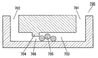
- FIG. 11 is a cross-sectional view of a conventional channel device 700 for detecting hybridization.
- the flow channel device 700 has a flow channel 703 provided with an inlet 701 and a discharge port 702 at both ends, and a weir 704 provided in the flow channel 703.
- a narrow portion 706 is formed by a weir 704 in the channel 703.
- the flow path device 700 is used for detection of DNA hybridization.
- the microbead 705 has a modified nucleotide chain that hybridizes with the DNA to be detected.
- the microbeads 705 flowing in the flow path 703 cannot pass through the constricted portion 706 and are accumulated on the inlet 701 side of the weir 704.
- the user detects the presence or absence of DNA hybridization by observing the microbeads 705 accumulated by the weir 704.
- Non-Patent Document 1 is known as a prior art document related to the invention of the present application.
- the first flow path device includes an input area where a sample is input, a discharge area where the sample is discharged, a cylindrical flow path, and a trap body.
- the circumference of the cylindrical channel is surrounded by a wall surface.
- the trap body is provided in a region between the input region and the discharge region in the flow channel so as to form a narrowed portion in the flow channel.
- the trap body has a side surface facing the charging area side. The area of the side surface of the trap body is larger than the projected area of the side surface projected along the flow path from the trap region input region side to the discharge region side.
- the second flow path device includes an input area where a sample is input, a discharge area where the sample is discharged, a cylindrical flow path, and a trap body.
- the circumference of the cylindrical channel is surrounded by a wall surface.
- the trap body is provided in a region between the input region and the discharge region in the flow channel so as to form a narrowed portion in the flow channel.
- the trap body has a side surface facing the charging area side.
- the side surface of the trap body has a portion that is not parallel to the flow path cross section perpendicular to the flow direction in the region where the trap body is formed.
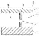
- FIG. 1 is a top view showing a schematic configuration of a flow channel device according to Embodiment 1 of the present invention.
- 1 is a side sectional view showing a schematic configuration of a flow channel device according to Embodiment 1 of the present invention.
- Side sectional view showing the main configuration of the flow channel device shown in FIG. 1B Top view sectional drawing which shows the main structures of the flow-path device shown to FIG. 1A
- Side sectional view which shows typically operation
- FIG. 1A Sectional side view which shows the other trap body in Embodiment 1 of this invention Top view sectional drawing which shows typically operation
- Top view sectional drawing which shows typically operation
- Side sectional view of the flow path device according to Embodiment 5 of the present invention Side sectional view schematically showing a conventional channel device
- the channel device 700 needs to have a nanoscale microstructure.
- the detection target is likely to be clogged in the constricted portion 706, the channel resistance is rapidly increased, and the flow is stagnated.
- a mechanism for generating a high pressure that overcomes the flow path resistance is required, and the chip structure becomes complicated.
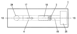
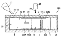
- FIG. 1A is a top view showing a schematic configuration of a flow channel device 1 according to Embodiment 1 of the present invention
- FIG. 1B is a side sectional view taken along line 1B-1B in FIG. 1A.
- the flow path device 1 has a flow path 4 including an input area 15 into which a sample is input and a discharge area 16 from which the sample is discharged.
- the flow path 4 has a cylindrical shape surrounded by a wall surface.
- a trap body 3 is provided in a region between the input region 15 and the discharge region 16 in the flow channel 4 so as to form the narrowed portion 2 in the flow channel 4.
- the trap body 3 has a side surface facing the input region 15 side.
- the area of the side surface of the trap body 3 facing the input region 15 side is larger than the projected area of the side surface of the trap body 3 projected along the flow path 4 from the input region 15 side to the discharge region 16 side.
- the sample flows from the input area 15 toward the discharge area 16.
- the sample is injected from an injection port 24 formed upstream from the input region 15.
- the injected sample is temporarily stored in the storage unit 25.
- the tested sample that has passed through the discharge region 16 is stored in the storage unit 26.
- the user injects a sample to be inspected into the storage unit 25 from the injection port 24 with a dropper 27 or the like.
- the sample is, for example, a biological solution such as blood or saliva.
- the sample stored in the storage unit 25 is input to the input region 15 of the flow path 4 by capillary action or the like.
- the sample put into the flow path 4 flows in the direction of the arrow 17 in the flow path 4, passes through the trap portion 18, is discharged from the discharge region 16, and is stored in the storage portion 26.
- the detection target contained in the sample is trapped in the narrowed portion 2 of the flow path formed by the trap body 3 and accumulated in the trap portion 18.
- the wall forming the flow path 4 is formed of a transparent material such as glass, resin, silicon, or transparent plastic that efficiently transmits light.
- the trap body 3 is made of glass, resin, silicon, transparent plastic, metal or the like. Further, the wall and the trap body 3 may be formed by bonding separately formed ones or integrally formed.
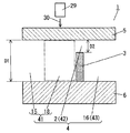
- An electromagnetic wave source 29 is disposed above the upper wall 5, that is, in the direction opposite to the lower wall 6 with respect to the upper wall 5.
- the electromagnetic wave source 29 irradiates the trap portion 18 with the electromagnetic wave 30 from above the upper wall 5.
- the detection object accumulated in the trap unit 18 is detected by, for example, the electromagnetic wave 30 irradiated to the flow path device 1.
- the flow path device 1 or the detection target object reflects or radiates electromagnetic waves such as light.
- the user detects the detection target object by detecting an electromagnetic wave such as light reflected or radiated from the flow path device 1 or the detection target object with a detection unit (not shown).
- the electromagnetic wave 30 is visible light.
- the detection unit is not always necessary, and the detection target in the sample can be detected by detecting the color change or intensity of the electromagnetic wave with the eyes of the user.
- the object to be detected refers to an object that is clogged in the narrowed portion 2 in the flow path 4 and accumulated in the trap portion 18. Specifically, for example, particles having a diameter larger than the constriction part 2 such as beads contained in the sample, or fine particles having a diameter smaller than the constriction part 2 were combined to have a diameter larger than the constriction part 2. Such as aggregates.
- An acceptor that specifically binds to the object to be measured is fixed to the fine particles forming the aggregate.
- An object to be measured is, for example, a virus contained in a sample. If the sample contains a virus, the fine particles to which a specific acceptor is immobilized bind to the virus, form an aggregate, and accumulate in the trap part.
- the fine particles to which the acceptor that specifically binds to the object to be measured in the sample and forms an aggregate are fixed may be disposed on the wall surface in the flow path 4 or may be included in the sample.
- the acceptor refers to a capturing body that specifically binds to the object to be measured, for example, an antibody, a receptor protein, an aptamer, a porphyrin, a polymer produced by a molecular imprinting technique, or the like.
- a filter 28 is disposed between the inlet 24 and the reservoir 25.
- the filter 28 can remove unnecessary materials such as dust mixed in the sample.
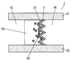
- FIGS. 2A to 6B are side sectional views showing the main configuration of the flow path device 1
- FIG. 2B is a cross-sectional view in top view showing the main configuration of the flow path device 1.
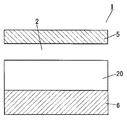
- the flow channel device 1 is provided with an upper wall 5 and a lower wall 6 that are opposed to each other with the flow channel 4 interposed therebetween.
- a trap body 3 that traps a detection target is disposed in the flow channel 4. Is provided.
- the flow channel device 1 is provided with a side wall 21 and a side wall 22 that face each other with the flow channel 4 interposed therebetween. Therefore, the flow path 4 is formed as a cylindrical flow path 4 surrounded by four wall surfaces of the lower surface 5A of the upper wall 5, the upper surface 6A of the lower wall 6, the side surface 21A of the side wall 21, and the side surface 22A of the side wall 22. Yes.
- a narrowed portion 2 is provided in the flow path 4 by an upper wall 5 and a trap body 3.
- the flow path 4 is provided on the input region 15 side with respect to the trap body 3 between the input region 15 into which the sample is input and the discharge region 16 in which the sample is discharged.
- the flow path 4 includes a flow path (first flow path 41) constituted by the input region 15 and the trap part 18, and a flow path (second flow path 42) constituted by the narrowed part 2. And it is comprised by the flow path (3rd flow path 43) comprised by the discharge
- the flow path 4 has a height of the second flow path 42 (a distance between the upper wall 5 and the trap body 3) higher than a height of the first flow path 41 (a distance between the upper wall 5 and the lower wall 6). It is formed to be smaller. That is, in the flow path 4, the height D 1 of the first flow path 41 is larger than the height D 2 of the second flow path 42.
- FIG. 3 shows the trap portion 18 in an enlarged manner.
- the height D2 of the flow path is smaller than the diameter of the detection target 10 to be trapped in the sample.
- the detection target 10 having a diameter larger than D 2 is caught at the entrance of the narrowed portion 2 of the flow channel 4 and accumulated in the trap portion 18. Then, the flow path 4 is blocked by the detection object 10 captured first, and the detection object 10 that flows next is accumulated in the trap unit 18. That is, the detection non-object 11, the medium 12, and the solution that are present in the sample and whose diameter is D 2 or less can pass through the constriction 2, but the detection object 10 whose diameter is larger than D 2 passes through the constriction 2. Can not. Therefore, the detection target 10 having a diameter larger than D2 is accumulated in the trap unit 18.
- the side surface 31 facing the charging region side of the trap body 3 is composed of, for example, a plurality of planes, and a part of the side surface 31 protrudes toward the charging region 15.
- the gap provided here may be a gap larger than the detection target 10 or a small gap.
- the angle formed by the adjacent protrusions is arbitrary. The detection object 10 in the sample is captured at this corner portion.
- the side surface 31 facing the input region 15 side of the trap body 3 is a surface having an outward normal vector on the surface of the trap body 3 having a component in a direction toward the input region 15 side of the flow path 4. Show.
- FIG. 4 shows a projection surface 20 of the side surface 31 facing the input region 15 side of the trap body 3 projected along the flow path from the input region 15 side of the trap body 3 toward the discharge region 16 side.
- the trap body 3 has a side surface S1 projected so that the side area S1 of the side surface 31 of the trap body 3 on the input region 15 side is along the flow path 4 from the input region 15 side of the trap body 3 toward the discharge region 16 side. It is formed to be larger than the area S2 of the projection surface 20.
- the side surface 31 facing the charging region 15 side of the trap body 3 has a portion that is not parallel to the channel cross section perpendicular to the flow direction in the channel 4 in the region where the trap body 3 is formed.
- the side surface 31 of the trap body 3 is parallel to the channel cross section perpendicular to the flow direction in the channel 4, for example, the side surface 201 of the trap body 202 facing the input region 15 shown in FIG. 6B. Point to the shape.
- the position of the narrowed portion 2 provided in the flow path 4 is arranged along the upper wall 5 of the flow path 4, but the present invention is not limited to this. You may arrange
- the flow path 4 was demonstrated using the cylindrical flow path 4 enclosed by four surfaces including the upper and lower walls, the periphery of the flow path 4 is closed by the wall surface in the cross-sectional shape of the flow path 4. As long as it is substantially circular, it may be a polygon such as a triangle or a rectangle.
- FIG. 6A is a top view sectional view showing the operation of the flow path device.
- FIG. 6A is an operation diagram when a sample including the detection target 10 is flowed in the flow channel device 1 shown in FIG. 2B.
- FIG. 6B shows a top cross-sectional view showing the operation of the flow channel device 200.
- the flow channel device 200 has a trap body 202 in the flow channel.
- the trap body 202 has a side surface 201 facing the charging region 215 side.
- the area S4 of the projection surface of the side surface 201 projected along the flow path from the input region 215 side to the discharge region 216 side of the trap body 202 is equal to the side area S3 of the side surface 201.
- the sample including the detection target 10 flowing in the flow path moves toward the trap bodies 3 and 202 from the input regions 15 and 215 side.
- the detection non-target 11, the medium 12, and the solution having a diameter smaller than D2 pass through the constriction 2 as shown in FIG. To the discharge areas 16, 216.
- the detection target 10 having a diameter larger than D2 cannot pass through the constricted portion in the flow path and is accumulated in the trap portions 18 and 218.
- the side surface 201 facing the input region 215 side of the trap body 202 is formed perpendicular to the flow direction of the flow channel, and the flow between the side wall 221 and the side wall 222 is It has an area for the road width.
- the flow path device 1 shown in FIG. 6A has two or more planes on the side surface 31 facing the input region 15 side of the trap body 3. And the flow-path device 1 has the projection part formed by the adjacent plane. In this way, the side surface 31 facing the input region 15 side of the trap body 3 is formed by two or more planes, and the protrusion is formed by the adjacent plane, thereby facing the input region 15 side of the trap body 3.
- the side surface 31 has an area larger than the flow path width.
- the area S2 of the projection surface of the side surface 31 shown in FIG. 6A is equal to the area S4 of the projection surface of the side surface 201 shown in FIG. 6B, the area S1 of the side surface of the trap body on the injection region 15 side is larger than S3.
- the detection object 10 When the diameter of the detection object 10 is smaller than the gap between the tips of the adjacent protrusions of the trap body 3, the detection object 10 enters the corner portion. Further, the detection target 10 is less likely to be clogged in the vicinity of the tip of the protruding portion that protrudes toward the charging region 15 of the trap body 3. As described above, the trap body 3 has a portion where the detection target 10 is easily clogged in the narrowed portion 2 and a portion where clogging is difficult. Therefore, the trap body 3 can leave more passages of the sample of the constricted portion 2 as compared with the trap body 202 having the straight side surface 201 provided perpendicular to the flow direction shown in FIG. 6B. .
- the sample can flow from the input region 15 side to the discharge region 16 side even when the detection target 10 is trapped in the trap body 3 to some extent. . Therefore, more detection objects 10 can be captured by the trap unit 18.
- the detection target 10 When the diameter of the detection target 10 is larger than the gap between the tips of adjacent protrusions of the trap body 3, the detection target 10 does not enter the gap of the trap body 3 and is captured at the tip of the protrusion. In this case, the sample can go around from the vertical direction of the detection target 10 and pass through the narrowed portion 2. Therefore, an increase in channel resistance due to clogging of the sample can be suppressed. By suppressing the rapid increase in channel resistance, the sample can flow from the input region 15 side to the discharge region 16 side even when the detection target 10 is trapped in the trap body 3 to some extent. . Therefore, more detection objects 10 can be captured by the trap unit 18.
- the detection sensitivity of the detection target object 10 is improved, and detection with a simpler detection device becomes possible.
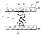
- FIG. 7 is a top view cross-sectional view of the flow channel device 300. Note that in this embodiment, the same parts as those in Embodiment 1 are denoted by the same reference numerals, and description thereof may be omitted.
- the side surface 301 facing the input region 15 side of the trap body 302 included in the flow path device 300 is a corrugated surface.
- One or more waveforms may be used. In FIG. 7, all of the side surfaces 301 have a waveform, but only a part may have a waveform. That is, the trap body 302 has a wavy line at the end of the side surface 301 facing the constriction 2.
- the interval between the waves formed on the side surface 301 of the trap body 302 may be larger or smaller than the detection target 10. Further, the waves formed on the side surface 301 may be all at the same interval or at different intervals.
- the trap body 302 is a projection of the side surface 301 projected so that the side area S5 of the side surface 301 on the input region 15 side of the trap body 302 is along the flow path 4 from the input region 15 side of the trap body 302 toward the discharge region 16 side. It is formed to be larger than the surface area S6.
- the side surface 301 has an area S5 larger than the flow channel width between the side wall 21 and the side wall 22 by making the side surface 301 a corrugated surface. That is, when the area S6 of the projection surface of the side surface 301 shown in FIG. 7 is equal to the area S4 of the projection surface of the side surface 201 shown in FIG. 6B, the area S5 of the side surface on the input region 15 side of the trap body 302 is larger than the area S3. large.
- the detection object 10 When the diameter of the detection object 10 is smaller than the interval between the waves formed on the side surface 301, the detection object 10 enters the recess. However, the detection target 10 is less likely to be clogged in the vicinity of the convex portion that protrudes toward the charging region 15 of the trap body 302.
- the concave portion of the trap body 302 is a portion where a wave protrudes toward the discharge region 16, and the convex portion indicates a portion where the wave protrudes toward the input region 15.
- the trap body 302 has a portion where the detection target 10 is likely to be clogged in the narrowed portion 2 and a portion where clogging is difficult.
- the trap body 302 can leave more passages of the sample of the constricted portion 2 as compared with the trap body 202 having the straight side surface 201 provided perpendicular to the flow direction shown in FIG. 6B. . Therefore, an increase in channel resistance due to clogging of the sample can be suppressed. By suppressing the rapid increase in channel resistance, the sample can flow from the input region 15 side to the discharge region 16 side even when the detection target 10 is trapped to some extent by the trap body 302. . Therefore, more detection objects 10 can be captured by the trap unit 18.
- the detection target 10 When the diameter of the detection target 10 is larger than the interval between the waves formed on the side surface 301, the detection target 10 does not enter the concave portion of the trap body 302 and is captured by the adjacent convex portion. In this case, the sample can go around from the vertical direction of the detection target 10 and pass through the narrowed portion 2. Therefore, an increase in channel resistance due to clogging of the sample can be suppressed. By suppressing the rapid increase in channel resistance, the sample can flow from the input region 15 side to the discharge region 16 side even when the detection target 10 is trapped to some extent by the trap body 302. . Therefore, more detection objects 10 can be captured by the trap unit 18.
- the detection sensitivity of the detection target object 10 is improved, and detection with a simpler detection device becomes possible.
- FIG. 8 is a top view cross-sectional view of the flow channel device 400. Note that in this embodiment, the same parts as those in Embodiment 1 are denoted by the same reference numerals, and description thereof may be omitted.
- the side surface 401 facing the input region 15 of the trap body 402 included in the flow path device 400 has a curved surface. That is, the trap body 402 has a curved end at the side surface 401 facing the constriction 2.
- the curved surface is, for example, a semi-cylindrical shape or a hemispherical shape.
- the side surface 401 facing the trap body input region side has a convex curved surface on the discharge region 16 side, but the shape of the curved surface is not limited to this.
- the side surface 401 facing the charging region side of the trap body may have a convex curved surface on the charging region side.
- the side surface 401 facing the trap body input region side may have a configuration in which a curved surface is partially formed or a configuration in which a plurality of curved surfaces are formed.
- the trap body 402 is a projection of the side surface 401 projected such that the side area S7 of the side surface 401 of the trap body 402 on the input region 15 side is along the flow path 4 from the input region 15 side of the trap body 402 toward the discharge region 16 side. It is formed to be larger than the surface area S8.
- the side surface 401 has a larger area than the channel width between the side wall 21 and the side wall 22 by making the side surface 401 a curved surface. That is, when the area S8 of the projection surface of the side surface 401 shown in FIG. 8 is equal to the area S4 of the projection surface of the side surface 201 shown in FIG. 6B, the area S7 of the side surface on the injection region 15 side of the trap body 402 is larger than the area S3. .
- the detection target 10 enters the recess. Therefore, the detection target 10 is less likely to be clogged near the side walls 21 and 22 of the side surface 401.
- the concave portion of the trap body 402 indicates a portion where a curved surface protrudes toward the discharge region 16 side.
- the trap body 402 has a portion where the detection target 10 is likely to be clogged in the narrowed portion 2 and a portion where clogging is difficult. Therefore, the trap body 402 can leave more passages of the sample of the narrowed portion 2 as compared with the trap body 202 having the straight side surface 201 provided perpendicular to the flow direction shown in FIG. 6B. .
- the sample can flow from the input region 15 side to the discharge region 16 side even when the detection target 10 is trapped in the trap body 402 to some extent. Therefore, more detection objects 10 can be captured by the trap unit 18.
- the detection target object 10 is the concave portion of the trap body 302. Don't get in.
- the sample can go around from the vertical direction of the detection target 10 and pass through the narrowed portion 2. Therefore, an increase in channel resistance due to clogging of the sample can be suppressed.
- the sample can flow from the input region 15 side to the discharge region 16 side even when the detection target 10 is trapped in the trap body 402 to some extent. Therefore, more detection objects 10 can be captured by the trap unit 18.
- the detection sensitivity of the detection target object 10 is improved, and detection with a simpler detection device becomes possible.
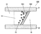
- FIG. 9 is a top cross-sectional view of the flow channel device 500. Note that in this embodiment, the same parts as those in Embodiment 1 are denoted by the same reference numerals, and description thereof may be omitted.
- the side surface 501 facing the input region side of the trap body 502 included in the flow path device 500 has a slope.
- the fact that the side surface 501 facing the input region side of the trap body 502 has an inclined surface means that it has a plane that is not parallel to the cross section of the flow path perpendicular to the flow direction in the flow path 4.
- the slope formed on the side surface 501 may be the whole or a part. That is, the side surface 501 has a portion that is not parallel to the flow path cross section perpendicular to the flow direction in the region where the trap body is formed.
- the trap body 502 is a projection of the side surface 501 projected so that the side area S9 of the side surface 501 of the trap body 502 on the input region 15 side is along the flow path 4 from the input region 15 side of the trap body 502 toward the discharge region 16 side. It is formed to be larger than the surface area S10.
- the side surface 501 facing the input region 15 side of the trap body 502 is formed between the side wall 21 and the side wall 22 by forming the side surface 501 facing the input region 15 side of the trap body 502 as an inclined surface. It has an area larger than the flow path width. That is, when the area S10 of the projection surface of the side surface 501 shown in FIG. 9 is equal to the area S4 of the projection surface of the side surface 201 shown in FIG. 6B, the area S9 of the side surface on the injection region 15 side of the trap body 502 is larger than the area S3. large.
- the detection object 10 When the side surface 501 is an inclined surface, the detection object 10 is likely to be clogged on the side wall 21 side in the portion of the side surface 501 entering the discharge region 16 side. However, the detection object 10 is less likely to be clogged at the portion of the side surface 401 that protrudes toward the input region 15.
- the portion of the side surface 501 that enters the discharge region 16 side indicates the vicinity of the side wall 21 of the slope, and the portion that protrudes toward the input region 15 indicates the vicinity of the side wall 22 of the slope.
- the trap body 502 has a portion where the detection target 10 is likely to be clogged in the narrowed portion 2 and a portion where clogging is difficult.
- the trap body 502 can leave more passages of the sample in the constricted portion 2 as compared with the trap body 202 having the straight side surface 201 provided perpendicular to the flow direction shown in FIG. 6B. . Therefore, an increase in channel resistance due to clogging of the sample can be suppressed. By suppressing the rapid increase in channel resistance, the sample can flow from the input region 15 side to the discharge region 16 side even when the detection target 10 is trapped in the trap body 502 to some extent. Therefore, more detection objects 10 can be captured by the trap unit 18.
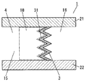
- FIG. 10 is a side cross-sectional view of the flow path device 600 in the present embodiment. Note that in this embodiment, the same parts as those in Embodiment 1 are denoted by the same reference numerals, and description thereof may be omitted.
- the flow path device 600 includes a flow path 4, a trap body 3, a metal layer 601 provided on the upper wall of the flow path 4, and a metal layer 602 provided on the lower wall of the flow path 4.
- the trap body 3 has the same structure as any of the trap bodies of the first to fourth embodiments.
- the metal layer 602 is disposed so as to face the metal layer 601 through the flow path 4.
- the flow path device 600 has the metal layers 601 and 602 formed on part of the wall surface.
- the metal layers 601 and 602 are made of gold, silver, or the like.
- the electromagnetic wave source 29 is disposed above the metal layer 601, that is, in the direction opposite to the metal layer 602 with respect to the metal layer 601.
- the electromagnetic wave source 29 irradiates the metal layer 601 with the electromagnetic wave 30 from above the metal layer 601.
- the metal layers 601 and 602 reflect the electromagnetic waves 30 incident on the upper side and the lower side of the flow path 4, respectively.
- the user can detect the detection object by detecting the interference between the two reflected electromagnetic waves.
- the metal layer 601 has a thickness of approximately 100 nm or less.
- the electromagnetic wave 30 incident from the upper surface of the metal layer 601 is visible light.
- the metal layer 601 preferably has a film thickness in the range of 35 nm to 45 nm.
- the metal layer 602 When the metal layer 602 is made of gold, the metal layer 602 desirably has a thickness of 100 nm or more. This is because when the film thickness is less than 100 nm, the incident electromagnetic wave (visible light) passes through the metal layer 602 and the intensity of the electromagnetic wave reflected in the flow path is reduced.
- a part of the electromagnetic wave applied to the upper surface 601A from above the metal layer 601 at an incident angle ⁇ (the angle between the vertical direction of the metal layer 601 and the incident direction of the electromagnetic wave is ⁇ ) is on the upper surface 601A and the lower surface 601B.
- the light is reflected and propagates upward from the metal layer 601 in the direction of the reflection angle ⁇ .
- the electromagnetic waves incident from above the metal layer 601 the electromagnetic waves reflected by the metal layer 601 and propagating upward from the metal layer 601 in the direction of the angle ⁇ are referred to as first electromagnetic waves.
- the electromagnetic waves not reflected by the upper surface 601A and the lower surface 601B of the metal layer 601 are transmitted through the metal layer 601 and propagated through the flow path 4, and reach the upper surface 602A of the metal layer 602.
- the thickness of the metal layer 602 is sufficiently thick, such as 200 nm or more, all of the electromagnetic waves that have arrived from above the metal layer 602 are reflected by the metal layer 602 and propagate again in the flow path 4 toward the lower surface 601B of the metal layer 601.
- a part of the electromagnetic wave reaching the lower surface 601B of the metal layer 601 passes through the metal layer 601 and propagates upward from the metal layer 601 in the direction of the angle ⁇ .
- an electromagnetic wave that passes through the metal layer 601 from the flow path 4 and propagates upward from the metal layer 601 in the direction of the angle ⁇ is referred to as a second electromagnetic wave.
- Such interference conditions mainly include the thickness of the metal layer 601 and the metal layer 602, the distance between the metal layer 601 and the metal layer 602, the refractive index of the metal layer 601, the refractive index of the metal layer 602, the flow path 4 It can be controlled by the refractive index.
- a detection unit (not shown) for detecting electromagnetic waves such as light is disposed above the upper surface 601A of the metal layer 601.
- the detection unit receives an electromagnetic wave such as light reflected or radiated from the flow path device 1.
- the detection unit is not necessarily required.
- the electromagnetic wave is visible light, the color change and intensity of the electromagnetic wave can be detected by the user's own eyes. Thereby, a simple and inexpensive sensor device can be constructed.
- the trap bodies 3, 302, 402, and 502 shown in the second to fifth embodiments are formed of glass, resin, silicon, transparent plastic, metal, or the like as in the first embodiment. Further, the wall surface and the trap bodies 302, 402, 502 may be formed by bonding separately formed ones or integrally formed.
- the side surfaces of the trap bodies 3, 302, 402, and 502 on the discharge region 16 side are described in accordance with the side surface shape on the input region 15 side.
- the present invention is not limited to these. Absent.
- the side surface on the discharge region side may be a plane perpendicular to the cross section of the flow path.
- the fine particles to which the acceptor that specifically binds to the measurement object in the sample and forms an aggregate are fixed are arranged on the wall surface in the channel 4. Or may be contained in the sample.
- the flow channel device is capable of accumulating detection particles in a wide range with a simple configuration, and thus has high detection sensitivity and can be used for a low-cost biosensor or the like.
- Electromagnetic wave source 30 Electromagnetic wave 31, 201, 301 , 401, 501 Side surface 41 First flow channel 42 Second flow channel 43 Third flow channel 601, 602 Metal layer
Landscapes
- Chemical & Material Sciences (AREA)
- Health & Medical Sciences (AREA)
- General Health & Medical Sciences (AREA)
- Analytical Chemistry (AREA)
- Hematology (AREA)
- Clinical Laboratory Science (AREA)
- Chemical Kinetics & Catalysis (AREA)
- Molecular Biology (AREA)
- Dispersion Chemistry (AREA)
- Life Sciences & Earth Sciences (AREA)
- Optical Measuring Cells (AREA)
- Automatic Analysis And Handling Materials Therefor (AREA)
- Apparatus Associated With Microorganisms And Enzymes (AREA)
Abstract
Description
図1Aは、本発明の実施の形態1における流路デバイス1の概略構成を示す上面図、図1Bは、図1Aの1B-1B線における側断面図である。 (Embodiment 1)
1A is a top view showing a schematic configuration of a
次に、本発明の実施の形態2における流路デバイス300について、図7を参照しながら説明する。図7は、流路デバイス300の上面視断面図である。なお、本実施の形態において、実施の形態1と同様の部分については同様の符号を用い、説明を省略する場合がある。 (Embodiment 2)
Next, the
次に、本発明の実施の形態3における流路デバイス400について、図8を参照しながら説明する。図8は、流路デバイス400の上面視断面図である。なお、本実施の形態において、実施の形態1と同様の部分については同様の符号を用い、説明を省略する場合がある。 (Embodiment 3)
Next, the
次に、本発明の実施の形態4における流路デバイス500について、図9を参照しながら説明する。図9は、流路デバイス500の上面視断面図である。なお、本実施の形態において、実施の形態1と同様の部分については同様の符号を用い、説明を省略する場合がある。 (Embodiment 4)
Next, the
次に、本発明の実施の形態5における流路デバイス600について、図10を参照しながら説明する。図10は、本実施の形態における流路デバイス600の側断面図である。なお、本実施の形態において、実施の形態1と同様の部分については同様の符号を用い、説明を省略する場合がある。 (Embodiment 5)
Next, a

2 狭窄部
3,202,302,402,502 トラップ体
4 流路
5 上壁
6 下壁
10 検出対象物
11 検出非対象物
12 媒質
15,215 投入領域
16,216 排出領域
17 矢印
18 トラップ部
21,22,221,222 側壁
21A,22A 側面
20 投影面
24 注入口
25,26 貯留部
27 スポイト
28 フィルタ
29 電磁波源
30 電磁波
31,201,301,401,501 側面
41 第1の流路
42 第2の流路
43 第3の流路
601,602 金属層
Claims (22)
- 試料が投入される投入領域と、
前記試料が排出される排出領域と、を有し、
周囲が壁面に囲まれた筒状の流路と、
前記流路内の前記投入領域と前記排出領域との間の領域に、前記流路内に狭窄部を形成するように設けられたトラップ体と、を備え、
前記トラップ体は、前記投入領域側に面した側面を有し、
前記トラップ体の前記側面の面積は、前記トラップ体の前記投入領域側から前記排出領域側へ向かって流路に沿うように投影した前記側面の投影面積よりも大きい
流路デバイス。 A loading area where a sample is loaded;
A discharge area from which the sample is discharged;
A cylindrical channel surrounded by a wall,
A trap body provided in a region between the input region and the discharge region in the flow channel so as to form a narrowed portion in the flow channel,
The trap body has a side surface facing the charging area side,
The flow path device in which the area of the side surface of the trap body is larger than the projected area of the side surface projected along the flow path from the input region side to the discharge region side of the trap body. - 前記側面が、2つ以上の平面を有する請求項1に記載の流路デバイス。 The flow channel device according to claim 1, wherein the side surface has two or more planes.
- 前記狭窄部に面した前記側面の端部が、波線を有する請求項1に記載の流路デバイス。 The flow path device according to claim 1, wherein an end portion of the side surface facing the narrowed portion has a wavy line.
- 前記狭窄部に面した前記側面の端部が、曲線を有する請求項1に記載の流路デバイス。 The flow path device according to claim 1, wherein an end portion of the side surface facing the narrowed portion has a curved line.
- 前記トラップ体と前記壁面が一体形成されている請求項1に記載の流路デバイス。 The flow channel device according to claim 1, wherein the trap body and the wall surface are integrally formed.
- 前記壁面の一部に金属層が形成された請求項1に記載の流路デバイス。 The flow channel device according to claim 1, wherein a metal layer is formed on a part of the wall surface.
- 前記試料は、生体由来の溶液である請求項1に記載の流路デバイス。 The flow channel device according to claim 1, wherein the sample is a solution derived from a living body.
- 前記試料は、試料中の被測定物と特異的に結合し凝集体を形成するアクセプタを固定した微粒子を含む請求項1に記載の流路デバイス。 The flow channel device according to claim 1, wherein the sample includes fine particles to which an acceptor that specifically binds to an object to be measured and forms an aggregate is fixed.
- 前記狭窄部は、前記微粒子より大きく、前記凝集体より小さい請求項8に記載の流路デバイス。 The flow path device according to claim 8, wherein the narrowed portion is larger than the fine particles and smaller than the aggregate.
- 前記試料中の被測定物と特異的に結合し凝集体を形成するアクセプタを固定した微粒子は、前記壁面に配置された請求項1に記載の流路デバイス。 The flow channel device according to claim 1, wherein fine particles to which an acceptor that specifically binds to an object to be measured and forms an aggregate in the sample are fixed are arranged on the wall surface.
- 前記狭窄部は、前記微粒子より大きく、前記凝集体より小さい請求項10に記載の流路デバイス。 The flow path device according to claim 10, wherein the narrowed portion is larger than the fine particles and smaller than the aggregate.
- 試料が投入される投入領域と、
前記試料が排出される排出領域と、を有し、
周囲が壁面に囲まれた筒状の流路と、
前記流路内の前記投入領域と前記排出領域との間の領域に、前記流路内に狭窄部を形成するように設けられたトラップ体と、を備え、
前記トラップ体は、前記投入領域側に面した側面を有し、
前記トラップ体の前記側面は、前記トラップ体が形成された前記領域における流れ方向に垂直な流路断面に平行でない部分を有する
流路デバイス。 A loading area where a sample is loaded;
A discharge area from which the sample is discharged;
A cylindrical channel surrounded by a wall,
A trap body provided in a region between the input region and the discharge region in the flow channel so as to form a narrowed portion in the flow channel,
The trap body has a side surface facing the charging area side,
The flow channel device, wherein the side surface of the trap body has a portion that is not parallel to a flow channel cross section perpendicular to the flow direction in the region where the trap body is formed. - 前記側面が、2つ以上の平面を有する請求項12に記載の流路デバイス。 The flow channel device according to claim 12, wherein the side surface has two or more planes.
- 前記狭窄部に面した前記側面の端部が、波線を有する請求項12に記載の流路デバイス。 The flow path device according to claim 12, wherein an end portion of the side surface facing the narrowed portion has a wavy line.
- 前記狭窄部に面した前記側面の端部が、曲線を有する請求項12に記載の流路デバイス。 The flow path device according to claim 12, wherein an end portion of the side surface facing the constriction portion has a curved line.
- 前記トラップ体と前記壁面が一体成形されている請求項12に記載の流路デバイス。 The flow path device according to claim 12, wherein the trap body and the wall surface are integrally formed.
- 前記壁面の一部に金属層が形成された請求項12に記載の流路デバイス。 The flow channel device according to claim 12, wherein a metal layer is formed on a part of the wall surface.
- 前記試料は、生体由来の溶液である請求項12に記載の流路デバイス。 The flow channel device according to claim 12, wherein the sample is a solution derived from a living body.
- 前記試料は、試料中の被測定物と特異的に結合し凝集体を形成するアクセプタを固定した微粒子を含む請求項12に記載の流路デバイス。 The flow channel device according to claim 12, wherein the sample includes fine particles to which an acceptor that specifically binds to an object to be measured and forms an aggregate is fixed.
- 前記狭窄部は、前記微粒子より大きく、前記凝集体より小さい請求項19に記載の流路デバイス。 The channel device according to claim 19, wherein the narrowed portion is larger than the fine particles and smaller than the aggregate.
- 試料中の被測定物と特異的に結合し凝集体を形成するアクセプタを固定した微粒子は、前記壁面に配置された請求項12に記載の流路デバイス。 The flow channel device according to claim 12, wherein fine particles to which an acceptor that specifically binds to an object to be measured in a sample and forms an aggregate are fixed are arranged on the wall surface.
- 前記狭窄部は、前記微粒子より大きく、前記凝集体より小さい請求項21に記載の流路デバイス。 The flow path device according to claim 21, wherein the narrowed portion is larger than the fine particles and smaller than the aggregate.
Priority Applications (2)
| Application Number | Priority Date | Filing Date | Title |
|---|---|---|---|
| US14/759,166 US20150343437A1 (en) | 2013-01-07 | 2013-12-26 | Duct device |
| JP2014555398A JPWO2014106881A1 (en) | 2013-01-07 | 2013-12-26 | Channel device |
Applications Claiming Priority (2)
| Application Number | Priority Date | Filing Date | Title |
|---|---|---|---|
| JP2013-000301 | 2013-01-07 | ||
| JP2013000301 | 2013-01-07 |
Publications (1)
| Publication Number | Publication Date |
|---|---|
| WO2014106881A1 true WO2014106881A1 (en) | 2014-07-10 |
Family
ID=51062206
Family Applications (1)
| Application Number | Title | Priority Date | Filing Date |
|---|---|---|---|
| PCT/JP2013/007618 WO2014106881A1 (en) | 2013-01-07 | 2013-12-26 | Duct device |
Country Status (3)
| Country | Link |
|---|---|
| US (1) | US20150343437A1 (en) |
| JP (1) | JPWO2014106881A1 (en) |
| WO (1) | WO2014106881A1 (en) |
Families Citing this family (2)
| Publication number | Priority date | Publication date | Assignee | Title |
|---|---|---|---|---|
| JPWO2014174807A1 (en) * | 2013-04-25 | 2017-02-23 | パナソニックIpマネジメント株式会社 | Flow path device and detection method using the same |
| CA2975423A1 (en) * | 2015-01-30 | 2016-08-04 | Hewlett-Packard Development Company, L.P. | Fluid testing chip and cassette |
Citations (9)
| Publication number | Priority date | Publication date | Assignee | Title |
|---|---|---|---|---|
| JP2001004628A (en) * | 1999-06-18 | 2001-01-12 | Kanagawa Acad Of Sci & Technol | Immunoassay and its method |
| WO2003062823A1 (en) * | 2002-01-24 | 2003-07-31 | Kanagawa Academy Of Science And Technology | Chip and method for analyzing enzyme immunity |
| WO2006016617A1 (en) * | 2004-08-11 | 2006-02-16 | Japan Science And Technology Agency | Method of quantifying substance and device for quantifying substance |
| WO2008010677A1 (en) * | 2006-07-20 | 2008-01-24 | Seoulin Bioscience Co., Ltd. | Microchip for protein fixation |
| JP2008215960A (en) * | 2007-03-01 | 2008-09-18 | Research Institute Of Biomolecule Metrology Co Ltd | Inspection kit |
| JP2009505634A (en) * | 2005-08-31 | 2009-02-12 | 日産化学工業株式会社 | Microchip for cell response evaluation |
| JP2009209094A (en) * | 2008-03-04 | 2009-09-17 | Sharp Corp | Microchip for protein extraction, protein extraction apparatus, protein measurement apparatus, protein extraction method using them, and air conditioner |
| JP2011145276A (en) * | 2009-12-16 | 2011-07-28 | Sony Corp | Cell for testing microbeads and method of analyzing microbeads |
| JP2011525109A (en) * | 2008-06-20 | 2011-09-15 | インターナショナル・ビジネス・マシーンズ・コーポレーション | System and method for selecting library elements and method for manufacturing a microfluidic device (microfluidic selection of library elements) |
Family Cites Families (3)
| Publication number | Priority date | Publication date | Assignee | Title |
|---|---|---|---|---|
| JP3380744B2 (en) * | 1998-05-19 | 2003-02-24 | 株式会社日立製作所 | Sensor and measuring device using the same |
| US8241570B1 (en) * | 2011-02-03 | 2012-08-14 | I Shou University | Flow cell device |
| US8358419B2 (en) * | 2011-04-05 | 2013-01-22 | Integrated Plasmonics Corporation | Integrated plasmonic sensing device and apparatus |
-
2013
- 2013-12-26 WO PCT/JP2013/007618 patent/WO2014106881A1/en active Application Filing
- 2013-12-26 JP JP2014555398A patent/JPWO2014106881A1/en active Pending
- 2013-12-26 US US14/759,166 patent/US20150343437A1/en not_active Abandoned
Patent Citations (9)
| Publication number | Priority date | Publication date | Assignee | Title |
|---|---|---|---|---|
| JP2001004628A (en) * | 1999-06-18 | 2001-01-12 | Kanagawa Acad Of Sci & Technol | Immunoassay and its method |
| WO2003062823A1 (en) * | 2002-01-24 | 2003-07-31 | Kanagawa Academy Of Science And Technology | Chip and method for analyzing enzyme immunity |
| WO2006016617A1 (en) * | 2004-08-11 | 2006-02-16 | Japan Science And Technology Agency | Method of quantifying substance and device for quantifying substance |
| JP2009505634A (en) * | 2005-08-31 | 2009-02-12 | 日産化学工業株式会社 | Microchip for cell response evaluation |
| WO2008010677A1 (en) * | 2006-07-20 | 2008-01-24 | Seoulin Bioscience Co., Ltd. | Microchip for protein fixation |
| JP2008215960A (en) * | 2007-03-01 | 2008-09-18 | Research Institute Of Biomolecule Metrology Co Ltd | Inspection kit |
| JP2009209094A (en) * | 2008-03-04 | 2009-09-17 | Sharp Corp | Microchip for protein extraction, protein extraction apparatus, protein measurement apparatus, protein extraction method using them, and air conditioner |
| JP2011525109A (en) * | 2008-06-20 | 2011-09-15 | インターナショナル・ビジネス・マシーンズ・コーポレーション | System and method for selecting library elements and method for manufacturing a microfluidic device (microfluidic selection of library elements) |
| JP2011145276A (en) * | 2009-12-16 | 2011-07-28 | Sony Corp | Cell for testing microbeads and method of analyzing microbeads |
Also Published As
| Publication number | Publication date |
|---|---|
| US20150343437A1 (en) | 2015-12-03 |
| JPWO2014106881A1 (en) | 2017-01-19 |
Similar Documents
| Publication | Publication Date | Title |
|---|---|---|
| Soler et al. | Principles, technologies, and applications of plasmonic biosensors | |
| US7385460B1 (en) | Combined electrostatic and optical waveguide based microfluidic chip systems and methods | |
| KR102394394B1 (en) | Membrane carrier for liquid sample test kit, liquid sample test kit and manufacturing method of liquid sample test kit | |
| Krupin et al. | Long-range surface plasmon-polariton waveguide biosensors for disease detection | |
| JP2013137267A (en) | Microchip and microchip-type fine-particle measuring device | |
| KR20180054828A (en) | Immunoassay | |
| WO2014106881A1 (en) | Duct device | |
| KR20100009347A (en) | An immunochromatography detection sensor comprising optical waveguide and a detection method using the same | |
| JP6664741B2 (en) | Optical measuring method and measuring device | |
| JP2019516993A (en) | Biosensor and sample analysis method using the same | |
| Salieb-Beugelaar et al. | Towards nano-diagnostics for rapid diagnosis of infectious diseases–current technological state | |
| JP5315381B2 (en) | Fluorescence detection apparatus, sample cell for fluorescence detection, and fluorescence detection method | |
| JPWO2020066369A1 (en) | Membrane carrier for test kit and test kit | |
| JP6019415B2 (en) | Sensor device | |
| JP6386062B2 (en) | Fluorescence detection method and detection sample cell | |
| WO2012132313A1 (en) | Immunoassay device | |
| KR102553911B1 (en) | Membrane carriers and test kits | |
| JP2009175108A (en) | Assay-use micro-channel device | |
| US20220214339A1 (en) | Membrane carrier and test kit | |
| US10024848B2 (en) | Flow channel device and detection method using same | |
| JP2014025879A (en) | Sensor chip and optical device for detecting specimen having the sensor chip | |
| JP2012145516A (en) | Measuring apparatus and sensor chip | |
| JP5556139B2 (en) | Surface plasmon resonance sensing system and surface plasmon resonance in-line measurement method | |
| KR101142793B1 (en) | A microfluidic device comprising a microchannel wherein a protrusion is formed on a bottom surface | |
| Ning et al. | Detection of influenza virus with specific subtype by using localized surface plasmons excited on a flat metal surface |
Legal Events
| Date | Code | Title | Description |
|---|---|---|---|
| 121 | Ep: the epo has been informed by wipo that ep was designated in this application |
Ref document number: 13870224 Country of ref document: EP Kind code of ref document: A1 |
|
| ENP | Entry into the national phase |
Ref document number: 2014555398 Country of ref document: JP Kind code of ref document: A |
|
| WWE | Wipo information: entry into national phase |
Ref document number: 14759166 Country of ref document: US |
|
| NENP | Non-entry into the national phase |
Ref country code: DE |
|
| 122 | Ep: pct application non-entry in european phase |
Ref document number: 13870224 Country of ref document: EP Kind code of ref document: A1 |