WO2014088676A1 - Simultaneous transmit and receive (str) structures immune to phase and amplitude imbalances - Google Patents
Simultaneous transmit and receive (str) structures immune to phase and amplitude imbalances Download PDFInfo
- Publication number
- WO2014088676A1 WO2014088676A1 PCT/US2013/060445 US2013060445W WO2014088676A1 WO 2014088676 A1 WO2014088676 A1 WO 2014088676A1 US 2013060445 W US2013060445 W US 2013060445W WO 2014088676 A1 WO2014088676 A1 WO 2014088676A1
- Authority
- WO
- WIPO (PCT)
- Prior art keywords
- signal
- phase
- echo
- phase shifter
- transmit
- Prior art date
Links
- 230000010363 phase shift Effects 0.000 claims abstract description 35
- 238000004364 calculation method Methods 0.000 claims abstract description 25
- 239000013598 vector Substances 0.000 claims description 68
- 238000000034 method Methods 0.000 claims description 30
- 230000007774 longterm Effects 0.000 claims description 5
- GVVPGTZRZFNKDS-JXMROGBWSA-N geranyl diphosphate Chemical compound CC(C)=CCC\C(C)=C\CO[P@](O)(=O)OP(O)(O)=O GVVPGTZRZFNKDS-JXMROGBWSA-N 0.000 claims description 4
- 230000001413 cellular effect Effects 0.000 claims description 3
- 238000010586 diagram Methods 0.000 description 15
- 230000006870 function Effects 0.000 description 10
- 230000002238 attenuated effect Effects 0.000 description 4
- 238000013459 approach Methods 0.000 description 3
- 230000005540 biological transmission Effects 0.000 description 3
- 238000007906 compression Methods 0.000 description 3
- 230000006835 compression Effects 0.000 description 2
- 230000001934 delay Effects 0.000 description 2
- 238000004519 manufacturing process Methods 0.000 description 2
- 239000000463 material Substances 0.000 description 2
- 238000005259 measurement Methods 0.000 description 2
- 238000012545 processing Methods 0.000 description 2
- 238000007789 sealing Methods 0.000 description 2
- 230000011664 signaling Effects 0.000 description 2
- 208000015976 Corneal dystrophy-perceptive deafness syndrome Diseases 0.000 description 1
- 241000283986 Lepus Species 0.000 description 1
- 150000004770 chalcogenides Chemical class 0.000 description 1
- 239000003795 chemical substances by application Substances 0.000 description 1
- 238000004891 communication Methods 0.000 description 1
- 230000006837 decompression Effects 0.000 description 1
- 230000001419 dependent effect Effects 0.000 description 1
- 238000001514 detection method Methods 0.000 description 1
- 238000005516 engineering process Methods 0.000 description 1
- 230000007613 environmental effect Effects 0.000 description 1
- 238000012423 maintenance Methods 0.000 description 1
- 238000012986 modification Methods 0.000 description 1
- 230000004048 modification Effects 0.000 description 1
- 230000003287 optical effect Effects 0.000 description 1
- 239000004065 semiconductor Substances 0.000 description 1
- 230000001360 synchronised effect Effects 0.000 description 1
- 238000012546 transfer Methods 0.000 description 1
Classifications
-
- H—ELECTRICITY
- H04—ELECTRIC COMMUNICATION TECHNIQUE
- H04J—MULTIPLEX COMMUNICATION
- H04J11/00—Orthogonal multiplex systems, e.g. using WALSH codes
- H04J11/0069—Cell search, i.e. determining cell identity [cell-ID]
-
- H—ELECTRICITY
- H04—ELECTRIC COMMUNICATION TECHNIQUE
- H04W—WIRELESS COMMUNICATION NETWORKS
- H04W56/00—Synchronisation arrangements
-
- H—ELECTRICITY
- H04—ELECTRIC COMMUNICATION TECHNIQUE
- H04W—WIRELESS COMMUNICATION NETWORKS
- H04W72/00—Local resource management
- H04W72/50—Allocation or scheduling criteria for wireless resources
- H04W72/54—Allocation or scheduling criteria for wireless resources based on quality criteria
- H04W72/542—Allocation or scheduling criteria for wireless resources based on quality criteria using measured or perceived quality
-
- H—ELECTRICITY
- H04—ELECTRIC COMMUNICATION TECHNIQUE
- H04B—TRANSMISSION
- H04B3/00—Line transmission systems
- H04B3/02—Details
- H04B3/20—Reducing echo effects or singing; Opening or closing transmitting path; Conditioning for transmission in one direction or the other
- H04B3/23—Reducing echo effects or singing; Opening or closing transmitting path; Conditioning for transmission in one direction or the other using a replica of transmitted signal in the time domain, e.g. echo cancellers
- H04B3/232—Reducing echo effects or singing; Opening or closing transmitting path; Conditioning for transmission in one direction or the other using a replica of transmitted signal in the time domain, e.g. echo cancellers using phase shift, phase roll or frequency offset correction
-
- H—ELECTRICITY
- H04—ELECTRIC COMMUNICATION TECHNIQUE
- H04B—TRANSMISSION
- H04B7/00—Radio transmission systems, i.e. using radiation field
- H04B7/015—Reducing echo effects
-
- H—ELECTRICITY
- H04—ELECTRIC COMMUNICATION TECHNIQUE
- H04J—MULTIPLEX COMMUNICATION
- H04J13/00—Code division multiplex systems
- H04J13/0003—Code application, i.e. aspects relating to how codes are applied to form multiplexed channels
-
- H—ELECTRICITY
- H04—ELECTRIC COMMUNICATION TECHNIQUE
- H04L—TRANSMISSION OF DIGITAL INFORMATION, e.g. TELEGRAPHIC COMMUNICATION
- H04L25/00—Baseband systems
-
- H—ELECTRICITY
- H04—ELECTRIC COMMUNICATION TECHNIQUE
- H04L—TRANSMISSION OF DIGITAL INFORMATION, e.g. TELEGRAPHIC COMMUNICATION
- H04L25/00—Baseband systems
- H04L25/02—Details ; arrangements for supplying electrical power along data transmission lines
- H04L25/03—Shaping networks in transmitter or receiver, e.g. adaptive shaping networks
- H04L25/03828—Arrangements for spectral shaping; Arrangements for providing signals with specified spectral properties
- H04L25/03866—Arrangements for spectral shaping; Arrangements for providing signals with specified spectral properties using scrambling
-
- H—ELECTRICITY
- H04—ELECTRIC COMMUNICATION TECHNIQUE
- H04L—TRANSMISSION OF DIGITAL INFORMATION, e.g. TELEGRAPHIC COMMUNICATION
- H04L27/00—Modulated-carrier systems
- H04L27/26—Systems using multi-frequency codes
- H04L27/2601—Multicarrier modulation systems
- H04L27/2602—Signal structure
- H04L27/261—Details of reference signals
- H04L27/2613—Structure of the reference signals
-
- H—ELECTRICITY
- H04—ELECTRIC COMMUNICATION TECHNIQUE
- H04L—TRANSMISSION OF DIGITAL INFORMATION, e.g. TELEGRAPHIC COMMUNICATION
- H04L5/00—Arrangements affording multiple use of the transmission path
- H04L5/003—Arrangements for allocating sub-channels of the transmission path
- H04L5/0048—Allocation of pilot signals, i.e. of signals known to the receiver
- H04L5/005—Allocation of pilot signals, i.e. of signals known to the receiver of common pilots, i.e. pilots destined for multiple users or terminals
-
- H—ELECTRICITY
- H04—ELECTRIC COMMUNICATION TECHNIQUE
- H04L—TRANSMISSION OF DIGITAL INFORMATION, e.g. TELEGRAPHIC COMMUNICATION
- H04L5/00—Arrangements affording multiple use of the transmission path
- H04L5/14—Two-way operation using the same type of signal, i.e. duplex
-
- H—ELECTRICITY
- H04—ELECTRIC COMMUNICATION TECHNIQUE
- H04L—TRANSMISSION OF DIGITAL INFORMATION, e.g. TELEGRAPHIC COMMUNICATION
- H04L67/00—Network arrangements or protocols for supporting network services or applications
- H04L67/01—Protocols
- H04L67/10—Protocols in which an application is distributed across nodes in the network
- H04L67/104—Peer-to-peer [P2P] networks
- H04L67/1061—Peer-to-peer [P2P] networks using node-based peer discovery mechanisms
- H04L67/1068—Discovery involving direct consultation or announcement among potential requesting and potential source peers
-
- H—ELECTRICITY
- H04—ELECTRIC COMMUNICATION TECHNIQUE
- H04W—WIRELESS COMMUNICATION NETWORKS
- H04W48/00—Access restriction; Network selection; Access point selection
- H04W48/08—Access restriction or access information delivery, e.g. discovery data delivery
-
- H—ELECTRICITY
- H04—ELECTRIC COMMUNICATION TECHNIQUE
- H04W—WIRELESS COMMUNICATION NETWORKS
- H04W72/00—Local resource management
- H04W72/20—Control channels or signalling for resource management
- H04W72/21—Control channels or signalling for resource management in the uplink direction of a wireless link, i.e. towards the network
-
- H—ELECTRICITY
- H04—ELECTRIC COMMUNICATION TECHNIQUE
- H04W—WIRELESS COMMUNICATION NETWORKS
- H04W72/00—Local resource management
- H04W72/50—Allocation or scheduling criteria for wireless resources
- H04W72/54—Allocation or scheduling criteria for wireless resources based on quality criteria
- H04W72/541—Allocation or scheduling criteria for wireless resources based on quality criteria using the level of interference
-
- H—ELECTRICITY
- H04—ELECTRIC COMMUNICATION TECHNIQUE
- H04W—WIRELESS COMMUNICATION NETWORKS
- H04W76/00—Connection management
- H04W76/10—Connection setup
- H04W76/14—Direct-mode setup
-
- H—ELECTRICITY
- H04—ELECTRIC COMMUNICATION TECHNIQUE
- H04W—WIRELESS COMMUNICATION NETWORKS
- H04W76/00—Connection management
- H04W76/20—Manipulation of established connections
- H04W76/27—Transitions between radio resource control [RRC] states
-
- H—ELECTRICITY
- H04—ELECTRIC COMMUNICATION TECHNIQUE
- H04W—WIRELESS COMMUNICATION NETWORKS
- H04W8/00—Network data management
- H04W8/005—Discovery of network devices, e.g. terminals
-
- H—ELECTRICITY
- H04—ELECTRIC COMMUNICATION TECHNIQUE
- H04B—TRANSMISSION
- H04B7/00—Radio transmission systems, i.e. using radiation field
- H04B7/02—Diversity systems; Multi-antenna system, i.e. transmission or reception using multiple antennas
- H04B7/04—Diversity systems; Multi-antenna system, i.e. transmission or reception using multiple antennas using two or more spaced independent antennas
- H04B7/0413—MIMO systems
-
- H—ELECTRICITY
- H04—ELECTRIC COMMUNICATION TECHNIQUE
- H04J—MULTIPLEX COMMUNICATION
- H04J13/00—Code division multiplex systems
- H04J2013/0096—Network synchronisation
Definitions
- Embodiments described herein are generally directed to the field of wireless communications.
- a transmitted signal x( t ) can be represented by an in-phase component and a quadrature -phase component as x ( t J ⁇ ⁇ ⁇ ⁇ ⁇ ⁇ x-it )cos(iitf)+ x q ( ⁇ )8 ⁇ ) ( 1) in which ⁇ is the carrier frequency in rad/sec, X,(t) is the magnitude of the in-phase component as a function of time t , and x (t ) is the magnitude of the quadrature-phase component as a function of time t .
- Figure 2 depicts a vector representation of an ideal output of a conventional vector modulator.
- FIG. 3 depicts a vector representation of an exemplary output of a conventional vector modulator in which both phase and amplitude imbalances are present.
- vector x(f) is not orthogonal to x(t) so the vectors orthogonal to x(t) or x(t) cannot be represented by a linear combination of x(t) and x(i) .
- vector x(t) has a different power magnitude than x(() .
- Figure 1 depicts a functional block diagram of an exemplary- embodiment of a vector modulator in which M fixed-phase phase shifters are used according to the subject matter disclosed herein;
- Figure 2 depicts an exemplary ideal estimated echo signal x(t) that has been estimated by scaling and rotating x(j) ;
- Figure 3 depicts a vector representation of an exemplary output of a conventional vector modulator in which both phase and amplitude imbalances are present;
- Figure 4 depicts a vector representation of an exemplary output of a vector modulator comprising three phase shifters according to the subjeci matter disclosed herein;
- Figure 5A depicts a functional block diagram of an exemplary embodiment of an STR system having an echo-canceling unit that uses M fixed-phase phase shifters for each of K taps of a transmit signal for generating an echo-canceling signal according to the subjeci matter disclosed herein;
- Figure 5B depicts a functional block diagram of an exemplary embodiment of a weight calculation device according to the subject matter disclosed herein;
- Figure 6A depicts a functional block diagram of an exemplary embodiment of an STR system having an echo-canceling unit that uses M variable-ph se phase shifters for K taps of a transmit signal for generating an echo-canceling signal according to the subject matter disclosed herein;
- Figure 7 depicts a flow diagram of an exemplary process to provide an echo canceling technique that is immune to phase and amplitude imbalances by using more than two phase shifters to estimate an echo signal for an STR system according to the subject matter disclosed herein;
- Figure 8 shows an exemplary block diagram of the overall architecture of a 3 GPP LTE network that utilizes any of the techniques disclosed herein to provide an echo canceling technique that is immune to phase and amplitude imbalances by using more than two phase shifters to estimate an echo signal for an STR system according to the subject matter disclosed herein;
- Figure 9 depicts an exemplary functional block diagram of an information-handling system that utilizes any of the techniques disclosed herein to provide an echo canceling technique that is immune to phase and amplitude imbalances by using more than two phase shifters to estimate an echo signal for an STR sysiem according to the subject maiter disclosed herein;
- Figure 10 depicts an isometric view of an exemplary embodiment of the information- handling system of Figure 9 that optionally may include a touch screen in accordance with one or more embodiments;
- Figure 1 1 depicts an exemplary embodiment of an article of manufacture comprising a non-transitory computer-readable storage medium having stored thereon computer-readable instructions that, when executed by a computer-type device, results in any of the various techniques and methods according to the subject matter disclosed herein.
- an echo-canceling unit utilizes a vector modulator comprising three phase shifters.
- an echo-canceling unit utilizes a vector modulator comprising M phase shifters in which M is an integer equal to or greater than 3.
- each phase shifter may have a different phase imbalance, and although, each of the phase shifters do not have an identical phase shift, any rotation of x(t) can be achieved by the three phase shifters. For example, with phase shifters having a 0°, 60° and 120° phase shifts, up to a ⁇ 30° phase imbalance is allowed.
- Embodiments of the subject matter disclosed herein provide a simultaneous transmit and receive (STR) system that uses a vector modulator comprising M fixed-phase phase shifters for each of K taps of a transmit signal for generating an echo-canceling signal according to the subject matter disclosed herein. That is, embodiments of the subject matter disclosed herein provide an echo canceling technique that is immune to phase and amplitude imbalances by using a vector modulator comprising more than two phase shifters to estimate an echo signal for a Simultaneous Transmit and Receive (STR) system. In one exemplary embodiment, three phase shifters are used. The phase shifters can be either fixed-phase phase shifters or variable -phase phase shifters.
- FIG. 4 depicts a vector representation of an exemplary output of a vector modulator comprising three phase shifters according to the subject matter disclosed herein. Accordingly, each phase shifter of the vector modulator may have a different phase imbalance, and although, each of the phase shifters do not have an identical phase shift, any rotation of x(t) can be achieved by the three phase shifters.
- three phase shifters respectively have nominally a 0°, 60° and 120°phase shifts, a phase imbalance of up to a ⁇ 30° is allowed.
- Equation (3) For a complex baseband signal, Equation (3) can be written as in which
- the estimated echo signal E(l) is a
- the received signal containing an echo is Y ⁇ l) ; consequently, the output of the echo- canceler is /(/ > > ' ⁇ / ; E t) .
- Weights VI', , and , are selected based on a minimization of cost function
- Figure 1 depicts a functional block diagram of an exemplary embodiment of a vector modulator 100 in which M fixed-phase phase shifters are used according to the subject matter disclosed herein.
- vector modulator 100 comprises fixed-phase phase shifters IO I H O IM, variable attenuators 102I - 1 02M, and a summer 103 ,
- An input signal x( t— T ] ) received from, for this example, the k— 1 tap of a transmitted signal (and having a delay of l ) is input to each of the M fixed-phase phase shifters 1011 - 101 -
- Phase shifter 10 L is configured for a fixed 0° phase shift
- phase shifter 102.2 is configured for a fixed 1 80 M phase shift, ..
- phase shifter 102 / ,, / is configured for a fixed 180°( - 1)/ phase shift.
- the outputs of phase shifters 1011 - 101 M are respectively attenuated by weights w 1 , - w 1 M , and then summed by summer 1 03 to form x x (t) , which is the estimated echo output signal of the M phase shifters at tap K ⁇ ⁇ .
- M 3. It should be understood that M can be any integer that is equal to or greater than 3.
- one or more taps of the transmitted signal that can be provided, that is, K is an integer greater than 0.
- Figure 5A depicts a functional block diagram of an exemplary embodiment of a simultaneous transmit and receive (STR) system 500 having an echo-canceling unit that uses M fixed-phase phase shifters for each of K taps of a transmit signal for generating an echo- canceling signal according to the subject matter disclosed herein, STR system 500 comprises M vector modulators 501 for each of K taps.
- the general nomenclature used in Figure 5A for a vector modulator is 501 *. » , in which index k represents the particular tap associated with the vector modulator, and index m represents the particular vector modulator.
- a vector modulator 5011 ⁇ 4 m comprises a fixed-phase phase shifter 502* , considerably,, a down converter 503* ,»» , a weight calculation unit (device, module or circuit) 504*,», and a variable attenuator 505*, » ,.
- fixed-phase phase shifter 502*, » together with the other phase shifters of the same tap k are configured similarly as the fixed-phase phase shifters depicted in Figure 1. That is, in one exemplary embodiment, phase shifter 502*, / is configured for a fixed 0° phase shift, phase shifter 502* ⁇ is configured for a fixed 1807M. phase shift, .. .
- phase shifter 502* ,» is coupled to a down converter 503* ,» , that down converts the output of phase shifter 502*,», in a well-known manner to generate in-phase component x k m f (t) and quadrature-phase component x k m a (t) .
- Weight calculation device 504* receives the in-phase component zXt) and quadrature -phase component ⁇ (i) of the echo-canceled signal z(t) and determines weight w k m , which is coupled to one input of variable attenuator
- phase shifter 502*, » is coupled to the other input of variable attenuator 505* ,» , to form vector component x k P! (t) .
- the M vector components for the k-th tap are summed by summer 506.
- the K vector components x k r folk(t) for each of the K taps (respectively having delays r, through ⁇ ⁇ ) are summed by summer 507, and the output of summer 507 is coupled into a received signal containing an echo y(t) in a well-known manner to form echo-canceled signal z(t) , Echo- canceled signal z(f) is coupled to the receiver through a low-noise amplifier (L A) 508 and to the input of a down converter 509, Down converter 509 down converts echo-canceled signal z ⁇ t) in a well-known manner and outputs the in-phase component z,(t) and quadrature-phase component z (t) that are input to weight calculation device 504 ⁇ ,,,.
- L A low-noise amplifier
- M 3. It should again be understood that M can be any integer that is equal to or greater than 3, Moreover, one or more taps of the transmitted signal that can be provided, that is, K is an integer greater than 0.
- FIG. 5B depicts a fimctional block diagram of an exemplary embodiment of a weight calculation device 503 ⁇ 4. ⁇ according to the subject matter disclosed herein.
- Weight calculation device 5043 ⁇ 4 m comprises multipliers 510 and 51 1 , a summer 512, an integrator 513 and an attenuator 514.
- Multiplier 510 receives as inputs x k m , ⁇ t) and z, (t). Similarly, multiplier
- Weight calculation device 504 k n operates in accordance with Equations (10) and (1 1) to output weight signal w m , which is used to weight the amplitude of the vector component x k m (t) .
- Embodiments of the subject matter disclosed herein also provide a simultaneous transmit and receive (STR) system that uses M variable-phase phase shifters for each of K taps of a transmit signal for generating an echo-canceling signal according to the subject matter disclosed herein. That is, embodiments of the subject matter disclosed herein also provide an echo canceling technique that is immune to phase and amplitude imbalances by using more than two variable-phase phase shifters to estimate an echo signal for an STR system.
- STR simultaneous transmit and receive
- the estimated echo output signal with a variable phase shift 6 k of the m-t vector modulator at k-ih tap can be written as *( - g* ⁇ *i(t - r k ) ⁇ (t - r k )- 0 k )+ x q (t - v k ) sin(fi>(t - r. ) - ) ⁇ . (12)
- the weight w k is derived by the same approach as used for the exemplary STR system 500 depicted in Figure 5A.
- the hase shift 6 k is obtained by
- phase distortion is ignored and can be absorbed in step size ⁇ , Consequently,
- Figure 6A depicts a functional block diagram of an exemplary embodiment of a simultaneous transmit and receive (STR) system 600 having an echo -canceling unit that uses M variable-phase phase shifters for K taps of a transmit signal for generating an echo-canceling signal according to the subject matter disclosed herein.
- STR. system 600 comprises a vector modulator 601 for each of K taps.
- the general nomenclature used in Figure 6A for a vector modulator is 601* in which index k represents the particular tap associated with the vector modulator.
- a vector modulator 601* comprises a phase shifter 6023 ⁇ 4 a down converter 603*.
- phase shifter 602* comprises a variable-phase phase shifter.
- the output of phase shifter 602* is coupled to a down converter 603* that down converts the output of phase shifter 602* in a well-known manner to generate in-phase component x k i (l) and quadrature-phase component x k (t) .
- Weight calculation device 604* receives the in- phase component z,(t) and quadrature-phase component zA t) of the echo-canceled signal z(t) and determines weight w k and 9 k ⁇ Weight w k is coupled to one input of variable attenuator 605*, and phase shift 0 k is coupled to phase shifter 602*. Additional details regarding weight calculation device 604* are described in connection with Figure 6B. The output of phase shifter 602* is coupled to the other input of variable attenuator 605* to form vector component x k (( ⁇ .
- the K vector components for each of the K taps are summed by summer 606, and the output of summer 606 is coupled into received signal containing an echo y(t) in a well-known manner to form echo-canceled signal z(t) .
- Echo-canceled signal z(f) is coupled to the receiver through a low-noise amplifier (L A) 608 and to the input of a down converter 609.
- Down converter 609 down converts echo-canceled signal z(t) in a well-known manner and outputs the in-phase component z, (l) and quadrature- phase component z a (t) that are input to weight calculation device 601 ⁇ 2.
- FIG. 6A depicts a functional block diagram of an exemplary embodiment of a weight calculation device 604* according to the subject matter disclosed herein.
- Weight calculation device 604* comprises multipliers 61 0-6 3, summers 614 and 615, integrator 616 and 617, attenuators 618 and 620, sign inverter 619, and sign device 621 .
- Multiplier 610 receives as inputs x k ; ⁇ t) and z. (t).
- multiplier 61 1 receives as inputs x k (t) and z . (t).
- the outputs of multipliers 610 and 61 1 are summed by summer 614.
- the output of summer 614 is integrated by integrator 616.
- the output of integrator 616 is attenuated by attenuator 618 having gain ⁇ to generate weight signal w k in accordance with Equations (10) and ( 1 1), which is used to weight the amplitude of the vector component x k (j) .
- Multiplier 612 receives as inputs 3 ⁇ 4 , (/) and z, (t). Similarly, multiplier 613 receives as inputs and z (i). The output of multiplier 613 is subtracted from the output of multiplier 612. at summer 615.
- the output of summer 615 is input to sign inverter 619, which receives a sign input control signal from sign device 621. Sign device receives the sign of weight w k .
- Sign device receives the sign of weight w k .
- the output of sign inverter 619 is integrated by integrator 617.
- the output of integrator 617 is attenuated by attenuator 620 having gain ⁇ to generate variable phase-shift control signal 9 k in accordance with Equations (13)-(16).
- Variable phase- shift control signal 9 k is input to phase shifter 602 ⁇ and controls the phase shift of phase shifter 602*.
- Figure 7 depicts a flow diagram of an exemplary process 700 to provide an echo canceling technique that is immune to phase and amplitude imbalances by using more than two phase shifters to estimate an echo signal for an STR system according to the subject matter disclosed herein.
- the process begins.
- Flow continues to 702 where three or more weighted vectors are generated.
- the three or more weighted vectors are generated in accordance with Equations (3)-(l 1) using fixed-phase phase shifters.
- Figures 5 A and 5B depict exemplary embodiments of the subject matter disclosed herein to generate the three or more weighted vectors are generated in accordance with Equations (3)-(l l ) using fixed-phase phase shifters.
- one or more weighted vectors are generated in accordance with Equations (12)-(16) using variable-phase phase shifters.
- Figure 8 shows an exemplary block diagram of the overall architecture of a 3 ro
- FIG. 8 also generally shows exemplar ⁇ ' network elements and exemplary standardized interfaces.
- network 800 comprises a core network (CN) 801 (also referred to as an evolved Packet System (EPC)), and an air-interface access network E-UTRAN 802, CN 801 is responsible for the overall control of the various User Equipment (UE) connected to the network and establishment of the bearers, CN 801 may include functional entities, such as a home agent HA and/or an ANDSF server or entity, although not explicitly depicted.
- E-UTRAN 802 is responsible for all radio-related functions.
- the main exemplary logical nodes of CN 801 include, but are not limited to, a Serving GPRS Support Node 803, the Mobility Management Entity 804, a Home Subscriber Server (HSS) 805, a Se ing Gate (SGW) 806, a PDN Gateway 807 and a Policy and Charging Rules Function (PCRF) Manager 808.
- HSS Home Subscriber Server
- SGW Se ing Gate
- PCRF Policy and Charging Rules Function Manager 808
- the functionality of each of the network elements of CN 801 is well known and is not described herein.
- Each of the network elements of CN 801 are interconnected by well-known exemplary standardized interfaces, some of which are indicated in Figure 8, such as interfaces S3, 84, 85, etc., although not described herein.
- the E-UTRAN access network 802 is formed by one node, the evolved NodeB (base station (BS), eNB or eNodeB) 810, which connects to one or more User Equipment (UE) 81 1, of which only one is depicted in Figure 8.
- UE 81 1 is also referred to herein as a wireless device (WD) and/ or a subscriber station (SS), and can include an M2M-type device.
- a single cell of an E-UTRAN access network 802 provides one substantially localized geographical transmission point (having multiple antenna devices) that provides access to one or more UEs.
- a single cell of an E-UTRAN access network 802 provides multiple geographically substantially isolated transmission points (each having one or more antenna devices) with each transmission point providing access to one or more UEs simultaneously and with the signaling bits defined for the one cell so that all UEs share the same spatial signaling dimensioning.
- the eNBs are normally interconnected with each other by an interface known as "X2" and to the EPC by an S I interface. More specifically, an eNB is connected to MME 804 by an S l-MME interface and to SGW 806 by an Sl -U interface.
- the protocols that run between the eNBs and the UEs are generally referred to as the "AS protocols.” Details of the various interfaces are well known and not described herein.
- the eNB 810 hosts the PHYsical (PHY), Medium Access Control (MAC), Radio Link Control (RLC), and Packet Data Control Protocol (PDCP) layers, which are not shown in Figure 8, and which include the functionality of user-plane header-compression and encryption.
- the eNB 810 also provides Radio Resource Control (RRC) functionality corresponding to the control plane, and performs many functions including radio resource management, admission control, scheduling, enforcement of negotiated Up Link (UL) QoS, cell information broadcast, ciphering/deciphering of user and control plane data, and compression/decompression of DL/UL user plane packet headers.
- RRC Radio Resource Control
- the RRC layer in eNB 810 covers all functions related to the radio bearers, such as radio bearer control, radio admission control, radio mobilit control, scheduling and dynamic allocation of resources to UEs in both uplink and downlink, header compression for efficient use of the radio interface, security of all data sent over the radio interface, and connectivity to the EPC.
- the RRC layer makes handover decisions based on neighbor cell measurements sent by UE 811 , generates pages for UEs 81 1 over the air, broadcasts system information, controls LIE measurement reporting, such as the periodicity of Channel Quality Information (CQI) reports, and allocates cell-level temporary identifiers to active UEs 81 1.
- the RRC layer also executes transfer of UE context from a source eNB to a target eNB during handover, and provides integrity protection for RRC messages. Additionally, the RRC layer is responsible for the setting up and maintenance of radio bearers.
- Figure 9 depicts an exemplary functional block diagram of an information-handling system 900 that utilizes any of the techniques disclosed herein to provide an echo canceling technique that is immune to phase and amplitude imbalances by using more than two phase
- Information-handling system 900 of Figure 9 may tangibly embody one or more of any of the exemplary network elements and/or functional entities of the network as shown in and described with respect to Figure 8, Although information-handling system 900 represents one example of se veral types of computing platforms, such as, but not limited to, eNB 810, and for a terminal device, such as a mobile station (MS), or User Equipment (UE) 81 1, information- handling system 900 may include more or fewer elements and/or different arrangements of elements than shown in Figure 9, and the scope of the claimed subject matter is not limited in these respects.
- eNB 810 evolved Node B
- UE User Equipment
- information-handling system 900 may comprise one or more applications processor 910 and a baseband processor 912.
- Applications processor 910 may be utilized as a general purpose processor to run applications and the various subsystems for information- handling system 900.
- Applications processor 910 may include a single core or alternatively may include multiple processing cores wherein one or more of the cores may comprise a digital signal processor or digital signal processing core.
- applications processor 910 may include a graphics processor or coprocessor disposed on the same chip, or alternatively a graphics processor coupled to applications processor 910 may comprise a separate, discrete graphics chip.
- Applications processor 910 may include on-board memory, such as cache memory, and further may be coupled to external memory devices such as synchronous dynamic random access memory (SDRAM) 914 for storing and/or executing applications during operation, and AND flash 916 for storing applications and/or data even when information-handling system 900 is powered off.
- Baseband processor 912 may control the broadband radio functions for information-handling system 900.
- Baseband processor 912 may store code for controlling such broadband radio functions in a NOR flash 918.
- Baseband processor 912 controls a wireless wide area network (WW AN) transceiver 920 which is used for modulating and/or demodulating broadband network signals, for example, for communicating via a 3 GPP LTE network or the like as discussed herein with respect to Figure 8.
- WW AN wireless wide area network
- the WWAN transceiver 920 couples to one or more power amplifiers 92.2 that are respectively coupled to one or more antennas 924 for sending and receiving radio-frequency signals via the WWAN broadband network.
- the baseband processor 912 also may control a wireless local area network (WLAN) transceiver 926 coupled to one or more suitable antennas 928 and that may be capable of communicating via a Bluetooth-based standard, an IEEE 802.1 1 -based standard, an IEEE 802.16-based standard, an IEEE 802.18-based wireless network standard, an LTE -based wireless network standard, a 3GPP-based protocol wireless network, a Third Generation Partnership Project Long Term Evolution (3GPP LTE) based wireless network standard, a 3GPP2 Air Interface Evolution (3GPP2 AIE) based wireless network standard, a UMTS-based protocol wireless network, a CDMA200G-based protocol wireless network, a GSM-hased protocol wireless network, a cellular-digital-packet-data-based (CDPD-based) protocol wireless network, or
- any ⁇ one or more of SDRAM 914, NAND flash 916 and/or NOR flash 918 may comprise other types of memory technology, such as magnetic-based memory, chalcogenide -based memory, phase- change-based memory, optical-based memory, or ovonic-based memory, and the scope of the claimed subject matter is not limited in this respect.
- applications processor 910 may drive a display 930 for displaying various information or data, and may further receive touch input from a user via a touch screen 932 for example via a finger or a stylus.
- An ambient light sensor 934 may be utilized to detect an amount of ambient light in which information-handling system 900 is operating, for example, to control a brightness or contrast value for display 930 as a function of the intensity of ambient light detected by ambient fight sensor 934.
- One or more cameras 936 may be utilized to capture images that are processed by applications processor 910 and/or at least temporarily stored in NAND flash 916.
- applications processor may couple to a gyroscope 938, accelerometer 940, magnetometer 942, audio coder/decoder (CODEC) 944, and/or global positioning system (GPS) controller 946 coupled to an appropriate GPS antenna 948, for detection of various environmental properties including location, movement, and/or orientation of information-handling system 900.
- controller 946 may comprise a Global Navigation Satellite System (GNSS) controller.
- Audio CODEC 944 may be coupled to one or more audio ports 950 to provide microphone input and speaker outputs either via internal devices and/or via external devices coupled to information-handling system via the audio ports 950, for example, via a headphone and microphone jack.
- applications processor 910 may couple to one or more input/output (I/O) transceivers 952 to couple to one or more I/O ports 954 such as a universal serial bus (USB) port, a high-definition multimedia interface (HDMI) port, a serial port, and so on.
- I/O transceivers 952 may couple to one or more memory slots 956 for optional removable memory, such as secure digital (SD) card or a subscriber identity module (SIM) card, although the scope of the claimed subject matter is not limited in these respects.
- Figure 10 depicts an isometric view of an exemplary embodiment of the information- handling system of Figure 9 that optionally may include a touch screen in accordance with one or more embodiments.
- Figure 10 shows an example implementation of information-handling system 900 of Figure 9 tangibly embodied as a cellular telephone, smartphone, or tablet-type device or the like.
- the information- handling system 900 may comprise a housing 1010 having a display 930 that may include a touch screen 932 for receiving tactile input control and commands via a finger 1016 of a user and/or a via stylus 918 to control one or more applications processors 910.
- the housing 1010 may house one or more components of information-handling system 900, for example, one or more applications processors 910, one or more of SDRAM 914, NAND flash 916, NOR flash 918, baseband processor 912, and/or WWAN transceiver 92.0.
- the information-handling system 900 further may optionally include a physical actuator area 1020 that may comprise a keyboard or buttons for controlling information- handling system 900 via one or more buttons or switches.
- the information-handling system 900 may also include a memory port or slot 956 for receiving non-volatile memory, such as flash memory, for example, in the form of a secure digital (SD) card or a subscriber identity module (SIM) card.
- the information-handling system 900 may further include one or more speakers and/or microphones 1024 and a connection port 954 for connecting the information-handling system 900 to another electronic device, dock, display, battery charger, and so on.
- information-handling system 900 may include a headphone or speaker jack 1028 and one or more cameras 1036 on one or more sides of the housing 1010. It should be noted that the infonnation-handling system 900 of Figures 9 and 10 may include more or fewer elements than shown, in various arrangements, and the scope of the claimed subject matter is not limited in this respect.
- Figure 11 depicts an exemplary embodiment of an article of manufacture 1 100 comprising a non-transitory computer-readable storage medium 1 101 having stored thereon computer-readable instructions that, when executed by a computer-type device, results in any of the various techniques and methods according to the subject matter disclosed herein.
- Exemplary computer-readable storage mediums that could be used for computer-readable storage medium 1101 could be, but are not limited to, a semiconductor-based memory, an optically based memory, a magnetic-based memory, or a combination thereof.
Landscapes
- Engineering & Computer Science (AREA)
- Signal Processing (AREA)
- Computer Networks & Wireless Communication (AREA)
- Databases & Information Systems (AREA)
- Quality & Reliability (AREA)
- Physics & Mathematics (AREA)
- Spectroscopy & Molecular Physics (AREA)
- Power Engineering (AREA)
- Computer Security & Cryptography (AREA)
- Mobile Radio Communication Systems (AREA)
- Cable Transmission Systems, Equalization Of Radio And Reduction Of Echo (AREA)
Abstract
An echo-canceling unit for a simultaneous transmit and receive (STR) system includes at least three phase shifters in which each respective phase shifter is coupled to a transmit signal to generate an output signal comprising a selected phase shift with respect to the transmit signal. A weight calculation unit generates a corresponding amplitude-weight signal for the output signal of the phase shifter. A variable attenuator attenuates the output signal of each respective phase shifter based on the corresponding amplitude-weight signal to form an echo-cancelation signal component corresponding to the phase shifter. A first summer then sums the respective echo-cancelation signal components into a received signal containing an echo signal to form an echo-canceled signal.
Description
SIMULTANEOUS TRANSMIT AND RECEIVE (STR) STRUCTURES IMMUNE
To PHASE AND AMPLITUDE IMBALANCES
TECHNICAL FIELD
Embodiments described herein are generally directed to the field of wireless communications.
BACKGROUND
In order to cancel an echo signal caused by a transmitted signal and experienced by a receiver of a simultaneous transmit and receive (STR) system, one conventional approach for estimating the echo signal (f - r) has been to use a vector modulator having two phase shifters that arbitrarily rotates and two variable attenuators that arbitrarily scales x(t) . A transmitted signal x( t ) can be represented by an in-phase component and a quadrature -phase component as x(t J■■■■■■ x-it )cos(iitf)+ xq( ΐ)8ϊη{ωί) ( 1) in which ω is the carrier frequency in rad/sec, X,(t) is the magnitude of the in-phase component as a function of time t , and x (t ) is the magnitude of the quadrature-phase component as a function of time t . Figure 2 depicts an exemplary ideal estimated echo signal x(f) that has been estimated by sealing and rotating x(t) as x(t) = W^ t) + Wqx(t) (2.) in which x(t) is the Hilbert transform of x(() (which is a 90-degree phase shift of x(t) ), and v, and wa respectively are the weights for the in-phase and quadrature-phase components of x( t) .
Figure 2, in particular, depicts a vector representation of an ideal output of a conventional vector modulator.
Due to phase imbalances the phase shifters of a conventional vector modulator, however, x(() is typically not orthogonal to x(t) . Additionally, amplitude imbalances of a conventional vector modulator cause x(() to typically have a different power magnitude than x( t) . Figure 3 depicts a vector representation of an exemplary output of a conventional vector modulator in which both phase and amplitude imbalances are present. As shown in Figure 3,
vector x(f) is not orthogonal to x(t) so the vectors orthogonal to x(t) or x(t) cannot be represented by a linear combination of x(t) and x(i) . Additionally, vector x(t) has a different power magnitude than x(() .
BRIEF DESCRIPTION OF THE DRAWINGS
Embodiments disclosed herein are illustrated by way of example, and not by way of limitation, in the figures of the accompanymg drawings in which Hke reference numerals refer to similar elements and in which:
Figure 1 depicts a functional block diagram of an exemplary- embodiment of a vector modulator in which M fixed-phase phase shifters are used according to the subject matter disclosed herein;
Figure 2 depicts an exemplary ideal estimated echo signal x(t) that has been estimated by scaling and rotating x(j) ;
Figure 3 depicts a vector representation of an exemplary output of a conventional vector modulator in which both phase and amplitude imbalances are present;
Figure 4 depicts a vector representation of an exemplary output of a vector modulator comprising three phase shifters according to the subjeci matter disclosed herein;
Figure 5A depicts a functional block diagram of an exemplary embodiment of an STR system having an echo-canceling unit that uses M fixed-phase phase shifters for each of K taps of a transmit signal for generating an echo-canceling signal according to the subjeci matter disclosed herein;
Figure 5B depicts a functional block diagram of an exemplary embodiment of a weight calculation device according to the subject matter disclosed herein;
Figure 6A depicts a functional block diagram of an exemplary embodiment of an STR system having an echo-canceling unit that uses M variable-ph se phase shifters for K taps of a transmit signal for generating an echo-canceling signal according to the subject matter disclosed herein;
Figure 7 depicts a flow diagram of an exemplary process to provide an echo canceling technique that is immune to phase and amplitude imbalances by using more than two phase shifters to estimate an echo signal for an STR system according to the subject matter disclosed herein;
Figure 8 shows an exemplary block diagram of the overall architecture of a 3 GPP LTE network that utilizes any of the techniques disclosed herein to provide an echo canceling technique that is immune to phase and amplitude imbalances by using more than two phase
shifters to estimate an echo signal for an STR system according to the subject matter disclosed herein;
Figure 9 depicts an exemplary functional block diagram of an information-handling system that utilizes any of the techniques disclosed herein to provide an echo canceling technique that is immune to phase and amplitude imbalances by using more than two phase shifters to estimate an echo signal for an STR sysiem according to the subject maiter disclosed herein;
Figure 10 depicts an isometric view of an exemplary embodiment of the information- handling system of Figure 9 that optionally may include a touch screen in accordance with one or more embodiments; and
Figure 1 1 depicts an exemplary embodiment of an article of manufacture comprising a non-transitory computer-readable storage medium having stored thereon computer-readable instructions that, when executed by a computer-type device, results in any of the various techniques and methods according to the subject matter disclosed herein.
It will be appreciated that for simplicity and/or clarity of illustration, elements depicted in the figures have not necessarily been drawn to scale. For example, the dimensions of some of the elements may be exaggerated relative to other elements for clarity. The sealing of the figures does not represent precise dimensions and/or dimensional ratios of the various elements depicted herein. Further, if considered appropriate, reference numerals have been repeated among the figures to indicate corresponding and/or analogous elements.
DESCRIPTION OF THE EMBODIMENTS
Conventional approaches for canceling an echo caused by a transmitted signal and experienced by a receiver of a simultaneous transmit and receive (STR) system have utilized vector modulators having two phase shifters that suffer from phase and amplitude imbalances. Embodiments of the subject matter disclosed herein relate to techniques for echo canceling that is immune to phase and amplitude imbalances by using more than two phase shifters to estimate an echo signal for an STR system. In one exemplary embodiment, an echo-canceling unit utilizes a vector modulator comprising three phase shifters. In other exemplary embodiments, an echo-canceling unit utilizes a vector modulator comprising M phase shifters in which M is an integer equal to or greater than 3. According to the subject matter disclosed herein, each phase shifter may have a different phase imbalance, and although, each of the phase shifters do not have an identical phase shift, any rotation of x(t) can be achieved by the three phase shifters. For
example, with phase shifters having a 0°, 60° and 120° phase shifts, up to a ±30° phase imbalance is allowed.
Reference throughout this specification to "one embodiment" or "an embodiment" means that a particular feature, structure or characteristic described in connection with the embodiment is included in at least one embodiment. Thus, appearances of the phrases "in one embodiment" or "in an embodiment" in various places throughout this specification are not necessarily all referring to the same embodiment. Furthermore, the particular features, stractures or characteristics may be combined in any suitable manner in one or more embodiments. Additionally, the word "exemplary" is used herein to mean "serving as an example, instance, or illustration." Any embodiment described herein as "exemplary" is not to be construed as necessarily preferred or advantageous over other embodiments.
Various operations may be described herein as multiple discrete operations in turn and in a manner that is most helpful in understanding the claimed subject matter. The order of description, however, should not be construed as to imply that these operations are necessarily order dependent. In particular, these operations need not be performed in the order of presentation. Operations described may be performed in a different order than the described embodiment. Various additional operaiions may be performed and/or described operations may be omitted in additional embodiments. Additionally, in the following description, numerous specific details are set forth to provide a thorough understanding of embodiments disclosed herein. One skilled in the relevant art will recognize, however, that the embodiments disclosed herein can be practiced without one or more of the specific details, or with other methods, components, materials, and so forth. In other instances, well-known structures, materials, or operations are not shown or described in detail to avoid obscuring aspects of the specification.
Embodiments of the subject matter disclosed herein provide a simultaneous transmit and receive (STR) system that uses a vector modulator comprising M fixed-phase phase shifters for each of K taps of a transmit signal for generating an echo-canceling signal according to the subject matter disclosed herein. That is, embodiments of the subject matter disclosed herein provide an echo canceling technique that is immune to phase and amplitude imbalances by using a vector modulator comprising more than two phase shifters to estimate an echo signal for a Simultaneous Transmit and Receive (STR) system. In one exemplary embodiment, three phase shifters are used. The phase shifters can be either fixed-phase phase shifters or variable -phase phase shifters.
Figure 4 depicts a vector representation of an exemplary output of a vector modulator comprising three phase shifters according to the subject matter disclosed herein. Accordingly,
each phase shifter of the vector modulator may have a different phase imbalance, and although, each of the phase shifters do not have an identical phase shift, any rotation of x(t) can be achieved by the three phase shifters. For an exemplary embodiment in which three phase shifters respectively have nominally a 0°, 60° and 120°phase shifts, a phase imbalance of up to a ±30° is allowed.
Assuming K (delay) taps of the transmit signal and M phase shifters, the estimated echo output signal of the
 tap can be written as xt m (t ) = gt m { x, (t ~ tk ) cos{ (t - rk ) - 0k ,n ) + x ( t - Tk ) sin{ o (t ~ tk
 in which gk m is the gain of ihe phase shifter and represents an amplitude imbalance,
9k m = ~— m + fa„ is the phase shift and φ, is the phase imbalance of the phase shifter.
■ M
For a complex baseband signal, Equation (3) can be written as
 in which
X* . t) = \ X; (t - τ* ) cos{ank + 9k )- xq(t - Tk ) sin{o k + 9k„ )} (5) and
Xk,m,q (0 = 8k,, { xt (t - Tk ) sin(cotk + Ok n ) + xq (t - r, ) cos(a>Tk + 6k m )} . (6)
The estimated echo signal E(l) is

The received signal containing an echo is Y{l) ; consequently, the output of the echo- canceler is
/(/ > >'· / ; E t) . (8)
Weights VI', ,„ are selected based on a minimization of cost function

Optimizing weights wk m by a Least Means Squared (LMS) technique, it follows that
14'. Z( J „ · + z ry- · y (10)
OH' in which Z* (/) is the complex conjugate of Z(t) . Accordingly, wk + i Re Xk t )Z(t)). (I D
Figure 1 depicts a functional block diagram of an exemplary embodiment of a vector modulator 100 in which M fixed-phase phase shifters are used according to the subject matter disclosed herein. As depicted in Figure 1 , vector modulator 100 comprises fixed-phase phase shifters IO I H O IM, variable attenuators 102I - 1 02M, and a summer 103 , An input signal x( t— T] ) received from, for this example, the k— 1 tap of a transmitted signal (and having a delay of l ) is input to each of the M fixed-phase phase shifters 1011 - 101 - Phase shifter 10 L is configured for a fixed 0° phase shift, phase shifter 102.2 is configured for a fixed 1 80 M phase shift, .. . , and phase shifter 102/,,/ is configured for a fixed 180°( - 1)/ phase shift. The outputs of phase shifters 1011 - 101 M are respectively attenuated by weights w1 , - w1 M , and then summed by summer 1 03 to form xx(t) , which is the estimated echo output signal of the M phase shifters at tap K ~ \ . In one exemplary embodiment, M = 3. It should be understood that M can be any integer that is equal to or greater than 3. Moreover, one or more taps of the transmitted signal that can be provided, that is, K is an integer greater than 0.
Figure 5A depicts a functional block diagram of an exemplary embodiment of a simultaneous transmit and receive (STR) system 500 having an echo-canceling unit that uses M fixed-phase phase shifters for each of K taps of a transmit signal for generating an echo-
canceling signal according to the subject matter disclosed herein, STR system 500 comprises M vector modulators 501 for each of K taps. The general nomenclature used in Figure 5A for a vector modulator is 501 *.», in which index k represents the particular tap associated with the vector modulator, and index m represents the particular vector modulator.
As depicted in Figure 5 A, a vector modulator 501¼m comprises a fixed-phase phase shifter 502*,„,, a down converter 503*,»», a weight calculation unit (device, module or circuit) 504*,», and a variable attenuator 505*,»,. In one exemplary embodiment, fixed-phase phase shifter 502*,», together with the other phase shifters of the same tap k are configured similarly as the fixed-phase phase shifters depicted in Figure 1. That is, in one exemplary embodiment, phase shifter 502*,/ is configured for a fixed 0° phase shift, phase shifter 502*^ is configured for a fixed 1807M. phase shift, .. . , and phase shifter
 is configured for a fixed 180 " (M --- l) i M phase shift. The output of phase shifter 502*,», is coupled to a down converter 503*,», that down converts the output of phase shifter 502*,», in a well-known manner to generate in-phase component xk m f (t) and quadrature-phase component xk m a (t) . The outputs of down converter
503.t,w are input to weight calculation device 504*.»,. Weight calculation device 504*,», receives the in-phase component zXt) and quadrature -phase component ∑ (i) of the echo-canceled signal z(t) and determines weight wk m , which is coupled to one input of variable attenuator
505*,»,. Additional details regarding weight calculation device 504*,», are described in connection with Figure 5B. The output of phase shifter 502*,», is coupled to the other input of variable attenuator 505*,», to form vector component xk P!(t) .
The M vector components for the k-th tap are summed by summer 506. The K vector components xk r„(t) for each of the K taps (respectively having delays r, through τκ ) are summed by summer 507, and the output of summer 507 is coupled into a received signal containing an echo y(t) in a well-known manner to form echo-canceled signal z(t) , Echo- canceled signal z(f) is coupled to the receiver through a low-noise amplifier (L A) 508 and to the input of a down converter 509, Down converter 509 down converts echo-canceled signal z{ t) in a well-known manner and outputs the in-phase component z,(t) and quadrature-phase component z (t) that are input to weight calculation device 504^,,,.
it should be understood that some components in Figure 5 A have been indicated, but are not described herein because they are well known and an explanation is not necessary for understanding the subject matter disclosed herein. Additionally, in one exemplary embodiment, M = 3. It should again be understood that M can be any integer that is equal to or greater than
3, Moreover, one or more taps of the transmitted signal that can be provided, that is, K is an integer greater than 0.
Figure 5B depicts a fimctional block diagram of an exemplary embodiment of a weight calculation device 50¾.Η according to the subject matter disclosed herein. Weight calculation device 504¾m comprises multipliers 510 and 51 1 , a summer 512, an integrator 513 and an attenuator 514. Multiplier 510 receives as inputs xk m ,{t) and z, (t). Similarly, multiplier
51 1 receives as inputs ¾ (/) and z (t). The outputs of multipliers 510 and 51 1 are summed by summer 512. The output of summer 512 is integrated by integrator 513. The output of integrator 513 is attenuated by attenuator 514 having gain μ . Weight calculation device 504k n operates in accordance with Equations (10) and (1 1) to output weight signal w m , which is used to weight the amplitude of the vector component xk m(t) .
Embodiments of the subject matter disclosed herein also provide a simultaneous transmit and receive (STR) system that uses M variable-phase phase shifters for each of K taps of a transmit signal for generating an echo-canceling signal according to the subject matter disclosed herein. That is, embodiments of the subject matter disclosed herein also provide an echo canceling technique that is immune to phase and amplitude imbalances by using more than two variable-phase phase shifters to estimate an echo signal for an STR system.
According to embodiments disclosed herein, the estimated echo output signal with a variable phase shift 6k of the m-t vector modulator at k-ih tap can be written as *( - g*{ *i(t - rk)∞ (t - rk)- 0k)+ xq(t - vk ) sin(fi>(t - r. ) - )}. (12)
The weight wk is derived by the same approach as used for the exemplary STR system 500 depicted in Figure 5A. The hase shift 6k is obtained by
Thus,
(14)
 And,
And,
ek = ek + Mwk Re(- jZ(t)Xl{t)e M) . (15)
For simplicity, the phase distortion is ignored and
 can be absorbed in step size μ , Consequently,

Figure 6A depicts a functional block diagram of an exemplary embodiment of a simultaneous transmit and receive (STR) system 600 having an echo -canceling unit that uses M variable-phase phase shifters for K taps of a transmit signal for generating an echo-canceling signal according to the subject matter disclosed herein. STR. system 600 comprises a vector modulator 601 for each of K taps. The general nomenclature used in Figure 6A for a vector modulator is 601* in which index k represents the particular tap associated with the vector modulator.
As depicted in Figure 6 A, a vector modulator 601* comprises a phase shifter 602¾ a down converter 603*. a weight calculation unit (device, module or circuit) 604* and a variable attenuator 605*. In one exemplary embodiment, phase shifter 602* comprises a variable-phase phase shifter. The output of phase shifter 602* is coupled to a down converter 603* that down converts the output of phase shifter 602* in a well-known manner to generate in-phase component xk i (l) and quadrature-phase component xk (t) . The outputs of down converter
603* are input to weight calculation device 604*. Weight calculation device 604* receives the in- phase component z,(t) and quadrature-phase component zA t) of the echo-canceled signal z(t) and determines weight wk and 9k■ Weight wk is coupled to one input of variable attenuator 605*, and phase shift 0k is coupled to phase shifter 602*. Additional details regarding weight calculation device 604* are described in connection with Figure 6B. The output of phase shifter 602* is coupled to the other input of variable attenuator 605* to form vector component xk ((} .
The K vector components for each of the K taps (respectively having delays τ{ through TK ) are summed by summer 606, and the output of summer 606 is coupled into received signal containing an echo y(t) in a well-known manner to form echo-canceled signal z(t) . Echo-canceled signal z(f) is coupled to the receiver through a low-noise amplifier (L A) 608
and to the input of a down converter 609. Down converter 609 down converts echo-canceled signal z(t) in a well-known manner and outputs the in-phase component z, (l) and quadrature- phase component za(t) that are input to weight calculation device 60½.
It should be understood that some components in Figure 6A have been indicated, but are not described herein because they are well known and an explanation is not necessary for understanding the subject matter disclosed herein. Additionally, in one exemplary embodiment one variable phase shifter is used per tap and in which there are multiple taps ( K ) of the transmit signal. Figure 6B depicts a functional block diagram of an exemplary embodiment of a weight calculation device 604* according to the subject matter disclosed herein. Weight calculation device 604* comprises multipliers 61 0-6 3, summers 614 and 615, integrator 616 and 617, attenuators 618 and 620, sign inverter 619, and sign device 621 . Multiplier 610 receives as inputs xk ; {t) and z. (t). Similarly, multiplier 61 1 receives as inputs xk (t) and z . (t). The outputs of multipliers 610 and 61 1 are summed by summer 614. The output of summer 614 is integrated by integrator 616. The output of integrator 616 is attenuated by attenuator 618 having gain μ to generate weight signal wk in accordance with Equations (10) and ( 1 1), which is used to weight the amplitude of the vector component xk(j) .
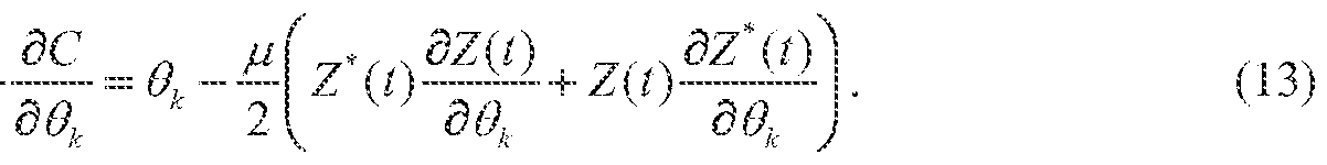
Multiplier 612 receives as inputs ¾ , (/) and z, (t). Similarly, multiplier 613 receives as inputs and z (i). The output of multiplier 613 is subtracted from the output of multiplier 612. at summer 615. The output of summer 615 is input to sign inverter 619, which receives a sign input control signal from sign device 621. Sign device receives the sign of weight wk . The output of sign inverter 619 is integrated by integrator 617. The output of integrator 617 is attenuated by attenuator 620 having gain μ to generate variable phase-shift control signal 9k in accordance with Equations (13)-(16). Variable phase- shift control signal 9k is input to phase shifter 602^ and controls the phase shift of phase shifter 602*.
Figure 7 depicts a flow diagram of an exemplary process 700 to provide an echo canceling technique that is immune to phase and amplitude imbalances by using more than two phase shifters to estimate an echo signal for an STR system according to the subject matter disclosed herein. At 701 the process begins. Flow continues to 702 where three or more weighted vectors are generated. In one exemplary embodiment, the three or more weighted vectors are generated in accordance with Equations (3)-(l 1) using fixed-phase phase shifters. Figures 5 A and 5B depict exemplary embodiments of the subject matter disclosed herein to generate the three or more weighted vectors are generated in accordance with Equations (3)-(l l )
using fixed-phase phase shifters. In another exemplar}' embodiment, one or more weighted vectors are generated in accordance with Equations (12)-(16) using variable-phase phase shifters. Figures 6A and 6B depict exemplary embodiments of the subject matter disclosed herein to generate the one or more weighted vectors are generated in accordance with Equations (12)-(16) using variable-phase phase shifters.
Flow continues to 703 wherein the three or more weighted vectors are summed to form an estimated echo output signal xk m(t) . Flow continues to 704 where the estimated echo signal is subtracted from a received signal containing an echo to form an echo-canceled signal z(t) .
Figure 8 shows an exemplary block diagram of the overall architecture of a 3ro
Generation Partnership Project (3 GPP) Long Term Evolution (LTE) network 800 that utilizes any of the techniques disclosed herein to provide an echo canceling technique that is immune to phase and amplitude imbalances by using more than two phase shifters to estimate an echo signal for an STR system according to the subject matter disclosed herein. Figure 8 also generally shows exemplar}' network elements and exemplary standardized interfaces. At a high level, network 800 comprises a core network (CN) 801 (also referred to as an evolved Packet System (EPC)), and an air-interface access network E-UTRAN 802, CN 801 is responsible for the overall control of the various User Equipment (UE) connected to the network and establishment of the bearers, CN 801 may include functional entities, such as a home agent HA and/or an ANDSF server or entity, although not explicitly depicted. E-UTRAN 802 is responsible for all radio-related functions.
The main exemplary logical nodes of CN 801 include, but are not limited to, a Serving GPRS Support Node 803, the Mobility Management Entity 804, a Home Subscriber Server (HSS) 805, a Se ing Gate (SGW) 806, a PDN Gateway 807 and a Policy and Charging Rules Function (PCRF) Manager 808. The functionality of each of the network elements of CN 801 is well known and is not described herein. Each of the network elements of CN 801 are interconnected by well-known exemplary standardized interfaces, some of which are indicated in Figure 8, such as interfaces S3, 84, 85, etc., although not described herein.
While CN 801 includes many logical nodes, the E-UTRAN access network 802 is formed by one node, the evolved NodeB (base station (BS), eNB or eNodeB) 810, which connects to one or more User Equipment (UE) 81 1, of which only one is depicted in Figure 8. UE 81 1 is also referred to herein as a wireless device (WD) and/ or a subscriber station (SS), and can include an M2M-type device. In one exemplary configuration, a single cell of an E-UTRAN access network 802 provides one substantially localized geographical transmission point (having
multiple antenna devices) that provides access to one or more UEs. In another exemplary configuration, a single cell of an E-UTRAN access network 802 provides multiple geographically substantially isolated transmission points (each having one or more antenna devices) with each transmission point providing access to one or more UEs simultaneously and with the signaling bits defined for the one cell so that all UEs share the same spatial signaling dimensioning. For normal user traffic (as opposed to broadcast), there is no centralized controller in E-UTRAN; hence the E-UTRAN architecture is said to be flat. The eNBs are normally interconnected with each other by an interface known as "X2" and to the EPC by an S I interface. More specifically, an eNB is connected to MME 804 by an S l-MME interface and to SGW 806 by an Sl -U interface. The protocols that run between the eNBs and the UEs are generally referred to as the "AS protocols." Details of the various interfaces are well known and not described herein.
The eNB 810 hosts the PHYsical (PHY), Medium Access Control (MAC), Radio Link Control (RLC), and Packet Data Control Protocol (PDCP) layers, which are not shown in Figure 8, and which include the functionality of user-plane header-compression and encryption. The eNB 810 also provides Radio Resource Control (RRC) functionality corresponding to the control plane, and performs many functions including radio resource management, admission control, scheduling, enforcement of negotiated Up Link (UL) QoS, cell information broadcast, ciphering/deciphering of user and control plane data, and compression/decompression of DL/UL user plane packet headers.
The RRC layer in eNB 810 covers all functions related to the radio bearers, such as radio bearer control, radio admission control, radio mobilit control, scheduling and dynamic allocation of resources to UEs in both uplink and downlink, header compression for efficient use of the radio interface, security of all data sent over the radio interface, and connectivity to the EPC. The RRC layer makes handover decisions based on neighbor cell measurements sent by UE 811 , generates pages for UEs 81 1 over the air, broadcasts system information, controls LIE measurement reporting, such as the periodicity of Channel Quality Information (CQI) reports, and allocates cell-level temporary identifiers to active UEs 81 1. The RRC layer also executes transfer of UE context from a source eNB to a target eNB during handover, and provides integrity protection for RRC messages. Additionally, the RRC layer is responsible for the setting up and maintenance of radio bearers.
Figure 9 depicts an exemplary functional block diagram of an information-handling system 900 that utilizes any of the techniques disclosed herein to provide an echo canceling technique that is immune to phase and amplitude imbalances by using more than two phase
1 ^
shifters to estimate an echo signal for an STR. system according to the subject matter disclosed herein. Information-handling system 900 of Figure 9 may tangibly embody one or more of any of the exemplary network elements and/or functional entities of the network as shown in and described with respect to Figure 8, Although information-handling system 900 represents one example of se veral types of computing platforms, such as, but not limited to, eNB 810, and for a terminal device, such as a mobile station (MS), or User Equipment (UE) 81 1, information- handling system 900 may include more or fewer elements and/or different arrangements of elements than shown in Figure 9, and the scope of the claimed subject matter is not limited in these respects.
In one or more embodiments, information-handling system 900 may comprise one or more applications processor 910 and a baseband processor 912. Applications processor 910 may be utilized as a general purpose processor to run applications and the various subsystems for information- handling system 900. Applications processor 910 may include a single core or alternatively may include multiple processing cores wherein one or more of the cores may comprise a digital signal processor or digital signal processing core. Furthermore, applications processor 910 may include a graphics processor or coprocessor disposed on the same chip, or alternatively a graphics processor coupled to applications processor 910 may comprise a separate, discrete graphics chip. Applications processor 910 may include on-board memory, such as cache memory, and further may be coupled to external memory devices such as synchronous dynamic random access memory (SDRAM) 914 for storing and/or executing applications during operation, and AND flash 916 for storing applications and/or data even when information-handling system 900 is powered off. Baseband processor 912 may control the broadband radio functions for information-handling system 900. Baseband processor 912 may store code for controlling such broadband radio functions in a NOR flash 918. Baseband processor 912 controls a wireless wide area network (WW AN) transceiver 920 which is used for modulating and/or demodulating broadband network signals, for example, for communicating via a 3 GPP LTE network or the like as discussed herein with respect to Figure 8. The WWAN transceiver 920 couples to one or more power amplifiers 92.2 that are respectively coupled to one or more antennas 924 for sending and receiving radio-frequency signals via the WWAN broadband network. The baseband processor 912 also may control a wireless local area network (WLAN) transceiver 926 coupled to one or more suitable antennas 928 and that may be capable of communicating via a Bluetooth-based standard, an IEEE 802.1 1 -based standard, an IEEE 802.16-based standard, an IEEE 802.18-based wireless network standard, an LTE -based wireless network standard, a 3GPP-based protocol wireless network, a Third Generation Partnership
Project Long Term Evolution (3GPP LTE) based wireless network standard, a 3GPP2 Air Interface Evolution (3GPP2 AIE) based wireless network standard, a UMTS-based protocol wireless network, a CDMA200G-based protocol wireless network, a GSM-hased protocol wireless network, a cellular-digital-packet-data-based (CDPD-based) protocol wireless network, or a Mobitex-based protocol wireless network, or the like. It should be noted that these are merely example implementations for applications processor 910 and baseband processor 912, and the scope of the claimed subject matter is not limited in these respects. For example, any¬ one or more of SDRAM 914, NAND flash 916 and/or NOR flash 918 may comprise other types of memory technology, such as magnetic-based memory, chalcogenide -based memory, phase- change-based memory, optical-based memory, or ovonic-based memory, and the scope of the claimed subject matter is not limited in this respect.
In one or more embodiments, applications processor 910 ma drive a display 930 for displaying various information or data, and may further receive touch input from a user via a touch screen 932 for example via a finger or a stylus. An ambient light sensor 934 may be utilized to detect an amount of ambient light in which information-handling system 900 is operating, for example, to control a brightness or contrast value for display 930 as a function of the intensity of ambient light detected by ambient fight sensor 934. One or more cameras 936 may be utilized to capture images that are processed by applications processor 910 and/or at least temporarily stored in NAND flash 916. Furthermore, applications processor may couple to a gyroscope 938, accelerometer 940, magnetometer 942, audio coder/decoder (CODEC) 944, and/or global positioning system (GPS) controller 946 coupled to an appropriate GPS antenna 948, for detection of various environmental properties including location, movement, and/or orientation of information-handling system 900. Alternatively, controller 946 may comprise a Global Navigation Satellite System (GNSS) controller. Audio CODEC 944 may be coupled to one or more audio ports 950 to provide microphone input and speaker outputs either via internal devices and/or via external devices coupled to information-handling system via the audio ports 950, for example, via a headphone and microphone jack. In addition, applications processor 910 may couple to one or more input/output (I/O) transceivers 952 to couple to one or more I/O ports 954 such as a universal serial bus (USB) port, a high-definition multimedia interface (HDMI) port, a serial port, and so on. Furthermore, one or more of the I/O transceivers 952 may couple to one or more memory slots 956 for optional removable memory, such as secure digital (SD) card or a subscriber identity module (SIM) card, although the scope of the claimed subject matter is not limited in these respects.
Figure 10 depicts an isometric view of an exemplary embodiment of the information- handling system of Figure 9 that optionally may include a touch screen in accordance with one or more embodiments. For example, Figure 10 shows an example implementation of information-handling system 900 of Figure 9 tangibly embodied as a cellular telephone, smartphone, or tablet-type device or the like. In one or more embodiments, the information- handling system 900 may comprise a housing 1010 having a display 930 that may include a touch screen 932 for receiving tactile input control and commands via a finger 1016 of a user and/or a via stylus 918 to control one or more applications processors 910. The housing 1010 may house one or more components of information-handling system 900, for example, one or more applications processors 910, one or more of SDRAM 914, NAND flash 916, NOR flash 918, baseband processor 912, and/or WWAN transceiver 92.0. The information-handling system 900 further may optionally include a physical actuator area 1020 that may comprise a keyboard or buttons for controlling information- handling system 900 via one or more buttons or switches. The information-handling system 900 may also include a memory port or slot 956 for receiving non-volatile memory, such as flash memory, for example, in the form of a secure digital (SD) card or a subscriber identity module (SIM) card. Optionally, the information-handling system 900 may further include one or more speakers and/or microphones 1024 and a connection port 954 for connecting the information-handling system 900 to another electronic device, dock, display, battery charger, and so on. Additionally, information-handling system 900 may include a headphone or speaker jack 1028 and one or more cameras 1036 on one or more sides of the housing 1010. It should be noted that the infonnation-handling system 900 of Figures 9 and 10 may include more or fewer elements than shown, in various arrangements, and the scope of the claimed subject matter is not limited in this respect.
Figure 11 depicts an exemplary embodiment of an article of manufacture 1 100 comprising a non-transitory computer-readable storage medium 1 101 having stored thereon computer-readable instructions that, when executed by a computer-type device, results in any of the various techniques and methods according to the subject matter disclosed herein. Exemplary computer-readable storage mediums that could be used for computer-readable storage medium 1101 could be, but are not limited to, a semiconductor-based memory, an optically based memory, a magnetic-based memory, or a combination thereof.
These modifications can be made in light of the above detailed description. The terms used in the following claims should not be construed to limit the scope to the specific embodiments disclosed in the specification and the claims. Rather, the scope of the
embodiments disclosed herein is to be determined by the following claims, which are to be construed in accordance with established doctrines of claim interpretation.
Claims
CLAIMS:
1, An echo-canceler for a simultaneous transmit and receive (STR) system, comprising:
at least three phase shifters, each respective phase shifter being coupled to a transmit signal of the STR system to generate an output signal comprising a selected phase shift with respect to the transmit signal, the transmit signal comprising a 310 Generation Partnership Project (3GPP) Long Term Evolution (LTE) transmit signal;
a weight calculation unit coupled to the output signal of each respective phase shifter, each weight calculation unit to generate a corresponding amplitude-weight signal for the output signal of the phase shifter;
a variable attenuator to attenuate the output signal of each respective phase shifter based on the corresponding amplitude-weight signal to form an echo-cancelation signal component corresponding to the phase shifter; and
a first summer to sum the respective echo-cancelation signal components into a received signal containing an echo signal to form an echo-canceled signal
2, The system according to claim 1, wherein each phase shifter is a fixed-phase phase shifter.
3, The system according to claim 1, wherein a first phase shifter of the at least three phase shifters generates a nominal phase shift of 0° with respect to the transmit signal, a second phase shifter of the at least three phase shifters generates a nominal phase shift of 60° with respect to the transmit signal, and a third phase shifter of the at least three phase shifters generates a nominal phase shift of 120° with respect to the transmit signal.
4, The system according to claim 1 , wherein the at least three phase shifters comprise part of a vector modulator.
5, The system according to claim 1 , wherein the system further comprises a plurality of vector modulators, each vector modulator comprising:
at least three phase shifters, each phase shifter being coupled to the transmit signal of the STR system at a selected tap of the transmit signal to generate an output signal comprising a selected phase shift from the transmit signal with respect to the selected tap;
a weight calculation unit coupled to the output signal of each respective phase shifter of the vector modulator to generate a corresponding amplitude-weight signal for the output signal of the phase shifter;
a variable attenuator to attenuate the output signal of each respective phase shifter based on the corresponding amplitude-weight signal to form an echo-cancelation signal component corresponding to the output signal of the phase shifter; and
a second summer to sum the respective echo-cancelation signal of the vector modulator into an echo-cancelation signal for the vector modulator, and
wherein the first summer sums the respective echo-cancelation signals of the respective vector modulators into the received signal containing an echo signal to form the echo- canceled signal.
6. The system according to claim 5, wherein a first phase shifter of the ai least three phase shifters of at least one vector modulator generates a nominal phase shift of 0° from the transmit signal with respect to the selected tap, a second phase shifter of the at least three phase shifters of the at least one vector modulator generates a nominal phase shift of 60° from the transmit signal with respect to the selected tap, and a third phase shifter of the at least three phase shifters of the at least one vector modulator generates a nominal phase shift of 120° from the transmit signal with respect to the selected tap.
7. The system according to claim 1, wherein each phase shifter is a variable-phase phase shifter, and
wherein the weight calculation unit is to further generate a variable-phase weight signal corresponding to the output signal of the phase shifter that varies a phase of the phase shifter.
8. The system according to claim 7, wherein each respective phase shifter is coupled to the transmit signal of the STR system at a different selected tap of the transmit signal to generate an output signal comprising a phase shift from the transmit signal with respect to the selected tap based on the variable-phase weight signal.
9. An information-handling system, comprising:
a receiver capable of receiving a signal, the received signal containing an echo signal and comprising a 3!d Generation Partnership Project (3 GPP) Long Term Evolution (LTE) downlink signal;
a transmitter capable of transmitting a transmit signal simultaneously as the receiver receives the recei ved signal; and
an echo-canceling unit coupled to the transmit signal and the received signal to generate an estimated echo signal, the echo-canceler comprising:
at least three phase shifters, each respective phase shifter to generate an output signal comprising a selected phase shift with respect to the transmit signal;
a first signal attenuator to attenuate the output signal of each respective phase shifter based on a weight signal corresponding to the output signal of the phase shifter to form an echo-cancelation signal component corresponding to the phase shifter; and
a second signal combiner to combine the respective echo-cancelation signal components into the received signal containing the echo signal to form an echo-canceled signal.
10. The information-handling system according to claim 9, wherein the echo- canceling unit further comprises a weight calculation unit to generate the weight signal for the output signal of the phase shifter.
11. The information-handling system according to claim 9, wherein each phase shifter is a fixed-phase phase shifter.
12. The information-handling system according to claim 9, wherein a first phase shifter of the at least three phase shifters generates a nominal phase shift of 0° with respect to the transmit signal, a second phase shifter of the at least three phase shifters generates a nominal phase shift of 60° with respect to the transmit signal, and a third phase shifter of the at least three phase shifters generates a nominal phase shift of 120° with respect to the transmit signal.
13. The information-handling system according to claim 9, wherein the at least three phase shifters comprise part of a vector modulator.
14. The information-handling system according to claim 9, wherein the echo- canceling unit further comprises a plurality of vector modulators, at least one vector modulator comprising:
the at least three phase shifters; and
at least three weight calculation units, each weight calculation unit to generate a weight signal for the output signal of a corresponding phase shifter;
wherein the first signal attenuator is to attenuate the output signal of each respective phase shifter based on the corresponding weight signal to form an echo-cancefation signal component corresponding to the phase shifter; and
wherein the second signal combiner is to combine the respective echo- cancelation signal components into the received signal containing the echo signal to form the echo-canceled signal.
15. The information- handling system according to claim 14, wherein a first phase shifter of the at least three phase shifters of at least one vector modulator generates a nominal phase shift of 0° from the transmit signal with respect to the selected tap, a second phase shifter of the at least three phase shifters of the at least one vector modulator generates a nominal phase shift of 60° from the transmit signal with respect to the selected tap, and a third phase shifter of the at least three phase shifters of the at least one vector modulator generates a nominal phase shift of 120° from the transmit signal with respect to the selected tap. 6. The information-handling system according to claim 9, wherein each phase shifter is a variable-phase phase shifter, and
wherein echo-canceling unit further comprises a weight calculation unit corresponding to each phase shifter to generate a variable-phase weight signal corresponding to the output signal of the phase shifter that varies a phase of the phase shifter.
17. The infonnation-handling system according to claim 9, wherein the information- handling system comprises a cellular telephone, smartphone, smart-type device, or tablet-type device.
18. The information-handling system according to claim 17, wherein the cellular telephone, smartphone, smart-type device, or tablet-type device further comprises a touchscreen display capabl e of receiving input information from a touch of a user or a stylus.
19. A method to cancel an echo signal in a received signal, the method comprising: generating three or more weighted vector signals representing a transmitted signal;
summing the three or more weighted vector signals to form an estimated echo signal: and
combining the estimated echo signal with a received signal that comprises an echo signal to form an echo-canceled signal.
20. The method according to claim 19, wherein generating the three or more weighted vector signals comprises:
generating three or more phase-shifted signals, each phase-shifted signal being phase shifted with respect to the transmitted signal;
generating a weighted signal corresponding to each respective phase-shifted signal;
combining each phase-shifted signal with the corresponding weighted signal to form the three or more weighted vector signals.
21. The method according to claim 20, wherein generating the three or more phase- shifted signals comprises using fixed-phase phase shifters.
22. The method according to claim 21, wherein a first fixed-phase phase shifter generates a nominal phase shift of 0° from the transmit signal, a second fixed-phase phase shifter generates a nominal phase shift of 60° from the transmit signal, and a third fixed-phase phase shifter generates a nominal phase shift of 120° from the transmit signal.
23. The method according to claim 20, wherein generating the three or more phase- shifted signals comprises using variable-phase phase shifters.
24. The method according to claim 23, wherein generating the weighted signal corresponding to the each respective phase-shifted signal further comprises generating a variable-phase weight signal corresponding to the output signal of the variable phase shifter that varies a phase of the variable phase shifter.
25. The method according to claim 19, further comprising:
transmitting the transmitted signal; and
receiving the received signal simultaneously with the transmitted signal, the transmitted signal and the received signal comprising a 3rfJ Generation Partnership Project (3GPP) Long Term Evolution (LTE) signals.
Priority Applications (2)
| Application Number | Priority Date | Filing Date | Title |
|---|---|---|---|
| US14/128,278 US9282564B2 (en) | 2012-12-06 | 2013-09-18 | Simultaneous transmit and receive (STR) structures immune to phase and amplitude imbalances |
| EP13859685.3A EP2929632A4 (en) | 2012-12-06 | 2013-09-18 | Simultaneous transmit and receive (str) structures immune to phase and amplitude imbalances |
Applications Claiming Priority (2)
| Application Number | Priority Date | Filing Date | Title |
|---|---|---|---|
| US201261734323P | 2012-12-06 | 2012-12-06 | |
| US61/734,323 | 2012-12-06 |
Publications (1)
| Publication Number | Publication Date |
|---|---|
| WO2014088676A1 true WO2014088676A1 (en) | 2014-06-12 |
Family
ID=50883854
Family Applications (4)
| Application Number | Title | Priority Date | Filing Date |
|---|---|---|---|
| PCT/US2013/058028 WO2014088659A1 (en) | 2012-12-06 | 2013-09-04 | New carrier type (nct) information embedded in synchronization signal |
| PCT/US2013/060445 WO2014088676A1 (en) | 2012-12-06 | 2013-09-18 | Simultaneous transmit and receive (str) structures immune to phase and amplitude imbalances |
| PCT/US2013/062485 WO2014088688A1 (en) | 2012-12-06 | 2013-09-27 | Method of transmitting and receiving device-to-device discovery signal |
| PCT/US2013/072890 WO2014089093A1 (en) | 2012-12-06 | 2013-12-03 | Device-to-device communication |
Family Applications Before (1)
| Application Number | Title | Priority Date | Filing Date |
|---|---|---|---|
| PCT/US2013/058028 WO2014088659A1 (en) | 2012-12-06 | 2013-09-04 | New carrier type (nct) information embedded in synchronization signal |
Family Applications After (2)
| Application Number | Title | Priority Date | Filing Date |
|---|---|---|---|
| PCT/US2013/062485 WO2014088688A1 (en) | 2012-12-06 | 2013-09-27 | Method of transmitting and receiving device-to-device discovery signal |
| PCT/US2013/072890 WO2014089093A1 (en) | 2012-12-06 | 2013-12-03 | Device-to-device communication |
Country Status (4)
| Country | Link |
|---|---|
| US (4) | US9516659B2 (en) |
| EP (2) | EP2929632A4 (en) |
| CN (2) | CN104756418B (en) |
| WO (4) | WO2014088659A1 (en) |
Families Citing this family (66)
| Publication number | Priority date | Publication date | Assignee | Title |
|---|---|---|---|---|
| US9516659B2 (en) | 2012-12-06 | 2016-12-06 | Intel Corporation | Carrier type (NCT) information embedded in synchronization signal |
| RU2629430C2 (en) * | 2013-01-16 | 2017-08-29 | Интердиджитал Пэйтент Холдингз, Инк. | Generation and detection signal reception |
| US11177919B2 (en) * | 2013-01-18 | 2021-11-16 | Texas Instruments Incorporated | Methods for energy-efficient unicast and multicast transmission in a wireless communication system |
| US9986380B2 (en) * | 2013-01-25 | 2018-05-29 | Blackberry Limited | Proximity and interest determination by a wireless device |
| CN109462838A (en) * | 2013-02-06 | 2019-03-12 | 索尼公司 | Wireless communications method, base station and wireless telecom equipment |
| KR102019716B1 (en) * | 2013-03-08 | 2019-09-09 | 삼성전자 주식회사 | Method and apparatus for device-to-device direct communication in wireless communication system |
| US9319851B2 (en) * | 2013-03-22 | 2016-04-19 | Mediatek, Inc. | Radio resource efficient transmission for group communication over LTE eMBMS |
| US9603065B2 (en) | 2013-04-03 | 2017-03-21 | Google Technology Holdings LLC | Methods and devices for cell discovery |
| PL2984885T3 (en) | 2013-04-12 | 2017-09-29 | Telefonaktiebolaget Lm Ericsson (Publ) | A method and wireless device for providing device-to-device communication |
| PL3031257T3 (en) * | 2013-08-09 | 2018-10-31 | Telefonaktiebolaget Lm Ericsson (Publ) | Method and apparatus for timing misalignment signalling |
| WO2015020602A1 (en) | 2013-08-09 | 2015-02-12 | Telefonaktiebolaget L M Ericsson (Publ) | Direct control signaling in a wireless communication system |
| US9516541B2 (en) * | 2013-09-17 | 2016-12-06 | Intel IP Corporation | Congestion measurement and reporting for real-time delay-sensitive applications |
| EP3057368B1 (en) * | 2013-10-11 | 2019-07-17 | Kyocera Corporation | Communication control method, user terminal, and communication device |
| US10187531B2 (en) * | 2013-10-31 | 2019-01-22 | Samsung Electronics Co., Ltd. | Method and system for charging information recording in device to device (D2D) communication |
| US9537612B2 (en) | 2013-12-09 | 2017-01-03 | Apple Inc. | Restrictions on transmissions of control plane data with carrier aggregation |
| WO2015105387A1 (en) * | 2014-01-10 | 2015-07-16 | 삼성전자 주식회사 | Radio resource allocation method and apparatus for device to device communication in mobile communication system |
| US10348852B2 (en) * | 2014-01-21 | 2019-07-09 | Lg Electronics Inc. | Method for determining terminal identifier in wireless communication system supporting device-to-device communication and apparatus for same |
| WO2015122715A1 (en) | 2014-02-13 | 2015-08-20 | 엘지전자 주식회사 | Method for transmitting/receiving synchronization signal for d2d communication in wireless communication system, and apparatus therefor |
| EP3111606B1 (en) | 2014-02-25 | 2018-09-19 | Intel Corporation | Apparatus, system and method of simultaneous transmit and receive (str) wireless communication |
| US10034301B2 (en) * | 2014-03-18 | 2018-07-24 | Sharp Kabushiki Kaisha | Scheduling wireless device-to-device communications |
| EP3120504B1 (en) | 2014-03-18 | 2019-09-11 | Sharp Kabushiki Kaisha | Device-to-device communications apparatus and methods |
| US9723630B2 (en) * | 2014-03-21 | 2017-08-01 | Samsung Electronics Co., Ltd. | Contention-based resource allocation method and apparatus for low power D2D communication |
| EP3138335B1 (en) | 2014-05-01 | 2023-12-20 | Sharp Kabushiki Kaisha | Device-to-device communications apparatus and method |
| EP3141038B1 (en) | 2014-05-08 | 2020-07-22 | Sharp Kabushiki Kaisha | Device-to device communications apparatus and methods |
| US9723655B2 (en) * | 2014-06-13 | 2017-08-01 | Htc Corporation | Method and apparatus for handling device to device communication in a wireless communication system |
| KR20170003978A (en) * | 2014-06-19 | 2017-01-10 | 후지쯔 가부시끼가이샤 | Wireless communication system, wireless communication method, wireless device, and wireless base station |
| US9860860B2 (en) | 2014-08-06 | 2018-01-02 | Sharp Kabushiki Kaisha | Synchronization signals for device-to-device communcations |
| WO2016065615A1 (en) * | 2014-10-31 | 2016-05-06 | Sony Corporation | User equipment, communication system, and method of controlling a user equipment |
| WO2016096558A1 (en) * | 2014-12-17 | 2016-06-23 | Nokia Solutions And Networks Oy | Measuring neighboring cells by user equipment served by master radio access node and secondary radio access node |
| US20160226142A1 (en) * | 2015-01-29 | 2016-08-04 | Robert Leroux | Phase control for antenna array |
| EP3257211B1 (en) * | 2015-02-11 | 2019-09-25 | Commscope Technologies LLC | Channel identification in a mimo telecommunications system |
| US10149343B2 (en) * | 2015-05-11 | 2018-12-04 | Apple Inc. | Use of baseband triggers to coalesce application data activity |
| DE102015012002A1 (en) * | 2015-09-18 | 2017-03-23 | Hella Kgaa Hueck & Co. | Locking circuit and method for locking a data line |
| US10523353B2 (en) | 2015-10-02 | 2019-12-31 | Lg Electronics Inc. | Method and device for transmitting and receiving secondary synchronization signal in wireless access system supporting narrowband Internet of things |
| EP3361793B1 (en) * | 2015-11-06 | 2021-03-03 | Huawei Technologies Co., Ltd. | Frequency determining method and device |
| CN106303918B (en) | 2015-11-24 | 2020-06-02 | 北京智谷睿拓技术服务有限公司 | Inter-device communication method, inter-device communication resource allocation method, and device thereof |
| KR102443505B1 (en) * | 2015-12-10 | 2022-09-15 | 삼성전자주식회사 | Apparatus and method for radio connection in wireless communication system |
| US9882747B2 (en) * | 2015-12-16 | 2018-01-30 | Marvell World Trade Ltd. | Channel quality indicator for wireline channel degradation detection |
| US10225754B2 (en) * | 2015-12-16 | 2019-03-05 | Futurewei Technologies, Inc. | System and method for a hub device search |
| US9923592B2 (en) | 2015-12-26 | 2018-03-20 | Intel Corporation | Echo cancellation using minimal complexity in a device |
| US10244542B2 (en) | 2016-02-03 | 2019-03-26 | Microsoft Technology Licensing, Llc | Mobile communication device clustering |
| WO2017136001A1 (en) * | 2016-02-05 | 2017-08-10 | Intel IP Corporation | Apparatus, system and method of vehicular user equipment (ue) communication |
| US10511372B2 (en) * | 2016-02-25 | 2019-12-17 | Intel IP Corporation | System and method for channel quality reporting |
| JP6772281B2 (en) * | 2016-03-30 | 2020-10-21 | オッポ広東移動通信有限公司Guangdong Oppo Mobile Telecommunications Corp., Ltd. | Methods and equipment for establishing wireless resource control connections |
| CN108702244B (en) * | 2016-04-01 | 2022-04-29 | 英特尔公司 | Link adaptation for low complexity device-to-device (D2D) communication |
| EP3513591B1 (en) | 2016-09-29 | 2022-11-30 | Huawei Technologies Duesseldorf GmbH | Sidelink-assisted handover in cellular networks |
| WO2018084880A1 (en) * | 2016-11-04 | 2018-05-11 | Intel Corporation | Enodeb assisted network ue scheduling in 5g nr-things sidelink |
| US10129768B1 (en) * | 2016-11-17 | 2018-11-13 | Sprint Spectrum L.P. | Determining potential interference in a wireless network |
| KR20180059207A (en) * | 2016-11-25 | 2018-06-04 | 에이치피프린팅코리아 주식회사 | Method for setting wireless connection of image forming apparatus using mobile terminal and image forming apparatus for performing the same |
| CN108134657B (en) * | 2016-12-01 | 2020-05-05 | 维沃移动通信有限公司 | Processing method of synchronization signal, network equipment and terminal equipment |
| US10185415B2 (en) | 2017-02-24 | 2019-01-22 | Microsoft Technology Licensing, Llc | Configurable communication protocol for communication between a stylus device and a host device |
| CN108811077B (en) * | 2017-05-05 | 2020-10-09 | 电信科学技术研究院 | Generation method, detection method, base station and user equipment of secondary synchronization sequence |
| US10439753B2 (en) | 2017-05-25 | 2019-10-08 | Microsoft Technology Licensing, Llc | Multi-protocol communications between host devices and stylus devices |
| CN108988978B (en) | 2017-06-01 | 2021-01-15 | 华为技术有限公司 | Scrambling code sequence generation method and device |
| US10645228B2 (en) * | 2017-06-26 | 2020-05-05 | Apple Inc. | Adaptability in EVS codec to improve power efficiency |
| US10700758B2 (en) * | 2017-11-16 | 2020-06-30 | Mediatek Inc. | Control information for CSI acquisition and beam management |
| US11044129B2 (en) * | 2017-12-21 | 2021-06-22 | Qualcomm Incorporated | Hierarchical communication for device-to-device communications |
| CN110035449B (en) * | 2018-01-12 | 2021-06-22 | 华为技术有限公司 | Method and device for sending data volume report |
| US11791958B2 (en) * | 2018-03-28 | 2023-10-17 | Apple Inc. | Methods and devices for radio resource allocation |
| CN108769958B (en) * | 2018-06-14 | 2020-11-06 | 重庆邮电大学 | M2M communication joint clustering and resource allocation method based on energy consumption optimization |
| GB2575329B (en) * | 2018-07-06 | 2021-02-17 | Canon Kk | Unique direct link session ID to drive stations in a wireless network |
| US11284376B2 (en) * | 2018-08-17 | 2022-03-22 | At&T Intellectual Property I, L.P. | Distributed control information for multiple party communications for 5G or other next generation network |
| US10833811B2 (en) * | 2019-02-11 | 2020-11-10 | Huawei Technologies Co., Ltd. | Systems and methods for user equipment cooperation with sidelink HARQ feedback |
| US11239985B2 (en) * | 2019-04-16 | 2022-02-01 | Cisco Technology, Inc. | Echo cancellation in multiple port full duplex (FDX) nodes and amplifiers |
| US11689952B1 (en) | 2021-04-28 | 2023-06-27 | T-Mobile Innovations Llc | Identifying a worst interfering sector |
| KR20230095032A (en) * | 2021-12-21 | 2023-06-28 | 한국전자통신연구원 | Method and apparatus for radio signal transmission and reception in communication system |
Citations (5)
| Publication number | Priority date | Publication date | Assignee | Title |
|---|---|---|---|---|
| US5636272A (en) * | 1995-05-30 | 1997-06-03 | Ericsson Inc. | Apparatus amd method for increasing the intelligibility of a loudspeaker output and for echo cancellation in telephones |
| WO2010077545A1 (en) * | 2008-12-31 | 2010-07-08 | Andrew Llc | Circuit and method for feedback cancellation in repeaters |
| US20110019831A1 (en) * | 2009-07-21 | 2011-01-27 | Yamaha Corporation | Echo Suppression Method and Apparatus Thereof |
| KR20110025667A (en) * | 2008-05-29 | 2011-03-10 | 퀄컴 인코포레이티드 | Systems, methods, apparatus, and computer program products for spectral contrast enhancement |
| US20120269102A1 (en) * | 2006-12-22 | 2012-10-25 | Charles Nicholls | Frequency agile duplex filter |
Family Cites Families (48)
| Publication number | Priority date | Publication date | Assignee | Title |
|---|---|---|---|---|
| US3735055A (en) * | 1971-11-05 | 1973-05-22 | Bell Telephone Labor Inc | Method for improving the settling time of a transversal filter adaptive echo canceller |
| US5473686A (en) * | 1994-02-01 | 1995-12-05 | Tandy Corporation | Echo cancellation apparatus |
| US6278785B1 (en) * | 1999-09-21 | 2001-08-21 | Acoustic Technologies, Inc. | Echo cancelling process with improved phase control |
| US7577125B2 (en) * | 2005-07-08 | 2009-08-18 | Microsoft Corporation | Direct wireless client to client communication |
| KR100938756B1 (en) * | 2007-07-06 | 2010-01-26 | 엘지전자 주식회사 | Method for performing cell search procedure in wireless communication system |
| KR100921769B1 (en) * | 2007-07-12 | 2009-10-15 | 한국전자통신연구원 | Method for generating downlink frame, and method for searching cell |
| US8559952B2 (en) * | 2007-08-14 | 2013-10-15 | Telefonaktiebolaget Lm Ericsson (Publ) | Automated and seamless change of reporting cell identity |
| US8577363B2 (en) * | 2008-07-14 | 2013-11-05 | Nokia Corporation | Setup of device-to-device connection |
| CN102246575A (en) | 2008-10-29 | 2011-11-16 | 诺基亚公司 | Apparatus and method for dynamic communication resource allocation for device-to-device communications in a wireless communication system |
| US8565064B2 (en) * | 2008-12-15 | 2013-10-22 | Futurewei Technologies, Inc. | System and method for employing six-bit rank 1 and 2 codebooks for four transmit antennas |
| US9351340B2 (en) * | 2009-04-08 | 2016-05-24 | Nokia Technologies Oy | Apparatus and method for mode selection for device-to-device communications |
| US8565260B2 (en) * | 2009-04-13 | 2013-10-22 | Lg Electronics Inc. | Method and apparatus for transmitting system information from a base station supporting an improved system |
| US8102817B2 (en) * | 2009-04-22 | 2012-01-24 | Infineon Technologies Delta Gmbh | Method of measurement reporting and cellular radio terminal |
| CA2775305C (en) * | 2009-09-25 | 2017-07-11 | Research In Motion Limited | System and method for multi-carrier network operation |
| US9949261B2 (en) * | 2009-10-15 | 2018-04-17 | Qualcomm Incorporated | Method and apparatus for conveying resource assignment for multiple system bandwidths |
| US8666403B2 (en) * | 2009-10-23 | 2014-03-04 | Nokia Solutions And Networks Oy | Systems, methods, and apparatuses for facilitating device-to-device connection establishment |
| US20120329502A1 (en) | 2010-01-15 | 2012-12-27 | Frank Frederiksen | Feedback Signaling |
| EP2526731A4 (en) * | 2010-01-19 | 2016-06-01 | Nokia Technologies Oy | Evolved node b controlled centralized resource reuse for device-to-device and cellular users |
| EP3110227B1 (en) * | 2010-03-11 | 2018-10-03 | Nokia Technologies Oy | Method and apparatus for device-to-device communication setup |
| WO2011116815A1 (en) * | 2010-03-23 | 2011-09-29 | Nokia Siemens Networks Oy | Resource allocation for direct terminal-to-terminal communication in a cellular system |
| US9198210B2 (en) * | 2010-04-20 | 2015-11-24 | Nokia Solutions And Networks Oy | D2D communications considering different network operators |
| US8867458B2 (en) * | 2010-04-30 | 2014-10-21 | Nokia Corporation | Network controlled device to device / machine to machine cluster operation |
| US8504052B2 (en) * | 2010-05-06 | 2013-08-06 | Nokia Corporation | Measurements and fast power adjustments in D2D communications |
| US8224246B2 (en) * | 2010-05-10 | 2012-07-17 | Nokia Corporation | Device to device connection setup using near-field communication |
| US8831119B2 (en) * | 2010-06-28 | 2014-09-09 | Lg Electronics Inc. | Method and apparatus for transmitting synchronization signal in multi-node system |
| US8548483B2 (en) * | 2010-10-04 | 2013-10-01 | Nokia Corporation | Feedback mapping for D2D control signals |
| US8744458B2 (en) * | 2010-11-19 | 2014-06-03 | Nokia Corporation | Signaling mixed resource allocations for D2D communications |
| EP2647175B1 (en) * | 2010-12-03 | 2018-04-04 | Nokia Technologies Oy | Facilitating device-to-device communication |
| EP2461502B1 (en) * | 2010-12-06 | 2013-07-24 | Sequans Communications | Non-coherent secondary synchronization signal detecting method, device and corresponding computer program |
| WO2012091420A2 (en) * | 2010-12-27 | 2012-07-05 | 한국전자통신연구원 | Method for establishing a device-to-device link connection and scheduling for device-to-device communication and terminal relaying |
| US9374767B2 (en) | 2011-03-09 | 2016-06-21 | Intel Deutschland Gmbh | Communication devices and methods for network signaling |
| US9775135B2 (en) * | 2011-03-18 | 2017-09-26 | Lg Electronics Inc. | Method and device for communicating device-to-device |
| WO2013025040A2 (en) * | 2011-08-18 | 2013-02-21 | 엘지전자 주식회사 | Method for performing device to device direct communication, method for supporting the same, and device therefor |
| KR20140068088A (en) * | 2011-08-30 | 2014-06-05 | 엘지전자 주식회사 | Method for supporting device-to-device communication in a cellular network, and apparatus for same |
| WO2013068788A1 (en) * | 2011-11-10 | 2013-05-16 | Nokia Corporation | Methods and apparatuses for facilitating use of carrier aggregation for device-to-device communications |
| EP2787658B1 (en) * | 2011-12-02 | 2019-02-06 | LG Electronics Inc. | Definition of new identifier in wireless access system that supports device to device communication, and transmission method and device using same |
| US9185690B2 (en) * | 2012-02-29 | 2015-11-10 | Sharp Kabushiki Kaisha | Allocating and determining resources for a device-to-device link |
| US9258692B2 (en) * | 2012-03-30 | 2016-02-09 | Qualcomm Incorporated | Relay assisted peer discovery |
| US8964561B2 (en) * | 2012-05-04 | 2015-02-24 | Nokia Corporation | Method and apparatus for signaling sequence root |
| US9763246B2 (en) * | 2012-06-12 | 2017-09-12 | Qualcomm Incorporated | Transport block size determination in new carrier type in LTE |
| US20130343300A1 (en) * | 2012-06-21 | 2013-12-26 | Lg Electronics Inc. | Method and apparatus for transmitting and receiving data |
| US9451570B2 (en) * | 2012-08-29 | 2016-09-20 | Alcatel Lucent | Device discovery for device-to-device communication |
| US9826381B2 (en) * | 2012-09-18 | 2017-11-21 | Blackberry Limited | Device handshake/discovery for inter-device communication in wireless communication systems |
| US10154467B2 (en) * | 2012-09-26 | 2018-12-11 | Blackberry Limited | Transmit power adjustment for inter-device communication in wireless communication systems |
| US9131434B2 (en) * | 2012-10-19 | 2015-09-08 | Blackberry Limited | Using a cell as a pathloss or timing reference |
| US9516659B2 (en) | 2012-12-06 | 2016-12-06 | Intel Corporation | Carrier type (NCT) information embedded in synchronization signal |
| US9780934B2 (en) * | 2013-05-09 | 2017-10-03 | Lg Electronics Inc. | Method for puncturing UE specific reference signal in radio access system supporting new carrier type and apparatus supporting same |
| CN105453638B (en) * | 2013-08-07 | 2019-03-22 | 瑞典爱立信有限公司 | For the configuration of the requirement to time of measuring for the cell reselection process for including the search of autonomous closed subscriber group CSG cell and gravity treatment |
-
2013
- 2013-09-04 US US14/128,343 patent/US9516659B2/en active Active
- 2013-09-04 WO PCT/US2013/058028 patent/WO2014088659A1/en active Application Filing
- 2013-09-04 CN CN201380056832.9A patent/CN104756418B/en not_active Expired - Fee Related
- 2013-09-18 US US14/128,278 patent/US9282564B2/en not_active Expired - Fee Related
- 2013-09-18 WO PCT/US2013/060445 patent/WO2014088676A1/en active Application Filing
- 2013-09-18 EP EP13859685.3A patent/EP2929632A4/en not_active Withdrawn
- 2013-09-27 WO PCT/US2013/062485 patent/WO2014088688A1/en active Application Filing
- 2013-09-27 US US14/126,043 patent/US20140269419A1/en not_active Abandoned
- 2013-09-27 EP EP13859754.7A patent/EP2929727A4/en not_active Withdrawn
- 2013-12-03 CN CN201380057958.8A patent/CN104770048B/en active Active
- 2013-12-03 US US14/440,429 patent/US9674847B2/en active Active
- 2013-12-03 WO PCT/US2013/072890 patent/WO2014089093A1/en active Application Filing
Patent Citations (5)
| Publication number | Priority date | Publication date | Assignee | Title |
|---|---|---|---|---|
| US5636272A (en) * | 1995-05-30 | 1997-06-03 | Ericsson Inc. | Apparatus amd method for increasing the intelligibility of a loudspeaker output and for echo cancellation in telephones |
| US20120269102A1 (en) * | 2006-12-22 | 2012-10-25 | Charles Nicholls | Frequency agile duplex filter |
| KR20110025667A (en) * | 2008-05-29 | 2011-03-10 | 퀄컴 인코포레이티드 | Systems, methods, apparatus, and computer program products for spectral contrast enhancement |
| WO2010077545A1 (en) * | 2008-12-31 | 2010-07-08 | Andrew Llc | Circuit and method for feedback cancellation in repeaters |
| US20110019831A1 (en) * | 2009-07-21 | 2011-01-27 | Yamaha Corporation | Echo Suppression Method and Apparatus Thereof |
Non-Patent Citations (1)
| Title |
|---|
| See also references of EP2929632A4 * |
Also Published As
| Publication number | Publication date |
|---|---|
| CN104756418B (en) | 2017-10-20 |
| US20150289282A1 (en) | 2015-10-08 |
| WO2014088688A1 (en) | 2014-06-12 |
| US9282564B2 (en) | 2016-03-08 |
| EP2929632A4 (en) | 2016-08-31 |
| US9516659B2 (en) | 2016-12-06 |
| CN104770048B (en) | 2018-09-07 |
| US9674847B2 (en) | 2017-06-06 |
| US20140269419A1 (en) | 2014-09-18 |
| US20140254567A1 (en) | 2014-09-11 |
| WO2014088659A1 (en) | 2014-06-12 |
| CN104756418A (en) | 2015-07-01 |
| EP2929727A1 (en) | 2015-10-14 |
| WO2014089093A1 (en) | 2014-06-12 |
| CN104770048A (en) | 2015-07-08 |
| US20150009867A1 (en) | 2015-01-08 |
| EP2929632A1 (en) | 2015-10-14 |
| EP2929727A4 (en) | 2016-07-20 |
Similar Documents
| Publication | Publication Date | Title |
|---|---|---|
| US9282564B2 (en) | Simultaneous transmit and receive (STR) structures immune to phase and amplitude imbalances | |
| US10673682B2 (en) | Network resource model to support network function virtualization lifecycle management | |
| US10484062B2 (en) | Transmit beamforming | |
| US11757506B2 (en) | Beamforming management in wireless networks | |
| US10333608B2 (en) | Inter-beam mobility control in MIMO communication systems | |
| CN105706478B (en) | Adaptive cell range extension mechanism for LTE cells | |
| EP3360268B1 (en) | Architecture for wireless network access | |
| US10356653B2 (en) | Multi-user based splitting for multi-rat aggregation | |
| US10609596B2 (en) | Network utility maximization with multi-rat aggregation | |
| WO2014046761A1 (en) | Method and apparatus for power control in full-duplex wireless systems with simultaneous transmission reception | |
| WO2020216159A1 (en) | Beam selection method and apparatus | |
| US11172389B2 (en) | Measurement gap configuration | |
| US10419145B2 (en) | Identifying victims and aggressors in full duplex communication systems | |
| WO2018004589A1 (en) | Apparatus, system and method of internet connectivity via a relay station | |
| US20230047970A1 (en) | Power adjustment method, apparatus, and system | |
| WO2018006237A1 (en) | Downlink control information (dci) configuration | |
| EP4311350A1 (en) | Wireless communication method, terminal device and network device | |
| CN117795886A (en) | Enhanced spectral shaping for cellular communication networks |
Legal Events
| Date | Code | Title | Description |
|---|---|---|---|
| WWE | Wipo information: entry into national phase |
Ref document number: 14128278 Country of ref document: US |
|
| 121 | Ep: the epo has been informed by wipo that ep was designated in this application |
Ref document number: 13859685 Country of ref document: EP Kind code of ref document: A1 |
|
| WWE | Wipo information: entry into national phase |
Ref document number: 2013859685 Country of ref document: EP |
|
| NENP | Non-entry into the national phase |
Ref country code: DE |