WO2014068733A1 - Quick charger for electric vehicle - Google Patents
Quick charger for electric vehicle Download PDFInfo
- Publication number
- WO2014068733A1 WO2014068733A1 PCT/JP2012/078248 JP2012078248W WO2014068733A1 WO 2014068733 A1 WO2014068733 A1 WO 2014068733A1 JP 2012078248 W JP2012078248 W JP 2012078248W WO 2014068733 A1 WO2014068733 A1 WO 2014068733A1
- Authority
- WO
- WIPO (PCT)
- Prior art keywords
- power
- electric vehicle
- storage battery
- power source
- quick charger
- Prior art date
Links
Images

Classifications
-
- H—ELECTRICITY
- H02—GENERATION; CONVERSION OR DISTRIBUTION OF ELECTRIC POWER
- H02J—CIRCUIT ARRANGEMENTS OR SYSTEMS FOR SUPPLYING OR DISTRIBUTING ELECTRIC POWER; SYSTEMS FOR STORING ELECTRIC ENERGY
- H02J7/00—Circuit arrangements for charging or depolarising batteries or for supplying loads from batteries
- H02J7/34—Parallel operation in networks using both storage and other dc sources, e.g. providing buffering
- H02J7/35—Parallel operation in networks using both storage and other dc sources, e.g. providing buffering with light sensitive cells
-
- B—PERFORMING OPERATIONS; TRANSPORTING
- B60—VEHICLES IN GENERAL
- B60L—PROPULSION OF ELECTRICALLY-PROPELLED VEHICLES; SUPPLYING ELECTRIC POWER FOR AUXILIARY EQUIPMENT OF ELECTRICALLY-PROPELLED VEHICLES; ELECTRODYNAMIC BRAKE SYSTEMS FOR VEHICLES IN GENERAL; MAGNETIC SUSPENSION OR LEVITATION FOR VEHICLES; MONITORING OPERATING VARIABLES OF ELECTRICALLY-PROPELLED VEHICLES; ELECTRIC SAFETY DEVICES FOR ELECTRICALLY-PROPELLED VEHICLES
- B60L50/00—Electric propulsion with power supplied within the vehicle
- B60L50/10—Electric propulsion with power supplied within the vehicle using propulsion power supplied by engine-driven generators, e.g. generators driven by combustion engines
- B60L50/16—Electric propulsion with power supplied within the vehicle using propulsion power supplied by engine-driven generators, e.g. generators driven by combustion engines with provision for separate direct mechanical propulsion
-
- B—PERFORMING OPERATIONS; TRANSPORTING
- B60—VEHICLES IN GENERAL
- B60L—PROPULSION OF ELECTRICALLY-PROPELLED VEHICLES; SUPPLYING ELECTRIC POWER FOR AUXILIARY EQUIPMENT OF ELECTRICALLY-PROPELLED VEHICLES; ELECTRODYNAMIC BRAKE SYSTEMS FOR VEHICLES IN GENERAL; MAGNETIC SUSPENSION OR LEVITATION FOR VEHICLES; MONITORING OPERATING VARIABLES OF ELECTRICALLY-PROPELLED VEHICLES; ELECTRIC SAFETY DEVICES FOR ELECTRICALLY-PROPELLED VEHICLES
- B60L53/00—Methods of charging batteries, specially adapted for electric vehicles; Charging stations or on-board charging equipment therefor; Exchange of energy storage elements in electric vehicles
- B60L53/10—Methods of charging batteries, specially adapted for electric vehicles; Charging stations or on-board charging equipment therefor; Exchange of energy storage elements in electric vehicles characterised by the energy transfer between the charging station and the vehicle
- B60L53/11—DC charging controlled by the charging station, e.g. mode 4
-
- B—PERFORMING OPERATIONS; TRANSPORTING
- B60—VEHICLES IN GENERAL
- B60L—PROPULSION OF ELECTRICALLY-PROPELLED VEHICLES; SUPPLYING ELECTRIC POWER FOR AUXILIARY EQUIPMENT OF ELECTRICALLY-PROPELLED VEHICLES; ELECTRODYNAMIC BRAKE SYSTEMS FOR VEHICLES IN GENERAL; MAGNETIC SUSPENSION OR LEVITATION FOR VEHICLES; MONITORING OPERATING VARIABLES OF ELECTRICALLY-PROPELLED VEHICLES; ELECTRIC SAFETY DEVICES FOR ELECTRICALLY-PROPELLED VEHICLES
- B60L53/00—Methods of charging batteries, specially adapted for electric vehicles; Charging stations or on-board charging equipment therefor; Exchange of energy storage elements in electric vehicles
- B60L53/10—Methods of charging batteries, specially adapted for electric vehicles; Charging stations or on-board charging equipment therefor; Exchange of energy storage elements in electric vehicles characterised by the energy transfer between the charging station and the vehicle
- B60L53/14—Conductive energy transfer
-
- B—PERFORMING OPERATIONS; TRANSPORTING
- B60—VEHICLES IN GENERAL
- B60L—PROPULSION OF ELECTRICALLY-PROPELLED VEHICLES; SUPPLYING ELECTRIC POWER FOR AUXILIARY EQUIPMENT OF ELECTRICALLY-PROPELLED VEHICLES; ELECTRODYNAMIC BRAKE SYSTEMS FOR VEHICLES IN GENERAL; MAGNETIC SUSPENSION OR LEVITATION FOR VEHICLES; MONITORING OPERATING VARIABLES OF ELECTRICALLY-PROPELLED VEHICLES; ELECTRIC SAFETY DEVICES FOR ELECTRICALLY-PROPELLED VEHICLES
- B60L53/00—Methods of charging batteries, specially adapted for electric vehicles; Charging stations or on-board charging equipment therefor; Exchange of energy storage elements in electric vehicles
- B60L53/30—Constructional details of charging stations
- B60L53/305—Communication interfaces
-
- B—PERFORMING OPERATIONS; TRANSPORTING
- B60—VEHICLES IN GENERAL
- B60L—PROPULSION OF ELECTRICALLY-PROPELLED VEHICLES; SUPPLYING ELECTRIC POWER FOR AUXILIARY EQUIPMENT OF ELECTRICALLY-PROPELLED VEHICLES; ELECTRODYNAMIC BRAKE SYSTEMS FOR VEHICLES IN GENERAL; MAGNETIC SUSPENSION OR LEVITATION FOR VEHICLES; MONITORING OPERATING VARIABLES OF ELECTRICALLY-PROPELLED VEHICLES; ELECTRIC SAFETY DEVICES FOR ELECTRICALLY-PROPELLED VEHICLES
- B60L53/00—Methods of charging batteries, specially adapted for electric vehicles; Charging stations or on-board charging equipment therefor; Exchange of energy storage elements in electric vehicles
- B60L53/50—Charging stations characterised by energy-storage or power-generation means
- B60L53/51—Photovoltaic means
-
- B—PERFORMING OPERATIONS; TRANSPORTING
- B60—VEHICLES IN GENERAL
- B60L—PROPULSION OF ELECTRICALLY-PROPELLED VEHICLES; SUPPLYING ELECTRIC POWER FOR AUXILIARY EQUIPMENT OF ELECTRICALLY-PROPELLED VEHICLES; ELECTRODYNAMIC BRAKE SYSTEMS FOR VEHICLES IN GENERAL; MAGNETIC SUSPENSION OR LEVITATION FOR VEHICLES; MONITORING OPERATING VARIABLES OF ELECTRICALLY-PROPELLED VEHICLES; ELECTRIC SAFETY DEVICES FOR ELECTRICALLY-PROPELLED VEHICLES
- B60L53/00—Methods of charging batteries, specially adapted for electric vehicles; Charging stations or on-board charging equipment therefor; Exchange of energy storage elements in electric vehicles
- B60L53/50—Charging stations characterised by energy-storage or power-generation means
- B60L53/53—Batteries
-
- H—ELECTRICITY
- H02—GENERATION; CONVERSION OR DISTRIBUTION OF ELECTRIC POWER
- H02J—CIRCUIT ARRANGEMENTS OR SYSTEMS FOR SUPPLYING OR DISTRIBUTING ELECTRIC POWER; SYSTEMS FOR STORING ELECTRIC ENERGY
- H02J7/00—Circuit arrangements for charging or depolarising batteries or for supplying loads from batteries
- H02J7/34—Parallel operation in networks using both storage and other dc sources, e.g. providing buffering
- H02J7/342—The other DC source being a battery actively interacting with the first one, i.e. battery to battery charging
-
- B—PERFORMING OPERATIONS; TRANSPORTING
- B60—VEHICLES IN GENERAL
- B60L—PROPULSION OF ELECTRICALLY-PROPELLED VEHICLES; SUPPLYING ELECTRIC POWER FOR AUXILIARY EQUIPMENT OF ELECTRICALLY-PROPELLED VEHICLES; ELECTRODYNAMIC BRAKE SYSTEMS FOR VEHICLES IN GENERAL; MAGNETIC SUSPENSION OR LEVITATION FOR VEHICLES; MONITORING OPERATING VARIABLES OF ELECTRICALLY-PROPELLED VEHICLES; ELECTRIC SAFETY DEVICES FOR ELECTRICALLY-PROPELLED VEHICLES
- B60L2210/00—Converter types
- B60L2210/10—DC to DC converters
-
- B—PERFORMING OPERATIONS; TRANSPORTING
- B60—VEHICLES IN GENERAL
- B60L—PROPULSION OF ELECTRICALLY-PROPELLED VEHICLES; SUPPLYING ELECTRIC POWER FOR AUXILIARY EQUIPMENT OF ELECTRICALLY-PROPELLED VEHICLES; ELECTRODYNAMIC BRAKE SYSTEMS FOR VEHICLES IN GENERAL; MAGNETIC SUSPENSION OR LEVITATION FOR VEHICLES; MONITORING OPERATING VARIABLES OF ELECTRICALLY-PROPELLED VEHICLES; ELECTRIC SAFETY DEVICES FOR ELECTRICALLY-PROPELLED VEHICLES
- B60L2210/00—Converter types
- B60L2210/30—AC to DC converters
-
- H—ELECTRICITY
- H02—GENERATION; CONVERSION OR DISTRIBUTION OF ELECTRIC POWER
- H02J—CIRCUIT ARRANGEMENTS OR SYSTEMS FOR SUPPLYING OR DISTRIBUTING ELECTRIC POWER; SYSTEMS FOR STORING ELECTRIC ENERGY
- H02J2310/00—The network for supplying or distributing electric power characterised by its spatial reach or by the load
- H02J2310/40—The network being an on-board power network, i.e. within a vehicle
- H02J2310/48—The network being an on-board power network, i.e. within a vehicle for electric vehicles [EV] or hybrid vehicles [HEV]
-
- Y—GENERAL TAGGING OF NEW TECHNOLOGICAL DEVELOPMENTS; GENERAL TAGGING OF CROSS-SECTIONAL TECHNOLOGIES SPANNING OVER SEVERAL SECTIONS OF THE IPC; TECHNICAL SUBJECTS COVERED BY FORMER USPC CROSS-REFERENCE ART COLLECTIONS [XRACs] AND DIGESTS
- Y02—TECHNOLOGIES OR APPLICATIONS FOR MITIGATION OR ADAPTATION AGAINST CLIMATE CHANGE
- Y02T—CLIMATE CHANGE MITIGATION TECHNOLOGIES RELATED TO TRANSPORTATION
- Y02T10/00—Road transport of goods or passengers
- Y02T10/60—Other road transportation technologies with climate change mitigation effect
- Y02T10/70—Energy storage systems for electromobility, e.g. batteries
-
- Y—GENERAL TAGGING OF NEW TECHNOLOGICAL DEVELOPMENTS; GENERAL TAGGING OF CROSS-SECTIONAL TECHNOLOGIES SPANNING OVER SEVERAL SECTIONS OF THE IPC; TECHNICAL SUBJECTS COVERED BY FORMER USPC CROSS-REFERENCE ART COLLECTIONS [XRACs] AND DIGESTS
- Y02—TECHNOLOGIES OR APPLICATIONS FOR MITIGATION OR ADAPTATION AGAINST CLIMATE CHANGE
- Y02T—CLIMATE CHANGE MITIGATION TECHNOLOGIES RELATED TO TRANSPORTATION
- Y02T10/00—Road transport of goods or passengers
- Y02T10/60—Other road transportation technologies with climate change mitigation effect
- Y02T10/7072—Electromobility specific charging systems or methods for batteries, ultracapacitors, supercapacitors or double-layer capacitors
-
- Y—GENERAL TAGGING OF NEW TECHNOLOGICAL DEVELOPMENTS; GENERAL TAGGING OF CROSS-SECTIONAL TECHNOLOGIES SPANNING OVER SEVERAL SECTIONS OF THE IPC; TECHNICAL SUBJECTS COVERED BY FORMER USPC CROSS-REFERENCE ART COLLECTIONS [XRACs] AND DIGESTS
- Y02—TECHNOLOGIES OR APPLICATIONS FOR MITIGATION OR ADAPTATION AGAINST CLIMATE CHANGE
- Y02T—CLIMATE CHANGE MITIGATION TECHNOLOGIES RELATED TO TRANSPORTATION
- Y02T10/00—Road transport of goods or passengers
- Y02T10/60—Other road transportation technologies with climate change mitigation effect
- Y02T10/72—Electric energy management in electromobility
-
- Y—GENERAL TAGGING OF NEW TECHNOLOGICAL DEVELOPMENTS; GENERAL TAGGING OF CROSS-SECTIONAL TECHNOLOGIES SPANNING OVER SEVERAL SECTIONS OF THE IPC; TECHNICAL SUBJECTS COVERED BY FORMER USPC CROSS-REFERENCE ART COLLECTIONS [XRACs] AND DIGESTS
- Y02—TECHNOLOGIES OR APPLICATIONS FOR MITIGATION OR ADAPTATION AGAINST CLIMATE CHANGE
- Y02T—CLIMATE CHANGE MITIGATION TECHNOLOGIES RELATED TO TRANSPORTATION
- Y02T90/00—Enabling technologies or technologies with a potential or indirect contribution to GHG emissions mitigation
- Y02T90/10—Technologies relating to charging of electric vehicles
- Y02T90/12—Electric charging stations
-
- Y—GENERAL TAGGING OF NEW TECHNOLOGICAL DEVELOPMENTS; GENERAL TAGGING OF CROSS-SECTIONAL TECHNOLOGIES SPANNING OVER SEVERAL SECTIONS OF THE IPC; TECHNICAL SUBJECTS COVERED BY FORMER USPC CROSS-REFERENCE ART COLLECTIONS [XRACs] AND DIGESTS
- Y02—TECHNOLOGIES OR APPLICATIONS FOR MITIGATION OR ADAPTATION AGAINST CLIMATE CHANGE
- Y02T—CLIMATE CHANGE MITIGATION TECHNOLOGIES RELATED TO TRANSPORTATION
- Y02T90/00—Enabling technologies or technologies with a potential or indirect contribution to GHG emissions mitigation
- Y02T90/10—Technologies relating to charging of electric vehicles
- Y02T90/14—Plug-in electric vehicles
-
- Y—GENERAL TAGGING OF NEW TECHNOLOGICAL DEVELOPMENTS; GENERAL TAGGING OF CROSS-SECTIONAL TECHNOLOGIES SPANNING OVER SEVERAL SECTIONS OF THE IPC; TECHNICAL SUBJECTS COVERED BY FORMER USPC CROSS-REFERENCE ART COLLECTIONS [XRACs] AND DIGESTS
- Y02—TECHNOLOGIES OR APPLICATIONS FOR MITIGATION OR ADAPTATION AGAINST CLIMATE CHANGE
- Y02T—CLIMATE CHANGE MITIGATION TECHNOLOGIES RELATED TO TRANSPORTATION
- Y02T90/00—Enabling technologies or technologies with a potential or indirect contribution to GHG emissions mitigation
- Y02T90/10—Technologies relating to charging of electric vehicles
- Y02T90/16—Information or communication technologies improving the operation of electric vehicles
Definitions
- the present invention relates to a quick charger for an electric vehicle.
- Patent Document 1 discloses a rapid charging method and apparatus that enables rapid charging with an appropriate charging voltage regardless of the remaining charge level of an external storage battery to be charged mounted on an electric vehicle (EV).
- EV electric vehicle
- An object of the present invention is to provide a quick charger for an electric vehicle that can supply electric power to the electric vehicle when power is not received from an external power source.
- a quick charger for an electric vehicle includes a power receiving unit that receives power from an external power source, and a storage battery that is connected to the power receiving unit and can supply power to the electric vehicle when not receiving power from the external power source. And.
- the quick charger for an electric vehicle includes a control device capable of receiving power from the external power source and the storage battery to a control power source, and supplies power to the control power source and the electric vehicle when power is not received from the external power source. It is preferable to output output power from the storage battery.
- the power receiving unit includes a power receiving unit for receiving power from a power generation device different from a commercial power source, and input power received from the power generation device is output power supplied to the electric vehicle. In the case of exceeding the value, it is preferable to charge the storage battery with the input power.
- the power receiving means for the power generator preferably receives power from a solar power generator.
- the electric vehicle rapid charger preferably includes a power converter connected to the storage battery, and the solar power generation device is connected between the storage battery and the power converter.
- the power receiving means for the power generator receives power from the wind power generator.
- the electric vehicle rapid charger includes a plurality of the power receiving means including a commercial power receiving means for receiving power from a commercial power source.
- the quick charger for an electric vehicle includes authentication means for authenticating use of a user.
- the authentication means cannot receive power from the commercial power source, the electric vehicle is more likely to receive power from the commercial power source. It is preferable to limit the number of users that can be charged.
- the quick charger for an electric vehicle includes a control device capable of receiving power from the commercial power source and the storage battery to the control power source, and the commercial power source when the commercial power source functions by receiving power from the commercial power source.
- a control device capable of receiving power from the commercial power source and the storage battery to the control power source, and the commercial power source when the commercial power source functions by receiving power from the commercial power source.
- the quick charger for an electric vehicle includes a switching device for connecting or disconnecting the commercial power source, and when the commercial power source is interrupted, the switching device shuts off the commercial power source, and the switching is performed after the commercial power source is restored. It is preferable to connect the commercial power supply by an apparatus.
- the power received from the commercial power source is zero. .
- a quick charger for an electric vehicle includes a power receiving unit that receives power from an external power source, and a storage battery that is connected to the power receiving unit and that can supply power to the electric vehicle when not receiving power from the external power source. .
- the quick charger for an electric vehicle according to the present invention has an effect that electric power can be supplied to the electric vehicle when power is not received from an external power source.
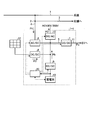
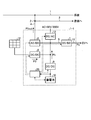
- FIG. 1 is a schematic configuration diagram of a quick charger for an electric vehicle according to the first embodiment.
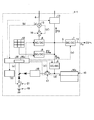
- FIG. 2 is a diagram showing details of the quick charger for an electric vehicle according to the first embodiment.
- FIG. 3 is an operation explanatory diagram when the facility storage battery is fully charged.
- FIG. 4 is an explanatory diagram of power storage for the facility storage battery.
- FIG. 5 is an explanatory diagram of power storage for a storage battery for facilities using input power from the solar power generation device.
- FIG. 6 is an explanatory diagram of reverse power transmission to the store side.
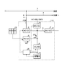
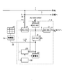
- FIG. 7 is a schematic configuration diagram of a quick charger for an electric vehicle according to the second embodiment.
- FIG. 1 is a schematic configuration diagram of a quick charger for an electric vehicle according to the first embodiment of the present invention
- FIG. 2 is a diagram showing details of the quick charger for an electric vehicle according to the first embodiment.
- the electric vehicle quick charger 1-1 shown in FIGS. 1 and 2 has a function of charging the electric vehicle EV.
- the electric vehicle EV includes not only one having no power source other than the electric motor but also a hybrid vehicle having a power source such as an internal combustion engine in addition to the electric motor.
- the quick charger 1-1 for an electric vehicle according to the present embodiment includes a bus 5, an AC / DC converter 6, a first DC / DC converter 7, a power controller 8, a second DC / DC converter 9,
- the storage battery 10 for facilities, the output line 11, the DC / AC converter 13, and the control apparatus 20 are comprised.
- the distribution board 2 is connected to a commercial power line 1, a store power line 3 and a charger power line 4.
- the electric vehicle quick charger 1-1 is connected to the commercial power line 1 and the store power line 3 through the charger power line 4 and the distribution board 2, respectively.
- the store power line 3 supplies power to a store such as a convenience store.
- the bus 5 is connected to the charger power line 4 via the AC / DC converter 6.
- the AC / DC converter 6 is included in a power receiving unit that receives power from an external power source, and functions as a commercial power receiving unit that receives power from a commercial power source.
- the AC / DC converter 6 converts the alternating current input from the power supply line 4 for the charger into a direct current and outputs it to the bus 5, and converts the direct current input from the bus 5 into an alternating current for the charger.
- the power can be output to the power line 4.
- the output line 11 is connected to the bus 5 via the first DC / DC converter 7.
- the output line 11 is a power supply line that supplies power to a battery mounted on the electric vehicle EV.
- the first DC / DC converter 7 supplies at least one of the received power P1 from the commercial power source, the input power P2 from the solar power generation device 12, or the discharge power Pb from the facility storage battery 10 to the electric vehicle EV.
- the first DC / DC converter 7 converts the direct current voltage of the bus 5 into a target voltage and outputs it to the output line 11.
- a solar power generation device 12 is connected to the bus 5 via a power controller 8.
- the solar power generation device 12 is a power generation device different from a commercial power source, and converts the light energy of sunlight into electrical energy and outputs a direct current.
- the maximum value of the generated power is 20 kW.
- the power controller 8 is included in a power receiving unit that receives power from an external power source, and functions as a power receiving unit power receiving unit that receives power from a power generator different from the commercial power source.
- the power controller 8 has a DC / DC converter and can execute MPPT (Maximum Power Point Tracking) control.
- the MPPT control is control for causing the solar power generation device 12 to generate power at a voltage and current value that can maximize the output.
- the current generated by the solar power generation device 12 is output to the bus 5 via the power controller 8.
- the power controller 8 increases the output voltage to the bus 5 higher than the voltage of the facility storage battery 10 in the control of the input power P ⁇ b> 2 input from the solar power generation device 12 to the bus 5.
- the power controller 8 controls the output voltage to the bus 5 to be equal to or lower than the voltage when the storage battery 10 for facilities is fully charged.
- a storage battery 10 for equipment is connected to the bus 5 via a second DC / DC converter 9.
- the second DC / DC converter 9 is a power converter connected to the facility storage battery 10.
- the storage battery 10 for facilities can be charged and discharged.
- the storage battery 10 for equipment of this embodiment is a lithium ion storage battery.
- the effective capacity (storage capacity) of the facility storage battery 10 is Qb (kWh).
- the effective capacity Qb is a capacity in a range used in the charge / discharge control among the total capacity of the facility storage battery 10. For example, when charge / discharge control is performed in the range of 10% to 90% of the total capacity of the storage battery 10 for facilities, the effective capacity Qb is a value of 80% of the total capacity. In this embodiment, since the facility storage battery 10 having a total capacity of 20 kWh is used in the range of 10 to 90% of the total capacity, the effective capacity Qb is 16 kWh.
- the second DC / DC converter 9 converts the voltage of the direct current of the bus 5 into a target voltage and outputs it to the facility storage battery 10, and the target voltage of the direct current discharged from the facility storage battery 10 Can be output to the bus 5. Even if the voltage of the storage battery 10 for facilities changes according to the electrical storage remaining amount SOC, the second DC / DC converter 9 can suppress fluctuations in the voltage output to the bus 5. Therefore, the stability of the voltage supplied to the electric vehicle EV can be improved. In addition, since the second DC / DC converter 9 is arranged, the number of batteries of the storage battery 10 for facilities (the number of series connection) can be changed without reassembling the circuit.
- a DC / AC converter 13 is connected to the bus 5.
- the DC / AC converter 13 can convert the direct current of the bus 5 into an alternating current of a target voltage and output it.
- the DC / AC converter 13 of the present embodiment can convert the direct current of the bus 5 and output alternating current 100V and alternating current 200V.
- the DC / AC converter 13 is used, for example, as an emergency power supply that outputs an alternating current during a power failure to a store that receives power supply from the store power line 3.
- the input / output device 22 shown in FIG. 2 is a device having a function as a notification means for notifying the user of the quick charger 1-1 for an electric vehicle and a function as an input means for receiving an input from the user. is there.
- the input / output device 22 of this embodiment notifies the user of information by displaying visual information such as characters and graphics on the display screen. Note that the input / output device 22 may notify information by sound or light instead of or in addition to characters or graphics.
- the input / output device 22 of this embodiment has a touch panel, and an input from a user is made by the touch panel.
- a voltmeter 15 and a switching device 16 are arranged on the power supply line 4 for the charger.
- the voltmeter 15 detects a voltage input from a commercial power source.
- the switching device 16 is disposed between the voltmeter 15 and the AC / DC converter 6.
- the switching device 16 is a relay that opens and closes the charger power line 4, and cuts off or connects the commercial power line 1 and the AC / DC converter 6.
- the voltmeter 15 changes the electrical signal output to the control device 20 and the switching device 16 when the voltage input from the commercial power line 1 is equal to or higher than a predetermined voltage and when it is lower than the predetermined voltage. Let The storage battery 10 for facilities has the monitoring apparatus 10a.
- the monitoring device 10 a monitors the temperature and voltage of the facility storage battery 10, the remaining power SOC (%), the current value to be charged / discharged, and the like, and outputs it to the control device 20.
- the facility storage battery 10 is connected to the control device 20 via a relay 17 and a switching power supply 18.
- the switching power supply 18 steps down the voltage of the facility storage battery 10 and outputs it to the control device 20.
- the control device 20 controls the quick charger 1-1 for the electric vehicle.
- the control device 20 of the present embodiment includes an AC / DC converter 6, a first DC / DC converter 7, a second DC / DC converter 9, a facility storage battery 10, a power controller 8, a DC / AC converter 13, a relay 17, and a relay. 21 and the input / output device 22, an AC / DC converter 6, a first DC / DC converter 7, a second DC / DC converter 9, a storage battery 10 for equipment, a power controller 8, a DC / AC converter 13, a relay 17. Control the relay 21 and the input / output device 22. Further, the control device 20 has a function of acquiring the power consumption of the electric load connected to the store power line 3 through communication or the like.
- the control device 20 When there is a charge request from the electric vehicle EV connected to the output line 11, the control device 20 sets the output power Po (kW) supplied to the electric vehicle EV.
- the maximum output power Pomax which is the maximum value of the output power Po, is 50 kW, but it may be any value.
- the control device 20 outputs to the first DC / DC converter 7 a voltage and current command value to be output to the output line 11 based on a request from the electric vehicle EV.
- the first DC / DC converter 7 controls the voltage and current output from the bus 5 to the output line 11 based on the command value from the control device 20.
- the electric vehicle quick charger 1-1 has at least one of received power P1 (kW) received from a commercial power source, input power P2 received from the solar power generation device 12, and discharge power Pb of the storage battery 10 for facilities. To supply output power Po to the electric vehicle EV.
- Control device 20 determines a command value for received power P1, a command value for input power P2, and a command value for discharge power Pb based on output power Po output to electric vehicle EV. Control device 20 outputs command values for voltage and current to be output to bus 5 based on the determined received power P1. The AC / DC converter 6 controls the voltage and current output to the bus 5 based on the command value received from the control device 20.
- the control device 20 acquires the input power P2 (voltage and current) generated by the solar power generation device 12 and input to the bus 5 from the power controller 8.
- the control device 20 can command the input power P2 to the power controller 8 to cause the solar power generation device 12 to generate power with an output different from the output determined by the MPPT control. For example, when the control device 20 instructs the power controller 8 to shut off the solar power generation device 12 and the bus 5 and sets the input power P2 to 0 or maximizes the output of the solar power generation device 12 It is possible to reduce the actual input power P ⁇ b> 2 with respect to the power (thinning the output of the solar power generation device 12).
- the control device 20 determines the discharge power Pb of the facility storage battery 10 and outputs a voltage and current command value output from the facility storage battery 10 to the bus 5 based on the discharge power Pb, or outputs from the bus 5 to the facility storage battery 10.
- the voltage and current command values are output to the second DC / DC converter 9.
- the second DC / DC converter 9 controls the voltage and current output from the facility storage battery 10 to the bus 5 or the voltage and current output from the bus 5 to the facility storage battery 10 based on the command value from the control device 20. To do.
- control device 20 determines the supply power P3 output from the bus 5 via the DC / AC converter 13, and determines the voltage and current command values output via the DC / AC converter 13 based on the supply power P3. Output to the DC / AC converter 13.
- the DC / AC converter 13 controls the voltage and current output via the DC / AC converter 13 based on the command value from the control device 20.
- the electric vehicle quick charger 1-1 is connected to a power receiving unit that receives power from an external power source and to the power receiving unit, and supplies power to the electric vehicle EV when the power is not received from the external power source.
- the storage battery 10 for facilities which can be provided.
- the external power source is a commercial power source and the solar power generation device 12.
- the electric vehicle quick charger 1-1 according to the present embodiment can charge the electric vehicle EV when it does not receive power from an external power source such as during a power failure.
- the electric vehicle quick charger 1-1 when the electric vehicle quick charger 1-1 receives no electric power from an external power source, the electric power for the control power source and the output electric power Po to be supplied to the electric vehicle EV are output from the storage battery 10 for facilities. can do. Therefore, the electric vehicle quick charger 1-1 functions independently when there is no external power supply, and can charge the electric vehicle EV.
- the control device 20 of the present embodiment can supply power for the control power source 20a from the commercial power source and the facility storage battery 10.
- the control device 20 can receive power from the commercial power source or the facility storage battery 10 to the control power source 20a, and can receive power from both the commercial power source and the facility storage battery 10 to the control power source 20a. It is.
- the commercial power supply fails when the electric vehicle quick charger 1-1 is functioning by receiving power from the commercial power supply to the control power supply 20a, the power supply to the control power supply 20a is stopped and the function is stopped.
- the system is restarted and functions by supplying power from the storage battery 10 for equipment to the control power source 20a.
- the control apparatus 20 may be comprised so that electric power can be further supplied with respect to the control power supply 20a from the solar power generation device 12.
- FIG. 1 the electric vehicle quick charger 1-1 is supplied with power from either the commercial power source or the solar power generation device 12 when functioning by receiving power from the external power source to the control power source 20a.
- the supply of power to the control power supply 20a is stopped, the function is stopped, and the function is restarted, and the power is supplied from the facility storage battery 10 to the control power supply 20a so as to function.
- a signal indicating a power failure output from the voltmeter 15 to the control device 20 is a control power OFF command for the control device 20.
- the control device 20 normally receives power from the commercial power source, the control device 20 operates by receiving power from the commercial power source to the control power source 20a.
- the power received via the charger power supply line 4 is stepped down to a voltage (for example, 12 V) for the control power supply 20a and supplied to the control device 20.
- the control device 20 stops the function of the electric vehicle quick charger 1-1 and stops supplying power to the control power supply 20a.
- the functions of the electric vehicle quick charger 1-1 include a charging function for the electric vehicle EV, an AC output to the outside via the DC / AC converter 13, a power generation control of the solar power generator 12 by the power controller 8, and a facility Charge / discharge of the storage battery 10 is included.
- the quick charger 1-1 for an electric vehicle according to the present embodiment temporarily stops its operation including the system power supply temporarily when the commercial power supply is interrupted.
- a signal indicating a power failure output from the voltmeter 15 to the switching device 16 is a disconnection command to the switching device 16.
- the switching device 16 connects the commercial power line 1 and the AC / DC converter 6 when normally receiving power from the commercial power source.
- the switching device 16 receives the disconnection command, the switching device 16 is opened, and the commercial power line 1 is cut off from the AC / DC converter 6.
- the opening / closing command for the switching device 16 may be issued by the control device 20.
- control power supply 20a After the control power supply OFF and disconnection are completed, the control power supply 20a is turned on again.
- the relay 21 is closed, and power is supplied from the battery 19 which is a power source for starting to the control power source 20a of the control device 20.
- the control device 20 instructs the relay 21 to turn on the activation power after a predetermined time.
- the relay 21 is closed after the quick charger 1-1 for the electric vehicle stops functioning, and the control power supply 20a is turned on again.
- the control device 20 When power is supplied from the battery 19, the control device 20 communicates with the monitoring device 10 a to check the state of the facility storage battery 10. If the facility storage battery 10 is normal, the control device 20 issues a power supply command to the facility storage battery 10 and closes the relay 17 (d ′). When the relay 17 is closed, power is supplied from the facility storage battery 10 to the control power supply 20a of the control device 20 via the switching power supply 18, and the electric vehicle quick charger 1-1 functions.
- the control device 20 When the electric vehicle quick charger 1-1 functions by the power from the facility storage battery 10 at the time of a power failure of the commercial power supply, the control device 20 outputs the output power Po for the electric vehicle EV more than when the power is supplied from the commercial power supply.
- the maximum output power Pomax that is the maximum value of is reduced.
- the control device 20 changes the maximum value of the current supplied to the electric vehicle EV.
- the maximum current value for the electric vehicle EV at the time of a power failure when the commercial power source is interrupted is smaller than the maximum current value for the electric vehicle EV in a normal time when power is supplied from the commercial power source.
- the maximum output power Pomax during normal times is 50 kW
- the maximum output power Pomax during a power failure is 25 kW.
- the control device 20 When charging the electric vehicle EV at the time of a power failure, the control device 20 outputs the amount of the input power P2 from the solar power generation device 12 that is insufficient with respect to the output power Po by the facility storage battery 10. That is, at the time of a power failure, the discharge power Pb of the facility storage battery 10 is determined by the following formula (1).
- Pb Po ⁇ P2 (1)
- the control device 20 charges the facility storage battery 10 with the input power P2.
- the control apparatus 20 charges the storage battery 10 for facilities with the input electric power P2, when not charging with respect to the electric vehicle EV.
- the control device 20 may determine the discharge power Pb by the following equation (2) when there is power supply to the outside via the DC / AC converter 13 at the time of a power failure.
- Pb Po-P2-P3 (2)
- the quick charger 1-1 for the electric vehicle limits the number of users who can charge the electric vehicle EV when power cannot be received from the commercial power source, compared to the case where power can be received from the commercial power source. To do.
- the electric vehicle quick charger 1-1 performs user authentication based on information input to the input / output device 22, for example, a password.
- the input / output device 22 and the control device 20 function as authentication means for performing user authentication.
- a user (vehicle) who can use the charging function of the quick charger 1-1 for an electric vehicle than a normal time that can receive power from the commercial power source is used by the control device 20. Limited by.
- the control device 20 permits a user of a public vehicle such as an ambulance or a police car or an emergency vehicle to be charged by the quick charger 1-1 for an electric vehicle, and the vehicle other than the public vehicle or the emergency vehicle The user can be prevented from being charged by the electric vehicle quick charger 1-1.
- the electric vehicle quick charger 1-1 may restrict users who can charge the electric vehicle EV by requesting the input of a password only during a power failure.
- the user authentication method is not limited to a password, and may be, for example, a key, an ID card, biometric authentication, or the like.
- the electric vehicle quick charger 1-1 may include an authentication unit separately from the control device 20.
- the control device 20 may acquire information related to use authentication from the authentication unit, and use restriction may be performed at the time of a power failure or the like based on the information.
- the authentication unit itself may restrict use at the time of a power failure or the like. You may do it.
- the power source of the control power supply 20a becomes the facility storage battery. 10 to a commercial power source. Since the switching device 16 is opened at the time of a power failure of the commercial power source, the power source of the control power source 20a can be switched from the facility storage battery 10 to the commercial power source in a predetermined procedure when the commercial power source is restored.
- the control device 20 stops the power supply to the control power source 20a by the facility storage battery 10 after the commercial power source is restored, and then connects the commercial power source to the AC / DC converter 6 by the switching device 16 to quickly charge the electric vehicle 1- 1 is restarted.
- FIG. 3 is an operation explanatory diagram when the facility storage battery 10 is fully charged.
- the quick charger 1-1 for an electric vehicle according to the present embodiment has a solar battery when the storage battery 10 for facilities is fully charged (for example, the remaining amount of stored SOC is 100%) and the electric vehicle EV is not charged.
- Input power P ⁇ b> 2 from the photovoltaic device 12 is supplied to the store power line 3.
- the electric vehicle quick charger 1-1 controls the input power P2 so as not to generate a reverse power flow to the commercial power line 1.
- the control device 20 controls the input power P2 from the solar power generation device 12 with the constant power consumption in the store as an upper limit.
- the control device 20 may use the actual power consumption in the store as the upper limit of the input power P2 from the solar power generation device 12 instead of the steady power consumption.
- the electric vehicle quick charger 1-1 calculates the discharge power Pb of the facility storage battery 10 by the following equation (3).
- Pb Po-P1-P2 (3)
- a maximum received power P1max is determined as an upper limit based on the contract power and the power consumption of the store.
- the maximum received power P1max is the difference between the contract power and the power consumption of the store. Even if the received power P1 is set to the maximum received power P1max, when the sum of the received power P1 and the input power P2 is insufficient with respect to the output power Po, the discharge power Pb of the storage battery 10 for facilities corresponds. Thereby, the amount of power received from the commercial power source can be suppressed.
- the electric vehicle quick charger 1-1 stores electricity in the facility storage battery 10 when surplus power is generated when the electric vehicle EV is charged.
- FIG. 4 is an explanatory diagram of power storage for the facility storage battery 10.
- the electric vehicle EV When the electric vehicle EV is charged, for example, when the electric vehicle EV is charged, the sum of the maximum received power P1max and the input power P2 from the solar power generation device 12 is larger than the output power Po, that is, When the following formula (4) is satisfied, the battery is stored in the facility storage battery 10. Po ⁇ P1max + P2 (4)
- the stored power Pbin is calculated by the following equation (5).
- the facility storage battery 10 has an allowable maximum stored power Pinmax, which is the maximum power allowed for power storage.
- the received power P1 is adjusted so that the stored power Pbin is equal to or less than the allowable maximum stored power Pinmax.
- the electric vehicle quick charger 1-1 stores the facility storage battery 10 when the output power Po is less than the input power P2 from the solar power generation device 12.
- FIG. 5 is an explanatory diagram of power storage for the facility storage battery 10 by the input power P ⁇ b> 2 from the solar power generation device 12.
- the control device 20 charges the facility storage battery 10 with the input power P2.
- the stored power Pbin is calculated by the following formula (6).
- Pbin P2-Po (6)
- surplus power is generated even when the stored power Pbin is set to the allowable maximum stored power Pinmax when charging the electric vehicle EV, the surplus power is output to the store power line 3.
- Output power (reverse transmission power) P1out from the AC / DC converter 6 to the store side is calculated by the following equation (7).
- P1out P2- (Po + Pinmax) (7)
- the input power P2 from the solar power generation device 12 is limited so that the reverse transmission power P1out does not exceed the power consumption in the store.
- the electric vehicle quick charger 1-1 performs reverse power transmission to the store power line 3 when the power consumption of the store exceeds the contract power.
- FIG. 6 is an explanatory diagram of reverse power transmission to the store side.
- the control device 20 outputs power from the storage battery 10 for equipment so that the following formula (8) is established.
- P1out + Po P2 + Pb (8)
- the reverse transmission power P1out is a difference between the power consumption of the store and the contract power.
- the reverse transmission power P1out is limited if the reverse transmission power P1out is not sufficient for the difference between the power consumption of the store and the contract power even if the discharge power Pb of the facility storage battery 10 is the maximum allowable value Pbmax.
- the quick charger 1-1 for the electric vehicle uses 0 as the received power P1 from the commercial power source. It can be.
- the control device 20 predicts that the charge amount for the electric vehicle EV can be secured based on the remaining amount of storage SOC of the facility storage battery 10 and the input power P2 from the solar power generation device 12, the electric vehicle EV is Judge that charging is possible.
- the control device 20 determines a charging pattern of predetermined output ⁇ predetermined charging time based on a charging request from the electric vehicle EV, and can complete charging according to the charging pattern with the input power P2 and the discharging power Pb. When predicted, the received power P1 is set to zero.
- an undervoltage relay or the like may be provided instead of the voltmeter 15.
- the undervoltage relay when the voltage from the commercial power supply line 1 is less than a predetermined voltage for a predetermined time or longer, signals output to the control device 20 and the switching device 16 indicate normal power reception. The signal changes to a signal indicating a power outage.
- the facility storage battery 10 is connected to the bus 5 via the second DC / DC converter 9, but the facility storage battery 10 is a power converter such as the second DC / DC converter 9. It may be connected to the bus 5 without being interposed.
- the power controller 8 as a power receiving means for power generators received power from the solar power generator 12, it may replace with this and may receive power from a wind power generator.
- the electric vehicle quick charger 1-1 has the power controller 8.
- the power controller 8 may be provided outside the electric vehicle quick charger 1-1. .
- the controller includes an electric vehicle quick charger 1-1, an output power Po for the electric vehicle EV, a discharge power Pb (voltage and current) of the storage battery 10 for the facility, and an input power P2 (voltage and current) from the solar power generator 12.
- the controller communicates with the power controller 8 the conversion power command (voltage, current, power upper limit command) of the power controller 8, the power command (voltage, current, power upper limit command) of the AC / DC converter 6 and the like. Output.
- the power receiving means is either a commercial power receiving means for receiving power from a commercial power source or a power receiving apparatus power receiving means for receiving power from a power generator different from the commercial power source. You may make it have.
- the electric vehicle quick charger 1-1 has, for example, commercial power receiving means, and the power receiving device power receiving means for receiving power from the solar power generation device 12 or the like may be omitted. Even if the configuration does not include the power receiving means for the power generator, the quick charger 1-1 for the electric vehicle having the facility storage battery 10 supplies power to the electric vehicle from the facility storage battery 10 when it does not receive power from the commercial power source. Can be supplied.
- the electric vehicle quick charger 1-1 may include a power receiving device power receiving means, and the commercial power receiving means may be omitted.
- the power receiving means for a power generation device may receive power from a plurality of different types of power generation devices.
- the power receiving means for the power generator may receive power from both the solar power generator 12 and the wind power generator.
- FIG. 7 is a schematic configuration diagram of a quick charger for an electric vehicle according to the second embodiment.
- the quick charger 1-2 for the electric vehicle according to the present embodiment differs from the quick charger 1-1 for the electric vehicle according to the first embodiment in that the solar power generation device 12 is not connected to the power converter. It is a point connected to the storage battery 10 for facilities.
- connection line 23 of the solar power generation device 12 is connected to a line connecting the facility storage battery 10 and the second DC / DC converter 9.
- a connection box 24 is disposed on the connection line 23.
- the connection box 24 includes a contactor and a controller, and cuts off or connects the solar power generation device 12 and the electric vehicle quick charger 1-2.
- the junction box 24 does not have a power converter.
- the connection box 24 shuts off the solar power generation device 12 and the rapid charger 1-2 for the electric vehicle when an overcurrent flows through the connection line 23 or when the voltage of the storage battery 10 for facilities is too high.
- the connection box 24 when the voltage of the connection line 23 is the voltage of the storage battery 10 for facilities when the remaining power SOC is 100%, the solar power generator 12 and the quick charger 1-2 for the electric vehicle And disconnect.
- the power controller 8 since the power controller 8 is not provided, the power controller 8 cannot narrow down the output of the solar power generation device 12. However, when the input power P2 from the solar power generation device 12 is unnecessary, the solar power generation device 12 is disconnected by the connection box 24 if the storage battery 10 for facilities is fully charged. Therefore, the electric vehicle quick charger 1-2 can exhibit the same function as the electric vehicle quick charger 1-1 of the first embodiment.
Landscapes
- Engineering & Computer Science (AREA)
- Power Engineering (AREA)
- Transportation (AREA)
- Mechanical Engineering (AREA)
- Charge And Discharge Circuits For Batteries Or The Like (AREA)
Abstract
This quick charger (1-1) for an electric vehicle comprises: a power receiving means (6) that receives power from an external power supply; and a storage battery (10) that is connected to the power receiving means, and that can supply power to an electric vehicle (EV) when power is not received from the external power supply. When power is not received from the external power supply, power for a control power supply (20a) of a control device (20) and output power (Po) to be supplied to the electric vehicle are preferably output from the storage battery. The quick charger may have a plurality of power receiving means including a commercial power receiving means that receives power from a commercial power supply.
Description
本発明は、電気自動車用急速充電器に関する。
The present invention relates to a quick charger for an electric vehicle.
従来、急速充電器がある。例えば、特許文献1には、電気自動車(EV)に搭載された充電対象外部蓄電池の充電残量がどの程度であっても、適切な充電電圧による急速充電を可能とする急速充電方法及び装置の技術が開示されている。
Conventionally, there is a quick charger. For example, Patent Document 1 discloses a rapid charging method and apparatus that enables rapid charging with an appropriate charging voltage regardless of the remaining charge level of an external storage battery to be charged mounted on an electric vehicle (EV). Technology is disclosed.
ここで、停電時など、外部の電源から受電しない場合であっても電気自動車に対して電力を供給できることが望ましい。
Here, it is desirable that electric power can be supplied to an electric vehicle even when power is not received from an external power source, such as during a power failure.
本発明の目的は、外部の電源から受電しない場合に電気自動車に対して電力を供給することができる電気自動車用急速充電器を提供することである。
An object of the present invention is to provide a quick charger for an electric vehicle that can supply electric power to the electric vehicle when power is not received from an external power source.
本発明の電気自動車用急速充電器は、外部の電源から受電する受電手段と、前記受電手段と接続され、前記外部の電源から受電しない場合に電気自動車に対して電力を供給することができる蓄電池と、を備えることを特徴とする。
A quick charger for an electric vehicle according to the present invention includes a power receiving unit that receives power from an external power source, and a storage battery that is connected to the power receiving unit and can supply power to the electric vehicle when not receiving power from the external power source. And.
上記電気自動車用急速充電器において、前記外部の電源および前記蓄電池から制御電源に受電可能な制御装置を備え、前記外部の電源から受電しない場合、前記制御電源用の電力および前記電気自動車に供給する出力電力を前記蓄電池から出力することが好ましい。
The quick charger for an electric vehicle includes a control device capable of receiving power from the external power source and the storage battery to a control power source, and supplies power to the control power source and the electric vehicle when power is not received from the external power source. It is preferable to output output power from the storage battery.
上記電気自動車用急速充電器において、前記受電手段は、商用電源とは異なる発電装置から受電する発電装置用受電手段を有し、前記発電装置から受電する入力電力が前記電気自動車に供給する出力電力を上回る場合、前記入力電力によって前記蓄電池を充電することが好ましい。
In the quick charger for an electric vehicle, the power receiving unit includes a power receiving unit for receiving power from a power generation device different from a commercial power source, and input power received from the power generation device is output power supplied to the electric vehicle. In the case of exceeding the value, it is preferable to charge the storage battery with the input power.
上記電気自動車用急速充電器において、前記発電装置用受電手段は、太陽光発電装置から受電することが好ましい。
In the quick charger for an electric vehicle, the power receiving means for the power generator preferably receives power from a solar power generator.
上記電気自動車用急速充電器において、前記蓄電池と接続された電力変換器を備え、前記太陽光発電装置は、前記蓄電池と前記電力変換器との間に接続されていることが好ましい。
The electric vehicle rapid charger preferably includes a power converter connected to the storage battery, and the solar power generation device is connected between the storage battery and the power converter.
上記電気自動車用急速充電器において、前記発電装置用受電手段は、風力発電装置から受電することが好ましい。
In the quick charger for an electric vehicle, it is preferable that the power receiving means for the power generator receives power from the wind power generator.
上記電気自動車用急速充電器において、商用電源から受電する商用受電手段を含む複数の前記受電手段を有することが好ましい。
Preferably, the electric vehicle rapid charger includes a plurality of the power receiving means including a commercial power receiving means for receiving power from a commercial power source.
上記電気自動車用急速充電器において、利用者の使用認証を行う認証手段を備え、前記認証手段は、前記商用電源から受電不可能な場合は、前記商用電源から受電可能な場合よりも前記電気自動車に充電を行うことができる利用者を制限することが好ましい。
The quick charger for an electric vehicle includes authentication means for authenticating use of a user. When the authentication means cannot receive power from the commercial power source, the electric vehicle is more likely to receive power from the commercial power source. It is preferable to limit the number of users that can be charged.
上記電気自動車用急速充電器において、前記商用電源および前記蓄電池から制御電源に受電可能な制御装置を備え、前記商用電源から前記制御電源に電力の供給を受けて機能しているときに前記商用電源が停電すると、前記制御電源に対する電力の供給を停止して機能を停止した後に再起動し、前記蓄電池から前記制御電源に電力を供給して機能することが好ましい。
The quick charger for an electric vehicle includes a control device capable of receiving power from the commercial power source and the storage battery to the control power source, and the commercial power source when the commercial power source functions by receiving power from the commercial power source. When a power failure occurs, it is preferable that the power supply to the control power supply is stopped and the function is stopped and then restarted, and power is supplied from the storage battery to the control power supply to function.
上記電気自動車用急速充電器において、前記商用電源を接続あるいは遮断する切替装置を備え、前記商用電源が停電したときに前記切替装置によって前記商用電源を遮断し、前記商用電源が復帰した後に前記切替装置により前記商用電源を接続することが好ましい。
The quick charger for an electric vehicle includes a switching device for connecting or disconnecting the commercial power source, and when the commercial power source is interrupted, the switching device shuts off the commercial power source, and the switching is performed after the commercial power source is restored. It is preferable to connect the commercial power supply by an apparatus.
上記電気自動車用急速充電器において、前記外部の電源のうち前記商用電源以外の電源と、前記蓄電池とによって前記電気自動車を充電可能な場合、前記商用電源からの受電電力を0とすることが好ましい。
In the electric vehicle quick charger, when the electric vehicle can be charged by a power source other than the commercial power source among the external power sources and the storage battery, it is preferable that the power received from the commercial power source is zero. .
本発明に係る電気自動車用急速充電器は、外部の電源から受電する受電手段と、受電手段と接続され、外部の電源から受電しない場合に電気自動車に対して電力を供給することができる蓄電池と、を備える。本発明に係る電気自動車用急速充電器によれば、外部の電源から受電しない場合に電気自動車に対して電力を供給することができるという効果を奏する。
A quick charger for an electric vehicle according to the present invention includes a power receiving unit that receives power from an external power source, and a storage battery that is connected to the power receiving unit and that can supply power to the electric vehicle when not receiving power from the external power source. . The quick charger for an electric vehicle according to the present invention has an effect that electric power can be supplied to the electric vehicle when power is not received from an external power source.
以下に、本発明の実施形態に係る電気自動車用急速充電器につき図面を参照しつつ詳細に説明する。なお、この実施形態によりこの発明が限定されるものではない。また、下記の実施形態における構成要素には、当業者が容易に想定できるものあるいは実質的に同一のものが含まれる。
Hereinafter, a quick charger for an electric vehicle according to an embodiment of the present invention will be described in detail with reference to the drawings. In addition, this invention is not limited by this embodiment. In addition, constituent elements in the following embodiments include those that can be easily assumed by those skilled in the art or those that are substantially the same.
[第1実施形態]
図1から図6を参照して、第1実施形態について説明する。本実施形態は、電気自動車用急速充電器に関する。図1は、本発明の第1実施形態に係る電気自動車用急速充電器の概略構成図、図2は、第1実施形態に係る電気自動車用急速充電器の詳細を示す図である。 [First Embodiment]
The first embodiment will be described with reference to FIGS. 1 to 6. The present embodiment relates to a quick charger for an electric vehicle. FIG. 1 is a schematic configuration diagram of a quick charger for an electric vehicle according to the first embodiment of the present invention, and FIG. 2 is a diagram showing details of the quick charger for an electric vehicle according to the first embodiment.
図1および図2に示す電気自動車用急速充電器1-1は、電気自動車EVに充電する機能を有する。ここで、電気自動車EVは、電動機以外の動力源を有しないものだけでなく、電動機に加えて内燃機関等の動力源を有するハイブリッド自動車も含む。本実施形態に係る電気自動車用急速充電器1-1は、バス5と、AC/DCコンバータ6と、第一DC/DCコンバータ7と、パワーコントローラ8と、第二DC/DCコンバータ9と、設備用蓄電池10と、出力ライン11と、DC/ACコンバータ13と、制御装置20とを含んで構成されている。
The electric vehicle quick charger 1-1 shown in FIGS. 1 and 2 has a function of charging the electric vehicle EV. Here, the electric vehicle EV includes not only one having no power source other than the electric motor but also a hybrid vehicle having a power source such as an internal combustion engine in addition to the electric motor. The quick charger 1-1 for an electric vehicle according to the present embodiment includes a bus 5, an AC / DC converter 6, a first DC / DC converter 7, a power controller 8, a second DC / DC converter 9, The storage battery 10 for facilities, the output line 11, the DC / AC converter 13, and the control apparatus 20 are comprised.
分電盤2には、商用電源ライン1、店舗用電源ライン3および充電器用電源ライン4が接続されている。電気自動車用急速充電器1-1は、充電器用電源ライン4および分電盤2を介して商用電源ライン1および店舗用電源ライン3とそれぞれ接続されている。店舗用電源ライン3は、コンビニエンスストア等の店舗に電力を供給する。バス5は、AC/DCコンバータ6を介して充電器用電源ライン4と接続されている。AC/DCコンバータ6は、外部の電源から受電する受電手段に含まれ、商用電源から受電する商用受電手段として機能する。AC/DCコンバータ6は、充電器用電源ライン4から入力される交流電流を直流電流に変換してバス5に出力すること、およびバス5から入力される直流電流を交流電流に変換して充電器用電源ライン4に出力することができる。
The distribution board 2 is connected to a commercial power line 1, a store power line 3 and a charger power line 4. The electric vehicle quick charger 1-1 is connected to the commercial power line 1 and the store power line 3 through the charger power line 4 and the distribution board 2, respectively. The store power line 3 supplies power to a store such as a convenience store. The bus 5 is connected to the charger power line 4 via the AC / DC converter 6. The AC / DC converter 6 is included in a power receiving unit that receives power from an external power source, and functions as a commercial power receiving unit that receives power from a commercial power source. The AC / DC converter 6 converts the alternating current input from the power supply line 4 for the charger into a direct current and outputs it to the bus 5, and converts the direct current input from the bus 5 into an alternating current for the charger. The power can be output to the power line 4.
バス5には、第一DC/DCコンバータ7を介して出力ライン11が接続されている。出力ライン11は、電気自動車EVに搭載された電池に対して電力を供給する電源ラインである。第一DC/DCコンバータ7は、商用電源からの受電電力P1、太陽光発電装置12からの入力電力P2、あるいは設備用蓄電池10からの放電電力Pbの少なくともいずれか一つを電気自動車EVに対して出力する出力手段である。第一DC/DCコンバータ7は、バス5の直流電流の電圧を目標とする電圧に変換して出力ライン11に出力する。バス5には、パワーコントローラ8を介して太陽光発電装置12が接続されている。太陽光発電装置12は、商用電源とは異なる発電装置であり、太陽光の光エネルギーを電気エネルギーに変換して直流電流を出力する。本実施形態の太陽光発電装置12は、発電電力の最大値が20kWである。パワーコントローラ8は、外部の電源から受電する受電手段に含まれ、商用電源とは異なる発電装置から受電する発電装置用受電手段として機能する。
The output line 11 is connected to the bus 5 via the first DC / DC converter 7. The output line 11 is a power supply line that supplies power to a battery mounted on the electric vehicle EV. The first DC / DC converter 7 supplies at least one of the received power P1 from the commercial power source, the input power P2 from the solar power generation device 12, or the discharge power Pb from the facility storage battery 10 to the electric vehicle EV. Output means. The first DC / DC converter 7 converts the direct current voltage of the bus 5 into a target voltage and outputs it to the output line 11. A solar power generation device 12 is connected to the bus 5 via a power controller 8. The solar power generation device 12 is a power generation device different from a commercial power source, and converts the light energy of sunlight into electrical energy and outputs a direct current. In the solar power generation device 12 of the present embodiment, the maximum value of the generated power is 20 kW. The power controller 8 is included in a power receiving unit that receives power from an external power source, and functions as a power receiving unit power receiving unit that receives power from a power generator different from the commercial power source.
パワーコントローラ8は、DC/DCコンバータを有しており、MPPT(Maximum Power Point Tracking)制御を実行することができる。MPPT制御は、出力を最大化できる電圧および電流値で太陽光発電装置12に発電を行わせる制御である。太陽光発電装置12により発電された電流は、パワーコントローラ8を介してバス5に出力される。パワーコントローラ8は、太陽光発電装置12からバス5に入力する入力電力P2の制御において、バス5への出力電圧を設備用蓄電池10の電圧よりも高めていく。入力電力P2が太陽光発電装置12の発電電力に等しくなると、自動的にバランスする。なお、パワーコントローラ8は、バス5への出力電圧を設備用蓄電池10の満充電時の電圧以下に制御する。
The power controller 8 has a DC / DC converter and can execute MPPT (Maximum Power Point Tracking) control. The MPPT control is control for causing the solar power generation device 12 to generate power at a voltage and current value that can maximize the output. The current generated by the solar power generation device 12 is output to the bus 5 via the power controller 8. The power controller 8 increases the output voltage to the bus 5 higher than the voltage of the facility storage battery 10 in the control of the input power P <b> 2 input from the solar power generation device 12 to the bus 5. When the input power P2 becomes equal to the generated power of the solar power generation device 12, the balance is automatically made. The power controller 8 controls the output voltage to the bus 5 to be equal to or lower than the voltage when the storage battery 10 for facilities is fully charged.
バス5には、第二DC/DCコンバータ9を介して設備用蓄電池10が接続されている。第二DC/DCコンバータ9は、設備用蓄電池10と接続された電力変換器である。設備用蓄電池10は、充電および放電が可能なものである。本実施形態の設備用蓄電池10は、リチウムイオン蓄電池である。設備用蓄電池10の有効容量(蓄電容量)は、Qb(kWh)である。なお、有効容量Qbは、設備用蓄電池10の全容量のうち、充放電制御において使用される範囲の容量である。例えば、設備用蓄電池10の全容量の10%から90%の範囲で充放電制御を行う場合、有効容量Qbは、全容量の80%の値である。本実施形態では、全容量20kWhの設備用蓄電池10を全容量の10~90%の範囲で使用するため、有効容量Qbは16kWhである。
A storage battery 10 for equipment is connected to the bus 5 via a second DC / DC converter 9. The second DC / DC converter 9 is a power converter connected to the facility storage battery 10. The storage battery 10 for facilities can be charged and discharged. The storage battery 10 for equipment of this embodiment is a lithium ion storage battery. The effective capacity (storage capacity) of the facility storage battery 10 is Qb (kWh). The effective capacity Qb is a capacity in a range used in the charge / discharge control among the total capacity of the facility storage battery 10. For example, when charge / discharge control is performed in the range of 10% to 90% of the total capacity of the storage battery 10 for facilities, the effective capacity Qb is a value of 80% of the total capacity. In this embodiment, since the facility storage battery 10 having a total capacity of 20 kWh is used in the range of 10 to 90% of the total capacity, the effective capacity Qb is 16 kWh.
第二DC/DCコンバータ9は、バス5の直流電流の電圧を目標とする電圧に変換して設備用蓄電池10に出力すること、および設備用蓄電池10から放電される直流電流を目標とする電圧に変換してバス5に出力することが可能である。第二DC/DCコンバータ9は、蓄電残量SOCに応じて設備用蓄電池10の電圧が変化したとしても、バス5に出力する電圧の変動を抑制することができる。従って、電気自動車EVに対して供給する電圧の安定性を向上させることができる。また、第二DC/DCコンバータ9が配置されていることで、回路の組み直しをすることなく設備用蓄電池10のバッテリの個数(直列つなぎの個数)を変更することができる。
The second DC / DC converter 9 converts the voltage of the direct current of the bus 5 into a target voltage and outputs it to the facility storage battery 10, and the target voltage of the direct current discharged from the facility storage battery 10 Can be output to the bus 5. Even if the voltage of the storage battery 10 for facilities changes according to the electrical storage remaining amount SOC, the second DC / DC converter 9 can suppress fluctuations in the voltage output to the bus 5. Therefore, the stability of the voltage supplied to the electric vehicle EV can be improved. In addition, since the second DC / DC converter 9 is arranged, the number of batteries of the storage battery 10 for facilities (the number of series connection) can be changed without reassembling the circuit.
バス5には、DC/ACコンバータ13が接続されている。DC/ACコンバータ13は、バス5の直流電流を目標とする電圧の交流電流に変換して出力することができる。本実施形態のDC/ACコンバータ13は、バス5の直流電流を変換して交流100Vおよび交流200Vを出力することができる。DC/ACコンバータ13は、例えば、店舗用電源ライン3から電力の供給を受ける店舗に対して停電時に交流電流を出力する非常用電源として用いられる。
A DC / AC converter 13 is connected to the bus 5. The DC / AC converter 13 can convert the direct current of the bus 5 into an alternating current of a target voltage and output it. The DC / AC converter 13 of the present embodiment can convert the direct current of the bus 5 and output alternating current 100V and alternating current 200V. The DC / AC converter 13 is used, for example, as an emergency power supply that outputs an alternating current during a power failure to a store that receives power supply from the store power line 3.
図2に示す入出力装置22は、電気自動車用急速充電器1-1の利用者に対して情報を知らせる報知手段としての機能や利用者からの入力を受け付ける入力手段としての機能を有する装置である。本実施形態の入出力装置22は、表示用画面に文字や図形等の視覚情報を表示することで利用者に対して情報を知らせる。なお、入出力装置22は、文字や図形等に代えて、あるいは文字や図形等に加えて、音や光によって情報を知らせるものであってもよい。本実施形態の入出力装置22は、タッチパネルを有しており、タッチパネルによって利用者からの入力がなされる。
The input / output device 22 shown in FIG. 2 is a device having a function as a notification means for notifying the user of the quick charger 1-1 for an electric vehicle and a function as an input means for receiving an input from the user. is there. The input / output device 22 of this embodiment notifies the user of information by displaying visual information such as characters and graphics on the display screen. Note that the input / output device 22 may notify information by sound or light instead of or in addition to characters or graphics. The input / output device 22 of this embodiment has a touch panel, and an input from a user is made by the touch panel.
充電器用電源ライン4には、電圧計15および切替装置16が配置されている。電圧計15は、商用電源から入力される電圧を検出する。切替装置16は、電圧計15とAC/DCコンバータ6との間に配置されている。切替装置16は、充電器用電源ライン4を開閉する継電器であり、商用電源ライン1とAC/DCコンバータ6とを遮断あるいは接続する。電圧計15は、商用電源ライン1から入力される電圧が所定の電圧以上である場合と、所定の電圧未満である場合とで、制御装置20および切替装置16に対して出力する電気信号を変化させる。設備用蓄電池10は、監視装置10aを有する。監視装置10aは、設備用蓄電池10の温度や電圧、蓄電残量SOC(%)、充放電する電流値等を監視し、制御装置20に出力する。設備用蓄電池10は、リレー17およびスイッチング電源18を介して制御装置20に接続されている。スイッチング電源18は、設備用蓄電池10の電圧を降圧して制御装置20に出力する。
A voltmeter 15 and a switching device 16 are arranged on the power supply line 4 for the charger. The voltmeter 15 detects a voltage input from a commercial power source. The switching device 16 is disposed between the voltmeter 15 and the AC / DC converter 6. The switching device 16 is a relay that opens and closes the charger power line 4, and cuts off or connects the commercial power line 1 and the AC / DC converter 6. The voltmeter 15 changes the electrical signal output to the control device 20 and the switching device 16 when the voltage input from the commercial power line 1 is equal to or higher than a predetermined voltage and when it is lower than the predetermined voltage. Let The storage battery 10 for facilities has the monitoring apparatus 10a. The monitoring device 10 a monitors the temperature and voltage of the facility storage battery 10, the remaining power SOC (%), the current value to be charged / discharged, and the like, and outputs it to the control device 20. The facility storage battery 10 is connected to the control device 20 via a relay 17 and a switching power supply 18. The switching power supply 18 steps down the voltage of the facility storage battery 10 and outputs it to the control device 20.
制御装置20は、電気自動車用急速充電器1-1を制御する。本実施形態の制御装置20は、AC/DCコンバータ6、第一DC/DCコンバータ7、第二DC/DCコンバータ9、設備用蓄電池10、パワーコントローラ8、DC/ACコンバータ13、リレー17、リレー21および入出力装置22と接続されており、AC/DCコンバータ6、第一DC/DCコンバータ7、第二DC/DCコンバータ9、設備用蓄電池10、パワーコントローラ8、DC/ACコンバータ13、リレー17、リレー21および入出力装置22を制御する。また、制御装置20は、店舗用電源ライン3に接続された電気負荷の消費電力を通信等により取得する機能を有している。
The control device 20 controls the quick charger 1-1 for the electric vehicle. The control device 20 of the present embodiment includes an AC / DC converter 6, a first DC / DC converter 7, a second DC / DC converter 9, a facility storage battery 10, a power controller 8, a DC / AC converter 13, a relay 17, and a relay. 21 and the input / output device 22, an AC / DC converter 6, a first DC / DC converter 7, a second DC / DC converter 9, a storage battery 10 for equipment, a power controller 8, a DC / AC converter 13, a relay 17. Control the relay 21 and the input / output device 22. Further, the control device 20 has a function of acquiring the power consumption of the electric load connected to the store power line 3 through communication or the like.
制御装置20は、出力ライン11に接続された電気自動車EVからの充電要求がある場合、電気自動車EVに対して供給する出力電力Po(kW)を設定する。本実施形態では、出力電力Poの最大値である最大出力電力Pomaxは、50kWとするが、いずれの値であっても構わない。制御装置20は、電気自動車EVからの要求に基づいて出力ライン11に出力する電圧および電流の指令値を第一DC/DCコンバータ7に出力する。第一DC/DCコンバータ7は、制御装置20からの指令値に基づいて、バス5から出力ライン11に出力する電圧および電流を制御する。電気自動車用急速充電器1-1は、商用電源から受電する受電電力P1(kW)、太陽光発電装置12から受電する入力電力P2、あるいは設備用蓄電池10の放電電力Pbの少なくともいずれか一つによって電気自動車EVに対して出力電力Poを供給する。
When there is a charge request from the electric vehicle EV connected to the output line 11, the control device 20 sets the output power Po (kW) supplied to the electric vehicle EV. In the present embodiment, the maximum output power Pomax, which is the maximum value of the output power Po, is 50 kW, but it may be any value. The control device 20 outputs to the first DC / DC converter 7 a voltage and current command value to be output to the output line 11 based on a request from the electric vehicle EV. The first DC / DC converter 7 controls the voltage and current output from the bus 5 to the output line 11 based on the command value from the control device 20. The electric vehicle quick charger 1-1 has at least one of received power P1 (kW) received from a commercial power source, input power P2 received from the solar power generation device 12, and discharge power Pb of the storage battery 10 for facilities. To supply output power Po to the electric vehicle EV.
制御装置20は、電気自動車EVに対して出力する出力電力Poに基づいて、受電電力P1の指令値、入力電力P2の指令値および放電電力Pbの指令値をそれぞれ決定する。制御装置20は、決定した受電電力P1に基づいてバス5に出力する電圧および電流の指令値を出力する。AC/DCコンバータ6は、制御装置20から受け取った指令値に基づいて、バス5に出力する電圧および電流を制御する。
Control device 20 determines a command value for received power P1, a command value for input power P2, and a command value for discharge power Pb based on output power Po output to electric vehicle EV. Control device 20 outputs command values for voltage and current to be output to bus 5 based on the determined received power P1. The AC / DC converter 6 controls the voltage and current output to the bus 5 based on the command value received from the control device 20.
制御装置20は、パワーコントローラ8から、太陽光発電装置12によって発電されてバス5に入力される入力電力P2(電圧および電流)を取得する。制御装置20は、パワーコントローラ8に対して任意の入力電力P2を指令し、MPPT制御によって決定される出力と異なる出力で太陽光発電装置12に発電を行わせることができる。例えば、制御装置20は、パワーコントローラ8に指令して太陽光発電装置12とバス5とを遮断し、入力電力P2を0とすることや、太陽光発電装置12の出力を最大化させたときの電力に対して実際の入力電力P2を低減させる(太陽光発電装置12の出力を絞る)ことが可能である。制御装置20は、設備用蓄電池10の放電電力Pbを決定し、放電電力Pbに基づいて設備用蓄電池10からバス5に出力する電圧および電流の指令値、あるいはバス5から設備用蓄電池10に出力する電圧および電流の指令値を第二DC/DCコンバータ9に出力する。第二DC/DCコンバータ9は、制御装置20からの指令値に基づいて、設備用蓄電池10からバス5に出力する電圧および電流、あるいはバス5から設備用蓄電池10に出力する電圧および電流を制御する。
The control device 20 acquires the input power P2 (voltage and current) generated by the solar power generation device 12 and input to the bus 5 from the power controller 8. The control device 20 can command the input power P2 to the power controller 8 to cause the solar power generation device 12 to generate power with an output different from the output determined by the MPPT control. For example, when the control device 20 instructs the power controller 8 to shut off the solar power generation device 12 and the bus 5 and sets the input power P2 to 0 or maximizes the output of the solar power generation device 12 It is possible to reduce the actual input power P <b> 2 with respect to the power (thinning the output of the solar power generation device 12). The control device 20 determines the discharge power Pb of the facility storage battery 10 and outputs a voltage and current command value output from the facility storage battery 10 to the bus 5 based on the discharge power Pb, or outputs from the bus 5 to the facility storage battery 10. The voltage and current command values are output to the second DC / DC converter 9. The second DC / DC converter 9 controls the voltage and current output from the facility storage battery 10 to the bus 5 or the voltage and current output from the bus 5 to the facility storage battery 10 based on the command value from the control device 20. To do.
また、制御装置20は、バス5からDC/ACコンバータ13を介して出力する供給電力P3を決定し、供給電力P3に基づいてDC/ACコンバータ13を介して出力する電圧および電流の指令値をDC/ACコンバータ13に出力する。DC/ACコンバータ13は、制御装置20からの指令値に基づいて、DC/ACコンバータ13を介して出力する電圧および電流を制御する。
Further, the control device 20 determines the supply power P3 output from the bus 5 via the DC / AC converter 13, and determines the voltage and current command values output via the DC / AC converter 13 based on the supply power P3. Output to the DC / AC converter 13. The DC / AC converter 13 controls the voltage and current output via the DC / AC converter 13 based on the command value from the control device 20.
本実施形態に係る電気自動車用急速充電器1-1は、外部の電源から受電する受電手段と、受電手段と接続され、外部の電源から受電しない場合に電気自動車EVに対して電力を供給することができる設備用蓄電池10とを備えている。本実施形態では、外部の電源は、商用電源および太陽光発電装置12である。本実施形態に係る電気自動車用急速充電器1-1は、停電時等の外部の電源から受電しない場合に電気自動車EVに充電することができる。
The electric vehicle quick charger 1-1 according to the present embodiment is connected to a power receiving unit that receives power from an external power source and to the power receiving unit, and supplies power to the electric vehicle EV when the power is not received from the external power source. The storage battery 10 for facilities which can be provided. In the present embodiment, the external power source is a commercial power source and the solar power generation device 12. The electric vehicle quick charger 1-1 according to the present embodiment can charge the electric vehicle EV when it does not receive power from an external power source such as during a power failure.
また、電気自動車用急速充電器1-1は、以下に説明するように、外部の電源から受電しない場合、制御電源用の電力および電気自動車EVに供給する出力電力Poを設備用蓄電池10から出力することができる。よって、電気自動車用急速充電器1-1は、外部からの電力供給が無い場合に自立して機能し、電気自動車EVに充電を行うことができる。
Further, as will be described below, when the electric vehicle quick charger 1-1 receives no electric power from an external power source, the electric power for the control power source and the output electric power Po to be supplied to the electric vehicle EV are output from the storage battery 10 for facilities. can do. Therefore, the electric vehicle quick charger 1-1 functions independently when there is no external power supply, and can charge the electric vehicle EV.
図2を参照して、外部の電源から受電しない場合の電気自動車用急速充電器1-1の動作について説明する。本実施形態の制御装置20は、商用電源および設備用蓄電池10から制御電源20a用の電力を供給可能である。制御装置20は、商用電源あるいは設備用蓄電池10のいずれかより制御電源20aに電力の供給を受けること、および商用電源と設備用蓄電池10の両方から制御電源20aに電力の供給を受けることが可能である。電気自動車用急速充電器1-1は、商用電源から制御電源20aに電力の供給を受けて機能しているときに商用電源が停電すると、制御電源20aに対する電力の供給を停止して機能を停止した後に再起動し、設備用蓄電池10から制御電源20aに電力を供給して機能する。なお、制御装置20は、更に太陽光発電装置12から制御電源20aに対して電力を供給可能に構成されていてもよい。この場合、電気自動車用急速充電器1-1は、外部の電源から制御電源20aに電力の供給を受けて機能しているときに商用電源および太陽光発電装置12のいずれからも電力の供給を受けることができなくなった場合、制御電源20aに対する電力の供給を停止して機能を停止した後に再起動し、設備用蓄電池10から制御電源20aに電力を供給して機能するようにすればよい。
Referring to FIG. 2, the operation of the quick charger 1-1 for an electric vehicle when not receiving power from an external power source will be described. The control device 20 of the present embodiment can supply power for the control power source 20a from the commercial power source and the facility storage battery 10. The control device 20 can receive power from the commercial power source or the facility storage battery 10 to the control power source 20a, and can receive power from both the commercial power source and the facility storage battery 10 to the control power source 20a. It is. When the commercial power supply fails when the electric vehicle quick charger 1-1 is functioning by receiving power from the commercial power supply to the control power supply 20a, the power supply to the control power supply 20a is stopped and the function is stopped. Then, the system is restarted and functions by supplying power from the storage battery 10 for equipment to the control power source 20a. In addition, the control apparatus 20 may be comprised so that electric power can be further supplied with respect to the control power supply 20a from the solar power generation device 12. FIG. In this case, the electric vehicle quick charger 1-1 is supplied with power from either the commercial power source or the solar power generation device 12 when functioning by receiving power from the external power source to the control power source 20a. When it becomes impossible to receive the power, the supply of power to the control power supply 20a is stopped, the function is stopped, and the function is restarted, and the power is supplied from the facility storage battery 10 to the control power supply 20a so as to function.
(a.停電検知)
電圧計15において商用電源の停電が検出されると、電圧計15から制御装置20および切替装置16に対して出力される信号が、正常な受電を示す信号から停電を示す信号に変化する。本実施形態では、電圧計15の検出する電圧が所定の電圧未満となると、停電が検出され、電圧計15から出力される信号が停電を示す信号に変化する。 (A. Power failure detection)
When a power failure of the commercial power source is detected in thevoltmeter 15, the signal output from the voltmeter 15 to the control device 20 and the switching device 16 changes from a signal indicating normal power reception to a signal indicating a power failure. In the present embodiment, when the voltage detected by the voltmeter 15 becomes less than a predetermined voltage, a power failure is detected, and the signal output from the voltmeter 15 changes to a signal indicating a power failure.
電圧計15において商用電源の停電が検出されると、電圧計15から制御装置20および切替装置16に対して出力される信号が、正常な受電を示す信号から停電を示す信号に変化する。本実施形態では、電圧計15の検出する電圧が所定の電圧未満となると、停電が検出され、電圧計15から出力される信号が停電を示す信号に変化する。 (A. Power failure detection)
When a power failure of the commercial power source is detected in the
(b.制御電源OFF指令)
電圧計15から制御装置20に出力される停電を示す信号は、制御装置20に対する制御電源OFF指令となる。制御装置20は、商用電源から正常に受電している場合、商用電源から制御電源20aに電力の供給を受けて作動する。充電器用電源ライン4を介して受電する電力は、制御電源20a用の電圧(例えば、12V)に降圧されて制御装置20に供給される。制御装置20は、制御電源OFF指令を受け取ると、電気自動車用急速充電器1-1の機能を停止し、制御電源20aに対する電力の供給を停止する。電気自動車用急速充電器1-1の機能には、電気自動車EVに対する充電機能、DC/ACコンバータ13を介した外部への交流出力、パワーコントローラ8による太陽光発電装置12の発電制御、設備用蓄電池10の充放電等が含まれる。本実施形態に係る電気自動車用急速充電器1-1は、商用電源の停電時に一時的にシステム電源を含め完全に動作を停止する。 (B. Control power OFF command)
A signal indicating a power failure output from thevoltmeter 15 to the control device 20 is a control power OFF command for the control device 20. When the control device 20 normally receives power from the commercial power source, the control device 20 operates by receiving power from the commercial power source to the control power source 20a. The power received via the charger power supply line 4 is stepped down to a voltage (for example, 12 V) for the control power supply 20a and supplied to the control device 20. Upon receiving the control power supply OFF command, the control device 20 stops the function of the electric vehicle quick charger 1-1 and stops supplying power to the control power supply 20a. The functions of the electric vehicle quick charger 1-1 include a charging function for the electric vehicle EV, an AC output to the outside via the DC / AC converter 13, a power generation control of the solar power generator 12 by the power controller 8, and a facility Charge / discharge of the storage battery 10 is included. The quick charger 1-1 for an electric vehicle according to the present embodiment temporarily stops its operation including the system power supply temporarily when the commercial power supply is interrupted.
電圧計15から制御装置20に出力される停電を示す信号は、制御装置20に対する制御電源OFF指令となる。制御装置20は、商用電源から正常に受電している場合、商用電源から制御電源20aに電力の供給を受けて作動する。充電器用電源ライン4を介して受電する電力は、制御電源20a用の電圧(例えば、12V)に降圧されて制御装置20に供給される。制御装置20は、制御電源OFF指令を受け取ると、電気自動車用急速充電器1-1の機能を停止し、制御電源20aに対する電力の供給を停止する。電気自動車用急速充電器1-1の機能には、電気自動車EVに対する充電機能、DC/ACコンバータ13を介した外部への交流出力、パワーコントローラ8による太陽光発電装置12の発電制御、設備用蓄電池10の充放電等が含まれる。本実施形態に係る電気自動車用急速充電器1-1は、商用電源の停電時に一時的にシステム電源を含め完全に動作を停止する。 (B. Control power OFF command)
A signal indicating a power failure output from the
(b’.解列)
電圧計15から切替装置16に出力される停電を示す信号は、切替装置16に対する解列指令となる。切替装置16は、商用電源から正常に受電している場合、商用電源ライン1とAC/DCコンバータ6とを接続する。切替装置16は、解列指令を受け取ると開放し、商用電源ライン1をAC/DCコンバータ6から遮断する。商用電源ライン1がAC/DCコンバータ6から遮断されることで、商用電源が停電から復帰したときに突然電力が入力されてしまうことを未然に防ぐことができる。なお、切替装置16に対する開閉の指令は、制御装置20によってなされてもよい。 (B '. Solution sequence)
A signal indicating a power failure output from thevoltmeter 15 to the switching device 16 is a disconnection command to the switching device 16. The switching device 16 connects the commercial power line 1 and the AC / DC converter 6 when normally receiving power from the commercial power source. When the switching device 16 receives the disconnection command, the switching device 16 is opened, and the commercial power line 1 is cut off from the AC / DC converter 6. By shutting off the commercial power supply line 1 from the AC / DC converter 6, it is possible to prevent power from being suddenly input when the commercial power supply is restored from a power failure. The opening / closing command for the switching device 16 may be issued by the control device 20.
電圧計15から切替装置16に出力される停電を示す信号は、切替装置16に対する解列指令となる。切替装置16は、商用電源から正常に受電している場合、商用電源ライン1とAC/DCコンバータ6とを接続する。切替装置16は、解列指令を受け取ると開放し、商用電源ライン1をAC/DCコンバータ6から遮断する。商用電源ライン1がAC/DCコンバータ6から遮断されることで、商用電源が停電から復帰したときに突然電力が入力されてしまうことを未然に防ぐことができる。なお、切替装置16に対する開閉の指令は、制御装置20によってなされてもよい。 (B '. Solution sequence)
A signal indicating a power failure output from the
(c.制御電源再投入)
制御電源OFFと解列が完了した後に、制御電源20aの再投入がなされる。リレー21が閉じられ、起動用の電源である電池19から制御装置20の制御電源20aに電力が供給される。制御装置20は、例えば、停電時に機能を一旦停止する際に、リレー21に対して一定時間後に起動用の電源を投入する指令を行う。この指令に応じて、電気自動車用急速充電器1-1が機能を停止した後にリレー21が閉じ、制御電源20aの再投入が実行される。 (C. Re-control power supply)
After the control power supply OFF and disconnection are completed, thecontrol power supply 20a is turned on again. The relay 21 is closed, and power is supplied from the battery 19 which is a power source for starting to the control power source 20a of the control device 20. For example, when the function is temporarily stopped at the time of a power failure, the control device 20 instructs the relay 21 to turn on the activation power after a predetermined time. In response to this command, the relay 21 is closed after the quick charger 1-1 for the electric vehicle stops functioning, and the control power supply 20a is turned on again.
制御電源OFFと解列が完了した後に、制御電源20aの再投入がなされる。リレー21が閉じられ、起動用の電源である電池19から制御装置20の制御電源20aに電力が供給される。制御装置20は、例えば、停電時に機能を一旦停止する際に、リレー21に対して一定時間後に起動用の電源を投入する指令を行う。この指令に応じて、電気自動車用急速充電器1-1が機能を停止した後にリレー21が閉じ、制御電源20aの再投入が実行される。 (C. Re-control power supply)
After the control power supply OFF and disconnection are completed, the
(d.電源供給)
電池19から電力供給がなされると、制御装置20は、監視装置10aと通信して設備用蓄電池10の状態を確認する。制御装置20は、設備用蓄電池10が正常であれば、設備用蓄電池10に対して電力供給指令を行い、リレー17を閉じる(d’)。リレー17が閉じると、設備用蓄電池10からスイッチング電源18を介して制御装置20の制御電源20aに電力が供給され、電気自動車用急速充電器1-1が機能する。 (D. Power supply)
When power is supplied from thebattery 19, the control device 20 communicates with the monitoring device 10 a to check the state of the facility storage battery 10. If the facility storage battery 10 is normal, the control device 20 issues a power supply command to the facility storage battery 10 and closes the relay 17 (d ′). When the relay 17 is closed, power is supplied from the facility storage battery 10 to the control power supply 20a of the control device 20 via the switching power supply 18, and the electric vehicle quick charger 1-1 functions.
電池19から電力供給がなされると、制御装置20は、監視装置10aと通信して設備用蓄電池10の状態を確認する。制御装置20は、設備用蓄電池10が正常であれば、設備用蓄電池10に対して電力供給指令を行い、リレー17を閉じる(d’)。リレー17が閉じると、設備用蓄電池10からスイッチング電源18を介して制御装置20の制御電源20aに電力が供給され、電気自動車用急速充電器1-1が機能する。 (D. Power supply)
When power is supplied from the
(e.最大出力指令変更)
制御装置20は、商用電源の停電時に設備用蓄電池10からの電力により電気自動車用急速充電器1-1が機能する場合、商用電源から電力の供給を受ける場合よりも電気自動車EVに対する出力電力Poの最大値である最大出力電力Pomaxを低減する。本実施形態では、制御装置20は、電気自動車EVに対して供給する電流の最大値を変更する。商用電源が停電している停電時における電気自動車EVに対する最大電流値は、商用電源から電力の供給を受ける平常時における電気自動車EVに対する最大電流値よりも小さい。本実施形態では、平常時の最大出力電力Pomaxが50kW、停電時の最大出力電力Pomaxは25kWである。 (E. Maximum output command change)
When the electric vehicle quick charger 1-1 functions by the power from thefacility storage battery 10 at the time of a power failure of the commercial power supply, the control device 20 outputs the output power Po for the electric vehicle EV more than when the power is supplied from the commercial power supply. The maximum output power Pomax that is the maximum value of is reduced. In the present embodiment, the control device 20 changes the maximum value of the current supplied to the electric vehicle EV. The maximum current value for the electric vehicle EV at the time of a power failure when the commercial power source is interrupted is smaller than the maximum current value for the electric vehicle EV in a normal time when power is supplied from the commercial power source. In this embodiment, the maximum output power Pomax during normal times is 50 kW, and the maximum output power Pomax during a power failure is 25 kW.
制御装置20は、商用電源の停電時に設備用蓄電池10からの電力により電気自動車用急速充電器1-1が機能する場合、商用電源から電力の供給を受ける場合よりも電気自動車EVに対する出力電力Poの最大値である最大出力電力Pomaxを低減する。本実施形態では、制御装置20は、電気自動車EVに対して供給する電流の最大値を変更する。商用電源が停電している停電時における電気自動車EVに対する最大電流値は、商用電源から電力の供給を受ける平常時における電気自動車EVに対する最大電流値よりも小さい。本実施形態では、平常時の最大出力電力Pomaxが50kW、停電時の最大出力電力Pomaxは25kWである。 (E. Maximum output command change)
When the electric vehicle quick charger 1-1 functions by the power from the
制御装置20は、停電時に電気自動車EVを充電する場合、出力電力Poに対して太陽光発電装置12からの入力電力P2が不足する分を設備用蓄電池10によって出力する。すなわち、停電時には、下記式(1)によって、設備用蓄電池10の放電電力Pbを決定する。
Pb=Po-P2…(1)
制御装置20は、入力電力P2が出力電力Poを上回る場合、入力電力P2によって設備用蓄電池10を充電する。また、制御装置20は、電気自動車EVに対する充電を行わないときは、入力電力P2によって設備用蓄電池10を充電する。なお、制御装置20は、停電時にDC/ACコンバータ13を介した外部への電力供給がある場合、下記式(2)によって放電電力Pbを決定するようにしてもよい。
Pb=Po-P2-P3…(2) When charging the electric vehicle EV at the time of a power failure, thecontrol device 20 outputs the amount of the input power P2 from the solar power generation device 12 that is insufficient with respect to the output power Po by the facility storage battery 10. That is, at the time of a power failure, the discharge power Pb of the facility storage battery 10 is determined by the following formula (1).
Pb = Po−P2 (1)
When the input power P2 exceeds the output power Po, thecontrol device 20 charges the facility storage battery 10 with the input power P2. Moreover, the control apparatus 20 charges the storage battery 10 for facilities with the input electric power P2, when not charging with respect to the electric vehicle EV. Note that the control device 20 may determine the discharge power Pb by the following equation (2) when there is power supply to the outside via the DC / AC converter 13 at the time of a power failure.
Pb = Po-P2-P3 (2)
Pb=Po-P2…(1)
制御装置20は、入力電力P2が出力電力Poを上回る場合、入力電力P2によって設備用蓄電池10を充電する。また、制御装置20は、電気自動車EVに対する充電を行わないときは、入力電力P2によって設備用蓄電池10を充電する。なお、制御装置20は、停電時にDC/ACコンバータ13を介した外部への電力供給がある場合、下記式(2)によって放電電力Pbを決定するようにしてもよい。
Pb=Po-P2-P3…(2) When charging the electric vehicle EV at the time of a power failure, the
Pb = Po−P2 (1)
When the input power P2 exceeds the output power Po, the
Pb = Po-P2-P3 (2)
本実施形態の電気自動車用急速充電器1-1は、商用電源からの受電が不可能な場合は、商用電源から受電可能な場合よりも電気自動車EVに充電を行うことができる利用者を制限する。電気自動車用急速充電器1-1は、入出力装置22に入力される情報、例えばパスワードに基づいて利用者の使用認証を行う。本実施形態では、入出力装置22および制御装置20が利用者の使用認証を行う認証手段として機能する。停電時等の商用電源から受電不可能な場合には、商用電源から受電可能な平常時よりも電気自動車用急速充電器1-1の充電機能を利用可能な利用者(車両)が制御装置20によって制限される。例えば、制御装置20は、停電時には、救急車やパトカー等の公用車や緊急車両の利用者に対して電気自動車用急速充電器1-1による充電を許可し、公用車や緊急車両以外の車両の利用者に対しては電気自動車用急速充電器1-1による充電を許可しないようにすることができる。また、電気自動車用急速充電器1-1は、停電時に限りパスワードの入力を要求することにより電気自動車EVに充電を行うことができる利用者を制限するようにしてもよい。
The quick charger 1-1 for the electric vehicle according to the present embodiment limits the number of users who can charge the electric vehicle EV when power cannot be received from the commercial power source, compared to the case where power can be received from the commercial power source. To do. The electric vehicle quick charger 1-1 performs user authentication based on information input to the input / output device 22, for example, a password. In the present embodiment, the input / output device 22 and the control device 20 function as authentication means for performing user authentication. When power cannot be received from a commercial power source during a power failure or the like, a user (vehicle) who can use the charging function of the quick charger 1-1 for an electric vehicle than a normal time that can receive power from the commercial power source is used by the control device 20. Limited by. For example, at the time of a power failure, the control device 20 permits a user of a public vehicle such as an ambulance or a police car or an emergency vehicle to be charged by the quick charger 1-1 for an electric vehicle, and the vehicle other than the public vehicle or the emergency vehicle The user can be prevented from being charged by the electric vehicle quick charger 1-1. Further, the electric vehicle quick charger 1-1 may restrict users who can charge the electric vehicle EV by requesting the input of a password only during a power failure.
なお、利用者の認証方法は、パスワードに限定されるものではなく、例えば、鍵やIDカード、生体認証等によるものであってもよい。また、電気自動車用急速充電器1-1は、制御装置20とは別に認証手段を備えてもよい。この場合、制御装置20が、認証手段から使用認証に関する情報を取得し、当該情報に基づいて停電時等に利用制限を行うようにしてもよく、認証手段自体が停電時等に利用制限を行うようにしてもよい。
The user authentication method is not limited to a password, and may be, for example, a key, an ID card, biometric authentication, or the like. Further, the electric vehicle quick charger 1-1 may include an authentication unit separately from the control device 20. In this case, the control device 20 may acquire information related to use authentication from the authentication unit, and use restriction may be performed at the time of a power failure or the like based on the information. The authentication unit itself may restrict use at the time of a power failure or the like. You may do it.
設備用蓄電池10から制御電源20aに電力の供給を受けて電気自動車用急速充電器1-1が機能しているときに、商用電源が停電から復帰すると、制御電源20aの電力源が設備用蓄電池10から商用電源に切り替えられる。商用電源の停電時に切替装置16が開放されているため、商用電源の復帰時に予め定められた手順で制御電源20aの電力源を設備用蓄電池10から商用電源に切り替えることができる。制御装置20は、商用電源の復帰後に、設備用蓄電池10による制御電源20aに対する電力供給を停止した後に切替装置16により商用電源をAC/DCコンバータ6に接続して電気自動車用急速充電器1-1を再起動する。
When power is supplied from the facility storage battery 10 to the control power supply 20a and the electric vehicle quick charger 1-1 is functioning, when the commercial power supply recovers from the power failure, the power source of the control power supply 20a becomes the facility storage battery. 10 to a commercial power source. Since the switching device 16 is opened at the time of a power failure of the commercial power source, the power source of the control power source 20a can be switched from the facility storage battery 10 to the commercial power source in a predetermined procedure when the commercial power source is restored. The control device 20 stops the power supply to the control power source 20a by the facility storage battery 10 after the commercial power source is restored, and then connects the commercial power source to the AC / DC converter 6 by the switching device 16 to quickly charge the electric vehicle 1- 1 is restarted.
次に、商用電源からの受電が可能な場合の電気自動車用急速充電器1-1の動作について説明する。図3は、設備用蓄電池10が満充電である場合の動作説明図である。本実施形態に係る電気自動車用急速充電器1-1は、設備用蓄電池10が満充電(例えば、蓄電残量SOCが100%)であり、かつ電気自動車EVに対する充電を行わないときは、太陽光発電装置12からの入力電力P2を店舗用電源ライン3に供給する。電気自動車用急速充電器1-1は、商用電源ライン1への逆潮流を発生させないように入力電力P2を制御する。制御装置20は、例えば、店舗における定常的な消費電力を上限として太陽光発電装置12からの入力電力P2を制御する。例えば、定常的な消費電力が10kWの店舗である場合、入力電力P2の上限は10kWとされる。制御装置20は、定常的な消費電力に代えて、店舗における実際の消費電力を太陽光発電装置12からの入力電力P2の上限としてもよい。
Next, the operation of the quick charger 1-1 for an electric vehicle when receiving power from a commercial power source will be described. FIG. 3 is an operation explanatory diagram when the facility storage battery 10 is fully charged. The quick charger 1-1 for an electric vehicle according to the present embodiment has a solar battery when the storage battery 10 for facilities is fully charged (for example, the remaining amount of stored SOC is 100%) and the electric vehicle EV is not charged. Input power P <b> 2 from the photovoltaic device 12 is supplied to the store power line 3. The electric vehicle quick charger 1-1 controls the input power P2 so as not to generate a reverse power flow to the commercial power line 1. For example, the control device 20 controls the input power P2 from the solar power generation device 12 with the constant power consumption in the store as an upper limit. For example, when the store has a constant power consumption of 10 kW, the upper limit of the input power P2 is 10 kW. The control device 20 may use the actual power consumption in the store as the upper limit of the input power P2 from the solar power generation device 12 instead of the steady power consumption.
電気自動車用急速充電器1-1は、電気自動車EVに対する充電を行う場合、下記式(3)によって設備用蓄電池10の放電電力Pbを算出する。
Pb=Po-P1-P2…(3)
商用電源ライン1からの受電電力P1には、契約電力および店舗の消費電力に基づく上限として最大受電電力P1maxが定められる。最大受電電力P1maxは、契約電力と店舗の消費電力との差である。受電電力P1を最大受電電力P1maxとしても、受電電力P1と入力電力P2との和が出力電力Poに対して不足する場合、設備用蓄電池10の放電電力Pbによって対応する。これにより、商用電源からの受電量を抑制することができる。 When charging the electric vehicle EV, the electric vehicle quick charger 1-1 calculates the discharge power Pb of thefacility storage battery 10 by the following equation (3).
Pb = Po-P1-P2 (3)
For the received power P1 from thecommercial power line 1, a maximum received power P1max is determined as an upper limit based on the contract power and the power consumption of the store. The maximum received power P1max is the difference between the contract power and the power consumption of the store. Even if the received power P1 is set to the maximum received power P1max, when the sum of the received power P1 and the input power P2 is insufficient with respect to the output power Po, the discharge power Pb of the storage battery 10 for facilities corresponds. Thereby, the amount of power received from the commercial power source can be suppressed.
Pb=Po-P1-P2…(3)
商用電源ライン1からの受電電力P1には、契約電力および店舗の消費電力に基づく上限として最大受電電力P1maxが定められる。最大受電電力P1maxは、契約電力と店舗の消費電力との差である。受電電力P1を最大受電電力P1maxとしても、受電電力P1と入力電力P2との和が出力電力Poに対して不足する場合、設備用蓄電池10の放電電力Pbによって対応する。これにより、商用電源からの受電量を抑制することができる。 When charging the electric vehicle EV, the electric vehicle quick charger 1-1 calculates the discharge power Pb of the
Pb = Po-P1-P2 (3)
For the received power P1 from the
電気自動車用急速充電器1-1は、電気自動車EVに対する充電時に余剰電力が生じた場合、設備用蓄電池10に蓄電する。図4は、設備用蓄電池10に対する蓄電の説明図である。電気自動車用急速充電器1-1は、例えば、電気自動車EVに対する充電時に、最大受電電力P1maxと太陽光発電装置12からの入力電力P2との和が出力電力Poよりも大である場合、すなわち、下記式(4)が成り立つ場合に設備用蓄電池10に蓄電する。
Po<P1max+P2…(4)
電気自動車EVに対する充電時に設備用蓄電池10への蓄電がなされる場合、蓄電電力Pbinは、下記式(5)により算出される。
Pbin=(P1+P2)-Po…(5)
なお、設備用蓄電池10には、蓄電において許容される最大電力である許容最大蓄電電力Pinmaxが定められている。蓄電電力Pbinが、許容最大蓄電電力Pinmax以下となるように受電電力P1が調整される。 The electric vehicle quick charger 1-1 stores electricity in thefacility storage battery 10 when surplus power is generated when the electric vehicle EV is charged. FIG. 4 is an explanatory diagram of power storage for the facility storage battery 10. When the electric vehicle EV is charged, for example, when the electric vehicle EV is charged, the sum of the maximum received power P1max and the input power P2 from the solar power generation device 12 is larger than the output power Po, that is, When the following formula (4) is satisfied, the battery is stored in the facility storage battery 10.
Po <P1max + P2 (4)
When power is stored in thefacility storage battery 10 during charging of the electric vehicle EV, the stored power Pbin is calculated by the following equation (5).
Pbin = (P1 + P2) −Po (5)
Thefacility storage battery 10 has an allowable maximum stored power Pinmax, which is the maximum power allowed for power storage. The received power P1 is adjusted so that the stored power Pbin is equal to or less than the allowable maximum stored power Pinmax.
Po<P1max+P2…(4)
電気自動車EVに対する充電時に設備用蓄電池10への蓄電がなされる場合、蓄電電力Pbinは、下記式(5)により算出される。
Pbin=(P1+P2)-Po…(5)
なお、設備用蓄電池10には、蓄電において許容される最大電力である許容最大蓄電電力Pinmaxが定められている。蓄電電力Pbinが、許容最大蓄電電力Pinmax以下となるように受電電力P1が調整される。 The electric vehicle quick charger 1-1 stores electricity in the
Po <P1max + P2 (4)
When power is stored in the
Pbin = (P1 + P2) −Po (5)
The
電気自動車用急速充電器1-1は、出力電力Poが太陽光発電装置12からの入力電力P2未満である場合、設備用蓄電池10を蓄電する。図5は、太陽光発電装置12からの入力電力P2による設備用蓄電池10に対する蓄電の説明図である。制御装置20は、出力電力Poを太陽光発電装置12からの入力電力P2が上回る場合、入力電力P2によって設備用蓄電池10を充電する。蓄電電力Pbinは、下記式(6)により算出される。
Pbin=P2-Po…(6)
更に、電気自動車EVに対する充電時に蓄電電力Pbinを許容最大蓄電電力Pinmaxとしても余剰電力が生じる場合、余剰電力は店舗用電源ライン3に出力される。AC/DCコンバータ6から店舗側への出力電力(逆送電電力)P1outは、下記式(7)により算出される。
P1out=P2-(Po+Pinmax)…(7)
このときに、逆送電電力P1outが店舗での消費電力を上回らないように、太陽光発電装置12からの入力電力P2が制限される。 The electric vehicle quick charger 1-1 stores thefacility storage battery 10 when the output power Po is less than the input power P2 from the solar power generation device 12. FIG. 5 is an explanatory diagram of power storage for the facility storage battery 10 by the input power P <b> 2 from the solar power generation device 12. When the input power P2 from the solar power generation device 12 exceeds the output power Po, the control device 20 charges the facility storage battery 10 with the input power P2. The stored power Pbin is calculated by the following formula (6).
Pbin = P2-Po (6)
Furthermore, when surplus power is generated even when the stored power Pbin is set to the allowable maximum stored power Pinmax when charging the electric vehicle EV, the surplus power is output to thestore power line 3. Output power (reverse transmission power) P1out from the AC / DC converter 6 to the store side is calculated by the following equation (7).
P1out = P2- (Po + Pinmax) (7)
At this time, the input power P2 from the solarpower generation device 12 is limited so that the reverse transmission power P1out does not exceed the power consumption in the store.
Pbin=P2-Po…(6)
更に、電気自動車EVに対する充電時に蓄電電力Pbinを許容最大蓄電電力Pinmaxとしても余剰電力が生じる場合、余剰電力は店舗用電源ライン3に出力される。AC/DCコンバータ6から店舗側への出力電力(逆送電電力)P1outは、下記式(7)により算出される。
P1out=P2-(Po+Pinmax)…(7)
このときに、逆送電電力P1outが店舗での消費電力を上回らないように、太陽光発電装置12からの入力電力P2が制限される。 The electric vehicle quick charger 1-1 stores the
Pbin = P2-Po (6)
Furthermore, when surplus power is generated even when the stored power Pbin is set to the allowable maximum stored power Pinmax when charging the electric vehicle EV, the surplus power is output to the
P1out = P2- (Po + Pinmax) (7)
At this time, the input power P2 from the solar
電気自動車用急速充電器1-1は、店舗の消費電力が契約電力を上回る場合、店舗用電源ライン3への逆送電を行う。図6は、店舗側への逆送電の説明図である。制御装置20は、下記式(8)が成立するように、設備用蓄電池10から電力を出力させる。
P1out+Po=P2+Pb…(8)
逆送電電力P1outは、店舗の消費電力と契約電力との差分とされる。ただし、設備用蓄電池10の放電電力Pbを許容される最大値Pbmaxとしても逆送電電力P1outが店舗の消費電力と契約電力との差分に足りない場合、逆送電電力P1outは制限される。 The electric vehicle quick charger 1-1 performs reverse power transmission to thestore power line 3 when the power consumption of the store exceeds the contract power. FIG. 6 is an explanatory diagram of reverse power transmission to the store side. The control device 20 outputs power from the storage battery 10 for equipment so that the following formula (8) is established.
P1out + Po = P2 + Pb (8)
The reverse transmission power P1out is a difference between the power consumption of the store and the contract power. However, the reverse transmission power P1out is limited if the reverse transmission power P1out is not sufficient for the difference between the power consumption of the store and the contract power even if the discharge power Pb of thefacility storage battery 10 is the maximum allowable value Pbmax.
P1out+Po=P2+Pb…(8)
逆送電電力P1outは、店舗の消費電力と契約電力との差分とされる。ただし、設備用蓄電池10の放電電力Pbを許容される最大値Pbmaxとしても逆送電電力P1outが店舗の消費電力と契約電力との差分に足りない場合、逆送電電力P1outは制限される。 The electric vehicle quick charger 1-1 performs reverse power transmission to the
P1out + Po = P2 + Pb (8)
The reverse transmission power P1out is a difference between the power consumption of the store and the contract power. However, the reverse transmission power P1out is limited if the reverse transmission power P1out is not sufficient for the difference between the power consumption of the store and the contract power even if the discharge power Pb of the
また、電気自動車用急速充電器1-1は、商用電源以外の電源である太陽光発電装置12と設備用蓄電池10とによって電気自動車EVを充電可能な場合、商用電源からの受電電力P1を0とすることができる。例えば、制御装置20は、設備用蓄電池10の蓄電残量SOCと太陽光発電装置12からの入力電力P2とに基づいて、電気自動車EVに対する充電量を確保できると予測した場合、電気自動車EVを充電可能と判断する。一例として、制御装置20は、電気自動車EVからの充電要求に基づいて所定出力×所定充電時間の充電パターンを定め、この充電パターンに従った充電を入力電力P2と放電電力Pbとによって完了できると予測した場合、受電電力P1を0とする。
Further, when the electric vehicle EV can be charged by the solar power generation device 12 which is a power source other than the commercial power source and the facility storage battery 10, the quick charger 1-1 for the electric vehicle uses 0 as the received power P1 from the commercial power source. It can be. For example, if the control device 20 predicts that the charge amount for the electric vehicle EV can be secured based on the remaining amount of storage SOC of the facility storage battery 10 and the input power P2 from the solar power generation device 12, the electric vehicle EV is Judge that charging is possible. As an example, the control device 20 determines a charging pattern of predetermined output × predetermined charging time based on a charging request from the electric vehicle EV, and can complete charging according to the charging pattern with the input power P2 and the discharging power Pb. When predicted, the received power P1 is set to zero.
本実施形態に係る電気自動車用急速充電器1-1において、電圧計15に代えて、不足電圧継電器等が設けられてもよい。不足電圧継電器は、商用電源ライン1からの電圧が予め定められた電圧未満である状態が所定時間以上継続すると、制御装置20および切替装置16に対して出力される信号が、正常な受電を示す信号から停電を示す信号に変化する。
In the quick charger 1-1 for an electric vehicle according to the present embodiment, an undervoltage relay or the like may be provided instead of the voltmeter 15. In the undervoltage relay, when the voltage from the commercial power supply line 1 is less than a predetermined voltage for a predetermined time or longer, signals output to the control device 20 and the switching device 16 indicate normal power reception. The signal changes to a signal indicating a power outage.
なお、本実施形態では、設備用蓄電池10が第二DC/DCコンバータ9を介してバス5に接続されていたが、設備用蓄電池10は、第二DC/DCコンバータ9等の電力変換器を介さずにバス5に接続されてもよい。また、本実施形態では、発電装置用受電手段としてのパワーコントローラ8は、太陽光発電装置12から受電したが、これに代えて、風力発電装置から受電してもよい。
In the present embodiment, the facility storage battery 10 is connected to the bus 5 via the second DC / DC converter 9, but the facility storage battery 10 is a power converter such as the second DC / DC converter 9. It may be connected to the bus 5 without being interposed. Moreover, in this embodiment, although the power controller 8 as a power receiving means for power generators received power from the solar power generator 12, it may replace with this and may receive power from a wind power generator.
[第1実施形態の第1変形例]
上記第1実施形態では、電気自動車用急速充電器1-1がパワーコントローラ8を有していたが、パワーコントローラ8は、電気自動車用急速充電器1-1の外部に設けられていてもよい。この場合、電気自動車用急速充電器1-1およびパワーコントローラ8のそれぞれと通信可能に接続されたコントローラを設けることが好ましい。このコントローラは、電気自動車用急速充電器1-1から、電気自動車EVに対する出力電力Po、設備用蓄電池10の放電電力Pb(電圧および電流)、太陽光発電装置12からの入力電力P2(電圧および電流)、AC/DCコンバータ6の電力(電圧および電流)、蓄電残量SOC(kWhに換算)、設備用蓄電池10の充放電可能電力(電流制限値)等を通信により取得する。また、コントローラは、パワーコントローラ8に対して、パワーコントローラ8の変換電力指令(電圧、電流、電力上限指令)やAC/DCコンバータ6の電力指令(電圧、電流、電力上限指令)等を通信により出力する。 [First Modification of First Embodiment]
In the first embodiment, the electric vehicle quick charger 1-1 has thepower controller 8. However, the power controller 8 may be provided outside the electric vehicle quick charger 1-1. . In this case, it is preferable to provide a controller communicably connected to each of the electric vehicle quick charger 1-1 and the power controller 8. The controller includes an electric vehicle quick charger 1-1, an output power Po for the electric vehicle EV, a discharge power Pb (voltage and current) of the storage battery 10 for the facility, and an input power P2 (voltage and current) from the solar power generator 12. Current), power (voltage and current) of the AC / DC converter 6, remaining power storage SOC (converted to kWh), chargeable / dischargeable power (current limit value) of the storage battery 10 for equipment, and the like are acquired by communication. Further, the controller communicates with the power controller 8 the conversion power command (voltage, current, power upper limit command) of the power controller 8, the power command (voltage, current, power upper limit command) of the AC / DC converter 6 and the like. Output.
上記第1実施形態では、電気自動車用急速充電器1-1がパワーコントローラ8を有していたが、パワーコントローラ8は、電気自動車用急速充電器1-1の外部に設けられていてもよい。この場合、電気自動車用急速充電器1-1およびパワーコントローラ8のそれぞれと通信可能に接続されたコントローラを設けることが好ましい。このコントローラは、電気自動車用急速充電器1-1から、電気自動車EVに対する出力電力Po、設備用蓄電池10の放電電力Pb(電圧および電流)、太陽光発電装置12からの入力電力P2(電圧および電流)、AC/DCコンバータ6の電力(電圧および電流)、蓄電残量SOC(kWhに換算)、設備用蓄電池10の充放電可能電力(電流制限値)等を通信により取得する。また、コントローラは、パワーコントローラ8に対して、パワーコントローラ8の変換電力指令(電圧、電流、電力上限指令)やAC/DCコンバータ6の電力指令(電圧、電流、電力上限指令)等を通信により出力する。 [First Modification of First Embodiment]
In the first embodiment, the electric vehicle quick charger 1-1 has the
[第1実施形態の第2変形例]
上記第1実施形態の電気自動車用急速充電器1-1において、受電手段は、商用電源から受電する商用受電手段あるいは商用電源とは異なる発電装置から受電する発電装置用受電手段のいずれか一方を有するようにしてもよい。電気自動車用急速充電器1-1は、例えば、商用受電手段を有し、太陽光発電装置12等から受電する発電装置用受電手段が省略されてもよい。発電装置用受電手段を有しない構成であっても、設備用蓄電池10を有する電気自動車用急速充電器1-1は、商用電源から受電しない場合に設備用蓄電池10から電気自動車に対して電力を供給することができる。また、電気自動車用急速充電器1-1は、発電装置用受電手段を有し、商用受電手段が省略されてもよい。また、発電装置用受電手段は、複数の異なる種類の発電装置から受電するものであってもよい。例えば発電装置用受電手段は、太陽光発電装置12および風力発電装置の両方から受電するものであってもよい。 [Second Modification of First Embodiment]
In the quick charger 1-1 for the electric vehicle according to the first embodiment, the power receiving means is either a commercial power receiving means for receiving power from a commercial power source or a power receiving apparatus power receiving means for receiving power from a power generator different from the commercial power source. You may make it have. The electric vehicle quick charger 1-1 has, for example, commercial power receiving means, and the power receiving device power receiving means for receiving power from the solarpower generation device 12 or the like may be omitted. Even if the configuration does not include the power receiving means for the power generator, the quick charger 1-1 for the electric vehicle having the facility storage battery 10 supplies power to the electric vehicle from the facility storage battery 10 when it does not receive power from the commercial power source. Can be supplied. Further, the electric vehicle quick charger 1-1 may include a power receiving device power receiving means, and the commercial power receiving means may be omitted. Moreover, the power receiving means for a power generation device may receive power from a plurality of different types of power generation devices. For example, the power receiving means for the power generator may receive power from both the solar power generator 12 and the wind power generator.
上記第1実施形態の電気自動車用急速充電器1-1において、受電手段は、商用電源から受電する商用受電手段あるいは商用電源とは異なる発電装置から受電する発電装置用受電手段のいずれか一方を有するようにしてもよい。電気自動車用急速充電器1-1は、例えば、商用受電手段を有し、太陽光発電装置12等から受電する発電装置用受電手段が省略されてもよい。発電装置用受電手段を有しない構成であっても、設備用蓄電池10を有する電気自動車用急速充電器1-1は、商用電源から受電しない場合に設備用蓄電池10から電気自動車に対して電力を供給することができる。また、電気自動車用急速充電器1-1は、発電装置用受電手段を有し、商用受電手段が省略されてもよい。また、発電装置用受電手段は、複数の異なる種類の発電装置から受電するものであってもよい。例えば発電装置用受電手段は、太陽光発電装置12および風力発電装置の両方から受電するものであってもよい。 [Second Modification of First Embodiment]
In the quick charger 1-1 for the electric vehicle according to the first embodiment, the power receiving means is either a commercial power receiving means for receiving power from a commercial power source or a power receiving apparatus power receiving means for receiving power from a power generator different from the commercial power source. You may make it have. The electric vehicle quick charger 1-1 has, for example, commercial power receiving means, and the power receiving device power receiving means for receiving power from the solar
[第2実施形態]
図7を参照して、第2実施形態について説明する。第2実施形態については、上記第1実施形態で説明したものと同様の機能を有する構成要素には同一の符号を付して重複する説明は省略する。図7は、第2実施形態に係る電気自動車用急速充電器の概略構成図である。本実施形態に係る電気自動車用急速充電器1-2において、上記第1実施形態の電気自動車用急速充電器1-1と異なる点は、太陽光発電装置12が、電力変換器を介さずに設備用蓄電池10に接続されている点である。 [Second Embodiment]
A second embodiment will be described with reference to FIG. In the second embodiment, components having the same functions as those described in the first embodiment are given the same reference numerals, and duplicate descriptions are omitted. FIG. 7 is a schematic configuration diagram of a quick charger for an electric vehicle according to the second embodiment. The quick charger 1-2 for the electric vehicle according to the present embodiment differs from the quick charger 1-1 for the electric vehicle according to the first embodiment in that the solarpower generation device 12 is not connected to the power converter. It is a point connected to the storage battery 10 for facilities.
図7を参照して、第2実施形態について説明する。第2実施形態については、上記第1実施形態で説明したものと同様の機能を有する構成要素には同一の符号を付して重複する説明は省略する。図7は、第2実施形態に係る電気自動車用急速充電器の概略構成図である。本実施形態に係る電気自動車用急速充電器1-2において、上記第1実施形態の電気自動車用急速充電器1-1と異なる点は、太陽光発電装置12が、電力変換器を介さずに設備用蓄電池10に接続されている点である。 [Second Embodiment]
A second embodiment will be described with reference to FIG. In the second embodiment, components having the same functions as those described in the first embodiment are given the same reference numerals, and duplicate descriptions are omitted. FIG. 7 is a schematic configuration diagram of a quick charger for an electric vehicle according to the second embodiment. The quick charger 1-2 for the electric vehicle according to the present embodiment differs from the quick charger 1-1 for the electric vehicle according to the first embodiment in that the solar
図7に示すように、太陽光発電装置12の接続ライン23は、設備用蓄電池10と第二DC/DCコンバータ9とを接続するラインに接続されている。接続ライン23には、接続箱24が配置されている。接続箱24は、コンタクターとコントローラを有しており、太陽光発電装置12と電気自動車用急速充電器1-2とを遮断あるいは接続する。接続箱24は、電力変換器を有していない。接続箱24は、接続ライン23に過電流が流れた場合や、設備用蓄電池10の電圧が高すぎる場合に太陽光発電装置12と電気自動車用急速充電器1-2とを遮断する。例えば、接続箱24は、接続ライン23の電圧が、蓄電残量SOCが100%であるときの設備用蓄電池10の電圧であると、太陽光発電装置12と電気自動車用急速充電器1-2とを切り離す。
As shown in FIG. 7, the connection line 23 of the solar power generation device 12 is connected to a line connecting the facility storage battery 10 and the second DC / DC converter 9. A connection box 24 is disposed on the connection line 23. The connection box 24 includes a contactor and a controller, and cuts off or connects the solar power generation device 12 and the electric vehicle quick charger 1-2. The junction box 24 does not have a power converter. The connection box 24 shuts off the solar power generation device 12 and the rapid charger 1-2 for the electric vehicle when an overcurrent flows through the connection line 23 or when the voltage of the storage battery 10 for facilities is too high. For example, in the connection box 24, when the voltage of the connection line 23 is the voltage of the storage battery 10 for facilities when the remaining power SOC is 100%, the solar power generator 12 and the quick charger 1-2 for the electric vehicle And disconnect.
上記第1実施形態とは異なり、パワーコントローラ8が設けられていないため、パワーコントローラ8によって太陽光発電装置12の出力を絞ることはできない。しかしながら、太陽光発電装置12からの入力電力P2が不要である場合、設備用蓄電池10を満充電とすれば接続箱24によって太陽光発電装置12が切り離される。よって、電気自動車用急速充電器1-2は、上記第1実施形態の電気自動車用急速充電器1-1と同様の機能を発揮することができる。
Unlike the first embodiment, since the power controller 8 is not provided, the power controller 8 cannot narrow down the output of the solar power generation device 12. However, when the input power P2 from the solar power generation device 12 is unnecessary, the solar power generation device 12 is disconnected by the connection box 24 if the storage battery 10 for facilities is fully charged. Therefore, the electric vehicle quick charger 1-2 can exhibit the same function as the electric vehicle quick charger 1-1 of the first embodiment.
上記の各実施形態および変形例に開示された内容は、適宜組み合わせて実行することができる。
The contents disclosed in the above embodiments and modifications can be executed in appropriate combination.
1-1,1-2 電気自動車用急速充電器
1 商用電源ライン
5 バス
6 AC/DCコンバータ
7 第一DC/DCコンバータ
8 パワーコントローラ
9 第二DC/DCコンバータ
10 設備用蓄電池
11 出力ライン
12 太陽光発電装置
20 制御装置
20a 制御電源
P1 受電電力
P1max 最大受電電力
P2 入力電力
P3 供給電力
Pb 放電電力
Po 出力電力
Pomax 最大出力電力 1-1, 1-2 Electric vehiclequick charger 1 Commercial power supply line 5 Bus 6 AC / DC converter 7 First DC / DC converter 8 Power controller 9 Second DC / DC converter 10 Facility storage battery 11 Output line 12 Sun Photovoltaic generator 20 Controller 20a Control power supply P1 Received power P1max Maximum received power P2 Input power P3 Supply power Pb Discharge power Po Output power Pomax Maximum output power
1 商用電源ライン
5 バス
6 AC/DCコンバータ
7 第一DC/DCコンバータ
8 パワーコントローラ
9 第二DC/DCコンバータ
10 設備用蓄電池
11 出力ライン
12 太陽光発電装置
20 制御装置
20a 制御電源
P1 受電電力
P1max 最大受電電力
P2 入力電力
P3 供給電力
Pb 放電電力
Po 出力電力
Pomax 最大出力電力 1-1, 1-2 Electric vehicle
Claims (11)
- 外部の電源から受電する受電手段と、
前記受電手段と接続され、前記外部の電源から受電しない場合に電気自動車に対して電力を供給することができる蓄電池と、
を備えることを特徴とする電気自動車用急速充電器。 Power receiving means for receiving power from an external power source;
A storage battery connected to the power receiving means and capable of supplying power to the electric vehicle when not receiving power from the external power source;
A quick charger for an electric vehicle, comprising: - 前記外部の電源および前記蓄電池から制御電源に受電可能な制御装置を備え、
前記外部の電源から受電しない場合、前記制御電源用の電力および前記電気自動車に供給する出力電力を前記蓄電池から出力する
請求項1に記載の電気自動車用急速充電器。 A control device capable of receiving power from the external power source and the storage battery to the control power source,
The quick charger for an electric vehicle according to claim 1, wherein when the electric power is not received from the external power source, electric power for the control power source and output electric power to be supplied to the electric vehicle are output from the storage battery. - 前記受電手段は、商用電源とは異なる発電装置から受電する発電装置用受電手段を有し、
前記発電装置から受電する入力電力が前記電気自動車に供給する出力電力を上回る場合、前記入力電力によって前記蓄電池を充電する
請求項1または2に記載の電気自動車用急速充電器。 The power receiving means includes a power receiving device power receiving means for receiving power from a power generating device different from a commercial power source,
The rapid charger for an electric vehicle according to claim 1, wherein when the input power received from the power generation device exceeds the output power supplied to the electric vehicle, the storage battery is charged with the input power. - 前記発電装置用受電手段は、太陽光発電装置から受電する
請求項3に記載の電気自動車用急速充電器。 The quick charger for an electric vehicle according to claim 3, wherein the power receiving means for the power generator receives power from the solar power generator. - 前記蓄電池と接続された電力変換器を備え、
前記太陽光発電装置は、前記蓄電池と前記電力変換器との間に接続されている
請求項4に記載の電気自動車用急速充電器。 Comprising a power converter connected to the storage battery,
The quick charger for an electric vehicle according to claim 4, wherein the solar power generation device is connected between the storage battery and the power converter. - 前記発電装置用受電手段は、風力発電装置から受電する
請求項3に記載の電気自動車用急速充電器。 The quick charger for an electric vehicle according to claim 3, wherein the power receiving means for the power generator receives power from a wind power generator. - 商用電源から受電する商用受電手段を含む複数の前記受電手段を有する
請求項1から6のいずれか1項に記載の電気自動車用急速充電器。 The quick charger for an electric vehicle according to any one of claims 1 to 6, comprising a plurality of the power receiving means including a commercial power receiving means for receiving power from a commercial power source. - 利用者の使用認証を行う認証手段を備え、
前記認証手段は、前記商用電源から受電不可能な場合は、前記商用電源から受電可能な場合よりも前記電気自動車に充電を行うことができる利用者を制限する
請求項7に記載の電気自動車用急速充電器。 It has an authentication means to authenticate the use of users,
8. The electric vehicle according to claim 7, wherein when the power cannot be received from the commercial power source, the authentication unit restricts a user who can charge the electric vehicle than when the power can be received from the commercial power source. Quick charger. - 前記商用電源および前記蓄電池から制御電源に受電可能な制御装置を備え、
前記商用電源から前記制御電源に電力の供給を受けて機能しているときに前記商用電源が停電すると、前記制御電源に対する電力の供給を停止して機能を停止した後に再起動し、前記蓄電池から前記制御電源に電力を供給して機能する
請求項7または8に記載の電気自動車用急速充電器。 A control device capable of receiving power from the commercial power source and the storage battery to a control power source;
If the commercial power supply fails when the power supply is functioning from the commercial power supply to the control power supply, the power supply to the control power supply is stopped, the function is stopped, and then restarted. The quick charger for an electric vehicle according to claim 7 or 8, wherein the quick charger functions by supplying electric power to the control power source. - 前記商用電源を接続あるいは遮断する切替装置を備え、
前記商用電源が停電したときに前記切替装置によって前記商用電源を遮断し、前記商用電源が復帰した後に前記切替装置により前記商用電源を接続する
請求項7から9のいずれか1項に記載の電気自動車用急速充電器。 A switching device for connecting or disconnecting the commercial power supply is provided,
The electricity according to any one of claims 7 to 9, wherein when the commercial power supply fails, the commercial power source is shut off by the switching device, and the commercial power source is connected by the switching device after the commercial power source is restored. Quick charger for automobiles. - 前記外部の電源のうち前記商用電源以外の電源と、前記蓄電池とによって前記電気自動車を充電可能な場合、前記商用電源からの受電電力を0とする
請求項7から10のいずれか1項に記載の電気自動車用急速充電器。 The power received from the commercial power source is set to 0 when the electric vehicle can be charged by a power source other than the commercial power source among the external power sources and the storage battery. Quick charger for electric cars.
Priority Applications (1)
| Application Number | Priority Date | Filing Date | Title |
|---|---|---|---|
| PCT/JP2012/078248 WO2014068733A1 (en) | 2012-10-31 | 2012-10-31 | Quick charger for electric vehicle |
Applications Claiming Priority (1)
| Application Number | Priority Date | Filing Date | Title |
|---|---|---|---|
| PCT/JP2012/078248 WO2014068733A1 (en) | 2012-10-31 | 2012-10-31 | Quick charger for electric vehicle |
Publications (1)
| Publication Number | Publication Date |
|---|---|
| WO2014068733A1 true WO2014068733A1 (en) | 2014-05-08 |
Family
ID=50626699
Family Applications (1)
| Application Number | Title | Priority Date | Filing Date |
|---|---|---|---|
| PCT/JP2012/078248 WO2014068733A1 (en) | 2012-10-31 | 2012-10-31 | Quick charger for electric vehicle |
Country Status (1)
| Country | Link |
|---|---|
| WO (1) | WO2014068733A1 (en) |
Cited By (4)
| Publication number | Priority date | Publication date | Assignee | Title |
|---|---|---|---|---|
| EP3600947A4 (en) * | 2017-03-24 | 2020-09-09 | The Noco Company | Electric vehicle (ev) fast recharge station and system |
| LU102237B1 (en) * | 2020-11-25 | 2022-05-30 | Phoenix Contact Gmbh & Co | Method for determining the wiring and function of power converters of a charging station for charging electric vehicles |
| US11600996B2 (en) | 2017-03-24 | 2023-03-07 | The Noco Company | Electric vehicle (EV) fast recharge station and system |
| EP4195450A4 (en) * | 2020-09-30 | 2023-10-04 | Huawei Digital Power Technologies Co., Ltd. | Charging block and charging system |
Citations (3)
| Publication number | Priority date | Publication date | Assignee | Title |
|---|---|---|---|---|
| JPH06178461A (en) * | 1992-12-09 | 1994-06-24 | Japan Storage Battery Co Ltd | System-linked power supply system |
| JP2011200104A (en) * | 2010-01-08 | 2011-10-06 | Jfe Engineering Corp | Quick charging system |
| JP2012050291A (en) * | 2010-08-30 | 2012-03-08 | Terrara Code Research Institute Inc | Power feeding stand |
-
2012
- 2012-10-31 WO PCT/JP2012/078248 patent/WO2014068733A1/en active Application Filing
Patent Citations (3)
| Publication number | Priority date | Publication date | Assignee | Title |
|---|---|---|---|---|
| JPH06178461A (en) * | 1992-12-09 | 1994-06-24 | Japan Storage Battery Co Ltd | System-linked power supply system |
| JP2011200104A (en) * | 2010-01-08 | 2011-10-06 | Jfe Engineering Corp | Quick charging system |
| JP2012050291A (en) * | 2010-08-30 | 2012-03-08 | Terrara Code Research Institute Inc | Power feeding stand |
Cited By (6)
| Publication number | Priority date | Publication date | Assignee | Title |
|---|---|---|---|---|
| EP3600947A4 (en) * | 2017-03-24 | 2020-09-09 | The Noco Company | Electric vehicle (ev) fast recharge station and system |
| AU2021203245B2 (en) * | 2017-03-24 | 2021-07-01 | The Noco Company | Electric vehicle (EV) fast recharge station and system |
| US11600996B2 (en) | 2017-03-24 | 2023-03-07 | The Noco Company | Electric vehicle (EV) fast recharge station and system |
| US11949274B2 (en) | 2017-03-24 | 2024-04-02 | The Noco Company | Electric vehicle (EV) fast recharge station and system |
| EP4195450A4 (en) * | 2020-09-30 | 2023-10-04 | Huawei Digital Power Technologies Co., Ltd. | Charging block and charging system |
| LU102237B1 (en) * | 2020-11-25 | 2022-05-30 | Phoenix Contact Gmbh & Co | Method for determining the wiring and function of power converters of a charging station for charging electric vehicles |
Similar Documents
| Publication | Publication Date | Title |
|---|---|---|
| AU2021201000B2 (en) | Renewable energy system with integrated home power supply system | |
| US9566867B2 (en) | Vehicle-solar-grid integration | |
| US20180037121A1 (en) | Energy generation and storage system with electric vehicle charging capability | |
| US9899871B2 (en) | Islanded operating system | |
| JP5709779B2 (en) | Power storage type power generation system | |
| US20190326778A1 (en) | Load test system | |
| WO2015103164A1 (en) | Direct current to direct current battery based fast charging system for an electric vehicle charging station | |
| JP2014212659A (en) | Power supply system and method | |
| KR101793579B1 (en) | Dc-ac common bus type hybrid power system | |
| US20130175860A1 (en) | Battery power supply device and method of controlling power of the same | |
| US10284115B2 (en) | Inverter system | |
| WO2014068733A1 (en) | Quick charger for electric vehicle | |
| Song et al. | Design and integration of the bi-directional electric vehicle charger into the microgrid as emergency power supply | |
| JP2014027856A (en) | System interconnection apparatus | |
| US9929571B1 (en) | Integrated energy storage system | |
| US10320327B1 (en) | Power storage power conditioner | |
| WO2021044653A1 (en) | Power conversion apparatus and system interconnection system | |
| WO2014068735A1 (en) | Quick charger | |
| WO2014068732A1 (en) | Quick charger | |
| WO2014068738A1 (en) | Quick charger | |
| Stefano de Souza Pelegrino et al. | Integrated system for power flow control between electric vehicle, utility grid and residence | |
| JP7282024B2 (en) | Generator car and generator car system | |
| KR102512062B1 (en) | Apparatus for controlling disconnecting switch and uninterruptible power supply including the same | |
| US11791638B2 (en) | Power supply system | |
| RU136934U1 (en) | POWER SUPPLY SYSTEM |
Legal Events
| Date | Code | Title | Description |
|---|---|---|---|
| 121 | Ep: the epo has been informed by wipo that ep was designated in this application |
Ref document number: 12887728 Country of ref document: EP Kind code of ref document: A1 |
|
| NENP | Non-entry into the national phase |
Ref country code: DE |
|
| 122 | Ep: pct application non-entry in european phase |
Ref document number: 12887728 Country of ref document: EP Kind code of ref document: A1 |
|
| NENP | Non-entry into the national phase |
Ref country code: JP |