WO2014051152A1 - Glass substrate for magnetic disk, and magnetic disk - Google Patents
Glass substrate for magnetic disk, and magnetic disk Download PDFInfo
- Publication number
- WO2014051152A1 WO2014051152A1 PCT/JP2013/076614 JP2013076614W WO2014051152A1 WO 2014051152 A1 WO2014051152 A1 WO 2014051152A1 JP 2013076614 W JP2013076614 W JP 2013076614W WO 2014051152 A1 WO2014051152 A1 WO 2014051152A1
- Authority
- WO
- WIPO (PCT)
- Prior art keywords
- glass substrate
- magnetic disk
- polishing
- magnetic
- curvature
- Prior art date
Links
Images


Classifications
-
- G—PHYSICS
- G11—INFORMATION STORAGE
- G11B—INFORMATION STORAGE BASED ON RELATIVE MOVEMENT BETWEEN RECORD CARRIER AND TRANSDUCER
- G11B5/00—Recording by magnetisation or demagnetisation of a record carrier; Reproducing by magnetic means; Record carriers therefor
- G11B5/74—Record carriers characterised by the form, e.g. sheet shaped to wrap around a drum
- G11B5/82—Disk carriers
-
- G11B5/7315—
-
- G—PHYSICS
- G11—INFORMATION STORAGE
- G11B—INFORMATION STORAGE BASED ON RELATIVE MOVEMENT BETWEEN RECORD CARRIER AND TRANSDUCER
- G11B5/00—Recording by magnetisation or demagnetisation of a record carrier; Reproducing by magnetic means; Record carriers therefor
- G11B5/62—Record carriers characterised by the selection of the material
- G11B5/73—Base layers, i.e. all non-magnetic layers lying under a lowermost magnetic recording layer, e.g. including any non-magnetic layer in between a first magnetic recording layer and either an underlying substrate or a soft magnetic underlayer
- G11B5/739—Magnetic recording media substrates
- G11B5/73911—Inorganic substrates
- G11B5/73921—Glass or ceramic substrates
Definitions
- the present invention relates to a glass substrate for a magnetic disk and a magnetic disk.
- a personal computer or a DVD (Digital Versatile Disc) recording device has a built-in hard disk device (HDD: Hard Disk Drive) for data recording.
- HDD Hard Disk Drive
- a magnetic disk in which a magnetic layer is provided on a glass substrate is used, and the magnetic head slightly floats above the surface of the magnetic disk.
- the rotational speed of the magnetic disk at this time is, for example, about 5400 rpm.
- a glass substrate having a higher rigidity and higher impact resistance than a metal substrate (aluminum substrate) or the like is preferably used.
- the thickness of the magnetic disk glass substrate is typically 0.635 mm or 0.8 mm in the case of a 2.5-inch magnetic disk, for example.
- fluttering is a phenomenon in which the substrate vibrates (flutters) as the substrate rotates.
- Patent Document 1 in order to reduce fluttering during high-speed rotation, the maximum value Smax and the minimum value Smin of the interval S from the inner periphery to the outer periphery of the projected image projected on a plane parallel to the main surface are Discloses a glass substrate for a magnetic disk with a difference ⁇ S of less than 2 ⁇ m.
- the difference between the maximum value and the minimum value of the distance from the inner periphery to the outer periphery of the main surface is specified.
- fluttering during high-speed rotation may occur due to the end face shape of the glass substrate.
- an object of the present invention is to provide a magnetic disk glass substrate and a magnetic disk that can further reduce fluttering during high-speed rotation.
- the inventors of the present application have found that the outer peripheral end surface of the glass substrate (a side wall surface orthogonal to the main surface and a chamfered surface between the main surface and the side wall surface) It was found that fluttering can be further reduced by reducing the change in shape in the circumferential direction.
- the present inventors consider the reason as follows. That is, when the change in the shape of the outer peripheral end face in the circumferential direction of the glass substrate in a short cycle increases, the amount of air in contact with the outer peripheral end face changes greatly, thereby stabilizing the airflow around the outer peripheral end face accompanying the rotation of the substrate. It is thought that it will not.
- a wall (shroud) that covers the outer periphery of the magnetic disk mounted on the spindle may be provided, and the gap between the wall and the outer peripheral end surface of the magnetic disk is reduced. This makes it possible to stabilize the airflow in the gap.
- the change in the shape of the outer peripheral end face in the circumferential direction of the glass substrate increases in a state where the gap is small, the rate of change in the gap between the wall and the outer peripheral end face of the magnetic disk increases. It is conceivable that the airflow in the air tends to be disturbed.
- the change in the shape of the outer peripheral end surface in the circumferential direction of the glass substrate is reduced, the air flow around the outer peripheral end surface of the glass substrate can be stabilized, and the gap between the wall and the outer peripheral end surface of the magnetic disk can be substantially reduced. Since it can be kept constant, fluttering can be further reduced.
- a first aspect of the present invention is that an outer peripheral end face and an inner circumference are formed of a pair of main surfaces, a side wall surface, and a chamfered surface formed between the main surface and the side wall surface.
- a glass substrate for a donut-shaped magnetic disk having an end surface, wherein a measurement point is provided every 30 degrees in the circumferential direction with respect to the center of the glass substrate at the outer peripheral end surface, and the side wall surface and the chamfered surface A glass substrate for a magnetic disk, wherein a difference in the radius of curvature between adjacent measurement points is 0.01 mm or less when the radius of curvature at the measurement point of the shape of the portion in between is obtained.
- the difference in the radius of curvature between adjacent measurement points is 0.005 mm or less.
- a measurement point is provided every 30 degrees in the circumferential direction with respect to the center of the glass substrate, and a radius of curvature at the measurement point of a shape of a portion between the main surface and the chamfered surface Is determined as the second radius of curvature, the difference in the second radius of curvature between adjacent measurement points is preferably 0.004 mm or less.
- the glass substrate for a magnetic disk, the glass substrate preferably has a thickness of 0.635 mm or less.
- a second aspect of the present invention is a magnetic disk in which at least a magnetic layer is formed on the glass substrate for a magnetic disk.
- the top view of the glass substrate for magnetic discs of embodiment The figure which shows the expanded cross section of XX of FIG. 1A. The figure which expands and shows a part of FIG. 1B further. The principal part enlarged view of FIG. 1B.
- Aluminosilicate glass, soda lime glass, borosilicate glass, or the like can be used as the material for the magnetic disk glass substrate in the present embodiment.
- aluminosilicate glass can be suitably used in that it can be chemically strengthened and a glass substrate for a magnetic disk excellent in the flatness of the main surface and the strength of the substrate can be produced. More preferably, it is an amorphous aluminosilicate glass.
- the composition of the glass substrate for a magnetic disk of this embodiment is not limited, the glass substrate of this embodiment is preferably converted to an oxide standard and expressed in mol%, SiO 2 is 50 to 75%, Al 2 to O 3 to 1 to 15%, at least one component selected from Li 2 O, Na 2 O and K 2 O in total 5 to 35%, selected from MgO, CaO, SrO, BaO and ZnO 0-20% in total of at least one component, and at least one selected from ZrO 2 , TiO 2 , La 2 O 3 , Y 2 O 3 , Ta 2 O 5 , Nb 2 O 5 and HfO 2 An amorphous aluminosilicate glass having a composition having a total of 0 to 10% of components (hereinafter referred to as “glass composition 1”).
- the glass substrate of the present embodiment is preferably 57% to 75% SiO 2 , 5% to 20% Al 2 O 3 in mass% as disclosed in, for example, Japanese Patent Application Laid-Open No. 2009-99239, ( However, the total amount of SiO 2 and Al 2 O 3 is 74% or more), ZrO 2 , HfO 2 , Nb 2 O 5 , Ta 2 O 5 , La 2 O 3 , Y 2 O 3 and TiO 2 in total 0 %, 6% or less, Li 2 O more than 1%, 9% or less, Na 2 O 5 to 18% (however, the mass ratio Li 2 O / Na 2 O is 0.5 or less), K 2 0 to 6% for O, 0 to 4% for MgO, more than 0% for CaO and 5% or less (however, the total amount of MgO and CaO is 5% or less, and the content of CaO is the content of MgO) More), an amorphous composition comprising 0 to 3% of SrO + Ba
- the glass substrate of the present embodiment is SiO 2 : 45.60 to 60%, Al 2 O 3 : 7 to 20%, and B 2 O 3 : 1.00 to less than 8%, and P 2 O 5 : 0.50 to 7%, and TiO 2 : 1 to 15%, and the total amount of RO: 5 to 35% (where R is Zn and Mg), the CaO content is 3.00% or less, the BaO content is 4% or less, the PbO component, the As 2 O 3 component, the Sb 2 O 3 component, and Cl ⁇ , NO.
- the crystal grain size of the main crystal phase is 0.5 nm to 20 It may be a crystallized glass having a range of nm, a crystallinity of 15% or less, and a specific gravity of 2.95 or less.
- the composition of the glass substrate for a magnetic disk according to the present embodiment includes, as an essential component, at least one alkaline earth metal selected from the group consisting of SiO 2 , Li 2 O, Na 2 O, and MgO, CaO, SrO, and BaO.
- the molar ratio of the CaO content to the total content of MgO, CaO, SrO and BaO (CaO / (MgO + CaO + SrO + BaO)) is 0.20 or less and the glass transition temperature is 650 ° C. or more. Also good.
- a glass substrate for a magnetic disk having such a composition is suitable for a glass substrate for a magnetic disk used for a magnetic disk for energy-assisted magnetic recording (hereinafter referred to as “glass composition 2”).
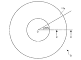
- FIG. 1A to 1C and FIG. 2 show the shape of the magnetic disk glass substrate G of the present embodiment.
- FIG. 1A is a plan view of a glass substrate for a magnetic disk according to the present embodiment.
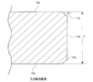
- FIG. 1B is an enlarged cross-sectional view taken along line XX in FIG. 1A.
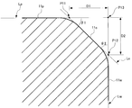
- FIG. 1C is an enlarged view of a part of FIG. 1B.
- FIG. 2 is an enlarged view of a main part of FIG. 1B.
- the glass substrate may be fixed so that the chamfered surface on the outer peripheral side is substantially horizontal, and the fixed glass substrate or the stylus of the contour shape measuring machine may be moved in the radial direction of the glass substrate.
- the magnetic disk glass substrate G of the present embodiment has a donut shape with a circular hole formed at the center and an annular outer shape.
- the magnetic disk glass substrate G of this embodiment includes a pair of main surfaces 11p and 12p, an inner peripheral side wall surface (that is, a circular hole side wall surface), and an outer peripheral side wall surface ( That is, it has two side wall surfaces (outer side wall surfaces).
- FIG. 1A the magnetic disk glass substrate G of the present embodiment has a donut shape with a circular hole formed at the center and an annular outer shape.
- the magnetic disk glass substrate G of this embodiment includes a pair of main surfaces 11p and 12p, an inner peripheral side wall surface (that is, a circular hole side wall surface), and an outer peripheral side wall surface ( That is, it has two side wall surfaces (outer side wall
- the side wall surface 11w of the glass substrate G is an outer peripheral side wall surface.
- the side wall surface 11w on the outer peripheral side of the glass substrate G preferably includes a surface orthogonal to each of the pair of main surfaces 11p and 12p.
- Chamfered surfaces 11c and 12c are formed between the pair of main surfaces 11p and 12p and the outer peripheral side wall surface 11w, respectively.
- FIG. 1B the case where the chamfered surfaces 11c and 12c are formed in a planar shape is shown as an example.
- the chamfered surfaces 11c and 12c are, for example, surfaces curved outward of the glass substrate G. It may be formed so as to include. In this case, it is preferable that the degree of bending is substantially constant along the circumferential direction of the glass substrate G.
- the shape of the edge part of the outer peripheral side of the glass substrate G for magnetic discs of this embodiment is demonstrated.
- the straight portions of the main surface 11p, the side wall surface 11w, and the chamfered surface 11c are denoted as Lp, Lw, and Lc, respectively.
- the intersection of the straight portion Lp of the main surface 11p and the straight portion Lc of the chamfered surface 11c is P11, and the intersection of the straight portion Lw of the side wall surface 11w and the straight portion Lc of the chamfered surface 11c.
- the angle (chamfering angle; ⁇ 1) formed by the straight line portion Lp of the main surface 11p and the straight line portion Lc of the chamfered surface 11c is preferably 40 to 70 degrees, for example.
- the angle (chamfering angle; ⁇ 2) formed by the straight line portion Lp of the main surface 11p and the straight line portion Lc of the chamfered surface 11c is preferably 20 to 50 degrees, for example.
- the distance D1 between the points P11 and P13 is preferably 0.05 to 0.20 mm, and the distance D2 between the points P12 and P13 is preferably 0.10 to 0.30 mm.
- outer peripheral side wall surface 11w and the chamfered surfaces 11c and 12c are collectively referred to as an outer peripheral end surface, and an inner peripheral side wall surface and a chamfered surface (not shown) are collectively referred to as an inner peripheral end surface.
- R is the radius of a circle C2 that forms the curvature of the shape of the portion between the side wall surface 11w and the chamfered surface 11c, and is the curvature radius of the shape of the portion.
- the curvature radius R can be determined as follows, for example. First, let P1 be the intersection of an imaginary line L1 extending the straight line portion of the chamfered surface 11c and a virtual line L2 extending the straight line portion of the side wall surface 11w.
- an imaginary line L3 passing through the intersection point P1 and extending perpendicularly to the straight portion of the chamfered surface 11c is set.
- an intersection between the portion between the side wall surface 11w and the chamfered surface 11c and the virtual line L3 is defined as P2.
- a circle C1 having a predetermined radius (for example, 50 ⁇ m) around the intersection P2 is set.
- two intersections of the part between the side wall surface 11w and the chamfering surface 11c, and the outer periphery of the circle C1 be P3 and P4, respectively.
- a circle C2 passing through each of the three intersections P2, P3, P4 is set.
- the radius of curvature R of the shape of the portion between the side wall surface 11w and the chamfered surface 11c is determined.
- the curvature radius of the shape of the part between the side wall surface 11w and the chamfered surface 12c can also be stopped similarly to the above.
- measurement points are provided every 30 degrees in the circumferential direction with reference to the center C of the glass substrate G (see FIG. 1A). That is, the number of measurement points is 12.
- the radius of curvature R of the shape of the portion between the side wall surface 11w and the chamfered surface 11c is determined, a total of twelve (the portion between the other chamfered surface of the disc is also a portion). 24) (including the shape), the difference (absolute value) in the radius of curvature R between adjacent measurement points is set to 0.01 mm or less.
- the change of the shape of the outer peripheral end surface in the circumferential direction of the glass substrate G can be reduced, when the magnetic disk manufactured using this glass substrate G is rotated at a high speed, the outer peripheral end surface of the magnetic disk The surrounding airflow can be stabilized. Further, when this magnetic disk is mounted on the spindle of a magnetic disk drive device, the gap between the outer wall of the magnetic disk (shroud) and the outer peripheral end surface of the magnetic disk can be kept substantially constant. The airflow in can be stabilized. Therefore, according to the glass substrate G of the present embodiment, fluttering during high-speed rotation can be further reduced. In addition, when the difference of the curvature radius R between adjacent measurement points is 0.005 mm or less, it is preferable at the point which can further reduce fluttering at the time of high speed rotation.
- the curvature radius (second curvature radius) of the shape of the portion between the main surface 11p and the chamfered surface 11c may be obtained. Specifically, an intersection of an imaginary line L1 extending the straight line portion of the chamfered surface 11c and an imaginary line L4 (not illustrated) extending the straight line portion of the main surface 11p is defined as P5 (not illustrated). Next, an imaginary line L5 (not shown) passing through the intersection point P5 and extending perpendicularly to the main surface 11p is set. Next, the intersection between the main surface 11p and the chamfered surface 11c and the virtual line L5 is defined as P6 (not shown).
- a circle C3 (not shown) having a predetermined radius (for example, 10 ⁇ m) around the intersection P6 is set. Further, two intersections between the portion between the main surface 11p and the chamfered surface 11c and the outer periphery of the circle C3 are defined as P7 and P8 (respectively omitted). Further, a circle C4 (not shown) passing through each of the three intersections P6, P7, P8 is set. Then, by determining the radius of the circle C4, the second curvature radius of the shape of the portion between the main surface 11p and the chamfered surface 11c is determined. In addition, the 2nd curvature radius of the shape of the part between the main surface 12p and the chamfering surface 12c can also be stopped similarly to the above.
- the second radius of curvature is determined at each measuring point (12 measuring points) between adjacent measuring points
- the difference in the second curvature radius may be set to 0.004 mm or less.
- the size of the magnetic disk glass substrate G of the present embodiment is not limited, but may be, for example, a nominal diameter of 2.5 inches.
- the glass substrate G for magnetic disk of the present embodiment may be used for a magnetic disk incorporated in a magnetic disk drive device mounted on a server device or a notebook personal computer, for example.
- the conventional magnetic disk since the conventional magnetic disk is operated at a high speed rotation of, for example, 10,000 rpm or more, it has been required to secure a desired plate thickness that does not cause fluttering at such a high speed rotation.
- magnetic disk drive devices have been reduced in size and thickness based on demands for reduction in size and thickness of notebook personal computers and the like. Accordingly, there is an increasing demand for thinning the magnetic disk.
- the conventional magnetic disk when the plate thickness is simply reduced (thinned), it becomes easy to be affected by the air flow accompanying the rotation of the magnetic disk, and it has been difficult to reduce fluttering. For this reason, it has been difficult for conventional magnetic disks to meet the demand for thinning.
- the present embodiment by reducing the change in the shape of the outer peripheral end face in the circumferential direction of the glass substrate G, the airflow around the outer peripheral end face of the magnetic disk can be stabilized, so the thickness of the glass substrate G is small. Even in this case, fluttering can be reduced. As a result, it is possible to meet the demand for a thinner magnetic disk.
- the plate thickness T of the glass substrate G (see FIG. 1B) is nominally 0.635 mm or less, the effect obtained by applying the configuration of the present embodiment becomes significant, which is preferable.
- the case where the plate thickness of the glass substrate is “nominal 0.635 mm” includes the case where the actual plate thickness is slightly thicker or slightly thinner than 0.635 mm.
- a glass base plate having a predetermined shape as a base of a magnetic disk glass substrate is cut out from the plate glass.
- the glass base plate may be formed by press molding using an upper mold and a lower mold, for example.
- a glass base plate can also be manufactured not only using these methods but using well-known manufacturing methods, such as a downdraw method, a redraw method, and a fusion method.
- a chamfering step for forming a chamfered surface at the end is performed.
- the chamfering process may be performed by using a conventionally known apparatus and method, for example, while supplying a grinding liquid to the grinding portion using a rotating general grinding wheel. Grooves may be formed in advance on the surface of the total-type grindstone so as to have a desired end shape after processing.
- the chamfering step first, the outer peripheral end and the inner peripheral end of the annular glass base plate are subjected to rough grinding using, for example, a relatively rough diamond grindstone to form a chamfered shape at a relatively high speed.
- the chamfered surface is finish-ground to a surface property close to a mirror surface.
- the surface roughness after finishing can be reduced by increasing the count of the grinding wheel used for grinding (that is, by reducing the grain size of the diamond abrasive grains). You can reduce your bill. Since the shape prepared in the grinding process is maintained as the machining allowance for end face polishing is smaller, the shape accuracy can be increased. That is, the difference in the radius of curvature at the measurement positions adjacent in the circumferential direction of the outer peripheral end can be reduced.
- End face polishing step end face polishing of an annular glass base plate is performed.
- the end surface polishing is performed by contacting the polishing means while rotating the glass base plate in the same manner as the chamfering step. Since there is no processing for grinding / polishing the end face after the end face polishing, the end face polishing plays an important role in substantially determining the final shape in the circumferential direction.
- a magnetic slurry is formed by holding the magnetic slurry along the lines of magnetic force, and this mass is brought into contact with the inner peripheral end surface and the outer peripheral end surface of the glass base plate to move relative to each other. Polishing the inner and outer peripheral edges of the plate. At this time, the side wall surface and the chamfered surface can be polished simultaneously.
- the magnetic slurry includes a magnetorheological fluid and fine particles such as cerium oxide and zirconium oxide as abrasive grains.
- a magnetorheological fluid for example, a fluid containing magnetic fine particles made of Fe and nonpolar or polar oil is used.
- the disturbance of the shape can be made extremely small, and the surface roughness and undulation can also be made extremely small.
- the hair tip bends or breaks when the tip of the brush contacts the workpiece surface, and the pressure when the tip of the brush contacts within the side wall surface or chamfered surface varies.
- the shape accuracy of the end face is deteriorated due to local deep blurring.
- the boundary portion between the side wall surface and the chamfered surface may be shaved unevenly in the circumferential direction, and the shape accuracy of the end surface may deteriorate.
- the machining allowance in the end surface polishing step of the present case can be significantly reduced as compared with a conventional method using a brush, and can be, for example, 10 ⁇ m or less.
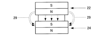
- FIG. 3A to FIG. 3C and FIG. 4 are diagrams for explaining an example of a polishing method in end face polishing in the present embodiment.
- the apparatus 20 for polishing the end surface polishes the end surface of the glass substrate using a magnetism generating means and a magnetic slurry.
- the outline of the apparatus 20 for performing end face polishing will be described.
- the apparatus 20 includes, for example, a pair of magnets 22 and 24 that are permanent magnets, a spacer 26, and a non-magnetic material such as a cylinder made of stainless steel.
- a pipe 28 having a shape. Magnets 22 and 24 and a spacer 26 are built in the pipe 28.
- the glass base plate for end face polishing is held by a holder (not shown).
- the pipe 28 is arrange
- the lump 30 formed by the magnets 22 and 24 in the pipe 28 is brought into contact with the outer peripheral end face of the glass base plate.
- a holder (not shown) that holds the pipe 28 and the glass base plate of the apparatus 20 is mechanically connected to a drive motor (not shown). By rotating the pipe 28 and the holder to relatively move the outer peripheral end surface of the glass base plate and the lump 30, the outer peripheral end surface of the glass base plate can be polished.
- the pipe 28 may be rotated at, for example, 500 to 5000 rpm.
- the glass base plate may be rotated at 10 to 1000 rpm, for example.
- the rotation direction of both at the processing point may be either down cut or up cut, but the down cut is preferable because it has a lower polishing rate but less variation in shape.
- both up-cut and down-cut if the difference in tangential speed between the glass substrate and the magnetic slurry at the processing point is 800 m / min or less, the variation in the shape in the circumferential direction is caused between one surface and the other surface. This is preferable because the difference between them (described later, the difference between the A surface and the B surface) can be reduced.
- the magnet 22 and the magnet 24 are close to each other and function as magnetism generating means, thereby forming a magnetic force line 29 that travels from the magnet 22 to the magnet 24 as shown in FIG. 3B.
- the magnetic force lines 29 proceed so as to protrude outward from the centers of the magnets 22 and 24, and proceed in the thickness direction of the glass base plate.
- a spacer 26 made of a non-magnetic material is provided in order to create a lump 30 of magnetic slurry on the outer periphery of the pipe 28 as shown in FIG. 3C.
- the magnetic flux density in the magnetism generating means may be set to such an extent that the magnetic slurry lump 30 is formed, but is preferably 0.1 to 10 Tesla from the viewpoint of efficient end face polishing.
- a permanent magnet is used as the magnetism generating means, but an electromagnet can also be used.
- the magnets 22 and 24 are fixed to the pipe 28 without using the spacer 26, and the separation distance between the N pole end face of the magnet 22 and the S pole end face of the magnet 24 can be secured constant.
- the abrasive grains contained in the magnetic slurry known abrasive grains of glass substrates such as cerium oxide, colloidal silica, zirconia oxide, alumina abrasive grains, diamond abrasive grains and the like can be used.
- the average particle diameter (D50) of the abrasive grains is, for example, 0.5 to 10 ⁇ m. By using abrasive grains in this range, the inner end face of the glass base plate can be satisfactorily polished.
- the abrasive grains are contained, for example, in an amount of 1 to 20 vol% in the magnetic slurry.
- the average particle diameter (D50) means a particle diameter at which the cumulative volume frequency calculated by the volume fraction is 50% calculated from the smaller particle diameter.
- Precision grinding process In a precision grinding process, it grinds with respect to the main surface of an annular
- the fixed abrasive grindstone for example, a grinding pad in which diamond abrasive grains are fixed with a resin can be used.
- the double-sided grinding apparatus has a pair of upper and lower surface plates (upper surface plate and lower surface plate), and an annular glass base plate is sandwiched between the upper surface plate and the lower surface plate. Then, by moving both the upper surface plate and the lower surface plate, or both of them, the main surface of the glass base plate is ground by relatively moving the glass base plate and each surface plate. be able to.
- polishing main surface grinding
- polishing is given to the main surface of the ground glass substrate.
- a double-side polishing apparatus having a planetary gear mechanism is used.
- an annular flat plate polishing pad is attached to the upper surface of the lower surface plate and the bottom surface of the upper surface plate as a whole.
- the glass element mounted on the carrier is used.
- the polishing pad is pressed against the plate, and the polishing liquid is supplied between the glass base plate and the polishing pad.
- the material of the polishing pad is, for example, foamed urethane.
- As the polishing liquid for example, a polishing liquid containing cerium oxide or zirconium oxide as polishing abrasive grains is used.
- polishing process is chemically strengthened.
- the chemical strengthening liquid for example, a mixed melt of potassium nitrate and sodium sulfate can be used. Chemical strengthening is performed by immersing a glass base plate in a chemical strengthening solution.
- Second Polishing is applied to the glass base plate that has been chemically strengthened and sufficiently cleaned.
- the second polishing for example, a polishing apparatus similar to the first polishing is used.
- the difference from the first polishing is that the type and particle size of the free abrasive grains are different and the hardness of the resin polisher is different.
- the free abrasive grains used in the second polishing for example, fine particles (particle size: diameter of about 10 to 50 nm) such as colloidal silica are used.
- a magnetic disk is obtained as follows using a magnetic disk glass substrate.
- the magnetic disk is, for example, on the main surface of a glass substrate for magnetic disk (hereinafter simply referred to as “substrate”), in order from the closest to the main surface, at least an adhesion layer, an underlayer, a magnetic layer (magnetic recording layer), and a protection A layer and a lubricating layer are laminated.
- the substrate is introduced into a film forming apparatus that has been evacuated, and a film is sequentially formed from an adhesion layer to a magnetic layer on the main surface of the substrate in an Ar atmosphere by a DC magnetron sputtering method.
- a CoPt alloy can be used as the adhesion layer
- CrRu can be used as the underlayer.
- a CoPt alloy can be used. It is also possible to form a CoPt-based alloy and FePt based alloy L 10 regular structure and magnetic layer for heat-assisted magnetic recording.
- a magnetic recording medium can be formed by forming a protective layer using, for example, C 2 H 4 by a CVD method and subsequently performing nitriding treatment for introducing nitrogen into the surface. Thereafter, for example, PFPE (perfluoropolyether) is applied on the protective layer by a dip coating method, whereby a lubricating layer can be formed.
- PFPE perfluoropolyether
- the manufactured magnetic disk is preferably a magnetic disk drive device (HDD) as a magnetic recording / reproducing device, which includes a magnetic head equipped with a DFH (Dynamic Flying Height) control mechanism and a spindle for fixing the magnetic disk. (Hard Disk Drive)).
- HDD magnetic disk drive device
- DFH Dynamic Flying Height
- Example 1 About the glass substrate for magnetic discs of Example 1, it produced by performing each process of the manufacturing method of the glass substrate for magnetic discs of this embodiment in order.
- a press molding method was used, followed by rough grinding with loose abrasive grains.
- a circular hole was formed at the center of the glass base plate using a cylindrical drill.
- rough grinding was performed to form a chamfered surface using a diamond grindstone with a particle size of # 400. Thereafter, the chamfered surface was finish-ground using a diamond grindstone with a grain size of # 2000.
- the shape of the chamfered part was set to 45 degrees for both ⁇ 1 and ⁇ 2 (see FIG. 1C). Further, the distance D1 shown in FIG. 1C is 0.15 mm, and the distance D2 is 0.15 mm.
- the front and back surfaces and the chamfered portions on the inner and outer peripheral sides have the same shape.
- end surface polishing of (4) end surface polishing was performed using the magnetic slurry described above.
- the magnetic slurry used was a magnetic fluid in which fine particles of Fe were dispersed in nonmagnetic oil and cerium oxide was dispersed as abrasive grains.
- a permanent magnet was used as the magnet, and it was processed by up-cutting.
- the chamfering allowance in the step (4) was 10 ⁇ m.
- grinding was performed using a grinding apparatus in which a diamond pad was fixed with a resin and a grinding pad that was a fixed abrasive grindstone was attached to a surface plate.
- a polishing liquid containing cerium oxide abrasive grains was used, and a hard urethane pad was used as the polishing pad.
- the glass base plate was immersed in a mixed melt of potassium nitrate and sodium nitrate as the chemical strengthening solution.
- a polishing liquid containing fine particles of colloidal silica was used as an abrasive. Thereafter, the glass base plate was washed to obtain a glass substrate for a magnetic disk.
- Example 2 A glass substrate for a magnetic disk was manufactured in the same manner as in Example 1 except that the allowance for end face polishing in (4) was 8 ⁇ m.
- Example 3 In the chamfering step of (3), after rough grinding using a diamond grindstone of particle size # 500, finish grinding using a diamond grindstone of particle size # 3000, and further, the allowance for end surface polishing of (4) was set to 8 ⁇ m.
- a magnetic disk glass substrate was produced in the same manner as in Example 2 except for the above.
- Example 4 A glass substrate for a magnetic disk was manufactured in the same manner as in Example 3 except that the allowance for the end surface polishing in (4) was 5 ⁇ m.
- Example 5 A glass substrate for a magnetic disk was manufactured in the same manner as in Example 3 except that the end face polishing in (4) was such that the rotation direction of the magnet and the glass base plate was downcut at the processing point.
- Example 6 A glass substrate for a magnetic disk was manufactured in the same manner as in Example 5 except that in the end surface polishing in (4), the machining allowance was 8 ⁇ m.
- Example 7 A glass substrate for a magnetic disk was manufactured in the same manner as in Example 5 except that in the end surface polishing of (4), the machining allowance was 4 ⁇ m.
- Comparative Example 1 On the other hand, in Comparative Example 1, in the chamfering of (3), rough grinding was performed to form a chamfered surface using a diamond grindstone having a particle size of # 400. In the comparative example, finish grinding is not performed. In the end face polishing of (4), the end face of the glass base plate was polished with a polishing brush using cerium oxide as the free abrasive grains. The chamfering allowance in the step (4) was 50 ⁇ m.
- measurement points are provided on the outer peripheral end surface every 30 degrees in the circumferential direction of the main surface with reference to the center of the main surface, and the side wall surface and the chamfered surface at each measurement point
- the radius of curvature of the shape of the part in the middle was determined.
- the curvature radius measured 24 points
- the difference in curvature radius when “0 to 30 degrees” means the absolute value of the difference between the curvature radius at the measurement point of 0 degrees and the curvature radius at the measurement point of 30 degrees. Further, for example, the back side of the 30-degree position on the A surface is set to the 30-degree position on the B surface.
- a magnetic disk having a magnetic layer formed on the obtained glass substrate for magnetic disk was produced. Thereafter, fluttering was evaluated for each of the magnetic disks of Examples and Comparative Examples using a laser Doppler vibrometer.
- a magnetic disk is mounted on a spindle of a hard disk drive (HDD) having a rotational speed of 7200 rpm, and laser light is irradiated from the laser Doppler vibrometer to the main surface of the rotating magnetic disk.
- the laser beam reflected by the magnetic disk is received by the laser Doppler vibrometer, thereby obtaining a vibration value in the thickness direction of the magnetic disk. More details are as follows.
- a magnetic disk is mounted on a 2.5-inch HDD spindle, the magnetic disk is rotated, and the main surface of the rotating magnetic disk is irradiated with laser light from a laser Doppler vibrometer. .
- a cover is properly attached and a hole for laser irradiation is formed in the HDD cover.
- the laser Doppler vibrometer receives the laser light reflected by the magnetic disk, and the amount of shake in the thickness direction of the magnetic disk is measured as a fluttering characteristic value.
- fluttering characteristic values were measured under the following conditions. ⁇ Environment of HDD and measurement system: Maintain the temperature at 25 ° C.
- Table 3 shows the evaluation of fluttering when the difference in radius of curvature between adjacent measurement points is 0.01 mm or less and the maximum difference in the second radius of curvature between adjacent measurement points is different. Results are shown. In addition, fluttering evaluation was performed in the same manner as described above except that a 2.5-inch HDD having a rotation speed of 10,000 rpm was used. As can be seen from Table 3, a better evaluation could be obtained when the difference in the second curvature radius between adjacent measurement points was 0.004 mm or less.
- a 2.5-inch magnetic disk is produced from a glass substrate for magnetic disk having a glass composition 2 different from the glass composition 1 described above.
- the method for producing the glass substrate for magnetic disk is the same as in the case of glass composition 1 (that is, the above (1) to (8)).
- the glass composition 2 is preferable as a glass composition used for the glass substrate for magnetic disks used for the magnetic disk for energy assist magnetic recording as mentioned above.
- Example 8 the radius of curvature of the shape of the portion between the side wall surface and the chamfered surface at each measurement point was determined at measurement points every 30 degrees in the circumferential direction of the main surface with reference to the center of the main surface. .
- the maximum value of the difference in curvature radius between adjacent measurement points was 0.01 mm.
- Example 9 A magnetic disk glass substrate was produced in the same manner as in Example 1 and Comparative Example 1 except that the center value of the plate thickness was 0.500 mm, and film formation was performed to obtain a magnetic disk (Example 9, Comparative example 3).
- a glass substrate for a magnetic disk was manufactured in the same manner as in Example 1 and Comparative Example 1 except that the center value of the plate thickness was 0.800 mm, and film formation was performed to obtain a magnetic disk (each of the examples). 10 and Comparative Example 4).
- a glass substrate for a magnetic disk was manufactured in the same manner as in Example 1 and Comparative Example 1 except that the center value of the plate thickness was 1.000 mm, and film formation was performed to obtain a magnetic disk (each of the examples). 11 and Comparative Example 5).
- Examples 9, 10, and 11 were the same as Example 1, and Comparative Examples 3, 4, and 5 were the same as Comparative Example 1.
- fluttering evaluation was performed in the same manner as described above except that a 2.5-inch HDD having a rotation speed of 5400 rpm was used. It was.
- the improvement width of the fluttering characteristic value (the value obtained by subtracting the fluttering measurement value of the example from the fluttering characteristic value of the comparative example) in the example and the comparative example having the same plate thickness was obtained as follows.
- -Improvement width when plate thickness is 0.800 mm 5.0 nm ⁇ Improvement width when plate thickness is 0.635 mm: 10.0 nm ⁇ Improvement width when plate thickness is 0.500 mm: 20.5 nm From the above results, it was confirmed that the present invention exerts a particularly large improvement effect when the plate thickness is 0.635 mm or less.
- the relationship between the difference between the A surface and the B surface of the difference in radius of curvature adjacent to each other and fluttering was investigated. Specifically, the average value of the difference between adjacent curvature radii for each of the A surface and the B surface is obtained, and the difference between the average value on the A surface and the average value on the B surface is obtained as an absolute value.
- the difference from the B surface ( ⁇ R) was used. ⁇ R was varied by controlling the tangential speed at the processing point during end face polishing based on the manufacturing conditions of Example 1. In Examples 12 and 13, the difference in tangential velocity was set to 800 m / min or less, and in Examples 14 and 15, it was set to be greater than 800 m / min.
- fluttering evaluation was performed in the same manner as described above except that a 2.5-inch HDD having a rotation speed of 15000 rpm was used. Note that this evaluation was made under very severe conditions, and there is no practical problem even at level 3. As a result of the evaluation, it was found that fluttering characteristics at the time of ultra-high speed rotation are further improved by setting ⁇ R to 0.003 mm or less. From this, it was found that it is important that the difference in the radius of curvature adjacent to each other in the circumferential direction is the same between the A surface and the B surface during the ultra-high speed rotation.
Landscapes
- Chemical & Material Sciences (AREA)
- Engineering & Computer Science (AREA)
- Ceramic Engineering (AREA)
- Inorganic Chemistry (AREA)
- Magnetic Record Carriers (AREA)
- Manufacturing Of Magnetic Record Carriers (AREA)
Abstract
Description
この理由について、本願発明者らは、以下のように考察している。すなわち、ガラス基板の周方向における外周端面の形状の短い周期での変化が大きくなると、当該外周端面と接する空気の量が大きく変化し、それによって、基板の回転に伴う外周端面周辺の気流が安定しなくなると考えられる。また、近年の磁気ディスクドライブ装置には、スピンドルに装着された磁気ディスクの外周を覆う壁(シュラウド)が設けられる場合があり、当該壁と磁気ディスクの外周端面との間の間隙を小さくすることにより、当該間隙における気流を安定させることが可能となっている。しかしながら、間隙が小さい状態で、ガラス基板の周方向における外周端面の形状の変化が大きくなると、当該壁と磁気ディスクの外周端面との間の間隙の変化の割合が大きくなり、それによって、当該間隙における気流が乱れ易くなることが考えられる。したがって、ガラス基板の周方向における外周端面の形状の変化を小さくすれば、ガラス基板の外周端面周辺の気流を安定させることができるとともに、当該壁と磁気ディスクの外周端面との間の間隙をほぼ一定に保つことができるので、フラッタリングをさらに低減することが可能となる。 As a result of earnest research to further reduce fluttering during high-speed rotation, the inventors of the present application have found that the outer peripheral end surface of the glass substrate (a side wall surface orthogonal to the main surface and a chamfered surface between the main surface and the side wall surface) It was found that fluttering can be further reduced by reducing the change in shape in the circumferential direction.
The present inventors consider the reason as follows. That is, when the change in the shape of the outer peripheral end face in the circumferential direction of the glass substrate in a short cycle increases, the amount of air in contact with the outer peripheral end face changes greatly, thereby stabilizing the airflow around the outer peripheral end face accompanying the rotation of the substrate. It is thought that it will not. Further, in recent magnetic disk drive devices, a wall (shroud) that covers the outer periphery of the magnetic disk mounted on the spindle may be provided, and the gap between the wall and the outer peripheral end surface of the magnetic disk is reduced. This makes it possible to stabilize the airflow in the gap. However, when the change in the shape of the outer peripheral end face in the circumferential direction of the glass substrate increases in a state where the gap is small, the rate of change in the gap between the wall and the outer peripheral end face of the magnetic disk increases. It is conceivable that the airflow in the air tends to be disturbed. Therefore, if the change in the shape of the outer peripheral end surface in the circumferential direction of the glass substrate is reduced, the air flow around the outer peripheral end surface of the glass substrate can be stabilized, and the gap between the wall and the outer peripheral end surface of the magnetic disk can be substantially reduced. Since it can be kept constant, fluttering can be further reduced.
本実施形態における磁気ディスク用ガラス基板の材料として、アルミノシリケートガラス、ソーダライムガラス、ボロシリケートガラスなどを用いることができる。特に、化学強化を施すことができ、また主表面の平坦度及び基板の強度において優れた磁気ディスク用ガラス基板を作製することができるという点で、アルミノシリケートガラスを好適に用いることができる。アモルファスのアルミノシリケートガラスとするとさらに好ましい。 [Magnetic disk glass substrate]
Aluminosilicate glass, soda lime glass, borosilicate glass, or the like can be used as the material for the magnetic disk glass substrate in the present embodiment. In particular, aluminosilicate glass can be suitably used in that it can be chemically strengthened and a glass substrate for a magnetic disk excellent in the flatness of the main surface and the strength of the substrate can be produced. More preferably, it is an amorphous aluminosilicate glass.
図1Aに示すように、本実施形態の磁気ディスク用ガラス基板Gは、円形の円孔が中心に形成され、かつ環状の外形を備えたドーナツ型の形状を備えている。図1Bに示すように、本実施形態の磁気ディスク用ガラス基板Gは、一対の主表面11p,12pと、内周側の側壁面(つまり、円孔の側壁面)及び外周側の側壁面(つまり、外形の側壁面)の2つの側壁面を有する。図1Bにおいて、ガラス基板Gの側壁面11wは外周側の側壁面である。ガラス基板Gの外周側の側壁面11wは、一対の主表面11p,12pの各々と直交する面を含むことが好ましい。一対の主表面11p,12pと外周側の側壁面11wとの間には、それぞれ面取面11c,12cが形成されている。ここで、図1Bでは、面取面11c,12cが平面状に形成されている場合を一例として示しているが、面取面11c,12cは、例えば、ガラス基板Gの外方に湾曲する面を含むように形成されてもよい。この場合、湾曲の程度は、ガラス基板Gの周方向に沿ってほぼ一定であることが好ましい。 1A to 1C and FIG. 2 show the shape of the magnetic disk glass substrate G of the present embodiment. FIG. 1A is a plan view of a glass substrate for a magnetic disk according to the present embodiment. FIG. 1B is an enlarged cross-sectional view taken along line XX in FIG. 1A. FIG. 1C is an enlarged view of a part of FIG. 1B. FIG. 2 is an enlarged view of a main part of FIG. 1B. Here, in order to obtain the shape of the cross section, it is not necessary to actually cut the substrate, and measurement may be performed using a contour shape measuring machine. Specifically, for example, the glass substrate may be fixed so that the chamfered surface on the outer peripheral side is substantially horizontal, and the fixed glass substrate or the stylus of the contour shape measuring machine may be moved in the radial direction of the glass substrate.
As shown in FIG. 1A, the magnetic disk glass substrate G of the present embodiment has a donut shape with a circular hole formed at the center and an annular outer shape. As shown in FIG. 1B, the magnetic disk glass substrate G of this embodiment includes a pair of
主表面11pの直線部Lpと面取面11cの直線部Lcとのなす角(面取り角度;θ1)は、例えば40~70度とすることが好ましい。主表面11pの直線部Lpと面取面11cの直線部Lcとのなす角(面取り角度;θ2)は、例えば20~50度とすることが好ましい。また、点P11と点P13の間の距離D1は0.05~0.20mm、点P12と点P13の間の距離D2は0.10~0.30mmとすることが好ましい。上述の範囲内の形状とすることで、ガラス基板の製造完了後の検査工程、成膜工程、HDDの組み立て工程などにおいて外周端部を把持したときでも、外周端部がカケたり、基板が落下したりする不具合を防止することができる。
尚、図1Cを参照して磁気ディスク用ガラス基板Gの外周側の一方の主表面に近い端部の形状について説明したが、他の端部(つまり、外周側の他方の主表面に近い端部や、内周側の端部)についても同様である。
以下の説明では適宜、外周側の側壁面11wおよび面取面11c,12cを総称して外周端面といい、図示しない内周側の側壁面および面取面を総称して内周端面という。 With reference to FIG. 1C, the shape of the edge part of the outer peripheral side of the glass substrate G for magnetic discs of this embodiment is demonstrated. In FIG. 1C, the straight portions of the
The angle (chamfering angle; θ1) formed by the straight line portion Lp of the
In addition, although the shape of the edge part close | similar to one main surface of the outer peripheral side of the glass substrate G for magnetic discs was demonstrated with reference to FIG. 1C, the other edge part (namely, end close | similar to the other main surface of an outer peripheral side) This is the same for the portion and the inner peripheral end).
In the following description, the outer peripheral
そして、円C2の半径をもとめることによって、側壁面11wと面取面11cとの間の部分の形状の曲率半径Rがもとめられる。
なお、側壁面11wと面取面12cとの間の部分の形状の曲率半径も、上記と同様にもとめることができる。 Next, with reference to FIG. 2, a method for determining the curvature radius of the shape of the portion between the
Then, by determining the radius of the circle C2, the radius of curvature R of the shape of the portion between the
In addition, the curvature radius of the shape of the part between the
そして、円C4の半径をもとめることによって、主表面11pと面取面11cとの間の部分の形状の第2曲率半径がもとめられる。
なお、主表面12pと面取面12cとの間の部分の形状の第2曲率半径も、上記と同様にもとめることができる。 Similarly to the above, the curvature radius (second curvature radius) of the shape of the portion between the
Then, by determining the radius of the circle C4, the second curvature radius of the shape of the portion between the
In addition, the 2nd curvature radius of the shape of the part between the
以下、本実施形態の磁気ディスク用ガラス基板の製造方法について、工程毎に説明する。ただし、各工程の順番は適宜入れ替えてもよい。 [Method of manufacturing glass substrate for magnetic disk]
Hereinafter, the manufacturing method of the glass substrate for magnetic disks of this embodiment is demonstrated for every process. However, the order of each step may be changed as appropriate.
例えばフロート法によって板状ガラスを形成した後、この板状ガラスから、磁気ディスク用ガラス基板の元となる所定形状のガラス素板が切り出される。フロート法の代わりに、例えば上型と下型を用いたプレス成形によってガラス素板を成形してもよい。なお、ガラス素板は、これらの方法に限らず、ダウンドロー法、リドロー法、フュージョン法などの公知の製造方法を用いて製造することもできる。
なお、ガラス素板の両主表面に対して、必要に応じて、遊離砥粒を用いた粗研削加工を行ってもよい。 (1) Molding of glass base plate and rough grinding step After forming a plate glass by, for example, a float process, a glass base plate having a predetermined shape as a base of a magnetic disk glass substrate is cut out from the plate glass. Instead of the float process, the glass base plate may be formed by press molding using an upper mold and a lower mold, for example. In addition, a glass base plate can also be manufactured not only using these methods but using well-known manufacturing methods, such as a downdraw method, a redraw method, and a fusion method.
In addition, you may perform the rough grinding process using a loose abrasive grain with respect to both the main surfaces of a glass base plate as needed.
円筒状のドリルを用いて、ガラス素板の中心部に円孔を形成し、円環状のガラス素板とする。なお、ダイヤモンドカッター等を用いてガラス素板の表面に円形の切筋を形成した後、切筋に沿って割断することによって円孔を形成してもよい。 (2) Circular hole formation process Using a cylindrical drill, a circular hole is formed in the center part of a glass base plate, and it is set as an annular | circular shaped glass base plate. In addition, after forming a circular score on the surface of a glass base plate using a diamond cutter etc., you may form a circular hole by cleaving along a score.
円孔形成工程の後、端部(外周端部及び内周端部)に面取面を形成するための面取り工程が行われる。面取り工程は、従来知られた装置及び方法を用いることができ、例えば回転する総型砥石を用いて研削加工部に研削液を供給しながら実施すればよい。総型砥石の表面には、加工後に所望の端部形状となるように予め溝を形成しておけばよい。面取り工程では先ず、円環状のガラス素板の外周端部及び内周端部に対して、例えば比較的粗いダイヤモンド砥石等を用いて粗研削を行い、比較的高速で面取り形状を作り込む。次いで、例えば比較的細かいダイヤモンド砥石等、研磨レートは低いが端部表面にダメージを与えない砥石を用いて、面取面を鏡面に近い表面性状まで仕上げ研削する。このとき、ガラス素板と砥石はいずれも回転して接触することにより研削加工されるので、ガラス素板における円周方向の形状が形づくられる。
ここで、研削加工に用いる研削砥石の番手を高くする(すなわち、ダイヤモンド砥粒の粒径を小さくする)ことにより、仕上がり後の表面粗さを小さくすることができ、この後の端面研磨の取り代を少なくできる。端面研磨の取り代が小さいほど研削工程で整えた形状が維持されるため、形状精度が高めることができる。すなわち、外周端部の周方向において隣接する測定位置での曲率半径の差を小さくすることができる。 (3) Chamfering step After the circular hole forming step, a chamfering step for forming a chamfered surface at the end (outer peripheral end and inner peripheral end) is performed. The chamfering process may be performed by using a conventionally known apparatus and method, for example, while supplying a grinding liquid to the grinding portion using a rotating general grinding wheel. Grooves may be formed in advance on the surface of the total-type grindstone so as to have a desired end shape after processing. In the chamfering step, first, the outer peripheral end and the inner peripheral end of the annular glass base plate are subjected to rough grinding using, for example, a relatively rough diamond grindstone to form a chamfered shape at a relatively high speed. Next, using a grindstone that has a low polishing rate but does not damage the end surface, such as a relatively fine diamond grindstone, the chamfered surface is finish-ground to a surface property close to a mirror surface. At this time, since the glass base plate and the grindstone are both rotated and brought into contact with each other, the circumferential shape of the glass base plate is formed.
Here, the surface roughness after finishing can be reduced by increasing the count of the grinding wheel used for grinding (that is, by reducing the grain size of the diamond abrasive grains). You can reduce your bill. Since the shape prepared in the grinding process is maintained as the machining allowance for end face polishing is smaller, the shape accuracy can be increased. That is, the difference in the radius of curvature at the measurement positions adjacent in the circumferential direction of the outer peripheral end can be reduced.
次に、円環状のガラス素板の端面研磨が行われる。端面研磨は、面取り工程と同様にガラス素板を回転させながら研磨手段と接触させることにより行われる。そして、端面研磨より後に端面を研削・研磨する処理は存在しないので、端面研磨は最終的な円周方向の形状を実質的に決定する重要な役割を担う。
端面研磨では、磁性スラリを磁力線に沿って保持させることにより磁性スラリの塊を形成させ、この塊と、ガラス素板の内周端面及び外周端面とを接触させて相対移動させることにより、ガラス素板の内周端面と外周端面の研磨を行う。このとき、側壁面と面取面とを同時に研磨することができる。磁性スラリは、磁気粘性流体と、研磨砥粒として、例えば、酸化セリウムや酸化ジルコニウム等の微粒子とが含まれる。磁気粘性流体は、例えば、Feからなる磁性体微粒子と非極性または極性オイルを含んだ流体が用いられる。端面研磨を行うことにより、ガラス素板の端面での塵等が付着した汚染、傷等の損傷の除去を行うことができ、サーマルアスペリティ障害の発生の防止や、ナトリウムやカリウム等のコロージョンの原因となるイオン析出の発生を防止することができる。本実施形態の端面研磨は、従来のブラシによる端面研磨の方式に比べて、極めて精密で品質の高い加工が可能である。具体的には、形状の乱れを極めて小さくすることができるとともに、表面の粗さやうねりも極めて小さくすることができる。ブラシ研磨の場合、ブラシの先端がワーク表面に接触して倣うことにより毛材が曲がったり折れたりすることによって、側壁面や面取面の面内においてブラシの先端が接触するときの圧力がばらついてしまい、これによって局所的に深ボレするなどして、端面の形状精度が悪化する場合がある。また、同様に、側壁面と面取面の境界部分が周方向で不均一に削られて端面の形状精度が悪化する場合もある。なお、本件の端面研磨工程における取り代は、従来のブラシを用いた方法よりも大幅に少なくすることができ、例えば10μm以下とすることができる。 (4) End face polishing step Next, end face polishing of an annular glass base plate is performed. The end surface polishing is performed by contacting the polishing means while rotating the glass base plate in the same manner as the chamfering step. Since there is no processing for grinding / polishing the end face after the end face polishing, the end face polishing plays an important role in substantially determining the final shape in the circumferential direction.
In end face polishing, a magnetic slurry is formed by holding the magnetic slurry along the lines of magnetic force, and this mass is brought into contact with the inner peripheral end surface and the outer peripheral end surface of the glass base plate to move relative to each other. Polishing the inner and outer peripheral edges of the plate. At this time, the side wall surface and the chamfered surface can be polished simultaneously. The magnetic slurry includes a magnetorheological fluid and fine particles such as cerium oxide and zirconium oxide as abrasive grains. As the magnetorheological fluid, for example, a fluid containing magnetic fine particles made of Fe and nonpolar or polar oil is used. By polishing the end face, it is possible to remove damage such as contamination and scratches attached to the end face of the glass base plate, prevent the occurrence of thermal asperity failure, and cause corrosion such as sodium and potassium. It is possible to prevent the occurrence of ion precipitation. The end surface polishing according to the present embodiment enables extremely precise and high quality processing as compared with the conventional end surface polishing method using a brush. Specifically, the disturbance of the shape can be made extremely small, and the surface roughness and undulation can also be made extremely small. In the case of brush polishing, the hair tip bends or breaks when the tip of the brush contacts the workpiece surface, and the pressure when the tip of the brush contacts within the side wall surface or chamfered surface varies. As a result, there is a case where the shape accuracy of the end face is deteriorated due to local deep blurring. Similarly, the boundary portion between the side wall surface and the chamfered surface may be shaved unevenly in the circumferential direction, and the shape accuracy of the end surface may deteriorate. In addition, the machining allowance in the end surface polishing step of the present case can be significantly reduced as compared with a conventional method using a brush, and can be, for example, 10 μm or less.
端面研磨を行う装置20は、磁気発生させる手段と磁性スラリを用いてガラス基板の端面の研磨を行う。端面研磨を行う装置20の概要を説明すると、図3Aに示すように、装置20は、例えば、永久磁石である一対の磁石22,24と、スペーサ26と、非磁性体、例えばステンレスからなる円筒形状のパイプ28と、を含む。パイプ28内に、磁石22,24及びスペーサ26が内蔵されている。端面研磨を行うガラス素板は、図示されない保持具によって把持されている。また、図4に示すように、パイプ28は、ガラス素板の外周端面の近傍に配置されている。このパイプ28内の磁石22,24によって形成された塊30を、ガラス素板の外周端面と接触させる。装置20のパイプ28及びガラス素板を保持する図示されない保持具は、図示されない駆動モータと機械的に接続されている。パイプ28と保持具が回転してガラス素板の外周端面と塊30とを相対的に移動させることにより、ガラス素板の外周端面を研磨することができる。なお、パイプ28と保持具を固定し、ガラス素板のみを回転させることによって、ガラス素板の外周端面と塊30とを相対的に移動させてもよい。パイプ28は例えば500~5000rpmで回転させればよい。また、ガラス素板は例えば10~1000rpmで回転させればよい。なお、加工点における両者の回転方向は、ダウンカット、アップカットいずれでもよいが、ダウンカットの方が研磨レートは低いものの形状の変動が少なく好適である。また、アップカット、ダウンカットいずれにおいても、加工点におけるガラス基板と磁性スラリそれぞれの接線速度の差を800m/min以下とすると、円周方向の形状の変動の、一方の面と他方の面の間の差(後述する、A面とB面との差)を小さくすることができるので好ましい。 Here, the end face polishing will be described in more detail. FIG. 3A to FIG. 3C and FIG. 4 are diagrams for explaining an example of a polishing method in end face polishing in the present embodiment.
The
磁気発生手段における磁束密度は、磁性スラリの塊30を形成させる程度に設定すればよいが、端面研磨を効率よく行う点で、0.1~10テスラであることが好ましい。
なお、図3A~図3C、及び図4に示す例では、磁気発生手段として永久磁石を用いたが、電磁石を用いることもできる。また、スペーサ26を用いず、パイプ28に磁石22,24が固定されて、磁石22のN極の端面と磁石24のS極の端面との間の離間距離を一定に確保することもできる。 More specifically, the end face polishing will be described. The
The magnetic flux density in the magnetism generating means may be set to such an extent that the
In the examples shown in FIGS. 3A to 3C and FIG. 4, a permanent magnet is used as the magnetism generating means, but an electromagnet can also be used. In addition, the
精研削工程では、固定砥粒砥石を用い、遊星歯車機構を備えた両面研削装置を用いて円環状のガラス素板の主表面に対して研削加工を行う。固定砥粒砥石としては、例えば、ダイヤモンド砥粒が樹脂で固定された研削パッドを使用することができる。両面研削装置は、上下一対の定盤(上定盤および下定盤)を有しており、上定盤および下定盤の間に円環状のガラス素板が狭持される。そして、上定盤または下定盤のいずれか一方、または、双方を移動操作することにより、ガラス素板と各定盤とを相対的に移動させることで、ガラス素板の両主表面を研削することができる。 (5) Precision grinding process In a precision grinding process, it grinds with respect to the main surface of an annular | circular shaped glass base plate using the double-sided grinding apparatus provided with the planetary gear mechanism using a fixed abrasive wheel. As the fixed abrasive grindstone, for example, a grinding pad in which diamond abrasive grains are fixed with a resin can be used. The double-sided grinding apparatus has a pair of upper and lower surface plates (upper surface plate and lower surface plate), and an annular glass base plate is sandwiched between the upper surface plate and the lower surface plate. Then, by moving both the upper surface plate and the lower surface plate, or both of them, the main surface of the glass base plate is ground by relatively moving the glass base plate and each surface plate. be able to.
次に、研削されたガラス基板の主表面に第1研磨が施される。第1研磨工程においては、遊星歯車機構を備えた両面研磨装置が用いられる。この研磨装置において、下定盤の上面および上定盤の底面には、全体として円環形状の平板の研磨パッドが取り付けられており、遊星歯車機構の動作中には、キャリアに装着されたガラス素板に対して研磨パッドが押圧され、ガラス素板と研磨パッドとの間に研磨液が供給される。研磨パッドの材質は、例えば発砲ウレタンである。研磨液には、例えば酸化セリウム又は酸化ジルコニウムを研磨砥粒として含有する研磨液が用いられる。 (6) 1st grinding | polishing (main surface grinding | polishing) process Next, 1st grinding | polishing is given to the main surface of the ground glass substrate. In the first polishing step, a double-side polishing apparatus having a planetary gear mechanism is used. In this polishing apparatus, an annular flat plate polishing pad is attached to the upper surface of the lower surface plate and the bottom surface of the upper surface plate as a whole. During operation of the planetary gear mechanism, the glass element mounted on the carrier is used. The polishing pad is pressed against the plate, and the polishing liquid is supplied between the glass base plate and the polishing pad. The material of the polishing pad is, for example, foamed urethane. As the polishing liquid, for example, a polishing liquid containing cerium oxide or zirconium oxide as polishing abrasive grains is used.
次に、第1研磨工程後のガラス素板は化学強化される。
化学強化液として、例えば硝酸カリウムと硫酸ナトリウムの混合溶融液等を用いることができる。化学強化では、ガラス素板を化学強化液中に浸漬することによって行われる。 (7) Chemical strengthening process Next, the glass base plate after a 1st grinding | polishing process is chemically strengthened.
As the chemical strengthening liquid, for example, a mixed melt of potassium nitrate and sodium sulfate can be used. Chemical strengthening is performed by immersing a glass base plate in a chemical strengthening solution.
次に、化学強化されて十分に洗浄されたガラス素板に第2研磨が施される。第2研磨では例えば、第1研磨と同様の研磨装置を用いる。このとき、第1研磨と異なる点は、遊離砥粒の種類及び粒子サイズが異なることと、樹脂ポリッシャの硬度が異なることである。
第2研磨に用いる遊離砥粒として、例えば、コロイダルシリカ等の微粒子(粒子サイズ:直径10~50nm程度)が用いられる。
研磨されたガラス素板を洗浄することで、磁気ディスク用ガラス基板が得られる。 (8) Second Polishing (Final Polishing) Step Next, second polishing is applied to the glass base plate that has been chemically strengthened and sufficiently cleaned. In the second polishing, for example, a polishing apparatus similar to the first polishing is used. At this time, the difference from the first polishing is that the type and particle size of the free abrasive grains are different and the hardness of the resin polisher is different.
As the free abrasive grains used in the second polishing, for example, fine particles (particle size: diameter of about 10 to 50 nm) such as colloidal silica are used.
By cleaning the polished glass base plate, a glass substrate for a magnetic disk can be obtained.
磁気ディスクは、磁気ディスク用ガラス基板を用いて以下のようにして得られる。
磁気ディスクは、例えば磁気ディスク用ガラス基板(以下、単に「基板」という。)の主表面上に、主表面に近いほうから順に、少なくとも付着層、下地層、磁性層(磁気記録層)、保護層、潤滑層が積層された構成になっている。
例えば基板を、真空引きを行った成膜装置内に導入し、DCマグネトロンスパッタリング法にてAr雰囲気中で、基板の主表面上に付着層から磁性層まで順次成膜する。付着層としては例えばCrTi、下地層としては例えばCrRuを用いることができる。磁性層としては、例えばCoPt系合金を用いることができる。また、L10規則構造のCoPt系合金やFePt系合金を形成して熱アシスト磁気記録用の磁性層とすることもできる。上記成膜後、例えばCVD法によりC2H4を用いて保護層を成膜し、続いて表面に窒素を導入する窒化処理を行うことにより、磁気記録媒体を形成することができる。その後、例えばPFPE(パーフルオロポリエーテル)をディップコート法により保護層上に塗布することにより、潤滑層を形成することができる。
作製された磁気ディスクは、好ましくは、DFH(Dynamic Flying Height)コントロール機構を搭載した磁気ヘッドと、磁気ディスクを固定するためのスピンドルとを備えた、磁気記録再生装置としての磁気ディスクドライブ装置(HDD(Hard Disk Drive))に組み込まれる。 [Magnetic disk]
A magnetic disk is obtained as follows using a magnetic disk glass substrate.
The magnetic disk is, for example, on the main surface of a glass substrate for magnetic disk (hereinafter simply referred to as “substrate”), in order from the closest to the main surface, at least an adhesion layer, an underlayer, a magnetic layer (magnetic recording layer), and a protection A layer and a lubricating layer are laminated.
For example, the substrate is introduced into a film forming apparatus that has been evacuated, and a film is sequentially formed from an adhesion layer to a magnetic layer on the main surface of the substrate in an Ar atmosphere by a DC magnetron sputtering method. For example, CrTi can be used as the adhesion layer, and CrRu can be used as the underlayer. As the magnetic layer, for example, a CoPt alloy can be used. It is also possible to form a CoPt-based alloy and FePt based alloy L 10 regular structure and magnetic layer for heat-assisted magnetic recording. After the above film formation, a magnetic recording medium can be formed by forming a protective layer using, for example, C 2 H 4 by a CVD method and subsequently performing nitriding treatment for introducing nitrogen into the surface. Thereafter, for example, PFPE (perfluoropolyether) is applied on the protective layer by a dip coating method, whereby a lubricating layer can be formed.
The manufactured magnetic disk is preferably a magnetic disk drive device (HDD) as a magnetic recording / reproducing device, which includes a magnetic head equipped with a DFH (Dynamic Flying Height) control mechanism and a spindle for fixing the magnetic disk. (Hard Disk Drive)).
本実施形態の磁気ディスク用ガラス基板の効果を確認するために、上述のガラス組成1を用いて、公称2.5インチサイズ、板厚の中心値が0.635mmの磁気ディスク用ガラス基板(外径65mm、内径20mm、板厚0.635mm)を作製し、さらに磁気ディスクを製造した。 [Examples and Comparative Examples]
In order to confirm the effect of the glass substrate for magnetic disk of the present embodiment, using the
実施例1の磁気ディスク用ガラス基板については、本実施形態の磁気ディスク用ガラス基板の製造方法の各工程を順序通りに行うことで作製した。
ここで、
(1)のガラス素板の成形は、プレス成形方法を用い、その後、遊離砥粒で粗研削した。
(2)の円孔形成工程では、円筒状のドリルを用いて、ガラス素板の中心部に円孔を形成した。
(3)の面取りでは、粒度#400のダイヤモンド砥石を用いて面取面を形成する粗研削を行った。その後、粒度#2000のダイヤモンド砥石を用いて面取面を仕上げ研削した。なお、面取部の形状は、θ1、θ2(図1C参照)ともに45度となるようにした。また、図1Cに示した距離D1は0.15mm、距離D2は0.15mmとなるようにした。なお、表裏、及び、内周側、外周側のいずれの面取部についても同じ形状とした。
(4)の端面研磨では、上述の磁性スラリによる端面研磨を行った。磁性スラリは、Feの微粒子を非磁性オイルに分散させた磁性流体に、研磨砥粒として酸化セリウムを分散させたものを用いた。磁石には永久磁石を用い、アップカットで加工した。なお、(4)の工程における面取面の取り代は、10μmであった。
(5)の固定砥粒による研削では、ダイヤモンド砥粒を樹脂で固めて固定砥粒砥石とした研削パッドを定盤に貼り付けた研削装置を用いて研削した。
(6)の第1研磨では、酸化セリウム砥粒を含む研磨液を用い、研磨パッドとして硬質ウレタンパッドを使用した。
(7)の化学強化では、化学強化液として硝酸カリウムと硝酸ナトリウムの混合溶融液にガラス素板を浸漬させた。
(8)の第2研磨では、研磨剤としてコロイダルシリカの微粒子を含む研磨液を用いた。その後、ガラス素板を洗浄し、磁気ディスク用ガラス基板を得た。 [Example 1]
About the glass substrate for magnetic discs of Example 1, it produced by performing each process of the manufacturing method of the glass substrate for magnetic discs of this embodiment in order.
here,
For forming the glass base plate (1), a press molding method was used, followed by rough grinding with loose abrasive grains.
In the circular hole forming step (2), a circular hole was formed at the center of the glass base plate using a cylindrical drill.
In the chamfering of (3), rough grinding was performed to form a chamfered surface using a diamond grindstone with a particle size of # 400. Thereafter, the chamfered surface was finish-ground using a diamond grindstone with a grain size of # 2000. The shape of the chamfered part was set to 45 degrees for both θ1 and θ2 (see FIG. 1C). Further, the distance D1 shown in FIG. 1C is 0.15 mm, and the distance D2 is 0.15 mm. The front and back surfaces and the chamfered portions on the inner and outer peripheral sides have the same shape.
In the end surface polishing of (4), end surface polishing was performed using the magnetic slurry described above. The magnetic slurry used was a magnetic fluid in which fine particles of Fe were dispersed in nonmagnetic oil and cerium oxide was dispersed as abrasive grains. A permanent magnet was used as the magnet, and it was processed by up-cutting. In addition, the chamfering allowance in the step (4) was 10 μm.
In the grinding with the fixed abrasive in (5), grinding was performed using a grinding apparatus in which a diamond pad was fixed with a resin and a grinding pad that was a fixed abrasive grindstone was attached to a surface plate.
In the first polishing of (6), a polishing liquid containing cerium oxide abrasive grains was used, and a hard urethane pad was used as the polishing pad.
In the chemical strengthening of (7), the glass base plate was immersed in a mixed melt of potassium nitrate and sodium nitrate as the chemical strengthening solution.
In the second polishing of (8), a polishing liquid containing fine particles of colloidal silica was used as an abrasive. Thereafter, the glass base plate was washed to obtain a glass substrate for a magnetic disk.
(4)の端面研磨の取り代を8μmとしたこと以外は実施例1と同様にして磁気ディスク用ガラス基板を製造した。
[実施例3]
(3)の面取り工程において、粒度#500のダイヤモンド砥石を用いて粗研削した後、粒度#3000のダイヤモンド砥石を用いて仕上げ研削し、さらに(4)の端面研磨の取り代を8μmとしたこと以外は、実施例2と同様にして磁気ディスク用ガラス基板を製造した。
[実施例4]
(4)の端面研磨の取り代を5μmとしたこと以外は実施例3と同様にして磁気ディスク用ガラス基板を製造した。
[実施例5]
(4)の端面研磨において、磁石とガラス素板の回転方向を加工点においてダウンカットとなるようにした他は、実施例3と同様にして磁気ディスク用ガラス基板を製造した。
[実施例6]
(4)の端面研磨において、取り代を8μmとした他は、実施例5と同様にして磁気ディスク用ガラス基板を製造した。
[実施例7]
(4)の端面研磨において、取り代を4μmとした他は、実施例5と同様にして磁気ディスク用ガラス基板を製造した。 [Example 2]
A glass substrate for a magnetic disk was manufactured in the same manner as in Example 1 except that the allowance for end face polishing in (4) was 8 μm.
[Example 3]
In the chamfering step of (3), after rough grinding using a diamond grindstone of particle size # 500, finish grinding using a diamond grindstone of particle size # 3000, and further, the allowance for end surface polishing of (4) was set to 8 μm. A magnetic disk glass substrate was produced in the same manner as in Example 2 except for the above.
[Example 4]
A glass substrate for a magnetic disk was manufactured in the same manner as in Example 3 except that the allowance for the end surface polishing in (4) was 5 μm.
[Example 5]
A glass substrate for a magnetic disk was manufactured in the same manner as in Example 3 except that the end face polishing in (4) was such that the rotation direction of the magnet and the glass base plate was downcut at the processing point.
[Example 6]
A glass substrate for a magnetic disk was manufactured in the same manner as in Example 5 except that in the end surface polishing in (4), the machining allowance was 8 μm.
[Example 7]
A glass substrate for a magnetic disk was manufactured in the same manner as in Example 5 except that in the end surface polishing of (4), the machining allowance was 4 μm.
一方、比較例1では、(3)の面取りにおいて、粒度#400のダイヤモンド砥石を用いて面取面を形成する粗研削を行った。なお、比較例では、仕上げ研削を行っていない。
また、(4)の端面研磨において、ガラス素板の端面を、酸化セリウムを遊離砥粒として用いて、研磨ブラシにより研磨した。(4)の工程における面取面の取り代は、50μmであった。
[比較例2]
(3)の面取りにおいて、粒度#500のダイヤモンド砥石を用いて粗研削した後、粒度#3000のダイヤモンド砥石を用いて仕上げ研削し、さらに(4)ブラシ研磨における面取面の取り代を30μmとした他は、比較例1と同様にして磁気ディスク用ガラス基板を製造した。 [Comparative Example 1]
On the other hand, in Comparative Example 1, in the chamfering of (3), rough grinding was performed to form a chamfered surface using a diamond grindstone having a particle size of # 400. In the comparative example, finish grinding is not performed.
In the end face polishing of (4), the end face of the glass base plate was polished with a polishing brush using cerium oxide as the free abrasive grains. The chamfering allowance in the step (4) was 50 μm.
[Comparative Example 2]
In the chamfering in (3), after rough grinding using a diamond grindstone of particle size # 500, finish grinding using a diamond grindstone of particle size # 3000, and (4) chamfering allowance in brush polishing is 30 μm Otherwise, a glass substrate for magnetic disk was produced in the same manner as in Comparative Example 1.

より詳細には、下記のとおりである。
フラッタリング特性値の測定では、磁気ディスクを2.5インチ型HDDのスピンドルに装着して磁気ディスクを回転させ、回転中の磁気ディスクの主表面に対してレーザドップラー振動計からレーザ光を照射する。なお、外気の影響を受けないように、きちんとカバーを取り付け、HDDのカバーにはレーザ照射用の穴を開けてある。次に、磁気ディスクで反射したレーザ光をレーザドップラー振動計が受光することにより、磁気ディスクの板厚方向の振れ量をフラッタリング特性値として測定する。このとき、以下の条件でフラッタリング特性値を測定した。
・HDD及び測定システムの環境:恒温恒湿チャンバー内で温度を25℃に維持
・磁気ディスクの回転数:7200rpm
・レーザ光の照射位置:磁気ディスクの中心から半径方向に31mm(外周端から1.5mm)の位置
・HDDの筐体のディスク装着部の内壁直径の最小値:65.880mm
[評価基準]
測定されたフラッタリング特性値に対する評価結果を、良好な順に(つまり、フラッタリング特性値が小さい順に)4つのレベル1~4に分けて示した。レベル1、2であれば実用上合格である。結果を表2、表3に示す。
レベル1:20nm以下
レベル2:20nmより大きく、30nm以下
レベル3:30nmより大きく、40nm以下
レベル4:40nmより大きい A magnetic disk having a magnetic layer formed on the obtained glass substrate for magnetic disk was produced. Thereafter, fluttering was evaluated for each of the magnetic disks of Examples and Comparative Examples using a laser Doppler vibrometer. For evaluation of fluttering, first, a magnetic disk is mounted on a spindle of a hard disk drive (HDD) having a rotational speed of 7200 rpm, and laser light is irradiated from the laser Doppler vibrometer to the main surface of the rotating magnetic disk. Next, the laser beam reflected by the magnetic disk is received by the laser Doppler vibrometer, thereby obtaining a vibration value in the thickness direction of the magnetic disk.
More details are as follows.
In the measurement of fluttering characteristic values, a magnetic disk is mounted on a 2.5-inch HDD spindle, the magnetic disk is rotated, and the main surface of the rotating magnetic disk is irradiated with laser light from a laser Doppler vibrometer. . In order to avoid the influence of outside air, a cover is properly attached and a hole for laser irradiation is formed in the HDD cover. Next, the laser Doppler vibrometer receives the laser light reflected by the magnetic disk, and the amount of shake in the thickness direction of the magnetic disk is measured as a fluttering characteristic value. At this time, fluttering characteristic values were measured under the following conditions.
・ Environment of HDD and measurement system: Maintain the temperature at 25 ° C. in a constant temperature and humidity chamber ・ Rotation speed of magnetic disk: 7200 rpm
・ Laser beam irradiation position: 31 mm in the radial direction from the center of the magnetic disk (1.5 mm from the outer edge) ・ Minimum inner wall diameter of the disk mounting portion of the HDD housing: 65.880 mm
[Evaluation criteria]
The evaluation results for the measured fluttering characteristic values are divided into four
Level 1: 20 nm or less Level 2: Greater than 20 nm, 30 nm or less Level 3: Greater than 30 nm, 40 nm or less Level 4: Greater than 40 nm


なお、比較例1,2において、周方向に40度ごとに曲率半径を測定し、上記と同様に隣接する測定点間の曲率半径の差の最大値を求めたところ、いずれも0.01mm以下となった。また、比較例1,2において、周方向に60度ごとに曲率半径を測定した場合も、いずれも0.01mm以下となった。したがって、30度ごとに測定することが重要であることがわかった。すなわち、30度ごとに測定することによって、より短い周期での端部形状の変動を検出することが可能となったため、フラッタリングとの相関が得られたものと推定される。本発明では、磁性スラリを用いて端面研磨することによって、ブラシで研磨した場合に発生する円周方向の端部形状の乱れを抑制することができるので、フラッタリングを低減することが可能となる。 As can be seen from Table 2, when the difference in radius of curvature between adjacent measurement points was 0.01 mm or less, good evaluation could be obtained. From this result, it can be seen that fluttering during high-speed rotation can be further reduced by reducing the change in the shape of the outer peripheral end face in the circumferential direction of the glass substrate. Further, as can be seen from Table 2, when the difference in the radius of curvature between adjacent measurement points is 0.005 mm or less, a better evaluation can be obtained compared to the case where the difference is 0.01 mm or less. It was.
In Comparative Examples 1 and 2, the radius of curvature was measured every 40 degrees in the circumferential direction, and the maximum value of the difference in radius of curvature between adjacent measurement points was determined in the same manner as described above. It became. In Comparative Examples 1 and 2, when the radius of curvature was measured every 60 degrees in the circumferential direction, both were 0.01 mm or less. Therefore, it was found that it is important to measure every 30 degrees. That is, by measuring every 30 degrees, it becomes possible to detect a variation in the end shape in a shorter cycle, and it is estimated that a correlation with fluttering was obtained. In the present invention, end surface polishing using a magnetic slurry can suppress disturbance in the shape of the end portion in the circumferential direction that occurs when polishing with a brush, so fluttering can be reduced. .
次に、本実施形態の磁気ディスク用ガラス基板の製造方法の効果をさらに確認するために、上記ガラス組成1とは異なるガラス組成2の磁気ディスク用ガラス基板から2.5インチの磁気ディスクを作製した(実施例8)。磁気ディスク用ガラス基板の作製方法は、ガラス組成1の場合(つまり、上記(1)~(8))と同じである。なお、ガラス組成2は、前述したように、エネルギーアシスト磁気記録用磁気ディスクに使用される磁気ディスク用ガラス基板に使用されるガラスの組成として好ましい。 [Evaluation with different glass compositions]
Next, in order to further confirm the effect of the method for producing a glass substrate for magnetic disk of the present embodiment, a 2.5-inch magnetic disk is produced from a glass substrate for magnetic disk having a glass composition 2 different from the
次に、実施例8についてフラッタリングの評価を行ったところ、実施例1と同様に良好な結果が得られた。 For Example 8, the radius of curvature of the shape of the portion between the side wall surface and the chamfered surface at each measurement point was determined at measurement points every 30 degrees in the circumferential direction of the main surface with reference to the center of the main surface. . As in Example 1, the maximum value of the difference in curvature radius between adjacent measurement points was 0.01 mm.
Next, when fluttering was evaluated for Example 8, good results were obtained as in Example 1.
[異なる板厚での評価]
板厚の中心値が0.500mmである他は実施例1及び比較例1と同様にして、磁気ディスク用ガラス基板を製造し、さらに成膜して磁気ディスクを得た(それぞれ実施例9、比較例3とする)。
また、板厚の中心値が0.800mmである他は実施例1及び比較例1と同様にして、磁気ディスク用ガラス基板を製造し、さらに成膜して磁気ディスクを得た(それぞれ実施例10、比較例4とする)。
また、板厚の中心値が1.000mmである他は実施例1及び比較例1と同様にして、磁気ディスク用ガラス基板を製造し、さらに成膜して磁気ディスクを得た(それぞれ実施例11、比較例5とする)。
外周端面における曲率半径の最大値を評価したところ、実施例9,10、11については実施例1と同じであり、比較例3,4、5については比較例1と同じであった。
実施例1,9,10、11、比較例1、3、4、5それぞれの磁気ディスクについて、回転数が5400rpmの2.5インチHDDを用いた他は上記と同様にしてフラッタリング評価を行った。同じ板厚の実施例と比較例でフラッタリング特性値の改善幅(比較例のフラッタリング特性値から実施例のフラッタリング測定値を差し引いた値)を求めたところ、下記のようになった。
・板厚1.000mmの場合の改善幅: 2.6nm
・板厚0.800mmの場合の改善幅: 5.0nm
・板厚0.635mmの場合の改善幅:10.0nm
・板厚0.500mmの場合の改善幅:20.5nm
上記結果より、本発明は、板厚が0.635mm以下となった場合において特に大きな改善効果を発揮することが確認された。 Next, in order to further confirm the effect of the method for producing a magnetic disk glass substrate of the present embodiment, 2.5-inch magnetic disks were produced from magnetic disk glass substrates having different thicknesses.
[Evaluation with different plate thickness]
A magnetic disk glass substrate was produced in the same manner as in Example 1 and Comparative Example 1 except that the center value of the plate thickness was 0.500 mm, and film formation was performed to obtain a magnetic disk (Example 9, Comparative example 3).
In addition, a glass substrate for a magnetic disk was manufactured in the same manner as in Example 1 and Comparative Example 1 except that the center value of the plate thickness was 0.800 mm, and film formation was performed to obtain a magnetic disk (each of the examples). 10 and Comparative Example 4).
In addition, a glass substrate for a magnetic disk was manufactured in the same manner as in Example 1 and Comparative Example 1 except that the center value of the plate thickness was 1.000 mm, and film formation was performed to obtain a magnetic disk (each of the examples). 11 and Comparative Example 5).
When the maximum value of the radius of curvature at the outer peripheral end face was evaluated, Examples 9, 10, and 11 were the same as Example 1, and Comparative Examples 3, 4, and 5 were the same as Comparative Example 1.
For each of the magnetic disks of Examples 1, 9, 10, 11, and Comparative Examples 1, 3, 4, and 5, fluttering evaluation was performed in the same manner as described above except that a 2.5-inch HDD having a rotation speed of 5400 rpm was used. It was. The improvement width of the fluttering characteristic value (the value obtained by subtracting the fluttering measurement value of the example from the fluttering characteristic value of the comparative example) in the example and the comparative example having the same plate thickness was obtained as follows.
-Improvement width when plate thickness is 1.000 mm: 2.6 nm
-Improvement width when plate thickness is 0.800 mm: 5.0 nm
・ Improvement width when plate thickness is 0.635 mm: 10.0 nm
・ Improvement width when plate thickness is 0.500 mm: 20.5 nm
From the above results, it was confirmed that the present invention exerts a particularly large improvement effect when the plate thickness is 0.635 mm or less.
また、フラッタリング評価は、回転数が15000rpmの2.5インチHDDを用いた他は上記と同様にして行った。なお、この評価はあえて非常に厳しい条件としたものであり、レベル3であっても実用上の問題はない。
評価の結果、ΔRを0.003mm以下とすることによって、超高速回転時のフラッタリング特性がさらに良好となることがわかった。このことから、超高速回転時には、円周方向の隣り合う曲率半径の差の値が、A面とB面とで同等であることも重要であることがわかった。 Next, the relationship between the difference between the A surface and the B surface of the difference in radius of curvature adjacent to each other and fluttering was investigated. Specifically, the average value of the difference between adjacent curvature radii for each of the A surface and the B surface is obtained, and the difference between the average value on the A surface and the average value on the B surface is obtained as an absolute value. The difference from the B surface (ΔR) was used. ΔR was varied by controlling the tangential speed at the processing point during end face polishing based on the manufacturing conditions of Example 1. In Examples 12 and 13, the difference in tangential velocity was set to 800 m / min or less, and in Examples 14 and 15, it was set to be greater than 800 m / min.
Further, fluttering evaluation was performed in the same manner as described above except that a 2.5-inch HDD having a rotation speed of 15000 rpm was used. Note that this evaluation was made under very severe conditions, and there is no practical problem even at level 3.
As a result of the evaluation, it was found that fluttering characteristics at the time of ultra-high speed rotation are further improved by setting ΔR to 0.003 mm or less. From this, it was found that it is important that the difference in the radius of curvature adjacent to each other in the circumferential direction is the same between the A surface and the B surface during the ultra-high speed rotation.

11p,12p 主表面
11c,12c 面取面
11w 側壁面
20 装置
22,24 磁石
26 スペーサ
28 パイプ
30 塊 G Glass substrate for
Claims (5)
- 中心に円孔が形成され、一対の主表面と、側壁面および主表面と側壁面との間に形成された面取面からなる外周端面および内周端面とを有するドーナツ型の磁気ディスク用ガラス基板であって、
外周端面において、前記ガラス基板の中心を基準として周方向に30度ごとに測定点を設け、前記側壁面と前記面取面との間の部分の形状の前記測定点における曲率半径をもとめたときに、隣接する測定点間の前記曲率半径の差が0.01mm以下であることを特徴とする、
磁気ディスク用ガラス基板。 Donut-shaped magnetic disk glass having a circular hole in the center and having a pair of main surfaces, an outer peripheral end surface and an inner peripheral end surface comprising a side wall surface and a chamfered surface formed between the main surface and the side wall surface A substrate,
When measuring points are provided at intervals of 30 degrees in the circumferential direction with respect to the center of the glass substrate on the outer peripheral end surface, and the radius of curvature at the measuring point of the shape between the side wall surface and the chamfered surface is obtained. Further, the difference in curvature radius between adjacent measurement points is 0.01 mm or less,
Glass substrate for magnetic disk. - 隣接する測定点間の前記曲率半径の差が0.005mm以下であることを特徴とする、
請求項1に記載された磁気ディスク用ガラス基板。 The difference in curvature radius between adjacent measurement points is 0.005 mm or less,
The glass substrate for magnetic disks according to claim 1. - 前記ガラス基板の中心を基準として周方向に30度ごとに測定点を設け、前記主表面と前記面取面との間の部分の形状の前記測定点における曲率半径を第2曲率半径としてもとめたときに、隣接する測定点間の前記第2曲率半径の差が0.004mm以下であることを特徴とする、
請求項1または2に記載された磁気ディスク用ガラス基板。 Measurement points are provided every 30 degrees in the circumferential direction with respect to the center of the glass substrate, and the radius of curvature at the measurement point of the shape between the main surface and the chamfered surface is determined as the second curvature radius. Sometimes, the difference in the second radius of curvature between adjacent measurement points is 0.004 mm or less,
The glass substrate for magnetic disks according to claim 1 or 2. - 前記ガラス基板の板厚は、0.635mm以下であることを特徴とする、
請求項1~3のいずれかに記載された磁気ディスク用ガラス基板。 The plate thickness of the glass substrate is 0.635 mm or less,
The glass substrate for a magnetic disk according to any one of claims 1 to 3. - 請求項1~4のいずれかに記載された磁気ディスク用ガラス基板に対して、少なくとも磁性層が成膜されている、磁気ディスク。
5. A magnetic disk, wherein at least a magnetic layer is formed on the magnetic disk glass substrate according to claim 1.
Priority Applications (6)
| Application Number | Priority Date | Filing Date | Title |
|---|---|---|---|
| JP2014519114A JP5574392B1 (en) | 2012-09-28 | 2013-09-30 | Glass substrate for magnetic disk, magnetic disk |
| CN201380044545.6A CN104603875B (en) | 2012-09-28 | 2013-09-30 | Glass substrate for disc, disk |
| US14/432,186 US9583128B2 (en) | 2012-09-28 | 2013-09-30 | Magnetic-disk glass substrate and magnetic disk |
| SG11201501457VA SG11201501457VA (en) | 2012-09-28 | 2013-09-30 | Magnetic-disk glass substrate and magnetic disk |
| US15/420,502 US10290315B2 (en) | 2012-09-28 | 2017-01-31 | Magnetic-disk substrate and magnetic disk |
| US16/368,165 US11094344B2 (en) | 2012-09-28 | 2019-03-28 | Hard disk drive with magnetic-disk substrate |
Applications Claiming Priority (2)
| Application Number | Priority Date | Filing Date | Title |
|---|---|---|---|
| JP2012218706 | 2012-09-28 | ||
| JP2012-218706 | 2012-09-28 |
Related Child Applications (2)
| Application Number | Title | Priority Date | Filing Date |
|---|---|---|---|
| US14/432,186 A-371-Of-International US9583128B2 (en) | 2012-09-28 | 2013-09-30 | Magnetic-disk glass substrate and magnetic disk |
| US15/420,502 Continuation US10290315B2 (en) | 2012-09-28 | 2017-01-31 | Magnetic-disk substrate and magnetic disk |
Publications (1)
| Publication Number | Publication Date |
|---|---|
| WO2014051152A1 true WO2014051152A1 (en) | 2014-04-03 |
Family
ID=50388536
Family Applications (1)
| Application Number | Title | Priority Date | Filing Date |
|---|---|---|---|
| PCT/JP2013/076614 WO2014051152A1 (en) | 2012-09-28 | 2013-09-30 | Glass substrate for magnetic disk, and magnetic disk |
Country Status (6)
| Country | Link |
|---|---|
| US (3) | US9583128B2 (en) |
| JP (2) | JP5574392B1 (en) |
| CN (2) | CN106098085B (en) |
| MY (1) | MY171392A (en) |
| SG (2) | SG10201605879PA (en) |
| WO (1) | WO2014051152A1 (en) |
Cited By (1)
| Publication number | Priority date | Publication date | Assignee | Title |
|---|---|---|---|---|
| JP2016058128A (en) * | 2014-03-31 | 2016-04-21 | Hoya株式会社 | Glass substrate for magnetic disk |
Families Citing this family (9)
| Publication number | Priority date | Publication date | Assignee | Title |
|---|---|---|---|---|
| CN106098085B (en) * | 2012-09-28 | 2019-07-02 | Hoya株式会社 | The glass plate of glass substrate for disc, disk and annular shape |
| SG11201505070VA (en) * | 2012-12-29 | 2015-08-28 | Hoya Corp | Glass substrate for magnetic disk and magnetic disk |
| JP5703430B2 (en) * | 2013-02-22 | 2015-04-22 | Hoya株式会社 | Glass substrate for magnetic disk, magnetic disk |
| CN108847257B (en) | 2013-03-01 | 2021-02-09 | Hoya株式会社 | Annular substrate, substrate for magnetic disk and manufacturing method thereof, magnetic disk and manufacturing method thereof |
| JP6020754B1 (en) * | 2015-12-25 | 2016-11-02 | 旭硝子株式会社 | Glass substrate for magnetic recording medium, magnetic recording medium |
| WO2020021705A1 (en) * | 2018-07-27 | 2020-01-30 | Hoya株式会社 | Manufacturing method for glass substrate and manufacturing method for magnetic disc |
| US11640833B2 (en) * | 2018-08-07 | 2023-05-02 | Hoya Corporation | Substrate for magnetic disk and magnetic disk |
| JP7467759B2 (en) | 2021-02-24 | 2024-04-15 | Hoya株式会社 | Magnetic disk substrate, magnetic disk, annular substrate, and method for manufacturing magnetic disk substrate |
| US11664050B2 (en) | 2021-10-05 | 2023-05-30 | Western Digital Technologies, Inc. | Tuned edge profile of a disk substrate for use in magnetic recording media |
Citations (4)
| Publication number | Priority date | Publication date | Assignee | Title |
|---|---|---|---|---|
| JP2008094982A (en) * | 2006-10-12 | 2008-04-24 | Kao Corp | Polishing liquid composition for memory hard disk substrate |
| JP2009134802A (en) * | 2007-11-29 | 2009-06-18 | Furukawa Electric Co Ltd:The | Glass substrate for magnetic disk and magnetic disk apparatus |
| JP2009151881A (en) * | 2007-12-21 | 2009-07-09 | Hoya Corp | Glass substrate for magnetic disk, magnetic disk, and method of manufacturing glass substrate for magnetic disk |
| JP2009157968A (en) * | 2007-12-25 | 2009-07-16 | Hoya Corp | Method of manufacturing glass substrate for magnetic disk |
Family Cites Families (17)
| Publication number | Priority date | Publication date | Assignee | Title |
|---|---|---|---|---|
| DE19850744C1 (en) * | 1998-11-04 | 2000-10-05 | Schott Glas | Use of glasses for the production of hard disk substrates |
| JP2002100031A (en) * | 2000-09-26 | 2002-04-05 | Hoya Corp | Glass substrate for magnetic recording medium and magnetic recording medium |
| JP4274708B2 (en) | 2001-05-14 | 2009-06-10 | Hoya株式会社 | Glass substrate for magnetic recording medium and manufacturing method thereof |
| JP2006079800A (en) * | 2004-08-11 | 2006-03-23 | Showa Denko Kk | Silicon substrate for magnetic recording medium, manufacturing method thereof, and magnetic recording medium |
| JP2006092722A (en) * | 2004-08-27 | 2006-04-06 | Showa Denko Kk | Magnetic disk substrate and production method of magnetic disk |
| CN101010734A (en) | 2004-08-30 | 2007-08-01 | 昭和电工株式会社 | Glass substrate for magnetic recording medium and magnetic recording medium |
| JP2006099945A (en) * | 2004-08-30 | 2006-04-13 | Showa Denko Kk | Glass substrate for magnetic recording medium, and magnetic recording medium |
| JP4545714B2 (en) * | 2005-07-08 | 2010-09-15 | 昭和電工株式会社 | Magnetic recording medium and magnetic recording / reproducing apparatus |
| SG192516A1 (en) * | 2007-02-20 | 2013-08-30 | Hoya Corp | Magnetic disk substrate, magnetic disk, and magnetic disk device |
| CN101611444B (en) * | 2007-02-20 | 2012-10-10 | Hoya株式会社 | Magnetic disc substrate, magnetic disc, and magnetic disc device |
| JP4952311B2 (en) | 2007-03-14 | 2012-06-13 | コニカミノルタオプト株式会社 | Glass substrate for information recording medium and magnetic recording medium |
| JP4860580B2 (en) * | 2007-09-07 | 2012-01-25 | Hoya株式会社 | Magnetic disk substrate and magnetic disk |
| JP2010257562A (en) | 2009-03-30 | 2010-11-11 | Hoya Corp | Substrate for magnetic disk and method for manufacturing the same |
| CN106098085B (en) * | 2012-09-28 | 2019-07-02 | Hoya株式会社 | The glass plate of glass substrate for disc, disk and annular shape |
| SG11201505070VA (en) * | 2012-12-29 | 2015-08-28 | Hoya Corp | Glass substrate for magnetic disk and magnetic disk |
| JP5703430B2 (en) * | 2013-02-22 | 2015-04-22 | Hoya株式会社 | Glass substrate for magnetic disk, magnetic disk |
| CN108847257B (en) * | 2013-03-01 | 2021-02-09 | Hoya株式会社 | Annular substrate, substrate for magnetic disk and manufacturing method thereof, magnetic disk and manufacturing method thereof |
-
2013
- 2013-09-30 CN CN201610412698.7A patent/CN106098085B/en active Active
- 2013-09-30 MY MYPI2015700584A patent/MY171392A/en unknown
- 2013-09-30 US US14/432,186 patent/US9583128B2/en active Active
- 2013-09-30 WO PCT/JP2013/076614 patent/WO2014051152A1/en active Application Filing
- 2013-09-30 JP JP2014519114A patent/JP5574392B1/en active Active
- 2013-09-30 SG SG10201605879PA patent/SG10201605879PA/en unknown
- 2013-09-30 SG SG11201501457VA patent/SG11201501457VA/en unknown
- 2013-09-30 CN CN201380044545.6A patent/CN104603875B/en active Active
-
2014
- 2014-05-13 JP JP2014099972A patent/JP6089001B2/en active Active
-
2017
- 2017-01-31 US US15/420,502 patent/US10290315B2/en active Active
-
2019
- 2019-03-28 US US16/368,165 patent/US11094344B2/en active Active
Patent Citations (4)
| Publication number | Priority date | Publication date | Assignee | Title |
|---|---|---|---|---|
| JP2008094982A (en) * | 2006-10-12 | 2008-04-24 | Kao Corp | Polishing liquid composition for memory hard disk substrate |
| JP2009134802A (en) * | 2007-11-29 | 2009-06-18 | Furukawa Electric Co Ltd:The | Glass substrate for magnetic disk and magnetic disk apparatus |
| JP2009151881A (en) * | 2007-12-21 | 2009-07-09 | Hoya Corp | Glass substrate for magnetic disk, magnetic disk, and method of manufacturing glass substrate for magnetic disk |
| JP2009157968A (en) * | 2007-12-25 | 2009-07-16 | Hoya Corp | Method of manufacturing glass substrate for magnetic disk |
Cited By (2)
| Publication number | Priority date | Publication date | Assignee | Title |
|---|---|---|---|---|
| JP2016058128A (en) * | 2014-03-31 | 2016-04-21 | Hoya株式会社 | Glass substrate for magnetic disk |
| US11024335B2 (en) | 2014-03-31 | 2021-06-01 | Hoya Corporation | Magnetic-disk glass substrate |
Also Published As
| Publication number | Publication date |
|---|---|
| CN106098085A (en) | 2016-11-09 |
| JPWO2014051152A1 (en) | 2016-08-25 |
| CN104603875A (en) | 2015-05-06 |
| SG11201501457VA (en) | 2015-04-29 |
| MY171392A (en) | 2019-10-10 |
| CN104603875B (en) | 2016-07-06 |
| JP5574392B1 (en) | 2014-08-20 |
| US11094344B2 (en) | 2021-08-17 |
| US9583128B2 (en) | 2017-02-28 |
| JP6089001B2 (en) | 2017-03-01 |
| US20150262604A1 (en) | 2015-09-17 |
| US20170140785A1 (en) | 2017-05-18 |
| US10290315B2 (en) | 2019-05-14 |
| JP2014160539A (en) | 2014-09-04 |
| SG10201605879PA (en) | 2016-08-30 |
| CN106098085B (en) | 2019-07-02 |
| US20190221233A1 (en) | 2019-07-18 |
Similar Documents
| Publication | Publication Date | Title |
|---|---|---|
| JP6089001B2 (en) | Glass substrate for magnetic disk, magnetic disk | |
| US10553243B2 (en) | Substrate for magnetic disk and magnetic disk | |
| US10580448B2 (en) | Magnetic-disk glass substrate, magnetic disk and method for manufacturing magnetic-disk glass substrate | |
| JP6181107B2 (en) | Toroidal substrate, magnetic disk substrate, magnetic disk substrate manufacturing method, magnetic disk, magnetic disk manufacturing method, hard disk device | |
| JP2008226376A (en) | Glass substrate for information recording medium and magnetic recording medium | |
| JP6170557B2 (en) | Manufacturing method of glass substrate for magnetic disk, manufacturing method of magnetic disk, grinding wheel | |
| JP5870187B2 (en) | Glass substrate for magnetic disk, magnetic disk, magnetic disk drive device | |
| JP2015069687A (en) | Method of manufacturing glass substrate for magnetic disk and method of manufacturing the magnetic disk |
Legal Events
| Date | Code | Title | Description |
|---|---|---|---|
| ENP | Entry into the national phase |
Ref document number: 2014519114 Country of ref document: JP Kind code of ref document: A |
|
| 121 | Ep: the epo has been informed by wipo that ep was designated in this application |
Ref document number: 13842091 Country of ref document: EP Kind code of ref document: A1 |
|
| WWE | Wipo information: entry into national phase |
Ref document number: 14432186 Country of ref document: US |
|
| NENP | Non-entry into the national phase |
Ref country code: DE |
|
| 122 | Ep: pct application non-entry in european phase |
Ref document number: 13842091 Country of ref document: EP Kind code of ref document: A1 |