WO2014051125A1 - Parking assistance device, and parking assistance method and program - Google Patents
Parking assistance device, and parking assistance method and program Download PDFInfo
- Publication number
- WO2014051125A1 WO2014051125A1 PCT/JP2013/076432 JP2013076432W WO2014051125A1 WO 2014051125 A1 WO2014051125 A1 WO 2014051125A1 JP 2013076432 W JP2013076432 W JP 2013076432W WO 2014051125 A1 WO2014051125 A1 WO 2014051125A1
- Authority
- WO
- WIPO (PCT)
- Prior art keywords
- parking
- area
- line
- target position
- vehicle
- Prior art date
Links
- 238000000034 method Methods 0.000 title claims description 29
- 238000001514 detection method Methods 0.000 claims abstract description 178
- 238000004364 calculation method Methods 0.000 claims abstract description 51
- 238000003384 imaging method Methods 0.000 claims description 31
- 230000008569 process Effects 0.000 claims description 14
- 238000012545 processing Methods 0.000 description 18
- 238000005259 measurement Methods 0.000 description 11
- 238000010586 diagram Methods 0.000 description 5
- 230000001133 acceleration Effects 0.000 description 3
- 238000002485 combustion reaction Methods 0.000 description 3
- 230000006870 function Effects 0.000 description 3
- 230000008859 change Effects 0.000 description 2
- 239000000284 extract Substances 0.000 description 2
- 230000005540 biological transmission Effects 0.000 description 1
- 230000015572 biosynthetic process Effects 0.000 description 1
- 238000004891 communication Methods 0.000 description 1
- 238000012937 correction Methods 0.000 description 1
- 238000006073 displacement reaction Methods 0.000 description 1
- 238000000605 extraction Methods 0.000 description 1
- 239000000446 fuel Substances 0.000 description 1
- 239000004973 liquid crystal related substance Substances 0.000 description 1
- 238000012986 modification Methods 0.000 description 1
- 230000004048 modification Effects 0.000 description 1
- 230000003287 optical effect Effects 0.000 description 1
- 239000007787 solid Substances 0.000 description 1
- 238000003786 synthesis reaction Methods 0.000 description 1
- 230000009466 transformation Effects 0.000 description 1
- 230000000007 visual effect Effects 0.000 description 1
Images


Classifications
-
- B—PERFORMING OPERATIONS; TRANSPORTING
- B60—VEHICLES IN GENERAL
- B60R—VEHICLES, VEHICLE FITTINGS, OR VEHICLE PARTS, NOT OTHERWISE PROVIDED FOR
- B60R21/00—Arrangements or fittings on vehicles for protecting or preventing injuries to occupants or pedestrians in case of accidents or other traffic risks
-
- G—PHYSICS
- G08—SIGNALLING
- G08G—TRAFFIC CONTROL SYSTEMS
- G08G1/00—Traffic control systems for road vehicles
- G08G1/14—Traffic control systems for road vehicles indicating individual free spaces in parking areas
-
- B—PERFORMING OPERATIONS; TRANSPORTING
- B60—VEHICLES IN GENERAL
- B60Q—ARRANGEMENT OF SIGNALLING OR LIGHTING DEVICES, THE MOUNTING OR SUPPORTING THEREOF OR CIRCUITS THEREFOR, FOR VEHICLES IN GENERAL
- B60Q9/00—Arrangement or adaptation of signal devices not provided for in one of main groups B60Q1/00 - B60Q7/00, e.g. haptic signalling
- B60Q9/008—Arrangement or adaptation of signal devices not provided for in one of main groups B60Q1/00 - B60Q7/00, e.g. haptic signalling for anti-collision purposes
-
- B—PERFORMING OPERATIONS; TRANSPORTING
- B60—VEHICLES IN GENERAL
- B60R—VEHICLES, VEHICLE FITTINGS, OR VEHICLE PARTS, NOT OTHERWISE PROVIDED FOR
- B60R1/00—Optical viewing arrangements; Real-time viewing arrangements for drivers or passengers using optical image capturing systems, e.g. cameras or video systems specially adapted for use in or on vehicles
- B60R1/20—Real-time viewing arrangements for drivers or passengers using optical image capturing systems, e.g. cameras or video systems specially adapted for use in or on vehicles
- B60R1/22—Real-time viewing arrangements for drivers or passengers using optical image capturing systems, e.g. cameras or video systems specially adapted for use in or on vehicles for viewing an area outside the vehicle, e.g. the exterior of the vehicle
- B60R1/23—Real-time viewing arrangements for drivers or passengers using optical image capturing systems, e.g. cameras or video systems specially adapted for use in or on vehicles for viewing an area outside the vehicle, e.g. the exterior of the vehicle with a predetermined field of view
- B60R1/26—Real-time viewing arrangements for drivers or passengers using optical image capturing systems, e.g. cameras or video systems specially adapted for use in or on vehicles for viewing an area outside the vehicle, e.g. the exterior of the vehicle with a predetermined field of view to the rear of the vehicle
-
- G—PHYSICS
- G06—COMPUTING; CALCULATING OR COUNTING
- G06V—IMAGE OR VIDEO RECOGNITION OR UNDERSTANDING
- G06V20/00—Scenes; Scene-specific elements
- G06V20/50—Context or environment of the image
- G06V20/56—Context or environment of the image exterior to a vehicle by using sensors mounted on the vehicle
- G06V20/58—Recognition of moving objects or obstacles, e.g. vehicles or pedestrians; Recognition of traffic objects, e.g. traffic signs, traffic lights or roads
- G06V20/586—Recognition of moving objects or obstacles, e.g. vehicles or pedestrians; Recognition of traffic objects, e.g. traffic signs, traffic lights or roads of parking space
-
- G—PHYSICS
- G06—COMPUTING; CALCULATING OR COUNTING
- G06V—IMAGE OR VIDEO RECOGNITION OR UNDERSTANDING
- G06V20/00—Scenes; Scene-specific elements
- G06V20/50—Context or environment of the image
- G06V20/56—Context or environment of the image exterior to a vehicle by using sensors mounted on the vehicle
- G06V20/588—Recognition of the road, e.g. of lane markings; Recognition of the vehicle driving pattern in relation to the road
-
- B—PERFORMING OPERATIONS; TRANSPORTING
- B60—VEHICLES IN GENERAL
- B60R—VEHICLES, VEHICLE FITTINGS, OR VEHICLE PARTS, NOT OTHERWISE PROVIDED FOR
- B60R2300/00—Details of viewing arrangements using cameras and displays, specially adapted for use in a vehicle
- B60R2300/30—Details of viewing arrangements using cameras and displays, specially adapted for use in a vehicle characterised by the type of image processing
- B60R2300/302—Details of viewing arrangements using cameras and displays, specially adapted for use in a vehicle characterised by the type of image processing combining image information with GPS information or vehicle data, e.g. vehicle speed, gyro, steering angle data
-
- B—PERFORMING OPERATIONS; TRANSPORTING
- B60—VEHICLES IN GENERAL
- B60R—VEHICLES, VEHICLE FITTINGS, OR VEHICLE PARTS, NOT OTHERWISE PROVIDED FOR
- B60R2300/00—Details of viewing arrangements using cameras and displays, specially adapted for use in a vehicle
- B60R2300/30—Details of viewing arrangements using cameras and displays, specially adapted for use in a vehicle characterised by the type of image processing
- B60R2300/304—Details of viewing arrangements using cameras and displays, specially adapted for use in a vehicle characterised by the type of image processing using merged images, e.g. merging camera image with stored images
- B60R2300/305—Details of viewing arrangements using cameras and displays, specially adapted for use in a vehicle characterised by the type of image processing using merged images, e.g. merging camera image with stored images merging camera image with lines or icons
-
- B—PERFORMING OPERATIONS; TRANSPORTING
- B60—VEHICLES IN GENERAL
- B60R—VEHICLES, VEHICLE FITTINGS, OR VEHICLE PARTS, NOT OTHERWISE PROVIDED FOR
- B60R2300/00—Details of viewing arrangements using cameras and displays, specially adapted for use in a vehicle
- B60R2300/80—Details of viewing arrangements using cameras and displays, specially adapted for use in a vehicle characterised by the intended use of the viewing arrangement
- B60R2300/802—Details of viewing arrangements using cameras and displays, specially adapted for use in a vehicle characterised by the intended use of the viewing arrangement for monitoring and displaying vehicle exterior blind spot views
- B60R2300/8026—Details of viewing arrangements using cameras and displays, specially adapted for use in a vehicle characterised by the intended use of the viewing arrangement for monitoring and displaying vehicle exterior blind spot views in addition to a rear-view mirror system
-
- B—PERFORMING OPERATIONS; TRANSPORTING
- B60—VEHICLES IN GENERAL
- B60R—VEHICLES, VEHICLE FITTINGS, OR VEHICLE PARTS, NOT OTHERWISE PROVIDED FOR
- B60R2300/00—Details of viewing arrangements using cameras and displays, specially adapted for use in a vehicle
- B60R2300/80—Details of viewing arrangements using cameras and displays, specially adapted for use in a vehicle characterised by the intended use of the viewing arrangement
- B60R2300/806—Details of viewing arrangements using cameras and displays, specially adapted for use in a vehicle characterised by the intended use of the viewing arrangement for aiding parking
-
- G—PHYSICS
- G06—COMPUTING; CALCULATING OR COUNTING
- G06T—IMAGE DATA PROCESSING OR GENERATION, IN GENERAL
- G06T2207/00—Indexing scheme for image analysis or image enhancement
- G06T2207/30—Subject of image; Context of image processing
- G06T2207/30248—Vehicle exterior or interior
- G06T2207/30252—Vehicle exterior; Vicinity of vehicle
- G06T2207/30264—Parking
Definitions
- Embodiments of the present invention relate to a parking assistance apparatus, a parking assistance method, and a program.
- the parking target position can not be set unless the parking division line is provided on the traveling surface.
- the parking target position is set at the middle position of the pair of parking division lines, so the parking target position is I get too close to other vehicles.
- the parking target position can not be set unless there is another vehicle (obstacle). Further, when another vehicle is parked at an angle with respect to the parking lot line, the parking target position is set to be tilted with respect to the parking lot line according to the inclination.
- the parking target position is set using the method of using the detection result of a parking lot line or the method of using a detection result of a parking available space.
- the parking available space is set at the middle position of the pair of parking lot lines, so the parking target position is too close to other vehicles. .
- the parking assistance device includes an area detection unit that detects a parkable area that can be parked by a vehicle, a line detection unit that detects a parking section line provided on a traveling surface, and the parking area by the area detection unit. Is detected by the line detection unit, and the parking line is detected outside the parking area, the parking target position is detected using the detection result of the parking area by the area detection unit. And a target position calculation unit for calculating Therefore, according to the parking assistance apparatus, as an example, when both of the parking available space and the parking lot line are detected, the detection result of the parking available area is used, so the parking target position for the other vehicle is It is possible to suppress being too close.
- the area detection unit is provided on the vehicle, and uses a detection result output from a launch unit that emits a wave to the side of the vehicle and detects a reflected wave of the wave.
- the parking area is detected, and the line detection unit detects the parking division line by using imaging data of a reverse process of the vehicle, which is output from an imaging unit provided in the vehicle and imaging the rear of the vehicle.
- the target position calculation unit may repeatedly calculate the target parking position in the process of reversing the vehicle.
- the situation behind the vehicle can be sequentially detected as the vehicle moves backward, so that the parking target position can be sequentially changed according to the detection result.
- the target position calculation unit in addition to the detection result of the parkable area by the area detection unit, the line detection unit when the parking division line is located outside the parking area.
- the parking target position may be calculated using the detection result of the parking division line according to According to the parking assistance apparatus, as an example, using the detection result of the parking section line in addition to the detection result of the parking available area, it is possible to suppress the parking target position from being too close to other vehicles.
- the line detection unit detects a pair of parking division lines provided on the traveling surface
- the target position calculation unit is configured to use one of the pair of parking division lines as the parking
- the parking target position is set closer to the one parking division line between the pair of parking division lines. May be set. According to the parking assistance device, as an example, it is possible to suppress the parking target position from becoming too close to other vehicles while positioning the parking target position between the pair of parking division lines.
- the area detection unit detects the parkable area
- the line detection unit detects at least one of the pair of parking division lines provided on the traveling surface.
- the parking target position may be along the parking section line detected by the line detection unit. According to the parking assistance device, as an example, even when the other of the pair of parking section lines is not detected, it is possible to suppress the parking target position from being inclined with respect to the parking section line.
- the area detection unit detects a parkable area where the vehicle can park
- the line detection unit detects a parking division line provided on the traveling surface
- a target position calculation When the parking area is detected by the area detection unit, the parking detection line is detected by the line detection unit, and the parking detection line is located outside the parking detection area, the area detection unit Calculating the parking target position using the detection result of the parking available area.
- the parking assistance method as an example, when both the parking available space and the parking lot line are detected, the detection result of the parking available area is used, so the parking target position becomes closer to other vehicles. It is possible to suppress too much.
- the program according to the embodiment includes the steps of detecting a parkable area in which the vehicle can park, detecting a parking line provided on the traveling surface, detecting the parking area and detecting the parking line. And causing the computer to execute the step of calculating a parking target position using the detection result of the parking available area, when the parking section line is located outside the parking available area.
- the program as an example, when both the parking available space and the parking lot line are detected, the detection result of the parking available area is used, so the parking target position becomes too close to other vehicles. Can be suppressed.
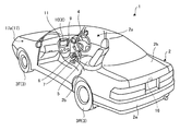
- FIG. 1 is a perspective view showing an example of a vehicle according to the embodiment with a part of the vehicle cut away.
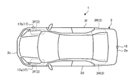
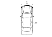
- FIG. 2 is a plan view showing an example of a vehicle according to the embodiment.
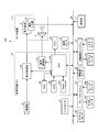
- FIG. 3 is a block diagram showing an example of the configuration of the vehicle according to the embodiment.
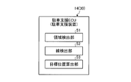
- FIG. 4 is a block diagram showing an example of a functional configuration of the vehicle according to the embodiment.
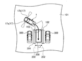
- FIG. 5 is an explanatory view showing an example of the process of detecting the parking available area according to the embodiment.
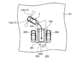
- FIG. 6 is an explanatory view showing an example of a reflection unit of another vehicle according to the embodiment.
- FIG. 7 is a diagram showing an example of the parking target position according to the embodiment.
- FIG. 8 is a diagram showing an example of the parking target position according to the embodiment.
- FIG. 9 is a diagram showing an example of the parking target position according to the embodiment.
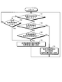
- FIG. 10 is a flowchart showing an example of processing executed by the parking assistance apparatus according to the embodiment.
- the vehicle 1 may be, for example, an automobile (internal combustion engine automobile) having an internal combustion engine (engine, not shown) as a drive source, or an electric motor (motor, not shown) as a drive source.
- the vehicle may be an electric vehicle (electric vehicle, fuel cell vehicle, etc.), or an electric vehicle (hybrid vehicle) that uses both of them as a driving source.
- the vehicle 1 can be equipped with various transmissions, and can be equipped with various devices (systems, parts, etc.) necessary to drive an internal combustion engine or a motor.
- the method, number, layout, and the like of devices related to the driving of the wheels 3 in the vehicle 1 can be set variously.
- the vehicle body 2 constitutes a passenger compartment 2a in which a passenger (not shown) rides.
- a steering unit 4, an acceleration operation unit 5, a braking operation unit 6, a gear change operation unit 7 and the like are provided in the passenger compartment 2a in a state of facing the driver's seat 2b as a passenger.
- the steering unit 4 is a steering wheel protruding from a dashboard (instrument panel)
- the acceleration operation unit 5 is an accelerator pedal positioned under the driver's foot
- a braking operation unit Reference numeral 6 denotes a brake pedal positioned under the driver's foot
- the shift operating unit 7 is a shift lever protruding from the center console, but is not limited thereto.
- a display device 8 (display output unit) and an audio output device 9 (audio output unit) are provided.
- the display device 8 is, for example, a liquid crystal display (LCD), an organic electroluminescent display (OELD), or the like.
- the audio output device 9 is a speaker as an example.
- the display device 8 is covered with a transparent operation input unit 10 (for example, a touch panel or the like). An occupant or the like can visually recognize an image (image) displayed on the display screen of the display device 8 through the operation input unit 10.
- an occupant or the like operates by touching, pushing or moving the operation input unit 10 with a finger or the like at a position corresponding to the image (image) displayed on the display screen of the display device 8. Input) can be performed.
- the display device 8, the voice output device 9, the operation input unit 10, and the like are provided in the monitor device 11 positioned at the center of the dashboard in the vehicle width direction (horizontal direction). ing.
- the monitor device 11 can have an operation input unit (not shown) such as a switch, a dial, a joystick, or a push button.
- an audio output device (not shown) can be provided at another position in the vehicle compartment 2a different from the monitor device 11, and audio can be output from the audio output device 9 of the monitor device 11 and another audio output device. It can be output.
- the monitor device 11 is also used as a navigation system or an audio system as an example, but a monitor device for a parking assistance device may be provided separately from these systems.
- an alarm sound or the like can be output from an audio output unit such as a buzzer 24 (see FIG. 3).
- the vehicle 1 is a four-wheeled vehicle (four-wheeled vehicle), and includes two left and right front wheels 3F and two left and right rear wheels 3R. Have. In the present embodiment, of the four wheels 3, two left and right front wheels 3F can be steered (steerable).
- the vehicle 1 has a front wheel steering system 12 that steers the front wheel 3F.
- the front wheel steering system 12 is electrically controlled by a parking assist ECU 14 (electronic control unit) or the like to operate its actuator 12 a.
- the front wheel steering system 12 is, for example, an electric power steering system, an SBW (steer by wire) system, or the like.
- the front wheel steering system 12 applies a torque (assist torque) to the steering unit 4 by the actuator 12a to compensate for the steering force, and steers (automatically steers) the front wheel 3F.
- a torque assist torque
- the two front wheels 3F are steered substantially in parallel and in parallel with each other.
- the rear wheel 3R may be steered.
- only the rear wheel 3R may be steered.
- drive wheels can be set variously.
- an imaging unit 16 is provided in the vehicle 1 (the vehicle body 2).
- the imaging unit 16 is, for example, a digital camera that incorporates an imaging device such as a charge coupled device (CCD) or a CMOS image sensor (CIS).
- the imaging unit 16 is, for example, a monocular camera.
- the imaging unit 16 can output image data (moving image data, frame data) at a predetermined frame rate.
- the imaging unit 16 has a wide-angle lens, and as an example, can capture a range (viewing angle) of 140 ° to 190 ° in the horizontal direction. Further, the optical axis of the imaging unit 16 is set downward (obliquely downward).
- the imaging unit 16 can capture an area around the vehicle body 2 (vehicle 1) including the road surface.
- the imaging unit 16 is located at an end 2e on the rear side (rear side in the vehicle longitudinal direction) of the vehicle body 2 and is provided on the lower wall of the rear trunk door 2h.
- Image pick-up data of image pick-up part 16 may be memorized by RAM14c of parking assistance ECU14 as an example.
- the parking assistance ECU 14 executes arithmetic processing and image processing based on the image data obtained by the imaging unit 16.
- the parking assist ECU 14 can detect (extract) an object (obstacle) that is positioned around the vehicle 1 and that may interfere with the moving vehicle 1 from the image of the imaging unit 16.
- a plurality of (two as an example in the present embodiment) distance measurement units 17 (17 a, 17 b) are provided to the vehicle 1 (vehicle body 2).
- a launcher and a detector) are provided.
- the distance measuring unit 17a is located at the end 2d of the left side (left side in the vehicle width direction) of the vehicle body 2.
- the distance measuring unit 17 b is located at an end 2 f on the right side (right side in the vehicle width direction) of the vehicle body 2.
- the distance measuring units 17a and 17b are positioned close to an end 2c (an end in a plan view) of the front side (the front side in the vehicle longitudinal direction) of the vehicle body 2. That is, these distance measuring units 17 a and 17 b are provided at the front of the vehicle body 2.
- the distance measuring units 17a and 17b are located above the front wheel 3F, for example.
- the distance measuring unit 17 is, for example, a sonar (sonar sensor, ultrasonic detector, active type distance sensor) which emits (radiates) an ultrasonic wave as a wave and captures (detects) a reflected wave.
- the parking assist ECU 14 can measure the presence or absence and the distance of an object (obstacle) located on the side of the vehicle 1 (the vehicle body 2) based on the detection result of the distance measurement unit 17. That is, the distance measurement unit 17 is an example of the object detection unit.
- the monitor device 11, the front wheel steering system 12, the distance measuring unit 17 and the like, the brake system 18, A steering angle sensor 19 (angle sensor), an accelerator sensor 20, a shift sensor 21, a wheel speed sensor 22 and the like are electrically connected via an in-vehicle network 23 (electric communication line).
- the in-vehicle network 23 is configured as a CAN (controller area network) as an example.
- the parking assist ECU 14 can control the front wheel steering system 12, the brake system 18, and the like by transmitting control signals through the in-vehicle network 23.
- the parking assist ECU 14 detects detection results of the torque sensor 12b, the distance measuring unit 17, the brake sensor 18b, the steering angle sensor 19, the accelerator sensor 20, the shift sensor 21, the wheel speed sensor 22 and the like via the in-vehicle network 23, And an instruction signal (a control signal, a switching signal, an operation signal, an input signal, data) of the operation input unit 10 or the like.
- the parking assistance ECU 14 is, for example, a CPU 14 a (central processing unit), a ROM 14 b (read only memory), a RAM 14 c (random access memory), a display control unit 14 d, a voice control unit 14 e, an SSD 14 f (solid state drive, flash memory) have.
- the CPU 14a can execute various processing such as image processing related to an image displayed on the display device 8, calculation of a movement route of the vehicle 1, determination of presence or absence of interference with an object, and the like.
- the CPU 14a can read a program stored (installed) in a non-volatile storage device such as the ROM 14b and execute arithmetic processing according to the program.
- the RAM 14c temporarily stores various data used in the calculation in the CPU 14a.
- the display control unit 14 d mainly performs image processing using image data obtained by the imaging unit 16 and image processing of image data displayed by the display device 8 among the calculation processing in the parking assistance ECU 14 (an example As synthesis etc.).
- the voice control unit 14 e mainly performs processing of voice data outputted by the voice output device 9 among the calculation processing by the parking assist ECU 14.
- the SSD 14 f is a rewritable non-volatile storage unit, and can store data even when the parking assist ECU 14 is powered off.
- the CPU 14a, the ROM 14b, the RAM 14c, and the like can be integrated in the same package.
- the parking assist ECU 14 may be configured to use another logical operation processor such as a DSP (digital signal processor) or a logic circuit instead of the CPU 14a.
- a hard disk drive (HDD) may be provided instead of the SSD 14f, and the SSD 14f and the HDD may be provided separately from the parking assist ECU 14.
- the brake system 18 enhances anti-lock brake system (ABS) which suppresses the lock of the brake, an anti-slip device (ESC: electronic stability control) which suppresses the side slip of the vehicle 1 at cornering, and enhances the braking force (brake assist ) (Electric brake system, BBW (brake by wire) etc.).
- ABS anti-lock brake system
- ESC electronic stability control
- BBW brake by wire
- the steering angle sensor 19 is a sensor that detects a steering amount (turning angle) of the steering unit 4 (in the present embodiment, a steering wheel as an example), and is configured using a hall element or the like as an example.
- the parking assist ECU 14 acquires the steering amount of the steering unit 4 by the driver, the steering amount of each wheel 3 at the time of automatic steering, and the like from the steering angle sensor 19 and executes various controls.
- the torque sensor 12 b detects a torque that the driver applies to the steering unit 4.
- the wheel speed sensor 22 is a sensor that detects the amount of rotation of the wheel 3 and the number of rotations per unit time, and is configured using a Hall element or the like as an example.
- the parking assistance ECU 14 calculates the amount of movement of the vehicle 1 and the like based on the data acquired from the wheel speed sensor 22 and executes various controls.
- the wheel speed sensor 22 may be provided in the brake system 18.
- the brake system 18 can execute various controls by detecting the lock of the brake, the idle rotation of the wheel 3, the sign of a side slip, and the like from the difference in rotation of the left and right wheels 3.
- the parking assist ECU 14 acquires data via the brake system 18.
- the brake sensor 18 b is a sensor that detects the amount of operation of the brake pedal, and the parking assist ECU 14 acquires information via the brake system 18. For example, when the braking operation unit 6 is operated during automatic steering, the parking assist ECU 14 can interrupt or cancel the automatic steering as being in a situation not suitable for automatic steering.
- the shift sensor 21 is, for example, a sensor (switch) that detects the position of the movable portion (lever, arm, button) of the gear shift operation unit 7, and is configured using a displacement sensor or the like.
- the parking assistance ECU 14 can start the assistance control when the movable part is set to the reverse or can terminate the assistance control when the reverse is changed to the forward movement.
- the parking assist ECU 14 functions (operates) as at least a part of the parking assist device 30 by cooperation of hardware and software (program). That is, in the present embodiment, as shown in FIG. 4 as an example, the parking assist ECU 14 functions (operates) as the area detection unit 51, the line detection unit 52, the target position calculation unit 53, and the like. As an example, when the movable part of the gear shift operation part 7 is set to reverse, the parking assistance ECU 14 functions as the above-mentioned parts to execute the parking assistance processing (parking assistance method).
- the program may include, as an example, a module corresponding to each block shown in FIG.
- the area detection unit 51 detects a parkable area 201 (a parkable space, see FIG. 7) in which the vehicle 1 can park.
- the area detection unit 51 detects the parking available area 201 using the detection result output from the distance measurement unit 17 that emits a wave to the side of the vehicle 1 and detects a reflected wave of the wave.
- the distance measuring unit 17 outputs a reflecting unit S (a set of reflection points such as sound waves) of obstacles such as the other vehicle 300 in a point sequence.
- the output data is stored in the RAM 14b for each output cycle, as an example.
- the area detection unit 51 detects the parkable area 201 located on the side of the vehicle 1 based on the detection result (point sequence) of the distance measurement unit 17.
- the area detection unit 51 detects the parkable area 201 located on the left and right sides of the vehicle independently and in parallel based on the detection results of the left and right distance measurement units 17a and 17b.
- the left and right detection methods may be the same.
- the area detection unit 51 detects a point sequence of the first predetermined length and detects a point sequence of the first predetermined length if the point sequence no longer exists than the second predetermined length. It is determined that the parking available area 201 exists on the side of the object (the front side in the traveling direction of the vehicle 1 when the point train is detected).
- the second prescribed length is the minimum width required as an area where the vehicle 1 can park. Therefore, the second prescribed length is set depending on the width of the vehicle 1.
- the distance measuring unit 17 can detect the outline of the obstacle located on the side of the vehicle 1 based on the detection result (point sequence) of the distance measuring unit 17.
- the detection result of the distance measurement unit 17 may be stored in the RAM 14 b as well as the detection result of the distance measurement unit 17 at the time other than the parking assistance processing.
- the line detection unit 52 detects a parking section line 102 (white line, guide line, see FIG. 7) provided on the traveling surface 101 (ground, road surface, see FIG. 7).
- the line detection unit 52 detects the parking lot line 102 using the imaging data output from the imaging unit 16 that images the rear of the vehicle 1.
- the line detection unit 52 can detect the parking division line 102 using the imaging data at the time of the backward movement, the forward movement, and the stop of the vehicle 1 output from the imaging unit 16.
- the imaging data is stored in the RAM 14b as an example.
- the line detection unit 52 detects a pair of parking division lines 102 provided on the traveling surface 101 by performing edge extraction from the imaging data output from the imaging unit 16.
- the line detection unit 52 extracts a luminance change point (feature point) equal to or higher than a predetermined threshold value.
- the line detection unit 52 performs transformation of each pixel from the imaging (camera) coordinate system to the real coordinate system by distortion correction.
- the line detection unit 52 performs a straight line approximation process on the point sequence of the feature points to obtain an outline of the feature points.
- the line detection part 52 detects the site
- the line detection unit 52 may detect a pair of (two) mutually parallel outlines separated by a predetermined interval or more as the pair of parking division lines 102.
- the imaging data of the imaging unit 16 at the time other than the parking assistance processing may also be stored in the RAM 14 b.
- the parking area 201 is detected by the area detection unit 51, the parking section line 102 is detected by the line detection section 52, and the pair of parking section lines 102 can be parked.
- the parking target position 200 is calculated using the detection result of the parking division line 102 by the line detection unit 52.
- the target position calculation unit 53 sets the parking target position 200 such that the center of the parking target position 200 is located in the middle between the pair of parking division lines 102.
- the target position calculation unit 53 aligns the front end of the parking section line 102 with the front end of the parking section line 102 when the parking section line 102 is detected, for example.
- the target position calculation unit 53 calculates the parking target position 200, for example, when the distance L1 between the pair of parking division lines 102 (the distance between the broken lines 202) is equal to or greater than the specified parking width.
- the parking target position 200 may not be calculated.
- the specified parking width is, for example, the vehicle width of the host vehicle 1 plus the specified width.
- the parking area 201 is detected by the area detection unit 51, the parking detection line 102 is detected by the line detection unit 52, and the parking detection line 102 can be parked.
- the parking target position 200 is calculated using the detection result of the parking available area 201 by the area detection unit 51.
- the target position calculation unit 53 may use the detection result of the parking area 201 by the area detection unit 51, and the parking division line 102 by the line detection unit 52 together with the detection result of the parking area 201 by the area detection unit 51.
- the detection results of may also be used.
- the target position calculation section 53 detects the parking declination area 201 by the area detection section 51 and the detection result of the parking demarcation line 102 by the line detection section 52.
- the parking target position 200 may be calculated using
- one (left) parking division line 102 is located in the parking available area 201, and the other vehicle 300 is positioned on the other (right) parking division line 102, the other (right)
- An example is shown in which the parking section line 102 is located outside the parking area 201.
- the target position calculation unit 53 is, for example, one (left side in FIG. 8) of the parking division line 102 located in the parking available area 201 and the other located outside the parking available area 201. If the distance L2 (the distance between the broken lines 202) to the other vehicle 300 (the other vehicle 300 on the right in FIG.
- the target parking position 200 is set close to the parking section line 102 of FIG. That is, as an example, in the target position calculation unit 53, one of the pair of parking division lines 102 detected by the line detection unit 52 is located in the parkable area 201, and the other of the pair of parking division lines 102 is When it is located out of the parking area 201, the parking target position 200 is set by moving it to one parking division line 102 between the pair of parking division lines 102.
- target position calculation unit 53 is located on parking division line 102 located on one side (left side in FIG. 8) within parking area 201 and on the other parking division line 102 located outside parking area 201.
- the detection result of the parking available area 201 by the area detection unit 51 is Among the detection results of the parking section line 102, the parking target position 200 is set using only the detection result of the parking available area 201 by the area detection unit 51.
- the target position calculation unit 53 sets the parking target position 200 such that the center in the width direction of the parking available area 201 and the center in the width direction of the parking target position 200 coincide (see FIG. ).
- one parking division line 102 located in the parking area 201 (left side in FIG. 8) and another vehicle 300 located on the other parking division line 102 located outside the parking area 201 If the distance L2 between the other vehicle 300 on the right side in FIG. 8 and the obstacle) is less than the prescribed parking width, the target position calculation unit 53 does not set the parking target position 200, and the parking assist device 30 parks The support process may be canceled.
- the target position calculation unit 53 in the target position calculation unit 53, one of the pair of parking division lines 102 detected by the line detection unit 52 is located in the parking available area 201, and the pair of parking division lines 102 is If the other of the above is located outside the parkable area 201, the parking target position 200 is made to follow the one parking section line 102. Furthermore, in the target position calculation unit 53, the parking area 201 is detected by the area detection unit 51, and at least one of the pair of parking division lines 102 provided on the traveling surface 101 is detected by the line detection unit 52. If so, the parking target position 200 is made to follow the detected parking lot line 102. In detail, the target position calculation unit 53 makes the parking target position 200 parallel to one parking division line 102.
- the target position calculation unit 53 when the area detection unit 51 detects the parkable area 201 and the line detection unit 52 does not detect the parking division line 102, parking by the area detection unit 51 is performed.
- the target parking position 200 is calculated using the detection result of the possible area 201.
- FIG. 9 shows an example in which the parking available area 201 is detected on the side of the other vehicle 300.
- the target position calculation unit 53 sets the parking target position 200 so that the center position in the width L3 direction (the center position between the broken lines 202) of the parking available area 201 matches the center of the parking target position 200 in the width direction.
- the target position calculation unit 53 when the area detection unit 51 does not detect the parking available area 201 and the line detection unit 52 detects the parking division line 102, the target position calculation unit 53 performs parking by the line detection unit 52. The detection result of the dividing line 102 is reflected on the parking target position 200.
- a situation is, for example, a case where there is no parked vehicle around the host vehicle 1 in a parking lot where many vehicles can be parked.
- the target position calculation unit 53 sets the parking target position 200 such that the center of the parking target position 200 is located in the middle between the pair of parking section lines 102.
- the target position calculation unit 53 repeatedly calculates and updates the parking target position 200 in the process of reversing the vehicle 1. That is, in the present embodiment, the parking target position 200 is set while repeatedly performing image recognition (detection of the parking division line 102 by the line detection unit 52) (visual servo) while the vehicle 1 moves backward.
- the target position calculation unit 53 detects the parking division line 102. It is determined whether or not the vehicle is in the parking available area 201 (step S4).
- the target position calculation unit 53 determines that both of the pair of parking division lines 102 are included in the parkable area 201 (Yes in step S4), the detection result of the parking division line 102 by the line detection unit 52 is parked The target position 200 is reflected (step S5).
- An example of the parking target position 200 in this case is shown in FIG. Note that the detection of the parking available area 201 and the detection of the parking division line 102 are performed, for example, when the vehicle 1 is stopped or when the vehicle travels in reverse.
- step S4 if the target position calculation unit 53 determines that at least one of the pair of parking division lines 102 is located outside the parkable area 201 (No in step S4), the area detection unit 51 The detection result of the parking area 201 is reflected in the setting of the target position 200 for parking (step S6).
- step S6 the position of the parking target position 200 is set based on only the detection result of the parking available area 201 among the detected parking division lines 102 and the parking available area 201.
- An example of the parking target position in this case is shown in FIG.
- step S6 An example of the parking target position in this case is shown in FIG.
- the target position calculation unit 53 The detection result of the parking lot line 102 by the detection unit 52 is reflected in the parking target position 200.
- steps S1 and S2 are performed. Repeated. The above processing is repeatedly performed at predetermined intervals in the process of reversing the vehicle 1.
- the parking assistance device 30 may control the steering unit 4 to guide the vehicle 1 to the parking target position 200 (automatic steering unit).
- the parking assistance device 30 controls the steering unit 4, the acceleration operation unit 5, the braking operation unit 6, the shift operation unit 7 and the like to automatically park the vehicle 1 at the parking target position 200.
- Good automated parking part
- the parking assistance device 30 may cause the display device 8 to display a parking target position as parking assistance information (aiding information display unit). At this time, the parking assistance device 30 (parking assistance ECU 14) may cause the display device 8 to display the relative positional relationship between the parking target position and the parking lot line and the obstacle.
- the parking area 102 is detected by the area detection unit 51, the parking line 102 is detected by the line detection unit 52, and the parking line 102 is located outside the parking area 201.
- the target position calculation unit 53 calculates the parking target position 200 using the detection result of the parking available area 201 by the area detection unit 51. Therefore, according to the present embodiment, when the area detection unit 51 detects the parking area 201 and the line detection unit 52 detects the parking division line 102, at least the detection result of the parking area 201 is used. Since the parking target position 200 is calculated, it is possible to prevent the parking target position 200 from being too close to the other vehicle 300 as compared to the case where only the detection result of the line detection unit 52 is used.
- the line detection unit 52 detects the parking division line 102 using the imaging data of the reverse process of the vehicle 1 output from the imaging unit 16 that images the rear of the vehicle 1 and calculates the target position.
- the unit 53 repeatedly calculates the parking target position 200 in the process of reverse travel of the vehicle 1. Therefore, according to the present embodiment, as one example, since the situation behind the vehicle can be sequentially detected as the vehicle 1 moves backward, the parking target position can be sequentially changed according to the detection result.
- the target parking position 200 is calculated using the detection result of the parking available area 201 in a state where the parking available area 201 is detected immediately after the vehicle 1 moves backward and the parking section line 102 is not detected.
- the parking target position 200 is calculated using the parking available area 201 as an example.
- the target position calculation unit 53 detects the parking declination area 201 by the area detection unit 51 and the parking demarcation line by the line detection unit 52.
- a parking target position 200 is calculated using the detection result of 102. Therefore, according to the present embodiment, as an example, the parking target position 200 is prevented from being too close to the other vehicle 300 using the detection result of the parking available area 201 and the detection result of the parking section line 102. be able to.
- one of the pair of parking division lines 102 is located within the parking available area 201, and the other of the pair of parking division lines 102 is outside the parking available area 201. If it is located, the target parking position 200 is set close to one parking division line 102 between the pair of parking division lines 102. Therefore, according to the present embodiment, as an example, it is possible to prevent the parking target position 200 from becoming too close to the other vehicle 300 while positioning the parking target position 200 between the pair of parking division lines 102. .
- the parking area 201 is detected by the area detection unit 51, and the line detection unit 52 detects one of the pair of parking division lines 102 provided on the traveling surface 101. If at least one is detected, the parking target position 200 is made parallel to the detected parking lot line 102. Therefore, according to the present embodiment, as an example, even when the other of the pair of parking section lines 102 is not detected, it is possible to suppress the inclination of the parking target position 200 with respect to the parking section line 102.
- the distance measuring unit 17 also detects the other vehicle 300 and the like while moving back to the parking target position 200, and corrects (updates) the parkable area 201 detected during forward movement as described in FIG. Then, the process described above may be performed. Specifically, as an example, in addition to the distance measuring units 17a and 17b, in order to detect an obstacle on the rear side of the vehicle 1, the end 2e on the rear side (rear direction in the vehicle longitudinal direction) of the vehicle body 2 is detected. Similar to the distance measurement units 17a and 17b, the vehicle body 2 is further provided with two distance measurement units that emit (radiate) ultrasonic waves (waves) toward the left and right sides of the vehicle similarly to the distance measurement units 17a and 17b.
- the two distance measuring units further detect the other vehicle 300 or the like at any time during traveling by retreating to the parking target position 200, and correct (update) the parkable area 201 based on the detection result.
- the other vehicle 300 on the right side in FIG. 5 is parked in an inclined manner so that the front wheels are not positioned on the parking section line 102 but the rear wheels are positioned on the parking section line 102 Even in such a case, it becomes possible to appropriately identify the parking available area 201 which becomes narrower as the back side of the parking target position 200 is approached, and the vehicle 1 can be guided to the suitable parking target position 200.
Landscapes
- Engineering & Computer Science (AREA)
- Multimedia (AREA)
- Mechanical Engineering (AREA)
- Physics & Mathematics (AREA)
- General Physics & Mathematics (AREA)
- Theoretical Computer Science (AREA)
- Human Computer Interaction (AREA)
- Traffic Control Systems (AREA)
- Control Of Driving Devices And Active Controlling Of Vehicle (AREA)
Abstract
A parking assistance device according to an embodiment is equipped with: a space detection unit for detecting a potential parking space where a vehicle can be parked; a line detection unit for detecting parking demarcation lines provided on the travel surface; and a target position calculation unit for calculating a target parking position using the result of potential parking space detection by the space detection unit when a potential parking space and parking demarcation lines are detected by the space detection unit and the line detection unit, respectively, and the parking demarcation lines are located outside the potential parking space.
Description
本発明の実施形態は、駐車支援装置、駐車支援方法およびプログラムに関する。
Embodiments of the present invention relate to a parking assistance apparatus, a parking assistance method, and a program.
従来、駐車支援装置における駐車目標位置の算出方法としては、カメラを用いて駐車区画線を検出してその検出結果を用いる方法(駐車区画線認識方法)と、超音波ソナーを用いて駐車可能空間を検出してその検出結果を用いる方法(駐車可能領域認識方法)とが知られている(例えば、特許文献1,2参照)。
Conventionally, as a calculation method of a parking target position in a parking assistance device, a method of detecting a parking lot line using a camera and using the detection result (parking lot line recognition method) and a parking available space using an ultrasonic sonar And a method of using the detection result (parkable area recognition method) are known (see, for example, Patent Documents 1 and 2).
しかしながら、駐車目標位置の算出に駐車区画線の検出結果を用いる場合には、駐車区画線が走行面に設けられていないと、駐車目標位置の設定ができない。また、一対の駐車区画線の片方の駐車区画線上に他車両が駐車している場合であっても、一対の駐車区画線の中間位置に駐車目標位置が設定されてしまうため、駐車目標位置が他車両に寄りすぎてしまう。
However, in the case where the detection result of the parking division line is used for calculation of the parking target position, the parking target position can not be set unless the parking division line is provided on the traveling surface. In addition, even when another vehicle is parked on one parking division line of the pair of parking division lines, the parking target position is set at the middle position of the pair of parking division lines, so the parking target position is I get too close to other vehicles.
一方、駐車目標位置の算出に駐車可能空間の検出結果を用いる場合には、他車両(障害物)が存在しなければ、駐車目標位置の設定ができない。また、他車両が駐車区画線に対して傾いて駐車していると、その傾きに合わせて駐車目標位置が駐車区画線に対して傾いて設定されてしまう。
On the other hand, when using the detection result of the parking available space for calculation of the parking target position, the parking target position can not be set unless there is another vehicle (obstacle). Further, when another vehicle is parked at an angle with respect to the parking lot line, the parking target position is set to be tilted with respect to the parking lot line according to the inclination.
特許文献2では、駐車区画線の検出結果を用いる方法または駐車可能空間の検出結果を用いる方法を用いて駐車目標位置を設定している。しかしながら、駐車可能空間と駐車区画線との両方が検出された場合には、一対の駐車区画線の中間位置に駐車可能空間が設定されてしまうので、駐車目標位置が他車両に寄りすぎてしまう。
In patent document 2, the parking target position is set using the method of using the detection result of a parking lot line or the method of using a detection result of a parking available space. However, when both the parking available space and the parking lot line are detected, the parking available space is set at the middle position of the pair of parking lot lines, so the parking target position is too close to other vehicles. .
この種の駐車支援装置では、一例として、駐車可能空間と駐車区画線との両方が検出された場合に、駐車目標位置が他車両に対して近くなりすぎることを抑制することが望まれている。
In this type of parking assistance apparatus, as an example, it is desirable to prevent the parking target position from becoming too close to other vehicles when both the parking available space and the parking lot line are detected. .
実施形態の駐車支援装置は、車両が駐車可能な駐車可能領域を検出する領域検出部と、走行面に設けられた駐車区画線を検出する線検出部と、前記領域検出部によって前記駐車可能領域が検出され且つ前記線検出部によって前記駐車区画線が検出され、前記駐車区画線が前記駐車可能領域外に位置する場合、前記領域検出部による前記駐車可能領域の検出結果を用いて駐車目標位置を算出する目標位置算出部と、を備えた。したがって、当該駐車支援装置によれば、一例として、駐車可能空間と駐車区画線との両方が検出された場合に、駐車可能領域の検出結果が用いられるので、駐車目標位置が他車両に対して近くなりすぎることを抑制することができる。
The parking assistance device according to the embodiment includes an area detection unit that detects a parkable area that can be parked by a vehicle, a line detection unit that detects a parking section line provided on a traveling surface, and the parking area by the area detection unit. Is detected by the line detection unit, and the parking line is detected outside the parking area, the parking target position is detected using the detection result of the parking area by the area detection unit. And a target position calculation unit for calculating Therefore, according to the parking assistance apparatus, as an example, when both of the parking available space and the parking lot line are detected, the detection result of the parking available area is used, so the parking target position for the other vehicle is It is possible to suppress being too close.
前記駐車支援装置にあっては、前記領域検出部は、前記車両に設けられ前記車両の側方に波を発射して当該波の反射波を検出する発射部から出力された検出結果を用いて前記駐車可能領域を検出し、前記線検出部は、前記車両に設けられ前記車両の後方を撮像する撮像部から出力された前記車両の後進過程の撮像データを用いて、前記駐車区画線を検出し、前記目標位置算出部は、前記車両の後進過程で前記駐車目標位置を繰り返し算出してよい。当該駐車支援装置によれば、一例として、車両の後進に伴って車両の後方の状況を順次検出できるので、その検出結果に応じて駐車目標位置を順次変更することができる。
In the parking assistance device, the area detection unit is provided on the vehicle, and uses a detection result output from a launch unit that emits a wave to the side of the vehicle and detects a reflected wave of the wave. The parking area is detected, and the line detection unit detects the parking division line by using imaging data of a reverse process of the vehicle, which is output from an imaging unit provided in the vehicle and imaging the rear of the vehicle. The target position calculation unit may repeatedly calculate the target parking position in the process of reversing the vehicle. According to the parking assistance apparatus, as one example, the situation behind the vehicle can be sequentially detected as the vehicle moves backward, so that the parking target position can be sequentially changed according to the detection result.
前記駐車支援装置にあっては、前記目標位置算出部は、前記駐車区画線が前記駐車可能領域外に位置する場合、前記領域検出部による前記駐車可能領域の検出結果に加えて前記線検出部による前記駐車区画線の検出結果を用いて前記駐車目標位置を算出してよい。当該駐車支援装置によれば、一例として、駐車可能領域の検出結果に加えて駐車区画線の検出結果を用いて、駐車目標位置が他車両に対して近くなりすぎることを抑制することができる。
In the parking assistance device, the target position calculation unit, in addition to the detection result of the parkable area by the area detection unit, the line detection unit when the parking division line is located outside the parking area. The parking target position may be calculated using the detection result of the parking division line according to According to the parking assistance apparatus, as an example, using the detection result of the parking section line in addition to the detection result of the parking available area, it is possible to suppress the parking target position from being too close to other vehicles.
前記駐車支援装置にあっては、前記線検出部は、走行面に設けられた一対の駐車区画線を検出し、前記目標位置算出部は、一対の前記駐車区画線のうちの一方が前記駐車可能領域内に位置し一対の前記駐車区画線のうちの他方が前記駐車可能領域外に位置した場合、前記一対の駐車区画線の間で前記一方の駐車区画線に寄せて前記駐車目標位置を設定してよい。当該駐車支援装置によれば、一例として、駐車目標位置を一対の駐車区画線の間に位置させながら駐車目標位置が他車両に対して近くなりすぎることを抑制することができる。
In the parking assistance device, the line detection unit detects a pair of parking division lines provided on the traveling surface, and the target position calculation unit is configured to use one of the pair of parking division lines as the parking When the other of the pair of parking division lines is located outside the parking area, the parking target position is set closer to the one parking division line between the pair of parking division lines. May be set. According to the parking assistance device, as an example, it is possible to suppress the parking target position from becoming too close to other vehicles while positioning the parking target position between the pair of parking division lines.
前記駐車支援装置にあっては、前記領域検出部によって前記駐車可能領域が検出され、且つ前記線検出部によって、走行面に設けられた一対の前記駐車区画線のうちの少なくとも一方が検出された場合、前記駐車目標位置を前記線検出部によって検出された前記駐車区画線に沿わせてよい。当該駐車支援装置によれば、一例として、一対の駐車区画線の他方が検出されない場合であっても駐車目標位置が駐車区画線に対して傾くことを抑制することができる。
In the parking assistance device, the area detection unit detects the parkable area, and the line detection unit detects at least one of the pair of parking division lines provided on the traveling surface. In this case, the parking target position may be along the parking section line detected by the line detection unit. According to the parking assistance device, as an example, even when the other of the pair of parking section lines is not detected, it is possible to suppress the parking target position from being inclined with respect to the parking section line.
実施形態の駐車支援方法は、領域検出部が、車両が駐車可能な駐車可能領域を検出するステップと、線検出部が、走行面に設けられた駐車区画線を検出するステップと、目標位置算出部が、前記領域検出部によって前記駐車可能領域が検出され且つ前記線検出部によって前記駐車区画線が検出され、前記駐車区画線が前記駐車可能領域外に位置する場合、前記領域検出部による前記駐車可能領域の検出結果を用いて駐車目標位置を算出するステップと、を含む。当該駐車支援方法によれば、一例として、駐車可能空間と駐車区画線との両方が検出された場合に、駐車可能領域の検出結果が用いられるので、駐車目標位置が他車両に対して近くなりすぎることを抑制することができる。
In the parking assistance method according to the embodiment, the area detection unit detects a parkable area where the vehicle can park, the line detection unit detects a parking division line provided on the traveling surface, and a target position calculation. When the parking area is detected by the area detection unit, the parking detection line is detected by the line detection unit, and the parking detection line is located outside the parking detection area, the area detection unit Calculating the parking target position using the detection result of the parking available area. According to the parking assistance method, as an example, when both the parking available space and the parking lot line are detected, the detection result of the parking available area is used, so the parking target position becomes closer to other vehicles. It is possible to suppress too much.
実施形態のプログラムは、車両が駐車可能な駐車可能領域を検出するステップと、走行面に設けられた駐車区画線を検出するステップと、前記駐車可能領域が検出され且つ前記駐車区画線が検出され、前記駐車区画線が前記駐車可能領域外に位置する場合、前記駐車可能領域の検出結果を用いて駐車目標位置を算出するステップと、をコンピュータに実行させる。当該プログラムによれば、一例として、駐車可能空間と駐車区画線との両方が検出された場合に、駐車可能領域の検出結果が用いられるので、駐車目標位置が他車両に対して近くなりすぎることを抑制することができる。
The program according to the embodiment includes the steps of detecting a parkable area in which the vehicle can park, detecting a parking line provided on the traveling surface, detecting the parking area and detecting the parking line. And causing the computer to execute the step of calculating a parking target position using the detection result of the parking available area, when the parking section line is located outside the parking available area. According to the program, as an example, when both the parking available space and the parking lot line are detected, the detection result of the parking available area is used, so the parking target position becomes too close to other vehicles. Can be suppressed.
本実施形態では、車両1は、例えば、内燃機関(エンジン、図示されず)を駆動源とする自動車(内燃機関自動車)であってもよいし、電動機(モータ、図示されず)を駆動源とする自動車(電気自動車、燃料電池自動車等)であってもよいし、それらの双方を駆動源とする自動車(ハイブリッド自動車)であってもよい。また、車両1は、種々の変速装置を搭載することができるし、内燃機関や電動機を駆動するのに必要な種々の装置(システム、部品等)を搭載することができる。また、車両1における車輪3の駆動に関わる装置の方式や、数、レイアウト等は、種々に設定することができる。
In the present embodiment, the vehicle 1 may be, for example, an automobile (internal combustion engine automobile) having an internal combustion engine (engine, not shown) as a drive source, or an electric motor (motor, not shown) as a drive source. The vehicle may be an electric vehicle (electric vehicle, fuel cell vehicle, etc.), or an electric vehicle (hybrid vehicle) that uses both of them as a driving source. In addition, the vehicle 1 can be equipped with various transmissions, and can be equipped with various devices (systems, parts, etc.) necessary to drive an internal combustion engine or a motor. In addition, the method, number, layout, and the like of devices related to the driving of the wheels 3 in the vehicle 1 can be set variously.
図1に示されるように、車体2は、乗員(図示されず)が乗車する車室2aを構成している。車室2a内には、乗員としての運転者の座席2bに臨む状態で、操舵部4や、加速操作部5、制動操作部6、変速操作部7等が設けられている。本実施形態では、一例として、操舵部4は、ダッシュボード(インストルメントパネル)から突出したステアリングホイールであり、加速操作部5は、運転者の足下に位置されたアクセルペダルであり、制動操作部6は、運転者の足下に位置されたブレーキペダルであり、変速操作部7は、センターコンソールから突出したシフトレバーであるが、これらには限定されない。
As shown in FIG. 1, the vehicle body 2 constitutes a passenger compartment 2a in which a passenger (not shown) rides. A steering unit 4, an acceleration operation unit 5, a braking operation unit 6, a gear change operation unit 7 and the like are provided in the passenger compartment 2a in a state of facing the driver's seat 2b as a passenger. In the present embodiment, as an example, the steering unit 4 is a steering wheel protruding from a dashboard (instrument panel), the acceleration operation unit 5 is an accelerator pedal positioned under the driver's foot, and a braking operation unit Reference numeral 6 denotes a brake pedal positioned under the driver's foot, and the shift operating unit 7 is a shift lever protruding from the center console, but is not limited thereto.
また、車室2a内には、表示装置8(表示出力部)や、音声出力装置9(音声出力部)が設けられている。表示装置8は、例えば、LCD(liquid crystal display)や、OELD(organic electroluminescent display)等である。音声出力装置9は、一例として、スピーカである。また、本実施形態では、一例として、表示装置8は、透明な操作入力部10(例えば、タッチパネル等)で覆われている。乗員等は、操作入力部10を介して表示装置8の表示画面に表示される映像(画像)を視認することができる。また、乗員等は、表示装置8の表示画面に表示される映像(画像)に対応した位置で手指等で操作入力部10を触れたり押したり動かしたりして操作することで、操作入力(指示入力)を実行することができる。また、本実施形態では、一例として、表示装置8や、音声出力装置9、操作入力部10等は、ダッシュボードの車幅方向(左右方向)の中央部に位置されたモニタ装置11に設けられている。モニタ装置11は、スイッチや、ダイヤル、ジョイスティック、押しボタン等の操作入力部(図示されず)を有することができる。また、モニタ装置11とは異なる車室2a内の他の位置に音声出力装置(図示されず)を設けることができるし、モニタ装置11の音声出力装置9と他の音声出力装置から、音声を出力することができる。また、本実施形態では、一例として、モニタ装置11は、ナビゲーションシステムやオーディオシステムと兼用されているが、駐車支援装置用のモニタ装置を、これらのシステムとは別に設けてもよい。また、音声出力装置9の他に、ブザー24(図3参照)等の音声出力部から、警報音等が出力されるように構成することができる。
In the passenger compartment 2a, a display device 8 (display output unit) and an audio output device 9 (audio output unit) are provided. The display device 8 is, for example, a liquid crystal display (LCD), an organic electroluminescent display (OELD), or the like. The audio output device 9 is a speaker as an example. Moreover, in the present embodiment, as an example, the display device 8 is covered with a transparent operation input unit 10 (for example, a touch panel or the like). An occupant or the like can visually recognize an image (image) displayed on the display screen of the display device 8 through the operation input unit 10. In addition, an occupant or the like operates by touching, pushing or moving the operation input unit 10 with a finger or the like at a position corresponding to the image (image) displayed on the display screen of the display device 8. Input) can be performed. Further, in the present embodiment, as an example, the display device 8, the voice output device 9, the operation input unit 10, and the like are provided in the monitor device 11 positioned at the center of the dashboard in the vehicle width direction (horizontal direction). ing. The monitor device 11 can have an operation input unit (not shown) such as a switch, a dial, a joystick, or a push button. In addition, an audio output device (not shown) can be provided at another position in the vehicle compartment 2a different from the monitor device 11, and audio can be output from the audio output device 9 of the monitor device 11 and another audio output device. It can be output. Further, in the present embodiment, the monitor device 11 is also used as a navigation system or an audio system as an example, but a monitor device for a parking assistance device may be provided separately from these systems. Further, in addition to the audio output device 9, an alarm sound or the like can be output from an audio output unit such as a buzzer 24 (see FIG. 3).
また、図1,2に示されるように、本実施形態では、一例として、車両1は、四輪車(四輪自動車)であり、左右二つの前輪3Fと、左右二つの後輪3Rとを有する。本実施形態では、これら四つの車輪3のうち、左右二つの前輪3Fが操舵されうるように(転舵可能に)構成されている。具体的には、図3に示されるように、車両1は、前輪3Fを操舵する前輪操舵システム12を有している。前輪操舵システム12は、駐車支援ECU14(electronic control unit)等によって電気的に制御されて、そのアクチュエータ12aを動作させる。前輪操舵システム12は、例えば、電動パワーステアリングシステムや、SBW(steer by wire)システム等である。前輪操舵システム12は、アクチュエータ12aによって操舵部4にトルク(アシストトルク)を付加して操舵力を補ったり、前輪3Fを操舵(自動操舵)したりする。また、本実施形態では、一例として、二つの前輪3Fは、互いに同相で略平行に転舵される。なお、前輪3Fの他に後輪3Rも操舵してよい。また、後輪3Rだけを操舵してもよい。また、駆動輪は種々に設定可能である。
Further, as shown in FIGS. 1 and 2, in the present embodiment, as an example, the vehicle 1 is a four-wheeled vehicle (four-wheeled vehicle), and includes two left and right front wheels 3F and two left and right rear wheels 3R. Have. In the present embodiment, of the four wheels 3, two left and right front wheels 3F can be steered (steerable). Specifically, as shown in FIG. 3, the vehicle 1 has a front wheel steering system 12 that steers the front wheel 3F. The front wheel steering system 12 is electrically controlled by a parking assist ECU 14 (electronic control unit) or the like to operate its actuator 12 a. The front wheel steering system 12 is, for example, an electric power steering system, an SBW (steer by wire) system, or the like. The front wheel steering system 12 applies a torque (assist torque) to the steering unit 4 by the actuator 12a to compensate for the steering force, and steers (automatically steers) the front wheel 3F. Further, in the present embodiment, as an example, the two front wheels 3F are steered substantially in parallel and in parallel with each other. In addition to the front wheel 3F, the rear wheel 3R may be steered. Also, only the rear wheel 3R may be steered. In addition, drive wheels can be set variously.
また、本実施形態では、一例として、図2に示されるように、車両1(車体2)には、撮像部16が設けられている。撮像部16は、例えば、CCD(charge coupled device)やCIS(CMOS image sensor)等の撮像素子を内蔵するデジタルカメラである。撮像部16は、一例として、単眼カメラである。撮像部16は、所定のフレームレートで画像データ(動画データ、フレームデータ)を出力することができる。撮像部16は、広角レンズを有し、一例として、水平方向には140°~190°の範囲(視野角)を撮影することができる。また、撮像部16の光軸は下方(斜め下方)に向けて設定されている。よって、撮像部16は、路面を含む車体2(車両1)の周辺を撮影することができる。本実施形態では、一例として、撮像部16は、車体2の後側(車両前後方向の後方側)の端部2eに位置され、リヤトランクのドア2hの下方の壁部に設けられている。撮像部16の撮像データは、一例として、駐車支援ECU14のRAM14cに記憶されうる。駐車支援ECU14は、撮像部16で得られた画像データに基づいて演算処理や画像処理を実行する。また、駐車支援ECU14は、撮像部16の画像から、車両1の周辺に位置され移動する車両1と干渉する可能性がある物体(障害物)を検出(抽出)することができる。
Further, in the present embodiment, as an example, as shown in FIG. 2, an imaging unit 16 is provided in the vehicle 1 (the vehicle body 2). The imaging unit 16 is, for example, a digital camera that incorporates an imaging device such as a charge coupled device (CCD) or a CMOS image sensor (CIS). The imaging unit 16 is, for example, a monocular camera. The imaging unit 16 can output image data (moving image data, frame data) at a predetermined frame rate. The imaging unit 16 has a wide-angle lens, and as an example, can capture a range (viewing angle) of 140 ° to 190 ° in the horizontal direction. Further, the optical axis of the imaging unit 16 is set downward (obliquely downward). Therefore, the imaging unit 16 can capture an area around the vehicle body 2 (vehicle 1) including the road surface. In the present embodiment, as an example, the imaging unit 16 is located at an end 2e on the rear side (rear side in the vehicle longitudinal direction) of the vehicle body 2 and is provided on the lower wall of the rear trunk door 2h. Image pick-up data of image pick-up part 16 may be memorized by RAM14c of parking assistance ECU14 as an example. The parking assistance ECU 14 executes arithmetic processing and image processing based on the image data obtained by the imaging unit 16. In addition, the parking assist ECU 14 can detect (extract) an object (obstacle) that is positioned around the vehicle 1 and that may interfere with the moving vehicle 1 from the image of the imaging unit 16.
また、本実施形態では、一例として、図1,2に示されるように、車両1(車体2)には、複数(本実施形態では、一例として二つ)の測距部17(17a,17b、発射部、探知部)が設けられている。本実施形態では、一例として、測距部17aは、車体2の左側(車幅方向の左側)の端部2dに位置されている。測距部17bは、車体2の右側(車幅方向の右側)の端部2fに位置されている。これらの測距部17a,17bは、車体2の前側(車両前後方向の前方側)の端部2c(平面視での端部)に寄せて位置されている。つまり、これらの測距部17a,17bは、車体2の前部に設けられている。また、これらの測距部17a,17bは、一例として、前輪3Fの上方に位置されている。測距部17は、例えば、波として超音波を発射(放射)してその反射波を捉える(検出する)ソナー(ソナーセンサ、超音波探知器、アクティブ方式の距離センサ)である。駐車支援ECU14は、測距部17の検出結果により、車両1(車体2)の側方に位置された物体(障害物)の有無や距離を測定することができる。すなわち、測距部17は、物体検出部の一例である。
Further, in the present embodiment, as an example, as shown in FIGS. 1 and 2, a plurality of (two as an example in the present embodiment) distance measurement units 17 (17 a, 17 b) are provided to the vehicle 1 (vehicle body 2). , A launcher and a detector) are provided. In the present embodiment, as an example, the distance measuring unit 17a is located at the end 2d of the left side (left side in the vehicle width direction) of the vehicle body 2. The distance measuring unit 17 b is located at an end 2 f on the right side (right side in the vehicle width direction) of the vehicle body 2. These distance measuring units 17a and 17b are positioned close to an end 2c (an end in a plan view) of the front side (the front side in the vehicle longitudinal direction) of the vehicle body 2. That is, these distance measuring units 17 a and 17 b are provided at the front of the vehicle body 2. The distance measuring units 17a and 17b are located above the front wheel 3F, for example. The distance measuring unit 17 is, for example, a sonar (sonar sensor, ultrasonic detector, active type distance sensor) which emits (radiates) an ultrasonic wave as a wave and captures (detects) a reflected wave. The parking assist ECU 14 can measure the presence or absence and the distance of an object (obstacle) located on the side of the vehicle 1 (the vehicle body 2) based on the detection result of the distance measurement unit 17. That is, the distance measurement unit 17 is an example of the object detection unit.
また、本実施形態では、一例として、図3に示されるように、駐車支援システム100では、駐車支援ECU14や、モニタ装置11、前輪操舵システム12、測距部17等の他、ブレーキシステム18、舵角センサ19(角度センサ)、アクセルセンサ20、シフトセンサ21、車輪速センサ22等が、車内ネットワーク23(電気通信回線)を介して電気的に接続されている。車内ネットワーク23は、一例としては、CAN(controller area network)として構成されている。駐車支援ECU14は、車内ネットワーク23を通じて制御信号を送ることで、前輪操舵システム12や、ブレーキシステム18等を制御することができる。また、駐車支援ECU14は、車内ネットワーク23を介して、トルクセンサ12b、測距部17、ブレーキセンサ18b、舵角センサ19、アクセルセンサ20、シフトセンサ21、車輪速センサ22等の検出結果、ならびに、操作入力部10等の指示信号(制御信号、切替信号、操作信号、入力信号、データ)を受け取ることができる。
Further, in the present embodiment, as an example, as shown in FIG. 3, in the parking assistance system 100, in addition to the parking assistance ECU 14, the monitor device 11, the front wheel steering system 12, the distance measuring unit 17 and the like, the brake system 18, A steering angle sensor 19 (angle sensor), an accelerator sensor 20, a shift sensor 21, a wheel speed sensor 22 and the like are electrically connected via an in-vehicle network 23 (electric communication line). The in-vehicle network 23 is configured as a CAN (controller area network) as an example. The parking assist ECU 14 can control the front wheel steering system 12, the brake system 18, and the like by transmitting control signals through the in-vehicle network 23. The parking assist ECU 14 detects detection results of the torque sensor 12b, the distance measuring unit 17, the brake sensor 18b, the steering angle sensor 19, the accelerator sensor 20, the shift sensor 21, the wheel speed sensor 22 and the like via the in-vehicle network 23, And an instruction signal (a control signal, a switching signal, an operation signal, an input signal, data) of the operation input unit 10 or the like.
駐車支援ECU14は、一例として、CPU14a(central processing unit)や、ROM14b(read only memory)、RAM14c(random access memory)、表示制御部14d、音声制御部14e、SSD14f(solid state drive、フラッシュメモリ)等を有している。CPU14aは、例えば、表示装置8で表示される画像に関連した画像処理や、車両1の移動経路の演算、物体との干渉の有無の判断等の各種の演算処理を実行することができる。CPU14aは、ROM14b等の不揮発性の記憶装置に記憶された(インストールされた)プログラムを読み出し、当該プログラムにしたがって演算処理を実行することができる。RAM14cは、CPU14aでの演算で用いられる各種のデータを一時的に記憶する。また、表示制御部14dは、駐車支援ECU14での演算処理のうち、主として、撮像部16で得られた画像データを用いた画像処理や、表示装置8で表示される画像データの画像処理(一例としては合成等)等を実行する。また、音声制御部14eは、駐車支援ECU14での演算処理のうち、主として、音声出力装置9で出力される音声データの処理を実行する。また、SSD14fは、書き換え可能な不揮発性の記憶部であって、駐車支援ECU14の電源がオフされた場合にあってもデータを記憶することができる。なお、CPU14aや、ROM14b、RAM14c等は、同一パッケージ内に集積されることができる。また、駐車支援ECU14は、CPU14aに替えて、DSP(digital signal processor)等の他の論理演算プロセッサや論理回路等が用いられる構成であってもよい。また、SSD14fに替えてHDD(hard disk drive)が設けられてもよいし、SSD14fやHDDは、駐車支援ECU14とは別に設けられてもよい。
The parking assistance ECU 14 is, for example, a CPU 14 a (central processing unit), a ROM 14 b (read only memory), a RAM 14 c (random access memory), a display control unit 14 d, a voice control unit 14 e, an SSD 14 f (solid state drive, flash memory) have. For example, the CPU 14a can execute various processing such as image processing related to an image displayed on the display device 8, calculation of a movement route of the vehicle 1, determination of presence or absence of interference with an object, and the like. The CPU 14a can read a program stored (installed) in a non-volatile storage device such as the ROM 14b and execute arithmetic processing according to the program. The RAM 14c temporarily stores various data used in the calculation in the CPU 14a. In addition, the display control unit 14 d mainly performs image processing using image data obtained by the imaging unit 16 and image processing of image data displayed by the display device 8 among the calculation processing in the parking assistance ECU 14 (an example As synthesis etc.). Further, the voice control unit 14 e mainly performs processing of voice data outputted by the voice output device 9 among the calculation processing by the parking assist ECU 14. Further, the SSD 14 f is a rewritable non-volatile storage unit, and can store data even when the parking assist ECU 14 is powered off. The CPU 14a, the ROM 14b, the RAM 14c, and the like can be integrated in the same package. In addition, the parking assist ECU 14 may be configured to use another logical operation processor such as a DSP (digital signal processor) or a logic circuit instead of the CPU 14a. In addition, a hard disk drive (HDD) may be provided instead of the SSD 14f, and the SSD 14f and the HDD may be provided separately from the parking assist ECU 14.
ブレーキシステム18は、ブレーキのロックを抑制するABS(anti-lock brake system)や、コーナリング時の車両1の横滑りを抑制する横滑り防止装置(ESC:electronic stability control)、ブレーキ力を増強させる(ブレーキアシストを実行する)電動ブレーキシステム、BBW(brake by wire)等である。ブレーキシステム18は、アクチュエータ18aを介して、車輪3(車両1)に制動力を与える。
The brake system 18 enhances anti-lock brake system (ABS) which suppresses the lock of the brake, an anti-slip device (ESC: electronic stability control) which suppresses the side slip of the vehicle 1 at cornering, and enhances the braking force (brake assist ) (Electric brake system, BBW (brake by wire) etc.). The brake system 18 applies a braking force to the wheel 3 (vehicle 1) via the actuator 18a.
舵角センサ19は、操舵部4(本実施形態では、一例としてステアリングホイール)の操舵量(回動角度)を検出するセンサであり、一例としては、ホール素子などを用いて構成される。駐車支援ECU14は、運転者による操舵部4の操舵量や、自動操舵時の各車輪3の操舵量等を、舵角センサ19から取得して各種制御を実行する。なお、トルクセンサ12bは、運転者が操舵部4に与えるトルクを検出する。
The steering angle sensor 19 is a sensor that detects a steering amount (turning angle) of the steering unit 4 (in the present embodiment, a steering wheel as an example), and is configured using a hall element or the like as an example. The parking assist ECU 14 acquires the steering amount of the steering unit 4 by the driver, the steering amount of each wheel 3 at the time of automatic steering, and the like from the steering angle sensor 19 and executes various controls. The torque sensor 12 b detects a torque that the driver applies to the steering unit 4.
車輪速センサ22は、車輪3の回転量や単位時間当たりの回転数を検出するセンサであり、一例としては、ホール素子などを用いて構成される。駐車支援ECU14は、車輪速センサ22から取得したデータに基づいて車両1の移動量などを演算し、各種制御を実行する。車輪速センサ22は、ブレーキシステム18に設けられている場合もある。また、ブレーキシステム18は、左右の車輪3の回転差などからブレーキのロックや、車輪3の空回り、横滑りの兆候等を検出して、各種制御を実行することができる。車輪速センサ22がブレーキシステム18に設けられている場合には、駐車支援ECU14は、ブレーキシステム18を介してデータを取得する。ブレーキセンサ18bは、ブレーキペダルの操作量を検出するセンサであり、駐車支援ECU14は、ブレーキシステム18を介して情報を取得する。駐車支援ECU14は、例えば、自動操舵中に制動操作部6が操作されたような場合に、自動操舵には適さない状況にあるとして自動操舵を中断したり中止したりすることができる。
The wheel speed sensor 22 is a sensor that detects the amount of rotation of the wheel 3 and the number of rotations per unit time, and is configured using a Hall element or the like as an example. The parking assistance ECU 14 calculates the amount of movement of the vehicle 1 and the like based on the data acquired from the wheel speed sensor 22 and executes various controls. The wheel speed sensor 22 may be provided in the brake system 18. In addition, the brake system 18 can execute various controls by detecting the lock of the brake, the idle rotation of the wheel 3, the sign of a side slip, and the like from the difference in rotation of the left and right wheels 3. When the wheel speed sensor 22 is provided in the brake system 18, the parking assist ECU 14 acquires data via the brake system 18. The brake sensor 18 b is a sensor that detects the amount of operation of the brake pedal, and the parking assist ECU 14 acquires information via the brake system 18. For example, when the braking operation unit 6 is operated during automatic steering, the parking assist ECU 14 can interrupt or cancel the automatic steering as being in a situation not suitable for automatic steering.
シフトセンサ21は、一例としては、変速操作部7の可動部(レバーや、アーム、ボタン)の位置を検出するセンサ(スイッチ)であり、変位センサなどを用いて構成される。例えば、駐車支援ECU14は、可動部がリバースにセットされた場合に支援制御を開始したり、リバースから前進に変更された場合に支援制御を終了させたりすることができる。
The shift sensor 21 is, for example, a sensor (switch) that detects the position of the movable portion (lever, arm, button) of the gear shift operation unit 7, and is configured using a displacement sensor or the like. For example, the parking assistance ECU 14 can start the assistance control when the movable part is set to the reverse or can terminate the assistance control when the reverse is changed to the forward movement.
なお、上述した各種センサやアクチュエータの構成や、配置、電気的な接続形態等は、あくまで一例であって、種々に設定(変更)することができる。
The configuration, arrangement, electrical connection form, and the like of the various sensors and actuators described above are merely examples and can be set (changed) in various ways.
また、本実施形態では、一例として、駐車支援ECU14は、ハードウエアとソフトウエア(プログラム)との協働によって、駐車支援装置30の少なくとも一部として機能(動作)する。すなわち、本実施形態では、一例として、図4に示されるように、駐車支援ECU14は、領域検出部51、線検出部52、目標位置算出部53等として機能(動作)する。駐車支援ECU14は、一例として、変速操作部7の可動部がリバースにセットされた場合に、上記の各部として機能して駐車支援処理(駐車支援方法)を実行する。なお、プログラムには、一例としては、図4に示される各ブロックに対応したモジュールが含まれうる。
Also, in the present embodiment, as an example, the parking assist ECU 14 functions (operates) as at least a part of the parking assist device 30 by cooperation of hardware and software (program). That is, in the present embodiment, as shown in FIG. 4 as an example, the parking assist ECU 14 functions (operates) as the area detection unit 51, the line detection unit 52, the target position calculation unit 53, and the like. As an example, when the movable part of the gear shift operation part 7 is set to reverse, the parking assistance ECU 14 functions as the above-mentioned parts to execute the parking assistance processing (parking assistance method). The program may include, as an example, a module corresponding to each block shown in FIG.
領域検出部51は、車両1が駐車可能な駐車可能領域201(駐車可能空間、図7参照)を検出する。領域検出部51は、車両1の側方に波を発射して当該波の反射波を検出する測距部17から出力された検出結果を用いて、駐車可能領域201を検出する。
The area detection unit 51 detects a parkable area 201 (a parkable space, see FIG. 7) in which the vehicle 1 can park. The area detection unit 51 detects the parking available area 201 using the detection result output from the distance measurement unit 17 that emits a wave to the side of the vehicle 1 and detects a reflected wave of the wave.
測距部17の検出結果を用いての駐車可能領域201の検出方法を、図5,6を参照して説明する。測距部17は、他車両300等の障害物の反射部S(音波等の反射点の集合)を点列で出力する。出力されたデータは、一例として、出力周期毎にRAM14bに記憶される。そして、領域検出部51は、測距部17の検出結果(点列)に基づいて、車両1の側方に位置する駐車可能領域201を検出する。領域検出部51は、左右の測距部17a,17bによる検出結果に基づいて、車両左右側方に位置する駐車可能領域201を、左右で独立且つ並列的に検出する。左右のそれぞれの検出方法は同一であってよい。ここでは、車両1の一方の一側方における駐車可能領域201の検出方法について説明する。領域検出部51は、第一の規定長さの点列が検出され、且つ、その後第二の規定長さ以上点列が存在しなくなった場合、第一の規定長さの点列にかかる障害物の横側(点列検出時の車両1の進行方向前方側)に、駐車可能領域201が存在すると判断する。第二の規定長さは、車両1が駐車可能な領域として必要な最小幅である。したがって、第二の規定長さは、車両1の車幅に依存して設定される。また、測距部17は、測距部17の検出結果(点列)に基づいて、車両1の側方に位置する障害物の外形を検出可能である。なお、測距部17の検出結果は、駐車支援処理以外の時の測距部17の検出結果もRAM14bに記憶されてよい。
A method of detecting the parking available area 201 using the detection result of the distance measuring unit 17 will be described with reference to FIGS. The distance measuring unit 17 outputs a reflecting unit S (a set of reflection points such as sound waves) of obstacles such as the other vehicle 300 in a point sequence. The output data is stored in the RAM 14b for each output cycle, as an example. Then, the area detection unit 51 detects the parkable area 201 located on the side of the vehicle 1 based on the detection result (point sequence) of the distance measurement unit 17. The area detection unit 51 detects the parkable area 201 located on the left and right sides of the vehicle independently and in parallel based on the detection results of the left and right distance measurement units 17a and 17b. The left and right detection methods may be the same. Here, a method of detecting the parking available area 201 on one side of the vehicle 1 will be described. The area detection unit 51 detects a point sequence of the first predetermined length and detects a point sequence of the first predetermined length if the point sequence no longer exists than the second predetermined length. It is determined that the parking available area 201 exists on the side of the object (the front side in the traveling direction of the vehicle 1 when the point train is detected). The second prescribed length is the minimum width required as an area where the vehicle 1 can park. Therefore, the second prescribed length is set depending on the width of the vehicle 1. Further, the distance measuring unit 17 can detect the outline of the obstacle located on the side of the vehicle 1 based on the detection result (point sequence) of the distance measuring unit 17. The detection result of the distance measurement unit 17 may be stored in the RAM 14 b as well as the detection result of the distance measurement unit 17 at the time other than the parking assistance processing.
線検出部52は、走行面101(地面、路面、図7参照)に設けられた駐車区画線102(白線、ガイド線、図7参照)を検出する。線検出部52は、車両1の後方を撮像する撮像部16から出力された撮像データを用いて駐車区画線102を検出する。線検出部52は、撮像部16から出力された車両1の後進過程や前進過程、停止時の撮像データを用いて駐車区画線102を検出可能である。撮像データは、一例としてRAM14bに記憶される。線検出部52は、一例として、走行面101に設けられた一対の駐車区画線102を、撮像部16から出力された撮像データからエッジ抽出を行うことで検出する。詳細には、線検出部52は、規定の閾値以上の輝度変化点(特徴点)を抽出する。次に、線検出部52は、各画素の撮像(カメラ)座標系から実座標系への変換を歪曲補正によって行う。次に、線検出部52は、特徴点の点列に対して直線近似処理を行い、特徴点の輪郭線を得る。そして、線検出部52は、一例として、規定以上の長さの輪郭線を含む部位を、駐車区画線102として検出する。なお、線検出部52は、別例として、規定以上の間隔をあけた一対(二つ)の相互に平行な輪郭線を、一対の駐車区画線102として検出するようにしてもよい。なお、駐車支援処理以外の時の撮像部16の撮像データもRAM14bに記憶してよい。
The line detection unit 52 detects a parking section line 102 (white line, guide line, see FIG. 7) provided on the traveling surface 101 (ground, road surface, see FIG. 7). The line detection unit 52 detects the parking lot line 102 using the imaging data output from the imaging unit 16 that images the rear of the vehicle 1. The line detection unit 52 can detect the parking division line 102 using the imaging data at the time of the backward movement, the forward movement, and the stop of the vehicle 1 output from the imaging unit 16. The imaging data is stored in the RAM 14b as an example. As an example, the line detection unit 52 detects a pair of parking division lines 102 provided on the traveling surface 101 by performing edge extraction from the imaging data output from the imaging unit 16. Specifically, the line detection unit 52 extracts a luminance change point (feature point) equal to or higher than a predetermined threshold value. Next, the line detection unit 52 performs transformation of each pixel from the imaging (camera) coordinate system to the real coordinate system by distortion correction. Next, the line detection unit 52 performs a straight line approximation process on the point sequence of the feature points to obtain an outline of the feature points. And the line detection part 52 detects the site | part containing the outline of the length more than prescription | regulation as the parking division line 102 as an example. As another example, the line detection unit 52 may detect a pair of (two) mutually parallel outlines separated by a predetermined interval or more as the pair of parking division lines 102. The imaging data of the imaging unit 16 at the time other than the parking assistance processing may also be stored in the RAM 14 b.
目標位置算出部53は、図7に示されるように、領域検出部51によって駐車可能領域201が検出され且つ線検出部52によって駐車区画線102が検出され、一対の駐車区画線102が駐車可能領域201内に位置する場合、線検出部52による駐車区画線102の検出結果を用いて駐車目標位置200を算出する。このとき、目標位置算出部53は、駐車目標位置200の中心が、一対の駐車区画線102間の中間に位置するように、駐車目標位置200を設定する。目標位置算出部53は、一例として、駐車区画線102が検出された場合、駐車区画線102の前端部を駐車区画線102の前端部に合わせる。なお、このとき、目標位置算出部53は、一例として、一対の駐車区画線102間の距離L1(破線202間の距離)が規定の駐車幅以上ある場合に、駐車目標位置200を算出し、一対の駐車区画線102間の距離(破線202間の距離)が規定の駐車幅以上ない場合には、駐車目標位置200を算出しなくてもよい。ここで、規定の駐車幅は、一例として、自車両1の車幅に規定の幅を加えたものである。
In the target position calculation unit 53, as shown in FIG. 7, the parking area 201 is detected by the area detection unit 51, the parking section line 102 is detected by the line detection section 52, and the pair of parking section lines 102 can be parked. When it is located in the area 201, the parking target position 200 is calculated using the detection result of the parking division line 102 by the line detection unit 52. At this time, the target position calculation unit 53 sets the parking target position 200 such that the center of the parking target position 200 is located in the middle between the pair of parking division lines 102. The target position calculation unit 53 aligns the front end of the parking section line 102 with the front end of the parking section line 102 when the parking section line 102 is detected, for example. At this time, the target position calculation unit 53 calculates the parking target position 200, for example, when the distance L1 between the pair of parking division lines 102 (the distance between the broken lines 202) is equal to or greater than the specified parking width. When the distance between the pair of parking section lines 102 (the distance between the broken lines 202) is not equal to or more than the specified parking width, the parking target position 200 may not be calculated. Here, the specified parking width is, for example, the vehicle width of the host vehicle 1 plus the specified width.
また、目標位置算出部53は、図8に示されるように、領域検出部51によって駐車可能領域201が検出され且つ線検出部52によって駐車区画線102が検出され、駐車区画線102が駐車可能領域201外に位置する場合、領域検出部51による駐車可能領域201の検出結果を用いて駐車目標位置200を算出する。この場合、目標位置算出部53は、領域検出部51による駐車可能領域201の検出結果を用いればよく、領域検出部51による駐車可能領域201の検出結果とともに、線検出部52による駐車区画線102の検出結果も用いてよい。即ち、目標位置算出部53は、駐車区画線102が駐車可能領域201外に位置する場合、領域検出部51による駐車可能領域201の検出結果と線検出部52による駐車区画線102の検出結果とを用いて駐車目標位置200を算出してよい。
Further, as shown in FIG. 8, in the target position calculation unit 53, the parking area 201 is detected by the area detection unit 51, the parking detection line 102 is detected by the line detection unit 52, and the parking detection line 102 can be parked. When it is located out of the area 201, the parking target position 200 is calculated using the detection result of the parking available area 201 by the area detection unit 51. In this case, the target position calculation unit 53 may use the detection result of the parking area 201 by the area detection unit 51, and the parking division line 102 by the line detection unit 52 together with the detection result of the parking area 201 by the area detection unit 51. The detection results of may also be used. That is, when the parking demarcation line 102 is located outside the parkable area 201, the target position calculation section 53 detects the parking declination area 201 by the area detection section 51 and the detection result of the parking demarcation line 102 by the line detection section 52. The parking target position 200 may be calculated using
ここで、図8には、一方(左)の駐車区画線102が駐車可能領域201内に位置し、他方(右)の駐車区画線102上に他車両300が位置して、他方(右)の駐車区画線102が駐車可能領域201外に位置する例が示されている。この図8の例の場合、目標位置算出部53は、一例として、駐車可能領域201内に位置する一方(図8中左側)の駐車区画線102と、駐車可能領域201外に位置する他方の駐車区画線102上に位置する他車両300(図8中右側の他車両300、障害物)との間の距離L2(破線202間の距離)が、規定の駐車幅以上ある場合には、一方の駐車区画線102に寄せて駐車目標位置200を設定する。即ち、目標位置算出部53は、一例として、線検出部52が検出した一対の駐車区画線102のうちの一方が駐車可能領域201内に位置し、一対の駐車区画線102のうちの他方が駐車可能領域201外に位置した場合、それら一対の駐車区画線102の間で一方の駐車区画線102に寄せて駐車目標位置200を設定する。
Here, in FIG. 8, one (left) parking division line 102 is located in the parking available area 201, and the other vehicle 300 is positioned on the other (right) parking division line 102, the other (right) An example is shown in which the parking section line 102 is located outside the parking area 201. In the example of FIG. 8, the target position calculation unit 53 is, for example, one (left side in FIG. 8) of the parking division line 102 located in the parking available area 201 and the other located outside the parking available area 201. If the distance L2 (the distance between the broken lines 202) to the other vehicle 300 (the other vehicle 300 on the right in FIG. 8, an obstacle) located on the parking section line 102 is equal to or more than the prescribed parking width, The target parking position 200 is set close to the parking section line 102 of FIG. That is, as an example, in the target position calculation unit 53, one of the pair of parking division lines 102 detected by the line detection unit 52 is located in the parkable area 201, and the other of the pair of parking division lines 102 is When it is located out of the parking area 201, the parking target position 200 is set by moving it to one parking division line 102 between the pair of parking division lines 102.
一方、目標位置算出部53は、一例として、駐車可能領域201内に位置する一方(図8中左側)の駐車区画線102と、駐車可能領域201外に位置する他方の駐車区画線102上に位置する他車両300(図8中右側の他車両300、障害物)と、の間の距離L2が、規定の駐車幅未満の場合には、領域検出部51による駐車可能領域201の検出結果と駐車区画線102の検出結果とのうち、領域検出部51による駐車可能領域201の検出結果だけを用いて駐車目標位置200を設定する。詳細には、この場合、目標位置算出部53は、駐車可能領域201の幅方向の中心と駐車目標位置200の幅方向の中心とが一致するように、駐車目標位置200を設定する(図示せず)。なお、別例として、駐車可能領域201内に位置する一方(図8中左側)の駐車区画線102と、駐車可能領域201外に位置する他方の駐車区画線102上に位置する他車両300(図8中右側の他車両300、障害物)と、の間の距離L2が、規定の駐車幅未満の場合、目標位置算出部53が駐車目標位置200を設定せず、駐車支援装置30が駐車支援処理を中止するようにしてもよい。
On the other hand, as an example, target position calculation unit 53 is located on parking division line 102 located on one side (left side in FIG. 8) within parking area 201 and on the other parking division line 102 located outside parking area 201. When the distance L2 between the located other vehicle 300 (the other vehicle 300 on the right in FIG. 8, an obstacle) is less than the prescribed parking width, the detection result of the parking available area 201 by the area detection unit 51 is Among the detection results of the parking section line 102, the parking target position 200 is set using only the detection result of the parking available area 201 by the area detection unit 51. Specifically, in this case, the target position calculation unit 53 sets the parking target position 200 such that the center in the width direction of the parking available area 201 and the center in the width direction of the parking target position 200 coincide (see FIG. ). As another example, one parking division line 102 located in the parking area 201 (left side in FIG. 8) and another vehicle 300 located on the other parking division line 102 located outside the parking area 201 ( If the distance L2 between the other vehicle 300 on the right side in FIG. 8 and the obstacle) is less than the prescribed parking width, the target position calculation unit 53 does not set the parking target position 200, and the parking assist device 30 parks The support process may be canceled.
また、目標位置算出部53は、図8に示されるように、線検出部52が検出した一対の駐車区画線102のうちの一方が駐車可能領域201内に位置し、一対の駐車区画線102のうちの他方が駐車可能領域201外に位置した場合、駐車目標位置200を一方の駐車区画線102に沿わせる。更には、目標位置算出部53は、領域検出部51によって駐車可能領域201が検出され、且つ線検出部52によって、走行面101に設けられた一対の駐車区画線102のうちの少なくとも一方が検出された場合、駐車目標位置200をその検出された駐車区画線102に沿わせる。詳細には、目標位置算出部53は、駐車目標位置200を一方の駐車区画線102と平行にする。
Further, as shown in FIG. 8, in the target position calculation unit 53, one of the pair of parking division lines 102 detected by the line detection unit 52 is located in the parking available area 201, and the pair of parking division lines 102 is If the other of the above is located outside the parkable area 201, the parking target position 200 is made to follow the one parking section line 102. Furthermore, in the target position calculation unit 53, the parking area 201 is detected by the area detection unit 51, and at least one of the pair of parking division lines 102 provided on the traveling surface 101 is detected by the line detection unit 52. If so, the parking target position 200 is made to follow the detected parking lot line 102. In detail, the target position calculation unit 53 makes the parking target position 200 parallel to one parking division line 102.
また、目標位置算出部53は、図9に示されるように、領域検出部51によって駐車可能領域201が検出され且つ線検出部52によって駐車区画線102が検出されない場合、領域検出部51による駐車可能領域201の検出結果を用いて駐車目標位置200を算出する。一例として、図9には、他車両300の側方に駐車可能領域201が検出された例が示されている。この場合、目標位置算出部53は、駐車可能領域201の幅L3方向の中心位置(破線202間の中心位置)と駐車目標位置200の幅方向の中心とが一致するように、駐車目標位置200を設定する。
Further, as shown in FIG. 9, in the target position calculation unit 53, when the area detection unit 51 detects the parkable area 201 and the line detection unit 52 does not detect the parking division line 102, parking by the area detection unit 51 is performed. The target parking position 200 is calculated using the detection result of the possible area 201. As an example, FIG. 9 shows an example in which the parking available area 201 is detected on the side of the other vehicle 300. In this case, the target position calculation unit 53 sets the parking target position 200 so that the center position in the width L3 direction (the center position between the broken lines 202) of the parking available area 201 matches the center of the parking target position 200 in the width direction. Set
また、目標位置算出部53は、領域検出部51が駐車可能領域201を検出せず、線検出部52が駐車区画線102を検出した場合、目標位置算出部53は、線検出部52による駐車区画線102の検出結果を駐車目標位置200に反映する。このような状況は、一例としては、多数の車両が駐車可能な駐車場において、自車両1の周囲に駐車車両が存在しない場合等である。この場合、目標位置算出部53は、駐車目標位置200の中心が、一対の駐車区画線102間の中間に位置するように、駐車目標位置200を設定する。
Further, in the target position calculation unit 53, when the area detection unit 51 does not detect the parking available area 201 and the line detection unit 52 detects the parking division line 102, the target position calculation unit 53 performs parking by the line detection unit 52. The detection result of the dividing line 102 is reflected on the parking target position 200. Such a situation is, for example, a case where there is no parked vehicle around the host vehicle 1 in a parking lot where many vehicles can be parked. In this case, the target position calculation unit 53 sets the parking target position 200 such that the center of the parking target position 200 is located in the middle between the pair of parking section lines 102.
また、目標位置算出部53は、一例として、車両1の後進過程で駐車目標位置200を繰り返し算出し、更新する。即ち、本実施形態では、車両1が後退しながら撮像部16によって画像認識(線検出部52による駐車区画線102の検出)を繰り返し実行しながら(ビジュアルサーボ)、駐車目標位置200を設定する。
Further, as an example, the target position calculation unit 53 repeatedly calculates and updates the parking target position 200 in the process of reversing the vehicle 1. That is, in the present embodiment, the parking target position 200 is set while repeatedly performing image recognition (detection of the parking division line 102 by the line detection unit 52) (visual servo) while the vehicle 1 moves backward.
次に、駐車支援処理の一例の流れを図10に示すフローチャートに沿って説明する。本処理は、上述のとおり、一例として、変速操作部7の可動部がリバースにセットされた場合に実行される。
Next, the flow of an example of the parking assistance processing will be described along the flowchart shown in FIG. As described above, this process is executed, for example, when the movable portion of the gear shift operation unit 7 is set to reverse.
領域検出部51が駐車可能領域201を検出し(ステップS1のYes)、線検出部52が駐車区画線102を検出した場合(ステップS3のYes)、目標位置算出部53が、駐車区画線102が駐車可能領域201内に入っているか否かを判定する(ステップS4)。目標位置算出部53は、一対の駐車区画線102の両方が駐車可能領域201内に入っていると判定した場合(ステップS4のYes)、線検出部52による駐車区画線102の検出結果を駐車目標位置200に反映する(ステップS5)。この場合の駐車目標位置200の一例は、図7に示されている。なお、駐車可能領域201の検出や駐車区画線102の検出は、一例として、車両1の停止時や後進時に行われる。
When the area detection unit 51 detects the parkable area 201 (Yes in step S1) and the line detection unit 52 detects the parking division line 102 (Yes in step S3), the target position calculation unit 53 detects the parking division line 102. It is determined whether or not the vehicle is in the parking available area 201 (step S4). When the target position calculation unit 53 determines that both of the pair of parking division lines 102 are included in the parkable area 201 (Yes in step S4), the detection result of the parking division line 102 by the line detection unit 52 is parked The target position 200 is reflected (step S5). An example of the parking target position 200 in this case is shown in FIG. Note that the detection of the parking available area 201 and the detection of the parking division line 102 are performed, for example, when the vehicle 1 is stopped or when the vehicle travels in reverse.
また、ステップS4において、目標位置算出部53は、一対の駐車区画線102のうち少なくとも一方が駐車可能領域201外に位置していると判定した場合(ステップS4のNo)、領域検出部51による駐車可能領域201の検出結果を駐車目標位置200の位置の設定に反映する(ステップS6)。換言すると、ステップS6では、検出した駐車区画線102と駐車可能領域201とのうち、駐車可能領域201の検出結果のみに基づいて駐車目標位置200の位置を設定する。この場合の駐車目標位置の一例は、図8に示されている。
Further, in step S4, if the target position calculation unit 53 determines that at least one of the pair of parking division lines 102 is located outside the parkable area 201 (No in step S4), the area detection unit 51 The detection result of the parking area 201 is reflected in the setting of the target position 200 for parking (step S6). In other words, in step S6, the position of the parking target position 200 is set based on only the detection result of the parking available area 201 among the detected parking division lines 102 and the parking available area 201. An example of the parking target position in this case is shown in FIG.
また、領域検出部51が駐車可能領域201を検出し(ステップS1のYes)、線検出部52が駐車区画線102を検出しない場合(ステップS3のNo)、目標位置算出部53は、領域検出部51による駐車可能領域201の検出結果を駐車目標位置200に反映する(ステップS6)。この場合の駐車目標位置の一例は、図9に示されている。
When the area detection unit 51 detects the parkable area 201 (Yes in step S1) and the line detection unit 52 does not detect the parking division line 102 (No in step S3), the target position calculation unit 53 detects the area. The detection result of the parking available area 201 by the unit 51 is reflected on the parking target position 200 (step S6). An example of the parking target position in this case is shown in FIG.
また、領域検出部51が駐車可能領域201を検出せず(ステップS1のNo)、線検出部52が駐車区画線102を検出した場合(ステップS2のYes)、目標位置算出部53は、線検出部52による駐車区画線102の検出結果を駐車目標位置200に反映する。
In addition, when the area detection unit 51 does not detect the parkable area 201 (No in step S1) and the line detection unit 52 detects the parking division line 102 (Yes in step S2), the target position calculation unit 53 The detection result of the parking lot line 102 by the detection unit 52 is reflected in the parking target position 200.
また、領域検出部51が駐車可能領域201を検出せず(ステップS1のNo)、線検出部52が駐車区画線102を検出しない場合(ステップS2のNo)には、ステップS1とステップS2が繰り返される。以上の処理は、車両1の後進過程で所定間隔で繰り返し行われる。
In addition, when the area detection unit 51 does not detect the parkable area 201 (No in step S1) and the line detection unit 52 does not detect the parking division line 102 (No in step S2), steps S1 and S2 are performed. Repeated. The above processing is repeatedly performed at predetermined intervals in the process of reversing the vehicle 1.
また、駐車支援処理で、駐車支援装置30(駐車支援ECU14)は、操舵部4を制御して駐車目標位置200に車両1を誘導してよい(自動操舵部)。また、駐車支援装置30(駐車支援ECU14)は、操舵部4や加速操作部5、制動操作部6、変速操作部7等を制御して駐車目標位置200に車両1を自動で駐車させてもよい(自動駐車部)。また、駐車支援装置30(駐車支援ECU14)は、駐車支援情報として駐車目標位置を表示装置8に表示させてもよい(支援情報表示部)。このとき、駐車支援装置30(駐車支援ECU14)は、駐車目標位置と駐車区画線および障害物との相対位置関係を表示装置8に表示させてよい。
In the parking assistance processing, the parking assistance device 30 (parking assistance ECU 14) may control the steering unit 4 to guide the vehicle 1 to the parking target position 200 (automatic steering unit). In addition, the parking assistance device 30 (parking assistance ECU 14) controls the steering unit 4, the acceleration operation unit 5, the braking operation unit 6, the shift operation unit 7 and the like to automatically park the vehicle 1 at the parking target position 200. Good (automatic parking part). In addition, the parking assistance device 30 (parking assistance ECU 14) may cause the display device 8 to display a parking target position as parking assistance information (aiding information display unit). At this time, the parking assistance device 30 (parking assistance ECU 14) may cause the display device 8 to display the relative positional relationship between the parking target position and the parking lot line and the obstacle.
以上説明したように、本実施形態では、領域検出部51によって駐車可能領域201が検出され且つ線検出部52によって駐車区画線102が検出され、駐車区画線102が駐車可能領域201外に位置する場合、目標位置算出部53が、領域検出部51による駐車可能領域201の検出結果を用いて駐車目標位置200を算出する。したがって、本実施形態によれば、領域検出部51によって駐車可能領域201が検出され且つ線検出部52によって駐車区画線102が検出された場合には、少なくとも駐車可能領域201の検出結果が用いられて、駐車目標位置200が算出されるので、線検出部52の検出結果だけを用いる場合に比べて、駐車目標位置200が他車両300に対して近くなりすぎることを抑制することができる。
As described above, in the present embodiment, the parking area 102 is detected by the area detection unit 51, the parking line 102 is detected by the line detection unit 52, and the parking line 102 is located outside the parking area 201. In this case, the target position calculation unit 53 calculates the parking target position 200 using the detection result of the parking available area 201 by the area detection unit 51. Therefore, according to the present embodiment, when the area detection unit 51 detects the parking area 201 and the line detection unit 52 detects the parking division line 102, at least the detection result of the parking area 201 is used. Since the parking target position 200 is calculated, it is possible to prevent the parking target position 200 from being too close to the other vehicle 300 as compared to the case where only the detection result of the line detection unit 52 is used.
また、本実施形態では、線検出部52は、車両1の後方を撮像する撮像部16から出力された車両1の後進過程の撮像データを用いて、駐車区画線102を検出し、目標位置算出部53は、車両1の後進過程で駐車目標位置200を繰り返し算出する。したがって、本実施形態によれば、一例として、車両1の後進に伴って車両の後方の状況を順次検出できるので、その検出結果に応じて駐車目標位置を順次変更することができる。例えば、車両1の後進直後に駐車可能領域201が検出され駐車区画線102が検出されていない状態では、駐車目標位置200は駐車可能領域201の検出結果を用いて算出される。その後、車両1の後進に伴って一対の駐車区画線102が検出されて当該一対の駐車区画線102が駐車可能領域201内であれば、一対の駐車区画線102の検出結果を用いて駐車目標位置200が算出される。その後、一例として、図8に示されるように、車両1の後進に伴って一対の駐車区画線102のうちの他方が他車両300に踏まれて駐車可能領域201外に位置していることが検出された場合には、一例として、駐車目標位置200は、駐車可能領域201を用いて算出される。
Further, in the present embodiment, the line detection unit 52 detects the parking division line 102 using the imaging data of the reverse process of the vehicle 1 output from the imaging unit 16 that images the rear of the vehicle 1 and calculates the target position. The unit 53 repeatedly calculates the parking target position 200 in the process of reverse travel of the vehicle 1. Therefore, according to the present embodiment, as one example, since the situation behind the vehicle can be sequentially detected as the vehicle 1 moves backward, the parking target position can be sequentially changed according to the detection result. For example, the target parking position 200 is calculated using the detection result of the parking available area 201 in a state where the parking available area 201 is detected immediately after the vehicle 1 moves backward and the parking section line 102 is not detected. Thereafter, when the pair of parking division lines 102 is detected as the vehicle 1 moves backward and the pair of parking division lines 102 is in the parking available area 201, the parking target is detected using the detection results of the pair of parking division lines 102. The position 200 is calculated. Thereafter, as an example, as shown in FIG. 8, when the vehicle 1 moves backward, the other of the pair of parking section lines 102 is stepped by another vehicle 300 and positioned outside the parkable area 201. When it is detected, the parking target position 200 is calculated using the parking available area 201 as an example.
また、本実施形態では、目標位置算出部53は、駐車区画線102が駐車可能領域201外に位置する場合、領域検出部51による駐車可能領域201の検出結果と線検出部52による駐車区画線102の検出結果とを用いて駐車目標位置200を算出する。したがって、本実施形態によれば、一例として、駐車可能領域201の検出結果と駐車区画線102の検出結果とを用いて、駐車目標位置200が他車両300に対して近くなりすぎることを抑制することができる。
Further, in the present embodiment, when the parking demarcation line 102 is located outside the parkable area 201, the target position calculation unit 53 detects the parking declination area 201 by the area detection unit 51 and the parking demarcation line by the line detection unit 52. A parking target position 200 is calculated using the detection result of 102. Therefore, according to the present embodiment, as an example, the parking target position 200 is prevented from being too close to the other vehicle 300 using the detection result of the parking available area 201 and the detection result of the parking section line 102. be able to.
また、本実施形態では、目標位置算出部53は、一対の駐車区画線102のうちの一方が駐車可能領域201内に位置し一対の駐車区画線102のうちの他方が駐車可能領域201外に位置した場合、一対の駐車区画線102の間で一方の駐車区画線102に寄せて駐車目標位置200を設定する。したがって、本実施形態によれば、一例として、駐車目標位置200を一対の駐車区画線102の間に位置させながら駐車目標位置200が他車両300に対して近くなりすぎることを抑制することができる。
Further, in the present embodiment, in the target position calculation unit 53, one of the pair of parking division lines 102 is located within the parking available area 201, and the other of the pair of parking division lines 102 is outside the parking available area 201. If it is located, the target parking position 200 is set close to one parking division line 102 between the pair of parking division lines 102. Therefore, according to the present embodiment, as an example, it is possible to prevent the parking target position 200 from becoming too close to the other vehicle 300 while positioning the parking target position 200 between the pair of parking division lines 102. .
また、本実施形態では、目標位置算出部53は、領域検出部51によって駐車可能領域201が検出され、且つ線検出部52によって、走行面101に設けられた一対の駐車区画線102のうちの少なくとも一方が検出された場合、駐車目標位置200をその検出された駐車区画線102に沿わせる(平行にする)。したがって、本実施形態によれば、一例として、一対の駐車区画線102の他方が検出されない場合であっても駐車目標位置200が駐車区画線102に対して傾くことを抑制することができる。
Further, in the present embodiment, in the target position calculation unit 53, the parking area 201 is detected by the area detection unit 51, and the line detection unit 52 detects one of the pair of parking division lines 102 provided on the traveling surface 101. If at least one is detected, the parking target position 200 is made parallel to the detected parking lot line 102. Therefore, according to the present embodiment, as an example, even when the other of the pair of parking section lines 102 is not detected, it is possible to suppress the inclination of the parking target position 200 with respect to the parking section line 102.
なお、駐車目標位置200への後退中にも測距部17による他車両300等の検出を行い、図5にて説明したように、前進中に検出された駐車可能領域201を補正(更新)した上で、上述した処理を行ってもよい。具体的には、一例として、測距部17a,17bに加え、車両1の後側方の障害物を検出するために、車体2の後側(車体前後方向の後方方向)の端部2eに寄せて位置され測距部17a、17bと同様に車両の左右側方に向けて超音波(波)を発射(放射)する2つの測距部を車体2に更に備えた構成とする。そして、この更に備えた2つの測距部により、駐車目標位置200への後退による走行中に他車両300等の検出を随時行い、当該検出結果に基づいて駐車可能領域201を補正(更新)しながら、図10に示される駐車支援処理等を実行する。このように構成することで、例えば、図5中右側の他車両300が、前輪は駐車区画線102上に位置しないが後輪が駐車区画線102上に位置するように傾いて駐車されている場合であっても、駐車目標位置200の奥側に進入するに従って狭くなる駐車可能領域201を適切に特定することが可能になり、好適な駐車目標位置200に車両1を誘導させることができる。
The distance measuring unit 17 also detects the other vehicle 300 and the like while moving back to the parking target position 200, and corrects (updates) the parkable area 201 detected during forward movement as described in FIG. Then, the process described above may be performed. Specifically, as an example, in addition to the distance measuring units 17a and 17b, in order to detect an obstacle on the rear side of the vehicle 1, the end 2e on the rear side (rear direction in the vehicle longitudinal direction) of the vehicle body 2 is detected. Similar to the distance measurement units 17a and 17b, the vehicle body 2 is further provided with two distance measurement units that emit (radiate) ultrasonic waves (waves) toward the left and right sides of the vehicle similarly to the distance measurement units 17a and 17b. The two distance measuring units further detect the other vehicle 300 or the like at any time during traveling by retreating to the parking target position 200, and correct (update) the parkable area 201 based on the detection result. While performing the parking support process shown in FIG. With this configuration, for example, the other vehicle 300 on the right side in FIG. 5 is parked in an inclined manner so that the front wheels are not positioned on the parking section line 102 but the rear wheels are positioned on the parking section line 102 Even in such a case, it becomes possible to appropriately identify the parking available area 201 which becomes narrower as the back side of the parking target position 200 is approached, and the vehicle 1 can be guided to the suitable parking target position 200.
なお、本発明は、上記実施形態に限ることなく本発明の要旨を逸脱しない範囲で他の実施形態および変形例を各種採用することができる。
The present invention is not limited to the above embodiment, and various other embodiments and modifications can be adopted without departing from the scope of the present invention.
1…車両、16…撮像部、17…測距部、30…駐車支援装置、51…領域検出部、52…線検出部、53…目標位置算出部、101…走行面、102…駐車区画線、200…駐車目標位置、201…駐車可能領域。
DESCRIPTION OF SYMBOLS 1 ... Vehicle, 16 ... Imaging part, 17 ... Ranging part, 30 ... Parking assistance device, 51 ... Area detection part, 52 ... Line detection part, 53 ... Target position calculation part, 101 ... Traveling surface, 102 ... Parking division line , 200 ... parking target position, 201 ... parking available area.
Claims (7)
- 車両が駐車可能な駐車可能領域を検出する領域検出部と、
走行面に設けられた駐車区画線を検出する線検出部と、
前記領域検出部によって前記駐車可能領域が検出され且つ前記線検出部によって前記駐車区画線が検出され、前記駐車区画線が前記駐車可能領域外に位置する場合、前記領域検出部による前記駐車可能領域の検出結果を用いて駐車目標位置を算出する目標位置算出部と、
を備えた駐車支援装置。 An area detection unit that detects an available parking area where the vehicle can park;
A line detection unit for detecting a parking line provided on the traveling surface;
When the parking area is detected by the area detection unit, the parking line is detected by the line detection unit, and the parking line is located outside the parking area, the parking area by the area detection unit A target position calculation unit that calculates a parking target position using the detection result of
Parking assistance device equipped with. - 前記領域検出部は、前記車両に設けられ前記車両の側方に波を発射して当該波の反射波を検出する発射部から出力された検出結果を用いて前記駐車可能領域を検出し、
前記線検出部は、前記車両に設けられ前記車両の後方を撮像する撮像部から出力された前記車両の後進過程の撮像データを用いて、前記駐車区画線を検出し、
前記目標位置算出部は、前記車両の後進過程で前記駐車目標位置を繰り返し算出する請求項1に記載の駐車支援装置。 The area detection unit detects the parking available area using a detection result output from a launcher provided in the vehicle and emitting a wave to the side of the vehicle and detecting a reflected wave of the wave.
The line detection unit detects the parking division line by using imaging data of a reverse process of the vehicle, which is output from an imaging unit provided in the vehicle and imaging the rear of the vehicle,
The parking assistance apparatus according to claim 1, wherein the target position calculation unit repeatedly calculates the parking target position in the process of reversing the vehicle. - 前記目標位置算出部は、前記駐車区画線が前記駐車可能領域外に位置する場合、前記領域検出部による前記駐車可能領域の検出結果に加えて前記線検出部による前記駐車区画線の検出結果を用いて前記駐車目標位置を算出する請求項1または2に記載の駐車支援装置。 The target position calculation unit, in addition to the detection result of the parking area by the area detection unit, the detection result of the parking division line by the line detection unit when the parking division line is located outside the parking area. The parking assistance device according to claim 1 or 2, wherein the parking target position is calculated using the vehicle.
- 前記線検出部は、走行面に設けられた一対の駐車区画線を検出し、
前記目標位置算出部は、一対の前記駐車区画線のうちの一方が前記駐車可能領域内に位置し一対の前記駐車区画線のうちの他方が前記駐車可能領域外に位置した場合、前記一対の駐車区画線の間で前記一方の駐車区画線に寄せて前記駐車目標位置を設定する請求項3に記載の駐車支援装置。 The line detection unit detects a pair of parking division lines provided on the traveling surface,
When one of the pair of parking division lines is located within the parking area and the other of the pair of parking division lines is located outside the parking area, the target position calculation unit The parking assistance device according to claim 3, wherein the parking target position is set by bringing the parking division line closer to the one parking division line among the parking division lines. - 前記目標位置算出部は、前記領域検出部によって前記駐車可能領域が検出され、且つ前記線検出部によって、走行面に設けられた一対の前記駐車区画線のうちの少なくとも一方が検出された場合、前記駐車目標位置を前記線検出部によって検出された前記駐車区画線に沿わせる請求項1ないし4のいずれか一項に記載の駐車支援装置。 In the target position calculation unit, when the area detection unit detects the parking area and the line detection unit detects at least one of the pair of parking division lines provided on the traveling surface, The parking assistance apparatus according to any one of claims 1 to 4, wherein the parking target position is along the parking section line detected by the line detection unit.
- 領域検出部が、車両が駐車可能な駐車可能領域を検出するステップと、
線検出部が、走行面に設けられた駐車区画線を検出するステップと、
目標位置算出部が、前記領域検出部によって前記駐車可能領域が検出され且つ前記線検出部によって前記駐車区画線が検出され、前記駐車区画線が前記駐車可能領域外に位置する場合、前記領域検出部による前記駐車可能領域の検出結果を用いて駐車目標位置を算出するステップと、
を含む駐車支援方法。 The area detection unit detects a parkable area in which the vehicle can park;
A line detection unit detecting a parking lot line provided on the traveling surface;
When the target position calculation unit detects the parking area by the area detection unit, the parking detection line is detected by the line detection unit, and the parking detection line is located outside the parking detection area, the area detection Calculating a parking target position using the detection result of the parking available area by the storage unit;
Parking assistance method including. - 車両が駐車可能な駐車可能領域を検出するステップと、
走行面に設けられた駐車区画線を検出するステップと、
前記駐車可能領域が検出され且つ前記駐車区画線が検出され、前記駐車区画線が前記駐車可能領域外に位置する場合、前記駐車可能領域の検出結果を用いて駐車目標位置を算出するステップと、
をコンピュータに実行させるためのプログラム。 Detecting a parkable area where the vehicle can park;
Detecting a parking lot line provided on the traveling surface;
Calculating the target parking position using the detection result of the parkable area when the parking area is detected, the parking division line is detected, and the parking division line is located outside the parking area;
A program to make a computer run.
Priority Applications (3)
| Application Number | Priority Date | Filing Date | Title |
|---|---|---|---|
| EP13842680.4A EP2902271B1 (en) | 2012-09-28 | 2013-09-27 | Parking assistance device, and parking assistance method and program |
| US14/431,608 US9741250B2 (en) | 2012-09-28 | 2013-09-27 | Parking assist apparatus, parking assist method, and computer program product |
| CN201380050334.3A CN104661880A (en) | 2012-09-28 | 2013-09-27 | Parking assistance device, and parking assistance method and program |
Applications Claiming Priority (2)
| Application Number | Priority Date | Filing Date | Title |
|---|---|---|---|
| JP2012-217915 | 2012-09-28 | ||
| JP2012217915A JP6015314B2 (en) | 2012-09-28 | 2012-09-28 | Device for calculating parking target position, method and program for calculating parking target position |
Publications (1)
| Publication Number | Publication Date |
|---|---|
| WO2014051125A1 true WO2014051125A1 (en) | 2014-04-03 |
Family
ID=50388514
Family Applications (1)
| Application Number | Title | Priority Date | Filing Date |
|---|---|---|---|
| PCT/JP2013/076432 WO2014051125A1 (en) | 2012-09-28 | 2013-09-27 | Parking assistance device, and parking assistance method and program |
Country Status (5)
| Country | Link |
|---|---|
| US (1) | US9741250B2 (en) |
| EP (1) | EP2902271B1 (en) |
| JP (1) | JP6015314B2 (en) |
| CN (1) | CN104661880A (en) |
| WO (1) | WO2014051125A1 (en) |
Cited By (2)
| Publication number | Priority date | Publication date | Assignee | Title |
|---|---|---|---|---|
| EP2974909A1 (en) * | 2014-07-14 | 2016-01-20 | Aisin Seiki Kabushiki Kaisha | Periphery surveillance apparatus and program |
| CN105835795A (en) * | 2015-01-30 | 2016-08-10 | 现代摩比斯株式会社 | Parking assistant device |
Families Citing this family (34)
| Publication number | Priority date | Publication date | Assignee | Title |
|---|---|---|---|---|
| KR102268641B1 (en) * | 2014-07-10 | 2021-06-23 | 현대모비스 주식회사 | Around view system and the operating method |
| JP6094543B2 (en) * | 2014-07-31 | 2017-03-15 | トヨタ自動車株式会社 | Origin / Destination Extraction Device, Origin / Destination Extraction Method |
| JP6623602B2 (en) * | 2015-07-31 | 2019-12-25 | アイシン精機株式会社 | Parking assistance device |
| KR101795151B1 (en) | 2015-10-05 | 2017-12-01 | 현대자동차주식회사 | Parking guidance apparatus and method for vehicle |
| CN108351958B (en) * | 2015-10-22 | 2022-03-25 | 日产自动车株式会社 | Method and device for detecting frame line of parking space |
| EP3366524B1 (en) * | 2015-10-22 | 2020-01-08 | Nissan Motor Co., Ltd. | Parking space detection method and device |
| US10919574B2 (en) * | 2015-11-10 | 2021-02-16 | Hyundai Motor Company | Automatic parking system and automatic parking method |
| JP2017088112A (en) | 2015-11-17 | 2017-05-25 | 三菱電機株式会社 | Steering control device for vehicle |
| JP6642306B2 (en) * | 2016-06-29 | 2020-02-05 | アイシン精機株式会社 | Perimeter monitoring device |
| JP6776842B2 (en) * | 2016-11-22 | 2020-10-28 | 日産自動車株式会社 | Parking support method and parking support device |
| JP6479295B2 (en) * | 2017-01-18 | 2019-03-06 | 三菱電機株式会社 | Parking assistance device |
| JP6869467B2 (en) * | 2017-04-24 | 2021-05-12 | アイシン精機株式会社 | Parking support device |
| JP6984173B2 (en) * | 2017-05-25 | 2021-12-17 | 株式会社デンソー | Automatic parking system, method and program |
| US11275957B2 (en) | 2017-07-11 | 2022-03-15 | Hitachi Astemo, Ltd. | Parking assistance apparatus |
| JP6958117B2 (en) * | 2017-08-29 | 2021-11-02 | 株式会社アイシン | Parking support device |
| WO2019123586A1 (en) * | 2017-12-20 | 2019-06-27 | 日産自動車株式会社 | Parking control method and parking control device |
| RU2744447C1 (en) * | 2017-12-20 | 2021-03-09 | Ниссан Мотор Ко., Лтд. | Parking control method and parking control equipment |
| JP6927330B2 (en) * | 2017-12-20 | 2021-08-25 | 日産自動車株式会社 | Parking control method and parking control device |
| JP7003755B2 (en) * | 2018-03-15 | 2022-01-21 | 株式会社アイシン | Parking support device |
| JP7203587B2 (en) | 2018-12-14 | 2023-01-13 | 株式会社デンソーテン | Image processing device and image processing method |
| JP2020095623A (en) | 2018-12-14 | 2020-06-18 | 株式会社デンソーテン | Image processing device and image processing method |
| JP7236857B2 (en) | 2018-12-14 | 2023-03-10 | 株式会社デンソーテン | Image processing device and image processing method |
| JP2020095620A (en) | 2018-12-14 | 2020-06-18 | 株式会社デンソーテン | Image processing device and image processing method |
| JP7359541B2 (en) | 2018-12-14 | 2023-10-11 | 株式会社デンソーテン | Image processing device and image processing method |
| JP7141940B2 (en) * | 2018-12-14 | 2022-09-26 | 株式会社デンソーテン | Image processing device and image processing method |
| JP7226986B2 (en) | 2018-12-14 | 2023-02-21 | 株式会社デンソーテン | Image processing device and image processing method |
| JP2020095624A (en) | 2018-12-14 | 2020-06-18 | 株式会社デンソーテン | Image processing device and image processing method |
| JP7252750B2 (en) | 2018-12-14 | 2023-04-05 | 株式会社デンソーテン | Image processing device and image processing method |
| JP7195131B2 (en) | 2018-12-14 | 2022-12-23 | 株式会社デンソーテン | Image processing device and image processing method |
| CN109677398A (en) * | 2019-02-22 | 2019-04-26 | 海马汽车有限公司 | Automatic parking method, apparatus and automobile |
| KR20200106233A (en) * | 2019-02-25 | 2020-09-14 | 현대자동차주식회사 | Apparatus for controlling remote parking of vehicle and method thereof |
| CN109934146A (en) * | 2019-03-05 | 2019-06-25 | 上海钧正网络科技有限公司 | Vehicle monitoring method, device, system, server and camera |
| JP6990686B2 (en) * | 2019-06-24 | 2022-01-12 | 本田技研工業株式会社 | Parking support system |
| US11631329B2 (en) * | 2020-07-08 | 2023-04-18 | Honda Motor Co., Ltd | Venue location identification for vehicular access control |
Citations (6)
| Publication number | Priority date | Publication date | Assignee | Title |
|---|---|---|---|---|
| JP2006193011A (en) * | 2005-01-12 | 2006-07-27 | Toyota Motor Corp | Parking supporting device |
| JP2007290557A (en) * | 2006-04-25 | 2007-11-08 | Toyota Motor Corp | Parking support device and parking support method |
| JP2008296639A (en) * | 2007-05-29 | 2008-12-11 | Toyota Motor Corp | Parking support device |
| JP4235026B2 (en) | 2003-04-28 | 2009-03-04 | トヨタ自動車株式会社 | Parking assistance device |
| JP2009143410A (en) * | 2007-12-14 | 2009-07-02 | Nissan Motor Co Ltd | Parking supporting device and method |
| JP2009202610A (en) * | 2008-02-26 | 2009-09-10 | Hitachi Ltd | Parking assist system |
Family Cites Families (16)
| Publication number | Priority date | Publication date | Assignee | Title |
|---|---|---|---|---|
| JPH04235026A (en) | 1991-01-11 | 1992-08-24 | Kawasaki Heavy Ind Ltd | Preparation of part made of composite material |
| JP4345391B2 (en) * | 2003-08-29 | 2009-10-14 | トヨタ自動車株式会社 | Parking assistance device |
| JP3977368B2 (en) | 2004-09-30 | 2007-09-19 | クラリオン株式会社 | Parking assistance system |
| CN101322158B (en) * | 2005-10-20 | 2015-05-06 | 卡尔泰姆技术股份公司 | Automatic payment and/or registration of traffic related fees |
| JP4414959B2 (en) * | 2005-11-16 | 2010-02-17 | アイシン精機株式会社 | Parking assistance device |
| JP4769625B2 (en) * | 2006-04-25 | 2011-09-07 | トヨタ自動車株式会社 | Parking assistance device and parking assistance method |
| JP4386083B2 (en) | 2007-02-27 | 2009-12-16 | トヨタ自動車株式会社 | Parking assistance device |
| DE102008027779A1 (en) | 2008-06-11 | 2009-12-17 | Valeo Schalter Und Sensoren Gmbh | Method for assisting a driver of a vehicle when parking in a parking space |
| DE102008028763A1 (en) | 2008-06-17 | 2009-12-24 | Valeo Schalter Und Sensoren Gmbh | Method and device for supporting a parking process of a vehicle |
| CN101402362A (en) * | 2008-11-14 | 2009-04-08 | 上海世科嘉车辆技术研发有限公司 | Full-automatic auxiliary control method and system for backing a car |
| FR2941537B1 (en) * | 2009-01-29 | 2016-02-05 | Valeo Vision Sas | METHOD FOR MONITORING THE ENVIRONMENT OF A MOTOR VEHICLE |
| US8339253B2 (en) * | 2009-09-08 | 2012-12-25 | GM Global Technology Operations LLC | Methods and systems for displaying vehicle rear camera images in different modes |
| JP5240316B2 (en) * | 2010-10-26 | 2013-07-17 | 株式会社デンソー | Vehicle occupant non-operation driving system |
| TWI464085B (en) * | 2011-07-22 | 2014-12-11 | Automotive Res & Testing Ct | Parking space detection method |
| TWI468647B (en) * | 2011-10-13 | 2015-01-11 | Altek Autotronics Corp | Obstacle detection system and obstacle detection method thereof |
| US20140055615A1 (en) * | 2012-08-27 | 2014-02-27 | Stephen Chen | Parking assistant device |
-
2012
- 2012-09-28 JP JP2012217915A patent/JP6015314B2/en active Active
-
2013
- 2013-09-27 CN CN201380050334.3A patent/CN104661880A/en active Pending
- 2013-09-27 WO PCT/JP2013/076432 patent/WO2014051125A1/en active Application Filing
- 2013-09-27 EP EP13842680.4A patent/EP2902271B1/en active Active
- 2013-09-27 US US14/431,608 patent/US9741250B2/en active Active
Patent Citations (7)
| Publication number | Priority date | Publication date | Assignee | Title |
|---|---|---|---|---|
| JP4235026B2 (en) | 2003-04-28 | 2009-03-04 | トヨタ自動車株式会社 | Parking assistance device |
| JP2006193011A (en) * | 2005-01-12 | 2006-07-27 | Toyota Motor Corp | Parking supporting device |
| JP2007290557A (en) * | 2006-04-25 | 2007-11-08 | Toyota Motor Corp | Parking support device and parking support method |
| JP4432930B2 (en) | 2006-04-25 | 2010-03-17 | トヨタ自動車株式会社 | Parking assistance device and parking assistance method |
| JP2008296639A (en) * | 2007-05-29 | 2008-12-11 | Toyota Motor Corp | Parking support device |
| JP2009143410A (en) * | 2007-12-14 | 2009-07-02 | Nissan Motor Co Ltd | Parking supporting device and method |
| JP2009202610A (en) * | 2008-02-26 | 2009-09-10 | Hitachi Ltd | Parking assist system |
Cited By (4)
| Publication number | Priority date | Publication date | Assignee | Title |
|---|---|---|---|---|
| EP2974909A1 (en) * | 2014-07-14 | 2016-01-20 | Aisin Seiki Kabushiki Kaisha | Periphery surveillance apparatus and program |
| CN105282499A (en) * | 2014-07-14 | 2016-01-27 | 爱信精机株式会社 | Periphery surveillance apparatus and program |
| US9902323B2 (en) | 2014-07-14 | 2018-02-27 | Aisin Seiki Kabushiki Kaisha | Periphery surveillance apparatus and program |
| CN105835795A (en) * | 2015-01-30 | 2016-08-10 | 现代摩比斯株式会社 | Parking assistant device |
Also Published As
| Publication number | Publication date |
|---|---|
| JP2014069722A (en) | 2014-04-21 |
| EP2902271A4 (en) | 2016-01-27 |
| EP2902271B1 (en) | 2018-10-24 |
| EP2902271A1 (en) | 2015-08-05 |
| JP6015314B2 (en) | 2016-10-26 |
| CN104661880A (en) | 2015-05-27 |
| US20150254981A1 (en) | 2015-09-10 |
| US9741250B2 (en) | 2017-08-22 |
Similar Documents
| Publication | Publication Date | Title |
|---|---|---|
| WO2014051125A1 (en) | Parking assistance device, and parking assistance method and program | |
| EP3124360B1 (en) | Parking assistance device | |
| US9884646B2 (en) | Parking assist system and path determination method | |
| US10239520B2 (en) | Parking assistance device and parking assistance method | |
| JP5995931B2 (en) | Parking assistance device, parking assistance method, and control program | |
| JP6094266B2 (en) | Parking assistance device, parking assistance method and program | |
| US9886859B2 (en) | Parking assistance device | |
| JP6096157B2 (en) | Parking assistance device | |
| US9505436B2 (en) | Parking assist system | |
| JP6110349B2 (en) | Parking assistance device | |
| JP6275006B2 (en) | Parking assistance device | |
| US9902427B2 (en) | Parking assistance device, parking assistance method, and non-transitory computer readable medium storing program | |
| US10055994B2 (en) | Parking assistance device | |
| WO2016039411A1 (en) | Vehicle position detection apparatus | |
| JP6006765B2 (en) | Driving assistance device | |
| JP2018034659A (en) | Parking support device | |
| CN112644466A (en) | Parking assistance device, parking assistance method, and recording medium | |
| JP6227514B2 (en) | Parking assistance device | |
| JP7427907B2 (en) | parking assist device | |
| JP2019138655A (en) | Traveling support device | |
| JP2020083184A (en) | Parking support device and program | |
| JP6730885B2 (en) | Departure support device | |
| JP2024009685A (en) | Parking support device |
Legal Events
| Date | Code | Title | Description |
|---|---|---|---|
| 121 | Ep: the epo has been informed by wipo that ep was designated in this application |
Ref document number: 13842680 Country of ref document: EP Kind code of ref document: A1 |
|
| WWE | Wipo information: entry into national phase |
Ref document number: 2013842680 Country of ref document: EP |
|
| WWE | Wipo information: entry into national phase |
Ref document number: 14431608 Country of ref document: US |
|
| NENP | Non-entry into the national phase |
Ref country code: DE |