WO2014041636A1 - Illuminating optical device, projector, and method for controlling illuminating optical device - Google Patents
Illuminating optical device, projector, and method for controlling illuminating optical device Download PDFInfo
- Publication number
- WO2014041636A1 WO2014041636A1 PCT/JP2012/073334 JP2012073334W WO2014041636A1 WO 2014041636 A1 WO2014041636 A1 WO 2014041636A1 JP 2012073334 W JP2012073334 W JP 2012073334W WO 2014041636 A1 WO2014041636 A1 WO 2014041636A1
- Authority
- WO
- WIPO (PCT)
- Prior art keywords
- light
- light source
- color
- incident
- lighting
- Prior art date
Links
Images


Classifications
-
- G—PHYSICS
- G03—PHOTOGRAPHY; CINEMATOGRAPHY; ANALOGOUS TECHNIQUES USING WAVES OTHER THAN OPTICAL WAVES; ELECTROGRAPHY; HOLOGRAPHY
- G03B—APPARATUS OR ARRANGEMENTS FOR TAKING PHOTOGRAPHS OR FOR PROJECTING OR VIEWING THEM; APPARATUS OR ARRANGEMENTS EMPLOYING ANALOGOUS TECHNIQUES USING WAVES OTHER THAN OPTICAL WAVES; ACCESSORIES THEREFOR
- G03B21/00—Projectors or projection-type viewers; Accessories therefor
- G03B21/14—Details
- G03B21/20—Lamp housings
- G03B21/2006—Lamp housings characterised by the light source
- G03B21/2033—LED or laser light sources
- G03B21/204—LED or laser light sources using secondary light emission, e.g. luminescence or fluorescence
-
- G—PHYSICS
- G02—OPTICS
- G02B—OPTICAL ELEMENTS, SYSTEMS OR APPARATUS
- G02B26/00—Optical devices or arrangements for the control of light using movable or deformable optical elements
- G02B26/007—Optical devices or arrangements for the control of light using movable or deformable optical elements the movable or deformable optical element controlling the colour, i.e. a spectral characteristic, of the light
- G02B26/008—Optical devices or arrangements for the control of light using movable or deformable optical elements the movable or deformable optical element controlling the colour, i.e. a spectral characteristic, of the light in the form of devices for effecting sequential colour changes, e.g. colour wheels
-
- G—PHYSICS
- G02—OPTICS
- G02B—OPTICAL ELEMENTS, SYSTEMS OR APPARATUS
- G02B27/00—Optical systems or apparatus not provided for by any of the groups G02B1/00 - G02B26/00, G02B30/00
- G02B27/10—Beam splitting or combining systems
- G02B27/14—Beam splitting or combining systems operating by reflection only
- G02B27/141—Beam splitting or combining systems operating by reflection only using dichroic mirrors
-
- G—PHYSICS
- G03—PHOTOGRAPHY; CINEMATOGRAPHY; ANALOGOUS TECHNIQUES USING WAVES OTHER THAN OPTICAL WAVES; ELECTROGRAPHY; HOLOGRAPHY
- G03B—APPARATUS OR ARRANGEMENTS FOR TAKING PHOTOGRAPHS OR FOR PROJECTING OR VIEWING THEM; APPARATUS OR ARRANGEMENTS EMPLOYING ANALOGOUS TECHNIQUES USING WAVES OTHER THAN OPTICAL WAVES; ACCESSORIES THEREFOR
- G03B21/00—Projectors or projection-type viewers; Accessories therefor
- G03B21/14—Details
- G03B21/20—Lamp housings
- G03B21/2006—Lamp housings characterised by the light source
- G03B21/2013—Plural light sources
-
- G—PHYSICS
- G03—PHOTOGRAPHY; CINEMATOGRAPHY; ANALOGOUS TECHNIQUES USING WAVES OTHER THAN OPTICAL WAVES; ELECTROGRAPHY; HOLOGRAPHY
- G03B—APPARATUS OR ARRANGEMENTS FOR TAKING PHOTOGRAPHS OR FOR PROJECTING OR VIEWING THEM; APPARATUS OR ARRANGEMENTS EMPLOYING ANALOGOUS TECHNIQUES USING WAVES OTHER THAN OPTICAL WAVES; ACCESSORIES THEREFOR
- G03B21/00—Projectors or projection-type viewers; Accessories therefor
- G03B21/14—Details
- G03B21/20—Lamp housings
- G03B21/2053—Intensity control of illuminating light
-
- G—PHYSICS
- G03—PHOTOGRAPHY; CINEMATOGRAPHY; ANALOGOUS TECHNIQUES USING WAVES OTHER THAN OPTICAL WAVES; ELECTROGRAPHY; HOLOGRAPHY
- G03B—APPARATUS OR ARRANGEMENTS FOR TAKING PHOTOGRAPHS OR FOR PROJECTING OR VIEWING THEM; APPARATUS OR ARRANGEMENTS EMPLOYING ANALOGOUS TECHNIQUES USING WAVES OTHER THAN OPTICAL WAVES; ACCESSORIES THEREFOR
- G03B21/00—Projectors or projection-type viewers; Accessories therefor
- G03B21/14—Details
- G03B21/20—Lamp housings
- G03B21/2066—Reflectors in illumination beam
-
- G—PHYSICS
- G03—PHOTOGRAPHY; CINEMATOGRAPHY; ANALOGOUS TECHNIQUES USING WAVES OTHER THAN OPTICAL WAVES; ELECTROGRAPHY; HOLOGRAPHY
- G03B—APPARATUS OR ARRANGEMENTS FOR TAKING PHOTOGRAPHS OR FOR PROJECTING OR VIEWING THEM; APPARATUS OR ARRANGEMENTS EMPLOYING ANALOGOUS TECHNIQUES USING WAVES OTHER THAN OPTICAL WAVES; ACCESSORIES THEREFOR
- G03B21/00—Projectors or projection-type viewers; Accessories therefor
- G03B21/14—Details
- G03B21/20—Lamp housings
- G03B21/208—Homogenising, shaping of the illumination light
-
- G—PHYSICS
- G03—PHOTOGRAPHY; CINEMATOGRAPHY; ANALOGOUS TECHNIQUES USING WAVES OTHER THAN OPTICAL WAVES; ELECTROGRAPHY; HOLOGRAPHY
- G03B—APPARATUS OR ARRANGEMENTS FOR TAKING PHOTOGRAPHS OR FOR PROJECTING OR VIEWING THEM; APPARATUS OR ARRANGEMENTS EMPLOYING ANALOGOUS TECHNIQUES USING WAVES OTHER THAN OPTICAL WAVES; ACCESSORIES THEREFOR
- G03B33/00—Colour photography, other than mere exposure or projection of a colour film
- G03B33/04—Colour photography, other than mere exposure or projection of a colour film by four or more separation records
-
- G—PHYSICS
- G03—PHOTOGRAPHY; CINEMATOGRAPHY; ANALOGOUS TECHNIQUES USING WAVES OTHER THAN OPTICAL WAVES; ELECTROGRAPHY; HOLOGRAPHY
- G03B—APPARATUS OR ARRANGEMENTS FOR TAKING PHOTOGRAPHS OR FOR PROJECTING OR VIEWING THEM; APPARATUS OR ARRANGEMENTS EMPLOYING ANALOGOUS TECHNIQUES USING WAVES OTHER THAN OPTICAL WAVES; ACCESSORIES THEREFOR
- G03B33/00—Colour photography, other than mere exposure or projection of a colour film
- G03B33/10—Simultaneous recording or projection
- G03B33/12—Simultaneous recording or projection using beam-splitting or beam-combining systems, e.g. dichroic mirrors
-
- H—ELECTRICITY
- H04—ELECTRIC COMMUNICATION TECHNIQUE
- H04N—PICTORIAL COMMUNICATION, e.g. TELEVISION
- H04N9/00—Details of colour television systems
- H04N9/12—Picture reproducers
- H04N9/31—Projection devices for colour picture display, e.g. using electronic spatial light modulators [ESLM]
- H04N9/3102—Projection devices for colour picture display, e.g. using electronic spatial light modulators [ESLM] using two-dimensional electronic spatial light modulators
- H04N9/3111—Projection devices for colour picture display, e.g. using electronic spatial light modulators [ESLM] using two-dimensional electronic spatial light modulators for displaying the colours sequentially, e.g. by using sequentially activated light sources
-
- H—ELECTRICITY
- H04—ELECTRIC COMMUNICATION TECHNIQUE
- H04N—PICTORIAL COMMUNICATION, e.g. TELEVISION
- H04N9/00—Details of colour television systems
- H04N9/12—Picture reproducers
- H04N9/31—Projection devices for colour picture display, e.g. using electronic spatial light modulators [ESLM]
- H04N9/3141—Constructional details thereof
- H04N9/315—Modulator illumination systems
- H04N9/3158—Modulator illumination systems for controlling the spectrum
-
- H—ELECTRICITY
- H04—ELECTRIC COMMUNICATION TECHNIQUE
- H04N—PICTORIAL COMMUNICATION, e.g. TELEVISION
- H04N9/00—Details of colour television systems
- H04N9/12—Picture reproducers
- H04N9/31—Projection devices for colour picture display, e.g. using electronic spatial light modulators [ESLM]
- H04N9/3141—Constructional details thereof
- H04N9/315—Modulator illumination systems
- H04N9/3164—Modulator illumination systems using multiple light sources
-
- G—PHYSICS
- G03—PHOTOGRAPHY; CINEMATOGRAPHY; ANALOGOUS TECHNIQUES USING WAVES OTHER THAN OPTICAL WAVES; ELECTROGRAPHY; HOLOGRAPHY
- G03B—APPARATUS OR ARRANGEMENTS FOR TAKING PHOTOGRAPHS OR FOR PROJECTING OR VIEWING THEM; APPARATUS OR ARRANGEMENTS EMPLOYING ANALOGOUS TECHNIQUES USING WAVES OTHER THAN OPTICAL WAVES; ACCESSORIES THEREFOR
- G03B21/00—Projectors or projection-type viewers; Accessories therefor
- G03B21/005—Projectors using an electronic spatial light modulator but not peculiar thereto
- G03B21/008—Projectors using an electronic spatial light modulator but not peculiar thereto using micromirror devices
Definitions
- the present invention relates to an illumination optical device, a projector, and a control method for the illumination optical device.
- an illumination optical device that emits a plurality of color lights in a time-sharing manner, and each color light from an illumination optical device such as a DMD (Digital Mirror Device) is reflected and emitted to the screen.
- an illumination optical device such as a DMD (Digital Mirror Device)
- DMD Digital Mirror Device
- the illumination optical device of a single-plate DLP projector usually has a white light source and a color wheel that time-divides light from the white light source into a plurality of color lights.
- the color wheel includes a disk including a plurality of transmission regions having different colors of transmitted light, and a motor that rotates the disk. When the disc is rotated by the motor, the position on the disc where the light from the white light source enters changes, and the light enters the transmission regions in order. As a result, the color of the light transmitted through the color wheel changes in a time-sharing manner.
- the disk is normally provided with three transmission regions that transmit red (R), green (G), and blue (B) (hereinafter collectively referred to as RGB) light.
- a plurality of color lights emitted from the illumination optical device in a time-sharing manner are modulated by a reflective image display element and projected onto a screen via a projection optical system. Therefore, each color light is sequentially projected on the screen. At this time, if the rotation speed of the color wheel becomes higher than the level at which human beings cannot perceive image switching, the human will recognize the projected image as a color image in which images of the respective color lights are combined.
- the light source is emitted by increasing the proportion of the light emitted from the light source that passes through the color wheel and enters the DMD.
- a transmission region that transmits color light other than RGB for example, white W, yellow Y, magenta M, cyan C, etc.
- RGB for example, white W, yellow Y, magenta M, cyan C, etc.
- Patent Document 1 discloses that a light source can be obtained by changing a white light source to a light source that emits colored light instead of using a transmission region that transmits light other than RGB.
- a projector that increases the use efficiency of the projector is described.
- the projector includes a first light emitting diode that emits light including red light and green light, a second light emitting diode that emits blue light, a color wheel, and a DMD.
- a general projector has multiple display modes that are suitable for the scene in which the projector is used, such as a high-brightness mode that projects images with high brightness and a high-color reproducibility mode that projects images with high color reproducibility.
- a high-brightness mode that projects images with high brightness
- a high-color reproducibility mode that projects images with high color reproducibility.
- the technique of adding a region that transmits color light in addition to RGB and the technique described in Patent Document 1 can increase the luminance.
- the maximum luminance of each color light can be increased. As a result, the luminance is greatly reduced.
- An object of the present invention is to provide an illumination optical device, a projector, and a control method for the illumination optical device that can suppress a decrease in luminance in the high color reproducibility mode.
- the illumination optical device includes a plurality of light source units that emit light of different colors and a plurality of transmission regions that transmit light of different colors, and rotates so that incident light from each light source unit is transmitted.
- a color wheel whose incident position moves on each transmission region, a storage unit that stores a plurality of lighting pattern information indicating each of a plurality of lighting patterns with different lighting periods for lighting each light source unit, and the plurality of lighting patterns
- a control unit that turns on each light source in accordance with lighting pattern information indicating a lighting pattern selected by the selection signal.
- the projector according to the present invention projects the illumination optical device, a reflective image display element that modulates light output from the illumination optical apparatus based on a video signal, and light that is modulated by the reflective image display element. And an optical system.
- the illumination method according to the present invention includes a plurality of light source units that emit light of different colors and a plurality of transmission regions that transmit light of different colors, and incident light from each light source unit is incident by rotating.
- a plurality of lighting pattern information indicating each of a plurality of lighting patterns having different lighting periods for lighting each light source unit.
- a method for controlling an illumination optical apparatus wherein a selection signal for selecting one of the light sources is received and each light source is turned on according to lighting pattern information indicating a lighting pattern selected by the selection signal.
- FIG. 1 is a diagram showing a configuration of a projector according to an embodiment of the present invention.
- a projector 100 shown in FIG. 1 is a single-plate DLP projector having one reflective image display element.
- the projector 100 includes a first light source 11, a first collimator lens 12, a first condenser lens 13, a first diverging lens 14, a first diffuser plate 15, a dichroic mirror 16, and a second condenser lens 17.
- the first light source 11 is an excitation light source that emits excitation light.
- the first light source 11 has a plurality of laser diodes and emits blue light. Since the first light source 11 is an excitation light source, it may be light having a wavelength shorter than the emission wavelength of the phosphor, and is not limited to blue light. Hereinafter, in the present embodiment, the first light source 11 will be described as emitting blue light.
- the first collimator lens 12 refracts the blue light emitted from each laser diode of the first light source 11 into parallel light.
- the first condenser lens 13 condenses a plurality of light beams converted into parallel light by the first collimator lens 12.
- the first diverging lens 14 diverges a plurality of light beams collected by the first condensing lens 13 to make parallel light again.
- the first diffusing plate 15 diffuses the light beam made parallel by the first diverging lens 14 to make the illuminance distribution uniform.
- the dichroic mirror 16 separates the incident light by reflecting or transmitting the incident light for each wavelength.
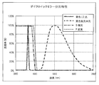
- FIG. 2 is a graph showing the spectral characteristics of the dichroic mirror 16. As shown in FIG. 2, the dichroic mirror 16 transmits blue light and reflects yellow light. Yellow light is light including red light and green light. In this embodiment, the dichroic mirror 16 reflects yellow light obtained by wavelength-converting blue light emitted from the first light source 11 by the phosphor wheel 19 and transmits blue light emitted from the second light source 20.
- the dichroic mirror 16 is an example of a combining unit that combines yellow light incident from the phosphor wheel 19 and blue light incident from the second light source 20 and enters the color wheel 28.
- the second condenser lens 17 condenses the blue light transmitted through the first diffusion plate 15 and the dichroic mirror 16, and makes the light incident from the phosphor wheel 19 side into parallel light.
- the third condenser lens 18 condenses the blue light that has passed through the second condenser lens 17 onto the phosphor wheel 19 and refracts the light incident from the phosphor wheel 19 side so as to refract the second condenser lens 17. To enter.
- the phosphor wheel 19 includes a disk coated with a phosphor and a motor that rotates the disk.
- the phosphor wheel 19 converts the wavelength of the blue light incident from the first light source 11 side, and emits yellow light. By rotating the disk, it is possible to prevent the incident blue light from being irradiated locally on the phosphor with a high light density and causing burning.
- the first light source 11 and the phosphor wheel 19 are an example of a first light source unit that emits combined light including first color light and second color light.
- the second light source 20 has a plurality of laser diodes and emits blue light.
- the second collimator lens 21 refracts the blue light emitted from each laser diode of the second light source 20 into parallel light.
- the fourth condenser lens 22 condenses a plurality of light beams converted into parallel light by the second collimator lens 21.
- the second diverging lens 23 diverges a plurality of light beams collected by the fourth condensing lens 22 to make it parallel light again.
- the second diffusing plate 24 diffuses the light beam converted into parallel light by the second diverging lens 23 to make the illuminance distribution uniform.
- the fifth condenser lens 25 collects yellow light incident on the dichroic mirror 16 from the phosphor wheel 19 side and reflected by the dichroic mirror 16 and blue light incident from the second light source 20 side.
- the first reflecting mirror 26 reflects the light transmitted through the fifth condenser lens 25 and changes the traveling direction of the light.
- the sixth condenser lens 27 condenses the light reflected by the first reflecting mirror 26.
- the color wheel 28 includes a plurality of transmission regions having different transmission wavelength ranges, and uses light emitted from the first light source 11 and the second light source 20 as incident light. Further, the color wheel 28 rotates a disk portion including a plurality of transmission regions around a predetermined rotation axis, so that a position where incident light is incident moves on each transmission region, whereby the incident light is converted into a plurality of color lights. Time-divided into
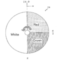
- FIG. 3 is an explanatory diagram showing the configuration of the transmission region of the color wheel of the projector according to the present embodiment.
- a quarter of the entire region is a red light transmitting region that transmits the red light wavelength region
- a quarter of the region is the green light wavelength region.
- a green light transmission region that transmits light, and a half region is a white light transmission region that transmits light in the entire wavelength region.
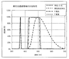
- FIG. 4 is a graph showing the spectral characteristics of the red light transmission region of the color wheel of the projector according to the present embodiment. As shown in FIG. 4, the red light transmission region has a characteristic of transmitting only a red component contained in yellow light.
- FIG. 4 is a graph showing the spectral characteristics of the red light transmission region of the color wheel of the projector according to the present embodiment. As shown in FIG. 4, the red light transmission region has a characteristic of transmitting only a red component contained in yellow light.
- the green light transmission region has a characteristic of transmitting only a green component contained in yellow light.
- the color wheel 28 has a disk portion that rotates counterclockwise.
- the light tunnel 29 receives the light transmitted through the color wheel 28 as incident light, has a plurality of reflection surfaces on the inner wall, and reflects the incident light a plurality of times to emit the incident light with uniform luminance distribution. .
- the seventh condenser lens 30 condenses the light emitted from the light tunnel 29.
- the second reflecting mirror 31 reflects the light transmitted through the seventh condenser lens 30 and changes the traveling direction of the light.
- the eighth condenser lens 32 condenses the light reflected by the second reflected light 31.
- the third reflecting mirror 33 reflects the light transmitted through the eighth condenser lens 32 and changes the traveling direction of the light.
- the ninth condensing lens 34 condenses the light reflected by the third reflecting mirror 33.
- the ninth condenser lens 34 condenses light on the DMD 36.
- the cover glass 35 protects the surface of the DMD 36.
- the cover glass 35 transmits the light refracted by the ninth condenser lens 34.
- the DMD 36 is a semiconductor projection device in which minute mirrors are arranged in a matrix, and outputs modulated light obtained by spatially modulating incident light based on a video signal.
- each mirror included in the DMD 36 corresponds to a pixel, and sets an angle with respect to incident light to an ON state or an OFF state based on a video signal.
- the light reflected by the mirror in the ON state travels in the direction of the projection optical system 37.
- the light reflected by the OFF mirror travels in a direction different from the direction of the projection optical system 37.
- the ON state and the OFF state are switched at high speed, and the color gradation is expressed by changing the temporal ratio between the ON state and the OFF state.
- the projection optical system 37 enlarges the light reflected by the DMD 36 and projects it onto a screen (not shown).
- the storage unit 50 stores data used for the projector 100 to operate.
- the storage unit 50 stores a plurality of lighting pattern information indicating a plurality of lighting patterns having different periods during which the first light source 11 and the second light source 20 are turned on while the color wheel 28 rotates once.
- the lighting pattern information is information determined corresponding to each of a plurality of display modes.
- the lighting pattern indicated by the lighting pattern information includes a lighting pattern in which light obtained by combining light emitted from the light source units becomes white light in a state where a plurality of light source units are turned on.
- the lighting pattern indicated by the lighting pattern information includes a lighting pattern corresponding to the high color reproducibility mode in which blue light is incident on the white light transmission region as incident light, and a high luminance mode in which a plurality of color lights are sequentially incident on the white light transmission region. And a lighting pattern corresponding to.
- the control unit 60 is electrically connected to the first light source 11, the second light source 20, the color wheel 28, the DMD 36, and the like, and controls the operation of each connected unit. For example, the control unit 60 turns on the first light source 11 and the second light source 20 based on any of a plurality of lighting pattern information stored in the storage unit 50. At this time, the control unit 60 receives a selection signal for selecting one of the plurality of lighting patterns, and lights each light source according to lighting pattern information indicating the lighting pattern selected by the selection signal. The control unit 60 switches between the ON state and the OFF state of each mirror of the DMD 36 based on the video signal.
- the path of light emitted from each light source is as follows. First, the light emitted from the first light source 11 is converted into parallel light by the first collimator lens 12, and a plurality of light beams that have become parallel light are collected by the first condenser lens 13, and parallel again by the first divergent lens 14. Returned to the light.
- the size of the optical component used in the latter stage can be reduced by reducing the luminous flux of the light emitted from the plurality of laser diodes by the first condenser lens 13 and the first diverging lens 14.
- the parallel light that has passed through the first diverging lens 14 passes through the first diffusion plate 15 and the dichroic mirror 16, and passes through the second condenser lens 17 and the third condenser lens 18 to be collected on the phosphor wheel 19.
- the light condensed on the phosphor wheel 19 is converted into yellow light that is wavelength-converted by the phosphor and is distributed in the wavelength range of about 485 nm to 780 nm. This yellow light is emitted as diverging light in a state close to complete diffused light.
- the yellow light passes through the third condenser lens 18 and the second condenser lens 17 and enters the dichroic mirror 16 as pseudo-parallel light.
- the yellow light is reflected by the dichroic mirror 16, is collected near the entrance opening of the light tunnel 29 by the fifth condenser lens 25 and the sixth condenser lens 27, and enters the light tunnel 29.
- light is reflected by the first reflecting mirror 26 between the fifth condenser lens 25 and the sixth condenser lens 27.
- the first reflecting mirror 26 is arranged to bend the optical path to reduce the size of the projector 100.
- the light incident on the light tunnel 29 is repeatedly reflected by the reflecting mirror on the inner surface of the light tunnel 29, and has a rectangular distribution with a substantially uniform illuminance on the exit surface of the light tunnel 29. While maintaining the illuminance distribution on the exit surface of the light tunnel 29, the light passes through the relay optical system including the seventh condenser lens 30, the eighth condenser lens 32, and the ninth condenser lens 34 and the cover glass 35. The light is transmitted and magnified on the DMD 36.
- the second reflecting mirror 31 disposed between the seventh condensing lens 30 and the eighth condensing lens 32, and the third reflecting mirror disposed between the eighth condensing lens 32 and the ninth condensing lens 34.
- the first reflecting mirror 26, 33 is arranged to bend the optical path to reduce the apparatus size of the projector 100 and determine the angle of light incident on the DMD 36.
- the light incident on the DMD 36 is spatially modulated based on the video signal, and the light reflected by the ON-state mirror among the mirrors of the DMD 36 is incident on the projection optical system 37.
- the projection optical system 37 enlarges and projects the incident light toward the screen.
- the light emitted from the second light source 20 is converted into parallel light by the second collimator lens 21, and the plurality of light beams that have become parallel light are condensed by the fourth condenser lens 22 and again by the second divergent lens 23. Returned to parallel light.
- the parallel light after passing through the second diverging lens 23 passes through the second diffusion plate 24 and enters the dichroic mirror 16.
- the light incident on the dichroic mirror 16 passes through the dichroic mirror 16, and the light path coincides with the light reflected by the phosphor wheel 19. Since the light path after passing through the dichroic mirror 16 is the same as the light reflected by the phosphor wheel 19, a description thereof is omitted here.
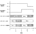
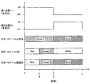
- FIGS. 6 to 9 are explanatory diagrams showing an example of a lighting pattern, a color sequence of light incident on the color wheel, a configuration of a transmission region of the color wheel, and a color sequence of transmitted light transmitted through the color wheel, respectively.
- the configuration of the transmission region of the color wheel shown in FIGS. 6 to 9 is the same as that shown in FIG.
- T is the time taken for the color wheel 28 to make one rotation.
- 6 to 9 show the color sequence of the light transmitted through the color wheel 28 for the period of 0 ⁇ t ⁇ T.
- the period of 0> t ⁇ T is also used for the period of t> T.
- turning on and off each light source is repeated.
- FIG. 6 shows an example in which the control unit 60 lights each light source unit based on the first lighting pattern information.
- control unit 60 turns on the first light source 11 during a period of 0 ⁇ t ⁇ 5T / 6, and turns on the second light source 20 during a period of 2T / 3 ⁇ t ⁇ T.
- the incident light incident on the color wheel 28 is light in which a plurality of lights from each light source unit are mixed during a period in which the respective light source units are lit simultaneously. Therefore, in this case, the incident light incident on the color wheel 28 is yellow light in a period of 0 ⁇ t ⁇ 2T / 3, and white light in which yellow light and blue light are mixed in a period of 2T / 3 ⁇ t ⁇ 5T / 6. It becomes light and becomes blue light in a period of 5T / 6 ⁇ t ⁇ T.
- yellow light is incident on the red light transmission region of the color wheel 28, the green light component of the incident yellow light is shielded by the red light transmission region, and only the red light component passes through the red light transmission region.
- the yellow light also enters the green light transmission region of the color wheel 28, and the red light component of the incident yellow light is shielded by the green light transmission region, and only the green light component passes through the green light transmission region.
- yellow light, white light, and blue light sequentially enter the white light transmission region, and yellow light, white light, and blue light respectively transmit through the white light transmission region.
- the color of the transmitted light that has passed through the color wheel 28 changes in the order of red, green, yellow, white, and blue.
- FIG. 7 shows an example in which the control unit 60 lights each light source unit based on the second lighting pattern information.
- control unit 60 turns on the first light source 11 during a period of 0 ⁇ t ⁇ 3T / 4, and turns on the second light source 20 during a period of T / 2 ⁇ t ⁇ T.
- the incident light incident on the color wheel 28 becomes yellow light in a period of 0 ⁇ t ⁇ T / 2, becomes white light in a period of T / 2 ⁇ t ⁇ 3T / 4, and has a period of 3T / 4 ⁇ t ⁇ T. Becomes blue light.
- yellow light is incident on the red light transmission region of the color wheel 28, the green light component contained in the incident yellow light is shielded by the red light transmission region, and only the red light component is transmitted through the red light. Transparent through the area.
- the yellow light also enters the green light transmission region of the color wheel 28, and the red light component of the incident yellow light is shielded by the green light transmission region, and only the green light component passes through the green light transmission region.
- White light and blue light are sequentially incident on the white light transmission region. At this time, white light and blue light are transmitted through the white light transmission region.
- the color of the transmitted light that has passed through the color wheel 28 changes in the order of red, green, white, and blue.
- FIG. 8 shows an example in which the control unit 60 lights each light source unit based on the third lighting pattern information.
- control unit 60 turns on the first light source 11 during a period of 0 ⁇ t ⁇ 3T / 4, and turns on the second light source 20 during a period of 3T / 4 ⁇ t ⁇ T.
- the incident light incident on the color wheel 28 becomes yellow light during a period of 0 ⁇ t ⁇ 3T / 4, and becomes blue light during a period of 3T / 4 ⁇ t ⁇ T.
- yellow light is incident on the red light transmission region of the color wheel 28, the green light component contained in the incident yellow light is shielded by the red light transmission region, and only the red light component is transmitted through the red light. Transparent through the area.
- the yellow light also enters the green light transmission region of the color wheel 28, and the red light component of the incident yellow light is shielded by the green light transmission region, and only the green light component passes through the green light transmission region.
- yellow light and blue light are sequentially incident on the white light transmission region. At this time, yellow light and blue light respectively transmit through the white light transmission region.
- the color of the transmitted light that has passed through the color wheel 28 changes in the order of red, green, yellow, and blue.
- FIG. 9 shows an example in which the control unit 60 lights each light source unit based on the fourth lighting pattern information.
- the control unit 60 turns on the first light source 11 during a period of 0 ⁇ t ⁇ T / 2, and turns on the second light source 20 during a period of T / 2 ⁇ t ⁇ T.
- the incident light incident on the color wheel 28 becomes yellow light in a period of 0 ⁇ t ⁇ T / 2, and becomes blue light in a period of T / 2 ⁇ t ⁇ T.
- yellow light is incident on the red light transmission region of the color wheel 28, the green light component contained in the incident yellow light is shielded by the red light transmission region, and only the red light component is transmitted through the red light. Transparent through the area.
- the yellow light also enters the green light transmission region of the color wheel 28, and the red light component of the incident yellow light is shielded by the green light transmission region, and only the green light component passes through the green light transmission region. .
- blue light is incident on the white light transmission region, and at this time, the blue light is transmitted through the white light transmission region.
- the color of the transmitted light that has passed through the color wheel 28 changes in the order of red, green, and blue.
- the projector 100 changes the color of the transmitted light that has passed through the color wheel 28 from five colors (RGYWB), four colors (RGYB, RGWB), and three colors (RGB) by using the plurality of lighting pattern information exemplified above. Can be made.
- the color of the transmitted light is five or four, the proportion of the light that passes through the color wheel 28 in the incident light is higher during one rotation of the color wheel 28 than in the case of three colors. Therefore, the brightness of the projected image can be increased.
- the amount of each RGB color light is increased, so that the color reproducibility can be improved. Therefore, a lighting pattern with five or four colors of transmitted light can correspond to the high luminance mode, and a lighting pattern with three colors of transmitted light can correspond to the high color reproducibility mode.
- each light source unit is turned on according to the selected lighting pattern. Therefore, according to the lighting pattern, each light source unit is turned on during one rotation of the color wheel 28. The lighting period is changed. For this reason, the color sequence of light incident on the color wheel 28 changes for each lighting pattern, and as a result, the color sequence of transmitted light that has passed through the color wheel 28 changes. Accordingly, since color reproducibility and luminance change according to the color sequence of the transmitted light that has passed through the color wheel 28, color reproducibility can be improved by appropriately setting the lighting pattern without limiting the maximum luminance. be able to. For this reason, it is possible to suppress a decrease in luminance in the display mode in which color reproducibility is emphasized.
- the light emitted from the plurality of light source units is incident on the color wheel 28 after being combined by the dichroic mirror 16.
- the color wheel 28 includes a white transmission region that transmits incident light in all wavelength ranges, and the plurality of lighting patterns include a lighting pattern in which light combined by the dichroic mirror 16 becomes white light. Accordingly, it is possible to generate a period in which all white light passes through the color wheel, and it is possible to display an image with high luminance.
- the light source unit emits the combined light including the first color light and the second color light, and the third color light
- the color wheel 28 transmits the first color light. 1 transmission region, a second transmission region that transmits the second color light, and a white light transmission region that transmits incident light in all wavelength regions.
- the first transmission region of the color wheel 28 can transmit the first color light
- the second transmission region can transmit the second color light. Further, by changing the color of incident light incident on the white light transmission region, it is possible to change the color sequence of the transmitted light transmitted through the color wheel 28 into various patterns.
- the blue light emitted from the first light source 11 enters the phosphor wheel 19, and the phosphor wheel 19 excites and emits yellow light including red light and green light.
- the second light source 20 emits blue light.
- the control unit 60 receives the lighting pattern for the high color reproducibility mode in which the three colors of transmitted light are emitted from the color wheel 28, and the four or five colors of transmitted light from the color wheel 28.
- Each light source unit is turned on according to any one of a plurality of lighting patterns including a lighting pattern for the high luminance mode to be emitted. Thereby, the user can display an appropriate image according to the usage scene.
- each light source unit is a plurality of laser diodes.
- the light source unit may be a single laser diode.
- Each light source unit may be a light emitting diode (LED) instead of a laser diode.
- the display mode was switched by changing the period when each light source part is turned on while the color wheel makes one rotation, the display mode is adjusted more finely by adjusting the light intensity of each light source. It is also possible.
- a plurality of lighting patterns are exemplified, but the lighting patterns are not limited to those illustrated, and various changes may be added.
- the order in which the color of the incident light incident on the color wheel 28 changes is merely an example, and the color of the incident light can be changed in a different order by changing the order in which the light sources are turned on.
- the configuration of the transmission region of the color wheel shown in the above embodiment is an example, and the configuration and the size of each transmission region can be changed in addition to the configuration shown in the drawing.
- the projector according to the above embodiment may be a front projector that projects an image from the front surface (the surface viewed by the user) of the screen, or a rear projector that projects an image from the back surface of the screen (the back surface of the user viewing surface). It may be.
Landscapes
- Physics & Mathematics (AREA)
- General Physics & Mathematics (AREA)
- Engineering & Computer Science (AREA)
- Multimedia (AREA)
- Signal Processing (AREA)
- Optics & Photonics (AREA)
- Astronomy & Astrophysics (AREA)
- Spectroscopy & Molecular Physics (AREA)
- Projection Apparatus (AREA)
Abstract
Provided is an illuminating optical device capable of suppressing a reduction of luminance in a display mode in which color reproducibility is emphasized. A plurality of light source units (11, 19, 20) each emit different colors of light. A color wheel (28) includes a plurality of transmission regions each for transmitting a different color of light, and by rotation of the color wheel (28), the position at which incident light from the light source units is incident moves over the transmission regions. A storage unit (50) stores a plurality of lighting pattern information indicating each of a plurality of lighting patterns having different lighting periods for which each light source unit is lit. A control unit (60) receives a selection signal for selecting any of the plurality of lighting patterns, and causes each light source unit to light in response to the lighting pattern information indicating the lighting pattern selected by the selection signal.
Description
本発明は、照明光学装置、プロジェクタ、および照明光学装置の制御方法に関する。
The present invention relates to an illumination optical device, a projector, and a control method for the illumination optical device.
スクリーンに画像を投写するプロジェクタには、複数の色光を時分割して出射する照明光学装置と、DMD(Digital Mirror Device)のような、照明光学装置からの各色光を反射してスクリーンに出射する反射型画像表示素子とを有する単板式のDLP(Digital Light Processing)プロジェクタがある。
For projectors that project images onto a screen, an illumination optical device that emits a plurality of color lights in a time-sharing manner, and each color light from an illumination optical device such as a DMD (Digital Mirror Device) is reflected and emitted to the screen. There is a single plate type DLP (Digital Light Processing) projector having a reflective image display element.
単板式のDLPプロジェクタの照明光学装置は、通常、白色光源と、白色光源からの光を複数の色光に時分割するカラーホイールとを有する。カラーホイールは、透過する光の色がそれぞれ異なる複数の透過領域を含む円盤と、円盤を回転させるモータとを有する。モータによって円盤が回転すると、白色光源からの光が入射する円盤上の位置が変化していき、光が各透過領域に順番に入射する。これにより、カラーホイールを透過した光の色が時分割で変化することになる。なお、円盤には、通常、赤(R),緑(G),青(B)(以下、まとめてRGBと略す。)のそれぞれの光を透過する3つの透過領域が設けられている。
The illumination optical device of a single-plate DLP projector usually has a white light source and a color wheel that time-divides light from the white light source into a plurality of color lights. The color wheel includes a disk including a plurality of transmission regions having different colors of transmitted light, and a motor that rotates the disk. When the disc is rotated by the motor, the position on the disc where the light from the white light source enters changes, and the light enters the transmission regions in order. As a result, the color of the light transmitted through the color wheel changes in a time-sharing manner. Note that the disk is normally provided with three transmission regions that transmit red (R), green (G), and blue (B) (hereinafter collectively referred to as RGB) light.
照明光学装置から時分割して出射された複数の色光は、反射型画像表示素子で変調され、投写光学系を介してスクリーンに投写される。このため、スクリーンには、各色光が順次投写される。このとき、カラーホイールの回転速度が、人間が画像の切り替わりを知覚できない程度以上になると、人間には、投写画像は各色光による画像が合成されたカラー画像として認知される。
A plurality of color lights emitted from the illumination optical device in a time-sharing manner are modulated by a reflective image display element and projected onto a screen via a projection optical system. Therefore, each color light is sequentially projected on the screen. At this time, if the rotation speed of the color wheel becomes higher than the level at which human beings cannot perceive image switching, the human will recognize the projected image as a color image in which images of the respective color lights are combined.
上記の構成において、投写画像の輝度を高める方法の1つとして、光源の数を増やすことで光源が出射する光自体の輝度を高める方法がある。ところが光源の数を増やすと、消費電力が増大してしまう。これに対して消費電力を増大させずに投写画像の輝度を高める方法としては、光源が出射した光のうちカラーホイールを透過してDMDに入射する光の割合を高めることで、光源が出射した光の利用効率を高める方法がある。
In the above configuration, as one method of increasing the brightness of the projected image, there is a method of increasing the brightness of the light itself emitted from the light source by increasing the number of light sources. However, increasing the number of light sources increases power consumption. On the other hand, as a method for increasing the brightness of the projected image without increasing the power consumption, the light source is emitted by increasing the proportion of the light emitted from the light source that passes through the color wheel and enters the DMD. There is a method for increasing the light utilization efficiency.
具体的には、光の利用効率を高めるための技術としては、例えば、カラーホイールにRGB以外の色光(例えば白W,黄Y,マゼンタM,シアンCなど)を透過する透過領域を加えることで、入射光のうちカラーホイールで遮蔽される光の割合を減らすものがある。
Specifically, as a technique for improving the light utilization efficiency, for example, a transmission region that transmits color light other than RGB (for example, white W, yellow Y, magenta M, cyan C, etc.) is added to the color wheel. Some of the incident light reduces the proportion of light blocked by the color wheel.
また、光の利用効率を高めるための技術の別の例として、特許文献1には、RGB以外を透過する透過領域を用いる代わりに、白色光源を、色光を出射する光源に変更することで光の利用効率を高くするプロジェクタが記載されている。このプロジェクタは、赤色光および緑色光を含む光を発光する第1の発光ダイオードと、青色光を発光する第2の発光ダイオードと、カラーホイールと、DMDとを有する。
Moreover, as another example of the technique for improving the light utilization efficiency, Patent Document 1 discloses that a light source can be obtained by changing a white light source to a light source that emits colored light instead of using a transmission region that transmits light other than RGB. A projector that increases the use efficiency of the projector is described. The projector includes a first light emitting diode that emits light including red light and green light, a second light emitting diode that emits blue light, a color wheel, and a DMD.
特許文献1に記載のプロジェクタは、例えば、DMDに赤色光を入射する場合、第1の発光ダイオードが出射する赤色光および緑色光を含む光を、赤色光を透過させる赤色光透過領域に入射させる。この場合、カラーホイールにより緑色光のみが遮蔽され赤色光が透過される。このため、白色光源からの白色光が赤色光透過領域に入射される場合には、緑色光以外の光も赤色光透過領域で遮蔽されてしまうので、特許文献1に記載のプロジェクタでは、白色光源を用いる場合と比べて、光の利用効率を高くすることが可能になる。
In the projector described in Patent Document 1, for example, when red light is incident on the DMD, light including red light and green light emitted from the first light emitting diode is incident on a red light transmission region that transmits red light. . In this case, only the green light is blocked by the color wheel and the red light is transmitted. For this reason, when white light from the white light source is incident on the red light transmission region, light other than green light is also shielded by the red light transmission region. It is possible to increase the light use efficiency as compared with the case of using.
また、映画などの色彩豊かな画像を投写する場合には、色再現性を高くすることが望まれている。しかしながら、色再現性を高めようとすると、各色のバランスを調整するために、各色光の最大輝度を制限する必要があり、その結果、輝度が低下してしまう。このようにプロジェクタの輝度を高めることと、色再現性を高めることとはトレードオフの関係にあり、高輝度な表示と色再現性の高い表示とを同時に実現することはできなかった。
Also, when projecting a colorful image such as a movie, it is desired to improve color reproducibility. However, in order to improve the color reproducibility, it is necessary to limit the maximum luminance of each color light in order to adjust the balance of each color, and as a result, the luminance decreases. Thus, increasing the brightness of the projector and increasing the color reproducibility are in a trade-off relationship, and a high-brightness display and a display with high color reproducibility cannot be realized simultaneously.
そのため、一般的なプロジェクタでは、輝度の高い画像を投写する高輝度モードや、色再現性の高い画像を投写する高色再現性モードのような、プロジェクタの使用シーンに適合した複数の表示モードを備えている。例えばプレゼンテーション資料などを表示する場合には、高輝度モードが用いられ、映画などを表示する場合には、高色再現性モードが用いられる。
For this reason, a general projector has multiple display modes that are suitable for the scene in which the projector is used, such as a high-brightness mode that projects images with high brightness and a high-color reproducibility mode that projects images with high color reproducibility. I have. For example, when displaying presentation materials, the high luminance mode is used, and when displaying movies, the high color reproducibility mode is used.
しかしながら、高色再現性モードでは、各色光の最大輝度が制限されてしまうため、投写画像の輝度が大幅に低下してしまい、ユーザが画像を見づらいことがあった。これに対して、RGB以外に色光を透過する領域を加える技術や、特許文献1に記載の技術では、輝度を高くすることが可能になるが、高色再現性モードでは、各色光の最大輝度が制限されてしまうため、結局、輝度が大幅に低下してしまう。
However, in the high color reproducibility mode, since the maximum luminance of each color light is limited, the luminance of the projected image is greatly reduced, and it may be difficult for the user to view the image. On the other hand, the technique of adding a region that transmits color light in addition to RGB and the technique described in Patent Document 1 can increase the luminance. However, in the high color reproducibility mode, the maximum luminance of each color light can be increased. As a result, the luminance is greatly reduced.
本発明の目的は、高色再現性モードにおける輝度の低下を抑制することの可能な照明光学装置、プロジェクタ、および照明光学装置の制御方法を提供することである。
An object of the present invention is to provide an illumination optical device, a projector, and a control method for the illumination optical device that can suppress a decrease in luminance in the high color reproducibility mode.
本発明による照明光学装置は、それぞれ異なる色の光を出射する複数の光源部と、それぞれ異なる色の光を透過する複数の透過領域を含み、回転することで、各光源部からの入射光が入射する位置が各透過領域上を移動するカラーホイールと、各光源部を点灯する点灯期間が異なる複数の点灯パターンのそれぞれを示す複数の点灯パターン情報を記憶する記憶部と、前記複数の点灯パターンのいずれかを選択する選択信号を受信し、当該選択信号にて選択された点灯パターンを示す点灯パターン情報に応じて、各光源を点灯させる制御部とを有する。
The illumination optical device according to the present invention includes a plurality of light source units that emit light of different colors and a plurality of transmission regions that transmit light of different colors, and rotates so that incident light from each light source unit is transmitted. A color wheel whose incident position moves on each transmission region, a storage unit that stores a plurality of lighting pattern information indicating each of a plurality of lighting patterns with different lighting periods for lighting each light source unit, and the plurality of lighting patterns And a control unit that turns on each light source in accordance with lighting pattern information indicating a lighting pattern selected by the selection signal.
本発明によるプロジェクタは、前記照明光学装置と、前記照明光学装置から出力された光を映像信号に基づいて変調する反射型画像表示素子と、前記反射型画像表示素子が変調した光を投写する投写光学系と、を有する。
The projector according to the present invention projects the illumination optical device, a reflective image display element that modulates light output from the illumination optical apparatus based on a video signal, and light that is modulated by the reflective image display element. And an optical system.
本発明による照明方法は、それぞれ異なる色の光を出射する複数の光源部と、それぞれ異なる色の光を透過する複数の透過領域を含み、回転することで、各光源部からの入射光が入射する位置が各透過領域上を移動するカラーホイールと、を有する照明光学装置による照明方法であって、各光源部を点灯する点灯期間が異なる複数の点灯パターンのそれぞれを示す複数の点灯パターン情報のいずれかを選択する選択信号を受信し、当該選択信号にて選択された点灯パターンを示す点灯パターン情報に応じて、各光源を点灯させる、照明光学装置の制御方法。
The illumination method according to the present invention includes a plurality of light source units that emit light of different colors and a plurality of transmission regions that transmit light of different colors, and incident light from each light source unit is incident by rotating. A plurality of lighting pattern information indicating each of a plurality of lighting patterns having different lighting periods for lighting each light source unit. A method for controlling an illumination optical apparatus, wherein a selection signal for selecting one of the light sources is received and each light source is turned on according to lighting pattern information indicating a lighting pattern selected by the selection signal.
本発明によれば、色再現性を重視した表示モードにおける輝度の低下を抑制することが可能になる。
According to the present invention, it is possible to suppress a decrease in luminance in a display mode that emphasizes color reproducibility.
以下、本発明の実施形態について添付の図面を参照して説明する。なお、本明細書および図面において、同一の機能を有する構成要素については同じ符号を付することにより重複説明を省略する場合がある。
Hereinafter, embodiments of the present invention will be described with reference to the accompanying drawings. In addition, in this specification and drawing, the description which overlaps may be abbreviate | omitted by attaching | subjecting the same code | symbol about the component which has the same function.
図1は、本発明の一実施形態にかかるプロジェクタの構成を示す図である。図1に示すプロジェクタ100は、1つの反射型画像表示素子を有する単板式のDLPプロジェクタである。
FIG. 1 is a diagram showing a configuration of a projector according to an embodiment of the present invention. A projector 100 shown in FIG. 1 is a single-plate DLP projector having one reflective image display element.
プロジェクタ100は、第1光源11と、第1コリメータレンズ12と、第1集光レンズ13と、第1発散レンズ14と、第1拡散板15と、ダイクロイックミラー16と、第2集光レンズ17と、第3集光レンズ18と、蛍光体ホイール19と、第2光源20と、第2コリメータレンズ21と、第4集光レンズ22と、第2発散レンズ23と、第2拡散板24と、第5集光レンズ25と、第1反射鏡26と、第6集光レンズ27と、カラーホイール28と、ライトトンネル29と、第7集光レンズ30と、第2反射鏡31と、第8集光レンズ32と、第3反射鏡33と、第9集光レンズ34と、カバーガラス35と、DMD36と、投写光学系37と、記憶部50と、制御部60とを有する。
The projector 100 includes a first light source 11, a first collimator lens 12, a first condenser lens 13, a first diverging lens 14, a first diffuser plate 15, a dichroic mirror 16, and a second condenser lens 17. The third condenser lens 18, the phosphor wheel 19, the second light source 20, the second collimator lens 21, the fourth condenser lens 22, the second diverging lens 23, and the second diffuser plate 24. The fifth condenser lens 25, the first reflector 26, the sixth condenser lens 27, the color wheel 28, the light tunnel 29, the seventh condenser lens 30, the second reflector 31, and It has an 8 condensing lens 32, a third reflecting mirror 33, a ninth condensing lens 34, a cover glass 35, a DMD 36, a projection optical system 37, a storage unit 50, and a control unit 60.
第1光源11は、励起光を出射する励起光源である。第1光源11は、複数のレーザダイオードを有し、青色光を出射する。なお第1光源11は、励起光源であるため蛍光体の発光波長よりも短波長の光であればよく、青色光に限定するものではない。以下、本実施形態では、第1光源11は青色光を出射するものとして説明する。
The first light source 11 is an excitation light source that emits excitation light. The first light source 11 has a plurality of laser diodes and emits blue light. Since the first light source 11 is an excitation light source, it may be light having a wavelength shorter than the emission wavelength of the phosphor, and is not limited to blue light. Hereinafter, in the present embodiment, the first light source 11 will be described as emitting blue light.
第1コリメータレンズ12は、第1光源11の各レーザダイオードが出射した青色光を屈折させてそれぞれ平行光にする。
The first collimator lens 12 refracts the blue light emitted from each laser diode of the first light source 11 into parallel light.
第1集光レンズ13は、第1コリメータレンズ12にて平行光にされた複数の光束を集光する。
The first condenser lens 13 condenses a plurality of light beams converted into parallel light by the first collimator lens 12.
第1発散レンズ14は、第1集光レンズ13が集光した複数の光束を発散させて再び平行光にする。
The first diverging lens 14 diverges a plurality of light beams collected by the first condensing lens 13 to make parallel light again.
第1拡散板15は、第1発散レンズ14にて平行光にされた光束を拡散して照度分布を均一にする。
The first diffusing plate 15 diffuses the light beam made parallel by the first diverging lens 14 to make the illuminance distribution uniform.
ダイクロイックミラー16は、入射光を波長ごとに反射または透過させることで、入射光を分光する。図2は、ダイクロイックミラー16の分光特性を示すグラフである。図2に示されたように、ダイクロイックミラー16は、青色光を透過させ、黄色光を反射させる。なお黄色光は、赤色光と緑色光とを含む光である。本実施形態ではダイクロイックミラー16は、蛍光体ホイール19が第1光源11が出射した青色光を波長変換した黄色光を反射させ、第2光源20が出射した青色光を透過させる。なおダイクロイックミラー16は、蛍光体ホイール19から入射した黄色光と、第2光源20から入射された青色光とを合波してカラーホイール28に入射する合波部の一例である。
The dichroic mirror 16 separates the incident light by reflecting or transmitting the incident light for each wavelength. FIG. 2 is a graph showing the spectral characteristics of the dichroic mirror 16. As shown in FIG. 2, the dichroic mirror 16 transmits blue light and reflects yellow light. Yellow light is light including red light and green light. In this embodiment, the dichroic mirror 16 reflects yellow light obtained by wavelength-converting blue light emitted from the first light source 11 by the phosphor wheel 19 and transmits blue light emitted from the second light source 20. The dichroic mirror 16 is an example of a combining unit that combines yellow light incident from the phosphor wheel 19 and blue light incident from the second light source 20 and enters the color wheel 28.
第2集光レンズ17は、第1拡散板15およびダイクロイックミラー16を透過した青色光を集光するとともに、蛍光体ホイール19側から入射した光を平行光にする。
The second condenser lens 17 condenses the blue light transmitted through the first diffusion plate 15 and the dichroic mirror 16, and makes the light incident from the phosphor wheel 19 side into parallel light.
第3集光レンズ18は、第2集光レンズ17を透過した青色光を蛍光体ホイール19上に集光するとともに、蛍光体ホイール19側から入射した光を屈折させて第2集光レンズ17に入射させる。
The third condenser lens 18 condenses the blue light that has passed through the second condenser lens 17 onto the phosphor wheel 19 and refracts the light incident from the phosphor wheel 19 side so as to refract the second condenser lens 17. To enter.
蛍光体ホイール19は、蛍光体が塗布された円盤と、この円盤を回転させるモータとを含む。蛍光体ホイール19は、第1光源11側から入射された青色光を波長変換して、黄色光を出射する。円盤が回転することで、入射された青色光が局所的に高い光密度で蛍光体に照射され、焦げ付きが生じることを防止することができる。なお、第1光源11および蛍光体ホイール19は、第1の色光および第2の色光を含む合成光を出射する第1の光源部の一例である。
The phosphor wheel 19 includes a disk coated with a phosphor and a motor that rotates the disk. The phosphor wheel 19 converts the wavelength of the blue light incident from the first light source 11 side, and emits yellow light. By rotating the disk, it is possible to prevent the incident blue light from being irradiated locally on the phosphor with a high light density and causing burning. The first light source 11 and the phosphor wheel 19 are an example of a first light source unit that emits combined light including first color light and second color light.
第2光源20は、複数のレーザダイオードを有し、青色光を出射する。
The second light source 20 has a plurality of laser diodes and emits blue light.
第2コリメータレンズ21は、第2光源20の各レーザダイオードが出射した青色光を屈折させてそれぞれ平行光にする。
The second collimator lens 21 refracts the blue light emitted from each laser diode of the second light source 20 into parallel light.
第4集光レンズ22は、第2コリメータレンズ21にて平行光にされた複数の光束を集光する。
The fourth condenser lens 22 condenses a plurality of light beams converted into parallel light by the second collimator lens 21.
第2発散レンズ23は、第4集光レンズ22が集光した複数の光束を発散させて再び平行光にする。
The second diverging lens 23 diverges a plurality of light beams collected by the fourth condensing lens 22 to make it parallel light again.
第2拡散板24は、第2発散レンズ23にて平行光にされた光束を拡散して照度分布を均一にする。
The second diffusing plate 24 diffuses the light beam converted into parallel light by the second diverging lens 23 to make the illuminance distribution uniform.
第5集光レンズ25は、蛍光体ホイール19側からダイクロイックミラー16に入射され、ダイクロイックミラー16で反射した黄色光と、第2光源20側から入射された青色光とを集光する。
The fifth condenser lens 25 collects yellow light incident on the dichroic mirror 16 from the phosphor wheel 19 side and reflected by the dichroic mirror 16 and blue light incident from the second light source 20 side.
第1反射鏡26は、第5集光レンズ25を透過した光を反射して光の進行方向を変更する。
The first reflecting mirror 26 reflects the light transmitted through the fifth condenser lens 25 and changes the traveling direction of the light.
第6集光レンズ27は、第1反射鏡26で反射した光を集光する。
The sixth condenser lens 27 condenses the light reflected by the first reflecting mirror 26.
カラーホイール28は、透過波長域がそれぞれ異なる複数の透過領域を含み、第1光源11および第2光源20が出射した光を入射光とする。またカラーホイール28は、複数の透過領域を含む円盤部分が所定の回転軸を中心として回転することで、入射光が入射する位置が各透過領域上を移動し、これにより入射光を複数の色光に時分割する。
The color wheel 28 includes a plurality of transmission regions having different transmission wavelength ranges, and uses light emitted from the first light source 11 and the second light source 20 as incident light. Further, the color wheel 28 rotates a disk portion including a plurality of transmission regions around a predetermined rotation axis, so that a position where incident light is incident moves on each transmission region, whereby the incident light is converted into a plurality of color lights. Time-divided into
図3は、本実施形態にかかるプロジェクタのカラーホイールの透過領域の構成を示す説明図である。図3に示すカラーホイール28の円盤は、全体の4分の1の領域が、赤色光の波長域を透過させる赤色光透過領域であり、4分の1の領域が、緑色光の波長域を透過させる緑色光透過領域であり、2分の1の領域が全波長域の光を透過させる白色光透過領域である。図4は、本実施形態にかかるプロジェクタのカラーホイールが有する赤色光透過領域の分光特性を示すグラフである。図4に示されるように、赤色光透過領域は、黄色光に含まれる赤色成分のみを透過させる特性を有する。また図5は、本実施形態にかかるプロジェクタのカラーホイールが有する緑色光透過領域の分光特性を示すグラフである。図5に示されるように、緑色光透過領域は、黄色光に含まれる緑色成分のみを透過させる特性を有する。このカラーホイール28は、円盤部分が反時計回りに回転する。
FIG. 3 is an explanatory diagram showing the configuration of the transmission region of the color wheel of the projector according to the present embodiment. In the disk of the color wheel 28 shown in FIG. 3, a quarter of the entire region is a red light transmitting region that transmits the red light wavelength region, and a quarter of the region is the green light wavelength region. A green light transmission region that transmits light, and a half region is a white light transmission region that transmits light in the entire wavelength region. FIG. 4 is a graph showing the spectral characteristics of the red light transmission region of the color wheel of the projector according to the present embodiment. As shown in FIG. 4, the red light transmission region has a characteristic of transmitting only a red component contained in yellow light. FIG. 5 is a graph showing the spectral characteristics of the green light transmission region of the color wheel of the projector according to the present embodiment. As shown in FIG. 5, the green light transmission region has a characteristic of transmitting only a green component contained in yellow light. The color wheel 28 has a disk portion that rotates counterclockwise.
図1の説明に戻る。ライトトンネル29は、カラーホイール28を透過した光を入射光として受け付け、内壁に複数の反射面を有し、入射光を複数回反射させることで入射光を輝度分布が均一な光にして出射する。
Returning to the explanation of FIG. The light tunnel 29 receives the light transmitted through the color wheel 28 as incident light, has a plurality of reflection surfaces on the inner wall, and reflects the incident light a plurality of times to emit the incident light with uniform luminance distribution. .
第7集光レンズ30は、ライトトンネル29が出射した光を集光する。
The seventh condenser lens 30 condenses the light emitted from the light tunnel 29.
第2反射鏡31は、第7集光レンズ30を透過した光を反射して光の進行方向を変更する。
The second reflecting mirror 31 reflects the light transmitted through the seventh condenser lens 30 and changes the traveling direction of the light.
第8集光レンズ32は、第2反射光31が反射した光を集光する。
The eighth condenser lens 32 condenses the light reflected by the second reflected light 31.
第3反射鏡33は、第8集光レンズ32を透過した光を反射して光の進行方向を変更する。
The third reflecting mirror 33 reflects the light transmitted through the eighth condenser lens 32 and changes the traveling direction of the light.
第9集光レンズ34は、第3反射鏡33が反射した光を集光する。この第9集光レンズ34は、DMD36上に光を集光する。
The ninth condensing lens 34 condenses the light reflected by the third reflecting mirror 33. The ninth condenser lens 34 condenses light on the DMD 36.
カバーガラス35は、DMD36の表面を保護する。カバーガラス35は、第9集光レンズ34が屈折させた光を透過させる。
The cover glass 35 protects the surface of the DMD 36. The cover glass 35 transmits the light refracted by the ninth condenser lens 34.
DMD36は、微小のミラーをマトリックス状に並べた半導体型投写デバイスであり、映像信号に基づいて、入射光を空間変調した変調光を出力する。具体的には、DMD36に含まれる各ミラーは、画素に対応しており、映像信号に基づいて、入射光に対する角度をON状態またはOFF状態にする。ON状態のミラーが反射した光は、投写光学系37方向に進行する。一方OFF状態のミラーが反射した光は投写光学系37方向とは異なる方向に進行する。このON状態とOFF状態とが高速で切り替えられ、ON状態とOFF状態との時間的な比率を変化させることで、色の階調が表現される。
The DMD 36 is a semiconductor projection device in which minute mirrors are arranged in a matrix, and outputs modulated light obtained by spatially modulating incident light based on a video signal. Specifically, each mirror included in the DMD 36 corresponds to a pixel, and sets an angle with respect to incident light to an ON state or an OFF state based on a video signal. The light reflected by the mirror in the ON state travels in the direction of the projection optical system 37. On the other hand, the light reflected by the OFF mirror travels in a direction different from the direction of the projection optical system 37. The ON state and the OFF state are switched at high speed, and the color gradation is expressed by changing the temporal ratio between the ON state and the OFF state.
投写光学系37は、DMD36が反射した光を拡大してスクリーン(図示せず)に投写する。
The projection optical system 37 enlarges the light reflected by the DMD 36 and projects it onto a screen (not shown).
記憶部50は、プロジェクタ100が動作するために用いるデータを格納する。本実施形態において記憶部50は、カラーホイール28が1回転する間に第1光源11および第2光源20を点灯する期間がそれぞれ異なる複数の点灯パターンのそれぞれを示す複数の点灯パターン情報を記憶する。ここで点灯パターン情報は、複数の表示モードそれぞれに対応して定められた情報である。例えば点灯パターン情報の示す点灯パターンは、複数の光源部が点灯した状態で、光源部が出射した光を合波した光が白色光となる点灯パターンを含む。また点灯パターン情報の示す点灯パターンは、白色光透過領域に青色光を入射光として入射する高色再現性モードに対応した点灯パターンと、白色光透過領域に複数の色光を順次入射する高輝度モードに対応した点灯パターンとを含む。
The storage unit 50 stores data used for the projector 100 to operate. In the present embodiment, the storage unit 50 stores a plurality of lighting pattern information indicating a plurality of lighting patterns having different periods during which the first light source 11 and the second light source 20 are turned on while the color wheel 28 rotates once. . Here, the lighting pattern information is information determined corresponding to each of a plurality of display modes. For example, the lighting pattern indicated by the lighting pattern information includes a lighting pattern in which light obtained by combining light emitted from the light source units becomes white light in a state where a plurality of light source units are turned on. The lighting pattern indicated by the lighting pattern information includes a lighting pattern corresponding to the high color reproducibility mode in which blue light is incident on the white light transmission region as incident light, and a high luminance mode in which a plurality of color lights are sequentially incident on the white light transmission region. And a lighting pattern corresponding to.
制御部60は、第1光源11、第2光源20、カラーホイール28、およびDMD36などと電気的に接続され、接続された各部の動作を制御する。例えば、制御部60は、記憶部50に記憶された複数の点灯パターン情報のいずれかに基づいて、第1光源11および第2光源20をそれぞれ点灯する。このとき制御部60は、複数の点灯パターンのいずれかを選択する選択信号を受信し、当該選択信号にて選択された点灯パターンを示す点灯パターン情報に応じて、各光源を点灯させる。また制御部60は、DMD36の各ミラーのON状態とOFF状態とを映像信号に基づいて切り替える。
The control unit 60 is electrically connected to the first light source 11, the second light source 20, the color wheel 28, the DMD 36, and the like, and controls the operation of each connected unit. For example, the control unit 60 turns on the first light source 11 and the second light source 20 based on any of a plurality of lighting pattern information stored in the storage unit 50. At this time, the control unit 60 receives a selection signal for selecting one of the plurality of lighting patterns, and lights each light source according to lighting pattern information indicating the lighting pattern selected by the selection signal. The control unit 60 switches between the ON state and the OFF state of each mirror of the DMD 36 based on the video signal.
このような構成により、各光源が出射した光の経路は、以下の通りとなる。まず第1光源11が出射した光は、第1コリメータレンズ12によりそれぞれ平行光となり、平行光となった複数の光束が第1集光レンズ13により集光され、第1発散レンズ14により再び平行光に戻される。なお、複数のレーザダイオードから出射された光の光束を第1集光レンズ13および第1発散レンズ14で小さくすることで、後段で使用する光学部品のサイズを小さくすることができる。
With such a configuration, the path of light emitted from each light source is as follows. First, the light emitted from the first light source 11 is converted into parallel light by the first collimator lens 12, and a plurality of light beams that have become parallel light are collected by the first condenser lens 13, and parallel again by the first divergent lens 14. Returned to the light. In addition, the size of the optical component used in the latter stage can be reduced by reducing the luminous flux of the light emitted from the plurality of laser diodes by the first condenser lens 13 and the first diverging lens 14.
第1発散レンズ14透過後の平行光は、第1拡散板15およびダイクロイックミラー16を透過し、第2集光レンズ17および第3集光レンズ18を透過することで蛍光体ホイール19上に集光される。蛍光体ホイール19上に集光された光は、蛍光体で波長変換されて波長485nmから780nm程度に分布する黄色光となる。この黄色光は、完全拡散光に近い状態の発散光として発光する。
The parallel light that has passed through the first diverging lens 14 passes through the first diffusion plate 15 and the dichroic mirror 16, and passes through the second condenser lens 17 and the third condenser lens 18 to be collected on the phosphor wheel 19. To be lighted. The light condensed on the phosphor wheel 19 is converted into yellow light that is wavelength-converted by the phosphor and is distributed in the wavelength range of about 485 nm to 780 nm. This yellow light is emitted as diverging light in a state close to complete diffused light.
この黄色光は、第3集光レンズ18および第2集光レンズ17を透過して疑似平行光としてダイクロイックミラー16に入射する。黄色光はダイクロイックミラー16にて反射され、第5集光レンズ25および第6集光レンズ27によってライトトンネル29の入射開口部付近で集光されてライトトンネル29に入射する。このとき第5集光レンズ25および第6集光レンズ27の間では第1反射鏡26により光が反射される。この第1反射鏡26は、光路を折り曲げてプロジェクタ100の装置サイズを小さくするために配置されている。
The yellow light passes through the third condenser lens 18 and the second condenser lens 17 and enters the dichroic mirror 16 as pseudo-parallel light. The yellow light is reflected by the dichroic mirror 16, is collected near the entrance opening of the light tunnel 29 by the fifth condenser lens 25 and the sixth condenser lens 27, and enters the light tunnel 29. At this time, light is reflected by the first reflecting mirror 26 between the fifth condenser lens 25 and the sixth condenser lens 27. The first reflecting mirror 26 is arranged to bend the optical path to reduce the size of the projector 100.
ライトトンネル29に入射した光は、ライトトンネル29内面の反射鏡によって反射を繰り返し、ライトトンネル29の出射面で照度がほぼ均一な矩形の分布を有する。このライトトンネル29の出射面での照度分布を保ったまま、光は、第7集光レンズ30、第8集光レンズ32、および第9集光レンズ34からなるリレー光学系およびカバーガラス35を透過してDMD36に拡大照明される。第7集光レンズ30および第8集光レンズ32の間に配置される第2反射鏡31、および、第8集光レンズ32および第9集光レンズ34の間に配置される第3反射鏡33も、第1反射鏡26と同様に光路を折り曲げてプロジェクタ100の装置サイズを小さくするために配置されているとともにDMD36へ入射する光線角度を決定している。
The light incident on the light tunnel 29 is repeatedly reflected by the reflecting mirror on the inner surface of the light tunnel 29, and has a rectangular distribution with a substantially uniform illuminance on the exit surface of the light tunnel 29. While maintaining the illuminance distribution on the exit surface of the light tunnel 29, the light passes through the relay optical system including the seventh condenser lens 30, the eighth condenser lens 32, and the ninth condenser lens 34 and the cover glass 35. The light is transmitted and magnified on the DMD 36. The second reflecting mirror 31 disposed between the seventh condensing lens 30 and the eighth condensing lens 32, and the third reflecting mirror disposed between the eighth condensing lens 32 and the ninth condensing lens 34. Similarly to the first reflecting mirror 26, 33 is arranged to bend the optical path to reduce the apparatus size of the projector 100 and determine the angle of light incident on the DMD 36.
DMD36に入射した光は、映像信号に基づいて空間変調され、DMD36の有するミラーのうちON状態のミラーが反射した光は、投写光学系37に入射する。投写光学系37は、入射した光をスクリーンに向けて拡大投写する。
The light incident on the DMD 36 is spatially modulated based on the video signal, and the light reflected by the ON-state mirror among the mirrors of the DMD 36 is incident on the projection optical system 37. The projection optical system 37 enlarges and projects the incident light toward the screen.
一方、第2光源20が出射した光は、第2コリメータレンズ21によりそれぞれ平行光となり、平行光となった複数の光束が第4集光レンズ22により集光され、第2発散レンズ23により再び平行光に戻される。
On the other hand, the light emitted from the second light source 20 is converted into parallel light by the second collimator lens 21, and the plurality of light beams that have become parallel light are condensed by the fourth condenser lens 22 and again by the second divergent lens 23. Returned to parallel light.
第2発散レンズ23透過後の平行光は、第2拡散板24を透過し、ダイクロイックミラー16に入射する。ダイクロイックミラー16に入射した光は、ダイクロイックミラー16を透過して、蛍光体ホイール19で反射された光と光路が一致する。ダイクロイックミラー16透過後の光の経路は、蛍光体ホイール19で反射された光と同様であるため、ここでは説明を省略する。
The parallel light after passing through the second diverging lens 23 passes through the second diffusion plate 24 and enters the dichroic mirror 16. The light incident on the dichroic mirror 16 passes through the dichroic mirror 16, and the light path coincides with the light reflected by the phosphor wheel 19. Since the light path after passing through the dichroic mirror 16 is the same as the light reflected by the phosphor wheel 19, a description thereof is omitted here.
次に、点灯パターン情報を複数例示し、例示した点灯パターン情報に基づいて第1光源11および第2光源20を点灯または消灯したときにカラーホイール28を透過した透過光のカラーシーケンスについて説明する。図6~図9は、それぞれ点灯パターン、カラーホイールへの入射光のカラーシーケンス、カラーホイールの透過領域の構成、およびカラーホイールを透過した透過光のカラーシーケンスの一例を示す説明図である。なお、図6~図9に示すカラーホイールの透過領域の構成は、図3に示した構成と同様である。
Next, a plurality of lighting pattern information will be exemplified, and a color sequence of transmitted light transmitted through the color wheel 28 when the first light source 11 and the second light source 20 are turned on or off based on the exemplified lighting pattern information will be described. 6 to 9 are explanatory diagrams showing an example of a lighting pattern, a color sequence of light incident on the color wheel, a configuration of a transmission region of the color wheel, and a color sequence of transmitted light transmitted through the color wheel, respectively. The configuration of the transmission region of the color wheel shown in FIGS. 6 to 9 is the same as that shown in FIG.
ここで、カラーホイール28が一回転するのにかかる時間をTとする。なお図6~図9においては、0≦t≦Tの期間についてカラーホイール28を透過した光のカラーシーケンスを示したが、実際にはt>Tの期間についても0≦t≦Tの期間と同様に各光源の点灯および消灯が繰り返される。
Here, T is the time taken for the color wheel 28 to make one rotation. 6 to 9 show the color sequence of the light transmitted through the color wheel 28 for the period of 0 ≦ t ≦ T. Actually, the period of 0> t ≦ T is also used for the period of t> T. Similarly, turning on and off each light source is repeated.
例えば図6では、制御部60が第1点灯パターン情報に基づいて各光源部を点灯する場合における例が示されている。
For example, FIG. 6 shows an example in which the control unit 60 lights each light source unit based on the first lighting pattern information.
図6において制御部60は、0<t<5T/6の期間、第1光源11を点灯し、2T/3<t<Tの期間、第2光源20を点灯する。
In FIG. 6, the control unit 60 turns on the first light source 11 during a period of 0 <t <5T / 6, and turns on the second light source 20 during a period of 2T / 3 <t <T.
カラーホイール28に入射する入射光は、各光源部が同時に点灯している期間では、各光源部からの複数の光が混合された光となる。したがってこの場合、カラーホイール28に入射する入射光は、0<t<2T/3の期間において黄色光となり、2T/3<t<5T/6の期間において黄色光と青色光とを混合した白色光となり、5T/6<t<Tの期間において青色光となる。
The incident light incident on the color wheel 28 is light in which a plurality of lights from each light source unit are mixed during a period in which the respective light source units are lit simultaneously. Therefore, in this case, the incident light incident on the color wheel 28 is yellow light in a period of 0 <t <2T / 3, and white light in which yellow light and blue light are mixed in a period of 2T / 3 <t <5T / 6. It becomes light and becomes blue light in a period of 5T / 6 <t <T.
このため、カラーホイール28の赤色光透過領域には黄色光が入射し、入射した黄色光のうち緑色光の成分は赤色光透過領域で遮蔽され、赤色光の成分のみが、赤色光透過領域を透過する。またカラーホイール28の緑色光透過領域にも黄色光が入射し、入射した黄色光のうち赤色光の成分は緑色光透過領域で遮蔽され、緑色光の成分のみが、緑色光透過領域を透過する。また白色光透過領域には、黄色光、白色光、青色光が順次入射し、黄色光、白色光、および青色光は、それぞれ白色光透過領域を透過する。
For this reason, yellow light is incident on the red light transmission region of the color wheel 28, the green light component of the incident yellow light is shielded by the red light transmission region, and only the red light component passes through the red light transmission region. To Penetrate. The yellow light also enters the green light transmission region of the color wheel 28, and the red light component of the incident yellow light is shielded by the green light transmission region, and only the green light component passes through the green light transmission region. . In addition, yellow light, white light, and blue light sequentially enter the white light transmission region, and yellow light, white light, and blue light respectively transmit through the white light transmission region.
これにより、カラーホイール28を透過した透過光は、赤、緑、黄、白、青の順番で色が変化する。
Thus, the color of the transmitted light that has passed through the color wheel 28 changes in the order of red, green, yellow, white, and blue.
また図7では、制御部60が第2点灯パターン情報に基づいて各光源部を点灯する場合における例が示されている。
FIG. 7 shows an example in which the control unit 60 lights each light source unit based on the second lighting pattern information.
図7において制御部60は、0<t<3T/4の期間、第1光源11を点灯し、T/2<t<Tの期間、第2光源20を点灯する。
7, the control unit 60 turns on the first light source 11 during a period of 0 <t <3T / 4, and turns on the second light source 20 during a period of T / 2 <t <T.
するとカラーホイール28に入射する入射光は、0<t<T/2の期間において黄色光となり、T/2<t<3T/4の期間において白色光となり、3T/4<t<Tの期間において青色光となる。
Then, the incident light incident on the color wheel 28 becomes yellow light in a period of 0 <t <T / 2, becomes white light in a period of T / 2 <t <3T / 4, and has a period of 3T / 4 <t <T. Becomes blue light.
このため、カラーホイール28の赤色光透過領域には黄色光が入射し、入射した黄色光に含まれる緑色光の成分は、赤色光透過領域で遮蔽され、赤色光の成分のみが、赤色光透過領域を透過する。またカラーホイール28の緑色光透過領域にも黄色光が入射し、入射した黄色光のうち赤色光の成分は緑色光透過領域で遮蔽され、緑色光の成分のみが、緑色光透過領域を透過する。また白色光透過領域には、白色光および青色光が順次入射する。このとき白色光および青色光は、それぞれ白色光透過領域を透過する。
For this reason, yellow light is incident on the red light transmission region of the color wheel 28, the green light component contained in the incident yellow light is shielded by the red light transmission region, and only the red light component is transmitted through the red light. Transparent through the area. The yellow light also enters the green light transmission region of the color wheel 28, and the red light component of the incident yellow light is shielded by the green light transmission region, and only the green light component passes through the green light transmission region. . White light and blue light are sequentially incident on the white light transmission region. At this time, white light and blue light are transmitted through the white light transmission region.
これにより、カラーホイール28を透過した透過光は、赤、緑、白、青の順番で色が変化する。
Thus, the color of the transmitted light that has passed through the color wheel 28 changes in the order of red, green, white, and blue.
また図8では、制御部60が第3点灯パターン情報に基づいて各光源部を点灯する場合における例が示されている。
FIG. 8 shows an example in which the control unit 60 lights each light source unit based on the third lighting pattern information.
図8において制御部60は、0<t<3T/4の期間、第1光源11を点灯し、3T/4<t<Tの期間、第2光源20を点灯する。
In FIG. 8, the control unit 60 turns on the first light source 11 during a period of 0 <t <3T / 4, and turns on the second light source 20 during a period of 3T / 4 <t <T.
するとカラーホイール28に入射する入射光は、0<t<3T/4の期間において黄色光となり、3T/4<t<Tの期間において青色光となる。
Then, the incident light incident on the color wheel 28 becomes yellow light during a period of 0 <t <3T / 4, and becomes blue light during a period of 3T / 4 <t <T.
このため、カラーホイール28の赤色光透過領域には黄色光が入射し、入射した黄色光に含まれる緑色光の成分は、赤色光透過領域で遮蔽され、赤色光の成分のみが、赤色光透過領域を透過する。またカラーホイール28の緑色光透過領域にも黄色光が入射し、入射した黄色光のうち赤色光の成分は緑色光透過領域で遮蔽され、緑色光の成分のみが、緑色光透過領域を透過する。また白色光透過領域には、黄色光および青色光が順次入射する。このとき黄色光および青色光は、それぞれ白色光透過領域を透過する。
For this reason, yellow light is incident on the red light transmission region of the color wheel 28, the green light component contained in the incident yellow light is shielded by the red light transmission region, and only the red light component is transmitted through the red light. Transparent through the area. The yellow light also enters the green light transmission region of the color wheel 28, and the red light component of the incident yellow light is shielded by the green light transmission region, and only the green light component passes through the green light transmission region. . In addition, yellow light and blue light are sequentially incident on the white light transmission region. At this time, yellow light and blue light respectively transmit through the white light transmission region.
これにより、カラーホイール28を透過した透過光は、赤、緑、黄、青の順番で色が変化する。
Thus, the color of the transmitted light that has passed through the color wheel 28 changes in the order of red, green, yellow, and blue.
また図9では、制御部60が第4点灯パターン情報に基づいて各光源部を点灯する場合の例が示されている。
FIG. 9 shows an example in which the control unit 60 lights each light source unit based on the fourth lighting pattern information.
制御部60は、0<t<T/2の期間、第1光源11を点灯し、T/2<t<Tの期間、第2光源20を点灯する。
The control unit 60 turns on the first light source 11 during a period of 0 <t <T / 2, and turns on the second light source 20 during a period of T / 2 <t <T.
するとカラーホイール28に入射する入射光は、0<t<T/2の期間において黄色光となり、T/2<t<Tの期間において青色光となる。
Then, the incident light incident on the color wheel 28 becomes yellow light in a period of 0 <t <T / 2, and becomes blue light in a period of T / 2 <t <T.
このため、カラーホイール28の赤色光透過領域には黄色光が入射し、入射した黄色光に含まれる緑色光の成分は、赤色光透過領域で遮蔽され、赤色光の成分のみが、赤色光透過領域を透過する。またカラーホイール28の緑色光透過領域にも黄色光が入射し、入射した黄色光のうち赤色光の成分は緑色光透過領域で遮蔽され、緑色光の成分のみが、緑色光透過領域を透過する。また白色光透過領域には、青色光が入射し、このとき青色光は、白色光透過領域を透過する。
For this reason, yellow light is incident on the red light transmission region of the color wheel 28, the green light component contained in the incident yellow light is shielded by the red light transmission region, and only the red light component is transmitted through the red light. Transparent through the area. The yellow light also enters the green light transmission region of the color wheel 28, and the red light component of the incident yellow light is shielded by the green light transmission region, and only the green light component passes through the green light transmission region. . Further, blue light is incident on the white light transmission region, and at this time, the blue light is transmitted through the white light transmission region.
これにより、カラーホイール28を透過した透過光は、赤、緑、青の順番で色が変化する。
Thus, the color of the transmitted light that has passed through the color wheel 28 changes in the order of red, green, and blue.
プロジェクタ100は、上記に例示した複数の点灯パターン情報を用いることで、カラーホイール28を透過した透過光の色を5色(RGYWB)、4色(RGYB,RGWB)、3色(RGB)と変化させることができる。透過光の色が5色または4色の場合には、3色の場合と比較して、カラーホイール28が1回転する間において、入射光のうちカラーホイール28を透過する光の割合が高くなるため、投写画像の輝度を高くすることが可能になる。一方、透過光の色が3色の場合には、RGBそれぞれの色光の光量が大きくなるため、色再現性を高くすることが可能になる。したがって、透過光の色が5色または4色となる点灯パターンは、高輝度モードに対応させ、透過光の色が3色となる点灯パターンは、高色再現性モードに対応させることができる。
The projector 100 changes the color of the transmitted light that has passed through the color wheel 28 from five colors (RGYWB), four colors (RGYB, RGWB), and three colors (RGB) by using the plurality of lighting pattern information exemplified above. Can be made. When the color of the transmitted light is five or four, the proportion of the light that passes through the color wheel 28 in the incident light is higher during one rotation of the color wheel 28 than in the case of three colors. Therefore, the brightness of the projected image can be increased. On the other hand, when there are three colors of transmitted light, the amount of each RGB color light is increased, so that the color reproducibility can be improved. Therefore, a lighting pattern with five or four colors of transmitted light can correspond to the high luminance mode, and a lighting pattern with three colors of transmitted light can correspond to the high color reproducibility mode.
以上説明したように、本実施形態によれば、選択された点灯パターンに応じて、各光源部が点灯されるため、点灯パターンに応じて、カラーホイール28が1回転する間に各光源部を点灯する期間が変更される。このため点灯パターンごとに、カラーホイール28に入射する光のカラーシーケンスが変わることとなり、その結果、カラーホイール28を透過した透過光のカラーシーケンスが変化する。したがって、カラーホイール28を透過した透過光のカラーシーケンスに応じて、色再現性や輝度が変化するので、点灯パターンを適宜設定することで、最大輝度を制限しなくても色再現性を向上させることができる。このため、色再現性を重視した表示モードにおける輝度の低下を抑制することが可能になる。
As described above, according to the present embodiment, each light source unit is turned on according to the selected lighting pattern. Therefore, according to the lighting pattern, each light source unit is turned on during one rotation of the color wheel 28. The lighting period is changed. For this reason, the color sequence of light incident on the color wheel 28 changes for each lighting pattern, and as a result, the color sequence of transmitted light that has passed through the color wheel 28 changes. Accordingly, since color reproducibility and luminance change according to the color sequence of the transmitted light that has passed through the color wheel 28, color reproducibility can be improved by appropriately setting the lighting pattern without limiting the maximum luminance. be able to. For this reason, it is possible to suppress a decrease in luminance in the display mode in which color reproducibility is emphasized.
また、本実施形態によれば、複数の光源部が出射した光は、ダイクロイックミラー16にて合波された後にカラーホイール28に入射される。そしてカラーホイール28は、全ての波長域の入射光を透過させる白色透過領域を含み、複数の点灯パターンは、ダイクロイックミラー16が合波した光が白色光となる点灯パターンを含む。これにより、白色光が全てカラーホイールを透過する期間を生じさせることが可能になり、高輝度は画像を表示することが可能になる。
Further, according to the present embodiment, the light emitted from the plurality of light source units is incident on the color wheel 28 after being combined by the dichroic mirror 16. The color wheel 28 includes a white transmission region that transmits incident light in all wavelength ranges, and the plurality of lighting patterns include a lighting pattern in which light combined by the dichroic mirror 16 becomes white light. Accordingly, it is possible to generate a period in which all white light passes through the color wheel, and it is possible to display an image with high luminance.
また、本実施形態によれば、光源部から、第1の色光および第2の色光を含む合成光と、第3の色光とが出射され、カラーホイール28は、第1の色光を透過する第1の透過領域と、第2の色光を透過する第2の透過領域と、全ての波長域の入射光を透過する白色光透過領域とを含む。これにより、カラーホイール28の第1の透過領域は第1の色光を透過することが可能になり、第2の透過領域は第2の色光を透過することが可能になる。また白色光透過領域に入射する入射光の色を様々に変化させることで、カラーホイール28を透過した透過光のカラーシーケンスを様々なパターンに変化させることが可能になる。
According to the present embodiment, the light source unit emits the combined light including the first color light and the second color light, and the third color light, and the color wheel 28 transmits the first color light. 1 transmission region, a second transmission region that transmits the second color light, and a white light transmission region that transmits incident light in all wavelength regions. As a result, the first transmission region of the color wheel 28 can transmit the first color light, and the second transmission region can transmit the second color light. Further, by changing the color of incident light incident on the white light transmission region, it is possible to change the color sequence of the transmitted light transmitted through the color wheel 28 into various patterns.
また、本実施形態によれば、第1光源11が出射した青色光は蛍光体ホイール19に入射し、蛍光体ホイール19は、赤色光および緑色光を含む黄色光を励起して出射する。また第2光源20は、青色光を出射する。
Further, according to the present embodiment, the blue light emitted from the first light source 11 enters the phosphor wheel 19, and the phosphor wheel 19 excites and emits yellow light including red light and green light. The second light source 20 emits blue light.
また、本実施形態によれば、制御部60は、カラーホイール28から3色の透過光が出射する高色再現性モード用の点灯パターンと、カラーホイール28から4色または5色の透過光が出射する高輝度モード用の点灯パターンとを含む、複数の点灯パターンのうちのいずれかに応じて、各光源部を点灯させる。これにより、ユーザは、使用シーンに合わせて適切な画像を表示させることが可能になる。
Further, according to the present embodiment, the control unit 60 receives the lighting pattern for the high color reproducibility mode in which the three colors of transmitted light are emitted from the color wheel 28, and the four or five colors of transmitted light from the color wheel 28. Each light source unit is turned on according to any one of a plurality of lighting patterns including a lighting pattern for the high luminance mode to be emitted. Thereby, the user can display an appropriate image according to the usage scene.
以上、実施形態を参照して本願発明を説明したが、本願発明は上記実施形態に限定されるものではない。本願発明の構成や詳細には、本願発明のスコープ内で当業者が理解し得る様々な変更をすることができる。
The present invention has been described above with reference to the embodiments, but the present invention is not limited to the above embodiments. Various changes that can be understood by those skilled in the art can be made to the configuration and details of the present invention within the scope of the present invention.
例えば、上記実施形態では、2種類の光源が用いられたが、本発明はかかる例に限定されない。例えば、3種類以上の光源が用いられてもよい。また上記実施形態では、それぞれの光源部は複数のレーザダイオードであることとしたが、必要な光量が確保できる場合、光源部は、1つのレーザダイオードであってよい。また各光源部は、レーザダイオードの代わりに発光ダイオード(LED:Light Emitting Diode)であってもよい。
For example, in the above embodiment, two types of light sources are used, but the present invention is not limited to such an example. For example, three or more types of light sources may be used. In the above embodiment, each light source unit is a plurality of laser diodes. However, when a necessary light amount can be secured, the light source unit may be a single laser diode. Each light source unit may be a light emitting diode (LED) instead of a laser diode.
また上記実施形態では、カラーホイールが1回転する間の各光源部を点灯する期間を変更することで表示モードを切り替えたが、各光源の光強度を調整することでさらに細かく表示モードを調整することも可能である。
Moreover, in the said embodiment, although the display mode was switched by changing the period when each light source part is turned on while the color wheel makes one rotation, the display mode is adjusted more finely by adjusting the light intensity of each light source. It is also possible.
また上記実施形態では、複数の点灯パターンを例示したが、点灯パターンは図示したものに限られず、様々な変更が加えられてもよい。例えば、カラーホイール28に入射する入射光の色が変化する順番は例示にすぎず、各光源部を点灯する順番を変更することで異なる順番で入射光の色を変化させることができる。
In the above embodiment, a plurality of lighting patterns are exemplified, but the lighting patterns are not limited to those illustrated, and various changes may be added. For example, the order in which the color of the incident light incident on the color wheel 28 changes is merely an example, and the color of the incident light can be changed in a different order by changing the order in which the light sources are turned on.
また上記実施形態で示したカラーホイールの透過領域の構成は一例であり、透過領域の構成は、図示した構成以外にも各透過領域の配置および大きさを変更することが可能である。
Further, the configuration of the transmission region of the color wheel shown in the above embodiment is an example, and the configuration and the size of each transmission region can be changed in addition to the configuration shown in the drawing.
また上記実施形態にかかるプロジェクタは、スクリーンの前面(ユーザが見る面)から画像を投写するフロントプロジェクタであってもよいし、スクリーンの背面(ユーザが見る面の裏面)から画像を投写するリアプロジェクタであってもよい。
The projector according to the above embodiment may be a front projector that projects an image from the front surface (the surface viewed by the user) of the screen, or a rear projector that projects an image from the back surface of the screen (the back surface of the user viewing surface). It may be.
100 プロジェクタ(照明光学装置)
11 第1光源
16 ダイクロイックミラー
19 蛍光体ホイール
20 第2光源
25 第5集光レンズ(合波部)
28 カラーホイール
36 DMD(反射型画像表示素子)
37 投写光学系
100 Projector (illumination optical device)
11 First light source 16Dichroic mirror 19 Phosphor wheel 20 Second light source 25 Fifth condensing lens (multiplexing unit)
28Color Wheel 36 DMD (Reflective Image Display Device)
37 Projection optics
11 第1光源
16 ダイクロイックミラー
19 蛍光体ホイール
20 第2光源
25 第5集光レンズ(合波部)
28 カラーホイール
36 DMD(反射型画像表示素子)
37 投写光学系
100 Projector (illumination optical device)
11 First light source 16
28
37 Projection optics
Claims (7)
- それぞれ異なる色の光を出射する複数の光源部と、
それぞれ異なる色の光を透過する複数の透過領域を含み、回転することで、各光源部からの入射光が入射する位置が各透過領域上を移動するカラーホイールと、
各光源部を点灯する点灯期間が異なる複数の点灯パターンのそれぞれを示す複数の点灯パターン情報を記憶する記憶部と、
前記複数の点灯パターンのいずれかを選択する選択信号を受信し、当該選択信号にて選択された点灯パターンを示す点灯パターン情報に応じて、各光源部を点灯させる制御部と、を備える照明光学装置。 A plurality of light source sections each emitting light of different colors;
A color wheel that includes a plurality of transmission regions that transmit light of different colors, and rotates so that the position where incident light from each light source unit is incident moves on each transmission region;
A storage unit for storing a plurality of lighting pattern information indicating each of a plurality of lighting patterns with different lighting periods for lighting each light source unit;
A control unit that receives a selection signal for selecting any one of the plurality of lighting patterns and lights each light source unit according to lighting pattern information indicating the lighting pattern selected by the selection signal. apparatus. - 前記複数の光源部が出射した光を合波して前記カラーホイールに入射する合波部をさらに備え、
前記カラーホイールは、全ての波長域の入射光を透過する白色光透過領域を前記透過領域として含み、
前記複数の点灯パターンは、前記合波部が合波した光が白色光となる点灯パターンを含む、請求項1に記載の照明光学装置。 Further comprising a combining unit that combines the light emitted from the plurality of light source units and enters the color wheel;
The color wheel includes a white light transmission region that transmits incident light in all wavelength ranges as the transmission region,
The illumination optical device according to claim 1, wherein the plurality of lighting patterns include a lighting pattern in which light combined by the multiplexing unit becomes white light. - 前記複数の光源部は、第1の色光および第2の色光を含む合成光を出射する第1の光源部、および、第3の色光を出射する第2の光源部からなり、
前記カラーホイールは、前記第1の色光を透過する第1の透過領域と、前記第2の色光を透過する第2の透過領域と、全ての波長域の入射光を透過する白色光透過領域と、を前記透過領域として含む請求項1または2に記載の照明光学装置。 The plurality of light source units includes a first light source unit that emits combined light including first color light and second color light, and a second light source unit that emits third color light,
The color wheel includes a first transmission region that transmits the first color light, a second transmission region that transmits the second color light, and a white light transmission region that transmits incident light in all wavelength regions. The illumination optical device according to claim 1, comprising: - 前記第1の光源部は、
青色光を出射する青色光源と、
前記青色光源から出射された青色光を用いて、前記第1の色光として赤色光を含み、前記第2の色光として緑色光を含む前記合成光を励起して出射する蛍光体部と、を有し、
前記第2の光源部は、前記第3の色光として青色光を出射する、請求項3に記載の照明光学装置。 The first light source unit is
A blue light source that emits blue light;
And a phosphor portion that excites and emits the combined light including red light as the first color light and green light as the second color light using the blue light emitted from the blue light source. And
The illumination optical device according to claim 3, wherein the second light source unit emits blue light as the third color light. - 前記複数の点灯パターンは、前記カラーホイールから3色の透過光が出射する高色再現性モード用の点灯パターンと、前記カラーホイールから4色または5色の透過光が出射する高輝度モード用の点灯パターンとを含む、請求項3または4に記載の照明光学装置。 The plurality of lighting patterns include a lighting pattern for a high color reproducibility mode in which transmitted light of three colors is emitted from the color wheel, and a lighting pattern for a high luminance mode in which transmitted light of four or five colors is emitted from the color wheel. The illumination optical device according to claim 3 or 4, comprising a lighting pattern.
- 請求項1ないし5のいずれか1項に記載の照明光学装置と、
前記照明光学装置から出力された光を映像信号に基づいて変調する反射型画像表示素子と、
前記反射型画像表示素子が変調した光を投写する投写光学系と、を備えるプロジェクタ。 The illumination optical apparatus according to any one of claims 1 to 5,
A reflective image display element that modulates light output from the illumination optical device based on a video signal;
A projection optical system that projects light modulated by the reflective image display element. - それぞれ異なる色の光を出射する複数の光源部と、各光源部からの光が入射するカラーホイールとを有し、前記カラーホイールは、それぞれ異なる色の光を透過する複数の透過領域を含み、回転することで、各光源部からの入射光が入射する位置が各透過領域上を移動する照明光学装置の制御方法であって、
各光源部を点灯する点灯期間が異なる複数の点灯パターンのそれぞれを示す複数の点灯パターン情報のいずれかを選択する選択信号を受信し、
当該選択信号にて選択された点灯パターンを示す点灯パターン情報に応じて、各光源を点灯させる、照明光学装置の制御方法。 A plurality of light source units that emit light of different colors, and a color wheel on which light from each light source unit is incident, the color wheel includes a plurality of transmission regions that transmit light of different colors, A method for controlling the illumination optical device in which the position where the incident light from each light source unit is incident is moved on each transmission region by rotating,
Receiving a selection signal for selecting one of a plurality of lighting pattern information indicating each of a plurality of lighting patterns having different lighting periods for lighting each light source unit;
A control method for an illumination optical device, wherein each light source is turned on according to lighting pattern information indicating a lighting pattern selected by the selection signal.
Priority Applications (2)
| Application Number | Priority Date | Filing Date | Title |
|---|---|---|---|
| US14/426,724 US9606428B2 (en) | 2012-09-12 | 2012-09-12 | Illuminating optical device, projector and method of controlling an illuminating optical device |
| PCT/JP2012/073334 WO2014041636A1 (en) | 2012-09-12 | 2012-09-12 | Illuminating optical device, projector, and method for controlling illuminating optical device |
Applications Claiming Priority (1)
| Application Number | Priority Date | Filing Date | Title |
|---|---|---|---|
| PCT/JP2012/073334 WO2014041636A1 (en) | 2012-09-12 | 2012-09-12 | Illuminating optical device, projector, and method for controlling illuminating optical device |
Publications (1)
| Publication Number | Publication Date |
|---|---|
| WO2014041636A1 true WO2014041636A1 (en) | 2014-03-20 |
Family
ID=50277792
Family Applications (1)
| Application Number | Title | Priority Date | Filing Date |
|---|---|---|---|
| PCT/JP2012/073334 WO2014041636A1 (en) | 2012-09-12 | 2012-09-12 | Illuminating optical device, projector, and method for controlling illuminating optical device |
Country Status (2)
| Country | Link |
|---|---|
| US (1) | US9606428B2 (en) |
| WO (1) | WO2014041636A1 (en) |
Cited By (6)
| Publication number | Priority date | Publication date | Assignee | Title |
|---|---|---|---|---|
| JP2014222317A (en) * | 2013-05-14 | 2014-11-27 | 株式会社リコー | Luminaire, projection device including luminaire, and illumination method |
| EP2960575A1 (en) * | 2014-04-24 | 2015-12-30 | Samsung Electronics Co., Ltd | Illumination apparatus and projection-type image display apparatus having the same |
| JP2017009981A (en) * | 2015-06-17 | 2017-01-12 | 株式会社リコー | Illumination device and image projection device |
| CN110018606A (en) * | 2018-01-09 | 2019-07-16 | 卡西欧计算机株式会社 | Light supply apparatus and projection arrangement |
| EP3591468A4 (en) * | 2017-03-03 | 2021-01-20 | Appotronics Corporation Limited | Light source device and projection display system thereof |
| CN112930711A (en) * | 2018-09-13 | 2021-06-08 | 昕诺飞控股有限公司 | Dynamic flash lighting device |
Families Citing this family (12)
| Publication number | Priority date | Publication date | Assignee | Title |
|---|---|---|---|---|
| JP6216307B2 (en) * | 2014-11-17 | 2017-10-18 | 矢崎総業株式会社 | Head-up display device and backlight device |
| US11493838B2 (en) * | 2015-03-20 | 2022-11-08 | Delta Electronics, Inc. | Optical device |
| JP6924923B2 (en) * | 2015-12-22 | 2021-08-25 | パナソニックIpマネジメント株式会社 | Fluorescent wheel device, lighting device, and projection type image display device |
| US10542240B2 (en) * | 2016-09-16 | 2020-01-21 | Nec Display Solutions, Ltd. | Projector and method for controlling rotation of phosphor wheel and color wheel in projector |
| CN110389490B (en) * | 2018-04-20 | 2022-06-21 | 中强光电股份有限公司 | Projection device and illumination system |
| CN110412818A (en) * | 2018-04-28 | 2019-11-05 | 中强光电股份有限公司 | Lighting system, projection arrangement and its operating method |
| CN110874001B (en) * | 2018-08-31 | 2022-07-12 | 中强光电股份有限公司 | Illumination system and projection device |
| CN110888293B (en) * | 2018-09-10 | 2022-09-16 | 深圳光峰科技股份有限公司 | Projection device, white balance presetting method and implementation method |
| CN111722462A (en) * | 2019-03-22 | 2020-09-29 | 中强光电股份有限公司 | Illumination system and projection device |
| CN111983879A (en) * | 2019-05-24 | 2020-11-24 | 中强光电股份有限公司 | Optical element and projection device |
| CN111006838B (en) * | 2019-11-29 | 2021-10-01 | 中国航天空气动力技术研究院 | Nested movable wind tunnel collector device |
| CN113448158B (en) * | 2020-03-28 | 2023-08-18 | 苏州佳世达电通有限公司 | Support and electronic device using same |
Citations (6)
| Publication number | Priority date | Publication date | Assignee | Title |
|---|---|---|---|---|
| JP2005025107A (en) * | 2003-07-02 | 2005-01-27 | Nec Viewtechnology Ltd | Projector |
| JP2005156881A (en) * | 2003-11-25 | 2005-06-16 | Casio Comput Co Ltd | Light source device and projector |
| JP2005331705A (en) * | 2004-05-20 | 2005-12-02 | Plus Vision Corp | Projector including semiconductor light-emitting element in light source |
| JP2007094108A (en) * | 2005-09-29 | 2007-04-12 | Casio Comput Co Ltd | Projector device and light source control method thereof |
| JP2011013316A (en) * | 2009-06-30 | 2011-01-20 | Casio Computer Co Ltd | Light source device and projector |
| JP2011191602A (en) * | 2010-03-16 | 2011-09-29 | Seiko Epson Corp | Projector |
Family Cites Families (3)
| Publication number | Priority date | Publication date | Assignee | Title |
|---|---|---|---|---|
| JP4678556B2 (en) * | 2009-03-17 | 2011-04-27 | カシオ計算機株式会社 | Light emitting device, light source device, and projector using the light source device |
| TWI392954B (en) * | 2009-05-11 | 2013-04-11 | Coretronic Corp | Illumination system and illumination control method |
| JP4711156B2 (en) * | 2009-06-30 | 2011-06-29 | カシオ計算機株式会社 | Light source device and projector |
-
2012
- 2012-09-12 WO PCT/JP2012/073334 patent/WO2014041636A1/en active Application Filing
- 2012-09-12 US US14/426,724 patent/US9606428B2/en active Active
Patent Citations (6)
| Publication number | Priority date | Publication date | Assignee | Title |
|---|---|---|---|---|
| JP2005025107A (en) * | 2003-07-02 | 2005-01-27 | Nec Viewtechnology Ltd | Projector |
| JP2005156881A (en) * | 2003-11-25 | 2005-06-16 | Casio Comput Co Ltd | Light source device and projector |
| JP2005331705A (en) * | 2004-05-20 | 2005-12-02 | Plus Vision Corp | Projector including semiconductor light-emitting element in light source |
| JP2007094108A (en) * | 2005-09-29 | 2007-04-12 | Casio Comput Co Ltd | Projector device and light source control method thereof |
| JP2011013316A (en) * | 2009-06-30 | 2011-01-20 | Casio Computer Co Ltd | Light source device and projector |
| JP2011191602A (en) * | 2010-03-16 | 2011-09-29 | Seiko Epson Corp | Projector |
Cited By (9)
| Publication number | Priority date | Publication date | Assignee | Title |
|---|---|---|---|---|
| JP2014222317A (en) * | 2013-05-14 | 2014-11-27 | 株式会社リコー | Luminaire, projection device including luminaire, and illumination method |
| EP2960575A1 (en) * | 2014-04-24 | 2015-12-30 | Samsung Electronics Co., Ltd | Illumination apparatus and projection-type image display apparatus having the same |
| US9664990B2 (en) | 2014-04-24 | 2017-05-30 | Samsung Electronics Co., Ltd. | Illumination apparatus and projection-type image display apparatus having the same |
| JP2017009981A (en) * | 2015-06-17 | 2017-01-12 | 株式会社リコー | Illumination device and image projection device |
| EP3591468A4 (en) * | 2017-03-03 | 2021-01-20 | Appotronics Corporation Limited | Light source device and projection display system thereof |
| CN110018606A (en) * | 2018-01-09 | 2019-07-16 | 卡西欧计算机株式会社 | Light supply apparatus and projection arrangement |
| JP2019120813A (en) * | 2018-01-09 | 2019-07-22 | カシオ計算機株式会社 | Light source device and projector |
| CN110018606B (en) * | 2018-01-09 | 2021-05-14 | 卡西欧计算机株式会社 | Light source device and projection device |
| CN112930711A (en) * | 2018-09-13 | 2021-06-08 | 昕诺飞控股有限公司 | Dynamic flash lighting device |
Also Published As
| Publication number | Publication date |
|---|---|
| US20150219984A1 (en) | 2015-08-06 |
| US9606428B2 (en) | 2017-03-28 |
Similar Documents
| Publication | Publication Date | Title |
|---|---|---|
| WO2014041636A1 (en) | Illuminating optical device, projector, and method for controlling illuminating optical device | |
| US9509966B2 (en) | Projector in illumination optical system including phosphor wheel driver | |
| US9348204B2 (en) | Light source module with wavelength conversion module and projection apparatus | |
| US9022580B2 (en) | Illumination optical system and projector using the same | |
| CN110161791B (en) | Illumination system and projection device | |
| US20110292349A1 (en) | Light source device, lighting device and image display device using such light device | |
| JP5418839B2 (en) | Light source unit and projector | |
| JP5397684B2 (en) | Light source device and projector | |
| JP6844220B2 (en) | Light source device and projector | |
| JP2013178290A (en) | Light source device and illuminating device | |
| JP2011191602A (en) | Projector | |
| US20130083294A1 (en) | Illumination system and projection apparatus | |
| JP2016224304A (en) | Light source device, projection type display device and light generation method | |
| US20080239248A1 (en) | Display illumination apparatus | |
| JP2018136506A (en) | Lighting device and image projector device | |
| KR102595295B1 (en) | Projector | |
| JP6759853B2 (en) | Lighting equipment, image projection equipment | |
| JP2007157548A (en) | Light source device and projector | |
| US20150323156A1 (en) | Light source device | |
| JP4143533B2 (en) | Light source device, image display device | |
| JP6908036B2 (en) | Light source device and projection display device | |
| JP2018013541A (en) | Projection type picture display device | |
| JP2019174676A (en) | Image formation unit and image projection apparatus | |
| JP2015152639A (en) | display device and light source device | |
| JPH1164792A (en) | Illuminator and picture projector |
Legal Events
| Date | Code | Title | Description |
|---|---|---|---|
| 121 | Ep: the epo has been informed by wipo that ep was designated in this application |
Ref document number: 12884707 Country of ref document: EP Kind code of ref document: A1 |
|
| WWE | Wipo information: entry into national phase |
Ref document number: 14426724 Country of ref document: US |
|
| NENP | Non-entry into the national phase |
Ref country code: DE |
|
| 122 | Ep: pct application non-entry in european phase |
Ref document number: 12884707 Country of ref document: EP Kind code of ref document: A1 |
|
| NENP | Non-entry into the national phase |
Ref country code: JP |