WO2014020902A1 - Communication system, control apparatus, communication method, and program - Google Patents
Communication system, control apparatus, communication method, and program Download PDFInfo
- Publication number
- WO2014020902A1 WO2014020902A1 PCT/JP2013/004611 JP2013004611W WO2014020902A1 WO 2014020902 A1 WO2014020902 A1 WO 2014020902A1 JP 2013004611 W JP2013004611 W JP 2013004611W WO 2014020902 A1 WO2014020902 A1 WO 2014020902A1
- Authority
- WO
- WIPO (PCT)
- Prior art keywords
- job
- flow
- control apparatus
- switch
- control
- Prior art date
Links
Images


Classifications
-
- H—ELECTRICITY
- H04—ELECTRIC COMMUNICATION TECHNIQUE
- H04L—TRANSMISSION OF DIGITAL INFORMATION, e.g. TELEGRAPHIC COMMUNICATION
- H04L45/00—Routing or path finding of packets in data switching networks
- H04L45/38—Flow based routing
-
- H—ELECTRICITY
- H04—ELECTRIC COMMUNICATION TECHNIQUE
- H04L—TRANSMISSION OF DIGITAL INFORMATION, e.g. TELEGRAPHIC COMMUNICATION
- H04L41/00—Arrangements for maintenance, administration or management of data switching networks, e.g. of packet switching networks
-
- H—ELECTRICITY
- H04—ELECTRIC COMMUNICATION TECHNIQUE
- H04L—TRANSMISSION OF DIGITAL INFORMATION, e.g. TELEGRAPHIC COMMUNICATION
- H04L41/00—Arrangements for maintenance, administration or management of data switching networks, e.g. of packet switching networks
- H04L41/34—Signalling channels for network management communication
- H04L41/342—Signalling channels for network management communication between virtual entities, e.g. orchestrators, SDN or NFV entities
-
- H—ELECTRICITY
- H04—ELECTRIC COMMUNICATION TECHNIQUE
- H04L—TRANSMISSION OF DIGITAL INFORMATION, e.g. TELEGRAPHIC COMMUNICATION
- H04L41/00—Arrangements for maintenance, administration or management of data switching networks, e.g. of packet switching networks
- H04L41/40—Arrangements for maintenance, administration or management of data switching networks, e.g. of packet switching networks using virtualisation of network functions or resources, e.g. SDN or NFV entities
Definitions
- the present invention is based upon and claims the benefit of the priority of Japanese patent application No. 2012-168483, filed on July 30, 2012, the disclosure of which is incorporated herein in its entirety by reference thereto.
- the present invention relates to a communication system, a control apparatus, a communication method, and a program.
- a communication system having a control apparatus controlling switches in a centralized manner, a control apparatus, a communication method, and a program.
- OpenFlow recognizes communications as end-to-end flows and performs path control, failure recovery, load balancing, and optimization on a per-flow basis.
- An OpenFlow switch according to NPL 2 has a secure channel for communication with an OpenFlow controller and operates according to a flow table suitably added or rewritten by the OpenFlow controller.
- a flow table a set of the following three is defined for each flow: matching conditions (Match Fields) against which a packet header is matched; flow statistical information (Counters); and Instructions that define processing contents (see section "4.1 Flow Table" in NPL 2).
- the OpenFlow switch when receiving a packet, the OpenFlow switch searches the flow table for an entry having a matching condition (see "4.3 Match Fields" in NPL 2) that matches header information of the incoming packet. If the OpenFlow switch finds an entry matching the incoming packet as a result of the search, the OpenFlow switch updates the flow statistical information (Counters) and processes the incoming packet based on a processing content (packet transmission from a specified port, flooding, drop, etc.) written in the Instructions field of the entry. If the OpenFlow switch does not find an entry matching the incoming packet as a result of the search, the OpenFlow switch transmits an entry setting request (Packet-In message) to the OpenFlow controller via the secure channel.
- a matching condition see "4.3 Match Fields" in NPL 2
- the OpenFlow switch updates the flow statistical information (Counters) and processes the incoming packet based on a processing content (packet transmission from a specified port, flooding, drop, etc.) written in the Instructions field of the entry. If the OpenFlow switch does not
- the OpenFlow switch requests the OpenFlow controller to transmit control information for processing the incoming packet.
- the OpenFlow switch receives a flow entry defining a processing content and updates the flow table. In this way, by using an entry stored in the flow table as control information, the OpenFlow switch executes packet forwarding.
- patent literature (PTL) 1 discloses a method for reducing load on a path control apparatus corresponding to the OpenFlow controller. According to this method, different time-out values are set in the flow entries per section of a packet communication path.
- PTL 2 discloses a path control system used in a connection setting type network in which a plurality of nodes, each of which has a plurality of ports, are mutually connected between a calling terminal and a receiving terminal.
- each node previously stores a plurality of paths that can be set when forwarding a connection setting request signal.
- the node selects an output port in accordance with the paths set and forwards the connection setting request signal. If the node receives the same connection setting request signals from different nodes, the node discards the subsequently-received connection setting request signals.
- Patent Literature and Non Patent Literatures describe that the OpenFlow controller and the path control apparatus can execute detailed path control per flow.
- these techniques have problems. Namely, these techniques cannot execute job-based control, such as forwarding packets relating to a certain job via a certain link or apparatus or prioritizing packets relating to a certain job over other packets.
- a switch of the path control system in PTL 2 When a switch of the path control system in PTL 2 receives a connection setting request frame, the switch extracts a destination address in a header of the frame and acquires an output port number corresponding to a destination table from a path table. In addition, such switch of the path control system in PTL 2 only manages a connection table, based on availability of a port having this output port number. Thus, job-based path control cannot be executed.
- a communication system comprising: a control apparatus referring to job-related information representing a relationship between a job and a flow, generating control information for processing a flow, and transmitting the control information to a switch receiving a packet belonging to the flow; and a switch processing a packet belonging to the flow based on the control information received from the control apparatus.
- a control apparatus connected to a switch processing a packet belonging to a flow based on control information received from the control apparatus; wherein the control apparatus refers to job-related information representing a relationship between a job and a flow, generates control information for processing a flow, and transmits the control information to the switch.
- a communication method comprising steps of: causing a control apparatus, connected to a switch processing a packet belonging to a flow based on control information generated per flow, to refer to job-related information representing a relationship between a job and a flow and to generate control information for processing a flow; and causing the control apparatus to transmit the generated control information to the switch.
- This method is associated with a certain machine, that is, with the control apparatus controlling switches by using control information.
- a program causing a computer constituting a control apparatus connected to a switch processing a packet belonging to a flow based on control information generated per flow to execute processes of: referring to job-related information representing a relationship between a job and a flow and generating control information for processing a flow; and transmitting the generated control information to the switch.
- This program can be recorded in a computer-readable (non-transient) storage medium.
- the present invention can be embodied as a computer program product.
- job-based path control can be realized while using a configuration that enables path control per flow.
- Fig. 1 illustrates a configuration according to a first exemplary embodiment of the present disclosure.
- Fig. 2 illustrates a configuration of a switch according to the first exemplary embodiment of the present disclosure.
- Fig. 3 illustrates an outline of a flow entry set in the switch according to the first exemplary embodiment of the present disclosure.
- Fig. 4 illustrates processing contents (actions) set in the flow entry in Fig. 3.
- Fig. 5 illustrates a configuration of a control apparatus according to the first exemplary embodiment of the present disclosure.
- Fig. 6 illustrates configurations of entries in a topology database (topology DB) in the control apparatus according to the first exemplary embodiment of the present disclosure.
- topology database topology DB
- FIG. 7 illustrates a configuration of an entry in a link selection table in the control apparatus according to the first exemplary embodiment of the present disclosure.
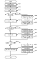
- Fig. 8 is a flow chart illustrating an operation of the switch according to the first exemplary embodiment of the present disclosure.
- Fig. 9 is a flow chart illustrating an operation of the control apparatus according to the first exemplary embodiment of the present disclosure.
- Fig. 10 is a flow chart illustrating a path calculation process of the control apparatus according to the first exemplary embodiment of the present disclosure.
- Fig. 11 is a sequence diagram illustrating an overall operation according to the first exemplary embodiment of the present disclosure.
- Fig. 12 illustrates a configuration according to a second exemplary embodiment of the present disclosure.
- Fig. 12 illustrates a configuration according to a second exemplary embodiment of the present disclosure.
- FIG. 13 illustrates a configuration of a job scheduler according to the second exemplary embodiment of the present disclosure.
- Fig. 14 illustrates configurations of entries in an attribute database (attribute DB) in the job scheduler according to the second exemplary embodiment of the present disclosure.
- Fig. 15 is a flow chart illustrating an operation of the job scheduler according to the second exemplary embodiment of the present disclosure.
- Fig. 16 is a sequence diagram illustrating an overall operation according to the second exemplary embodiment of the present disclosure.
- Fig. 17 illustrates a configuration of a control apparatus according to a third exemplary embodiment of the present disclosure.
- Fig. 18 illustrates a configuration of an entry in a path table in the control apparatus according to the third exemplary embodiment of the present disclosure.
- FIG. 19 is a flow chart illustrating an operation of a job scheduler according to the third exemplary embodiment of the present disclosure.
- Fig. 20 is a flow chart illustrating an operation of the control apparatus according to the third exemplary embodiment of the present disclosure.
- Fig. 21 is a flow chart illustrating an operation of the control apparatus according to the third exemplary embodiment of the present disclosure.
- Fig. 22 is a sequence diagram illustrating an overall operation according to the third exemplary embodiment of the present disclosure.
- Fig. 23 illustrates a configuration according to a fourth exemplary embodiment of the present disclosure.
- Fig. 24 is a sequence diagram illustrating an overall operation according to the fourth exemplary embodiment of the present disclosure.
- Fig. 25 is a sequence diagram illustrating an overall operation according to the fourth exemplary embodiment of the present disclosure.
- an exemplary embodiment of the present disclosure can be realized by a configuration including a control apparatus (30 in Fig. 1) referring to job-related information representing a relationship between a job and a flow, generating control information for processing a flow, and transmitting the control information to a switch (20 in Fig. 1) receiving a packet belonging to the flow; and a switch (20 in Fig. 1) processing a packet belonging to the flow based on control information received from the control apparatus (30 in Fig. 1).
- control apparatus (30 in Fig. 1) generates control information for processing a flow at a predetermined timing, such as a request is transmitted from the switch (20 in Fig. 1) or a network configuration is changed.
- the control apparatus (30 in Fig. 1) refers to job-related information (see Figs. 7 and 14, for example) representing a relationship between a job and a flow and generates control information in view of a job type and content.
- the control apparatus (30 in Fig. 1) transmits the generated control information to the switch (20 in Fig. 1).
- the switch (20 in Fig. 1) processes incoming packets by referring to the control information.
- job-based path control is realized.
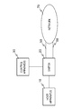
- Fig. 1 illustrates a configuration according to the first exemplary embodiment of the present disclosure.
- Fig. 1 illustrates a communication system including a switch 20 arranged between a host apparatus 10 and a network 70 and a control apparatus 30 controlling the switch 20. Between the network 70 and the switch 20, a first link (predetermined link) 60 that can be used depending on the job and a second link (general link) 50 that can be used irrespective of the job or the like are arranged.
- the host apparatus 10 is a computer in which a program is executed in response to a request from a user terminal or the like.
- the switch 20 refers to a flow entry set as control information by the control apparatus and processes an incoming packet.
- control apparatus 30 controls the switch 20.
- the network 70 is a network formed by a group of switches including an OpenFlow switch equivalent to the switch 20 and other communication apparatuses, for example.
- Fig. 2 illustrates a configuration of the switch according to the first exemplary embodiment of the present disclosure.
- the switch includes a packet processing unit 21 and a flow entry storage unit 22.
- Fig. 3 illustrates a flow entry stored in the flow entry storage unit 22.
- Fig. 3 illustrates an entry, in which a field storing rules (matching conditions) against which an incoming packet header or the like is matched, flow statistical information field (Counters) storing statistical information about a packet matching the rules (matching conditions), and an instruction field (Instructions) storing processing contents (Actions) that are applied to a packet matching the rules (matching conditions) are associated with each other.
- rules matching conditions
- wildcards can be set.
- Fig. 4 illustrates processing names (Actions) and the processing contents thereof that can be set in the instruction field (Instructions).
- the action name "OUTPUT" is an action for outputting an incoming packet to a specified port (interface).
- the action names from SET_VLAN_VID to SET_TP_DST are actions for modifying packet header fields. By combining these actions, for example, the switch can rewrite the VLAN ID of a packet transmitted from a source to a destination and output the packet from a specified port.
- the packet processing unit 21 When receiving a packet, the packet processing unit 21 searches the flow entry storage unit 22 for a flow entry having a rule (a matching condition) matching the incoming packet. As a result of the search, if the packet processing unit 21 finds a flow entry having a rule (a matching condition) matching the packet, the packet processing unit 21 applies the processing content stored in the instruction field (Instructions) to the incoming packet. If, as a result of the search, the packet processing unit 21 does not find a flow entry having a rule (a matching condition) matching the packet, the packet processing unit 21 requests the control apparatus 30 to transmit a flow entry.
- a rule a matching condition
- Flow entries transmitted from the control apparatus 30 are stored in the flow entry storage unit 22.
- Such switch 20 can be realized by an OpenFlow switch in which a flow entry is set by an OpenFlow controller through the OpenFlow protocol in NPL 2.
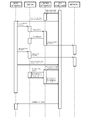
- Fig. 5 illustrates a configuration of the control apparatus according to the first exemplary embodiment of the present disclosure.
- the control apparatus includes a communication unit 31, a path calculation unit 32, a topology database (topology DB) 33, a link selection table 34 in which conditions for determining a flow and a control content applied per job are associated with each other, and a flow entry setting unit 35.
- topology database topology DB
- Fig. 6 illustrates entries stored in the topology DB 33 storing topology information about the network 70 including the switch 20.
- Fig. 6(A) represents a link between switches, each of which is determined by a switch identifier (DPID) and a port number.
- Fig. 6(B) illustrates an entry of an apparatus (for example, a host apparatus) connected to a certain switch. In the entry, a switch identifier (DPID), a port number, and the MAC (Media Access Control) address of the apparatus are associated with each other.
- DPID switch identifier
- a port number for example, a port number
- MAC Media Access Control
- Fig. 7 illustrates an entry stored in the link selection table 34.
- the condition field stores information for determining a flow, as being similar to the rules (matching conditions) in the flow entry illustrated in Fig. 3.
- the link field stores an identifier of the predetermined link 60 illustrated in Fig. 1, for example.
- the use/non-use field stores information representing whether to use the link specified in the link field for forwarding packets belonging to the flow determined by the condition field.
- a wildcard arbitrary
- a negative condition if a packet and a value in the condition do not match, the packet and the condition are deemed to match
- a user may register an entry in the link selection table 34 in advance or an external program that operates on a terminal of a user may automatically register the entry.
- Such control apparatus 30 can be realized by adding the above link selection table 34 and a path calculation function using the contents of the link selection table 34 to the OpenFlow controller in NPL 2.
- the path calculation unit of the control apparatus 30 in Fig. 5 can be realized by a computer program which causes a computer constituting the control apparatus 30 to use hardware of the computer and to execute a job-based flow entry generation process based on contents of the above topology DB 33 and the link selection table 34.
- Fig. 8 is a flow chart illustrating an operation executed when the switch according to the first exemplary embodiment of the present disclosure receives a packet.
- the switch 20 when receiving a packet, the switch 20 searches the flow entry storage unit 22 for a flow entry having a rule (matching condition) matching the incoming packet (step S201).
- the switch 20 finds a flow entry having a rule (matching condition) matching the incoming packet (Yes in step S202), the switch 20 processes the incoming packet in accordance with the content of the instruction field (Instructions) of the flow entry (step S204).
- the switch 20 If the switch 20 does not find a flow entry having a rule (matching condition) matching the incoming packet (No in step S202), the switch 20 transmits the incoming packet or information extracted from the incoming packet to the control apparatus 30 and requests the control apparatus 30 to transmit a flow entry (step S203).
- Fig. 9 is a flow chart illustrating an operation executed when the control apparatus 30 according to the first exemplary embodiment of the present disclosure receives a flow entry transmission request.
- the control apparatus 30 when receiving a packet or information extracted from a packet from the switch 20, the control apparatus 30 searches the link selection table 34 for an entry having a rule (matching condition) matching the packet or the information extracted from the packet transmitted from the switch 20 (step S120).
- control apparatus 30 calculates a path accordingly (step S126). Even if control apparatus 30 finds such entry, if "non-use" is set in the use/non-use field of the entry, the control apparatus 30 determines that the topology in the topology DB 33 does not include the predetermined link 60. Thus, the control apparatus 30 calculates a path accordingly (step S126).
- control apparatus 30 finds the entry and "use” is set in the use/non-use field, the control apparatus 30 refers to the topology including the predetermined link 60 in the topology DB 33 and calculates a path (step S122).
- a path is calculated in steps S122 or S126, Dijkstra's algorithm or the like can be used.
- end-to-end paths may be calculated in advance, and an appropriate path may be selected depending on the search result obtained by the link selection table 34.
- control apparatus 30 creates flow entries that are set in the switches 20 on the path calculated in step S122 or S126 (step S123).
- control apparatus 30 transmits the created flow entries to the switches 20 on the path and requests each flow entry storage unit 22 to register a corresponding flow entry (step S124).
- control apparatus 30 instructs the switches 20 to output the packet to the destination, by using the packet or the information extracted from the packet supplied from the switch 20 (step S125). In this way, the first packet received by the switch 20 is forwarded to the destination.
- this packet output instruction "Packet-Out message" of the OpenFlow protocol in NPL 2 can be used.
- the control apparatus 30 can transmit this packet output instruction to a switch in the network 70, in particular, to a switch closest to the end point (destination).
- Fig. 10 is a flow chart illustrating a path calculation process executed by the control apparatus according to the first exemplary embodiment of the present disclosure.
- control apparatus 30 calculates a path between a start point and one node point (node point A) in the predetermined link 60 (step S401).
- control apparatus 30 calculates a path between another node point (node point B) in the predetermined link 60 and an end point (step S402).
- control apparatus 30 calculates a path between the start point and the node point B (step S403).
- control apparatus 30 calculates a path between the node point A and the end point (step S404).
- step S406 determines whether the control apparatus 30 could not calculate a path in the above step S403 and/or S404. If the control apparatus 30 determines that the control apparatus 30 could not calculate a path in the above step S403 and/or S404, since a path that travels through the predetermined link 60 does not exist, the control apparatus 30 does not create a flow entry (No in step S406).
- control apparatus 30 could calculate a path in the above step S401 or S402 (Yes in step S405), the control apparatus 30 compares a cost obtained by the path of start point-node point A-node point B-end point calculated in steps S401 and S402 with a cost obtained by the path of start point-node point B-node point A-end point calculated in the steps S403 and S404 (step S407).
- the number of hops or the bandwidth of each link can be used, for example.
- the control apparatus 30 determines that the cost obtained by the path of start point-node point A-node point B-end point calculated in steps S401 and S402 is lower (including when a path could not be calculated in step S403 and/or S404), the control apparatus 30 adopts the path of start point-node point A-node point B-end point calculated in steps S401 and S402.
- step S405 represents that the control apparatus 30 could not calculate a path in step S401 and/or S402
- the control apparatus 30 adopts the path of start point-node point B-node point A-end point calculated in steps S403 and S404.
- a path is calculated in steps S401 to S404, Dijkstra's algorithm or the like can be used.
- end-to-end paths may be calculated in advance, and a path of start point-node point A-node point B-end point may be selected from among the paths.
- Fig. 11 is a sequence diagram illustrating an overall operation according to the first exemplary embodiment of the present disclosure.
- a user executes setting of whether to use the predetermined link 60 for a flow generated by a job to be executed (S001 in Fig. 11). More specifically, a user adds or changes an entry illustrated in Fig. 7 in the link selection table 34.
- the user uses a terminal or the like and accesses the host apparatus 10 to initiate a job (S002 in Fig. 11).
- the host apparatus 10 transmits a packet to a predetermined destination in the network 70 (S003 in Fig. 11).
- the control apparatus 30 When receiving the flow entry transmission request from the switch 20, in accordance with the flow charts in Figs. 9 and 10, the control apparatus 30 calculates a path that travels through the predetermined link 60 or a path that travels through the general link 50 based on features of the packet transmitted by the job execution. Next, the control apparatus 30 generates a flow entry for forwarding the packet on the calculated path and sets the flow entry in the switch 20 (S005 in Fig. 11; Flow-Mod). In Fig. 11, the control apparatus 30 sets the flow entry only in the switch 20. However, it is desirable that the control apparatus 30 also set flow entries in the other switches on the path in the network 70.
- control apparatus 30 instructs a switch closest to the end point (destination) on the path in the network 70 to output the packet (S006 in Fig. 11; corresponding to step S125 in Fig. 9).
- the switch 20 forwards the packets in accordance with the flow entry set in S005 in Fig. 11 (S008 in Fig. 11).
- the control apparatus 30 can select a path that travels through the predetermined link 60 or a path that travels through the general link 50 and can execute packet forwarding.
- the present exemplary embodiment has been described based on an example in which only the use of the predetermined link 60 is defined in the link selection table 34. However, by setting necessary contents in the link selection table 34, various flow control operations can be realized. For example, depending on the job (packet features matched against the conditions (rules) in Fig. 7), the flow can be controlled to travel through one of a plurality of predetermined links 60 or the flow can be given priority over other flows.
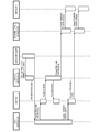
- Fig. 12 illustrates a configuration according to the second exemplary embodiment of the present disclosure. This configuration differs from that of the first exemplary embodiment illustrated in Fig. 1 in that a job scheduler 40 transmitting job-related information to the control apparatus 30 is added between the host apparatus 10 and the control apparatus 30. The following description will be made with a focus on the difference from the first exemplary embodiment.
- Fig. 13 illustrates a configuration of the job scheduler according to the second exemplary embodiment of the present disclosure.
- the job scheduler includes a job management unit 41, an attribute database (attribute DB) 42, and a link usage determination unit 43.
- Fig. 14 illustrates a configuration of an entry stored in the attribute DB 42.
- Fig. 14(A) is an example in which job attributes and information about use/non-use of a link are associated with each other.
- the job attributes include an execution user, an execution user group, an executable file, a use resource (the number of servers to be used, the number of necessary cores, a CPU architecture, a memory capacity, a temporary disk capacity, the location of a file to be used, etc.), pre-boot processing (which may be described in script, for example), post-boot processing (which may be described in script, for example), a job priority, executable file components (a library linked, a class library to be used, symbols within binary, etc.), time (registration and initiation), additional information relating to job operations (occupation/sharing of a resource, frequency of communication between nodes, use/non-use of a predetermined link, information about a predetermined link to be used, a use priority of a predetermined link, occupation/sharing of
- Fig. 14(B) illustrates an example in which, for example, an identifier of and configuration information (switches and ports) about the predetermined link 60 are added to the entry in Fig. 14(A).
- the job management unit 41 manages execution of a job in the host apparatus 10 and notifies the link usage determination unit 43 of a job to be executed.
- the link usage determination unit 43 When receiving information about a job to be executed from the job management unit 41, the link usage determination unit 43 refers to the attribute DB 42, determines use of the link, and notifies the control apparatus 30 of the determination result.
- Examples of the method of registering a job in the job scheduler 40 include, as in a batch system, a method of registering a file in which contents of a job is described and a method of calling an executable file by a command line.
- Fig. 15 is a flow chart illustrating an operation of the job scheduler 40.
- a job is registered in the job management unit 41 of the job scheduler 40 (step S301).
- the job management unit 41 of the job scheduler 40 waits until the job is executed in accordance with the scheduling policy of the job (step S302).
- a resource necessary for executing the job is allocated (step S303).
- the link usage determination unit 43 searches the attribute DB 42 to determine whether execution of the job involves the predetermined link 60, namely, whether the job requires communication via the predetermined link 60 (step S304).
- the link usage determination unit 43 determines that the job requires communication via the predetermined link 60, based on job-communication-related resource information acquired from the host apparatus 10 in which the job operates or other information sources, the link usage determination unit 43 requests the control apparatus 30 to register a new entry in the link selection table 34 (step S306). More specifically, this new entry is configured by associating: information for determining packets generated by the job, such as the IP (Internet Protocol) address, the MAC address, and a port number of the communication source and the IP address, the MAC address, and a port number of the communication destination; the predetermined link 60; and information about use/non-use of the predetermined link 60 with each other.
- IP Internet Protocol
- step S307 the job management unit 41 of the job scheduler 40 executes the job (step S307).
- the job scheduler 40 requests the control apparatus 30 to delete the entry registered in step S306 from the link selection table 34 and ends the operation (step S308). Because of this deletion of the entry from the link selection table 34, the control apparatus 30 executes path control that does not involve the predetermined link 60 when receiving packets having the same source and destination subsequently.
- step S304 the link usage determination unit 43 determines that the job does not need communication via the predetermined link 60
- the job scheduler 40 executes the job without adding the entry in the link selection table 34 (step S305).
- Fig. 16 is a sequence diagram illustrating an overall operation according to the second exemplary embodiment of the present disclosure.
- the job scheduler 40 requests the control apparatus 30 to register an entry corresponding to a job to be executed in the link selection table 34 (S501 in Fig. 16; see step S306 in Fig. 15).
- the job scheduler 40 initiates the job (S502 in Fig. 16), the job in the host apparatus 10 transmits a packet to a predetermined destination in the network 70 (S503 in Fig. 16).
- control apparatus 30 creates a flow entry based on the link selection table and sets the flow entry in the switch 20. Subsequently, until the execution of the job is completed, packets transmitted from the host apparatus 10 are forwarded via the path that travels through the predetermined link 60.
- the present disclosure can suitably be applied to a configuration having the job scheduler.
- a third exemplary embodiment will be described in detail with reference to the drawings.
- a flow entry deletion function that coordinates with a job execution phase is added to the above control apparatus according to the second exemplary embodiment. Since the present exemplary embodiment can be achieved by changing the control apparatus according to the second exemplary embodiment, the present exemplary embodiment will hereinafter be described with a focus on the difference.
- Fig. 17 illustrates a configuration of a control apparatus 30A according to the third exemplary embodiment of the present disclosure.
- the control apparatus 30A differs from the control apparatus 30 illustrated in Fig. 5 in that the control apparatus 30A includes a path table 36 managing calculated paths and a path deletion unit 37 deleting entries from the path table 36.
- Fig. 18 illustrates a configuration of an entry in the path table 37.
- Fig. 18 illustrates an entry in which an entry ID of the link selection table 34 and information about the switches constituting a path are associated with each other.
- the entry ID field in the link selection table in Fig. 18 stores an ID for determining an entry of the link selection table 34 generated for the path in question.
- the identifiers (DPID) of the switches on the path and the contents of the flow entries set in the switches corresponding to the path are stored in the switch information field.
- the path deletion unit 37 deletes an entry from the path table 36, based on an instruction from the job scheduler 40.
- Fig. 19 is a flow chart illustrating an operation of the job scheduler according to the third exemplary embodiment of the present disclosure.
- the present exemplary embodiment will hereinafter be described based on an example where a job requiring execution of pre-processing and post-processing before and after execution of the job is executed.
- a job is registered in the job management unit 41 of the job scheduler 40 (step S601).
- the job management unit 41 of the job scheduler 40 waits until the job is executed in accordance with the scheduling policy of the job (step S602).
- a resource necessary for executing the job is allocated (step S603).
- the link usage determination unit 43 searches the attribute DB42 to determine whether execution of the pre-processing of the job involves the predetermined link 60, namely, whether the pre-processing requires communication via the predetermined link 60 (step S604).
- the link usage determination unit 43 determines that the pre-processing of the job requires communication via the predetermined link 60, based on job-communication-related resource information acquired from the host apparatus 10 in which the job operates or other information sources, the link usage determination unit 43 requests the control apparatus 30 to register a new entry in the link selection table 34 (step S606). More specifically, this new entry is configured by associating: information for determining packets generated by the job, such as the IP (Internet Protocol) address, the MAC address, and a port number of the communication source and the IP address, the MAC address, and a port number of the communication destination; the predetermined link 60; and information about use/non-use of the predetermined link 60 with each other.
- IP Internet Protocol
- the job management unit 41 of the job scheduler 40 executes the pre-processing of the job (step S607).
- the job scheduler 40 requests the control apparatus 30 to delete the entry registered in step S606 from the link selection table 34 and ends the operation (step S608).
- step S604 the link usage determination unit 43 determines that the pre-processing of the job does not need communication via the predetermined link 60, the job scheduler 40 executes the pre-processing of the job without transmitting a request for registration of the entry in the link selection table 34 (step S605).
- the job scheduler 40 refers to the attribute DB 42 to determine whether the job and the post-processing thereof need communication via the predetermined link 60. Depending on the result, the job scheduler 40 requests the control apparatus 30 to register an entry in the link selection table 34, executes the job and the post-processing, and requests the control apparatus 30 to delete the entry from the link selection table 34 (steps S609 to S618).
- Fig. 20 is a flow chart illustrating an operation of the control apparatus 30A according to the present exemplary embodiment.
- This operation of the control apparatus 30A differs from that of the control apparatus 30 according to the first exemplary embodiment illustrated in Fig. 9 in that flow entries are created (step S123) and a calculated path is recorded in the path table 36 (step S123-2). Since other steps are the same as those according to the first exemplary embodiment illustrated in Fig. 9, description thereof will be omitted.
- Fig. 21 is a flow chart illustrating an operation executed by the control apparatus 30A when receiving a request for deleting an entry from the link selection table 34 from the job scheduler 40.
- the control apparatus 30A when the control apparatus 30A receives a request for deleting an entry from the link selection table 34 from the job scheduler 40, the control apparatus 30A deletes the entry from the link selection table 34 (step S701).
- control apparatus 30A searches the path table 36 for a path entry relating to the entry deleted in step S701 (step S702). As a result of the search, if the control apparatus 30A cannot find a path entry relating to the entry deleted in step S701 (No in step S703), the control apparatus 30A ends this operation.
- step S701 finds a path entry relating to the entry deleted in step S701 (Yes in step S703), the control apparatus 30A instructs the switches 20 on the path indicated by the path entry to delete the flow entries corresponding to the deleted path entry (step S704).
- control apparatus 30A deletes the path entry from the path table 36 (step S705).
- Fig. 22 is a sequence diagram illustrating an overall operation according to the third exemplary embodiment of the present disclosure.
- the job scheduler 40 requests the control apparatus 30 to register an entry corresponding to a job (including pre-processing and post-processing) to be executed in the link selection table 34 (S501 in Fig. 22; see step S306 in Fig. 15).
- the pre-processing of the job is executed in the host apparatus 10 and a packet is transmitted to a predetermined destination in the network 70 in accordance with the content of the processing (S503 in Fig. 22).
- the control apparatus 30A deletes the entry from the link selection table 34, refers to the path table 36, and instructs the switches 20 in which flow entries corresponding to the unnecessary path are set to delete the flow entries (S511 in Fig. 22; Flow-Mod (DEL); step S704 in Fig. 21).
- the control apparatus 30A deletes the corresponding entry from the path table 36 and notifies the job scheduler 40 of completion of use of the predetermined link 60 (S513 in Fig. 22).
- the job scheduler 40 initiates a job (S502a in Fig. 22) and steps similar to the above step S503 and steps subsequent thereto are executed.
- a flow entry unnecessary in the flow entry storage unit 22 in each switch 20 can be deleted.
- the use efficiency of a storage area in the flow entry storage unit 22 is improved, and the flow entry search performance (response performance) of the switch 20 is improved.
- an intermediate apparatus is arranged on the predetermined link 60.
- Fig. 23 illustrates a configuration according to the fourth exemplary embodiment of the present disclosure.
- an intermediate apparatus 80 is added between the switch 20 and the network 70 according to the above second and third exemplary embodiments. Since other components of the apparatuses are the same as those according to the above second and third exemplary embodiments, the present exemplary embodiment will be hereinafter described with a focus on the difference.
- Examples of the intermediate apparatus 80 include an encapsulation apparatus encapsulating/decapsulating an incoming packet, an encryption device executing encryption/decryption processing on an incoming packet, a firewall, and a packet analysis apparatus. Of course, these apparatuses are examples. Other various types of apparatuses may be arranged.
- the use/non-use field in the link selection table 34 illustrated in Fig. 7 is used as information indicating whether the intermediate apparatus 80 is used. If a plurality of apparatuses each serving as the intermediate apparatus 80 are arranged, a field for specifying a type of and identification information about each intermediate apparatus 80 may be added in an corresponding entry in the link selection table 34 illustrated in Fig. 7.
- Figs. 24 and 25 are sequence diagrams illustrating overall operations according to the fourth exemplary embodiment of the present disclosure.
- Fig. 24 is a sequence used when the link selection table 34 determines that the intermediate apparatus 80 is not used. Since a basic flow of this sequence is the same as that of the sequence illustrated in Fig. 16, description of the sequence will be omitted.
- Fig. 25 is a sequence used when the link selection table 34 determines that the intermediate apparatus 80 is used.
- the control apparatus 30A creates a path traveling through the intermediate apparatus 80 on the predetermined link 60 and creates flow entries for forwarding packets along the path.
- whether the intermediate apparatus 80 is used can be controlled on a job basis, other than whether a predetermined link is used.
- an encryption apparatus is arranged as the intermediate apparatus 80, regarding communication relating to jobs needing high security, the communication does not need to be encrypted by job. Instead, encryption for improving security can be executed by the intermediate apparatus when the communication with the outside is executed.
- a firewall may be used as the intermediate apparatus 80.
- a firewall may be used as the intermediate apparatus 80.
- jobs having low reliability to execute communication using the firewall inappropriate communication can be blocked.
- jobs having high reliability to execute communication without using the firewall reduction in overhead can be achieved.
- jobs can be distinguished based on a user or a group, and use of the firewall can be determined accordingly.
- a packet analysis apparatus such as a deep packet inspection apparatus may be used as the intermediate apparatus 80.
- packets can be analyzed in detail only for communication of a certain job. Reduction in overhead may be achieved by omitting analysis on the jobs other than the analysis target job.
- whether communication uses the intermediate apparatus may be determined based on a communication destination or a communication source.
- the predetermined link 60 can be a line that guarantees delay and the general link 50 can be a best-effort line. In such case, it is desirable that the predetermined link 60 be used for jobs for which communication delay needs to be guaranteed and the best-effort line be used for the other jobs. Namely, the predetermined link can preferentially be allocated to mission critical jobs such as for core operations.
- the predetermined link 60 can be a high-bandwidth dedicated line and the general link 50 can be the Internet.
- the predetermined link 60 be used for jobs using the high-bandwidth line and the Internet be used for the other jobs.
- the charges of the dedicated line can be decreased.
- reduction in communication cost can be expected.
- examples of use of the predetermined link 60 include forwarding backup data to a backup site, forwarding data for replication of a database, and exchanging data with a computer center.
- connection to various networks such as an optic fiber, 3G, LTE (UMTS Long Term Evolution), PHS (Personal Handy-phone System), and WiMAX (Worldwide Interoperability for Microwave Access) can be achieved via relevant ones of the predetermined links.
- a network can be selected and set per job. For example, when certain lines cannot be used at the time of a disaster, stable communication lines can be used for jobs for which communication needs to be executed preferentially and other lines can be used for the other jobs.
- a user or a user group can be used for determining a job priority.
- the predetermined links 60 can be used for communication of user jobs that need to be processed preferentially at the time of a disaster.
- a plurality of predetermined links 60 may be configured by lines having different communication bandwidths or different communication delays.
- a job priority, a delay level of a predetermined link, and a bandwidth can be associated with each other.
- the job priority and the line quality can easily be associated with each other.
- the job scheduler 40 includes the attribute DB 42 and the link usage determination unit 43.
- the attribute DB 42 and the link usage determination unit 43 may be arranged outside the job scheduler 40.
- the attribute DB 42 and the link usage determination unit 43 may be arranged in the control apparatus 30.
- host apparatus 20 switch 21 packet processing unit 22 flow entry storage unit 30, 30A control apparatus 31 communication unit 32 path calculation unit 33 topology database (topology DB) 34 link selection table 35 flow entry setting unit 36 path table 37 path deletion unit 40 job scheduler 41 job management unit 42 attribute database (attribute DB) 43 link usage determination unit 50 second link (general link) 60 first link (predetermined link) 70 network 80 intermediate apparatus
Landscapes
- Engineering & Computer Science (AREA)
- Computer Networks & Wireless Communication (AREA)
- Signal Processing (AREA)
- Data Exchanges In Wide-Area Networks (AREA)
Abstract
The present invention realizes job-based path control while using a configuration that enables path control per flow. A communication system comprises: a control apparatus referring to job-related information representing a relationship between a job and a flow, generating control information for processing a flow, and transmitting the control information to a switch receiving a packet belonging to the flow; and a switch processing a packet belonging to the flow based on the control information received from the control apparatus.
Description
(CROSS-REFERENCE TO RELATED APPLICATIONS)
The present invention is based upon and claims the benefit of the priority of Japanese patent application No. 2012-168483, filed on July 30, 2012, the disclosure of which is incorporated herein in its entirety by reference thereto.
The present invention relates to a communication system, a control apparatus, a communication method, and a program. In particular, it relates to a communication system having a control apparatus controlling switches in a centralized manner, a control apparatus, a communication method, and a program.
In recent years, a technique referred to as OpenFlow has been proposed (see non patent literature (NPL 1 and 2)). OpenFlow recognizes communications as end-to-end flows and performs path control, failure recovery, load balancing, and optimization on a per-flow basis. An OpenFlow switch according to NPL 2 has a secure channel for communication with an OpenFlow controller and operates according to a flow table suitably added or rewritten by the OpenFlow controller. In a flow table, a set of the following three is defined for each flow: matching conditions (Match Fields) against which a packet header is matched; flow statistical information (Counters); and Instructions that define processing contents (see section "4.1 Flow Table" in NPL 2).
For example, when receiving a packet, the OpenFlow switch searches the flow table for an entry having a matching condition (see "4.3 Match Fields" in NPL 2) that matches header information of the incoming packet. If the OpenFlow switch finds an entry matching the incoming packet as a result of the search, the OpenFlow switch updates the flow statistical information (Counters) and processes the incoming packet based on a processing content (packet transmission from a specified port, flooding, drop, etc.) written in the Instructions field of the entry. If the OpenFlow switch does not find an entry matching the incoming packet as a result of the search, the OpenFlow switch transmits an entry setting request (Packet-In message) to the OpenFlow controller via the secure channel. Namely, the OpenFlow switch requests the OpenFlow controller to transmit control information for processing the incoming packet. The OpenFlow switch receives a flow entry defining a processing content and updates the flow table. In this way, by using an entry stored in the flow table as control information, the OpenFlow switch executes packet forwarding.
In addition, patent literature (PTL) 1 discloses a method for reducing load on a path control apparatus corresponding to the OpenFlow controller. According to this method, different time-out values are set in the flow entries per section of a packet communication path.
In addition, PTL 2 discloses a path control system used in a connection setting type network in which a plurality of nodes, each of which has a plurality of ports, are mutually connected between a calling terminal and a receiving terminal. According to this method, each node previously stores a plurality of paths that can be set when forwarding a connection setting request signal. When a node receives a connection setting request signal from the calling terminal, if a resource can be ensured and connection can be set, the node selects an output port in accordance with the paths set and forwards the connection setting request signal. If the node receives the same connection setting request signals from different nodes, the node discards the subsequently-received connection setting request signals.
Nick McKeown, and seven others, "OpenFlow: Enabling Innovation in Campus Networks," [online], [searched on July 13, 2012], Internet <URL:http://www.openflow.org/documents/openflow-wp-latest.pdf>
"OpenFlow Switch Specification" Version 1.1.0 Implemented (Wire Protocol 0x02), [online], [searched on July 13, 2012], Internet <URL:http://www.openflow.org/documents/openflow-spec-v1.1.0.pdf>
The entire disclosure of the above-listed Patent Literature and Non Patent Literatures is incorporated herein by reference.
The following analysis has been given by the present invention. PTL 1 and NPL 1 and 2 describe that the OpenFlow controller and the path control apparatus can execute detailed path control per flow. However, these techniques have problems. Namely, these techniques cannot execute job-based control, such as forwarding packets relating to a certain job via a certain link or apparatus or prioritizing packets relating to a certain job over other packets.
The following analysis has been given by the present invention. PTL 1 and NPL 1 and 2 describe that the OpenFlow controller and the path control apparatus can execute detailed path control per flow. However, these techniques have problems. Namely, these techniques cannot execute job-based control, such as forwarding packets relating to a certain job via a certain link or apparatus or prioritizing packets relating to a certain job over other packets.
When a switch of the path control system in PTL 2 receives a connection setting request frame, the switch extracts a destination address in a header of the frame and acquires an output port number corresponding to a destination table from a path table. In addition, such switch of the path control system in PTL 2 only manages a connection table, based on availability of a port having this output port number. Thus, job-based path control cannot be executed.
It is an object of the present invention to provide a communication system, a control apparatus, a communication method, and a program for realizing job- based path control while using a configuration that enables path control per flow.
According to a first aspect, there is provided a communication system, comprising: a control apparatus referring to job-related information representing a relationship between a job and a flow, generating control information for processing a flow, and transmitting the control information to a switch receiving a packet belonging to the flow; and a switch processing a packet belonging to the flow based on the control information received from the control apparatus.
According to a second aspect, there is provided a control apparatus, connected to a switch processing a packet belonging to a flow based on control information received from the control apparatus; wherein the control apparatus refers to job-related information representing a relationship between a job and a flow, generates control information for processing a flow, and transmits the control information to the switch.
According to a third aspect, there is provided a communication method, comprising steps of: causing a control apparatus, connected to a switch processing a packet belonging to a flow based on control information generated per flow, to refer to job-related information representing a relationship between a job and a flow and to generate control information for processing a flow; and causing the control apparatus to transmit the generated control information to the switch. This method is associated with a certain machine, that is, with the control apparatus controlling switches by using control information.
According to a fourth aspect, there is provided a program, causing a computer constituting a control apparatus connected to a switch processing a packet belonging to a flow based on control information generated per flow to execute processes of: referring to job-related information representing a relationship between a job and a flow and generating control information for processing a flow; and transmitting the generated control information to the switch. This program can be recorded in a computer-readable (non-transient) storage medium. Namely, the present invention can be embodied as a computer program product.
According to the present invention, job-based path control can be realized while using a configuration that enables path control per flow.
First, an outline of an exemplary embodiment of the present disclosure will be described with reference to the drawings. In the following outline, various components are denoted by reference characters for the sake of convenience. Namely, the following reference characters are merely used as examples to facilitate understanding of the present disclosure, not to limit the present disclosure to the illustrated modes.
As illustrated in Fig. 1, an exemplary embodiment of the present disclosure can be realized by a configuration including a control apparatus (30 in Fig. 1) referring to job-related information representing a relationship between a job and a flow, generating control information for processing a flow, and transmitting the control information to a switch (20 in Fig. 1) receiving a packet belonging to the flow; and a switch (20 in Fig. 1) processing a packet belonging to the flow based on control information received from the control apparatus (30 in Fig. 1).
More specifically, the control apparatus (30 in Fig. 1) generates control information for processing a flow at a predetermined timing, such as a request is transmitted from the switch (20 in Fig. 1) or a network configuration is changed. In such case, the control apparatus (30 in Fig. 1) refers to job-related information (see Figs. 7 and 14, for example) representing a relationship between a job and a flow and generates control information in view of a job type and content. Next, the control apparatus (30 in Fig. 1) transmits the generated control information to the switch (20 in Fig. 1). Subsequently, the switch (20 in Fig. 1) processes incoming packets by referring to the control information. Thus, by setting control information in view of a job type and content, job-based path control is realized.
<First exemplary embodiment>
Next, a first exemplary embodiment of the present disclosure will be described in detail with reference to the drawings. Fig. 1 illustrates a configuration according to the first exemplary embodiment of the present disclosure. Fig. 1 illustrates a communication system including aswitch 20 arranged between a host apparatus 10 and a network 70 and a control apparatus 30 controlling the switch 20. Between the network 70 and the switch 20, a first link (predetermined link) 60 that can be used depending on the job and a second link (general link) 50 that can be used irrespective of the job or the like are arranged.
Next, a first exemplary embodiment of the present disclosure will be described in detail with reference to the drawings. Fig. 1 illustrates a configuration according to the first exemplary embodiment of the present disclosure. Fig. 1 illustrates a communication system including a
The host apparatus 10 is a computer in which a program is executed in response to a request from a user terminal or the like.
The switch 20 refers to a flow entry set as control information by the control apparatus and processes an incoming packet.
By setting a flow entry disclosed in NPL 2 in the switch 20 as control information, the control apparatus 30 controls the switch 20.
The network 70 is a network formed by a group of switches including an OpenFlow switch equivalent to the switch 20 and other communication apparatuses, for example.
Fig. 2 illustrates a configuration of the switch according to the first exemplary embodiment of the present disclosure. Referring to Fig. 2, the switch includes a packet processing unit 21 and a flow entry storage unit 22.
Fig. 3 illustrates a flow entry stored in the flow entry storage unit 22. Fig. 3 illustrates an entry, in which a field storing rules (matching conditions) against which an incoming packet header or the like is matched, flow statistical information field (Counters) storing statistical information about a packet matching the rules (matching conditions), and an instruction field (Instructions) storing processing contents (Actions) that are applied to a packet matching the rules (matching conditions) are associated with each other. As the rules (matching conditions), wildcards can be set.
Fig. 4 illustrates processing names (Actions) and the processing contents thereof that can be set in the instruction field (Instructions). The action name "OUTPUT" is an action for outputting an incoming packet to a specified port (interface). The action names from SET_VLAN_VID to SET_TP_DST are actions for modifying packet header fields. By combining these actions, for example, the switch can rewrite the VLAN ID of a packet transmitted from a source to a destination and output the packet from a specified port.
When receiving a packet, the packet processing unit 21 searches the flow entry storage unit 22 for a flow entry having a rule (a matching condition) matching the incoming packet. As a result of the search, if the packet processing unit 21 finds a flow entry having a rule (a matching condition) matching the packet, the packet processing unit 21 applies the processing content stored in the instruction field (Instructions) to the incoming packet. If, as a result of the search, the packet processing unit 21 does not find a flow entry having a rule (a matching condition) matching the packet, the packet processing unit 21 requests the control apparatus 30 to transmit a flow entry.
Flow entries transmitted from the control apparatus 30 are stored in the flow entry storage unit 22.
Fig. 5 illustrates a configuration of the control apparatus according to the first exemplary embodiment of the present disclosure. Referring to Fig. 5, the control apparatus includes a communication unit 31, a path calculation unit 32, a topology database (topology DB) 33, a link selection table 34 in which conditions for determining a flow and a control content applied per job are associated with each other, and a flow entry setting unit 35.
Fig. 6 illustrates entries stored in the topology DB 33 storing topology information about the network 70 including the switch 20. Fig. 6(A) represents a link between switches, each of which is determined by a switch identifier (DPID) and a port number. In addition, Fig. 6(B) illustrates an entry of an apparatus (for example, a host apparatus) connected to a certain switch. In the entry, a switch identifier (DPID), a port number, and the MAC (Media Access Control) address of the apparatus are associated with each other.
Fig. 7 illustrates an entry stored in the link selection table 34. The condition field stores information for determining a flow, as being similar to the rules (matching conditions) in the flow entry illustrated in Fig. 3. The link field stores an identifier of the predetermined link 60 illustrated in Fig. 1, for example. The use/non-use field stores information representing whether to use the link specified in the link field for forwarding packets belonging to the flow determined by the condition field. In addition, as with the case of the rules (matching conditions) in the flow entry, a wildcard (arbitrary) can be set or a negative condition (if a packet and a value in the condition do not match, the packet and the condition are deemed to match) can be used in the condition field. In this way, the description property of the condition field can be improved.
A user may register an entry in the link selection table 34 in advance or an external program that operates on a terminal of a user may automatically register the entry.
The path calculation unit of the control apparatus 30 in Fig. 5 can be realized by a computer program which causes a computer constituting the control apparatus 30 to use hardware of the computer and to execute a job-based flow entry generation process based on contents of the above topology DB 33 and the link selection table 34.
Next, an operation of each of the above apparatuses will be described. Fig. 8 is a flow chart illustrating an operation executed when the switch according to the first exemplary embodiment of the present disclosure receives a packet. Referring to Fig. 8, when receiving a packet, the switch 20 searches the flow entry storage unit 22 for a flow entry having a rule (matching condition) matching the incoming packet (step S201).
If the switch 20 finds a flow entry having a rule (matching condition) matching the incoming packet (Yes in step S202), the switch 20 processes the incoming packet in accordance with the content of the instruction field (Instructions) of the flow entry (step S204).
If the switch 20 does not find a flow entry having a rule (matching condition) matching the incoming packet (No in step S202), the switch 20 transmits the incoming packet or information extracted from the incoming packet to the control apparatus 30 and requests the control apparatus 30 to transmit a flow entry (step S203).
Fig. 9 is a flow chart illustrating an operation executed when the control apparatus 30 according to the first exemplary embodiment of the present disclosure receives a flow entry transmission request. Referring to Fig. 9, when receiving a packet or information extracted from a packet from the switch 20, the control apparatus 30 searches the link selection table 34 for an entry having a rule (matching condition) matching the packet or the information extracted from the packet transmitted from the switch 20 (step S120).
As a result of the search, if the control apparatus 30 cannot find such entry, the control apparatus 30 determines that the topology in the topology DB 33 does not include the predetermined link 60. Thus, the control apparatus 30 calculates a path accordingly (step S126). Even if control apparatus 30 finds such entry, if "non-use" is set in the use/non-use field of the entry, the control apparatus 30 determines that the topology in the topology DB 33 does not include the predetermined link 60. Thus, the control apparatus 30 calculates a path accordingly (step S126).
As a result of the search, if the control apparatus 30 finds the entry and "use" is set in the use/non-use field, the control apparatus 30 refers to the topology including the predetermined link 60 in the topology DB 33 and calculates a path (step S122).
When a path is calculated in steps S122 or S126, Dijkstra's algorithm or the like can be used. Alternatively, instead of calculating a path each time, end-to-end paths may be calculated in advance, and an appropriate path may be selected depending on the search result obtained by the link selection table 34.
Next, the control apparatus 30 creates flow entries that are set in the switches 20 on the path calculated in step S122 or S126 (step S123). Next, the control apparatus 30 transmits the created flow entries to the switches 20 on the path and requests each flow entry storage unit 22 to register a corresponding flow entry (step S124).
Finally, the control apparatus 30 instructs the switches 20 to output the packet to the destination, by using the packet or the information extracted from the packet supplied from the switch 20 (step S125). In this way, the first packet received by the switch 20 is forwarded to the destination. For this packet output instruction, "Packet-Out message" of the OpenFlow protocol in NPL 2 can be used. In addition, instead of transmitting this packet output instruction to the switch 20, the control apparatus 30 can transmit this packet output instruction to a switch in the network 70, in particular, to a switch closest to the end point (destination).
Next, the path calculation in step S122, which is executed when use of the predetermined link 60 is specified, will be described in detail. Fig. 10 is a flow chart illustrating a path calculation process executed by the control apparatus according to the first exemplary embodiment of the present disclosure.
First, the control apparatus 30 calculates a path between a start point and one node point (node point A) in the predetermined link 60 (step S401).
Next, the control apparatus 30 calculates a path between another node point (node point B) in the predetermined link 60 and an end point (step S402).
Next, the control apparatus 30 calculates a path between the start point and the node point B (step S403).
Next, the control apparatus 30 calculates a path between the node point A and the end point (step S404).
If the control apparatus 30 could not calculate a path in the above step S401 and/or S402 (No in step S405), the control apparatus 30 determines whether the control apparatus 30 could not calculate a path in the above step S403 and/or S404 (step S406). In step S406, if the control apparatus 30 determines that the control apparatus 30 could not calculate a path in the above step S403 and/or S404, since a path that travels through the predetermined link 60 does not exist, the control apparatus 30 does not create a flow entry (No in step S406).
If the control apparatus 30 could calculate a path in the above step S401 or S402 (Yes in step S405), the control apparatus 30 compares a cost obtained by the path of start point-node point A-node point B-end point calculated in steps S401 and S402 with a cost obtained by the path of start point-node point B-node point A-end point calculated in the steps S403 and S404 (step S407). For this cost comparison, the number of hops or the bandwidth of each link can be used, for example.
As a result of the cost comparison, if the control apparatus 30 determines that the cost obtained by the path of start point-node point A-node point B-end point calculated in steps S401 and S402 is lower (including when a path could not be calculated in step S403 and/or S404), the control apparatus 30 adopts the path of start point-node point A-node point B-end point calculated in steps S401 and S402.
As a result of the cost comparison, if the control apparatus 30 determines that the cost obtained by the path of start point-node point B-node point A-end point calculated in steps S403 and S404 is lower or if the operation in step S405 represents that the control apparatus 30 could not calculate a path in step S401 and/or S402, the control apparatus 30 adopts the path of start point-node point B-node point A-end point calculated in steps S403 and S404.
When a path is calculated in steps S401 to S404, Dijkstra's algorithm or the like can be used. Alternatively, instead of calculating a path each time, end-to-end paths may be calculated in advance, and a path of start point-node point A-node point B-end point may be selected from among the paths.
Finally, a series of operations in which the above apparatuses coordinate with each other will be described. Fig. 11 is a sequence diagram illustrating an overall operation according to the first exemplary embodiment of the present disclosure. Referring to Fig. 11, a user executes setting of whether to use the predetermined link 60 for a flow generated by a job to be executed (S001 in Fig. 11). More specifically, a user adds or changes an entry illustrated in Fig. 7 in the link selection table 34.
Next, the user uses a terminal or the like and accesses the host apparatus 10 to initiate a job (S002 in Fig. 11). Next, the host apparatus 10 transmits a packet to a predetermined destination in the network 70 (S003 in Fig. 11).
While the switch 20 searches for a flow entry in accordance with the flow chart illustrated in Fig. 8, since this packet is a new packet transmitted from a newly-initiated job, the switch 20 requests the control apparatus 30 to transmit a flow entry (S004 in Fig. 11; Packet-In).
When receiving the flow entry transmission request from the switch 20, in accordance with the flow charts in Figs. 9 and 10, the control apparatus 30 calculates a path that travels through the predetermined link 60 or a path that travels through the general link 50 based on features of the packet transmitted by the job execution. Next, the control apparatus 30 generates a flow entry for forwarding the packet on the calculated path and sets the flow entry in the switch 20 (S005 in Fig. 11; Flow-Mod). In Fig. 11, the control apparatus 30 sets the flow entry only in the switch 20. However, it is desirable that the control apparatus 30 also set flow entries in the other switches on the path in the network 70.
In addition, the control apparatus 30 instructs a switch closest to the end point (destination) on the path in the network 70 to output the packet (S006 in Fig. 11; corresponding to step S125 in Fig. 9).
Subsequently, when the host apparatus executing the job transmits subsequent packets (S007 in Fig. 11), the switch 20 forwards the packets in accordance with the flow entry set in S005 in Fig. 11 (S008 in Fig. 11).
In this way, according to the present exemplary embodiment, based on features of a packet transmitted by execution of a job, the control apparatus 30 can select a path that travels through the predetermined link 60 or a path that travels through the general link 50 and can execute packet forwarding. The present exemplary embodiment has been described based on an example in which only the use of the predetermined link 60 is defined in the link selection table 34. However, by setting necessary contents in the link selection table 34, various flow control operations can be realized. For example, depending on the job (packet features matched against the conditions (rules) in Fig. 7), the flow can be controlled to travel through one of a plurality of predetermined links 60 or the flow can be given priority over other flows.
<Second exemplary embodiment>
Next, a second exemplary embodiment of the present disclosure will be described in detail with reference to the drawings. In the second exemplary embodiment, a job scheduler that manages execution of jobs in the host apparatus is added.
Next, a second exemplary embodiment of the present disclosure will be described in detail with reference to the drawings. In the second exemplary embodiment, a job scheduler that manages execution of jobs in the host apparatus is added.
Fig. 12 illustrates a configuration according to the second exemplary embodiment of the present disclosure. This configuration differs from that of the first exemplary embodiment illustrated in Fig. 1 in that a job scheduler 40 transmitting job-related information to the control apparatus 30 is added between the host apparatus 10 and the control apparatus 30. The following description will be made with a focus on the difference from the first exemplary embodiment.
Fig. 13 illustrates a configuration of the job scheduler according to the second exemplary embodiment of the present disclosure. Referring to Fig. 13, the job scheduler includes a job management unit 41, an attribute database (attribute DB) 42, and a link usage determination unit 43.
Fig. 14 illustrates a configuration of an entry stored in the attribute DB 42. Fig. 14(A) is an example in which job attributes and information about use/non-use of a link are associated with each other. Examples of the job attributes include an execution user, an execution user group, an executable file, a use resource (the number of servers to be used, the number of necessary cores, a CPU architecture, a memory capacity, a temporary disk capacity, the location of a file to be used, etc.), pre-boot processing (which may be described in script, for example), post-boot processing (which may be described in script, for example), a job priority, executable file components (a library linked, a class library to be used, symbols within binary, etc.), time (registration and initiation), additional information relating to job operations (occupation/sharing of a resource, frequency of communication between nodes, use/non-use of a predetermined link, information about a predetermined link to be used, a use priority of a predetermined link, occupation/sharing of a predetermined link, etc.), and a type of an intermediate apparatus to be used (an encryption apparatus, a firewall, a packet analysis apparatus, etc.).
Fig. 14(B) illustrates an example in which, for example, an identifier of and configuration information (switches and ports) about the predetermined link 60 are added to the entry in Fig. 14(A).
In accordance with a job execution scheduling policy, the job management unit 41 manages execution of a job in the host apparatus 10 and notifies the link usage determination unit 43 of a job to be executed.
When receiving information about a job to be executed from the job management unit 41, the link usage determination unit 43 refers to the attribute DB 42, determines use of the link, and notifies the control apparatus 30 of the determination result.
Examples of the method of registering a job in the job scheduler 40 include, as in a batch system, a method of registering a file in which contents of a job is described and a method of calling an executable file by a command line.
Next, an operation according to the present exemplary embodiment will be described in detail with reference to the drawings. Fig. 15 is a flow chart illustrating an operation of the job scheduler 40. First, a job is registered in the job management unit 41 of the job scheduler 40 (step S301).
The job management unit 41 of the job scheduler 40 waits until the job is executed in accordance with the scheduling policy of the job (step S302).
At the execution timing of the job, a resource necessary for executing the job is allocated (step S303).
Next, based on information about the job executed, the link usage determination unit 43 searches the attribute DB 42 to determine whether execution of the job involves the predetermined link 60, namely, whether the job requires communication via the predetermined link 60 (step S304).
As a result of the determination, if the link usage determination unit 43 determines that the job requires communication via the predetermined link 60, based on job-communication-related resource information acquired from the host apparatus 10 in which the job operates or other information sources, the link usage determination unit 43 requests the control apparatus 30 to register a new entry in the link selection table 34 (step S306). More specifically, this new entry is configured by associating: information for determining packets generated by the job, such as the IP (Internet Protocol) address, the MAC address, and a port number of the communication source and the IP address, the MAC address, and a port number of the communication destination; the predetermined link 60; and information about use/non-use of the predetermined link 60 with each other.
Next, the job management unit 41 of the job scheduler 40 executes the job (step S307). When the execution of the job is completed, the job scheduler 40 requests the control apparatus 30 to delete the entry registered in step S306 from the link selection table 34 and ends the operation (step S308). Because of this deletion of the entry from the link selection table 34, the control apparatus 30 executes path control that does not involve the predetermined link 60 when receiving packets having the same source and destination subsequently.
If, in step S304, the link usage determination unit 43 determines that the job does not need communication via the predetermined link 60, the job scheduler 40 executes the job without adding the entry in the link selection table 34 (step S305).
Finally, a series of operations executed by the configuration including the above job scheduler 40 will be described. Fig. 16 is a sequence diagram illustrating an overall operation according to the second exemplary embodiment of the present disclosure. Referring to Fig. 16, the job scheduler 40 requests the control apparatus 30 to register an entry corresponding to a job to be executed in the link selection table 34 (S501 in Fig. 16; see step S306 in Fig. 15).
Next, the job scheduler 40 initiates the job (S502 in Fig. 16), the job in the host apparatus 10 transmits a packet to a predetermined destination in the network 70 (S503 in Fig. 16).
The subsequent operation is the same as that of the first exemplary embodiment. Namely, the control apparatus 30 creates a flow entry based on the link selection table and sets the flow entry in the switch 20. Subsequently, until the execution of the job is completed, packets transmitted from the host apparatus 10 are forwarded via the path that travels through the predetermined link 60.
As described above, the present disclosure can suitably be applied to a configuration having the job scheduler.
<Third exemplary embodiment>
Next, a third exemplary embodiment will be described in detail with reference to the drawings. In the third exemplary embodiment, a flow entry deletion function that coordinates with a job execution phase is added to the above control apparatus according to the second exemplary embodiment. Since the present exemplary embodiment can be achieved by changing the control apparatus according to the second exemplary embodiment, the present exemplary embodiment will hereinafter be described with a focus on the difference.
Next, a third exemplary embodiment will be described in detail with reference to the drawings. In the third exemplary embodiment, a flow entry deletion function that coordinates with a job execution phase is added to the above control apparatus according to the second exemplary embodiment. Since the present exemplary embodiment can be achieved by changing the control apparatus according to the second exemplary embodiment, the present exemplary embodiment will hereinafter be described with a focus on the difference.
Fig. 17 illustrates a configuration of a control apparatus 30A according to the third exemplary embodiment of the present disclosure. The control apparatus 30A differs from the control apparatus 30 illustrated in Fig. 5 in that the control apparatus 30A includes a path table 36 managing calculated paths and a path deletion unit 37 deleting entries from the path table 36.
Fig. 18 illustrates a configuration of an entry in the path table 37. Fig. 18 illustrates an entry in which an entry ID of the link selection table 34 and information about the switches constituting a path are associated with each other. The entry ID field in the link selection table in Fig. 18 stores an ID for determining an entry of the link selection table 34 generated for the path in question. In addition, the identifiers (DPID) of the switches on the path and the contents of the flow entries set in the switches corresponding to the path are stored in the switch information field.
The path deletion unit 37 deletes an entry from the path table 36, based on an instruction from the job scheduler 40.
Next, an operation according to the present exemplary embodiment will be described in detail with reference to the drawings. Fig. 19 is a flow chart illustrating an operation of the job scheduler according to the third exemplary embodiment of the present disclosure. The present exemplary embodiment will hereinafter be described based on an example where a job requiring execution of pre-processing and post-processing before and after execution of the job is executed.
Referring to Fig. 19, first, a job is registered in the job management unit 41 of the job scheduler 40 (step S601).
The job management unit 41 of the job scheduler 40 waits until the job is executed in accordance with the scheduling policy of the job (step S602).
At the execution timing of the job, a resource necessary for executing the job is allocated (step S603).
Next, based on information about the job executed, the link usage determination unit 43 searches the attribute DB42 to determine whether execution of the pre-processing of the job involves the predetermined link 60, namely, whether the pre-processing requires communication via the predetermined link 60 (step S604).
As a result of the determination, if the link usage determination unit 43 determines that the pre-processing of the job requires communication via the predetermined link 60, based on job-communication-related resource information acquired from the host apparatus 10 in which the job operates or other information sources, the link usage determination unit 43 requests the control apparatus 30 to register a new entry in the link selection table 34 (step S606). More specifically, this new entry is configured by associating: information for determining packets generated by the job, such as the IP (Internet Protocol) address, the MAC address, and a port number of the communication source and the IP address, the MAC address, and a port number of the communication destination; the predetermined link 60; and information about use/non-use of the predetermined link 60 with each other.
Next, the job management unit 41 of the job scheduler 40 executes the pre-processing of the job (step S607). When the execution of the pre-processing of the job is completed, the job scheduler 40 requests the control apparatus 30 to delete the entry registered in step S606 from the link selection table 34 and ends the operation (step S608).
If, in step S604, the link usage determination unit 43 determines that the pre-processing of the job does not need communication via the predetermined link 60, the job scheduler 40 executes the pre-processing of the job without transmitting a request for registration of the entry in the link selection table 34 (step S605).
Subsequently, the job scheduler 40 refers to the attribute DB 42 to determine whether the job and the post-processing thereof need communication via the predetermined link 60. Depending on the result, the job scheduler 40 requests the control apparatus 30 to register an entry in the link selection table 34, executes the job and the post-processing, and requests the control apparatus 30 to delete the entry from the link selection table 34 (steps S609 to S618).
Fig. 20 is a flow chart illustrating an operation of the control apparatus 30A according to the present exemplary embodiment. This operation of the control apparatus 30A differs from that of the control apparatus 30 according to the first exemplary embodiment illustrated in Fig. 9 in that flow entries are created (step S123) and a calculated path is recorded in the path table 36 (step S123-2). Since other steps are the same as those according to the first exemplary embodiment illustrated in Fig. 9, description thereof will be omitted.
Fig. 21 is a flow chart illustrating an operation executed by the control apparatus 30A when receiving a request for deleting an entry from the link selection table 34 from the job scheduler 40. Referring to Fig. 21, when the control apparatus 30A receives a request for deleting an entry from the link selection table 34 from the job scheduler 40, the control apparatus 30A deletes the entry from the link selection table 34 (step S701).
Next, the control apparatus 30A searches the path table 36 for a path entry relating to the entry deleted in step S701 (step S702). As a result of the search, if the control apparatus 30A cannot find a path entry relating to the entry deleted in step S701 (No in step S703), the control apparatus 30A ends this operation.
On the other hand, if step S701 finds a path entry relating to the entry deleted in step S701 (Yes in step S703), the control apparatus 30A instructs the switches 20 on the path indicated by the path entry to delete the flow entries corresponding to the deleted path entry (step S704).
Finally, the control apparatus 30A deletes the path entry from the path table 36 (step S705).
Finally, an operation according to the present exemplary embodiment will be described. Fig. 22 is a sequence diagram illustrating an overall operation according to the third exemplary embodiment of the present disclosure. Referring to Fig. 22, the job scheduler 40 requests the control apparatus 30 to register an entry corresponding to a job (including pre-processing and post-processing) to be executed in the link selection table 34 (S501 in Fig. 22; see step S306 in Fig. 15).
Next, when the job scheduler 40 initiates the pre-processing of the job (S502a in Fig. 22), the pre-processing of the job is executed in the host apparatus 10 and a packet is transmitted to a predetermined destination in the network 70 in accordance with the content of the processing (S503 in Fig. 22).
The subsequent operation until S508 in Fig. 22 is the same as that according to the second exemplary embodiment. Next, when the pre-processing of the job is completed (S509a in Fig. 22), the job scheduler 40 requests the control apparatus 30A to delete the entry from the link selection table 34 (S510 in Fig. 22).
The control apparatus 30A deletes the entry from the link selection table 34, refers to the path table 36, and instructs the switches 20 in which flow entries corresponding to the unnecessary path are set to delete the flow entries (S511 in Fig. 22; Flow-Mod (DEL); step S704 in Fig. 21).
Next, when notified by each switch 20 of completion of deletion of a flow entry (S510 in Fig. 22), the control apparatus 30A deletes the corresponding entry from the path table 36 and notifies the job scheduler 40 of completion of use of the predetermined link 60 (S513 in Fig. 22). Next, the job scheduler 40 initiates a job (S502a in Fig. 22) and steps similar to the above step S503 and steps subsequent thereto are executed.
As described above, according to the present exemplary embodiment, in addition to the advantageous effects of the above first and second exemplary embodiments, a flow entry unnecessary in the flow entry storage unit 22 in each switch 20 can be deleted. As a result, the use efficiency of a storage area in the flow entry storage unit 22 is improved, and the flow entry search performance (response performance) of the switch 20 is improved.
<Fourth exemplary embodiment>
Next, a fourth exemplary embodiment will be described in detail with reference to the drawings. In the fourth exemplary embodiment, an intermediate apparatus is arranged on thepredetermined link 60.
Next, a fourth exemplary embodiment will be described in detail with reference to the drawings. In the fourth exemplary embodiment, an intermediate apparatus is arranged on the
Fig. 23 illustrates a configuration according to the fourth exemplary embodiment of the present disclosure. As illustrated in Fig. 23, according to the present exemplary embodiment, an intermediate apparatus 80 is added between the switch 20 and the network 70 according to the above second and third exemplary embodiments. Since other components of the apparatuses are the same as those according to the above second and third exemplary embodiments, the present exemplary embodiment will be hereinafter described with a focus on the difference.
Examples of the intermediate apparatus 80 include an encapsulation apparatus encapsulating/decapsulating an incoming packet, an encryption device executing encryption/decryption processing on an incoming packet, a firewall, and a packet analysis apparatus. Of course, these apparatuses are examples. Other various types of apparatuses may be arranged.
In the present exemplary embodiment, the use/non-use field in the link selection table 34 illustrated in Fig. 7 is used as information indicating whether the intermediate apparatus 80 is used. If a plurality of apparatuses each serving as the intermediate apparatus 80 are arranged, a field for specifying a type of and identification information about each intermediate apparatus 80 may be added in an corresponding entry in the link selection table 34 illustrated in Fig. 7.
Figs. 24 and 25 are sequence diagrams illustrating overall operations according to the fourth exemplary embodiment of the present disclosure. Fig. 24 is a sequence used when the link selection table 34 determines that the intermediate apparatus 80 is not used. Since a basic flow of this sequence is the same as that of the sequence illustrated in Fig. 16, description of the sequence will be omitted.
Fig. 25 is a sequence used when the link selection table 34 determines that the intermediate apparatus 80 is used. In this case, the control apparatus 30A creates a path traveling through the intermediate apparatus 80 on the predetermined link 60 and creates flow entries for forwarding packets along the path.
Thus, according to the present exemplary embodiment, whether the intermediate apparatus 80 is used can be controlled on a job basis, other than whether a predetermined link is used.
For example, if an encryption apparatus is arranged as the intermediate apparatus 80, regarding communication relating to jobs needing high security, the communication does not need to be encrypted by job. Instead, encryption for improving security can be executed by the intermediate apparatus when the communication with the outside is executed.
Alternatively, for example, a firewall may be used as the intermediate apparatus 80. Thus, by causing only the jobs having low reliability to execute communication using the firewall, inappropriate communication can be blocked. In contrast, by causing jobs having high reliability to execute communication without using the firewall, reduction in overhead can be achieved. In addition, in this case, jobs can be distinguished based on a user or a group, and use of the firewall can be determined accordingly.
Alternatively, for example, a packet analysis apparatus such as a deep packet inspection apparatus may be used as the intermediate apparatus 80. In this way, packets can be analyzed in detail only for communication of a certain job. Reduction in overhead may be achieved by omitting analysis on the jobs other than the analysis target job. In addition, in this case, whether communication uses the intermediate apparatus may be determined based on a communication destination or a communication source.
While exemplary embodiments of the present disclosure have thus been described, the present disclosure is not limited thereto. Further variations, substitutions, or adjustments may be added without departing from the basic technical concept of the present disclosure. For example, the configurations of the networks, the control apparatuses, and the job scheduler in the above exemplary embodiments are merely used as examples to facilitate understanding of the present disclosure. Namely, the present disclosure is not limited to these configurations illustrated in the drawings.
In addition, the above exemplary embodiments have been described, assuming that the present disclosure is applied to a system that complies with OpenFlow in NPL 2. However, the present disclosure is also applicable to systems of other central control types.
The following modes will be exemplified as further variations of the present disclosure.
<Mode 1>
In the above exemplary embodiments, thepredetermined link 60 can be a line that guarantees delay and the general link 50 can be a best-effort line. In such case, it is desirable that the predetermined link 60 be used for jobs for which communication delay needs to be guaranteed and the best-effort line be used for the other jobs. Namely, the predetermined link can preferentially be allocated to mission critical jobs such as for core operations.
<Mode 2>
In the above exemplary embodiments, thepredetermined link 60 can be a high-bandwidth dedicated line and the general link 50 can be the Internet. In such case too, it is desirable that the predetermined link 60 be used for jobs using the high-bandwidth line and the Internet be used for the other jobs. By limiting use of the dedicated line in this way, the charges of the dedicated line can be decreased. Thus, reduction in communication cost can be expected. In addition, examples of use of the predetermined link 60 include forwarding backup data to a backup site, forwarding data for replication of a database, and exchanging data with a computer center.
<Mode 3>
In the above exemplary embodiments, a plurality ofpredetermined links 60 may be arranged. In this case, connection to various networks such as an optic fiber, 3G, LTE (UMTS Long Term Evolution), PHS (Personal Handy-phone System), and WiMAX (Worldwide Interoperability for Microwave Access) can be achieved via relevant ones of the predetermined links. In addition, in such case, a network can be selected and set per job. For example, when certain lines cannot be used at the time of a disaster, stable communication lines can be used for jobs for which communication needs to be executed preferentially and other lines can be used for the other jobs.
<Mode 4>
In addition, in this case, a user or a user group can be used for determining a job priority. In this way, thepredetermined links 60 can be used for communication of user jobs that need to be processed preferentially at the time of a disaster.
<Mode 5>
In addition, a plurality ofpredetermined links 60 may be configured by lines having different communication bandwidths or different communication delays. In this case, a job priority, a delay level of a predetermined link, and a bandwidth can be associated with each other. In this way, the job priority and the line quality can easily be associated with each other.
<Mode 6>
In addition, in the exemplary embodiments, thejob scheduler 40 includes the attribute DB 42 and the link usage determination unit 43. However, the attribute DB 42 and the link usage determination unit 43 may be arranged outside the job scheduler 40. For example, the attribute DB 42 and the link usage determination unit 43 may be arranged in the control apparatus 30.
<Mode 1>
In the above exemplary embodiments, the
<Mode 2>
In the above exemplary embodiments, the
<Mode 3>
In the above exemplary embodiments, a plurality of
<Mode 4>
In addition, in this case, a user or a user group can be used for determining a job priority. In this way, the
<Mode 5>
In addition, a plurality of
<Mode 6>
In addition, in the exemplary embodiments, the
The entire disclosures of the above PTL and NPL are incorporated herein by reference thereto. Modifications and adjustments of the exemplary embodiments and examples are possible within the scope of the overall disclosure (including the claims) of the present invention and based on the basic technical concept of the present invention. In addition, various combinations and selections of various disclosed elements (including the elements in each of the claims, exemplary embodiments, examples, drawings, etc.) are possible within the scope of the claims of the present invention. That is, the present invention of course includes various variations and modifications that could be made by those skilled in the art according to the overall disclosure including the claims and the technical concept.
10 host apparatus
20 switch
21 packet processing unit
22 flow entry storage unit
30, 30A control apparatus
31 communication unit
32 path calculation unit
33 topology database (topology DB)
34 link selection table
35 flow entry setting unit
36 path table
37 path deletion unit
40 job scheduler
41 job management unit
42 attribute database (attribute DB)
43 link usage determination unit
50 second link (general link)
60 first link (predetermined link)
70 network
80 intermediate apparatus
Claims (10)
- A communication system, comprising:
a control apparatus referring to job-related information representing a relationship between a job and a flow, generating control information for processing a flow, and transmitting the control information to a switch receiving a packet belonging to the flow; and
a switch processing a packet belonging to the flow based on the control information received from the control apparatus. - The communication system according to claim 1;
wherein the control apparatus comprises a table in which a condition for determining a flow and a control content applied per job are associated with each other; and
wherein the control apparatus refers to the table updated based on the job-related information and generates the control information. - The communication system according to claim 2, further comprising:
a job scheduler transmitting job-related information to the control apparatus;
wherein the control apparatus updates the table based on the job-related information received from the job scheduler. - The communication system according to any one of claims 1 to 3;
wherein the control apparatus receives information about whether a predetermined link needs to be used as the job-related information from the job scheduler; and
wherein, based on the information about whether the predetermined link needs to be used, the control apparatus generates control information for forwarding a packet along a path including the predetermined link or a path that does not include the predetermined link. - The communication system according to claim 4;
wherein the job scheduler changes whether the predetermined link needs to be used per job execution phase. - The communication system according to any one of claims 3 to 5;
wherein the control apparatus requests the switch to delete control information based on an instruction from the job scheduler. - The communication system according to any one of claims 1 to 6;
wherein the predetermined link is connected to an intermediate apparatus, which is at least one of an encapsulation apparatus, an encryption apparatus, a firewall, and a packet analysis apparatus;
wherein whether the intermediate apparatus executes processing is selected on a job basis. - A control apparatus,
connected to a switch processing a packet belonging to a flow based on control information received from the control apparatus;
wherein the control apparatus refers to job-related information representing a relationship between a job and a flow, generates control information for processing a flow, and transmits the control information to the switch. - A communication method, comprising steps of:
causing a control apparatus, connected to a switch processing a packet belonging to a flow based on control information generated per flow, to refer to job-related information representing a relationship between a job and a flow and to generate control information for processing a flow; and
causing the control apparatus to transmit the generated control information to the switch. - A program, causing a computer constituting a control apparatus connected to a switch processing a packet belonging to a flow based on control information generated per flow to execute processes of:
referring to job-related information representing a relationship between a job and a flow and generating control information for processing a flow; and
transmitting the generated control information to the switch.
Priority Applications (1)
| Application Number | Priority Date | Filing Date | Title |
|---|---|---|---|
| JP2015504659A JP2015523749A (en) | 2012-07-30 | 2013-07-30 | COMMUNICATION SYSTEM, CONTROL DEVICE, COMMUNICATION METHOD, AND PROGRAM |
Applications Claiming Priority (2)
| Application Number | Priority Date | Filing Date | Title |
|---|---|---|---|
| JP2012-168483 | 2012-07-30 | ||
| JP2012168483 | 2012-07-30 |
Publications (1)
| Publication Number | Publication Date |
|---|---|
| WO2014020902A1 true WO2014020902A1 (en) | 2014-02-06 |
Family
ID=50027607
Family Applications (1)
| Application Number | Title | Priority Date | Filing Date |
|---|---|---|---|
| PCT/JP2013/004611 WO2014020902A1 (en) | 2012-07-30 | 2013-07-30 | Communication system, control apparatus, communication method, and program |
Country Status (2)
| Country | Link |
|---|---|
| JP (1) | JP2015523749A (en) |
| WO (1) | WO2014020902A1 (en) |
Cited By (1)
| Publication number | Priority date | Publication date | Assignee | Title |
|---|---|---|---|---|
| US10153979B2 (en) | 2014-03-31 | 2018-12-11 | Hewlett Packard Enterprise Development Lp | Prioritization of network traffic in a distributed processing system |
Citations (1)
| Publication number | Priority date | Publication date | Assignee | Title |
|---|---|---|---|---|
| WO2012086816A1 (en) * | 2010-12-24 | 2012-06-28 | 日本電気株式会社 | Communication system, control device, policy management device, communication method, and program |
-
2013
- 2013-07-30 JP JP2015504659A patent/JP2015523749A/en active Pending
- 2013-07-30 WO PCT/JP2013/004611 patent/WO2014020902A1/en active Application Filing
Patent Citations (1)
| Publication number | Priority date | Publication date | Assignee | Title |
|---|---|---|---|---|
| WO2012086816A1 (en) * | 2010-12-24 | 2012-06-28 | 日本電気株式会社 | Communication system, control device, policy management device, communication method, and program |
Non-Patent Citations (1)
| Title |
|---|
| SUGAWARA, T.: "Shin Network Seigyo Gijyutsu OpenFlow to sono Riyo Hoho", SACSIS 2011 TUTORIAL, 2011 * |
Cited By (1)
| Publication number | Priority date | Publication date | Assignee | Title |
|---|---|---|---|---|
| US10153979B2 (en) | 2014-03-31 | 2018-12-11 | Hewlett Packard Enterprise Development Lp | Prioritization of network traffic in a distributed processing system |
Also Published As
| Publication number | Publication date |
|---|---|
| JP2015523749A (en) | 2015-08-13 |
Similar Documents
| Publication | Publication Date | Title |
|---|---|---|
| US11134012B2 (en) | Communication system, communication device, controller, and method and program for controlling forwarding path of packet flow | |
| KR101703088B1 (en) | Aggregated routing method based on sdn and system thereof | |
| US9426061B2 (en) | Communication system, node, control device, communication method, and program | |
| WO2012111051A1 (en) | Flow communication system | |
| US9935876B2 (en) | Communication system, control apparatus, communication apparatus, communication control method, and program | |
| US10171352B2 (en) | Communication system, node, control device, communication method, and program | |
| WO2014112616A1 (en) | Control apparatus, communication apparatus, communication system, switch control method and program | |
| JP6323547B2 (en) | COMMUNICATION SYSTEM, CONTROL DEVICE, COMMUNICATION CONTROL METHOD, AND PROGRAM | |
| JP2014516215A (en) | Communication system, control device, processing rule setting method and program | |
| US9461831B2 (en) | Packet forwarding system, control apparatus, packet forwarding method, and program | |
| EP2922250B1 (en) | Control apparatus, communication system, control information creating method and program | |
| US20130275620A1 (en) | Communication system, control apparatus, communication method, and program | |
| JP5725236B2 (en) | Communication system, node, packet transfer method and program | |
| US10348623B2 (en) | Communication system, control apparatus, control method and program | |
| US20150381775A1 (en) | Communication system, communication method, control apparatus, control apparatus control method, and program | |
| KR101812856B1 (en) | Switch device, vlan configuration and management method, and program | |
| WO2014061583A1 (en) | Communication node, control device, communication system, packet processing method, and program | |
| WO2014020902A1 (en) | Communication system, control apparatus, communication method, and program | |
| WO2014034119A1 (en) | Access control system, access control method, and program | |
| US20160205099A1 (en) | Communication system, control instruction apparatus, communication control method and program | |
| US20150372900A1 (en) | Communication system, control apparatus, communication control method, and program | |
| WO2014038143A1 (en) | Flow information collecting system, method and program | |
| JP6314970B2 (en) | COMMUNICATION SYSTEM, CONTROL DEVICE, COMMUNICATION METHOD, AND PROGRAM | |
| US9860178B2 (en) | Control message relay apparatus, control message relay method, and program | |
| WO2017110712A1 (en) | Controller, switch, communication system, method for setting flow entries, method for processing packets, and program |
Legal Events
| Date | Code | Title | Description |
|---|---|---|---|
| 121 | Ep: the epo has been informed by wipo that ep was designated in this application |
Ref document number: 13825215 Country of ref document: EP Kind code of ref document: A1 |
|
| ENP | Entry into the national phase |
Ref document number: 2015504659 Country of ref document: JP Kind code of ref document: A |
|
| NENP | Non-entry into the national phase |
Ref country code: DE |
|
| 122 | Ep: pct application non-entry in european phase |
Ref document number: 13825215 Country of ref document: EP Kind code of ref document: A1 |