WO2014003099A1 - Video production device - Google Patents
Video production device Download PDFInfo
- Publication number
- WO2014003099A1 WO2014003099A1 PCT/JP2013/067611 JP2013067611W WO2014003099A1 WO 2014003099 A1 WO2014003099 A1 WO 2014003099A1 JP 2013067611 W JP2013067611 W JP 2013067611W WO 2014003099 A1 WO2014003099 A1 WO 2014003099A1
- Authority
- WO
- WIPO (PCT)
- Prior art keywords
- video
- image
- projected
- projector
- sensor camera
- Prior art date
Links
Images


Classifications
-
- G—PHYSICS
- G09—EDUCATION; CRYPTOGRAPHY; DISPLAY; ADVERTISING; SEALS
- G09G—ARRANGEMENTS OR CIRCUITS FOR CONTROL OF INDICATING DEVICES USING STATIC MEANS TO PRESENT VARIABLE INFORMATION
- G09G3/00—Control arrangements or circuits, of interest only in connection with visual indicators other than cathode-ray tubes
- G09G3/001—Control arrangements or circuits, of interest only in connection with visual indicators other than cathode-ray tubes using specific devices not provided for in groups G09G3/02 - G09G3/36, e.g. using an intermediate record carrier such as a film slide; Projection systems; Display of non-alphanumerical information, solely or in combination with alphanumerical information, e.g. digital display on projected diapositive as background
- G09G3/002—Control arrangements or circuits, of interest only in connection with visual indicators other than cathode-ray tubes using specific devices not provided for in groups G09G3/02 - G09G3/36, e.g. using an intermediate record carrier such as a film slide; Projection systems; Display of non-alphanumerical information, solely or in combination with alphanumerical information, e.g. digital display on projected diapositive as background to project the image of a two-dimensional display, such as an array of light emitting or modulating elements or a CRT
-
- G—PHYSICS
- G06—COMPUTING; CALCULATING OR COUNTING
- G06F—ELECTRIC DIGITAL DATA PROCESSING
- G06F3/00—Input arrangements for transferring data to be processed into a form capable of being handled by the computer; Output arrangements for transferring data from processing unit to output unit, e.g. interface arrangements
- G06F3/14—Digital output to display device ; Cooperation and interconnection of the display device with other functional units
- G06F3/1423—Digital output to display device ; Cooperation and interconnection of the display device with other functional units controlling a plurality of local displays, e.g. CRT and flat panel display
Definitions
- the present invention relates to a video production device.
- Patent Document 1 discloses a mechanism that detects a user's instruction and line of sight from an image of a user's appearance and reflects it in information presentation such as an advertisement, but is not intended for video production. Not enough.
- the present invention has been proposed in view of the above-described conventional problems, and an object of the present invention is to provide an interesting video effect capable of capturing various contents.
- the projector and the distance sensor camera arranged at a predetermined position on the viewpoint side of the possible appearance area of the object to be image projected, and the distance sensor camera are obtained.
- a control device that generates an image projected on the surface of the object based on distance information of the surface of the object and outputs a video signal to the projector.
- the video presentation apparatus of the present invention can capture various contents and can perform interesting video presentation.
- FIG. (1) which shows the example of a video production.
- FIG. (2) which shows the example of a video production.
- FIG. 3 which shows the example of a video production.
- FIG. 1 is a diagram illustrating a configuration example of a video effect device according to an embodiment of the present invention.
- a large LCD (Liquid Crystal Display) panel 1 is installed on a wall or the like where the player P can approach, and a projector 2 and a distance sensor camera 3 are installed on the ceiling or the like above. It is assumed that the visual field of the distance sensor camera 3 covers an area where an object such as the player P to be detected can appear.
- LCD Liquid Crystal Display
- the LCD panel 1 receives a video signal and displays a video.
- the projector 2 inputs a video signal and projects the video on the surface of an object such as a hand or a body of the player P.
- the distance sensor camera 3 irradiates a fine pattern of infrared light in the direction to be imaged, images an image including the pattern, and analyzes the distance information indicating the distance from the distance sensor camera 3 for each pixel ( A distance video signal having depth information) is output.
- distance information it is good also as what gives an offset to the distance from the distance sensor camera 3, and shows the distance from another position.
- the LCD panel 1, the projector 2, and the distance sensor camera 3 are connected to a control device 4 such as a PC (Personal Computer).
- An audio amplifier 5 for driving the speaker 6 is also connected to the control device 4.
- the display is performed in two systems, that is, the display of the image by the LCD panel 1 and the display (projection) of the image by the projector 2, but the LCD panel 1 is omitted and only the projector 2 is used. You can also.
- the projector 2 and the distance sensor camera 3 are provided above, and this is determined by the relationship between the viewpoint (eye position) of the player P and the target object (here, the hand and body of the player P) to be projected. is there. For example, if an image is projected on the inside of an open umbrella held by the player P, the projector 2 and the distance sensor camera 3 are arranged facing downward.
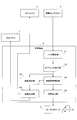
- FIG. 2 is a diagram illustrating a configuration example of the control device 4.
- the control device 4 includes a noise removal unit 41, an object extraction unit 42, a video / audio production unit 43, a video correction unit 44, a video output unit 45, and an audio output unit 46.
- the noise removing unit 41 has a function of removing noise from the distance video signal output from the distance sensor camera 3.
- the object extraction unit 42 has a function of extracting contour coordinates of an object such as the head, hand, and body of the player P and distance information of each pixel in the contour from the distance video signal after noise removal by the noise removal unit 41. is doing.
- the video / audio production unit 43 has a function of generating video and audio for a predetermined video production according to the state of the object (position, shape, movement, etc. in the three-dimensional space) extracted by the object extraction unit 42. Have.
- the display object displayed on the LCD panel 1 is transferred to the hand or body of the player P. Generate video to be moved.
- the player P's hand moves to a position away from the LCD panel 1, an image for moving the display object that has moved to the player P's hand or body to the LCD panel 1 is generated.
- the player P is in a position where one hand touches the LCD panel 1 and the other hand moves to a position where the other hand touches the LCD panel 1, the display object that has moved to the hand or body of the player P is displayed. Moves to the LCD panel 1 through the other hand, and generates an image that circulates these.
- the video correction unit 44 extracts the head object of the player P from the output of the object extraction unit 42 to specify the viewpoint, and also generates the video generated by the video / audio production unit 43 (video to be output to the projector 2. For the output video, correction is not necessary.)
- the distance information of the surface of the object on which the video is projected is acquired from the output of the object extraction unit 42, and the video viewed from the viewpoint is obtained in a desired shape (for example, by projection mapping). If the image represents a sphere, it has a function of correcting the image so that it becomes a sphere when viewed from the viewpoint.
- the video correcting unit 44 corrects the projected video based on the distance information of the surface of the object to be projected. Furthermore, the image correction unit 44 follows the object surface even if the object surface changes dynamically by acquiring distance information on the object surface at predetermined time intervals (for example, every 1/30 second). The video can be corrected.
- the video output unit 45 has a function of outputting the video corrected by the video correction unit 44 (the video on the LCD panel 1 is not corrected) to the LCD panel 1 and the projector 2.
- the audio output unit 46 has a function of outputting the audio generated by the video / audio production unit 43 to the audio amplifier 5.
- FIG. 3 is a diagram illustrating a configuration example of the video correction unit 44.
- the video correction unit 44 includes a head object extraction unit 441, a viewpoint determination unit 442, a video projection region extraction unit 443, a surface distance information extraction unit 444, and a video projection region video correction unit 445.
- the head object extracting unit 441 has a function of extracting contour coordinates of the head object of the player P (an object estimated from the shape as an object corresponding to the head) and distance information of each pixel in the contour from the output of the object extracting unit 42. have.
- the viewpoint determination unit 442 has a function of determining the three-dimensional coordinates of the viewpoint from the output of the head object extraction unit 441 based on a general head shape and a three-dimensional relative position model of the eyes.
- the video projection area extraction unit 443 has a function of extracting area coordinates where the main projection video exists (for example, area coordinates of the video projected onto the hand of the player P) from the video output from the video / audio production unit 43. .
- the video / audio production unit 43 outputs the region coordinates where the main projection video exists separately, the video projection region extraction unit 443 is omitted and the video / audio production unit 43 replaces the output of the video projection region extraction unit 443.
- Region coordinate output can be used.
- the surface distance information extraction unit 444 is based on the region coordinates where the main projection image extracted by the image projection region extraction unit 443 exists, the contour coordinates of each object of the object extraction unit 42, and the distance information of each pixel in the contour. It has a function of extracting distance information of the surface of the object of the projection part.
- the video projection area video correction unit 445 converts the video in the contour coordinates extracted by the surface distance information extraction unit 444 from the original video of the video / audio production unit 43 according to the distance information of each pixel in the contour. It has a function of performing a matrix calculation or the like so that the video viewed from the viewpoint determined by the viewpoint determination unit 442 becomes a normal image, and outputs the corrected video signal to the video output unit 45. Yes.
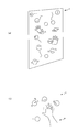
- 4 to 6 are diagrams showing examples of video effects.
- a spherical display object that looks like a mysterious creature or a hand-shaped display object for guiding touching with a hand is displayed. Displayed on the LCD panel 1.
- a spherical display object on the LCD panel 1 is placed around the player P's hand as shown in FIG.
- the projector 2 projects and displays the video that gathers and moves through the hand on the hand of the player P.
- the image projected on the hand of the player P is corrected to be viewed from the viewpoint of the player P, it is possible to realize that the spherical display object comes in real.
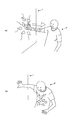
- FIG. 5B shows a state in which spherical display objects are gathered on the player P's chest.
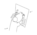
- FIG. 6 shows that when the player P touches the LCD panel 1 with the other hand and touches with both hands, the spherical display object moves from one hand of the player P to the other hand through the chest. Returning to the LCD panel 1, it is shown cyclically repeating it.
- the viewpoint determining unit 442 determines a viewpoint serving as a reference for correcting the projected image.
- this viewpoint may be arbitrarily set according to the configuration of the device.
- the viewpoint may be set at a fixed position in advance with respect to the floor or the LCD panel 1, or the viewpoint may be set at infinity on the normal line of each surface of the projection target object.
Landscapes
- Engineering & Computer Science (AREA)
- Theoretical Computer Science (AREA)
- Physics & Mathematics (AREA)
- General Physics & Mathematics (AREA)
- Computer Hardware Design (AREA)
- Human Computer Interaction (AREA)
- General Engineering & Computer Science (AREA)
- Controls And Circuits For Display Device (AREA)
- Projection Apparatus (AREA)
- Digital Computer Display Output (AREA)
Abstract
In order to produce an interesting video that enables a variety of content to be captured, this video production device is provided with: a projector and a distance-sensing camera that are positioned in a prescribed position on a viewpoint-side of an area where an object to be projected can appear; and a controller that generates a video to be projected on the surface of the object on the basis of distance information regarding the surface of the object obtained by the distance-sensing camera, and outputs a video signal to the projector.
Description
本発明は映像演出装置に関する。
The present invention relates to a video production device.
プレイヤ等の動きのある物体の動作に連動して映像を提示するといった映像演出が望まれるが、従来、充分なものは提案されていない。
Although video production such as presenting video in conjunction with the movement of a moving object such as a player is desired, hitherto, no sufficient video has been proposed.
特許文献1には、ユーザの姿を撮像した画像からユーザの指示や視線を検出し、広告等の情報提示に反映する仕組が開示されているが、映像演出を主目的としたものではなく、充分なものではない。
Patent Document 1 discloses a mechanism that detects a user's instruction and line of sight from an image of a user's appearance and reflects it in information presentation such as an advertisement, but is not intended for video production. Not enough.
上述したように、従来、映像演出として充分な面白みのあるものが存在せず、斬新な仕組の出現が待たれていた。
As described above, there has been no interesting thing as a video production so far, and the appearance of a novel mechanism has been awaited.
本発明は上記の従来の問題点に鑑み提案されたものであり、その目的とするところは、種々のコンテンツを取り込むことが可能な、面白みのある映像演出を行うことにある。
The present invention has been proposed in view of the above-described conventional problems, and an object of the present invention is to provide an interesting video effect capable of capturing various contents.
上記の課題を解決するため、本発明にあっては、映像投影の対象となる物体の出現可能領域の視点側所定位置に配置されたプロジェクタおよび距離センサカメラと、前記距離センサカメラにより得られた前記物体の表面の距離情報に基づいて前記物体の表面に映写する映像を生成し、前記プロジェクタに映像信号を出力する制御装置とを備えるようにしている。
In order to solve the above-described problems, in the present invention, the projector and the distance sensor camera arranged at a predetermined position on the viewpoint side of the possible appearance area of the object to be image projected, and the distance sensor camera are obtained. And a control device that generates an image projected on the surface of the object based on distance information of the surface of the object and outputs a video signal to the projector.
本発明の映像演出装置にあっては、種々のコンテンツを取り込むことが可能であり、面白みのある映像演出を行うことができる。
The video presentation apparatus of the present invention can capture various contents and can perform interesting video presentation.
以下、本発明の好適な実施形態につき説明する。
Hereinafter, preferred embodiments of the present invention will be described.
図1は本発明の一実施形態にかかる映像演出装置の構成例を示す図である。
FIG. 1 is a diagram illustrating a configuration example of a video effect device according to an embodiment of the present invention.
図1において、プレイヤPが近寄ることのできる壁等に大型のLCD(Liquid Crystal Display)パネル1が設置され、その上方の天井等にプロジェクタ2と距離センサカメラ3とが設置されている。距離センサカメラ3の視野は、検出対象となるプレイヤP等の物体の出現可能領域をカバーするものとする。
In FIG. 1, a large LCD (Liquid Crystal Display) panel 1 is installed on a wall or the like where the player P can approach, and a projector 2 and a distance sensor camera 3 are installed on the ceiling or the like above. It is assumed that the visual field of the distance sensor camera 3 covers an area where an object such as the player P to be detected can appear.
LCDパネル1は、映像信号を入力し、映像を表示するものである。プロジェクタ2は、映像信号を入力し、映像をプレイヤPの手や体等の物体の表面に投影するものである。距離センサカメラ3は、撮像しようとする方向に赤外線光の微細なパターンを照射し、そのパターンを含む映像を撮像し解析することで、画素毎に距離センサカメラ3からの距離を示す距離情報(深度情報)を持った距離映像信号を出力するものである。なお、距離情報として、距離センサカメラ3からの距離にオフセットを与えて別の位置からの距離を示すものとしてもよい。
The LCD panel 1 receives a video signal and displays a video. The projector 2 inputs a video signal and projects the video on the surface of an object such as a hand or a body of the player P. The distance sensor camera 3 irradiates a fine pattern of infrared light in the direction to be imaged, images an image including the pattern, and analyzes the distance information indicating the distance from the distance sensor camera 3 for each pixel ( A distance video signal having depth information) is output. In addition, as distance information, it is good also as what gives an offset to the distance from the distance sensor camera 3, and shows the distance from another position.
LCDパネル1、プロジェクタ2および距離センサカメラ3は、PC(Personal Computer)等の制御装置4に接続されている。制御装置4には、スピーカ6を駆動するためのオーディオアンプ5も接続されている。
The LCD panel 1, the projector 2, and the distance sensor camera 3 are connected to a control device 4 such as a PC (Personal Computer). An audio amplifier 5 for driving the speaker 6 is also connected to the control device 4.
なお、図1の構成では、LCDパネル1による映像の表示とプロジェクタ2による映像の表示(投影)との2系統で表示を行っているが、LCDパネル1を省略し、プロジェクタ2のみとすることもできる。
In the configuration of FIG. 1, the display is performed in two systems, that is, the display of the image by the LCD panel 1 and the display (projection) of the image by the projector 2, but the LCD panel 1 is omitted and only the projector 2 is used. You can also.
また、プロジェクタ2および距離センサカメラ3は上方に設けているが、これはプレイヤPの視点(目の位置)と投影する対象物体(ここではプレイヤPの手や体)との関係により決まるものである。例えば、プレイヤPが手に持った開いた傘の内側等に映像を投影するのであれば、プロジェクタ2および距離センサカメラ3は下方に上を向いて配置することになる。
The projector 2 and the distance sensor camera 3 are provided above, and this is determined by the relationship between the viewpoint (eye position) of the player P and the target object (here, the hand and body of the player P) to be projected. is there. For example, if an image is projected on the inside of an open umbrella held by the player P, the projector 2 and the distance sensor camera 3 are arranged facing downward.
図2は制御装置4の構成例を示す図である。
FIG. 2 is a diagram illustrating a configuration example of the control device 4.
図2において、制御装置4は、ノイズ除去部41とオブジェクト抽出部42と映像音声演出部43と映像補正部44と映像出力部45と音声出力部46とを備えている。
2, the control device 4 includes a noise removal unit 41, an object extraction unit 42, a video / audio production unit 43, a video correction unit 44, a video output unit 45, and an audio output unit 46.
ノイズ除去部41は、距離センサカメラ3の出力する距離映像信号からノイズを除去する機能を有している。
The noise removing unit 41 has a function of removing noise from the distance video signal output from the distance sensor camera 3.
オブジェクト抽出部42は、ノイズ除去部41によりノイズ除去された後の距離映像信号からプレイヤPの頭、手、体といったオブジェクトの輪郭座標と輪郭内の各画素の距離情報とを抽出する機能を有している。
The object extraction unit 42 has a function of extracting contour coordinates of an object such as the head, hand, and body of the player P and distance information of each pixel in the contour from the distance video signal after noise removal by the noise removal unit 41. is doing.
映像音声演出部43は、オブジェクト抽出部42により抽出されたオブジェクトの状態(3次元空間内の位置、形状、動き等)に応じて所定の映像演出のための映像および音声の生成を行う機能を有している。
The video / audio production unit 43 has a function of generating video and audio for a predetermined video production according to the state of the object (position, shape, movement, etc. in the three-dimensional space) extracted by the object extraction unit 42. Have.
例えば、プレイヤPの手(手の可能性のある体の一部)がLCDパネル1に触れる位置に移動した場合には、LCDパネル1に表示していた表示オブジェクトをプレイヤPの手や体に移動させる映像を生成する。また、プレイヤPの手がLCDパネル1から離れる位置に移動した場合には、プレイヤPの手や体に移動していた表示オブジェクトをLCDパネル1に移動させる映像を生成する。また、プレイヤPの一方の手がLCDパネル1に触れる位置にある状態で、他方の手がLCDパネル1に触れる位置に移動した場合には、プレイヤPの手や体に移動していた表示オブジェクトが他方の手を通ってLCDパネル1に移動し、これらを循環させる映像を生成する。
For example, when the hand of the player P (a part of the body that may be a hand) moves to a position where the player touches the LCD panel 1, the display object displayed on the LCD panel 1 is transferred to the hand or body of the player P. Generate video to be moved. When the player P's hand moves to a position away from the LCD panel 1, an image for moving the display object that has moved to the player P's hand or body to the LCD panel 1 is generated. Further, when the player P is in a position where one hand touches the LCD panel 1 and the other hand moves to a position where the other hand touches the LCD panel 1, the display object that has moved to the hand or body of the player P is displayed. Moves to the LCD panel 1 through the other hand, and generates an image that circulates these.
映像補正部44は、オブジェクト抽出部42の出力からプレイヤPの頭オブジェクトを抽出して視点を特定するとともに、映像音声演出部43により生成された映像(プロジェクタ2に出力する映像。LCDパネル1に出力する映像について補正は不要。)につき、オブジェクト抽出部42の出力から映像の投影されるオブジェクトの表面の距離情報を取得して、いわゆるプロジェクションマッピングにより、視点から見た映像が所望の形状(例えば、映像が球を表わしているならば、視点から見て球)になるように映像を補正する機能を有している。
The video correction unit 44 extracts the head object of the player P from the output of the object extraction unit 42 to specify the viewpoint, and also generates the video generated by the video / audio production unit 43 (video to be output to the projector 2. For the output video, correction is not necessary.) The distance information of the surface of the object on which the video is projected is acquired from the output of the object extraction unit 42, and the video viewed from the viewpoint is obtained in a desired shape (for example, by projection mapping). If the image represents a sphere, it has a function of correcting the image so that it becomes a sphere when viewed from the viewpoint.
すなわち、投影する映像が微妙な形状等の再現を要さないものであれば特に問題はないが、物体の表面の傾斜・湾曲や凹凸によって物体の表面に投影される映像が歪み、映像が正確に表現されず、映像演出の効果が低下してしまう問題がある。そのため、映像補正部44は投影対象の物体の表面の距離情報に基づいて投影する映像に補正を加えるようにしている。更には、映像補正部44は所定の時間間隔(例えば、30分の1秒ごと)にオブジェクトの表面の距離情報を取得し直すことにより、オブジェクトの表面が動的に変化しても、それに追随して映像の補正をすることができる。
In other words, there is no particular problem if the projected image does not require the reproduction of subtle shapes, etc., but the image projected on the object surface is distorted due to the inclination, curvature or unevenness of the object surface, and the image is accurate. In other words, there is a problem that the effect of the video production is reduced. Therefore, the video correcting unit 44 corrects the projected video based on the distance information of the surface of the object to be projected. Furthermore, the image correction unit 44 follows the object surface even if the object surface changes dynamically by acquiring distance information on the object surface at predetermined time intervals (for example, every 1/30 second). The video can be corrected.
映像出力部45は、映像補正部44により補正された後の映像(LCDパネル1に対する映像は補正なし)をLCDパネル1およびプロジェクタ2に出力する機能を有している。
The video output unit 45 has a function of outputting the video corrected by the video correction unit 44 (the video on the LCD panel 1 is not corrected) to the LCD panel 1 and the projector 2.
音声出力部46は、映像音声演出部43により生成された音声をオーディオアンプ5に出力する機能を有している。
The audio output unit 46 has a function of outputting the audio generated by the video / audio production unit 43 to the audio amplifier 5.
図3は映像補正部44の構成例を示す図である。
FIG. 3 is a diagram illustrating a configuration example of the video correction unit 44.
図3において、映像補正部44は、頭オブジェクト抽出部441と視点決定部442と映像投影領域抽出部443と表面距離情報抽出部444と映像投影領域映像補正部445とを備えている。
3, the video correction unit 44 includes a head object extraction unit 441, a viewpoint determination unit 442, a video projection region extraction unit 443, a surface distance information extraction unit 444, and a video projection region video correction unit 445.
頭オブジェクト抽出部441は、オブジェクト抽出部42の出力からプレイヤPの頭オブジェクト(形状から頭に対応するオブジェクトと推定されるオブジェクト)の輪郭座標と輪郭内の各画素の距離情報とを抽出する機能を有している。
The head object extracting unit 441 has a function of extracting contour coordinates of the head object of the player P (an object estimated from the shape as an object corresponding to the head) and distance information of each pixel in the contour from the output of the object extracting unit 42. have.
視点決定部442は、頭オブジェクト抽出部441の出力から、一般的な頭の形状と目の3次元的な相対位置のモデルに基づいて視点の3次元座標を決定する機能を有している。
The viewpoint determination unit 442 has a function of determining the three-dimensional coordinates of the viewpoint from the output of the head object extraction unit 441 based on a general head shape and a three-dimensional relative position model of the eyes.
映像投影領域抽出部443は、映像音声演出部43の出力の映像から主たる投影映像の存在する領域座標(例えば、プレイヤPの手に投影する映像の領域座標)を抽出する機能を有している。なお、映像音声演出部43が、主たる投影映像の存在する領域座標を別に出力する場合、映像投影領域抽出部443を省略し、映像投影領域抽出部443の出力に代えて映像音声演出部43の領域座標の出力を用いることができる。
The video projection area extraction unit 443 has a function of extracting area coordinates where the main projection video exists (for example, area coordinates of the video projected onto the hand of the player P) from the video output from the video / audio production unit 43. . When the video / audio production unit 43 outputs the region coordinates where the main projection video exists separately, the video projection region extraction unit 443 is omitted and the video / audio production unit 43 replaces the output of the video projection region extraction unit 443. Region coordinate output can be used.
表面距離情報抽出部444は、映像投影領域抽出部443により抽出された主たる投影映像の存在する領域座標と、オブジェクト抽出部42の各オブジェクトの輪郭座標および輪郭内の各画素の距離情報とから、投影部分のオブジェクトの表面の距離情報を抽出する機能を有している。
The surface distance information extraction unit 444 is based on the region coordinates where the main projection image extracted by the image projection region extraction unit 443 exists, the contour coordinates of each object of the object extraction unit 42, and the distance information of each pixel in the contour. It has a function of extracting distance information of the surface of the object of the projection part.
映像投影領域映像補正部445は、映像音声演出部43の元の映像のうち、表面距離情報抽出部444で抽出された輪郭座標内の映像を、輪郭内の各画素の距離情報に応じて、視点決定部442で決定された視点から見た映像が正視した映像となるように、マトリックス演算等を施して補正を行い、映像出力部45に補正後の映像信号を出力する機能を有している。
The video projection area video correction unit 445 converts the video in the contour coordinates extracted by the surface distance information extraction unit 444 from the original video of the video / audio production unit 43 according to the distance information of each pixel in the contour. It has a function of performing a matrix calculation or the like so that the video viewed from the viewpoint determined by the viewpoint determination unit 442 becomes a normal image, and outputs the corrected video signal to the video output unit 45. Yes.
図4~図6は映像演出の例を示す図である。
4 to 6 are diagrams showing examples of video effects.
図4(a)に示すように、プレイヤPがLCDパネル1に触れていない状態では、謎の生命体に見立てた球状の表示オブジェクトや手で触れることを誘導するための手形状の表示オブジェクトをLCDパネル1に表示する。
As shown in FIG. 4A, in a state where the player P is not touching the LCD panel 1, a spherical display object that looks like a mysterious creature or a hand-shaped display object for guiding touching with a hand is displayed. Displayed on the LCD panel 1.
これに応じて、図4(b)に示すようにプレイヤPがLCDパネル1に触れると、図5(a)に示すように、LCDパネル1上の球状の表示オブジェクトがプレイヤPの手の周りに集まり、手を伝って移動してくる映像をプロジェクタ2によりプレイヤPの手に投影して表示する。この場合、プレイヤPの手に投影される映像は、プレイヤPの視点から見て正視した状態に補正されているため、球状の表示オブジェクトがリアルに這ってくることを実感させることができる。
Accordingly, when the player P touches the LCD panel 1 as shown in FIG. 4B, a spherical display object on the LCD panel 1 is placed around the player P's hand as shown in FIG. The projector 2 projects and displays the video that gathers and moves through the hand on the hand of the player P. In this case, since the image projected on the hand of the player P is corrected to be viewed from the viewpoint of the player P, it is possible to realize that the spherical display object comes in real.
図5(b)は、球状の表示オブジェクトがプレイヤPの胸に集まった状態を示している。
FIG. 5B shows a state in which spherical display objects are gathered on the player P's chest.
図6は、プレイヤPが更にLCDパネル1に他方の手を触れて両手で触れる状態となることで、球状の表示オブジェクトがプレイヤPの一方の手から胸を通って他方の手に移動してLCDパネル1に戻り、それを循環的に繰り返す様子を示している。
FIG. 6 shows that when the player P touches the LCD panel 1 with the other hand and touches with both hands, the spherical display object moves from one hand of the player P to the other hand through the chest. Returning to the LCD panel 1, it is shown cyclically repeating it.
また、プレイヤPがLCDパネル1から手を離した場合、プレイヤPの手や胸に表示されていた球状の表示オブジェクトは勢いよくLCDパネル1に移動する(戻っていく)。
Also, when the player P releases his / her hand from the LCD panel 1, the spherical display object displayed on the player's P hand or chest moves to the LCD panel 1 vigorously (returns).
上述した映像演出の他にも種々の態様が考えられる。例えば、人の体に衣服の映像を投影したり、車のボンネットにコマーシャルメッセージの映像を投影したりすることも可能であり、投影対象の物体の表面の傾斜・湾曲や凹凸によって映像を歪ませることなく表示することができる。
In addition to the video production described above, various aspects are possible. For example, it is possible to project clothing images on the human body or project commercial messages on the hood of a car. The image is distorted by the inclination, curvature, or unevenness of the surface of the object to be projected. It can be displayed without.
なお、上記の実施形態では、投影映像を補正する際の基準となる視点を視点決定部442で決定していたが、機器の構成などに合わせて、この視点は任意に設定してもよい。例えば、床やLCDパネル1を基準にして予め固定位置に視点を設定してもよいし、また、投影対象の物体の各表面の法線上の無限遠に視点を設定してもよい。
In the above-described embodiment, the viewpoint determining unit 442 determines a viewpoint serving as a reference for correcting the projected image. However, this viewpoint may be arbitrarily set according to the configuration of the device. For example, the viewpoint may be set at a fixed position in advance with respect to the floor or the LCD panel 1, or the viewpoint may be set at infinity on the normal line of each surface of the projection target object.
以上、本発明の好適な実施の形態により本発明を説明した。ここでは特定の具体例を示して本発明を説明したが、特許請求の範囲に定義された本発明の広範な趣旨および範囲から逸脱することなく、これら具体例に様々な修正および変更を加えることができることは明らかである。すなわち、具体例の詳細および添付の図面により本発明が限定されるものと解釈してはならない。
The present invention has been described above by the preferred embodiments of the present invention. While the invention has been described with reference to specific embodiments, various modifications and changes may be made to the embodiments without departing from the broad spirit and scope of the invention as defined in the claims. Obviously you can. In other words, the present invention should not be construed as being limited by the details of the specific examples and the accompanying drawings.
1 LCDパネル
2 プロジェクタ
3 距離センサカメラ
4 制御装置
41 ノイズ除去部
42 オブジェクト抽出部
43 映像音声演出部
44 映像補正部
441 頭オブジェクト抽出部
442 視点決定部
443 映像投影領域抽出部
444 表面距離情報抽出部
445 映像投影領域映像補正部
45 映像出力部
46 音声出力部
5 オーディオアンプ
6 スピーカ
P プレイヤ DESCRIPTION OF SYMBOLS 1LCD panel 2 Projector 3 Distance sensor camera 4 Control apparatus 41 Noise removal part 42 Object extraction part 43 Image | video audio production part 44 Video correction part 441 Head object extraction part 442 View point determination part 443 Image | video projection area extraction part 444 Surface distance information extraction part 445 video projection area video correction unit 45 video output unit 46 audio output unit 5 audio amplifier 6 speaker P player
2 プロジェクタ
3 距離センサカメラ
4 制御装置
41 ノイズ除去部
42 オブジェクト抽出部
43 映像音声演出部
44 映像補正部
441 頭オブジェクト抽出部
442 視点決定部
443 映像投影領域抽出部
444 表面距離情報抽出部
445 映像投影領域映像補正部
45 映像出力部
46 音声出力部
5 オーディオアンプ
6 スピーカ
P プレイヤ DESCRIPTION OF SYMBOLS 1
Claims (4)
- 映像投影の対象となる物体の出現可能領域の視点側所定位置に配置されたプロジェクタおよび距離センサカメラと、
前記距離センサカメラにより得られた前記物体の表面の距離情報に基づいて前記物体の表面に映写する映像を生成し、前記プロジェクタに映像信号を出力する制御装置と
を備えたことを特徴とする映像演出装置。 A projector and a distance sensor camera arranged at a predetermined position on the viewpoint side of an appearable region of an object to be projected;
An image comprising: a control device that generates an image projected on the surface of the object based on distance information of the surface of the object obtained by the distance sensor camera, and outputs an image signal to the projector Production device. - 請求項1に記載の映像演出装置において、
前記制御装置は、前記距離センサカメラにより得られた前記物体の表面の各点における距離情報に基づき、前記プロジェクタにより前記物体の表面に映写する映像を補正する映像補正手段
を備えたことを特徴とする映像演出装置。 The video effect device according to claim 1,
The control device includes image correction means for correcting an image projected on the surface of the object by the projector based on distance information at each point on the surface of the object obtained by the distance sensor camera. A video production device. - 映像投影の対象となる物体の出現可能領域の視点側所定位置に配置された距離センサカメラから前記物体の表面の距離情報を取得する工程と、
前記距離センサカメラにより得られた前記物体の表面の距離情報に基づいて前記物体の表面に映写する映像を生成し、映像投影の対象となる前記物体の出現可能領域の視点側所定位置に配置されたプロジェクタに映像信号を出力する工程と
を備えたことを特徴とする映像演出方法。 Obtaining distance information of the surface of the object from a distance sensor camera arranged at a predetermined position on the viewpoint side of the possible appearance area of the object to be image projected;
Based on the distance information of the surface of the object obtained by the distance sensor camera, an image to be projected on the surface of the object is generated and placed at a predetermined position on the viewpoint side of the appearable area of the object to be image projected. And a step of outputting a video signal to the projector. - コンピュータを、
映像投影の対象となる物体の出現可能領域の視点側所定位置に配置された距離センサカメラから前記物体の表面の距離情報を取得する手段、
前記距離センサカメラにより得られた前記物体の表面の距離情報に基づいて前記物体の表面に映写する映像を生成し、映像投影の対象となる前記物体の出現可能領域の視点側所定位置に配置されたプロジェクタに映像信号を出力する手段
として機能させる映像演出プログラム。 Computer
Means for acquiring distance information of the surface of the object from a distance sensor camera arranged at a predetermined position on the viewpoint side of an appearable area of the object to be projected;
Based on the distance information of the surface of the object obtained by the distance sensor camera, an image to be projected on the surface of the object is generated and placed at a predetermined position on the viewpoint side of the appearable area of the object to be image projected. A video production program for causing a projector to function as a means for outputting a video signal.
Applications Claiming Priority (2)
| Application Number | Priority Date | Filing Date | Title |
|---|---|---|---|
| JP2012-148008 | 2012-06-29 | ||
| JP2012148008A JP2014010362A (en) | 2012-06-29 | 2012-06-29 | Image producing device |
Publications (1)
| Publication Number | Publication Date |
|---|---|
| WO2014003099A1 true WO2014003099A1 (en) | 2014-01-03 |
Family
ID=49783237
Family Applications (1)
| Application Number | Title | Priority Date | Filing Date |
|---|---|---|---|
| PCT/JP2013/067611 WO2014003099A1 (en) | 2012-06-29 | 2013-06-27 | Video production device |
Country Status (2)
| Country | Link |
|---|---|
| JP (1) | JP2014010362A (en) |
| WO (1) | WO2014003099A1 (en) |
Cited By (3)
| Publication number | Priority date | Publication date | Assignee | Title |
|---|---|---|---|---|
| WO2015151766A1 (en) * | 2014-03-31 | 2015-10-08 | コニカミノルタ株式会社 | Projection photographing system, karaoke device, and simulation device |
| WO2017057426A1 (en) * | 2015-09-29 | 2017-04-06 | シャープ株式会社 | Projection device, content determination device, projection method, and program |
| US20180191990A1 (en) * | 2015-09-02 | 2018-07-05 | Bandai Namco Entertainment Inc. | Projection system |
Families Citing this family (4)
| Publication number | Priority date | Publication date | Assignee | Title |
|---|---|---|---|---|
| US9900570B2 (en) | 2014-03-18 | 2018-02-20 | Advanced Healthcare Co., Ltd. | Projector system and calibration board |
| US9943759B2 (en) * | 2014-06-16 | 2018-04-17 | Universal City Studios Llc | Interactive game floor system and method |
| JP7147314B2 (en) * | 2018-07-19 | 2022-10-05 | セイコーエプソン株式会社 | Display system and reflector |
| JP2023023791A (en) | 2021-08-06 | 2023-02-16 | セイコーエプソン株式会社 | Display method |
Citations (3)
| Publication number | Priority date | Publication date | Assignee | Title |
|---|---|---|---|---|
| JPH05249428A (en) * | 1992-03-05 | 1993-09-28 | Koudo Eizou Gijutsu Kenkyusho:Kk | Projection system |
| WO2010137496A1 (en) * | 2009-05-26 | 2010-12-02 | パナソニック電工株式会社 | Information presentation device |
| JP2011254411A (en) * | 2010-06-04 | 2011-12-15 | Hokkaido Univ | Video projection system and video projection program |
-
2012
- 2012-06-29 JP JP2012148008A patent/JP2014010362A/en active Pending
-
2013
- 2013-06-27 WO PCT/JP2013/067611 patent/WO2014003099A1/en active Application Filing
Patent Citations (3)
| Publication number | Priority date | Publication date | Assignee | Title |
|---|---|---|---|---|
| JPH05249428A (en) * | 1992-03-05 | 1993-09-28 | Koudo Eizou Gijutsu Kenkyusho:Kk | Projection system |
| WO2010137496A1 (en) * | 2009-05-26 | 2010-12-02 | パナソニック電工株式会社 | Information presentation device |
| JP2011254411A (en) * | 2010-06-04 | 2011-12-15 | Hokkaido Univ | Video projection system and video projection program |
Cited By (4)
| Publication number | Priority date | Publication date | Assignee | Title |
|---|---|---|---|---|
| WO2015151766A1 (en) * | 2014-03-31 | 2015-10-08 | コニカミノルタ株式会社 | Projection photographing system, karaoke device, and simulation device |
| US20180191990A1 (en) * | 2015-09-02 | 2018-07-05 | Bandai Namco Entertainment Inc. | Projection system |
| WO2017057426A1 (en) * | 2015-09-29 | 2017-04-06 | シャープ株式会社 | Projection device, content determination device, projection method, and program |
| JPWO2017057426A1 (en) * | 2015-09-29 | 2018-08-30 | シャープ株式会社 | Projection device, content determination device, projection method, and program |
Also Published As
| Publication number | Publication date |
|---|---|
| JP2014010362A (en) | 2014-01-20 |
Similar Documents
| Publication | Publication Date | Title |
|---|---|---|
| WO2014003099A1 (en) | Video production device | |
| JP7283506B2 (en) | Information processing device, information processing method, and information processing program | |
| JP6747504B2 (en) | Information processing apparatus, information processing method, and program | |
| US9778815B2 (en) | Three dimensional user interface effects on a display | |
| US8559677B2 (en) | Image generation system, image generation method, and information storage medium | |
| JP6344380B2 (en) | Image processing apparatus and method, and program | |
| JP5148660B2 (en) | Program, information storage medium, and image generation system | |
| US8655015B2 (en) | Image generation system, image generation method, and information storage medium | |
| JP2015114818A (en) | Information processing device, information processing method, and program | |
| WO2013069360A1 (en) | Information processing device, display control method, and program | |
| US9449394B2 (en) | Image synthesis device, image synthesis system, image synthesis method and program | |
| JP7073481B2 (en) | Image display system | |
| US20190371072A1 (en) | Static occluder | |
| TW201214266A (en) | Three dimensional user interface effects on a display by using properties of motion | |
| KR20230048554A (en) | Devices, methods and graphical user interfaces for interaction with three-dimensional environments | |
| WO2017051570A1 (en) | Information processing device, information processing method, and program | |
| WO2020003860A1 (en) | Information processing device, information processing method, and program | |
| JP2015084002A (en) | Mirror display system and image display method thereof | |
| JP2011133955A (en) | Video reproducing apparatus and method | |
| KR20090040839A (en) | Augmented reality computer device | |
| JP4945694B2 (en) | Video playback apparatus and video playback method | |
| US11589001B2 (en) | Information processing apparatus, information processing method, and program | |
| JP7367689B2 (en) | Information processing device, information processing method, and recording medium | |
| TW201016275A (en) | Image system for adjusting displaying angle by detecting human face and visual simulation control apparatus thereof | |
| JP2009212582A (en) | Feedback system for virtual studio |
Legal Events
| Date | Code | Title | Description |
|---|---|---|---|
| 121 | Ep: the epo has been informed by wipo that ep was designated in this application |
Ref document number: 13810744 Country of ref document: EP Kind code of ref document: A1 |
|
| NENP | Non-entry into the national phase |
Ref country code: DE |
|
| 122 | Ep: pct application non-entry in european phase |
Ref document number: 13810744 Country of ref document: EP Kind code of ref document: A1 |