WO2013154272A1 - System of secondary cell including mixed cathode material, and apparatus and method for secondary cell management - Google Patents
System of secondary cell including mixed cathode material, and apparatus and method for secondary cell management Download PDFInfo
- Publication number
- WO2013154272A1 WO2013154272A1 PCT/KR2013/002149 KR2013002149W WO2013154272A1 WO 2013154272 A1 WO2013154272 A1 WO 2013154272A1 KR 2013002149 W KR2013002149 W KR 2013002149W WO 2013154272 A1 WO2013154272 A1 WO 2013154272A1
- Authority
- WO
- WIPO (PCT)
- Prior art keywords
- secondary battery
- voltage
- state
- positive electrode
- electrode material
- Prior art date
Links
Images


Classifications
-
- H—ELECTRICITY
- H01—ELECTRIC ELEMENTS
- H01M—PROCESSES OR MEANS, e.g. BATTERIES, FOR THE DIRECT CONVERSION OF CHEMICAL ENERGY INTO ELECTRICAL ENERGY
- H01M10/00—Secondary cells; Manufacture thereof
- H01M10/42—Methods or arrangements for servicing or maintenance of secondary cells or secondary half-cells
-
- G—PHYSICS
- G01—MEASURING; TESTING
- G01R—MEASURING ELECTRIC VARIABLES; MEASURING MAGNETIC VARIABLES
- G01R31/00—Arrangements for testing electric properties; Arrangements for locating electric faults; Arrangements for electrical testing characterised by what is being tested not provided for elsewhere
- G01R31/36—Arrangements for testing, measuring or monitoring the electrical condition of accumulators or electric batteries, e.g. capacity or state of charge [SoC]
- G01R31/367—Software therefor, e.g. for battery testing using modelling or look-up tables
-
- H—ELECTRICITY
- H01—ELECTRIC ELEMENTS
- H01M—PROCESSES OR MEANS, e.g. BATTERIES, FOR THE DIRECT CONVERSION OF CHEMICAL ENERGY INTO ELECTRICAL ENERGY
- H01M10/00—Secondary cells; Manufacture thereof
- H01M10/04—Construction or manufacture in general
-
- H—ELECTRICITY
- H01—ELECTRIC ELEMENTS
- H01M—PROCESSES OR MEANS, e.g. BATTERIES, FOR THE DIRECT CONVERSION OF CHEMICAL ENERGY INTO ELECTRICAL ENERGY
- H01M10/00—Secondary cells; Manufacture thereof
- H01M10/05—Accumulators with non-aqueous electrolyte
- H01M10/052—Li-accumulators
-
- H—ELECTRICITY
- H01—ELECTRIC ELEMENTS
- H01M—PROCESSES OR MEANS, e.g. BATTERIES, FOR THE DIRECT CONVERSION OF CHEMICAL ENERGY INTO ELECTRICAL ENERGY
- H01M10/00—Secondary cells; Manufacture thereof
- H01M10/05—Accumulators with non-aqueous electrolyte
- H01M10/058—Construction or manufacture
-
- H—ELECTRICITY
- H01—ELECTRIC ELEMENTS
- H01M—PROCESSES OR MEANS, e.g. BATTERIES, FOR THE DIRECT CONVERSION OF CHEMICAL ENERGY INTO ELECTRICAL ENERGY
- H01M10/00—Secondary cells; Manufacture thereof
- H01M10/42—Methods or arrangements for servicing or maintenance of secondary cells or secondary half-cells
- H01M10/425—Structural combination with electronic components, e.g. electronic circuits integrated to the outside of the casing
- H01M10/4257—Smart batteries, e.g. electronic circuits inside the housing of the cells or batteries
-
- H—ELECTRICITY
- H01—ELECTRIC ELEMENTS
- H01M—PROCESSES OR MEANS, e.g. BATTERIES, FOR THE DIRECT CONVERSION OF CHEMICAL ENERGY INTO ELECTRICAL ENERGY
- H01M10/00—Secondary cells; Manufacture thereof
- H01M10/42—Methods or arrangements for servicing or maintenance of secondary cells or secondary half-cells
- H01M10/48—Accumulators combined with arrangements for measuring, testing or indicating the condition of cells, e.g. the level or density of the electrolyte
-
- H—ELECTRICITY
- H01—ELECTRIC ELEMENTS
- H01M—PROCESSES OR MEANS, e.g. BATTERIES, FOR THE DIRECT CONVERSION OF CHEMICAL ENERGY INTO ELECTRICAL ENERGY
- H01M4/00—Electrodes
- H01M4/02—Electrodes composed of, or comprising, active material
- H01M4/36—Selection of substances as active materials, active masses, active liquids
- H01M4/362—Composites
- H01M4/364—Composites as mixtures
-
- H—ELECTRICITY
- H01—ELECTRIC ELEMENTS
- H01M—PROCESSES OR MEANS, e.g. BATTERIES, FOR THE DIRECT CONVERSION OF CHEMICAL ENERGY INTO ELECTRICAL ENERGY
- H01M50/00—Constructional details or processes of manufacture of the non-active parts of electrochemical cells other than fuel cells, e.g. hybrid cells
- H01M50/50—Current conducting connections for cells or batteries
- H01M50/569—Constructional details of current conducting connections for detecting conditions inside cells or batteries, e.g. details of voltage sensing terminals
-
- H—ELECTRICITY
- H02—GENERATION; CONVERSION OR DISTRIBUTION OF ELECTRIC POWER
- H02J—CIRCUIT ARRANGEMENTS OR SYSTEMS FOR SUPPLYING OR DISTRIBUTING ELECTRIC POWER; SYSTEMS FOR STORING ELECTRIC ENERGY
- H02J7/00—Circuit arrangements for charging or depolarising batteries or for supplying loads from batteries
- H02J7/0063—Circuit arrangements for charging or depolarising batteries or for supplying loads from batteries with circuits adapted for supplying loads from the battery
-
- H—ELECTRICITY
- H02—GENERATION; CONVERSION OR DISTRIBUTION OF ELECTRIC POWER
- H02J—CIRCUIT ARRANGEMENTS OR SYSTEMS FOR SUPPLYING OR DISTRIBUTING ELECTRIC POWER; SYSTEMS FOR STORING ELECTRIC ENERGY
- H02J7/00—Circuit arrangements for charging or depolarising batteries or for supplying loads from batteries
- H02J7/007—Regulation of charging or discharging current or voltage
- H02J7/00711—Regulation of charging or discharging current or voltage with introduction of pulses during the charging process
-
- H—ELECTRICITY
- H02—GENERATION; CONVERSION OR DISTRIBUTION OF ELECTRIC POWER
- H02J—CIRCUIT ARRANGEMENTS OR SYSTEMS FOR SUPPLYING OR DISTRIBUTING ELECTRIC POWER; SYSTEMS FOR STORING ELECTRIC ENERGY
- H02J7/00—Circuit arrangements for charging or depolarising batteries or for supplying loads from batteries
- H02J7/007—Regulation of charging or discharging current or voltage
- H02J7/00712—Regulation of charging or discharging current or voltage the cycle being controlled or terminated in response to electric parameters
- H02J7/007182—Regulation of charging or discharging current or voltage the cycle being controlled or terminated in response to electric parameters in response to battery voltage
-
- G—PHYSICS
- G01—MEASURING; TESTING
- G01R—MEASURING ELECTRIC VARIABLES; MEASURING MAGNETIC VARIABLES
- G01R31/00—Arrangements for testing electric properties; Arrangements for locating electric faults; Arrangements for electrical testing characterised by what is being tested not provided for elsewhere
- G01R31/36—Arrangements for testing, measuring or monitoring the electrical condition of accumulators or electric batteries, e.g. capacity or state of charge [SoC]
- G01R31/382—Arrangements for monitoring battery or accumulator variables, e.g. SoC
- G01R31/3842—Arrangements for monitoring battery or accumulator variables, e.g. SoC combining voltage and current measurements
-
- H—ELECTRICITY
- H01—ELECTRIC ELEMENTS
- H01M—PROCESSES OR MEANS, e.g. BATTERIES, FOR THE DIRECT CONVERSION OF CHEMICAL ENERGY INTO ELECTRICAL ENERGY
- H01M10/00—Secondary cells; Manufacture thereof
- H01M10/05—Accumulators with non-aqueous electrolyte
- H01M10/052—Li-accumulators
- H01M10/0525—Rocking-chair batteries, i.e. batteries with lithium insertion or intercalation in both electrodes; Lithium-ion batteries
-
- H—ELECTRICITY
- H01—ELECTRIC ELEMENTS
- H01M—PROCESSES OR MEANS, e.g. BATTERIES, FOR THE DIRECT CONVERSION OF CHEMICAL ENERGY INTO ELECTRICAL ENERGY
- H01M10/00—Secondary cells; Manufacture thereof
- H01M10/42—Methods or arrangements for servicing or maintenance of secondary cells or secondary half-cells
- H01M10/425—Structural combination with electronic components, e.g. electronic circuits integrated to the outside of the casing
- H01M2010/4271—Battery management systems including electronic circuits, e.g. control of current or voltage to keep battery in healthy state, cell balancing
-
- H—ELECTRICITY
- H01—ELECTRIC ELEMENTS
- H01M—PROCESSES OR MEANS, e.g. BATTERIES, FOR THE DIRECT CONVERSION OF CHEMICAL ENERGY INTO ELECTRICAL ENERGY
- H01M2220/00—Batteries for particular applications
- H01M2220/20—Batteries in motive systems, e.g. vehicle, ship, plane
-
- H—ELECTRICITY
- H01—ELECTRIC ELEMENTS
- H01M—PROCESSES OR MEANS, e.g. BATTERIES, FOR THE DIRECT CONVERSION OF CHEMICAL ENERGY INTO ELECTRICAL ENERGY
- H01M4/00—Electrodes
- H01M4/02—Electrodes composed of, or comprising, active material
- H01M4/36—Selection of substances as active materials, active masses, active liquids
- H01M4/48—Selection of substances as active materials, active masses, active liquids of inorganic oxides or hydroxides
- H01M4/50—Selection of substances as active materials, active masses, active liquids of inorganic oxides or hydroxides of manganese
- H01M4/505—Selection of substances as active materials, active masses, active liquids of inorganic oxides or hydroxides of manganese of mixed oxides or hydroxides containing manganese for inserting or intercalating light metals, e.g. LiMn2O4 or LiMn2OxFy
-
- H—ELECTRICITY
- H01—ELECTRIC ELEMENTS
- H01M—PROCESSES OR MEANS, e.g. BATTERIES, FOR THE DIRECT CONVERSION OF CHEMICAL ENERGY INTO ELECTRICAL ENERGY
- H01M4/00—Electrodes
- H01M4/02—Electrodes composed of, or comprising, active material
- H01M4/36—Selection of substances as active materials, active masses, active liquids
- H01M4/48—Selection of substances as active materials, active masses, active liquids of inorganic oxides or hydroxides
- H01M4/52—Selection of substances as active materials, active masses, active liquids of inorganic oxides or hydroxides of nickel, cobalt or iron
- H01M4/525—Selection of substances as active materials, active masses, active liquids of inorganic oxides or hydroxides of nickel, cobalt or iron of mixed oxides or hydroxides containing iron, cobalt or nickel for inserting or intercalating light metals, e.g. LiNiO2, LiCoO2 or LiCoOxFy
-
- H—ELECTRICITY
- H01—ELECTRIC ELEMENTS
- H01M—PROCESSES OR MEANS, e.g. BATTERIES, FOR THE DIRECT CONVERSION OF CHEMICAL ENERGY INTO ELECTRICAL ENERGY
- H01M4/00—Electrodes
- H01M4/02—Electrodes composed of, or comprising, active material
- H01M4/36—Selection of substances as active materials, active masses, active liquids
- H01M4/58—Selection of substances as active materials, active masses, active liquids of inorganic compounds other than oxides or hydroxides, e.g. sulfides, selenides, tellurides, halogenides or LiCoFy; of polyanionic structures, e.g. phosphates, silicates or borates
- H01M4/5825—Oxygenated metallic salts or polyanionic structures, e.g. borates, phosphates, silicates, olivines
-
- H—ELECTRICITY
- H01—ELECTRIC ELEMENTS
- H01M—PROCESSES OR MEANS, e.g. BATTERIES, FOR THE DIRECT CONVERSION OF CHEMICAL ENERGY INTO ELECTRICAL ENERGY
- H01M4/00—Electrodes
- H01M4/02—Electrodes composed of, or comprising, active material
- H01M4/62—Selection of inactive substances as ingredients for active masses, e.g. binders, fillers
- H01M4/624—Electric conductive fillers
- H01M4/625—Carbon or graphite
-
- Y—GENERAL TAGGING OF NEW TECHNOLOGICAL DEVELOPMENTS; GENERAL TAGGING OF CROSS-SECTIONAL TECHNOLOGIES SPANNING OVER SEVERAL SECTIONS OF THE IPC; TECHNICAL SUBJECTS COVERED BY FORMER USPC CROSS-REFERENCE ART COLLECTIONS [XRACs] AND DIGESTS
- Y02—TECHNOLOGIES OR APPLICATIONS FOR MITIGATION OR ADAPTATION AGAINST CLIMATE CHANGE
- Y02E—REDUCTION OF GREENHOUSE GAS [GHG] EMISSIONS, RELATED TO ENERGY GENERATION, TRANSMISSION OR DISTRIBUTION
- Y02E60/00—Enabling technologies; Technologies with a potential or indirect contribution to GHG emissions mitigation
- Y02E60/10—Energy storage using batteries
-
- Y—GENERAL TAGGING OF NEW TECHNOLOGICAL DEVELOPMENTS; GENERAL TAGGING OF CROSS-SECTIONAL TECHNOLOGIES SPANNING OVER SEVERAL SECTIONS OF THE IPC; TECHNICAL SUBJECTS COVERED BY FORMER USPC CROSS-REFERENCE ART COLLECTIONS [XRACs] AND DIGESTS
- Y02—TECHNOLOGIES OR APPLICATIONS FOR MITIGATION OR ADAPTATION AGAINST CLIMATE CHANGE
- Y02P—CLIMATE CHANGE MITIGATION TECHNOLOGIES IN THE PRODUCTION OR PROCESSING OF GOODS
- Y02P70/00—Climate change mitigation technologies in the production process for final industrial or consumer products
- Y02P70/50—Manufacturing or production processes characterised by the final manufactured product
-
- Y—GENERAL TAGGING OF NEW TECHNOLOGICAL DEVELOPMENTS; GENERAL TAGGING OF CROSS-SECTIONAL TECHNOLOGIES SPANNING OVER SEVERAL SECTIONS OF THE IPC; TECHNICAL SUBJECTS COVERED BY FORMER USPC CROSS-REFERENCE ART COLLECTIONS [XRACs] AND DIGESTS
- Y02—TECHNOLOGIES OR APPLICATIONS FOR MITIGATION OR ADAPTATION AGAINST CLIMATE CHANGE
- Y02T—CLIMATE CHANGE MITIGATION TECHNOLOGIES RELATED TO TRANSPORTATION
- Y02T10/00—Road transport of goods or passengers
- Y02T10/60—Other road transportation technologies with climate change mitigation effect
- Y02T10/70—Energy storage systems for electromobility, e.g. batteries
Definitions
- the present application relates to a system for a secondary battery including the mixed cathode material, and a management apparatus and method for a secondary battery including the mixed cathode material.
- a battery may be a device that can be carried in a human hand such as a mobile phone, a laptop computer, a digital camera, a video camera, a tablet computer, a power tool, or the like;
- Various electric drive power devices such as electric bicycles, electric motorcycles, electric vehicles, hybrid vehicles, electric boats, electric airplanes, and the like;
- a power storage device used to store power generated by renewable energy or surplus generated power;
- the field of use extends to an uninterruptible power supply for stably supplying power to various information communication devices including server computers and communication base stations.
- the cell comprises three basic components: an anode comprising a material that is oxidized while releasing electrons during discharge, and a cathode comprising a material that is reduced while receiving electrons during discharge. And an electrolyte that allows the movement of working ions between the cathode and the anode.
- the battery may be classified into a primary battery that cannot be reused after being discharged and a secondary battery capable of repetitive charging and discharging because the electrochemical reaction is at least partially reversible.
- secondary batteries examples include lead-acid batteries, nickel-cadmium batteries, nickel-zinc batteries, nickel-iron batteries, silver oxide batteries, nickel metal hydride batteries, zinc-manganese oxide batteries, zinc-bromide batteries, and metal- Air batteries, lithium secondary batteries and the like are known. Among them, lithium secondary batteries have attracted the greatest commercial interest because of their higher energy density, higher battery voltage, and longer shelf life than other secondary batteries.
- Lithium secondary batteries have characteristics in which intercalation and de-intercalation reactions of lithium ions occur in a positive electrode and a negative electrode. That is, during discharge, lithium ions are detached from the negative electrode material included in the negative electrode and then moved to the positive electrode through the electrolyte and inserted into the positive electrode material included in the positive electrode, and vice versa while charging is in progress.
- the material used as the cathode material has a significant effect on the performance of the secondary battery, it is possible to provide a cathode material having a high energy capacity while maintaining stability at high temperature and having a low manufacturing cost. Various attempts are being made.
- the present application identifies the electrochemical reaction mechanism of the blended cathode material that can compensate for the disadvantages of each cathode material by branding two or more cathode materials.
- the present application also provides a system, an apparatus, and a method for reliably predicting the electrochemical behavior of a secondary battery including a mixed cathode material by identifying an electrochemical reaction mechanism of the mixed cathode material to a level capable of mathematical modeling.
- the mixed cathode material includes at least a first cathode material and a second cathode material having different operating voltage ranges.
- first and second positive electrode materials have different reaction concentrations of working ions reacting with them as the voltage changes, and become in an idle state or a no-load state in an intrinsic voltage band. Voltage relaxation is possible by transferring the working ions to each other.
- the mixed cathode material may be used as a cathode material of a secondary battery that is charged or discharged in a voltage range including the intrinsic voltage band.
- the operating ions refer to ions which undergo an electrochemical reaction with the first and second cathode materials during the charging or discharging of the secondary battery including the mixed cathode material.
- the operating ions may vary depending on the type of secondary battery.
- the operating ion may be lithium ion.
- the electrochemical reaction includes oxidation and reduction reactions of the first and second cathode materials, which are involved in the charging and discharging of the secondary battery, and may vary according to the operation mechanism of the secondary battery.
- the electrochemical reaction may mean that operating ions are inserted into the first cathode material and / or the second cathode material or vice versa from the inside.
- the concentration of operating ions inserted into the first and second cathode materials or the concentration of operating ions detached from the first and second cathode materials may vary as the voltage of the secondary battery changes.
- the first and second cathode materials have different operating voltage ranges with respect to operating ions.
- operating ions may be preferentially inserted into the first cathode material in a certain voltage band, and vice versa in another voltage band.
- operating ions may be preferentially desorbed from the second cathode material in one voltage band under the condition that the secondary battery is charged, and vice versa in another voltage band.
- the idle state is a state in which a large discharge current is drawn from the secondary battery to the main load side of the device on which the secondary battery is mounted, and the minimum discharge current required by the electronic device included in the apparatus is secondary. It means a drawn state from the battery (drawn).
- the secondary battery is in an idle state, the magnitude of the discharge current exiting from the secondary battery is quite small.
- the magnitude of the current flowing out of the secondary battery may be constant, substantially constant, or variable.
- a secondary battery when a secondary battery is mounted in an electric vehicle, a computer unit or an audio device mounted in the electric vehicle, although the secondary battery does not supply a discharge current to the motor immediately after the driver turns on the key. Supplying a small discharge current to the back; (ii) a pause for waiting for a traffic signal while the electric vehicle is in operation, or a computer unit switched to a sleep mode after the electric vehicle is parked, (iii) a secondary battery
- the use of the information communication device equipped with the interruption for more than a certain time without turning off the power source may be a state in which the processor of the information communication device is switched to the sleep mode to save energy.
- the no-load state means a state in which charging or discharging of the secondary battery is stopped and substantially no change in capacity of the secondary battery occurs.
- the voltage relaxation is caused by a potential difference between the first and second positive electrode materials when the secondary battery is in an idle state or a no-load state, and the potential difference causes movement of operating ions between positive electrode materials. Refers to a phenomenon that resolves with time.
- the voltage relaxation occurs when the secondary battery including the mixed cathode material is discharged in the intrinsic voltage band and then switched to an idle state or a no-load state.
- the positive electrode material that reacts well with the operating ions among the first and second positive electrode materials may be left in a state in which there is little remaining capacity to react with the operating ions.
- One cathode material begins to react with the working ions.
- the operating ions near the surface of the first positive electrode material and the second positive electrode material diffuse into the center of the positive electrode material at different diffusion speeds, and the positive electrode materials There is a potential difference between them.
- the resulting potential difference causes the movement of working ions between the positive electrode materials, resulting in voltage relaxation in which the potential difference between the positive electrode materials is resolved.
- the idle or no-load state can also be defined from the following perspectives. That is, when the discharge current is discharged from the secondary battery, operating ions are inserted into the cathode materials. However, when the magnitude of the discharge current is small, voltage relaxation may still appear even when working ions are inserted into the cathode materials. Therefore, a state in which a small discharge current flows or a state in which the discharge current does not flow at all, which does not prevent voltage relaxation between the cathode materials, may be defined as an idle state or a no-load state.
- a small current of less than 1 C-rate may flow out of the secondary battery.
- a small current of less than 0.5 C-rate may flow out of the secondary battery.
- a small current of less than 0.1 C-rate may flow out of the secondary battery.
- the magnitude of the current flowing out of the secondary battery may vary depending on the type of device on which the secondary battery is mounted. For example, the C-rate is relatively high when the secondary battery is mounted in a hybrid or plugged hybrid vehicle (HEV or PHEV), and the C-rate is relatively low when the secondary battery is mounted in an electric vehicle.
- HEV hybrid or plugged hybrid vehicle
- the intrinsic voltage range may be varied by various factors including the type of the first and second cathode materials, the magnitude of the charge or discharge current of the secondary battery, the secondary battery state when the secondary battery is in an idle state or no-load state, and the like. .
- the secondary battery 'state' refers to the amount of electrical energy stored in the secondary battery as a non-limiting example may be a 'charge state'.
- the state of charge is known in the art as a parameter of state of charge (SOC), hereinafter 'state' means 'charge state' unless otherwise specified.
- SOC state of charge
- the 'state' can be displayed quantitatively by the parameters SOC and z. When the 'state' is expressed as a percentage, the SOC parameter is used, and when the 'state' is expressed as 1 or less, Use a parameter.
- the intrinsic voltage band may be expressed by changing to a state of a corresponding secondary battery in terms of uniformity theory. Therefore, if the secondary battery causes voltage relaxation in a specific state range, it is obvious that the secondary battery operating in the state range is operated in a specific voltage band.
- the voltage relaxation phenomenon exhibited by the first and second cathode materials in the intrinsic voltage band may be generated between cathode materials satisfying at least one or more of the following conditions.
- the voltage relaxation may show a difference in the position of the main peak and / or the intensity of the main peak in the dQ / dV distribution of each cathode material when the dQ / dV distribution is measured for the first and second cathode materials. Can occur when.
- the dQ / dV distribution means the capacity characteristics of the operating ions for the cathode material by voltage. Therefore, it can be seen that the cathode materials having different positions of the main peak and / or the intensity of the main peak appearing in the dQ / dV distribution have different operating voltage ranges.
- the position difference with respect to the main peak may vary depending on the type of the first and second cathode materials. For example, the position difference between the main peaks may be 0.1 to 4V.
- the voltage relaxation may occur when the discharge resistance profile has a convex pattern (so-called convex shape) when the discharge resistance of each secondary battery including the mixed cathode material is measured for each SOC.
- the voltage relaxation may occur when the discharge resistance profile has at least two inflection points before and after the peak of the convex pattern when measuring the discharge resistance for each SOC of the secondary battery including the mixed cathode material.
- the voltage relaxation may occur when the secondary battery including the mixed cathode material has a charge or discharge profile including at least one voltage flat region.
- the voltage flat region refers to a voltage section in which an inflection point exists and a voltage change is small before and after the inflection point so that the voltage appears to be substantially constant.
- a material that can be used as the first and second cathode materials is not particularly limited as long as it can cause voltage relaxation in the intrinsic voltage band.
- the first cathode material the general formula A [A x M y ] O 2 + z
- A includes at least one element of Li, Na and K; M is Ni, Co, Mn, Ca, At least one element selected from Mg, Al, Ti, Si, Fe, Mo, V, Zr, Zn, Cu, Al, Mo, Sc, Zr, Ru, and Cr; x ⁇ 0, 1 ⁇ x + y ⁇ 2, -0.1 ⁇ z ⁇ 2; the stoichiometric coefficients of the components included in x, y, z, and M may be alkali metal compounds represented by).
- the first cathode material comprises at least one alkali metal compound xLiM 1 O 2- (1-x) Li 2 M 2 O 3 (M 1 has an average oxidation state 3 of US 6,677,082, US 6,680,143, etc.).
- the second cathode material is a general formula Li a M 1 x Fe 1-x M 2 y P 1-y M 3 z O 4-z
- M 1 is Ti, Si, Mn, Co, Fe, At least one element selected from V, Cr, Mo, Ni, Nd, Al, Mg, and Al
- M 2 is Ti, Si, Mn, Co, Fe, V, Cr, Mo, Ni, Nd, Al, Mg
- M 3 includes a halogenated element optionally comprising F; 0 ⁇ a ⁇ 2, 0 ⁇ x ⁇ 1, 0 ⁇ y ⁇ 1, 0 ⁇ z ⁇ 1; the stoichiometric coefficients of the components included in a, x, y, z, M 1 , M 2 , and M 3 are selected so that the compound maintains electrical neutrality, or Li 3 Number of lithium metal phosphates represented by M 2 (PO 4 ) 3 [
- the second positive electrode material may be at least one selected from the group consisting of LiFePO 4 , LiMn x Fe y PO 4 (0 ⁇ x + y ⁇ 1), and Li 3 Fe 2 (PO 4 ) 3 .
- the first positive electrode material and / or the second positive electrode material may include a coating layer.
- the coating layer comprises a carbon layer, or in the group consisting of Ti, Si, Mn, Co, Fe, V, Cr, Mo, Ni, Nd, Al, Mg, Al, As, Sb, Si, Ge, V and S It may include an oxide layer or a fluoride layer containing at least one element selected.
- the mixing ratio of the first and second positive electrode materials is an electrochemical design condition considering the use of the secondary battery to be manufactured, the electrochemical characteristics of the positive electrode materials necessary to cause voltage relaxation between the positive electrode materials, voltage relaxation It may be appropriately adjusted in consideration of the range of the intrinsic voltage band causing the noise.
- the number of cathode materials that may be included in the mixed cathode material is not limited to two.
- the addition of other additives such as a conductive agent, a binder, etc. to the mixed cathode material is not particularly limited in order to improve physical properties of the mixed cathode material.
- a mixed cathode material contains at least two cathode materials that can cause voltage relaxation when idle or unloaded in the intrinsic voltage band
- the scope of the present application is independent of the number of cathode materials and the presence of other additives. It should be understood by those skilled in the art that it should be interpreted as being included.
- the mixed cathode material may be used as a cathode material of a secondary battery mounted on various kinds of electric drive devices capable of operating with electrical energy, and the electric drive device is not particularly limited in its kind.
- the electric drive device may be a mobile computer device such as a mobile phone, a laptop computer, a tablet computer, or a handheld multimedia device including a digital camera, a video camera, an audio / video playback device, and the like.
- a mobile computer device such as a mobile phone, a laptop computer, a tablet computer, or a handheld multimedia device including a digital camera, a video camera, an audio / video playback device, and the like.
- the electric drive device may be an electric power device capable of being moved by electricity, such as an electric car, a hybrid car, an electric bicycle, an electric motorcycle, an electric train, an electric boat, an electric plane, or an electric drill, an electric grinder, or the like. It can be a power tool with a motor as well.
- the electric drive device a large-capacity power storage device installed in the power grid to store renewable energy or surplus power generation, or various information including a server computer or mobile communication equipment in an emergency situation, such as a power outage It may be an uninterruptible power supply for supplying power to a communication device.
- the secondary battery may be charged or discharged in a voltage range including the intrinsic voltage band in which the mixed cathode material causes voltage relaxation.
- the secondary battery may further include an electrolyte containing operating ions.
- the electrolyte is not particularly limited as long as it can generate an electrochemical oxidation or reduction reaction at the anode and the cathode through the working ions, including the working ions.
- the secondary battery may further include a packing material for sealing the positive electrode, the negative electrode, and the separator.
- the packaging material is not particularly limited as long as it is chemically safe.
- the appearance of the secondary battery is determined by the structure of the packaging material.
- the structure of the packaging material may be one of various structures known in the art, and may typically have a structure such as a cylinder, a square, a pouch, a coin, and the like.
- the secondary battery may be electrically connected to a control unit that monitors the voltage characteristic exhibited by the voltage relaxation.
- the control unit may detect the voltage relaxation using the voltage characteristic, and optionally estimate a state of a secondary battery corresponding to the voltage relaxation.
- the control unit after the secondary battery is in an idle state or no load state from the discharge state, the threshold voltage that the voltage change amount of the secondary battery measured during a predetermined measurement time may correspond to the voltage relaxation You can monitor whether it is in range.
- the threshold voltage range may vary depending on the mixed cathode material, and may be set in a range of 50 to 400 mV as a non-limiting example.
- the control unit may indirectly detect that voltage relaxation has occurred in the mixed cathode material included in the secondary battery when the amount of change in voltage within the threshold voltage range is monitored, and selectively monitor the secondary battery during the measurement time.
- the state of the secondary battery which may correspond to the voltage change pattern may be estimated quantitatively.
- control unit may determine whether an inflection point corresponding to the voltage relaxation occurs in a voltage profile measured after the secondary battery is in an idle state or a no load state, and / or an inflection point is generated. It can be monitored whether the time taken until it falls within the threshold time range and / or whether the voltage profile slope at the inflection point falls within the threshold slope range.
- the voltage of the secondary battery may exhibit two voltage rises before and after the inflection point.
- the voltage relaxation may be referred to as two stage voltage relaxation.
- the control unit may, in the measured voltage profile, generate an inflection point that supports the occurrence of the voltage relaxation, and / or a voltage profile slope at an inflection point that belongs to a threshold slope range, and / or a time that falls within a threshold time range. If the appearance of the inflection point is confirmed during this time, it is possible to indirectly detect that voltage relaxation has occurred in the mixed cathode material included in the secondary battery, and may optionally correspond to the voltage change pattern of the secondary battery monitored during the measurement time. The state of the battery can be estimated quantitatively.
- control unit is at least two before and after the inflection point based on the inflection point supporting the occurrence of voltage relaxation in the voltage profile measured after the secondary battery is in an idle state or a no-load state in a discharge state. Whether one voltage increase is detected, and / or whether the voltage change summating the at least two voltage increases is within the threshold voltage range, and / or the time taken for each voltage increase to occur is within the threshold time range. You can monitor whether or not.
- the control unit may include, in the measured voltage profile, a voltage change amount falling within a threshold voltage range when summing two voltage increases and / or two voltage increases before and after the inflection point based on the inflection point, and / or,
- a voltage change amount falling within a threshold voltage range when summing two voltage increases and / or two voltage increases before and after the inflection point based on the inflection point, and / or,
- the control unit may be a battery management system (BMS) that may be electrically coupled with a secondary battery or may be a control element included in the battery management system.
- BMS battery management system
- the battery management system may mean a system called BMS in the technical field to which the present application belongs, but any system that performs at least one function described in this application from a functional point of view may be a category of the battery management system. Can be included.
- the present application may also provide a secondary battery management apparatus capable of detecting the voltage relaxation in a state electrically connected to the secondary battery and selectively estimating a state of the secondary battery corresponding to the voltage relaxation.
- the secondary battery management apparatus may include a battery management system electrically connected to the secondary battery to estimate a state of the secondary battery.
- the battery management system comprises a sensor configured to measure current and voltage of a secondary battery during operation of the secondary battery, a voltage profile and optionally a current profile from the measured voltage and current of the secondary battery. And a control unit configured to detect voltage relaxation using the voltage profile, and optionally estimate a state of a secondary battery corresponding to the voltage relaxation.
- the battery management system includes a sensor configured to measure current and voltage of a secondary battery during operation of the secondary battery, and detect voltage relaxation of the secondary battery from a change in the measured voltage, and optionally It may include a control unit configured to estimate the state of the secondary battery corresponding to the voltage relaxation.
- the sensor may measure the voltage and current of the secondary battery for a predetermined measurement time when at least the secondary battery is in an idle state or a no-load state in a discharge state.
- the voltage is a voltage applied between the positive electrode and the negative electrode of the secondary battery
- the current may mean a discharge current flowing out of the secondary battery.
- the battery management system may include a predefined voltage estimation model.
- the voltage estimating model may be used to estimate a voltage profile of a secondary battery over time when the secondary battery becomes idle or no-load.
- the battery management system may include the voltage estimation model as a software algorithm executable by a processor.
- the voltage estimation model may be written as program code, stored in a memory device, and executed by the processor.
- the control unit may estimate the voltage profile of the secondary battery in the idle state or the no-load state using the voltage estimation model when the voltage relaxation is detected.
- the voltage estimation model may estimate the voltage profile over time by the following equation represented by a discrete time equation.
- V cell V cathode [k]-V anode [k]
- V cathode [k] f (V c1 [k], V c2 [k], i cell [k], R 0_relax ,7)
- V anode [k] g (V a [k], i cell [k],7)
- V c1 [k] OCV c1 (z c1 [k]) + V impedance_c1 [k]
- V c2 [k] OCV c2 (z c2 [k]) + V impedance_c2 [k]
- V a [k] OCV a (z a [k]) + V impedance_a [k]
- k is a time index, which is a time parameter starting from 0 when the estimation of the voltage profile starts and increasing by one each time a predetermined time ⁇ t elapses.
- the z c1 [k] is a parameter that decreases from 1 to 0 in inverse proportion to the ratio of the capacity of the operating ions already inserted to the total capacity of the operating ions that can be inserted into the first cathode material. Accordingly, z c1 [k] may be regarded as a parameter corresponding to the state SOC of the first cathode material.
- the z c2 [k] is a parameter that decreases from 1 to 0 in inverse proportion to the ratio of the capacity of the operating ions already inserted to the total capacity of the operating ions that can be inserted into the second cathode material. Accordingly, z c2 [k] may be regarded as a parameter corresponding to the state SOC of the second cathode material.
- Z c1 [k] and z c2 [k] have a relationship with z cell [k], which is a state parameter of a secondary battery, as in the following formula.
- Q * c1 is occupied by the state of the secondary battery (SOC) when z c1 [k] becomes 1, that is, when all of the operating ions acceptable to the first cathode material are inserted into the first cathode material. It means the state ratio of a 1st positive electrode material.
- Q * c1 corresponds to a value obtained by dividing the total capacity Ah of the working ions that can be inserted into the first cathode material by the total capacity Ah of the working ions that can be inserted throughout the mixed cathode material.
- Q * c2 is the zero occupied state of the secondary battery (SOC) when z c2 [k] becomes 1, that is, when all of the operating ions acceptable to the second cathode material are inserted into the second cathode material.
- SOC secondary battery
- Q * c2 corresponds to a value obtained by dividing the total capacity Ah of the working ions that can be inserted into the second cathode material by the total capacity Ah of the working ions that can be inserted into the whole mixed cathode material.
- Q * c1 and Q * c2 may vary in the range of 0 to 1 depending on the voltage band in which the secondary battery is used, and can be easily calculated through experiments.
- the z a [k] is a parameter that decreases from 1 to 0 in inverse proportion to the ratio of the operating ion capacity already detached from the negative electrode material to the total capacity of the operating ions that may be detached from the negative electrode material. Accordingly, z a [k] is a parameter corresponding to the state of charge (SOC) of the negative electrode material, which is substantially the same as the state z cell [k] of the secondary battery.
- SOC state of charge
- the V c1 [k] is a voltage component formed by the first positive electrode material, OCV c1 (z c1 [k]), which is an open voltage component that varies according to two voltage components, that is, z c1 [k].
- the V c2 [k] is the second as the voltage component is formed by a positive electrode material, the two voltage components, i.e., the open-circuit voltage component which varies in accordance with the z c2 [k] OCV c2 ( z c2 [k]) and the second Impedance voltage component V impedance_c2 [k] formed by the impedance derived from the electrochemical properties of the positive electrode material.
- the V a [k] is a voltage component formed by the negative electrode material, and the electrochemical properties of OCV a (z a [k]) and the negative electrode material, which are open voltage components that vary according to two voltage components, that is, z a [k] Impedance voltage component V impedance_a [k] formed by the impedance derived from the characteristic.
- the i cell [k] is a parameter representing the current of the secondary battery.
- the i cell [k] represents a discharge current when the secondary battery is being discharged and has a value of zero or close to zero when the secondary battery is switched to an idle state or a no-load state.
- the R 0_relax is a parameter representing a resistance component that prevents operating ion transfer when voltage relaxation occurs between the first and second cathode materials, and transfers operating ions based on when voltage relaxation starts in a secondary battery.
- R 0_relax is an operating ion capacity inserted into the second cathode material for an operating ion capacity that can be inserted into the first cathode material. It can be expressed as a function defined by the relative ratio of. The above assumptions apply equally afterwards.
- the R 0_relax is a parameter considered when the secondary battery is discharged in an intrinsic voltage band causing voltage relaxation and then switched to an idle state or a no-load state. Thus, when voltage relaxation does not occur, the R 0_relax is a parameter of a function f. May not be considered as.
- the function f is based on the condition that some of the operating ions detached from the negative electrode material and moved to the positive electrode when the secondary battery is discharged move to the first positive electrode material and the remaining to the second positive electrode material, and the V c1 [k ] And V c2 [k] can be obtained from the same condition.
- the function g can be obtained from the condition that when the secondary battery is discharged, the discharge current of the secondary battery is proportional to the difference between V a [k] and V anode [k] and inversely proportional to the magnitude of the impedance present in the negative electrode material.
- the secondary battery including the mixed cathode material can be equivalently analyzed as a circuit model, and the voltage estimation model can be embodied using the circuit model.
- the circuit model is a circuit element connected in series with each other, the negative electrode circuit unit corresponding to the negative electrode material and the positive electrode material circuit unit corresponding to the mixed positive electrode material, the positive electrode material circuit unit is a first connected in parallel with each other.
- the cathode material circuit unit and the second cathode material circuit unit may be included.
- the V impedance_c1 [k], the V impedance_c2 [k] and the V impedance_a [k] are respectively present in the first positive electrode material circuit unit, the second positive electrode material circuit unit, and the negative electrode material circuit unit, respectively.
- Each impedance may include a single or a plurality of circuit elements selected from the group consisting of one or more resistance components, one or more capacitive components, one or more inductor components, or a combination thereof, depending on the electrochemical characteristics of the first and second cathode materials and the anode material. It may include.
- Each of the impedances may include, for example, an RC circuit and / or a resistor. When each impedance includes an RC circuit and a resistor, the RC circuit and the resistor can be connected in series.
- the V impedance_c1 [k], the V impedance_c2 [k] and the V impedance_a [k] may be calculated from an impedance voltage calculation formula that may be derived from general circuit theory.
- the circuit elements included in the impedance may be connected in series and / or in parallel according to the electrochemical properties of the first and second cathode materials and the anode material.
- the voltage formed by the RC circuit may be regarded to change with time by a discrete time equation such as the following equation.
- R 0 _ relax is a series resistance component existing between the first cathode material circuit unit and the second cathode material circuit unit. May be considered.
- the R 0 _ relax may be considered as a series resistance component that exists separately between the first positive electrode material circuit unit and the second positive electrode material circuit unit, and the first positive electrode material circuit unit and / or the first It may be considered as a series resistance component included in the impedance present in the bipolar material circuit unit.
- the OCV c1 , OCV c1 and OCV a is the state of the first positive electrode material, the second positive electrode material and the negative electrode material z c1 [k], z c2 [k] and z a [k] is the first positive electrode material, the second positive electrode material And an operator for converting to an open voltage component of the negative electrode material.
- the operator may be a lookup table that makes the 'state' and the 'open voltage' cross-referenceable, or a lookup function in which a corresponding relationship between the 'state' and the 'open voltage' is defined as a mathematical function.
- the look-up table or look-up function may be obtained by making a half cell using the first positive electrode material, the second positive electrode material, and the negative electrode material and measuring an open voltage according to a change in state.
- the voltage estimation model uses z c1 [k], z c2 by the amp counting method (see equation below) for ⁇ t time whenever k increases, regardless of whether the resistance component R 0_relax is included in the circuit model.
- i c1 [k] is a current flowing in the first positive electrode material circuit unit in the process of inserting the operating ions into the first positive electrode material, and the open voltage component OCV c1 (z c1 [k]) of the first positive electrode material. It can be calculated from the over-impedance voltage component V impedance_c1 [k].
- i c2 [k] is a current flowing in the second cathode material circuit unit in the process of inserting the operating ions into the second cathode material, and the impedance of the open voltage component OCV c2 (z c2 [k]) of the second cathode material is impedance.
- the calculation can be made from the voltage component V impedance_c2 [k].
- the i a [k] is a current flowing in the negative electrode material circuit unit while the operating ions are separated from the negative electrode material, the same as the current i cell [k] of the secondary battery, the i cell [k] is when k increases Can be measured every time.
- Q c1 and Q c2 are the total capacity (Ah) at which the working ions can be inserted into the first cathode material and the second cathode material, respectively, and Q a is the total capacity (Ah) at which the working ions can be detached from the cathode material. ) Parameter.
- I c1 [k] and i c2 [k] have a negative value when the secondary battery is being discharged and have a positive value when the secondary battery is being charged.
- the i a [k] and the i cell [k] have a positive value when the secondary battery is being discharged and have a negative value when the secondary battery is being charged.
- the voltage profile estimated by the voltage estimating model includes the initial conditions V impedance_c1 [0], V impedance_c2 [0], V impedance_a [0], z c1 [0], z c2 [0] and z a [0].
- V impedance_c1 [0] V impedance_c2 [0]
- V impedance_a [0] V impedance_a [0]
- z c1 [0] z c2 [0]
- z c2 [0] z a [0].
- i cell [0] has a value of 0 or close to 0, so that the impedances present in the first and second positive electrode material circuit units and the negative electrode material circuit unit are reduced. It can be assumed that the voltage components formed by V impedance_c1 [0], V impedance_c2 [0] and V impedance_a [0] have small values close to zero.
- z a [0] substantially corresponds to z cell [0] immediately after the secondary battery becomes in an idle state or a no-load state.
- the voltage V cell [0] measured immediately after the secondary battery is in the idle state or the no-load state is regarded as the open voltage, and the correlation between the open voltage and the state of the secondary battery is determined by using a look-up table or a look-up function that is predefined.
- a state value of a secondary battery corresponding to the voltage V cell [0] may be obtained and assigned to an initial condition z a [0].
- the change pattern of the voltage profile estimated by the voltage estimation model is changed depending on the initial conditions z c1 [0] and z c2 [0] and R 0_relax .
- the size of R 0_relax correlates with the capacity of operating ions inserted into the first and second cathode materials immediately after the secondary battery is in an idle state or a no-load state, it is estimated by the voltage estimation model. It can be seen that the changing pattern of the voltage profile is mainly changed according to the initial conditions z c1 [0] and z c2 [0].
- the control unit upon detecting the occurrence of voltage relaxation from the measured voltage profile after the secondary battery is in an idle state or no-load state, the initial conditions z c1 [0] and z c2 [0]
- the voltage estimation model is repeatedly applied to each combination (z c1 [0], z c2 [0], R 0_relax ) p while varying the allocated value and the value of R 0_relax that can be estimated therefrom into various combinations.
- a number of estimation profiles for the secondary battery voltage can be obtained.
- initial conditions V impedance_c1 [0], V impedance_c2 [0], V impedance_a [0], and z a [0] can be set to the above-mentioned conditions.
- z c1 [0] and z c2 [0] either one may be fixed and the other may be changed, or both may be changed.
- the value to be fixed is preferably set near the boundary value at which voltage relaxation starts to occur.
- the boundary value may be set to a value calculated in advance through experiments.
- control unit is configured to identify an approximation estimation profile that matches the measured voltage profile among the plurality of estimation profiles, that is, the least error, and to use the initial condition z * c1 [0] and Using z * c1 [0], the state of the secondary battery can be estimated by the following equation.
- control unit calculates, as at least one reference parameter, a feature appearing in a voltage profile when voltage relaxation is detected, and pre-defines a corresponding relationship between the reference parameter and a secondary battery state through experiments.
- the state of the secondary battery corresponding to the calculated reference parameter may be estimated with reference to the lookup table.
- the reference parameter may include any parameter that can define the shape of the voltage profile including the inflection point.
- the reference parameter may include a voltage at a point where an inflection point occurs in the voltage profile, a time taken until the inflection point occurs, an amount of voltage change in which voltage changes before and after the inflection point are added, and a slope of the voltage profile calculated at the inflection point (primary Differential value), a value obtained by integrating the voltage profile relative to a specific time point before the inflection point and a specific time point after the inflection point, the first or second derivative value of the voltage profile calculated at a specific time point before the inflection point and / or after the inflection point, Combinations thereof.
- the reference parameter is an element defining the shape of the voltage profile including the inflection point. Therefore, the greater the number of reference parameters, the more precisely the shape of the voltage profile can be defined.
- At least one or more reference parameters included in the lookup table and a corresponding relationship with the secondary battery state may be converted into a lookup function through numerical analysis.
- the lookup function refers to a function that uses at least one reference parameter and a state of a secondary battery corresponding thereto as an input parameter and an output parameter, respectively.
- control unit calculates, as at least one reference parameter, a feature appearing in the voltage profile when voltage relaxation is detected, and calculates a reference parameter calculated in a look-up function that predefines the correspondence between the reference parameter and the secondary battery state. By substituting as an input parameter, the state of the secondary battery corresponding to the calculated reference parameter can be estimated.
- control unit may calculate the inflection point parameter by analyzing the voltage measured by the sensor in real time, and if the calculated value of the inflection point parameter corresponds to the detection condition of voltage relaxation, then The state of the secondary battery may be estimated using the inflection point parameter calculated value, the measured voltage when the detection condition is established, or the measurement time of the voltage.
- control unit may receive a voltage value from the sensor every time a voltage is measured by the sensor, and then use the first derivative or the second derivative of the voltage value as the inflection point parameter in real time. If the condition that the first derivative value is maximized or the second derivative value is 0 is established, the maximum value of the first derivative value and / or the time required to establish the condition and / or the condition is The voltage at the time of establishment can be determined as a reference parameter, and the state of the secondary battery can be estimated using the determined reference parameter.
- the inflection point parameter refers to a parameter capable of identifying in real time that an inflection point is generated in a change pattern of voltage, and the above examples are merely an example. Therefore, any parameter that can identify inflection point generated in the change pattern of the voltage value measured by the sensor 120 in real time may be determined as the inflection point parameter.
- control unit may update the state of the secondary battery, which was estimated before the secondary battery became an idle state or a no-load state, to the state of the secondary battery estimated by the method.
- control unit may be electrically connected to the display unit, and may display the state of the secondary battery estimated in the idle state or the no-load state through the display unit through a graphic interface.
- the graphic interface is an interface for visually displaying the state of the secondary battery, and the type thereof is not particularly limited.
- Non-limiting examples of the graphical interface include a method of displaying the state of the secondary battery in proportion to the length of the bar, a method of displaying the state of the secondary battery in proportion to the amount of rotation or linear movement of the pointer, and an increase in the number.
- the method of displaying the state of a secondary battery in proportion, etc. are mentioned.
- control unit may be electrically connected to the storage unit, and maintains the voltage data and / or current data provided by the sensor and the state of the estimated secondary battery in the storage unit. )can do.
- the holding means storing and updating data in the storage unit.
- the control unit may output the state of the secondary battery held in the storage unit through a graphic interface through the display unit.
- the present application can provide a method of managing a secondary battery including a positive electrode, a negative electrode, and a separator including a first positive electrode material and a second positive electrode material having different operating voltage ranges.
- the secondary battery management method includes: acquiring current and voltage of the secondary battery for a predetermined time while the secondary battery is in operation; Preparing a voltage profile and optionally a current profile from the obtained voltage and current of the secondary battery; Detecting voltage relaxation caused by operating ion exchange between the first positive electrode material and the second positive electrode material when the secondary battery is in an idle state or no-load state; And estimating a state of charge (SOC) using the voltage profile of the secondary battery when the voltage relaxation is detected.
- SOC state of charge
- the present application may also provide a method for manufacturing the above-described secondary battery.
- the method of manufacturing the secondary battery may include preparing a mixed cathode material in which at least the first and second cathode materials are mixed.
- the first and second positive electrode materials are selected as materials having different characteristics in operating voltage range, and having voltage relaxation characteristics by transferring the operating ions to each other when they are idle or unloaded in the natural voltage band.
- the type and compounding ratio of the first and second cathode materials may be determined according to the type of secondary battery, and the use of commercially available cathode materials is not limited. In addition, in order to improve the electrochemical properties of the blended cathode material, it is not excluded that cathode materials other than the first and second cathode materials are added to the blended cathode material.
- the secondary battery manufacturing method may further include a process of forming a slurry including the mixed cathode material and other additives such as a conductive agent, a binder, and an organic solvent.
- the method of manufacturing the secondary battery may further include a step of forming the cathode material coating layer on the metal current collector by coating the slurry on at least one surface of the metal current collector and then drying and compressing the slurry.
- the secondary battery manufacturing method may further include a process of forming a negative electrode and a packaging process of a secondary battery.
- the secondary battery manufacturing method may further include a step of activating the secondary battery to enable charging and discharging in a voltage range including the intrinsic voltage band.
- a positive electrode of a secondary battery includes a single positive electrode material and a negative electrode includes two or more negative electrode materials.
- voltage relaxation may occur when the secondary battery is switched from a charged state to an idle state or a non-charged state.
- the no-charge state means a state in which the charging current is zero, and the idle state has already been defined above.
- the negative electrode of the secondary battery may include first and second negative electrode materials having different operating voltage ranges, and the first negative electrode material may be activated at a lower voltage range (or lower charged state) than the second negative electrode material. That is, when the voltage of the secondary battery is low, operating ions may be mainly inserted into the first negative electrode material, and when the voltage of the secondary battery is high, operating ions may be mainly inserted into the second negative electrode material.
- the operating ions are mainly inserted into the first cathode material.
- the state of charge increases until the capacity for inserting the working ions into the first negative electrode material is almost exhausted, the resistance of the first negative electrode material increases rapidly and the operating ions start to be inserted into the second negative electrode material.
- the secondary battery is in an idle state or in a non-charge state with operating ions inserted into the second negative electrode material to some extent, a potential difference is induced between the first negative electrode material and the second negative electrode material to be inserted into the second negative electrode material.
- a voltage relaxation phenomenon may occur in which the operated ions are transferred to the first cathode material.
- the voltage of the secondary battery has a pattern of decreasing as it converges to an open voltage.
- the voltage of the secondary battery converges to an open voltage while showing a voltage reduction pattern including an inflection point.
- measuring the voltage profile of a secondary battery when the secondary battery being charged is in an idle state or in a no-charge state can identify the occurrence of voltage relaxation from the voltage profile, optionally derived from a circuit model.
- the state of charge of the secondary battery may be estimated from the voltage profile using the voltage estimation model.
- the various methods described above can be applied.
- those skilled in the art can easily change the above-described circuit model in consideration of the fact that the mixed negative electrode material is included in the negative electrode of the secondary battery and the single positive electrode material is included in the positive electrode of the secondary battery. That is, the circuit model used for deriving the voltage estimation model may be changed into a circuit model including a cathode material circuit unit including a first cathode material circuit unit and a second cathode material circuit unit, and a cathode material circuit unit. It is apparent to those skilled in the art that the current flowing through each circuit unit and the voltage formed on the circuit elements included in each circuit unit can be reinterpreted in view of the charging of the secondary battery.
- the technical idea of the present application may be similarly applied to the case where the mixed positive electrode material and the mixed negative electrode material are respectively included in the positive electrode and the negative electrode of the secondary battery.
- the secondary battery may cause voltage relaxation in both the discharge mode and the charge mode. That is, when the secondary battery in the discharge mode is in an idle state or no load state in a voltage section in which voltage relaxation occurs, or when the secondary battery in the charge mode is in an idle state or in a non-charge state in a voltage section in which voltage relaxation occurs. Voltage relaxation may occur.
- Voltage relaxation generated in the discharge mode or the charge mode may be detected by measuring the voltage profile of the secondary battery. And, optionally, the state of the secondary battery may be estimated from the measured voltage profile using the voltage estimation model according to the present invention.
- the circuit model used for deriving the voltage estimation model includes a negative electrode material circuit unit including a first negative electrode material circuit unit and a second negative electrode material circuit unit, a second positive electrode material circuit unit, and a second positive electrode material circuit unit. It can be changed to a circuit model including a positive electrode material circuit unit, the current flowing through each circuit unit and the voltage formed in the circuit elements included in each circuit unit in terms of charging of the secondary battery or discharge of the secondary battery Can be.
- a voltage relaxation phenomenon which is a unique voltage change behavior that occurs when a positive electrode material having different reaction concentrations of operating ions according to voltage changes. Therefore, due to the unusual voltage change behavior resulting from the voltage relaxation phenomenon, it is possible to commercialize the mixed cathode material capable of charging and discharging even in a voltage range in which charge and discharge control is difficult.
- the present application it is possible to estimate the state of the secondary battery even in the intrinsic voltage region in which a specific voltage change behavior is caused by the voltage relaxation. Therefore, branding is possible for various combinations of cathode materials that could not be branded due to the unusual voltage change behavior.
- two or more positive electrode materials in various combinations according to the purpose of use of the secondary battery among various kinds of available positive electrode materials it is possible to provide a mixed positive electrode material optimized for use of the secondary battery.
- the unusual voltage change behavior causes a variety of branding ratio of the mixed cathode material can not be adjusted.
- it is possible to accurately interpret the unusual voltage change behavior it is possible to adjust the mixing ratio of the positive electrode materials included in the mixed positive electrode material to various conditions according to the purpose of using the secondary battery.
- the commercialization of the mixed cathode material by providing not only the mixed cathode material but also a secondary battery including the same and a method of manufacturing the same, and a method and apparatus for estimating the state of the secondary battery including the mixed cathode material
- a method and apparatus for estimating the state of the secondary battery including the mixed cathode material We can provide the total solution needed for
- FIG. 1 is a conceptual view illustrating a voltage relaxation phenomenon occurring in a secondary battery including a mixed cathode material.
- FIG. 2 is a graph illustrating a change pattern with respect to a voltage of a secondary battery when the secondary battery becomes no-load in an intrinsic voltage band in which voltage relaxation occurs.
- 3 is a graph showing that the voltage change pattern of the secondary battery that appears when voltage relaxation occurs depends on the state of the secondary battery.
- FIG. 4 is a graph showing that a voltage change pattern of a secondary battery that appears when voltage relaxation occurs depends on discharge conditions of the secondary battery.
- FIG. 5 is a graph showing dQ / dV distribution of a lithium secondary battery including an NMC cathode material and an LFP cathode material.
- FIG. 6 is a graph illustrating a discharge resistance profile of a lithium secondary battery including an NMC cathode material and an LFP cathode material.
- FIG. 7 is a graph illustrating a discharge profile of a lithium secondary battery including an NMC cathode material and an LFP cathode material.
- FIG. 8 shows the half-cell using the NMC positive electrode and the lithium metal as the positive and negative electrodes, and the half cell using the LFP positive electrode and the lithium metal as the positive and negative electrodes, respectively. It is a graph which measured and showed the result.
- FIG. 9 is a diagram illustrating parameters that can be used to identify the occurrence of voltage relaxation.
- FIG. 10 is a block diagram illustrating a configuration of a secondary battery management apparatus according to an embodiment of the present application.
- FIG. 11 is a circuit diagram of a circuit model according to an embodiment of the present application.
- FIG. 12 is a graph illustrating a voltage profile of a secondary battery estimated using a voltage estimation model according to an embodiment of the present application.
- 13 to 15 are circuit diagrams illustrating various connection schemes of the resistance component R 0_relax , which is an element that prevents the transfer of operating ions when voltage relaxation occurs.
- FIG. 16 is a graph showing that the voltage profile estimated by the voltage estimation model can be well matched with the actual voltage profile when the resistance component R 0_relax is reflected in the circuit model.
- FIG. 17 illustrates that even if the voltage change pattern generated when voltage relaxation occurs depends on the state of the secondary battery or the discharge condition, the voltage profile that can be matched with various voltage change patterns can be estimated by changing the size of R 0_relax . It is a graph showing.
- FIG. 18 is a graph showing that the magnitude of the resistance component R 0_relax may be estimated using a parameter X relax defined by the states z c1 and z c2 of the first and second cathode materials.
- 19 and 20 are flowcharts of a method of managing a secondary battery according to an embodiment of the present application.
- 21 is a flowchart illustrating an embodiment of a method of estimating a state of a secondary battery using an iterative calculation method.
- 22 is a graph showing that the state of the secondary battery estimated by the embodiment of the present application is well matched with the actual state.
- FIG. 23 is a graph showing that initial conditions of the first and second positive electrode material states are important parameters affecting the size of the resistance component R 0_relax when estimating the state of the secondary battery according to an embodiment of the present application.
- FIG. 24 is a diagram illustrating various embodiments of a graphic interface that may be used when displaying a state of a secondary battery estimated by an embodiment of the present application.
- the lithium secondary battery is a generic term for a secondary battery in which lithium ions act as operating ions during charging and discharging to induce an electrochemical reaction in the positive electrode and the negative electrode.
- the working ions refer to ions participating in the electrochemical oxidation and reduction reaction in the process of charging or discharging the secondary battery, for example, lithium. Therefore, even if the name of the secondary battery is changed according to the type of electrolyte or separator used in the lithium secondary battery, the type of packaging material used to package the secondary battery, or the internal or external structure of the lithium secondary battery, lithium ions are used as working ions. All secondary batteries should be interpreted as being included in the category of the lithium secondary battery.
- the present application can be applied to secondary batteries other than the lithium secondary battery. Therefore, even if the operating ion is not a lithium ion, any secondary battery to which the technical spirit of the present application can be applied should be interpreted as being included in the scope of the present application regardless of its type.
- the secondary battery in the corresponding embodiment is used as a concept including various types of secondary batteries.
- secondary batteries are not limited by the number of elements which comprise it.
- secondary batteries may include a single cell based on a negative electrode, an electrolyte, and a positive electrode, an assembly of a single cell, a module in which a plurality of assemblies are connected in series and / or in parallel, a pack in which a plurality of modules are connected in series and / or in parallel, Should be interpreted to include battery systems connected in series and / or in parallel.
- FIG. 1 is a conceptual diagram illustrating a voltage relaxation phenomenon occurring in the mixed cathode material according to the present application.
- a secondary battery including a blended cathode material branded with two cathode materials having different degrees of reaction (that is, different operating voltage ranges) with lithium ions that are operating ions of a lithium secondary battery is unique.
- voltage relaxation occurs between the cathode materials.
- lithium ions undergo an electrochemical reaction with the first cathode material 10 and the second cathode material 20 while the lithium secondary battery is being discharged.
- the electrochemical reaction means that lithium ions are intercalated into the first and second cathode materials 10 and 20 or vice versa from the inside. Since the electrochemical reaction may vary depending on the operation mechanism of the lithium secondary battery, the present application is not limited by the reaction mode of the operating ions.
- the first and second cathode materials 10 and 20 have a characteristic that the reaction concentrations of lithium ions reacting with them vary with voltage. That is, the first and second positive electrode materials 10 and 20 have different operating voltage ranges. For example, lithium ions may be preferentially inserted into the first positive electrode material 10 in some voltage bands under the condition that the secondary battery is discharged, and vice versa in other voltage bands. As another example, operating ions may be preferentially desorbed from the second cathode material 20 in one voltage band under conditions where the lithium secondary battery is charged, and vice versa in another voltage band. .
- FIG. 1 shows a state in which the concentration of lithium ions reacting with the first cathode material 10 is greater than the concentration of lithium ions reacting with the second cathode material 20 when the lithium secondary battery is discharged.
- the reaction concentration of lithium ions with respect to the first and second cathode materials 10 and 20 may be reversed.
- the voltage of the secondary battery measured during the discharge of the lithium secondary battery is mainly determined by the concentration of lithium ions present near the surface of the cathode material.
- the surface potentials V 1 and V 2 of the first and second cathode materials 10 and 20 are not significantly different while the lithium secondary battery is in the discharge state.
- the voltage measured when a lithium secondary battery is discharging is called a dynamic voltage.
- the lithium secondary battery when the lithium secondary battery is in a no-load state, the reaction between the first and second cathode materials 10 and 20 and lithium ions are stopped, and lithium ions are formed inside the first and second cathode materials 10 and 20.
- the dispersion of concentrations of lithium ions causes diffusion of lithium ions. Therefore, when the no-load state is maintained for a predetermined time, the voltage of the lithium secondary battery is determined by the average concentration of lithium ions present in the first and second cathode materials 10 and 20.
- the potential V OCV1 of the first positive electrode material 10 indicated by the dotted line is larger than the potential V OCV2 of the second positive electrode material 10 indicated by the dotted line in terms of potential, and the difference between the potentials V OCV1 and V OCV2 is no load. As time goes on, it grows bigger.
- the voltage measured when the secondary battery is in a no-load state is referred to as a no-load voltage.
- the no-load state means a state in which charging or discharging of the secondary battery is stopped so that the capacity change of the secondary battery is substantially or negligibly small. If the capacity change of the secondary battery is small enough to be negligible when the secondary battery is in the idle state, the idle state may be regarded as a concept equivalent to the no-load state.
- the first and second positive electrode materials 10 and 20 are different.
- the potential difference occurs and the magnitude of the potential difference becomes large enough to cause the movement of lithium ions
- lithium ions start to move from the second cathode material 20 to the first cathode material 10.
- the potential of the second positive electrode material 20 for providing lithium ions increases and the potential of the first positive electrode material 10 for receiving lithium ions decreases.
- lithium ions are discharged from the viewpoint of the second cathode material 20 to be charged (potential rise), and from the viewpoint of the first cathode material 10, lithium ions are inserted to discharge (potential fall). .
- the potential difference generated between the first and second cathode materials 10 and 20 is gradually resolved, and lithium ions no longer move.
- the potentials of the first and second positive electrode materials 10 and 20 become equal to each other.
- the concept of 'voltage relaxation' can be defined from the unique electrochemical behavior of such a mixed cathode material. That is, the term "voltage relaxation" means that lithium ions are stored inside the first and second cathode materials 10 and 20 included in the mixed cathode material when the lithium secondary battery is in an idle state or a no load state in a discharge state. As the diffusion occurs, a potential difference occurs between the first and second positive electrode materials 10 and 20, and the potential difference may cause a movement of lithium ions between the positive electrode materials to gradually resolve the potential difference.
- the voltage relaxation phenomenon does not occur in all voltage bands in which the lithium secondary battery including the mixed cathode material is discharged, but occurs in some voltage bands. That is, the voltage relaxation phenomenon occurs when the lithium secondary battery is discharged in an idle state or no load state in the partial voltage band.
- the voltage range may include various factors including the type and branding ratio of the first and second cathode materials 10 and 20, the magnitude of the discharge current, the state when the secondary battery is in an idle state or a no-load state (SOC), and the like.
- SOC no-load state
- the first positive electrode material 10 that reacts well with lithium ions among the first and second positive electrode materials 10 and 20 may have most reaction with lithium ions. It becomes a state. Therefore, from the standpoint of lithium ions, it becomes difficult to react with the first cathode material 10. That is, when the dynamic voltage enters the intrinsic voltage band while the lithium secondary battery is discharged, the resistance of the first positive electrode material 10 rises rapidly, and as a result, the resistance of the second positive electrode material 20 becomes the first positive electrode. It is relatively lower than the ash (10). Accordingly, lithium ions react with the second cathode material 20 having a relatively low resistance and begin to be inserted into the second cathode material 20.
- the lithium secondary battery When such a state is maintained for a certain time and the lithium secondary battery is switched to an idle state or a no-load state while the concentration of lithium ions present near the surface of the second cathode material 20 is increased to some extent, the above-described voltage relaxation phenomenon occurs. It is done. That is, in the voltage relaxation phenomenon, the lithium secondary battery is idle at an initial stage when the capacity of the first positive electrode material 10 to insert lithium ions remains and the second positive electrode material 20 starts to react with the lithium ions. Or it can be said to occur when there is no load state.
- NMC cathode material a lithium transition metal oxide having a layered structure as a first cathode material.
- LFP positive electrode material abbreviated as LiFePO 4 (abbreviated as LFP positive electrode material) having a olivine structure is 7: 3 (weight ratio) and a carbon material is included in the negative electrode.
- the first section I is a section in which the dynamic voltage of the lithium secondary battery gradually decreases while the lithium secondary battery having a voltage of 3.2 V (SOC 32%) discharges to about 3 V.
- the dynamic voltage of the lithium secondary battery is 3.2V
- the capacity for inserting lithium ions into the first cathode material is insufficient. Therefore, when the lithium secondary battery is discharged from 3.2V to 3.0V, the concentration of lithium ions increases near the surface of the second cathode material because the second cathode material reacts mainly with lithium ions rather than the first cathode material.
- the second section (II) is a no-load state is started while the discharge of the lithium secondary battery is stopped at about 3.0V, the lithium ion is diffused inside the first and second cathode materials constituting the mixed cathode material, the no-load of the lithium secondary battery This is the section where the voltage gradually rises.
- the sudden increase in the no-load voltage of the lithium secondary battery at the boundary between the first section I and the second section II causes the IR drop voltage to become substantially zero while the discharge of the lithium secondary battery is stopped. Because. That is, when the discharge of the lithium secondary battery is stopped, the voltage drop caused by the IR drop phenomenon disappears and the no-load voltage of the lithium secondary battery is increased by the voltage drop.
- the lithium ions are diffused in the first and second cathode materials, a potential difference is generated between the cathode materials, and operating ions are transferred between the cathode materials by the potential difference so that voltage relaxation occurs.
- the no-load voltage of the lithium secondary battery gradually increases to about 3.5V corresponding to the equilibrium voltage.
- the equilibrium voltage means a voltage when the no-load voltage of the lithium secondary battery hardly changes.
- the overlapping of the second section (II) and the third section (III) is a positive electrode before the diffusion of lithium ions inside the cathode material 'completely' (that is, before the second section ends) It is because the boundary between the second section II and the third section III cannot be clearly distinguished since transfer of operating ions causing voltage relaxation between the ashes is started.
- Fig. 2 it should be noted that there is an inflection point (part indicated by dashed circle) between the second section II and the third section III.
- 'dominant' means that some electrochemical mechanisms prevail over others. That is, before the inflection point appears, the no-load voltage of the lithium secondary battery increases due to the diffusion of lithium ions occurring inside the positive electrode material, and after the inflection point appears, the positive electrode material mainly transfers the operating ions that occur between the positive electrode materials. In the process of voltage relaxation, the no-load voltage of the lithium secondary battery increases.
- the change pattern of the voltage shown in FIG. 2 shows two steps of voltage rise.
- the voltage rise in the first stage occurs before the inflection point appears, and the voltage rise in the second stage occurs after the inflection point appears. Therefore, the voltage relaxation in which the secondary battery including the mixed cathode material in the cathode exhibits a voltage change pattern as shown in FIG. 2 may be referred to as two-step voltage relaxation.
- FIG. 3 shows various changes of the state (z cell ) of a lithium secondary battery including a mixed cathode material in which an NMC cathode material and an LFP cathode material are branded at 7: 3 (weight ratio), to 0.90, 0.80, 0.40, 0.30, 0.20, and 0.10.
- This is a graph showing how the no-load voltage of the lithium secondary battery changes when the discharge is stopped after 9C pulse discharge for a short time.
- z cell means a state of a lithium secondary battery.
- the dotted line represents the dynamic voltage measured in the pulse discharge section
- the solid line represents the no-load voltage measured in the no-load state section.
- the inflection point supporting the occurrence of voltage relaxation starts to appear when the state of the lithium secondary battery decreases to about 0.40 and continues to appear until the state reaches about 0.20.
- the voltage relaxation phenomenon occurs when the state of the lithium secondary battery falls within the range of 0.2 to 0.4 (indicated by a square).
- the state of the lithium secondary battery is proportional to the dynamic voltage of the lithium secondary battery.
- the state range may be regarded as equivalent to the intrinsic voltage band, and in this context, the state range of 0.2 to 0.4 is different from the numerical value for the intrinsic voltage band. It should be understood that it is only an expression. Accordingly, the state range of 0.2 to 0.4 may be regarded as an inherent state band corresponding to the intrinsic voltage band.
- the voltage profiles disclosed in the drawings pulse a lithium secondary battery containing the same mixed cathode material as the previous embodiment for 10 seconds under various conditions (0.190 to 0.333) and discharge conditions (2c, 5c, and 9c) in which voltage relaxation may occur. It shows how the no-load voltage of the lithium secondary battery changes as time passes when the pulse discharge is stopped while discharging.
- the amount (reaction concentration) of lithium ions reacting with the LFP cathode material increases.
- the low state means that the resistance of the NMC cathode material has increased so much that the possibility of lithium ions supplied by the discharge current is more likely to react with the LFP cathode material.
- Increasing the amount of lithium ions reacted with the LFP cathode material increases the time taken for lithium ions to be transferred during voltage relaxation. This increase in time can be confirmed from a phenomenon in which the inflection point appears as the state of the secondary battery decreases in the voltage profiles disclosed in FIG. 4 and the time point at which the no-load voltage of the lithium secondary battery reaches an equilibrium state is delayed.
- the concentration of lithium ions reacting with the NMC positive electrode material increases, thereby increasing the resistance increasing speed of the NMC positive electrode material. Therefore, when the discharge current increases under the same condition of the secondary battery, the point at which the lithium ions start to react with the LFP cathode material is advanced, thereby increasing the amount of lithium ions inserted into the LFP cathode material. Therefore, when voltage relaxation occurs, the time required for transferring lithium ions inserted into the LFP cathode material to the NMC cathode material increases in proportion to the increase in the amount of lithium ions reacted with the LFP. This increase in time can be confirmed from the delay of the time when the inflection point appears on the voltage profile and the time when the no-load voltage of the lithium secondary battery reaches an equilibrium state.
- the lower the discharge current the lower the state of the secondary battery where voltage relaxation starts. That is, when the discharge current is lowered near the intrinsic voltage band where voltage relaxation occurs, the increase in resistance of the NMC cathode material is alleviated, thereby increasing the probability that lithium ions further react with the NMC cathode material. Therefore, the lithium ion still reacts with the NMC cathode material even under the condition that voltage relaxation starts to occur when the discharge current is large. Therefore, the reaction between the lithium ion and the LFP cathode material is only started when the discharge current is small. It can be.
- the mixed cathode material including the first and second cathode materials will be described in detail what are necessary conditions for causing voltage relaxation in the intrinsic voltage band.
- the voltage relaxation is a difference between the position of the main peak and / or the intensity of the main peak appearing in the dQ / dV distribution of each cathode material when the dQ / dV distribution is measured for the first and second cathode material Can be generated when
- the dQ / dV distribution means the capacity characteristics of the operating ions for the cathode material by voltage.
- the position difference with respect to the main peak may vary depending on the type of the first and second cathode materials.
- the position difference between the main peaks may be 0.1 to 4V.
- FIG. 5 illustrates that dQ / is applied by applying a discharge condition of 1C to a lithium secondary battery including a mixed cathode material in which a NMC cathode material and an LFP cathode material are blended at 7: 3 (weight ratio) in a cathode, and a carbon material in a cathode; It is a graph which shows the result of measuring dV distribution.
- two main peaks exist in the dQ / dV distribution.
- the peak on the left corresponds to the main peak of the LFP cathode material and the peak on the right corresponds to the main peak of the NMC cathode material.
- the profile displayed around the main peak of the LFP cathode material is the reaction between the LFP cathode material and the lithium ions
- the profile displayed around the main peak of the NMC cathode material is caused by the reaction of the NMC cathode material and the lithium ions.
- the dQ / dV distribution shown in FIG. 5 supports that the NMC positive electrode material and the LFP positive electrode material have different operating voltage ranges.
- the position of the main peak on the dQ / dV distribution of the NMC cathode material and the LFP cathode material is about 0.4 V, and the intensity of the main peak is also about twice that of the LMC cathode material.
- the NMC cathode material and the LFP cathode material having such dQ / dV characteristics exhibit voltage relaxation in the intrinsic voltage band.
- the position of the main peak and / or the intensity of the main peak in the dQ / dV distribution of the first and second positive electrode materials used for branding show a difference, that is, the first and second positive electrode materials have different operating voltage ranges. If it is, it can be said that the blended cathode material branded with the first and the second cathode material satisfies the conditions that can cause voltage relaxation in the intrinsic voltage band irrespective of the type of the first and second cathode material.
- the voltage relaxation may be obtained when the discharge resistance profile has a Convex pattern when the discharge resistance is measured for each SOC of the lithium secondary battery including the mixed cathode material, or the discharge resistance profile is before and after the peak of the Convex pattern. It can be generated when having two inflection points.
- FIG. 6 illustrates a discharge resistance according to SOC change of a lithium secondary battery including a carbon material including a mixed cathode material in which a NMC cathode material and an LFP cathode material are 7: 3 (weight ratio) in a cathode. It is a discharge resistance profile which shows the result of a measurement.
- the discharge resistance profile of the lithium secondary battery including the mixed cathode material has a convex pattern when the SOC is in a range of about 20 to 40%.
- an inflection point (a portion indicated by a dotted circle) occurs twice when the SOC is in the range of 20 to 30% and in the range of 30 to 40%.
- the discharge resistance of the lithium secondary battery increases rapidly when the SOC is 30 to 40%. This is because the resistance of the NMC positive electrode material rapidly decreases as the capacity for inserting lithium ions into the NMC positive electrode material is exhausted. It is solved because it increases.
- the lithium secondary battery including the mixed cathode material in which the NMC cathode material and the LFP cathode material are branded has already been described with reference to FIG. 2. Therefore, when the discharge resistance profile of the lithium secondary battery has a Convex pattern or when the discharge resistance profile has two inflection points before and after the peak of the convex pattern, the mixed cathode material branded with the first and second cathode materials may be formed of the first and second cathode materials. Regardless of the type of the first and second positive electrode materials, it can be said that the conditions for causing voltage relaxation in the intrinsic voltage band are satisfied.
- the voltage relaxation may occur when the lithium secondary battery including the mixed cathode material has a charge or discharge profile including at least one voltage flat region.
- FIG. 7 shows an open voltage for each SOC while discharging a lithium secondary battery including a carbon material including a mixed cathode material in which a NMC cathode material and an LFP cathode material are 7: 3 (weight ratio) in a cathode. It is a discharge profile which shows the result of a measurement.
- a voltage flat region in which the discharge profile of the lithium secondary battery including the mixed cathode material is substantially free of voltage change that is, the voltage is substantially constant, when the open voltage is approximately 3.2V. You can see that you have a (Plateau).
- This voltage flat region may be identified even when the open voltage is measured for each SOC while charging the lithium secondary battery including the mixed cathode material in which the NMC cathode material and the LFP cathode material are branded at 7: 3 (weight ratio). .
- the lithium secondary battery including the mixed cathode material in which the NMC cathode material and the LFP cathode material are branded has already been described with reference to FIG. 2.
- the blended cathode material branded with the first and second cathode materials is dependent on the kind or blending ratio of the first and second cathode materials. Regardless, it can be said that it meets the conditions that can cause voltage relaxation in the intrinsic voltage band.
- FIG. 8 shows the half-cell using the NMC positive electrode and the lithium metal as the positive and negative electrodes, and the half cell using the LFP positive electrode and the lithium metal as the positive and negative electrodes, respectively. It is a graph which measured and showed the result.
- graph 1 is a voltage profile of a half cell containing an NMC cathode material
- graph 2 is a voltage profile of a half cell containing an LFP cathode material.
- NMC cathode materials are activated at the beginning when the state of charge begins to decrease from 100%, and lithium ions are mainly inserted into NMC cathode materials.
- the LFP cathode material is activated and lithium ions start to be inserted into the LFP cathode material, and when the state of the secondary battery reaches 0%, the NMC
- the state of charge of the cathode material and the LFP cathode material is also 0%, supporting that each cathode material will be used up to accommodate lithium ions.
- the graph of FIG. 8 is a secondary including the mixed cathode material when at least one of the first and second cathode materials included in the mixed cathode material has a voltage profile including a voltage flat region under half cell conditions This supports the fact that the battery exhibits voltage relaxation in the intrinsic voltage band.
- the graph of FIG. 8 shows that one of the first and second cathode materials included in the mixed cathode material has a voltage profile including a voltage flat region under half cell conditions, and the other under half cell conditions.
- the secondary battery including the mixed cathode material exhibits voltage relaxation in the intrinsic voltage band. Supports the fact.
- a material that can be used as the first and second cathode materials is not particularly limited as long as it can cause voltage relaxation in the intrinsic voltage band. Therefore, it will be appreciated by those skilled in the art that a combination of cathode materials satisfying at least one or more of the above-mentioned conditions in addition to the NMC cathode material and the LFP cathode material may be considered as the first and second cathode materials. There will be.
- the first cathode material the general formula A [A x M y ] O 2 + z
- A includes at least one element of Li, Na and K; M is Ni, Co, Mn, Ca, At least one element selected from Mg, Al, Ti, Si, Fe, Mo, V, Zr, Zn, Cu, Al, Mo, Sc, Zr, Ru, and Cr; x ⁇ 0, 1 ⁇ x + y ⁇ 2, -0.1 ⁇ z ⁇ 2; the stoichiometric coefficients of the components included in x, y, z, and M may be alkali metal compounds represented by).
- the first cathode material comprises at least one alkali metal compound xLiM 1 O 2- (1-x) Li 2 M 2 O 3 (M 1 has an average oxidation state 3 of US 6,677,082, US 6,680,143, etc.).
- the second cathode material is a general formula Li a M 1 x Fe 1-x M 2 y P 1-y M 3 z O 4-z
- M 1 is Ti, Si, Mn, Co, Fe, At least one element selected from V, Cr, Mo, Ni, Nd, Al, Mg, and Al
- M 2 is Ti, Si, Mn, Co, Fe, V, Cr, Mo, Ni, Nd, Al, Mg
- M 3 includes a halogenated element optionally comprising F; 0 ⁇ a ⁇ 2, 0 ⁇ x ⁇ 1, 0 ⁇ y ⁇ 1, 0 ⁇ z ⁇ 1; the stoichiometric coefficients of the components included in a, x, y, z, M 1 , M 2 , and M 3 are selected so that the compound maintains electrical neutrality, or Li 3 Number of lithium metal phosphates represented by M 2 (PO 4 ) 3 [
- the second positive electrode material may be at least one selected from the group consisting of LiFePO 4 , LiMn x Fe y PO 4 (0 ⁇ x + y ⁇ 1), and Li 3 Fe 2 (PO 4 ) 3 .
- the first positive electrode material and / or the second positive electrode material may include a coating layer.
- the coating layer comprises a carbon layer, or in the group consisting of Ti, Si, Mn, Co, Fe, V, Cr, Mo, Ni, Nd, Al, Mg, Al, As, Sb, Si, Ge, V and S It may include an oxide layer or a fluoride layer containing at least one element selected.
- the selection of the type and the mixing ratio of the first and second cathode materials, the use of the secondary battery to be manufactured, the electrochemical design conditions for the secondary battery, the positive electrode required to cause voltage relaxation between the cathode materials This can be adjusted appropriately taking into account the electrochemical properties of the ashes, the range of inherent voltage bands that cause voltage relaxation.
- a positive electrode material having a fast reaction rate with lithium ions may be selected as one of the first and second positive electrode materials, and the mixing ratio of the positive electrode materials may cause voltage relaxation. It can be set as large as possible in the condition (meaning any one or more of the above conditions).
- Li [Ni 1/3 Mn 1/3 Co 1/3 ] O 2 and LiFePO 4 are selected as the first cathode material and the second cathode material, respectively, and the mixing ratio of the first cathode material and the second cathode material is It can be set to 5: 5.
- a cathode material having excellent high temperature safety may be selected as one of the first and second cathode materials, and a mixing ratio of the cathode material may cause voltage relaxation (described above). Can be set as large as possible under any one or more of the conditions.
- Li [Ni 1/3 Mn 1/3 Co 1/3 ] O 2 and LiFePO 4 are selected as the first cathode material and the second cathode material, respectively, and the mixing ratio of the first cathode material and the second cathode material is Can be set to 2: 8.
- a cathode material having a low cost of materials may be selected as one of the first and second cathode materials, and a mixing ratio of the cathode material may cause voltage relaxation. It can be set as large as possible under (meaning any one or more of the above conditions).
- Li [Ni 1/3 Mn 1/3 Co 1/3 ] O 2 and LiFePO 4 are selected as the first cathode material and the second cathode material, respectively, and the mixing ratio of the first cathode material and the second cathode material is Can be set to 1: 9.
- a cathode material having a high reaction rate with operating ions and a cathode material having high temperature safety are selected as the first and second cathode materials, respectively.
- the mixing ratio of the cathode materials may be set in consideration of the degree of balancing of the discharge output and the high temperature safety under conditions that may cause relaxation (satisfying any one or more of the above conditions).
- Li [Ni 1/3 Mn 1/3 Co 1/3 ] O 2 and LiFePO 4 are selected as the first cathode material and the second cathode material, respectively, and the mixing ratio of the first cathode material and the second cathode material is Can be set to 4: 6.
- a condition in which a positive electrode material having a high capacity per weight is selected as one of the first and second positive electrode materials, and a mixing ratio of the positive electrode materials may cause voltage relaxation. It can be set large under (measures any one or more of the above conditions).
- Li [Ni 0.5 Mn 0.3 Co 0.2 ] O 2 and LiFePO 4 may be selected as the first positive electrode material and the second positive electrode material, respectively, and the mixing ratio of the first positive electrode material and the second positive electrode material may be set to 9: 1. have.
- the above-described selection of the first and second cathode materials and the adjustment method of the mixing ratio are merely examples. Therefore, in consideration of the relative weight and balance of the electrochemical properties to be applied to the mixed cathode material under conditions that can cause voltage relaxation, the first and second cathode materials can be appropriately selected and the mixing ratio of each cathode material can be appropriately set. It will be apparent to those skilled in the art.
- the number of cathode materials that may be included in the mixed cathode material is not limited to two.
- other additives such as a conductive agent, a binder, and the like are not particularly limited. Therefore, if the secondary battery is a mixed cathode material containing at least two cathode materials capable of causing voltage relaxation when the secondary battery becomes idle or no-load in the intrinsic voltage band, the present application may be applied regardless of the number of cathode materials and the presence of other additives. It is obvious to those skilled in the art to be interpreted to fall within the scope of.
- a mixed cathode material including at least the first and second cathode materials may be used as a cathode material of a secondary battery that is charged or discharged in a voltage range including the intrinsic voltage band to utilize the voltage relaxation phenomenon. Can be.
- the secondary battery may be mounted on various kinds of electric driving apparatuses capable of operating with electrical energy, and the electric driving apparatus is not particularly limited in its kind.
- the electric drive device may be a mobile computer device such as a mobile phone, a laptop computer, a tablet computer, or a handheld multimedia device including a digital camera, a video camera, an audio / video playback device, and the like.
- a mobile computer device such as a mobile phone, a laptop computer, a tablet computer, or a handheld multimedia device including a digital camera, a video camera, an audio / video playback device, and the like.
- the electric drive device may be an electric power device capable of being moved by electricity, such as an electric vehicle, a hybrid car, an electric bicycle, an electric motorcycle, an electric train, an electric boat, an electric plane, or an electric drill, an electric grinder, or the like. It can be a power tool with a motor as well.
- the electric drive device is a large-capacity power storage device that is installed in the power grid to store renewable energy or surplus power generation, or various information including a server computer or mobile communication equipment in an emergency such as a power failure It may be an uninterruptible power supply for supplying power to a communication device.
- the mixed cathode material described above may be included in the cathode of the secondary battery.
- the secondary battery may further include a negative electrode and a separator in addition to the positive electrode.
- the secondary battery may be charged or discharged in a voltage range including the intrinsic voltage band in which the mixed cathode material causes voltage relaxation.
- the positive electrode may include a thin plate-shaped metal current collector made of a conductive material and a positive electrode material coating layer containing the mixed positive electrode material and coated on at least one surface of the metal current collector.
- the metal current collector is made of a material having high chemical stability and high conductivity.
- the metal current collector may be made of aluminum, stainless steel, nickel, titanium, calcined carbon, or the like.
- the metal current collector may be made of aluminum or stainless steel coated with carbon, nickel, titanium, silver, or the like on a surface thereof.
- the cathode material coating layer may further include additives such as a conductive agent and a binder in addition to the mixed cathode material.
- the conductive agent is not particularly limited as long as it is a material capable of improving the electrical conductivity of the mixed cathode material, but is not limited thereto. Carbon materials can be used.
- the binder is not particularly limited as long as it is a material which enables intimate physical bonding between the particles constituting the mixed cathode material and intimate interface bonding between the mixed cathode material and the metal current collector.
- vinylidene fluoride-hexafluoropropylene copolymer PVDF-co-HFP
- polyvinylidene fluoride polyvinylidenefluoride
- polyacrylonitrile polymethylmethacrylate
- Various kinds of polymers such as may be used as the binder.
- the negative electrode may include a thin plate-shaped metal current collector made of a conductive material, and a negative electrode material coating layer containing a negative electrode material and coated on at least one surface of the metal current collector.
- the metal current collector is made of a material having high chemical stability and high conductivity.
- the metal current collector may be made of copper, aluminum, stainless steel, nickel, titanium, calcined carbon, or the like.
- the metal current collector may be made of copper, stainless steel, or aluminum-cadmium alloy coated with carbon, nickel, titanium, silver, and the like on a surface thereof.
- the negative electrode material is not particularly limited as long as it has a different redox potential from the mixed positive electrode material, and the working ions are inserted in the charging process and desorb the working ions in the discharging process.
- a carbon material As a non-limiting example of the negative electrode material, a carbon material, a lithium metal, silicon, tin, or the like may be used, and metal oxides such as TiO 2 and SnO 2 having a potential of less than 2 V may be used.
- a carbon material may be used, and as the carbon material, both low crystalline carbon and high crystalline carbon may be used.
- Soft crystalline carbon and hard carbon are typical low crystalline carbon, and high crystalline carbon is natural graphite, artificial graphite, Kish graphite, pyrolytic carbon, liquid crystal pitch High temperature firing such as mesophase pitch based carbon fiber, meso-carbon microbeads, mesophase pitches, petroleum derived cokes, and tar pitch derived cokes Carbon is representative.
- the negative electrode material coating layer may further include additives such as a conductive agent and a binder in addition to the negative electrode material.
- additives such as a conductive agent and a binder in addition to the negative electrode material.
- a conductive agent and the binder a material which may be used as the conductive agent and the binder included in the cathode material coating layer may be used.
- the separator is not particularly limited as long as it has a pore structure for electrically separating the positive electrode and the negative electrode and mediating the movement of operating ions.
- the separator is a porous polymer film, for example, porous made of a polyolefin-based polymer such as ethylene homopolymer, propylene homopolymer, ethylene / butene copolymer, ethylene / hexene copolymer, ethylene / methacrylate copolymer, etc.
- the polymer films may be used alone or in combination of these.
- the separator may be a conventional porous nonwoven fabric, for example, a non-woven fabric made of high melting glass fibers, polyethylene terephthalate fibers, or the like.
- At least one surface of the separator may include a coating layer of inorganic particles. It is also possible that the separator itself consists of a coating layer of inorganic particles. Particles constituting the coating layer may have a structure combined with a binder such that an interstitial volume exists between adjacent particles. Such a structure is disclosed in PCT Publication WO / 2006/025662, which can be incorporated as part of the present specification.
- the inorganic particles may be made of an inorganic material having a dielectric constant of 5 or more.
- the inorganic particles may include Pb (Zr, Ti) O 3 (PZT), Pb 1-x La x Zr 1-y Ti y O 3 (PLZT), PB (Mg 3 Nb 2/3 ) O 3- PbTiO 3 (PMN-PT), BaTiO 3 , hafnia (HfO 2 ), SrTiO 3 , TiO 2 , Al 2 O 3 , ZrO 2 , SnO 2 , CeO 2 , MgO, CaO, ZnO and Y 2 O 3 It may include at least one material selected from the group consisting of.
- the secondary battery may further include an electrolyte containing operating ions.
- the electrolyte is not particularly limited as long as it can generate an electrochemical oxidation or reduction reaction at the anode and the cathode through the working ions, including the working ions.
- the electrolyte is A + B - It may be a salt having a structure such as.
- a + Li + , Na + , K + It includes ions consisting of alkali metal cations such as or a combination thereof.
- the electrolyte can also be used by dissolving in an organic solvent.
- organic solvent propylene carbonate (PC), ethylene carbonate (EC), diethyl carbonate (DEC), dimethyl carbonate (DMC), dipropyl carbonate (DPC) ), Dimethyl sulfoxide, acetonitrile, dimethoxyethane, diethoxyethane, tetrahydrofuran, N-methyl-2-pyrrolidone (N-methyl 2-pyrrolidone (NMP), ethyl methyl carbonate (EMC), gamma butyrolactone or mixtures thereof may be used.
- the secondary battery may further include a packaging material for sealing the positive electrode, the negative electrode and the separator.
- a packaging material for sealing the positive electrode, the negative electrode and the separator.
- the positive electrode and the negative electrode may be bonded to the positive electrode terminal and the negative electrode terminal, respectively, and the positive electrode terminal and the negative electrode terminal may be drawn out of the packing material.
- the packaging material functions as an electrode terminal
- any one of the positive electrode terminal and the negative electrode terminal may be replaced with the packaging material.
- the negative electrode is electrically connected to the inner surface of the packaging material, the outer surface of the packaging material may function as the negative electrode.
- the packaging material is not particularly limited as long as it is chemically safe, and as a non-limiting example, it may be made of a metal, a polymer, a flexible pouch film, or the like.
- the flexible pouch film may typically be an aluminum pouch film having a structure in which a heat seal layer, an aluminum layer, and an outer protective layer are stacked.
- the appearance of the secondary battery is determined by the structure of the packaging material.
- the structure of the packaging material can be adopted that used in the art, there is no particular limitation on the appearance according to the use of the battery.
- the outer shape of the packaging material may have a structure such as cylindrical, square, pouch type, coin type using a can.
- the mixed positive electrode material may be preferably used in the positive electrode forming process included in the secondary battery manufacturing method.
- the secondary battery manufacturing method may include preparing a mixed cathode material in which at least the first and second cathode materials are mixed.
- the first and second positive electrode materials have different concentrations of working ions reacting with them as the voltage changes, and transfer the working ions to each other when they become idle or no-load in a specific voltage band. It is selected as a material having a relaxing property.
- the type and compounding ratio of the first and second cathode materials may be determined according to the type of secondary battery, and the use of commercially available cathode materials is not limited. In addition, in order to improve the electrochemical properties of the blended cathode material, it is not excluded that cathode materials other than the first and second cathode materials are added to the blended cathode material.
- the secondary battery manufacturing method may further include forming a slurry including the mixed cathode material and other additives such as a conductive agent, a binder, and an organic solvent.
- the conductive agent, the binder, and the organic solvent may be appropriately selected from among the above-described materials so that the characteristics of the mixed cathode material are preferably expressed.
- the method of manufacturing the secondary battery may further include a step of forming the cathode material coating layer on the metal current collector by coating the slurry on at least one surface of the metal current collector and then drying and compressing the slurry.
- the secondary battery manufacturing method may further include a process of forming a negative electrode and a packaging process of a secondary battery.
- These additional processes may be selected from various techniques known in the art to allow the mixed cathode material to express the best performance in consideration of the type or structure of the secondary battery. Therefore, the disclosure of the additional processes provided below is only one example, and does not limit the scope of the present application.
- the method of manufacturing the secondary battery may further include a negative electrode forming process.
- the negative electrode may be formed by coating a slurry including a negative electrode material and other additives such as a conductive agent, a binder, and an organic solvent on at least one side of a metal current collector, followed by drying and pressing.
- the negative electrode material, the conductive agent, the binder, and the organic solvent may be appropriately selected from among the above-described materials so that the characteristics of the mixed positive electrode material are preferably expressed.
- the secondary battery manufacturing method may further include forming an electrode assembly by interposing a separator between the positive electrode and the negative electrode.
- the electrode assembly includes a unit cell having a stacked structure of at least an anode / separator / cathode.
- the unit cell may have various structures known in the art.
- the unit cell may have a bi-cell having the same polarity of the outermost electrode or a full cell structure in which the polarities of the outermost electrodes are opposite to each other.
- the bi-cell may have a structure of an anode, a separator, a cathode, a separator, and an anode.
- the full cell may have a structure of an anode, a separator, a cathode, a separator, an anode, a separator, and a cathode.
- the electrode assembly may have various structures known in the art.
- the electrode assembly may have a simple stack structure in which the unit cells and the separation film are repeatedly stacked while going from bottom to top.
- the electrode assembly may have a stack folding structure formed by arranging the unit cells at regular intervals on the separation film and then rolling the separation film together with the unit cells in a predetermined direction.
- the electrode assembly may have a jelly roll structure formed by placing a unit cell made in a sheet shape extending in one direction on a separation film and then rolling the unit cell and the separation film in a roll shape.
- the secondary battery manufacturing method may further include forming a secondary battery by sealing the electrode assembly together with an electrolyte in a packaging material.
- the electrolyte may be appropriately selected from among the above-described materials so that the performance of the mixed cathode material is preferably expressed.
- the electrolyte since the electrolyte is not particularly limited in its physical properties, it may be used in the form of a solid electrolyte, a liquid electrolyte, a gel electrolyte, and the like.
- the electrolyte may be injected into the packaging material or may be impregnated in the electrode assembly in a separate process when the electrode assembly is loaded into the packaging material.
- the separator can be replaced with a solid electrolyte film.
- the secondary battery manufacturing method may also include a process of activating the secondary battery to enable charging and discharging in a voltage range including the intrinsic voltage band.
- the activating step includes performing initial charging so that the secondary battery can be used in a voltage band including the intrinsic voltage band.
- the intrinsic voltage band depends on the type of mixed cathode material. As an example, when the first and second cathode materials are NMC cathode materials and LFP cathode materials, the intrinsic voltage band includes a range of 2.5 to 4.3V.
- the activation step may also optionally include discharging the gas collected in the packaging to the outside when the initial filling process is performed.
- the secondary battery manufacturing method may further include a step of welding an electrode lead made of metal to the tab when the tabs drawn out are formed in the metal current collectors included in the positive electrode and the negative electrode.
- the step of sealing the electrode current collector in the packaging material preferably proceeds with the condition that one end of the electrode lead is exposed to the outside.
- the secondary battery including the mixed cathode material may be electrically connected to a control unit that monitors electrical characteristics resulting from the voltage relaxation when in the idle state or the no load state.
- electrically connected means that the control unit is electrically coupled with the positive electrode and the negative electrode of the secondary battery so as to measure electrical characteristics such as voltage or current of the secondary battery.
- the control unit optionally includes a processor, an application-specific integrated circuit (ASIC), other chipsets, logic circuits, registers, communication modems, data processing devices, and the like, which are known in the art for executing various control logics described later. can do.
- the control logic when the control logic is implemented in software, the control unit may be implemented in a set of program modules.
- the program module may be stored in a memory and executed by a processor.
- the memory may be internal or external to the processor and may be coupled to the processor by a variety of known means.
- the memory may be included in a storage unit (see FIG. 10) of the present application.
- the memory refers to a device that stores information regardless of the type of device, and does not refer to a specific memory device.
- the control unit may be a battery management system (BMS) that may be electrically coupled with a secondary battery or may be a control element included in the battery management system.
- BMS battery management system
- the battery management system may mean a system called BMS in the technical field to which the present application belongs, but any system that performs at least one function described in this application from a functional point of view may be a category of the battery management system. Can be included.
- the control unit may monitor the voltage characteristic of the secondary battery to detect that voltage relaxation occurs between the first and second cathode materials included in the secondary battery.
- the voltage characteristics may be, as a non-limiting example, voltages of the secondary battery repeatedly measured at a time interval after the secondary battery is in an idle state or a no-load state.
- the voltages can constitute a voltage profile that shows how the voltage changes over time when considered in conjunction with the measurement time.
- the control unit may indirectly detect that voltage relaxation has occurred in the mixed cathode material included in the secondary battery by analyzing the voltage profile in various ways.
- FIG. 9 is a graph showing a typical shape of the voltage profile that occurs when voltage relaxation occurs, showing various factors that the control unit can use to detect the occurrence of voltage relaxation.
- an inflection point C is generated between a time when the secondary battery is in an idle state or a no load state and a time when the voltage of the secondary battery reaches an equilibrium state.
- the inflection point C occurs and / or whether the time ⁇ relax until the inflection point C occurs is within the threshold time range, and / or the voltage profile slope at the inflection point C is the critical slope. Whether it falls within the range can be considered as a factor.
- the threshold voltage range, the threshold slope range, and the threshold time range may be determined in advance through experiments, and may be uniquely set according to the type and branding ratio of the cathode materials included in the blended cathode material.
- control unit monitors the voltage of the secondary battery in consideration of various factors described above after the secondary battery is in an idle state or a no-load state, and thus voltage relaxation occurs in the mixed cathode material included in the secondary battery. Can be detected.
- control unit monitors the voltage change amount of the secondary battery for a preset measurement time after the secondary battery is in an idle state or no load state in a discharge state, and the voltage change amount is in a threshold voltage range. You can check whether it belongs.
- the threshold voltage range and the measurement time may be set in advance through an experiment. That is, the secondary battery including the mixed cathode material is discharged in a unique voltage band where voltage relaxation may occur, and then the discharge is stopped to make the secondary battery idle or no-load and analyze and set the voltage profile of the secondary battery. Can be.
- the voltage, the magnitude of the discharge current, SOC, and the like are variously changed under the conditions where voltage relaxation may occur.
- the threshold voltage range and the measurement time may vary according to the mixed cathode material included in the secondary battery.
- a plurality of data regarding the voltage change amount obtained through the plurality of voltage profiles and a plurality of time data taken to detect the voltage change amount Can be set in consideration.
- the threshold voltage range and the measurement time may be set in the range of 50 to 400 mV and 5 to 100 seconds, respectively, as non-limiting examples.
- control unit may indirectly detect that voltage relaxation has occurred in the mixed cathode material included in the secondary battery when the amount of change in the voltage within the threshold voltage range is monitored during the measurement time. For example, it is possible to quantitatively estimate the state of the secondary battery, which may correspond to the voltage change pattern of the secondary battery monitored during the measurement time. A detailed manner of quantitatively estimating the state of the secondary battery will be described later.
- control unit is configured to determine whether an inflection point C is generated in the measured voltage profile during a preset measurement time after the secondary battery becomes idle or idle in a discharged state, and / or Whether the slope of the voltage profile calculated at the inflection point (C) falls within the critical slope range, and / or whether the time ⁇ relax until the inflection point (C) occurs is within the threshold time range. have.
- the measurement time can be set through experiments similar to the method disclosed in the above-described embodiment. That is, the secondary battery containing the mixed cathode material is discharged in a specific voltage band where voltage relaxation may occur, and then the discharge is stopped to make the secondary battery idle or no-load, and the inflection point (C) in the voltage profile of the secondary battery appears at this time. You can analyze and set the time taken until) is generated.
- the idle state or the no-load state is formed in the experiment process, the voltage, the magnitude of the discharge current, SOC, and the like are variously changed under the conditions where voltage relaxation may occur.
- control unit is configured to generate an inflection point C that supports the occurrence of the voltage relaxation in the voltage profile, and / or a voltage profile slope at the inflection point C that falls within a critical slope range, and /
- the control unit is configured to generate an inflection point C that supports the occurrence of the voltage relaxation in the voltage profile, and / or a voltage profile slope at the inflection point C that falls within a critical slope range, and /
- the control unit is configured to generate an inflection point C that supports the occurrence of the voltage relaxation in the voltage profile, and / or a voltage profile slope at the inflection point C that falls within a critical slope range, and /
- the state of the secondary battery which may correspond to the voltage change pattern of the battery, may be quantitatively estimated.
- control unit is configured to set an inflection point C that supports the occurrence of voltage relaxation in a voltage profile measured for a preset measurement time after the secondary battery becomes idle or idle in a discharged state. Whether or not two voltage increases ( ⁇ V 1 , ⁇ V 2 ) are detected before and after the inflection point, and / or whether the voltage change amount ( ⁇ V relax ), which is the sum of the two voltage increases, falls within the threshold voltage range, and And / or monitor whether the time taken for the voltage change of ⁇ V 1 and / or ⁇ V 2 to occur falls within the threshold time range.
- the measurement time can be set through experiments similar to the method disclosed in the above-described embodiment. That is, the secondary battery including the mixed positive electrode material is discharged in an intrinsic voltage band where voltage relaxation may occur, and then the discharge is stopped to make the secondary battery idle or no-load and analyze the voltage profile of the secondary battery.
- the time taken until a voltage change of 1 and / or ⁇ V 2 is detected can be set in advance by analyzing it.
- the voltage, the magnitude of the discharge current, SOC, and the like are variously changed under the conditions where voltage relaxation may occur.
- control unit is provided with two voltage increases ( ⁇ V 1 , ⁇ V 2 ) before and after the inflection point with respect to the inflection point C supporting the occurrence of the voltage relaxation in the voltage profile, and / or Voltage relaxation occurs in the mixed cathode material included in the secondary battery when a voltage change amount ⁇ V relax in the threshold voltage range and / or a voltage increase of ⁇ V 1 and / or ⁇ V 2 is detected in a time condition in the threshold time range. Indirectly can be detected, and optionally, it is possible to quantitatively estimate the state of the secondary battery that can correspond to the voltage change pattern of the secondary battery monitored during the measurement time.
- a secondary battery including a mixed cathode material exhibiting a voltage relaxation phenomenon in a natural voltage band including at least first and second cathode materials includes a secondary battery management device for estimating a state of a secondary battery; Can be combined.
- FIG. 10 is a block diagram schematically illustrating a configuration of a secondary battery management apparatus 100 according to an embodiment of the present application.
- the secondary battery management apparatus 100 measures the electrical characteristics of the secondary battery 110 during a preset measurement time when the secondary battery 110 is in an idle state or a no-load state in a discharge state.
- the measurement time may be set in a manner in which the control unit 130 identifies the occurrence of the voltage relaxation.
- the setting method of the measurement time may be set by any one of various methods disclosed in the above-described embodiments.
- the electrical property may include, as a non-limiting example, a voltage applied between the positive electrode and the negative electrode of the secondary battery 110 and the current of the secondary battery 110.
- the electrical property may be repeatedly measured at time intervals during the measurement time.
- the data regarding the repeatedly measured electrical properties can form a profile.
- the measured voltage data may form a voltage profile.
- the measured current data may form a current profile.
- the control unit 130 is provided with a measurement value regarding the electrical characteristics from the sensor 120.
- the measured value may be an analog signal or a digital signal.
- the control unit 130 may prepare a voltage profile and optionally a current profile using a plurality of voltage and current values obtained from the sensor 120.
- the sensor 120 and the control unit 130 constitute a battery management system (BMS), and the battery management system may be included in the secondary battery management apparatus 100.
- BMS battery management system
- the battery management system may be a system named BMS in the technical field to which the present application belongs. However, since the present application is not limited thereto, any system including a component that performs the same function as the sensor 120 and the control unit 130 may be included in the scope of the battery management system.
- the sensor 120 may not be a component of the battery management system.
- the battery management system includes a control unit 130 as an essential component, and may be electrically coupled with the sensor 120 to obtain a measurement value regarding electrical characteristics from the sensor 120.
- the secondary battery management apparatus 100 is electrically connected to the load 140.
- the load 140 is included in the above-described various electric drive devices, and means an energy consuming device included in the electric drive device operated by the electric energy supplied when the secondary battery 110 is discharged.
- the load may be a rotary power device such as a motor, a power converter such as an inverter, or the like as a non-limiting example, but the present application is not limited by the type of load.
- the secondary battery management apparatus 100 may further include a storage unit 160 optionally.
- the storage unit 160 is not particularly limited as long as it is a storage medium capable of recording and erasing information.
- the storage unit 160 may be a RAM, a ROM, a register, a hard disk, an optical recording medium, or a magnetic recording medium.
- the storage unit 160 may also be connected with the control unit 130 via, for example, a data bus so as to be accessible by the control unit 130.
- the storage unit 160 also stores and / or updates and / or erases and / or programs containing various control logics performed by the control unit 130 and / or data generated when the control logic is executed. send.
- the storage unit 160 may be logically divided into two or more, and is not limited to being included in the control unit 130.
- the secondary battery management apparatus 100 may further optionally further include a display unit 150.
- the display unit 150 is not particularly limited as long as it can display the information generated by the control unit 130 in a graphic interface.
- the display unit 150 may be a liquid crystal display, an LED display, an OLED display, an E-INK display, a flexible display, or the like.
- the display unit 150 may be directly or indirectly connected to the control unit 130. When the latter method is adopted, the display unit 150 may be located in an area physically separated from the area in which the control unit 130 is located.
- a third control unit (not shown) is interposed between the display unit 150 and the control unit 130 so that the third control unit can express the display unit 150 from the control unit 130.
- the information may be provided and displayed on the display unit 150. To this end, the third control unit and the control unit 130 may be connected by a communication line.
- the control unit 130 is a component capable of executing at least one or more control logics necessary for estimating the state of the secondary battery 110.
- the control unit 130 may define a mathematical model, a lookup table, a lookup function, and the like.
- the state of the secondary battery 110 can be estimated by using the method.
- control unit 130 may estimate the state of the secondary battery using a predefined voltage estimation model.
- the voltage estimation model may be based on a circuit model.
- the voltage estimating model is a mathematical model for estimating a voltage profile that can approximate the voltage profile measured by the sensor 120 after the secondary battery is in an idle state or a no-load state. Same as (1).
- V cell [k] V cathode [k]-V anode [k] (1)
- V cell [k] is the estimated voltage of the secondary battery 110
- V cathode [k] is the estimated voltage formed at the anode of the secondary battery 110
- V anode [k] is It is an estimated voltage formed on the negative electrode of the secondary battery 110.
- K is a time index corresponding to the voltage measurement time point of the secondary battery 110. For example, if the profile of the voltages measured by the sensor 120 is composed of voltage data measured over 100 times, k has an integer value in the range of 0 to 99 (including the boundary). In the following, unless otherwise stated, the terms to which k is assigned are the kth estimated or calculated components.
- V cathode [k] and the V anode [k] may be represented as the following formulas (2) and (3) as a generalized function.
- V cathode [k] f (V c1 [k], V c2 [k], i cell [k], R 0_relax ,%) (2)
- V anode [k] g (V a [k], i cell [k],...) (3)
- V c1 [k], V c2 [k] and V a [k] can be represented as generalized as the following formulas (4), (5) and (6) as non-limiting examples.
- V c1 [k] OCV c1 (z c1 [k]) + V impedance_c1 [k] (4)
- V c2 [k] OCV c2 (z c2 [k]) + V impedance_c2 [k] (5)
- V a [k] OCV a (z a [k]) + V impedance_a [k] (6)
- the function f is a function for calculating the voltage for the positive electrode of the secondary battery 110
- the function g calculates the voltage for the negative electrode of the secondary battery 110 Function.
- the subscripts c1 and c2 mean the first positive electrode material and the second positive electrode material included in the mixed positive electrode material, respectively, and the subscript a denotes the negative electrode Meaning the included negative electrode material.
- Subscripts impedance_c1 and impedance_c2 represent impedances including resistance components, capacitive components, inductor components, or a combination thereof derived from the first positive electrode material and the second positive electrode material, respectively, and impedance_a represents a resistance derived from the negative electrode material. Impedance, including component, capacitive component, inductor component, or a combination thereof.
- the function f used to calculate the potential V cathode [k] of the anode is an input parameter, and at least V c1 [k], V c2 [k], i cell [k] and R 0_relax It includes. And is a function used to calculate the electric potential V anode [k] g of the negative electrode includes, as input parameters, the at least a V [k] and cell i [k]. Symbols in Functions f and g 'Indicates that other parameters may be added as input parameters as needed.
- i cell [k] represents the current flowing through the secondary battery 110 as a common parameter.
- the i cell [k] may be detected by the sensor 120.
- I cell [k] is a discharge current when the secondary battery 110 is in a discharge state. When the secondary battery 110 is in an idle state or a no load state in a discharge state, the i cell [k] becomes substantially zero or decreases to a negligible small value.
- the functions f and g include various parameters in addition to i cell [k].
- the various parameters will be considered for each function f and g as follows.
- V c1 [k] is a voltage formed in the first positive electrode material as a result of the reaction between the first positive electrode material and the operating ions, and at least OCV c1 (z c1 [k]) and V impedance_c1 [k]. It is expressed as a sum.
- the OCV c1 (z c1 [k]) is an open voltage component of the first positive electrode material, and is a function that varies depending on z c1 [k], which is a state of the first positive electrode material. Since z c1 [k] decreases from 1 to 0 as operating ions react with the first cathode material, the OCV c1 (z c1 [k]) tends to decrease as z c1 [k] decreases. .
- the OCV c1 (z c1 [k]) is a half cell using the first positive electrode material and discharges until the SOC (ie, z c1 [k]) is from 1 to 0, and the open voltage profile of the half cell. Can be defined in advance.
- the OCV c1 (z c1 [k]) may be, as a non-limiting example, a lookup table in which the open voltage values for each z c1 [k] constituting the open voltage profile are data-formed in the form of a table.
- the open voltage profile may be a lookup function that is functionalized by numerical analysis.
- the z c1 [k] is from 1 in inverse proportion to the ratio of the first operation the anode material functioning ion insertion of the full capacity which can be inserted operating ions when said Q c1 is inserted when the Q c1 contrast begins to ion capacity It is a parameter that decreases and becomes zero when all working ions corresponding to the total capacity Q 1 are inserted. That is, z c1 [k] is a parameter related to the amount of operating ions reacted with the first cathode material and may correspond to the SOC for the half cell of the first cathode material mentioned above. Therefore, the z c1 [k] may be regarded as a parameter representing the state of the first cathode material.
- the V impedance_c1 [k] represents a voltage component formed by an impedance including a resistance component, a capacitance component, an inductor component, or a combination thereof derived from the first cathode material.
- the impedance may vary depending on the type of the first positive electrode material, and does not exclude that the V impedance_c1 [k] becomes zero if there is no impedance in the electrochemical characteristics of the first positive electrode material.
- at least one or more components included in the impedance may be connected in series and / or in parallel.
- the V impedance_c1 [k] changes under the influence of a current generated while the first cathode material and the operating ions react. Therefore, the V impedance_c1 [k] can be calculated using the impedance voltage calculation formula derived by conventional circuit theory.
- V c2 [k] is a voltage formed in the second cathode material as a result of the reaction between the second cathode material and the operating ions, and at least OCV c2 (z c2 [k]) and V impedance_c2 [k]. ] As a sum.
- the OCV c2 (z c2 [k]) is an open voltage component of the second positive electrode material, and is a function that varies depending on z c2 [k], which is a state of the second positive electrode material. Since z c2 [k] decreases from 1 to 0 as operating ions react with the second cathode material, the OCV c2 (z c2 [k]) tends to decrease as z c2 [k] decreases. .
- the OCV c2 (z c2 [k]) is a half cell using the second cathode material and discharges until the SOC (i.e., z c2 [k]) is from 1 to 0, and the open voltage profile of the half cell. Can be defined in advance.
- the OCV c2 (z c2 [k]) may be, as a non-limiting example, a lookup table in which the open voltage values for each z c2 [k] constituting the open voltage profile are data-formed in the form of a table.
- the open voltage profile may be a lookup function that is functionalized by numerical analysis.
- the z c2 [k] is from 1 in inverse proportion to the ratio of the second operation a positive electrode material work ion insertion of the full capacity which can be inserted operating ions when said Q c2 is inserted when the Q c2 contrast begins to ion capacity It is a parameter that decreases and becomes zero when all working ions corresponding to the total capacity Q c2 are inserted. That is, z c2 [k] is a parameter related to the amount of working ions reacted with the second cathode material and may correspond to the SOC for the half cell of the second cathode material mentioned above. Therefore, the z c2 [k] may be regarded as a parameter representing the state of the second cathode material.
- V impedance_c2 [k] represents a voltage component formed by an impedance including a resistance component, a capacitance component, an inductor component, or a combination thereof derived from the second cathode material.
- the impedance may vary depending on the type of the second positive electrode material, and when there is no impedance due to the electrochemical characteristics of the second positive electrode material, the V impedance_c2 [k] is not excluded from being zero.
- at least one or more components included in the impedance may be connected in series and / or in parallel.
- the V impedance_c2 [k] changes under the influence of the current generated when the second cathode material reacts with the operating ions. Therefore, V impedance_c2 [k] can be calculated using an impedance voltage calculation formula derived by conventional circuit theory.
- R 0_relax another input parameter included in the function f, represents a resistance component that prevents movement of operating ions in the process of transferring operating ions between the cathode materials when voltage relaxation occurs in the mixed cathode material. That is, since the transfer of the operating ions between the cathode materials can be equivalently analyzed as the flow of current, R 0_relax represents a series resistance component existing on the path of the current from the electrical circuit point of view.
- R 0_relax varies according to the amount of operating ions inserted into the first and second cathode materials, assuming that the first and second cathode materials are receivers and donors of operating ions, respectively, the change behavior of R 0_relax will be described. As follows.
- R 0_relax corresponds to a resistance component that prevents the movement of operating ions from an electrical point of view
- the voltage relaxation time is defined as ⁇ relax in FIG. 9.
- R 0_relax may be estimated from a parameter that can be displayed by generalization as shown in the following formula (7) by way of non-limiting example.
- V a [k] is a voltage formed in the negative electrode material as a result of the reaction between the negative electrode material and the working ions, and is expressed by at least the sum of OCV a (z a [k]) and V impedance_a [k]. .
- the OCV a (z a [k]) is an open voltage component of the negative electrode material, and is a function that varies depending on the state of the negative electrode material z a [k].
- z a [k] decreases as the state of the negative electrode material decreases, that is, as the working ions are released from the negative electrode material.
- the OCV a (z a [k]) tends to increase as z a [k] decreases.
- the OCV a (z a [k]) is an open voltage profile obtained by discharging the half cell using the negative electrode material and then performing a discharge experiment until the SOC (ie, z a [k]) becomes 1 to 0. Can be defined.
- the OCV a (z a [k]) may be, as a non-limiting example, a lookup table in which the open voltage values for each of the z a [k] constituting the open voltage profile are data-formed in the form of a table.
- the open voltage profile may be a lookup function that is functionalized by numerical analysis.
- Z a [k] decreases from 1 in inverse proportion to the ratio of the desorbed working ion capacity to Q a when the decommissioning of the working ions starts when Q a is the total capacity of the desorbed working ions from the negative electrode material as Q a . It is a parameter that becomes zero when all working ions corresponding to the total capacity Q a are released. Accordingly, z a [k] is a parameter related to the amount of operating ions desorbed from the negative electrode material and may correspond to the SOC for the half cell of the negative electrode material mentioned above. In addition, since the ratio of the operating ions detached from the negative electrode material is the same as that of the secondary battery, the z a [k] may correspond to the z cell [k] which is a state parameter of the secondary battery.
- the V impedance_a [k] represents a voltage component formed by an impedance including a resistance component, a capacitance component, an inductor component, or a combination thereof derived from the negative electrode material.
- the impedance may vary depending on the type of the negative electrode material, and if there is no impedance due to the electrochemical characteristics of the negative electrode material, the v impedance_a [k] is not excluded from being zero.
- at least one or more components included in the impedance may be connected in series and / or in parallel.
- the V impedance_a [k] changes under the influence of the current generated when the negative electrode material reacts with the operating ions. Therefore, the V impedance_a [k] can be calculated using an impedance voltage calculation formula derived by conventional circuit theory.
- V cell [k], V c1 [k], V c2 [k] and V a [k] are summed up again, and the following formulas (8), (9), (10) and (11) )
- V cell [k] f (V c1 [k], V c2 [k], i cell [k], R 0_relax ,...) -g (V a [k], i cell [k], etc (8 )
- V c1 [k] OCV c1 (z c1 [k]) + V impedance_c1 [k] (9)
- V c2 [k] OCV c2 (z c2 [k]) + V impedance_c2 [k] (10)
- V a [k] OCV a (z a [k]) + V impedance_a [k] (11)
- a voltage estimation model that can be derived using a circuit model is illustrated as a more specific embodiment.
- the present application is not limited to the disclosed embodiment.
- the circuit model that can be used to derive the voltage estimation model can be modified as many according to the type of mixed cathode material included in the secondary battery. Therefore, even if a deformation is added to the circuit model with the change of the mixed cathode material, it is obvious that the modified circuit model should also be interpreted as being included in the scope of the circuit model disclosed in the present application.
- FIG. 11 is a circuit diagram illustrating a circuit model 200 from which a voltage estimation model can be derived, according to an embodiment of the present application.
- the circuit model 200 includes a cathode circuit unit 210 and an anode circuit unit 220, and the anode circuit unit 220 includes at least a first cathode material circuit unit 221.
- the second cathode material circuit unit 222 is included.
- the negative electrode circuit unit 210 includes an open voltage component 210a of the negative electrode material and an impedance component 210b related to the electrochemical properties of the negative electrode material.
- voltage differences corresponding to OCV a (z a [k]) and V impedance_a [k] are generated at both ends of the open voltage component 210a and the impedance component 210b of the negative electrode material, respectively.
- the OCV a (z a [k]) and V impedance_a [k] have been described with reference to equation (11).
- the negative electrode material impedance component (210b) is a resistance component connected in parallel as a circuit element (R a) and a capacitance component (C a) RC circuit, and the RC resistance component connected in series with the circuit including a (R 0_a ).
- the resistance components R a and R 0_a and the capacitance component C a included in the impedance component 210b of the negative electrode material are determined at least by the electrical properties of the negative electrode material and the electrical properties of the metal current collector included in the negative electrode. do.
- the resistance component and / or the capacitance component included in the impedance component 210b of the negative electrode material may be omitted.
- the impedance component 210b of the negative electrode material may further include another resistance component, another capacitance component, another inductor component, or a combination thereof.
- the first positive electrode material circuit unit 221 includes an open voltage component 221a of the first positive electrode material and an impedance component 221b of the first positive electrode material.
- voltage differences corresponding to OCV c1 (z c1 [k]) and V impedance_c1 [k] are generated at both ends of the open voltage component 221a and the impedance component 221b of the first cathode material.
- the OCV c1 (z c1 [k]) and V impedance_c1 [k] have been described with reference to equation (9).
- the impedance component 221b of the first positive electrode material is an RC circuit comprising a resistance component R c1 and a capacitor component C c1 connected in parallel as a circuit component, and connected in series with the RC circuit.
- Resistance component R 0_c1 The resistive components R c1 and R 0_c1 and the capacitive component C c1 included in the impedance component 221b of the first cathode material may be formed by at least the electrochemical properties of the first cathode material and the electrical properties of the metal current collector included in the anode. The value is determined.
- the resistance component and / or the capacitance component included in the impedance component 221b of the first cathode material may be omitted.
- the impedance component 221b of the first cathode material may further include another resistance component, another capacitance component, another inductor component, or a combination thereof.
- the second positive electrode material circuit unit 222 includes an open voltage component 222a and an impedance component 222b of the second positive electrode material.
- voltage differences corresponding to OCV c2 (z c2 [k]) and V impedance_c2 [k] are generated at both ends of the open voltage component 222a and the impedance component 222b of the second cathode material.
- the OCV c2 (z c2 [k]) and V impedance_c2 [k] have been described with reference to equation (10).
- the impedance component 222b of the second cathode material is an RC circuit comprising a resistance component R c2 and a capacitor component C c2 connected in parallel as a circuit component, and connected in series with the RC circuit. Resistance component R 0_c2 .
- the resistance components R c2 and R 0_c2 and the capacitance component C c2 included in the impedance component 222b of the second cathode material are determined by at least the electrochemical properties of the second cathode material and the electrical characteristics of the metal current collector included in the anode. This is determined.
- the resistance component and / or the capacitance component included in the impedance component 222b of the second cathode material may be omitted.
- the impedance component 222b of the second cathode material may further include another resistance component, another capacitance component, another inductor component, or a combination thereof.
- the operating ions are released from the negative electrode material included in the negative electrode and move to the mixed positive electrode material contained in the positive electrode.
- This movement of working ions can be represented by the flow of current i cell , i c1 , i c2 in the circuit model 200.
- the operating ion moved from the negative electrode to the positive electrode during the discharge of the secondary battery exhibits the exclusivity of reacting with only one of the first positive electrode material and the second positive electrode material.
- Equation (12) of the i c1 [k] and i c2 [k] can be represented by Equation (13) and (14), respectively, by Ohm's law.
- V R0_c1 [k] and V R0_c2 [k] in the formulas (13) and (14) can be represented by the following formulas (15) and (16), respectively.
- V R0 _ c1 [k] V cathode [k]-V * c1 [k] (15)
- V R0 _ c2 [k] V cathode [k]-V * c1 [k] (16)
- Formula (12) can be summed up as following Formula (17).
- V cathode (1 / R 0 _ c1 + 1 / R 0 _ c2 ) V * c1 [k] / R 0 _ c1 + V * c2 [k] / R 0 _ c2 -i cell [k]
- V cathode ⁇ R 0 _ c1 R 0 _ c2 / (R 0 _ c1 + R 0 _ c2 ) ⁇ (V * c1 [k] / R 0 _ c1 + V * c2 [k] / R 0 _ c2 -i cell [k] (17)
- Formula (13) and (14) can be summed up as following formula (18) and (19). have.
- V * c1 [k] and V * c2 [k] are represented by the following equations (20) and ( 21).
- OCV c1 (z c1 [k]) is a voltage formed by the open voltage component 221a of the first positive electrode material
- V RC_c1 [k] is the impedance component 221b of the first positive electrode material.
- OCV c2 (z c2 [k]) is a voltage formed by the open voltage component 222a of the second positive electrode material
- V RC_c2 [k] is the impedance component 222b of the second positive electrode material. Is the voltage formed by the RC circuit included in
- V cathode [k] ⁇ R 0 _ c1 R 0 _ c2 / (R 0 _ c1 + R 0 _ c2 ) ⁇ ⁇ (OCV c1 (z c1 [k]) + V RC _C1 [k]) / R 0 _ c1 + (OCV c2 (z c2 [k]) + V RC_C2 [k]) / R 0_c2 -i cell [k] ⁇ (22)
- i c1 [k] ⁇ (OCV c2 (z c2 [k]) + V RC _C2 [k])-(OCV c1 (z c1 [k]) + V RC _C1 [k])-i cell [k] R 0_ c2 ⁇ ⁇ ⁇ R 0 _ c1 + R 0 _ c2 ⁇ (23)
- i c2 [k] ⁇ (OCV c1 (z c1 [k]) + V RC _C1 [k])-(OCV c2 (z c2 [k]) + V RC _C2 [k])-i cell [k] R 0_ c1 ⁇ ⁇ ⁇ R 0 _ c1 + R 0 _ c2 ⁇ (24)
- V RC _ c1 [k] and V RC _ c2 [k] are formed in the RC circuits of the first and the cathode material circuit units 221 and 222, respectively.
- Voltage In general, the voltage and current of the RC circuit satisfy the differential equation (25) below as time t changes. Therefore, if equation (25) is converted into a discrete-time equation, it can be expressed as the following equation (26). In Equation (26),? T represents a measurement interval between current and voltage.
- Equation (26) corresponding to the RC circuit equation, the voltages V RC _ c1 [k] and V RC _ c2 [formed by the RC circuits of the first and second positive electrode material circuit units 221, 222, respectively. k] can be represented by a discrete time equation as in the following equations (27) and (28).
- Equation (27) is a voltage calculation formula formed by the RC circuit among the impedance components included in the first cathode material circuit unit 221.
- the impedance of the first cathode material circuit unit 221 further includes a resistor R 0_c1 . Therefore, the impedance voltage calculation formula for calculating the voltage formed by the impedance of the first cathode material circuit unit 221 is derived by adding the voltage R 0_c1 * i c1 [k] formed by the resistor R 0_c1 to Equation (27). can do.
- Equation (28) is a voltage calculation formula formed by the RC circuit among the impedance components included in the second cathode material circuit unit 222.
- the impedance of the second cathode material circuit unit 222 further includes a resistor R 0_c2 . Therefore, the impedance voltage calculation formula for calculating the voltage formed by the impedance of the second cathode material circuit unit 222 is derived by adding the voltage R 0_c2 * i c2 [k] formed by the resistor R 0_c2 to Equation (28). can do.
- the voltage V cathode [k] of the positive electrode terminal is a voltage OCV formed by four variables, that is, the open voltage components of the first and second positive electrode material circuit units 221 and 222. It is determined by the voltages V RC_c1 [k] and V RC_c2 [k] formed by c1 (z c1 [k]) and OCV c2 (z c2 [k]) and the RC circuit.
- OCV c1 (z c1 [k]) and OCV c2 (z c2 [k] ) corresponding to the look-up table in advance, as mentioned earlier, or It can be defined as a lookup function. Therefore, OCV c1 (z c1 [k]) and OCV c2 (z c2 [k]) can be calculated immediately if they know z c1 [k] and z c2 [k], respectively.
- V RC_c1 when k is 0 It is necessary to initialize [0], V RC_c2 [0], z c1 [0], z c2 [0], i c1 [0], i c2 [0] to a specific value.
- i c1 [0] and i c2 [0] are written to V RC_c1 [0], V RC_c2 [0], z c1 [0] and z c2 [0].
- the value that needs to be initialized is eventually reduced to V RC_c1 [0], V RC_c2 [0], z c1 [0] and z c2 [0].
- V RC_c1 [0] and V RC_c2 [0] are RC circuits included in the first and second cathode material circuit units 221 and 222 after the secondary battery is in an idle state or a no-load state. Is the voltage formed on the. However, the voltage changes gradually in the RC circuit even though current flows. Therefore, in one embodiment, V RC_c1 [0] and V RC_c2 [0] may set 0 to an initial condition value as shown in Equations (31) and (32) below. Of course, V RC_c1 [0] and V RC_c2 [0] may be set to a value greater than zero depending on the type of mixed cathode material included in the secondary battery.
- V RC_c1 [0] 0 (31)
- V RC_c2 [0] 0 (32)
- V impedance_c1 [k] included in the first positive electrode material circuit unit 221 and the second positive electrode material circuit unit 222 and V impedance_c2 [k] may be initialized to R 0_c1 * i c1 [0] and R 0_c2 * i c2 [0], respectively.
- Z c1 [0] and z c2 [0] indicates how much residual capacity the operating ions can be inserted into the first and second cathode materials when the secondary battery is in an idle state or no-load state.
- Z c1 [0] and z c2 OCV [0] -One c1 (OCV c1 [0]) and OCV -One c2 (OCV c2 Can be initialized to the value [0]).
- OCV -One c1 And OCV -One c1 Is an OCV that can be predefined as a lookup table or lookup function c1 (z c1 [k]) and OCV c2 (z c2 Corresponds to the inverse transform lookup table or inverse transform lookup function of [k]).
- the OCV -One c1 And OCV -One c1 OCV is the voltage formed on the open voltage component of the first and second positive electrode material circuit units, respectively.
- the values of the OCV c1 [0] and OCV c2 [0] are not exactly known. Accordingly, the OCV c1 [0] and the OCV c2 [0] are examples of the following equations using the voltage of the secondary battery (V cell [0]) measured immediately after the secondary battery is converted into an idle state or a no-load state. It can be set approximately like (33) and (34). However, the following formulas (33) and (34) can be modified as much as the type of mixed cathode material included in the secondary battery or the operation mechanism of the secondary battery.
- z cell [0] is calculated using a look-up table that defines an open voltage of a secondary battery according to the state of the secondary battery or an inverse transform OCV- 1 cell of an OCV cell corresponding to a look-up function. can do. That is, z cell [0] is to be.
- the look-up table and look-up function of the OCV cell can be easily obtained through the open-circuit measurement experiment for each state of the secondary battery including the mixed cathode material.
- OCV a is a look-up table or look-up function that calculates the voltage formed in the open voltage component of the negative electrode material circuit unit 210 by using the state of the negative electrode material, that is, the residual capacity of operating ions that can be detached from the negative electrode material as an input parameter. to be. This was described above with reference to equation (11).
- the initial values of z c1 and z c2 can be set as in the following formulas (35) and (36).
- the voltage estimation model described above has been focused on estimating the positive electrode voltage of a secondary battery including a mixed positive electrode material. However, the above-described voltage estimation model may be similarly applied to estimating the negative voltage of the secondary battery.
- the voltage V * a [k] applied to the left terminal of the resistor R 0_a is the negative electrode material circuit as shown in Equation (37) below when the node n is regarded as the reference potential. It may be represented by the sum of the open voltage component of the unit 210 and the voltage formed in the RC circuit.
- V anode [k] of the negative electrode terminal is lower by i cell [k] R 0_a than V * a [k]
- V anode [k] can be represented by the following formula (38).
- Equation (40) is a voltage calculation formula formed by the RC circuit among the impedance components included in the negative electrode material circuit unit 210.
- the impedance of the anode material circuit unit 210 further includes a resistor R 0_a . Therefore, the impedance voltage calculation formula for calculating the voltage formed by the impedance of the negative electrode material circuit unit 210 can be derived by adding the voltage R 0_a * i cell [k] formed by the resistor R 0_a to Equation (40). have.
- the initial conditions V RC_a [0] and z a [0] can be set as Equations (41) and (42), respectively, as an example. .
- V RC_a [0] 0 (41)
- V RC_a [0] the reason why the initial condition of V RC_a [0] is set to 0 is that the secondary battery is switched to the idle state or the no-load state and the current changes in the RC circuit depending on the current change. This is because the voltage change occurs slowly.
- the reason why the initial condition of z a [0] is set equal to that of z cell [0] is that the state of the negative electrode material is substantially the same as that of the secondary battery when the secondary battery is switched to the idle state or the no-load state. to be.
- V RC_a [0] when V RC_a [0] is initialized as in Equation (41), the impedance voltage component V impedance_a [k] included in the negative electrode material circuit unit 210 may be initialized to R 0_a * i cell [0]. have. However, when the secondary battery is in a no-load state, i cell [0] is zero or close to zero. Therefore, the initial condition V impedance_a [0] may be considered to be zero or close to zero.
- control unit 130 estimates the voltage of the secondary battery each time ⁇ t elapses from immediately after the secondary battery becomes idle or no-load using the voltage estimation model described above. It will be described in detail.
- the control unit 130 uses the voltage V cell [0] value measured immediately after the secondary battery is in the idle state or the no-load state, V RC_c2 [0], V corresponding to the initial condition on the positive electrode side. Initialize the values of RC_c2 [0], z c1 [0], and z c2 [0] and the values of V RC_a [0] and z a [0] corresponding to the initial conditions on the cathode side.
- control unit 130 calculates i c1 [0] and i c2 [0] by applying the initial condition and the value of i cell [0] to equations (23) and (24) relating to the anode. do.
- the value of i cell [0] is a constant having a small value substantially zero or near zero.
- i c1 [0] ⁇ (OCV c2 (z c2 [0]) + V RC _C2 [0])-(OCV c1 (z c1 [0]) + V RC _C1 [0])-i cell [0] R 0_ c2 ⁇ ⁇ ⁇ R 0 _ c1 + R 0 _ c2 ⁇
- control unit 130 calculates the values of V RC_c1 [0], V RC_c2 [0], i c1 [0], and i c2 [0] on the anode side by using the equations (27), (28), and (29). ) And (30) to obtain V RC_c1 [1], V RC_c2 [1], z c1 [1] and z c2 [1], and V RC_a [0] and i cell [0] for the cathode side. Substituted in equations (40) and (39), respectively, to obtain V RC_a [1] and z a [1].
- V cathode [1] ⁇ R 0 _ c1 R 0 _ c2 / (R 0 _ c1 + R 0 _ c2 ) ⁇ ⁇ (OCV c1 (z c1 [1]) + V RC _C1 [1]) / R 0 _ c1 + (OCV c2 (z c2 [1]) + V RC_C2 [1]) / R 0_c2 -i cell [1] ⁇
- i c1 [1] ⁇ (OCV c2 (z c2 [1]) + V RC _C2 [1])-(OCV c1 (z c1 [1]) + V RC _C1 [1])-i cell [1] R 0_ c2 ⁇ ⁇ ⁇ R 0 _ c1 + R 0 _ c2 ⁇
- i c2 [1] ⁇ (OCV c1 (z c1 [1]) + V RC _C1 [1])-(OCV c2 (z c2 [1]) + V RC _C2 [1])-i cell [1] R 0_ c1 ⁇ ⁇ ⁇ R 0 _ c1 + R 0 _ c2 ⁇
- V anode [1] OCV a (Z a [1]) + V RC _a [1]-i cell [1] R 0_a
- V cell [1] V cathode [1]-V anode [1]
- the control unit 130 is substantially the same as described above, each time ⁇ t elapses, V RC_c1 [k], V RC_c2 [k], z c1 [k] and z c2 [k] for the anode side. Is updated to estimate V cathode [k], and similarly, V RC_a [k] and z a [k] are updated on the cathode side to estimate V anode [k].
- the control unit 130 performs an operation for estimating V cathode [k] and V anode [k] when the time index k reaches a predetermined number since the secondary battery is in an idle state or no-load state. Repeat until. Therefore, the control unit 130 may obtain an estimated profile of the secondary battery voltage over time during the preset measurement time.
- V cell [0] in a broad sense should be interpreted as the voltage measured for initial condition setting when estimating the voltage of the secondary battery using the voltage estimation model regardless of whether the secondary battery is being discharged or stopped. It is apparent to those skilled in the art.
- FIG. 12 shows an intrinsic voltage band in which a secondary battery including a mixed cathode material in which a NMC cathode material and an LFP cathode material are mixed at a ratio of 7: 3 (weight ratio) in a cathode, and a carbon material in a cathode;
- dotted lines and solid lines represent voltage profiles estimated using the above-described voltage estimation model in the pulse discharge section and the no-load state section, respectively.
- the initial conditions necessary to calculate V cathode [k] and V anode [k] were set using V cell [0] measured at the start of pulse discharge.
- i cell [k] was set to a pulse current value before the no-load state and to 0 after the no-load state.
- ⁇ t was set to 1 second.
- the voltage profile of the no-load state section includes an inflection point supporting that voltage relaxation occurs in the secondary battery.
- the change pattern of the voltage shown on the voltage profile is similar to the change pattern of voltage that appears when voltage relaxation occurs.
- 13 to 15 are circuit diagrams illustrating various ways in which the resistance component R 0_relax is connected in the circuit model from which the voltage estimation model is derived.
- the resistance component R 0_relax may be connected in series between the first and second positive electrode material circuit units 221 and 222.
- the resistance component R 0_relax may be included in the circuit model as a resistance component separate from the resistance components R 0_c1 and R 0_c2 included in the first and second cathode material circuit units 221 and 222.
- the resistance component R 0_relax is connected in series between the first and second cathode material circuit units 221 and 222, and included in the first and second cathode material circuit units 221 and 222. It may be included in the circuit model as a resistance component including the resistance components R 0_c1 and R 0_c2 .
- the resistance component R 0_relax is the first and second positive electrode material circuit units 221 and 222. It can be connected in series between the open voltage components of.
- connection method of the resistance component R 0_relax is not limited to the above. Therefore, it is apparent to those skilled in the art that if the type of mixed cathode material included in the secondary battery or the configuration of the circuit model is changed, the connection method of the resistance component R 0_relax can also be changed.
- the voltage profile I is the profile of the voltage illustrated in FIG. 12
- the voltage profile II is the measured voltage profile of the secondary battery
- the voltage profile III is obtained by using a voltage estimation model derived from a circuit model containing the resistance component R 0_relax. Profile of the estimated voltage.
- the resistance component R 0_relax is a resistance component connected in series between the first and second cathode material circuit units 221 and 222, the magnitudes of R 0_c1 and / or R 0_c2 in the equations constituting the voltage estimation model. If the increase in proportion to the resistance component R 0_relax a side-effect of the resistance component R it 0_relax soon be reflected directly to the various formulas above induction. Therefore, in estimating the voltage profile III, the equations used to obtain the voltage profile I are used as they are, but only the sizes of R 0_c1 and R 0_c2 are appropriately increased corresponding to the sizes of the resistance components R 0_relax .
- the first increase in the width of the R 0_c1 included in the cathode material circuit 221 was set to be larger than the increase in the width of the R 0_c2 to reflect the R 0_relax 0_c1 the R and / or R 0_c2.
- the increase condition of R 0_c1 and / or R 0_c2 applied when estimating the voltage profile III was determined through Trial & Error.
- the voltage profile I does not match the voltage profile II, while the voltage profile III matches substantially similar to the voltage profile II.
- FIG. 17 illustrates that the voltage profile estimated by the voltage estimating model may be well matched with the actual voltage profile of the secondary battery, even if the size of the resistance component R 0_relax is varied, even if voltage relaxation occurs in different secondary battery states and discharge conditions. Shows that there is.
- the dotted line corresponds to the estimation profile of the secondary battery voltage obtained using the voltage estimation model
- the solid line corresponds to the measurement profile of the secondary battery voltage
- the amount of R is 0_relax was adjusted by increasing the R 0_c1 and / or R 0_c2. And the increase condition of R 0_c1 and / or R 0_c2 was determined through Trial & Error.
- the graphs (a) to (d) show that the magnitude of R 0_relax does not change even when the inflection point (see ⁇ relax ) and the voltage change pattern of the inflection point supporting the occurrence of voltage relaxation due to the change of the state or the discharge condition of the secondary battery are changed. Properly adjusted shows that the estimated and measured profiles of secondary battery voltages can be matched well. Therefore, it can be seen that R 0_relax is an important factor in determining the accuracy of the voltage estimation model in the intrinsic voltage band where voltage relaxation occurs.
- R 0_relax can be expressed as the following equation (44) as a function of the parameter X relax which can be expressed by the following equation (43).
- H is a function using X relax as an input parameter
- an embodiment of the function H may be obtained through the following experiment.
- the measurement profile M i of the secondary battery voltage is obtained for each of a plurality of SOC i conditions causing voltage relaxation. Then, an estimate that can best match the measurement profile M i while varying the initial conditions z c1 [0] and z c2 [0] and the resistance component R 0_relax of the voltage estimation model in response to the SOC i condition Profile E i is identified by Trial & Error.
- a data set (X relax , R 0_relax ) i may be configured for each SOC i using Equation (43).
- n data sets (X relax , R 0_relax ) i [k 1, 2, 3,... , n-1, n].
- the function H can be obtained by analyzing the n data sets using numerical analysis.
- FIG. 18 illustrates a secondary battery including a mixed cathode material in which a NMC cathode material and an LFP cathode material are branded at a ratio (weight ratio) of 7: 3 by using the method described above, and a carbon material included in the cathode.
- the graph shows the change pattern of the H function after obtaining the function.
- the H function illustrated in FIG. 18 is a polynomial function that can be expressed as in Equation (45) below.
- the H function can be expressed in a form other than the polynomial function according to the numerical analysis method, the present application is not limited by the specific embodiment of the H function.
- R 0_relax is proportional to the capacity (1-z c2 [0]) of the operating ions inserted into the second cathode material when the secondary battery is in an idle state or no load state, and the first cathode material is operated. It is supported once again that it is inversely proportional to the remaining capacity to accept ions (z c1 [0]).
- the secondary battery management apparatus uses the voltage estimation model reflecting the resistance component R 0_relax when the secondary battery including the mixed cathode material is idle or no-loaded in the intrinsic voltage band causing voltage relaxation.
- the process of estimating the state of the secondary battery will be described in more detail.
- 19 and 20 are flowcharts illustrating a process of estimating a state of a secondary battery by the secondary battery management apparatus.
- the process of estimating the state of the secondary battery 110 is performed by the sensor 120, the control unit 130, and the storage unit 160 included in the apparatus. do.
- the control unit 130 determines whether the ⁇ t monitor has elapsed (S10).
- the ⁇ t monitor represents a time interval during which the control unit 130 monitors the electrical characteristics of the secondary battery 110 when the secondary battery is being discharged.
- the control unit 130 receives the electrical characteristics of the secondary battery 110 measured by the sensor 120 from the sensor 120 and stores the storage unit 160 with a time stamp. Save to (S20).
- the electrical characteristics include at least the voltage V cell and the discharge current i cell of the secondary battery.
- the time stamp means a time at which the control unit 130 receives an electrical characteristic from the sensor 120 or a time at which data relating to the electrical characteristic is stored in the storage unit 160. Used as a concept.
- the control unit 130 determines whether the secondary battery 110 is switched from the discharge state to the idle state or the no load state by using the electrical characteristics stored in the storage unit 160 (S30). . This determination can be made by using the size of the discharge current i cell of the secondary battery. That is, when the size of the discharge current i cell is substantially reduced to 0 or less than a predetermined size (eg, several mA), the secondary battery 110 may be regarded as being switched from the discharge state to the idle state or the no-load state.
- a predetermined size eg, several mA
- the voltage and the discharge current of the secondary battery 110 stored in the storage unit 160 are referred to as a no load start voltage and a no load start current, respectively.
- the control unit 130 receives the electrical characteristic from the sensor 120 when the ⁇ t monitor elapses by shifting the process to S10 and transmits to the storage unit 160. Repeat the saving process again. Therefore, when the idle or no-load condition is not satisfied, the control unit 130 receives the electrical characteristics of the secondary battery 110 from the sensor 120 whenever the ⁇ t monitor elapses and stores the storage unit together with the time stamp. 160) repeat the process of saving.
- the control unit 130 shifts the process to the next step and initializes the time index k used in the voltage estimation model to 0 (S40). Then, the control unit 130 assigns the no-load starting voltage and the no-load starting current to the values of V cell [0] and i cell [0] and stores them in the storage unit together with a time stamp (S50).
- the control unit 130 determines whether ⁇ t has passed.
- ⁇ t represents a time interval during which the control unit 130 monitors the electrical characteristics of the secondary battery 110 after the secondary battery 110 is in an idle or no-load state.
- the control unit 130 increases the time index k by one (S70).
- the control unit 130 receives the electrical characteristics of the secondary battery 110 measured by the sensor 120 from the sensor 120 and the voltage and current of the secondary battery V cell [k] and i cell [k] is assigned (currently k is 1) and stored in the storage unit 160 with a time stamp (S80).
- the control unit 130 determines whether a predetermined measurement time has elapsed (S90). And, if it is determined that the measurement time has not elapsed, the control unit 130 shifts the process to S60 to increase the time index k when ⁇ t elapses and receive electrical characteristics from the sensor 120, After allocating the voltage and current of the secondary battery 110 to V cell [k] and i cell [k], the process of storing the secondary battery 110 in the storage unit 160 with the time stamp is repeated again. Accordingly, the storage unit 160 stores a plurality of data sets for V cell [k] and i cell [k] together with a time stamp until the measurement time elapses.
- the plurality of V cell [k] and time stamps corresponding to each V cell [k] form a voltage profile of the secondary battery.
- the time stamps corresponding to the plurality of I cells [k] and each of the I cells [k] form a current profile of the secondary battery.
- step S90 the control unit 130 proceeds to the next step and reads the measured voltage profile from the storage unit 160 (S100).
- reading the voltage profile means reading a plurality of V cells [k] and time stamps corresponding to each V cell [k]. Then, the control unit 130 analyzes the voltage profile to determine whether the above-described generation conditions of voltage relaxation can be satisfied (S110).
- control unit 130 estimates the state of the secondary battery using the voltage estimation model described above (S120).
- control unit 130 may estimate the state of the secondary battery using an iteration.
- repeated calculations also has the R 0_relax the parameter to be added to the parameters that make up the initial conditions of voltage estimation model corresponding to the Application z c1 [0] and z c2 [0] and the circuit model when the voltage relaxation occurs
- Obtain a plurality of estimation profiles for the secondary battery voltages with varying values identify the estimation profile that best matches the voltage profile read in step S100 among the plurality of estimation profiles thus obtained, and the initial conditions used to obtain the identified estimation profile. It means the method of estimating the state of a secondary battery by following formula (46) using the z * c1 [0] and the z * c2 [0].
- 21 is a flowchart illustrating a state estimation process of a secondary battery in detail using an iterative calculation method according to an embodiment of the present application.
- the control unit 130 initializes the iteration calculation index p to 1 (S121). Then, the control unit 130, of the initial conditions used to obtain the estimated profile of the secondary battery voltage by the voltage estimation model first and second of z c1 parameter related to the amount of the positive electrode material and a reaction operation ion Initial values ⁇ 1 and ⁇ 1 are assigned to [0] and z c2 [0] (S122). Subscripts denoted by ⁇ and ⁇ indicate the repetition calculation index.
- the ⁇ 1 and ⁇ 1 can be set arbitrarily. However, considering that the voltage relaxation occurs in the initial stage when the capacity of the first positive electrode material capable of reacting with the working ions is largely exhausted and the second positive electrode material and the operating ions start to react, first ⁇ 1 Set a value fairly close to 1, for example 0.98.
- the control unit 130 when defining the secondary battery state immediately before the idle state or the no-load state as z cell _ discharge , the control unit 130 accumulates the discharge current by ampere counting when the secondary battery 110 starts to discharge. Z cell _ discharge may be calculated and the value may be maintained in the storage unit 160.
- the z cell to be estimated by the control unit 130 is a value close to z cell _ discharge .
- ⁇ 1 is slightly larger than the value that can be calculated as the solution when substituting ⁇ 1 and z cell _ discharge as z * c2 [0] and z cell as equation (46), respectively. It is preferable to set small. After setting ⁇ 1 larger than the solution, gradually reduce the value assigned to z c1 [0] from the next iteration calculation period, or conversely, set ⁇ 1 smaller than the solution and then Increasing the value assigned to z c1 [0] from the iterative calculation period causes the estimated profile of the secondary battery voltage calculated by the voltage estimating model to become closer to the actual measured voltage profile and thus to match the measured voltage profile. Approximate estimate profiles that can be easily identified.
- the control unit 130 assigns initial values to z c1 [0] and z c2 [0], and then sets initial conditions of the voltage estimation model as follows (S123). Since the derivation of the initial condition of the voltage estimation model has been described above, a repeated description thereof will be omitted.
- the resistance component that appears when this occurs is reflected in the voltage estimation model (S125). Since the method of reflecting the resistance component in the voltage estimation model has been described above, repetitive description thereof will be omitted.
- the voltage V cell [k] of the secondary battery is estimated to calculate an estimated profile of the secondary battery voltage and store it in the storage unit 160 (S126).
- the estimated time and ⁇ t parameter may be set substantially the same as the measured time and ⁇ t which are parameters used when obtaining the measured voltage profile of the secondary battery voltage.
- a repetitive description thereof will be omitted.
- control unit 130 calculates an error existing between the measured voltage profile of the secondary battery obtained through the steps S50 to S80 and the estimated profile of the secondary battery voltage obtained through the step S126 (S127).
- the error can be calculated, for example, by the root mean square of the difference between the measured voltage profile and the estimated profile.
- the control unit 130 determines whether the amount of change in the error is less than the threshold (S128).
- the iteration calculation index p is 1, the amount of change in the error cannot be calculated. Therefore, the change amount of the error is calculated from when the iteration calculation index p is 2.
- the threshold is set to a value close to zero. If the variation in error decreases below the threshold and approaches zero, it means that an estimated profile of the secondary battery voltage has been obtained that can most closely match the measured voltage profile. In other words, the error existing between the estimated profile of the secondary battery voltage and the measured voltage profile converges to the minimum value.
- control unit 130 If it is determined that the amount of change of the error is not less than the threshold, the control unit 130 increases the iteration calculation index p by one (S129). Then, the control unit 130 proceeds to step S122, and reassigns initial values ⁇ 2 and ⁇ 2 to the parameters z c1 [0] and z c2 [0] (S122). Subscripts denoted by ⁇ and ⁇ indicate the repetition calculation index.
- the values of ⁇ 2 and ⁇ 2 may be set based on the values of ⁇ 1 and ⁇ 1 .
- the value of ⁇ 2 is a fixed value as the value of ⁇ 1, and the ⁇ 2 can be reduced at a fixed value, based on the ⁇ 1. For example, if the values of ⁇ 1 and ⁇ 1 were 0.30 and 0.98, respectively, the values of ⁇ 2 and ⁇ 2 could be set to 0.295 and 0.98, respectively.
- the manner of setting the values of ⁇ 2 and ⁇ 2 is not limited to the above. That is, the variation range and the change direction of ⁇ 2 and ⁇ 2 based on ⁇ 1 and ⁇ 1 can be variously modified.
- the values of ⁇ 2 and ⁇ 2 may decrease and increase a constant value based on the values of ⁇ 1 and ⁇ 1 . For example, if the values of ⁇ 1 and ⁇ 1 were 0.30 and 0.98, respectively, the values of ⁇ 2 and ⁇ 2 could be set to 0.295 and 0.981, respectively.
- the value of ⁇ 2 is a value fixed as the value of ⁇ 1, and the ⁇ 2 can be increased at a fixed value, based on the ⁇ 1. For example, if the values of ⁇ 1 and ⁇ 1 were 0.30 and 0.98, respectively, the values of ⁇ 2 and ⁇ 2 could be set to 0.30 and 0.981, respectively.
- the variation of the error decreases as the process loop is repeated, and if the iteration calculation loop is executed a significant number of times, the variation of the error decreases to a value close to zero and eventually falls below a threshold.
- the variation of the error approaches zero, an error existing between the estimated profile of the secondary battery voltage and the measured voltage profile is minimized, and an estimated profile of the secondary battery voltage which can be well matched with the measured voltage profile is obtained. .
- the control unit 130 sees the estimated profile at that time as an approximated estimated profile that best matches the measured voltage profile of the secondary battery voltage, and views the approximated estimated profile.
- the state z cell of the secondary battery is estimated using the following equation (49) using ⁇ p * and ⁇ p * assigned to z c1 [0] and z c2 [0] (S130).
- the subscript p * indicates that the ⁇ and ⁇ values are the parameters used when obtaining the approximate profile.
- the state z cell of the secondary battery becomes 0.28 (28%).
- control unit 130 may obtain an approximation estimation profile by the following modified method.
- control unit 130 obtains the corresponding R 0_relax, p from the plurality of ⁇ p and ⁇ p values , and then uses the corresponding parameter combinations ⁇ p , ⁇ p and R 0_relax, p to correspond to the secondary batteries.
- ⁇ p * and ⁇ p used to obtain an estimated profile of the voltage, to identify an approximate estimated profile of which the error is minimal and the measured voltage profile of the secondary battery among the plurality of estimated profiles thus obtained, and to calculate the identified approximate estimated profile
- the estimated value of the secondary battery state can be calculated from the * values.
- the method of changing the values of ⁇ p and ⁇ p may be used as it is in the above-described embodiment, and ⁇ may be included in the approximated estimation profile in which the error is close to 0. It is desirable to appropriately set the value at which the change in the p and / or ⁇ p value starts and ends, and the width of the change.
- FIG. 22 is a diagram illustrating an experimental result showing that the state of the secondary battery estimated by applying the above-described state estimation method of the secondary battery can be well matched with the actual state of the secondary battery.
- a secondary battery including a mixed cathode material in which the NFC cathode material and the LFP cathode material were branded at 7: 3 (weight ratio) was included in the cathode, and the carbon-based anode material was included in the anode.
- the secondary battery was charged until the state (z cell ) became 1.
- the secondary battery was discharged until the state of the secondary battery became 0.30, which is a condition that can cause voltage relaxation.
- the value of 0.30 is calculated by the ampere counting method.
- the open voltage (OCV) was measured and the actual state of the secondary battery was calculated by referring to the OCV-state lookup table.
- the actual state of the secondary battery was 0.333, and showed an error of 0.033 (about 10%) and a state value calculated by the ampere counting method.
- the occurrence of this error is a typical problem of the amp counting method, which is caused by the accumulation of measurement errors in the process of measuring the discharge current of the secondary battery.
- the inflection point that supports the occurrence of voltage relaxation is located near 20 seconds.
- the secondary battery may be regarded as transitioning to a no-load state in an intrinsic voltage band causing voltage relaxation.
- the voltage quickly rose to 3.2V over several seconds and at least two voltage rises were made before and after the inflection point. Specifically, the voltage change amount of 250mV for about 20 seconds after the rapid voltage rise. Is observed.
- the state value is estimated to be 0.27 when the state of the secondary battery is estimated from the OCV-state lookup table.
- (B) of FIG. 22 is a graph showing estimated profiles of secondary battery voltages calculated by increasing the iteration calculation index p by 1 together with the actually measured voltage profile. 22C shows how the estimated value of the state corresponding to each estimation profile changes based on the actual state value as the iteration calculation index p increases.
- the estimation profiles converge more and more towards the measured voltage profile as the iteration index increases.
- the estimated value of the state corresponding to each estimation profile also converges to the actual state value as the iteration calculation index (140 or more) increases.
- the state estimation value converged to 0.331, which has only 0.6% error compared to the actual state value 0.333.
- FIG. 23 shows the initial conditions ⁇ p * and ⁇ p * used to estimate the state values that can be matched with the actual state values by performing the same experiments described above while changing the actual state values of the secondary battery to five different values.
- the estimated profiles of the secondary battery voltages calculated by the identified five ⁇ p * and ⁇ p * values and the respective ⁇ p * and ⁇ p * values.
- Table 1 summarizes the SOC estimate calculated from the ⁇ p * and the ⁇ p * , the actual SOC value (SOC real ), and an error between these two values.
- control unit 130 may estimate the state of the secondary battery using a lookup table stored in the storage unit 160 in advance without using a voltage estimation model requiring application of the iterative calculation method. It may be.
- the lookup table sums the voltage V * of the point where the inflection point occurs in the voltage profile when the secondary battery is switched to the idle state or the no-load state in the intrinsic voltage band, the time T * taken until the inflection point occurs, and the voltage change before and after the inflection point.
- the reference parameter is a parameter related to the inflection point, and is an element defining the shape of the voltage profile including the inflection point. Therefore, the greater the number of reference parameters, the more precisely the shape of the voltage profile can be defined. Therefore, when the number of reference parameters used to estimate the state value of the secondary battery increases, the state of the secondary battery can be estimated more accurately.
- any parameter that can define the shape of the voltage profile including the inflection point may be considered as the reference parameter. See, for example, the integral of the voltage profile relative to a point in time before the inflection point and a point in time after the inflection point, the first derivative or the second derivative of the voltage profile calculated at a point in time before the inflection point and / or after the point of inflection. Can be considered as a parameter.
- the present application is not limited by the specific type and number of reference parameters.
- the control unit 130 When estimating the state of the secondary battery using the lookup table as described above, the control unit 130 reads the measured voltage profile of the secondary battery stored in the storage unit 160 in step S100 of FIG. 20. At least one reference parameter is calculated from the measured voltage profile.
- the control unit 130 estimates a state value of the secondary battery corresponding to the reference parameter by referring to the lookup table.
- the corresponding relationship between the reference parameters included in the lookup table and the state of the secondary battery may be converted into a lookup function.
- the lookup function refers to a function that uses at least one reference parameter and a state of a secondary battery corresponding thereto as an input parameter and an output parameter, respectively.
- the lookup function may be represented by Equation (50) in one embodiment.
- the operator combination ⁇ is a function of combining at least one or more of the reference parameters and selecting the input parameter of the Look_up function
- the Look_up function may correspond to the reference parameters selected by the operator combination ⁇ . This function outputs the state of a secondary battery.
- the Look_up function may be defined differently according to the type of input parameter selected by the operator combination ⁇ , and may be derived through numerical analysis of data included in the lookup table. As an example, set V * n and T * n as input parameters, set SOC estimate, n as output parameters, and then for multiple data sets, (V * n , T * n , SOC estimate, n ). Numerical analysis can derive the Look_up function from which the SOC estimate can be calculated from V * and T * .
- the control unit 130 estimates the state of the secondary battery using the look-up function as described above, after reading the measured voltage profile of the secondary battery stored in the storage unit 160 in operation S100 of FIG. 20, At least one reference parameter is calculated from the measured voltage profile.
- control unit 130 estimates the state of the secondary battery using a lookup table or a lookup function
- the control unit 130 can estimate the state of the secondary battery more accurately than when using the voltage estimation model.
- control unit 130 calculates the inflection point parameter after analyzing the pattern in which the voltage measured by the sensor 120 changes over time in real time to calculate the inflection point parameter
- the state of the secondary battery can be estimated using the inflection point parameter calculated value at that time, the voltage measured when the detection condition is established, or the measurement time of the voltage.
- control unit 130 receives a voltage value from the sensor 120 each time the voltage is measured by the sensor 120, and then first derivative value of the voltage value according to the progress of the measurement time point. Or calculate a second derivative value in real time as an inflection point parameter, and when the condition that the first derivative value is maximum or the second derivative value is zero is established, the maximum value of the first derivative value and / or the condition is established.
- the time required and / or the voltage when the condition is established can be determined as a reference parameter, and the state of the secondary battery can be estimated using the determined reference parameter.
- the inflection point parameter refers to a parameter capable of identifying in real time that an inflection point is generated in a change pattern of voltage, and the above examples are merely an example. Therefore, any parameter that can identify inflection point generated in the change pattern of the voltage value measured by the sensor 120 in real time may be determined as the inflection point parameter.
- control unit 130 estimates the state of the secondary battery stored in the storage unit 160 by estimating the state of the secondary battery before the secondary battery becomes an idle state or a no-load state. It can update to the state of the secondary battery estimated by this.
- This process may optionally be added as step S140 after step S120 in FIG. Step S140 is indicated by a dotted line, indicating that the step is not an essential step.
- the ampere counting method widely used for estimating the state of a secondary battery has a problem in that the error increases with time due to a measurement error occurring in the process of measuring the current of the secondary battery.
- This problem is not limited to the amp counting method, and other types of secondary battery state estimation methods known in the art have similar problems. Therefore, when a device using a secondary battery is in an idle state or a no-load state in an intrinsic voltage band, the state value of the secondary battery is accurately estimated using the present application, and then estimated before the state value is idle or no-load state. When the state value is updated, the state value of the secondary battery can be corrected to a more accurate value.
- the state of the secondary battery is estimated using the present application and is idle.
- the state of the secondary battery estimated by the ampere counting method or the like can be updated before the state or the no-load state.
- control unit 130 may be electrically connected to the display unit 150, and may display the state of the secondary battery estimated in the idle state or the no-load state. 150 may be displayed, for example in a graphical interface. This process may optionally be added as step S150 after step S120 in FIG. The step S150 is indicated by a dotted line, indicating that the step is not an essential step.
- the display unit 150 does not necessarily need to be included in the secondary battery management apparatus according to the present application, but may be included in another device connected to the secondary battery management apparatus.
- the display unit 150 and the control unit 130 are not directly connected, but are indirectly connected to the display unit via a control unit included in the other device. Therefore, it is to be understood that the electrical connection between the display unit 150 and the control unit 130 also includes such an indirect connection method.
- the state value includes the display unit 150.
- the control unit 130 may be connected to the other device to enable data transmission, and the other device may receive the state value of the secondary battery from the control unit 130, and the other device may connect with itself.
- the received state value may be displayed in a graphical interface through the connected display unit 150.
- the graphic interface may be anything that can indicate the state of the secondary battery to the user. 24 shows various embodiments of the graphical interface.
- the graphic interface displays a method of displaying a state of a secondary battery in a bar graph length (a), a method of displaying a state of a secondary battery in a gauge pointer (b), and a number of states of a secondary battery.
- the method (c) etc. which are displayed as is possible.
- control unit 130 may be one embodiment of the secondary battery management method according to the present application by itself by selectively combining at least one or more. Therefore, a separate description of the secondary battery management method will be omitted.
- control unit 130 may be combined, and the combined control logics may be written in a computer readable code system and stored in a computer readable recording medium.
- the recording medium is not particularly limited as long as it is accessible by a processor included in the computer.
- the recording medium includes at least one selected from the group consisting of a ROM, a RAM, a register, a CD-ROM, a magnetic tape, a hard disk, a floppy disk, and an optical data recording device.
- the code system may be modulated into a carrier signal to be included in a communication carrier at a specific point in time, and may be distributed and stored and executed in a networked computer.
- functional programs, code and code segments for implementing the combined control logics can be easily inferred by programmers in the art to which this application belongs.
- a cathode of a secondary battery includes a single cathode material, and a cathode includes two or more anode materials.
- voltage relaxation may occur when the secondary battery is switched from a charged state to an idle state or a non-charged state.
- the no-charge state means a state in which the charging current is zero, and the idle state has already been defined above.
- the negative electrode of the secondary battery may include a first and a second negative electrode material having a different operating voltage range.
- the secondary battery when the secondary battery is in the charging mode, when the voltage of the secondary battery is low, operating ions are mainly inserted into the second negative electrode material. On the contrary, when the secondary battery is high, operating ions are mainly inserted into the first negative electrode material. Can be.
- the secondary battery when the secondary battery is in the discharge mode, when the voltage of the secondary battery is high, the operating ions may be detached from the first negative electrode material. On the contrary, when the secondary battery is low, the operating ions may be detached from the second negative electrode material.
- the operating ions are mainly inserted into the second cathode material.
- the state of charge increases until the capacity for inserting the working ions into the second negative electrode material is almost exhausted, the resistance of the second negative electrode material increases rapidly and the operating ions start to be inserted into the first negative electrode material.
- the secondary battery is in an idle state or in a non-charge state in a state where operating ions are inserted into the first negative electrode material to some extent, a potential difference is induced between the first negative electrode material and the second negative electrode material to be inserted into the first negative electrode material.
- a voltage relaxation phenomenon may occur in which the operated ions are transferred to the second cathode material.
- the voltage of the secondary battery has a pattern of decreasing as it converges to an open voltage.
- the voltage of the secondary battery converges to an open voltage while showing a voltage reduction pattern including an inflection point.
- measuring the voltage profile of a secondary battery when the secondary battery being charged is in an idle state or in a no-charge state can identify the occurrence of voltage relaxation from the voltage profile, optionally derived from a circuit model.
- the state of charge of the secondary battery may be estimated from the voltage profile using the voltage estimation model.
- the various methods described above can be applied.
- those skilled in the art can easily change the above-described circuit model in consideration of the fact that the mixed negative electrode material is included in the negative electrode of the secondary battery and the single positive electrode material is included in the positive electrode of the secondary battery. That is, the circuit model used for deriving the voltage estimation model may be changed into a circuit model including a cathode material circuit unit including a first cathode material circuit unit and a second cathode material circuit unit, and a cathode material circuit unit. It is apparent to those skilled in the art that the current flowing through each circuit unit and the voltage formed on the circuit elements included in each circuit unit can be reinterpreted in view of the charging of the secondary battery.
- the secondary battery may cause voltage relaxation in both the discharge mode and the charge mode. That is, when the secondary battery in the discharge mode is in an idle state or no load state in a voltage section in which voltage relaxation occurs, or when the secondary battery in the charge mode is in an idle state or in a non-charge state in a voltage section in which voltage relaxation occurs. Voltage relaxation may occur.
- Voltage relaxation generated in the discharge mode or the charge mode may be detected by measuring the voltage profile of the secondary battery. And, optionally, the state of the secondary battery may be estimated from the measured voltage profile using the voltage estimation model according to the present invention.
- the circuit model used for deriving the voltage estimation model includes a negative electrode material circuit unit including a first negative electrode material circuit unit and a second negative electrode material circuit unit, a second positive electrode material circuit unit, and a second positive electrode material circuit unit. It can be changed to a circuit model including a positive electrode material circuit unit, the current flowing through each circuit unit and the voltage formed in the circuit elements included in each circuit unit in terms of charging of the secondary battery or discharge of the secondary battery It will be apparent to those skilled in the art.
- components named 'units' should be understood as functionally distinct elements rather than physically distinct elements.
- each component may be selectively integrated with other components or each component may be divided into subcomponents for efficient execution of control logic (s).
- control logic control logic
- the integrated or divided components should also be interpreted as being within the scope of the present application, provided that the functional identity can be recognized even if the components are integrated or divided.
Landscapes
- Chemical & Material Sciences (AREA)
- Engineering & Computer Science (AREA)
- Chemical Kinetics & Catalysis (AREA)
- Electrochemistry (AREA)
- General Chemical & Material Sciences (AREA)
- Manufacturing & Machinery (AREA)
- Power Engineering (AREA)
- Composite Materials (AREA)
- Microelectronics & Electronic Packaging (AREA)
- Physics & Mathematics (AREA)
- General Physics & Mathematics (AREA)
- Inorganic Chemistry (AREA)
- Secondary Cells (AREA)
- Crystallography & Structural Chemistry (AREA)
- Materials Engineering (AREA)
- Battery Electrode And Active Subsutance (AREA)
- Charge And Discharge Circuits For Batteries Or The Like (AREA)
Abstract
Description


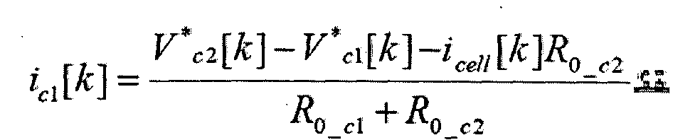

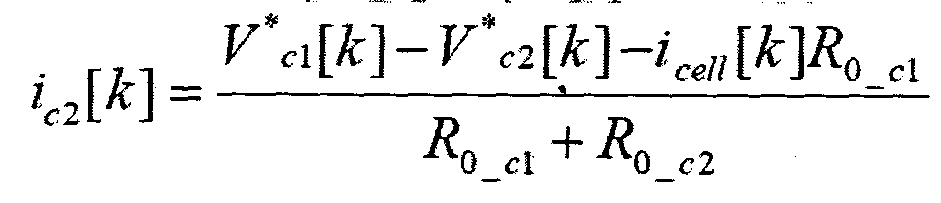


상기 식 (33) 및 (34)에서, zcell[0]은 이차 전지의 상태에 따라 이차 전지의 개방 전압을 정의한 룩업 테이블 또는 룩업 함수에 해당하는 OCVcell의 역변환 OCV-1 cell을 이용하여 산출할 수 있다. 즉, zcell[0]은
In Equations (33) and (34), z cell [0] is calculated using a look-up table that defines an open voltage of a secondary battery according to the state of the secondary battery or an inverse transform OCV- 1 cell of an OCV cell corresponding to a look-up function. can do. That is, z cell [0] is
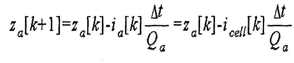


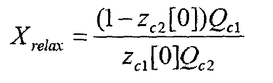

먼저, 전압 이완을 일으키는 복수의 SOCi 조건 각각에 대해 이차 전지 전압의 측정 프로파일 Mi를 얻는다. 그런 다음, SOCi 조건에 대응하여 상기 전압 추정 모델의 초기 조건 zc1[0] 및 zc2[0]와 저항 성분 R0_relax를 다양하게 변화시키면서 상기 측정 프로파일 Mi와 가장 잘 정합될 수 있는 추정 프로파일 Ei를 Trial & Error에 의해 식별한다. 그런 다음, 식별된 추정 프로파일 Ei를 얻는데 사용된
First, the measurement profile M i of the secondary battery voltage is obtained for each of a plurality of SOC i conditions causing voltage relaxation. Then, an estimate that can best match the measurement profile M i while varying the initial conditions z c1 [0] and z c2 [0] and the resistance component R 0_relax of the voltage estimation model in response to the SOC i condition Profile E i is identified by Trial & Error. Then, used to obtain the identified estimation profile E i
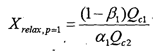
| αp* | βp* | SOCestimate | SOCreal | 오차 |
| 0.20 | 0.98 | 0.356 | 0.356 | 0 |
| 0.15 | 0.98 | 0.316 | 0.316 | 0 |
| 0.10 | 0.98 | 0.276 | 0.276 | 0 |
| 0.07 | 0.98 | 0.252 | 0.252 | 0 |
| 0.05 | 0.98 | 0.236 | 0.236 | 0 |
| α p * | β p * | SOC estimate | SOC real | error |
| 0.20 | 0.98 | 0.356 | 0.356 | 0 |
| 0.15 | 0.98 | 0.316 | 0.316 | 0 |
| 0.10 | 0.98 | 0.276 | 0.276 | 0 |
| 0.07 | 0.98 | 0.252 | 0.252 | 0 |
| 0.05 | 0.98 | 0.236 | 0.236 | 0 |
상기 룩업 테이블은, 전압 이완이 생길 수 있는 고유 전압 대역에서 이차 전지의 상태와 방전 전류의 크기 등에 대한 다수의 실험 조건 (SOC, idischarge)n을 미리 설계하고, 각각의 실험 조건 (SOC, idischarge)n에서 유휴 상태 또는 무부하 상태 전환 실험을 수행함으로써 변곡점이 포함된 측정 프로파일 Mn을 얻고, 측정 프로파일 Mn으로부터 룩업 테이블에 포함될 수 있는 참조 파라미터, 즉 V* n, T* n, △V* n,
The look-up table is designed in advance to design a plurality of experimental conditions (SOC, i discharge ) n for the state of the secondary battery and the magnitude of the discharge current in the intrinsic voltage range where voltage relaxation can occur, and each of the experimental conditions (SOC, i discharge) by performing idle or no load switching test on the n getting the measured profile M n contains the inflection point, the reference, which may be included in a look-up table from the measured profile M n parameters, namely V * n, T * n, △ V * n ,
상기 제어 유닛(130)은, 상기와 같은 룩업 테이블을 이용하여 이차 전지의 상태를 추정할 경우, 도 20의 S100 단계에서 저장 유닛(160)에 저장된 이차 전지의 측정된 전압 프로파일을 리드한 후, 상기 측정된 전압 프로파일로부터 적어도 하나 이상의 참조 파라미터를 계산한다. 여기서, 참조 파라미터는 V*, T*, △V* 및
When estimating the state of the secondary battery using the lookup table as described above, the
SOCestimate = Look_up(combination{ V*, T*, △V*,
SOC estimate = Look_up (combination {V * , T * , ΔV * ,
Claims (99)
- 전지 관리 시스템(Battery Management System; BMS), 및 다른 동작 전압 범위를 갖는 제1양극재 및 제2양극재를 포함하는 양극, 음극 및 분리막을 포함하는 이차 전지를 포함하는 이차 전지 시스템으로서, A secondary battery system comprising a battery management system (BMS), and a secondary battery including a positive electrode, a negative electrode, and a separator including a first positive electrode material and a second positive electrode material having a different operating voltage range,상기 BMS는 상기 이차 전지와 전기적으로 연결되고, 상기 이차 전지 시스템이 동작되는 동안 상기 이차 전지가 유휴 상태(idle state) 또는 부무하 상태(no-load state)가 되었을 때 상기 제1양극재 및 상기 제2양극재 사이의 작동 이온 전달에 의해 생기는 전압 이완(voltage relaxation)을 검출하도록 구성된 것을 특징으로 하는, 이차 전지 시스템.The BMS is electrically connected to the secondary battery and when the secondary battery is in an idle state or no-load state while the secondary battery system is operating, the first cathode material and the A secondary battery system, characterized in that it is configured to detect voltage relaxation caused by operating ion transfer between the second cathode material.
- 제1항에 있어서, The method of claim 1,상기 이차 전지가 유휴 상태 또는 무부하 상태가 되었을 때, 정전류(constant current) 또는 실질적으로 정전류가 상기 이차 전지로부터 흘러 나가는(drawn) 것을 특징으로 하는, 이차 전지 시스템.And a constant current or substantially a constant current drawn from the secondary battery when the secondary battery becomes idle or no-load.
- 제1항에 있어서,The method of claim 1,상기 이차 전지가 유휴 상태 또는 무부하 상태가 되었을 때, 1 C-rate 보다 작은 전류가 상기 이차 전지로부터 흘러 나가는 것을 특징으로 하는, 이차 전지 시스템.When the secondary battery is in an idle state or no load state, a current smaller than 1 C-rate flows out of the secondary battery.
- 제1항에 있어서,The method of claim 1,상기 이차 전지가 유휴 상태 또는 무부하 상태가 되었을 때, 0.5 C-rate 보다 작은 전류가 상기 이차 전지로부터 흘러 나가는 것을 특징으로 하는, 이차 전지 시스템.And when the secondary battery is in an idle state or no load state, a current smaller than 0.5 C-rate flows out of the secondary battery.
- 제1항에 있어서,The method of claim 1,상기 이차 전지가 유휴 상태 또는 무부하 상태가 되었을 때, 0.1 C-rate 보다 작은 전류가 상기 이차 전지로부터 흘러 나가는 것을 특징으로 하는, 이차 전지 시스템.And when the secondary battery is in an idle state or no load state, a current smaller than 0.1 C-rate flows out of the secondary battery.
- 제1항에 있어서, The method of claim 1,상기 BMS는, 회로 모델을 포함하고, The BMS includes a circuit model,상기 회로 모델은, The circuit model,음극재의 개방 전압 성분 및 선택적으로는 상기 음극재의 임피던스 전압 성분을 포함하는 음극재 회로 유닛; 및A negative electrode circuit unit including an open voltage component of the negative electrode material and optionally an impedance voltage component of the negative electrode material; And상기 제1양극재의 개방 전압 성분과 임피던스 전압 성분을 포함하는 제1양극재 회로 유닛과, 상기 제2양극재의 개방 전압 성분과 임피던스 전압 성분을 포함하는 제2양극재 회로 유닛을 포함하는 양극재 회로 유닛을 포함하는 것을 특징으로 하는, 이차 전지 시스템.A positive electrode material circuit comprising a first positive electrode material circuit unit including an open voltage component and an impedance voltage component of the first positive electrode material, and a second positive electrode material circuit unit including an open voltage component and an impedance voltage component of the second positive electrode material. A secondary battery system, comprising a unit.
- 제6항에 있어서, The method of claim 6,상기 음극재 회로 유닛과 상기 양극재 회로 유닛은 서로 직렬로 연결되고,The anode material circuit unit and the cathode material circuit unit are connected to each other in series,상기 제1양극재 회로 유닛과 상기 제2양극재 회로 유닛은 서로 병렬로 연결된 것을 특징으로 하는, 이차 전지 시스템.And the first positive electrode material circuit unit and the second positive electrode material circuit unit are connected in parallel with each other.
- 제6항에 있어서,The method of claim 6,각각의 임피던스 전압 성분은, 하나 이상의 저항 성분(resistance element), 하나 이상의 용량 성분(capacity component), 하나 이상의 인덕터 성분(indector element) 및 이들의 결합으로 이루어진 군에서 선택된 회로 요소를 포함하는 것을 특징으로 하는, 이차 전지 시스템.Each impedance voltage component comprises a circuit element selected from the group consisting of one or more resistance elements, one or more capacity components, one or more inductor elements, and combinations thereof. Secondary battery system.
- 제6항에 있어서, The method of claim 6,각각의 임피던스 전압 성분은, 복수의 회로 요소들을 포함하고, Each impedance voltage component comprises a plurality of circuit elements,상기 복수의 회로 요소들은 직렬 및/또는 병렬로 연결된 것을 특징으로 하는, 이차 전지 시스템.And the plurality of circuit elements are connected in series and / or in parallel.
- 제6항에 있어서, The method of claim 6,상기 음극재 회로 유닛은, 적어도 하나의 임피던스 전압 성분을 포함하는 것을 특징으로 하는, 이차 전지 시스템.The negative electrode circuit unit includes at least one impedance voltage component.
- 제6항에 있어서, The method of claim 6,각각의 임피던스 전압 성분은, 적어도 하나의 RC 회로와 적어도 하나의 저항으로 이루어진 군에서 선택된 하나 이상의 회로 요소를 포함하는 것을 특징으로 하는, 이차 전지 시스템.Each impedance voltage component comprises at least one circuit element selected from the group consisting of at least one RC circuit and at least one resistor.
- 제11항에 있어서, The method of claim 11,각각의 임피던스 전압 성분은 RC 회로와 상기 RC 회로와 직렬로 연결된 저항을 포함하는 것을 특징으로 하는, 이차 전지 시스템.Wherein each impedance voltage component comprises an RC circuit and a resistor connected in series with the RC circuit.
- 제11항에 있어서, The method of claim 11,상기 RC 회로에 의해 형성되는 전압 성분은, 다음의 이산 시간 방정식(discrete time equation)에 의해 계산되는 것을 특징으로 하는,The voltage component formed by the RC circuit is calculated by the following discrete time equation,
 이차 전지 시스템.Secondary battery system.
 - 제1항에 있어서, The method of claim 1,상기 제1양극재 및 상기 제2양극재 중 적어도 하나는, 실질적으로 전압이 일정한 평탄 영역(plateau portion)을 가지는 전압 프로파일을 가지는 것을 특징으로 하는, 이차 전지 시스템.At least one of the first positive electrode material and the second positive electrode material has a voltage profile having a plateau portion having a substantially constant voltage.
- 제1항에 있어서, The method of claim 1,상기 제1양극재는, 일반 화학식 A[AxMy]O2+z(A는 Li, Na 및 K 중 적어도 하나 이상의 원소를 포함; M은 Ni, Co, Mn, Ca, Mg, Al, Ti, Si, Fe, Mo, V, Zr, Zn, Cu, Al, Mo, Sc, Zr, Ru, 및 Cr에서 선택된 적어도 하나 이상의 원소를 포함; x ≥ 0, 1 ≤ x+y ≤2, -0.1 ≤ z ≤ 2; x, y, z 및 M에 포함된 성분의 화학량론적 계수는 화합물이 전기적 중성을 유지하도록 선택됨) 또는 xLiM1O2-(1-x)Li2M2O3(M1은 평균 산화 상태 3을 갖는 적어도 하나 이상의 원소를 포함; M2는 평균 산화 상태 4를 갖는 적어도 하나 이상의 원소를 포함; 0≤x≤1)로 표시되고, 선택적으로 탄소층/산화물층/또는 불화물층이 코팅된 알칼리 금속 화합물을 포함하는 것을 특징으로 하는, 이차 전지 시스템.The first cathode material is a general formula A [A x M y ] O 2 + z (A includes at least one element of Li, Na and K; M is Ni, Co, Mn, Ca, Mg, Al, Ti At least one element selected from Si, Fe, Mo, V, Zr, Zn, Cu, Al, Mo, Sc, Zr, Ru, and Cr; x ≥ 0, 1 ≤ x + y ≤ 2, -0.1 ≤ z ≤ 2; stoichiometric coefficients of components included in x, y, z and M are chosen so that the compound maintains electrical neutrality or xLiM 1 O 2- (1-x) Li 2 M 2 O 3 (M 1 Comprises at least one element having an average oxidation state 3; M 2 comprises at least one element having an average oxidation state 4; represented by 0 ≦ x ≦ 1) and optionally carbon layer / oxide layer / or fluoride A secondary battery system, characterized in that the layer comprises an alkali metal compound coated.
- 제15항에 있어서, The method of claim 15,상기 제1양극재는, Li[LiaNibCocMnd]O2+z(a≥0; a+b+c+d=1; b, c 및 d 중 적어도 하나 이상은 0이 아님; -0.1 ≤ z ≤ 2)로 표시되고, 선택적으로 탄소층/산화물층/또는 불화물층이 코팅된 알칼리 금속 화합물을 포함하는 것을 특징으로 하는, 이차 전지 시스템.The first cathode material is Li [Li a Ni b Co c Mn d ] O 2 + z (a ≧ 0; a + b + c + d = 1; at least one of b, c and d is not 0; -0.1 ≦ z ≦ 2), and optionally comprising an alkali metal compound coated with a carbon layer / oxide layer / or fluoride layer.
- 제1항에 있어서,The method of claim 1,상기 제2양극재는, 일반 화학식 LiaM1 xFe1-xM2 yP1-yM3 zO4-z(M1은 Ti, Si, Mn, Co, Fe, V, Cr, Mo, Ni, Nd, Al, Mg 및 Al에서 선택된 적어도 하나 이상의 원소를 포함; M2는 Ti, Si, Mn, Co, Fe, V, Cr, Mo, Ni, Nd, Al, Mg, Al, As, Sb, Si, Ge, V 및 S에서 선택된 적어도 하나 이상의 원소를 포함; M3는 F를 선택적으로 포함하는 할로겐족 원소를 포함; 0 < a ≤2, 0 ≤ x ≤ 1, 0 ≤ y < 1, 0 ≤ z < 1; a, x, y, z, M1, M2, 및 M3에 포함된 성분의 화학량론적 계수는 화합물이 전기적 중성을 유지하도록 선택됨), 또는 Li3M2(PO4)3[M은 Ti, Si, Mn, Fe, Co, V, Cr, Mo, Ni, Al, Mg 및 Al에서 선택된 적어도 하나 이상의 원소를 포함]로 표시되고, 선택적으로 탄소층/산화물층/또는 불화물층이 코팅된 리튬 금속 포스페이트를 포함하는 것을 특징으로 하는, 이차 전지 시스템.The second cathode material is a general formula Li a M 1 x Fe 1-x M 2 y P 1-y M 3 z O 4-z (M 1 is Ti, Si, Mn, Co, Fe, V, Cr, Mo At least one element selected from Ni, Nd, Al, Mg, and Al; M 2 is Ti, Si, Mn, Co, Fe, V, Cr, Mo, Ni, Nd, Al, Mg, Al, As, At least one element selected from Sb, Si, Ge, V and S; M 3 comprises a halogen group element optionally comprising F; 0 <a ≤ 2, 0 ≤ x ≤ 1, 0 ≤ y <1, 0 ≦ z <1; stoichiometric coefficients of components included in a, x, y, z, M 1 , M 2 , and M 3 are selected such that the compound maintains electrical neutrality, or Li 3 M 2 (PO 4 ) 3 [M is at least one element selected from Ti, Si, Mn, Fe, Co, V, Cr, Mo, Ni, Al, Mg and Al], optionally carbon layer / oxide layer / or A secondary battery system, characterized in that the fluoride layer comprises a coated lithium metal phosphate.
- 제17항에 있어서, The method of claim 17,상기 제2양극재는, LiFePO4, LiMnxFeyPO4(0<x+y ≤ 1), Li3Fe2(PO4)3, 탄소층/산화물층/또는 불화물층으로 코팅된 LiFePO4, 탄소층/산화물층/또는 불화물층으로 코팅된 LiMnxFeyPO4(0<x+y ≤ 1), 및 탄소층/산화물층/또는 불화물층으로 코팅된 Li3Fe2(PO4)3 로 이루어진 군에서 선택된 적어도 하나 이상을 포함하는 것을 특징으로 하는, 이차 전지 시스템.The second cathode material may be LiFePO 4, LiMn x Fe y PO 4 (0 <x + y ≦ 1), Li 3 Fe 2 (PO 4 ) 3 , LiFePO 4 coated with a carbon layer / oxide layer / or fluoride layer, LiMn x Fe y PO 4 (0 <x + y ≦ 1) coated with carbon / oxide layer / or fluoride layer, and Li 3 Fe 2 (PO 4 ) 3 coated with carbon layer / oxide layer / or fluoride layer Secondary battery system, characterized in that it comprises at least one selected from the group consisting of.
- 전지 관리 시스템(Battery Management System; BMS), 및 다른 동작 전압 범위를 갖는 제1양극재 및 제2양극재를 포함하는 양극, 음극 및 분리막을 포함하는 이차 전지를 포함하는 이차 전지 시스템으로서, A secondary battery system comprising a battery management system (BMS), and a secondary battery including a positive electrode, a negative electrode, and a separator including a first positive electrode material and a second positive electrode material having a different operating voltage range,상기 BMS는, 상기 이차 전지와 전기적으로 연결되고, 상기 이차 전지 시스템이 동작되는 동안 상기 이차 전지가 유휴 상태(idle state) 또는 부무하 상태(no-load state)가 되었을 때, 상기 이차 전지의 전압 변화로부터 2 단계 전압 이완(two-stage voltage relaxation)을 검출하도록 구성된 것을 특징으로 하는, 이차 전지 시스템.The BMS is electrically connected to the secondary battery, and when the secondary battery is in an idle state or a no-load state while the secondary battery system is operating, the voltage of the secondary battery And configured to detect two-stage voltage relaxation from change.
- 제19항에 있어서, The method of claim 19,상기 BMS는, 상기 이차 전지 전압을 시간에 따라 모니터하고, 상기 전압의 변화 패턴에서 변곡점의 발생이 식별되면, 상기 2 단계 전압 이완을 검출하는 것을 특징으로 하는, 이차 전지 시스템.And the BMS monitors the secondary battery voltage over time, and detects the second-stage voltage relaxation when occurrence of an inflection point in the change pattern of the voltage is identified.
- 제20항에 있어서, The method of claim 20,상기 BMS는, 상기 이차 전지 전압의 프로파일을 분석하여 상기 변곡점의 발생을 식별하는 것을 특징으로 하는, 이차 전지 시스템.And the BMS analyzes the profile of the secondary battery voltage to identify the occurrence of the inflection point.
- 제20항에 있어서, The method of claim 20,상기 BMS는, 상기 이차 전지 전압의 변화 패턴을 실시간으로 분석하여 상기 변곡점의 발생을 식별하는 것을 특징으로 하는, 이차 전지 시스템.The BMS, the secondary battery system, characterized in that to identify the occurrence of the inflection point by analyzing the change pattern of the secondary battery voltage in real time.
- 제20항에 있어서, The method of claim 20,상기 BMS는, 시간에 대한 상기 이차 전지 전압의 일차 미분 값 또는 이차 미분 값을 이용하여 상기 변곡점을 식별하는 것을 특징으로 하는, 이차 전지 시스템.And the BMS identifies the inflection point using a first derivative or a second derivative of the secondary battery voltage over time.
- 제20항에 있어서, The method of claim 20,상기 BMS는, 상기 변곡점에 대응되는 전압, 상기 변곡점에 대응되는 시간, 상기 변곡점 전후의 전압 변화를 합산한 전압 변화량, 상기 변곡점에서 계산한 시간에 대한 전압의 일차 미분 값, 상기 변곡점 전의 특정 시점과 상기 변곡점 후의 특정 시점 사이를 기준으로 전압 프로파일을 적분한 값, 상기 변곡점 전의 특정 시점 또는 상기 변곡점 후의 특정 시점에서 계산한 시간에 대한 전압의 일차 미분 값 또는 이차 미분 값, 또는 이들의 조합을 포함하는 참조 파라미터를 결정하고, 상기 참조 파라미터와 상기 이차 전지의 상태에 대한 미리 정의된 대응 관계를 이용하여 상기 결정된 참조 파라미터에 대응하는 이차 전지의 상태를 추정하는 것을 특징으로 하는, 이차 전지 시스템.The BMS includes a voltage corresponding to the inflection point, a time corresponding to the inflection point, a voltage change amount obtained by adding the voltage change before and after the inflection point, a first derivative of the voltage with respect to the time calculated at the inflection point, and a specific time point before the inflection point. A value obtained by integrating a voltage profile with respect to a specific time point after the inflection point, a first derivative value or a second derivative value of voltage with respect to a time calculated at a specific time point before the inflection point or a specific time point after the inflection point, or a combination thereof And determining a reference parameter and estimating a state of a secondary battery corresponding to the determined reference parameter using a predefined correspondence between the reference parameter and the state of the secondary battery.
- 제24항에 있어서, The method of claim 24,상기 미리 정의된 대응 관계는, 적어도 하나 이상의 참조 파라미터에 의해 이차 전지의 상태를 맵핑할 수 있는 룩업 테이블인 것을 특징으로 하는, 이차 전지 시스템.The predefined correspondence relationship is a secondary battery system, characterized in that the look-up table capable of mapping the state of the secondary battery by at least one or more reference parameters.
- 제24항에 있어서, The method of claim 24,상기 미리 정의된 대응 관계는, 적어도 하나 이상의 참조 파라미터와 이와 대응되는 이차 전지의 상태가 각각 입력 파라미터 및 출력 파라미터로 정의된 룩업 함수인 것을 특징으로 하는, 이차 전지 시스템.The predefined correspondence relationship is a secondary battery system, characterized in that the at least one reference parameter and the state of the secondary battery corresponding thereto are lookup functions defined by input parameters and output parameters, respectively.
- 이차 전지 관리 장치로서, 다른 동작 전압 범위를 가지는 제1양극재 및 제2양극재를 포함하는 양극, 음극 및 분리막을 포함하는 이차 전지에 전기적으로 연결되도록 구성된 전지 관리 시스템(Battery Managemenet System: BMS)를 포함하고,A secondary battery management device, comprising: a battery management system (BMS) configured to be electrically connected to a secondary battery including a positive electrode, a negative electrode, and a separator including a first positive electrode material and a second positive electrode material having different operating voltage ranges. Including,상기 BMS는, The BMS,상기 이차 전지가 동작하는 동안 이차 전지의 전류와 전압을 측정하도록 구성된 센서; 및A sensor configured to measure current and voltage of the secondary battery while the secondary battery is in operation; And상기 이차 전지의 상기 측정된 전압 및 전류로부터 전압 프로파일 및 선택적으로는 전류 프로파일을 준비하고, 상기 이차 전지가 유휴 상태 또는 무부하 상태가 되었을 때, 상기 제1양극재 및 상기 제2양극재 사이의 작동 이온 전달에 의해 생기는 전압 이완을 검출하도록 구성된 제어 유닛을 포함하는 것을 특징으로 하는, 이차 전지 관리 장치.Preparing a voltage profile and optionally a current profile from the measured voltage and current of the secondary battery and operating between the first cathode material and the second cathode material when the secondary battery is in an idle or no-load state. And a control unit configured to detect voltage relaxation caused by ion transfer.
- 제27항에 있어서, The method of claim 27,상기 이차 전지가 유휴 상태 또는 무부하 상태가 되었을 때, 정전류(constant current) 또는 실질적으로 정전류가 상기 이차 전지로부터 흘러 나가는(drawn) 것을 특징으로 하는, 이차 전지 관리 장치.And a constant current or substantially a constant current drawn from the secondary battery when the secondary battery is in an idle state or no-load state.
- 제27항에 있어서, The method of claim 27,상기 이차 전지가 유휴 상태 또는 무부하 상태가 되었을 때, 1 C-rate 보다 작은 전류가 상기 이차 전지로부터 흘러 나가는 것을 특징으로 하는, 이차 전지 관리 장치.When the secondary battery is in an idle state or no load state, a current smaller than 1 C-rate flows out of the secondary battery.
- 제27항에 있어서, The method of claim 27,상기 이차 전지가 유휴 상태 또는 무부하 상태가 되었을 때, 0.5 C-rate 보다 작은 전류가 상기 이차 전지로부터 흘러 나가는 것을 특징으로 하는, 이차 전지 관리 장치.When the secondary battery is in an idle state or no load state, a current smaller than 0.5 C-rate flows out of the secondary battery.
- 제27항에 있어서, The method of claim 27,상기 이차 전지가 유휴 상태 또는 무부하 상태가 되었을 때, 0.1 C-rate 보다 작은 전류가 상기 이차 전지로부터 흘러 나가는 것을 특징으로 하는, 이차 전지 관리 장치.When the secondary battery is in an idle state or no load state, a current smaller than 0.1 C-rate flows out of the secondary battery.
- 제27항에 있어서, The method of claim 27,상기 BMS는, 회로 모델을 포함하고,The BMS includes a circuit model,상기 회로 모델은, 음극재의 개방 전압 성분 및 선택적으로 상기 음극재의 임피던스 전압 성분을 포함하는 음극재 회로 유닛; 및The circuit model comprises a negative electrode circuit unit comprising an open voltage component of a negative electrode material and optionally an impedance voltage component of the negative electrode material; And상기 제1양극재의 개방 전압 성분과 임피던스 전압 성분을 포함하는 제1양극재 회로 유닛과, 상기 제2양극재의 개방 전압 성분과 임피던스 전압 성분을 포함하는 제2양극재 회로 유닛을 포함하는 양극재 회로 유닛을 포함하는 것을 특징으로 하는, 이차 전지 관리 장치.A positive electrode material circuit comprising a first positive electrode material circuit unit including an open voltage component and an impedance voltage component of the first positive electrode material, and a second positive electrode material circuit unit including an open voltage component and an impedance voltage component of the second positive electrode material. A secondary battery management device comprising a unit.
- 제32항에 있어서,33. The method of claim 32,상기 음극재 회로 유닛과 상기 양극재 회로 유닛은 서로 직렬로 연결되고,The anode material circuit unit and the cathode material circuit unit are connected to each other in series,상기 제1양극재 회로 유닛과 상기 제2양극재 회로 유닛은 서로 병렬로 연결된 것을 특징으로 하는, 이차 전지 관리 장치.And the first cathode material circuit unit and the second cathode material circuit unit are connected in parallel with each other.
- 제32항에 있어서, 33. The method of claim 32,각각의 임피던스 전압 성분은, 하나 이상의 저항 성분(resistance element), 하나 이상의 용량 성분(capacity component), 하나 이상의 인덕터 성분(indector element) 및 이들의 결합으로 이루어진 군에서 선택된 회로 요소를 포함하는 것을 특징으로 하는, 이차 전지 관리 장치.Each impedance voltage component comprises a circuit element selected from the group consisting of one or more resistance elements, one or more capacity components, one or more inductor elements, and combinations thereof. Secondary battery management device.
- 제32항에 있어서, 33. The method of claim 32,각각의 임피던스 전압 성분은, 복수의 회로 요소들을 포함하고, Each impedance voltage component comprises a plurality of circuit elements,상기 복수의 회로 요소들은 직렬 및/또는 병렬로 연결된 것을 특징으로 하는, 이차 전지 관리 장치.And the plurality of circuit elements are connected in series and / or in parallel.
- 제32항에 있어서, 33. The method of claim 32,상기 음극재 회로 유닛은, 적어도 하나의 임피던스 전압 성분을 포함하는 것을 특징으로 하는, 이차 전지 관리 장치.The negative electrode circuit unit includes at least one impedance voltage component.
- 제32항에 있어서,33. The method of claim 32,각각의 임피던스 전압 성분은, 적어도 하나의 RC 회로와 적어도 하나의 저항으로 이루어진 군에서 선택된 하나 이상의 회로 요소를 포함하는 것을 특징으로 하는, 이차 전지 관리 장치.Each impedance voltage component comprises at least one circuit element selected from the group consisting of at least one RC circuit and at least one resistor.
- 제37항에 있어서,The method of claim 37,각각의 임피던스 전압 성분은 RC 회로와 상기 RC 회로와 직렬로 연결된 저항을 포함하는 것을 특징으로 하는, 이차 전지 관리 장치.Wherein each impedance voltage component comprises an RC circuit and a resistor connected in series with the RC circuit.
- 제37항에 있어서,The method of claim 37,상기 RC 회로에 의해 형성되는 전압 성분은, 다음의 이산 시간 방정식(discrete time equation)에 의해 계산되는 것을 특징으로 하는,The voltage component formed by the RC circuit is calculated by the following discrete time equation,
 이차 전지 관리 장치.Secondary Battery Management Device.
 - 제27항에 있어서, 상기 제1양극재 및 상기 제2양극재 중 적어도 하나는,The method of claim 27, wherein at least one of the first cathode material and the second cathode material,실질적으로 전압이 일정한 평탄 영역(plateau portion)을 가지는 전압 프로파일을 가지는 것을 특징으로 하는, 이차 전지 관리 장치.And a voltage profile having a plateau portion having a substantially constant voltage.
- 제27항에 있어서,The method of claim 27,상기 제1양극재는, 일반 화학식 A[AxMy]O2+z(A는 Li, Na 및 K 중 적어도 하나 이상의 원소를 포함; M은 Ni, Co, Mn, Ca, Mg, Al, Ti, Si, Fe, Mo, V, Zr, Zn, Cu, Al, Mo, Sc, Zr, Ru, 및 Cr에서 선택된 적어도 하나 이상의 원소를 포함; x ≥ 0, 1 ≤ x+y ≤2, -0.1 ≤ z ≤ 2; x, y, z 및 M에 포함된 성분의 화학량론적 계수는 화합물이 전기적 중성을 유지하도록 선택됨) 또는 xLiM1O2-(1-x)Li2M2O3(M1은 평균 산화 상태 3을 갖는 적어도 하나 이상의 원소를 포함; M2는 평균 산화 상태 4를 갖는 적어도 하나 이상의 원소를 포함; 0≤x≤1)로 표시되고, 선택적으로 탄소층/산화물층/또는 불화물층이 코팅된 알칼리 금속 화합물을 포함하는 것을 특징으로 하는, 이차 전지 관리 장치.The first cathode material is a general formula A [A x M y ] O 2 + z (A includes at least one element of Li, Na and K; M is Ni, Co, Mn, Ca, Mg, Al, Ti At least one element selected from Si, Fe, Mo, V, Zr, Zn, Cu, Al, Mo, Sc, Zr, Ru, and Cr; x ≥ 0, 1 ≤ x + y ≤ 2, -0.1 ≤ z ≤ 2; stoichiometric coefficients of components included in x, y, z and M are chosen so that the compound maintains electrical neutrality or xLiM 1 O 2- (1-x) Li 2 M 2 O 3 (M 1 Comprises at least one element having an average oxidation state 3; M 2 comprises at least one element having an average oxidation state 4; represented by 0 ≦ x ≦ 1) and optionally carbon layer / oxide layer / or fluoride A secondary battery management device, characterized in that the layer contains an alkali metal compound coated.
- 제41항에 있어서, The method of claim 41, wherein상기 제1양극재는, Li[LiaNibCocMnd]O2+z(a≥0; a+b+c+d=1; b, c 및 d 중 적어도 하나 이상은 0이 아님; -0.1 ≤ z ≤ 2)로 표시되고, 선택적으로 탄소층/산화물층/또는 불화물층이 코팅된 알칼리 금속 화합물을 포함하는 것을 특징으로 하는, 이차 전지 관리 장치.The first cathode material is Li [Li a Ni b Co c Mn d ] O 2 + z (a ≧ 0; a + b + c + d = 1; at least one of b, c and d is not 0; And -0.1? Z? 2), and optionally comprising an alkali metal compound coated with a carbon layer / oxide layer / or fluoride layer.
- 제27항에 있어서,The method of claim 27,상기 제2양극재는, 일반 화학식 LiaM1 xFe1-xM2 yP1-yM3 zO4-z(M1은 Ti, Si, Mn, Co, Fe, V, Cr, Mo, Ni, Nd, Al, Mg 및 Al에서 선택된 적어도 하나 이상의 원소를 포함; M2는 Ti, Si, Mn, Co, Fe, V, Cr, Mo, Ni, Nd, Al, Mg, Al, As, Sb, Si, Ge, V 및 S에서 선택된 적어도 하나 이상의 원소를 포함; M3는 F를 선택적으로 포함하는 할로겐족 원소를 포함; 0 < a ≤2, 0 ≤ x ≤ 1, 0 ≤ y < 1, 0 ≤ z < 1; a, x, y, z, M1, M2, 및 M3에 포함된 성분의 화학량론적 계수는 화합물이 전기적 중성을 유지하도록 선택됨), 또는 Li3M2(PO4)3[M은 Ti, Si, Mn, Fe, Co, V, Cr, Mo, Ni, Al, Mg 및 Al에서 선택된 적어도 하나 이상의 원소를 포함]로 표시되고, 선택적으로 탄소층/산화물층/또는 불화물층이 코팅된 리튬 금속 포스페이트를 포함하는 것을 특징으로 하는, 이차 전지 관리 장치.The second cathode material is a general formula Li a M 1 x Fe 1-x M 2 y P 1-y M 3 z O 4-z (M 1 is Ti, Si, Mn, Co, Fe, V, Cr, Mo At least one element selected from Ni, Nd, Al, Mg, and Al; M 2 is Ti, Si, Mn, Co, Fe, V, Cr, Mo, Ni, Nd, Al, Mg, Al, As, At least one element selected from Sb, Si, Ge, V and S; M 3 comprises a halogen group element optionally comprising F; 0 <a ≤ 2, 0 ≤ x ≤ 1, 0 ≤ y <1, 0 ≦ z <1; stoichiometric coefficients of components included in a, x, y, z, M 1 , M 2 , and M 3 are selected such that the compound maintains electrical neutrality, or Li 3 M 2 (PO 4 ) 3 [M is at least one element selected from Ti, Si, Mn, Fe, Co, V, Cr, Mo, Ni, Al, Mg and Al], optionally carbon layer / oxide layer / or A secondary battery management device, characterized in that the fluoride layer is coated with a lithium metal phosphate.
- 제43항에 있어서,The method of claim 43,상기 제2양극재는, LiFePO4, LiMnxFeyPO4(0<x+y ≤ 1), Li3Fe2(PO4)3, 탄소층/산화물층/또는 불화물층으로 코팅된 LiFePO4, 탄소층/산화물층/또는 불화물층으로 코팅된 LiMnxFeyPO4(0<x+y ≤ 1), 및 탄소층/산화물층/또는 불화물층으로 코팅된 Li3Fe2(PO4)3 로 이루어진 군에서 선택된 적어도 하나 이상을 포함하는 것을 특징으로 하는, 이차 전지 관리 장치.The second cathode material may be LiFePO 4, LiMn x Fe y PO 4 (0 <x + y ≦ 1), Li 3 Fe 2 (PO 4 ) 3 , LiFePO 4 coated with a carbon layer / oxide layer / or fluoride layer, LiMn x Fe y PO 4 (0 <x + y ≦ 1) coated with carbon / oxide layer / or fluoride layer, and Li 3 Fe 2 (PO 4 ) 3 coated with carbon layer / oxide layer / or fluoride layer Secondary battery management device, characterized in that it comprises at least one selected from the group consisting of.
- 이차 전지 관리 장치로서, 다른 동작 전압 범위를 가지는 제1양극재 및 제2양극재를 포함하는 양극, 음극 및 분리막을 포함하는 이차 전지에 전기적으로 연결되도록 구성된 전지 관리 시스템(Battery Managemenet System: BMS)를 포함하고, A secondary battery management device, comprising: a battery management system (BMS) configured to be electrically connected to a secondary battery including a positive electrode, a negative electrode, and a separator including a first positive electrode material and a second positive electrode material having different operating voltage ranges. Including,상기 BMS는, The BMS,상기 이차 전지가 동작하는 동안 이차 전지의 전류와 전압을 측정하도록 구성된 센서; 및A sensor configured to measure current and voltage of the secondary battery while the secondary battery is in operation; And상기 측정된 전류로부터 상기 이차 전지가 유휴 상태 또는 무부하 상태가 되었음을 식별하고, 상기 측정된 전압의 변화로부터 2 단계 전압 이완을 검출하도록 구성된 제어 유닛을 포함하는 것을 특징으로 하는, 이차 전지 관리 장치.And a control unit configured to identify from the measured current that the secondary battery is in an idle state or a no-load state, and to detect two-step voltage relaxation from a change in the measured voltage.
- 제45항에 있어서,The method of claim 45,상기 BMS는, 상기 이차 전지 전압을 시간에 따라 모니터하고, 상기 전압의 변화 패턴에서 변곡점의 발생이 식별되면, 상기 2 단계 전압 이완을 검출하는 것을 특징으로 하는, 이차 전지 관리 장치.And the BMS monitors the secondary battery voltage over time and detects the second-stage voltage relaxation when generation of an inflection point is identified in the voltage change pattern.
- 제46항에 있어서, 47. The method of claim 46 wherein상기 BMS는, 상기 이차 전지의 유휴 상태 또는 무부하 상태가 유지되는 동안, 상기 이차 전지 전압의 프로파일을 분석하여 상기 변곡점의 발생을 식별하는 것을 특징으로 하는, 이차 전지 관리 장치.Wherein the BMS, the secondary battery management device, characterized in that the generation of the inflection point by analyzing the profile of the secondary battery voltage while the idle state or no-load state of the secondary battery is maintained.
- 제46항에 있어서, 47. The method of claim 46 wherein상기 BMS는, 상기 이차 전지 전압의 변화 패턴을 실시간으로 분석하여 상기 변곡점의 발생을 식별하는 것을 특징으로 하는, 이차 전지 관리 장치.The BMS, the secondary battery management device, characterized in that to identify the occurrence of the inflection point by analyzing the change pattern of the secondary battery voltage in real time.
- 제46항에 있어서, 47. The method of claim 46 wherein상기 BMS는, 시간에 대한 상기 이차 전지 전압의 일차 미분 값 또는 이차 미분 값을 이용하여 상기 변곡점의 발생을 식별하는 것을 특징으로 하는, 이차 전지 관리 장치.And the BMS identifies the occurrence of the inflection point using a first derivative or a second derivative of the secondary battery voltage over time.
- 제46항에 있어서, 47. The method of claim 46 wherein상기 BMS는, 상기 변곡점에 대응되는 전압, 상기 변곡점에 대응되는 시간, 상기 변곡점 전후의 전압 변화를 합산한 전압 변화량, 상기 변곡점에서 계산한 시간에 대한 전압의 일차 미분 값, 상기 변곡점 전의 특정 시점과 상기 변곡점 후의 특정 시점 사이를 기준으로 전압 프로파일을 적분한 값, 상기 변곡점 전의 특정 시점 또는 상기 변곡점 후의 특정 시점에서 계산한 시간에 대한 전압의 일차 미분 값 또는 이차 미분 값, 또는 이들의 조합을 포함하는 참조 파라미터를 결정하고, 상기 참조 파라미터와 상기 이차 전지의 상태에 대한 미리 정의된 대응 관계를 이용하여 상기 결정된 참조 파라미터에 대응하는 이차 전지의 상태를 추정하는 것을 특징으로 하는, 이차 전지 관리 장치.The BMS includes a voltage corresponding to the inflection point, a time corresponding to the inflection point, a voltage change amount obtained by adding the voltage change before and after the inflection point, a first derivative of the voltage with respect to the time calculated at the inflection point, and a specific time point before the inflection point. A value obtained by integrating a voltage profile with respect to a specific time point after the inflection point, a first derivative value or a second derivative value of voltage with respect to a time calculated at a specific time point before the inflection point or a specific time point after the inflection point, or a combination thereof And determining a reference parameter and estimating a state of a secondary battery corresponding to the determined reference parameter using a predefined correspondence relationship between the reference parameter and the state of the secondary battery.
- 제50항에 있어서, 51. The method of claim 50,상기 미리 정의된 대응 관계는, 적어도 하나 이상의 참조 파라미터에 의해 이차 전지의 상태를 맵핑할 수 있는 룩업 테이블인 것을 특징으로 하는, 이차 전지 관리 장치.The predefined correspondence relationship is a secondary battery management apparatus, characterized in that the look-up table capable of mapping the state of the secondary battery by at least one or more reference parameters.
- 제50항에 있어서,51. The method of claim 50,상기 미리 정의된 대응 관계는, 적어도 하나 이상의 참조 파라미터와 이와 대응되는 이차 전지의 상태가 각각 입력 파라미터 및 출력 파라미터로 정의된 룩업 함수인 것을 특징으로 하는, 이차 전지 관리 장치.The predefined correspondence relationship is a secondary battery management apparatus, characterized in that the at least one reference parameter and the state of the secondary battery corresponding thereto are lookup functions defined by input parameters and output parameters, respectively.
- 이차 전지 관리 장치로서, 다른 동작 전압 범위를 가지는 제1양극재 및 제2양극재를 포함하는 양극, 음극 및 분리막을 포함하는 이차 전지에 전기적으로 연결되도록 구성된 전지 관리 시스템(Battery Managemenet System: BMS)를 포함하고, A secondary battery management device, comprising: a battery management system (BMS) configured to be electrically connected to a secondary battery including a positive electrode, a negative electrode, and a separator including a first positive electrode material and a second positive electrode material having different operating voltage ranges. Including,상기 BMS는, 상기 이차 전지가 동작하는 동안 이차 전지의 전류와 전압을 측정하도록 구성된 센서; 및The BMS includes: a sensor configured to measure current and voltage of the secondary battery while the secondary battery is in operation; And상기 측정된 전류로부터 상기 이차 전지가 유휴 상태 또는 무부하 상태가 되었음을 식별하고, 상기 측정된 전압이 변곡점을 포함하는 변화 패턴을 보이는지 여부에 따라 2 단계 전압 이완을 검출하도록 구성된 제어 유닛을 포함하는 것을 특징으로 하는, 이차 전지 관리 장치.And a control unit configured to identify from the measured current that the secondary battery is in an idle state or a no-load state and to detect a two-step voltage relaxation depending on whether the measured voltage exhibits a change pattern including an inflection point. The secondary battery management apparatus made into.
- 이차 전지 관리 장치로서, 다른 동작 전압 범위를 가지는 제1양극재 및 제2양극재를 포함하는 양극, 음극 및 분리막을 포함하는 이차 전지에 전기적으로 연결되도록 구성된 전지 관리 시스템(Battery Managemenet System: BMS)를 포함하고, A secondary battery management device, comprising: a battery management system (BMS) configured to be electrically connected to a secondary battery including a positive electrode, a negative electrode, and a separator including a first positive electrode material and a second positive electrode material having different operating voltage ranges. Including,상기 BMS는,상기 이차 전지가 동작하는 동안 이차 전지의 전류와 전압을 측정하도록 구성된 센서; 및 The BMS includes: a sensor configured to measure current and voltage of a secondary battery while the secondary battery is in operation; And상기 측정된 전류로부터 상기 이차 전지가 유휴 상태 또는 무부하 상태가 되었음을 식별하고, 상기 측정된 전압의 변화로부터 변곡점을 식별하여 2 단계 전압 이완을 검출하도록 구성된 제어 유닛을 포함하는 것을 특징으로 하는, 이차 전지 관리 장치.And a control unit configured to identify from the measured current that the secondary battery is in an idle state or no-load state, and to identify a inflection point from a change in the measured voltage to detect a two-step voltage relaxation. Management device.
- 이차 전지 관리 장치로서, 다른 동작 전압 범위를 가지는 제1양극재 및 제2양극재를 포함하는 양극, 음극 및 분리막을 포함하는 이차 전지에 전기적으로 연결되도록 구성된 전지 관리 시스템(Battery Managemenet System: BMS)를 포함하고, A secondary battery management device, comprising: a battery management system (BMS) configured to be electrically connected to a secondary battery including a positive electrode, a negative electrode, and a separator including a first positive electrode material and a second positive electrode material having different operating voltage ranges. Including,상기 BMS는, 상기 이차 전지가 동작하는 동안 이차 전지의 전류와 전압을 측정하도록 구성된 센서; 및The BMS includes: a sensor configured to measure current and voltage of the secondary battery while the secondary battery is in operation; And상기 측정된 전류로부터 상기 이차 전지가 유휴 상태 또는 무부하 상태가 되었음을 식별하고, 상기 측정된 전압으로부터 변곡점 파라미터를 결정하고, 상기 변곡점 파라미터로부터 2 단계 전압 이완을 검출하도록 구성된 제어 유닛을 포함하는 것을 특징으로 하는, 이차 전지 관리 장치.And a control unit configured to identify from the measured current that the secondary battery is in an idle state or no load state, determine an inflection point parameter from the measured voltage, and detect a two-step voltage relaxation from the inflection point parameter. Secondary battery management device.
- 제55항에 있어서, The method of claim 55,상기 변곡점 파라미터는, 시간에 대한 상기 이차 전지 전압의 일차 미분 값 또는 이차 미분 값임을 특징으로 하는, 이차 전지 관리 장치.The inflection point parameter is a secondary battery management device, characterized in that the first derivative or the second derivative value of the secondary battery voltage over time.
- 제56항에 있어서, The method of claim 56, wherein상기 제어 유닛은, 상기 이차 전지 전압이 측정될 때마다 상기 변곡점 파라미터를 갱신하는 것을 특징으로 하는, 이차 전지 관리 장치.And the control unit updates the inflection point parameter whenever the secondary battery voltage is measured.
- 이차 전지 관리 장치로서, 다른 동작 전압 범위를 가지는 제1양극재 및 제2양극재를 포함하는 양극, 음극 및 분리막을 포함하는 이차 전지에 전기적으로 연결되도록 구성된 전지 관리 시스템(Battery Managemenet System: BMS)를 포함하고, A secondary battery management device, comprising: a battery management system (BMS) configured to be electrically connected to a secondary battery including a positive electrode, a negative electrode, and a separator including a first positive electrode material and a second positive electrode material having different operating voltage ranges. Including,상기 BMS는, 상기 이차 전지가 동작하는 동안 이차 전지의 전류와 전압을 측정하도록 구성된 센서; 및The BMS includes: a sensor configured to measure current and voltage of the secondary battery while the secondary battery is in operation; And상기 측정된 전류로부터 상기 이차 전지가 유휴 상태 또는 무부하 상태가 되었음을 식별하고, 상기 측정된 전압의 변화로부터 2 단계 전압 이완을 검출하고, 상기 2 단계 전압 이완이 검출된 상기 이차 전지의 전압 프로파일에 대응되는 이차 전지의 상태를 추정하도록 구성된 제어 유닛을 포함하는 것을 특징으로 하는, 이차 전지 관리 장치.From the measured current, the secondary battery is identified as being in an idle state or no-load state, detects a two-stage voltage relaxation from the change in the measured voltage, and corresponds to a voltage profile of the secondary battery in which the two-stage voltage relaxation is detected. And a control unit configured to estimate a state of a secondary battery to be used.
- 이차 전지 관리 장치로서, 다른 동작 전압 범위를 가지는 제1양극재 및 제2양극재를 포함하는 양극, 음극 및 분리막을 포함하는 이차 전지에 전기적으로 연결되도록 구성된 전지 관리 시스템(Battery Managemenet System: BMS)를 포함하고, A secondary battery management device, comprising: a battery management system (BMS) configured to be electrically connected to a secondary battery including a positive electrode, a negative electrode, and a separator including a first positive electrode material and a second positive electrode material having different operating voltage ranges. Including,상기 BMS는, 상기 이차 전지가 동작하는 동안 이차 전지의 전류와 전압을 측정하도록 구성된 센서; 및The BMS includes: a sensor configured to measure current and voltage of the secondary battery while the secondary battery is in operation; And상기 측정된 전류로부터 상기 이차 전지가 유휴 상태 또는 무부하 상태가 되었음을 식별하고, 상기 측정된 전압의 변화로부터 변곡점에 관한 참조 파라미터를 결정하고, 상기 참조 파라미터와 이차 전지 상태의 미리 정의된 대응 관계를 이용하여 상기 결정된 참조 파라미터에 대응되는 이차 전지의 상태를 추정하도록 구성된 제어 유닛을 포함하는 것을 특징으로 하는, 이차 전지 관리 장치.From the measured current, the secondary battery is identified as being in an idle state or no-load state, a reference parameter relating to an inflection point is determined from the change in the measured voltage, and a predefined corresponding relationship between the reference parameter and the secondary battery state is used. And a control unit configured to estimate a state of a secondary battery corresponding to the determined reference parameter.
- 다른 동작 전압 범위를 가지는 제1양극재 및 제2양극재를 포함하는 양극, 음극 및 분리막을 포함하는 이차 전지의 관리를 위한 이차 전지 관리 방법에 있어서, In the secondary battery management method for the management of a secondary battery comprising a positive electrode, a negative electrode and a separator comprising a first positive electrode material and a second positive electrode material having a different operating voltage range,상기 이차 전지가 동작하는 동안 소정의 시간 동안 상기 이차 전지의 전류와 전압을 획득하는 단계;Acquiring current and voltage of the secondary battery for a predetermined time while the secondary battery is in operation;상기 획득된 이차 전지의 전압과 전류로부터 전압 프로파일과 선택적으로는 전류 프로파일을 준비하는 단계;Preparing a voltage profile and optionally a current profile from the obtained voltage and current of the secondary battery;상기 이차 전지가 유휴 상태 또는 무부하 상태가 되었을 때 상기 제1양극재 및 상기 제2양극재 사이의 작동 이온 교환에 의해 생기는 전압 이완을 검출하는 단계; 및Detecting voltage relaxation caused by operating ion exchange between the first positive electrode material and the second positive electrode material when the secondary battery is in an idle state or no-load state; And상기 전압 이완이 검출되면, 상기 이차 전지의 상기 전압 프로파일을 이용하여 충전 상태(SOC)를 추정하는 단계;를 포함하는 것을 특징으로 하는, 이차 전지 관리 방법.Estimating a state of charge (SOC) using the voltage profile of the secondary battery when the voltage relaxation is detected.
- 제60항에 있어서, The method of claim 60,상기 전압 이완이 검출되었을 때, 하기 파라미터들의 가변을 통해서 상기 이차 전지의 전압에 대한 다수의 추정 프로파일들을 산출할 수 있는 전압 추정 모델을 사용하여, When the voltage relaxation is detected, using a voltage estimation model that can calculate a plurality of estimation profiles for the voltage of the secondary battery through the variation of the following parameters,상기 제1양극재의 상태, The state of the first cathode material,상기 제2양극재의 상태, 및 The state of the second cathode material, and상기 제1양극재 및 제2양극재 사이에 생기는 저항 성분Resistance component generated between the first cathode material and the second cathode material상기 측정된 전압 프로파일과 정합될 수 있는 근사 추정 프로파일을 식별하고, 그것을 얻는데 사용된 상기 제1 및 제2양극재의 상태 조건으로부터 이차 전지의 상태를 추정하는 것을 특징으로 하는, 이차 전지 관리 방법.Identifying an approximation estimation profile that can be matched with the measured voltage profile and estimating the state of the secondary battery from the state conditions of the first and second cathode materials used to obtain it.
- 제61항에 있어서, 62. The method of claim 61,상기 제1양극재의 상태 및 상기 제2양극재의 상태는 상기 전압 추정 모델의 초기 조건에 해당하는 것을 특징으로 하는, 이차 전지 관리 방법.And a state of the first cathode material and a state of the second cathode material correspond to initial conditions of the voltage estimation model.
- 제61항에 있어서, 62. The method of claim 61,상기 제1양극재의 상태와 상기 제2양극재의 상태로부터 상기 저항 성분을 추정하는 것을 특징으로 하는, 이차 전지 관리 방법.The secondary battery management method characterized by estimating the said resistance component from the state of a said 1st positive electrode material, and the state of a said 2nd positive electrode material.
- 제63항에 있어서,The method of claim 63, wherein상기 제1양극재 및 상기 제2양극재가 각각 작동 이온의 리시버 및 도우너이고, 상기 제1양극재의 상태와 상기 제2양극재의 상태를 각각 zc1 및 zc2라 할 때, 상기 저항 성분을 (1- zc1)에 비례하고 zc2에 반비례하도록 추정하는 것을 특징으로 하는, 이차 전지 관리 방법.When the first positive electrode material and the second positive electrode material are receivers and donors of working ions, respectively, and the state of the first positive electrode material and the state of the second positive electrode material are z c1 and z c2 , respectively, the resistance component (1 -estimating proportional to z c1 ) and inversely proportional to z c2 .
- 제61항에 있어서, 62. The method of claim 61,상기 파라미터들을 가변시킬 때 상기 제1양극재의 상태 또는 상기 제2양극재의 상태에 대해 고정값을 부여하는 것을 특징으로 하는, 이차 전지 관리 방법.And a fixed value for a state of the first cathode material or a state of the second cathode material when the parameters are varied.
- 제65항에 있어서, 66. The method of claim 65,실험에 의해 상기 전압 이완이 발생되는 것으로 확인된 상기 제1양극재의 상태 또는 상기 제2양극재의 상태와 근접하게 상기 고정값을 설정하는 것을 특징으로 하는, 이차 전지 관리 방법.The secondary battery management method characterized by setting the fixed value close to the state of the first positive electrode material or the state of the second positive electrode material confirmed by the experiment that the voltage relaxation occurs.
- 제65항 또는 제66항에 있어서,67. The method of claim 65 or 66,상기 제1양극재와 상기 제2양극재가 각각 작동 이온의 리시버 및 도우너일 때, 상기 제2양극재의 상태에 1에 가까운 고정값을 부여하는 것을 특징으로 하는, 이차 전지 관리 방법.A secondary battery management method, characterized in that, when the first positive electrode material and the second positive electrode material are receivers and donors of operating ions, respectively, a fixed value close to 1 is given to the state of the second positive electrode material.
- 제61항에 있어서, 62. The method of claim 61,상기 제1양극재와 상기 제2양극재가 각각 작동 이온의 리시버 및 도우너일 때, 상기 제2양극재의 상태는 1에 가까운 값의 범위에서 가변시키고, 상기 제1양극재의 상태는 상기 전압 이완이 생기기 전에 추정된 이차 전지의 상태와 상기 제2양극재의 상태를 이용하여 추정된 값을 기준으로 가변시키는 것을 특징으로 하는, 이차 전지 관리 방법.When the first positive electrode material and the second positive electrode material are receivers and donors of operating ions, respectively, the state of the second positive electrode material is varied in a range close to 1, and the state of the first positive electrode material causes the voltage relaxation. The secondary battery management method, characterized in that for varying on the basis of the estimated value using the state of the secondary battery and the state of the second positive electrode material previously estimated.
- 제61항에 있어서, 62. The method of claim 61,상기 전압 추정 모델은, 상기 작동 이온이 상기 이차 전지에 포함된 음극재와 상기 제1 및 제2양극재와 반응을 할 때 각각의 전극재에 생기는 전압 변화를 하기의 2가지 전압 성분의 합으로 해석한 회로 모델로부터 유도된 것을 특징으로 하는, The voltage estimating model is a sum of the following two voltage components of the voltage change generated in each of the electrode material when the operating ions react with the negative electrode material included in the secondary battery and the first and second positive electrode material. Derived from the analyzed circuit model,작동 이온과 반응하는 전극재의 상태에 따라 가변되는 개방 전압 성분; 및An open voltage component that varies with the state of the electrode material reacting with the working ions; And상기 반응에 의해 가변되는 전극재의 임피던스 전압 성분Impedance voltage component of the electrode material that is varied by the reaction이차 전지 관리 방법.How to Care for Secondary Batteries.
- 제69항에 있어서, The method of claim 69, wherein상기 회로 모델은, 상기 음극재의 개방 전압 성분 및 선택적으로는 음극재의 임피던스 전압 성분이 포함된 음극재 회로 유닛; 및The circuit model includes a negative electrode circuit unit including an open voltage component of the negative electrode material and optionally an impedance voltage component of the negative electrode material; And상기 제1양극재의 개방 전압 성분과 임피던스 전압 성분이 포함된 제1양극재 회로 유닛과 상기 제2양극재의 개방 전압 성분과 임피던스 전압 성분이 포함된 제2양극재 회로 유닛;을 포함하는 양극재 회로 유닛을 포함하는 것을 특징으로 하는, 이차 전지 관리 방법. And a first cathode material circuit unit including an open voltage component and an impedance voltage component of the first cathode material, and a second cathode material circuit unit including an open voltage component and an impedance voltage component of the second cathode material. A secondary battery management method, comprising the unit.
- 제70항에 있어서, The method of claim 70,상기 저항 성분은 상기 제1 및 제2양극재 회로 유닛 사이에 직렬 저항으로 존재하는 것을 특징으로 하는, 이차 전지 관리 방법.And the resistance component is present in series resistance between the first and second cathode material circuit units.
- 제70항에 있어서, The method of claim 70,상기 저항 성분은 상기 제1양극재 회로 유닛의 임피던스 성분 및/또는 상기 제2양극재 회로 유닛의 임피던스 성분에 직렬 저항으로 포함되는 것을 특징으로 하는, 이차 전지 관리 방법.And the resistance component is included as a series resistor in the impedance component of the first positive electrode material circuit unit and / or the impedance component of the second positive electrode material circuit unit.
- 제70항에 있어서, The method of claim 70,상기 음극재 회로 유닛과 상기 양극재 회로 유닛은 직렬로 연결되고, The anode material circuit unit and the cathode material circuit unit are connected in series,상기 제1 및 제2양극재 회로 유닛은 병렬로 연결된 것을 특징으로 하는, 이차 전지 관리 방법.And the first and second positive electrode material circuit units are connected in parallel.
- 제70항에 있어서, The method of claim 70,각각의 임피던스 전압 성분은, 하나 이상의 저항 성분(resistance element), 하나 이상의 용량 성분(capacity component), 하나 이상의 인덕터 성분(indector element) 및 이들의 결합으로 이루어진 군에서 선택된 회로 요소를 포함하는 것을 특징으로 하는, 이차 전지 관리 방법.Each impedance voltage component comprises a circuit element selected from the group consisting of one or more resistance elements, one or more capacity components, one or more inductor elements, and combinations thereof. Secondary battery management method to do.
- 제70항에 있어서, The method of claim 70,각각의 임피던스 전압 성분이 복수의 회로 요소들을 포함하고, 상기 회로 요소들은 직렬 및/또는 병렬로 연결된 것을 특징으로 하는, 이차 전지 관리 방법.Wherein each impedance voltage component comprises a plurality of circuit elements, the circuit elements connected in series and / or in parallel.
- 제70항에 있어서, The method of claim 70,상기 음극재 회로 유닛과 상기 제1 및 제2양극재 회로 유닛에 포함된 임피던스 전압 성분들 중 적어도 어느 하나는 0인 것을 특징으로 하는, 이차 전지 관리 방법.And at least one of impedance voltage components included in the negative electrode material circuit unit and the first and second positive electrode material circuit units is zero.
- 제70항에 있어서, The method of claim 70,각각의 임피던스 전압 성분은, 적어도 하나의 RC 회로와 적어도 하나의 저항으로 이루어진 군에서 선택된 하나 이상의 회로 요소를 포함하는 것을 특징으로 하는, 이차 전지 관리 방법.Each impedance voltage component comprises at least one circuit element selected from the group consisting of at least one RC circuit and at least one resistor.
- 제77항에 있어서, 78. The method of claim 77 wherein각각의 임피던스 전압 성분은, RC 회로와 상기 RC 회로와 직렬로 연결된 저항을 포함하는 것을 특징으로 하는, 이차 전지 관리 방법.Wherein each impedance voltage component comprises an RC circuit and a resistor connected in series with the RC circuit.
- 제77항에 있어서, 78. The method of claim 77 wherein상기 RC 회로에 의해 형성되는 전압 성분은, 다음의 이산 시간 방정식(discrete time equation)에 의해 계산되는 것을 특징으로 하는,The voltage component formed by the RC circuit is calculated by the following discrete time equation,
 이차 전지 관리 방법. How to Care for Secondary Batteries.
 - 제61항에 있어서, 이산 시간 방정식에 의해 표현된 하기 식들을 이용하여 상기 이차 전지의 전압에 대한 다수의 추정 프로파일을 얻는 것을 특징으로 하는,62. The method of claim 61, wherein a plurality of estimation profiles for the voltage of the secondary battery are obtained using the following equations represented by discrete time equations.Vcell[k] = Vcathode[k] - Vanode[k]; V cell [k] = V cathode [k]-V anode [k];Vcathode[k] = f (Vc1[k], Vc2[k], icell[k], R0_relax, …) ; V cathode [k] = f (V c1 [k], V c2 [k], i cell [k], R 0_relax ,…);Vanode[k] = g (Va[k], icell[k], …) ; V anode [k] = g (V a [k], i cell [k],…);Vc1[k] = OCVc1(zc1[k]) + Vimpedance_c1[k]; V c1 [k] = OCV c1 (z c1 [k]) + V impedance_c1 [k];Vc2[k] = OCVc2(zc2[k]) + Vimpedance_c2[k]; 및 V c2 [k] = OCV c2 (z c2 [k]) + V impedance_c2 [k]; AndVa[k] = OCVa(za[k]) + Vimpedance_a[k];V a [k] = OCV a (z a [k]) + V impedance_a [k];(Vcell[k]는 이차 전지의 전압, 전압; Vcell[k] 는 이차 전지의 전압; Vcathode[k]는 양극의 전압; Vanode[k]는 음극의 전압; zc1[k], zc2[k] 및 za[k]는 각각 제1양극재, 제2양극재 및 음극재의 상태; OCVc1, OCVc2, 및 OCVa는 개방 전압 성분을 산출하는 연산자; Vimpedance_c1, Vimpedance_c2, 및 Vimpedance_a,는 임피던스 전압 성분을 산출하는 연산자; icell[k]는 이차 전지의 전류; R0_relax는 상기 전압 이완이 생겼을 때 상기 제1 및 제2양극재 사이에 생기는 저항 성분; f는 회로 모델로부터 유도된 회로 방정식으로부터 얻은 Vcathode[k]; g는 회로 모델로부터 유도된 회로 방정식으로부터 얻은 Vanode[k] 산출식; k는 시간 △t가 경과할 때마다 증가하는 시간 인덱스)(V cell [k] is the voltage of the secondary battery, voltage; V cell [k] is the voltage of the secondary battery; V cathode [k] is the voltage of the anode; V anode [k] is the voltage of the cathode; z c1 [k] , z c2 [k] and z a [k] are states of the first positive electrode material, the second positive electrode material and the negative electrode material, respectively, OCV c1 , OCV c2 , and OCV a are operators for calculating the open voltage component; V impedance_c1 , V impedance_c2 and V impedance_a are operators for calculating an impedance voltage component, i cell [k] is a current of a secondary battery, R 0_relax is a resistance component generated between the first and second cathode materials when the voltage relaxation occurs; Is the V cathode [k] obtained from the circuit equation derived from the circuit model; g is the V anode [k] equation derived from the circuit equation derived from the circuit model; k is the time index that increases with each time Δt.이차 전지 관리 방법.How to Care for Secondary Batteries.
- 제80항에 있어서, The method of claim 80,상기 다수의 추정 프로파일들을 얻을 때, zc1[0], zc2[0] 및 R0_relax를 가변시키는 것을 특징으로 하는, 이차 전지 관리 방법. When obtaining the plurality of estimation profiles, varying z c1 [0], z c2 [0] and R 0_relax .
- 제80항에 있어서, The method of claim 80,상기 다수의 추정 프로파일들을 얻을 때, za[0]에 대해서는 상기 이차 전지가 상기 유휴 상태 또는 무부하 상태가 된 직후에 측정한 이차 전지의 전압을 개방 전압으로 간주하고 상기 개방 전압으로부터 얻은 이차 전지의 상태를 할당하는 것을 특징으로 하는, 이차 전지 관리 방법.In obtaining the plurality of estimated profiles, for z a [0], the voltage of the secondary battery measured immediately after the secondary battery becomes the idle state or the no-load state is regarded as an open voltage, and is obtained from the open voltage. The secondary battery management method characterized by assigning a state.
- 제80항에 있어서, The method of claim 80,시간 주기 △t가 경과될 때마다, 암페어 카운팅 방법에 의해 zc1[k], zc2[k] 및 za[k]를 갱신하고,Each time time period Δt elapses, z c1 [k], z c2 [k] and z a [k] are updated by an amp counting method,회로 이론으로부터 유도한 임피던스 전압 계산식으로부터 Vimpedance_c1[k], Vimpedance_c2[k], 및 Vimpedance_a[k]를 갱신하고, 상기 갱신된 값들을 이용하여 이차 전지 전압을 재 추정하는 것을 특징으로 하는, 이차 전지 관리 방법.Characterized by updating V impedance_c1 [k], V impedance_c2 [k], and V impedance_a [k] from the impedance voltage calculation derived from the circuit theory, and re-estimating the secondary battery voltage using the updated values. How to Care for Secondary Batteries.
- 제83항에 있어서, 84. The method of claim 83,상기 제어 유닛은, 소정 시간 동안, 상기 갱신과 상기 이차 전지 전압의 재 추정을 반복하는 것을 특징으로 하는, 이차 전지 관리 방법.And the control unit repeats the updating and re-estimation of the secondary battery voltage for a predetermined time.
- 제80항에 있어서, The method of claim 80,상기 근사 추정 프로파일을 얻는데 사용된 상기 제1양극재의 상태와 상기 제2양극재의 상태를 각각 αp* 및 βp*라고 할 때 하기 식을 이용하여 이차 전지의 상태를 추정하는 것을 특징으로 하는,When the state of the first positive electrode material and the state of the second positive electrode material used to obtain the approximation estimation profile are α p * and β p * , respectively, characterized in that to estimate the state of the secondary battery,zcell= αp* Q* c1+ βp*Q* c2 z cell = α p * Q * c1 + β p * Q * c2(zcell은 이차 전지의 상태; Q* c1은 제1양극재의 총 용량/혼합 양극재의 전체 용량; Q* c2은 제2양극재의 총 용량/혼합 양극재의 전체 용량)이차 전지 관리 방법.(z cell is the state of the secondary battery; Q * c1 is the total capacity of the first cathode material / total capacity of the mixed cathode material; Q * c2 is the total capacity of the second cathode material / the total capacity of the mixed cathode material) secondary battery management method.
- 제60항에 있어서, The method of claim 60,상기 전압 이완이 식별되면, 상기 전압 프로파일에 나타난 특성을 적어도 하나 이상의 참조 파라미터로서 계산하고, 상기 참조 파라미터와 이차 전지 상태 사이의 미리 정의된 대응 관계를 이용하여 상기 계산된 참조 파라미터에 대응하는 이차 전지의 상태를 추정하는 것을 특징으로 하는, 이차 전지 관리 방법.If the voltage relaxation is identified, the characteristic shown in the voltage profile is calculated as at least one reference parameter, and the secondary battery corresponding to the calculated reference parameter using a predefined correspondence between the reference parameter and the secondary battery state. The secondary battery management method characterized by estimating the state of.
- 제86항에 있어서, 87. The method of claim 86,상기 참조 파라미터는, 상기 전압 프로파일에서 변곡점이 생긴 점의 전압, 상기 변곡점이 생길 때까지 걸린 시간, 변곡점 전후의 전압 변화를 합산한 전압 변화량, 상기 변곡점에서 계산한 전압 프로파일의 기울기(일차 미분 값), 변곡점 전의 특정 시점과 변곡점 후의 특정 시점 사이를 기준으로 전압 프로파일을 적분한 값, 변곡점 전의 특정 시점 또는 변곡점 후의 특정 시점에서 계산한 전압 프로파일의 일차 미분 값 또는 이차 미분 값, 또는 이들의 조합을 포함하는 것을 특징으로 하는, 이차 전지 관리 방법.The reference parameter may include a voltage at a point where an inflection point occurs in the voltage profile, a time taken until the inflection point occurs, an amount of voltage change in which voltage changes before and after the inflection point are added, and a slope (first differential value) calculated at the inflection point. A value obtained by integrating the voltage profile relative to a point in time before the inflection point and a point in time after the inflection point, a first derivative value or a second derivative value of the voltage profile calculated at a particular point before the inflection point or after the inflection point, or a combination thereof. The secondary battery management method characterized by the above-mentioned.
- 제86항에 있어서, 87. The method of claim 86,상기 미리 정의된 대응 관계는, 적어도 하나 이상의 참조 파라미터에 의해 이차 전지의 상태를 맵핑할 수 있는 룩업 테이블인 것을 특징으로 하는, 이차 전지 관리 방법.The predefined correspondence relationship is a secondary battery management method, characterized in that the look-up table capable of mapping the state of the secondary battery by at least one or more reference parameters.
- 제86항에 있어서, 87. The method of claim 86,상기 미리 정의된 대응 관계는, 적어도 하나 이상의 참조 파라미터와 이와 대응되는 이차 전지의 상태가 각각 입력 파라미터 및 출력 파라미터로 정의된 룩업 함수인 것을 특징으로 하는, 이차 전지 관리 방법.The predefined correspondence relationship is a secondary battery management method, characterized in that the at least one reference parameter and the state of the secondary battery corresponding thereto are lookup functions defined by input parameters and output parameters, respectively.
- 제60항에 있어서, The method of claim 60,상기 전압 프로파일에서 상기 전압 이완에 대응될 수 있는 임계 전압 범위에 속하는 전압 변화량을 감지하는 것에 의해 상기 전압 이완을 검출하는 것을 특징으로 하는, 이차 전지 관리 방법. And detecting the voltage relaxation by detecting an amount of change in voltage within a threshold voltage range that may correspond to the voltage relaxation in the voltage profile.
- 제90항에 있어서, 91. The method of claim 90,상기 임계 전압 범위는 50 ~ 400mV인 것을 특징으로 하는 이차 전지 관리 방법.The threshold voltage range is a secondary battery management method, characterized in that 50 ~ 400mV.
- 제60항에 있어서, The method of claim 60,상기 전압 프로파일에서 변곡점의 발생, 및/또는, 임계 기울기 범위에 속하는 변곡점에서의 전압 프로파일 기울기, 및/또는, 임계 시간 범위에서 변곡점의 출현을 감지하는 것에 의해 상기 전압 이완을 검출하는 것을 특징으로 하는, 이차 전지 관리 방법.Detecting the voltage relaxation by detecting the occurrence of an inflection point in the voltage profile and / or the slope of the voltage profile at an inflection point belonging to a critical slope range, and / or the appearance of an inflection point in a critical time range. , Secondary battery management method.
- 제60항에 있어서, The method of claim 60,상기 전압 프로파일에서 변곡점을 기준으로 변곡점 이전과 이후에 2 번의 전압 증가, 및/또는, 상기 2번의 전압 증가 동안 임계 전압 범위에 속하는 전압 변화량, 및/또는, 임계 시간 범위에 속하는 시간 동안 상기 2번의 전압 상승을 감지하는 것에 의해 상기 전압 이완을 검출하는 것을 특징으로 하는, 이차 전지 관리 방법.Two voltage increases before and after the inflection point in the voltage profile, and / or the amount of voltage change that falls within a threshold voltage range during the two voltage increases, and / or during the time that falls within a threshold time range. And detecting the voltage relaxation by detecting a voltage rise.
- 제60항에 있어서, The method of claim 60,상기 이차 전지가 유휴 상태 또는 무부하 상태가 되기 전에 추정된 상기 이차 전지의 상태를, 상기 전압 이완이 검출된 이후에 추정된 이차 전지의 상태로 갱신하는 것을 특징으로 하는, 이차 전지 관리 방법.And updating the state of the secondary battery estimated before the secondary battery becomes an idle state or a no-load state to the state of the secondary battery estimated after the voltage relaxation is detected.
- 제60항에 있어서, The method of claim 60,상기 전압 이완이 검출된 이후에 추정된 상기 이차 전지의 상태를 그래픽 인터페이스로 표시하는 단계를 더 포함하는 것을 특징으로 하는, 이차 전지 관리 방법.And displaying the state of the secondary battery estimated after the voltage relaxation is detected by using a graphic interface.
- 제60항에 있어서, The method of claim 60,상기 전압 프로파일 및 선택적으로는 상기 전류 프로파일에 관한 데이터와 상기 추정된 이차 전지의 상태를 저장하는 단계를 더 포함하는 것을 특징으로 하는, 이차 전지 관리 방법.Storing data relating to the voltage profile and optionally the current profile and the estimated state of the secondary battery.
- 다른 동작 전압 범위를 가지는 제1양극재 및 제2양극재를 포함하는 양극, 음극 및 분리막을 포함하는 이차 전지의 관리를 위한 이차 전지 관리 방법에 있어서, In the secondary battery management method for the management of a secondary battery comprising a positive electrode, a negative electrode and a separator comprising a first positive electrode material and a second positive electrode material having a different operating voltage range,상기 이차 전지가 동작하는 동안 소정의 시간 동안 상기 이차 전지의 전류와 전압을 측정하는 단계;Measuring current and voltage of the secondary battery for a predetermined time while the secondary battery is in operation;상기 측정된 이차 전지 전류로부터 상기 이차 전지가 유휴 상태 또는 무부하 상태가 되었음을 결정하는 단계;Determining that the secondary battery is in an idle state or a no-load state from the measured secondary battery current;상기 측정된 이차 전지 전압의 변화로부터 2 단계 전압 이완에 대응되는 참조 파라미터를 결정하는 단계; 및Determining a reference parameter corresponding to two-step voltage relaxation from the measured change of the secondary battery voltage; And상기 참조 파라미터와 상기 이차 전지의 상태 사이의 미리 정의된 대응 관계를 이용하여 상기 결정된 참조 파라미터로부터 상기 이차 전지의 충전 상태(SOC)를 추정하는 단계;를 포함하는 것을 특징으로 하는, 이차 전지 관리 방법.Estimating a state of charge (SOC) of the secondary battery from the determined reference parameter using a predefined correspondence between the reference parameter and the state of the secondary battery. .
- 다른 동작 전압 범위를 가지는 제1양극재 및 제2양극재를 포함하는 양극, 음극 및 분리막을 포함하는 이차 전지의 관리를 위한 이차 전지 관리 방법에 있어서, In the secondary battery management method for the management of a secondary battery comprising a positive electrode, a negative electrode and a separator comprising a first positive electrode material and a second positive electrode material having a different operating voltage range,상기 이차 전지가 동작하는 동안 소정의 시간 동안 상기 이차 전지의 전류와 전압을 측정하는 단계;Measuring current and voltage of the secondary battery for a predetermined time while the secondary battery is in operation;상기 측정된 이차 전지 전류로부터 상기 이차 전지가 유휴 상태 또는 무부하 상태가 되었음을 결정하는 단계;Determining that the secondary battery is in an idle state or a no-load state from the measured secondary battery current;상기 측정된 이차 전지 전압의 변화로부터 변곡점이 포함된 전압 프로파일을 식별하는 단계; 및Identifying a voltage profile including an inflection point from the measured change in secondary battery voltage; And상기 전압 프로파일과 상기 이차 전지의 상태 사이의 미리 정의된 대응 관계를 이용하여 상기 식별된 전압 프로파일에 대응하는 상기 이차 전지의 충전 상태(SOC)를 추정하는 단계;를 포함하는 것을 특징으로 하는, 이차 전지 관리 방법.Estimating a state of charge (SOC) of the secondary battery corresponding to the identified voltage profile using a predefined correspondence between the voltage profile and the state of the secondary battery. Battery Care Methods.
- 제60항 내지 제98항 중 어느 한 항에 따른 이차 전지 관리 방법을 프로그램화하여 수록한 컴퓨터로 읽을 수 있는 기록 매체.99. A computer readable recording medium having programmed thereon a secondary battery management method according to any one of claims 60 to 98.
Priority Applications (11)
| Application Number | Priority Date | Filing Date | Title |
|---|---|---|---|
| CN201380019727.8A CN104396082B (en) | 2012-04-13 | 2013-03-15 | Battery system and its management equipment and method for the secondary cell including blended anode material |
| JP2015505629A JP6021087B2 (en) | 2012-04-13 | 2013-03-15 | System for secondary battery including mixed positive electrode material, management apparatus and method for secondary battery including mixed positive electrode material |
| EP17180416.4A EP3255444B1 (en) | 2012-04-13 | 2013-03-15 | Method for managing a secondary battery |
| PL17180412T PL3252854T3 (en) | 2012-04-13 | 2013-03-15 | Battery system for secondary battery comprising blended cathode material, and apparatus and method for managing the same |
| EP17180412.3A EP3252854B1 (en) | 2012-04-13 | 2013-03-15 | Battery system for secondary battery comprising blended cathode material, and apparatus and method for managing the same |
| PL17180416T PL3255444T3 (en) | 2012-04-13 | 2013-03-15 | Method for managing a secondary battery |
| EP13775270.5A EP2838151B1 (en) | 2012-04-13 | 2013-03-15 | System of secondary cell including mixed cathode material, and apparatus and method for secondary cell management |
| US13/969,108 US8822054B2 (en) | 2012-04-13 | 2013-08-16 | Battery system for secondary battery comprising blended cathode material, and apparatus and method for managing the same |
| US13/969,068 US8854005B2 (en) | 2012-04-13 | 2013-08-16 | Battery system for secondary battery comprising blended cathode material, and apparatus and method for managing the same |
| US13/969,128 US8935113B2 (en) | 2012-04-13 | 2013-08-16 | Battery system for secondary battery comprising blended cathode material, and apparatus and method for managing the same |
| US14/563,169 US10283819B2 (en) | 2012-04-13 | 2014-12-08 | Battery system for secondary battery comprising blended cathode material, and apparatus and method for managing the same |
Applications Claiming Priority (4)
| Application Number | Priority Date | Filing Date | Title |
|---|---|---|---|
| KR10-2012-0038779 | 2012-04-13 | ||
| KR20120038779 | 2012-04-13 | ||
| KR1020130028120A KR101419920B1 (en) | 2012-04-13 | 2013-03-15 | System for Secondary Battery Comprising Blended Cathode Material, and Apparatus and Method for Managing the Same |
| KR10-2013-0028120 | 2013-03-15 |
Related Child Applications (3)
| Application Number | Title | Priority Date | Filing Date |
|---|---|---|---|
| US13/969,128 Continuation US8935113B2 (en) | 2012-04-13 | 2013-08-16 | Battery system for secondary battery comprising blended cathode material, and apparatus and method for managing the same |
| US13/969,108 Continuation US8822054B2 (en) | 2012-04-13 | 2013-08-16 | Battery system for secondary battery comprising blended cathode material, and apparatus and method for managing the same |
| US13/969,068 Continuation US8854005B2 (en) | 2012-04-13 | 2013-08-16 | Battery system for secondary battery comprising blended cathode material, and apparatus and method for managing the same |
Publications (1)
| Publication Number | Publication Date |
|---|---|
| WO2013154272A1 true WO2013154272A1 (en) | 2013-10-17 |
Family
ID=49635427
Family Applications (1)
| Application Number | Title | Priority Date | Filing Date |
|---|---|---|---|
| PCT/KR2013/002149 WO2013154272A1 (en) | 2012-04-13 | 2013-03-15 | System of secondary cell including mixed cathode material, and apparatus and method for secondary cell management |
Country Status (7)
| Country | Link |
|---|---|
| US (4) | US8854005B2 (en) |
| EP (3) | EP3255444B1 (en) |
| JP (1) | JP6021087B2 (en) |
| KR (1) | KR101419920B1 (en) |
| CN (1) | CN104396082B (en) |
| PL (2) | PL3255444T3 (en) |
| WO (1) | WO2013154272A1 (en) |
Cited By (2)
| Publication number | Priority date | Publication date | Assignee | Title |
|---|---|---|---|---|
| CN105659428A (en) * | 2013-10-21 | 2016-06-08 | 丰田自动车株式会社 | Cell system |
| US11342594B2 (en) * | 2019-11-29 | 2022-05-24 | Robert Bosch Gmbh | Management systems and methods for silicon-containing lithium-ion batteries |
Families Citing this family (49)
| Publication number | Priority date | Publication date | Assignee | Title |
|---|---|---|---|---|
| WO2013129182A1 (en) * | 2012-02-29 | 2013-09-06 | 新神戸電機株式会社 | Lithium-ion cell |
| EP3255444B1 (en) | 2012-04-13 | 2020-01-08 | LG Chem, Ltd. | Method for managing a secondary battery |
| CN104364668B (en) * | 2012-06-13 | 2017-02-22 | 株式会社Lg化学 | Apparatus and method for estimating voltage of secondary battery including mixed positive electrode material |
| US9692039B2 (en) | 2012-07-24 | 2017-06-27 | Quantumscape Corporation | Nanostructured materials for electrochemical conversion reactions |
| CN104871021B (en) * | 2012-12-04 | 2017-05-31 | 株式会社Lg化学 | Method and apparatus for estimating depth of discharge of secondary battery |
| US9742042B2 (en) * | 2013-11-23 | 2017-08-22 | Hrl Laboratories, Llc | Voltage protection and health monitoring of batteries with reference electrodes |
| US10371753B1 (en) * | 2013-12-20 | 2019-08-06 | Hrl Laboratories, Llc | Methods for online estimation of battery capacity and state of health |
| CN104849554B (en) * | 2014-02-14 | 2018-01-05 | 快捷半导体(苏州)有限公司 | Impedance detection circuit, method and integrated circuit |
| KR102384822B1 (en) | 2014-02-25 | 2022-04-08 | 퀀텀스케이프 배터리, 인코포레이티드 | Hybrid electrodes with both intercalation and conversion materials |
| US20160018469A1 (en) * | 2014-07-21 | 2016-01-21 | Richtek Technology Corporation | Method of estimating the state of charge of a battery and system thereof |
| US20160018468A1 (en) * | 2014-07-21 | 2016-01-21 | Richtek Technology Corporation | Method of estimating the state of charge of a battery and system thereof |
| US10326135B2 (en) | 2014-08-15 | 2019-06-18 | Quantumscape Corporation | Doped conversion materials for secondary battery cathodes |
| CN104319425B (en) * | 2014-08-25 | 2016-06-22 | 江苏华东锂电技术研究院有限公司 | The method that the capacity of lithium ion battery is managed |
| ES2924835T3 (en) * | 2014-09-19 | 2022-10-11 | Toshiba Kk | Storage cell device and storage cell system |
| US10101401B2 (en) * | 2015-03-05 | 2018-10-16 | Gs Yuasa International Ltd. | Energy storage device management apparatus, energy storage device management method, energy storage device module, energy storage device management program, and movable body |
| US11038361B2 (en) * | 2015-03-16 | 2021-06-15 | Lenovo (Singapore) Pte. Ltd. | Battery with cathode materials for charging at different rates |
| DE102015212176A1 (en) | 2015-05-29 | 2016-12-01 | Robert Bosch Gmbh | Method for determining a potential of an anode and / or a potential of a cathode in a battery cell |
| US20170033572A1 (en) * | 2015-07-27 | 2017-02-02 | Robert Bosch Gmbh | Capacity estimation in a secondary battery |
| KR101897859B1 (en) * | 2015-08-24 | 2018-09-12 | 주식회사 엘지화학 | Detection method of Li plating, method and apparatus for charging secondary battery and secondary battery system using the same |
| KR101896316B1 (en) * | 2015-11-09 | 2018-09-07 | 현대자동차 주식회사 | Performance testing apparatus of fuel cell |
| JP6361643B2 (en) * | 2015-12-15 | 2018-07-25 | 横河電機株式会社 | Energy storage service system |
| JP6323441B2 (en) * | 2015-12-25 | 2018-05-16 | マツダ株式会社 | Lithium-ion battery remaining capacity estimation device |
| TWI607226B (en) * | 2016-07-27 | 2017-12-01 | 致茂電子股份有限公司 | Detecting apparatus for batteries and detecting method thereof |
| KR102038610B1 (en) * | 2016-12-05 | 2019-10-30 | 주식회사 엘지화학 | Battery management apparatus and method thereof |
| KR102066703B1 (en) * | 2017-01-24 | 2020-01-15 | 주식회사 엘지화학 | Apparatus and method for managing a battery |
| US10483592B2 (en) * | 2017-08-30 | 2019-11-19 | GM Global Technology Operations LLC | Method of manufacturing lithium ion battery cells |
| KR102266508B1 (en) * | 2017-09-26 | 2021-06-16 | 주식회사 엘지에너지솔루션 | Battery Rapid Charging System |
| KR102206606B1 (en) | 2017-11-16 | 2021-01-21 | 주식회사 엘지화학 | Apparatus for estimating remain capacity |
| JP7080043B2 (en) * | 2017-12-20 | 2022-06-03 | 株式会社エンビジョンAescジャパン | Lithium ion secondary battery |
| US11026761B2 (en) * | 2018-02-05 | 2021-06-08 | Covidien Lp | Methods of determining a relative state of charge of a battery for a surgical instrument and surgical instruments and computer-readable media implementing the same |
| KR102458526B1 (en) * | 2018-02-07 | 2022-10-25 | 주식회사 엘지에너지솔루션 | Apparatus and method for estimating soc base on operating state of battery |
| KR102259219B1 (en) | 2018-07-03 | 2021-05-31 | 삼성에스디아이 주식회사 | Lithium secondary battery |
| KR102259218B1 (en) | 2018-07-03 | 2021-05-31 | 삼성에스디아이 주식회사 | Electrode for lithium secondary battery, and lithium secondary battery including the same |
| KR20200075921A (en) * | 2018-12-10 | 2020-06-29 | 현대자동차주식회사 | Vehicle, and controlling method thereof |
| KR102323950B1 (en) | 2018-12-12 | 2021-11-08 | 삼성에스디아이 주식회사 | Electrode for rechargeable lithium battery and rechargeable lithium battery including same |
| WO2020180317A1 (en) * | 2019-03-06 | 2020-09-10 | Johnson Controls Fire Protection LP | Lithium battery passivation detection |
| WO2020180318A1 (en) | 2019-03-06 | 2020-09-10 | Johnson Controls Fire Protection LP | Lithium battery activation and long-term maintenance |
| JP6896783B2 (en) * | 2019-03-11 | 2021-06-30 | 株式会社東芝 | Rechargeable battery system, rechargeable battery, and assembled battery system |
| KR102425513B1 (en) | 2019-05-03 | 2022-07-25 | 삼성에스디아이 주식회사 | Lithium secondary battery |
| KR102492831B1 (en) | 2019-05-03 | 2023-01-26 | 삼성에스디아이 주식회사 | Lithium secondary battery |
| KR102425515B1 (en) * | 2019-05-03 | 2022-07-25 | 삼성에스디아이 주식회사 | Lithium secondary battery |
| KR102487628B1 (en) | 2019-05-03 | 2023-01-12 | 삼성에스디아이 주식회사 | Rechargeable lithium battery |
| KR102492832B1 (en) | 2019-05-03 | 2023-01-26 | 삼성에스디아이 주식회사 | Lithium secondary battery |
| KR102425514B1 (en) | 2019-05-03 | 2022-07-25 | 삼성에스디아이 주식회사 | Lithium secondary battery |
| KR20200136733A (en) * | 2019-05-28 | 2020-12-08 | 주식회사 엘지화학 | Bms and method for sending data to upper system |
| CN112578296B (en) * | 2019-09-27 | 2022-03-15 | 比亚迪股份有限公司 | Battery capacity estimation method and apparatus, and computer storage medium |
| CN111044813B (en) * | 2019-11-27 | 2021-04-27 | 深圳猛犸电动科技有限公司 | Charging mode identification method and device and terminal equipment |
| DE112020007490T5 (en) * | 2020-08-04 | 2023-06-07 | Mitsubishi Electric Corporation | DEVICE FOR ESTIMATION OF THE INTERNAL CONDITION OF A STORAGE BATTERY AND METHOD OF ESTIMATION OF THE INTERNAL CONDITION OF A STORAGE BATTERY |
| WO2024049177A1 (en) * | 2022-09-02 | 2024-03-07 | 주식회사 엘지에너지솔루션 | Battery diagnosis device, battery pack, electric vehicle, and battery diagnosis method |
Citations (8)
| Publication number | Priority date | Publication date | Assignee | Title |
|---|---|---|---|---|
| US6677082B2 (en) | 2000-06-22 | 2004-01-13 | The University Of Chicago | Lithium metal oxide electrodes for lithium cells and batteries |
| US6680143B2 (en) | 2000-06-22 | 2004-01-20 | The University Of Chicago | Lithium metal oxide electrodes for lithium cells and batteries |
| US20040232884A1 (en) * | 2001-05-25 | 2004-11-25 | Jean-Pierre Vaillancourt | Self-diagnosis system for an energy storage device |
| WO2006025662A1 (en) | 2004-09-02 | 2006-03-09 | Lg Chem, Ltd. | Organic/inorganic composite porous film and electrochemical device prepared thereby |
| JP2007250299A (en) * | 2006-03-15 | 2007-09-27 | Hitachi Vehicle Energy Ltd | Nonaqueous electrolyte solution secondary battery |
| KR20080068593A (en) * | 2007-01-18 | 2008-07-23 | 주식회사 엘지화학 | Cathode active material and secondary battery comprising the same |
| KR20110097718A (en) * | 2010-02-24 | 2011-08-31 | 주식회사 엘지화학 | Positive-electrode active material for elevation of output in low voltage and lithium secondary battery including them |
| JP2011238570A (en) * | 2010-05-13 | 2011-11-24 | Sony Corp | Battery pack, electronic device, and inspection method of battery pack |
Family Cites Families (24)
| Publication number | Priority date | Publication date | Assignee | Title |
|---|---|---|---|---|
| US4388582A (en) * | 1978-05-31 | 1983-06-14 | Black & Decker Inc. | Apparatus and method for charging batteries |
| JP2508767B2 (en) * | 1987-11-13 | 1996-06-19 | 日本電装株式会社 | Battery condition detector |
| US5561360A (en) * | 1994-05-02 | 1996-10-01 | General Motors Corporation | Battery cycle life improvements through bifurcated recharge method |
| US6610440B1 (en) * | 1998-03-10 | 2003-08-26 | Bipolar Technologies, Inc | Microscopic batteries for MEMS systems |
| JP2002141063A (en) * | 2000-11-02 | 2002-05-17 | Toyota Central Res & Dev Lab Inc | Lithium secondary battery |
| WO2005093447A2 (en) * | 2004-03-26 | 2005-10-06 | Eaton Power Quality Company | Method of testing an electrochemical device |
| KR100759706B1 (en) | 2005-05-11 | 2007-09-17 | 주식회사 엘지화학 | Method of estimating soc of battery for hybrid electric vehicle |
| JP4580949B2 (en) * | 2006-06-02 | 2010-11-17 | 株式会社東芝 | Non-aqueous electrolyte battery, battery pack and rechargeable vacuum cleaner |
| JP4884945B2 (en) * | 2006-11-30 | 2012-02-29 | 三菱重工業株式会社 | Charging state prediction program, overhead line-less traffic system and charging method thereof |
| US9331513B2 (en) * | 2008-04-11 | 2016-05-03 | Apple Inc. | Adaptive surface concentration battery charging |
| US8242738B2 (en) * | 2008-05-28 | 2012-08-14 | Texas Instruments Incorporated | Systems and methods for determining battery parameters following active operation of the battery |
| US8855956B2 (en) * | 2008-06-05 | 2014-10-07 | A123 Systems Llc | Method and system for determining state of charge of an energy delivery device |
| JP5332983B2 (en) * | 2009-07-08 | 2013-11-06 | トヨタ自動車株式会社 | Battery system |
| DE102009029347A1 (en) * | 2009-09-10 | 2011-03-24 | Robert Bosch Gmbh | Method for determining charging condition of secondary intercalation cell, involves soaking anode, cathode and separator in electrolyte phase, and incorporating diffusion mechanisms of moving ions in electrochemical simulation model |
| US8415926B2 (en) * | 2009-10-19 | 2013-04-09 | Apple Inc. | In-situ battery health detector and end-of-life indicator |
| US20110234167A1 (en) * | 2010-03-24 | 2011-09-29 | Chin-Hsing Kao | Method of Predicting Remaining Capacity and Run-time of a Battery Device |
| US8765306B2 (en) * | 2010-03-26 | 2014-07-01 | Envia Systems, Inc. | High voltage battery formation protocols and control of charging and discharging for desirable long term cycling performance |
| DE102010020346A1 (en) | 2010-05-12 | 2011-11-17 | Harting Electric Gmbh & Co. Kg | Electrical contact element |
| US8791669B2 (en) * | 2010-06-24 | 2014-07-29 | Qnovo Inc. | Method and circuitry to calculate the state of charge of a battery/cell |
| US9466853B2 (en) * | 2010-09-30 | 2016-10-11 | Ut-Battelle, Llc | High energy density aluminum battery |
| KR101788862B1 (en) | 2010-10-14 | 2017-10-20 | 성균관대학교산학협력단 | Threshing drum and threshing apparatus using the same |
| US8655532B2 (en) * | 2011-06-30 | 2014-02-18 | GM Global Technology Operations LLC | System and method for operating a hybrid vehicle |
| EP3255444B1 (en) * | 2012-04-13 | 2020-01-08 | LG Chem, Ltd. | Method for managing a secondary battery |
| CN104364668B (en) * | 2012-06-13 | 2017-02-22 | 株式会社Lg化学 | Apparatus and method for estimating voltage of secondary battery including mixed positive electrode material |
-
2013
- 2013-03-15 EP EP17180416.4A patent/EP3255444B1/en active Active
- 2013-03-15 KR KR1020130028120A patent/KR101419920B1/en active IP Right Grant
- 2013-03-15 EP EP17180412.3A patent/EP3252854B1/en active Active
- 2013-03-15 JP JP2015505629A patent/JP6021087B2/en active Active
- 2013-03-15 WO PCT/KR2013/002149 patent/WO2013154272A1/en active Application Filing
- 2013-03-15 CN CN201380019727.8A patent/CN104396082B/en active Active
- 2013-03-15 PL PL17180416T patent/PL3255444T3/en unknown
- 2013-03-15 EP EP13775270.5A patent/EP2838151B1/en active Active
- 2013-03-15 PL PL17180412T patent/PL3252854T3/en unknown
- 2013-08-16 US US13/969,068 patent/US8854005B2/en active Active
- 2013-08-16 US US13/969,108 patent/US8822054B2/en active Active
- 2013-08-16 US US13/969,128 patent/US8935113B2/en active Active
-
2014
- 2014-12-08 US US14/563,169 patent/US10283819B2/en active Active
Patent Citations (8)
| Publication number | Priority date | Publication date | Assignee | Title |
|---|---|---|---|---|
| US6677082B2 (en) | 2000-06-22 | 2004-01-13 | The University Of Chicago | Lithium metal oxide electrodes for lithium cells and batteries |
| US6680143B2 (en) | 2000-06-22 | 2004-01-20 | The University Of Chicago | Lithium metal oxide electrodes for lithium cells and batteries |
| US20040232884A1 (en) * | 2001-05-25 | 2004-11-25 | Jean-Pierre Vaillancourt | Self-diagnosis system for an energy storage device |
| WO2006025662A1 (en) | 2004-09-02 | 2006-03-09 | Lg Chem, Ltd. | Organic/inorganic composite porous film and electrochemical device prepared thereby |
| JP2007250299A (en) * | 2006-03-15 | 2007-09-27 | Hitachi Vehicle Energy Ltd | Nonaqueous electrolyte solution secondary battery |
| KR20080068593A (en) * | 2007-01-18 | 2008-07-23 | 주식회사 엘지화학 | Cathode active material and secondary battery comprising the same |
| KR20110097718A (en) * | 2010-02-24 | 2011-08-31 | 주식회사 엘지화학 | Positive-electrode active material for elevation of output in low voltage and lithium secondary battery including them |
| JP2011238570A (en) * | 2010-05-13 | 2011-11-24 | Sony Corp | Battery pack, electronic device, and inspection method of battery pack |
Non-Patent Citations (1)
| Title |
|---|
| See also references of EP2838151A4 |
Cited By (4)
| Publication number | Priority date | Publication date | Assignee | Title |
|---|---|---|---|---|
| CN105659428A (en) * | 2013-10-21 | 2016-06-08 | 丰田自动车株式会社 | Cell system |
| KR101776546B1 (en) * | 2013-10-21 | 2017-09-07 | 도요타지도샤가부시키가이샤 | Cell system |
| US10181622B2 (en) | 2013-10-21 | 2019-01-15 | Toyota Jidosha Kabushiki Kaisha | Cell system |
| US11342594B2 (en) * | 2019-11-29 | 2022-05-24 | Robert Bosch Gmbh | Management systems and methods for silicon-containing lithium-ion batteries |
Also Published As
| Publication number | Publication date |
|---|---|
| US8935113B2 (en) | 2015-01-13 |
| US8822054B2 (en) | 2014-09-02 |
| US20130335030A1 (en) | 2013-12-19 |
| EP3252854B1 (en) | 2018-09-26 |
| US20130346000A1 (en) | 2013-12-26 |
| US10283819B2 (en) | 2019-05-07 |
| PL3252854T3 (en) | 2019-04-30 |
| KR101419920B1 (en) | 2014-07-15 |
| EP2838151A4 (en) | 2016-01-13 |
| EP3255444A1 (en) | 2017-12-13 |
| JP6021087B2 (en) | 2016-11-02 |
| CN104396082A (en) | 2015-03-04 |
| EP2838151A1 (en) | 2015-02-18 |
| EP3252854A1 (en) | 2017-12-06 |
| US8854005B2 (en) | 2014-10-07 |
| EP2838151B1 (en) | 2017-08-23 |
| KR20130116170A (en) | 2013-10-23 |
| EP3255444B1 (en) | 2020-01-08 |
| PL3255444T3 (en) | 2020-06-01 |
| US20150086812A1 (en) | 2015-03-26 |
| CN104396082B (en) | 2017-09-22 |
| US20130337301A1 (en) | 2013-12-19 |
| JP2015523543A (en) | 2015-08-13 |
Similar Documents
| Publication | Publication Date | Title |
|---|---|---|
| WO2013154272A1 (en) | System of secondary cell including mixed cathode material, and apparatus and method for secondary cell management | |
| WO2013187583A1 (en) | Apparatus and method for estimating voltage of secondary cell including mixed cathode material | |
| WO2015056963A1 (en) | Apparatus for estimating state of secondary battery including blended positive electrode material, and method therefor | |
| WO2014088324A1 (en) | Method and device for estimating parameters for secondary battery | |
| WO2015056964A1 (en) | Apparatus for estimating state of hybrid secondary battery and method therefor | |
| WO2013187581A1 (en) | Apparatus and method for estimating state of charge state of charge of secondary cell including mixed cathode material | |
| WO2020189915A1 (en) | Battery management device | |
| WO2018169371A2 (en) | Electrolyte for lithium secondary battery and lithium secondary battery comprising same | |
| WO2013187582A1 (en) | Apparatus and method for estimating state of charge of secondary cell including mixed cathode material | |
| WO2021235794A1 (en) | Secondary battery | |
| WO2019013501A1 (en) | Non-aqueous electrolyte solution additive, non-aqueous electrolyte solution for lithium secondary battery and lithium secondary battery, comprising non-aqueous electrolyte solution additive | |
| WO2018106078A1 (en) | Electrolyte for lithium secondary battery and lithium secondary battery comprising same | |
| WO2019093853A1 (en) | Non-aqueous electrolyte for lithium secondary battery and lithium secondary battery comprising same | |
| WO2020009436A1 (en) | Lithium secondary battery with improved high temperature characteristics | |
| WO2019135624A1 (en) | Gel polymer electrolyte composition, gel polymer electrolyte prepared therefrom, and lithium secondary battery comprising same | |
| WO2019108032A1 (en) | Gel polymer electrolyte composition and lithium secondary battery comprising same | |
| WO2021025521A1 (en) | Copolymer for polymer electrolyte, gel polymer electrolyte comprising same, and lithium secondary battery | |
| WO2020242138A1 (en) | Cathode for lithium secondary battery, manufacturing method therefor, and lithium secondary battery comprising same | |
| WO2019039903A2 (en) | Nonaqueous electrolyte for lithium secondary battery and lithium secondary battery comprising same | |
| WO2023229326A1 (en) | Apparatus and method for diagnosing battery cell | |
| WO2021015535A1 (en) | Lithium secondary battery | |
| WO2020036444A1 (en) | Method for preparing negative electrode for lithium secondary battery, and negative electrode for lithium secondary battery, prepared using same | |
| WO2019088733A1 (en) | Electrolyte for lithium secondary battery and lithium secondary battery comprising same | |
| WO2018080259A1 (en) | Polymer electrolyte for secondary battery and secondary battery comprising same | |
| WO2023075442A1 (en) | Anode and secondary battery comprising same |
Legal Events
| Date | Code | Title | Description |
|---|---|---|---|
| 121 | Ep: the epo has been informed by wipo that ep was designated in this application |
Ref document number: 13775270 Country of ref document: EP Kind code of ref document: A1 |
|
| ENP | Entry into the national phase |
Ref document number: 2015505629 Country of ref document: JP Kind code of ref document: A |
|
| NENP | Non-entry into the national phase |
Ref country code: DE |
|
| REEP | Request for entry into the european phase |
Ref document number: 2013775270 Country of ref document: EP |
|
| WWE | Wipo information: entry into national phase |
Ref document number: 2013775270 Country of ref document: EP |