WO2013145949A1 - Original plate for lithographic printing plate, and method for printing same - Google Patents
Original plate for lithographic printing plate, and method for printing same Download PDFInfo
- Publication number
- WO2013145949A1 WO2013145949A1 PCT/JP2013/054155 JP2013054155W WO2013145949A1 WO 2013145949 A1 WO2013145949 A1 WO 2013145949A1 JP 2013054155 W JP2013054155 W JP 2013054155W WO 2013145949 A1 WO2013145949 A1 WO 2013145949A1
- Authority
- WO
- WIPO (PCT)
- Prior art keywords
- group
- lithographic printing
- printing plate
- plate precursor
- compound
- Prior art date
Links
- QLIBJPGWWSHWBF-UHFFFAOYSA-O CC(C(OCC[NH3+])=O)=C Chemical compound CC(C(OCC[NH3+])=O)=C QLIBJPGWWSHWBF-UHFFFAOYSA-O 0.000 description 1
Classifications
-
- B—PERFORMING OPERATIONS; TRANSPORTING
- B41—PRINTING; LINING MACHINES; TYPEWRITERS; STAMPS
- B41C—PROCESSES FOR THE MANUFACTURE OR REPRODUCTION OF PRINTING SURFACES
- B41C1/00—Forme preparation
- B41C1/10—Forme preparation for lithographic printing; Master sheets for transferring a lithographic image to the forme
- B41C1/1008—Forme preparation for lithographic printing; Master sheets for transferring a lithographic image to the forme by removal or destruction of lithographic material on the lithographic support, e.g. by laser or spark ablation; by the use of materials rendered soluble or insoluble by heat exposure, e.g. by heat produced from a light to heat transforming system; by on-the-press exposure or on-the-press development, e.g. by the fountain of photolithographic materials
- B41C1/1016—Forme preparation for lithographic printing; Master sheets for transferring a lithographic image to the forme by removal or destruction of lithographic material on the lithographic support, e.g. by laser or spark ablation; by the use of materials rendered soluble or insoluble by heat exposure, e.g. by heat produced from a light to heat transforming system; by on-the-press exposure or on-the-press development, e.g. by the fountain of photolithographic materials characterised by structural details, e.g. protective layers, backcoat layers or several imaging layers
-
- B—PERFORMING OPERATIONS; TRANSPORTING
- B41—PRINTING; LINING MACHINES; TYPEWRITERS; STAMPS
- B41N—PRINTING PLATES OR FOILS; MATERIALS FOR SURFACES USED IN PRINTING MACHINES FOR PRINTING, INKING, DAMPING, OR THE LIKE; PREPARING SUCH SURFACES FOR USE AND CONSERVING THEM
- B41N1/00—Printing plates or foils; Materials therefor
- B41N1/12—Printing plates or foils; Materials therefor non-metallic other than stone, e.g. printing plates or foils comprising inorganic materials in an organic matrix
- B41N1/14—Lithographic printing foils
-
- C—CHEMISTRY; METALLURGY
- C09—DYES; PAINTS; POLISHES; NATURAL RESINS; ADHESIVES; COMPOSITIONS NOT OTHERWISE PROVIDED FOR; APPLICATIONS OF MATERIALS NOT OTHERWISE PROVIDED FOR
- C09D—COATING COMPOSITIONS, e.g. PAINTS, VARNISHES OR LACQUERS; FILLING PASTES; CHEMICAL PAINT OR INK REMOVERS; INKS; CORRECTING FLUIDS; WOODSTAINS; PASTES OR SOLIDS FOR COLOURING OR PRINTING; USE OF MATERIALS THEREFOR
- C09D11/00—Inks
- C09D11/02—Printing inks
- C09D11/10—Printing inks based on artificial resins
- C09D11/106—Printing inks based on artificial resins containing macromolecular compounds obtained by reactions only involving carbon-to-carbon unsaturated bonds
-
- B—PERFORMING OPERATIONS; TRANSPORTING
- B41—PRINTING; LINING MACHINES; TYPEWRITERS; STAMPS
- B41M—PRINTING, DUPLICATING, MARKING, OR COPYING PROCESSES; COLOUR PRINTING
- B41M1/00—Inking and printing with a printer's forme
- B41M1/06—Lithographic printing
-
- G—PHYSICS
- G03—PHOTOGRAPHY; CINEMATOGRAPHY; ANALOGOUS TECHNIQUES USING WAVES OTHER THAN OPTICAL WAVES; ELECTROGRAPHY; HOLOGRAPHY
- G03F—PHOTOMECHANICAL PRODUCTION OF TEXTURED OR PATTERNED SURFACES, e.g. FOR PRINTING, FOR PROCESSING OF SEMICONDUCTOR DEVICES; MATERIALS THEREFOR; ORIGINALS THEREFOR; APPARATUS SPECIALLY ADAPTED THEREFOR
- G03F7/00—Photomechanical, e.g. photolithographic, production of textured or patterned surfaces, e.g. printing surfaces; Materials therefor, e.g. comprising photoresists; Apparatus specially adapted therefor
- G03F7/004—Photosensitive materials
-
- B—PERFORMING OPERATIONS; TRANSPORTING
- B41—PRINTING; LINING MACHINES; TYPEWRITERS; STAMPS
- B41C—PROCESSES FOR THE MANUFACTURE OR REPRODUCTION OF PRINTING SURFACES
- B41C1/00—Forme preparation
- B41C1/10—Forme preparation for lithographic printing; Master sheets for transferring a lithographic image to the forme
- B41C1/1008—Forme preparation for lithographic printing; Master sheets for transferring a lithographic image to the forme by removal or destruction of lithographic material on the lithographic support, e.g. by laser or spark ablation; by the use of materials rendered soluble or insoluble by heat exposure, e.g. by heat produced from a light to heat transforming system; by on-the-press exposure or on-the-press development, e.g. by the fountain of photolithographic materials
-
- B—PERFORMING OPERATIONS; TRANSPORTING
- B41—PRINTING; LINING MACHINES; TYPEWRITERS; STAMPS
- B41C—PROCESSES FOR THE MANUFACTURE OR REPRODUCTION OF PRINTING SURFACES
- B41C2201/00—Location, type or constituents of the non-imaging layers in lithographic printing formes
- B41C2201/04—Intermediate layers
-
- B—PERFORMING OPERATIONS; TRANSPORTING
- B41—PRINTING; LINING MACHINES; TYPEWRITERS; STAMPS
- B41C—PROCESSES FOR THE MANUFACTURE OR REPRODUCTION OF PRINTING SURFACES
- B41C2201/00—Location, type or constituents of the non-imaging layers in lithographic printing formes
- B41C2201/12—Location, type or constituents of the non-imaging layers in lithographic printing formes characterised by non-macromolecular organic compounds
-
- B—PERFORMING OPERATIONS; TRANSPORTING
- B41—PRINTING; LINING MACHINES; TYPEWRITERS; STAMPS
- B41C—PROCESSES FOR THE MANUFACTURE OR REPRODUCTION OF PRINTING SURFACES
- B41C2210/00—Preparation or type or constituents of the imaging layers, in relation to lithographic printing forme preparation
- B41C2210/04—Negative working, i.e. the non-exposed (non-imaged) areas are removed
-
- B—PERFORMING OPERATIONS; TRANSPORTING
- B41—PRINTING; LINING MACHINES; TYPEWRITERS; STAMPS
- B41C—PROCESSES FOR THE MANUFACTURE OR REPRODUCTION OF PRINTING SURFACES
- B41C2210/00—Preparation or type or constituents of the imaging layers, in relation to lithographic printing forme preparation
- B41C2210/08—Developable by water or the fountain solution
-
- B—PERFORMING OPERATIONS; TRANSPORTING
- B41—PRINTING; LINING MACHINES; TYPEWRITERS; STAMPS
- B41C—PROCESSES FOR THE MANUFACTURE OR REPRODUCTION OF PRINTING SURFACES
- B41C2210/00—Preparation or type or constituents of the imaging layers, in relation to lithographic printing forme preparation
- B41C2210/22—Preparation or type or constituents of the imaging layers, in relation to lithographic printing forme preparation characterised by organic non-macromolecular additives, e.g. dyes, UV-absorbers, plasticisers
-
- B—PERFORMING OPERATIONS; TRANSPORTING
- B41—PRINTING; LINING MACHINES; TYPEWRITERS; STAMPS
- B41C—PROCESSES FOR THE MANUFACTURE OR REPRODUCTION OF PRINTING SURFACES
- B41C2210/00—Preparation or type or constituents of the imaging layers, in relation to lithographic printing forme preparation
- B41C2210/24—Preparation or type or constituents of the imaging layers, in relation to lithographic printing forme preparation characterised by a macromolecular compound or binder obtained by reactions involving carbon-to-carbon unsaturated bonds, e.g. acrylics, vinyl polymers
-
- B—PERFORMING OPERATIONS; TRANSPORTING
- B41—PRINTING; LINING MACHINES; TYPEWRITERS; STAMPS
- B41C—PROCESSES FOR THE MANUFACTURE OR REPRODUCTION OF PRINTING SURFACES
- B41C2210/00—Preparation or type or constituents of the imaging layers, in relation to lithographic printing forme preparation
- B41C2210/26—Preparation or type or constituents of the imaging layers, in relation to lithographic printing forme preparation characterised by a macromolecular compound or binder obtained by reactions not involving carbon-to-carbon unsaturated bonds
-
- G—PHYSICS
- G03—PHOTOGRAPHY; CINEMATOGRAPHY; ANALOGOUS TECHNIQUES USING WAVES OTHER THAN OPTICAL WAVES; ELECTROGRAPHY; HOLOGRAPHY
- G03F—PHOTOMECHANICAL PRODUCTION OF TEXTURED OR PATTERNED SURFACES, e.g. FOR PRINTING, FOR PROCESSING OF SEMICONDUCTOR DEVICES; MATERIALS THEREFOR; ORIGINALS THEREFOR; APPARATUS SPECIALLY ADAPTED THEREFOR
- G03F7/00—Photomechanical, e.g. photolithographic, production of textured or patterned surfaces, e.g. printing surfaces; Materials therefor, e.g. comprising photoresists; Apparatus specially adapted therefor
- G03F7/004—Photosensitive materials
- G03F7/027—Non-macromolecular photopolymerisable compounds having carbon-to-carbon double bonds, e.g. ethylenic compounds
- G03F7/028—Non-macromolecular photopolymerisable compounds having carbon-to-carbon double bonds, e.g. ethylenic compounds with photosensitivity-increasing substances, e.g. photoinitiators
- G03F7/031—Organic compounds not covered by group G03F7/029
-
- G—PHYSICS
- G03—PHOTOGRAPHY; CINEMATOGRAPHY; ANALOGOUS TECHNIQUES USING WAVES OTHER THAN OPTICAL WAVES; ELECTROGRAPHY; HOLOGRAPHY
- G03F—PHOTOMECHANICAL PRODUCTION OF TEXTURED OR PATTERNED SURFACES, e.g. FOR PRINTING, FOR PROCESSING OF SEMICONDUCTOR DEVICES; MATERIALS THEREFOR; ORIGINALS THEREFOR; APPARATUS SPECIALLY ADAPTED THEREFOR
- G03F7/00—Photomechanical, e.g. photolithographic, production of textured or patterned surfaces, e.g. printing surfaces; Materials therefor, e.g. comprising photoresists; Apparatus specially adapted therefor
- G03F7/004—Photosensitive materials
- G03F7/038—Macromolecular compounds which are rendered insoluble or differentially wettable
- G03F7/0388—Macromolecular compounds which are rendered insoluble or differentially wettable with ethylenic or acetylenic bands in the side chains of the photopolymer
-
- G—PHYSICS
- G03—PHOTOGRAPHY; CINEMATOGRAPHY; ANALOGOUS TECHNIQUES USING WAVES OTHER THAN OPTICAL WAVES; ELECTROGRAPHY; HOLOGRAPHY
- G03F—PHOTOMECHANICAL PRODUCTION OF TEXTURED OR PATTERNED SURFACES, e.g. FOR PRINTING, FOR PROCESSING OF SEMICONDUCTOR DEVICES; MATERIALS THEREFOR; ORIGINALS THEREFOR; APPARATUS SPECIALLY ADAPTED THEREFOR
- G03F7/00—Photomechanical, e.g. photolithographic, production of textured or patterned surfaces, e.g. printing surfaces; Materials therefor, e.g. comprising photoresists; Apparatus specially adapted therefor
- G03F7/004—Photosensitive materials
- G03F7/09—Photosensitive materials characterised by structural details, e.g. supports, auxiliary layers
- G03F7/091—Photosensitive materials characterised by structural details, e.g. supports, auxiliary layers characterised by antireflection means or light filtering or absorbing means, e.g. anti-halation, contrast enhancement
-
- G—PHYSICS
- G03—PHOTOGRAPHY; CINEMATOGRAPHY; ANALOGOUS TECHNIQUES USING WAVES OTHER THAN OPTICAL WAVES; ELECTROGRAPHY; HOLOGRAPHY
- G03F—PHOTOMECHANICAL PRODUCTION OF TEXTURED OR PATTERNED SURFACES, e.g. FOR PRINTING, FOR PROCESSING OF SEMICONDUCTOR DEVICES; MATERIALS THEREFOR; ORIGINALS THEREFOR; APPARATUS SPECIALLY ADAPTED THEREFOR
- G03F7/00—Photomechanical, e.g. photolithographic, production of textured or patterned surfaces, e.g. printing surfaces; Materials therefor, e.g. comprising photoresists; Apparatus specially adapted therefor
- G03F7/004—Photosensitive materials
- G03F7/09—Photosensitive materials characterised by structural details, e.g. supports, auxiliary layers
- G03F7/105—Photosensitive materials characterised by structural details, e.g. supports, auxiliary layers having substances, e.g. indicators, for forming visible images
-
- G—PHYSICS
- G03—PHOTOGRAPHY; CINEMATOGRAPHY; ANALOGOUS TECHNIQUES USING WAVES OTHER THAN OPTICAL WAVES; ELECTROGRAPHY; HOLOGRAPHY
- G03F—PHOTOMECHANICAL PRODUCTION OF TEXTURED OR PATTERNED SURFACES, e.g. FOR PRINTING, FOR PROCESSING OF SEMICONDUCTOR DEVICES; MATERIALS THEREFOR; ORIGINALS THEREFOR; APPARATUS SPECIALLY ADAPTED THEREFOR
- G03F7/00—Photomechanical, e.g. photolithographic, production of textured or patterned surfaces, e.g. printing surfaces; Materials therefor, e.g. comprising photoresists; Apparatus specially adapted therefor
- G03F7/004—Photosensitive materials
- G03F7/09—Photosensitive materials characterised by structural details, e.g. supports, auxiliary layers
- G03F7/11—Photosensitive materials characterised by structural details, e.g. supports, auxiliary layers having cover layers or intermediate layers, e.g. subbing layers
Definitions
- the present invention relates to an on-press development type lithographic printing plate precursor and a printing method thereof, and more particularly, to a lithographic printing plate precursor having excellent visibility of a visible image after exposure and a printing method thereof.
- a lithographic printing plate comprises an oleophilic image area that receives ink in the printing process and a hydrophilic non-image area that receives dampening water.
- Lithographic printing utilizes the property that water and oil-based inks repel each other, so that the oleophilic image area of the lithographic printing plate is the ink receiving area, and the hydrophilic non-image area is dampened with the water receiving area (ink non-receiving area).
- a difference in ink adhesion is caused on the surface of the lithographic printing plate, and after ink is applied only to the image area, the ink is transferred to a printing medium such as paper and printed.
- a lithographic printing plate precursor in which an oleophilic photosensitive resin layer (image forming layer) is provided on a hydrophilic support is used.
- a mask such as a film
- development with an alkaline developer is performed to leave the image forming layer corresponding to the image area, and dissolve and remove the unnecessary image forming layer corresponding to the non-image area. And obtained a lithographic printing plate.
- lithographic printing plates can be obtained by CTP (computer to plate) technology. That is, a lithographic printing plate can be obtained by scanning and exposing a lithographic printing plate precursor directly using a laser or a laser diode without a lith film, and developing it.
- CTP computer to plate
- lithographic printing plate precursor As another problem related to the lithographic printing plate precursor, environmental problems related to waste liquids associated with wet processing such as development processing are highlighted, and the development or plate making is directed to simplification and no processing.
- a method called “on-press development” is performed. That is, after the exposure of the lithographic printing plate precursor, conventional development is not performed, but it is mounted in a printing machine as it is, and unnecessary portions of the image forming layer are removed at the initial stage of a normal printing process.
- an infrared ray having a wavelength of 760 to 1200 nm is used as the light source.
- Solid-state lasers such as semiconductor lasers and YAG lasers are used.
- Patent Documents 1 and 2 As a lithographic printing plate capable of on-press development, for example, in Patent Documents 1 and 2, a lithographic printing plate precursor having an image forming layer (thermosensitive layer) containing a microcapsule containing a polymerizable compound on a hydrophilic support. Is described. Patent Document 3 describes a lithographic printing plate precursor in which an image forming layer (photosensitive layer) containing an infrared absorber, a radical polymerization initiator, and a polymerizable compound is provided on a support.
- Patent Document 4 on-press development is possible in which an image forming layer containing a polymerizable compound and a graft polymer having a polyethylene oxide chain in the side chain or a block polymer having a polyethylene oxide block is provided on a support.
- a planographic printing plate precursor is described.
- an operation (inspection) for inspecting and identifying the image on the printing plate is performed to check whether the image is recorded on the printing plate as intended.
- lithographic printing plate precursors with development processing steps colored images can be obtained by development processing if the image forming layer is colored, so it is easy to check the image before attaching the printing plate to the printing press. is there.
- an on-press development type or no processing (no development) type lithographic printing plate precursor that does not undergo development processing there is no image on the printing plate at the stage of attaching the printing plate to the printing press, and plate inspection cannot be performed.
- a lithographic printing plate precursor using a compound that generates an acid, base, or radical by light or heat and a compound that changes color by interacting with the generated acid, base, or radical has been proposed (for example, , See Patent Document 5). It has also been proposed to use the color change of a thermally decomposable compound as a printing-out agent for a direct-drawing lithographic printing plate precursor having a heat-sensitive layer (see, for example, Patent Document 6). Furthermore, it has also been proposed to use a heat-decomposable dye having a heat decomposition temperature of 250 ° C. or less as a print-out agent (for example, see Patent Document 7). According to these, coloring or decoloring occurs in the exposed area, and the plate inspection performance of the image is improved to some extent, but it is still not sufficient.
- Patent Document 8 discloses a print-out image at a level that has good visibility and can be inspected by a system containing a cyanine dye-based infrared absorber having a methine chain and a radical generator. It is described that it is obtained. However, further improvement is desired from a practical viewpoint.
- Japanese Unexamined Patent Publication No. 2001-277740 Japanese Laid-Open Patent Publication No. 2001-277742 Japanese Patent Laid-Open No. 2002-287334 US Patent Application Publication No. 2003/0064318 Japanese Laid-Open Patent Publication No. 11-277927 Japanese Unexamined Patent Publication No. 2000-335129 Japanese Unexamined Patent Publication No. 2003-191657 Japanese Unexamined Patent Publication No. 2007-090850
- planographic printing plate precursor capable of on-press development with excellent recognizability of a visible image after exposure and a printing method thereof.
- a lithographic printing plate precursor having at least a white substrate and an image recording layer, The white substrate has a reflection density of 0.25 or less on the side having the image recording layer,
- the lithographic printing plate characterized in that the image recording layer contains an infrared absorber, an onium salt polymerization initiator, a polymerizable compound, and a color-forming compound and can be removed by at least one of printing ink and fountain solution.
- Original edition 2.
- the white layer contains a polymer having a repeating unit containing at least one ethylenically unsaturated bond and a repeating unit containing at least one functional group that interacts with the aluminum support surface.
- A45 represents an area ratio of a portion having an inclination of 45 ° or more obtained by extracting a component having a wavelength of 0.2 ⁇ m or more and 2 ⁇ m or less.
- R 1 and R 8 each independently represents a monovalent substituent.
- R 2 , R 3 , R 6 and R 7 each independently represent a hydrogen atom or a hydrocarbon group.
- X represents —NPh 2 .
- Q 1 and Q 2 each independently represents —NR 9 —, a sulfur atom, an oxygen atom, or a dialkylmethylene group.
- R 9 represents a hydrogen atom or a hydrocarbon group which may have a substituent.
- T 1 and T 2 each independently represents an aromatic ring or a heteroaromatic ring.
- a ⁇ represents an anion. 11.
- the lithographic printing plate precursor according to any one of 16.1 to 15 is exposed imagewise with an infrared laser and then mounted on a printing machine, and then printing ink and fountain solution are supplied to form an image recording layer.
- an on-press developable lithographic printing plate precursor excellent in the visibility of a visible image after exposure and a printing method thereof.
- the lithographic printing plate precursor according to the invention is a lithographic printing plate precursor having at least a white substrate and an image recording layer (also referred to as an image forming layer), and the white substrate has a reflection density of 0 on the side having the image recording layer. .25 or less, and the image recording layer contains an infrared absorber, an onium salt polymerization initiator, a polymerizable compound, and a coloring compound, and can be removed by at least one of printing ink and dampening water. It is characterized by.
- the lithographic printing plate precursor according to the invention can have a protective layer on the image recording layer. An undercoat layer can be provided between the aluminum support and the image recording layer.
- the reflection density from the side having the image recording layer is preferably 0.53 or less, and the image recording layer does not contain a colorant or the content is 2.5 mass. % Or less is more preferable in order to obtain good recognition of a color image after exposure.
- the reflection density is an optical density (Optical Density).
- O.D. D. A value represented by Log 10 (I 0 / I).
- the reflection density described in the present invention is a value measured in a monochrome mode using a Macbeth reflection densitometer model number RD918 (manufactured by Macbeth).
- the white substrate of the present invention means a substrate having a surface with a reflection density of 0.25 or less.
- Specific examples of the white substrate include (1) a substrate provided with a white layer on an aluminum support. In this case, the image recording layer is formed on the white layer.
- Other examples of the white substrate include (2) an aluminum support that has been roughened and anodized so that the steepness a45 is 30% or less.
- the image recording layer may be formed on the aluminum support without a white layer, or an undercoat layer may be provided on the aluminum support and formed thereon. Further, a white layer may be provided on the aluminum support, and an image recording layer may be provided thereon.
- the value of the reflection density of the white substrate is preferably 0.25 to 0.01, more preferably 0.20 to 0.01, and most preferably 0.15 to 0.01.
- the reflection density exceeds 0.25, even if a printed image is obtained in the exposure range, the unexposed portion is colored, so the color change between the unexposed portion and the exposed portion is small, and a good image is obtained. There was a problem that recognition was not obtained.
- the steepness a45 is one of the factors representing the surface shape, and is a value obtained as follows.
- the surface shape is measured to obtain three-dimensional data.
- the surface shape is measured with an atomic force microscope (AFM) to obtain three-dimensional data.
- the measurement can be performed, for example, under the following conditions. That is, the support is cut to a size of 1 cm square, set on a horizontal sample stage on a piezo scanner, the cantilever is approached to the sample surface, and when it reaches the region where the atomic force works, it scans in the XY direction. At that time, the unevenness of the sample is captured by the displacement of the piezo in the Z direction.
- a piezo scanner that can scan 150 ⁇ m in the XY direction and 10 ⁇ m in the Z direction is used.
- a cantilever having a resonance frequency of 120 to 150 kHz and a spring constant of 12 to 20 N / m (SI-DF20, manufactured by NANOPROBE) is used for measurement in the DFM mode (Dynamic Force Mode). Further, the reference plane is obtained by correcting the slight inclination of the sample by approximating the obtained three-dimensional data by least squares. At the time of measurement, the surface of 50 ⁇ 50 ⁇ m is measured at 512 ⁇ 512 points.
- the resolution in the XY direction is 1.9 ⁇ m
- the resolution in the Z direction is 1 nm
- the scan speed is 60 ⁇ m / sec.
- (3) a45 is calculated.
- three adjacent points are extracted, and the angle formed between the micro triangle formed by the three points and the reference plane is determined.
- the calculation is performed for all data, and the slope distribution curve is obtained.
- the total area of the minute triangles is obtained to obtain the actual area. From the slope distribution curve, the area ratio a45 (unit%) of the portion having the slope of 45 degrees or more with respect to the actual area is calculated.
- the white layer of the present invention preferably contains at least one of a fluorescent brightener and a white pigment.
- a white layer containing a fluorescent brightening agent is preferable. You may contain both a fluorescent whitening agent and a white pigment.
- the white layer preferably contains an inorganic hydrophilic matrix. Further, the white layer may contain a polymer having a repeating unit containing at least one ethylenically unsaturated bond and a repeating unit containing at least one functional group that interacts with the aluminum support surface.
- the optical brightener comprises a compound having the property of absorbing light having a wavelength of about 320 to about 410 nm and emitting light having a wavelength of about 410 to about 500 nm.
- the fabric dyed with these fluorescent whitening agents is added with blue light having a wavelength of about 410 to about 500 nm which is newly emitted by the fluorescent whitening agent in addition to the original yellow reflected light. It is known that the energy of visible light is increased by the amount of the fluorescent effect, and as a result, the dyed fabric itself seems to have increased in white color and is whitened. As a result of investigations, the inventors have found that the same effect is produced even in a lithographic printing plate precursor containing a fluorescent brightening agent.
- optical brightener used in the present invention examples include K.I. Mention may be made of the compounds described in “Chemistry of Synthetic Dies” Volume V, Chapter 8 edited by Veen-Ratamanmann. More specifically, stilbene compounds, biphenyl compounds, coumarin compounds, imidazole compounds, benzoxazolyl compounds, naphthalimide compounds, pyrazoline compounds, carbostyryl compounds, and the like can be given. Among these, as the optical brightener used in the invention, a stilbene compound is preferable, and a water-soluble diaminostilbene compound is particularly preferable. What has a sulfo group as a water-soluble group is still more preferable.
- this invention is not limited to these.
- the content of the fluorescent whitening agent of the white layer is preferably 0.05 ⁇ 0.2g / m 2, more preferably 0.07 ⁇ 0.15g / m 2. Good reflection density is obtained within this range, and good visibility of the printout image is obtained.
- white pigment examples of the white pigment used in the white layer of the present invention include titanium oxide, silica, zinc oxide, barium sulfate, calcium carbonate, fine powder silicon, lead white, kaolin clay, wollastonite, potassium titanate, and barium titanate.
- the present invention is not limited to this.
- titanium oxide is preferable.
- the particle size of the white pigment is preferably 0.5 to 0.01 ⁇ m.
- the addition amount of the white pigment of the white layer is preferably 0.05 ⁇ 0.3g / m 2, more preferably 0.10 ⁇ 0.20g / m 2, most preferably 0.12 ⁇ 0.18g / m 2 . Good reflection density is obtained within this range, and good visibility of the printout image is obtained.
- the white layer of the present invention preferably contains an inorganic hydrophilic matrix.
- a system capable of sol-gel conversion that can be used to form an inorganic hydrophilic matrix has a network structure in which a bonding group coming out of a polyvalent element forms an oxygen atom, and at the same time a polyvalent metal.
- the surface of the solid fine particles is modified to change the hydrophilicity.
- the polyvalent bonding element of the compound having a hydroxy group or an alkoxy group that performs sol-gel conversion is a metal alkoxide selected from Si, Ti, Zr, and Al, and any of these can be used in the present invention.
- a sol-gel conversion system using a siloxane bond that can be most preferably used will be described.
- Sol-gel conversion using aluminum, titanium, and zirconium can be performed by replacing silicon described below with each element.
- a system including a silane compound having at least one silanol group capable of sol-gel conversion is particularly preferably used.
- the inorganic hydrophilic matrix formed by sol-gel conversion is preferably a resin having a siloxane bond and a silanol group, and a coating solution which is a sol system containing a silane compound having at least one silanol group is applied.
- a coating solution which is a sol system containing a silane compound having at least one silanol group is applied.
- the siloxane resin forming the gel structure is represented by the following general formula (2), and the silane compound having at least one silanol group is obtained by hydrolysis of the silane compound represented by the following general formula (3).
- the partial hydrolyzate of the silane compound of the general formula (3) does not necessarily need to be a single hydrolyzate.
- the silane compound may consist of a partially hydrolyzed oligomer, or a mixed composition of the silane compound and its oligomer. There may be.
- the siloxane-based resin of the general formula (2) is formed by sol-gel conversion of at least one silane compound represented by the following general formula (3), and R 01 to R 03 in the general formula (2). At least one of them represents a hydroxy group, and the other represents an organic residue selected from the symbols R 0 and Y in the following general formula (3).
- R 0 represents a hydroxy group, a hydrocarbon group, or a heterocyclic group.
- Y represents a hydrogen atom, a halogen atom (representing a fluorine atom, a chlorine atom, a bromine atom or an iodine atom), —OR 1 , —OCOR 2 or —N (R 3 ) (R 4 ) (R 1 , R 2
- R 3 and R 4 may be the same or different and each represents a hydrogen atom or a hydrocarbon group
- n represents 0, 1, 2, or 3.
- the hydrocarbon group or heterocyclic group represented by R 0 in the general formula (3) is, for example, a linear or branched alkyl group having 1 to 12 carbon atoms which may be substituted (for example, a methyl group, an ethyl group, or the like).
- a linear or branched alkenyl group having 2 to 12 carbon atoms which may be substituted for example, vinyl group, propenyl group, butenyl group, pentenyl group, hexenyl group, octenyl group, decenyl group, dodecenyl group, etc.
- Examples of the group substituted by the group include those having the same contents as the group substituted by the alkyl group), an aralkyl group having 7 to 14 carbon atoms which may be substituted (for example, benzyl group, phenethyl group, 3-phenylpropyl group, naphthylmethyl group, 2-naphthylethyl group and the like; Examples of the group substituted by these groups include those having the same content as the group substituted by the alkyl group, and a plurality of substituted groups. You may)
- An alicyclic group having 5 to 10 carbon atoms which may be substituted for example, cyclopentyl group, cyclohexyl group, 2-cyclohexylethyl group, 2-cyclopentylethyl group, norbornyl group, adamantyl group, etc.
- Examples of the group include those having the same contents as the substituent of the alkyl group, and may be substituted in plural, or an aryl group having 6 to 12 carbon atoms (for example, phenyl group, naphthyl group).
- the substituent may be the same as the group that is substituted with the alkyl group, or may be substituted in plural, or at least one selected from a nitrogen atom, an oxygen atom, and a sulfur atom.
- Heterocyclic group which contains an atom and may be condensed for example, the heterocyclic ring includes pyran ring, furan ring, thiophene ring, morpholine ring, pyrrole ring, thiazole , An oxazole ring, a pyridine ring, a piperidine ring, a pyrrolidone ring, a benzothiazole ring, a benzoxazole ring, a quinoline ring, a tetrahydrofuran ring, etc.
- the substituent may be substituted with the alkyl group. A group having the same content as the group, or a plurality of groups may be substituted).
- R 1 is an optionally substituted aliphatic group having 1 to 10 carbon atoms (for example, methyl group, ethyl group, propyl group, butyl group, heptyl group, hexyl group, pentyl group, octyl group, Nonyl, decyl, propenyl, butenyl, heptenyl, hexenyl, octenyl, decenyl, 2-hydroxyethyl, 2-hydroxypropyl, 2-methoxyethyl, 2- (methoxyethyloxo) ethyl Group, 1- (N, N-diethylamino) ethyl group, 2-methoxypropyl group, 2-cyanoethy
- R 2 is an aliphatic group having the same contents as R 1 or an aromatic group having 6 to 12 carbon atoms which may be substituted (the aromatic group is exemplified by the aryl group in R above) The same as the above).
- R 3 and R 4 may be the same or different from each other, and each is a hydrogen atom or an aliphatic group having 1 to 10 carbon atoms which may be substituted ( Examples thereof include those having the same contents as R 1 of the —OR 1 group. More preferably, the total number of carbon atoms of R 3 and R 4 is 16 or less.
- Specific examples of the silane compound represented by the general formula (3) include, but are not limited to, the following.
- an acidic catalyst or a basic catalyst in combination.
- an acid or a basic compound is used as it is or in a state in which it is dissolved in a solvent such as water or alcohol.
- concentration at that time is not particularly limited, but when the concentration is high, the hydrolysis / polycondensation rate tends to increase.
- the degree of the basic catalyst is desirably 1 N (concentration in aqueous solution) or less.
- the type of the acidic catalyst or the basic catalyst is not particularly limited.
- the acidic catalyst may be a basic catalyst such as hydrochloric acid, nitric acid, sulfuric acid, phosphoric acid, acetic acid, malic acid, oxalic acid, benzenesulfonic acid, etc. Includes ammonia, tetramethylammonium hydroxide, potassium hydroxide, sodium hydroxide, and the like.
- the content of the inorganic hydrophilic matrix in the white layer is preferably 10 to 90% by mass, more preferably 20 to 80% by mass, based on the total solid content of the white layer.
- the white layer of the present invention comprises a repeating unit containing at least one ethylenically unsaturated bond and aluminum for the purpose of improving physical performance such as film strength and flexibility, improving coating properties, and adjusting hydrophilicity.
- a polymer having a repeating unit containing at least one functional group that interacts with the surface of the support (hereinafter referred to as “specific copolymer”) can be contained. As such a specific copolymer, one containing a repeating unit represented by the following formula (a) is preferable.
- a 1 represents a repeating unit containing at least one ethylenically unsaturated bond
- a 2 represents a repeating unit containing at least one functional group that interacts with the aluminum support surface.
- x and y represent copolymerization ratios.
- the repeating unit represented by A 1 is preferably represented by the following formula (A1).
- R 1 to R 3 each independently represents a hydrogen atom, an alkyl group having 1 to 6 carbon atoms, or a halogen atom.
- R 4 to R 6 each independently represents a hydrogen atom, an alkyl group having 1 to 6 carbon atoms, a halogen atom, an acyl group, or an acyloxy group. Further, R 4 and R 5 , or R 5 and R 6 may form a ring.
- L represents a divalent linking group selected from the group consisting of —CO—, —O—, —NH—, a divalent aliphatic group, a divalent aromatic group, and combinations thereof.
- L1 —CO—NH—divalent aliphatic group —O—CO—
- L2 —CO—divalent aliphatic group —O—CO—
- L3 —CO—O—divalent aliphatic group —O—CO—
- L4 -Divalent aliphatic group -O-CO- L5: —CO—NH—divalent aromatic group —O—CO—
- L6 —CO—divalent aromatic group —O—CO—
- L7 -Divalent aromatic group -O-CO-
- L8 —CO—O—divalent aliphatic group —CO—O—divalent aliphatic group —O—CO—
- L9 —CO—O—Divalent aliphatic group —O—CO—Divalent aliphatic group
- the divalent aliphatic group means an alkylene group, a substituted alkylene group, an alkenylene group, a substituted alkenylene group, an alkynylene group, a substituted alkynylene group or a polyalkyleneoxy group. Of these, an alkylene group, a substituted alkylene group, an alkenylene group, and a substituted alkenylene group are preferable, and an alkylene group and a substituted alkylene group are more preferable.
- the divalent aliphatic group is preferably a chain structure rather than a cyclic structure, and more preferably a linear structure than a branched chain structure.
- the number of carbon atoms in the divalent aliphatic group is preferably 1 to 20, more preferably 1 to 15, still more preferably 1 to 12, and still more preferably 1 to 10. It is preferably 1 to 8, and most preferably.
- substituent of the divalent aliphatic group include a halogen atom (F, Cl, Br, I), a hydroxyl group, a carboxyl group, an amino group, a cyano group, an aryl group, an alkoxy group, an aryloxy group, and an acyl group. , Alkoxycarbonyl group, aryloxycarbonyl group, acyloxy group, monoalkylamino group, dialkylamino group, arylamino group and diarylamino group.
- the divalent aromatic group means an arylene group or a substituted arylene group.
- substituent for the divalent aromatic group include an alkyl group in addition to the examples of the substituent for the divalent aliphatic group.
- L1 to L17, L1, L3, L5, L7, and L17 are preferable.
- the repeating unit represented by A 2 is specifically represented by the following formula (A2).
- R 1 to R 3 and L are synonymous with those represented by the formula (A1).
- Q represents a functional group that interacts with the surface of the aluminum support (hereinafter sometimes abbreviated as “specific functional group”).
- Specific functional groups include, for example, covalent bonds, ionic bonds, hydrogen bonds, polar interactions, van der Waals with metals, metal oxides, hydroxy groups, etc. present on anodized or hydrophilized supports. Examples include groups capable of interaction such as interaction. Specific examples of the specific functional group are listed below.
- R 11 to R 13 each independently represents a hydrogen atom, an alkyl group, an aryl group, an alkynyl group, or an alkenyl group
- M 1 and M 2 each independently represent a hydrogen atom, a metal atom, or Represents an ammonium group
- X ⁇ represents a counter anion.
- the specific functional group is preferably an onium base such as an ammonium group or a pyridinium group, a ⁇ -diketone group such as a phosphate group, a phosphonic acid group, a boric acid group, or an acetylacetone group.
- L represents a divalent linking group selected from the group consisting of —CO—, —O—, —NH—, a divalent aliphatic group, a divalent aromatic group, and combinations thereof.
- Specific examples of L composed of combinations include the following in addition to the specific examples of L in the formula (A1). In the following examples, the left side is bonded to the main chain.
- the repeating unit represented by the formula (A2) may have a hydrophilic portion.
- the copolymer used in the present invention preferably further contains a repeating unit represented by the following formula (A3) as a copolymerization component.
- R1 to R3 and L are synonymous with those represented by the formula (A1).
- W represents the following hydrophilic group.
- R 7 and R 8 each independently represents a hydrogen atom or a linear or branched alkyl group having 1 to 6 carbon atoms.
- R 9 represents a linear or branched alkylene group having 1 to 6 carbon atoms, preferably an ethylene group.
- R 10 represents a hydrogen atom or an alkyl group having 1 to 12 carbon atoms.
- n represents an integer of 1 to 100, preferably 1 to 30.
- the repeating unit containing at least one hydrophilic group represented by (A3) preferably has a log P of -3 to 3, more preferably -1 to 2. Within this range, good on-press developability can be obtained.
- logP refers to Medicinal Chemistry Project.
- the W preferably contains an alkyleneoxy group.
- the molecular weight of the specific copolymer is preferably in the range of 500 to 100,000, more preferably in the range of 700 to 50,000 in terms of mass average molar mass (Mw).
- (a1) is preferably from 5 to 80 mol%, more preferably from 10 to 50 mol%, based on the total copolymerized monomers.
- (A2) is preferably from 5 to 80 mol%, more preferably from 10 to 50 mol%, based on all copolymerized monomers. Further, (a3) is preferably from 5 to 80 mol%, more preferably from 10 to 50 mol%, based on all copolymerized monomers.
- x, y, z, and w (x, y, z, and w that are written together in the main chain repeating unit) written in each repeating unit represent a mole percentage of the repeating unit.
- the numerical value written together with the repeating unit of the side chain indicates the number of repetitions of the repeating site.
- the content of the specific copolymer in the white layer is preferably 5 to 20% by mass based on the total solid content of the white layer.
- hydrophilic polymers other than the specific copolymer for example, polyvinyl alcohol (polyvinyl acetate having a saponification degree of 60% or more), modified polyvinyl alcohol such as carboxy-modified polyvinyl alcohol, starch and derivatives thereof, carboxy Methyl cellulose and salts thereof, cellulose derivatives such as hydroxyethyl cellulose, casein, gelatin, gum arabic, polyvinylpyrrolidone, vinyl acetate-crotonic acid copolymer and salts thereof, styrene-maleic acid copolymer and salts thereof, polyacrylic acid and Its salt, polymethacrylic acid and its salt, polyethylene glycol, polyethyleneimine, polyvinylphosphonic acid and its salt, polystyrene sulfonic acid and its salt, poly (methacryloyloxypropane sulfonic acid) and its , Polyvinyl sulfonic acid and salts thereof, polyvinyl sul
- the white layer used in the present invention is, for example, water or a suitable solvent such as a polar solvent such as methanol, ethanol or the like, dissolved or dispersed in necessary components in a mixed solvent, and coated on a support. It is formed by drying and curing.
- the coating amount of the white layer is preferably 0.05 to 0.6 g / m 2 and more preferably 0.07 to 0.5 g / m 2 . Further, it is more preferably 0.1 to 0.4 g / m 2 .
- the aluminum support used in the present invention is a pure aluminum plate, an alloy plate containing aluminum as a main component and containing a trace amount of foreign elements, or a plastic laminated on a thin film of aluminum or aluminum alloy.
- foreign elements contained in the aluminum alloy include silicon, iron, manganese, copper, magnesium, chromium, zinc, bismuth, nickel, and titanium.
- the content of foreign elements in the alloy is preferably 10% by mass or less.
- a pure aluminum plate is preferable, but completely pure aluminum is difficult to manufacture in terms of refining technology, and therefore may contain a slightly different element.
- the composition of the aluminum plate is not specified, and a publicly known material can be used as appropriate.
- the thickness of the support is preferably from 0.1 to 0.6 mm, more preferably from 0.15 to 0.4 mm, still more preferably from 0.2 to 0.3 mm.
- a surface roughening treatment, an anodizing treatment, and a hydrophilization treatment as necessary are performed prior to using the aluminum plate.
- a surface roughening treatment, an anodizing treatment, and a hydrophilization treatment are performed prior to roughening the aluminum plate.
- a degreasing treatment with a surfactant, an organic solvent, an alkaline aqueous solution or the like for removing rolling oil on the surface is performed as desired.
- Examples of the surface roughening method include mechanical surface roughening, chemical etching, and electrolytic grain as disclosed in JP-A-56-28893. Furthermore, an electrochemical surface roughening method in which the surface is electrochemically roughened in a hydrochloric acid or nitric acid electrolyte solution, a wire brush grain method in which the aluminum surface is scratched with a metal wire, and the aluminum surface is ground with a polishing ball and an abrasive.
- a mechanical surface roughening method such as a pole grain method, a brush grain method in which the surface is roughened with a nylon brush and an abrasive, can be used, and the above surface roughening methods can be used alone or in combination. it can.
- a method usefully used for roughening is an electrochemical method in which roughening is chemically carried out in hydrochloric acid or nitric acid electrolyte, and a suitable amount of electricity at the time of anode is 50 C / dm 2 to 400 C / dm 2. Range. More specifically, alternating current is performed in an electrolyte containing 0.1 to 50% hydrochloric acid or nitric acid at a temperature of 20 to 80 ° C., a time of 1 second to 30 minutes, and a current density of 10 A / dm 2 to 50 A / dm 2. It is preferable to perform direct current electrolysis.
- Etching process The aluminum support thus roughened is preferably chemically etched with acid or alkali.
- Etching agent and treatment time preferably used are caustic soda, sodium carbonate, sodium aluminate, sodium metasilicate, sodium phosphate, potassium hydroxide, lithium hydroxide and the like, the concentration is 1 to 50% by mass, and the temperature is 20 The preferred range of time is 1 to 10 seconds at -100 ° C. More preferable ranges of concentration, temperature, and time at this time are 10 to 50% by mass, 45 to 95 ° C., and 2 to 9 seconds, respectively, and particularly preferable ranges of concentration, temperature, and time are 20 to 45% by mass, respectively. %, 70-90 ° C., 3-8 seconds.
- Such etching treatment can reduce the steepness a45 of the aluminum surface and lower the reflection density of the aluminum support.
- Pickling is performed to remove dirt (smut) remaining on the surface after etching.
- the acid used nitric acid, sulfuric acid, phosphoric acid, chromic acid, hydrofluoric acid, borohydrofluoric acid and the like are used.
- the aluminum support treated as described above is then anodized.
- sulfuric acid, phosphoric acid, oxalic acid, or an aqueous solution of boric acid / sodium borate is used as a main component of the electrolytic bath singly or in combination.
- the component normally contained in at least Al alloy plate, an electrode, tap water, groundwater, etc. may of course be contained in electrolyte solution.
- the second and third components may be added.
- the second and third components are, for example, metal ions such as Na, K, Mg, Li, Ca, Ti, Al, V, Cr, Mn, Fe, Co, Ni, Cu, and Zn, and ammonium ions.
- Examples include cations, nitrate ions, carbonate ions, chloride ions, phosphate ions, fluorine ions, sulfite ions, titanate ions, silicate ions, borate ions and the like, and the concentration is 0 to 10,000 ppm. May be included.
- the conditions of the anodizing treatment are such that the amount of the anodized film produced by the treatment is in the range of 0.5 to 10.0 g / m 2 , more preferably 1.0 to 5.0 g / m 2 .
- the concentration of the acid as the main component is preferably 30 to 500 g / liter, the treatment liquid temperature is 10 to 70 ° C., and the current density is in the range of 1 to 40 A / m 2 by direct current or alternating current electrolysis.
- hydrophilization treatment of the support surface As the hydrophilization treatment of the support surface, widely known methods can be applied. As a particularly preferred treatment, a hydrophilization treatment with an alkali metal silicate or polyvinylphosphonic acid is performed.
- the film is formed with a Si or P element amount of 2 to 40 mg / m 2 , more preferably 4 to 30 mg / m 2 .
- the coating amount can be measured by fluorescent X-ray analysis.
- the hydrophilization treatment described above is performed in an amount of 1 to 30% by mass, preferably 2 to 15% by mass of alkali metal silicate (sodium silicate, potassium silicate, lithium silicate, etc.) or polyvinylphosphonic acid at 25 ° C. This is carried out by immersing an aluminum support on which an anodized film is formed in an aqueous solution having a pH of 10 to 13 at 15 to 80 ° C. for 0.5 to 120 seconds, for example.
- alkali metal silicate sodium silicate, potassium silicate, lithium silicate, etc.
- polyvinylphosphonic acid at 25 ° C.
- the aluminum support of the present invention preferably has a lower reflection density on the support surface. Since the steepness a45 is reduced by the etching process after the above-described roughening process and the a45 is 30% or less, the reflection density of the surface is 0.25 or less. Can also be used as the white substrate of the present invention. In addition, a substrate provided with a white layer on a support having a steepness a45 of 30% or less is also a white substrate of the present invention, and the reflection density is further reduced, and thus particularly high visibility of a printed image is exhibited.
- the image recording layer of the present invention contains an infrared absorber, an onium salt polymerization initiator, a polymerizable compound, and a color-forming compound, and can be removed by at least one of printing ink and fountain solution. To do. Further, the image recording layer of the present invention can contain known compounds other than those described above, if necessary.
- Such an infrared absorber used in the present invention is preferably a dye or pigment having an absorption maximum at a wavelength of 760 to 1200 nm.
- dyes such as azo dyes, metal complex azo dyes, pyrazolone azo dyes, naphthoquinone dyes, anthraquinone dyes, phthalocyanine dyes, carbonium dyes, quinoneimine dyes, methine dyes, cyanine dyes, squarylium dyes, pyrylium salts, metal thiolate complexes, etc. Is mentioned.
- Preferred dyes include, for example, cyanine dyes described in JP-A-58-125246, JP-A-59-84356, JP-A-60-78787, JP-A-58-173696, The methine dyes described in Japanese Laid-Open Patent Publication Nos.
- a near infrared absorption sensitizer described in US Pat. No. 5,156,938 is also preferably used, and a substituted arylbenzo (thio) described in US Pat. No. 3,881,924 is also suitable.
- cyanine dyes cyanine dyes, squarylium dyes, pyrylium salts, nickel thiolate complexes, and indolenine cyanine dyes are particularly preferable. Further, cyanine dyes and indolenine cyanine dyes are preferable, and one particularly preferable example is a cyanine dye represented by the following general formula (1).
- R 1 and R 8 each independently represents a monovalent substituent.
- the monovalent substituent represented by R 1 and R 8 include a hydrocarbon group having 20 or less carbon atoms which may have a substituent. Preferred substituents include alkoxy groups having 12 or less carbon atoms, carboxyl groups, and sulfo groups.
- R 2 , R 3 , R 6 and R 7 each independently represent a hydrogen atom or a hydrocarbon group. From the availability of raw materials, a hydrogen atom is preferred.
- X represents —NPh 2 (Ph represents a phenyl group).
- Q 1 and Q 2 each independently represents —NR 9 —, a sulfur atom, an oxygen atom, or a dialkylmethylene group.
- R 9 represents a hydrogen atom or a hydrocarbon group which may have a substituent.
- T 1 and T 2 each independently represents an aromatic ring or a heteroaromatic ring.
- Preferred aromatic rings include a benzene ring and a naphthalene ring.
- a C12 or less hydrocarbon group, a halogen atom, and a C12 or less alkoxy group are mentioned.
- a ⁇ represents an anion.
- R 1 and R 8 are preferably an alkyl group or a substituted alkyl group, and most preferably an alkyl group substituted with a heteroatom.
- X is -NPh 2 is preferred.
- Q 1 and Q 2 preferably have the same structure, and most preferably a dialkylmethylene group.
- a showing the anion - is cyanine dye represented by formula (1) has an anionic substituent in the structure, not necessary and does not necessitate neutralization of the charge.
- Preferred A ⁇ is a halide ion, a perchlorate ion, a tetrafluoroborate ion, a hexafluorophosphate ion, and a sulfonate ion, particularly preferably a perchlorate ion, from the viewpoint of storage stability of the image recording layer coating solution.
- Hexafluorophosphate ions, and aryl sulfonate ions are examples of the image recording layer coating solution.
- R 1 and R 8 are substituted alkyl groups
- R 2 , R 3 , R 5 , R 7 are hydrogen atoms
- X is —NPh 2
- Q 1 and Q 2 are both dialkyl
- a combination that is a methylene group is preferred.
- cyanine dye represented by the general formula (1) examples include the following dyes.
- the infrared absorber is preferably water-soluble, but when it is water-insoluble, it can be added by a method such as dispersion or dissolution in a mixed solvent.
- These infrared absorbers are added in a proportion of 0.001 to 50% by mass, preferably 0.005 to 30% by mass, particularly preferably 0.01 to 10% by mass, based on the total solid content of the image recording layer. Can do. Within this range, high sensitivity can be obtained without adversely affecting the uniformity and film strength of the image recording layer.
- the onium salt polymerization initiator functions not only as a radical generator but also as an acid generator.
- a radical generator the polymerization and crosslinking of a polymerizable compound and a polymer having a polymerizable group are promoted and contribute to color development by reaction with a cyanine dye.
- the acid generator contributes to color development in combination with an acid color former.
- any onium salt polymerization initiator represented by the formulas (4) to (6) is used.
- a sulfonium salt or an iodonium salt represented by formula (4) or formula (5) is more preferable.
- Ar 1 , Ar 2 , Ar 3 , Ar 4 and Ar 5 each independently represent a group represented by the formula (7).
- R 21 , R 22 , R 23 , R 24 and R 25 each independently represent a hydrogen atom, an alkyl group, an alkoxy group, an aryl group, a cyano group or a halogen atom.
- R 21 and R 22 , and R 22 and R 23 may be combined with each other to form a ring to form a condensed ring structure.
- R 26 represents an alkyl group or an aryl group.
- Z ⁇ represents an anion.
- R 27 in Formula (7) represents an alkyl group, an alkoxy group, or a halogen atom, and a plurality of R 27 may be the same or different.
- m represents an integer of 0 to 5.
- Ar 1 , Ar 2 and Ar 3 in the formula (4) are more preferably groups represented by the following formula (10).
- Ar 4 and Ar 5 in formula (5) are more preferably groups represented by the following formula (11).
- R 30 represents a halogen atom, and a plurality of R 30 may be the same or different.
- R 31 represents an alkyl group or an alkoxy group, and a plurality of R 31 may be the same or different.
- m and m ′ each represents an integer of 0 to 5.
- the alkyl group represented by R 21 , R 22 , R 23 , R 24 , R 25 , R 26 , R 27 , and R 31 is preferably an alkyl group having 1 to 20 carbon atoms, and an alkyl group having 1 to 10 carbon atoms. Is more preferable, and an alkyl group having 1 to 4 carbon atoms is most preferable.
- alkyl groups a methyl group, an ethyl group, a propyl group, a butyl group
- R 21 , R 22 , R 23 , R 24 , R 25 , R 27 , and R 31 represent an alkoxy group, it is represented by an alkyl group —O—, and preferred embodiments of the alkyl group include R 21 , R 22 , R 23 , R 24 , R 25 , R 26 , R 27 , and R 31 are the same as the preferred embodiments in the case where they represent an alkyl group.
- the aryl group represented by R 21 , R 22 , R 23 , R 24 , R 25 and R 26 is preferably an aryl group having 6 to 30 carbon atoms, more preferably an aryl group having 6 to 20 carbon atoms, Most preferred are 6-12 aryl groups.
- Z ⁇ representing an anion include halide ion, perchlorate ion, tetrafluoroborate ion, hexafluorophosphate ion and sulfonate ion, and particularly preferred are perchlorate ion and hexafluorophosphate ion. And aryl sulfonate ions, and hexafluorophosphate ions are most preferred.
- the onium salt-based polymerization initiator in the present invention is preferably 0.1 to 50% by mass, more preferably 0.5 to 30% by mass, and particularly preferably 0.8 to 0% by mass with respect to the total solid content constituting the image recording layer. It can be added at a ratio of 25% by mass.
- the polymerizable compound used in the image recording layer in the present invention is an addition polymerizable compound having at least one ethylenically unsaturated double bond, and a compound having at least one terminal ethylenically unsaturated bond, preferably two or more. Chosen from.
- a compound group is widely known in the industrial field, and can be used without any particular limitation in the present invention. These have chemical forms such as monomers, prepolymers, i.e. dimers, trimers and oligomers, or mixtures thereof and copolymers thereof.
- Examples of monomers and copolymers thereof include unsaturated carboxylic acids (for example, acrylic acid, methacrylic acid, itaconic acid, crotonic acid, isocrotonic acid, maleic acid, etc.), and esters and amides thereof.
- unsaturated carboxylic acids for example, acrylic acid, methacrylic acid, itaconic acid, crotonic acid, isocrotonic acid, maleic acid, etc.
- esters and amides thereof examples include unsaturated carboxylic acids (for example, acrylic acid, methacrylic acid, itaconic acid, crotonic acid, isocrotonic acid, maleic acid, etc.), and esters and amides thereof.
- an ester of an unsaturated carboxylic acid and an aliphatic polyhydric alcohol compound, or an amide of an unsaturated carboxylic acid and an aliphatic polyvalent amine compound is used.
- a dehydration condensation reaction product with a functional carboxylic acid is also preferably used.
- a substitution reaction product of an unsaturated carboxylic acid ester or amide having a leaving substituent such as a tosyloxy group and a monofunctional or polyfunctional alcohol, amine or thiol is also suitable.
- ester monomer of an aliphatic polyhydric alcohol compound and an unsaturated carboxylic acid include acrylic acid esters such as ethylene glycol diacrylate, triethylene glycol diacrylate, 1,3-butanediol diacrylate, and tetramethylene glycol.
- Methacrylic acid esters include tetramethylene glycol dimethacrylate, triethylene glycol dimethacrylate, neopentyl glycol dimethacrylate, trimethylolpropane trimethacrylate, trimethylolethane trimethacrylate, ethylene glycol dimethacrylate, 1,3-butanediol dimethacrylate, Hexanediol dimethacrylate, pentaerythritol dimethacrylate, pentaerythritol trimethacrylate, pentaerythritol tetramethacrylate, dipentaerythritol dimethacrylate, dipentaerythritol hexamethacrylate, sorbitol trimethacrylate, sorbitol tetramethacrylate, bis [p- (3-methacryloxy- 2-hydroxyp Epoxy) phenyl] dimethyl methane, bis - [p- (me
- Itaconic acid esters include ethylene glycol diitaconate, propylene glycol diitaconate, 1,3-butanediol diitaconate, 1,4-butanediol diitaconate, tetramethylene glycol diitaconate, pentaerythritol diitaconate And sorbitol tetritaconate.
- crotonic acid esters include ethylene glycol dicrotonate, tetramethylene glycol dicrotonate, pentaerythritol dicrotonate, and sorbitol tetradicrotonate.
- isocrotonic acid esters include ethylene glycol diisocrotonate, pentaerythritol diisocrotonate, and sorbitol tetraisocrotonate.
- maleic acid esters include ethylene glycol dimaleate, triethylene glycol dimaleate, pentaerythritol dimaleate, and sorbitol tetramaleate.
- esters examples include aliphatic alcohol esters described in JP-B-51-47334 and JP-A-57-196231, JP-A-59-5240, and JP-A-59-59. Those having an aromatic skeleton described in each publication of JP 5241 and JP-A-2-226149 and those containing an amino group described in JP-A-1-165613 are also preferably used. Furthermore, the ester monomers described above can also be used as a mixture.
- amide monomers of aliphatic polyvalent amine compounds and unsaturated carboxylic acids include methylene bis-acrylamide, methylene bis-methacrylamide, 1,6-hexamethylene bis-acrylamide, 1,6-hexamethylene bis. -Methacrylamide, diethylenetriamine trisacrylamide, xylylene bisacrylamide, xylylene bismethacrylamide and the like.
- examples of other preferable amide monomers include those having a cyclohexylene structure described in JP-B No. 54-21726.
- urethane-based addition polymerizable compounds produced by an addition reaction of isocyanate and hydroxy group are also suitable. Specific examples thereof include, for example, one molecule described in JP-B-48-41708.
- a vinyl containing two or more polymerizable vinyl groups in one molecule obtained by adding a vinyl monomer containing a hydroxy group represented by the following general formula (b) to a polyisocyanate compound having two or more isocyanate groups.
- a urethane compound etc. are mentioned.
- CH 2 C (R 4) COOCH 2 CH (R 5) OH (b) (However, R 4 and R 5 represent H or CH 3. )
- urethane acrylates as described in JP-A-51-37193, JP-B-2-32293, JP-B-2-16765, JP-B-58-49860, JP-B-56- Urethane compounds having an ethylene oxide skeleton described in Japanese Patent No. 17654, Japanese Patent Publication No. 62-39417, and Japanese Patent Publication No. 62-39418 are also suitable.
- addition polymerizable compounds having an amino structure or a sulfide structure in the molecule described in JP-A-63-277653, JP-A-63-260909, and JP-A-1-105238 are used. Depending on the case, it is possible to obtain a photopolymerizable composition excellent in the photosensitive speed.
- polyester acrylates examples include polyester acrylates, epoxy resins and (meth) acrylic acid described in JP-A-48-64183, JP-B-49-43191, JP-B-52-30490, and JP-B-52-30490. Mention may be made of polyfunctional acrylates and methacrylates such as reacted epoxy acrylates.
- specific unsaturated compounds described in JP-B-46-43946, JP-B-1-40337, and JP-B-1-40336, vinylphosphonic acid compounds described in JP-A-2-25493, and the like are also included. Can be mentioned.
- a structure containing a perfluoroalkyl group described in JP-A-61-22048 is preferably used.
- Journal of Japan Adhesion Association vol. 20, no. 7, pages 300 to 308 (1984), which are introduced as photocurable monomers and oligomers can also be used.
- the details of usage such as the structure, single use or combination, addition amount, etc. can be arbitrarily set according to the performance design of the final lithographic printing plate precursor. For example, it is selected from the following viewpoints. From the viewpoint of sensitivity, a structure having a large unsaturated group content per molecule is preferable, and in many cases, a bifunctional or higher functionality is preferable. Further, in order to increase the strength of the image area, that is, the cured film, those having three or more functionalities are preferable. Further, different functional numbers and different polymerizable groups (for example, acrylic acid ester, methacrylic acid ester, styrenic compound, vinyl ether type).
- a method of adjusting both sensitivity and strength by using a compound is also effective.
- the compatibility and dispersibility with other components in the image recording layer for example, binder polymer, polymerization initiator, colorant, etc.
- the selection and use method of the polymerizable compound is an important factor, For example, the compatibility may be improved by using a low-purity compound or using two or more kinds in combination.
- a specific structure may be selected for the purpose of improving adhesion to a support or a protective layer described later.
- the above-mentioned polymerizable compound is preferably used in the image recording layer in the range of 5 to 80% by mass, more preferably 25 to 75% by mass. These may be used alone or in combination of two or more.
- the usage of the polymerizable compound can be arbitrarily selected from the viewpoint of polymerization inhibition with respect to oxygen, resolution, fogging, refractive index change, surface adhesiveness, etc.
- the layer construction and coating method such as undercoating and overcoating can also be carried out.
- color formers used in the present invention include acid color formers and thermal color formers.
- the above-mentioned infrared absorbing agent is a cyanine dye
- the cyanine dye develops color in the visible light region upon exposure, so that it can also serve as a color forming compound.
- a cyanine dye and an acid color former or a thermal color former may be used in combination. The combined use further improves the bake-out property.
- Acid Color Developing Agent Any acid color developing agent used in the present invention can be suitably used as long as it is a compound that develops color (change from colorless to colored) by the action of an acid.
- dyes include triarylmethane compounds, bisphenylmethane compounds, xanthene compounds, fluorane compounds, thiazine compounds, spiropyran compounds, and compounds described in JP-A-2001-277730. Of these, triarylmethane compounds, xanthene compounds, fluorane compounds, spiropyran compounds, and compounds described in JP-A-2001-277730 are particularly preferred.
- Examples of the acid color former are described below, but the present invention is not limited thereto.
- the addition amount of the acid color former is preferably 0.01 ⁇ 0.5g / m 2, more preferably 0.02 ⁇ 0.2g / m 2, more particularly preferably 0.03 ⁇ 0.1g / m 2.
- thermochromic agent used in the present invention may be used as long as it is a compound that develops color (change from colorless to colored) by the action of heat.
- dyes include liquid crystal such as spiropyran compounds, anthrone compounds, condensed aromatic ring-substituted ethylene derivatives, polythiophene derivatives, cholesteric liquid crystals, and electron transfer by thermal equilibrium in polar compounds of electron donors and electron acceptors.
- Metamocolor registered trademark, manufactured by Pilot Ink
- the present invention is not limited to these. Specific examples of the thermochromic agent suitable for the present invention are listed below, but are not limited thereto.
- the addition amount of the thermal color former is preferably 0.01 ⁇ 0.5g / m 2, more preferably 0.02 ⁇ 0.2g / m 2, more particularly preferably 0.03 ⁇ 0.1g / m 2.
- the image recording layer of the invention preferably contains a borate compound.
- a borate compound By containing the borate compound, the color developability of the heat or acid color former can be improved.
- the borate compound that can be used in the present invention is not particularly limited as long as it is a compound having a boron anion structure, but a borate compound having a structure represented by the following general formula (c) is preferable.
- R 1 to R 4 each independently represents a monovalent organic group
- Z n + represents an n-valent cation
- n represents an integer of 1 to 6.
- Examples of the monovalent organic group represented by R 1 to R 4 include an alkyl group, an alkenyl group, an aryl group, an alkynyl group, and a cycloalkyl group. Among them, an aryl group is preferable.
- These organic groups may have a substituent, and examples of the substituent that can be introduced include an alkyl group, a halogenated alkyl group, an alkenyl group, an alkynyl group, an aryl group, a halogen atom, an alkoxy group, and an alkoxycarbonyl group.
- R 1 to R 4 are each an aryl group are preferred, and an aryl group having an electron-withdrawing group as a substituent is more preferred.
- R 1 to R 4 may be the same or different.
- a preferable electron withdrawing group introduced into the aryl group a halogen atom and a fluoroalkyl group are preferable, and a fluorine atom and a trifluoromethyl group are particularly preferable.
- Z n + can be used without limitation as long as it is a cation capable of neutralizing the boron anion, and preferred examples include alkali metal ions, alkaline earth metal ions, sulfonium salts, iodonium salts, azinium salts, ammonium salts, phosphoniums. Salts, onium salts such as diazonium salts, and the like can be used, but alkali metal ions such as Li, Na, and K are preferred from the viewpoint of developability.
- alkali metal ions such as Li, Na, and K are preferred from the viewpoint of developability.
- borate compounds tetraphenylborate is most preferable.
- the preferable content of the borate compound in the image recording layer of the present invention is preferably from 0.1 to 20% by mass, more preferably from 1 to 10% by mass in terms of solid content, from the viewpoint of printability. It is a range.
- Binder polymer In the image recording layer of the present invention, a binder polymer can be used in order to improve the film strength of the image recording layer.
- a binder polymer that can be used in the present invention, conventionally known binder polymers can be used without limitation, and polymers having film properties are preferred. Of these, acrylic resins, polyvinyl acetal resins, and polyurethane resins are preferable.
- a crosslinkable functional group for improving the film strength of an image portion is a main chain or a side chain, preferably a side chain.
- Crosslinking is formed between the polymer molecules by the crosslinkable group, and curing is accelerated.
- the crosslinkable functional group is preferably an ethylenically unsaturated group such as a (meth) acryl group, a vinyl group or an allyl group, or an epoxy group, and these groups can be introduced into the polymer by polymer reaction or copolymerization.
- a reaction between an acrylic polymer or polyurethane having a carboxy group in the side chain and polyurethane and glycidyl methacrylate, or a reaction between a polymer having an epoxy group and an ethylenically unsaturated group-containing carboxylic acid such as methacrylic acid can be used.
- the content of the crosslinkable group in the binder polymer is preferably 0.1 to 10.0 mmol, more preferably 1.0 to 7.0 mmol, most preferably 2.0 to 5.5 mmol per 1 g of the binder polymer. .
- the binder polymer of the present invention preferably further has a hydrophilic group.
- the hydrophilic group contributes to imparting on-press developability to the image recording layer.
- the coexistence of the crosslinkable group and the hydrophilic group makes it possible to achieve both printing durability and developability.
- hydrophilic group examples include a hydroxy group, a carboxy group, an alkylene oxide structure, an amino group, an ammonium group, an amide group, a sulfo group, and a phosphoric acid group.
- an alkylene oxide unit having 2 or 3 carbon atoms An alkylene oxide structure having 1 to 9 is preferred.
- a polyethylene oxide structure having 2 to 8 ethylene oxide units is preferred.
- a monomer having a hydrophilic group may be copolymerized.
- an oleophilic group such as an alkyl group, an aryl group, an aralkyl group or an alkenyl group can be introduced in order to control the inking property.
- a lipophilic group-containing monomer such as an alkyl methacrylate may be copolymerized.
- the ratio of repeating units is a molar ratio.
- the binder polymer preferably has a mass average molar mass (Mw) of 2000 or more, more preferably 5000 or more, and still more preferably 10,000 to 300,000.
- hydrophilic polymers such as polyacrylic acid and polyvinyl alcohol described in JP-A-2008-195018 can be used as necessary. Further, a lipophilic binder polymer and a hydrophilic binder polymer can be used in combination.
- the content of the binder polymer is usually 5 to 90% by mass, preferably 5 to 80% by mass, and more preferably 10 to 70% by mass with respect to the total solid content of the image recording layer.
- polymer fine particles can be used in order to improve the on-press developability.
- polymer fine particles having a polyalkylene oxide structure are preferred.
- polymer fine particles having a polyalkylene oxide group in the side chain are preferred.
- the polymer fine particles in the present invention are preferably hydrophobized precursors that can convert the image recording layer to hydrophobic when heat is applied.
- the hydrophobized precursor polymer fine particles are preferably at least one particle selected from hydrophobic thermoplastic polymer fine particles, heat-reactive polymer fine particles, microcapsules enclosing a hydrophobic compound, and microgel (crosslinked polymer fine particles).
- polymer fine particles and microgels having a polymerizable group are preferable.
- Hydrophobic thermoplastic polymer fine particles include Research Disclosure No. 1 of January 1992. 331,003, JP-A-9-123387, JP-A-9-131850, JP-A-9-171249, JP-A-9-171250, and European Patent No. 931647 are suitable.
- Polymers constituting such polymer fine particles include ethylene, styrene, vinyl chloride, methyl acrylate, ethyl acrylate, methyl methacrylate, ethyl methacrylate, vinylidene chloride, acrylonitrile, vinyl carbazole, and polyalkylene structures. Mention may be made of homopolymers or copolymers of monomers such as acrylates or methacrylates or mixtures thereof. Among them, more preferable examples include a copolymer containing polystyrene, styrene and acrylonitrile, and polymethyl methacrylate.
- the average particle diameter of the hydrophobic thermoplastic polymer fine particles used in the present invention is preferably 0.01 to 2.0 ⁇ m.
- heat-reactive polymer fine particles used in the present invention include polymer fine particles having a heat-reactive group, and these form a hydrophobic region by cross-linking due to a heat reaction and a functional group change at that time.
- the thermally reactive group in the polymer fine particle having a thermally reactive group used in the present invention may be any functional group that performs a reaction as long as a chemical bond is formed, but is an ethylenically unsaturated group that performs a radical polymerization reaction.
- a functional group having an active hydrogen atom as a reaction partner for example, an amino group, a hydroxy group, a carboxy group, etc.
- a carboxy group for performing a condensation reaction for example, a hydroxy group or an amino group as a reaction partner, a ring-opening addition reaction
- suitable acid anhydrides and amino or hydroxy groups that are reaction partners That.
- the microcapsules used in the present invention for example, as described in JP-A Nos. 2001-277740 and 2001-277742, all or part of the constituent components of the image recording layer are encapsulated in the microcapsules. Is.
- the constituent components of the image recording layer can also be contained outside the microcapsules.
- the image recording layer containing the microcapsule includes a hydrophobic constituent component in the microcapsule and a hydrophilic constituent component outside the microcapsule.
- a cross-linked resin particle that is, an embodiment containing microgel may be used.
- This microgel can contain a part of the constituents of the image recording layer in at least one of the inside and the surface thereof.
- the mode in which the reactive microgel is formed by having a polymerizable compound on the surface is an image. It is particularly preferable from the viewpoint of formation sensitivity and printing durability.
- the average particle size of the above microcapsules and microgels is preferably 0.01 to 3.0 ⁇ m. 0.05 to 2.0 ⁇ m is more preferable, and 0.10 to 1.0 ⁇ m is particularly preferable. Within this range, good resolution and stability over time can be obtained.
- the content of polymer fine particles is preferably in the range of 5 to 90% by mass of the total solid content of the image recording layer.
- the image recording layer in the invention may contain a low molecular weight hydrophilic compound in order to improve the on-press developability without reducing the printing durability.
- a low molecular weight hydrophilic compound for example, as the water-soluble organic compound, ethylene glycol, diethylene glycol, triethylene glycol, propylene glycol, dipropylene glycol, tripropylene glycol and the like glycols and ether or ester derivatives thereof, glycerin, Polyols such as pentaerythritol and tris (2-hydroxyethyl) isocyanurate, organic amines such as triethanolamine, diethanolamine and monoethanolamine and salts thereof, organic sulfones such as alkylsulfonic acid, toluenesulfonic acid and benzenesulfonic acid Acids and salts thereof, organic sulfamic acids such as alkylsulfamic acid and salts thereof, organic sulfuric acids such
- organic sulfonates include alkyl sulfonates such as sodium n-butyl sulfonate, sodium n-hexyl sulfonate, sodium 2-ethylhexyl sulfonate, sodium cyclohexyl sulfonate, and sodium n-octyl sulfonate.
- organic sulfate examples include polyethylene oxide alkyl, alkenyl, alkynyl, aryl or heterocyclic monoether sulfates.
- the ethylene oxide unit is preferably 1 to 4, and the salt is preferably a sodium salt, potassium salt or lithium salt. Specific examples thereof include compounds described in paragraph numbers [0034] to [0038] of JP-A-2007-276454.
- betaines compounds in which the hydrocarbon substituent on the nitrogen atom has 1 to 5 carbon atoms are preferable.
- Specific examples include trimethylammonium acetate, dimethylpropylammonium acetate, 3-hydroxy-4-trimethyl.
- the above low molecular weight hydrophilic compound has a small hydrophobic part structure and almost no surface-active action, so that dampening water penetrates into the exposed part of the image recording layer (image part) and the hydrophobicity and film strength of the image part. Ink acceptability and printing durability of the image recording layer can be maintained satisfactorily.
- the amount of these low molecular weight hydrophilic compounds added to the image recording layer is preferably 0.5% by mass or more and 20% by mass or less of the total solid content of the image recording layer. More preferably, they are 1 mass% or more and 15 mass% or less, More preferably, they are 2 mass% or more and 10 mass% or less. In this range, good on-press developability and printing durability can be obtained. These compounds may be used alone or in combination of two or more.
- a lipid sensitizer such as a phosphonium compound, a nitrogen-containing low molecular weight compound, or an ammonium group-containing polymer is used for the image recording layer in order to improve the inking property. be able to.
- these compounds function as a surface coating agent for the inorganic layered compound, and prevent a decrease in the inking property during printing by the inorganic layered compound.
- nitrogen-containing low molecular weight compound examples include amine salts and quaternary ammonium salts. Also included are imidazolinium salts, benzoimidazolinium salts, pyridinium salts, and quinolinium salts. Of these, quaternary ammonium salts and pyridinium salts are preferable.
- tetramethylammonium hexafluorophosphate
- tetrabutylammonium hexafluorophosphate
- dodecyltrimethylammonium p-toluenesulfonate
- benzyltriethylammonium hexafluorophosphate
- benzyldimethyloctylammonium hexafluorophosphate.
- the ammonium group-containing polymer may be any polymer as long as it has an ammonium group in its structure, but a polymer containing 5 to 80 mol% of (meth) acrylate having an ammonium group in the side chain as a copolymerization component is preferable.
- Specific examples include the polymers described in JP 2009-208458 A, paragraph numbers [0089] to [0105].
- the ammonium salt-containing polymer preferably has a reduced specific viscosity (unit: ml / g) determined by the measuring method described in JP-A-2009-208458, preferably in the range of 5 to 120. Are more preferable, and those in the range of 15 to 100 are particularly preferable.
- Mw mass average molar mass
- the content of the sensitizer is preferably 0.01 to 30.0% by mass, more preferably 0.1 to 15.0% by mass, and more preferably 1 to 10% by mass with respect to the total solid content of the image recording layer. Is more preferable.
- the image recording layer in the present invention is a coating solution prepared by dispersing or dissolving the necessary components in a known solvent as described in paragraphs [0142] to [0143] of JP-A-2008-195018, for example. This is prepared by coating the substrate by a known method such as bar coater coating and drying.
- the image recording layer coating amount (solid content) on the support obtained after coating and drying varies depending on the application, but is generally preferably 0.3 to 3.0 g / m 2 , and preferably 0.5 to 2.0 g / m 2. m 2 is more preferable, and 0.8 to 1.5 g / m 2 is most preferable.
- an undercoat layer can be provided between the white substrate and the image recording layer.
- the undercoat layer enhances the adhesion between the support and the image recording layer in the exposed area, and easily peels off the image recording layer from the support in the unexposed area. Contributes to improvement.
- the undercoat layer functions as a heat insulating layer, thereby preventing the heat generated by the exposure from diffusing to the support and reducing the sensitivity.
- those having a functional group that interacts with the surface of the aluminum support and a crosslinkable group in order to improve adhesion to the image recording layer particularly a group having an ethylenically unsaturated bond are preferable.
- compounds having a hydrophilicity-imparting group such as a sulfo group can also be mentioned as suitable compounds. These compounds may be low molecular weight or high molecular weight polymers. Moreover, you may use these compounds in mixture of 2 or more types as needed.
- a copolymer of a monomer having a functional group that interacts with the surface of the aluminum support, a monomer having an ethylenically unsaturated bond in the side chain, and a monomer having a hydrophilic group is preferable.
- examples of such polymers include specific copolymers used in the white layer.
- the undercoat layer of the present invention comprises, in addition to the above undercoat compound, a chelating agent, a secondary or tertiary amine, a polymerization inhibitor, an amino group, or a functional group having a polymerization inhibiting ability, in order to prevent contamination over time.
- a chelating agent for example, 1,4-diazabicyclo [2,2,2] octane (DABCO), 2,3,5,6-tetrahydroxy-p-quinone, chloranil , Sulfophthalic acid, hydroxyethylethylenediaminetriacetic acid, dihydroxyethylethylenediaminediacetic acid, hydroxyethyliminodiacetic acid, and the like.
- the undercoat layer is applied by a known method.
- the coating amount (solid content) of the undercoat layer is preferably 0.1 to 100 mg / m 2 , and more preferably 1 to 30 mg / m 2 .
- the lithographic printing plate precursor according to the invention is preferably provided with a protective layer on the image recording layer in order to block the diffusion and penetration of oxygen that hinders the polymerization reaction during exposure.
- a material that can be used for the protective layer either a water-soluble polymer or a water-insoluble polymer can be appropriately selected and used, and two or more types can be mixed and used as necessary.
- Specific examples include polyvinyl alcohol, modified polyvinyl alcohol, polyvinyl pyrrolidone, water-soluble cellulose derivatives, poly (meth) acrylonitrile, and the like.
- the use of polyvinyl alcohol as a main component is based on basic characteristics such as oxygen barrier properties and development removability. Give the best results.
- the polyvinyl alcohol used for the protective layer may be partially substituted with an ester, an ether, and an acetal as long as it contains an unsubstituted vinyl alcohol unit for having necessary oxygen barrier properties and water solubility. Similarly, some of them may have other copolymer components.
- Polyvinyl alcohol can be obtained by hydrolyzing polyvinyl acetate. Specific examples of polyvinyl alcohol include 69.0 to 100 mol% of hydrolyzed polyvinyl alcohol having polymerization repeating units in the range of 300 to 2400. . Specifically, Kuraray Co., Ltd.
- the content of polyvinyl alcohol in the protective layer is 20 to 95% by mass, more preferably 30 to 90% by mass.
- modified polyvinyl alcohol can also be used preferably.
- acid-modified polyvinyl alcohol having a carboxylic acid group or a sulfonic acid group is preferably used.
- Specific examples include polyvinyl alcohols described in JP-A-2005-250216 and JP-A-2006-259137.
- the component to be mixed is preferably a modified polyvinyl alcohol, polyvinyl pyrrolidone or a modified product thereof from the viewpoint of oxygen barrier properties, development removability, and the content in the protective layer. It is 3.5 to 80% by mass, preferably 10 to 60% by mass, and more preferably 15 to 30% by mass.
- glycerin, dipropylene glycol and the like can be added in an amount corresponding to several mass% with respect to the (co) polymer to provide flexibility.
- Anionic surfactants such as sodium acid salts; amphoteric surfactants such as alkylaminocarboxylates and alkylaminodicarboxylates; nonionic surfactants such as polyoxyethylene alkylphenyl ethers to the (co) polymer Mass% can be added.
- the protective layer of the present invention preferably contains an inorganic layered compound for the purpose of improving oxygen barrier properties and image recording layer surface protective properties.
- an inorganic layered compound fluorine-based swellable synthetic mica, which is a synthetic inorganic layered compound, is particularly useful.
- inorganic layered compounds described in JP-A No. 2005-119273 are preferable.
- the coating amount of the protective layer is preferably in the range of 0.05 to 10 g / m 2 in terms of the coating amount after drying.
- the coating amount is 0.1 to 5 g / m 2.
- the range of 0.5 to 5 g / m 2 is more preferable.
- the lithographic printing plate precursor according to the invention is preferably made by an on-press development method.
- the on-press development method includes an image exposure process for a lithographic printing plate precursor, a printing process in which an oil-based ink and an aqueous component are supplied and printed without performing any development process on the exposed lithographic printing plate precursor. And the unexposed portion of the lithographic printing plate precursor is removed during the printing process.
- Imagewise exposure may be performed on the printing machine after the lithographic printing plate precursor is mounted on the printing machine, or may be separately performed with a plate setter or the like. In the latter case, the exposed lithographic printing plate precursor is mounted on a printing machine without undergoing a development process.
- an on-press development process that is, an image recording layer in an unexposed area is removed at an early stage of printing, Accordingly, the surface of the hydrophilic support is exposed to form a non-image part.
- an oil-based ink and the aqueous component ordinary lithographic printing ink and fountain solution are used. This will be described in more detail below.
- the light source used for image exposure is preferably a laser.
- the laser used in the present invention is not particularly limited, and preferred examples include solid lasers and semiconductor lasers that irradiate infrared rays having a wavelength of 760 to 1200 nm.
- the output is preferably 100 mW or more
- the exposure time per pixel is preferably within 20 microseconds
- the irradiation energy amount is preferably 10 to 300 mJ / cm 2 .
- the exposed lithographic printing plate precursor is mounted on the plate cylinder of a printing press.
- image exposure is performed after a lithographic printing plate precursor is mounted on a plate cylinder of the printing press.
- the image recording layer cured by exposure has a printing ink acceptance having an oleophilic surface in the exposed portion of the image recording layer. Forming part.
- the uncured image recording layer is removed by dissolution or dispersion by the supplied dampening water and / or printing ink, and a hydrophilic surface is exposed in that area.
- the fountain solution adheres to the exposed hydrophilic surface, and the printing ink is deposited on the image recording layer in the exposed area and printing is started.
- dampening water or printing ink may be supplied to the printing plate first, but printing is first performed in order to prevent the dampening water from being contaminated by the removed image recording layer components. It is preferable to supply ink.
- the planographic printing plate precursor of the present invention is developed on an offset printing machine and used for printing a large number of sheets as it is.
- the molecular weight is a mass average molar mass (Mw), and the ratio of repeating units is a mole percentage, except for those specifically defined.
- Example 1 Treatment of support: Condition 1 In order to remove rolling oil on the surface of an aluminum plate (material 1050) having a thickness of 0.3 mm, a degreasing treatment was performed at 50 ° C. for 30 seconds using a 10 mass% sodium aluminate aqueous solution, and then the hair diameter was 0.3 mm. The aluminum surface was grained using three bundle-planted nylon brushes and a pumice-water suspension (specific gravity 1.1 g / cm 3 ) having a median diameter of 25 ⁇ m and washed thoroughly with water.
- This plate was etched by being immersed in a 25 mass% sodium hydroxide aqueous solution at 45 ° C for 9 seconds, washed with water, further immersed in 20 mass% nitric acid at 60 ° C for 20 seconds, and washed with water.
- the etching amount of the grained surface at this time was about 3 g / m 2 .
- an electrochemical roughening treatment was performed continuously using an alternating voltage of 60 Hz.
- the electrolytic solution at this time was a 1% by mass aqueous solution of nitric acid (containing 0.5% by mass of aluminum ions) and a liquid temperature of 50 ° C.
- the AC power supply waveform is electrochemical roughening treatment using a trapezoidal rectangular wave AC with a time TP of 0.8 msec until the current value reaches a peak from zero, a duty ratio of 1: 1, and a trapezoidal rectangular wave AC. Went. Ferrite was used for the auxiliary anode. The current density was 30 A / dm 2 at the peak current value, and 5% of the current flowing from the power source was shunted to the auxiliary anode. The amount of electricity in nitric acid electrolysis was 175 C / dm 2 when the aluminum plate was the anode. Then, water washing by spraying was performed.
- nitric acid electrolysis was performed with an aqueous solution of 0.5% by mass of hydrochloric acid (containing 0.5% by mass of aluminum ions) and an electrolytic solution having a liquid temperature of 50 ° C. and an aluminum plate serving as an anode with an electric quantity of 50 C / dm 2.
- an electrochemical surface roughening treatment was performed, followed by washing with water by spraying.
- the plate was provided with a direct current anodized film of 2.5 g / m 2 at a current density of 15 A / dm 2 using 15 mass% sulfuric acid (containing 0.5 mass% of aluminum ions) as an electrolytic solution, then washed with water and dried. Furthermore, it processed for 10 second at 30 degreeC with 2.5 mass% sodium silicate aqueous solution.
- the steepness a45 of the support was calculated from the surface shape measured by AFM and found to be 52%.
- the reflection density was measured and found to be 0.41.
- Sol-gel preparation liquid (1) (the following composition) 4.7 g Compound 1 [the following structure] 0.64 g ⁇ Polyoxyethylene nonylphenyl ether (Nonipol 100, Sanyo Chemical Industries, Ltd.) 0.025g ⁇ Water 15g ⁇ Methanol 5g
- sol-gel preparation liquid (1) A solution having the following composition was aged at room temperature for 1 hour to prepare a sol-gel preparation solution. ⁇ Tetraethoxysilane 8.5g ⁇ Methanol 1.8g ⁇ Water 15.0g ⁇ Phosphoric acid 0.015g
- ⁇ Image forming layer coating solution 1> -Binder polymer (1) [the following structure] 0.240 g ⁇ Microgel (1) 1.900 g Infrared absorber and color forming compound: cyanine dye (1) [the following structure] 0.015g ⁇ Polymerization initiator (1) [the following structure] 0.100 g Polymerizable compound tris (acryloyloxyethyl) isocyanurate (NK ester A-9300, manufactured by Shin-Nakamura Chemical Co., Ltd.) 0.192 g ⁇ Low molecular weight hydrophilic compound Tris (2-hydroxyethyl) isocyanurate 0.062g ⁇ Low molecular weight hydrophilic compound (1) [the following structure] 0.050 g -Sensitizing agent Phosphonium compound (1) [the following structure] 0.055 g ⁇ Sensitizer Benzyl-dimethyl-octylammonium ⁇ PF 6 salt 0.018g ⁇ Sensitizer Ammonium group-containing polymer [The
- aqueous phase component 40 g of a 4% by mass aqueous solution of polyvinyl alcohol (PVA-205 manufactured by Kuraray Co., Ltd.) was prepared.
- the oil phase component and the aqueous phase component were mixed and emulsified for 10 minutes at 12,000 rpm using a homogenizer.
- the obtained emulsion was added to 25 g of distilled water, stirred at room temperature for 30 minutes, and then stirred at 50 ° C. for 3 hours.
- the solid content concentration of the microgel solution thus obtained was diluted with distilled water so as to be 15% by mass, and this was used as the microgel.
- the average particle size of the microgel was measured by a light scattering method, the average particle size was 0.2 ⁇ m.
- a protective layer coating solution (1) having the following composition was applied on the image forming layer, it was oven-dried at 120 ° C for 60 seconds, and the dry coating amount was 0.15 g / m 2.
- a lithographic printing plate precursor was obtained by forming a protective layer.
- Example 2 A lithographic printing plate precursor was prepared in the same manner as in Example 1 except that the image forming layer coating solution was changed to the image forming layer coating solution 2.
- Example 3 A lithographic printing plate precursor was prepared in the same manner as in Example 1 except that the image forming layer coating solution was changed to the image forming layer coating solution 3.
- thermochromic agent is further added to the image forming layer coating solution 1 used in Example 1.
- -Image forming layer coating solution 1 12.38 g
- Thermal coloring agent (the following structure) 0.1g
- Example 4 A lithographic printing plate precursor was prepared in the same manner as in Example 1 except that the image forming layer coating solution was changed to the image forming layer coating solution 4.
- Example 5 A lithographic printing plate precursor was prepared in the same manner as in Example 1 except that the fluorescent whitening agent used was changed to Compound 2 (the following structure) in the formation of the white layer.
- Example 6 A lithographic printing plate precursor was prepared in the same manner as in Example 1 except that the fluorescent whitening agent used for forming the white layer was changed to Compound 3 (the following structure).
- Example 7 A lithographic printing plate precursor was prepared in the same manner as in Example 1 except that the fluorescent whitening agent used for forming the white layer was changed to Compound 4 (the following structure).
- Example 8 A lithographic printing plate precursor was prepared in the same manner as in Example 1 except that the following sol-gel solution 2 was used instead of the sol-gel solution 1 of Example 1.
- the coating amount of the white layer carrying the white pigment in the inorganic hydrophilic matrix was such that the dry mass of the white pigment was 0.5 g / m 2 .
- Example 9 A lithographic printing plate precursor was prepared in the same manner as in Example 1 except that the following sol-gel solution 3 was used instead of the sol-gel solution 1 of Example 1. This forms a white layer in which the white pigment coated with the specific copolymer (1) having a group that interacts with the aluminum support and the ethylenically unsaturated bond group is contained in the inorganic hydrophilic matrix. The white pigment was applied so as to have a dry mass of 0.5 g / m 2 . Otherwise, a lithographic printing plate precursor was prepared in the same manner as in Example 1.
- Example 10 A lithographic printing plate precursor was prepared in the same manner as in Example 9 except that the image forming layer coating solution was changed to the image forming layer coating solution 2.
- Example 11 A lithographic printing plate precursor was prepared in the same manner as in Example 9 except that the image forming layer coating solution was changed to the image forming layer coating solution 3.
- Example 12 A lithographic printing plate precursor was prepared in the same manner as in Example 11 except that the sol-gel solution 3 was replaced with the following sol-gel solution 4. Thereby, a white layer becomes a form which contained the white pigment coated with the specific copolymer (1), and also the fluorescent whitening agent in the inorganic hydrophilic matrix. As in Example 11, the coating amount was set so that the white pigment was 0.5 g / m 2 in terms of dry mass.
- Example 13 Treatment of support: Condition 2 In order to remove rolling oil on the surface of an aluminum plate (material 1050) having a thickness of 0.3 mm, a degreasing treatment was performed at 50 ° C. for 30 seconds using a 10 mass% sodium aluminate aqueous solution, and then the hair diameter was 0.3 mm.
- the aluminum surface was grained using three bundle-planted nylon brushes and a pumice-water suspension (specific gravity 1.1 g / cm 3 ) having a median diameter of 25 ⁇ m and washed thoroughly with water.
- This plate was etched by being immersed in a 25 mass% sodium hydroxide aqueous solution at 45 ° C for 9 seconds, washed with water, further immersed in 20 mass% nitric acid at 60 ° C for 20 seconds, and washed with water.
- the etching amount of the grained surface at this time was about 3 g / m 2 .
- an electrochemical roughening treatment was performed continuously using an alternating voltage of 60 Hz.
- the electrolytic solution at this time was a 1% by mass aqueous solution of nitric acid (containing 0.5% by mass of aluminum ions) and a liquid temperature of 50 ° C.
- the AC power supply waveform is electrochemical roughening treatment using a trapezoidal rectangular wave AC with a time TP of 0.8 msec until the current value reaches a peak from zero, a duty ratio of 1: 1, and a trapezoidal rectangular wave AC. Went. Ferrite was used for the auxiliary anode. The current density was 30 A / dm 2 at the peak current value, and 5% of the current flowing from the power source was shunted to the auxiliary anode. The amount of electricity in nitric acid electrolysis was 175 C / dm 2 when the aluminum plate was the anode. Then, water washing by spraying was performed.
- nitric acid electrolysis was performed with an aqueous solution of 0.5% by mass of hydrochloric acid (containing 0.5% by mass of aluminum ions) and an electrolytic solution having a liquid temperature of 50 ° C. and an aluminum plate serving as an anode with an electric quantity of 50 C / dm 2.
- an electrochemical surface roughening treatment was performed, followed by washing with water by spraying.
- a caustic soda aqueous solution (caustic soda concentration 26 mass%) was sprayed onto the treated surface, and etching treatment was performed by dissolving aluminum. After 6 seconds, water washing by spraying was performed.
- the temperature for the alkali etching treatment was 70 ° C.
- the plate was provided with a direct current anodized film of 2.5 g / m 2 at a current density of 15 A / dm 2 using 15 mass% sulfuric acid (containing 0.5 mass% of aluminum ions) as an electrolytic solution, then washed with water and dried. Furthermore, it processed for 10 second at 30 degreeC with 2.5 mass% sodium silicate aqueous solution. The steepness a45 of the support was calculated from the surface shape measured by AFM and found to be 28%.
- a lithographic printing plate precursor was prepared by forming an image forming layer of / m 2 and providing a protective layer in the same manner as in Example 1.
- Example 14 Treatment of support: Condition 3 The support was treated in the same manner as in Example 13 except that the caustic soda aqueous solution in the treatment condition 2 of the support was changed to a caustic soda concentration of 30% by mass and an aluminum ion concentration of 6% by mass. The steepness a45 of this support was calculated from the surface shape measured by AFM and found to be 20%.
- Example 15 A lithographic printing plate precursor was prepared in the same manner as in Example 14 except that the image forming layer coating solution was changed to the image forming layer coating solution 2.
- Example 16 A lithographic printing plate precursor was prepared in the same manner as in Example 14 except that the image forming layer coating solution was changed to the image forming layer coating solution 3.
- Example 17 The undercoat layer coating solution 1 described below was applied on the support surface having a steepness a45 of 20% described in Example 14 to a dry coating amount of 20 mg / m 2 to form an undercoat layer. Next, an image forming layer (image forming coating solution 1) and a protective layer were provided on the undercoat layer in the same manner as in Example 14 to prepare a lithographic printing plate precursor.
- Example 18 A lithographic printing plate precursor was prepared in the same manner as in Example 14 except that the image forming layer coating solution was changed to the image forming layer coating solution 5 described below.
- ⁇ Image forming layer coating solution 5 Tetraphenylborate and an acid color former are added to the image forming layer coating solution 1 used in Example 1. That is, the composition of the image forming layer coating solution 5 is as follows. -Image forming layer coating solution 1 12.38 g ⁇ Sodium tetraphenylborate 0.100g ⁇ Acid color former 0.1g
- Example 19 A lithographic printing plate precursor was prepared in the same manner as in Example 14 except that the image forming layer coating solution was changed to the image forming layer coating solution 6 described below.
- ⁇ Image forming layer coating solution 6 Tetraphenylborate and a thermochromic agent are added to the image forming layer coating solution 1 used in Example 1. That is, the composition of the image forming layer coating solution 6 is as follows. -Image forming layer coating solution 1 12.38 g ⁇ Sodium tetraphenylborate 0.100g ⁇ Thermal coloring agent 0.1g
- Example 20 A white layer, an image forming layer and a protective layer were formed on the support surface having a steepness a45 of 20% described in Example 14 in the same manner as in Example 12 to prepare a lithographic printing plate precursor.
- Example 1 For comparison with Example 1, a lithographic printing plate precursor was produced in the same manner as in Example 1 except that the formation of the white layer was omitted in the production of the lithographic printing plate precursor of Example 1.
- Example 2 As a comparative example of Example 2, a lithographic printing plate precursor was produced in the same manner as in Example 2 except that the white layer was not formed in the production of the lithographic printing plate precursor of Example 2.
- Example 3 As a comparative example of Example 3, a lithographic printing plate precursor was produced in the same manner as in Example 3 except that the formation of the white layer was omitted in the production of the lithographic printing plate precursor of Example 3.
- Example 4 For comparison with Example 1, in the preparation of the lithographic printing plate precursor of Example 1, an image forming layer was formed with the following image forming layer coating solution 7 without forming a white layer. A lithographic printing plate precursor provided with the same protective layer was prepared.
- Example 5 For comparison with Example 1, the planographic printing plate precursor of Example 1 was prepared in the same manner as in Example 1 except that the image forming layer coating solution was replaced with the image forming layer coating solution 8 described below. A printing plate precursor was prepared.
- an on-press developable lithographic printing plate precursor excellent in the visibility of a visible image after exposure and a printing method thereof.
Landscapes
- Physics & Mathematics (AREA)
- Engineering & Computer Science (AREA)
- Chemical & Material Sciences (AREA)
- General Physics & Mathematics (AREA)
- Manufacturing & Machinery (AREA)
- Optics & Photonics (AREA)
- Thermal Sciences (AREA)
- Spectroscopy & Molecular Physics (AREA)
- Chemical Kinetics & Catalysis (AREA)
- Life Sciences & Earth Sciences (AREA)
- Materials Engineering (AREA)
- Wood Science & Technology (AREA)
- Organic Chemistry (AREA)
- Printing Plates And Materials Therefor (AREA)
- Materials For Photolithography (AREA)
- Photosensitive Polymer And Photoresist Processing (AREA)
- Mechanical Engineering (AREA)
Abstract
Description
この平版印刷版を作製するため、従来は、親水性の支持体上に親油性の感光性樹脂層(画像形成層)を設けてなる平版印刷版原版(PS版)を用い、PS版にリスフィルムなどのマスクを通した露光を行った後、アルカリ性現像液などによる現像処理を行い、画像部に対応する画像形成層を残存させ、非画像部に対応する不要な画像形成層を溶解除去して、平版印刷版を得ていた。 In general, a lithographic printing plate comprises an oleophilic image area that receives ink in the printing process and a hydrophilic non-image area that receives dampening water. Lithographic printing utilizes the property that water and oil-based inks repel each other, so that the oleophilic image area of the lithographic printing plate is the ink receiving area, and the hydrophilic non-image area is dampened with the water receiving area (ink non-receiving area). In this method, a difference in ink adhesion is caused on the surface of the lithographic printing plate, and after ink is applied only to the image area, the ink is transferred to a printing medium such as paper and printed.
In order to produce this lithographic printing plate, conventionally, a lithographic printing plate precursor (PS plate) in which an oleophilic photosensitive resin layer (image forming layer) is provided on a hydrophilic support is used. After exposure through a mask such as a film, development with an alkaline developer is performed to leave the image forming layer corresponding to the image area, and dissolve and remove the unnecessary image forming layer corresponding to the non-image area. And obtained a lithographic printing plate.
簡易な製版方法の一つとしては、「機上現像」と呼ばれる方法が行われている。すなわち、平版印刷版原版を露光後、従来の現像は行わず、そのまま印刷機に装着して、画像形成層の不要部分の除去を通常の印刷工程の初期段階で行う方法である。 In addition, as another problem related to the lithographic printing plate precursor, environmental problems related to waste liquids associated with wet processing such as development processing are highlighted, and the development or plate making is directed to simplification and no processing.
As one simple plate making method, a method called “on-press development” is performed. That is, after the exposure of the lithographic printing plate precursor, conventional development is not performed, but it is mounted in a printing machine as it is, and unnecessary portions of the image forming layer are removed at the initial stage of a normal printing process.
しかし、現像処理を行わない機上現像型又は無処理(無現像)型の平版印刷版原版では、印刷版を印刷機に取り付ける段階で印刷版上に画像がなく、検版ができない。特に、多色印刷において見当合わせの目印となるトンボ(レジスタマーク)が描きこまれていることを判別できるか否かは印刷作業にとって重要である。そのため、機上現像型又は無処理(無現像)型平版印刷版原版は、露光した段階で画像を確認する手段、すなわち、露光領域が発色又は消色する、いわゆる焼き出し画像が生ずることが要求されている。 In general, as a pre-process for attaching the printing plate to the printing machine, an operation (inspection) for inspecting and identifying the image on the printing plate is performed to check whether the image is recorded on the printing plate as intended. In general lithographic printing plate precursors with development processing steps, colored images can be obtained by development processing if the image forming layer is colored, so it is easy to check the image before attaching the printing plate to the printing press. is there.
However, with an on-press development type or no processing (no development) type lithographic printing plate precursor that does not undergo development processing, there is no image on the printing plate at the stage of attaching the printing plate to the printing press, and plate inspection cannot be performed. In particular, whether or not it is possible to determine that a register mark (register mark) that serves as a registration mark in multi-color printing is drawn is important for the printing operation. Therefore, on-machine development type or unprocessed (no development) type lithographic printing plate precursor is required to produce a so-called print-out image in which the image is confirmed at the stage of exposure, that is, the exposed area is colored or decolored. Has been.
これらによれば、露光部において発色あるいは消色が生じ、画像の検版性はある程度向上はするが、未だ十分ではなかった。 A lithographic printing plate precursor using a compound that generates an acid, base, or radical by light or heat and a compound that changes color by interacting with the generated acid, base, or radical has been proposed (for example, , See Patent Document 5). It has also been proposed to use the color change of a thermally decomposable compound as a printing-out agent for a direct-drawing lithographic printing plate precursor having a heat-sensitive layer (see, for example, Patent Document 6). Furthermore, it has also been proposed to use a heat-decomposable dye having a heat decomposition temperature of 250 ° C. or less as a print-out agent (for example, see Patent Document 7).
According to these, coloring or decoloring occurs in the exposed area, and the plate inspection performance of the image is improved to some extent, but it is still not sufficient.
白色基板は画像記録層を有する側の反射濃度が0.25以下であり、
画像記録層は赤外線吸収剤、オニウム塩系重合開始剤、重合性化合物、及び発色性化合物を含有し、印刷インキ及び湿し水の少なくともいずれかにより除去可能であることを特徴とする平版印刷版原版。
2.白色基板が、アルミニウム支持体上に白色層を有することを特徴とする1に記載の平版印刷版原版。
3.白色層が、蛍光増白剤及び白色顔料の少なくともいずれかを含有することを特徴とする2に記載の平版印刷版原版。
4.白色層が蛍光増白剤を含有することを特徴とする3に記載の平版印刷版原版。
5.蛍光増白剤がスチルベン系化合物であることを特徴とする4に記載の平版印刷版原版。
6.白色層が無機親水性マトリックスを含有することを特徴とする2~5のいずれか一項に記載の平版印刷版原版。
7.白色層が 、エチレン性不飽和結合を少なくとも1つ含有する繰り返し単位とアルミニウム支持体表面と相互作用する官能基を少なくとも1つ含有する繰り返し単位とを有するポリマーを含有することを特徴とする2~6のいずれか一項に記載の平版印刷版原版。
8.白色基板が、急峻度a45が30%以下となるように粗面化処理及び陽極酸化処理されたアルミニウム支持体であることを特徴とする1に記載の平版印刷版原版。
〔a45は、波長0.2μm以上2μm以下の成分を抽出して得られる傾斜度45゜以上の部分の面積率を表す。〕
9.急峻度a45が30%以下となるように粗面化処理及び陽極酸化処理されたアルミニウム支持体と画像記録層との間に、エチレン性不飽和結合を少なくとも1つ含有する繰り返し単位とアルミニウム支持体表面と相互作用する官能基を少なくとも1つ含有する繰り返し単位とを有するポリマーを含有することを特徴とする8に記載の平版印刷版原版。
10.発色性化合物が下記一般式(1)で表されるシアニン色素であることを特徴とする1~9のいずれか一項に記載の平版印刷版原版。 1. A lithographic printing plate precursor having at least a white substrate and an image recording layer,
The white substrate has a reflection density of 0.25 or less on the side having the image recording layer,
The lithographic printing plate characterized in that the image recording layer contains an infrared absorber, an onium salt polymerization initiator, a polymerizable compound, and a color-forming compound and can be removed by at least one of printing ink and fountain solution. Original edition.
2. 2. The lithographic printing plate precursor as described in 1, wherein the white substrate has a white layer on an aluminum support.
3. The lithographic printing plate precursor as described in 2, wherein the white layer contains at least one of a fluorescent brightener and a white pigment.
4). 4. The lithographic printing plate precursor as described in 3, wherein the white layer contains a fluorescent brightening agent.
5. 5. The lithographic printing plate precursor as described in 4, wherein the optical brightener is a stilbene compound.
6). The lithographic printing plate precursor as described in any one of 2 to 5, wherein the white layer contains an inorganic hydrophilic matrix.
7). The white layer contains a polymer having a repeating unit containing at least one ethylenically unsaturated bond and a repeating unit containing at least one functional group that interacts with the aluminum support surface. The lithographic printing plate precursor as described in any one of 6 above.
8). 2. The lithographic printing plate precursor as described in 1, wherein the white substrate is an aluminum support that has been roughened and anodized so that the steepness a45 is 30% or less.
[A45 represents an area ratio of a portion having an inclination of 45 ° or more obtained by extracting a component having a wavelength of 0.2 μm or more and 2 μm or less. ]
9. A repeating unit containing at least one ethylenically unsaturated bond and an aluminum support between an aluminum support that has been roughened and anodized so that the steepness a45 is 30% or less and the image recording layer The lithographic printing plate precursor as described in 8, which comprises a polymer having a repeating unit containing at least one functional group that interacts with the surface.
10. The lithographic printing plate precursor as described in any one of 1 to 9, wherein the color forming compound is a cyanine dye represented by the following general formula (1).
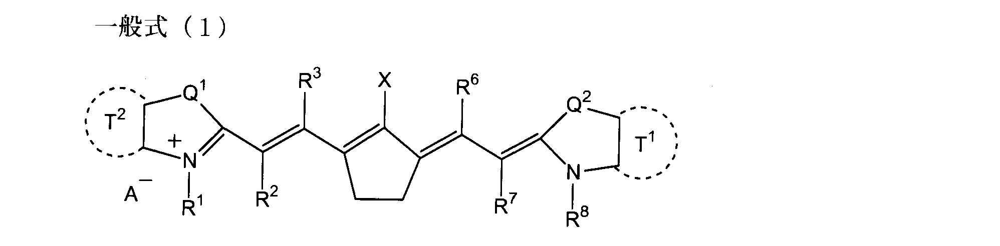
11.オニウム塩系重合開始剤がヨードニウム塩又はスルホニウム塩であることを特徴とする1~10のいずれか一項に記載の平版印刷版原版。
12.発色性化合物が酸発色剤であることを特徴とする1~11のいずれか一項に記載の平版印刷版原版。
13.発色性化合物が熱発色剤であることを特徴とする1~12のいずれか一項に記載の平版印刷版原版。
14.画像記録層がボレート化合物を含有することを特徴とする12又は13のいずれか一項に記載の平版印刷版原版。
15.ボレート化合物がテトラフェニルボレートであることを特徴とする14に記載の平版印刷版原版。
16.1~15のいずれか一項に記載の平版印刷版原版を、赤外線レーザーで画像様に露光した後、印刷機に装着し、次いで印刷インキと湿し水とを供給して画像記録層の未露光部を除去し、印刷することを特徴とする平版印刷版の印刷方法。 In the formula, R 1 and R 8 each independently represents a monovalent substituent. R 2 , R 3 , R 6 and R 7 each independently represent a hydrogen atom or a hydrocarbon group. X represents —NPh 2 . Q 1 and Q 2 each independently represents —NR 9 —, a sulfur atom, an oxygen atom, or a dialkylmethylene group. R 9 represents a hydrogen atom or a hydrocarbon group which may have a substituent. T 1 and T 2 each independently represents an aromatic ring or a heteroaromatic ring. A − represents an anion.
11. The lithographic printing plate precursor as described in any one of 1 to 10, wherein the onium salt-based polymerization initiator is an iodonium salt or a sulfonium salt.
12 The lithographic printing plate precursor as described in any one of 1 to 11, wherein the color former is an acid color former.
13. The lithographic printing plate precursor as described in any one of 1 to 12, wherein the color-forming compound is a thermochromic agent.
14 The lithographic printing plate precursor as described in any one of 12 or 13, wherein the image recording layer contains a borate compound.
15. 14. The lithographic printing plate precursor as described in 14, wherein the borate compound is tetraphenylborate.
16. The lithographic printing plate precursor according to any one of 16.1 to 15 is exposed imagewise with an infrared laser and then mounted on a printing machine, and then printing ink and fountain solution are supplied to form an image recording layer. A printing method for a lithographic printing plate, wherein the unexposed portion is removed and printed.
本発明の平版印刷版原版は、少なくとも白色基板と画像記録層(画像形成層ともいう)とを有する平版印刷版原版であって、前記白色基板は前記画像記録層を有する側の反射濃度が0.25以下であり、前記画像記録層は赤外線吸収剤、オニウム塩系重合開始剤、重合性化合物、及び発色性化合物を含有し、印刷インキ及び湿し水の少なくともいずれかにより除去可能であることを特徴とする。本発明の平版印刷版原版は、画像記録層の上に保護層を有することができる。また、アルミニウム支持体と画像記録層の間に下塗り層を有することができる。
本発明の平版印刷版原版は、画像記録層を有する側からの反射濃度が0.53以下であることが好ましく、画像記録層が着色剤を含有しないか、又は、含有量が2.5質量%以下であることが、露光後の発色画像の良好な認識性を得るために、より好ましい。
ここで、反射濃度とは 光学濃度(Optical Density)のことであり、反射面への入射光の強度をI0、反射面からの反射光の強度をIとするとき、O.D.=Log10(I0/I)で表される値である。本発明に記載する反射濃度は、Macbeth反射濃度計 型番RD918(Macbeth社製)を用いて白黒モードにより測定された値である。 [Lithographic printing plate precursor]
The lithographic printing plate precursor according to the invention is a lithographic printing plate precursor having at least a white substrate and an image recording layer (also referred to as an image forming layer), and the white substrate has a reflection density of 0 on the side having the image recording layer. .25 or less, and the image recording layer contains an infrared absorber, an onium salt polymerization initiator, a polymerizable compound, and a coloring compound, and can be removed by at least one of printing ink and dampening water. It is characterized by. The lithographic printing plate precursor according to the invention can have a protective layer on the image recording layer. An undercoat layer can be provided between the aluminum support and the image recording layer.
In the lithographic printing plate precursor according to the invention, the reflection density from the side having the image recording layer is preferably 0.53 or less, and the image recording layer does not contain a colorant or the content is 2.5 mass. % Or less is more preferable in order to obtain good recognition of a color image after exposure.
Here, the reflection density is an optical density (Optical Density). When the intensity of incident light on the reflecting surface is I 0 and the intensity of reflected light from the reflecting surface is I, O.D. D. = A value represented by Log 10 (I 0 / I). The reflection density described in the present invention is a value measured in a monochrome mode using a Macbeth reflection densitometer model number RD918 (manufactured by Macbeth).
本発明の白色基板は、反射濃度が0.25以下である表面を有する基板を意味する。白色基板の具体例としては、(1)アルミニウム支持体上に白色層を設けた基板が挙げられる。この場合は、画像記録層は白色層の上に形成される。白色基板の別の例としては、(2)急峻度a45が30%以下となるように粗面化処理及び陽極酸化処理されたアルミニウム支持体が挙げられる。この場合、画像記録層は、白色層なしに該アルミニウム支持体上に形成してもよいし、該アルミニウム支持体上に下塗り層を設け、その上に形成してもよい。また、該アルミニウム支持体上に白色層を設け、その上に画像記録層を設けてもよい。好ましい白色基板の反射濃度の値としては0.25~0.01、更に好ましくは0.20~0.01、最も好ましくは0.15~0.01である。反射濃度が0.25を超える場合、露光量域に焼だし画像が得られたとしても、未露光部が着色しているために、未露光部と露光部の色変化が小さく、良好な画像認識性は得られないという問題があった。
上記急峻度a45とは、表面形状を表すファクターの一つであり、次のようにして求めた値である。 [White substrate]
The white substrate of the present invention means a substrate having a surface with a reflection density of 0.25 or less. Specific examples of the white substrate include (1) a substrate provided with a white layer on an aluminum support. In this case, the image recording layer is formed on the white layer. Other examples of the white substrate include (2) an aluminum support that has been roughened and anodized so that the steepness a45 is 30% or less. In this case, the image recording layer may be formed on the aluminum support without a white layer, or an undercoat layer may be provided on the aluminum support and formed thereon. Further, a white layer may be provided on the aluminum support, and an image recording layer may be provided thereon. The value of the reflection density of the white substrate is preferably 0.25 to 0.01, more preferably 0.20 to 0.01, and most preferably 0.15 to 0.01. When the reflection density exceeds 0.25, even if a printed image is obtained in the exposure range, the unexposed portion is colored, so the color change between the unexposed portion and the exposed portion is small, and a good image is obtained. There was a problem that recognition was not obtained.
The steepness a45 is one of the factors representing the surface shape, and is a value obtained as follows.
まず、原子間力顕微鏡(Atomic Force Microscope:AFM)により表面形状を測定し、3次元データを求める。
測定は、例えば、以下の条件で行うことができる。すなわち、支持体を1cm角の大きさに切り取って、ピエゾスキャナー上の水平な試料台にセットし、カンチレバーを試料表面にアプローチし、原子間力が働く領域に達したところで、XY方向にスキャンし、その際、試料の凹凸をZ方向のピエゾの変位でとらえる。ピエゾスキャナーは、XY方向について150μm、Z方向について10μm、走査可能なものを使用する。カンチレバーは共振周波数120~150kHz、バネ定数12~20N/mのもの(SI-DF20、NANOPROBE社製)を用い、DFMモード(Dynamic Force Mode)で測定する。また、求めた3次元データを最小二乗近似することにより試料のわずかな傾きを補正し基準面を求める。
計測の際は、表面の50×50μmを512×512点測定する。XY方向の分解能は1.9μm、Z方向の分解能は1nm、スキャン速度は60μm/secとする。 (1) The surface shape is measured to obtain three-dimensional data.
First, the surface shape is measured with an atomic force microscope (AFM) to obtain three-dimensional data.
The measurement can be performed, for example, under the following conditions. That is, the support is cut to a size of 1 cm square, set on a horizontal sample stage on a piezo scanner, the cantilever is approached to the sample surface, and when it reaches the region where the atomic force works, it scans in the XY direction. At that time, the unevenness of the sample is captured by the displacement of the piezo in the Z direction. A piezo scanner that can scan 150 μm in the XY direction and 10 μm in the Z direction is used. A cantilever having a resonance frequency of 120 to 150 kHz and a spring constant of 12 to 20 N / m (SI-DF20, manufactured by NANOPROBE) is used for measurement in the DFM mode (Dynamic Force Mode). Further, the reference plane is obtained by correcting the slight inclination of the sample by approximating the obtained three-dimensional data by least squares.
At the time of measurement, the surface of 50 × 50 μm is measured at 512 × 512 points. The resolution in the XY direction is 1.9 μm, the resolution in the Z direction is 1 nm, and the scan speed is 60 μm / sec.
a45の算出には、上記(1)で求められた3次元データから波長0.2μm以上2μm以下の成分を除去する補正をしたものを用いる。この補正により、平版印刷版原版に用いる支持体のような深い凹凸を有する表面をAFMの探針で走査した場合に、探針が凸部のエッジ部分に当たって跳ねたり、深い凹部の壁面に探針の尖端以外の部分が接触したりして生じるノイズを除去することができる。
補正は、上記(1)で求められた3次元データを高速フーリエ変換をして周波数分布を求め、次いで、波長0.2μm以上2μm以下の成分を除去した後、フーリエ逆変換をすることにより行う。 (2) Perform correction.
For the calculation of a45, a correction obtained by removing the component having a wavelength of 0.2 μm or more and 2 μm or less from the three-dimensional data obtained in (1) above is used. With this correction, when a surface having deep irregularities, such as a support used in a lithographic printing plate precursor, is scanned with an AFM probe, the probe bounces against the edge of the convex portion, or the probe touches the wall surface of the deep concave portion. It is possible to remove noise that occurs when a part other than the tip of the contacted part.
The correction is performed by performing a fast Fourier transform on the three-dimensional data obtained in (1) above to obtain a frequency distribution, removing components having wavelengths of 0.2 μm or more and 2 μm or less, and then performing an inverse Fourier transform. .
上記(2)で補正して得られた3次元データ(f(x,y))を用い、隣り合う3点を抽出し、その3点で形成される微小三角形と基準面とのなす角を全データについて算出し、傾斜度分布曲線を求め、一方で、該微小三角形の面積の総和を求めて実面積とする。傾斜度分布曲線より、実面積に対する傾斜度45度以上の部分の面積の割合a45(単位%)を算出する。 (3) a45 is calculated.
Using the three-dimensional data (f (x, y)) obtained by correcting in (2) above, three adjacent points are extracted, and the angle formed between the micro triangle formed by the three points and the reference plane is determined. The calculation is performed for all data, and the slope distribution curve is obtained. On the other hand, the total area of the minute triangles is obtained to obtain the actual area. From the slope distribution curve, the area ratio a45 (unit%) of the portion having the slope of 45 degrees or more with respect to the actual area is calculated.
本発明の白色層は、蛍光増白剤及び白色顔料の少なくともいずれかを含有することが好ましい。なかでも好ましいのは、蛍光増白剤を含有する白色層である。蛍光増白剤と白色顔料の両方を含有してもよい。
また、白色層は、無機親水性マトリックスを含有することが好ましい。更に白色層は、エチレン性不飽和結合を少なくとも1つ含有する繰り返し単位とアルミニウム支持体表面と相互作用する官能基を少なくとも1つ含有する繰り返し単位とを有するポリマーを含有していてもよい。 [White layer]
The white layer of the present invention preferably contains at least one of a fluorescent brightener and a white pigment. Among these, a white layer containing a fluorescent brightening agent is preferable. You may contain both a fluorescent whitening agent and a white pigment.
The white layer preferably contains an inorganic hydrophilic matrix. Further, the white layer may contain a polymer having a repeating unit containing at least one ethylenically unsaturated bond and a repeating unit containing at least one functional group that interacts with the aluminum support surface.
一般に、蛍光増白剤は約320~約410nmの波長の光を吸収して、約410~約500nmの波長の光を放射する性質を有する化合物よりなる。これらの蛍光増白剤で染められた織物は、本来の黄色い反射光の他に新たに蛍光増白剤により発光される約410~約500nmの波長の青色光が付加されるため反射光は白色になり、かつ蛍光効果による分だけ可視光のエネルギーが増加するため、結果として染められた織物自体は目視で白色が増したように感じられ、増白されることは知られているが、本発明者らは検討の結果、蛍光増白剤を含有する平版印刷版原版でも同様の効果が生じることを見出した。 (Fluorescent whitening agent)
In general, the optical brightener comprises a compound having the property of absorbing light having a wavelength of about 320 to about 410 nm and emitting light having a wavelength of about 410 to about 500 nm. The fabric dyed with these fluorescent whitening agents is added with blue light having a wavelength of about 410 to about 500 nm which is newly emitted by the fluorescent whitening agent in addition to the original yellow reflected light. It is known that the energy of visible light is increased by the amount of the fluorescent effect, and as a result, the dyed fabric itself seems to have increased in white color and is whitened. As a result of investigations, the inventors have found that the same effect is produced even in a lithographic printing plate precursor containing a fluorescent brightening agent.
これらのなかでも、発明に用いられる蛍光増白剤としては、スチルベン化合物が好ましく、特に水溶性ジアミノスチルベン化合物が好ましい。水溶性基としてスルホ基を有するものが更に好ましい。
以下、本発明に好ましく使用される蛍光増白剤の化合物例を示すが、本発明はこれらに限定されることはない。 Examples of the optical brightener used in the present invention include K.I. Mention may be made of the compounds described in “Chemistry of Synthetic Dies” Volume V, Chapter 8 edited by Veen-Ratamanmann. More specifically, stilbene compounds, biphenyl compounds, coumarin compounds, imidazole compounds, benzoxazolyl compounds, naphthalimide compounds, pyrazoline compounds, carbostyryl compounds, and the like can be given.
Among these, as the optical brightener used in the invention, a stilbene compound is preferable, and a water-soluble diaminostilbene compound is particularly preferable. What has a sulfo group as a water-soluble group is still more preferable.
Hereinafter, although the example of the compound of the optical brightener preferably used for this invention is shown, this invention is not limited to these.


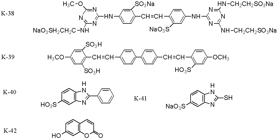
本発明の白色層に用いられる白色顔料としては、酸化チタン、シリカ、酸化亜鉛、硫酸バリウム、炭酸カルシウム、微粉末珪素、鉛白、カオリンクレー、ワラスナイト、チタン酸カリウム、チタン酸バリウムなどが挙げられるが、本発明はこれに限定されるものではない。白色顔料として用いられるものは、酸化チタンが好ましい。白色顔料の粒径は0.5~0.01μmが好ましい。 (White pigment)
Examples of the white pigment used in the white layer of the present invention include titanium oxide, silica, zinc oxide, barium sulfate, calcium carbonate, fine powder silicon, lead white, kaolin clay, wollastonite, potassium titanate, and barium titanate. However, the present invention is not limited to this. As the white pigment, titanium oxide is preferable. The particle size of the white pigment is preferably 0.5 to 0.01 μm.
本発明の白色層は、無機親水性マトリックスを含有することが好ましい。無機親水性マトリックスを形成するのに使用することができるゾル-ゲル変換が可能な系は、多価元素から出ている結合基が酸素原子を介して網目状構造を形成し、同時に多価金属は未結合のヒドロキシ基やアルコキシ基も有していて、これらが混在した樹脂状構造となっている高分子体であって、アルコキシ基やヒドロキシ基が多い段階ではゾル状態であり、エーテル結合化が進行するのに伴って網目状の樹脂構造が強固となる。また、ヒドロキシ基の一部が固体微粒子に結合することによって固体微粒子の表面を修飾し、親水性度を変化させる働きをも併せ持っている。ゾル-ゲル変換を行うヒドロキシ基やアルコキシ基を有する化合物の多価結合元素は、Si、Ti、Zr、Alから選択される金属アルコキシドなどであり、これらはいずれも本発明に用いることができるが、以下はもっとも好ましく用いることのできるシロキサン結合によるゾル-ゲル変換系について説明する。アルミニウム、チタン及びジルコニウムを用いるゾル-ゲル変換は、下記の説明の珪素をそれぞれの元素に置き換えて実施することができる。 (Inorganic hydrophilic matrix)
The white layer of the present invention preferably contains an inorganic hydrophilic matrix. A system capable of sol-gel conversion that can be used to form an inorganic hydrophilic matrix has a network structure in which a bonding group coming out of a polyvalent element forms an oxygen atom, and at the same time a polyvalent metal. Is a polymer with a resinous structure that also contains unbonded hydroxy groups and alkoxy groups, and is in a sol state when there are many alkoxy groups and hydroxy groups. As the process proceeds, the network-like resin structure becomes stronger. In addition, when a part of the hydroxy group is bonded to the solid fine particles, the surface of the solid fine particles is modified to change the hydrophilicity. The polyvalent bonding element of the compound having a hydroxy group or an alkoxy group that performs sol-gel conversion is a metal alkoxide selected from Si, Ti, Zr, and Al, and any of these can be used in the present invention. Hereinafter, a sol-gel conversion system using a siloxane bond that can be most preferably used will be described. Sol-gel conversion using aluminum, titanium, and zirconium can be performed by replacing silicon described below with each element.

一般式(3)で示されるシラン化合物の具体例としては、以下のものが挙げられるが、これに限定されるものではない。 In the —OCOR 2 group, R 2 is an aliphatic group having the same contents as R 1 or an aromatic group having 6 to 12 carbon atoms which may be substituted (the aromatic group is exemplified by the aryl group in R above) The same as the above). In the —N (R 3 ) (R 4 ) group, R 3 and R 4 may be the same or different from each other, and each is a hydrogen atom or an aliphatic group having 1 to 10 carbon atoms which may be substituted ( Examples thereof include those having the same contents as R 1 of the —OR 1 group. More preferably, the total number of carbon atoms of R 3 and R 4 is 16 or less.
Specific examples of the silane compound represented by the general formula (3) include, but are not limited to, the following.
本発明の白色層には、膜強度、柔軟性等の物理的性能向上や、塗布性の改良、親水性の調整等を目的として、エチレン性不飽和結合を少なくとも1つ含有する繰り返し単位とアルミニウム支持体表面と相互作用する官能基を少なくとも1つ含有する繰り返し単位とを有するポリマー(以下では、「特定共重合体」と呼ぶ。)を含有することができる。このような特定共重合体としては、下記式(a)で表される繰り返し単位を含有するものが好ましい。 (Polymer having a repeating unit containing at least one ethylenically unsaturated bond and a repeating unit containing at least one functional group that interacts with the aluminum support surface)
The white layer of the present invention comprises a repeating unit containing at least one ethylenically unsaturated bond and aluminum for the purpose of improving physical performance such as film strength and flexibility, improving coating properties, and adjusting hydrophilicity. A polymer having a repeating unit containing at least one functional group that interacts with the surface of the support (hereinafter referred to as “specific copolymer”) can be contained. As such a specific copolymer, one containing a repeating unit represented by the following formula (a) is preferable.
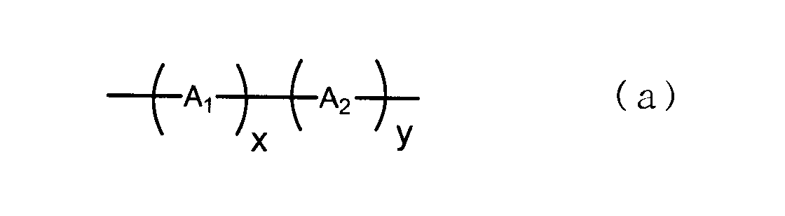
式(a)において、A1で表される繰り返し単位は、好ましくは下記式(A1)で表される。 In the formula (a), A 1 represents a repeating unit containing at least one ethylenically unsaturated bond, and A 2 represents a repeating unit containing at least one functional group that interacts with the aluminum support surface. x and y represent copolymerization ratios.
In the formula (a), the repeating unit represented by A 1 is preferably represented by the following formula (A1).

L1:-CO-NH-二価の脂肪族基-O-CO-
L2:-CO-二価の脂肪族基-O-CO-
L3:-CO-O-二価の脂肪族基-O-CO-
L4:-二価の脂肪族基-O-CO-
L5:-CO-NH-二価の芳香族基-O-CO-
L6:-CO-二価の芳香族基-O-CO-
L7:-二価の芳香族基-O-CO-
L8:-CO-O-二価の脂肪族基-CO-O-二価の脂肪族基-O-CO-
L9:-CO-O-二価の脂肪族基-O-CO-二価の脂肪族基-O-CO-
L10:-CO-O-二価の芳香族基-CO-O-二価の脂肪族基-O-CO-
L11:-CO-O-二価の芳香族基-O-CO-二価の脂肪族基-O-CO-
L12:-CO-O-二価の脂肪族基-CO-O-二価の芳香族基-O-CO-
L13:-CO-O-二価の脂肪族基-O-CO-二価の芳香族基-O-CO-
L14:-CO-O-二価の芳香族基-CO-O-二価の芳香族基-O-CO-
L15:-CO-O-二価の芳香族基-O-CO-二価の芳香族基-O-CO-
L16:-CO-O-二価の芳香族基-O-CO-NH-二価の脂肪族基-O-CO-
L17:-CO-O-二価の脂肪族基-O-CO-NH-二価の脂肪族基-O-CO- Specific examples of L composed of combinations are given below. In the following examples, the left side is bonded to the main chain, and the right side is bonded to the ethylenically unsaturated bond.
L1: —CO—NH—divalent aliphatic group —O—CO—
L2: —CO—divalent aliphatic group —O—CO—
L3: —CO—O—divalent aliphatic group —O—CO—
L4: -Divalent aliphatic group -O-CO-
L5: —CO—NH—divalent aromatic group —O—CO—
L6: —CO—divalent aromatic group —O—CO—
L7: -Divalent aromatic group -O-CO-
L8: —CO—O—divalent aliphatic group —CO—O—divalent aliphatic group —O—CO—
L9: —CO—O—Divalent aliphatic group —O—CO—Divalent aliphatic group —O—CO—
L10: —CO—O—divalent aromatic group —CO—O—divalent aliphatic group —O—CO—
L11: —CO—O—divalent aromatic group —O—CO—divalent aliphatic group —O—CO—
L12: —CO—O—divalent aliphatic group —CO—O—divalent aromatic group —O—CO—
L13: —CO—O—divalent aliphatic group —O—CO—divalent aromatic group —O—CO—
L14: —CO—O—divalent aromatic group —CO—O—divalent aromatic group —O—CO—
L15: —CO—O—divalent aromatic group —O—CO—divalent aromatic group —O—CO—
L16: —CO—O—divalent aromatic group —O—CO—NH—divalent aliphatic group —O—CO—
L17: —CO—O—divalent aliphatic group —O—CO—NH—divalent aliphatic group —O—CO—
二価の脂肪族基は、環状構造よりも鎖状構造の方が好ましく、更に分岐を有する鎖状構造よりも直鎖状構造の方が好ましい。
二価の脂肪族基の炭素原子数は、1乃至20であることが好ましく、1乃至15であることがより好ましく、1乃至12であることが更に好ましく、1乃至10であることが更にまた好ましく、1乃至8であることが最も好ましい。
二価の脂肪族基の置換基の例としては、ハロゲン原子(F、Cl、Br、I)、ヒドロキシル基、カルボキシル基、アミノ基、シアノ基、アリール基、アルコキシ基、アリールオキシ基、アシル基、アルコキシカルボニル基、アリールオキシカルボニル基、アシルオキシ基、モノアルキルアミノ基、ジアルキルアミノ基、アリールアミノ基及びジアリールアミノ基等が挙げられる。 The divalent aliphatic group means an alkylene group, a substituted alkylene group, an alkenylene group, a substituted alkenylene group, an alkynylene group, a substituted alkynylene group or a polyalkyleneoxy group. Of these, an alkylene group, a substituted alkylene group, an alkenylene group, and a substituted alkenylene group are preferable, and an alkylene group and a substituted alkylene group are more preferable.
The divalent aliphatic group is preferably a chain structure rather than a cyclic structure, and more preferably a linear structure than a branched chain structure.
The number of carbon atoms in the divalent aliphatic group is preferably 1 to 20, more preferably 1 to 15, still more preferably 1 to 12, and still more preferably 1 to 10. It is preferably 1 to 8, and most preferably.
Examples of the substituent of the divalent aliphatic group include a halogen atom (F, Cl, Br, I), a hydroxyl group, a carboxyl group, an amino group, a cyano group, an aryl group, an alkoxy group, an aryloxy group, and an acyl group. , Alkoxycarbonyl group, aryloxycarbonyl group, acyloxy group, monoalkylamino group, dialkylamino group, arylamino group and diarylamino group.
二価の芳香族基の置換基の例としては、上記二価の脂肪族基の置換基の例に加えて、アルキル基が挙げられる。
前記L1からL17の中では、L1、L3、L5、L7、L17が好ましい。 The divalent aromatic group means an arylene group or a substituted arylene group. Preferable are phenylene, substituted phenylene group, naphthylene and substituted naphthylene group.
Examples of the substituent for the divalent aromatic group include an alkyl group in addition to the examples of the substituent for the divalent aliphatic group.
Among L1 to L17, L1, L3, L5, L7, and L17 are preferable.
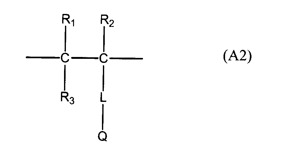
特定官能基としては、例えば、陽極酸化処理又は親水化処理を施した支持体上に存在する金属、金属酸化物、ヒドロキシ基などと共有結合、イオン結合、水素結合、極性相互作用、ファンデルワールズ相互作用などの相互作用が可能な基が挙げられる。
特定官能基の具体例を以下に挙げる。 In the formula, R 1 to R 3 and L are synonymous with those represented by the formula (A1). Q represents a functional group that interacts with the surface of the aluminum support (hereinafter sometimes abbreviated as “specific functional group”).
Specific functional groups include, for example, covalent bonds, ionic bonds, hydrogen bonds, polar interactions, van der Waals with metals, metal oxides, hydroxy groups, etc. present on anodized or hydrophilized supports. Examples include groups capable of interaction such as interaction.
Specific examples of the specific functional group are listed below.

これらのなかでも特定官能基としては、アンモニウム基、ピリジニウム基等のオニウム塩基、リン酸エステル基、ホスホン酸基、ホウ酸基、アセチルアセトン基などのβ-ジケトン基などが好適である。 (Wherein R 11 to R 13 each independently represents a hydrogen atom, an alkyl group, an aryl group, an alkynyl group, or an alkenyl group, and M 1 and M 2 each independently represent a hydrogen atom, a metal atom, or Represents an ammonium group, and X − represents a counter anion.)
Among these, the specific functional group is preferably an onium base such as an ammonium group or a pyridinium group, a β-diketone group such as a phosphate group, a phosphonic acid group, a boric acid group, or an acetylacetone group.
組み合わせからなるLの具体例としては、前記式(A1)におけるLの具体例に加えて以下のものを挙げることができる。なお、下記例において左側が主鎖に結合する。
L18: -CO-NH-
L19: -CO-O-
L20: -二価の芳香族基- In the formula (A2), L represents a divalent linking group selected from the group consisting of —CO—, —O—, —NH—, a divalent aliphatic group, a divalent aromatic group, and combinations thereof. .
Specific examples of L composed of combinations include the following in addition to the specific examples of L in the formula (A1). In the following examples, the left side is bonded to the main chain.
L18: —CO—NH—
L19: —CO—O—
L20: -Divalent aromatic group-

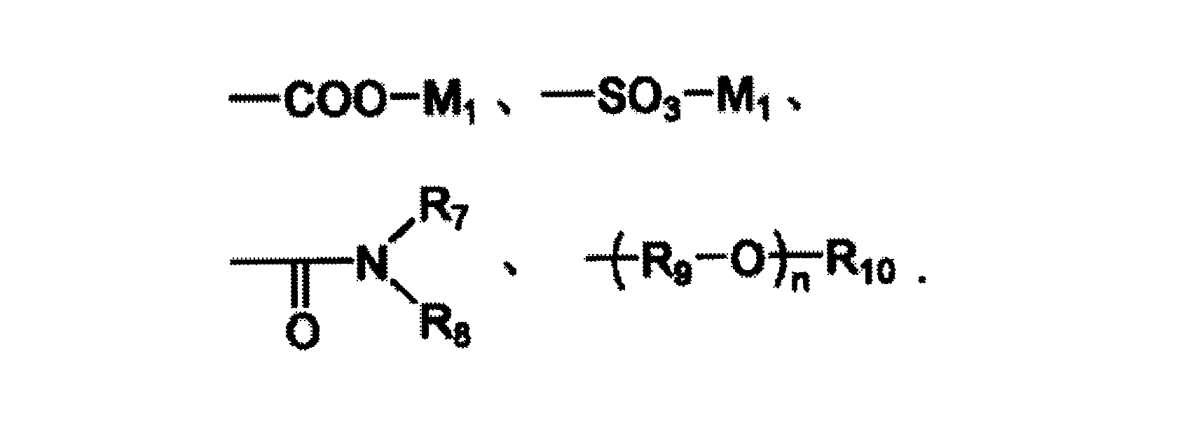
R7及びR8はそれぞれ独立に、水素原子、あるいは炭素数1~6の直鎖又は分岐のアルキル基を表す。R9は炭素数1~6の直鎖又は分岐のアルキレン基を表し、エチレン基が好ましい。R10は水素原子又は炭素数1~12のアルキル基を表す。nは1~100の整数を表し、1~30が好ましい。
前記(A3)で表される親水性基を少なくとも1つ含有する繰り返し単位は、そのlogPが、-3~3であるのが好ましく、-1~2であるのがより好ましい。この範囲で、良好な機上現像性が得られる。
ここでlogPとは、Medicinal Chemistry Project.Pomona College,Claremont.Californiaで開発され、Daylight Chemical Information System Inc.より入手できるソフトウェアPCModelsを用いて算出した化合物のオクタノール/水分配係数(P)の値の対数である。
前記Wとしては、アルキレンオキシ基を含むものが好ましい。
前記特定共重合体の分子量としては、質量平均モル質量(Mw)で500~100,000の範囲が好ましく、700~50,000の範囲がより好ましい。また(a1)は全共重合モノマーに対して5~80モル%が好ましく、10~50モル%がより好ましい。(a2)は全共重合モノマーに対して5~80モル%が好ましく、10~50モル%がより好ましい。更に、(a3)は全共重合モノマーに対して5~80モル%が好ましく、10~50モル%がより好ましい。 However, M 1 is the same meanings as those represented in the description of the formula (A2).
R 7 and R 8 each independently represents a hydrogen atom or a linear or branched alkyl group having 1 to 6 carbon atoms. R 9 represents a linear or branched alkylene group having 1 to 6 carbon atoms, preferably an ethylene group. R 10 represents a hydrogen atom or an alkyl group having 1 to 12 carbon atoms. n represents an integer of 1 to 100, preferably 1 to 30.
The repeating unit containing at least one hydrophilic group represented by (A3) preferably has a log P of -3 to 3, more preferably -1 to 2. Within this range, good on-press developability can be obtained.
Here, logP refers to Medicinal Chemistry Project. Pomona College, Claremont. Developed at California, Daylight Chemical Information System Inc. It is the logarithm of the octanol / water partition coefficient (P) value of a compound calculated using the more available software PCModels.
The W preferably contains an alkyleneoxy group.
The molecular weight of the specific copolymer is preferably in the range of 500 to 100,000, more preferably in the range of 700 to 50,000 in terms of mass average molar mass (Mw). Further, (a1) is preferably from 5 to 80 mol%, more preferably from 10 to 50 mol%, based on the total copolymerized monomers. (A2) is preferably from 5 to 80 mol%, more preferably from 10 to 50 mol%, based on all copolymerized monomers. Further, (a3) is preferably from 5 to 80 mol%, more preferably from 10 to 50 mol%, based on all copolymerized monomers.


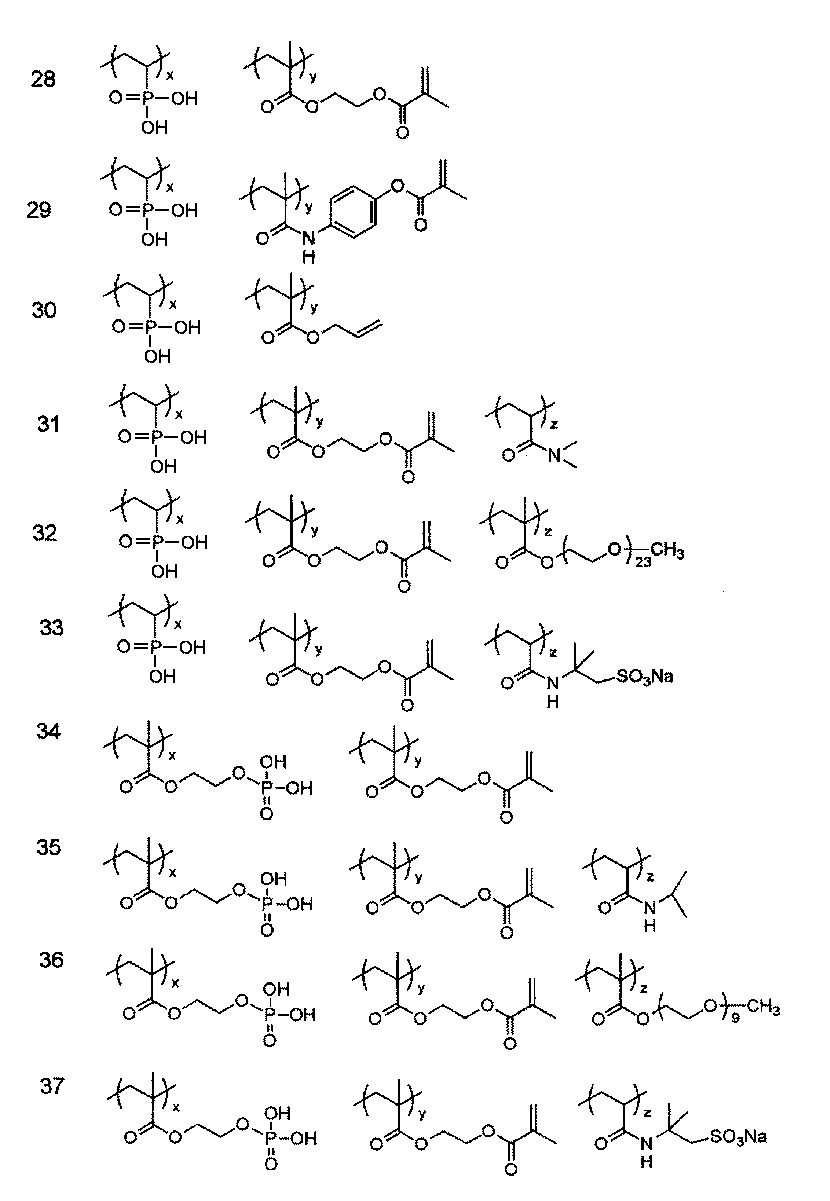


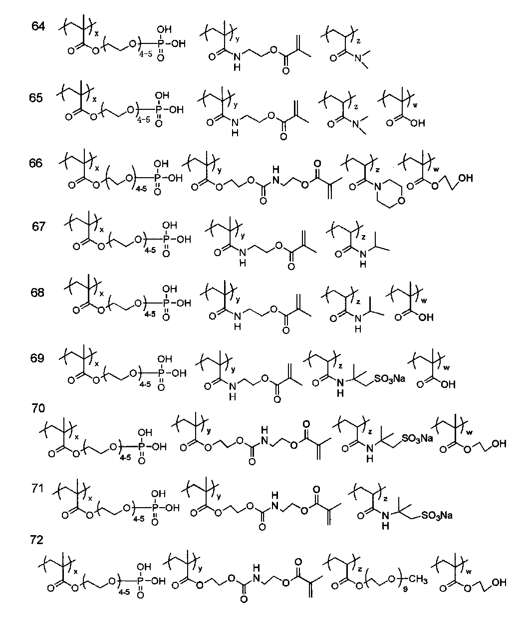
本発明の白色層中には、上記以外にも、親水性の程度の制御、親水性層の物理的強度の向上、層を構成する組成物相互の分散性の向上、塗布性の向上印刷適性の向上などの種々の目的の化合物を添加することができる。そのようなその他の成分として、特定共重合体以外の親水性ポリマー(例えば、ポリビニルアルコール(ケン化度60%以上のポリビニルアセテート)、カルボキシ変性ポリビニルアルコール等の変性ポリビニルアルコール、澱粉及びその誘導体、カルボキシメチルセルロース及びその塩、ヒドロキシエチルセルロースのようなセルロース誘導体、カゼイン、ゼラチン、アラビアゴム、ポリビニルピロリドン、酢酸ビニル-クロトン酸共重合体及びその塩、スチレン-マレイン酸共重合体及びその塩、ポリアクリル酸及びその塩、ポリメタクリル酸及びその塩、ポリエチレングリコール、ポリエチレンイミン、ポリビニルホスホン酸及びその塩、ポリスチレンスルホン酸及びその塩、ポリ(メタクリロイロキシプロパンスルホン酸)及びその塩、ポリビニルスルホン酸及びその塩、ポリ(メタクリロイロキシエチルトリメチルアンモニウムクロライド)、ポリヒドロキシエチルメタクリレート、ポリヒドロキシエチルアクリレート、ポリアクリルアミドなど)、可塑剤、界面活性剤、親水性の粒子等が挙げられる。 (Other ingredients)
In the white layer of the present invention, in addition to the above, control of the degree of hydrophilicity, improvement of the physical strength of the hydrophilic layer, improvement of the dispersibility of the components constituting the layer, improvement of coatability, printability Various objective compounds such as improvement of the above can be added. Examples of such other components include hydrophilic polymers other than the specific copolymer (for example, polyvinyl alcohol (polyvinyl acetate having a saponification degree of 60% or more), modified polyvinyl alcohol such as carboxy-modified polyvinyl alcohol, starch and derivatives thereof, carboxy Methyl cellulose and salts thereof, cellulose derivatives such as hydroxyethyl cellulose, casein, gelatin, gum arabic, polyvinylpyrrolidone, vinyl acetate-crotonic acid copolymer and salts thereof, styrene-maleic acid copolymer and salts thereof, polyacrylic acid and Its salt, polymethacrylic acid and its salt, polyethylene glycol, polyethyleneimine, polyvinylphosphonic acid and its salt, polystyrene sulfonic acid and its salt, poly (methacryloyloxypropane sulfonic acid) and its , Polyvinyl sulfonic acid and salts thereof, poly (methacryloyloxyethyl trimethyl ammonium chloride), polyhydroxyethyl methacrylate, polyhydroxyethyl acrylate, polyacrylamide, etc.), plasticizers, surfactants, and the hydrophilicity of the particles.
本発明に用いる上記白色層は、例えば、水や、メタノール、エタノール等の極性溶剤等の適当な溶剤の単独又はこれらの混合溶媒に必要な成分を溶解あるいは分散して、支持体上に塗布、乾燥、硬化して形成される。
白色層塗布量は0.05~0.6g/m2が好ましく、0.07~0.5g/m2がより好ましい。更には0.1~0.4g/m2とすることがより好ましい。 (Formation of white layer)
The white layer used in the present invention is, for example, water or a suitable solvent such as a polar solvent such as methanol, ethanol or the like, dissolved or dispersed in necessary components in a mixed solvent, and coated on a support. It is formed by drying and curing.
The coating amount of the white layer is preferably 0.05 to 0.6 g / m 2 and more preferably 0.07 to 0.5 g / m 2 . Further, it is more preferably 0.1 to 0.4 g / m 2 .
本発明に用いたれるアルミニウム支持体は、純アルミニウム板、アルミニウムを主成分とし、微量の異元素を含む合金板、又は、アルミニウム若しくはアルミニウム合金の薄膜にプラスチックがラミネートされているものである。アルミニウム合金に含まれる異元素には、ケイ素、鉄、マンガン、銅、マグネシウム、クロム、亜鉛、ビスマス、ニッケル、チタン等がある。合金中の異元素の含有量は10質量%以下であるのが好ましい。本発明においては、純アルミニウム板が好ましいが、完全に純粋なアルミニウムは精錬技術上製造が困難であるので、わずかに異元素を含有するものでもよい。アルミニウム板は、その組成が特定されるものではなく、公知公用の素材のものを適宜利用することができる。 [Aluminum support]
The aluminum support used in the present invention is a pure aluminum plate, an alloy plate containing aluminum as a main component and containing a trace amount of foreign elements, or a plastic laminated on a thin film of aluminum or aluminum alloy. Examples of foreign elements contained in the aluminum alloy include silicon, iron, manganese, copper, magnesium, chromium, zinc, bismuth, nickel, and titanium. The content of foreign elements in the alloy is preferably 10% by mass or less. In the present invention, a pure aluminum plate is preferable, but completely pure aluminum is difficult to manufacture in terms of refining technology, and therefore may contain a slightly different element. The composition of the aluminum plate is not specified, and a publicly known material can be used as appropriate.
粗面化処理方法は、特開昭56-28893号公報に開示されているような機械的粗面化、化学的エッチング、電解グレインなどがある。更に、塩酸又は硝酸電解液中で電気化学的に粗面化する電気化学的粗面化方法、及び、アルミニウム表面を金属ワイヤーでひっかくワイヤーブラシグレイン法、研磨球と研磨剤でアルミニウム表面を砂目立でするポールグレイン法、ナイロンブラシと研磨剤で表面を粗面化するブラシグレイン法のような機械的粗面化法を用いることができ、上記粗面化方法を単独あるいは組み合わせて用いることもできる。
その中でも粗面化に有用に使用される方法は、塩酸又は硝酸電解液中で化学的に粗面化する電気化学的方法であり、適する陽極時電気量は50C/dm2~400C/dm2の範囲である。更に具体的には、0.1~50%の塩酸又は硝酸を含む電解液中、温度20~80℃、時間1秒~30分、電流密度10A/dm2~50A/dm2の条件で交流及び/又は直流電解を行うことが好ましい。 (Roughening treatment)
Examples of the surface roughening method include mechanical surface roughening, chemical etching, and electrolytic grain as disclosed in JP-A-56-28893. Furthermore, an electrochemical surface roughening method in which the surface is electrochemically roughened in a hydrochloric acid or nitric acid electrolyte solution, a wire brush grain method in which the aluminum surface is scratched with a metal wire, and the aluminum surface is ground with a polishing ball and an abrasive. A mechanical surface roughening method such as a pole grain method, a brush grain method in which the surface is roughened with a nylon brush and an abrasive, can be used, and the above surface roughening methods can be used alone or in combination. it can.
Among them, a method usefully used for roughening is an electrochemical method in which roughening is chemically carried out in hydrochloric acid or nitric acid electrolyte, and a suitable amount of electricity at the time of anode is 50 C / dm 2 to 400 C / dm 2. Range. More specifically, alternating current is performed in an electrolyte containing 0.1 to 50% hydrochloric acid or nitric acid at a temperature of 20 to 80 ° C., a time of 1 second to 30 minutes, and a current density of 10 A / dm 2 to 50 A / dm 2. It is preferable to perform direct current electrolysis.
このように粗面化処理したアルミニウム支持体は、酸又はアルカリにより化学的にエッチングされることが好ましい。好適に用いられるエッチング剤と処理時間は、苛性ソーダ、炭酸ソーダ、アルミン酸ソーダ、メタケイ酸ソーダ、リン酸ソーダ、水酸化カリウム、水酸化リチウム等であり、濃度は1~50質量%、温度は20~100℃、時間の好ましい範囲は1~10秒である。このときの濃度、温度と時間のより好ましい範囲はそれぞれ10~50質量%、45~95℃、2~9秒であり、更には、濃度、温度と時間の特に好ましい範囲はそれぞれ20~45質量%、70~90℃、3~8秒である。
このようなエッチング処理によってアルミニウム表面の急峻度a45を低下させ、アルミニウム支持体の反射濃度を低くすることができる。
エッチングのあと表面に残留する汚れ(スマット)を除去するために酸洗いが行われる。用いられる酸は硝酸、硫酸、リン酸、クロム酸、フッ酸、ホウフッ化水素酸等が用いられる。 (Etching process)
The aluminum support thus roughened is preferably chemically etched with acid or alkali. Etching agent and treatment time preferably used are caustic soda, sodium carbonate, sodium aluminate, sodium metasilicate, sodium phosphate, potassium hydroxide, lithium hydroxide and the like, the concentration is 1 to 50% by mass, and the temperature is 20 The preferred range of time is 1 to 10 seconds at -100 ° C. More preferable ranges of concentration, temperature, and time at this time are 10 to 50% by mass, 45 to 95 ° C., and 2 to 9 seconds, respectively, and particularly preferable ranges of concentration, temperature, and time are 20 to 45% by mass, respectively. %, 70-90 ° C., 3-8 seconds.
Such etching treatment can reduce the steepness a45 of the aluminum surface and lower the reflection density of the aluminum support.
Pickling is performed to remove dirt (smut) remaining on the surface after etching. As the acid used, nitric acid, sulfuric acid, phosphoric acid, chromic acid, hydrofluoric acid, borohydrofluoric acid and the like are used.
以上のようにして処理されたアルミニウム支持体には、その後に陽極酸化処理がなされる。陽極酸化処理は、硫酸、燐酸、シュウ酸若しくは硼酸/硼酸ナトリウムの水溶液が単独若しくは複数種類組み合わせて電解浴の主成分として用いられる。この際、電解液中に少なくともAl合金板、電極、水道水、地下水等に通常含まれる成分は勿論含まれても構わない。更には第2、第3成分が添加されていても構わない。ここでいう第2、3成分とは、例えば、Na、K、Mg、Li、Ca、Ti、Al、V、Cr、Mn、Fe、Co、Ni、Cu、Zn等の金属のイオンやアンモニウムイオン等に陽イオンや、硝酸イオン、炭酸イオン、塩素イオン、リン酸イオン、フッ素イオン、亜硫酸イオン、チタン酸イオン、ケイ酸イオン、硼酸イオン等の陰イオンが挙げられ、その濃度としては0~10000ppm程度含まれてもよい。陽極酸化処理の条件は、処理によって作製される陽極酸化皮膜量が0.5~10.0g/m2、より好ましくは1.0~5.0g/m2の範囲であり、通常電解液の主成分となる酸の濃度は30~500g/リットル、処理液温10~70℃で、電流密度1~40A/m2の範囲で直流又は交流電解によって処理されることが好ましい。 (Anodizing treatment)
The aluminum support treated as described above is then anodized. In the anodizing treatment, sulfuric acid, phosphoric acid, oxalic acid, or an aqueous solution of boric acid / sodium borate is used as a main component of the electrolytic bath singly or in combination. Under the present circumstances, the component normally contained in at least Al alloy plate, an electrode, tap water, groundwater, etc. may of course be contained in electrolyte solution. Further, the second and third components may be added. Here, the second and third components are, for example, metal ions such as Na, K, Mg, Li, Ca, Ti, Al, V, Cr, Mn, Fe, Co, Ni, Cu, and Zn, and ammonium ions. Examples include cations, nitrate ions, carbonate ions, chloride ions, phosphate ions, fluorine ions, sulfite ions, titanate ions, silicate ions, borate ions and the like, and the concentration is 0 to 10,000 ppm. May be included. The conditions of the anodizing treatment are such that the amount of the anodized film produced by the treatment is in the range of 0.5 to 10.0 g / m 2 , more preferably 1.0 to 5.0 g / m 2 . The concentration of the acid as the main component is preferably 30 to 500 g / liter, the treatment liquid temperature is 10 to 70 ° C., and the current density is in the range of 1 to 40 A / m 2 by direct current or alternating current electrolysis.
前記支持体表面の親水化処理としては、広く公知の方法が適用できる。特に好ましい処理としては、アルカリ金属ケイ酸塩又はポリビニルホスホン酸等による親水化処理が施される。皮膜はSi又はP元素量として2~40mg/m2、より好ましくは4~30mg/m2で形成される。塗布量はケイ光X線分析法により測定できる。 (Hydrophilic treatment)
As the hydrophilization treatment of the support surface, widely known methods can be applied. As a particularly preferred treatment, a hydrophilization treatment with an alkali metal silicate or polyvinylphosphonic acid is performed. The film is formed with a Si or P element amount of 2 to 40 mg / m 2 , more preferably 4 to 30 mg / m 2 . The coating amount can be measured by fluorescent X-ray analysis.
また、急峻度a45が30%以下になった支持体上に白色層を設けた基板も本発明の白色基板であり、反射濃度が一層低下するため、特に高い焼き出し画像の視認性を示す。 The aluminum support of the present invention preferably has a lower reflection density on the support surface. Since the steepness a45 is reduced by the etching process after the above-described roughening process and the a45 is 30% or less, the reflection density of the surface is 0.25 or less. Can also be used as the white substrate of the present invention.
In addition, a substrate provided with a white layer on a support having a steepness a45 of 30% or less is also a white substrate of the present invention, and the reflection density is further reduced, and thus particularly high visibility of a printed image is exhibited.
本発明の画像記録層は、赤外線吸収剤、オニウム塩系重合開始剤、重合性化合物、及び発色性化合物を含有し、印刷インキ及び湿し水の少なくともいずれかにより除去可能であることを特徴とする。また、本発明の画像記録層は、必要に応じて、上記以外の公知の化合物を含有できる。 (Image recording layer)
The image recording layer of the present invention contains an infrared absorber, an onium salt polymerization initiator, a polymerizable compound, and a color-forming compound, and can be removed by at least one of printing ink and fountain solution. To do. Further, the image recording layer of the present invention can contain known compounds other than those described above, if necessary.
本発明で用いられるかかる赤外線吸収剤は、好ましくは波長760~1200nmに吸収極大を有する染料又は顔料である。 (Infrared absorber)
Such an infrared absorber used in the present invention is preferably a dye or pigment having an absorption maximum at a wavelength of 760 to 1200 nm.
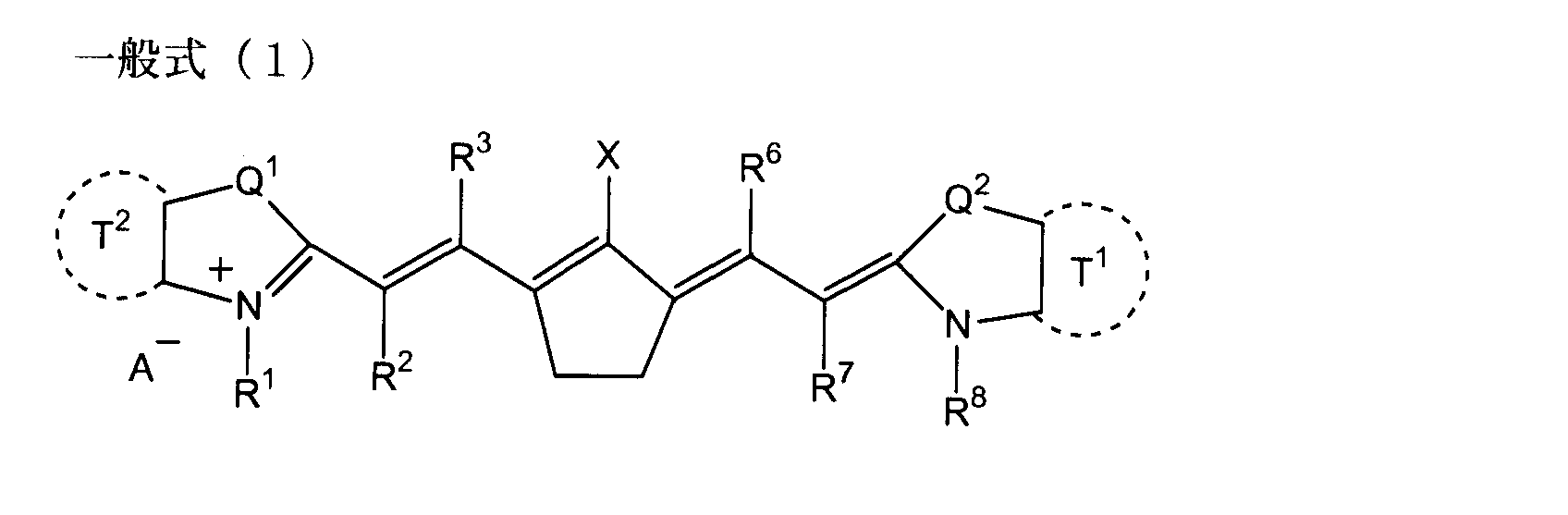
各部分の好ましい組み合わせとしては、特にR1及びR8は置換アルキル基、R2、R3、R5、R7は水素原子、Xは-NPh2、並びに、Q1及びQ2は共にジアルキルメチレン基である組み合わせが好ましい。 From the viewpoint of sensitivity, R 1 and R 8 are preferably an alkyl group or a substituted alkyl group, and most preferably an alkyl group substituted with a heteroatom. X is -NPh 2 is preferred. Q 1 and Q 2 preferably have the same structure, and most preferably a dialkylmethylene group. A showing the anion - is cyanine dye represented by formula (1) has an anionic substituent in the structure, not necessary and does not necessitate neutralization of the charge. Preferred A − is a halide ion, a perchlorate ion, a tetrafluoroborate ion, a hexafluorophosphate ion, and a sulfonate ion, particularly preferably a perchlorate ion, from the viewpoint of storage stability of the image recording layer coating solution. , Hexafluorophosphate ions, and aryl sulfonate ions.
As a preferred combination of each moiety, particularly R 1 and R 8 are substituted alkyl groups, R 2 , R 3 , R 5 , R 7 are hydrogen atoms, X is —NPh 2 , and Q 1 and Q 2 are both dialkyl A combination that is a methylene group is preferred.

本発明ではオニウム塩系重合開始剤はラジカル発生剤としてのみならず酸発生剤として機能する。ラジカル発生剤としては、重合性化合物及び重合性基を有するポリマーの重合及び架橋を促進し、シアニン色素との反応により発色にも寄与する。酸発生剤としては、酸発色剤との組み合わせで発色に寄与する。
本発明では、式(4)~(6)で示すいずれかのオニウム塩系重合開始剤を用いる。式(4)又は式(5)に示すスルホニウム塩又はヨードニウム塩が更に好ましい。 (Onium salt polymerization initiator)
In the present invention, the onium salt polymerization initiator functions not only as a radical generator but also as an acid generator. As a radical generator, the polymerization and crosslinking of a polymerizable compound and a polymer having a polymerizable group are promoted and contribute to color development by reaction with a cyanine dye. The acid generator contributes to color development in combination with an acid color former.
In the present invention, any onium salt polymerization initiator represented by the formulas (4) to (6) is used. A sulfonium salt or an iodonium salt represented by formula (4) or formula (5) is more preferable.

式(7)のR27は、アルキル基、アルコキシ基、又はハロゲン原子を示し、複数のR27は同一であっても異なっていてもよい。mは0~5の整数を示す。 In the above formula, Ar 1 , Ar 2 , Ar 3 , Ar 4 and Ar 5 each independently represent a group represented by the formula (7). R 21 , R 22 , R 23 , R 24 and R 25 each independently represent a hydrogen atom, an alkyl group, an alkoxy group, an aryl group, a cyano group or a halogen atom. R 21 and R 22 , and R 22 and R 23 may be combined with each other to form a ring to form a condensed ring structure. R 26 represents an alkyl group or an aryl group. Z − represents an anion.
R 27 in Formula (7) represents an alkyl group, an alkoxy group, or a halogen atom, and a plurality of R 27 may be the same or different. m represents an integer of 0 to 5.

具体的には、例えば、メチル基、エチル基、プロピル基、ブチル基、ペンチル基、ヘキシル基、ヘプチル基、オクチル基、ノニル基、デシル基、ウンデシル基、ドデシル基、トリデシル基、ヘキサデシル基、オクタデシル基、エイコシル基、イソプロピル基、イソブチル基、s-ブチル基、t-ブチル基、イソペンチル基、ネオペンチル基、1-メチルブチル基、イソヘキシル基、2-エチルヘキシル基、2-メチルヘキシル基、シクロヘキシル基、シクロペンチル基、及び2-ノルボルニル基を挙げられる。
これらアルキル基の中で、メチル基、エチル基、プロピル基、ブチル基、t-ブチル基が特に好ましい。 The alkyl group represented by R 21 , R 22 , R 23 , R 24 , R 25 , R 26 , R 27 , and R 31 is preferably an alkyl group having 1 to 20 carbon atoms, and an alkyl group having 1 to 10 carbon atoms. Is more preferable, and an alkyl group having 1 to 4 carbon atoms is most preferable.
Specifically, for example, methyl group, ethyl group, propyl group, butyl group, pentyl group, hexyl group, heptyl group, octyl group, nonyl group, decyl group, undecyl group, dodecyl group, tridecyl group, hexadecyl group, octadecyl group Group, eicosyl group, isopropyl group, isobutyl group, s-butyl group, t-butyl group, isopentyl group, neopentyl group, 1-methylbutyl group, isohexyl group, 2-ethylhexyl group, 2-methylhexyl group, cyclohexyl group, cyclopentyl Group, and 2-norbornyl group.
Of these alkyl groups, a methyl group, an ethyl group, a propyl group, a butyl group, and a t-butyl group are particularly preferable.
具体的には、例えば、フェニル基、ビフェニル基、1-ナフチル基、2-ナフチル基、9-フルオレニル基、ターフェニル基、o-、m-、及びp-トリル基、キシリル基、o-、m-、及びp-クメニル基、メシチル基、ビフェニレニル基、インダセニル基、フルオレニル基、p-クロロフェニル基、p-ブロモフェニル基、p-フルオロフェニル基、o-クロロフェニル基、o-ブロモフェニル基、o-フルオロフェニル基、p-メトキシフェニル基、m-メトキシフェニル基、p-ジメチルアミノフェニル基、p-メチルチオフェニル基、m-メチルチオフェニル基、p-フェニルチオフェニル基、2,3-ジフルオロフェニル基、2,3-クロロフェニル基、2,4-ジフルオロフェニル基、2,4-ジクロロフェニル基、2,5-ジフルオロフェニル基、2,5-ジクロロフェニル基、2,6-ジフルオロフェニル基、2,6-ジクロロフェニル基、2,4,6-トリフルオロフェニル基、2,4,6-トリクロロフェニル基、3,4,5-トリフルオロフェニル基、3,4,5-トリクロロフェニル基等が挙げられる。
これらアリール基の中で、フェニル基、p-メトキシフェニル基、p-ジメチルアミノフェニル基が特に好ましい。 The aryl group represented by R 21 , R 22 , R 23 , R 24 , R 25 and R 26 is preferably an aryl group having 6 to 30 carbon atoms, more preferably an aryl group having 6 to 20 carbon atoms, Most preferred are 6-12 aryl groups.
Specifically, for example, phenyl group, biphenyl group, 1-naphthyl group, 2-naphthyl group, 9-fluorenyl group, terphenyl group, o-, m-, and p-tolyl group, xylyl group, o-, m- and p-cumenyl, mesityl, biphenylenyl, indacenyl, fluorenyl, p-chlorophenyl, p-bromophenyl, p-fluorophenyl, o-chlorophenyl, o-bromophenyl, o -Fluorophenyl group, p-methoxyphenyl group, m-methoxyphenyl group, p-dimethylaminophenyl group, p-methylthiophenyl group, m-methylthiophenyl group, p-phenylthiophenyl group, 2,3-difluorophenyl group 2,3-chlorophenyl group, 2,4-difluorophenyl group, 2,4-dichlorophenyl group, 2,5- Fluorophenyl group, 2,5-dichlorophenyl group, 2,6-difluorophenyl group, 2,6-dichlorophenyl group, 2,4,6-trifluorophenyl group, 2,4,6-trichlorophenyl group, 3,4 , 5-trifluorophenyl group, 3,4,5-trichlorophenyl group and the like.
Of these aryl groups, a phenyl group, a p-methoxyphenyl group, and a p-dimethylaminophenyl group are particularly preferable.
本発明における画像記録層に用いる重合性化合物は、少なくとも一個のエチレン性不飽和二重結合を有する付加重合性化合物であり、末端エチレン性不飽和結合を少なくとも1個、好ましくは2個以上有する化合物から選ばれる。このような化合物群は当該産業分野において広く知られるものであり、本発明においてはこれらを特に限定無く用いることができる。これらは、例えばモノマー、プレポリマー、すなわち2量体、3量体及びオリゴマー、又はそれらの混合物並びにそれらの共重合体などの化学的形態をもつ。モノマー及びその共重合体の例としては、不飽和カルボン酸(例えば、アクリル酸、メタクリル酸、イタコン酸、クロトン酸、イソクロトン酸、マレイン酸など)や、そのエステル類、アミド類が挙げられ、好ましくは、不飽和カルボン酸と脂肪族多価アルコール化合物とのエステル、不飽和カルボン酸と脂肪族多価アミン化合物とのアミド類が用いられる。また、ヒドロキシル基やアミノ基、メルカプト基等の求核性置換基を有する不飽和カルボン酸エステルあるいはアミド類と単官能若しくは多官能イソシアネート類あるいはエポキシ類との付加反応物、及び単官能若しくは、多官能のカルボン酸との脱水縮合反応物等も好適に使用される。また、イソシアネート基や、エポキシ基等の親電子性置換基を有する不飽和カルボン酸エステルあるいはアミド類と単官能若しくは多官能のアルコール類、アミン類、チオール類との付加反応物、更にハロゲノ基や、トシルオキシ基等の脱離性置換基を有する不飽和カルボン酸エステルあるいはアミド類と単官能若しくは多官能のアルコール類、アミン類、チオール類との置換反応物も好適である。また、別の例として、上記の不飽和カルボン酸の代わりに、不飽和ホスホン酸、スチレン、ビニルエーテル等に置き換えた化合物群を使用することも可能である。 (Polymerizable compound)
The polymerizable compound used in the image recording layer in the present invention is an addition polymerizable compound having at least one ethylenically unsaturated double bond, and a compound having at least one terminal ethylenically unsaturated bond, preferably two or more. Chosen from. Such a compound group is widely known in the industrial field, and can be used without any particular limitation in the present invention. These have chemical forms such as monomers, prepolymers, i.e. dimers, trimers and oligomers, or mixtures thereof and copolymers thereof. Examples of monomers and copolymers thereof include unsaturated carboxylic acids (for example, acrylic acid, methacrylic acid, itaconic acid, crotonic acid, isocrotonic acid, maleic acid, etc.), and esters and amides thereof. In this case, an ester of an unsaturated carboxylic acid and an aliphatic polyhydric alcohol compound, or an amide of an unsaturated carboxylic acid and an aliphatic polyvalent amine compound is used. In addition, an addition reaction product of an unsaturated carboxylic acid ester or amide having a nucleophilic substituent such as a hydroxyl group, amino group or mercapto group with a monofunctional or polyfunctional isocyanate or epoxy, and a monofunctional or polyfunctional compound. A dehydration condensation reaction product with a functional carboxylic acid is also preferably used. Further, an addition reaction product of an unsaturated carboxylic acid ester or amide having an electrophilic substituent such as an epoxy group or an epoxy group with a monofunctional or polyfunctional alcohol, amine or thiol, a halogeno group or In addition, a substitution reaction product of an unsaturated carboxylic acid ester or amide having a leaving substituent such as a tosyloxy group and a monofunctional or polyfunctional alcohol, amine or thiol is also suitable. As another example, it is also possible to use a group of compounds substituted with unsaturated phosphonic acid, styrene, vinyl ether or the like instead of the unsaturated carboxylic acid.
(ただし、R4及びR5は、H又はCH3を示す。) CH 2 = C (R 4) COOCH 2 CH (R 5) OH (b)
(However, R 4 and R 5 represent H or CH 3. )
感度の点では1分子あたりの不飽和基含量が多い構造が好ましく、多くの場合、2官能以上が好ましい。また、画像部すなわち硬化膜の強度を高くするためには、3官能以上のものがよく、更に、異なる官能数・異なる重合性基(例えばアクリル酸エステル、メタクリル酸エステル、スチレン系化合物、ビニルエーテル系化合物)のものを併用することで、感度と強度の両方を調節する方法も有効である。
また、画像記録層中の他の成分(例えばバインダーポリマー、重合開始剤、着色剤等)との相溶性、分散性に対しても、重合性化合物の選択・使用法は重要な要因であり、例えば、低純度化合物の使用や、2種以上の併用により相溶性を向上させうることがある。また、支持体や後述の保護層等との密着性を向上せしめる目的で特定の構造を選択することもあり得る。 About these polymerizable compounds, the details of usage such as the structure, single use or combination, addition amount, etc. can be arbitrarily set according to the performance design of the final lithographic printing plate precursor. For example, it is selected from the following viewpoints.
From the viewpoint of sensitivity, a structure having a large unsaturated group content per molecule is preferable, and in many cases, a bifunctional or higher functionality is preferable. Further, in order to increase the strength of the image area, that is, the cured film, those having three or more functionalities are preferable. Further, different functional numbers and different polymerizable groups (for example, acrylic acid ester, methacrylic acid ester, styrenic compound, vinyl ether type). A method of adjusting both sensitivity and strength by using a compound) is also effective.
In addition, the compatibility and dispersibility with other components in the image recording layer (for example, binder polymer, polymerization initiator, colorant, etc.), the selection and use method of the polymerizable compound is an important factor, For example, the compatibility may be improved by using a low-purity compound or using two or more kinds in combination. In addition, a specific structure may be selected for the purpose of improving adhesion to a support or a protective layer described later.
本発明で用いられる発色剤としては酸発色剤及び熱発色剤が挙げられる。前述の赤外線吸収剤がシアニン色素である場合は、シアニン色素が露光によって可視光域に発色するので、発色性化合物を兼ねることができる。本発明ではシアニン色素と酸発色剤又は熱発色剤を併用することもできる。併用によって、焼き出し性が一層向上する。 (Chromogenic compound)
Examples of color formers used in the present invention include acid color formers and thermal color formers. When the above-mentioned infrared absorbing agent is a cyanine dye, the cyanine dye develops color in the visible light region upon exposure, so that it can also serve as a color forming compound. In the present invention, a cyanine dye and an acid color former or a thermal color former may be used in combination. The combined use further improves the bake-out property.
本発明に用いられる酸発色剤としては、酸の作用によって発色(無色から有色の変化)を起こす化合物であればいずれも好適に使用できる。このような色素の例としては、トリアリールメタン化合物、ビスフェニルメタン化合物、キサンテン化合物、フルオラン化合物、チアジン化合物、スピロピラン化合物、及び特開2001-277730号公報記載の化合物が挙げられる。なかでも、トリアリールメタン化合物、キサンテン化合物、フルオラン化合物、スピロピラン化合物、特開2001-277730号公報記載の化合物が特に好ましい。酸発色剤の例を以下に記載するが、本発明はこれらに限定されるものではない。 (1) Acid Color Developing Agent Any acid color developing agent used in the present invention can be suitably used as long as it is a compound that develops color (change from colorless to colored) by the action of an acid. Examples of such dyes include triarylmethane compounds, bisphenylmethane compounds, xanthene compounds, fluorane compounds, thiazine compounds, spiropyran compounds, and compounds described in JP-A-2001-277730. Of these, triarylmethane compounds, xanthene compounds, fluorane compounds, spiropyran compounds, and compounds described in JP-A-2001-277730 are particularly preferred. Examples of the acid color former are described below, but the present invention is not limited thereto.
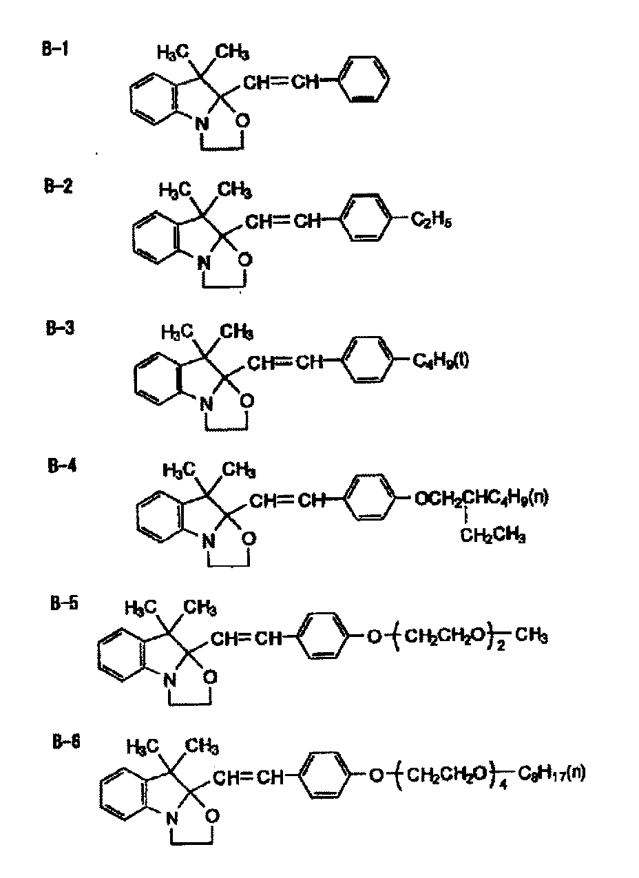
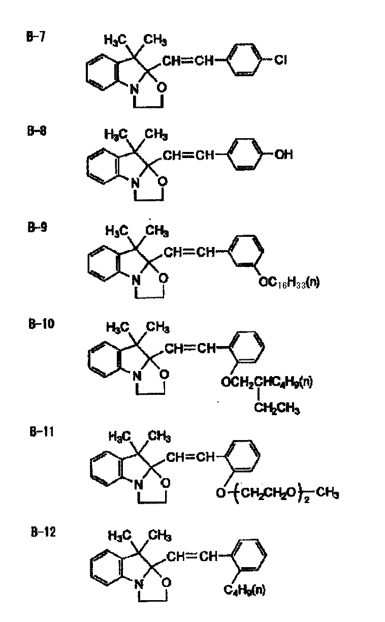

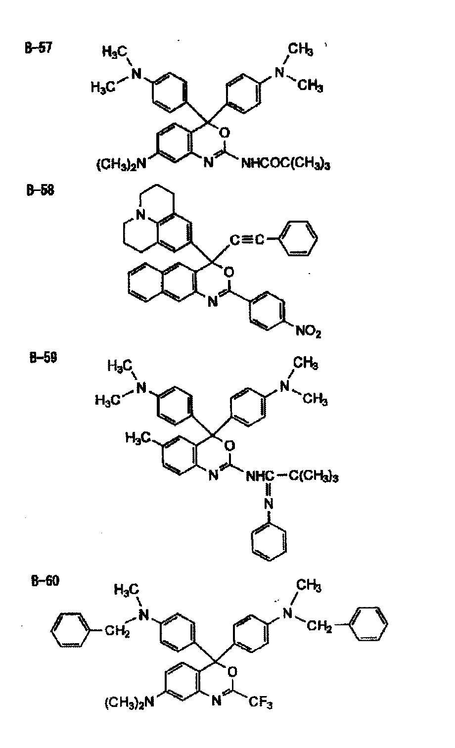

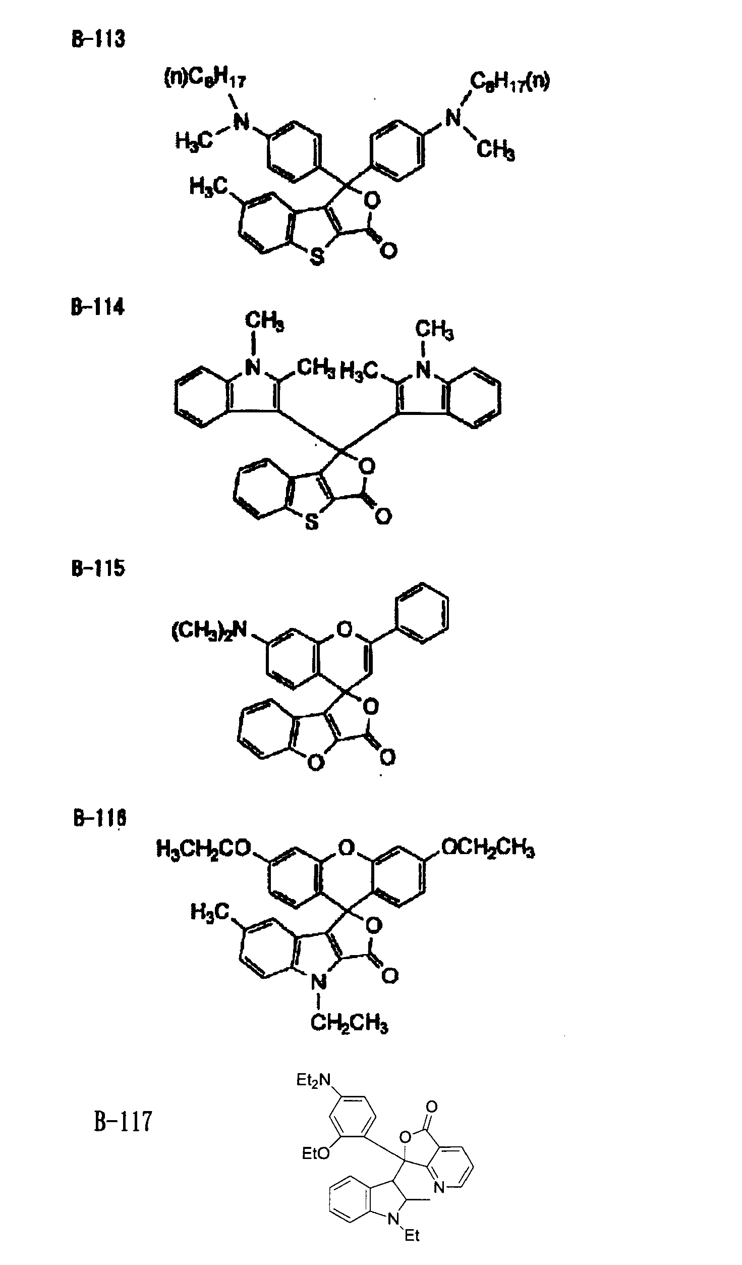
本発明に用いられる熱発色剤としては、熱の作用によって発色(無色から有色の変化)を起こす化合物であればいずれも好適に使用できる。このような色素の例としては、スピロピラン化合物、アントロン化合物のような縮合芳香環置換エチレン誘導体、ポリチオフェン誘導体、コレステリック液晶などの液晶、電子供与体と電子受容体の有極性化合物中の熱平衡による電子授受機構にもとづくサーモクロミック材料であるメタモカラー(登録商標、パイロットインキ製)等が挙げられる。本発明はこれらに限定されるものではない。
以下に、本発明において好適な熱発色剤の具体例を挙げるが、これらに限定されない。 (2) Thermochromic agent Any thermochromic agent used in the present invention may be used as long as it is a compound that develops color (change from colorless to colored) by the action of heat. Examples of such dyes include liquid crystal such as spiropyran compounds, anthrone compounds, condensed aromatic ring-substituted ethylene derivatives, polythiophene derivatives, cholesteric liquid crystals, and electron transfer by thermal equilibrium in polar compounds of electron donors and electron acceptors. Metamocolor (registered trademark, manufactured by Pilot Ink), which is a thermochromic material based on the mechanism, may be mentioned. The present invention is not limited to these.
Specific examples of the thermochromic agent suitable for the present invention are listed below, but are not limited thereto.


(1)ボレート化合物
本発明の画像記録層にはボレート化合物を含ませることが好ましい。ボレート化合物を含有させることにより、熱又は酸発色剤の発色性を向上させることができる。本発明に使用することができるボレート化合物は、硼素アニオン構造を有する化合物であれば、特に制限無く使用することができるが、下記一般式(c)に示す構造を有するボレート化合物が好ましい。 (Other compounds)
(1) Borate compound The image recording layer of the invention preferably contains a borate compound. By containing the borate compound, the color developability of the heat or acid color former can be improved. The borate compound that can be used in the present invention is not particularly limited as long as it is a compound having a boron anion structure, but a borate compound having a structure represented by the following general formula (c) is preferable.

R1~R4で表される1価の有機基としては、例えば、アルキル基、アルケニル基、アリール基、アルキニル基、シクロアルキル基が挙げられ、なかでもアリール基が好ましい。これらの有機基は、置換基を有していてもよく、導入可能な置換基としては、アルキル基、ハロゲン化アルキル基、アルケニル基、アルキニル基、アリール基、ハロゲン原子、アルコキシ基、アルコキシカルボニル基、アミノ基、シアノ基、アミド基、ウレタン基、スルホ基、チオアルコキシ基、カルボキシ基などが挙げられる。
なかでも、好ましくはR1~R4がそれぞれアリール基である化合物であり、更に好ましくは置換基として電子吸引性基を有するアリール基が好ましい。ここで、R1~R4はそれぞれ同じでも異なっていてもよい。
アリール基に導入される好ましい電子吸引性基としては、ハロゲン原子、フルオロアルキル基が好ましく、なかでもフッ素原子、トリフルオロメチル基が好ましい。 In general formula (c), R 1 to R 4 each independently represents a monovalent organic group, and Z n + represents an n-valent cation. n represents an integer of 1 to 6.
Examples of the monovalent organic group represented by R 1 to R 4 include an alkyl group, an alkenyl group, an aryl group, an alkynyl group, and a cycloalkyl group. Among them, an aryl group is preferable. These organic groups may have a substituent, and examples of the substituent that can be introduced include an alkyl group, a halogenated alkyl group, an alkenyl group, an alkynyl group, an aryl group, a halogen atom, an alkoxy group, and an alkoxycarbonyl group. Amino group, cyano group, amide group, urethane group, sulfo group, thioalkoxy group, carboxy group and the like.
Of these, compounds in which R 1 to R 4 are each an aryl group are preferred, and an aryl group having an electron-withdrawing group as a substituent is more preferred. Here, R 1 to R 4 may be the same or different.
As a preferable electron withdrawing group introduced into the aryl group, a halogen atom and a fluoroalkyl group are preferable, and a fluorine atom and a trifluoromethyl group are particularly preferable.
下記に本発明に用いられる好ましいボレート化合物の例を示すが、本発明は下記に制限されるものではない。 Z n + can be used without limitation as long as it is a cation capable of neutralizing the boron anion, and preferred examples include alkali metal ions, alkaline earth metal ions, sulfonium salts, iodonium salts, azinium salts, ammonium salts, phosphoniums. Salts, onium salts such as diazonium salts, and the like can be used, but alkali metal ions such as Li, Na, and K are preferred from the viewpoint of developability.
Although the example of the preferable borate compound used for this invention below is shown, this invention is not restrict | limited to the following.
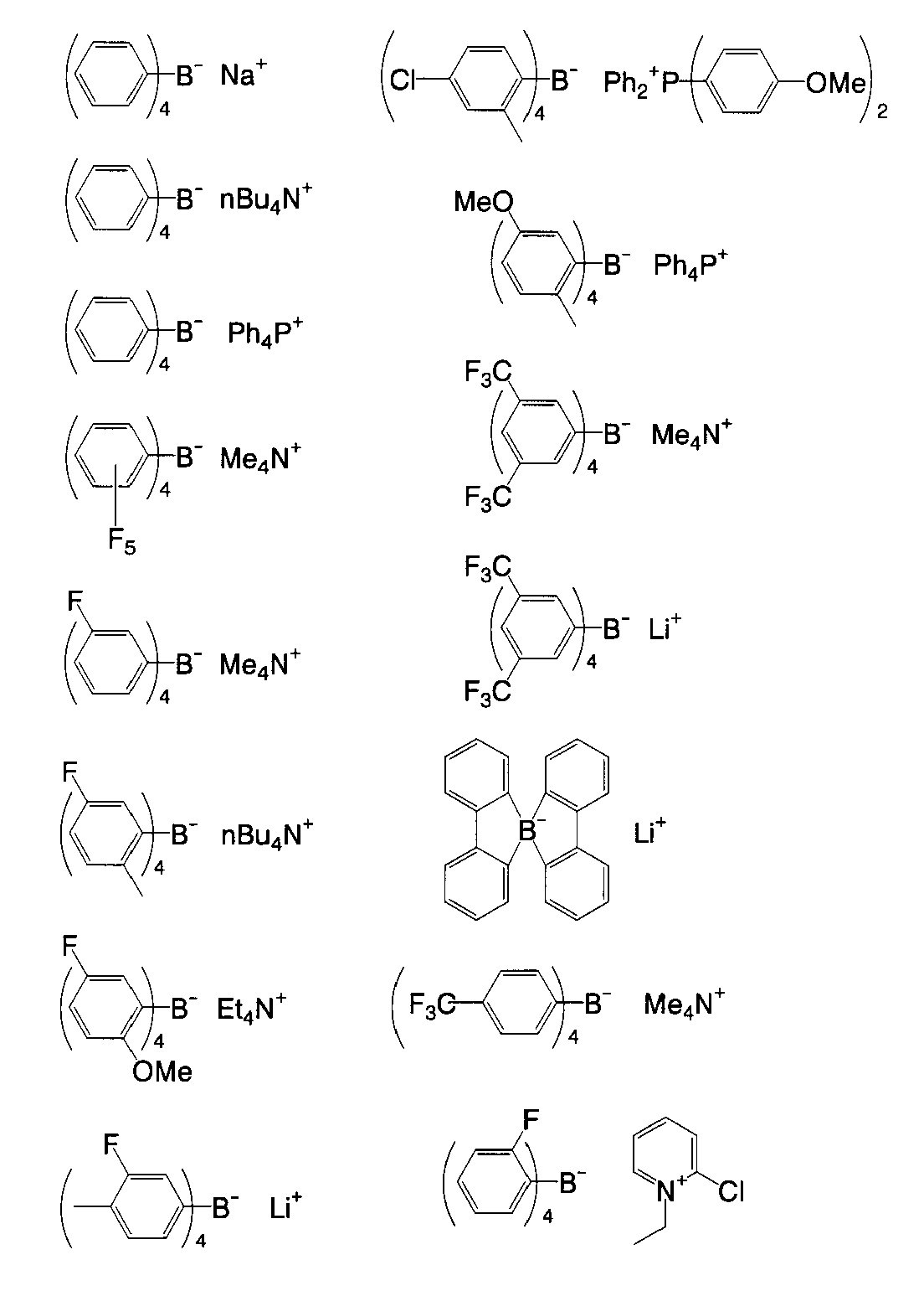
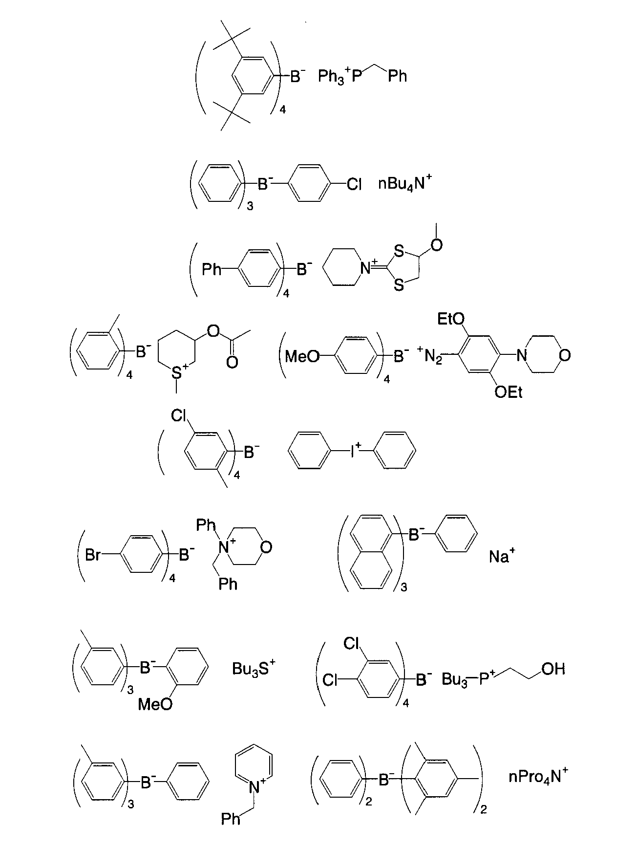

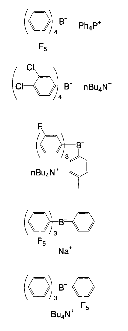

本発明の画像記録層には、画像記録層の膜強度を向上させるため、バインダーポリマーを用いることができる。本発明に用いることができるバインダーポリマーは、従来公知のものを制限なく使用でき、皮膜性を有するポリマーが好ましい。なかでも、アクリル樹脂、ポリビニルアセタール樹脂、ポリウレタン樹脂が好ましい。 (2) Binder polymer In the image recording layer of the present invention, a binder polymer can be used in order to improve the film strength of the image recording layer. As the binder polymer that can be used in the present invention, conventionally known binder polymers can be used without limitation, and polymers having film properties are preferred. Of these, acrylic resins, polyvinyl acetal resins, and polyurethane resins are preferable.
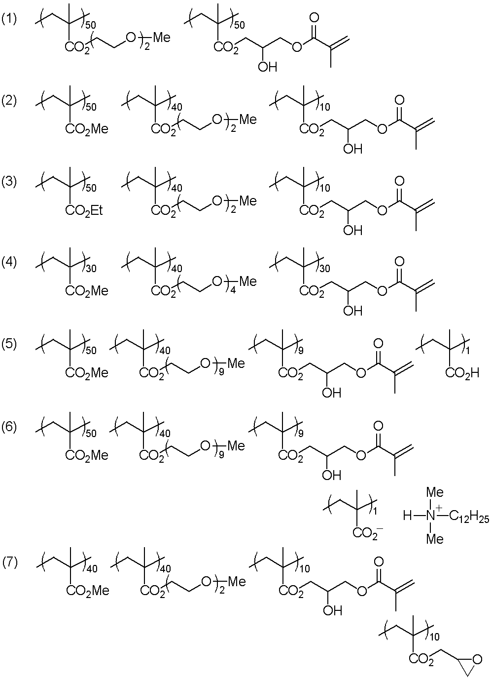

本発明では、機上現像性を向上させるため、ポリマー微粒子を用いることができる。特に、ポリアルキレンオキシド構造を有するポリマー微粒子が好ましい。特に側鎖にポリアルキレンオキシド基を有するポリマー微粒子が好ましい。これらにより、湿し水の浸透性が向上し、機上現像性が良好となる。
本発明におけるポリマー微粒子は、熱が加えられたときに画像記録層を疎水性に変換できる疎水化前駆体であることが好ましい。疎水化前駆体ポリマー微粒子としては、疎水性熱可塑性ポリマー微粒子、熱反応性ポリマー微粒子、疎水性化合物を内包しているマイクロカプセル、及びミクロゲル(架橋ポリマー微粒子)から選ばれる少なくともひとつの粒子が好ましい。なかでも、重合性基を有するポリマー微粒子及びミクロゲルが好ましい。機上現像性を向上させるためには、上記の如く、ポリアルキレンオキシド構造を有することが好ましい。 (3) Polymer fine particles In the present invention, polymer fine particles can be used in order to improve the on-press developability. In particular, polymer fine particles having a polyalkylene oxide structure are preferred. In particular, polymer fine particles having a polyalkylene oxide group in the side chain are preferred. As a result, the permeability of the fountain solution is improved and the on-press developability is improved.
The polymer fine particles in the present invention are preferably hydrophobized precursors that can convert the image recording layer to hydrophobic when heat is applied. The hydrophobized precursor polymer fine particles are preferably at least one particle selected from hydrophobic thermoplastic polymer fine particles, heat-reactive polymer fine particles, microcapsules enclosing a hydrophobic compound, and microgel (crosslinked polymer fine particles). Among these, polymer fine particles and microgels having a polymerizable group are preferable. In order to improve the on-press developability, it is preferable to have a polyalkylene oxide structure as described above.
このようなポリマー微粒子を構成するポリマーの具体例としては、エチレン、スチレン、塩化ビニル、アクリル酸メチル、アクリル酸エチル、メタクリル酸メチル、メタクリル酸エチル、塩化ビニリデン、アクリロニトリル、ビニルカルバゾール、ポリアルキレン構造を有するアクリレート又はメタクリレートなどのモノマーのホモポリマー若しくはコポリマー又はそれらの混合物を挙げることができる。その中で、より好適なものとして、ポリスチレン、スチレン及びアクリロニトリルを含む共重合体、ポリメタクリル酸メチルを挙げることができる。 Hydrophobic thermoplastic polymer fine particles include Research Disclosure No. 1 of January 1992. 331,003, JP-A-9-123387, JP-A-9-131850, JP-A-9-171249, JP-A-9-171250, and European Patent No. 931647 are suitable. Can be cited as
Specific examples of polymers constituting such polymer fine particles include ethylene, styrene, vinyl chloride, methyl acrylate, ethyl acrylate, methyl methacrylate, ethyl methacrylate, vinylidene chloride, acrylonitrile, vinyl carbazole, and polyalkylene structures. Mention may be made of homopolymers or copolymers of monomers such as acrylates or methacrylates or mixtures thereof. Among them, more preferable examples include a copolymer containing polystyrene, styrene and acrylonitrile, and polymethyl methacrylate.
本発明における画像記録層は、耐刷性を低下させることなく機上現像性を向上させるために、低分子親水性化合物を含有してもよい。
低分子親水性化合物としては、例えば、水溶性有機化合物としては、エチレングリコール、ジエチレングリコール、トリエチレングリコール、プロピレングリコール、ジプロピレングリコール、トリプロピレングリコール等のグリコール類及びそのエーテル又はエステル誘導体類、グリセリン、ペンタエリスリトール、トリス(2-ヒドロキシエチル)イソシアヌレート等のポリオール類、トリエタノールアミン、ジエタノールアミン、モノエタノールアミン等の有機アミン類及びその塩、アルキルスルホン酸、トルエンスルホン酸、ベンゼンスルホン酸等の有機スルホン酸類及びその塩、アルキルスルファミン酸等の有機スルファミン酸類及びその塩、アルキル硫酸、アルキルエーテル硫酸等の有機硫酸類及びその塩、フェニルホスホン酸等の有機ホスホン酸類及びその塩、酒石酸、シュウ酸、クエン酸、リンゴ酸、乳酸、グルコン酸、アミノ酸類等の有機カルボン酸類及びその塩、ベタイン類、等が挙げられる。 (4) Low molecular weight hydrophilic compound The image recording layer in the invention may contain a low molecular weight hydrophilic compound in order to improve the on-press developability without reducing the printing durability.
As the low molecular weight hydrophilic compound, for example, as the water-soluble organic compound, ethylene glycol, diethylene glycol, triethylene glycol, propylene glycol, dipropylene glycol, tripropylene glycol and the like glycols and ether or ester derivatives thereof, glycerin, Polyols such as pentaerythritol and tris (2-hydroxyethyl) isocyanurate, organic amines such as triethanolamine, diethanolamine and monoethanolamine and salts thereof, organic sulfones such as alkylsulfonic acid, toluenesulfonic acid and benzenesulfonic acid Acids and salts thereof, organic sulfamic acids such as alkylsulfamic acid and salts thereof, organic sulfuric acids such as alkylsulfuric acid and alkylethersulfuric acid and salts thereof, phenylphosphonic acid Organic phosphonic acids and salts thereof, tartaric acid, oxalic acid, citric acid, malic acid, lactic acid, gluconic acid, organic carboxylic acids and salts thereof such as amino acids, betaines, and the like.
これらの化合物は単独で用いてもよく、2種以上を混合して用いてもよい。 The amount of these low molecular weight hydrophilic compounds added to the image recording layer is preferably 0.5% by mass or more and 20% by mass or less of the total solid content of the image recording layer. More preferably, they are 1 mass% or more and 15 mass% or less, More preferably, they are 2 mass% or more and 10 mass% or less. In this range, good on-press developability and printing durability can be obtained.
These compounds may be used alone or in combination of two or more.
本発明の画像記録層には、着肉性を向上させるために、画像記録層にホスホニウム化合物、含窒素低分子化合物、アンモニウム基含有ポリマーなどの感脂化剤を用いることができる。特に、保護層に無機質の層状化合物を含有させる場合、これらの化合物は、無機質の層状化合物の表面被覆剤として機能し、無機質の層状化合物による印刷途中の着肉性低下を防止する。 (5) Grease Sensitizer In the image recording layer of the present invention, a lipid sensitizer such as a phosphonium compound, a nitrogen-containing low molecular weight compound, or an ammonium group-containing polymer is used for the image recording layer in order to improve the inking property. be able to. In particular, when an inorganic layered compound is contained in the protective layer, these compounds function as a surface coating agent for the inorganic layered compound, and prevent a decrease in the inking property during printing by the inorganic layered compound.
(1)2-(トリメチルアンモニオ)エチルメタクリレート=p-トルエンスルホナート/3,6-ジオキサヘプチルメタクリレート共重合体(モル比10/90 Mw4.5万)(2)2-(トリメチルアンモニオ)エチルメタクリレート=ヘキサフルオロホスファート/3,6-ジオキサヘプチルメタクリレート共重合体(モル比20/80 Mw6.0万)(3)2-(エチルジメチルアンモニオ)エチルメタクリレート=p-トルエンスルホナート/ヘキシルメタクリレート共重合体(モル比30/70 Mw4.5万)(4)2-(トリメチルアンモニオ)エチルメタクリレート=ヘキサフルオロホスファート/2-エチルヘキシルメタクリレート共重合体(モル比20/80 Mw6.0万)(5)2-(トリメチルアンモニオ)エチルメタクリレート=メチルスルファート/ヘキシルメタクリレート共重合体(モル比40/60 Mw7.0万)(6)2-(ブチルジメチルアンモニオ)エチルメタクリレート=ヘキサフルオロホスファート/3,6-ジオキサヘプチルメタクリレート共重合体(モル比 25/75 Mw6.5万)(7)2-(ブチルジメチルアンモニオ)エチルアクリレート=ヘキサフルオロホスファート/3,6-ジオキサヘプチルメタクリレート共重合体(モル比20/80 Mw6.5万)(8)2-(ブチルジメチルアンモニオ)エチルメタクリレート=13-エチル-5,8,11-トリオキサ-1-ヘプタデカンスルホナート/3,6-ジオキサヘプチルメタクリレート共重合体(モル比20/80 Mw7.5万)(9)2-(ブチルジメチルアンモニオ)エチルメタクリレート=ヘキサフルオロホスファート/3,6-ジオキサヘプチルメタクリレート/2-ヒドロキシ-3-メタクロイルオキシプロピルメタクリレート共重合体(モル比15/80/5 Mw6.5万) Specific examples of the ammonium group-containing polymer are shown below.
(1) 2- (trimethylammonio) ethyl methacrylate = p-toluenesulfonate / 3,6-dioxaheptyl methacrylate copolymer (molar ratio 10/90 Mw 45,000) (2) 2- (trimethylammonio) ) Ethyl methacrylate = hexafluorophosphate / 3,6-dioxaheptyl methacrylate copolymer (molar ratio 20/80 Mw 60,000) (3) 2- (ethyldimethylammonio) ethyl methacrylate = p-toluenesulfonate / Hexyl methacrylate copolymer (molar ratio 30/70 Mw 45,000) (4) 2- (trimethylammonio) ethyl methacrylate = hexafluorophosphate / 2-ethylhexyl methacrylate copolymer (molar ratio 20/80 Mw 6. (0000) (5) 2- (Trimethylammonio) Eth Methacrylate = methyl sulfate / hexyl methacrylate copolymer (molar ratio 40/60 Mw 7 million) (6) 2- (butyldimethylammonio) ethyl methacrylate = hexafluorophosphate / 3,6-dioxaheptyl methacrylate Copolymer (molar ratio 25/75 Mw 65,000) (7) 2- (butyldimethylammonio) ethyl acrylate = hexafluorophosphate / 3,6-dioxaheptyl methacrylate copolymer (molar ratio 20/80 Mw 65,000) (8) 2- (Butyldimethylammonio) ethyl methacrylate = 13-ethyl-5,8,11-trioxa-1-heptadecanesulfonate / 3,6-dioxaheptyl methacrylate copolymer ( Molar ratio 20/80 Mw 75,000) (9) 2- (Butyldimethyl) Ammonio) ethyl methacrylate hexafluorophosphate / 3,6-dioxaheptyl methacrylate / 2-hydroxy-3-methacryloyl oxy propyl methacrylate copolymer (molar ratio 15/80/5 Mw6.5 50,000)
更にその他の成分として、界面活性剤、着色剤、焼き出し剤、重合禁止剤、高級脂肪酸誘導体、可塑剤、無機微粒子、無機質層状化合物、及び共増感剤若しくは連鎖移動剤などを添加することができる。具体的には、特開2008-284817号公報の段落番号[0114]~[0159]、特開2006-091479号公報の段落番号[0023]~[0027]、米国特許公開2008/0311520号明細書段落番号[0060]に記載の化合物及び添加量が好ましい。 (6) Other components As other components, surfactants, colorants, print-out agents, polymerization inhibitors, higher fatty acid derivatives, plasticizers, inorganic fine particles, inorganic layered compounds, and co-sensitizers or chain transfer agents Etc. can be added. Specifically, paragraph numbers [0114] to [0159] of Japanese Patent Application Laid-Open No. 2008-284817, paragraph numbers [0023] to [0027] of Japanese Patent Application Laid-Open No. 2006-091479, and US Patent Publication No. 2008/0311520. The compounds and addition amounts described in paragraph [0060] are preferred.
本発明における画像記録層は、例えば、特開2008-195018号公報の段落番号[0142]~[0143]に記載のように、必要な上記各成分を公知の溶剤に分散又は溶解して塗布液を調製し、これを支持体上にバーコーター塗布など公知の方法で塗布し、乾燥することで形成される。塗布、乾燥後に得られる支持体上の画像記録層塗布量(固形分)は、用途によって異なるが、一般的に0.3~3.0g/m2が好ましく、0.5~2.0g/m2がより好ましく、0.8~1.5g/m2が最も好ましい。 (Formation of image recording layer)
The image recording layer in the present invention is a coating solution prepared by dispersing or dissolving the necessary components in a known solvent as described in paragraphs [0142] to [0143] of JP-A-2008-195018, for example. This is prepared by coating the substrate by a known method such as bar coater coating and drying. The image recording layer coating amount (solid content) on the support obtained after coating and drying varies depending on the application, but is generally preferably 0.3 to 3.0 g / m 2 , and preferably 0.5 to 2.0 g / m 2. m 2 is more preferable, and 0.8 to 1.5 g / m 2 is most preferable.
本発明の平版印刷版原版は、白色基板と画像記録層との間に下塗り層を設けることができる。下塗り層は、露光部においては支持体と画像記録層との密着を強化し、未露光部においては画像記録層の支持体からのはく離を生じやすくさせるため、耐刷性を損なわず現像性を向上させるのに寄与する。また、赤外線レーザー露光の場合は、下塗り層が断熱層として機能することにより、露光により発生した熱が支持体に拡散して感度が低下するのを防ぐ。 (Undercoat layer)
In the lithographic printing plate precursor according to the invention, an undercoat layer can be provided between the white substrate and the image recording layer. The undercoat layer enhances the adhesion between the support and the image recording layer in the exposed area, and easily peels off the image recording layer from the support in the unexposed area. Contributes to improvement. In the case of infrared laser exposure, the undercoat layer functions as a heat insulating layer, thereby preventing the heat generated by the exposure from diffusing to the support and reducing the sensitivity.
本発明の平版印刷版原版には、露光時の重合反応を妨害する酸素の拡散侵入を遮断するため、画像記録層上に保護層が設けられることが好ましい。保護層に使用できる材料としては、水溶性ポリマー、水不溶性ポリマーのいずれをも適宜選択して使用することができ、必要に応じて2種類以上を混合して使用することもできる。具体的には、例えば、ポリビニルアルコール、変性ポリビニルアルコール、ポリビニルピロリドン、水溶性セルロース誘導体、ポリ(メタ)アクリロニトリル等が挙げられる。これらの中で、比較的結晶性に優れた水溶性高分子化合物を用いることが好ましく、具体的には、ポリビニルアルコールを主成分として用いる事が、酸素遮断性、現像除去性といった基本特性的に最も良好な結果を与える。 [Protective layer]
The lithographic printing plate precursor according to the invention is preferably provided with a protective layer on the image recording layer in order to block the diffusion and penetration of oxygen that hinders the polymerization reaction during exposure. As a material that can be used for the protective layer, either a water-soluble polymer or a water-insoluble polymer can be appropriately selected and used, and two or more types can be mixed and used as necessary. Specific examples include polyvinyl alcohol, modified polyvinyl alcohol, polyvinyl pyrrolidone, water-soluble cellulose derivatives, poly (meth) acrylonitrile, and the like. Among these, it is preferable to use a water-soluble polymer compound having relatively excellent crystallinity. Specifically, the use of polyvinyl alcohol as a main component is based on basic characteristics such as oxygen barrier properties and development removability. Give the best results.
ポリビニルアルコールと別の材料を混合して使用する場合、混合する成分としては、変性ポリビニルアルコール、ポリビニルピロリドン又はその変性物が酸素遮断性、現像除去性といった観点から好ましく、保護層中の含有率が3.5~80質量%、好ましくは10~60質量%、更に好ましくは15~30質量%である。 Moreover, well-known modified polyvinyl alcohol can also be used preferably. In particular, acid-modified polyvinyl alcohol having a carboxylic acid group or a sulfonic acid group is preferably used. Specific examples include polyvinyl alcohols described in JP-A-2005-250216 and JP-A-2006-259137.
When using a mixture of polyvinyl alcohol and another material, the component to be mixed is preferably a modified polyvinyl alcohol, polyvinyl pyrrolidone or a modified product thereof from the viewpoint of oxygen barrier properties, development removability, and the content in the protective layer. It is 3.5 to 80% by mass, preferably 10 to 60% by mass, and more preferably 15 to 30% by mass.
本発明の平版印刷版原版の製版は機上現像方法で行うことが好ましい。機上現像方法は、平版印刷版原版を画像露光する工程と、露光後の平版印刷版原版になんらの現像処理を施すことなく、油性インキと水性成分とを供給して、印刷する印刷工程とを有し、該印刷工程の途上において平版印刷版原版の未露光部分が除去されることを特徴とする。画像様の露光は平版印刷版原版を印刷機に装着した後、印刷機上で行ってもよいし、プレートセッターなどで別途行ってもよい。後者の場合は、露光済み平版印刷版原版は現像処理工程を経ないでそのまま印刷機に装着される。その後、該印刷機を用い、油性インキと水性成分とを供給してそのまま印刷することにより、印刷途上の初期の段階で機上現像処理、すなわち、未露光領域の画像記録層が除去され、それに伴って親水性支持体表面が露出され非画像部が形成される。油性インキ及び水性成分としては、通常の平版印刷用の印刷インキと湿し水が用いられる。
以下、更に詳細に説明する。 [Printing method]
The lithographic printing plate precursor according to the invention is preferably made by an on-press development method. The on-press development method includes an image exposure process for a lithographic printing plate precursor, a printing process in which an oil-based ink and an aqueous component are supplied and printed without performing any development process on the exposed lithographic printing plate precursor. And the unexposed portion of the lithographic printing plate precursor is removed during the printing process. Imagewise exposure may be performed on the printing machine after the lithographic printing plate precursor is mounted on the printing machine, or may be separately performed with a plate setter or the like. In the latter case, the exposed lithographic printing plate precursor is mounted on a printing machine without undergoing a development process. Thereafter, by using the printing machine and supplying the oil-based ink and the aqueous component and printing as it is, an on-press development process, that is, an image recording layer in an unexposed area is removed at an early stage of printing, Accordingly, the surface of the hydrophilic support is exposed to form a non-image part. As the oil-based ink and the aqueous component, ordinary lithographic printing ink and fountain solution are used.
This will be described in more detail below.
赤外線レーザーに関しては、出力は100mW以上であることが好ましく、1画素当たりの露光時間は20マイクロ秒以内であるのが好ましく、また照射エネルギー量は10~300mJ/cm2であるのが好ましい。レーザーにおいては、露光時間を短縮するためマルチビームレーザーデバイスを用いるのが好ましい。 In the present invention, the light source used for image exposure is preferably a laser. The laser used in the present invention is not particularly limited, and preferred examples include solid lasers and semiconductor lasers that irradiate infrared rays having a wavelength of 760 to 1200 nm.
Regarding the infrared laser, the output is preferably 100 mW or more, the exposure time per pixel is preferably within 20 microseconds, and the irradiation energy amount is preferably 10 to 300 mJ / cm 2 . In the laser, it is preferable to use a multi-beam laser device in order to shorten the exposure time.
このようにして、本発明の平版印刷版原版はオフセット印刷機上で現像され、そのまま多数枚の印刷に用いられる。 Here, dampening water or printing ink may be supplied to the printing plate first, but printing is first performed in order to prevent the dampening water from being contaminated by the removed image recording layer components. It is preferable to supply ink.
In this way, the planographic printing plate precursor of the present invention is developed on an offset printing machine and used for printing a large number of sheets as it is.
(1)支持体の処理 : 条件1
厚み0.3mmのアルミニウム板(材質1050)の表面の圧延油を除去するため、10質量%アルミン酸ソーダ水溶液を用いて50℃で30秒間、脱脂処理を施した後、毛径0.3mmの束植ナイロンブラシ3本とメジアン径25μmのパミス-水懸濁液(比重1.1g/cm3)を用いアルミニウム表面を砂目立てして、水でよく洗浄した。この板を45℃の25質量%水酸化ナトリウム水溶液に9秒間浸漬してエッチングを行い、水洗後、更に60℃で20質量%硝酸に20秒間浸漬し、水洗した。この時の砂目立て表面のエッチング量は約3g/m2であった。
次に、60Hzの交流電圧を用いて連続的に電気化学的な粗面化処理を行った。このときの電解液は、硝酸1質量%水溶液(アルミニウムイオンを0.5質量%含む)、液温50℃であった。交流電源波形は、電流値がゼロからピークに達するまでの時間TPが0.8msec、duty比1:1、台形の矩形波交流を用いて、カーボン電極を対極として電気化学的な粗面化処理を行った。補助アノードにはフェライトを用いた。電流密度は電流のピーク値で30A/dm2、補助陽極には電源から流れる電流の5%を分流させた。硝酸電解における電気量はアルミニウム板が陽極時の電気量175C/dm2であった。その後、スプレーによる水洗を行った。
次に、塩酸0.5質量%水溶液(アルミニウムイオンを0.5質量%含む)、液温50℃の電解液にて、アルミニウム板が陽極時の電気量50C/dm2の条件で、硝酸電解と同様の方法で、電気化学的な粗面化処理を行い、その後、スプレーによる水洗を行った。この板を15質量%硫酸(アルミニウムイオンを0.5質量%含む)を電解液として電流密度15A/dm2で2.5g/m2の直流陽極酸化皮膜を設けた後、水洗、乾燥し、更に、珪酸ナトリウム2.5質量%水溶液にて30℃で10秒処理した。この支持体の急峻度a45をAFMで測定した表面形状から算出したところ、52%であった。反射濃度を測定したところ、0.41であった。 [Example 1]
(1) Treatment of support: Condition 1
In order to remove rolling oil on the surface of an aluminum plate (material 1050) having a thickness of 0.3 mm, a degreasing treatment was performed at 50 ° C. for 30 seconds using a 10 mass% sodium aluminate aqueous solution, and then the hair diameter was 0.3 mm. The aluminum surface was grained using three bundle-planted nylon brushes and a pumice-water suspension (specific gravity 1.1 g / cm 3 ) having a median diameter of 25 μm and washed thoroughly with water. This plate was etched by being immersed in a 25 mass% sodium hydroxide aqueous solution at 45 ° C for 9 seconds, washed with water, further immersed in 20 mass% nitric acid at 60 ° C for 20 seconds, and washed with water. The etching amount of the grained surface at this time was about 3 g / m 2 .
Next, an electrochemical roughening treatment was performed continuously using an alternating voltage of 60 Hz. The electrolytic solution at this time was a 1% by mass aqueous solution of nitric acid (containing 0.5% by mass of aluminum ions) and a liquid temperature of 50 ° C. The AC power supply waveform is electrochemical roughening treatment using a trapezoidal rectangular wave AC with a time TP of 0.8 msec until the current value reaches a peak from zero, a duty ratio of 1: 1, and a trapezoidal rectangular wave AC. Went. Ferrite was used for the auxiliary anode. The current density was 30 A / dm 2 at the peak current value, and 5% of the current flowing from the power source was shunted to the auxiliary anode. The amount of electricity in nitric acid electrolysis was 175 C / dm 2 when the aluminum plate was the anode. Then, water washing by spraying was performed.
Next, nitric acid electrolysis was performed with an aqueous solution of 0.5% by mass of hydrochloric acid (containing 0.5% by mass of aluminum ions) and an electrolytic solution having a liquid temperature of 50 ° C. and an aluminum plate serving as an anode with an electric quantity of 50 C / dm 2. In the same manner as above, an electrochemical surface roughening treatment was performed, followed by washing with water by spraying. The plate was provided with a direct current anodized film of 2.5 g / m 2 at a current density of 15 A / dm 2 using 15 mass% sulfuric acid (containing 0.5 mass% of aluminum ions) as an electrolytic solution, then washed with water and dried. Furthermore, it processed for 10 second at 30 degreeC with 2.5 mass% sodium silicate aqueous solution. The steepness a45 of the support was calculated from the surface shape measured by AFM and found to be 52%. The reflection density was measured and found to be 0.41.
次いで、粗面化処理されたアルミニウム表面に下記のゾル-ゲル液1を塗布し、加熱乾燥(100℃、10分)することにより、乾燥質量0.2g/m2の蛍光増白剤(化合物1)を無機親水性マトリクス中に含有する白色層を形成した。 (2) Formation of white layer Next, the following sol-gel solution 1 was applied to the roughened aluminum surface and dried by heating (100 ° C., 10 minutes), whereby a dry mass of 0.2 g / m 2 was obtained. A white layer containing the fluorescent whitening agent (Compound 1) in an inorganic hydrophilic matrix was formed.
・ゾル-ゲル調製液(1)(下記組成) 4.7g
・化合物1〔下記構造〕 0.64g
・ポリオキシエチレンノニルフェニルエーテル
(ノニポール100、三洋化成工業(株)製) 0.025g
・水 15g
・メタノール 5g <Sol-gel solution 1>
Sol-gel preparation liquid (1) (the following composition) 4.7 g
Compound 1 [the following structure] 0.64 g
・ Polyoxyethylene nonylphenyl ether
(Nonipol 100, Sanyo Chemical Industries, Ltd.) 0.025g
・ Water 15g
・ Methanol 5g

下記組成の液を室温において、1時間熟成してゾル-ゲル調製液を作製した。
・テトラエトキシシラン 8.5g
・メタノール 1.8g
・水 15.0g
・リン酸 0.015g (Preparation of sol-gel preparation liquid (1))
A solution having the following composition was aged at room temperature for 1 hour to prepare a sol-gel preparation solution.
・ Tetraethoxysilane 8.5g
・ Methanol 1.8g
・ Water 15.0g
・ Phosphoric acid 0.015g
上記のようにして形成された支持体上に、下記組成の画像形成層塗布液1をバー塗布した後、100℃60秒でオーブン乾燥し、乾燥塗布量1.0g/m2の画像形成層を形成した。 (3) Formation of Image Forming Layer After the image forming layer coating solution 1 having the following composition is bar-coated on the support formed as described above, it is oven-dried at 100 ° C. for 60 seconds. An image forming layer of 0 g / m 2 was formed.
・バインダーポリマー(1)〔下記構造〕 0.240g
・ミクロゲル(1) 1.900g
・赤外線吸収剤及び発色性化合物:シアニン色素(1)〔下記構造〕
0.015g
・重合開始剤(1)〔下記構造〕 0.100g
・重合性化合物 トリス(アクリロイルオキシエチル)イソシアヌレート
(NKエステルA-9300、新中村化学(株)製) 0.192g
・低分子親水性化合物
トリス(2-ヒドロキシエチル)イソシアヌレート 0.062g
・低分子親水性化合物(1)〔下記構造〕 0.050g
・感脂化剤 ホスホニウム化合物(1)〔下記構造〕 0.055g
・感脂化剤 ベンジル-ジメチル-オクチルアンモニウム・PF6塩
0.018g
・感脂化剤 アンモニウム基含有ポリマー
[下記構造、還元粘度44ml/g] 0.035g
・フッ素系界面活性剤(1)〔下記構造〕 0.008g
・2-ブタノン 1.091g
・1-メトキシ-2-プロパノール 8.609g <Image forming layer coating solution 1>
-Binder polymer (1) [the following structure] 0.240 g
・ Microgel (1) 1.900 g
Infrared absorber and color forming compound: cyanine dye (1) [the following structure]
0.015g
・ Polymerization initiator (1) [the following structure] 0.100 g
Polymerizable compound tris (acryloyloxyethyl) isocyanurate
(NK ester A-9300, manufactured by Shin-Nakamura Chemical Co., Ltd.) 0.192 g
・ Low molecular weight hydrophilic compound Tris (2-hydroxyethyl) isocyanurate 0.062g
・ Low molecular weight hydrophilic compound (1) [the following structure] 0.050 g
-Sensitizing agent Phosphonium compound (1) [the following structure] 0.055 g
・ Sensitizer Benzyl-dimethyl-octylammonium ・ PF 6 salt 0.018g
・ Sensitizer Ammonium group-containing polymer
[The following structure, reduced viscosity 44 ml / g] 0.035 g
・ Fluorosurfactant (1) [The following structure] 0.008g
・ 2-butanone 1.091g
・ 1-methoxy-2-propanol 8.609g
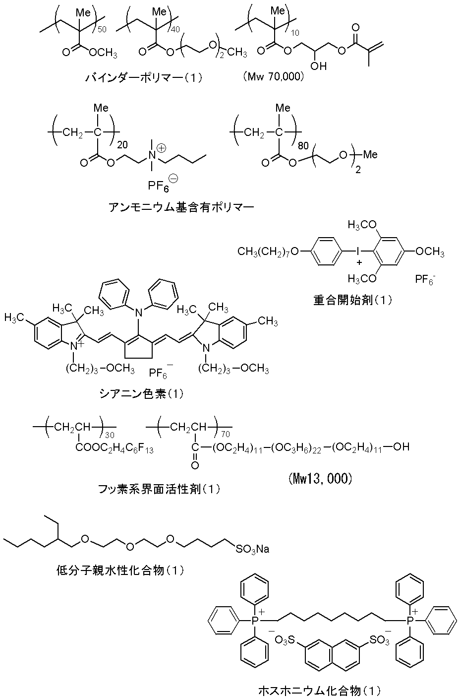
油相成分として、トリメチロールプロパンとキシレンジイソシアナート付加体(三井化学(株)製、タケネートD-110N)10g、ペンタエリスリトールトリアクリレート(日本化薬(株)製、SR444)3.15g、及びパイオニンA-41C(竹本油脂(株)製)0.1gを酢酸エチル17gに溶解した。水相成分としてポリビニルアルコール((株)クラレ製PVA-205)の4質量%水溶液40gを調製した。油相成分及び水相成分を混合し、ホモジナイザーを用いて12,000rpmで10分間乳化した。得られた乳化物を、蒸留水25gに添加し、室温で30分攪拌後、50℃で3時間攪拌した。このようにして得られたミクロゲル液の固形分濃度を、15質量%になるように蒸留水を用いて希釈し、これを前記ミクロゲルとした。ミクロゲルの平均粒径を光散乱法により測定したところ、平均粒径は0.2μmであった。 <Synthesis of Microgel (1)>
As an oil phase component, trimethylolpropane and xylene diisocyanate adduct (manufactured by Mitsui Chemicals, Takenate D-110N) 10 g, pentaerythritol triacrylate (manufactured by Nippon Kayaku Co., Ltd., SR444) 3.15 g, and 0.1 g of Piionin A-41C (manufactured by Takemoto Yushi Co., Ltd.) was dissolved in 17 g of ethyl acetate. As an aqueous phase component, 40 g of a 4% by mass aqueous solution of polyvinyl alcohol (PVA-205 manufactured by Kuraray Co., Ltd.) was prepared. The oil phase component and the aqueous phase component were mixed and emulsified for 10 minutes at 12,000 rpm using a homogenizer. The obtained emulsion was added to 25 g of distilled water, stirred at room temperature for 30 minutes, and then stirred at 50 ° C. for 3 hours. The solid content concentration of the microgel solution thus obtained was diluted with distilled water so as to be 15% by mass, and this was used as the microgel. When the average particle size of the microgel was measured by a light scattering method, the average particle size was 0.2 μm.
画像形成層の上に、更に下記組成の保護層塗布液(1)をバー塗布した後、120℃、60秒でオーブン乾燥し、乾燥塗布量0.15g/m2の保護層を形成して平版印刷版原版を得た。 (4) Formation of protective layer After a bar coating of a protective layer coating solution (1) having the following composition was applied on the image forming layer, it was oven-dried at 120 ° C for 60 seconds, and the dry coating amount was 0.15 g / m 2. A lithographic printing plate precursor was obtained by forming a protective layer.
・無機質層状化合物分散液(1) 1.5g
・ポリビニルアルコール(日本合成化学工業(株)製CKS50、スルホン酸変性、けん化度99モル%以上、重合度300)6質量%水溶液
0.55g
・ポリビニルアルコール((株)クラレ製PVA-405、
けん化度81.5モル%、重合度500)6質量%水溶液 0.03g
・日本エマルジョン(株)製界面活性剤
(エマレックス710)1質量%水溶液 0.86g
・イオン交換水 6.0g <Coating liquid for protective layer (1)>
・ Inorganic layered compound dispersion (1) 1.5 g
・ Polyvinyl alcohol (CKS50, Nippon Synthetic Chemical Industry Co., Ltd., sulfonic acid modification, saponification degree 99 mol% or more, polymerization degree 300) 6% by mass aqueous solution 0.55 g
・ Polyvinyl alcohol (PVA-405 manufactured by Kuraray Co., Ltd.)
Degree of saponification 81.5 mol%, degree of polymerization 500) 6% by weight aqueous solution 0.03 g
-0.86 g of 1% by weight aqueous solution of surfactant (Emalex 710) manufactured by Nippon Emulsion Co., Ltd.
・ Ion-exchanged water 6.0g
イオン交換水193.6gに合成雲母ソマシフME-100(コープケミカル(株)製)6.4gを添加し、ホモジナイザーを用いて平均粒径(レーザー散乱法)が3μmになるまで分散した。得られた分散粒子のアスペクト比は100以上であった。 (Preparation of inorganic layered compound dispersion (1))
6.4 g of synthetic mica Somasif ME-100 (manufactured by Coop Chemical Co., Ltd.) was added to 193.6 g of ion-exchanged water and dispersed using an homogenizer until the average particle size (laser scattering method) became 3 μm. The aspect ratio of the obtained dispersed particles was 100 or more.
画像形成層の塗布液を画像形成層塗布液2に変更すること以外、上記実施例1と同様にして平版印刷版原版を作製した。 [Example 2]
A lithographic printing plate precursor was prepared in the same manner as in Example 1 except that the image forming layer coating solution was changed to the image forming layer coating solution 2.
実施例1使用の画像形成層塗布液1に更に酸発色剤を添加する。
・画像形成層塗布液1 12.38g
・酸発色剤(下記構造) 0.1g <Image forming layer coating solution 2>
An acid color former is further added to the image forming layer coating solution 1 used in Example 1.
-Image forming layer coating solution 1 12.38 g
・ Acid color former (structure below) 0.1g
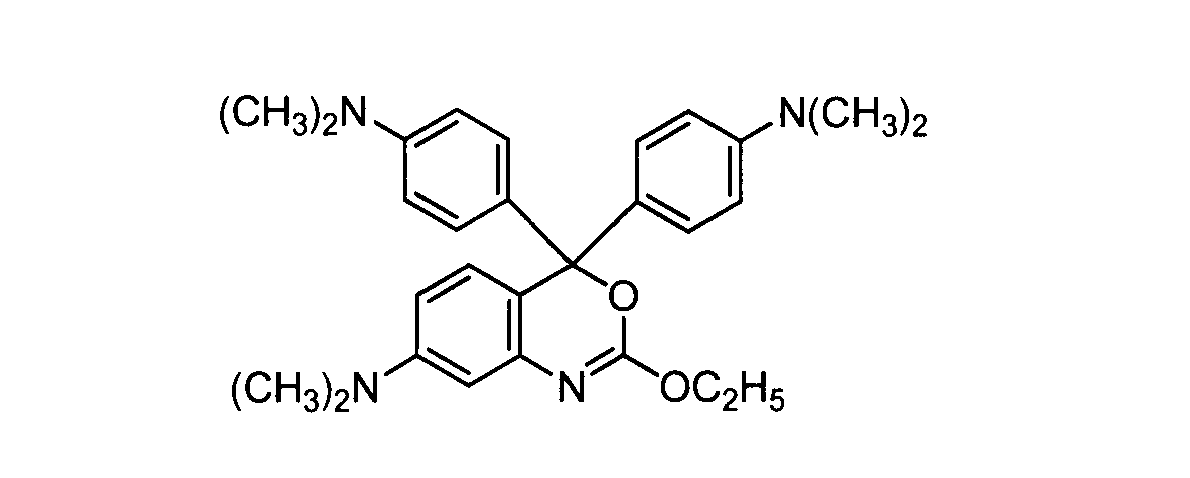
画像形成層の塗布液を画像形成層塗布液3に変更すること以外,上記実施例1と同様にして平版印刷版原版を作製した。 [Example 3]
A lithographic printing plate precursor was prepared in the same manner as in Example 1 except that the image forming layer coating solution was changed to the image forming layer coating solution 3.
実施例1使用の画像形成層塗布液1に更に熱発色剤を添加する。
・画像形成層塗布液1 12.38g
・熱発色剤(下記構造) 0.1g <Image forming layer coating solution 3>
A thermochromic agent is further added to the image forming layer coating solution 1 used in Example 1.
-Image forming layer coating solution 1 12.38 g
・ Thermal coloring agent (the following structure) 0.1g

画像形成層の塗布液を画像形成層塗布液4に変更すること以外、上記実施例1と同様にして平版印刷版原版を作製した。 [Example 4]
A lithographic printing plate precursor was prepared in the same manner as in Example 1 except that the image forming layer coating solution was changed to the image forming layer coating solution 4.
・バインダーポリマー(1) 0.240g
・ミクロゲル(1) 1.900g
・赤外吸収剤及び発色性化合物:シアニン色素(1) 0.015g
・重合開始剤(2)(下記構造) 0.100g
・重合性化合物 トリス(アクリロイルオキシエチル)イソシアヌレート
(NKエステルA-9300、新中村化学(株)製) 0.192g
・低分子親水性化合物
トリス(2-ヒドロキシエチル)イソシアヌレート 0.062g
・低分子親水性化合物(1) 0.050g
・感脂化剤 ホスホニウム化合物(1) 0.055g
・感脂化剤 ベンジル-ジメチル-オクチルアンモニウム・PF6塩
0.018g
・感脂化剤 アンモニウム基含有ポリマー [還元粘度44ml/g]
0.035g
・フッ素系界面活性剤(1) 0.008g
・2-ブタノン 1.091g
・1-メトキシ-2-プロパノール 8.609g <Image forming layer coating solution 4>
-Binder polymer (1) 0.240g
・ Microgel (1) 1.900 g
Infrared absorber and color forming compound: cyanine dye (1) 0.015 g
・ Polymerization initiator (2) (the following structure) 0.100 g
Polymerizable compound tris (acryloyloxyethyl) isocyanurate (NK ester A-9300, manufactured by Shin-Nakamura Chemical Co., Ltd.) 0.192 g
・ Low molecular weight hydrophilic compounds
Tris (2-hydroxyethyl) isocyanurate 0.062g
・ Low molecular weight hydrophilic compound (1) 0.050 g
・ Sensitizer Phosphonium compound (1) 0.055g
・ Sensitizer Benzyl-dimethyl-octylammonium ・ PF 6 salt 0.018g
-Sensitizing agent Ammonium group-containing polymer [reduced viscosity 44 ml / g]
0.035g
・ Fluorosurfactant (1) 0.008g
・ 2-butanone 1.091g
・ 1-methoxy-2-propanol 8.609g

白色層の形成において、用いた蛍光増白剤を化合物2(下記構造)に変更したこと以外、上記実施例1と同様にして平版印刷版原版を作製した。 [Example 5]
A lithographic printing plate precursor was prepared in the same manner as in Example 1 except that the fluorescent whitening agent used was changed to Compound 2 (the following structure) in the formation of the white layer.

白色層の形成に用いた蛍光増白剤を化合物3(下記構造)に変更したこと以外、上記実施例1と同様にして平版印刷版原版を作製した。 [Example 6]
A lithographic printing plate precursor was prepared in the same manner as in Example 1 except that the fluorescent whitening agent used for forming the white layer was changed to Compound 3 (the following structure).

白色層の形成に用いた蛍光増白剤を化合物4(下記構造)に変更したこと以外、上記実施例1と同様上記実施例1と同様にして平版印刷版原版を作製した。 [Example 7]
A lithographic printing plate precursor was prepared in the same manner as in Example 1 except that the fluorescent whitening agent used for forming the white layer was changed to Compound 4 (the following structure).

実施例1のゾルーゲル液1の代わりに下記ゾルーゲル液2を用いた以外は実施例1と同様にして平版印刷版原版を作製した。無機親水性マトリクス中に白色顔料を坦持した白色層の塗布量は、白色顔料の乾燥質量が0.5g/m2となるようにした。 [Example 8]
A lithographic printing plate precursor was prepared in the same manner as in Example 1 except that the following sol-gel solution 2 was used instead of the sol-gel solution 1 of Example 1. The coating amount of the white layer carrying the white pigment in the inorganic hydrophilic matrix was such that the dry mass of the white pigment was 0.5 g / m 2 .
・ゾル-ゲル調製液(1) 4.7g
・酸化チタン20質量%/ポリビニルアルコール10質量%の水分散液
〔酸化チタン(和光純薬工業(株)製、ルチル型、平均粒径200nm)、
ポリビニルアルコール((株)クラレ製PVA117)〕 8g
・メタノールシリカ
(日産化学(株)製:10nm~20nmのシリカ粒子を30質量%含有するメタノール溶液からなるコロイド)
8g
・ポリオキシエチレンノニルフェニルエーテル
(ノニポール100、三洋化成工業(株)製) 0.025g
・水 15g
・メタノール 5g <Sol-gel solution 2>
-Sol-gel preparation liquid (1) 4.7 g
-Aqueous dispersion of titanium oxide 20% by mass / polyvinyl alcohol 10% by mass [titanium oxide (manufactured by Wako Pure Chemical Industries, Ltd., rutile type, average particle size 200 nm),
Polyvinyl alcohol (PVA117 manufactured by Kuraray Co., Ltd.)] 8g
Methanol silica (manufactured by Nissan Chemical Co., Ltd .: colloid consisting of a methanol solution containing 30% by mass of 10-20 nm silica particles)
8g
・ Polyoxyethylene nonylphenyl ether
(Nonipol 100, Sanyo Chemical Industries, Ltd.) 0.025g
・ Water 15g
・ Methanol 5g
実施例1のゾルーゲル液1の代わりに下記ゾルーゲル液3を用いた以外は実施例1と同様にして平版印刷版原版を作製した。これにより、アルミニウム支持体と相互作用する基とエチレン性不飽和結合基を有する特定共重合体(1)でコーティングされた白色顔料が無機親水性マトリクス中に含有された白色層が形成される。白色顔料が乾燥質量で0.5g/m2となるように塗布した。それ以外は上記実施例1と同様にして平版印刷版原版を作製した。 [Example 9]
A lithographic printing plate precursor was prepared in the same manner as in Example 1 except that the following sol-gel solution 3 was used instead of the sol-gel solution 1 of Example 1. This forms a white layer in which the white pigment coated with the specific copolymer (1) having a group that interacts with the aluminum support and the ethylenically unsaturated bond group is contained in the inorganic hydrophilic matrix. The white pigment was applied so as to have a dry mass of 0.5 g / m 2 . Otherwise, a lithographic printing plate precursor was prepared in the same manner as in Example 1.
・ゾル-ゲル調製液(1) 4.7g
・酸化チタン20質量%/下記特定共重合体(1)10質量%含有の水分散液
(酸化チタン:和光純薬工業(株)製、ルチル型、平均粒径200nm)
8g
・メタノールシリカ(日産化学製:10nm~20nmのシリカ粒子を
30質量%含有するメタノール溶液からなるコロイド) 8g
・ポリオキシエチレンノニルフェニルエーテル
(三洋化成工業(株)製ノニポール100) 0.025g
・水 15g
・メタノール 5g <Sol-gel solution 3>
-Sol-gel preparation liquid (1) 4.7 g
-Titanium oxide 20% by mass / the following specific copolymer (1) 10% by mass-containing aqueous dispersion (titanium oxide: manufactured by Wako Pure Chemical Industries, Ltd., rutile type, average particle size 200 nm)
8g
Methanol silica (manufactured by Nissan Chemical Co., Ltd .: colloid consisting of a methanol solution containing 30% by mass of silica particles of 10 nm to 20 nm) 8 g
・ Polyoxyethylene nonylphenyl ether
(Sanyo Chemical Industries nonipol 100) 0.025g
・ Water 15g
・ Methanol 5g

画像形成層の塗布液を画像形成層塗布液2に変更すること以外、上記実施例9と同様にして平版印刷版原版を作製した。 [Example 10]
A lithographic printing plate precursor was prepared in the same manner as in Example 9 except that the image forming layer coating solution was changed to the image forming layer coating solution 2.
画像形成層の塗布液を画像形成層塗布液3に変更すること以外、上記実施例9と同様にして平版印刷版原版を作製した。 [Example 11]
A lithographic printing plate precursor was prepared in the same manner as in Example 9 except that the image forming layer coating solution was changed to the image forming layer coating solution 3.
ゾル-ゲル液3を下記のゾルーゲル液4に代えた以外は実施例11と同様にして平版印刷版原版を作製した。これにより、白色層は、特定共重合体(1)でコーティングされた白色顔料、更に蛍光増白剤を無機親水性マトリクス中に含有した形態となる。塗布量は、実施例11と同様、白色顔料が乾燥質量で0.5g/m2となるようにした。 [Example 12]
A lithographic printing plate precursor was prepared in the same manner as in Example 11 except that the sol-gel solution 3 was replaced with the following sol-gel solution 4. Thereby, a white layer becomes a form which contained the white pigment coated with the specific copolymer (1), and also the fluorescent whitening agent in the inorganic hydrophilic matrix. As in Example 11, the coating amount was set so that the white pigment was 0.5 g / m 2 in terms of dry mass.
・ゾル-ゲル調製液(1) 4.7g
・酸化チタン20質量%/特定共重合体(1)10質量%を含有する水分散液
(酸化チタン:和光純薬(株)製、ルチル型、平均粒径200nm)
4g
・メタノールシリカ(日産化学製:10nm~20nmのシリカ粒子を30質量%含有するメタノール溶液からなるコロイド)
4g
・化合物1 0.32g
・ポリオキシエチレンノニルフェニルエーテル (ノニポール100、三洋化成工業(株)製)
0.025g
・水 15g
・メタノール 5g <Sol-gel solution 4>
-Sol-gel preparation liquid (1) 4.7 g
-Aqueous dispersion containing 20% by mass of titanium oxide / 10% by mass of the specific copolymer (1) (titanium oxide: manufactured by Wako Pure Chemical Industries, Ltd., rutile type, average particle size 200 nm)
4g
Methanol silica (manufactured by Nissan Chemical Co., Ltd .: a colloid composed of a methanol solution containing 30% by mass of silica particles of 10 nm to 20 nm)
4g
・ Compound 1 0.32 g
・ Polyoxyethylene nonylphenyl ether (Nonipol 100, manufactured by Sanyo Chemical Industries, Ltd.)
0.025g
・ Water 15g
・ Methanol 5g
(1)支持体の処理:条件2
厚み0.3mmのアルミニウム板(材質1050)の表面の圧延油を除去するため、10質量%アルミン酸ソーダ水溶液を用いて50℃で30秒間、脱脂処理を施した後、毛径0.3mmの束植ナイロンブラシ3本とメジアン径25μmのパミス-水懸濁液(比重1.1g/cm3)を用いアルミニウム表面を砂目立てして、水でよく洗浄した。この板を45℃の25質量%水酸化ナトリウム水溶液に9秒間浸漬してエッチングを行い、水洗後、更に60℃で20質量%硝酸に20秒間浸漬し、水洗した。この時の砂目立て表面のエッチング量は約3g/m2であった。
次に、60Hzの交流電圧を用いて連続的に電気化学的な粗面化処理を行った。このときの電解液は、硝酸1質量%水溶液(アルミニウムイオンを0.5質量%含む)、液温50℃であった。交流電源波形は、電流値がゼロからピークに達するまでの時間TPが0.8msec、duty比1:1、台形の矩形波交流を用いて、カーボン電極を対極として電気化学的な粗面化処理を行った。補助アノードにはフェライトを用いた。電流密度は電流のピーク値で30A/dm2、補助陽極には電源から流れる電流の5%を分流させた。硝酸電解における電気量はアルミニウム板が陽極時の電気量175C/dm2であった。その後、スプレーによる水洗を行った。
次に、塩酸0.5質量%水溶液(アルミニウムイオンを0.5質量%含む)、液温50℃の電解液にて、アルミニウム板が陽極時の電気量50C/dm2の条件で、硝酸電解と同様の方法で、電気化学的な粗面化処理を行い、その後、スプレーによる水洗を行った。
更に、処理面上にカセイソーダ水溶液(カセイソーダ濃度 26質量%)をスプレーで噴きつけ、アルミニウム溶解でエッチング処理を行った。6秒後に、スプレーによる水洗を行った。なお、アルカリエッチング処理の温度は、70℃であった。
この板を15質量%硫酸(アルミニウムイオンを0.5質量%含む)を電解液として電流密度15A/dm2で2.5g/m2の直流陽極酸化皮膜を設けた後、水洗、乾燥し、更に、珪酸ナトリウム2.5質量%水溶液にて30℃で10秒処理した。この支持体の急峻度a45をAFMで測定した表面形状から算出したところ、28%であった。 [Example 13]
(1) Treatment of support: Condition 2
In order to remove rolling oil on the surface of an aluminum plate (material 1050) having a thickness of 0.3 mm, a degreasing treatment was performed at 50 ° C. for 30 seconds using a 10 mass% sodium aluminate aqueous solution, and then the hair diameter was 0.3 mm. The aluminum surface was grained using three bundle-planted nylon brushes and a pumice-water suspension (specific gravity 1.1 g / cm 3 ) having a median diameter of 25 μm and washed thoroughly with water. This plate was etched by being immersed in a 25 mass% sodium hydroxide aqueous solution at 45 ° C for 9 seconds, washed with water, further immersed in 20 mass% nitric acid at 60 ° C for 20 seconds, and washed with water. The etching amount of the grained surface at this time was about 3 g / m 2 .
Next, an electrochemical roughening treatment was performed continuously using an alternating voltage of 60 Hz. The electrolytic solution at this time was a 1% by mass aqueous solution of nitric acid (containing 0.5% by mass of aluminum ions) and a liquid temperature of 50 ° C. The AC power supply waveform is electrochemical roughening treatment using a trapezoidal rectangular wave AC with a time TP of 0.8 msec until the current value reaches a peak from zero, a duty ratio of 1: 1, and a trapezoidal rectangular wave AC. Went. Ferrite was used for the auxiliary anode. The current density was 30 A / dm 2 at the peak current value, and 5% of the current flowing from the power source was shunted to the auxiliary anode. The amount of electricity in nitric acid electrolysis was 175 C / dm 2 when the aluminum plate was the anode. Then, water washing by spraying was performed.
Next, nitric acid electrolysis was performed with an aqueous solution of 0.5% by mass of hydrochloric acid (containing 0.5% by mass of aluminum ions) and an electrolytic solution having a liquid temperature of 50 ° C. and an aluminum plate serving as an anode with an electric quantity of 50 C / dm 2. In the same manner as above, an electrochemical surface roughening treatment was performed, followed by washing with water by spraying.
Further, a caustic soda aqueous solution (caustic soda concentration 26 mass%) was sprayed onto the treated surface, and etching treatment was performed by dissolving aluminum. After 6 seconds, water washing by spraying was performed. The temperature for the alkali etching treatment was 70 ° C.
The plate was provided with a direct current anodized film of 2.5 g / m 2 at a current density of 15 A / dm 2 using 15 mass% sulfuric acid (containing 0.5 mass% of aluminum ions) as an electrolytic solution, then washed with water and dried. Furthermore, it processed for 10 second at 30 degreeC with 2.5 mass% sodium silicate aqueous solution. The steepness a45 of the support was calculated from the surface shape measured by AFM and found to be 28%.
上記のようにして形成された支持体上に、前記の画像形成層塗布液1をバー塗布した後、100℃60秒でオーブン乾燥し、乾燥塗布量1.0g/m2の画像形成層を形成し、実施例1と同様に保護層を設けて平版印刷版原版を作製した。 (2) Formation of Image Forming Layer After the above image forming layer coating solution 1 is bar coated on the support formed as described above, it is oven dried at 100 ° C. for 60 seconds, and the dry coating amount is 1.0 g. A lithographic printing plate precursor was prepared by forming an image forming layer of / m 2 and providing a protective layer in the same manner as in Example 1.
(1)支持体の処理:条件3
前記支持体の処理条件2のカセイソーダ水溶液のカセイソーダ濃度を30質量%に、アルミニウムイオン濃度を6質量%に変更したこと以外、上記実施例13と同様に支持体の処理を行った。この支持体の急峻度a45をAFMで測定した表面形状から算出したところ、20%であった。
(2)画像形成層の形成
上記のように形成された支持体上に、実施例13と同様に画像形成層及び保護層を設けて、平版印刷版原版を作製した。 [Example 14]
(1) Treatment of support: Condition 3
The support was treated in the same manner as in Example 13 except that the caustic soda aqueous solution in the treatment condition 2 of the support was changed to a caustic soda concentration of 30% by mass and an aluminum ion concentration of 6% by mass. The steepness a45 of this support was calculated from the surface shape measured by AFM and found to be 20%.
(2) Formation of image forming layer On the support formed as described above, an image forming layer and a protective layer were provided in the same manner as in Example 13 to prepare a lithographic printing plate precursor.
画像形成層の塗布液を画像形成層塗布液2に変更すること以外、上記実施例14と同様にして平版印刷版原版を作製した。 [Example 15]
A lithographic printing plate precursor was prepared in the same manner as in Example 14 except that the image forming layer coating solution was changed to the image forming layer coating solution 2.
画像形成層の塗布液を画像形成層塗布液3に変更すること以外、上記実施例14と同様にして平版印刷版原版を作製した。 [Example 16]
A lithographic printing plate precursor was prepared in the same manner as in Example 14 except that the image forming layer coating solution was changed to the image forming layer coating solution 3.
上記実施例14に記載の急峻度a45が20%である支持体面上に、下記の下塗り層塗布液1を乾燥塗布量が20mg/m2になるよう塗布して下塗り層を形成した。次いで、下塗り層上に実施例14と同様に画像形成層(画像形成塗布液1)及び保護層を設けて平版印刷版原版を作製した。 [Example 17]
The undercoat layer coating solution 1 described below was applied on the support surface having a steepness a45 of 20% described in Example 14 to a dry coating amount of 20 mg / m 2 to form an undercoat layer. Next, an image forming layer (image forming coating solution 1) and a protective layer were provided on the undercoat layer in the same manner as in Example 14 to prepare a lithographic printing plate precursor.
・特定共重合体(1) 0.18g
・ヒドロキシエチルイミノ二酢酸 0.10g
・メタノール 55.24g
・水 6.15g <Undercoat layer coating solution 1>
-Specific copolymer (1) 0.18 g
・ Hydroxyethyliminodiacetic acid 0.10g
・ Methanol 55.24g
・ Water 6.15g
画像形成層の塗布液を下記の画像形成層塗布液5に変更すること以外,上記実施例14と同様にして平版印刷版原版を作製した。 [Example 18]
A lithographic printing plate precursor was prepared in the same manner as in Example 14 except that the image forming layer coating solution was changed to the image forming layer coating solution 5 described below.
実施例1使用の画像形成層塗布液1にテトラフェニルボレート及び酸発色剤を添加する。すなわち、画像形成層塗布液5の組成は下記の通りである。
・画像形成層塗布液1 12.38g
・テトラフェニルホウ酸ナトリウム 0.100g
・酸発色剤 0.1g <Image forming layer coating solution 5>
Tetraphenylborate and an acid color former are added to the image forming layer coating solution 1 used in Example 1. That is, the composition of the image forming layer coating solution 5 is as follows.
-Image forming layer coating solution 1 12.38 g
・ Sodium tetraphenylborate 0.100g
・ Acid color former 0.1g
画像形成層の塗布液を下記の画像形成層塗布液6に変更すること以外、上記実施例14と同様にして平版印刷版原版を作製した。 [Example 19]
A lithographic printing plate precursor was prepared in the same manner as in Example 14 except that the image forming layer coating solution was changed to the image forming layer coating solution 6 described below.
実施例1使用の画像形成層塗布液1にテトラフェニルボレート及び熱発色剤を添加する。すなわち、画像形成層塗布液6の組成は下記の通りである。
・画像形成層塗布液1 12.38g
・テトラフェニルホウ酸ナトリウム 0.100g
・熱発色剤 0.1g <Image forming layer coating solution 6>
Tetraphenylborate and a thermochromic agent are added to the image forming layer coating solution 1 used in Example 1. That is, the composition of the image forming layer coating solution 6 is as follows.
-Image forming layer coating solution 1 12.38 g
・ Sodium tetraphenylborate 0.100g
・ Thermal coloring agent 0.1g
上記実施例14に記載の急峻度a45が20%である支持体面上に、実施例12と同様にして、白色層、画像形成層及び保護層を形成し、平版印刷版原版を作製した。 [Example 20]
A white layer, an image forming layer and a protective layer were formed on the support surface having a steepness a45 of 20% described in Example 14 in the same manner as in Example 12 to prepare a lithographic printing plate precursor.
上記実施例1の比較用として、実施例1の平版印刷版原版の作製において、白色層の形成を省いた以外は、実施例1と同様にして平版印刷版原版を作製した。 [Comparative Example 1]
For comparison with Example 1, a lithographic printing plate precursor was produced in the same manner as in Example 1 except that the formation of the white layer was omitted in the production of the lithographic printing plate precursor of Example 1.
上記実施例2の比較用として、実施例2の平版印刷版原版の作製において、白色層の形成を省いた以外は、実施例2と同様にして平版印刷版原版を作製した。 [Comparative Example 2]
As a comparative example of Example 2, a lithographic printing plate precursor was produced in the same manner as in Example 2 except that the white layer was not formed in the production of the lithographic printing plate precursor of Example 2.
上記実施例3の比較用として、実施例3の平版印刷版原版の作製において、白色層の形成を省いた以外は、実施例3と同様にして平版印刷版原版を作製した。 [Comparative Example 3]
As a comparative example of Example 3, a lithographic printing plate precursor was produced in the same manner as in Example 3 except that the formation of the white layer was omitted in the production of the lithographic printing plate precursor of Example 3.
上記実施例1の比較用として、実施例1の平版印刷版原版の作製において、白色層の形成をせずに、画像形成層を下記の画像形成層塗布液7で形成し、実施例1と同じ保護層を設けた平版印刷版原版を作製した。 [Comparative Example 4]
For comparison with Example 1, in the preparation of the lithographic printing plate precursor of Example 1, an image forming layer was formed with the following image forming layer coating solution 7 without forming a white layer. A lithographic printing plate precursor provided with the same protective layer was prepared.
・画像形成層塗布液1 12.38g
・化合物1 0.100g <Image forming coating solution 7>
-Image forming layer coating solution 1 12.38 g
・ Compound 1 0.100 g
上記実施例1の比較用として、実施例1の平版印刷版原版の作製において、画像形成層の塗布液を下記の画像形成層塗布液8に代えた以外は、実施例1と同様にして平版印刷版原版を作製した。 [Comparative Example 5]
For comparison with Example 1, the planographic printing plate precursor of Example 1 was prepared in the same manner as in Example 1 except that the image forming layer coating solution was replaced with the image forming layer coating solution 8 described below. A printing plate precursor was prepared.
・画像形成層塗布液1 12.38g
・メチレンブルー 1.00g <Image forming layer coating solution 8>
-Image forming layer coating solution 1 12.38 g
・ Methylene blue 1.00g
(露光)
得られた平版印刷版原版を水冷式40W赤外線半導体レーザー搭載のCreo社製Trendsetter3244VXにて、出力11.7W、外面ドラム回転数250rpm、解像度2400dpiの条件で露光した。露光画像にはベタ画像部と細線チャートを含むようにした。 [Evaluation of planographic printing plate precursors of Examples 1 to 20 and Comparative Examples 1 to 5]
(exposure)
The resulting lithographic printing plate precursor was exposed to a Trend setter 3244VX manufactured by Creo equipped with a water-cooled 40 W infrared semiconductor laser under the conditions of an output of 11.7 W, an outer drum rotational speed of 250 rpm, and a resolution of 2400 dpi. The exposure image includes a solid image portion and a thin line chart.
得られた露光済み原版の検版のし易さは、L*a*b*表色系のL値(明度)を用い、露光部のL値と未露光部のL値の差ΔLで表記した。ΔLの値が大きい程、焼き出し性(検版性)が優れることを意味する。測定は、KONICA-MINOLTA製分光測色計CM2600dとオペレーションソフトCM-S100Wを用い、SCE(正反射光除去)方式で行った。SCE方式では、正反射光を除去し、拡散光だけを測定しているので、目視に近い色の評価となり、実際の人による検版とよく相関する。ΔLは露光から30分以内に測定した。結果を表1に示す。 (Evaluation of bake-out property: ΔL measurement)
The ease of inspection of the obtained exposed original plate is expressed by the difference ΔL between the L value of the exposed area and the L value of the unexposed area using the L value (brightness) of the L * a * b * color system. did. The larger the value of ΔL, the better the printout property (plate inspection property). The measurement was performed by the SCE (regular reflected light removal) method using a spectrocolorimeter CM2600d manufactured by KONICA-MINOLTA and operation software CM-S100W. In the SCE method, specularly reflected light is removed and only diffused light is measured. Therefore, the color is evaluated visually, and correlates well with an actual human inspection. ΔL was measured within 30 minutes after exposure. The results are shown in Table 1.
得られた露光済み原版を現像処理することなく、(株)小森コーポレーション製印刷機LITHRONE26の版胴に取り付けた。Ecolity-2(富士フイルム(株)製)/水道水=2/98(容量比)の湿し水とFusion-G(N)墨インキ(DICグラフィックス(株)製)とを用い、LITHRONE26の標準自動印刷スタート方法で湿し水とインキとを供給して機上現像した後、毎時10000枚の印刷速度で、特菱アート(76.5kg)紙に印刷を500枚行った。
画像形成層の未露光部の印刷機上での機上現像が完了し、印刷用紙にインキが転写しない状態になるまでに要した印刷用紙の枚数を機上現像枚数として計量したところ、いずれの平版印刷版原版を用いた場合も、100枚以内で非画像部の汚れのない印刷物が得られた。 (Print evaluation)
The obtained exposed original plate was attached to a plate cylinder of a printing machine LITHRONE 26 manufactured by Komori Corporation without developing. Using LITHRONE26 with Equality-2 (manufactured by FUJIFILM Corporation) / tap water = 2/98 (volume ratio) and Fusion-G (N) black ink (manufactured by DIC Graphics Co., Ltd.) After dampening water and ink were supplied by the standard automatic printing start method and developed on the machine, 500 sheets were printed on Tokishi Art (76.5 kg) paper at a printing speed of 10,000 sheets per hour.
When the on-machine development on the printing machine of the unexposed part of the image forming layer was completed and the amount of printing paper required until the ink was not transferred to the printing paper was measured as the on-machine development number, Even when the planographic printing plate precursor was used, a printed matter having no stain on the non-image area was obtained within 100 sheets.
得られた露光済み平版印刷版原版を印刷機に取り付ける前に、800Lxの照度の蛍光灯下に一定時間さらしたのち、上記と同じ印刷条件で機上現像枚数を計量し、機上現像性劣化が発生する蛍光灯曝光時間を求めた。
機上現像性劣化が発生する蛍光灯曝光時間が2時間以上3時間未満をセーフライト安全性B、3時間以上をセーフライト安全性Aと評価した。結果を表1に示す。 (Evaluation of safelight safety)
Before attaching the obtained exposed lithographic printing plate precursor to a printing press, it is exposed to a fluorescent lamp with an illuminance of 800 Lx for a certain period of time. Fluorescent lamp exposure time for generating sapphire was determined.
Fluorescent lamp exposure time in which on-press developability deterioration occurred was evaluated as safelight safety B when the exposure time was 2 hours or more and less than 3 hours, and safelight safety A when 3 hours or more. The results are shown in Table 1.

本出願は、2012年03月29日出願の日本特許出願(特願2012-078095)に基づくものであり、その内容はここに参照として取り込まれる。 Although the present invention has been described in detail and with reference to specific embodiments, it will be apparent to those skilled in the art that various changes and modifications can be made without departing from the spirit and scope of the invention.
This application is based on a Japanese patent application filed on Mar. 29, 2012 (Japanese Patent Application No. 2012-078095), the contents of which are incorporated herein by reference.
Claims (16)
- 少なくとも白色基板と画像記録層とを有する平版印刷版原版であって、
前記白色基板は前記画像記録層を有する側の反射濃度が0.25以下であり、
前記画像記録層は赤外線吸収剤、オニウム塩系重合開始剤、重合性化合物、及び発色性化合物を含有し、印刷インキ及び湿し水の少なくともいずれかにより除去可能であることを特徴とする平版印刷版原版。 A lithographic printing plate precursor having at least a white substrate and an image recording layer,
The white substrate has a reflection density of 0.25 or less on the side having the image recording layer,
The lithographic printing characterized in that the image recording layer contains an infrared absorber, an onium salt polymerization initiator, a polymerizable compound, and a coloring compound, and can be removed by at least one of printing ink and fountain solution. Version original edition. - 前記白色基板が、アルミニウム支持体上に白色層を有することを特徴とする請求項1に記載の平版印刷版原版。 The lithographic printing plate precursor as claimed in claim 1, wherein the white substrate has a white layer on an aluminum support.
- 前記白色層が、蛍光増白剤及び白色顔料の少なくともいずれかを含有することを特徴とする請求項2に記載の平版印刷版原版。 The lithographic printing plate precursor as claimed in claim 2, wherein the white layer contains at least one of a fluorescent brightener and a white pigment.
- 前記白色層が蛍光増白剤を含有することを特徴とする請求項3に記載の平版印刷版原版。 4. The lithographic printing plate precursor as claimed in claim 3, wherein the white layer contains a fluorescent brightening agent.
- 前記蛍光増白剤がスチルベン系化合物であることを特徴とする請求項4に記載の平版印刷版原版。 The lithographic printing plate precursor as claimed in claim 4, wherein the optical brightener is a stilbene compound.
- 前記白色層が無機親水性マトリックスを含有することを特徴とする請求項2~5のいずれか一項に記載の平版印刷版原版。 The lithographic printing plate precursor as claimed in any one of claims 2 to 5, wherein the white layer contains an inorganic hydrophilic matrix.
- 前記白色層が 、エチレン性不飽和結合を少なくとも1つ含有する繰り返し単位とアルミニウム支持体表面と相互作用する官能基を少なくとも1つ含有する繰り返し単位とを有するポリマーを含有することを特徴とする請求項2~6のいずれか一項に記載の平版印刷版原版。 The white layer contains a polymer having a repeating unit containing at least one ethylenically unsaturated bond and a repeating unit containing at least one functional group that interacts with the aluminum support surface. Item 7. The lithographic printing plate precursor as described in any one of Items 2 to 6.
- 前記白色基板が、急峻度a45が30%以下となるように粗面化処理及び陽極酸化処理されたアルミニウム支持体であることを特徴とする請求項1に記載の平版印刷版原版。
〔a45は、波長0.2μm以上2μm以下の成分を抽出して得られる傾斜度45゜以上の部分の面積率を表す。〕 2. The lithographic printing plate precursor as claimed in claim 1, wherein the white substrate is an aluminum support that has been roughened and anodized so that the steepness a45 is 30% or less.
[A45 represents an area ratio of a portion having an inclination of 45 ° or more obtained by extracting a component having a wavelength of 0.2 μm or more and 2 μm or less. ] - 前記急峻度a45が30%以下となるように粗面化処理及び陽極酸化処理されたアルミニウム支持体と前記画像記録層との間に、エチレン性不飽和結合を少なくとも1つ含有する繰り返し単位とアルミニウム支持体表面と相互作用する官能基を少なくとも1つ含有する繰り返し単位とを有するポリマーを含有することを特徴とする請求項8に記載の平版印刷版原版。 A repeating unit containing at least one ethylenically unsaturated bond and aluminum between the aluminum support that has been roughened and anodized so that the steepness a45 is 30% or less and the image recording layer The lithographic printing plate precursor according to claim 8, comprising a polymer having a repeating unit containing at least one functional group that interacts with the surface of the support.
- 前記発色性化合物が下記一般式(1)で表されるシアニン色素であることを特徴とする請求項1~9のいずれか一項に記載の平版印刷版原版。

式中、R1及びR8は、それぞれ独立に一価の置換基を表す。R2、R3、R6及びR7は、それぞれ独立に水素原子又は炭化水素基を表す。Xは、-NPh2を表す。Q1及びQ2は、それぞれ独立に-NR9-、硫黄原子、酸素原子又はジアルキルメチレン基を表す。R9は、水素原子又は置換基を有してもよい炭化水素基を表す。T1およびT2はそれぞれ独立に芳香環又は複素芳香環を表す。A-はアニオンを表す。 The lithographic printing plate precursor as claimed in any one of claims 1 to 9, wherein the color-forming compound is a cyanine dye represented by the following general formula (1).
In the formula, R 1 and R 8 each independently represents a monovalent substituent. R 2 , R 3 , R 6 and R 7 each independently represent a hydrogen atom or a hydrocarbon group. X represents —NPh 2 . Q 1 and Q 2 each independently represents —NR 9 —, a sulfur atom, an oxygen atom, or a dialkylmethylene group. R 9 represents a hydrogen atom or a hydrocarbon group which may have a substituent. T 1 and T 2 each independently represents an aromatic ring or a heteroaromatic ring. A − represents an anion. - 前記オニウム塩系重合開始剤がヨードニウム塩又はスルホニウム塩であることを特徴とする請求項1~10のいずれか一項に記載の平版印刷版原版。 The lithographic printing plate precursor as claimed in any one of claims 1 to 10, wherein the onium salt polymerization initiator is an iodonium salt or a sulfonium salt.
- 前記発色性化合物が酸発色剤であることを特徴とする請求項1~11のいずれか一項に記載の平版印刷版原版。 The lithographic printing plate precursor as claimed in any one of claims 1 to 11, wherein the color forming compound is an acid color former.
- 前記発色性化合物が熱発色剤であることを特徴とする請求項1~12のいずれか一項に記載の平版印刷版原版。 The lithographic printing plate precursor as claimed in any one of claims 1 to 12, wherein the chromogenic compound is a thermochromic agent.
- 前記画像記録層がボレート化合物を含有することを特徴とする請求項12又は13のいずれか一項に記載の平版印刷版原版。 The lithographic printing plate precursor as claimed in any one of claims 12 or 13, wherein the image recording layer contains a borate compound.
- 前記ボレート化合物がテトラフェニルボレートであることを特徴とする請求項14に記載の平版印刷版原版。 The lithographic printing plate precursor as claimed in claim 14, wherein the borate compound is tetraphenylborate.
- 請求項1~15のいずれか一項に記載の平版印刷版原版を、赤外線レーザーで画像様に露光した後、印刷機に装着し、次いで印刷インキと湿し水とを供給して画像記録層の未露光部を除去し、印刷することを特徴とする平版印刷版の印刷方法。 The lithographic printing plate precursor according to any one of claims 1 to 15 is imagewise exposed with an infrared laser and then mounted on a printing machine, and then printing ink and a fountain solution are supplied to the image recording layer. A printing method for a lithographic printing plate, wherein the unexposed portion is removed and printed.
Priority Applications (5)
| Application Number | Priority Date | Filing Date | Title |
|---|---|---|---|
| BR112014024167-8A BR112014024167B1 (en) | 2012-03-29 | 2013-02-20 | PRECURSOR OF LITHOGRAPHIC PRINTING PLATE AND ITS PRINTING METHOD |
| JP2014507520A JP5703417B2 (en) | 2012-03-29 | 2013-02-20 | Planographic printing plate precursor and printing method thereof |
| EP13767386.9A EP2839968B1 (en) | 2012-03-29 | 2013-02-20 | Original plate for lithographic printing plate, and method for printing same |
| CN201380016974.2A CN104203588B (en) | 2012-03-29 | 2013-02-20 | Original edition of lithographic printing plate and its printing process |
| US14/488,413 US20150000544A1 (en) | 2012-03-29 | 2014-09-17 | Lithographic printing plate precursor and printing method thereof |
Applications Claiming Priority (2)
| Application Number | Priority Date | Filing Date | Title |
|---|---|---|---|
| JP2012-078095 | 2012-03-29 | ||
| JP2012078095 | 2012-03-29 |
Related Child Applications (1)
| Application Number | Title | Priority Date | Filing Date |
|---|---|---|---|
| US14/488,413 Continuation US20150000544A1 (en) | 2012-03-29 | 2014-09-17 | Lithographic printing plate precursor and printing method thereof |
Publications (1)
| Publication Number | Publication Date |
|---|---|
| WO2013145949A1 true WO2013145949A1 (en) | 2013-10-03 |
Family
ID=49259231
Family Applications (1)
| Application Number | Title | Priority Date | Filing Date |
|---|---|---|---|
| PCT/JP2013/054155 WO2013145949A1 (en) | 2012-03-29 | 2013-02-20 | Original plate for lithographic printing plate, and method for printing same |
Country Status (6)
| Country | Link |
|---|---|
| US (1) | US20150000544A1 (en) |
| EP (1) | EP2839968B1 (en) |
| JP (1) | JP5703417B2 (en) |
| CN (2) | CN106183520B (en) |
| BR (1) | BR112014024167B1 (en) |
| WO (1) | WO2013145949A1 (en) |
Cited By (11)
| Publication number | Priority date | Publication date | Assignee | Title |
|---|---|---|---|---|
| JP2016110003A (en) * | 2014-12-10 | 2016-06-20 | 互応化学工業株式会社 | Solder resist composition and coated printed wiring board |
| JP2016179592A (en) * | 2015-03-24 | 2016-10-13 | 富士フイルム株式会社 | Original plate of planographic printing plate, plate-making method for planographic printing plate, and printing method |
| JP2017074691A (en) * | 2015-10-14 | 2017-04-20 | 株式会社日立産機システム | Intensifier and ink jet printer device |
| WO2018012440A1 (en) * | 2016-07-15 | 2018-01-18 | 富士フイルム株式会社 | Laminated body, kit, laminated body production method, and optical sensor |
| JP6454828B1 (en) * | 2017-08-31 | 2019-01-16 | 富士フイルム株式会社 | Planographic printing plate precursor, lithographic printing plate manufacturing method, printing method |
| WO2019013268A1 (en) * | 2017-07-13 | 2019-01-17 | 富士フイルム株式会社 | Lithographic printing plate original plate, and method for producing lithographic printing plate |
| WO2019013139A1 (en) * | 2017-07-13 | 2019-01-17 | 富士フイルム株式会社 | Planographic printing original plate, method for preparing planographic printing plate, color developing composition, curable composition, and image forming material |
| WO2019044700A1 (en) * | 2017-08-30 | 2019-03-07 | 富士フイルム株式会社 | On-press developing type lithographic printing plate precursor and method for making lithographic printing plate |
| WO2019044087A1 (en) * | 2017-08-31 | 2019-03-07 | 富士フイルム株式会社 | Planographic printing plate original plate, method for manufacturing planographic printing plate, and printing method |
| JPWO2018043125A1 (en) * | 2016-08-31 | 2019-06-24 | 富士フイルム株式会社 | Lithographic printing plate precursor and plate making method using the same |
| WO2019188910A1 (en) * | 2018-03-28 | 2019-10-03 | 富士フイルム株式会社 | Planographic printing original plate, and method for manufacturing planographic printing original plate |
Families Citing this family (15)
| Publication number | Priority date | Publication date | Assignee | Title |
|---|---|---|---|---|
| CN108698426B (en) * | 2016-02-29 | 2021-04-09 | 富士胶片株式会社 | Lithographic printing plate precursor and method for making lithographic printing plate |
| BR112019013079A2 (en) | 2016-12-22 | 2020-06-16 | Illumina, Inc. | MATRIX INCLUDING SEQUENCING INITIATOR AND NON SEQUENCING ENTITY |
| JP6454057B1 (en) * | 2017-03-31 | 2019-01-16 | 富士フイルム株式会社 | Lithographic printing plate precursor and production method thereof, lithographic printing plate precursor laminate, and lithographic printing method |
| JP6956787B2 (en) * | 2017-06-12 | 2021-11-02 | 富士フイルム株式会社 | Planographic printing plate original plate, lithographic printing plate making method, organic polymer particles, and photosensitive resin composition |
| CN109863034B (en) * | 2017-09-29 | 2020-11-27 | 富士胶片株式会社 | Lithographic printing plate precursor, method for producing lithographic printing plate, and lithographic printing method |
| JP6977065B2 (en) * | 2018-01-31 | 2021-12-08 | 富士フイルム株式会社 | How to make a lithographic printing plate original plate and a lithographic printing plate |
| EP3768513A1 (en) * | 2018-03-22 | 2021-01-27 | Agfa Nv | A lithographic printing plate precursor |
| WO2019219565A1 (en) * | 2018-05-14 | 2019-11-21 | Agfa Nv | A lithographic printing plate precursor |
| JP2020069789A (en) * | 2018-10-31 | 2020-05-07 | 富士フイルム株式会社 | Lithographic printing plate original plate, method for producing lithographic printing plate and lithographic printing method |
| JP7056541B2 (en) * | 2018-12-19 | 2022-04-19 | 信越化学工業株式会社 | Photosensitive resin composition, photosensitive dry film and pattern forming method |
| EP3991986A4 (en) * | 2019-06-28 | 2022-09-28 | FUJIFILM Corporation | Original plate for on-press development type lithographic printing plate, method for fabricating lithographic printing plate, and lithographic printing method |
| CN114450161B (en) * | 2019-09-30 | 2024-04-02 | 富士胶片株式会社 | Lithographic printing plate precursor, method for producing lithographic printing plate, and lithographic printing method |
| CN114845875A (en) * | 2019-12-27 | 2022-08-02 | 富士胶片株式会社 | Lithographic printing method |
| US11714354B2 (en) * | 2020-03-25 | 2023-08-01 | Eastman Kodak Company | Lithographic printing plate precursor and method of use |
| JP2022032747A (en) * | 2020-08-14 | 2022-02-25 | 株式会社日立産機システム | Ink for charge control type inkjet printer |
Citations (94)
| Publication number | Priority date | Publication date | Assignee | Title |
|---|---|---|---|---|
| GB434875A (en) | 1933-02-08 | 1935-09-05 | Bela Gasper | An improved method of producing multi-colour photographic images on coloured and differently sensitized multi-layer photographic material |
| US3458311A (en) | 1966-06-27 | 1969-07-29 | Du Pont | Photopolymerizable elements with solvent removable protective layers |
| JPS4643946B1 (en) | 1967-11-09 | 1971-12-27 | ||
| JPS4864183A (en) | 1971-12-09 | 1973-09-05 | ||
| JPS4841708B1 (en) | 1970-01-13 | 1973-12-07 | ||
| JPS4943191B1 (en) | 1969-07-11 | 1974-11-19 | ||
| US3881924A (en) | 1971-08-25 | 1975-05-06 | Matsushita Electric Ind Co Ltd | Organic photoconductive layer sensitized with trimethine compound |
| JPS5137193A (en) | 1974-09-25 | 1976-03-29 | Toyo Boseki | |
| JPS5147334B1 (en) | 1970-11-02 | 1976-12-14 | ||
| JPS5230490B2 (en) | 1972-03-21 | 1977-08-09 | ||
| JPS5549729B2 (en) | 1973-02-07 | 1980-12-13 | ||
| JPS5617654B2 (en) | 1970-12-28 | 1981-04-23 | ||
| JPS5628893B2 (en) | 1974-07-17 | 1981-07-04 | ||
| US4283475A (en) | 1979-08-21 | 1981-08-11 | Fuji Photo Film Co., Ltd. | Pentamethine thiopyrylium salts, process for production thereof, and photoconductive compositions containing said salts |
| US4327169A (en) | 1981-01-19 | 1982-04-27 | Eastman Kodak Company | Infrared sensitive photoconductive composition, elements and imaging method using trimethine thiopyrylium dye |
| JPS57196231A (en) | 1981-05-20 | 1982-12-02 | Hoechst Ag | Mixture able to be polymerized by radiation and copying material mainly composed thereof |
| JPS58112793A (en) | 1981-12-28 | 1983-07-05 | Ricoh Co Ltd | Optical information recording medium |
| JPS58112792A (en) | 1981-12-28 | 1983-07-05 | Ricoh Co Ltd | Optical information recording medium |
| JPS58125246A (en) | 1982-01-22 | 1983-07-26 | Ricoh Co Ltd | Laser recording medium |
| JPS58173696A (en) | 1982-04-06 | 1983-10-12 | Canon Inc | Optical recording medium |
| JPS58181051A (en) | 1982-04-19 | 1983-10-22 | Canon Inc | Organic photoconductor |
| JPS58181690A (en) | 1982-04-19 | 1983-10-24 | Canon Inc | Optical recording medium |
| JPS5849860B2 (en) | 1973-12-07 | 1983-11-07 | ヘキスト アクチェンゲゼルシャフト | Kouji Yugosei Fuchsia Yazairiyo |
| JPS58194595A (en) | 1982-05-10 | 1983-11-12 | Canon Inc | Optical recording medium |
| JPS58220143A (en) | 1982-06-16 | 1983-12-21 | Canon Inc | Organic film |
| JPS58224793A (en) | 1982-06-25 | 1983-12-27 | Nec Corp | Optical recording medium |
| JPS595240A (en) | 1982-06-21 | 1984-01-12 | ヘキスト・アクチエンゲゼルシヤフト | Radiation polymerizable mixture |
| JPS595241A (en) | 1982-06-21 | 1984-01-12 | ヘキスト・アクチエンゲゼルシヤフト | Radiation polymerizable mixture |
| JPS5941363A (en) | 1982-08-31 | 1984-03-07 | Canon Inc | Pyrylium dye, thiopyrylium dye and its preparation |
| JPS5948187A (en) | 1982-09-10 | 1984-03-19 | Nec Corp | Photo recording medium |
| JPS5973996A (en) | 1982-10-22 | 1984-04-26 | Nec Corp | Optical recording medium |
| JPS5984248A (en) | 1982-11-05 | 1984-05-15 | Canon Inc | Organic coat |
| JPS5984249A (en) | 1982-11-05 | 1984-05-15 | Canon Inc | Organic coat |
| JPS5984356A (en) | 1982-11-05 | 1984-05-16 | Ricoh Co Ltd | Manufacture of optical disk master |
| JPS59146063A (en) | 1983-02-09 | 1984-08-21 | Canon Inc | Organic film |
| JPS59146061A (en) | 1983-02-09 | 1984-08-21 | Canon Inc | Organic film |
| JPS59216146A (en) | 1983-05-24 | 1984-12-06 | Sony Corp | Electrophotographic sensitive material |
| JPS6052940A (en) | 1983-09-02 | 1985-03-26 | Nec Corp | Optical recording medium |
| JPS6063744A (en) | 1983-08-23 | 1985-04-12 | Nec Corp | Optical information recording medium |
| JPS6078787A (en) | 1983-10-07 | 1985-05-04 | Ricoh Co Ltd | Optical information recording medium |
| JPS6122048A (en) | 1984-06-08 | 1986-01-30 | ヘキスト・アクチエンゲゼルシヤフト | Polymerizable compound, manufacture and radiation sensitive copying layer |
| JPS6239418B2 (en) | 1978-05-20 | 1987-08-22 | Hoechst Ag | |
| JPS6239417B2 (en) | 1978-05-20 | 1987-08-22 | Hoechst Ag | |
| US4756993A (en) | 1986-01-27 | 1988-07-12 | Fuji Photo Film Co., Ltd. | Electrophotographic photoreceptor with light scattering layer or light absorbing layer on support backside |
| JPS63260909A (en) | 1987-03-28 | 1988-10-27 | ヘキスト・アクチエンゲゼルシヤフト | Photopolymerizable mixture and recording material produced therefrom |
| JPS63277653A (en) | 1987-03-28 | 1988-11-15 | ヘキスト・アクチエンゲゼルシヤフト | Polymerizable compound, radiation polymerizable mixture and radiation polymerizable recording material |
| JPH01105238A (en) | 1987-03-28 | 1989-04-21 | Hoechst Ag | Photopolymerizable mixture and photopolymerizable material |
| JPH01165613A (en) | 1987-11-16 | 1989-06-29 | Hoechst Ag | Polymerizable compound, radiation polymerizable mixture thereof and radiation polymerized recording material |
| JPH0140336B2 (en) | 1979-12-29 | 1989-08-28 | Hoechst Ag | |
| JPH0140337B2 (en) | 1979-12-29 | 1989-08-28 | Hoechst Ag | |
| JPH0225493A (en) | 1988-05-21 | 1990-01-26 | Hoechst Ag | Alkenylphosphonic ester and alkenylphoshinic ester, production thereof, radiation polymerizable mixture containing the same and recording material |
| JPH0216765B2 (en) | 1980-09-29 | 1990-04-18 | Hoechst Ag | |
| JPH0232293B2 (en) | 1980-12-22 | 1990-07-19 | Hoechst Ag | |
| JPH02226149A (en) | 1988-12-22 | 1990-09-07 | Hoechst Ag | Photopolymerizing compound, photopolymerizing mixture containing the same and photopolymerizing copying material manufactured therefrom |
| US5156938A (en) | 1989-03-30 | 1992-10-20 | Graphics Technology International, Inc. | Ablation-transfer imaging/recording |
| JPH0513514B2 (en) | 1985-09-10 | 1993-02-22 | Fuji Photo Film Co Ltd | |
| JPH0519702B2 (en) | 1985-09-05 | 1993-03-17 | Fuji Photo Film Co Ltd | |
| JPH09123387A (en) | 1995-10-24 | 1997-05-13 | Agfa Gevaert Nv | Manufacture of lithographic printing plate including development on printing machine |
| JPH09131850A (en) | 1995-10-24 | 1997-05-20 | Agfa Gevaert Nv | Preparation of lithographic printing plate including development on press |
| JPH09171249A (en) | 1995-11-09 | 1997-06-30 | Agfa Gevaert Nv | Thermosensitive image formation element and method for manufacture of printing plate by using it |
| JPH09171250A (en) | 1995-11-09 | 1997-06-30 | Agfa Gevaert Nv | Thermosensitive image formation element and method for manufacture of printing plate by using it |
| EP0931647A1 (en) | 1998-01-23 | 1999-07-28 | Agfa-Gevaert N.V. | A heat sensitive element and a method for producing lithographic plates therewith |
| JPH11277927A (en) | 1998-03-27 | 1999-10-12 | Konica Corp | Printing plate original plate, method for making printing plate using original plate, and printing method using printing plate |
| JP2000335129A (en) | 1999-06-01 | 2000-12-05 | Toray Ind Inc | Original plate of direct drawing type lithographic plate |
| JP2001277740A (en) | 2000-01-27 | 2001-10-10 | Fuji Photo Film Co Ltd | Original plate for lithographic printing plate |
| JP2001277742A (en) | 2000-01-27 | 2001-10-10 | Fuji Photo Film Co Ltd | Original plate for lithographic printing plate |
| JP2001277730A (en) | 2000-03-29 | 2001-10-10 | Fuji Photo Film Co Ltd | Image forming method and image forming material |
| JP2002287334A (en) | 2001-03-26 | 2002-10-03 | Fuji Photo Film Co Ltd | Original plate of planographic printing plate and planographic prirting method |
| US20030064318A1 (en) | 2001-04-04 | 2003-04-03 | Jianbing Huang | On-press developable IR sensitive printing plates using binder resins having polyethylene oxide segments |
| JP2003191657A (en) | 2001-10-03 | 2003-07-09 | Fuji Photo Film Co Ltd | Original plate for lithographic printing plate |
| JP2004101892A (en) * | 2002-09-10 | 2004-04-02 | Fuji Photo Film Co Ltd | Photosensitive planographic printing plate |
| JP2005119273A (en) | 2003-09-24 | 2005-05-12 | Fuji Photo Film Co Ltd | Lithographic printing original plate and lithographic printing method |
| JP2005250216A (en) | 2004-03-05 | 2005-09-15 | Fuji Photo Film Co Ltd | Original plate for negative planographic printing plate and method of manufacturing planographic printing plate |
| JP2005262708A (en) * | 2004-03-19 | 2005-09-29 | Fuji Photo Film Co Ltd | Original plate of lithographic printing plate and lithographic printing method |
| JP2005349745A (en) * | 2004-06-11 | 2005-12-22 | Fuji Photo Film Co Ltd | Original plate of lithographic printing plate, platemaking method of original plate of lithographic printing plate and lithographic printing method |
| JP2006007699A (en) * | 2004-06-29 | 2006-01-12 | Konica Minolta Medical & Graphic Inc | Printing plate material and image forming method |
| JP2006035459A (en) * | 2004-07-22 | 2006-02-09 | Fuji Photo Film Co Ltd | Lithographic printing original plate |
| JP2006091479A (en) | 2004-09-24 | 2006-04-06 | Fuji Photo Film Co Ltd | Photosensitive lithographic printing plate |
| JP2006259137A (en) | 2005-03-16 | 2006-09-28 | Fuji Photo Film Co Ltd | Negative lithographic printing forme original plate |
| JP2006297907A (en) | 2005-02-28 | 2006-11-02 | Fuji Photo Film Co Ltd | Original lithographic printing plate, method for manufacturing original lithographic printing plate and lithographic printing method |
| JP2007050660A (en) | 2005-08-19 | 2007-03-01 | Fujifilm Corp | Lithographic printing plate original plate and lithographic printing method |
| JP2007090850A (en) | 2005-08-29 | 2007-04-12 | Fujifilm Corp | Lithographic printing plate precursor, lithographic printing method and novel cyanine dye |
| JP2007203715A (en) * | 2006-02-06 | 2007-08-16 | Fujifilm Corp | Original plate of lithographic printing plate and lithographic printing method |
| JP2007276454A (en) | 2006-03-14 | 2007-10-25 | Fujifilm Corp | Lithographic printing plate original plate |
| JP2008015503A (en) | 2006-06-09 | 2008-01-24 | Fujifilm Corp | Planographic printing plate precursor and pile of planographic printing plate precursor |
| JP2008089916A (en) | 2006-09-29 | 2008-04-17 | Fujifilm Corp | Lithographic printing plate precursor, and lithographic printing plate precursor laminate |
| JP2008139813A (en) | 2006-11-09 | 2008-06-19 | Fujifilm Corp | Planographic printing plate precursor and stack thereof |
| JP2008195018A (en) | 2007-02-15 | 2008-08-28 | Fujifilm Corp | Original plate of lithographic printing plate and lithographic printing method |
| JP2008284817A (en) | 2007-05-18 | 2008-11-27 | Fujifilm Corp | Planographic printing original plate and printing method using the same |
| JP2008284858A (en) | 2007-05-21 | 2008-11-27 | Fujifilm Corp | Original plate for lithographic printing plate, and printing method using the same |
| US20080311520A1 (en) | 2007-06-13 | 2008-12-18 | Jianfei Yu | On-press developable negative-working imageable elements and methods of use |
| JP2009090645A (en) | 2007-09-20 | 2009-04-30 | Fujifilm Corp | Original printing plate of lithographic printing plate and method for printing using it |
| JP2009154525A (en) | 2007-10-29 | 2009-07-16 | Fujifilm Corp | Lithographic printing original plate |
| JP2009208458A (en) | 2007-06-21 | 2009-09-17 | Fujifilm Corp | Original printing plate of lithographic printing plate and lithographic printing method |
Family Cites Families (13)
| Publication number | Priority date | Publication date | Assignee | Title |
|---|---|---|---|---|
| AU6138180A (en) * | 1979-10-17 | 1981-04-30 | Polychrome Corp. | White lithographic substrate |
| DE69411242T2 (en) * | 1993-04-20 | 1999-03-25 | Asahi Chemical Ind | LITHOGRAPHIC PRINT PLATE AND METHOD FOR THE PRODUCTION THEREOF |
| JPH086241A (en) * | 1994-06-21 | 1996-01-12 | Konica Corp | Photosensitive planographic printing plate |
| JP2002251008A (en) * | 2001-02-23 | 2002-09-06 | Fuji Photo Film Co Ltd | Image recording material |
| DE60211426T2 (en) * | 2001-07-06 | 2007-05-16 | Fuji Photo Film Co., Ltd., Minami-Ashigara | Presensitized plate for making a lithographic printing plate |
| JP2005059446A (en) * | 2003-08-15 | 2005-03-10 | Fuji Photo Film Co Ltd | Original printing plate for lithographic printing plate and method for lithographic printing |
| EP1717024A1 (en) * | 2004-01-23 | 2006-11-02 | Fuji Photo Film Co., Ltd. | Lithographic printing plate precursor and lithographic printing method |
| US7632625B2 (en) * | 2004-05-25 | 2009-12-15 | Roberts David H | Method of pre-exposing relief image printing plate |
| WO2005116766A1 (en) * | 2004-05-25 | 2005-12-08 | Kodak Polychrome Graphics Japan Ltd. | Negative photosensitive composition and negative photosensitive lithography plate |
| EP1614541A3 (en) * | 2004-07-08 | 2006-06-07 | Agfa-Gevaert | Method of making a lithographic printing plate. |
| JP2006150605A (en) * | 2004-11-25 | 2006-06-15 | Konica Minolta Medical & Graphic Inc | Printing method of process-less printing plate material |
| JP5236171B2 (en) * | 2006-02-27 | 2013-07-17 | 富士フイルム株式会社 | INK COMPOSITION, INKJET RECORDING METHOD, PRINTED MATERIAL, AND METHOD FOR PRODUCING A lithographic printing plate |
| US20100126367A1 (en) * | 2007-09-21 | 2010-05-27 | Ji-Su Kim | Method for etching glass or metal substrates using negative photoresist and method for fabricating cliche using the same |
-
2013
- 2013-02-20 CN CN201610515704.1A patent/CN106183520B/en active Active
- 2013-02-20 JP JP2014507520A patent/JP5703417B2/en not_active Expired - Fee Related
- 2013-02-20 BR BR112014024167-8A patent/BR112014024167B1/en active IP Right Grant
- 2013-02-20 EP EP13767386.9A patent/EP2839968B1/en active Active
- 2013-02-20 CN CN201380016974.2A patent/CN104203588B/en active Active
- 2013-02-20 WO PCT/JP2013/054155 patent/WO2013145949A1/en active Application Filing
-
2014
- 2014-09-17 US US14/488,413 patent/US20150000544A1/en not_active Abandoned
Patent Citations (95)
| Publication number | Priority date | Publication date | Assignee | Title |
|---|---|---|---|---|
| GB434875A (en) | 1933-02-08 | 1935-09-05 | Bela Gasper | An improved method of producing multi-colour photographic images on coloured and differently sensitized multi-layer photographic material |
| US3458311A (en) | 1966-06-27 | 1969-07-29 | Du Pont | Photopolymerizable elements with solvent removable protective layers |
| JPS4643946B1 (en) | 1967-11-09 | 1971-12-27 | ||
| JPS4943191B1 (en) | 1969-07-11 | 1974-11-19 | ||
| JPS4841708B1 (en) | 1970-01-13 | 1973-12-07 | ||
| JPS5147334B1 (en) | 1970-11-02 | 1976-12-14 | ||
| JPS5617654B2 (en) | 1970-12-28 | 1981-04-23 | ||
| US3881924A (en) | 1971-08-25 | 1975-05-06 | Matsushita Electric Ind Co Ltd | Organic photoconductive layer sensitized with trimethine compound |
| JPS4864183A (en) | 1971-12-09 | 1973-09-05 | ||
| JPS5230490B2 (en) | 1972-03-21 | 1977-08-09 | ||
| JPS5549729B2 (en) | 1973-02-07 | 1980-12-13 | ||
| JPS5849860B2 (en) | 1973-12-07 | 1983-11-07 | ヘキスト アクチェンゲゼルシャフト | Kouji Yugosei Fuchsia Yazairiyo |
| JPS5628893B2 (en) | 1974-07-17 | 1981-07-04 | ||
| JPS5137193A (en) | 1974-09-25 | 1976-03-29 | Toyo Boseki | |
| JPS6239418B2 (en) | 1978-05-20 | 1987-08-22 | Hoechst Ag | |
| JPS6239417B2 (en) | 1978-05-20 | 1987-08-22 | Hoechst Ag | |
| US4283475A (en) | 1979-08-21 | 1981-08-11 | Fuji Photo Film Co., Ltd. | Pentamethine thiopyrylium salts, process for production thereof, and photoconductive compositions containing said salts |
| JPH0140336B2 (en) | 1979-12-29 | 1989-08-28 | Hoechst Ag | |
| JPH0140337B2 (en) | 1979-12-29 | 1989-08-28 | Hoechst Ag | |
| JPH0216765B2 (en) | 1980-09-29 | 1990-04-18 | Hoechst Ag | |
| JPH0232293B2 (en) | 1980-12-22 | 1990-07-19 | Hoechst Ag | |
| US4327169A (en) | 1981-01-19 | 1982-04-27 | Eastman Kodak Company | Infrared sensitive photoconductive composition, elements and imaging method using trimethine thiopyrylium dye |
| JPS57142645A (en) | 1981-01-19 | 1982-09-03 | Eastman Kodak Co | Infrared sensitive photoconductive element |
| JPS57196231A (en) | 1981-05-20 | 1982-12-02 | Hoechst Ag | Mixture able to be polymerized by radiation and copying material mainly composed thereof |
| JPS58112792A (en) | 1981-12-28 | 1983-07-05 | Ricoh Co Ltd | Optical information recording medium |
| JPS58112793A (en) | 1981-12-28 | 1983-07-05 | Ricoh Co Ltd | Optical information recording medium |
| JPS58125246A (en) | 1982-01-22 | 1983-07-26 | Ricoh Co Ltd | Laser recording medium |
| JPS58173696A (en) | 1982-04-06 | 1983-10-12 | Canon Inc | Optical recording medium |
| JPS58181690A (en) | 1982-04-19 | 1983-10-24 | Canon Inc | Optical recording medium |
| JPS58181051A (en) | 1982-04-19 | 1983-10-22 | Canon Inc | Organic photoconductor |
| JPS58194595A (en) | 1982-05-10 | 1983-11-12 | Canon Inc | Optical recording medium |
| JPS58220143A (en) | 1982-06-16 | 1983-12-21 | Canon Inc | Organic film |
| JPS595240A (en) | 1982-06-21 | 1984-01-12 | ヘキスト・アクチエンゲゼルシヤフト | Radiation polymerizable mixture |
| JPS595241A (en) | 1982-06-21 | 1984-01-12 | ヘキスト・アクチエンゲゼルシヤフト | Radiation polymerizable mixture |
| JPS58224793A (en) | 1982-06-25 | 1983-12-27 | Nec Corp | Optical recording medium |
| JPS5941363A (en) | 1982-08-31 | 1984-03-07 | Canon Inc | Pyrylium dye, thiopyrylium dye and its preparation |
| JPS5948187A (en) | 1982-09-10 | 1984-03-19 | Nec Corp | Photo recording medium |
| JPS5973996A (en) | 1982-10-22 | 1984-04-26 | Nec Corp | Optical recording medium |
| JPS5984248A (en) | 1982-11-05 | 1984-05-15 | Canon Inc | Organic coat |
| JPS5984249A (en) | 1982-11-05 | 1984-05-15 | Canon Inc | Organic coat |
| JPS5984356A (en) | 1982-11-05 | 1984-05-16 | Ricoh Co Ltd | Manufacture of optical disk master |
| JPS59146061A (en) | 1983-02-09 | 1984-08-21 | Canon Inc | Organic film |
| JPS59146063A (en) | 1983-02-09 | 1984-08-21 | Canon Inc | Organic film |
| JPS59216146A (en) | 1983-05-24 | 1984-12-06 | Sony Corp | Electrophotographic sensitive material |
| JPS6063744A (en) | 1983-08-23 | 1985-04-12 | Nec Corp | Optical information recording medium |
| JPS6052940A (en) | 1983-09-02 | 1985-03-26 | Nec Corp | Optical recording medium |
| JPS6078787A (en) | 1983-10-07 | 1985-05-04 | Ricoh Co Ltd | Optical information recording medium |
| JPS6122048A (en) | 1984-06-08 | 1986-01-30 | ヘキスト・アクチエンゲゼルシヤフト | Polymerizable compound, manufacture and radiation sensitive copying layer |
| JPH0519702B2 (en) | 1985-09-05 | 1993-03-17 | Fuji Photo Film Co Ltd | |
| JPH0513514B2 (en) | 1985-09-10 | 1993-02-22 | Fuji Photo Film Co Ltd | |
| US4756993A (en) | 1986-01-27 | 1988-07-12 | Fuji Photo Film Co., Ltd. | Electrophotographic photoreceptor with light scattering layer or light absorbing layer on support backside |
| JPS63277653A (en) | 1987-03-28 | 1988-11-15 | ヘキスト・アクチエンゲゼルシヤフト | Polymerizable compound, radiation polymerizable mixture and radiation polymerizable recording material |
| JPH01105238A (en) | 1987-03-28 | 1989-04-21 | Hoechst Ag | Photopolymerizable mixture and photopolymerizable material |
| JPS63260909A (en) | 1987-03-28 | 1988-10-27 | ヘキスト・アクチエンゲゼルシヤフト | Photopolymerizable mixture and recording material produced therefrom |
| JPH01165613A (en) | 1987-11-16 | 1989-06-29 | Hoechst Ag | Polymerizable compound, radiation polymerizable mixture thereof and radiation polymerized recording material |
| JPH0225493A (en) | 1988-05-21 | 1990-01-26 | Hoechst Ag | Alkenylphosphonic ester and alkenylphoshinic ester, production thereof, radiation polymerizable mixture containing the same and recording material |
| JPH02226149A (en) | 1988-12-22 | 1990-09-07 | Hoechst Ag | Photopolymerizing compound, photopolymerizing mixture containing the same and photopolymerizing copying material manufactured therefrom |
| US5156938A (en) | 1989-03-30 | 1992-10-20 | Graphics Technology International, Inc. | Ablation-transfer imaging/recording |
| JPH09123387A (en) | 1995-10-24 | 1997-05-13 | Agfa Gevaert Nv | Manufacture of lithographic printing plate including development on printing machine |
| JPH09131850A (en) | 1995-10-24 | 1997-05-20 | Agfa Gevaert Nv | Preparation of lithographic printing plate including development on press |
| JPH09171249A (en) | 1995-11-09 | 1997-06-30 | Agfa Gevaert Nv | Thermosensitive image formation element and method for manufacture of printing plate by using it |
| JPH09171250A (en) | 1995-11-09 | 1997-06-30 | Agfa Gevaert Nv | Thermosensitive image formation element and method for manufacture of printing plate by using it |
| EP0931647A1 (en) | 1998-01-23 | 1999-07-28 | Agfa-Gevaert N.V. | A heat sensitive element and a method for producing lithographic plates therewith |
| JPH11277927A (en) | 1998-03-27 | 1999-10-12 | Konica Corp | Printing plate original plate, method for making printing plate using original plate, and printing method using printing plate |
| JP2000335129A (en) | 1999-06-01 | 2000-12-05 | Toray Ind Inc | Original plate of direct drawing type lithographic plate |
| JP2001277740A (en) | 2000-01-27 | 2001-10-10 | Fuji Photo Film Co Ltd | Original plate for lithographic printing plate |
| JP2001277742A (en) | 2000-01-27 | 2001-10-10 | Fuji Photo Film Co Ltd | Original plate for lithographic printing plate |
| JP2001277730A (en) | 2000-03-29 | 2001-10-10 | Fuji Photo Film Co Ltd | Image forming method and image forming material |
| JP2002287334A (en) | 2001-03-26 | 2002-10-03 | Fuji Photo Film Co Ltd | Original plate of planographic printing plate and planographic prirting method |
| US20030064318A1 (en) | 2001-04-04 | 2003-04-03 | Jianbing Huang | On-press developable IR sensitive printing plates using binder resins having polyethylene oxide segments |
| JP2003191657A (en) | 2001-10-03 | 2003-07-09 | Fuji Photo Film Co Ltd | Original plate for lithographic printing plate |
| JP2004101892A (en) * | 2002-09-10 | 2004-04-02 | Fuji Photo Film Co Ltd | Photosensitive planographic printing plate |
| JP2005119273A (en) | 2003-09-24 | 2005-05-12 | Fuji Photo Film Co Ltd | Lithographic printing original plate and lithographic printing method |
| JP2005250216A (en) | 2004-03-05 | 2005-09-15 | Fuji Photo Film Co Ltd | Original plate for negative planographic printing plate and method of manufacturing planographic printing plate |
| JP2005262708A (en) * | 2004-03-19 | 2005-09-29 | Fuji Photo Film Co Ltd | Original plate of lithographic printing plate and lithographic printing method |
| JP2005349745A (en) * | 2004-06-11 | 2005-12-22 | Fuji Photo Film Co Ltd | Original plate of lithographic printing plate, platemaking method of original plate of lithographic printing plate and lithographic printing method |
| JP2006007699A (en) * | 2004-06-29 | 2006-01-12 | Konica Minolta Medical & Graphic Inc | Printing plate material and image forming method |
| JP2006035459A (en) * | 2004-07-22 | 2006-02-09 | Fuji Photo Film Co Ltd | Lithographic printing original plate |
| JP2006091479A (en) | 2004-09-24 | 2006-04-06 | Fuji Photo Film Co Ltd | Photosensitive lithographic printing plate |
| JP2006297907A (en) | 2005-02-28 | 2006-11-02 | Fuji Photo Film Co Ltd | Original lithographic printing plate, method for manufacturing original lithographic printing plate and lithographic printing method |
| JP2006259137A (en) | 2005-03-16 | 2006-09-28 | Fuji Photo Film Co Ltd | Negative lithographic printing forme original plate |
| JP2007050660A (en) | 2005-08-19 | 2007-03-01 | Fujifilm Corp | Lithographic printing plate original plate and lithographic printing method |
| JP2007090850A (en) | 2005-08-29 | 2007-04-12 | Fujifilm Corp | Lithographic printing plate precursor, lithographic printing method and novel cyanine dye |
| JP2007203715A (en) * | 2006-02-06 | 2007-08-16 | Fujifilm Corp | Original plate of lithographic printing plate and lithographic printing method |
| JP2007276454A (en) | 2006-03-14 | 2007-10-25 | Fujifilm Corp | Lithographic printing plate original plate |
| JP2008015503A (en) | 2006-06-09 | 2008-01-24 | Fujifilm Corp | Planographic printing plate precursor and pile of planographic printing plate precursor |
| JP2008089916A (en) | 2006-09-29 | 2008-04-17 | Fujifilm Corp | Lithographic printing plate precursor, and lithographic printing plate precursor laminate |
| JP2008139813A (en) | 2006-11-09 | 2008-06-19 | Fujifilm Corp | Planographic printing plate precursor and stack thereof |
| JP2008195018A (en) | 2007-02-15 | 2008-08-28 | Fujifilm Corp | Original plate of lithographic printing plate and lithographic printing method |
| JP2008284817A (en) | 2007-05-18 | 2008-11-27 | Fujifilm Corp | Planographic printing original plate and printing method using the same |
| JP2008284858A (en) | 2007-05-21 | 2008-11-27 | Fujifilm Corp | Original plate for lithographic printing plate, and printing method using the same |
| US20080311520A1 (en) | 2007-06-13 | 2008-12-18 | Jianfei Yu | On-press developable negative-working imageable elements and methods of use |
| JP2009208458A (en) | 2007-06-21 | 2009-09-17 | Fujifilm Corp | Original printing plate of lithographic printing plate and lithographic printing method |
| JP2009090645A (en) | 2007-09-20 | 2009-04-30 | Fujifilm Corp | Original printing plate of lithographic printing plate and method for printing using it |
| JP2009154525A (en) | 2007-10-29 | 2009-07-16 | Fujifilm Corp | Lithographic printing original plate |
Non-Patent Citations (6)
| Title |
|---|
| "Senryo Binran", 1970, THE SOCIETY OF SYNTHETIC ORGANIC CHEMISTRY |
| HIROSHI HIRASHIMA: "Saishin Sol-gel Ho niyoru Kinosei Hakumaku Sakusei Giiutu", 1992, SOUGOU GIJUTU CENTER |
| JOURNAL OF JAPAN ADHESION SOCIETY, vol. 20, no. 7, 1984, pages 300 - 308 |
| RESEARCH DISCLOSURE, January 1992 (1992-01-01) |
| See also references of EP2839968A4 |
| SUMIO SAKUHANA: "Sol-gel Ho no Kagaku", 1988, AGUNE SHOFU SHA |
Cited By (24)
| Publication number | Priority date | Publication date | Assignee | Title |
|---|---|---|---|---|
| JP2016110003A (en) * | 2014-12-10 | 2016-06-20 | 互応化学工業株式会社 | Solder resist composition and coated printed wiring board |
| JP2016179592A (en) * | 2015-03-24 | 2016-10-13 | 富士フイルム株式会社 | Original plate of planographic printing plate, plate-making method for planographic printing plate, and printing method |
| JP2017074691A (en) * | 2015-10-14 | 2017-04-20 | 株式会社日立産機システム | Intensifier and ink jet printer device |
| WO2017064879A1 (en) * | 2015-10-14 | 2017-04-20 | 株式会社日立産機システム | Makeup fluid and inkjet printer apparatus |
| US10843477B2 (en) | 2015-10-14 | 2020-11-24 | Hitachi Industrial Equipment Systems Co., Ltd. | Makeup fluid and inkjet printer apparatus |
| JPWO2018012440A1 (en) * | 2016-07-15 | 2019-03-28 | 富士フイルム株式会社 | LAMINATE, KIT, LAMINATE MANUFACTURING METHOD, AND OPTICAL SENSOR |
| WO2018012440A1 (en) * | 2016-07-15 | 2018-01-18 | 富士フイルム株式会社 | Laminated body, kit, laminated body production method, and optical sensor |
| US11635557B2 (en) | 2016-07-15 | 2023-04-25 | Fujifilm Corporation | Laminate, kit, method for producing laminate, and optical sensor |
| KR20190013943A (en) * | 2016-07-15 | 2019-02-11 | 후지필름 가부시키가이샤 | LAMINATE, KIT, METHOD FOR MANUFACTURING LAMINATE AND OPTICAL SENSOR |
| KR102156556B1 (en) * | 2016-07-15 | 2020-09-16 | 후지필름 가부시키가이샤 | Laminate, kit, manufacturing method of laminate, and optical sensor |
| JPWO2018043125A1 (en) * | 2016-08-31 | 2019-06-24 | 富士フイルム株式会社 | Lithographic printing plate precursor and plate making method using the same |
| WO2019013268A1 (en) * | 2017-07-13 | 2019-01-17 | 富士フイルム株式会社 | Lithographic printing plate original plate, and method for producing lithographic printing plate |
| JPWO2019013268A1 (en) * | 2017-07-13 | 2020-01-09 | 富士フイルム株式会社 | Lithographic printing plate precursor and method of making lithographic printing plate |
| WO2019013139A1 (en) * | 2017-07-13 | 2019-01-17 | 富士フイルム株式会社 | Planographic printing original plate, method for preparing planographic printing plate, color developing composition, curable composition, and image forming material |
| US11294279B2 (en) | 2017-07-13 | 2022-04-05 | Fujifilm Corporation | Lithographic printing plate precursor, and method for producing lithographic printing plate |
| JPWO2019044700A1 (en) * | 2017-08-30 | 2020-03-26 | 富士フイルム株式会社 | On-press development type lithographic printing plate precursor and method for preparing lithographic printing plate |
| WO2019044700A1 (en) * | 2017-08-30 | 2019-03-07 | 富士フイルム株式会社 | On-press developing type lithographic printing plate precursor and method for making lithographic printing plate |
| US11560010B2 (en) | 2017-08-30 | 2023-01-24 | Fujifilm Corporation | On-machine development-type lithographic printing plate precursor and method for producing lithographic printing plate |
| WO2019044087A1 (en) * | 2017-08-31 | 2019-03-07 | 富士フイルム株式会社 | Planographic printing plate original plate, method for manufacturing planographic printing plate, and printing method |
| US10875346B2 (en) | 2017-08-31 | 2020-12-29 | Fujifilm Corporation | Lithographic printing plate precursor, lithographic printing plate manufacturing method and printing method |
| JP6454828B1 (en) * | 2017-08-31 | 2019-01-16 | 富士フイルム株式会社 | Planographic printing plate precursor, lithographic printing plate manufacturing method, printing method |
| WO2019188910A1 (en) * | 2018-03-28 | 2019-10-03 | 富士フイルム株式会社 | Planographic printing original plate, and method for manufacturing planographic printing original plate |
| JP6628949B1 (en) * | 2018-03-28 | 2020-01-15 | 富士フイルム株式会社 | Lithographic printing plate precursor and method of manufacturing lithographic printing plate precursor |
| CN111867848A (en) * | 2018-03-28 | 2020-10-30 | 富士胶片株式会社 | Lithographic printing plate precursor and method for producing lithographic printing plate precursor |
Also Published As
| Publication number | Publication date |
|---|---|
| BR112014024167A2 (en) | 2021-06-22 |
| CN104203588A (en) | 2014-12-10 |
| JPWO2013145949A1 (en) | 2015-12-10 |
| BR112014024167B1 (en) | 2022-08-09 |
| CN106183520B (en) | 2019-05-17 |
| US20150000544A1 (en) | 2015-01-01 |
| EP2839968A4 (en) | 2016-01-20 |
| JP5703417B2 (en) | 2015-04-22 |
| CN106183520A (en) | 2016-12-07 |
| EP2839968B1 (en) | 2018-07-11 |
| CN104203588B (en) | 2017-03-08 |
| EP2839968A1 (en) | 2015-02-25 |
Similar Documents
| Publication | Publication Date | Title |
|---|---|---|
| JP5703417B2 (en) | Planographic printing plate precursor and printing method thereof | |
| EP1759836B1 (en) | Lithographic printing plate precursor and lithographic printing method | |
| US7425406B2 (en) | Lithographic printing plate precursor and lithographic printing method | |
| EP1520694B1 (en) | Lithographic printing plate precursor and lithographic printing method | |
| US7910286B2 (en) | Lithographic printing plate precursor, lithographic printing method and packaged body of lithographic printing plate precursors | |
| EP1500498B1 (en) | Lithographic printing plate precursour and lithographic printing method | |
| WO2018043259A1 (en) | Color-assuming composition, lithographic printing plate precursor, method for forming lithographic printing plate, and compound | |
| US20050170282A1 (en) | Lithographic printing plate precursor and lithographic printing method | |
| EP1767353B1 (en) | Lithographic printing method | |
| JP5172563B2 (en) | Plate making method of lithographic printing plate precursor | |
| JP5690696B2 (en) | Planographic printing plate making method | |
| JP4675719B2 (en) | Planographic printing method and planographic printing plate precursor | |
| JP2013199089A (en) | Infrared color-developing curable composition, lithographic printing plate original plate and plate making method | |
| JP5283339B2 (en) | Image forming material, image forming method, planographic printing plate precursor and planographic printing method | |
| JP4542932B2 (en) | Planographic printing plate precursor and planographic printing method | |
| JP4939878B2 (en) | Planographic printing plate precursor and planographic printing method | |
| JP2009073116A (en) | Original plate of lithographic printing plate | |
| JP2009078366A (en) | Original printing plate for lithographic printing plate and its manufacturing method | |
| JP2009045897A (en) | Original printing plate for lithographic printing plate | |
| JP2005096201A (en) | Lithographic printing plate original plate and lithographic printing method | |
| JP2014024893A (en) | Color developing curable composition, and lithographic printing original plate |
Legal Events
| Date | Code | Title | Description |
|---|---|---|---|
| 121 | Ep: the epo has been informed by wipo that ep was designated in this application |
Ref document number: 13767386 Country of ref document: EP Kind code of ref document: A1 |
|
| ENP | Entry into the national phase |
Ref document number: 2014507520 Country of ref document: JP Kind code of ref document: A |
|
| WWE | Wipo information: entry into national phase |
Ref document number: 2013767386 Country of ref document: EP |
|
| REG | Reference to national code |
Ref country code: BR Ref legal event code: B01A Ref document number: 112014024167 Country of ref document: BR |
|
| NENP | Non-entry into the national phase |
Ref country code: DE |
|
| ENP | Entry into the national phase |
Ref document number: 112014024167 Country of ref document: BR Kind code of ref document: A2 Effective date: 20140929 |
|
| ENPC | Correction to former announcement of entry into national phase, pct application did not enter into the national phase |
Ref document number: 112014024167 Country of ref document: BR Kind code of ref document: A8 Free format text: ANULADA A PUBLICACAO CODIGO 1.3 NA RPI NO 2424 DE 20/06/2017 POR TER SIDO INDEVIDA. |
|
| REG | Reference to national code |
Ref country code: BR Ref legal event code: B01E Ref document number: 112014024167 Country of ref document: BR Kind code of ref document: A8 Free format text: APRESENTAR A TRADUCAO SIMPLES DA FOLHA DE ROSTO DA CERTIDAO DE DEPOSITO DA PRIORIDADE JP 2012-078095 DE 29/03/2012 OU DECLARACAO CONTENDO, OBRIGATORIAMENTE, TODOS OS DADOS IDENTIFICADORES DESTA (DEPOSITANTE(S), INVENTOR(ES), NUMERO DE REGISTRO, DATA DE DEPOSITO E TITULO), CONFORME O PARAGRAFO UNICO DO ART. 25 DA RESOLUCAO 77/2013, UMA VEZ QUE NAO FOI POSSIVEL DETERMINAR O(S) TITULAR(ES) DA CITADA PRIORIDADE, NEM SEUS INVENTORES, INFORMACAO NECESSARIA PARA O EXAME. |
|
| ENP | Entry into the national phase |
Ref document number: 112014024167 Country of ref document: BR Kind code of ref document: A2 Effective date: 20140929 |