WO2013145885A1 - Wireless base station, wireless communication system, and wireless communication method - Google Patents
Wireless base station, wireless communication system, and wireless communication method Download PDFInfo
- Publication number
- WO2013145885A1 WO2013145885A1 PCT/JP2013/053031 JP2013053031W WO2013145885A1 WO 2013145885 A1 WO2013145885 A1 WO 2013145885A1 JP 2013053031 W JP2013053031 W JP 2013053031W WO 2013145885 A1 WO2013145885 A1 WO 2013145885A1
- Authority
- WO
- WIPO (PCT)
- Prior art keywords
- cell
- cells
- base station
- communication capacity
- user terminals
- Prior art date
Links
Images


Classifications
-
- H—ELECTRICITY
- H04—ELECTRIC COMMUNICATION TECHNIQUE
- H04W—WIRELESS COMMUNICATION NETWORKS
- H04W72/00—Local resource management
- H04W72/04—Wireless resource allocation
- H04W72/044—Wireless resource allocation based on the type of the allocated resource
- H04W72/046—Wireless resource allocation based on the type of the allocated resource the resource being in the space domain, e.g. beams
-
- H—ELECTRICITY
- H04—ELECTRIC COMMUNICATION TECHNIQUE
- H04B—TRANSMISSION
- H04B7/00—Radio transmission systems, i.e. using radiation field
- H04B7/02—Diversity systems; Multi-antenna system, i.e. transmission or reception using multiple antennas
- H04B7/04—Diversity systems; Multi-antenna system, i.e. transmission or reception using multiple antennas using two or more spaced independent antennas
- H04B7/06—Diversity systems; Multi-antenna system, i.e. transmission or reception using multiple antennas using two or more spaced independent antennas at the transmitting station
- H04B7/0613—Diversity systems; Multi-antenna system, i.e. transmission or reception using multiple antennas using two or more spaced independent antennas at the transmitting station using simultaneous transmission
- H04B7/0615—Diversity systems; Multi-antenna system, i.e. transmission or reception using multiple antennas using two or more spaced independent antennas at the transmitting station using simultaneous transmission of weighted versions of same signal
-
- H—ELECTRICITY
- H04—ELECTRIC COMMUNICATION TECHNIQUE
- H04B—TRANSMISSION
- H04B7/00—Radio transmission systems, i.e. using radiation field
- H04B7/02—Diversity systems; Multi-antenna system, i.e. transmission or reception using multiple antennas
- H04B7/04—Diversity systems; Multi-antenna system, i.e. transmission or reception using multiple antennas using two or more spaced independent antennas
- H04B7/06—Diversity systems; Multi-antenna system, i.e. transmission or reception using multiple antennas using two or more spaced independent antennas at the transmitting station
- H04B7/0697—Diversity systems; Multi-antenna system, i.e. transmission or reception using multiple antennas using two or more spaced independent antennas at the transmitting station using spatial multiplexing
-
- H—ELECTRICITY
- H04—ELECTRIC COMMUNICATION TECHNIQUE
- H04W—WIRELESS COMMUNICATION NETWORKS
- H04W16/00—Network planning, e.g. coverage or traffic planning tools; Network deployment, e.g. resource partitioning or cells structures
- H04W16/24—Cell structures
- H04W16/28—Cell structures using beam steering
-
- H—ELECTRICITY
- H04—ELECTRIC COMMUNICATION TECHNIQUE
- H04W—WIRELESS COMMUNICATION NETWORKS
- H04W52/00—Power management, e.g. TPC [Transmission Power Control], power saving or power classes
- H04W52/04—TPC
- H04W52/06—TPC algorithms
- H04W52/14—Separate analysis of uplink or downlink
- H04W52/143—Downlink power control
-
- H—ELECTRICITY
- H04—ELECTRIC COMMUNICATION TECHNIQUE
- H04W—WIRELESS COMMUNICATION NETWORKS
- H04W52/00—Power management, e.g. TPC [Transmission Power Control], power saving or power classes
- H04W52/04—TPC
- H04W52/30—TPC using constraints in the total amount of available transmission power
- H04W52/34—TPC management, i.e. sharing limited amount of power among users or channels or data types, e.g. cell loading
- H04W52/343—TPC management, i.e. sharing limited amount of power among users or channels or data types, e.g. cell loading taking into account loading or congestion level
-
- H—ELECTRICITY
- H04—ELECTRIC COMMUNICATION TECHNIQUE
- H04W—WIRELESS COMMUNICATION NETWORKS
- H04W16/00—Network planning, e.g. coverage or traffic planning tools; Network deployment, e.g. resource partitioning or cells structures
- H04W16/02—Resource partitioning among network components, e.g. reuse partitioning
- H04W16/06—Hybrid resource partitioning, e.g. channel borrowing
- H04W16/08—Load shedding arrangements
-
- H—ELECTRICITY
- H04—ELECTRIC COMMUNICATION TECHNIQUE
- H04W—WIRELESS COMMUNICATION NETWORKS
- H04W16/00—Network planning, e.g. coverage or traffic planning tools; Network deployment, e.g. resource partitioning or cells structures
- H04W16/24—Cell structures
- H04W16/30—Special cell shapes, e.g. doughnuts or ring cells
-
- H—ELECTRICITY
- H04—ELECTRIC COMMUNICATION TECHNIQUE
- H04W—WIRELESS COMMUNICATION NETWORKS
- H04W52/00—Power management, e.g. TPC [Transmission Power Control], power saving or power classes
- H04W52/04—TPC
- H04W52/38—TPC being performed in particular situations
- H04W52/42—TPC being performed in particular situations in systems with time, space, frequency or polarisation diversity
-
- H—ELECTRICITY
- H04—ELECTRIC COMMUNICATION TECHNIQUE
- H04W—WIRELESS COMMUNICATION NETWORKS
- H04W72/00—Local resource management
- H04W72/04—Wireless resource allocation
- H04W72/044—Wireless resource allocation based on the type of the allocated resource
- H04W72/0446—Resources in time domain, e.g. slots or frames
-
- H—ELECTRICITY
- H04—ELECTRIC COMMUNICATION TECHNIQUE
- H04W—WIRELESS COMMUNICATION NETWORKS
- H04W72/00—Local resource management
- H04W72/50—Allocation or scheduling criteria for wireless resources
- H04W72/52—Allocation or scheduling criteria for wireless resources based on load
-
- H—ELECTRICITY
- H04—ELECTRIC COMMUNICATION TECHNIQUE
- H04W—WIRELESS COMMUNICATION NETWORKS
- H04W88/00—Devices specially adapted for wireless communication networks, e.g. terminals, base stations or access point devices
- H04W88/08—Access point devices
Definitions
- the present invention relates to a radio base station, a radio communication system, and a radio communication method applicable to a next generation mobile communication system.
- UMTS Universal Mobile Telecommunications System
- WSDPA High Speed Downlink Packet Access
- HSUPA High Speed Uplink Packet Access
- CDMA Wideband Code Division Multiple Access
- LTE Long Term Evolution
- the third generation system can achieve a maximum transmission rate of about 2 Mbps on the downlink using generally a fixed bandwidth of 5 MHz.
- a maximum transmission rate of about 300 Mbps on the downlink and about 75 Mbps on the uplink can be realized using a variable band of 1.4 MHz to 20 MHz.
- LTE-A LTE Advanced
- LTE-A LTE Advanced
- a MIMO (Multi Input Multi Output) system has been proposed as a wireless communication technology that improves data rate (frequency utilization efficiency) by transmitting and receiving data with a plurality of antennas (for example, non-patented).
- Reference 1 a MIMO system, a plurality of transmission / reception antennas are prepared in a transmitter / receiver, and different transmission information sequences are transmitted simultaneously from different transmission antennas.
- the data rate frequency utilization efficiency
- the data rate is increased by separating and detecting simultaneously transmitted information sequences using the fact that different fading fluctuations occur between transmission / reception antennas. Is possible.
- VSEC vertical sectorization
- 3GPP TR 25.913 “Requirements for Evolved UTRA and Evolved UTRAN” O.N.C. Yilmaz et al., “System level analysis of vertical sectorization for 3GPP LTE”, Proc. Of ISWCS, 2009.
- VSEC depending on the installation conditions of the radio base station, etc., there may be a difference in the number of user terminals residing in a plurality of cells sectorized in the vertical direction, and there may be a difference in the communication capacity of each cell. .
- the number of user terminals connected to each cell is greatly different, there is a large difference in resources that can be allocated to one user terminal, making it difficult to effectively use radio resources.
- the present invention has been made in view of such a point, and an object of the present invention is to effectively use radio resources in a VSEC that outputs a plurality of beams having different tilt angles and sectorizes them in the vertical direction.
- the wireless communication method of the present invention provides wireless communication between a wireless base station that forms a plurality of cells sectorized in the vertical direction by outputting a plurality of beams having different tilt angles, and a user terminal that is wirelessly connected to the wireless base station.
- the wireless base station obtains information on the communication capacity of each of the plurality of cells, and a vertical plane beam of each cell so as to reduce a difference in communication capacity of each of the plurality of cells. And controlling the width and / or transmission power to set the coverage area of each cell, respectively.
- the resource of each cell is controlled to increase / decrease the power of the cell and the antenna gain, beam width, and tilt angle are synchronized in time for each cell. It is a figure which shows an example in the case of doing. It is a figure which shows an example of the resource allocation control of each cell based on the number of user terminals located in each of a plurality of cells. Based on the number of user terminals located in each of a plurality of cells, the resource of each cell is controlled in synchronism with time for each cell along with the control of increase / decrease of the power of the cell and the antenna gain, beam width, and tilt angle. It is a figure which shows an example of a case.
- FIG. 5 is a diagram illustrating an example of expanding a coverage area of a specific cell. It is a conceptual diagram of the array antenna which comprises an antenna apparatus. It is a figure which shows the network structure of the radio
- a radio base station outputs a plurality of beams having different tilt angles via an antenna to form a plurality of cells sectorized in the vertical direction.
- a case where two cells are configured and a case where three or more cells are configured will be described.
- the tilt angle refers to the angle of the beam with respect to the horizontal direction (for example, the ground).
- dividing the space into a plurality of sectors by a plurality of beams whose tilt angles are changed is called vertical sectorization for convenience.
- the present inventors have already proposed a VSEC control method in Japanese Patent Application No. 2011-177604.
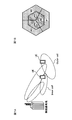
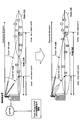
- FIG. 1 and FIG. 2 show a plurality of cells that are sectorized in the vertical direction by outputting a plurality of beams having different tilt angles from one antenna.
- FIG. 1A when two beams having different tilt angles are output, a cell (inner cell) relatively near from the radio base station and a cell (outer cell) relatively far from each other are formed.
- the tilt angle of the beam forming the inner cell is larger than the tilt angle of the beam forming the outer cell (Outer tilt angle).
- FIG. 2A by increasing the number of beams having different tilt angles, it is possible to increase the number of cells that are divided into vertical sectors.
- a plurality of cells sectorized in the vertical direction can be formed in different horizontal directions.
- a plurality of inner cells here, Cell # 4 to Cell # 6
- a plurality of outer cells here, Cell # 1 to Cell # 3
- FIG. 1B In the configuration of 3 cells or more, there are a plurality of cells sectorized in the vertical direction (here, Cell # 1, Cell # K + 1,..., Cell # K (N-1) +1 vertical sectored group)
- a vertical sectorized group of Cell # 2, Cell # K + 2,... Cell # K (N-1) +2) is formed (see FIG. 2B).
- N indicates the number of vertical sectors
- K indicates the number of horizontal sectors.
- the plurality of beams output from the radio base station can be output from one antenna, or each beam can be output from the plurality of antennas.
- each beam can be output from the plurality of antennas.
- beams having different tilt angles may be output from two or more antennas.
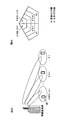
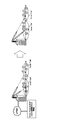
- connection ratio of user terminals For example, as shown in FIG. 3, if the ratio of the number of user terminals connected to the inner cell and the number of user terminals connected to the outer cell (connection ratio of user terminals) is different, On the other hand, a difference occurs in resources that can be allocated.
- the number of user terminals located in the coverage area of the inner cell is 2 (connection ratio is 2/10), and the number of user terminals located in the coverage area of the outer cell is 8 (connection ratio is 8/10). It has become.
- the number of resources that can be allocated to one user terminal located in the inner cell is the same as the number of resources allocated to one user terminal located in the outer cell. It becomes larger than the number of resources that can be allocated. In this case, it is assumed that there are not enough resources to be allocated to user terminals in the inner cell, and there are not enough resources to be allocated to user terminals in the outer cell. As a result, it is difficult to effectively use radio resources in the inner cell and the outer cell.
- the number of user terminals located in the coverage area of the innermost cell (Cell # K (N-1) +1) is 1 (connection ratio is 1 / M), and the second cell from the outside (Cell #
- the number of user terminals located in the coverage area of K + 1) is 4 (connection ratio is 4 / M), and the number of user terminals located in the coverage area of the outermost cell (Cell # 1) is 2 (connection ratio is 2 / M).
- N is the number of vertical sectors
- K is the number of horizontal sectors
- M is the total number of user terminals per horizontal sector.
- the present inventor in VSEC, based on the communication capacity of each of a plurality of cells (for example, the number of user terminals existing in each cell, the number of active users, or statistical values thereof) Control the coverage area by changing the width for each cell, or synchronize the antenna gain, beam width, or tilt angle for each cell with each cell's power increase / decrease control or ON / OFF control.
- the idea was that it would be possible to effectively use radio resources by controlling them.
- the present embodiment is not limited to this.
- the radio base station acquires information on the number of user terminals located in each cell. This information is converted into data of the connection ratio of user terminals to each cell (the number of user terminals connected to the cell / the total number of user terminals of all cells). Information relating to the number of user terminals located in each cell can be acquired from system information output from the network side, for example.
- the number of user terminals connected to each cell can be acquired by various methods other than actually counting the number of user terminals that perform wireless communication by connecting to each cell. For example, assuming that user terminals are uniformly distributed in the area where each cell is formed, the number of user terminals located in each cell can be calculated. In this case, the number of user terminals connected to each cell is calculated depending on the area of the cell.
- a statistical value obtained by statistically calculating the number of user terminals, and the number of user terminals are calculated in consideration of design conditions (for example, locations where each cell is formed) of the radio base station.
- design conditions for example, locations where each cell is formed
- a value obtained by predicting the number of user terminals or the number of user terminals by past statistics or system simulation may be applied.
- the installation conditions of the radio base station correspond to the surrounding environment such as the position (height, location, etc.) where the radio base station is installed, the location where each cell is formed, and the like.
- the radio base station determines the coverage area condition (for example, coverage area size) of each cell so that the difference in the connection ratio of the user terminal to each cell becomes small based on the acquired information on the connection ratio of the user terminal of each cell. ) Is set. For example, if the connection ratio of user terminals in a certain cell is lower than the average value of the connection ratios of user terminals in all cells (that is, the reciprocal of the total number of cells and 1/2 in the 2-cell configuration), the condition for increasing the coverage size is set. A condition for reducing the coverage size if the connection ratio of user terminals in a certain cell is higher than the average value of the connection ratios of user terminals in all cells (that is, the reciprocal of the total number of cells and 1/2 in the 2-cell configuration). Set.
- the coverage area condition for example, coverage area size
- beam conditions for forming each cell for example, tilt angle of each cell, transmission power of each cell, antenna gain of each cell, vertical plane beam width (HPBW: half-) of each cell) power bandwidth
- the size and position of the coverage area of each cell are changed according to the connection ratio of the user terminal.
- Cells with a low connection ratio” and cells lower than the average value of the connection ratios of user terminals in all cells are “cells with a high connection ratio of user terminals” It is defined as
- the radio base station narrows the vertical plane beam width of a cell having a large connection ratio of user terminals in accordance with the connection ratio of the user terminals, The vertical plane beam width of a cell having a small connection ratio is increased according to the connection ratio of the user terminal (see FIG. 5). Specifically, the radio base station determines, for each cell, the offset (Offset) value of the vertical plane beam width of the beam forming each cell, based on the connection ratio of user terminals in each cell. Then, weights (phase and amplitude) applied to the antenna unit are generated based on the determined offset value, and the vertical plane beam width of the output beam is changed by multiplying the transmission signal by the weight.
- the offset Offset
- FIG. 5 as an example, a control example in a two-cell configuration is shown.
- the vertical plane beam width of the inner cell is widened according to the connection ratio of the user terminals, and the vertical plane beam width of the outer cell is set to that of the user terminal.
- the case where the user terminal connected to an outer cell is connected to an inner cell by narrowing according to a connection ratio is shown.
- the connection ratio of user terminals becomes uniform among the cells, so that the user terminals located in each cell
- resources can be allocated uniformly. As a result, it is possible to use radio resources without bias among user terminals.
- the radio base station After changing the coverage area of each cell, the radio base station obtains again information on the number of user terminals located in each cell after a predetermined period of time, and the vertical plane beam width of each cell is similar to the above.
- the process of resetting the coverage area can be repeatedly performed by changing. By repeatedly performing the process of setting the coverage area of a cell, it is possible to reduce the difference in the number of user terminals between cells, and to optimize so that radio resources can be utilized evenly among user terminals. Alternatively, the active users can be counted in real time, and the optimization can be made so that the radio resources are utilized evenly among the user terminals.
- the offset value of the vertical plane beam width can be a database of combinations of various offset amounts, and a predetermined offset value can be determined according to the connection ratio of user terminals in each cell.
- the database in which the offset amount is defined can be created based on information already obtained at other radio base stations or values calculated based on simulation.
- the radio base station may control the cell coverage area by changing not only the vertical plane beam width but also the horizontal plane beam width.
- a vertical array and a horizontal array may be provided as antenna elements, and the transmission signal may be multiplied by a vertical weight and a horizontal weight.
- the radio base station When the coverage area of each cell is controlled by changing the transmission power (Power), the radio base station lowers the transmission power of a cell having a high connection ratio of user terminals in accordance with the connection ratio of the user terminals, and The transmission power of a cell with a low connection rate is increased according to the connection rate of the user terminal (see FIG. 6). Specifically, the radio base station determines an offset value of transmission power for each cell based on the connection ratio of user terminals in each cell. Then, the input signal to each beam is changed based on the determined offset value.
- FIG. 6 shows an example of control in a two-cell configuration as an example.
- the transmission power of the inner cell is increased according to the connection ratio of the user terminal
- the transmission power of the outer cell is increased according to the connection ratio of the user terminal.
- the user terminal connected to the outer cell is connected to the inner cell.
- the connection ratio of the user terminals becomes uniform among the cells, and the user terminals located in each cell Resources can be allocated uniformly. As a result, it is possible to use radio resources without bias among user terminals.
- the radio base station After changing the coverage area of each cell, the radio base station obtains again information on the number of user terminals located in each cell after a predetermined period of time, and changes the transmission power of each cell in the same manner as described above. Can be made.
- the process of resetting the coverage area it is possible to reduce the difference in the number of user terminals between cells, and to optimize the radio resources so that they are utilized evenly among the user terminals.
- the active users can be counted in real time, and the optimization can be made so that the radio resources are utilized evenly among the user terminals.
- the transmission power offset value can be a database of combinations of various offset amounts, and a predetermined offset value can be determined according to the connection ratio of user terminals in each cell.
- the database in which the offset amount is defined can be created based on information already obtained at other radio base stations or values calculated based on simulation.
- the vertical plane beam width and / or transmission power of each cell is set based on the connection ratio of user terminals in each cell, as in the case of 2 cells. Can be controlled.
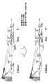
- FIG. 7 shows a control example when the number of vertical sectors is N and the number of horizontal sectors is K (for example, in the case of FIG. 2B).
- the vertical plane beam width and / or transmission power is controlled so that the coverage area of cells (#K (N-1) +1 and # 1) with a low connection ratio of user terminals is expanded, and The vertical plane beam width and / or transmission power is controlled so that the coverage area of a cell (Cell # K + 1) with a large connection ratio is reduced.
- the difference of the connection ratio of the user terminal of each cell can be made small, and the efficiency of a radio
- the radio base station acquires information on the number of user terminals located in each cell. This information is converted into data of the connection ratio of user terminals to each cell (the number of user terminals connected to the cell / the total number of user terminals of all cells). Information regarding the connection ratio of the user terminal can be acquired by various methods as described above.
- the radio base station changes the (power) resource amount allocated to each cell according to the acquired information on the connection ratio of the user terminals. Specifically, a (power) resource amount to be allocated is set to a cell with a low connection ratio of user terminals in accordance with the connection ratio of user terminals. A large amount of (power) resources to be allocated according to the connection ratio of the user terminal is set for a cell having a high connection ratio of the user terminal. Based on the (power) resource amount condition allocated to each cell, the radio base station outputs a beam that forms each cell, and allocates resources to user terminals located in each cell.
- FIG. 8 shows an example of control in a two-cell configuration as an example.
- the radio base station reduces the amount of (power) resources allocated to cells with a low connection rate of user terminals, and the connection rate of user terminals. This shows a case where a large amount of (power) resources to be allocated to a cell having a large amount of is set.
- the (power) resource amount allocated per user terminal in each cell can be controlled equally. As a result, it is possible to optimize the wireless resources so that they are utilized without unevenness among the user terminals.
- the (power) resource amount allocated to each cell can be controlled in accordance with the connection ratio of user terminals.
- the amount of (power) resources allocated to each cell in the case of controlling the amount of (power) resources allocated to each cell in proportion to the connection ratio of user terminals (1 ⁇ K / M in Cell # K (N ⁇ 1) +1, Cell # K + 1 4 ⁇ K / M, when 2 ⁇ K / M is assigned to Cell # 1).
- the frequency band is divided and resources are allocated according to the connection ratio of the user terminals, or the time is divided and resources are allocated according to the connection ratio of the user terminals, or a combination of these is the connection ratio of the user terminals.
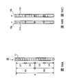
- FIG. 10 shows an example of control in a two-cell configuration as an example, and shows an example of resource allocation control for a cell with a low connection ratio of user terminals and a cell with a high connection ratio.
- FIG. 10A shows a state before resource allocation control.
- FIG. 10B shows a case where allocation is controlled in the frequency domain (frequency allocation control). In this case, resources are allocated only to a narrower frequency region than before resource allocation control according to the connection ratio of user terminals to cells (inner cells in FIG. 10) with a low connection ratio of user terminals.
- resource allocation is performed using a wider frequency region than before resource allocation control according to the connection ratio of the user terminal.
- FIG. 10C shows a case where assignment is controlled in the time domain.
- the time domain for allocation is made smaller than before resource allocation control, according to the connection rate of user terminals, than before resource allocation control.
- the time area for allocating resources according to the connection ratio of the user terminals is increased as compared to before resource allocation control (time allocation control).
- resources are allocated to a cell (external cell in FIGS. 10 and 11) with a high connection ratio of user terminals, and the connection ratio of user terminals is low.
- a time region t 1 in which resources are not allocated to cells (inner cells in FIGS. 10 and 11) is periodically provided. Further, it is preferable to relatively high transmission power of the cell connecting a large proportion of the user terminal in the time domain t 1.
- the radio base station preferably allocates resources to the user terminal (UE # 3 in FIG. 11) located at the cell edge in the time domain t 1 that is not affected by interference from the inner cell.
- frequency allocation control and time allocation control can be performed according to the connection ratio of user terminals.
- FIG. 12 when frequency allocation control and time allocation control are performed according to the connection ratio of user terminals (1 ⁇ K / M for Cell # K (N ⁇ 1) +1, 4 ⁇ K for Cell # K + 1). / M, 2 ⁇ K / M assigned to Cell # 1).
- a resource is not allocated to Cell # K + 1 and Cell # 1, but a time region t 1 for selectively allocating resources to Cell # K (N ⁇ 1) +1 is provided. .
- the cell tilt angle and / or the vertical plane beam width and / or the antenna gain are set so that the coverage area of the cell with a high connection ratio of user terminals overlaps the coverage area of a cell with a low connection ratio. It can also be changed (see FIG. 11).
- the coverage area of a cell having a high connection ratio of user terminals is formed in another cell (in FIG. 11, the connection ratio of user terminals is small) in the time region t 2 other than the time region t 1 .
- the radio base station apparatus changes the tilt angle and / or vertical plane beam width and / or antenna gain of a beam forming a cell with a high connection ratio of user terminals (for example, in the case of a two-cell configuration) , Increase the tilt angle of the outer cell).
- UE # 3 in FIG. 11 located at a cell edge of a cell with a high connection ratio and located near a cell with a low connection ratio of user terminals. .
- the coverage area of the cell with a high connection ratio of user terminals overlaps the coverage area of a cell with a low connection ratio in the time domain t 1 .
- the coverage area of Cell # K (N ⁇ 1) +1 is Cell # 1 in time region t 1 in which resources are selectively allocated to a cell (Cell # K + 1) with a high connection ratio of user terminals. Control to expand in the coverage area direction.
- UE # M-2 in FIG. 13 since a user terminal (UE # M-2 in FIG. 13) at the cell edge is not affected by Cell # 1, it is preferable to allocate resources to the user terminal.
- Figure 14 is a user radio base station, with selectively providing the time domain t 3 allocates resources to the proportion of connecting user terminals is small cell (in FIG. 14 inner cells), to the time domain t 3 This shows a case where the coverage area of a cell with a small terminal connection ratio is expanded (Range Expansion).
- the radio base station acquires information related to the connection ratio of user terminals in each cell.
- the radio base station is a user terminal (UE # 3 to # 10) in a coverage area of a cell where the connection ratio of user terminals is high (for example, the outer cell in FIG. 14 having a two-cell configuration)
- Predetermined user terminals (UE # 3 to # 5 in FIG. 14) connectable to a cell with a small connection ratio of user terminals (for example, an inner cell in FIG. 14 having a two-cell configuration) with a predetermined quality or higher. select.
- the radio base station performs allocation of resources to the cell connecting small percentage of the user terminal, the time does not perform resource allocation region t 3 periodically for the connection ratio is large cells of the user terminal Provide. Furthermore, the radio base station, in the time domain t 3 by connecting the connection ratio is small cell of the user terminal to a given user terminal (UE # 3 ⁇ # 5) , the connection ratio is small cell user terminals Allocate resources. In this way, by controlling resource allocation and expanding the coverage area of a cell with a low connection ratio of user terminals, the connection ratio of user terminals with respect to predetermined user terminals (UE # 3 to # 5) can be reduced. The influence of interference from many cells can be reduced, and resources can be uniformly allocated to user terminals located in each cell.
- the selectively time domain t 3 when performing the allocation of resources for the connection ratio is small cell of the user terminal, may change the coverage area of the cell connecting a small percentage of the user terminal.
- the time coverage area of the cell connecting a small percentage of the user terminal other than the time domain t 3 region t 4 The tilt angle and / or vertical plane beam width of a beam forming a cell with a small connection ratio of user terminals can be changed so as to expand in the coverage area direction of a cell with a high connection ratio of user terminals.
- a predetermined user terminal It is possible to improve communication quality for UEs # 3 to # 5).
- resources can be more uniformly allocated to user terminals located in each cell, and radio resources can be used effectively.
- the time region t 3 is cycled when the coverage area of a cell with a low user terminal connection ratio is expanded (Range Expansion). Can be provided.
- a time region t 3 for selectively allocating resources is provided in a cell (Cell # K (N ⁇ 1) +1, Cell # 1) with a low connection ratio of user terminals, and coverage is provided in the time region t 3 .
- a case where the area is expanded (Range Expansion) is shown.
- the radio base station to connect the predetermined user terminals in the time domain t 3 (UE # 2) and the connection rate is small cell of the user terminal (Cell # K (N-1 ) +1), the user The terminal (UE # M-2) and Cell # 1 are connected to allocate resources. Further, in the time domain t 3, (FIG. 15, Cell # K (N- 1) + 1, Cell # 1) user proportion of connecting terminals is small cell coverage area, the time domain t 3 than in the time domain (in FIG. 15, cell # K + 1) user proportion of connecting terminals is large cells formed t 4 can be controlled so as to expand the coverage area direction.
- the radio communication system includes a radio base station capable of forming a plurality of vertical sectorized beams, and a user terminal that performs radio connection in a cell formed by the radio base station.
- the radio base station has an antenna that outputs a plurality of beams to form vertical sectors into a plurality of cells.
- An example of such an antenna is an array antenna composed of a plurality of antenna elements.
- FIG. 16A is a conceptual diagram of an array antenna.
- the array antenna 10 is composed of a plurality of antenna elements 11 arranged in one line in one direction.
- FIG. 16A illustrates 16 antenna elements 11.
- array antenna 10 is configured by a polarization antenna that is a combination of vertical polarization antenna 10a and horizontal polarization antenna 10b.
- the antenna to which the radio base station according to the present embodiment is applicable is not limited to this antenna configuration. Further, not only horizontal and vertical polarized waves but also ⁇ 45 degree polarized antenna elements may be used, or an array antenna composed of antenna elements tilted from them may be used.
- FIG. 16B is a conceptual diagram showing the vertically polarized antenna 10a alone
- FIG. 16C is a conceptual diagram showing the horizontally polarized antenna 10b alone.
- each antenna element 11 is composed of a set of a vertical polarization element 11V and a horizontal polarization element 11H.
- the radio base station can provide a plurality of communication types by using an array antenna including the plurality of antenna elements.
- a first communication type to a third communication type will be described.
- the first communication type is a type in which one antenna branch is constituted by the whole antenna by forming one group A by the whole antenna elements 11 constituting the array antenna 10.
- the second communication type is a type in which two antenna branches are formed by the whole antenna by forming two groups B1 and B2 that divide the array antenna 10 into two vertically.
- the third communication type is a type in which four antenna branches are formed by forming four groups C1, C2, C3, and C4 that divide the array antenna 10 vertically into four.
- the first communication type has the longest antenna length constituting one branch (the largest number of antenna elements). As the number of antenna branches increases, the antenna length per branch decreases (the number of antenna elements decreases). In general, when a beam is formed by an array antenna, the antenna gain increases and the beam width can be reduced as the number of antenna elements per branch increases. Therefore, in the first communication type, since the entire antenna is configured by one antenna branch, the antenna gain is maximized and a sharp beam toward the cell edge can be formed.
- the number of antenna elements per branch is half, the antenna gain is reduced and the beam width is increased as compared with the first communication type.
- the number of antenna elements per branch is further reduced to 1 ⁇ 2 from the second communication type, so that the antenna gain is reduced and the beam width is larger than that of the second communication type.
- the present embodiment is not limited to the first to third communication types described above, and an arbitrary number of communication types is appropriately selected according to the number of vertical divisions of the antenna elements 11 constituting the array antenna 10. Can be set. Further, the maximum number of branches can be appropriately selected according to the antenna element 11. Also, the radio communication system of the present embodiment can switch the branch configuration of array antenna 10 according to the weight.
- FIG. 17 is a diagram for explaining a configuration of a radio communication system 1 having a mobile station 100 and a radio base station 200 according to an embodiment of the present invention.
- the radio communication system 1 illustrated in FIG. 17 is a system including, for example, an LTE system or SUPER 3G.
- the mobile communication system 1 may be called IMT-Advanced or 4G.
- the radio communication system 1 includes a radio base station 200 and a plurality of mobile stations 100 (100 1 , 100 2 , 100 3 ,... 100 n , n communicating with the radio base station 200. n> 0).
- the radio base station 200 is connected to the higher station apparatus 300, and the higher station apparatus 300 is connected to the core network 400.
- the mobile station 100 communicates with the radio base station 200 in the cell 500.
- the upper station apparatus 300 includes, for example, an access gateway apparatus, a radio network controller (RNC), a mobility management entity (MME), and the like, but is not limited thereto.
- RNC radio network controller
- MME mobility management entity
- each mobile station (100 1 , 100 2 , 100 3 ,... 100 n ) has the same configuration, function, and state, the following description will be given as the mobile station 100 unless otherwise specified.
- the mobile station 100 is in radio communication with the radio base station 200, but more generally user equipment (UE: User Equipment) including both mobile terminal devices and fixed terminal devices. Good.
- UE User Equipment
- OFDMA orthogonal frequency division multiple access
- SC-FDMA single carrier-frequency division multiple access
- OFDMA is a multi-carrier transmission scheme that performs communication by dividing a frequency band into a plurality of narrow frequency bands (subcarriers) and mapping data to each subcarrier.
- SC-FDMA is a single carrier transmission method that reduces interference between terminals by dividing a system band into bands each consisting of one or continuous resource blocks for each terminal, and a plurality of terminals using different bands. .
- PDSCH shared by each mobile station 100 and downlink L1 / L2 control channels (PDCCH, PCFICH, PHICH) are used.
- User data that is, a normal data signal is transmitted by this PDSCH. Transmission data is included in this user data.
- the component carrier (CC) and scheduling information allocated to the mobile station 100 by the radio base station 200 are notified to the mobile station 100 through the L1 / L2 control channel.
- PUSCH For the uplink, PUSCH that is shared and used by each mobile station 100 and PUCCH that is an uplink control channel are used. User data is transmitted by this PUSCH. Also, downlink radio quality information (CQI: Channel Quality Indicator) and the like are transmitted by PUCCH.
- CQI Channel Quality Indicator
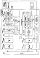
- FIG. 18 is a block diagram showing a configuration of radio base station 200 according to the present embodiment.
- FIG. 19 is a block diagram illustrating a configuration of the antenna unit 230.
- FIG. 20 is a block diagram showing a configuration of mobile station 100 according to the present embodiment. Note that the configurations of the radio base station 200, the antenna unit 230, and the mobile station 100 shown in FIG. 18 to FIG. 20 are simplified to explain the present invention. It is assumed that the station has a configuration.
- radio base station 200 shown in FIG. 18 has a cell control unit # 1 (hereinafter referred to as “first cell control unit”) that controls radio communication in a first cell (for example, an inner cell) in a two-cell configuration.
- a cell control unit # 2 (hereinafter referred to as a “second cell control unit”) that controls radio communication in a second cell (for example, an outer cell), and an antenna that outputs a beam forming each cell.
- first cell control unit hereinafter referred to as “first cell control unit”
- a cell control unit # 2 (hereinafter referred to as a “second cell control unit”) that controls radio communication in a second cell (for example, an outer cell), and an antenna that outputs a beam forming each cell.
- Part 230 As described above, radio base station 200 according to the present embodiment is not limited to a two-cell configuration, and can be configured to have three or more cells.
- a third cell control unit In the case of a configuration of three or more cells, a third cell control unit,..., And a control unit can be added in addition to the first cell control unit and the second cell control unit.
- the radio base station 200 illustrated in FIG. 18 is a radio base station that controls the vertical plane beam width of each cell as described above.
- the radio base station 200 includes a communication capacity information acquisition unit 231 that acquires information regarding the communication capacity of each cell (for example, the connection ratio of user terminals in each cell).
- the communication capacity information acquisition unit 231 can acquire information on the number of user terminals located in each cell based on, for example, system information notified from a higher station apparatus or the like.
- the communication capacity information acquisition unit 231 acquires information on the number of user terminals located in each cell, and then converts the acquired information into data on the connection ratio of user terminals to each cell.
- the communication capacity information acquisition unit 231 can acquire the number of user terminals connected to each cell by various methods other than actually counting the number of user terminals connected to each cell and performing wireless communication. . For example, assuming that user terminals are uniformly distributed in the area where each cell is formed, the number of user terminals located in each cell can be calculated. Also, as information on the number of user terminals, a statistical value obtained by statistically calculating the number of user terminals, and the number of user terminals are calculated in consideration of design conditions (for example, locations where each cell is formed) of the radio base station. Alternatively, a value obtained by predicting the number of user terminals or the number of user terminals by past statistics or system simulation may be applied.
- the offset amount determination unit 232 determines an offset value for changing the vertical plane beam width of the beam forming the inner cell and the outer cell, based on the information acquired by the communication capacity information acquisition unit 231. Specifically, the offset amount determination unit 232 determines, for each cell, the vertical plane beam width and / or transmission power offset value of the beam forming each cell based on the connection ratio of the user terminals of each cell, The determined offset value is output to the vertical weight generation unit 233.
- the offset amount determination unit 232 can make a database of various combinations of offset amounts and determine a predetermined offset value according to the connection ratio of user terminals in each cell.
- the database in which the offset amount is defined can be created based on information already obtained at other radio base stations or values calculated based on simulation.
- the vertical weight generation unit 233 generates vertical weights (phase and amplitude) to be applied by the antenna unit 230 based on the offset value determined by the offset amount determination unit 232.
- the vertical weight generated by the vertical weight generation unit 233 is output to the antenna unit 230.
- the antenna unit 230 multiplies the transmission signal by the weight, so that the vertical plane beam width of the beam output from the antenna unit 230 is reduced. Be controlled.
- the transmission power of the beam to be output may be controlled based on the power offset value determined by the offset amount determination unit 232 based on the information acquired by the communication capacity information acquisition unit 231. .
- the resource allocated by the scheduler to each cell may be controlled based on the information acquired by the communication capacity information acquisition unit 231.
- the communication capacity information acquisition unit 231, the offset amount determination unit 232, and the vertical weight generation unit 233 are provided for the first cell control unit and the second cell control unit, respectively. I can't. At least one of the communication capacity information acquisition unit 231, the offset amount determination unit 232, and the vertical weight generation unit 233 (for example, the communication capacity information acquisition unit 231 and the offset amount determination unit 232) is replaced with a plurality of cell control units (first in FIG. 18). It is good also as a structure provided in common with respect to the cell control part and the 2nd cell control part.
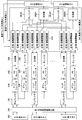
- a scheduler determines the number of users to be multiplexed (the number of multiplexed users) based on channel estimation values given from channel estimation sections 215 # 1 to 215 # K described later. Then, uplink / downlink resource allocation contents (scheduling information) for each user are determined, and transmission data # 1 to #K for users # 1 to #K are transmitted to corresponding channel coding sections 201 # 1 to 201 # K. .
- Transmission data is channel-encoded by channel encoders 201 # 1 to 201 # K, and then output to data modulators 202 # 1 to 202 # K for data modulation.
- channel coding and data modulation are performed based on channel coding rates and modulation schemes provided from MIMO switching sections 221 # 1 to 221 # K described later.
- the transmission data # 1 to #K data-modulated by the data modulators 202 # 1 to 202 # K are subjected to discrete Fourier transform by a discrete Fourier transform unit (not shown) and converted from a time-series signal to a frequency domain signal. It is output to the subcarrier mapping unit 203.
- the subcarrier mapping unit 203 maps the transmission data # 1 to #K to subcarriers according to resource allocation information given from the resource allocation control unit 220 described later. At this time, subcarrier mapping section 203 transmits reference signals # 1 to #K input from a reference signal generation section (not shown), broadcast information and system information input from broadcast information generation section and system information generation section. Mapping (multiplexing) onto subcarriers together with data # 1 to #K. Transmission data # 1 to #K mapped to subcarriers in this way are output to precoding multiplication sections 204 # 1 to 204 #K.
- Precoding multiplication sections 204 # 1 to 204 # K convert transmission data # 1 to #K for each antenna element # 1 to #N based on a precoding weight given from a precoding weight control section 219 described later. // Amplitude shift (weighting of antenna elements # 1 to #N by precoding).
- the transmission data # 1 to #K whose phases and / or amplitudes have been shifted by the precoding multipliers 204 # 1 to 204 # K are output to the multiplexer (MUX) 205.
- MUX multiplexer
- the multiplexer (MUX) 205 synthesizes transmission data # 1 to #K whose phases and / or amplitude has been shifted, and generates transmission signals for the antenna elements # 1 to #N.
- the transmission signal generated by the multiplexer (MUX) 205 is subjected to inverse fast Fourier transform by the inverse fast Fourier transform units (IFFT) 206 # 1 to 206 # N, and converted from the frequency domain signal to the time domain signal. Then, a CP is added by cyclic prefix (CP) adding sections 207 # 1 to 207 # N, and then output to antenna section 230.
- IFFT inverse fast Fourier transform units
- CP cyclic prefix
- the transmission signal transmitted from the mobile station 100 on the uplink is received by the antenna unit 230, and frequency-converted from a radio frequency signal to a baseband signal.
- the frequency-converted baseband signals are output to the fast Fourier transform units (FFT units) 212 # 1 to 212 # N after the CPs are removed by the CP removal units 211 # 1 to 211 # N.
- FFT units fast Fourier transform units
- FFT sections 212 # 1 to 212 # N perform Fourier transform on the input received signals, and convert the time series signals into frequency domain signals.
- the received signals converted into these frequency domain signals are output to data channel signal demultiplexing sections 214 # 1 to 214 # K.
- the data channel signal separation units 214 # 1 to 214 # K receive signals input from the FFT units 212 # 1 to 212 # N, for example, mean square error minimum (MMSE: Minimum Mean Squared Error) or maximum likelihood estimation. It separates by the detection (MLD: Maximum Likelihood Detection) signal separation method. As a result, the received signal arriving from the mobile station 100 is separated into received signals related to the user terminals # 1 to #K.
- MMSE Minimum Mean Squared Error
- MLD Maximum Likelihood Detection
- Channel estimation units 215 # 1 to 215 # K estimate channel states from reference signals included in the received signals separated by data channel signal separation units 214 # 1 to 214 # K, and control channel demodulation is performed on the estimated channel states. Sections 216 # 1 to 216 # K are notified.
- the received signals related to user terminals # 1 to #K separated by data channel signal demultiplexing sections 214 # 1 to 214 # K are de-mapped by a subcarrier demapping section (not shown) and returned to a time-series signal. After that, the data demodulation sections 217 # 1 to 217 # K demodulate the data.
- Control channel demodulation sections 216 # 1 to 216 # K demodulate control channel signals (for example, PUCCH) included in the reception signals separated by data channel signal separation sections 214 # 1 to 214 # K. At this time, control channel demodulation sections 216 # 1 to 216 # K correspond to user terminals # 1 to #K, respectively, based on channel states notified from channel estimation sections 215 # 1 to 215 # K. Demodulate the control channel signal. The control channel signals demodulated by control channel demodulation sections 216 # 1 to 216 # K are output to CSI information update sections 218 # 1 to 218 # K.
- control channel demodulation sections 216 # 1 to 216 # K demodulate control channel signals (for example, PUCCH) included in the reception signals separated by data channel signal separation sections 214 # 1 to 214 # K. At this time, control channel demodulation sections 216 # 1 to 216 # K correspond to user terminals # 1 to #K, respectively, based on channel states notified from channel estimation sections 215 # 1 to
- CSI information updating sections 218 # 1 to 218 # K are channel states included in each control channel signal (for example, PUCCH) or shared data channel signal (PUSCH) input from control channel demodulation sections 216 # 1 to 216 # K.
- Information (CSI) is extracted and the CSI is always updated to the latest state.
- CSI includes PMI, RI, and CQI.
- the CSI information updated by the CSI information updating units 218 # 1 to 218 # K is output to the precoding weight control unit 219, the resource allocation control unit 220, and the MIMO switching units 221 # 1 to 221 # K.
- Precoding weight control section 219 indicates the phase and / or amplitude shift amount for transmission data # 1 to #K based on beam selection information and CSI information input from CSI information update sections 218 # 1 to 218 # K. Generate precoding weights. Each generated precoding weight is output to precoding multiplication sections 204 # 1 to 204 # K, and is used for precoding transmission data # 1 to transmission data #K.
- the resource allocation control unit 220 determines resource allocation information to be allocated to each user based on the CSI information input from the CSI information update units 218 # 1 to 218 # K.
- MIMO switching sections 221 # 1 to 221 # K select a MIMO transmission method to be used for transmission data # 1 to transmission data #K based on the CSI information input from CSI information update sections 218 # 1 to 218 # K. . Then, channel coding rates and modulation schemes for transmission data # 1 to transmission data #K according to the selected MIMO transmission scheme are determined. The determined channel coding rates are output to channel coding sections 201 # 1 to 201 # K, respectively, and the determined modulation schemes are output to data modulation sections 202 # 1 to 202 # K, respectively.
- the antenna unit 230 includes a plurality of antenna elements 250, an RF phase amplitude adjustment circuit 249, a vertical weight multiplication unit 240, and the like.
- the signal output from the CP adding unit 207 of the first cell control unit and the second cell control unit is input to the vertical weight multiplication unit 240.
- information regarding the weight in the vertical direction generated by the vertical weight generator 233 of the first cell controller and the second cell controller is also input to the vertical weight multiplier 240.
- the signals from the first cell control unit and the second cell control unit are branched through the dividers 241 # 1 and 241 # 2, respectively. It is output to the amplitude adjuster 243.
- the vertical weight multiplication unit 240 multiplies the weight in the vertical direction so as to realize the offset value (in this case, the vertical plane beam width offset value) determined by the offset amount determination unit 232 in the phase / amplitude adjuster 243. .
- the transmission signals in the first cell (for example, the inner cell) and the second cell (for example, the outer cell) output from the vertical weight multiplication unit 240 are combined by the combiner 244, and then the DA converter 245, the up converter 246,
- the signal is output to the RF phase amplitude adjustment circuit 249 via a duplexer 247.
- the RF phase amplitude adjustment circuit 249 adjusts the direction of the beam forming the first cell and the second cell, and performs calibration between the branches.
- the signal output from the RF phase amplitude adjustment circuit 249 is output via the antenna element 250.
- the transmission signal transmitted from the mobile station 100 in the uplink is received by the antenna element 250 and then output to the duplexer (Duplexer) 247 via the RF phase amplitude adjustment circuit 249.
- the duplexer 247 After being separated into a transmission path and a reception path by the duplexer 247, it is output to the divider 252 via the down converter 248 and the AD converter 251.
- the signal is branched to the signals of the first cell and the second cell, and then output to the combiners 242 # 1 and 242 # 2 via the phase / amplitude adjuster 243 of the vertical weight multiplier 240.
- the received signals received by the antenna element 250 are combined for each of the first cell and the second cell, and are combined into the first cell controller and the second cell controller. Each is output.
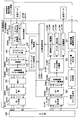
- the transmission signal transmitted from the radio base station 200 is received by the transmission / reception antennas TRX # 1 to TRX # N, and is transmitted to the transmission path by the duplexers 101 # 1 to 101 # N.
- the signals are output to the RF reception circuits 102 # 1 to 102 # N.
- the RF receiving circuits 102 # 1 to 102 # N perform frequency conversion from the radio frequency signal to the baseband signal.
- Baseband signals are output to fast Fourier transform units (FFT units) 104 # 1 to 104 # N after CPs are removed by cyclic prefix (CP) removal units 103 # 1 to 103 # N.
- FFT units fast Fourier transform units
- Reception timing estimation section 105 estimates the reception timing from the reference signal included in the reception signal, and notifies the CP removal sections 103 # 1 to 103 # N of the estimation result.
- the FFT units 104 # 1 to 104 # N convert the input received signals from time series signals to frequency domain signals by Fourier transform.
- the received signal converted into the frequency domain signal is output to data channel signal separation section 106.
- the data channel signal separation unit 106 separates the received signals input from the FFT units 104 # 1 to 104 # N by, for example, a mean square error minimum (MMSE) or maximum likelihood estimation detection (MLD) signal separation method.
- MMSE mean square error minimum
- MLD maximum likelihood estimation detection
- the received signal coming from radio base station 200 is separated into received signals related to user terminals # 1 to #K, and received signals related to the user of mobile station 100 (here, referred to as user K) are extracted.
- the channel estimation unit 107 estimates the channel state from the reference signal included in the received signal separated by the data channel signal separation unit 106 and notifies the control channel demodulation unit 108 of the estimated channel state.
- the received signal related to user terminal #K separated by data channel signal demultiplexing section 106 is demapped by a subcarrier demapping section (not shown) and returned to a time-series signal, and then demodulated by data demodulation section 109.
- the And transmission signal #K is reproduced
- the control channel demodulation unit 108 demodulates a control channel signal (for example, PDCCH) included in the reception signal separated by the data channel signal separation unit 106. At this time, control channel demodulation section 108 demodulates the control channel signal corresponding to user terminal #K based on the channel state notified from channel estimation section 107. Each control channel signal demodulated by the control channel demodulation unit 108 is output to the channel quality measurement unit 110.
- a control channel signal for example, PDCCH
- control channel demodulation section 108 demodulates the control channel signal corresponding to user terminal #K based on the channel state notified from channel estimation section 107.
- Each control channel signal demodulated by the control channel demodulation unit 108 is output to the channel quality measurement unit 110.
- the channel quality measurement unit 110 measures the channel quality (CQI) based on the control channel signal input from the control channel demodulation unit 108. Further, the channel quality measurement unit 110 selects PMI and RI based on the measured CQI. Then, CSI (CQI, PMI, RI) or RSRP is notified to CSI feedback signal generation section 111 and MIMO switching section 112.
- CQI channel quality
- the CSI feedback signal generation unit 111 a CSI feedback signal to be fed back to the radio base station 200 is generated.
- the CSI feedback signal includes CQI, PMI, and RI notified from the channel quality measurement unit 110.
- the feedback signal (CSI feedback, RSRP feedback) generated by the CSI feedback signal generation unit 111 is output to the multiplexer (MUX) 113.
- MIMO switching section 112 selects a MIMO transmission scheme to be used for transmission data #K based on CQI, PMI, and RI input from channel quality measurement section 110. Then, the channel coding rate and modulation scheme for transmission data #K corresponding to the selected MIMO transmission scheme are determined. The determined channel coding rate is output to channel encoding section 114, and the determined modulation scheme is output to data modulation section 115.
- transmission data #K related to user #K transmitted from the upper layer is channel-encoded by channel encoder 114 and then data-modulated by data modulator 115.
- Transmission data #K data-modulated by data modulation section 115 is converted from a time-series signal to a frequency domain signal by a serial-parallel conversion section (not shown) and output to subcarrier mapping section 116.
- the subcarrier mapping unit 116 maps the transmission data #K to subcarriers according to the schedule information instructed from the radio base station 200. At this time, subcarrier mapping section 116 maps (multiplexes) reference signal #K generated by a reference signal generation section (not shown) to subcarrier together with transmission data #K. Transmission data #K mapped to subcarriers in this way is output to precoding multiplication section 117.
- the precoding multiplier 117 shifts the phase and / or amplitude of the transmission data #K for each of the transmission / reception antennas TRX # 1 to TRX # N. At this time, the precoding multiplication unit 117 performs phase and / or amplitude shift according to the precoding weight corresponding to the PMI specified by the control channel signal demodulated by the control channel demodulation unit 108. The transmission data #K whose phase and / or amplitude has been shifted by the precoding multiplier 117 is output to the multiplexer (MUX) 113.
- MUX multiplexer
- the multiplexer (MUX) 113 synthesizes the transmission data #K shifted in phase and / or amplitude and the control signal generated by the CSI feedback signal generation unit 111 and transmits the transmission data #K to the transmission / reception antennas TRX # 1 to TRX # N.
- a transmission signal is generated.
- the transmission signal generated by the multiplexer (MUX) 113 is subjected to inverse fast Fourier transform by an inverse fast Fourier transform unit 118 # 1 to 118 # N, converted from a frequency domain signal to a time domain signal, and then subjected to CP addition.
- CPs are added by the units 119 # 1 to 119 # N and output to the RF transmission circuits 120 # 1 to 120 # N.
- the signals are output to the transmission / reception antennas TRX # 1 to TRX # N via the duplexers 101 # 1 to 101 # N.
- the transmission / reception antennas TRX # 1 to TRX # N transmit the uplink to the radio base station 200.
- the configuration of the radio base station 200 applicable in the present embodiment is not limited to the configuration shown in FIG.
- the configuration of the antenna unit 230 is not limited to the configuration shown in FIG.
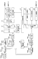
- the vertical weight multiplication unit 240 may be provided in the inner cell control unit and the outer cell control unit.
- An example of the configuration of the radio base station 200 and the antenna unit 230 in this case will be described with reference to FIGS. The description of the same parts as those in FIGS. 18 and 19 is omitted.
- the radio base station 200 shown in FIG. 21 includes transmission vertical weight multiplication units 236 # 1 to #K that multiply transmission / reception signals by vertical weights in the first cell control unit and the second cell control unit, and reception vertical weight multiplication. Sections 235 # 1 to #K.
- the vertical weight generated by the vertical weight generation unit 233 is controlled by the weight switching unit 234, and the transmission vertical weight multiplication unit 236 # 1.
- the weight switching unit 234 switches and controls a plurality of weights output from the vertical weight generation unit 233 for each predetermined period, and transmits the vertical weight generated by the vertical weight generation unit 233 to the transmission vertical weight multiplication unit 236 #. 1 to #K and output to reception vertical weight multiplication sections 235 # 1 to #K.
- the weight switching unit 234 when applying the time allocation control, if the vertical plane beam width, tilt angle, etc. of each cell are changed every predetermined period, the weight switching unit 234 performs the control. Is done. Specifically, the weight switching unit 234 assigns to each user terminal from the connection ratio data of the user terminal to each cell generated by the communication capacity information acquiring unit 231 and the offset value determined by the offset amount determining unit 232. Determine the length of time allocated to t 1 and t 2 or t 3 and t 4 respectively so that the resources to be served are appropriate (eg, uniform).
- the weight switching unit 23 together with the scheduling information of each user terminal assigned by the subcarrier mapping unit 203, links a plurality of weights output from the vertical weight generation unit 233 in conjunction with the passage of the time length. Control is performed so as to output to the transmission vertical weight multiplication units 236 # 1 to #K.
- information such as the transmission timing of the mobile station determined based on the length of time allocated to t 1 and t 2 or t 3 and t 4 is notified from the radio base station to the mobile station by broadcast information.
- Each user terminal receives the signal transmitted from the radio base station as usual, while regarding the transmission timing, the user terminal controls the transmission schedule in accordance with the transmission timing notified by the broadcast information from the radio base station.
- the radio base station controls to switch a plurality of weights output from the vertical weight generation unit 233 in conjunction with the time length and output the weights to the reception vertical weight multiplication units 235 # 1 to #K.
- the signals of the respective mobile stations are received with matching timing.
- FIG. 22 shows a block diagram of the transmission / reception vertical weight multiplication unit 236.
- the signal output from the precoding multiplication unit 204 is branched by the divider 261 and output to the phase / amplitude adjuster 263 corresponding to each of the plurality of antenna elements 250.
- the phase / amplitude adjuster 263 multiplies the signal by the weight generated by the vertical weight generator 233.
- reception vertical weight multiplication section 235 the signal output from FFT section 212 is adjusted by phase / amplitude adjuster 264, combined by combiner 262, and output to data channel signal separation section 214.
- the antenna unit 230 excludes the vertical weight multiplier 240 from the configuration shown in FIG. 19 as shown in FIG. It can be configured.
- the present invention has been described in detail using the above-described embodiments. However, it is obvious for those skilled in the art that the present invention is not limited to the embodiments described in the present specification.
- the number of users and the number of processing units in the apparatus are not limited to this, and can be appropriately changed according to the apparatus configuration.
- the present invention can be implemented as modifications and changes without departing from the spirit and scope of the present invention defined by the description of the scope of claims. Therefore, the description of the present specification is for illustrative purposes and does not have any limiting meaning to the present invention.
Landscapes
- Engineering & Computer Science (AREA)
- Computer Networks & Wireless Communication (AREA)
- Signal Processing (AREA)
- Mobile Radio Communication Systems (AREA)
- Radio Transmission System (AREA)
Abstract
The purpose of the present invention is to effectively utilize a wireless resource in a VSEC for outputting a plurality of beams that have different tilt angles and performing sectoring in the vertical direction. A method for wireless communication between a wireless base station for outputting a plurality of beams that have different tilt angles and forming a plurality of cells sectored in the vertical direction, and a user terminal wirelessly connected to the wireless base station, wherein the method comprises a step for the wireless base station to acquire information pertaining to the communication capacity of each of the cells, and a step for controlling the transmission power and/or the vertical plane beam width of each of the cells and setting the respective coverage area of each of the cells so as to reduce the difference between the communication capacity of each of the cells.
Description
本発明は、次世代移動通信システムに適用可能な無線基地局、無線通信システム及び無線通信方法に関する。
The present invention relates to a radio base station, a radio communication system, and a radio communication method applicable to a next generation mobile communication system.
UMTS(Universal Mobile Telecommunications System)ネットワークにおいては、周波数利用効率の向上、データレートの向上を目的として、HSDPA(High Speed Downlink Packet Access)やHSUPA(High Speed Uplink Packet Access)を採用することにより、W-CDMA(Wideband Code Division Multiple Access)をベースとしたシステムの特徴を最大限に引き出すことが行われている。このUMTSネットワークについては、更なる高速データレート、低遅延などを目的としてロングタームエボリューション(LTE:Long Term Evolution)が検討されている。
In the UMTS (Universal Mobile Telecommunications System) network, WSDPA (High Speed Downlink Packet Access) and HSUPA (High Speed Uplink Packet Access) are adopted for the purpose of improving frequency utilization efficiency and data rate. The system features based on CDMA (Wideband Code Division Multiple Access) are maximally extracted. For this UMTS network, Long Term Evolution (LTE) is being studied for the purpose of further high data rate and low delay.
第3世代のシステムは、概して5MHzの固定帯域を用いて、下り回線で最大2Mbps程度の伝送レートを実現できる。一方、LTE方式のシステムにおいては、1.4MHz~20MHzの可変帯域を用いて、下り回線で最大300Mbps及び上り回線で75Mbps程度の伝送レートを実現できる。また、UMTSネットワークにおいては、更なる広帯域化及び高速化を目的として、LTEの後継のシステムも検討されている(例えば、LTEアドバンスト(LTE-A))。例えば、LTE-Aにおいては、LTE仕様の最大システム帯域である20MHzを、100MHz程度まで拡張することが予定されている。
The third generation system can achieve a maximum transmission rate of about 2 Mbps on the downlink using generally a fixed bandwidth of 5 MHz. On the other hand, in the LTE system, a maximum transmission rate of about 300 Mbps on the downlink and about 75 Mbps on the uplink can be realized using a variable band of 1.4 MHz to 20 MHz. In the UMTS network, a successor system of LTE is also being studied for the purpose of further broadbandization and speeding up (for example, LTE Advanced (LTE-A)). For example, in LTE-A, it is planned to extend the maximum system band of LTE specifications, 20 MHz, to about 100 MHz.
また、LTE方式のシステムにおいては、複数のアンテナでデータを送受信し、データレート(周波数利用効率)を向上させる無線通信技術としてMIMO(Multi Input Multi Output)システムが提案されている(例えば、非特許文献1参照)。MIMOシステムにおいては、送受信機に複数の送信/受信アンテナを用意し、異なる送信アンテナから同時に異なる送信情報系列を送信する。一方、受信機側では、送信/受信アンテナ間で異なるフェージング変動が生じることを利用して、同時に送信された情報系列を分離して検出することにより、データレート(周波数利用効率)を増大することが可能である。
In addition, in the LTE system, a MIMO (Multi Input Multi Output) system has been proposed as a wireless communication technology that improves data rate (frequency utilization efficiency) by transmitting and receiving data with a plurality of antennas (for example, non-patented). Reference 1). In a MIMO system, a plurality of transmission / reception antennas are prepared in a transmitter / receiver, and different transmission information sequences are transmitted simultaneously from different transmission antennas. On the other hand, on the receiver side, the data rate (frequency utilization efficiency) is increased by separating and detecting simultaneously transmitted information sequences using the fact that different fading fluctuations occur between transmission / reception antennas. Is possible.
ところで、近年、無線通信システムにおいて通信容量を確保する技術として、垂直方向のセクタ化(VSEC:Vertical Sectorization)が注目されている。例えば、アンテナ装置から水平方向に対するビームの角度(チルト角)が異なる複数のビームを出力し、ビームのチルト角を無線基地局の条件に応じて設定することにより、セル毎のスループットを向上することが提案されている(例えば、非特許文献2参照)。
By the way, in recent years, vertical sectorization (VSEC) has been attracting attention as a technique for securing communication capacity in a wireless communication system. For example, by outputting a plurality of beams having different beam angles (tilt angles) with respect to the horizontal direction from the antenna device and setting the beam tilt angles according to the conditions of the radio base station, the throughput for each cell can be improved. Has been proposed (see, for example, Non-Patent Document 2).
しかしながら、VSECにおいては、無線基地局の設置条件等により、垂直方向にセクタ化される複数のセルに在圏するユーザ端末数等に差が生じ、セル毎の通信容量に差が生じるおそれがある。各セルに接続されるユーザ端末数が大きく異なる場合、1ユーザ端末に対して割当て可能となるリソースに大きな差が生じ、無線リソースの有効活用が困難となる。
However, in VSEC, depending on the installation conditions of the radio base station, etc., there may be a difference in the number of user terminals residing in a plurality of cells sectorized in the vertical direction, and there may be a difference in the communication capacity of each cell. . When the number of user terminals connected to each cell is greatly different, there is a large difference in resources that can be allocated to one user terminal, making it difficult to effectively use radio resources.
本発明はかかる点に鑑みてなされたものであり、チルト角が異なる複数のビームを出力して垂直方向にセクタ化するVSECにおいて、無線リソースを有効活用することを目的とする。
The present invention has been made in view of such a point, and an object of the present invention is to effectively use radio resources in a VSEC that outputs a plurality of beams having different tilt angles and sectorizes them in the vertical direction.
本発明の無線通信方法は、チルト角が異なる複数のビームを出力して垂直方向にセクタ化される複数のセルを形成する無線基地局と、前記無線基地局に無線接続するユーザ端末との無線通信方法であって、前記無線基地局が、前記複数のセルそれぞれの通信容量に関する情報を取得する工程と、前記複数のセルそれぞれの通信容量の差が小さくなるように、各セルの垂直面ビーム幅及び/又は送信電力をそれぞれ制御して、各セルのカバレッジエリアをそれぞれ設定する工程と、を有することを特徴とする。
The wireless communication method of the present invention provides wireless communication between a wireless base station that forms a plurality of cells sectorized in the vertical direction by outputting a plurality of beams having different tilt angles, and a user terminal that is wirelessly connected to the wireless base station. In the communication method, the wireless base station obtains information on the communication capacity of each of the plurality of cells, and a vertical plane beam of each cell so as to reduce a difference in communication capacity of each of the plurality of cells. And controlling the width and / or transmission power to set the coverage area of each cell, respectively.
本発明によれば、チルト角が異なる複数のビームを出力して垂直方向にセクタ化するVSECにおいて、無線リソースを有効活用することができる。
According to the present invention, it is possible to effectively use radio resources in VSEC that outputs a plurality of beams having different tilt angles to sectorize in the vertical direction.
まず、無線基地局がアンテナを介してチルト角が異なる複数のビームを出力して、垂直方向にセクタ化される複数のセルを形成する場合について説明する。以下の説明では、構成されるセルが2セルの場合と、構成されるセルが3セル以上の場合について示す。垂直方向にセクタ化されるセルが2セルの場合、一方を内セル(Inner-cell)、他方を外セル(Outer-cell)と呼ぶ。なお、本実施の形態において、チルト角とは、水平方向(例えば、地面)に対するビームの角度を指す。また、本実施の形態では、チルト角を変化させた複数のビームによって空間を複数のセクタに区分けすることを便宜的に垂直セクタ化と呼んでいる。なお、本発明者らはVSECの制御方法について既に特願2011-177604において提案している。
First, a case where a radio base station outputs a plurality of beams having different tilt angles via an antenna to form a plurality of cells sectorized in the vertical direction will be described. In the following description, a case where two cells are configured and a case where three or more cells are configured will be described. When two cells are sectorized in the vertical direction, one is called an inner cell (Inner-cell) and the other is called an outer cell (Outer-cell). In the present embodiment, the tilt angle refers to the angle of the beam with respect to the horizontal direction (for example, the ground). Further, in this embodiment, dividing the space into a plurality of sectors by a plurality of beams whose tilt angles are changed is called vertical sectorization for convenience. The present inventors have already proposed a VSEC control method in Japanese Patent Application No. 2011-177604.
図1、図2は、1つのアンテナからチルト角が異なる複数のビームを出力して、垂直方向にセクタ化される複数のセルを示している。図1Aに示すように、チルト角が互いに異なる2つのビームを出力する場合、無線基地局から相対的に近いセル(内セル)と、相対的に遠いセル(外セル)が形成される。内セルを形成するビームのチルト角(Inner tilt angle)は、外セルを形成するビームのチルト角(Outer tilt angle)より大きくなる。また、図2Aに示すように、チルト角が異なるビーム数を増やすことにより、垂直セクタ化されるセルの数を増やすことができる。
FIG. 1 and FIG. 2 show a plurality of cells that are sectorized in the vertical direction by outputting a plurality of beams having different tilt angles from one antenna. As shown in FIG. 1A, when two beams having different tilt angles are output, a cell (inner cell) relatively near from the radio base station and a cell (outer cell) relatively far from each other are formed. The tilt angle of the beam forming the inner cell is larger than the tilt angle of the beam forming the outer cell (Outer tilt angle). Further, as shown in FIG. 2A, by increasing the number of beams having different tilt angles, it is possible to increase the number of cells that are divided into vertical sectors.
また、異なる水平方向に対してチルト角が異なるビームを複数出力することにより、垂直方向にセクタ化される複数のセルを異なる水平方向に対して複数形成することができる。例えば、2セル構成では内セル(ここでは、Cell#4~Cell#6)及び外セル(ここでは、Cell#1~Cell#3)が複数形成される(図1B参照)。また、3セル以上の構成では、垂直方向にセクタ化されるセルが複数(ここでは、Cell#1,Cell#K+1,…,Cell#K(N-1)+1の垂直セクタ化グループと、Cell#2,Cell#K+2,…Cell#K(N-1)+2の垂直セクタ化グループ)形成される(図2B参照)。なお、図2において、Nは垂直セクタ数、Kは水平セクタ数を示す。
Further, by outputting a plurality of beams having different tilt angles with respect to different horizontal directions, a plurality of cells sectorized in the vertical direction can be formed in different horizontal directions. For example, in the 2-cell configuration, a plurality of inner cells (here, Cell # 4 to Cell # 6) and a plurality of outer cells (here, Cell # 1 to Cell # 3) are formed (see FIG. 1B). In the configuration of 3 cells or more, there are a plurality of cells sectorized in the vertical direction (here, Cell # 1, Cell # K + 1,..., Cell # K (N-1) +1 vertical sectored group) Then, a vertical sectorized group of Cell # 2, Cell # K + 2,... Cell # K (N-1) +2) is formed (see FIG. 2B). In FIG. 2, N indicates the number of vertical sectors, and K indicates the number of horizontal sectors.
無線基地局から出力する複数のビームは、1つのアンテナから出力することもできるし、複数のアンテナからそれぞれビームを出力することも可能である。なお、以下の説明では、1つのアンテナから複数のビームを出力する場合を示すが、本実施の形態では、2つ以上の複数のアンテナからチルト角が異なるビームをそれぞれ出力してもよい。
The plurality of beams output from the radio base station can be output from one antenna, or each beam can be output from the plurality of antennas. In the following description, a case where a plurality of beams are output from one antenna is shown, but in this embodiment, beams having different tilt angles may be output from two or more antennas.
図1、図2に示すように、垂直方向にセクタ化される複数セルを形成すると共に、各セルを形成するビームのチルト角を無線基地局の状態に応じて適宜設定することにより、セルのスループットを向上することが可能となる。しかし、VSECにおいて複数のセルのチルト角を制御する場合であっても、無線基地局の設置条件等により、各セルにそれぞれ在圏するユーザ端末の数(あるいは、アクティブなユーザ数)が大きく異なり、各セルの通信容量の差が大きくなる場合が考えられる。その結果、各セルに在圏するそれぞれのユーザ端末に対して、均一にリソースの割当てを行うことができず、無線リソースの有効活用が図れない(通信速度が遅くなる)おそれがある。
As shown in FIG. 1 and FIG. 2, by forming a plurality of cells sectorized in the vertical direction and appropriately setting the tilt angle of the beam forming each cell according to the state of the radio base station, Throughput can be improved. However, even when controlling the tilt angles of a plurality of cells in VSEC, the number of user terminals located in each cell (or the number of active users) varies greatly depending on the installation conditions of the radio base station. A case where the difference in communication capacity between cells becomes large is considered. As a result, resources cannot be uniformly allocated to each user terminal located in each cell, and there is a possibility that radio resources cannot be effectively used (communication speed becomes slow).
例えば、図3に示すように、内セルに接続するユーザ端末数と外セルに接続するユーザ端末数の割合(ユーザ端末の接続割合)が異なる場合、内セルと外セルにおいて、1ユーザ端末に対してそれぞれ割当て可能となるリソースに差が生じる。図3では、内セルのカバレッジエリアに在圏するユーザ端末数が2(接続割合は2/10)、外セルのカバレッジエリアに在圏するユーザ端末数が8(接続割合は8/10)となっている。
For example, as shown in FIG. 3, if the ratio of the number of user terminals connected to the inner cell and the number of user terminals connected to the outer cell (connection ratio of user terminals) is different, On the other hand, a difference occurs in resources that can be allocated. In FIG. 3, the number of user terminals located in the coverage area of the inner cell is 2 (connection ratio is 2/10), and the number of user terminals located in the coverage area of the outer cell is 8 (connection ratio is 8/10). It has become.
内セルと外セルでそれぞれユーザ端末に対して割当て可能なリソース量が同じである場合、内セルに在圏する1ユーザ端末に割当て可能なリソース数は、外セルに在圏する1ユーザ端末に割当て可能なリソース数より大きくなる。この場合、内セルのユーザ端末へ割当てるためのリソースが余り、外セルのユーザ端末へ割当てるリソースが足りなくなることも想定される。その結果、内セルと外セルにおいて、無線リソースの有効活用が困難となる。
When the amount of resources that can be allocated to user terminals in the inner cell and the outer cell is the same, the number of resources that can be allocated to one user terminal located in the inner cell is the same as the number of resources allocated to one user terminal located in the outer cell. It becomes larger than the number of resources that can be allocated. In this case, it is assumed that there are not enough resources to be allocated to user terminals in the inner cell, and there are not enough resources to be allocated to user terminals in the outer cell. As a result, it is difficult to effectively use radio resources in the inner cell and the outer cell.
同様に、図4に示すように、構成されるセルが3セルかそれ以上の場合についても、各セルに接続するユーザ端末数の割合(ユーザ端末の接続割合)が異なる場合、1ユーザ端末に対してそれぞれ割当て可能となるリソースに差が生じ、セル間でリソースの差が生じ、無線リソースの有効活用が困難となる。図4では、最も内側のセル(Cell#K(N-1)+1)のカバレッジエリアに在圏するユーザ端末数が1(接続割合は1/M)、外側から2番目のセル(Cell#K+1)のカバレッジエリアに在圏するユーザ端末数が4(接続割合は4/M)、最も外側のセル(Cell#1)のカバレッジエリアに在圏するユーザ端末数が2(接続割合は2/M)となっている。この場合、最も内側のセル(#K(N-1)+1)へ割当てるためのリソースが余り、セル(Cell#K+1)のユーザ端末へ割当てるリソースが足りなくなるおそれがある。なお、図4において、Nは垂直セクタ数、Kは水平セクタ数、Mは各水平セクタあたりの総ユーザ端末数を示す。
Similarly, as shown in FIG. 4, even when the number of configured cells is 3 or more, if the ratio of the number of user terminals connected to each cell (connection ratio of user terminals) is different, one user terminal On the other hand, there is a difference in resources that can be allocated to each other, a difference in resources occurs between cells, and it becomes difficult to effectively use radio resources. In FIG. 4, the number of user terminals located in the coverage area of the innermost cell (Cell # K (N-1) +1) is 1 (connection ratio is 1 / M), and the second cell from the outside (Cell # The number of user terminals located in the coverage area of K + 1) is 4 (connection ratio is 4 / M), and the number of user terminals located in the coverage area of the outermost cell (Cell # 1) is 2 (connection ratio is 2 / M). In this case, there is a possibility that the resources allocated to the innermost cell (#K (N-1) +1) remain, and the resources allocated to the user terminal of the cell (Cell # K + 1) are insufficient. In FIG. 4, N is the number of vertical sectors, K is the number of horizontal sectors, and M is the total number of user terminals per horizontal sector.
そこで、本発明者は、VSECにおいて、複数のセルそれぞれの通信容量(例えば、各セルに在圏するユーザ端末数やアクティブなユーザ数、あるいは、これらの統計値)に基づいて、アンテナ利得やビーム幅をセル毎に変化させてカバレッジエリアを制御すること、又は各セルに対するリソースを当該セルの電力の増減の制御あるいはON/OFFの制御とともに、アンテナ利得やビーム幅もしくはチルト角をセル毎に同期して制御することにより、無線リソースの有効活用を図ることができることを着想した。
In view of this, the present inventor, in VSEC, based on the communication capacity of each of a plurality of cells (for example, the number of user terminals existing in each cell, the number of active users, or statistical values thereof) Control the coverage area by changing the width for each cell, or synchronize the antenna gain, beam width, or tilt angle for each cell with each cell's power increase / decrease control or ON / OFF control. The idea was that it would be possible to effectively use radio resources by controlling them.
以下に、チルト角が異なる複数のビームを出力して複数のセルで垂直セクタ化する際に、各セルのカバレッジエリアを制御する方法やリソース割当てを制御する方法について具体的に説明する。なお、以下の説明では、2セル構成において内セルのカバレッジエリアに在圏するユーザ端末の数が、外セルのカバレッジエリアに在圏するユーザ端末の数より少ない場合を一例として詳述するが、本実施の形態はこれに限られない。
Hereinafter, a method for controlling the coverage area of each cell and a method for controlling resource allocation when a plurality of beams having different tilt angles are output to form vertical sectors in a plurality of cells will be described in detail. In the following description, a case where the number of user terminals located in the coverage area of the inner cell in the two-cell configuration is smaller than the number of user terminals located in the coverage area of the outer cell will be described in detail as an example. The present embodiment is not limited to this.
また、以下の説明では、各セルそれぞれの通信容量に基づいて、各セルのカバレッジエリア制御やリソース割当て制御を行う場合の一例として、各セルに在圏するユーザ端末数を評価指標とする場合を例に挙げて説明するが、本実施の形態はこれに限られない。各セルのアクティブなユーザ数や各セルで消費するリソース消費量、各セルのスループット、これらを統計的に計算処理した統計値、これらを設計値に基づき数値計算した値、あるいは過去の統計量やシステムのシミュレーションにより予測した値等を評価指標として、各セルのカバレッジエリア制御やリソース割当て制御を行うことも可能である。
Further, in the following description, as an example of performing coverage area control or resource allocation control of each cell based on the communication capacity of each cell, the case where the number of user terminals existing in each cell is used as an evaluation index Although described with an example, the present embodiment is not limited to this. The number of active users in each cell, the resource consumption consumed in each cell, the throughput of each cell, the statistical value obtained by statistically calculating these, the value calculated numerically based on the design value, the past statistical value, It is also possible to perform coverage area control and resource allocation control of each cell using values predicted by system simulation as evaluation indexes.
(カバレッジエリアの制御)
各セルにそれぞれ在圏するユーザ端末数に基づいて、各セルのカバレッジエリアをそれぞれ制御する場合、まず無線基地局は、各セルにそれぞれ在圏するユーザ端末数に関する情報を取得する。この情報から各セルへのユーザ端末の接続割合(当該セルに接続しているユーザ端末数/すべてのセルのユーザ端末数の合計)のデータに変換する。各セルに在圏するユーザ端末数に関する情報は、例えば、ネットワーク側から出力されるシステム情報から取得することができる。 (Control of coverage area)
When controlling the coverage area of each cell based on the number of user terminals located in each cell, first, the radio base station acquires information on the number of user terminals located in each cell. This information is converted into data of the connection ratio of user terminals to each cell (the number of user terminals connected to the cell / the total number of user terminals of all cells). Information relating to the number of user terminals located in each cell can be acquired from system information output from the network side, for example.
また、各セルと接続して無線通信を行うユーザ端末数を実際にカウントする以外にも様々な方法で各セルに接続されるユーザ端末数を取得することができる。例えば、各セルが形成されるエリアにおいてユーザ端末が一様に分布すると仮定して、各セルに在圏するユーザ端末数を算出することができる。この場合、各セルにそれぞれ接続されるユーザ端末数はセルの面積に依存して算出されることとなる。
Also, the number of user terminals connected to each cell can be acquired by various methods other than actually counting the number of user terminals that perform wireless communication by connecting to each cell. For example, assuming that user terminals are uniformly distributed in the area where each cell is formed, the number of user terminals located in each cell can be calculated. In this case, the number of user terminals connected to each cell is calculated depending on the area of the cell.
また、ユーザ端末数に関する情報として、ユーザ端末数を統計的に計算処理した統計値、ユーザ端末数を無線基地局の設計条件(例えば、各セルが形成される場所等)等を考慮して算出した値、あるいはユーザ端末数を過去の統計量やシステムのシミュレーションにより予測した値等を適用してもよい。無線基地局の設置条件としては、無線基地局を設置する位置(高さ、場所等)、各セルが形成される場所等の周辺環境等に相当する。
Also, as information on the number of user terminals, a statistical value obtained by statistically calculating the number of user terminals, and the number of user terminals are calculated in consideration of design conditions (for example, locations where each cell is formed) of the radio base station. Alternatively, a value obtained by predicting the number of user terminals or the number of user terminals by past statistics or system simulation may be applied. The installation conditions of the radio base station correspond to the surrounding environment such as the position (height, location, etc.) where the radio base station is installed, the location where each cell is formed, and the like.
無線基地局は、取得した各セルのユーザ端末の接続割合の情報に基づいて、各セルへのユーザ端末の接続割合の差が小さくなるように、各セルのカバレッジエリア条件(例えば、カバレッジエリアサイズ)を設定する。例えば、あるセルのユーザ端末の接続割合が、全セルのユーザ端末の接続割合の平均値(つまり、全セル数の逆数、2セル構成では1/2)より低ければカバレッジサイズを大きくする条件を設定し、あるセルのユーザ端末の接続割合が、全セルのユーザ端末の接続割合の平均値(つまり、全セル数の逆数、2セル構成では1/2)より高ければカバレッジサイズを小さくする条件を設定する。
The radio base station determines the coverage area condition (for example, coverage area size) of each cell so that the difference in the connection ratio of the user terminal to each cell becomes small based on the acquired information on the connection ratio of the user terminal of each cell. ) Is set. For example, if the connection ratio of user terminals in a certain cell is lower than the average value of the connection ratios of user terminals in all cells (that is, the reciprocal of the total number of cells and 1/2 in the 2-cell configuration), the condition for increasing the coverage size is set. A condition for reducing the coverage size if the connection ratio of user terminals in a certain cell is higher than the average value of the connection ratios of user terminals in all cells (that is, the reciprocal of the total number of cells and 1/2 in the 2-cell configuration). Set.
そして、カバレッジエリア条件に基づいて、各セルをそれぞれ形成するビーム条件(例えば、各セルのチルト角、各セルの送信電力、各セルのアンテナ利得、各セルの垂直面ビーム幅(HPBW:half-power bandwidth))を決定し、各セルのカバレッジエリアのサイズや位置をユーザ端末の接続割合に応じて変化させる。以下に、各セルの垂直面ビーム幅と各セルの送信電力を制御する場合について、図面を参照して説明する。なお、以下の説明において、ユーザ端末の接続割合が、全セルのユーザ端末の接続割合の平均値(つまり、全セル数の逆数、2セル構成では1/2)より低いセルを「ユーザ端末の接続割合が少ないセル」とし、全セルのユーザ端末の接続割合の平均値(つまり、全セル数の逆数、2セル構成では1/2)より低いセルを「ユーザ端末の接続割合が多いセル」と定義する。
Then, based on the coverage area condition, beam conditions for forming each cell (for example, tilt angle of each cell, transmission power of each cell, antenna gain of each cell, vertical plane beam width (HPBW: half-) of each cell) power bandwidth)) is determined, and the size and position of the coverage area of each cell are changed according to the connection ratio of the user terminal. Hereinafter, the case of controlling the vertical plane beam width of each cell and the transmission power of each cell will be described with reference to the drawings. In the following description, a cell in which the connection ratio of user terminals is lower than the average value of the connection ratios of user terminals in all cells (that is, the reciprocal of the total number of cells, or 1/2 in the 2-cell configuration) “Cells with a low connection ratio” and cells lower than the average value of the connection ratios of user terminals in all cells (that is, the reciprocal of the total number of cells and 1/2 in the 2-cell configuration) are “cells with a high connection ratio of user terminals” It is defined as
<垂直面ビーム幅の制御>
垂直面ビーム幅を変化させて各セルのカバレッジエリアを制御する場合、無線基地局は、ユーザ端末の接続割合が多いセルの垂直面ビーム幅をユーザ端末の接続割合に応じて狭くし、ユーザ端末の接続割合が少ないセルの垂直面ビーム幅をユーザ端末の接続割合に応じて広くする(図5参照)。具体的には、無線基地局は、各セルのユーザ端末の接続割合に基づいて、各セルをそれぞれ形成するビームの垂直面ビーム幅のオフセット(Offset)値をセル毎に決定する。そして、決定したオフセット値に基づいてアンテナ部に適用するウェイト(位相及び振幅)を生成し、送信信号にウェイトを乗算することにより出力するビームの垂直面ビーム幅を変化させる。 <Control of vertical beam width>
When the coverage area of each cell is controlled by changing the vertical plane beam width, the radio base station narrows the vertical plane beam width of a cell having a large connection ratio of user terminals in accordance with the connection ratio of the user terminals, The vertical plane beam width of a cell having a small connection ratio is increased according to the connection ratio of the user terminal (see FIG. 5). Specifically, the radio base station determines, for each cell, the offset (Offset) value of the vertical plane beam width of the beam forming each cell, based on the connection ratio of user terminals in each cell. Then, weights (phase and amplitude) applied to the antenna unit are generated based on the determined offset value, and the vertical plane beam width of the output beam is changed by multiplying the transmission signal by the weight.
このように、ユーザ端末の接続割合が多いセルのカバレッジエリアをユーザ端末の接続割合に応じて縮小し、ユーザ端末の接続割合が少ないセルのカバレッジエリアをユーザ端末の接続割合に応じて拡大することにより、各セルのユーザ端末の接続割合の差が小さくなる。つまり、各セルに在圏するユーザ端末の数を概略同等とすることができる。
Thus, reducing the coverage area of a cell with a high user terminal connection ratio according to the connection ratio of the user terminal and expanding the coverage area of a cell with a low user terminal connection ratio according to the connection ratio of the user terminal Thus, the difference in the connection ratio of the user terminals in each cell is reduced. That is, the number of user terminals residing in each cell can be made approximately equal.
図5では、一例として、2セル構成での制御例を示しており、内セルの垂直面ビーム幅をユーザ端末の接続割合に応じて広くすると共に、外セルの垂直面ビーム幅をユーザ端末の接続割合に応じて狭くすることにより、外セルに接続されるユーザ端末を内セルに接続する場合を示している。このように、各セルのユーザ端末の接続割合に基づいて、各セルの垂直面ビーム幅を制御することにより、ユーザ端末の接続割合がセル間で均一となり、各セルに在圏するユーザ端末に対してリソースを均一に割当てることができる。その結果、無線リソースをユーザ端末間で偏りなく使用することが可能となる。
In FIG. 5, as an example, a control example in a two-cell configuration is shown. The vertical plane beam width of the inner cell is widened according to the connection ratio of the user terminals, and the vertical plane beam width of the outer cell is set to that of the user terminal. The case where the user terminal connected to an outer cell is connected to an inner cell by narrowing according to a connection ratio is shown. In this way, by controlling the vertical plane beam width of each cell based on the connection ratio of user terminals in each cell, the connection ratio of user terminals becomes uniform among the cells, so that the user terminals located in each cell On the other hand, resources can be allocated uniformly. As a result, it is possible to use radio resources without bias among user terminals.
また、無線基地局は、各セルのカバレッジエリアを変化させた後に、所定期間経過後に各セルに在圏するユーザ端末数の情報を再度取得して、上記と同様に各セルの垂直面ビーム幅を変化させることによりカバレッジエリアを再設定する処理を繰り返し行うことができる。セルのカバレッジエリアの設定処理を繰り返し行うことにより、各セル間のユーザ端末数の差をより小さくし、無線リソースがユーザ端末間で偏りなく活用されるよう最適化を図ることができる。あるいはアクティブなユーザをリアルタイムにカウントし、それに応じて無線リソースがユーザ端末間で偏りなく活用されるよう最適化を図ることもできる。
Also, after changing the coverage area of each cell, the radio base station obtains again information on the number of user terminals located in each cell after a predetermined period of time, and the vertical plane beam width of each cell is similar to the above. The process of resetting the coverage area can be repeatedly performed by changing. By repeatedly performing the process of setting the coverage area of a cell, it is possible to reduce the difference in the number of user terminals between cells, and to optimize so that radio resources can be utilized evenly among user terminals. Alternatively, the active users can be counted in real time, and the optimization can be made so that the radio resources are utilized evenly among the user terminals.
なお、垂直面ビーム幅のオフセット値は、様々なオフセット量の組み合わせをデータベース化しておき、各セルのユーザ端末の接続割合に応じて所定のオフセット値を決定することができる。オフセット量が規定されるデータベースは、他の無線基地局で既に得られている情報や、シミュレーションに基づいて算出された値に基づいて作成することができる。
Note that the offset value of the vertical plane beam width can be a database of combinations of various offset amounts, and a predetermined offset value can be determined according to the connection ratio of user terminals in each cell. The database in which the offset amount is defined can be created based on information already obtained at other radio base stations or values calculated based on simulation.
また、本実施の形態において、無線基地局は、垂直面ビーム幅だけでなく水平面ビーム幅を変化させてセルのカバレッジエリアを制御してもよい。この場合、アンテナ素子として垂直方向のアレーと水平方向のアレーを設け、送信信号に対して垂直方向のウェイトと水平方向のウェイトを乗算すればよい。
In the present embodiment, the radio base station may control the cell coverage area by changing not only the vertical plane beam width but also the horizontal plane beam width. In this case, a vertical array and a horizontal array may be provided as antenna elements, and the transmission signal may be multiplied by a vertical weight and a horizontal weight.
<電力オフセット制御>
送信電力(Power)を変化させて各セルのカバレッジエリアを制御する場合、無線基地局は、ユーザ端末の接続割合が多いセルの送信電力をユーザ端末の接続割合に応じて低くし、ユーザ端末の接続割合が少ないセルの送信電力をユーザ端末の接続割合に応じて高くする(図6参照)。具体的には、無線基地局は、各セルのユーザ端末の接続割合に基づいて、各セルに対する送信電力のオフセット値を決定する。そして、決定したオフセット値に基づいて各ビームへの入力信号を変化させる。 <Power offset control>
When the coverage area of each cell is controlled by changing the transmission power (Power), the radio base station lowers the transmission power of a cell having a high connection ratio of user terminals in accordance with the connection ratio of the user terminals, and The transmission power of a cell with a low connection rate is increased according to the connection rate of the user terminal (see FIG. 6). Specifically, the radio base station determines an offset value of transmission power for each cell based on the connection ratio of user terminals in each cell. Then, the input signal to each beam is changed based on the determined offset value.
図6では、一例として、2セル構成での制御例を示しており、内セルの送信電力をユーザ端末の接続割合に応じて高くすると共に、外セルの送信電力をユーザ端末の接続割合に応じて低くすることにより、外セルに接続されるユーザ端末を内セルに接続する場合を示している。このように、各セルのユーザ端末の接続割合に基づいて、各セルの送信電力を制御することにより、ユーザ端末の接続割合がセル間で均一となり、各セルに在圏するユーザ端末に対してリソースを均一に割当てることができる。その結果、無線リソースをユーザ端末間で偏りなく使用することが可能となる。
FIG. 6 shows an example of control in a two-cell configuration as an example. The transmission power of the inner cell is increased according to the connection ratio of the user terminal, and the transmission power of the outer cell is increased according to the connection ratio of the user terminal. In this case, the user terminal connected to the outer cell is connected to the inner cell. In this way, by controlling the transmission power of each cell based on the connection ratio of the user terminals in each cell, the connection ratio of the user terminals becomes uniform among the cells, and the user terminals located in each cell Resources can be allocated uniformly. As a result, it is possible to use radio resources without bias among user terminals.
また、無線基地局は、各セルのカバレッジエリアを変化させた後に、所定期間経過後に各セルに在圏するユーザ端末数の情報を再度取得して、上記と同様に各セルの送信電力を変化させることができる。カバレッジエリアを再設定する処理を繰り返し行うことにより、各セル間のユーザ端末数の差をより小さくし、無線リソースがユーザ端末間で偏りなく活用されるよう最適化を図ることができる。あるいはアクティブなユーザをリアルタイムにカウントし、それに応じて無線リソースがユーザ端末間で偏りなく活用されるよう最適化を図ることもできる。
In addition, after changing the coverage area of each cell, the radio base station obtains again information on the number of user terminals located in each cell after a predetermined period of time, and changes the transmission power of each cell in the same manner as described above. Can be made. By repeatedly performing the process of resetting the coverage area, it is possible to reduce the difference in the number of user terminals between cells, and to optimize the radio resources so that they are utilized evenly among the user terminals. Alternatively, the active users can be counted in real time, and the optimization can be made so that the radio resources are utilized evenly among the user terminals.
なお、送信電力のオフセット値は、様々なオフセット量の組み合わせをデータベース化しておき、各セルのユーザ端末の接続割合に応じて所定のオフセット値を決定することができる。オフセット量が規定されるデータベースは、他の無線基地局で既に得られている情報や、シミュレーションに基づいて算出された値に基づいて作成することができる。
The transmission power offset value can be a database of combinations of various offset amounts, and a predetermined offset value can be determined according to the connection ratio of user terminals in each cell. The database in which the offset amount is defined can be created based on information already obtained at other radio base stations or values calculated based on simulation.
上記図5、図6に示したように、各セルのユーザ端末の接続割合に基づいて、各セルの垂直面ビーム幅及び/又は送信電力をそれぞれ制御することにより、各セルのユーザ端末の接続割合の差を小さくして、無線リソースの効率化を図ることができる。
As shown in FIG. 5 and FIG. 6 described above, by controlling the vertical plane beam width and / or transmission power of each cell based on the connection ratio of the user terminal of each cell, the connection of the user terminal of each cell It is possible to reduce the difference between the ratios and improve the efficiency of radio resources.
なお、垂直セクタ化されるセルが3セル以上の場合にも、2セルの場合と同様に各セルのユーザ端末の接続割合に基づいて、各セルの垂直面ビーム幅及び/又は送信電力をそれぞれ制御することができる。図7に垂直セクタ数がN、水平セクタ数がKの場合(例えば、図2Bの場合)の制御例を示す。図7では、ユーザ端末の接続割合が少ないセル(#K(N-1)+1と#1)のカバレッジエリアが拡大するように垂直面ビーム幅及び/又は送信電力を制御し、ユーザ端末の接続割合が多いセル(Cell#K+1)のカバレッジエリアが縮小するように垂直面ビーム幅及び/又は送信電力を制御する。これにより、各セルのユーザ端末の接続割合の差を小さくして、無線リソースの効率化を図ることができる。
In addition, even when the number of cells to be vertical sector is 3 cells or more, the vertical plane beam width and / or transmission power of each cell is set based on the connection ratio of user terminals in each cell, as in the case of 2 cells. Can be controlled. FIG. 7 shows a control example when the number of vertical sectors is N and the number of horizontal sectors is K (for example, in the case of FIG. 2B). In FIG. 7, the vertical plane beam width and / or transmission power is controlled so that the coverage area of cells (#K (N-1) +1 and # 1) with a low connection ratio of user terminals is expanded, and The vertical plane beam width and / or transmission power is controlled so that the coverage area of a cell (Cell # K + 1) with a large connection ratio is reduced. Thereby, the difference of the connection ratio of the user terminal of each cell can be made small, and the efficiency of a radio | wireless resource can be achieved.
続いて、各セルのユーザ端末の接続割合に基づいて、各セルに対するリソース割当てを制御する方法について説明する。
Next, a method for controlling resource allocation to each cell based on the connection ratio of user terminals in each cell will be described.
(リソース割当て制御)
各セルにそれぞれ在圏するユーザ端末数に基づいて、各セルのリソースの割当てを制御する場合、まず無線基地局は、各セルにそれぞれ在圏するユーザ端末数に関する情報を取得する。この情報から各セルへのユーザ端末の接続割合(当該セルに接続しているユーザ端末数/すべてのセルのユーザ端末数の合計)のデータに変換する。ユーザ端末の接続割合に関する情報は、上述したように様々な方法で取得することができる。 (Resource allocation control)
When the resource allocation of each cell is controlled based on the number of user terminals located in each cell, first, the radio base station acquires information on the number of user terminals located in each cell. This information is converted into data of the connection ratio of user terminals to each cell (the number of user terminals connected to the cell / the total number of user terminals of all cells). Information regarding the connection ratio of the user terminal can be acquired by various methods as described above.
無線基地局は、取得したユーザ端末の接続割合の情報に応じて、各セルに割当てる(電力)リソース量を変化させる。具体的には、ユーザ端末の接続割合が少ないセルに対してユーザ端末の接続割合に応じて割当てる(電力)リソース量を少なく設定する。ユーザ端末の接続割合が多いセルに対してユーザ端末の接続割合に応じて割当てる(電力)リソース量を多く設定する。無線基地局は、各セルに割当てる(電力)リソース量の条件に基づいて、各セルをそれぞれ形成するビームを出力すると共に、各セルにそれぞれ在圏するユーザ端末にリソースの割当てを行う。
The radio base station changes the (power) resource amount allocated to each cell according to the acquired information on the connection ratio of the user terminals. Specifically, a (power) resource amount to be allocated is set to a cell with a low connection ratio of user terminals in accordance with the connection ratio of user terminals. A large amount of (power) resources to be allocated according to the connection ratio of the user terminal is set for a cell having a high connection ratio of the user terminal. Based on the (power) resource amount condition allocated to each cell, the radio base station outputs a beam that forms each cell, and allocates resources to user terminals located in each cell.
図8は、一例として、2セル構成での制御例を示しており、無線基地局が、ユーザ端末の接続割合の少ないセルに対して割当てる(電力)リソース量を少なくし、ユーザ端末の接続割合の多いセルに対して割当てる(電力)リソース量を多く設定する場合を示している。これにより、ユーザ端末の接続割合に応じて各セルにおける(電力)リソース量が決定されるため、各セルにおける1ユーザ端末あたりに割り当てられる(電力)リソース量を同等に制御できる。これにより無線リソースがユーザ端末間で偏りなく活用されるよう最適化を図ることができる。
FIG. 8 shows an example of control in a two-cell configuration as an example. The radio base station reduces the amount of (power) resources allocated to cells with a low connection rate of user terminals, and the connection rate of user terminals. This shows a case where a large amount of (power) resources to be allocated to a cell having a large amount of is set. Thereby, since the (power) resource amount in each cell is determined according to the connection ratio of the user terminals, the (power) resource amount allocated per user terminal in each cell can be controlled equally. As a result, it is possible to optimize the wireless resources so that they are utilized without unevenness among the user terminals.
また、図9に示すように、垂直セクタ化されるセルが3セル以上の場合も、ユーザ端末の接続割合に応じて、各セルに割当てる(電力)リソース量を制御することができる。図9では、ユーザ端末の接続割合に比例して各セルに割当てる(電力)リソース量を制御する場合(Cell#K(N-1)+1に1×K/M、Cell#K+1に4×K/M、Cell#1に2×K/Mを割当てる場合)を示している。
Also, as shown in FIG. 9, even when there are three or more cells to be vertical sectored, the (power) resource amount allocated to each cell can be controlled in accordance with the connection ratio of user terminals. In FIG. 9, in the case of controlling the amount of (power) resources allocated to each cell in proportion to the connection ratio of user terminals (1 × K / M in Cell # K (N−1) +1, Cell # K + 1 4 × K / M, when 2 × K / M is assigned to Cell # 1).
上記では、(電力)リソース量を割当てるにあたり、ユーザ端末の接続割合に応じて電力の割当てを変える例を示したが、これに限られない。他にも、周波数帯域を分割してユーザ端末の接続割合に応じてリソースを割当てる、もしくは時間を分割してユーザ端末の接続割合に応じたリソースを割当てる、あるいはこれらを組み合わせてユーザ端末の接続割合に応じたリソースを割当てることで、無線リソースがユーザ端末間で偏りなく活用されるよう最適化を図ることもできる。
In the above description, the example of changing the power allocation according to the connection ratio of the user terminals when allocating the (power) resource amount is shown, but the present invention is not limited to this. In addition, the frequency band is divided and resources are allocated according to the connection ratio of the user terminals, or the time is divided and resources are allocated according to the connection ratio of the user terminals, or a combination of these is the connection ratio of the user terminals. By allocating resources according to, it is possible to optimize so that radio resources are utilized evenly among user terminals.
図10は、一例として、2セル構成での制御例を示しており、ユーザ端末の接続割合が少ないセルと接続割合が多いセルに対するリソース割当て制御の一例を示している。図10Aは、リソース割当て制御前の状態を示している。図10Bは、周波数領域において割当てを制御する場合(周波数割当て制御)を示している。この場合、ユーザ端末の接続割合が少ないセル(図10では内セル)に対してユーザ端末の接続割合に応じて、リソース割当て制御前よりも狭い周波数領域に限定してリソースを割当てる。一方で、接続割合が多いセル(図10では外セル)に対してはユーザ端末の接続割合に応じて、リソース割当て制御前よりも広い周波数領域を利用してリソースの割当てを行う。
FIG. 10 shows an example of control in a two-cell configuration as an example, and shows an example of resource allocation control for a cell with a low connection ratio of user terminals and a cell with a high connection ratio. FIG. 10A shows a state before resource allocation control. FIG. 10B shows a case where allocation is controlled in the frequency domain (frequency allocation control). In this case, resources are allocated only to a narrower frequency region than before resource allocation control according to the connection ratio of user terminals to cells (inner cells in FIG. 10) with a low connection ratio of user terminals. On the other hand, for a cell with a high connection ratio (outer cell in FIG. 10), resource allocation is performed using a wider frequency region than before resource allocation control according to the connection ratio of the user terminal.
図10Cは、時間領域において割当てを制御する場合を示している。この場合、ユーザ端末の接続割合が少ないセル(図10では内セル)に対してユーザ端末の接続割合に応じて、リソース割当て制御前よりも割当てを行う時間領域をリソース割当て制御前よりも少なくする。一方で、ユーザ端末の接続割合が多いセル(図10では外セル)に対してユーザ端末の接続割合に応じてリソースの割当てを行う時間領域をリソース割当て制御前よりも多くする(時間割当て制御)。
FIG. 10C shows a case where assignment is controlled in the time domain. In this case, for a cell with a low connection rate of user terminals (internal cell in FIG. 10), the time domain for allocation is made smaller than before resource allocation control, according to the connection rate of user terminals, than before resource allocation control. . On the other hand, for a cell having a high connection ratio of user terminals (outer cell in FIG. 10), the time area for allocating resources according to the connection ratio of the user terminals is increased as compared to before resource allocation control (time allocation control). .
具体的には、図10C、図11に示すように、ユーザ端末の接続割合が多いセル(図10、図11では外セル)に対してリソースの割当てを行うと共に、ユーザ端末の接続割合が少ないセル(図10、図11では内セル)に対してリソースの割当てを行わない時間領域t1を周期的に設ける。また、当該時間領域t1においてユーザ端末の接続割合が多いセルの送信電力を相対的に高くすることが好ましい。
Specifically, as shown in FIGS. 10C and 11, resources are allocated to a cell (external cell in FIGS. 10 and 11) with a high connection ratio of user terminals, and the connection ratio of user terminals is low. A time region t 1 in which resources are not allocated to cells (inner cells in FIGS. 10 and 11) is periodically provided. Further, it is preferable to relatively high transmission power of the cell connecting a large proportion of the user terminal in the time domain t 1.
例えば、図11に示すように、内セルにユーザ端末(UE#1,UE#2)が在圏し、外セルにユーザ端末(UE#3~UE#10)が在圏している場合、時間領域t1において、ユーザ端末の接続割合が多いセル(図11では外セル)に選択的にリソースを割当てると共に電力を高くする。これにより、時間領域t1において、ユーザ端末の接続割合が少ないセルからユーザ端末の接続割合が多いセルへの干渉を抑制すると共に、ユーザ端末の接続割合が多いセルに対してより多くのリソースを割当てることが可能となる。また、無線基地局は、内セルからの干渉の影響を受けない時間領域t1において、セル端にいるユーザ端末(図11ではUE#3)にリソースの割当てを行うことが好ましい。
For example, as shown in FIG. 11, when user terminals (UE # 1, UE # 2) are located in the inner cell and user terminals (UE # 3 to UE # 10) are located in the outer cell, In the time domain t 1 , resources are selectively allocated to a cell having a high connection ratio of user terminals (outer cells in FIG. 11) and power is increased. As a result, in the time domain t 1 , interference from a cell having a low user terminal connection ratio to a cell having a high user terminal connection ratio is suppressed, and more resources are allocated to a cell having a high user terminal connection ratio. Can be assigned. In addition, the radio base station preferably allocates resources to the user terminal (UE # 3 in FIG. 11) located at the cell edge in the time domain t 1 that is not affected by interference from the inner cell.
また、垂直セクタ化されるセルが3セル以上の場合も、ユーザ端末の接続割合に応じて、周波数割当て制御、時間割当て制御を行うことができる。図12では、ユーザ端末の接続割合に応じて、周波数割当て制御、時間割当て制御を行う場合(Cell#K(N-1)+1に1×K/M、Cell#K+1に4×K/M、Cell#1に2×K/Mを割当てる場合)を示している。図12における、時間割当て制御においては、Cell#K+1及びCell#1にリソース割当てを行わず、Cell#K(N-1)+1に選択的にリソース割当てを行う時間領域t1を設ける。
Also, when the number of cells to be vertical sectored is three or more, frequency allocation control and time allocation control can be performed according to the connection ratio of user terminals. In FIG. 12, when frequency allocation control and time allocation control are performed according to the connection ratio of user terminals (1 × K / M for Cell # K (N−1) +1, 4 × K for Cell # K + 1). / M, 2 × K / M assigned to Cell # 1). In the time allocation control in FIG. 12, a resource is not allocated to Cell # K + 1 and Cell # 1, but a time region t 1 for selectively allocating resources to Cell # K (N−1) +1 is provided. .
また、ユーザ端末の接続割合が多いセルに対して選択的にリソースの割当てを行う時間領域t1では、ユーザ端末の接続割合が少ないセルのリソース割り当てが行われない。そのため、時間領域t1において、ユーザ端末の接続割合が多いセルのカバレッジエリアを接続割合が少ないセルのカバレッジエリアに重なるようにセルのチルト角及び/又は垂直面ビーム幅及び/又はアンテナ利得等を変化させることもできる(図11参照)。
Further, in the time domain t 1 in which resources are selectively allocated to cells having a high connection ratio of user terminals, resource allocation of cells having a low connection ratio of user terminals is not performed. Therefore, in the time domain t 1 , the cell tilt angle and / or the vertical plane beam width and / or the antenna gain are set so that the coverage area of the cell with a high connection ratio of user terminals overlaps the coverage area of a cell with a low connection ratio. It can also be changed (see FIG. 11).
この場合、ユーザ端末の接続割合が多いセル(図11では外セル)のカバレッジエリアが、時間領域t1以外の時間領域t2に形成される他セル(図11ではユーザ端末の接続割合が少ない内セル)のカバレッジエリア方向に拡大するように制御する。具体的には、無線基地局装置は、ユーザ端末の接続割合が多いセルを形成するビームのチルト角及び/又は垂直面ビーム幅及び/又はアンテナ利得等を変化させる(例えば、2セル構成の場合、外セルのチルト角を大きくする)。これにより、ビームを変えたセルに隣接する他のセルに対する干渉を低減することができる。また、接続割合が多いセルのセル端に位置し、ユーザ端末の接続割合が少ないセルに近い位置に在圏するユーザ端末(図11ではUE#3)に対する通信品質を向上することが可能となる。
In this case, the coverage area of a cell having a high connection ratio of user terminals (outer cell in FIG. 11) is formed in another cell (in FIG. 11, the connection ratio of user terminals is small) in the time region t 2 other than the time region t 1 . Control to expand in the coverage area direction of the inner cell). Specifically, the radio base station apparatus changes the tilt angle and / or vertical plane beam width and / or antenna gain of a beam forming a cell with a high connection ratio of user terminals (for example, in the case of a two-cell configuration) , Increase the tilt angle of the outer cell). As a result, interference with other cells adjacent to the cell whose beam is changed can be reduced. Further, it is possible to improve communication quality for a user terminal (UE # 3 in FIG. 11) located at a cell edge of a cell with a high connection ratio and located near a cell with a low connection ratio of user terminals. .
また、図13に示すように垂直セクタ化されるセルが3セル以上の場合も、時間領域t1において、ユーザ端末の接続割合が多いセルのカバレッジエリアを接続割合が少ないセルのカバレッジエリアに重なるように変化させることができる。図13では、ユーザ端末の接続割合が多いセル(Cell#K+1)に選択的にリソース割当てを行う時間領域t1において、Cell#K(N-1)+1のカバレッジエリアがCell#1のカバレッジエリア方向に拡大するように制御する。このとき、セル端にいるユーザ端末(図13ではUE#M-2)は、Cell#1からの影響を受けないため、当該ユーザ端末にリソースの割当てを行うことが好ましい。
Also, as shown in FIG. 13, even when the number of cells to be vertical sectored is three or more, the coverage area of the cell with a high connection ratio of user terminals overlaps the coverage area of a cell with a low connection ratio in the time domain t 1 . Can be changed. In FIG. 13, the coverage area of Cell # K (N−1) +1 is Cell # 1 in time region t 1 in which resources are selectively allocated to a cell (Cell # K + 1) with a high connection ratio of user terminals. Control to expand in the coverage area direction. At this time, since a user terminal (UE # M-2 in FIG. 13) at the cell edge is not affected by Cell # 1, it is preferable to allocate resources to the user terminal.
<Range Expansion>
また、本実施の形態では、各セルのユーザ端末の接続割合に基づいて、リソースの割当てを制御すると共に、カバレッジエリアを拡大することにより、各セルのユーザ端末の接続割合の差を小さくする制御を行うことができる。図14は、無線基地局が、ユーザ端末の接続割合が少ないセル(図14では内セル)に対して選択的にリソースの割当てを行う時間領域t3を設けると共に、当該時間領域t3にユーザ端末の接続割合が少ないセルのカバレッジエリアを拡大する(Range Expansion)場合を示している。 <Range Expansion>
Moreover, in this Embodiment, while allocating resources based on the connection ratio of user terminals in each cell and expanding the coverage area, control for reducing the difference in connection ratios of user terminals in each cell It can be performed. Figure 14 is a user radio base station, with selectively providing the time domain t 3 allocates resources to the proportion of connecting user terminals is small cell (in FIG. 14 inner cells), to the time domain t 3 This shows a case where the coverage area of a cell with a small terminal connection ratio is expanded (Range Expansion).
無線基地局は、各セルのユーザ端末の接続割合に関する情報を取得する。また、無線基地局は、ユーザ端末の接続割合が高いセル(一例として、2セル構成の図14における外セル)のカバレッジエリアに在圏するユーザ端末の中(UE#3~#10)で、ユーザ端末の接続割合が小さいセル(一例として、2セル構成の図14における内セル)に対して所定の品質以上で接続可能な所定のユーザ端末(図14では、UE#3~#5)を選択する。
The radio base station acquires information related to the connection ratio of user terminals in each cell. In addition, the radio base station is a user terminal (UE # 3 to # 10) in a coverage area of a cell where the connection ratio of user terminals is high (for example, the outer cell in FIG. 14 having a two-cell configuration) Predetermined user terminals (UE # 3 to # 5 in FIG. 14) connectable to a cell with a small connection ratio of user terminals (for example, an inner cell in FIG. 14 having a two-cell configuration) with a predetermined quality or higher. select.
また、無線基地局は、ユーザ端末の接続割合が小さいセルに対してリソースの割当てを行うと共に、ユーザ端末の接続割合が多いセルに対してリソースの割当てを行わない時間領域t3を周期的に設ける。さらに、無線基地局は、当該時間領域t3において所定のユーザ端末(UE#3~#5)に対してユーザ端末の接続割合が少ないセルと接続させて、ユーザ端末の接続割合が少ないセルからリソースの割当てを行う。このように、リソースの割当てを制御すると共に、ユーザ端末の接続割合が少ないセルのカバレッジエリアを拡大することにより、所定のユーザ端末(UE#3~#5)に対してユーザ端末の接続割合が多いセルからの干渉の影響を低減すると共に、各セルに在圏するユーザ端末に対してリソースの割当てを均一に行うことができる。
The radio base station performs allocation of resources to the cell connecting small percentage of the user terminal, the time does not perform resource allocation region t 3 periodically for the connection ratio is large cells of the user terminal Provide. Furthermore, the radio base station, in the time domain t 3 by connecting the connection ratio is small cell of the user terminal to a given user terminal (UE # 3 ~ # 5) , the connection ratio is small cell user terminals Allocate resources. In this way, by controlling resource allocation and expanding the coverage area of a cell with a low connection ratio of user terminals, the connection ratio of user terminals with respect to predetermined user terminals (UE # 3 to # 5) can be reduced. The influence of interference from many cells can be reduced, and resources can be uniformly allocated to user terminals located in each cell.
また、ユーザ端末の接続割合が少ないセルに対して選択的にリソースの割当てを行う時間領域t3において、ユーザ端末の接続割合が少ないセルのカバレッジエリアを変化させてもよい。例えば、ユーザ端末の接続割合が少ないセルに対して選択的にリソースの割当てを行う時間領域において、ユーザ端末の接続割合が少ないセルのカバレッジエリアが当該時間領域t3以外の時間領域t4に形成されるユーザ端末の接続割合が多いセルのカバレッジエリア方向に拡大するように、ユーザ端末の接続割合が少ないセルを形成するビームのチルト角及び/又は垂直面ビーム幅を変化させることができる。
Further, the selectively time domain t 3 when performing the allocation of resources for the connection ratio is small cell of the user terminal, may change the coverage area of the cell connecting a small percentage of the user terminal. For example, formed in the selective time region for allocation of resources to the connection ratio is small cell of the user terminal, the time coverage area of the cell connecting a small percentage of the user terminal other than the time domain t 3 region t 4 The tilt angle and / or vertical plane beam width of a beam forming a cell with a small connection ratio of user terminals can be changed so as to expand in the coverage area direction of a cell with a high connection ratio of user terminals.
この場合、ユーザ端末の接続割合が少ないセルに選択的にリソースを割当てる時間領域t3において、ユーザ端末の接続割合が少ないセルに隣接する他のセルに対する干渉を低減すると共に、所定のユーザ端末(UE#3~#5)に対する通信品質を向上することが可能となる。また、各セルに在圏するユーザ端末に対してリソースをより均一に割当てることが可能となり、無線リソースを有効に使用することが可能となる。
In this case, in the time domain t 3 when allocating selectively resources to cell connection a small percentage of the user terminal, while reducing interference to other cells adjacent to the cell connecting a small percentage of the user terminal, a predetermined user terminal ( It is possible to improve communication quality for UEs # 3 to # 5). In addition, resources can be more uniformly allocated to user terminals located in each cell, and radio resources can be used effectively.
また、図15に示すように垂直セクタ化されるセルが3セル以上の場合も、ユーザ端末の接続割合が少ないセルのカバレッジエリアを拡大する(Range Expansion)際に、上記時間領域t3を周期的に設けることができる。図15では、ユーザ端末の接続割合が少ないセル(Cell#K(N-1)+1,Cell#1)に選択的にリソース割当てを行う時間領域t3を設け、当該時間領域t3においてカバレッジエリアを拡大する(Range Expansion)場合を示している。具体的には、無線基地局は、時間領域t3において所定のユーザ端末(UE#2)とユーザ端末の接続割合が少ないセル(Cell#K(N-1)+1)を接続させ、ユーザ端末(UE#M-2)とCell#1を接続させて、リソースの割当てを行う。また、時間領域t3において、ユーザ端末の接続割合が少ないセル(図15では、Cell#K(N-1)+1,Cell#1)のカバレッジエリアを、当該時間領域t3以外の時間領域t4に形成されるユーザ端末の接続割合が多いセル(図15では、Cell#K+1)のカバレッジエリア方向に拡大するように制御することができる。
Also, as shown in FIG. 15, even when the number of cells to be vertical sectored is 3 or more, the time region t 3 is cycled when the coverage area of a cell with a low user terminal connection ratio is expanded (Range Expansion). Can be provided. In FIG. 15, a time region t 3 for selectively allocating resources is provided in a cell (Cell # K (N−1) +1, Cell # 1) with a low connection ratio of user terminals, and coverage is provided in the time region t 3 . A case where the area is expanded (Range Expansion) is shown. Specifically, the radio base station, to connect the predetermined user terminals in the time domain t 3 (UE # 2) and the connection rate is small cell of the user terminal (Cell # K (N-1 ) +1), the user The terminal (UE # M-2) and Cell # 1 are connected to allocate resources. Further, in the time domain t 3, (FIG. 15, Cell # K (N- 1) + 1, Cell # 1) user proportion of connecting terminals is small cell coverage area, the time domain t 3 than in the time domain (in FIG. 15, cell # K + 1) user proportion of connecting terminals is large cells formed t 4 can be controlled so as to expand the coverage area direction.
(アンテナ)
本実施の形態に係る無線通信システムは、上述したように、垂直セクタ化された複数ビームを形成可能な無線基地局と、この無線基地局が形成するセルにおいて無線接続するユーザ端末とを有する。無線基地局は、複数のビームを出力して複数のセルに垂直セクタ化するアンテナを有している。このようなアンテナの一例として、複数のアンテナ素子から構成されるアレーアンテナが挙げられる。 (antenna)
As described above, the radio communication system according to the present embodiment includes a radio base station capable of forming a plurality of vertical sectorized beams, and a user terminal that performs radio connection in a cell formed by the radio base station. The radio base station has an antenna that outputs a plurality of beams to form vertical sectors into a plurality of cells. An example of such an antenna is an array antenna composed of a plurality of antenna elements.
図16Aは、アレーアンテナの概念図である。図16Aに示すように、アレーアンテナ10は、一方向に1列に配列された複数のアンテナ素子11から構成されている。図16Aには16個のアンテナ素子11が例示されている。本実施の形態では、アレーアンテナ10は、垂直偏波アンテナ10aと水平偏波アンテナ10bとを組み合わせた偏波アンテナで構成される。ただし、本実施の形態に係る無線基地局が適用可能なアンテナは、このアンテナ構成に限定されない。また、水平垂直偏波だけでなく±45度偏波のアンテナ素子でもよいし、それらを傾けたアンテナ素子で構成されるアレーアンテナでもよい。
FIG. 16A is a conceptual diagram of an array antenna. As shown in FIG. 16A, the array antenna 10 is composed of a plurality of antenna elements 11 arranged in one line in one direction. FIG. 16A illustrates 16 antenna elements 11. In the present embodiment, array antenna 10 is configured by a polarization antenna that is a combination of vertical polarization antenna 10a and horizontal polarization antenna 10b. However, the antenna to which the radio base station according to the present embodiment is applicable is not limited to this antenna configuration. Further, not only horizontal and vertical polarized waves but also ± 45 degree polarized antenna elements may be used, or an array antenna composed of antenna elements tilted from them may be used.
図16Bは垂直偏波アンテナ10aを単独で示した概念図であり、図16Cは水平偏波アンテナ10bを単独で示した概念図である。偏波アンテナが適用される場合、個々のアンテナ素子11は、それぞれ垂直偏波素子11Vと水平偏波素子11Hのセットで構成される。
FIG. 16B is a conceptual diagram showing the vertically polarized antenna 10a alone, and FIG. 16C is a conceptual diagram showing the horizontally polarized antenna 10b alone. When a polarization antenna is applied, each antenna element 11 is composed of a set of a vertical polarization element 11V and a horizontal polarization element 11H.
また、無線基地局は、上記複数のアンテナ素子から構成されるアレーアンテナを用いて、複数の通信タイプを提供することが可能となる。以下に、無線基地局が適用可能な複数の通信タイプの一例として、第1の通信タイプ~第3の通信タイプについて説明する。
In addition, the radio base station can provide a plurality of communication types by using an array antenna including the plurality of antenna elements. Hereinafter, as an example of a plurality of communication types to which the radio base station can be applied, a first communication type to a third communication type will be described.
第1の通信タイプは、アレーアンテナ10を構成するアンテナ素子11の全体で1つのグループAを形成することによって、アンテナ全体で1つのアンテナブランチを構成するタイプである。第2の通信タイプは、アレーアンテナ10を上下に2分割する2つのグループB1,B2を形成することによって、アンテナ全体で2つのアンテナブランチを構成するタイプである。第3の通信タイプは、アレーアンテナ10を上下に4分割する4つのグループC1,C2,C3,C4を形成することによって、4つのアンテナブランチを構成するタイプである。
The first communication type is a type in which one antenna branch is constituted by the whole antenna by forming one group A by the whole antenna elements 11 constituting the array antenna 10. The second communication type is a type in which two antenna branches are formed by the whole antenna by forming two groups B1 and B2 that divide the array antenna 10 into two vertically. The third communication type is a type in which four antenna branches are formed by forming four groups C1, C2, C3, and C4 that divide the array antenna 10 vertically into four.
第1の通信タイプ~第3の通信タイプの中では、第1の通信タイプが1ブランチを構成するアンテナ長が最も長い(アンテナ素子数が最も多い)。アンテナブランチ数が増えるのに従って1ブランチ当たりのアンテナ長が短くなる(アンテナ素子数が少なくなる)。一般的に、アレーアンテナによってビーム形成する場合、1ブランチ当たりのアンテナ素子数が多くなるのに従って、アンテナ利得が増大し、かつビーム幅を小さくできる。したがって、第1の通信タイプは、アンテナ全体を1アンテナブランチで構成するので、アンテナ利得が最大となり、セルエッジに向けたシャープなビームを形成できる。
Among the first communication type to the third communication type, the first communication type has the longest antenna length constituting one branch (the largest number of antenna elements). As the number of antenna branches increases, the antenna length per branch decreases (the number of antenna elements decreases). In general, when a beam is formed by an array antenna, the antenna gain increases and the beam width can be reduced as the number of antenna elements per branch increases. Therefore, in the first communication type, since the entire antenna is configured by one antenna branch, the antenna gain is maximized and a sharp beam toward the cell edge can be formed.
第2の通信タイプは、1ブランチ当たりのアンテナ素子数が半分であるので、第1の通信タイプに比べて、アンテナ利得が減少し、かつビーム幅が大きくなる。第3の通信タイプは、1ブランチ当たりのアンテナ素子数が第2の通信タイプからさらに1/2に減少するので、第2の通信タイプに比べて、アンテナ利得が減少し、かつビーム幅が大きくなる。
In the second communication type, since the number of antenna elements per branch is half, the antenna gain is reduced and the beam width is increased as compared with the first communication type. In the third communication type, the number of antenna elements per branch is further reduced to ½ from the second communication type, so that the antenna gain is reduced and the beam width is larger than that of the second communication type. Become.
なお、本実施の形態は、上記第1の通信タイプ~第3の通信タイプに限定されず、アレーアンテナ10を構成するアンテナ素子11の垂直方向の分割数に応じて適宜任意の数の通信タイプを設定可能である。また、最大ブランチ数はアンテナ素子11に応じて適宜選択可能である。また、本実施の形態の無線通信システムは、ウェイトによってアレーアンテナ10のブランチ構成を切り替えることができる。
The present embodiment is not limited to the first to third communication types described above, and an arbitrary number of communication types is appropriately selected according to the number of vertical divisions of the antenna elements 11 constituting the array antenna 10. Can be set. Further, the maximum number of branches can be appropriately selected according to the antenna element 11. Also, the radio communication system of the present embodiment can switch the branch configuration of array antenna 10 according to the weight.
(無線通信システム)
以下、上述した実施の形態に係る無線通信システムについて、添付図面を参照して詳細に説明する。 (Wireless communication system)
Hereinafter, the wireless communication system according to the above-described embodiment will be described in detail with reference to the accompanying drawings.
以下、上述した実施の形態に係る無線通信システムについて、添付図面を参照して詳細に説明する。 (Wireless communication system)
Hereinafter, the wireless communication system according to the above-described embodiment will be described in detail with reference to the accompanying drawings.
図17を参照しながら、本実施の形態に係るユーザ端末(以下、「移動局100」という)及び無線基地局(eNodeB)200を有する無線通信システム1について説明する。図17は、本発明の一実施の形態に係る移動局100及び無線基地局200を有する無線通信システム1の構成を説明するための図である。なお、図17に示す無線通信システム1は、例えば、LTEシステム又はSUPER 3Gが包含されるシステムである。また、この移動通信システム1は、IMT-Advancedと呼ばれても良いし、4Gと呼ばれても良い。
Referring to FIG. 17, a radio communication system 1 having a user terminal (hereinafter referred to as “mobile station 100”) and a radio base station (eNodeB) 200 according to the present embodiment will be described. FIG. 17 is a diagram for explaining a configuration of a radio communication system 1 having a mobile station 100 and a radio base station 200 according to an embodiment of the present invention. Note that the radio communication system 1 illustrated in FIG. 17 is a system including, for example, an LTE system or SUPER 3G. The mobile communication system 1 may be called IMT-Advanced or 4G.
図17に示すように、無線通信システム1は、無線基地局200と、この無線基地局200と通信する複数の移動局100(1001、1002、1003、・・・100n、nはn>0の整数)とを含んで構成されている。無線基地局200は、上位局装置300と接続され、この上位局装置300は、コアネットワーク400と接続される。移動局100は、セル500において無線基地局200と通信を行っている。なお、上位局装置300には、例えば、アクセスゲートウェイ装置、無線ネットワークコントローラ(RNC)、モビリティマネジメントエンティティ(MME)等が含まれるが、これに限定されるものではない。
As shown in FIG. 17, the radio communication system 1 includes a radio base station 200 and a plurality of mobile stations 100 (100 1 , 100 2 , 100 3 ,... 100 n , n communicating with the radio base station 200. n> 0). The radio base station 200 is connected to the higher station apparatus 300, and the higher station apparatus 300 is connected to the core network 400. The mobile station 100 communicates with the radio base station 200 in the cell 500. The upper station apparatus 300 includes, for example, an access gateway apparatus, a radio network controller (RNC), a mobility management entity (MME), and the like, but is not limited thereto.
各移動局(1001、1002、1003、・・・100n)は、同一の構成、機能、状態を有するので、以下においては、特段の断りがない限り移動局100として説明を進める。また、説明の便宜上、無線基地局200と無線通信するのは移動局100であるものとして説明するが、より一般的には移動端末装置も固定端末装置も含むユーザ装置(UE:User Equipment)でよい。
Since each mobile station (100 1 , 100 2 , 100 3 ,... 100 n ) has the same configuration, function, and state, the following description will be given as the mobile station 100 unless otherwise specified. For convenience of explanation, it is assumed that the mobile station 100 is in radio communication with the radio base station 200, but more generally user equipment (UE: User Equipment) including both mobile terminal devices and fixed terminal devices. Good.
無線通信システム1においては、無線アクセス方式として、下りリンクについてはOFDMA(直交周波数分割多元接続)が、上りリンクについてはSC-FDMA(シングルキャリア-周波数分割多元接続)が適用される。OFDMAは、周波数帯域を複数の狭い周波数帯域(サブキャリア)に分割し、各サブキャリアにデータをマッピングして通信を行うマルチキャリア伝送方式である。SC-FDMAは、システム帯域を端末毎に1つ又は連続したリソースブロックからなる帯域に分割し、複数の端末が互いに異なる帯域を用いることで、端末間の干渉を低減するシングルキャリア伝送方式である。
In the wireless communication system 1, OFDMA (orthogonal frequency division multiple access) is applied for the downlink and SC-FDMA (single carrier-frequency division multiple access) is applied for the uplink as the radio access scheme. OFDMA is a multi-carrier transmission scheme that performs communication by dividing a frequency band into a plurality of narrow frequency bands (subcarriers) and mapping data to each subcarrier. SC-FDMA is a single carrier transmission method that reduces interference between terminals by dividing a system band into bands each consisting of one or continuous resource blocks for each terminal, and a plurality of terminals using different bands. .
ここで、LTE/LTE-Aシステムにおける通信チャネルについて説明する。下りリンクについては、各移動局100で共有されるPDSCHと、下りL1/L2制御チャネル(PDCCH、PCFICH、PHICH)とが用いられる。このPDSCHにより、ユーザデータ、すなわち、通常のデータ信号が伝送される。送信データは、このユーザデータに含まれる。なお、無線基地局200で移動局100に割り当てたコンポーネントキャリア(CC)やスケジューリング情報は、L1/L2制御チャネルにより移動局100に通知される。
Here, communication channels in the LTE / LTE-A system will be described. For downlink, PDSCH shared by each mobile station 100 and downlink L1 / L2 control channels (PDCCH, PCFICH, PHICH) are used. User data, that is, a normal data signal is transmitted by this PDSCH. Transmission data is included in this user data. Note that the component carrier (CC) and scheduling information allocated to the mobile station 100 by the radio base station 200 are notified to the mobile station 100 through the L1 / L2 control channel.
上りリンクについては、各移動局100で共有して使用されるPUSCHと、上りリンクの制御チャネルであるPUCCHとが用いられる。このPUSCHにより、ユーザデータが伝送される。また、PUCCHにより、下りリンクの無線品質情報(CQI:Channel Quality Indicator)等が伝送される。
For the uplink, PUSCH that is shared and used by each mobile station 100 and PUCCH that is an uplink control channel are used. User data is transmitted by this PUSCH. Also, downlink radio quality information (CQI: Channel Quality Indicator) and the like are transmitted by PUCCH.
図18は、本実施の形態に係る無線基地局200の構成を示すブロック図である。図19は、アンテナ部230の構成を示すブロック図である。図20は、本実施の形態に係る移動局100の構成を示すブロック図である。なお、図18~図20に示す無線基地局200、アンテナ部230及び移動局100の構成は、本発明を説明するために簡略化したものであり、それぞれ通常の無線基地局、アンテナ部及び移動局が有する構成は備えているものとする。
FIG. 18 is a block diagram showing a configuration of radio base station 200 according to the present embodiment. FIG. 19 is a block diagram illustrating a configuration of the antenna unit 230. FIG. 20 is a block diagram showing a configuration of mobile station 100 according to the present embodiment. Note that the configurations of the radio base station 200, the antenna unit 230, and the mobile station 100 shown in FIG. 18 to FIG. 20 are simplified to explain the present invention. It is assumed that the station has a configuration.
図18に示す無線基地局200は、一例として、2セル構成における、第1のセル(例えば、内セル)における無線通信を制御するセル制御部#1(以下、「第1セル制御部」と記す)と、第2のセル(例えば、外セル)における無線通信を制御するセル制御部#2(以下、「第2セル制御部」と記す)と、各セルを形成するビームを出力するアンテナ部230を有している。上述したように本実施の形態に係る無線基地局200は、2セル構成に限られず、3セル以上の構成とすることも可能である。3セル以上の構成の場合、第1セル制御部、第2セル制御部に加えて第3セル制御部、・・・・と制御部を追加できるものとする。なお、図18に示す無線基地局200は、上述したように、各セルの垂直面ビーム幅を制御する無線基地局を示している。
As an example, radio base station 200 shown in FIG. 18 has a cell control unit # 1 (hereinafter referred to as “first cell control unit”) that controls radio communication in a first cell (for example, an inner cell) in a two-cell configuration. A cell control unit # 2 (hereinafter referred to as a “second cell control unit”) that controls radio communication in a second cell (for example, an outer cell), and an antenna that outputs a beam forming each cell. Part 230. As described above, radio base station 200 according to the present embodiment is not limited to a two-cell configuration, and can be configured to have three or more cells. In the case of a configuration of three or more cells, a third cell control unit,..., And a control unit can be added in addition to the first cell control unit and the second cell control unit. Note that the radio base station 200 illustrated in FIG. 18 is a radio base station that controls the vertical plane beam width of each cell as described above.
まず、垂直面ビーム幅の制御方法について説明する。無線基地局200は、各セルそれぞれの通信容量(例えば、各セルのユーザ端末の接続割合)に関する情報を取得する通信容量情報取得部231を有している。通信容量情報取得部231は、例えば、上位局装置等から通知されるシステム情報等に基づいて、各セルにそれぞれ在圏するユーザ端末数に関する情報を取得することができる。
First, a method for controlling the vertical plane beam width will be described. The radio base station 200 includes a communication capacity information acquisition unit 231 that acquires information regarding the communication capacity of each cell (for example, the connection ratio of user terminals in each cell). The communication capacity information acquisition unit 231 can acquire information on the number of user terminals located in each cell based on, for example, system information notified from a higher station apparatus or the like.
具体的に、通信容量情報取得部231は、各セルにそれぞれ在圏するユーザ端末数に関する情報を取得した後、取得した情報から各セルへのユーザ端末の接続割合のデータに変換する。なお、通信容量情報取得部231は、各セルと接続して無線通信を行うユーザ端末数を実際にカウントする以外にも様々な方法で各セルに接続されるユーザ端末数を取得することができる。例えば、各セルが形成されるエリアにおいてユーザ端末が一様に分布すると仮定して、各セルに在圏するユーザ端末数を算出することができる。また、ユーザ端末数に関する情報として、ユーザ端末数を統計的に計算処理した統計値、ユーザ端末数を無線基地局の設計条件(例えば、各セルが形成される場所等)等を考慮して算出した値、あるいはユーザ端末数を過去の統計量やシステムのシミュレーションにより予測した値等を適用してもよい。
Specifically, the communication capacity information acquisition unit 231 acquires information on the number of user terminals located in each cell, and then converts the acquired information into data on the connection ratio of user terminals to each cell. The communication capacity information acquisition unit 231 can acquire the number of user terminals connected to each cell by various methods other than actually counting the number of user terminals connected to each cell and performing wireless communication. . For example, assuming that user terminals are uniformly distributed in the area where each cell is formed, the number of user terminals located in each cell can be calculated. Also, as information on the number of user terminals, a statistical value obtained by statistically calculating the number of user terminals, and the number of user terminals are calculated in consideration of design conditions (for example, locations where each cell is formed) of the radio base station. Alternatively, a value obtained by predicting the number of user terminals or the number of user terminals by past statistics or system simulation may be applied.
オフセット量決定部232は、通信容量情報取得部231で取得した情報に基づいて、内セルと外セルをそれぞれ形成するビームの垂直面ビーム幅を変化させるためのオフセット値を決定する。具体的に、オフセット量決定部232は、各セルのユーザ端末の接続割合に基づいて、各セルをそれぞれ形成するビームの垂直面ビーム幅及び/又は送信電力のオフセット値をセル毎に決定し、決定したオフセット値を垂直ウェイト生成部233に出力する。
The offset amount determination unit 232 determines an offset value for changing the vertical plane beam width of the beam forming the inner cell and the outer cell, based on the information acquired by the communication capacity information acquisition unit 231. Specifically, the offset amount determination unit 232 determines, for each cell, the vertical plane beam width and / or transmission power offset value of the beam forming each cell based on the connection ratio of the user terminals of each cell, The determined offset value is output to the vertical weight generation unit 233.
また、オフセット量決定部232は、様々なオフセット量の組み合わせをデータベース化しておき、各セルのユーザ端末の接続割合に応じて所定のオフセット値を決定することができる。オフセット量が規定されるデータベースは、他の無線基地局で既に得られている情報や、シミュレーションに基づいて算出された値に基づいて作成することができる。
Also, the offset amount determination unit 232 can make a database of various combinations of offset amounts and determine a predetermined offset value according to the connection ratio of user terminals in each cell. The database in which the offset amount is defined can be created based on information already obtained at other radio base stations or values calculated based on simulation.
垂直ウェイト生成部233は、オフセット量決定部232で決定されたオフセット値に基づいて、アンテナ部230で適用する垂直方向のウェイト(位相及び振幅)を生成する。垂直ウェイト生成部233で生成された垂直方向のウェイトはアンテナ部230に出力され、アンテナ部230において送信信号にウェイトが乗算されることにより、アンテナ部230から出力されるビームの垂直面ビーム幅が制御される。
The vertical weight generation unit 233 generates vertical weights (phase and amplitude) to be applied by the antenna unit 230 based on the offset value determined by the offset amount determination unit 232. The vertical weight generated by the vertical weight generation unit 233 is output to the antenna unit 230. The antenna unit 230 multiplies the transmission signal by the weight, so that the vertical plane beam width of the beam output from the antenna unit 230 is reduced. Be controlled.
なお、送信電力を制御する場合も、通信容量情報取得部231で取得した情報に基づいてオフセット量決定部232で決定された電力オフセット値に基づいて、出力するビームの送信電力を制御すればよい。同様に、リソース割当てを制御する場合も通信容量情報取得部231で取得した情報に基づいて、スケジューラが各セルに割当てるリソースを制御すればよい。
In the case of controlling the transmission power, the transmission power of the beam to be output may be controlled based on the power offset value determined by the offset amount determination unit 232 based on the information acquired by the communication capacity information acquisition unit 231. . Similarly, when controlling resource allocation, the resource allocated by the scheduler to each cell may be controlled based on the information acquired by the communication capacity information acquisition unit 231.
図18では、通信容量情報取得部231、オフセット量決定部232、垂直ウェイト生成部233を、第1セル制御部と第2セル制御部に対してそれぞれ設ける構成となっているが、これに限られない。通信容量情報取得部231、オフセット量決定部232、垂直ウェイト生成部233の少なくとも一つ(例えば、通信容量情報取得部231及びオフセット量決定部232)を複数のセル制御部(図18では第1セル制御部と第2セル制御部)に対して共通に設けた構成としてもよい。
In FIG. 18, the communication capacity information acquisition unit 231, the offset amount determination unit 232, and the vertical weight generation unit 233 are provided for the first cell control unit and the second cell control unit, respectively. I can't. At least one of the communication capacity information acquisition unit 231, the offset amount determination unit 232, and the vertical weight generation unit 233 (for example, the communication capacity information acquisition unit 231 and the offset amount determination unit 232) is replaced with a plurality of cell control units (first in FIG. 18). It is good also as a structure provided in common with respect to the cell control part and the 2nd cell control part.
次に、送受信データの制御について説明する。図18に示す無線基地局200において、不図示のスケジューラは、後述するチャネル推定部215#1~215#Kから与えられるチャネル推定値に基づいて多重するユーザ数(多重ユーザ数)を決定する。そして、各ユーザに対する上下リンクのリソース割当て内容(スケジューリング情報)を決定し、ユーザ#1~#Kに対する送信データ#1~#Kを対応するチャネル符号化部201#1~201#Kに送出する。
Next, transmission / reception data control will be described. In radio base station 200 shown in FIG. 18, a scheduler (not shown) determines the number of users to be multiplexed (the number of multiplexed users) based on channel estimation values given from channel estimation sections 215 # 1 to 215 # K described later. Then, uplink / downlink resource allocation contents (scheduling information) for each user are determined, and transmission data # 1 to #K for users # 1 to #K are transmitted to corresponding channel coding sections 201 # 1 to 201 # K. .
送信データは、チャネル符号化部201#1~201#Kでチャネル符号化された後、データ変調部202#1~202#Kに出力され、データ変調される。この際、チャネル符号化及びデータ変調は、後述するMIMO切替部221#1~221#Kから与えられるチャネル符号化率及び変調方式に基づいて行われる。データ変調部202#1~202#Kでデータ変調された送信データ#1~#Kは、不図示の離散フーリエ変換部で離散フーリエ変換され、時系列の信号から周波数領域の信号に変換されてサブキャリアマッピング部203に出力される。
Transmission data is channel-encoded by channel encoders 201 # 1 to 201 # K, and then output to data modulators 202 # 1 to 202 # K for data modulation. At this time, channel coding and data modulation are performed based on channel coding rates and modulation schemes provided from MIMO switching sections 221 # 1 to 221 # K described later. The transmission data # 1 to #K data-modulated by the data modulators 202 # 1 to 202 # K are subjected to discrete Fourier transform by a discrete Fourier transform unit (not shown) and converted from a time-series signal to a frequency domain signal. It is output to the subcarrier mapping unit 203.
サブキャリアマッピング部203においては、送信データ#1~#Kを、後述するリソース割当制御部220から与えられるリソース割当情報に応じてサブキャリアにマッピングする。このとき、サブキャリアマッピング部203は、不図示の参照信号生成部から入力される参照信号#1~#K、報知情報生成部及びシステム情報生成部から入力される報知情報及びシステム情報を、送信データ#1~#Kと共にサブキャリアにマッピング(多重)する。このようにしてサブキャリアにマッピングされた送信データ#1~#Kがプリコーディング乗算部204#1~204#Kに出力される。
The subcarrier mapping unit 203 maps the transmission data # 1 to #K to subcarriers according to resource allocation information given from the resource allocation control unit 220 described later. At this time, subcarrier mapping section 203 transmits reference signals # 1 to #K input from a reference signal generation section (not shown), broadcast information and system information input from broadcast information generation section and system information generation section. Mapping (multiplexing) onto subcarriers together with data # 1 to #K. Transmission data # 1 to #K mapped to subcarriers in this way are output to precoding multiplication sections 204 # 1 to 204 #K.
プリコーディング乗算部204#1~204#Kは、後述するプリコーディングウェイト制御部219から与えられるプリコーディングウェイトに基づいて、アンテナ素子#1~#N毎に送信データ#1~#Kを位相及び/又は振幅シフトする(プリコーディングによるアンテナ素子#1~#Nの重み付け)。プリコーディング乗算部204#1~204#Kにより位相及び/又は振幅シフトされた送信データ#1~#Kは、マルチプレクサ(MUX)205に出力される。
Precoding multiplication sections 204 # 1 to 204 # K convert transmission data # 1 to #K for each antenna element # 1 to #N based on a precoding weight given from a precoding weight control section 219 described later. // Amplitude shift (weighting of antenna elements # 1 to #N by precoding). The transmission data # 1 to #K whose phases and / or amplitudes have been shifted by the precoding multipliers 204 # 1 to 204 # K are output to the multiplexer (MUX) 205.
マルチプレクサ(MUX)205においては、位相及び/又は振幅シフトされた送信データ#1~#Kを合成し、アンテナ素子#1~#N毎の送信信号を生成する。マルチプレクサ(MUX)205により生成された送信信号は、逆高速フーリエ変換部(IFFT)206#1~206#Nにて逆高速フーリエ変換して周波数領域の信号から時間領域の信号に変換される。そして、サイクリックプレフィクス(CP)付加部207#1~207#NにてCPが付加された後、アンテナ部230へ出力される。
The multiplexer (MUX) 205 synthesizes transmission data # 1 to #K whose phases and / or amplitude has been shifted, and generates transmission signals for the antenna elements # 1 to #N. The transmission signal generated by the multiplexer (MUX) 205 is subjected to inverse fast Fourier transform by the inverse fast Fourier transform units (IFFT) 206 # 1 to 206 # N, and converted from the frequency domain signal to the time domain signal. Then, a CP is added by cyclic prefix (CP) adding sections 207 # 1 to 207 # N, and then output to antenna section 230.
一方、移動局100から上りリンクで送出された送信信号は、アンテナ部230で受信され、無線周波数信号からベースバンド信号に周波数変換される。周波数変換されたベースバンド信号は、CP除去部211#1~211#NにてCPが除去された後、高速フーリエ変換部(FFT部)212#1~212#Nに出力される。
On the other hand, the transmission signal transmitted from the mobile station 100 on the uplink is received by the antenna unit 230, and frequency-converted from a radio frequency signal to a baseband signal. The frequency-converted baseband signals are output to the fast Fourier transform units (FFT units) 212 # 1 to 212 # N after the CPs are removed by the CP removal units 211 # 1 to 211 # N.
FFT部212#1~212#Nは、入力された受信信号をフーリエ変換し、時系列の信号から周波数領域の信号に変換する。これらの周波数領域の信号に変換された受信信号は、データチャネル信号分離部214#1~214#Kに出力される。
FFT sections 212 # 1 to 212 # N perform Fourier transform on the input received signals, and convert the time series signals into frequency domain signals. The received signals converted into these frequency domain signals are output to data channel signal demultiplexing sections 214 # 1 to 214 # K.
データチャネル信号分離部214#1~214#Kは、FFT部212#1~212#Nから入力された受信信号を、例えば、平均2乗誤差最小(MMSE:Minimum Mean Squared Error)や最尤推定検出(MLD:Maximum Likelihood Detection)信号分離法により分離する。これにより、移動局100から到来した受信信号は、ユーザ端末#1~ユーザ端末#Kに関する受信信号に分離される。
The data channel signal separation units 214 # 1 to 214 # K, for example, receive signals input from the FFT units 212 # 1 to 212 # N, for example, mean square error minimum (MMSE: Minimum Mean Squared Error) or maximum likelihood estimation. It separates by the detection (MLD: Maximum Likelihood Detection) signal separation method. As a result, the received signal arriving from the mobile station 100 is separated into received signals related to the user terminals # 1 to #K.
チャネル推定部215#1~215#Kは、データチャネル信号分離部214#1~214#Kで分離された受信信号に含まれる参照信号からチャネル状態を推定し、推定したチャネル状態を制御チャネル復調部216#1~216#Kに通知する。
Channel estimation units 215 # 1 to 215 # K estimate channel states from reference signals included in the received signals separated by data channel signal separation units 214 # 1 to 214 # K, and control channel demodulation is performed on the estimated channel states. Sections 216 # 1 to 216 # K are notified.
データチャネル信号分離部214#1~214#Kにより分離されたユーザ端末#1~ユーザ端末#Kに関する受信信号は、不図示のサブキャリアデマッピング部にてデマッピングされて時系列の信号に戻された後、データ復調部217#1~217#Kでデータ復調される。
The received signals related to user terminals # 1 to #K separated by data channel signal demultiplexing sections 214 # 1 to 214 # K are de-mapped by a subcarrier demapping section (not shown) and returned to a time-series signal. After that, the data demodulation sections 217 # 1 to 217 # K demodulate the data.
制御チャネル復調部216#1~216#Kは、データチャネル信号分離部214#1~214#Kで分離された受信信号に含まれる制御チャネル信号(例えば、PUCCH)を復調する。この際、制御チャネル復調部216#1~216#Kにおいては、チャネル推定部215#1~215#Kから通知されたチャネル状態に基づいて、それぞれユーザ端末#1~ユーザ端末#Kに対応する制御チャネル信号を復調する。制御チャネル復調部216#1~216#Kにより復調された各制御チャネル信号は、CSI情報更新部218#1~218#Kに出力される。
Control channel demodulation sections 216 # 1 to 216 # K demodulate control channel signals (for example, PUCCH) included in the reception signals separated by data channel signal separation sections 214 # 1 to 214 # K. At this time, control channel demodulation sections 216 # 1 to 216 # K correspond to user terminals # 1 to #K, respectively, based on channel states notified from channel estimation sections 215 # 1 to 215 # K. Demodulate the control channel signal. The control channel signals demodulated by control channel demodulation sections 216 # 1 to 216 # K are output to CSI information update sections 218 # 1 to 218 # K.
CSI情報更新部218#1~218#Kは、制御チャネル復調部216#1~216#Kから入力された各制御チャネル信号(例えば、PUCCH)又は共有データチャネル信号(PUSCH)に含まれるチャネル状態情報(CSI)を抽出し、常にCSIを最新の状態に更新する。例えば、CSIには、PMI、RI及びCQIが含まれる。
CSI information updating sections 218 # 1 to 218 # K are channel states included in each control channel signal (for example, PUCCH) or shared data channel signal (PUSCH) input from control channel demodulation sections 216 # 1 to 216 # K. Information (CSI) is extracted and the CSI is always updated to the latest state. For example, CSI includes PMI, RI, and CQI.
CSI情報更新部218#1~218#Kに更新されるCSI情報は、プリコーディングウェイト制御部219、リソース割当制御部220及びMIMO切替部221#1~221#Kに出力される。
The CSI information updated by the CSI information updating units 218 # 1 to 218 # K is output to the precoding weight control unit 219, the resource allocation control unit 220, and the MIMO switching units 221 # 1 to 221 # K.
プリコーディングウェイト制御部219は、CSI情報更新部218#1~218#Kから入力されたビーム選択情報、CSI情報に基づいて、送信データ#1~#Kに対する位相及び/又は振幅シフト量を示すプリコーディングウェイトを生成する。生成された各プリコーディングウェイトは、プリコーディング乗算部204#1~204#Kに出力され、送信データ#1~送信データ#Kのプリコーディングに利用される。
Precoding weight control section 219 indicates the phase and / or amplitude shift amount for transmission data # 1 to #K based on beam selection information and CSI information input from CSI information update sections 218 # 1 to 218 # K. Generate precoding weights. Each generated precoding weight is output to precoding multiplication sections 204 # 1 to 204 # K, and is used for precoding transmission data # 1 to transmission data #K.
リソース割当制御部220は、CSI情報更新部218#1~218#Kから入力されたCSI情報に基づいて、各ユーザに割り当てるリソース割当情報を決定する。
The resource allocation control unit 220 determines resource allocation information to be allocated to each user based on the CSI information input from the CSI information update units 218 # 1 to 218 # K.
MIMO切替部221#1~221#Kは、CSI情報更新部218#1~218#Kから入力されたCSI情報に基づいて、送信データ#1~送信データ#Kに用いるMIMO伝送方式を選択する。そして、選択したMIMO伝送方式に応じた送信データ#1~送信データ#Kに対するチャネル符号化率及び変調方式を決定する。決定されたチャネル符号化率は、それぞれチャネル符号化部201#1~201#Kに出力され、決定された変調方式は、それぞれデータ変調部202#1~202#Kに出力される。
MIMO switching sections 221 # 1 to 221 # K select a MIMO transmission method to be used for transmission data # 1 to transmission data #K based on the CSI information input from CSI information update sections 218 # 1 to 218 # K. . Then, channel coding rates and modulation schemes for transmission data # 1 to transmission data #K according to the selected MIMO transmission scheme are determined. The determined channel coding rates are output to channel coding sections 201 # 1 to 201 # K, respectively, and the determined modulation schemes are output to data modulation sections 202 # 1 to 202 # K, respectively.
次に、アンテナ部230の構成について図19を参照して説明する。アンテナ部230は、複数のアンテナ素子250、RF位相振幅調整回路249、垂直ウェイト乗算部240等を有している。
Next, the configuration of the antenna unit 230 will be described with reference to FIG. The antenna unit 230 includes a plurality of antenna elements 250, an RF phase amplitude adjustment circuit 249, a vertical weight multiplication unit 240, and the like.
アンテナ部230において、第1セル制御部及び第2セル制御部のCP付加部207から出力された信号は、垂直ウェイト乗算部240に入力する。また、第1セル制御部及び第2セル制御部の垂直ウェイト生成部233で生成された垂直方向のウェイトに関する情報も垂直ウェイト乗算部240に入力する。
In the antenna unit 230, the signal output from the CP adding unit 207 of the first cell control unit and the second cell control unit is input to the vertical weight multiplication unit 240. In addition, information regarding the weight in the vertical direction generated by the vertical weight generator 233 of the first cell controller and the second cell controller is also input to the vertical weight multiplier 240.
垂直ウェイト乗算部240においては、第1セル制御部と第2セル制御部からの信号がそれぞれディバイダ241#1、241#2を介して分岐されて、複数のアンテナ素子250毎に対応する位相・振幅調整器243に出力される。垂直ウェイト乗算部240は、位相・振幅調整器243において、オフセット量決定部232で決定されたオフセット値(ここでは、垂直面ビーム幅オフセット値)を実現するように、垂直方向のウェイトを乗算する。
In the vertical weight multiplication unit 240, the signals from the first cell control unit and the second cell control unit are branched through the dividers 241 # 1 and 241 # 2, respectively. It is output to the amplitude adjuster 243. The vertical weight multiplication unit 240 multiplies the weight in the vertical direction so as to realize the offset value (in this case, the vertical plane beam width offset value) determined by the offset amount determination unit 232 in the phase / amplitude adjuster 243. .
垂直ウェイト乗算部240から出力された第1セル(例えば、内セル)と第2セル(例えば、外セル)における送信信号は、合成器244で合成された後、DAコンバータ245、アップコンバータ246、デュプレクサ(Duplexer)247を介してRF位相振幅調整回路249に出力される。RF位相振幅調整回路249は、第1セルと第2セルを形成するビームの方向を調整すると共に、ブランチ間のキャリブレーションを行う。RF位相振幅調整回路249から出力された信号は、アンテナ素子250を介して出力される。
The transmission signals in the first cell (for example, the inner cell) and the second cell (for example, the outer cell) output from the vertical weight multiplication unit 240 are combined by the combiner 244, and then the DA converter 245, the up converter 246, The signal is output to the RF phase amplitude adjustment circuit 249 via a duplexer 247. The RF phase amplitude adjustment circuit 249 adjusts the direction of the beam forming the first cell and the second cell, and performs calibration between the branches. The signal output from the RF phase amplitude adjustment circuit 249 is output via the antenna element 250.
一方、移動局100から上りリンクで送出された送信信号は、アンテナ素子250で受信された後、RF位相振幅調整回路249を介して、デュプレクサ(Duplexer)247に出力される。デュプレクサ247にて送信経路と受信経路とに分離された後、ダウンコンバータ248、ADコンバータ251を介して、ディバイダ252に出力される。ディバイダ252において、第1セルと第2セルの信号にそれぞれ分岐された後、垂直ウェイト乗算部240の位相・振幅調整器243を介して合成器242#1、242#2に出力される。垂直ウェイト乗算部240の合成器242#1、242#2において、アンテナ素子250で受信した受信信号が第1セルと第2セル毎に合成され、第1セル制御部と第2セル制御部にそれぞれ出力される。
On the other hand, the transmission signal transmitted from the mobile station 100 in the uplink is received by the antenna element 250 and then output to the duplexer (Duplexer) 247 via the RF phase amplitude adjustment circuit 249. After being separated into a transmission path and a reception path by the duplexer 247, it is output to the divider 252 via the down converter 248 and the AD converter 251. In the divider 252, the signal is branched to the signals of the first cell and the second cell, and then output to the combiners 242 # 1 and 242 # 2 via the phase / amplitude adjuster 243 of the vertical weight multiplier 240. In the synthesizers 242 # 1 and 242 # 2 of the vertical weight multiplier 240, the received signals received by the antenna element 250 are combined for each of the first cell and the second cell, and are combined into the first cell controller and the second cell controller. Each is output.
次に、移動局100の構成について図20を参照して説明する。図20に示す移動局100において、無線基地局200から送出された送信信号は、送受信アンテナTRX#1~TRX#Nにより受信され、デュプレクサ(Duplexer)101#1~101#Nにて送信経路と受信経路とに分離された後、RF受信回路102#1~102#Nに出力される。そして、RF受信回路102#1~102#Nにて、無線周波数信号からベースバンド信号に周波数変換される。ベースバンド信号は、サイクリックプレフィクス(CP)除去部103#1~103#NにてCPが除去された後、高速フーリエ変換部(FFT部)104#1~104#Nに出力される。受信タイミング推定部105は、受信信号に含まれる参照信号から受信タイミングを推定し、その推定結果をCP除去部103#1~103#Nに通知する。FFT部104#1~104#Nは、入力された受信信号をフーリエ変換することによって、時系列の信号から周波数領域の信号に変換する。周波数領域の信号に変換された受信信号は、データチャネル信号分離部106に出力される。
Next, the configuration of the mobile station 100 will be described with reference to FIG. In the mobile station 100 shown in FIG. 20, the transmission signal transmitted from the radio base station 200 is received by the transmission / reception antennas TRX # 1 to TRX # N, and is transmitted to the transmission path by the duplexers 101 # 1 to 101 # N. After being separated into reception paths, the signals are output to the RF reception circuits 102 # 1 to 102 # N. Then, the RF receiving circuits 102 # 1 to 102 # N perform frequency conversion from the radio frequency signal to the baseband signal. Baseband signals are output to fast Fourier transform units (FFT units) 104 # 1 to 104 # N after CPs are removed by cyclic prefix (CP) removal units 103 # 1 to 103 # N. Reception timing estimation section 105 estimates the reception timing from the reference signal included in the reception signal, and notifies the CP removal sections 103 # 1 to 103 # N of the estimation result. The FFT units 104 # 1 to 104 # N convert the input received signals from time series signals to frequency domain signals by Fourier transform. The received signal converted into the frequency domain signal is output to data channel signal separation section 106.
データチャネル信号分離部106は、FFT部104#1~104#Nから入力された受信信号を、例えば、平均2乗誤差最小(MMSE)や最尤推定検出(MLD)信号分離法により分離する。これにより、無線基地局200から到来した受信信号は、ユーザ端末#1~ユーザ端末#Kに関する受信信号に分離され、移動局100のユーザ(ここでは、ユーザKとする)に関する受信信号が抽出される。チャネル推定部107は、データチャネル信号分離部106で分離された受信信号に含まれる参照信号からチャネル状態を推定し、推定したチャネル状態を制御チャネル復調部108に通知する。
The data channel signal separation unit 106 separates the received signals input from the FFT units 104 # 1 to 104 # N by, for example, a mean square error minimum (MMSE) or maximum likelihood estimation detection (MLD) signal separation method. As a result, the received signal coming from radio base station 200 is separated into received signals related to user terminals # 1 to #K, and received signals related to the user of mobile station 100 (here, referred to as user K) are extracted. The The channel estimation unit 107 estimates the channel state from the reference signal included in the received signal separated by the data channel signal separation unit 106 and notifies the control channel demodulation unit 108 of the estimated channel state.
データチャネル信号分離部106により分離されたユーザ端末#Kに関する受信信号は、不図示のサブキャリアデマッピング部にてデマッピングされて時系列の信号に戻された後、データ復調部109で復調される。そして、図示しないチャネル復号部にてチャネル復号されることで送信信号#Kが再生される。
The received signal related to user terminal #K separated by data channel signal demultiplexing section 106 is demapped by a subcarrier demapping section (not shown) and returned to a time-series signal, and then demodulated by data demodulation section 109. The And transmission signal #K is reproduced | regenerated by channel decoding by the channel decoding part which is not shown in figure.
制御チャネル復調部108は、データチャネル信号分離部106で分離された受信信号に含まれる制御チャネル信号(例えば、PDCCH)を復調する。この際、制御チャネル復調部108においては、チャネル推定部107から通知されたチャネル状態に基づいて、ユーザ端末#Kに対応する制御チャネル信号を復調する。制御チャネル復調部108により復調された各制御チャネル信号は、チャネル品質測定部110に出力される。
The control channel demodulation unit 108 demodulates a control channel signal (for example, PDCCH) included in the reception signal separated by the data channel signal separation unit 106. At this time, control channel demodulation section 108 demodulates the control channel signal corresponding to user terminal #K based on the channel state notified from channel estimation section 107. Each control channel signal demodulated by the control channel demodulation unit 108 is output to the channel quality measurement unit 110.
チャネル品質測定部110は、制御チャネル復調部108から入力された制御チャネル信号に基づいてチャネル品質(CQI)を測定する。また、チャネル品質測定部110は、測定したCQIに基づいてPMI及びRIを選択する。そして、CSI(CQI、PMI、RI)、またはRSRPをCSIフィードバック信号生成部111及びMIMO切替部112に通知する。
The channel quality measurement unit 110 measures the channel quality (CQI) based on the control channel signal input from the control channel demodulation unit 108. Further, the channel quality measurement unit 110 selects PMI and RI based on the measured CQI. Then, CSI (CQI, PMI, RI) or RSRP is notified to CSI feedback signal generation section 111 and MIMO switching section 112.
CSIフィードバック信号生成部111においては、無線基地局200にフィードバックするCSIフィードバック信号が生成される。この場合、CSIフィードバック信号には、チャネル品質測定部110から通知されたCQI、PMI及びRIが含まれる。CSIフィードバック信号生成部111で生成されたフィードバック信号(CSIフィードバック、RSRPフィードバック)は、マルチプレクサ(MUX)113に出力される。
In the CSI feedback signal generation unit 111, a CSI feedback signal to be fed back to the radio base station 200 is generated. In this case, the CSI feedback signal includes CQI, PMI, and RI notified from the channel quality measurement unit 110. The feedback signal (CSI feedback, RSRP feedback) generated by the CSI feedback signal generation unit 111 is output to the multiplexer (MUX) 113.
MIMO切替部112は、チャネル品質測定部110から入力されたCQI、PMI及びRIに基づいて、送信データ#Kに用いるMIMO伝送方式を選択する。そして、選択したMIMO伝送方式に応じた送信データ#Kに対するチャネル符号化率及び変調方式を決定する。決定されたチャネル符号化率は、それぞれチャネル符号化部114に出力され、決定された変調方式は、それぞれデータ変調部115に出力される。
MIMO switching section 112 selects a MIMO transmission scheme to be used for transmission data #K based on CQI, PMI, and RI input from channel quality measurement section 110. Then, the channel coding rate and modulation scheme for transmission data #K corresponding to the selected MIMO transmission scheme are determined. The determined channel coding rate is output to channel encoding section 114, and the determined modulation scheme is output to data modulation section 115.
一方、上位レイヤから送出されたユーザ#Kに関する送信データ#Kは、チャネル符号化部114によりチャネル符号化された後、データ変調部115にてデータ変調される。データ変調部115にてデータ変調された送信データ#Kは、不図示の直並列変換部で、時系列の信号から周波数領域の信号に変換されてサブキャリアマッピング部116に出力される。
On the other hand, transmission data #K related to user #K transmitted from the upper layer is channel-encoded by channel encoder 114 and then data-modulated by data modulator 115. Transmission data #K data-modulated by data modulation section 115 is converted from a time-series signal to a frequency domain signal by a serial-parallel conversion section (not shown) and output to subcarrier mapping section 116.
サブキャリアマッピング部116においては、送信データ#Kを、無線基地局200から指示されたスケジュール情報に応じてサブキャリアにマッピングする。このとき、サブキャリアマッピング部116は、不図示の参照信号生成部により生成された参照信号#Kを、送信データ#Kと共にサブキャリアにマッピング(多重)する。このようにしてサブキャリアにマッピングされた送信データ#Kがプリコーディング乗算部117に出力される。
The subcarrier mapping unit 116 maps the transmission data #K to subcarriers according to the schedule information instructed from the radio base station 200. At this time, subcarrier mapping section 116 maps (multiplexes) reference signal #K generated by a reference signal generation section (not shown) to subcarrier together with transmission data #K. Transmission data #K mapped to subcarriers in this way is output to precoding multiplication section 117.
プリコーディング乗算部117は、送受信アンテナTRX#1~TRX#N毎に送信データ#Kを位相及び/又は振幅シフトする。このとき、プリコーディング乗算部117は、制御チャネル復調部108で復調された制御チャネル信号で指定されるPMIに対応するプリコーディングウェイトに応じて位相及び/又は振幅シフトする。プリコーディング乗算部117により位相及び/又は振幅シフトされた送信データ#Kは、マルチプレクサ(MUX)113に出力される。
The precoding multiplier 117 shifts the phase and / or amplitude of the transmission data #K for each of the transmission / reception antennas TRX # 1 to TRX # N. At this time, the precoding multiplication unit 117 performs phase and / or amplitude shift according to the precoding weight corresponding to the PMI specified by the control channel signal demodulated by the control channel demodulation unit 108. The transmission data #K whose phase and / or amplitude has been shifted by the precoding multiplier 117 is output to the multiplexer (MUX) 113.
マルチプレクサ(MUX)113においては、位相及び/又は振幅シフトされた送信データ#Kと、CSIフィードバック信号生成部111により生成された制御信号とを合成し、送受信アンテナTRX#1~TRX#N毎の送信信号を生成する。マルチプレクサ(MUX)113により生成された送信信号は、逆高速フーリエ変換部118#1~118#Nにて逆高速フーリエ変換して周波数領域の信号から時間領域の信号に変換された後、CP付加部119#1~119#NでCPが付加されてRF送信回路120#1~120#Nへ出力される。そして、RF送信回路120#1~120#Nで無線周波数帯に変換する周波数変換処理が施された後、デュプレクサ101#1~101#Nを介して送受信アンテナTRX#1~TRX#Nに出力され、送受信アンテナTRX#1~TRX#Nから上りリンクで無線基地局200に送出される。
The multiplexer (MUX) 113 synthesizes the transmission data #K shifted in phase and / or amplitude and the control signal generated by the CSI feedback signal generation unit 111 and transmits the transmission data #K to the transmission / reception antennas TRX # 1 to TRX # N. A transmission signal is generated. The transmission signal generated by the multiplexer (MUX) 113 is subjected to inverse fast Fourier transform by an inverse fast Fourier transform unit 118 # 1 to 118 # N, converted from a frequency domain signal to a time domain signal, and then subjected to CP addition. CPs are added by the units 119 # 1 to 119 # N and output to the RF transmission circuits 120 # 1 to 120 # N. Then, after frequency conversion processing for conversion to a radio frequency band is performed by the RF transmission circuits 120 # 1 to 120 # N, the signals are output to the transmission / reception antennas TRX # 1 to TRX # N via the duplexers 101 # 1 to 101 # N. The transmission / reception antennas TRX # 1 to TRX # N transmit the uplink to the radio base station 200.
なお、本実施の形態で適用可能な無線基地局200の構成は、上記図18で示した構成に限られない。同様にアンテナ部230の構成も図19で示した構成に限られない。他の構成として、垂直ウェイト乗算部240を、内セル制御部と外セル制御部に設けた構成としてもよい。この場合の無線基地局200、アンテナ部230の構成の一例について図21~図23を参照して説明する。なお、上記図18、図19と重複する部分の説明は省略する。
Note that the configuration of the radio base station 200 applicable in the present embodiment is not limited to the configuration shown in FIG. Similarly, the configuration of the antenna unit 230 is not limited to the configuration shown in FIG. As another configuration, the vertical weight multiplication unit 240 may be provided in the inner cell control unit and the outer cell control unit. An example of the configuration of the radio base station 200 and the antenna unit 230 in this case will be described with reference to FIGS. The description of the same parts as those in FIGS. 18 and 19 is omitted.
図21で示す無線基地局200は、第1セル制御部及び第2セル制御部において、送受信信号に垂直方向のウェイトを乗算する送信垂直ウェイト乗算部236#1~#Kと、受信垂直ウェイト乗算部235#1~#Kとを有している。
The radio base station 200 shown in FIG. 21 includes transmission vertical weight multiplication units 236 # 1 to #K that multiply transmission / reception signals by vertical weights in the first cell control unit and the second cell control unit, and reception vertical weight multiplication. Sections 235 # 1 to #K.
無線基地局200の第1セル制御部及び第2セル制御部において、垂直ウェイト生成部233で生成された垂直方向のウェイトは、ウェイト切替部234で制御されて、送信垂直ウェイト乗算部236#1~#K、受信垂直ウェイト乗算部235#1~#Kに出力される。ウェイト切替部234は、垂直ウェイト生成部233から出力される複数のウェイトを所定期間毎に切り替えて制御し、垂直ウェイト生成部233で生成された垂直方向のウェイトを、送信垂直ウェイト乗算部236#1~#K、受信垂直ウェイト乗算部235#1~#Kに出力する。
In the first cell control unit and the second cell control unit of the radio base station 200, the vertical weight generated by the vertical weight generation unit 233 is controlled by the weight switching unit 234, and the transmission vertical weight multiplication unit 236 # 1. To #K and output to reception vertical weight multiplication sections 235 # 1 to #K. The weight switching unit 234 switches and controls a plurality of weights output from the vertical weight generation unit 233 for each predetermined period, and transmits the vertical weight generated by the vertical weight generation unit 233 to the transmission vertical weight multiplication unit 236 #. 1 to #K and output to reception vertical weight multiplication sections 235 # 1 to #K.
例えば、上記図11~図15等で示したように、時間割当て制御を適用する際に、各セルの垂直面ビーム幅やチルト角等を所定期間毎に変化させる場合、ウェイト切替部234において制御される。具体的に、ウェイト切替部234は、通信容量情報取得部231で生成された各セルへのユーザ端末の接続割合のデータおよびオフセット量決定部232で決定されたオフセット値から、各ユーザ端末へ割当てられるリソースが適当になるように(例えば、均一になるように)t1およびt2あるいはt3およびt4に割当てる時間の長さをそれぞれ決定する。また、ウェイト切替部234は、サブキャリアマッピング部203で割当てられた各ユーザ端末のスケジューリング情報と合わせて、上記時間長の経過と連動させて、垂直ウェイト生成部233から出力される複数のウェイトを切り替えて、送信垂直ウェイト乗算部236#1~#Kに出力するように制御する。
For example, as shown in FIG. 11 to FIG. 15 and the like, when applying the time allocation control, if the vertical plane beam width, tilt angle, etc. of each cell are changed every predetermined period, the weight switching unit 234 performs the control. Is done. Specifically, the weight switching unit 234 assigns to each user terminal from the connection ratio data of the user terminal to each cell generated by the communication capacity information acquiring unit 231 and the offset value determined by the offset amount determining unit 232. Determine the length of time allocated to t 1 and t 2 or t 3 and t 4 respectively so that the resources to be served are appropriate (eg, uniform). In addition, the weight switching unit 234, together with the scheduling information of each user terminal assigned by the subcarrier mapping unit 203, links a plurality of weights output from the vertical weight generation unit 233 in conjunction with the passage of the time length. Control is performed so as to output to the transmission vertical weight multiplication units 236 # 1 to #K.
あわせて、t1およびt2あるいはt3およびt4に割り当てる時間の長さに基づいて決定された移動局の送信タイミング等の情報は、報知情報により無線基地局から移動局へ通知される。各ユーザ端末は、無線基地局から送信された信号に関しては通常通り受信し、一方で送信タイミングに関しては、無線基地局から報知情報により通知された送信タイミングに合わせて送信スケジュールを制御する。このとき無線基地局では、上記時間長と連動させて、垂直ウェイト生成部233から出力される複数のウェイトを切り替えて、受信垂直ウェイト乗算部235#1~#Kに出力するように制御することで、各移動局の信号をタイミングを合わせて受信する。
In addition, information such as the transmission timing of the mobile station determined based on the length of time allocated to t 1 and t 2 or t 3 and t 4 is notified from the radio base station to the mobile station by broadcast information. Each user terminal receives the signal transmitted from the radio base station as usual, while regarding the transmission timing, the user terminal controls the transmission schedule in accordance with the transmission timing notified by the broadcast information from the radio base station. At this time, the radio base station controls to switch a plurality of weights output from the vertical weight generation unit 233 in conjunction with the time length and output the weights to the reception vertical weight multiplication units 235 # 1 to #K. Thus, the signals of the respective mobile stations are received with matching timing.
図22に、送受信垂直ウェイト乗算部236のブロック図を示す。送信垂直ウェイト乗算部236では、プリコーディング乗算部204から出力された信号がディバイダ261で分岐され、複数のアンテナ素子250毎に対応する位相・振幅調整器263に出力される。位相・振幅調整器263において、垂直ウェイト生成部233で生成されたウェイトを信号に乗算する。受信垂直ウェイト乗算部235では、FFT部212から出力された信号が位相・振幅調整器264で調整された後、合成器262で合成され、データチャネル信号分離部214に出力される。なお、第1セル制御部及び第2セル制御部に、垂直ウェイト乗算部を設ける場合、アンテナ部230は、図23に示すように、図19に示した構成から垂直ウェイト乗算部240を除いた構成とすることができる。
FIG. 22 shows a block diagram of the transmission / reception vertical weight multiplication unit 236. In the transmission vertical weight multiplication unit 236, the signal output from the precoding multiplication unit 204 is branched by the divider 261 and output to the phase / amplitude adjuster 263 corresponding to each of the plurality of antenna elements 250. The phase / amplitude adjuster 263 multiplies the signal by the weight generated by the vertical weight generator 233. In reception vertical weight multiplication section 235, the signal output from FFT section 212 is adjusted by phase / amplitude adjuster 264, combined by combiner 262, and output to data channel signal separation section 214. When the vertical weight multiplier is provided in the first cell controller and the second cell controller, the antenna unit 230 excludes the vertical weight multiplier 240 from the configuration shown in FIG. 19 as shown in FIG. It can be configured.
以上、上述の実施形態を用いて本発明について詳細に説明したが、当業者にとっては、本発明が本明細書中に説明した実施形態に限定されるものではないということは明らかである。例えば、上述の実施形態において、ユーザ数や装置における処理部数については、これに限定されず、装置構成に応じて適宜変更することが可能である。また、本発明は、特許請求の範囲の記載により定まる本発明の趣旨及び範囲を逸脱することなく修正及び変更態様として実施することができる。従って、本明細書の記載は、例示説明を目的とするものであり、本発明に対して何ら制限的な意味を有するものではない。
As described above, the present invention has been described in detail using the above-described embodiments. However, it is obvious for those skilled in the art that the present invention is not limited to the embodiments described in the present specification. For example, in the above-described embodiment, the number of users and the number of processing units in the apparatus are not limited to this, and can be appropriately changed according to the apparatus configuration. In addition, the present invention can be implemented as modifications and changes without departing from the spirit and scope of the present invention defined by the description of the scope of claims. Therefore, the description of the present specification is for illustrative purposes and does not have any limiting meaning to the present invention.
本出願は、2012年3月30日出願の特願2012-081085に基づく。この内容は、全てここに含めておく。
This application is based on Japanese Patent Application No. 2012-081085 filed on March 30, 2012. All this content is included here.
Claims (13)
- チルト角が異なる複数のビームを出力して垂直方向にセクタ化される複数のセルを形成する無線基地局と、前記無線基地局に無線接続するユーザ端末との無線通信方法であって、
前記無線基地局が、前記複数のセルそれぞれの通信容量に関する情報を取得する工程と、前記複数のセルそれぞれの通信容量の差が小さくなるように、各セルの垂直面ビーム幅及び/又は送信電力をそれぞれ制御して、各セルのカバレッジエリアをそれぞれ設定する工程と、を有することを特徴とする無線通信方法。 A wireless base station that forms a plurality of cells that are vertically sectorized by outputting a plurality of beams having different tilt angles, and a wireless communication method between a user terminal that is wirelessly connected to the wireless base station,
The wireless base station acquires information on the communication capacity of each of the plurality of cells, and the vertical plane beam width and / or transmission power of each cell so that the difference between the communication capacities of the plurality of cells is reduced. And respectively setting the coverage area of each cell. - 前記無線基地局は、前記複数のセルのうち通信容量が少ないセルの垂直面ビーム幅を広くし、且つ通信容量が多いセルの垂直面ビーム幅を狭くするように、前記複数のセルをそれぞれ形成するビームの垂直面ビーム幅のオフセット値を決定し、前記オフセット値に基づいて出力するビームの垂直面ビーム幅を制御することを特徴とする請求項1に記載の無線通信方法。 The radio base station forms each of the plurality of cells so as to widen a vertical plane beam width of a cell having a small communication capacity among the plurality of cells and to narrow a vertical plane beam width of a cell having a large communication capacity. The wireless communication method according to claim 1, wherein an offset value of a vertical plane beam width of a beam to be determined is determined, and a vertical plane beam width of an output beam is controlled based on the offset value.
- 前記無線基地局は、前記複数のセルのうち通信容量が少ないセルの送信電力を高くし、且つ通信容量が多いセルの送信電力を小さくするように、前記複数のセルをそれぞれ形成するビームの送信電力のオフセット値を決定し、前記オフセット値に基づいて出力するビームの送信電力を制御することを特徴とする請求項1に記載の無線通信方法。 The radio base station transmits a beam that forms each of the plurality of cells so as to increase transmission power of a cell having a small communication capacity among the plurality of cells and decrease transmission power of a cell having a large communication capacity. The radio communication method according to claim 1, wherein an offset value of power is determined, and transmission power of a beam to be output is controlled based on the offset value.
- 前記無線基地局は、前記通信容量に関する情報を、前記複数のセルにそれぞれ在圏するユーザ端末数とすることを特徴とする請求項1に記載の無線通信方法。 The radio communication method according to claim 1, wherein the radio base station sets the information on the communication capacity as the number of user terminals located in each of the plurality of cells.
- 前記無線基地局は、前記ユーザ端末が一様に分布すると仮定して、各セルにそれぞれ在圏するユーザ端末数を算出することを特徴とする請求項4に記載の無線通信方法。 The radio communication method according to claim 4, wherein the radio base station calculates the number of user terminals located in each cell on the assumption that the user terminals are uniformly distributed.
- チルト角が異なる複数のビームを出力して垂直方向にセクタ化される複数のセルを形成する無線基地局と、前記無線基地局に無線接続するユーザ端末との無線通信方法であって、
前記無線基地局は、前記複数のセルそれぞれの通信容量に関する情報を取得する工程と、前記複数のセルのうち通信容量が相対的に少ないセルに対して割当てるリソース量を、通信容量が相対的に多いセルより低く設定する工程と、を有することを特徴とする無線通信方法。 A wireless base station that forms a plurality of cells that are vertically sectorized by outputting a plurality of beams having different tilt angles, and a wireless communication method between a user terminal that is wirelessly connected to the wireless base station,
The radio base station obtains information on the communication capacity of each of the plurality of cells and a resource amount to be allocated to a cell having a relatively small communication capacity among the plurality of cells. And a step of setting lower than many cells. - 前記無線基地局は、前記複数のセルのうち通信容量が相対的に少ないセルに対してリソースを割当てる周波数領域及び/又はリソースを割当てる時間領域を、通信容量が相対的に多いセルより狭くすることを特徴とする請求項6に記載の無線通信方法。 The radio base station narrows a frequency domain in which resources are allocated to a cell having a relatively small communication capacity among the plurality of cells and / or a time domain in which resources are allocated to a cell having a relatively large communication capacity. The wireless communication method according to claim 6.
- 前記無線基地局は、前記通信容量が相対的に多いセルに対してリソースの割当てを行い、且つ、前記通信容量が相対的に少ないセルに対してリソースの割当てを行わない時間領域を設け、前記時間領域において前記通信容量が相対的に多いセルの送信電力を高くすることを特徴とする請求項7に記載の無線通信方法。 The radio base station allocates resources to a cell having a relatively large communication capacity, and provides a time region in which resources are not allocated to a cell having a relatively small communication capacity, The radio communication method according to claim 7, wherein transmission power of a cell having a relatively large communication capacity in the time domain is increased.
- 前記無線基地局は、前記時間領域において、前記通信容量が相対的に多いセルのカバレッジエリアが前記時間領域以外に形成される前記通信容量が相対的に少ないセルのカバレッジエリア方向に拡大するように、前記通信容量が相対的に多いセルを形成するビームのチルト角を変化させることを特徴とする請求項8に記載の無線通信方法。 In the time domain, the radio base station may expand a coverage area of a cell having a relatively large communication capacity in a direction of a coverage area of a cell having a relatively small communication capacity formed outside the time domain. 9. The wireless communication method according to claim 8, wherein a tilt angle of a beam forming a cell having a relatively large communication capacity is changed.
- チルト角が異なる複数のビームを出力して垂直方向にセクタ化される複数のセルを形成する無線基地局と、前記無線基地局に無線接続するユーザ端末との無線通信方法であって、
前記無線基地局は、前記複数のセルそれぞれの通信容量に関する情報を取得する工程と、前記複数のセルのうち通信容量が相対的に多いセルのカバレッジエリアに在圏するユーザ端末の中で、通信容量が相対的に少ないセルに対して所定の品質以上で接続可能な所定のユーザ端末を選択する工程と、前記通信容量が相対的に少ないセルに対してリソースの割当てを行い、且つ、前記通信容量が相対的に多いセルに対してリソースの割当てを行わない時間領域を設け、前記時間領域において前記所定のユーザ端末に対して前記通信容量が相対的に少ないセルからリソースの割当てを行う工程と、を有することを特徴とする無線通信方法。 A wireless base station that forms a plurality of cells that are vertically sectorized by outputting a plurality of beams having different tilt angles, and a wireless communication method between a user terminal that is wirelessly connected to the wireless base station,
The radio base station obtains information on the communication capacity of each of the plurality of cells, and communicates among user terminals located in a coverage area of a cell having a relatively large communication capacity among the plurality of cells. Selecting a predetermined user terminal connectable to a cell having a relatively small capacity at a predetermined quality or higher, allocating resources to the cell having a relatively small communication capacity, and performing the communication Providing a time region in which resources are not allocated to a cell having a relatively large capacity, and allocating resources from a cell having a relatively small communication capacity to the predetermined user terminal in the time region; And a wireless communication method. - 前記無線基地局は、前記時間領域において、前記通信容量が相対的に少ないセルのカバレッジエリアが前記時間領域以外に形成される前記通信容量が相対的に多いセルのカバレッジエリア方向に拡大するように、前記通信容量が相対的に少ないセルを形成するビームのチルト角及び/又は垂直面ビーム幅を変化させることを特徴とする請求項10に記載の無線通信方法。 The radio base station may expand a coverage area of a cell having a relatively small communication capacity in the time domain toward a coverage area of a cell having a relatively large communication capacity formed outside the time domain. The wireless communication method according to claim 10, wherein the tilt angle and / or the vertical plane beam width of a beam forming a cell having a relatively small communication capacity is changed.
- 垂直方向にセクタ化される複数のセルを形成する無線基地局であって、
チルト角が異なり前記複数のセルを形成する複数のビームを出力するアンテナ部と、
前記複数のセルそれぞれの通信容量に関する情報を取得する情報取得部と、
前記複数のセルそれぞれの通信容量の差が小さくなるように、各セルの垂直面ビーム幅及び/又は送信電力をそれぞれ制御して、各セルのカバレッジエリアをそれぞれ設定する制御部と、を有することを特徴とする無線基地局。 A radio base station forming a plurality of cells sectorized in the vertical direction,
An antenna unit for outputting a plurality of beams having different tilt angles and forming the plurality of cells;
An information acquisition unit for acquiring information on the communication capacity of each of the plurality of cells;
A control unit that sets the coverage area of each cell by controlling the vertical plane beam width and / or transmission power of each cell so that the difference in communication capacity between each of the plurality of cells is reduced. A wireless base station characterized by. - 垂直方向にセクタ化される複数のセルを形成する無線基地局と、前記無線基地局に無線接続するユーザ端末とを備えた無線通信システムであって、
前記無線基地局は、チルト角が異なり前記複数のセルを形成する複数のビームを出力するアンテナ部と、前記複数のセルそれぞれの通信容量に関する情報を取得する情報取得部と、前記複数のセルそれぞれの通信容量の差が小さくなるように、各セルの垂直面ビーム幅及び/又は送信電力をそれぞれ制御して、各セルのカバレッジエリアをそれぞれ設定する制御部と、を有することを特徴とする無線通信システム。 A radio communication system comprising a radio base station forming a plurality of cells sectorized in the vertical direction, and a user terminal wirelessly connected to the radio base station,
The radio base station has an antenna unit that outputs a plurality of beams that form the plurality of cells with different tilt angles, an information acquisition unit that acquires information on communication capacity of each of the plurality of cells, and each of the plurality of cells And a control unit for setting the coverage area of each cell by controlling the vertical plane beam width and / or transmission power of each cell so that the difference in communication capacity between the cells is reduced. Communications system.
Priority Applications (2)
| Application Number | Priority Date | Filing Date | Title |
|---|---|---|---|
| US14/387,383 US9439198B2 (en) | 2012-03-30 | 2013-02-08 | Radio base station, radio communication system and radio communication method |
| EP13770028.2A EP2833662B1 (en) | 2012-03-30 | 2013-02-08 | Wireless base station, wireless communication system, and wireless communication method |
Applications Claiming Priority (2)
| Application Number | Priority Date | Filing Date | Title |
|---|---|---|---|
| JP2012-081085 | 2012-03-30 | ||
| JP2012081085A JP6053305B2 (en) | 2012-03-30 | 2012-03-30 | Wireless base station, wireless communication system, and wireless communication method |
Publications (1)
| Publication Number | Publication Date |
|---|---|
| WO2013145885A1 true WO2013145885A1 (en) | 2013-10-03 |
Family
ID=49259170
Family Applications (1)
| Application Number | Title | Priority Date | Filing Date |
|---|---|---|---|
| PCT/JP2013/053031 WO2013145885A1 (en) | 2012-03-30 | 2013-02-08 | Wireless base station, wireless communication system, and wireless communication method |
Country Status (4)
| Country | Link |
|---|---|
| US (1) | US9439198B2 (en) |
| EP (1) | EP2833662B1 (en) |
| JP (1) | JP6053305B2 (en) |
| WO (1) | WO2013145885A1 (en) |
Families Citing this family (22)
| Publication number | Priority date | Publication date | Assignee | Title |
|---|---|---|---|---|
| US9973941B2 (en) * | 2013-03-19 | 2018-05-15 | Nokia Solutions And Networks Oy | Methods and apparatus for antenna tilt optimization |
| US20140295869A1 (en) * | 2013-03-31 | 2014-10-02 | Tejas Networks Limited | Method and System of creating virtual sector within physical sector to avoid the interference and maximize the system throughput |
| WO2015065156A1 (en) | 2013-11-04 | 2015-05-07 | 엘지전자 주식회사 | Method and apparatus for transmitting signal in wireless communication system |
| JP6244868B2 (en) * | 2013-12-10 | 2017-12-13 | 富士通株式会社 | base station |
| WO2016010167A1 (en) * | 2014-07-15 | 2016-01-21 | 엘지전자 주식회사 | Resource allocation method and signal processing method of terminal |
| JP6301766B2 (en) * | 2014-07-25 | 2018-03-28 | 株式会社東芝 | Communication control device and communication control system |
| JP2016046750A (en) * | 2014-08-26 | 2016-04-04 | 富士通株式会社 | Control device, transmission power control method, and radio communication system |
| KR101555020B1 (en) | 2014-09-29 | 2015-09-22 | 고려대학교 산학협력단 | System and method for providing mobile communications service |
| JP6487221B2 (en) * | 2015-01-23 | 2019-03-20 | Kddi株式会社 | Control device, control method, and computer program |
| JP6580833B2 (en) * | 2015-01-23 | 2019-09-25 | Kddi株式会社 | Control device, control method, and computer program |
| KR101620956B1 (en) * | 2015-01-28 | 2016-05-16 | 고려대학교 산학협력단 | Method of scheduling for multicasting |
| CN106160801B (en) * | 2015-03-25 | 2020-01-31 | 联想(北京)有限公司 | signal processing method and base station |
| WO2016167447A1 (en) * | 2015-04-17 | 2016-10-20 | 엘지전자 주식회사 | Method for transmitting and receiving synchronization signal in wireless communication system |
| CN115955261A (en) * | 2015-10-12 | 2023-04-11 | 诺基亚技术有限公司 | Discovery signal transmission in cellular system |
| US10805827B2 (en) * | 2016-12-02 | 2020-10-13 | Sharp Kabushiki Kaisha | Base station device, communication system, and beam control method and program |
| WO2019072392A1 (en) * | 2017-10-12 | 2019-04-18 | Telefonaktiebolaget Lm Ericsson (Publ) | Beam forming for synchronization signals |
| KR102469563B1 (en) * | 2017-10-17 | 2022-11-22 | 삼성전자주식회사 | Apparatus and method for controlling uplink transmission power in wireless communication system |
| US10892814B2 (en) * | 2018-12-07 | 2021-01-12 | Charter Communications Operating, Llc | Performing receive beamforming in a fifth generation millimeter wave system |
| JP7081555B2 (en) * | 2019-04-02 | 2022-06-07 | 日本電信電話株式会社 | Station placement support method and station placement support system |
| CN110191510B (en) * | 2019-04-03 | 2022-10-25 | 中国联合网络通信集团有限公司 | Beam distribution method and device |
| US10716015B1 (en) * | 2019-07-08 | 2020-07-14 | Sprint Communications Company L.P. | Broadcast beam profile assignment |
| US11342973B1 (en) * | 2021-10-19 | 2022-05-24 | King Faisal University | System and method for maintaining link communications in millimeter wave cellular networks |
Citations (4)
| Publication number | Priority date | Publication date | Assignee | Title |
|---|---|---|---|---|
| JP2011019039A (en) * | 2009-07-08 | 2011-01-27 | Nec Corp | Base station control method, base station, and base station control device |
| WO2011029497A1 (en) * | 2009-09-10 | 2011-03-17 | Alcatel Lucent | Base station, method and computer program product for load balancing in a group of base stations |
| JP2011177604A (en) | 2010-02-26 | 2011-09-15 | Hitachi Ltd | Seawater desalination apparatus |
| JP2012054736A (en) * | 2010-09-01 | 2012-03-15 | Hitachi Ltd | Mobile communication system and load distribution method for the same |
Family Cites Families (27)
| Publication number | Priority date | Publication date | Assignee | Title |
|---|---|---|---|---|
| JP2949533B2 (en) * | 1991-09-03 | 1999-09-13 | 日本電信電話株式会社 | Mobile communication wireless zone configuration method |
| US6246674B1 (en) * | 1997-01-27 | 2001-06-12 | Metawave Communications Corporation | Antenna deployment sector cell shaping system and method |
| US7493143B2 (en) * | 2001-05-07 | 2009-02-17 | Qualcomm Incorporated | Method and system for utilizing polarization reuse in wireless communications |
| JP2004072663A (en) * | 2002-08-09 | 2004-03-04 | Fujitsu Ltd | Antenna controller |
| US7437166B2 (en) * | 2003-09-24 | 2008-10-14 | Telefonaktiebolaget Lm Ericsson (Publ) | Reducing shared downlink radio channel interference by transmitting to multiple mobiles using multiple antenna beams |
| ATE486437T1 (en) * | 2006-05-12 | 2010-11-15 | Alcatel Lucent | RESOURCE ALLOCATION FOR OFDM TRANSMISSION WITH SUB CARRIER SHARING AND TWO-SIDE SUB CARRIER EXCHANGE BETWEEN BASE STATIONS |
| JP4808651B2 (en) * | 2007-03-02 | 2011-11-02 | Kddi株式会社 | Base station apparatus and cell configuration method |
| JP5152472B2 (en) * | 2007-04-28 | 2013-02-27 | 日本電気株式会社 | Resource allocation control method and apparatus in radio communication system |
| US7706323B2 (en) | 2007-05-02 | 2010-04-27 | Alvarion Ltd. | Wireless communications in a multi-sector network |
| EP2166782A1 (en) * | 2007-07-10 | 2010-03-24 | Panasonic Corporation | Radio communication base station device, radio communication terminal device, and radio communication method |
| KR20090041323A (en) * | 2007-10-23 | 2009-04-28 | 엘지전자 주식회사 | Method of effectively transmitting identification information of terminal during the generation of data block |
| US9215692B2 (en) * | 2007-10-31 | 2015-12-15 | Nec Corporation | Resource allocation method in communication system, resource allocation system, and base station used for the same |
| US8150399B2 (en) * | 2007-12-21 | 2012-04-03 | Intel Corporation | Techniques for wireless communications networks employing beamforming |
| JP5088149B2 (en) * | 2008-01-17 | 2012-12-05 | 富士通株式会社 | Scheduling method and radio base station |
| CN101971658B (en) * | 2008-04-02 | 2014-04-02 | 日本电气株式会社 | Control device, communication system, resource allocation method, and recording medium containing the program |
| KR20100046338A (en) * | 2008-10-27 | 2010-05-07 | 삼성전자주식회사 | Device and method for precoding beam by channel sensitive scheduling in wireless communication system |
| US8311005B2 (en) * | 2008-11-13 | 2012-11-13 | Nec Laboratories America, Inc. | Methods and systems for allocation of macro cell resources in a distributed femto cell network and a distributed relay station network |
| US8682326B2 (en) * | 2008-12-23 | 2014-03-25 | Telefonaktiebolaget Lm Ericsson (Publ) | Base station and method for vertical tilt antenna beam sweeping |
| US20120015684A1 (en) * | 2009-03-26 | 2012-01-19 | Kyocera Corporation | Antenna controller device, radio communication system, and antenna controlling method |
| CN102396111B (en) * | 2009-04-16 | 2016-10-05 | 日本电气株式会社 | Antenna assembly and multiaerial system |
| KR101555820B1 (en) * | 2009-12-02 | 2015-10-06 | 삼성전자주식회사 | Hierarchical-cell communication system using asymmetric feedback scheme according to class of access network |
| WO2012029237A1 (en) * | 2010-09-03 | 2012-03-08 | パナソニック株式会社 | Wireless communication system, low transmission power cell base station, macrocell base station, wireless terminal, and load distribution method |
| JP4923161B1 (en) * | 2010-09-29 | 2012-04-25 | シャープ株式会社 | Mobile communication system, mobile station apparatus, base station apparatus, communication method, and integrated circuit |
| CN103733542A (en) | 2011-08-15 | 2014-04-16 | 株式会社Ntt都科摩 | Wireless base station, user terminal, wireless communication system, and wireless communication method |
| US9094977B2 (en) * | 2011-11-11 | 2015-07-28 | Samsung Electronics Co., Ltd. | Apparatus and method for supporting mobility management in communication systems with large number of antennas |
| US9749935B2 (en) * | 2012-03-09 | 2017-08-29 | Samsung Electronics Co., Ltd. | Methods and apparatus for cell scanning in system with large number of antennas |
| US9173200B2 (en) * | 2013-02-28 | 2015-10-27 | Intel Mobile Communications GmbH | Communication terminal, network component, base station and method for communicating |
-
2012
- 2012-03-30 JP JP2012081085A patent/JP6053305B2/en not_active Expired - Fee Related
-
2013
- 2013-02-08 US US14/387,383 patent/US9439198B2/en not_active Expired - Fee Related
- 2013-02-08 EP EP13770028.2A patent/EP2833662B1/en not_active Not-in-force
- 2013-02-08 WO PCT/JP2013/053031 patent/WO2013145885A1/en active Application Filing
Patent Citations (4)
| Publication number | Priority date | Publication date | Assignee | Title |
|---|---|---|---|---|
| JP2011019039A (en) * | 2009-07-08 | 2011-01-27 | Nec Corp | Base station control method, base station, and base station control device |
| WO2011029497A1 (en) * | 2009-09-10 | 2011-03-17 | Alcatel Lucent | Base station, method and computer program product for load balancing in a group of base stations |
| JP2011177604A (en) | 2010-02-26 | 2011-09-15 | Hitachi Ltd | Seawater desalination apparatus |
| JP2012054736A (en) * | 2010-09-01 | 2012-03-15 | Hitachi Ltd | Mobile communication system and load distribution method for the same |
Non-Patent Citations (3)
| Title |
|---|
| "Requirements for Evolved UTRA and Evolved UTRAN", 3GPP TR 25.913 |
| O.N.C. YILMAZ ET AL.: "System Level Analysis of Vertical Sectorization for 3GPP LTE", PROC. OF ISWCS, 2009 |
| See also references of EP2833662A4 |
Also Published As
| Publication number | Publication date |
|---|---|
| EP2833662A4 (en) | 2015-12-16 |
| US20150094076A1 (en) | 2015-04-02 |
| JP6053305B2 (en) | 2016-12-27 |
| EP2833662A1 (en) | 2015-02-04 |
| JP2013211716A (en) | 2013-10-10 |
| US9439198B2 (en) | 2016-09-06 |
| EP2833662B1 (en) | 2018-08-01 |
Similar Documents
| Publication | Publication Date | Title |
|---|---|---|
| JP6053305B2 (en) | Wireless base station, wireless communication system, and wireless communication method | |
| JP5706528B2 (en) | Wireless base station, user terminal, wireless communication system, and wireless communication method | |
| ES2791352T3 (en) | Programming of the same resource in radio access networks | |
| JP6224880B2 (en) | Base station apparatus, user terminal, communication system, and communication control method | |
| JP5753022B2 (en) | Radio communication system, radio base station apparatus, user terminal, and radio communication method | |
| JP5557712B2 (en) | Radio base station apparatus performing antenna transmission power control | |
| JP5039110B2 (en) | Base station apparatus, mobile station apparatus, and transmission power control method | |
| ES2950425T3 (en) | Radio access networks in which remote units synchronize clocks with a controller | |
| US9894672B2 (en) | Method and access network device for interference coordination | |
| WO2014021008A1 (en) | Base station, user equipment, communication system and communication control method | |
| KR102052420B1 (en) | Apparatus and method for interference measurement in a communication system | |
| WO2013082734A1 (en) | A method and a central base station for interference management in a cellular network | |
| JP7177141B2 (en) | Wireless communication method, user equipment and base station | |
| KR20150009045A (en) | method and apparatus for measurement of MU-MIMO interference in a cellular system | |
| CN105103467A (en) | Selection of transmission mode based on radio conditions | |
| WO2014077742A1 (en) | Methods and apparatus for reference signal antenna mapping configuration | |
| US20130252625A1 (en) | Base station apparatus, mobile terminal apparatus and scheduling method | |
| JP2018078593A (en) | Base station device, user terminal, and radio communication method | |
| JP2018029375A (en) | Base station device, user terminal, and communication control method | |
| KR102449735B1 (en) | Method and apparatus for transmitting pilot in multi-antenna communication system, and method and apparatus for allocating pilot in multi-antenna communication system |
Legal Events
| Date | Code | Title | Description |
|---|---|---|---|
| 121 | Ep: the epo has been informed by wipo that ep was designated in this application |
Ref document number: 13770028 Country of ref document: EP Kind code of ref document: A1 |
|
| WWE | Wipo information: entry into national phase |
Ref document number: 14387383 Country of ref document: US |
|
| NENP | Non-entry into the national phase |
Ref country code: DE |
|
| WWE | Wipo information: entry into national phase |
Ref document number: 2013770028 Country of ref document: EP |