WO2013145635A1 - プローブ及び画像診断装置 - Google Patents
プローブ及び画像診断装置 Download PDFInfo
- Publication number
- WO2013145635A1 WO2013145635A1 PCT/JP2013/001853 JP2013001853W WO2013145635A1 WO 2013145635 A1 WO2013145635 A1 WO 2013145635A1 JP 2013001853 W JP2013001853 W JP 2013001853W WO 2013145635 A1 WO2013145635 A1 WO 2013145635A1
- Authority
- WO
- WIPO (PCT)
- Prior art keywords
- reception unit
- transmission
- ultrasonic
- optical
- optical transmission
- Prior art date
Links
Images


Classifications
-
- A—HUMAN NECESSITIES
- A61—MEDICAL OR VETERINARY SCIENCE; HYGIENE
- A61B—DIAGNOSIS; SURGERY; IDENTIFICATION
- A61B5/00—Measuring for diagnostic purposes; Identification of persons
- A61B5/0033—Features or image-related aspects of imaging apparatus classified in A61B5/00, e.g. for MRI, optical tomography or impedance tomography apparatus; arrangements of imaging apparatus in a room
- A61B5/0035—Features or image-related aspects of imaging apparatus classified in A61B5/00, e.g. for MRI, optical tomography or impedance tomography apparatus; arrangements of imaging apparatus in a room adapted for acquisition of images from more than one imaging mode, e.g. combining MRI and optical tomography
-
- A—HUMAN NECESSITIES
- A61—MEDICAL OR VETERINARY SCIENCE; HYGIENE
- A61B—DIAGNOSIS; SURGERY; IDENTIFICATION
- A61B1/00—Instruments for performing medical examinations of the interior of cavities or tubes of the body by visual or photographical inspection, e.g. endoscopes; Illuminating arrangements therefor
- A61B1/00064—Constructional details of the endoscope body
- A61B1/00071—Insertion part of the endoscope body
- A61B1/0008—Insertion part of the endoscope body characterised by distal tip features
- A61B1/00096—Optical elements
-
- A—HUMAN NECESSITIES
- A61—MEDICAL OR VETERINARY SCIENCE; HYGIENE
- A61B—DIAGNOSIS; SURGERY; IDENTIFICATION
- A61B5/00—Measuring for diagnostic purposes; Identification of persons
- A61B5/0059—Measuring for diagnostic purposes; Identification of persons using light, e.g. diagnosis by transillumination, diascopy, fluorescence
- A61B5/0062—Arrangements for scanning
- A61B5/0066—Optical coherence imaging
-
- A—HUMAN NECESSITIES
- A61—MEDICAL OR VETERINARY SCIENCE; HYGIENE
- A61B—DIAGNOSIS; SURGERY; IDENTIFICATION
- A61B5/00—Measuring for diagnostic purposes; Identification of persons
- A61B5/0059—Measuring for diagnostic purposes; Identification of persons using light, e.g. diagnosis by transillumination, diascopy, fluorescence
- A61B5/0082—Measuring for diagnostic purposes; Identification of persons using light, e.g. diagnosis by transillumination, diascopy, fluorescence adapted for particular medical purposes
- A61B5/0084—Measuring for diagnostic purposes; Identification of persons using light, e.g. diagnosis by transillumination, diascopy, fluorescence adapted for particular medical purposes for introduction into the body, e.g. by catheters
-
- A—HUMAN NECESSITIES
- A61—MEDICAL OR VETERINARY SCIENCE; HYGIENE
- A61B—DIAGNOSIS; SURGERY; IDENTIFICATION
- A61B8/00—Diagnosis using ultrasonic, sonic or infrasonic waves
- A61B8/12—Diagnosis using ultrasonic, sonic or infrasonic waves in body cavities or body tracts, e.g. by using catheters
-
- A—HUMAN NECESSITIES
- A61—MEDICAL OR VETERINARY SCIENCE; HYGIENE
- A61B—DIAGNOSIS; SURGERY; IDENTIFICATION
- A61B8/00—Diagnosis using ultrasonic, sonic or infrasonic waves
- A61B8/13—Tomography
-
- A—HUMAN NECESSITIES
- A61—MEDICAL OR VETERINARY SCIENCE; HYGIENE
- A61B—DIAGNOSIS; SURGERY; IDENTIFICATION
- A61B8/00—Diagnosis using ultrasonic, sonic or infrasonic waves
- A61B8/44—Constructional features of the ultrasonic, sonic or infrasonic diagnostic device
- A61B8/4416—Constructional features of the ultrasonic, sonic or infrasonic diagnostic device related to combined acquisition of different diagnostic modalities, e.g. combination of ultrasound and X-ray acquisitions
-
- A—HUMAN NECESSITIES
- A61—MEDICAL OR VETERINARY SCIENCE; HYGIENE
- A61B—DIAGNOSIS; SURGERY; IDENTIFICATION
- A61B8/00—Diagnosis using ultrasonic, sonic or infrasonic waves
- A61B8/44—Constructional features of the ultrasonic, sonic or infrasonic diagnostic device
- A61B8/4444—Constructional features of the ultrasonic, sonic or infrasonic diagnostic device related to the probe
- A61B8/445—Details of catheter construction
-
- A—HUMAN NECESSITIES
- A61—MEDICAL OR VETERINARY SCIENCE; HYGIENE
- A61B—DIAGNOSIS; SURGERY; IDENTIFICATION
- A61B8/00—Diagnosis using ultrasonic, sonic or infrasonic waves
- A61B8/44—Constructional features of the ultrasonic, sonic or infrasonic diagnostic device
- A61B8/4444—Constructional features of the ultrasonic, sonic or infrasonic diagnostic device related to the probe
- A61B8/4461—Features of the scanning mechanism, e.g. for moving the transducer within the housing of the probe
-
- G—PHYSICS
- G01—MEASURING; TESTING
- G01N—INVESTIGATING OR ANALYSING MATERIALS BY DETERMINING THEIR CHEMICAL OR PHYSICAL PROPERTIES
- G01N29/00—Investigating or analysing materials by the use of ultrasonic, sonic or infrasonic waves; Visualisation of the interior of objects by transmitting ultrasonic or sonic waves through the object
- G01N29/04—Analysing solids
- G01N29/043—Analysing solids in the interior, e.g. by shear waves
-
- G—PHYSICS
- G01—MEASURING; TESTING
- G01N—INVESTIGATING OR ANALYSING MATERIALS BY DETERMINING THEIR CHEMICAL OR PHYSICAL PROPERTIES
- G01N29/00—Investigating or analysing materials by the use of ultrasonic, sonic or infrasonic waves; Visualisation of the interior of objects by transmitting ultrasonic or sonic waves through the object
- G01N29/22—Details, e.g. general constructional or apparatus details
- G01N29/24—Probes
- G01N29/2418—Probes using optoacoustic interaction with the material, e.g. laser radiation, photoacoustics
-
- A—HUMAN NECESSITIES
- A61—MEDICAL OR VETERINARY SCIENCE; HYGIENE
- A61B—DIAGNOSIS; SURGERY; IDENTIFICATION
- A61B8/00—Diagnosis using ultrasonic, sonic or infrasonic waves
- A61B8/08—Detecting organic movements or changes, e.g. tumours, cysts, swellings
- A61B8/0891—Detecting organic movements or changes, e.g. tumours, cysts, swellings for diagnosis of blood vessels
-
- A—HUMAN NECESSITIES
- A61—MEDICAL OR VETERINARY SCIENCE; HYGIENE
- A61B—DIAGNOSIS; SURGERY; IDENTIFICATION
- A61B8/00—Diagnosis using ultrasonic, sonic or infrasonic waves
- A61B8/13—Tomography
- A61B8/14—Echo-tomography
-
- A—HUMAN NECESSITIES
- A61—MEDICAL OR VETERINARY SCIENCE; HYGIENE
- A61B—DIAGNOSIS; SURGERY; IDENTIFICATION
- A61B8/00—Diagnosis using ultrasonic, sonic or infrasonic waves
- A61B8/52—Devices using data or image processing specially adapted for diagnosis using ultrasonic, sonic or infrasonic waves
- A61B8/5215—Devices using data or image processing specially adapted for diagnosis using ultrasonic, sonic or infrasonic waves involving processing of medical diagnostic data
- A61B8/5238—Devices using data or image processing specially adapted for diagnosis using ultrasonic, sonic or infrasonic waves involving processing of medical diagnostic data for combining image data of patient, e.g. merging several images from different acquisition modes into one image
- A61B8/5261—Devices using data or image processing specially adapted for diagnosis using ultrasonic, sonic or infrasonic waves involving processing of medical diagnostic data for combining image data of patient, e.g. merging several images from different acquisition modes into one image combining images from different diagnostic modalities, e.g. ultrasound and X-ray
-
- G—PHYSICS
- G01—MEASURING; TESTING
- G01N—INVESTIGATING OR ANALYSING MATERIALS BY DETERMINING THEIR CHEMICAL OR PHYSICAL PROPERTIES
- G01N2291/00—Indexing codes associated with group G01N29/00
- G01N2291/02—Indexing codes associated with the analysed material
- G01N2291/023—Solids
-
- G—PHYSICS
- G01—MEASURING; TESTING
- G01N—INVESTIGATING OR ANALYSING MATERIALS BY DETERMINING THEIR CHEMICAL OR PHYSICAL PROPERTIES
- G01N2291/00—Indexing codes associated with group G01N29/00
- G01N2291/02—Indexing codes associated with the analysed material
- G01N2291/028—Material parameters
- G01N2291/0289—Internal structure, e.g. defects, grain size, texture
Definitions
- the present invention relates to a probe and a diagnostic imaging apparatus.
- diagnostic imaging devices have been widely used for diagnosis of arteriosclerosis, preoperative diagnosis at the time of endovascular treatment with a high-function catheter such as a balloon catheter or a stent, or confirmation of postoperative results.
- the diagnostic imaging apparatus includes an intravascular ultrasound diagnostic apparatus (IVUS: Intra Vascular Ultra Sound), an optical coherence tomography diagnostic apparatus (OCT: Optical Coherence Tomography), and the like, each having different characteristics.
- IVUS Intra Vascular Ultra Sound
- OCT optical coherence tomography diagnostic apparatus
- an image diagnostic apparatus combining an IVUS function and an OCT function has also been proposed (see, for example, Patent Documents 1 and 2). According to such an image diagnostic apparatus, it is possible to generate a tomographic image utilizing the characteristics of IVUS that can be measured up to a high depth region and the characteristics of OCT that can be measured with high resolution.
- a tomographic image is generated by transmitting and receiving ultrasonic waves or light in the transmitting and receiving unit while rotating and axially moving the probe unit in the blood vessel.
- the IVUS transmitter / receiver and the OCT transmitter / receiver are arranged in the probe as disclosed in Patent Document 1 or 2, the scanning positions of the ultrasound and light in the blood vessel are shifted. Will occur.
- Both the IVUS transceiver and the OCT transceiver have a certain size, and both need to be shifted in the radial direction or the axial direction, so that the transmission and reception positions are completely the same. Because you can't.
- the scanning position in the blood vessel scanned by the IVUS transmission / reception unit is matched with the scanning position in the blood vessel scanned by the OCT transmission / reception unit. It is desirable to be able to observe the same position completely.
- the present invention has been made in view of the above problems, and is the same in an image diagnostic apparatus capable of generating respective tomographic images using a transmission / reception unit capable of transmitting / receiving ultrasonic waves and a transmission / reception unit capable of transmitting / receiving light.
- the purpose is to be able to observe the position.
- a probe according to the present invention has the following configuration. That is, An ultrasonic transmission / reception unit that transmits / receives ultrasonic waves and an optical transmission / reception unit that transmits / receives light are arranged, and transmits ultrasonic waves and light while rotating the transmission / reception unit. Using the reflected wave from the biological tissue received by the ultrasonic transmission / reception unit and the reflected light from the biological tissue received by the optical transmission / reception unit while moving the axis in the axial direction.
- An angle difference ⁇ [deg] formed in the azimuth direction between the ultrasonic transmission / reception unit and the optical transmission / reception unit is between the axial position of the ultrasonic transmission / reception unit and the axial position of the optical transmission / reception unit.
- the ultrasonic transmission / reception unit and the transmission / reception unit are proportional to the distance L [mm] and the rotational speed ⁇ [r / s] of the transmission / reception unit and inversely proportional to the axial movement speed V [mm / s] of the transmission / reception unit.
- the optical transmission / reception unit is arranged.
- an image diagnostic apparatus capable of generating each tomographic image using a transmission / reception unit capable of transmitting and receiving ultrasonic waves and a transmission / reception unit capable of transmitting and receiving light.
- FIG. 1 is a diagram showing an external configuration of a diagnostic imaging apparatus 100 according to an embodiment of the present invention.
- FIG. 2 is a diagram showing an overall configuration of the probe portion and a cross-sectional configuration of the tip portion.
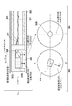
- FIG. 3 is a diagram illustrating a cross-sectional configuration of the imaging core and an arrangement of the ultrasonic transmission / reception unit and the optical transmission / reception unit.
- FIG. 4A is a diagram illustrating a scanning position when the ultrasonic transmission / reception unit and the optical transmission / reception unit of the conventional diagnostic imaging apparatus are rotated and operated in the axial direction.
- FIG. 1 is a diagram showing an external configuration of a diagnostic imaging apparatus 100 according to an embodiment of the present invention.
- FIG. 2 is a diagram showing an overall configuration of the probe portion and a cross-sectional configuration of the tip portion.
- FIG. 3 is a diagram illustrating a cross-sectional configuration of the imaging core and an arrangement of the ultrasonic transmission / reception unit and the optical transmission / reception unit
- FIG. 4B is a diagram illustrating a scanning position when the ultrasonic transmission / reception unit and the optical transmission / reception unit of the diagnostic imaging apparatus 100 are rotated and moved in the axial direction.
- FIG. 5 is a diagram illustrating a functional configuration of the diagnostic imaging apparatus 100.
- FIG. 6 is a diagram illustrating a functional configuration of the signal processing unit.
- FIG. 7 is a diagram for explaining a correspondence relationship between the tomographic image generated by the diagnostic imaging apparatus 100 and the scanning positions of the ultrasonic transmission / reception unit and the optical transmission / reception unit.
- FIG. 8 is a diagram for explaining the correspondence between the line data of the ultrasonic signal and the optical signal generated by the diagnostic imaging apparatus 100 and the frame.
- FIG. 9 is a diagram illustrating a cross-sectional configuration of the imaging core, and an arrangement of the ultrasonic transmission / reception unit and the optical transmission / reception unit.
- FIG. 1 is a diagram showing an external configuration of an image diagnostic apparatus (an image diagnostic apparatus having an IVUS function and an OCT function) 100 according to an embodiment of the present invention.
- the diagnostic imaging apparatus 100 includes a probe unit 101, a scanner / pullback unit 102, and an operation control device 103, and the scanner / pullback unit 102 and the operation control device 103 are connected by a signal line 104. Various signals are connected so that transmission is possible.
- the probe unit 101 is directly inserted into a body cavity such as a blood vessel and transmits an ultrasonic wave based on a pulse signal into the body cavity and receives a reflected wave from the body cavity, and transmitted light (measurement).
- An imaging core including an optical transmission / reception unit that continuously transmits light) into a body cavity and continuously receives reflected light from inside the body cavity is inserted.
- the state inside the body cavity is measured by using the imaging core.
- the scanner / pullback unit 102 is detachably attached to the probe unit 101, and operates in an axial direction and a rotational direction in the body cavity of the imaging core inserted into the probe unit 101 by driving a built-in motor. It stipulates. Further, the reflected wave received by the ultrasonic transmission / reception unit and the reflected light received by the optical transmission / reception unit are acquired and transmitted to the operation control apparatus 103.
- the operation control device 103 has a function for inputting various set values and a function for processing data obtained by the measurement and displaying it as a tomographic image in the body cavity when performing the measurement.
- 111 is a main body control unit, which generates ultrasonic data based on the reflected wave obtained by measurement, and processes the line data generated based on the ultrasonic data, An ultrasonic tomographic image is generated. Further, interference light data is generated by causing interference between the reflected light obtained by measurement and the reference light obtained by separating the light from the light source, and line data generated based on the interference light data. To generate an optical tomographic image.
- 111-1 is a printer / DVD recorder, which prints the processing result in the main body control unit 111 or stores it as data.
- Reference numeral 112 denotes an operation panel, and the user inputs various setting values and instructions via the operation panel 112.
- Reference numeral 113 denotes an LCD monitor as a display device, which displays a tomographic image generated by the main body control unit 111.
- the probe unit 101 includes a long catheter sheath 201 inserted into a body cavity such as a blood vessel and a user's hand without being inserted into a body cavity such as a blood vessel for operation by the user. It is comprised by the connector part 202 arrange
- a guide wire lumen tube 203 constituting a guide wire lumen is provided at the distal end of the catheter sheath 201.
- the catheter sheath 201 forms a continuous lumen from a connection portion with the guide wire lumen tube 203 to a connection portion with the connector portion 202.
- a transmission / reception unit 221 Inside the lumen of the catheter sheath 201 is provided with a transmission / reception unit 221 in which an ultrasonic transmission / reception unit for transmitting / receiving ultrasonic waves and an optical transmission / reception unit for transmitting / receiving light, an electric signal cable and an optical fiber cable are provided.
- An imaging core 220 including a coil-shaped drive shaft 222 that transmits a rotational drive force for rotating the catheter sheath 201 is inserted over almost the entire length of the catheter sheath 201.
- the connector portion 202 includes a sheath connector 202a configured integrally with the proximal end of the catheter sheath 201, and a drive shaft connector 202b configured by rotatably fixing the drive shaft 222 to the proximal end of the drive shaft 222.
- a kink protector 211 is provided at the boundary between the sheath connector 202a and the catheter sheath 201. Thereby, predetermined rigidity is maintained, and bending (kink) due to a sudden change in physical properties can be prevented.
- the base end of the drive shaft connector 202b is detachably attached to the scanner / pullback unit 102.
- a housing 223 Inside the lumen of the catheter sheath 201 is a housing 223 in which an ultrasonic transmission / reception unit for transmitting / receiving ultrasonic waves and an optical transmission / reception unit for transmitting / receiving light are arranged, and a rotation for rotating the housing 223
- An imaging core 220 including a driving shaft 222 that transmits a driving force is inserted through substantially the entire length to form the probe unit 101.
- the transmission / reception unit 221 transmits ultrasonic waves and light toward the tissue in the body cavity and receives reflected waves and reflected light from the tissue in the body cavity.
- the drive shaft 222 is formed in a coil shape, and an electric signal cable and an optical fiber cable (single-mode optical fiber cable) are arranged therein.
- the housing 223 has a shape having a notch in a part of a short cylindrical metal pipe, and is formed by cutting out from a metal lump, MIM (metal powder injection molding) or the like.
- the housing 223 includes an ultrasonic transmission / reception unit and an optical transmission / reception unit as a transmission / reception unit 221 inside, and a proximal end side is connected to the drive shaft 222.
- a short coil-shaped elastic member 231 is provided on the tip side.
- the elastic member 231 is a stainless steel wire formed in a coil shape, and the elastic member 231 is disposed on the distal end side, thereby preventing the imaging core 220 from being caught in the catheter sheath 201 when moving the imaging core 220 back and forth.
- 232 is a reinforcing coil, which is provided for the purpose of preventing a sharp bending of the distal end portion of the catheter sheath 201.
- the guide wire lumen tube 203 has a guide wire lumen into which a guide wire can be inserted.
- the guide wire lumen tube 203 is used to receive a guide wire previously inserted into a body cavity such as a blood vessel, and guide the catheter sheath 201 to the affected area using the guide wire.
- the drive shaft 222 is capable of rotating and axially moving the transmission / reception unit 221 with respect to the catheter sheath 201.
- the drive shaft 222 is made of a metal wire such as stainless steel that is flexible and can transmit rotation well. It is composed of multiple multilayer close-contact coils and the like.
- FIG. 3 is a diagram illustrating a cross-sectional configuration of the imaging core and an arrangement of the ultrasonic transmission / reception unit and the optical transmission / reception unit.
- the transmission / reception unit 221 disposed in the housing 223 includes an ultrasonic transmission / reception unit 310 and an optical transmission / reception unit 320.
- the ultrasonic transmission / reception unit 310 and the optical transmission / reception unit 320 are respectively Further, the drive shaft 222 is disposed along the axial direction on the rotation center axis (on the one-dot chain line 30a).
- the ultrasonic transmission / reception unit 310 is disposed on the distal end side of the probe unit 101, and the optical transmission / reception unit 320 is disposed on the proximal end side of the probe unit 101, and the ultrasonic transmission / reception position of the ultrasonic transmission / reception unit 310 is It is attached in the housing 223 so that the distance (distance interval) between the optical transmission / reception unit 320 and the optical transmission / reception position becomes L.
- the ultrasonic transmission / reception unit 310 and the optical transmission / reception unit 320 include an ultrasonic transmission direction (elevation angle direction) of the ultrasonic transmission / reception unit 310 and an optical transmission direction (elevation angle direction) of the optical transmission / reception unit 320 with respect to the axial direction of the drive shaft 222.
- the ultrasonic transmission direction Elevation angle direction
- the optical transmission direction Elelevation angle direction
- each transmission direction is slightly shifted from 90 ° so as not to receive reflection on the inner surface of the lumen of the catheter sheath 201.
- an electric signal cable 311 connected to the ultrasonic transmission / reception unit 310 and an optical fiber cable 321 connected to the optical transmission / reception unit 320 are arranged, and the electric signal cable 311 is an optical fiber.
- the cable 321 is spirally wound.
- the ultrasonic transmission direction (rotational angle direction (also referred to as azimuth angle direction)) of the ultrasonic transmission / reception unit 310 is ⁇ .
- 3c is a cross-sectional view taken along a plane substantially orthogonal to the rotation center axis at the optical transmission / reception position.
- the optical transmission direction (rotation angle direction) of the optical transmission / reception unit 320 is 0. That is, in the ultrasonic transmission / reception unit 310 and the optical transmission / reception unit 320, the ultrasonic transmission direction (rotation angle direction) of the ultrasonic transmission / reception unit 310 and the optical transmission direction (rotation angle direction) of the optical transmission / reception unit 320 are shifted from each other by ⁇ .
- the ultrasonic transmission / reception unit 310 and the optical transmission / reception unit 320 are arranged on the same axis (on the rotation center axis) because the image center of the constructed ultrasonic tomographic image matches the image center of the optical tomographic image. It is for doing so.
- the pullback speed (moving speed in the axial direction) in the scanner / pullback unit 102 of the diagnostic imaging apparatus 100 according to the present embodiment is V PB [mm / s] and the rotation speed is ⁇ [r / s]
- the distance L and the angle difference ⁇ have the following relationship.
- the scanning position by the ultrasonic transmission / reception unit 310 and the scanning position by the optical transmission / reception unit 320 can be matched. It is not desirable that the scanning timing due to is greatly separated from the scanning timing by the optical transceiver 320. This is because if the scan timing shift (time difference) is large, the measurement object may change during that time.
- the diagnostic imaging apparatus 100 is configured to satisfy ⁇ ⁇ 360 ° (that is, L [mm] ⁇ V PB [mm / s] / ⁇ [r / s]). ing.
- the transmission / reception unit 221 The length in the axial direction needs to be suppressed to less than 600 [ ⁇ m], preferably about 500 [ ⁇ m].
- the distance L is desirably suppressed to 150 [ ⁇ m] or less.
- the diagnostic imaging apparatus 100 can scan the same scanning position.
- the relationship between the scanning position of the ultrasonic transmission / reception unit 310 and the scanning position of the optical transmission / reception unit 320 will be described with reference to FIGS. 4A and 4B.
- FIG. 4A shows, for comparison, the scanning positional relationship when the ultrasonic transmission / reception unit and the optical transmission / reception unit of the conventional diagnostic imaging apparatus are rotated and operated in the axial direction (the ultrasonic transmission / reception unit and the optical transmission / reception unit). Shows the scanning position relationship when L and ⁇ are not defined so that the same scanning position is scanned.
- the horizontal axis represents the position coordinates in the axial direction of the body cavity such as a blood vessel
- the vertical axis represents the position coordinates in the radial direction of the body cavity such as the blood vessel.
- 40a indicates the scanning trajectory of the ultrasonic transmission / reception unit
- 40b indicates the scanning trajectory of the optical transmission / reception unit.
- the angle difference ⁇ between the ultrasonic transmission direction (rotation angle direction) of the ultrasonic transmission / reception unit and the optical transmission direction (rotation angle direction) of the optical transmission / reception unit is 0 °
- the axial direction on the rotation center axis The distance L between the ultrasonic transmission / reception position and the optical transmission / reception position along the line is arranged to be L1.
- the scanning trajectory of the ultrasonic transmission / reception unit deviates from the scanning trajectory of the optical transmission / reception unit as shown in 40c of FIG.
- the scanning position of the transmission / reception unit and the scanning position of the optical transmission / reception unit are not the same).
- FIG. 4B shows a scanning position relationship when the ultrasonic transmission / reception unit 310 and the optical transmission / reception unit 320 are configured to have the relationship of the above formula (1).
- the angle difference ⁇ between the ultrasonic transmission direction (rotation angle direction) of the ultrasonic transmission / reception unit and the optical transmission direction (rotation angle direction) of the optical transmission / reception unit is ⁇ 2, which is the axial direction on the rotation center axis.
- the distance L between the ultrasonic transmission / reception position and the optical transmission / reception position is set to be L2.
- the scanning trajectory of the ultrasonic transmission / reception unit 310 and the scanning trajectory of the optical transmission / reception unit 320 coincide with each other as indicated by 41c in FIG. 4B ( That is, the scanning position of the ultrasonic transmission / reception unit 310 is the same as the scanning position of the optical transmission / reception unit 320).
- FIG. 5 is a diagram illustrating a functional configuration of the diagnostic imaging apparatus 100 that combines the function of IVUS and the function of OCT (here, wavelength sweep type OCT). Note that the diagnostic imaging apparatus combining the IVUS function and the other OCT functions also has the same functional configuration, and thus the description thereof is omitted here.
- OCT wavelength sweep type OCT
- the imaging core 220 includes an ultrasonic transmission / reception unit 310 inside the tip, and the ultrasonic transmission / reception unit 310 transmits ultrasonic waves based on the pulse wave transmitted from the ultrasonic signal transmitter / receiver 552.
- the reflected wave echo
- the ultrasonic signal transmitter / receiver 552 is received and transmitted to the ultrasonic signal transmitter / receiver 552 as an ultrasonic echo via the adapter 502 and the slip ring 551.
- the rotational drive unit side of the slip ring 551 is rotationally driven by a radial scanning motor 505 of the rotational drive unit 504. Further, the rotation angle of the radial scanning motor 505 is detected by the encoder unit 506. Further, the scanner / pullback unit 102 includes a linear drive device 507, and defines the axial operation of the imaging core 220 based on a signal from the signal processing unit 528.
- the ultrasonic signal transmitter / receiver 552 includes a transmission wave circuit and a reception wave circuit (not shown).
- the transmission wave circuit transmits a pulse wave to the ultrasonic transmission / reception unit 310 in the imaging core 220 based on the control signal transmitted from the signal processing unit 528.
- the reception wave circuit receives an ultrasonic signal from the ultrasonic transmission / reception unit 310 in the imaging core 220.
- the received ultrasonic signal is amplified by the amplifier 553 and then input to the detector 554 for detection.
- the A / D converter 555 samples the ultrasonic signal output from the detector 554 for 200 points at 30.6 MHz to generate one line of digital data (ultrasound data).
- 30.6 MHz is assumed, but this is calculated on the assumption that 200 points are sampled at a depth of 5 mm when the sound speed is 1530 m / sec. Therefore, the sampling frequency is not particularly limited to this.
- the line-unit ultrasonic data generated by the A / D converter 555 is input to the signal processing unit 528.
- the signal processing unit 528 converts the ultrasonic data to gray scale to form an ultrasonic tomographic image at each position in the body cavity such as a blood vessel, and outputs it to the LCD monitor 113 at a predetermined frame rate.
- the signal processing unit 528 is connected to the motor control circuit 529 and receives the video synchronization signal of the motor control circuit 529.
- the signal processing unit 528 constructs an ultrasonic tomographic image in synchronization with the received video synchronization signal.
- the video synchronization signal of the motor control circuit 529 is also sent to the rotation drive device 504, and the rotation drive device 504 outputs a drive signal synchronized with the video synchronization signal.
- Wavelength Sweep OCT 508 is a wavelength swept light source (Swept Laser), which is an extended-cavity comprising an optical fiber 516 and a polygon scanning filter (508b) coupled in a ring shape with an SOA 515 (semiconductor optical amplifier). It is a kind of Laser.
- Spept Laser wavelength swept light source
- SOA 515 semiconductor optical amplifier
- the light output from the SOA 515 travels through the optical fiber 516 and enters the polygon scanning filter 508b, where the light whose wavelength is selected is amplified by the SOA 515 and finally output from the coupler 514.
- a wavelength is selected by a combination of a diffraction grating 512 that separates light and a polygon mirror 509.
- the light dispersed by the diffraction grating 512 is condensed on the surface of the polygon mirror 509 by two lenses (510, 511).
- only light having a wavelength orthogonal to the polygon mirror 509 returns through the same optical path and is output from the polygon scanning filter 508b. That is, by rotating the polygon mirror 509, time sweeping of the wavelength can be performed.
- the polygon mirror 509 for example, a 32-hedron mirror is used, and the rotation speed is about 50000 rpm.
- a wavelength sweeping method combining the polygon mirror 509 and the diffraction grating 512 enables high-speed, high-output wavelength sweeping.
- the light of the wavelength swept light source 508 output from the coupler 514 is incident on one end of the first single mode fiber 540 and transmitted to the distal end side.
- the first single mode fiber 540 is optically coupled to the second single mode fiber 545 and the third single mode fiber 544 at an intermediate optical coupler 541. Therefore, the light incident on the first single mode fiber 540 is divided by the optical coupler unit 541 into three optical paths and transmitted.
- An optical rotary joint (optical cup) that transmits light by coupling a non-rotating part (fixed part) and a rotating part (rotational drive part) to the tip side of the optical coupler part 541 of the first single mode fiber 540.
- a ring portion 503 is provided in the rotary drive device 504.
- the fifth single mode fiber 543 of the probe unit 101 is detachably connected to the distal end side of the fourth single mode fiber 542 in the optical rotary joint (optical coupling unit) 503 via the adapter 502. Yes.
- the light from the wavelength swept light source 508 is transmitted to the fifth single mode fiber 543 that is inserted into the imaging core 220 and can be driven to rotate.
- the transmitted light is irradiated from the optical transmission / reception unit 320 of the imaging core 220 to the living tissue in the living body lumen while rotating and moving in the axial direction. Then, a part of the reflected light scattered on the surface of the living tissue or inside thereof is taken in by the light transmitting / receiving unit 320 of the imaging core 220 and returns to the first single mode fiber 540 side through the reverse optical path. Further, a part of the light is moved to the second single mode fiber 545 side by the optical coupler unit 541 and emitted from one end of the second single mode fiber 545, and then received by a photodetector (eg, a photodiode 524).
- a photodetector eg, a photodiode 524
- the rotational drive unit side of the optical rotary joint 503 is rotationally driven by a radial scanning motor 505 of the rotational drive device 504. Further, the rotation angle of the radial scanning motor 505 is detected by the encoder unit 506. Further, the scanner / pullback unit 102 includes a linear drive device 507, and defines the axial operation of the imaging core 220 based on an instruction from the signal processing unit 528.
- an optical path length variable mechanism 532 for finely adjusting the optical path length of the reference light is provided at the tip of the third single mode fiber 544 opposite to the optical coupler section 541.
- the optical path length changing mechanism 532 changes the optical path length to change the optical path length corresponding to the variation in length so that the variation in length of each probe unit 101 when the probe unit 101 is replaced and used can be absorbed. Means.
- the third single mode fiber 544 and the collimating lens 518 are provided on a uniaxial stage 522 that is movable as indicated by an arrow 523 in the direction of the optical axis, and form optical path length changing means.
- the uniaxial stage 522 when the probe unit 101 is replaced, functions as an optical path length changing unit having a variable range of the optical path length that can absorb variations in the optical path length of the probe unit 101. Further, the uniaxial stage 522 also has a function as an adjusting means for adjusting the offset. For example, even when the tip of the probe unit 101 is not in close contact with the surface of the biological tissue, the optical path length is minutely changed by the uniaxial stage to set the state to interfere with the reflected light from the surface position of the biological tissue. Is possible.
- the optical path length is finely adjusted by the uniaxial stage 522, and the light reflected by the mirror 521 via the grating 519 and the lens 520 is first reflected by the optical coupler unit 541 provided in the middle of the third single mode fiber 544. It is mixed with light obtained from the single mode fiber 540 side and received by the photodiode 524.
- the interference light received by the photodiode 524 in this way is photoelectrically converted, amplified by the amplifier 525, and then input to the demodulator 526.
- the demodulator 526 performs demodulation processing for extracting only the signal portion of the interfered light, and its output is input to the A / D converter 527 as an interference light signal.
- the A / D converter 527 samples the interference light signal for 2048 points at 180 MHz, for example, and generates one line of digital data (interference light data).
- the sampling frequency of 180 MHz is based on the assumption that about 90% of the wavelength sweep cycle (12.5 ⁇ sec) is extracted as 2048 digital data when the wavelength sweep repetition frequency is 40 kHz.
- the present invention is not limited to this.
- the line-by-line interference light data generated by the A / D converter 527 is input to the signal processing unit 528.
- the signal processing unit 528 frequency-decomposes interference light data by FFT (Fast Fourier Transform) to generate data in the depth direction (line data), and coordinate-converts this to obtain a body cavity such as a blood vessel.
- FFT Fast Fourier Transform
- An optical tomographic image at each position is constructed and output to the LCD monitor 113 at a predetermined frame rate.
- the signal processing unit 528 is further connected to the optical path length adjusting means control device 530.
- the signal processing unit 528 controls the position of the uniaxial stage 522 via the optical path length adjusting unit controller 530.
- FIG. 6 is a diagram showing a functional configuration and related functional blocks for realizing a construction process in the signal processing unit 528 of the diagnostic imaging apparatus 100.
- the interference light data 621 generated by the A / D converter 527 is output from the motor control circuit 529 to the encoder of the radial scanning motor 505 in the line data generation unit 601 in the signal processing unit 528.
- processing is performed so that the number of lines per rotation of the radial scanning is 512.
- an optical tomographic image is constructed from 512 lines, but the number of lines is not limited to this.
- the line data 622 output from the line data generation unit 601 is stored in the line data memory 602 for each rotation of the radial scan based on an instruction from the control unit 605.
- the control unit 605 counts the pulse signal 641 output from the movement amount detector of the linear driving device 507 and generates each line data 622 when the line data 622 is stored in the line data memory 602. The count value is stored in association with each other.
- the line data 623 stored in association with the count value is subjected to various processes (line addition averaging process, filter process, etc.) in the optical tomographic image construction unit 603 based on an instruction from the control unit 605, By the R ⁇ conversion, the optical tomographic image 624 is sequentially output.
- the image processing unit 604 performs image processing for display on the LCD monitor 113 and then outputs the optical tomographic image 625 to the LCD monitor 113.
- the ultrasonic data 631 generated by the A / D converter 555 is a signal of the encoder unit 506 of the radial scanning motor 505 output from the motor control circuit 529 in the line data generation unit 611 in the signal processing unit 528. Is used so that the number of lines per one rotation of the radial scanning is 512.
- the line data 632 output from the line data generation unit 611 is stored in the line data memory 612 for each rotation of the radial scan based on an instruction from the control unit 605.
- the control unit 605 counts the pulse signal 641 output from the movement amount detector of the linear driving device 507 and generates each line data 632 when storing the line data 632 in the line data memory 612.
- the count value is stored in association with each other.
- the count value stored in association with the line data 632 stored for each rotation of radial scanning is the count value stored in association with the line data 622 stored for each rotation of radial scanning.
- the count value corresponding to the angle difference ⁇ between the ultrasonic transmission direction (rotation angle direction) and the optical transmission direction (rotation angle direction) is shifted. This will be described in detail with reference to FIGS.
- FIG. 7 is a diagram illustrating a correspondence relationship between the ultrasonic tomographic image and the optical tomographic image generated by the diagnostic imaging apparatus 100 and the scanning positions of the ultrasonic transmission / reception unit 310 and the optical transmission / reception unit 320.
- FIG. It is a figure for demonstrating the correspondence of the line data 632 and 622 of an ultrasonic wave data and interference light data produced
- Reference numeral 70a denotes a scanning trajectory of the ultrasonic transmission / reception unit 310
- reference numeral 70b denotes a scanning trajectory of the optical transmission / reception unit 320.
- the ultrasonic transmission direction (rotation angle direction) and the optical transmission direction (rotation angle direction) have an angle difference of ⁇ , when radial scanning is started at the same time, ultrasonic transmission / reception is performed at each time.
- the scanning position of the unit 310 is different from the scanning position of the optical transmission / reception unit 320 (for example, when the radial scanning starts, the ultrasonic transmission / reception unit 310 scans the scanning position indicated by reference numeral 701).
- the optical transceiver 320 scans the scanning position indicated by reference numeral 711).
- the respective tomographic images have lines at different scanning positions. It will be constructed using data.
- a line for one rotation of radial scanning is obtained with the time difference of the angle difference between the ultrasonic transmission direction (rotation angle direction) and the optical transmission direction (rotation angle direction). It is configured to capture data.
- the ultrasonic tomographic image 702 stores the line data acquired at timing 703 as the first line data for one rotation of radial scanning, and the line data acquired at timing 704 is stored for one rotation of radial scanning. It is an ultrasonic tomographic image constructed by storing as 512th line data.
- the optical tomographic image 712 stores the line data acquired at timing 711 as the first line data for one rotation of radial scanning, and the line data acquired at timing 714 is 512 for one rotation of radial scanning. It is an optical tomographic image constructed by storing as the main line data.
- FIG. 8A shows an example of line data 632 stored in the line data memory 612 in this way
- FIG. 8B shows an example of line data 622 stored in the line data memory 602.
- the line data 632 for one rotation of radial scanning is shifted from the line data 622 for one rotation of radial scanning by an angle difference ⁇ . 612 is stored.
- the line data 633 stored in association with the count value is subjected to various processes (line addition averaging process, filter process, etc.) in the ultrasonic tomographic image construction unit 613 based on an instruction from the control unit 605. , R ⁇ conversion, and sequentially output as an ultrasonic tomographic image 634.
- the image is output to the LCD monitor 113 as an ultrasonic tomographic image 635.
- the ultrasonic transmission / reception unit 310 and the optical transmission / reception unit 320 are arranged along the axial direction on the rotation center axis.
- the arrangement corresponds to the pullback speed and the rotation speed.
- the line data used for constructing one frame of the ultrasonic tomographic image and the one frame of optical tomographic image are used according to the angular difference in the rotation angle direction between the ultrasonic transceiver unit 310 and the optical transceiver unit 320.
- the line data is determined.
- the ultrasonic transmission / reception unit 310 and the optical transmission / reception unit 320 are arranged along the axial direction on the rotation center axis.
- the present invention is not limited to this and is shifted from the rotation center axis. It is good also as a structure to arrange. Since each image center can be adjusted by image processing at the time of ultrasonic image generation and optical tomographic image generation, the ultrasonic transmission / reception unit 310 and the optical transmission / reception unit 320 do not necessarily have to be arranged on the rotation center axis. Because.
- FIG. 9 is a diagram illustrating a cross-sectional configuration of an imaging core and an arrangement of an ultrasonic transmission / reception unit and an optical transmission / reception unit in the diagnostic imaging apparatus according to the present embodiment.
- the description will focus on the differences from FIG.
- the ultrasonic transmission / reception unit 310 and the optical transmission / reception unit 320 are arranged at a position separated by a distance r with respect to the rotation center axis. They are arranged so that the angle difference between the sound wave transmission direction (rotation angle direction) and the light transmission direction (rotation angle direction) is ⁇ .
- the ultrasonic transmission / reception unit and the optical transmission / reception unit are located at the same position as in the first embodiment by being arranged along the axial direction at a position equidistant from the rotation center axis. Can be observed.
- the ultrasonic transmission / reception unit 310 is disposed on the distal end side and the optical transmission / reception unit 320 is disposed on the proximal end side.
- the present invention is not limited to this, and the optical transmission / reception unit 320 is disposed on the distal end side.
- the ultrasonic transmission / reception unit 310 may be arranged on the proximal end side.
- the display form of the constructed ultrasonic tomographic image and optical tomographic image is not particularly mentioned.
- the ultrasonic tomographic image and the optical tomographic image are in the axial direction in a body cavity such as a blood vessel.
- the tomographic images corresponding to the respective positions may be displayed in parallel, or may be configured to be displayed in a superimposed manner so that the image centers coincide.
Abstract
画像診断装置において、同一位置を観察できるようにする。本発明は、超音波送受信部310と、光送受信部320とが配置された送受信部221を有するプローブであって、超音波送受信部310と光送受信部320とは、軸方向に沿って配置されており、超音波送受信部310の軸方向の位置と光送受信部320の軸方向の位置の間の距離L[mm]、及び、超音波送受信部310の超音波の送信方向と、光送受信部320の光の送信方向との間の角度差θ[deg]は、送受信部221の回転速度をω[r/s]、送受信部221の軸方向の移動速度をV[mm/s]とした場合、L=V/ω×θ/360の関係を満たすことを特徴とする。
Description
本発明は、プローブ及び画像診断装置に関するものである。
従来より、動脈硬化の診断や、バルーンカテーテルまたはステント等の高機能カテーテルによる血管内治療時の術前診断、あるいは、術後の結果確認のために、画像診断装置が広く使用されている。
画像診断装置には、血管内超音波診断装置(IVUS:Intra Vascular Ultra Sound)や光干渉断層診断装置(OCT:Optical Coherence Tomography)等が含まれ、それぞれに異なる特性を有している。
更に、最近では、IVUSの機能と、OCTの機能とを組み合わせた画像診断装置も提案されている(例えば、特許文献1、2参照)。このような画像診断装置によれば、高深度領域まで測定できるIVUSの特性と、高分解能で測定できるOCTの特性とを活かした断層画像を生成することができる。
しかしながら、画像診断装置では、通常、血管内においてプローブ部を回転動作及び軸方向動作させながら、送受信部にて超音波または光を送受信させることで断層画像の生成を行う。このため、IVUS用の送受信部とOCT用の送受信部とを、プローブ内において上記特許文献1または2に開示されているような配置とした場合、超音波及び光の血管内における走査位置にずれが生じることとなる。IVUS用の送受信部とOCT用の送受信部は、いずれも一定のサイズを有しており、両者は径方向または軸方向にずらして配置する必要があることから、送受信位置を完全に同一にさせることができないからである。
一方で、血管内のプラーク等の性状は、IVUSを用いて生成された断層画像とOCTを用いて生成された断層画像とを用いて観察することが有効である。このため、走査位置にずれがあった場合に、有効な観察ができない可能性がある。
このようなことから、上述のような画像診断装置においては、IVUS用の送受信部により走査される血管内の走査位置と、OCT用の送受信部により走査される血管内の走査位置とを一致させ、完全に同一位置を観察できるようにすることが望ましい。
本発明は上記課題に鑑みてなされたものであり、超音波を送受信可能な送受信部と、光を送受信可能な送受信部とを用いて、それぞれの断層画像を生成可能な画像診断装置において、同一位置を観察できるようにすることを目的とする。
上記の目的を達成するために、本発明に係るプローブは以下のような構成を備える。即ち、
超音波の送受信を行う超音波送受信部と、光の送受信を行う光送受信部とが配置された送受信部を有し、該送受信部を回転させながら超音波及び光を送信し、生体管腔内を軸方向に移動させながら、該超音波送受信部が受信した生体組織からの反射波と、該光送受信部が受信した生体組織からの反射光とを用いて、該生体組織の軸方向の超音波断層画像及び光断層画像を生成する画像診断装置に対して、反射波及び反射光を伝送可能なプローブであって、
前記超音波送受信部と前記光送受信部との方位角方向になす角度差θ[deg]が、前記超音波送受信部の前記軸方向の位置と前記光送受信部の前記軸方向の位置との間の距離L[mm]および前記送受信部の回転速度ω[r/s]に比例し、前記送受信部の軸方向の移動速度V[mm/s]に反比例するように、前記超音波送受信部及び前記光送受信部が配置されていることを特徴とする。
本発明によれば、超音波を送受信可能な送受信部と、光を送受信可能な送受信部とを用いて、それぞれの断層画像を生成可能な画像診断装置において、同一位置を観察することが可能となる。
本発明のその他の特徴及び利点は、添付図面を参照とした以下の説明により明らかになるであろう。なお、添付図面においては、同じ若しくは同様の構成には、同じ参照番号を付す。
添付図面は明細書に含まれ、その一部を構成し、本発明の実施の形態を示し、その記述と共に本発明の原理を説明するために用いられる。
図1は、本発明の一実施形態にかかる画像診断装置100の外観構成を示す図である。
図2は、プローブ部の全体構成及び先端部の断面構成を示す図である。
図3は、イメージングコアの断面構成、ならびに超音波送受信部及び光送受信部の配置を示す図である。
図4Aは、従来の画像診断装置の超音波送受信部及び光送受信部を回転動作及び軸方向動作させた場合の、走査位置を示す図である。
図4Bは、画像診断装置100の超音波送受信部及び光送受信部を回転動作及び軸方向動作させた場合の、走査位置を示す図である。
図5は、画像診断装置100の機能構成を示す図である。
図6は、信号処理部の機能構成を示す図である。
図7は、画像診断装置100により生成される断層画像と、超音波送受信部及び光送受信部の走査位置との対応関係を説明するための図である。
図8は、画像診断装置100により生成される超音波信号及び光信号のラインデータとフレームとの対応関係を説明するための図である。
図9は、イメージングコアの断面構成、ならびに超音波送受信部及び光送受信部の配置を示す図である。
以下、本発明の各実施形態について添付図面を参照しながら詳細に説明する。なお、以下に述べる実施の形態は、本発明の好適な具体例であるから、技術的に好ましい種々の限定が付されているが、本発明の範囲は、以下の説明において特に本発明を限定する旨の記載がない限り、これらの態様に限られるものではない。
[第1の実施形態]
<1.画像診断装置の外観構成>
図1は本発明の一実施形態にかかる画像診断装置(IVUSの機能と、OCTの機能とを備える画像診断装置)100の外観構成を示す図である。
<1.画像診断装置の外観構成>
図1は本発明の一実施形態にかかる画像診断装置(IVUSの機能と、OCTの機能とを備える画像診断装置)100の外観構成を示す図である。
図1に示すように、画像診断装置100は、プローブ部101と、スキャナ/プルバック部102と、操作制御装置103とを備え、スキャナ/プルバック部102と操作制御装置103とは、信号線104により各種信号が伝送可能に接続されている。
プローブ部101は、直接血管等の体腔内に挿入され、パルス信号に基づく超音波を体腔内に送信するとともに、体腔内からの反射波を受信する超音波送受信部と、伝送された光(測定光)を連続的に体腔内に送信するとともに、体腔内からの反射光を連続的に受信する光送受信部と、を備えるイメージングコアが内挿されている。画像診断装置100では、該イメージングコアを用いることで体腔内部の状態を測定する。
スキャナ/プルバック部102は、プローブ部101が着脱可能に取り付けられ、内蔵されたモータを駆動させることでプローブ部101に内挿されたイメージングコアの体腔内の軸方向の動作及び回転方向の動作を規定している。また、超音波送受信部において受信された反射波及び光送受信部において受信された反射光を取得し、操作制御装置103に対して送信する。
操作制御装置103は、測定を行うにあたり、各種設定値を入力するための機能や、測定により得られたデータを処理し、体腔内の断層画像として表示するための機能を備える。
操作制御装置103において、111は本体制御部であり、測定により得られた反射波に基づいて超音波データを生成するとともに、該超音波データに基づいて生成されたラインデータを処理することで、超音波断層画像を生成する。更に、測定により得られた反射光と光源からの光を分離することで得られた参照光とを干渉させることで干渉光データを生成するとともに、該干渉光データに基づいて生成されたラインデータを処理することで、光断層画像を生成する。
111-1はプリンタ/DVDレコーダであり、本体制御部111における処理結果を印刷したり、データとして記憶したりする。112は操作パネルであり、ユーザは該操作パネル112を介して、各種設定値及び指示の入力を行う。113は表示装置としてのLCDモニタであり、本体制御部111において生成された断層画像を表示する。
<2.プローブ部の全体構成及び先端部の断面構成>
次に、プローブ部101の全体構成及び先端部の断面構成について図2を用いて説明する。図2に示すように、プローブ部101は、血管等の体腔内に挿入される長尺のカテーテルシース201と、ユーザが操作するために血管等の体腔内に挿入されることなく、ユーザの手元側に配置されるコネクタ部202とにより構成される。カテーテルシース201の先端には、ガイドワイヤルーメンを構成するガイドワイヤルーメン用チューブ203が設けられている。カテーテルシース201は、ガイドワイヤルーメン用チューブ203との接続部分からコネクタ部202との接続部分にかけて連続する管腔を形成している。
次に、プローブ部101の全体構成及び先端部の断面構成について図2を用いて説明する。図2に示すように、プローブ部101は、血管等の体腔内に挿入される長尺のカテーテルシース201と、ユーザが操作するために血管等の体腔内に挿入されることなく、ユーザの手元側に配置されるコネクタ部202とにより構成される。カテーテルシース201の先端には、ガイドワイヤルーメンを構成するガイドワイヤルーメン用チューブ203が設けられている。カテーテルシース201は、ガイドワイヤルーメン用チューブ203との接続部分からコネクタ部202との接続部分にかけて連続する管腔を形成している。
カテーテルシース201の管腔内部には、超音波を送受信する超音波送受信部と光を送受信する光送受信部とが配置された送受信部221と、電気信号ケーブル及び光ファイバケーブルを内部に備え、それを回転させるための回転駆動力を伝達するコイル状の駆動シャフト222とを備えるイメージングコア220が、カテーテルシース201のほぼ全長にわたって挿通されている。
コネクタ部202は、カテーテルシース201の基端に一体化して構成されたシースコネクタ202aと、駆動シャフト222の基端に駆動シャフト222を回動可能に固定して構成された駆動シャフトコネクタ202bとを備える。
シースコネクタ202aとカテーテルシース201との境界部には、耐キンクプロテクタ211が設けられている。これにより所定の剛性が保たれ、急激な物性の変化による折れ曲がり(キンク)を防止することができる。
駆動シャフトコネクタ202bの基端は、スキャナ/プルバック部102に着脱可能に取り付けられる。
次に、プローブ部101の先端部の断面構成について説明する。カテーテルシース201の管腔内部には、超音波を送受信する超音波送受信部と光を送受信する光送受信部とが配置された送受信部221が配されたハウジング223と、それを回転させるための回転駆動力を伝送する駆動シャフト222とを備えるイメージングコア220がほぼ全長にわたって挿通されており、プローブ部101を形成している。
送受信部221では、体腔内組織に向けて超音波及び光を送信するとともに、体腔内組織からの反射波及び反射光を受信する。
駆動シャフト222はコイル状に形成され、その内部には電気信号ケーブル及び光ファイバケーブル(シングルモードの光ファイバケーブル)が配されている。
ハウジング223は、短い円筒状の金属パイプの一部に切り欠き部を有した形状をしており、金属塊からの削りだしやMIM(金属粉末射出成形)等により成形される。ハウジング223は、内部に送受信部221として、超音波送受信部及び光送受信部を有し、基端側は駆動シャフト222と接続されている。また、先端側には短いコイル状の弾性部材231が設けられている。
弾性部材231はステンレス鋼線材をコイル状に形成したものであり、弾性部材231が先端側に配されることで、イメージングコア220を前後移動させる際にカテーテルシース201内での引っかかりを防止する。
232は補強コイルであり、カテーテルシース201の先端部分の急激な折れ曲がりを防止する目的で設けられている。
ガイドワイヤルーメン用チューブ203は、ガイドワイヤが挿入可能なガイドワイヤ用ルーメンを有する。ガイドワイヤルーメン用チューブ203は、予め血管等の体腔内に挿入されたガイドワイヤを受け入れ、ガイドワイヤによってカテーテルシース201を患部まで導くのに使用される。
駆動シャフト222は、カテーテルシース201に対して送受信部221を回転動作及び軸方向動作させることが可能であり、柔軟で、かつ回転をよく伝送できる特性をもつ、例えば、ステンレス等の金属線からなる多重多層密着コイル等により構成されている。
<3.イメージングコアの断面構成>
次に、イメージングコア220の断面構成、ならびに超音波送受信部及び光送受信部の配置について説明する。図3は、イメージングコアの断面構成、ならびに超音波送受信部及び光送受信部の配置を示す図である。
次に、イメージングコア220の断面構成、ならびに超音波送受信部及び光送受信部の配置について説明する。図3は、イメージングコアの断面構成、ならびに超音波送受信部及び光送受信部の配置を示す図である。
図3の30aに示すように、ハウジング223内に配された送受信部221は、超音波送受信部310と光送受信部320とを備えており、超音波送受信部310及び光送受信部320は、それぞれ、駆動シャフト222の回転中心軸上(30aの一点鎖線上)において軸方向に沿って配置されている。
このうち、超音波送受信部310は、プローブ部101の先端側に、また、光送受信部320は、プローブ部101の基端側に配置されており、超音波送受信部310の超音波送受信位置と光送受信部320の光送受信位置との間の距離(距離間隔)がLとなるように、ハウジング223内に取り付けられている。
また、超音波送受信部310及び光送受信部320は、駆動シャフト222の軸方向に対する、超音波送受信部310の超音波送信方向(仰角方向)、及び、光送受信部320の光送信方向(仰角方向)が、それぞれ、略90°となるようにハウジング223内に取り付けられている。また、各送信方向は、カテーテルシース201の管腔内表面での反射を受信しないように90°よりややずらすことが望ましい。
駆動シャフト222の内部には、超音波送受信部310と接続された電気信号ケーブル311と、光送受信部320に接続された光ファイバケーブル321とが配されており、電気信号ケーブル311は、光ファイバケーブル321に対して螺旋状に巻き回されている。
図3の30bは、超音波受信位置において、回転中心軸に略直交する面で切断した場合の断面図である。図3の30bに示すように、紙面下方向を0とした場合、超音波送受信部310の超音波送信方向(回転角方向(方位角方向ともいう))は、θとなっている。
図3の30cは、光送受信位置において、回転中心軸に略直交する面で切断した場合の断面図である。図3の30cに示すように、紙面下方向を0とした場合、光送受信部320の光送信方向(回転角方向)は、0となっている。つまり、超音波送受信部310と光送受信部320は、超音波送受信部310の超音波送信方向(回転角方向)と、光送受信部320の光送信方向(回転角方向)とが、互いにθずれるように配置されている。
<4.超音波送受信部と光送受信部との位置関係>
超音波送受信部310と光送受信部320との位置関係について更に詳説する。上述したように、超音波送受信部310及び光送受信部320は、回転中心軸上において軸方向に沿って、超音波送受信位置と光送受信位置との間の距離がLとなるように配置されており、かつ、超音波送信方向(回転角方向)と光送信方向(回転角方向)との角度差がθとなるように配置されている。なお、超音波送受信部310と光送受信部320を同一の軸上(回転中心軸上)に配置したのは、構築される超音波断層画像の画像中心と光断層画像の画像中心とが一致するようにするためである。
超音波送受信部310と光送受信部320との位置関係について更に詳説する。上述したように、超音波送受信部310及び光送受信部320は、回転中心軸上において軸方向に沿って、超音波送受信位置と光送受信位置との間の距離がLとなるように配置されており、かつ、超音波送信方向(回転角方向)と光送信方向(回転角方向)との角度差がθとなるように配置されている。なお、超音波送受信部310と光送受信部320を同一の軸上(回転中心軸上)に配置したのは、構築される超音波断層画像の画像中心と光断層画像の画像中心とが一致するようにするためである。
ここで、本実施形態に係る画像診断装置100のスキャナ/プルバック部102におけるプルバック速度(軸方向の移動速度)をVPB[mm/s]、回転速度をω[r/s]とすると、超音波送受信部310による走査位置と、光送受信部320による走査位置とを一致させるためには、距離Lと角度差θが、以下のような関係を有していることが必要である。
L[mm]=VPB[mm/s]/ω[r/s]×θ[deg]/360[deg] ・・・ (式1)
ここで、一例として、スキャナ/プルバック部102のプルバック速度VPBを20[mm/s]、回転速度ωを30[r/s](1800[rpm])とした場合の、距離Lと角度差θの適正値について以下に検討する。
ここで、一例として、スキャナ/プルバック部102のプルバック速度VPBを20[mm/s]、回転速度ωを30[r/s](1800[rpm])とした場合の、距離Lと角度差θの適正値について以下に検討する。
(1)同時性を考慮した場合
上式1を満たすことで、超音波送受信部310による走査位置と、光送受信部320による走査位置とを一致させることが可能となるが、超音波送受信部310による走査タイミングと光送受信部320による走査タイミングとが大きく離れていることは望ましくない。走査タイミングのずれ(時間差)が大きい場合、その間に、測定対象が変化してしまうことがありえるからである。
上式1を満たすことで、超音波送受信部310による走査位置と、光送受信部320による走査位置とを一致させることが可能となるが、超音波送受信部310による走査タイミングと光送受信部320による走査タイミングとが大きく離れていることは望ましくない。走査タイミングのずれ(時間差)が大きい場合、その間に、測定対象が変化してしまうことがありえるからである。
このため、本実施形態に係る画像診断装置100では、同一の走査位置に対する、超音波送受信部310による走査タイミングと光送受信部320による走査タイミングのずれ(時間差)が、1フレーム未満となるようにし、両者の同時性を高める構成としている。つまり、本実施形態に係る画像診断装置100では、θ<360°となるように(つまり、L[mm]<VPB[mm/s]/ω[r/s]となるように)構成されている。
(2)拍動を考慮した場合
血管内の断層画像を生成する場合、拍動の影響を考慮する必要があり、同一の走査位置に対する、超音波送受信部310による走査タイミングと光送受信部320による走査タイミングとの時間差における、拍動による血管内の変化は、極力抑える必要がある。一般に、走査タイミングのずれ(時間差)を10msec以下に抑えれば、拍動による血管内の変化を無視することができる(10msec以下であれば、超音波送受信部310と光送受信部320とは、ほぼ同じタイミングで走査しているとみなすことができる)。
血管内の断層画像を生成する場合、拍動の影響を考慮する必要があり、同一の走査位置に対する、超音波送受信部310による走査タイミングと光送受信部320による走査タイミングとの時間差における、拍動による血管内の変化は、極力抑える必要がある。一般に、走査タイミングのずれ(時間差)を10msec以下に抑えれば、拍動による血管内の変化を無視することができる(10msec以下であれば、超音波送受信部310と光送受信部320とは、ほぼ同じタイミングで走査しているとみなすことができる)。
このようなことから、本実施形態に係る画像診断装置100では、同一の走査位置に対する、超音波送受信部310による走査タイミングと光送受信部320による走査タイミングのずれ(時間差)が、10msec以下となるようにし、拍動に対する両者の同時性を高める構成としている。つまり、本実施形態に係る画像診断装置100では、θ<108°(=10[msec]/33.3[msec/r]×360[deg])となるように構成されている。
(3)送受信部サイズを考慮した場合
プローブ部101は、直接血管等の体腔内に挿入されるものであり、低侵襲の観点及び細径の血管への挿入等を考慮すると、送受信部221の軸方向の長さは、600[μm]未満、望ましくは500[μm]程度に抑える必要がある。そして、超音波送受信部310及び光送受信部320の製造可能な最小サイズを考慮すると、距離Lは150[μm]以下に抑えることが望ましい。
プローブ部101は、直接血管等の体腔内に挿入されるものであり、低侵襲の観点及び細径の血管への挿入等を考慮すると、送受信部221の軸方向の長さは、600[μm]未満、望ましくは500[μm]程度に抑える必要がある。そして、超音波送受信部310及び光送受信部320の製造可能な最小サイズを考慮すると、距離Lは150[μm]以下に抑えることが望ましい。
このようなことから、本実施形態に係る画像診断装置100では、θ≦90°(=150[μm]/20[mm/s]/30[r/s]×360[deg])となるように構成されている。
<5.走査位置についての説明>
超音波送受信部310と光送受信部320との上記位置関係により、本実施形態に係る画像診断装置100では、同一の走査位置を走査することが可能となる。以下、図4A及び図4Bを用いて、超音波送受信部310の走査位置と光送受信部320の走査位置との関係について説明する。
超音波送受信部310と光送受信部320との上記位置関係により、本実施形態に係る画像診断装置100では、同一の走査位置を走査することが可能となる。以下、図4A及び図4Bを用いて、超音波送受信部310の走査位置と光送受信部320の走査位置との関係について説明する。
このうち、図4Aは、比較のために、従来の画像診断装置の超音波送受信部と光送受信部を回転動作及び軸方向動作させた場合の走査位置関係(超音波送受信部と光送受信部とが同一の走査位置を走査するように、L及びθが規定されていない場合の走査位置関係)を示している。
図4Aの40a~40cにおいて、横軸は、血管等の体腔の軸方向の位置座標を、縦軸は、血管等の体腔の径方向の位置座標をそれぞれ示している。
このうち、40aは超音波送受信部の走査軌跡を、40bは光送受信部の走査軌跡をそれぞれ示している。
図4Aの例では、超音波送受信部の超音波送信方向(回転角方向)と、光送受信部の光送信方向(回転角方向)との角度差θが0°、回転中心軸上において軸方向に沿った、超音波送受信位置と光送受信位置との間の距離LがL1となるように配置されている。
この場合、送受信部を回転動作及び軸方向動作させると、図4Aの40cに示すように、超音波送受信部の走査軌跡と、光送受信部の走査軌跡とがずれることとなる(つまり、超音波送受信部の走査位置と、光送受信部の走査位置とが同一とならない)。
一方、図4Bは、超音波送受信部310と光送受信部320とを上式(1)の関係を有するように構成した場合の、走査位置関係を示している。
図4Bの例では、超音波送受信部の超音波送信方向(回転角方向)と、光送受信部の光送信方向(回転角方向)との角度差θがθ2、回転中心軸上において軸方向に沿った、超音波送受信位置と光送受信位置との間の距離LがL2となるように配置されている。
この場合、送受信部221を回転動作及び軸方向動作させると、図4Bの41cに示すように、超音波送受信部310の走査軌跡と、光送受信部320の走査軌跡とが一致することとなる(つまり、超音波送受信部310の走査位置と、光送受信部320の走査位置とが同一となる)。
<6.画像診断装置の機能構成>
次に、画像診断装置100の機能構成について説明する。図5は、IVUSの機能とOCT(ここでは、例として波長掃引型OCT)の機能とを組み合わせた画像診断装置100の機能構成を示す図である。なお、IVUSの機能と他のOCTの機能とを組み合わせた画像診断装置についても、同様の機能構成を有するため、ここでは説明を省略する。
次に、画像診断装置100の機能構成について説明する。図5は、IVUSの機能とOCT(ここでは、例として波長掃引型OCT)の機能とを組み合わせた画像診断装置100の機能構成を示す図である。なお、IVUSの機能と他のOCTの機能とを組み合わせた画像診断装置についても、同様の機能構成を有するため、ここでは説明を省略する。
(1)IVUSの機能
イメージングコア220は、先端内部に超音波送受信部310を備えており、超音波送受信部310は、超音波信号送受信器552より送信されたパルス波に基づいて、超音波を生体組織に送信するとともに、その反射波(エコー)を受信し、アダプタ502及びスリップリング551を介して超音波エコーとして超音波信号送受信器552に送信する。
イメージングコア220は、先端内部に超音波送受信部310を備えており、超音波送受信部310は、超音波信号送受信器552より送信されたパルス波に基づいて、超音波を生体組織に送信するとともに、その反射波(エコー)を受信し、アダプタ502及びスリップリング551を介して超音波エコーとして超音波信号送受信器552に送信する。
なお、スリップリング551の回転駆動部側は回転駆動装置504のラジアル走査モータ505により回転駆動される。また、ラジアル走査モータ505の回転角度は、エンコーダ部506により検出される。更に、スキャナ/プルバック部102は、直線駆動装置507を備え、信号処理部528からの信号に基づいて、イメージングコア220の軸方向動作を規定する。
超音波信号送受信器552は、送信波回路と受信波回路とを備える(不図示)。送信波回路は、信号処理部528から送信された制御信号に基づいて、イメージングコア220内の超音波送受信部310に対してパルス波を送信する。
また、受信波回路は、イメージングコア220内の超音波送受信部310より超音波信号を受信する。受信された超音波信号はアンプ553により増幅された後、検波器554に入力され検波される。
更に、A/D変換器555では、検波器554より出力された超音波信号を30.6MHzで200ポイント分サンプリングして、1ラインのデジタルデータ(超音波データ)を生成する。なお、ここでは、30.6MHzとしているが、これは音速を1530m/secとしたときに、深度5mmに対して200ポイントサンプリングすることを前提として算出されたものである。したがって、サンプリング周波数は特にこれに限定されるものではない。
A/D変換器555にて生成されたライン単位の超音波データは信号処理部528に入力される。信号処理部528では、超音波データをグレースケールに変換することにより、血管等の体腔内の各位置での超音波断層画像を形成し、所定のフレームレートでLCDモニタ113に出力する。
なお、信号処理部528はモータ制御回路529と接続され、モータ制御回路529のビデオ同期信号を受信する。信号処理部528では、受信したビデオ同期信号に同期して超音波断層画像の構築を行う。
また、このモータ制御回路529のビデオ同期信号は、回転駆動装置504にも送られ、回転駆動装置504はビデオ同期信号に同期した駆動信号を出力する。
(2)波長掃引型OCTの機能
508は波長掃引光源(Swept Laser)であり、SOA515(semiconductor optical amplifier)とリング状に結合された光ファイバ516とポリゴンスキャニングフィルタ(508b)よりなる、Extended-cavity Laserの一種である。
508は波長掃引光源(Swept Laser)であり、SOA515(semiconductor optical amplifier)とリング状に結合された光ファイバ516とポリゴンスキャニングフィルタ(508b)よりなる、Extended-cavity Laserの一種である。
SOA515から出力された光は、光ファイバ516を進み、ポリゴンスキャニングフィルタ508bに入り、ここで波長選択された光は、SOA515で増幅され、最終的にcoupler514から出力される。
ポリゴンスキャニングフィルタ508bでは、光を分光する回折格子512とポリゴンミラー509との組み合わせで波長を選択する。具体的には、回折格子512により分光された光を2枚のレンズ(510、511)によりポリゴンミラー509の表面に集光させる。これによりポリゴンミラー509と直交する波長の光のみが同一の光路を戻り、ポリゴンスキャニングフィルタ508bから出力されることとなる。つまり、ポリゴンミラー509を回転させることで、波長の時間掃引を行うことができる。
ポリゴンミラー509は、例えば、32面体のミラーが使用され、回転数が50000rpm程度である。ポリゴンミラー509と回折格子512とを組み合わせた波長掃引方式により、高速、高出力の波長掃引が可能である。
Coupler514から出力された波長掃引光源508の光は、第1のシングルモードファイバ540の一端に入射され、先端側に伝送される。第1のシングルモードファイバ540は、途中の光カップラ部541において第2のシングルモードファイバ545及び第3のシングルモードファイバ544と光学的に結合されている。従って、第1のシングルモードファイバ540に入射された光は、この光カップラ部541により最大で3つの光路に分割されて伝送される。
第1のシングルモードファイバ540の光カップラ部541より先端側には、非回転部(固定部)と回転部(回転駆動部)との間を結合し、光を伝送する光ロータリジョイント(光カップリング部)503が回転駆動装置504内に設けられている。
更に、光ロータリジョイント(光カップリング部)503内の第4のシングルモードファイバ542の先端側には、プローブ部101の第5のシングルモードファイバ543がアダプタ502を介して着脱自在に接続されている。これによりイメージングコア220内に挿通され回転駆動可能な第5のシングルモードファイバ543に、波長掃引光源508からの光が伝送される。
伝送された光は、イメージングコア220の光送受信部320から生体管腔内の生体組織に対して回転動作及び軸方向動作しながら照射される。そして、生体組織の表面あるいは内部で散乱した反射光の一部がイメージングコア220の光送受信部320により取り込まれ、逆の光路を経て第1のシングルモードファイバ540側に戻る。さらに、光カップラ部541によりその一部が第2のシングルモードファイバ545側に移り、第2のシングルモードファイバ545の一端から出射された後、光検出器(例えばフォトダイオード524)にて受光される。
なお、光ロータリジョイント503の回転駆動部側は回転駆動装置504のラジアル走査モータ505により回転駆動される。また、ラジアル走査モータ505の回転角度は、エンコーダ部506により検出される。更に、スキャナ/プルバック部102は、直線駆動装置507を備え、信号処理部528からの指示に基づいて、イメージングコア220の軸方向動作を規定する。
一方、第3のシングルモードファイバ544の光カップラ部541と反対側の先端には、参照光の光路長を微調整する光路長の可変機構532が設けられている。
この光路長の可変機構532はプローブ部101を交換して使用した場合の個々のプローブ部101の長さのばらつきを吸収できるよう、その長さのばらつきに相当する光路長を変化させる光路長変化手段を備えている。
第3のシングルモードファイバ544およびコリメートレンズ518は、その光軸方向に矢印523で示すように移動自在な1軸ステージ522上に設けられており、光路長変化手段を形成している。
具体的には、1軸ステージ522はプローブ部101を交換した場合に、プローブ部101の光路長のばらつきを吸収できるだけの光路長の可変範囲を有する光路長変化手段として機能する。さらに、1軸ステージ522はオフセットを調整する調整手段としての機能も備えている。例えば、プローブ部101の先端が生体組織の表面に密着していない場合でも、1軸ステージにより光路長を微小変化させることにより、生体組織の表面位置からの反射光と干渉させる状態に設定することが可能である。
1軸ステージ522で光路長が微調整され、グレーティング519、レンズ520を介してミラー521にて反射された光は第3のシングルモードファイバ544の途中に設けられた光カップラ部541で第1のシングルモードファイバ540側から得られた光と混合されて、フォトダイオード524にて受光される。
このようにしてフォトダイオード524にて受光された干渉光は光電変換され、アンプ525により増幅された後、復調器526に入力される。この復調器526では干渉した光の信号部分のみを抽出する復調処理を行い、その出力は干渉光信号としてA/D変換器527に入力される。
A/D変換器527では、干渉光信号を例えば180MHzで2048ポイント分サンプリングして、1ラインのデジタルデータ(干渉光データ)を生成する。なお、サンプリング周波数を180MHzとしたのは、波長掃引の繰り返し周波数を40kHzにした場合に、波長掃引の周期(12.5μsec)の90%程度を2048点のデジタルデータとして抽出することを前提としたものであり、特にこれに限定されるものではない。
A/D変換器527にて生成されたライン単位の干渉光データは、信号処理部528に入力される。測定モードの場合、信号処理部528では干渉光データをFFT(高速フーリエ変換)により周波数分解して深さ方向のデータ(ラインデータ)を生成し、これを座標変換することにより、血管等の体腔内の各位置での光断層画像を構築し、所定のフレームレートでLCDモニタ113に出力する。
信号処理部528は、更に光路長調整手段制御装置530と接続されている。信号処理部528は光路長調整手段制御装置530を介して1軸ステージ522の位置の制御を行う。
<7.信号処理部の機能構成>
次に、画像診断装置100の信号処理部528において、断層画像を構築するための、信号処理部528の機能構成について図6を用いて説明する。なお、以下に説明する構築処理は、専用のハードウェアを用いて実現されてもよいし、ソフトウェアにより(コンピュータがプログラムを実行することにより)実現されてもよい。
次に、画像診断装置100の信号処理部528において、断層画像を構築するための、信号処理部528の機能構成について図6を用いて説明する。なお、以下に説明する構築処理は、専用のハードウェアを用いて実現されてもよいし、ソフトウェアにより(コンピュータがプログラムを実行することにより)実現されてもよい。
図6は、画像診断装置100の信号処理部528における構築処理を実現するための機能構成ならびに関連する機能ブロックを示した図である。
図6に示すように、A/D変換器527で生成された干渉光データ621は、信号処理部528内のラインデータ生成部601において、モータ制御回路529から出力されるラジアル走査モータ505のエンコーダ部506の信号を用いて、ラジアル走査1回転あたりのライン数が512本となるように処理される。
なお、ここでは一例として、512ラインから光断層画像を構築することとしているが、このライン数に限定されるものではない。
ラインデータ生成部601より出力されたラインデータ622は、制御部605からの指示に基づいて、ラジアル走査1回転分ごとに、ラインデータメモリ602に格納される。このとき、制御部605では、直線駆動装置507の移動量検出器より出力されたパルス信号641をカウントしておき、ラインデータ622をラインデータメモリ602に格納する際、それぞれのラインデータ622を生成した際のカウント値を対応付けて格納する。
カウント値と対応付けて格納されたラインデータ623は、制御部605からの指示に基づいて、光断層画像構築部603にて各種処理(ライン加算平均処理、フィルタ処理等)が施された後、Rθ変換されることで、順次光断層画像624として出力される。
更に、画像処理部604において、LCDモニタ113に表示するための画像処理が施された後、光断層画像625としてLCDモニタ113に出力される。
同様に、A/D変換器555で生成された超音波データ631は、信号処理部528内のラインデータ生成部611において、モータ制御回路529から出力されるラジアル走査モータ505のエンコーダ部506の信号を用いて、ラジアル走査1回転あたりのライン数が512本となるように処理される。
ラインデータ生成部611より出力されたラインデータ632は、制御部605からの指示に基づいて、ラジアル走査1回転分ごとに、ラインデータメモリ612に格納される。このとき、制御部605では、直線駆動装置507の移動量検出機より出力されたパルス信号641をカウントしておき、ラインデータ632をラインデータメモリ612に格納する際、それぞれのラインデータ632を生成した際のカウント値を対応付けて格納する。
なお、ラジアル走査1回転分ごとに格納されるラインデータ632と対応付けて格納されるカウント値は、ラジアル走査1回転分ごとに格納されるラインデータ622と対応付けて格納されるカウント値とは、超音波送信方向(回転角方向)と光送信方向(回転角方向)との角度差θに対応するカウント値だけずれている。図7及び図8を用いて詳説する。
図7は、画像診断装置100により生成される超音波断層画像及び光断層画像と、超音波送受信部310及び光送受信部320の走査位置との対応関係を示す図であり、図8は、画像診断装置100により生成される超音波データ及び干渉光データのラインデータ632、622とフレームとの対応関係を説明するための図である。
図7の70a、70bにおいて、横軸は時間を、縦軸は血管等の体腔の径方向の位置座標をそれぞれ示している。また、70aは超音波送受信部310の走査軌跡を、70bは光送受信部320の走査軌跡をそれぞれ示している。
上述したように、超音波送信方向(回転角方向)と光送信方向(回転角方向)とは、θの角度差を有しているため、同時にラジアル走査を開始すると、各時間において超音波送受信部310の走査位置と光送受信部320の走査位置とは異なることとなる(例えば、ラジアル走査開始した時点で、超音波送受信部310は、参照番号701に示す走査位置を走査するのに対して、光送受信部320は、参照番号711に示す走査位置を走査する)。
このため、超音波断層画像1フレーム分のラインデータ632と、光断層画像1フレーム分のラインデータ622とを、同じタイミングで取り込む構成としてしまうと、それぞれの断層画像は、互いに異なる走査位置のラインデータを用いて構築されてしまうこととなる。
このようなことから、本実施形態に係る画像診断装置100では、超音波送信方向(回転角方向)と光送信方向(回転角方向)との角度差分の時間差をもって、ラジアル走査1回転分のラインデータを取り込む構成としている。
例えば、超音波断層画像702は、タイミング703にて取得されたラインデータをラジアル走査1回転分の1本目のラインデータとして格納し、タイミング704にて取得されたラインデータをラジアル走査1回転分の512本目のラインデータとして格納することで構築された超音波断層画像である。
一方、光断層画像712は、タイミング711にて取得されたラインデータをラジアル走査1回転分の1本目のラインデータとして格納し、タイミング714にて取得されたラインデータをラジアル走査1回転分の512本目のラインデータとして格納することで構築された光断層画像である。
図8の80aは、このようにしてラインデータメモリ612に格納されたラインデータ632の一例を示す図であり、図8の80bは、ラインデータメモリ602に格納されたラインデータ622の一例を示す図である。
図8の80aと図8の80bとの対比からわかるように、ラジアル走査1回転分のラインデータ632は、ラジアル走査1回転分のラインデータ622とは、角度差θ分だけずれてラインデータメモリ612に格納されることとなる。
図6の説明に戻る。カウント値と対応付けて格納されたラインデータ633は、制御部605からの指示に基づいて、超音波断層画像構築部613にて各種処理(ライン加算平均処理、フィルタ処理等)が施された後、Rθ変換されることで、順次超音波断層画像634として出力される。
更に、画像処理部604において、LCDモニタ113に表示するための画像処理が施された後、超音波断層画像635としてLCDモニタ113に出力される。
以上の説明から明らかなように、本実施形態に係る画像診断装置100では、超音波送受信部310及び光送受信部320を回転中心軸上において軸方向に沿って配置するにあたり、スキャナ/プルバック部におけるプルバック速度及び回転速度に対応する配置とした。
また、超音波送受信部310と光送受信部320との間の距離および回転角方向の角度差を、両者の測定の同時性及び拍動の影響、ならびに送受信部サイズを考慮して決定する構成とした。
更に、超音波送受信部310と光送受信部320との間の回転角方向の角度差に応じて、超音波断層画像1フレームの構築に用いられるラインデータ及び光断層画像1フレームの構築に用いられるラインデータを決定する構成とした。
この結果、超音波送受信部と光送受信部とを用いて、それぞれの断層画像を生成可能な画像診断装置において、同一位置を観察することが可能となった。
[第2の実施形態]
上記第1の実施形態では、超音波送受信部310及び光送受信部320を回転中心軸上において軸方向に沿って配置する構成としたが本発明はこれに限定されず、回転中心軸からずらして配置する構成としてもよい。超音波画像生成時及び光断層画像生成時の画像処理によりそれぞれの画像中心を調整可能であるため、超音波送受信部310と光送受信部320とは、必ずしも回転中心軸上に配置させる必要がないからである。
上記第1の実施形態では、超音波送受信部310及び光送受信部320を回転中心軸上において軸方向に沿って配置する構成としたが本発明はこれに限定されず、回転中心軸からずらして配置する構成としてもよい。超音波画像生成時及び光断層画像生成時の画像処理によりそれぞれの画像中心を調整可能であるため、超音波送受信部310と光送受信部320とは、必ずしも回転中心軸上に配置させる必要がないからである。
図9は、本実施形態に係る画像診断装置における、イメージングコアの断面構成、ならびに超音波送受信部及び光送受信部の配置を示す図である。なお、ここでは図3との相違点を中心に説明する。
図9に示すように、本実施形態に係る画像診断装置では、超音波送受信部310及び光送受信部320は、回転中心軸に対して距離rだけ離れた位置において配置されており、かつ、超音波送信方向(回転角方向)と光送信方向(回転角方向)との角度差がθとなるように配置されている。
このように、回転中心軸から等距離の位置において軸方向に沿って配置するように構成することで、上記第1の実施形態と同様に、超音波送受信部と光送受信部とは、同一位置を観察することができる。
[第3の実施形態]
上記第1の実施形態では、超音波送受信部310を先端側に、光送受信部320を基端側に配置する構成としたが、本発明はこれに限定されず、光送受信部320を先端側に、超音波送受信部310を基端側に配置する構成としてもよい。
上記第1の実施形態では、超音波送受信部310を先端側に、光送受信部320を基端側に配置する構成としたが、本発明はこれに限定されず、光送受信部320を先端側に、超音波送受信部310を基端側に配置する構成としてもよい。
また、上記第1の実施形態では、構築された超音波断層画像と光断層画像の表示態様について特に言及しなかったが、超音波断層画像と光断層画像は、血管等の体腔内の軸方向の各位置に対応する各断層画像を、並列して表示させるように構成してもよいし、画像中心が一致するように重畳して表示させるように構成してもよい。
[その他の実施形態]
本発明は上記実施の形態に制限されるものではなく、本発明の精神及び範囲から離脱することなく、様々な変更及び変形が可能である。従って、本発明の範囲を公にするために、以下の請求項を添付する。
本発明は上記実施の形態に制限されるものではなく、本発明の精神及び範囲から離脱することなく、様々な変更及び変形が可能である。従って、本発明の範囲を公にするために、以下の請求項を添付する。
本願は、2012年3月26日提出の日本国特許出願特願2012-069682を基礎として優先権を主張するものであり、その記載内容の全てを、ここに援用する。
Claims (9)
- 超音波の送受信を行う超音波送受信部と、光の送受信を行う光送受信部とが配置された送受信部を有し、該送受信部を回転させながら超音波及び光を送信し、生体管腔内を軸方向に移動させながら、該超音波送受信部が受信した生体組織からの反射波と、該光送受信部が受信した生体組織からの反射光とを用いて、該生体組織の軸方向の超音波断層画像及び光断層画像を生成する画像診断装置に対して、反射波及び反射光を伝送可能なプローブであって、
前記超音波送受信部と前記光送受信部との方位角方向になす角度差θ[deg]が、前記超音波送受信部の前記軸方向の位置と前記光送受信部の前記軸方向の位置との間の距離L[mm]および前記送受信部の回転速度ω[r/s]に比例し、前記送受信部の軸方向の移動速度V[mm/s]に反比例するように、前記超音波送受信部及び前記光送受信部が配置されていることを特徴とするプローブ。 - 前記超音波送受信部の前記軸方向の位置と前記光送受信部の前記軸方向の位置との間の距離L[mm]と、前記超音波送受信部と前記光送受信部との方位角方向になす角度差θ[deg]は、前記送受信部の回転速度をω[r/s]、前記送受信部の軸方向の移動速度をV[mm/s]とした場合、
L=V/ω×θ/360
の関係を満たすように、前記超音波送受信部及び前記光送受信部が配置されていることを特徴とする請求項1に記載のプローブ。 - 前記角度差θは、360[deg]未満であることを特徴とする請求項2に記載のプローブ。
- 前記生体管腔内の同一位置を前記超音波送受信部が走査するタイミングと前記光送受信部が走査するタイミングとの時間差が、10msec以下であることを特徴とする請求項3に記載のプローブ。
- 前記距離L[mm]は、150[μm]以下であることを特徴とする請求項4に記載のプローブ。
- 前記超音波送受信部による超音波の送信方向及び前記光送受信部による光の送信方向の前記軸方向に対する仰角は、略90°であることを特徴とする請求項1乃至5のいずれか1項に記載のプローブ。
- 請求項1乃至6のいずれか1項に記載のプローブから送信された前記反射波及び前記反射光を用いて、超音波断層画像及び光断層画像を生成する画像診断装置であって、
前記超音波断層画像及び前記光断層画像の各フレームは、前記超音波送受信部と前記光送受信部とが同一の走査位置を走査した際に取得した反射波及び反射光に基づいて生成されたラインデータを用いて構築されることを特徴とする画像診断装置。 - 超音波の送受信を行う超音波送受信部と、光の送受信を行う光送受信部とが配置された送受信部を有し、該送受信部を回転させながら超音波及び光を送信し、生体管腔内を軸方向に移動させながら、該超音波送受信部が受信した生体組織からの反射波と、該光送受信部が受信した生体組織からの反射光とを用いて、該生体組織の軸方向の超音波断層画像及び光断層画像を生成する画像診断装置に対して、反射波及び反射光を伝送可能なプローブであって、
前記超音波送受信部と前記光送受信部とは、前記軸方向に沿って配置されており、前記超音波送受信部と前記光送受信部との方位角方向になす角度差をθ[deg]、前記送受信部の回転速度をω[r/s]、前記送受信部の軸方向の移動速度をV[mm/s]とした場合、
V/ω×θ/360
の値が、600[μm]未満であることを特徴とするプローブ。 - 前記軸方向と超音波送信方向のなす角度と、前記軸方向と光送信方向のなす角度とがほぼ等しいことを特徴とする請求項1または8に記載のプローブ。
Priority Applications (3)
| Application Number | Priority Date | Filing Date | Title |
|---|---|---|---|
| EP13770276.7A EP2832303B1 (en) | 2012-03-26 | 2013-03-19 | Probe and diagnostic imaging device |
| JP2014507400A JP6031089B2 (ja) | 2012-03-26 | 2013-03-19 | プローブ及び画像診断装置 |
| US14/496,127 US9980648B2 (en) | 2012-03-26 | 2014-09-25 | Probe and imaging apparatus for diagnosis |
Applications Claiming Priority (2)
| Application Number | Priority Date | Filing Date | Title |
|---|---|---|---|
| JP2012069682 | 2012-03-26 | ||
| JP2012-069682 | 2012-03-26 |
Related Child Applications (1)
| Application Number | Title | Priority Date | Filing Date |
|---|---|---|---|
| US14/496,127 Continuation US9980648B2 (en) | 2012-03-26 | 2014-09-25 | Probe and imaging apparatus for diagnosis |
Publications (1)
| Publication Number | Publication Date |
|---|---|
| WO2013145635A1 true WO2013145635A1 (ja) | 2013-10-03 |
Family
ID=49258949
Family Applications (1)
| Application Number | Title | Priority Date | Filing Date |
|---|---|---|---|
| PCT/JP2013/001853 WO2013145635A1 (ja) | 2012-03-26 | 2013-03-19 | プローブ及び画像診断装置 |
Country Status (4)
| Country | Link |
|---|---|
| US (1) | US9980648B2 (ja) |
| EP (1) | EP2832303B1 (ja) |
| JP (1) | JP6031089B2 (ja) |
| WO (1) | WO2013145635A1 (ja) |
Cited By (3)
| Publication number | Priority date | Publication date | Assignee | Title |
|---|---|---|---|---|
| WO2016152624A1 (ja) * | 2015-03-24 | 2016-09-29 | テルモ株式会社 | 画像診断装置及びその制御方法、プログラム及びコンピュータ可読記憶媒体 |
| JPWO2016047772A1 (ja) * | 2014-09-26 | 2017-07-20 | テルモ株式会社 | 画像診断プローブ |
| JPWO2018061780A1 (ja) * | 2016-09-29 | 2019-07-11 | テルモ株式会社 | 制御装置、画像診断装置、制御装置の処理方法およびプログラム |
Families Citing this family (5)
| Publication number | Priority date | Publication date | Assignee | Title |
|---|---|---|---|---|
| EP4035586A1 (en) | 2015-04-16 | 2022-08-03 | Gentuity LLC | Micro-optic probes for neurology |
| WO2016207692A1 (en) * | 2015-06-22 | 2016-12-29 | B-K Medical Aps | Us imaging probe with an us transducer array and an integrated optical imaging sub-system |
| JP6981967B2 (ja) | 2015-08-31 | 2021-12-17 | ジェンテュイティ・リミテッド・ライアビリティ・カンパニーGentuity, LLC | 撮像プローブおよびデリバリデバイスを含む撮像システム |
| JP7160935B2 (ja) | 2017-11-28 | 2022-10-25 | ジェンテュイティ・リミテッド・ライアビリティ・カンパニー | 撮像システム |
| WO2019204573A1 (en) * | 2018-04-19 | 2019-10-24 | The General Hospital Corporation | Method and apparatus for measuring intravascular blood flow using a backscattering contrast |
Citations (7)
| Publication number | Priority date | Publication date | Assignee | Title |
|---|---|---|---|---|
| JPH1156752A (ja) | 1997-08-28 | 1999-03-02 | Olympus Optical Co Ltd | 被検体内断層イメージング装置 |
| JP2004290548A (ja) * | 2003-03-28 | 2004-10-21 | Toshiba Corp | 画像診断装置、診断・治療装置及び診断・治療方法 |
| JP2007268131A (ja) * | 2006-03-31 | 2007-10-18 | Terumo Corp | 画像診断装置およびその処理方法 |
| JP2008510586A (ja) * | 2004-08-24 | 2008-04-10 | ザ ジェネラル ホスピタル コーポレイション | 血管セグメントを画像化する方法および装置 |
| JP2010508973A (ja) | 2006-11-08 | 2010-03-25 | ライトラブ イメージング, インコーポレイテッド | 光−音響イメージングデバイスおよび方法 |
| WO2010077632A2 (en) * | 2008-12-08 | 2010-07-08 | Silicon Valley Medical Instruments, Inc. | System and catheter for image guidance and methods thereof |
| JP2010246767A (ja) * | 2009-04-16 | 2010-11-04 | Fujifilm Corp | 3次元画像構築装置及びその画像処理方法 |
Family Cites Families (4)
| Publication number | Priority date | Publication date | Assignee | Title |
|---|---|---|---|---|
| WO2009009802A1 (en) * | 2007-07-12 | 2009-01-15 | Volcano Corporation | Oct-ivus catheter for concurrent luminal imaging |
| JP5011147B2 (ja) * | 2008-02-05 | 2012-08-29 | 国立大学法人山口大学 | 診断システム |
| US11701089B2 (en) * | 2012-11-19 | 2023-07-18 | Lightlab Imaging, Inc. | Multimodal imaging systems, probes and methods |
| US9833221B2 (en) * | 2013-03-15 | 2017-12-05 | Lightlab Imaging, Inc. | Apparatus and method of image registration |
-
2013
- 2013-03-19 EP EP13770276.7A patent/EP2832303B1/en active Active
- 2013-03-19 WO PCT/JP2013/001853 patent/WO2013145635A1/ja active Application Filing
- 2013-03-19 JP JP2014507400A patent/JP6031089B2/ja active Active
-
2014
- 2014-09-25 US US14/496,127 patent/US9980648B2/en active Active
Patent Citations (7)
| Publication number | Priority date | Publication date | Assignee | Title |
|---|---|---|---|---|
| JPH1156752A (ja) | 1997-08-28 | 1999-03-02 | Olympus Optical Co Ltd | 被検体内断層イメージング装置 |
| JP2004290548A (ja) * | 2003-03-28 | 2004-10-21 | Toshiba Corp | 画像診断装置、診断・治療装置及び診断・治療方法 |
| JP2008510586A (ja) * | 2004-08-24 | 2008-04-10 | ザ ジェネラル ホスピタル コーポレイション | 血管セグメントを画像化する方法および装置 |
| JP2007268131A (ja) * | 2006-03-31 | 2007-10-18 | Terumo Corp | 画像診断装置およびその処理方法 |
| JP2010508973A (ja) | 2006-11-08 | 2010-03-25 | ライトラブ イメージング, インコーポレイテッド | 光−音響イメージングデバイスおよび方法 |
| WO2010077632A2 (en) * | 2008-12-08 | 2010-07-08 | Silicon Valley Medical Instruments, Inc. | System and catheter for image guidance and methods thereof |
| JP2010246767A (ja) * | 2009-04-16 | 2010-11-04 | Fujifilm Corp | 3次元画像構築装置及びその画像処理方法 |
Cited By (5)
| Publication number | Priority date | Publication date | Assignee | Title |
|---|---|---|---|---|
| JPWO2016047772A1 (ja) * | 2014-09-26 | 2017-07-20 | テルモ株式会社 | 画像診断プローブ |
| WO2016152624A1 (ja) * | 2015-03-24 | 2016-09-29 | テルモ株式会社 | 画像診断装置及びその制御方法、プログラム及びコンピュータ可読記憶媒体 |
| JPWO2016152624A1 (ja) * | 2015-03-24 | 2018-01-18 | テルモ株式会社 | 画像診断装置及びその作動方法、プログラム及びコンピュータ可読記憶媒体 |
| US10555723B2 (en) | 2015-03-24 | 2020-02-11 | Terumo Kabushiki Kaisha | Imaging apparatus for diagnosis, control method therefor, program, and computer readable storage medium |
| JPWO2018061780A1 (ja) * | 2016-09-29 | 2019-07-11 | テルモ株式会社 | 制御装置、画像診断装置、制御装置の処理方法およびプログラム |
Also Published As
| Publication number | Publication date |
|---|---|
| US9980648B2 (en) | 2018-05-29 |
| EP2832303A1 (en) | 2015-02-04 |
| EP2832303A4 (en) | 2015-12-02 |
| JP6031089B2 (ja) | 2016-11-24 |
| US20150051485A1 (en) | 2015-02-19 |
| EP2832303B1 (en) | 2018-06-20 |
| JPWO2013145635A1 (ja) | 2015-12-10 |
Similar Documents
| Publication | Publication Date | Title |
|---|---|---|
| JP6031089B2 (ja) | プローブ及び画像診断装置 | |
| JP6117772B2 (ja) | プローブ及び画像診断装置 | |
| JP5981557B2 (ja) | 画像診断装置 | |
| JP4838032B2 (ja) | 画像診断装置およびその処理方法 | |
| JP6001765B2 (ja) | 画像診断装置及びプログラム | |
| JP5956589B2 (ja) | 画像診断装置及びその作動方法及びプログラム | |
| JP6055463B2 (ja) | 断層画像生成装置および作動方法 | |
| JP2007268131A (ja) | 画像診断装置およびその処理方法 | |
| JP6013502B2 (ja) | 画像診断装置及び情報処理装置及びそれらの制御方法 | |
| JP6059334B2 (ja) | 画像診断装置及び情報処理装置及びそれらの作動方法、プログラム及びコンピュータ可読記憶媒体 | |
| JP6125615B2 (ja) | 画像診断装置及びプログラム | |
| JP5718819B2 (ja) | 画像診断装置及びその制御方法 | |
| JP5913607B2 (ja) | 校正冶具、画像診断装置及び画像診断装置の校正方法 | |
| JP6062421B2 (ja) | 画像診断装置及びその作動方法 | |
| WO2014049641A1 (ja) | 画像診断装置及び情報処理装置並びにそれらの制御方法 | |
| WO2014162366A1 (ja) | 画像診断装置及びその制御方法、プログラム及びコンピュータ可読記憶媒体 |
Legal Events
| Date | Code | Title | Description |
|---|---|---|---|
| 121 | Ep: the epo has been informed by wipo that ep was designated in this application |
Ref document number: 13770276 Country of ref document: EP Kind code of ref document: A1 |
|
| WWE | Wipo information: entry into national phase |
Ref document number: 2013770276 Country of ref document: EP |
|
| ENP | Entry into the national phase |
Ref document number: 2014507400 Country of ref document: JP Kind code of ref document: A |
|
| NENP | Non-entry into the national phase |
Ref country code: DE |