WO2013145199A1 - Virtual computer schedule method - Google Patents
Virtual computer schedule method Download PDFInfo
- Publication number
- WO2013145199A1 WO2013145199A1 PCT/JP2012/058295 JP2012058295W WO2013145199A1 WO 2013145199 A1 WO2013145199 A1 WO 2013145199A1 JP 2012058295 W JP2012058295 W JP 2012058295W WO 2013145199 A1 WO2013145199 A1 WO 2013145199A1
- Authority
- WO
- WIPO (PCT)
- Prior art keywords
- priority
- virtual machine
- schedule
- identifier
- interrupt
- Prior art date
Links
Images


Classifications
-
- G—PHYSICS
- G06—COMPUTING; CALCULATING OR COUNTING
- G06F—ELECTRIC DIGITAL DATA PROCESSING
- G06F9/00—Arrangements for program control, e.g. control units
- G06F9/06—Arrangements for program control, e.g. control units using stored programs, i.e. using an internal store of processing equipment to receive or retain programs
- G06F9/46—Multiprogramming arrangements
- G06F9/48—Program initiating; Program switching, e.g. by interrupt
- G06F9/4806—Task transfer initiation or dispatching
- G06F9/4843—Task transfer initiation or dispatching by program, e.g. task dispatcher, supervisor, operating system
- G06F9/4881—Scheduling strategies for dispatcher, e.g. round robin, multi-level priority queues
- G06F9/4887—Scheduling strategies for dispatcher, e.g. round robin, multi-level priority queues involving deadlines, e.g. rate based, periodic
Definitions
- the present invention relates to a computer system operated by a virtual computer that requires real-time performance in a server virtualization environment, and more particularly, is a method for scheduling a virtual computer on a computer with a limited CPU resource.
- Server virtualization technology can reduce operating costs, computer installation location, power consumption, etc. by reducing the number of physical computers by executing multiple virtual machines (VMs) on one physical computer
- VMs virtual machines
- real-time performance is required by the application in the virtual machine.
- a performance guarantee method such as occupying the CPU resource.
- sufficient real-time performance Guarantees are difficult.
- interruptions frequently occur from an external device such as a network device connected to a computer
- a processing delay of an application in the virtual computer occurs, further aggravating the situation.
- the control system requires real-time guarantee of the application on the virtual machine even in such a computer situation.
- the application to be processed by the virtual machine is divided into units of threads, and the divided thread units are shared by a plurality of virtual machines to perform processing.
- the execution order of virtual machines was scheduled.
- the load (and processing capability) of each CPU is different, it is difficult to cope with a multi-CPU environment having a plurality of CPU configurations, so that the CPU resources of the physical computer cannot be effectively used.
- the present invention provides a real-time property of an application processed by a virtual computer in a scheduling method of a virtual system composed of a plurality of virtual computers operating a large-scale application in a physical computer environment where one or more CPU resources can be used. It is an object of the present invention to provide a virtual machine scheduling technique that can guarantee the above.
- the physical computer and each virtual computer share a physical NIC, and communicate with external devices such as a computer server and a controller via the physical NIC.
- a VM scheduler control unit is provided on the host OS inside the computer.
- a guest OS runs on each virtual machine and executes an application on the virtual machine.
- an in-VM schedule control unit that determines the execution order of the applications in the group according to the execution priority of the application is provided.
- the host OS is provided with a virtualization program having a scheduling function for allocating CPU resources to each virtual machine and an interrupt processing function for transmitting an interrupt from an external device to the virtual machine.
- the guest OS processes a schedule function that can execute an application by allocating a CPU resource allocated from the host OS to each virtual machine to an application in the virtual machine, and an interrupt notified from a virtualization program on the host OS. It is assumed that it has a function.
- the in-VM schedule control unit operating on the guest OS divides the applications in the virtual machine into groups according to priority.
- the first application and the last application to be executed in the group prepared by the in-VM schedule control unit are registered at the beginning and the end of each group.
- Each priority group has an identifier representing the priority.
- “L1” is the highest priority group and “Ln” is the lowest priority group.
- the in-VM schedule control unit manages the processing time of each priority group so as to ensure that all applications belonging to any group from “L1” to “Ln” are processed on a certain deadline.
- the processing time of each group is managed by the start time of the group head application and the end time of the last application. The deadline design needs to be adjusted according to the requirements of the system providing the present invention.
- the in-VM schedule control unit of each guest OS includes a notification means with the VM scheduler control unit on the host OS.
- the VM schedule control unit on the guest OS performs the start of the first application and the last application of the priority group in the virtual machine. The end is notified to the VM scheduler control unit on the host OS.
- the above notification is not performed. Since the overhead of notification from the virtual machine to the host OS is large, the overhead is reduced by not managing the start / end of the low priority group.
- the VM scheduler control unit on the host OS can grasp the priority of the application executed in each virtual machine.
- the VM scheduler control unit on the host OS always records and manages the priority group priority as the execution state of each virtual machine, and lowers the priority of the notification source virtual machine with a high priority group end notification. Go. Therefore, it is possible to grasp the virtual machine to which the CPU resource should be assigned with the highest priority among the plurality of virtual machines.
- a group having a low priority such as “Ln” is not schedule control based on deadline based on notification of the start of the first application and the end of the last application from the in-VM schedule control unit in the virtual machine to the host OS. Schedule control is performed at the quota time for allocating CPU resources to be executed.
- an interrupt management control unit is provided in the VM scheduler control unit on the host OS to limit the number of interrupts allowed in the deadline of the virtual machine.
- the interrupt number limit manages the number obtained by dividing one interrupt processing time with respect to the allowable value of the deadline of each virtual machine as the limit value of the interrupt number. If the interrupt number from the virtualization program on the host OS is within the interrupt limit value, the virtual machine is notified of the interrupt.
- the priority is changed to the highest priority regardless of the current execution priority of the corresponding virtual machine, and the host OS allocates CPU resources to the corresponding virtual machine.
- interrupt processing is performed by the guest OS, and the scheduler of the guest OS selects an application of the priority group set by the VM internal schedule control unit, and allocates CPU resources.
- a quota time for maintaining the priority is set in the highest priority setting based on the interrupt notification. That is, when the time allocated for interrupt processing reaches the quota time, the priority is adjusted to the original priority, and the host OS always allocates CPU resources to the virtual machine with the highest priority.
- the CPU resources according to the priority group executed in the virtual machine by the application management method in the priority group by the VM schedule control unit in the virtual machine and the VM scheduler control unit on the host OS By allocating to the virtual machine, it is possible to guarantee the real-time property of the application in the virtual machine even in a system with limited CPU resources.
- by providing an interrupt management control unit in the VM scheduler control unit on the host OS it is possible to guarantee real-time applications in the virtual computer even in a computer environment with a high load of interrupt processing.
- the VM scheduler control unit manages the CPU resource allocation of the virtual machine by the deadline of the priority group of the processing application in the virtual machine, the real-time guarantee can be ensured even in the computer system in which the CPU resource is limited. It becomes possible.
- the number of interrupt notifications and processes is limited by the deadline of the priority group of the processing application in the virtual machine, so real-time performance is guaranteed. It becomes possible.
- FIG. 1 is an overall configuration diagram of virtual machine schedule control according to the embodiment of this invention.
- the virtual machine schedule control includes one virtualization system 1, one terminal 2, and an external network 3.
- the virtualization system 1 is composed of one computer.
- the computer 100 includes a memory 101, a processor 102, a storage device 103, and an external communication interface 104.
- a host operating system 400 abbreviated as “host OS” in the figure
- a VM scheduler control program 300 abbreviated as “VM” in the figure
- a virtualization program 401 is held in the host OS 400.
- the VM scheduler control program 300 includes an in-VM schedule management table 301, a VM management table 302, a timer-management table 303, an interrupt management table 304, an in-VM schedule input program 305, a VM dead run management program 306, a timer-management program 307, and It consists of an interrupt management program 308.
- the VM 200 includes an application 211 (abbreviated as AP in the figure), a schedule 212 in the VM, a guest operating system 213 (abbreviated as guest OS in the figure), and a notification interface 214 (interface is abbreviated as I / F in the figure). Composed.
- FIG. 1 examples of VM1 (200-A) and VM2 (200-B) indicated by solid line frames as VM200 in computer 100 and other VM200 indicated by dotted line frames are shown. In particular, the number of VMs is shown. Is not limited.
- the terminal 2 and the computer 100 are connected via the external network 3.
- the external network 3 is connected to the external communication I / F 104.
- the terminal 2 can communicate with the virtualization system 1 via the external network 3.
- the storage device 103 of the computer node 100 stores a host OS 400, a VM scheduler control program 300 (programs and various table information), an AP 211, a VM schedule 212, a guest OS 213, and a notification I / F 214 that configure the VM 200.
- the processor 102 expands and executes the components of the host OS 400, the VM scheduler control program 300, and the VM 200 from the storage device 103 to the memory 101, and processes an interrupt from the external communication I / F 104.
- the external communication I / F 104 transmits / receives data to / from the terminal 2 through the external network 3.
- the virtualization program 401 is a program for creating and managing the VM 200, and notifies the VM 200 via the notification I / F 214 of an interrupt from the external communication I / F 104.
- the host OS 400 uses the virtualization program 401 to control the execution of the VM scheduler control program 300 and the VM 200 and to control access to the external communication I / F 104 and the storage device 103.
- the VM 200 is a virtual execution environment created by the virtualization program 401 in which a unique program or operating system can operate.
- programs and operating systems that operate in different VMs 200 may be the same or different.
- programs and operating systems operating in different VMs 200 do not directly affect each other.
- the VM 200 has a unique identifier in the virtualization system 1. For example, the VM 200 in FIG. 1 has an identifier of “VM1” or “VM2”.
- AP 211 is an operation application program in the VM 200.
- AP1-1 (211-A) and AP1-n (211-B) are shown as APs 211, but the number of APs 211 operating in the VM 200 is not limited.
- the guest OS 213 controls the AP 211 using the in-VM schedule 212 in the VM 200 environment.
- the notification IF 214 receives the processing result of the in-VM schedule 212 from the guest OS 213 and outputs it to the VM scheduler control program 300.
- the VM scheduler control program 300 When the VM scheduler control program 300 operates on the VM 200, the VM scheduler control program 300 receives the schedule information of the AP 211 in the VM 200 from the schedule 212 in the VM 200 via the notification IF 214. The VM scheduler control program 300 inputs the schedule information of the AP 211 to the in-VM schedule input program 305. The in-VM schedule input program 305 stores the schedule information of the AP 211 in the in-VM schedule management table 301.
- the in-VM schedule 212 operating in the VM 200 is grouped according to the operation priority of the AP 211 and schedules the execution time in the processor 102. A scheduling method based on operation priority will be described later.
- the in-VM schedule 212 operating in the VM 200 notifies the VM deadline management program 306 operating in the VM scheduler control program 300 via the notification IF 214 of the operation start and end of the AP 211 of the operation priority group.
- the VM deadline management program adjusts the priority of the VM 200 based on the start and end of the operation of the AP 211. Also, the operation start and end times are written in the interrupt table 304 as execution time deadlines.
- the virtualization program 401 executes the VM 200 according to the priority of the VM 200.
- the in-VM schedule 212 operating in the VM 200 notifies the timer-event management program 307 of the timer-registration of the AP 211 of the highest priority group via the notification IF 214.
- the timer-event management program 307 registers information for timer control in the timer-management table 303 and delegates timer-control to the virtualization program 401.
- the virtualization program 401 notifies the timer-event management program 307 when the timer is fired (started).
- the timer-event management program 307 notifies the interrupt management program 308 of the timer-event.
- the interrupt management program 308 notifies the VM 200 of the timer-event via the notification IF 214.
- the guest OS 213 processes the timer-event from the interrupt management program 308, and notifies the AP 211 that has performed the timer-registration of the processing result.
- the interrupt management program 308 notifies an interrupt from the external IF 104 to the VM 200 via the notification IF 214.
- the interrupt is processed by the guest OS 213.
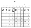
- FIG. 2 is a diagram showing a configuration of the in-VM schedule management table 301 according to the embodiment of this invention.
- the in-VM schedule management table 301 is held in the in-VM schedule 212 and the VM scheduler control program 300, and holds schedule information of the AP 211 of each VM 200 of the VM 200-A and VM 200-B created in the computer 100.
- the period 3102 stores the time when all APs 211 operating in each VM 200 are executed. In FIG. 2, it means that it takes 1 second (1000 ms) to execute from AP1-1 to AP1-n operating on VM1 of VM200-A.
- the priority level identifier 3103 stores information by which the AP 211 is grouped according to execution priority that determines the order in which the guest OS 213 executes the AP 211 and uniquely identifies the group.
- the L1 group has the highest priority, followed by L2, then L3, and then Ln.
- the AP 211 belonging to the group is configured such that the AP 211 that is executed first from the AP 211 that is executed first in the group has a ring shape (ring shape).
- the VM 200 needs to register the first and last APs 211 of each priority group in advance.
- the first and last APs 211 are APs 211 in which the in-VM schedule 213 is registered.
- the level ring start / end identifier 3104 stores “S” indicating that the first AP 211 belonging to the group starts and “E” indicating the end of the AP 211 to be executed last.
- “N” is stored in the level ring start / end identifier 3104.
- the task identifier 3105 stores information for uniquely identifying the AP 211 in the group.
- the priority 3106 stores execution priority information of the AP 211 that determines the order in which the guest OS 213 executes the AP 211.
- the runtime 3107 stores the time when the AP 211 is executed by the guest OS 213 in units of “ms”.
- the sequence control task identifier 3108 stores the task identifier 3105 of the AP 211 to be executed next when the execution of the AP 211 is completed.
- information other than the task identifier 3105 “E” is stored in the order control task identifier 3108, the corresponding AP 211 is executed.
- information “E” is stored in the task identifier 3105 and “N” is stored in the leveling start / end identifier 3104, the other AP 211 of the same group is executed.
- the time allocated to the execution of the AP 211 whose priority level identifier 3013 belongs to “Ln” is stored.
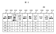
- FIG. 3 is a diagram showing a configuration of the VM management table 302 according to the embodiment of this invention.
- the VM management table 302 is used for the virtualization program 401 to execute the VM 200.
- the priority identifier 3201 information for uniquely identifying the VM 200 in the computer 100 is stored.
- the priority level identifier 3102 to which the AP 211 executed by the guest OS 213 belongs is stored.
- the priority identifier 3202 is acquired from information stored in the notification format 500 described later by the in-VM schedule 212.
- the level ring start / end identifier 3203 stores information on the start “S” of the first AP 211 or the end “E” of the last AP 211 in the priority group of the priority level identifier 3103. “I” represents a change in priority ID.
- the deadline 3204 stores the time from the start of the first AP 211 of the priority group of the priority level identifier 3103 to the end of the last AP 211 in “ms” units.
- the task identifier 3205 is acquired from information stored in the notification format 500.
- the execution state of the VM 200 executed by the virtualization program 401 is stored.
- “R” is stored in the execution state 3206.
- the VM 200 not executed by the virtualization program 401 stores “0”.
- the processor 102 has a multi-core configuration, a plurality of VMs 200 are executed by the virtualization program 401.
- the runtime 3207 stores the execution time of the VM 200 executed by the virtualization program 401 in units of “ms”.
- the time for executing the VM 200 by the virtualization program 401 is stored.
- the execution time is stored in the Quota 3208 even if the priority group has a priority other than “Ln”.
- the information of the Quota 3208 stored by the timer event management program 307 and the interrupt management program 308 is that the priority group of the AP 211 executed by the guest OS 213 after the timer-event and interrupt are processed by the guest OS 213 of the VM 200 is the priority identifier 3202. May not match.
- the VM deadline management program 306 is not notified of the start / end, so the VM 200 of the priority group whose priority identifier 3202 of the VM management table 304 is higher than “Ln”. If there is, the execution order based on priority cannot be maintained. In order to keep the execution order based on the priority, it is necessary to store the Quota 3208 in the timer-event and interrupt notification.
- Time Runtime 3207 is stored in TimeStamp 3209. This is because the VM deadline management program 307, which will be described later, determines whether the time of the Quota 3208 has elapsed.
- information on the priority identifier 3202 is stored when the priority “L1” is stored in the priority identifier 3202 in the timer-event and interrupt processing.
- the timer-event and the interrupt processing need to be preferentially processed by the VM 200 in order to guarantee the real-time property of the control system. Therefore, it is necessary to set the highest priority “L1” regardless of the execution priority of the VM 200. is there.
- the priority of the original priority 3210 is stored in the priority identifier 3202.
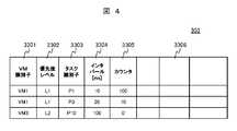
- FIG. 4 is a diagram showing a configuration of the timer-management table 303 according to the embodiment of this invention.
- the timer-management table 303 is a table necessary for the virtualization program 401 to perform timer-registration of the AP 211 belonging to the execution priority group “L1” among the APs 211 executed by the guest OS 213 of the VM 200.
- the AP 211 in the “L1” group is an application that requires real-time performance. Therefore, processing is performed not by the guest OS 213 of the VM 200 but by the virtualization program 401 of the host OS 400.
- the in-VM schedule 212 notifies the timer-event management program 307 of the timer-registration of the AP 211 belonging to the “L1” group via the notification IF 214.
- VM identifier 3301 information for uniquely identifying the VM 200 in the computer 100 is stored.
- a priority level identifier 3103 is stored in the priority level 3302.
- the task identifier 3303 stores information for identifying the AP 211.
- the interval 3304 stores the timer-event firing time.
- the counter 3305 stores the firing frequency per unit time (for example, 1 second) of the timer-event.
- FIG. 5 is a diagram showing a configuration of the interrupt management table 304 according to the embodiment of this invention.
- it is necessary to limit the number of interrupts processed by the VM 200 in order to guarantee the real-time property of the AP 211. It is managed by an interrupt management program 308 described later.
- VM identifier 3401 information for uniquely identifying the VM 200 in the computer 100 is stored.
- period 3402 information on the period 3102 of the in-VM schedule management table 301 is stored.
- the priority level 3403 stores a VM identifier 3401 managed by the timer management table 303.
- the deadline 3404 stores the deadline 3204 of the VM management table 302.
- an allowable time that can guarantee real-time performance from the execution deadline time of the AP 211 group belonging to the priority level 3404 is stored in “ms”.
- the guest OS 213 of the VM 200 stores the time for processing one interrupt from the external IF 102 in “ms”.
- the interrupt number critical value 3407 stores a value that is 90% of the number obtained by dividing one interrupt processing time 3406 with respect to the deadline allowable value 3405. By storing 90%, a margin value of 10% is provided.
- the period deadline 3408 stores the period 3102 of the in-VM schedule management table 301.
- the interrupt accumulation 3409 stores the number of interrupts generated within the period of the periodic deadline 3408.
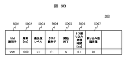
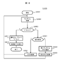
- FIG. 6A is a processing outline of the notification IF 214 according to the embodiment of this invention.
- FIG. 6B shows the configuration of the notification format 500.
- the virtualization program 401 of the host OS 400 determines the execution order of the VMs 200.
- the virtualization program 401 processes interrupts and timer-events from the external communication IF 104 and notifies the VM scheduler control program 300 of them.
- the VM scheduler control program 300 sets “L1” in the priority identifier 3202 of the VM management table 302, sets Quota 3208, and notifies the VM 200 with the notification IF 214 (501).
- the VM identifier 5001, the cycle 5002, the priority level 5003, and the task identifier 5004 at the start correspond to the respective items of the in-VM schedule management table 301 of FIG. Is set by the first AP 211 at the start of the first AP 211, and “S” is set to the start / end 5005.
- the VM scheduler control program 300 sets one interrupt processing time 5006 and an interrupt count critical value 5007 based on the items 3406 and 3407 of the interrupt management table 304 of FIG.
- a task identifier 5004 at the end is set, and “E” is set at the start / end 5005.
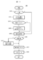
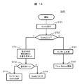
- FIG. 7 is a flowchart of the in-VM schedule 212 according to the embodiment of this invention.
- the host OS 400 and the processor 102 start the processing of the VM 200 when the VM scheduler control program 300 and the VM 200 are expanded in the memory 101 of the computer 100.
- processing of the guest OS 213 is started, and processing of the in-VM schedule 212 is started.
- the VM schedule 212 reads the VM schedule management table 301 from the storage device 103 into the memory 101 (S1001).
- the in-VM schedule 212 registers the start AP 211 and the end AP 211 for all priority level groups except the “Ln” level group stored in the information of the priority level identifier 3103 of the in-VM schedule management table 301 ( S1002).
- the AP 211 having the highest priority is selected from the task identifier 3105 from the information of the priority 3106 in the in-VM schedule management table 301 (S1003).
- the task identifier 3105 having the minimum runtime is selected from the information of the runtime 3107 in the in-VM schedule management table 301 (S1011).
- the in-VM schedule 212 registers the AP 211 having the task identifier 3105 as an application to be started by the guest OS 213 (S1021).
- the VM identifier 5001, the period 5002, the priority level 5003, and the task identifier 5004 are acquired from the in-VM schedule management table 301 and stored in the notification format 500.
- “S” is stored in the start / end 5005 (S1032).
- the start of the AP 211 is transmitted to the VM scheduler control program 300 via the notification IF 214 (S1033).
- the in-VM schedule 212 registers the AP 211 with the task identifier 3105 as an application to be processed by the guest OS 213 (S1034).
- An end process is performed (S1035) (see FIG. 8). Thereafter, the VM schedule 212 activates all APs 211 belonging to the group of the priority level identifier 3103.
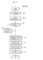
- FIG. 8 is a flowchart of the end process (1035) shown in FIG. 7 according to the embodiment of the present invention.
- the in-VM schedule 212 registers all APs 211 whose priority level identifiers 3104 in the in-VM schedule management table 301 are in the priority group as applications to be started by the guest OS 213 in the in-VM schedule 212.
- the runtime when the first AP 211 in the priority group of the priority level identifier 3104 is processed by the guest OS 213 is added to the runtime 3107 of the in-VM schedule management table 301 in FIG. 2 (S2002). It is determined from the level ring start / end identifier 3104 of the in-VM schedule management table 301 whether the AP 211 is the last AP 211 in the priority group of the priority level identifier 3104 (S2003). If the information of the start / end identifier 3104 is “E”, this is set in the notification format 500 to notify the VM scheduler control program 300 that the processing of the application in the priority group AP 211 has been completed, and the processing is performed. The process ends (S2011, S2012).
- the information of the start / end identifier 3104 is not “E”
- the runtime 3107 selects the smallest task identifier 3105 from the AP 211 in the same group, and the guest OS 213 starts the corresponding AP 211.
- the application is registered in the VM schedule 212 (S2022, S2023). Thereafter, the above process is performed for the next task.
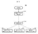
- FIG. 9 is an overall flowchart of the virtualization system 1 according to the embodiment of this invention.
- the overall processing of the virtualization system 1 includes a startup process of the VM scheduler control program 300, a VM deadline management program 306, a timer-event management program 307, and an interrupt management program 308.
- the processing of the VM scheduler control program 300 is started.
- the VM management table 301, the VM management table 302, the timer-event management table 303, and the interrupt management table 304 are read from the storage device 103 into the memory 101 (S101). ), The VM 200 is activated (S102).
- the VM scheduler control program 300 executes each of the VM deadline management program 306 (see FIG. 10), timer event management program 307 (see FIG. 12), and interrupt management program 308 (see FIG. 15). And wait for notification or interruption.
- FIG. 10 is a flowchart of the VM deadline management program 306 according to the embodiment of this invention. If there is a notification from the in-VM schedule 212 of the VM 200 (Y in S301), the start / end information 5005 of the communication format 500 from the notification IF 214 is read (S302).
- the task identifier 3205 of the VM management table 302 that matches the task identifier 5004 of the communication format 500 is searched, and the searched task identifier 3205 is searched.
- “E” is written in the leveling start / end identifier 3203 relating to (S311).
- “0” is set in the execution state 3206 to indicate that the VM 200 is not in the execution state (S312).
- the difference between the time of the host 400 and the Timestamp 3209 is stored in the deadline 3204 as a deadline.
- the deadline 3204 is added to the line time 3207 (S313).
- the level of the priority identifier 3202 of the VM 200 is lowered by 1 (S314). For example, if the level of the priority 3202 is “L1”, “L2” is stored. If the level of the priority 3202 is “Ln” (Y in S315), the time of the host OS 400 is stored in the Timestamp 3209 (S316). The leveling start / end identifier 3203 stores “I” indicating that the priority identifier 3202 is changed (S317). The host OS 400 selects the VM 200 to be processed by the processor 102 (S318) (see FIG. 11).
- the task identifier 3205 of the VM management table 302 that matches the task identifier 5004 of the communication format 500 is searched (S321). If the searched task identifier 3205 is a VM 200 not registered in the VM management table 302 (Y in S321), the searched task identifier 3205 is registered in the VM management table 302 (S331). If the retrieved task identifier 3205 is a VM 200 registered in the VM management table 302 (N in S321), the start “S” is stored in the leveling start / end identifier 3203 (S322), and the Timestamp 3209 stores the start of the host OS 400. The time is stored (S323).
- FIG. 11 is a flowchart of execution VM selection (S318 in FIG. 10) according to the embodiment of this invention.
- the host OS 400 selects the VM 200 to be processed by the processor 102. From the VM management table 302, a VM identifier 3201 having a priority 3202 of “L1” is searched (S401). If there is no VM identifier 3201 storing the priority “L1” (Y in S401), the period 3102 of the VM identifier 3101 in the in-VM schedule management table 301 that matches the VM identifier 3201 whose runtime 3207 is the minimum is read. (S402).
- the priority identifier 3202 corresponding to the VM identifier 3201 is assigned the highest priority “L1”.
- the VM identifier 3201 having the highest priority is searched from the priority identifier 3202 (S405).
- the VM identifier 3201 having the highest priority is searched from the priority identifier 3202 (S405).
- the runtime 3207 in the same row as the VM identifier 3201 selects the smallest VM identifier 3201 (S411). “R” is stored in the execution state 3206 of the same row of the selected VM identifier 3201, indicating that it is waiting to be executed (S421).
- the selected VM identifier 3201 is registered in the host OS 400 as the VM 200 to be processed by the processor 102 by the host OS 400 (S422).
- FIG. 12 is a flowchart of the timer-event management program (307) according to the embodiment of this invention.
- Wait for timer-event notification (S501).
- the priority level 5003 of the notification format 500 is read (S503). If the priority level is “L1” (S504), the priority level is set in the timer-management table 303 and registered as a timer-event of the host OS 400 (S505).
- FIG. 13 is a flowchart of external event processing (S512 in FIG. 12, S821 in FIG. 15) according to the embodiment of this invention.
- the external event is notified from the host OS 400 to the VM scheduler control program 300.
- Information of the notification destination VM 200 is stored in the external event.
- the VM 200 that matches the VM identifier 3201 of the VM management table 302 is selected from the received external event (S601).
- the priority identifier 3202 in the column of the VM identifier 3201 is read (S602). If the priority identifier 3202 is “Ln” (Y in S603), the value “10” is stored in the Quota 3208 (S604).
- the priority identifier 3202 is stored in the original priority identifier 3210, and the highest priority “L1” is stored in the priority identifier 3202 (S611). “R” indicating waiting for execution is stored in the execution state 3206, and the host OS time is stored in the Timestamp 3209 (S612). The external event is notified to the VM scheduler control program 300 via the notification IF 214 (S613).
- the host OS 400 registers the VM identifier 3201 in the host OS 400 as the VM 200 processed by the processor 102 (S614).
- FIG. 14 is a flowchart of the quota management process (S341 in FIG. 10) according to the embodiment of this invention.
- a VM identifier 3201 other than “0” in the quota 3208 of the VM management table 302 is selected.
- the quota 3208 related to the VM identifier 3201 is read (S701).
- the original priority identifier 3210 that is, “0” is stored in the priority identifier 3202 related to the VM identifier 3201 (S711).
- the Quota 3208 is added to the runtime 3207 (S713). If the priority identifier 3202 is not “Ln” (N in S712), the Quota 3208 is added to the runtime 3207, and “0” is stored in the Quota 3208 (S714).
- the difference between the time of the host OS 400 and the Timestamp 3209 is less than the quota 3208 (N in S702)
- the difference between the time of the host OS 400 and the Timestamp 3209 is added to the runtime 3207 (S721).
- the time of the host OS 400 is stored in the Timestamp 3209 (S722).
- FIG. 15 is a flowchart of the interrupt management program (308) according to the embodiment of this invention.
- the in-VM schedule management table 301 is read, information is set in the items 3401 to 3404 of the interrupt management table 304, the default value “10” is stored in the deadline allowable value 3405, and one interrupt processing time 3406 is “ 0.1 "is stored (S801).
- the interrupt number critical value 3407 a number obtained by subtracting “10” from the number obtained by dividing one deadline allowable value 3405 by the interrupt processing time 3406 is stored (S802).
- a margin value for a critical value error caused by an error in the processing time of one interrupt processing time 3406 is set.
- interrupt accumulation 3409 is within the interrupt number critical value 3407 (Y in S813), it is determined whether or not the interrupt is a timer-event (S814). If it is a timer-event (Y in S814), “1” is subtracted from the interrupt accumulation 3409 (S815) and notified to the timer-event management program 307 (S816). If the interrupt is not a timer-event (N in S814), external event processing is called (S821) (see FIG. 13).
Landscapes
- Engineering & Computer Science (AREA)
- Software Systems (AREA)
- Theoretical Computer Science (AREA)
- Physics & Mathematics (AREA)
- General Engineering & Computer Science (AREA)
- General Physics & Mathematics (AREA)
- Stored Programmes (AREA)
- Computer And Data Communications (AREA)
- Debugging And Monitoring (AREA)
Abstract
In a virtualized system that runs multiple virtual computers, due to a restriction on a CPU core resource and due to a process delay in I/O control specific to the virtualized system, it has been difficult to operate a virtual computer demanding real-time performance. In the present invention, in a virtualized system that runs multiple virtual computers: applications processed on the virtual computers are grouped by priority level; the start of a first task of each priority level group is managed as a process deadline for the priority level group, and the end of a last task of each priority level group is managed as a process deadline for the priority level group; and a host operating system is notified of a process start of each priority level group, and is notified of a process end of each priority level group. The host operating system: receives the start notification for each priority level group, and receives the end notification for each priority level group; adjusts the priority level of a virtual computer; and in response to an interrupt process from an external device, restricts the number of interrupt notifications so as to meet the deadlines of the highest-priority-level group among the virtual computers.
Description
本発明は、サーバ仮想化環境においてリアルタイム性が必要な仮想計算機の運用する計算機システムに関し、特にCPUリソースの制限がある計算機上の仮想計算機をスケジュールする方法である。
The present invention relates to a computer system operated by a virtual computer that requires real-time performance in a server virtualization environment, and more particularly, is a method for scheduling a virtual computer on a computer with a limited CPU resource.
サーバ仮想化技術は、1台の物理計算機上で複数の仮想計算機(VM)を実行して、物理計算機の台数を削減することで、運用コスト、計算機の設置場所及び消費電力等を削減できる利点があり、注目を浴びている。その際、仮想計算機内のアプリケーションによってリアルタイム性が要求される。しかし、物理計算機に仮想計算機に割り当てるCPUリソースが十分に存在する場合は、CPUリソースを占有割当するなどの性能保証の手法が存在するが、CPUリソースが不十分な計算機環境では、十分なリアルタイム性保証は困難である。また、計算機と接続されているネットワークデバイス等の外部装置からの割り込みが頻繁に発生する場合、仮想計算機内のアプリケーションの処理遅延が発生し、その状況をさらに悪化させる。しかし、制御システムにおいてはこのような計算機状況でも、仮想計算機上のアプリケーションのリアルタイム性保証が要求される。
Server virtualization technology can reduce operating costs, computer installation location, power consumption, etc. by reducing the number of physical computers by executing multiple virtual machines (VMs) on one physical computer There is a lot of attention. At that time, real-time performance is required by the application in the virtual machine. However, if there are enough CPU resources to be allocated to the virtual machine in the physical computer, there is a performance guarantee method such as occupying the CPU resource. However, in a computer environment with insufficient CPU resources, sufficient real-time performance Guarantees are difficult. In addition, when interruptions frequently occur from an external device such as a network device connected to a computer, a processing delay of an application in the virtual computer occurs, further aggravating the situation. However, the control system requires real-time guarantee of the application on the virtual machine even in such a computer situation.
特許文献1に示す従来の仮想計算機のスケジュール方式では、仮想計算機で処理するアプリケーションをスレッド単位に分離し、分離したスレッド単位を複数の仮想計算機で分担して処理を行うこととし、アプリケーションの処理順に仮想計算機の実行順番をスケジュールしていた。しかし、複数のアプリケーションから構成されるシステムの場合、リソースの占有状態を考慮すると、アプリケーションの処理順序のみに基づいて、仮想計算機の実行順番を決定するのは困難である。また、それぞれのCPUの負荷(さらには処理能力)が異なるので複数CPU構成のマルチCPU環境での対応が困難であるため、物理計算機のCPUリソースの有効な活用ができない。
In the schedule method of the conventional virtual machine shown in Patent Document 1, the application to be processed by the virtual machine is divided into units of threads, and the divided thread units are shared by a plurality of virtual machines to perform processing. The execution order of virtual machines was scheduled. However, in the case of a system composed of a plurality of applications, it is difficult to determine the execution order of the virtual machines based only on the processing order of the applications, considering the resource occupation state. In addition, since the load (and processing capability) of each CPU is different, it is difficult to cope with a multi-CPU environment having a plurality of CPU configurations, so that the CPU resources of the physical computer cannot be effectively used.
そこで、本発明は1つ以上のCPUリソースが利用できる物理計算機環境において、大規模なアプリケーションを稼働する複数仮想計算機で構成される仮想化システムのスケジュール方法において、仮想計算機で処理するアプリケーションのリアルタイム性を保証できる仮想計算機のスケジューリング技術を提供することを目的とする。
Therefore, the present invention provides a real-time property of an application processed by a virtual computer in a scheduling method of a virtual system composed of a plurality of virtual computers operating a large-scale application in a physical computer environment where one or more CPU resources can be used. It is an object of the present invention to provide a virtual machine scheduling technique that can guarantee the above.
物理計算機及び各仮想計算機は物理NICを共有し、それを介して計算機サーバやコントローラ等の外部装置と通信を行っている。また、ホストOSおよび複数の仮想計算機を搭載する計算機システムにおいて、上記の計算機内部のホストOS上にVMスケジューラ制御部を設ける。また、各仮想計算機上にはゲストOSが稼働して、仮想計算機上のアプリケーションの実行処理を行う。ゲストOS上には、前記アプリケーションの実行優先度別グループでアプリケーションの実行順を決定するVM内スケジュール制御部を設ける。ただし、ホストOSには各仮想計算機にCPUリソースを割り当てるスケジュール機能を備え、外部装置からの割り込みを該当仮想計算機へ伝達する割り込み処理機能を備えた仮想化プログラムを備えていることを前提とする。また、ゲストOSには、ホストOSから各仮想計算機に割り当てたCPUリソースを仮想計算機内アプリケーションに割り当ててアプリケーションを実行できるスケジュール機能、及び、ホストOS上の仮想化プログラムから通知された割り込みを処理する機能を備えていることを前提とする。
The physical computer and each virtual computer share a physical NIC, and communicate with external devices such as a computer server and a controller via the physical NIC. Further, in a computer system equipped with a host OS and a plurality of virtual machines, a VM scheduler control unit is provided on the host OS inside the computer. In addition, a guest OS runs on each virtual machine and executes an application on the virtual machine. On the guest OS, an in-VM schedule control unit that determines the execution order of the applications in the group according to the execution priority of the application is provided. However, it is assumed that the host OS is provided with a virtualization program having a scheduling function for allocating CPU resources to each virtual machine and an interrupt processing function for transmitting an interrupt from an external device to the virtual machine. In addition, the guest OS processes a schedule function that can execute an application by allocating a CPU resource allocated from the host OS to each virtual machine to an application in the virtual machine, and an interrupt notified from a virtualization program on the host OS. It is assumed that it has a function.
まず、ゲストOS上で稼働するVM内スケジュール制御部は、仮想計算機内のアプリケーションを優先度別にグループに分ける。また、各グループの先頭と最後尾にはVM内スケジュール制御部が用意するグループの中で最初に実行するアプリケーションと最後に実行するアプリケーションが登録される。
First, the in-VM schedule control unit operating on the guest OS divides the applications in the virtual machine into groups according to priority. In addition, the first application and the last application to be executed in the group prepared by the in-VM schedule control unit are registered at the beginning and the end of each group.
前記優先度グループは複数存在する。各優先度グループは優先度を表す識別子を持つ。本発明では、「L1」が最高優先度グループとし、「Ln」が最低優先度グループとする。VM内スケジュール制御部は「L1」から「Ln」までのいずれかのグループに属する全アプリケーションは、あるデッドラインで処理されることを保証するように各優先度グループの処理時間が管理される。各グループの処理時間は、前記グループ先頭アプリケーションの起動時間と、最後尾アプリケーションを終了時間で管理している。前記デッドライン設計は、本発明を提供するシステムの要件によって調整する必要がある。
複数 There are multiple priority groups. Each priority group has an identifier representing the priority. In the present invention, “L1” is the highest priority group and “Ln” is the lowest priority group. The in-VM schedule control unit manages the processing time of each priority group so as to ensure that all applications belonging to any group from “L1” to “Ln” are processed on a certain deadline. The processing time of each group is managed by the start time of the group head application and the end time of the last application. The deadline design needs to be adjusted according to the requirements of the system providing the present invention.
なお、ホストOS上のVMスケジューラ制御部へ各仮想計算機の内部スケジュール状態を通知するために、各ゲストOSのVM内スケジュール制御部は、ホストOS上のVMスケジューラ制御部との通知手段を備える。ホストOS上のVMスケジューラ制御部が各仮想計算機の内部スケジュール状態を把握するために、ゲストOS上のVM内スケジュール制御部は、仮想計算機内の優先度グループの先頭アプリケーションの開始と最後尾アプリケーションの終了をホストOS上のVMスケジューラ制御部に通知する。
In addition, in order to notify the internal schedule state of each virtual machine to the VM scheduler control unit on the host OS, the in-VM schedule control unit of each guest OS includes a notification means with the VM scheduler control unit on the host OS. In order for the VM scheduler control unit on the host OS to grasp the internal schedule state of each virtual machine, the VM schedule control unit on the guest OS performs the start of the first application and the last application of the priority group in the virtual machine. The end is notified to the VM scheduler control unit on the host OS.
ただし、優先度が最も低い「Ln」優先度グループにおいては、前記の通知は行わない。仮想計算機からホストOSへの通知のオーバヘッドは大きいため、低優先度のグループの開始終了は管理しないことで、前記オーバヘッドの低減を実施する。「Ln」以外の高優先度グループからのアプリケーションの開始と終了の時間の通知によって、ホストOS上のVMスケジューラ制御部は各仮想化計算機で実行されているアプリケーションの優先度が把握できる。
However, in the “Ln” priority group with the lowest priority, the above notification is not performed. Since the overhead of notification from the virtual machine to the host OS is large, the overhead is reduced by not managing the start / end of the low priority group. By notification of application start and end times from the high priority group other than “Ln”, the VM scheduler control unit on the host OS can grasp the priority of the application executed in each virtual machine.
仮想計算機内の実行優先度から、CPUリソースに割り当てるべき仮想計算機を選択する。そのため、ホストOS上のVMスケジューラ制御部は、各仮想計算機の実行状態として優先度グループの優先度を常に記録管理し、高優先度グループの終了通知をもって通知元の仮想計算機の優先度を下げていく。したがって、複数の仮想計算機の中で最優先にCPUリソースを割り当てるべき仮想計算機が把握できる。
仮 想 Select the virtual machine to be allocated to the CPU resource from the execution priority in the virtual machine. Therefore, the VM scheduler control unit on the host OS always records and manages the priority group priority as the execution state of each virtual machine, and lowers the priority of the notification source virtual machine with a high priority group end notification. Go. Therefore, it is possible to grasp the virtual machine to which the CPU resource should be assigned with the highest priority among the plurality of virtual machines.
なお、各仮想計算機が守るべきデッドラインを監視し、現状の実行優先度が低い仮想計算機であってもデッドラインに近い仮想計算機は最高優先度に調整し、かならずデッドラインを守るように調整する。「Ln」のような優先度が低いグループは、仮想計算機内のVM内スケジュール制御部からホストOSへの、先頭アプリケーションの開始及び最後尾アプリケーションの終了の通知によるデッドラインによるスケジュール制御ではなく、後述するCPUリソースを割り当てるQuota時間でスケジュール制御を行う。
Monitor the deadline that each virtual machine should protect, and adjust the virtual machine close to the deadline to the highest priority even if the current virtual machine has a low execution priority, and make adjustments so that the deadline is always protected. . A group having a low priority such as “Ln” is not schedule control based on deadline based on notification of the start of the first application and the end of the last application from the in-VM schedule control unit in the virtual machine to the host OS. Schedule control is performed at the quota time for allocating CPU resources to be executed.
一方、割り込み処理においては、ホストOS上のVMスケジューラ制御部内に割り込み管理制御部を設け、仮想計算機のデッドライン内で許容される割り込み数を制限する。割り込み数制限は、各仮想計算機のデッドラインの許容値に対して1つの割り込み処理時間を割った数を割り込み数の制限値として管理する。ホストOS上の仮想化プログラムからの割り込み通知に対して割り込み数制限値内であれば、仮想計算機へ割り込みの通知を行う。
On the other hand, in interrupt processing, an interrupt management control unit is provided in the VM scheduler control unit on the host OS to limit the number of interrupts allowed in the deadline of the virtual machine. The interrupt number limit manages the number obtained by dividing one interrupt processing time with respect to the allowable value of the deadline of each virtual machine as the limit value of the interrupt number. If the interrupt number from the virtualization program on the host OS is within the interrupt limit value, the virtual machine is notified of the interrupt.
割り込みの通知の際には、該当仮想計算機の現在の実行優先度にかかわらず最高優先度に変更し、ホストOSがCPUのリソースを該当仮想計算機に割り当てるようにする。該当仮想計算機内では、ゲストOSで割り込み処理が行われ、ゲストOSのスケジューラはVM内部スケジュール制御部で設定している優先度グループのアプリケーションを選択し、CPUリソースを割り当てる。
When an interrupt is notified, the priority is changed to the highest priority regardless of the current execution priority of the corresponding virtual machine, and the host OS allocates CPU resources to the corresponding virtual machine. In the corresponding virtual machine, interrupt processing is performed by the guest OS, and the scheduler of the guest OS selects an application of the priority group set by the VM internal schedule control unit, and allocates CPU resources.
しかし、そのアプリケーションより高い実行優先度のアプリケーションを実行する仮想計算機にCPUリソースが割り当てられなくなるため、割り込み通知による最高優先度設定には、その優先度を維持するQuota時間を設ける。即ち、割り込み処理に割り当てられていた時間がQuota時間となると元の優先度に調整され、常にホストOSは最高優先度の仮想計算機にCPUリソースを割り当てるようにする。
However, since CPU resources are not allocated to a virtual machine that executes an application having a higher execution priority than that application, a quota time for maintaining the priority is set in the highest priority setting based on the interrupt notification. That is, when the time allocated for interrupt processing reaches the quota time, the priority is adjusted to the original priority, and the host OS always allocates CPU resources to the virtual machine with the highest priority.
以上のように、仮想計算機内のVM内スケジュール制御部による優先度グループでのアプリケーション管理方法と、ホストOS上のVMスケジューラ制御部によって、仮想計算機内で実行している優先度グループに従って、CPUリソースを仮想計算機へ割り当てることで、CPUリソースの制限があるシステムにおいても仮想計算機内のアプリケーションのリアルタイム性保証が可能である。また、ホストOS上のVMスケジューラ制御部に割り込み管理制御部を設けることで、割り込み処理の高負荷の計算機環境においても仮想計算機内のアプリケーションのリアルタイム保証が可能である。
As described above, the CPU resources according to the priority group executed in the virtual machine by the application management method in the priority group by the VM schedule control unit in the virtual machine and the VM scheduler control unit on the host OS By allocating to the virtual machine, it is possible to guarantee the real-time property of the application in the virtual machine even in a system with limited CPU resources. In addition, by providing an interrupt management control unit in the VM scheduler control unit on the host OS, it is possible to guarantee real-time applications in the virtual computer even in a computer environment with a high load of interrupt processing.
本発明によれば、VMスケジューラ制御部が仮想計算機内の処理アプリケーションの優先度グループのデッドラインによって仮想計算機のCPUリソース割当を管理するため、CPUリソースが制限される計算機システムにおいてもリアルタイム性保証が可能となる。また、外部割り込みが多く発生する外部ネットワークを利用する仮想計算機の運用においても、仮想計算機内の処理アプリケーションの優先度グループのデッドラインによって割り込み通知・処理の数制限を設けるため、リアルタイム性の保証が可能となる。
According to the present invention, since the VM scheduler control unit manages the CPU resource allocation of the virtual machine by the deadline of the priority group of the processing application in the virtual machine, the real-time guarantee can be ensured even in the computer system in which the CPU resource is limited. It becomes possible. In addition, even in the operation of virtual machines that use external networks that generate many external interrupts, the number of interrupt notifications and processes is limited by the deadline of the priority group of the processing application in the virtual machine, so real-time performance is guaranteed. It becomes possible.
以下、本発明の一実施の形態を、図面を用いて説明する。なお、本発明が実施の形態に制限されることは無く、本発明の思想に合致するあらゆる応用例が本発明に該当する。
Hereinafter, an embodiment of the present invention will be described with reference to the drawings. It should be noted that the present invention is not limited to the embodiments, and any application example that matches the idea of the present invention falls under the present invention.
(全体構成図)
図1は本発明の実施形態の仮想マシンのスケジュール制御の全体構成図である。仮想マシンのスケジュール制御は、一つの仮想化システム1及び一つ端末2及び外部ネットワーク3から構成される。仮想化システム1は、1台の計算機で構成されている。計算機100は、メモリ101、プロセッサ102、記憶装置103、及び外部通信インタフェース104を備える。メモリ101内には、ホストオペレーティングシステム400(図中、ホストOSと略記)、VMスケジューラ制御プログラム300、及び、一つまたは複数の仮想マシン環境200(図中、VMと略記)が保持される。ホストOS400内には仮想化プログラム401が保持される。 (Overall configuration diagram)
FIG. 1 is an overall configuration diagram of virtual machine schedule control according to the embodiment of this invention. The virtual machine schedule control includes one virtualization system 1, oneterminal 2, and an external network 3. The virtualization system 1 is composed of one computer. The computer 100 includes a memory 101, a processor 102, a storage device 103, and an external communication interface 104. In the memory 101, a host operating system 400 (abbreviated as “host OS” in the figure), a VM scheduler control program 300, and one or a plurality of virtual machine environments 200 (abbreviated as “VM” in the figure) are held. A virtualization program 401 is held in the host OS 400.
図1は本発明の実施形態の仮想マシンのスケジュール制御の全体構成図である。仮想マシンのスケジュール制御は、一つの仮想化システム1及び一つ端末2及び外部ネットワーク3から構成される。仮想化システム1は、1台の計算機で構成されている。計算機100は、メモリ101、プロセッサ102、記憶装置103、及び外部通信インタフェース104を備える。メモリ101内には、ホストオペレーティングシステム400(図中、ホストOSと略記)、VMスケジューラ制御プログラム300、及び、一つまたは複数の仮想マシン環境200(図中、VMと略記)が保持される。ホストOS400内には仮想化プログラム401が保持される。 (Overall configuration diagram)
FIG. 1 is an overall configuration diagram of virtual machine schedule control according to the embodiment of this invention. The virtual machine schedule control includes one virtualization system 1, one
VMスケジューラ制御プログラム300は、VM内スケジュール管理テーブル301、VM管理テーブル302、タイマ-管理テーブル303、割り込み管理テーブル304、VM内スケジュール入力プログラム305、VMデッドラン管理プログラム306、タイマ-管理プログラム307、及び割り込み管理プログラム308から構成される。VM200は、アプリケーション211(図中、APと略記)、VM内スケジュール212、ゲストオペレーティングシステム213(図中、ゲストOSと略記)、及び通知インタフェース214(図中、インタフェースをI/Fと略記)から構成される。図1では、計算機 100内にVM200として実線枠で示したVM1(200-A)、VM2(200-B)及び点線枠で示したその他のVM200の例が示されているが、特にVMの台数は限定されるものではない。
The VM scheduler control program 300 includes an in-VM schedule management table 301, a VM management table 302, a timer-management table 303, an interrupt management table 304, an in-VM schedule input program 305, a VM dead run management program 306, a timer-management program 307, and It consists of an interrupt management program 308. The VM 200 includes an application 211 (abbreviated as AP in the figure), a schedule 212 in the VM, a guest operating system 213 (abbreviated as guest OS in the figure), and a notification interface 214 (interface is abbreviated as I / F in the figure). Composed. In FIG. 1, examples of VM1 (200-A) and VM2 (200-B) indicated by solid line frames as VM200 in computer 100 and other VM200 indicated by dotted line frames are shown. In particular, the number of VMs is shown. Is not limited.
端末2と計算機100は外部ネットワーク3を介して接続される。計算機100では、外部ネットワーク3は外部通信I/F104に接続される。
The terminal 2 and the computer 100 are connected via the external network 3. In the computer 100, the external network 3 is connected to the external communication I / F 104.
端末2は外部ネットワーク3を介して仮想化システム1との通信を行うことができる。
The terminal 2 can communicate with the virtualization system 1 via the external network 3.
計算機ノード100の記憶装置103は、ホストOS400、VMスケジューラ制御プログラム300(プログラムと各種テーブル情報)、さらに、VM200を構成するAP211、VM内スケジュール212、ゲストOS213、及び通知I/F214を格納する。プロセッサ102は記憶装置103からホストOS400、VMスケジューラ制御プログラム300、VM200の構成要素をメモリ101に展開して実行し、また、外部通信I/F104からの割込みを処理する。外部通信I/F104は、外部ネットワーク3を通じて端末2とのデータの送受信を行う。
The storage device 103 of the computer node 100 stores a host OS 400, a VM scheduler control program 300 (programs and various table information), an AP 211, a VM schedule 212, a guest OS 213, and a notification I / F 214 that configure the VM 200. The processor 102 expands and executes the components of the host OS 400, the VM scheduler control program 300, and the VM 200 from the storage device 103 to the memory 101, and processes an interrupt from the external communication I / F 104. The external communication I / F 104 transmits / receives data to / from the terminal 2 through the external network 3.
仮想化プログラム401は、VM200を作成して管理するためのプログラムであり、外部通信I/F104から割り込みを、通知I/F214を介してVM200に通知する。ホストOS400は、仮想化プログラム401を用いて、VMスケジューラ制御プログラム300やVM200の実行を制御し、外部通信I/F104や記憶装置103へのアクセス制御を行う。
The virtualization program 401 is a program for creating and managing the VM 200, and notifies the VM 200 via the notification I / F 214 of an interrupt from the external communication I / F 104. The host OS 400 uses the virtualization program 401 to control the execution of the VM scheduler control program 300 and the VM 200 and to control access to the external communication I / F 104 and the storage device 103.
VM200は、固有のプログラムやオペレーティングシステムが動作することが可能な、仮想化プログラム401により作成された仮想的な実行環境である。複数のVM200が存在する場合に、異なるVM200内で動作するプログラムやオペレーティングシステムは同じでも良いし、異なっていても良い。また、異なるVM200内で動作するプログラムやオペレーティングシステムが互いに直接影響を与え合うことはない。VM200は、仮想化システム1内で一意の識別子を持ち、例えば、図1中のVM200は「VM1」、あるいは「VM2」の識別子を保有する。
The VM 200 is a virtual execution environment created by the virtualization program 401 in which a unique program or operating system can operate. When there are a plurality of VMs 200, programs and operating systems that operate in different VMs 200 may be the same or different. In addition, programs and operating systems operating in different VMs 200 do not directly affect each other. The VM 200 has a unique identifier in the virtualization system 1. For example, the VM 200 in FIG. 1 has an identifier of “VM1” or “VM2”.
AP211は、VM200内で動作アプリケーションプログラムである。AP211として、AP1-1(211-A)、AP1-n(211-B)が示されているが、VM200内で動作するAP211の数を限定するものではない。ゲストOS213は、VM200環境内でVM内スケジュール212を利用してAP211を制御する。通知IF214は、VM内スケジュール212の処理結果をゲストOS213から受け取りVMスケジューラ制御プログラム300へ出力する。
AP 211 is an operation application program in the VM 200. AP1-1 (211-A) and AP1-n (211-B) are shown as APs 211, but the number of APs 211 operating in the VM 200 is not limited. The guest OS 213 controls the AP 211 using the in-VM schedule 212 in the VM 200 environment. The notification IF 214 receives the processing result of the in-VM schedule 212 from the guest OS 213 and outputs it to the VM scheduler control program 300.
VMスケジューラ制御プログラム300は、VM200で稼働するときに、VM内スケジュール212から、VM200内のAP211のスケジュール情報を、通知IF214を介して受け取る。VMスケジューラ制御プログラム300は、AP211のスケジュール情報を、VM内スケジュール入力プログラム305に入力する。VM内スケジュール入力プログラム305は、AP211のスケジュール情報をVM内スケジュール管理テーブル301に格納する。
When the VM scheduler control program 300 operates on the VM 200, the VM scheduler control program 300 receives the schedule information of the AP 211 in the VM 200 from the schedule 212 in the VM 200 via the notification IF 214. The VM scheduler control program 300 inputs the schedule information of the AP 211 to the in-VM schedule input program 305. The in-VM schedule input program 305 stores the schedule information of the AP 211 in the in-VM schedule management table 301.
VM200内で動作するVM内スケジュール212は、AP211の動作優先度に応じてグループ化してプロセッサ102での実行時間をスケジュールする。動作優先度によるスケジュール方法は後述する。
The in-VM schedule 212 operating in the VM 200 is grouped according to the operation priority of the AP 211 and schedules the execution time in the processor 102. A scheduling method based on operation priority will be described later.
VM200内で動作するVM内スケジュール212は、動作優先度グループのAP211の動作開始と終了を、通知IF214を介してVMスケジューラ制御プログラム300で動作するVMデッドライン管理プログラム306に通知する。VMデッドライン管理プログラムは、AP211の動作開始と終了を元にVM200の優先度の調整を行う。また、割り込みテーブル304に、動作開始と終了の時間を実行時間のデッドラインとして書き込む。VM200の優先度に応じて仮想化プログラム401はVM200を実行する。
The in-VM schedule 212 operating in the VM 200 notifies the VM deadline management program 306 operating in the VM scheduler control program 300 via the notification IF 214 of the operation start and end of the AP 211 of the operation priority group. The VM deadline management program adjusts the priority of the VM 200 based on the start and end of the operation of the AP 211. Also, the operation start and end times are written in the interrupt table 304 as execution time deadlines. The virtualization program 401 executes the VM 200 according to the priority of the VM 200.
VM200内で動作するVM内スケジュール212は、最高優先度グループのAP211のタイマ-登録をタイマ-イベント管理プログラム307に通知IF214を介して通知する。タイマ-イベント管理プログラム307は、タイマー制御のための情報をタイマ-管理テーブル303に登録し、仮想化プログラム401にタイマ-制御を委ねる。仮想化プログラム401は、タイマ-が発火(起動)するとタイマ-イベント管理プログラム307に通知する。タイマ-イベント管理プログラム307は、タイマ-イベントを割り込み管理プログラム308に通知する。割り込み管理プログラム308は、通知IF214を介してVM200にタイマ-イベントを通知する。ゲストOS213が割り込み管理プログラム308からタイマ-イベントを処理し、処理結果を、タイマ-登録を行ったAP211に通知する。
The in-VM schedule 212 operating in the VM 200 notifies the timer-event management program 307 of the timer-registration of the AP 211 of the highest priority group via the notification IF 214. The timer-event management program 307 registers information for timer control in the timer-management table 303 and delegates timer-control to the virtualization program 401. The virtualization program 401 notifies the timer-event management program 307 when the timer is fired (started). The timer-event management program 307 notifies the interrupt management program 308 of the timer-event. The interrupt management program 308 notifies the VM 200 of the timer-event via the notification IF 214. The guest OS 213 processes the timer-event from the interrupt management program 308, and notifies the AP 211 that has performed the timer-registration of the processing result.
割り込み管理プログラム308は、外部IF104からの割り込みを、通知IF214を介してVM200に通知する。割り込みはゲストOS213で処理する。
The interrupt management program 308 notifies an interrupt from the external IF 104 to the VM 200 via the notification IF 214. The interrupt is processed by the guest OS 213.
VMスケジューラ制御プログラム300の詳細は、図7と共に後述する。
Details of the VM scheduler control program 300 will be described later with reference to FIG.
(VM内スケジュール管理テーブル)
図2は本発明の実施形態のVM内スケジュール管理テーブル301の構成を示す図である。VM内スケジュール管理テーブル301は、VM内スケジュール212とVMスケジューラ制御プログラム300内に保持され、計算機100内に作成されているVM200-AやVM200-Bの各VM200のAP211のスケジュール情報を保持する。 (In-VM schedule management table)
FIG. 2 is a diagram showing a configuration of the in-VM schedule management table 301 according to the embodiment of this invention. The in-VM schedule management table 301 is held in the in-VM schedule 212 and the VM scheduler control program 300, and holds schedule information of the AP 211 of each VM 200 of the VM 200-A and VM 200-B created in the computer 100.
図2は本発明の実施形態のVM内スケジュール管理テーブル301の構成を示す図である。VM内スケジュール管理テーブル301は、VM内スケジュール212とVMスケジューラ制御プログラム300内に保持され、計算機100内に作成されているVM200-AやVM200-Bの各VM200のAP211のスケジュール情報を保持する。 (In-VM schedule management table)
FIG. 2 is a diagram showing a configuration of the in-VM schedule management table 301 according to the embodiment of this invention. The in-VM schedule management table 301 is held in the in-
VM識別子3101には、計算機100内でVM200を一意に識別する情報を格納する。周期3102は、各VM200で動作する全AP211が実行される時間を格納する。図2では、VM200-AのVM1で動作するAP1-1からAP1-nまで実行するのに1秒(1000ms)かかることを意味している。
In the VM identifier 3101, information for uniquely identifying the VM 200 within the computer 100 is stored. The period 3102 stores the time when all APs 211 operating in each VM 200 are executed. In FIG. 2, it means that it takes 1 second (1000 ms) to execute from AP1-1 to AP1-n operating on VM1 of VM200-A.
優先度レベル識別子3103は、AP211をゲストOS213がAP211を実行する順位を決める実行優先度別にグループ化し、そのグループを一意に識別する情報を格納する。図2では、L1グループの優先度が最も高く、次にL2、次にL3、次にLnの順に優先度が高い。
The priority level identifier 3103 stores information by which the AP 211 is grouped according to execution priority that determines the order in which the guest OS 213 executes the AP 211 and uniquely identifies the group. In FIG. 2, the L1 group has the highest priority, followed by L2, then L3, and then Ln.
また、グループに属するAP211は、同グループ内で最初に実行するAP211から最後に実行するAP211がリング状(円環)状となるように構成されている。同一グループに属しているAP211をリング状に構成するため、VM200には、各優先度グループの最初と最後のAP211を事前に登録しておく必要がある。最初と最後のAP211は、ユーザが登録するアプリケーションとは異なり、VM内スケジュール213が登録されたAP211である。
In addition, the AP 211 belonging to the group is configured such that the AP 211 that is executed first from the AP 211 that is executed first in the group has a ring shape (ring shape). In order to configure the APs 211 belonging to the same group in a ring shape, the VM 200 needs to register the first and last APs 211 of each priority group in advance. Unlike the application registered by the user, the first and last APs 211 are APs 211 in which the in-VM schedule 213 is registered.
レベルリング開始終了識別子3104には、グループに属する最初のAP211が開始することを知らせる「S」と最後に実行するAP211の終了を示す「E」が格納される。AP211がグループの最初と最後のAP211ではない場合はレベルリング開始終了識別子3104に「N」が格納される。
The level ring start / end identifier 3104 stores “S” indicating that the first AP 211 belonging to the group starts and “E” indicating the end of the AP 211 to be executed last. When the AP 211 is not the first and last AP 211 in the group, “N” is stored in the level ring start / end identifier 3104.
タスク識別子3105には、グループ内のAP211を一意に識別する情報を格納する。優先度3106には、ゲストOS213がAP211を実行する順位を決めるAP211の実行優先度情報を格納する。ランタイム3107には、AP211がゲストOS213で実行された時間を「ms」単位で格納する。順序制御タスク識別子3108には、AP211の実行が終了した場合、次に実行するAP211のタスク識別子3105を格納する。順序制御タスク識別子3108にタスク識別子3105「E」以外の情報が格納されている場合は、該当するAP211を実行する。タスク識別子3105に「E」の情報が格納され、レベルリング開始終了識別子3104に「N」が格納されている場合は同グループの他AP211の実行を行う。
The task identifier 3105 stores information for uniquely identifying the AP 211 in the group. The priority 3106 stores execution priority information of the AP 211 that determines the order in which the guest OS 213 executes the AP 211. The runtime 3107 stores the time when the AP 211 is executed by the guest OS 213 in units of “ms”. The sequence control task identifier 3108 stores the task identifier 3105 of the AP 211 to be executed next when the execution of the AP 211 is completed. When information other than the task identifier 3105 “E” is stored in the order control task identifier 3108, the corresponding AP 211 is executed. When information “E” is stored in the task identifier 3105 and “N” is stored in the leveling start / end identifier 3104, the other AP 211 of the same group is executed.
Quota3109には、優先度レベル識別子3013が「Ln」に属しているAP211の実行に割り当てる時間を格納する。
In the Quota 3109, the time allocated to the execution of the AP 211 whose priority level identifier 3013 belongs to “Ln” is stored.
VM内スケジュール212の詳細は図7と共に後述する。
Details of the in-VM schedule 212 will be described later with reference to FIG.
(VM管理テーブル)
図3は本発明の実施形態のVM管理テーブル302の構成を示す図である。VM管理テーブル302は、仮想化プログラム401がVM200を実行するために用いる。 (VM management table)
FIG. 3 is a diagram showing a configuration of the VM management table 302 according to the embodiment of this invention. The VM management table 302 is used for thevirtualization program 401 to execute the VM 200.
図3は本発明の実施形態のVM管理テーブル302の構成を示す図である。VM管理テーブル302は、仮想化プログラム401がVM200を実行するために用いる。 (VM management table)
FIG. 3 is a diagram showing a configuration of the VM management table 302 according to the embodiment of this invention. The VM management table 302 is used for the
VM識別子3201には、計算機100内でVM200を一意に識別する情報を格納する。優先度識別子3202には、ゲストOS213が実行しているAP211が属している優先度レベル識別子3102を格納する。優先度識別子3202は、VM内スケジュール212が後述する通知フォーマット500に格納する情報から取得する。レベルリング開始終了識別子3203には、優先度レベル識別子3103の優先度グループの最初AP211の開始「S」または、最後のAP211の終了「E」の情報を格納する。「I」は優先度IDの変更を表わす。
In the VM identifier 3201, information for uniquely identifying the VM 200 in the computer 100 is stored. In the priority identifier 3202, the priority level identifier 3102 to which the AP 211 executed by the guest OS 213 belongs is stored. The priority identifier 3202 is acquired from information stored in the notification format 500 described later by the in-VM schedule 212. The level ring start / end identifier 3203 stores information on the start “S” of the first AP 211 or the end “E” of the last AP 211 in the priority group of the priority level identifier 3103. “I” represents a change in priority ID.
デッドライン3204は、優先度レベル識別子3103の優先度グループの最初のAP211の開始から最後のAP211の終了までの時間を「ms」単位で格納する。タスク識別子3205は、通知フォーマット500に格納する情報から取得する。
The deadline 3204 stores the time from the start of the first AP 211 of the priority group of the priority level identifier 3103 to the end of the last AP 211 in “ms” units. The task identifier 3205 is acquired from information stored in the notification format 500.
実行状態3206には、仮想化プログラム401が実行するVM200の実行状態を格納する。仮想化プログラム401がVM200を実行する場合、実行状態3206には「R」と格納する。仮想化プログラム401によって実行してないVM200は「0」を格納する。プロセッサ102がマルチコア構成の場合は、仮想化プログラム401によって実行されるVM200は複数個となる。
In the execution state 3206, the execution state of the VM 200 executed by the virtualization program 401 is stored. When the virtualization program 401 executes the VM 200, “R” is stored in the execution state 3206. The VM 200 not executed by the virtualization program 401 stores “0”. When the processor 102 has a multi-core configuration, a plurality of VMs 200 are executed by the virtualization program 401.
ランタイム3207には、仮想化プログラム401によって実行されたVM200の実行時間が「ms」単位で格納する。Quota3208には、ゲストOS213が実行しているAP211の優先度グループが「Ln」の場合、仮想化プログラム401によって該当VM200を実行する時間が格納される。また、後述するタイマ-イベント管理プログラム307と割り込み管理プログラム308の処理では、優先度グループが「Ln」以外の優先度であってもQuota3208には実行時間を格納する。
The runtime 3207 stores the execution time of the VM 200 executed by the virtualization program 401 in units of “ms”. In the Quota 3208, when the priority group of the AP 211 being executed by the guest OS 213 is “Ln”, the time for executing the VM 200 by the virtualization program 401 is stored. In the processing of the timer-event management program 307 and the interrupt management program 308 described later, the execution time is stored in the Quota 3208 even if the priority group has a priority other than “Ln”.
タイマーイベント管理プログラム307と割り込み管理プログラム308によって格納するQuota3208の情報は、タイマ-イベントと割り込みがVM200のゲストOS213によって処理された後、ゲストOS213によって実行されるAP211の優先度グループが優先度識別子3202と一致しないことがある。特に、「Ln」優先度グループのAP211が実行される場合、開始終了がVMデッドライン管理プログラム306に通知されないため、VM管理テーブル304の優先度識別子3202が「Ln」より高い優先度グループのVM200がある場合、優先度による実行順序が守れなくなる。優先度による実行順序を守るため、タイマ-イベントと割り込み通知にはQuota3208を格納する必要がある。
The information of the Quota 3208 stored by the timer event management program 307 and the interrupt management program 308 is that the priority group of the AP 211 executed by the guest OS 213 after the timer-event and interrupt are processed by the guest OS 213 of the VM 200 is the priority identifier 3202. May not match. In particular, when the AP 211 of the “Ln” priority group is executed, the VM deadline management program 306 is not notified of the start / end, so the VM 200 of the priority group whose priority identifier 3202 of the VM management table 304 is higher than “Ln”. If there is, the execution order based on priority cannot be maintained. In order to keep the execution order based on the priority, it is necessary to store the Quota 3208 in the timer-event and interrupt notification.
TimeStamp3209にはランタイム3207を格納する。後述するVMデッドライン管理プログラム307がQuota3208の時間が経過したかを判断するためである。元優先度3210には、タイマ-イベントと割り込み処理では優先度識別子3202に優先度「L1」を格納する際に優先度識別子3202の情報を格納する。タイマ-イベントと割り込み処理は、制御システムのリアルタイム性保証のためにVM200が優先的に処理するようにする必要があるため、VM200の実行優先度に関係なく最高優先度「L1」にする必要がある。Quota3208の経過後は、元優先度3210の優先度を優先度識別子3202に格納する。
Time Runtime 3207 is stored in TimeStamp 3209. This is because the VM deadline management program 307, which will be described later, determines whether the time of the Quota 3208 has elapsed. In the original priority 3210, information on the priority identifier 3202 is stored when the priority “L1” is stored in the priority identifier 3202 in the timer-event and interrupt processing. The timer-event and the interrupt processing need to be preferentially processed by the VM 200 in order to guarantee the real-time property of the control system. Therefore, it is necessary to set the highest priority “L1” regardless of the execution priority of the VM 200. is there. After the quota 3208 has elapsed, the priority of the original priority 3210 is stored in the priority identifier 3202.
(タイマ-管理テーブル)
図4は本発明の実施形態のタイマ-管理テーブル303の構成を示す図である。タイマ-管理テーブル303は、VM200のゲストOS213が実行するAP211の中で実行優先度グループ「L1」に属しているAP211のタイマ-登録を仮想化プログラム401で行うために必要なテーブルである。「L1」のグループのAP211はリアルタイム性が必要なアプリケーションである。そのため、VM200のゲストOS213ではなく、ホストOS400の仮想化プログラム401で処理を行う。「L1」のグループに属しているAP211のタイマ-登録を、VM内スケジュール212が通知IF214を介してタイマ-イベント管理プログラム307に通知する。 (Timer management table)
FIG. 4 is a diagram showing a configuration of the timer-management table 303 according to the embodiment of this invention. The timer-management table 303 is a table necessary for thevirtualization program 401 to perform timer-registration of the AP 211 belonging to the execution priority group “L1” among the APs 211 executed by the guest OS 213 of the VM 200. The AP 211 in the “L1” group is an application that requires real-time performance. Therefore, processing is performed not by the guest OS 213 of the VM 200 but by the virtualization program 401 of the host OS 400. The in-VM schedule 212 notifies the timer-event management program 307 of the timer-registration of the AP 211 belonging to the “L1” group via the notification IF 214.
図4は本発明の実施形態のタイマ-管理テーブル303の構成を示す図である。タイマ-管理テーブル303は、VM200のゲストOS213が実行するAP211の中で実行優先度グループ「L1」に属しているAP211のタイマ-登録を仮想化プログラム401で行うために必要なテーブルである。「L1」のグループのAP211はリアルタイム性が必要なアプリケーションである。そのため、VM200のゲストOS213ではなく、ホストOS400の仮想化プログラム401で処理を行う。「L1」のグループに属しているAP211のタイマ-登録を、VM内スケジュール212が通知IF214を介してタイマ-イベント管理プログラム307に通知する。 (Timer management table)
FIG. 4 is a diagram showing a configuration of the timer-management table 303 according to the embodiment of this invention. The timer-management table 303 is a table necessary for the
VM識別子3301には、計算機100内でVM200を一意に識別する情報を格納する。優先度レベル3302には優先度レベル識別子3103を格納する。タスク識別子3303にはAP211の識別する情報を格納する。インタバール3304にはタイマ-イベントの発火時間を格納する。カウンタ3305にはタイマ-イベントの単位時間(例えば1秒間)当たりの発火頻度を格納する。
In the VM identifier 3301, information for uniquely identifying the VM 200 in the computer 100 is stored. A priority level identifier 3103 is stored in the priority level 3302. The task identifier 3303 stores information for identifying the AP 211. The interval 3304 stores the timer-event firing time. The counter 3305 stores the firing frequency per unit time (for example, 1 second) of the timer-event.
(割り込み管理テーブル)
図5は本発明の実施形態の割り込み管理テーブル304の構成を示す図である。仮想化システムにおいては前記AP211のリアルタイム性を保証するにはVM200が処理する割り込み数を制限する必要がある。後述する割り込み管理プログラム308によって管理される。 (Interrupt management table)
FIG. 5 is a diagram showing a configuration of the interrupt management table 304 according to the embodiment of this invention. In the virtualized system, it is necessary to limit the number of interrupts processed by theVM 200 in order to guarantee the real-time property of the AP 211. It is managed by an interrupt management program 308 described later.
図5は本発明の実施形態の割り込み管理テーブル304の構成を示す図である。仮想化システムにおいては前記AP211のリアルタイム性を保証するにはVM200が処理する割り込み数を制限する必要がある。後述する割り込み管理プログラム308によって管理される。 (Interrupt management table)
FIG. 5 is a diagram showing a configuration of the interrupt management table 304 according to the embodiment of this invention. In the virtualized system, it is necessary to limit the number of interrupts processed by the
VM識別子3401には計算機100内でVM200を一意に識別する情報を格納する。周期3402にはVM内スケジュール管理テーブル301の周期3102の情報を格納する。優先度レベル3403にはタイマー管理テーブル303で管理しているVM識別子3401を格納する。デッドライン3404にはVM管理テーブル302のデッドライン3204を格納する。デッドライン許容値3405には優先度レベル3404に属するAP211のグループの実行デッドライン時間からリアルタイム性を保証できる許容時間を「ms」で格納する。
In the VM identifier 3401, information for uniquely identifying the VM 200 in the computer 100 is stored. In the period 3402, information on the period 3102 of the in-VM schedule management table 301 is stored. The priority level 3403 stores a VM identifier 3401 managed by the timer management table 303. The deadline 3404 stores the deadline 3204 of the VM management table 302. In the allowable deadline value 3405, an allowable time that can guarantee real-time performance from the execution deadline time of the AP 211 group belonging to the priority level 3404 is stored in “ms”.
1つ割り込み処理時間3406にはVM200のゲストOS213が外部IF102からの1つの割り込みを処理する時間を「ms」で格納する。割り込み数臨界値3407にはデッドライン許容値3405に対して1つ割り込み処理時間3406を割った数の90%の値を格納する。90%を格納することで、10%の余裕値を設ける。周期デッドライン3408にはVM内スケジュール管理テーブル301の周期3102を格納する。割り込み累積3409には、周期デッドライン3408の時間内で発生した割り込み数を格納する。
In one interrupt processing time 3406, the guest OS 213 of the VM 200 stores the time for processing one interrupt from the external IF 102 in “ms”. The interrupt number critical value 3407 stores a value that is 90% of the number obtained by dividing one interrupt processing time 3406 with respect to the deadline allowable value 3405. By storing 90%, a margin value of 10% is provided. The period deadline 3408 stores the period 3102 of the in-VM schedule management table 301. The interrupt accumulation 3409 stores the number of interrupts generated within the period of the periodic deadline 3408.
(通知IF処理概要)
図6Aは本発明の実施形態の通知IF214の処理概要である。図6Bは、通知フォーマット500の構成を示す。優先度グループの最初のAP211の開始と最後のAP211の終了の際に通知フォーマット500にAP211の情報を格納し(503)、VMスケジューラ制御プログラム300に通知する(502)。通知によってホストOS400の仮想化プログラム401がVM200の実行順序を決定する。外部通信IF104からの割り込みとタイマ-イベントは仮想化プログラム401が処理し、VMスケジューラ制御プログラム300に通知する。VMスケジューラ制御プログラム300はVM管理テーブル302の優先度識別子3202に「L1」を設定し、Quota3208を設定し、通知IF214でVM200に通知する(501)。 (Notification IF processing overview)
FIG. 6A is a processing outline of the notification IF 214 according to the embodiment of this invention. FIG. 6B shows the configuration of thenotification format 500. When the first AP 211 of the priority group starts and the last AP 211 ends, the information of the AP 211 is stored in the notification format 500 (503) and notified to the VM scheduler control program 300 (502). By the notification, the virtualization program 401 of the host OS 400 determines the execution order of the VMs 200. The virtualization program 401 processes interrupts and timer-events from the external communication IF 104 and notifies the VM scheduler control program 300 of them. The VM scheduler control program 300 sets “L1” in the priority identifier 3202 of the VM management table 302, sets Quota 3208, and notifies the VM 200 with the notification IF 214 (501).
図6Aは本発明の実施形態の通知IF214の処理概要である。図6Bは、通知フォーマット500の構成を示す。優先度グループの最初のAP211の開始と最後のAP211の終了の際に通知フォーマット500にAP211の情報を格納し(503)、VMスケジューラ制御プログラム300に通知する(502)。通知によってホストOS400の仮想化プログラム401がVM200の実行順序を決定する。外部通信IF104からの割り込みとタイマ-イベントは仮想化プログラム401が処理し、VMスケジューラ制御プログラム300に通知する。VMスケジューラ制御プログラム300はVM管理テーブル302の優先度識別子3202に「L1」を設定し、Quota3208を設定し、通知IF214でVM200に通知する(501)。 (Notification IF processing overview)
FIG. 6A is a processing outline of the notification IF 214 according to the embodiment of this invention. FIG. 6B shows the configuration of the
図6Bの通知フォーマット500における、VM識別子5001、周期5002、優先度レベル5003、及び開始時のタスク識別子5004は、図2のVM内スケジュール管理テーブル301のそれぞれの項目に対応して、優先度グループの最初のAP211の開始時に、最初のAP211によって設定され、開始終了5005に「S」が設定される。VMスケジューラ制御プログラム300によって、図5の割り込み管理テーブル304の項目3406及び3407に基づいて、1つ割り込み処理時間5006、及び割り込み数臨界値5007が設定される。最後のAP211の終了時に、終了時のタスク識別子5004が設定され、開始終了5005に「E」が設定される。
In the notification format 500 of FIG. 6B, the VM identifier 5001, the cycle 5002, the priority level 5003, and the task identifier 5004 at the start correspond to the respective items of the in-VM schedule management table 301 of FIG. Is set by the first AP 211 at the start of the first AP 211, and “S” is set to the start / end 5005. The VM scheduler control program 300 sets one interrupt processing time 5006 and an interrupt count critical value 5007 based on the items 3406 and 3407 of the interrupt management table 304 of FIG. At the end of the last AP 211, a task identifier 5004 at the end is set, and “E” is set at the start / end 5005.
(VM内スケジュールのフローチャート)
図7は本発明の実施形態のVM内スケジュール212のフローチャートである。ホストOS400及びプロセッサ102は、VMスケジューラ制御プログラム300及びVM200を計算機100のメモリ101内に展開すると、VM200の処理を開始する。VM200が処理を始めるとゲストOS213の処理を始め、VM内スケジュール212の処理を始める。 (Flowchart of schedule in VM)
FIG. 7 is a flowchart of the in-VM schedule 212 according to the embodiment of this invention. The host OS 400 and the processor 102 start the processing of the VM 200 when the VM scheduler control program 300 and the VM 200 are expanded in the memory 101 of the computer 100. When the VM 200 starts processing, processing of the guest OS 213 is started, and processing of the in-VM schedule 212 is started.
図7は本発明の実施形態のVM内スケジュール212のフローチャートである。ホストOS400及びプロセッサ102は、VMスケジューラ制御プログラム300及びVM200を計算機100のメモリ101内に展開すると、VM200の処理を開始する。VM200が処理を始めるとゲストOS213の処理を始め、VM内スケジュール212の処理を始める。 (Flowchart of schedule in VM)
FIG. 7 is a flowchart of the in-
VM内スケジュール212は、記憶装置103からVM内スケジュール管理テーブル301をメモリ101内に読み込む(S1001)。VM内スケジュール212はVM内スケジュール管理テーブル301の優先度レベル識別子3103の情報に格納している「Ln」レベルグループを除く全優先度レベルグループに対して開始用AP211と終了用AP211を登録する(S1002)。
The VM schedule 212 reads the VM schedule management table 301 from the storage device 103 into the memory 101 (S1001). The in-VM schedule 212 registers the start AP 211 and the end AP 211 for all priority level groups except the “Ln” level group stored in the information of the priority level identifier 3103 of the in-VM schedule management table 301 ( S1002).
VM内スケジュール管理テーブル301の優先度3106の情報から最高優先度のAP211を、タスク識別子3105から選択する(S1003)。優先度3106の情報の数字が大きいほど優先度は高い。優先度が同じであるタスク識別子3105が複数ある場合(S1004のY)、VM内スケジュール管理テーブル301のランタイム3107の情報からランタイムが最小のタスク識別子3105を選択する(S1011)。
The AP 211 having the highest priority is selected from the task identifier 3105 from the information of the priority 3106 in the in-VM schedule management table 301 (S1003). The higher the information number of the priority 3106, the higher the priority. When there are a plurality of task identifiers 3105 having the same priority (Y in S1004), the task identifier 3105 having the minimum runtime is selected from the information of the runtime 3107 in the in-VM schedule management table 301 (S1011).
前記タスク識別子3105の属する優先度レベル識別子3103が「Ln」かどうかを判断する(S1012)。優先度レベルが「Ln」の場合、VM内スケジュール212は、前記タスク識別子3105のAP211を、ゲストOS213が起動するアプリケーションとして登録する(S1021)。
It is determined whether or not the priority level identifier 3103 to which the task identifier 3105 belongs is “Ln” (S1012). When the priority level is “Ln”, the in-VM schedule 212 registers the AP 211 having the task identifier 3105 as an application to be started by the guest OS 213 (S1021).
優先度レベルが「Ln」ではない場合、通知フォーマット500に、VM識別子5001と周期5002と優先度レベル5003とタスク識別子5004をVM内スケジュール管理テーブル301から取得して該当情報を格納する。開始終了5005には「S」を格納する(S1032)。通知IF214を介して通知フォーマット500をVMスケジューラ制御プログラム300にAP211の開始を送信する(S1033)。VM内スケジュール212は、前記タスク識別子3105のAP211を、ゲストOS213が処理するアプリケーションとして登録する(S1034)。終了処理を行う(S1035)(図8参照)。その後、VM内スケジュール212は、優先度レベル識別子3103のグループに属しているAP211をすべて起動する。
When the priority level is not “Ln”, the VM identifier 5001, the period 5002, the priority level 5003, and the task identifier 5004 are acquired from the in-VM schedule management table 301 and stored in the notification format 500. “S” is stored in the start / end 5005 (S1032). The start of the AP 211 is transmitted to the VM scheduler control program 300 via the notification IF 214 (S1033). The in-VM schedule 212 registers the AP 211 with the task identifier 3105 as an application to be processed by the guest OS 213 (S1034). An end process is performed (S1035) (see FIG. 8). Thereafter, the VM schedule 212 activates all APs 211 belonging to the group of the priority level identifier 3103.
(終了処理のフローチャート)
図8は本発明の実施形態の図7に示した終了処理(1035)のフローチャートである。VM内スケジュール212は、VM内スケジュール管理テーブル301の優先度レベル識別子3104が優先度グループ内にあるAP211すべてを、ゲストOS213が起動するアプリケーションとしてVM内スケジュール212に登録する。 (End processing flowchart)
FIG. 8 is a flowchart of the end process (1035) shown in FIG. 7 according to the embodiment of the present invention. The in-VM schedule 212 registers all APs 211 whose priority level identifiers 3104 in the in-VM schedule management table 301 are in the priority group as applications to be started by the guest OS 213 in the in-VM schedule 212.
図8は本発明の実施形態の図7に示した終了処理(1035)のフローチャートである。VM内スケジュール212は、VM内スケジュール管理テーブル301の優先度レベル識別子3104が優先度グループ内にあるAP211すべてを、ゲストOS213が起動するアプリケーションとしてVM内スケジュール212に登録する。 (End processing flowchart)
FIG. 8 is a flowchart of the end process (1035) shown in FIG. 7 according to the embodiment of the present invention. The in-
優先度レベル識別子3104の優先度グループ内の最初のAP211がゲストOS213によって処理された際のランタイムを、図2のVM内スケジュール管理テーブル301のランタイム3107に加算する(S2002)。AP211が、優先度レベル識別子3104の優先度グループ内の最後AP211かどうかを、VM内スケジュール管理テーブル301のレベルリング開始終了識別子3104から判断する(S2003)。開始終了識別子3104の情報が「E」であれば、これを通知フォーマット500に設定して、優先度グループ内AP211のアプリケーションの処理が終了したことを、VMスケジューラ制御プログラム300に通知し、処理を終了する(S2011、S2012)。
The runtime when the first AP 211 in the priority group of the priority level identifier 3104 is processed by the guest OS 213 is added to the runtime 3107 of the in-VM schedule management table 301 in FIG. 2 (S2002). It is determined from the level ring start / end identifier 3104 of the in-VM schedule management table 301 whether the AP 211 is the last AP 211 in the priority group of the priority level identifier 3104 (S2003). If the information of the start / end identifier 3104 is “E”, this is set in the notification format 500 to notify the VM scheduler control program 300 that the processing of the application in the priority group AP 211 has been completed, and the processing is performed. The process ends (S2011, S2012).
開始終了識別子3104の情報が「E」ではない場合、VM内スケジュール管理テーブル301の順序制御タスク識別子3108に、順序制御タスク識別子3108から順序に処理するAP211が存在するかどうかを判断する(S2021)。順序制御タスク識別子3108にAP211のタスク識別子3105の情報が格納されていれば、該当AP211を、ゲストOS213が起動するアプリケーションとしてVM内スケジュール212に登録する(S2031)。順序制御タスク識別子3108にAP211のタスク識別子3105の情報が「0」であれば、同グループ内のAP211から、ランタイム3107が最小のタスク識別子3105を選択して、該当AP211を、ゲストOS213が起動するアプリケーションとしてVM内スケジュール212に登録する(S2022、S2023)。その後、次のタスクについて上記の処理を行う。
When the information of the start / end identifier 3104 is not “E”, it is determined whether or not the AP 211 to be processed in order from the order control task identifier 3108 exists in the order control task identifier 3108 of the in-VM schedule management table 301 (S2021). . If the information of the task identifier 3105 of the AP 211 is stored in the order control task identifier 3108, the corresponding AP 211 is registered in the in-VM schedule 212 as an application activated by the guest OS 213 (S2031). If the information of the task identifier 3105 of the AP 211 is “0” in the order control task identifier 3108, the runtime 3107 selects the smallest task identifier 3105 from the AP 211 in the same group, and the guest OS 213 starts the corresponding AP 211. The application is registered in the VM schedule 212 (S2022, S2023). Thereafter, the above process is performed for the next task.
(仮想化システムの全体フローチャート)
図9は本発明の実施形態の仮想化システム1の全体フローチャートである。仮想化システム1の全体処理は、VMスケジューラ制御プログラム300の起動処理及び、VMデッドライン管理プログラム306、タイマ-イベント管理プログラム307、割り込み管理プログラム308より成り立つ。 (Overall flow chart of virtualization system)
FIG. 9 is an overall flowchart of the virtualization system 1 according to the embodiment of this invention. The overall processing of the virtualization system 1 includes a startup process of the VMscheduler control program 300, a VM deadline management program 306, a timer-event management program 307, and an interrupt management program 308.
図9は本発明の実施形態の仮想化システム1の全体フローチャートである。仮想化システム1の全体処理は、VMスケジューラ制御プログラム300の起動処理及び、VMデッドライン管理プログラム306、タイマ-イベント管理プログラム307、割り込み管理プログラム308より成り立つ。 (Overall flow chart of virtualization system)
FIG. 9 is an overall flowchart of the virtualization system 1 according to the embodiment of this invention. The overall processing of the virtualization system 1 includes a startup process of the VM
ホストOS400及びプロセッサ102はVMスケジューラ制御プログラム300及びVM200を計算機100のメモリ101内に展開すると、VMスケジューラ制御プログラム300の処理を開始する。VMスケジューラ制御プログラム300の処理は処理が開始されると、記憶装置103からVM内管理テーブル301、VM管理テーブル302、タイマ-イベント管理テーブル303、及び割り込み管理テーブル304をメモリ101内に読込み(S101)、VM200を起動する(S102)。VMスケジューラ制御プログラム300はテーブルの読み込みS102の後、VMデッドライン管理プログラム306(図10参照)、タイマーイベント管理プログラム307(図12参照)、及び割り込み管理プログラム308(図15参照)のそれぞれのプログラムを立ち上げ、通知又は割り込みがあるまで待機する。
When the host OS 400 and the processor 102 expand the VM scheduler control program 300 and the VM 200 in the memory 101 of the computer 100, the processing of the VM scheduler control program 300 is started. When the processing of the VM scheduler control program 300 starts, the VM management table 301, the VM management table 302, the timer-event management table 303, and the interrupt management table 304 are read from the storage device 103 into the memory 101 (S101). ), The VM 200 is activated (S102). After the table reading S102, the VM scheduler control program 300 executes each of the VM deadline management program 306 (see FIG. 10), timer event management program 307 (see FIG. 12), and interrupt management program 308 (see FIG. 15). And wait for notification or interruption.
(VMデッドライン管理プログラムのフローチャート)
図10は本発明の実施形態のVMデッドライン管理プログラム306のフローチャートである。VM200のVM内スケジュール212から通知があれば(S301のY)、通知IF214からの通信フォーマット500の開始終了情報5005を読み取る(S302)。 (VM deadline management program flowchart)
FIG. 10 is a flowchart of the VMdeadline management program 306 according to the embodiment of this invention. If there is a notification from the in-VM schedule 212 of the VM 200 (Y in S301), the start / end information 5005 of the communication format 500 from the notification IF 214 is read (S302).
図10は本発明の実施形態のVMデッドライン管理プログラム306のフローチャートである。VM200のVM内スケジュール212から通知があれば(S301のY)、通知IF214からの通信フォーマット500の開始終了情報5005を読み取る(S302)。 (VM deadline management program flowchart)
FIG. 10 is a flowchart of the VM
通信フォーマット500の開始終了情報5005が終了の「E」であれば(S303のY)、通信フォーマット500のタスク識別子5004と一致するVM管理テーブル302のタスク識別子3205を検索し、検索したタスク識別子3205に関するレベルリング開始終了識別子3203に「E」を書き込む(S311)。実行状態3206には「0」セットし、前記VM200が実行状態ではないことを示す(S312)。デッドライン3204に、ホスト400の時刻とTimestamp3209との差をデッドラインとして格納する。ラインタイム3207には、デッドライン3204を加算する(S313)。前記VM200の優先度識別子3202のレベルを1つ下げる(S314)。例えば、優先度3202のレベルが「L1」であれば「L2」を格納する。優先度3202のレベルが「Ln」であれば(S315のY)、Timestamp3209にホストOS400の時刻を格納する(S316)。レベルリング開始終了識別子3203には、優先度識別子3202の変更があることを示す「I」を格納する(S317)。ホストOS400がプロセッサ102で処理するVM200を選択する(S318)(図11参照)。
If the start / end information 5005 of the communication format 500 is “E” for completion (Y in S303), the task identifier 3205 of the VM management table 302 that matches the task identifier 5004 of the communication format 500 is searched, and the searched task identifier 3205 is searched. “E” is written in the leveling start / end identifier 3203 relating to (S311). “0” is set in the execution state 3206 to indicate that the VM 200 is not in the execution state (S312). The difference between the time of the host 400 and the Timestamp 3209 is stored in the deadline 3204 as a deadline. The deadline 3204 is added to the line time 3207 (S313). The level of the priority identifier 3202 of the VM 200 is lowered by 1 (S314). For example, if the level of the priority 3202 is “L1”, “L2” is stored. If the level of the priority 3202 is “Ln” (Y in S315), the time of the host OS 400 is stored in the Timestamp 3209 (S316). The leveling start / end identifier 3203 stores “I” indicating that the priority identifier 3202 is changed (S317). The host OS 400 selects the VM 200 to be processed by the processor 102 (S318) (see FIG. 11).
通信フォーマット500の開始終了情報5005が終了の「E」でない場合(S303のN)、通信フォーマット500のタスク識別子5004と一致するVM管理テーブル302のタスク識別子3205を検索する(S321)。検索したタスク識別子3205がVM管理テーブル302に登録されてないVM200であれば(S321のY)、VM管理テーブル302に検索したタスク識別子3205を登録する(S331)。検索したタスク識別子3205がVM管理テーブル302に登録されているVM200であれば(S321のN)、レベルリング開始終了識別子3203に開始の「S」を格納し(S322)、Timestamp3209にはホストOS400の時刻を格納する(S323)。
When the start / end information 5005 of the communication format 500 is not “E” indicating the end (N in S303), the task identifier 3205 of the VM management table 302 that matches the task identifier 5004 of the communication format 500 is searched (S321). If the searched task identifier 3205 is a VM 200 not registered in the VM management table 302 (Y in S321), the searched task identifier 3205 is registered in the VM management table 302 (S331). If the retrieved task identifier 3205 is a VM 200 registered in the VM management table 302 (N in S321), the start “S” is stored in the leveling start / end identifier 3203 (S322), and the Timestamp 3209 stores the start of the host OS 400. The time is stored (S323).
VM200のVM内スケジュール212から通知がない場合(S301のN)、VM内スケジュール管理テーブル301のQuota3208の処理を行う(S341)(図14参照)。処理S318、331、323、341の後、次の通知を待つ。
When there is no notification from the in-VM schedule 212 of the VM 200 (N in S301), the process of the Quota 3208 of the in-VM schedule management table 301 is performed (S341) (see FIG. 14). After processing S318, 331, 323, and 341, the next notification is waited.
(実行VM選択のフローチャート)
図11は本発明の実施形態の実行VM選択(図10のS318)のフローチャートである。ホストOS400がプロセッサ102で処理するVM200を選択する。VM管理テーブル302から、優先度3202が「L1」のVM識別子3201を検索する(S401)。「L1」優先度を格納しているVM識別子3201がない場合(S401のY)、ランタイム3207が最小であるVM識別子3201と一致するVM内スケジュール管理テーブル301内のVM識別子3101の周期3102を読み込む(S402)。ホストOS400の時刻とTimestamp3209との差が周期3102の長さ以上、即ち、周期デッドライン以上であれば(S403のY)、VM識別子3201に対応する優先度識別子3202に最高優先度「L1」を格納する(S404)。優先度識別子3202から最優先度を持つVM識別子3201を検索する(S405)。 (Execution VM selection flowchart)
FIG. 11 is a flowchart of execution VM selection (S318 in FIG. 10) according to the embodiment of this invention. Thehost OS 400 selects the VM 200 to be processed by the processor 102. From the VM management table 302, a VM identifier 3201 having a priority 3202 of “L1” is searched (S401). If there is no VM identifier 3201 storing the priority “L1” (Y in S401), the period 3102 of the VM identifier 3101 in the in-VM schedule management table 301 that matches the VM identifier 3201 whose runtime 3207 is the minimum is read. (S402). If the difference between the time of the host OS 400 and the Timestamp 3209 is not less than the length of the period 3102, that is, not less than the period deadline (Y in S403), the priority identifier 3202 corresponding to the VM identifier 3201 is assigned the highest priority “L1”. Store (S404). The VM identifier 3201 having the highest priority is searched from the priority identifier 3202 (S405).
図11は本発明の実施形態の実行VM選択(図10のS318)のフローチャートである。ホストOS400がプロセッサ102で処理するVM200を選択する。VM管理テーブル302から、優先度3202が「L1」のVM識別子3201を検索する(S401)。「L1」優先度を格納しているVM識別子3201がない場合(S401のY)、ランタイム3207が最小であるVM識別子3201と一致するVM内スケジュール管理テーブル301内のVM識別子3101の周期3102を読み込む(S402)。ホストOS400の時刻とTimestamp3209との差が周期3102の長さ以上、即ち、周期デッドライン以上であれば(S403のY)、VM識別子3201に対応する優先度識別子3202に最高優先度「L1」を格納する(S404)。優先度識別子3202から最優先度を持つVM識別子3201を検索する(S405)。 (Execution VM selection flowchart)
FIG. 11 is a flowchart of execution VM selection (S318 in FIG. 10) according to the embodiment of this invention. The
「L1」優先度を格納しているVM識別子3201がある場合(S401のN)、優先度識別子3202から最優先度を持つVM識別子3201を検索する(S405)。
If there is a VM identifier 3201 storing “L1” priority (N in S401), the VM identifier 3201 having the highest priority is searched from the priority identifier 3202 (S405).
優先度識別子3202が同じVM識別子3201が複数ある場合(S406のY)、VM識別子3201の同列のランタイム3207が最小のVM識別子3201を選択する(S411)。選択したVM識別子3201の同列の実行状態3206に「R」を格納し、実行待ちであることを示す(S421)。ホストOS400がプロセッサ102で処理するVM200として、選択したVM識別子3201をホストOS400に登録する(S422)。
If there are a plurality of VM identifiers 3201 having the same priority identifier 3202 (Y in S406), the runtime 3207 in the same row as the VM identifier 3201 selects the smallest VM identifier 3201 (S411). “R” is stored in the execution state 3206 of the same row of the selected VM identifier 3201, indicating that it is waiting to be executed (S421). The selected VM identifier 3201 is registered in the host OS 400 as the VM 200 to be processed by the processor 102 by the host OS 400 (S422).
(タイマ-イベント管理プログラムのフローチャート)
図12は本発明の実施形態のタイマ-イベント管理プログラム(307)のフローチャートである。タイマ-イベントの通知を待つ(S501)。VM200内のVM内スケジュール212からの通知の場合(S502のY)、通知フォーマット500の優先度レベル5003を読み込み(S503)。優先度レベルが「L1」であれば(S504)、タイマ-管理テーブル303に優先度レベルを設定し、ホストOS400のタイマ-イベントとして登録する(S505)。 (Timer-event management program flowchart)
FIG. 12 is a flowchart of the timer-event management program (307) according to the embodiment of this invention. Wait for timer-event notification (S501). In the case of notification from the in-VM schedule 212 in the VM 200 (Y in S502), the priority level 5003 of the notification format 500 is read (S503). If the priority level is “L1” (S504), the priority level is set in the timer-management table 303 and registered as a timer-event of the host OS 400 (S505).
図12は本発明の実施形態のタイマ-イベント管理プログラム(307)のフローチャートである。タイマ-イベントの通知を待つ(S501)。VM200内のVM内スケジュール212からの通知の場合(S502のY)、通知フォーマット500の優先度レベル5003を読み込み(S503)。優先度レベルが「L1」であれば(S504)、タイマ-管理テーブル303に優先度レベルを設定し、ホストOS400のタイマ-イベントとして登録する(S505)。 (Timer-event management program flowchart)
FIG. 12 is a flowchart of the timer-event management program (307) according to the embodiment of this invention. Wait for timer-event notification (S501). In the case of notification from the in-
ホストOS400の仮想化プログラム401からの通知でなければ(S502のN)、タイマ-イベントを受信し(S511)、外部イベント処理を行う(S512)(図13参照)。処理505、512の後、次の通知を待つ。
If the notification is not from the virtualization program 401 of the host OS 400 (N in S502), a timer-event is received (S511), and external event processing is performed (S512) (see FIG. 13). After processing 505 and 512, the next notification is waited.
(外部イベント処理のフローチャート)
図13は本発明の実施形態の外部イベント処理(図12のS512、図15のS821)のフローチャートである。外部イベントは、ホストOS400からVMスケジューラ制御プログラム300に通知される。外部イベントには通知先のVM200の情報が格納されている。 (External event processing flowchart)
FIG. 13 is a flowchart of external event processing (S512 in FIG. 12, S821 in FIG. 15) according to the embodiment of this invention. The external event is notified from thehost OS 400 to the VM scheduler control program 300. Information of the notification destination VM 200 is stored in the external event.
図13は本発明の実施形態の外部イベント処理(図12のS512、図15のS821)のフローチャートである。外部イベントは、ホストOS400からVMスケジューラ制御プログラム300に通知される。外部イベントには通知先のVM200の情報が格納されている。 (External event processing flowchart)
FIG. 13 is a flowchart of external event processing (S512 in FIG. 12, S821 in FIG. 15) according to the embodiment of this invention. The external event is notified from the
受信外部イベントからVM管理テーブル302のVM識別子3201と一致するVM200を選択する(S601)。VM識別子3201の列の優先度識別子3202を読み込む(S602)。優先度識別子3202が「Ln」であれば(S603のY)、Quota3208にその値「10」を格納する(S604)。
The VM 200 that matches the VM identifier 3201 of the VM management table 302 is selected from the received external event (S601). The priority identifier 3202 in the column of the VM identifier 3201 is read (S602). If the priority identifier 3202 is “Ln” (Y in S603), the value “10” is stored in the Quota 3208 (S604).
優先度識別子3202が「Ln」でない場合(S603のN)、元優先度識別子3210に優先度識別子3202を格納し、優先度識別子3202に最高優先度「L1」を格納する(S611)。実行状態3206に実行待ちであることを示す「R」を格納し、ホストOS時刻をTimestamp3209に格納する(S612)。通知IF214を介して前記外部イベントをVMスケジューラ制御プログラム300に通知する(S613)。ホストOS400が、プロセッサ102で処理するVM200として、ホストOS400にVM識別子3201を登録する(S614)。
If the priority identifier 3202 is not “Ln” (N in S603), the priority identifier 3202 is stored in the original priority identifier 3210, and the highest priority “L1” is stored in the priority identifier 3202 (S611). “R” indicating waiting for execution is stored in the execution state 3206, and the host OS time is stored in the Timestamp 3209 (S612). The external event is notified to the VM scheduler control program 300 via the notification IF 214 (S613). The host OS 400 registers the VM identifier 3201 in the host OS 400 as the VM 200 processed by the processor 102 (S614).
(Quota管理処理のフローチャート)
図14は本発明の実施形態のQuota管理処理(図10のS341)のフローチャートである。VM管理テーブル302のQuota3208が「0」以外のVM識別子3201を選択する。VM識別子3201に関するQuota3208を読み込む(S701)。ホストOS400の時刻とTimestamp3209の差がQuota3208を超過した場合(S702のY)、前記VM識別子3201に関する優先度識別子3202に元優先度識別子3210、即ち「0」を格納する(S711)。 (Quota management process flowchart)
FIG. 14 is a flowchart of the quota management process (S341 in FIG. 10) according to the embodiment of this invention. AVM identifier 3201 other than “0” in the quota 3208 of the VM management table 302 is selected. The quota 3208 related to the VM identifier 3201 is read (S701). When the difference between the time of the host OS 400 and the Timestamp 3209 exceeds the Quota 3208 (Y in S702), the original priority identifier 3210, that is, “0” is stored in the priority identifier 3202 related to the VM identifier 3201 (S711).
図14は本発明の実施形態のQuota管理処理(図10のS341)のフローチャートである。VM管理テーブル302のQuota3208が「0」以外のVM識別子3201を選択する。VM識別子3201に関するQuota3208を読み込む(S701)。ホストOS400の時刻とTimestamp3209の差がQuota3208を超過した場合(S702のY)、前記VM識別子3201に関する優先度識別子3202に元優先度識別子3210、即ち「0」を格納する(S711)。 (Quota management process flowchart)
FIG. 14 is a flowchart of the quota management process (S341 in FIG. 10) according to the embodiment of this invention. A
優先度識別子3202が「Ln」であれば(S712のY)、ランタイム3207にQuota3208を加算する(S713)。優先度識別子3202が「Ln」でない場合(S712のN)、ランタイム3207にQuota3208を加算し、Quota3208に「0」を格納する(S714)。
If the priority identifier 3202 is “Ln” (Y in S712), the Quota 3208 is added to the runtime 3207 (S713). If the priority identifier 3202 is not “Ln” (N in S712), the Quota 3208 is added to the runtime 3207, and “0” is stored in the Quota 3208 (S714).
ホストOS400の時刻とTimestamp3209の差がQuota3208の未満の場合(S702のN)、ランタイム3207にホストOS400の時刻とTimestamp3209の差を加算する(S721)。ホストOS400の時刻をTimestamp3209に格納する(S722)。処理S713、714、722の後、処理S341は終了する。
When the difference between the time of the host OS 400 and the Timestamp 3209 is less than the quota 3208 (N in S702), the difference between the time of the host OS 400 and the Timestamp 3209 is added to the runtime 3207 (S721). The time of the host OS 400 is stored in the Timestamp 3209 (S722). After the processes S713, 714, and 722, the process S341 ends.
(割り込み管理プログラムのフローチャート)
図15は本発明の実施形態の割り込み管理プログラム(308)のフローチャートである。VM内スケジュール管理テーブル301を読み込み、割り込み管理テーブル304の項目3401から3404に情報を設定し、デッドライン許容値3405にはdefault値の「10」を格納し、1つ割り込み処理時間3406には「0.1」を格納する(S801)。割り込み数臨界値3407には、デッドライン許容値3405を1つ割り込み処理時間3406で割った数に「10」を引いた数を格納する(S802)。1つ割り込み処理時間3406割った数に「10」を引くことで、1つ割り込み処理時間3406の処理時間の誤差によって発生する臨界値誤差に対する余裕値が設定される。 (Interrupt management program flowchart)
FIG. 15 is a flowchart of the interrupt management program (308) according to the embodiment of this invention. The in-VM schedule management table 301 is read, information is set in theitems 3401 to 3404 of the interrupt management table 304, the default value “10” is stored in the deadline allowable value 3405, and one interrupt processing time 3406 is “ 0.1 "is stored (S801). In the interrupt number critical value 3407, a number obtained by subtracting “10” from the number obtained by dividing one deadline allowable value 3405 by the interrupt processing time 3406 is stored (S802). By subtracting “10” from the number obtained by dividing one interrupt processing time 3406, a margin value for a critical value error caused by an error in the processing time of one interrupt processing time 3406 is set.
図15は本発明の実施形態の割り込み管理プログラム(308)のフローチャートである。VM内スケジュール管理テーブル301を読み込み、割り込み管理テーブル304の項目3401から3404に情報を設定し、デッドライン許容値3405にはdefault値の「10」を格納し、1つ割り込み処理時間3406には「0.1」を格納する(S801)。割り込み数臨界値3407には、デッドライン許容値3405を1つ割り込み処理時間3406で割った数に「10」を引いた数を格納する(S802)。1つ割り込み処理時間3406割った数に「10」を引くことで、1つ割り込み処理時間3406の処理時間の誤差によって発生する臨界値誤差に対する余裕値が設定される。 (Interrupt management program flowchart)
FIG. 15 is a flowchart of the interrupt management program (308) according to the embodiment of this invention. The in-VM schedule management table 301 is read, information is set in the
ホストOS400から割り込みがあるか判断する(S803)。割り込み情報には通常割り込み通知先のVM200の情報が格納されている。割り込み情報に含まれているVM200の情報とVM識別子3401が一致する、割り込み管理テーブル304の行を選択する(S811)。割り込み累積3409に「1」を加算する(S812)。割り込み累積3409が割り込み数臨界値3407未満であるかどうかを判断する(S813)。
It is determined whether there is an interrupt from the host OS 400 (S803). In the interrupt information, information on the VM 200 that is the normal interrupt notification destination is stored. The row of the interrupt management table 304 that matches the VM 200 information included in the interrupt information and the VM identifier 3401 is selected (S811). “1” is added to the interrupt accumulation 3409 (S812). It is determined whether or not the interrupt accumulation 3409 is less than the interrupt number critical value 3407 (S813).
割り込み累積3409が割り込み数臨界値3407内であれば(S813のY)、割り込みがタイマ-イベントであるかどうかを判断する(S814)。タイマ-イベントであれば(S814のY)、割り込み累積3409を「1」減算し(S815)、タイマ-イベント管理プログラム307に通知する(S816)。割り込みがタイマ-イベントでない場合(S814のN)、外部イベント処理を呼び出す(S821)(図13参照)。
If the interrupt accumulation 3409 is within the interrupt number critical value 3407 (Y in S813), it is determined whether or not the interrupt is a timer-event (S814). If it is a timer-event (Y in S814), “1” is subtracted from the interrupt accumulation 3409 (S815) and notified to the timer-event management program 307 (S816). If the interrupt is not a timer-event (N in S814), external event processing is called (S821) (see FIG. 13).
割り込み累積3409が割り込み数臨界値3407を超過した場合(S813のN)、ホストOS400の仮想化プログラム401の割り込みペンディング処理(図示せず)を呼び出し、割り込み通知を遅延する(S831)。
When the interrupt accumulation 3409 exceeds the interrupt number critical value 3407 (N in S813), the interrupt pending process (not shown) of the virtualization program 401 of the host OS 400 is called to delay the interrupt notification (S831).
1…仮想化システム、2…端末、3…外部ネットワーク、100…計算機ノード、101…メモリ、102…プロセッサ、103…記憶装置、104…外部通信I/F、200…VM、211…AP、212…VM内スケジュールプログラム、213…ゲストOS、214…通知I/F、300…VMスケジューラ制御プログラム、301…VM内スケジュール管理テーブル、302…VM管理テーブル、303…タイマ-管理テーブル、304…割り込み管理テーブル、306…VMデッドライン管理プログラム、307…タイマ-イベント管理プログラム、308…割り込み管理プログラム、400…ホストOS、401…仮想化プログラム
DESCRIPTION OF SYMBOLS 1 ... Virtualization system, 2 ... Terminal, 3 ... External network, 100 ... Computer node, 101 ... Memory, 102 ... Processor, 103 ... Storage device, 104 ... External communication I / F, 200 ... VM, 211 ... AP, 212 ... VM schedule program, 213 ... guest OS, 214 ... notification I / F, 300 ... VM scheduler control program, 301 ... VM schedule management table, 302 ... VM management table, 303 ... timer-management table, 304 ... interrupt management Table: 306: VM deadline management program, 307: Timer-event management program, 308: Interrupt management program, 400: Host OS, 401: Virtualization program
Claims (4)
- ホストOSおよび仮想計算機を搭載する計算機システムにおける仮想計算機のスケジュール方法であって、
前記仮想計算機上に設けたVM内スケジュール処理部は、
前記仮想計算機上で動作するアプリケーションの優先度に従って優先度グループを作成し、
リアルタイム処理が必要な高優先度グループの動作開始と終了を通知する前記優先度グループの先頭タスクと後尾タスクを導入することで前記優先度グループをリング状で管理し、
前記ホストOS上のVMスケジューラ制御部は、
前記優先度グループの先頭タスクと後尾タスクからの前記優先度グループの処理が開始と終了の通知をうけ、仮想計算機の処理優先度を決定することを特徴とする仮想計算機のスケジュール方法。 A virtual computer scheduling method in a computer system equipped with a host OS and a virtual computer,
The in-VM schedule processing unit provided on the virtual machine is
Create a priority group according to the priority of the application running on the virtual machine,
Manage the priority group in a ring by introducing the first task and the last task of the priority group that notifies the start and end of the operation of the high priority group that requires real-time processing,
The VM scheduler controller on the host OS
A scheduling method for a virtual machine, comprising receiving notifications of the start and end of processing of the priority group from a head task and a tail task of the priority group and determining a processing priority of the virtual machine. - 前記VMスケジュール処理部に設けた割り込み管理部は、仮想計算機毎に外部装置からの割り込み数を制限することによって、仮想計算機のリアルタイム性を保証する制御を行うことを特徴とする請求項1に記載の仮想計算機のスケジュール方法。 The interrupt management unit provided in the VM schedule processing unit performs control for guaranteeing real-time performance of a virtual machine by limiting the number of interrupts from an external device for each virtual machine. Virtual machine scheduling method.
- ホストOSおよび仮想計算機を搭載する計算機システムにおいて、
前記仮想計算機上に設けたVM内スケジュール処理部は、
前記仮想計算機上で動作するアプリケーションの優先度に従って優先度グループを作成し、リアルタイム処理が必要な高優先度グループの動作開始と終了を通知する前記優先度グループの先頭タスクと後尾タスクを導入することで前記優先度グループをリング状で管理する、VM内スケジュール処理部を前記仮想計算機上に設け、
前記優先度グループの先頭タスクと後尾タスクからの前記優先度グループの処理が開始と終了の通知をうけ、仮想計算機の処理優先度を決定するVMスケジューラ制御部を前記ホストOS上に設けたことを特徴とする仮想計算機システム。 In a computer system equipped with a host OS and a virtual machine,
The in-VM schedule processing unit provided on the virtual machine is
Create a priority group according to the priority of the application running on the virtual machine, and introduce the first task and the tail task of the priority group that notify the operation start and end of the high priority group that requires real-time processing In the VM, the VM schedule processing unit that manages the priority group in a ring shape is provided on the virtual machine,
The VM scheduler control unit for determining the processing priority of the virtual machine is provided on the host OS upon receiving notification of the start and end of processing of the priority group from the first task and the tail task of the priority group. A featured virtual computer system. - 前記VMスケジュール処理部に、仮想計算機毎に外部装置からの割り込み数を制限する割り込み管理部を設け、仮想計算機のリアルタイム性を保証する制御を行うことを特徴とする請求項3に記載の仮想計算機システム。 4. The virtual computer according to claim 3, wherein the VM schedule processing unit is provided with an interrupt management unit that limits the number of interrupts from an external device for each virtual computer, and performs control to guarantee real-time performance of the virtual computer. system.
Priority Applications (4)
| Application Number | Priority Date | Filing Date | Title |
|---|---|---|---|
| EP12872541.3A EP2833264B1 (en) | 2012-03-29 | 2012-03-29 | Virtual computer schedule method |
| ES12872541T ES2802173T3 (en) | 2012-03-29 | 2012-03-29 | Virtual computer planning method |
| PCT/JP2012/058295 WO2013145199A1 (en) | 2012-03-29 | 2012-03-29 | Virtual computer schedule method |
| JP2014507165A JP5820525B2 (en) | 2012-03-29 | 2012-03-29 | Virtual computer scheduling system and method thereof |
Applications Claiming Priority (1)
| Application Number | Priority Date | Filing Date | Title |
|---|---|---|---|
| PCT/JP2012/058295 WO2013145199A1 (en) | 2012-03-29 | 2012-03-29 | Virtual computer schedule method |
Publications (1)
| Publication Number | Publication Date |
|---|---|
| WO2013145199A1 true WO2013145199A1 (en) | 2013-10-03 |
Family
ID=49258563
Family Applications (1)
| Application Number | Title | Priority Date | Filing Date |
|---|---|---|---|
| PCT/JP2012/058295 WO2013145199A1 (en) | 2012-03-29 | 2012-03-29 | Virtual computer schedule method |
Country Status (4)
| Country | Link |
|---|---|
| EP (1) | EP2833264B1 (en) |
| JP (1) | JP5820525B2 (en) |
| ES (1) | ES2802173T3 (en) |
| WO (1) | WO2013145199A1 (en) |
Cited By (5)
| Publication number | Priority date | Publication date | Assignee | Title |
|---|---|---|---|---|
| JP6242557B1 (en) * | 2017-03-21 | 2017-12-06 | 三菱電機株式会社 | Control device and control program |
| JP2019053591A (en) * | 2017-09-15 | 2019-04-04 | 株式会社東芝 | Notification control device, notification control method and program |
| JP2022006909A (en) * | 2020-06-25 | 2022-01-13 | Kddi株式会社 | Control device, information processing device, information processing control method, and computer program |
| JP2022508119A (en) * | 2019-03-11 | 2022-01-19 | エヌイーシー ラボラトリーズ アメリカ インク | Use case specifications and runtime execution |
| US11467944B2 (en) | 2018-05-07 | 2022-10-11 | Mitsubishi Electric Corporation | Information processing apparatus, tuning method, and computer readable medium |
Families Citing this family (1)
| Publication number | Priority date | Publication date | Assignee | Title |
|---|---|---|---|---|
| CN110308991B (en) * | 2019-06-21 | 2020-06-19 | 长沙学院 | Data center energy-saving optimization method and system based on random tasks |
Citations (2)
| Publication number | Priority date | Publication date | Assignee | Title |
|---|---|---|---|---|
| JP2005043959A (en) * | 2003-07-22 | 2005-02-17 | Toshiba Corp | Scheduling method and information processing system |
| JP2011198027A (en) | 2010-03-19 | 2011-10-06 | Fujitsu Ltd | Virtual machine system and virtual machine management method |
Family Cites Families (11)
| Publication number | Priority date | Publication date | Assignee | Title |
|---|---|---|---|---|
| US7136800B1 (en) * | 2002-10-18 | 2006-11-14 | Microsoft Corporation | Allocation of processor resources in an emulated computing environment |
| US20060294238A1 (en) * | 2002-12-16 | 2006-12-28 | Naik Vijay K | Policy-based hierarchical management of shared resources in a grid environment |
| US7415708B2 (en) * | 2003-06-26 | 2008-08-19 | Intel Corporation | Virtual machine management using processor state information |
| US7765543B1 (en) * | 2003-12-17 | 2010-07-27 | Vmware, Inc. | Selective descheduling of idling guests running on a host computer system |
| US7707578B1 (en) * | 2004-12-16 | 2010-04-27 | Vmware, Inc. | Mechanism for scheduling execution of threads for fair resource allocation in a multi-threaded and/or multi-core processing system |
| US8621458B2 (en) * | 2004-12-21 | 2013-12-31 | Microsoft Corporation | Systems and methods for exposing processor topology for virtual machines |
| US8145760B2 (en) * | 2006-07-24 | 2012-03-27 | Northwestern University | Methods and systems for automatic inference and adaptation of virtualized computing environments |
| FR2937439B1 (en) * | 2008-10-17 | 2012-04-20 | Commissariat Energie Atomique | METHOD FOR DETERMINISTIC EXECUTION AND SYNCHRONIZATION OF AN INFORMATION PROCESSING SYSTEM COMPRISING MULTIPLE PROCESSING HEADS EXECUTING SYSTEM TASKS |
| US8019861B2 (en) * | 2009-01-29 | 2011-09-13 | Vmware, Inc. | Speculative virtual machine resource scheduling |
| US8365178B2 (en) * | 2009-10-02 | 2013-01-29 | Red Hat Israel, Ltd. | Prioritizing scheduling of virtual machines by recalculating priority numbers for each virtual machine based on the interaction of users with the virtual machines |
| US20110197004A1 (en) * | 2010-02-05 | 2011-08-11 | Serebrin Benjamin C | Processor Configured to Virtualize Guest Local Interrupt Controller |
-
2012
- 2012-03-29 JP JP2014507165A patent/JP5820525B2/en not_active Expired - Fee Related
- 2012-03-29 EP EP12872541.3A patent/EP2833264B1/en active Active
- 2012-03-29 WO PCT/JP2012/058295 patent/WO2013145199A1/en active Application Filing
- 2012-03-29 ES ES12872541T patent/ES2802173T3/en active Active
Patent Citations (2)
| Publication number | Priority date | Publication date | Assignee | Title |
|---|---|---|---|---|
| JP2005043959A (en) * | 2003-07-22 | 2005-02-17 | Toshiba Corp | Scheduling method and information processing system |
| JP2011198027A (en) | 2010-03-19 | 2011-10-06 | Fujitsu Ltd | Virtual machine system and virtual machine management method |
Cited By (10)
| Publication number | Priority date | Publication date | Assignee | Title |
|---|---|---|---|---|
| JP6242557B1 (en) * | 2017-03-21 | 2017-12-06 | 三菱電機株式会社 | Control device and control program |
| WO2018173123A1 (en) * | 2017-03-21 | 2018-09-27 | 三菱電機株式会社 | Control device and control program |
| JP2019053591A (en) * | 2017-09-15 | 2019-04-04 | 株式会社東芝 | Notification control device, notification control method and program |
| US11188399B2 (en) | 2017-09-15 | 2021-11-30 | Kabushiki Kaisha Toshiba | Determining whether to suppress an interrupt indicating completion of processing of a frame based on priority of the frame and current value information |
| JP7000088B2 (en) | 2017-09-15 | 2022-01-19 | 株式会社東芝 | Notification control device, notification control method and program |
| US11467944B2 (en) | 2018-05-07 | 2022-10-11 | Mitsubishi Electric Corporation | Information processing apparatus, tuning method, and computer readable medium |
| JP2022508119A (en) * | 2019-03-11 | 2022-01-19 | エヌイーシー ラボラトリーズ アメリカ インク | Use case specifications and runtime execution |
| JP7157877B2 (en) | 2019-03-11 | 2022-10-20 | エヌイーシー ラボラトリーズ アメリカ インク | Use case specification and runtime execution |
| JP2022006909A (en) * | 2020-06-25 | 2022-01-13 | Kddi株式会社 | Control device, information processing device, information processing control method, and computer program |
| JP7350694B2 (en) | 2020-06-25 | 2023-09-26 | Kddi株式会社 | Control device, information processing device, information processing control method, and computer program |
Also Published As
| Publication number | Publication date |
|---|---|
| EP2833264A4 (en) | 2016-01-13 |
| ES2802173T3 (en) | 2021-01-15 |
| JPWO2013145199A1 (en) | 2015-08-03 |
| EP2833264A1 (en) | 2015-02-04 |
| JP5820525B2 (en) | 2015-11-24 |
| EP2833264B1 (en) | 2020-06-24 |
Similar Documents
| Publication | Publication Date | Title |
|---|---|---|
| EP1837762B1 (en) | Scheduling method, scheduling device, and multiprocessor system | |
| JP6294586B2 (en) | Execution management system combining instruction threads and management method | |
| JP5820525B2 (en) | Virtual computer scheduling system and method thereof | |
| JP5466568B2 (en) | Resource management method, resource management program, and resource management apparatus | |
| EP3425502A1 (en) | Task scheduling method and device | |
| JP5458998B2 (en) | Virtual machine system and virtual machine management method | |
| JP4345630B2 (en) | Information processing apparatus, interrupt processing control method, and computer program | |
| EP2562644B1 (en) | Systems and methods for bounding processing times on multiple processing units | |
| KR101680109B1 (en) | Multi-Core Apparatus And Method For Balancing Load Of The Same | |
| JPH03144847A (en) | Multi-processor system and process synchronization thereof | |
| KR20130080722A (en) | Cluster system, host node, computing node, and application execution method based on parallel computing framework | |
| JP2015138323A (en) | Scheduler mechanism, operating system, and multi-processor system | |
| JP2008257572A (en) | Storage system for dynamically assigning resource to logical partition and logical partitioning method for storage system | |
| JP2013232150A (en) | Semiconductor device | |
| US8892819B2 (en) | Multi-core system and external input/output bus control method | |
| KR20070090649A (en) | Apparatus and method for providing cooperative scheduling on multi-core system | |
| CN103793255A (en) | Configurable multi-main-mode multi-OS-inner-core real-time operating system structure and starting method | |
| CN111176829A (en) | Flexible resource allocation for physical and virtual functions in a virtualized processing system | |
| JP5178778B2 (en) | Virtual machine and CPU allocation method | |
| CN114816777A (en) | Command processing device, method, electronic device and computer readable storage medium | |
| CN108845969B (en) | Operation control method and operation system suitable for incompletely symmetrical multi-processing microcontroller | |
| US20130104141A1 (en) | Divided central data processing, | |
| KR101332839B1 (en) | Host node and memory management method for cluster system based on parallel computing framework | |
| JP2005327007A (en) | Integrated computer control program, recording medium for recording its program and integrated system | |
| Saranya et al. | An implementation of partitioned scheduling scheme for hard real-time tasks in multicore linux with fair share for linux tasks |
Legal Events
| Date | Code | Title | Description |
|---|---|---|---|
| 121 | Ep: the epo has been informed by wipo that ep was designated in this application |
Ref document number: 12872541 Country of ref document: EP Kind code of ref document: A1 |
|
| ENP | Entry into the national phase |
Ref document number: 2014507165 Country of ref document: JP Kind code of ref document: A |
|
| WWE | Wipo information: entry into national phase |
Ref document number: 2012872541 Country of ref document: EP |
|
| NENP | Non-entry into the national phase |
Ref country code: DE |