WO2013129354A1 - Three-dimensional object detection device - Google Patents
Three-dimensional object detection device Download PDFInfo
- Publication number
- WO2013129354A1 WO2013129354A1 PCT/JP2013/054855 JP2013054855W WO2013129354A1 WO 2013129354 A1 WO2013129354 A1 WO 2013129354A1 JP 2013054855 W JP2013054855 W JP 2013054855W WO 2013129354 A1 WO2013129354 A1 WO 2013129354A1
- Authority
- WO
- WIPO (PCT)
- Prior art keywords
- dimensional object
- light source
- threshold value
- object detection
- bird
- Prior art date
Links
- 238000001514 detection method Methods 0.000 title claims abstract description 328
- 235000004522 Pentaglottis sempervirens Nutrition 0.000 claims abstract description 88
- 238000006243 chemical reaction Methods 0.000 claims abstract description 33
- 238000003384 imaging method Methods 0.000 claims abstract description 29
- 240000004050 Pentaglottis sempervirens Species 0.000 claims description 73
- 238000010586 diagram Methods 0.000 description 50
- 238000000034 method Methods 0.000 description 37
- 230000005484 gravity Effects 0.000 description 17
- 238000012545 processing Methods 0.000 description 14
- 239000013256 coordination polymer Substances 0.000 description 6
- 238000011156 evaluation Methods 0.000 description 6
- 239000007787 solid Substances 0.000 description 5
- 238000002474 experimental method Methods 0.000 description 4
- 241000196324 Embryophyta Species 0.000 description 3
- 238000003708 edge detection Methods 0.000 description 3
- 230000000694 effects Effects 0.000 description 3
- 240000001973 Ficus microcarpa Species 0.000 description 2
- 238000013461 design Methods 0.000 description 2
- 230000035807 sensation Effects 0.000 description 2
- 230000007704 transition Effects 0.000 description 2
- 241000905137 Veronica schmidtiana Species 0.000 description 1
- 238000005286 illumination Methods 0.000 description 1
- 230000003287 optical effect Effects 0.000 description 1
Images


Classifications
-
- G—PHYSICS
- G06—COMPUTING; CALCULATING OR COUNTING
- G06T—IMAGE DATA PROCESSING OR GENERATION, IN GENERAL
- G06T5/00—Image enhancement or restoration
- G06T5/80—Geometric correction
-
- H—ELECTRICITY
- H04—ELECTRIC COMMUNICATION TECHNIQUE
- H04N—PICTORIAL COMMUNICATION, e.g. TELEVISION
- H04N13/00—Stereoscopic video systems; Multi-view video systems; Details thereof
- H04N13/10—Processing, recording or transmission of stereoscopic or multi-view image signals
- H04N13/106—Processing image signals
- H04N13/111—Transformation of image signals corresponding to virtual viewpoints, e.g. spatial image interpolation
-
- G—PHYSICS
- G06—COMPUTING; CALCULATING OR COUNTING
- G06T—IMAGE DATA PROCESSING OR GENERATION, IN GENERAL
- G06T7/00—Image analysis
- G06T7/20—Analysis of motion
- G06T7/262—Analysis of motion using transform domain methods, e.g. Fourier domain methods
-
- G—PHYSICS
- G06—COMPUTING; CALCULATING OR COUNTING
- G06V—IMAGE OR VIDEO RECOGNITION OR UNDERSTANDING
- G06V20/00—Scenes; Scene-specific elements
- G06V20/50—Context or environment of the image
- G06V20/56—Context or environment of the image exterior to a vehicle by using sensors mounted on the vehicle
- G06V20/58—Recognition of moving objects or obstacles, e.g. vehicles or pedestrians; Recognition of traffic objects, e.g. traffic signs, traffic lights or roads
- G06V20/584—Recognition of moving objects or obstacles, e.g. vehicles or pedestrians; Recognition of traffic objects, e.g. traffic signs, traffic lights or roads of vehicle lights or traffic lights
-
- G—PHYSICS
- G06—COMPUTING; CALCULATING OR COUNTING
- G06V—IMAGE OR VIDEO RECOGNITION OR UNDERSTANDING
- G06V20/00—Scenes; Scene-specific elements
- G06V20/60—Type of objects
- G06V20/64—Three-dimensional objects
-
- H—ELECTRICITY
- H04—ELECTRIC COMMUNICATION TECHNIQUE
- H04N—PICTORIAL COMMUNICATION, e.g. TELEVISION
- H04N13/00—Stereoscopic video systems; Multi-view video systems; Details thereof
- H04N13/20—Image signal generators
- H04N13/204—Image signal generators using stereoscopic image cameras
- H04N13/207—Image signal generators using stereoscopic image cameras using a single 2D image sensor
-
- G—PHYSICS
- G06—COMPUTING; CALCULATING OR COUNTING
- G06T—IMAGE DATA PROCESSING OR GENERATION, IN GENERAL
- G06T2207/00—Indexing scheme for image analysis or image enhancement
- G06T2207/20—Special algorithmic details
- G06T2207/20048—Transform domain processing
- G06T2207/20064—Wavelet transform [DWT]
-
- G—PHYSICS
- G06—COMPUTING; CALCULATING OR COUNTING
- G06T—IMAGE DATA PROCESSING OR GENERATION, IN GENERAL
- G06T2207/00—Indexing scheme for image analysis or image enhancement
- G06T2207/30—Subject of image; Context of image processing
- G06T2207/30248—Vehicle exterior or interior
- G06T2207/30252—Vehicle exterior; Vicinity of vehicle
- G06T2207/30256—Lane; Road marking
-
- G—PHYSICS
- G06—COMPUTING; CALCULATING OR COUNTING
- G06V—IMAGE OR VIDEO RECOGNITION OR UNDERSTANDING
- G06V20/00—Scenes; Scene-specific elements
- G06V20/50—Context or environment of the image
- G06V20/56—Context or environment of the image exterior to a vehicle by using sensors mounted on the vehicle
- G06V20/58—Recognition of moving objects or obstacles, e.g. vehicles or pedestrians; Recognition of traffic objects, e.g. traffic signs, traffic lights or roads
-
- H—ELECTRICITY
- H04—ELECTRIC COMMUNICATION TECHNIQUE
- H04N—PICTORIAL COMMUNICATION, e.g. TELEVISION
- H04N13/00—Stereoscopic video systems; Multi-view video systems; Details thereof
- H04N2013/0074—Stereoscopic image analysis
-
- H—ELECTRICITY
- H04—ELECTRIC COMMUNICATION TECHNIQUE
- H04N—PICTORIAL COMMUNICATION, e.g. TELEVISION
- H04N7/00—Television systems
- H04N7/18—Closed-circuit television [CCTV] systems, i.e. systems in which the video signal is not broadcast
- H04N7/183—Closed-circuit television [CCTV] systems, i.e. systems in which the video signal is not broadcast for receiving images from a single remote source
Definitions
- the present invention relates to a three-dimensional object detection device.
- This application claims priority based on Japanese Patent Application No. 2012-045352 filed on Mar. 1, 2012.
- the contents described in the application are incorporated into the present application by reference and made a part of the description of the present application.
- Patent Literature a technique is known in which two captured images captured at different times are converted into a bird's-eye view image, and an obstacle is detected based on the difference between the two converted bird's-eye view images.
- a lane adjacent to the adjacent lane (hereinafter also referred to as an adjacent adjacent lane)
- the headlight light image may be erroneously detected as other vehicles traveling in the adjacent lane.
- the problem to be solved by the present invention is that when detecting a three-dimensional object (another vehicle) existing in an adjacent lane adjacent to the lane in which the host vehicle is traveling, the other vehicle traveling in the adjacent adjacent lane adjacent to the adjacent lane This is to eliminate the influence of light emitted from the headlight and accurately detect a three-dimensional object existing in the adjacent lane.
- the present invention detects a light source existing behind the host vehicle so that a three-dimensional object is more easily detected in a region behind the line connecting the detected light source and the imaging device than a region in front of the line.
- the above-mentioned problem is solved by lowering the threshold for detecting other vehicles traveling in the adjacent lane.
- the light emitted from the headlights of other vehicles traveling in the adjacent lane illuminates the front of the line connecting the light source and the imaging device, while the image of the three-dimensional object existing in the adjacent lane is the light source and the imaging device.
- the threshold for detecting other vehicles traveling in the adjacent lane is set so that a three-dimensional object can be easily detected behind the line connecting the headlight (light source) and the imaging device. By setting it low, the three-dimensional object existing in the adjacent lane can be detected appropriately.
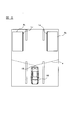
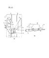
- FIG. 1 is a schematic configuration diagram of a vehicle equipped with the three-dimensional object detection device according to the first embodiment.
- FIG. 2 is a plan view showing a traveling state of the vehicle of FIG.
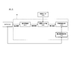
- FIG. 3 is a block diagram showing details of the computer according to the first embodiment.
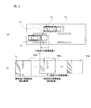
- FIG. 4 is a diagram for explaining the outline of the processing of the alignment unit according to the first embodiment, (a) is a plan view showing the moving state of the vehicle, and (b) is an image showing the outline of the alignment. It is.
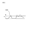
- FIG. 5 is a schematic diagram illustrating how a differential waveform is generated by the three-dimensional object detection unit according to the first embodiment.
- FIG. 6 is a diagram for explaining a method of detecting an adjacent vehicle according to the first embodiment.
- FIG. 7 is a diagram illustrating an example of the relationship between the luminance and the threshold value ⁇ at the detection positions in the detection areas A1 and A2.
- FIG. 8 is a diagram illustrating an example of the gain of the threshold value ⁇ set in accordance with the positional relationship between the camera and the light source.
- FIG. 9 is a diagram for explaining a method of adjusting the gain of the threshold value ⁇ shown in FIG.
- FIG. 10 is a diagram for explaining a method of adjusting the gain of the threshold value ⁇ shown in FIG.
- FIG. 11 is a diagram for explaining a method of adjusting the gain of the threshold value ⁇ according to the distance L.
- FIG. 12 is a diagram for explaining a method of adjusting the gain of the threshold value ⁇ according to the distance L.
- FIG. 13 is a diagram illustrating a small area divided by the three-dimensional object detection unit according to the first embodiment.
- FIG. 14 is a diagram illustrating an example of a histogram obtained by the three-dimensional object detection unit according to the first embodiment.
- FIG. 15 is a diagram illustrating weighting by the three-dimensional object detection unit according to the first embodiment.
- FIG. 16 is a diagram illustrating another example of a histogram obtained by the three-dimensional object detection unit according to the first embodiment.
- FIG. 17 is a flowchart illustrating the adjacent vehicle detection method according to the first embodiment.
- FIG. 18 is a flowchart showing the threshold value ⁇ setting process in step S105.
- FIG. 19 is a block diagram illustrating details of the computer according to the second embodiment.
- FIG. 20A and 20B are diagrams illustrating a traveling state of the vehicle, in which FIG. 20A is a plan view illustrating the positional relationship of the detection region and the like, and FIG. 20B is a perspective view illustrating the positional relationship of the detection region and the like in real space.
- FIG. 21 is a diagram for explaining the operation of the luminance difference calculation unit according to the second embodiment.
- FIG. 21A is a diagram illustrating the positional relationship among the attention line, the reference line, the attention point, and the reference point in the bird's-eye view image.
- (B) is a figure which shows the positional relationship of the attention line, reference line, attention point, and reference point in real space.
- 22A and 22B are diagrams for explaining the detailed operation of the luminance difference calculation unit according to the second embodiment.
- FIG. 22A is a diagram showing a detection region in a bird's-eye view image
- FIG. It is a figure which shows the positional relationship of a line, a reference line, an attention point, and a reference point.
- FIG. 23 is a diagram illustrating an example of an image for explaining the edge detection operation.
- FIG. 24 is a diagram illustrating an example of the relationship between the luminance and the threshold value ⁇ in the detection areas A1 and A2.
- FIG. 25 is a diagram illustrating an example of the gain of the threshold value ⁇ set according to the position of the light source.
- 26A and 26B are diagrams illustrating edge lines and luminance distribution on the edge lines.
- FIG. 26A is a diagram illustrating the luminance distribution when a three-dimensional object (adjacent vehicle) is present in the detection area, and FIG. It is a figure which shows luminance distribution when a solid object does not exist in FIG.
- FIG. 27 is a flowchart illustrating an adjacent vehicle detection method according to the second embodiment.
- FIG. 1 is a schematic configuration diagram of a vehicle equipped with a three-dimensional object detection device 1 according to the first embodiment.
- the three-dimensional object detection device 1 according to the present embodiment is intended to detect a vehicle (hereinafter also referred to as an adjacent vehicle V2) that exists in an adjacent lane that may be contacted when the host vehicle V1 changes lanes. To do.
- the three-dimensional object detection device 1 according to the present embodiment includes a camera 10, a vehicle speed sensor 20, and a calculator 30.
- the camera 10 is attached to the vehicle V ⁇ b> 1 so that the optical axis is at an angle ⁇ downward from the horizontal at a position of the height h behind the host vehicle V ⁇ b> 1.
- the camera 10 captures an image of a predetermined area in the surrounding environment of the host vehicle V1 from this position.
- the vehicle speed sensor 20 detects the traveling speed of the host vehicle V1, and calculates the vehicle speed from the wheel speed detected by, for example, a wheel speed sensor that detects the rotational speed of the wheel.
- the computer 30 detects an adjacent vehicle existing in an adjacent lane behind the host vehicle.
- FIG. 2 is a plan view showing a traveling state of the host vehicle V1 of FIG.
- the camera 10 images the vehicle rear side at a predetermined angle of view a.
- the angle of view a of the camera 10 is set to an angle of view at which the left and right lanes (adjacent lanes) can be imaged in addition to the lane in which the host vehicle V1 travels.
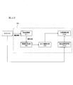
- FIG. 3 is a block diagram showing details of the computer 30 of FIG. In FIG. 3, the camera 10 and the vehicle speed sensor 20 are also illustrated in order to clarify the connection relationship.
- the computer 30 includes a viewpoint conversion unit 31, a positioning unit 32, a three-dimensional object detection unit 33, and a detection reference setting unit 34. Below, each structure is demonstrated.
- the viewpoint conversion unit 31 inputs captured image data of a predetermined area obtained by imaging with the camera 10, and converts the viewpoint of the input captured image data into bird's-eye image data in a bird's-eye view state.
- the state viewed from a bird's-eye view is a state viewed from the viewpoint of a virtual camera looking down from above, for example, vertically downward.
- This viewpoint conversion can be executed as described in, for example, Japanese Patent Application Laid-Open No. 2008-219063.
- the viewpoint conversion of captured image data to bird's-eye view image data is based on the principle that a vertical edge peculiar to a three-dimensional object is converted into a straight line group passing through a specific fixed point by viewpoint conversion to bird's-eye view image data. This is because a planar object and a three-dimensional object can be distinguished if used.
- the alignment unit 32 sequentially inputs the bird's-eye view image data obtained by the viewpoint conversion of the viewpoint conversion unit 31 and aligns the positions of the inputted bird's-eye view image data at different times.
- 4A and 4B are diagrams for explaining the outline of the processing of the alignment unit 32, where FIG. 4A is a plan view showing the moving state of the host vehicle V1, and FIG. 4B is an image showing the outline of the alignment.
- the host vehicle V1 of the current time is located in P 1, one unit time before the vehicle V1 is located in the P 1 '. Further, there is a parallel running state with the vehicle V1 is located is adjacent vehicle V2 laterally after the vehicle V1, located in P 2 adjacent vehicle V2 is the current time, one unit time before the adjacent vehicle V2 is P 2 Suppose it is located at '. Furthermore, it is assumed that the host vehicle V1 has moved a distance d at one time. Note that “one hour before” may be a past time for a predetermined time (for example, one control cycle) from the current time, or may be a past time for an arbitrary time.
- the bird's-eye view image PB t at the current time is as shown in Figure 4 (b).
- the adjacent vehicle V2 (position P 2) is tilting occurs.
- the white line drawn on the road surface has a rectangular shape, and is in a state of being relatively accurately viewed in plan, but the adjacent vehicle V2 (position P 2). ') Will fall down.
- the vertical edges of solid objects are straight lines along the collapse direction by the viewpoint conversion processing to bird's-eye view image data. This is because the plane image on the road surface does not include a vertical edge, but such a fall does not occur even when the viewpoint is changed.
- the alignment unit 32 performs alignment of the bird's-eye view images PB t and PB t ⁇ 1 as described above on the data. At this time, the alignment unit 32 offsets the bird's-eye view image PB t-1 at the previous time and matches the position with the bird's-eye view image PB t at the current time.
- the image on the left side and the center image in FIG. 4B show a state that is offset by the movement distance d ′.
- This offset amount d ′ is a movement amount on the bird's-eye view image data corresponding to the actual movement distance d of the host vehicle V1 shown in FIG. 4 (a). It is determined based on the time until the time.
- the alignment unit 32 takes the difference between the bird's-eye view images PB t and PB t ⁇ 1 and generates data of the difference image PD t .
- the alignment unit 32 converts the pixel value difference between the bird's-eye view images PB t and PB t ⁇ 1 to an absolute value in order to cope with a change in the illumination environment, and the absolute value is a predetermined value.
- the three-dimensional object detection unit 33 detects a three-dimensional object based on the data of the difference image PD t shown in FIG. At this time, the three-dimensional object detection unit 33 also calculates the movement distance of the three-dimensional object in the real space. In detecting the three-dimensional object and calculating the movement distance, the three-dimensional object detection unit 33 first generates a differential waveform.
- the three-dimensional object detection unit 33 sets a detection region in the difference image PD t .
- the three-dimensional object detection device 1 of the present example is intended to calculate a movement distance for an adjacent vehicle that may be contacted when the host vehicle V1 changes lanes. For this reason, in this example, as shown in FIG. 2, rectangular detection areas A1, A2 are set on the rear side of the host vehicle V1. Such detection areas A1, A2 may be set from a relative position with respect to the host vehicle V1, or may be set based on the position of the white line. When setting the position of the white line as a reference, the three-dimensional object detection device 1 may use, for example, an existing white line recognition technique.
- the three-dimensional object detection unit 33 recognizes the sides (sides along the traveling direction) of the set detection areas A1 and A2 on the own vehicle V1 side as the ground lines L1 and L2.
- the ground line means a line in which the three-dimensional object contacts the ground.
- the ground line is set as described above, not a line in contact with the ground. Even in this case, from experience, the difference between the ground line according to the present embodiment and the ground line obtained from the position of the original adjacent vehicle V2 is not too large, and there is no problem in practical use.
- FIG. 5 is a schematic diagram illustrating how the three-dimensional object detection unit 33 generates a differential waveform.
- the three-dimensional object detection unit 33 calculates a differential waveform from a portion corresponding to the detection areas A ⁇ b> 1 and A ⁇ b> 2 in the difference image PD t (right diagram in FIG. 4B) calculated by the alignment unit 32.
- DW t is generated.
- the three-dimensional object detection unit 33 generates a differential waveform DW t along the direction in which the three-dimensional object falls by viewpoint conversion.
- the detection area A1 is described for convenience, but the difference waveform DW t is generated for the detection area A2 in the same procedure.
- first three-dimensional object detection unit 33 defines a line La on the direction the three-dimensional object collapses on data of the difference image PD t. Then, the three-dimensional object detection unit 33 counts the number of difference pixels DP indicating a predetermined difference on the line La.
- the difference pixel DP indicating the predetermined difference is expressed by the pixel value of the difference image PD t as “0” and “1”, and the pixel indicating “1” is counted as the difference pixel DP. .
- the three-dimensional object detection unit 33 counts the number of difference pixels DP and then obtains an intersection point CP between the line La and the ground line L1. Then, the three-dimensional object detection unit 33 associates the intersection CP with the count number, determines the horizontal axis position based on the position of the intersection CP, that is, the position on the vertical axis in the right diagram of FIG. The axis position, that is, the position on the right and left axis in the right diagram of FIG. 5 is determined and plotted as the count number at the intersection CP.
- the three-dimensional object detection unit 33 defines lines Lb, Lc... In the direction in which the three-dimensional object falls, counts the number of difference pixels DP, and determines the horizontal axis position based on the position of each intersection CP. Then, the vertical axis position is determined from the count number (number of difference pixels DP) and plotted.
- the three-dimensional object detection unit 33 generates the differential waveform DW t as shown in the right diagram of FIG.
- the difference pixel PD on the data of the difference image PD t is a pixel that has changed in the images at different times, in other words, a location where a three-dimensional object exists.
- the difference waveform DW t is generated by counting the number of pixels along the direction in which the three-dimensional object collapses and performing frequency distribution at the location where the three-dimensional object exists.
- the differential waveform DW t is generated from the information in the height direction for the three-dimensional object.
- the line La and the line Lb in the direction in which the three-dimensional object collapses have different distances overlapping the detection area A1. For this reason, if the detection area A1 is filled with the difference pixels DP, the number of difference pixels DP is larger on the line La than on the line Lb. For this reason, when the three-dimensional object detection unit 33 determines the vertical axis position from the count number of the difference pixels DP, the three-dimensional object detection unit 33 is normalized based on the distance at which the lines La and Lb in the direction in which the three-dimensional object falls and the detection area A1 overlap. Turn into. As a specific example, in the left diagram of FIG.
- the three-dimensional object detection unit 33 normalizes the count number by dividing it by the overlap distance.
- the difference waveform DW t the line La on the direction the three-dimensional object collapses, the value of the differential waveform DW t corresponding to Lb is substantially the same.
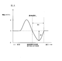
- FIG. 6 is a diagram for explaining a detection method of the adjacent vehicle by the three-dimensional object detection unit 33, and shows an example of the differential waveform DW t and the threshold value ⁇ for detecting the adjacent vehicle.
- the three-dimensional object detection unit 33 determines whether or not the peak of the generated difference waveform DW t is equal to or greater than a threshold value ⁇ corresponding to the peak position of the difference waveform DW t .
- the three-dimensional object detection unit 33 determines that no adjacent vehicle exists in the detection areas A1 and A2, while the peak of the differential waveform DW t Is equal to or greater than a predetermined threshold value ⁇ , it is determined that there is an adjacent vehicle in the detection areas A1 and A2, thereby detecting the adjacent vehicle existing in the adjacent lane.
- the differential waveform DW t is an aspect of pixel distribution information indicating a predetermined luminance difference
- the “pixel distribution information” in the present embodiment is obtained when the captured image is converted into a bird's-eye view image. It can be positioned as information indicating the distribution state of “pixels having a luminance difference equal to or greater than a predetermined threshold” detected along the direction in which the three-dimensional object falls.
- the three-dimensional object detection unit 33 distributes pixels whose luminance difference is equal to or greater than the predetermined threshold th in the direction in which the three-dimensional object falls when the viewpoint is converted into the bird's-eye view image on the bird's-eye view image obtained by the viewpoint conversion unit 31.
- the difference waveform DW t Based on this, a three-dimensional object is detected.
- the threshold value ⁇ is set by the detection reference setting unit 34 shown in FIG.
- the detection reference setting unit 34 detects positions in the detection areas A1, A2 (hereinafter, detection positions in the detection areas A1, A2) corresponding to the lines La, Lb, Lc,... For each of the detection positions in the detection areas A1, A2 (for example, the average luminance of the difference pixels DP on the lines La, Lb, Lc... In the direction in which the three-dimensional object shown in the left diagram of FIG.
- the threshold value ⁇ for detecting an adjacent vehicle is set according to the positional relationship between the camera 10 and the light source.
- FIG. 7 is a graph showing an example of the relationship between the luminance and the threshold value ⁇ at the detection positions in the detection areas A1 and A2
- FIG. 8 is set according to the positional relationship between the camera 10 and the light source. It is a figure which shows an example of the gain of threshold value (alpha).
- the detection reference setting unit 34 sets the threshold value ⁇ corresponding to the detection position to a higher value as the luminance at the detection position in the detection areas A1 and A2 is higher.
- the detection reference setting unit 34 sets the threshold value ⁇ corresponding to the detection position to a higher value as the luminance at the detection position in the detection areas A1 and A2 is higher.
- the detection reference setting unit 34 changes the gain of the threshold ⁇ according to the position of the detection position in the traveling direction of the host vehicle.
- the reference position P O shown in FIG. 8 correspond to the position of the light source such as headlight of neighboring adjacent vehicle, which, as shown in FIG. 8, the reference position P O in front, as compared with the rear of the reference position P O, is set higher gain threshold alpha, the result, in front of the reference position P O, as compared from the rear reference position P O, the threshold alpha is set high Will be.
- the gain threshold value ⁇ is set low, when the luminance is the same, the reference position in behind the P O, compared to the front of the reference position P O, so that the threshold value ⁇ is set low.
- the detection reference setting unit 34 adjusts the gain of the threshold value ⁇ shown in FIG. 8 according to the positional relationship between the camera 10 and the light source.
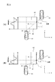
- a method for adjusting the gain of the threshold value ⁇ shown in FIG. 8 will be described with reference to FIGS. 9 and 10 are diagrams for explaining a method of adjusting the gain of the threshold value ⁇ shown in FIG.
- the detection reference design unit 34 first detects a light source such as a headlight of the adjacent vehicle V3 from the captured image captured by the camera 10. Then, the detection reference setting unit 34 detects the position of the center of gravity of the detected light source, and sets a straight line Lc that passes through the position of the center of gravity of the light source and the center position of the camera 10. Further, the detection reference setting unit 34 calculates an intersection point O between the straight line Lc and a side (side along the traveling direction) L2 'on the adjacent adjacent lane side of the detection area A2. A method for detecting the light source by the detection reference setting unit 34 will be described later.
- FIG. 9B illustrates a scene in which the adjacent vehicle V3 is close to the host vehicle V1 from the scene illustrated in FIG. 9A.
- the intersection O between the straight line Lc and the line L2 ′ of the detection area A2 is the intersection O shown in FIG. 9A. Rather than forward (Y-axis negative direction). Therefore, as shown in FIG.
- the detection reference setting unit 34 so that the position of the intersection point O shown in FIG. 9 (B) the right figure, and the reference position P O shown in FIG. 8 coincides 8, when the gain of the threshold value ⁇ shown in FIG. 8 is adjusted, the gain of the threshold value ⁇ shown in FIG. 8 is equal to the gain of the threshold value ⁇ shown in the left figure of FIG. 9A. compared to being entirely shifted forward (Y-axis negative direction), thereby, the position of the light source, and the reference position P O shown in FIG. 8 and thus corresponds.
- the gain of the threshold value ⁇ is the largest at the position of the light source, and the gain of the threshold value ⁇ is also large at the position near the light source. Therefore, the threshold value ⁇ for detecting the adjacent vehicle is set to the highest value at the position of the light source, and the threshold value ⁇ for detecting the adjacent vehicle is set to a high value at the position near the light source. . As a result, it is possible to effectively prevent erroneous detection of the head ride (light source) of the adjacent vehicle as the adjacent vehicle when the light source of the adjacent vehicle is irradiated on the adjacent lane.
- the region Rr behind the light source is determined as a region where the possibility that the adjacent vehicle exists is a predetermined value or more, and as shown in FIGS. 8 and 9, the region behind the light source.
- the position of the camera 10 in the Y direction in the region Rf ahead of the light source (that is, in the XY plane where the traveling direction of the host vehicle is the Y direction and the vehicle width direction is the X direction).
- the gain of the threshold value ⁇ is set high in the region where Y ⁇ kX), and from the headlight (light source)
- the rear region Rr that is, the position of the camera 10 in the Y direction is 0 in the XY plane where the traveling direction of the host vehicle is the Y direction and the vehicle width direction is the X direction, and Y> 0 is behind the camera 10;
- the gain of the threshold value ⁇ is set low in a region where Y ⁇ kX. For this reason, when the luminance is the same, the threshold value ⁇ is set higher in the region Rf ahead of the light source, and the threshold value ⁇ is set lower in the region Rr behind the headlight (light source).
- the detection reference setting unit 34 is shown in FIG. 8 according to the distance L in the vehicle width direction (X-axis direction) from the center position of the camera 10 to the gravity center position of the light source.
- the gain of the threshold value ⁇ is adjusted.
- the detection reference setting unit 34 as the distance L from the center position of the camera 10 to the center of gravity position of the light source is large, such that the threshold ⁇ is increased is set in the rear than the reference position P O, the reference than a position P O to reduce the gain of the decrease width dh threshold ⁇ in the rear (decrease width dh for gain threshold ⁇ at the reference position P O shown in FIG. 8).
- the detection reference setting unit 34 as the distance L from the center position of the camera 10 to the center of gravity position of the light source is large, such that the threshold ⁇ is increased is set in the rear than the reference position P O, the reference than a position P O to reduce the gain of the decrease width dh threshold ⁇ in the rear (decrease width dh for gain threshold ⁇ at the
- the detection reference setting unit 34 sets the gain reduction width dh of the threshold value ⁇ to the gain reduction width of the threshold value ⁇ shown in FIG.
- the gain of the threshold value ⁇ shown in FIG. 8 is adjusted so as to be smaller than dh.
- the detection reference setting unit 34 is less likely to detect a three-dimensional object as the distance L in the vehicle width direction from the center position of the camera 10 to the gravity center position of the light source is longer.
- the threshold value ⁇ serving as a detection reference can be set.
- the detection reference setting unit 34 is configured to change the gain reduction width dh of the threshold value ⁇ in accordance with the distance L from the center position of the camera 10 to the gravity center position of the light source.
- the gain of the threshold value ⁇ is larger than the gain of the threshold value ⁇ at the reference position PO . It is also possible to reduce the range dw in which the transition is low (the range corresponding to the tire wheel of the adjacent vehicle existing behind the light source). For example, when the gain of the threshold value ⁇ shown in FIG. 8 is obtained in the scene shown in FIG.
- the detection reference setting unit 34 is compared with FIG. 10A, for example, as shown in FIG. Te, when the distance L from the center position of the camera 10 to the center of gravity position of the light source is increased, as shown in FIG. 12, narrowing the range dw gain threshold ⁇ has remained lower than the reference position P O To do.
- the range of the threshold ⁇ is set higher in the rear than the reference position P O corresponding to the position of the light source becomes wider, even in the region behind Rr than the light source, may next adjacent vehicle V3 is present When it is high, it is possible to more appropriately eliminate the influence of the headlight of the adjacent vehicle V3.
- the detection reference setting unit 34 changes the threshold value ⁇ in order to effectively prevent erroneous detection of the light of the headlight of the adjacent vehicle adjacent to the adjacent lane as an adjacent vehicle. . Therefore, in the present embodiment, the threshold value ⁇ can be changed by the detection reference setting unit 34 only at night when the adjacent vehicle V2 lights the headlight. Note that the detection reference setting unit 34 may determine that it is nighttime, for example, when the luminance of an image captured by the camera 10 is equal to or less than a predetermined value.
- the description returns to the description of the three-dimensional object detection unit 33.
- the three-dimensional object detection unit 33 After detecting the three-dimensional object present in the adjacent lane, the three-dimensional object detection unit 33, in contrast with the differential waveform DW t in one time before the differential waveform DW t-1 and the current time, of the three-dimensional object present on the adjacent vehicle Calculate the travel distance. That is, the three-dimensional object detection unit 33 calculates the movement distance from the time change of the difference waveforms DW t and DW t ⁇ 1 .
- the three-dimensional object detection unit 33 divides the differential waveform DW t into a plurality of small areas DW t1 to DW tn (n is an arbitrary integer equal to or greater than 2).
- FIG. 13 is a diagram illustrating the small areas DW t1 to DW tn divided by the three-dimensional object detection unit 33.
- the small areas DW t1 to DW tn are divided so as to overlap each other, for example, as shown in FIG. For example, the small area DW t1 and the small area DW t2 overlap, and the small area DW t2 and the small area DW t3 overlap.
- the three-dimensional object detection unit 33 obtains an offset amount (amount of movement of the differential waveform in the horizontal axis direction (vertical direction in FIG. 13)) for each of the small regions DW t1 to DW tn .
- the offset amount is determined from the difference between the differential waveform DW t in the difference waveform DW t-1 and the current time before one unit time (distance in the horizontal axis direction).
- three-dimensional object detection unit 33 for each small area DW t1 ⁇ DW tn, when moving the differential waveform DW t1 before one unit time in the horizontal axis direction, the differential waveform DW t at the current time The position where the error is minimized (the position in the horizontal axis direction) is determined, and the amount of movement in the horizontal axis between the original position of the differential waveform DW t ⁇ 1 and the position where the error is minimized is obtained as an offset amount. Then, the three-dimensional object detection unit 33 counts the offset amount obtained for each of the small areas DW t1 to DW tn and forms a histogram.
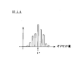
- FIG. 14 is a diagram illustrating an example of a histogram obtained by the three-dimensional object detection unit 33.
- the offset amount which is the amount of movement that minimizes the error between each of the small areas DW t1 to DW tn and the differential waveform DW t ⁇ 1 one time before, has some variation.
- the three-dimensional object detection unit 33 forms a histogram of offset amounts including variations, and calculates a movement distance from the histogram.
- the three-dimensional object detection unit 33 calculates the moving distance of the adjacent vehicle from the maximum value of the histogram. That is, in the example illustrated in FIG.
- the three-dimensional object detection unit 33 calculates the offset amount indicating the maximum value of the histogram as the movement distance ⁇ * .
- the moving distance ⁇ * is a relative moving distance of the adjacent vehicle with respect to the own vehicle. For this reason, when calculating the absolute movement distance, the three-dimensional object detection unit 33 calculates the absolute movement distance based on the obtained movement distance ⁇ * and the signal from the vehicle speed sensor 20.
- a one-dimensional waveform is obtained by calculating the moving distance of the three-dimensional object from the offset amount of the differential waveform DW t when the error of the differential waveform DW t generated at different times is minimized.
- the movement distance is calculated from the offset amount of the information, and the calculation cost can be suppressed in calculating the movement distance.
- by dividing the differential waveform DW t generated at different times into a plurality of small areas DW t1 to DW tn it is possible to obtain a plurality of waveforms representing respective portions of the three-dimensional object.
- the calculation accuracy of the movement distance can be improved. Further, in the present embodiment, by calculating the moving distance of the three-dimensional object from the time change of the differential waveform DW t including the information in the height direction, compared with a case where attention is paid only to one point of movement, Since the detection location before the time change and the detection location after the time change are specified including information in the height direction, it is likely to be the same location in the three-dimensional object, and the movement distance is calculated from the time change of the same location, and the movement Distance calculation accuracy can be improved.
- the three-dimensional object detection unit 33 weights each of the plurality of small areas DW t1 to DW tn and forms a histogram by counting the offset amount obtained for each of the small areas DW t1 to DW tn according to the weight. May be.
- FIG. 15 is a diagram illustrating weighting by the three-dimensional object detection unit 33.
- the small area DW m (m is an integer of 1 to n ⁇ 1) is flat. That is, in the small area DW m , the difference between the maximum value and the minimum value of the number of pixels indicating a predetermined difference is small. Three-dimensional object detection unit 33 to reduce the weight for such small area DW m. This is because the flat small area DW m has no characteristics and is likely to have a large error in calculating the offset amount.
- the small region DW m + k (k is an integer equal to or less than nm) is rich in undulations. That is, in the small area DW m , the difference between the maximum value and the minimum value of the number of pixels indicating a predetermined difference is large.
- Three-dimensional object detection unit 33 increases the weight for such small area DW m. This is because the small region DW m + k rich in undulations is characteristic and there is a high possibility that the offset amount can be accurately calculated. By weighting in this way, the calculation accuracy of the movement distance can be improved.
- the differential waveform DW t is divided into a plurality of small areas DW t1 to DW tn in order to improve the calculation accuracy of the movement distance.
- the small area DW t1 is divided. It is not necessary to divide into ⁇ DW tn .
- the three-dimensional object detection unit 33 calculates the moving distance from the offset amount of the differential waveform DW t when the error between the differential waveform DW t and the differential waveform DW t ⁇ 1 is minimized. That is, the method for obtaining the offset amount of the difference waveform DW t in the difference waveform DW t-1 and the current time before one unit time is not limited to the above disclosure.
- the three-dimensional object detection unit 33 obtains the moving speed of the host vehicle V1 (camera 10), and obtains the offset amount for the stationary object from the obtained moving speed. After obtaining the offset amount of the stationary object, the three-dimensional object detection unit 33 ignores the offset amount corresponding to the stationary object among the maximum values of the histogram and calculates the moving distance of the adjacent vehicle.
- FIG. 16 is a diagram illustrating another example of a histogram obtained by the three-dimensional object detection unit 33.
- two maximum values ⁇ 1 and ⁇ 2 appear in the obtained histogram.
- one of the two maximum values ⁇ 1, ⁇ 2 is the offset amount of the stationary object.
- the three-dimensional object detection unit 33 calculates the offset amount for the stationary object from the moving speed, ignores the maximum value corresponding to the offset amount, and calculates the moving distance of the three-dimensional object by using the remaining maximum value. To do. Thereby, the situation where the calculation accuracy of the moving distance of a solid object falls by a stationary object can be prevented.
- the three-dimensional object detection unit 33 stops calculating the movement distance. Thereby, in the present embodiment, it is possible to prevent a situation in which an erroneous movement distance having a plurality of maximum values is calculated.
- FIG. 17 is a flowchart showing the adjacent vehicle detection process of the present embodiment.
- the computer 30 acquires the data of the captured image P from the camera 10 (step S ⁇ b> 101), and the viewpoint conversion unit 31 performs the bird's-eye view based on the acquired captured image P data.
- Data of the image PB t is generated (step S102).
- the alignment unit 33 aligns the data of the bird's-eye view image PB t and the data of the bird's-eye view image PB t ⁇ 1 one hour before, and generates data of the difference image PD t (step S103). . Then, three-dimensional object detection unit 33, from the data of the difference image PD t, pixel value by counting the number of difference pixel DP "1", to generate a difference waveform DW t (step S104).
- the detection reference setting unit 34 sets a threshold value ⁇ for detecting an adjacent vehicle (step S105).
- FIG. 18 is a flowchart showing the threshold value ⁇ setting processing in step S105.
- the detection reference setting unit 34 first detects a light source such as a headlight of an adjacent vehicle from the captured image captured by the camera 10 (step S201).
- the detection reference setting unit 34 eliminates the influence of noise and appropriately detects a headlight of another vehicle as a light source, so that the difference in brightness from the surroundings in the captured image is equal to or greater than a predetermined value s d. And an image area having a size equal to or larger than the predetermined value s 1 is detected as an area corresponding to the light source.
- the detection reference setting unit 34 first performs edge processing of the captured image, and detects a region where the difference in brightness from the surroundings is equal to or greater than the predetermined value sd as a light source candidate.
- the detection reference setting unit 34 does not limit the predetermined value sd to a constant value in order to appropriately detect the light source.
- the rear distance from the camera 10 to the light source candidate The predetermined value s d can be changed based on the brightness of the region where the candidate exists.
- the detection reference setting unit 34 has a threshold map in which a predetermined value s d is set according to the luminance, and a threshold map in which the predetermined value s d is set according to the rear distance from the camera 10 to the light source candidate. and compares these two thresholds map, that the predetermined value s d of the higher of the prescribed value s d obtained for each threshold map is selected as the predetermined value s d for detecting the light source candidate it can.
- the detection reference setting unit 34 detects an image area having a size equal to or larger than the predetermined value s 1 among the detected light source candidates as an area corresponding to the light source.
- the predetermined value s 1 is not limited to a constant value, and the detection reference setting unit 34 may change the predetermined value s 1 according to the rear distance from the camera 10 to the light source candidate, for example. For example, when the length of the detection areas A1 and A2 in the traveling direction of the host vehicle is 10 m, the detection reference setting unit 34 moves the detection areas A1 and A2 from the position closest to the camera 10 in the detection areas A1 and A2.
- the detection reference setting unit 34 includes, for example, an image region in which the height ⁇ width is 5 ⁇ 5 pixels or more in the region R1 near the host vehicle and the region R3 far from the host vehicle in the detection regions A1 and A2.
- an image region having a height ⁇ width of 7 ⁇ 7 pixels or more is detected as a region corresponding to the light source. it can.
- the threshold value ⁇ shown in FIG. 7 is calculated as the threshold value ⁇ for detecting the adjacent vehicle, and the threshold value ⁇ setting process in step S105 ends.
- the detection reference setting unit 34 sets a straight line Lc passing through the detected barycentric position of the light source and the center position of the camera 10 as shown in the right figure of FIG.
- the reference setting unit 34 calculates the intersection point O between the set straight line Lc and the side L2 ′ on the adjacent adjacent lane side of the detection area A2 (step S203). Then, the detection reference setting unit 34, as shown in FIG. 10 (B) left, and the intersection point O calculated at step S203, so that the reference position P O shown in FIG. 8 coincide, the gain threshold value ⁇ Adjust (step S204).
- the detection reference setting unit 34 changes the threshold value ⁇ set according to the brightness with the gain of the threshold value ⁇ adjusted in step S ⁇ b> 204, thereby detecting the adjacent vehicle.
- ⁇ is calculated (step S205).
- a threshold value ⁇ for detecting the adjacent vehicle is set based on the differential waveform DW t .
- the three-dimensional object detection unit 33 detects the peak of the differential waveform DW t generated in step S104 based on the threshold value ⁇ set in step S105, and the position where the peak of the differential waveform DW t is detected. It is determined whether or not the threshold value ⁇ is greater than or equal to (step S106). When the peak of the difference waveform DW t is not equal to or greater than the threshold value ⁇ , that is, when there is almost no difference, it is considered that there is no adjacent vehicle in the captured image P.
- step S106 No
- the three-dimensional object detection unit 33 determines that there is no adjacent vehicle in the adjacent lane (step S115). The process shown in FIG.
- step S106 Yes
- the three-dimensional object detection unit 33 determines that a three-dimensional object exists in the adjacent lane, and proceeds to step S107.
- the three-dimensional object detection unit 33 divides the differential waveform DW t into a plurality of small areas DW t1 to DW tn .
- the three-dimensional object detection unit 33 performs weighting for each of the small areas DW t1 to DW tn (step S108), calculates an offset amount for each of the small areas DW t1 to DW tn (step S109), and adds the weights.
- a histogram is generated (step S110).
- the three-dimensional object detection unit 33 calculates a relative movement distance that is a movement distance of the adjacent vehicle with respect to the own vehicle based on the histogram (step S111). Furthermore, the three-dimensional object detection unit 33 calculates the absolute movement speed of the adjacent vehicle from the relative movement distance (step S112). At this time, the three-dimensional object detection unit 33 calculates the relative movement speed by differentiating the relative movement distance with respect to time, and adds the own vehicle speed detected by the vehicle speed sensor 20 to calculate the absolute movement speed of the adjacent vehicle.
- the rear sides of the host vehicle are set as detection areas A1 and A2, and emphasis is placed on whether or not there is a possibility of contact when the host vehicle changes lanes. For this reason, the process of step S113 is performed. That is, assuming that the system according to the present embodiment is operated on a highway, if the speed of the adjacent vehicle is less than 10 km / h, even if the adjacent vehicle exists, the host vehicle is required to change the lane. Because it is located far behind, there are few problems.
- step S113 determining whether the absolute moving speed of the adjacent vehicle is 10 km / h or more and the relative moving speed of the adjacent vehicle with respect to the own vehicle is +60 km / h or less has the following effects.
- the absolute moving speed of the stationary object may be detected to be several km / h. Therefore, by determining whether the speed is 10 km / h or more, it is possible to reduce the possibility that the stationary object is determined to be an adjacent vehicle.
- the relative speed of the adjacent vehicle to the host vehicle may be detected as a speed exceeding +60 km / h. Therefore, the possibility of erroneous detection due to noise can be reduced by determining whether the relative speed is +60 km / h or less.
- step S113 it may be determined that the absolute movement speed of the adjacent vehicle is not negative or not 0 km / h. Further, in this embodiment, since an emphasis is placed on whether or not there is a possibility of contact when the host vehicle changes lanes, a warning sound is sent to the driver of the host vehicle when an adjacent vehicle is detected in step S114. Or a display corresponding to a warning may be performed by a predetermined display device.
- the detection areas A1 and A2 behind the host vehicle are captured at different times, the captured images are converted into bird's-eye view images, and based on the difference between the bird's-eye view images at different times.
- the difference image PD t is generated.
- the difference waveform DW t is generated from the data of the difference image PD t by counting the number of pixels indicating a predetermined difference and performing frequency distribution along the direction in which the three-dimensional object falls by the viewpoint conversion.
- the peak of the generated difference waveform DW t is equal to or greater than a predetermined threshold value ⁇ set according to the positional relationship between the camera 10 and the light source, and the peak of the difference waveform DW t is equal to or greater than the threshold value ⁇ .
- a predetermined threshold value ⁇ set according to the positional relationship between the camera 10 and the light source
- the threshold value ⁇ is changed according to the luminance.
- luminance can be excluded, and an adjacent vehicle can be detected appropriately.
- the light source behind the host vehicle is detected, and the threshold value ⁇ for detecting the adjacent vehicle is changed according to the position of the detected light source.
- the gain of the threshold value ⁇ is higher in the front than the reference position P O corresponding to the position of the light source and lower in the rear than the reference position P O.
- the present embodiment Since the threshold value ⁇ for detecting the adjacent vehicle can be lowered behind the headlight (light source), the tire wheel of the adjacent vehicle existing behind the headlight (light source) can be detected appropriately. Can do.
- the threshold ⁇ for detecting the adjacent vehicle can be increased with respect to the luminance. It is possible to effectively prevent erroneous detection of an image of the reflected light, which is reflected by the headlight (light source) from the adjacent vehicle, as an adjacent vehicle.
- the gain of the threshold value ⁇ shown in FIG. 9 is adjusted according to the distance L in the vehicle width direction from the center position of the camera 10 to the gravity center position of the light source. Specifically, as shown in FIG. 11, as the distance L from the center position of the camera 10 to the center of gravity position of the light source is large, such that the threshold ⁇ is increased at the rear of the light source, in the rear than the reference position P O The gain reduction width dh of the threshold value ⁇ is reduced.
- the farther the detected headlight (light source) is from the camera 10 in the vehicle width direction (X-axis direction) the more adjacent the detected headlight is to the headlight of the adjacent vehicle. It is more likely to be a vehicle headlight.
- the reference position P O corresponding to the position of the light source can be increased threshold ⁇ in the rear, in the rear area than the light source, the headlight of the next adjacent vehicle Can be more appropriately eliminated. Further, as shown in FIG.
- the gain threshold value ⁇ at the reference position P O, the threshold ⁇ Similarly, even when the range dw in which the gain of the transition is low is narrowed, the influence of the headlight of the adjacent vehicle can be eliminated more appropriately.
- the three-dimensional object detection device 1a according to the second embodiment includes a computer 30 a instead of the computer 30 of the first embodiment, except that it operates as described below. This is the same as in the first embodiment.
- FIG. 19 is a block diagram showing details of the computer 30a according to the second embodiment.
- the three-dimensional object detection device 1a includes a camera 10 and a computer 30a.
- the computer 30a includes a viewpoint conversion unit 31, a luminance difference calculation unit 35, and an edge line detection unit. 36, a three-dimensional object detection unit 33a, and a detection reference setting unit 34a.
- FIG. 20 is a diagram illustrating an imaging range and the like of the camera 10 of FIG. 19, FIG. 20A is a plan view, and FIG. 20B is a perspective view in real space on the rear side from the host vehicle V1. Show.
- the camera 10 has a predetermined angle of view a, and images the rear side from the host vehicle V1 included in the predetermined angle of view a.
- the angle of view a of the camera 10 is set so that the imaging range of the camera 10 includes the adjacent lane in addition to the lane in which the host vehicle V1 travels.
- the detection areas A1 and A2 in this example are trapezoidal in a plan view (when viewed from a bird's eye), and the positions, sizes, and shapes of the detection areas A1 and A2 are determined based on the distances d 1 to d 4. Is done.
- the detection areas A1 and A2 in the example shown in the figure are not limited to a trapezoidal shape, and may be other shapes such as a rectangle when viewed from a bird's eye view as shown in FIG.
- the distance d1 is a distance from the host vehicle V1 to the ground lines L1 and L2.
- the ground lines L1 and L2 mean lines on which a three-dimensional object existing in the lane adjacent to the lane in which the host vehicle V1 travels contacts the ground.
- the object is to detect adjacent vehicles V2 and the like (including two-wheeled vehicles) traveling in the left and right lanes adjacent to the lane of the host vehicle V1 on the rear side of the host vehicle V1.
- a distance d1 which is a position to be the ground lines L1, L2 of the adjacent vehicle V2 is determined from a distance d11 from the own vehicle V1 to the white line W and a distance d12 from the white line W to a position where the adjacent vehicle V2 is predicted to travel. It can be determined substantially fixedly.
- the distance d1 is not limited to being fixedly determined, and may be variable.
- the computer 30a recognizes the position of the white line W with respect to the host vehicle V1 by a technique such as white line recognition, and determines the distance d11 based on the recognized position of the white line W.
- the distance d1 is variably set using the determined distance d11.
- the distance d1 is It shall be fixedly determined.
- the distance d2 is a distance extending in the vehicle traveling direction from the rear end portion of the host vehicle V1.
- the distance d2 is determined so that the detection areas A1 and A2 are at least within the angle of view a of the camera 10.
- the distance d2 is set so as to be in contact with the range divided into the angle of view a.
- the distance d3 is a distance indicating the length of the detection areas A1, A2 in the vehicle traveling direction. This distance d3 is determined based on the size of the three-dimensional object to be detected. In the present embodiment, since the detection target is the adjacent vehicle V2 or the like, the distance d3 is set to a length including the adjacent vehicle V2.
- the distance d4 is a distance indicating a height that is set to include a tire such as the adjacent vehicle V2 in the real space.
- the distance d4 is a length shown in FIG. 20A in the bird's-eye view image.
- the distance d4 may be a length that does not include a lane that is further adjacent to the left and right lanes in the bird's-eye view image (that is, the adjacent lane that is adjacent to two lanes). If the lane adjacent to the two lanes is included from the lane of the own vehicle V1, there is an adjacent vehicle V2 in the adjacent lane on the left and right of the own lane that is the lane in which the own vehicle V1 is traveling. This is because it becomes impossible to distinguish whether there is an adjacent vehicle on the lane.
- the distances d1 to d4 are determined, and thereby the positions, sizes, and shapes of the detection areas A1 and A2 are determined. More specifically, the position of the upper side b1 of the detection areas A1 and A2 forming a trapezoid is determined by the distance d1. The starting point position C1 of the upper side b1 is determined by the distance d2. The end point position C2 of the upper side b1 is determined by the distance d3. The side b2 of the detection areas A1 and A2 having a trapezoidal shape is determined by a straight line L3 extending from the camera 10 toward the starting point position C1.
- a side b3 of trapezoidal detection areas A1 and A2 is determined by a straight line L4 extending from the camera 10 toward the end position C2.
- the position of the lower side b4 of the detection areas A1 and A2 having a trapezoidal shape is determined by the distance d4.
- the areas surrounded by the sides b1 to b4 are set as the detection areas A1 and A2.
- the detection areas A1 and A2 are true squares (rectangles) in the real space behind the host vehicle V1.
- the viewpoint conversion unit 31 inputs captured image data of a predetermined area obtained by imaging with the camera 10.
- the viewpoint conversion unit 31 performs viewpoint conversion processing on the input captured image data to the bird's-eye image data in a bird's-eye view state.
- the bird's-eye view is a state seen from the viewpoint of a virtual camera looking down from above, for example, vertically downward (or slightly obliquely downward).
- This viewpoint conversion process can be realized by a technique described in, for example, Japanese Patent Application Laid-Open No. 2008-219063.
- the luminance difference calculation unit 35 calculates a luminance difference with respect to the bird's-eye view image data subjected to viewpoint conversion by the viewpoint conversion unit 31 in order to detect the edge of the three-dimensional object included in the bird's-eye view image. For each of a plurality of positions along a vertical imaginary line extending in the vertical direction in the real space, the brightness difference calculating unit 35 calculates a brightness difference between two pixels in the vicinity of each position.
- the luminance difference calculation unit 35 can calculate the luminance difference by either a method of setting only one vertical virtual line extending in the vertical direction in the real space or a method of setting two vertical virtual lines.
- the brightness difference calculation unit 35 applies a first vertical imaginary line corresponding to a line segment extending in the vertical direction in the real space and a vertical direction in the real space different from the first vertical imaginary line with respect to the bird's-eye view image that has undergone viewpoint conversion.
- a second vertical imaginary line corresponding to the extending line segment is set.
- the luminance difference calculation unit 35 continuously obtains a luminance difference between a point on the first vertical imaginary line and a point on the second vertical imaginary line along the first vertical imaginary line and the second vertical imaginary line.
- the operation of the luminance difference calculation unit 35 will be described in detail.
- the luminance difference calculation unit 35 corresponds to a line segment extending in the vertical direction in the real space, and passes through the detection area A1 (hereinafter, the attention line La). Set).
- the luminance difference calculation unit 35 corresponds to a line segment extending in the vertical direction in the real space and also passes through the second vertical virtual line Lr (hereinafter referred to as a reference line Lr) passing through the detection area A1.
- the reference line Lr is set at a position separated from the attention line La by a predetermined distance in the real space.
- the line corresponding to the line segment extending in the vertical direction in the real space is a line that spreads radially from the position Ps of the camera 10 in the bird's-eye view image.
- This radially extending line is a line along the direction in which the three-dimensional object falls when converted to bird's-eye view.
- the luminance difference calculation unit 35 sets the attention point Pa (point on the first vertical imaginary line) on the attention line La.
- the luminance difference calculation unit 35 sets a reference point Pr (a point on the second vertical plate) on the reference line Lr.
- the attention line La, the attention point Pa, the reference line Lr, and the reference point Pr have the relationship shown in FIG. 21B in the real space.
- the attention line La and the reference line Lr are lines extending in the vertical direction on the real space, and the attention point Pa and the reference point Pr are substantially the same height in the real space. This is the point that is set.
- the attention point Pa and the reference point Pr do not necessarily have the same height, and an error that allows the attention point Pa and the reference point Pr to be regarded as the same height is allowed.
- the luminance difference calculation unit 35 obtains a luminance difference between the attention point Pa and the reference point Pr. If the luminance difference between the attention point Pa and the reference point Pr is large, it is considered that an edge exists between the attention point Pa and the reference point Pr.
- a vertical virtual line is set as a line segment extending in the vertical direction in the real space with respect to the bird's-eye view image, In the case where the luminance difference between the attention line La and the reference line Lr is high, there is a high possibility that there is an edge of the three-dimensional object at the set position of the attention line La. For this reason, the edge line detection unit 36 shown in FIG. 19 detects the edge line based on the luminance difference between the attention point Pa and the reference point Pr.
- FIG. 22 is a diagram illustrating a detailed operation of the luminance difference calculation unit 35.
- FIG. 22 (a) shows a bird's-eye view image in a bird's-eye view state
- FIG. 22 (b) shows FIG. 22 (a). It is the figure which expanded a part B1 of the bird's-eye view image.
- the luminance difference is calculated in the same procedure for the detection area A2.
- the adjacent vehicle V2 When the adjacent vehicle V2 is reflected in the captured image captured by the camera 10, the adjacent vehicle V2 appears in the detection area A1 in the bird's-eye view image as shown in FIG. As shown in the enlarged view of the region B1 in FIG. 22A in FIG. 22B, it is assumed that the attention line La is set on the rubber part of the tire of the adjacent vehicle V2 on the bird's-eye view image.
- the luminance difference calculation unit 35 first sets the reference line Lr.
- the reference line Lr is set along the vertical direction at a position away from the attention line La by a predetermined distance in the real space.
- the reference line Lr is set at a position separated from the attention line La by 10 cm in the real space.
- the reference line Lr is set on the wheel of the tire of the adjacent vehicle V2, which is separated from the rubber of the tire of the adjacent vehicle V2, for example, by 10 cm, on the bird's eye view image.
- the luminance difference calculation unit 35 sets a plurality of attention points Pa1 to PaN on the attention line La.
- attention point Pai when an arbitrary point is indicated
- the number of attention points Pa set on the attention line La may be arbitrary.
- N attention points Pa are set on the attention line La.
- the luminance difference calculation unit 35 sets the reference points Pr1 to PrN so as to be the same height as the attention points Pa1 to PaN in the real space. Then, the luminance difference calculation unit 35 calculates the luminance difference between the attention point Pa and the reference point Pr having the same height. Thereby, the luminance difference calculation unit 35 calculates the luminance difference between the two pixels for each of a plurality of positions (1 to N) along the vertical imaginary line extending in the vertical direction in the real space. For example, the luminance difference calculating unit 35 calculates a luminance difference between the first attention point Pa1 and the first reference point Pr1, and the second difference between the second attention point Pa2 and the second reference point Pr2. Will be calculated.
- the luminance difference calculation unit 35 continuously calculates the luminance difference along the attention line La and the reference line Lr. That is, the luminance difference calculation unit 35 sequentially obtains the luminance difference between the third to Nth attention points Pa3 to PaN and the third to Nth reference points Pr3 to PrN.
- the luminance difference calculation unit 35 repeatedly executes the above-described processing such as setting the reference line Lr, setting the attention point Pa and the reference point Pr, and calculating the luminance difference while shifting the attention line La in the detection area A1. That is, the luminance difference calculation unit 35 repeatedly executes the above processing while changing the positions of the attention line La and the reference line Lr by the same distance in the extending direction of the ground line L1 in the real space. For example, the luminance difference calculation unit 35 sets the reference line Lr as the reference line Lr in the previous processing, sets the reference line Lr for the attention line La, and sequentially obtains the luminance difference. It will be.
- the edge extending in the vertical direction is obtained by calculating the luminance difference from the attention point Pa on the attention line La and the reference point Pr on the reference line Lr that are substantially the same height in the real space. It is possible to clearly detect a luminance difference in the case where there is. Also, in order to compare the brightness of vertical virtual lines extending in the vertical direction in real space, even if the three-dimensional object is stretched according to the height from the road surface by converting to a bird's-eye view image, The detection process is not affected, and the detection accuracy of the three-dimensional object can be improved.
- the edge line detection unit 36 detects an edge line from the continuous luminance difference calculated by the luminance difference calculation unit 35.
- the first attention point Pa1 and the first reference point Pr1 are located in the same tire portion, and thus the luminance difference is small.
- the second to sixth attention points Pa2 to Pa6 are located in the rubber part of the tire, and the second to sixth reference points Pr2 to Pr6 are located in the wheel part of the tire. Therefore, the luminance difference between the second to sixth attention points Pa2 to Pa6 and the second to sixth reference points Pr2 to Pr6 becomes large. Therefore, the edge line detection unit 36 may detect that an edge line exists between the second to sixth attention points Pa2 to Pa6 and the second to sixth reference points Pr2 to Pr6 having a large luminance difference. it can.
- the edge line detection unit 36 firstly follows the following Equation 1 to determine the i-th attention point Pai (coordinate (xi, yi)) and the i-th reference point Pri (coordinate ( xi ′, yi ′)) and the i th attention point Pai are attributed.
- Equation 1 t represents a predetermined threshold, I (xi, yi) represents the luminance value of the i-th attention point Pai, and I (xi ′, yi ′) represents the luminance value of the i-th reference point Pri.
- t represents a predetermined threshold
- I (xi, yi) represents the luminance value of the i-th attention point Pai
- I (xi ′, yi ′) represents the luminance value of the i-th reference point Pri.
- the attribute s (xi, yi) of the attention point Pai is “ ⁇ 1”.
- the attribute s (xi, yi) of the attention point Pai is “0”.
- the edge line detection unit 36 determines whether or not the attention line La is an edge line from the continuity c (xi, yi) of the attribute s along the attention line La based on Equation 2 below.
- the continuity c (xi, yi) is “1”.
- the attribute s (xi, yi) of the attention point Pai is not the same as the attribute s (xi + 1, yi + 1) of the adjacent attention point Pai + 1
- the continuity c (xi, yi) is “0”.
- the edge line detection unit 36 obtains the sum for the continuity c of all the points of interest Pa on the line of interest La.
- the edge line detection unit 36 normalizes the continuity c by dividing the obtained sum of continuity c by the number N of points of interest Pa. Then, the edge line detection unit 36 determines that the attention line La is an edge line when the normalized value exceeds the threshold ⁇ .
- the threshold value ⁇ is a value set in advance through experiments or the like.
- the edge line detection unit 36 determines whether or not the attention line La is an edge line based on Equation 3 below. Then, the edge line detection unit 36 determines whether or not all the attention lines La drawn on the detection area A1 are edge lines. [Equation 3] ⁇ c (xi, yi) / N> ⁇
- the attention point Pa is attributed based on the luminance difference between the attention point Pa on the attention line La and the reference point Pr on the reference line Lr, and the attribute along the attention line La is attributed. Since it is determined whether the attention line La is an edge line based on the continuity c of the image, the boundary between the high luminance area and the low luminance area is detected as an edge line, and an edge in line with a natural human sense Detection can be performed. This effect will be described in detail.
- FIG. 23 is a diagram illustrating an example of an image for explaining the processing of the edge line detection unit 36.
- 102 is an adjacent image.
- a region where the brightness of the first striped pattern 101 is high and a region where the brightness of the second striped pattern 102 is low are adjacent to each other, and a region where the brightness of the first striped pattern 101 is low and the second striped pattern 102. Is adjacent to a region with high brightness.
- the portion 103 located at the boundary between the first striped pattern 101 and the second striped pattern 102 tends not to be perceived as an edge depending on human senses.
- the edge line detection unit 36 determines the part 103 as an edge line only when there is continuity in the attribute of the luminance difference in addition to the luminance difference in the part 103, the edge line detection unit 36 An erroneous determination of recognizing a part 103 that is not recognized as an edge line as a sensation as an edge line can be suppressed, and edge detection according to a human sensation can be performed.
- the three-dimensional object detection unit 33 a detects a three-dimensional object based on the amount of edge lines detected by the edge line detection unit 36.
- the three-dimensional object detection device 1a detects an edge line extending in the vertical direction in real space. The fact that many edge lines extending in the vertical direction are detected means that there is a high possibility that a three-dimensional object exists in the detection areas A1 and A2. For this reason, the three-dimensional object detection unit 33 a detects a three-dimensional object based on the amount of edge lines detected by the edge line detection unit 36.
- the three-dimensional object detection unit 33a determines whether or not the amount of edge lines detected by the edge line detection unit 36 is equal to or greater than a predetermined threshold value ⁇ , and the amount of edge lines is equal to the predetermined threshold value ⁇ .
- the edge line detected by the edge line detection unit 36 is determined to be an edge line of a three-dimensional object, thereby detecting the three-dimensional object based on the edge line as the adjacent vehicle V2.
- the edge line is an aspect of pixel distribution information indicating a predetermined luminance difference
- the “pixel distribution information” in the present embodiment is a three-dimensional object when a captured image is converted into a bird's-eye view image. It can be positioned as information indicating the distribution state of “pixels having a luminance difference equal to or greater than a predetermined threshold” detected along the falling direction. That is, in the bird's-eye view image obtained by the viewpoint conversion unit 31, the three-dimensional object detection unit 33a distributes pixels whose luminance difference is greater than or equal to the threshold value t along the direction in which the three-dimensional object falls when the viewpoint is converted into the bird's-eye view image.
- the degree of pixel distribution the amount of edge lines
- the three-dimensional object is detected based on the pixel distribution information (edge line).
- the threshold value ⁇ for detecting the adjacent vehicle is set by the detection reference setting unit 34. That is, in the second embodiment, as in the first embodiment, the detection reference setting unit 34a sets the threshold value ⁇ according to the luminance as shown in FIG. 24, and further, as shown in FIG. The gain of the threshold value ⁇ is changed according to the position of the light source detected at the rear of the vehicle. Further, the detection reference setting unit 34, similarly to the first embodiment, the position of the light source, and is matched with the reference position P O shown in FIG. 25, as well as adjust the gain threshold ⁇ shown in FIG. 25, the As in the first embodiment, the threshold value ⁇ gain reduction range dh shown in FIG.
- the detection reference setting unit 34a sets the threshold value ⁇ at each position in the detection areas A1 and A2 in the traveling direction of the host vehicle according to the luminance as shown in FIG. 24, and sets the set threshold value ⁇ to the light source. It changes according to the gain of the threshold value ⁇ adjusted according to the position.
- the three-dimensional object detection unit 33a determines whether or not the edge line detected by the edge line detection unit 36 is correct.
- the three-dimensional object detection unit 33a determines whether or not the luminance change along the edge line of the bird's-eye view image on the edge line is equal to or greater than a predetermined threshold value tb.
- a predetermined threshold value tb When the brightness change of the bird's-eye view image on the edge line is equal to or greater than the threshold value tb, it is determined that the edge line has been detected by erroneous determination.
- the luminance change of the bird's-eye view image on the edge line is less than the threshold value tb, it is determined that the edge line is correct.
- the threshold value tb is a value set in advance by experiments or the like.
- FIG. 26 is a diagram showing the luminance distribution of the edge line
- FIG. 26A shows the edge line and luminance distribution when the adjacent vehicle V2 as a three-dimensional object exists in the detection area A1
- FIG. Indicates an edge line and a luminance distribution when there is no solid object in the detection area A1.
- the attention line La set in the tire rubber portion of the adjacent vehicle V2 is determined to be an edge line in the bird's-eye view image.
- the luminance change of the bird's-eye view image on the attention line La is gentle. This is because the tire of the adjacent vehicle V2 is extended in the bird's-eye view image by converting the image captured by the camera 10 into a bird's-eye view image.
- the attention line La set in the white character portion “50” drawn on the road surface in the bird's-eye view image is erroneously determined as an edge line.
- the brightness change of the bird's-eye view image on the attention line La has a large undulation. This is because a portion with high brightness in white characters and a portion with low brightness such as a road surface are mixed on the edge line.
- the three-dimensional object detection unit 33a determines whether or not the edge line is detected by erroneous determination.
- the three-dimensional object detection unit 33a has detected the edge line by erroneous determination, and the edge line is caused by the three-dimensional object.
- the edge line is caused by the three-dimensional object.
- white characters such as “50” on the road surface, weeds on the road shoulder, and the like are determined as edge lines, and the detection accuracy of the three-dimensional object is prevented from being lowered.
- the three-dimensional object detection unit 33a determines that the edge line is an edge line of the three-dimensional object, and the three-dimensional object exists. Judge.
- the three-dimensional object detection unit 33a calculates the luminance change of the edge line according to any one of the following mathematical formulas 4 and 5.
- the luminance change of the edge line corresponds to the evaluation value in the vertical direction in the real space.
- Equation 4 below evaluates the luminance distribution by the sum of the squares of the differences between the i-th luminance value I (xi, yi) on the attention line La and the adjacent i + 1-th luminance value I (xi + 1, yi + 1). .
- the attribute b (xi, yi) of the attention point Pa (xi, yi) is “1”. Become. If the relationship is other than that, the attribute b (xi, yi) of the attention point Pai is '0'.
- This threshold value t2 is set in advance by an experiment or the like in order to determine that the attention line La is not on the same three-dimensional object. Then, the three-dimensional object detection unit 33a sums the attributes b for all the attention points Pa on the attention line La and obtains an evaluation value in the vertical equivalent direction, whereby the edge line is caused by the three-dimensional object. It is determined whether or not a three-dimensional object exists.
- FIG. 27 is a flowchart showing details of the adjacent vehicle detection method according to the present embodiment.
- the process for the detection area A1 will be described, but the same process is executed for the detection area A2.
- step S301 the camera 10 captures an image of a predetermined area specified by the angle of view a and the attachment position, and the computer 30a acquires image data of the captured image P captured by the camera 10.
- step S302 the viewpoint conversion unit 31 performs viewpoint conversion on the acquired image data to generate bird's-eye view image data.
- the luminance difference calculation unit 35 sets the attention line La on the detection area A1 in step S303. At this time, the luminance difference calculation unit 35 sets a line corresponding to a line extending in the vertical direction in the real space as the attention line La.
- the luminance difference calculation unit 35 sets the reference line Lr on the detection area A1. At this time, the luminance difference calculation unit 35 sets a reference line Lr that corresponds to a line segment extending in the vertical direction in the real space and is separated from the attention line La by a predetermined distance in the real space.
- step S305 the luminance difference calculation unit 35 sets a plurality of attention points Pa on the attention line La.
- the luminance difference calculation unit 35 sets the attention points Pa as many as not causing a problem at the time of edge detection by the edge line detection unit 36.
- step S306 the luminance difference calculation unit 35 sets the reference point Pr so that the attention point Pa and the reference point Pr are substantially the same height in the real space. Thereby, the attention point Pa and the reference point Pr are arranged in a substantially horizontal direction, and it becomes easy to detect an edge line extending in the vertical direction in the real space.
- step S307 the luminance difference calculation unit 35 calculates the luminance difference between the attention point Pa and the reference point Pr that have the same height in the real space.
- the edge line detection unit 36 calculates the attribute s of each attention point Pa in accordance with Equation 1 above.
- step S308 the edge line detection unit 36 calculates the continuity c of the attribute s of each attention point Pa according to the above mathematical formula 2.
- step S309 the edge line detection unit 36 determines whether or not the value obtained by normalizing the total sum of continuity c is greater than the threshold value ⁇ according to the above formula 3.
- step S309 Yes
- the edge line detection unit 36 detects the attention line La as an edge line in step S310. Then, the process proceeds to step S311.
- step S309 No
- the edge line detection unit 36 does not detect the attention line La as an edge line, and the process proceeds to step S311.
- step S311 the computer 30a determines whether or not the processing in steps S303 to S310 has been executed for all the attention lines La that can be set on the detection area A1.
- step S312 the three-dimensional object detection unit 33a calculates a luminance change along the edge line for each edge line detected in step S310.
- the three-dimensional object detection unit 33a calculates the luminance change of the edge line according to any one of the above formulas 4, 5, and 6.
- step S313 the three-dimensional object detection unit 33a excludes edge lines whose luminance change is equal to or greater than a predetermined threshold value tb from among the edge lines. That is, it is determined that an edge line having a large luminance change is not a correct edge line, and the edge line is not used for detecting a three-dimensional object. As described above, this is to prevent characters on the road surface, roadside weeds, and the like included in the detection area A1 from being detected as edge lines.
- the predetermined threshold value tb is a value set based on a luminance change generated by characters on the road surface, weeds on the road shoulder, or the like, which is obtained in advance through experiments or the like.
- the three-dimensional object detection unit 33a determines an edge line whose luminance change is less than the predetermined threshold value tb among the edge lines as an edge line of the three-dimensional object, and thereby detects a three-dimensional object existing in the adjacent vehicle. .
- step S314 the threshold value ⁇ for determining whether or not the three-dimensional object detected in step S310 is an adjacent vehicle is set by the detection reference setting unit 34a.
- the detection criterion setting unit 34a like step S105 of the first embodiment, has four wheels that appear in the detection areas A1 and A2 from the number of edge lines as shown in FIG.
- the threshold value ⁇ that can be determined to be a car is set according to the luminance, and the set threshold value ⁇ is changed according to the gain of the threshold value ⁇ that is set according to the position of the light source, as shown in FIG.
- the detection reference setting unit 34a like the first embodiment, the position of the detected light source, in association with the reference position P O of the control map shown in FIG. 25, the control shown in FIG. 25 While adjusting the map, the control map shown in FIG. 25 is adjusted according to the distance L in the vehicle width direction from the center position of the camera 10 to the gravity center position of the light source.
- step S315 the three-dimensional object detection unit 33a determines whether the amount of the edge line is equal to or larger than the threshold value ⁇ set in step S314.
- step S315 Yes
- step S316 the three-dimensional object detection unit 33a determines in step S316 that an adjacent vehicle exists in the detection area A1.
- step S317 the three-dimensional object detection unit 33a determines in step S317 that there is no adjacent vehicle in the detection area A1. Then, the process shown in FIG. 27 is complete
- a captured image is converted into a bird's-eye view image, and edge information of the three-dimensional object is detected from the converted bird's-eye view image. Then, it is determined whether or not the amount of edge lines detected in the bird's-eye view image is equal to or larger than a threshold value ⁇ set according to the positional relationship between the camera 10 and the light source, and the amount of edge lines is equal to or larger than the threshold value ⁇ . In this case, it is possible to appropriately detect the three-dimensional object existing in the adjacent lane by determining that the three-dimensional object exists in the adjacent lane.
- the threshold value ⁇ is set higher in the region behind the light source.
- the difference between the pixel values of the bird's-eye view images PB t and PB t ⁇ 1 is converted to an absolute value, and when the absolute value is equal to or greater than a predetermined threshold th, the difference image PD t
- the configuration in which the pixel value is “1” and the pixel value of the difference image PD t is “0” when the absolute value is less than the predetermined threshold th has been exemplified. It is good also as a structure changed according to this positional relationship.
- the detection reference setting unit 34 in the detection region A1, A2 in the region Rr behind the light source is more than the region Rf in front of the light source.
- the gain of the threshold th may be reduced.
- the threshold th is set to a low value with respect to the luminance, so that it is easy to detect the tire wheel of the adjacent vehicle behind the light source as the differential waveform DW t , As a result, the adjacent vehicle can be detected more appropriately.
- the threshold th may be changed in accordance with the luminance at the detection positions in the detection areas A1 and A2.
- the gain of the threshold th may be changed according to the distance L in the vehicle width direction from the camera 10 to the light source. That is, when the distance L in the vehicle width direction from the camera 10 to the light source is long and there is a high possibility that the detected light source is a headlight of an adjacent vehicle adjacent to the camera 10, the distance L in the vehicle width direction from the camera 10 to the light source is The gain of the threshold value th may be increased behind the light source as compared with the case where it is small. Thereby, when the possibility that the detected light source is the headlight of the adjacent vehicle is high, it becomes difficult to detect the light of the headlight of the adjacent vehicle as the differential waveform DW t even behind the light source. Can be prevented more effectively.
- the pixel value of the difference image PD t is detected by “0” or “1” by the alignment unit 32, and the three-dimensional object detection unit 33 based on the difference image PD t.
- the configuration in which the three-dimensional object is detected by counting the pixels having the pixel value “1” of the difference image PD t as the difference pixel DP is exemplified.
- the configuration is not limited to this configuration.
- the unit 32 detects the pixel value of the difference image PD t with the absolute value of the difference between the pixel values of the bird's-eye view images PB t and PB t ⁇ 1 , and the solid object detection unit 33 sets a predetermined difference threshold value. It is good also as a structure which counts the pixel exceeding it as the difference pixel DP.
- the captured current time image and the image one hour before are converted into a bird's eye view, and after the alignment of the converted bird's eye view is performed, the difference image PD t is generated and generated.
- the present invention is not limited to this Alternatively, the following configuration may be used.
- collapsing the difference image PD t direction corresponding to the direction may be configured to generate a difference waveform DW t by evaluating along.
- the difference image PD t is generated from the difference between the two images subjected to the alignment, and the difference image PD t is converted into a bird's eye view
- the bird's-eye view does not necessarily have to be clearly generated as long as the evaluation can be performed along the direction in which the user falls.
- the vehicle speed of the own vehicle V1 is judged based on the signal from the speed sensor 20, it is not restricted to this, As a structure which estimates a speed from the several image at different time. Good. In this case, the vehicle speed sensor 20 is not necessary, and the configuration can be simplified.
- the attribute s of the attention point Pai is set to “1” or “ ⁇ 1”,
- An attention line La in which the attribute s (xi, yi) of the point Pai and the attribute s (xi + 1, yi + 1) of the adjacent attention point Pai + 1 are “1” or “ ⁇ 1” continuously over a predetermined threshold ⁇
- the threshold value t and the threshold value ⁇ may be changed according to the position of the detected light source.
- the detection reference setting unit 34a has a threshold value in the region Rr behind the light source in the detection region A1 and A2, which is higher than the region Rf in front of the light source.
- the gain of t and threshold value ⁇ may be reduced.
- the threshold value t and the threshold value ⁇ are set to a low value with respect to the brightness, so that it is easy to detect the tire wheel of the adjacent vehicle existing behind the light source as an edge line, As a result, an adjacent vehicle can be detected appropriately.
- the gains of the threshold value t and the threshold value ⁇ may be changed according to the luminance at the detection positions in the detection areas A1 and A2.
- the gains of the threshold t and the threshold ⁇ may be changed according to the distance L in the vehicle width direction from the camera 10 to the light source. That is, when the distance L in the vehicle width direction from the camera 10 to the light source is large and there is a high possibility that the detected light source is a headlight of the adjacent vehicle, the distance L in the vehicle width direction from the camera 10 to the light source is Compared to the case where the value is small, the gains of the threshold value t and the threshold value ⁇ may be increased behind the light source. As a result, when there is a high possibility that the detected light source is the headlight of the adjacent vehicle, it becomes difficult to detect the light of the headlight of the adjacent vehicle as an edge line, even behind the light source. Detection can be prevented more effectively.
- the luminance change of the edge line is calculated according to any one of the equations 4, 5, and 6, and among the edge lines, the edge line whose luminance change is equal to or greater than a predetermined threshold value tb.
- the threshold value tb may be changed according to the position of the detected light source.
- the detection reference setting unit 34a has a threshold value tb in the region Rr behind the light source in the detection regions A1 and A2 than in the region Rf in front of the light source.
- the gain may be reduced.
- the threshold value tb is set to a value lower than the luminance, so that the edge line of the tire wheel of the adjacent vehicle existing behind the light source can be detected with higher accuracy.
- the threshold value tb may be changed according to the luminance at the detection positions in the detection areas A1 and A2.
- the gain of the threshold value tb may be changed according to the distance L in the vehicle width direction from the camera 10 to the light source. That is, when the distance L in the vehicle width direction from the camera 10 to the light source is large and there is a high possibility that the detected light source is a headlight of the adjacent vehicle, the distance L in the vehicle width direction from the camera 10 to the light source is The gain of the threshold value tb may be increased behind the light source as compared with the case where the light source is small. As a result, when there is a high possibility that the detected light source is the headlight of the adjacent vehicle, it becomes difficult to detect the light of the headlight of the adjacent vehicle as an edge line, even behind the light source. Detection can be prevented more effectively.
- the configuration in which the detection criterion such as the threshold value ⁇ is set to a low value so that the three-dimensional object is easily detected in the region Rr behind the headlight (light source) is exemplified.
- the detection standard is set to a high value so that the three-dimensional object is easily detected in the region Rr behind the headlight (light source). It is good also as a structure to set.
- the camera 10 of the above-described embodiment corresponds to the imaging unit of the present invention
- the viewpoint conversion unit 31 corresponds to the image conversion unit of the present invention
- the units 34 and 34a, the luminance difference calculation unit 35, and the edge line detection unit 36 correspond to the three-dimensional object detection unit of the present invention
- the detection reference setting units 34 and 34a correspond to the distance calculation unit of the present invention.
Landscapes
- Engineering & Computer Science (AREA)
- Physics & Mathematics (AREA)
- Multimedia (AREA)
- General Physics & Mathematics (AREA)
- Theoretical Computer Science (AREA)
- Signal Processing (AREA)
- Mathematical Physics (AREA)
- Computer Vision & Pattern Recognition (AREA)
- Image Analysis (AREA)
- Image Processing (AREA)
- Traffic Control Systems (AREA)
- Geometry (AREA)
- Control Of Driving Devices And Active Controlling Of Vehicle (AREA)
- Closed-Circuit Television Systems (AREA)
Abstract
Description
本出願は、2012年3月1日に出願された日本国特許出願の特願2012-045352に基づく優先権を主張するものであり、文献の参照による組み込みが認められる指定国については、上記の出願に記載された内容を参照により本出願に組み込み、本出願の記載の一部とする。 The present invention relates to a three-dimensional object detection device.
This application claims priority based on Japanese Patent Application No. 2012-045352 filed on Mar. 1, 2012. For designated countries that are allowed to be incorporated by reference, The contents described in the application are incorporated into the present application by reference and made a part of the description of the present application.
図1は、第1実施形態に係る立体物検出装置1を搭載した車両の概略構成図である。本実施形態に係る立体物検出装置1は、自車両V1が車線変更する際に接触の可能性がある隣接車線に存在する車両(以下、隣接車両V2ともいう。)を検出することを目的とする。本実施形態に係る立体物検出装置1は、図1に示すように、カメラ10と、車速センサ20と、計算機30とを備える。 << First Embodiment >>
FIG. 1 is a schematic configuration diagram of a vehicle equipped with a three-dimensional
続いて、第2実施形態に係る立体物検出装置1aについて説明する。第2実施形態に係る立体物検出装置1aは、図19に示すように、第1実施形態の計算機30に代えて、計算機30aを備えており、以下に説明するように動作すること以外は、第1実施形態と同様である。ここで、図19は、第2実施形態に係る計算機30aの詳細を示すブロック図である。 << Second Embodiment >>
Next, the three-dimensional object detection device 1a according to the second embodiment will be described. As shown in FIG. 19, the three-dimensional object detection device 1 a according to the second embodiment includes a
[数1]
I(xi,yi)>I(xi’,yi’)+tのとき
s(xi,yi)=1
I(xi,yi)<I(xi’,yi’)-tのとき
s(xi,yi)=-1
上記以外のとき
s(xi,yi)=0 Specifically, when detecting the edge line, the edge line detection unit 36 firstly follows the following
[Equation 1]
When I (xi, yi)> I (xi ′, yi ′) + t s (xi, yi) = 1
When I (xi, yi) <I (xi ′, yi ′) − t s (xi, yi) = − 1
Otherwise s (xi, yi) = 0
[数2]
s(xi,yi)=s(xi+1,yi+1)のとき(且つ0=0を除く)、
c(xi,yi)=1
上記以外のとき、
c(xi,yi)=0 Next, the edge line detection unit 36 determines whether or not the attention line La is an edge line from the continuity c (xi, yi) of the attribute s along the attention line La based on
[Equation 2]
When s (xi, yi) = s (xi + 1, yi + 1) (and excluding 0 = 0),
c (xi, yi) = 1
Other than the above
c (xi, yi) = 0
[数3]
Σc(xi,yi)/N>θ That is, the edge line detection unit 36 determines whether or not the attention line La is an edge line based on Equation 3 below. Then, the edge line detection unit 36 determines whether or not all the attention lines La drawn on the detection area A1 are edge lines.
[Equation 3]
Σc (xi, yi) / N> θ
[数4]
鉛直相当方向の評価値=Σ[{I(xi,yi)-I(xi+1,yi+1)}2]
[数5]
鉛直相当方向の評価値=Σ|I(xi,yi)-I(xi+1,yi+1)| Specifically, the three-dimensional object detection unit 33a calculates the luminance change of the edge line according to any one of the following mathematical formulas 4 and 5. The luminance change of the edge line corresponds to the evaluation value in the vertical direction in the real space. Equation 4 below evaluates the luminance distribution by the sum of the squares of the differences between the i-th luminance value I (xi, yi) on the attention line La and the adjacent i + 1-th luminance value I (xi + 1, yi + 1). . Also, the following Equation 5 represents the luminance distribution according to the sum of absolute values of the differences between the i-th luminance value I (xi, yi) on the attention line La and the adjacent i + 1-th luminance value I (xi + 1, yi + 1). To evaluate.
[Equation 4]
Evaluation value in the vertical equivalent direction = Σ [{I (xi, yi) −I (xi + 1, yi + 1)} 2 ]
[Equation 5]
Evaluation value in the vertical equivalent direction = Σ | I (xi, yi) −I (xi + 1, yi + 1) |
[数6]
鉛直相当方向の評価値=Σb(xi,yi)
但し、|I(xi,yi)-I(xi+1,yi+1)|>t2のとき、
b(xi,yi)=1
上記以外のとき、
b(xi,yi)=0 In addition, not only Formula 5 but also Formula 6 below, the threshold value t2 is used to binarize the attribute b of the adjacent luminance value, and the binarized attribute b is summed for all the attention points Pa. Also good.
[Equation 6]
Evaluation value in the vertical equivalent direction = Σb (xi, yi)
However, when | I (xi, yi) −I (xi + 1, yi + 1) |> t2,
b (xi, yi) = 1
Other than the above
b (xi, yi) = 0
10…カメラ
20…車速センサ
30,30a…計算機
31…視点変換部
32…位置合わせ部
33,33a…立体物検出部
34,34a…検出基準設定部
35…輝度差算出部
36…エッジ線検出部
a…画角
A1,A2…検出領域
CP…交点
DP…差分画素
DWt,DWt’…差分波形
DWt1~DWm,DWm+k~DWtn…小領域
L1,L2…接地線
La,Lb…立体物が倒れ込む方向上の線
P…撮像画像
PBt…鳥瞰視画像
PDt…差分画像
V1…自車両
V2…隣接車両
V3…隣隣接車両 DESCRIPTION OF
Claims (7)
- 自車両後方の隣接車線を基準とする所定領域を撮像する撮像手段と、
前記撮像手段により得られた撮像画像を鳥瞰視画像に視点変換する画像変換手段と、
前記画像変換手段により得られた異なる時刻の鳥瞰視画像の位置を鳥瞰視上で位置合わせし、当該位置合わせされた鳥瞰視画像の差分画像上で、所定の第1閾値以上の差分を示す画素数をカウントして度数分布化することで差分波形情報を生成し、当該差分波形情報が所定の第2閾値以上である場合に、前記差分波形情報に基づいて隣接車線に存在する立体物を検出する立体物検出手段と、
前記撮像手段により得られた前記撮像画像に基づいて、自車両後方に存在する光源を検出する光源検出手段と、を備え、
前記立体物検出手段は、前記所定領域のうち、前記光源検出手段により検出された前記光源と前記撮像手段とを結ぶ線よりも後方の後方領域の方が、前記線よりも前方の前方領域と比較して前記立体物が検出され易いように、前記第1閾値または前記第2閾値を低く設定することを特徴とする立体物検出装置。 Imaging means for imaging a predetermined area based on an adjacent lane behind the host vehicle;
Image conversion means for converting the captured image obtained by the imaging means into a bird's eye view image;
Pixels that align the positions of the bird's-eye view images at different times obtained by the image conversion means on the bird's-eye view, and that show a difference equal to or greater than a predetermined first threshold on the difference image of the aligned bird's-eye view images The differential waveform information is generated by counting the number and performing frequency distribution, and when the differential waveform information is equal to or greater than a predetermined second threshold, the three-dimensional object existing in the adjacent lane is detected based on the differential waveform information Three-dimensional object detection means
Light source detection means for detecting a light source present behind the host vehicle based on the captured image obtained by the imaging means, and
The three-dimensional object detection unit is configured such that, in the predetermined region, a rear region behind a line connecting the light source detected by the light source detection unit and the imaging unit is a front region ahead of the line. The three-dimensional object detection device, wherein the first threshold value or the second threshold value is set low so that the three-dimensional object is easily detected by comparison. - 請求項1に記載の立体物検出装置であって、
前記撮像手段から前記光源までの車幅方向における距離を算出する距離算出手段をさらに備え、
前記立体物検出手段は、前記撮像手段から前記光源までの車幅方向における距離が長いほど前記立体物が検出され難いように、前記後方領域の前記第1閾値または前記第2閾値を高く設定することを特徴とする立体物検出装置。 The three-dimensional object detection device according to claim 1,
A distance calculating means for calculating a distance in the vehicle width direction from the imaging means to the light source;
The three-dimensional object detection means sets the first threshold value or the second threshold value of the rear region higher so that the three-dimensional object is less likely to be detected as the distance in the vehicle width direction from the imaging means to the light source is longer. The three-dimensional object detection apparatus characterized by the above-mentioned. - 請求項1または2に記載の立体物検出装置であって、
前記立体物検出手段は、前記所定領域のうち前記後方領域においては、前記前方領域と比較して前記立体物が検出され易いように、前記第1閾値および前記第2閾値を低く設定することを特徴とする立体物検出装置。 The three-dimensional object detection device according to claim 1 or 2,
The three-dimensional object detection means sets the first threshold value and the second threshold value low in the rear area of the predetermined area so that the three-dimensional object is more easily detected than the front area. A three-dimensional object detection device. - 自車両後方の隣接車線を基準とする所定領域を撮像する撮像手段と、
前記撮像手段により得られた撮像画像を鳥瞰視画像に視点変換する画像変換手段と、
前記画像変換手段により得られた鳥瞰視画像から所定の第1閾値以上のエッジ情報を検出し、当該エッジ情報が所定の第2閾値以上である場合に、前記エッジ情報に基づいて隣接車線に存在する立体物を検出する立体物検出手段と、
前記撮像手段により得られた前記撮像画像に基づいて、自車両後方に存在する光源を検出する光源検出手段と、を備え、
前記立体物検出手段は、前記所定領域のうち、前記光源検出手段により検出された前記光源と前記撮像手段とを結ぶ線よりも後方の後方領域の方が、前記線よりも前方の前方領域と比較して前記立体物が検出され易いように、前記第1閾値または前記第2閾値を低く設定することを特徴とする立体物検出装置。 Imaging means for imaging a predetermined area based on an adjacent lane behind the host vehicle;
Image conversion means for converting the captured image obtained by the imaging means into a bird's eye view image;
When edge information greater than or equal to a predetermined first threshold is detected from a bird's eye view image obtained by the image conversion means, and the edge information is greater than or equal to a predetermined second threshold, it exists in an adjacent lane based on the edge information A three-dimensional object detecting means for detecting a three-dimensional object to be performed;
Light source detection means for detecting a light source present behind the host vehicle based on the captured image obtained by the imaging means, and
The three-dimensional object detection unit is configured such that, in the predetermined region, a rear region behind a line connecting the light source detected by the light source detection unit and the imaging unit is a front region ahead of the line. The three-dimensional object detection device, wherein the first threshold value or the second threshold value is set low so that the three-dimensional object is easily detected by comparison. - 請求項4に記載の立体物検出装置であって、
前記撮像手段から前記光源までの車幅方向における距離を算出する距離算出手段をさらに備え、
前記立体物検出手段は、前記撮像手段から前記光源までの車幅方向における距離が長いほど前記立体物が検出され難いように、前記後方領域の前記第1閾値または前記第2閾値を高く設定することを特徴とする立体物検出装置。 The three-dimensional object detection device according to claim 4,
A distance calculating means for calculating a distance in the vehicle width direction from the imaging means to the light source;
The three-dimensional object detection unit sets the first threshold value or the second threshold value of the rear region higher so that the three-dimensional object is less likely to be detected as the distance in the vehicle width direction from the imaging unit to the light source is longer. The three-dimensional object detection apparatus characterized by the above-mentioned. - 請求項4または5に記載の立体物検出装置であって、
前記立体物検出手段は、前記所定領域のうち前記後方領域においては、前記前方領域と比較して前記立体物が検出され易いように、前記第1閾値および前記第2閾値を低くすることを特徴とする立体物検出装置。 The three-dimensional object detection device according to claim 4 or 5,
The three-dimensional object detection means lowers the first threshold value and the second threshold value so that the three-dimensional object is easily detected in the rear region of the predetermined region as compared with the front region. A three-dimensional object detection device. - 自車両後方の隣接車線を基準とする所定領域を撮像する撮像手段と、
前記撮像手段により得られた撮像画像を鳥瞰視画像に視点変換する画像変換手段と、
前記画像変換手段により得られた前記鳥瞰視画像上で、前記鳥瞰視画像に視点変換した際に立体物が倒れこむ方向において、輝度差が所定の第1閾値以上の画素の分布情報を検出し、前記立体物が倒れこむ方向における前記画素の分布の度合いが所定の第2閾値以上である場合に、前記画素の分布情報に基づいて、前記立体物の検出を行う立体物検出手段と、
前記撮像手段により得られた前記撮像画像に基づいて、自車両後方に存在する光源を検出する光源検出手段と、を備え、
前記立体物検出手段は、前記光源検出手段により検出された前記光源の検出位置に基づいて、前記所定領域において、隣接車線を走行する他車両が存在する可能性が所定値以上となる領域を検出対象領域として特定し、前記検出対象領域において、前記第1閾値または前記第2閾値を低く設定することを特徴とする立体物検出装置。 Imaging means for imaging a predetermined area based on an adjacent lane behind the host vehicle;
Image conversion means for converting the captured image obtained by the imaging means into a bird's eye view image;
On the bird's-eye view image obtained by the image conversion means, pixel distribution information having a luminance difference equal to or greater than a predetermined first threshold is detected in a direction in which the three-dimensional object collapses when the viewpoint is converted into the bird's-eye view image. Three-dimensional object detection means for detecting the three-dimensional object based on the distribution information of the pixel when the degree of distribution of the pixel in a direction in which the three-dimensional object falls is equal to or greater than a predetermined second threshold;
Light source detection means for detecting a light source present behind the host vehicle based on the captured image obtained by the imaging means, and
The three-dimensional object detection means detects an area where the possibility that another vehicle traveling in an adjacent lane exists in the predetermined area is a predetermined value or more in the predetermined area based on the detection position of the light source detected by the light source detection means. A three-dimensional object detection device that is specified as a target region and sets the first threshold value or the second threshold value low in the detection target region.
Priority Applications (7)
| Application Number | Priority Date | Filing Date | Title |
|---|---|---|---|
| RU2014139676A RU2635280C2 (en) | 2012-03-01 | 2013-02-26 | Device for detecting three-dimensional objects |
| EP13755644.5A EP2821982B1 (en) | 2012-03-01 | 2013-02-26 | Three-dimensional object detection device |
| US14/373,054 US9832444B2 (en) | 2012-03-01 | 2013-02-26 | Three-dimensional object detection device |
| JP2014502223A JP5682735B2 (en) | 2012-03-01 | 2013-02-26 | Three-dimensional object detection device |
| BR112014020407-1A BR112014020407B1 (en) | 2012-03-01 | 2013-02-26 | THREE-DIMENSIONAL OBJECT DETECTION DEVICE |
| MX2014010244A MX349873B (en) | 2012-03-01 | 2013-02-26 | Three-dimensional object detection device. |
| CN201380009565.XA CN104115203B (en) | 2012-03-01 | 2013-02-26 | Stereoscopic article detection device |
Applications Claiming Priority (2)
| Application Number | Priority Date | Filing Date | Title |
|---|---|---|---|
| JP2012045352 | 2012-03-01 | ||
| JP2012-045352 | 2012-03-01 |
Publications (1)
| Publication Number | Publication Date |
|---|---|
| WO2013129354A1 true WO2013129354A1 (en) | 2013-09-06 |
Family
ID=49082551
Family Applications (1)
| Application Number | Title | Priority Date | Filing Date |
|---|---|---|---|
| PCT/JP2013/054855 WO2013129354A1 (en) | 2012-03-01 | 2013-02-26 | Three-dimensional object detection device |
Country Status (9)
| Country | Link |
|---|---|
| US (1) | US9832444B2 (en) |
| EP (1) | EP2821982B1 (en) |
| JP (1) | JP5682735B2 (en) |
| CN (1) | CN104115203B (en) |
| BR (1) | BR112014020407B1 (en) |
| MX (1) | MX349873B (en) |
| MY (1) | MY179329A (en) |
| RU (1) | RU2635280C2 (en) |
| WO (1) | WO2013129354A1 (en) |
Cited By (2)
| Publication number | Priority date | Publication date | Assignee | Title |
|---|---|---|---|---|
| JP2015055968A (en) * | 2013-09-11 | 2015-03-23 | アルパイン株式会社 | Vehicle position detection device and blind spot warning system |
| WO2016092925A1 (en) * | 2014-12-09 | 2016-06-16 | クラリオン株式会社 | Approaching vehicle detection device |
Families Citing this family (6)
| Publication number | Priority date | Publication date | Assignee | Title |
|---|---|---|---|---|
| WO2017145152A1 (en) * | 2016-02-24 | 2017-08-31 | Superb Reality Ltd. | System and method for object differentiation in three-dimensional space |
| WO2018142779A1 (en) | 2017-02-06 | 2018-08-09 | 三菱電機株式会社 | Monitoring device |
| JP6776213B2 (en) * | 2017-11-01 | 2020-10-28 | 株式会社東芝 | Orbit identification device |
| CN112639877A (en) * | 2018-09-12 | 2021-04-09 | 日立汽车系统株式会社 | Image recognition device |
| JP7327992B2 (en) * | 2019-05-10 | 2023-08-16 | フォルシアクラリオン・エレクトロニクス株式会社 | Three-dimensional object detection device and three-dimensional object detection method |
| CN113822841B (en) * | 2021-01-29 | 2022-05-20 | 深圳信息职业技术学院 | Sewage impurity caking detection method and device and related equipment |
Citations (5)
| Publication number | Priority date | Publication date | Assignee | Title |
|---|---|---|---|---|
| JP2008052320A (en) * | 2006-08-22 | 2008-03-06 | Alpine Electronics Inc | Surround monitoring system |
| JP2008219063A (en) | 2007-02-28 | 2008-09-18 | Sanyo Electric Co Ltd | Apparatus and method for monitoring vehicle's surrounding |
| JP2008227646A (en) | 2007-03-09 | 2008-09-25 | Clarion Co Ltd | Obstacle detector |
| JP2010262437A (en) * | 2009-05-01 | 2010-11-18 | Alpine Electronics Inc | Navigation device, and method and program for deciding own vehicle travelling lane |
| JP2012003662A (en) * | 2010-06-21 | 2012-01-05 | Nissan Motor Co Ltd | Moving distance detector and moving distance detection method |
Family Cites Families (6)
| Publication number | Priority date | Publication date | Assignee | Title |
|---|---|---|---|---|
| US6411204B1 (en) * | 1999-11-15 | 2002-06-25 | Donnelly Corporation | Deceleration based anti-collision safety light control for vehicle |
| JP4644550B2 (en) * | 2005-07-20 | 2011-03-02 | 株式会社オートネットワーク技術研究所 | Camera system |
| JP4930256B2 (en) * | 2007-08-03 | 2012-05-16 | 日産自動車株式会社 | Adjacent vehicle detection device and adjacent vehicle detection method |
| JP5336325B2 (en) * | 2009-10-30 | 2013-11-06 | 大日本スクリーン製造株式会社 | Image processing method |
| RU2533645C2 (en) * | 2010-05-27 | 2014-11-20 | Сергей Анатольевич Королев | Intelligent transport system and method for use thereof |
| JP5809785B2 (en) * | 2010-07-30 | 2015-11-11 | 日立オートモティブシステムズ株式会社 | Vehicle external recognition device and light distribution control system using the same |
-
2013
- 2013-02-26 CN CN201380009565.XA patent/CN104115203B/en active Active
- 2013-02-26 MY MYPI2014702377A patent/MY179329A/en unknown
- 2013-02-26 EP EP13755644.5A patent/EP2821982B1/en active Active
- 2013-02-26 WO PCT/JP2013/054855 patent/WO2013129354A1/en active Application Filing
- 2013-02-26 BR BR112014020407-1A patent/BR112014020407B1/en active IP Right Grant
- 2013-02-26 JP JP2014502223A patent/JP5682735B2/en active Active
- 2013-02-26 US US14/373,054 patent/US9832444B2/en active Active
- 2013-02-26 MX MX2014010244A patent/MX349873B/en active IP Right Grant
- 2013-02-26 RU RU2014139676A patent/RU2635280C2/en active
Patent Citations (5)
| Publication number | Priority date | Publication date | Assignee | Title |
|---|---|---|---|---|
| JP2008052320A (en) * | 2006-08-22 | 2008-03-06 | Alpine Electronics Inc | Surround monitoring system |
| JP2008219063A (en) | 2007-02-28 | 2008-09-18 | Sanyo Electric Co Ltd | Apparatus and method for monitoring vehicle's surrounding |
| JP2008227646A (en) | 2007-03-09 | 2008-09-25 | Clarion Co Ltd | Obstacle detector |
| JP2010262437A (en) * | 2009-05-01 | 2010-11-18 | Alpine Electronics Inc | Navigation device, and method and program for deciding own vehicle travelling lane |
| JP2012003662A (en) * | 2010-06-21 | 2012-01-05 | Nissan Motor Co Ltd | Moving distance detector and moving distance detection method |
Non-Patent Citations (1)
| Title |
|---|
| See also references of EP2821982A4 |
Cited By (3)
| Publication number | Priority date | Publication date | Assignee | Title |
|---|---|---|---|---|
| JP2015055968A (en) * | 2013-09-11 | 2015-03-23 | アルパイン株式会社 | Vehicle position detection device and blind spot warning system |
| WO2016092925A1 (en) * | 2014-12-09 | 2016-06-16 | クラリオン株式会社 | Approaching vehicle detection device |
| JP2016110484A (en) * | 2014-12-09 | 2016-06-20 | クラリオン株式会社 | Approaching vehicle detection device |
Also Published As
| Publication number | Publication date |
|---|---|
| EP2821982A4 (en) | 2015-06-03 |
| RU2635280C2 (en) | 2017-11-09 |
| US9832444B2 (en) | 2017-11-28 |
| MY179329A (en) | 2020-11-04 |
| EP2821982A1 (en) | 2015-01-07 |
| BR112014020407A2 (en) | 2021-05-25 |
| CN104115203A (en) | 2014-10-22 |
| RU2014139676A (en) | 2016-04-20 |
| CN104115203B (en) | 2016-10-19 |
| JPWO2013129354A1 (en) | 2015-07-30 |
| US20150009292A1 (en) | 2015-01-08 |
| BR112014020407B1 (en) | 2021-09-14 |
| JP5682735B2 (en) | 2015-03-11 |
| MX2014010244A (en) | 2014-11-12 |
| MX349873B (en) | 2017-08-17 |
| EP2821982B1 (en) | 2018-06-27 |
Similar Documents
| Publication | Publication Date | Title |
|---|---|---|
| JP5804180B2 (en) | Three-dimensional object detection device | |
| JP5682735B2 (en) | Three-dimensional object detection device | |
| JP5787024B2 (en) | Three-dimensional object detection device | |
| JP5776795B2 (en) | Three-dimensional object detection device | |
| JP5743020B2 (en) | Three-dimensional object detection device | |
| JP5943077B2 (en) | Three-dimensional object detection apparatus and three-dimensional object detection method | |
| JP5733467B2 (en) | Three-dimensional object detection device | |
| JP5874831B2 (en) | Three-dimensional object detection device | |
| JP5682734B2 (en) | Three-dimensional object detection device | |
| JP5783319B2 (en) | Three-dimensional object detection apparatus and three-dimensional object detection method | |
| JP5835459B2 (en) | Three-dimensional object detection device | |
| WO2013125335A1 (en) | Solid-object detection device and method for detecting solid object | |
| JP5790867B2 (en) | Three-dimensional object detection device | |
| JP5999183B2 (en) | Three-dimensional object detection apparatus and three-dimensional object detection method | |
| JP5768927B2 (en) | Three-dimensional object detection device | |
| JP5668891B2 (en) | Three-dimensional object detection device |
Legal Events
| Date | Code | Title | Description |
|---|---|---|---|
| 121 | Ep: the epo has been informed by wipo that ep was designated in this application |
Ref document number: 13755644 Country of ref document: EP Kind code of ref document: A1 |
|
| ENP | Entry into the national phase |
Ref document number: 2014502223 Country of ref document: JP Kind code of ref document: A |
|
| WWE | Wipo information: entry into national phase |
Ref document number: 2013755644 Country of ref document: EP |
|
| WWE | Wipo information: entry into national phase |
Ref document number: 14373054 Country of ref document: US |
|
| WWE | Wipo information: entry into national phase |
Ref document number: MX/A/2014/010244 Country of ref document: MX |
|
| NENP | Non-entry into the national phase |
Ref country code: DE |
|
| ENP | Entry into the national phase |
Ref document number: 2014139676 Country of ref document: RU Kind code of ref document: A |
|
| REG | Reference to national code |
Ref country code: BR Ref legal event code: B01A Ref document number: 112014020407 Country of ref document: BR |
|
| ENP | Entry into the national phase |
Ref document number: 112014020407 Country of ref document: BR Kind code of ref document: A2 Effective date: 20140819 |
|
| REG | Reference to national code |
Ref country code: BR Ref legal event code: B01E Ref document number: 112014020407 Country of ref document: BR Kind code of ref document: A8 Free format text: APRESENTE A TRADUCAO SIMPLES DA FOLHA DE ROSTO DA CERTIDAO DE DEPOSITO DA PRIORIDADE REIVINDICADA; OU DECLARACAO DE QUE OS DADOS DO PEDIDO INTERNACIONAL ESTAO FIELMENTE CONTIDOS NA PRIORIDADE REIVINDICADA, CONTENDO TODOS OS DADOS IDENTIFICADORES (NUMERO DA PRIORIDADE, DATA, DEPOSITANTE E INVENTORES), CONFORME O PARAGRAFO UNICO DO ART. 25 DA RESOLUCAO 77/2013. CABE SALIENTAR NAO FOI POSSIVEL INDIVIDUALIZAR OS TITULARES DA CITADA PRIORIDADE, INFORMACAO NECESSARIA PARA O EXAME DA CESSAO DO DOCUMENTO DE PRIORIDADE, SE FOR O CASO. |
|
| ENP | Entry into the national phase |
Ref document number: 112014020407 Country of ref document: BR Kind code of ref document: A2 Effective date: 20140819 |