WO2013128902A1 - Cordless handset for power management system and power management system - Google Patents
Cordless handset for power management system and power management system Download PDFInfo
- Publication number
- WO2013128902A1 WO2013128902A1 PCT/JP2013/001136 JP2013001136W WO2013128902A1 WO 2013128902 A1 WO2013128902 A1 WO 2013128902A1 JP 2013001136 W JP2013001136 W JP 2013001136W WO 2013128902 A1 WO2013128902 A1 WO 2013128902A1
- Authority
- WO
- WIPO (PCT)
- Prior art keywords
- unit
- channel
- communication
- interface unit
- power
- Prior art date
Links
Images
Classifications
-
- G—PHYSICS
- G01—MEASURING; TESTING
- G01D—MEASURING NOT SPECIALLY ADAPTED FOR A SPECIFIC VARIABLE; ARRANGEMENTS FOR MEASURING TWO OR MORE VARIABLES NOT COVERED IN A SINGLE OTHER SUBCLASS; TARIFF METERING APPARATUS; MEASURING OR TESTING NOT OTHERWISE PROVIDED FOR
- G01D4/00—Tariff metering apparatus
- G01D4/002—Remote reading of utility meters
- G01D4/004—Remote reading of utility meters to a fixed location
-
- G—PHYSICS
- G08—SIGNALLING
- G08C—TRANSMISSION SYSTEMS FOR MEASURED VALUES, CONTROL OR SIMILAR SIGNALS
- G08C17/00—Arrangements for transmitting signals characterised by the use of a wireless electrical link
- G08C17/02—Arrangements for transmitting signals characterised by the use of a wireless electrical link using a radio link
-
- H—ELECTRICITY
- H04—ELECTRIC COMMUNICATION TECHNIQUE
- H04B—TRANSMISSION
- H04B3/00—Line transmission systems
- H04B3/54—Systems for transmission via power distribution lines
- H04B3/546—Combination of signalling, telemetering, protection
-
- H—ELECTRICITY
- H04—ELECTRIC COMMUNICATION TECHNIQUE
- H04L—TRANSMISSION OF DIGITAL INFORMATION, e.g. TELEGRAPHIC COMMUNICATION
- H04L69/00—Network arrangements, protocols or services independent of the application payload and not provided for in the other groups of this subclass
- H04L69/08—Protocols for interworking; Protocol conversion
-
- H—ELECTRICITY
- H04—ELECTRIC COMMUNICATION TECHNIQUE
- H04M—TELEPHONIC COMMUNICATION
- H04M11/00—Telephonic communication systems specially adapted for combination with other electrical systems
- H04M11/002—Telephonic communication systems specially adapted for combination with other electrical systems with telemetering systems
-
- H—ELECTRICITY
- H04—ELECTRIC COMMUNICATION TECHNIQUE
- H04Q—SELECTING
- H04Q9/00—Arrangements in telecontrol or telemetry systems for selectively calling a substation from a main station, in which substation desired apparatus is selected for applying a control signal thereto or for obtaining measured values therefrom
-
- H—ELECTRICITY
- H04—ELECTRIC COMMUNICATION TECHNIQUE
- H04B—TRANSMISSION
- H04B2203/00—Indexing scheme relating to line transmission systems
- H04B2203/54—Aspects of powerline communications not already covered by H04B3/54 and its subgroups
- H04B2203/5429—Applications for powerline communications
- H04B2203/5433—Remote metering
-
- H—ELECTRICITY
- H04—ELECTRIC COMMUNICATION TECHNIQUE
- H04B—TRANSMISSION
- H04B2203/00—Indexing scheme relating to line transmission systems
- H04B2203/54—Aspects of powerline communications not already covered by H04B3/54 and its subgroups
- H04B2203/5429—Applications for powerline communications
- H04B2203/5441—Wireless systems or telephone
-
- H—ELECTRICITY
- H04—ELECTRIC COMMUNICATION TECHNIQUE
- H04Q—SELECTING
- H04Q2209/00—Arrangements in telecontrol or telemetry systems
- H04Q2209/40—Arrangements in telecontrol or telemetry systems using a wireless architecture
-
- H—ELECTRICITY
- H04—ELECTRIC COMMUNICATION TECHNIQUE
- H04Q—SELECTING
- H04Q2209/00—Arrangements in telecontrol or telemetry systems
- H04Q2209/60—Arrangements in telecontrol or telemetry systems for transmitting utility meters data, i.e. transmission of data from the reader of the utility meter
-
- H—ELECTRICITY
- H04—ELECTRIC COMMUNICATION TECHNIQUE
- H04Q—SELECTING
- H04Q2209/00—Arrangements in telecontrol or telemetry systems
- H04Q2209/80—Arrangements in the sub-station, i.e. sensing device
- H04Q2209/88—Providing power supply at the sub-station
-
- Y—GENERAL TAGGING OF NEW TECHNOLOGICAL DEVELOPMENTS; GENERAL TAGGING OF CROSS-SECTIONAL TECHNOLOGIES SPANNING OVER SEVERAL SECTIONS OF THE IPC; TECHNICAL SUBJECTS COVERED BY FORMER USPC CROSS-REFERENCE ART COLLECTIONS [XRACs] AND DIGESTS
- Y02—TECHNOLOGIES OR APPLICATIONS FOR MITIGATION OR ADAPTATION AGAINST CLIMATE CHANGE
- Y02B—CLIMATE CHANGE MITIGATION TECHNOLOGIES RELATED TO BUILDINGS, e.g. HOUSING, HOUSE APPLIANCES OR RELATED END-USER APPLICATIONS
- Y02B90/00—Enabling technologies or technologies with a potential or indirect contribution to GHG emissions mitigation
- Y02B90/20—Smart grids as enabling technology in buildings sector
-
- Y—GENERAL TAGGING OF NEW TECHNOLOGICAL DEVELOPMENTS; GENERAL TAGGING OF CROSS-SECTIONAL TECHNOLOGIES SPANNING OVER SEVERAL SECTIONS OF THE IPC; TECHNICAL SUBJECTS COVERED BY FORMER USPC CROSS-REFERENCE ART COLLECTIONS [XRACs] AND DIGESTS
- Y04—INFORMATION OR COMMUNICATION TECHNOLOGIES HAVING AN IMPACT ON OTHER TECHNOLOGY AREAS
- Y04S—SYSTEMS INTEGRATING TECHNOLOGIES RELATED TO POWER NETWORK OPERATION, COMMUNICATION OR INFORMATION TECHNOLOGIES FOR IMPROVING THE ELECTRICAL POWER GENERATION, TRANSMISSION, DISTRIBUTION, MANAGEMENT OR USAGE, i.e. SMART GRIDS
- Y04S20/00—Management or operation of end-user stationary applications or the last stages of power distribution; Controlling, monitoring or operating thereof
- Y04S20/30—Smart metering, e.g. specially adapted for remote reading
Definitions
- the present invention relates to a slave unit and a power management system of a power management system, and more particularly to a slave unit and power of a power management system having a function of transmitting meter-reading data including a power amount measured by a power meter of a consumer to a host device.
- management system Regarding management system.
- the master unit communicates with a host server (upper aggregation server) operated by an electric power company or the like through a communication network, and aggregates meter reading data for each power meter acquired from the slave unit as meter reading information.
- the data is transmitted to a host server, thereby enabling remote meter reading.
- power line carrier communication using a distribution line as a communication path is used as communication between a slave unit and a host device (master unit and host server).
- Wireless communication is used when the carrier communication cannot be used.
- Reference 1 also describes that communication between nodes is established via another device that relays wireless communication when nodes (slave devices, higher-level devices) are not arranged nearby.
- a maintenance terminal that is wirelessly communicated with each of the slave unit and the host device and is used for maintenance and inspection is used as a relay device, thereby ensuring a communication path between the slave unit and the host device.
- the slave unit attached to the power meter be configured to be able to communicate not only with the host device but also with electric equipment used by customers.
- the electrical equipment displays the measurement result of the power meter, for example, visualizes the amount of power used by the consumer, or based on the signal from the power company in order to suppress the peak of energy demand (peak cut) To control the operation.
- the slave unit has a communication function with at least the host device and a maintenance terminal for maintenance and inspection, if a communication function with a consumer electric device is further added, a communication interface is provided. Three or more are required, leading to an increase in size and cost. In particular, it is not desirable for a user who does not use an electrical device that can communicate with the slave unit, because the slave unit is unnecessarily increased in size and cost due to the addition of the communication function of the electrical device.
- the present invention has been made in view of the above-mentioned reasons, and while avoiding an increase in size and cost as much as possible, it is possible to communicate with not only a host device but also an electric device used by a consumer and a power unit slave unit and power
- the purpose is to provide a management system.
- the slave unit of the power management system is a power management system that collects meter-reading data including the amount of power from a power meter that measures the amount of power supplied from a power source to a predetermined place through a distribution line. It is a handset.
- the slave unit includes a first interface unit, a second interface unit, a third interface unit, and a control unit.
- the first interface unit is configured to communicate with a host device.
- the second interface unit is configured to communicate with an electrical device installed at a predetermined location.
- the third interface unit is configured to communicate with a communication terminal.
- the control unit controls the function of acquiring the meter reading data from the power meter, the function of controlling the first interface unit to transmit the meter reading data to the host device, and the third interface unit. A function of transmitting the meter reading data to the communication terminal.
- the second interface unit and the third interface unit are configured to perform wireless communication using radio waves.
- the second interface unit and the third interface unit are configured to use the same communication protocol.
- the communication protocol used for the second interface unit and the third interface unit includes a plurality of different channels.
- the second interface unit and the third interface unit are configured to perform wireless communication using different communication channels.
- the different communication channels are selected from the plurality of channels so that radio waves from the second interface unit and radio waves from the third interface unit do not interfere with each other.
- the said 1st interface part is connected to the said high-order apparatus via the said distribution line,
- the said distribution line Is configured to perform power line carrier communication with the host device.
- the power meter is configured such that the power source is connected to the power source via a transformer that adjusts the power from the power source to the power suitable for the predetermined location. Connected to.
- the distribution line includes a first line between the power source and the transformer, and a second line between the transformer and the power meter.
- the host device is connected to the second line.
- the first interface unit is configured to perform power line carrier communication with the host device through the second line.
- the first interface unit is configured to perform wireless communication using radio waves with the host device.
- the first interface unit and the second interface unit are configured to use the same communication protocol. .
- the first interface unit and the second interface unit are configured to use different communication protocols.
- the control unit includes a channel selection unit, an interference evaluation unit, a change instruction unit, Are further provided.
- the channel selection unit is configured to select a communication channel used for the wireless communication of at least one of the second interface unit and the third interface unit from a plurality of channels.
- the interference evaluation unit is configured to determine whether radio wave interference occurs with respect to the communication channel.
- the change instruction unit is configured to give a change instruction to the channel selection unit when the interference evaluation unit determines that the radio wave interference occurs.
- the channel selection unit is configured to change the communication channel upon receiving the change instruction from the change instruction unit.
- the control unit includes an identification information holding unit that stores identification information unique to the slave unit.
- the channel selection unit is configured to select an initial channel that is a candidate for the communication channel from the plurality of channels based on the identification information stored in the identification information holding unit.
- the channel selection unit is configured to select a channel different from the initial channel from the plurality of channels and adopt it as the communication channel.
- the channel selection unit is configured to adopt the initial channel as the communication channel if the change instruction is not received from the change instruction unit.
- the interference evaluation unit determines whether there is an empty channel that does not cause radio wave interference in the plurality of channels. Is configured to determine.
- the interference evaluating unit is configured to give empty channel information specifying the empty channel to the change instructing unit if the empty channels are present in the plurality of channels.
- the change instruction unit selects a used free channel used as the communication channel from the free channels specified by the free channel information, and gives the change instruction for designating the used free channel to the channel selection unit. Configured.
- the channel selection unit receives the change instruction from the change instruction unit, the channel selection unit is configured to adopt the used unused channel designated by the change instruction as the communication channel.
- the control unit further includes a communication quality evaluation unit and a power instruction unit.
- the communication quality evaluation unit is configured to evaluate communication quality of the communication channel selected by the channel selection unit.
- the power instruction unit is configured to set the strength of the radio wave corresponding to the communication channel to a lower limit value in a range where the communication quality evaluated by the communication quality evaluation unit satisfies a specified condition.
- the communication channel is used for the wireless communication of the third interface unit.
- the channel selection unit is configured to select a second communication channel used for the wireless communication of the second interface unit from a plurality of channels.
- the third interface unit is configured to determine whether use of the communication terminal has started. When it is determined that the use of the communication terminal is started in the third interface unit, the change instruction unit designates a channel used by the communication terminal and a channel that does not cause interference as the second communication channel.
- a change instruction is provided to the channel selection unit.
- the channel selection unit is configured to change the second communication channel to a channel designated by the change instruction unit when receiving the change instruction from the change instruction unit.
- the channel is a frequency, a time slot, or a combination of a frequency and a time slot.
- the identification information is given from the host device to the slave unit.
- a slave unit of the power management system according to the fifteenth aspect of the present invention is attached to the power meter in any one of the first to fourteenth aspects.
- a power management system includes a slave unit, a host device, and a communication terminal.
- mobile_unit is comprised so that the meter-reading data containing the said electric energy may be acquired from the electric power meter which measures the electric energy supplied through a distribution line from a power supply to a predetermined place.
- the host device is configured to acquire the meter reading data from the slave unit.
- the communication terminal is configured to acquire the meter reading data from the slave unit.
- the slave unit includes a first interface unit, a second interface unit, a third interface unit, and a control unit.
- the first interface unit is configured to communicate with a host device.
- the second interface unit is configured to communicate with an electrical device installed at the predetermined location.
- the third interface unit is configured to communicate with a communication terminal.
- the control unit controls the function of acquiring the meter reading data from the power meter, the function of controlling the first interface unit to transmit the meter reading data to the host device, and the third interface unit. A function of transmitting the meter reading data to the communication terminal.
- the second interface unit and the third interface unit are configured to perform wireless communication using radio waves.
- the second interface unit and the third interface unit are configured to use the same communication protocol.
- the host device includes a parent device connected to the distribution line and a host server connected to the parent device.
- the master unit has a function of acquiring the meter reading data from the slave unit and a function of transmitting the meter reading data acquired from the slave unit to the upper server.
- the upper server is configured to store the meter reading data received from the parent device.
- the communication terminal has a function of communicating with the electrical device.
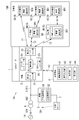
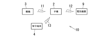
- FIG. 1 is a block diagram illustrating a configuration of a power management system according to a first embodiment.
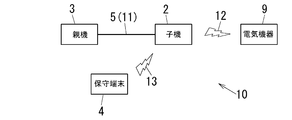
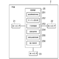
- FIG. 2 is a system configuration diagram illustrating an operation of the power management system according to the first embodiment. It is a block diagram which shows the subunit
- FIG. It is a schematic block diagram which shows the usage example of the subunit
- FIG. FIG. 5 is a diagram illustrating a setting example of an initial channel in the example illustrated in FIG. 4.
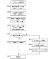
- FIG. 6 is an operation explanatory diagram illustrating a channel setting procedure in the slave unit according to the first embodiment. It is a figure which shows the example of a channel setting in the example shown in FIG. It is a figure which shows the example of a channel setting in the example shown in FIG.
- FIG. 6 is a system configuration diagram illustrating an operation of a power management system according to a second embodiment.
- the power management system 10 of the present embodiment is supplied from a power source (commercial AC power source in the present embodiment) 14 to a predetermined location (the customer 100 in the present embodiment) through the distribution line 5.
- Meter reading data including the electric energy is collected from the electric power meter 1 that measures the electric energy.
- the power source 14 is not limited to a commercial AC power source.
- the predetermined place is not limited to the customer 100.
- the power management system 10 of the present embodiment includes a slave unit (communication device) 2, a host device 30, and a communication terminal (maintenance terminal) 4.
- mobile_unit 2 is comprised so that the meter-reading data containing an electric energy may be acquired from the electric power meter 1.
- the slave unit 2 includes a first interface unit 21, a second interface unit 22, a third interface unit 23, a meter interface unit 24, and a control unit 25. And having.
- the first interface unit 21 is used for communication with the host device 30. That is, the first interface unit 21 is configured to communicate with the host device 30.
- the first interface unit 21 is realized by, for example, hardware and software necessary for communicating with the host device 30.
- the 2nd interface part 22 is used for communication with the electric equipment 9 installed in a predetermined place (customer 100). That is, the second interface unit 22 is configured to communicate with the electrical device 9. In the present embodiment, the second interface unit 22 is configured to perform wireless communication using radio waves with the communication terminal 4. The second interface unit 22 is realized by hardware and software necessary for communicating with the electrical device 9, for example.
- the electric equipment 9 does not necessarily need to be fixedly installed in a predetermined place.
- the electric device 9 may be installed at a predetermined place so as to be portable, and it is only necessary that the electric device 9 can be used at the predetermined place.
- the third interface unit 23 is used for communication with the communication terminal 4. That is, the third interface unit 23 is configured to communicate with the communication terminal 4.
- the third interface unit 23 is configured to perform wireless communication using radio waves with the communication terminal 4.
- the third interface unit 23 is realized by hardware and software necessary for communicating with the communication terminal 4, for example.
- the meter interface unit 24 is used for communication with the power meter 1. That is, the meter interface unit 24 is configured to communicate with the power meter 1. For example, the meter interface unit 24 is configured to perform short-distance communication with the power meter 1 using infrared rays as a transmission medium.
- the meter interface unit 24 is realized by hardware and software necessary for communicating with the power meter 1, for example.
- the control unit 25 has a function of acquiring meter reading data from the power meter 1.
- the control unit 25 is configured to communicate with the power meter 1 through the meter interface unit 24 and acquire meter reading data from the power meter 1. Further, the control unit 25 controls the first interface unit 21 to transmit meter reading data to the host device 30, and controls the third interface unit 23 to transmit meter reading data to the communication terminal 4. Have.
- the power meter 1 is connected to the power source 14 via a transformer (step-down transformer) 6 that adjusts the power from the power source 14 to a power suitable for a predetermined place (the customer 100). Therefore, the distribution line 5 includes a distribution line (first line) 501 between the power supply 14 and the transformer 6 and a distribution line (second line) 502 between the transformer 6 and the power meter 1.
- the host device 30 is connected to the second line 502.
- the host device 40 includes a parent device 3 connected to the distribution line 5 (second line 502) and a host server 8 connected to the parent device 3.
- the master unit 3 has a function of acquiring meter reading data from the slave unit 2 and a function of transmitting meter reading data acquired from the slave unit 2 to the upper server 8.
- the upper server 8 is configured to store the meter reading data received from the parent device 3.
- the communication terminal 4 has a function of acquiring meter reading data from the slave unit 2 and a function of communicating with the electrical device 9.
- the power management system 10 of the present embodiment includes a slave unit 2 attached to the power meter 1, a master unit 3 that acquires meter reading data of the power meter 1 from the slave unit 2, and the slave unit 2. And a maintenance terminal 4 for acquiring meter reading data.
- mobile_unit 2 is attached to the electric power meter 1 means that the subunit
- mobile_unit 2 preferably shares the electric power meter 1 and a housing
- the customer 100 is each dwelling unit of the apartment
- the present invention is not limited to this example, and the customer 100 may be a detached house, an office, a factory, or the like.
- the power meter 1 is connected to a distribution line 5 to which commercial power from an electric power company (electricity company) is supplied, and measures the amount of power used by the customer 100.
- the power meter 1 constitutes a so-called smart meter together with the slave unit 2, and the master unit 3 connected to the distribution line 5 and the slave unit 2 communicate to transmit meter-reading data to the power company to perform remote meter reading. Etc. are possible.
- the meter reading data includes at least the amount of electric power (the amount of electric power used by the customer 100) measured within a predetermined period by the electric power meter 1.
- Communication between the slave unit 2 and the master unit 3 is realized by power line communication (PLC) that performs communication using the distribution line 5 as a transmission medium. That is, the first communication path 11 using the distribution line 5 (second line 502) on the upstream side of the power meter 1 as a transmission medium is formed between the slave unit 2 and the master unit 3, and the slave unit 2 Transmits the meter reading data to the parent device 3 by performing power line carrier communication with the parent device 3 through the first communication path 11.
- the slave unit 2 has a function of communicating not only with the master unit 3 but also with the maintenance terminal 4 and the electrical device 9 used in the customer 100.
- mobile_unit 2 communicates with the 1st interface part 21 which communicates with the main
- the first interface unit 21 performs power line carrier communication with the parent device 3 through the first communication path 11 using the distribution line 5 on the upstream side of the power meter 1 as a transmission medium. Configured to do.
- the second interface unit 22 bi-directionally passes through the second communication path 12 using radio waves as a transmission medium with the electric device 9 having a communication function among the electric devices used by the customer 100. It is configured to perform wireless communication.
- the third interface unit 23 is configured to perform two-way wireless communication with the maintenance terminal 4 through the third communication path 13 using radio waves as a transmission medium.
- the first interface unit 21, the second interface unit 22, and the third interface unit 23 exchange packets composed of a header, a payload, and a trailer, respectively.
- the header includes information for identifying a channel set for each of the first communication path 11, the second communication path 12, and the third communication path 13. That is, a frequency for transmitting information is assigned to each communication channel as a channel.
- a time slot that is a time zone obtained by dividing a communication period into a plurality of times is also used as a communication channel. If a different channel is assigned to each communication path, information is transmitted without interfering with each other between the different communication paths.
- mobile_unit 2 is further provided with the meter interface part 24 for acquiring a measurement result from the electric power meter 1, and the control part 25 which controls operation
- the control unit 25 mainly includes a device such as a microcomputer having a processor that operates according to a program, and implements various functions by executing predetermined programs.
- the meter interface unit 24 enables data exchange with the power meter 1 by, for example, a wired connection to an extension terminal (not shown) of the power meter 1.
- the meter interface unit 24 is not limited to the configuration connected to the power meter 1 by wire, and may be configured to perform wireless communication with the power meter 1, and the display portion of the power meter 1 is imaged with a camera (not shown). The configuration may be such that the measurement result is read from the image by image processing.
- mobile_unit 2 acquires the measurement result of the electric power meter 1 in the meter interface part 24, and transmits this measurement result to the main
- mobile_unit 2 has a memory
- step-down transformer 6 provided in a power pole (not shown) installed in the vicinity of the customer 100, and after being stepped down by the step-down transformer 6, demand is supplied through the distribution line 5. Supplied to the house 100.
- the step-down transformer 6 may be buried in the ground, or housed in a metal box and installed on the ground.
- the base unit 3 is installed in the vicinity of the step-down transformer 6 that supplies commercial power to the customer 100 (for example, a utility pole), and provides a power company or a total amount of power service via a dedicated line 7 using an optical fiber or the like.
- Meter reading data is transmitted to the upper server 8 operated by the operator. That is, the master unit 3 acquires meter reading data from the power meter 1 of one or more consumers 100 and transmits the acquired meter reading data to the upper server 8 through the dedicated line 7.
- the master unit 3 includes a lower communication unit 31 that communicates with the child device 2 and an upper communication unit 32 that communicates with the upper server 8, and the meter reading data received by the lower communication unit 31 is transmitted to the upper communication unit.
- the data is transmitted from the unit 32 to the upper server 8.
- the lower communication unit 31 is connected to the distribution line 5 connected to the secondary side of the step-down transformer 6, and the first interface unit of the slave unit 2 using the distribution line 5 as the first communication path 11. 21 to communicate.
- the upper communication unit 32 is connected to the dedicated line 7.
- base station 3 has a memory
- a base unit 3 may be provided on the secondary side of each step-down transformer 6, and the base unit 3 may be an electrical room in the building or a management room. It is placed in a human room.
- the host server 8 includes a server computer that collects meter reading data from the power meters 1 of a plurality of consumers 100 within the management range, and the host server 3 that acquires the meter reading data from the power meters 1 of one or more consumers 100.
- the apparatus 30 is configured.
- the host device (the master unit 3 and the host server 8) 30 is connected to the first interface unit 21 of the slave unit 2 through the first communication path 11 formed by the distribution line 5 with the slave unit 2.
- the meter reading data is acquired from the slave unit 2 by performing power line carrier communication.
- a management server (not shown) provided for each region may be interposed between the parent device 3 and the upper server 8.
- the management server collects meter reading data from the parent device 3 for each region, and the upper server 8 efficiently collects the meter reading data of the customers 100 in a plurality of regions by collecting the meter reading data from the plurality of management servers. Can be collected.
- the management server is also included in the host device 30.
- these electrical devices 9 display the measurement result of the power meter 1 to visualize the amount of power used by the customer 100 or suppress the peak of energy demand (peak cut) from the power company side, for example.
- the operation can be controlled based on the signal.
- the electric device 9 As a specific example of the electric device 9, as shown in FIG. 1, it is connected to first devices 91 and 92 for displaying measurement results (meter reading data) and the like of the power meter 1 and various loads of the customer 100.
- a second device 93 including a HEMS (Home Energy Management System) device.
- one first device 92 communicates with the child device 2 via the repeater 94, so that the combination of the first device 92 and the repeater 94 also constitutes the electric device 9.
- the second device 93 communicates with the slave unit 2 via the measurement unit 95 installed in the distribution board 90, the combination of the second device 93 and the measurement unit 95 also constitutes the electric device 9. To do.
- the measurement unit 95 may be used alone as the electrical device 9.
- Each of these electrical devices 9 has a wireless communication unit 901 in order to realize a communication function with the slave unit 2.
- the first device 91 performs wireless communication directly with the second interface unit 22 of the slave unit 2 in the wireless communication unit 901, and the first device 92 performs the second communication of the slave unit 2 in the wireless communication unit 901.
- Wireless communication is performed via the interface unit 22 and the wireless communication unit 901 of the repeater 94.
- the measurement unit 95 performs wireless communication directly with the second interface unit 22 of the slave unit 2 through the wireless communication unit 901 and further performs wireless communication with the wireless communication unit 901 of the second device 93.
- the first devices 91 and 92 have a function of displaying the meter reading data received from the slave unit 2 on its own display unit (not shown), or displaying it on the housing information panel or TV of the customer 100. have.
- the second device 93 has a function of transmitting power consumption information and the like of each load to the power company via the slave unit 2 and controlling the operation of each load.
- the measurement unit 95 has a function of measuring the amount of power used for each branch circuit, and when receiving a signal for peak cut from the slave unit 2, based on the current power used by each branch circuit, A signal for controlling the load is transmitted to the second device 93. Thereby, the 2nd apparatus 93 can control operation
- the first devices 91 and 92 may have a function of performing various settings of the second device 93 by communicating with the second device 93. In this case, it is possible for the first devices 91 and 92 to determine the load control content by the second device 93.
- the maintenance terminal 4 is carried by an operator of an electric power company and is generally used for maintenance and inspection of the electric power meter 1 and the slave unit 2. Furthermore, in the power management system 10 of the present embodiment, the maintenance terminal 4 is also used for meter reading work (so-called on-site meter reading) performed by an operator at the site (customer 100). That is, the worker carrying the maintenance terminal 4 can cause the maintenance terminal 4 to read out the measurement result (meter reading data) of the power meter 1 by causing the maintenance terminal 4 to communicate with the slave unit 2 at the customer 100. it can.
- the maintenance terminal 4 stores a wireless communication unit 41 that communicates with the slave unit 2, an operation input unit 42 that receives human operation inputs, a display unit 43 that performs various displays, and read meter reading data and the like.
- Storage unit 44 Accordingly, the maintenance terminal 4 directly performs wireless communication with the third interface unit 23 of the slave unit 2 in the wireless communication unit 41 according to the operation input to the operation input unit 42, and displays the read meter reading data and the like on the display unit 43. And stored in the storage unit 44.
- the maintenance terminal 4 can also perform maintenance, inspection, change of various settings, and the like of the power meter 1 and the slave unit 2 using the operation input unit 42 and the display unit 43.
- the maintenance terminal 4 is used by a power company operator for meter reading, maintenance, inspection, etc. at the site (customer 100), so communication with the slave unit 2 is possible only at a short distance of about several meters. Near field communication. Further, the maintenance terminal 4 identifies the slave unit 2 using information (for example, a meter number) for identifying the power meter 1 assigned in advance for each power meter 1. Therefore, when the maintenance terminal 4 communicates with the subunit
- the company manages the electric device 9 and the second communication path 12 by the customer 100.
- the first communication path 11 is included in the information provision route (so-called A route) between the power meter 1 and the power company.
- the second communication path 12 is included in an information provision route (so-called B route) that enables direct acquisition from the power meter 1.
- the 2nd interface part 22 which communicates with the electric equipment 9, and the 3rd interface part 23 which communicates with the maintenance terminal 4 are the same.
- Wireless communication is performed using a communication protocol. That is, the second interface unit 22 and the third interface unit 23 are configured to perform wireless communication using radio waves. Further, the second interface unit 22 is configured to use the same communication protocol as the third interface unit 23.
- the second interface unit 22 and the third interface unit 23 use the same frequency band, modulation method, and the like through the second communication path 12 and the third communication path 13 each using radio waves as a medium.
- the communication protocol is the same.
- the second interface unit 22 and the third interface unit 23 communicate with the electrical device 9 or the maintenance terminal 4 using the 920 MHz band of the specific low power wireless specification. Since the 2nd interface part 22 and the 3rd interface part 23 are used only for the communication in the consumer 100 vicinity, the transmission output is set to 20 mW, for example.
- interference may occur. If they are different, interference can be avoided.
- the second interface unit 22 and the third interface unit 23 use the same communication protocol, but the second communication path 12 and the third communication path 13 form independent communication paths. As described above, wireless communication is performed using different channels.
- a communication protocol that defines (has) a plurality of different channels is used for the second interface unit 22 and the third interface unit 23 .
- the second interface unit 22 and the third interface unit 23 are configured to perform wireless communication using different communication channels.
- Different communication channels are selected from a plurality of channels defined in the communication protocol so that interference between the radio wave from the second interface unit 22 and the radio wave from the third interface unit 23 does not occur. Note that “no interference occurs” not only means that interference does not occur in a strict sense, but also includes the meaning that interference does not occur substantially.
- the second interface unit 22 and the third interface unit 23 may be configured to perform wireless communication according to the same communication protocol using a communication path using radio waves as a transmission medium, and are limited to the above-described 920 MHz band.
- Various communication rules can be applied.
- standards such as WiFi (registered trademark), ZigBee (registered trademark), and Bluetooth (registered trademark) may be applied to the second interface unit 22 and the third interface unit 23.
- mobile_unit 2 of the power management system 10 uses the same communication protocol by the 2nd interface part 22 and the 3rd interface part 23, the 2nd interface part 22 and the 3rd interface part 23, Can be configured by one communication module 26.
- the second interface unit 22 and the third interface unit 23 are provided in one communication module 26, and the slave unit 2 includes both the electric device 9 and the maintenance terminal 4 in one communication module 26. It becomes possible to communicate with. Note that whether the communication module 26 operates as the second interface unit 22 or the third interface unit 23 can be switched by, for example, an instruction from the control unit 25 to the communication module 26.
- mobile_unit 2 acquires meter-reading data for every fixed time (for example, every 1 minute, every 5 minutes, every 10 minutes, etc.) from the electric power meter 1 (refer FIG. 1), and for a fixed period for a memory
- the master unit 3 can communicate with a plurality of slave units 2 connected to the first communication path 11 including the distribution line 5, and communicates with each slave unit 2 through the first communication path 11.
- the meter reading data is periodically collected from the plurality of slave units 2 (so-called periodic meter reading).
- periodic meter reading For example, at a specified time (for example, 0 o'clock) every day, the base unit 3 requests the slave unit 2 to transmit meter reading data by power line carrier communication, and receives meter reading data from the slave unit 2 as a response thereto. It memorize
- the master unit 3 acquires meter reading data from all the slave units 2 connected to the distribution line 5
- the acquired meter reading data is aggregated to generate meter reading information, and the meter reading information is used as a dedicated line 7 (see FIG. 1).
- To the upper server 8 see FIG. 1).
- the slave unit 2 has a function of transmitting stored meter reading data to the maintenance terminal 4 even in response to a request from the maintenance terminal 4. That is, the maintenance terminal 4 requests the slave unit 2 to transmit meter reading data by wireless communication through the third communication path 13, and acquires meter reading data by receiving meter reading data from the slave unit 2 as a response thereto. (On-site meter reading). In short, when the periodic meter reading by the master unit 3 fails, the operator can perform on-site meter reading at the maintenance terminal 4 so that the leaked meter reading data can be interpolated.
- the maintenance terminal 4 also has a communication function with the electric device 9, and communicates with the electric device 9 via the third communication path 13, the slave unit 2, and the second communication path 12.
- the maintenance terminal 4 transmits, for example, instruction data such as a setting change for the electrical device 9 to the slave unit 2 through the third communication path 13, and this instruction data is transmitted from the slave unit 2 through the second communication path 12. It can be transferred to the electric device 9.
- the maintenance terminal 4 can also receive reply data from the electrical device 9 via the slave unit 2.
- mobile_unit 2 transmits the measurement result of the electric power meter 1 to the electric equipment 9, for example by performing radio
- the amount can be displayed on the electrical device 9.
- mobile_unit 2 transmits the signal from the electric power company side transmitted via the main
- the master unit 3 requests the slave unit 2 for information on the electrical device 9 of the customer 100 through the first communication path 11, so that the slave unit 2 acquires from the electrical device 9 through the second communication path 12. It is also possible to collect information on the electrical device 9. Further, the maintenance terminal 4 transmits the meter reading data acquired by the on-site meter reading to the slave unit 2 through the third communication path 13 and transfers the meter reading data from the slave unit 2 to the master unit 3 through the first communication path 11. It is also possible.
- the maintenance terminal 4 makes a request for changing communication settings such as a communication level such as a frequency band, a modulation method, a transmission output, and a reception sensitivity applied by the second interface unit 22 and the third interface unit 23, You may have the function to transmit with respect to the subunit
- the worker changes the communication settings of the second interface unit 22 and the third interface unit 23 according to the communication state between the slave unit 2 and the electrical device 9 and the maintenance terminal 4 in the customer 100. Can do.
- the slave unit 2 attached to the power meter 1 can communicate not only with the master unit 3 and the maintenance terminal but also with the electrical device 9 used in the customer 100. Become. Therefore, for example, the electrical device 9 displays the measurement result of the power meter 1 to visualize the amount of power used by the customer 100, or suppresses the peak of energy demand (peak cut) to a signal from the power company side. It is possible to control the operation based on this.
- the handset 2 since the handset 2 uses the same communication protocol for the second interface unit 22 and the third interface unit 23, the second interface unit 22 and the third interface unit 23 are connected to each other. A single communication module 26 can be used. Therefore, the slave unit 2 is smaller and lower in comparison with the configuration in which the communication function with the electric device 9 is added to the communication function with the master unit 3 and the maintenance terminal 4 and three or more communication interfaces are provided. Cost can be reduced. That is, the slave unit 2 of the power management system 10 according to the present embodiment is not only used for the host device (master unit 3) 30 but also the electrical device 9 used by the customer 100 while avoiding an increase in size and cost. There is an advantage that communication is possible.
- power line carrier communication is used for communication between the child device 2 and the parent device 3, and wireless communication is used for communication between the child device 2, the maintenance terminal 4, and the electric device 9. Therefore, there is an advantage that traffic can be separated between the communication between the child device 2 and the parent device 3 and other communication. That is, in the power management system 10, it is possible to avoid the communication between the slave unit 2 and the master unit 3 from interfering with the communication between the slave unit 2 and the maintenance terminal 4 or the communication between the slave unit 2 and the electrical device 9.
- the power management system 10 since the subunit
- interface unit is described as “I / F” as necessary.
- the slave unit 2 in order for the higher-level device 30 to identify one or more slave units 2, the slave unit 2 needs to include identification information.
- This identification information is selected from an address for the handset 2 to communicate with the host device 30, a serial number set uniquely for the handset 2, a MAC address set for the handset 2 capable of communication, and the like.
- the identification information only needs to be set uniquely in the slave unit 2 managed by the host device 30, and more specifically, it may be unique in the slave unit 2 managed by the master unit 3.
- mobile_unit 2 is provided with the identification information holding
- illustration of meter I / F24 is abbreviate
- the base unit 3 issues a communication address to the managed slave unit 2 and uses this address for identification information
- the master unit 3 issues an address used by the slave unit 2 for communication with the host device 30 (A route communication).
- the base unit 3 issues an address when the address request is received from the handset 2, and notifies the address to the handset 2 that has made the address request.
- the base unit 3 issues addresses to the handset 2 in the order in which the address requests are received, and an integer value representing the order of issue is used as the address.
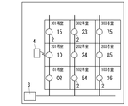
- FIG. 4 shows an example in which the slave unit 2 is arranged in each dwelling unit (customer 100) of the apartment house, and the numerical value described on the right side of the slave unit 2 represents the address issued by the master unit 3.
- the squares shown in FIG. 4 schematically show the separation of the dwelling units, and “--No. Room” shown in the squares represents the dwelling unit number.
- one master unit 3 is provided in the building of the apartment house, and meter reading data is collected from the slave units 2 respectively arranged in the dwelling units of the apartment house.
- the base unit 3 assigns addresses to the handset 2 in the order in which the address requests are received, as illustrated in FIG. 4, the physical position of the unit represented by the unit number, There is no relationship with the address of handset 2. As described above, if the address is not required to have a relationship with the dwelling unit number, the operation of assigning the address to the slave unit 2 is simplified, and the introduction of the system is facilitated.
- the communication range must be restrict
- the communication range between the slave unit 2 and the maintenance terminal 4 is not limited so that the maintenance terminal 4 does not communicate with other slave units 2 during the period in which the slave unit 2 communicates with the maintenance terminal 4. Don't be.
- a technology for limiting the communication range a technology for determining a channel used in the communication range, a technology for adjusting one of the output power (transmission output) on the transmission side and the reception sensitivity on the reception side, and an encryption key used in the communication range are distributed. Technology is known.
- the communication range is not limited to the case where the second I / F 22 and the third I / F 23 use radio waves as a transmission medium as in this embodiment, but also power line carrier communication using the distribution line 5 as a transmission medium. May also be necessary.
- a technique for determining a channel will be described, and then a technique for adjusting at least one of output power and reception sensitivity will be described.
- mobile_unit 2 selects the channel used by 2nd I / F22 and 3rd I / F23 from the some channel of the selection range prepared beforehand.
- the third I / F 23 is not always used. Therefore, when the third I / F 23 uses the same channel in all the slave units 2 and the third I / F 23 is not used, this channel is made available for the second I / F 22. It is desirable.
- the channel is defined by at least one of frequency and time slot. That is, the handset 2 uses a plurality of types of frequencies, a plurality of types of time slots, a plurality of types of frequencies, and a plurality of types of time slots as channels used by the second I / F 22 and the third I / F 23.
- One of the combinations is defined as a parameter of the selection range. That is, a channel may be a frequency, a time slot, or a combination of frequency and time slot.
- mobile_unit 2 equips the control part 25 with the channel selection part 252 which selects the channel used with an own machine from the some channel of the selection range prepared beforehand.
- the control unit 25 of the slave unit 2 selects a communication channel (first communication channel) used for wireless communication (wireless communication by the third interface unit 23) from a plurality of channels.
- a channel selection unit 252 is provided.
- the channel selection unit 252 is configured to designate a communication channel (second communication channel) used for the second wireless communication (wireless communication by the second interface unit 22).
- the channel selection unit 252 selects the same channel as the first communication channel and the second communication channel.
- the channel selection unit 252 only needs to be configured to select a communication channel used for at least one wireless communication between the second interface unit 22 and the third interface unit 23 from a plurality of channels.
- an integer value of 0 or more associated with the parameter of the selection range described above is used.
- the format representing the channel is not limited, but the channel can be easily designated by using an integer value.
- the slave unit 2 Before determining the channel to be used, the slave unit 2 performs preprocessing for provisionally setting the channel, evaluates interference in the case of performing communication using the channel set in the preprocessing, and then determines if necessary according to the evaluation result. Post-processing to change the channel. That is, handset 2 performs a two-stage process of provisionally setting a channel (hereinafter referred to as “initial channel”) by pre-processing and appropriately changing the initial channel so that interference does not occur by post-processing. .
- the handset 2 has an interference evaluation unit 253 for evaluating the degree of interference when using the provisionally set initial channel, and a channel selection unit 252 when there is a possibility of interference.
- the control unit 25 includes a change instruction unit 254 for instructing channel change. That is, as shown in FIG. 3, the control unit 25 of the child device 2 includes an interference evaluation unit 253 and a change instruction unit 254.
- the interference evaluation unit 253 is configured to determine whether or not radio wave interference occurs regarding the communication channel. For example, the interference evaluation unit 253 obtains an evaluation value indicating the degree of interference, and evaluates the degree of interference by comparing the evaluation value with a prescribed threshold value.
- RSSI Received Signal Strength Indication
- frequency time slot
- time slot time slot
- a standard for evaluating the degree of interference can be obtained by digitizing these pieces of information as evaluation values.
- the evaluation value is determined so as to increase monotonously according to the degree of interference.
- the interference evaluation unit 253 compares the evaluation value with a threshold value, and if the evaluation value exceeds the threshold value, it determines that the degree of interference is large and the channel needs to be changed.
- the change instruction unit 254 is configured to give a change instruction to the channel selection unit 252 when the interference evaluation unit 253 determines that radio wave interference occurs. For example, when the interference evaluation unit 253 determines that the channel needs to be changed (that is, when the evaluation value exceeds the threshold value), the change instruction unit 254 changes the channel selected to the channel selection unit 252. Instruct. Further, the change instruction unit 254 is configured not to give a change instruction to the channel selection unit 252 unless the interference evaluation unit 253 determines that radio wave interference occurs. For example, if the evaluation value is equal to or less than the threshold value in the interference evaluation unit 253, the change instruction unit 254 uses the channel selected by the channel selection unit 252 for communication.
- the channel selection unit 252 is configured to change the communication channel upon receiving a change instruction from the change instruction unit 254.
- the channel selection unit 252 is configured to select an initial channel as a communication channel candidate from a plurality of channels based on the identification information stored in the identification information holding unit 251.
- the channel selection unit 252 is configured to select a channel different from the initial channel from a plurality of channels and adopt it as a communication channel. If the channel selection unit 252 does not receive the change instruction from the change instruction unit 254, the channel selection unit 252 is configured to adopt the initial channel as the communication channel.
- the illustrated example shows a state in which the parent device 3 has issued identification information to the child device 2 in accordance with an address request from the child device 2, and the child device 2 uses the identification information issued by the parent device 3 as the identification information holding unit 251. Hold on.
- the channel selection unit 252 selects a channel corresponding to the least significant digit of the two-digit integer value held in the identification information holding unit 251 as the initial channel.
- two-digit identification information (address) issued under the management of the parent device 3 is set, such as “02”, “54”,..., “15”, “23”. Since these pieces of identification information are issued so that the parent device 3 does not overlap, they do not overlap in the management range of the parent device 3.
- the channel selection unit 252 of the handset 2 uses the channel that matches the least significant digit of the identification information as the initial channel, as shown in FIG. 5, as the initial channel, a single digit of “0” to “9” Set the channel corresponding to the numerical value.
- the same initial channel “04” is given to the 102 and 202 rooms adjacent vertically, and the same initial channel “05” is given to the 203 and 303 rooms adjacent vertically. It is done.
- the initial channel is determined by applying other rules such as using the least significant digit of the identification information given by an integer value and using a remainder obtained by dividing the identification information given by an integer value by an appropriate divisor. May be.
- the least significant digit is used for the initial channel, the number of selectable channels is ten.
- the initial channel is determined using a remainder, the number of selectable channels is determined by the divisor.
- the adjacent dwelling unit is set.
- the same channel may be set in the provided handset 2. That is, the initial channel may be set redundantly in a plurality of adjacent slave units 2, and if slave units 2 having the same initial channel are arranged adjacent to each other, interference may occur during communication. There is.
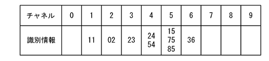
- the handset 2 obtains the received signal strength for all channels in the selected range, and the threshold value defined by the received signal strength Channels exceeding are stored as “busy channels”.
- the interference evaluation unit 253 performs the process of extracting the busy channel. In order to extract the channel in use, it is necessary to obtain the received signal strength for each channel, so the interference evaluation unit 253 sequentially detects the received signal strength of all the channels in the selected range.
- the interference evaluation unit 253 selects the slave unit 2 that uses the same channel as the initial channel of the own unit among the extracted in-use channels. Extract.
- mobile_unit 2 receives not only the channel of the other subunit
- the interference evaluation unit 253 determines that the identification information is set when the same initial channel is set in a plurality of slave units 2. Is used to select one slave unit 2 that uses the initial channel. That is, the interference evaluation unit 253 compares the size of the identification information when there are a plurality of slave units 2 in which the same initial channel is set and the received signal strength exceeds the threshold, and if the identification information of the own unit is minimum In the own device, the initial channel is continuously used as a communication channel. If the identification information of the own device is not the minimum, the interference evaluation unit 253 requests the channel selection unit 252 to change the channel through the change instruction unit 254.
- the interference evaluation unit 253 When the interference evaluation unit 253 requests the change instruction unit 254 to change the channel, the interference evaluation unit 253 first extracts a channel whose received signal strength is equal to or less than a set threshold from the channels that are the selection range. A channel whose received signal strength is less than or equal to the threshold is not used, or even if it is used, it is considered that no interference occurs. Therefore, the extracted channel is set as an “empty channel”. When a free channel is extracted, the interference evaluation unit 253 hands over the free channel information to the change instruction unit 254. That is, the interference evaluation unit 253 is configured to determine whether or not there is an empty channel that does not cause radio wave interference among the plurality of channels.
- the interference evaluation unit 253 is configured to provide the change instruction unit 254 with empty channel information for specifying an empty channel if there are empty channels in a plurality of channels. There may be a plurality of empty channels. In this case, the empty channel information identifies each of the plurality of empty channels.
- the change instruction unit 254 is configured to select a used empty channel used as a communication channel from the empty channels specified by the empty channel information, and to give a change instruction for designating the used empty channel to the channel selecting unit 252. For example, the change instruction unit 254 instructs the channel selection unit 252 to change the channel after the standby time determined according to the initial channel.
- the standby time is set to be shorter as the initial channel is smaller (for example, a time obtained by multiplying the unit time by the initial channel is set as the standby time).
- the channel selection unit 252 When the channel selection unit 252 receives the change instruction from the change instruction unit 254, the channel selection unit 252 is configured to adopt the available unused channel designated by the change instruction as the communication channel.
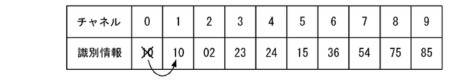
- the channel selection unit 252 selects the least significant digit as the initial channel from the identification information of the handset 2 given as an integer value (S11).
- the interference evaluation unit 253 sequentially detects the received signal strengths of all the channels in the selected range (S12), and extracts and stores the channels whose received signal strengths exceed the threshold as in-use channels (S13).
- the interference evaluation unit 253 extracts the identification information of the handset 2 whose used channel overlaps with the initial channel from the header of the packet (S14). When there is a handset 2 whose channel in use matches the initial channel and this handset 2 interferes, the size of the identification information of the handset 2 is compared (S15).
- the interference evaluation unit 253 extracts an empty channel by evaluating the received signal strength for all channels (S17).
- the change instruction unit 254 causes the channel selection unit 252 to set the channel used by the second I / F 22 to the minimum value of the empty channels after a predetermined waiting time (S18). Instruct (S19).
- the channel used by the second I / F 22 is selected by the channel selection unit 252 as described above, the operation of the slave unit 2 is started using the channel (S20).
- the initial channel is duplicated. Is not detected.
- reception is performed to the extent that the headers of the slave units 2 cannot be recognized. If the signal strength is small, the identification information of the handset 2 is not compared even if there is a possibility of interference.
- the slave unit 2 can communicate with the home electrical device 9 and the maintenance terminal 4 and communicate with other slave units 2. If it is not possible, it can be used without changing the initial channel.
- control unit 25 of the child device 2 performs a power communication instruction for adjusting output power of the communication quality evaluation unit 255 that performs test communication and evaluates communication quality, and the second I / F 22 and the third I / F 23. Part 256.
- the communication quality evaluation unit 255 is configured to evaluate the communication quality of the communication channel (first communication channel) selected by the channel selection unit 252. For example, the communication quality evaluation unit 255 performs test communication using the communication channel (first communication channel) selected by the channel selection unit 252, so that the communication quality (first number) in the communication path 13 with the communication terminal 4 is obtained. A communication quality of one communication channel).
- the power instruction unit 256 is configured to set the strength of the radio wave corresponding to the communication channel (first communication channel) to a lower limit value in a range where the communication quality evaluated by the communication quality evaluation unit 255 satisfies the specified condition. .
- the power instruction unit 256 receives a radio wave (corresponding to a communication channel) output from the third interface unit 23 within a range in which the communication quality (communication quality of the communication path 13) evaluated by the communication quality evaluation unit 255 satisfies a specified condition. Configured to reduce the strength of radio waves).
- the communication quality evaluation unit 255 is configured to evaluate the communication quality of the communication channel (second communication channel) selected by the channel selection unit 252. For example, the communication quality evaluation unit 255 performs test communication using the communication channel (second communication channel) selected by the channel selection unit 252, so that the communication quality (first in the communication path 12 with the electrical device 9 (first The communication quality of the two communication channels).
- the power instruction unit 256 has a lower limit value in a range where the communication quality (communication quality of the second communication channel) evaluated by the communication quality evaluation unit 255 for the strength of the radio wave corresponding to the second communication channel satisfies the specified condition.
- the power instruction unit 256 receives a radio wave (second communication channel) output from the second interface unit 22 within a range in which the communication quality evaluated by the communication quality evaluation unit 255 (communication quality of the communication path 12) satisfies a specified condition. Is configured to reduce the strength of the radio wave).
- the slave unit 2 When the slave unit 2 acquires the address for communication issued by the master unit 3 and an initial channel is set, first, the slave unit 2 performs test communication between the home electrical device 9 and the maintenance terminal 4 that it manages. Do. In addition, when the initial channel is set in the child device 2, it is assumed that the operator of the child device 2 carries the maintenance terminal 4 and the maintenance terminal 4 exists in the communication range of the child device 2. is doing.
- the slave unit 2 that performs the test communication decreases the output power when transmitting the packet with the passage of time, and a communication error rate, a retransmission rate, etc. for at least one of the second I / F 22 and the third I / F 23
- the communication quality evaluation unit 255 measures communication statistical information (communication quality). Furthermore, this subunit
- the slave unit 2 reduces the output power to the allowable lower limit in a range where the communication quality is good, the communication quality with the home electric device 9 and the maintenance terminal 4 is maintained. As a result, the probability that the handset 2 changes the initial channel is reduced, and no interference occurs in the number of handset 2 greater than the number of channels, although the number of selectable channels is limited. So that the channel can be set.
- the cordless handset 2 and the home electric device 9 can communicate with each other by linking (channel setting).
- the electric device 9 includes two operation modes: a registration mode in which a channel is set for associating with the child device 2 and a normal mode that operates using the set channel. In the registration mode, for example, the electric device 9 sequentially selects all the channels as time elapses until a packet that the slave unit 2 periodically transmits can be received.
- the electric device 9 selects the channel of the own child device 2 by comparing the information for identifying the power meter 1, and as a result, the child device 2 and the electric device 9 can be linked without error. Is possible.
- the electric device 9 can be received by the slave unit 2 of the other house. Is prevented from being tied.
- the electric device 9 shifts to the normal mode, and communicates with the child device 2 using the selected channel.
- the maintenance terminal 4 is used when, for example, an operator (meter meter) of an electric power company visits the meter reading of the electric power meter 1, and at this time, by communicating with the slave unit 2, the integrated value of the electric energy is obtained. Acquire the meter reading data. Therefore, the handset 2 must set a channel not only with the electrical device 9 but also with the maintenance terminal 4.
- the channels used by the maintenance terminal 4 are fixedly set, if the use of the channel assigned to the maintenance terminal 4 is prohibited in the slave unit 2, the channel selection range in the slave unit 2 is narrow. Become. In other words, it is not preferable to occupy one channel for the maintenance terminal 4 having a low usage frequency in consideration of the channel utilization efficiency although the number of selectable channels is limited.
- the channel assigned to the maintenance terminal 4 is assigned to the second I / F 22 and the electric device 9 during a period when the third I / F 23 does not communicate with the maintenance terminal 4. It can also be used for communication with.
- the handset 2 to which the channel used by the maintenance terminal 4 is set is detected to start using the maintenance terminal 4, the handset 2 hands over the channel to the maintenance terminal 4 and selects and uses another channel.
- the start of use of the maintenance terminal 4 is detected by receiving a radio wave transmitted from the maintenance terminal 4 when an operator of the power company starts the operation of the maintenance terminal 4 in the vicinity of the slave unit 2. Since the maintenance terminal 4 is used in the vicinity of the slave unit 2, it is possible for the slave unit 2 to receive a radio wave having a large electric field strength. The slave unit 2 receives the radio wave received by the third I / F 23. It is possible to detect the start of use of the maintenance terminal 4 by evaluating the electric field strength. Further, the maintenance terminal 4 may send a participation request packet to the slave unit 2 at the start of use, and allow the slave unit 2 to recognize the address of the maintenance terminal 4 included in the header of this packet.
- the change instruction unit 254 instructs the channel selection unit 252 to indicate that the slave unit 2 in which the channel used by the maintenance terminal 4 is set has elapsed. As a result, all channels are selected in turn.
- the third interface unit 23 is configured to determine whether or not the use of the communication terminal (maintenance terminal) 4 has been started. If the change instruction unit 254 determines that the use of the communication terminal 4 is started in the third interface unit 23, the change instruction unit 254 specifies a channel used by the communication terminal 4 and a channel that does not cause interference as the second communication channel. Is provided to the channel selector 252. The channel selection unit 252 is configured to change the second communication channel to the channel designated by the change instruction unit 254 when receiving the change instruction from the change instruction unit 254.
- the interference evaluation unit 253 monitors the received signal strength for each channel during the period in which the change instruction unit 254 sequentially selects the channels.
- This handset 2 detects a channel whose received signal strength is equal to or less than a threshold value (reference value) as a free channel, and allocates a free channel as a channel used in the second I / F 22.
- a threshold value reference value
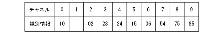
- the channel used by the maintenance terminal 4 is “0”.
- the identification information of the slave unit 2 in room 201 is “10”, the least significant digit of the identification information is “0”.
- the channel used in the second I / F 22 in the slave unit 2 is also a channel corresponding to “0”. Therefore, the handset 2 in the room 201 uses the same channel as the maintenance terminal 4 for communication with the electrical device 9.
- channel “1” does not use any slave unit 2
- the channels used by Room 103, Room 203, and Room 303 are the received signal strengths of Unit 2 slave unit 2. Is not interfered by being out of range. That is, if channels are assigned to each slave unit 2 as shown in FIG. 7, the empty channels in the slave unit 2 in the room 201 are channel “1”, channel “6”, channel “8”, channel There will be four "9".
- the change instructing unit 254 of the handset 2 hands over the right to use the channel “0” used in the second I / F 22 to the maintenance terminal 4 and assigns the channel used for communication with the electrical device 9 to an empty channel. Search from.
- the slave unit 2 changes the channel (second communication channel) for communicating with the electrical device 9 to the channel “1” as shown in FIG.
- the rules for selecting a channel by the handset 2 may be set as appropriate, and other free channels can be selected.
- mobile_unit 2 changes the channel for communicating with the electric equipment 9, it notifies the electric equipment 9 prior notice before changing the channel, and also instructs the electric equipment 9 to change the channel. . Since the electric device 9 and the child device 2 need to be linked, the packet transmitted from the child device 2 to the electric device 9 for instructing the channel change includes information for identifying the power meter 1. Thus, the electric device 9 confirms that the slave unit 2 is a communication partner.
- mobile_unit 2 returns the channel to be used to the channel before a change, after communication with the maintenance terminal 4 is complete
- mobile_unit 2 performs the advance notice regarding the change of a channel with respect to the electric equipment 9, before returning a channel.
- the handset 2 using the same channel as that of the maintenance terminal 4 temporarily changes the channel used when communicating with the maintenance terminal 4.
- the channel used by the maintenance terminal 4 can be used as the channel used by the child device 2, and the channel utilization efficiency in the child device 2 is increased.
- indicates to perform the test communication similar to the test communication which the subunit
- the communication quality evaluation unit 255 of the handset 2 that has instructed the test communication monitors the received signal strength from the electrical device 9 and the maintenance terminal 4, and the electrical device 9 The communication quality is acquired from the maintenance terminal 4.
- the communication quality means communication statistical information such as a communication error rate or a retransmission rate.
- the communication quality evaluation unit 255 of the child device 2 evaluates at least one of the received signal strength and the communication quality by comparing with the threshold value, and reduces the output power to the allowable lower limit for the electrical device 9 and the maintenance terminal 4. To instruct. In this way, when the handset 2 sets a channel, the electric power 9 and the maintenance terminal 4 also reduce the output power (transmission output) to the allowable lower limit. The possibility of being tied to 2 is reduced. That is, it is possible to avoid the interference of the home electric device 9 and the maintenance terminal 4 with respect to the other handset 2 in advance.
- the slave unit 2 of the power management system 10 of the present embodiment is attached to the power meter 1 that measures the amount of power used by the customer 100 and includes the amount of power measured by the power meter 1.
- This is a slave unit of the power management system having a function of transmitting meter reading data to the host device 30.
- mobile_unit 2 has the 1st interface part 21, the 2nd interface part 22, and the 3rd interface part 23.
- the first interface unit 21 is configured to communicate with the host device 30 through the first communication path 11.
- the second interface unit 22 performs wireless communication with the electric device 9 having a communication function among the electric devices used by the customer 100 through the second communication path 12 using a radio wave as a transmission medium. Composed.
- the third interface unit 23 is configured to perform wireless communication with the maintenance terminal 4 having at least a function of acquiring meter reading data through the third communication path 13 using radio waves as a transmission medium.
- the second interface unit 22 and the third interface unit 23 are configured to perform wireless communication using the same communication protocol.
- the 1st interface part 21 is a high-order apparatus through the 1st communication path 11 which used the distribution line 5 of the upstream of the electric power meter 1 for the transmission medium. Power line carrier communication with 30 is performed.
- the 1st communication path 11 is a distribution line (2nd track
- the high-order apparatus 30 has the high-order server 8 which consists of a server computer which collects meter-reading data from the power meter 1 of the some customer 100 in a management range, and high-order.
- a master unit 3 having a communication function with the server 8 and transmitting meter reading data acquired from the power meter 1 of one or more consumers 100 to the host server 8 is provided.
- the maintenance terminal 4 has a communication function with the electrical device 9.
- mobile_unit 2 of the power management system 10 of this embodiment is further provided with the channel selection part 252, the interference evaluation part 253, and the change instruction
- the channel selection unit 252 is configured to select a communication channel used by the second interface unit 22 and the third interface unit 23 from a selection range prepared in advance.
- the interference evaluation unit 253 is configured to evaluate the degree of interference by comparing an evaluation value representing the degree of interference when the channel selected by the channel selection unit 252 is used with a prescribed threshold value.
- the change instruction unit 254 is configured to instruct the channel selection unit 252 to change the selected channel when the evaluation value is on the side where the degree of interference is larger than the threshold value.
- mobile_unit 2 of the power management system 10 of this embodiment is further provided with the identification information holding
- the identification information holding unit 251 is configured to hold identification information that is unique within the management range of the host device 30.
- the channel selection unit 252 is configured to select a channel obtained from the identification information held by the identification information holding unit 251 using a predetermined rule as an initial channel.
- the channel selection unit 252 selects a communication channel different from the initial channel if there is a change instruction from the change instruction unit 254, and selects the initial channel as a communication channel if there is no change instruction from the change instruction unit 254. Configured to do.
- the interference evaluation part 253 delivers the information of an empty channel to the change instruction
- the change instruction unit 254 is configured to instruct the channel selection unit 252 to change to a channel selected from the empty channels delivered from the interference evaluation unit 253.
- indication part 254 is a 3rd interface.
- the channel selection unit 252 is instructed to temporarily change the channel used by the second interface unit 22 to an empty channel that does not cause interference.
- mobile_unit 2 of the power management system 10 of this embodiment is further provided with the communication quality evaluation part 255 and the electric power instruction
- the communication quality evaluation unit 255 is configured to evaluate the communication quality in the communication path 12 with the electrical device 9 by performing test communication using the channel selected by the channel selection unit 252.
- the power instruction unit 256 is configured to reduce the output power of the second interface unit 22 to an allowable lower limit within a range where the communication quality is good.
- the channel selection unit 252 may select a frequency used for communication. Moreover, the channel selection part 252 may select the time slot used for communication. Further, the channel selection unit 252 may select a combination of a frequency and a time slot used for communication.
- the identification information held by the identification information holding unit 251 is assigned from the host device 30.
- the handset 2 of the power management system 10 of the present embodiment has the following first to twelfth characteristics.
- the second to twelfth features are arbitrary features.
- the slave unit 2 receives meter reading data including the amount of power from the power meter 1 that measures the amount of power supplied from the power source (commercial AC power source) 14 to the predetermined place (the customer 100) through the distribution line 5. It is a slave unit of the power management system to collect.
- mobile_unit 2 is provided with the 1st interface part 21, the 2nd interface part 22, the 3rd interface part 23, and the control part 25.
- the first interface unit 21 is configured to communicate with the host device 30.
- the 2nd interface part 22 is comprised so that it may communicate with the electric equipment 9 installed in a predetermined place (customer 100).
- the third interface unit 23 is configured to communicate with the communication terminal 4.
- the control unit 25 has a function of acquiring meter reading data from the power meter 1, a function of controlling the first interface unit 21 to transmit meter reading data to the host device 30, and a function of controlling the third interface unit 23 to read the meter. And a function of transmitting data to the communication terminal 4.
- the second interface unit 22 and the third interface unit 23 are configured to perform wireless communication using radio waves.
- the second interface unit 22 and the third interface unit 23 are configured to use the same communication protocol.
- the communication protocol used for the second interface unit 22 and the third interface unit 23 in the first feature is a communication protocol that defines a plurality of different channels.
- the second interface unit 22 and the third interface unit 23 are configured to perform wireless communication using different communication channels. Different communication channels are selected from a plurality of channels so that interference between the radio wave from the second interface unit 22 and the radio wave from the third interface unit 23 does not occur.
- the first interface unit 21 is connected to the host device 30 through the distribution line 5 and performs power line carrier communication with the host device 30 through the distribution line 5. Configured.
- the power meter 1 is connected to the power source 14 via a transformer (step-down transformer) 6 that adjusts the power from the power source 14 to power suitable for a predetermined location.
- the distribution line 5 includes a first line 501 between the power source 14 and the transformer 6 and a second line 502 between the transformer 6 and the power meter 1.
- the host device 30 is connected to the second line 502.
- the first interface unit 21 is configured to perform power line carrier communication with the host device 30 through the second line 502.
- the control unit 25 further includes a channel selection unit 252, an interference evaluation unit 253, and a change instruction unit 254.
- the channel selection unit 252 is configured to select a communication channel used for at least one wireless communication between the second interface unit 22 and the third interface unit 23 from a plurality of channels.
- the interference evaluation unit 253 is configured to determine whether radio wave interference occurs regarding the communication channel.
- the change instruction unit 254 is configured to give a change instruction to the channel selection unit 252 when the interference evaluation unit 253 determines that radio wave interference occurs.
- the channel selection unit 252 is configured to change the communication channel when receiving the change instruction from the change instruction unit 254.
- the control unit 25 includes an identification information holding unit 251 that stores identification information unique to the slave unit 2.
- the channel selection unit 252 is configured to select an initial channel that is a communication channel candidate from a plurality of channels based on the identification information stored in the identification information holding unit 251.
- the channel selection unit 252 is configured to select a channel different from the initial channel from a plurality of channels and adopt it as a communication channel. If the channel selection unit 252 does not receive the change instruction from the change instruction unit 254, the channel selection unit 252 is configured to adopt the initial channel as the communication channel.
- the interference evaluation unit 253 is configured to determine whether or not there is an empty channel that does not cause radio wave interference in the plurality of channels.
- the interference evaluation unit 253 is configured to provide the change instruction unit 254 with empty channel information for specifying an empty channel if there are empty channels in a plurality of channels.
- the change instruction unit 254 is configured to select a used empty channel to be used as a communication channel from the empty channels specified by the empty channel information, and to give a change instruction to specify the used empty channel to the channel selecting unit 252.
- the channel selection unit 252 receives the change instruction from the change instruction unit 254, the channel selection unit 252 is configured to adopt the used free channel designated by the change instruction as the communication channel.
- control unit 25 further includes a communication quality evaluation unit 255 and a power instruction unit 256.
- the communication quality evaluation unit 255 is configured to evaluate the communication quality of the communication channel selected by the channel selection unit 252.
- the power instruction unit 256 is configured to set the strength of the radio wave corresponding to the communication channel to a lower limit value in a range where the communication quality evaluated by the communication quality evaluation unit 255 satisfies the specified condition.
- the communication channel is a channel used for wireless communication of the third interface unit 23.
- the channel selection unit 252 is configured to select a second communication channel used for wireless communication of the second interface unit 22 from a plurality of channels.
- the third interface unit 23 is configured to determine whether or not the use of the communication terminal 4 has been started. If the change instruction unit 254 determines that the use of the communication terminal 4 is started in the third interface unit 23, the change instruction unit 254 specifies a channel used by the communication terminal 4 and a channel that does not cause interference as the second communication channel. Is provided to the channel selector 252.
- the channel selection unit 252 is configured to change the second communication channel to the channel designated by the change instruction unit 254 when receiving the change instruction from the change instruction unit 254.
- the channel is a frequency, a time slot, or a combination of a frequency and a time slot.
- the identification information is given from the host device 30 to the child device 2.
- the slave unit 2 is attached to the power meter 1 in any one of the first to eleventh features.
- the second interface unit 22 and the third interface unit 23 use the same communication protocol. While avoiding the increase as much as possible, there is an advantage that communication is possible not only with the host device 30 but also with the electric equipment 9 used in the customer 100.
- the power management system 10 of the present embodiment includes a parent device 3, a child device 2, and a maintenance terminal 4.
- the master unit 3 has a communication function with the upper server 8 that collects meter reading data including the amount of power used by the customer 100 measured by the power meter 1 from the power meters 1 of a plurality of customers 100 within the management range.
- the meter reading data acquired from the power meter 1 of one or more consumers 100 is transmitted to the upper server 8.
- mobile_unit 2 is attached to the electric power meter 1, and has a function which transmits meter-reading data to the main
- the maintenance terminal 4 has at least a function of acquiring meter reading data from the slave unit 2.
- mobile_unit 2 has the 1st interface part 21, the 2nd interface part 22, and the 3rd interface part 23.
- FIG. The first interface unit 21 is configured to communicate with the parent device 3 through the first communication path 11.
- the second interface unit 22 performs wireless communication with the electric device 9 having a communication function among the electric devices used by the customer 100 through the second communication path 12 using a radio wave as a transmission medium.
- the third interface unit 23 is configured to perform wireless communication with the maintenance terminal 4 having at least a function of acquiring meter reading data through the third communication path 13 using radio waves as a transmission medium.
- the second interface unit 22 and the third interface unit 23 perform wireless communication using the same communication protocol.
- the power management system 10 of this embodiment has the following thirteenth to fifteenth features.
- the fourteenth and fifteenth features are arbitrary features.
- the power management system 10 includes a handset 2, a host device 30, and a communication terminal 4.
- mobile_unit 2 is comprised so that the meter-reading data containing electric energy may be acquired from the electric power meter 1 which measures the electric energy supplied through the distribution line 5 from the power supply 14 to a predetermined place.
- the host device 30 is configured to acquire meter reading data from the slave unit 2.
- the communication terminal 4 is configured to acquire meter reading data from the handset 2.
- mobile_unit 2 is provided with the 1st interface part 21, the 2nd interface part 22, the 3rd interface part 23, and the control part 25.
- the control unit 25 is configured to acquire meter reading data.
- the first interface unit 21 is configured to communicate with the host device 30.
- the 2nd interface part 22 is comprised so that it may communicate with the electric equipment 9 installed in the predetermined place.
- the third interface unit 23 is configured to communicate with the communication terminal 4.
- the control unit 25 has a function of acquiring meter reading data from the power meter 1, a function of controlling the first interface unit 21 to transmit meter reading data to the host device 30, and a function of controlling the third interface unit 23 to read the meter.
- the second interface unit 22 and the third interface unit 23 are configured to perform wireless communication using radio waves.
- the second interface unit 22 and the third interface unit 23 are configured to use the same communication protocol.
- the host device 30 includes the parent device 3 connected to the distribution line 5 and the host server 8 connected to the parent device 3.
- the parent device 3 has a function of acquiring meter reading data from the child device 2 and a function of transmitting meter reading data acquired from the child device 2 to the upper server 8.
- the host server 8 is configured to store meter reading data received from the parent device 3.
- the communication terminal 4 has a function of communicating with the electrical device 9.
- the slave unit 2 since the second interface unit 22 and the third interface unit 23 use the same communication protocol, the slave unit 2 avoids an increase in size and cost as much as possible. However, there is an advantage that communication is possible not only with the host device 30 but also with the electrical equipment 9 used by the customer 100.
- the power management system 10 of the present embodiment is configured such that the first interface unit 21 of the slave unit 2 communicates with the master unit 3 by wireless communication through the first communication path 11 using radio waves as a transmission medium. This is different from the power management system 10 of the first embodiment.
- the same configurations as those of the first embodiment are denoted by common reference numerals, and description thereof is omitted as appropriate.
- the first interface unit 21, the second interface unit 22, and the third interface unit 23 are all configured to perform wireless communication using radio waves. Therefore, in this embodiment, as shown in FIG. 9, communication between the slave unit 2 and the master unit 3, communication between the slave unit 2 and the maintenance terminal 4, and communication between the slave unit 2 and the electrical device 9 are all performed. Therefore, the handset 2 does not need to be connected to the distribution line 5.
- the first interface unit 21 uses, for example, a WiFi (registered trademark) line, a PHS (Personal Handyphone System) line, or the like for communication with the base unit 3.
- a WiFi registered trademark
- PHS Personal Handyphone System
- the power management system 10 of the present embodiment when the operator attaches the slave unit 2 to the power meter 1, the operation of connecting the slave unit 2 to the distribution line 5 becomes unnecessary. There is an advantage that the introduction work of the machine 2 is simplified.
- the first interface unit 21 may be configured to perform wireless communication using the same communication protocol as the second interface unit 22. That is, the subunit
- mobile_unit 2 may be comprised so that the 1st interface part 21 and the 2nd interface part 22 may perform radio
- mobile_unit 2 can comprise the 1st interface part 21, the 2nd interface part 22, and the 3rd interface part 23 by one communication module, and further size reduction and cost reduction are attained. Can be achieved.
- the first interface unit 21 may be configured to perform wireless communication using a communication protocol different from that of the second interface unit 22. That is, the first interface unit 21 and the second interface unit 22 use different communication protocols so that the first communication path 11 and the second communication path 12 form an independent communication path. And may be configured to perform wireless communication.
- the communication protocol is a wireless communication method, and defines a frequency, a modulation method, a time slot, a radio wave transmission output, a radio wave reception sensitivity, an antenna arrangement, and the like.
- the first interface unit 21 performs wireless communication with the host device 30 through the first communication path 11 using radio waves as a transmission medium. Configured to do.
- mobile_unit 2 of this embodiment has the following 16th characteristics in addition to the said 1st characteristic.
- the first interface unit 21 is configured to perform wireless communication using radio waves with the host device 30.
- the 1st interface part 21 and the 2nd interface part 22 are comprised so that wireless communication may be performed using the same communication protocol.
- the handset 2 of the present embodiment may have the following seventeenth feature in addition to the sixteenth feature.
- the first interface unit 21 and the second interface unit 22 are configured to use the same communication protocol.
- the 1st communication path 11 and the 2nd communication path 12 became mutually independent.
- wireless communication is performed using different communication protocols.
- mobile_unit 2 of this embodiment may have the following 18th characteristics instead of the 17th characteristic.
- the first interface unit 21 and the second interface unit 22 are configured to use different communication protocols.
- mobile_unit 2 of this embodiment may have said 2nd, 5th-12th characteristics as needed.
- the slave unit 2 of the present embodiment may have the following nineteenth to twenty-third features as necessary.
- the control unit 25 further includes a channel selection unit 252, an interference evaluation unit 253, and a change instruction unit 254.
- the channel selection unit 252 is configured to select a communication channel (third communication channel) used for wireless communication of the first interface unit 22 from a plurality of channels.
- the interference evaluation unit 253 is configured to determine whether radio wave interference occurs regarding the communication channel (third communication channel).
- the change instruction unit 254 is configured to give a change instruction to the channel selection unit 252 when the interference evaluation unit 253 determines that radio wave interference occurs.
- the channel selection unit 252 is configured to change the communication channel (third communication channel) when receiving the change instruction from the change instruction unit 254.
- the control unit 25 includes an identification information holding unit 251 that stores identification information unique to the slave unit 2.
- the channel selection unit 252 is configured to select an initial channel that is a candidate for a communication channel (third communication channel) from a plurality of channels based on the identification information stored in the identification information holding unit 251.
- the channel selection unit 252 receives the change instruction from the change instruction unit 254
- the channel selection unit 252 is configured to select a channel different from the initial channel from a plurality of channels and adopt it as the communication channel (third communication channel).
- the channel selection unit 252 is configured to adopt the initial channel as the communication channel (third communication channel) if no change instruction is received from the change instruction unit 254.
- the interference evaluating unit 253 is configured to determine whether or not there is an empty channel that does not cause radio wave interference in the plurality of channels.
- the interference evaluation unit 253 is configured to provide the change instruction unit 254 with empty channel information for specifying an empty channel if there are empty channels in a plurality of channels.
- the change instruction unit 254 is configured to select a used empty channel to be used as a communication channel from the empty channels specified by the empty channel information, and to give a change instruction to specify the used empty channel to the channel selecting unit 252.
- the channel selection unit 252 receives the change instruction from the change instruction unit 254, the channel selection unit 252 is configured to adopt the used unused channel designated by the change instruction as the communication channel (third communication channel).
- control unit 25 further includes a communication quality evaluation unit 255 and a power instruction unit 256.
- the communication quality evaluation unit 255 is configured to evaluate the communication quality of the communication channel (third communication channel) selected by the channel selection unit 252.
- the power instruction unit 256 is configured to set the strength of the radio wave corresponding to the communication channel (third communication channel) to a lower limit value in a range where the communication quality evaluated by the communication quality evaluation unit 255 satisfies the specified condition. .
- the third interface unit 23 is configured to determine whether or not the use of the communication terminal 4 is started.
- the change instruction unit 254 specifies a channel used by the communication terminal 4 and a channel that does not cause interference as the third communication channel. Is provided to the channel selector 252.
- the channel selection unit 252 is configured to change the third communication channel to the channel specified by the change instruction unit 254 when receiving the change instruction from the change instruction unit 254.
Abstract
Description
本実施形態の電力管理システム10は、図1に示すように、電源(本実施形態では、商用交流電源)14から所定場所(本実施形態では、需要家100)に配電線5を通じて供給される電力量を計測する電力メータ1から電力量を含む検針データを収集する。なお、電源14は、商用交流電源に限定されない。また、所定場所は、需要家100に限定されない。 (Embodiment 1)
As shown in FIG. 1, the
本実施形態の電力管理システム10は、子機2の第1のインターフェイス部21が電波を伝送媒体に用いた第1の通信路11を通して無線通信により親機3と通信するように構成されている点で実施形態1の電力管理システム10と相違する。以下、実施形態1と同様の構成については、共通の符号を付して適宜説明を省略する。 (Embodiment 2)
The
Claims (18)
- 電源から所定場所に配電線を通じて供給される電力量を計測する電力メータから前記電力量を含む検針データを収集する電力管理システムの子機であって、
上位装置と通信を行う第1のインターフェイス部と、
前記所定場所に設置される電気機器と通信を行う第2のインターフェイス部と、
通信端末と通信を行う第3のインターフェイス部と、
前記電力メータから前記検針データを取得する機能と、前記第1のインターフェイス部を制御して前記検針データを前記上位装置に送信する機能と、前記第3のインターフェイス部を制御して前記検針データを前記通信端末に送信する機能と、を有する制御部と、
を備え、
前記第2のインターフェイス部および前記第3のインターフェイス部は、電波を利用する無線通信を行うように構成され、
前記第2のインターフェイス部および前記第3のインターフェイス部は、同一の通信規約を用いるように構成される
ことを特徴とする電力管理システムの子機。 It is a slave unit of a power management system that collects meter reading data including the amount of power from a power meter that measures the amount of power supplied from a power source to a predetermined place through a distribution line,
A first interface unit that communicates with a host device;
A second interface unit that communicates with an electrical device installed in the predetermined place;
A third interface unit for communicating with the communication terminal;
A function of acquiring the meter reading data from the power meter, a function of controlling the first interface unit to transmit the meter reading data to the host device, and a function of controlling the third interface unit to obtain the meter reading data. A control unit having a function of transmitting to the communication terminal;
With
The second interface unit and the third interface unit are configured to perform wireless communication using radio waves,
The second interface unit and the third interface unit are configured to use the same communication protocol. - 前記第2のインターフェイス部および前記第3のインターフェイス部に使用される通信規約は、互いに異なる複数のチャネルを定義する通信規約であり、
前記第2のインターフェイス部および前記第3のインターフェイス部は、互いに異なる通信チャネルを用いて無線通信を行うように構成され、
前記互いに異なる通信チャネルは、前記複数のチャネルから、前記第2のインターフェイス部からの電波と前記第3のインターフェイス部からの電波との干渉が起きないように選択される
ことを特徴とする請求項1に記載の電力管理システムの子機。 The communication protocol used for the second interface unit and the third interface unit is a communication protocol that defines a plurality of different channels.
The second interface unit and the third interface unit are configured to perform wireless communication using different communication channels,
The different communication channels are selected from the plurality of channels so as not to cause interference between radio waves from the second interface unit and radio waves from the third interface unit. The subunit | mobile_unit of the power management system of 1. - 前記第1のインターフェイス部は、前記配電線を介して前記上位装置に接続され、前記配電線を通じて前記上位装置と電力線搬送通信を行うように構成される
ことを特徴とする請求項1に記載の電力管理システムの子機。 The said 1st interface part is connected to the said high-order apparatus via the said distribution line, and is comprised so that power line carrier communication may be performed with the said high-order apparatus through the said distribution line. A child of the power management system. - 前記電力メータは、前記電源からの電力を前記所定場所に適した電力に調整するトランスを介して前記電源に接続され、
前記配電線は、前記電源と前記トランスとの間の第1線路と、前記トランスと前記電力メータとの間の第2線路と、を含み、
前記上位装置は、前記第2線路に接続され、
前記第1のインターフェイス部は、前記第2線路を通じて前記上位装置と電力線搬送通信を行うように構成される
ことを特徴とする請求項3に記載の電力管理システムの子機。 The power meter is connected to the power source through a transformer that adjusts power from the power source to power suitable for the predetermined location,
The distribution line includes a first line between the power source and the transformer, and a second line between the transformer and the power meter,
The upper device is connected to the second line,
The slave unit of the power management system according to claim 3, wherein the first interface unit is configured to perform power line carrier communication with the host device through the second line. - 前記第1のインターフェイス部は、電波を利用する無線通信を前記上位装置と行うように構成される
ことを特徴とする請求項1に記載の電力管理システムの子機。 The slave unit of the power management system according to claim 1, wherein the first interface unit is configured to perform wireless communication using radio waves with the host device. - 前記第1のインターフェイス部と前記第2のインターフェイス部とは、同一の通信規約を用いるように構成される
ことを特徴とする請求項5に記載の電力管理システムの子機。 The slave unit of the power management system according to claim 5, wherein the first interface unit and the second interface unit are configured to use the same communication protocol. - 前記第1のインターフェイス部と前記第2のインターフェイス部とは、異なる通信規約を用いるように構成される
ことを特徴とする請求項5に記載の電力管理システムの子機。 The slave unit of the power management system according to claim 5, wherein the first interface unit and the second interface unit are configured to use different communication protocols. - 前記制御部は、
前記第2のインターフェイス部との前記第3のインターフェイス部との少なくとも一方の前記無線通信に使用される通信チャネルを複数のチャネルから選択するチャネル選択部と、
前記通信チャネルに関して電波の干渉が起きるか否かを判定する干渉評価部と、
前記干渉評価部で前記電波の干渉が起きると判定されると前記チャネル選択部に変更指示を与える変更指示部と、
を備え、
前記チャネル選択部は、前記変更指示部から前記変更指示を受け取ると、前記通信チャネルを変更するように構成される
ことを特徴とする請求項1に記載の電力管理システムの子機。 The controller is
A channel selection unit that selects a communication channel used for the wireless communication of at least one of the second interface unit and the third interface unit from a plurality of channels;
An interference evaluation unit for determining whether radio wave interference occurs with respect to the communication channel;
A change instruction unit that gives a change instruction to the channel selection unit when it is determined by the interference evaluation unit that the radio wave interference occurs;
With
The slave unit of the power management system according to claim 1, wherein the channel selection unit is configured to change the communication channel when receiving the change instruction from the change instruction unit. - 前記制御部は、前記子機に固有の識別情報を記憶する識別情報保持部を備え、
前記チャネル選択部は、前記識別情報保持部に記憶された前記識別情報に基づいて前記複数のチャネルから前記通信チャネルの候補となる初期チャネルを選択するように構成され、
前記チャネル選択部は、前記変更指示部から前記変更指示を受け取ると、前記複数のチャネルから前記初期チャネルと異なるチャネルを選択して前記通信チャネルに採用するように構成され、
前記チャネル選択部は、前記変更指示部から前記変更指示を受け取らなければ、前記初期チャネルを前記通信チャネルに採用するように構成される
ことを特徴とする請求項8に記載の電力管理システムの子機。 The control unit includes an identification information holding unit that stores identification information unique to the slave unit,
The channel selection unit is configured to select an initial channel that is a candidate for the communication channel from the plurality of channels based on the identification information stored in the identification information holding unit,
The channel selection unit is configured to select a channel different from the initial channel from the plurality of channels and adopt the channel as the communication channel when receiving the change instruction from the change instruction unit.
The child of the power management system according to claim 8, wherein the channel selection unit is configured to adopt the initial channel as the communication channel if the change instruction is not received from the change instruction unit. Machine. - 前記干渉評価部は、前記複数のチャネルに電波の干渉を引き起こさない空チャネルがあるか否かを判定するように構成され、
前記干渉評価部は、前記複数のチャネルに前記空チャネルがあれば、前記空きチャネルを特定する空きチャネル情報を前記変更指示部に与えるように構成され、
前記変更指示部は、前記空きチャネル情報で特定された前記空きチャネルから前記通信チャネルとして使用される使用空きチャネルを選択し、前記使用空きチャネルを指定する前記変更指示を前記チャネル選択部に与えるように構成され、
前記チャネル選択部は、前記変更指示部から前記変更指示を受け取ると、前記変更指示で指定された前記使用空きチャネルを前記通信チャネルに採用するように構成される
ことを特徴とする請求項8に記載の電力管理システムの子機。 The interference evaluation unit is configured to determine whether there is an empty channel that does not cause radio wave interference in the plurality of channels,
The interference evaluation unit is configured to provide, to the change instruction unit, empty channel information for specifying the empty channel if the empty channels are included in the plurality of channels.
The change instruction unit selects a used free channel used as the communication channel from the free channels specified by the free channel information, and gives the change instruction for designating the used free channel to the channel selection unit. Composed of
The said channel selection part is comprised so that the said use free channel designated by the said change instruction may be employ | adopted for the said communication channel, if the said change instruction is received from the said change instruction | indication part. The slave unit of the described power management system. - 前記制御部は、
前記チャネル選択部で選択された前記通信チャネルの通信品質を評価する通信品質評価部と、
前記通信チャネルに対応する電波の強さを前記通信品質評価部で評価された前記通信品質が規定条件を満たす下限値に設定する電力指示部と、
をさらに備える
ことを特徴とする請求項8に記載の電力管理システムの子機。 The controller is
A communication quality evaluation unit for evaluating communication quality of the communication channel selected by the channel selection unit;
A power instruction unit that sets a radio signal strength corresponding to the communication channel to a lower limit value that satisfies the communication quality evaluated by the communication quality evaluation unit;
The slave unit of the power management system according to claim 8, further comprising: - 前記通信チャネルは、前記第3のインターフェイス部の前記無線通信に使用されるチャネルであり、
前記チャネル選択部は、前記第2のインターフェイス部の前記無線通信に使用される第2通信チャネルを複数のチャネルから選択するように構成され、
前記第3のインターフェイス部は、前記通信端末の使用が開始されたか否かを判定するように構成され、
前記変更指示部は、前記第3のインターフェイス部で前記通信端末の使用が開始されたと判定されると、前記通信端末が使用するチャネルと干渉が起きないチャネルを前記第2通信チャネルとして指定する前記変更指示を前記チャネル選択部に与えるように構成され、
前記チャネル選択部は、前記変更指示部から前記変更指示を受け取ると、前記第2通信チャネルを前記変更指示部で指定されたチャネルに変更するように構成される
ことを特徴とする請求項8に記載の電力管理システムの子機。 The communication channel is a channel used for the wireless communication of the third interface unit,
The channel selection unit is configured to select a second communication channel used for the wireless communication of the second interface unit from a plurality of channels,
The third interface unit is configured to determine whether use of the communication terminal is started;
When it is determined that the use of the communication terminal is started in the third interface unit, the change instruction unit designates a channel used by the communication terminal and a channel that does not cause interference as the second communication channel. A change instruction is provided to the channel selection unit;
The channel selection unit is configured to change the second communication channel to a channel designated by the change instruction unit when receiving the change instruction from the change instruction unit. The slave unit of the described power management system. - 前記チャネルは、周波数、タイムスロット、または、周波数とタイムスロットの組み合わせである
ことを特徴とする請求項8に記載の電力管理システムの子機。 The slave unit of the power management system according to claim 8, wherein the channel is a frequency, a time slot, or a combination of a frequency and a time slot. - 前記識別情報は、前記上位装置から前記子機に与えられる
ことを特徴とする請求項9に記載の電力管理システムの子機。 The slave unit of the power management system according to claim 9, wherein the identification information is given to the slave unit from the host device. - 前記電力メータに付設される
ことを特徴とする請求項1に記載の電力管理システムの子機。 The slave unit of the power management system according to claim 1, wherein the slave unit is attached to the power meter. - 電源から所定場所に配電線を通じて供給される電力量を計測する電力メータから前記電力量を含む検針データを取得する子機と、
前記子機から前記検針データを取得する上位装置と、
前記子機から前記検針データを取得する通信端末と、
を備え、
前記子機は、
上位装置と通信を行う第1のインターフェイス部と、
前記所定場所に設置される電気機器と通信を行う第2のインターフェイス部と、
通信端末と通信を行う第3のインターフェイス部と、
前記電力メータから前記検針データを取得する機能と、前記第1のインターフェイス部を制御して前記検針データを前記上位装置に送信する機能と、前記第3のインターフェイス部を制御して前記検針データを前記通信端末に送信する機能と、を有する制御部と、
を備え、
前記第2のインターフェイス部および前記第3のインターフェイス部は、電波を利用する無線通信を行うように構成され、
前記第2のインターフェイス部および前記第3のインターフェイス部は、同一の通信規約を用いるように構成される
ことを特徴とする電力管理システム。 A slave unit that acquires meter reading data including the amount of power from a power meter that measures the amount of power supplied from a power source to a predetermined place through a distribution line;
A host device for acquiring the meter reading data from the slave unit;
A communication terminal for acquiring the meter reading data from the slave unit;
With
The slave is
A first interface unit that communicates with a host device;
A second interface unit that communicates with an electrical device installed in the predetermined place;
A third interface unit for communicating with the communication terminal;
A function of acquiring the meter reading data from the power meter, a function of controlling the first interface unit to transmit the meter reading data to the host device, and a function of controlling the third interface unit to obtain the meter reading data. A control unit having a function of transmitting to the communication terminal;
With
The second interface unit and the third interface unit are configured to perform wireless communication using radio waves,
The power management system, wherein the second interface unit and the third interface unit are configured to use the same communication protocol. - 前記上位装置は、前記配電線に接続される親機と、前記親機に接続される上位サーバと、を備え、
前記親機は、前記子機から前記検針データを取得する機能と、前記子機から取得した前記検針データを前記上位サーバに送信する機能と、を有し、
前記上位サーバは、前記親機から受信した前記検針データを記憶するように構成される
ことを特徴とする請求項16に記載の電力管理システム。 The host device includes a master unit connected to the distribution line, and a host server connected to the master unit,
The master unit has a function of acquiring the meter reading data from the slave unit, and a function of transmitting the meter reading data acquired from the slave unit to the upper server,
The power management system according to claim 16, wherein the upper server is configured to store the meter reading data received from the master unit. - 前記通信端末は、前記電気機器と通信する機能を有する
ことを特徴とする請求項16に記載の電力管理システム。 The power management system according to claim 16, wherein the communication terminal has a function of communicating with the electrical device.
Priority Applications (4)
| Application Number | Priority Date | Filing Date | Title |
|---|---|---|---|
| US14/381,931 US20150035682A1 (en) | 2012-03-01 | 2013-02-26 | Slave suitable for energy management systems and energy management system |
| CN201380011758.9A CN104137431A (en) | 2012-03-01 | 2013-02-26 | Cordless handset for power management system and power management system |
| IN7044DEN2014 IN2014DN07044A (en) | 2012-03-01 | 2013-02-26 | |
| JP2014502032A JP5891462B2 (en) | 2012-03-01 | 2013-02-26 | Handset of power management system and power management system |
Applications Claiming Priority (4)
| Application Number | Priority Date | Filing Date | Title |
|---|---|---|---|
| JP2012-045651 | 2012-03-01 | ||
| JP2012045651 | 2012-03-01 | ||
| JP2012155692 | 2012-07-11 | ||
| JP2012-155692 | 2012-07-11 |
Publications (1)
| Publication Number | Publication Date |
|---|---|
| WO2013128902A1 true WO2013128902A1 (en) | 2013-09-06 |
Family
ID=49082114
Family Applications (1)
| Application Number | Title | Priority Date | Filing Date |
|---|---|---|---|
| PCT/JP2013/001136 WO2013128902A1 (en) | 2012-03-01 | 2013-02-26 | Cordless handset for power management system and power management system |
Country Status (5)
| Country | Link |
|---|---|
| US (1) | US20150035682A1 (en) |
| JP (1) | JP5891462B2 (en) |
| CN (1) | CN104137431A (en) |
| IN (1) | IN2014DN07044A (en) |
| WO (1) | WO2013128902A1 (en) |
Cited By (9)
| Publication number | Priority date | Publication date | Assignee | Title |
|---|---|---|---|---|
| JP2015154157A (en) * | 2014-02-12 | 2015-08-24 | パナソニックIpマネジメント株式会社 | Communication device, managing device and managing system using the same |
| WO2015146199A1 (en) * | 2014-03-27 | 2015-10-01 | 京セラ株式会社 | Wireless-device control apparatus, wireless-device control method and wireless-device control system |
| EP2938143A1 (en) * | 2014-04-22 | 2015-10-28 | Fujitsu Component Limited | Control device and communication system |
| JP2016127296A (en) * | 2014-12-26 | 2016-07-11 | 日本電気株式会社 | Wireless communication device and control method therefor |
| JP2019036852A (en) * | 2017-08-16 | 2019-03-07 | 住友電気工業株式会社 | Parent device and communication control method |
| JP2019165416A (en) * | 2018-03-20 | 2019-09-26 | 株式会社東芝 | System, electronic device and test method |
| JP2020058038A (en) * | 2018-11-21 | 2020-04-09 | ホーチキ株式会社 | Setting device of radio disaster prevention system and relay node |
| JP2020057940A (en) * | 2018-10-02 | 2020-04-09 | 中国電力株式会社 | Data management system |
| JP2022058762A (en) * | 2017-02-21 | 2022-04-12 | ラピスセミコンダクタ株式会社 | Communication system, semiconductor device, electronic apparatus and communication method |
Families Citing this family (8)
| Publication number | Priority date | Publication date | Assignee | Title |
|---|---|---|---|---|
| DE102015010944A1 (en) | 2015-08-19 | 2017-02-23 | Diehl Metering Systems Gmbh | Bidirectional radio data transmission method |
| US10642770B2 (en) | 2017-02-07 | 2020-05-05 | Johnson Controls Technology Company | Building management system with dynamic master controller selection |
| US10528016B2 (en) | 2017-02-07 | 2020-01-07 | Johnson Controls Technology Company | Building management system with automatic remote server query for hands free commissioning and configuration |
| CN107276870B (en) * | 2017-06-15 | 2020-08-28 | 上海一诺仪表有限公司 | Data transmission method and device of instrument lower computer |
| CN107920089A (en) * | 2017-12-28 | 2018-04-17 | 国电南瑞科技股份有限公司 | A kind of intelligent network lotus interactive terminal protecting information safety authentication encryption method |
| DE102018129690A1 (en) * | 2018-11-26 | 2020-05-28 | Insta Gmbh | Control module for wireless control of an actuator integrated in a building installation radio network, as well as a method for setting up the same and arrangement |
| CN112489412A (en) * | 2020-11-16 | 2021-03-12 | 广东电网有限责任公司 | Intelligent meter reading system and method |
| CN113110192B (en) * | 2021-04-22 | 2022-12-06 | 江苏中信博新能源科技股份有限公司 | Photovoltaic power station tracking control system and method |
Citations (6)
| Publication number | Priority date | Publication date | Assignee | Title |
|---|---|---|---|---|
| JPH09163007A (en) * | 1995-12-08 | 1997-06-20 | Fuji Electric Co Ltd | Automatic meter reading processing system |
| JP2003249973A (en) * | 2002-02-22 | 2003-09-05 | Sharp Corp | Communication system, communication controller, and communication terminal device |
| JP2008216243A (en) * | 2007-02-08 | 2008-09-18 | Tokyo Electric Power Co Inc:The | System and method for electric power consumption display |
| JP2010004265A (en) * | 2008-06-19 | 2010-01-07 | Panasonic Electric Works Co Ltd | Remote metering system |
| JP2011114448A (en) * | 2009-11-25 | 2011-06-09 | Mega Chips Corp | Communication system and communication device |
| JP2011250301A (en) * | 2010-05-28 | 2011-12-08 | Panasonic Electric Works Co Ltd | Remote meter reading system |
Family Cites Families (11)
| Publication number | Priority date | Publication date | Assignee | Title |
|---|---|---|---|---|
| US6998962B2 (en) * | 2000-04-14 | 2006-02-14 | Current Technologies, Llc | Power line communication apparatus and method of using the same |
| CN2494989Y (en) * | 2001-08-24 | 2002-06-12 | 陕西银河电力仪表股份有限公司 | Low-voltage power line carrier collector |
| JP2003228783A (en) * | 2002-02-04 | 2003-08-15 | Toshiba Corp | Security system |
| US7216108B2 (en) * | 2002-08-14 | 2007-05-08 | Itron, Inc. | Transferable meter licenses using smartcard technology |
| JP2004348377A (en) * | 2003-05-21 | 2004-12-09 | Toshiba Corp | Radio meter-reading system |
| US20080177678A1 (en) * | 2007-01-24 | 2008-07-24 | Paul Di Martini | Method of communicating between a utility and its customer locations |
| JP4910933B2 (en) * | 2007-08-08 | 2012-04-04 | 株式会社日立プラントテクノロジー | Wireless information communication system |
| CN201170925Y (en) * | 2008-03-03 | 2008-12-24 | 王燕军 | Control system for centralized meter-reading of dweller remotely |
| JP5874023B2 (en) * | 2010-05-28 | 2016-03-01 | パナソニックIpマネジメント株式会社 | Remote meter reading system, relay master station |
| US20120249339A1 (en) * | 2011-03-30 | 2012-10-04 | General Electric Company | Utility meter display system |
| WO2013054415A1 (en) * | 2011-10-13 | 2013-04-18 | 三菱電機株式会社 | Radio terminal apparatus and wireless communication system |
-
2013
- 2013-02-26 WO PCT/JP2013/001136 patent/WO2013128902A1/en active Application Filing
- 2013-02-26 US US14/381,931 patent/US20150035682A1/en not_active Abandoned
- 2013-02-26 JP JP2014502032A patent/JP5891462B2/en not_active Expired - Fee Related
- 2013-02-26 IN IN7044DEN2014 patent/IN2014DN07044A/en unknown
- 2013-02-26 CN CN201380011758.9A patent/CN104137431A/en active Pending
Patent Citations (6)
| Publication number | Priority date | Publication date | Assignee | Title |
|---|---|---|---|---|
| JPH09163007A (en) * | 1995-12-08 | 1997-06-20 | Fuji Electric Co Ltd | Automatic meter reading processing system |
| JP2003249973A (en) * | 2002-02-22 | 2003-09-05 | Sharp Corp | Communication system, communication controller, and communication terminal device |
| JP2008216243A (en) * | 2007-02-08 | 2008-09-18 | Tokyo Electric Power Co Inc:The | System and method for electric power consumption display |
| JP2010004265A (en) * | 2008-06-19 | 2010-01-07 | Panasonic Electric Works Co Ltd | Remote metering system |
| JP2011114448A (en) * | 2009-11-25 | 2011-06-09 | Mega Chips Corp | Communication system and communication device |
| JP2011250301A (en) * | 2010-05-28 | 2011-12-08 | Panasonic Electric Works Co Ltd | Remote meter reading system |
Cited By (14)
| Publication number | Priority date | Publication date | Assignee | Title |
|---|---|---|---|---|
| JP2015154157A (en) * | 2014-02-12 | 2015-08-24 | パナソニックIpマネジメント株式会社 | Communication device, managing device and managing system using the same |
| JPWO2015146199A1 (en) * | 2014-03-27 | 2017-04-13 | 京セラ株式会社 | Wireless device control apparatus, wireless device control method, and wireless device control system |
| WO2015146199A1 (en) * | 2014-03-27 | 2015-10-01 | 京セラ株式会社 | Wireless-device control apparatus, wireless-device control method and wireless-device control system |
| US10143014B2 (en) | 2014-04-22 | 2018-11-27 | Fujitsu Component Limited | Control device and communication system |
| JP2015207939A (en) * | 2014-04-22 | 2015-11-19 | 富士通コンポーネント株式会社 | Controller and communication system |
| EP2938143A1 (en) * | 2014-04-22 | 2015-10-28 | Fujitsu Component Limited | Control device and communication system |
| JP2016127296A (en) * | 2014-12-26 | 2016-07-11 | 日本電気株式会社 | Wireless communication device and control method therefor |
| JP2022058762A (en) * | 2017-02-21 | 2022-04-12 | ラピスセミコンダクタ株式会社 | Communication system, semiconductor device, electronic apparatus and communication method |
| JP7247385B2 (en) | 2017-02-21 | 2023-03-28 | ラピスセミコンダクタ株式会社 | Communication system, semiconductor device, electronic equipment and communication method |
| JP2019036852A (en) * | 2017-08-16 | 2019-03-07 | 住友電気工業株式会社 | Parent device and communication control method |
| JP2019165416A (en) * | 2018-03-20 | 2019-09-26 | 株式会社東芝 | System, electronic device and test method |
| JP2020057940A (en) * | 2018-10-02 | 2020-04-09 | 中国電力株式会社 | Data management system |
| JP7099234B2 (en) | 2018-10-02 | 2022-07-12 | 中国電力株式会社 | Data management system |
| JP2020058038A (en) * | 2018-11-21 | 2020-04-09 | ホーチキ株式会社 | Setting device of radio disaster prevention system and relay node |
Also Published As
| Publication number | Publication date |
|---|---|
| JPWO2013128902A1 (en) | 2015-07-30 |
| US20150035682A1 (en) | 2015-02-05 |
| CN104137431A (en) | 2014-11-05 |
| IN2014DN07044A (en) | 2015-04-10 |
| JP5891462B2 (en) | 2016-03-23 |
Similar Documents
| Publication | Publication Date | Title |
|---|---|---|
| JP5891462B2 (en) | Handset of power management system and power management system | |
| JP5942157B2 (en) | Handset of power management system and power management system | |
| WO2013128904A1 (en) | Child node device for power management system and power management system | |
| JP5866580B2 (en) | Remote meter reading system, slave station, master station | |
| KR101125968B1 (en) | System and method for remote metering of power usage | |
| JP6102024B2 (en) | Communication system and communication apparatus | |
| KR20150009216A (en) | Remote Automatic Meter Reading System for facilitating transmission of data | |
| KR20140129944A (en) | Smart appliance apparatus and network management system | |
| JP6167461B2 (en) | Power management system slave unit, power management system | |
| KR101303032B1 (en) | Remote automatic meter reading system for facilitating transmission of data | |
| KR20140129947A (en) | Smart appliance apparatus and urgent message transmission system | |
| KR20140129942A (en) | Method and system of network access using federated trust center in multiple home area network environment | |
| WO2014167791A1 (en) | Communication system and base unit | |
| JP2017045227A (en) | Centralized monitoring system | |
| JP5906413B2 (en) | Wireless communication system, communication terminal device, and portable terminal device | |
| Anthony et al. | Survey on Wi-Fi and Cellular Communication Technology for Advanced Metering Infrastructure (AMI) in a Developing Economy | |
| WO2014125783A1 (en) | Power line carrier communication system and communication apparatus | |
| KR20140129943A (en) | Federated trust center apparatus and network management system | |
| JP2015186090A (en) | Communication system and route constructing method | |
| JP2015050707A (en) | Power line communication system and power line communication method | |
| WO2014103319A1 (en) | Communication system and signal converter | |
| WO2015037228A1 (en) | Communication management apparatus and communication system | |
| KR20180105468A (en) | Wireless Remote Metering System and Driving Method for the Same | |
| KR20140129938A (en) | Data mirroring method for battery operated device in home area network | |
| KR20140129939A (en) | Data mirroring system for battery operated device in home area network |
Legal Events
| Date | Code | Title | Description |
|---|---|---|---|
| 121 | Ep: the epo has been informed by wipo that ep was designated in this application |
Ref document number: 13755027 Country of ref document: EP Kind code of ref document: A1 |
|
| ENP | Entry into the national phase |
Ref document number: 2014502032 Country of ref document: JP Kind code of ref document: A |
|
| WWE | Wipo information: entry into national phase |
Ref document number: 14381931 Country of ref document: US |
|
| NENP | Non-entry into the national phase |
Ref country code: DE |
|
| 122 | Ep: pct application non-entry in european phase |
Ref document number: 13755027 Country of ref document: EP Kind code of ref document: A1 |