WO2013128832A1 - Image coding method, image decoding method, image coding device, image decoding device, and image coding-decoding device - Google Patents
Image coding method, image decoding method, image coding device, image decoding device, and image coding-decoding device Download PDFInfo
- Publication number
- WO2013128832A1 WO2013128832A1 PCT/JP2013/000856 JP2013000856W WO2013128832A1 WO 2013128832 A1 WO2013128832 A1 WO 2013128832A1 JP 2013000856 W JP2013000856 W JP 2013000856W WO 2013128832 A1 WO2013128832 A1 WO 2013128832A1
- Authority
- WO
- WIPO (PCT)
- Prior art keywords
- reference picture
- picture
- current
- decoding
- view
- Prior art date
Links
Images


Classifications
-
- H—ELECTRICITY
- H04—ELECTRIC COMMUNICATION TECHNIQUE
- H04N—PICTORIAL COMMUNICATION, e.g. TELEVISION
- H04N19/00—Methods or arrangements for coding, decoding, compressing or decompressing digital video signals
- H04N19/10—Methods or arrangements for coding, decoding, compressing or decompressing digital video signals using adaptive coding
- H04N19/169—Methods or arrangements for coding, decoding, compressing or decompressing digital video signals using adaptive coding characterised by the coding unit, i.e. the structural portion or semantic portion of the video signal being the object or the subject of the adaptive coding
- H04N19/17—Methods or arrangements for coding, decoding, compressing or decompressing digital video signals using adaptive coding characterised by the coding unit, i.e. the structural portion or semantic portion of the video signal being the object or the subject of the adaptive coding the unit being an image region, e.g. an object
- H04N19/176—Methods or arrangements for coding, decoding, compressing or decompressing digital video signals using adaptive coding characterised by the coding unit, i.e. the structural portion or semantic portion of the video signal being the object or the subject of the adaptive coding the unit being an image region, e.g. an object the region being a block, e.g. a macroblock
-
- H—ELECTRICITY
- H04—ELECTRIC COMMUNICATION TECHNIQUE
- H04N—PICTORIAL COMMUNICATION, e.g. TELEVISION
- H04N19/00—Methods or arrangements for coding, decoding, compressing or decompressing digital video signals
- H04N19/46—Embedding additional information in the video signal during the compression process
- H04N19/463—Embedding additional information in the video signal during the compression process by compressing encoding parameters before transmission
-
- H—ELECTRICITY
- H04—ELECTRIC COMMUNICATION TECHNIQUE
- H04N—PICTORIAL COMMUNICATION, e.g. TELEVISION
- H04N19/00—Methods or arrangements for coding, decoding, compressing or decompressing digital video signals
- H04N19/50—Methods or arrangements for coding, decoding, compressing or decompressing digital video signals using predictive coding
- H04N19/503—Methods or arrangements for coding, decoding, compressing or decompressing digital video signals using predictive coding involving temporal prediction
- H04N19/51—Motion estimation or motion compensation
- H04N19/573—Motion compensation with multiple frame prediction using two or more reference frames in a given prediction direction
-
- H—ELECTRICITY
- H04—ELECTRIC COMMUNICATION TECHNIQUE
- H04N—PICTORIAL COMMUNICATION, e.g. TELEVISION
- H04N19/00—Methods or arrangements for coding, decoding, compressing or decompressing digital video signals
- H04N19/50—Methods or arrangements for coding, decoding, compressing or decompressing digital video signals using predictive coding
- H04N19/503—Methods or arrangements for coding, decoding, compressing or decompressing digital video signals using predictive coding involving temporal prediction
- H04N19/51—Motion estimation or motion compensation
- H04N19/577—Motion compensation with bidirectional frame interpolation, i.e. using B-pictures
-
- H—ELECTRICITY
- H04—ELECTRIC COMMUNICATION TECHNIQUE
- H04N—PICTORIAL COMMUNICATION, e.g. TELEVISION
- H04N19/00—Methods or arrangements for coding, decoding, compressing or decompressing digital video signals
- H04N19/50—Methods or arrangements for coding, decoding, compressing or decompressing digital video signals using predictive coding
- H04N19/597—Methods or arrangements for coding, decoding, compressing or decompressing digital video signals using predictive coding specially adapted for multi-view video sequence encoding
-
- H—ELECTRICITY
- H04—ELECTRIC COMMUNICATION TECHNIQUE
- H04N—PICTORIAL COMMUNICATION, e.g. TELEVISION
- H04N19/00—Methods or arrangements for coding, decoding, compressing or decompressing digital video signals
- H04N19/70—Methods or arrangements for coding, decoding, compressing or decompressing digital video signals characterised by syntax aspects related to video coding, e.g. related to compression standards
-
- H—ELECTRICITY
- H04—ELECTRIC COMMUNICATION TECHNIQUE
- H04N—PICTORIAL COMMUNICATION, e.g. TELEVISION
- H04N19/00—Methods or arrangements for coding, decoding, compressing or decompressing digital video signals
- H04N19/30—Methods or arrangements for coding, decoding, compressing or decompressing digital video signals using hierarchical techniques, e.g. scalability
Definitions
- the present invention relates to an image encoding method for encoding a picture for each block.
- Non-Patent Document 1 There is a technique described in Non-Patent Document 1 as a technique related to an image encoding method for encoding a picture for each block.
- the present invention provides an image encoding method capable of improving the encoding efficiency in image encoding.
- An image encoding method is an image encoding method for encoding a current picture for each block, and assigns a reference picture index to a reference picture that can be referred to in encoding of the current picture, and A generation step of generating a reference picture list including the reference picture to which the reference picture index is assigned, and a reference picture to be referred to in encoding of a current block included in the current picture is specified from the reference picture list and specified
- An encoding step of encoding the current block with reference to the generated reference picture, and in the generation step, a reference picture belonging to a reference view different from the current view to which the current picture belongs is If there is a possibility of being referred to in encoding, it belongs to the reference view. Add a reference picture that the reference picture list.
- the image encoding method according to an aspect of the present invention can improve the encoding efficiency in image encoding.
- FIG. 1 is a diagram illustrating an example of a reference picture list.
- FIG. 2 is a block diagram showing a configuration of the image coding apparatus according to Embodiment 1.
- FIG. 3 is a flowchart showing the operation of the image coding apparatus according to Embodiment 1.
- FIG. 4 is a diagram illustrating an example of adjacent blocks according to the first embodiment.
- FIG. 5 is a diagram showing predicted motion vector candidates according to the first embodiment.
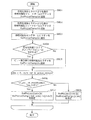
- FIG. 6 is a flowchart showing a process of determining a motion vector predictor index according to the first embodiment.
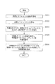
- FIG. 7 is a flowchart showing reference picture list calculation processing according to the first example of the first embodiment.
- FIG. 8 is a flowchart showing reference picture list calculation processing in the first prediction direction according to the first example of Embodiment 1.
- FIG. 9 is a flowchart showing the calculation process of the reference picture list in the second prediction direction according to the first example of the first embodiment.
- FIG. 10 is a conceptual diagram showing a reference picture according to the first example of the first embodiment.
- FIG. 11A is a diagram showing the syntax of the sequence parameter set according to the first embodiment.
- FIG. 11B is a diagram illustrating the syntax of the slice header according to Embodiment 1.
- FIG. 11C is a diagram showing a syntax for designating a short term picture according to Embodiment 1.
- FIG. 11D is a diagram showing a syntax for modifying the reference picture list according to Embodiment 1.
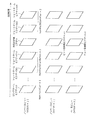
- FIG. 12A is a diagram showing a process of adding to the temporary reference picture list in the first prediction direction according to Embodiment 1.
- FIG. 12A is a diagram showing a process of adding to the temporary reference picture list in the first prediction direction according to Embodiment 1.
- FIG. 12B is a diagram showing a process of adding to the final reference picture list in the first prediction direction according to Embodiment 1.
- FIG. 12C is a diagram showing a process of adding to the temporary reference picture list in the second prediction direction according to Embodiment 1.
- FIG. 12D is a diagram showing an addition process to the final reference picture list in the second prediction direction according to Embodiment 1.
- FIG. 13 is a flowchart illustrating reference picture list calculation processing according to the second example of the first embodiment.
- FIG. 14 is a flowchart illustrating reference picture list calculation processing in the first prediction direction according to the second example of the first embodiment.
- FIG. 15 is a flowchart showing reference picture list calculation processing in the second prediction direction according to the second example of the first embodiment.
- FIG. 16 is a conceptual diagram showing a reference picture according to the second example of the first embodiment.
- FIG. 17 is a block diagram illustrating a configuration of the image decoding apparatus according to the second embodiment.
- FIG. 18 is a flowchart showing the operation of the image decoding apparatus according to the second embodiment.
- FIG. 19 is a block diagram showing a configuration of an image coding apparatus according to Embodiment 3.
- FIG. 20 is a flowchart showing the operation of the image coding apparatus according to Embodiment 3.
- FIG. 21 is a block diagram showing the configuration of the image decoding apparatus according to Embodiment 3.
- FIG. 22 is a flowchart showing an operation of the image decoding apparatus according to the third embodiment.
- FIG. 23 is an overall configuration diagram of a content supply system that implements a content distribution service.
- FIG. 24 is an overall configuration diagram of a digital broadcasting system.
- FIG. 25 is a block diagram illustrating a configuration example of a television.
- FIG. 26 is a block diagram illustrating a configuration example of an information reproducing / recording unit that reads and writes information from and on a recording medium that is an optical disk.
- FIG. 27 is a diagram illustrating a structure example of a recording medium that is an optical disk.
- FIG. 28A is a diagram illustrating an example of a mobile phone.
- FIG. 28B is a block diagram illustrating a configuration example of a mobile phone.
- FIG. 29 is a diagram showing a structure of multiplexed data.
- FIG. 30 is a diagram schematically showing how each stream is multiplexed in the multiplexed data.
- FIG. 30 is a diagram schematically showing how each stream is multiplexed in the multiplexed data.
- FIG. 31 is a diagram showing in more detail how the video stream is stored in the PES packet sequence.
- FIG. 32 is a diagram showing the structure of TS packets and source packets in multiplexed data.
- FIG. 33 shows the data structure of the PMT.
- FIG. 34 shows the internal structure of multiplexed data information.
- FIG. 35 shows the internal structure of stream attribute information.
- FIG. 36 is a diagram showing steps for identifying video data.
- FIG. 37 is a block diagram illustrating a configuration example of an integrated circuit that realizes the moving picture coding method and the moving picture decoding method according to each embodiment.
- FIG. 38 is a diagram showing a configuration for switching the drive frequency.
- FIG. 39 is a diagram illustrating steps for identifying video data and switching between driving frequencies.
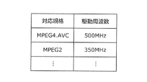
- FIG. 40 is a diagram illustrating an example of a look-up table in which video data standards are associated with drive frequencies.
- FIG. 41A is a diagram illustrating an example of a configuration for sharing a module of a signal processing unit.
- FIG. 41B is a diagram illustrating another example of a configuration for sharing a module of a signal processing unit.
- the present inventor has found a problem regarding an image encoding method for encoding a picture for each block. This will be specifically described below.
- the amount of information is compressed using redundancy in the spatial direction and temporal direction of an image.
- redundancy in the spatial direction conversion to the frequency domain is used, and as a method of using redundancy in the temporal direction, inter-picture prediction (hereinafter referred to as inter prediction) encoding processing is used. .
- the image encoding device When encoding an encoding target picture (current picture) in the inter prediction encoding process, the image encoding device reads an encoded picture that is forward or backward in display time order with respect to the encoding target picture, Used as a reference picture. Then, the image encoding device derives a motion vector by detecting the motion of the encoding target picture with respect to the reference picture.
- the image coding apparatus removes redundancy in the time direction by acquiring the difference between the predicted image data obtained by performing motion compensation based on the motion vector and the image data of the coding target picture.
- the image coding apparatus calculates a difference value between a coding target block (current block) in a coding target picture and a block in a reference picture in motion detection, and calculates the difference value in the reference picture having the smallest difference value. Identify the block as a reference block. Then, the image encoding device detects a motion vector using the encoding target block and the reference block.
- Non-Patent Document 1 An image encoding method called H.264 has already been standardized (Non-Patent Document 1).
- this image coding system three types of picture types, i.e., I picture, P picture, and B picture, are used to compress the amount of information.
- An I picture is a picture that is not subjected to inter prediction encoding processing, that is, is subjected to intra prediction (hereinafter referred to as intra prediction) encoding processing.
- the P picture is a picture that is subjected to inter prediction coding that refers to one already coded picture that is in front of or behind the current picture in display time order.
- the B picture is a picture that is subjected to inter prediction encoding that refers to two already encoded pictures that are in front of or behind the current picture in display time order.
- the image encoding device generates a reference picture list for specifying a reference picture in inter prediction encoding.
- the reference picture list is a list in which a reference picture index is assigned to an encoded reference picture that is referred to in inter prediction.
- the image encoding apparatus stores two reference picture lists (L0, L1) in order to encode a B picture with reference to two pictures.
- FIG. 1 shows an example of a reference picture list in a B picture.
- the first reference picture list (L0) in FIG. 1 is an example of a reference picture list in the first prediction direction in bidirectional prediction.
- a reference picture R3 whose display order is 2 is assigned to the reference picture index “0”.
- a reference picture R2 whose display order is 1 is assigned to the reference picture index “1”.
- a reference picture R1 whose display order is 0 is assigned to the reference picture index “2”.
- a smaller reference picture index is assigned to a coding target picture as it is closer to the coding target picture in display order.
- the second reference picture list (L1) is an example of a reference picture list in the second prediction direction in bidirectional prediction.
- a reference picture R2 whose display order is 1 is assigned to a reference picture index of “0”.
- a reference picture R3 whose display order is 2 is assigned to the reference picture index “1”.
- a reference picture R1 whose display order is 0 is assigned to the reference picture index “2”.
- different reference picture indexes may be assigned to one reference picture (reference pictures R2 and R3 in FIG. 1).
- the same reference picture index may be assigned to one reference picture (reference picture R1 in FIG. 1).
- this reference picture list a new calculation method is currently being studied.
- an image encoding apparatus may encode a non-base view picture with reference to a base view picture. Such calculation is not taken into consideration in the calculation methods currently under consideration.
- MVC Multiview Video Coding
- an image encoding method is an image encoding method for encoding a current picture for each block, and assigns a reference picture index to a reference picture that can be referred to in the encoding of the current picture. Generating a reference picture list including the reference picture to which the reference picture index is assigned, and identifying a reference picture to be referred to in encoding the current block included in the current picture from the reference picture list.
- An encoding step of encoding the current block with reference to the identified reference picture, and in the generating step, a reference picture belonging to a reference view different from the current view to which the current picture belongs is If there is a possibility of reference in picture coding, the reference Add a reference picture belonging to over to the reference picture list.
- the reference picture list may be generated using a parameter, and in the encoding step, the parameter used for generating the reference picture list may be further encoded.
- the number of reference pictures that can be referred to belongs to the current view.
- a second number that is the number of reference pictures that can be referred to belonging to the reference view is added to the number of 1
- a third number that is the number of reference pictures that can be referred to in the coding of the current picture is obtained.
- a range of values of a correction list for calculating and correcting the reference picture index assigned to the reference picture included in the reference picture list may be determined based on the third number.
- the generation step based on whether or not the current view is a non-base view, whether or not a reference picture belonging to the reference view may be referred to in encoding the current picture It may be determined whether or not.
- the generation step it may be further determined whether or not the current view is a non-base view based on a view order index assigned to the current view in encoding order.
- the view including the encoding target picture is a non-base view.
- An image decoding method is an image decoding method for decoding a current picture for each block, wherein a reference picture index is assigned to a reference picture that can be referred to in decoding of the current picture, and the reference
- a parameter used for generating the reference picture list may be further decoded, and in the generating step, the reference picture list may be generated using the decoded parameter.
- the first reference picture is the number of reference pictures that can be referred to belonging to the current view.
- a third number that is the number of reference pictures that can be referred to in decoding the current picture is calculated.
- the correction list value range for correcting the reference picture index assigned to the reference picture included in the reference picture list may be determined based on the third number.
- the generation step based on whether or not the current view is a non-base view, whether or not a reference picture belonging to the reference view may be referred to in decoding of the current picture It may be determined.
- the generation step it may be further determined whether or not the current view is a non-base view based on a view order index assigned to the current view in decoding order.
- the view including the decoding target picture is a non-base view.
- FIG. 2 is a block diagram showing the configuration of the image coding apparatus according to the present embodiment.
- the image encoding device 100 includes a subtraction unit 101, an orthogonal transformation unit 102, a quantization unit 103, an inverse quantization unit 105, an inverse orthogonal transformation unit 106, an addition unit 107, a block memory 108, a frame memory 109, An intra prediction unit 110, an inter prediction unit 111, a switching unit 112, an inter prediction control unit 114, a reference picture list calculation unit 115, a picture type determination unit 113, a motion vector predictor calculation unit 116, and a variable length coding unit 104 Prepare.
- the orthogonal transform unit 102 performs transform from the pixel region to the frequency region for the input image.
- the quantization unit 103 performs a quantization process on the input image converted into the frequency domain.
- the inverse quantization unit 105 performs an inverse quantization process on the input image quantized by the quantization unit 103.
- the inverse orthogonal transform unit 106 performs transform from the frequency domain to the pixel domain on the input image subjected to the inverse quantization process.
- the block memory 108 stores input images in units of blocks, and the frame memory 109 stores input images in units of frames.
- the picture type determining unit 113 determines which of the I picture, B picture, and P picture is to be used for encoding the input image, and generates picture type information.
- the intra prediction unit 110 uses the block-unit input image stored in the block memory 108 to encode the encoding target block by intra prediction, and generates predicted image data.
- the inter prediction unit 111 encodes the block to be encoded by inter prediction using the input image of each frame stored in the frame memory 109 and the motion vector derived by motion detection or the like, and converts the predicted image data into Generate.
- the predicted motion vector candidate calculation unit 116 derives a predicted motion vector candidate in the predicted motion vector designation mode.
- a motion vector predictor candidate is derived using colPic information such as a motion vector of a block adjacent to an encoding target block and a co-located block included in an already encoded picture.
- a predicted motion vector candidate in the predicted motion vector designation mode is a predicted motion vector candidate used for encoding a motion vector. Then, the motion vector predictor candidate calculation unit 116 calculates the number of motion vector predictor candidates.
- the predicted motion vector candidate calculation unit 116 assigns a value of the predicted motion vector index to the derived predicted motion vector candidate. Then, the motion vector predictor candidate calculation unit 116 sends the motion vector predictor candidate and the motion vector predictor index to the inter prediction control unit 114. Further, the motion vector predictor candidate calculation unit 116 transmits the calculated number of motion vector predictor candidates to the variable length coding unit 104.
- the inter prediction control unit 114 together with the inter prediction unit 111, generates an inter prediction image using a motion vector derived by motion detection. Then, the inter prediction control unit 114 performs inter prediction encoding using the inter prediction image together with the inter prediction unit 111.
- the inter prediction control unit 114 selects a motion vector predictor candidate that is optimal for coding the motion vector used for the inter prediction coding by a method described later. Then, the inter prediction control unit 114 sends the prediction motion vector index corresponding to the selected prediction motion vector candidate and prediction error information to the variable length encoding unit 104.
- the reference picture list calculation unit 115 calculates a reference picture list for encoding an encoding target picture or slice by a method described later, and sends the reference picture list to the inter prediction control unit 114 and the prediction motion vector candidate calculation unit 116. Output. Then, the reference picture list calculation unit 115 outputs parameters for calculating the reference picture list used for encoding to the variable length encoding unit 104 as reference picture list information.
- the orthogonal transform unit 102 performs transformation from the pixel region to the frequency region on the generated prediction image data and prediction error data between the input image.
- the quantization unit 103 performs a quantization process on the prediction error data converted to the frequency domain.
- the variable length encoding unit 104 generates a bitstream by performing variable length encoding processing on the quantized prediction error data, prediction direction flag, picture type information, and reference picture list information.
- the variable length coding unit 104 sets the number of motion vector predictor candidates to the size of the motion vector predictor candidate list. Then, the variable length coding unit 104 performs variable length coding by assigning a bit string determined according to the size of the motion vector predictor candidate list to the motion vector predictor index used for motion vector coding.
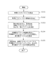
- FIG. 3 is an outline of a processing flow of the image coding method according to the present embodiment.
- the reference picture list calculation unit 115 calculates a reference picture list of an encoding target picture or slice by a method described later (S101).
- the variable length encoding unit 104 encodes the reference picture list information and adds the encoded reference picture list information to the header. That is, the variable length coding unit 104 adds parameters used for calculating the reference picture list as reference picture list information to an SPS (Sequence Parameter Set), a PPS (Picture Parameter Set), or a slice header ( S102).
- SPS Sequence Parameter Set
- PPS Picture Parameter Set
- S102 slice header
- the inter prediction control unit 114 performs motion detection and determines a prediction direction, a reference picture index, and a motion vector of the encoding target block (S103). In motion detection, the inter prediction control unit 114 calculates, for example, a difference value between a coding target block in a coding target picture and a block in a reference picture, and refers to the block in the reference picture having the smallest difference value. Decide as a block. The inter prediction control unit 114 uses a method for obtaining a motion vector from the position of the encoding target block and the position of the reference block.
- the inter prediction control unit 114 performs motion detection on the reference picture in the first prediction direction and the reference picture in the second prediction direction, respectively. Then, the inter prediction control unit 114 selects the first prediction direction, the second prediction direction, or the bi-directional prediction using, for example, Equation 1 indicating the RD optimization model.
- D represents coding distortion.
- R represents the generated code amount.
- ⁇ is a Lagrange multiplier.
- the predicted motion vector candidate calculation unit 116 generates a predicted motion vector candidate as shown in FIG. 5 from the adjacent block of the encoding target block as shown in FIG. 4 and the co-located block. Then, the inter prediction control unit 114 determines a prediction motion vector index, which is an index of the prediction motion vector used for coding the motion vector, according to the flow shown in FIG. 6, and calculates a difference motion vector (S104). ).
- the difference motion vector is a difference between the motion vector and the predicted motion vector.
- variable length coding unit 104 performs variable length coding on the prediction direction, the reference picture index, the predicted motion vector index, and the differential motion vector (S105).
- a method of calculating a reference picture list when the image encoding apparatus 100 encodes a coding target picture without referring to a picture of another view will be described. This method is used, for example, when a sequence including only the base view is encoded.
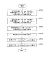
- FIG. 7 is a detailed processing flow of S101 in FIG. 3, and shows a calculation method of a reference picture list when a picture of another view is not referred to. Hereinafter, FIG. 7 will be described.
- the reference picture list calculation unit 115 displays the display order of a short term picture (Short Term Picture) that is in the display order (POC: Picture Order Count) before the encoding target picture and can be referred to in inter prediction, and the display order thereof.
- the number of sheets (NumPocStCurrBefore) is calculated (S301).
- the reference picture list calculation unit 115 calculates the display order of the short term pictures that can be referred to in the inter prediction after the display order of the current picture to be encoded, and the number (NumPocStCurrAfter) (S302). ).
- the reference picture list calculation unit 115 calculates the display order of long term pictures (Long Term Pictures) that can be referred to in inter prediction, and the number (NumPocLtCurr) of the long term pictures (S303).
- the reference picture list calculation unit 115 calculates the total number of reference pictures (NumPocTotalCurr) that can be referred to in inter prediction by adding NumPocStCurrBefore, NumPocStCurrAfter, and NumPocLtCurr (S304).
- the reference picture list calculation unit 115 calculates a reference picture list RefPicList0 in the first prediction direction by a method described later (S305). Then, the reference picture list calculation unit 115 calculates the reference picture list RefPicList1 in the second prediction direction (S306).
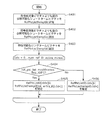
- FIG. 8 is a detailed processing flow of S305 in FIG. 7 and represents a method of calculating the reference picture list RefPicList0 in the first prediction direction. Hereinafter, FIG. 8 will be described.
- the reference picture list calculation unit 115 adds the reference pictures corresponding to the display order calculated in S301 of FIG. 7 to the reference picture list RefPicListTemp0 for the calculated NumPocStCurrBefore (S401).
- the reference picture list calculation unit 115 adds the reference pictures corresponding to the display order calculated in S302 of FIG. 7 to the reference picture list RefPicListTemp0 for the calculated NumPocStCurrAfter (S402).
- the reference picture list calculation unit 115 adds the reference pictures corresponding to the display order calculated in S303 of FIG. 7 to the reference picture list RefPicListTemp0 for the calculated NumPocLtCurr (S403).
- the reference picture list calculation unit 115 calculates the reference picture list RefPicList0 using the reference picture list RefPicListTemp0 obtained in S401 to S403.
- the number of reference pictures in the calculated reference picture list RefPicList0 is equal to the number of reference pictures (num_ref_10_active_minus1 + 1) that can be referred to in the first prediction direction from the current picture (or slice).
- the reference picture list calculation unit 115 calculates the reference picture list RefPicList0 according to the flag value. Specifically, the reference picture list calculation unit 115 determines whether or not a flag ref_pic_list_modification_flag_10 indicating whether or not to correct the reference picture list in the first prediction direction is 1 (S404).
- the reference picture list calculation unit 115 calculates the reference picture list RefPicList0 according to the reference picture list RefPicListTemp0 and the value of list_entry_10 [cIdx] (cIdx is 0 to num_ref_10_active_minus1). (S405).
- the reference picture list calculation unit 115 assigns RefPicListTemp0 [list_entry_l0 [cIdx]] to RefPicList0 [cIdx] and calculates the reference picture list RefPicList0.
- list_entry_10 [cIdx] is a parameter (correction list) used to correct the reference picture list in the first prediction direction. This parameter is used to assign the cIdx-th reference picture index to the list_entry_l0 [cIdx] -th reference picture index, and is added to the slice header or the like.
- list_entry_10 [cIdx] is based on the value of NumPocTotalCurr, and is limited to 0 or more and (NumPocTotalCurr-1) or less.
- the reference picture list calculation unit 115 calculates the reference picture list RefPicList0 using the reference picture list RefPicListTemp0 (S406). Specifically, the reference picture list calculation unit 115 assigns RefPicListTemp0 [cIdx] to RefPicList0 [cIdx] and calculates the reference picture list RefPicList0.
- FIG. 9 is a detailed processing flow of S306 in FIG. 7 and represents a method of calculating the reference picture list RefPicList1 in the second prediction direction. Hereinafter, FIG. 9 will be described.
- the reference picture list calculation unit 115 adds the reference pictures corresponding to the display order calculated in S302 of FIG. 7 to the reference picture list RefPicListTemp1 for the calculated number of NumPocStCurrAfter (S501).
- the reference picture list calculation unit 115 adds the reference pictures corresponding to the display order calculated in S301 of FIG. 7 to the reference picture list RefPicListTemp1 for the calculated NumPocStCurrBefore (S502).
- the reference picture list calculation unit 115 adds the reference pictures corresponding to the display order calculated in S303 of FIG. 7 to the reference picture list RefPicListTemp1 for the calculated NumPocLtCurr (S503).
- the reference picture list calculation unit 115 calculates the reference picture list RefPicList1 using the reference picture list RefPicListTemp1 obtained in S501 to S503.
- the calculated number of reference pictures in the reference picture list RefPicList1 is equal to the number of reference pictures (num_ref_l1_active_minus1 + 1) that can be referred to in the second prediction direction from the current picture (or slice).
- the reference picture list calculation unit 115 calculates the reference picture list RefPicList1 according to the value of the flag. Specifically, the reference picture list calculation unit 115 determines whether or not a flag ref_pic_list_modification_flag_l1 indicating whether or not to correct the reference picture list in the second prediction direction is 1 (S504).
- the reference picture list calculation unit 115 calculates the reference picture list RefPicList1 according to the reference picture list RefPicListTemp1 and the value of list_entry_l1 [cIdx] (cIdx is 0 to num_ref_l1_active_minus1). (S505).
- the reference picture list calculation unit 115 assigns RefPicListTemp1 [list_entry_l1 [cIdx]] to RefPicList1 [cIdx] and calculates the reference picture list RefPicList1.
- list_entry_l1 [cIdx] is a parameter (correction list) used to correct the reference picture list in the second prediction direction. This parameter is used to assign the cIdx-th reference picture index to the list_entry_l1 [cIdx] -th reference picture index, and is added to the slice header or the like.
- list_entry_l1 [cIdx] is based on the value of NumPocTotalCurr and is limited to 0 or more and (NumPocTotalCurr-1) or less.
- the reference picture list calculation unit 115 calculates the reference picture list RefPicList1 using the reference picture list RefPicListTemp1 (S506). Specifically, the reference picture list calculation unit 115 assigns RefPicListTemp1 [cIdx] to RefPicList1 [cIdx] and calculates the reference picture list RefPicList1.
- FIG. 10 is a diagram illustrating an example of a reference picture when a picture of another view is not used as a reference picture.
- the short term pictures St1 and St2 whose display order is earlier than the encoding target picture and can be referred to in inter prediction are the short term pictures St1 and St2, and the number NumPocStCurrBefore is 2.
- Short term pictures that are displayed later than the current picture and can be referred to by inter prediction are the short term pictures St3 and St4, and the number NumPocStCurrAfter is two.
- the long term picture that can be referred to in the inter prediction is the long term picture Lt, and the number NumPocLtCurr thereof is 1.
- the reference picture list RefPicList0 in the first prediction direction includes St2, St1, St3, St4, Thus, a reference picture is assigned.
- the reference picture list RefPicList1 in the second prediction direction is assigned in the order of St3, St4, St2, St1, and Lt. It is done.
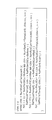
- FIG. 11A to FIG. 11D show examples of syntaxes when parameters used for reference picture list calculation are added as SPS, PPS, or slice header as reference picture list information.
- lists_modification_present_flag is a flag indicating whether or not there is a flag indicating whether or not to modify the reference picture list.
- short_term_ref_pic_set (i) is a syntax for designating a short term picture.
- long_term_ref_pics_present_flag is a flag indicating whether or not a long term picture exists.
- short_term_ref_pic_set (num_short_term_ref_pic_sets) is a syntax for designating a short term picture.
- num_long_term_pics is the number of long term pictures.
- num_ref_idx_10_active_minus1 is the number of reference pictures that can be referred to in the first prediction direction.
- num_ref_idx_l1_active_minus1 is the number of reference pictures that can be referred to in the second prediction direction.
- each element is a parameter for designating a short term picture.
- ref_pic_list_modification_flag_10 is a flag indicating whether or not to modify the reference picture list in the first prediction direction.
- ref_pic_list_modification_flag_l1 is a flag indicating whether or not to modify the reference picture list in the second prediction direction.
- list_entry_10 [i] is a parameter for changing the reference picture assigned to the reference picture list in the first prediction direction.
- list_entry_l1 [i] is a parameter for changing the reference picture to be assigned to the reference picture list in the second prediction direction.
- list_entry_l0 [i] and list_entry_l1 [i] are limited to 0 or more and NumPocTotalCurr-1.
- list_entry_lX [i] When 0 or 1 is represented by X, the index of the reference picture in the reference picture list LX is specified by list_entry_lX [i].
- the length of list_entry_lX [i] is Ceil (Log2 (NumPocTotalCurr)) bits.
- list_entry_lX [i] is limited to 0 or more and NumPocTotalCurr-1. If list_entry_lX [i] does not exist, list_entry_lX [i] is treated as 0.
- RefPicSetStCurrBefore RefPicSetStCurrAfter, RefPicSetStFoll, RefPicSetLtCurr, and RefPicSetLtFoll.
- NumPocTotalCurr is equal to NumPocStCurrBefore + NumPocStCurrAfter + NumPocLtCurr.
- NumPocTotalCurr is not 0 in P slice or B slice encoding and decoding.
- FIG. 12A and 12B show calculation examples of the reference picture list RefPicList0.
- the calculation of the reference picture list RefPicList0 is performed in encoding and decoding of the header of the P slice or B slice.
- NumRpsCurrTempList0 is the larger of num_ref_idx_10_active_minus1 + 1 and NumPocTotalCurr. More specifically, FIG. 12A shows a calculation example of RefPicListTemp0, and FIG. 12B shows a calculation example of RefPicList0.
- FIG. 12C and 12D show calculation examples of the reference picture list RefPicList1.
- the calculation of the reference picture list RefPicList1 is performed in encoding and decoding of the header of the B slice.
- NumRpsCurrTempList1 is the larger of num_ref_idx_l1_active_minus1 + 1 and NumPocTotalCurr. More specifically, FIG. 12C shows a calculation example of RefPicListTemp1, and FIG. 12D shows a calculation example of RefPicList1.
- the sum of NumPocStCurrBefore, NumPocStCurrAfter, and NumPocLtCurr is set to the number of reference pictures NumPocTotalCurr that can be referred to in inter prediction.
- Parameters such as list_entry_l0 and list_entry_l1 whose values that can be set vary based on the value of NumPocTotalCurr are used.
- the calculation method of the reference picture list when another view is referenced is shown.
- the following calculation method is used when the image encoding apparatus 100 encodes a multi-view video including a base view and a non-base view.
- FIG. 13 is a detailed processing flow of S101 in FIG. 3, and shows a reference picture list calculation method when there is a possibility that a picture of another view is referred to from the encoding target picture.
- FIG. 13 will be described.
- the reference picture list calculation unit 115 displays the display order of a short term picture (Short Term Picture) that is in the display order (POC: Picture Order Count) before the encoding target picture and can be referred to in inter prediction, and the display order thereof.
- the number of sheets (NumPocStCurrBefore) is calculated (S601).
- the reference picture list calculation unit 115 calculates the display order of the short term pictures that are later in display order than the current picture to be encoded and can be referred to in inter prediction, and the number (NumPocStCurrAfter) (S602). ).
- the reference picture list calculation unit 115 calculates the display order of long term pictures (Long Term Pictures) that can be referred to in inter prediction, and the number (NumPocLtCurr) thereof (S603).
- the reference picture list calculation unit 115 calculates the total number of reference pictures that can be referred to in inter prediction (NumPocTotalCurr) by adding NumPocStCurrBefore, NumPocStCurrAfter, and NumPocLtCurr (S604).
- the reference picture list calculation unit 115 determines whether or not the encoding target picture is included in the non-base view (S605). Note that this determination may be performed based on, for example, VOIdx (View Order Index) assigned in the encoding (decoding) order of each view, specific nal_type, view_id assigned to each view, or the like.
- the determination method may be any method.
- VOIdx is used.
- the reference picture list calculation unit 115 determines that the encoding target picture is included in the base view.
- the reference picture list calculation unit 115 determines that the encoding target picture is included in the non-base view.
- the reference picture list calculation unit 115 adds num_inter-view_reference [VOIdx] to NumPocTotalCurr (S606). ).
- inter-view_reference [VOIdx] is the number of reference pictures that can be referred to in the inter-view prediction from the current picture.
- inter-view prediction means that a predicted image is generated with reference to a picture of a view different from the view to which the encoding target picture belongs.
- the reference picture list calculation unit 115 calculates a reference picture list RefPicList0 in the first prediction direction and a reference picture list RefPicList1 in the second prediction direction by a method to be described later (S607, S608).
- FIG. 14 is a detailed processing flow of S607 in FIG. 13, and shows a method of calculating the reference picture list RefPicList0 in the first prediction direction.
- FIG. 14 will be described.
- the reference picture list calculation unit 115 adds the reference pictures corresponding to the display order calculated in S601 of FIG. 13 to the reference picture list RefPicListTemp0 for the calculated NumPocStCurrBefore (S701).
- the reference picture list calculation unit 115 adds the reference pictures corresponding to the display order calculated in S602 of FIG. 13 to the reference picture list RefPicListTemp0 for the calculated NumPocStCurrAfter (S702).
- the reference picture list calculation unit 115 adds the reference pictures corresponding to the display order calculated in S603 of FIG. 13 to the reference picture list RefPicListTemp0 for the calculated NumPocLtCurr (S703).
- the reference picture list calculation unit 115 determines whether or not the encoding target picture is included in the non-base view (S704). Note that this determination may be performed based on, for example, VOIdx (View Order Index) assigned in the encoding (decoding) order of each view, specific nal_type, view_id assigned to each view, or the like.
- the determination method may be any method.
- VOIdx is used.
- the reference picture list calculation unit 115 determines that the encoding target picture is included in the base view.
- the reference picture list calculation unit 115 determines that the encoding target picture is included in the non-base view.
- the reference picture list calculation unit 115 adds the reference picture to the reference picture list RefPicListTemp0 (S705). Specifically, in this case, the reference picture list calculation unit 115 adds num_inter-view_reference [VOIdx] reference pictures that can be referred to using the inter-view prediction from the current picture to the reference picture list RefPicListTemp0. .
- the reference picture list calculation unit 115 calculates the reference picture list RefPicList0 using the reference picture list RefPicListTemp0 obtained in S701 to S705.
- the number of reference pictures in the calculated reference picture list RefPicList0 is equal to the number of reference pictures (num_ref_10_active_minus1 + 1) that can be referred to in the first prediction direction from the current picture (or slice).
- the reference picture list calculation unit 115 calculates the reference picture list RefPicList0 according to the flag value. Specifically, the reference picture list calculation unit 115 determines whether or not a flag ref_pic_list_modification_flag_10 indicating whether or not to correct the reference picture list in the first prediction direction is 1 (S706).
- the reference picture list calculation unit 115 calculates the reference picture list RefPicList0 according to the reference picture list RefPicListTemp0 and the value of list_entry_10 [cIdx] (cIdx is 0 to num_ref_10_active_minus1). (S707).
- the reference picture list calculation unit 115 assigns RefPicListTemp0 [list_entry_l0 [cIdx]] to RefPicList0 [cIdx] and calculates the reference picture list RefPicList0.
- list_entry_10 [cIdx] is a parameter (correction list) used to correct the reference picture list in the first prediction direction. This parameter is used to assign the cIdx-th reference picture index to the list_entry_l0 [cIdx] -th reference picture index, and is added to the slice header or the like.
- list_entry_10 [cIdx] is based on the value of NumPocTotalCurr, and is limited to 0 or more and (NumPocTotalCurr-1) or less.
- the reference picture list calculation unit 115 calculates the reference picture list RefPicList0 using the reference picture list RefPicListTemp0 (S708). Specifically, the reference picture list calculation unit 115 assigns RefPicListTemp0 [cIdx] to RefPicList0 [cIdx] and calculates the reference picture list RefPicList0.
- FIG. 15 is a detailed processing flow of S608 of FIG. 13, and shows a method of calculating the reference picture list RefPicList1 in the second prediction direction. Hereinafter, FIG. 15 will be described.
- the reference picture list calculation unit 115 adds the reference pictures corresponding to the display order calculated in S602 of FIG. 13 to the reference picture list RefPicListTemp1 for the calculated NumPocStCurrAfter (S801).
- the reference picture list calculation unit 115 adds the reference pictures corresponding to the display order calculated in S601 of FIG. 13 to the reference picture list RefPicListTemp1 for the calculated NumPocStCurrBefore (S802).
- the reference picture list calculation unit 115 adds the reference pictures corresponding to the display order calculated in S603 of FIG. 13 to the reference picture list RefPicListTemp1 for the calculated NumPocLtCurr (S803).
- the reference picture list calculation unit 115 determines whether or not the encoding target picture is included in the non-base view (S804). Note that this determination may be made based on, for example, VOIdx (View Order Index) assigned in the encoding (decoding) order of each view, specific nal_type, view_id assigned to each view, or the like. .
- the determination method may be any method.
- VOIdx is used.
- the reference picture list calculation unit 115 determines that the encoding target picture is included in the base view.
- the reference picture list calculation unit 115 determines that the encoding target picture is included in the non-base view.
- the reference picture list calculation unit 115 adds the reference picture to the reference picture list RefPicListTemp1 (S805). Specifically, in this case, the reference picture list calculation unit 115 adds num_inter-view_reference [VOIdx] reference pictures that can be referred to using the inter-view prediction from the encoding target picture to the reference picture list RefPicListTemp1. .
- the reference picture list calculation unit 115 calculates the reference picture list RefPicList1 using the reference picture list RefPicListTemp1 obtained in S801 to S805.
- the calculated number of reference pictures in the reference picture list RefPicList1 is equal to the number of reference pictures (num_ref_l1_active_minus1 + 1) that can be referred to in the second prediction direction from the current picture (or slice).
- the reference picture list calculation unit 115 calculates the reference picture list RefPicList1 according to the value of the flag. Specifically, the reference picture list calculation unit 115 determines whether or not a flag ref_pic_list_modification_flag_l1 indicating whether or not to correct the reference picture list in the second prediction direction is 1 (S806).
- the reference picture list calculation unit 115 calculates the reference picture list RefPicList1 according to the reference picture list RefPicListTemp1 and the value of list_entry_l1 [cIdx] (cIdx is 0 to num_ref_l1_active_minus1). (S807).
- the reference picture list calculation unit 115 assigns RefPicListTemp1 [list_entry_l1 [cIdx]] to RefPicList1 [cIdx] and calculates the reference picture list RefPicList1.
- list_entry_l1 [cIdx] is a parameter (correction list) used to correct the reference picture list in the second prediction direction. This parameter is used to assign the cIdx-th reference picture index to the list_entry_l1 [cIdx] -th reference picture index, and is added to the slice header or the like.
- list_entry_l1 [cIdx] is based on the value of NumPocTotalCurr and is limited to 0 or more and (NumPocTotalCurr-1) or less.
- the reference picture list calculation unit 115 calculates the reference picture list RefPicList1 using the reference picture list RefPicListTemp1 (S808). Specifically, the reference picture list calculation unit 115 assigns RefPicListTemp1 [cIdx] to RefPicList1 [cIdx] and calculates the reference picture list RefPicList1.
- FIG. 16 is a diagram illustrating an example of a reference picture when a picture of another view is used as a reference picture.
- the encoding target picture belongs to the non-base view, and VOIdx is 2.
- the short term pictures St1 and St2 whose display order is earlier than the picture to be encoded and can be referred to by inter prediction are the short term pictures St1 and St2, and the number NumPocStCurrBefore is 2.
- Short term pictures that are displayed later than the current picture and can be referred to by inter prediction are the short term pictures St3 and St4, and the number NumPocStCurrAfter is two.
- the long term picture that can be referred to in the inter prediction is the long term picture Lt, and the number NumPocLtCurr thereof is 1.
- reference pictures (inter-view reference pictures) that can be referred to in inter-view prediction are inter-view reference pictures Iv1 and Iv2, and the number num_inter-view_reference [VOIdx] is two.
- the number num_inter-view_reference [VOIdx] that can be referred to in inter-view prediction is added to the value.
- NumPocTotalCurr is set to 7.
- the reference picture list RefPicList0 in the first prediction direction includes St2, St1, St3, St4, St1, St4, Reference pictures are assigned in the order of Iv2.
- the reference picture list RefPicList1 in the second prediction direction is in the order of St3, St4, St2, St1, Iv, Stv, Iv, A reference picture is assigned.
- FIGS. 11A to 11D Even when another view is referred to, the syntax shown in FIGS. 11A to 11D may be used.
- the reference picture list includes RefPicSetStCurrBefore, RefPicSetStCurrAfter, RefPicSetStFoll, RefPicSetLtCurr, and RefPicSetLtFoll.
- NumPocTotalCurr is equal to NumPocStCurrBefore + NumPocStCurrAfter + NumPocLtCurr.
- NumPocTotalCurr is not 0 in P slice or B slice encoding and decoding.
- num_inter-view_reference is equal to num_anchor_refs_lX [i] or num_anchor_refs_lX [i].
- the calculation examples shown in FIGS. 12A and 12B may be used for calculating the reference picture list RefPicList0 in the first prediction direction.
- a reference picture that can be referred to in inter-view prediction is added to the reference picture list RefPicListTemp0.
- the number of reference pictures added is equal to num_inter-view_reference.
- a reference picture corresponding to inter-view_reference [VOIdx] [j] is added to RefPicListTemp0 and RefPicList0.
- the calculation examples shown in FIGS. 12C and 12D may be used to calculate the reference picture list RefPicList1 in the second prediction direction.
- a reference picture that can be referred to in inter-view prediction is added to the reference picture list RefPicListTemp1.
- the number of reference pictures added is equal to num_inter-view_reference.
- a reference picture corresponding to inter-view_reference [VOIdx] [j] is added to RefPicListTemp1 and RefPicList1.
- the picture of another view when a picture of another view is referred to from the encoding target picture, for example, when a picture included in a non-base view is encoded, the picture of another view is encoded as a reference picture. Is added to the reference picture list of the target picture. As a result, a picture of another view is set to be referable in the reference picture list, and the coding efficiency is improved.
- the total number of NumPocStCurrBefore, NumPocStCurrAfter, and NumPocLtCurr is set to the number of reference pictures NumPocTotalCurr that can be referred to in inter prediction.
- the number of reference pictures num_inter-view_reference [VOIdx] that can be referred to in inter-view prediction is added to NumPocTotalCurr.
- NumPocTotalCurr is calculated.
- Parameters such as list_entry_l0 and list_entry_l1 whose values that can be set vary based on the value of NumPocTotalCurr are used.
- a case where a picture of another view is referred to from the encoding target picture for example, a case where a picture included in a non-base view is encoded is shown as an example.
- the scope of application is not limited to this.
- the method shown in the present embodiment may be applied.
- the method shown in the present embodiment may be applied to SVC (Scalable Video Coding) or the like.
- SVC Scalable Video Coding
- the total number of NumPocStCurrBefore, NumPocStCurrAfter, and NumPocLtCurr is set to the number NumPocTotalCurr that can be referred to in inter prediction.
- the number of reference pictures that can be referred to included in another layer may be added to NumPocTotalCurr.
- FIG. 17 is a block diagram showing a configuration of the image decoding apparatus according to the present embodiment.
- the image decoding apparatus 200 includes a variable length decoding unit 204, an inverse quantization unit 205, an inverse orthogonal transform unit 206, an addition unit 207, a block memory 208, a frame memory 209, an intra prediction unit 210, and an inter prediction unit 211.
- variable length decoding unit 204 performs variable length decoding processing on the input bitstream, and generates picture type information, a prediction direction flag, a quantization coefficient, and reference picture list information. In addition, the variable length decoding unit 204 performs a variable length decoding process of the motion vector predictor index using the number of motion vector predictor candidates decoded from the header or the like.
- the inverse quantization unit 205 performs an inverse quantization process on the quantization coefficient obtained by the variable length decoding process.
- the inverse orthogonal transform unit 206 transforms the orthogonal transform coefficient obtained by the inverse quantization process from the frequency domain to the pixel domain, and generates prediction error image data.
- the block memory 208 stores an image generated by adding the prediction error image data and the prediction image data in units of blocks.
- the frame memory 209 stores the image in units of frames.
- the intra prediction unit 210 generates prediction error image data of a decoding target block (current block) by executing intra prediction using an image in units of blocks stored in the block memory 208.
- the inter prediction unit 211 generates prediction error image data of the decoding target block by performing inter prediction using the image in units of frames stored in the frame memory 209.
- the reference picture list calculation unit 215 calculates a reference picture list for decoding a decoding target picture (current picture) or a slice by a method to be described later, an inter prediction control unit 214, and a prediction motion vector candidate calculation unit To 216.
- the predicted motion vector candidate calculation unit 216 uses the information such as the motion vector of the adjacent block of the decoding target block and the information such as the motion vector of the co-located block stored in the colPic memory to calculate the predicted motion vector candidate. To derive. Also, the motion vector predictor candidate calculation unit 216 assigns the value of the motion vector predictor index to the derived motion vector predictor candidate and sends the motion vector predictor candidate to the inter prediction control unit 214.
- the inter prediction control unit 214 calculates a motion vector used for inter prediction from the predicted motion vector candidates based on the decoded predicted motion vector index, and generates an inter prediction image using the calculated motion vector.
- the adding unit 207 generates a decoded image by adding the decoded predicted image data and the prediction error image data.
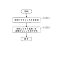
- FIG. 18 is an outline of the processing flow of the image decoding method according to the present embodiment.
- the variable length decoding unit 204 decodes reference picture list information used for calculating a reference picture list from an SPS, PPS, slice header, or the like (S901).
- the reference picture list calculation unit 215 calculates a reference picture list by the same method as in FIG. 7 or FIG. 13 (S902).
- the variable length decoding unit 204 decodes the prediction direction flag, the reference picture index, and the difference motion vector (S903).
- the predicted motion vector candidate calculation unit 216 generates a predicted motion vector candidate based on the adjacent block of the decoding target block and the co-located block. Further, the variable length decoding unit 204 performs variable length decoding on the motion vector predictor index included in the bitstream using the motion vector predictor candidate list size obtained by the variable length decoding (S904).
- the inter prediction control unit 214 calculates a motion vector by adding the decoded differential motion vector to the predicted motion vector candidate indicated by the decoded predicted motion vector index. Then, the inter prediction unit 211 generates an inter prediction image (S905).
- the reference picture list calculation unit 215 calculates a reference picture list by the same method as in FIG. Then, when a decoding target picture is decoded with reference to a picture of another view, the reference picture list calculation unit 215 calculates a reference picture list by the same method as in FIG.
- the sum of NumPocStCurrBefore, NumPocStCurrAfter, and NumPocLtCurr is set to the number of reference pictures NumPocTotalCurr that can be referred to in inter prediction.
- Parameters such as list_entry_l0 and list_entry_l1 whose values that can be set vary based on the value of NumPocTotalCurr are used.
- the picture of another view when a picture of another view is referred to from the decoding target picture, for example, when a picture included in a non-base view is decoded, the picture of another view is decoded as a reference picture. It is added to the reference picture list of the target picture. Thereby, a picture of another view is set to be referable in the reference picture list. Therefore, decoding corresponding to highly efficient encoding is possible.
- the total number of NumPocStCurrBefore, NumPocStCurrAfter, and NumPocLtCurr is set to the number of reference pictures NumPocTotalCurr that can be referred to in inter prediction.
- the number of reference pictures num_inter-view_reference [VOIdx] that can be referred to in inter-view prediction is added to NumPocTotalCurr.
- Parameters such as list_entry_l0 and list_entry_l1 whose values that can be set vary based on the value of NumPocTotalCurr are used.
- a case where a picture of another view is referred to from the decoding target picture for example, a case where a picture included in a non-base view is decoded is shown as an example.
- the scope of application is not limited to this.
- the method shown in the present embodiment may be applied.
- the method shown in the present embodiment may be applied to SVC (Scalable Video Coding) or the like.
- SVC Scalable Video Coding
- the total number of NumPocStCurrBefore, NumPocStCurrAfter, and NumPocLtCurr is set to the number NumPocTotalCurr that can be referred to in inter prediction.
- the number of reference pictures that can be referred to included in another layer may be added to NumPocTotalCurr.
- FIG. 19 is a block diagram showing a configuration of the image coding apparatus according to the present embodiment.
- the image encoding device 300 includes a generation unit 301 and an encoding unit 302.
- the generation unit 301 corresponds to the reference picture list calculation unit 115 and the like of the first embodiment.
- Coding section 302 corresponds to inter prediction control section 114, inter prediction section 111, variable length coding section 104, and the like of the first embodiment.
- FIG. 20 is a flowchart showing the operation of the image coding apparatus 300 shown in FIG.
- the image encoding device 300 encodes the current picture for each block based on the following operation.
- the generation unit 301 assigns a reference picture index to a reference picture that can be referred to in encoding the current picture. Then, the generation unit 301 generates a reference picture list including a reference picture to which a reference picture index is assigned (S1001). At this time, if there is a possibility that a reference picture belonging to a reference view different from the current view to which the current picture belongs may be referred to in encoding of the current picture, the generating unit 301 adds the reference picture belonging to the reference view to the reference picture list. to add.
- the encoding unit 302 identifies a reference picture to be referenced in encoding the current block included in the current picture from the reference picture list.
- the encoding unit 302 then encodes the current block with reference to the identified reference picture (S1002).
- the generation unit 301 may generate a reference picture list using a predetermined parameter (such as a correction list). Then, the encoding unit 302 may encode the parameters used for generating the reference picture list.
- a predetermined parameter such as a correction list
- the generation unit 301 may calculate a number that is the number of reference pictures that can be referred to in encoding of the current picture. Good. For example, in this case, the generating unit 301 adds the number of reference pictures that can be referred to that belong to the reference view to the number of reference pictures that can be referred to that belong to the current view. Calculate the number of pictures.
- the generation unit 301 determines the range of the correction list value for correcting the reference picture index assigned to the reference picture included in the reference picture list based on the calculated number. Also good.
- the generation unit 301 determines whether or not a reference picture belonging to the reference view may be referred to in encoding of the current picture based on whether or not the current view is a non-base view. May be.
- the generation unit 301 may determine whether or not the current view is a non-base view based on the view order index assigned to the current view in the encoding order.
- FIG. 21 is a block diagram showing a configuration of the image decoding apparatus according to the present embodiment.
- the image decoding device 400 includes a generation unit 401 and a decoding unit 402.
- the generation unit 401 corresponds to the reference picture list calculation unit 215 and the like of the second embodiment.
- the decoding unit 402 corresponds to the inter prediction control unit 214, the inter prediction unit 211, the variable length decoding unit 204, and the like according to the second embodiment.
- FIG. 22 is a flowchart showing the operation of the image decoding apparatus 400 shown in FIG.
- the image decoding apparatus 400 decodes the current picture for each block based on the following operation.
- the generation unit 401 assigns a reference picture index to a reference picture that can be referred to in decoding of the current picture. Then, the generation unit 401 generates a reference picture list including a reference picture to which a reference picture index is assigned (S1101). At this time, if there is a possibility that a reference picture belonging to a reference view different from the current view to which the current picture belongs may be referred to in decoding of the current picture, the generation unit 401 adds the reference picture belonging to the reference view to the reference picture list. To do.
- the decoding unit 402 identifies, from the reference picture list, a reference picture that is referenced in decoding of the current block included in the current picture. Then, the decoding unit 402 refers to the identified reference picture and decodes the current block (S1102).
- the decoding unit 402 may decode predetermined parameters (such as a correction list) used for generating the reference picture list. Then, the generation unit 401 may generate a reference picture list using the decoded parameters.
- predetermined parameters such as a correction list
- the generation unit 401 may calculate the number of reference pictures that can be referred to in decoding of the current picture. For example, in this case, the generation unit 401 adds the number of reference pictures that can be referred to that belong to the reference view to the number of reference pictures that belong to the current view, thereby enabling reference pictures that can be referred to in decoding of the current picture. The number of is calculated.
- the generation unit 401 determines a correction list value range for correcting the reference picture index assigned to the reference picture included in the reference picture list, based on the calculated number. Also good.
- the generation unit 401 determines whether or not a reference picture belonging to the reference view may be referred to in decoding of the current picture based on whether or not the current view is a non-base view. Also good. For example, the generation unit 401 may determine whether the current view is a non-base view based on the view order index assigned to the current view in decoding order.
- the image coding apparatus 300 and the image decoding apparatus 400 add a reference picture of another view to the reference picture list. As a result, a more appropriate reference picture can be selected. Therefore, encoding efficiency is improved.
- each component may be configured by dedicated hardware or may be realized by executing a software program suitable for each component.
- Each component may be realized by a program execution unit such as a CPU or a processor reading and executing a software program recorded on a recording medium such as a hard disk or a semiconductor memory.
- the software that realizes the image encoding device of each of the above embodiments is the following program.
- this program is an image coding method for coding a current picture for each block to a computer, and assigns a reference picture index to a reference picture that can be referred to in coding of the current picture, and the reference picture index Generating a reference picture list including the reference picture to which the reference picture is assigned, and identifying a reference picture to be referred to in encoding the current block included in the current picture from the reference picture list, and specifying the identified reference
- An encoding step of encoding the current block with reference to a picture wherein in the generation step, a reference picture belonging to a reference view different from the current view to which the current picture belongs is referred to in encoding the current picture The reference view.
- the program is an image decoding method for decoding a current picture for each block to a computer, and assigns a reference picture index to a reference picture that can be referred to in decoding the current picture, and the reference picture index is assigned to the computer.
- Generating a reference picture list including the reference picture, identifying a reference picture to be referenced in decoding of a current block included in the current picture from the reference picture list, and referring to the identified reference picture A decoding step of decoding the current block, and in the generation step, a reference picture belonging to a reference view different from the current view to which the current picture belongs may be referred to in decoding of the current picture , Reference pixels belonging to the reference view Image decoding method to add catcher in the reference picture list may be run.
- Each component may be a circuit. These circuits may constitute one circuit as a whole, or may be separate circuits. Each component may be realized by a general-purpose processor or a dedicated processor.
- the image encoding / decoding device may include an image encoding device and an image decoding device.
- another processing unit may execute a process executed by a specific processing unit.
- the order in which the processes are executed may be changed, or a plurality of processes may be executed in parallel.
- the storage medium may be any medium that can record a program, such as a magnetic disk, an optical disk, a magneto-optical disk, an IC card, and a semiconductor memory.
- the system has an image encoding / decoding device including an image encoding device using an image encoding method and an image decoding device using an image decoding method.
- image encoding / decoding device including an image encoding device using an image encoding method and an image decoding device using an image decoding method.
- Other configurations in the system can be appropriately changed according to circumstances.
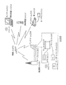
- FIG. 23 is a diagram showing an overall configuration of a content supply system ex100 that realizes a content distribution service.
- a communication service providing area is divided into desired sizes, and base stations ex106, ex107, ex108, ex109, and ex110, which are fixed wireless stations, are installed in each cell.
- This content supply system ex100 includes a computer ex111, a PDA (Personal Digital Assistant) ex112, a camera ex113, a mobile phone ex114, a game machine ex115 via the Internet ex101, the Internet service provider ex102, the telephone network ex104, and the base stations ex106 to ex110. Etc. are connected.
- PDA Personal Digital Assistant
- each device may be directly connected to the telephone network ex104 without going from the base station ex106, which is a fixed wireless station, to ex110.
- the devices may be directly connected to each other via short-range wireless or the like.
- the camera ex113 is a device that can shoot moving images such as a digital video camera
- the camera ex116 is a device that can shoot still images and movies such as a digital camera.
- the mobile phone ex114 is a GSM (registered trademark) (Global System for Mobile Communications) system, a CDMA (Code Division Multiple Access) system, a W-CDMA (Wideband-Code Division Multiple Access) system, or an LTE (Long Terminal Term Evolution). It is possible to use any of the above-mentioned systems, HSPA (High Speed Packet Access) mobile phone, PHS (Personal Handyphone System), or the like.
- the camera ex113 and the like are connected to the streaming server ex103 through the base station ex109 and the telephone network ex104, thereby enabling live distribution and the like.
- live distribution content that is shot by a user using the camera ex113 (for example, music live video) is encoded as described in each of the above embodiments (that is, in one aspect of the present invention).
- the streaming server ex103 stream-distributes the content data transmitted to the requested client. Examples of the client include a computer ex111, a PDA ex112, a camera ex113, a mobile phone ex114, and a game machine ex115 that can decode the encoded data.
- Each device that receives the distributed data decodes the received data and reproduces it (that is, functions as an image decoding device according to one embodiment of the present invention).
- the captured data may be encoded by the camera ex113, the streaming server ex103 that performs data transmission processing, or may be shared with each other.
- the decryption processing of the distributed data may be performed by the client, the streaming server ex103, or may be performed in common with each other.
- still images and / or moving image data captured by the camera ex116 may be transmitted to the streaming server ex103 via the computer ex111.
- the encoding process in this case may be performed by any of the camera ex116, the computer ex111, and the streaming server ex103, or may be performed in a shared manner.
- these encoding / decoding processes are generally performed in the computer ex111 and the LSI ex500 included in each device.
- the LSI ex500 may be configured as a single chip or a plurality of chips.
- moving image encoding / decoding software is incorporated into some recording medium (CD-ROM, flexible disk, hard disk, etc.) that can be read by the computer ex111, etc., and encoding / decoding processing is performed using the software. May be.
- moving image data acquired by the camera may be transmitted.
- the moving image data at this time is data encoded by the LSI ex500 included in the mobile phone ex114.
- the streaming server ex103 may be a plurality of servers or a plurality of computers, and may process, record, and distribute data in a distributed manner.
- the encoded data can be received and reproduced by the client.
- the information transmitted by the user can be received, decrypted and reproduced by the client in real time, and personal broadcasting can be realized even for a user who does not have special rights or facilities.
- the digital broadcasting system ex200 also includes at least the moving image encoding device (image encoding device) or the moving image decoding according to each of the above embodiments. Any of the devices (image decoding devices) can be incorporated.
- the broadcast station ex201 multiplexed data obtained by multiplexing music data and the like on video data is transmitted to a communication or satellite ex202 via radio waves.
- This video data is data encoded by the moving image encoding method described in each of the above embodiments (that is, data encoded by the image encoding apparatus according to one aspect of the present invention).
- the broadcasting satellite ex202 transmits a radio wave for broadcasting, and this radio wave is received by a home antenna ex204 capable of receiving satellite broadcasting.
- the received multiplexed data is decoded and reproduced by an apparatus such as the television (receiver) ex300 or the set top box (STB) ex217 (that is, functions as an image decoding apparatus according to one embodiment of the present invention).
- a reader / recorder ex218 that reads and decodes multiplexed data recorded on a recording medium ex215 such as a DVD or a BD, or encodes a video signal on the recording medium ex215 and, in some cases, multiplexes and writes it with a music signal. It is possible to mount the moving picture decoding apparatus or moving picture encoding apparatus described in the above embodiments. In this case, the reproduced video signal is displayed on the monitor ex219, and the video signal can be reproduced in another device or system using the recording medium ex215 on which the multiplexed data is recorded.
- a moving picture decoding apparatus may be mounted in a set-top box ex217 connected to a cable ex203 for cable television or an antenna ex204 for satellite / terrestrial broadcasting and displayed on the monitor ex219 of the television.
- the moving picture decoding apparatus may be incorporated in the television instead of the set top box.
- FIG. 25 is a diagram illustrating a television (receiver) ex300 that uses the video decoding method and the video encoding method described in each of the above embodiments.
- the television ex300 obtains or outputs multiplexed data in which audio data is multiplexed with video data via the antenna ex204 or the cable ex203 that receives the broadcast, and demodulates the received multiplexed data.
- the modulation / demodulation unit ex302 that modulates multiplexed data to be transmitted to the outside, and the demodulated multiplexed data is separated into video data and audio data, or the video data and audio data encoded by the signal processing unit ex306 Is provided with a multiplexing / demultiplexing unit ex303.
- the television ex300 also decodes the audio data and the video data, or encodes the information, the audio signal processing unit ex304, the video signal processing unit ex305 (the image encoding device or the image according to one embodiment of the present invention) A signal processing unit ex306 that functions as a decoding device), a speaker ex307 that outputs the decoded audio signal, and an output unit ex309 that includes a display unit ex308 such as a display that displays the decoded video signal. Furthermore, the television ex300 includes an interface unit ex317 including an operation input unit ex312 that receives an input of a user operation. Furthermore, the television ex300 includes a control unit ex310 that performs overall control of each unit, and a power supply circuit unit ex311 that supplies power to each unit.
- the interface unit ex317 includes a bridge unit ex313 connected to an external device such as a reader / recorder ex218, a recording unit ex216 such as an SD card, and an external recording unit such as a hard disk.
- a driver ex315 for connecting to a medium, a modem ex316 for connecting to a telephone network, and the like may be included.
- the recording medium ex216 is capable of electrically recording information by using a nonvolatile / volatile semiconductor memory element to be stored.
- Each part of the television ex300 is connected to each other via a synchronous bus.
- the television ex300 receives a user operation from the remote controller ex220 or the like, and demultiplexes the multiplexed data demodulated by the modulation / demodulation unit ex302 by the multiplexing / demultiplexing unit ex303 based on the control of the control unit ex310 having a CPU or the like. Furthermore, in the television ex300, the separated audio data is decoded by the audio signal processing unit ex304, and the separated video data is decoded by the video signal processing unit ex305 using the decoding method described in each of the above embodiments.
- the decoded audio signal and video signal are output from the output unit ex309 to the outside. At the time of output, these signals may be temporarily stored in the buffers ex318, ex319, etc. so that the audio signal and the video signal are reproduced in synchronization. Also, the television ex300 may read multiplexed data from recording media ex215 and ex216 such as a magnetic / optical disk and an SD card, not from broadcasting. Next, a configuration in which the television ex300 encodes an audio signal or a video signal and transmits the signal to the outside or to a recording medium will be described.
- the television ex300 receives a user operation from the remote controller ex220 and the like, encodes an audio signal with the audio signal processing unit ex304, and converts the video signal with the video signal processing unit ex305 based on the control of the control unit ex310. Encoding is performed using the encoding method described in (1).
- the encoded audio signal and video signal are multiplexed by the multiplexing / demultiplexing unit ex303 and output to the outside. When multiplexing, these signals may be temporarily stored in the buffers ex320, ex321, etc. so that the audio signal and the video signal are synchronized.
- a plurality of buffers ex318, ex319, ex320, and ex321 may be provided as illustrated, or one or more buffers may be shared. Further, in addition to the illustrated example, data may be stored in the buffer as a buffer material that prevents system overflow and underflow, for example, between the modulation / demodulation unit ex302 and the multiplexing / demultiplexing unit ex303.
- the television ex300 has a configuration for receiving AV input of a microphone and a camera, and performs encoding processing on the data acquired from them. Also good.
- the television ex300 has been described as a configuration capable of the above-described encoding processing, multiplexing, and external output, but these processing cannot be performed, and only the above-described reception, decoding processing, and external output are possible. It may be a configuration.
- the decoding process or the encoding process may be performed by either the television ex300 or the reader / recorder ex218,
- the reader / recorder ex218 may share with each other.
- FIG. 26 shows a configuration of the information reproducing / recording unit ex400 when data is read from or written to an optical disk.
- the information reproducing / recording unit ex400 includes elements ex401, ex402, ex403, ex404, ex405, ex406, and ex407 described below.
- the optical head ex401 irradiates a laser spot on the recording surface of the recording medium ex215 that is an optical disk to write information, and detects information reflected from the recording surface of the recording medium ex215 to read the information.
- the modulation recording unit ex402 electrically drives a semiconductor laser built in the optical head ex401 and modulates the laser beam according to the recording data.
- the reproduction demodulator ex403 amplifies the reproduction signal obtained by electrically detecting the reflected light from the recording surface by the photodetector built in the optical head ex401, separates and demodulates the signal component recorded on the recording medium ex215, and is necessary To play back information.
- the buffer ex404 temporarily holds information to be recorded on the recording medium ex215 and information reproduced from the recording medium ex215.
- the disk motor ex405 rotates the recording medium ex215.
- the servo control unit ex406 moves the optical head ex401 to a predetermined information track while controlling the rotational drive of the disk motor ex405, and performs a laser spot tracking process.
- the system control unit ex407 controls the entire information reproduction / recording unit ex400.
- the system control unit ex407 uses various types of information held in the buffer ex404, and generates and adds new information as necessary.
- the modulation recording unit ex402, the reproduction demodulation unit This is realized by recording / reproducing information through the optical head ex401 while operating the ex403 and the servo control unit ex406 in a coordinated manner.
- the system control unit ex407 includes, for example, a microprocessor, and executes these processes by executing a read / write program.
- the optical head ex401 has been described as irradiating a laser spot.
- a configuration in which higher-density recording is performed using near-field light may be used.
- FIG. 27 shows a schematic diagram of a recording medium ex215 that is an optical disk.
- Guide grooves grooves
- address information indicating the absolute position on the disc is recorded in advance on the information track ex230 by changing the shape of the groove.
- This address information includes information for specifying the position of the recording block ex231 that is a unit for recording data, and the recording block is specified by reproducing the information track ex230 and reading the address information in a recording or reproducing apparatus.
- the recording medium ex215 includes a data recording area ex233, an inner peripheral area ex232, and an outer peripheral area ex234.
- the area used for recording user data is the data recording area ex233, and the inner circumference area ex232 and the outer circumference area ex234 arranged on the inner or outer circumference of the data recording area ex233 are used for specific purposes other than user data recording. Used.
- the information reproducing / recording unit ex400 reads / writes encoded audio data, video data, or multiplexed data obtained by multiplexing these data with respect to the data recording area ex233 of the recording medium ex215.
- an optical disk such as a single-layer DVD or BD has been described as an example.
- the present invention is not limited to these, and an optical disk having a multilayer structure and capable of recording other than the surface may be used.
- an optical disc with a multi-dimensional recording / reproducing structure such as recording information using light of different wavelengths in the same place on the disc, or recording different layers of information from various angles. It may be.
- the car ex210 having the antenna ex205 can receive data from the satellite ex202 and the like, and the moving image can be reproduced on a display device such as the car navigation ex211 that the car ex210 has.
- the configuration of the car navigation ex211 may include a configuration including a GPS receiving unit in the configuration illustrated in FIG. 25, and the same may be applied to the computer ex111, the mobile phone ex114, and the like.
- FIG. 28A is a diagram showing the mobile phone ex114 using the moving picture decoding method and the moving picture encoding method described in the above embodiment.
- the mobile phone ex114 includes an antenna ex350 for transmitting and receiving radio waves to and from the base station ex110, a camera unit ex365 capable of capturing video and still images, a video captured by the camera unit ex365, a video received by the antenna ex350, and the like Is provided with a display unit ex358 such as a liquid crystal display for displaying the decrypted data.
- the mobile phone ex114 further includes a main body unit having an operation key unit ex366, an audio output unit ex357 such as a speaker for outputting audio, an audio input unit ex356 such as a microphone for inputting audio, a captured video,
- an audio input unit ex356 such as a microphone for inputting audio
- a captured video In the memory unit ex367 for storing encoded data or decoded data such as still images, recorded audio, received video, still images, mails, or the like, or an interface unit with a recording medium for storing data
- a slot ex364 is provided.
- the mobile phone ex114 has a power supply circuit part ex361, an operation input control part ex362, and a video signal processing part ex355 with respect to a main control part ex360 that comprehensively controls each part of the main body including the display part ex358 and the operation key part ex366.
- a camera interface unit ex363, an LCD (Liquid Crystal Display) control unit ex359, a modulation / demodulation unit ex352, a multiplexing / demultiplexing unit ex353, an audio signal processing unit ex354, a slot unit ex364, and a memory unit ex367 are connected to each other via a bus ex370. ing.
- the power supply circuit unit ex361 starts up the mobile phone ex114 in an operable state by supplying power from the battery pack to each unit.
- the cellular phone ex114 converts the audio signal collected by the audio input unit ex356 in the voice call mode into a digital audio signal by the audio signal processing unit ex354 based on the control of the main control unit ex360 having a CPU, a ROM, a RAM, and the like. Then, this is subjected to spectrum spread processing by the modulation / demodulation unit ex352, digital-analog conversion processing and frequency conversion processing are performed by the transmission / reception unit ex351, and then transmitted via the antenna ex350.
- the mobile phone ex114 also amplifies the received data received via the antenna ex350 in the voice call mode, performs frequency conversion processing and analog-digital conversion processing, performs spectrum despreading processing by the modulation / demodulation unit ex352, and performs voice signal processing unit After being converted into an analog audio signal by ex354, this is output from the audio output unit ex357.
- the text data of the e-mail input by operating the operation key unit ex366 of the main unit is sent to the main control unit ex360 via the operation input control unit ex362.
- the main control unit ex360 performs spread spectrum processing on the text data in the modulation / demodulation unit ex352, performs digital analog conversion processing and frequency conversion processing in the transmission / reception unit ex351, and then transmits the text data to the base station ex110 via the antenna ex350.
- almost the reverse process is performed on the received data and output to the display unit ex358.
- the video signal processing unit ex355 compresses the video signal supplied from the camera unit ex365 by the moving image encoding method described in the above embodiments. Encode (that is, function as an image encoding device according to an aspect of the present invention), and send the encoded video data to the multiplexing / demultiplexing unit ex353.
- the audio signal processing unit ex354 encodes the audio signal picked up by the audio input unit ex356 while the camera unit ex365 images a video, a still image, etc., and sends the encoded audio data to the multiplexing / separating unit ex353. To do.
- the multiplexing / demultiplexing unit ex353 multiplexes the encoded video data supplied from the video signal processing unit ex355 and the encoded audio data supplied from the audio signal processing unit ex354 by a predetermined method, and is obtained as a result.
- the multiplexed data is subjected to spread spectrum processing by the modulation / demodulation unit (modulation / demodulation circuit unit) ex352, digital-analog conversion processing and frequency conversion processing by the transmission / reception unit ex351, and then transmitted via the antenna ex350.
- the multiplexing / separating unit ex353 separates the multiplexed data into a video data bit stream and an audio data bit stream, and performs video signal processing on the video data encoded via the synchronization bus ex370.
- the encoded audio data is supplied to the audio signal processing unit ex354 while being supplied to the unit ex355.
- the video signal processing unit ex355 decodes the video signal by decoding using the video decoding method corresponding to the video encoding method described in each of the above embodiments (that is, an image according to an aspect of the present invention).
- video and still images included in the moving image file linked to the home page are displayed from the display unit ex358 via the LCD control unit ex359.
- the audio signal processing unit ex354 decodes the audio signal, and the audio is output from the audio output unit ex357.
- the terminal such as the mobile phone ex114 is referred to as a transmission terminal having only an encoder and a receiving terminal having only a decoder.
- a transmission terminal having only an encoder
- a receiving terminal having only a decoder.
- multiplexed data in which music data or the like is multiplexed with video data is received and transmitted, but data in which character data or the like related to video is multiplexed in addition to audio data It may be video data itself instead of multiplexed data.
- the moving picture encoding method or the moving picture decoding method shown in each of the above embodiments can be used in any of the above-described devices / systems. The described effect can be obtained.
- multiplexed data obtained by multiplexing audio data or the like with video data is configured to include identification information indicating which standard the video data conforms to.
- identification information indicating which standard the video data conforms to.
- FIG. 29 is a diagram showing a structure of multiplexed data.
- multiplexed data is obtained by multiplexing one or more of a video stream, an audio stream, a presentation graphics stream (PG), and an interactive graphics stream.
- the video stream indicates the main video and sub-video of the movie
- the audio stream (IG) indicates the main audio portion of the movie and the sub-audio mixed with the main audio
- the presentation graphics stream indicates the subtitles of the movie.
- the main video indicates a normal video displayed on the screen
- the sub-video is a video displayed on a small screen in the main video.
- the interactive graphics stream indicates an interactive screen created by arranging GUI components on the screen.
- the video stream is encoded by the moving image encoding method or apparatus shown in the above embodiments, or the moving image encoding method or apparatus conforming to the conventional standards such as MPEG-2, MPEG4-AVC, and VC-1. ing.
- the audio stream is encoded by a method such as Dolby AC-3, Dolby Digital Plus, MLP, DTS, DTS-HD, or linear PCM.
- Each stream included in the multiplexed data is identified by PID. For example, 0x1011 for video streams used for movie images, 0x1100 to 0x111F for audio streams, 0x1200 to 0x121F for presentation graphics, 0x1400 to 0x141F for interactive graphics streams, 0x1B00 to 0x1B1F are assigned to the video stream used for the sub-picture, and 0x1A00 to 0x1A1F are assigned to the audio stream used for the sub-audio mixed with the main audio.
- FIG. 30 is a diagram schematically showing how multiplexed data is multiplexed.
- a video stream ex235 composed of a plurality of video frames and an audio stream ex238 composed of a plurality of audio frames are converted into PES packet sequences ex236 and ex239, respectively, and converted into TS packets ex237 and ex240.
- the data of the presentation graphics stream ex241 and interactive graphics ex244 are converted into PES packet sequences ex242 and ex245, respectively, and further converted into TS packets ex243 and ex246.
- the multiplexed data ex247 is configured by multiplexing these TS packets into one stream.
- FIG. 31 shows in more detail how the video stream is stored in the PES packet sequence.
- the first row in FIG. 31 shows a video frame sequence of the video stream.
- the second level shows a PES packet sequence.
- a plurality of Video Presentation Units in the video stream are divided into pictures, B pictures, and P pictures, and are stored in the payload of the PES packet.
- Each PES packet has a PES header, and a PTS (Presentation Time-Stamp) that is a display time of a picture and a DTS (Decoding Time-Stamp) that is a decoding time of a picture are stored in the PES header.
- PTS Presentation Time-Stamp
- DTS Decoding Time-Stamp
- FIG. 32 shows the format of TS packets that are finally written in the multiplexed data.
- the TS packet is a 188-byte fixed-length packet composed of a 4-byte TS header having information such as a PID for identifying a stream and a 184-byte TS payload for storing data.
- the PES packet is divided and stored in the TS payload.
- a 4-byte TP_Extra_Header is added to a TS packet, forms a 192-byte source packet, and is written in multiplexed data.
- TP_Extra_Header information such as ATS (Arrival_Time_Stamp) is described.
- ATS indicates the transfer start time of the TS packet to the PID filter of the decoder.
- Source packets are arranged in the multiplexed data as shown in the lower part of FIG. 32, and the number incremented from the head of the multiplexed data is called SPN (source packet number).
- TS packets included in the multiplexed data include PAT (Program Association Table), PMT (Program Map Table), PCR (Program Clock Reference), and the like in addition to each stream such as video / audio / caption.
- PAT indicates what the PID of the PMT used in the multiplexed data is, and the PID of the PAT itself is registered as 0.
- the PMT has the PID of each stream such as video / audio / subtitles included in the multiplexed data and the attribute information of the stream corresponding to each PID, and has various descriptors related to the multiplexed data.
- the descriptor includes copy control information for instructing permission / non-permission of copying of multiplexed data.
- the PCR corresponds to the ATS in which the PCR packet is transferred to the decoder. Contains STC time information.
- FIG. 33 is a diagram for explaining the data structure of the PMT in detail.
- a PMT header describing the length of data included in the PMT is arranged at the head of the PMT.
- a plurality of descriptors related to multiplexed data are arranged.
- the copy control information and the like are described as descriptors.
- a plurality of pieces of stream information regarding each stream included in the multiplexed data are arranged.
- the stream information includes a stream descriptor in which a stream type, a stream PID, and stream attribute information (frame rate, aspect ratio, etc.) are described to identify a compression codec of the stream.
- the multiplexed data is recorded together with the multiplexed data information file.
- the multiplexed data information file is management information of multiplexed data, has a one-to-one correspondence with the multiplexed data, and includes multiplexed data information, stream attribute information, and an entry map.
- the multiplexed data information is composed of a system rate, a reproduction start time, and a reproduction end time.
- the system rate indicates a maximum transfer rate of multiplexed data to a PID filter of a system target decoder described later.
- the ATS interval included in the multiplexed data is set to be equal to or less than the system rate.
- the playback start time is the PTS of the first video frame of the multiplexed data
- the playback end time is set by adding the playback interval for one frame to the PTS of the video frame at the end of the multiplexed data.
- attribute information about each stream included in the multiplexed data is registered for each PID.
- the attribute information has different information for each video stream, audio stream, presentation graphics stream, and interactive graphics stream.
- the video stream attribute information includes the compression codec used to compress the video stream, the resolution of the individual picture data constituting the video stream, the aspect ratio, and the frame rate. It has information such as how much it is.
- the audio stream attribute information includes the compression codec used to compress the audio stream, the number of channels included in the audio stream, the language supported, and the sampling frequency. With information. These pieces of information are used for initialization of the decoder before the player reproduces it.
- the stream type included in the PMT is used.
- video stream attribute information included in the multiplexed data information is used.
- the video encoding shown in each of the above embodiments for the stream type or video stream attribute information included in the PMT.
- FIG. 36 shows the steps of the moving picture decoding method according to the present embodiment.
- step exS100 the stream type included in the PMT or the video stream attribute information included in the multiplexed data information is acquired from the multiplexed data.
- step exS101 it is determined whether or not the stream type or the video stream attribute information indicates multiplexed data generated by the moving picture encoding method or apparatus described in the above embodiments. To do.
- step exS102 the above embodiments are performed. Decoding is performed by selecting a reference picture or a motion vector from candidates by the moving picture decoding method shown in the embodiment.
- the conventional information Decoding is performed by a moving image decoding method compliant with the standard. For example, if the attribute information indicates that it conforms to the MPEG4-AVC standard, it is not selected from a plurality of candidates, but from motion vectors of neighboring blocks spatially or temporally adjacent. Decoding is performed using the calculated motion vector.
- FIG. 37 shows a configuration of the LSI ex500 that is made into one chip.
- the LSI ex500 includes elements ex501, ex502, ex503, ex504, ex505, ex506, ex507, ex508, and ex509 described below, and each element is connected via a bus ex510.
- the power supply circuit unit ex505 is activated to an operable state by supplying power to each unit when the power supply is on.
- the LSI ex500 uses the AV I / O ex509 to perform the microphone ex117 and the camera ex113 based on the control of the control unit ex501 including the CPU ex502, the memory controller ex503, the stream controller ex504, the driving frequency control unit ex512, and the like.
- the AV signal is input from the above.
- the input AV signal is temporarily stored in an external memory ex511 such as SDRAM.
- the accumulated data is divided into a plurality of times as appropriate according to the processing amount and the processing speed and sent to the signal processing unit ex507, and the signal processing unit ex507 encodes an audio signal and / or video. Signal encoding is performed.
- the encoding process of the video signal is the encoding process described in the above embodiments.
- the signal processing unit ex507 further performs processing such as multiplexing the encoded audio data and the encoded video data according to circumstances, and outputs the result from the stream I / Oex 506 to the outside.
- the output multiplexed data is transmitted to the base station ex107 or written to the recording medium ex215. It should be noted that data should be temporarily stored in the buffer ex508 so as to be synchronized when multiplexing.
- the memory ex511 is described as an external configuration of the LSI ex500.
- a configuration included in the LSI ex500 may be used.
- the number of buffers ex508 is not limited to one, and a plurality of buffers may be provided.
- the LSI ex500 may be made into one chip or a plurality of chips.
- control unit ex501 includes the CPU ex502, the memory controller ex503, the stream controller ex504, the drive frequency control unit ex512, and the like, but the configuration of the control unit ex501 is not limited to this configuration.
- the signal processing unit ex507 may further include a CPU.
- the CPU ex502 may be configured to include a signal processing unit ex507 or, for example, an audio signal processing unit that is a part of the signal processing unit ex507.
- the control unit ex501 is configured to include a signal processing unit ex507 or a CPU ex502 having a part thereof.
- LSI LSI
- IC system LSI
- super LSI ultra LSI depending on the degree of integration
- the method of circuit integration is not limited to LSI, and implementation with a dedicated circuit or a general-purpose processor is also possible.
- An FPGA Field Programmable Gate Array
- Such a programmable logic device typically loads or reads a program constituting software or firmware from a memory or the like, thereby moving the moving picture coding method or moving picture shown in each of the above embodiments.
- An image decoding method can be performed.
- FIG. 38 shows a configuration ex800 in the present embodiment.
- the drive frequency switching unit ex803 sets the drive frequency high when the video data is generated by the moving image encoding method or apparatus described in the above embodiments.
- the decoding processing unit ex801 that executes the moving picture decoding method described in each of the above embodiments is instructed to decode the video data.
- the video data is video data compliant with the conventional standard, compared to the case where the video data is generated by the moving picture encoding method or apparatus shown in the above embodiments, Set the drive frequency low. Then, it instructs the decoding processing unit ex802 compliant with the conventional standard to decode the video data.
- the drive frequency switching unit ex803 includes the CPU ex502 and the drive frequency control unit ex512 in FIG.
- the decoding processing unit ex801 that executes the moving picture decoding method described in each of the above embodiments and the decoding processing unit ex802 that conforms to the conventional standard correspond to the signal processing unit ex507 in FIG.
- the CPU ex502 identifies which standard the video data conforms to. Then, based on the signal from the CPU ex502, the drive frequency control unit ex512 sets the drive frequency. Further, based on the signal from the CPU ex502, the signal processing unit ex507 decodes the video data.
- the identification information described in the fifth embodiment may be used.
- the identification information is not limited to that described in the fifth embodiment, and any information that can identify which standard the video data conforms to may be used. For example, it is possible to identify which standard the video data conforms to based on an external signal that identifies whether the video data is used for a television or a disk. In some cases, identification may be performed based on such an external signal.
- the selection of the driving frequency in the CPU ex502 may be performed based on, for example, a lookup table in which video data standards and driving frequencies are associated with each other as shown in FIG. The look-up table is stored in the buffer ex508 or the internal memory of the LSI, and the CPU ex502 can select the drive frequency by referring to the look-up table.
- FIG. 39 shows steps for executing the method of the present embodiment.
- the signal processing unit ex507 acquires identification information from the multiplexed data.
- the CPU ex502 identifies whether the video data is generated by the encoding method or apparatus described in each of the above embodiments based on the identification information.
- the CPU ex502 sends a signal for setting the drive frequency high to the drive frequency control unit ex512. Then, the drive frequency control unit ex512 sets a high drive frequency.
- step exS203 the CPU ex502 drives the signal for setting the drive frequency low. This is sent to the frequency control unit ex512. Then, in the drive frequency control unit ex512, the drive frequency is set to be lower than that in the case where the video data is generated by the encoding method or apparatus described in the above embodiments.
- the power saving effect can be further enhanced by changing the voltage applied to the LSI ex500 or the device including the LSI ex500 in conjunction with the switching of the driving frequency. For example, when the drive frequency is set low, it is conceivable that the voltage applied to the LSI ex500 or the device including the LSI ex500 is set low as compared with the case where the drive frequency is set high.
- the setting method of the driving frequency may be set to a high driving frequency when the processing amount at the time of decoding is large, and to a low driving frequency when the processing amount at the time of decoding is small. It is not limited to the method.
- the amount of processing for decoding video data compliant with the MPEG4-AVC standard is larger than the amount of processing for decoding video data generated by the moving picture encoding method or apparatus described in the above embodiments. It is conceivable that the setting of the driving frequency is reversed to that in the case described above.
- the method for setting the drive frequency is not limited to the configuration in which the drive frequency is lowered.
- the voltage applied to the LSIex500 or the apparatus including the LSIex500 is set high.
- the driving of the CPU ex502 is stopped.
- the CPU ex502 is temporarily stopped because there is room in processing. Is also possible. Even when the identification information indicates that the video data is generated by the moving image encoding method or apparatus described in each of the above embodiments, if there is a margin for processing, the CPU ex502 is temporarily driven. It can also be stopped. In this case, it is conceivable to set the stop time shorter than in the case where the video data conforms to the conventional standards such as MPEG-2, MPEG4-AVC, and VC-1.
- a plurality of video data that conforms to different standards may be input to the above-described devices and systems such as a television and a mobile phone.
- the signal processing unit ex507 of the LSI ex500 needs to support a plurality of standards in order to be able to decode even when a plurality of video data complying with different standards is input.
- the signal processing unit ex507 corresponding to each standard is used individually, there is a problem that the circuit scale of the LSI ex500 increases and the cost increases.
- a decoding processing unit for executing the moving picture decoding method shown in each of the above embodiments and a decoding conforming to a standard such as MPEG-2, MPEG4-AVC, or VC-1
- the processing unit is partly shared.
- An example of this configuration is shown as ex900 in FIG. 41A.
- the moving picture decoding method shown in each of the above embodiments and the moving picture decoding method compliant with the MPEG4-AVC standard are processed in processes such as entropy coding, inverse quantization, deblocking filter, and motion compensation. Some contents are common.
- the decoding processing unit ex902 corresponding to the MPEG4-AVC standard is shared, and for other processing contents specific to one aspect of the present invention that do not correspond to the MPEG4-AVC standard, a dedicated decoding processing unit A configuration using ex901 is conceivable.
- a dedicated decoding processing unit ex901 is used for motion compensation, and other entropy decoding, deblocking filter, and inverse quantization are performed. For any or all of these processes, it is conceivable to share the decoding processing unit.
- the decoding processing unit for executing the moving picture decoding method described in each of the above embodiments is shared, and the processing content specific to the MPEG4-AVC standard As for, a configuration using a dedicated decoding processing unit may be used.
- ex1000 in FIG. 41B shows another example in which processing is partially shared.
- a dedicated decoding processing unit ex1001 corresponding to the processing content specific to one aspect of the present invention
- a dedicated decoding processing unit ex1002 corresponding to the processing content specific to another conventional standard
- a common decoding processing unit ex1003 corresponding to the processing contents common to the moving image decoding method according to the above and other conventional moving image decoding methods.
- the dedicated decoding processing units ex1001 and ex1002 are not necessarily specialized in one aspect of the present invention or processing content specific to other conventional standards, and can execute other general-purpose processing. Also good.
- the configuration of the present embodiment can be implemented by LSI ex500.
- the processing content common to the moving picture decoding method according to one aspect of the present invention and the moving picture decoding method of the conventional standard reduces the circuit scale of the LSI by sharing the decoding processing unit, In addition, the cost can be reduced.
- the present invention is applicable to, for example, a television receiver, a digital video recorder, a car navigation, a mobile phone, a digital camera, a digital video camera, or the like.
Abstract
Description
本発明者は、ピクチャをブロック毎に符号化する画像符号化方法に関して、課題を見出した。以下、具体的に説明する。 (Knowledge that became the basis of the present invention)
The present inventor has found a problem regarding an image encoding method for encoding a picture for each block. This will be specifically described below.
図2は、本実施の形態に係る画像符号化装置の構成を示すブロック図である。図2の通り、画像符号化装置100は、減算部101、直交変換部102、量子化部103、逆量子化部105、逆直交変換部106、加算部107、ブロックメモリ108、フレームメモリ109、イントラ予測部110、インター予測部111、切り替え部112、インター予測制御部114、参照ピクチャリスト算出部115、ピクチャタイプ決定部113、予測動きベクトル候補算出部116、および、可変長符号化部104を備える。 (Embodiment 1)
FIG. 2 is a block diagram showing the configuration of the image coding apparatus according to the present embodiment. As shown in FIG. 2, the
図17は、本実施の形態に係る画像復号装置の構成を示すブロック図である。図17の通り、画像復号装置200は、可変長復号部204、逆量子化部205、逆直交変換部206、加算部207、ブロックメモリ208、フレームメモリ209、イントラ予測部210、インター予測部211、切り替え部212、インター予測制御部214、参照ピクチャリスト算出部215、および、予測動きベクトル候補算出部216を備える。 (Embodiment 2)
FIG. 17 is a block diagram showing a configuration of the image decoding apparatus according to the present embodiment. As illustrated in FIG. 17, the
本実施の形態では、上記の複数の実施の形態で示された特徴的な構成および特徴的な手順が確認的に示される。 (Embodiment 3)
In the present embodiment, the characteristic configuration and the characteristic procedure shown in the plurality of embodiments are confirmed.
上記各実施の形態で示した動画像符号化方法(画像符号化方法)または動画像復号化方法(画像復号方法)の構成を実現するためのプログラムを記憶メディアに記録することにより、上記各実施の形態で示した処理を独立したコンピュータシステムにおいて簡単に実施することが可能となる。記憶メディアは、磁気ディスク、光ディスク、光磁気ディスク、ICカード、半導体メモリ等、プログラムを記録できるものであればよい。 (Embodiment 4)
By recording a program for realizing the configuration of the moving image encoding method (image encoding method) or the moving image decoding method (image decoding method) shown in each of the above embodiments on a storage medium, each of the above embodiments It is possible to easily execute the processing shown in the form in the independent computer system. The storage medium may be any medium that can record a program, such as a magnetic disk, an optical disk, a magneto-optical disk, an IC card, and a semiconductor memory.
上記各実施の形態で示した動画像符号化方法または装置と、MPEG-2、MPEG4-AVC、VC-1など異なる規格に準拠した動画像符号化方法または装置とを、必要に応じて適宜切替えることにより、映像データを生成することも可能である。 (Embodiment 5)
The moving picture coding method or apparatus shown in the above embodiments and the moving picture coding method or apparatus compliant with different standards such as MPEG-2, MPEG4-AVC, and VC-1 are appropriately switched as necessary. Thus, it is also possible to generate video data.
上記各実施の形態で示した動画像符号化方法および装置、動画像復号化方法および装置は、典型的には集積回路であるLSIで実現される。一例として、図37に1チップ化されたLSIex500の構成を示す。LSIex500は、以下に説明する要素ex501、ex502、ex503、ex504、ex505、ex506、ex507、ex508、ex509を備え、各要素はバスex510を介して接続している。電源回路部ex505は電源がオン状態の場合に各部に対して電力を供給することで動作可能な状態に起動する。 (Embodiment 6)
The moving picture encoding method and apparatus and moving picture decoding method and apparatus described in the above embodiments are typically realized by an LSI that is an integrated circuit. As an example, FIG. 37 shows a configuration of the LSI ex500 that is made into one chip. The LSI ex500 includes elements ex501, ex502, ex503, ex504, ex505, ex506, ex507, ex508, and ex509 described below, and each element is connected via a bus ex510. The power supply circuit unit ex505 is activated to an operable state by supplying power to each unit when the power supply is on.
上記各実施の形態で示した動画像符号化方法または装置によって生成された映像データを復号する場合、従来のMPEG-2、MPEG4-AVC、VC-1などの規格に準拠する映像データを復号する場合に比べ、処理量が増加することが考えられる。そのため、LSIex500において、従来の規格に準拠する映像データを復号する際のCPUex502の駆動周波数よりも高い駆動周波数に設定する必要がある。しかし、駆動周波数を高くすると、消費電力が高くなるという課題が生じる。 (Embodiment 7)
When decoding the video data generated by the moving picture encoding method or apparatus shown in the above embodiments, the video data conforming to the conventional standards such as MPEG-2, MPEG4-AVC, and VC-1 is decoded. It is conceivable that the amount of processing increases compared to the case. Therefore, in LSI ex500, it is necessary to set a driving frequency higher than the driving frequency of CPU ex502 when decoding video data compliant with the conventional standard. However, when the drive frequency is increased, there is a problem that power consumption increases.
テレビや、携帯電話など、上述した機器・システムには、異なる規格に準拠する複数の映像データが入力される場合がある。このように、異なる規格に準拠する複数の映像データが入力された場合にも復号できるようにするために、LSIex500の信号処理部ex507が複数の規格に対応している必要がある。しかし、それぞれの規格に対応する信号処理部ex507を個別に用いると、LSIex500の回路規模が大きくなり、また、コストが増加するという課題が生じる。 (Embodiment 8)
A plurality of video data that conforms to different standards may be input to the above-described devices and systems such as a television and a mobile phone. As described above, the signal processing unit ex507 of the LSI ex500 needs to support a plurality of standards in order to be able to decode even when a plurality of video data complying with different standards is input. However, when the signal processing unit ex507 corresponding to each standard is used individually, there is a problem that the circuit scale of the LSI ex500 increases and the cost increases.
101 減算部
102 直交変換部
103 量子化部
104 可変長符号化部
105、205 逆量子化部
106、206 逆直交変換部
107、207 加算部
108、208 ブロックメモリ
109、209 フレームメモリ
110、210 イントラ予測部
111、211 インター予測部
112、212 切り替え部
113 ピクチャタイプ決定部
114、214 インター予測制御部
115、215 参照ピクチャリスト算出部
116、216 予測動きベクトル候補算出部
200、400 画像復号装置
204 可変長復号部
301、401 生成部
302 符号化部
402 復号部 100, 300
Claims (13)
- 現ピクチャをブロック毎に符号化する画像符号化方法であって、
前記現ピクチャの符号化において参照可能な参照ピクチャに参照ピクチャインデックスを割り当てて、前記参照ピクチャインデックスが割り当てられた前記参照ピクチャを含む参照ピクチャリストを生成する生成ステップと、
前記現ピクチャに含まれる現ブロックの符号化において参照される参照ピクチャを前記参照ピクチャリストから特定し、特定された前記参照ピクチャを参照して、前記現ブロックを符号化する符号化ステップとを含み、
前記生成ステップでは、前記現ピクチャが属する現ビューとは異なる参照ビューに属する参照ピクチャが前記現ピクチャの符号化において参照される可能性がある場合、前記参照ビューに属する参照ピクチャを前記参照ピクチャリストに追加する
画像符号化方法。 An image encoding method for encoding a current picture for each block,
Generating a reference picture list including the reference picture to which the reference picture index is assigned by assigning a reference picture index to a reference picture that can be referred to in encoding of the current picture;
A coding step of identifying a reference picture to be referred to in coding of a current block included in the current picture from the reference picture list, and coding the current block with reference to the identified reference picture. ,
In the generating step, if there is a possibility that a reference picture belonging to a reference view different from the current view to which the current picture belongs may be referred to in the encoding of the current picture, the reference picture belonging to the reference view is added to the reference picture list. Image coding method to add to. - 前記生成ステップでは、パラメータを用いて前記参照ピクチャリストを生成し、
前記符号化ステップでは、さらに、前記参照ピクチャリストの生成に用いられた前記パラメータを符号化する
請求項1に記載の画像符号化方法。 In the generating step, the reference picture list is generated using parameters,
The image encoding method according to claim 1, wherein in the encoding step, the parameter used for generating the reference picture list is further encoded. - 前記生成ステップでは、さらに、前記参照ビューに属する参照ピクチャが前記現ピクチャの符号化において参照される可能性がある場合、
前記現ビューに属する参照可能な参照ピクチャの数である第1の数に、前記参照ビューに属する参照可能な参照ピクチャの数である第2の数を加算することによって、前記現ピクチャの符号化において参照可能な参照ピクチャの数である第3の数を算出し、
前記参照ピクチャリストに含まれる前記参照ピクチャに対して割り当てられた前記参照ピクチャインデックスを修正するための修正リストの値の範囲を、前記第3の数に基づいて決定する
請求項1または2に記載の画像符号化方法。 In the generating step, when a reference picture belonging to the reference view may be referred to in encoding of the current picture,
Encoding the current picture by adding a second number that is the number of reference pictures that can be referred to that belong to the reference view to a first number that is the number of reference pictures that can be referred to that belong to the current view A third number that is the number of reference pictures that can be referenced in
The range of values of a correction list for correcting the reference picture index assigned to the reference picture included in the reference picture list is determined based on the third number. Image coding method. - 前記生成ステップでは、さらに、前記現ビューがノンベースビューであるか否かに基づいて、前記参照ビューに属する参照ピクチャが前記現ピクチャの符号化において参照される可能性があるか否かを判定する
請求項1~3のいずれか1項に記載の画像符号化方法。 In the generating step, it is further determined whether or not a reference picture belonging to the reference view may be referred to in the encoding of the current picture based on whether or not the current view is a non-base view. The image encoding method according to any one of claims 1 to 3. - 前記生成ステップでは、さらに、符号化順で前記現ビューに対して割り当てられたビューオーダーインデックスに基づいて、前記現ビューがノンベースビューであるか否かを判定する
請求項4に記載の画像符号化方法。 5. The image code according to claim 4, wherein the generating step further determines whether or not the current view is a non-base view based on a view order index assigned to the current view in an encoding order. Method. - 現ピクチャをブロック毎に復号する画像復号方法であって、
前記現ピクチャの復号において参照可能な参照ピクチャに参照ピクチャインデックスを割り当てて、前記参照ピクチャインデックスが割り当てられた前記参照ピクチャを含む参照ピクチャリストを生成する生成ステップと、
前記現ピクチャに含まれる現ブロックの復号において参照される参照ピクチャを前記参照ピクチャリストから特定し、特定された前記参照ピクチャを参照して、前記現ブロックを復号する復号ステップとを含み、
前記生成ステップでは、前記現ピクチャが属する現ビューとは異なる参照ビューに属する参照ピクチャが前記現ピクチャの復号において参照される可能性がある場合、前記参照ビューに属する参照ピクチャを前記参照ピクチャリストに追加する
画像復号方法。 An image decoding method for decoding a current picture for each block,
Generating a reference picture list including the reference picture to which the reference picture index is assigned by assigning a reference picture index to a reference picture that can be referred to in decoding of the current picture;
A decoding step of identifying a reference picture to be referenced in decoding of a current block included in the current picture from the reference picture list, and decoding the current block with reference to the identified reference picture,
In the generating step, when there is a possibility that a reference picture belonging to a reference view different from the current view to which the current picture belongs is referred to in decoding of the current picture, the reference picture belonging to the reference view is added to the reference picture list. Image decoding method to add. - 前記復号ステップでは、さらに、前記参照ピクチャリストの生成に用いられるパラメータを復号し、
前記生成ステップでは、復号された前記パラメータを用いて、前記参照ピクチャリストを生成する
請求項6に記載の画像復号方法。 In the decoding step, further, parameters used for generating the reference picture list are decoded,
The image decoding method according to claim 6, wherein, in the generation step, the reference picture list is generated using the decoded parameter. - 前記生成ステップでは、さらに、前記参照ビューに属する参照ピクチャが前記現ピクチャの復号において参照される可能性がある場合、
前記現ビューに属する参照可能な参照ピクチャの数である第1の数に、前記参照ビューに属する参照可能な参照ピクチャの数である第2の数を加算することによって、前記現ピクチャの復号において参照可能な参照ピクチャの数である第3の数を算出し、
前記参照ピクチャリストに含まれる前記参照ピクチャに対して割り当てられた前記参照ピクチャインデックスを修正するための修正リストの値の範囲を、前記第3の数に基づいて決定する
請求項6または7に記載の画像復号方法。 In the generating step, when a reference picture belonging to the reference view may be referred to in decoding of the current picture,
In decoding the current picture, by adding a second number that is the number of reference pictures that can be referred to that belong to the reference view to a first number that is the number of reference pictures that can be referred to that belong to the current view. Calculating a third number which is the number of reference pictures that can be referred to;
The range of values of a correction list for correcting the reference picture index assigned to the reference picture included in the reference picture list is determined based on the third number. Image decoding method. - 前記生成ステップでは、さらに、前記現ビューがノンベースビューであるか否かに基づいて、前記参照ビューに属する参照ピクチャが前記現ピクチャの復号において参照される可能性があるか否かを判定する
請求項6~8のいずれか1項に記載の画像復号方法。 In the generating step, it is further determined whether or not a reference picture belonging to the reference view may be referred to in decoding of the current picture based on whether or not the current view is a non-base view. The image decoding method according to any one of claims 6 to 8. - 前記生成ステップでは、さらに、復号順で前記現ビューに対して割り当てられたビューオーダーインデックスに基づいて、前記現ビューがノンベースビューであるか否かを判定する
請求項9に記載の画像復号方法。 The image decoding method according to claim 9, wherein the generation step further determines whether or not the current view is a non-base view based on a view order index assigned to the current view in decoding order. . - 現ピクチャをブロック毎に符号化する画像符号化装置であって、
前記現ピクチャの符号化において参照可能な参照ピクチャに参照ピクチャインデックスを割り当てて、前記参照ピクチャインデックスが割り当てられた前記参照ピクチャを含む参照ピクチャリストを生成する生成部と、
前記現ピクチャに含まれる現ブロックの符号化において参照される参照ピクチャを前記参照ピクチャリストから特定し、特定された前記参照ピクチャを参照して、前記現ブロックを符号化する符号化部とを備え、
前記生成部は、前記現ピクチャが属する現ビューとは異なる参照ビューに属する参照ピクチャが前記現ピクチャの符号化において参照される可能性がある場合、前記参照ビューに属する参照ピクチャを前記参照ピクチャリストに追加する
画像符号化装置。 An image encoding device for encoding a current picture for each block,
A generating unit that allocates a reference picture index to a reference picture that can be referred to in encoding of the current picture, and generates a reference picture list including the reference picture to which the reference picture index is allocated;
A coding section that identifies a reference picture to be referred to in coding of a current block included in the current picture from the reference picture list, and codes the current block with reference to the identified reference picture. ,
When there is a possibility that a reference picture belonging to a reference view different from the current view to which the current picture belongs may be referred to in the encoding of the current picture, the generation unit selects a reference picture belonging to the reference view to the reference picture list Add to the image encoding device. - 現ピクチャをブロック毎に復号する画像復号装置であって、
前記現ピクチャの復号において参照可能な参照ピクチャに参照ピクチャインデックスを割り当てて、前記参照ピクチャインデックスが割り当てられた前記参照ピクチャを含む参照ピクチャリストを生成する生成部と、
前記現ピクチャに含まれる現ブロックの復号において参照される参照ピクチャを前記参照ピクチャリストから特定し、特定された前記参照ピクチャを参照して、前記現ブロックを復号する復号部とを備え、
前記生成部は、前記現ピクチャが属する現ビューとは異なる参照ビューに属する参照ピクチャが前記現ピクチャの復号において参照される可能性がある場合、前記参照ビューに属する参照ピクチャを前記参照ピクチャリストに追加する
画像復号装置。 An image decoding device for decoding a current picture for each block,
A generating unit that assigns a reference picture index to a reference picture that can be referred to in decoding of the current picture, and generates a reference picture list including the reference picture to which the reference picture index is assigned;
A decoding unit for identifying a reference picture to be referred to in decoding of a current block included in the current picture from the reference picture list, and decoding the current block with reference to the identified reference picture;
When there is a possibility that a reference picture belonging to a reference view different from the current view to which the current picture belongs may be referred to in decoding of the current picture, the generation unit adds the reference picture belonging to the reference view to the reference picture list. Image decoding device to add. - 請求項11に記載の画像符号化装置と、
請求項12に記載の画像復号装置とを備える
画像符号化復号装置。 An image encoding device according to claim 11,
An image encoding / decoding device comprising: the image decoding device according to claim 12.
Priority Applications (6)
| Application Number | Priority Date | Filing Date | Title |
|---|---|---|---|
| CN201380002077.6A CN103650497B (en) | 2012-03-02 | 2013-02-15 | Method for encoding images, picture decoding method, picture coding device, picture decoding apparatus and image encoding/decoding device |
| KR1020147000421A KR102137149B1 (en) | 2012-03-02 | 2013-02-15 | Image coding method, image decoding method, image coding device, image decoding device, and image coding-decoding device |
| US14/130,505 US9621889B2 (en) | 2012-03-02 | 2013-02-15 | Image encoding method, image decoding method, image encoding apparatus, image decoding apparatus, and image coding apparatus |
| EP13755862.3A EP2822277A4 (en) | 2012-03-02 | 2013-02-15 | Image coding method, image decoding method, image coding device, image decoding device, and image coding-decoding device |
| US15/441,593 US10547866B2 (en) | 2012-03-02 | 2017-02-24 | Image encoding method, image decoding method, image encoding apparatus, image decoding apparatus, and image coding apparatus |
| US16/709,386 US11109063B2 (en) | 2012-03-02 | 2019-12-10 | Image encoding method, image decoding method, image encoding apparatus, image decoding apparatus, and image coding apparatus |
Applications Claiming Priority (2)
| Application Number | Priority Date | Filing Date | Title |
|---|---|---|---|
| US201261605870P | 2012-03-02 | 2012-03-02 | |
| US61/605,870 | 2012-03-02 |
Related Child Applications (2)
| Application Number | Title | Priority Date | Filing Date |
|---|---|---|---|
| US14/130,505 A-371-Of-International US9621889B2 (en) | 2012-03-02 | 2013-02-15 | Image encoding method, image decoding method, image encoding apparatus, image decoding apparatus, and image coding apparatus |
| US15/441,593 Continuation US10547866B2 (en) | 2012-03-02 | 2017-02-24 | Image encoding method, image decoding method, image encoding apparatus, image decoding apparatus, and image coding apparatus |
Publications (1)
| Publication Number | Publication Date |
|---|---|
| WO2013128832A1 true WO2013128832A1 (en) | 2013-09-06 |
Family
ID=49082048
Family Applications (1)
| Application Number | Title | Priority Date | Filing Date |
|---|---|---|---|
| PCT/JP2013/000856 WO2013128832A1 (en) | 2012-03-02 | 2013-02-15 | Image coding method, image decoding method, image coding device, image decoding device, and image coding-decoding device |
Country Status (7)
| Country | Link |
|---|---|
| US (3) | US9621889B2 (en) |
| EP (1) | EP2822277A4 (en) |
| JP (2) | JPWO2013128832A1 (en) |
| KR (1) | KR102137149B1 (en) |
| CN (2) | CN107835428B (en) |
| TW (1) | TWI581621B (en) |
| WO (1) | WO2013128832A1 (en) |
Cited By (3)
| Publication number | Priority date | Publication date | Assignee | Title |
|---|---|---|---|---|
| JP2017525314A (en) * | 2014-10-08 | 2017-08-31 | エルジー エレクトロニクス インコーポレイティド | Depth picture coding method and apparatus in video coding |
| US10368084B2 (en) | 2014-11-27 | 2019-07-30 | Kt Corporation | Video signal processing method and device |
| US10469864B2 (en) | 2014-11-27 | 2019-11-05 | Kt Corporation | Method and apparatus for video signal coding using current picture reference flag |
Families Citing this family (7)
| Publication number | Priority date | Publication date | Assignee | Title |
|---|---|---|---|---|
| CN113035212A (en) * | 2015-05-20 | 2021-06-25 | 瑞典爱立信有限公司 | Coding of multi-channel audio signals |
| KR101782155B1 (en) * | 2015-06-05 | 2017-09-26 | 인텔렉추얼디스커버리 주식회사 | Image encoding/decoding method and image decoding apparatus using motion vector precision |
| KR101782153B1 (en) * | 2015-06-05 | 2017-09-26 | 인텔렉추얼디스커버리 주식회사 | Method for selecting motion vector candidate and method for encoding/decoding image using the same |
| US10178403B2 (en) * | 2015-06-23 | 2019-01-08 | Qualcomm Incorporated | Reference picture list construction in intra block copy mode |
| EP3565259A1 (en) * | 2016-12-28 | 2019-11-06 | Panasonic Intellectual Property Corporation of America | Three-dimensional model distribution method, three-dimensional model receiving method, three-dimensional model distribution device, and three-dimensional model receiving device |
| CA3105938A1 (en) * | 2018-07-18 | 2020-01-23 | Panasonic Intellectual Property Corporation Of America | Encoder, decoder, encoding method, and decoding method |
| US11196988B2 (en) * | 2018-12-17 | 2021-12-07 | Apple Inc. | Reference picture management and list construction |
Citations (3)
| Publication number | Priority date | Publication date | Assignee | Title |
|---|---|---|---|---|
| JP2009522986A (en) * | 2006-01-09 | 2009-06-11 | トムソン ライセンシング | Multi-view video encoding method and apparatus |
| WO2010109904A1 (en) * | 2009-03-26 | 2010-09-30 | パナソニック株式会社 | Coding method, error detection method, decoding method, coding device, error detection device, and decoding device |
| JP2012028960A (en) * | 2010-07-22 | 2012-02-09 | Jvc Kenwood Corp | Image decoding device, image decoding method and image decoding program |
Family Cites Families (26)
| Publication number | Priority date | Publication date | Assignee | Title |
|---|---|---|---|---|
| EP1427216A1 (en) * | 2002-07-02 | 2004-06-09 | Matsushita Electric Industrial Co., Ltd. | Image encoding method and image decoding method |
| US7728878B2 (en) * | 2004-12-17 | 2010-06-01 | Mitsubishi Electric Research Labortories, Inc. | Method and system for processing multiview videos for view synthesis using side information |
| WO2007081177A1 (en) | 2006-01-12 | 2007-07-19 | Lg Electronics Inc. | Processing multiview video |
| KR101245251B1 (en) * | 2006-03-09 | 2013-03-19 | 삼성전자주식회사 | Method and apparatus for encoding and decoding multi-view video to provide uniform video quality |
| KR100959538B1 (en) | 2006-03-30 | 2010-05-27 | 엘지전자 주식회사 | A method and apparatus for decoding/encoding a video signal |
| US20100091845A1 (en) * | 2006-03-30 | 2010-04-15 | Byeong Moon Jeon | Method and apparatus for decoding/encoding a video signal |
| BRPI0714022A2 (en) * | 2006-07-06 | 2012-12-04 | Thomson Licensing | method and apparatus for separating frame number and / or image order count (poc) for multi-view video encoding and decoding |
| WO2008010039A2 (en) * | 2006-07-12 | 2008-01-24 | Les Hôpitaux Universitaires De Geneve | Medical device for tissue ablation |
| US8532178B2 (en) * | 2006-08-25 | 2013-09-10 | Lg Electronics Inc. | Method and apparatus for decoding/encoding a video signal with inter-view reference picture list construction |
| BRPI0716957A2 (en) * | 2006-10-13 | 2013-10-29 | Thomson Licensing | SYMPTOM MANAGEMENT LIST OF REFERENCE IMAGES FOR MULTIPLE VIDEO ENCODING |
| DE102006049154B4 (en) * | 2006-10-18 | 2009-07-09 | Fraunhofer-Gesellschaft zur Förderung der angewandten Forschung e.V. | Coding of an information signal |
| WO2008123917A2 (en) * | 2007-04-04 | 2008-10-16 | Thomson Licensing | Reference picture list management |
| JP5578775B2 (en) | 2008-09-02 | 2014-08-27 | 富士通株式会社 | Encoding device and decoding device |
| US8325796B2 (en) | 2008-09-11 | 2012-12-04 | Google Inc. | System and method for video coding using adaptive segmentation |
| WO2010110255A1 (en) * | 2009-03-24 | 2010-09-30 | 国立大学法人北海道大学 | Radiation therapy apparatus |
| WO2010123198A2 (en) * | 2009-04-21 | 2010-10-28 | 엘지전자 주식회사 | Method and apparatus for processing multi-view video signal |
| KR20110139304A (en) * | 2009-04-22 | 2011-12-28 | 엘지전자 주식회사 | Reference picture list changing method of multi-view video |
| JP2011082683A (en) | 2009-10-05 | 2011-04-21 | Sony Corp | Image processing apparatus, image processing method, and program |
| US20140003521A1 (en) * | 2011-03-11 | 2014-01-02 | Samsung Electronics Co., Ltd. | Method and apparatus for encoding images and method and apparatus for decoding |
| US9674525B2 (en) * | 2011-07-28 | 2017-06-06 | Qualcomm Incorporated | Multiview video coding |
| US9420307B2 (en) * | 2011-09-23 | 2016-08-16 | Qualcomm Incorporated | Coding reference pictures for a reference picture set |
| IN2014KN00990A (en) * | 2011-11-11 | 2015-10-09 | Fraunhofer Ges Forschung | |
| US9648321B2 (en) * | 2011-12-02 | 2017-05-09 | Qualcomm Incorporated | Coding picture order count values identifying long-term reference frames |
| US9258559B2 (en) * | 2011-12-20 | 2016-02-09 | Qualcomm Incorporated | Reference picture list construction for multi-view and three-dimensional video coding |
| US9973749B2 (en) * | 2012-01-20 | 2018-05-15 | Nokia Technologies Oy | Method for video coding and an apparatus, a computer-program product, a system, and a module for the same |
| US9369710B2 (en) * | 2012-02-06 | 2016-06-14 | Qualcomm Incorporated | Reference picture list modification for video coding |
-
2013
- 2013-02-15 CN CN201711211139.0A patent/CN107835428B/en active Active
- 2013-02-15 EP EP13755862.3A patent/EP2822277A4/en active Pending
- 2013-02-15 JP JP2014502001A patent/JPWO2013128832A1/en active Pending
- 2013-02-15 WO PCT/JP2013/000856 patent/WO2013128832A1/en active Application Filing
- 2013-02-15 CN CN201380002077.6A patent/CN103650497B/en active Active
- 2013-02-15 KR KR1020147000421A patent/KR102137149B1/en active IP Right Grant
- 2013-02-15 US US14/130,505 patent/US9621889B2/en active Active
- 2013-02-26 TW TW102106693A patent/TWI581621B/en active
-
2017
- 2017-02-24 US US15/441,593 patent/US10547866B2/en active Active
-
2019
- 2019-03-29 JP JP2019065934A patent/JP6920670B2/en active Active
- 2019-12-10 US US16/709,386 patent/US11109063B2/en active Active
Patent Citations (3)
| Publication number | Priority date | Publication date | Assignee | Title |
|---|---|---|---|---|
| JP2009522986A (en) * | 2006-01-09 | 2009-06-11 | トムソン ライセンシング | Multi-view video encoding method and apparatus |
| WO2010109904A1 (en) * | 2009-03-26 | 2010-09-30 | パナソニック株式会社 | Coding method, error detection method, decoding method, coding device, error detection device, and decoding device |
| JP2012028960A (en) * | 2010-07-22 | 2012-02-09 | Jvc Kenwood Corp | Image decoding device, image decoding method and image decoding program |
Non-Patent Citations (3)
| Title |
|---|
| ADVANCED VIDEO CODING FOR GENERIC AUDIOVISUAL SERVICES, March 2010 (2010-03-01) |
| MAREK DOMANSKI ET AL.: "Multiview HEVC - experimental results", JOINT COLLABORATIVE TEAM ON VIDEO CODING (JCT-VC) OF ITU-T SG16 WP3 AND ISO/IEC JTC1/SC29/WG11 JCTVC-G582_R2, ITU-T, 18 November 2011 (2011-11-18), pages 1 - 6, XP030110566 * |
| See also references of EP2822277A4 * |
Cited By (6)
| Publication number | Priority date | Publication date | Assignee | Title |
|---|---|---|---|---|
| JP2017525314A (en) * | 2014-10-08 | 2017-08-31 | エルジー エレクトロニクス インコーポレイティド | Depth picture coding method and apparatus in video coding |
| US10659814B2 (en) | 2014-10-08 | 2020-05-19 | Lg Electronics Inc. | Depth picture coding method and device in video coding |
| US10368084B2 (en) | 2014-11-27 | 2019-07-30 | Kt Corporation | Video signal processing method and device |
| US10469864B2 (en) | 2014-11-27 | 2019-11-05 | Kt Corporation | Method and apparatus for video signal coding using current picture reference flag |
| US10880569B2 (en) | 2014-11-27 | 2020-12-29 | Kt Corporation | Video signal processing method and device |
| US11563971B2 (en) | 2014-11-27 | 2023-01-24 | Kt Corporation | Video signal processing method and device |
Also Published As
| Publication number | Publication date |
|---|---|
| TW201347557A (en) | 2013-11-16 |
| CN103650497A (en) | 2014-03-19 |
| TWI581621B (en) | 2017-05-01 |
| KR20140133803A (en) | 2014-11-20 |
| CN103650497B (en) | 2018-01-05 |
| EP2822277A4 (en) | 2015-03-04 |
| EP2822277A1 (en) | 2015-01-07 |
| JPWO2013128832A1 (en) | 2015-07-30 |
| US20170171559A1 (en) | 2017-06-15 |
| US11109063B2 (en) | 2021-08-31 |
| US9621889B2 (en) | 2017-04-11 |
| US20140211856A1 (en) | 2014-07-31 |
| JP6920670B2 (en) | 2021-08-18 |
| CN107835428B (en) | 2021-09-24 |
| US20200112744A1 (en) | 2020-04-09 |
| CN107835428A (en) | 2018-03-23 |
| KR102137149B1 (en) | 2020-07-23 |
| US10547866B2 (en) | 2020-01-28 |
| JP2019126085A (en) | 2019-07-25 |
Similar Documents
| Publication | Publication Date | Title |
|---|---|---|
| JP6167409B2 (en) | Image decoding method and image decoding apparatus | |
| JP6004271B2 (en) | Image encoding method, image decoding method, image encoding device, and image decoding device | |
| JP6394966B2 (en) | Encoding method, decoding method, encoding device, and decoding device using temporal motion vector prediction | |
| JP6920670B2 (en) | Image coding method, image coding device, image decoding method and image decoding device | |
| JP6422011B2 (en) | Moving picture encoding method, moving picture decoding method, moving picture encoding apparatus, and moving picture decoding apparatus | |
| JP2017127033A (en) | Image coding method and image coding device | |
| WO2013051209A1 (en) | Image encoding method, image encoding device, image decoding method, image decoding device, and image encoding/decoding device | |
| JP5893570B2 (en) | Image encoding method and image decoding method | |
| JP6112418B2 (en) | Image encoding method, image decoding method, image encoding device, image decoding device, and image encoding / decoding device | |
| JP6156648B2 (en) | Moving picture coding method, moving picture coding apparatus, moving picture decoding method, and moving picture decoding apparatus | |
| WO2013001749A1 (en) | Image encoding method, image decoding method, image encoding device, image decoding device, and image encoding/decoding device | |
| JPWO2014010192A1 (en) | Image encoding method, image decoding method, image encoding device, and image decoding device | |
| WO2013108613A1 (en) | Moving picture encoding method, moving picture decoding method, moving picture encoding device, moving picture decoding device and moving picture encoding/decoding device | |
| JP2018129808A (en) | Moving image decoding method and moving image decoder | |
| JPWO2013150764A1 (en) | Image encoding method, image decoding method, image encoding device, and image decoding device | |
| WO2012090495A1 (en) | Image encoding method and image decoding method | |
| WO2012081246A1 (en) | Image encoding method and image decoding method | |
| JP6361847B2 (en) | Image encoding method, image decoding method, image encoding device, and image decoding device | |
| WO2012081225A1 (en) | Image encoding method and image decoding method | |
| WO2012073481A1 (en) | Video-image encoding method and video-image decoding method | |
| WO2012096157A1 (en) | Image encoding method, image decoding method, image encoding device, and image decoding device |
Legal Events
| Date | Code | Title | Description |
|---|---|---|---|
| 121 | Ep: the epo has been informed by wipo that ep was designated in this application |
Ref document number: 13755862 Country of ref document: EP Kind code of ref document: A1 |
|
| ENP | Entry into the national phase |
Ref document number: 2014502001 Country of ref document: JP Kind code of ref document: A |
|
| WWE | Wipo information: entry into national phase |
Ref document number: 14130505 Country of ref document: US |
|
| ENP | Entry into the national phase |
Ref document number: 20147000421 Country of ref document: KR Kind code of ref document: A |
|
| WWE | Wipo information: entry into national phase |
Ref document number: 2013755862 Country of ref document: EP |
|
| NENP | Non-entry into the national phase |
Ref country code: DE |