WO2013120087A1 - Methods and systems for full duplex wireless communications - Google Patents
Methods and systems for full duplex wireless communications Download PDFInfo
- Publication number
- WO2013120087A1 WO2013120087A1 PCT/US2013/025602 US2013025602W WO2013120087A1 WO 2013120087 A1 WO2013120087 A1 WO 2013120087A1 US 2013025602 W US2013025602 W US 2013025602W WO 2013120087 A1 WO2013120087 A1 WO 2013120087A1
- Authority
- WO
- WIPO (PCT)
- Prior art keywords
- signal
- waveform
- node
- antenna
- receive chain
- Prior art date
Links
Classifications
-
- H—ELECTRICITY
- H04—ELECTRIC COMMUNICATION TECHNIQUE
- H04L—TRANSMISSION OF DIGITAL INFORMATION, e.g. TELEGRAPHIC COMMUNICATION
- H04L5/00—Arrangements affording multiple use of the transmission path
- H04L5/14—Two-way operation using the same type of signal, i.e. duplex
- H04L5/1461—Suppression of signals in the return path, i.e. bidirectional control circuits
-
- H—ELECTRICITY
- H04—ELECTRIC COMMUNICATION TECHNIQUE
- H04L—TRANSMISSION OF DIGITAL INFORMATION, e.g. TELEGRAPHIC COMMUNICATION
- H04L5/00—Arrangements affording multiple use of the transmission path
- H04L5/14—Two-way operation using the same type of signal, i.e. duplex
- H04L5/143—Two-way operation using the same type of signal, i.e. duplex for modulated signals
-
- H—ELECTRICITY
- H04—ELECTRIC COMMUNICATION TECHNIQUE
- H04B—TRANSMISSION
- H04B1/00—Details of transmission systems, not covered by a single one of groups H04B3/00 - H04B13/00; Details of transmission systems not characterised by the medium used for transmission
- H04B1/38—Transceivers, i.e. devices in which transmitter and receiver form a structural unit and in which at least one part is used for functions of transmitting and receiving
- H04B1/40—Circuits
- H04B1/44—Transmit/receive switching
-
- H—ELECTRICITY
- H04—ELECTRIC COMMUNICATION TECHNIQUE
- H04B—TRANSMISSION
- H04B7/00—Radio transmission systems, i.e. using radiation field
- H04B7/14—Relay systems
- H04B7/15—Active relay systems
- H04B7/155—Ground-based stations
- H04B7/15564—Relay station antennae loop interference reduction
- H04B7/15585—Relay station antennae loop interference reduction by interference cancellation
-
- H—ELECTRICITY
- H04—ELECTRIC COMMUNICATION TECHNIQUE
- H04L—TRANSMISSION OF DIGITAL INFORMATION, e.g. TELEGRAPHIC COMMUNICATION
- H04L25/00—Baseband systems
- H04L25/02—Details ; arrangements for supplying electrical power along data transmission lines
- H04L25/03—Shaping networks in transmitter or receiver, e.g. adaptive shaping networks
- H04L25/03006—Arrangements for removing intersymbol interference
- H04L25/03178—Arrangements involving sequence estimation techniques
- H04L25/03248—Arrangements for operating in conjunction with other apparatus
- H04L25/0328—Arrangements for operating in conjunction with other apparatus with interference cancellation circuitry
-
- H—ELECTRICITY
- H04—ELECTRIC COMMUNICATION TECHNIQUE
- H04L—TRANSMISSION OF DIGITAL INFORMATION, e.g. TELEGRAPHIC COMMUNICATION
- H04L25/00—Baseband systems
- H04L25/02—Details ; arrangements for supplying electrical power along data transmission lines
- H04L25/03—Shaping networks in transmitter or receiver, e.g. adaptive shaping networks
- H04L25/03878—Line equalisers; line build-out devices
- H04L25/03885—Line equalisers; line build-out devices adaptive
-
- H—ELECTRICITY
- H04—ELECTRIC COMMUNICATION TECHNIQUE
- H04L—TRANSMISSION OF DIGITAL INFORMATION, e.g. TELEGRAPHIC COMMUNICATION
- H04L5/00—Arrangements affording multiple use of the transmission path
- H04L5/0001—Arrangements for dividing the transmission path
- H04L5/0014—Three-dimensional division
- H04L5/0023—Time-frequency-space
Definitions
- the present invention relates generally to full duplex wireless communication, and more specifically to transmission and reception of information in the same frequency channel at the same time.
- Prior art wireless networks such as 802.1 la/b/g/n were designed for half duplex radios which limit the efficiency of bandwidth utilization and throughput, and increase the complexity of networking protocols.
- Prior art wireless networks To achieve full duplex wireless communication, prior art wireless networks generally use separate frequency channels for transmitting and receiving. which increases the bandwidth requirement and reduces bandwidth efficiency.
- the QHx220 chip's design is based on phase-shifting and attenuating a sample of the transmitted signal to cancel out the transmitted signal at the receiving antenna. It is basically a linear vector modulator.
- the QHx220 noise canceller chip has an input pin that is connected to the transmitter's output to sample the transmitted RF analog signal. It shifts the phase and changes the amplitudes of the sampled signal to minimize the transmitted signal component in the received signal at the receiving antenna.
- the design principle of the QHx220 chip therefore limits its application to narrow band signals because it is difficult to achieve ⁇ shift for all frequency components in a wide band signal.
- by positioning two transmitting antennas whose distances to the receiving antenna having a difference of half-wavelength ⁇ /2 can only effectively cancel out signals at the center frequency with the wavelength ⁇ .
- aspects of the invention relate to full duplex wireless communications.
- One aspect of the invention provides a method useful for full duplex radio communications, comprising: transmitting a training signal by a node in a radio network: extracting a waveform from a version of the training signal obtained from a receive chain of the node; generating a cancellation signal using the waveform: and applying the cancellation signal to the receive chain of the node.
- a radio node comprising: a transmit chain for transmitting a signal; a receive for receiving a signal; and cancellation elements including: waveform extraction circuitry coupled to the receive chain, the waveform extractor circuitry configured to extract a first basis waveform from information of a signal from the receive chain; memory for storing information of the first basis waveform: and waveform generation circuitry coupled to the memory and the receive chain, the waveform generation circuitry configured to generate a cancellation signal using information of the first basis waveform.
- Another aspect of the invention provides a method useful for full duplex communications, comprising: transmitting one or more training signals from a radio node having at least two transmitters and at least one receiver; receiving at least one of the training signals by a receiver of the radio node; extracting a waveform in the time domain from the received training signal; defining a prefilter using the waveform; transmitting a signal prefiltered using the prefilter so as to reduce strength of a combined signal formed of received signals from the transmitters in a frequency band of interest.
- FIG. 1 is a block diagram of a prior art wireless transmitter.
- FIG. 2 is a block diagram of a full duplex radio with a single transmitting antenna and a single receiving antenna in accordance with aspects of the invention.
- FIG. 3 is a block diagram of a full duplex radio with multiple transmitting antennas and a single receiving antenna in accordance with aspects of the invention.
- FIG. 4 is a block diagram of a full duplex radio with a single antenna for transmission and reception in accordance with aspects of the invention.
- FIG. 5 illustrates antenna useful in embodiments of the invention.
- FIG. 6 illustrates antenna useful in embodiments of the invention.
- FIG. 7 illustrates antenna useful in embodiments of the invention.
- FIG. 8 illustrates antenna useful in embodiments of the invention.
- FIG. 1 A transmitting path in the last stage of a typical radio of a wireless networking device is shown in Fig. 1.
- the symbols s[n] may be complex and the real and imaginary components of s[n] after conversion to an analog signal by a digital-to-analog converter (DAC) 111 can be transmitted using a quadrature mixer 113 in which Re ⁇ s(n) ⁇ amplitude-modulates a carrier f c in a first path while Im ⁇ s(n) ⁇ amplitude-modulates the same carrier f c with a phase shift of 90 degrees in a second path.
- the two amplitude-modulated signals are summed and fed to a power amplifier 115 for transmission by an antenna 117.
- a(t) GRe ⁇ b(t) exp(2 ⁇ f c t) ⁇ (1.1)
- b(t) ⁇ n s[n]p(t - nT) (1.2) is the baseband signal
- G the gain of the transmitter power amplifier PA
- s[n] is the symbol sequence to be transmitted
- p(t) is the pulse waveform of the transmitter.
- the self-interference from the first transmitter to the first receiver is given as
- h(t) is the baseband channel impulse response from the transmitter to the receiver co-located in the same wireless device or in close proximity. Note that the carrier phase shift due to the channel is lumped into h(t). For a linear and time-invariant channel h(t), Eq. ( 1.4) can be expressed as
- the channel h(t) may be time-varying, but the time-invariance assumption may hold well in a short time period and within that short time-invariance period.
- y(t) is a weighted sum of time-delayed pulses with the waveform q(t).
- a system with such an embodiment may acquire a first basis waveform of an interference signal received by the first Rx antenna caused by a signal transmitted from the first Tx antenna, and generate and couple a cancellation signal to the first Rx antenna or Rx circuit to cancel the first interference signal, with the cancellation signal generated from a weighted sum of time-delayed versions of a first basis waveform and coupled to the receiving antenna or receiving circuit using a circuit connection.
- the block diagram of an implementation of an embodiment for the cancellation of the transmitted signal from the first Tx antenna on the first Rx antenna of the same radio is shown in Fig. 2. In Fig.
- a signal is processed for transmission by a transmit chain. More particularly, in Fig. 2 a signal s[n] converted to an analog signal s(t) by a DAC 211 upconverted by a mixer 213. generally in quadrature, and amplified by an amplifier 215 for transmission over Tx antenna 217.
- a cancellation signal c(t) is coupled onto the Rx antenna or Rx circuit.
- the cancellation signal is coupled to the receiving circuit by way of the cable.
- the cable is coupled to the receiving circuit by way of an RF combiner or a T connection.
- the coupling of the cancellation signal c(t) onto an Rx antenna 219 or Rx circuit may be a direct circuit coupling 221 or through a directional coupler.
- One embodiment uses an isolator or directional coupler to couple c(t) onto the Rx antenna or Rx circuit to prevent the received signal from reaching the cancellation circuit.
- a circulator or another isolator is used at the coupling to prevent the un-canceled portion of the cancellation signal c(t) from transmitting out of the Rx antenna.
- One embodiment uses a cancellation monitor 223 which initiates a re-acquisition of a first basis waveform of the interference signal when a change in the RF environment and/or the transmitter causes interference remaining in the signal after cancellation to exceed a threshold.
- the cancellation monitor may sample the signal u(t), q(t) (after the signal q(t) is passed through a mixer 253) or v(t) (after the signal u(t) is downconverted to baseband by a mixer 253 and filtered by a filter 255) to detect the remaining interference signal after cancellation.
- the signal v(t) is a received signal processed by other reception chain circuitry to receive and process information transmitted by another radio.
- the LNA. mixer 253, and filter are also part of the receive chain, the other reception/cancellation elements being signal cancellation elements.
- the cancellation monitor may also accept a sample of the signal sent to the first Tx antenna for use in the detection of the remaining interference after cancellation.
- a cancellation circuit 225 is set to an off mode and a basis waveform acquisition circuit 227 is set to an acquisition mode.
- the acquisition of a first basis waveform of the interference signal comprises opening an electronic switch Si (e.g..
- the above process is repeated multiple times, and the received signals are combined (e.g., averaged) to produce the first basis waveform of the interference signal to reduce the background noise component in the first basis of waveform.
- the cancellation monitor detects that change in the RF environment and/or transmitter causes the interference remaining in the signal after cancellation to exceed a threshold
- the process for acquisition of first basis waveform of the interference signal is repeated and a new first basis waveform is recorded and used for interference cancellation.
- the switches Si and switch S 2 may not be implemented as actual electronic switches in a circuit, as long as the relevant circuit branch is in open circuit state or does not emit signals or draw signal power when it is not intended to be used.
- an ADC 229 samples the received signal at a sufficiently high sampling rate and digitizes the sample values into a sequence of digital numbers from which the first basis waveform is extracted, for example by waveform extraction circuitry 231. and stored in a digital memory 233.
- the cancellation circuit is put to an operational mode to generate the cancellation signal.
- the cancellation signal may be formed by a) computing w[n], a sliding-window weighted sum of the first basis waveform using the symbols s[n] as the weights, for example using a waveform generator 261.
- the first basis waveform at higher transmitting power can be obtained by scaling the first basis waveform obtained at low- transmission power.
- the linearity assumption is a more accurate approximation if the first basis waveform is obtained using a transmission power level close to the normal operating point.
- an iterative process with a sequence of transmitting power levels ⁇ 1 ⁇ ⁇ 2 ⁇ ⁇ 3 ⁇ ⁇ 4 ⁇ ⁇ ⁇ is used to obtain the first basis waveform at a high transmission power level or a transmission power level close to the normal operating point.
- a signal with the lowest power level ⁇ is transmitted from the first Tx antenna with ⁇ chosen such that the receiver circuit can extract a first approximation r b1 (t) of the first basis waveform without any cancellation signal.
- Cb 2 ⁇ 2 to cancel the interference due to the transmitted signal at power level ⁇ 2 ⁇
- the first basis waveform estimated from the previous step is used to generate a cancellation signal to cancel out major portion of the interference and the remaining signal is used to produce a new estimate of the first basis waveform at the higher power level.
- each Tx antenna transmits a signal ⁇ ( ⁇ ) (t) with a baseband signal b ( ⁇ ) (t) as given in Eqs. (1.1) and (1.2).
- the superscript (i) indicates the signals or parameters associated with the i - th transmitter.
- the self-interference from the antennas to the Rx antenna is given as
- the cancellation signal c m (t) is generated by summing the cancellation signal for each
- each c ( ⁇ ) (t) is generated as a sliding-window summation over a number of T intervals of time-delayed first basis waveforms r of the i - th Tx-to-Rx channel, in
- a first transmit chain 321 drives a signal for transmission on a first Tx antenna 313 and a second transmit chain 323 drives a signal for transmission on a second Tx antenna 313.
- the first and second transmit chains are similar to or the same as the transmit chain of Fig. 2.
- the cancellation signal is generated by signal cancellation elements 325.
- the signal cancellation elements are the same as or similar to the signal cancellation elements of Fig. 2.
- the cancellation signal elements receive a signal v(t), q(t), or v(t). from a location on a receive chain with portions 327 of the receive chain illustrated in Fig. 3 being the same as or similar to portions of the receive chain of Fig. 2. Similar to the single Tx antenna, the remaining interference can be further canceled by digital signal processing.
- the acquisition of first basis waveform of the interference signal from each Tx antenna is carried out separately, i.e.. one transmitter, say the i— th transmitter, transmits via its antenna a pilot signal x antenna, and the Rx antenna receiving
- the above process is repeated multiple times for each Tx-to-Rx channel, and the received signals are combined (e.g.. averaged) to produce a first basis waveform of the interference signal for the i— th Tx-to-Rx channel to reduce the background noise component in the first basis of waveform.
- the Process for acquisition of first basis waveforms of the interference signals is repeated and a new set of first basis waveforms is recorded and used for interference cancellation.
- the iterative process with multiple transmitting power levels ⁇ ⁇ ⁇ 2 ⁇ ⁇ 3 ⁇ ⁇ described in the single Tx antenna section can also be extended to the multiple Tx antenna case.
- the multiple Tx antenna and single Rx antenna case can be easily extended to the case with multiple Tx antennas and multiple Rx antenna by simply repeating the above process for each Rx antenna.
- the acquisition of the set of first basis waveforms may also be performed in parallel.
- the multiple Tx antennas may transmit pilot signals simultaneously and the multiple Rx circuits may separate out the signal sources and extract the first basis waveform for each Tx-to-Rx channel.
- the cancellation signals may be generated using prefilters.
- the signal transmitted from the k— th transmitter has the following form:
- s (i) [n] is the (complex) symbol sequence for data stream i
- N is the number of complex symbols (including the prefixed symbols such as those used in OFDM system) per stream
- p(t) is the fundamental waveform, which has bandwidth W and (effective) duration T.
- W can be any relatively large number (e.g.. 20MHz. 100MH or larger).
- h l,k (t) is the (complex) baseband channel impulse response from the k— th transmitter to the I— th receiver on the same radio.
- n r cancellation circuits one coupled to each Rx antenna or Rx circuit
- n t — n r transmitters the n r cancellation circuits may be considered as equivalent "transmitters" where the channel impulse response from each cancellation circuit to the coupled Rx antenna or Rx circuit is S(t) subject to a scaling and zero for all other receivers.
- the same antenna may sometimes be used for both transmitting and receiving signals.
- the transmitted signal is sampled, attenuated and phase-shifted so that it is equal in amplitude and anti-phase ( ⁇ -shift) to the transmitter signal leaked onto the receiver input.
- This cancellation signal is coupled to the Rx circuit to cancel the transmitter leakage.
- the effectiveness and use of such approaches are limited to canceling narrow band signals and the need of bulky and/or expensive analog and microwave components to achieve the effect of phase shifting and amplitude attenuation.
- Fig. 4 is the same as Fig. 2 except a single antenna is used by both Tx and Rx and a circulator 409 is used to keep the transmitting path and receiving path separate.
- a transmit chain 41 1 is used to provide a signal for transmission over an antenna 413. with the circulator coupling the transmission chain and the antenna.
- the transmit chain may be the same as or similar to the transmit chain of Fig. 2.
- a signal received by the antenna is provided, by way of the circulator, to portions of a receive chain 415, which also may be the same as or similar to the portions of the receive chain of Fig. 2.
- an isolator may be inserted before the cancellation signal is coupled to the receiving circuit to prevent the received signal from reaching the cancellation circuit.
- the acquisition of the first basis waveform of the interference signal, the generation and coupling of the cancellation signal to cancel out the interference can be achieved in the same manner as in the single Tx antenna and single Rx antenna embodiments.
- the cancellation signal is coupled to the input to the receiver amplifier to cancel out the transmitter signal leaked onto the receiver input.
- the process of acquiring multiple versions of the first basis waveform to remove background noise components can also be used in the embodiment with a single antenna for both Tx and Rx.
- the embodiment with a single antenna for Tx and Rx and the embodiments with separate Tx antenna(s) and Rx antenna(s) can be combined to produce an embodiment of a MIMO full duplex radio in which one or more of the antennas function as both Tx and Rx antenna and the other antenna(s) function as either Tx or Rx.
- the cancellation signal in RF is coupled to the Rx antenna prior to the LNA of the receiver, between r(t) and u(t) in Figs. 2. 3 and 4.
- the cancellation signal in baseband form may be coupled to the baseband signal at v(t) in Figs. 2, 3 and 4 to cancel the interference in baseband instead of in RF.
- the above embodiments can be extended to different modulation schemes.
- the waveform prefilters can be used to remove self-interferences from the transmitters to the receivers on the same radio at the RF frontend. thus allowing the transmitters and the receivers placed in close proximity on the same radio to receive up to n r streams of data and transmit up to n t - n r streams of data at the same time using the same frequency channel.
- the broadband waveform prefiltering method of this application works for any channel response characteristics of the self-interferences.
- One embodiment uses primary and secondary antennas in which the secondary antennas are used for interference cancelation with low power and the primary antennas (mainly directional) are used for either receiving or transmitting data depending on the flow direction that the relay serves.
- a class of channel-response matched broadband waveform prefiltering may be used for broadband full-duplex radios.
- a radio has n r RF (radio frequency) receivers and n t RF transmitters.
- part of the transmit freedoms is used to cancel RF self- interferences at all receivers.
- self-interferences removed (or nearly removed) from all receivers at the very RF frontend.
- the desired signals to be received are kept within the dynamic range of the receivers and the linearity of the system is preserved. Any residual self-interferences can be further canceled by a follow-up baseband signal processing.
- the signal transmitted from the kth transmitter has the following form:
- [0049] is the (complex) baseband form of y k (t), g k (t) is the (complex) impulse response of the kth waveform prefilter for data stream i, is the (complex) symbol sequence for data stream i, N
- W can be any relatively large number (e.g.. 20MHz, 100MHz or larger).
- the self-interference received by the 1th receiver is
- [0054] is the (complex) baseband form of Vi(t). and h l,k (t) is the (complex) baseband channel impulse response from the kth transmitter to the 1th receiver on the same radio.
- the notions of vector space in the field of functions is used to handle the problem of Eqn. (2.5).
- n vectors of functions ⁇ fi (t), ..., f n (t) ⁇ may be said to be convolutively independen .
- the rank r H (t) of the H(t) is the largest number of columns (or rows) in H(t) that are convolutively independent. It follows that .
- A(t) is a square matrix equal to H(t) without its last n t — n r columns, and b
- det (A(t) ⁇ are computed in the same way as the conventional inverse and determinant except that all multiplications are substituted by convolutions.
- the self-interference channel response h l,k (t) is assumed arbitrary (subject to the double-sided bandwidth W) and available.
- One embodiment obtains h l,k (t) online by using a training period during which hi k (t) is calibrated.
- the pilot used for training can be chosen in many different ways.
- One embodiment uses a pulse much narrower than the pulse p(t) used for data transmission. In this case, the received signal is simply h l,k (t) (between transmitter k and receiver 1).
- the received waveform is p(t) * h l,k (t).
- the embodiment uses deconvolution to extract hi k (t) from the received waveform p(t) * h l,k (t).
- Another embodiment avoids the computation of h l,k (t) from p(t) * h l,k (t) by the following method.
- One embodiment uses a cancelation monitor which initiates a re-calculation of the prefilters when change in the RF environment causes the interference remaining in the signal after cancellation to exceed a threshold.
- a radio with waveform prefilters satisfying (2.5) may be used as full-duplex wireless relay.
- the channel between a source node (Node A) and the relay is virtually interference free.
- the quality of the channel between Node A and the relay in full-duplex mode is identical to that between Node A and the relay in half-duplex mode (provided that the same number of receivers are used for both modes).
- n t transmitters of the relay transmit the signals as shown in (2.1)
- n r receivers at a destination receive
- the channel matrix can also be calibrated online.
- Another (inner) layer of waveform prefiltering can be applied as in the conventional transmit beamforming for MIMO channels.
- the effective number of streams per channel is also N/2.
- Directional antennas can provide much improved network spectral efficiency than omnidirectional antennas.
- One embodiment uses relays equipped with directional antennas. Illustrated in Fig. 5 is an example of such an embodiment of a relay with 4 primary antennas 51 la-d and 4 secondary antennas 513a-d.
- One embodiment uses directional primary antennas for transmitting and lower power secondary antennas for canceling self-interference.
- the primary antennas are directional with primary beams pointing outwards from the relay or in such a way that the set of transmitting antennas primary beams are pointing away from the set of antennas that are receiving.
- each of the primary antennas can be used for receiving or transmitting depending on the direction of the intended source or destination node.
- the signal power of the source node is mainly from a first direction, e.g., from northeast
- the destination node can be reached by transmitting mainly to a second direction, e.g.. to the southeast
- the two primary antennas facing the first direction are used for receiving and the two primary antennas facing the second direction are used for transmitting.
- Directional antennas in practice are not ideal, and their RF transmission will leak in all directions, although the signal power in the back zone is significantly lower than in the front zone.
- the secondary antennas for self-interference cancelation can be made to work cooperatively with the primary antennas to eliminate the self-interference from the transmitting primary antennas to the receiving primary antennas during full-duplex mode. The methods presented earlier apply here directly.
- the power consumed by (and emitted from) the secondary antennas for interference cancelation is relatively small compared to that from the transmitting primary antennas.
- Another embodiment places the secondary antennas in the back zone of the transmitting primary antennas.
- one set of secondary antennas can be used to cancel interference from any pair of neighboring transmitting and receiving antennas.
- One example is illustrated in Fig.
- multiple dedicated directional antennas are used for transmission and dedicated receiving antennas are placed in the common area of the back zones of the transmitting antennas and secondary antennas for interference cancellation are placed adjacent to the dedicated receiving antennas to cancel the interference from the back zone leakage from the multiple dedicated directional transmitting antennas.
- An example embodiment with four directional transmitting antennas and two dedicated receiving antennas and two secondary antennas for interference cancellation is shown in Fig. 8, in which a comer reflector is used to create a back zone for a transmitting antenna. The corner reflectors serve to both steer the signal power of the dedicated directional transmitting antennas away from the back zone where the dedicated receiving antennas are located, and shield the signal power from the secondary antennas away from the dedicated directional transmitting antennas.
- the goal is to find q ⁇ z ⁇ with the shortest possible order
- One embodiment achieves a higher accuracy by using the estimate from (2.26) as an initial estimate of q ⁇ z ⁇ in an alternate least square fitting algorithm that minimizes the difference between the left and right of the equation (2.24).
- the shortened prefilter q ⁇ z ⁇ may have a bandwidth larger than W.
- One embodiment uses a low pass filter in the D-to-A processor that converts each element in q ⁇ z ⁇ to an analog waveform. After the low pass filter, the waveform may become longer. But the shortened prefilter q ⁇ z ⁇ along with a common low pass filter may be easier to implement than the original prefilter q ⁇ z ⁇ .
- H ⁇ z ⁇ which has the dimension n r x n t with n t > n r , and
- H ⁇ z ⁇ can be assumed to have a normal rank equal to n r . i.e., all rows of H ⁇ z ⁇ are independent for almost all z ⁇ C. which is equivalent to the property that all rows of H (t) are convolutively independent. This condition can be met easily in practice especially when the first n r transmitters are placed pairwisely near the n r receivers.
- embodiment comprises an iterative procedure for finding a set of these n t — n-. minimum length prefilters as presented below. [0138] It follows from (2.27) that
- the solution to (2.29) is replaced by the least square solution for better numerical stability.
- This embodiment further comprises keeping the least squared error very small for each iteration index k to prevent the error from propagating and deteriorating the quality of the subsequent iterations.
- the prefilters generated from the embodiments in this subsection are the shortest possible. Similar to the embodiments in the previous subsection, the shortened prefilters are further processed (either implicitly or explicitly) by a common low pass filter to meet the bandwidth constraint.
Landscapes
- Engineering & Computer Science (AREA)
- Signal Processing (AREA)
- Computer Networks & Wireless Communication (AREA)
- Power Engineering (AREA)
- Transceivers (AREA)
Abstract
A node of a full duplex wireless transmission system may include cancellation signal generation elements. The cancellation signal generation elements may extract a waveform from received signals, for example signals transmitted from the node, and use the waveform to generate a prefilter or cancellation signal to apply to further received signals. The cancellation signal may cancel interference in received signals caused by signals transmitted from the node.
Description
METHODS AND SYSTEMS FOR FULL DUPLEX WIRELESS COMMUNICATIONS
BACKGROUND OF THE INVENTION
[0001] The present invention relates generally to full duplex wireless communication, and more specifically to transmission and reception of information in the same frequency channel at the same time.
[0002] Prior art wireless networks such as 802.1 la/b/g/n were designed for half duplex radios which limit the efficiency of bandwidth utilization and throughput, and increase the complexity of networking protocols. To achieve full duplex wireless communication, prior art wireless networks generally use separate frequency channels for transmitting and receiving. which increases the bandwidth requirement and reduces bandwidth efficiency.
[0003] Full duplex wireless networking capable of transmitting and receiving at the same time over the same frequency channel is highly desired because of its many advantages at both the physical layer and the MAC layer. An attempt was made to do so, as discussed in Jung II Choic, Mayank Jain, Kannan Srinivasan. Philip Levis. Sachin Katti, ''Achieving Single Channel, Full Duplex Wireless Communication." Proceedings of the Sixteenth Annual International Conference on Mobile Computing and Networking, (MobiCom Ί0). (Sept. 20-24, 2010), the disclosure of which is incorporated by reference. In the attempt, use was made of a combination of an RF noise cancellation chip QHx220 by Quellan, antenna cancellation by positioning two antennas with half-wavelength distance difference, and prior art digital interference cancellation. but failed to achieve acceptable results. Two possible reasons for this failure include that the QHx220 chip's design is based on phase-shifting and attenuating a sample of the transmitted signal to cancel out the transmitted signal at the receiving antenna. It is basically a linear vector modulator. The QHx220 noise canceller chip has an input pin that is connected to the
transmitter's output to sample the transmitted RF analog signal. It shifts the phase and changes the amplitudes of the sampled signal to minimize the transmitted signal component in the received signal at the receiving antenna. The design principle of the QHx220 chip therefore limits its application to narrow band signals because it is difficult to achieve π shift for all frequency components in a wide band signal. In addition, by positioning two transmitting antennas whose distances to the receiving antenna having a difference of half-wavelength λ/2 can only effectively cancel out signals at the center frequency with the wavelength λ.
BRIEF SUMMARY OF THE INVENTION
[0004] Aspects of the invention relate to full duplex wireless communications. One aspect of the invention provides a method useful for full duplex radio communications, comprising: transmitting a training signal by a node in a radio network: extracting a waveform from a version of the training signal obtained from a receive chain of the node; generating a cancellation signal using the waveform: and applying the cancellation signal to the receive chain of the node.
[0005] Another aspect of the invention provides a radio node, comprising: a transmit chain for transmitting a signal; a receive for receiving a signal; and cancellation elements including: waveform extraction circuitry coupled to the receive chain, the waveform extractor circuitry configured to extract a first basis waveform from information of a signal from the receive chain; memory for storing information of the first basis waveform: and waveform generation circuitry coupled to the memory and the receive chain, the waveform generation circuitry configured to generate a cancellation signal using information of the first basis waveform.
[0006] Another aspect of the invention provides a method useful for full duplex communications, comprising: transmitting one or more training signals from a radio node having at least two transmitters and at least one receiver; receiving at least one of the training signals by
a receiver of the radio node; extracting a waveform in the time domain from the received training signal; defining a prefilter using the waveform; transmitting a signal prefiltered using the prefilter so as to reduce strength of a combined signal formed of received signals from the transmitters in a frequency band of interest.
[0007] These and other aspects of the invention are more fully comprehended upon review of this disclosure.
BRIEF DESCRIPTION OF THE FIGURES
[0008] FIG. 1 is a block diagram of a prior art wireless transmitter.
[0009] FIG. 2 is a block diagram of a full duplex radio with a single transmitting antenna and a single receiving antenna in accordance with aspects of the invention.
[0010] FIG. 3 is a block diagram of a full duplex radio with multiple transmitting antennas and a single receiving antenna in accordance with aspects of the invention.
[0011] FIG. 4 is a block diagram of a full duplex radio with a single antenna for transmission and reception in accordance with aspects of the invention.
[0012] FIG. 5 illustrates antenna useful in embodiments of the invention.
[0013] FIG. 6 illustrates antenna useful in embodiments of the invention.
[0014] FIG. 7 illustrates antenna useful in embodiments of the invention.
[0015] FIG. 8 illustrates antenna useful in embodiments of the invention.
DETAILED DESCRIPTION
[0016] Reference may now be made to the drawings wherein like numerals refer to like parts throughout. Exemplary embodiments of the invention may now be described. The exemplary embodiments are provided to illustrate aspects of the invention and should not be construed as limiting the scope of the invention. When the exemplary embodiments are described with
reference to block diagrams or flowcharts, each block represents both a method step or an apparatus element for performing the method step. Depending upon the implementation, the corresponding apparatus element may be configured in hardware, software, firmware or combinations thereof. In some aspects this application should be read in conjunction with U.S. Provisional Patent Application No. 61/597,065, filed February 9, 2012, and U.S. Provisional Patent Application No. 61/597,067, filed February 9, 2012, the disclosures of which are incorporated by reference, and to which this application claims priority.
[0017] A transmitting path in the last stage of a typical radio of a wireless networking device is shown in Fig. 1. The symbols s[n] may be complex and the real and imaginary components of s[n] after conversion to an analog signal by a digital-to-analog converter (DAC) 111 can be transmitted using a quadrature mixer 113 in which Re{s(n)} amplitude-modulates a carrier fc in a first path while Im{s(n)} amplitude-modulates the same carrier fc with a phase shift of 90 degrees in a second path. The two amplitude-modulated signals are summed and fed to a power amplifier 115 for transmission by an antenna 117.
[0018] The transmitted signal from the first transmitter is given by
a(t) = GRe{b(t) exp(2πfct)} (1.1) where b(t) =∑ns[n]p(t - nT) (1.2) is the baseband signal, G is the gain of the transmitter power amplifier PA, s[n] is the symbol sequence to be transmitted, and p(t) is the pulse waveform of the transmitter.
The self-interference from the first transmitter to the first receiver is given as
r(t) = GRe y(t) exp(2πfct)} (1.3) where y(t) = h(t) * b(t) =∑ns[n]p(t - nT) * h(t) (1.4)
4
is the baseband signal in the received signal r(t), and h(t) is the baseband channel impulse response from the transmitter to the receiver co-located in the same wireless device or in close proximity. Note that the carrier phase shift due to the channel is lumped into h(t). For a linear and time-invariant channel h(t), Eq. ( 1.4) can be expressed as
y(t) =∑ns[n]q(t - nT) (1.5) where q(t) = p(t) * h(t). The channel h(t) may be time-varying, but the time-invariance assumption may hold well in a short time period and within that short time-invariance period. y(t) is a weighted sum of time-delayed pulses with the waveform q(t).
SINGLE TRANSMITTING ANTENNA
[0019] The case of a full duplex radio with a single first transmitting (Tx) antenna and a single first receiving (Rx) antenna may first be considered. A system with such an embodiment may acquire a first basis waveform of an interference signal received by the first Rx antenna caused by a signal transmitted from the first Tx antenna, and generate and couple a cancellation signal to the first Rx antenna or Rx circuit to cancel the first interference signal, with the cancellation signal generated from a weighted sum of time-delayed versions of a first basis waveform and coupled to the receiving antenna or receiving circuit using a circuit connection. The block diagram of an implementation of an embodiment for the cancellation of the transmitted signal from the first Tx antenna on the first Rx antenna of the same radio is shown in Fig. 2. In Fig. 2, a signal is processed for transmission by a transmit chain. More particularly, in Fig. 2 a signal s[n] converted to an analog signal s(t) by a DAC 211 upconverted by a mixer 213. generally in quadrature, and amplified by an amplifier 215 for transmission over Tx antenna 217.
[0020] A cancellation signal c(t) is coupled onto the Rx antenna or Rx circuit. In some embodiments the cancellation signal is coupled to the receiving circuit by way of the cable. In
some embodiments the cable is coupled to the receiving circuit by way of an RF combiner or a T connection. The coupling of the cancellation signal c(t) onto an Rx antenna 219 or Rx circuit may be a direct circuit coupling 221 or through a directional coupler. One embodiment uses an isolator or directional coupler to couple c(t) onto the Rx antenna or Rx circuit to prevent the received signal from reaching the cancellation circuit. In another embodiment, a circulator or another isolator is used at the coupling to prevent the un-canceled portion of the cancellation signal c(t) from transmitting out of the Rx antenna.
[0021] One embodiment uses a cancellation monitor 223 which initiates a re-acquisition of a first basis waveform of the interference signal when a change in the RF environment and/or the transmitter causes interference remaining in the signal after cancellation to exceed a threshold. The cancellation monitor may sample the signal u(t), q(t) (after the signal q(t) is passed through a mixer 253) or v(t) (after the signal u(t) is downconverted to baseband by a mixer 253 and filtered by a filter 255) to detect the remaining interference signal after cancellation. Generally, the signal v(t) is a received signal processed by other reception chain circuitry to receive and process information transmitted by another radio. In many embodiments the LNA. mixer 253, and filter are also part of the receive chain, the other reception/cancellation elements being signal cancellation elements. The cancellation monitor may also accept a sample of the signal sent to the first Tx antenna for use in the detection of the remaining interference after cancellation.
[0022] In one embodiment, a cancellation circuit 225 is set to an off mode and a basis waveform acquisition circuit 227 is set to an acquisition mode. In Fig. 2. the acquisition of a first basis waveform of the interference signal comprises opening an electronic switch Si (e.g.. by applying a gate voltage to a MOSFET) or setting the cancellation circuit to an off mode, and closing electronic switch S2 or setting the basis waveform acquisition circuit to an acquisition
mode, transmitting a pilot signal α.β(t) = βRe{p(t) exp(2πfct)} from the first Tx antenna, and receiving a signal rβ(t) = βRe {p(t) exp(2πfct) * h(t)} and recording the baseband signal rb(t)— p(t) * h(t) as the first basis waveform in a memory. In some embodiments, the above process is repeated multiple times, and the received signals are combined (e.g., averaged) to produce the first basis waveform of the interference signal to reduce the background noise component in the first basis of waveform. In one embodiment, when the cancellation monitor detects that change in the RF environment and/or transmitter causes the interference remaining in the signal after cancellation to exceed a threshold, the process for acquisition of first basis waveform of the interference signal is repeated and a new first basis waveform is recorded and used for interference cancellation. Note that the switches Si and switch S2 may not be implemented as actual electronic switches in a circuit, as long as the relevant circuit branch is in open circuit state or does not emit signals or draw signal power when it is not intended to be used.
[0023] In one embodiment, in the acquisition mode, an ADC 229 samples the received signal at a sufficiently high sampling rate and digitizes the sample values into a sequence of digital numbers from which the first basis waveform is extracted, for example by waveform extraction circuitry 231. and stored in a digital memory 233. In normal operation mode when the first transmitter is transmitting a signal and the first receiver is receiving a signal at the same time using the same frequency channel, the cancellation circuit is put to an operational mode to generate the cancellation signal. The cancellation signal may be formed by a) computing w[n], a sliding-window weighted sum of the first basis waveform using the symbols s[n] as the weights, for example using a waveform generator 261. b) converting w[n] to an analog signal w(t) using a
DAC 263. c) upconverting the signal to fc using a mixer 265, and d) scaling the signal by G using an amplifier 267. Notationally.
w(t) = -∑ns[n]rb(t - nT) = -∑ns[n]q(t - nT) = -∑ns[n]p(t - nT) * h(t) (1.6) c(t) = GcRe{w(t) exp(27r/ct)} ( 1.7) where Gc is the gain of the cancellation circuit and is chosen such that GCC = G where C is the coupling coefficient that couples c(t) onto the first Rx antenna or Rx circuit. When the cancellation signal c(t) in Eq. (7) is coupled onto the Rx antenna or Rx circuit, it will cancel out the interference signal or major part of the interference signal given in Eqs. (1.3) and (1.4). Since the first basis waveform rb(t) is of finite length, the sliding-window summation in Eq. (1.6) may only need to be carried out over a small number of T intervals in which multiple time-delayed rb(t— nT)'s that are overlapping are weighted and summed.
[0024] The power level β of the pilot signal αβ(t) = βRe {ρ(t) exp(2πfct)} transmitted by the first Tx antenna for the acquisition of the first basis waveform is preferably made sufficiently low such that the received signal power at the first Rx antenna does not saturate the receiver circuit. With the assumption of a linear system and linear channel, the first basis waveform at higher transmitting power can be obtained by scaling the first basis waveform obtained at low- transmission power. In general, the linearity assumption is a more accurate approximation if the first basis waveform is obtained using a transmission power level close to the normal operating point.
[0025] In one embodiment, an iterative process with a sequence of transmitting power levels β1< β2< β3< β4· · ·· is used to obtain the first basis waveform at a high transmission power level or a transmission power level close to the normal operating point. First, a signal with the lowest power level βι is transmitted from the first Tx antenna with βι chosen such that the receiver
circuit can extract a first approximation rb1(t) of the first basis waveform without any cancellation signal. Then, a signal with power level β2>β1 is transmitted from the first Tx antenna and use the cancelation signal cβ2(t) =—Cb2Re{rbl(t) exp(2πfct)} where Cb2 = β2 to cancel the interference due to the transmitted signal at power level β2· Let a scaled version of the received baseband signal after the cancellation be rβ2(t) and update the first basis waveform to rb1(t) = rb1(t) + rb1(t). Next, a signal with power level β3>β2 is transmitted from the first Tx antenna and use the cancelation signal cβ3 (t) = -Cb3Re{rb2(t) exp(2πfct)} where Cb3 = β3 to cancel the interference due to the transmitted signal at power level β3. Let a scaled version of the received baseband signal after the cancellation be rβ3(t) and update the first basis waveform to rβ3(t) = rβ2(t) + rβ3(t). This process may be repeated k>l steps until the power level β1ι reaches or is close to the normal operating level of the transmitting power of the first transmitter. In each step, the first basis waveform estimated from the previous step is used to generate a cancellation signal to cancel out major portion of the interference and the remaining signal is used to produce a new estimate of the first basis waveform at the higher power level. MULTIPLE TRANSMITTING ANTENNAS
[0026] The embodiments described in the previous section can be extended to a MIMO full duplex radio with nr Rx antennas and nt Tx antennas. In the discussion below only the scenario with multiple Tx antennas and a single Rx antenna is considered since the cancellation circuit for a single Rx antenna can be duplicated for each additional Rx antenna. In a full duplex radio with nt Tx antennas and a single Rx antenna, each Tx antenna transmits a signal α(ί)(t) with a baseband signal b(ί)(t) as given in Eqs. (1.1) and (1.2). The superscript (i) indicates the signals
or parameters associated with the i - th transmitter. The self-interference from the antennas to the Rx antenna is given as

where
[0027] To cancel the interference described in Eqs. (1.8) and (1.9). the process in the previous section for a single Tx antenna is duplicated nt times, one for each Tx antenna, and the cancellation signal is given by

where where C is the coupling coefficient that couples cm(t) onto the Rx antenna

or Rx circuit. As shown in Eq. (1.10), the cancellation signal cm(t) is generated by summing the cancellation signal for each

Tx-to-Rx channel and each c(ί)(t) is generated as a sliding-window summation over a number of T intervals of time-delayed first basis waveforms r of the i - th Tx-to-Rx channel, in

the same manner as in the embodiments in the previous section for a single Tx antenna and a single Rx antenna. When the cancellation signal cm(t) in Eq. (1.10) is coupled onto the Rx antenna or Rx circuit, it will cancel out the interference signal or major part of the interference signal from the nt Tx antennas given in Eqs. (1.8) and (1.9). A circuit implementing this embodiment illustrated in Fig. 3 with two Tx antennas and a single Rx antenna 315. A first transmit chain 321 drives a signal for transmission on a first Tx antenna 313 and a second transmit chain 323 drives a signal for transmission on a second Tx antenna 313. The first and second transmit chains are similar to or the same as the transmit chain of Fig. 2. The cancellation
signal is generated by signal cancellation elements 325. The signal cancellation elements are the same as or similar to the signal cancellation elements of Fig. 2. The cancellation signal elements receive a signal v(t), q(t), or v(t). from a location on a receive chain with portions 327 of the receive chain illustrated in Fig. 3 being the same as or similar to portions of the receive chain of Fig. 2. Similar to the single Tx antenna, the remaining interference can be further canceled by digital signal processing.
[0028] As shown in Eq. (1.10). in the multiple Tx antenna embodiment, a set of first basis waveforms, one for each Tx-to-Rx channel, is acquired and stored in a

waveform memory bank to generate the combined cancellation signal. In one embodiment, the acquisition of first basis waveform of the interference signal from each Tx antenna is carried out separately, i.e.. one transmitter, say the i— th transmitter, transmits via its antenna a pilot signal x antenna, and the Rx antenna receiving

a signal and recording the baseband signal

as the first basis waveform for the i— th Tx-to-Rx channel in a

memory. In one embodiment, the above process is repeated multiple times for each Tx-to-Rx channel, and the received signals are combined (e.g.. averaged) to produce a first basis waveform of the interference signal for the i— th Tx-to-Rx channel to reduce the background noise component in the first basis of waveform. In another embodiment, when the Cancellation Monitor detects that change in the RF environment and/or one or more transmitters causes the interference remaining in the signal after cancellation to exceed a threshold, the process for acquisition of first basis waveforms of the interference signals is repeated and a new set of first basis waveforms is recorded and used for interference cancellation.
[0029] The iterative process with multiple transmitting power levels β ι< β2< β3< β described in the single Tx antenna section can also be extended to the multiple Tx antenna case. [0030] The multiple Tx antenna and single Rx antenna case can be easily extended to the case with multiple Tx antennas and multiple Rx antenna by simply repeating the above process for each Rx antenna. When multiple Tx antennas and multiple Rx antennas are used in MIMO devices, the acquisition of the set of first basis waveforms may also be performed in parallel. The multiple Tx antennas may transmit pilot signals simultaneously and the multiple Rx circuits may separate out the signal sources and extract the first basis waveform for each Tx-to-Rx channel.
MIMO PREFILTER IMPLEMENTATION
[0031] In a MIMO environment, the cancellation signals may be generated using prefilters. For each transmitted data packet subject to linear modulation, the signal transmitted from the k— th transmitter has the following form:
where

is the (complex) baseband form of is the (complex) impulse response of the

k— th waveform prefilter for data stream i. s(i)[n] is the (complex) symbol sequence for data stream i, N is the number of complex symbols (including the prefixed symbols such as those used in OFDM system) per stream, and p(t) is the fundamental waveform, which has bandwidth W and (effective) duration T. For high spectral efficiency, it is typical that T is equal to or only slightly larger than 1/W. For a broadband system. W can be any relatively large number (e.g.. 20MHz. 100MH or larger).
[0032] The self-interference received by the /— th receiver is
 where
where

is the (complex) baseband form of rl(t). and hl,k(t) is the (complex) baseband channel impulse response from the k— th transmitter to the I— th receiver on the same radio.
[0033] To cancel the interference,
 is found such that yl(t) = 0 for all
/ = 1, ...nr, or equivalently
 The matrix form of this condition is

[0034] In one embodiment with nr receivers. nr cancellation circuits (one coupled to each Rx antenna or Rx circuit), and nt— nr transmitters, the nr cancellation circuits may be considered as equivalent "transmitters" where the channel impulse response from each cancellation circuit to the coupled Rx antenna or Rx circuit is S(t) subject to a scaling and zero for all other receivers. Arranging the cancellation circuit to be the first nr "transmitters" in Eq. (1.14), we have
 and . This

is because the k— th cancellation circuit is directly coupled to the k— th receiver and there is no over-the-air transmission from the nr cancellation circuit to the other I≠ k receivers except for leakage which can be kept to negligibly small using proper shielding and layout. The H(t) matrix becomes


[0035] Note that in the last step of Eq. (1.14), all appear in the format of *

 p{t). Since components of are either , zero or there is no need to de-convolve


to extract ). We simply need to record the waveforms which


are exactly the first basis waveforms described in the previous sections.
USING THE SAME ANTENNA FOR TRANSMITTING AND RECEIVING
[0036] In some instance the same antenna may sometimes be used for both transmitting and receiving signals. The transmitted signal is sampled, attenuated and phase-shifted so that it is equal in amplitude and anti-phase (π-shift) to the transmitter signal leaked onto the receiver input. This cancellation signal is coupled to the Rx circuit to cancel the transmitter leakage. The effectiveness and use of such approaches are limited to canceling narrow band signals and the need of bulky and/or expensive analog and microwave components to achieve the effect of phase shifting and amplitude attenuation.
[0037] The embodiments of this invention described in the previous sections can be extended to an embodiment of a full duplex radio in which a single antenna is used for transmitting and receiving in the same frequency channel. One implementation of this embodiment is illustrated in Fig. 4, which is the same as Fig. 2 except a single antenna is used by both Tx and Rx and a circulator 409 is used to keep the transmitting path and receiving path separate. Thus, the
embodiment of Fig. 4. a transmit chain 41 1 is used to provide a signal for transmission over an antenna 413. with the circulator coupling the transmission chain and the antenna. The transmit chain may be the same as or similar to the transmit chain of Fig. 2. A signal received by the antenna is provided, by way of the circulator, to portions of a receive chain 415, which also may be the same as or similar to the portions of the receive chain of Fig. 2. In addition, an isolator may be inserted before the cancellation signal is coupled to the receiving circuit to prevent the received signal from reaching the cancellation circuit.
[0038] In this embodiment, the acquisition of the first basis waveform of the interference signal, the generation and coupling of the cancellation signal to cancel out the interference can be achieved in the same manner as in the single Tx antenna and single Rx antenna embodiments. The cancellation signal is coupled to the input to the receiver amplifier to cancel out the transmitter signal leaked onto the receiver input. The iterative process of acquiring the first basis waveform for the interference signal using increasing transmitting power levels β1< β2< β3< β4· · · · And the process of acquiring multiple versions of the first basis waveform to remove background noise components can also be used in the embodiment with a single antenna for both Tx and Rx.
[0039] The embodiment with a single antenna for Tx and Rx and the embodiments with separate Tx antenna(s) and Rx antenna(s) can be combined to produce an embodiment of a MIMO full duplex radio in which one or more of the antennas function as both Tx and Rx antenna and the other antenna(s) function as either Tx or Rx.
[0040] In all the above preferred embodiments, the cancellation signal in RF is coupled to the Rx antenna prior to the LNA of the receiver, between r(t) and u(t) in Figs. 2. 3 and 4. Alternatively, if high dynamic range LNA is available, the cancellation signal in baseband form
may be coupled to the baseband signal at v(t) in Figs. 2, 3 and 4 to cancel the interference in baseband instead of in RF. Further, the above embodiments can be extended to different modulation schemes.
[0041] In some embodiments with nr > 1 RF (radio frequency) receivers and nt > nr RF transmitters, the waveform prefilters can be used to remove self-interferences from the transmitters to the receivers on the same radio at the RF frontend. thus allowing the transmitters and the receivers placed in close proximity on the same radio to receive up to nr streams of data and transmit up to nt - nr streams of data at the same time using the same frequency channel. The broadband waveform prefiltering method of this application works for any channel response characteristics of the self-interferences. One embodiment uses primary and secondary antennas in which the secondary antennas are used for interference cancelation with low power and the primary antennas (mainly directional) are used for either receiving or transmitting data depending on the flow direction that the relay serves.
[0042] In some embodiments a class of channel-response matched broadband waveform prefiltering may be used for broadband full-duplex radios.
[0043] In one embodiment, a radio has nr RF (radio frequency) receivers and nt RF transmitters. In order to achieve full-duplex, part of the transmit freedoms is used to cancel RF self- interferences at all receivers. With self-interferences removed (or nearly removed) from all receivers at the very RF frontend. the desired signals to be received are kept within the dynamic range of the receivers and the linearity of the system is preserved. Any residual self-interferences can be further canceled by a follow-up baseband signal processing.
[0044] Broadband Data Transmission
[0045] In one embodiment, for each transmitted data packet subject to linear modulation, the signal transmitted from the kth transmitter has the following form:
[0046]
[0047] where
[0048]
[0049] is the (complex) baseband form of yk(t), gk(t) is the (complex) impulse response of the kth waveform prefilter for data stream i, is the (complex) symbol sequence for data stream i, N

is the number of complex symbols (including the prefixed symbols such as those used in OFDM system) per stream, and p(t) is the fundamental waveform, which has bandwidth W and (effective) duration T For high spectral efficiency, it is typical that Tis equal to or only slightly larger than 1 /W. For a broadband system. W can be any relatively large number (e.g.. 20MHz, 100MHz or larger).
[0050] The self-interference received by the 1th receiver is
[0051]
[0052] where
[0053] u

nT)) (2.4)
[0054] is the (complex) baseband form of Vi(t). and hl,k(t) is the (complex) baseband channel impulse response from the kth transmitter to the 1th receiver on the same radio.
[0055] We need to find
 such that Uj(t) = 0 for all 1 =1, .... nr. or equivalently . The matrix form of this condition is

[0056] or equivalently H(t) * g(i (t) = 0 (2.5)
 [0057] Broadband Waveform Prefiltering
[0058] In one embodiment, the notions of vector space in the field of functions is used to handle the problem of Eqn. (2.5). n vectors of functions {fi (t), ..., fn(t)} may be said to be convolutively independen
 . The rank rH(t) of the H(t) is the largest number of columns (or rows) in H(t) that are convolutively independent. It follows that
 . The dimension of the solution space of (2.5). which is also called the dimension of the (right) null space of H(t). is the number of convolutively independent solutions to (2.5), which is always dnull = nt - rH(t). In general, dnull > nt - min{nr, nt}. If dnull = nt - min {nr, nt} we call it a typical case (very likely in practice), or otherwise if dnull > nt— min {nr, nt}, atypical case (not very likely in practice). To ensure dnull > 1 in both cases, we choose nt > nr.
[0059] Embodiments with I = nt— nr convolutively independent solutions for g(t) of (2.5) are shown below:
[0060] If nr = 1 and nt = 2 where I = 1, a solution for g(t)is
[0061]

[0062] If nr = 1 and nt = 3 where I = 2, a pair of two convolutively independent solutions for g(t) are
[0063]
[0064]

[0065] If nr— 1 and nt = 4 where I = 3, a pair of two convolutively independent solutions for g(t) are
[0066]
[0067]

[0069] If nr = 2 and nt = 3 where I = 1, a solution for g(t)is
[0070]

[0071] If nr = 2 and nt = 4 where I = 2, a pair of two convolutively independent solutions for g(t) are
[0072]
[0073]

[0074] In general, for nt > nr > 1, the ith of a set of I = nt— nr convolutively independent solutions for g(t)of (2.S) is such that [0075]

[0076] where Om>1 is the m x 1 zero vector, and are a solution to
[0077] A
[0078] where A(t) is a square matrix equal to H(t) without its last nt— nr columns, and b|(t) the (nr+i)th column of H(t). The solution
[0079]


det (A(t)} are computed in the same way as the conventional inverse and determinant except that all multiplications are substituted by convolutions.
[0081] Among all possible sets of convolutively independent solutions to (2.S), there is one which has the shortest length (shortest time duration). The solutions shown above are not necessarily the solutions with shortest length. Methods for finding the shortest solutions are addressed below.
[0082] Although the above solutions (2.9)-(2.17) are valid for arbitrary H(f), they are the best forms if hk k(t)for k =l....,nr are the strongest (i.e.. producing the strongest signal) among all hl,k(t) for 1=1. ...,nt. This condition can be always met by properly indexing the transmitters with respect to the receivers.
[0083] Prefilter Implementation Methods
[0084] In the above embodiments, the self-interference channel response hl,k(t) is assumed arbitrary (subject to the double-sided bandwidth W) and available. One embodiment obtains hl,k(t) online by using a training period during which hi k(t) is calibrated. The pilot used for training can be chosen in many different ways. One embodiment uses a pulse much narrower than the pulse p(t) used for data transmission. In this case, the received signal is simply hl,k(t) (between transmitter k and receiver 1). In another embodiment that uses the data transmission pulse p(t) for training, the received waveform is p(t) * hl,k(t). The embodiment uses deconvolution to extract hi k(t) from the received waveform p(t) * hl,k(t).
[0085] In the embodiment with nr = 1. there is no need to compute h]ik(t) from p(t) * hj k(t). This is because we can use p(t) * hl,k(t) directly to generate (2.1) where
[0086]

[0087] and is either zero or identical to one of ).
[0088] Another embodiment avoids the computation of hl,k(t) from p(t) * hl,k(t) by the following method. Denote ), which is the waveform measured by receiver 1

in response to the pulse p(t) from transmitter k. If hl,k(t) is replaced by
 ) for all 1 and k. then is replaced by
 . Here, for example, is


equivalent to ). During data transmissions, we let transmitter k (for all k)

transmit
[0089]

[0090] where
[0091]

[0092] It is easy to verify that
[0093] It is useful to place nr of the total nt transmitters closer to the nr receivers, pairwisely. than other nt - nr transmitters. In this way. the closer transmitters need to consume less power for interference cancelation and at the same time cause less interference to other receivers. This arrangement of transmitters also leads to the desired condition for the solutions (2.9)-(2.17). i.e.. hk,k(t) for k = 1, ... , nr are the strongest among all hl,k(t) for 1 = 1 nr and k=l nt.
[0094] One embodiment uses a cancelation monitor which initiates a re-calculation of the prefilters when change in the RF environment causes the interference remaining in the signal after cancellation to exceed a threshold.
[0095] Effect of Waveform Prefilters on Channels between Nodes in Wireless Relaying
[0096] A radio with waveform prefilters satisfying (2.5) may be used as full-duplex wireless relay. In such an embodiment, the channel between a source node (Node A) and the relay is virtually interference free. The quality of the channel between Node A and the relay in full-duplex mode is identical to that between Node A and the relay in half-duplex mode (provided that the same number of receivers are used for both modes).
[0097] When nt transmitters of the relay transmit the signals as shown in (2.1), nrreceivers at a destination (Node B) receive
[0098]
[0099] where
[0100]

(2.22)
[0101] where 1=1,..., nr and hl,k(t) is the baseband channel impulse response between the kth transmitter of the relay and the Ith receiver on Node B. The effective channel matrix between the I streams of data from the relay and the nr receivers at Node B is [0102]

[0103] The quality of this channel matrix depends on
 which is independent of hl,k(t). To ensure that all I streams of data can be received by Node B. we need I < nr.
[0104] With given for all i and k, the channel matrix can also be calibrated online.
Another (inner) layer of waveform prefiltering can be applied as in the conventional transmit beamforming for MIMO channels.
[010S] Antennas for Full-Duplex Wireless Networking
[0106] In practice, the number of antennas on each relay node is limited. If there are total N omnidirectional antennas on the relay, a full-duplex mode with transmit antenna beamforming for self-interference cancelation may use nr antennas for receiving and N - nr antennas for self- interference cancelation and transmitting. If the relay is restricted to receive the same number of independent streams as it transmits, we need N— nr > 2nr, i.e., N > 3nrwhich allows nr = N/3 independent streams through the relay.
[0107] For comparison, in the half-duplex mode where the relay receives using all N antennas and, in another channel, transmits using all N antennas, the effective number of streams per channel is also N/2.
[0108] Therefore, it seems reasonable to say that if all antennas on the relay are omnidirectional, the half-duplex mode is a better choice than the full-duplex mode in terms of the antenna usage and implementation complexity.
[0109] However, in practice, there are many types of antennas that do not have the omnidirectional property, i.e., they are directional. Directional antennas can provide much improved network spectral efficiency than omnidirectional antennas. One embodiment uses relays equipped with directional antennas. Illustrated in Fig. 5 is an example of such an embodiment of a relay with 4 primary antennas 51 la-d and 4 secondary antennas 513a-d.
[0110] One embodiment uses directional primary antennas for transmitting and lower power secondary antennas for canceling self-interference. The primary antennas are directional with primary beams pointing outwards from the relay or in such a way that the set of transmitting antennas primary beams are pointing away from the set of antennas that are receiving. In one embodiment, each of the primary antennas can be used for receiving or transmitting depending on the direction of the intended source or destination node. When the signal power of the source node
is mainly from a first direction, e.g., from northeast, and the destination node can be reached by transmitting mainly to a second direction, e.g.. to the southeast, the two primary antennas facing the first direction are used for receiving and the two primary antennas facing the second direction are used for transmitting.
[0111 ] Directional antennas in practice are not ideal, and their RF transmission will leak in all directions, although the signal power in the back zone is significantly lower than in the front zone. The secondary antennas for self-interference cancelation can be made to work cooperatively with the primary antennas to eliminate the self-interference from the transmitting primary antennas to the receiving primary antennas during full-duplex mode. The methods presented earlier apply here directly.
[0112] In the example illustrated in Fig. 4. when the relay serves a traffic flow from a first direction (northeast) to a second direction (southwest) which is opposite or approximately opposite to the first direction, there are two receivers (corresponding to the two primary antennas on the northeast of the relay) and four transmitters (corresponding to the two secondary antennas on the northeast of the relay and the two primary antennas on the southwest of the relay), as shown in Fig.
6. Since the power of leakage in the back zone is relatively small compared to the transmitted power of the primary beams in the front zone, the power consumed by (and emitted from) the secondary antennas for interference cancelation is relatively small compared to that from the transmitting primary antennas.
[0113] Another embodiment places the secondary antennas in the back zone of the transmitting primary antennas. In this case, one set of secondary antennas can be used to cancel interference from any pair of neighboring transmitting and receiving antennas. One example is illustrated in Fig.
7. Only two secondary antennas are needed to cancel the interference from any two transmitting
primary antennas to the other two primary receiving antennas. In comparison to the configuration in Fig. 6, it eliminates the two idle secondary antennas.
[0114] In yet another embodiment, multiple dedicated directional antennas are used for transmission and dedicated receiving antennas are placed in the common area of the back zones of the transmitting antennas and secondary antennas for interference cancellation are placed adjacent to the dedicated receiving antennas to cancel the interference from the back zone leakage from the multiple dedicated directional transmitting antennas. An example embodiment with four directional transmitting antennas and two dedicated receiving antennas and two secondary antennas for interference cancellation is shown in Fig. 8, in which a comer reflector is used to create a back zone for a transmitting antenna. The corner reflectors serve to both steer the signal power of the dedicated directional transmitting antennas away from the back zone where the dedicated receiving antennas are located, and shield the signal power from the secondary antennas away from the dedicated directional transmitting antennas.
[0115] Shortening of Prefilters
[0116] The prefilters discussed earlier are not the shortest possible although they are easy to construct and convenient for practical use. In this section, embodiments for shortening the prefilters without losing its effectiveness on interference cancelation are presented.

[0117] Shortening a given vector of prefilters
[0118] First, consider a given vector of prefilters for stream i as discussed earlier. To

preserve the desirable zero entries in g(l)(t), the zero entries can be removed from g(l)(0 and the resulting (nr + 1) x 1 vector can be named as q(i)(t). For convenience, the superscript (i) will be dropped. Subject to the double-sided bandwidth W. we can use a sampling rate fs > W can be used to convert q(t) into a vector sequence q[l] for 1 = 0 L where L is the effective length (or order) of
]. There is a one-to-one mapping between the sequence q[I] and its Z-transform q{z} =

In one embodiment the goal is to find q{z} with the shortest possible order


such that
[0119]
[0120] where a{z} is a scalar polynomial of order
 The equation (24) is equivalent to
[0121]
[0122] where
[0123]
[0124]
[0125]

[0126] It is known that has a full column rank

range is which is positive for any n if


[0127] With unknown
 can be chosen to construct
 q Then, from the rank of which is can be determined. If the SVD of τ is denoted


as where j can be contructed.

(This step can be replaced by rank-revealing QR decomposition.) Then,
 can be found by
[0128]
can be found by
[0128]

[0129] which is a quadratic minimization and has a unique solution.
[0130] One embodiment achieves a higher accuracy by using the estimate from (2.26) as an initial estimate of q{z} in an alternate least square fitting algorithm that minimizes the difference between the left and right of the equation (2.24).
[0131] The shortened prefilter q{z} may have a bandwidth larger than W. One embodiment uses a low pass filter in the D-to-A processor that converts each element in q{z} to an analog waveform. After the low pass filter, the waveform may become longer. But the shortened prefilter q{z} along with a common low pass filter may be easier to implement than the original prefilter q{z}.
[0132] Finding All Shortest Prefilters Jointly
[0133] The discrete-time version of (2.5) in Z-domain can be written as
[0134]
 { }g { }
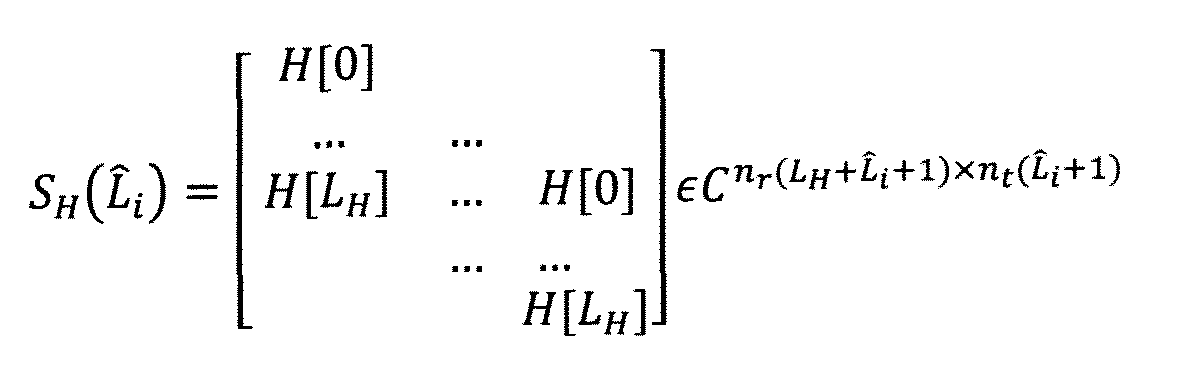
[0135] where H{z} = which has the dimension nr x nt with nt > nr, and


[0136] H{z} can be assumed to have a normal rank equal to nr. i.e., all rows of H{z} are independent for almost all z ε C. which is equivalent to the property that all rows of H (t) are convolutively independent. This condition can be met easily in practice especially when the first nr transmitters are placed pairwisely near the nr receivers.
[0137] Then, it is known from the rational vector space theory that there are nt— nr independent vectors g of the minimum degrees (or lengths), satisfying (2.27). One

embodiment comprises an iterative procedure for finding a set of these nt— n-. minimum length prefilters as presented below.
[0138] It follows from (2.27) that
[0139]
[
[0140]

[0141] and I is a reference degree for g{z). Note that there is a one-to-one mapping between ) and g{z) of degree It is clear that if of degree Lf is a solution to (2.27) then


) of with ø[/] = 0 for ; must be a solution to (2.28) with .


 Also note that if of degree Lt is a solution to (2.27). so is for any m≥ 0.
Therefore, for must also be solutions to (28) with
 . It is also


easy to verify that are independent vectors in

[0142] To find the total nt - n-. independent minimum-degree vectors
 a smallest may be started with such that (2.28) has a solution. Then, set
 and record the number nx of the independent solutions with the degree Lx. These solutions

correspond to Without loss of generality, it can be assumed that


independent minimum-degree vectors g of degree where


have been found. A smallest may


be chosen such that there is a solution to the following equation:
[0143]
[0144] where P the orthonormal matrix Q
 is from the QR decomposition

consists of all the following column vectors:
[0146] Then, set
] of degree where the computation is


completed. Otherwise, repeat the previous process with k increased by one. Obviously, we can set P0 = / in (2.29).
[0147] In another embodiment, the solution to (2.29) is replaced by the least square solution for better numerical stability. This embodiment further comprises keeping the least squared error very small for each iteration index k to prevent the error from propagating and deteriorating the quality of the subsequent iterations.
[0148] The prefilters generated from the embodiments in this subsection are the shortest possible. Similar to the embodiments in the previous subsection, the shortened prefilters are further processed (either implicitly or explicitly) by a common low pass filter to meet the bandwidth constraint.
[0149] Although the foregoing descriptions of the preferred embodiments of the present invention have shown, described, or illustrated the fundamental novel features or principles of the invention, it is understood that various omissions, substitutions, and changes in the form of the detail of the methods, elements or apparatuses as illustrated, as well as the uses thereof, may be made by those skilled in the art without departing from the spirit of the present invention. Hence, the scope of the present invention should not be limited to the foregoing descriptions. Rather, the principles of the invention may be applied to a wide range of methods, systems, and apparatuses, to achieve the advantages described herein and to achieve other advantages or to satisfy other objectives as well. Although the invention has been discussed with respect to various
embodiments, it should be recognized that the invention comprises the novel and non-obvious claims supported by this disclosure.
Claims
1. A method useful for full duplex radio communications, comprising:
transmitting a training signal by a node in a radio network;
extracting a waveform from a version of the training signal obtained from a receive chain of the node;
generating a cancellation signal using the waveform; and
applying the cancellation signal to the receive chain of the node.
2. The method of claim 1, wherein the cancellation signal is determined using a sliding window weighted sum of the waveform.
3. The method of claim 2, wherein coefficients of a signal to be transmitted comprise weights of the weighted sum.
4. The method of claim 1, wherein the training signal is transmitted over a first antenna of the node, the receive chain is coupled to a second antenna of the node, and the version of the training signal obtained from the receive chain is a version of the training signal received by the second antenna.
5. The method of claim 1. wherein the training signal is transmitted over a first antenna of the node, the receive chain is coupled to the first antenna, and the receive chain receives the training signal through a circulator.
6. The method of claim 1 , further comprising iteratively:
transmitting the training signal, at increased power compared to prior transmissions of the training signal, by the node in the radio network;
extracting a further waveform from a version of the training signal transmitted at increasing power obtained from the receive chain of the node;
generating a further cancellation signal using the waveform: and
applying the cancellation signal to the receive chain of the node.
7. The method of claim 1, wherein the node includes nr receive antennas and nt transmit antennas, and urther comprising transmitting a training signal a, by each of the nt transmit antennas, and wherein the version of the training signal obtained from the receive chain is a version of a combination of the a, transmitted signals.
8. The method of claim 7. wherein each of the a, transmitted signals are different signals.
9. The method of claim 7, wherein: extracting a waveform from a version of the training signal obtained from a receive chain of the node.
generating a cancellation signal using the waveform, and
applying the cancellation signal to the receive chain of the node;
is performed for each of the nr receive antennas.
10. A radio node, comprising:
a transmit chain for transmitting a signal; a receive for receiving a signal; and
cancellation elements including:
waveform extraction circuitry coupled to the receive chain, the waveform extractor circuitry configured to extract a first basis waveform from information of a signal from the receive chain;
memory for storing information of the first basis waveform: and
waveform generation circuitry coupled to the memory and the receive chain, the waveform generation circuitry configured to generate a cancellation signal using information of the first basis waveform.
1 1. The radio node of claim 10, wherein the waveform generation circuitry is coupled to the receive chain between prior to a low noise amplifier in the receive chain.
12. The radio node of claim 10, wherein the coupling of the waveform generation circuitry to the receive chain includes a digital to analog converter, a mixer, and a power amplifier.
13. The radio node of claim 10. wherein the transmit chain is coupled to a transmit antenna and the receive chain is coupled to a receive antenna.
14. The radio node of claim 10, wherein the transmit chain and the receive chain are coupled to a common antenna.
15. The radio node of claim 14. wherein the transmit chain and the receive chain are coupled to a common antenna by way of an RF circulator.
16. The radio node of claim 10. wherein the radio node include t transmit chains and r receive chains, each of the r receive chains including the cancellation elements.
17. A method useful for full duplex communications, comprising:
transmitting one or more training signals from a radio node having at least two transmitters and at least one receiver;
receiving at least one of the training signals by a receiver of the radio node;
extracting a waveform in the time domain from the received training signal;
defining a prefilter using the waveform:
transmitting a signal prefiltered using the prefilter so as to reduce strength of a combined signal formed of received signals from the transmitters in a frequency band of interest.
18. The method of claim 17, wherein the prefilter is defined without using deconvolution to obtain a channel impulse response.
Priority Applications (1)
| Application Number | Priority Date | Filing Date | Title |
|---|---|---|---|
| US14/378,093 US10116426B2 (en) | 2012-02-09 | 2013-02-11 | Methods and systems for full duplex wireless communications |
Applications Claiming Priority (4)
| Application Number | Priority Date | Filing Date | Title |
|---|---|---|---|
| US201261597065P | 2012-02-09 | 2012-02-09 | |
| US201261597067P | 2012-02-09 | 2012-02-09 | |
| US61/597,065 | 2012-02-09 | ||
| US61/597,067 | 2012-02-09 |
Publications (1)
| Publication Number | Publication Date |
|---|---|
| WO2013120087A1 true WO2013120087A1 (en) | 2013-08-15 |
Family
ID=48948102
Family Applications (1)
| Application Number | Title | Priority Date | Filing Date |
|---|---|---|---|
| PCT/US2013/025602 WO2013120087A1 (en) | 2012-02-09 | 2013-02-11 | Methods and systems for full duplex wireless communications |
Country Status (2)
| Country | Link |
|---|---|
| US (1) | US10116426B2 (en) |
| WO (1) | WO2013120087A1 (en) |
Cited By (6)
| Publication number | Priority date | Publication date | Assignee | Title |
|---|---|---|---|---|
| US20150029904A1 (en) * | 2013-07-27 | 2015-01-29 | Nec Laboratories America, Inc. | Enabling full-duplex communication in legacy lte systems |
| CN104685843A (en) * | 2013-09-30 | 2015-06-03 | 华为技术有限公司 | Antenna and communication device |
| WO2015131116A1 (en) * | 2014-02-27 | 2015-09-03 | Huawei Technologies Co., Ltd. | System and method for multiple-input and multiple-output (mimo) full-duplex precoding structures |
| EP2999196A4 (en) * | 2013-12-19 | 2016-09-21 | Huawei Tech Co Ltd | Full-duplex antenna and mobile terminal |
| CN107210907A (en) * | 2015-02-09 | 2017-09-26 | 华为技术有限公司 | The system and method for the training signal of full duplex communication system |
| CN111181610A (en) * | 2019-12-09 | 2020-05-19 | 华侨大学 | Non-credible relay full-duplex transmission method and system combined with sink zero-forcing scrambling |
Families Citing this family (45)
| Publication number | Priority date | Publication date | Assignee | Title |
|---|---|---|---|---|
| US8130880B1 (en) | 2007-05-23 | 2012-03-06 | Hypress, Inc. | Wideband digital spectrometer |
| CA2873411C (en) | 2012-05-13 | 2020-06-16 | Amir Khandani | Full duplex wireless transmission with self-interference cancellation |
| US9490963B2 (en) * | 2013-02-04 | 2016-11-08 | Kumu Networks, Inc. | Signal cancellation using feedforward and feedback paths |
| US10177896B2 (en) | 2013-05-13 | 2019-01-08 | Amir Keyvan Khandani | Methods for training of full-duplex wireless systems |
| WO2015021463A2 (en) | 2013-08-09 | 2015-02-12 | Kumu Networks, Inc. | Systems and methods for frequency independent analog selfinterference cancellation |
| US9698860B2 (en) | 2013-08-09 | 2017-07-04 | Kumu Networks, Inc. | Systems and methods for self-interference canceller tuning |
| CN105556860B (en) | 2013-08-09 | 2018-04-03 | 库姆网络公司 | The system and method eliminated for non-linear, digital self-interference |
| US9054795B2 (en) | 2013-08-14 | 2015-06-09 | Kumu Networks, Inc. | Systems and methods for phase noise mitigation |
| US10673519B2 (en) | 2013-08-29 | 2020-06-02 | Kuma Networks, Inc. | Optically enhanced self-interference cancellation |
| US10177836B2 (en) | 2013-08-29 | 2019-01-08 | Kumu Networks, Inc. | Radio frequency self-interference-cancelled full-duplex relays |
| US9520983B2 (en) | 2013-09-11 | 2016-12-13 | Kumu Networks, Inc. | Systems for delay-matched analog self-interference cancellation |
| US9236996B2 (en) | 2013-11-30 | 2016-01-12 | Amir Keyvan Khandani | Wireless full-duplex system and method using sideband test signals |
| US10230422B2 (en) | 2013-12-12 | 2019-03-12 | Kumu Networks, Inc. | Systems and methods for modified frequency-isolation self-interference cancellation |
| US9774405B2 (en) | 2013-12-12 | 2017-09-26 | Kumu Networks, Inc. | Systems and methods for frequency-isolated self-interference cancellation |
| US9820311B2 (en) * | 2014-01-30 | 2017-11-14 | Amir Keyvan Khandani | Adapter and associated method for full-duplex wireless communication |
| US9712312B2 (en) | 2014-03-26 | 2017-07-18 | Kumu Networks, Inc. | Systems and methods for near band interference cancellation |
| US10128879B2 (en) * | 2014-03-31 | 2018-11-13 | Intel IP Corporation | Enhanced receive sensitivity for concurrent communications |
| WO2015171177A1 (en) | 2014-05-05 | 2015-11-12 | The Regents Of The University Of California | Full-duplex self-interference cancellation systems |
| WO2015178964A1 (en) | 2014-05-23 | 2015-11-26 | Eltawil Ahmed Mohamed | Full duplex reconfigurable antenna self-interference cancellation systems |
| US10205585B2 (en) * | 2014-09-25 | 2019-02-12 | Huawei Technologies Co., Ltd. | Systems and methods for analog cancellation for division free duplexing for radios using MIMO |
| US9521023B2 (en) | 2014-10-17 | 2016-12-13 | Kumu Networks, Inc. | Systems for analog phase shifting |
| US9712313B2 (en) | 2014-11-03 | 2017-07-18 | Kumu Networks, Inc. | Systems for multi-peak-filter-based analog self-interference cancellation |
| US9673854B2 (en) | 2015-01-29 | 2017-06-06 | Kumu Networks, Inc. | Method for pilot signal based self-inteference cancellation tuning |
| US10033513B2 (en) * | 2015-02-09 | 2018-07-24 | Huawei Technologies Co., Ltd. | Channel impulse response estimation for full-duplex communication networks |
| US20160233904A1 (en) * | 2015-02-09 | 2016-08-11 | Huawei Technologies Co., Ltd. | System and Method for Full-Duplex Operation in a Wireless Communications System |
| US9634823B1 (en) * | 2015-10-13 | 2017-04-25 | Kumu Networks, Inc. | Systems for integrated self-interference cancellation |
| US9742593B2 (en) | 2015-12-16 | 2017-08-22 | Kumu Networks, Inc. | Systems and methods for adaptively-tuned digital self-interference cancellation |
| US10666305B2 (en) | 2015-12-16 | 2020-05-26 | Kumu Networks, Inc. | Systems and methods for linearized-mixer out-of-band interference mitigation |
| KR102075284B1 (en) | 2015-12-16 | 2020-02-07 | 쿠무 네트웍스, 아이엔씨. | Time delay filter |
| US9800275B2 (en) | 2015-12-16 | 2017-10-24 | Kumu Networks, Inc. | Systems and methods for out-of band-interference mitigation |
| US10009052B2 (en) * | 2016-02-01 | 2018-06-26 | Qorvo Us, Inc. | UL CA TX-TX tunable cross-isolation method |
| WO2017189592A1 (en) | 2016-04-25 | 2017-11-02 | Kumu Networks, Inc. | Integrated delay modules |
| US10454444B2 (en) | 2016-04-25 | 2019-10-22 | Kumu Networks, Inc. | Integrated delay modules |
| US10333593B2 (en) | 2016-05-02 | 2019-06-25 | Amir Keyvan Khandani | Systems and methods of antenna design for full-duplex line of sight transmission |
| US10148294B2 (en) | 2016-12-06 | 2018-12-04 | Qorvo Us, Inc. | Multi-band radio frequency front-end circuit |
| US10103774B1 (en) | 2017-03-27 | 2018-10-16 | Kumu Networks, Inc. | Systems and methods for intelligently-tuned digital self-interference cancellation |
| WO2018183333A1 (en) | 2017-03-27 | 2018-10-04 | Kumu Networks, Inc | Systems and methods for tunable out-of-band interference mitigation |
| JP6837573B2 (en) | 2017-03-27 | 2021-03-03 | クム ネットワークス, インコーポレイテッドKumu Networks, Inc. | Linearity-enhanced mixer |
| US10700766B2 (en) * | 2017-04-19 | 2020-06-30 | Amir Keyvan Khandani | Noise cancelling amplify-and-forward (in-band) relay with self-interference cancellation |
| US10200076B1 (en) | 2017-08-01 | 2019-02-05 | Kumu Networks, Inc. | Analog self-interference cancellation systems for CMTS |
| US11146395B2 (en) | 2017-10-04 | 2021-10-12 | Amir Keyvan Khandani | Methods for secure authentication |
| US11012144B2 (en) | 2018-01-16 | 2021-05-18 | Amir Keyvan Khandani | System and methods for in-band relaying |
| EP3759844A4 (en) | 2018-02-27 | 2021-11-24 | Kumu Networks, Inc. | Systems and methods for configurable hybrid self-interference cancellation |
| US10868661B2 (en) | 2019-03-14 | 2020-12-15 | Kumu Networks, Inc. | Systems and methods for efficiently-transformed digital self-interference cancellation |
| US11159197B2 (en) * | 2019-04-29 | 2021-10-26 | Qualcomm Incorporated | Self-interference cancellation for in-band full-duplex wireless communication |
Citations (5)
| Publication number | Priority date | Publication date | Assignee | Title |
|---|---|---|---|---|
| US20040142700A1 (en) * | 2003-01-21 | 2004-07-22 | Interdigital Technology Corporation | System and method for increasing cellular system capacity by the use of the same frequency and time slot for both uplink and downlink transmissions |
| US20080107046A1 (en) * | 2006-11-06 | 2008-05-08 | Nokia Corporation | Analog signal path modeling for self-interference cancellation |
| US20100022201A1 (en) * | 2008-07-22 | 2010-01-28 | Patrick Vandenameele | Apparatus and method for reducing self-interference in a radio system |
| US20100232324A1 (en) * | 2009-03-16 | 2010-09-16 | Microsoft Corporation | Full-Duplex Wireless Communications |
| US20110143655A1 (en) * | 2008-08-14 | 2011-06-16 | Electronics And Telecommunications Research Institute | Self-interference cancellation method and apparatus of relay using the same frequency band in ofdm-based radio communication system |
Family Cites Families (4)
| Publication number | Priority date | Publication date | Assignee | Title |
|---|---|---|---|---|
| US6429798B1 (en) * | 2000-02-08 | 2002-08-06 | Ericsson Inc. | Combined transmit filter and D-to-A converter |
| EP2082486A1 (en) * | 2006-10-17 | 2009-07-29 | Interdigital Technology Corporation | Transceiver with hybrid adaptive interference canceller for removing transmitter generated noise |
| US8954024B2 (en) * | 2011-03-31 | 2015-02-10 | Chien-Cheng Tung | Full duplex wireless method and apparatus |
| US9124475B2 (en) * | 2011-09-19 | 2015-09-01 | Alcatel Lucent | Method and apparatus for interference cancellation for antenna arrays |
-
2013
- 2013-02-11 WO PCT/US2013/025602 patent/WO2013120087A1/en active Application Filing
- 2013-02-11 US US14/378,093 patent/US10116426B2/en active Active
Patent Citations (5)
| Publication number | Priority date | Publication date | Assignee | Title |
|---|---|---|---|---|
| US20040142700A1 (en) * | 2003-01-21 | 2004-07-22 | Interdigital Technology Corporation | System and method for increasing cellular system capacity by the use of the same frequency and time slot for both uplink and downlink transmissions |
| US20080107046A1 (en) * | 2006-11-06 | 2008-05-08 | Nokia Corporation | Analog signal path modeling for self-interference cancellation |
| US20100022201A1 (en) * | 2008-07-22 | 2010-01-28 | Patrick Vandenameele | Apparatus and method for reducing self-interference in a radio system |
| US20110143655A1 (en) * | 2008-08-14 | 2011-06-16 | Electronics And Telecommunications Research Institute | Self-interference cancellation method and apparatus of relay using the same frequency band in ofdm-based radio communication system |
| US20100232324A1 (en) * | 2009-03-16 | 2010-09-16 | Microsoft Corporation | Full-Duplex Wireless Communications |
Cited By (14)
| Publication number | Priority date | Publication date | Assignee | Title |
|---|---|---|---|---|
| US20150029904A1 (en) * | 2013-07-27 | 2015-01-29 | Nec Laboratories America, Inc. | Enabling full-duplex communication in legacy lte systems |
| CN104685843A (en) * | 2013-09-30 | 2015-06-03 | 华为技术有限公司 | Antenna and communication device |
| US10044492B2 (en) | 2013-09-30 | 2018-08-07 | Huawei Technologies Co., Ltd. | Antenna and communications device |
| EP3043525A4 (en) * | 2013-09-30 | 2016-08-31 | Huawei Tech Co Ltd | Antenna and communication device |
| RU2628015C1 (en) * | 2013-12-19 | 2017-08-14 | Хуавэй Текнолоджиз Ко., Лтд. | Full-duplex antenna and mobile terminal |
| EP2999196A4 (en) * | 2013-12-19 | 2016-09-21 | Huawei Tech Co Ltd | Full-duplex antenna and mobile terminal |
| US10003123B2 (en) | 2013-12-19 | 2018-06-19 | Huawei Technologies Co., Ltd. | Full-duplex antenna and mobile terminal |
| US9391680B2 (en) | 2014-02-27 | 2016-07-12 | Huawei Technologies Canada Co., Ltd. | System and method for multiple-input and multiple-output (MIMO) full-duplex precoding structures |
| US9608706B2 (en) | 2014-02-27 | 2017-03-28 | Huawei Technologies Canada Co., Ltd. | System and method for multiple-input and multiple-output (MIMO) full-duplex precoding structures |
| WO2015131116A1 (en) * | 2014-02-27 | 2015-09-03 | Huawei Technologies Co., Ltd. | System and method for multiple-input and multiple-output (mimo) full-duplex precoding structures |
| CN107210907A (en) * | 2015-02-09 | 2017-09-26 | 华为技术有限公司 | The system and method for the training signal of full duplex communication system |
| CN107210907B (en) * | 2015-02-09 | 2020-04-14 | 华为技术有限公司 | System and method for training signals for full duplex communication systems |
| CN111181610A (en) * | 2019-12-09 | 2020-05-19 | 华侨大学 | Non-credible relay full-duplex transmission method and system combined with sink zero-forcing scrambling |
| CN111181610B (en) * | 2019-12-09 | 2021-12-31 | 华侨大学 | Non-credible relay full-duplex transmission method and system combined with sink zero-forcing scrambling |
Also Published As
| Publication number | Publication date |
|---|---|
| US20140348032A1 (en) | 2014-11-27 |
| US10116426B2 (en) | 2018-10-30 |
Similar Documents
| Publication | Publication Date | Title |
|---|---|---|
| US10116426B2 (en) | Methods and systems for full duplex wireless communications | |
| Heino et al. | Recent advances in antenna design and interference cancellation algorithms for in-band full duplex relays | |
| Korpi et al. | Adaptive nonlinear digital self-interference cancellation for mobile inband full-duplex radio: Algorithms and RF measurements | |
| US9209840B2 (en) | Same-aperture any-frequency simultaneous transmit and receive communication system | |
| Hua et al. | A method for broadband full-duplex MIMO radio | |
| JP6100406B2 (en) | Multi-tap adaptive filter for transmit signal leakage cancellation | |
| Askar et al. | Active self-interference cancellation mechanism for full-duplex wireless transceivers | |
| JP5890069B2 (en) | Same aperture arbitrary frequency simultaneous transmission and reception communication system | |
| US10374656B2 (en) | Same-aperture any-frequency simultaneous transmit and receive communication system | |
| BRPI0808541A2 (en) | PHYSICAL LAYER REPEATER USING REAL TIME MEASUREMENT METRICS AND ADAPTIVE ANTENNA ARRANGEMENT TO PROMOTE SIGNAL INTEGRITY AND AMPLIFICATION | |
| Korpi et al. | Modeling and cancellation of self-interference in full-duplex radio transceivers: Volterra series-based approach | |
| US9906262B2 (en) | All-analog and hybrid radio interference cancellation using cables, attenuators and power splitters | |
| Ginzberg et al. | A full-duplex quadrature balanced RF front end with digital pre-PA self-interference cancellation | |
| Korpi et al. | Advanced architectures for self-interference cancellation in full-duplex radios: Algorithms and measurements | |
| Zhao et al. | A broadband multistage self-interference canceller for full-duplex MIMO radios | |
| Lampu et al. | Air-induced PIM cancellation in FDD MIMO transceivers | |
| Askar et al. | Agile full-duplex transceiver: The concept and self-interference channel characteristics | |
| Kiayani et al. | Active RF cancellation of nonlinear TX leakage in FDD transceivers | |
| US8099056B2 (en) | Digital hybrid amplifier calibration and compensation method | |
| Li et al. | Self-interference cancellation with frequency offset and nonlinear distortion suppression for cooperative jamming communications | |
| Quan et al. | Suppression of analog self-interference canceller nonlinearities in MIMO full duplex | |
| Zhao et al. | Polarization mismatch based self-interference cancellation against power amplifier nonlinear distortion in full duplex systems | |
| Chandran et al. | Transmitter leakage analysis when operating USRP (N210) in duplex mode | |
| Laughlin et al. | Antennas and radio frequency self-interference cancellation | |
| US20190326946A1 (en) | Same-Aperture Any-Frequency Simultaneous Transmit and Receive Communication System |
Legal Events
| Date | Code | Title | Description |
|---|---|---|---|
| 121 | Ep: the epo has been informed by wipo that ep was designated in this application |
Ref document number: 13746238 Country of ref document: EP Kind code of ref document: A1 |
|
| NENP | Non-entry into the national phase |
Ref country code: DE |
|
| WWE | Wipo information: entry into national phase |
Ref document number: 14378093 Country of ref document: US |
|
| 122 | Ep: pct application non-entry in european phase |
Ref document number: 13746238 Country of ref document: EP Kind code of ref document: A1 |