WO2013105139A1 - Method for controlling and device for controlling secondary battery - Google Patents
Method for controlling and device for controlling secondary battery Download PDFInfo
- Publication number
- WO2013105139A1 WO2013105139A1 PCT/JP2012/000189 JP2012000189W WO2013105139A1 WO 2013105139 A1 WO2013105139 A1 WO 2013105139A1 JP 2012000189 W JP2012000189 W JP 2012000189W WO 2013105139 A1 WO2013105139 A1 WO 2013105139A1
- Authority
- WO
- WIPO (PCT)
- Prior art keywords
- secondary battery
- voltage
- unit cell
- upper limit
- battery
- Prior art date
Links
Images


Classifications
-
- H—ELECTRICITY
- H01—ELECTRIC ELEMENTS
- H01M—PROCESSES OR MEANS, e.g. BATTERIES, FOR THE DIRECT CONVERSION OF CHEMICAL ENERGY INTO ELECTRICAL ENERGY
- H01M10/00—Secondary cells; Manufacture thereof
- H01M10/42—Methods or arrangements for servicing or maintenance of secondary cells or secondary half-cells
- H01M10/48—Accumulators combined with arrangements for measuring, testing or indicating the condition of cells, e.g. the level or density of the electrolyte
-
- H—ELECTRICITY
- H01—ELECTRIC ELEMENTS
- H01M—PROCESSES OR MEANS, e.g. BATTERIES, FOR THE DIRECT CONVERSION OF CHEMICAL ENERGY INTO ELECTRICAL ENERGY
- H01M10/00—Secondary cells; Manufacture thereof
- H01M10/42—Methods or arrangements for servicing or maintenance of secondary cells or secondary half-cells
- H01M10/44—Methods for charging or discharging
-
- H—ELECTRICITY
- H02—GENERATION; CONVERSION OR DISTRIBUTION OF ELECTRIC POWER
- H02J—CIRCUIT ARRANGEMENTS OR SYSTEMS FOR SUPPLYING OR DISTRIBUTING ELECTRIC POWER; SYSTEMS FOR STORING ELECTRIC ENERGY
- H02J7/00—Circuit arrangements for charging or depolarising batteries or for supplying loads from batteries
- H02J7/007—Regulation of charging or discharging current or voltage
- H02J7/00712—Regulation of charging or discharging current or voltage the cycle being controlled or terminated in response to electric parameters
-
- G—PHYSICS
- G01—MEASURING; TESTING
- G01R—MEASURING ELECTRIC VARIABLES; MEASURING MAGNETIC VARIABLES
- G01R31/00—Arrangements for testing electric properties; Arrangements for locating electric faults; Arrangements for electrical testing characterised by what is being tested not provided for elsewhere
- G01R31/36—Arrangements for testing, measuring or monitoring the electrical condition of accumulators or electric batteries, e.g. capacity or state of charge [SoC]
- G01R31/392—Determining battery ageing or deterioration, e.g. state of health
-
- H—ELECTRICITY
- H01—ELECTRIC ELEMENTS
- H01M—PROCESSES OR MEANS, e.g. BATTERIES, FOR THE DIRECT CONVERSION OF CHEMICAL ENERGY INTO ELECTRICAL ENERGY
- H01M2220/00—Batteries for particular applications
- H01M2220/20—Batteries in motive systems, e.g. vehicle, ship, plane
-
- H—ELECTRICITY
- H02—GENERATION; CONVERSION OR DISTRIBUTION OF ELECTRIC POWER
- H02J—CIRCUIT ARRANGEMENTS OR SYSTEMS FOR SUPPLYING OR DISTRIBUTING ELECTRIC POWER; SYSTEMS FOR STORING ELECTRIC ENERGY
- H02J7/00—Circuit arrangements for charging or depolarising batteries or for supplying loads from batteries
- H02J7/0069—Charging or discharging for charge maintenance, battery initiation or rejuvenation
-
- Y—GENERAL TAGGING OF NEW TECHNOLOGICAL DEVELOPMENTS; GENERAL TAGGING OF CROSS-SECTIONAL TECHNOLOGIES SPANNING OVER SEVERAL SECTIONS OF THE IPC; TECHNICAL SUBJECTS COVERED BY FORMER USPC CROSS-REFERENCE ART COLLECTIONS [XRACs] AND DIGESTS
- Y02—TECHNOLOGIES OR APPLICATIONS FOR MITIGATION OR ADAPTATION AGAINST CLIMATE CHANGE
- Y02E—REDUCTION OF GREENHOUSE GAS [GHG] EMISSIONS, RELATED TO ENERGY GENERATION, TRANSMISSION OR DISTRIBUTION
- Y02E60/00—Enabling technologies; Technologies with a potential or indirect contribution to GHG emissions mitigation
- Y02E60/10—Energy storage using batteries
Definitions
- the present invention relates to a control device and a control method for controlling charge / discharge of a secondary battery.
- the charging of the secondary battery is controlled so that the voltage of the secondary battery does not become higher than a predetermined upper limit voltage.
- the discharge of the secondary battery is controlled so that the voltage of the secondary battery does not become lower than a predetermined lower limit voltage.
- the secondary battery may be excessively restricted from being charged or discharged, or overcharge or overdischarge may be difficult to suppress.
- 1st invention of this application is a control apparatus which controls charging / discharging of a secondary battery, Comprising: It has a controller which sets the threshold voltage which can perform charging / discharging of a secondary battery.
- the controller specifies the current deterioration state of the secondary battery, and sets the threshold voltage corresponding to the current deterioration state using information in which the threshold voltage changes with the progress of deterioration of the secondary battery.
- charging / discharging of the secondary battery can be controlled using the threshold voltage corresponding to the current deterioration state. Thereby, depending on the threshold voltage, it can be prevented that charging / discharging of the secondary battery is excessively limited or charging / discharging of the secondary battery is difficult to limit. And the input-output performance of a secondary battery can fully be exhibited.
- Threshold voltage includes an upper limit voltage that can charge the secondary battery and a lower limit voltage that can discharge the secondary battery.
- the upper limit voltage can be continuously reduced according to the progress of deterioration of the secondary battery. By reducing the upper limit voltage according to the progress (degradation state) of the secondary battery, it is possible to prevent the secondary battery from being excessively restricted from charging or to suppress overcharge of the secondary battery. Can be.
- the lower limit voltage can be continuously increased as the secondary battery deteriorates.
- By increasing the lower limit voltage according to the degree of progress (degradation state) of the secondary battery it is possible to prevent the secondary battery from being restricted excessively or to suppress the secondary battery from over-discharge. Can be.
- the upper limit value of power that allows charging of the secondary battery can be reduced.
- Reducing the upper limit value of the charging power includes setting the upper limit value to 0 [kW], in other words, not charging the secondary battery.
- the upper limit value of power that allows the secondary battery to discharge can be reduced.
- the voltage of the secondary battery can be suppressed from becoming lower than the lower limit voltage.
- Reducing the upper limit value of the discharge power includes setting the upper limit value to 0 [kW], in other words, not discharging the secondary battery.
- the deterioration state of the secondary battery can be specified using at least one of the capacity, resistance, and usage time of the secondary battery. Since the capacity of the secondary battery decreases as the deterioration of the secondary battery proceeds, the deterioration state of the secondary battery can be specified using the capacity of the secondary battery. Since the resistance of the secondary battery increases as the deterioration of the secondary battery progresses, the deterioration state of the secondary battery can be specified using the resistance of the secondary battery. If the secondary battery continues to be used, aged deterioration occurs. Therefore, the deterioration state of the secondary battery can be specified using the usage time of the secondary battery.
- a second invention of the present application is a control method for controlling charging / discharging of a secondary battery, wherein a threshold voltage that can identify the current deterioration state of the secondary battery and charge / discharge the secondary battery is secondary.
- a threshold voltage corresponding to the current deterioration state is set using information that changes with the progress of battery deterioration. Also in the second invention of the present application, the same effect as that of the first invention of the present application can be obtained.
- FIG. 1 is a diagram illustrating a configuration of a battery system.
- the battery system of the present embodiment can be mounted on a vehicle.
- Vehicles include hybrid cars and electric cars.
- the hybrid vehicle includes an engine or a fuel cell as a power source for running the vehicle in addition to the assembled battery described later.
- the electric vehicle includes only an assembled battery described later as a power source for running the vehicle.
- the assembled battery 10 has a plurality of unit cells 11 connected in series.
- a secondary battery such as a nickel metal hydride battery or a lithium ion battery can be used.
- the number of unit cells 11 constituting the assembled battery 10 can be appropriately set based on the required output of the assembled battery 10 and the like. In the present embodiment, all the unit cells 11 constituting the assembled battery 10 are connected in series, but the present invention is not limited to this.
- a plurality of unit cells 11 connected in parallel may be included in the assembled battery 10.
- the unit cell 11 has a power generation element that charges and discharges and a battery case that houses the power generation element.
- the power generation element can be composed of, for example, a positive electrode plate, a negative electrode plate, and a separator disposed between the positive electrode plate and the negative electrode plate.
- the positive electrode plate includes a current collector plate and a positive electrode active material layer formed on the surface of the current collector plate.
- the negative electrode plate has a current collector plate and a negative electrode active material layer formed on the surface of the current collector plate.
- the positive electrode active material layer includes a positive electrode active material and a conductive agent
- the negative electrode active material layer includes a negative electrode active material and a conductive agent.
- the current collector plate of the positive electrode plate can be formed of aluminum, and the current collector plate of the negative electrode plate can be formed of copper.
- the positive electrode active material for example, LiCo 1/3 Ni 1/3 Mn 1/3 O 2 can be used, and as the negative electrode active material, for example, carbon can be used.
- An electrolyte solution is infiltrated into the separator, the positive electrode active material layer, and the negative electrode active material layer.
- a solid electrolyte layer may be disposed between the positive electrode plate and the negative electrode plate.
- the voltage sensor 21 detects the voltage of each cell 11 and outputs the detection result to the controller 30.
- the voltage sensor 21 is used to detect the voltage of each cell 11, but this is not a limitation.
- the plurality of single cells 11 constituting the assembled battery 10 can be divided into a plurality of battery blocks, and the voltage of each battery block can be detected.
- the plurality of battery blocks are connected in series, and each battery block includes a plurality of single cells 11 connected in series.
- the number of single cells 11 constituting each battery block can be set as appropriate.
- the current sensor 22 detects the current value flowing through the assembled battery 10 (unit cell 11) and outputs the detection result to the controller 30.
- the controller 30 has a built-in memory 31.
- the memory 31 stores a program for operating the controller 30 and specific information.
- the memory 31 can also be provided outside the controller 30.
- the system main relay SMR-B is provided on the positive electrode line PL of the assembled battery 10. System main relay SMR-B is switched between on and off by receiving a control signal from controller 30.
- a system main relay SMR-G is provided on the negative electrode line NL of the assembled battery 10. System main relay SMR-G is switched between on and off by receiving a control signal from controller 30.
- System main relay SMR-P and current limiting resistor R are connected in parallel to system main relay SMR-G.
- System main relay SMR-P and current limiting resistor R are connected in series.
- System main relay SMR-P is switched between on and off in response to a control signal from controller 30.
- the current limiting resistor R is used for suppressing an inrush current from flowing when the assembled battery 10 is connected to a load (specifically, a booster circuit 23 described later).
- the controller 30 controls the turning on and off of the system main relays SMR-B, SMR-G, and SMR-P, thereby connecting the assembled battery 10 to a load and cutting off the connection between the assembled battery 10 and the load. be able to.
- the booster circuit 23 boosts the output voltage of the assembled battery 10 and outputs the boosted power to the inverter 24. Further, the booster circuit 23 can step down the output voltage of the inverter 24 and output the reduced power to the assembled battery 10.
- the booster circuit 23 operates in response to a control signal from the controller 30. In the battery system of this embodiment, the booster circuit 23 is used, but the booster circuit 23 may be omitted.
- the inverter 24 converts the DC power output from the booster circuit 23 into AC power and outputs the AC power to the motor / generator 25.
- the inverter 24 converts AC power generated by the motor / generator 25 into DC power and outputs the DC power to the booster circuit 23.
- a three-phase AC motor can be used as the motor / generator 25.
- the motor / generator 25 receives AC power from the inverter 24 and generates kinetic energy for running the vehicle. When the vehicle is driven using the electric power of the assembled battery 10, the kinetic energy generated by the motor / generator 25 is transmitted to the wheels.
- the motor / generator 25 converts kinetic energy generated during braking of the vehicle into electric energy (AC power).
- the electric energy generated by the motor / generator 25 is supplied to the assembled battery 10 via the inverter 24 and the booster circuit 23. Thereby, regenerative electric power can be stored in the assembled battery 10.
- charging of the cell 11 is controlled so that the voltage of the cell 11 does not become higher than the upper limit voltage in order to suppress overcharging of the cell 11.
- the discharge of the single battery 11 is controlled so that the voltage of the single battery 11 does not become lower than the lower limit voltage.
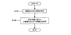
- FIG. 2 is a flowchart showing processing for setting an upper limit voltage and a lower limit voltage. The process shown in FIG. 2 is executed by the controller 30.
- step S101 the controller 30 specifies the deterioration state of the unit cell 11.
- the controller 30 can specify the deterioration state of the unit cell 11 based on the capacity, resistance, usage period, and the like of the unit cell 11.
- capacitance, resistance, and a use period become a parameter
- the deterioration state of the cell 11 can be specified. Further, since the unit cell 11 may be deteriorated due to wear or the like due to a change with time, the deterioration state of the unit cell 11 can be specified by measuring the usage period of the unit cell 11. The usage period of the unit cell 11 can be measured using a timer, for example.
- the current value flowing through the unit cell 11 is integrated while the voltage of the unit cell 11 is changed from the first voltage to the second voltage.
- the voltage of the cell 11 can be reduced from the first voltage to the second voltage (second voltage ⁇ first voltage).
- the voltage of the cell 11 can be increased from the first voltage to the second voltage (second voltage> first voltage).
- an external power source When charging the cell 11, an external power source can be used.
- the external power source is a power source provided separately from the battery system shown in FIG.
- As the external power source for example, a commercial power source can be used.
- the power of the external power source can be supplied to the assembled battery 10 to charge the assembled battery 10 (unit cell 11).
- the unit cell 11 is compared by comparing the current integrated value of the unit cell 11 in the initial state with the measured current integrated value. It is possible to specify the deterioration state of the.
- the initial state is a state in which the unit cell 11 has not deteriorated, and refers to a state immediately after the unit cell 11 is manufactured. When the measured current integrated value is smaller than the current integrated value of the cell 11 in the initial state, it can be seen that the cell 11 is in a deteriorated state.
- the internal resistance of the cell 11 can be calculated from the voltage value and current value of the cell 11.
- the controller 30 can acquire the voltage value of the single battery 11 based on the output of the voltage sensor 21. Further, the controller 30 can acquire the current value of the unit cell 11 based on the output of the current sensor 22. As the deterioration of the unit cell 11 progresses, the internal resistance of the unit cell 11 increases, so that the deterioration state of the unit cell 11 can be specified by monitoring the internal resistance of the unit cell 11.
- the method for specifying the deterioration state of the unit cell 11 is not limited to the method described above. Any method can be used as long as it can determine the deterioration state of the unit cell 11, in other words, the deterioration of the input / output characteristics of the unit cell 11.
- step S102 the controller 30 sets an upper limit voltage and a lower limit voltage corresponding to the deterioration state specified in step S101.
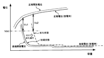
- the upper limit voltage Vu_lim and the lower limit voltage Vl_lim change according to the deterioration state of the unit cell 11. Specifically, the upper limit voltage Vu_lim continuously decreases as the deterioration of the unit cell 11 progresses. Further, the lower limit voltage Vl_lim continuously increases as the deterioration of the unit cell 11 progresses.
- the information shown in FIG. 3 can be acquired in advance by an experiment or the like and stored in the memory 31.
- the controller 30 can specify the upper limit voltage Vu_lim and the lower limit voltage Vl_lim corresponding to the deterioration state specified in step S101 using the information shown in FIG.
- a correspondence relationship between this index and the upper limit voltage Vu_lim and the lower limit voltage Vl_lim may be obtained in advance.
- the correspondence between these indicators and Vu_lim and the lower limit voltage Vl_lim may be obtained in advance.
- the lower limit voltage Vl_lim changes between the voltage V1 and the voltage V2.
- the voltage V1 is an upper limit voltage used in charge / discharge control of the cell 11 in the initial state.
- the voltage V2 is an upper limit voltage used in charge / discharge control of the unit cell 1 when it is determined that the deterioration state of the unit cell 11 is a lifetime.
- the voltage V2 is higher than the voltage V1.
- FIG. 4 shows the positive electrode potential and the negative electrode potential when the unit cell 11 is discharged.
- the positive electrode potential is the electrical potential energy of the positive electrode active material with respect to the reference potential located between the positive electrode and the negative electrode.
- the negative electrode potential is the electrical potential energy of the negative electrode active material with respect to the reference potential.
- the positive electrode open potential shown in FIG. 4 is a positive electrode potential when the cell 11 is in an initial state and in an unloaded state. As shown in FIG. 4, the positive electrode potential during discharge is lower than the positive electrode open potential by a potential corresponding to the resistance component (internal resistance) of the unit cell 11.
- the negative electrode open-circuit potential shown in FIG. 4 is a negative electrode potential when the unit cell 11 is in an initial state and in a no-load state. As shown in FIG. 4, the negative electrode potential at the time of discharging is higher than the negative electrode open potential by a potential corresponding to the resistance component (internal resistance) of the unit cell 11.
- the negative electrode potential shifts to the right side of FIG. 4 with respect to the positive electrode potential.
- the shift amount of the negative electrode potential varies depending on the deterioration state of the unit cell 11. That is, as the deterioration of the unit cell 11 proceeds, the amount of shift of the negative electrode potential increases.
- the positive electrode potential is fixed and only the negative electrode potential is shifted in order to represent the deterioration state of the unit cell 11, but this is not restrictive. That is, when the unit cell 11 is in a deteriorated state, the correspondence relationship between the positive electrode potential and the negative electrode potential is relatively shifted in the left-right direction in FIG.
- the current collector plate (eg, copper) of the negative electrode plate may be eluted.
- the negative electrode potential during discharge increases, the positive electrode potential during discharge decreases, and when the positive electrode potential during discharge decreases excessively, the structure of the positive electrode may change. If the reaction that occurs first among these secondary reactions at the positive and negative electrodes is known, the potential at which this reaction occurs can be set as the threshold potential Vth1.
- the negative electrode potential during discharge needs to be changed within a range lower than the threshold potential Vth1.
- the voltage of the unit cell 11 corresponds to the difference between the positive electrode potential and the negative electrode potential during discharge.
- the negative electrode potential during discharge needs to be changed within a range lower than the threshold potential Vth1.
- the threshold potential Vth1 when the cell 11 is in a deteriorated state, it is necessary to suppress the voltage of the cell 11 from being lower than the voltage Vc2.
- the battery voltage Vc2 becomes higher than the battery voltage Vc1.
- the battery voltage Vc1 shown in FIG. 4 corresponds to the battery voltage V1 shown in FIG.
- FIG. 5 shows the positive electrode potential and the negative electrode potential when the cell 11 is charged.
- the positive electrode potential during charging is higher than the positive electrode open potential by a potential corresponding to the resistance component (internal resistance) of the unit cell 11.
- the negative electrode potential during charging is lower than the negative electrode open potential by a potential corresponding to the resistance component (internal resistance) of the unit cell 11.
- the positive electrode open potential and the negative electrode open potential shown in FIG. 5 are the same as the positive electrode open potential and the negative electrode open potential shown in FIG.
- the positive electrode potential shifts to the left side in FIG. 5 with respect to the negative electrode potential.
- the shift amount of the positive electrode potential varies depending on the deterioration state of the unit cell 11. That is, the amount of shift of the positive electrode potential increases as the deterioration of the unit cell 11 progresses.
- the negative electrode potential is fixed and only the positive electrode potential is shifted in order to represent the deterioration state of the unit cell 11, but this is not restrictive. That is, when the unit cell 11 is in a deteriorated state, the correspondence relationship between the positive electrode potential and the negative electrode potential is relatively shifted in the left-right direction in FIG.
- the positive electrode potential during charging needs to be changed within a range lower than the threshold potential Vth2. In other words, when the unit cell 11 is in the initial state, it is necessary to suppress the voltage of the unit cell 11 from becoming higher than the voltage Vc3.
- the positive electrode potential during charging needs to be changed within a range lower than the threshold potential Vth2.
- the threshold potential Vth2 when the cell 11 is in a deteriorated state, it is necessary to suppress the voltage of the cell 11 from becoming higher than the voltage Vc4.
- the battery voltage Vc4 becomes lower than the battery voltage Vc3.
- the battery voltage Vc3 shown in FIG. 5 corresponds to the battery voltage V4 shown in FIG.
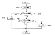
- step S201 the controller 30 acquires the detection voltage of the voltage sensor 21.
- step S202 the controller 30 determines whether or not the detected voltage is higher than the upper limit voltage Vu_lim.
- the upper limit voltage Vu_lim is a value set by the process shown in FIG. When the detected voltage is higher than the upper limit voltage Vu_lim, the process proceeds to step S203. When the detected voltage is lower than the upper limit voltage Vu_lim, the process proceeds to step S204.
- step S203 the controller 30 restricts the input of the unit cell 11. Specifically, the controller 30 reduces the upper limit power that can allow the input of the single battery 11.
- the charging of the cell 11 is controlled so that the input power of the cell 11 does not become higher than the upper limit power. Therefore, the charging of the unit cell 11 is suppressed by reducing the upper limit power.
- Decreasing the upper limit power includes setting the upper limit power to 0 [kW]. By setting the upper limit power to 0 [kW], the unit cell 11 is not charged.
- step S204 the controller 30 determines whether or not the detected voltage is lower than the lower limit voltage Vl_lim. When the detected voltage is lower than the lower limit voltage Vl_lim, the process proceeds to step S205.
- step S205 the controller 30 limits the output of the unit cell 11. Specifically, the controller 30 reduces the upper limit power that can allow the output of the single battery 11.
- the discharge of the cell 11 is controlled so that the output power of the cell 11 does not become higher than the upper limit power. Therefore, the discharge of the cell 11 is suppressed by reducing the upper limit power.
- Decreasing the upper limit power includes setting the upper limit power to 0 [kW]. By setting the upper limit power to 0 [kW], the unit cell 11 is not discharged.
- step S204 when the detected voltage is higher than the lower limit voltage Vl_lim, the processing shown in FIG. That is, the controller 30 does not decrease the upper limit power corresponding to the input / output of the unit cell 11.
- the upper limit voltage and the lower limit voltage of the unit cell 11 are set, but the present invention is not limited to this. Specifically, when monitoring the voltage of the battery block, an upper limit voltage and a lower limit voltage can be set for the voltage of the battery block.
- each of the upper limit voltage and the lower limit voltage of the battery block constitutes a battery block with respect to each of the upper limit voltage and the lower limit voltage of the single cell 11. What is necessary is just to multiply the number of the single cells 11.
- the unit cell 11 since the lower limit voltage Vl_lim corresponding to the deterioration state of the unit cell 11 is set, the unit cell 11 is made efficient while suppressing the negative electrode potential during discharge from becoming higher than the threshold potential Vth1. It can discharge well. That is, the output performance of the unit cell 11 can be sufficiently exhibited.
- the charging / discharging of the cell 11 is controlled, if the upper limit voltage Vu_lim is fixed to the voltage V4 (see FIG. 3), the positive electrode potential at the time of charging becomes the threshold potential Vth2 (see FIG. 5) when the cell 11 deteriorates. May be higher than If the upper limit voltage Vu_lim is fixed at the voltage V3 (see FIG. 3), the charging of the unit cell 11 is excessively limited when the unit cell 11 is not deteriorated.
- the unit cell 11 since the upper limit voltage Vu_lim corresponding to the deterioration state of the unit cell 11 is set, the unit cell 11 is made efficient while suppressing the positive electrode potential during charging from being higher than the threshold potential Vth2. It can be charged well. That is, the input performance of the unit cell 11 can be sufficiently exhibited.
- the present invention is not limited to this. That is, in the apparatus provided with the unit cell 11, the upper limit voltage and the lower limit voltage according to the deterioration state of the unit cell 11 can be set as described in the present embodiment.
Landscapes
- Engineering & Computer Science (AREA)
- Manufacturing & Machinery (AREA)
- Chemical & Material Sciences (AREA)
- Chemical Kinetics & Catalysis (AREA)
- Electrochemistry (AREA)
- General Chemical & Material Sciences (AREA)
- Power Engineering (AREA)
- Secondary Cells (AREA)
Abstract
[Problem] To cause the sufficient evincing of the input/output performance of a secondary battery while suppressing overcharging and overdischarging of the secondary battery. [Solution] This control device, which controls the charging/discharging of a secondary battery, has a controller that sets a threshold voltage at which charging/discharging of the secondary battery can be performed. The controller identifies the current state of degradation of the secondary battery, and using information regarding the threshold voltage changing alongside the progress of degradation of the secondary battery, the threshold voltage is set in accordance with the current state of degradation.
Description
本発明は、二次電池の充放電を制御する制御装置および制御方法に関する。
The present invention relates to a control device and a control method for controlling charge / discharge of a secondary battery.
二次電池の充放電を制御するときには、二次電池の過放電や過充電を抑制する必要がある。具体的には、二次電池の電圧が、予め定めた上限電圧よりも高くならないように、二次電池の充電を制御している。また、二次電池の電圧が、予め定めた下限電圧よりも低くならないように、二次電池の放電を制御している。
When controlling the charge / discharge of the secondary battery, it is necessary to suppress the overdischarge and overcharge of the secondary battery. Specifically, the charging of the secondary battery is controlled so that the voltage of the secondary battery does not become higher than a predetermined upper limit voltage. Further, the discharge of the secondary battery is controlled so that the voltage of the secondary battery does not become lower than a predetermined lower limit voltage.
上限電圧や下限電圧を固定値にすると、二次電池の充電や放電を過度に制限してしまったり、過充電や過放電を抑制し難かったりすることがある。
If the upper limit voltage and lower limit voltage are fixed values, the secondary battery may be excessively restricted from being charged or discharged, or overcharge or overdischarge may be difficult to suppress.
本願第1の発明は、二次電池の充放電を制御する制御装置であって、二次電池の充放電を行うことができる閾値電圧を設定するコントローラを有する。コントローラは、現在の二次電池の劣化状態を特定し、閾値電圧が二次電池の劣化の進行とともに変化する情報を用いて、現在の劣化状態に対応した閾値電圧を設定する。
1st invention of this application is a control apparatus which controls charging / discharging of a secondary battery, Comprising: It has a controller which sets the threshold voltage which can perform charging / discharging of a secondary battery. The controller specifies the current deterioration state of the secondary battery, and sets the threshold voltage corresponding to the current deterioration state using information in which the threshold voltage changes with the progress of deterioration of the secondary battery.
本願第1の発明によれば、現在の劣化状態に対応した閾値電圧を用いて、二次電池の充放電を制御することができる。これにより、閾値電圧によっては、二次電池の充放電を過度に制限したり、二次電池の充放電が制限し難かったりするのを防止できる。そして、二次電池の入出力性能を十分に発揮させることができる。
According to the first invention of the present application, charging / discharging of the secondary battery can be controlled using the threshold voltage corresponding to the current deterioration state. Thereby, depending on the threshold voltage, it can be prevented that charging / discharging of the secondary battery is excessively limited or charging / discharging of the secondary battery is difficult to limit. And the input-output performance of a secondary battery can fully be exhibited.
閾値電圧としては、二次電池を充電することができる上限電圧や、二次電池を放電することができる下限電圧がある。上限電圧は、二次電池の劣化の進行に応じて連続的に低下させることができる。二次電池の劣化の進行度合い(劣化状態)に応じて、上限電圧を低下させることにより、二次電池の充電が過度に制限されるのを防止したり、二次電池の過充電を抑制したりすることができる。
Threshold voltage includes an upper limit voltage that can charge the secondary battery and a lower limit voltage that can discharge the secondary battery. The upper limit voltage can be continuously reduced according to the progress of deterioration of the secondary battery. By reducing the upper limit voltage according to the progress (degradation state) of the secondary battery, it is possible to prevent the secondary battery from being excessively restricted from charging or to suppress overcharge of the secondary battery. Can be.
下限電圧は、二次電池の劣化の進行に応じて連続的に上昇させることができる。二次電池の劣化の進行度合い(劣化状態)に応じて、下限電圧を上昇させることにより、二次電池の放電が過度に制限されるのを防止したり、二次電池の過放電を抑制したりすることができる。
The lower limit voltage can be continuously increased as the secondary battery deteriorates. By increasing the lower limit voltage according to the degree of progress (degradation state) of the secondary battery, it is possible to prevent the secondary battery from being restricted excessively or to suppress the secondary battery from over-discharge. Can be.
二次電池の電圧が上限電圧よりも高いときには、二次電池の充電を許容する電力の上限値を低下させることができる。充電電力の上限値を低下させることにより、二次電池の電圧が上限電圧よりも高くなるのを抑制できる。充電電力の上限値を低下させることには、上限値を0[kW]に設定すること、言い換えれば、二次電池の充電を行わないことも含まれる。
When the voltage of the secondary battery is higher than the upper limit voltage, the upper limit value of power that allows charging of the secondary battery can be reduced. By reducing the upper limit value of the charging power, it is possible to suppress the voltage of the secondary battery from becoming higher than the upper limit voltage. Reducing the upper limit value of the charging power includes setting the upper limit value to 0 [kW], in other words, not charging the secondary battery.
二次電池の電圧が下限電圧よりも低いときには、二次電池の放電を許容する電力の上限値を低下させることができる。放電電力の上限値を低下させることにより、二次電池の電圧が下限電圧よりも低くなるのを抑制できる。放電電力の上限値を低下させることには、上限値を0[kW]に設定すること、言い換えれば、二次電池の放電を行わないことも含まれる。
When the voltage of the secondary battery is lower than the lower limit voltage, the upper limit value of power that allows the secondary battery to discharge can be reduced. By reducing the upper limit value of the discharge power, the voltage of the secondary battery can be suppressed from becoming lower than the lower limit voltage. Reducing the upper limit value of the discharge power includes setting the upper limit value to 0 [kW], in other words, not discharging the secondary battery.
二次電池の容量、抵抗および使用時間の少なくとも1つを用いて、二次電池の劣化状態を特定することができる。二次電池の容量は、二次電池の劣化が進行することに応じて、低下するため、二次電池の容量を用いて、二次電池の劣化状態を特定することができる。二次電池の抵抗は、二次電池の劣化が進行することに応じて、上昇するため、二次電池の抵抗を用いて、二次電池の劣化状態を特定することができる。二次電池を使用し続ければ、経年劣化が発生するため、二次電池の使用時間を用いて、二次電池の劣化状態を特定することができる。
The deterioration state of the secondary battery can be specified using at least one of the capacity, resistance, and usage time of the secondary battery. Since the capacity of the secondary battery decreases as the deterioration of the secondary battery proceeds, the deterioration state of the secondary battery can be specified using the capacity of the secondary battery. Since the resistance of the secondary battery increases as the deterioration of the secondary battery progresses, the deterioration state of the secondary battery can be specified using the resistance of the secondary battery. If the secondary battery continues to be used, aged deterioration occurs. Therefore, the deterioration state of the secondary battery can be specified using the usage time of the secondary battery.
本願第2の発明は、二次電池の充放電を制御する制御方法であって、現在の二次電池の劣化状態を特定し、二次電池の充放電を行うことができる閾値電圧が二次電池の劣化の進行とともに変化する情報を用いて、現在の劣化状態に対応した閾値電圧を設定する。本願第2の発明においても、本願第1の発明と同様の効果を得ることができる。
A second invention of the present application is a control method for controlling charging / discharging of a secondary battery, wherein a threshold voltage that can identify the current deterioration state of the secondary battery and charge / discharge the secondary battery is secondary. A threshold voltage corresponding to the current deterioration state is set using information that changes with the progress of battery deterioration. Also in the second invention of the present application, the same effect as that of the first invention of the present application can be obtained.
以下、本発明の実施例について説明する。
Hereinafter, examples of the present invention will be described.
本発明の実施例1である電池システムについて、図1を用いて説明する。図1は、電池システムの構成を示す図である。本実施例の電池システムは、車両に搭載することができる。
A battery system that is Embodiment 1 of the present invention will be described with reference to FIG. FIG. 1 is a diagram illustrating a configuration of a battery system. The battery system of the present embodiment can be mounted on a vehicle.
車両としては、ハイブリッド自動車や電気自動車がある。ハイブリッド自動車は、車両を走行させる動力源として、後述する組電池に加えて、エンジン又は燃料電池を備えている。電気自動車は、車両を走行させる動力源として、後述する組電池だけを備えている。
Vehicles include hybrid cars and electric cars. The hybrid vehicle includes an engine or a fuel cell as a power source for running the vehicle in addition to the assembled battery described later. The electric vehicle includes only an assembled battery described later as a power source for running the vehicle.
組電池10は、直列に接続された複数の単電池11を有する。単電池11としては、ニッケル水素電池やリチウムイオン電池といった二次電池を用いることができる。組電池10を構成する単電池11の数は、組電池10の要求出力などに基づいて、適宜設定することができる。本実施例では、組電池10を構成する、すべての単電池11が直列に接続されているが、これに限るものではない。並列に接続された複数の単電池11が組電池10に含まれていてもよい。
The assembled battery 10 has a plurality of unit cells 11 connected in series. As the cell 11, a secondary battery such as a nickel metal hydride battery or a lithium ion battery can be used. The number of unit cells 11 constituting the assembled battery 10 can be appropriately set based on the required output of the assembled battery 10 and the like. In the present embodiment, all the unit cells 11 constituting the assembled battery 10 are connected in series, but the present invention is not limited to this. A plurality of unit cells 11 connected in parallel may be included in the assembled battery 10.
単電池11は、充放電を行う発電要素と、発電要素を収容する電池ケースとを有する。発電要素は、例えば、正極板と、負極板と、正極板および負極板の間に配置されるセパレータとで構成することができる。正極板は、集電板と、集電板の表面に形成された正極活物質層とを有する。負極板は、集電板と、集電板の表面に形成された負極活物質層とを有する。正極活物質層は、正極活物質や導電剤などを含んでおり、負極活物質層は、負極活物質や導電剤などを含んでいる。
The unit cell 11 has a power generation element that charges and discharges and a battery case that houses the power generation element. The power generation element can be composed of, for example, a positive electrode plate, a negative electrode plate, and a separator disposed between the positive electrode plate and the negative electrode plate. The positive electrode plate includes a current collector plate and a positive electrode active material layer formed on the surface of the current collector plate. The negative electrode plate has a current collector plate and a negative electrode active material layer formed on the surface of the current collector plate. The positive electrode active material layer includes a positive electrode active material and a conductive agent, and the negative electrode active material layer includes a negative electrode active material and a conductive agent.
単電池11としてリチウムイオン二次電池を用いるときには、例えば、正極板の集電板をアルミニウムで形成し、負極板の集電板を銅で形成することができる。また、正極活物質としては、例えば、LiCo1/3Ni1/3Mn1/3O2を用い、負極活物質としては、例えば、カーボンを用いることができる。セパレータ、正極活物質層および負極活物質層には、電解液がしみ込んでいる。電解液を用いる代わりに、正極板および負極板の間に、固体電解質層を配置することもできる。
When a lithium ion secondary battery is used as the single battery 11, for example, the current collector plate of the positive electrode plate can be formed of aluminum, and the current collector plate of the negative electrode plate can be formed of copper. As the positive electrode active material, for example, LiCo 1/3 Ni 1/3 Mn 1/3 O 2 can be used, and as the negative electrode active material, for example, carbon can be used. An electrolyte solution is infiltrated into the separator, the positive electrode active material layer, and the negative electrode active material layer. Instead of using the electrolytic solution, a solid electrolyte layer may be disposed between the positive electrode plate and the negative electrode plate.
電圧センサ21は、各単電池11の電圧を検出し、検出結果をコントローラ30に出力する。本実施例では、電圧センサ21を用いて、各単電池11の電圧を検出しているが、これに限るものではない。具体的には、組電池10を構成する複数の単電池11を複数の電池ブロックに分けて、各電池ブロックの電圧を検出することができる。複数の電池ブロックは、直列に接続されており、各電池ブロックには、直列に接続された複数の単電池11が含まれている。各電池ブロックを構成する単電池11の数は、適宜設定することができる。
The voltage sensor 21 detects the voltage of each cell 11 and outputs the detection result to the controller 30. In the present embodiment, the voltage sensor 21 is used to detect the voltage of each cell 11, but this is not a limitation. Specifically, the plurality of single cells 11 constituting the assembled battery 10 can be divided into a plurality of battery blocks, and the voltage of each battery block can be detected. The plurality of battery blocks are connected in series, and each battery block includes a plurality of single cells 11 connected in series. The number of single cells 11 constituting each battery block can be set as appropriate.
電流センサ22は、組電池10(単電池11)に流れる電流値を検出し、検出結果をコントローラ30に出力する。コントローラ30は、メモリ31を内蔵している。メモリ31は、コントローラ30を動作させるためのプログラムや、特定の情報を記憶している。メモリ31は、コントローラ30の外部に設けることもできる。
The current sensor 22 detects the current value flowing through the assembled battery 10 (unit cell 11) and outputs the detection result to the controller 30. The controller 30 has a built-in memory 31. The memory 31 stores a program for operating the controller 30 and specific information. The memory 31 can also be provided outside the controller 30.
組電池10の正極ラインPLには、システムメインリレーSMR-Bが設けられている。システムメインリレーSMR-Bは、コントローラ30からの制御信号を受けることにより、オンおよびオフの間で切り替わる。組電池10の負極ラインNLには、システムメインリレーSMR-Gが設けられている。システムメインリレーSMR-Gは、コントローラ30からの制御信号を受けることにより、オンおよびオフの間で切り替わる。
The system main relay SMR-B is provided on the positive electrode line PL of the assembled battery 10. System main relay SMR-B is switched between on and off by receiving a control signal from controller 30. A system main relay SMR-G is provided on the negative electrode line NL of the assembled battery 10. System main relay SMR-G is switched between on and off by receiving a control signal from controller 30.
システムメインリレーSMR-Gには、システムメインリレーSMR-Pおよび電流制限抵抗Rが並列に接続されている。システムメインリレーSMR-Pおよび電流制限抵抗Rは、直列に接続されている。システムメインリレーSMR-Pは、コントローラ30からの制御信号を受けることにより、オンおよびオフの間で切り替わる。電流制限抵抗Rは、組電池10を負荷(具体的には、後述する昇圧回路23)と接続するときに、突入電流が流れるのを抑制するために用いられる。
System main relay SMR-P and current limiting resistor R are connected in parallel to system main relay SMR-G. System main relay SMR-P and current limiting resistor R are connected in series. System main relay SMR-P is switched between on and off in response to a control signal from controller 30. The current limiting resistor R is used for suppressing an inrush current from flowing when the assembled battery 10 is connected to a load (specifically, a booster circuit 23 described later).
コントローラ30は、システムメインリレーSMR-B,SMR-G,SMR-Pのオンおよびオフを制御することにより、組電池10を負荷と接続したり、組電池10および負荷の接続を遮断したりすることができる。
The controller 30 controls the turning on and off of the system main relays SMR-B, SMR-G, and SMR-P, thereby connecting the assembled battery 10 to a load and cutting off the connection between the assembled battery 10 and the load. be able to.
昇圧回路23は、組電池10の出力電圧を昇圧し、昇圧後の電力をインバータ24に出力する。また、昇圧回路23は、インバータ24の出力電圧を降圧し、降圧後の電力を組電池10に出力することができる。昇圧回路23は、コントローラ30からの制御信号を受けて動作する。本実施例の電池システムでは、昇圧回路23を用いているが、昇圧回路23を省略することもできる。
The booster circuit 23 boosts the output voltage of the assembled battery 10 and outputs the boosted power to the inverter 24. Further, the booster circuit 23 can step down the output voltage of the inverter 24 and output the reduced power to the assembled battery 10. The booster circuit 23 operates in response to a control signal from the controller 30. In the battery system of this embodiment, the booster circuit 23 is used, but the booster circuit 23 may be omitted.
インバータ24は、昇圧回路23から出力された直流電力を交流電力に変換し、交流電力をモータ・ジェネレータ25に出力する。また、インバータ24は、モータ・ジェネレータ25が生成した交流電力を直流電力に変換し、直流電力を昇圧回路23に出力する。モータ・ジェネレータ25としては、例えば、三相交流モータを用いることができる。
The inverter 24 converts the DC power output from the booster circuit 23 into AC power and outputs the AC power to the motor / generator 25. The inverter 24 converts AC power generated by the motor / generator 25 into DC power and outputs the DC power to the booster circuit 23. For example, a three-phase AC motor can be used as the motor / generator 25.
モータ・ジェネレータ25は、インバータ24からの交流電力を受けて、車両を走行させるための運動エネルギを生成する。組電池10の電力を用いて車両を走行させるとき、モータ・ジェネレータ25によって生成された運動エネルギは、車輪に伝達される。
The motor / generator 25 receives AC power from the inverter 24 and generates kinetic energy for running the vehicle. When the vehicle is driven using the electric power of the assembled battery 10, the kinetic energy generated by the motor / generator 25 is transmitted to the wheels.
車両を減速させたり、停止させたりするとき、モータ・ジェネレータ25は、車両の制動時に発生する運動エネルギを電気エネルギ(交流電力)に変換する。モータ・ジェネレータ25が生成した電気エネルギは、インバータ24および昇圧回路23を介して、組電池10に供給される。これにより、回生電力を組電池10に蓄えることができる。
When the vehicle is decelerated or stopped, the motor / generator 25 converts kinetic energy generated during braking of the vehicle into electric energy (AC power). The electric energy generated by the motor / generator 25 is supplied to the assembled battery 10 via the inverter 24 and the booster circuit 23. Thereby, regenerative electric power can be stored in the assembled battery 10.
単電池11の充放電を制御するときには、単電池11の過充電を抑制するために、単電池11の電圧が上限電圧よりも高くならないように、単電池11の充電が制御される。また、単電池11の過放電を抑制するために、単電池11の電圧が下限電圧よりも低くならないように、単電池11の放電が制御される。
When controlling charging / discharging of the cell 11, charging of the cell 11 is controlled so that the voltage of the cell 11 does not become higher than the upper limit voltage in order to suppress overcharging of the cell 11. Moreover, in order to suppress the overdischarge of the single battery 11, the discharge of the single battery 11 is controlled so that the voltage of the single battery 11 does not become lower than the lower limit voltage.
図2は、上限電圧および下限電圧を設定する処理を示すフローチャートである。図2に示す処理は、コントローラ30によって実行される。
FIG. 2 is a flowchart showing processing for setting an upper limit voltage and a lower limit voltage. The process shown in FIG. 2 is executed by the controller 30.
ステップS101において、コントローラ30は、単電池11の劣化状態を特定する。コントローラ30は、単電池11の容量、抵抗、使用期間などに基づいて、単電池11の劣化状態を特定することができる。容量、抵抗および使用期間は、単電池11の劣化状態を判断するための指標となる。
In step S101, the controller 30 specifies the deterioration state of the unit cell 11. The controller 30 can specify the deterioration state of the unit cell 11 based on the capacity, resistance, usage period, and the like of the unit cell 11. A capacity | capacitance, resistance, and a use period become a parameter | index for judging the deterioration state of the cell 11.
単電池11の劣化が進行すると、容量や抵抗が変化する。具体的には、単電池11の劣化によって、単電池11の容量が低下する。また、単電池11の劣化によって、単電池11の抵抗が上昇する。
As capacity of battery cell 11 deteriorates, capacity and resistance change. Specifically, the capacity of the unit cell 11 decreases due to the deterioration of the unit cell 11. Further, the resistance of the single battery 11 increases due to the deterioration of the single battery 11.
したがって、単電池11の容量や抵抗を測定することにより、単電池11の劣化状態を特定することができる。また、単電池11は、経時変化による摩耗などによって劣化することがあるため、単電池11の使用期間を測定することにより、単電池11の劣化状態を特定することができる。単電池11の使用期間は、例えば、タイマを用いて測定することができる。
Therefore, by measuring the capacity and resistance of the cell 11, the deterioration state of the cell 11 can be specified. Further, since the unit cell 11 may be deteriorated due to wear or the like due to a change with time, the deterioration state of the unit cell 11 can be specified by measuring the usage period of the unit cell 11. The usage period of the unit cell 11 can be measured using a timer, for example.
単電池11の容量に基づいて劣化状態を特定する場合には、まず、単電池11の電圧を第1電圧から第2電圧まで変化させている間において、単電池11に流れる電流値を積算する。ここで、単電池11を連続的に放電することにより、単電池11の電圧を第1電圧から第2電圧(第2電圧<第1電圧)まで低下させることができる。また、単電池11を連続的に充電することにより、単電池11の電圧を第1電圧から第2電圧(第2電圧>第1電圧)まで上昇させることができる。
When the deterioration state is specified based on the capacity of the unit cell 11, first, the current value flowing through the unit cell 11 is integrated while the voltage of the unit cell 11 is changed from the first voltage to the second voltage. . Here, by continuously discharging the cell 11, the voltage of the cell 11 can be reduced from the first voltage to the second voltage (second voltage <first voltage). Further, by continuously charging the cell 11, the voltage of the cell 11 can be increased from the first voltage to the second voltage (second voltage> first voltage).
単電池11を充電するときには、外部電源を用いることができる。外部電源とは、図1に示す電池システムとは別に設けられた電源である。外部電源としては、例えば、商用電源を用いることができる。外部電源を正極ラインPLおよび負極ラインNLに接続することにより、外部電源の電力を組電池10に供給して、組電池10(単電池11)を充電することができる。
When charging the cell 11, an external power source can be used. The external power source is a power source provided separately from the battery system shown in FIG. As the external power source, for example, a commercial power source can be used. By connecting the external power source to the positive electrode line PL and the negative electrode line NL, the power of the external power source can be supplied to the assembled battery 10 to charge the assembled battery 10 (unit cell 11).
単電池11が初期状態にあるときの電流積算値を予め測定しておけば、初期状態にある単電池11の電流積算値と、測定された電流積算値とを比較することにより、単電池11の劣化状態を特定することができる。初期状態とは、単電池11が劣化していない状態であり、単電池11を製造した直後の状態をいう。測定された電流積算値が、初期状態にある単電池11の電流積算値よりも小さいときには、単電池11が劣化状態であることが分かる。
If the current integrated value when the unit cell 11 is in the initial state is measured in advance, the unit cell 11 is compared by comparing the current integrated value of the unit cell 11 in the initial state with the measured current integrated value. It is possible to specify the deterioration state of the. The initial state is a state in which the unit cell 11 has not deteriorated, and refers to a state immediately after the unit cell 11 is manufactured. When the measured current integrated value is smaller than the current integrated value of the cell 11 in the initial state, it can be seen that the cell 11 is in a deteriorated state.
一方、単電池11の電圧値および電流値から、単電池11の内部抵抗を算出することができる。コントローラ30は、電圧センサ21の出力に基づいて、単電池11の電圧値を取得することができる。また、コントローラ30は、電流センサ22の出力に基づいて、単電池11の電流値を取得することができる。単電池11の劣化が進行すると、単電池11の内部抵抗が上昇するため、単電池11の内部抵抗を監視することにより、単電池11の劣化状態を特定することができる。
On the other hand, the internal resistance of the cell 11 can be calculated from the voltage value and current value of the cell 11. The controller 30 can acquire the voltage value of the single battery 11 based on the output of the voltage sensor 21. Further, the controller 30 can acquire the current value of the unit cell 11 based on the output of the current sensor 22. As the deterioration of the unit cell 11 progresses, the internal resistance of the unit cell 11 increases, so that the deterioration state of the unit cell 11 can be specified by monitoring the internal resistance of the unit cell 11.
単電池11の劣化状態を特定する方法は、上述した方法に限るものではない。単電池11の劣化状態、言い換えれば、単電池11の入出力特性の低下を判断できる方法であれば、いかなる方法を用いることもできる。
The method for specifying the deterioration state of the unit cell 11 is not limited to the method described above. Any method can be used as long as it can determine the deterioration state of the unit cell 11, in other words, the deterioration of the input / output characteristics of the unit cell 11.
ステップS102において、コントローラ30は、ステップS101で特定した劣化状態に対応した上限電圧および下限電圧を設定する。図3に示すように、上限電圧Vu_limおよび下限電圧Vl_limは、単電池11の劣化状態に応じて変化している。具体的には、上限電圧Vu_limは、単電池11の劣化が進行するのに伴って、連続的に低下している。また、下限電圧Vl_limは、単電池11の劣化が進行するのに伴って、連続的に上昇している。
In step S102, the controller 30 sets an upper limit voltage and a lower limit voltage corresponding to the deterioration state specified in step S101. As shown in FIG. 3, the upper limit voltage Vu_lim and the lower limit voltage Vl_lim change according to the deterioration state of the unit cell 11. Specifically, the upper limit voltage Vu_lim continuously decreases as the deterioration of the unit cell 11 progresses. Further, the lower limit voltage Vl_lim continuously increases as the deterioration of the unit cell 11 progresses.
図3に示す情報は、実験などによって予め取得しておき、メモリ31に記憶しておくことができる。コントローラ30は、図3に示す情報を用いて、ステップS101で特定した劣化状態に対応する上限電圧Vu_limおよび下限電圧Vl_limを特定することができる。劣化状態を判断する指標として、1つの指標を用いるときには、この指標と、上限電圧Vu_limおよび下限電圧Vl_limとの対応関係を予め求めておけばよい。一方、劣化状態を判断する指標として、複数の指標を用いるときには、これらの指標と、Vu_limおよび下限電圧Vl_limとの対応関係を予め求めておけばよい。
The information shown in FIG. 3 can be acquired in advance by an experiment or the like and stored in the memory 31. The controller 30 can specify the upper limit voltage Vu_lim and the lower limit voltage Vl_lim corresponding to the deterioration state specified in step S101 using the information shown in FIG. When one index is used as an index for judging the deterioration state, a correspondence relationship between this index and the upper limit voltage Vu_lim and the lower limit voltage Vl_lim may be obtained in advance. On the other hand, when a plurality of indicators are used as indicators for determining the deterioration state, the correspondence between these indicators and Vu_lim and the lower limit voltage Vl_lim may be obtained in advance.
下限電圧Vl_limは、電圧V1および電圧V2の間で変化している。電圧V1は、初期状態にある単電池11の充放電制御で用いられる上限電圧である。電圧V2は、単電池11の劣化状態が寿命であると判断したとき、この単電池1の充放電制御で用いられる上限電圧である。電圧V2は、電圧V1よりも高い。
The lower limit voltage Vl_lim changes between the voltage V1 and the voltage V2. The voltage V1 is an upper limit voltage used in charge / discharge control of the cell 11 in the initial state. The voltage V2 is an upper limit voltage used in charge / discharge control of the unit cell 1 when it is determined that the deterioration state of the unit cell 11 is a lifetime. The voltage V2 is higher than the voltage V1.
単電池11が劣化するときには、図4に示すように、正極電位および負極電位の組成対応関係がずれることになる。図4において、縦軸は電位を示し、横軸は単電池11の容量を示す。図4は、単電池11の放電時における正極電位および負極電位を示している。正極電位は、正極および負極の間に位置する基準の電位に対して、正極活物質の持つ電気的位置エネルギである。負極電位は、基準の電位に対して、負極活物質の持つ電気的位置エネルギである。
When the unit cell 11 deteriorates, as shown in FIG. 4, the composition correspondence relationship between the positive electrode potential and the negative electrode potential shifts. In FIG. 4, the vertical axis indicates the potential, and the horizontal axis indicates the capacity of the unit cell 11. FIG. 4 shows the positive electrode potential and the negative electrode potential when the unit cell 11 is discharged. The positive electrode potential is the electrical potential energy of the positive electrode active material with respect to the reference potential located between the positive electrode and the negative electrode. The negative electrode potential is the electrical potential energy of the negative electrode active material with respect to the reference potential.
図4に示す正極開放電位は、単電池11が初期状態であって、無負荷状態にあるときの正極電位である。図4に示すように、放電時の正極電位は、正極開放電位に対して、単電池11の抵抗成分(内部抵抗)に応じた電位だけ、低くなる。図4に示す負極開放電位は、単電池11が初期状態であって、無負荷状態にあるときの負極電位である。図4に示すように、放電時の負極電位は、負極開放電位に対して、単電池11の抵抗成分(内部抵抗)に応じた電位だけ、高くなる。
The positive electrode open potential shown in FIG. 4 is a positive electrode potential when the cell 11 is in an initial state and in an unloaded state. As shown in FIG. 4, the positive electrode potential during discharge is lower than the positive electrode open potential by a potential corresponding to the resistance component (internal resistance) of the unit cell 11. The negative electrode open-circuit potential shown in FIG. 4 is a negative electrode potential when the unit cell 11 is in an initial state and in a no-load state. As shown in FIG. 4, the negative electrode potential at the time of discharging is higher than the negative electrode open potential by a potential corresponding to the resistance component (internal resistance) of the unit cell 11.
単電池11が劣化したときには、例えば、負極電位が、正極電位に対して、図4の右側にシフトすることになる。負極電位のシフト量は、単電池11の劣化状態に応じて異なる。すなわち、単電池11の劣化が進行するほど、負極電位のシフト量は大きくなる。
When the unit cell 11 deteriorates, for example, the negative electrode potential shifts to the right side of FIG. 4 with respect to the positive electrode potential. The shift amount of the negative electrode potential varies depending on the deterioration state of the unit cell 11. That is, as the deterioration of the unit cell 11 proceeds, the amount of shift of the negative electrode potential increases.
図4では、単電池11の劣化状態を表すために、正極電位を固定し、負極電位だけをシフトさせているが、これに限るものではない。すなわち、単電池11が劣化状態にあるときには、正極電位および負極電位の対応関係が、図4の左右方向において、相対的にずれることになる。
In FIG. 4, the positive electrode potential is fixed and only the negative electrode potential is shifted in order to represent the deterioration state of the unit cell 11, but this is not restrictive. That is, when the unit cell 11 is in a deteriorated state, the correspondence relationship between the positive electrode potential and the negative electrode potential is relatively shifted in the left-right direction in FIG.
単電池11を放電するときにおいて、放電時の負極電位が閾値電位Vth1よりも高くなると、負極板の集電板(例えば、銅)が溶出することがある。一方、放電時の負極電位が上昇するときには、放電時の正極電位が低下し、放電時の正極電位が低下しすぎると、正極の構造が変化することがある。これら正負極での副次的な反応のうち、最初に発生する反応が分かっていれば、この反応が発生するときの電位を閾値電位Vth1として設定することができる。
When discharging the unit cell 11, if the negative electrode potential during discharge becomes higher than the threshold potential Vth1, the current collector plate (eg, copper) of the negative electrode plate may be eluted. On the other hand, when the negative electrode potential during discharge increases, the positive electrode potential during discharge decreases, and when the positive electrode potential during discharge decreases excessively, the structure of the positive electrode may change. If the reaction that occurs first among these secondary reactions at the positive and negative electrodes is known, the potential at which this reaction occurs can be set as the threshold potential Vth1.
以下、単電池11の放電時では、負極板における集電板の溶出が、最初に発生する副次的な反応であると仮定して説明する。集電板の溶出を抑制するためには、放電時の負極電位は、閾値電位Vth1よりも低い範囲内で変化させる必要がある。言い換えれば、単電池11が初期状態にあるときには、単電池11の電圧が、電圧Vc1よりも低くなるのを抑制する必要がある。ここで、単電池11の電圧は、放電時における正極電位および負極電位の差に相当する。
Hereinafter, description will be made on the assumption that when the single battery 11 is discharged, the elution of the current collector plate in the negative electrode plate is a secondary reaction that occurs first. In order to suppress elution of the current collector plate, the negative electrode potential during discharge needs to be changed within a range lower than the threshold potential Vth1. In other words, when the unit cell 11 is in the initial state, it is necessary to suppress the voltage of the unit cell 11 from being lower than the voltage Vc1. Here, the voltage of the unit cell 11 corresponds to the difference between the positive electrode potential and the negative electrode potential during discharge.
単電池11の劣化によって、負極電位がシフトしたときにも、放電時の負極電位は、閾値電位Vth1よりも低い範囲内で変化させる必要がある。言い換えれば、単電池11が劣化状態にあるときには、単電池11の電圧が、電圧Vc2よりも低くなるのを抑制する必要がある。負極電位がシフトすることにより、電池電圧Vc2は、電池電圧Vc1よりも高くなる。
Even when the negative electrode potential shifts due to the deterioration of the unit cell 11, the negative electrode potential during discharge needs to be changed within a range lower than the threshold potential Vth1. In other words, when the cell 11 is in a deteriorated state, it is necessary to suppress the voltage of the cell 11 from being lower than the voltage Vc2. As the negative electrode potential shifts, the battery voltage Vc2 becomes higher than the battery voltage Vc1.
単電池11が劣化するほど、負極電位は、正極電位に対して図4の右側にシフトするため、閾値電位Vth1を基準とした電池電圧は、上昇することになる。この電池電圧は、図3に示す下限電圧Vl_limに相当する。したがって、図3に示すように、単電池11の劣化が進行するほど、下限電圧Vl_limを上昇させる必要がある。図4に示す電池電圧Vc1は、図3に示す電池電圧V1に相当する。
As the unit cell 11 deteriorates, the negative electrode potential shifts to the right side of FIG. 4 with respect to the positive electrode potential, so that the battery voltage based on the threshold potential Vth1 increases. This battery voltage corresponds to the lower limit voltage Vl_lim shown in FIG. Therefore, as shown in FIG. 3, it is necessary to raise the lower limit voltage Vl_lim as the deterioration of the unit cell 11 progresses. The battery voltage Vc1 shown in FIG. 4 corresponds to the battery voltage V1 shown in FIG.
一方、単電池11が劣化するときには、図5に示すように、正極電位および負極電位の組成対応関係がずれることになる。図5において、縦軸は電位を示し、横軸は単電池11の容量を示す。図5は、単電池11の充電時における正極電位および負極電位を示している。図5に示すように、充電時の正極電位は、正極開放電位に対して、単電池11の抵抗成分(内部抵抗)に応じた電位だけ、高くなる。充電時の負極電位は、負極開放電位に対して、単電池11の抵抗成分(内部抵抗)に応じた電位だけ、低くなる。図5に示す正極開放電位および負極開放電位は、図4に示す正極開放電位および負極開放電位と同じである。
On the other hand, when the unit cell 11 deteriorates, the composition correspondence relationship between the positive electrode potential and the negative electrode potential shifts as shown in FIG. In FIG. 5, the vertical axis represents the potential, and the horizontal axis represents the capacity of the unit cell 11. FIG. 5 shows the positive electrode potential and the negative electrode potential when the cell 11 is charged. As shown in FIG. 5, the positive electrode potential during charging is higher than the positive electrode open potential by a potential corresponding to the resistance component (internal resistance) of the unit cell 11. The negative electrode potential during charging is lower than the negative electrode open potential by a potential corresponding to the resistance component (internal resistance) of the unit cell 11. The positive electrode open potential and the negative electrode open potential shown in FIG. 5 are the same as the positive electrode open potential and the negative electrode open potential shown in FIG.
単電池11が劣化したときには、例えば、正極電位が、負極電位に対して、図5の左側にシフトすることになる。正極電位のシフト量は、単電池11の劣化状態に応じて異なる。すなわち、単電池11の劣化が進行するほど、正極電位のシフト量は大きくなる。
When the unit cell 11 deteriorates, for example, the positive electrode potential shifts to the left side in FIG. 5 with respect to the negative electrode potential. The shift amount of the positive electrode potential varies depending on the deterioration state of the unit cell 11. That is, the amount of shift of the positive electrode potential increases as the deterioration of the unit cell 11 progresses.
図5では、単電池11の劣化状態を表すために、負極電位を固定し、正極電位だけをシフトさせているが、これに限るものではない。すなわち、単電池11が劣化状態にあるときには、正極電位および負極電位の対応関係が、図5の左右方向において、相対的にずれることになる。
In FIG. 5, the negative electrode potential is fixed and only the positive electrode potential is shifted in order to represent the deterioration state of the unit cell 11, but this is not restrictive. That is, when the unit cell 11 is in a deteriorated state, the correspondence relationship between the positive electrode potential and the negative electrode potential is relatively shifted in the left-right direction in FIG.
単電池11を充電するときにおいて、充電時の正極電位が閾値電位Vth2よりも高くなると、電解液が分解されることがある。したがって、充電時の正極電位は、閾値電位Vth2よりも低い範囲内で変化させる必要がある。言い換えれば、単電池11が初期状態にあるときには、単電池11の電圧が、電圧Vc3よりも高くなるのを抑制する必要がある。
When charging the cell 11, if the positive electrode potential at the time of charging becomes higher than the threshold potential Vth 2, the electrolytic solution may be decomposed. Therefore, the positive electrode potential during charging needs to be changed within a range lower than the threshold potential Vth2. In other words, when the unit cell 11 is in the initial state, it is necessary to suppress the voltage of the unit cell 11 from becoming higher than the voltage Vc3.
単電池11の劣化によって、正極電位がシフトしたときにも、充電時の正極電位は、閾値電位Vth2よりも低い範囲内で変化させる必要がある。言い換えれば、単電池11が劣化状態にあるときには、単電池11の電圧が、電圧Vc4よりも高くなるのを抑制する必要がある。正極電位がシフトすることにより、電池電圧Vc4は、電池電圧Vc3よりも低くなる。
Even when the positive electrode potential shifts due to deterioration of the unit cell 11, the positive electrode potential during charging needs to be changed within a range lower than the threshold potential Vth2. In other words, when the cell 11 is in a deteriorated state, it is necessary to suppress the voltage of the cell 11 from becoming higher than the voltage Vc4. As the positive electrode potential shifts, the battery voltage Vc4 becomes lower than the battery voltage Vc3.
単電池11が劣化するほど、正極電位は、負極電位に対して図5の左側にシフトするため、閾値電位Vth2を基準とした電池電圧は、低下することになる。この電池電圧は、図3に示す上限電圧Vu_limに相当する。したがって、図3に示すように、単電池11の劣化が進行するほど、上限電圧Vu_limを低下させる必要がある。図5に示す電池電圧Vc3は、図3に示す電池電圧V4に相当する。
As the unit cell 11 deteriorates, the positive electrode potential shifts to the left side of FIG. 5 with respect to the negative electrode potential, and thus the battery voltage based on the threshold potential Vth2 decreases. This battery voltage corresponds to the upper limit voltage Vu_lim shown in FIG. Therefore, as shown in FIG. 3, it is necessary to lower the upper limit voltage Vu_lim as the deterioration of the unit cell 11 progresses. The battery voltage Vc3 shown in FIG. 5 corresponds to the battery voltage V4 shown in FIG.
次に、上限電圧Vu_limおよび下限電圧Vl_limを設定したときの充放電制御について、図6に示すフローチャートを用いて説明する。図6に示す処理は、所定の周期で行われ、コントローラ30によって実行される。
Next, charge / discharge control when the upper limit voltage Vu_lim and the lower limit voltage Vl_lim are set will be described with reference to the flowchart shown in FIG. The process shown in FIG. 6 is performed at a predetermined cycle and executed by the controller 30.
ステップS201において、コントローラ30は、電圧センサ21の検出電圧を取得する。ステップS202において、コントローラ30は、検出電圧が上限電圧Vu_limよりも高いか否かを判別する。上限電圧Vu_limは、図2に示す処理で設定された値である。検出電圧が上限電圧Vu_limよりも高いときには、ステップS203の処理に進む。検出電圧が上限電圧Vu_limよりも低いときには、ステップS204の処理に進む。
In step S201, the controller 30 acquires the detection voltage of the voltage sensor 21. In step S202, the controller 30 determines whether or not the detected voltage is higher than the upper limit voltage Vu_lim. The upper limit voltage Vu_lim is a value set by the process shown in FIG. When the detected voltage is higher than the upper limit voltage Vu_lim, the process proceeds to step S203. When the detected voltage is lower than the upper limit voltage Vu_lim, the process proceeds to step S204.
ステップS203において、コントローラ30は、単電池11の入力を制限する。具体的には、コントローラ30は、単電池11の入力を許容することができる上限電力を低下させる。単電池11の充放電を制御するときには、単電池11の入力電力が上限電力よりも高くならないように、単電池11の充電が制御される。したがって、上限電力を低下させることにより、単電池11の充電が抑制されることになる。上限電力を低下させることには、上限電力を0[kW]に設定することも含まれる。上限電力を0[kW]に設定することにより、単電池11を充電しないことになる。
In step S203, the controller 30 restricts the input of the unit cell 11. Specifically, the controller 30 reduces the upper limit power that can allow the input of the single battery 11. When charging / discharging of the cell 11 is controlled, the charging of the cell 11 is controlled so that the input power of the cell 11 does not become higher than the upper limit power. Therefore, the charging of the unit cell 11 is suppressed by reducing the upper limit power. Decreasing the upper limit power includes setting the upper limit power to 0 [kW]. By setting the upper limit power to 0 [kW], the unit cell 11 is not charged.
ステップS204において、コントローラ30は、検出電圧が下限電圧Vl_limよりも低いか否かを判別する。検出電圧が下限電圧Vl_limよりも低いときには、ステップS205の処理に進む。
In step S204, the controller 30 determines whether or not the detected voltage is lower than the lower limit voltage Vl_lim. When the detected voltage is lower than the lower limit voltage Vl_lim, the process proceeds to step S205.
ステップS205において、コントローラ30は、単電池11の出力を制限する。具体的には、コントローラ30は、単電池11の出力を許容することができる上限電力を低下させる。単電池11の充放電を制御するときには、単電池11の出力電力が上限電力よりも高くならないように、単電池11の放電が制御される。したがって、上限電力を低下させることにより、単電池11の放電が抑制されることになる。上限電力を低下させることには、上限電力を0[kW]に設定することも含まれる。上限電力を0[kW]に設定することにより、単電池11を放電しないことになる。
In step S205, the controller 30 limits the output of the unit cell 11. Specifically, the controller 30 reduces the upper limit power that can allow the output of the single battery 11. When charging / discharging of the cell 11 is controlled, the discharge of the cell 11 is controlled so that the output power of the cell 11 does not become higher than the upper limit power. Therefore, the discharge of the cell 11 is suppressed by reducing the upper limit power. Decreasing the upper limit power includes setting the upper limit power to 0 [kW]. By setting the upper limit power to 0 [kW], the unit cell 11 is not discharged.
ステップS204において、検出電圧が下限電圧Vl_limよりも高いときには、図6に示す処理を終了する。すなわち、コントローラ30は、単電池11の入出力に対応した上限電力を低下させない。
In step S204, when the detected voltage is higher than the lower limit voltage Vl_lim, the processing shown in FIG. That is, the controller 30 does not decrease the upper limit power corresponding to the input / output of the unit cell 11.
本実施例では、単電池11の上限電圧および下限電圧を設定しているが、これに限るものではない。具体的には、電池ブロックの電圧を監視するときには、電池ブロックの電圧に対して、上限電圧および下限電圧を設定することができる。電池ブロックでは、複数の単電池11が直列に接続されているため、電池ブロックの上限電圧および下限電圧のそれぞれは、単電池11の上限電圧および下限電圧のそれぞれに対して、電池ブロックを構成する単電池11の数を乗算すればよい。
In this embodiment, the upper limit voltage and the lower limit voltage of the unit cell 11 are set, but the present invention is not limited to this. Specifically, when monitoring the voltage of the battery block, an upper limit voltage and a lower limit voltage can be set for the voltage of the battery block. In the battery block, since the plurality of single cells 11 are connected in series, each of the upper limit voltage and the lower limit voltage of the battery block constitutes a battery block with respect to each of the upper limit voltage and the lower limit voltage of the single cell 11. What is necessary is just to multiply the number of the single cells 11.
単電池11の充放電を制御するときに、下限電圧Vl_limを電圧V1(図3参照)に固定すると、単電池11が劣化したときに、放電時の負極電位が閾値電位Vth1(図4参照)よりも高くなってしまうことがある。一方、下限電圧Vl_limを電圧V2(図3参照)に固定すると、単電池11が劣化していないときに、単電池11の放電を過度に制限してしまうことになる。
When the charging / discharging of the unit cell 11 is controlled, if the lower limit voltage Vl_lim is fixed to the voltage V1 (see FIG. 3), the negative electrode potential at the time of discharge becomes the threshold potential Vth1 (see FIG. 4) when the unit cell 11 deteriorates. May be higher than On the other hand, if the lower limit voltage Vl_lim is fixed to the voltage V2 (see FIG. 3), the discharge of the unit cell 11 is excessively limited when the unit cell 11 is not deteriorated.
本実施例によれば、単電池11の劣化状態に対応した下限電圧Vl_limを設定しているため、放電時の負極電位が閾値電位Vth1よりも高くなるのを抑制しながら、単電池11を効率良く放電することができる。すなわち、単電池11の出力性能を十分に発揮させることができる。
According to the present embodiment, since the lower limit voltage Vl_lim corresponding to the deterioration state of the unit cell 11 is set, the unit cell 11 is made efficient while suppressing the negative electrode potential during discharge from becoming higher than the threshold potential Vth1. It can discharge well. That is, the output performance of the unit cell 11 can be sufficiently exhibited.
単電池11の充放電を制御するときに、上限電圧Vu_limを電圧V4(図3参照)に固定すると、単電池11が劣化したときに、充電時の正極電位が閾値電位Vth2(図5参照)よりも高くなってしまうことがある。また、上限電圧Vu_limを電圧V3(図3参照)に固定すると、単電池11が劣化していないときに、単電池11の充電を過度に制限してしまうことになる。
When the charging / discharging of the cell 11 is controlled, if the upper limit voltage Vu_lim is fixed to the voltage V4 (see FIG. 3), the positive electrode potential at the time of charging becomes the threshold potential Vth2 (see FIG. 5) when the cell 11 deteriorates. May be higher than If the upper limit voltage Vu_lim is fixed at the voltage V3 (see FIG. 3), the charging of the unit cell 11 is excessively limited when the unit cell 11 is not deteriorated.
本実施例によれば、単電池11の劣化状態に対応した上限電圧Vu_limを設定しているため、充電時の正極電位が閾値電位Vth2よりも高くなるのを抑制しながら、単電池11を効率良く充電することができる。すなわち、単電池11の入力性能を十分に発揮させることができる。
According to the present embodiment, since the upper limit voltage Vu_lim corresponding to the deterioration state of the unit cell 11 is set, the unit cell 11 is made efficient while suppressing the positive electrode potential during charging from being higher than the threshold potential Vth2. It can be charged well. That is, the input performance of the unit cell 11 can be sufficiently exhibited.
本実施例では、車両に搭載された単電池11の充放電を制御する場合について説明したが、これに限るものではない。すなわち、単電池11を備えた機器においては、本実施例で説明したように、単電池11の劣化状態に応じた上限電圧および下限電圧を設定することができる。
In the present embodiment, the case where the charging / discharging of thesingle battery 11 mounted on the vehicle is controlled has been described, but the present invention is not limited to this. That is, in the apparatus provided with the unit cell 11, the upper limit voltage and the lower limit voltage according to the deterioration state of the unit cell 11 can be set as described in the present embodiment.
In the present embodiment, the case where the charging / discharging of the
Claims (9)
- 二次電池の充放電を制御する制御装置であって、
前記二次電池の充放電を行うことができる閾値電圧を設定するコントローラを有し、
前記コントローラは、現在の前記二次電池の劣化状態を特定し、前記閾値電圧が前記二次電池の劣化の進行とともに変化する情報を用いて、現在の劣化状態に対応した前記閾値電圧を設定することを特徴とする制御装置。 A control device for controlling charge and discharge of a secondary battery,
A controller for setting a threshold voltage capable of charging and discharging the secondary battery;
The controller identifies a current deterioration state of the secondary battery, and sets the threshold voltage corresponding to the current deterioration state using information in which the threshold voltage changes as the deterioration of the secondary battery progresses. A control device characterized by that. - 前記閾値電圧は、前記二次電池を充電することができる上限電圧であることを特徴とする請求項1に記載の制御装置。 2. The control device according to claim 1, wherein the threshold voltage is an upper limit voltage capable of charging the secondary battery.
- 前記上限電圧は、前記二次電池の劣化の進行に応じて連続的に低下することを特徴とする請求項2に記載の制御装置。 3. The control device according to claim 2, wherein the upper limit voltage continuously decreases as the secondary battery deteriorates.
- 前記コントローラは、前記二次電池の電圧が前記上限電圧よりも高いときには、前記二次電池の充電を許容する電力の上限値を低下させることを特徴とする請求項2又は3に記載の制御装置。 4. The control device according to claim 2, wherein when the voltage of the secondary battery is higher than the upper limit voltage, the controller reduces an upper limit value of electric power that allows charging of the secondary battery. 5. .
- 前記閾値電圧は、前記二次電池を放電することができる下限電圧であることを特徴とする請求項1に記載の制御装置。 2. The control device according to claim 1, wherein the threshold voltage is a lower limit voltage capable of discharging the secondary battery.
- 前記下限電圧は、前記二次電池の劣化の進行に応じて連続的に上昇することを特徴とする請求項5に記載の制御装置。 6. The control device according to claim 5, wherein the lower limit voltage continuously increases in accordance with the progress of deterioration of the secondary battery.
- 前記コントローラは、前記二次電池の電圧が前記下限電圧よりも低いときには、前記二次電池の放電を許容する電力の上限値を低下させることを特徴とする請求項5又は6に記載の制御装置。 7. The control device according to claim 5, wherein when the voltage of the secondary battery is lower than the lower limit voltage, the controller reduces an upper limit value of electric power that allows discharge of the secondary battery. .
- 前記コントローラは、前記二次電池の容量、抵抗および使用時間の少なくとも1つを用いて、前記二次電池の劣化状態を特定することを特徴とする請求項1から7のいずれか1つに記載の制御装置。 The said controller specifies the deterioration state of the said secondary battery using at least 1 of the capacity | capacitance, resistance, and use time of the said secondary battery, The any one of Claim 1 to 7 characterized by the above-mentioned. Control device.
- 二次電池の充放電を制御する制御方法であって、
現在の前記二次電池の劣化状態を特定し、
前記二次電池の充放電を行うことができる閾値電圧が前記二次電池の劣化の進行とともに変化する情報を用いて、現在の劣化状態に対応した前記閾値電圧を設定する、
ことを特徴とする制御方法。
A control method for controlling charge and discharge of a secondary battery,
Identify the current degradation state of the secondary battery,
Using the information that the threshold voltage that can charge and discharge the secondary battery changes with the progress of the deterioration of the secondary battery, the threshold voltage corresponding to the current deterioration state is set.
A control method characterized by that.
Priority Applications (1)
| Application Number | Priority Date | Filing Date | Title |
|---|---|---|---|
| PCT/JP2012/000189 WO2013105139A1 (en) | 2012-01-13 | 2012-01-13 | Method for controlling and device for controlling secondary battery |
Applications Claiming Priority (1)
| Application Number | Priority Date | Filing Date | Title |
|---|---|---|---|
| PCT/JP2012/000189 WO2013105139A1 (en) | 2012-01-13 | 2012-01-13 | Method for controlling and device for controlling secondary battery |
Publications (1)
| Publication Number | Publication Date |
|---|---|
| WO2013105139A1 true WO2013105139A1 (en) | 2013-07-18 |
Family
ID=48781122
Family Applications (1)
| Application Number | Title | Priority Date | Filing Date |
|---|---|---|---|
| PCT/JP2012/000189 WO2013105139A1 (en) | 2012-01-13 | 2012-01-13 | Method for controlling and device for controlling secondary battery |
Country Status (1)
| Country | Link |
|---|---|
| WO (1) | WO2013105139A1 (en) |
Cited By (2)
| Publication number | Priority date | Publication date | Assignee | Title |
|---|---|---|---|---|
| WO2015075785A1 (en) * | 2013-11-20 | 2015-05-28 | 株式会社日立製作所 | Lithium-ion secondary battery system and method for diagnosing deterioration of lithium-ion secondary battery |
| WO2020179228A1 (en) * | 2019-03-04 | 2020-09-10 | パナソニックIpマネジメント株式会社 | Information processing method and information processing system |
Citations (1)
| Publication number | Priority date | Publication date | Assignee | Title |
|---|---|---|---|---|
| JP2006211789A (en) * | 2005-01-26 | 2006-08-10 | Toyota Motor Corp | Power output device, automobile mounting it and control method of power output device |
-
2012
- 2012-01-13 WO PCT/JP2012/000189 patent/WO2013105139A1/en active Application Filing
Patent Citations (1)
| Publication number | Priority date | Publication date | Assignee | Title |
|---|---|---|---|---|
| JP2006211789A (en) * | 2005-01-26 | 2006-08-10 | Toyota Motor Corp | Power output device, automobile mounting it and control method of power output device |
Cited By (3)
| Publication number | Priority date | Publication date | Assignee | Title |
|---|---|---|---|---|
| WO2015075785A1 (en) * | 2013-11-20 | 2015-05-28 | 株式会社日立製作所 | Lithium-ion secondary battery system and method for diagnosing deterioration of lithium-ion secondary battery |
| WO2020179228A1 (en) * | 2019-03-04 | 2020-09-10 | パナソニックIpマネジメント株式会社 | Information processing method and information processing system |
| US11938834B2 (en) | 2019-03-04 | 2024-03-26 | Panasonic Intellectual Property Management Co., Ltd. | Information processing method and information processing system |
Similar Documents
| Publication | Publication Date | Title |
|---|---|---|
| CN108292854B (en) | Battery control device | |
| US9933491B2 (en) | Electric storage system | |
| JP5682708B2 (en) | Power storage system | |
| KR101245788B1 (en) | Method and device for controlling the operating point of a battery | |
| EP3323184B1 (en) | A method and system for balancing a battery pack | |
| JP5621818B2 (en) | Power storage system and equalization method | |
| WO2010047046A1 (en) | Failure diagnosis circuit, power supply device, and failure diagnosis method | |
| JP5623629B2 (en) | Remaining life judgment method | |
| JP6500789B2 (en) | Control system of secondary battery | |
| JP2003032908A (en) | Capacitor battery pack, control method and controller thereof, and automotive storage system | |
| JP5720538B2 (en) | Storage device control device | |
| JP5796457B2 (en) | Battery system and battery system control method | |
| JP5835136B2 (en) | In-vehicle charging controller | |
| KR101567557B1 (en) | Voltage balancing apparatus and method of secondary battery cells | |
| JP7016628B2 (en) | Combined power storage system | |
| KR101572178B1 (en) | Voltage balancing apparatus and method of secondary battery cells | |
| CN104835988A (en) | Battery system and correcting method of state of charge (SOC) of the battery system | |
| JP2005117722A (en) | Charge/discharge control device of battery pack | |
| CN112384405B (en) | Method of controlling battery system in vehicle | |
| JP2021082426A (en) | Method and system for charging battery | |
| JP5822779B2 (en) | Power storage system and charge / discharge control method thereof | |
| JP2013053943A (en) | Device and method for estimation | |
| CN103688438B (en) | Accumulating system and the method for the state that differentiates power storage block | |
| WO2013105139A1 (en) | Method for controlling and device for controlling secondary battery | |
| JP5137603B2 (en) | Charge / discharge control method and charge / discharge control system for alkaline storage battery |
Legal Events
| Date | Code | Title | Description |
|---|---|---|---|
| 121 | Ep: the epo has been informed by wipo that ep was designated in this application |
Ref document number: 12864776 Country of ref document: EP Kind code of ref document: A1 |
|
| NENP | Non-entry into the national phase |
Ref country code: DE |
|
| 122 | Ep: pct application non-entry in european phase |
Ref document number: 12864776 Country of ref document: EP Kind code of ref document: A1 |
|
| NENP | Non-entry into the national phase |
Ref country code: JP |