WO2013073522A1 - Image-forming apparatus, method for controlling image-forming apparatus, and program - Google Patents
Image-forming apparatus, method for controlling image-forming apparatus, and program Download PDFInfo
- Publication number
- WO2013073522A1 WO2013073522A1 PCT/JP2012/079363 JP2012079363W WO2013073522A1 WO 2013073522 A1 WO2013073522 A1 WO 2013073522A1 JP 2012079363 W JP2012079363 W JP 2012079363W WO 2013073522 A1 WO2013073522 A1 WO 2013073522A1
- Authority
- WO
- WIPO (PCT)
- Prior art keywords
- forming apparatus
- image forming
- sleep
- transmission
- notification
- Prior art date
Links
Images


Classifications
-
- H—ELECTRICITY
- H04—ELECTRIC COMMUNICATION TECHNIQUE
- H04N—PICTORIAL COMMUNICATION, e.g. TELEVISION
- H04N1/00—Scanning, transmission or reproduction of documents or the like, e.g. facsimile transmission; Details thereof
- H04N1/00885—Power supply means, e.g. arrangements for the control of power supply to the apparatus or components thereof
- H04N1/00888—Control thereof
- H04N1/00896—Control thereof using a low-power mode, e.g. standby
-
- G—PHYSICS
- G06—COMPUTING; CALCULATING OR COUNTING
- G06F—ELECTRIC DIGITAL DATA PROCESSING
- G06F1/00—Details not covered by groups G06F3/00 - G06F13/00 and G06F21/00
- G06F1/26—Power supply means, e.g. regulation thereof
- G06F1/32—Means for saving power
-
- G—PHYSICS
- G06—COMPUTING; CALCULATING OR COUNTING
- G06F—ELECTRIC DIGITAL DATA PROCESSING
- G06F3/00—Input arrangements for transferring data to be processed into a form capable of being handled by the computer; Output arrangements for transferring data from processing unit to output unit, e.g. interface arrangements
- G06F3/12—Digital output to print unit, e.g. line printer, chain printer
- G06F3/1201—Dedicated interfaces to print systems
- G06F3/1202—Dedicated interfaces to print systems specifically adapted to achieve a particular effect
- G06F3/1203—Improving or facilitating administration, e.g. print management
-
- G—PHYSICS
- G06—COMPUTING; CALCULATING OR COUNTING
- G06F—ELECTRIC DIGITAL DATA PROCESSING
- G06F3/00—Input arrangements for transferring data to be processed into a form capable of being handled by the computer; Output arrangements for transferring data from processing unit to output unit, e.g. interface arrangements
- G06F3/12—Digital output to print unit, e.g. line printer, chain printer
- G06F3/1201—Dedicated interfaces to print systems
- G06F3/1223—Dedicated interfaces to print systems specifically adapted to use a particular technique
- G06F3/1229—Printer resources management or printer maintenance, e.g. device status, power levels
-
- G—PHYSICS
- G06—COMPUTING; CALCULATING OR COUNTING
- G06F—ELECTRIC DIGITAL DATA PROCESSING
- G06F3/00—Input arrangements for transferring data to be processed into a form capable of being handled by the computer; Output arrangements for transferring data from processing unit to output unit, e.g. interface arrangements
- G06F3/12—Digital output to print unit, e.g. line printer, chain printer
- G06F3/1201—Dedicated interfaces to print systems
- G06F3/1223—Dedicated interfaces to print systems specifically adapted to use a particular technique
- G06F3/1236—Connection management
-
- G—PHYSICS
- G06—COMPUTING; CALCULATING OR COUNTING
- G06F—ELECTRIC DIGITAL DATA PROCESSING
- G06F3/00—Input arrangements for transferring data to be processed into a form capable of being handled by the computer; Output arrangements for transferring data from processing unit to output unit, e.g. interface arrangements
- G06F3/12—Digital output to print unit, e.g. line printer, chain printer
- G06F3/1201—Dedicated interfaces to print systems
- G06F3/1278—Dedicated interfaces to print systems specifically adapted to adopt a particular infrastructure
- G06F3/1285—Remote printer device, e.g. being remote from client or server
-
- G—PHYSICS
- G06—COMPUTING; CALCULATING OR COUNTING
- G06K—GRAPHICAL DATA READING; PRESENTATION OF DATA; RECORD CARRIERS; HANDLING RECORD CARRIERS
- G06K15/00—Arrangements for producing a permanent visual presentation of the output data, e.g. computer output printers
- G06K15/40—Details not directly involved in printing, e.g. machine management, management of the arrangement as a whole or of its constitutive parts
- G06K15/4005—Sharing resources or data with other data processing systems; Preparing such data
- G06K15/402—Sharing data concerning the arrangement's configuration or current state
-
- G—PHYSICS
- G06—COMPUTING; CALCULATING OR COUNTING
- G06K—GRAPHICAL DATA READING; PRESENTATION OF DATA; RECORD CARRIERS; HANDLING RECORD CARRIERS
- G06K15/00—Arrangements for producing a permanent visual presentation of the output data, e.g. computer output printers
- G06K15/40—Details not directly involved in printing, e.g. machine management, management of the arrangement as a whole or of its constitutive parts
- G06K15/4055—Managing power consumption, e.g. standby mode
-
- G—PHYSICS
- G06—COMPUTING; CALCULATING OR COUNTING
- G06F—ELECTRIC DIGITAL DATA PROCESSING
- G06F3/00—Input arrangements for transferring data to be processed into a form capable of being handled by the computer; Output arrangements for transferring data from processing unit to output unit, e.g. interface arrangements
- G06F3/12—Digital output to print unit, e.g. line printer, chain printer
- G06F3/1201—Dedicated interfaces to print systems
- G06F3/1202—Dedicated interfaces to print systems specifically adapted to achieve a particular effect
- G06F3/1218—Reducing or saving of used resources, e.g. avoiding waste of consumables or improving usage of hardware resources
- G06F3/1221—Reducing or saving of used resources, e.g. avoiding waste of consumables or improving usage of hardware resources with regard to power consumption
-
- Y—GENERAL TAGGING OF NEW TECHNOLOGICAL DEVELOPMENTS; GENERAL TAGGING OF CROSS-SECTIONAL TECHNOLOGIES SPANNING OVER SEVERAL SECTIONS OF THE IPC; TECHNICAL SUBJECTS COVERED BY FORMER USPC CROSS-REFERENCE ART COLLECTIONS [XRACs] AND DIGESTS
- Y02—TECHNOLOGIES OR APPLICATIONS FOR MITIGATION OR ADAPTATION AGAINST CLIMATE CHANGE
- Y02D—CLIMATE CHANGE MITIGATION TECHNOLOGIES IN INFORMATION AND COMMUNICATION TECHNOLOGIES [ICT], I.E. INFORMATION AND COMMUNICATION TECHNOLOGIES AIMING AT THE REDUCTION OF THEIR OWN ENERGY USE
- Y02D10/00—Energy efficient computing, e.g. low power processors, power management or thermal management
Definitions
- the present invention relates to a packet control technique at the time of state transition in an image forming apparatus.
- the sub CPU has a function of determining and processing whether to proxy response or discard the received network packet or to return the main CPU from the sleep state.
- the device may transition to the sleep state during processing by the protocol stack or application depending on the timing (see FIG. 7).
- the packet processing is advanced and the response packet is transmitted at the time of returning from sleep next time, the content of the responded packet becomes invalid because the fixed time has passed, or is not intended when viewed from the external host 702 Since there is a response packet, it may be regarded as an attack packet.
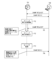
- the main CPU generally performs processing of discarding transmission / reception packets during sleep preparation processing at the driver or protocol stack level (see FIG. 8).
- the image forming apparatus 801 discards the packet (812) even if it receives a request packet (SNMP Request) 811 that requests processing from the external host 802. ) And transition to the sleep state (813).
- SNMP Request request packet
- Recent device management applications generally have a function of grasping the sleep state of a device. For example, there is a function of calculating the power consumption of the device by managing when the device transits to the sleep state and when the device returns from the sleep state, and presents it to the user.
- the device has a function of transmitting a notification packet to the management application immediately before transitioning to the sleep state or immediately after returning from the sleep state.
- the sleep state transition notification packet is actually transmitted before the state transition.
- the device has two types of sleep state notification functions.
- One is a protocol for notifying a sleep state by multicast, and the other is a protocol for notifying a host registered in advance by a unicast TCP or UDP.
- the device (901) When the transition to the sleep state is tentatively determined, as shown in FIG. 9, the device (901) first notifies the management application with a multicast packet (910). When receiving the sleep notification packet, the management application changes the state of the device from “normal state” to “sleep state”.
- the device (901) sends a sleep notification to each of the pre-registered hosts by unicast (911, 912). If a network access (913) occurs from a certain external host to the device during this time, the device (901) postpones the transition to the sleep state (914). For example, when a printing process is executed from a certain host, the device does not transition to the sleep state until printing is completed and the hard disk protection time of the device elapses (915).
- An object of the present invention is to provide a mechanism that does not transmit an unauthorized network packet from a device that has returned from a sleep state, and that a management application that manages the device can also accurately manage the device state without inconsistency. It is.
- the present invention relates to an image forming apparatus having a transmission / reception unit for transmitting / receiving data to / from an external device via a network, the sleep unit for shifting the image forming apparatus to a sleep state, and the effect of shifting to the sleep state.
- a storage unit that stores a destination to be notified, a reception data discard setting unit that validates a reception filter control process in which the data received by the image forming apparatus is discarded by the transmission / reception unit when shifting to the sleep state;
- a notification unit configured to transmit a sleep notification indicating that the image forming apparatus shifts to a sleep state to the destination registered in the storage unit via the transmission / reception unit after enabling reception filter control processing;
- a transmission filter control process for discarding data transmitted from the image forming apparatus by the transmission / reception means after completion of the sleep notification.
- a transmission data discard setting means for enabling, said sleep means, after enabling the transmission filter control processing, and wherein the shifting the image forming apparatus to the sleep state.
- the present invention it is possible to provide a mechanism that does not transmit an unauthorized network packet from a device that has returned from a sleep state, and that a management application that manages the device can also accurately manage the device state without inconsistency. Is possible.
- FIG. 1 is a block diagram illustrating an example of a hardware configuration of an image forming apparatus according to an embodiment of the present invention.
- FIG. 2 is a block diagram illustrating an example of a software configuration of the image forming apparatus 1 illustrated in FIG. 1.
- 3 is a flowchart showing an example of the operation of the image forming apparatus software 2 shown in FIG. 6 is a diagram illustrating an example of a sleep notification destination DB 208 according to the first embodiment.
- FIG. It is a figure which shows an example of the network sequence in Example 1.
- FIG. FIG. 10 illustrates an example of a sleep notification destination DB 208 according to the second embodiment. It is a figure which shows an example of the conventional network sequence. It is a figure which shows an example of the conventional network sequence. It is a figure which shows an example of the conventional network sequence. It is a figure which shows an example of the conventional network sequence. It is a figure which shows an example of the conventional network sequence.
- FIG. 1 is a block diagram illustrating an example of a hardware configuration of an image forming apparatus according to an embodiment of the present invention.
- the image forming apparatus 1 of this embodiment includes a controller 100, a scanner 111, a printer engine 112, and an operation panel 113.
- a control program that can be executed by the CPU 109 is recorded in the program ROM of the ROM 103.
- Information used in the image forming apparatus 1 is recorded in the data ROM of the ROM 103.
- the CPU 109 generally controls access to various devices connected to the system bus 110 based on a control program recorded in the ROM for program of the ROM 103 so as to be readable by a computer.
- the CPU 109 outputs an image signal as output information to the printer engine 112 connected via the printer I / F 106 and controls an image signal input from the scanner 111 connected via the scanner I / F 101. To do.
- the RAM 104 mainly functions as a main memory and work area for the CPU 109.
- the RAM 104 is configured so that the memory capacity can be expanded by an optional RAM connected to an expansion port (not shown).
- a hard disk (HDD) 105 is used as a job storage area for storing font data, an emulation program, form data, and the like, temporarily spooling a print job, and controlling the spooled job from the outside.
- the HDD 105 holds image data read from the scanner 111 and image data of a print job as BOX data, and is also used as a BOX data storage area for reference and printing from the network.
- the non-volatile memory (NVRAM) 107 stores various setting information set on the operation panel 113 via the panel control unit 108.
- a network interface (NW I / F) 102 performs data communication with the external network 120 via a network cable.
- FIG. 2 is a block diagram showing an example of the software configuration of the image forming apparatus 1 shown in FIG.
- the configuration of the image forming apparatus software 2 is roughly divided into a kernel portion that operates in the kernel space and an application portion (application 202) that operates in the user space.
- a network protocol stack (protocol stack 201) for controlling network transmission / reception is mounted in the kernel portion.
- the application 202 includes a sleep control unit 205, a sleep notification control unit 206, a sleep notification transmission unit 207, and a sleep notification destination DB 208.
- the sleep control unit 205 controls whether to shift from a “normal state” in which power is supplied to all units of the image forming apparatus to a “sleep state” in which power is supplied to only one unit.
- the sleep control unit 205 determines to shift to the sleep state, the sleep control unit 205 notifies the sleep notification control unit 206 of information about the sleep shift determination.
- the sleep notification control unit 206 When the sleep notification control unit 206 receives the notification of the sleep transition determination information, the sleep notification control unit 206 transmits a sleep notification packet to the external host via the sleep notification transmission unit 207.
- a general protocol such as Service Location Protocol (SLP) may be used, or a unique protocol may be defined.
- SLP Service Location Protocol
- the destination to which the sleep notification is transmitted is determined based on the destination IP address stored in the sleep notification destination DB 208.
- the sleep control unit 205 when returning from the “sleep state” to the “normal state”, the sleep control unit 205 notifies the sleep notification control unit 206 of the sleep return information.
- the sleep notification control unit 206 When the sleep notification control unit 206 receives notification of sleep recovery information, the sleep notification control unit 206 transmits a sleep recovery notification packet to the external host via the sleep notification transmission unit 207.
- the protocol stack 201 interprets the IP header and the TCP header, and performs packet control of data communication between the application 202 and the external host.
- the protocol stack 201 includes a reception filter control unit 204 and a transmission filter control unit 203.
- the reception filter control unit 204 has a function (reception filter control processing function) that can process reception packet discard and permission for access from a specific destination or access to a specific port number.
- the transmission filter control unit 203 has a function (transmission filter control processing function) that can process discarding and permission of a transmission packet for access to a specific destination and transmission to a port number.
- filter control is performed at the driver level which is a physical layer, but this control may be performed in any of the physical layer, IP layer, TCP / UDP layer, and application layer.
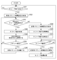
- FIG. 3 is a flowchart showing an example of the operation of the image forming apparatus software 2 shown in FIG. That is, the operation of this flowchart is realized by the CPU 109 of the image forming apparatus 1 reading and executing a program recorded in the ROM 103 so as to be readable by a computer.
- step S301 the sleep control unit 205 determines whether the image forming apparatus 1 can enter the sleep state. As a determination criterion for the sleep state transition, for example, it is determined whether or not the hard disk protection time has elapsed since the last access to the hard disk 105.
- the sleep control unit 205 If it is determined in S301 that the sleep cannot be shifted (No), the sleep control unit 205 returns the process to S301.
- the sleep control unit 205 notifies the sleep notification control unit 206 that the sleep can be shifted.
- the sleep notification control unit 206 Upon receiving a notification that sleep can be shifted, the sleep notification control unit 206 activates the reception filter control unit 204 of the protocol stack 201 in S302 and sets a process (reception filter control process) for discarding all received packets (reception filter control process) (S302). Enable Receive data discard setting.
- the sleep notification control unit 206 refers to the sleep notification destination DB 208 and determines whether there is a destination to which the sleep notification is to be transmitted.
- the sleep notification destination DB 208 is, for example, a list as shown in FIG.
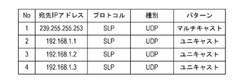
- FIG. 4 is a diagram illustrating an example of the sleep notification destination DB 208 according to the first embodiment.
- the notification destination data (destination) managed by the sleep notification destination DB 208 includes a destination IP address, a protocol type (for example, SLP), a transport type (for example, UDP), and a pattern (for example, multicast, unidirectional). Cast).
- a protocol type for example, SLP
- a transport type for example, UDP
- a pattern for example, multicast, unidirectional). Cast
- No. 1 in FIG. 4 stores a destination for performing sleep notification transmission by SLP multicast.
- a destination for performing sleep notification transmission by SLP unicast using UDP with respect to 192.168.1.1 is stored.
- a destination for performing sleep notification transmission by SLP unicast using UDP with respect to 192.168.1.2 is stored.
- a destination for performing sleep notification transmission by SLP unicast using UDP with respect to 192.168.1.3 is stored.
- the notification destination data managed by the sleep notification destination DB 208 may include attributes such as a port number and an address family (AF_INET, AF_INET6, etc.).
- the sleep notification destination DB 208 stores and manages static destinations stored in advance in the ROM 103 and the like and dynamic destinations registered by the user when shipped from the factory.
- the sleep notification transmission unit 207 advances the process to S304.
- the sleep notification transmission unit 207 reads a destination existing in the sleep notification destination DB 208 and transmits a sleep notification to the destination.
- step S305 the sleep notification transmission unit 207 refers to the sleep notification destination DB 208 to determine whether there is a next destination.
- reception filter control unit 204 for which the reception packet discard setting has been enabled in S302 described above determines that a network packet has been received from the external host during the steps of S303 to S305 (Yes in S306), the reception filter control unit 204 The filter control unit 204 discards the received packet (S307). By this processing, the device can prevent the sleep transition from being postponed due to network reception.
- the sleep notification transmission unit 207 returns the process to S303, and determines whether there is a destination to which the sleep notification is to be transmitted next based on the reference result of the next destination in S305. Then, while there is a destination to be transmitted (Yes in S303), the sleep notification transmission unit 207 repeats the processes of S304 to S305.
- a sleep notification is transmitted by SLP multicast.
- a sleep notification is transmitted by SLP unicast using UDP to 192.168.1.1.
- a sleep notification is transmitted to 192.168.1.2.
- a sleep notification is transmitted to 192.168.1.3. Accordingly, the management application side that has received the sleep notification starts management with the state of the image forming apparatus 1 as the sleep state.
- the sleep notification transmission unit 207 advances the processing to S308.
- the sleep notification control unit 206 activates the transmission filter control unit 203 of the protocol stack 201, and validates the setting (transmission filter control processing) setting (transmission data discard setting) for discarding all transmission packets. Further, the sleep notification control unit 206 notifies the sleep control unit 205 that the sleep notification and the filter control are completed.
- the sleep control unit 205 When the sleep control unit 205 receives the sleep notification and the notification that the filter control has been completed from the sleep notification control unit 206, the sleep control unit 205 starts the sleep transition process in S309, and transitions to the sleep state as soon as the transition process is completed (S310). ).
- the sleep control unit 205 When the sleep control unit 205 returns from the sleep state (Yes in S311), the sleep control unit 205 notifies the sleep notification control unit 206 of the return from the sleep state.
- the sleep notification control unit 206 Upon receiving notification that the mobile device has returned from the sleep state, the sleep notification control unit 206 sets the reception packet discard setting of the reception filter control unit 204 enabled in S302 and the transmission enabled in S308 in S312. The setting of discarding transmission packets in the filter control unit 203 is invalidated.
- the sleep notification control unit 206 transmits a sleep return notification to all the destinations stored in the sleep notification destination DB 208 via the sleep notification transmission unit 207.
- a sleep return notification is first transmitted by SLP multicast.
- a sleep return notification is transmitted by SLP unicast using UDP to 192.168.1.1.
- a sleep return notification is transmitted to 192.168.1.2.
- a sleep return notification is transmitted to 192.168.1.3.
- the management application side that has received the sleep return notification starts management with the state of the image forming apparatus 1 as the normal state.
- FIG. 5 is a diagram illustrating an example of a network sequence according to the first embodiment.
- the image forming apparatus 1 requests an LPD request for print processing from the external host 501 while the sleep notifications (511 to 513) are transmitted as shown in FIG. Even if the packet (LPD Print Request) 514 is received, since the received packet discard setting is valid (510), the received packet is discarded without accepting printing (515).
- the image forming apparatus 1 can always shift to the sleep state when the sleep notification is transmitted (516). Therefore, there is a mismatch between the notification to the management application and the actual state of the image forming apparatus 1. Can be resolved.
- the print request request is received from the external host, but the present invention can be applied without any particular limitation on the protocol.
- the sleep transition time must be postponed at least for the hard disk protection time.
- the time is generally postponed so as not to shift to sleep for several tens of seconds.
- the device is not limited to the image forming apparatus, and the present invention can be applied to any network device that transitions to the sleep state.
- the sleep notification control unit 206 sets the reception packet discard setting of the reception filter control unit 204 enabled in S302 and the transmission enabled in S308 immediately before the image forming apparatus 1 transitions to the sleep state. You may comprise so that the setting of the transmission packet discard of the filter control part 203 may each be invalidated. In the case of this configuration, the sleep notification control unit 206 transmits the sleep return notification in S313 without performing the invalidation processing of the transmission / reception packet discard setting in S312 when returning from sleep.
- Embodiment 2 describes a case where the image forming apparatus 1 to which the present invention is applied transmits a sleep notification using TCP.
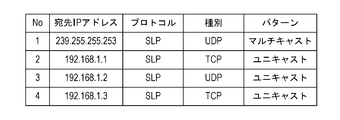
- FIG. 6 is a diagram illustrating an example of the sleep notification destination DB 208 according to the second embodiment.
- the image forming apparatus 1 first transmits a sleep notification by SLP multicast. Next, a sleep notification is transmitted by SLP unicast using TCP to 192.168.1.1. Next, a sleep notification is transmitted by SLP unicast using UDP to 192.168.1.2. Furthermore, a sleep notification is transmitted by SLP unicast using TCP to 192.168.1.3.
- the image forming apparatus 1 when the destination is registered in the sleep notification destination DB 208 as shown in FIG. 6, the image forming apparatus 1 sends a sleep notification to the 192.168.1.1 or 192.168.1.3 by TCP. Need to send. Depending on the management application, it may be desired to send a sleep notification by TCP in order to reliably receive the notification.
- the image forming apparatus 1 transmits a sleep notification by TCP to 192.168.1.1 in S304 of FIG. 3, first, a TCP SYN packet is transmitted.
- the discard setting is enabled in the reception filter control unit 204 in the configuration of the first embodiment.
- the reception filter control unit 204 discards the SYN ACK packet. Therefore, a sleep notification cannot be made to a destination of 192.168.1.1 or 192.168.1.3 that has registered a sleep notification by TCP without establishing a TCP session.
- the stateful inspection function is enabled in the protocol stack 201 and the reception filter control process is executed. For example, when the received packet discard setting is validated in S302 of FIG. 3, the sleep notification control unit 206 determines whether there is a destination for which the sleep notification is registered by TCP, and if there is, the reception filter control unit The stateful inspection function 204 is also enabled.
- the stateful inspection function stores the transmitted packet data as a log, and the reception filter control unit 204 uses the log as a basis.
- This is a function for determining whether or not the received packet data is the corresponding response data, and performing control so that the reception processing is performed without considering the received response data as the reception filter target.
- the shutdown notification is transmitted after the reception filter control processing function is enabled, and the transmission filter is transmitted when transmission of the shutdown notification is completed.
- the management application that prevents unauthorized network packets from being transmitted from the network device such as the image forming apparatus and manages the device also does not change the state of the device such as the image forming apparatus. It is possible to construct a network environment that can be managed accurately without consistency.
- the image forming apparatus has been described as an example of the device of the present invention.
- the device of the present invention is not limited to the image forming apparatus, and may be a device that can perform network communication and transition to the sleep state.
- the present invention can take an embodiment as a system, apparatus, method, program, storage medium, or the like. Specifically, the present invention may be applied to a system composed of a plurality of devices, or may be applied to an apparatus composed of a single device.
Landscapes
- Engineering & Computer Science (AREA)
- Theoretical Computer Science (AREA)
- General Engineering & Computer Science (AREA)
- Physics & Mathematics (AREA)
- General Physics & Mathematics (AREA)
- Human Computer Interaction (AREA)
- Multimedia (AREA)
- Signal Processing (AREA)
- Accessory Devices And Overall Control Thereof (AREA)
- Facsimiles In General (AREA)
- Data Exchanges In Wide-Area Networks (AREA)
Abstract
The invention relates to an image-forming apparatus having a send-receive means that sends data to and receives data from an external device via a network.
Description
本発明は、画像形成装置における状態遷移時のパケット制御技術に関する。
The present invention relates to a packet control technique at the time of state transition in an image forming apparatus.
近年、画像形成装置等の機器が消費する電力を低減するため、稼動していない状態が一定時間以上経過した場合は、電力の供給を機器の一部に限定し低電力で動作する「スリープ状態」へ遷移する省電力機能が進歩している。
In recent years, in order to reduce the power consumed by devices such as image forming devices, when the device has not been operated for a certain period of time or longer, the power supply is limited to a part of the device and operates at low power. The power saving function that makes the transition to "is progressing.
また、ネットワーク技術の普及に伴い、ネットワークを利用して機器とホスト間で定期的にデータのやりとりを行う状況が想定される。機器が「スリープ状態」であっても、このようなネットワーク経由のデータの処理を行うために、機器に複数のCPUを搭載し、非スリープ時にはメインCPUで処理を行うが、スリープ時には、電力消費の小さいサブCPUでメインCPUの処理を代替させる手法が考えられている(特開2006-259906参照)。
Also, with the spread of network technology, it is assumed that data is regularly exchanged between devices and hosts using the network. Even when the device is in “sleep state”, in order to process data via such a network, the device is equipped with multiple CPUs, and processing is performed by the main CPU during non-sleep, but power consumption during sleep A method of substituting the processing of the main CPU with a small sub CPU (see Japanese Patent Laid-Open No. 2006-259906) has been considered.
このようなシステムでは、サブCPUは受信したネットワークパケットに対して代理応答するか破棄するか、メインCPUをスリープ状態から復帰させるかを判断し処理する機能を有している。
In such a system, the sub CPU has a function of determining and processing whether to proxy response or discard the received network packet or to return the main CPU from the sleep state.
一方、近年、機器の多機能化に伴い、機器を制御するメインCPUには多くのドライバが搭載されている。その為、スリープ状態に遷移する場合、これらのドライバに対してスリープ状態遷移の為の停止処理を実施する必要がある。また、機器が画像形成装置である場合、定着器等のエンジンを停止するための処理も必要となる。
On the other hand, in recent years, with the multi-functionalization of devices, many drivers are installed in the main CPU that controls the devices. Therefore, when transitioning to the sleep state, it is necessary to perform stop processing for transition to the sleep state for these drivers. Further, when the device is an image forming apparatus, a process for stopping an engine such as a fixing device is also required.
これらの処理を実施するには数秒間の時間が必要である。つまり、機器がスリープ移行を決定してから、実際にスリープ移行するまで、スリープ準備処理を実行している時間が数秒間発生していた。
It takes several seconds to execute these processes. That is, the time for executing the sleep preparation process has occurred for a few seconds after the device determines to shift to sleep until it actually shifts to sleep.
このスリープ準備中にメインCPUが外部ホストからネットワークパケットを受信すると、タイミングによってはプロトコルスタック、あるいはアプリケーションで処理中に機器がスリープ状態に遷移してしまう場合がある(図7参照)。
When the main CPU receives a network packet from an external host during sleep preparation, the device may transition to the sleep state during processing by the protocol stack or application depending on the timing (see FIG. 7).
図7のように、スリープ移行(710)している間では、画像形成装置701は、外部ホスト702から処理を要求するリクエストパケット(SNMP Request)711を受信しても、プロトコルスタックあるいはアプリケーションで処理中に、スリープ状態に遷移する(712)。そして、次にスリープ復帰(713)した瞬間にリクエストパケット711の処理を進め、応答パケット(714)を外部ホスト702に送信する。
As shown in FIG. 7, during the sleep transition (710), even when the image forming apparatus 701 receives a request packet (SNMP Request) 711 requesting processing from the external host 702, it is processed by the protocol stack or application. During the transition to the sleep state (712). Then, at the moment of returning from sleep (713), the processing of the request packet 711 proceeds, and the response packet (714) is transmitted to the external host 702.
しかし、次にスリープ復帰した際にパケット処理を進めて応答パケットを送信しても、一定時間が経過しているため応答したパケットの内容が不正になる、あるいは外部ホスト702から見れば意図しない時間に応答パケットが来るため攻撃パケットとみなされる可能性もある。
However, even if the packet processing is advanced and the response packet is transmitted at the time of returning from sleep next time, the content of the responded packet becomes invalid because the fixed time has passed, or is not intended when viewed from the external host 702 Since there is a response packet, it may be regarded as an attack packet.
そのため、メインCPUではスリープ準備処理中の送受信パケットをドライバあるいはプロトコルスタックレベルで破棄するという処理が一般的である(図8参照)。
Therefore, the main CPU generally performs processing of discarding transmission / reception packets during sleep preparation processing at the driver or protocol stack level (see FIG. 8).
図8のように、スリープ移行(810)している間では、画像形成装置801は、外部ホスト802から処理を要求するリクエストパケット(SNMP Request)811を受信しても、パケットを破棄し(812)、スリープ状態に遷移する(813)。
As shown in FIG. 8, during the sleep transition (810), the image forming apparatus 801 discards the packet (812) even if it receives a request packet (SNMP Request) 811 that requests processing from the external host 802. ) And transition to the sleep state (813).
しかしながら、従来のスリープ遷移中に送受信パケットを破棄する制御では、機器を管理する管理アプリケーションが正確に機器管理できない問題が発生してしまう(図9参照)。
However, in the conventional control for discarding transmission / reception packets during the sleep transition, there arises a problem that the management application for managing the device cannot accurately manage the device (see FIG. 9).
近年の機器管理アプリケーションは、機器のスリープ状態も把握する機能が一般的である。例えば、機器が何時にスリープ状態に遷移したか、何時にスリープ状態から復帰したかを管理することで機器の消費電力を計算し、ユーザに提示する機能等がある。
Recent device management applications generally have a function of grasping the sleep state of a device. For example, there is a function of calculating the power consumption of the device by managing when the device transits to the sleep state and when the device returns from the sleep state, and presents it to the user.
そのため、機器はスリープ状態に遷移する直前や、スリープ状態から復帰した直後は管理アプリケーションに対して通知パケットを送信する機能を有している。しかし、前述のように機器においてスリープ状態遷移中は送受信パケットを破棄するため、実際にスリープ状態移行通知パケットを送信するのは状態遷移前となる。
Therefore, the device has a function of transmitting a notification packet to the management application immediately before transitioning to the sleep state or immediately after returning from the sleep state. However, as described above, since the transmission / reception packet is discarded during the sleep state transition in the device, the sleep state transition notification packet is actually transmitted before the state transition.
例えば、機器が2種類のスリープ状態通知機能を有しているとする。1つはマルチキャストでスリープ状態通知を行うプロトコルであり、もう1つは予め登録されたホストに対してユニキャストのTCPあるいはUDPでスリープ状態通知を行うプロトコルとする。
For example, assume that the device has two types of sleep state notification functions. One is a protocol for notifying a sleep state by multicast, and the other is a protocol for notifying a host registered in advance by a unicast TCP or UDP.
スリープ状態への遷移が仮決定したら、図9のように、機器(901)は、まずマルチキャストパケットで管理アプリケーションに対してスリープ通知を行う(910)。管理アプリケーションは、スリープ通知パケットを受信したら、機器の状態を「通常状態」から「スリープ状態」に変更する。
When the transition to the sleep state is tentatively determined, as shown in FIG. 9, the device (901) first notifies the management application with a multicast packet (910). When receiving the sleep notification packet, the management application changes the state of the device from “normal state” to “sleep state”.
次に、機器(901)は、予め登録されているホストに対してユニキャストで1台1台にスリープ通知を行っていく(911,912)。もしこの間に、ある外部ホストから機器に対してネットワークアクセス(913)が発生すると、機器(901)はスリープ状態への移行を延期してしまう(914)。例えば、あるホストから印刷処理が実行された場合、機器は、印刷が完了し機器のハードディスク保護時間が経過するまではスリープ状態へ遷移しない(915)。
Next, the device (901) sends a sleep notification to each of the pre-registered hosts by unicast (911, 912). If a network access (913) occurs from a certain external host to the device during this time, the device (901) postpones the transition to the sleep state (914). For example, when a printing process is executed from a certain host, the device does not transition to the sleep state until printing is completed and the hard disk protection time of the device elapses (915).
このような場合、機器の管理アプリケーションではスリープ通知(910)を受信したのに、実際に機器はスリープ状態に遷移していない、という管理不整合(916)が発生してしまう問題があった。
In such a case, there is a problem that a management inconsistency (916) occurs that the device management application receives the sleep notification (910), but the device does not actually shift to the sleep state.
本発明は、上記の問題点を解決するためになされたものである。本発明の目的は、スリープ状態から復帰した機器から不正なネットワークパケットを送信せず、且つ、機器を管理する管理アプリケーションも機器の状態を不整合なく正確に管理することができる仕組みを提供することである。
The present invention has been made to solve the above problems. An object of the present invention is to provide a mechanism that does not transmit an unauthorized network packet from a device that has returned from a sleep state, and that a management application that manages the device can also accurately manage the device state without inconsistency. It is.
本発明は、ネットワークを介して外部装置とデータの送受信を行う送受信手段とを有する画像形成装置であって、前記画像形成装置をスリープ状態に移行させるスリープ手段と、前記スリープ状態に移行する旨を通知する宛先を記憶する記憶手段と、前記スリープ状態に移行する場合に、前記画像形成装置が受信するデータを前記送受信手段で破棄する受信フィルタ制御処理を有効にする受信データ破棄設定手段と、前記受信フィルタ制御処理を有効にした後に、前記送受信手段を介して、前記画像形成装置がスリープ状態に移行する旨を示すスリープ通知を前記記憶手段に登録されている宛先へ送信する通知手段と、前記スリープ通知の完了の後に、前記画像形成装置から送信するデータを前記送受信手段で破棄する送信フィルタ制御処理を有効にする送信データ破棄設定手段とを有し、前記スリープ手段は、前記送信フィルタ制御処理を有効にした後に、前記画像形成装置をスリープ状態に移行させることを特徴とする。
The present invention relates to an image forming apparatus having a transmission / reception unit for transmitting / receiving data to / from an external device via a network, the sleep unit for shifting the image forming apparatus to a sleep state, and the effect of shifting to the sleep state. A storage unit that stores a destination to be notified, a reception data discard setting unit that validates a reception filter control process in which the data received by the image forming apparatus is discarded by the transmission / reception unit when shifting to the sleep state; A notification unit configured to transmit a sleep notification indicating that the image forming apparatus shifts to a sleep state to the destination registered in the storage unit via the transmission / reception unit after enabling reception filter control processing; A transmission filter control process for discarding data transmitted from the image forming apparatus by the transmission / reception means after completion of the sleep notification. And a transmission data discard setting means for enabling, said sleep means, after enabling the transmission filter control processing, and wherein the shifting the image forming apparatus to the sleep state.
本発明によれば、スリープ状態から復帰した機器から不正なネットワークパケットを送信せず、且つ、機器を管理する管理アプリケーションも機器の状態を不整合なく正確に管理することができる仕組みを提供することが可能となる。
According to the present invention, it is possible to provide a mechanism that does not transmit an unauthorized network packet from a device that has returned from a sleep state, and that a management application that manages the device can also accurately manage the device state without inconsistency. Is possible.
以下、本発明を実施するための最良の形態について図面を用いて説明する。ここでは、本発明の機器として、画像形成装置を例に説明する。
Hereinafter, the best mode for carrying out the present invention will be described with reference to the drawings. Here, an image forming apparatus will be described as an example of the device of the present invention.
実施例1として、本発明を適用した画像形成装置がUDPを用いてスリープ通知を送信する場合について説明する。
As a first embodiment, a case where an image forming apparatus to which the present invention is applied transmits a sleep notification using UDP will be described.
図1は、本発明の一実施例を示す画像形成装置のハードウェア構成の一例を示すブロック図である。
FIG. 1 is a block diagram illustrating an example of a hardware configuration of an image forming apparatus according to an embodiment of the present invention.
図1に示すように、本実施例の画像形成装置1は、コントローラ100、スキャナ111、プリンタエンジン112、オペレーションパネル113を有する。
As shown in FIG. 1, the image forming apparatus 1 of this embodiment includes a controller 100, a scanner 111, a printer engine 112, and an operation panel 113.
ROM103のプログラム用ROMには、CPU109が実行可能な制御プログラム等が記録されている。ROM103のデータ用ROMには、画像形成装置1で利用される情報等が記録されている。
A control program that can be executed by the CPU 109 is recorded in the program ROM of the ROM 103. Information used in the image forming apparatus 1 is recorded in the data ROM of the ROM 103.
CPU109は、ROM103のプログラム用ROMにコンピュータ読み取り可能に記録された制御プログラムに基づいて、システムバス110に接続される各種のデバイスとのアクセスを総括的に制御する。
The CPU 109 generally controls access to various devices connected to the system bus 110 based on a control program recorded in the ROM for program of the ROM 103 so as to be readable by a computer.
また、CPU109は、プリンタI/F106を介して接続されるプリンタエンジン112に出力情報としての画像信号を出力したり、スキャナI/F101を介して接続されるスキャナ111から入力される画像信号を制御する。
Further, the CPU 109 outputs an image signal as output information to the printer engine 112 connected via the printer I / F 106 and controls an image signal input from the scanner 111 connected via the scanner I / F 101. To do.
RAM104は、主としてCPU109の主メモリ,ワークエリア等として機能する。なお、RAM104は、図示しない増設ポートに接続されるオプションRAMによりメモリ容量を拡張することができるように構成されている。
The RAM 104 mainly functions as a main memory and work area for the CPU 109. The RAM 104 is configured so that the memory capacity can be expanded by an optional RAM connected to an expansion port (not shown).
ハードディスク(HDD)105は、フォントデータ、エミュレーションプログラム、フォームデータ等を記憶、プリントジョブを一時的にスプールし、スプールされたジョブを外部から制御するためのジョブ格納領域として使用される。また、HDD105は、スキャナ111から読み取った画像データやプリントジョブの画像データをBOXデータとして保持し、ネットワークから参照、印刷を行うBOXデータ格納領域としても使用される。
A hard disk (HDD) 105 is used as a job storage area for storing font data, an emulation program, form data, and the like, temporarily spooling a print job, and controlling the spooled job from the outside. The HDD 105 holds image data read from the scanner 111 and image data of a print job as BOX data, and is also used as a BOX data storage area for reference and printing from the network.
不揮発性メモリ(NVRAM)107は、オペレーションパネル113で設定される各種設定情報をパネル制御部108経由で記憶している。ネットワークインタフェース(NW I/F)102は、ネットワークケーブルを経由して外部ネットワーク120とデータ通信を行う。
The non-volatile memory (NVRAM) 107 stores various setting information set on the operation panel 113 via the panel control unit 108. A network interface (NW I / F) 102 performs data communication with the external network 120 via a network cable.
図2は、図1に示した画像形成装置1のソフトウェア構成の一例を示すブロック図である。
FIG. 2 is a block diagram showing an example of the software configuration of the image forming apparatus 1 shown in FIG.
図2に示す画像形成装置ソフトウェア2は、画像形成装置1のCPU109がROM103にコンピュータ読み取り可能に記録されたプログラムを読み出して実行することにより実現される機能である。
2 is a function realized when the CPU 109 of the image forming apparatus 1 reads out and executes a program recorded in the ROM 103 so as to be readable by a computer.
図2に示すように、画像形成装置ソフトウェア2の構成は、大きく分けて、カーネル空間で動作するカーネル部分と、ユーザ空間で動作するアプリケーション部分(アプリケーション202)とに分けられる。このカーネル部分にネットワーク送受信を制御するネットワークプロトコルスタック(プロトコルスタック201)が搭載されている。
As shown in FIG. 2, the configuration of the image forming apparatus software 2 is roughly divided into a kernel portion that operates in the kernel space and an application portion (application 202) that operates in the user space. A network protocol stack (protocol stack 201) for controlling network transmission / reception is mounted in the kernel portion.
まず、アプリケーション202について説明する。
First, the application 202 will be described.
アプリケーション202は、スリープ制御部205、スリープ通知制御部206、スリープ通知送信部207、スリープ通知先DB208を有する。
The application 202 includes a sleep control unit 205, a sleep notification control unit 206, a sleep notification transmission unit 207, and a sleep notification destination DB 208.
スリープ制御部205は、画像形成装置の全ユニットに電力が供給されている「通常状態」から、1部のユニットへのみ電力が供給される「スリープ状態」に移行するかどうかの制御を行う。スリープ状態に移行すると決定した場合、スリープ制御部205は、スリープ通知制御部206へスリープ移行決定の情報を通知する。
The sleep control unit 205 controls whether to shift from a “normal state” in which power is supplied to all units of the image forming apparatus to a “sleep state” in which power is supplied to only one unit. When the sleep control unit 205 determines to shift to the sleep state, the sleep control unit 205 notifies the sleep notification control unit 206 of information about the sleep shift determination.
スリープ通知制御部206は、スリープ移行決定の情報の通知を受けると、スリープ通知送信部207を介して外部ホスト宛にスリープ通知パケットを送信する。スリープ通知パケットのフォーマットは、Service Location Protocol(SLP)などの汎用プロトコルを使用してもよいし、独自プロトコルを定義してもよい。この時、スリープ通知を送信する宛先は、スリープ通知先DB208に格納されている宛先IPアドレスに基づいて決定される。
When the sleep notification control unit 206 receives the notification of the sleep transition determination information, the sleep notification control unit 206 transmits a sleep notification packet to the external host via the sleep notification transmission unit 207. For the format of the sleep notification packet, a general protocol such as Service Location Protocol (SLP) may be used, or a unique protocol may be defined. At this time, the destination to which the sleep notification is transmitted is determined based on the destination IP address stored in the sleep notification destination DB 208.
同様に、スリープ制御部205は、「スリープ状態」から「通常状態」に復帰した場合、スリープ通知制御部206へスリープ復帰の情報を通知する。
Similarly, when returning from the “sleep state” to the “normal state”, the sleep control unit 205 notifies the sleep notification control unit 206 of the sleep return information.
スリープ通知制御部206は、スリープ復帰の情報の通知を受けると、スリープ通知送信部207を介して外部ホスト宛にスリープ復帰通知パケットを送信する。
When the sleep notification control unit 206 receives notification of sleep recovery information, the sleep notification control unit 206 transmits a sleep recovery notification packet to the external host via the sleep notification transmission unit 207.
次に、プロトコルスタック201について説明する。
Next, the protocol stack 201 will be described.
プロトコルスタック201は、IPヘッダやTCPヘッダを解釈し、アプリケーション202と外部ホストとのデータ通信のパケット制御を行う。プロトコルスタック201は、受信フィルタ制御部204、送信フィルタ制御部203を有する。
The protocol stack 201 interprets the IP header and the TCP header, and performs packet control of data communication between the application 202 and the external host. The protocol stack 201 includes a reception filter control unit 204 and a transmission filter control unit 203.
受信フィルタ制御部204は、特定の宛先からのアクセスや特定のポート番号へのアクセスに対して、受信パケットの破棄、許可を処理できる機能(受信フィルタ制御処理機能)を有する。同様に、送信フィルタ制御部203は、特定の宛先へのアクセスやポート番号への送信に対して、送信パケットの破棄、許可を処理できる機能(送信フィルタ制御処理機能)を有する。
The reception filter control unit 204 has a function (reception filter control processing function) that can process reception packet discard and permission for access from a specific destination or access to a specific port number. Similarly, the transmission filter control unit 203 has a function (transmission filter control processing function) that can process discarding and permission of a transmission packet for access to a specific destination and transmission to a port number.
本実施例では、物理層であるドライバレベルでフィルタ制御する例を説明するが、本制御は、物理層、IP層、TCP/UDP層、アプリケーション層いずれのレイヤーで実施されてもよい。
In this embodiment, an example in which filter control is performed at the driver level which is a physical layer will be described, but this control may be performed in any of the physical layer, IP layer, TCP / UDP layer, and application layer.
以下、図3を用いて、画像形成装置ソフトウェア2の動作について説明する。
Hereinafter, the operation of the image forming apparatus software 2 will be described with reference to FIG.
図3は、図2に示した画像形成装置ソフトウェア2の動作の一例を示すフローチャートである。即ち、本フローチャートの動作は、画像形成装置1のCPU109がROM103にコンピュータ読み取り可能に記録されたプログラムを読み出して実行することにより実現されるものである。
FIG. 3 is a flowchart showing an example of the operation of the image forming apparatus software 2 shown in FIG. That is, the operation of this flowchart is realized by the CPU 109 of the image forming apparatus 1 reading and executing a program recorded in the ROM 103 so as to be readable by a computer.
S301において、スリープ制御部205は、画像形成装置1がスリープ状態に移行できるかどうかを判断する。スリープ状態移行の判断基準としては、例えば、最後にハードディスク105にアクセスしてから、ハードディスク保護時間が経過しているか否か等で判断を行うものとする。
In step S301, the sleep control unit 205 determines whether the image forming apparatus 1 can enter the sleep state. As a determination criterion for the sleep state transition, for example, it is determined whether or not the hard disk protection time has elapsed since the last access to the hard disk 105.
前記S301において、スリープ移行可能でないと判断した場合(No)、スリープ制御部205は、S301に処理を戻す。
If it is determined in S301 that the sleep cannot be shifted (No), the sleep control unit 205 returns the process to S301.
一方、前記S301において、スリープ移行可能と判断した場合(Yes)、スリープ制御部205は、スリープ通知制御部206にスリープ移行可能の旨を通知する。
On the other hand, when it is determined in S301 that the sleep can be shifted (Yes), the sleep control unit 205 notifies the sleep notification control unit 206 that the sleep can be shifted.
スリープ移行可能の旨の通知を受けると、スリープ通知制御部206は、S302において、プロトコルスタック201の受信フィルタ制御部204を起動させ、受信パケットを全て破棄する処理(受信フィルタ制御処理)の設定(受信データ破棄設定)を有効にする。
Upon receiving a notification that sleep can be shifted, the sleep notification control unit 206 activates the reception filter control unit 204 of the protocol stack 201 in S302 and sets a process (reception filter control process) for discarding all received packets (reception filter control process) (S302). Enable Receive data discard setting.
次に、S303において、スリープ通知制御部206は、スリープ通知先DB208を参照し、スリープ通知を送信すべき宛先が存在するか否かを判断する。スリープ通知先DB208は、例えば図4のようなリストとなっている。
Next, in S303, the sleep notification control unit 206 refers to the sleep notification destination DB 208 and determines whether there is a destination to which the sleep notification is to be transmitted. The sleep notification destination DB 208 is, for example, a list as shown in FIG.
図4は、実施例1のスリープ通知先DB208の一例を示す図である。
FIG. 4 is a diagram illustrating an example of the sleep notification destination DB 208 according to the first embodiment.
図4に示すように、スリープ通知先DB208が管理する通知先データ(宛先)は、宛先IPアドレス、プロトコル種別(例えば、SLP)、トランスポート種別(例えば、UDP)、パターン(例えば、マルチキャスト、ユニキャスト)を含むものとする。
As shown in FIG. 4, the notification destination data (destination) managed by the sleep notification destination DB 208 includes a destination IP address, a protocol type (for example, SLP), a transport type (for example, UDP), and a pattern (for example, multicast, unidirectional). Cast).
例えば、図4のNo1には、SLPマルチキャストでスリープ通知送信を行うための宛先が格納されている。また、No2には、192.168.1.1に対してUDPを使用してSLPユニキャストでスリープ通知送信を行うための宛先が格納されている。また、No3には、192.168.1.2に対してUDPを使用してSLPユニキャストでスリープ通知送信を行うための宛先が格納されている。また、No4には、192.168.1.3に対してUDPを使用してSLPユニキャストでスリープ通知送信を行うための宛先が格納されている。なお、スリープ通知先DB208が管理する通知先データは、ポート番号やアドレスファミリー(AF_INET、AF_INET6等)等の属性を含んでいてもよい。
For example, No. 1 in FIG. 4 stores a destination for performing sleep notification transmission by SLP multicast. In No. 2, a destination for performing sleep notification transmission by SLP unicast using UDP with respect to 192.168.1.1 is stored. In No. 3, a destination for performing sleep notification transmission by SLP unicast using UDP with respect to 192.168.1.2 is stored. In No. 4, a destination for performing sleep notification transmission by SLP unicast using UDP with respect to 192.168.1.3 is stored. Note that the notification destination data managed by the sleep notification destination DB 208 may include attributes such as a port number and an address family (AF_INET, AF_INET6, etc.).
なお、スリープ通知先DB208は、工場出荷時等に予めROM103等に格納されている静的な宛先と、ユーザにより登録される動的な宛先を記憶管理している。
Note that the sleep notification destination DB 208 stores and manages static destinations stored in advance in the ROM 103 and the like and dynamic destinations registered by the user when shipped from the factory.
以下、図3の説明にもどる。
Returning to the explanation of FIG.
前記S303において、送信すべき宛先が存在すると判断した場合(Yes)、スリープ通知送信部207は、S304に処理を進める。
If it is determined in S303 that there is a destination to be transmitted (Yes), the sleep notification transmission unit 207 advances the process to S304.
S304では、スリープ通知送信部207は、前記スリープ通知先DB208に存在する宛先を読み出して、該宛先にスリープ通知を送信する。
In S304, the sleep notification transmission unit 207 reads a destination existing in the sleep notification destination DB 208 and transmits a sleep notification to the destination.
送信が完了したら、S305において、スリープ通知送信部207は、次の宛先が存在するかスリープ通知先DB208を参照する。
When the transmission is completed, in step S305, the sleep notification transmission unit 207 refers to the sleep notification destination DB 208 to determine whether there is a next destination.
なお、上記S302で受信パケット破棄設定を有効にされた受信フィルタ制御部204は、前記S303~S305の手順の間に、外部ホストからネットワークパケットを受信したと判断した場合(S306でYes)、受信フィルタ制御部204が受信パケットを破棄する(S307)。この処理によって、機器はネットワーク受信によってスリープ移行が延期されることを防止できる。
If the reception filter control unit 204 for which the reception packet discard setting has been enabled in S302 described above determines that a network packet has been received from the external host during the steps of S303 to S305 (Yes in S306), the reception filter control unit 204 The filter control unit 204 discards the received packet (S307). By this processing, the device can prevent the sleep transition from being postponed due to network reception.
次に、スリープ通知送信部207は、S303に処理を戻し、前記S305での次の宛先の参照結果に基づいて、次にスリープ通知を送信すべき宛先が存在するか否かを判断する。そして、送信すべき宛先が存在する間(S303でYesの間)、スリープ通知送信部207は、S304~S305の処理を繰り返す。
Next, the sleep notification transmission unit 207 returns the process to S303, and determines whether there is a destination to which the sleep notification is to be transmitted next based on the reference result of the next destination in S305. Then, while there is a destination to be transmitted (Yes in S303), the sleep notification transmission unit 207 repeats the processes of S304 to S305.
図4に示した例の場合、まずSLPマルチキャストでスリープ通知を送信する。次に、192.168.1.1に対してUDPを使用してSLPユニキャストでスリープ通知を送信する。次に、192.168.1.2に対してスリープ通知を送信する。さらに、192.168.1.3に対してスリープ通知を送信する。これにより、スリープ通知を受信した管理アプリケーション側は、画像形成装置1の状態をスリープ状態として管理を始める。
In the case of the example shown in FIG. 4, first, a sleep notification is transmitted by SLP multicast. Next, a sleep notification is transmitted by SLP unicast using UDP to 192.168.1.1. Next, a sleep notification is transmitted to 192.168.1.2. Further, a sleep notification is transmitted to 192.168.1.3. Accordingly, the management application side that has received the sleep notification starts management with the state of the image forming apparatus 1 as the sleep state.
そして、前記S303において、次にスリープ通知を送信すべき宛先が存在しないと判断した場合(No)、スリープ通知送信部207は、S308に処理を進める。
If it is determined in S303 that there is no destination to which the sleep notification is to be transmitted next (No), the sleep notification transmission unit 207 advances the processing to S308.
S308において、スリープ通知制御部206は、プロトコルスタック201の送信フィルタ制御部203を起動させ、送信パケットを全て破棄する処理(送信フィルタ制御処理)の設定(送信データ破棄設定)を有効にする。さらに、スリープ通知制御部206は、スリープ制御部205に対して、スリープ通知およびフィルタ制御が完了した旨の通知を行う。
In S308, the sleep notification control unit 206 activates the transmission filter control unit 203 of the protocol stack 201, and validates the setting (transmission filter control processing) setting (transmission data discard setting) for discarding all transmission packets. Further, the sleep notification control unit 206 notifies the sleep control unit 205 that the sleep notification and the filter control are completed.
スリープ制御部205は、スリープ通知制御部206からスリープ通知およびフィルタ制御が完了した旨の通知を受けると、S309において、スリープ移行処理を開始し、移行処理が完了次第、スリープ状態に移行する(S310)。
When the sleep control unit 205 receives the sleep notification and the notification that the filter control has been completed from the sleep notification control unit 206, the sleep control unit 205 starts the sleep transition process in S309, and transitions to the sleep state as soon as the transition process is completed (S310). ).
スリープ制御部205は、スリープ状態から復帰した場合(S311でYes)、スリープ通知制御部206に対して、スリープ状態から復帰した旨の通知を行う。
When the sleep control unit 205 returns from the sleep state (Yes in S311), the sleep control unit 205 notifies the sleep notification control unit 206 of the return from the sleep state.
スリープ状態から復帰した旨の通知を受けると、スリープ通知制御部206は、S312において、前記S302で有効にしていた受信フィルタ制御部204の受信パケット破棄の設定、及び前記S308で有効にしていた送信フィルタ制御部203の送信パケット破棄の設定をそれぞれ無効にする。
Upon receiving notification that the mobile device has returned from the sleep state, the sleep notification control unit 206 sets the reception packet discard setting of the reception filter control unit 204 enabled in S302 and the transmission enabled in S308 in S312. The setting of discarding transmission packets in the filter control unit 203 is invalidated.
次に、S313において、スリープ通知制御部206は、スリープ通知送信部207を介して、スリープ通知先DB208に格納されている全ての宛先に対して、スリープ復帰通知を送信する。図4に示した例の場合、まずSLPマルチキャストでスリープ復帰通知を送信する。次に、192.168.1.1に対してUDPを使用してSLPユニキャストでスリープ復帰通知を送信する。次に、192.168.1.2に対してスリープ復帰通知を送信する。さらに、192.168.1.3に対してスリープ復帰通知を送信する。これにより、スリープ復帰通知を受信した管理アプリケーション側は、画像形成装置1の状態を通常状態として管理を始める。
Next, in S313, the sleep notification control unit 206 transmits a sleep return notification to all the destinations stored in the sleep notification destination DB 208 via the sleep notification transmission unit 207. In the case of the example shown in FIG. 4, a sleep return notification is first transmitted by SLP multicast. Next, a sleep return notification is transmitted by SLP unicast using UDP to 192.168.1.1. Next, a sleep return notification is transmitted to 192.168.1.2. Further, a sleep return notification is transmitted to 192.168.1.3. As a result, the management application side that has received the sleep return notification starts management with the state of the image forming apparatus 1 as the normal state.
以下、図5を用いて、具体的例を示す。
Hereinafter, a specific example will be shown using FIG.
図5は、実施例1におけるネットワークシーケンスの一例を示す図である。
FIG. 5 is a diagram illustrating an example of a network sequence according to the first embodiment.
図3に示した処理を実行することで、図5のように、スリープ通知(511~513)を送信している間では、画像形成装置1は、外部ホスト501から印刷処理を要求するLPDリクエストパケット(LPD Print Request)514を受信しても、受信パケット破棄設定が有効(510)になっているので、印刷を受け付けることなく受信パケットを破棄する(515)。
By executing the process shown in FIG. 3, the image forming apparatus 1 requests an LPD request for print processing from the external host 501 while the sleep notifications (511 to 513) are transmitted as shown in FIG. Even if the packet (LPD Print Request) 514 is received, since the received packet discard setting is valid (510), the received packet is discarded without accepting printing (515).
そのため画像形成装置1は、スリープ通知を送信した場合は、必ずスリープ状態に移行することができるため(516)、管理アプリケーションへの通知と実際の画像形成装置1の状態との間の不整合を解消できる。
Therefore, the image forming apparatus 1 can always shift to the sleep state when the sleep notification is transmitted (516). Therefore, there is a mismatch between the notification to the management application and the actual state of the image forming apparatus 1. Can be resolved.
また、管理アプリケーション側でもスリープ通知を受信したのに、画像形成装置1がスリープ状態に移行していない、という不整合が発生することもない。
Also, there is no inconsistency that the image forming apparatus 1 has not shifted to the sleep state even though the management application side has received the sleep notification.
図5に示した例では、外部ホストから印刷要求リクエストを受信した場合であったが、特にプロトコルを限定することはなく本発明を適用できる。
In the example shown in FIG. 5, the print request request is received from the external host, but the present invention can be applied without any particular limitation on the protocol.
なお、プロトコル処理によってスリープ移行をどれだけの時間延期させるかは、機器構成によって異なるものとする。例えば、HDDにアクセスするようなプロトコル受信の場合は、少なくともハードディスク保護時間分はスリープ移行時間を延期しなければならない。また、SNMPやSLP等の機器の情報取得系のプロトコルであれば連続してアクセスしてくる可能性があるため、一般的には数十秒間はスリープ移行しないように時間を延期する。
Note that how long the sleep transition is postponed by protocol processing depends on the device configuration. For example, in the case of protocol reception for accessing the HDD, the sleep transition time must be postponed at least for the hard disk protection time. In addition, since there is a possibility of continuous access if it is an information acquisition protocol of a device such as SNMP or SLP, the time is generally postponed so as not to shift to sleep for several tens of seconds.
なお、機器は画像形成装置に限定されるものではなくスリープ状態に遷移するネットワーク機器であれば、本発明を適用可能である。
The device is not limited to the image forming apparatus, and the present invention can be applied to any network device that transitions to the sleep state.
以上示したように、本実施例によれば、スリープ状態に遷移する機器において不正なネットワークパケットの送信を防止し、かつ機器を管理する管理アプリケーションも機器の状態を不整合なく正確に管理することができるネットワーク環境を構築することができる。
As described above, according to the present embodiment, it is possible to prevent unauthorized network packet transmission in a device that transits to a sleep state, and a management application that manages the device also accurately manages the device state without any inconsistency. Can build a network environment that can
なお、スリープ通知制御部206は、画像形成装置1がスリープ状態に遷移する直前に、前記S302で有効にしていた受信フィルタ制御部204の受信パケット破棄の設定、及び前記S308で有効にしていた送信フィルタ制御部203の送信パケット破棄の設定をそれぞれ無効にするように構成してもよい。この構成の場合、スリープ通知制御部206は、スリープ復帰した場合に、S312の送受信パケット破棄設定の無効処理を行うことなく、S313のスリープ復帰通知の送信を行うものとする。
Note that the sleep notification control unit 206 sets the reception packet discard setting of the reception filter control unit 204 enabled in S302 and the transmission enabled in S308 immediately before the image forming apparatus 1 transitions to the sleep state. You may comprise so that the setting of the transmission packet discard of the filter control part 203 may each be invalidated. In the case of this configuration, the sleep notification control unit 206 transmits the sleep return notification in S313 without performing the invalidation processing of the transmission / reception packet discard setting in S312 when returning from sleep.
実施例2では、本発明を適用した画像形成装置1がTCPを用いてスリープ通知を送信する場合について説明する。
Embodiment 2 describes a case where the image forming apparatus 1 to which the present invention is applied transmits a sleep notification using TCP.
図6は、実施例2のスリープ通知先DB208の一例を示す図である。
FIG. 6 is a diagram illustrating an example of the sleep notification destination DB 208 according to the second embodiment.
図6に示す例の場合、画像形成装置1は、まずSLPマルチキャストでスリープ通知を送信する。次に、192.168.1.1に対してTCPを使用してSLPユニキャストでスリープ通知を送信する。次に、192.168.1.2に対してUDPを使用してSLPユニキャストでスリープ通知を送信する。さらに、192.168.1.3に対してTCPを使用してSLPユニキャストでスリープ通知を送信する。
In the example shown in FIG. 6, the image forming apparatus 1 first transmits a sleep notification by SLP multicast. Next, a sleep notification is transmitted by SLP unicast using TCP to 192.168.1.1. Next, a sleep notification is transmitted by SLP unicast using UDP to 192.168.1.2. Furthermore, a sleep notification is transmitted by SLP unicast using TCP to 192.168.1.3.
即ち、スリープ通知先DB208に図6のように宛先が登録されている場合、画像形成装置1は、192.168.1.1や192.168.1.3に対して、スリープ通知をTCPで送信する必要がある。管理アプリケーションによっては、確実に通知を受信したいため、TCPでスリープ通知を送信してほしい場合がある。
That is, when the destination is registered in the sleep notification destination DB 208 as shown in FIG. 6, the image forming apparatus 1 sends a sleep notification to the 192.168.1.1 or 192.168.1.3 by TCP. Need to send. Depending on the management application, it may be desired to send a sleep notification by TCP in order to reliably receive the notification.
このような場合、画像形成装置1が図3のS304において、192.168.1.1に対してTCPでスリープ通知を送信すると、まずはTCP SYNパケットが送信される。SYNに対して、192.168.1.1がSYN ACKの応答を画像形成装置1に対して送信すると、実施例1の構成では、受信フィルタ制御部204で破棄設定が有効になっているので、受信フィルタ制御部204がSYN ACKパケットを破棄してしまう。そのため、TCPセッションが確立せずに、TCPでスリープ通知を登録していた192.168.1.1や192.168.1.3の宛先に対しては、スリープ通知することができない。
In such a case, when the image forming apparatus 1 transmits a sleep notification by TCP to 192.168.1.1 in S304 of FIG. 3, first, a TCP SYN packet is transmitted. When 192.168.1.1 sends a SYN ACK response to the image forming apparatus 1 in response to SYN, the discard setting is enabled in the reception filter control unit 204 in the configuration of the first embodiment. The reception filter control unit 204 discards the SYN ACK packet. Therefore, a sleep notification cannot be made to a destination of 192.168.1.1 or 192.168.1.3 that has registered a sleep notification by TCP without establishing a TCP session.
この問題を解決するために、実施例2では、TCPでスリープ通知を登録している宛先が存在する場合、プロトコルスタック201において、ステートフルインスペクション機能を有効にして、受信フィルタ制御処理を実行する。例えば、図3のS302において受信パケット破棄設定を有効にする場合に、スリープ通知制御部206が、TCPでスリープ通知を登録している宛先が存在するか判定し、存在する場合、受信フィルタ制御部204のステートフルインスペクション機能も有効に設定する。
In order to solve this problem, in the second embodiment, when there is a destination for which a sleep notification is registered by TCP, the stateful inspection function is enabled in the protocol stack 201 and the reception filter control process is executed. For example, when the received packet discard setting is validated in S302 of FIG. 3, the sleep notification control unit 206 determines whether there is a destination for which the sleep notification is registered by TCP, and if there is, the reception filter control unit The stateful inspection function 204 is also enabled.
ステートフルインスペクション機能とは、例えば画像形成装置1がクライアントとなってリクエストパケットデータを送信する場合、該送信したパケットデータをログとして保管しておき、受信フィルタ制御部204が、このログに基づいて、受信したパケットデータが該当の応答データであるか判断し、該当の応答データであれば受信フィルタ対象とみなさずに受信処理を行うように制御する機能である。
For example, when the image forming apparatus 1 becomes a client and transmits request packet data, the stateful inspection function stores the transmitted packet data as a log, and the reception filter control unit 204 uses the log as a basis. This is a function for determining whether or not the received packet data is the corresponding response data, and performing control so that the reception processing is performed without considering the received response data as the reception filter target.
このステートフルインスペクション機能を有効にすることで、TCPで登録されている宛先に対してもスリープ通知を行うことが可能となる。即ち、実施例2によれば、TCPのように、送達確認等を行うプロトコルを使用して通信する宛先に対しても、スリープ通知を行うことが可能となる。
有効 By enabling this stateful inspection function, it is possible to send a sleep notification to a destination registered in TCP. That is, according to the second embodiment, it is possible to perform a sleep notification to a destination that communicates using a protocol that performs delivery confirmation or the like, such as TCP.
実施例3として、本発明を適用した画像形成装置が、シャットダウンする場合について説明する。
As a third embodiment, a case where an image forming apparatus to which the present invention is applied shuts down will be described.
画像形成装置1をシャットダウンする場合も、スリープ状態に移行する場合と同様の課題が存在する。
When the image forming apparatus 1 is shut down, the same problem as in the case of shifting to the sleep state exists.
シャットダウン処理中は、送受信パケットを破棄するフィルタ制御を有効にするため、フィルタ有効前にシャットダウン通知を送信する必要がある。
During shutdown processing, it is necessary to send a shutdown notification before the filter is valid in order to enable filter control that discards transmitted and received packets.
この場合も、通知宛先が多く存在し、通知処理中に外部ホストから印刷ジョブ等を受信してしまった場合、画像形成装置のシャットダウンは延期されるため、管理不整合が発生してしまう。
Also in this case, if there are many notification destinations and a print job or the like is received from an external host during the notification process, the shutdown of the image forming apparatus is postponed, resulting in management inconsistency.
本実施例においても、シャットダウンする場合、まずは受信フィルタ制御処理機能のみを有効にして、該受信フィルタ制御処理機能が有効になった後にシャットダウン通知を送信し、該シャットダウン通知の送信が完了したら送信フィルタ制御処理機能を有効にし、該送信フィルタ制御処理機能が有効になったらシャットダウン処理を開始する制御を画像形成装置ソフトウェア2に搭載することで解決できる。
Also in this embodiment, when shutting down, first, only the reception filter control processing function is enabled, the shutdown notification is transmitted after the reception filter control processing function is enabled, and the transmission filter is transmitted when transmission of the shutdown notification is completed. This can be solved by installing control in the image forming apparatus software 2 to enable the control processing function and start the shutdown processing when the transmission filter control processing function is enabled.
以上示したように、本実施例によれば、画像形成装置等のネットワーク機器からの不正なネットワークパケットの送信を防止し、かつ機器を管理する管理アプリケーションも画像形成装置等の機器の状態を不整合なく正確に管理することができるネットワーク環境を構築することができる。
As described above, according to the present embodiment, the management application that prevents unauthorized network packets from being transmitted from the network device such as the image forming apparatus and manages the device also does not change the state of the device such as the image forming apparatus. It is possible to construct a network environment that can be managed accurately without consistency.
なお、上記各実施例では、本発明の機器の例として画像形成装置を用いて説明した。しかし、本発明の機器は、画像形成装置に限定されるものではなく、ネットワーク通信可能な機器であってスリープ状態に遷移する機器であればよい。
In each of the above embodiments, the image forming apparatus has been described as an example of the device of the present invention. However, the device of the present invention is not limited to the image forming apparatus, and may be a device that can perform network communication and transition to the sleep state.
なお、上述した各種データの構成及びその内容はこれに限定されるものではなく、用途や目的に応じて、様々な構成や内容で構成されることは言うまでもない。
It should be noted that the configuration and contents of the various data described above are not limited to this, and needless to say, the data may be configured in various configurations and contents depending on the application and purpose.
以上、一実施形態について示したが、本発明は、例えば、システム、装置、方法、プログラムもしくは記憶媒体等としての実施態様をとることが可能である。具体的には、複数の機器から構成されるシステムに適用しても良いし、また、一つの機器からなる装置に適用しても良い。
Although one embodiment has been described above, the present invention can take an embodiment as a system, apparatus, method, program, storage medium, or the like. Specifically, the present invention may be applied to a system composed of a plurality of devices, or may be applied to an apparatus composed of a single device.
本発明は上記実施の形態に制限されるものではなく、本発明の精神及び範囲から離脱することなく、様々な変更及び変形が可能である。従って、本発明の範囲を公にするために以下の請求項を添付する。
The present invention is not limited to the above embodiment, and various changes and modifications can be made without departing from the spirit and scope of the present invention. Therefore, in order to make the scope of the present invention public, the following claims are attached.
本願は、2011年11月15日提出の日本国特許出願特願2011-249897を基礎として優先権を主張するものであり、その記載内容の全てをここに援用する。
This application claims priority on the basis of Japanese Patent Application No. 2011-249897 filed on Nov. 15, 2011, the entire contents of which are incorporated herein by reference.
Claims (10)
- ネットワークを介して外部装置とデータの送受信を行う送受信手段とを有する画像形成装置であって、
前記画像形成装置をスリープ状態に移行させるスリープ手段と、
前記スリープ状態に移行する旨を通知する宛先を記憶する記憶手段と、
前記スリープ状態に移行する場合に、前記画像形成装置が受信するデータを前記送受信手段で破棄する受信フィルタ制御処理を有効にする受信データ破棄設定手段と、
前記受信フィルタ制御処理を有効にした後に、前記送受信手段を介して、前記画像形成装置がスリープ状態に移行する旨を示すスリープ通知を前記記憶手段に登録されている宛先へ送信する通知手段と、
前記スリープ通知の完了の後に、前記画像形成装置から送信するデータを前記送受信手段で破棄する送信フィルタ制御処理を有効にする送信データ破棄設定手段とを有し、
前記スリープ手段は、前記送信フィルタ制御処理を有効にした後に、前記画像形成装置をスリープ状態に移行させることを特徴とする画像形成装置。 An image forming apparatus having transmission / reception means for transmitting / receiving data to / from an external device via a network,
A sleep unit configured to shift the image forming apparatus to a sleep state;
Storage means for storing a destination for notifying the transition to the sleep state;
A reception data discard setting unit that validates a reception filter control process for discarding data received by the image forming apparatus by the transmission / reception unit when shifting to the sleep state;
A notification unit that transmits a sleep notification indicating that the image forming apparatus shifts to a sleep state to the destination registered in the storage unit via the transmission / reception unit after enabling the reception filter control process;
A transmission data discard setting unit for enabling a transmission filter control process for discarding data transmitted from the image forming apparatus by the transmission / reception unit after completion of the sleep notification;
The image forming apparatus, wherein the sleep unit shifts the image forming apparatus to a sleep state after enabling the transmission filter control process. - 前記記憶手段に記憶される宛先は、IPアドレス、プロトコル種別、トランスポート種別の属性を有するデータであることを特徴とする請求項1に記載の画像形成装置。 2. The image forming apparatus according to claim 1, wherein the destination stored in the storage means is data having attributes of an IP address, a protocol type, and a transport type.
- 前記受信データ破棄設定手段は、前記宛先のトランスポート種別がTCPである場合、前記受信フィルタ制御処理を有効にする場合に、前記画像形成装置が受信したデータが前記画像形成装置より送信したデータの応答データである場合には、前記受信フィルタ制御処理において当該受信したデータを破棄しない機能をも有効にすることを特徴とする請求項2に記載の画像形成装置。 When the destination transport type is TCP and the reception filter control process is validated, the received data discard setting unit is configured such that the data received by the image forming apparatus is the data transmitted from the image forming apparatus. 3. The image forming apparatus according to claim 2, wherein in the case of response data, the function of not discarding the received data in the reception filter control processing is also enabled.
- 前記記憶手段は、予め登録されている静的な宛先と、ユーザにより登録される動的な宛先を記憶することを特徴とする請求項1乃至3のいずれか1項に記載の画像形成装置。 The image forming apparatus according to any one of claims 1 to 3, wherein the storage unit stores a static destination registered in advance and a dynamic destination registered by a user.
- 前記画像形成装置がスリープ状態から復帰した場合に、前記送信フィルタ制御処理、及び前記受信フィルタ制御処理を無効にする設定手段を有することを特徴とする請求項1乃至4のいずれか1項に記載の画像形成装置。 5. The apparatus according to claim 1, further comprising a setting unit that invalidates the transmission filter control process and the reception filter control process when the image forming apparatus returns from a sleep state. 6. Image forming apparatus.
- 前記画像形成装置がスリープ状態に遷移する直前に、前記送信フィルタ制御処理、及び前記受信フィルタ制御処理を無効にする設定手段を有することを特徴とする請求項1乃至4のいずれか1項に記載の画像形成装置。 5. The apparatus according to claim 1, further comprising a setting unit that invalidates the transmission filter control process and the reception filter control process immediately before the image forming apparatus transitions to a sleep state. Image forming apparatus.
- 前記通知手段は、前記スリープ状態から復帰した場合に、前記送受信手段を介して、前記画像形成装置がスリープ状態から復帰した旨を示すスリープ復帰通知を前記記憶手段に登録されている宛先へ送信することを特徴とする請求項1乃至6のいずれか1項に記載の画像形成装置。 When the notification unit returns from the sleep state, the notification unit transmits a sleep return notification indicating that the image forming apparatus has returned from the sleep state to the destination registered in the storage unit via the transmission / reception unit. The image forming apparatus according to claim 1, wherein the image forming apparatus is an image forming apparatus.
- 前記受信データ破棄設定手段は、前記画像形成装置をシャットダウンする場合に、前記受信フィルタ制御処理を有効にし、
前記通知手段は、前記シャットダウンのために前記受信フィルタ制御処理を有効にした後に、前記送受信手段を介して、前記画像形成装置をシャットダウンする旨を示すシャットダウン通知を前記記憶手段に登録されている宛先へ送信し、
前記シャットダウン通知の完了の後に、前記送信フィルタ制御処理を有効にし、
前記シャットダウンのために前記送信フィルタ制御処理を有効にした後に、前記画像形成装置をシャットダウンするシャットダウン手段を有することを特徴とする請求項1乃至7のいずれか1項に記載の画像形成装置。 The received data discard setting means enables the reception filter control process when shutting down the image forming apparatus,
The notification unit registers a shutdown notification indicating that the image forming apparatus is to be shut down via the transmission / reception unit after the reception filter control process is enabled for the shutdown, in the storage unit. Send to
After the completion of the shutdown notification, enable the transmission filter control process,
The image forming apparatus according to claim 1, further comprising: a shutdown unit that shuts down the image forming apparatus after enabling the transmission filter control process for the shutdown. - ネットワークを介して外部装置とデータの送受信を行う送受信手段とを有する画像形成装置の制御方法であって、
前記画像形成装置をスリープ状態に移行する場合に、前記画像形成装置が受信するデータを前記送受信手段で破棄する受信フィルタ制御処理を有効にする受信データ破棄設定ステップと、
前記受信フィルタ制御処理を有効にした後に、前記送受信手段を介して、前記画像形成装置がスリープ状態に移行する旨を示すスリープ通知を記憶手段に登録されている宛先へ送信する通知ステップと、
前記スリープ通知の完了の後に、前記画像形成装置から送信するデータを前記送受信手段で破棄する送信フィルタ制御処理を有効にする送信データ破棄設定ステップと、
前記送信フィルタ制御処理を有効にした後に、前記画像形成装置をスリープ状態に移行させるスリープ移行ステップと、
を有することを特徴とする画像形成装置の制御方法。 A control method of an image forming apparatus having a transmission / reception means for transmitting / receiving data to / from an external device via a network,
A reception data discard setting step for enabling a reception filter control process for discarding data received by the image forming apparatus by the transmission / reception unit when the image forming apparatus shifts to a sleep state;
A notification step of transmitting a sleep notification indicating that the image forming apparatus shifts to a sleep state to the destination registered in the storage unit via the transmission / reception unit after enabling the reception filter control process;
A transmission data discard setting step for enabling transmission filter control processing for discarding data transmitted from the image forming apparatus by the transmission / reception means after completion of the sleep notification;
A sleep transition step of causing the image forming apparatus to transition to a sleep state after enabling the transmission filter control processing; and
A control method for an image forming apparatus, comprising: - コンピュータを、請求項1乃至8のいずれか1項に記載の手段として機能させるためのプログラム。 A program for causing a computer to function as the means according to any one of claims 1 to 8.
Priority Applications (1)
| Application Number | Priority Date | Filing Date | Title |
|---|---|---|---|
| US13/894,162 US8913265B2 (en) | 2011-11-15 | 2013-05-14 | Image forming apparatus, method for controlling the image forming apparatus, and program |
Applications Claiming Priority (2)
| Application Number | Priority Date | Filing Date | Title |
|---|---|---|---|
| JP2011249897A JP5871576B2 (en) | 2011-11-15 | 2011-11-15 | Image forming apparatus, image forming apparatus control method, and program |
| JP2011-249897 | 2011-11-15 |
Related Child Applications (1)
| Application Number | Title | Priority Date | Filing Date |
|---|---|---|---|
| US13/894,162 Continuation US8913265B2 (en) | 2011-11-15 | 2013-05-14 | Image forming apparatus, method for controlling the image forming apparatus, and program |
Publications (1)
| Publication Number | Publication Date |
|---|---|
| WO2013073522A1 true WO2013073522A1 (en) | 2013-05-23 |
Family
ID=48429579
Family Applications (1)
| Application Number | Title | Priority Date | Filing Date |
|---|---|---|---|
| PCT/JP2012/079363 WO2013073522A1 (en) | 2011-11-15 | 2012-11-13 | Image-forming apparatus, method for controlling image-forming apparatus, and program |
Country Status (3)
| Country | Link |
|---|---|
| US (1) | US8913265B2 (en) |
| JP (1) | JP5871576B2 (en) |
| WO (1) | WO2013073522A1 (en) |
Families Citing this family (5)
| Publication number | Priority date | Publication date | Assignee | Title |
|---|---|---|---|---|
| JP6157098B2 (en) * | 2012-12-06 | 2017-07-05 | キヤノン株式会社 | Printing device |
| JP6127682B2 (en) * | 2013-04-18 | 2017-05-17 | 富士ゼロックス株式会社 | Processing control device, image processing device |
| JP6102553B2 (en) * | 2013-06-18 | 2017-03-29 | 富士ゼロックス株式会社 | Sub-control device, image processing device |
| EP3020232B1 (en) * | 2013-07-11 | 2017-12-06 | Nokia Technologies OY | Processor sleep mode communication handling |
| US10057850B2 (en) * | 2014-03-24 | 2018-08-21 | Acer Incorporated | Methods for deferring communications between a mobile communication device and a service network |
Citations (6)
| Publication number | Priority date | Publication date | Assignee | Title |
|---|---|---|---|---|
| JP2001100968A (en) * | 1999-09-28 | 2001-04-13 | Seiko Epson Corp | Print system with power-saving mode |
| JP2006237734A (en) * | 2005-02-22 | 2006-09-07 | Fuji Xerox Co Ltd | Image forming apparatus |
| JP2010000625A (en) * | 2008-06-18 | 2010-01-07 | Ricoh Co Ltd | Image forming apparatus and image forming method |
| JP2010280093A (en) * | 2009-06-03 | 2010-12-16 | Brother Ind Ltd | Communication device |
| JP2011138424A (en) * | 2009-12-29 | 2011-07-14 | Seiko Epson Corp | Control device, control system, control method and program |
| JP2011205580A (en) * | 2010-03-26 | 2011-10-13 | Brother Industries Ltd | Communication apparatus |
Family Cites Families (11)
| Publication number | Priority date | Publication date | Assignee | Title |
|---|---|---|---|---|
| US7398408B2 (en) * | 2004-11-24 | 2008-07-08 | Conexant Systems, Inc. | Systems and methods for waking up wireless LAN devices |
| JP2006277714A (en) * | 2005-03-01 | 2006-10-12 | Seiko Epson Corp | Output system, device management apparatus and program, and output method |
| JP2006259906A (en) | 2005-03-15 | 2006-09-28 | Ricoh Co Ltd | Communication control device, communication control system, power saving control method, power saving control program and recording medium recording program |
| JP2007243595A (en) * | 2006-03-08 | 2007-09-20 | Fuji Xerox Co Ltd | Network control apparatus and control method |
| JP4314249B2 (en) * | 2006-04-21 | 2009-08-12 | キヤノン株式会社 | Information processing apparatus for controlling apparatus equipped with energy saving mode and control method therefor |
| KR100950491B1 (en) * | 2006-08-03 | 2010-03-31 | 삼성전자주식회사 | Network interface card, network printer having the same and control method thereof |
| JP5034828B2 (en) * | 2007-09-26 | 2012-09-26 | 富士ゼロックス株式会社 | COMMUNICATION SYSTEM, RELAY DEVICE, AND PROGRAM |
| JP5008138B2 (en) * | 2007-11-12 | 2012-08-22 | 株式会社リコー | Information processing apparatus, information processing method, program, and recording medium |
| JP5024151B2 (en) * | 2008-03-27 | 2012-09-12 | 富士ゼロックス株式会社 | Communication apparatus, program, and image forming apparatus |
| JP2010130151A (en) * | 2008-11-26 | 2010-06-10 | Fuji Xerox Co Ltd | Receiver and image forming apparatus |
| JP5062284B2 (en) * | 2010-04-08 | 2012-10-31 | コニカミノルタビジネステクノロジーズ株式会社 | Image forming system, cooperation apparatus, and program |
-
2011
- 2011-11-15 JP JP2011249897A patent/JP5871576B2/en active Active
-
2012
- 2012-11-13 WO PCT/JP2012/079363 patent/WO2013073522A1/en active Application Filing
-
2013
- 2013-05-14 US US13/894,162 patent/US8913265B2/en active Active
Patent Citations (6)
| Publication number | Priority date | Publication date | Assignee | Title |
|---|---|---|---|---|
| JP2001100968A (en) * | 1999-09-28 | 2001-04-13 | Seiko Epson Corp | Print system with power-saving mode |
| JP2006237734A (en) * | 2005-02-22 | 2006-09-07 | Fuji Xerox Co Ltd | Image forming apparatus |
| JP2010000625A (en) * | 2008-06-18 | 2010-01-07 | Ricoh Co Ltd | Image forming apparatus and image forming method |
| JP2010280093A (en) * | 2009-06-03 | 2010-12-16 | Brother Ind Ltd | Communication device |
| JP2011138424A (en) * | 2009-12-29 | 2011-07-14 | Seiko Epson Corp | Control device, control system, control method and program |
| JP2011205580A (en) * | 2010-03-26 | 2011-10-13 | Brother Industries Ltd | Communication apparatus |
Also Published As
| Publication number | Publication date |
|---|---|
| US20130250337A1 (en) | 2013-09-26 |
| US8913265B2 (en) | 2014-12-16 |
| JP5871576B2 (en) | 2016-03-01 |
| JP2013103447A (en) | 2013-05-30 |
Similar Documents
| Publication | Publication Date | Title |
|---|---|---|
| JP5791223B2 (en) | Printing apparatus, network interface unit, printing apparatus control method and program | |
| US8180934B2 (en) | Device monitoring apparatus, control method therefor, device monitoring system, and recording medium | |
| WO2013073522A1 (en) | Image-forming apparatus, method for controlling image-forming apparatus, and program | |
| JP2009239870A (en) | Communication apparatus, control method therefor, program, and storage medium | |
| JP2006293983A (en) | Network communication device, image forming device, network communication method, and program | |
| US9535485B2 (en) | Image processing apparatus, method for controlling the same and storage medium | |
| JP2010283696A (en) | Information processing apparatus and method of controlling the same | |
| JP5082463B2 (en) | Information processing device | |
| JP5672627B2 (en) | Printing apparatus and program | |
| JP2015106217A (en) | Print controller, control method of print controller, and program | |
| JP5094356B2 (en) | Information processing apparatus, information processing method, and program for executing the method | |
| JP2014115774A (en) | Printing system, print control device, control method of print control device, and program | |
| JP2011192020A (en) | Device for control of image formation, image forming apparatus, image forming system, image formation control method and program | |
| JP2011060028A (en) | Information processing apparatus and control method thereof | |
| JP4888099B2 (en) | Network control apparatus and control method thereof | |
| JP4604605B2 (en) | Printing control apparatus and method and program | |
| JP2016210035A (en) | Communication device, control method, and program | |
| JP4872441B2 (en) | Image processing apparatus, device information requester identification method, and program | |
| JP2007028062A (en) | Image forming apparatus | |
| JP2003303080A (en) | Network interface circuit and data output system | |
| JP5562388B2 (en) | COMMUNICATION DEVICE, COMMUNICATION DEVICE CONTROL METHOD, AND PROGRAM | |
| JP6677841B2 (en) | Print control device, control method of print control device, and program | |
| JP3635573B2 (en) | Network equipment and network system | |
| JP3956361B2 (en) | Network device and network system | |
| JP2011037126A (en) | Power saving control apparatus and power saving control program |
Legal Events
| Date | Code | Title | Description |
|---|---|---|---|
| 121 | Ep: the epo has been informed by wipo that ep was designated in this application |
Ref document number: 12850613 Country of ref document: EP Kind code of ref document: A1 |
|
| NENP | Non-entry into the national phase |
Ref country code: DE |
|
| 122 | Ep: pct application non-entry in european phase |
Ref document number: 12850613 Country of ref document: EP Kind code of ref document: A1 |