WO2013061682A1 - Prepreg production method - Google Patents
Prepreg production method Download PDFInfo
- Publication number
- WO2013061682A1 WO2013061682A1 PCT/JP2012/071664 JP2012071664W WO2013061682A1 WO 2013061682 A1 WO2013061682 A1 WO 2013061682A1 JP 2012071664 W JP2012071664 W JP 2012071664W WO 2013061682 A1 WO2013061682 A1 WO 2013061682A1
- Authority
- WO
- WIPO (PCT)
- Prior art keywords
- defect
- prepreg
- resin
- sheet
- carbon fiber
- Prior art date
Links
Images

Classifications
-
- B—PERFORMING OPERATIONS; TRANSPORTING
- B29—WORKING OF PLASTICS; WORKING OF SUBSTANCES IN A PLASTIC STATE IN GENERAL
- B29C—SHAPING OR JOINING OF PLASTICS; SHAPING OF MATERIAL IN A PLASTIC STATE, NOT OTHERWISE PROVIDED FOR; AFTER-TREATMENT OF THE SHAPED PRODUCTS, e.g. REPAIRING
- B29C70/00—Shaping composites, i.e. plastics material comprising reinforcements, fillers or preformed parts, e.g. inserts
- B29C70/04—Shaping composites, i.e. plastics material comprising reinforcements, fillers or preformed parts, e.g. inserts comprising reinforcements only, e.g. self-reinforcing plastics
- B29C70/28—Shaping operations therefor
- B29C70/54—Component parts, details or accessories; Auxiliary operations, e.g. feeding or storage of prepregs or SMC after impregnation or during ageing
-
- B—PERFORMING OPERATIONS; TRANSPORTING
- B29—WORKING OF PLASTICS; WORKING OF SUBSTANCES IN A PLASTIC STATE IN GENERAL
- B29C—SHAPING OR JOINING OF PLASTICS; SHAPING OF MATERIAL IN A PLASTIC STATE, NOT OTHERWISE PROVIDED FOR; AFTER-TREATMENT OF THE SHAPED PRODUCTS, e.g. REPAIRING
- B29C70/00—Shaping composites, i.e. plastics material comprising reinforcements, fillers or preformed parts, e.g. inserts
- B29C70/04—Shaping composites, i.e. plastics material comprising reinforcements, fillers or preformed parts, e.g. inserts comprising reinforcements only, e.g. self-reinforcing plastics
- B29C70/28—Shaping operations therefor
- B29C70/40—Shaping or impregnating by compression not applied
- B29C70/50—Shaping or impregnating by compression not applied for producing articles of indefinite length, e.g. prepregs, sheet moulding compounds [SMC] or cross moulding compounds [XMC]
- B29C70/504—Shaping or impregnating by compression not applied for producing articles of indefinite length, e.g. prepregs, sheet moulding compounds [SMC] or cross moulding compounds [XMC] using rollers or pressure bands
- B29C70/506—Shaping or impregnating by compression not applied for producing articles of indefinite length, e.g. prepregs, sheet moulding compounds [SMC] or cross moulding compounds [XMC] using rollers or pressure bands and impregnating by melting a solid material, e.g. sheet, powder, fibres
-
- B—PERFORMING OPERATIONS; TRANSPORTING
- B32—LAYERED PRODUCTS
- B32B—LAYERED PRODUCTS, i.e. PRODUCTS BUILT-UP OF STRATA OF FLAT OR NON-FLAT, e.g. CELLULAR OR HONEYCOMB, FORM
- B32B29/00—Layered products comprising a layer of paper or cardboard
- B32B29/02—Layered products comprising a layer of paper or cardboard next to a fibrous or filamentary layer
-
- B—PERFORMING OPERATIONS; TRANSPORTING
- B32—LAYERED PRODUCTS
- B32B—LAYERED PRODUCTS, i.e. PRODUCTS BUILT-UP OF STRATA OF FLAT OR NON-FLAT, e.g. CELLULAR OR HONEYCOMB, FORM
- B32B41/00—Arrangements for controlling or monitoring lamination processes; Safety arrangements
-
- B—PERFORMING OPERATIONS; TRANSPORTING
- B32—LAYERED PRODUCTS
- B32B—LAYERED PRODUCTS, i.e. PRODUCTS BUILT-UP OF STRATA OF FLAT OR NON-FLAT, e.g. CELLULAR OR HONEYCOMB, FORM
- B32B7/00—Layered products characterised by the relation between layers; Layered products characterised by the relative orientation of features between layers, or by the relative values of a measurable parameter between layers, i.e. products comprising layers having different physical, chemical or physicochemical properties; Layered products characterised by the interconnection of layers
- B32B7/04—Interconnection of layers
- B32B7/06—Interconnection of layers permitting easy separation
-
- C—CHEMISTRY; METALLURGY
- C08—ORGANIC MACROMOLECULAR COMPOUNDS; THEIR PREPARATION OR CHEMICAL WORKING-UP; COMPOSITIONS BASED THEREON
- C08J—WORKING-UP; GENERAL PROCESSES OF COMPOUNDING; AFTER-TREATMENT NOT COVERED BY SUBCLASSES C08B, C08C, C08F, C08G or C08H
- C08J5/00—Manufacture of articles or shaped materials containing macromolecular substances
- C08J5/24—Impregnating materials with prepolymers which can be polymerised in situ, e.g. manufacture of prepregs
- C08J5/241—Impregnating materials with prepolymers which can be polymerised in situ, e.g. manufacture of prepregs using inorganic fibres
- C08J5/243—Impregnating materials with prepolymers which can be polymerised in situ, e.g. manufacture of prepregs using inorganic fibres using carbon fibres
-
- G—PHYSICS
- G01—MEASURING; TESTING
- G01N—INVESTIGATING OR ANALYSING MATERIALS BY DETERMINING THEIR CHEMICAL OR PHYSICAL PROPERTIES
- G01N21/00—Investigating or analysing materials by the use of optical means, i.e. using sub-millimetre waves, infrared, visible or ultraviolet light
- G01N21/84—Systems specially adapted for particular applications
- G01N21/8422—Investigating thin films, e.g. matrix isolation method
-
- G—PHYSICS
- G01—MEASURING; TESTING
- G01N—INVESTIGATING OR ANALYSING MATERIALS BY DETERMINING THEIR CHEMICAL OR PHYSICAL PROPERTIES
- G01N21/00—Investigating or analysing materials by the use of optical means, i.e. using sub-millimetre waves, infrared, visible or ultraviolet light
- G01N21/84—Systems specially adapted for particular applications
- G01N21/88—Investigating the presence of flaws or contamination
- G01N21/8806—Specially adapted optical and illumination features
-
- G—PHYSICS
- G01—MEASURING; TESTING
- G01N—INVESTIGATING OR ANALYSING MATERIALS BY DETERMINING THEIR CHEMICAL OR PHYSICAL PROPERTIES
- G01N21/00—Investigating or analysing materials by the use of optical means, i.e. using sub-millimetre waves, infrared, visible or ultraviolet light
- G01N21/84—Systems specially adapted for particular applications
- G01N21/88—Investigating the presence of flaws or contamination
- G01N21/89—Investigating the presence of flaws or contamination in moving material, e.g. running paper or textiles
- G01N21/8914—Investigating the presence of flaws or contamination in moving material, e.g. running paper or textiles characterised by the material examined
-
- G—PHYSICS
- G01—MEASURING; TESTING
- G01N—INVESTIGATING OR ANALYSING MATERIALS BY DETERMINING THEIR CHEMICAL OR PHYSICAL PROPERTIES
- G01N21/00—Investigating or analysing materials by the use of optical means, i.e. using sub-millimetre waves, infrared, visible or ultraviolet light
- G01N21/84—Systems specially adapted for particular applications
- G01N21/88—Investigating the presence of flaws or contamination
- G01N21/89—Investigating the presence of flaws or contamination in moving material, e.g. running paper or textiles
- G01N21/892—Investigating the presence of flaws or contamination in moving material, e.g. running paper or textiles characterised by the flaw, defect or object feature examined
- G01N21/8921—Streaks
-
- G—PHYSICS
- G01—MEASURING; TESTING
- G01N—INVESTIGATING OR ANALYSING MATERIALS BY DETERMINING THEIR CHEMICAL OR PHYSICAL PROPERTIES
- G01N21/00—Investigating or analysing materials by the use of optical means, i.e. using sub-millimetre waves, infrared, visible or ultraviolet light
- G01N21/84—Systems specially adapted for particular applications
- G01N21/88—Investigating the presence of flaws or contamination
- G01N21/89—Investigating the presence of flaws or contamination in moving material, e.g. running paper or textiles
- G01N21/892—Investigating the presence of flaws or contamination in moving material, e.g. running paper or textiles characterised by the flaw, defect or object feature examined
- G01N21/898—Irregularities in textured or patterned surfaces, e.g. textiles, wood
-
- G—PHYSICS
- G01—MEASURING; TESTING
- G01N—INVESTIGATING OR ANALYSING MATERIALS BY DETERMINING THEIR CHEMICAL OR PHYSICAL PROPERTIES
- G01N21/00—Investigating or analysing materials by the use of optical means, i.e. using sub-millimetre waves, infrared, visible or ultraviolet light
- G01N21/84—Systems specially adapted for particular applications
- G01N21/88—Investigating the presence of flaws or contamination
- G01N21/94—Investigating contamination, e.g. dust
-
- B—PERFORMING OPERATIONS; TRANSPORTING
- B32—LAYERED PRODUCTS
- B32B—LAYERED PRODUCTS, i.e. PRODUCTS BUILT-UP OF STRATA OF FLAT OR NON-FLAT, e.g. CELLULAR OR HONEYCOMB, FORM
- B32B41/00—Arrangements for controlling or monitoring lamination processes; Safety arrangements
- B32B2041/04—Detecting wrong registration, misalignment, deviation, failure
-
- B—PERFORMING OPERATIONS; TRANSPORTING
- B32—LAYERED PRODUCTS
- B32B—LAYERED PRODUCTS, i.e. PRODUCTS BUILT-UP OF STRATA OF FLAT OR NON-FLAT, e.g. CELLULAR OR HONEYCOMB, FORM
- B32B2250/00—Layers arrangement
- B32B2250/40—Symmetrical or sandwich layers, e.g. ABA, ABCBA, ABCCBA
-
- B—PERFORMING OPERATIONS; TRANSPORTING
- B32—LAYERED PRODUCTS
- B32B—LAYERED PRODUCTS, i.e. PRODUCTS BUILT-UP OF STRATA OF FLAT OR NON-FLAT, e.g. CELLULAR OR HONEYCOMB, FORM
- B32B2255/00—Coating on the layer surface
- B32B2255/12—Coating on the layer surface on paper layer
-
- B—PERFORMING OPERATIONS; TRANSPORTING
- B32—LAYERED PRODUCTS
- B32B—LAYERED PRODUCTS, i.e. PRODUCTS BUILT-UP OF STRATA OF FLAT OR NON-FLAT, e.g. CELLULAR OR HONEYCOMB, FORM
- B32B2255/00—Coating on the layer surface
- B32B2255/26—Polymeric coating
-
- B—PERFORMING OPERATIONS; TRANSPORTING
- B32—LAYERED PRODUCTS
- B32B—LAYERED PRODUCTS, i.e. PRODUCTS BUILT-UP OF STRATA OF FLAT OR NON-FLAT, e.g. CELLULAR OR HONEYCOMB, FORM
- B32B2262/00—Composition or structural features of fibres which form a fibrous or filamentary layer or are present as additives
- B32B2262/10—Inorganic fibres
- B32B2262/106—Carbon fibres, e.g. graphite fibres
-
- B—PERFORMING OPERATIONS; TRANSPORTING
- B32—LAYERED PRODUCTS
- B32B—LAYERED PRODUCTS, i.e. PRODUCTS BUILT-UP OF STRATA OF FLAT OR NON-FLAT, e.g. CELLULAR OR HONEYCOMB, FORM
- B32B2305/00—Condition, form or state of the layers or laminate
- B32B2305/07—Parts immersed or impregnated in a matrix
- B32B2305/076—Prepregs
-
- B—PERFORMING OPERATIONS; TRANSPORTING
- B32—LAYERED PRODUCTS
- B32B—LAYERED PRODUCTS, i.e. PRODUCTS BUILT-UP OF STRATA OF FLAT OR NON-FLAT, e.g. CELLULAR OR HONEYCOMB, FORM
- B32B2305/00—Condition, form or state of the layers or laminate
- B32B2305/08—Reinforcements
-
- B—PERFORMING OPERATIONS; TRANSPORTING
- B32—LAYERED PRODUCTS
- B32B—LAYERED PRODUCTS, i.e. PRODUCTS BUILT-UP OF STRATA OF FLAT OR NON-FLAT, e.g. CELLULAR OR HONEYCOMB, FORM
- B32B2305/00—Condition, form or state of the layers or laminate
- B32B2305/22—Fibres of short length
-
- B—PERFORMING OPERATIONS; TRANSPORTING
- B32—LAYERED PRODUCTS
- B32B—LAYERED PRODUCTS, i.e. PRODUCTS BUILT-UP OF STRATA OF FLAT OR NON-FLAT, e.g. CELLULAR OR HONEYCOMB, FORM
- B32B2307/00—Properties of the layers or laminate
- B32B2307/70—Other properties
- B32B2307/738—Thermoformability
-
- B—PERFORMING OPERATIONS; TRANSPORTING
- B32—LAYERED PRODUCTS
- B32B—LAYERED PRODUCTS, i.e. PRODUCTS BUILT-UP OF STRATA OF FLAT OR NON-FLAT, e.g. CELLULAR OR HONEYCOMB, FORM
- B32B2307/00—Properties of the layers or laminate
- B32B2307/70—Other properties
- B32B2307/748—Releasability
-
- B—PERFORMING OPERATIONS; TRANSPORTING
- B32—LAYERED PRODUCTS
- B32B—LAYERED PRODUCTS, i.e. PRODUCTS BUILT-UP OF STRATA OF FLAT OR NON-FLAT, e.g. CELLULAR OR HONEYCOMB, FORM
- B32B2313/00—Elements other than metals
- B32B2313/04—Carbon
-
- B—PERFORMING OPERATIONS; TRANSPORTING
- B32—LAYERED PRODUCTS
- B32B—LAYERED PRODUCTS, i.e. PRODUCTS BUILT-UP OF STRATA OF FLAT OR NON-FLAT, e.g. CELLULAR OR HONEYCOMB, FORM
- B32B2363/00—Epoxy resins
-
- B—PERFORMING OPERATIONS; TRANSPORTING
- B32—LAYERED PRODUCTS
- B32B—LAYERED PRODUCTS, i.e. PRODUCTS BUILT-UP OF STRATA OF FLAT OR NON-FLAT, e.g. CELLULAR OR HONEYCOMB, FORM
- B32B2377/00—Polyamides
-
- G—PHYSICS
- G01—MEASURING; TESTING
- G01N—INVESTIGATING OR ANALYSING MATERIALS BY DETERMINING THEIR CHEMICAL OR PHYSICAL PROPERTIES
- G01N21/00—Investigating or analysing materials by the use of optical means, i.e. using sub-millimetre waves, infrared, visible or ultraviolet light
- G01N21/84—Systems specially adapted for particular applications
- G01N2021/8472—Investigation of composite materials
-
- G—PHYSICS
- G01—MEASURING; TESTING
- G01N—INVESTIGATING OR ANALYSING MATERIALS BY DETERMINING THEIR CHEMICAL OR PHYSICAL PROPERTIES
- G01N21/00—Investigating or analysing materials by the use of optical means, i.e. using sub-millimetre waves, infrared, visible or ultraviolet light
- G01N21/84—Systems specially adapted for particular applications
- G01N21/88—Investigating the presence of flaws or contamination
- G01N21/8806—Specially adapted optical and illumination features
- G01N2021/8841—Illumination and detection on two sides of object
-
- G—PHYSICS
- G01—MEASURING; TESTING
- G01N—INVESTIGATING OR ANALYSING MATERIALS BY DETERMINING THEIR CHEMICAL OR PHYSICAL PROPERTIES
- G01N21/00—Investigating or analysing materials by the use of optical means, i.e. using sub-millimetre waves, infrared, visible or ultraviolet light
- G01N21/84—Systems specially adapted for particular applications
- G01N21/88—Investigating the presence of flaws or contamination
- G01N21/8851—Scan or image signal processing specially adapted therefor, e.g. for scan signal adjustment, for detecting different kinds of defects, for compensating for structures, markings, edges
- G01N2021/8854—Grading and classifying of flaws
- G01N2021/8861—Determining coordinates of flaws
-
- G—PHYSICS
- G01—MEASURING; TESTING
- G01N—INVESTIGATING OR ANALYSING MATERIALS BY DETERMINING THEIR CHEMICAL OR PHYSICAL PROPERTIES
- G01N21/00—Investigating or analysing materials by the use of optical means, i.e. using sub-millimetre waves, infrared, visible or ultraviolet light
- G01N21/84—Systems specially adapted for particular applications
- G01N21/88—Investigating the presence of flaws or contamination
- G01N21/8851—Scan or image signal processing specially adapted therefor, e.g. for scan signal adjustment, for detecting different kinds of defects, for compensating for structures, markings, edges
- G01N2021/8854—Grading and classifying of flaws
- G01N2021/8874—Taking dimensions of defect into account
-
- G—PHYSICS
- G01—MEASURING; TESTING
- G01N—INVESTIGATING OR ANALYSING MATERIALS BY DETERMINING THEIR CHEMICAL OR PHYSICAL PROPERTIES
- G01N21/00—Investigating or analysing materials by the use of optical means, i.e. using sub-millimetre waves, infrared, visible or ultraviolet light
- G01N21/84—Systems specially adapted for particular applications
- G01N21/88—Investigating the presence of flaws or contamination
- G01N21/8851—Scan or image signal processing specially adapted therefor, e.g. for scan signal adjustment, for detecting different kinds of defects, for compensating for structures, markings, edges
- G01N2021/8854—Grading and classifying of flaws
- G01N2021/888—Marking defects
-
- G—PHYSICS
- G01—MEASURING; TESTING
- G01N—INVESTIGATING OR ANALYSING MATERIALS BY DETERMINING THEIR CHEMICAL OR PHYSICAL PROPERTIES
- G01N21/00—Investigating or analysing materials by the use of optical means, i.e. using sub-millimetre waves, infrared, visible or ultraviolet light
- G01N21/84—Systems specially adapted for particular applications
- G01N21/88—Investigating the presence of flaws or contamination
- G01N21/89—Investigating the presence of flaws or contamination in moving material, e.g. running paper or textiles
- G01N21/8901—Optical details; Scanning details
- G01N2021/8908—Strip illuminator, e.g. light tube
-
- G—PHYSICS
- G01—MEASURING; TESTING
- G01N—INVESTIGATING OR ANALYSING MATERIALS BY DETERMINING THEIR CHEMICAL OR PHYSICAL PROPERTIES
- G01N21/00—Investigating or analysing materials by the use of optical means, i.e. using sub-millimetre waves, infrared, visible or ultraviolet light
- G01N21/84—Systems specially adapted for particular applications
- G01N21/88—Investigating the presence of flaws or contamination
- G01N21/89—Investigating the presence of flaws or contamination in moving material, e.g. running paper or textiles
- G01N21/892—Investigating the presence of flaws or contamination in moving material, e.g. running paper or textiles characterised by the flaw, defect or object feature examined
- G01N2021/8925—Inclusions
Definitions
- the present invention relates to a method for producing a prepreg comprising a carbon fiber bundle and a resin impregnated in the carbon fiber bundle. More specifically, the present invention relates to a method for manufacturing a prepreg that detects defects appearing in the prepreg in the manufacturing process of the prepreg and manufactures the prepreg using information on the detected defect.
- Composite materials consisting of reinforcing fibers and resins are widely used in sports or leisure equipment such as fishing rods and golf shafts, aircraft, automobiles, industrial equipment, and the like.
- a resin is applied to a reinforcing fiber sheet composed of a bundle of reinforcing fibers arranged in one direction, or a reinforcing fiber sheet composed of a reinforcing fiber arranged in at least two directions, for example, a reinforcing fiber fabric.
- a molding material called an impregnated prepreg is used.
- a composite material is manufactured by laminating a plurality of molding materials and molding them into a desired shape.
- a resin sheet composed of a release paper and a resin film formed by a resin applied to the surface of the release paper, that is, a resin film with a release paper, a carbon fiber bundle, or a resin is usually used.
- a carbon fiber sheet comprising a carbon fiber bundle that has already been impregnated is used.
- the surface of the resin film of the resin sheet faces the surface of at least one of the carbon fiber sheets to form a laminated sheet composed of the resin sheets and the carbon fiber sheets.
- a prepreg sheet made of the carbon fiber bundle and the resin impregnated in the carbon fiber bundle by impregnating the carbon fiber bundle in the formed laminated sheet with the resin in the laminated sheet under heating and / or pressure. Is manufactured.
- Two resin sheets may be used, and a prepreg may be produced by sandwiching the carbon fiber sheet between the two resin sheets.
- an uncured thermosetting resin for example, an uncured epoxy resin is usually used.
- the resin is applied to the surface of the release paper by thin film coating, and the resin film is formed on the release paper.
- the thermosetting resin usually contains a curing agent.
- the thermosetting resin may be used in the form of a resin mixture containing a thermoplastic resin mixed for the purpose of improving the performance of the composite material or adjusting the viscosity of the resin in the production process.
- the carbon fiber bundle a large number of carbon fibers arranged in one direction or a large number of carbon fibers arranged in at least two directions, for example, a carbon fiber cloth is used.
- the impregnation of the carbon fiber bundle with the resin is usually performed by a hot melt method.
- the impregnation of the resin into the carbon fiber bundle is performed once or twice or more as necessary.
- the second and subsequent impregnation of the resin with the carbon fiber bundle is performed on the carbon fiber bundle of the prepreg in which the carbon fiber bundle formed in the previous stage is impregnated with the resin.
- the detection of defects in these prepregs is performed by classifying the defects according to their types without variation, according to a standard determined in advance by the type of prepreg to be manufactured. Further, it is desired that the position of the detected defect in the prepreg being manufactured continuously can be grasped, and that the position of the defect can be marked on the prepreg. If it becomes possible to grasp the type of defect and the position thereof, it becomes possible to perform a defect correction operation and a defect portion removal operation, and manufacture a prepreg having good quality.
- Detecting defects in a prepreg has heretofore been generally performed by human visual inspection.
- this visual operation is not only a task requiring a high concentration, but also has a problem that individual differences are likely to occur in the determination of defects, or defects may be missed.
- Patent Document 1 proposes a prepreg manufacturing method and apparatus for detecting prepreg defects appearing in the manufacturing process by classifying them into fluff defects, crack defects and foreign object defects, and manufacturing the prepreg using the respective detection results.
- the defect inspection method according to Patent Document 1 the surface of the prepreg after the release paper is peeled is irradiated with light to detect a defect on the surface of the prepreg.
- this method when there is a release paper on one surface of the prepreg, it is impossible in principle to detect a defect occurring on the surface of the prepreg facing the release paper.
- Patent Document 2 proposes a prepreg manufacturing apparatus and a manufacturing method for detecting a transfer state (impregnation state) of a resin to a reinforcing fiber bundle in a prepreg manufacturing process and manufacturing the prepreg using the detection result. Yes.
- the inspection method of the transfer state of the resin according to Patent Document 2 is to inspect the state of the resin remaining on the surface of the release paper peeled off after the resin applied on the release paper is transferred to the reinforcing fiber bundle.
- the transfer state of the resin on the surface of the prepreg on the side from which the release paper has been peeled is estimated.
- the state relating to the transfer of the resin is detected.
- the detection of defects occurring on the surface of the prepreg facing the release paper is in principle. Can not.
- Patent Document 3 proposes a prepreg defect inspection method for detecting crack defects and fluff defects among prepreg defects.
- the prepreg has a plurality of types of defects in addition to the crack defect and the fluff defect, this method cannot fully exert the labor saving effect and the inspection accuracy improving effect.
- Patent Document 4 proposes a prepreg defect inspection method for detecting foreign matter defects, fuzz defects, streak defects, and wrinkle defects among defects of a prepreg.
- this method cannot fully exhibit the labor saving effect and the inspection accuracy improving effect.
- streak-like ones are sometimes called streak defects
- point-like ones are sometimes called point-like defects.
- foreign matter such as a cured resin product or a piece of release paper may be mixed before the manufactured resin sheet is wound up, and a defect may occur in the resin film. This defect due to the mixing of foreign matter may be referred to as a foreign matter defect.
- Patent Document 5 discloses a resin sheet manufacturing apparatus and a manufacturing method for detecting defects in a resin film formed by applying a resin to the surface of a release paper in a resin sheet manufacturing process, that is, a resin coating defect. Proposed.
- the defect inspection method according to Patent Document 5 detects a resin coating defect on the surface of a resin film in a resin sheet manufacturing process.
- An object of the present invention is to reduce the inspection time and the inspection accuracy in a prepreg manufacturing method including a resin impregnation step having one or two or more stages by a hot melt method using a release paper in view of the above-mentioned problems of the prior art.
- Prepreg defect inspection method that can improve the quality of the prepreg, especially the method of identifying the position and type of defects on both surfaces of the prepreg, and the position information of the prepreg defect in the prepreg inspection process, which is a subsequent process
- An object of the present invention is to provide a method for manufacturing a prepreg incorporating a transmission method.
- the method for producing the prepreg of the present invention is as follows.
- A at least one resin sheet supply step of continuously supplying a release sheet and a resin sheet formed of a resin film formed of a resin applied to the surface of the release paper;
- B a carbon fiber sheet or a carbon fiber sheet supply step for continuously supplying a carbon fiber sheet composed of a carbon fiber bundle impregnated with a resin;
- C The surface of the resin film supplied from the resin sheet supply step faces at least one surface of the carbon fiber sheet supplied from the carbon fiber sheet supply step, and the resin sheet and the carbon fiber sheet
- a laminated sheet forming step of forming a laminated sheet comprising: (D) impregnating the carbon fiber bundle in the laminated sheet formed in the laminated sheet forming step with the resin in the laminated sheet, and forming a prepreg sheet comprising the carbon fiber bundle and the resin impregnated in the carbon fiber bundle.
- At least one resin impregnation step to be formed (E) In the method for producing a prepreg comprising the prepreg sheet winding step of continuously winding the prepreg sheet formed in the resin impregnation step, (F) The surface of the resin film in the resin sheet supplying step is inspected by an optical device to detect a surface defect of the resin film that causes the prepreg defect, and the detected defect is a resin streak.
- a resin sheet inspection process for determining whether it belongs to a defect missing defect, a foreign substance contamination defect and a resin dot missing defect or (G)
- defects on the surface of the prepreg are detected.
- At least one of detecting and determining whether the detected defect belongs to a carbon fiber fluff defect, a foreign matter contamination defect, a carbon fiber bundle crack defect, a release paper wrinkle defect, a resin stripe defect, or a resin dot defect defect A prepreg manufacturing method having two prepreg sheet inspection steps.
- the optical device in the resin sheet inspection step irradiates light on the surface for inspecting the defect, and light from the surface irradiated from the light irradiation device.
- a light-receiving device that detects reflected light, and compares the intensity value of the reflected light detected by the light-receiving device with a preset threshold value to detect the defect, and the defect is a resin streaky missing defect, a foreign matter mixed defect, and a resin. It is preferable that the defect determination device determines whether the defect belongs to one of the point-like missing defects.
- the optical device in the prepreg sheet inspection step irradiates light on the surface for inspecting the defect, and light from the surface irradiated from the light irradiation device.
- a light receiving device that detects reflected light, and compares the intensity value of the reflected light detected by the light receiving device with a preset threshold value to detect the defect, and the defect is a carbon fiber fluff defect, a foreign matter contamination defect, a carbon fiber
- the defect determination device in the prepreg inspection step includes the carbon fiber fluff defect, a foreign matter mixing defect, a carbon fiber bundle crack defect, a release paper wrinkle defect, a resin streak defect defect, and a resin dot pattern.
- a threshold for at least one selected from the group consisting of brightness, width, length, and area is set in advance for each of the signals of specular reflection light and scattered reflection light.
- the type of the reflected light used for detection is determined based on the sensitivity of each reflected light, and the detected threshold value is compared with the signal of the reflected light. It is preferable to classify the defects into the respective defects.
- the defect determination device in the prepreg inspection step includes the carbon fiber fluff defect, the carbon fiber bundle crack defect, the release paper wrinkle defect, the resin streak missing defect, and the resin dot missing defect. It is preferable to classify based on the detected regular reflection light, and to classify the foreign substance contamination defect based on the detected scattered reflection light.
- the resin sheet supply step is provided on both sides of the carbon fiber sheet supplied by the carbon fiber sheet supply step, and the surface defects of the prepreg sheet in the prepreg sheet inspection step Is preferably detected by the optical device provided on both surfaces of the prepreg sheet.
- the resin sheet supply step is provided on both sides of the carbon fiber sheet supplied by the carbon fiber sheet supply step, and the prepreg sheet winding is performed from the carbon fiber sheet supply step.
- One release paper among the release papers located on both outer surfaces of the prepreg sheet that is provided in a plurality toward the taking process and has passed through the resin impregnation process located closest to the prepreg sheet winding process is peeled off.
- the prepreg sheet with release paper attached with the other release paper is wound up by the prepreg sheet winding process, and the surface of the prepreg sheet from which the release paper has been peeled is removed in the prepreg sheet inspection process. It is preferable to perform inspection.
- the optical device in the prepreg sheet inspection step irradiates light on the surface for inspecting the defect, and light from the surface irradiated from the light irradiation device.
- the light receiving device that detects the reflected light and the intensity of the reflected light detected by the light receiving device are compared with a preset threshold value to detect the defect, and the defect is detected as a foreign matter contamination defect, a carbon fiber bundle crack defect, a separation defect.
- It consists of a defect judging device that judges whether it belongs to a pattern paper wrinkle defect, a resin streak missing defect, or a resin dot missing defect, and the defect judging device includes the foreign matter contamination defect, the carbon fiber bundle crack defect, and the release paper wrinkle defect.
- the resin streaky missing defects and the resin dot missing defects are classified based on the detected regular reflected light.
- the light irradiation device in the prepreg inspection step is a light irradiation device made of a linear LED light
- the light receiving device is a light receiving device made of a CCD line sensor camera. preferable.
- the light irradiation device in the resin sheet inspection step is a light irradiation device using a linear black light as a light source, and the black light is directed to a running direction of the resin film.
- One or more pairs are arranged so as to be plane-symmetric with respect to a vertically standing surface and parallel to a straight line composed of the surface and the resin film surface, and the incident angle of the black light is 40 to 80 ° and 100 to 140. It is preferable that at least one is installed in the range of °.
- the light receiving device in the resin sheet inspection step is a light receiving device including a CCD line sensor camera, and the CCD line sensor camera is set up vertically with respect to the traveling direction of the resin film.
- the camera is preferably installed at a camera installation angle ⁇ c within a range of ⁇ 5 to + 5 ° from the surface.
- the CCD line sensor camera is preferably provided with an optical filter for removing light in the ultraviolet region.
- the position of the defect detected in the resin sheet inspection step or the prepreg sheet inspection step with respect to the prepreg sheet is determined by the marking device in the prepreg sheet winding step. It is preferable that the prepreg sheet wound with the pattern paper is marked at a predetermined position at the end portion in the width direction of the release paper, and the type of the defect and the position of the defect in the prepreg sheet are determined by the marking.
- the resin sheet inspection step In the method for producing a prepreg of the present invention, comprising the steps in the method for producing a prepreg of the present invention, and a prepreg sheet inspection step provided after the prepreg sheet winding step in the steps, the resin sheet inspection step Alternatively, the position information of the defect detected in the prepreg sheet inspection process, or the position information and type information of the defect is transmitted to the prepreg sheet inspection process, and the device information in the prepreg sheet inspection process To determine the position of a defect in the prepreg sheet inspection process, and when the defect appears in the prepreg sheet inspection process, generate an alarm and / or in the prepreg sheet inspection process.
- the defect position information or the defect information obtained by integrating the defect position information and the position information of the defect and the defect information and position information confirmed in the prepreg sheet inspection process are inspected.
- the defect part can be removed or a label can be attached to the defect part in accordance with a predetermined treatment standard for the product. preferable.
- the resin streak missing defect detected in the resin sheet inspection step or the prepreg sheet inspection step is a portion where the resin is not applied on the inspection surface of the sheet, or the resin application is incomplete, that is, The portion where the resin is missing is a defect that appears in the form of streaks in the longitudinal direction of the sheet.
- Occurrence of this resin streak-like defect is partly or continuously in the circumferential direction of the coating roll when the resin is applied on the release paper using the coating roll in the production of the resin sheet. In some cases, the resin disappears, and as a result, the resin is streaked on the release paper.
- the occurrence of the resin streak-like defect is caused by impregnating the carbon fiber bundle of the carbon fiber sheet with the resin film on the release paper in the resin impregnation step.
- the resin film is defectively transferred on the surface of the prepreg due to poor transfer of the resin film that may occur when the resin is transferred to the surface.
- This resin streaky missing defect is sometimes simply referred to as a streak defect.
- the resin dot missing defect is a portion where the resin is not applied on the inspection surface of the sheet, or the resin application is incomplete, that is, The portion where the resin is missing is a defect that appears in the form of dots with various sizes of areas on the surface of the sheet.
- this resin dot missing defect is caused when resin is partially applied to the peripheral surface of the coating roll when the resin is applied on the release paper in the production of the resin sheet, and as a result In some cases, the resin may be missing in the form of dots on the release paper.
- the occurrence of the resin dot missing defect is caused by impregnating the resin film on the release paper into the carbon fiber bundle of the carbon fiber sheet in the resin impregnation step, and causing the resin film to be impregnated with the carbon fiber bundle.
- the transfer of the resin film that may occur when the resin is transferred to the surface of the prepreg may cause the resin to be missing in a dot shape.
- This resin dot missing defect may be simply referred to as a resin missing defect.
- the foreign matter contamination defect detected in the resin sheet inspection step or the prepreg sheet inspection step is a defect that appears when foreign substances of various sizes are mixed in the resin on the inspection surface of the sheet.
- This foreign matter mixing defect is caused by foreign matter adhering to the apparatus used in the production of the resin sheet, for example, a lump of various sizes of cured resin, or a piece of release paper. It may be caused by mixing in the film.
- this foreign matter mixing defect is caused by various foreign matters adhering to an apparatus used in the carbon fiber sheet supply step, the laminated sheet forming step, or the resin impregnation step, for example, various carbon fibers.
- lumps of various sizes, lumps of various sizes of cured resin, or pieces of release paper are mixed into the prepreg.
- This foreign matter contamination defect may be simply referred to as a foreign matter defect.
- the carbon fiber fluff defect detected in the prepreg sheet inspection step is a defect that appears when carbon fiber fluff generated from the carbon fiber bundle is mixed or adhered to the prepreg.
- This carbon fiber fluff defect may be simply referred to as a fluff defect.
- the carbon fiber bundle cracking defect detected in the prepreg sheet inspection step is a carbon fiber bundle supplied to the carbon fiber sheet supply step, from the carbon fiber sheet supply step to the resin impregnation step through the laminated sheet formation step.
- This carbon fiber bundle crack defect is simplified and may be simply referred to as a crack defect.
- the release paper wrinkle defect detected in the prepreg sheet inspection process is when the release paper wrinkles in the release paper while passing through the resin sheet supply process, the laminated sheet formation process, or the resin impregnation process. This is a defect that appears on the surface of the prepreg when the wrinkles of the release paper are transferred to the prepreg.
- This release paper wrinkle defect may be simply referred to as a wrinkle defect.
- the determination of each defect in the resin sheet inspection process and the determination of each defect in the prepreg sheet inspection process are performed using a specific form of each defect.
- a sample having a defect to be inspected is prepared, the defect is detected by the optical device using the sample, and values of brightness, width, length, and area relating to the defect are obtained.
- the threshold value of the brightness is determined based on information on the type of prepreg to be manufactured, such as the type of release paper used, the type of resin, and the weight per unit area of the resin film formed on the release paper.
- threshold values for the width, length, and area of the defect are determined according to characteristics required for the target prepreg.
- the type of defect is determined by comparing the data relating to the defect detected and acquired by the optical device with the determined threshold value. Also, data regarding the position of the defect is acquired.
- the detection of the defect is performed based on a signal related to the received light by receiving the reflected light from the inspection surface of the light irradiated from the light irradiation device equipped in the optical device by the light receiving device equipped in the optical device.
- This reflected light regular reflected light and scattered reflected light can be used.
- specular reflection light is used for detection of the streak defect, resin missing defect, and fluff defect.
- specular reflection light is used for detection of the crack defect and wrinkle defect.
- Scattered reflected light is preferably used for detecting the defect.
- a carbon fiber sheet and a resin sheet are laminated due to defects on the surface of a resin film formed by applying a release paper coated with a resin impregnated in a carbon fiber bundle. Since it is detected at a position before reaching the laminated sheet forming step, it is possible to reliably grasp the defects of the prepreg sheet formed in the resin impregnation step through the laminated sheet forming step.
- the present invention when at least two resin impregnation steps for impregnating a carbon fiber bundle with a resin are included, it is possible to detect defects on both surfaces of the prepreg without adhesion of release paper. Furthermore, according to the present invention, the detected defect is determined based on a criterion according to the type of defect, and the result is transmitted to the inspection process, whereby the inspection process is finished and finally manufactured. Therefore, the quality of the prepreg product can be significantly improved as well as shortening the inspection time.
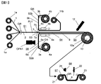
- FIG. 1 is a schematic side view of an example of a prepreg manufacturing apparatus for carrying out the prepreg manufacturing method of the present invention.
- FIG. 2 is a schematic sectional side view of an example of an optical device used for detecting defects in the prepreg manufacturing apparatus shown in FIG.
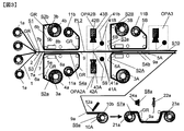
- FIG. 3 is a schematic side view of another example of a prepreg manufacturing apparatus for carrying out the prepreg manufacturing method of the present invention.
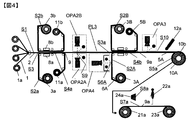
- FIG. 4 is a schematic side view of still another example of a prepreg manufacturing apparatus for carrying out the prepreg manufacturing method of the present invention.
- FIG. 1 is a schematic side view of an example of a prepreg manufacturing apparatus for carrying out the prepreg manufacturing method of the present invention.
- the prepreg manufacturing apparatus shown in FIG. 1 has a carbon fiber sheet supply step S1 on the left side.
- a bobbin 1a around which the carbon fiber bundle 1 is wound is rotatably mounted on a creel (not shown).
- a creel is equipped with a large number of bobbins 1a at intervals in the vertical direction of FIG. 1 and in the direction parallel to the paper surface of FIG. In FIG. 1, four bobbins 1a in one vertical row are illustrated.
- the carbon fiber bundles 1 continuously unwound from the bobbins 1a pass between the guide rolls GR positioned at intervals in the vertical direction, and enter the prepreg sheet production line PL1. It reaches.
- the carbon fiber bundles 1 reaching the prepreg sheet production line PL1 are arranged in the width direction and the thickness direction in accordance with the width and thickness of the prepreg sheet to be produced to form the carbon fiber sheet 2.
- a resin sheet supply step S2a and a resin sheet supply step S2b are provided on the downstream side of the carbon fiber sheet supply step S1 along the prepreg sheet production line PL1.
- the resin sheet supply step S2a and the resin sheet supply step S2b are positioned facing each other in the vertical direction with the prepreg sheet production line PL1 interposed therebetween.
- a resin sheet roll 4a around which the resin sheet 3a is wound is mounted on a roll shaft (not shown) so as to be rotatable.
- the resin sheet 3a includes a release paper 5a and a resin film 6a formed by being applied to the surface thereof.
- the resin sheet 3a continuously unwound from the resin sheet roll 4a passes through the guide roll GR and reaches the prepreg sheet production line PL1.
- two guide rolls GR are illustrated in the resin sheet supply step S2a.
- the outer surface of the release paper 5a of the resin sheet 3a (the surface on the side where the resin film 6a is not applied) is in contact with the peripheral surface of the guide roll GR.
- a resin sheet roll 4b around which the resin sheet 3b is wound is mounted on a roll shaft (not shown) so as to be rotatable.
- the resin sheet 3b includes a release paper 5b and a resin film 6b formed by being applied to the surface thereof.
- the resin sheet 3b continuously unwound from the resin sheet roll 4b passes through the guide roll GR and reaches the prepreg sheet production line PL1.
- two guide rolls GR are illustrated in the resin sheet supply step S2b.
- the prepreg manufacturing apparatus shown in FIG. 1 has two resin sheet supply steps S2a and S2b, but depending on the prepreg sheet to be manufactured, the upper resin sheet supply step S2b of these resin supply steps may be omitted. Also good.
- a laminated sheet forming step S3 is provided on the downstream side of the carbon fiber sheet supplying step S1 and the resin sheet supplying steps S2a and S2b.
- the surface of the resin film 6a of the resin sheet 3a supplied from the resin sheet supply step S2a faces the surface on the lower surface side of the carbon fiber sheet 2 supplied from the carbon fiber sheet supply step S1.
- a laminated sheet 7a of the carbon fiber sheet 2 and the resin sheet 3a is formed.
- the surface of the resin film 6b of the resin sheet 3b supplied from the resin sheet supply step S2b faces the surface on the upper surface side of the carbon fiber sheet 2 supplied from the carbon fiber sheet supply step S1.
- the laminated sheet 7b of the carbon fiber sheet 2 and the resin sheet 3b is formed. Thereby, the laminated sheet 7 in which the laminated sheet 7a and the laminated sheet 7b are integrated is formed.
- a resin impregnation step S4 is provided on the downstream side of the laminated sheet forming step S3 along the prepreg sheet production line PL1.
- a heater 8a is provided below the prepreg sheet production line PL1.
- a heater 8b is provided on the upper side of the preg sheet manufacturing line PL1 so as to be opposed to the lower heater 8a.
- the laminated sheet 7 formed in the laminated sheet forming step S3 is heated while passing between the heater 8a and the heater 8b, so that the resin forming the resin films 6a and 6b is impregnated into the carbon fiber bundle 1. Is done.
- the prepreg sheet 9 is formed by impregnating the carbon fiber bundle with the resin.
- a prepreg sheet winding step S5 is provided on the downstream side of the resin impregnation step S4 along the prepreg sheet production line PL1.
- a prepreg sheet winding device 10 is equipped.
- the prepreg sheet 9 formed in the resin impregnation step S4 is wound up by the prepreg sheet winding device 10 to form a prepreg sheet roll 10a.
- the release paper 5b of the resin sheet 3b is peeled from the prepreg sheet 9 and taken up by the release paper take-up device 11b.
- the release paper 5b is peeled and the prepreg sheet 9 moving to the prepreg sheet take-up device 10 has the release paper 5a attached to the lower surface side thereof. That is, the prepreg sheet 9 taken up by the prepreg sheet take-up device 10 is a prepreg sheet with release paper having release paper attached to one side.
- the prepreg manufacturing apparatus shown in FIG. 1 has a resin sheet inspection process S6 in the resin sheet supply process S2a.
- the resin sheet inspection step S6 is equipped with an optical device OPA1 that detects defects on the surface of the resin film 6a of the resin sheet 3a.
- the optical device OPA1 detects a defect present on the surface of the resin film 6a, and determines whether the detected defect belongs to a resin streak missing defect, a foreign matter mixed defect, or a resin dot missing defect.
- a resin sheet inspection process may be provided in the resin sheet supply process S2b, and a similar optical device may be provided.
- the prepreg manufacturing apparatus shown in FIG. 1 determines the types of defects obtained by determining the defects detected in the resin sheet inspection step S6 and the positions of the defects in the prepreg sheet in the width direction end of the release paper 5a of the prepreg sheet 9.
- a marking device 12 for marking a predetermined position in the section is included. Thereby, the type and position of the defect are marked on the release paper 5 a of the prepreg sheet 9.
- the prepreg manufacturing apparatus shown in FIG. 1 includes a prepreg sheet inspection step S7 in which the prepreg sheet roll 10a formed in the prepreg sheet winding apparatus 10 is detached from the prepreg sheet winding apparatus 10 and the prepreg sheet roll is inspected.
- the inspection member 22 visually observes the unwinding device 21 for attaching the prepreg sheet roll 10a conveyed from the prepreg sheet winding device 10 and the prepreg sheet 9 pulled out from the unwinding device 21.
- the guide roll GR for moving the arranged prepreg sheet 9 and the winding device 23 for winding up the prepreg sheet 9 after the inspection are provided.
- the prepreg sheet inspection step S7 has a defect information output step S8 for transmitting information about defects of the prepreg sheet 9 to the inspection member 22 by sound or light.
- an alarm device 24 is provided for transmitting information about defects of the prepreg sheet 9 to the inspection member 22 by sound or light.
- the greatest feature of the first aspect of the prepreg manufacturing method of the present invention described using the prepreg manufacturing apparatus of FIG. 1 is that the resin sheet 3a before going to the laminated sheet forming step S3 in the resin sheet inspection step S2a.
- the defect is that a defect on the surface of the resin film 6a is detected by the optical device OPA1 and it is determined what kind of defect the detected defect is. Thereby, the defect of the surface of the resin film 6a in which the release paper on the opposite side to the release paper 5a does not exist can be detected, and the type of the defect can be grasped. If present, this defect is a defect of a prepreg sheet formed thereafter.
- FIG. 2 is a schematic sectional side view of an example of an optical device OPA1 used for detecting a defect in the resin film 6a in the resin sheet inspection step S6 in the prepreg manufacturing apparatus shown in FIG.
- an optical device OPA1 includes a light irradiation device 31 that irradiates light on the surface of the resin film 6a, and a light receiving device 32 that detects reflected light from the surface of the resin film 6a of light irradiated from the light irradiation device 31.
- the intensity value of the reflected light detected by the light receiving device 32 is compared with a preset threshold value, and the surface defect of the resin film 6a belongs to any one of the resin streaky defect, the foreign matter contamination defect, and the resin dot defect. It consists of a defect determination device 33 that determines whether or not.
- the light irradiation device 31 includes light sources 31a and 31b. These light sources 31a and 31b are not particularly limited as long as they emit ultraviolet light. These light sources 31a and 31b are preferably linear black lights. One light source may be used. However, the light source is composed of one or more pairs so as to be plane-symmetric with respect to a plane that is perpendicular to the surface of the resin film 6a and perpendicular to the running direction of the resin film 6a. It is preferable to be installed so as to irradiate the whole. In this case, the light source 31a is installed so that the incident angle ⁇ a is in the range of 40 to 80 °, and the light source 31b is installed so that the incident angle ⁇ b is in the range of 100 to 140 °. preferable.
- the incident angle ⁇ a is 40 ° or more with respect to the surface of the resin film 6a, the amount of reflected light can be maintained even when the light source output is weak. Further, the closer the incident angle ⁇ a is to 90 °, the stronger the reflected light. However, the incident angle ⁇ a is preferably 80 ° or less because of the installation of the machine.
- ⁇ b is 140 ° or less with respect to the surface of the resin film 6a, so that the amount of reflected light can be maintained even when the light source output is weak. Further, the closer the incident angle ⁇ b is to 90 °, the stronger the reflected light is. However, the incident angle ⁇ b is preferably 100 ° or more in terms of mechanical installation.
- the reflected light means at least one of the reflected light itself of the light irradiated on the surface of the resin film 6a from the light source and the light newly excited and emitted by the irradiated light.
- the defect determination device 33 includes signal processing means in which threshold values such as brightness, width, length, and area are set in advance for each product type of the prepreg sheet to be manufactured, the presence / absence of a defect, and its type, position or level. It is preferable to comprise means for calculating and determining a signal in the scanning direction of the light receiving device 32 with respect to the time axis direction.
- the light receiving device 32 includes a camera 32a positioned at a predetermined speed so as to face the surface of the resin film 6a traveling in the right direction in FIG. Reflected light from the surface of the resin film 6a is detected by the camera 32a.
- the camera 32a is not particularly limited as long as it includes a sensor that can emit a signal corresponding to the detected level of reflected light.
- a CCD line sensor camera can be used as a typical camera.
- the camera 32a is preferably installed such that the camera installation angle ⁇ c from a surface standing perpendicular to the running direction of the resin film 6a is in the range of ⁇ 5 to + 5 °.
- the optical filter 32b is preferably one that cuts light having a wavelength of 300 to 400 nm in order to cut the ultraviolet light wavelength.
- a threshold sample is read by an inspection apparatus, set based on values such as brightness, width, length, and area for the sample, and then adjusted in an actual process. It is good to finally decide.
- the threshold value of luminance is determined based on product-specific information such as the type of release paper, the type of resin, and the basis weight of resin.
- the width and length information is determined based on product-specific information such as the type of release paper, the type of resin, and the basis weight of resin.
- use the width and length information to separate the resin streak missing defect from other defects, and use the area information to separate the foreign matter contamination defect and the resin dot missing defect from the other defects.
- the threshold value may be determined.
- FIG. 3 is a schematic side view of an example of a prepreg manufacturing apparatus for carrying out the prepreg manufacturing method of the present invention.
- the prepreg manufacturing apparatus shown in FIG. 3 includes two resin impregnation steps, a first resin impregnation step and a second resin impregnation step, at intervals in the movement direction of the prepreg sheet along the prepreg sheet production line PL2. Have.
- the release paper on at least one side of the prepreg sheet is peeled off, and the surface of the prepreg sheet where no release paper is present is detected.
- the prepreg manufacturing apparatus shown in FIG. 3 has only one resin impregnation step, and the prepreg manufacturing apparatus shown in FIG. 1 is used to detect defects on the surface of the resin film toward the resin impregnation step. Different.
- a bobbin 1a around which the carbon fiber bundle 1 is wound is rotatably mounted on a creel (not shown).
- the creel is equipped with a large number of bobbins 1a at intervals in the vertical direction of FIG. 3 and the direction parallel to the paper surface of FIG. In FIG. 3, four bobbins 1a in one vertical row are illustrated.
- the carbon fiber bundles 1 continuously unwound from the bobbins 1a pass between the guide rolls GR positioned at intervals in the vertical direction, and enter the prepreg sheet production line PL2. It reaches.
- the carbon fiber bundles 1 reaching the prepreg sheet production line PL2 are arranged in the width direction and the thickness direction in accordance with the width and thickness of the prepreg sheet to be produced to form the carbon fiber sheet 2.
- a resin sheet supply step S2a and a resin sheet supply step S2b are provided on the downstream side of the carbon fiber sheet supply step S1 along the prepreg sheet production line PL2.
- the resin sheet supply step S2a and the resin sheet supply step S2b are positioned facing each other in the vertical direction with the prepreg sheet production line PL2 interposed therebetween.
- a resin sheet roll 4a around which the resin sheet 3a is wound is mounted on a roll shaft (not shown) so as to be rotatable.
- the resin sheet 3a includes a release paper 5a and a resin film 6a formed by being applied to the surface thereof.
- the resin sheet 3a continuously unwound from the resin sheet roll 4a passes through the guide roll GR and reaches the prepreg sheet production line PL2.
- two guide rolls GR are illustrated in the resin sheet supply step S2a.
- the outer surface of the release paper 5a of the resin sheet 3a (the surface on the side where the resin film 6a is not applied) is in contact with the peripheral surface of the guide roll GR.
- a resin sheet roll 4b around which the resin sheet 3b is wound is mounted on a roll shaft (not shown) so as to be rotatable.
- the resin sheet 3b includes a release paper 5b and a resin film 6b formed by being applied to the surface thereof.
- the resin sheet 3b continuously unwound from the resin sheet roll 4b passes through the guide roll GR and reaches the prepreg sheet production line PL2.
- two guide rolls GR are illustrated in the resin sheet supply step S2b.
- the prepreg manufacturing apparatus shown in FIG. 3 has two resin sheet supply steps S2a and S2b. Depending on the prepreg sheet to be manufactured, one of the resin sheet supply steps may be omitted. good.
- a laminated sheet forming step S3 is provided on the downstream side of the carbon fiber sheet supplying step S1 and the resin sheet supplying steps S2a and S2b.
- the surface of the resin film 6a of the resin sheet 3a supplied from the resin sheet supply step S2a faces the surface on the lower surface side of the carbon fiber sheet 2 supplied from the carbon fiber sheet supply step S1.
- a laminated sheet 7a of the carbon fiber sheet 2 and the resin sheet 3a is formed.
- the surface of the resin film 6b of the resin sheet 3b supplied from the resin sheet supply step S2b faces the surface on the upper surface side of the carbon fiber sheet 2 supplied from the carbon fiber sheet supply step S1.
- the laminated sheet 7b of the carbon fiber sheet 2 and the resin sheet 3b is formed. Thereby, the laminated sheet 7 in which the laminated sheet 7a and the laminated sheet 7b are integrated is formed.
- a first resin impregnation step S4a is provided on the downstream side of the laminated sheet forming step S3 along the prepreg sheet production line PL2.
- a heater 8a is provided below the prepreg sheet production line PL2.
- a heater 8b is provided on the upper side of the preg sheet manufacturing line PL2 so as to be opposed to the lower heater 8a.
- the laminated sheet 7 formed in the laminated sheet forming step S3 is heated while passing between the heater 8a and the heater 8b, so that the resin forming the resin films 6a and 6b is impregnated into the carbon fiber bundle 1. Is done.
- the prepreg sheet 9 is formed by impregnating the carbon fiber bundle with the resin.
- the release paper 5a supporting the resin film 6a is peeled from the resin film 6a. It moves along the five guide rolls GR and is taken up by the release paper take-up device 11a.
- the release paper 5b supporting the resin film 6b is peeled off from the resin film 6b, moved along the five guide rolls GR, and taken up by the release paper take-up device 11b.
- the prepreg sheet 9 from which the release paper has been removed moves downstream along the prepreg sheet production line PL2, and reaches the prepreg sheet inspection step S9.
- an optical device OPA2A that detects defects on the surface of the prepreg sheet 9 is provided below the prepreg sheet production line PL2.
- an optical device OPA2B that detects defects on the surface of the prepreg sheet 9 is provided above the prepreg sheet production line PL2.
- the optical device OPA2A, OPA2B detects defects existing on the surface of the prepreg sheet 9, and the detected defects are carbon fiber fluff defects, foreign matter contamination defects, carbon fiber bundle crack defects, release paper wrinkle defects, and resin streaky defects. It is determined whether the defect belongs to a defect or a resin dot missing defect.
- the optical device OPA2A includes a light irradiation device 41A that irradiates light on the surface of the prepreg sheet 9, a light receiving device 42A that detects reflected light from the surface of the prepreg sheet 9 of light irradiated from the light irradiation device 41A, and a light receiving device 42A.
- the detected intensity of the reflected light is compared with a preset threshold value to detect a defect on the surface of the prepreg sheet 9, and the detected defects are a carbon fiber fluff defect, a foreign matter contamination defect, a carbon fiber bundle crack defect, a release paper.
- It comprises a defect determination device 43A that determines which of the wrinkle defect, the resin stripe defect, and the resin dot defect defect belongs.
- the optical device OPA2B detects the reflected light from the surface of the prepreg sheet 9 of the light irradiation device 41B that irradiates light on the surface of the prepreg sheet 9, and the light irradiated from the light irradiation device 41B.
- the device 42B and the reflected light intensity value detected by the light receiving device 42B are compared with a preset threshold value to detect a surface defect of the prepreg sheet 9, and the detected defects are a carbon fiber fluff defect, a foreign matter contamination defect, a carbon It consists of a defect determination device 43B that determines which one of a fiber bundle crack defect, a release paper wrinkle defect, a resin stripe defect, and a resin dot defect defect.
- the light irradiation devices 41A and 41B have light sources 41a and 41b.
- the light sources 41a and 41b are not particularly limited as long as the light emitting portion has a shape extending linearly in the width direction of the prepreg sheet 9.
- linear LED lights are preferably used as the light sources 41a and 41b.
- the light receiving devices 42A and 42B are not particularly limited as long as the light receiving devices 42A and 42B include a sensor that can detect reflected light from the surface of the prepreg sheet 9 and emit a signal corresponding to the level of the detected reflected light.
- CCD line sensor cameras are preferably used as the light receiving devices 42A and 42B.
- reflected light is classified into scattered reflected light and regular reflected light, and the defect can be clearly detected by properly using the reflected light according to the defect type.
- the reflected light can be divided into a bright signal and a dark signal due to a defect. By distinguishing these bright and dark signals, it becomes possible to detect the defects more clearly.
- the specular reflected light signal and scattered reflection For each light signal, light and dark reactions are distinguished in advance, at least one threshold value selected from the group consisting of brightness, width, length, and area is set, and the sensitivity of each reflected light is determined for each defect. It is preferable to classify the defects by determining the type of reflected light used for detection and comparing the threshold value with the signal of the reflected light.
- various defects are classified into those that are judged by specular reflection light, those that are judged by scattered reflection light, those that become bright signals, and those that become dark signals. Further, by using the two-dimensional shape information and other information together, it is possible to classify the defects. For example, when a defect on the surface of the prepreg sheet 9 is inspected, the carbon fiber fluff defect, the carbon fiber bundle crack defect, the release paper wrinkle defect, the resin stripe defect defect, and the resin dot defect defect occur from the surface of the prepreg sheet 9.
- the regular reflection light of the prepreg sheet 9 can be grasped by receiving the regular reflection light by the light receiving device, and the foreign matter mixed defect can be grasped by receiving the scattered reflected light from the surface of the prepreg sheet 9 by the light receiving device.
- two or more light sources and two or more light receiving devices are installed at each inspection position.
- two light sources and one light receiving device are used. It is more preferable to use a table.
- the light irradiation angle from the light source to the surface of the prepreg is 30 to 85 ° with respect to the surface of the prepreg when using regular reflection light, and 5 with respect to the surface of the prepreg when using scattered reflection light. It is preferable that it is thru
- the irradiation angle of light with respect to the surface of the prepreg is 40 to 80 °, and when using scattered reflected light, light with respect to the surface of the prepreg.
- the irradiation angle is more preferably 10 to 50 °.
- the light receiving angle of the light receiving device is preferably 0 ° or more on the opposite side of the light incident direction from the light source from the surface standing perpendicular to the traveling direction of the prepreg.
- the angle is more preferably 0 to 60 °.
- the prepreg sheet 9 that has passed through the prepreg sheet inspection step S9 moves to the second resin impregnation step S4b.
- a resin sheet supply step S2A for supplying the resin sheet 3A to the lower surface side of the prepreg sheet 9 and a resin for supplying the resin sheet 3B to the upper surface side of the prepreg sheet 9 A sheet supply step S2B is provided.
- Resin sheet supply process S2A is the same process as resin sheet supply process S2a shown in FIG.
- resin sheet supply process S2B is the same process as resin sheet supply process S2b shown in FIG.
- the resin sheet 3A supplied from the resin sheet supply step S2A, the resin sheet 3B supplied from the resin sheet supply step S2B, and the prepreg sheet 9 are laminated in the laminated sheet forming step S3a and then the second resin impregnation. Move to step S4b.
- the second resin impregnation step S4b is the same as the resin impregnation step S4 shown in FIG.
- the resin film 6A of the resin sheet 3A and the resin film 6B of the resin sheet 3B are impregnated into the prepreg sheet 9 to form the second prepreg sheet 9a.
- a prepreg sheet winding step S5a is provided on the downstream side of the second resin impregnation step S4b along the prepreg sheet production line PL2.
- the prepreg sheet winding step S5a is equipped with a prepreg sheet winding device 10A.
- the second prepreg sheet 9a formed in the second resin impregnation step S4b is wound up by the prepreg sheet winding device 10A to form the prepreg sheet roll 10b.
- the release paper 5B of the resin sheet 3B is peeled off from the prepreg sheet 9a, and the release paper take-up device It is wound up by 11B.
- the release paper 5B is peeled off, and the prepreg sheet 9a moving to the prepreg sheet winding device 10A has the release paper 5A attached to the lower surface side thereof. That is, the prepreg sheet 9a taken up by the prepreg sheet take-up device 10A is a prepreg sheet with release paper having release paper attached to one side.
- the prepreg manufacturing apparatus shown in FIG. 3 has a prepreg sheet inspection step S10 for inspecting a surface defect from which the release paper of the prepreg sheet 9a moving to the prepreg sheet take-up apparatus 10A is peeled off.
- a prepreg sheet inspection step S10 for inspecting a surface defect from which the release paper of the prepreg sheet 9a moving to the prepreg sheet take-up apparatus 10A is peeled off.
- an optical device OPA3 that detects defects on the surface of the prepreg sheet 9a from which the release paper has been peeled is provided.
- the optical device OPA3 is the same device as the optical device OPA2A. Thereby, the presence or absence and the kind of the surface defect of the prepreg sheet 9a before being wound up by the prepreg sheet winding device 10A are determined.
- the prepreg manufacturing apparatus shown in FIG. 3 indicates the types of defects obtained by the determination of defects detected in the prepreg sheet inspection steps S9 and S10 and the positions of the defects in the prepreg sheet in the width direction of the release paper 5A of the prepreg sheet 9a. It has a marking device 12a for marking a predetermined position at the end of the. Thereby, the kind and position of the defect are marked on the release paper 5A of the prepreg sheet 9a.
- the prepreg manufacturing apparatus shown in FIG. 3 includes a prepreg sheet inspection step S7a in which the prepreg sheet roll 10b formed in the prepreg sheet winding apparatus 10A is removed from the prepreg sheet winding apparatus 10A and the prepreg sheet winding process is performed.
- the inspection member 22a visually checks the unwinding device 21a for attaching the prepreg sheet roll 10b carried from the prepreg sheet winding device 10A and the prepreg sheet 9a pulled out from the unwinding device 21a.
- the guide roll GR for moving the arranged prepreg sheet 9a and the winding device 23a for winding up the prepreg sheet 9a after the inspection are provided.
- the prepreg sheet inspection step S7a has a defect information output step S8a for transmitting information about defects of the prepreg sheet 9a to the inspection member 22a by sound or light.
- the defect information output step S8a is provided with an alarm device 24a for transmitting information about defects of the prepreg sheet 9a to the inspection member 22a by sound or light.
- the greatest feature of the second aspect of the prepreg manufacturing method of the present invention described using the prepreg manufacturing apparatus of FIG. 3 is that in the prepreg sheet inspection step S9, the defect inspection is performed on the prepreg sheet having no release paper. It is a point that takes place on both surfaces. Further, in the prepreg sheet inspection step S10, the defect is inspected on the surface where there is no release paper of the prepreg sheet toward the winding device.
- FIG. 4 is a schematic side view of an example of a prepreg manufacturing apparatus for carrying out the prepreg manufacturing method of the present invention.
- the prepreg manufacturing apparatus shown in FIG. 4 includes two resin impregnation steps, a first resin impregnation step and a second resin impregnation step, at intervals in the movement direction of the prepreg sheet along the prepreg sheet production line PL3. Have.
- the release paper on at least one side of the prepreg sheet is peeled off, and the surface of the prepreg sheet where no release paper is present is detected.
- the prepreg manufacturing apparatus shown in FIG. 4 is the same as the prepreg manufacturing apparatus shown in FIG.
- the difference between the prepreg manufacturing apparatus shown in FIG. 4 and the prepreg manufacturing apparatus shown in FIG. 3 is that the surface of the resin film of the resin sheet introduced into the second resin impregnation step in the prepreg manufacturing apparatus shown in FIG. The defect is detected. Accordingly, the same steps and apparatus configurations between the prepreg manufacturing apparatus shown in FIG. 4 and the prepreg manufacturing apparatus shown in FIG. In addition, the description of the process and the apparatus configuration in FIG. 4 displayed with the same reference numerals as those in FIG.
- the optical device OPA4 is provided with a resin sheet inspection step S6A for detecting defects on the surface of the resin film 6A of the resin sheet 3A going to the second resin impregnation step S4b.
- the optical device OPA4 is provided to face the surface of the resin film 6A.
- the optical device OPA4 is the same as the optical device OPA1 for detecting defects on the surface of the resin film 6a used in the prepreg manufacturing apparatus shown in FIG.
- the purpose and function of the optical device OPA4 are the same as the purpose and function of the optical device OPA1 described above.
- a marking device 12a is provided at a position in front of the prepreg sheet winding apparatus 10A, as in the case of the prepreg manufacturing apparatus shown in FIG.
- this marking device 12a information on the defects detected and grasped up to the marking device 12a is marked on the release paper 5A of the prepreg sheet 9a.
- the marking device 12a marks information on the prepreg sheet 9 and defects on both surfaces of the prepreg sheet 9a, in some cases, only information on defects on one of the surfaces may be marked.
- the color and shape of the mark are selected as appropriate, and the defect occurrence location, for example, the defect detected on the front or back surface of the prepreg sheet after the first impregnation step and before the second impregnation step, the second It is preferable to mark defects detected on the surface of the resin film toward the impregnation step, and defects detected on the surface of the prepreg sheet after the second impregnation step. Similarly, it is also preferable to mark a mark corresponding to the type of defect.
- the place where the mark is marked is preferably a position inside by a predetermined distance from the end of the release paper on the back surface of the prepreg sheet. More preferably, the distance is about 6 to 21 mm from the end face. By setting the lower limit of this distance to 6 mm, it is possible to prevent marking errors outside the release paper, and by setting the upper limit of this distance to 21 mm, it is possible to prevent marking errors on the prepreg.
- the marking device 12a is not particularly limited as long as it can mark the release paper, but it is preferable to use a pen type. In addition, marking the defect name is also effective for improving the efficiency of the inspection in the subsequent process.
- the defects are spot-like, marking is performed on the release paper part (usually called the ear part) on the side edge side of the prepreg sheet at the point of occurrence, and the defects occur continuously. It is preferable to mark the release paper portion on the side end side of the prepreg sheet at the end point of occurrence of defects. Thereby, workability at the time of inspection can be improved. Furthermore, it is also preferable to change the length of the marking, or change the type and color of the line, in order to distinguish between the defect that has occurred continuously and the defect that has occurred in the spot. In the case of a defect that occurs continuously, marking may be performed over the entire section where the defect exists.
- the prepreg sheet roll 10b taken up by the prepreg sheet take-up device 10A is arranged by prepreg sheet roll together with defect position information, preferably defect type information, and is the next step of the prepreg manufacturing process. It is transmitted to step S7a.
- the prepreg sheet inspection step S7a the surface of the prepreg sheet 9a unwound from the unwinding device 21a is inspected by the inspection member 22a and wound on the product winding device 23a.
- the position of the defect (marking part if marking is performed) detected in the manufacturing process of the prepreg sheet is calculated from the position information of the defect, and this position is calculated.
- the alarm device 24a appears in the inspection process, the alarm device 24a is activated to generate an alarm and / or to reduce the speed of movement of the prepreg sheet in the inspection process, thereby enabling confirmation of defects. preferable.
- the inspection member 22a can accurately grasp the defect positions on the front and back surfaces of the prepreg sheet, prevent oversight of defects, reduce the difficulty of inspection work, and improve work efficiency. Can be raised.
- the defective part is removed and the normal parts are connected to each other.
- Such operations as correction of removal of carbon fiber fluff defects, carbon fiber bundle cracking defects, foreign matter contamination defects, etc., which can be corrected, and tagging are performed.
- defect information regarding the product after inspection is obtained. It is preferable to be tabulated. More preferably, these pieces of information are used as defect information of a product after necessary authentication.
- the prepreg sheet inspection step S7a is a so-called ear drop process in which both ends of the prepreg sheet are slit, and a width of 2 to 600 mm at the time of inspection so that a wide prepreg can be used in an automatic tape laminating machine or an automatic fiber pressment machine.
- a step of slitting the prepreg sheet in the longitudinal direction may be included.
- the prepreg manufacturing apparatus shown in FIG. 3 or FIG. 4 is equipped with two resin impregnation steps for impregnating the resin into the carbon fiber bundle, but if necessary, the number of resin impregnation steps can be further increased. is there.
- the resin impregnation process has two or more stages, after the second resin impregnation process, the surface of the prepreg sheet is covered with resin, and the unevenness of the surface becomes small, and it may be difficult to detect the carbon fiber fluff defect. is there. In such a case, it is preferable to detect the carbon fiber fluff defect between the first resin impregnation step and the second resin impregnation step.
- the carbon fiber bundle cracking defect is that the detection signal is emphasized due to the release paper on the back side of the prepreg sheet, so the carbon on the surface of the prepreg sheet in the process of passing through the final resin impregnation step and reaching the winding device It is preferable to detect a fiber bundle cracking defect.
- the wrinkle defect is received by the light receiving device. Therefore, it is preferable to detect.
- the state of the prepreg sheet varies depending on the defect detection location, the specular reflection light and the scattered reflection light are properly used depending on the detection location and the defect type so that the S / N ratio of the defect portion is increased. It is preferable.
- the width of the prepreg sheet produced by the prepreg production method of the present invention is not particularly limited, but is preferably 500 to 2000 mm.
- a prepreg sheet having a width of 600 mm or more it is compared with visual defect detection by an inspector.
- it is possible to manufacture a high-quality prepreg with excellent defect detection accuracy.
- the production speed of the prepreg sheet in the prepreg production method of the present invention is not particularly limited, but is preferably 1 to 30 m / min.
- the carbon fiber bundle used is not particularly limited, but the fineness is preferably 0.05 to 6 g / m, and more preferably 0.15 to 2 g / m.
- the carbon fiber bundle preferably has a strength of 3000 MPa or more and an elastic modulus of 200 GPa or more, more preferably a strength of 4900 MPa or more and an elastic modulus of 280 to 360 GPa. When the strength is 3000 MPa or more, it is possible to prevent frequent occurrence of defects such as fluff when impregnating the resin to form a prepreg.
- the occurrence of fluff defects for example, the number of fluff defects with a diameter of 5 cm or more is 10 / m 2 or less is not a problem. Can be suppressed.
- the resin to be impregnated into the carbon fiber bundle that is, as the matrix resin, epoxy resin, vinyl ester resin, BMI resin, polyimide resin, etc. are applied, but preferred resins are epoxy-based 180 ° C. curing type, fluorescent
- the epoxy resin composition containing the additive which emits is preferable, and the epoxy resin using an aromatic amine type hardening
- Each resin in the first stage resin impregnation and the second stage resin impregnation has the same basic composition, and as the resin in the second stage resin impregnation, a thermoplastic resin or conductive particles that increase interlayer toughness. Preferred are those containing ingredients and added additional performance.
- thermoplastic resin examples include finely divided polyamide 12 particles, polyamide fine particles (manufactured by Toray Industries, Inc., Trepal TN), polyamideimide, polyether ether ketone fine particles, and conductive particle components.
- polyamide 12 particles polyamide fine particles
- polyamide fine particles manufactured by Toray Industries, Inc., Trepal TN
- polyamideimide polyamideimide
- polyether ether ketone fine particles polyether ether ketone fine particles
- conductive particle components examples of the thermoplastic resin.
- carbon black or the like that is metal-plated to give conductivity to polymer fine particles can be used.
- the carbon fiber basis weight of the prepreg sheet is preferably 50 to 300 g / m 2, and the resin weight content is preferably 25 to 50%.
- the prepreg manufacturing method of the present invention in the prepreg manufacturing process, defects appearing in the prepreg are detected, and the prepreg is manufactured using information on the detected defects. Moreover, the type and position of the detected defect are determined based on the characteristics of the reflected light from the surface of the resin film formed by being applied to the release paper used for impregnating the carbon fiber bundle with the resin, Or it is based on the characteristic of the reflected light from the surface from which the release paper of the prepreg sheet formed by impregnating resin to the carbon fiber bundle was peeled. As a result, it has become possible to ascertain the defects on the direct surface of the prepreg, which has conventionally been impossible to detect defects due to the presence of the release paper, and it has become possible to produce a high-quality prepreg.
Landscapes
- Chemical & Material Sciences (AREA)
- Engineering & Computer Science (AREA)
- Health & Medical Sciences (AREA)
- Life Sciences & Earth Sciences (AREA)
- Physics & Mathematics (AREA)
- Immunology (AREA)
- Analytical Chemistry (AREA)
- Pathology (AREA)
- General Physics & Mathematics (AREA)
- General Health & Medical Sciences (AREA)
- Biochemistry (AREA)
- Textile Engineering (AREA)
- Composite Materials (AREA)
- Materials Engineering (AREA)
- Mechanical Engineering (AREA)
- Manufacturing & Machinery (AREA)
- Chemical Kinetics & Catalysis (AREA)
- Organic Chemistry (AREA)
- Polymers & Plastics (AREA)
- Medicinal Chemistry (AREA)
- Wood Science & Technology (AREA)
- Mathematical Physics (AREA)
- Inorganic Chemistry (AREA)
- Reinforced Plastic Materials (AREA)
- Investigating Materials By The Use Of Optical Means Adapted For Particular Applications (AREA)
Abstract
Description
(b)炭素繊維束、あるいは、樹脂が含浸されている炭素繊維束からなる炭素繊維シートを連続して供給する炭素繊維シート供給工程と、
(c)前記樹脂シート供給工程から供給される前記樹脂フィルムの表面を、前記炭素繊維シート供給工程から供給される前記炭素繊維シートの少なくとも一方の表面に向かい合わせ、前記樹脂シートと前記炭素繊維シートからなる積層シートを形成する積層シート形成工程と、
(d)該積層シート形成工程において形成された前記積層シートにおける前記炭素繊維束に前記積層シートにおける前記樹脂を含浸させ、前記炭素繊維束と該炭素繊維束に含浸した前記樹脂からなるプリプレグシートを形成する少なくとも一つの樹脂含浸工程と、
(e)該樹脂含浸工程において形成されたプリプレグシートを連続して巻き取るプリプレグシート巻き取り工程からなるプリプレグの製造方法において、
(f)前記樹脂シート供給工程における前記樹脂フィルムの表面を光学装置により検査することにより、前記プリプレグの欠陥の原因となる前記樹脂フィルムの表面の欠陥を検出し、検出された欠陥が、樹脂スジ状欠落欠点、異物混入欠点ならびに樹脂点状欠落欠点のいずれに属するかを判定する少なくとも一つの樹脂シート検査工程、あるいは、
(g)前記樹脂含浸工程から導出された前記離型紙を伴う離型紙付きプリプレグシートの該離型紙を剥離した後のプリプレグシートの表面を光学装置により検査することにより、前記プリプレグの表面の欠陥を検出し、検出された欠陥が、炭素繊維毛羽欠点、異物混入欠点、炭素繊維束ワレ欠点、離型紙シワ欠点、樹脂スジ状欠落欠点ならびに樹脂点状欠落欠点のいずれに属するかを判定する少なくとも一つのプリプレグシート検査工程を有するプリプレグの製造方法。 (A) at least one resin sheet supply step of continuously supplying a release sheet and a resin sheet formed of a resin film formed of a resin applied to the surface of the release paper;
(B) a carbon fiber sheet or a carbon fiber sheet supply step for continuously supplying a carbon fiber sheet composed of a carbon fiber bundle impregnated with a resin;
(C) The surface of the resin film supplied from the resin sheet supply step faces at least one surface of the carbon fiber sheet supplied from the carbon fiber sheet supply step, and the resin sheet and the carbon fiber sheet A laminated sheet forming step of forming a laminated sheet comprising:
(D) impregnating the carbon fiber bundle in the laminated sheet formed in the laminated sheet forming step with the resin in the laminated sheet, and forming a prepreg sheet comprising the carbon fiber bundle and the resin impregnated in the carbon fiber bundle. At least one resin impregnation step to be formed;
(E) In the method for producing a prepreg comprising the prepreg sheet winding step of continuously winding the prepreg sheet formed in the resin impregnation step,
(F) The surface of the resin film in the resin sheet supplying step is inspected by an optical device to detect a surface defect of the resin film that causes the prepreg defect, and the detected defect is a resin streak. At least one resin sheet inspection process for determining whether it belongs to a defect missing defect, a foreign substance contamination defect and a resin dot missing defect, or
(G) By inspecting the surface of the prepreg sheet of the prepreg sheet with a release paper accompanying the release paper derived from the resin impregnation step with the optical device after peeling the release paper, defects on the surface of the prepreg are detected. At least one of detecting and determining whether the detected defect belongs to a carbon fiber fluff defect, a foreign matter contamination defect, a carbon fiber bundle crack defect, a release paper wrinkle defect, a resin stripe defect, or a resin dot defect defect A prepreg manufacturing method having two prepreg sheet inspection steps.
1a ボビン
2 炭素繊維シート
3A、3B、3a、3b 樹脂シート
4a、4b 樹脂シートロール
5A、5B、5a、5b 離型紙
6A、6B、6a、6b 樹脂フィルム
7、7a、7b 積層シート
8a、8b ヒーター
9、9a プリプレグシート
10、10A プリプレグシート巻き取り装置
10a、10b プリプレグシートロール
11B、11a、11b 離型紙巻き取り装置
12、12a マーキング装置
21、21a 巻き出し装置
22、22a 検反員
23、23a 巻き取り装置
24、24a アラーム装置
31 光照射装置
31a、31b 光源
32 受光装置
32a カメラ
32b 光学フィルター
33 欠点判定装置
41A、41B 光照射装置
41a、41b 光源
42A、42B 受光装置
43A、43B 欠点判定装置
GR ガイドロール
OPA1、OPA2A、OPA2B、OPA3、OPA4 光学装置
PL1、PL2、PL3 プリプレグシート製造ライン
S1 炭素繊維シート供給工程
S2A、S2B、S2a、S2b 樹脂シート供給工程
S3、S3a 積層シート形成工程
S4 樹脂含浸工程
S4a 第1の樹脂含浸工程
S4b 第2の樹脂含浸工程
S5、S5a プリプレグシート巻き取り工程
S6、S6A 樹脂シート検査工程
S7、S7a プリプレグシート検反工程
S8、S8a 欠点情報出力工程
S9 プリプレグシート検査工程
S10 プリプレグシート検査工程
θa、θb 入射角
θc カメラ設置角度 DESCRIPTION OF SYMBOLS 1 Carbon fiber bundle 1a Bobbin 2 Carbon fiber sheet 3A, 3B, 3a, 3b Resin sheet 4a, 4b Resin sheet roll 5A, 5B, 5a, 5b Release paper 6A, 6B, 6a, 6b Resin film 7, 7a, 7b Laminated sheet 8a, 8b Heater 9, 9a Pre-preg sheet 10, 10A Pre-preg sheet take-up device 10a, 10b Pre-preg sheet roll 11B, 11a, 11b Release paper take-up device 12, 12a Marking device 21, 21a Unwind device 22, 22a Inspector 23, 23a Winding device 24, 24a Alarm device 31 Light irradiation device 31a, 31b Light source 32 Light receiving device 32a Camera 32b Optical filter 33 Defect determination device 41A, 41B Light irradiation device 41a, 41b Light source 42A, 42B Light receiving device 43A, 43B Defect Determination device GR guide roll OPA1, OPA2A, OPA2B, OPA3, OPA4 Optical device PL1, PL2, PL3 Prepreg sheet production line S1 Carbon fiber sheet supply step S2A, S2B, S2a, S2b Resin sheet supply step S3, S3a Laminated sheet formation step S4 Resin impregnation step S4a First resin impregnation step S4b Second resin impregnation step S5, S5a Pre-preg sheet winding step S6, S6A Resin sheet inspection step S7, S7a Pre-preg sheet inspection step S8, S8a Defect information output step S9 Pre-preg sheet Inspection process S10 Pre-preg sheet inspection process θa, θb Incident angle θc Camera installation angle
Claims (15)
- (a)離型紙と該離型紙の表面に塗布された樹脂により形成された樹脂フィルムからなる樹脂シートを連続して供給する少なくとも一つの樹脂シート供給工程と、
(b)炭素繊維束、あるいは、樹脂が含浸されている炭素繊維束からなる炭素繊維シートを連続して供給する炭素繊維シート供給工程と、
(c)前記樹脂シート供給工程から供給される前記樹脂フィルムの表面を、前記炭素繊維シート供給工程から供給される前記炭素繊維シートの少なくとも一方の表面に向かい合わせ、前記樹脂シートと前記炭素繊維シートからなる積層シートを形成する積層シート形成工程と、
(d)該積層シート形成工程において形成された前記積層シートにおける前記炭素繊維束に前記積層シートにおける前記樹脂を含浸させ、前記炭素繊維束と該炭素繊維束に含浸した前記樹脂からなるプリプレグシートを形成する少なくとも一つの樹脂含浸工程と、
(e)該樹脂含浸工程において形成されたプリプレグシートを連続して巻き取るプリプレグシート巻き取り工程からなるプリプレグの製造方法において、
(f)前記樹脂シート供給工程における前記樹脂フィルムの表面を光学装置により検査することにより、前記プリプレグの欠陥の原因となる前記樹脂フィルムの表面の欠陥を検出し、検出された欠陥が、樹脂スジ状欠落欠点、異物混入欠点ならびに樹脂点状欠落欠点のいずれに属するかを判定する少なくとも一つの樹脂シート検査工程、あるいは、
(g)前記樹脂含浸工程から導出された前記離型紙を伴う離型紙付きプリプレグシートの該離型紙を剥離した後のプリプレグシートの表面を光学装置により検査することにより、前記プリプレグの表面の欠陥を検出し、検出された欠陥が、炭素繊維毛羽欠点、異物混入欠点、炭素繊維束ワレ欠点、離型紙シワ欠点、樹脂スジ状欠落欠点ならびに樹脂点状欠落欠点のいずれに属するかを判定する少なくとも一つのプリプレグシート検査工程を有するプリプレグの製造方法。 (A) at least one resin sheet supply step of continuously supplying a release sheet and a resin sheet formed of a resin film formed of a resin applied to the surface of the release paper;
(B) a carbon fiber sheet or a carbon fiber sheet supply step for continuously supplying a carbon fiber sheet composed of a carbon fiber bundle impregnated with a resin;
(C) The surface of the resin film supplied from the resin sheet supply step faces at least one surface of the carbon fiber sheet supplied from the carbon fiber sheet supply step, and the resin sheet and the carbon fiber sheet A laminated sheet forming step of forming a laminated sheet comprising:
(D) impregnating the carbon fiber bundle in the laminated sheet formed in the laminated sheet forming step with the resin in the laminated sheet, and forming a prepreg sheet comprising the carbon fiber bundle and the resin impregnated in the carbon fiber bundle. At least one resin impregnation step to be formed;
(E) In the method for producing a prepreg comprising the prepreg sheet winding step of continuously winding the prepreg sheet formed in the resin impregnation step,
(F) The surface of the resin film in the resin sheet supplying step is inspected by an optical device to detect a surface defect of the resin film that causes the prepreg defect, and the detected defect is a resin streak. At least one resin sheet inspection process for determining whether it belongs to a defect missing defect, a foreign substance contamination defect and a resin dot missing defect, or
(G) By inspecting the surface of the prepreg sheet of the prepreg sheet with a release paper accompanying the release paper derived from the resin impregnation step with the optical device after peeling the release paper, defects on the surface of the prepreg are detected. At least one of detecting and determining whether the detected defect belongs to a carbon fiber fluff defect, a foreign matter contamination defect, a carbon fiber bundle crack defect, a release paper wrinkle defect, a resin stripe defect, or a resin dot defect defect A prepreg manufacturing method having two prepreg sheet inspection steps. - 前記樹脂シート検査工程における前記光学装置が、前記欠陥を検査する前記表面に光を照射する光照射装置と、該光照射装置から照射した光の前記表面からの反射光を検出する受光装置と、該受光装置が検出した反射光の強度の値と予め設定した閾値を比較し前記欠陥を検出し、前記欠陥が、樹脂スジ状欠落欠点、異物混入欠点ならびに樹脂点状欠落欠点のいずれかに属するかを判定する欠点判定装置からなる請求項1に記載のプリプレグの製造方法。 The optical device in the resin sheet inspection step is a light irradiation device that irradiates light on the surface for inspecting the defect, and a light receiving device that detects reflected light from the surface of light irradiated from the light irradiation device, The intensity of the reflected light detected by the light receiving device is compared with a preset threshold value to detect the defect, and the defect belongs to any one of a resin streak defect, a foreign matter defect, and a resin dot defect. The manufacturing method of the prepreg of Claim 1 which consists of a fault determination apparatus which determines these.
- 前記プリプレグシート検査工程における前記光学装置が、前記欠陥を検査する前記表面に光を照射する光照射装置と、該光照射装置から照射した光の前記表面からの反射光を検出する受光装置と、該受光装置が検出した反射光の強度の値と予め設定した閾値を比較し前記欠陥を検出し、前記欠陥が、炭素繊維毛羽欠点、異物混入欠点、炭素繊維束ワレ欠点、離型紙シワ欠点、樹脂スジ状欠落欠点ならびに樹脂点状欠落欠点のいずれに属するかを判定する欠点判定装置からなる請求項1に記載のプリプレグの製造方法。 The optical device in the prepreg sheet inspection step irradiates light on the surface for inspecting the defect, and a light receiving device for detecting reflected light from the surface of light irradiated from the light irradiation device, The value of the reflected light detected by the light receiving device is compared with a preset threshold value to detect the defect, and the defect is a carbon fiber fluff defect, a foreign matter contamination defect, a carbon fiber bundle crack defect, a release paper wrinkle defect, The manufacturing method of the prepreg of Claim 1 which consists of a fault determination apparatus which determines whether it belongs to the resin stripe-like missing defect and the resin dot-like missing defect.
- 前記欠点判定装置が、前記炭素繊維毛羽欠点、異物混入欠点、炭素繊維束ワレ欠点、離型紙シワ欠点、樹脂スジ状欠落欠点ならびに樹脂点状欠落欠点の各々に対して、正反射光の信号と散乱反射光の信号別に、予め、輝度、幅、長さ、および、面積からなる群から選択される少なくとも一つについての閾値を設定し、前記各欠点毎に、前記各反射光の感度をもとに、検出に用いる前記反射光の種類を決定し、それらの前記閾値と前記反射光の信号とを比較することによって、検出された前記欠陥を前記各欠点に分類してなる請求項3に記載のプリプレグの製造方法。 The defect determination device is configured to generate a signal of specular reflection light for each of the carbon fiber fluff defect, foreign matter contamination defect, carbon fiber bundle crack defect, release paper wrinkle defect, resin stripe defect, and resin dot defect defect. A threshold value for at least one selected from the group consisting of brightness, width, length, and area is set in advance for each signal of the scattered reflected light, and the sensitivity of each reflected light is set for each defect. In addition, the type of the reflected light used for detection is determined, and the detected defect is classified into the respective defects by comparing the threshold value with the signal of the reflected light. The manufacturing method of prepreg of description.
- 前記欠点判定装置が、前記炭素繊維毛羽欠点、炭素繊維束ワレ欠点、離型紙シワ欠点、樹脂スジ状欠落欠点ならびに樹脂点状欠落欠点を、検出した正反射光に基づき分類し、前記異物混入欠点を、検出した散乱反射光に基づき分類してなる請求項3に記載のプリプレグの製造方法。 The defect determination device classifies the carbon fiber fluff defect, the carbon fiber bundle crack defect, the release paper wrinkle defect, the resin streak missing defect and the resin dot missing defect based on the detected regular reflection light, and the foreign matter contamination defect The method for producing a prepreg according to claim 3, which is classified based on the detected scattered reflected light.
- 前記樹脂シート供給工程が、前記炭素繊維シート供給工程により供給される炭素繊維シートを挟んでその両側に設けられ、前記プリプレグシート検査工程におけるプリプレグシートの表面の欠陥の検出が、該プリプレグシートの両表面に対しそれぞれ設けられた前記光学装置により行われる請求項1に記載のプリプレグの製造方法。 The resin sheet supply step is provided on both sides of the carbon fiber sheet supplied by the carbon fiber sheet supply step, and detection of defects on the surface of the prepreg sheet in the prepreg sheet inspection step is performed on both sides of the prepreg sheet. The manufacturing method of the prepreg of Claim 1 performed by the said optical apparatus each provided with respect to the surface.
- 前記樹脂シート供給工程が、前記炭素繊維シート供給工程により供給される炭素繊維シートを挟んでその両側に設けられるとともに、前記炭素繊維シート供給工程から前記プリプレグシート巻き取り工程に向かい複数設けられ、前記プリプレグシート巻き取り工程の最も近くに位置する前記樹脂含浸工程を通過した前記プリプレグシートの両外表面に位置する前記離型紙のうちの一方の離型紙が剥離され、他の一方の離型紙が付いた離型紙付きプリプレグシートを前記プリプレグシート巻き取り工程により巻き取るとともに、前記一方の離型紙が剥離されたプリプレグシートの表面の欠陥を、前記プリプレグシート検査工程にて検査してなる請求項1に記載のプリプレグシートの製造方法。 The resin sheet supply step is provided on both sides of the carbon fiber sheet supplied by the carbon fiber sheet supply step, and a plurality of the resin sheet supply steps are provided from the carbon fiber sheet supply step to the prepreg sheet winding step, One release paper of the release papers located on both outer surfaces of the prepreg sheet that has passed through the resin impregnation process located closest to the prepreg sheet winding process is peeled off, and the other release paper is attached. The prepreg sheet with release paper is wound up by the prepreg sheet winding step, and the surface of the prepreg sheet from which the one release paper is peeled is inspected for defects in the prepreg sheet inspection step. The manufacturing method of the prepreg sheet | seat of description.
- 前記プリプレグシート検査工程における前記光学装置が、前記欠陥を検査する前記表面に光を照射する光照射装置と、該光照射装置から照射した光の前記表面からの反射光を検出する受光装置と、該受光装置が検出した反射光の強度の値と予め設定した閾値を比較し前記欠陥を検出し、前記欠陥が、異物混入欠点、炭素繊維束ワレ欠点、離型紙シワ欠点、樹脂スジ状欠落欠点ならびに樹脂点状欠落欠点のいずれに属するかを判定する欠点判定装置からなり、該欠点判定装置が、前記異物混入欠点、炭素繊維束ワレ欠点ならびに離型紙シワ欠点を、検出した散乱反射光に基づき分類し、前記樹脂スジ状欠落欠点ならびに樹脂点状欠落欠点を、検出した正反射光に基づき分類してなる請求項7に記載のプリプレグの製造方法。 The optical device in the prepreg sheet inspection step irradiates light on the surface for inspecting the defect, and a light receiving device for detecting reflected light from the surface of light irradiated from the light irradiation device, The defect is detected by comparing the intensity value of the reflected light detected by the light receiving device with a preset threshold value, and the defect is a foreign matter contamination defect, a carbon fiber bundle crack defect, a release paper wrinkle defect, a resin streak defect defect And a defect determination device for determining whether the defect belongs to a resin dot-like defect, and the defect determination device is configured to detect the foreign matter contamination defect, the carbon fiber bundle crack defect, and the release paper wrinkle defect based on the detected scattered reflected light. The method for producing a prepreg according to claim 7, wherein the defects are classified and the resin streak missing defects and the resin dot missing defects are classified based on the detected regular reflection light.
- 前記プリプレグシート検査工程における前記光照射装置が、線状のLEDライトからなる光照射装置であり、前記受光装置が、CCDラインセンサカメラからなる受光装置である請求項3に記載のプリプレグの製造方法。 The prepreg manufacturing method according to claim 3, wherein the light irradiation device in the prepreg sheet inspection step is a light irradiation device made of a linear LED light, and the light receiving device is a light receiving device made of a CCD line sensor camera. .
- 前記樹脂シート検査工程における前記光照射装置が、線状のブラックライトを光源とした光照射装置であり、該ブラックライトを、前記樹脂フィルムの走行方向に対して垂直に立てた面に対して面対称となり、かつ、該面と樹脂フィルム面からなる直線と平行になるように1対以上配し、該ブラックライトの入射角が40乃至80°および100乃至140°の範囲に各々1本以上設置した請求項2に記載のプリプレグの製造方法。 The light irradiation device in the resin sheet inspection step is a light irradiation device using a linear black light as a light source, and the black light is faced with respect to a surface standing perpendicular to the running direction of the resin film. One or more pairs are arranged so as to be symmetrical and parallel to the straight line formed by the surface and the resin film surface, and at least one black light incident angle is set in the range of 40 to 80 ° and 100 to 140 °. The method for producing a prepreg according to claim 2.
- 前記樹脂シート検査工程における前記受光装置が、CCDラインセンサカメラからなる受光装置であり、該CCDラインセンサカメラを、前記樹脂フィルムの走行方向に対して垂直に立てた面から-5乃至+5°の範囲に設置した請求項2に記載のプリプレグの製造方法。 The light receiving device in the resin sheet inspection step is a light receiving device comprising a CCD line sensor camera, and the CCD line sensor camera is −5 to + 5 ° from a surface standing perpendicular to the running direction of the resin film. The manufacturing method of the prepreg of Claim 2 installed in the range.
- 前記CCDラインセンサカメラに紫外領域の光を除去する光学フィルターが備え付けられている請求項11に記載のプリプレグの製造方法。 The prepreg manufacturing method according to claim 11, wherein the CCD line sensor camera is provided with an optical filter for removing light in an ultraviolet region.
- 前記樹脂シート検査工程、あるいは、前記プリプレグシート検査工程において検出された前記欠陥の前記プリプレグシートに対する位置が、マーキング装置により、前記プリプレグシート巻き取り工程において、前記離型紙とともに巻き取られるプリプレグシートの該離型紙の幅方向の端部における所定の位置にマーキングされ、該マーキングにより、前記欠点の種類と該欠点のプリプレグシートにおける位置が判別される請求項1に記載のプリプレグ製造方法。 The position of the defect detected in the resin sheet inspection step or the prepreg sheet inspection step with respect to the prepreg sheet is determined by the marking device in the prepreg sheet winding step together with the release paper in the prepreg sheet winding step. The prepreg manufacturing method according to claim 1, wherein marking is performed at a predetermined position at an end portion in a width direction of the release paper, and the type of the defect and a position of the defect in the prepreg sheet are determined by the marking.
- 請求項1に記載のプリプレグの製造方法における前記各工程と該各工程のうちのプリプレグシート巻き取り工程の後に設けられたプリプレグシート検反工程からなるプリプレグの製造方法において、請求項1に記載の前記樹脂シート検査工程、あるいは、前記プリプレグシート検査工程において検出された前記欠点の位置情報を、あるいは、前記欠点の位置情報および種類情報を、前記プリプレグシート検反工程に伝達し、該プリプレグシート検反工程における仕掛け情報を用いて演算することによって、該プリプレグシート検反工程における欠点位置を特定し、前記欠点が前記プリプレグシート検反工程において現れる時に、アラームを発生させ、および/または、前記プリプレグシート検反工程におけるプリプレグシートの移動速度を低下させ、前記欠点の確認を可能にするとともに、前記欠点の位置情報、または、前記欠点の位置情報および種類情報と、前記プリプレグシート検反工程で確認された欠点情報および位置情報とを統合した欠点情報を検査結果として出力する欠点情報出力工程を有するプリプレグの製造方法。 The method for producing a prepreg comprising the steps in the method for producing a prepreg according to claim 1 and a prepreg sheet inspection step provided after the prepreg sheet winding step among the steps. The position information of the defect detected in the resin sheet inspection process or the prepreg sheet inspection process, or the position information and type information of the defect are transmitted to the prepreg sheet inspection process, and the prepreg sheet inspection process is performed. By calculating using the device information in the reverse process, the position of the defect in the prepreg sheet inspection process is specified, and when the defect appears in the prepreg sheet inspection process, an alarm is generated and / or the prepreg is detected. The movement speed of the prepreg sheet in the sheet inspection process The defect position information or the defect position information and type information, and the defect information and position information confirmed in the prepreg sheet inspection process are integrated. A prepreg manufacturing method including a defect information output step of outputting defect information as an inspection result.
- 前記欠点の確認に基づき、予め設定された製品の処置基準に従い、該欠点個所の除去処理、または、該欠点個所への標識の貼付を行ってなる請求項14に記載のプリプレグの製造方法。 15. The method for producing a prepreg according to claim 14, wherein, based on the confirmation of the defect, the defect part is removed or a label is attached to the defect part according to a predetermined treatment standard for the product.
Priority Applications (3)
| Application Number | Priority Date | Filing Date | Title |
|---|---|---|---|
| US14/354,443 US9180653B2 (en) | 2011-10-28 | 2012-08-28 | Prepreg production method |
| EP12843661.5A EP2730914B1 (en) | 2011-10-28 | 2012-08-28 | Prepreg production method |
| KR1020147011153A KR101443017B1 (en) | 2011-10-28 | 2012-08-28 | Prepreg production method |
Applications Claiming Priority (2)
| Application Number | Priority Date | Filing Date | Title |
|---|---|---|---|
| JP2011236952 | 2011-10-28 | ||
| JP2011-236952 | 2011-10-28 |
Publications (1)
| Publication Number | Publication Date |
|---|---|
| WO2013061682A1 true WO2013061682A1 (en) | 2013-05-02 |
Family
ID=48167524
Family Applications (1)
| Application Number | Title | Priority Date | Filing Date |
|---|---|---|---|
| PCT/JP2012/071664 WO2013061682A1 (en) | 2011-10-28 | 2012-08-28 | Prepreg production method |
Country Status (5)
| Country | Link |
|---|---|
| US (1) | US9180653B2 (en) |
| EP (1) | EP2730914B1 (en) |
| JP (1) | JP5541328B2 (en) |
| KR (1) | KR101443017B1 (en) |
| WO (1) | WO2013061682A1 (en) |
Cited By (6)
| Publication number | Priority date | Publication date | Assignee | Title |
|---|---|---|---|---|
| US9481117B2 (en) * | 2013-08-13 | 2016-11-01 | Teijin Limited | Manufacturing method of decorative molded article and decorative molded article |
| WO2017150529A1 (en) * | 2016-02-29 | 2017-09-08 | 三菱ケミカル株式会社 | Fiber-reinforced resin material laminate and manufacturing method for same |
| CN108805857A (en) * | 2017-04-28 | 2018-11-13 | 波音公司 | The technology controlling and process of composite material manufacturing technology |
| US10416121B2 (en) | 2016-03-24 | 2019-09-17 | Subaru Corporation | Composite material molding jig, composite material molding method, ultrasonic test system, ultrasonic test method and aircraft structural object |
| JP2019219254A (en) * | 2018-06-19 | 2019-12-26 | 帝人株式会社 | Composite material manufacturing method and method for inspecting denier unevenness |
| CN113276532A (en) * | 2021-06-29 | 2021-08-20 | 东莞市正文机械有限公司 | Composite material prepreg cloth compounding machine and method |
Families Citing this family (24)
| Publication number | Priority date | Publication date | Assignee | Title |
|---|---|---|---|---|
| JP4969363B2 (en) | 2006-08-07 | 2012-07-04 | 東レ株式会社 | Prepreg and carbon fiber reinforced composites |
| JP6228517B2 (en) | 2013-11-07 | 2017-11-08 | 利雄 村田 | Impregnation apparatus and impregnation method |
| KR101533687B1 (en) * | 2013-12-17 | 2015-07-07 | 최대규 | Cabon-containing conductive sheet manufacturing device and conductive sheet |
| US11725088B2 (en) * | 2014-09-30 | 2023-08-15 | The Boeing Company | Prepreg compositions, their manufacture, and determination of their suitability for use in composite structures |
| US9724845B2 (en) | 2014-11-13 | 2017-08-08 | The Boeing Company | Systems and methods for making indexed prepreg composite sheets and laminated composite articles |
| US9815247B2 (en) | 2015-02-24 | 2017-11-14 | The Boeing Company | Systems and methods for making prepreg composite sheets including contoured charges |
| JP6720967B2 (en) * | 2015-05-01 | 2020-07-08 | 日立化成株式会社 | FRP precursor manufacturing method and manufacturing apparatus thereof |
| JP6645496B2 (en) * | 2015-05-01 | 2020-02-14 | 日立化成株式会社 | Method and apparatus for producing FRP precursor |
| DE102015009729A1 (en) * | 2015-07-31 | 2017-02-02 | Airbus Defence and Space GmbH | Composite material and method for detecting contamination on a surface of a composite |
| US10961363B2 (en) * | 2015-12-01 | 2021-03-30 | Nippon Steel Chemical & Material Co., Ltd. | In-situ polymerized type thermoplastic prepreg, thermoplastic composite, and methods of manufacturing the same |
| JP6753184B2 (en) * | 2016-07-22 | 2020-09-09 | 大日本印刷株式会社 | Inspection system and inspection method |
| JP6587671B2 (en) * | 2016-12-02 | 2019-10-09 | 花王株式会社 | Production line control system, production line control device, and production line control method |
| KR101913494B1 (en) * | 2017-02-08 | 2018-10-30 | 도레이첨단소재 주식회사 | Manufacturing method and device of carbon fiber sheet molding compound |
| WO2019051620A1 (en) * | 2017-09-14 | 2019-03-21 | Uster Technologies Ag | Fiber blend identification and/or ratio measurement |
| KR102191350B1 (en) * | 2017-11-27 | 2020-12-15 | 주식회사 엘지화학 | Optical film marking system |
| EP3742111A1 (en) * | 2018-01-18 | 2020-11-25 | Toray Industries, Inc. | Method for measuring conditions of resin on prepreg surface and apparatus for measuring said conditions |
| NL2020361B1 (en) * | 2018-01-31 | 2019-08-07 | Airborne Int B V | Tape sectioning system and method of sectioning tape |
| NL2020362B1 (en) | 2018-01-31 | 2019-08-07 | Airborne Int B V | Manufacturing layered products |
| KR101893901B1 (en) * | 2018-06-01 | 2018-08-31 | 주식회사 에이엘텍 | Aluminum foil inspection and cutting apparatus and control method thereof |
| CN110549515B (en) * | 2019-09-16 | 2024-05-03 | 河南本杰科技有限公司 | Full-automatic dipping machine for wet prepreg |
| CN112497888B (en) * | 2021-02-04 | 2021-05-14 | 常州市新创智能科技有限公司 | Prepreg surface layer material peeling and recombination integrated production system |
| JP2022164445A (en) * | 2021-04-16 | 2022-10-27 | 新光電気工業株式会社 | Method for forming resist layer, method for manufacturing wiring board and resist layer formation device |
| CN113215858B (en) * | 2021-04-30 | 2023-05-16 | 佛山市新飞卫生材料有限公司 | Production process of intermittent coating release paper |
| CN116609354B (en) * | 2023-07-21 | 2023-09-22 | 福建省闽清双棱纸业有限公司 | Quality inspection early warning system for impregnated paper production |
Citations (9)
| Publication number | Priority date | Publication date | Assignee | Title |
|---|---|---|---|---|
| JPH06228340A (en) * | 1993-02-02 | 1994-08-16 | Toray Ind Inc | Production of resin-coated sheet and production of prepreg |
| JPH0850105A (en) * | 1994-08-04 | 1996-02-20 | Toray Ind Inc | Sheet-shaped object and faulit check method thereof, fault check device and manufacture thereof |
| JPH09136323A (en) | 1995-11-15 | 1997-05-27 | Toray Ind Inc | Apparatus for manufacturing resin-coated sheet and method therefor |
| JPH09150416A (en) | 1995-11-30 | 1997-06-10 | Toray Ind Inc | Apparatus for preparing prepreg and its manufacture |
| JPH09225939A (en) | 1996-02-22 | 1997-09-02 | Toray Ind Inc | Method and device for manufacturing prepreg |
| JP2000017546A (en) * | 1998-06-22 | 2000-01-18 | Toyota Autom Loom Works Ltd | Inspection of woven fabric in loom and device therefor |
| JP2008196059A (en) * | 2007-02-08 | 2008-08-28 | Daio Paper Corp | Process release paper |
| JP2010085166A (en) | 2008-09-30 | 2010-04-15 | Toray Ind Inc | Prepreg defect inspection method |
| JP2011085468A (en) | 2009-10-15 | 2011-04-28 | Toray Ind Inc | Defect inspection method for sheet-like material |
Family Cites Families (5)
| Publication number | Priority date | Publication date | Assignee | Title |
|---|---|---|---|---|
| JPS6151547A (en) * | 1984-08-22 | 1986-03-14 | Hitachi Chem Co Ltd | Method for inspecting surface state of laminate plate |
| AU7047194A (en) * | 1993-06-02 | 1995-01-03 | Allied-Signal Inc. | Process for measurement of the degree of cure and percent resin of fiberglass-reinforced epoxy resin prepreg |
| US7171033B2 (en) * | 2001-03-28 | 2007-01-30 | The Boeing Company | System and method for identifying defects in a composite structure |
| JP2009133725A (en) * | 2007-11-30 | 2009-06-18 | Sumitomo Chemical Co Ltd | Method of inspecting coating film defect of resin coated film |
| US8522614B2 (en) | 2010-05-26 | 2013-09-03 | General Electric Company | In-line inspection methods and closed loop processes for the manufacture of prepregs and/or laminates comprising the same |
-
2012
- 2012-08-28 KR KR1020147011153A patent/KR101443017B1/en active IP Right Grant
- 2012-08-28 WO PCT/JP2012/071664 patent/WO2013061682A1/en active Application Filing
- 2012-08-28 EP EP12843661.5A patent/EP2730914B1/en active Active
- 2012-08-28 US US14/354,443 patent/US9180653B2/en active Active
- 2012-08-28 JP JP2012187388A patent/JP5541328B2/en active Active
Patent Citations (9)
| Publication number | Priority date | Publication date | Assignee | Title |
|---|---|---|---|---|
| JPH06228340A (en) * | 1993-02-02 | 1994-08-16 | Toray Ind Inc | Production of resin-coated sheet and production of prepreg |
| JPH0850105A (en) * | 1994-08-04 | 1996-02-20 | Toray Ind Inc | Sheet-shaped object and faulit check method thereof, fault check device and manufacture thereof |
| JPH09136323A (en) | 1995-11-15 | 1997-05-27 | Toray Ind Inc | Apparatus for manufacturing resin-coated sheet and method therefor |
| JPH09150416A (en) | 1995-11-30 | 1997-06-10 | Toray Ind Inc | Apparatus for preparing prepreg and its manufacture |
| JPH09225939A (en) | 1996-02-22 | 1997-09-02 | Toray Ind Inc | Method and device for manufacturing prepreg |
| JP2000017546A (en) * | 1998-06-22 | 2000-01-18 | Toyota Autom Loom Works Ltd | Inspection of woven fabric in loom and device therefor |
| JP2008196059A (en) * | 2007-02-08 | 2008-08-28 | Daio Paper Corp | Process release paper |
| JP2010085166A (en) | 2008-09-30 | 2010-04-15 | Toray Ind Inc | Prepreg defect inspection method |
| JP2011085468A (en) | 2009-10-15 | 2011-04-28 | Toray Ind Inc | Defect inspection method for sheet-like material |
Non-Patent Citations (1)
| Title |
|---|
| See also references of EP2730914A4 |
Cited By (9)
| Publication number | Priority date | Publication date | Assignee | Title |
|---|---|---|---|---|
| US9481117B2 (en) * | 2013-08-13 | 2016-11-01 | Teijin Limited | Manufacturing method of decorative molded article and decorative molded article |
| WO2017150529A1 (en) * | 2016-02-29 | 2017-09-08 | 三菱ケミカル株式会社 | Fiber-reinforced resin material laminate and manufacturing method for same |
| JPWO2017150529A1 (en) * | 2016-02-29 | 2018-03-08 | 三菱ケミカル株式会社 | Fiber reinforced resin material laminate and method for producing the same |
| US10416121B2 (en) | 2016-03-24 | 2019-09-17 | Subaru Corporation | Composite material molding jig, composite material molding method, ultrasonic test system, ultrasonic test method and aircraft structural object |
| CN108805857A (en) * | 2017-04-28 | 2018-11-13 | 波音公司 | The technology controlling and process of composite material manufacturing technology |
| CN108805857B (en) * | 2017-04-28 | 2023-08-25 | 波音公司 | Process Control of Composite Manufacturing Process |
| JP2019219254A (en) * | 2018-06-19 | 2019-12-26 | 帝人株式会社 | Composite material manufacturing method and method for inspecting denier unevenness |
| WO2019244857A1 (en) * | 2018-06-19 | 2019-12-26 | 帝人株式会社 | Method for manufacturing composite material and method for examining weight unevenness of composite material |
| CN113276532A (en) * | 2021-06-29 | 2021-08-20 | 东莞市正文机械有限公司 | Composite material prepreg cloth compounding machine and method |
Also Published As
| Publication number | Publication date |
|---|---|
| JP2013108058A (en) | 2013-06-06 |
| KR101443017B1 (en) | 2014-09-22 |
| US9180653B2 (en) | 2015-11-10 |
| US20140299253A1 (en) | 2014-10-09 |
| EP2730914B1 (en) | 2016-07-13 |
| EP2730914A4 (en) | 2015-04-29 |
| EP2730914A1 (en) | 2014-05-14 |
| KR20140072130A (en) | 2014-06-12 |
| JP5541328B2 (en) | 2014-07-09 |
Similar Documents
| Publication | Publication Date | Title |
|---|---|---|
| JP5541328B2 (en) | Manufacturing method of prepreg | |
| JP2013108058A5 (en) | ||
| JP6949594B2 (en) | Systems and methods for fast detection of surface and subsurface FOD and defects | |
| EP1545866B1 (en) | An automatic control and monitoring system for splice overlapping tolerance in textile ply | |
| US10458922B2 (en) | Method of detecting defects of a moving sheet of flexible fibrous material | |
| JP5626029B2 (en) | Prepreg defect inspection method, inspection system, and prepreg manufacturing method | |
| TW201610419A (en) | Laminated polarizing film defect inspection method, production method, and production device | |
| US8964174B2 (en) | Marking and defect recognition procedure in prepreg material | |
| US9164074B2 (en) | Fibre cloth inspecting method | |
| JP2012184929A5 (en) | ||
| CN106886070B (en) | Optical film manufacturing apparatus and optical film manufacturing method | |
| JP4202707B2 (en) | Method for identifying periodic defect occurrence location and inspection system | |
| JPS63285453A (en) | Detection for mixing of objects | |
| JP3528404B2 (en) | Prepreg manufacturing method and apparatus | |
| CN115705531A (en) | Method and system for online monitoring of compaction roller of composite paving machine | |
| JP2009229173A (en) | Device and method for inspecting uncoated part of thin film coating | |
| JP5637014B2 (en) | Surface defect detection device for glass fiber articles | |
| JP2021056221A (en) | Method for manufacturing prepreg | |
| JP7365886B2 (en) | Adhesive application state inspection method and inspection device | |
| JPH09150416A (en) | Apparatus for preparing prepreg and its manufacture | |
| JP2022108464A (en) | Device for detecting rubber adhesion failure on topping rubber sheet | |
| JP2018065284A (en) | Manufacturing method of pneumatic tire | |
| CN113758946A (en) | Defect detection system for optical hardening film trial production line | |
| JP2022087039A (en) | Color measuring device and method of manufacturing sheet | |
| KR20150085955A (en) | Inspection system for thickness and surface defects of prepreg |
Legal Events
| Date | Code | Title | Description |
|---|---|---|---|
| 121 | Ep: the epo has been informed by wipo that ep was designated in this application |
Ref document number: 12843661 Country of ref document: EP Kind code of ref document: A1 |
|
| REEP | Request for entry into the european phase |
Ref document number: 2012843661 Country of ref document: EP |
|
| WWE | Wipo information: entry into national phase |
Ref document number: 2012843661 Country of ref document: EP |
|
| ENP | Entry into the national phase |
Ref document number: 20147011153 Country of ref document: KR Kind code of ref document: A |
|
| WWE | Wipo information: entry into national phase |
Ref document number: 14354443 Country of ref document: US |
|
| NENP | Non-entry into the national phase |
Ref country code: DE |