WO2013039363A2 - Method for encoding/decoding image and device therefor - Google Patents
Method for encoding/decoding image and device therefor Download PDFInfo
- Publication number
- WO2013039363A2 WO2013039363A2 PCT/KR2012/007419 KR2012007419W WO2013039363A2 WO 2013039363 A2 WO2013039363 A2 WO 2013039363A2 KR 2012007419 W KR2012007419 W KR 2012007419W WO 2013039363 A2 WO2013039363 A2 WO 2013039363A2
- Authority
- WO
- WIPO (PCT)
- Prior art keywords
- mode
- split
- symbol
- flag
- value
- Prior art date
Links
Images


Classifications
-
- H—ELECTRICITY
- H04—ELECTRIC COMMUNICATION TECHNIQUE
- H04N—PICTORIAL COMMUNICATION, e.g. TELEVISION
- H04N19/00—Methods or arrangements for coding, decoding, compressing or decompressing digital video signals
- H04N19/90—Methods or arrangements for coding, decoding, compressing or decompressing digital video signals using coding techniques not provided for in groups H04N19/10-H04N19/85, e.g. fractals
- H04N19/96—Tree coding, e.g. quad-tree coding
Definitions
- the present invention relates to image processing, and more particularly, to an entropy encoding / decoding method and apparatus.
- an inter prediction technique for predicting pixel values included in a current picture from a previous and / or subsequent picture in time, and predicting pixel values included in a current picture using pixel information in the current picture.
- An intra prediction technique an entropy encoding technique of allocating a short code to a symbol with a high frequency of appearance and a long code to a symbol with a low frequency of appearance may be used.
- An object of the present invention is to provide an image encoding method and apparatus capable of improving image encoding / decoding efficiency and reducing complexity.
- Another object of the present invention is to provide an image decoding method and apparatus capable of improving image encoding / decoding efficiency and reducing complexity.
- Another object of the present invention is to provide an entropy encoding method and apparatus capable of improving image encoding / decoding efficiency and reducing complexity.
- Another technical problem of the present invention is to provide an entropy decoding method and apparatus capable of improving image encoding / decoding efficiency and reducing complexity.
- One embodiment of the present invention is a video decoding method.
- the method may further include receiving a bitstream, performing entropy decoding on the bitstream to derive decryption information corresponding to a decoding object block, and reconstructing a block corresponding to the decoding object block based on the decoding information.
- Generating a first partial bitstream corresponding to a combined symbol having a plurality of symbols combined; and deriving the decoding information comprises: generating the decoding information with respect to the first partial bitstream; Deriving a symbol value of the combined symbol by performing entropy decoding, and based on a mapping table representing a plurality of symbols corresponding to the combined symbol and a mapping relationship between the combined symbol, The method may further include deriving a symbol value of each of the plurality of symbols.
- the bitstream may further include a second partial bitstream corresponding to a merge flag symbol indicating whether a prediction mode of the decoding object block is a merge mode, and the combined symbol is the merge flag symbol.
- a plurality of symbols except for may be a combined symbol.
- the deriving of the decoding information may further include deriving a symbol value of the merge flag symbol by performing entropy decoding on the second partial bitstream separately from the first partial bitstream. Can be.
- entropy decoding may be performed on the second partial bitstream based on a fixed length code of 1 bit.
- the plurality of symbols corresponding to the combined symbol may include a coding unit division flag symbol indicating whether a coding unit (CU) corresponding to the decoding target block is divided into a plurality of sub-units, and the decoding target block.
- the symbol value corresponding to the asymmetric motion division mode and the symbol value corresponding to the symmetric motion division mode may be located above the symbol value corresponding to the intra mode and included in the mapping table.
- the symbol value may correspond to a shorter codeword as it is located at the top of the mapping table.
- the asymmetric motion splitting mode and the symmetric motion splitting mode are split modes corresponding to inter modes, and the asymmetric motion splitting mode is 2NxnU.
- the symmetric motion splitting mode may include splitting modes of 2NxN and Nx2N.
- a symbol value indicating that a coding unit corresponding to the decoding target block is divided into a plurality of sub-units and a symbol value corresponding to a skip mode are symbol values corresponding to an asymmetric motion division mode and symmetry.
- the symbol value included in the mapping table may correspond to a shorter codeword as the symbol value included in the mapping table corresponds to a shorter codeword
- the asymmetric motion division mode and the The symmetric motion splitting mode may be a split mode corresponding to an inter mode
- the asymmetric motion splitting mode may include splitting modes of 2NxnU, 2NxnD, nLx2N, and nRx2N
- the symmetric motion splitting mode may include splitting modes of 2NxN and Nx2N. have.
- the mapping table may be updated based on an occurrence probability of each of a plurality of symbols corresponding to the combined symbol, based on an adaptive sorting table.
- the mapping table may be selected from a plurality of mapping tables based on a depth value of a coding unit corresponding to the decoding target block.
- the mapping table may be selected from a plurality of mapping tables based on a difference value between a depth value of a coding unit corresponding to the decoding target block and a depth value of a smallest coding unit (SCU).
- the mapping table may be selected from a plurality of mapping tables based on whether the size of the coding unit corresponding to the decoding target block and the size of the minimum coding unit (SCU) are the same.
- Another embodiment of the present invention is an entropy decoding method.
- the method includes receiving a bitstream and performing entropy decoding on the bitstream to derive decoding information corresponding to a decoding target block, wherein the bitstream includes a combined symbol having a plurality of symbols combined.
- the decoded information may include a corresponding first partial bitstream, and the deriving information may include deriving a symbol value of the combined symbol by performing entropy decoding on the first partial bitstream and the combined symbol.
- the method may further include deriving a symbol value of each of the plurality of symbols corresponding to the symbol value of the combined symbol, based on a mapping table indicating a mapping relationship between the plurality of symbols corresponding to the combined symbol and the combined symbol.
- the bitstream may further include a second partial bitstream corresponding to a merge flag symbol indicating whether a prediction mode of the decoding object block is a merge mode, and the combined symbol is the merge flag symbol.
- a plurality of symbols except for may be a combined symbol.
- the deriving of the decoding information may further include deriving a symbol value of the merge flag symbol by performing entropy decoding on the second partial bitstream separately from the first partial bitstream. Can be.
- entropy decoding may be performed on the second partial bitstream based on a fixed length code of 1 bit.
- the plurality of symbols corresponding to the combined symbol may include a coding unit division flag symbol indicating whether a coding unit (CU) corresponding to the decoding target block is divided into a plurality of sub-units, and the decoding target block.
- the symbol value corresponding to the asymmetric motion division mode and the symbol value corresponding to the symmetric motion division mode may be located above the symbol value corresponding to the intra mode and included in the mapping table.
- the symbol value may correspond to a shorter codeword as it is located at the top of the mapping table.
- the asymmetric motion splitting mode and the symmetric motion splitting mode are split modes corresponding to inter modes, and the asymmetric motion splitting mode is 2NxnU.
- the symmetric motion splitting mode may include splitting modes of 2NxN and Nx2N.
- a symbol value indicating that a coding unit corresponding to the decoding target block is divided into a plurality of sub-units and a symbol value corresponding to a skip mode are symbol values corresponding to an asymmetric motion division mode and symmetry.
- the symbol value included in the mapping table may correspond to a shorter codeword as the symbol value included in the mapping table corresponds to a shorter codeword
- the asymmetric motion division mode and the The symmetric motion splitting mode may be a split mode corresponding to an inter mode
- the asymmetric motion splitting mode may include splitting modes of 2NxnU, 2NxnD, nLx2N, and nRx2N
- the symmetric motion splitting mode may include splitting modes of 2NxN and Nx2N. have.
- the mapping table may be updated based on an occurrence probability of each of a plurality of symbols corresponding to the combined symbol, based on an adaptive sorting table.
- the mapping table may be selected from a plurality of mapping tables based on a depth value of a coding unit corresponding to the decoding target block.
- the mapping table may be selected from a plurality of mapping tables based on a difference value between a depth value of a coding unit corresponding to the decoding target block and a depth value of a smallest coding unit (SCU).
- the mapping table may be selected from a plurality of mapping tables based on whether the size of the coding unit corresponding to the decoding target block and the size of the minimum coding unit (SCU) are the same.
- the image encoding / decoding efficiency can be improved and the complexity can be reduced.
- the image decoding method According to the image decoding method according to the present invention, the image encoding / decoding efficiency can be improved and the complexity can be reduced.
- image encoding / decoding efficiency may be improved and complexity may be reduced.
- image encoding / decoding efficiency can be improved and complexity can be reduced.
- FIG. 1 is a block diagram illustrating a configuration of an image encoding apparatus according to an embodiment of the present invention.
- FIG. 2 is a block diagram illustrating a configuration of an image decoding apparatus according to an embodiment of the present invention.
- FIG. 3 is a conceptual diagram schematically illustrating an embodiment in which one coding unit is divided into a plurality of sub-units.
- FIG. 4 is a diagram schematically illustrating an embodiment of a prediction unit corresponding to a coding unit.
- FIG. 5 is a flowchart schematically illustrating an embodiment of an inter prediction process.
- FIG. 6 is a flowchart schematically illustrating an embodiment of an intra prediction process.
- FIG. 7 is a flowchart schematically illustrating an embodiment of a method of transmitting encoded information according to an embodiment of the present invention.
- FIG. 8 is a flowchart schematically showing an embodiment of a decoding method according to an embodiment of the present invention.
- FIG. 9 is a diagram schematically illustrating a PU index value of each of four prediction units belonging to one coding unit having a split mode of N ⁇ N.
- first and second may be used to describe various components, but the components should not be limited by the terms. The terms are used only for the purpose of distinguishing one component from another.
- the first component may be referred to as the second component, and similarly, the second component may also be referred to as the first component.
- each component shown in the embodiments of the present invention are shown independently to represent different characteristic functions, and do not mean that each component is made of separate hardware or one software component unit.
- each component is included in each component for convenience of description, and at least two of the components may be combined into one component, or one component may be divided into a plurality of components to perform a function.
- Integrated and separate embodiments of the components are also included within the scope of the present invention without departing from the spirit of the invention.
- the components may not be essential components for performing essential functions in the present invention, but may be optional components for improving performance.
- the present invention can be implemented including only the components essential for implementing the essentials of the present invention except for the components used for improving performance, and the structure including only the essential components except for the optional components used for improving performance. Also included in the scope of the present invention.
- FIG. 1 is a block diagram illustrating a configuration of an image encoding apparatus according to an embodiment of the present invention.
- the image encoding apparatus 100 may include a motion predictor 111, a motion compensator 112, an intra predictor 120, a switch 115, a subtractor 125, and a converter 130.
- the quantizer 140 may include an entropy encoder 150, an inverse quantizer 160, an inverse transform unit 170, an adder 175, a filter unit 180, and a reference picture buffer 190.
- the image encoding apparatus 100 may encode an input image in an intra mode or an inter mode and output a bitstream. In the intra mode, the switch 115 may be switched to intra, and in the inter mode, the switch 115 may be switched to inter. The image encoding apparatus 100 may generate a prediction block for an input block of an input image and then encode a residual between the input block and the prediction block.
- the image encoding apparatus 100 may determine the prediction mode of the current block (input block).
- Prediction mode information indicating a prediction mode (eg, skip mode, intra mode, inter mode, etc.) of the current block (input block) may be represented as PredMode, for example.
- PredMode prediction mode information indicating a prediction mode of a current block will be referred to as a PredMode.
- the intra predictor 120 may generate a prediction block by performing spatial prediction using pixel values of blocks that are already encoded around the current block.
- the motion estimator 111 may obtain a motion vector by finding a region that best matches the input block in the reference image stored in the reference picture buffer 190 during the motion prediction process. have.
- the motion compensator 112 may generate a prediction block by performing motion compensation using the motion vector.
- the subtractor 125 may generate a residual block by the difference between the input block and the generated prediction block.
- the transform unit 130 may output a transform coefficient by performing a transform on the residual block.
- the quantization unit 140 may output the quantized coefficient by quantizing the input transform coefficient according to the quantization parameter.
- the entropy encoder 150 performs probability distribution on a symbol based on values (eg, quantized coefficients) calculated by the quantizer 140 and / or encoding parameter values calculated in the encoding process. According to the entropy encoding can be output a bit stream (bit stream).
- the entropy encoding method is a method of receiving symbols having various values and expressing them in a decodable column while removing statistical redundancy.
- Encoding parameters are parameters necessary for encoding and decoding, and may include information that may be inferred during encoding or decoding, as well as information encoded by an encoder and transmitted to a decoder, such as syntax elements. Means necessary information. Coding parameters include, for example, intra / inter prediction modes, moving / motion vectors, reference picture indices, coding block patterns, presence or absence of residual signals, transform coefficients, quantized transform coefficients, quantization parameters, block sizes, block partitioning information, or the like. May include statistics.
- the residual signal may mean a difference between the original signal and the prediction signal, and a signal in which the difference between the original signal and the prediction signal is transformed or a signal in which the difference between the original signal and the prediction signal is converted and quantized It may mean.
- the residual signal may be referred to as a residual block in block units.
- Encoding methods such as exponential golomb, Context-Adaptive Variable Length Coding (CAVLC), and Context-Adaptive Binary Arithmetic Coding (CABAC) for entropy coding
- CAVLC Context-Adaptive Variable Length Coding
- CABAC Context-Adaptive Binary Arithmetic Coding
- the entropy encoder 150 may store a table for performing entropy encoding, such as a variable length coding (VLC) table, and the entropy encoder 150 may store the stored variable length encoding. Entropy encoding may be performed using the (VLC) table.
- VLC variable length coding
- the entropy encoder 150 derives a binarization method of a target symbol and a probability model of a target symbol / bin, and then performs entropy encoding using the derived binarization method or a probability model. You may.
- binarization means expressing a symbol value as a binary sequence (bin sequence / string).
- a bin means the value of each binary number (0 or 1) when the symbol is represented as a column of binary numbers through binarization.
- the probability model refers to a predicted probability of a symbol / bin to be encoded / decoded, which can be derived through a context information / context model.
- the context information / context model refers to information for determining a probability of a symbol / bin to be encoded / decoded.
- the CABAC entropy encoding method binarizes non-binarized symbols to transform them into bins, and uses the encoding information of neighboring and encoding target blocks or the information of symbols / bins encoded in the previous step to construct a context model.
- the bitstream may be generated by performing an arithmetic encoding of the bin by predicting the occurrence probability of the bin according to the determined context model.
- the CABAC entropy encoding method may update the context model using information on the encoded symbol / bin for the context model of the next symbol / bin.
- an adaptive sorting table may be used.
- the adaptive sort table may be composed of a table index to which symbol values are mapped and a code number to which the table index is mapped.
- the entropy encoder 150 updates a table index on an adaptive sort table and a code number mapped to the table index so that a symbol value having a high occurrence probability is mapped to a short length codeword. can do. That is, the adaptive sort table allows a small code number to be mapped to a frequently occurring symbol value, and the small code number is assigned to a short length codeword on a variable length code table (VLC table). By mapping, the encoding / decoding efficiency can be improved.
- the variable length code table may include a code number and a codeword to which the code number is mapped, and one or more variable length code tables used for one symbol may be used.
- the entropy encoder 150 maps a symbol value to a table index corresponding to the symbol value, and maps the table index to a code number on the adaptive sort table. Can be mapped to At this time, the entropy encoder 150 may update the adaptive alignment table in consideration of the probability of occurrence of a symbol value.
- the code number may be mapped to a codeword by a variable length code table. Accordingly, the table index value may be regarded as a value to which a symbol value is mapped during encoding, and the code number may be regarded as a value to which a table index value is mapped at encoding.
- the image encoding apparatus Since the image encoding apparatus according to the embodiment of FIG. 1 performs inter prediction, the currently encoded image needs to be decoded and stored to be used as a reference image. Accordingly, the quantized coefficients are inversely quantized by the inverse quantizer 160 and inversely transformed by the inverse transformer 170. The inverse quantized and inverse transformed coefficients are added to the prediction block by the adder 175 and a reconstruction block is generated.
- the reconstruction block passes through the filter unit 180, and the filter unit 180 applies at least one or more of a deblocking filter, a sample adaptive offset (SAO), and an adaptive loop filter (ALF) to the reconstruction block or the reconstruction picture. can do.
- the filter unit 180 may be referred to as an adaptive in-loop filter.
- the deblocking filter can remove block distortion generated at the boundary between blocks.
- SAO can add an appropriate offset to the pixel value to compensate for coding errors.
- the ALF may perform filtering based on a value obtained by comparing the reconstructed image with the original image, and may be performed only when high efficiency is applied.
- the reconstructed block that has passed through the filter unit 180 may be stored in the reference picture buffer 190.
- FIG. 2 is a block diagram illustrating a configuration of an image decoding apparatus according to an embodiment of the present invention.
- the image decoding apparatus 200 may include an entropy decoder 210, an inverse quantizer 220, an inverse transformer 230, an intra predictor 240, a motion compensator 250, and an adder ( 255, a filter unit 260, and a reference picture buffer 270.
- the image decoding apparatus 200 may receive a bitstream output from the encoder and perform decoding in an intra mode or an inter mode, and output a reconstructed image, that is, a reconstructed image.
- the switch In the intra mode, the switch may be switched to intra, and in the inter mode, the switch may be switched to inter.
- the image decoding apparatus 200 may obtain a residual block from the input bitstream, generate a prediction block, and then add the residual block and the prediction block to generate a reconstructed block, that is, a reconstruction block.
- the entropy decoder 210 may entropy decode the input bitstream according to a probability distribution to generate symbols including symbols in the form of quantized coefficients.
- the entropy decoding method is a method of generating each symbol by receiving a binary string. The process of determining the value of a syntax element by performing entropy decoding may be called parsing.
- the entropy decoder 210 may determine a symbol corresponding to the syntax element by determining a value of the syntax element.
- the entropy decoding method is similar to the entropy coding method described above.
- the entropy decoder 210 may store a table for performing entropy decoding, such as a variable length coding (VLC) table.
- VLC variable length coding
- the entropy decoding unit 210 may perform entropy decoding using the stored variable length coding (VLC) table.
- the CABAC entropy decoding method receives a bin corresponding to each syntax element in a bitstream, and uses a context model by using syntax element information, decoding information of neighboring and decoding blocks, or symbol / bin information decoded in a previous step.
- a symbol corresponding to the value of each syntax element may be generated by performing arithmetic decoding of a bin by predicting a probability of occurrence of a bin according to the determined context model.
- the CABAC entropy decoding method may update the context model by using the information of the decoded symbol / bin for the context model of the next symbol / bin.
- an adaptive sorting table may be used as in the entropy encoding process.
- the adaptive sort table may include a table index to which symbol values are mapped and a code number to which the table index is mapped.
- the entropy decoder 210 may map a codeword to a code number based on a variable length code table.
- the entropy decoder 210 may map a code number to a table index based on an adaptive sort table (and / or a reverse adaptive sort table).
- the entropy decoder 210 may update the adaptive sort table (and / or the reverse adaptive sort table).
- the entropy decoder 210 may map the table index to a symbol value. Therefore, the code number may be viewed as a value mapped to a table index value at the time of decoding, and the table index value may be viewed as a value at which a code number is mapped at the time of decoding.
- the entropy decoding method When the entropy decoding method is applied, a small number of bits are allocated to a symbol having a high probability of occurrence and a large number of bits are allocated to a symbol having a low probability of occurrence, whereby the size of the bit string for each symbol is increased. Can be reduced. Therefore, the compression performance of image decoding can be improved through an entropy decoding method.
- the quantized coefficient is inversely quantized by the inverse quantizer 220 and inversely transformed by the inverse transformer 230, and as a result of the inverse quantization / inverse transformation of the quantized coefficient, a residual block may be generated.
- the intra predictor 240 may generate a prediction block by performing spatial prediction using pixel values of blocks that are already decoded around the current block.
- the motion compensator 250 may generate a predictive block by performing motion compensation using the reference image stored in the motion vector and the reference picture buffer 270.
- the residual block and the prediction block may be added through the adder 255, and the added block may pass through the filter unit 260.
- the filter unit 260 may apply at least one or more of the deblocking filter, SAO, and ALF to the reconstructed block or the reconstructed picture.
- the filter unit 260 may output a reconstructed image, that is, a reconstructed image.
- the reconstructed picture may be stored in the reference picture buffer 270 and used for inter prediction.
- a unit and / or a block means a unit of image encoding and decoding.
- a coding or decoding unit refers to a divided unit when the image is divided and encoded or decoded. Therefore, a macroblock, a coding unit (CU), a prediction unit (PU), and a transform are used. It may be called a unit (Transform Unit), a transform block, or the like.
- One block may be further divided into smaller sub-blocks.
- FIG. 3 is a conceptual diagram schematically illustrating an embodiment in which one coding unit is divided into a plurality of sub-units.
- the coding unit may mean a unit in which image encoding and decoding are performed.
- One coding unit may be hierarchically divided with depth information based on a tree structure. Each divided subunit may have depth information. Since the depth information indicates the number and / or degree of division of the unit, the depth information may include information about the size of the sub-unit.
- the highest node may be called a root node and may have the smallest depth value.
- the highest node may have a depth of level 0 and may represent the first unit that is not divided.
- the first undivided unit may have, for example, a depth value of zero. Since the first unit that is not divided corresponds to a coding unit having a maximum size, it may be referred to as a largest coding unit (LCU).
- LCU largest coding unit
- a lower node having a depth of level 1 may indicate a unit in which the first unit is divided once
- a lower node having a depth of level 2 may indicate a unit in which the first unit is divided twice.
- unit 320 corresponding to node a in 320 of FIG. 3 is a unit divided once in the original unit, may have a depth of level 1
- Unit and may have a level 2 depth.
- a unit in which the first unit is divided once may have a depth value 1
- a unit in which the first unit is divided twice may have a depth value 2.
- a leaf node of level 3 may indicate a unit in which the first unit is divided three times.
- the unit d corresponding to the node d in 320 of FIG. 3 may be a unit divided three times in the first unit and may have a depth of level 3.
- FIG. 3 the leaf node at level 3, which is the lowest node, may have the deepest depth. Since a coding unit corresponding to the lowest node corresponds to a coding unit having a minimum size, it may be referred to as a smallest coding unit (SCU).
- SCU smallest coding unit
- each coding unit may have coding unit split flag information.
- the coding unit splitting flag may indicate whether a coding unit corresponding to the flag is divided into a plurality of lower units (coding units).
- the coding unit split flag information may be represented by split_coding_unit_flag.
- split_coding_unit_flag For example, when 1 is allocated to split_coding_unit_flag, the flag may indicate that the coding unit is split into a plurality of sub-units.
- the flag may indicate that the coding unit is not divided into a plurality of sub-units.
- split_coding_unit_flag information indicating whether a coding unit is divided into a plurality of sub-units.
- FIG. 4 is a diagram schematically illustrating an embodiment of a prediction unit corresponding to a coding unit.
- One coding unit may be used as a prediction unit or may be divided into a plurality of prediction units.
- 410 of FIG. 4 illustrates an embodiment of a prediction unit corresponding to a coding unit in an intra mode
- 420 and 430 of FIG. 4 illustrate an embodiment of a prediction unit corresponding to a coding unit in an inter mode.
- the division scheme of the coding unit and / or the size (and / or shape) of the prediction unit corresponding to the coding unit may be represented by the division mode.
- the split mode may indicate whether a coding unit is used as a prediction unit or split into a plurality of prediction units.
- the split mode may be represented as PartMode.
- the division mode indicating the division scheme of the coding unit and / or the size (and / or shape) of the prediction unit corresponding to the coding unit will be referred to as PartMode.
- a split mode for a coding unit and / or a prediction unit in an intra mode may be 2N ⁇ 2N or N ⁇ N (N is a positive integer).
- the coding unit may be used as the prediction unit as it is. That is, the split mode of 2N ⁇ 2N may represent that the coding unit is not split into a plurality of prediction units.
- the split mode when the split mode is NxN, the coding unit may be divided into four square prediction units having an NxN size. Since the information indicating the split mode of 2Nx2N and NxN described above is split mode information in the intra mode, it may also be referred to as intra split mode information.
- the intra split mode information may indicate the division scheme of the coding unit and / or the size (and / or shape) of the prediction unit corresponding to the coding unit in the intra mode.
- Intra split mode information may be represented by intra_part_mode, for example.
- intra_part_mode intra split mode information indicating a split scheme of a coding unit and / or a size (and / or shape) of a prediction unit corresponding to the coding unit in the intra mode.
- the splitting mode for the coding unit and / or the prediction unit in the inter mode may be 2N ⁇ 2N, 2N ⁇ N, N ⁇ 2N, or N ⁇ N (N is a positive integer).
- the coding unit when the split mode is 2N ⁇ 2N, the coding unit may be used as the prediction unit as it is. That is, the split mode of 2N ⁇ 2N may represent that the coding unit is not split into a plurality of prediction units.
- the coding unit when the split mode is NxN, the coding unit may be divided into four square prediction units having an NxN size.
- the split mode when the split mode is Nx2N, the coding unit may be split into two rectangular prediction units having an Nx2N size. That is, when the split mode is Nx2N, a square coding unit may be symmetrically divided into two left and right prediction units, which may correspond to vertical division.
- the coding unit may be split into two rectangular prediction units having a size of 2N ⁇ N. That is, when the splitting mode is 2N ⁇ N, a square coding unit may be symmetrically divided into two up and down prediction units, which may correspond to horizontal division.
- the splitting modes of 2Nx2N and NxN are the splitting modes in the inter mode in which motion prediction is performed and the prediction unit has a square shape in the splitting mode
- the splitting modes of the 2Nx2N and NxN are square motion splitting modes. It is called.
- the split mode of 2NxN and Nx2N described above is a split mode in inter mode in which motion prediction is performed, and the prediction unit has a symmetrical shape in the split mode
- the split mode of 2NxN and Nx2N is symmetrical in the present specification. It is called symmetric motion partitioning mode.
- the splitting mode for the coding unit and / or the prediction unit in the inter mode may be 2NxnU, 2NxnD, nLx2N, or nRx2N (N is a positive integer).
- the coding unit may be split into two prediction units having sizes of 2Nx (1/2) N and 2Nx (3/2) N, respectively. That is, when the split mode is 2NxnU and 2NxnD, a square coding unit may be asymmetrically divided into two up and down prediction units, which may correspond to horizontal division.
- a 2Nx (1/2) N size prediction unit may be located at the top of the coding unit, and when the split mode is 2NxnD, the 2Nx (1/2) N size prediction unit may be It may be located at the lower end in the coding unit.
- the prediction unit located at the bottom may be larger, and when the split mode is 2NxnD, the prediction unit located at the top may be larger.
- the coding unit may be split into two prediction units having sizes (1/2) Nx2N and (3/2) Nx2N, respectively. That is, when the splitting modes are nLx2N and nRx2N, a square coding unit may be asymmetrically divided into two prediction units, which may correspond to vertical division.
- a (1/2) Nx2N size prediction unit may be located on the left side of the coding unit, and when the split mode is nRx2N, the (1/2) Nx2N size prediction unit is a coding unit It may be located on the right side of the inside. That is, when the split mode is nLx2N, the prediction unit located on the right side may be larger, and when the split mode is nRx2N, the prediction unit located on the left side may be larger.
- the splitting modes of 2NxnU, 2NxnD, nLx2N, and nRx2N are the splitting modes in the inter mode in which motion prediction is performed and the prediction unit has an asymmetric shape in the splitting mode
- the partition mode of is called asymmetric motion partitioning (AMP) mode.
- AMP asymmetric motion partitioning
- the asymmetric motion division modes 2NxnU, 2NxnD, nLx2N, and nRx2N may be indicated by the asymmetric motion division information.
- the asymmetric motion segmentation information may be represented by, for example, inter_amp_mode.
- inter_amp_mode may be assigned a value of 0, 1, 2, or 3, and values 0, 1, 2, and 3 of the asymmetric motion splitting information may indicate splitting modes 2NxnU, 2NxnD, nLx2N, and nRx2N, respectively.
- inter_amp_mode asymmetric motion segmentation information
- At least one split mode among 2Nx2N and NxN may be used in the intra mode.
- the inter mode at least one split mode among 2Nx2N, 2NxN, Nx2N, NxN, 2NxnU, 2NxnD, nLx2N, and nRx2N may be used.
- the prediction unit having the NxN division mode may be used only for the smallest coding unit (SCU) corresponding to the predetermined size.
- the NxN split mode may be applied only to a minimum coding unit (SCU) of size 8x8.
- the size of the prediction unit corresponding to the minimum coding unit may be 4 ⁇ 4.
- prediction (inter prediction and / or intra prediction) based on a 4x4 size prediction unit is referred to as 4x4 prediction (inter prediction and / or intra prediction).
- splitting modes (symmetrical motion splitting mode and asymmetrical motion splitting mode) of 2NxN, Nx2N, 2NxnU, 2NxnD, nLx2N, and nRx2N among the splitting modes in the inter mode are, in one embodiment, a horizontal splitting flag and a remaining splitting flag. It may be represented.
- the horizontal splitting flag may indicate whether the horizontal length of the prediction unit is longer or shorter than the vertical length of the prediction unit.
- the horizontal division flag may be represented by inter_part_horz_flag. For example, when the value of the horizontal division flag is 1, the horizontal division length of the prediction unit may be longer than the vertical length, so the division modes indicated by the horizontal division flag are 2NxN, 2NxnU, and 2NxnD. Can be. Further, when the value of the horizontal division flag is 0, the horizontal division length of the prediction unit may be shorter than the vertical length, and thus the division modes indicated by the horizontal division flag may be Nx2N, nLx2N, and nRx2N. have.
- the remaining split flag may indicate which split mode is the split mode for the coding unit and / or the prediction unit among the split modes indicated by the horizontal split flag.
- the values 0, 1, and 2 of the remaining division flag may be values indicating 2N ⁇ N, 2N ⁇ nU, and 2N ⁇ nD, respectively.
- the values 0, 1, and 2 of the remaining division flag may be values indicating Nx2N, nLx2N, and nRx2N, respectively.
- the remaining division flag may be represented by, for example, rem_inter_part_mode.
- inter_part_horz_flag the horizontal splitting flag
- rem_inter_part_mode the remaining splitting flag
- FIG. 5 is a flowchart schematically illustrating an embodiment of an inter prediction process.
- the encoder and the decoder may perform prediction on the current block by using various motion prediction methods, and each prediction method may be applied in different prediction modes.
- prediction modes used in inter prediction may include a skip mode, a merge mode, and an advanced motion vector prediction (AMVP) mode.
- AMVP advanced motion vector prediction
- the skip flag information may be represented by skip_flag.
- skip_flag when 1 is assigned to skip_flag, the flag may indicate that the inter prediction mode of the current block is the skip mode.
- the flag when 0 is assigned to skip_flag, the flag may indicate that the inter prediction mode of the current block is not the skip mode.
- the merge flag information may be represented by merge_flag.
- merge_flag when 1 is assigned to merge_flag, the flag may indicate that the inter prediction mode of the current block is a merge mode.
- merge_flag when 0 is assigned to merge_flag, the flag may indicate that the inter prediction mode of the current block is not a merge mode.
- the encoder and the decoder may derive motion information of the current block (S510).
- the merge mode motion information of neighboring blocks located around the current block and call information corresponding to the current block may be used as motion information of the current block.
- the call block may mean a block corresponding to the current block in a reference picture referenced by the current picture (picture belonging to the current block). That is, the merge may mean that motion information of the current block is derived from a neighboring block located near the current block and a call block corresponding to the current block.
- motion information of the current block may be derived in the same manner as in the merge mode, and the skip mode in this case may also be called a merge skip mode.
- the encoder and the decoder may generate a prediction block corresponding to the current block by performing inter prediction based on the derived motion information (S520).
- the encoder may generate a residual block by the difference between the current block and the generated prediction block, and the residual block may be encoded and transmitted to the decoder.
- the decoder may reconstruct the current block based on the transmitted residual block and the generated prediction block.
- the value of the residual signal between the current block and the prediction block may be zero. Accordingly, the residual signal may not be transmitted from the encoder to the decoder, and the prediction block generated based on the motion information may be used as a reconstruction block corresponding to the current block.
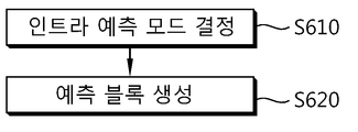
- FIG. 6 is a flowchart schematically illustrating an embodiment of an intra prediction process.
- the encoder and the decoder may determine an intra prediction mode corresponding to the current block (S610). Intra prediction may be performed according to the intra prediction mode of the current block, and each of the intra prediction modes may have a prediction direction corresponding thereto.
- the encoder may encode and transmit the information about the determined intra prediction mode to the decoder, and the decoder may determine the intra prediction mode of the current block based on the transmitted information.
- the encoder may use a method of predicting the intra prediction mode in order to reduce the amount of transmitted bits and to increase the coding efficiency.
- the encoder may encode the intra prediction mode of the current block based on the intra prediction mode of the reconstructed neighboring block.
- An intra prediction mode of the current block may be determined based on the intra prediction mode of the reconstructed neighboring block.
- the intra prediction mode derived based on the reconstructed neighboring block may be used as a prediction value for the intra prediction mode of the current block.
- the intra prediction mode used as a prediction value for the intra prediction mode of the reconstructed current block may be referred to as Most Probable Mode (MPM).
- MPM Most Probable Mode
- the encoder and the decoder may derive a plurality of MPM candidates corresponding to the current block based on the reconstructed neighboring block, and generate an MPM list based on the derived MPM candidate.
- the encoder determines whether the same MPM candidate as the intra prediction mode of the current block exists in the MPM list, and obtains MPM flag information indicating whether the same MPM candidate as the intra prediction mode of the current block exists in the MPM list. Can be sent to the decoder.
- the decoder may determine whether the same MPM candidate as the intra prediction mode of the current block exists in the MPM list based on the transmitted MPM flag information.
- the MPM flag information may indicate whether there is a candidate used as an intra prediction mode of the current block among the MPM candidate modes.
- the MPM flag information may be represented as prev_intra_luma_pred_flag.
- prev_intra_luma_pred_flag the MPM flag information will be referred to as prev_intra_luma_pred_flag.
- the encoder encodes and transmits MPM index information indicating which MPM candidate among MPM candidates in the MPM list is the same as the MPM candidate in the MPM list. Can be.
- the decoder may determine the MPM candidate indicated by the MPM index information as the intra prediction mode of the current block.
- the MPM index information may be represented as mpm_idx.
- the MPM index information will be referred to as mpm_idx.
- the encoder may derive a remaining mode based on the intra prediction mode and the MPM list of the current block.
- the remaining mode may be derived based on the intra prediction mode excluding the MPM candidate.
- the encoder may encode the generated remaining mode and transmit it to the decoder, and the decoder may determine an intra prediction mode of the current block based on the transmitted remaining mode.
- the remaining mode may be represented by rem_intra_luma_pred_mode.
- the encoder and the decoder may generate a prediction block corresponding to the current block by performing intra prediction based on the determined intra prediction mode (S620).
- FIG. 7 is a flowchart schematically illustrating an embodiment of a method of transmitting encoded information according to an embodiment of the present invention.
- the encoder may generate encoding information (and / or encoding target symbol) for the CU before performing entropy encoding on the CU (S710).
- the encoding information includes encoding unit split flag information (split_coding_unit_flag), skip flag information (skip_flag), merge flag information (merge_flag), prediction mode information (PredMode), split mode information (PartMode), intra split mode information (intra_part_mode), MPM flag information (prev_intra_luma_pred_flag) and MPM index information (mpm_idx) may be included.
- the encoder may perform entropy encoding on a plurality of syntax elements corresponding to the generated encoding information (S720).
- the encoder may use an entropy encoding scheme such as CAVLC, CABAC, or the like for entropy encoding.
- the encoder may improve image encoding efficiency by performing entropy encoding by combining two or more different syntax elements in consideration of a probability of occurrence of a symbol corresponding to each syntax element.
- there may be two or more syntax elements that may improve encoding efficiency by applying a joint encoding scheme.
- an encoding scheme for performing entropy encoding by combining a plurality of syntax elements and / or a plurality of syntax element values derived for the same syntax element is referred to as a joint coding scheme.
- a value of 0 or 1 may be transmitted based on a fixed length coding scheme.
- one bit may be coded in the same manner as in a symbol value having a small occurrence probability, even for a symbol value having a large occurrence probability among two symbol values.
- the joint encoding scheme is applied to a symbol having two symbol values having different occurrence probabilities, different bit amounts may be allocated to the two symbol values according to the occurrence probability, thereby improving encoding efficiency.
- the encoder may use one representative symbol corresponding to two or more symbols.
- the encoder may combine two or more symbol values into one group and assign one representative symbol value to the combined group.
- the encoder may determine an additional bit corresponding to the representative symbol value and transmit it to the decoder in order to distinguish a plurality of symbol values belonging to the group indicated by the representative symbol value.
- a symbol to which additional bits are applied and / or used to distinguish a plurality of symbol values corresponding to one representative symbol value may be referred to as an escape symbol.
- the encoder may improve the efficiency of probability update performed based on a sorting table during entropy encoding. That is, when the probability of a plurality of symbols is not individually updated, but the probability is updated in a group unit for a plurality of combined symbols, the probability of symbols, events, parameters, etc. belonging to the group may be updated at once. The accuracy of probability prediction can be improved.
- the above-described joint encoding scheme may not be applied only to a plurality of different syntax elements, but may also be applied to a plurality of syntax element values derived for the same syntax element.
- the encoder may combine a plurality of syntax element values corresponding to the encoding unit, the prediction unit, and / or the transform unit into one group and assign one representative symbol value to the combined group. That is, the encoder may combine the plurality of syntax element values derived for the same syntax element and encode the combined plurality of syntax element values into one syntax element (and / or one syntax element value).
- the joint encoding scheme may have various advantages in performing entropy encoding, and may improve encoding efficiency. Since specific embodiments of the joint encoding scheme are described below, a description thereof will be omitted.
- the encoder may transmit the syntax element information jointly encoded by the above-described process to the decoder (S730).
- FIG. 8 is a flowchart schematically showing an embodiment of a decoding method according to an embodiment of the present invention.
- the decoder may perform entropy decoding on the jointly encoded syntax element information (S810).
- entropy decoding performed on a jointly encoded syntax element is referred to as joint decoding.
- the decoder may use an entropy decoding scheme such as CAVLC, CABAC, or the like for entropy decoding.
- the decoder may perform a joint decoding process on two or more different syntax elements and / or a plurality of syntax element values corresponding to the same syntax element in consideration of a probability of occurrence of a symbol corresponding to each syntax element. Image decoding efficiency can be improved.
- a value of 0 or 1 may be transmitted based on a fixed length coding scheme.
- one bit may be coded in the same manner as in a symbol value having a small occurrence probability, even for a symbol value having a large occurrence probability among two symbol values.
- the combined decoding scheme is applied to a symbol having two symbol values having different occurrence probabilities, different bit amounts may be allocated to the two symbol values according to the occurrence probability, thereby improving the decoding efficiency.
- the decoder may use one representative symbol corresponding to two or more symbols.
- the decoder may determine one representative symbol value by entropy decoding, and may derive two or more symbol values corresponding to the representative symbol value based on the determined representative symbol value.
- the decoder may read an additional bit corresponding to the representative symbol value to distinguish a plurality of symbol values belonging to the group indicated by the representative symbol value.
- the additional bit corresponding to the representative symbol value may be determined by the encoder and transmitted to the decoder.
- a symbol in which an additional bit is applied and / or used to distinguish a plurality of symbol values corresponding to one representative symbol value may be referred to as an escape symbol.
- the decoder can improve the efficiency of the probability update performed based on a sorting table during entropy encoding. That is, when the probability of a plurality of symbols is not individually updated, but the probability is updated in a group unit for a plurality of combined symbols, the probability of symbols, events, parameters, etc. belonging to the group may be updated at once. The accuracy of probability prediction can be improved.
- the above-described combined decoding scheme may be applied not only to a plurality of syntax elements different from each other but also to a plurality of syntax element values derived for the same syntax element.
- one representative syntax element value corresponding to the group of the plurality of syntax element values may be derived by an entropy decoding process. That is, the decoder may determine one representative syntax element value by entropy decoding, and derive a plurality of syntax element values corresponding to the representative syntax element value based on the determined representative syntax element value.
- the combined decoding scheme may have various advantages in performing entropy decoding, and may improve decoding efficiency. Since specific embodiments of the joint decoding scheme will be described later, a description thereof will be omitted.
- the decoder may obtain decoding information corresponding to the encoding information based on the jointly decoded syntax element information (S820). That is, the decoder may acquire decoding information corresponding to the encoding information before performing the decoding process (the restoration block generation process) for the coding unit.
- the decoding information includes coding unit split flag information (split_coding_unit_flag), skip flag information (skip_flag), merge flag information (merge_flag), prediction mode information (PredMode), split mode information (PartMode), intra split mode information (intra_part_mode), MPM flag information (prev_intra_luma_pred_flag) and MPM index information (mpm_idx) may be included.
- the decoder may generate a reconstruction block corresponding to a decoding object block (eg, a coding unit, a prediction unit, and / or a transform unit) based on the obtained decoding information (S830).
- a decoding object block eg, a coding unit, a prediction unit, and / or a transform unit
- each symbol (and / or syntax element) representing the encoding information and the values assigned to each symbol (and / or syntax element) are arbitrary and modified embodiments. If it corresponds to the technical spirit substantially the same as the content described in the embodiments described later, will be included in the scope of the present invention.
- Table 1 below shows an embodiment of a joint encoding / combination decoding method when the size of an encoding / decoding target unit is larger than the SCU.
- MODE_SKIP may mean that the prediction mode of the coding unit (and / or the prediction unit) is the skip mode.
- MODE_INTER may mean that the prediction mode of the coding unit (and / or the prediction unit) is the inter mode.
- MODE_INTRA may mean that the prediction mode of the coding unit (and / or the prediction unit) is an intra mode.
- PART_2Nx2N, PART_2NxN, PART_Nx2N, PART_NxN, PART_2NxnU, PART_2NxnD, PART_nLx2N and PART_nRx2N can each represent split modes 2Nx2N, 2NxN, Nx2N, NxN, 2NxNN, Nx2N, and Nx2N.
- one representative syntax element may be determined in consideration of the occurrence probability of each of the plurality of syntax elements. Can be. Representative syntax elements may be mapped to each of the plurality of syntax elements. For example, the representative syntax element may be represented by cu_split_pred_part_mode as in the embodiment of Table 1.
- the encoder may determine a representative syntax element value based on the plurality of syntax element values, and may perform entropy encoding on the representative syntax element and transmit it to the decoder.
- the decoder may determine a representative syntax element value by performing entropy decoding on the transmitted information, and may derive the plurality of syntax element values based on the representative syntax element value.
- Table 2 below shows another embodiment of a joint encoding / combination decoding method.
- the encoder / decoder combines a plurality of syntax elements split_coding_unit_flag, skip_flag, merge_flag, Predmode, and Partmode as well as prev_intra_luma_pred_flag corresponding to intra encoding / decoding information to improve encoding / decoding performance.
- Entropy encoding / decoding may be performed.
- one representative syntax element may be determined in consideration of the occurrence probability of each of the plurality of syntax elements.
- Representative syntax elements may be mapped to each of the plurality of syntax elements.
- the representative syntax element may be represented by cu_split_pred_part_mode as in the embodiment of Table 2.
- the encoder / decoder may use an adaptive sort table in which the table index is re-assigned adaptively during the entropy encoding / decoding process.
- each of the plurality of prediction units may have a prev_intra_luma_pred_flag value, and thus, a plurality of prev_intra_luma_pred_flag values may exist.
- the encoder / decoder may apply the joint encoding / combination decoding scheme to all of the plurality of prev_intra_luma_pred_flag values in a similar manner as in the embodiment of Table 2. Even in this case, the encoder / decoder may use an adaptive sort table in which table indexes are re-assigned adaptively during entropy encoding / decoding.
- Table 3 shows another embodiment of a joint encoding / combination decoding method.
- mpm_idx may be combined with a plurality of syntax elements split_coding_unit_flag, skip_flag, merge_flag, Predmode, Partmode, and prev_intra_luma_pred_flag to be encoded / decoded.
- one representative syntax element corresponding to the plurality of syntax elements to be combined may be determined, and the representative syntax elements may be mapped to each of the plurality of syntax elements.
- the representative syntax element may be represented by cu_split_pred_part_mode as in the embodiment of Table 3.
- the encoder / decoder may use an adaptive sort table in which the table index is re-assigned adaptively during the entropy encoding / decoding process.
- the encoder / decoder may use an adaptive sort table in which the table index is re-assigned adaptively according to the occurrence probability of the symbol for cu_split_pred_part_mode, and thus, the occurrence probability of the symbol corresponding to MODE_INTRA and PART_2Nx2N is determined. You can use an escape symbol to increase it.
- the decoder may further parse one bit (first bit) corresponding to the symbol value.
- the prediction mode of the prediction unit is determined as MODE_INTRA and the split mode of the prediction unit (and / or coding unit) is determined as PART_2Nx2N, and the value assigned to prev_intra_luma_pred_flag May be determined to be zero.
- the prediction mode of the prediction unit (and / or coding unit) is determined as MODE_INTRA and the splitting mode of the prediction unit (and / or coding unit) is determined as PART_2Nx2N, and the value assigned to prev_intra_luma_pred_flag is 1 Can be determined.
- the decoder may further parse one bit (second bit) corresponding to the symbol value. In this case, if the parsed value is 0, the value assigned to mpm_idx may be determined as 0. If the parsed value is 1, the value assigned to mpm_idx may be determined as 1.
- prev_intra_luma_pred_flag and mpm_idx may be jointly encoded / complexed through cu_split_pred_part_mode. Accordingly, an effect of encoding / decoding of prev_intra_luma_pred_flag and mpm_idx, which are syntax elements related to intra prediction, may be combined with each other.
- Table 4 below shows another embodiment of a joint encoding / combination decoding method.
- an escape symbol may be used for an asymmetric motion partitioning mode (AMP mode).
- the encoder / decoder may use an adaptive sort table in which the table index is re-assigned adaptively during the entropy encoding / decoding process.
- the encoder / decoder can use an adaptive sort table in which the table index is re-assigned adaptively according to the occurrence probability of the symbol with respect to cu_split_pred_part_mode, the occurrence probability of the symbol corresponding to the asymmetric motion partitioning mode is used. You can use an escape symbol to increase this.
- the decoder may further parse one bit (first bit) corresponding to the symbol value.
- the division mode of the prediction unit (and / or encoding unit) may correspond to horizontal division, and the decoder may further include one bit corresponding to the symbol value ( Second bit) can be further parsed. If the value parsed for the second bit is 0, the division mode of the prediction unit (and / or encoding unit) may correspond to PART_2NxnU. If the value parsed for the second bit is 1, the prediction unit (and / or encoding unit) ) May correspond to PART_2NXnD.
- the division mode of the prediction unit (and / or encoding unit) may correspond to vertical division, and the decoder may further include one bit corresponding to the symbol value (first 2 bits) can be parsed further.
- the division mode of the prediction unit (and / or encoding unit) may correspond to PART_nLx2N
- the prediction unit (and / or Alternatively, the split mode of the coding unit may correspond to PART_nRx2N.
- the encoder / decoder may perform entropy encoding / decoding by combining intra_part_mode and prev_intra_luma_pred_flag.
- the probability distribution corresponding to the symbol value of each of intra_part_mode and prev_intra_luma_pred_flag may be represented as shown in the embodiments of Tables 5 and 6 below.
- part_size may mean a split mode in the intra mode.
- Intra_2Nx2N may indicate a split mode of 2Nx2N
- Intra_NxN may indicate a split mode of NxN.
- the encoder / decoder performs entropy encoding / decoding by combining the two syntax elements intra_part_mode and prev_intra_luma_pred_flag in consideration of the occurrence probability of the two syntax elements shown in the embodiments of Tables 5 and 6, thereby improving coding efficiency. Can be. This can be represented by Table 7 below.
- one representative syntax element may be determined in consideration of the occurrence probability of two syntax elements intra_part_mode and prev_intra_luma_pred_flag.
- the representative syntax element may be mapped to each of the two syntax elements.
- the representative syntax element may be represented by intra_part_mpm_mode as in the embodiment of Table 7.
- the encoder / decoder may use an adaptive sort table in which the table index is re-assigned adaptively during the entropy encoding / decoding process.
- the encoder / decoder may perform joint encoding / combination decoding on a plurality of prev_intra_luma_pred_flag values corresponding to one coding unit.
- the encoder / decoder may perform entropy encoding / entropy decoding on unified_prev_intra_luma_pred_flag indicating whether the plurality of prev_intra_luma_pred_flag values corresponding to the coding unit are jointly encoded / combined and decoded.
- the split mode of the current coding unit (and / or prediction unit) is Intra_NxN and 1 is assigned to unified_prev_intra_luma_pred_flag
- all of the values allocated to prev_intra_luma_pred_flag of four prediction units having NxN sizes may be determined to be zero.
- entropy encoding / entropy decoding may not be performed on prev_intra_luma_pred_flag of four prediction units having an Intra_NxN split mode.
- the encoder / decoder may perform entropy encoding / entropy decoding on all prev_intra_luma_pred_flag of four prediction units having the Intra_NxN division mode.
- Table 8 shows another embodiment of a joint encoding / combination decoding method.
- four prediction units belonging to one coding unit having a split mode of NxN may have NxN PU index values of 0, 1, 2, and 3, respectively.
- FIG. 9 is a diagram schematically illustrating a PU index value of each of four prediction units belonging to one coding unit having a split mode of N ⁇ N.
- the PU index value of the upper left prediction unit is 0, the PU index value of the upper right prediction unit is 1, and the PU index value of the lower left prediction unit Is 2 and the PU index value of the lower right prediction unit may be 3.
- one representative syntax element corresponding to the plurality of prev_intra_luma_pred_flag values is not used without using unified_prev_intra_luma_pred_flag. It is available.
- the representative syntax element may be mapped to a combination of the plurality of prev_intra_luma_pred_flag values.
- the representative syntax element may be represented as unified_prev_intra_luma_pred_mode as in the embodiment of Table 8.
- the encoder may determine a representative syntax element value (unified_prev_intra_luma_pred_mode) based on the plurality of syntax element values, and may perform entropy encoding on the representative syntax element and transmit it to the decoder.
- the decoder may determine a representative syntax element value (unified_prev_intra_luma_pred_mode) by performing entropy decoding on the transmitted information, and may derive the plurality of syntax element values based on the representative syntax element value.
- the encoder / decoder may use an adaptive sort table in which the table index is re-assigned adaptively during the entropy encoding / decoding process.
- the encoder / decoder may perform entropy encoding / entropy decoding by combining intra mode encoding related information such as split_coding_unit_flag, prev_intra_luma_pred_flag, and mpm_idx.
- intra mode encoding related information such as split_coding_unit_flag, prev_intra_luma_pred_flag, and mpm_idx.
- one representative syntax element corresponding to the plurality of syntax elements to be combined may be determined, and the representative syntax elements may be mapped to each of the plurality of syntax elements.
- the representative syntax element may be represented as intra_cu_split_pred_part_mode.
- Table 9 shows an embodiment of a codeword table applied to joint encoding / combination decoding based on intra_cu_split_pred_part_mode when the size of a coding unit to be encoded / decoded is larger than SCU.
- Table 10 shows an embodiment of a codeword table applied to joint encoding / combination decoding based on intra_cu_split_pred_part_mode when the size of a coding unit to be encoded / decoded is equal to the SCU.
- CUSize may indicate the size of a CU to be encoded / decoded.
- the encoder may determine a representative syntax element value based on the plurality of syntax element values, and may perform entropy encoding on the representative syntax element and transmit it to the decoder.
- the decoder may determine a representative syntax element value by performing entropy decoding on the transmitted information, and may derive the plurality of syntax element values based on the representative syntax element value.
- the encoder / decoder may use an adaptive sort table in which the table index is re-assigned adaptively during the entropy encoding / decoding process.
- each of the plurality of prediction units may have a prev_intra_luma_pred_flag value, an mpm_idx value, or the like, and thus, a plurality of prev_intra_luma_pred_flag values and a plurality of mpm_idx values may exist.
- the encoder / decoder may apply the joint encoding / combination decoding scheme to the plurality of prev_intra_luma_pred_flag values and the plurality of mpm_idx values in a similar manner as in the embodiments of Table 9 and Table 10. Even in this case, the encoder / decoder may use an adaptive sort table in which table indexes are re-assigned adaptively during entropy encoding / decoding.
- Table 11 shows an embodiment of syntax elements when joint encoding / combination decoding is performed based on intra_cu_split_pred_part_mode.
- the intra_cu_split_pred_part_mode syntax may be defined in a coding tree along with cu_split_pred_part_mode and split_coding_unit_flag, for example.
- Table 12 below shows another embodiment of a joint encoding / combination decoding method.
- Table 12 may correspond to an embodiment of a table applied when the size of a coding unit to be encoded / decoded is larger than the SCU.
- the encoder / decoder may perform entropy encoding / entropy decoding by combining a plurality of syntax elements split_coding_unit_flag, skip_flag, PredMode, and PartMode except one merge_flag into one representative syntax element cu_split_pred_part_mode.
- the encoder / decoder may perform entropy encoding / entropy decoding by combining only a plurality of syntax elements except for merge_flag in order to reduce degradation of encoding / decoding performance due to merge_flag.
- the encoder / decoder may perform joint encoding / combination decoding on split_coding_unit_flag, skip_flag, Predmode, and Partmode as in the embodiment of Table 12.
- the encoder / decoder may use an adaptive sort table in which the table index is re-assigned adaptively during the entropy encoding / decoding process.
- the encoder / decoder may independently perform entropy encoding / entropy decoding on cu_split_pred_part_mode and merge_flag.
- Table 13 below shows another embodiment of a joint encoding / combination decoding method.
- Table 13 may correspond to another embodiment of a combined encoding / combination decoding method for split_coding_unit_flag, skip_flag, PredMode, and PartMode when merge_flag is encoded / decoded as a separate syntax element distinguished from cu_split_pred_part_mode.
- Table 13 may correspond to an embodiment of a table applied when the size of a coding unit to be encoded / decoded is the same as the SCU and 4x4 inter prediction is allowed.
- the encoder / decoder may use escape symbols corresponding to PART_2Nx2N of MODE_INTRA, PART_NxN of MODE_INTRA, and PART_NxN of MODE_INTER.
- the encoder / decoder may use an adaptive alignment table in which a table index is adaptively reassigned during entropy encoding / entropy decoding.
- Table 14 below shows another embodiment of a joint encoding / combination decoding method.
- Table 14 may correspond to another embodiment of a combined encoding / combination decoding method for split_coding_unit_flag, skip_flag, PredMode, and PartMode when merge_flag is encoded / decoded as a separate syntax element distinguished from cu_split_pred_part_mode.
- Table 14 may correspond to an embodiment of a table applied when the size of a coding unit to be encoded / decoded is the same as that of the SCU and 4x4 inter prediction is not allowed.
- the encoder / decoder may use escape symbols corresponding to PART_2Nx2N of MODE_INTRA and PART_NxN of MODE_INTRA.
- the encoder / decoder may use an adaptive alignment table in which a table index is adaptively reassigned during entropy encoding / entropy decoding.
- Table 15 shows an embodiment of semantics of the syntax element cu_split_pred_part_mode when merge_flag is encoded / decoded as a separate syntax element distinguished from cu_split_pred_part_mode.
- syntax elements of the coding unit level of split_coding_unit_flag, skip_flag, Predmode, and Partmode may be used in a joint encoding / combination decoding process based on cu_split_pred_part_mode.
- the joint encoding / combination decoding may be performed only for.
- cu_split_pred_part_mode may indicate split_coding_unit_flag.
- cu_split_pred_part_mode may indicate skip_flag [x0] [y0], PredMode, and PartMode of the coding unit.
- X0 and y0 corresponding to the array index may indicate the position of the leftmost upper luma pixel in the coding unit with respect to the position of the leftmost upper luma pixel in the picture to which the coding unit belongs.
- Table 16 below shows an embodiment of prediction unit syntax when merge_flag is encoded / decoded as a separate syntax element distinguished from cu_split_pred_part_mode.
- the decoder may parse the merge_flag without checking an entropy decoding method and a condition regarding a split mode of the prediction unit. At this time, in the encoding / decoding process of the merge_flag, a fixed length code having a length of 1 bit may be used.
- merge_flag When merge_flag is combined with cu_split_pred_part_mode to perform entropy encoding / entropy decoding, merge_flag may be parsed when the split mode of the prediction unit (and / or encoding unit) is not 2N ⁇ 2N. However, if merge_flag is encoded / decoded as a separate syntax element distinguished from cu_split_pred_part_mode, the decoder can parse merge_flag in the same manner as in other split modes, even when the split mode of the prediction unit (and / or coding unit) is 2Nx2N. have. At this time, since the decoder can parse merge_flag without checking a specific condition, the complexity in the decoder can be reduced.
- mapping table 17 shows an embodiment of a mapping table applied to cu_split_pred_part_mode when merge_flag is encoded / decoded as a separate syntax element distinguished from cu_split_pred_part_mode.
- the mapping table may mean a table indicating a mapping relationship between a code number and a table index.
- the mapping table corresponding to cu_split_pred_part_mode may be represented by splitPredPartModeTable.
- the embodiment of Table 17 may correspond to an initialized table corresponding to the mapping table.
- cuDepth represents a depth value of a coding unit
- codeNum represents a code number.
- splitPredPartModeTable may have a different code number according to the depth value of the coding unit. Accordingly, the decoder may derive a plurality of symbols split_coding_unit_flag, skip_flag, Predmode, and Partmode corresponding to the representative syntax element cu_split_pred_part_mode according to the depth value of each coding unit based on splitPredPartModeTable. In this case, the decoder may apply an adaptive sort table to the splitPredPartModeTable during entropy decoding.
- each code number value may be mapped to a table index value of 0 to 9.
- a code number value of 0 to 4 may exist. At this time, each code number value may be mapped to a table index value of 1 to 5.
- the maximum number of code numbers may be equal to the maximum number of symbols corresponding to cu_split_pred_part_mode, and the number of symbols may correspond to the number of table indexes.
- a table index value corresponding to a code number having a value of 5 or more may correspond to a meaningless value that is not actually used. This is because when the depth value of the coding unit is 3, only five code numbers having a value of 0 to 4 can be used.
- Table 18 shows an example of code number and codeword allocation corresponding to cu_split_pred_part_mode when merge_flag is encoded / decoded as a separate syntax element distinguished from cu_split_pred_part_mode.
- Table 18 may correspond to an embodiment of a table applied when the size of a coding unit to be encoded / decoded is larger than the SCU.
- the value x allocated to cu_split_pred_part_mode may have a range of 0 ⁇ x ⁇ S, and at this time, the maximum value of x may be limited to S.
- each value allocated to cu_split_pred_part_mode may correspond to a table index, and the maximum value may be 9.
- cu_split_pred_part_mode since the maximum value assigned to cu_split_pred_part_mode is determined, cu_split_pred_part_mode can be encoded as a truncated unary code with high coding efficiency. Therefore, the decoder may parse the bitstream corresponding to cu_split_pred_part_mode based on the truncated unary code. For example, when a table index value is N (N is an integer greater than or equal to 0), the cutting type unary code corresponding to the table index value may be composed of N '0's and one' 1 '.
- the truncated unary code corresponding to the table index value may be configured with N max '0's.
- N is an integer greater than or equal to 0
- the cut unary code corresponding to the table index value may be composed of N '1's and one' 0 '.
- the truncated unary code corresponding to the table index value may be configured with N max '1's.
- the decoder After reading the codeword corresponding to cu_split_pred_part_mode from the bitstream, the decoder can derive symbol information (eg, split_coding_unit_flag, skip_flag, PredMode, PartMode, etc.) corresponding to the codeword based on Table 18. For example, when the codeword is '001', the codeword may be mapped to code number 2, and the code number 2 may be mapped to cu_split_pred_part_mode value 2. Accordingly, split_coding_unit_flag, skip_flag, PredMode, and PartMode may be determined as values and / or modes corresponding to cu_split_pred_part_mode value 2, respectively.
- symbol information eg, split_coding_unit_flag, skip_flag, PredMode, PartMode, etc.
- the value of split_coding_unit_flag may be determined as 0, and the value of skip_flag may be determined as 0.
- PredMode may be determined as MODE_INTER and PartMode may be determined as PART_2Nx2N.
- the code number and cu_split_pred_part_mode (and / or table index of cu_split_pred_part_mode) mapped to the code number may be updated based on the adaptive sort table.
- Table 19 shows another embodiment of code number and codeword allocation corresponding to cu_split_pred_part_mode when merge_flag is encoded / decoded as a separate syntax element distinguished from cu_split_pred_part_mode.
- Table 19 may correspond to an embodiment of a table applied when the size of a coding unit to be encoded / decoded is the same as the SCU and 4x4 inter prediction is allowed.
- the value x allocated to cu_split_pred_part_mode may have a range of 0 ⁇ x ⁇ S, and at this time, the maximum value of x may be limited to S.
- each value allocated to cu_split_pred_part_mode may correspond to a table index, and a maximum value may be four.
- cu_split_pred_part_mode since the maximum value assigned to cu_split_pred_part_mode is determined, cu_split_pred_part_mode can be encoded as a truncated unary code with high coding efficiency. Therefore, the decoder may parse the bitstream corresponding to cu_split_pred_part_mode based on the truncated unary code.
- the decoder After reading the codeword corresponding to cu_split_pred_part_mode from the bitstream, the decoder can derive symbol information (eg, split_coding_unit_flag, skip_flag, PredMode, PartMode, etc.) corresponding to the codeword based on Table 19.
- symbol information eg, split_coding_unit_flag, skip_flag, PredMode, PartMode, etc.
- split_coding_unit_flag, skip_flag, PredMode, and PartMode may be determined as values and / or modes corresponding to cu_split_pred_part_mode value 2, respectively.
- the value of split_coding_unit_flag may be determined as 0.
- PredMode may be determined as MODE_INTER and PartMode may be determined as PART_2Nx2N.
- the code number and cu_split_pred_part_mode (and / or table index of cu_split_pred_part_mode) mapped to the code number may be updated based on the adaptive sort table.
- the symbol when the cu_split_pred_part_mode value is 4, the symbol may be used as an escape symbol. For example, if the cu_split_pred_part_mode value is 4, the decoder may further parse one bit (first bit) corresponding to the symbol value. At this time, if the parsed value is 1, PredMode may be determined as MODE_INTRA and PartMode may be determined as PART_2N ⁇ 2N.
- the decoder may further parse one bit (second bit) corresponding to the symbol value.
- PredMode may be determined as MODE_INTRA and PartMode may be determined as PART_NxN.
- PredMode may be determined as MODE_INTER and PartMode may be determined as PART_NxN.
- Table 20 below shows another embodiment of code number and codeword allocation corresponding to cu_split_pred_part_mode when merge_flag is encoded / decoded as a separate syntax element distinguished from cu_split_pred_part_mode.
- Table 20 may correspond to an embodiment of a table applied when the size of a coding unit to be encoded / decoded is equal to the SCU and 4x4 inter prediction is not allowed.
- the value x allocated to cu_split_pred_part_mode may have a range of 0 ⁇ x ⁇ S, and at this time, the maximum value of x may be limited to S.
- each value allocated to cu_split_pred_part_mode may correspond to a table index, and a maximum value may be four.
- cu_split_pred_part_mode since the maximum value assigned to cu_split_pred_part_mode is determined, cu_split_pred_part_mode can be encoded as a truncated unary code with high coding efficiency. Therefore, the decoder may parse the bitstream corresponding to cu_split_pred_part_mode based on the truncated unary code.
- the decoder may derive symbol information (eg, split_coding_unit_flag, skip_flag, PredMode, PartMode, etc.) corresponding to the codeword based on Table 20.
- symbol information eg, split_coding_unit_flag, skip_flag, PredMode, PartMode, etc.
- split_coding_unit_flag, skip_flag, PredMode, and PartMode may be determined as values and / or modes corresponding to cu_split_pred_part_mode value 3, respectively.
- the value of split_coding_unit_flag may be determined to be zero.
- PredMode may be determined as MODE_INTER
- PartMode may be determined as PART_Nx2N.
- the code number and cu_split_pred_part_mode (and / or table index of cu_split_pred_part_mode) mapped to the code number may be updated based on the adaptive sort table.
- the symbol when the cu_split_pred_part_mode value is 4, the symbol may be used as an escape symbol.
- the decoder may further parse one bit (first bit) corresponding to the symbol value.
- PredMode may be determined as MODE_INTRA and PartMode may be determined as PART_2Nx2N.
- PredMode may be determined as MODE_INTRA and PartMode may be determined as PART_NxN.
- Table 21 shows another embodiment of a joint encoding / combination decoding method.
- Table 21 may correspond to an embodiment of a table applied when the size of a coding unit to be encoded / decoded is larger than the SCU.
- the encoder / decoder includes one representative of a plurality of syntax elements split_coding_unit_flag, skip_flag, PredMode, and PartMode except merge_flag (merge flag), inter_part_horz_flag (horizontal split flag), and rem_inter_part_mode (remaining split flag).
- Entropy encoding / entropy decoding can be performed by combining with the syntax element cu_split_pred_part_mode.
- Table 21 may correspond to an embodiment of a table applied when merge_flag, inter_part_horz_flag, and rem_inter_part_mode are encoded / decoded separately from cu_split_pred_part_mode.
- inter_part_horz_flag and rem_inter_part_mode may also be regarded as information related to the asymmetric motion division mode and the symmetric motion division mode.
- the encoder / decoder may perform entropy encoding / entropy decoding by combining only a plurality of syntax elements except merge_flag, inter_part_horz_flag, and rem_inter_part_mode to reduce degradation of encoding / decoding performance due to merge_flag, inter_part_horz_flag, and rem_inter_part_mode.
- the encoder / decoder may perform joint encoding / combination decoding on split_coding_unit_flag, skip_flag, Predmode, and Partmode as in the embodiment of Table 21.
- the encoder / decoder may use an adaptive sort table in which the table index is re-assigned adaptively during the entropy encoding / decoding process.
- merge_flag, inter_part_horz_flag, and rem_inter_part_mode are not combined with cu_split_pred_part_mode, and thus may correspond to separate syntax elements distinguished from cu_split_pred_part_mode. Accordingly, the encoder / decoder may independently perform entropy encoding / entropy decoding on cu_split_pred_part_mode, merge_flag, inter_part_horz_flag, and rem_inter_part_mode.
- Table 22 below shows another embodiment of a joint encoding / combination decoding method.
- Table 22 may correspond to another embodiment of a table applied when merge_flag, inter_part_horz_flag, and rem_inter_part_mode are encoded / decoded as separate syntax elements distinguished from cu_split_pred_part_mode.
- Table 22 may correspond to an embodiment of a table applied when the size of a coding unit to be encoded / decoded is equal to the SCU and 4x4 inter prediction is allowed.
- the encoder / decoder may use an escape symbol corresponding to PART_2NxN of MODE_INTER, PART_Nx2N of MODE_INTER, PART_2Nx2N of MODE_INTRA, PART_NxN of MODE_INTRA, and escape symbol corresponding to PART_NxN of MODE_INTER.
- the encoder / decoder may use an adaptive alignment table in which a table index is adaptively reassigned during the entropy encoding / entropy decoding process.
- Table 23 shows another embodiment of a joint encoding / combination decoding method.
- Table 23 may correspond to another embodiment of a table applied when merge_flag, inter_part_horz_flag, and rem_inter_part_mode are encoded / decoded as separate syntax elements distinguished from cu_split_pred_part_mode.
- Table 23 may correspond to an embodiment of a table applied when the size of a coding unit to be encoded / decoded is equal to the SCU and 4x4 inter prediction is not allowed.
- the encoder / decoder may use an escape symbol corresponding to PART_2NxN of MODE_INTER, PART_Nx2N of MODE_INTER, and an escape symbol corresponding to PART_2Nx2N of MODE_INTRA, and PART_NxN of MODE_INTRA.
- the encoder / decoder may use an adaptive alignment table in which a table index is adaptively reassigned during the entropy encoding / entropy decoding process.
- Table 24 shows an example of semantics of the syntax element cu_split_pred_part_mode when merge_flag, inter_part_horz_flag, and rem_inter_part_mode are encoded / decoded as separate syntax elements distinguished from cu_split_pred_part_mode.
- inter_part_horz_flag and rem_inter_part_mode a case where the encoding / decoding as a separate syntax element in a distinct and cu_split_pred_part_mode, in a combined coding / combining decoding process based on the cu_split_pred_part_mode split_coding_unit_flag, skip_flag, Predmode and 2Nx2N and NxN
- the joint encoding / combination decoding may be performed only on the syntax elements of the coding unit level of the part mode.
- cu_split_pred_part_mode may indicate split_coding_unit_flag.
- cu_split_pred_part_mode may indicate skip_flag [x0] [y0], PredMode and PartMode corresponding to 2Nx2N and NxN of the coding unit.
- X0 and y0 corresponding to the array index may indicate the position of the leftmost upper luma pixel in the coding unit with respect to the position of the leftmost upper luma pixel in the picture to which the coding unit belongs.
- Table 25 shows an embodiment of prediction unit syntax when merge_flag is encoded / decoded as a separate syntax element distinguished from cu_split_pred_part_mode.
- the decoder may parse the merge_flag without checking an entropy decoding method and a condition regarding a split mode of the prediction unit. At this time, in the encoding / decoding process of the merge_flag, a fixed length code having a length of 1 bit may be used.
- merge_flag When merge_flag is combined with cu_split_pred_part_mode to perform entropy encoding / entropy decoding, merge_flag may be parsed when the split mode of the prediction unit (and / or encoding unit) is not 2N ⁇ 2N. However, if merge_flag is encoded / decoded as a separate syntax element distinguished from cu_split_pred_part_mode, the decoder can parse merge_flag in the same manner as in other split modes, even when the split mode of the prediction unit (and / or coding unit) is 2Nx2N. have. At this time, since the decoder can parse merge_flag without checking a specific condition, the complexity in the decoder can be reduced.
- Table 26 shows an embodiment of encoding unit syntax when inter_part_horz_flag and rem_inter_part_mode are encoded / decoded as separate syntax elements distinguished from cu_split_pred_part_mode.
- inter_part_horz_flag and rem_inter_part_mode may be encoded and / or decoded as separate syntax elements distinguished from cu_split_pred_part_mode.
- a fixed length code having a length of 1 bit may be used in the entropy encoding / entropy decoding process of the inter_part_horz_flag.
- a variable length code may be used in the entropy encoding / entropy decoding process of rem_inter_part_mode.
- mapping table 27 shows an embodiment of a mapping table applied to cu_split_pred_part_mode when merge_flag, inter_part_horz_flag, and rem_inter_part_mode are encoded / decoded as separate syntax elements distinguished from cu_split_pred_part_mode.
- the mapping table may mean a table indicating a mapping relationship between a code number and a table index.
- the mapping table corresponding to cu_split_pred_part_mode may be represented by splitPredPartModeTable.
- the embodiment of Table 27 may correspond to an initialized table corresponding to the mapping table.
- cuDepth represents a depth value of a coding unit
- codeNum represents a code number.
- splitPredPartModeTable may have a different code number according to the depth value of the coding unit. Accordingly, the decoder may derive a plurality of symbols split_coding_unit_flag, skip_flag, Predmode, and Partmode corresponding to the representative syntax element cu_split_pred_part_mode according to the depth value of each coding unit based on splitPredPartModeTable. In this case, the decoder may apply an adaptive sort table to the splitPredPartModeTable during entropy decoding.
- each code number value may be mapped to a table index value of 0 to 4.
- a code number value of 0 to 3 may exist. At this time, each code number value may be mapped to a table index value of 1 to 4.
- the maximum number of code numbers may be equal to the maximum number of symbols corresponding to cu_split_pred_part_mode, and the number of symbols may correspond to the number of table indexes.
- a table index value corresponding to a code number having a value of 4 or more may correspond to a meaningless value that is not actually used. This is because when the depth value of the coding unit is 3, only four code numbers having a value of 0 to 3 can be used.
- Table 28 below shows an embodiment of code numbers and codeword assignments corresponding to cu_split_pred_part_mode when merge_flag, inter_part_horz_flag, and rem_inter_part_mode are encoded / decoded as separate syntax elements distinguished from cu_split_pred_part_mode.
- Table 28 may correspond to an embodiment of a table applied when the size of a coding unit to be encoded / decoded is larger than the SCU.
- the value x allocated to cu_split_pred_part_mode may have a range of 0 ⁇ x ⁇ S, and at this time, the maximum value of x may be limited to S.
- each value allocated to cu_split_pred_part_mode may correspond to a table index, and the maximum value may be 4.
- cu_split_pred_part_mode since the maximum value assigned to cu_split_pred_part_mode is determined, cu_split_pred_part_mode can be encoded as a truncated unary code with high coding efficiency. Therefore, the decoder may parse the bitstream corresponding to cu_split_pred_part_mode based on the truncated unary code.
- the decoder may derive symbol information (eg, split_coding_unit_flag, skip_flag, PredMode, PartMode, etc.) corresponding to the codeword based on Table 28. For example, when the codeword is '001', the codeword may be mapped to code number 2, and the code number 2 may be mapped to cu_split_pred_part_mode value 2. Accordingly, split_coding_unit_flag, skip_flag, PredMode, and PartMode may be determined as values and / or modes corresponding to cu_split_pred_part_mode value 2, respectively.
- symbol information eg, split_coding_unit_flag, skip_flag, PredMode, PartMode, etc.
- the value of split_coding_unit_flag may be determined as 0, the value of skip_flag may be determined as 0, and PredMode may be determined as MODE_INTER.
- PredMode may be determined as MODE_INTER.
- PartMode may be determined based on two syntax elements inter_part_horz_flag and rem_inter_part_mode corresponding to coding unit syntax.
- the code number and cu_split_pred_part_mode (and / or table index of cu_split_pred_part_mode) mapped to the code number may be updated based on the adaptive sort table.
- Table 29 below shows an embodiment of code number and codeword allocation corresponding to cu_split_pred_part_mode when merge_flag, inter_part_horz_flag, and rem_inter_part_mode are encoded / decoded as separate syntax elements distinguished from cu_split_pred_part_mode.
- Table 29 may correspond to an embodiment of a table applied when the size of a coding unit to be encoded / decoded is the same as that of the SCU and 4x4 inter prediction is allowed.
- the value x allocated to cu_split_pred_part_mode may have a range of 0 ⁇ x ⁇ S, and at this time, the maximum value of x may be limited to S.
- each value allocated to cu_split_pred_part_mode may correspond to a table index, and the maximum value may be 3.
- cu_split_pred_part_mode since the maximum value assigned to cu_split_pred_part_mode is determined, cu_split_pred_part_mode can be encoded as a truncated unary code with high coding efficiency. Therefore, the decoder may parse the bitstream corresponding to cu_split_pred_part_mode based on the truncated unary code.
- the decoder may derive symbol information (eg, split_coding_unit_flag, skip_flag, PredMode, PartMode, etc.) corresponding to the codeword based on Table 29. For example, when the codeword is '01', the codeword may be mapped to code number 2, and the code number 2 may be mapped to cu_split_pred_part_mode value 1. Accordingly, split_coding_unit_flag, skip_flag, PredMode, and PartMode may be determined as values and / or modes corresponding to cu_split_pred_part_mode value 1, respectively.
- symbol information eg, split_coding_unit_flag, skip_flag, PredMode, PartMode, etc.
- the value of split_coding_unit_flag may be determined as 0, and the value of skip_flag may be determined as 0.
- PredMode may be determined as MODE_INTER
- PartMode may be determined as PART_2Nx2N.
- the symbol when the cu_split_pred_part_mode value is 2 or 3, the symbol may be used as an escape symbol.
- the decoder may further parse one bit (first bit) corresponding to the symbol value. At this time, if the parsed value is 1, PredMode may be determined as MODE_INTRA and PartMode may be determined as PART_2N ⁇ 2N.
- the decoder may further parse one bit (second bit) corresponding to the symbol value.
- PredMode may be determined as MODE_INTRA and PartMode may be determined as PART_NxN.
- PredMode may be determined as MODE_INTER and PartMode may be determined as PART_NxN.
- the code number and cu_split_pred_part_mode (and / or table index of cu_split_pred_part_mode) mapped to the code number may be updated based on the adaptive sort table.
- Table 30 shows an embodiment of a code number and codeword assignment corresponding to cu_split_pred_part_mode when merge_flag, inter_part_horz_flag, and rem_inter_part_mode are encoded / decoded as separate syntax elements distinguished from cu_split_pred_part_mode.
- Table 30 may correspond to an embodiment of a table applied when the size of a coding unit to be encoded / decoded is equal to the SCU and 4x4 inter prediction is not allowed.
- the value x allocated to cu_split_pred_part_mode may have a range of 0 ⁇ x ⁇ S, and at this time, the maximum value of x may be limited to S.
- each value allocated to cu_split_pred_part_mode may correspond to a table index, and the maximum value may be 3.
- cu_split_pred_part_mode since the maximum value assigned to cu_split_pred_part_mode is determined, cu_split_pred_part_mode can be encoded as a truncated unary code with high coding efficiency. Therefore, the decoder may parse the bitstream corresponding to cu_split_pred_part_mode based on the truncated unary code.
- the decoder After reading the codeword corresponding to cu_split_pred_part_mode from the bitstream, the decoder can derive symbol information (eg, split_coding_unit_flag, skip_flag, PredMode, PartMode, etc.) corresponding to the codeword based on Table 30. For example, when the codeword is '001', the codeword may be mapped to code number 3, and the code number 3 may be mapped to cu_split_pred_part_mode value 2. Accordingly, split_coding_unit_flag, skip_flag, PredMode, and PartMode may be determined as values and / or modes corresponding to cu_split_pred_part_mode value 2, respectively.
- symbol information eg, split_coding_unit_flag, skip_flag, PredMode, PartMode, etc.
- split_coding_unit_flag may be determined as 0
- skip_flag may be determined as 0
- PredMode may be determined as MODE_INTER.
- PartMode may be determined based on two syntax elements inter_part_horz_flag and rem_inter_part_mode corresponding to coding unit syntax.
- the symbol when the cu_split_pred_part_mode value is 2 or 3, the symbol may be used as an escape symbol. For example, if the cu_split_pred_part_mode value is 3, the decoder may further parse one bit (first bit) corresponding to the symbol value. At this time, if the parsed value is 1, PredMode may be determined as MODE_INTRA and PartMode may be determined as PART_2Nx2N. In addition, if the parsed value is 0, PredMode may be determined as MODE_INTRA and PartMode may be determined as PART_NxN.
- the code number and cu_split_pred_part_mode (and / or table index of cu_split_pred_part_mode) mapped to the code number may be updated based on the adaptive sort table.
- Table 31 below shows another embodiment of a joint encoding / combination decoding method.
- Table 31 may correspond to an embodiment of a table applied when the size of a coding unit to be encoded / decoded is larger than the SCU. Further, in the embodiment of Table 31, the encoder / decoder combines a plurality of syntax elements split_coding_unit_flag, skip_flag, PredMode and PartMode except merge_flag (merge flag) and inter_amp_mode (asymmetric motion splitting information) into one representative syntax element cu_split_pred_part_mode to entropy. Encoding / entropy decoding can be performed. That is, Table 31 may correspond to an embodiment of a table applied when merge_flag and inter_amp_mode are encoded / decoded separately from cu_split_pred_part_mode.
- the encoder / decoder may perform entropy encoding / entropy decoding by combining only a plurality of syntax elements except for merge_flag and inter_amp_mode to reduce degradation of encoding / decoding performance due to merge_flag and inter_amp_mode.
- the encoder / decoder may perform joint encoding / combination decoding on split_coding_unit_flag, skip_flag, Predmode, and Partmode as in the embodiment of Table 31.
- the encoder / decoder may use an adaptive sort table in which the table index is re-assigned adaptively during the entropy encoding / decoding process.
- merge_flag and inter_amp_mode are not combined with cu_split_pred_part_mode, and thus may correspond to separate syntax elements distinguished from cu_split_pred_part_mode. Accordingly, the encoder / decoder may independently perform entropy encoding / entropy decoding on cu_split_pred_part_mode, merge_flag, and inter_amp_mode. In this case, a fixed length code or a variable length code may be used in the encoding / decoding process of the inter_amp_mode.
- Table 32 below shows another embodiment of a joint encoding / combination decoding method.
- Table 32 may correspond to another embodiment of a table applied when merge_flag and inter_amp_mode are encoded / decoded as separate syntax elements distinguished from cu_split_pred_part_mode.
- Table 32 may correspond to an embodiment of a table applied when the size of a coding unit to be encoded / decoded is the same as the SCU and 4x4 inter prediction is allowed.
- the encoder / decoder may use an adaptive alignment table in which a table index is adaptively reassigned in the entropy encoding / entropy decoding process.
- Table 33 below shows another embodiment of a joint encoding / combination decoding method.
- Table 33 may correspond to another embodiment of a table applied when merge_flag and inter_amp_mode are encoded / decoded as separate syntax elements distinguished from cu_split_pred_part_mode.
- Table 33 may correspond to an embodiment of a table applied when the size of a coding unit to be encoded / decoded is the same as that of the SCU and 4x4 inter prediction is not allowed.
- the encoder / decoder may use an adaptive alignment table in which a table index is adaptively reassigned during the entropy encoding / entropy decoding process.
- Table 34 shows an embodiment of semantics of syntax elements cu_split_pred_part_mode when merge_flag and inter_amp_mode are encoded / decoded as separate syntax elements distinguished from cu_split_pred_part_mode.
- cu_split_pred_part_mode may indicate split_coding_unit_flag.
- cu_split_pred_part_mode may indicate skip_flag [x0] [y0], PredMode and PartMode corresponding to 2Nx2N, 2NxN, Nx2N, and NxN of the coding unit.
- X0 and y0 corresponding to the array index may indicate the position of the leftmost upper luma pixel in the coding unit with respect to the position of the leftmost upper luma pixel in the picture to which the coding unit belongs.
- Table 35 shows an embodiment of prediction unit syntax when merge_flag is encoded / decoded as a separate syntax element distinguished from cu_split_pred_part_mode.
- the decoder may parse the merge_flag without checking an entropy decoding method and a condition regarding a split mode of the prediction unit.
- a fixed length code having a length of 1 bit may be used.
- merge_flag When merge_flag is combined with cu_split_pred_part_mode to perform entropy encoding / entropy decoding, merge_flag may be parsed when the split mode of the prediction unit (and / or encoding unit) is not 2N ⁇ 2N. However, if merge_flag is encoded / decoded as a separate syntax element distinguished from cu_split_pred_part_mode, the decoder can parse merge_flag in the same manner as in other split modes, even when the split mode of the prediction unit (and / or coding unit) is 2Nx2N. have. At this time, since the decoder can parse merge_flag without checking a specific condition, the complexity in the decoder can be reduced.
- Table 36 shows an embodiment of encoding unit syntax when inter_amp_mode is encoded / decoded as a separate syntax element distinguished from cu_split_pred_part_mode.
- inter_amp_mode may be encoded and / or decoded as a separate syntax element distinguished from cu_split_pred_part_mode.
- a fixed length code or a variable length code may be used in the entropy encoding / entropy decoding process of the inter_amp_mode.
- mapping table 37 shows an embodiment of a mapping table applied to cu_split_pred_part_mode when merge_flag and inter_amp_mode are encoded / decoded as separate syntax elements distinguished from cu_split_pred_part_mode.
- the mapping table may mean a table indicating a mapping relationship between a code number and a table index.
- the mapping table corresponding to cu_split_pred_part_mode may be represented by splitPredPartModeTable.
- the embodiment of Table 37 may correspond to an initialized table corresponding to the mapping table.
- Coding Type represents a coding type and codeNum represents a code number. Specific embodiments of the method for determining a value assigned to the coding type will be described later in Table 38.
- splitPredPartModeTable may have a different code number according to a value assigned to an encoding type. Accordingly, the decoder may derive a plurality of symbols split_coding_unit_flag, skip_flag, Predmode, and Partmode corresponding to the representative syntax element cu_split_pred_part_mode according to the value assigned to each encoding type based on splitPredPartModeTable. In this case, the decoder may apply an adaptive sort table to the splitPredPartModeTable during entropy decoding.
- each code number value may be mapped to a table index value of 0 to 6.
- a code number value of 0 to 5 may exist. At this time, each code number value may be mapped to a table index value of 1 to 6.
- the maximum number of code numbers may be equal to the maximum number of symbols corresponding to cu_split_pred_part_mode, and the number of symbols may correspond to the number of table indexes.
- a table index value corresponding to a code number having a value of 6 or more may correspond to a meaningless value that is not actually used. This is because when the value assigned to the encoding type is 3, only six code numbers having a value of 0 to 5 can be used.
- Table 38 shows an embodiment of a coding type applied to a coding unit to be encoded / decoded when merge_flag and inter_amp_mode are encoded / decoded as separate syntax elements distinguished from cu_split_pred_part_mode.
- the encoding type of Table 38 may be applied to, for example, an initial table corresponding to one coding unit (eg, an initial table according to the embodiment of Table 37, splitPredPartModeTable).
- an initial table corresponding to one coding unit eg, an initial table according to the embodiment of Table 37, splitPredPartModeTable.
- the coding unit to be encoded / decoded is called a current coding unit.
- CU-depth represents the depth (and / or size) of the current coding unit
- Coding Type represents the coding type.
- 'Prediction mode-top CU' indicates information (eg, prediction mode information, coding unit split flag information) of a top coding unit (top CU) adjacent to a top of a current coding unit, and indicates a Prediction mode-left CU ' May represent information (eg, prediction mode information, coding unit split flag information) of a left coding unit (left CU) adjacent to a left side of the current coding unit.
- SKIP may represent the skip mode (MODE_SKIP)
- "INTER” may represent the inter mode (MODE_INTER)
- "INTRA” may represent the intra mode (MODE_INTRA).
- 'SKIP', 'INTER' and 'INTRA' may correspond to prediction mode information.
- 'CU splitting' may also indicate that the current coding unit is split into lower units. That is, the “CU splitting” may correspond to coding unit split flag information split_coding_unit_flag.
- CU size> 8x8 (min) may indicate that the size of the current coding unit is larger than the SCU
- the coding type corresponding to the current coding unit includes size information of the current coding unit, information of the upper coding unit (for example, prediction mode information and coding unit split flag information, and the like) and information of the left coding unit. (For example, prediction mode information and coding unit split flag information, etc.).
- information of the upper coding unit for example, prediction mode information and coding unit split flag information, and the like
- information of the left coding unit for example, prediction mode information and coding unit split flag information, etc.
- one of four values from 0 to 3 may be allocated to the encoding type according to the size information of the current coding unit, the information of the upper coding unit, and the information of the left coding unit.
- Table 39 below shows an embodiment of code number and codeword allocation corresponding to cu_split_pred_part_mode when merge_flag and inter_amp_mode are encoded / decoded as separate syntax elements distinguished from cu_split_pred_part_mode.
- Table 39 may correspond to an embodiment of a table applied when a size of a coding unit to be encoded / decoded is larger than an SCU.
- the value x allocated to cu_split_pred_part_mode may have a range of 0 ⁇ x ⁇ S, and at this time, the maximum value of x may be limited to S.
- each value allocated to cu_split_pred_part_mode may correspond to a table index, and the maximum value may be 6.
- cu_split_pred_part_mode since the maximum value assigned to cu_split_pred_part_mode is determined, cu_split_pred_part_mode can be encoded as a truncated unary code with high coding efficiency. Therefore, the decoder may parse the bitstream corresponding to cu_split_pred_part_mode based on the truncated unary code.
- the decoder may derive symbol information (eg, split_coding_unit_flag, skip_flag, PredMode, PartMode, etc.) corresponding to the codeword based on Table 39.
- symbol information eg, split_coding_unit_flag, skip_flag, PredMode, PartMode, etc.
- split_coding_unit_flag, skip_flag, PredMode, and PartMode may be determined as values and / or modes corresponding to cu_split_pred_part_mode value 2, respectively.
- the value of split_coding_unit_flag may be determined as 0, and the value of skip_flag may be determined as 0.
- PredMode may be determined as MODE_INTRA
- PartMode may be determined as PART_2Nx2N.
- split_coding_unit_flag, skip_flag, PredMode, and PartMode may be determined as values and / or modes corresponding to cu_split_pred_part_mode value 6, respectively.
- the value of split_coding_unit_flag may be determined as 0, the value of skip_flag may be determined as 0, and PredMode may be determined as MODE_INTER
- PartMode may be a syntax element inter_amp_mode corresponding to encoding unit syntax It can be determined based on.
- the code number and cu_split_pred_part_mode (and / or table index of cu_split_pred_part_mode) mapped to the code number may be updated based on the adaptive sort table.
- Table 40 shows an embodiment of code number and codeword allocation corresponding to cu_split_pred_part_mode when merge_flag and inter_amp_mode are encoded / decoded as separate syntax elements distinguished from cu_split_pred_part_mode.
- Table 40 may correspond to an embodiment of a table applied when the size of a coding unit to be encoded / decoded is equal to the SCU and 4x4 inter prediction is allowed.
- the value x allocated to cu_split_pred_part_mode may have a range of 0 ⁇ x ⁇ S, and at this time, the maximum value of x may be limited to S.
- each value allocated to cu_split_pred_part_mode may correspond to a table index, and the maximum value may be 6.
- cu_split_pred_part_mode since the maximum value assigned to cu_split_pred_part_mode is determined, cu_split_pred_part_mode can be encoded as a truncated unary code with high coding efficiency. Therefore, the decoder may parse the bitstream corresponding to cu_split_pred_part_mode based on the truncated unary code.
- the decoder may derive symbol information (eg, split_coding_unit_flag, skip_flag, PredMode, PartMode, etc.) corresponding to the codeword based on Table 40.
- symbol information eg, split_coding_unit_flag, skip_flag, PredMode, PartMode, etc.
- split_coding_unit_flag, skip_flag, PredMode, and PartMode may be determined as values and / or modes corresponding to cu_split_pred_part_mode value 1, respectively.
- the value of split_coding_unit_flag may be determined as 0, and the value of skip_flag may be determined as 0.
- PredMode may be determined as MODE_INTER
- PartMode may be determined as PART_2Nx2N.
- split_coding_unit_flag, skip_flag, PredMode, and PartMode may be determined as values and / or modes corresponding to cu_split_pred_part_mode value 6, respectively.
- the value of split_coding_unit_flag may be determined as 0, and the value of skip_flag may be determined as 0.
- PredMode may be determined as MODE_INTER
- PartMode may be determined as PART_NxN.
- the code number and cu_split_pred_part_mode (and / or table index of cu_split_pred_part_mode) mapped to the code number may be updated based on the adaptive sort table.
- Table 41 shows an embodiment of a code number and codeword assignment corresponding to cu_split_pred_part_mode when merge_flag and inter_amp_mode are encoded / decoded as separate syntax elements distinguished from cu_split_pred_part_mode.
- Table 41 may correspond to an embodiment of a table applied when the size of a coding unit to be encoded / decoded is equal to the SCU and 4x4 inter prediction is not allowed.
- the value x allocated to cu_split_pred_part_mode may have a range of 0 ⁇ x ⁇ S, and at this time, the maximum value of x may be limited to S.
- each value allocated to cu_split_pred_part_mode may correspond to a table index, and the maximum value may be five.
- cu_split_pred_part_mode since the maximum value assigned to cu_split_pred_part_mode is determined, cu_split_pred_part_mode can be encoded as a truncated unary code with high coding efficiency. Therefore, the decoder may parse the bitstream corresponding to cu_split_pred_part_mode based on the truncated unary code.
- the decoder After reading the codeword corresponding to cu_split_pred_part_mode from the bitstream, the decoder can derive symbol information (eg, split_coding_unit_flag, skip_flag, PredMode, PartMode, etc.) corresponding to the codeword based on Table 41.
- symbol information eg, split_coding_unit_flag, skip_flag, PredMode, PartMode, etc.
- split_coding_unit_flag, skip_flag, PredMode, and PartMode may be determined as values and / or modes corresponding to cu_split_pred_part_mode value 2, respectively.
- the value of split_coding_unit_flag may be determined as 0, and the value of skip_flag may be determined as 0.
- PredMode may be determined as MODE_INTRA
- PartMode may be determined as PART_2Nx2N.
- split_coding_unit_flag, skip_flag, PredMode, and PartMode may be determined as values and / or modes corresponding to cu_split_pred_part_mode value 5, respectively.
- the value of split_coding_unit_flag may be determined as 0, and the value of skip_flag may be determined as 0.
- PredMode may be determined as MODE_INTRA
- PartMode may be determined as PART_NxN.
- the code number and cu_split_pred_part_mode (and / or table index of cu_split_pred_part_mode) mapped to the code number may be updated based on the adaptive sort table.
- the table in the encoder / decoder, in the joint encoding / combination decoding, the table may be selectively applied according to the depth value (and / or the size of the coding unit) of the coding unit to be encoded / decoded. That is, the encoder / decoder may select one table from among a plurality of tables based on the depth value (and / or size of the coding unit) of the coding unit, and perform joint coding / combination decoding based on the selected table. Can be done.
- the table may be a mapping table representing a mapping relationship between a representative syntax element (for example, cu_split_pred_part_mode) and a plurality of syntax elements coupled to the representative syntax element (hereinafter, referred to as a 'cu_split_pred_part_mode table') and / or code number
- a mapping table eg, splitPredPartModeTable
- a method of selecting a table according to the depth value of the coding unit may be represented as Table 42 in an embodiment.
- table A when the depth value of the coding unit is 0, table A may be applied, and when the depth value of the coding unit is 1, table B may be applied.
- table C when the depth value of the coding unit is 2, table C may be applied, and when the depth value of the coding unit is 3, table D may be applied.
- Table A, Table B, Table C, and Table D will be described later.
- one table corresponds to one depth value, but the encoder / decoder may apply one table to a plurality of depth values.
- table A may be applied when the depth values of the coding unit are 0 and 1 in the joint encoding / combination decoding process
- table B may be applied when the depth values of the coding unit are 2 and 3.
- the table is selected based only on the depth value (and / or the size of the coding unit) of the coding unit to be encoded / decoded, but the present invention is not limited thereto.
- the encoder / decoder compares the depth value (and / or size of the coding unit) of the coding unit and the depth value (and / or size of the coding unit) of the minimum coding unit (SCU), and according to the comparison result
- a table used for joint encoding / combination decoding may be selected differently.
- the table A may mean a table corresponding to the depth value 0 of the coding unit
- the table B may mean a table corresponding to the depth value 1 of the coding unit
- the table C may mean a table corresponding to the depth value 2 of the coding unit
- the table D may mean a table corresponding to the depth value 3 of the coding unit.
- Table 43 shows an embodiment of Table A applied to cu_split_pred_part_mode when inter_part_horz_flag and rem_inter_part_mode are encoded / decoded as separate syntax elements distinguished from cu_split_pred_part_mode.
- Table 43 may correspond to an embodiment of Table A applied when the depth value of the coding unit to be encoded / decoded is 0. Also, in the embodiment of Table 43, the encoder / decoder performs entropy encoding / entropy decoding by combining a plurality of syntax elements split_coding_unit_flag, skip_flag, merge_flag, PredMode, and PartMode except one of inter_part_horz_flag and rem_inter_part_mode into one representative syntax element cu_split_pred_part_mode. have.
- Table 43 may correspond to an embodiment of a table applied when inter_part_horz_flag and rem_inter_part_mode are encoded / decoded separately from cu_split_pred_part_mode.
- inter_part_horz_flag and rem_inter_part_mode may also be regarded as information related to the asymmetric motion division mode and the symmetric motion division mode.
- the encoder / decoder may perform entropy encoding / entropy decoding by combining only a plurality of syntax elements except inter_part_horz_flag and rem_inter_part_mode to reduce degradation of encoding / decoding performance due to inter_part_horz_flag and rem_inter_part_mode.
- the encoder / decoder may perform joint encoding / combination decoding on split_coding_unit_flag, skip_flag, merge_flag, Predmode, and Partmode as in the embodiment of Table 43.
- the encoder / decoder may use an adaptive sort table in which the table index is re-assigned adaptively during the entropy encoding / decoding process.
- inter_part_horz_flag and rem_inter_part_mode are not combined with cu_split_pred_part_mode, they may correspond to separate syntax elements distinguished from cu_split_pred_part_mode. Accordingly, the encoder / decoder may independently perform entropy encoding / entropy decoding on cu_split_pred_part_mode, inter_part_horz_flag, and rem_inter_part_mode.
- Table 44 shows an embodiment of Table B applied to cu_split_pred_part_mode when inter_part_horz_flag and rem_inter_part_mode are encoded / decoded as separate syntax elements distinguished from cu_split_pred_part_mode.
- Table 44 may correspond to another embodiment of a table applied when inter_part_horz_flag and rem_inter_part_mode are encoded / decoded as separate syntax elements distinguished from cu_split_pred_part_mode.
- Table 44 may correspond to an embodiment of Table B applied when the depth value of the coding unit to be encoded / decoded is 1.
- the encoder / decoder may use an adaptive alignment table in which a table index is adaptively reassigned during the entropy encoding / entropy decoding process.
- Table 45 shows an embodiment of table C applied to cu_split_pred_part_mode when inter_part_horz_flag and rem_inter_part_mode are encoded / decoded as separate syntax elements distinguished from cu_split_pred_part_mode.
- Table 45 may correspond to another embodiment of a table applied when inter_part_horz_flag and rem_inter_part_mode are encoded / decoded as separate syntax elements distinguished from cu_split_pred_part_mode.
- Table 45 may correspond to an embodiment of Table C applied when the depth value of the coding unit to be encoded / decoded is 2.
- the encoder / decoder may use an adaptive alignment table in which a table index is adaptively reassigned during the entropy encoding / entropy decoding process.
- Table 46 shows an embodiment of table D applied to cu_split_pred_part_mode when inter_part_horz_flag and rem_inter_part_mode are encoded / decoded as separate syntax elements distinguished from cu_split_pred_part_mode.
- Table 46 may correspond to another embodiment of a table applied when inter_part_horz_flag and rem_inter_part_mode are encoded / decoded as separate syntax elements distinguished from cu_split_pred_part_mode.
- Table 46 may correspond to an embodiment of Table D applied when a depth value of a coding unit to be encoded / decoded is 3 and 4x4 inter prediction is allowed.
- the encoder / decoder may use an escape symbol corresponding to PART_2NxN of MODE_INTER, PART_Nx2N of MODE_INTER, PART_2Nx2N of MODE_INTRA, PART_NxN of MODE_INTRA, and escape symbol corresponding to PART_NxN of MODE_INTER.
- the encoder / decoder may use an adaptive alignment table in which a table index is adaptively reassigned during the entropy encoding / entropy decoding process.
- Table 47 below shows another embodiment of table D applied to cu_split_pred_part_mode when inter_part_horz_flag and rem_inter_part_mode are encoded / decoded as separate syntax elements distinguished from cu_split_pred_part_mode.
- Table 47 may correspond to another embodiment of a table applied when inter_part_horz_flag and rem_inter_part_mode are encoded / decoded as separate syntax elements distinguished from cu_split_pred_part_mode.
- Table 47 may correspond to an embodiment of Table D applied when a depth value of a coding unit to be encoded / decoded is 3 and 4x4 inter prediction is not allowed.
- the encoder / decoder may use an escape symbol corresponding to PART_2NxN of MODE_INTER, PART_Nx2N of MODE_INTER, and an escape symbol corresponding to PART_2Nx2N of MODE_INTRA, and PART_NxN of MODE_INTRA.
- the encoder / decoder may use an adaptive alignment table in which a table index is adaptively reassigned during entropy encoding / entropy decoding.
- Table 48 below shows an example of semantics of syntax elements cu_split_pred_part_mode when inter_part_horz_flag and rem_inter_part_mode are encoded / decoded as separate syntax elements distinguished from cu_split_pred_part_mode.
- inter_part_horz_flag and rem_inter_part_mode a case where the encoding / decoding as a separate syntax element in a distinct and cu_split_pred_part_mode, in a combined coding / combining decoding process based on the cu_split_pred_part_mode split_coding_unit_flag, skip_flag, merge_flag, Predmode and 2Nx2N and NxN
- the joint encoding / combination decoding may be performed only on the syntax elements of the coding unit level of the part mode.
- cu_split_pred_part_mode may indicate split_coding_unit_flag.
- cu_split_pred_part_mode may indicate skip_flag [x0] [y0], PredMode and PartMode corresponding to 2Nx2N and NxN of the coding unit.
- X0 and y0 corresponding to the array index may indicate the position of the leftmost upper luma pixel in the coding unit with respect to the position of the leftmost upper luma pixel in the picture to which the coding unit belongs.
- the split modes of 2NxN, Nx2N, 2NxnU, 2NxnD, nLx2N, and nRx2N among the split modes in the inter mode may be determined based on cu_split_pred_part_mode, inter_part_horz_flag, and rem_inter_part_mode.
- Table 49 shows an embodiment of encoding unit syntax when inter_part_horz_flag and rem_inter_part_mode are encoded / decoded as separate syntax elements distinguished from cu_split_pred_part_mode.
- inter_part_horz_flag and rem_inter_part_mode may be encoded and / or decoded as separate syntax elements distinguished from cu_split_pred_part_mode.
- a fixed length code having a length of 1 bit may be used in the entropy encoding / entropy decoding process of the inter_part_horz_flag.
- a variable length code may be used in the entropy encoding / entropy decoding process of rem_inter_part_mode.
- a truncated unary code may be used in the entropy encoding / entropy decoding process of rem_inter_part_mode.
- the depth (cuDepth) value of the coding unit is a log value of the maximum coding unit (LCU) size (eg, Log2MaxCUSize) and a log value of the size of the coding unit to be encoded / decoded (eg For example, it may be derived based on Log2CUSize).
- the log values may correspond to a value of performing a log 2 x operation on an actual value x.
- mapping table may mean a table indicating a mapping relationship between a code number and a table index.
- the mapping table corresponding to cu_split_pred_part_mode may be represented by splitPredPartModeTable.
- Embodiments of Tables 50 and 51 may correspond to an initialized table corresponding to the mapping table, respectively.
- cuDepth represents a depth value of a coding unit
- codeNum represents a code number.
- splitPredPartModeTable may have a different code number according to the depth value of the coding unit. Accordingly, the decoder may derive a plurality of symbols split_coding_unit_flag, skip_flag, merge_flag, Predmode, and Partmode corresponding to the representative syntax element cu_split_pred_part_mode according to the depth value of each coding unit based on splitPredPartModeTable. In this case, the decoder may apply an adaptive sort table to the splitPredPartModeTable during entropy decoding.
- each code number value may be mapped to a table index value of 0 to 5.
- a code number value of 0 to 4 may exist. In this case, each code number value may be mapped to a table index value of 1 to 5.
- the maximum number of code numbers may be equal to the maximum number of symbols corresponding to cu_split_pred_part_mode, and the number of symbols may correspond to the number of table indexes.
- a table index value corresponding to a code number having a value of 5 or more may correspond to a meaningless value that is not actually used. This is because when the depth value of the coding unit is 3, only five code numbers having a value of 0 to 4 can be used.
- Table 52 below shows an example of code number and codeword allocation corresponding to cu_split_pred_part_mode when inter_part_horz_flag and rem_inter_part_mode are encoded / decoded as separate syntax elements distinguished from cu_split_pred_part_mode.
- Table 52 may correspond to an embodiment of Table A applied when a depth value of a coding unit to be encoded / decoded is 0.
- the value x allocated to cu_split_pred_part_mode may have a range of 0 ⁇ x ⁇ S, and at this time, the maximum value of x may be limited to S.
- each value allocated to cu_split_pred_part_mode may correspond to a table index, and the maximum value may be five.
- cu_split_pred_part_mode since the maximum value assigned to cu_split_pred_part_mode is determined, cu_split_pred_part_mode can be encoded as a truncated unary code with high coding efficiency. Therefore, the decoder may parse the bitstream corresponding to cu_split_pred_part_mode based on the truncated unary code.
- the decoder may derive symbol information (eg, split_coding_unit_flag, skip_flag, merge_flag, PredMode, PartMode, etc.) corresponding to the codeword based on Table 52.
- symbol information eg, split_coding_unit_flag, skip_flag, merge_flag, PredMode, PartMode, etc.
- split_coding_unit_flag, skip_flag, merge_flag, PredMode, and PartMode may be determined as values and / or modes corresponding to cu_split_pred_part_mode value 2, respectively.
- the value of split_coding_unit_flag may be determined to be zero.
- the decoder may further parse two syntax elements inter_part_horz_flag and rem_inter_part_mode corresponding to coding unit syntax, and determine PredMode and PartMode based on the parsed inter_part_horz_flag and rem_inter_part_mode.
- split_coding_unit_flag, skip_flag, merge_flag, PredMode, and PartMode may be determined as values and / or modes corresponding to cu_split_pred_part_mode value 4, respectively.
- the value of split_coding_unit_flag may be determined as 0, the value of skip_flag may be determined as 0, and the value of merge_flag may be determined as 1.
- PredMode may be determined as MODE_INTER
- PartMode may be determined as PART_2Nx2N.
- the code number and cu_split_pred_part_mode (and / or table index of cu_split_pred_part_mode) mapped to the code number may be updated based on the adaptive sort table.
- Table 53 shows an example of code number and codeword allocation corresponding to cu_split_pred_part_mode when inter_part_horz_flag and rem_inter_part_mode are encoded / decoded as separate syntax elements distinguished from cu_split_pred_part_mode.
- Table 53 may correspond to an embodiment of Table B applied when the depth value of the coding unit to be encoded / decoded is 1.
- the value x allocated to cu_split_pred_part_mode may have a range of 0 ⁇ x ⁇ S, and at this time, the maximum value of x may be limited to S.
- each value allocated to cu_split_pred_part_mode may correspond to a table index, and a maximum value may be five.
- cu_split_pred_part_mode since the maximum value assigned to cu_split_pred_part_mode is determined, cu_split_pred_part_mode can be encoded as a truncated unary code with high coding efficiency. Therefore, the decoder may parse the bitstream corresponding to cu_split_pred_part_mode based on the truncated unary code.
- the decoder After reading the codeword corresponding to cu_split_pred_part_mode from the bitstream, the decoder can derive symbol information (eg, split_coding_unit_flag, skip_flag, merge_flag, PredMode, PartMode, etc.) corresponding to the codeword based on Table 53.
- symbol information eg, split_coding_unit_flag, skip_flag, merge_flag, PredMode, PartMode, etc.
- split_coding_unit_flag, skip_flag, merge_flag, PredMode, and PartMode may be determined as values and / or modes corresponding to cu_split_pred_part_mode value 2, respectively.
- the value of split_coding_unit_flag may be determined to be zero.
- the decoder may further parse two syntax elements inter_part_horz_flag and rem_inter_part_mode corresponding to coding unit syntax, and determine PredMode and PartMode based on the parsed inter_part_horz_flag and rem_inter_part_mode.
- split_coding_unit_flag, skip_flag, merge_flag, PredMode, and PartMode may be determined as values and / or modes corresponding to cu_split_pred_part_mode value 4, respectively.
- the value of split_coding_unit_flag may be determined as 0, the value of skip_flag may be determined as 0, and the value of merge_flag may be determined as 0.
- PredMode may be determined as MODE_INTER
- PartMode may be determined as PART_2Nx2N.
- the code number and cu_split_pred_part_mode (and / or table index of cu_split_pred_part_mode) mapped to the code number may be updated based on the adaptive sort table.
- Table 54 shows an embodiment of code numbers and codeword assignments corresponding to cu_split_pred_part_mode when inter_part_horz_flag and rem_inter_part_mode are encoded / decoded as separate syntax elements distinguished from cu_split_pred_part_mode.
- Table 54 may correspond to an embodiment of Table C applied when the depth value of the coding unit to be encoded / decoded is 2.
- the value x allocated to cu_split_pred_part_mode may have a range of 0 ⁇ x ⁇ S, and at this time, the maximum value of x may be limited to S.
- each value allocated to cu_split_pred_part_mode may correspond to a table index, and a maximum value may be five.
- cu_split_pred_part_mode since the maximum value assigned to cu_split_pred_part_mode is determined, cu_split_pred_part_mode can be encoded as a truncated unary code with high coding efficiency. Therefore, the decoder may parse the bitstream corresponding to cu_split_pred_part_mode based on the truncated unary code.
- the decoder After reading the codeword corresponding to cu_split_pred_part_mode from the bitstream, the decoder can derive symbol information (eg, split_coding_unit_flag, skip_flag, merge_flag, PredMode, PartMode, etc.) corresponding to the codeword based on Table 54.
- symbol information eg, split_coding_unit_flag, skip_flag, merge_flag, PredMode, PartMode, etc.
- split_coding_unit_flag, skip_flag, merge_flag, PredMode, and PartMode may be determined as values and / or modes corresponding to cu_split_pred_part_mode value 2, respectively.
- the value of split_coding_unit_flag may be determined to be zero.
- the decoder may further parse two syntax elements inter_part_horz_flag and rem_inter_part_mode corresponding to coding unit syntax, and determine PredMode and PartMode based on the parsed inter_part_horz_flag and rem_inter_part_mode.
- split_coding_unit_flag, skip_flag, merge_flag, PredMode, and PartMode may be determined as values and / or modes corresponding to cu_split_pred_part_mode value 0, respectively.
- the value of split_coding_unit_flag may be determined as 0 and the value of skip_flag may be determined as 1.
- PredMode may be determined as MODE_SKIP
- PartMode may be determined as PART_2Nx2N.
- the code number and cu_split_pred_part_mode (and / or table index of cu_split_pred_part_mode) mapped to the code number may be updated based on the adaptive sort table.
- Table 55 shows an embodiment of a code number and codeword allocation corresponding to cu_split_pred_part_mode when inter_part_horz_flag and rem_inter_part_mode are encoded / decoded as separate syntax elements distinguished from cu_split_pred_part_mode.
- Table 55 may correspond to an embodiment of Table D applied when a depth value of a coding unit to be encoded / decoded is 3 and 4x4 inter prediction is allowed.
- the value x allocated to cu_split_pred_part_mode may have a range of 0 ⁇ x ⁇ S, and at this time, the maximum value of x may be limited to S.
- each value allocated to cu_split_pred_part_mode may correspond to a table index, and a maximum value may be four.
- cu_split_pred_part_mode since the maximum value assigned to cu_split_pred_part_mode is determined, cu_split_pred_part_mode can be encoded as a truncated unary code with high coding efficiency. Therefore, the decoder may parse the bitstream corresponding to cu_split_pred_part_mode based on the truncated unary code.
- the decoder After reading the codeword corresponding to cu_split_pred_part_mode from the bitstream, the decoder can derive symbol information (eg, split_coding_unit_flag, skip_flag, merge_flag, PredMode, PartMode, etc.) corresponding to the codeword based on Table 55.
- symbol information eg, split_coding_unit_flag, skip_flag, merge_flag, PredMode, PartMode, etc.
- split_coding_unit_flag, skip_flag, merge_flag, PredMode, and PartMode may be determined as values and / or modes corresponding to cu_split_pred_part_mode value 1, respectively.
- the value of split_coding_unit_flag may be determined to be zero.
- the decoder may further parse two syntax elements inter_part_horz_flag and rem_inter_part_mode corresponding to coding unit syntax, and determine PredMode and PartMode based on the parsed inter_part_horz_flag and rem_inter_part_mode.
- the symbol when the cu_split_pred_part_mode value is 3, the symbol may be used as an escape symbol. For example, if the cu_split_pred_part_mode value is 3, the decoder may further parse one bit (first bit) corresponding to the symbol value. At this time, if the parsed value is 1, PredMode may be determined as MODE_INTRA and PartMode may be determined as PART_2Nx2N.
- the decoder may further parse one bit (second bit) corresponding to the symbol value. At this time, if the parsed value is 1, PredMode may be determined as MODE_INTRA and PartMode may be determined as PART_NxN. In addition, if the parsed value is 0, PredMode may be determined as MODE_INTER and PartMode may be determined as PART_NxN.
- the code number and cu_split_pred_part_mode (and / or table index of cu_split_pred_part_mode) mapped to the code number may be updated based on the adaptive sort table.
- Table 56 shows an example of code number and codeword allocation corresponding to cu_split_pred_part_mode when inter_part_horz_flag and rem_inter_part_mode are encoded / decoded as separate syntax elements distinguished from cu_split_pred_part_mode.
- Table 56 may correspond to another embodiment of the table D applied when the depth value of the coding unit to be encoded / decoded is 3 and 4x4 inter prediction is not allowed.
- the value x allocated to cu_split_pred_part_mode may have a range of 0 ⁇ x ⁇ S, and at this time, the maximum value of x may be limited to S.
- each value allocated to cu_split_pred_part_mode may correspond to a table index, and a maximum value may be four.
- cu_split_pred_part_mode since the maximum value assigned to cu_split_pred_part_mode is determined, cu_split_pred_part_mode can be encoded as a truncated unary code with high coding efficiency. Therefore, the decoder may parse the bitstream corresponding to cu_split_pred_part_mode based on the truncated unary code.
- the decoder After reading the codeword corresponding to cu_split_pred_part_mode from the bitstream, the decoder can derive symbol information (eg, split_coding_unit_flag, skip_flag, merge_flag, PredMode, PartMode, etc.) corresponding to the codeword based on Table 56.
- symbol information eg, split_coding_unit_flag, skip_flag, merge_flag, PredMode, PartMode, etc.
- split_coding_unit_flag, skip_flag, merge_flag, PredMode, and PartMode may be determined as values and / or modes corresponding to cu_split_pred_part_mode value 2, respectively.
- the value of split_coding_unit_flag may be determined as 0, the value of skip_flag may be determined as 0, and the value of merge_flag may be determined as 1.
- PredMode may be determined as MODE_INTER
- PartMode may be determined as PART_2Nx2N.
- the symbol when the cu_split_pred_part_mode value is 3, the symbol may be used as an escape symbol. For example, if the cu_split_pred_part_mode value is 3, the decoder may further parse one bit (first bit) corresponding to the symbol value. At this time, if the parsed value is 1, PredMode may be determined as MODE_INTRA and PartMode may be determined as PART_2Nx2N. In addition, if the parsed value is 0, PredMode may be determined as MODE_INTRA and PartMode may be determined as PART_NxN.
- the code number and cu_split_pred_part_mode (and / or table index of cu_split_pred_part_mode) mapped to the code number may be updated based on the adaptive sort table.
- the encoder / decoder is jointly encoded according to the depth value (and / or size of the coding unit) of the coding unit to be encoded / decoded and the depth value (and / or size of the coding unit) of the minimum coding unit (SCU).
- the table may mean 'cu_split_pred_part_mode table' and / or 'splitPredPartModeTable'.
- a table applied at the time of joint encoding / combination decoding may include a difference value between a depth value of a coding unit to be encoded / decoded and a depth value of a minimum coding unit (SCU) (hereinafter, the embodiments of Tables 57 to 61).
- the difference value That is, the encoder / decoder may select one table from among a plurality of tables based on the difference value, and perform joint encoding / combination decoding based on the selected table.
- the method of selecting a table based on the difference value may be represented as shown in Table 57 in one embodiment.
- the size of the coding unit to be encoded / decoded may be the same as the size of the minimum coding unit (SCU).
- the table E when the difference value is 0, the table E may be selected, and when the difference value is 1, the table F may be selected. In addition, when the difference value is 2, the table G may be selected, and when the difference value is 3, the table H may be selected.
- Table E when the difference value is 0, the table E may be selected, and when the difference value is 1, the table F may be selected.
- the table G when the difference value is 2, the table G may be selected, and when the difference value is 3, the table H may be selected.
- the table E may mean a table corresponding to the difference value 0
- the table F may mean a table corresponding to the difference value 1.
- the table G may mean a table corresponding to the difference value 2
- the table H may mean a table corresponding to the difference value 3.
- Table 58 shows an embodiment of Table E applied to cu_split_pred_part_mode when inter_part_horz_flag and rem_inter_part_mode are encoded / decoded as separate syntax elements distinguished from cu_split_pred_part_mode.
- Table 58 may correspond to an embodiment of Table E applied when the difference value is 0 and 4x4 inter prediction is not allowed.
- Table 58 since the details of the table and the joint encoding / combining decoding method for split_coding_unit_flag, skip_flag, merge_flag, PredMode, and PartMode are similar to those in Tables 43 to 47, detailed description thereof will be omitted.
- Table 59 shows an embodiment of a table F applied to cu_split_pred_part_mode when inter_part_horz_flag and rem_inter_part_mode are encoded / decoded as separate syntax elements distinguished from cu_split_pred_part_mode.
- Table 59 may correspond to an embodiment of the table F applied when the difference value is 1.
- Table 59 the details of the table and the joint encoding / combination decoding method for split_coding_unit_flag, skip_flag, merge_flag, PredMode, and PartMode are similar to those in Tables 43 to 47, and thus a detailed description thereof will be omitted.
- Table 60 shows an embodiment of Table G applied to cu_split_pred_part_mode when inter_part_horz_flag and rem_inter_part_mode are encoded / decoded as separate syntax elements distinguished from cu_split_pred_part_mode.
- Table 60 may correspond to an embodiment of table G applied when the difference value is two.
- Table 60 the details of the table and the joint encoding / combining decoding method for split_coding_unit_flag, skip_flag, merge_flag, PredMode, and PartMode are similar to those in Tables 43 to 47, and thus a detailed description thereof will be omitted.
- Table 61 shows an embodiment of the table H applied to cu_split_pred_part_mode when inter_part_horz_flag and rem_inter_part_mode are encoded / decoded as separate syntax elements distinguished from cu_split_pred_part_mode.
- Table 61 may correspond to an embodiment of table H applied when the difference value is 3.
- Table 61 the details of the table and the joint encoding / combining decoding method for split_coding_unit_flag, skip_flag, merge_flag, PredMode, and PartMode are similar to those in Tables 43 to 47, and thus a detailed description thereof will be omitted.
- the encoder / decoder compares the size (and / or depth value of the coding unit) of the coding unit to be encoded / decoded with the size (and / or depth value of the coding unit) of the minimum coding unit (SCU).
- a table used for joint encoding / combination decoding may be differently selected. That is, the encoder / decoder compares the size of the coding unit (and / or the depth value of the coding unit) with the size of the minimum coding unit (SCU) (and / or the depth value of the coding unit), thereby selecting one of a plurality of tables.
- a table may be selected, and joint encoding / combination decoding may be performed based on the selected table.
- the table may mean 'cu_split_pred_part_mode table' and / or 'splitPredPartModeTable'.
- a method of selecting a table used for joint encoding / combination decoding by comparing the size of a coding unit to be encoded / decoded with the size of a minimum coding unit (SCU) may be represented as shown in Table 62 below.
- the table I when the size of the coding unit CU to be encoded / decoded is larger than the size of the minimum coding unit SCU, the table I may be selected and the coding unit to be encoded / decoded ( When the size of the CU) is the same as the size of the minimum coding unit SCU, the table J may be selected.
- Table 63 below shows an embodiment of Table I applied to cu_split_pred_part_mode when inter_part_horz_flag and rem_inter_part_mode are encoded / decoded as separate syntax elements distinguished from cu_split_pred_part_mode.
- Table 63 may correspond to an embodiment of Table I applied when the size of the coding unit CU that is an encoding / decoding target is larger than the size of the minimum coding unit SCU.
- Table 63 the details of the table and the joint encoding / combination decoding method for split_coding_unit_flag, skip_flag, merge_flag, PredMode, and PartMode are similar to those in Tables 43 to 47, and thus a detailed description thereof will be omitted.
- Table 64 shows an embodiment of Table J applied to cu_split_pred_part_mode when inter_part_horz_flag and rem_inter_part_mode are encoded / decoded as separate syntax elements distinguished from cu_split_pred_part_mode.
- Table 64 may correspond to an embodiment of Table J applied when the size of the encoding unit CU and the minimum coding unit SCU that are encoding / decoding targets are the same and 4x4 inter prediction is not allowed.
- Table 64 the details of the table and the joint encoding / combination decoding method for split_coding_unit_flag, skip_flag, merge_flag, PredMode, and PartMode are similar to those in Tables 43 to 47, and thus a detailed description thereof will be omitted.
- the encoder / decoder may selectively apply a table according to a predetermined criterion in performing joint encoding / combination decoding.
- the table may mean 'cu_split_pred_part_mode table' and / or 'splitPredPartModeTable'.
- each table used for joint encoding / combination decoding may have characteristics of the table itself.
- a small table index may be located at the top of a table compared to a large table index.
- a table index of a small value may be mapped to a code number and a short codeword of a small value.
- the up and down order of symbols included in the initial table may be determined according to the occurrence probability of the symbols.
- the up and down order of the symbols may correspond to the characteristics of the table itself, and the up and down order of the symbols may correspond to the initial order of the symbols in the table.
- a symbol located at the top of the initial table corresponds to a relatively short codeword
- a symbol having a high probability of occurrence may be located at the top of the initial table.
- a symbol located at the bottom of the initial table corresponds to a relatively long codeword
- a symbol having a low probability of occurrence may be located at the bottom of the initial table.
- the symbol in the initial table is relatively located at the top may mean that the symbol corresponds to a relatively small table index, a small code number, and / or a short codeword.
- a symbol in the initial table is located at a relatively lower end may mean that the symbol corresponds to a relatively large table index, a large code number, and / or a long codeword.
- Table 65 below schematically shows an embodiment of an initial order of symbols included in the table.
- Table 65 may correspond to an embodiment where inter_part_horz_flag and rem_inter_part_mode are encoded / decoded as separate syntax elements distinguished from cu_split_pred_part_mode.
- the encoder / decoder determines the initial order of each symbol corresponding to cu_split_pred_part_mode, the symmetric motion partitioning mode such as PART_2NxN, PART_Nx2N and / or PART_2NxnU, PART_2NxnD, PART_nLx2N, PART_nRx2N, PART_nRx2N, etc.
- the mode may be positioned above the square motion splitting modes such as PART_2Nx2N and PART_NxN. This is because the probability of occurrence of the asymmetric motion splitting mode and the symmetric motion splitting mode may be higher than that of the square motion splitting mode.
- the encoder / decoder may place a symbol having a high probability of occurrence at the top of the table, thereby allowing a short codeword to be assigned to a symbol having a high probability of occurrence and improving encoding / decoding efficiency.
- the cu_split_pred_part_mode table according to the embodiment of Table 65 may be previously stored in the encoder and the decoder in the same manner.
- the encoder / decoder may perform joint encoding / combination decoding based on the cu_split_pred_part_mode table.
- Table 66 below schematically shows another embodiment of an initial order of symbols included in the table.
- Table 66 may correspond to an embodiment where inter_part_horz_flag and rem_inter_part_mode are encoded / decoded as separate syntax elements distinguished from cu_split_pred_part_mode, and 4x4 inter prediction is allowed.
- the encoder / decoder determines the initial order of each symbol corresponding to cu_split_pred_part_mode, the symmetric motion partitioning mode such as PART_2NxN, PART_Nx2N, and / or PART_2NxnU, PART_2NxnD
- the asymmetric motion splitting modes such as PART_nLx2N and PART_nRx2N may be positioned above the square motion splitting modes such as PART_2Nx2N and PART_NxN. This is because the probability of occurrence of the asymmetric motion splitting mode and the symmetric motion splitting mode may be higher than that of the square motion splitting mode.
- the encoder / decoder can place a symbol having a high probability of occurrence at the top of the table, thereby allowing a short codeword to be assigned to a symbol having a high probability of occurrence and improving coding efficiency.
- the cu_split_pred_part_mode table according to the embodiment of Table 66 may be previously stored in the encoder and the decoder in the same manner.
- the encoder / decoder may perform joint encoding / combination decoding based on the cu_split_pred_part_mode table.
- Table 67 below schematically shows another embodiment of an initial order of symbols included in the table.
- Table 67 may correspond to an embodiment where inter_part_horz_flag and rem_inter_part_mode are encoded / decoded as separate syntax elements distinguished from cu_split_pred_part_mode.
- the inter mode (MODE_INTER) and / or PART_2NxnU, PART_2NxnD, PART_nLn2x, PART_2NxN, PART_Nx2N, etc.
- the inter mode MODE_INTER corresponding to the asymmetric motion splitting mode such as the above may be positioned at the upper end of the table than the intra mode MODE_INTRA. This is because the occurrence probability of the inter mode corresponding to the asymmetric motion splitting mode and the inter mode corresponding to the symmetric motion splitting mode may be higher than that of the intra mode.
- the encoder / decoder can place a symbol having a high probability of occurrence at the top of the table, thereby allowing a short codeword to be assigned to a symbol having a high probability of occurrence and improving coding efficiency.
- the cu_split_pred_part_mode table according to the embodiment of Table 67 may be previously stored in the encoder and the decoder in the same manner.
- the encoder / decoder may perform joint encoding / combination decoding based on the cu_split_pred_part_mode table.
- Table 68 below schematically shows another embodiment of an initial order of symbols included in the table.
- Table 68 may correspond to an embodiment where inter_part_horz_flag and rem_inter_part_mode are encoded / decoded as separate syntax elements distinguished from cu_split_pred_part_mode, and 4x4 inter prediction is not allowed.
- the inter mode (MODE_INTER) and / or PART_2NxnU, PART_2NxnD, PART_nLn2x, PART_2NxN, PART_Nx2N, etc.
- the inter mode MODE_INTER corresponding to the asymmetric motion splitting mode such as the above may be positioned at the upper end of the table than the intra mode MODE_INTRA. This is because the occurrence probability of the inter mode corresponding to the asymmetric motion splitting mode and the inter mode corresponding to the symmetric motion splitting mode may be higher than that of the intra mode.
- the encoder / decoder can place a symbol having a high probability of occurrence at the top of the table, thereby allowing a short codeword to be assigned to a symbol having a high probability of occurrence and improving coding efficiency.
- the cu_split_pred_part_mode table according to the embodiment of Table 68 may be previously stored in the encoder and the decoder in the same manner.
- the encoder / decoder may perform joint encoding / combination decoding based on the cu_split_pred_part_mode table.
- Table 69 schematically shows another embodiment of the initial order of the symbols included in the table.
- Table 69 may correspond to an embodiment where inter_part_horz_flag and rem_inter_part_mode are encoded / decoded as separate syntax elements distinguished from cu_split_pred_part_mode.
- coding unit split flag information split_coding_unit_flag
- MODE_SKIP skip mode information
- an occurrence probability of coding unit split flag information and skip mode information to which a value of 1 is assigned may be higher than that of symmetric motion split mode information and / or asymmetric motion split mode information.
- the encoder / decoder can place a symbol having a high probability of occurrence at the top of the table, thereby allowing a short codeword to be assigned to a symbol having a high probability of occurrence and improving coding efficiency.
- the encoding unit split flag information to which a value of 1 is allocated may indicate that the coding unit is divided into a plurality of sub-units.
- the cu_split_pred_part_mode table according to the embodiment of Table 69 may be previously stored in the encoder and the decoder in the same manner.
- the encoder / decoder may perform joint encoding / combination decoding based on the cu_split_pred_part_mode table.
- Table 70 schematically shows another embodiment of the initial order of the symbols included in the table.
- Table 70 may correspond to an embodiment where inter_part_horz_flag and rem_inter_part_mode are encoded / decoded as separate syntax elements distinguished from cu_split_pred_part_mode.
- coding unit split flag information split_coding_unit_flag
- MODE_SKIP skip mode information
- an occurrence probability of coding unit split flag information and skip mode information to which a value of 1 is assigned may be higher than that of symmetric motion split mode information and / or asymmetric motion split mode information.
- the encoder / decoder can place a symbol having a high probability of occurrence at the top of the table, thereby allowing a short codeword to be assigned to a symbol having a high probability of occurrence and improving coding efficiency.
- the cu_split_pred_part_mode table according to the embodiment of Table 70 may be previously stored in the encoder and the decoder in the same manner.
- the encoder / decoder may perform joint encoding / combination decoding based on the cu_split_pred_part_mode table.
- Table 71 schematically shows another embodiment of the initial order of the symbols included in the table.
- Table 71 may correspond to an embodiment where inter_part_horz_flag and rem_inter_part_mode are encoded / decoded as separate syntax elements distinguished from cu_split_pred_part_mode, and 4x4 inter prediction is allowed.
- the intra mode information MODE_INTRA may be located at the top of the table than the inter mode information corresponding to INTER_2Nx2N. This is because the occurrence probability of the intra mode information may be higher than the occurrence probability of the inter mode information corresponding to INTER_2Nx2N.
- the inter mode information corresponding to INTER_2Nx2N may mean inter mode information when PredMode is MODE_INTER, PartMode is 2Nx2N, and a value assigned to merge_flag is 0.
- the encoder / decoder can place a symbol having a high probability of occurrence at the top of the table, thereby allowing a short codeword to be assigned to a symbol having a high probability of occurrence and improving coding efficiency.
- the cu_split_pred_part_mode table according to the embodiment of Table 71 may be previously stored in the encoder and the decoder in the same manner.
- the encoder / decoder may perform joint encoding / combination decoding based on the cu_split_pred_part_mode table.
- Table 72 below schematically shows another embodiment of an initial order of symbols included in the table.
- Table 72 may correspond to an embodiment where inter_part_horz_flag and rem_inter_part_mode are encoded / decoded as separate syntax elements distinguished from cu_split_pred_part_mode, and 4x4 inter prediction is not allowed.
- the intra mode information MODE_INTRA may be located at the top of the table than the inter mode information corresponding to INTER_2Nx2N. This is because the occurrence probability of the intra mode information may be higher than the occurrence probability of the inter mode information corresponding to INTER_2Nx2N.
- the encoder / decoder can place a symbol having a high probability of occurrence at the top of the table, thereby allowing a short codeword to be assigned to a symbol having a high probability of occurrence and improving coding efficiency.
- the cu_split_pred_part_mode table according to the embodiment of Table 72 may be previously stored in the encoder and the decoder in the same manner.
- the encoder / decoder may perform joint encoding / combination decoding based on the cu_split_pred_part_mode table.
- Table 73 schematically shows another embodiment of the initial order of the symbols included in the table.
- the embodiment of Table 73 shows an initial order of symbols when the size of the coding unit CU to be encoded / decoded is larger than the size of the minimum coding unit SCU.
- Coding unit split flag information split_coding_unit_flag
- MODE_SKIP skip mode information
- symmetrical motion splitting mode information such as PART_2NxN, PART_Nx2N
- asymmetric motion splitting mode information such as PART_2NxnU, PART_2NxnD, PART_nLx2N, and PART_nRx2N. It can be located at.
- the occurrence probability of coding unit split flag information and skip mode information to which a value of 1 is assigned is symmetrical motion split mode information. And / or higher than an occurrence probability of the asymmetric motion splitting mode information.
- the encoder / decoder can place a symbol having a high probability of occurrence at the top of the table, thereby allowing a short codeword to be assigned to a symbol having a high probability of occurrence and improving coding efficiency.
- the cu_split_pred_part_mode table according to the embodiment of Table 73 may be previously stored in the encoder and the decoder in the same manner.
- the encoder / decoder may perform joint encoding / combination decoding based on the cu_split_pred_part_mode table.
- Table 74 below schematically shows another embodiment of an initial order of symbols included in the table.
- the embodiment of Table 74 shows the initial order of symbols when the size of the coding unit CU to be encoded / decoded is the same as the size of the minimum coding unit SCU and 4x4 inter prediction is allowed.
- the encoder / decoder determines the initial order of each symbol corresponding to cu_split_pred_part_mode.
- the intra mode MODE_INTRA is higher than the inter mode corresponding to the symmetric motion splitting modes such as PART_2NxN and PART_Nx2N, and the asymmetric motion splitting modes such as PART_2NxnU, PART_2NxnD, PART_nLx2N, and PART_nRx2N. It can be located at.
- the encoder / decoder may make the PART_Nx2N above the PART_2NxN in the table according to the occurrence probability.
- the cu_split_pred_part_mode table according to the embodiment of Table 74 may be previously stored in the encoder and the decoder in the same manner.
- the encoder / decoder may perform joint encoding / combination decoding based on the cu_split_pred_part_mode table.
- Table 75 below schematically shows another embodiment of the initial order of the symbols included in the table.
- the embodiment of Table 75 shows the initial order of symbols when the size of the coding unit CU to be encoded / decoded is the same as the size of the minimum coding unit SCU and 4x4 inter prediction is not allowed.
- the encoder / decoder initializes each symbol corresponding to cu_split_pred_part_mode.
- the inter mode MODE_INTER corresponding to the symmetric motion splitting modes such as PART_2NxN, PART_Nx2N, and the asymmetric motion splitting modes such as PART_2NxnU, PART_2NxnD, PART_nLx2N, PART_nRx2N, etc. It can be located at the top.
- the encoder / decoder may make the PART_Nx2N above the PART_2NxN in the table according to the occurrence probability.
- the cu_split_pred_part_mode table according to the embodiment of Table 75 may be previously stored in the encoder and the decoder in the same manner.
- the encoder / decoder may perform joint encoding / combination decoding based on the cu_split_pred_part_mode table.
- the methods are described based on a flowchart as a series of steps or blocks, but the present invention is not limited to the order of steps, and any steps may occur in a different order than or simultaneously with other steps as described above. Can be. Also, one of ordinary skill in the art would appreciate that the steps shown in the flowcharts are not exclusive, that other steps may be included, or that one or more steps in the flowcharts may be deleted without affecting the scope of the present invention. I can understand.
Abstract
A method for decoding an image according to the present invention comprises the steps of: receiving a bit stream; deriving decoding information by entropy-decoding the bit stream; and generating a restoration block corresponding to a decoding target block based on the decoding information. According to the present invention, the image encoding/decoding efficiency is improved and complexity can be reduced.
Description
본 발명은 영상 처리에 관한 것으로서, 보다 상세하게는 엔트로피 부호화/복호화 방법 및 장치에 관한 것이다.The present invention relates to image processing, and more particularly, to an entropy encoding / decoding method and apparatus.
최근 HD(High Definition) 해상도를 가지는 방송 서비스가 국내뿐만 아니라 세계적으로 확대되면서, 많은 사용자들이 고해상도, 고화질의 영상에 익숙해지고 있으며 이에 따라 많은 기관들이 차세대 영상기기에 대한 개발에 박차를 가하고 있다. 또한 HDTV와 더불어 HDTV의 4배 이상의 해상도를 갖는 UHD(Ultra High Definition)에 대한 관심이 증대되면서 보다 높은 해상도, 고화질의 영상에 대한 압축기술이 요구되고 있다.Recently, as the broadcasting service having high definition (HD) resolution has been expanded not only in Korea but also in the world, many users are getting used to high resolution and high quality video, and many organizations are accelerating the development of next generation video equipment. In addition, as interest in Ultra High Definition (UHD), which has four times the resolution of HDTV, is increasing along with HDTV, a compression technology for higher resolution and higher quality images is required.
영상 압축을 위해, 시간적으로 이전 및/또는 이후의 픽쳐로부터 현재 픽쳐에 포함된 화소값을 예측하는 인터(inter) 예측 기술, 현재 픽쳐 내의 화소 정보를 이용하여 현재 픽쳐에 포함된 화소값을 예측하는 인트라(intra) 예측 기술, 출현 빈도가 높은 심볼(symbol)에 짧은 부호를 할당하고 출현 빈도가 낮은 심볼에 긴 부호를 할당하는 엔트로피 부호화 기술 등이 사용될 수 있다.For image compression, an inter prediction technique for predicting pixel values included in a current picture from a previous and / or subsequent picture in time, and predicting pixel values included in a current picture using pixel information in the current picture. An intra prediction technique, an entropy encoding technique of allocating a short code to a symbol with a high frequency of appearance and a long code to a symbol with a low frequency of appearance may be used.
본 발명의 기술적 과제는 영상 부호화/복호화 효율을 향상시키고 복잡도를 감소시킬 수 있는 영상 부호화 방법 및 장치를 제공함에 있다.An object of the present invention is to provide an image encoding method and apparatus capable of improving image encoding / decoding efficiency and reducing complexity.
본 발명의 다른 기술적 과제는 영상 부호화/복호화 효율을 향상시키고 복잡도를 감소시킬 수 있는 영상 복호화 방법 및 장치를 제공함에 있다.Another object of the present invention is to provide an image decoding method and apparatus capable of improving image encoding / decoding efficiency and reducing complexity.
본 발명의 또 다른 기술적 과제는 영상 부호화/복호화 효율을 향상시키고 복잡도를 감소시킬 수 있는 엔트로피 부호화 방법 및 장치를 제공함에 있다.Another object of the present invention is to provide an entropy encoding method and apparatus capable of improving image encoding / decoding efficiency and reducing complexity.
본 발명의 또 다른 기술적 과제는 영상 부호화/복호화 효율을 향상시키고 복잡도를 감소시킬 수 있는 엔트로피 복호화 방법 및 장치를 제공함에 있다.Another technical problem of the present invention is to provide an entropy decoding method and apparatus capable of improving image encoding / decoding efficiency and reducing complexity.
본 발명의 일 실시 형태는 영상 복호화 방법이다. 상기 방법은, 비트스트림을 수신하는 단계, 상기 비트스트림에 대한 엔트로피 복호화를 수행하여 복호화 대상 블록에 대응하는 복호화 정보를 도출하는 단계 및 상기 복호화 정보를 기반으로 상기 복호화 대상 블록에 대응하는 복원 블록을 생성하는 단계를 포함하되, 상기 비트스트림은 복수의 심볼이 결합된 결합 심볼에 대응하는 제1 부분 비트스트림을 포함할 수 있고, 상기 복호화 정보를 도출하는 단계는, 상기 제1 부분 비트스트림에 대해 엔트로피 복호화를 수행함으로써, 상기 결합 심볼의 심볼 값을 도출하는 단계 및 상기 결합 심볼에 대응되는 복수의 심볼 및 상기 결합 심볼 간의 매핑 관계를 나타내는 매핑 테이블을 기반으로, 상기 결합 심볼의 심볼 값에 대응되는 복수의 심볼 각각의 심볼 값을 도출하는 단계를 더 포함할 수 있다.One embodiment of the present invention is a video decoding method. The method may further include receiving a bitstream, performing entropy decoding on the bitstream to derive decryption information corresponding to a decoding object block, and reconstructing a block corresponding to the decoding object block based on the decoding information. Generating a first partial bitstream corresponding to a combined symbol having a plurality of symbols combined; and deriving the decoding information comprises: generating the decoding information with respect to the first partial bitstream; Deriving a symbol value of the combined symbol by performing entropy decoding, and based on a mapping table representing a plurality of symbols corresponding to the combined symbol and a mapping relationship between the combined symbol, The method may further include deriving a symbol value of each of the plurality of symbols.
상기 비트스트림은, 상기 복호화 대상 블록의 예측 모드가 머지 모드(merge mode)인지 여부를 지시하는 머지 플래그 심볼에 대응하는 제2 부분 비트스트림을 더 포함할 수 있고, 상기 결합 심볼은 상기 머지 플래그 심볼을 제외한 복수의 심볼이 결합된 심볼일 수 있다. 이 때, 상기 복호화 정보를 도출하는 단계는, 상기 제1 부분 비트스트림과 별개로 상기 제2 부분 비트스트림에 대해 엔트로피 복호화를 수행함으로써, 상기 머지 플래그 심볼의 심볼 값을 도출하는 단계를 더 포함할 수 있다.The bitstream may further include a second partial bitstream corresponding to a merge flag symbol indicating whether a prediction mode of the decoding object block is a merge mode, and the combined symbol is the merge flag symbol. A plurality of symbols except for may be a combined symbol. In this case, the deriving of the decoding information may further include deriving a symbol value of the merge flag symbol by performing entropy decoding on the second partial bitstream separately from the first partial bitstream. Can be.
상기 머지 플래그 심볼의 심볼 값을 도출하는 단계에서는, 1비트의 고정 길이 코드(fixed length code)를 기반으로, 상기 제2 부분 비트스트림에 대해 엔트로피 복호화를 수행할 수 있다.In the deriving of a symbol value of the merge flag symbol, entropy decoding may be performed on the second partial bitstream based on a fixed length code of 1 bit.
상기 결합 심볼에 대응되는 복수의 심볼은, 상기 복호화 대상 블록에 대응되는 부호화 유닛(Coding Unit: CU)이 복수의 하위 유닛으로 분할되는지 여부를 지시하는 부호화 유닛 분할 플래그 심볼, 상기 복호화 대상 블록에 대응되는 예측 모드가 스킵 모드(skip mode)인지 여부를 지시하는 스킵 플래그 심볼, 상기 복호화 대상 블록에 대응되는 예측 모드를 나타내는 예측 모드 심볼 및 상기 복호화 대상 블록에 대응되는 분할 모드(partitioning mode)를 나타내는 분할 모드 심볼을 포함할 수 있다.The plurality of symbols corresponding to the combined symbol may include a coding unit division flag symbol indicating whether a coding unit (CU) corresponding to the decoding target block is divided into a plurality of sub-units, and the decoding target block. A skip flag symbol indicating whether a predicted prediction mode is a skip mode, a prediction mode symbol indicating a prediction mode corresponding to the decoding target block, and a partitioning mode indicating a partitioning mode corresponding to the decoding target block It may include a mode symbol.
상기 매핑 테이블에 포함된 심볼 값 중에서, 비대칭 움직임 분할 모드에 대응되는 심볼 값 및 대칭 움직임 분할 모드에 대응되는 심볼 값은 인트라 모드에 대응되는 심볼 값보다 상단에 위치할 수 있고, 상기 매핑 테이블에 포함된 심볼 값은 상기 매핑 테이블 내의 상단에 위치할 수록 짧은 코드워드에 대응될 수 있으며, 상기 비대칭 움직임 분할 모드 및 상기 대칭 움직임 분할 모드는 인터 모드에 해당되는 분할 모드이고, 상기 비대칭 움직임 분할 모드는 2NxnU, 2NxnD, nLx2N 및 nRx2N의 분할 모드를 포함하고, 상기 대칭 움직임 분할 모드는 2NxN 및 Nx2N의 분할 모드를 포함할 수 있다.Among the symbol values included in the mapping table, the symbol value corresponding to the asymmetric motion division mode and the symbol value corresponding to the symmetric motion division mode may be located above the symbol value corresponding to the intra mode and included in the mapping table. The symbol value may correspond to a shorter codeword as it is located at the top of the mapping table. The asymmetric motion splitting mode and the symmetric motion splitting mode are split modes corresponding to inter modes, and the asymmetric motion splitting mode is 2NxnU. , Splitting modes of 2NxnD, nLx2N, and nRx2N, and the symmetric motion splitting mode may include splitting modes of 2NxN and Nx2N.
상기 매핑 테이블에 포함된 심볼 값 중에서, 상기 복호화 대상 블록에 대응되는 부호화 유닛이 복수 개의 하위 유닛으로 분할됨을 나타내는 심볼 값 및 스킵 모드에 대응되는 심볼 값은 비대칭 움직임 분할 모드에 대응되는 심볼 값 및 대칭 움직임 분할 모드에 대응되는 심볼 값보다 상단에 위치할 수 있고, 상기 매핑 테이블에 포함된 심볼 값은 상기 매핑 테이블 내의 상단에 위치할 수록 짧은 코드워드에 대응될 수 있으며, 상기 비대칭 움직임 분할 모드 및 상기 대칭 움직임 분할 모드는 인터 모드에 해당되는 분할 모드이고, 상기 비대칭 움직임 분할 모드는 2NxnU, 2NxnD, nLx2N 및 nRx2N의 분할 모드를 포함하고, 상기 대칭 움직임 분할 모드는 2NxN 및 Nx2N의 분할 모드를 포함할 수 있다.Among the symbol values included in the mapping table, a symbol value indicating that a coding unit corresponding to the decoding target block is divided into a plurality of sub-units and a symbol value corresponding to a skip mode are symbol values corresponding to an asymmetric motion division mode and symmetry. The symbol value included in the mapping table may correspond to a shorter codeword as the symbol value included in the mapping table corresponds to a shorter codeword, and the asymmetric motion division mode and the The symmetric motion splitting mode may be a split mode corresponding to an inter mode, and the asymmetric motion splitting mode may include splitting modes of 2NxnU, 2NxnD, nLx2N, and nRx2N, and the symmetric motion splitting mode may include splitting modes of 2NxN and Nx2N. have.
상기 매핑 테이블은 적응적 정렬 테이블(adaptive sorting table)을 기반으로, 상기 결합 심볼에 대응되는 복수의 심볼 각각의 발생 확률에 따라 업데이트될 수 있다.The mapping table may be updated based on an occurrence probability of each of a plurality of symbols corresponding to the combined symbol, based on an adaptive sorting table.
상기 매핑 테이블은, 상기 복호화 대상 블록에 대응되는 부호화 유닛의 깊이 값을 기반으로 소정의 복수의 매핑 테이블 중에서 선택될 수 있다.The mapping table may be selected from a plurality of mapping tables based on a depth value of a coding unit corresponding to the decoding target block.
상기 매핑 테이블은, 상기 복호화 대상 블록에 대응되는 부호화 유닛의 깊이 값 및 최소 부호화 유닛(Smallest Coding Unit: SCU)의 깊이 값 간의 차분 값을 기반으로, 소정의 복수의 매핑 테이블 중에서 선택될 수 있다.The mapping table may be selected from a plurality of mapping tables based on a difference value between a depth value of a coding unit corresponding to the decoding target block and a depth value of a smallest coding unit (SCU).
상기 매핑 테이블은, 상기 복호화 대상 블록에 대응되는 부호화 유닛의 크기 및 최소 부호화 유닛(SCU)의 크기의 동일성 여부를 기반으로, 소정의 복수의 매핑 테이블 중에서 선택될 수 있다.The mapping table may be selected from a plurality of mapping tables based on whether the size of the coding unit corresponding to the decoding target block and the size of the minimum coding unit (SCU) are the same.
본 발명의 다른 실시 형태는 엔트로피 복호화 방법이다. 상기 방법은, 비트스트림을 수신하는 단계 및 상기 비트스트림에 대한 엔트로피 복호화를 수행하여 복호화 대상 블록에 대응하는 복호화 정보를 도출하는 단계를 포함하되, 상기 비트스트림은 복수의 심볼이 결합된 결합 심볼에 대응하는 제1 부분 비트스트림을 포함할 수 있고, 상기 복호화 정보를 도출하는 단계는, 상기 제1 부분 비트스트림에 대해 엔트로피 복호화를 수행함으로써, 상기 결합 심볼의 심볼 값을 도출하는 단계 및 상기 결합 심볼에 대응되는 복수의 심볼 및 상기 결합 심볼 간의 매핑 관계를 나타내는 매핑 테이블을 기반으로, 상기 결합 심볼의 심볼 값에 대응되는 복수의 심볼 각각의 심볼 값을 도출하는 단계를 더 포함할 수 있다.Another embodiment of the present invention is an entropy decoding method. The method includes receiving a bitstream and performing entropy decoding on the bitstream to derive decoding information corresponding to a decoding target block, wherein the bitstream includes a combined symbol having a plurality of symbols combined. The decoded information may include a corresponding first partial bitstream, and the deriving information may include deriving a symbol value of the combined symbol by performing entropy decoding on the first partial bitstream and the combined symbol. The method may further include deriving a symbol value of each of the plurality of symbols corresponding to the symbol value of the combined symbol, based on a mapping table indicating a mapping relationship between the plurality of symbols corresponding to the combined symbol and the combined symbol.
상기 비트스트림은, 상기 복호화 대상 블록의 예측 모드가 머지 모드(merge mode)인지 여부를 지시하는 머지 플래그 심볼에 대응하는 제2 부분 비트스트림을 더 포함할 수 있고, 상기 결합 심볼은 상기 머지 플래그 심볼을 제외한 복수의 심볼이 결합된 심볼일 수 있다. 이 때, 상기 복호화 정보를 도출하는 단계는, 상기 제1 부분 비트스트림과 별개로 상기 제2 부분 비트스트림에 대해 엔트로피 복호화를 수행함으로써, 상기 머지 플래그 심볼의 심볼 값을 도출하는 단계를 더 포함할 수 있다.The bitstream may further include a second partial bitstream corresponding to a merge flag symbol indicating whether a prediction mode of the decoding object block is a merge mode, and the combined symbol is the merge flag symbol. A plurality of symbols except for may be a combined symbol. In this case, the deriving of the decoding information may further include deriving a symbol value of the merge flag symbol by performing entropy decoding on the second partial bitstream separately from the first partial bitstream. Can be.
상기 머지 플래그 심볼의 심볼 값을 도출하는 단계에서는, 1비트의 고정 길이 코드(fixed length code)를 기반으로, 상기 제2 부분 비트스트림에 대해 엔트로피 복호화를 수행할 수 있다.In the deriving of a symbol value of the merge flag symbol, entropy decoding may be performed on the second partial bitstream based on a fixed length code of 1 bit.
상기 결합 심볼에 대응되는 복수의 심볼은, 상기 복호화 대상 블록에 대응되는 부호화 유닛(Coding Unit: CU)이 복수의 하위 유닛으로 분할되는지 여부를 지시하는 부호화 유닛 분할 플래그 심볼, 상기 복호화 대상 블록에 대응되는 예측 모드가 스킵 모드(skip mode)인지 여부를 지시하는 스킵 플래그 심볼, 상기 복호화 대상 블록에 대응되는 예측 모드를 나타내는 예측 모드 심볼 및 상기 복호화 대상 블록에 대응되는 분할 모드(partitioning mode)를 나타내는 분할 모드 심볼을 포함할 수 있다.The plurality of symbols corresponding to the combined symbol may include a coding unit division flag symbol indicating whether a coding unit (CU) corresponding to the decoding target block is divided into a plurality of sub-units, and the decoding target block. A skip flag symbol indicating whether a predicted prediction mode is a skip mode, a prediction mode symbol indicating a prediction mode corresponding to the decoding target block, and a partitioning mode indicating a partitioning mode corresponding to the decoding target block It may include a mode symbol.
상기 매핑 테이블에 포함된 심볼 값 중에서, 비대칭 움직임 분할 모드에 대응되는 심볼 값 및 대칭 움직임 분할 모드에 대응되는 심볼 값은 인트라 모드에 대응되는 심볼 값보다 상단에 위치할 수 있고, 상기 매핑 테이블에 포함된 심볼 값은 상기 매핑 테이블 내의 상단에 위치할 수록 짧은 코드워드에 대응될 수 있으며, 상기 비대칭 움직임 분할 모드 및 상기 대칭 움직임 분할 모드는 인터 모드에 해당되는 분할 모드이고, 상기 비대칭 움직임 분할 모드는 2NxnU, 2NxnD, nLx2N 및 nRx2N의 분할 모드를 포함하고, 상기 대칭 움직임 분할 모드는 2NxN 및 Nx2N의 분할 모드를 포함할 수 있다.Among the symbol values included in the mapping table, the symbol value corresponding to the asymmetric motion division mode and the symbol value corresponding to the symmetric motion division mode may be located above the symbol value corresponding to the intra mode and included in the mapping table. The symbol value may correspond to a shorter codeword as it is located at the top of the mapping table. The asymmetric motion splitting mode and the symmetric motion splitting mode are split modes corresponding to inter modes, and the asymmetric motion splitting mode is 2NxnU. , Splitting modes of 2NxnD, nLx2N, and nRx2N, and the symmetric motion splitting mode may include splitting modes of 2NxN and Nx2N.
상기 매핑 테이블에 포함된 심볼 값 중에서, 상기 복호화 대상 블록에 대응되는 부호화 유닛이 복수 개의 하위 유닛으로 분할됨을 나타내는 심볼 값 및 스킵 모드에 대응되는 심볼 값은 비대칭 움직임 분할 모드에 대응되는 심볼 값 및 대칭 움직임 분할 모드에 대응되는 심볼 값보다 상단에 위치할 수 있고, 상기 매핑 테이블에 포함된 심볼 값은 상기 매핑 테이블 내의 상단에 위치할 수록 짧은 코드워드에 대응될 수 있으며, 상기 비대칭 움직임 분할 모드 및 상기 대칭 움직임 분할 모드는 인터 모드에 해당되는 분할 모드이고, 상기 비대칭 움직임 분할 모드는 2NxnU, 2NxnD, nLx2N 및 nRx2N의 분할 모드를 포함하고, 상기 대칭 움직임 분할 모드는 2NxN 및 Nx2N의 분할 모드를 포함할 수 있다.Among the symbol values included in the mapping table, a symbol value indicating that a coding unit corresponding to the decoding target block is divided into a plurality of sub-units and a symbol value corresponding to a skip mode are symbol values corresponding to an asymmetric motion division mode and symmetry. The symbol value included in the mapping table may correspond to a shorter codeword as the symbol value included in the mapping table corresponds to a shorter codeword, and the asymmetric motion division mode and the The symmetric motion splitting mode may be a split mode corresponding to an inter mode, and the asymmetric motion splitting mode may include splitting modes of 2NxnU, 2NxnD, nLx2N, and nRx2N, and the symmetric motion splitting mode may include splitting modes of 2NxN and Nx2N. have.
상기 매핑 테이블은 적응적 정렬 테이블(adaptive sorting table)을 기반으로, 상기 결합 심볼에 대응되는 복수의 심볼 각각의 발생 확률에 따라 업데이트될 수 있다.The mapping table may be updated based on an occurrence probability of each of a plurality of symbols corresponding to the combined symbol, based on an adaptive sorting table.
상기 매핑 테이블은, 상기 복호화 대상 블록에 대응되는 부호화 유닛의 깊이 값을 기반으로 소정의 복수의 매핑 테이블 중에서 선택될 수 있다.The mapping table may be selected from a plurality of mapping tables based on a depth value of a coding unit corresponding to the decoding target block.
상기 매핑 테이블은, 상기 복호화 대상 블록에 대응되는 부호화 유닛의 깊이 값 및 최소 부호화 유닛(Smallest Coding Unit: SCU)의 깊이 값 간의 차분 값을 기반으로, 소정의 복수의 매핑 테이블 중에서 선택될 수 있다.The mapping table may be selected from a plurality of mapping tables based on a difference value between a depth value of a coding unit corresponding to the decoding target block and a depth value of a smallest coding unit (SCU).
상기 매핑 테이블은, 상기 복호화 대상 블록에 대응되는 부호화 유닛의 크기 및 최소 부호화 유닛(SCU)의 크기의 동일성 여부를 기반으로, 소정의 복수의 매핑 테이블 중에서 선택될 수 있다.The mapping table may be selected from a plurality of mapping tables based on whether the size of the coding unit corresponding to the decoding target block and the size of the minimum coding unit (SCU) are the same.
본 발명에 따른 영상 부호화 방법에 의하면, 영상 부호화/복호화 효율이 향상되고 복잡도가 감소될 수 있다.According to the image encoding method according to the present invention, the image encoding / decoding efficiency can be improved and the complexity can be reduced.
본 발명에 따른 영상 복호화 방법에 의하면, 영상 부호화/복호화 효율이 향상되고 복잡도가 감소될 수 있다.According to the image decoding method according to the present invention, the image encoding / decoding efficiency can be improved and the complexity can be reduced.
본 발명에 따른 엔트로피 부호화 방법에 의하면, 영상 부호화/복호화 효율이 향상되고 복잡도가 감소될 수 있다.According to the entropy encoding method according to the present invention, image encoding / decoding efficiency may be improved and complexity may be reduced.
본 발명에 따른 엔트로피 복호화 방법에 의하면, 영상 부호화/복호화 효율이 향상되고 복잡도가 감소될 수 있다.According to the entropy decoding method according to the present invention, image encoding / decoding efficiency can be improved and complexity can be reduced.
도 1은 본 발명이 적용되는 영상 부호화 장치의 일 실시예에 따른 구성을 나타내는 블록도이다.1 is a block diagram illustrating a configuration of an image encoding apparatus according to an embodiment of the present invention.
도 2는 본 발명이 적용되는 영상 복호화 장치의 일 실시예에 따른 구성을 나타내는 블록도이다.2 is a block diagram illustrating a configuration of an image decoding apparatus according to an embodiment of the present invention.
도 3은 하나의 부호화 유닛이 복수의 하위 유닛으로 분할되는 실시예를 개략적으로 나타내는 개념도이다.3 is a conceptual diagram schematically illustrating an embodiment in which one coding unit is divided into a plurality of sub-units.
도 4는 부호화 유닛에 대응하는 예측 유닛의 실시예를 개략적으로 나타내는 도면이다.4 is a diagram schematically illustrating an embodiment of a prediction unit corresponding to a coding unit.
도 5는 인터 예측 과정의 일 실시예를 개략적으로 나타내는 흐름도이다.5 is a flowchart schematically illustrating an embodiment of an inter prediction process.
도 6은 인트라 예측 과정의 일 실시예를 개략적으로 나타내는 흐름도이다.6 is a flowchart schematically illustrating an embodiment of an intra prediction process.
도 7은 본 발명의 실시예에 따른 부호화 정보 전송 방법의 일 실시예를 개략적으로 나타내는 흐름도이다.7 is a flowchart schematically illustrating an embodiment of a method of transmitting encoded information according to an embodiment of the present invention.
도 8은 본 발명의 실시예에 따른 복호화 방법의 일 실시예를 개략적으로 나타내는 흐름도이다.8 is a flowchart schematically showing an embodiment of a decoding method according to an embodiment of the present invention.
도 9는 NxN의 분할 모드를 갖는 하나의 부호화 유닛에 속한 네 개의 예측 유닛 각각의 PU 인덱스 값을 개략적으로 나타내는 도면이다.9 is a diagram schematically illustrating a PU index value of each of four prediction units belonging to one coding unit having a split mode of N × N.
이하, 도면을 참조하여 본 발명의 실시 형태에 대하여 구체적으로 설명한다. 본 명세서의 실시예를 설명함에 있어, 관련된 공지 구성 또는 기능에 대한 구체적인 설명이 본 명세서의 요지를 흐릴 수 있다고 판단되는 경우에는 그 상세한 설명은 생략한다.EMBODIMENT OF THE INVENTION Hereinafter, embodiment of this invention is described concretely with reference to drawings. In describing the embodiments of the present specification, when it is determined that a detailed description of a related well-known configuration or function may obscure the gist of the present specification, the detailed description thereof will be omitted.
어떤 구성 요소가 다른 구성 요소에 “연결되어” 있다거나 “접속되어” 있다고 언급된 때에는, 그 다른 구성 요소에 직접적으로 연결되어 있거나 또는 접속되어 있을 수도 있으나, 중간에 다른 구성 요소가 존재할 수도 있다고 이해되어야 할 것이다. 아울러, 본 발명에서 특정 구성을 “포함”한다고 기술하는 내용은 해당 구성 이외의 구성을 배제하는 것이 아니며, 추가적인 구성이 본 발명의 실시 또는 본 발명의 기술적 사상의 범위에 포함될 수 있음을 의미한다. When a component is said to be “connected” or “connected” to another component, it may be directly connected to or connected to that other component, but it may be understood that another component may exist in between. Should be. In addition, the description "include" a specific configuration in the present invention does not exclude a configuration other than the configuration, it means that additional configuration may be included in the scope of the technical spirit of the present invention or the present invention.
제1, 제2 등의 용어는 다양한 구성요소들을 설명하는데 사용될 수 있지만, 상기 구성요소들은 상기 용어들에 의해 한정되어서는 안 된다. 상기 용어들은 하나의 구성요소를 다른 구성요소로부터 구별하는 목적으로만 사용된다. 예를 들어, 본 발명의 권리 범위를 벗어나지 않으면서 제1 구성요소는 제2 구성요소로 명명될 수 있고, 유사하게 제2 구성요소도 제1 구성요소로 명명될 수 있다.Terms such as first and second may be used to describe various components, but the components should not be limited by the terms. The terms are used only for the purpose of distinguishing one component from another. For example, without departing from the scope of the present invention, the first component may be referred to as the second component, and similarly, the second component may also be referred to as the first component.
또한 본 발명의 실시예에 나타나는 구성부들은 서로 다른 특징적인 기능들을 나타내기 위해 독립적으로 도시되는 것으로, 각 구성부들이 분리된 하드웨어나 하나의 소프트웨어 구성단위로 이루어짐을 의미하지 않는다. 즉, 각 구성부는 설명의 편의상 각각의 구성부로 나열하여 포함한 것으로 각 구성부 중 적어도 두 개의 구성부가 합쳐져 하나의 구성부로 이루어지거나, 하나의 구성부가 복수 개의 구성부로 나뉘어져 기능을 수행할 수 있고 이러한 각 구성부의 통합된 실시예 및 분리된 실시예도 본 발명의 본질에서 벗어나지 않는 한 본 발명의 권리범위에 포함된다.In addition, the components shown in the embodiments of the present invention are shown independently to represent different characteristic functions, and do not mean that each component is made of separate hardware or one software component unit. In other words, each component is included in each component for convenience of description, and at least two of the components may be combined into one component, or one component may be divided into a plurality of components to perform a function. Integrated and separate embodiments of the components are also included within the scope of the present invention without departing from the spirit of the invention.
또한, 일부의 구성 요소는 본 발명에서 본질적인 기능을 수행하는 필수적인 구성 요소는 아니고 단지 성능을 향상시키기 위한 선택적 구성 요소일 수 있다. 본 발명은 단지 성능 향상을 위해 사용되는 구성 요소를 제외한 본 발명의 본질을 구현하는데 필수적인 구성부만을 포함하여 구현될 수 있고, 단지 성능 향상을 위해 사용되는 선택적 구성 요소를 제외한 필수 구성 요소만을 포함한 구조도 본 발명의 권리범위에 포함된다.In addition, some of the components may not be essential components for performing essential functions in the present invention, but may be optional components for improving performance. The present invention can be implemented including only the components essential for implementing the essentials of the present invention except for the components used for improving performance, and the structure including only the essential components except for the optional components used for improving performance. Also included in the scope of the present invention.
도 1은 본 발명이 적용되는 영상 부호화 장치의 일 실시예에 따른 구성을 나타내는 블록도이다.1 is a block diagram illustrating a configuration of an image encoding apparatus according to an embodiment of the present invention.
도 1을 참조하면, 상기 영상 부호화 장치(100)는 움직임 예측부(111), 움직임 보상부(112), 인트라 예측부(120), 스위치(115), 감산기(125), 변환부(130), 양자화부(140), 엔트로피 부호화부(150), 역양자화부(160), 역변환부(170), 가산기(175), 필터부(180) 및 참조 픽쳐 버퍼(190)를 포함할 수 있다. Referring to FIG. 1, the image encoding apparatus 100 may include a motion predictor 111, a motion compensator 112, an intra predictor 120, a switch 115, a subtractor 125, and a converter 130. The quantizer 140 may include an entropy encoder 150, an inverse quantizer 160, an inverse transform unit 170, an adder 175, a filter unit 180, and a reference picture buffer 190.
영상 부호화 장치(100)는 입력 영상에 대해 인트라(intra) 모드 또는 인터(inter) 모드로 부호화를 수행하고 비트스트림을 출력할 수 있다. 인트라 모드인 경우 스위치(115)가 인트라로 전환되고, 인터 모드인 경우 스위치(115)가 인터로 전환될 수 있다. 영상 부호화 장치(100)는 입력 영상의 입력 블록에 대한 예측 블록을 생성한 후, 입력 블록과 예측 블록의 차분(residual)을 부호화할 수 있다.The image encoding apparatus 100 may encode an input image in an intra mode or an inter mode and output a bitstream. In the intra mode, the switch 115 may be switched to intra, and in the inter mode, the switch 115 may be switched to inter. The image encoding apparatus 100 may generate a prediction block for an input block of an input image and then encode a residual between the input block and the prediction block.
영상 부호화 장치(100)는 현재 블록(입력 블록)의 예측 모드를 결정할 수 있다. 현재 블록(입력 블록)의 예측 모드(예를 들어, 스킵 모드, 인트라 모드, 인터 모드 등)를 나타내는 예측 모드 정보는 일례로, PredMode로 나타내어질 수 있다. 이하, 본 명세서에는 설명의 편의상 현재 블록의 예측 모드를 나타내는 예측 모드 정보는 PredMode라 지칭하기로 한다.The image encoding apparatus 100 may determine the prediction mode of the current block (input block). Prediction mode information indicating a prediction mode (eg, skip mode, intra mode, inter mode, etc.) of the current block (input block) may be represented as PredMode, for example. Hereinafter, for convenience of description, prediction mode information indicating a prediction mode of a current block will be referred to as a PredMode.
인트라 모드인 경우, 인트라 예측부(120)는 현재 블록 주변의 이미 부호화된 블록의 픽셀값을 이용하여 공간적 예측을 수행하여 예측 블록을 생성할 수 있다.In the intra mode, the intra predictor 120 may generate a prediction block by performing spatial prediction using pixel values of blocks that are already encoded around the current block.
인터 모드인 경우, 움직임 예측부(motion estimator)(111)는, 움직임 예측 과정에서 참조 픽쳐 버퍼(190)에 저장되어 있는 참조 영상에서 입력 블록과 가장 매치가 잘 되는 영역을 찾아 움직임 벡터를 구할 수 있다. 움직임 보상부(112)는 움직임 벡터를 이용하여 움직임 보상을 수행함으로써 예측 블록을 생성할 수 있다. In the inter mode, the motion estimator 111 may obtain a motion vector by finding a region that best matches the input block in the reference image stored in the reference picture buffer 190 during the motion prediction process. have. The motion compensator 112 may generate a prediction block by performing motion compensation using the motion vector.
감산기(125)는 입력 블록과 생성된 예측 블록의 차분에 의해 잔차 블록(residual block)을 생성할 수 있다. 변환부(130)는 잔차 블록에 대해 변환(transform)을 수행하여 변환 계수(transform coefficient)를 출력할 수 있다. 그리고 양자화부(140)는 입력된 변환 계수를 양자화 파라미터에 따라 양자화하여 양자화된 계수(quantized coefficient)를 출력할 수 있다. The subtractor 125 may generate a residual block by the difference between the input block and the generated prediction block. The transform unit 130 may output a transform coefficient by performing a transform on the residual block. The quantization unit 140 may output the quantized coefficient by quantizing the input transform coefficient according to the quantization parameter.
엔트로피 부호화부(150)는, 양자화부(140)에서 산출된 값(예를 들어, 양자화된 계수)들 및/또는 부호화 과정에서 산출된 부호화 파라미터 값 등을 기초로, 심볼(symbol)을 확률 분포에 따라 엔트로피 부호화하여 비트스트림(bit stream)을 출력할 수 있다. 엔트로피 부호화 방법은 다양한 값을 갖는 심볼을 입력 받아, 통계적 중복성을 제거하면서, 복호화 가능한 2진수의 열로 표현하는 방법이다.The entropy encoder 150 performs probability distribution on a symbol based on values (eg, quantized coefficients) calculated by the quantizer 140 and / or encoding parameter values calculated in the encoding process. According to the entropy encoding can be output a bit stream (bit stream). The entropy encoding method is a method of receiving symbols having various values and expressing them in a decodable column while removing statistical redundancy.
여기서, 심볼이란 부호화/복호화 대상 구문 요소(syntax element) 및 부호화 파라미터(coding parameter), 잔차 신호(residual signal)의 값 등을 의미한다. 부호화 파라미터는 부호화 및 복호화에 필요한 매개변수로서, 구문 요소와 같이 부호화기에서 부호화되어 복호화기로 전달되는 정보뿐만 아니라, 부호화 혹은 복호화 과정에서 유추될 수 있는 정보를 포함할 수 있으며 영상을 부호화하거나 복호화할 때 필요한 정보를 의미한다. 부호화 파라미터는 예를 들어 인트라/인터 예측모드, 이동/움직임 벡터, 참조 픽쳐 인덱스, 부호화 블록 패턴, 잔차 신호 유무, 변환 계수, 양자화된 변환 계수, 양자화 파라미터, 블록 크기, 블록 분할 정보 등의 값 또는 통계를 포함할 수 있다. 또한 잔차 신호는 원신호와 예측 신호의 차이를 의미할 수 있고, 또한 원신호와 예측 신호의 차이가 변환(transform)된 형태의 신호 또는 원신호와 예측 신호의 차이가 변환되고 양자화된 형태의 신호를 의미할 수도 있다. 잔차 신호는 블록 단위에서는 잔차 블록이라 할 수 있다.Here, the symbol means a syntax element, an encoding parameter, a residual signal, or the like that are encoding / decoding targets. Encoding parameters are parameters necessary for encoding and decoding, and may include information that may be inferred during encoding or decoding, as well as information encoded by an encoder and transmitted to a decoder, such as syntax elements. Means necessary information. Coding parameters include, for example, intra / inter prediction modes, moving / motion vectors, reference picture indices, coding block patterns, presence or absence of residual signals, transform coefficients, quantized transform coefficients, quantization parameters, block sizes, block partitioning information, or the like. May include statistics. In addition, the residual signal may mean a difference between the original signal and the prediction signal, and a signal in which the difference between the original signal and the prediction signal is transformed or a signal in which the difference between the original signal and the prediction signal is converted and quantized It may mean. The residual signal may be referred to as a residual block in block units.
엔트로피 부호화가 적용되는 경우, 높은 발생 확률을 갖는 심볼에 적은 수의 비트가 할당되고 낮은 발생 확률을 갖는 심볼에 많은 수의 비트가 할당되어 심볼이 표현됨으로써, 부호화 대상 심볼들에 대한 비트열의 크기가 감소될 수 있다. 따라서 엔트로피 부호화를 통해서 영상 부호화의 압축 성능이 높아질 수 있다. When entropy encoding is applied, a small number of bits are allocated to a symbol having a high probability of occurrence and a large number of bits are allocated to a symbol having a low probability of occurrence, whereby the size of the bit string for the symbols to be encoded is increased. Can be reduced. Therefore, compression performance of image encoding may be increased through entropy encoding.
엔트로피 부호화를 위해 지수 골룸(exponential golomb), CAVLC(Context-Adaptive Variable Length Coding, 문맥 기반 적응적 가변 길이 부호화), CABAC(Context-Adaptive Binary Arithmetic Coding, 문맥 기반 적응적 이진 산술 부호화)과 같은 부호화 방법이 사용될 수 있다. 예를 들어, 엔트로피 부호화부(150)에는 가변 길이 부호화(VLC: Variable Lenghth Coding/Code) 테이블과 같은 엔트로피 부호화를 수행하기 위한 테이블이 저장될 수 있고, 엔트로피 부호화부(150)는 저장된 가변 길이 부호화(VLC) 테이블을 사용하여 엔트로피 부호화를 수행할 수 있다. 또한 엔트로피 부호화부(150)는 대상 심볼의 이진화(binarization) 방법 및 대상 심볼/빈(bin)의 확률 모델(probability model)을 도출한 후, 도출된 이진화 방법 또는 확률 모델을 사용하여 엔트로피 부호화를 수행할 수도 있다.Encoding methods such as exponential golomb, Context-Adaptive Variable Length Coding (CAVLC), and Context-Adaptive Binary Arithmetic Coding (CABAC) for entropy coding This can be used. For example, the entropy encoder 150 may store a table for performing entropy encoding, such as a variable length coding (VLC) table, and the entropy encoder 150 may store the stored variable length encoding. Entropy encoding may be performed using the (VLC) table. In addition, the entropy encoder 150 derives a binarization method of a target symbol and a probability model of a target symbol / bin, and then performs entropy encoding using the derived binarization method or a probability model. You may.
여기서, 이진화(binarization)란 심볼의 값을 2진수의 열(bin sequence/string)로 표현하는 것을 의미한다. 빈(bin)은 심볼이 이진화를 통해 2진수의 열로 표현될 때, 각각의 2진수의 값(0 또는 1)을 의미한다. Here, binarization means expressing a symbol value as a binary sequence (bin sequence / string). A bin means the value of each binary number (0 or 1) when the symbol is represented as a column of binary numbers through binarization.
확률 모델이란, 문맥 정보(context information)/문맥 모델(context model)을 통해서 도출될 수 있는 부호화/복호화 대상 심볼/빈의 예측된 확률을 의미한다. 문맥 정보/문맥 모델은 부호화/복호화 대상 심볼/빈의 확률을 결정하기 위한 정보를 말한다.The probability model refers to a predicted probability of a symbol / bin to be encoded / decoded, which can be derived through a context information / context model. The context information / context model refers to information for determining a probability of a symbol / bin to be encoded / decoded.
보다 상세하게, CABAC 엔트로피 부호화 방법은, 이진화되지 않은 심볼을 이진화(binarization)하여 빈으로 변환하고, 주변 및 부호화 대상 블록의 부호화 정보 혹은 이전 단계에서 부호화된 심볼/빈의 정보를 이용하여 문맥 모델을 결정하고, 결정된 문맥 모델에 따라 빈(bin)의 발생 확률을 예측하여 빈의 산술 부호화(arithmetic encoding)를 수행하여 비트스트림을 생성할 수 있다. 이때, CABAC 엔트로피 부호화 방법은 문맥 모델 결정 후 다음 심볼/빈의 문맥 모델을 위해 부호화된 심볼/빈의 정보를 이용하여 문맥 모델을 업데이트할 수 있다.More specifically, the CABAC entropy encoding method binarizes non-binarized symbols to transform them into bins, and uses the encoding information of neighboring and encoding target blocks or the information of symbols / bins encoded in the previous step to construct a context model. The bitstream may be generated by performing an arithmetic encoding of the bin by predicting the occurrence probability of the bin according to the determined context model. In this case, after determining the context model, the CABAC entropy encoding method may update the context model using information on the encoded symbol / bin for the context model of the next symbol / bin.
또한, 엔트로피 부호화 과정에서는, 적응적 정렬 테이블(adaptive sorting table)이 사용될 수 있다. 적응적 정렬 테이블은 심볼 값이 매핑되는 테이블 인덱스(table index) 및 상기 테이블 인덱스가 매핑되는 코드 넘버(code number)로 구성될 수 있다. In addition, in the entropy encoding process, an adaptive sorting table may be used. The adaptive sort table may be composed of a table index to which symbol values are mapped and a code number to which the table index is mapped.
엔트로피 부호화부(150)는 심볼 값이 발생하는 경우, 적응적 정렬 테이블 상의 테이블 인덱스 및 상기 테이블 인덱스에 매핑되는 코드 넘버를 업데이트함으로써, 높은 발생 확률을 가진 심볼 값이 짧은 길이의 코드워드에 매핑되도록 할 수 있다. 즉, 상기 적응적 정렬 테이블은 자주 발생하는 심볼 값에 작은 값의 코드 넘버가 매핑되도록 하고 작은 코드 넘버는 가변 길이 코드 테이블(VLC table: Variable Length Code table) 상에서 짧은 길이의 코드워드(codeword)에 매핑되도록 함으로써, 부호화/복호화 효율을 향상시킬 수 있다. 여기서, 가변 길이 코드 테이블은 코드 넘버 및 상기 코드 넘버가 매핑되는 코드워드로 구성될 수 있으며, 하나의 심볼에 대해 사용되는 가변 길이 코드 테이블은 하나 이상일 수 있다. When a symbol value is generated, the entropy encoder 150 updates a table index on an adaptive sort table and a code number mapped to the table index so that a symbol value having a high occurrence probability is mapped to a short length codeword. can do. That is, the adaptive sort table allows a small code number to be mapped to a frequently occurring symbol value, and the small code number is assigned to a short length codeword on a variable length code table (VLC table). By mapping, the encoding / decoding efficiency can be improved. Here, the variable length code table may include a code number and a codeword to which the code number is mapped, and one or more variable length code tables used for one symbol may be used.
적응적 정렬 테이블을 기반으로 하는 엔트로피 부호화 과정의 일 실시예로, 엔트로피 부호화부(150)는 심볼 값을 상기 심볼 값에 대응하는 테이블 인덱스로 매핑시키고, 상기 테이블 인덱스를 적응적 정렬 테이블 상의 코드 넘버로 매핑시킬 수 있다. 이 때, 엔트로피 부호화부(150)는 심볼 값의 발생 확률을 고려하여 상기 적응적 정렬 테이블을 업데이트할 수 있다. 또한, 코드 넘버는 가변 길이 코드 테이블에 의해 코드워드로 매핑될 수 있다. 따라서, 테이블 인덱스 값은 부호화 시에 심볼 값이 매핑되는 값으로 볼 수 있으며, 코드 넘버는 부호화 시에 테이블 인덱스 값이 매핑되는 값으로 볼 수 있다.In an embodiment of an entropy encoding process based on an adaptive sort table, the entropy encoder 150 maps a symbol value to a table index corresponding to the symbol value, and maps the table index to a code number on the adaptive sort table. Can be mapped to At this time, the entropy encoder 150 may update the adaptive alignment table in consideration of the probability of occurrence of a symbol value. In addition, the code number may be mapped to a codeword by a variable length code table. Accordingly, the table index value may be regarded as a value to which a symbol value is mapped during encoding, and the code number may be regarded as a value to which a table index value is mapped at encoding.
도 1의 실시예에 따른 영상 부호화 장치는 인터 예측을 수행하므로, 현재 부호화된 영상은 참조 영상으로 사용되기 위해 복호화되어 저장될 필요가 있다. 따라서 양자화된 계수는 역양자화부(160)에서 역양자화되고 역변환부(170)에서 역변환된다. 역양자화, 역변환된 계수는 가산기(175)를 통해 예측 블록과 더해지고 복원 블록이 생성된다. Since the image encoding apparatus according to the embodiment of FIG. 1 performs inter prediction, the currently encoded image needs to be decoded and stored to be used as a reference image. Accordingly, the quantized coefficients are inversely quantized by the inverse quantizer 160 and inversely transformed by the inverse transformer 170. The inverse quantized and inverse transformed coefficients are added to the prediction block by the adder 175 and a reconstruction block is generated.
복원 블록은 필터부(180)를 거치고, 필터부(180)는 디블록킹 필터(deblocking filter), SAO(Sample Adaptive Offset), ALF(Adaptive Loop Filter) 중 적어도 하나 이상을 복원 블록 또는 복원 픽쳐에 적용할 수 있다. 필터부(180)는 적응적 인루프(in-loop) 필터로 불릴 수도 있다. 디블록킹 필터는 블록 간의 경계에 생긴 블록 왜곡을 제거할 수 있다. SAO는 코딩 에러를 보상하기 위해 픽셀값에 적정 오프셋(offset) 값을 더해줄 수 있다. ALF는 복원된 영상과 원래의 영상을 비교한 값을 기초로 필터링을 수행할 수 있으며, 고효율이 적용되는 경우에만 수행될 수도 있다. 필터부(180)를 거친 복원 블록은 참조 픽쳐 버퍼(190)에 저장될 수 있다.The reconstruction block passes through the filter unit 180, and the filter unit 180 applies at least one or more of a deblocking filter, a sample adaptive offset (SAO), and an adaptive loop filter (ALF) to the reconstruction block or the reconstruction picture. can do. The filter unit 180 may be referred to as an adaptive in-loop filter. The deblocking filter can remove block distortion generated at the boundary between blocks. SAO can add an appropriate offset to the pixel value to compensate for coding errors. The ALF may perform filtering based on a value obtained by comparing the reconstructed image with the original image, and may be performed only when high efficiency is applied. The reconstructed block that has passed through the filter unit 180 may be stored in the reference picture buffer 190.
도 2는 본 발명이 적용되는 영상 복호화 장치의 일 실시예에 따른 구성을 나타내는 블록도이다.2 is a block diagram illustrating a configuration of an image decoding apparatus according to an embodiment of the present invention.
도 2를 참조하면, 상기 영상 복호화 장치(200)는 엔트로피 복호화부(210), 역양자화부(220), 역변환부(230), 인트라 예측부(240), 움직임 보상부(250), 가산기(255), 필터부(260) 및 참조 픽쳐 버퍼(270)를 포함한다.Referring to FIG. 2, the image decoding apparatus 200 may include an entropy decoder 210, an inverse quantizer 220, an inverse transformer 230, an intra predictor 240, a motion compensator 250, and an adder ( 255, a filter unit 260, and a reference picture buffer 270.
영상 복호화 장치(200)는 부호화기에서 출력된 비트스트림을 입력 받아 인트라 모드 또는 인터 모드로 복호화를 수행하고 재구성된 영상, 즉 복원 영상을 출력할 수 있다. 인트라 모드인 경우 스위치가 인트라로 전환되고, 인터 모드인 경우 스위치가 인터로 전환될 수 있다. 영상 복호화 장치(200)는 입력 받은 비트스트림으로부터 잔차 블록(residual block)을 얻고 예측 블록을 생성한 후 잔차 블록과 예측 블록을 더하여 재구성된 블록, 즉 복원 블록을 생성할 수 있다.The image decoding apparatus 200 may receive a bitstream output from the encoder and perform decoding in an intra mode or an inter mode, and output a reconstructed image, that is, a reconstructed image. In the intra mode, the switch may be switched to intra, and in the inter mode, the switch may be switched to inter. The image decoding apparatus 200 may obtain a residual block from the input bitstream, generate a prediction block, and then add the residual block and the prediction block to generate a reconstructed block, that is, a reconstruction block.
엔트로피 복호화부(210)는, 입력된 비트스트림을 확률 분포에 따라 엔트로피 복호화하여, 양자화된 계수(quantized coefficient) 형태의 심볼을 포함한 심볼들을 생성할 수 있다. 엔트로피 복호화 방법은 2진수의 열을 입력 받아 각 심볼들을 생성하는 방법이다. 엔트로피 복호화를 수행하여 구문 요소의 값을 결정하는 과정은 파싱(parsing)으로 불릴 수 있다. 엔트로피 복호화부(210)는 구문 요소의 값을 결정함으로써, 상기 구문 요소에 대응하는 심볼을 결정할 수 있다. 엔트로피 복호화 방법은 상술한 엔트로피 부호화 방법과 유사하다.The entropy decoder 210 may entropy decode the input bitstream according to a probability distribution to generate symbols including symbols in the form of quantized coefficients. The entropy decoding method is a method of generating each symbol by receiving a binary string. The process of determining the value of a syntax element by performing entropy decoding may be called parsing. The entropy decoder 210 may determine a symbol corresponding to the syntax element by determining a value of the syntax element. The entropy decoding method is similar to the entropy coding method described above.
보다 상세하게, 엔트로피 복호화부(210)에는 가변 길이 부호화(VLC: Variable Lenghth Coding/Code) 테이블과 같은 엔트로피 복호화를 수행하기 위한 테이블이 저장되어 있을 수 있다. CAVLC 엔트로피 복호화 방법이 적용되는 경우, 엔트로피 복호화부(210)는 저장된 가변 길이 부호화(VLC) 테이블을 사용하여 엔트로피 복호화를 수행할 수 있다. CABAC 엔트로피 복호화 방법은, 비트스트림에서 각 구문 요소에 해당하는 빈을 수신하고, 복호화 대상 구문 요소 정보와 주변 및 복호화 대상 블록의 복호화 정보 혹은 이전 단계에서 복호화된 심볼/빈의 정보를 이용하여 문맥 모델을 결정하고, 결정된 문맥 모델에 따라 빈(bin)의 발생 확률을 예측하여 빈의 산술 복호화(arithmetic decoding)를 수행하여 각 구문 요소의 값에 해당하는 심볼을 생성할 수 있다. 이때, CABAC 엔트로피 복호화 방법은 문맥 모델 결정 후 다음 심볼/빈의 문맥 모델을 위해 복호화된 심볼/빈의 정보를 이용하여 문맥 모델을 업데이트할 수 있다.In more detail, the entropy decoder 210 may store a table for performing entropy decoding, such as a variable length coding (VLC) table. When the CAVLC entropy decoding method is applied, the entropy decoding unit 210 may perform entropy decoding using the stored variable length coding (VLC) table. The CABAC entropy decoding method receives a bin corresponding to each syntax element in a bitstream, and uses a context model by using syntax element information, decoding information of neighboring and decoding blocks, or symbol / bin information decoded in a previous step. Next, a symbol corresponding to the value of each syntax element may be generated by performing arithmetic decoding of a bin by predicting a probability of occurrence of a bin according to the determined context model. In this case, after determining the context model, the CABAC entropy decoding method may update the context model by using the information of the decoded symbol / bin for the context model of the next symbol / bin.
또한, 엔트로피 복호화 과정에서는, 엔트로피 부호화 과정에서와 마찬가지로 적응적 정렬 테이블(adaptive sorting table)이 사용될 수 있다. 상술한 바와 같이, 적응적 정렬 테이블은 심볼 값이 매핑되는 테이블 인덱스(table index) 및 상기 테이블 인덱스가 매핑되는 코드 넘버(code number)로 구성될 수 있다. In the entropy decoding process, an adaptive sorting table may be used as in the entropy encoding process. As described above, the adaptive sort table may include a table index to which symbol values are mapped and a code number to which the table index is mapped.
적응적 정렬 테이블을 기반으로 하는 엔트로피 복호화 과정의 일 실시예로, 엔트로피 복호화부(210)는 가변 길이 코드 테이블을 기반으로 코드워드를 코드 넘버로 매핑시킬 수 있다. 또한, 엔트로피 복호화부(210)는 적응적 정렬 테이블(및/또는 역 적응적 정렬 테이블)을 기반으로 코드 넘버를 테이블 인덱스로 매핑시킬 수 있다. 이 때, 엔트로피 복호화부(210)는 적응적 정렬 테이블(및/또는 역 적응적 정렬 테이블)을 업데이트할 수 있다. 적응적 정렬 테이블(및/또는 역 적응적 정렬 테이블)이 업데이트된 후, 엔트로피 복호화부(210)는 테이블 인덱스를 심볼 값에 매핑시킬 수 있다. 따라서, 코드 넘버는 복호화 시에 테이블 인덱스 값에 매핑되는 값으로 볼 수 있으며, 테이블 인덱스 값은 복호화 시에 코드 넘버가 매핑되는 값으로 볼 수 있다.In an embodiment of the entropy decoding process based on the adaptive alignment table, the entropy decoder 210 may map a codeword to a code number based on a variable length code table. In addition, the entropy decoder 210 may map a code number to a table index based on an adaptive sort table (and / or a reverse adaptive sort table). At this time, the entropy decoder 210 may update the adaptive sort table (and / or the reverse adaptive sort table). After the adaptive sort table (and / or reverse adaptive sort table) is updated, the entropy decoder 210 may map the table index to a symbol value. Therefore, the code number may be viewed as a value mapped to a table index value at the time of decoding, and the table index value may be viewed as a value at which a code number is mapped at the time of decoding.
엔트로피 복호화 방법이 적용되는 경우, 높은 발생 확률을 갖는 심볼에 적은 수의 비트가 할당되고 낮은 발생 확률을 갖는 심볼에 많은 수의 비트가 할당되어 심볼이 표현됨으로써, 각 심볼들에 대한 비트열의 크기가 감소될 수 있다. 따라서 엔트로피 복호화 방법을 통해서 영상 복호화의 압축 성능이 높아질 수 있다.When the entropy decoding method is applied, a small number of bits are allocated to a symbol having a high probability of occurrence and a large number of bits are allocated to a symbol having a low probability of occurrence, whereby the size of the bit string for each symbol is increased. Can be reduced. Therefore, the compression performance of image decoding can be improved through an entropy decoding method.
양자화된 계수는 역양자화부(220)에서 역양자화되고 역변환부(230)에서 역변환되며, 양자화된 계수가 역양자화/역변환 된 결과, 잔차 블록(residual block)이 생성될 수 있다. The quantized coefficient is inversely quantized by the inverse quantizer 220 and inversely transformed by the inverse transformer 230, and as a result of the inverse quantization / inverse transformation of the quantized coefficient, a residual block may be generated.
인트라 모드인 경우, 인트라 예측부(240)는 현재 블록 주변의 이미 복호화된 블록의 픽셀값을 이용하여 공간적 예측을 수행하여 예측 블록을 생성할 수 있다. 인터 모드인 경우, 움직임 보상부(250)는 움직임 벡터 및 참조 픽쳐 버퍼(270)에 저장되어 있는 참조 영상을 이용하여 움직임 보상을 수행함으로써 예측 블록을 생성할 수 있다. In the intra mode, the intra predictor 240 may generate a prediction block by performing spatial prediction using pixel values of blocks that are already decoded around the current block. In the inter mode, the motion compensator 250 may generate a predictive block by performing motion compensation using the reference image stored in the motion vector and the reference picture buffer 270.
잔차 블록과 예측 블록은 가산기(255)를 통해 더해지고, 더해진 블록은 필터부(260)를 거칠 수 있다. 필터부(260)는 디블록킹 필터, SAO, ALF 중 적어도 하나 이상을 복원 블록 또는 복원 픽쳐에 적용할 수 있다. 필터부(260)는 재구성된 영상, 즉 복원 영상을 출력할 수 있다. 복원 영상은 참조 픽쳐 버퍼(270)에 저장되어 인터 예측에 사용될 수 있다.The residual block and the prediction block may be added through the adder 255, and the added block may pass through the filter unit 260. The filter unit 260 may apply at least one or more of the deblocking filter, SAO, and ALF to the reconstructed block or the reconstructed picture. The filter unit 260 may output a reconstructed image, that is, a reconstructed image. The reconstructed picture may be stored in the reference picture buffer 270 and used for inter prediction.
이하, 유닛 및/또는 블록은 영상 부호화 및 복호화의 단위를 의미한다. 영상 부호화 및 복호화 시 부호화 혹은 복호화 단위는, 영상을 분할하여 부호화 혹은 복호화 할 때 그 분할된 단위를 의미하므로, 매크로 블록, 부호화 유닛 (CU: Coding Unit), 예측 유닛 (PU: Prediction Unit), 변환 유닛(TU: Transform Unit), 변환 블록(transform block) 등으로 불릴 수 있다. 하나의 블록은 크기가 더 작은 하위 블록으로 더 분할될 수 있다.Hereinafter, a unit and / or a block means a unit of image encoding and decoding. When encoding or decoding an image, a coding or decoding unit refers to a divided unit when the image is divided and encoded or decoded. Therefore, a macroblock, a coding unit (CU), a prediction unit (PU), and a transform are used. It may be called a unit (Transform Unit), a transform block, or the like. One block may be further divided into smaller sub-blocks.
도 3은 하나의 부호화 유닛이 복수의 하위 유닛으로 분할되는 실시예를 개략적으로 나타내는 개념도이다.3 is a conceptual diagram schematically illustrating an embodiment in which one coding unit is divided into a plurality of sub-units.
부호화 유닛은 영상 부호화 및 복호화가 수행되는 단위를 의미할 수 있다. 하나의 부호화 유닛은 트리 구조(tree structure)를 기초로 깊이 정보(depth)를 가지고 계층적으로 분할될 수 있다. 각각의 분할된 하위 유닛은 깊이 정보를 가질 수 있다. 상기 깊이 정보는 유닛이 분할된 회수 및/또는 정도를 나타내므로, 상기 하위 유닛의 크기에 관한 정보를 포함할 수도 있다.The coding unit may mean a unit in which image encoding and decoding are performed. One coding unit may be hierarchically divided with depth information based on a tree structure. Each divided subunit may have depth information. Since the depth information indicates the number and / or degree of division of the unit, the depth information may include information about the size of the sub-unit.
도 3의 310을 참조하면, 가장 상위 노드는 루트 노드(root node)로 불릴 수 있고, 가장 작은 깊이 값을 가질 수 있다. 이 때, 가장 상위 노드는 레벨 0의 깊이를 가질 수 있으며, 분할되지 않은 최초의 유닛을 나타낼 수 있다. 따라서, 분할되지 않은 최초의 유닛은 일례로, 깊이 값 0을 가질 수 있다. 분할되지 않은 최초의 유닛은 최대의 크기를 갖는 부호화 유닛에 해당되므로, 최대 부호화 유닛(LCU: Largest Coding Unit)으로 불릴 수 있다.Referring to 310 of FIG. 3, the highest node may be called a root node and may have the smallest depth value. At this time, the highest node may have a depth of level 0 and may represent the first unit that is not divided. Thus, the first undivided unit may have, for example, a depth value of zero. Since the first unit that is not divided corresponds to a coding unit having a maximum size, it may be referred to as a largest coding unit (LCU).
레벨 1의 깊이를 갖는 하위 노드는 최초 유닛이 한 번 분할된 유닛을 나타낼 수 있으며, 레벨 2의 깊이를 갖는 하위 노드는 최초의 유닛이 두 번 분할된 유닛을 나타낼 수 있다. 예를 들어, 도 3의 320에서 노드 a에 대응하는 유닛 a는 최초 유닛에서 한 번 분할된 유닛이고, 레벨 1의 깊이를 가질 수 있고, 노드 c에 대응하는 유닛 c는 최초 유닛에서 두 번 분할된 유닛이고, 레벨 2의 깊이를 가질 수 있다. 따라서, 일례로 최초 유닛이 한 번 분할된 유닛은 깊이 값 1을 가질 수 있고, 최초 유닛이 두 번 분할된 유닛은 깊이 값 2를 가질 수 있다.A lower node having a depth of level 1 may indicate a unit in which the first unit is divided once, and a lower node having a depth of level 2 may indicate a unit in which the first unit is divided twice. For example, unit 320 corresponding to node a in 320 of FIG. 3 is a unit divided once in the original unit, may have a depth of level 1, and unit c corresponding to node c splits twice in the original unit. Unit, and may have a level 2 depth. Thus, for example, a unit in which the first unit is divided once may have a depth value 1, and a unit in which the first unit is divided twice may have a depth value 2.
레벨 3의 리프 노드(leaf node)는 최초 유닛이 3번 분할된 유닛을 나타낼 수 있다. 예를 들어, 도3의 320에서 노드 d에 대응하는 유닛 d는 최초 유닛에서 세 번 분할된 유닛이고, 레벨 3의 깊이를 가질 수 있다. 따라서, 가장 하위 노드인 레벨 3의 리프 노드는 가장 깊은 깊이를 가질 수 있다. 가장 하위 노드에 대응되는 부호화 유닛은 최소의 크기를 갖는 부호화 유닛에 해당되므로, 최소 부호화 유닛(SCU: Smallest Coding Unit)으로 불릴 수 있다.A leaf node of level 3 may indicate a unit in which the first unit is divided three times. For example, the unit d corresponding to the node d in 320 of FIG. 3 may be a unit divided three times in the first unit and may have a depth of level 3. FIG. Thus, the leaf node at level 3, which is the lowest node, may have the deepest depth. Since a coding unit corresponding to the lowest node corresponds to a coding unit having a minimum size, it may be referred to as a smallest coding unit (SCU).
상술한 실시예에서, 각각의 부호화 유닛은 부호화 유닛 분할 플래그 정보를 가질 수 있다. 여기서 부호화 유닛 분할 플래그는 상기 플래그에 대응하는 부호화 유닛이, 복수 개의 하위 유닛(부호화 유닛)으로 분할되는지 여부를 지시할 수 있다. 일 실시예로, 상기 부호화 유닛 분할 플래그 정보는 split_coding_unit_flag 로 나타내어질 수 있다. 예를 들어, split_coding_unit_flag에 1이 할당되는 경우, 상기 플래그는 부호화 유닛이 복수 개의 하위 유닛으로 분할됨을 나타낼 수 있다. 또한, split_coding_unit_flag에 0이 할당되는 경우, 상기 플래그는 부호화 유닛이 복수 개의 하위 유닛으로 분할되지 않음을 나타낼 수 있다. 이하, 본 명세서에는 설명의 편의상 부호화 유닛이 복수 개의 하위 유닛으로 분할되는지 여부를 나타내는 정보는 split_coding_unit_flag 라 지칭하기로 한다.In the above-described embodiment, each coding unit may have coding unit split flag information. Here, the coding unit splitting flag may indicate whether a coding unit corresponding to the flag is divided into a plurality of lower units (coding units). In one embodiment, the coding unit split flag information may be represented by split_coding_unit_flag. For example, when 1 is allocated to split_coding_unit_flag, the flag may indicate that the coding unit is split into a plurality of sub-units. In addition, when 0 is allocated to split_coding_unit_flag, the flag may indicate that the coding unit is not divided into a plurality of sub-units. Hereinafter, for convenience of description, information indicating whether a coding unit is divided into a plurality of sub-units will be referred to as split_coding_unit_flag.
도 4는 부호화 유닛에 대응하는 예측 유닛의 실시예를 개략적으로 나타내는 도면이다.4 is a diagram schematically illustrating an embodiment of a prediction unit corresponding to a coding unit.
하나의 부호화 유닛은 그대로 예측 유닛으로 사용되거나 복수 개의 예측 유닛으로 분할될 수 있다. 도 4의 410은 인트라 모드에서 부호화 유닛에 대응하는 예측 유닛의 실시예를 도시하고, 도 4의 420 및 430은 인터 모드에서 부호화 유닛에 대응하는 예측 유닛의 실시예를 도시한다.One coding unit may be used as a prediction unit or may be divided into a plurality of prediction units. 410 of FIG. 4 illustrates an embodiment of a prediction unit corresponding to a coding unit in an intra mode, and 420 and 430 of FIG. 4 illustrate an embodiment of a prediction unit corresponding to a coding unit in an inter mode.
부호화 유닛의 분할 방식 및/또는 부호화 유닛에 대응하는 예측 유닛의 크기(및/또는 형태)는 분할 모드에 의해 나타내어질 수 있다. 이 때, 상기 분할 모드는 부호화 유닛이 그대로 예측 유닛으로 사용되는지 아니면 복수 개의 예측 유닛으로 분할되는지 여부를 나타낼 수도 있다. 일례로, 상기 분할 모드는 PartMode 로 나타내어질 수 있다. 이하, 본 명세서에는 설명의 편의상 부호화 유닛의 분할 방식 및/또는 부호화 유닛에 대응하는 예측 유닛의 크기(및/또는 형태)를 나타내는 분할 모드는 PartMode 라 지칭하기로 한다.The division scheme of the coding unit and / or the size (and / or shape) of the prediction unit corresponding to the coding unit may be represented by the division mode. In this case, the split mode may indicate whether a coding unit is used as a prediction unit or split into a plurality of prediction units. In one example, the split mode may be represented as PartMode. Hereinafter, for convenience of description, the division mode indicating the division scheme of the coding unit and / or the size (and / or shape) of the prediction unit corresponding to the coding unit will be referred to as PartMode.
도 4의 410을 참조하면, 인트라 모드에서 부호화 유닛 및/또는 예측 유닛에 대한 분할 모드는 2Nx2N 또는 NxN일 수 있다(N은 양의 정수). 이 때, 분할 모드가 2Nx2N인 경우에는 부호화 유닛이 그대로 예측 유닛으로 사용될 수 있다. 즉 2Nx2N의 분할 모드는 부호화 유닛이 복수의 예측 유닛으로 분할되지 않음을 나타낼 수 있다. 그리고, 분할 모드가 NxN인 경우에는 부호화 유닛이 NxN 크기를 갖는 네 개의 정방형 예측 유닛으로 분할될 수 있다. 상술한 2Nx2N, NxN의 분할 모드를 지시하는 정보는, 인트라 모드에서의 분할 모드 정보이므로, 인트라 분할 모드 정보로도 불릴 수 있다. 즉, 인트라 분할 모드 정보는 인트라 모드에서 부호화 유닛의 분할 방식 및/또는 부호화 유닛에 대응하는 예측 유닛의 크기(및/또는 형태)를 지시할 수 있다. 인트라 분할 모드 정보는 일례로, intra_part_mode에 의해 나타내어질 수 있다. 이하, 본 명세서에는 설명의 편의상 인트라 모드에서 부호화 유닛의 분할 방식 및/또는 부호화 유닛에 대응하는 예측 유닛의 크기(및/또는 형태)를 나타내는 인트라 분할 모드 정보는 intra_part_mode라 지칭하기로 한다.Referring to 410 of FIG. 4, a split mode for a coding unit and / or a prediction unit in an intra mode may be 2N × 2N or N × N (N is a positive integer). In this case, when the split mode is 2N × 2N, the coding unit may be used as the prediction unit as it is. That is, the split mode of 2N × 2N may represent that the coding unit is not split into a plurality of prediction units. In addition, when the split mode is NxN, the coding unit may be divided into four square prediction units having an NxN size. Since the information indicating the split mode of 2Nx2N and NxN described above is split mode information in the intra mode, it may also be referred to as intra split mode information. That is, the intra split mode information may indicate the division scheme of the coding unit and / or the size (and / or shape) of the prediction unit corresponding to the coding unit in the intra mode. Intra split mode information may be represented by intra_part_mode, for example. Hereinafter, for convenience of description, intra split mode information indicating a split scheme of a coding unit and / or a size (and / or shape) of a prediction unit corresponding to the coding unit in the intra mode will be referred to as intra_part_mode.
도 4의 420을 참조하면, 인터 모드에서 부호화 유닛 및/또는 예측 유닛에 대한 분할 모드는 2Nx2N, 2NxN, Nx2N 또는 NxN일 수 있다(N은 양의 정수). Referring to 420 of FIG. 4, the splitting mode for the coding unit and / or the prediction unit in the inter mode may be 2N × 2N, 2N × N, N × 2N, or N × N (N is a positive integer).
이 때, 분할 모드가 2Nx2N인 경우에는 부호화 유닛이 그대로 예측 유닛으로 사용될 수 있다. 즉 2Nx2N의 분할 모드는 부호화 유닛이 복수의 예측 유닛으로 분할되지 않음을 나타낼 수 있다. 그리고, 분할 모드가 NxN인 경우에는 부호화 유닛이 NxN 크기를 갖는 네 개의 정방형 예측 유닛으로 분할될 수 있다. 또한, 분할 모드가 Nx2N인 경우에는 부호화 유닛이 Nx2N 크기를 갖는 두 개의 직사각형 예측 유닛으로 분할될 수 있다. 즉, 분할 모드가 Nx2N인 경우에는 정방형의 부호화 유닛이 좌우 두 개의 예측 유닛으로 대칭 분할될 수 있으며, 이는 수직 분할에 해당될 수 있다. 그리고 분할 모드가 2NxN인 경우에는 부호화 유닛이 2NxN 크기를 갖는 두 개의 직사각형 예측 유닛으로 분할될 수 있다. 즉, 분할 모드가 2NxN인 경우에는 정방형의 부호화 유닛이 상하 두 개의 예측 유닛으로 대칭 분할될 수 있으며, 이는 수평 분할에 해당될 수 있다. In this case, when the split mode is 2N × 2N, the coding unit may be used as the prediction unit as it is. That is, the split mode of 2N × 2N may represent that the coding unit is not split into a plurality of prediction units. In addition, when the split mode is NxN, the coding unit may be divided into four square prediction units having an NxN size. In addition, when the split mode is Nx2N, the coding unit may be split into two rectangular prediction units having an Nx2N size. That is, when the split mode is Nx2N, a square coding unit may be symmetrically divided into two left and right prediction units, which may correspond to vertical division. When the splitting mode is 2N × N, the coding unit may be split into two rectangular prediction units having a size of 2N × N. That is, when the splitting mode is 2N × N, a square coding unit may be symmetrically divided into two up and down prediction units, which may correspond to horizontal division.
상술한 2Nx2N, NxN의 분할 모드는 움직임 예측이 수행되는 인터 모드에서의 분할 모드이고 상기 분할 모드에서는 예측 유닛이 정사각형 형태를 가지므로, 이하 본 명세서에서는 상기 2Nx2N, NxN의 분할 모드는 정방형 움직임 분할 모드라 한다. 또한, 상술한 2NxN, Nx2N의 분할 모드는 움직임 예측이 수행되는 인터 모드에서의 분할 모드이고 상기 분할 모드에서는 예측 유닛이 대칭 형태를 가지므로, 이하 본 명세서에서는 상기 2NxN, Nx2N의 분할 모드는 대칭 움직임 분할(symmetric motion partitioning) 모드라 한다.Since the splitting modes of 2Nx2N and NxN are the splitting modes in the inter mode in which motion prediction is performed and the prediction unit has a square shape in the splitting mode, the splitting modes of the 2Nx2N and NxN are square motion splitting modes. It is called. In addition, since the split mode of 2NxN and Nx2N described above is a split mode in inter mode in which motion prediction is performed, and the prediction unit has a symmetrical shape in the split mode, the split mode of 2NxN and Nx2N is symmetrical in the present specification. It is called symmetric motion partitioning mode.
도 4의 430을 참조하면, 인터 모드에서 부호화 유닛 및/또는 예측 유닛에 대한 분할 모드는 2NxnU, 2NxnD, nLx2N 또는 nRx2N일 수 있다(N은 양의 정수).Referring to 430 of FIG. 4, the splitting mode for the coding unit and / or the prediction unit in the inter mode may be 2NxnU, 2NxnD, nLx2N, or nRx2N (N is a positive integer).
이 때, 분할 모드가 2NxnU 및 2NxnD인 경우에는 부호화 유닛이 각각 2Nx(1/2)N 및 2Nx(3/2)N 크기를 갖는 두 개의 예측 유닛으로 분할될 수 있다. 즉, 분할 모드가 2NxnU 및 2NxnD인 경우에는 정방형의 부호화 유닛이 상하 두 개의 예측 유닛으로 비대칭 분할될 수 있으며, 이는 수평 분할에 해당될 수 있다. 여기서, 분할 모드가 2NxnU인 경우에는 2Nx(1/2)N 크기의 예측 유닛이 부호화 유닛 내의 상단에 위치할 수 있고, 분할 모드가 2NxnD인 경우에는 2Nx(1/2)N 크기의 예측 유닛이 부호화 유닛 내의 하단에 위치할 수 있다. 즉, 분할 모드가 2NxnU인 경우에는 하단에 위치한 예측 유닛이 더 클 수 있고, 분할 모드가 2NxnD인 경우에는 상단에 위치한 예측 유닛이 더 클 수 있다. 또한, 분할 모드가 nLx2N 및 nRx2N인 경우에는 부호화 유닛이 각각 (1/2)Nx2N 및 (3/2)Nx2N 크기를 갖는 두 개의 예측 유닛으로 분할될 수 있다. 즉, 분할 모드가 nLx2N 및 nRx2N인 경우에는 정방형의 부호화 유닛이 좌우 두 개의 예측 유닛으로 비대칭 분할될 수 있으며, 이는 수직 분할에 해당될 수 있다. 여기서, 분할 모드가 nLx2N인 경우에는 (1/2)Nx2N 크기의 예측 유닛이 부호화 유닛 내의 좌측에 위치할 수 있고, 분할 모드가 nRx2N인 경우에는 (1/2)Nx2N 크기의 예측 유닛이 부호화 유닛 내의 우측에 위치할 수 있다. 즉, 분할 모드가 nLx2N인 경우에는 우측에 위치한 예측 유닛이 더 클 수 있고, 분할 모드가 nRx2N인 경우에는 좌측에 위치한 예측 유닛이 더 클 수 있다.In this case, when the split mode is 2NxnU and 2NxnD, the coding unit may be split into two prediction units having sizes of 2Nx (1/2) N and 2Nx (3/2) N, respectively. That is, when the split mode is 2NxnU and 2NxnD, a square coding unit may be asymmetrically divided into two up and down prediction units, which may correspond to horizontal division. Here, when the split mode is 2NxnU, a 2Nx (1/2) N size prediction unit may be located at the top of the coding unit, and when the split mode is 2NxnD, the 2Nx (1/2) N size prediction unit may be It may be located at the lower end in the coding unit. That is, when the split mode is 2NxnU, the prediction unit located at the bottom may be larger, and when the split mode is 2NxnD, the prediction unit located at the top may be larger. In addition, when the split mode is nLx2N and nRx2N, the coding unit may be split into two prediction units having sizes (1/2) Nx2N and (3/2) Nx2N, respectively. That is, when the splitting modes are nLx2N and nRx2N, a square coding unit may be asymmetrically divided into two prediction units, which may correspond to vertical division. Here, when the split mode is nLx2N, a (1/2) Nx2N size prediction unit may be located on the left side of the coding unit, and when the split mode is nRx2N, the (1/2) Nx2N size prediction unit is a coding unit It may be located on the right side of the inside. That is, when the split mode is nLx2N, the prediction unit located on the right side may be larger, and when the split mode is nRx2N, the prediction unit located on the left side may be larger.
상술한 2NxnU, 2NxnD, nLx2N, nRx2N 의 분할 모드는 움직임 예측이 수행되는 인터 모드에서의 분할 모드이고 상기 분할 모드에서는 예측 유닛이 비대칭 형태를 가지므로, 이하 본 명세서에서 상기 2NxnU, 2NxnD, nLx2N, nRx2N의 분할 모드는 비대칭 움직임 분할(Asymmetric Motion Partitioning: AMP) 모드라 한다. 일 실시예로, 인터 모드에서의 분할 모드 중에서 비대칭 움직임 분할 모드(2NxnU, 2NxnD, nLx2N 및 nRx2N)는 비대칭 움직임 분할 정보에 의해 지시될 수 있다. 비대칭 움직임 분할 정보는 일례로, inter_amp_mode에 의해 나타내어질 수 있다. 여기서, inter_amp_mode에는 0, 1, 2 또는 3의 값이 할당될 수 있고, 비대칭 움직임 분할 정보의 값 0, 1, 2 및 3은 각각 분할 모드 2NxnU, 2NxnD, nLx2N 및 nRx2N를 지시할 수 있다. 이하, 본 명세서에서는 설명의 편의상 비대칭 움직임 분할 정보는 inter_amp_mode라 지칭하기로 한다.Since the splitting modes of 2NxnU, 2NxnD, nLx2N, and nRx2N are the splitting modes in the inter mode in which motion prediction is performed and the prediction unit has an asymmetric shape in the splitting mode, the 2NxnU, 2NxnD, nLx2N, and nRx2N will be described herein. The partition mode of is called asymmetric motion partitioning (AMP) mode. In an embodiment, among the division modes in the inter mode, the asymmetric motion division modes 2NxnU, 2NxnD, nLx2N, and nRx2N may be indicated by the asymmetric motion division information. The asymmetric motion segmentation information may be represented by, for example, inter_amp_mode. Here, inter_amp_mode may be assigned a value of 0, 1, 2, or 3, and values 0, 1, 2, and 3 of the asymmetric motion splitting information may indicate splitting modes 2NxnU, 2NxnD, nLx2N, and nRx2N, respectively. Hereinafter, for convenience of description, asymmetric motion segmentation information will be referred to as inter_amp_mode.
상술한 실시예에 의하면, 인트라 모드에서는 2Nx2N 및 NxN 중에서 적어도 하나의 분할 모드가 사용될 수 있다. 또한, 인터 모드에서는 2Nx2N, 2NxN, Nx2N, NxN, 2NxnU, 2NxnD, nLx2N 및 nRx2N 중에서 적어도 하나의 분할 모드가 사용될 수 있다. 이 때, NxN 분할 모드를 갖는 예측 유닛은 소정의 크기에 해당하는 최소 부호화 유닛(SCU)에 대해서만 사용될 수도 있다. 예를 들어, NxN 분할 모드는 8x8 크기의 최소 부호화 유닛(SCU)에 대해서만 적용될 수 있다. 이 때, 상기 최소 부호화 유닛에 대응하는 예측 유닛의 크기는 4x4일 수 있다. 이하, 본 명세서에서는 4x4 크기의 예측 유닛을 기반으로 하는 예측(인터 예측 및/또는 인트라 예측)은 4x4 예측(인터 예측 및/또는 인트라 예측)이라 한다. According to the above-described embodiment, at least one split mode among 2Nx2N and NxN may be used in the intra mode. In the inter mode, at least one split mode among 2Nx2N, 2NxN, Nx2N, NxN, 2NxnU, 2NxnD, nLx2N, and nRx2N may be used. In this case, the prediction unit having the NxN division mode may be used only for the smallest coding unit (SCU) corresponding to the predetermined size. For example, the NxN split mode may be applied only to a minimum coding unit (SCU) of size 8x8. In this case, the size of the prediction unit corresponding to the minimum coding unit may be 4 × 4. Hereinafter, in this specification, prediction (inter prediction and / or intra prediction) based on a 4x4 size prediction unit is referred to as 4x4 prediction (inter prediction and / or intra prediction).
한편, 인터 모드에서의 분할 모드 중에서 2NxN, Nx2N, 2NxnU, 2NxnD, nLx2N 및 nRx2N의 분할 모드(대칭 움직임 분할 모드 및 비대칭 움직임 분할 모드)는, 일 실시예로 수평 분할 플래그 및 리메이닝 분할 플래그에 의해 나타내어질 수도 있다. On the other hand, splitting modes (symmetrical motion splitting mode and asymmetrical motion splitting mode) of 2NxN, Nx2N, 2NxnU, 2NxnD, nLx2N, and nRx2N among the splitting modes in the inter mode are, in one embodiment, a horizontal splitting flag and a remaining splitting flag. It may be represented.
여기서, 수평 분할 플래그는 예측 유닛의 수평 방향 길이가 상기 예측 유닛의 수직 방향 길이보다 긴지 또는 짧은지 여부를 지시할 수 있다. 일 실시예로, 수평 분할 플래그는 inter_part_horz_flag로 나타내어질 수 있다. 일례로, 상기 수평 분할 플래그의 값이 1인 경우는 예측 유닛의 수평 방향 길이가 수직 방향 길이보다 긴 경우에 해당될 수 있으므로, 상기 수평 분할 플래그에 의해 지시되는 분할 모드는 2NxN, 2NxnU 및 2NxnD일 수 있다. 또한, 상기 수평 분할 플래그의 값이 0인 경우는 예측 유닛의 수평 방향 길이가 수직 방향 길이보다 짧은 경우에 해당될 수 있으므로, 상기 수평 분할 플래그에 의해 지시되는 분할 모드는 Nx2N, nLx2N 및 nRx2N일 수 있다. Here, the horizontal splitting flag may indicate whether the horizontal length of the prediction unit is longer or shorter than the vertical length of the prediction unit. In one embodiment, the horizontal division flag may be represented by inter_part_horz_flag. For example, when the value of the horizontal division flag is 1, the horizontal division length of the prediction unit may be longer than the vertical length, so the division modes indicated by the horizontal division flag are 2NxN, 2NxnU, and 2NxnD. Can be. Further, when the value of the horizontal division flag is 0, the horizontal division length of the prediction unit may be shorter than the vertical length, and thus the division modes indicated by the horizontal division flag may be Nx2N, nLx2N, and nRx2N. have.
또한, 리메이닝 분할 플래그는 수평 분할 플래그에 의해 지시되는 분할 모드 중에서 어떤 분할 모드가 부호화 유닛 및/또는 예측 유닛에 대한 분할 모드인지를 지시할 수 있다. 일례로, 수평 분할 플래그의 값이 1일 때, 리메이닝 분할 플래그의 값 0, 1 및 2는 각각 2NxN, 2NxnU 및 2NxnD를 지시하는 값일 수 있다. 또한, 수평 분할 플래그의 값이 0일 때, 리메이닝 분할 플래그의 값 0, 1 및 2는 각각 Nx2N, nLx2N 및 nRx2N를 지시하는 값일 수 있다. 상기 리메이닝 분할 플래그는 일례로, rem_inter_part_mode로 나타내어질 수 있다.In addition, the remaining split flag may indicate which split mode is the split mode for the coding unit and / or the prediction unit among the split modes indicated by the horizontal split flag. For example, when the value of the horizontal division flag is 1, the values 0, 1, and 2 of the remaining division flag may be values indicating 2N × N, 2N × nU, and 2N × nD, respectively. In addition, when the value of the horizontal division flag is 0, the values 0, 1, and 2 of the remaining division flag may be values indicating Nx2N, nLx2N, and nRx2N, respectively. The remaining division flag may be represented by, for example, rem_inter_part_mode.
이하, 본 명세서에는 설명의 편의상 수평 분할 플래그는 inter_part_horz_flag로 지칭하며, 리메이닝 분할 플래그는 rem_inter_part_mode라 지칭하기로 한다.Hereinafter, for convenience of description, the horizontal splitting flag is referred to as inter_part_horz_flag, and the remaining splitting flag is referred to as rem_inter_part_mode.
도 5는 인터 예측 과정의 일 실시예를 개략적으로 나타내는 흐름도이다.5 is a flowchart schematically illustrating an embodiment of an inter prediction process.
부호화기 및 복호화기는 다양한 움직임 예측 방법을 이용하여 현재 블록에 대한 예측을 수행할 수 있으며, 각각의 예측 방법은 서로 다른 예측 모드에서 적용될 수 있다. 예를 들어, 인터 예측에서 사용되는 예측 모드에는 스킵(skip) 모드, 머지(merge) 모드 및 AMVP(Advanced Motion Vector Prediction) 모드 등이 있을 수 있다. The encoder and the decoder may perform prediction on the current block by using various motion prediction methods, and each prediction method may be applied in different prediction modes. For example, prediction modes used in inter prediction may include a skip mode, a merge mode, and an advanced motion vector prediction (AMVP) mode.
현재 블록(부호화 유닛 및/또는 예측 유닛)이 스킵 모드에 해당되는지 여부는 스킵 플래그 정보에 의해 지시될 수 있다. 일 실시예로, 스킵 플래그 정보는 skip_flag로 나타내어질 수 있다. 일례로, skip_flag에 1이 할당되는 경우, 상기 플래그는 현재 블록의 인터 예측 모드가 스킵 모드임을 나타낼 수 있다. 또한, skip_flag에 0이 할당되는 경우, 상기 플래그는 현재 블록의 인터 예측 모드가 스킵 모드가 아님을 나타낼 수 있다. 이하, 본 명세서에는 설명의 편의상 스킵 플래그 정보는 skip_flag라 지칭하기로 한다. Whether the current block (coding unit and / or prediction unit) corresponds to the skip mode may be indicated by the skip flag information. In one embodiment, the skip flag information may be represented by skip_flag. For example, when 1 is assigned to skip_flag, the flag may indicate that the inter prediction mode of the current block is the skip mode. In addition, when 0 is assigned to skip_flag, the flag may indicate that the inter prediction mode of the current block is not the skip mode. Hereinafter, for convenience of description, the skip flag information will be referred to as skip_flag.
또한, 현재 블록(부호화 유닛 및/또는 예측 유닛)이 머지 모드에 해당되는지 여부는 머지 플래그에 의해 지시될 수 있다. 일례로, 머지 플래그 정보는 merge_flag로 나타내어질 수 있다. 일례로, merge_flag에 1이 할당되는 경우, 상기 플래그는 현재 블록의 인터 예측 모드가 머지 모드임을 나타낼 수 있다. 또한, merge_flag에 0이 할당되는 경우, 상기 플래그는 현재 블록의 인터 예측 모드가 머지 모드가 아님을 나타낼 수 있다. 이하, 본 명세서에는 설명의 편의상 머지 플래그 정보는 merge_flag라 지칭하기로 한다.In addition, whether the current block (coding unit and / or prediction unit) corresponds to the merge mode may be indicated by the merge flag. In one example, the merge flag information may be represented by merge_flag. For example, when 1 is assigned to merge_flag, the flag may indicate that the inter prediction mode of the current block is a merge mode. In addition, when 0 is assigned to merge_flag, the flag may indicate that the inter prediction mode of the current block is not a merge mode. Hereinafter, for convenience of description, the merge flag information will be referred to as merge_flag.
도 5를 참조하면, 부호화기 및 복호화기는 현재 블록의 움직임 정보를 도출할 수 있다(S510). 머지 모드에서는, 현재 블록 주변에 위치한 주변 블록의 움직임 정보 및 현재 블록에 대응하는 콜 블록(col block)의 움직임 정보가 현재 블록의 움직임 정보로 사용될 수 있다. 여기서, 콜 블록은 현재 픽쳐(현재 블록이 속한 픽쳐)가 참조하는 참조 픽쳐 내에서, 현재 블록에 대응하는 블록을 의미할 수 있다. 즉, 머지는 현재 블록의 움직임 정보가 현재 블록 주변에 위치한 주변 블록 및 현재 블록에 대응하는 콜 블록으로부터 도출되는 것을 의미할 수 있다. 또한, 스킵 모드에서도 머지 모드에서와 동일한 방식으로 현재 블록의 움직임 정보가 도출될 수 있으며, 이러한 경우의 스킵 모드는 머지 스킵 모드로도 불릴 수 있다. Referring to FIG. 5, the encoder and the decoder may derive motion information of the current block (S510). In the merge mode, motion information of neighboring blocks located around the current block and call information corresponding to the current block may be used as motion information of the current block. Here, the call block may mean a block corresponding to the current block in a reference picture referenced by the current picture (picture belonging to the current block). That is, the merge may mean that motion information of the current block is derived from a neighboring block located near the current block and a call block corresponding to the current block. In addition, in the skip mode, motion information of the current block may be derived in the same manner as in the merge mode, and the skip mode in this case may also be called a merge skip mode.
다시 도 5를 참조하면, 부호화기 및 복호화기는 도출된 움직임 정보를 기반으로 인터 예측을 수행함으로써, 현재 블록에 대응하는 예측 블록을 생성할 수 있다(S520). 머지 모드에서, 부호화기는 현재 블록 및 생성된 예측 블록 간의 차분에 의해 잔차 블록을 생성할 수 있으며, 상기 잔차 블록을 부호화되어 복호화기로 전송될 수 있다. 이 때, 복호화기는 전송된 잔차 블록 및 생성된 예측 블록을 기반으로 현재 블록을 복원할 수 있다. 스킵 모드에서는, 현재 블록과 예측 블록 간의 잔차 신호의 값이 0일 수 있다. 따라서, 부호화기에서 복호화기로 잔차 신호가 전송되지 않을 수 있으며, 움직임 정보를 기반으로 생성된 예측 블록이 그대로 현재 블록에 대응하는 복원 블록으로 사용될 수 있다.Referring back to FIG. 5, the encoder and the decoder may generate a prediction block corresponding to the current block by performing inter prediction based on the derived motion information (S520). In the merge mode, the encoder may generate a residual block by the difference between the current block and the generated prediction block, and the residual block may be encoded and transmitted to the decoder. In this case, the decoder may reconstruct the current block based on the transmitted residual block and the generated prediction block. In the skip mode, the value of the residual signal between the current block and the prediction block may be zero. Accordingly, the residual signal may not be transmitted from the encoder to the decoder, and the prediction block generated based on the motion information may be used as a reconstruction block corresponding to the current block.
도 6은 인트라 예측 과정의 일 실시예를 개략적으로 나타내는 흐름도이다.6 is a flowchart schematically illustrating an embodiment of an intra prediction process.
도 6을 참조하면, 부호화기 및 복호화기는 현재 블록에 대응하는 인트라 예측 모드를 결정할 수 있다(S610). 인트라 예측은 현재 블록의 인트라 예측 모드에 따라 수행될 수 있으며, 인트라 예측 모드 각각은 이에 해당하는 예측 방향(prediction direction)을 가질 수 있다.Referring to FIG. 6, the encoder and the decoder may determine an intra prediction mode corresponding to the current block (S610). Intra prediction may be performed according to the intra prediction mode of the current block, and each of the intra prediction modes may have a prediction direction corresponding thereto.
부호화기는 현재 블록의 인트라 예측 모드를 결정한 후, 결정된 인트라 예측 모드에 관한 정보를 부호화하여 복호화기로 전송할 수 있으며, 복호화기는 전송된 정보를 기반으로 현재 블록의 인트라 예측 모드를 결정할 수 있다. 이 때, 부호화기는 현재 블록에 대한 인트라 예측 모드를 부호화하여 전송할 때, 전송되는 비트량을 감소시키고 부호화 효율을 높이기 위해, 인트라 예측 모드를 예측하는 방법을 사용할 수 있다. After the encoder determines the intra prediction mode of the current block, the encoder may encode and transmit the information about the determined intra prediction mode to the decoder, and the decoder may determine the intra prediction mode of the current block based on the transmitted information. In this case, when the encoder encodes and transmits the intra prediction mode for the current block, the encoder may use a method of predicting the intra prediction mode in order to reduce the amount of transmitted bits and to increase the coding efficiency.
현재 블록의 인트라 예측 모드는 복원된 주변 블록의 인트라 예측 모드와 동일할 확률이 높으므로, 부호화기는 복원된 주변 블록의 인트라 예측 모드를 기반으로 현재 블록의 인트라 예측 모드를 부호화할 수 있고, 복호화기는 복원된 주변 블록의 인트라 예측 모드를 기반으로 현재 블록의 인트라 예측 모드를 결정할 수 있다. 이 때, 복원된 주변 블록을 기반으로 도출된 인트라 예측 모드는 현재 블록의 인트라 예측 모드에 대한 예측 값으로 사용될 수 있다. 여기서, 복원된 현재 블록의 인트라 예측 모드에 대한 예측 값으로 사용되는 인트라 예측 모드는 MPM(Most Probable Mode: 최적 가능 모드)으로 불릴 수 있다.Since the intra prediction mode of the current block has a high probability of being identical to the intra prediction mode of the reconstructed neighboring block, the encoder may encode the intra prediction mode of the current block based on the intra prediction mode of the reconstructed neighboring block. An intra prediction mode of the current block may be determined based on the intra prediction mode of the reconstructed neighboring block. In this case, the intra prediction mode derived based on the reconstructed neighboring block may be used as a prediction value for the intra prediction mode of the current block. Here, the intra prediction mode used as a prediction value for the intra prediction mode of the reconstructed current block may be referred to as Most Probable Mode (MPM).
부호화기 및 복호화기는 복원된 주변 블록을 기반으로 현재 블록에 대응하는 복수의 MPM 후보를 도출할 수 있고, 도출된 MPM 후보를 기반으로 MPM 리스트를 생성할 수 있다. 이 때, 부호화기는 MPM 리스트 내에 현재 블록의 인트라 예측 모드와 동일한 MPM 후보가 존재하는지 여부를 판단하고, MPM 리스트 내에 현재 블록의 인트라 예측 모드와 동일한 MPM 후보가 존재하는지 여부를 지시하는 MPM 플래그 정보를 복호화기로 전송할 수 있다. 이 때, 복호화기는 상기 전송된 MPM 플래그 정보를 기반으로 MPM 리스트 내에 현재 블록의 인트라 예측 모드와 동일한 MPM 후보가 존재하는지 여부를 결정할 수 있다. 즉, MPM 플래그 정보는 MPM 후보 모드 중에서 현재 블록의 인트라 예측 모드로 사용되는 후보가 존재하는지 여부를 지시할 수 있다. 일례로, MPM 플래그 정보는 prev_intra_luma_pred_flag로 나타내어질 수 있다. 이하, 본 명세서에는 설명의 편의상 MPM 플래그 정보는 prev_intra_luma_pred_flag라 지칭하기로 한다.The encoder and the decoder may derive a plurality of MPM candidates corresponding to the current block based on the reconstructed neighboring block, and generate an MPM list based on the derived MPM candidate. In this case, the encoder determines whether the same MPM candidate as the intra prediction mode of the current block exists in the MPM list, and obtains MPM flag information indicating whether the same MPM candidate as the intra prediction mode of the current block exists in the MPM list. Can be sent to the decoder. At this time, the decoder may determine whether the same MPM candidate as the intra prediction mode of the current block exists in the MPM list based on the transmitted MPM flag information. That is, the MPM flag information may indicate whether there is a candidate used as an intra prediction mode of the current block among the MPM candidate modes. In one example, the MPM flag information may be represented as prev_intra_luma_pred_flag. Hereinafter, for convenience of description, the MPM flag information will be referred to as prev_intra_luma_pred_flag.
MPM 리스트 내에 현재 블록의 인트라 예측 모드와 동일한 MPM 후보가 존재하는 경우, 부호화기는 현재 블록의 인트라 예측 모드가 MPM 리스트 내의 MPM 후보들 중 어떤 MPM 후보와 동일한지를 지시하는 MPM 인덱스 정보를 부호화하여 복호화기로 전송할 수 있다. 이 때, 복호화기는 상기 MPM 인덱스 정보가 지시하는 MPM 후보를 현재 블록의 인트라 예측 모드로 결정할 수 있다. 일례로, MPM 인덱스 정보는 mpm_idx로 나타내어질 수 있다. 이하, 본 명세서에서는 설명의 편의상 MPM 인덱스 정보는 mpm_idx라 지칭하기로 한다.If the same MPM candidate as the intra prediction mode of the current block is present in the MPM list, the encoder encodes and transmits MPM index information indicating which MPM candidate among MPM candidates in the MPM list is the same as the MPM candidate in the MPM list. Can be. In this case, the decoder may determine the MPM candidate indicated by the MPM index information as the intra prediction mode of the current block. In one example, the MPM index information may be represented as mpm_idx. Hereinafter, for convenience of description, the MPM index information will be referred to as mpm_idx.
MPM 리스트 내에 현재 블록의 인트라 예측 모드와 동일한 MPM 후보가 존재하지 않는 경우, 부호화기는 현재 블록의 인트라 예측 모드 및 MPM 리스트를 기반으로 리메이닝 모드(remaining mode)를 도출할 수 있다. 여기서, 리메이닝 모드는 MPM 후보를 제외한 인트라 예측 모드를 기반으로 도출될 수 있다. 부호화기는 생성된 리메이닝 모드를 부호화하여 복호화기로 전송할 수 있으며, 복호화기는 전송된 리메이닝 모드를 기반으로 현재 블록의 인트라 예측 모드를 결정할 수 있다. 일 실시예로 상기 리메이닝 모드는 rem_intra_luma_pred_mode로 나타내어질 수 있다.If there is no MPM candidate in the MPM list that is the same as the intra prediction mode of the current block, the encoder may derive a remaining mode based on the intra prediction mode and the MPM list of the current block. Here, the remaining mode may be derived based on the intra prediction mode excluding the MPM candidate. The encoder may encode the generated remaining mode and transmit it to the decoder, and the decoder may determine an intra prediction mode of the current block based on the transmitted remaining mode. In one embodiment, the remaining mode may be represented by rem_intra_luma_pred_mode.
다시 도 6을 참조하면, 부호화기 및 복호화기는 결정된 인트라 예측 모드를 기반으로 인트라 예측을 수행함으로써, 현재 블록에 대응하는 예측 블록을 생성할 수 있다(S620).Referring back to FIG. 6, the encoder and the decoder may generate a prediction block corresponding to the current block by performing intra prediction based on the determined intra prediction mode (S620).
도 7은 본 발명의 실시예에 따른 부호화 정보 전송 방법의 일 실시예를 개략적으로 나타내는 흐름도이다.7 is a flowchart schematically illustrating an embodiment of a method of transmitting encoded information according to an embodiment of the present invention.
도 7을 참조하면, 부호화기는 CU에 대한 엔트로피 부호화를 수행하기 전에 상기 CU에 대한 부호화 정보(및/또는 부호화 대상 심볼)를 생성할 수 있다(S710). 여기서, 부호화 정보에는 부호화 유닛 분할 플래그 정보(split_coding_unit_flag), 스킵 플래그 정보(skip_flag), 머지 플래그 정보(merge_flag), 예측 모드 정보(PredMode), 분할 모드 정보(PartMode), 인트라 분할 모드 정보(intra_part_mode), MPM 플래그 정보(prev_intra_luma_pred_flag) 및 MPM 인덱스 정보(mpm_idx) 등이 있을 수 있다.Referring to FIG. 7, the encoder may generate encoding information (and / or encoding target symbol) for the CU before performing entropy encoding on the CU (S710). Here, the encoding information includes encoding unit split flag information (split_coding_unit_flag), skip flag information (skip_flag), merge flag information (merge_flag), prediction mode information (PredMode), split mode information (PartMode), intra split mode information (intra_part_mode), MPM flag information (prev_intra_luma_pred_flag) and MPM index information (mpm_idx) may be included.
다시 도 7을 참조하면, 부호화기는 생성된 부호화 정보에 대응하는 복수의 구문 요소에 대해 엔트로피 부호화를 수행할 수 있다(S720). Referring to FIG. 7 again, the encoder may perform entropy encoding on a plurality of syntax elements corresponding to the generated encoding information (S720).
상술한 바와 같이, 부호화기는 엔트로피 부호화를 위해 CAVLC, CABAC 등과 같은 엔트로피 부호화 방식을 사용할 수 있다. 이 때, 부호화기는 각 구문 요소에 대응하는 심볼의 발생 확률을 고려하여, 두 개 이상의 서로 다른 구문 요소를 결합하여 엔트로피 부호화를 수행함으로써 영상 부호화 효율을 향상시킬 수 있다. 특히, 일반적으로 각각 독립적으로 엔트로피 부호화가 수행되는 복수의 구문 요소 중에서도, 결합 부호화 방식이 적용됨으로써 부호화 효율이 향상될 수 있는 둘 이상의 구문 요소가 존재할 수 있다. 이하 본 명세서에서는, 서로 다른 복수의 구문 요소 및/또는 동일한 하나의 구문 요소에 대해 도출된 복수의 구문 요소 값을 결합하여 엔트로피 부호화를 수행하는 부호화 방식은 결합 부호화(joint coding) 방식이라 한다. As described above, the encoder may use an entropy encoding scheme such as CAVLC, CABAC, or the like for entropy encoding. In this case, the encoder may improve image encoding efficiency by performing entropy encoding by combining two or more different syntax elements in consideration of a probability of occurrence of a symbol corresponding to each syntax element. In particular, among a plurality of syntax elements in which entropy encoding is generally independently performed, there may be two or more syntax elements that may improve encoding efficiency by applying a joint encoding scheme. Hereinafter, in the present specification, an encoding scheme for performing entropy encoding by combining a plurality of syntax elements and / or a plurality of syntax element values derived for the same syntax element is referred to as a joint coding scheme.
예를 들어, 하나의 구문 요소에 대응하는 심볼에 할당될 수 있는 값이 단 2가지인 경우, 통상적으로 고정 길이 부호화 방식을 기반으로 0 또는 1의 값이 전송될 수 있다. 이 경우, 두 개의 심볼 값 중 큰 발생 확률을 갖는 심볼 값에 대해서도 작은 발생 확률을 갖는 심볼 값에서와 마찬가지로 1비트가 부호화될 수 있다. 그러나, 발생 확률이 서로 다른 두 개의 심볼 값을 갖는 심볼에 결합 부호화 방식이 적용되면, 발생 확률에 따라 두 개의 심볼 값에 서로 다른 비트량이 할당될 수 있으므로, 부호화 효율이 향상될 수 있다. For example, when there are only two values that can be assigned to a symbol corresponding to one syntax element, a value of 0 or 1 may be transmitted based on a fixed length coding scheme. In this case, one bit may be coded in the same manner as in a symbol value having a small occurrence probability, even for a symbol value having a large occurrence probability among two symbol values. However, when the joint encoding scheme is applied to a symbol having two symbol values having different occurrence probabilities, different bit amounts may be allocated to the two symbol values according to the occurrence probability, thereby improving encoding efficiency.
결합 부호화 수행 시에 부호화기는 두 개 이상의 심볼에 대응하는 하나의 대표 심볼을 이용할 수 있다. 이 때, 부호화기는 두 개 이상의 심볼 값들을 하나의 그룹으로 결합하고 상기 결합된 그룹에 하나의 대표 심볼 값을 할당할 수 있다. When performing joint encoding, the encoder may use one representative symbol corresponding to two or more symbols. In this case, the encoder may combine two or more symbol values into one group and assign one representative symbol value to the combined group.
또한, 부호화기는 대표 심볼 값이 결정되면, 상기 대표 심볼 값에 의해 지시되는 그룹에 속한 복수의 심볼 값들을 구별하기 위해, 상기 대표 심볼 값에 대응되는 추가의 비트를 결정하여 복호화기로 전송할 수도 있다. 이와 같이, 하나의 대표 심볼 값에 대응되는 복수의 심볼 값들을 구별하기 위해 추가의 비트가 적용되거나 및/또는 사용되는 심볼은 이스케이프 심볼(escape symbol)로 불릴 수 있다. In addition, when the representative symbol value is determined, the encoder may determine an additional bit corresponding to the representative symbol value and transmit it to the decoder in order to distinguish a plurality of symbol values belonging to the group indicated by the representative symbol value. As such, a symbol to which additional bits are applied and / or used to distinguish a plurality of symbol values corresponding to one representative symbol value may be referred to as an escape symbol.
상술한 결합 부호화 방식 및/또는 이스케이프 심볼을 사용함으로써, 부호화기는 엔트로피 부호화 시에 정렬 테이블(sorting table)을 기반으로 수행되는 확률 업데이트의 효율을 향상시킬 수 있다. 즉, 복수의 심볼에 대한 확률이 각각 개별적으로 업데이트되지 않고 결합된 복수의 심볼에 대해 그룹 단위로 확률이 업데이트되는 경우, 상기 그룹에 속한 심볼, 이벤트, 파라미터 등의 확률이 한꺼번에 업데이트될 수 있으므로, 확률 예측의 정확성이 향상될 수 있다.By using the above-described joint encoding scheme and / or escape symbol, the encoder may improve the efficiency of probability update performed based on a sorting table during entropy encoding. That is, when the probability of a plurality of symbols is not individually updated, but the probability is updated in a group unit for a plurality of combined symbols, the probability of symbols, events, parameters, etc. belonging to the group may be updated at once. The accuracy of probability prediction can be improved.
한편, 상술한 결합 부호화 방식은 서로 다른 복수의 구문 요소에만 적용되는 것이 아니라, 동일한 하나의 구문 요소에 대해 도출되는 복수의 구문 요소 값에 대해서도 적용될 수 있다. 이 경우, 부호화기는 부호화 유닛, 예측 유닛 및/또는 변환 유닛에 대응하는 복수의 구문 요소 값들을 하나의 그룹으로 결합하고 상기 결합된 그룹에 하나의 대표 심볼 값을 할당할 수 있다. 즉, 부호화기는 동일한 하나의 구문 요소에 대해 도출되는 복수의 구문 요소 값에 결합하고 상기 결합된 복수의 구문 요소 값들을 하나의 구문 요소(및/또는 하나의 구문 요소 값)으로 부호화할 수 있다.Meanwhile, the above-described joint encoding scheme may not be applied only to a plurality of different syntax elements, but may also be applied to a plurality of syntax element values derived for the same syntax element. In this case, the encoder may combine a plurality of syntax element values corresponding to the encoding unit, the prediction unit, and / or the transform unit into one group and assign one representative symbol value to the combined group. That is, the encoder may combine the plurality of syntax element values derived for the same syntax element and encode the combined plurality of syntax element values into one syntax element (and / or one syntax element value).
상술한 바와 같이, 결합 부호화 방식은 엔트로피 부호화를 수행함에 있어 다양한 장점을 가질 수 있으며, 부호화 효율을 향상시킬 수 있다. 결합 부호화 방식의 구체적인 실시예들은 후술되므로, 여기서는 생략하기로 한다.As described above, the joint encoding scheme may have various advantages in performing entropy encoding, and may improve encoding efficiency. Since specific embodiments of the joint encoding scheme are described below, a description thereof will be omitted.
다시 도 7을 참조하면, 부호화기는 상술한 과정에 의해 결합 부호화된 구문 요소 정보를 복호화기로 전송할 수 있다(S730).Referring back to FIG. 7, the encoder may transmit the syntax element information jointly encoded by the above-described process to the decoder (S730).
도 8은 본 발명의 실시예에 따른 복호화 방법의 일 실시예를 개략적으로 나타내는 흐름도이다.8 is a flowchart schematically showing an embodiment of a decoding method according to an embodiment of the present invention.
도 8을 참조하면, 복호화기는 결합 부호화된 구문 요소 정보에 대한 엔트로피 복호화를 수행할 수 있다(S810). 이하 본 명세서에서는, 결합 부호화된 구문 요소에 대해 수행되는 엔트로피 복호화는 결합 복호화(joint decoding)라 한다.Referring to FIG. 8, the decoder may perform entropy decoding on the jointly encoded syntax element information (S810). Hereinafter, in this specification, entropy decoding performed on a jointly encoded syntax element is referred to as joint decoding.
상술한 바와 같이, 복호화기는 엔트로피 복호화를 위해 CAVLC, CABAC 등과 같은 엔트로피 복호화 방식을 사용할 수 있다. 이 때, 복호화기는 각 구문 요소에 대응하는 심볼의 발생 확률을 고려하여, 두 개 이상의 서로 다른 구문 요소 및/또는 동일한 하나의 구문 요소에 대응하는 복수의 구문 요소 값에 대해 결합 복호화 과정을 수행함으로써 영상 복호화 효율을 향상시킬 수 있다.As described above, the decoder may use an entropy decoding scheme such as CAVLC, CABAC, or the like for entropy decoding. In this case, the decoder may perform a joint decoding process on two or more different syntax elements and / or a plurality of syntax element values corresponding to the same syntax element in consideration of a probability of occurrence of a symbol corresponding to each syntax element. Image decoding efficiency can be improved.
예를 들어, 하나의 구문 요소에 대응하는 심볼에 할당될 수 있는 값이 단 2가지인 경우, 통상적으로 고정 길이 부호화 방식을 기반으로 0 또는 1의 값이 전송될 수 있다. 이 경우, 두 개의 심볼 값 중 큰 발생 확률을 갖는 심볼 값에 대해서도 작은 발생 확률을 갖는 심볼 값에서와 마찬가지로 1비트가 부호화될 수 있다. 그러나, 발생 확률이 서로 다른 두 개의 심볼 값을 갖는 심볼에 결합 복호화 방식이 적용되면, 발생 확률에 따라 두 개의 심볼 값에 서로 다른 비트량이 할당될 수 있으므로, 복호화 효율이 향상될 수 있다. For example, when there are only two values that can be assigned to a symbol corresponding to one syntax element, a value of 0 or 1 may be transmitted based on a fixed length coding scheme. In this case, one bit may be coded in the same manner as in a symbol value having a small occurrence probability, even for a symbol value having a large occurrence probability among two symbol values. However, when the combined decoding scheme is applied to a symbol having two symbol values having different occurrence probabilities, different bit amounts may be allocated to the two symbol values according to the occurrence probability, thereby improving the decoding efficiency.
결합 복호화 수행 시에 복호화기는 두 개 이상의 심볼에 대응하는 하나의 대표 심볼을 이용할 수 있다. 이 때, 복호화기는 엔트로피 복호화에 의해 하나의 대표 심볼 값을 결정할 수 있고, 상기 결정된 대표 심볼 값을 기반으로 상기 대표 심볼 값에 대응하는 두 개 이상의 심볼 값을 도출할 수 있다. When performing joint decoding, the decoder may use one representative symbol corresponding to two or more symbols. In this case, the decoder may determine one representative symbol value by entropy decoding, and may derive two or more symbol values corresponding to the representative symbol value based on the determined representative symbol value.
또한, 복호화기는 대표 심볼 값이 결정되면, 상기 대표 심볼 값에 의해 지시되는 그룹에 속한 복수의 심볼 값들을 구별하기 위해, 상기 대표 심볼 값에 대응되는 추가의 비트를 읽을 수도 있다. 여기서, 대표 심볼 값에 대응되는 추가의 비트는 부호화기에서 결정되어 복호화기로 전송될 수 있다. 상술한 바와 같이, 하나의 대표 심볼 값에 대응되는 복수의 심볼 값들을 구별하기 위해 추가의 비트가 적용되거나 및/또는 사용되는 심볼은 이스케이프 심볼(escape symbol)로 불릴 수 있다. In addition, when the representative symbol value is determined, the decoder may read an additional bit corresponding to the representative symbol value to distinguish a plurality of symbol values belonging to the group indicated by the representative symbol value. Here, the additional bit corresponding to the representative symbol value may be determined by the encoder and transmitted to the decoder. As described above, a symbol in which an additional bit is applied and / or used to distinguish a plurality of symbol values corresponding to one representative symbol value may be referred to as an escape symbol.
상술한 결합 복호화 방식 및/또는 이스케이프 심볼을 사용함으로써, 복호화기는 엔트로피 부호화 시에 정렬 테이블(sorting table)을 기반으로 수행되는 확률 업데이트의 효율을 향상시킬 수 있다. 즉, 복수의 심볼에 대한 확률이 각각 개별적으로 업데이트되지 않고 결합된 복수의 심볼에 대해 그룹 단위로 확률이 업데이트되는 경우, 상기 그룹에 속한 심볼, 이벤트, 파라미터 등의 확률이 한꺼번에 업데이트될 수 있으므로, 확률 예측의 정확성이 향상될 수 있다.By using the combined decoding scheme and / or the escape symbol described above, the decoder can improve the efficiency of the probability update performed based on a sorting table during entropy encoding. That is, when the probability of a plurality of symbols is not individually updated, but the probability is updated in a group unit for a plurality of combined symbols, the probability of symbols, events, parameters, etc. belonging to the group may be updated at once. The accuracy of probability prediction can be improved.
한편, 상술한 결합 복호화 방식은 서로 다른 복수의 구문 요소에만 적용되는 것이 아니라, 동일한 하나의 구문 요소에 대해 도출되는 복수의 구문 요소 값에 대해서도 적용될 수 있다. 이 경우에는 상기 복수의 구문 요소 값들의 그룹에 대응되는 하나의 대표 구문 요소 값이 엔트로피 복호화 과정에 의해 도출될 수 있다. 즉, 복호화기는 엔트로피 복호화에 의해 하나의 대표 구문 요소 값을 결정할 수 있고, 상기 결정된 대표 구문 요소 값을 기반으로 상기 대표 구문 요소 값에 대응하는 복수의 구문 요소 값을 도출할 수 있다.Meanwhile, the above-described combined decoding scheme may be applied not only to a plurality of syntax elements different from each other but also to a plurality of syntax element values derived for the same syntax element. In this case, one representative syntax element value corresponding to the group of the plurality of syntax element values may be derived by an entropy decoding process. That is, the decoder may determine one representative syntax element value by entropy decoding, and derive a plurality of syntax element values corresponding to the representative syntax element value based on the determined representative syntax element value.
상술한 바와 같이, 결합 복호화 방식은 엔트로피 복호화를 수행함에 있어 다양한 장점을 가질 수 있으며, 복호화 효율을 향상시킬 수 있다. 결합 복호화 방식의 구체적인 실시예들은 후술되므로, 여기서는 생략하기로 한다.As described above, the combined decoding scheme may have various advantages in performing entropy decoding, and may improve decoding efficiency. Since specific embodiments of the joint decoding scheme will be described later, a description thereof will be omitted.
다시 도 8을 참조하면, 복호화기는 결합 복호화된 구문 요소 정보를 기반으로, 부호화 정보에 대응하는 복호화 정보를 획득할 수 있다(S820). 즉, 복호화기는 부호화 유닛에 대한 복호화 과정(복원 블록 생성 과정)을 수행하기 전에 부호화 정보에 대응하는 복호화 정보를 획득할 수 있다. 여기서, 복호화 정보에는 부호화 유닛 분할 플래그 정보(split_coding_unit_flag), 스킵 플래그 정보(skip_flag), 머지 플래그 정보(merge_flag), 예측 모드 정보(PredMode), 분할 모드 정보(PartMode), 인트라 분할 모드 정보(intra_part_mode), MPM 플래그 정보(prev_intra_luma_pred_flag) 및 MPM 인덱스 정보(mpm_idx) 등이 있을 수 있다.Referring back to FIG. 8, the decoder may obtain decoding information corresponding to the encoding information based on the jointly decoded syntax element information (S820). That is, the decoder may acquire decoding information corresponding to the encoding information before performing the decoding process (the restoration block generation process) for the coding unit. Here, the decoding information includes coding unit split flag information (split_coding_unit_flag), skip flag information (skip_flag), merge flag information (merge_flag), prediction mode information (PredMode), split mode information (PartMode), intra split mode information (intra_part_mode), MPM flag information (prev_intra_luma_pred_flag) and MPM index information (mpm_idx) may be included.
다시 도 8을 참조하면, 복호화기는 획득된 복호화 정보를 기반으로 복호화 대상 블록(예를 들어, 부호화 유닛, 예측 유닛 및/또는 변환 유닛 등)에 대응하는 복원 블록을 생성할 수 있다(S830).Referring back to FIG. 8, the decoder may generate a reconstruction block corresponding to a decoding object block (eg, a coding unit, a prediction unit, and / or a transform unit) based on the obtained decoding information (S830).
이하, 결합 부호화/결합 복호화 과정의 실시예들이 표를 기반으로 서술된다. 후술되는 각각의 실시예들은 결합 부호화 및 결합 복호화 과정에 모두 적용될 수 있다. 또한, 후술되는 실시예들에서, 부호화 정보를 나타내는 각각의 심볼(및/또는 구문 요소)의 명칭 및 각각의 심볼(및/또는 구문 요소)에 할당되는 값들은 임의적인 것이며, 변형된 실시예들도 후술되는 실시예들에서 서술된 내용과 실질적으로 동일한 기술적 사상에 해당되는 것이라면, 본 발명의 권리 범위에 포함된다 할 것이다.Hereinafter, embodiments of the joint encoding / combination decoding process will be described based on a table. Each of the embodiments described below may be applied to both a joint encoding and a joint decoding process. Further, in the embodiments described below, the name of each symbol (and / or syntax element) representing the encoding information and the values assigned to each symbol (and / or syntax element) are arbitrary and modified embodiments. If it corresponds to the technical spirit substantially the same as the content described in the embodiments described later, will be included in the scope of the present invention.
다음 표 1은 부호화/복호화 대상 유닛의 크기가 SCU보다 큰 경우, 결합 부호화/결합 복호화 방법의 일 실시예를 나타낸다.Table 1 below shows an embodiment of a joint encoding / combination decoding method when the size of an encoding / decoding target unit is larger than the SCU.
[표 1]TABLE 1

표 1의 실시예에서, MODE_SKIP은 부호화 유닛(및/또는 예측 유닛)의 예측 모드가 스킵 모드임을 의미할 수 있다. 또한, MODE_INTER는 부호화 유닛(및/또는 예측 유닛)의 예측 모드가 인터 모드임을 의미할 수 있다. 또한, MODE_INTRA는 부호화 유닛(및/또는 예측 유닛)의 예측 모드가 인트라 모드임을 의미할 수 있다. 또한, PART_2Nx2N, PART_2NxN, PART_Nx2N, PART_NxN, PART_2NxnU, PART_2NxnD, PART_nLx2N 및 PART_nRx2N는 각각 분할 모드 2Nx2N, 2NxN, Nx2N, NxN, 2NxnU, 2NxnD, nLx2N 및 nRx2N을 의미할 수 있다.In the embodiment of Table 1, MODE_SKIP may mean that the prediction mode of the coding unit (and / or the prediction unit) is the skip mode. In addition, MODE_INTER may mean that the prediction mode of the coding unit (and / or the prediction unit) is the inter mode. In addition, MODE_INTRA may mean that the prediction mode of the coding unit (and / or the prediction unit) is an intra mode. In addition, PART_2Nx2N, PART_2NxN, PART_Nx2N, PART_NxN, PART_2NxnU, PART_2NxnD, PART_nLx2N and PART_nRx2N can each represent split modes 2Nx2N, 2NxN, Nx2N, NxN, 2NxNN, Nx2N, and Nx2N.
표 1을 참조하면, 부호화 유닛 및/또는 예측 유닛에 대한 복수의 구문 요소 split_coding_unit_flag, skip_flag, merge_flag, PredMode 및 PartMode에 대해, 상기 복수의 구문 요소 각각의 발생 확률을 고려하여 하나의 대표 구문 요소가 결정될 수 있다. 대표 구문 요소는 상기 복수의 구문 요소 각각에 대해 매핑될 수 있다. 일례로 상기 대표 구문 요소는 표 1의 실시예에서와 같이 cu_split_pred_part_mode로 나타내어질 수 있다.Referring to Table 1, for a plurality of syntax elements split_coding_unit_flag, skip_flag, merge_flag, PredMode, and PartMode for a coding unit and / or a prediction unit, one representative syntax element may be determined in consideration of the occurrence probability of each of the plurality of syntax elements. Can be. Representative syntax elements may be mapped to each of the plurality of syntax elements. For example, the representative syntax element may be represented by cu_split_pred_part_mode as in the embodiment of Table 1.
이 때, 부호화기는 상기 복수의 구문 요소 값을 기반으로 대표 구문 요소 값을 결정할 수 있고, 대표 구문 요소에 대해 엔트로피 부호화를 수행하여 복호화기로 전송할 수 있다. 복호화기는 전송된 정보에 대해 엔트로피 복호화를 수행함으로써 대표 구문 요소 값을 결정할 수 있고, 상기 대표 구문 요소 값을 기반으로 상기 복수의 구문 요소 값을 도출할 수 있다. In this case, the encoder may determine a representative syntax element value based on the plurality of syntax element values, and may perform entropy encoding on the representative syntax element and transmit it to the decoder. The decoder may determine a representative syntax element value by performing entropy decoding on the transmitted information, and may derive the plurality of syntax element values based on the representative syntax element value.
후술되는 표 2 이하의 실시예들에서, 대표 구문 요소를 기반으로 복수의 구문 요소 값을 부호화하는 과정 및 대표 구문 요소를 기반으로 복수의 구문 요소 값을 도출하는 과정은 표 1의 실시예에서와 유사하므로, 다른 설명이 필요한 경우가 아니라면 이에 대한 설명은 생략될 수 있다.In the following embodiments of Table 2 described below, the process of encoding a plurality of syntax element values based on the representative syntax element and the process of deriving a plurality of syntax element values based on the representative syntax element are as in the embodiment of Table 1, Similarly, the descriptions thereof may be omitted unless other explanations are required.
다음 표 2는 결합 부호화/결합 복호화 방법의 다른 실시예를 나타낸다.Table 2 below shows another embodiment of a joint encoding / combination decoding method.
[표 2]TABLE 2

표 2의 실시예를 참조하면, 부호화기/복호화기는 부호화/복호화 성능의 향상을 위해, 복수의 구문 요소 split_coding_unit_flag, skip_flag, merge_flag, Predmode, Partmode뿐만 아니라, 인트라 부호화/복호화 정보에 해당되는 prev_intra_luma_pred_flag를 결합하여 엔트로피 부호화/복호화를 수행할 수 있다. 이 때, prev_intra_luma_pred_flag를 포함한 복수의 구문 요소에 대해, 상기 복수의 구문 요소 각각의 발생 확률을 고려하여 하나의 대표 구문 요소가 결정될 수 있다. 대표 구문 요소는 상기 복수의 구문 요소 각각에 대해 매핑될 수 있다. 일례로 상기 대표 구문 요소는 표 2의 실시예에서와 같이 cu_split_pred_part_mode로 나타내어질 수 있다. 이 때, 부호화기/복호화기는 엔트로피 부호화/복호화 과정에서 각각 적응적으로 테이블 인덱스가 재할당되는 적응적 정렬 테이블을 사용할 수 있다. Referring to the embodiment of Table 2, the encoder / decoder combines a plurality of syntax elements split_coding_unit_flag, skip_flag, merge_flag, Predmode, and Partmode as well as prev_intra_luma_pred_flag corresponding to intra encoding / decoding information to improve encoding / decoding performance. Entropy encoding / decoding may be performed. In this case, for a plurality of syntax elements including prev_intra_luma_pred_flag, one representative syntax element may be determined in consideration of the occurrence probability of each of the plurality of syntax elements. Representative syntax elements may be mapped to each of the plurality of syntax elements. For example, the representative syntax element may be represented by cu_split_pred_part_mode as in the embodiment of Table 2. In this case, the encoder / decoder may use an adaptive sort table in which the table index is re-assigned adaptively during the entropy encoding / decoding process.
한편, 부호화/복호화 대상 유닛이 복수의 예측 유닛으로 분할된 경우에는, 복수의 예측 유닛 각각이 prev_intra_luma_pred_flag 값을 가질 수 있고, 따라서 복수의 prev_intra_luma_pred_flag 값이 존재할 수 있다. 이 때, 부호화기/복호화기는 복수의 prev_intra_luma_pred_flag 값 모두에 대해 표 2의 실시예에서와 유사한 방식으로 결합 부호화/결합 복호화 방식을 적용할 수 있다. 이 경우에도, 부호화기/복호화기는 엔트로피 부호화/복호화 과정에서 각각 적응적으로 테이블 인덱스가 재할당되는 적응적 정렬 테이블을 사용할 수 있다. Meanwhile, when the encoding / decoding target unit is divided into a plurality of prediction units, each of the plurality of prediction units may have a prev_intra_luma_pred_flag value, and thus, a plurality of prev_intra_luma_pred_flag values may exist. In this case, the encoder / decoder may apply the joint encoding / combination decoding scheme to all of the plurality of prev_intra_luma_pred_flag values in a similar manner as in the embodiment of Table 2. Even in this case, the encoder / decoder may use an adaptive sort table in which table indexes are re-assigned adaptively during entropy encoding / decoding.
다음 표 3은 결합 부호화/결합 복호화 방법의 또 다른 실시예를 나타낸다.Table 3 below shows another embodiment of a joint encoding / combination decoding method.
[표 3]TABLE 3

표 3의 실시예에서는, mpm_idx가 복수의 구문 요소 split_coding_unit_flag, skip_flag, merge_flag, Predmode, Partmode 및 prev_intra_luma_pred_flag와 함께 결합되어 부호화/복호화될 수 있다. 이 때, 결합되는 복수의 구문 요소에 대응하는 하나의 대표 구문 요소가 결정될 수 있으며, 대표 구문 요소는 상기 복수의 구문 요소 각각에 대해 매핑될 수 있다. 일례로 상기 대표 구문 요소는 표 3의 실시예에서와 같이 cu_split_pred_part_mode로 나타내어질 수 있다. 이 때, 부호화기/복호화기는 엔트로피 부호화/복호화 과정에서 각각 적응적으로 테이블 인덱스가 재할당되는 적응적 정렬 테이블을 사용할 수 있다. In the embodiment of Table 3, mpm_idx may be combined with a plurality of syntax elements split_coding_unit_flag, skip_flag, merge_flag, Predmode, Partmode, and prev_intra_luma_pred_flag to be encoded / decoded. In this case, one representative syntax element corresponding to the plurality of syntax elements to be combined may be determined, and the representative syntax elements may be mapped to each of the plurality of syntax elements. For example, the representative syntax element may be represented by cu_split_pred_part_mode as in the embodiment of Table 3. In this case, the encoder / decoder may use an adaptive sort table in which the table index is re-assigned adaptively during the entropy encoding / decoding process.
한편, 표 3의 실시예에서 부호화기/복호화기는 cu_split_pred_part_mode에 대해 심볼의 발생 확률에 따라 적응적으로 테이블 인덱스가 재할당되는 적응적 정렬 테이블을 사용할 수 있으므로, MODE_INTRA 및 PART_2Nx2N에 해당되는 심볼의 발생 확률을 높이기 위해 이스케이프 심볼(escape symbol)을 사용할 수 있다.Meanwhile, in the embodiment of Table 3, the encoder / decoder may use an adaptive sort table in which the table index is re-assigned adaptively according to the occurrence probability of the symbol for cu_split_pred_part_mode, and thus, the occurrence probability of the symbol corresponding to MODE_INTRA and PART_2Nx2N is determined. You can use an escape symbol to increase it.
예를 들어, cu_split_pred_part_mode의 심볼 값이 6이면, 복호화기는 상기 심볼 값에 대응하는 하나의 비트(제1 비트)를 추가로 파싱(parsing)할 수 있다. 이 때, 파싱된 값이 0이면, 예측 유닛(및/또는 부호화 유닛)의 예측 모드는 MODE_INTRA로 결정되고 예측 유닛(및/또는 부호화 유닛)의 분할 모드는 PART_2Nx2N로 결정되며, prev_intra_luma_pred_flag에 할당되는 값은 0으로 결정될 수 있다. For example, if the symbol value of cu_split_pred_part_mode is 6, the decoder may further parse one bit (first bit) corresponding to the symbol value. At this time, if the parsed value is 0, the prediction mode of the prediction unit (and / or coding unit) is determined as MODE_INTRA and the split mode of the prediction unit (and / or coding unit) is determined as PART_2Nx2N, and the value assigned to prev_intra_luma_pred_flag May be determined to be zero.
상기 파싱된 값이 1이면, 예측 유닛(및/또는 부호화 유닛)의 예측 모드는 MODE_INTRA로 결정되고 예측 유닛(및/또는 부호화 유닛)의 분할 모드는 PART_2Nx2N로 결정되며, prev_intra_luma_pred_flag에 할당되는 값은 1로 결정될 수 있다. 그리고, 복호화기는 추가로 상기 심볼 값에 대응하는 하나의 비트(제2 비트)를 더 파싱할 수 있다. 이 때, 파싱된 값이 0이면 mpm_idx에 할당되는 값은 0으로 결정될 수 있고, 파싱된 값이 1이면 mpm_idx에 할당되는 값은 1로 결정될 수 있다.If the parsed value is 1, the prediction mode of the prediction unit (and / or coding unit) is determined as MODE_INTRA and the splitting mode of the prediction unit (and / or coding unit) is determined as PART_2Nx2N, and the value assigned to prev_intra_luma_pred_flag is 1 Can be determined. The decoder may further parse one bit (second bit) corresponding to the symbol value. In this case, if the parsed value is 0, the value assigned to mpm_idx may be determined as 0. If the parsed value is 1, the value assigned to mpm_idx may be determined as 1.
상술한 표 3의 실시예에서는 prev_intra_luma_pred_flag 및 mpm_idx가 cu_split_pred_part_mode를 통해 결합 부호화/결합 복호화될 수 있다. 따라서, 인트라 예측에 관련된 구문 요소인 prev_intra_luma_pred_flag 및 mpm_idx가 서로 결합되어 부호화/복호화되는 효과가 발생할 수 있다.In the above-described embodiment of Table 3, prev_intra_luma_pred_flag and mpm_idx may be jointly encoded / complexed through cu_split_pred_part_mode. Accordingly, an effect of encoding / decoding of prev_intra_luma_pred_flag and mpm_idx, which are syntax elements related to intra prediction, may be combined with each other.
다음 표 4는 결합 부호화/결합 복호화 방법의 또 다른 실시예를 나타낸다.Table 4 below shows another embodiment of a joint encoding / combination decoding method.
[표 4]TABLE 4

표 4의 실시예에서는, cu_split_pred_part_mode를 기반으로 결합 부호화/결합 복호화가 수행되는 경우, 비대칭 움직임 분할 모드(Asymmetric Motion Partitioning mode: AMP mode)에 대해 이스케이프 심볼이 사용될 수 있다. 이 때, 부호화기/복호화기는 엔트로피 부호화/복호화 과정에서 각각 적응적으로 테이블 인덱스가 재할당되는 적응적 정렬 테이블을 사용할 수 있다.In the embodiment of Table 4, when joint encoding / combination decoding is performed based on cu_split_pred_part_mode, an escape symbol may be used for an asymmetric motion partitioning mode (AMP mode). In this case, the encoder / decoder may use an adaptive sort table in which the table index is re-assigned adaptively during the entropy encoding / decoding process.
한편, 표 4의 실시예에서 부호화기/복호화기는 cu_split_pred_part_mode에 대해 심볼의 발생 확률에 따라 적응적으로 테이블 인덱스가 재할당되는 적응적 정렬 테이블을 사용할 수 있으므로, 비대칭 움직임 분할 모드에 대응하는 심볼의 발생 확률을 높이기 위해 이스케이프 심볼(escape symbol)을 사용할 수 있다.Meanwhile, in the embodiment of Table 4, since the encoder / decoder can use an adaptive sort table in which the table index is re-assigned adaptively according to the occurrence probability of the symbol with respect to cu_split_pred_part_mode, the occurrence probability of the symbol corresponding to the asymmetric motion partitioning mode is used. You can use an escape symbol to increase this.
예를 들어, cu_split_pred_part_mode의 심볼 값이 7이면, 복호화기는 상기 심볼 값에 대응하는 하나의 비트(제1 비트)를 추가로 파싱(parsing)할 수 있다. For example, if the symbol value of cu_split_pred_part_mode is 7, the decoder may further parse one bit (first bit) corresponding to the symbol value.
이 때, 제1 비트에 대해 파싱된 값이 0이면, 예측 유닛(및/또는 부호화 유닛)의 분할 모드는 수평 분할에 해당될 수 있고, 복호화기는 추가로 상기 심볼 값에 대응하는 하나의 비트(제2 비트)를 더 파싱할 수 있다. 제2 비트에 대해 파싱된 값이 0이면 예측 유닛(및/또는 부호화 유닛)의 분할 모드는 PART_2NxnU에 해당될 수 있고, 제2 비트에 대해 파싱된 값이 1이면 예측 유닛(및/또는 부호화 유닛)의 분할 모드는 PART_2NXnD에 해당될 수 있다.At this time, if the value parsed for the first bit is 0, the division mode of the prediction unit (and / or encoding unit) may correspond to horizontal division, and the decoder may further include one bit corresponding to the symbol value ( Second bit) can be further parsed. If the value parsed for the second bit is 0, the division mode of the prediction unit (and / or encoding unit) may correspond to PART_2NxnU. If the value parsed for the second bit is 1, the prediction unit (and / or encoding unit) ) May correspond to PART_2NXnD.
또한, 제1 비트에 대해 파싱된 값이 1이면, 예측 유닛(및/또는 부호화 유닛)의 분할 모드는 수직 분할에 해당될 수 있고, 복호화기는 추가로 상기 심볼 값에 대응하는 하나의 비트(제2 비트)를 더 파싱할 수 있다. 이 때, 제2 비트에 대해 파싱된 값이 0이면 예측 유닛(및/또는 부호화 유닛)의 분할 모드는 PART_nLx2N에 해당될 수 있고, 제2 비트에 대해 파싱된 값이 1이면 예측 유닛(및/또는 부호화 유닛)의 분할 모드는 PART_nRx2N에 해당될 수 있다.Further, if the value parsed for the first bit is 1, the division mode of the prediction unit (and / or encoding unit) may correspond to vertical division, and the decoder may further include one bit corresponding to the symbol value (first 2 bits) can be parsed further. In this case, if the value parsed for the second bit is 0, the division mode of the prediction unit (and / or encoding unit) may correspond to PART_nLx2N, and if the value parsed for the second bit is 1, the prediction unit (and / or Alternatively, the split mode of the coding unit may correspond to PART_nRx2N.
결합 부호화/결합 복호화 방법의 또 다른 실시예로서, 부호화기/복호화기는 intra_part_mode 및 prev_intra_luma_pred_flag를 결합하여 엔트로피 부호화/복호화를 수행할 수 있다. 일례로, intra_part_mode 및 prev_intra_luma_pred_flag 각각의 심볼 값에 대응하는 확률 분포는 다음 표 5 및 표 6의 실시예와 같이 나타내어질 수 있다.As another embodiment of the joint encoding / combination decoding method, the encoder / decoder may perform entropy encoding / decoding by combining intra_part_mode and prev_intra_luma_pred_flag. For example, the probability distribution corresponding to the symbol value of each of intra_part_mode and prev_intra_luma_pred_flag may be represented as shown in the embodiments of Tables 5 and 6 below.
[표 5]TABLE 5

[표 6]TABLE 6

여기서, part_size는 인트라 모드에서의 분할 모드를 의미할 수 있다. 또한, Intra_2Nx2N은 2Nx2N의 분할 모드를 나타내고, Intra_NxN은 NxN의 분할 모드를 나타낼 수 있다. Here, part_size may mean a split mode in the intra mode. Intra_2Nx2N may indicate a split mode of 2Nx2N, and Intra_NxN may indicate a split mode of NxN.
부호화기/복호화기는 상기 표 5, 표 6의 실시예에 나타내어진 두 구문 요소의 발생 확률을 고려하여, 상기 두 개의 구문 요소 intra_part_mode 및 prev_intra_luma_pred_flag를 결합하여 엔트로피 부호화/복호화를 수행함으로써, 부호화 효율을 향상시킬 수 있다. 이는 다음 표 7에 의해 나타내어질 수 있다.The encoder / decoder performs entropy encoding / decoding by combining the two syntax elements intra_part_mode and prev_intra_luma_pred_flag in consideration of the occurrence probability of the two syntax elements shown in the embodiments of Tables 5 and 6, thereby improving coding efficiency. Can be. This can be represented by Table 7 below.
[표 7]TABLE 7

표 7의 실시예에서는 두 개의 구문 요소 intra_part_mode 및 prev_intra_luma_pred_flag의 발생 확률을 고려하여 하나의 대표 구문 요소가 결정될 수 있다. 상기 대표 구문 요소는 상기 두 개의 구문 요소 각각에 대해 매핑될 수 있다. 일례로 상기 대표 구문 요소는 표 7의 실시예에서와 같이 intra_part_mpm_mode로 나타내어질 수 있다. 이 때, 부호화기/복호화기는 엔트로피 부호화/복호화 과정에서 각각 적응적으로 테이블 인덱스가 재할당되는 적응적 정렬 테이블을 사용할 수 있다. In the embodiment of Table 7, one representative syntax element may be determined in consideration of the occurrence probability of two syntax elements intra_part_mode and prev_intra_luma_pred_flag. The representative syntax element may be mapped to each of the two syntax elements. For example, the representative syntax element may be represented by intra_part_mpm_mode as in the embodiment of Table 7. In this case, the encoder / decoder may use an adaptive sort table in which the table index is re-assigned adaptively during the entropy encoding / decoding process.
결합 부호화/결합 복호화 방법의 또 다른 실시예로서, 부호화기/복호화기는 하나의 부호화 유닛에 대응하는 복수의 prev_intra_luma_pred_flag 값에 대해 결합 부호화/결합 복호화를 수행할 수 있다. 이 때, 일 실시예로 부호화기/복호화기는 부호화 유닛에 대응하는 복수의 prev_intra_luma_pred_flag 값들이 결합 부호화/결합 복호화되는지 여부를 지시하는 unified_prev_intra_luma_pred_flag 에 대한 엔트로피 부호화/엔트로피 복호화를 수행할 수 있다. As another embodiment of the joint encoding / combination decoding method, the encoder / decoder may perform joint encoding / combination decoding on a plurality of prev_intra_luma_pred_flag values corresponding to one coding unit. In this embodiment, the encoder / decoder may perform entropy encoding / entropy decoding on unified_prev_intra_luma_pred_flag indicating whether the plurality of prev_intra_luma_pred_flag values corresponding to the coding unit are jointly encoded / combined and decoded.
예를 들어, 현재 부호화 유닛(및/또는 예측 유닛)의 분할 모드가 Intra_NxN이고 unified_prev_intra_luma_pred_flag 에 1이 할당된 경우, NxN 크기를 갖는 4개의 예측 유닛의 prev_intra_luma_pred_flag 에 할당되는 값은 모두 0으로 결정될 수 있다. 이 때, Intra_NxN 분할 모드를 갖는 4개의 예측 유닛의 prev_intra_luma_pred_flag 에 대해서는 엔트로피 부호화/엔트로피 복호화가 수행되지 않을 수 있다. For example, when the split mode of the current coding unit (and / or prediction unit) is Intra_NxN and 1 is assigned to unified_prev_intra_luma_pred_flag, all of the values allocated to prev_intra_luma_pred_flag of four prediction units having NxN sizes may be determined to be zero. At this time, entropy encoding / entropy decoding may not be performed on prev_intra_luma_pred_flag of four prediction units having an Intra_NxN split mode.
또한, 현재 부호화 유닛(및/또는 예측 유닛)의 분할 모드가 Intra_NxN이고 unified_prev_intra_luma_pred_flag 에 0이 할당된 경우, NxN 크기를 갖는 4개의 예측 유닛의 prev_intra_luma_pred_flag 중에서 적어도 하나에는 1이 할당될 수 있다. 이 때, 부호화기/복호화기는 Intra_NxN 분할 모드를 갖는 4개의 예측 유닛의 prev_intra_luma_pred_flag 모두에 대해 엔트로피 부호화/엔트로피 복호화를 수행할 수 있다. In addition, when the split mode of the current coding unit (and / or prediction unit) is Intra_NxN and 0 is assigned to unified_prev_intra_luma_pred_flag, 1 may be assigned to at least one of prev_intra_luma_pred_flag of four prediction units having an NxN size. In this case, the encoder / decoder may perform entropy encoding / entropy decoding on all prev_intra_luma_pred_flag of four prediction units having the Intra_NxN division mode.
다음 표 8은 결합 부호화/결합 복호화 방법의 또 다른 실시예를 나타낸다.Table 8 below shows another embodiment of a joint encoding / combination decoding method.
[표 8]TABLE 8

표 8을 참조하면, NxN의 분할 모드를 갖는 하나의 부호화 유닛에 속한 네 개의 예측 유닛은 각각 0, 1, 2 및 3의 NxN PU 인덱스 값을 가질 수 있다.Referring to Table 8, four prediction units belonging to one coding unit having a split mode of NxN may have NxN PU index values of 0, 1, 2, and 3, respectively.
도 9는 NxN의 분할 모드를 갖는 하나의 부호화 유닛에 속한 네 개의 예측 유닛 각각의 PU 인덱스 값을 개략적으로 나타내는 도면이다. 도 9를 참조하면, NxN 분할 모드를 갖는 부호화 유닛(910)에서, 좌측 상단 예측 유닛의 PU 인덱스 값은 0이고, 우측 상단 예측 유닛의 PU 인덱스 값은 1이고, 좌측 하단 예측 유닛의 PU 인덱스 값은 2이고, 우측 하단 예측 유닛의 PU 인덱스 값은 3일 수 있다.9 is a diagram schematically illustrating a PU index value of each of four prediction units belonging to one coding unit having a split mode of N × N. Referring to FIG. 9, in the coding unit 910 having the N × N split mode, the PU index value of the upper left prediction unit is 0, the PU index value of the upper right prediction unit is 1, and the PU index value of the lower left prediction unit Is 2 and the PU index value of the lower right prediction unit may be 3.
표 8의 실시예에서는, 하나의 부호화 유닛에 대응하는 복수의 prev_intra_luma_pred_flag 값에 대해 결합 부호화/결합 복호화를 수행하기 위해, unified_prev_intra_luma_pred_flag를 사용하지 않고, 상기 복수의 prev_intra_luma_pred_flag 값에 대응하는 하나의 대표 구문 요소를 이용할 수 있다. 이 때, 대표 구문 요소는 상기 복수의 prev_intra_luma_pred_flag 값의 조합에 매핑될 수 있다. 일례로 상기 대표 구문 요소는 표 8의 실시예에서와 같이 unified_prev_intra_luma_pred_mode로 나타내어질 수 있다. In the embodiment of Table 8, in order to perform joint encoding / combination decoding on a plurality of prev_intra_luma_pred_flag values corresponding to one coding unit, one representative syntax element corresponding to the plurality of prev_intra_luma_pred_flag values is not used without using unified_prev_intra_luma_pred_flag. It is available. In this case, the representative syntax element may be mapped to a combination of the plurality of prev_intra_luma_pred_flag values. For example, the representative syntax element may be represented as unified_prev_intra_luma_pred_mode as in the embodiment of Table 8.
부호화기는 상기 복수의 구문 요소 값을 기반으로 대표 구문 요소(unified_prev_intra_luma_pred_mode) 값을 결정할 수 있고, 대표 구문 요소에 대해 엔트로피 부호화를 수행하여 복호화기로 전송할 수 있다. 복호화기는 전송된 정보에 대해 엔트로피 복호화를 수행함으로써 대표 구문 요소 값(unified_prev_intra_luma_pred_mode)을 결정할 수 있고, 상기 대표 구문 요소 값을 기반으로 상기 복수의 구문 요소 값을 도출할 수 있다. 이 때, 부호화기/복호화기는 엔트로피 부호화/복호화 과정에서 각각 적응적으로 테이블 인덱스가 재할당되는 적응적 정렬 테이블을 사용할 수 있다.The encoder may determine a representative syntax element value (unified_prev_intra_luma_pred_mode) based on the plurality of syntax element values, and may perform entropy encoding on the representative syntax element and transmit it to the decoder. The decoder may determine a representative syntax element value (unified_prev_intra_luma_pred_mode) by performing entropy decoding on the transmitted information, and may derive the plurality of syntax element values based on the representative syntax element value. In this case, the encoder / decoder may use an adaptive sort table in which the table index is re-assigned adaptively during the entropy encoding / decoding process.
결합 부호화/결합 복호화 방법의 또 다른 실시예로서, 부호화기/복호화기는 split_coding_unit_flag, prev_intra_luma_pred_flag, mpm_idx 등의 인트라 모드 부호화 관련 정보를 결합하여 엔트로피 부호화/엔트로피 복호화를 수행할 수 있다. 이 때, 결합되는 복수의 구문 요소에 대응하는 하나의 대표 구문 요소가 결정될 수 있으며, 대표 구문 요소는 상기 복수의 구문 요소 각각에 대해 매핑될 수 있다. 일례로 상기 대표 구문 요소는 intra_cu_split_pred_part_mode로 나타내어질 수 있다.As another embodiment of the joint encoding / combination decoding method, the encoder / decoder may perform entropy encoding / entropy decoding by combining intra mode encoding related information such as split_coding_unit_flag, prev_intra_luma_pred_flag, and mpm_idx. In this case, one representative syntax element corresponding to the plurality of syntax elements to be combined may be determined, and the representative syntax elements may be mapped to each of the plurality of syntax elements. For example, the representative syntax element may be represented as intra_cu_split_pred_part_mode.
다음 표 9는 부호화/복호화 대상이 되는 부호화 유닛의 크기가 SCU보다 큰 경우에 intra_cu_split_pred_part_mode를 기반으로 한 결합 부호화/결합 복호화에 적용되는 코드워드 테이블의 일 실시예를 나타낸다.Table 9 below shows an embodiment of a codeword table applied to joint encoding / combination decoding based on intra_cu_split_pred_part_mode when the size of a coding unit to be encoded / decoded is larger than SCU.
[표 9]TABLE 9

한편, 다음 표 10은 부호화/복호화 대상이 되는 부호화 유닛의 크기가 SCU와 동일한 경우에 intra_cu_split_pred_part_mode를 기반으로 한 결합 부호화/결합 복호화에 적용되는 코드워드 테이블의 일 실시예를 나타낸다.Meanwhile, Table 10 below shows an embodiment of a codeword table applied to joint encoding / combination decoding based on intra_cu_split_pred_part_mode when the size of a coding unit to be encoded / decoded is equal to the SCU.
[표 10]TABLE 10

상기 표 9 및 표 10의 실시예에서, CUSize는 부호화/복호화 대상이 되는 CU의 크기를 나타낼 수 있다.In the embodiments of Tables 9 and 10, CUSize may indicate the size of a CU to be encoded / decoded.
상기 표 9 및 표 10의 실시예에서, 부호화기는 상기 복수의 구문 요소 값을 기반으로 대표 구문 요소 값을 결정할 수 있고, 대표 구문 요소에 대해 엔트로피 부호화를 수행하여 복호화기로 전송할 수 있다. 복호화기는 전송된 정보에 대해 엔트로피 복호화를 수행함으로써 대표 구문 요소 값을 결정할 수 있고, 상기 대표 구문 요소 값을 기반으로 상기 복수의 구문 요소 값을 도출할 수 있다. 이 때, 부호화기/복호화기는 엔트로피 부호화/복호화 과정에서 각각 적응적으로 테이블 인덱스가 재할당되는 적응적 정렬 테이블을 사용할 수 있다. In the embodiments of Tables 9 and 10, the encoder may determine a representative syntax element value based on the plurality of syntax element values, and may perform entropy encoding on the representative syntax element and transmit it to the decoder. The decoder may determine a representative syntax element value by performing entropy decoding on the transmitted information, and may derive the plurality of syntax element values based on the representative syntax element value. In this case, the encoder / decoder may use an adaptive sort table in which the table index is re-assigned adaptively during the entropy encoding / decoding process.
한편, 부호화/복호화 대상 유닛이 복수의 예측 유닛으로 분할된 경우에는, 복수의 예측 유닛 각각이 prev_intra_luma_pred_flag 값 및 mpm_idx 값 등을 가질 수 있고, 따라서 복수의 prev_intra_luma_pred_flag 값 및 복수의 mpm_idx 값이 존재할 수 있다. 이 때, 부호화기/복호화기는 복수의 prev_intra_luma_pred_flag 값 및 복수의 mpm_idx 값 모두에 대해 표 9 및 표 10의 실시예에서와 유사한 방식으로 결합 부호화/결합 복호화 방식을 적용할 수 있다. 이 경우에도, 부호화기/복호화기는 엔트로피 부호화/복호화 과정에서 각각 적응적으로 테이블 인덱스가 재할당되는 적응적 정렬 테이블을 사용할 수 있다. Meanwhile, when the encoding / decoding target unit is divided into a plurality of prediction units, each of the plurality of prediction units may have a prev_intra_luma_pred_flag value, an mpm_idx value, or the like, and thus, a plurality of prev_intra_luma_pred_flag values and a plurality of mpm_idx values may exist. In this case, the encoder / decoder may apply the joint encoding / combination decoding scheme to the plurality of prev_intra_luma_pred_flag values and the plurality of mpm_idx values in a similar manner as in the embodiments of Table 9 and Table 10. Even in this case, the encoder / decoder may use an adaptive sort table in which table indexes are re-assigned adaptively during entropy encoding / decoding.
다음 표 11은 intra_cu_split_pred_part_mode를 기반으로 결합 부호화/결합 복호화가 수행되는 경우의 구문 요소의 실시예를 나타낸다.Table 11 below shows an embodiment of syntax elements when joint encoding / combination decoding is performed based on intra_cu_split_pred_part_mode.
[표 11]TABLE 11

표 11을 참조하면, intra_cu_split_pred_part_mode 구문(syntax)은 일례로, cu_split_pred_part_mode 및 split_coding_unit_flag 등과 함께 코딩 트리(coding tree) 내에서 정의될 수 있다. Referring to Table 11, the intra_cu_split_pred_part_mode syntax may be defined in a coding tree along with cu_split_pred_part_mode and split_coding_unit_flag, for example.
다음 표 12는 결합 부호화/결합 복호화 방법의 또 다른 실시예를 나타낸다.Table 12 below shows another embodiment of a joint encoding / combination decoding method.
[표 12]TABLE 12

표 12는 부호화/복호화 대상이 되는 부호화 유닛의 크기가 SCU보다 큰 경우에 적용되는 테이블의 실시예에 해당될 수 있다. 표 12를 참조하면, 부호화기/복호화기는 merge_flag를 제외한 복수의 구문 요소 split_coding_unit_flag, skip_flag, PredMode 및 PartMode를 하나의 대표 구문 요소 cu_split_pred_part_mode로 결합하여 엔트로피 부호화/엔트로피 복호화를 수행할 수 있다.Table 12 may correspond to an embodiment of a table applied when the size of a coding unit to be encoded / decoded is larger than the SCU. Referring to Table 12, the encoder / decoder may perform entropy encoding / entropy decoding by combining a plurality of syntax elements split_coding_unit_flag, skip_flag, PredMode, and PartMode except one merge_flag into one representative syntax element cu_split_pred_part_mode.
cu_split_pred_part_mode에 merge_flag가 결합되어 엔트로피 부호화/엔트로피 복호화가 수행되는 경우, cu_split_pred_part_mode에 대응하는 심볼 값 통계가 제대로 반영되지 않아 부호화/복호화 성능에 한계가 있을 수 있다. 따라서, 부호화기/복호화기는 merge_flag에 의한 부호화/복호화 성능의 저하를 감소시키기 위해, merge_flag를 제외한 다른 복수의 구문 요소들만을 결합하여 엔트로피 부호화/엔트로피 복호화를 수행할 수 있다. 일례로, 부호화기/복호화기는 split_coding_unit_flag, skip_flag, Predmode 및 Partmode에 대해 표 12의 실시예에서와 같이 결합 부호화/결합 복호화를 수행할 수 있다. 이 때, 부호화기/복호화기는 엔트로피 부호화/복호화 과정에서 각각 적응적으로 테이블 인덱스가 재할당되는 적응적 정렬 테이블을 사용할 수 있다. When merge_flag is combined with cu_split_pred_part_mode to perform entropy encoding / entropy decoding, symbol value statistics corresponding to cu_split_pred_part_mode may not be properly reflected, which may limit encoding / decoding performance. Accordingly, the encoder / decoder may perform entropy encoding / entropy decoding by combining only a plurality of syntax elements except for merge_flag in order to reduce degradation of encoding / decoding performance due to merge_flag. For example, the encoder / decoder may perform joint encoding / combination decoding on split_coding_unit_flag, skip_flag, Predmode, and Partmode as in the embodiment of Table 12. In this case, the encoder / decoder may use an adaptive sort table in which the table index is re-assigned adaptively during the entropy encoding / decoding process.
한편, 표 12의 실시예에서 merge_flag는 cu_split_pred_part_mode에 결합되지 않으므로, cu_split_pred_part_mode와는 구별되는 별개의 구문 요소에 해당될 수 있다. 따라서, 부호화기/복호화기는 cu_split_pred_part_mode 및 merge_flag에 대해 각각 독립적으로 엔트로피 부호화/엔트로피 복호화를 수행할 수 있다.Meanwhile, in the embodiment of Table 12, since merge_flag is not combined with cu_split_pred_part_mode, it may correspond to a separate syntax element distinguished from cu_split_pred_part_mode. Accordingly, the encoder / decoder may independently perform entropy encoding / entropy decoding on cu_split_pred_part_mode and merge_flag.
다음 표 13은 결합 부호화/결합 복호화 방법의 또 다른 실시예를 나타낸다.Table 13 below shows another embodiment of a joint encoding / combination decoding method.
[표 13]TABLE 13

표 13은 merge_flag가 cu_split_pred_part_mode와 구별되는 별개의 구문 요소로서 부호화/복호화되는 경우, split_coding_unit_flag, skip_flag, PredMode 및 PartMode에 대한 결합 부호화/결합 복호화 방법의 다른 실시예에 해당될 수 있다. 이 때, 표 13은 부호화/복호화 대상이 되는 부호화 유닛의 크기가 SCU와 동일하고 4x4 인터 예측이 허용되는 경우에 적용되는 테이블의 실시예에 해당될 수 있다. 여기서, 일례로 부호화기/복호화기는 MODE_INTRA의 PART_2Nx2N, MODE_INTRA의 PART_NxN 및 MODE_INTER의 PART_NxN에 대응하는 이스케이프 심볼을 사용할 수 있다. 표 13의 실시예에 따른 결합 부호화/결합 복호화 방식이 적용되는 경우, 부호화기/복호화기는 엔트로피 부호화/엔트로피 복호화 과정에서 각각 적응적으로 테이블 인덱스가 재할당되는 적응적 정렬 테이블을 사용할 수 있다. Table 13 may correspond to another embodiment of a combined encoding / combination decoding method for split_coding_unit_flag, skip_flag, PredMode, and PartMode when merge_flag is encoded / decoded as a separate syntax element distinguished from cu_split_pred_part_mode. In this case, Table 13 may correspond to an embodiment of a table applied when the size of a coding unit to be encoded / decoded is the same as the SCU and 4x4 inter prediction is allowed. Here, for example, the encoder / decoder may use escape symbols corresponding to PART_2Nx2N of MODE_INTRA, PART_NxN of MODE_INTRA, and PART_NxN of MODE_INTER. When the joint encoding / combination decoding scheme according to the embodiment of Table 13 is applied, the encoder / decoder may use an adaptive alignment table in which a table index is adaptively reassigned during entropy encoding / entropy decoding.
다음 표 14는 결합 부호화/결합 복호화 방법의 또 다른 실시예를 나타낸다.Table 14 below shows another embodiment of a joint encoding / combination decoding method.
[표 14]TABLE 14

표 14는 merge_flag가 cu_split_pred_part_mode와 구별되는 별개의 구문 요소로서 부호화/복호화되는 경우, split_coding_unit_flag, skip_flag, PredMode 및 PartMode에 대한 결합 부호화/결합 복호화 방법의 또 다른 실시예에 해당될 수 있다. 이 때, 표 14는 부호화/복호화 대상이 되는 부호화 유닛의 크기가 SCU와 동일하고 4x4 인터 예측이 허용되지 않는 경우에 적용되는 테이블의 실시예에 해당될 수 있다. 여기서, 일례로 부호화기/복호화기는 MODE_INTRA의 PART_2Nx2N 및 MODE_INTRA의 PART_NxN에 대응하는 이스케이프 심볼을 사용할 수 있다. 표 14의 실시예에 따른 결합 부호화/결합 복호화 방식이 적용되는 경우, 부호화기/복호화기는 엔트로피 부호화/엔트로피 복호화 과정에서 각각 적응적으로 테이블 인덱스가 재할당되는 적응적 정렬 테이블을 사용할 수 있다. Table 14 may correspond to another embodiment of a combined encoding / combination decoding method for split_coding_unit_flag, skip_flag, PredMode, and PartMode when merge_flag is encoded / decoded as a separate syntax element distinguished from cu_split_pred_part_mode. In this case, Table 14 may correspond to an embodiment of a table applied when the size of a coding unit to be encoded / decoded is the same as that of the SCU and 4x4 inter prediction is not allowed. Here, as an example, the encoder / decoder may use escape symbols corresponding to PART_2Nx2N of MODE_INTRA and PART_NxN of MODE_INTRA. When the joint encoding / combination decoding scheme according to the embodiment of Table 14 is applied, the encoder / decoder may use an adaptive alignment table in which a table index is adaptively reassigned during entropy encoding / entropy decoding.
다음 표 15는 merge_flag가 cu_split_pred_part_mode와 구별되는 별개의 구문 요소로서 부호화/복호화되는 경우, 구문 요소 cu_split_pred_part_mode의 시맨틱스(semantics)의 일 실시예를 나타낸다.Table 15 below shows an embodiment of semantics of the syntax element cu_split_pred_part_mode when merge_flag is encoded / decoded as a separate syntax element distinguished from cu_split_pred_part_mode.
[표 15]TABLE 15

표 15를 참조하면, merge_flag가 cu_split_pred_part_mode와 구별되는 별개의 구문 요소로서 부호화/복호화되는 경우, cu_split_pred_part_mode을 기반으로 한 결합 부호화/결합 복호화 과정에서는 split_coding_unit_flag, skip_flag, Predmode 및 Partmode의 부호화 유닛 레벨의 구문 요소들에 대해서만 결합 부호화/결합 복호화가 수행될 수 있다. Referring to Table 15, when merge_flag is encoded / decoded as a separate syntax element distinguished from cu_split_pred_part_mode, syntax elements of the coding unit level of split_coding_unit_flag, skip_flag, Predmode, and Partmode may be used in a joint encoding / combination decoding process based on cu_split_pred_part_mode. The joint encoding / combination decoding may be performed only for.
표 15의 실시예에서, cu_split_pred_part_mode는 split_coding_unit_flag를 나타낼 수 있다. 부호화 유닛이 분할되지 않는 경우에, cu_split_pred_part_mode는 상기 부호화 유닛의 skip_flag[x0][y0], PredMode 및 PartMode를 나타낼 수 있다. 배열 인덱스에 해당되는 x0 및 y0은 상기 부호화 유닛이 속한 픽쳐(picture) 내의 가장 좌측 상단 루마(luma) 픽셀의 위치를 기준으로 상기 부호화 유닛 내의 가장 좌측 상단 루마 픽셀의 위치를 나타낼 수 있다.In the embodiment of Table 15, cu_split_pred_part_mode may indicate split_coding_unit_flag. When the coding unit is not split, cu_split_pred_part_mode may indicate skip_flag [x0] [y0], PredMode, and PartMode of the coding unit. X0 and y0 corresponding to the array index may indicate the position of the leftmost upper luma pixel in the coding unit with respect to the position of the leftmost upper luma pixel in the picture to which the coding unit belongs.
다음 표 16은 merge_flag가 cu_split_pred_part_mode와 구별되는 별개의 구문 요소로서 부호화/복호화되는 경우, 예측 유닛 신택스(syntax)의 일 실시예를 나타낸다.Table 16 below shows an embodiment of prediction unit syntax when merge_flag is encoded / decoded as a separate syntax element distinguished from cu_split_pred_part_mode.
[표 16]TABLE 16

표 16을 참조하면, merge_flag가 cu_split_pred_part_mode와 구별되는 별개의 구문 요소로서 부호화/복호화되는 경우, 복호화기는 엔트로피 복호화 방법 및 예측 유닛의 분할 모드에 관한 조건을 확인하지 않고 상기 merge_flag를 파싱할 수 있다. 이 때, 상기 merge_flag의 부호화/복호화 과정에서는 1 비트(bit) 길이의 고정 길이 코드(fixed length code)가 사용될 수 있다.Referring to Table 16, when merge_flag is encoded / decoded as a separate syntax element distinguished from cu_split_pred_part_mode, the decoder may parse the merge_flag without checking an entropy decoding method and a condition regarding a split mode of the prediction unit. At this time, in the encoding / decoding process of the merge_flag, a fixed length code having a length of 1 bit may be used.
cu_split_pred_part_mode에 merge_flag가 결합되어 엔트로피 부호화/엔트로피 복호화가 수행되는 경우, merge_flag는 예측 유닛(및/또는 부호화 유닛)의 분할 모드가 2Nx2N이 아닐 때 파싱될 수 있다. 그러나, merge_flag가 cu_split_pred_part_mode와 구별되는 별개의 구문 요소로서 부호화/복호화되는 경우, 복호화기는 예측 유닛(및/또는 부호화 유닛)의 분할 모드가 2Nx2N인 때에도 다른 분할 모드에서와 동일한 방식으로 merge_flag를 파싱할 수 있다. 이 때, 복호화기는 특정한 조건을 체크하지 않고 merge_flag를 파싱할 수 있으므로, 복호화기에서의 복잡도가 감소될 수 있다.When merge_flag is combined with cu_split_pred_part_mode to perform entropy encoding / entropy decoding, merge_flag may be parsed when the split mode of the prediction unit (and / or encoding unit) is not 2N × 2N. However, if merge_flag is encoded / decoded as a separate syntax element distinguished from cu_split_pred_part_mode, the decoder can parse merge_flag in the same manner as in other split modes, even when the split mode of the prediction unit (and / or coding unit) is 2Nx2N. have. At this time, since the decoder can parse merge_flag without checking a specific condition, the complexity in the decoder can be reduced.
다음 표 17은 merge_flag가 cu_split_pred_part_mode와 구별되는 별개의 구문 요소로서 부호화/복호화되는 경우, cu_split_pred_part_mode에 적용되는 매핑 테이블(mapping table)의 일 실시예를 나타낸다. 여기서, 매핑 테이블은 코드 넘버(code number) 및 테이블 인덱스(table index) 간의 매핑 관계를 나타내는 테이블을 의미할 수 있다. 일례로, cu_split_pred_part_mode에 대응하는 매핑 테이블은 splitPredPartModeTable로 나타내어질 수 있다.Table 17 below shows an embodiment of a mapping table applied to cu_split_pred_part_mode when merge_flag is encoded / decoded as a separate syntax element distinguished from cu_split_pred_part_mode. Here, the mapping table may mean a table indicating a mapping relationship between a code number and a table index. For example, the mapping table corresponding to cu_split_pred_part_mode may be represented by splitPredPartModeTable.
[표 17]TABLE 17

표 17의 실시예는 매핑 테이블에 대응되는 초기 테이블(initialized table)에 해당될 수 있다. 여기서, cuDepth는 부호화 유닛의 깊이 값을 나타내고, codeNum은 코드 넘버를 나타낸다.The embodiment of Table 17 may correspond to an initialized table corresponding to the mapping table. Here, cuDepth represents a depth value of a coding unit, and codeNum represents a code number.
표 17을 참조하면, splitPredPartModeTable는 부호화 유닛의 깊이 값에 따라 다른 코드 넘버를 가질 수 있다. 따라서, 복호화기는 splitPredPartModeTable을 기반으로, 각각의 부호화 유닛의 깊이 값에 따라 대표 구문 요소 cu_split_pred_part_mode에 대응하는 복수의 심볼 split_coding_unit_flag, skip_flag, Predmode 및 Partmode를 도출할 수 있다. 이 때, 복호화기는 엔트로피 복호화 과정에서 splitPredPartModeTable에 대해 적응적 정렬 테이블을 적용할 수 있다. Referring to Table 17, splitPredPartModeTable may have a different code number according to the depth value of the coding unit. Accordingly, the decoder may derive a plurality of symbols split_coding_unit_flag, skip_flag, Predmode, and Partmode corresponding to the representative syntax element cu_split_pred_part_mode according to the depth value of each coding unit based on splitPredPartModeTable. In this case, the decoder may apply an adaptive sort table to the splitPredPartModeTable during entropy decoding.
한편, 표 17의 실시예에서, 부호화/복호화 대상이 되는 부호화 유닛의 크기가 SCU보다 큰 경우(예를 들어, 부호화 유닛의 깊이 값이 0, 1 또는 2인 경우), 0 내지 9의 코드 넘버 값이 존재할 수 있다. 이 때, 각각의 코드 넘버 값은 0 내지 9의 테이블 인덱스 값에 매핑될 수 있다. 또한, 부호화/복호화 대상이 되는 부호화 유닛의 크기가 SCU의 크기와 동일한 경우(예를 들어, 부호화 유닛의 깊이 값이 3인 경우), 0 내지 4의 코드 넘버 값이 존재할 수 있다. 이 때, 각각의 코드 넘버 값은 1 내지 5의 테이블 인덱스 값에 매핑될 수 있다.On the other hand, in the embodiment of Table 17, when the size of the coding unit to be encoded / decoded is larger than the SCU (for example, when the depth value of the coding unit is 0, 1 or 2), the code number of 0 to 9 There may be a value. At this time, each code number value may be mapped to a table index value of 0 to 9. In addition, when the size of the coding unit to be encoded / decoded is the same as the size of the SCU (for example, when the depth value of the coding unit is 3), a code number value of 0 to 4 may exist. At this time, each code number value may be mapped to a table index value of 1 to 5.
이 때, 코드 넘버의 최대 개수는 cu_split_pred_part_mode에 대응하는 심볼의 최대 개수와 동일할 수 있으며, 상기 심볼의 개수는 테이블 인덱스의 개수에 해당될 수 있다. 또한, 부호화 유닛의 깊이 값이 3인 경우, 5 이상의 값을 갖는 코드 넘버에 대응하는 테이블 인덱스 값은 실제로 사용되지 않는 의미 없는 값에 해당될 수 있다. 이는 부호화 유닛의 깊이 값이 3인 경우에는 0 내지 4의 값을 갖는 5가지의 코드 넘버만이 사용될 수 있기 때문이다.In this case, the maximum number of code numbers may be equal to the maximum number of symbols corresponding to cu_split_pred_part_mode, and the number of symbols may correspond to the number of table indexes. In addition, when the depth value of the coding unit is 3, a table index value corresponding to a code number having a value of 5 or more may correspond to a meaningless value that is not actually used. This is because when the depth value of the coding unit is 3, only five code numbers having a value of 0 to 4 can be used.
다음 표 18은 merge_flag가 cu_split_pred_part_mode와 구별되는 별개의 구문 요소로서 부호화/복호화되는 경우, cu_split_pred_part_mode에 대응하는 코드 넘버 및 코드워드 할당의 실시예를 나타낸다. 표 18은 부호화/복호화 대상이 되는 부호화 유닛의 크기가 SCU보다 큰 경우에 적용되는 테이블의 실시예에 해당될 수 있다.Table 18 below shows an example of code number and codeword allocation corresponding to cu_split_pred_part_mode when merge_flag is encoded / decoded as a separate syntax element distinguished from cu_split_pred_part_mode. Table 18 may correspond to an embodiment of a table applied when the size of a coding unit to be encoded / decoded is larger than the SCU.
[표 18]TABLE 18

표 18을 참조하면, cu_split_pred_part_mode에 할당되는 값 x는 0≤x≤S 의 범위를 가질 수 있고, 이 때, x의 최대 값은 S로 제한될 수 있다. 표 18의 실시예에서, cu_split_pred_part_mode에 할당되는 각각의 값은 테이블 인덱스(table index)에 해당될 수 있으며, 최대 값은 9일 수 있다. Referring to Table 18, the value x allocated to cu_split_pred_part_mode may have a range of 0 ≦ x ≦ S, and at this time, the maximum value of x may be limited to S. In the embodiment of Table 18, each value allocated to cu_split_pred_part_mode may correspond to a table index, and the maximum value may be 9.
이 때, cu_split_pred_part_mode에 할당되는 최대 값이 정해져 있으므로, cu_split_pred_part_mode는 부호화 효율이 높은 절삭형 단항 코드(truncated unary code)로 부호화될 수 있다. 따라서, 복호화기는 절삭형 단항 코드를 기반으로 cu_split_pred_part_mode에 대응하는 비트스트림을 파싱할 수 있다. 일례로, 테이블 인덱스 값이 N(N은 0 이상의 정수)일 때, 상기 테이블 인덱스 값에 대응하는 절삭형 단항 코드는 N개의 ‘0’ 및 1개의 ‘1’로 구성될 수 있다. 이 때, 테이블 인덱스 값이 최대 값 Nmax에 해당되는 경우, 상기 테이블 인덱스 값에 대응하는 절삭형 단항 코드는 Nmax개의 ‘0’으로 구성될 수 있다. 다른 예로, 테이블 인덱스 값이 N(N은 0 이상의 정수)일 때, 상기 테이블 인덱스 값에 대응하는 절삭형 단항 코드는 N개의 ‘1’ 및 1개의 ‘0’으로 구성될 수 있다. 이 때, 테이블 인덱스 값이 최대 값 Nmax에 해당되는 경우, 상기 테이블 인덱스 값에 대응하는 절삭형 단항 코드는 Nmax개의 ‘1’로 구성될 수 있다.At this time, since the maximum value assigned to cu_split_pred_part_mode is determined, cu_split_pred_part_mode can be encoded as a truncated unary code with high coding efficiency. Therefore, the decoder may parse the bitstream corresponding to cu_split_pred_part_mode based on the truncated unary code. For example, when a table index value is N (N is an integer greater than or equal to 0), the cutting type unary code corresponding to the table index value may be composed of N '0's and one' 1 '. In this case, when the table index value corresponds to the maximum value N max , the truncated unary code corresponding to the table index value may be configured with N max '0's. As another example, when a table index value is N (N is an integer greater than or equal to 0), the cut unary code corresponding to the table index value may be composed of N '1's and one' 0 '. In this case, when the table index value corresponds to the maximum value N max , the truncated unary code corresponding to the table index value may be configured with N max '1's.
복호화기는 비트스트림으로부터 cu_split_pred_part_mode에 대응하는 코드워드를 읽은 후, 표 18을 기반으로 코드워드에 대응하는 심볼 정보(예를 들어, split_coding_unit_flag, skip_flag, PredMode 및 PartMode 등)를 도출할 수 있다. 예를 들어, 코드워드가 ‘001’인 경우, 상기 코드워드는 코드 넘버 2에 매핑될 수 있고, 상기 코드 넘버 2는 cu_split_pred_part_mode 값 2에 매핑될 수 있다. 따라서, split_coding_unit_flag, skip_flag, PredMode 및 PartMode는 각각 cu_split_pred_part_mode 값 2에 대응되는 값 및/또는 모드로 결정될 수 있다. 예를 들어, 표 18의 실시예에서 split_coding_unit_flag의 값은 0으로 결정될 수 있고, skip_flag의 값은 0으로 결정될 수 있다. 또한, PredMode는 MODE_INTER로 결정될 수 있으며, PartMode는 PART_2Nx2N으로 결정될 수 있다. 이 때, 코드 넘버 및 상기 코드 넘버에 매핑되는 cu_split_pred_part_mode(및/또는 cu_split_pred_part_mode의 테이블 인덱스)는 적응적 정렬 테이블을 기반으로 업데이트될 수 있다.After reading the codeword corresponding to cu_split_pred_part_mode from the bitstream, the decoder can derive symbol information (eg, split_coding_unit_flag, skip_flag, PredMode, PartMode, etc.) corresponding to the codeword based on Table 18. For example, when the codeword is '001', the codeword may be mapped to code number 2, and the code number 2 may be mapped to cu_split_pred_part_mode value 2. Accordingly, split_coding_unit_flag, skip_flag, PredMode, and PartMode may be determined as values and / or modes corresponding to cu_split_pred_part_mode value 2, respectively. For example, in the embodiment of Table 18, the value of split_coding_unit_flag may be determined as 0, and the value of skip_flag may be determined as 0. In addition, PredMode may be determined as MODE_INTER and PartMode may be determined as PART_2Nx2N. At this time, the code number and cu_split_pred_part_mode (and / or table index of cu_split_pred_part_mode) mapped to the code number may be updated based on the adaptive sort table.
다음 표 19는 merge_flag가 cu_split_pred_part_mode와 구별되는 별개의 구문 요소로서 부호화/복호화되는 경우, cu_split_pred_part_mode에 대응하는 코드 넘버 및 코드워드 할당의 다른 실시예를 나타낸다. 표 19는 부호화/복호화 대상이 되는 부호화 유닛의 크기가 SCU와 동일하고 4x4 인터 예측이 허용되는 경우에 적용되는 테이블의 실시예에 해당될 수 있다.Table 19 below shows another embodiment of code number and codeword allocation corresponding to cu_split_pred_part_mode when merge_flag is encoded / decoded as a separate syntax element distinguished from cu_split_pred_part_mode. Table 19 may correspond to an embodiment of a table applied when the size of a coding unit to be encoded / decoded is the same as the SCU and 4x4 inter prediction is allowed.
[표 19]TABLE 19

표 19를 참조하면, cu_split_pred_part_mode에 할당되는 값 x는 0≤x≤S 의 범위를 가질 수 있고, 이 때, x의 최대 값은 S로 제한될 수 있다. 표 19의 실시예에서, cu_split_pred_part_mode에 할당되는 각각의 값은 테이블 인덱스(table index)에 해당될 수 있으며, 최대 값은 4일 수 있다. Referring to Table 19, the value x allocated to cu_split_pred_part_mode may have a range of 0 ≦ x ≦ S, and at this time, the maximum value of x may be limited to S. In the embodiment of Table 19, each value allocated to cu_split_pred_part_mode may correspond to a table index, and a maximum value may be four.
이 때, cu_split_pred_part_mode에 할당되는 최대 값이 정해져 있으므로, cu_split_pred_part_mode는 부호화 효율이 높은 절삭형 단항 코드(truncated unary code)로 부호화될 수 있다. 따라서, 복호화기는 절삭형 단항 코드를 기반으로 cu_split_pred_part_mode에 대응하는 비트스트림을 파싱할 수 있다.At this time, since the maximum value assigned to cu_split_pred_part_mode is determined, cu_split_pred_part_mode can be encoded as a truncated unary code with high coding efficiency. Therefore, the decoder may parse the bitstream corresponding to cu_split_pred_part_mode based on the truncated unary code.
복호화기는 비트스트림으로부터 cu_split_pred_part_mode에 대응하는 코드워드를 읽은 후, 표 19를 기반으로 코드워드에 대응하는 심볼 정보(예를 들어, split_coding_unit_flag, skip_flag, PredMode 및 PartMode 등)를 도출할 수 있다. After reading the codeword corresponding to cu_split_pred_part_mode from the bitstream, the decoder can derive symbol information (eg, split_coding_unit_flag, skip_flag, PredMode, PartMode, etc.) corresponding to the codeword based on Table 19.
예를 들어, 코드워드가 ‘001’인 경우, 상기 코드워드는 코드 넘버 3에 매핑될 수 있고, 상기 코드 넘버 3은 cu_split_pred_part_mode 값 2에 매핑될 수 있다. 따라서, split_coding_unit_flag, skip_flag, PredMode 및 PartMode는 각각 cu_split_pred_part_mode 값 2에 대응되는 값 및/또는 모드로 결정될 수 있다. 예를 들어, 표 19의 실시예에서 split_coding_unit_flag의 값은 0으로 결정될 수 있다. 또한, PredMode는 MODE_INTER로 결정될 수 있으며, PartMode는 PART_2Nx2N으로 결정될 수 있다. 이 때, 코드 넘버 및 상기 코드 넘버에 매핑되는 cu_split_pred_part_mode(및/또는 cu_split_pred_part_mode의 테이블 인덱스)는 적응적 정렬 테이블을 기반으로 업데이트될 수 있다.For example, when the codeword is '001', the codeword may be mapped to code number 3, and the code number 3 may be mapped to cu_split_pred_part_mode value 2. Accordingly, split_coding_unit_flag, skip_flag, PredMode, and PartMode may be determined as values and / or modes corresponding to cu_split_pred_part_mode value 2, respectively. For example, in the embodiment of Table 19, the value of split_coding_unit_flag may be determined as 0. In addition, PredMode may be determined as MODE_INTER and PartMode may be determined as PART_2Nx2N. At this time, the code number and cu_split_pred_part_mode (and / or table index of cu_split_pred_part_mode) mapped to the code number may be updated based on the adaptive sort table.
다른 예로, cu_split_pred_part_mode 값이 4인 경우, 상기 심볼은 이스케이프 심볼로 사용될 수 있다. 예를 들어, cu_split_pred_part_mode 값이 4이면, 복호화기는 상기 심볼 값에 대응하는 하나의 비트(제1 비트)를 추가로 파싱(parsing)할 수 있다. 이 때, 파싱된 값이 1이면, PredMode는 MODE_INTRA로 결정되고 PartMode는 PART_2Nx2N로 결정될 수 있다. As another example, when the cu_split_pred_part_mode value is 4, the symbol may be used as an escape symbol. For example, if the cu_split_pred_part_mode value is 4, the decoder may further parse one bit (first bit) corresponding to the symbol value. At this time, if the parsed value is 1, PredMode may be determined as MODE_INTRA and PartMode may be determined as PART_2N × 2N.
상기 파싱된 값이 0이면, 복호화기는 추가로 상기 심볼 값에 대응하는 하나의 비트(제2 비트)를 더 파싱할 수 있다. 이 때, 파싱된 값이 1이면 PredMode는 MODE_INTRA로 결정될 수 있고 PartMode는 PART_NxN로 결정될 수 있다. 또한, 파싱된 값이 0이면 PredMode는 MODE_INTER로 결정되고 PartMode는 PART_NxN로 결정될 수 있다.If the parsed value is zero, the decoder may further parse one bit (second bit) corresponding to the symbol value. In this case, if the parsed value is 1, PredMode may be determined as MODE_INTRA and PartMode may be determined as PART_NxN. In addition, if the parsed value is 0, PredMode may be determined as MODE_INTER and PartMode may be determined as PART_NxN.
다음 표 20은 merge_flag가 cu_split_pred_part_mode와 구별되는 별개의 구문 요소로서 부호화/복호화되는 경우, cu_split_pred_part_mode에 대응하는 코드 넘버 및 코드워드 할당의 다른 실시예를 나타낸다. 표 20은 부호화/복호화 대상이 되는 부호화 유닛의 크기가 SCU와 동일하고 4x4 인터 예측이 허용되지 않는 경우에 적용되는 테이블의 실시예에 해당될 수 있다.Table 20 below shows another embodiment of code number and codeword allocation corresponding to cu_split_pred_part_mode when merge_flag is encoded / decoded as a separate syntax element distinguished from cu_split_pred_part_mode. Table 20 may correspond to an embodiment of a table applied when the size of a coding unit to be encoded / decoded is equal to the SCU and 4x4 inter prediction is not allowed.
[표 20]TABLE 20

표 20을 참조하면, cu_split_pred_part_mode에 할당되는 값 x는 0≤x≤S 의 범위를 가질 수 있고, 이 때, x의 최대 값은 S로 제한될 수 있다. 표 19의 실시예에서, cu_split_pred_part_mode에 할당되는 각각의 값은 테이블 인덱스(table index)에 해당될 수 있으며, 최대 값은 4일 수 있다. Referring to Table 20, the value x allocated to cu_split_pred_part_mode may have a range of 0 ≦ x ≦ S, and at this time, the maximum value of x may be limited to S. In the embodiment of Table 19, each value allocated to cu_split_pred_part_mode may correspond to a table index, and a maximum value may be four.
이 때, cu_split_pred_part_mode에 할당되는 최대 값이 정해져 있으므로, cu_split_pred_part_mode는 부호화 효율이 높은 절삭형 단항 코드(truncated unary code)로 부호화될 수 있다. 따라서, 복호화기는 절삭형 단항 코드를 기반으로 cu_split_pred_part_mode에 대응하는 비트스트림을 파싱할 수 있다.At this time, since the maximum value assigned to cu_split_pred_part_mode is determined, cu_split_pred_part_mode can be encoded as a truncated unary code with high coding efficiency. Therefore, the decoder may parse the bitstream corresponding to cu_split_pred_part_mode based on the truncated unary code.
복호화기는 비트스트림으로부터 cu_split_pred_part_mode에 대응하는 코드워드를 읽은 후, 표 20을 기반으로 코드워드에 대응하는 심볼 정보(예를 들어, split_coding_unit_flag, skip_flag, PredMode 및 PartMode 등)를 도출할 수 있다. After reading the codeword corresponding to cu_split_pred_part_mode from the bitstream, the decoder may derive symbol information (eg, split_coding_unit_flag, skip_flag, PredMode, PartMode, etc.) corresponding to the codeword based on Table 20.
예를 들어, 코드워드가 ‘0001’인 경우, 상기 코드워드는 코드 넘버 4에 매핑될 수 있고, 상기 코드 넘버 4는 cu_split_pred_part_mode 값 3에 매핑될 수 있다. 따라서, split_coding_unit_flag, skip_flag, PredMode 및 PartMode는 각각 cu_split_pred_part_mode 값 3에 대응되는 값 및/또는 모드로 결정될 수 있다. 예를 들어, 표 20의 실시예에서 split_coding_unit_flag의 값은 0으로 결정될 수 있다. 또한, PredMode는 MODE_INTER로 결정될 수 있으며, PartMode는 PART_Nx2N으로 결정될 수 있다. 이 때, 코드 넘버 및 상기 코드 넘버에 매핑되는 cu_split_pred_part_mode(및/또는 cu_split_pred_part_mode의 테이블 인덱스)는 적응적 정렬 테이블을 기반으로 업데이트될 수 있다.For example, when the codeword is '0001', the codeword may be mapped to code number 4, and the code number 4 may be mapped to cu_split_pred_part_mode value 3. Accordingly, split_coding_unit_flag, skip_flag, PredMode, and PartMode may be determined as values and / or modes corresponding to cu_split_pred_part_mode value 3, respectively. For example, in the embodiment of Table 20, the value of split_coding_unit_flag may be determined to be zero. In addition, PredMode may be determined as MODE_INTER, and PartMode may be determined as PART_Nx2N. At this time, the code number and cu_split_pred_part_mode (and / or table index of cu_split_pred_part_mode) mapped to the code number may be updated based on the adaptive sort table.
다른 예로, cu_split_pred_part_mode 값이 4인 경우, 상기 심볼은 이스케이프 심볼로 사용될 수 있다. 예를 들어, cu_split_pred_part_mode 값이 4이면, 복호화기는 상기 심볼 값에 대응하는 하나의 비트(제1 비트)를 추가로 파싱(parsing)할 수 있다. 이 때, 파싱된 값이 1이면, PredMode는 MODE_INTRA로 결정되고 PartMode는 PART_2Nx2N으로 결정될 수 있다. 또한, 파싱된 값이 0이면, PredMode는 MODE_INTRA로 결정되고 PartMode는 PART_NxN으로 결정될 수 있다.As another example, when the cu_split_pred_part_mode value is 4, the symbol may be used as an escape symbol. For example, if the cu_split_pred_part_mode value is 4, the decoder may further parse one bit (first bit) corresponding to the symbol value. At this time, if the parsed value is 1, PredMode may be determined as MODE_INTRA and PartMode may be determined as PART_2Nx2N. In addition, if the parsed value is 0, PredMode may be determined as MODE_INTRA and PartMode may be determined as PART_NxN.
다음 표 21은 결합 부호화/결합 복호화 방법의 또 다른 실시예를 나타낸다.Table 21 below shows another embodiment of a joint encoding / combination decoding method.
[표 21]TABLE 21

표 21은 부호화/복호화 대상이 되는 부호화 유닛의 크기가 SCU보다 큰 경우에 적용되는 테이블의 실시예에 해당될 수 있다. 또한, 표 21의 실시예에서, 부호화기/복호화기는 merge_flag(머지 플래그), inter_part_horz_flag(수평 분할 플래그) 및 rem_inter_part_mode(리메이닝 분할 플래그)를 제외한 복수의 구문 요소 split_coding_unit_flag, skip_flag, PredMode 및 PartMode를 하나의 대표 구문 요소 cu_split_pred_part_mode로 결합하여 엔트로피 부호화/엔트로피 복호화를 수행할 수 있다. 즉, 표 21은 merge_flag, inter_part_horz_flag 및 rem_inter_part_mode가 cu_split_pred_part_mode와는 별개로 부호화/복호화되는 경우에 적용되는 테이블의 실시예에 해당될 수 있다. 여기서, inter_part_horz_flag 및 rem_inter_part_mode는 비대칭 움직임 분할 모드 및 대칭 움직임 분할 모드에 관련된 정보로도 볼 수 있다.Table 21 may correspond to an embodiment of a table applied when the size of a coding unit to be encoded / decoded is larger than the SCU. Further, in the embodiment of Table 21, the encoder / decoder includes one representative of a plurality of syntax elements split_coding_unit_flag, skip_flag, PredMode, and PartMode except merge_flag (merge flag), inter_part_horz_flag (horizontal split flag), and rem_inter_part_mode (remaining split flag). Entropy encoding / entropy decoding can be performed by combining with the syntax element cu_split_pred_part_mode. That is, Table 21 may correspond to an embodiment of a table applied when merge_flag, inter_part_horz_flag, and rem_inter_part_mode are encoded / decoded separately from cu_split_pred_part_mode. Here, inter_part_horz_flag and rem_inter_part_mode may also be regarded as information related to the asymmetric motion division mode and the symmetric motion division mode.
cu_split_pred_part_mode에 merge_flag, inter_part_horz_flag 및 rem_inter_part_mode가 결합되어 엔트로피 부호화/엔트로피 복호화가 수행되는 경우, cu_split_pred_part_mode에 대응하는 심볼 값 통계가 제대로 반영되지 않아 부호화/복호화 성능에 한계가 있을 수 있다. 따라서, 부호화기/복호화기는 merge_flag, inter_part_horz_flag 및 rem_inter_part_mode에 의한 부호화/복호화 성능의 저하를 감소시키기 위해, merge_flag, inter_part_horz_flag 및 rem_inter_part_mode를 제외한 다른 복수의 구문 요소들만을 결합하여 엔트로피 부호화/엔트로피 복호화를 수행할 수 있다. 일례로, 부호화기/복호화기는 split_coding_unit_flag, skip_flag, Predmode 및 Partmode에 대해 표 21의 실시예에서와 같이 결합 부호화/결합 복호화를 수행할 수 있다. 이 때, 부호화기/복호화기는 엔트로피 부호화/복호화 과정에서 각각 적응적으로 테이블 인덱스가 재할당되는 적응적 정렬 테이블을 사용할 수 있다. When entropy encoding / entropy decoding is performed by combining merge_flag, inter_part_horz_flag, and rem_inter_part_mode with cu_split_pred_part_mode, symbol value statistics corresponding to cu_split_pred_part_mode may not be properly reflected, which may limit encoding / decoding performance. Accordingly, the encoder / decoder may perform entropy encoding / entropy decoding by combining only a plurality of syntax elements except merge_flag, inter_part_horz_flag, and rem_inter_part_mode to reduce degradation of encoding / decoding performance due to merge_flag, inter_part_horz_flag, and rem_inter_part_mode. . For example, the encoder / decoder may perform joint encoding / combination decoding on split_coding_unit_flag, skip_flag, Predmode, and Partmode as in the embodiment of Table 21. In this case, the encoder / decoder may use an adaptive sort table in which the table index is re-assigned adaptively during the entropy encoding / decoding process.
한편, 표 21의 실시예에서 merge_flag, inter_part_horz_flag 및 rem_inter_part_mode는 cu_split_pred_part_mode에 결합되지 않으므로, cu_split_pred_part_mode와는 구별되는 별개의 구문 요소에 해당될 수 있다. 따라서, 부호화기/복호화기는 cu_split_pred_part_mode, merge_flag, inter_part_horz_flag 및 rem_inter_part_mode에 대해 각각 독립적으로 엔트로피 부호화/엔트로피 복호화를 수행할 수 있다.Meanwhile, in the embodiment of Table 21, merge_flag, inter_part_horz_flag, and rem_inter_part_mode are not combined with cu_split_pred_part_mode, and thus may correspond to separate syntax elements distinguished from cu_split_pred_part_mode. Accordingly, the encoder / decoder may independently perform entropy encoding / entropy decoding on cu_split_pred_part_mode, merge_flag, inter_part_horz_flag, and rem_inter_part_mode.
다음 표 22는 결합 부호화/결합 복호화 방법의 또 다른 실시예를 나타낸다.Table 22 below shows another embodiment of a joint encoding / combination decoding method.
[표 22]Table 22

표 22는 merge_flag, inter_part_horz_flag 및 rem_inter_part_mode가 cu_split_pred_part_mode와 구별되는 별개의 구문 요소로서 부호화/복호화되는 경우에 적용되는 테이블의 다른 실시예에 해당될 수 있다. 표 22는 부호화/복호화 대상이 되는 부호화 유닛의 크기가 SCU와 동일하고 4x4 인터 예측이 허용되는 경우에 적용되는 테이블의 실시예에 해당될 수 있다. 여기서, 일례로 부호화기/복호화기는 MODE_INTER의 PART_2NxN, MODE_INTER의 PART_Nx2N에 대응하는 이스케이프 심볼 및 MODE_INTRA의 PART_2Nx2N, MODE_INTRA의 PART_NxN, MODE_INTER의 PART_NxN에 대응하는 이스케이프 심볼을 사용할 수 있다. 표 22의 실시예에 따른 결합 부호화/결합 복호화 방식이 적용되는 경우, 부호화기/복호화기는 엔트로피 부호화/엔트로피 복호화 과정에서 각각 적응적으로 테이블 인덱스가 재할당되는 적응적 정렬 테이블을 사용할 수 있다. Table 22 may correspond to another embodiment of a table applied when merge_flag, inter_part_horz_flag, and rem_inter_part_mode are encoded / decoded as separate syntax elements distinguished from cu_split_pred_part_mode. Table 22 may correspond to an embodiment of a table applied when the size of a coding unit to be encoded / decoded is equal to the SCU and 4x4 inter prediction is allowed. Here, for example, the encoder / decoder may use an escape symbol corresponding to PART_2NxN of MODE_INTER, PART_Nx2N of MODE_INTER, PART_2Nx2N of MODE_INTRA, PART_NxN of MODE_INTRA, and escape symbol corresponding to PART_NxN of MODE_INTER. When the joint encoding / combination decoding scheme according to the embodiment of Table 22 is applied, the encoder / decoder may use an adaptive alignment table in which a table index is adaptively reassigned during the entropy encoding / entropy decoding process.
다음 표 23은 결합 부호화/결합 복호화 방법의 또 다른 실시예를 나타낸다.Table 23 below shows another embodiment of a joint encoding / combination decoding method.
[표 23]TABLE 23

표 23은 merge_flag, inter_part_horz_flag 및 rem_inter_part_mode가 cu_split_pred_part_mode와 구별되는 별개의 구문 요소로서 부호화/복호화되는 경우에 적용되는 테이블의 또 다른 실시예에 해당될 수 있다. 표 23은 부호화/복호화 대상이 되는 부호화 유닛의 크기가 SCU와 동일하고 4x4 인터 예측이 허용되지 않는 경우에 적용되는 테이블의 실시예에 해당될 수 있다. 여기서, 일례로 부호화기/복호화기는 MODE_INTER의 PART_2NxN, MODE_INTER의 PART_Nx2N에 대응하는 이스케이프 심볼 및 MODE_INTRA의 PART_2Nx2N, MODE_INTRA의 PART_NxN에 대응하는 이스케이프 심볼을 사용할 수 있다. 표 23의 실시예에 따른 결합 부호화/결합 복호화 방식이 적용되는 경우, 부호화기/복호화기는 엔트로피 부호화/엔트로피 복호화 과정에서 각각 적응적으로 테이블 인덱스가 재할당되는 적응적 정렬 테이블을 사용할 수 있다. Table 23 may correspond to another embodiment of a table applied when merge_flag, inter_part_horz_flag, and rem_inter_part_mode are encoded / decoded as separate syntax elements distinguished from cu_split_pred_part_mode. Table 23 may correspond to an embodiment of a table applied when the size of a coding unit to be encoded / decoded is equal to the SCU and 4x4 inter prediction is not allowed. Here, for example, the encoder / decoder may use an escape symbol corresponding to PART_2NxN of MODE_INTER, PART_Nx2N of MODE_INTER, and an escape symbol corresponding to PART_2Nx2N of MODE_INTRA, and PART_NxN of MODE_INTRA. When the joint encoding / combination decoding scheme according to the embodiment of Table 23 is applied, the encoder / decoder may use an adaptive alignment table in which a table index is adaptively reassigned during the entropy encoding / entropy decoding process.
다음 표 24는 merge_flag, inter_part_horz_flag 및 rem_inter_part_mode가 cu_split_pred_part_mode와 구별되는 별개의 구문 요소로서 부호화/복호화되는 경우, 구문 요소 cu_split_pred_part_mode의 시맨틱스(semantics)의 일 실시예를 나타낸다.Table 24 below shows an example of semantics of the syntax element cu_split_pred_part_mode when merge_flag, inter_part_horz_flag, and rem_inter_part_mode are encoded / decoded as separate syntax elements distinguished from cu_split_pred_part_mode.
[표 24]TABLE 24

표 24를 참조하면, merge_flag, inter_part_horz_flag 및 rem_inter_part_mode가 cu_split_pred_part_mode와 구별되는 별개의 구문 요소로서 부호화/복호화되는 경우, cu_split_pred_part_mode을 기반으로 한 결합 부호화/결합 복호화 과정에서는 split_coding_unit_flag, skip_flag, Predmode 및 2Nx2N과 NxN에 해당되는 Partmode의 부호화 유닛 레벨의 구문 요소들에 대해서만 결합 부호화/결합 복호화가 수행될 수 있다. See Table 24 If, for the merge_flag, inter_part_horz_flag and rem_inter_part_mode a case where the encoding / decoding as a separate syntax element in a distinct and cu_split_pred_part_mode, in a combined coding / combining decoding process based on the cu_split_pred_part_mode split_coding_unit_flag, skip_flag, Predmode and 2Nx2N and NxN The joint encoding / combination decoding may be performed only on the syntax elements of the coding unit level of the part mode.
표 24의 실시예에서, cu_split_pred_part_mode는 split_coding_unit_flag를 나타낼 수 있다. 부호화 유닛이 분할되지 않는 경우에, cu_split_pred_part_mode는 상기 부호화 유닛의 skip_flag[x0][y0], PredMode 및 2Nx2N과 NxN에 해당되는 PartMode를 나타낼 수 있다. 배열 인덱스에 해당되는 x0 및 y0은 상기 부호화 유닛이 속한 픽쳐(picture) 내의 가장 좌측 상단 루마(luma) 픽셀의 위치를 기준으로 상기 부호화 유닛 내의 가장 좌측 상단 루마 픽셀의 위치를 나타낼 수 있다.In the embodiment of Table 24, cu_split_pred_part_mode may indicate split_coding_unit_flag. When the coding unit is not split, cu_split_pred_part_mode may indicate skip_flag [x0] [y0], PredMode and PartMode corresponding to 2Nx2N and NxN of the coding unit. X0 and y0 corresponding to the array index may indicate the position of the leftmost upper luma pixel in the coding unit with respect to the position of the leftmost upper luma pixel in the picture to which the coding unit belongs.
다음 표 25는 merge_flag가 cu_split_pred_part_mode와 구별되는 별개의 구문 요소로서 부호화/복호화되는 경우, 예측 유닛 신택스(syntax)의 일 실시예를 나타낸다.Table 25 below shows an embodiment of prediction unit syntax when merge_flag is encoded / decoded as a separate syntax element distinguished from cu_split_pred_part_mode.
[표 25]TABLE 25

표 25를 참조하면, merge_flag가 cu_split_pred_part_mode와 구별되는 별개의 구문 요소로서 부호화/복호화되는 경우, 복호화기는 엔트로피 복호화 방법 및 예측 유닛의 분할 모드에 관한 조건을 확인하지 않고 상기 merge_flag를 파싱할 수 있다. 이 때, 상기 merge_flag의 부호화/복호화 과정에서는 1 비트(bit) 길이의 고정 길이 코드(fixed length code)가 사용될 수 있다.Referring to Table 25, when merge_flag is encoded / decoded as a separate syntax element distinguished from cu_split_pred_part_mode, the decoder may parse the merge_flag without checking an entropy decoding method and a condition regarding a split mode of the prediction unit. At this time, in the encoding / decoding process of the merge_flag, a fixed length code having a length of 1 bit may be used.
cu_split_pred_part_mode에 merge_flag가 결합되어 엔트로피 부호화/엔트로피 복호화가 수행되는 경우, merge_flag는 예측 유닛(및/또는 부호화 유닛)의 분할 모드가 2Nx2N이 아닐 때 파싱될 수 있다. 그러나, merge_flag가 cu_split_pred_part_mode와 구별되는 별개의 구문 요소로서 부호화/복호화되는 경우, 복호화기는 예측 유닛(및/또는 부호화 유닛)의 분할 모드가 2Nx2N인 때에도 다른 분할 모드에서와 동일한 방식으로 merge_flag를 파싱할 수 있다. 이 때, 복호화기는 특정한 조건을 체크하지 않고 merge_flag를 파싱할 수 있으므로, 복호화기에서의 복잡도가 감소될 수 있다.When merge_flag is combined with cu_split_pred_part_mode to perform entropy encoding / entropy decoding, merge_flag may be parsed when the split mode of the prediction unit (and / or encoding unit) is not 2N × 2N. However, if merge_flag is encoded / decoded as a separate syntax element distinguished from cu_split_pred_part_mode, the decoder can parse merge_flag in the same manner as in other split modes, even when the split mode of the prediction unit (and / or coding unit) is 2Nx2N. have. At this time, since the decoder can parse merge_flag without checking a specific condition, the complexity in the decoder can be reduced.
다음 표 26은 inter_part_horz_flag 및 rem_inter_part_mode가 cu_split_pred_part_mode와 구별되는 별개의 구문 요소로서 부호화/복호화되는 경우, 부호화 유닛 신택스(syntax)의 일 실시예를 나타낸다.Table 26 below shows an embodiment of encoding unit syntax when inter_part_horz_flag and rem_inter_part_mode are encoded / decoded as separate syntax elements distinguished from cu_split_pred_part_mode.
[표 26]TABLE 26

표 26을 참조하면, inter_part_horz_flag 및 rem_inter_part_mode는 cu_split_pred_part_mode와 구별되는 별개의 구문 요소로서 부호화되거나 및/또는 복호화될 수 있다. 이 때, 상기 inter_part_horz_flag의 엔트로피 부호화/엔트로피 복호화 과정에서는 1 비트 길이의 고정 길이 코드(fixed length code)가 사용될 수 있다. 또한, 상기 rem_inter_part_mode의 엔트로피 부호화/엔트로피 복호화 과정에서는 가변 길이 코드(variable length code)가 사용될 수 있다.Referring to Table 26, inter_part_horz_flag and rem_inter_part_mode may be encoded and / or decoded as separate syntax elements distinguished from cu_split_pred_part_mode. At this time, in the entropy encoding / entropy decoding process of the inter_part_horz_flag, a fixed length code having a length of 1 bit may be used. In addition, a variable length code may be used in the entropy encoding / entropy decoding process of rem_inter_part_mode.
다음 표 27은 merge_flag, inter_part_horz_flag 및 rem_inter_part_mode가 cu_split_pred_part_mode와 구별되는 별개의 구문 요소로서 부호화/복호화되는 경우, cu_split_pred_part_mode에 적용되는 매핑 테이블(mapping table)의 일 실시예를 나타낸다. 여기서, 매핑 테이블은 코드 넘버(code number) 및 테이블 인덱스(table index) 간의 매핑 관계를 나타내는 테이블을 의미할 수 있다. 일례로, cu_split_pred_part_mode에 대응하는 매핑 테이블은 splitPredPartModeTable로 나타내어질 수 있다.Table 27 below shows an embodiment of a mapping table applied to cu_split_pred_part_mode when merge_flag, inter_part_horz_flag, and rem_inter_part_mode are encoded / decoded as separate syntax elements distinguished from cu_split_pred_part_mode. Here, the mapping table may mean a table indicating a mapping relationship between a code number and a table index. For example, the mapping table corresponding to cu_split_pred_part_mode may be represented by splitPredPartModeTable.
[표 27]TABLE 27

표 27의 실시예는 매핑 테이블에 대응되는 초기 테이블(initialized table)에 해당될 수 있다. 여기서, cuDepth는 부호화 유닛의 깊이 값을 나타내고, codeNum은 코드 넘버를 나타낸다.The embodiment of Table 27 may correspond to an initialized table corresponding to the mapping table. Here, cuDepth represents a depth value of a coding unit, and codeNum represents a code number.
표 27을 참조하면, splitPredPartModeTable는 부호화 유닛의 깊이 값에 따라 다른 코드 넘버를 가질 수 있다. 따라서, 복호화기는 splitPredPartModeTable을 기반으로, 각각의 부호화 유닛의 깊이 값에 따라 대표 구문 요소 cu_split_pred_part_mode에 대응하는 복수의 심볼 split_coding_unit_flag, skip_flag, Predmode 및 Partmode를 도출할 수 있다. 이 때, 복호화기는 엔트로피 복호화 과정에서 splitPredPartModeTable에 대해 적응적 정렬 테이블을 적용할 수 있다. Referring to Table 27, splitPredPartModeTable may have a different code number according to the depth value of the coding unit. Accordingly, the decoder may derive a plurality of symbols split_coding_unit_flag, skip_flag, Predmode, and Partmode corresponding to the representative syntax element cu_split_pred_part_mode according to the depth value of each coding unit based on splitPredPartModeTable. In this case, the decoder may apply an adaptive sort table to the splitPredPartModeTable during entropy decoding.
한편, 표 27의 실시예에서, 부호화/복호화 대상이 되는 부호화 유닛의 크기가 SCU보다 큰 경우(예를 들어, 부호화 유닛의 깊이 값이 0, 1 또는 2인 경우), 0 내지 4의 코드 넘버 값이 존재할 수 있다. 이 때, 각각의 코드 넘버 값은 0 내지 4의 테이블 인덱스 값에 매핑될 수 있다. 또한, 부호화/복호화 대상이 되는 부호화 유닛의 크기가 SCU의 크기와 동일한 경우(예를 들어, 부호화 유닛의 깊이 값이 3인 경우), 0 내지 3의 코드 넘버 값이 존재할 수 있다. 이 때, 각각의 코드 넘버 값은 1 내지 4의 테이블 인덱스 값에 매핑될 수 있다.On the other hand, in the embodiment of Table 27, when the size of the coding unit to be encoded / decoded is larger than the SCU (for example, when the depth value of the coding unit is 0, 1 or 2), the code number of 0 to 4 There may be a value. At this time, each code number value may be mapped to a table index value of 0 to 4. In addition, when the size of the coding unit to be encoded / decoded is the same as the size of the SCU (for example, when the depth value of the coding unit is 3), a code number value of 0 to 3 may exist. At this time, each code number value may be mapped to a table index value of 1 to 4.
이 때, 코드 넘버의 최대 개수는 cu_split_pred_part_mode에 대응하는 심볼의 최대 개수와 동일할 수 있으며, 상기 심볼의 개수는 테이블 인덱스의 개수에 해당될 수 있다. 또한, 부호화 유닛의 깊이 값이 3인 경우, 4 이상의 값을 갖는 코드 넘버에 대응하는 테이블 인덱스 값은 실제로 사용되지 않는 의미 없는 값에 해당될 수 있다. 이는 부호화 유닛의 깊이 값이 3인 경우에는 0 내지 3의 값을 갖는 4가지의 코드 넘버만이 사용될 수 있기 때문이다.In this case, the maximum number of code numbers may be equal to the maximum number of symbols corresponding to cu_split_pred_part_mode, and the number of symbols may correspond to the number of table indexes. In addition, when the depth value of the coding unit is 3, a table index value corresponding to a code number having a value of 4 or more may correspond to a meaningless value that is not actually used. This is because when the depth value of the coding unit is 3, only four code numbers having a value of 0 to 3 can be used.
다음 표 28은 merge_flag, inter_part_horz_flag 및 rem_inter_part_mode가 cu_split_pred_part_mode와 구별되는 별개의 구문 요소로서 부호화/복호화되는 경우, cu_split_pred_part_mode에 대응하는 코드 넘버 및 코드워드 할당의 실시예를 나타낸다. 표 28은 부호화/복호화 대상이 되는 부호화 유닛의 크기가 SCU보다 큰 경우에 적용되는 테이블의 실시예에 해당될 수 있다.Table 28 below shows an embodiment of code numbers and codeword assignments corresponding to cu_split_pred_part_mode when merge_flag, inter_part_horz_flag, and rem_inter_part_mode are encoded / decoded as separate syntax elements distinguished from cu_split_pred_part_mode. Table 28 may correspond to an embodiment of a table applied when the size of a coding unit to be encoded / decoded is larger than the SCU.
[표 28]TABLE 28

표 28을 참조하면, cu_split_pred_part_mode에 할당되는 값 x는 0≤x≤S 의 범위를 가질 수 있고, 이 때, x의 최대 값은 S로 제한될 수 있다. 표 28의 실시예에서, cu_split_pred_part_mode에 할당되는 각각의 값은 테이블 인덱스(table index)에 해당될 수 있으며, 최대 값은 4일 수 있다. Referring to Table 28, the value x allocated to cu_split_pred_part_mode may have a range of 0 ≦ x ≦ S, and at this time, the maximum value of x may be limited to S. In the embodiment of Table 28, each value allocated to cu_split_pred_part_mode may correspond to a table index, and the maximum value may be 4.
이 때, cu_split_pred_part_mode에 할당되는 최대 값이 정해져 있으므로, cu_split_pred_part_mode는 부호화 효율이 높은 절삭형 단항 코드(truncated unary code)로 부호화될 수 있다. 따라서, 복호화기는 절삭형 단항 코드를 기반으로 cu_split_pred_part_mode에 대응하는 비트스트림을 파싱할 수 있다. At this time, since the maximum value assigned to cu_split_pred_part_mode is determined, cu_split_pred_part_mode can be encoded as a truncated unary code with high coding efficiency. Therefore, the decoder may parse the bitstream corresponding to cu_split_pred_part_mode based on the truncated unary code.
복호화기는 비트스트림으로부터 cu_split_pred_part_mode에 대응하는 코드워드를 읽은 후, 표 28을 기반으로 코드워드에 대응하는 심볼 정보(예를 들어, split_coding_unit_flag, skip_flag, PredMode 및 PartMode 등)를 도출할 수 있다. 예를 들어, 코드워드가 ‘001’인 경우, 상기 코드워드는 코드 넘버 2에 매핑될 수 있고, 상기 코드 넘버 2는 cu_split_pred_part_mode 값 2에 매핑될 수 있다. 따라서, split_coding_unit_flag, skip_flag, PredMode 및 PartMode는 각각 cu_split_pred_part_mode 값 2에 대응되는 값 및/또는 모드로 결정될 수 있다. 예를 들어, 표 28의 실시예에서 split_coding_unit_flag의 값은 0으로 결정될 수 있고, skip_flag의 값은 0으로 결정될 수 있으며, PredMode는 MODE_INTER로 결정될 수 있다. 또한, PartMode는 부호화 유닛 신택스에 해당되는 두 개의 구문 요소 inter_part_horz_flag 및 rem_inter_part_mode를 기반으로 결정될 수 있다. 이 때, 코드 넘버 및 상기 코드 넘버에 매핑되는 cu_split_pred_part_mode(및/또는 cu_split_pred_part_mode의 테이블 인덱스)는 적응적 정렬 테이블을 기반으로 업데이트될 수 있다.After reading the codeword corresponding to cu_split_pred_part_mode from the bitstream, the decoder may derive symbol information (eg, split_coding_unit_flag, skip_flag, PredMode, PartMode, etc.) corresponding to the codeword based on Table 28. For example, when the codeword is '001', the codeword may be mapped to code number 2, and the code number 2 may be mapped to cu_split_pred_part_mode value 2. Accordingly, split_coding_unit_flag, skip_flag, PredMode, and PartMode may be determined as values and / or modes corresponding to cu_split_pred_part_mode value 2, respectively. For example, in the embodiment of Table 28, the value of split_coding_unit_flag may be determined as 0, the value of skip_flag may be determined as 0, and PredMode may be determined as MODE_INTER. In addition, PartMode may be determined based on two syntax elements inter_part_horz_flag and rem_inter_part_mode corresponding to coding unit syntax. At this time, the code number and cu_split_pred_part_mode (and / or table index of cu_split_pred_part_mode) mapped to the code number may be updated based on the adaptive sort table.
다음 표 29는 merge_flag, inter_part_horz_flag 및 rem_inter_part_mode가 cu_split_pred_part_mode와 구별되는 별개의 구문 요소로서 부호화/복호화되는 경우, cu_split_pred_part_mode에 대응하는 코드 넘버 및 코드워드 할당의 실시예를 나타낸다. 표 29는 부호화/복호화 대상이 되는 부호화 유닛의 크기가 SCU와 동일하고 4x4 인터 예측이 허용되는 경우에 적용되는 테이블의 실시예에 해당될 수 있다.Table 29 below shows an embodiment of code number and codeword allocation corresponding to cu_split_pred_part_mode when merge_flag, inter_part_horz_flag, and rem_inter_part_mode are encoded / decoded as separate syntax elements distinguished from cu_split_pred_part_mode. Table 29 may correspond to an embodiment of a table applied when the size of a coding unit to be encoded / decoded is the same as that of the SCU and 4x4 inter prediction is allowed.
[표 29]TABLE 29

표 29를 참조하면, cu_split_pred_part_mode에 할당되는 값 x는 0≤x≤S 의 범위를 가질 수 있고, 이 때, x의 최대 값은 S로 제한될 수 있다. 표 29의 실시예에서, cu_split_pred_part_mode에 할당되는 각각의 값은 테이블 인덱스(table index)에 해당될 수 있으며, 최대 값은 3일 수 있다. Referring to Table 29, the value x allocated to cu_split_pred_part_mode may have a range of 0 ≦ x ≦ S, and at this time, the maximum value of x may be limited to S. In the embodiment of Table 29, each value allocated to cu_split_pred_part_mode may correspond to a table index, and the maximum value may be 3.
이 때, cu_split_pred_part_mode에 할당되는 최대 값이 정해져 있으므로, cu_split_pred_part_mode는 부호화 효율이 높은 절삭형 단항 코드(truncated unary code)로 부호화될 수 있다. 따라서, 복호화기는 절삭형 단항 코드를 기반으로 cu_split_pred_part_mode에 대응하는 비트스트림을 파싱할 수 있다. At this time, since the maximum value assigned to cu_split_pred_part_mode is determined, cu_split_pred_part_mode can be encoded as a truncated unary code with high coding efficiency. Therefore, the decoder may parse the bitstream corresponding to cu_split_pred_part_mode based on the truncated unary code.
복호화기는 비트스트림으로부터 cu_split_pred_part_mode에 대응하는 코드워드를 읽은 후, 표 29를 기반으로 코드워드에 대응하는 심볼 정보(예를 들어, split_coding_unit_flag, skip_flag, PredMode 및 PartMode 등)를 도출할 수 있다. 예를 들어, 코드워드가 ‘01’인 경우, 상기 코드워드는 코드 넘버 2에 매핑될 수 있고, 상기 코드 넘버 2는 cu_split_pred_part_mode 값 1에 매핑될 수 있다. 따라서, split_coding_unit_flag, skip_flag, PredMode 및 PartMode는 각각 cu_split_pred_part_mode 값 1에 대응되는 값 및/또는 모드로 결정될 수 있다. 예를 들어, 표 29의 실시예에서 split_coding_unit_flag의 값은 0으로 결정될 수 있고, skip_flag의 값은 0으로 결정될 수 있다. 또한, PredMode는 MODE_INTER로 결정될 수 있고, PartMode는 PART_2Nx2N으로 결정될 수 있다. After reading the codeword corresponding to cu_split_pred_part_mode from the bitstream, the decoder may derive symbol information (eg, split_coding_unit_flag, skip_flag, PredMode, PartMode, etc.) corresponding to the codeword based on Table 29. For example, when the codeword is '01', the codeword may be mapped to code number 2, and the code number 2 may be mapped to cu_split_pred_part_mode value 1. Accordingly, split_coding_unit_flag, skip_flag, PredMode, and PartMode may be determined as values and / or modes corresponding to cu_split_pred_part_mode value 1, respectively. For example, in the embodiment of Table 29, the value of split_coding_unit_flag may be determined as 0, and the value of skip_flag may be determined as 0. In addition, PredMode may be determined as MODE_INTER, and PartMode may be determined as PART_2Nx2N.
다른 예로, cu_split_pred_part_mode 값이 2 또는 3인 경우, 상기 심볼은 이스케이프 심볼로 사용될 수 있다. 예를 들어, cu_split_pred_part_mode 값이 3이면, 복호화기는 상기 심볼 값에 대응하는 하나의 비트(제1 비트)를 추가로 파싱(parsing)할 수 있다. 이 때, 파싱된 값이 1이면, PredMode는 MODE_INTRA로 결정되고 PartMode는 PART_2Nx2N로 결정될 수 있다. As another example, when the cu_split_pred_part_mode value is 2 or 3, the symbol may be used as an escape symbol. For example, if the cu_split_pred_part_mode value is 3, the decoder may further parse one bit (first bit) corresponding to the symbol value. At this time, if the parsed value is 1, PredMode may be determined as MODE_INTRA and PartMode may be determined as PART_2N × 2N.
상기 파싱된 값이 0이면, 복호화기는 추가로 상기 심볼 값에 대응하는 하나의 비트(제2 비트)를 더 파싱할 수 있다. 이 때, 파싱된 값이 1이면 PredMode는 MODE_INTRA로 결정될 수 있고 PartMode는 PART_NxN로 결정될 수 있다. 또한, 파싱된 값이 0이면 PredMode는 MODE_INTER로 결정되고 PartMode는 PART_NxN로 결정될 수 있다.If the parsed value is zero, the decoder may further parse one bit (second bit) corresponding to the symbol value. In this case, if the parsed value is 1, PredMode may be determined as MODE_INTRA and PartMode may be determined as PART_NxN. In addition, if the parsed value is 0, PredMode may be determined as MODE_INTER and PartMode may be determined as PART_NxN.
상술한 실시예에서, 코드 넘버 및 상기 코드 넘버에 매핑되는 cu_split_pred_part_mode(및/또는 cu_split_pred_part_mode의 테이블 인덱스)는 적응적 정렬 테이블을 기반으로 업데이트될 수 있다.In the above-described embodiment, the code number and cu_split_pred_part_mode (and / or table index of cu_split_pred_part_mode) mapped to the code number may be updated based on the adaptive sort table.
다음 표 30은 merge_flag, inter_part_horz_flag 및 rem_inter_part_mode가 cu_split_pred_part_mode와 구별되는 별개의 구문 요소로서 부호화/복호화되는 경우, cu_split_pred_part_mode에 대응하는 코드 넘버 및 코드워드 할당의 실시예를 나타낸다. 표 30은 부호화/복호화 대상이 되는 부호화 유닛의 크기가 SCU와 동일하고 4x4 인터 예측이 허용되지 않는 경우에 적용되는 테이블의 실시예에 해당될 수 있다.Table 30 below shows an embodiment of a code number and codeword assignment corresponding to cu_split_pred_part_mode when merge_flag, inter_part_horz_flag, and rem_inter_part_mode are encoded / decoded as separate syntax elements distinguished from cu_split_pred_part_mode. Table 30 may correspond to an embodiment of a table applied when the size of a coding unit to be encoded / decoded is equal to the SCU and 4x4 inter prediction is not allowed.
[표 30]TABLE 30

표 30을 참조하면, cu_split_pred_part_mode에 할당되는 값 x는 0≤x≤S 의 범위를 가질 수 있고, 이 때, x의 최대 값은 S로 제한될 수 있다. 표 30의 실시예에서, cu_split_pred_part_mode에 할당되는 각각의 값은 테이블 인덱스(table index)에 해당될 수 있으며, 최대 값은 3일 수 있다. Referring to Table 30, the value x allocated to cu_split_pred_part_mode may have a range of 0 ≦ x ≦ S, and at this time, the maximum value of x may be limited to S. In the embodiment of Table 30, each value allocated to cu_split_pred_part_mode may correspond to a table index, and the maximum value may be 3.
이 때, cu_split_pred_part_mode에 할당되는 최대 값이 정해져 있으므로, cu_split_pred_part_mode는 부호화 효율이 높은 절삭형 단항 코드(truncated unary code)로 부호화될 수 있다. 따라서, 복호화기는 절삭형 단항 코드를 기반으로 cu_split_pred_part_mode에 대응하는 비트스트림을 파싱할 수 있다. At this time, since the maximum value assigned to cu_split_pred_part_mode is determined, cu_split_pred_part_mode can be encoded as a truncated unary code with high coding efficiency. Therefore, the decoder may parse the bitstream corresponding to cu_split_pred_part_mode based on the truncated unary code.
복호화기는 비트스트림으로부터 cu_split_pred_part_mode에 대응하는 코드워드를 읽은 후, 표 30을 기반으로 코드워드에 대응하는 심볼 정보(예를 들어, split_coding_unit_flag, skip_flag, PredMode 및 PartMode 등)를 도출할 수 있다. 예를 들어, 코드워드가 ‘001’인 경우, 상기 코드워드는 코드 넘버 3에 매핑될 수 있고, 상기 코드 넘버 3은 cu_split_pred_part_mode 값 2에 매핑될 수 있다. 따라서, split_coding_unit_flag, skip_flag, PredMode 및 PartMode는 각각 cu_split_pred_part_mode 값 2에 대응되는 값 및/또는 모드로 결정될 수 있다. 예를 들어, 표 30의 실시예에서 split_coding_unit_flag의 값은 0으로 결정될 수 있고, skip_flag의 값은 0으로 결정될 수 있으며, PredMode는 MODE_INTER로 결정될 수 있다. 또한, PartMode는 부호화 유닛 신택스에 해당되는 두 개의 구문 요소 inter_part_horz_flag 및 rem_inter_part_mode를 기반으로 결정될 수 있다. After reading the codeword corresponding to cu_split_pred_part_mode from the bitstream, the decoder can derive symbol information (eg, split_coding_unit_flag, skip_flag, PredMode, PartMode, etc.) corresponding to the codeword based on Table 30. For example, when the codeword is '001', the codeword may be mapped to code number 3, and the code number 3 may be mapped to cu_split_pred_part_mode value 2. Accordingly, split_coding_unit_flag, skip_flag, PredMode, and PartMode may be determined as values and / or modes corresponding to cu_split_pred_part_mode value 2, respectively. For example, in the embodiment of Table 30, the value of split_coding_unit_flag may be determined as 0, the value of skip_flag may be determined as 0, and PredMode may be determined as MODE_INTER. In addition, PartMode may be determined based on two syntax elements inter_part_horz_flag and rem_inter_part_mode corresponding to coding unit syntax.
다른 예로, cu_split_pred_part_mode 값이 2 또는 3인 경우, 상기 심볼은 이스케이프 심볼로 사용될 수도 있다. 예를 들어, cu_split_pred_part_mode 값이 3이면, 복호화기는 상기 심볼 값에 대응하는 하나의 비트(제1 비트)를 추가로 파싱(parsing)할 수 있다. 이 때, 파싱된 값이 1이면, PredMode는 MODE_INTRA로 결정되고 PartMode는 PART_2Nx2N으로 결정될 수 있다. 또한, 파싱된 값이 0이면, PredMode는 MODE_INTRA로 결정되고 PartMode는 PART_NxN으로 결정될 수 있다.As another example, when the cu_split_pred_part_mode value is 2 or 3, the symbol may be used as an escape symbol. For example, if the cu_split_pred_part_mode value is 3, the decoder may further parse one bit (first bit) corresponding to the symbol value. At this time, if the parsed value is 1, PredMode may be determined as MODE_INTRA and PartMode may be determined as PART_2Nx2N. In addition, if the parsed value is 0, PredMode may be determined as MODE_INTRA and PartMode may be determined as PART_NxN.
상술한 실시예에서, 코드 넘버 및 상기 코드 넘버에 매핑되는 cu_split_pred_part_mode(및/또는 cu_split_pred_part_mode의 테이블 인덱스)는 적응적 정렬 테이블을 기반으로 업데이트될 수 있다.In the above-described embodiment, the code number and cu_split_pred_part_mode (and / or table index of cu_split_pred_part_mode) mapped to the code number may be updated based on the adaptive sort table.
다음 표 31은 결합 부호화/결합 복호화 방법의 또 다른 실시예를 나타낸다.Table 31 below shows another embodiment of a joint encoding / combination decoding method.
[표 31]Table 31

표 31은 부호화/복호화 대상이 되는 부호화 유닛의 크기가 SCU보다 큰 경우에 적용되는 테이블의 실시예에 해당될 수 있다. 또한, 표 31의 실시예에서, 부호화기/복호화기는 merge_flag(머지 플래그) 및 inter_amp_mode(비대칭 움직임 분할 정보)를 제외한 복수의 구문 요소 split_coding_unit_flag, skip_flag, PredMode 및 PartMode를 하나의 대표 구문 요소 cu_split_pred_part_mode로 결합하여 엔트로피 부호화/엔트로피 복호화를 수행할 수 있다. 즉, 표 31은 merge_flag 및 inter_amp_mode가 cu_split_pred_part_mode와는 별개로 부호화/복호화되는 경우에 적용되는 테이블의 실시예에 해당될 수 있다. Table 31 may correspond to an embodiment of a table applied when the size of a coding unit to be encoded / decoded is larger than the SCU. Further, in the embodiment of Table 31, the encoder / decoder combines a plurality of syntax elements split_coding_unit_flag, skip_flag, PredMode and PartMode except merge_flag (merge flag) and inter_amp_mode (asymmetric motion splitting information) into one representative syntax element cu_split_pred_part_mode to entropy. Encoding / entropy decoding can be performed. That is, Table 31 may correspond to an embodiment of a table applied when merge_flag and inter_amp_mode are encoded / decoded separately from cu_split_pred_part_mode.
cu_split_pred_part_mode에 merge_flag 및 inter_amp_mode가 결합되어 엔트로피 부호화/엔트로피 복호화가 수행되는 경우, cu_split_pred_part_mode에 대응하는 심볼 값 통계가 제대로 반영되지 않아 부호화/복호화 성능에 한계가 있을 수 있다. 따라서, 부호화기/복호화기는 merge_flag 및 inter_amp_mode에 의한 부호화/복호화 성능의 저하를 감소시키기 위해, merge_flag 및 inter_amp_mode를 제외한 다른 복수의 구문 요소들만을 결합하여 엔트로피 부호화/엔트로피 복호화를 수행할 수 있다. 일례로, 부호화기/복호화기는 split_coding_unit_flag, skip_flag, Predmode 및 Partmode에 대해 표 31의 실시예에서와 같이 결합 부호화/결합 복호화를 수행할 수 있다. 이 때, 부호화기/복호화기는 엔트로피 부호화/복호화 과정에서 각각 적응적으로 테이블 인덱스가 재할당되는 적응적 정렬 테이블을 사용할 수 있다. When entropy encoding / entropy decoding is performed by combining merge_flag and inter_amp_mode with cu_split_pred_part_mode, symbol value statistics corresponding to cu_split_pred_part_mode may not be properly reflected, which may limit encoding / decoding performance. Accordingly, the encoder / decoder may perform entropy encoding / entropy decoding by combining only a plurality of syntax elements except for merge_flag and inter_amp_mode to reduce degradation of encoding / decoding performance due to merge_flag and inter_amp_mode. For example, the encoder / decoder may perform joint encoding / combination decoding on split_coding_unit_flag, skip_flag, Predmode, and Partmode as in the embodiment of Table 31. In this case, the encoder / decoder may use an adaptive sort table in which the table index is re-assigned adaptively during the entropy encoding / decoding process.
한편, 표 31의 실시예에서 merge_flag 및 inter_amp_mode는 cu_split_pred_part_mode에 결합되지 않으므로, cu_split_pred_part_mode와는 구별되는 별개의 구문 요소에 해당될 수 있다. 따라서, 부호화기/복호화기는 cu_split_pred_part_mode, merge_flag 및 inter_amp_mode에 대해 각각 독립적으로 엔트로피 부호화/엔트로피 복호화를 수행할 수 있다. 이 때, 상기 inter_amp_mode의 부호화/복호화 과정에서는 고정 길이 코드 또는 가변 길이 코드가 사용될 수 있다. Meanwhile, in the embodiment of Table 31, merge_flag and inter_amp_mode are not combined with cu_split_pred_part_mode, and thus may correspond to separate syntax elements distinguished from cu_split_pred_part_mode. Accordingly, the encoder / decoder may independently perform entropy encoding / entropy decoding on cu_split_pred_part_mode, merge_flag, and inter_amp_mode. In this case, a fixed length code or a variable length code may be used in the encoding / decoding process of the inter_amp_mode.
다음 표 32는 결합 부호화/결합 복호화 방법의 또 다른 실시예를 나타낸다.Table 32 below shows another embodiment of a joint encoding / combination decoding method.
[표 32]Table 32

표 32는 merge_flag 및 inter_amp_mode가 cu_split_pred_part_mode와 구별되는 별개의 구문 요소로서 부호화/복호화되는 경우에 적용되는 테이블의 다른 실시예에 해당될 수 있다. 표 32는 부호화/복호화 대상이 되는 부호화 유닛의 크기가 SCU와 동일하고 4x4 인터 예측이 허용되는 경우에 적용되는 테이블의 실시예에 해당될 수 있다. 표 32의 실시예에 따른 결합 부호화/결합 복호화 방식이 적용되는 경우, 부호화기/복호화기는 엔트로피 부호화/엔트로피 복호화 과정에서 각각 적응적으로 테이블 인덱스가 재할당되는 적응적 정렬 테이블을 사용할 수 있다. Table 32 may correspond to another embodiment of a table applied when merge_flag and inter_amp_mode are encoded / decoded as separate syntax elements distinguished from cu_split_pred_part_mode. Table 32 may correspond to an embodiment of a table applied when the size of a coding unit to be encoded / decoded is the same as the SCU and 4x4 inter prediction is allowed. When the joint encoding / combination decoding scheme according to the embodiment of Table 32 is applied, the encoder / decoder may use an adaptive alignment table in which a table index is adaptively reassigned in the entropy encoding / entropy decoding process.
다음 표 33은 결합 부호화/결합 복호화 방법의 또 다른 실시예를 나타낸다.Table 33 below shows another embodiment of a joint encoding / combination decoding method.
[표 33]Table 33

표 33은 merge_flag 및 inter_amp_mode가 cu_split_pred_part_mode와 구별되는 별개의 구문 요소로서 부호화/복호화되는 경우에 적용되는 테이블의 또 다른 실시예에 해당될 수 있다. 표 33은 부호화/복호화 대상이 되는 부호화 유닛의 크기가 SCU와 동일하고 4x4 인터 예측이 허용되지 않는 경우에 적용되는 테이블의 실시예에 해당될 수 있다. 표 33의 실시예에 따른 결합 부호화/결합 복호화 방식이 적용되는 경우, 부호화기/복호화기는 엔트로피 부호화/엔트로피 복호화 과정에서 각각 적응적으로 테이블 인덱스가 재할당되는 적응적 정렬 테이블을 사용할 수 있다. Table 33 may correspond to another embodiment of a table applied when merge_flag and inter_amp_mode are encoded / decoded as separate syntax elements distinguished from cu_split_pred_part_mode. Table 33 may correspond to an embodiment of a table applied when the size of a coding unit to be encoded / decoded is the same as that of the SCU and 4x4 inter prediction is not allowed. When the joint encoding / combination decoding scheme according to the embodiment of Table 33 is applied, the encoder / decoder may use an adaptive alignment table in which a table index is adaptively reassigned during the entropy encoding / entropy decoding process.
다음 표 34는 merge_flag 및 inter_amp_mode가 cu_split_pred_part_mode와 구별되는 별개의 구문 요소로서 부호화/복호화되는 경우, 구문 요소 cu_split_pred_part_mode의 시맨틱스(semantics)의 일 실시예를 나타낸다.Table 34 below shows an embodiment of semantics of syntax elements cu_split_pred_part_mode when merge_flag and inter_amp_mode are encoded / decoded as separate syntax elements distinguished from cu_split_pred_part_mode.
[표 34]Table 34

표 34를 참조하면, merge_flag 및 inter_amp_mode가 cu_split_pred_part_mode와 구별되는 별개의 구문 요소로서 부호화/복호화되는 경우, cu_split_pred_part_mode을 기반으로 한 결합 부호화/결합 복호화 과정에서는 split_coding_unit_flag, skip_flag, Predmode 및 2Nx2N, 2NxN, Nx2N, NxN에 대응되는 Partmode에 관련된 부호화 유닛 레벨의 구문 요소들에 대해서만 결합 부호화/결합 복호화가 수행될 수 있다. Referring to Table 34, when merge_flag and inter_amp_mode are encoded / decoded as separate syntax elements distinguished from cu_split_pred_part_mode, split_coding_unit_flag, skip_flag, Predmode, and 2Nx2N, 2NxN, Nx in the joint encoding / combination decoding process based on cu_split_pred_part_mode Joint encoding / combination decoding may be performed only on syntax elements of a coding unit level related to a partmode corresponding to.
표 34의 실시예에서, cu_split_pred_part_mode는 split_coding_unit_flag를 나타낼 수 있다. 부호화 유닛이 분할되지 않는 경우에, cu_split_pred_part_mode는 상기 부호화 유닛의 skip_flag[x0][y0], PredMode 및 2Nx2N, 2NxN, Nx2N, NxN에 대응되는 PartMode를 나타낼 수 있다. 배열 인덱스에 해당되는 x0 및 y0은 상기 부호화 유닛이 속한 픽쳐(picture) 내의 가장 좌측 상단 루마(luma) 픽셀의 위치를 기준으로 상기 부호화 유닛 내의 가장 좌측 상단 루마 픽셀의 위치를 나타낼 수 있다.In the embodiment of Table 34, cu_split_pred_part_mode may indicate split_coding_unit_flag. When the coding unit is not split, cu_split_pred_part_mode may indicate skip_flag [x0] [y0], PredMode and PartMode corresponding to 2Nx2N, 2NxN, Nx2N, and NxN of the coding unit. X0 and y0 corresponding to the array index may indicate the position of the leftmost upper luma pixel in the coding unit with respect to the position of the leftmost upper luma pixel in the picture to which the coding unit belongs.
다음 표 35는 merge_flag가 cu_split_pred_part_mode와 구별되는 별개의 구문 요소로서 부호화/복호화되는 경우, 예측 유닛 신택스(syntax)의 일 실시예를 나타낸다.Table 35 below shows an embodiment of prediction unit syntax when merge_flag is encoded / decoded as a separate syntax element distinguished from cu_split_pred_part_mode.
[표 35]Table 35

표 35를 참조하면, merge_flag가 cu_split_pred_part_mode와 구별되는 별개의 구문 요소로서 부호화/복호화되는 경우, 복호화기는 엔트로피 복호화 방법 및 예측 유닛의 분할 모드에 관한 조건을 확인하지 않고 상기 merge_flag를 파싱할 수 있다. 이 때, 상기 merge_flag의 부호화/복호화 과정에서는 1 비트(bit) 길이의 고정 길이 코드(fixed length code)가 사용될 수 있다.Referring to Table 35, when merge_flag is encoded / decoded as a separate syntax element distinguished from cu_split_pred_part_mode, the decoder may parse the merge_flag without checking an entropy decoding method and a condition regarding a split mode of the prediction unit. At this time, in the encoding / decoding process of the merge_flag, a fixed length code having a length of 1 bit may be used.
cu_split_pred_part_mode에 merge_flag가 결합되어 엔트로피 부호화/엔트로피 복호화가 수행되는 경우, merge_flag는 예측 유닛(및/또는 부호화 유닛)의 분할 모드가 2Nx2N이 아닐 때 파싱될 수 있다. 그러나, merge_flag가 cu_split_pred_part_mode와 구별되는 별개의 구문 요소로서 부호화/복호화되는 경우, 복호화기는 예측 유닛(및/또는 부호화 유닛)의 분할 모드가 2Nx2N인 때에도 다른 분할 모드에서와 동일한 방식으로 merge_flag를 파싱할 수 있다. 이 때, 복호화기는 특정한 조건을 체크하지 않고 merge_flag를 파싱할 수 있으므로, 복호화기에서의 복잡도가 감소될 수 있다.When merge_flag is combined with cu_split_pred_part_mode to perform entropy encoding / entropy decoding, merge_flag may be parsed when the split mode of the prediction unit (and / or encoding unit) is not 2N × 2N. However, if merge_flag is encoded / decoded as a separate syntax element distinguished from cu_split_pred_part_mode, the decoder can parse merge_flag in the same manner as in other split modes, even when the split mode of the prediction unit (and / or coding unit) is 2Nx2N. have. At this time, since the decoder can parse merge_flag without checking a specific condition, the complexity in the decoder can be reduced.
다음 표 36은 inter_amp_mode가 cu_split_pred_part_mode와 구별되는 별개의 구문 요소로서 부호화/복호화되는 경우, 부호화 유닛 신택스(syntax)의 일 실시예를 나타낸다.Table 36 below shows an embodiment of encoding unit syntax when inter_amp_mode is encoded / decoded as a separate syntax element distinguished from cu_split_pred_part_mode.
[표 36]TABLE 36

표 36을 참조하면, inter_amp_mode는 cu_split_pred_part_mode와 구별되는 별개의 구문 요소로서 부호화되거나 및/또는 복호화될 수 있다. 이 때, 상기 inter_amp_mode의 엔트로피 부호화/엔트로피 복호화 과정에서는 고정 길이 코드(fixed length code) 또는 가변 길이 코드(variable length code)가 사용될 수 있다.Referring to Table 36, inter_amp_mode may be encoded and / or decoded as a separate syntax element distinguished from cu_split_pred_part_mode. In this case, a fixed length code or a variable length code may be used in the entropy encoding / entropy decoding process of the inter_amp_mode.
다음 표 37은 merge_flag 및 inter_amp_mode가 cu_split_pred_part_mode와 구별되는 별개의 구문 요소로서 부호화/복호화되는 경우, cu_split_pred_part_mode에 적용되는 매핑 테이블(mapping table)의 일 실시예를 나타낸다. 여기서, 매핑 테이블은 코드 넘버(code number) 및 테이블 인덱스(table index) 간의 매핑 관계를 나타내는 테이블을 의미할 수 있다. 일례로, cu_split_pred_part_mode에 대응하는 매핑 테이블은 splitPredPartModeTable로 나타내어질 수 있다.Table 37 below shows an embodiment of a mapping table applied to cu_split_pred_part_mode when merge_flag and inter_amp_mode are encoded / decoded as separate syntax elements distinguished from cu_split_pred_part_mode. Here, the mapping table may mean a table indicating a mapping relationship between a code number and a table index. For example, the mapping table corresponding to cu_split_pred_part_mode may be represented by splitPredPartModeTable.
[표 37]TABLE 37

표 37의 실시예는 매핑 테이블에 대응되는 초기 테이블(initialized table)에 해당될 수 있다. 여기서, Coding Type은 부호화 타입을 나타내고, codeNum은 코드 넘버를 나타낸다. 상기 Coding Type에 할당되는 값을 결정하는 방법의 구체적인 실시예는 표 38에서 후술하기로 한다.The embodiment of Table 37 may correspond to an initialized table corresponding to the mapping table. Here, Coding Type represents a coding type and codeNum represents a code number. Specific embodiments of the method for determining a value assigned to the coding type will be described later in Table 38.
표 37을 참조하면, splitPredPartModeTable는 부호화 타입에 할당된 값에 따라 다른 코드 넘버를 가질 수 있다. 따라서, 복호화기는 splitPredPartModeTable을 기반으로, 각각의 부호화 타입에 할당된 값에 따라 대표 구문 요소 cu_split_pred_part_mode에 대응하는 복수의 심볼 split_coding_unit_flag, skip_flag, Predmode 및 Partmode를 도출할 수 있다. 이 때, 복호화기는 엔트로피 복호화 과정에서 splitPredPartModeTable에 대해 적응적 정렬 테이블을 적용할 수 있다. Referring to Table 37, splitPredPartModeTable may have a different code number according to a value assigned to an encoding type. Accordingly, the decoder may derive a plurality of symbols split_coding_unit_flag, skip_flag, Predmode, and Partmode corresponding to the representative syntax element cu_split_pred_part_mode according to the value assigned to each encoding type based on splitPredPartModeTable. In this case, the decoder may apply an adaptive sort table to the splitPredPartModeTable during entropy decoding.
한편, 표 37의 실시예에서, 부호화 타입에 할당된 값이 0, 1 또는 2인 경우, 0 내지 6의 코드 넘버 값이 존재할 수 있다. 이 때, 각각의 코드 넘버 값은 0 내지 6의 테이블 인덱스 값에 매핑될 수 있다. 또한, 부호화 타입에 할당된 값이 3인 경우, 0 내지 5의 코드 넘버 값이 존재할 수 있다. 이 때, 각각의 코드 넘버 값은 1 내지 6의 테이블 인덱스 값에 매핑될 수 있다.Meanwhile, in the embodiment of Table 37, when the value assigned to the encoding type is 0, 1, or 2, a code number value of 0 to 6 may exist. At this time, each code number value may be mapped to a table index value of 0 to 6. In addition, when the value assigned to the encoding type is 3, a code number value of 0 to 5 may exist. At this time, each code number value may be mapped to a table index value of 1 to 6.
이 때, 코드 넘버의 최대 개수는 cu_split_pred_part_mode에 대응하는 심볼의 최대 개수와 동일할 수 있으며, 상기 심볼의 개수는 테이블 인덱스의 개수에 해당될 수 있다. 또한, 부호화 타입에 할당된 값이 3인 경우, 6 이상의 값을 갖는 코드 넘버에 대응하는 테이블 인덱스 값은 실제로 사용되지 않는 의미 없는 값에 해당될 수 있다. 이는 부호화 타입에 할당된 값이 3인 경우에는 0 내지 5의 값을 갖는 6가지의 코드 넘버만이 사용될 수 있기 때문이다.In this case, the maximum number of code numbers may be equal to the maximum number of symbols corresponding to cu_split_pred_part_mode, and the number of symbols may correspond to the number of table indexes. In addition, when the value assigned to the encoding type is 3, a table index value corresponding to a code number having a value of 6 or more may correspond to a meaningless value that is not actually used. This is because when the value assigned to the encoding type is 3, only six code numbers having a value of 0 to 5 can be used.
다음 표 38은 merge_flag 및 inter_amp_mode가 cu_split_pred_part_mode와 구별되는 별개의 구문 요소로서 부호화/복호화되는 경우, 부호화/복호화 대상이 되는 부호화 유닛에 적용되는 부호화 타입의 일 실시예를 나타낸다.The following Table 38 shows an embodiment of a coding type applied to a coding unit to be encoded / decoded when merge_flag and inter_amp_mode are encoded / decoded as separate syntax elements distinguished from cu_split_pred_part_mode.
[표 38]Table 38

표 38의 부호화 타입은 일례로, 하나의 부호화 유닛에 대응하는 초기 테이블(예를 들어, 표 37의 실시예에 따른 초기 테이블, splitPredPartModeTable)에 적용될 수 있다. 이하 표 38의 실시예에서, 부호화/복호화 대상이 되는 부호화 유닛은 현재 부호화 유닛이라 한다.The encoding type of Table 38 may be applied to, for example, an initial table corresponding to one coding unit (eg, an initial table according to the embodiment of Table 37, splitPredPartModeTable). In the following embodiment of Table 38, the coding unit to be encoded / decoded is called a current coding unit.
표 38의 실시예에서, CU-depth는 현재 부호화 유닛의 깊이(및/또는 크기)를 나타내고, Coding Type은 부호화 타입을 나타낸다. 또한, ‘Prediction mode-top CU’는 현재 부호화 유닛의 상단에 인접한 상단 부호화 유닛(top CU)의 정보(예를 들어, 예측 모드 정보, 부호화 유닛 분할 플래그 정보)를 나타내고, Prediction mode-left CU’는 현재 부호화 유닛의 좌측에 인접한 좌측 부호화 유닛(left CU)의 정보(예를 들어, 예측 모드 정보, 부호화 유닛 분할 플래그 정보)를 나타낼 수 있다.In the embodiment of Table 38, CU-depth represents the depth (and / or size) of the current coding unit, Coding Type represents the coding type. Further, 'Prediction mode-top CU' indicates information (eg, prediction mode information, coding unit split flag information) of a top coding unit (top CU) adjacent to a top of a current coding unit, and indicates a Prediction mode-left CU ' May represent information (eg, prediction mode information, coding unit split flag information) of a left coding unit (left CU) adjacent to a left side of the current coding unit.
또한, 표 38의 실시예에서, ‘SKIP’은 스킵 모드(MODE_SKIP)를 나타내고, ‘INTER’는 인터 모드(MODE_INTER)를 나타내며, ‘INTRA’는 인트라 모드(MODE_INTRA)를 나타낼 수 있다. 따라서, 상기 ‘SKIP’, ‘INTER’및 ‘INTRA’는 예측 모드 정보에 대응될 수 있다. 또한 ‘CU splitting’은 현재 부호화 유닛이 하위 유닛으로 분할됨을 나타낼 수 있다. 즉, 상기 ‘CU splitting’은 부호화 유닛 분할 플래그 정보(split_coding_unit_flag)에 대응될 수 있다.In addition, in the embodiment of Table 38, "SKIP" may represent the skip mode (MODE_SKIP), "INTER" may represent the inter mode (MODE_INTER), "INTRA" may represent the intra mode (MODE_INTRA). Thus, the 'SKIP', 'INTER' and 'INTRA' may correspond to prediction mode information. 'CU splitting' may also indicate that the current coding unit is split into lower units. That is, the “CU splitting” may correspond to coding unit split flag information split_coding_unit_flag.
또한, ‘CU size > 8x8(min)’은 현재 부호화 유닛의 크기가 SCU보다 크다는 것을 나타내고, ‘CU size == 8x8(min)’은 현재 부호화 유닛의 크기가 SCU와 동일하다는 것을 나타낼 수 있다.In addition, "CU size> 8x8 (min)" may indicate that the size of the current coding unit is larger than the SCU, and "CU size == 8x8 (min)" may indicate that the size of the current coding unit is the same as the SCU.
표 38을 참조하면, 현재 부호화 유닛에 대응되는 부호화 타입은, 현재 부호화 유닛의 크기 정보, 상단 부호화 유닛의 정보(예를 들어, 예측 모드 정보 및 부호화 유닛 분할 플래그 정보 등) 및 좌측 부호화 유닛의 정보(예를 들어, 예측 모드 정보 및 부호화 유닛 분할 플래그 정보 등)를 기반으로 결정될 수 있다. 이 때 상기 부호화 타입에는, 현재 부호화 유닛의 크기 정보, 상단 부호화 유닛의 정보 및 좌측 부호화 유닛의 정보에 따라, 0에서 3까지의 4개의 값 중에서 하나의 값이 할당될 수 있다.Referring to Table 38, the coding type corresponding to the current coding unit includes size information of the current coding unit, information of the upper coding unit (for example, prediction mode information and coding unit split flag information, and the like) and information of the left coding unit. (For example, prediction mode information and coding unit split flag information, etc.). In this case, one of four values from 0 to 3 may be allocated to the encoding type according to the size information of the current coding unit, the information of the upper coding unit, and the information of the left coding unit.
다음 표 39는 merge_flag 및 inter_amp_mode가 cu_split_pred_part_mode와 구별되는 별개의 구문 요소로서 부호화/복호화되는 경우, cu_split_pred_part_mode에 대응하는 코드 넘버 및 코드워드 할당의 실시예를 나타낸다. 표 39는 부호화/복호화 대상이 되는 부호화 유닛의 크기가 SCU보다 큰 경우에 적용되는 테이블의 실시예에 해당될 수 있다.Table 39 below shows an embodiment of code number and codeword allocation corresponding to cu_split_pred_part_mode when merge_flag and inter_amp_mode are encoded / decoded as separate syntax elements distinguished from cu_split_pred_part_mode. Table 39 may correspond to an embodiment of a table applied when a size of a coding unit to be encoded / decoded is larger than an SCU.
[표 39]TABLE 39

표 39를 참조하면, cu_split_pred_part_mode에 할당되는 값 x는 0≤x≤S 의 범위를 가질 수 있고, 이 때, x의 최대 값은 S로 제한될 수 있다. 표 39의 실시예에서, cu_split_pred_part_mode에 할당되는 각각의 값은 테이블 인덱스(table index)에 해당될 수 있으며, 최대 값은 6일 수 있다. Referring to Table 39, the value x allocated to cu_split_pred_part_mode may have a range of 0 ≦ x ≦ S, and at this time, the maximum value of x may be limited to S. In the embodiment of Table 39, each value allocated to cu_split_pred_part_mode may correspond to a table index, and the maximum value may be 6.
이 때, cu_split_pred_part_mode에 할당되는 최대 값이 정해져 있으므로, cu_split_pred_part_mode는 부호화 효율이 높은 절삭형 단항 코드(truncated unary code)로 부호화될 수 있다. 따라서, 복호화기는 절삭형 단항 코드를 기반으로 cu_split_pred_part_mode에 대응하는 비트스트림을 파싱할 수 있다. At this time, since the maximum value assigned to cu_split_pred_part_mode is determined, cu_split_pred_part_mode can be encoded as a truncated unary code with high coding efficiency. Therefore, the decoder may parse the bitstream corresponding to cu_split_pred_part_mode based on the truncated unary code.
복호화기는 비트스트림으로부터 cu_split_pred_part_mode에 대응하는 코드워드를 읽은 후, 표 39를 기반으로 코드워드에 대응하는 심볼 정보(예를 들어, split_coding_unit_flag, skip_flag, PredMode 및 PartMode 등)를 도출할 수 있다. After reading the codeword corresponding to cu_split_pred_part_mode from the bitstream, the decoder may derive symbol information (eg, split_coding_unit_flag, skip_flag, PredMode, PartMode, etc.) corresponding to the codeword based on Table 39.
예를 들어, 코드워드가 ‘001’인 경우, 상기 코드워드는 코드 넘버 2에 매핑될 수 있고, 상기 코드 넘버 2는 cu_split_pred_part_mode 값 2에 매핑될 수 있다. 따라서, split_coding_unit_flag, skip_flag, PredMode 및 PartMode는 각각 cu_split_pred_part_mode 값 2에 대응되는 값 및/또는 모드로 결정될 수 있다. 예를 들어, 표 39의 실시예에서 split_coding_unit_flag의 값은 0으로 결정될 수 있고, skip_flag의 값은 0으로 결정될 수 있다. 또한, PredMode는 MODE_INTRA로 결정될 수 있고, PartMode는 PART_2Nx2N으로 결정될 수 있다. For example, when the codeword is '001', the codeword may be mapped to code number 2, and the code number 2 may be mapped to cu_split_pred_part_mode value 2. Accordingly, split_coding_unit_flag, skip_flag, PredMode, and PartMode may be determined as values and / or modes corresponding to cu_split_pred_part_mode value 2, respectively. For example, in the embodiment of Table 39, the value of split_coding_unit_flag may be determined as 0, and the value of skip_flag may be determined as 0. In addition, PredMode may be determined as MODE_INTRA, and PartMode may be determined as PART_2Nx2N.
다른 예로, 코드워드가 ‘000000’인 경우, 상기 코드워드는 코드 넘버 6에 매핑될 수 있고, 상기 코드 넘버 6은 cu_split_pred_part_mode 값 6에 매핑될 수 있다. 따라서, split_coding_unit_flag, skip_flag, PredMode 및 PartMode는 각각 cu_split_pred_part_mode 값 6에 대응되는 값 및/또는 모드로 결정될 수 있다. 예를 들어, 표 39의 실시예에서 split_coding_unit_flag의 값은 0으로 결정될 수 있고, skip_flag의 값은 0으로 결정될 수 있으며, PredMode는 MODE_INTER로 결정될 수 있다 또한, PartMode는 부호화 유닛 신택스에 해당되는 구문 요소 inter_amp_mode를 기반으로 결정될 수 있다.As another example, when the codeword is '000000', the codeword may be mapped to code number 6, and the code number 6 may be mapped to cu_split_pred_part_mode value 6. Accordingly, split_coding_unit_flag, skip_flag, PredMode, and PartMode may be determined as values and / or modes corresponding to cu_split_pred_part_mode value 6, respectively. For example, in the embodiment of Table 39, the value of split_coding_unit_flag may be determined as 0, the value of skip_flag may be determined as 0, and PredMode may be determined as MODE_INTER In addition, PartMode may be a syntax element inter_amp_mode corresponding to encoding unit syntax It can be determined based on.
상술한 실시예에서, 코드 넘버 및 상기 코드 넘버에 매핑되는 cu_split_pred_part_mode(및/또는 cu_split_pred_part_mode의 테이블 인덱스)는 적응적 정렬 테이블을 기반으로 업데이트될 수 있다.In the above-described embodiment, the code number and cu_split_pred_part_mode (and / or table index of cu_split_pred_part_mode) mapped to the code number may be updated based on the adaptive sort table.
다음 표 40은 merge_flag 및 inter_amp_mode가 cu_split_pred_part_mode와 구별되는 별개의 구문 요소로서 부호화/복호화되는 경우, cu_split_pred_part_mode에 대응하는 코드 넘버 및 코드워드 할당의 실시예를 나타낸다. 표 40은 부호화/복호화 대상이 되는 부호화 유닛의 크기가 SCU와 동일하고 4x4 인터 예측이 허용되는 경우에 적용되는 테이블의 실시예에 해당될 수 있다.Table 40 below shows an embodiment of code number and codeword allocation corresponding to cu_split_pred_part_mode when merge_flag and inter_amp_mode are encoded / decoded as separate syntax elements distinguished from cu_split_pred_part_mode. Table 40 may correspond to an embodiment of a table applied when the size of a coding unit to be encoded / decoded is equal to the SCU and 4x4 inter prediction is allowed.
[표 40]TABLE 40

표 40을 참조하면, cu_split_pred_part_mode에 할당되는 값 x는 0≤x≤S 의 범위를 가질 수 있고, 이 때, x의 최대 값은 S로 제한될 수 있다. 표 40의 실시예에서, cu_split_pred_part_mode에 할당되는 각각의 값은 테이블 인덱스(table index)에 해당될 수 있으며, 최대 값은 6일 수 있다. Referring to Table 40, the value x allocated to cu_split_pred_part_mode may have a range of 0 ≦ x ≦ S, and at this time, the maximum value of x may be limited to S. In the embodiment of Table 40, each value allocated to cu_split_pred_part_mode may correspond to a table index, and the maximum value may be 6.
이 때, cu_split_pred_part_mode에 할당되는 최대 값이 정해져 있으므로, cu_split_pred_part_mode는 부호화 효율이 높은 절삭형 단항 코드(truncated unary code)로 부호화될 수 있다. 따라서, 복호화기는 절삭형 단항 코드를 기반으로 cu_split_pred_part_mode에 대응하는 비트스트림을 파싱할 수 있다. At this time, since the maximum value assigned to cu_split_pred_part_mode is determined, cu_split_pred_part_mode can be encoded as a truncated unary code with high coding efficiency. Therefore, the decoder may parse the bitstream corresponding to cu_split_pred_part_mode based on the truncated unary code.
복호화기는 비트스트림으로부터 cu_split_pred_part_mode에 대응하는 코드워드를 읽은 후, 표 40을 기반으로 코드워드에 대응하는 심볼 정보(예를 들어, split_coding_unit_flag, skip_flag, PredMode 및 PartMode 등)를 도출할 수 있다.After reading the codeword corresponding to cu_split_pred_part_mode from the bitstream, the decoder may derive symbol information (eg, split_coding_unit_flag, skip_flag, PredMode, PartMode, etc.) corresponding to the codeword based on Table 40.
예를 들어, 코드워드가 ‘01’인 경우, 상기 코드워드는 코드 넘버 1에 매핑될 수 있고, 상기 코드 넘버 1은 cu_split_pred_part_mode 값 1에 매핑될 수 있다. 따라서, split_coding_unit_flag, skip_flag, PredMode 및 PartMode는 각각 cu_split_pred_part_mode 값 1에 대응되는 값 및/또는 모드로 결정될 수 있다. 예를 들어, 표 40의 실시예에서 split_coding_unit_flag의 값은 0으로 결정될 수 있고, skip_flag의 값은 0으로 결정될 수 있다. 또한, PredMode는 MODE_INTER로 결정될 수 있고, PartMode는 PART_2Nx2N으로 결정될 수 있다. For example, when the codeword is '01', the codeword may be mapped to code number 1, and the code number 1 may be mapped to cu_split_pred_part_mode value 1. Accordingly, split_coding_unit_flag, skip_flag, PredMode, and PartMode may be determined as values and / or modes corresponding to cu_split_pred_part_mode value 1, respectively. For example, in the embodiment of Table 40, the value of split_coding_unit_flag may be determined as 0, and the value of skip_flag may be determined as 0. In addition, PredMode may be determined as MODE_INTER, and PartMode may be determined as PART_2Nx2N.
다른 예로, 코드워드가 ‘000000’인 경우, 상기 코드워드는 코드 넘버 6에 매핑될 수 있고, 상기 코드 넘버 6은 cu_split_pred_part_mode 값 6에 매핑될 수 있다. 따라서, split_coding_unit_flag, skip_flag, PredMode 및 PartMode는 각각 cu_split_pred_part_mode 값 6에 대응되는 값 및/또는 모드로 결정될 수 있다. 예를 들어, 표 40의 실시예에서 split_coding_unit_flag의 값은 0으로 결정될 수 있고, skip_flag의 값은 0으로 결정될 수 있다. 또한, PredMode는 MODE_INTER로 결정될 수 있고, PartMode는 PART_NxN으로 결정될 수 있다. As another example, when the codeword is '000000', the codeword may be mapped to code number 6, and the code number 6 may be mapped to cu_split_pred_part_mode value 6. Accordingly, split_coding_unit_flag, skip_flag, PredMode, and PartMode may be determined as values and / or modes corresponding to cu_split_pred_part_mode value 6, respectively. For example, in the embodiment of Table 40, the value of split_coding_unit_flag may be determined as 0, and the value of skip_flag may be determined as 0. In addition, PredMode may be determined as MODE_INTER, and PartMode may be determined as PART_NxN.
상술한 실시예에서, 코드 넘버 및 상기 코드 넘버에 매핑되는 cu_split_pred_part_mode(및/또는 cu_split_pred_part_mode의 테이블 인덱스)는 적응적 정렬 테이블을 기반으로 업데이트될 수 있다.In the above-described embodiment, the code number and cu_split_pred_part_mode (and / or table index of cu_split_pred_part_mode) mapped to the code number may be updated based on the adaptive sort table.
다음 표 41은 merge_flag 및 inter_amp_mode가 cu_split_pred_part_mode와 구별되는 별개의 구문 요소로서 부호화/복호화되는 경우, cu_split_pred_part_mode에 대응하는 코드 넘버 및 코드워드 할당의 실시예를 나타낸다. 표 41은 부호화/복호화 대상이 되는 부호화 유닛의 크기가 SCU와 동일하고 4x4 인터 예측이 허용되지 않는 경우에 적용되는 테이블의 실시예에 해당될 수 있다.The following Table 41 shows an embodiment of a code number and codeword assignment corresponding to cu_split_pred_part_mode when merge_flag and inter_amp_mode are encoded / decoded as separate syntax elements distinguished from cu_split_pred_part_mode. Table 41 may correspond to an embodiment of a table applied when the size of a coding unit to be encoded / decoded is equal to the SCU and 4x4 inter prediction is not allowed.
[표 41]Table 41

표 41을 참조하면, cu_split_pred_part_mode에 할당되는 값 x는 0≤x≤S 의 범위를 가질 수 있고, 이 때, x의 최대 값은 S로 제한될 수 있다. 표 40의 실시예에서, cu_split_pred_part_mode에 할당되는 각각의 값은 테이블 인덱스(table index)에 해당될 수 있으며, 최대 값은 5일 수 있다. Referring to Table 41, the value x allocated to cu_split_pred_part_mode may have a range of 0 ≦ x ≦ S, and at this time, the maximum value of x may be limited to S. In the embodiment of Table 40, each value allocated to cu_split_pred_part_mode may correspond to a table index, and the maximum value may be five.
이 때, cu_split_pred_part_mode에 할당되는 최대 값이 정해져 있으므로, cu_split_pred_part_mode는 부호화 효율이 높은 절삭형 단항 코드(truncated unary code)로 부호화될 수 있다. 따라서, 복호화기는 절삭형 단항 코드를 기반으로 cu_split_pred_part_mode에 대응하는 비트스트림을 파싱할 수 있다. At this time, since the maximum value assigned to cu_split_pred_part_mode is determined, cu_split_pred_part_mode can be encoded as a truncated unary code with high coding efficiency. Therefore, the decoder may parse the bitstream corresponding to cu_split_pred_part_mode based on the truncated unary code.
복호화기는 비트스트림으로부터 cu_split_pred_part_mode에 대응하는 코드워드를 읽은 후, 표 41을 기반으로 코드워드에 대응하는 심볼 정보(예를 들어, split_coding_unit_flag, skip_flag, PredMode 및 PartMode 등)를 도출할 수 있다.After reading the codeword corresponding to cu_split_pred_part_mode from the bitstream, the decoder can derive symbol information (eg, split_coding_unit_flag, skip_flag, PredMode, PartMode, etc.) corresponding to the codeword based on Table 41.
예를 들어, 코드워드가 ‘001’인 경우, 상기 코드워드는 코드 넘버 1에 매핑될 수 있고, 상기 코드 넘버 2는 cu_split_pred_part_mode 값 2에 매핑될 수 있다. 따라서, split_coding_unit_flag, skip_flag, PredMode 및 PartMode는 각각 cu_split_pred_part_mode 값 2에 대응되는 값 및/또는 모드로 결정될 수 있다. 예를 들어, 표 41의 실시예에서 split_coding_unit_flag의 값은 0으로 결정될 수 있고, skip_flag의 값은 0으로 결정될 수 있다. 또한, PredMode는 MODE_INTRA로 결정될 수 있고, PartMode는 PART_2Nx2N으로 결정될 수 있다. For example, when the codeword is '001', the codeword may be mapped to code number 1 and the code number 2 may be mapped to cu_split_pred_part_mode value 2. Accordingly, split_coding_unit_flag, skip_flag, PredMode, and PartMode may be determined as values and / or modes corresponding to cu_split_pred_part_mode value 2, respectively. For example, in the embodiment of Table 41, the value of split_coding_unit_flag may be determined as 0, and the value of skip_flag may be determined as 0. In addition, PredMode may be determined as MODE_INTRA, and PartMode may be determined as PART_2Nx2N.
다른 예로, 코드워드가 ‘00000’인 경우, 상기 코드워드는 코드 넘버 5에 매핑될 수 있고, 상기 코드 넘버 5는 cu_split_pred_part_mode 값 5에 매핑될 수 있다. 따라서, split_coding_unit_flag, skip_flag, PredMode 및 PartMode는 각각 cu_split_pred_part_mode 값 5에 대응되는 값 및/또는 모드로 결정될 수 있다. 예를 들어, 표 41의 실시예에서 split_coding_unit_flag의 값은 0으로 결정될 수 있고, skip_flag의 값은 0으로 결정될 수 있다. 또한, PredMode는 MODE_INTRA로 결정될 수 있고, PartMode는 PART_NxN으로 결정될 수 있다. As another example, when the codeword is '00000', the codeword may be mapped to code number 5, and the code number 5 may be mapped to cu_split_pred_part_mode value 5. Accordingly, split_coding_unit_flag, skip_flag, PredMode, and PartMode may be determined as values and / or modes corresponding to cu_split_pred_part_mode value 5, respectively. For example, in the embodiment of Table 41, the value of split_coding_unit_flag may be determined as 0, and the value of skip_flag may be determined as 0. In addition, PredMode may be determined as MODE_INTRA, and PartMode may be determined as PART_NxN.
상술한 실시예에서, 코드 넘버 및 상기 코드 넘버에 매핑되는 cu_split_pred_part_mode(및/또는 cu_split_pred_part_mode의 테이블 인덱스)는 적응적 정렬 테이블을 기반으로 업데이트될 수 있다.In the above-described embodiment, the code number and cu_split_pred_part_mode (and / or table index of cu_split_pred_part_mode) mapped to the code number may be updated based on the adaptive sort table.
한편, 부호화기/복호화기는 결합 부호화/결합 복호화를 수행함에 있어, 부호화/복호화 대상이 되는 부호화 유닛의 깊이 값(및/또는 부호화 유닛의 크기)에 따라 선택적으로 테이블을 적용할 수 있다. 즉, 부호화기/복호화기는 부호화 유닛의 깊이 값(및/또는 부호화 유닛의 크기)을 기반으로, 소정의 복수의 테이블 중에서 하나의 테이블을 선택할 수 있고, 상기 선택된 테이블을 기반으로 결합 부호화/결합 복호화를 수행할 수 있다. 여기서, 상기 테이블은 대표 구문 요소(예를 들어, cu_split_pred_part_mode)와 상기 대표 구문 요소에 결합되는 복수의 구문 요소 간의 매핑 관계를 나타내는 매핑 테이블(이하, ‘cu_split_pred_part_mode 테이블’이라 함.) 및/또는 코드 넘버(code number)와 테이블 인덱스(table index) 간의 매핑 관계를 나타내는 매핑 테이블(예를 들어, splitPredPartModeTable)을 의미할 수 있다. 부호화 유닛의 깊이 값에 따라 테이블을 선택하는 방법은 일 실시예로 다음 표 42와 같이 나타내어질 수 있다.In the encoder / decoder, in the joint encoding / combination decoding, the table may be selectively applied according to the depth value (and / or the size of the coding unit) of the coding unit to be encoded / decoded. That is, the encoder / decoder may select one table from among a plurality of tables based on the depth value (and / or size of the coding unit) of the coding unit, and perform joint coding / combination decoding based on the selected table. Can be done. Here, the table may be a mapping table representing a mapping relationship between a representative syntax element (for example, cu_split_pred_part_mode) and a plurality of syntax elements coupled to the representative syntax element (hereinafter, referred to as a 'cu_split_pred_part_mode table') and / or code number A mapping table (eg, splitPredPartModeTable) representing a mapping relationship between a code number and a table index may be referred to. A method of selecting a table according to the depth value of the coding unit may be represented as Table 42 in an embodiment.
[표 42]Table 42

표 42를 참조하면, 부호화 유닛의 깊이 값이 0인 경우에는 테이블 A가 적용되고, 부호화 유닛의 깊이 값이 1인 경우에는 테이블 B가 적용될 수 있다. 또한, 부호화 유닛의 깊이 값이 2인 경우에는 테이블 C가 적용되고, 부호화 유닛의 깊이 값이 3인 경우에는 테이블 D가 적용될 수 있다. 여기서, 테이블 A, 테이블 B, 테이블 C 및 테이블 D의 구체적인 실시예는 후술하기로 한다.Referring to Table 42, when the depth value of the coding unit is 0, table A may be applied, and when the depth value of the coding unit is 1, table B may be applied. In addition, when the depth value of the coding unit is 2, table C may be applied, and when the depth value of the coding unit is 3, table D may be applied. Here, specific embodiments of Table A, Table B, Table C, and Table D will be described later.
또한, 상술한 표 42의 실시예에서는 하나의 깊이 값에 하나의 테이블이 대응되지만, 부호화기/복호화기는 복수의 깊이 값에 대해 하나의 테이블을 적용할 수도 있다. 일례로, 결합 부호화/결합 복호화 과정에서 부호화 유닛의 깊이 값이 0 및 1인 경우에 테이블 A가 적용될 수 있고, 부호화 유닛의 깊이 값이 2 및 3인 경우에 테이블 B가 적용될 수도 있다. In addition, in the above-described embodiment of Table 42, one table corresponds to one depth value, but the encoder / decoder may apply one table to a plurality of depth values. For example, table A may be applied when the depth values of the coding unit are 0 and 1 in the joint encoding / combination decoding process, and table B may be applied when the depth values of the coding unit are 2 and 3.
그리고, 상술한 표 42의 실시예에서는 부호화/복호화 대상이 되는 부호화 유닛의 깊이 값(및/또는 부호화 유닛의 크기)만을 기준으로 테이블이 선택되지만, 본 발명은 이에 한정되는 것은 아니다. 일례로, 부호화기/복호화기는 상기 부호화 유닛의 깊이 값(및/또는 부호화 유닛의 크기) 및 최소 부호화 유닛(SCU)의 깊이 값(및/또는 부호화 유닛의 크기)을 비교하여, 그 비교 결과에 따라 결합 부호화/결합 복호화에 사용되는 테이블을 다르게 선택할 수도 있다. In the above-described embodiment of Table 42, the table is selected based only on the depth value (and / or the size of the coding unit) of the coding unit to be encoded / decoded, but the present invention is not limited thereto. In one example, the encoder / decoder compares the depth value (and / or size of the coding unit) of the coding unit and the depth value (and / or size of the coding unit) of the minimum coding unit (SCU), and according to the comparison result A table used for joint encoding / combination decoding may be selected differently.
이하, 표 42의 실시예에서 상술한 테이블 A, 테이블 B, 테이블 C 및 테이블 D의 실시예들이 서술된다. 후술되는 실시예에서, 테이블 A는 부호화 유닛의 깊이 값 0에 대응되는 테이블을 의미할 수 있고, 테이블 B는 부호화 유닛의 깊이 값 1에 대응되는 테이블을 의미할 수 있다. 또한, 테이블 C는 부호화 유닛의 깊이 값 2에 대응되는 테이블을 의미할 수 있고, 테이블 D는 부호화 유닛의 깊이 값 3에 대응되는 테이블을 의미할 수 있다.Hereinafter, embodiments of Table A, Table B, Table C, and Table D described above in the embodiment of Table 42 are described. In an embodiment described below, the table A may mean a table corresponding to the depth value 0 of the coding unit, and the table B may mean a table corresponding to the depth value 1 of the coding unit. In addition, the table C may mean a table corresponding to the depth value 2 of the coding unit, and the table D may mean a table corresponding to the depth value 3 of the coding unit.
한편, 후술되는 테이블 A, 테이블 B, 테이블 C 및 테이블 D의 실시예들은 inter_part_horz_flag 및 rem_inter_part_mode가 cu_split_pred_part_mode와 별개로 부호화/복호화되는 경우를 기준으로 서술되지만, 본 발명은 이에 한정되는 것은 아니다. 즉, 상술한 실시예서와 같이 부호화 유닛의 깊이 값(및/또는 다른 소정의 기준)에 따라 테이블을 선택적으로 적용하는 방법은, 하나의 대표 구문 요소에 결합되는 복수의 구문 요소의 개수나 종류에 관계 없이, 다른 형태의 결합 부호화/결합 복호화 과정에도 후술되는 실시예에서와 유사한 방식으로 적용될 수 있다.Meanwhile, embodiments of Tables A, B, C, and D described below are described based on the case where inter_part_horz_flag and rem_inter_part_mode are encoded / decoded separately from cu_split_pred_part_mode, but the present invention is not limited thereto. That is, the method of selectively applying the table according to the depth value (and / or other predetermined criterion) of the coding unit, as in the above-described embodiment, may be applied to the number or kinds of syntax elements combined in one representative syntax element. Regardless, other types of combined encoding / combination decoding may be applied in a similar manner to the embodiments described below.
다음 표 43은 inter_part_horz_flag 및 rem_inter_part_mode가 cu_split_pred_part_mode와 구별되는 별개의 구문 요소로서 부호화/복호화되는 경우, cu_split_pred_part_mode에 적용되는 테이블 A의 실시예를 나타낸다.Table 43 below shows an embodiment of Table A applied to cu_split_pred_part_mode when inter_part_horz_flag and rem_inter_part_mode are encoded / decoded as separate syntax elements distinguished from cu_split_pred_part_mode.
[표 43]Table 43

표 43은 부호화/복호화 대상이 되는 부호화 유닛의 깊이 값이 0인 경우에 적용되는 테이블 A의 실시예에 해당될 수 있다. 또한, 표 43의 실시예에서, 부호화기/복호화기는 inter_part_horz_flag 및 rem_inter_part_mode를 제외한 복수의 구문 요소 split_coding_unit_flag, skip_flag, merge_flag, PredMode 및 PartMode를 하나의 대표 구문 요소 cu_split_pred_part_mode로 결합하여 엔트로피 부호화/엔트로피 복호화를 수행할 수 있다. 즉, 표 43은 inter_part_horz_flag 및 rem_inter_part_mode가 cu_split_pred_part_mode와는 별개로 부호화/복호화되는 경우에 적용되는 테이블의 실시예에 해당될 수 있다. 여기서, inter_part_horz_flag 및 rem_inter_part_mode는 비대칭 움직임 분할 모드 및 대칭 움직임 분할 모드에 관련된 정보로도 볼 수 있다.Table 43 may correspond to an embodiment of Table A applied when the depth value of the coding unit to be encoded / decoded is 0. Also, in the embodiment of Table 43, the encoder / decoder performs entropy encoding / entropy decoding by combining a plurality of syntax elements split_coding_unit_flag, skip_flag, merge_flag, PredMode, and PartMode except one of inter_part_horz_flag and rem_inter_part_mode into one representative syntax element cu_split_pred_part_mode. have. That is, Table 43 may correspond to an embodiment of a table applied when inter_part_horz_flag and rem_inter_part_mode are encoded / decoded separately from cu_split_pred_part_mode. Here, inter_part_horz_flag and rem_inter_part_mode may also be regarded as information related to the asymmetric motion division mode and the symmetric motion division mode.
cu_split_pred_part_mode에 inter_part_horz_flag 및 rem_inter_part_mode가 결합되어 엔트로피 부호화/엔트로피 복호화가 수행되는 경우, cu_split_pred_part_mode에 대응하는 심볼 값 통계가 제대로 반영되지 않아 부호화/복호화 성능에 한계가 있을 수 있다. 따라서, 부호화기/복호화기는 inter_part_horz_flag 및 rem_inter_part_mode에 의한 부호화/복호화 성능의 저하를 감소시키기 위해, inter_part_horz_flag 및 rem_inter_part_mode를 제외한 다른 복수의 구문 요소들만을 결합하여 엔트로피 부호화/엔트로피 복호화를 수행할 수 있다. 일례로, 부호화기/복호화기는 split_coding_unit_flag, skip_flag, merge_flag, Predmode 및 Partmode에 대해 표 43의 실시예에서와 같이 결합 부호화/결합 복호화를 수행할 수 있다. 이 때, 부호화기/복호화기는 엔트로피 부호화/복호화 과정에서 각각 적응적으로 테이블 인덱스가 재할당되는 적응적 정렬 테이블을 사용할 수 있다. When inter_part_horz_flag and rem_inter_part_mode are combined with cu_split_pred_part_mode to perform entropy encoding / entropy decoding, symbol value statistics corresponding to cu_split_pred_part_mode may not be properly reflected, which may limit encoding / decoding performance. Accordingly, the encoder / decoder may perform entropy encoding / entropy decoding by combining only a plurality of syntax elements except inter_part_horz_flag and rem_inter_part_mode to reduce degradation of encoding / decoding performance due to inter_part_horz_flag and rem_inter_part_mode. As an example, the encoder / decoder may perform joint encoding / combination decoding on split_coding_unit_flag, skip_flag, merge_flag, Predmode, and Partmode as in the embodiment of Table 43. In this case, the encoder / decoder may use an adaptive sort table in which the table index is re-assigned adaptively during the entropy encoding / decoding process.
한편, 표 43의 실시예에서 inter_part_horz_flag 및 rem_inter_part_mode는 cu_split_pred_part_mode에 결합되지 않으므로, cu_split_pred_part_mode와는 구별되는 별개의 구문 요소에 해당될 수 있다. 따라서, 부호화기/복호화기는 cu_split_pred_part_mode, inter_part_horz_flag 및 rem_inter_part_mode에 대해 각각 독립적으로 엔트로피 부호화/엔트로피 복호화를 수행할 수 있다.Meanwhile, in the embodiment of Table 43, since inter_part_horz_flag and rem_inter_part_mode are not combined with cu_split_pred_part_mode, they may correspond to separate syntax elements distinguished from cu_split_pred_part_mode. Accordingly, the encoder / decoder may independently perform entropy encoding / entropy decoding on cu_split_pred_part_mode, inter_part_horz_flag, and rem_inter_part_mode.
다음 표 44는 inter_part_horz_flag 및 rem_inter_part_mode가 cu_split_pred_part_mode와 구별되는 별개의 구문 요소로서 부호화/복호화되는 경우, cu_split_pred_part_mode에 적용되는 테이블 B의 실시예를 나타낸다.Table 44 below shows an embodiment of Table B applied to cu_split_pred_part_mode when inter_part_horz_flag and rem_inter_part_mode are encoded / decoded as separate syntax elements distinguished from cu_split_pred_part_mode.
[표 44]Table 44

표 44는 inter_part_horz_flag 및 rem_inter_part_mode가 cu_split_pred_part_mode와 구별되는 별개의 구문 요소로서 부호화/복호화되는 경우에 적용되는 테이블의 다른 실시예에 해당될 수 있다. 표 44는 부호화/복호화 대상이 되는 부호화 유닛의 깊이 값이 1인 경우에 적용되는 테이블 B의 실시예에 해당될 수 있다. 표 44의 실시예에 따른 결합 부호화/결합 복호화 방식이 적용되는 경우, 부호화기/복호화기는 엔트로피 부호화/엔트로피 복호화 과정에서 각각 적응적으로 테이블 인덱스가 재할당되는 적응적 정렬 테이블을 사용할 수 있다. Table 44 may correspond to another embodiment of a table applied when inter_part_horz_flag and rem_inter_part_mode are encoded / decoded as separate syntax elements distinguished from cu_split_pred_part_mode. Table 44 may correspond to an embodiment of Table B applied when the depth value of the coding unit to be encoded / decoded is 1. When the joint encoding / combination decoding scheme according to the embodiment of Table 44 is applied, the encoder / decoder may use an adaptive alignment table in which a table index is adaptively reassigned during the entropy encoding / entropy decoding process.
다음 표 45는 inter_part_horz_flag 및 rem_inter_part_mode가 cu_split_pred_part_mode와 구별되는 별개의 구문 요소로서 부호화/복호화되는 경우, cu_split_pred_part_mode에 적용되는 테이블 C의 실시예를 나타낸다.Table 45 below shows an embodiment of table C applied to cu_split_pred_part_mode when inter_part_horz_flag and rem_inter_part_mode are encoded / decoded as separate syntax elements distinguished from cu_split_pred_part_mode.
[표 45]TABLE 45

표 45는 inter_part_horz_flag 및 rem_inter_part_mode가 cu_split_pred_part_mode와 구별되는 별개의 구문 요소로서 부호화/복호화되는 경우에 적용되는 테이블의 또 다른 실시예에 해당될 수 있다. 표 45는 부호화/복호화 대상이 되는 부호화 유닛의 깊이 값이 2인 경우에 적용되는 테이블 C의 실시예에 해당될 수 있다. 표 45의 실시예에 따른 결합 부호화/결합 복호화 방식이 적용되는 경우, 부호화기/복호화기는 엔트로피 부호화/엔트로피 복호화 과정에서 각각 적응적으로 테이블 인덱스가 재할당되는 적응적 정렬 테이블을 사용할 수 있다. Table 45 may correspond to another embodiment of a table applied when inter_part_horz_flag and rem_inter_part_mode are encoded / decoded as separate syntax elements distinguished from cu_split_pred_part_mode. Table 45 may correspond to an embodiment of Table C applied when the depth value of the coding unit to be encoded / decoded is 2. When the joint encoding / combination decoding scheme according to the embodiment of Table 45 is applied, the encoder / decoder may use an adaptive alignment table in which a table index is adaptively reassigned during the entropy encoding / entropy decoding process.
다음 표 46은 inter_part_horz_flag 및 rem_inter_part_mode가 cu_split_pred_part_mode와 구별되는 별개의 구문 요소로서 부호화/복호화되는 경우, cu_split_pred_part_mode에 적용되는 테이블 D의 일 실시예를 나타낸다.Table 46 below shows an embodiment of table D applied to cu_split_pred_part_mode when inter_part_horz_flag and rem_inter_part_mode are encoded / decoded as separate syntax elements distinguished from cu_split_pred_part_mode.
[표 46]TABLE 46

표 46은 inter_part_horz_flag 및 rem_inter_part_mode가 cu_split_pred_part_mode와 구별되는 별개의 구문 요소로서 부호화/복호화되는 경우에 적용되는 테이블의 또 다른 실시예에 해당될 수 있다. 표 46은 부호화/복호화 대상이 되는 부호화 유닛의 깊이 값이 3이고 4x4 인터 예측이 허용되는 경우에 적용되는 테이블 D의 실시예에 해당될 수 있다. 여기서, 일례로 부호화기/복호화기는 MODE_INTER의 PART_2NxN, MODE_INTER의 PART_Nx2N에 대응하는 이스케이프 심볼 및 MODE_INTRA의 PART_2Nx2N, MODE_INTRA의 PART_NxN, MODE_INTER의 PART_NxN에 대응하는 이스케이프 심볼을 사용할 수 있다. 표 46의 실시예에 따른 결합 부호화/결합 복호화 방식이 적용되는 경우, 부호화기/복호화기는 엔트로피 부호화/엔트로피 복호화 과정에서 각각 적응적으로 테이블 인덱스가 재할당되는 적응적 정렬 테이블을 사용할 수 있다. Table 46 may correspond to another embodiment of a table applied when inter_part_horz_flag and rem_inter_part_mode are encoded / decoded as separate syntax elements distinguished from cu_split_pred_part_mode. Table 46 may correspond to an embodiment of Table D applied when a depth value of a coding unit to be encoded / decoded is 3 and 4x4 inter prediction is allowed. Here, for example, the encoder / decoder may use an escape symbol corresponding to PART_2NxN of MODE_INTER, PART_Nx2N of MODE_INTER, PART_2Nx2N of MODE_INTRA, PART_NxN of MODE_INTRA, and escape symbol corresponding to PART_NxN of MODE_INTER. When the joint encoding / combination decoding scheme according to the embodiment of Table 46 is applied, the encoder / decoder may use an adaptive alignment table in which a table index is adaptively reassigned during the entropy encoding / entropy decoding process.
다음 표 47은 inter_part_horz_flag 및 rem_inter_part_mode가 cu_split_pred_part_mode와 구별되는 별개의 구문 요소로서 부호화/복호화되는 경우, cu_split_pred_part_mode에 적용되는 테이블 D의 다른 실시예를 나타낸다.Table 47 below shows another embodiment of table D applied to cu_split_pred_part_mode when inter_part_horz_flag and rem_inter_part_mode are encoded / decoded as separate syntax elements distinguished from cu_split_pred_part_mode.
[표 47]TABLE 47

표 47은 inter_part_horz_flag 및 rem_inter_part_mode가 cu_split_pred_part_mode와 구별되는 별개의 구문 요소로서 부호화/복호화되는 경우에 적용되는 테이블의 또 다른 실시예에 해당될 수 있다. 표 47은 부호화/복호화 대상이 되는 부호화 유닛의 깊이 값이 3이고 4x4 인터 예측이 허용되지 않는 경우에 적용되는 테이블 D의 실시예에 해당될 수 있다. 여기서, 일례로 부호화기/복호화기는 MODE_INTER의 PART_2NxN, MODE_INTER의 PART_Nx2N에 대응하는 이스케이프 심볼 및 MODE_INTRA의 PART_2Nx2N, MODE_INTRA의 PART_NxN에 대응하는 이스케이프 심볼을 사용할 수 있다. 표 47의 실시예에 따른 결합 부호화/결합 복호화 방식이 적용되는 경우, 부호화기/복호화기는 엔트로피 부호화/엔트로피 복호화 과정에서 각각 적응적으로 테이블 인덱스가 재할당되는 적응적 정렬 테이블을 사용할 수 있다. Table 47 may correspond to another embodiment of a table applied when inter_part_horz_flag and rem_inter_part_mode are encoded / decoded as separate syntax elements distinguished from cu_split_pred_part_mode. Table 47 may correspond to an embodiment of Table D applied when a depth value of a coding unit to be encoded / decoded is 3 and 4x4 inter prediction is not allowed. Here, for example, the encoder / decoder may use an escape symbol corresponding to PART_2NxN of MODE_INTER, PART_Nx2N of MODE_INTER, and an escape symbol corresponding to PART_2Nx2N of MODE_INTRA, and PART_NxN of MODE_INTRA. When the joint encoding / combination decoding scheme according to the embodiment of Table 47 is applied, the encoder / decoder may use an adaptive alignment table in which a table index is adaptively reassigned during entropy encoding / entropy decoding.
다음 표 48은 inter_part_horz_flag 및 rem_inter_part_mode가 cu_split_pred_part_mode와 구별되는 별개의 구문 요소로서 부호화/복호화되는 경우, 구문 요소 cu_split_pred_part_mode의 시맨틱스(semantics)의 일 실시예를 나타낸다.Table 48 below shows an example of semantics of syntax elements cu_split_pred_part_mode when inter_part_horz_flag and rem_inter_part_mode are encoded / decoded as separate syntax elements distinguished from cu_split_pred_part_mode.
[표 48]TABLE 48

표 48을 참조하면, inter_part_horz_flag 및 rem_inter_part_mode가 cu_split_pred_part_mode와 구별되는 별개의 구문 요소로서 부호화/복호화되는 경우, cu_split_pred_part_mode을 기반으로 한 결합 부호화/결합 복호화 과정에서는 split_coding_unit_flag, skip_flag, merge_flag, Predmode 및 2Nx2N과 NxN에 해당되는 Partmode의 부호화 유닛 레벨의 구문 요소들에 대해서만 결합 부호화/결합 복호화가 수행될 수 있다. Referring to Table 48, for the inter_part_horz_flag and rem_inter_part_mode a case where the encoding / decoding as a separate syntax element in a distinct and cu_split_pred_part_mode, in a combined coding / combining decoding process based on the cu_split_pred_part_mode split_coding_unit_flag, skip_flag, merge_flag, Predmode and 2Nx2N and NxN The joint encoding / combination decoding may be performed only on the syntax elements of the coding unit level of the part mode.
표 48의 실시예에서, cu_split_pred_part_mode는 split_coding_unit_flag를 나타낼 수 있다. 부호화 유닛이 분할되지 않는 경우에, cu_split_pred_part_mode는 상기 부호화 유닛의 skip_flag[x0][y0], PredMode 및 2Nx2N과 NxN에 해당되는 PartMode를 나타낼 수 있다. 배열 인덱스에 해당되는 x0 및 y0은 상기 부호화 유닛이 속한 픽쳐(picture) 내의 가장 좌측 상단 루마(luma) 픽셀의 위치를 기준으로 상기 부호화 유닛 내의 가장 좌측 상단 루마 픽셀의 위치를 나타낼 수 있다.In the embodiment of Table 48, cu_split_pred_part_mode may indicate split_coding_unit_flag. When the coding unit is not split, cu_split_pred_part_mode may indicate skip_flag [x0] [y0], PredMode and PartMode corresponding to 2Nx2N and NxN of the coding unit. X0 and y0 corresponding to the array index may indicate the position of the leftmost upper luma pixel in the coding unit with respect to the position of the leftmost upper luma pixel in the picture to which the coding unit belongs.
이 때, 인터 모드에서의 분할 모드 중에서 2NxN, Nx2N, 2NxnU, 2NxnD, nLx2N 및 nRx2N의 분할 모드는, cu_split_pred_part_mode, inter_part_horz_flag 및 rem_inter_part_mode를 기반으로 결정될 수 있다.At this time, the split modes of 2NxN, Nx2N, 2NxnU, 2NxnD, nLx2N, and nRx2N among the split modes in the inter mode may be determined based on cu_split_pred_part_mode, inter_part_horz_flag, and rem_inter_part_mode.
다음 표 49는 inter_part_horz_flag 및 rem_inter_part_mode가 cu_split_pred_part_mode와 구별되는 별개의 구문 요소로서 부호화/복호화되는 경우, 부호화 유닛 신택스(syntax)의 일 실시예를 나타낸다.Table 49 below shows an embodiment of encoding unit syntax when inter_part_horz_flag and rem_inter_part_mode are encoded / decoded as separate syntax elements distinguished from cu_split_pred_part_mode.
[표 49]Table 49

표 49를 참조하면, inter_part_horz_flag 및 rem_inter_part_mode는 cu_split_pred_part_mode와 구별되는 별개의 구문 요소로서 부호화되거나 및/또는 복호화될 수 있다. 이 때, 상기 inter_part_horz_flag의 엔트로피 부호화/엔트로피 복호화 과정에서는 1 비트 길이의 고정 길이 코드(fixed length code)가 사용될 수 있다. 또한, 상기 rem_inter_part_mode의 엔트로피 부호화/엔트로피 복호화 과정에서는 가변 길이 코드(variable length code)가 사용될 수 있다. 예를 들어, 상기 rem_inter_part_mode의 엔트로피 부호화/엔트로피 복호화 과정에서는 절삭형 단항 코드(truncated unary code)가 사용될 수 있다.Referring to Table 49, inter_part_horz_flag and rem_inter_part_mode may be encoded and / or decoded as separate syntax elements distinguished from cu_split_pred_part_mode. At this time, in the entropy encoding / entropy decoding process of the inter_part_horz_flag, a fixed length code having a length of 1 bit may be used. In addition, a variable length code may be used in the entropy encoding / entropy decoding process of rem_inter_part_mode. For example, a truncated unary code may be used in the entropy encoding / entropy decoding process of rem_inter_part_mode.
한편, 표 49의 실시예에서 부호화 유닛의 깊이(cuDepth) 값은 최대 부호화 유닛(LCU) 크기의 로그 값(예를 들어, Log2MaxCUSize) 및 부호화/복호화 대상이 되는 부호화 유닛의 크기의 로그 값(예를 들어, Log2CUSize)을 기반으로 도출될 수 있다. 이 때, 일례로 상기 로그 값들은 실제 값 x에 대해 log2x 연산을 수행한 값에 해당될 수 있다.Meanwhile, in the embodiment of Table 49, the depth (cuDepth) value of the coding unit is a log value of the maximum coding unit (LCU) size (eg, Log2MaxCUSize) and a log value of the size of the coding unit to be encoded / decoded (eg For example, it may be derived based on Log2CUSize). In this case, for example, the log values may correspond to a value of performing a log 2 x operation on an actual value x.
다음 표 50 및 표 51은 각각 inter_part_horz_flag 및 rem_inter_part_mode가 cu_split_pred_part_mode와 구별되는 별개의 구문 요소로서 부호화/복호화되는 경우, cu_split_pred_part_mode에 적용되는 매핑 테이블(mapping table)의 실시예를 나타낸다. 여기서, 매핑 테이블은 코드 넘버(code number) 및 테이블 인덱스(table index) 간의 매핑 관계를 나타내는 테이블을 의미할 수 있다. 일례로, cu_split_pred_part_mode에 대응하는 매핑 테이블은 splitPredPartModeTable로 나타내어질 수 있다.Tables 50 and 51 below show an example of a mapping table applied to cu_split_pred_part_mode when inter_part_horz_flag and rem_inter_part_mode are encoded / decoded as separate syntax elements distinguished from cu_split_pred_part_mode. Here, the mapping table may mean a table indicating a mapping relationship between a code number and a table index. For example, the mapping table corresponding to cu_split_pred_part_mode may be represented by splitPredPartModeTable.
[표 50]TABLE 50

[표 51]Table 51

표 50 및 표 51의 실시예는 각각 매핑 테이블에 대응되는 초기 테이블(initialized table)에 해당될 수 있다. 여기서, cuDepth는 부호화 유닛의 깊이 값을 나타내고, codeNum은 코드 넘버를 나타낸다.Embodiments of Tables 50 and 51 may correspond to an initialized table corresponding to the mapping table, respectively. Here, cuDepth represents a depth value of a coding unit, and codeNum represents a code number.
표 50 및 표 51을 참조하면, splitPredPartModeTable는 부호화 유닛의 깊이 값에 따라 다른 코드 넘버를 가질 수 있다. 따라서, 복호화기는 splitPredPartModeTable을 기반으로, 각각의 부호화 유닛의 깊이 값에 따라 대표 구문 요소 cu_split_pred_part_mode에 대응하는 복수의 심볼 split_coding_unit_flag, skip_flag, merge_flag, Predmode 및 Partmode를 도출할 수 있다. 이 때, 복호화기는 엔트로피 복호화 과정에서 splitPredPartModeTable에 대해 적응적 정렬 테이블을 적용할 수 있다. Referring to Table 50 and Table 51, splitPredPartModeTable may have a different code number according to the depth value of the coding unit. Accordingly, the decoder may derive a plurality of symbols split_coding_unit_flag, skip_flag, merge_flag, Predmode, and Partmode corresponding to the representative syntax element cu_split_pred_part_mode according to the depth value of each coding unit based on splitPredPartModeTable. In this case, the decoder may apply an adaptive sort table to the splitPredPartModeTable during entropy decoding.
한편, 표 50 및 표 51의 실시예에서, 부호화 유닛의 깊이 값이 0, 1 또는 2인 경우, 0 내지 5의 코드 넘버 값이 존재할 수 있다. 이 때, 각각의 코드 넘버 값은 0 내지 5의 테이블 인덱스 값에 매핑될 수 있다. 또한, 부호화 유닛의 깊이 값이 3인 경우에는, 0 내지 4의 코드 넘버 값이 존재할 수 있다. 이 경우, 상기 각각의 코드 넘버 값은 1 내지 5의 테이블 인덱스 값에 매핑될 수 있다.Meanwhile, in the embodiments of Tables 50 and 51, when the depth value of the coding unit is 0, 1 or 2, code numbers of 0 to 5 may exist. At this time, each code number value may be mapped to a table index value of 0 to 5. In addition, when the depth value of the coding unit is 3, a code number value of 0 to 4 may exist. In this case, each code number value may be mapped to a table index value of 1 to 5.
이 때, 코드 넘버의 최대 개수는 cu_split_pred_part_mode에 대응하는 심볼의 최대 개수와 동일할 수 있으며, 상기 심볼의 개수는 테이블 인덱스의 개수에 해당될 수 있다. 또한, 부호화 유닛의 깊이 값이 3인 경우, 5 이상의 값을 갖는 코드 넘버에 대응하는 테이블 인덱스 값은 실제로 사용되지 않는 의미 없는 값에 해당될 수 있다. 이는 부호화 유닛의 깊이 값이 3인 경우에는 0 내지 4의 값을 갖는 5가지의 코드 넘버만이 사용될 수 있기 때문이다.In this case, the maximum number of code numbers may be equal to the maximum number of symbols corresponding to cu_split_pred_part_mode, and the number of symbols may correspond to the number of table indexes. In addition, when the depth value of the coding unit is 3, a table index value corresponding to a code number having a value of 5 or more may correspond to a meaningless value that is not actually used. This is because when the depth value of the coding unit is 3, only five code numbers having a value of 0 to 4 can be used.
다음 표 52는 inter_part_horz_flag 및 rem_inter_part_mode가 cu_split_pred_part_mode와 구별되는 별개의 구문 요소로서 부호화/복호화되는 경우, cu_split_pred_part_mode에 대응하는 코드 넘버 및 코드워드 할당의 실시예를 나타낸다. 표 52는 부호화/복호화 대상이 되는 부호화 유닛의 깊이 값이 0인 경우에 적용되는 테이블 A의 실시예에 해당될 수 있다.Table 52 below shows an example of code number and codeword allocation corresponding to cu_split_pred_part_mode when inter_part_horz_flag and rem_inter_part_mode are encoded / decoded as separate syntax elements distinguished from cu_split_pred_part_mode. Table 52 may correspond to an embodiment of Table A applied when a depth value of a coding unit to be encoded / decoded is 0.
[표 52]Table 52

표 52를 참조하면, cu_split_pred_part_mode에 할당되는 값 x는 0≤x≤S 의 범위를 가질 수 있고, 이 때, x의 최대 값은 S로 제한될 수 있다. 표 52의 실시예에서, cu_split_pred_part_mode에 할당되는 각각의 값은 테이블 인덱스(table index)에 해당될 수 있으며, 최대 값은 5일 수 있다. Referring to Table 52, the value x allocated to cu_split_pred_part_mode may have a range of 0 ≦ x ≦ S, and at this time, the maximum value of x may be limited to S. In the embodiment of Table 52, each value allocated to cu_split_pred_part_mode may correspond to a table index, and the maximum value may be five.
이 때, cu_split_pred_part_mode에 할당되는 최대 값이 정해져 있으므로, cu_split_pred_part_mode는 부호화 효율이 높은 절삭형 단항 코드(truncated unary code)로 부호화될 수 있다. 따라서, 복호화기는 절삭형 단항 코드를 기반으로 cu_split_pred_part_mode에 대응하는 비트스트림을 파싱할 수 있다. At this time, since the maximum value assigned to cu_split_pred_part_mode is determined, cu_split_pred_part_mode can be encoded as a truncated unary code with high coding efficiency. Therefore, the decoder may parse the bitstream corresponding to cu_split_pred_part_mode based on the truncated unary code.
복호화기는 비트스트림으로부터 cu_split_pred_part_mode에 대응하는 코드워드를 읽은 후, 표 52를 기반으로 코드워드에 대응하는 심볼 정보(예를 들어, split_coding_unit_flag, skip_flag, merge_flag, PredMode 및 PartMode 등)를 도출할 수 있다. After reading the codeword corresponding to cu_split_pred_part_mode from the bitstream, the decoder may derive symbol information (eg, split_coding_unit_flag, skip_flag, merge_flag, PredMode, PartMode, etc.) corresponding to the codeword based on Table 52.
예를 들어, 코드워드가 ‘001’인 경우, 상기 코드워드는 코드 넘버 2에 매핑될 수 있고, 상기 코드 넘버 2는 cu_split_pred_part_mode 값 2에 매핑될 수 있다. 따라서, split_coding_unit_flag, skip_flag, merge_flag, PredMode 및 PartMode는 각각 cu_split_pred_part_mode 값 2에 대응되는 값 및/또는 모드로 결정될 수 있다. 예를 들어, 표 52의 실시예에서 split_coding_unit_flag의 값은 0으로 결정될 수 있다. 또한, 복호화기는 부호화 유닛 신택스에 해당되는 두 개의 구문 요소 inter_part_horz_flag 및 rem_inter_part_mode를 추가적으로 파싱하고, 파싱된 inter_part_horz_flag 및 rem_inter_part_mode를 기반으로 PredMode 및 PartMode를 결정할 수 있다. For example, when the codeword is '001', the codeword may be mapped to code number 2, and the code number 2 may be mapped to cu_split_pred_part_mode value 2. Accordingly, split_coding_unit_flag, skip_flag, merge_flag, PredMode, and PartMode may be determined as values and / or modes corresponding to cu_split_pred_part_mode value 2, respectively. For example, in the embodiment of Table 52, the value of split_coding_unit_flag may be determined to be zero. In addition, the decoder may further parse two syntax elements inter_part_horz_flag and rem_inter_part_mode corresponding to coding unit syntax, and determine PredMode and PartMode based on the parsed inter_part_horz_flag and rem_inter_part_mode.
다른 예로, 코드워드가 ‘00001’인 경우, 상기 코드워드는 코드 넘버 4에 매핑될 수 있고, 상기 코드 넘버 4는 cu_split_pred_part_mode 값 4에 매핑될 수 있다. 따라서, split_coding_unit_flag, skip_flag, merge_flag, PredMode 및 PartMode는 각각 cu_split_pred_part_mode 값 4에 대응되는 값 및/또는 모드로 결정될 수 있다. 예를 들어, 표 52의 실시예에서 split_coding_unit_flag의 값은 0으로 결정되고, skip_flag의 값은 0으로 결정되며, merge_flag의 값은 1로 결정될 수 있다. 또한, PredMode는 MODE_INTER로 결정되고, PartMode는 PART_2Nx2N으로 결정될 수 있다. As another example, when the codeword is '00001', the codeword may be mapped to code number 4, and the code number 4 may be mapped to cu_split_pred_part_mode value 4. Accordingly, split_coding_unit_flag, skip_flag, merge_flag, PredMode, and PartMode may be determined as values and / or modes corresponding to cu_split_pred_part_mode value 4, respectively. For example, in the embodiment of Table 52, the value of split_coding_unit_flag may be determined as 0, the value of skip_flag may be determined as 0, and the value of merge_flag may be determined as 1. In addition, PredMode may be determined as MODE_INTER, and PartMode may be determined as PART_2Nx2N.
이 때, 코드 넘버 및 상기 코드 넘버에 매핑되는 cu_split_pred_part_mode(및/또는 cu_split_pred_part_mode의 테이블 인덱스)는 적응적 정렬 테이블을 기반으로 업데이트될 수 있다.At this time, the code number and cu_split_pred_part_mode (and / or table index of cu_split_pred_part_mode) mapped to the code number may be updated based on the adaptive sort table.
다음 표 53은 inter_part_horz_flag 및 rem_inter_part_mode가 cu_split_pred_part_mode와 구별되는 별개의 구문 요소로서 부호화/복호화되는 경우, cu_split_pred_part_mode에 대응하는 코드 넘버 및 코드워드 할당의 실시예를 나타낸다. 표 53은 부호화/복호화 대상이 되는 부호화 유닛의 깊이 값이 1인 경우에 적용되는 테이블 B의 실시예에 해당될 수 있다.Table 53 below shows an example of code number and codeword allocation corresponding to cu_split_pred_part_mode when inter_part_horz_flag and rem_inter_part_mode are encoded / decoded as separate syntax elements distinguished from cu_split_pred_part_mode. Table 53 may correspond to an embodiment of Table B applied when the depth value of the coding unit to be encoded / decoded is 1.
[표 53]Table 53

표 53을 참조하면, cu_split_pred_part_mode에 할당되는 값 x는 0≤x≤S 의 범위를 가질 수 있고, 이 때, x의 최대 값은 S로 제한될 수 있다. 표 53의 실시예에서, cu_split_pred_part_mode에 할당되는 각각의 값은 테이블 인덱스(table index)에 해당될 수 있으며, 최대 값은 5일 수 있다. Referring to Table 53, the value x allocated to cu_split_pred_part_mode may have a range of 0 ≦ x ≦ S, and at this time, the maximum value of x may be limited to S. In the embodiment of Table 53, each value allocated to cu_split_pred_part_mode may correspond to a table index, and a maximum value may be five.
이 때, cu_split_pred_part_mode에 할당되는 최대 값이 정해져 있으므로, cu_split_pred_part_mode는 부호화 효율이 높은 절삭형 단항 코드(truncated unary code)로 부호화될 수 있다. 따라서, 복호화기는 절삭형 단항 코드를 기반으로 cu_split_pred_part_mode에 대응하는 비트스트림을 파싱할 수 있다. At this time, since the maximum value assigned to cu_split_pred_part_mode is determined, cu_split_pred_part_mode can be encoded as a truncated unary code with high coding efficiency. Therefore, the decoder may parse the bitstream corresponding to cu_split_pred_part_mode based on the truncated unary code.
복호화기는 비트스트림으로부터 cu_split_pred_part_mode에 대응하는 코드워드를 읽은 후, 표 53을 기반으로 코드워드에 대응하는 심볼 정보(예를 들어, split_coding_unit_flag, skip_flag, merge_flag, PredMode 및 PartMode 등)를 도출할 수 있다. After reading the codeword corresponding to cu_split_pred_part_mode from the bitstream, the decoder can derive symbol information (eg, split_coding_unit_flag, skip_flag, merge_flag, PredMode, PartMode, etc.) corresponding to the codeword based on Table 53.
예를 들어, 코드워드가 ‘001’인 경우, 상기 코드워드는 코드 넘버 2에 매핑될 수 있고, 상기 코드 넘버 2는 cu_split_pred_part_mode 값 2에 매핑될 수 있다. 따라서, split_coding_unit_flag, skip_flag, merge_flag, PredMode 및 PartMode는 각각 cu_split_pred_part_mode 값 2에 대응되는 값 및/또는 모드로 결정될 수 있다. 예를 들어, 표 53의 실시예에서 split_coding_unit_flag의 값은 0으로 결정될 수 있다. 또한, 복호화기는 부호화 유닛 신택스에 해당되는 두 개의 구문 요소 inter_part_horz_flag 및 rem_inter_part_mode를 추가적으로 파싱하고, 파싱된 inter_part_horz_flag 및 rem_inter_part_mode를 기반으로 PredMode 및 PartMode를 결정할 수 있다. For example, when the codeword is '001', the codeword may be mapped to code number 2, and the code number 2 may be mapped to cu_split_pred_part_mode value 2. Accordingly, split_coding_unit_flag, skip_flag, merge_flag, PredMode, and PartMode may be determined as values and / or modes corresponding to cu_split_pred_part_mode value 2, respectively. For example, in the embodiment of Table 53, the value of split_coding_unit_flag may be determined to be zero. In addition, the decoder may further parse two syntax elements inter_part_horz_flag and rem_inter_part_mode corresponding to coding unit syntax, and determine PredMode and PartMode based on the parsed inter_part_horz_flag and rem_inter_part_mode.
다른 예로, 코드워드가 ‘00001’인 경우, 상기 코드워드는 코드 넘버 4에 매핑될 수 있고, 상기 코드 넘버 4는 cu_split_pred_part_mode 값 4에 매핑될 수 있다. 따라서, split_coding_unit_flag, skip_flag, merge_flag, PredMode 및 PartMode는 각각 cu_split_pred_part_mode 값 4에 대응되는 값 및/또는 모드로 결정될 수 있다. 예를 들어, 표 53의 실시예에서 split_coding_unit_flag의 값은 0으로 결정되고, skip_flag의 값은 0으로 결정되며, merge_flag의 값은 0으로 결정될 수 있다. 또한, PredMode는 MODE_INTER로 결정되고, PartMode는 PART_2Nx2N으로 결정될 수 있다. As another example, when the codeword is '00001', the codeword may be mapped to code number 4, and the code number 4 may be mapped to cu_split_pred_part_mode value 4. Accordingly, split_coding_unit_flag, skip_flag, merge_flag, PredMode, and PartMode may be determined as values and / or modes corresponding to cu_split_pred_part_mode value 4, respectively. For example, in the embodiment of Table 53, the value of split_coding_unit_flag may be determined as 0, the value of skip_flag may be determined as 0, and the value of merge_flag may be determined as 0. In addition, PredMode may be determined as MODE_INTER, and PartMode may be determined as PART_2Nx2N.
이 때, 코드 넘버 및 상기 코드 넘버에 매핑되는 cu_split_pred_part_mode(및/또는 cu_split_pred_part_mode의 테이블 인덱스)는 적응적 정렬 테이블을 기반으로 업데이트될 수 있다.At this time, the code number and cu_split_pred_part_mode (and / or table index of cu_split_pred_part_mode) mapped to the code number may be updated based on the adaptive sort table.
다음 표 54는 inter_part_horz_flag 및 rem_inter_part_mode가 cu_split_pred_part_mode와 구별되는 별개의 구문 요소로서 부호화/복호화되는 경우, cu_split_pred_part_mode에 대응하는 코드 넘버 및 코드워드 할당의 실시예를 나타낸다. 표 54는 부호화/복호화 대상이 되는 부호화 유닛의 깊이 값이 2인 경우에 적용되는 테이블 C의 실시예에 해당될 수 있다.The following Table 54 shows an embodiment of code numbers and codeword assignments corresponding to cu_split_pred_part_mode when inter_part_horz_flag and rem_inter_part_mode are encoded / decoded as separate syntax elements distinguished from cu_split_pred_part_mode. Table 54 may correspond to an embodiment of Table C applied when the depth value of the coding unit to be encoded / decoded is 2.
[표 54]TABLE 54

표 54를 참조하면, cu_split_pred_part_mode에 할당되는 값 x는 0≤x≤S 의 범위를 가질 수 있고, 이 때, x의 최대 값은 S로 제한될 수 있다. 표 54의 실시예에서, cu_split_pred_part_mode에 할당되는 각각의 값은 테이블 인덱스(table index)에 해당될 수 있으며, 최대 값은 5일 수 있다. Referring to Table 54, the value x allocated to cu_split_pred_part_mode may have a range of 0 ≦ x ≦ S, and at this time, the maximum value of x may be limited to S. In the embodiment of Table 54, each value allocated to cu_split_pred_part_mode may correspond to a table index, and a maximum value may be five.
이 때, cu_split_pred_part_mode에 할당되는 최대 값이 정해져 있으므로, cu_split_pred_part_mode는 부호화 효율이 높은 절삭형 단항 코드(truncated unary code)로 부호화될 수 있다. 따라서, 복호화기는 절삭형 단항 코드를 기반으로 cu_split_pred_part_mode에 대응하는 비트스트림을 파싱할 수 있다. At this time, since the maximum value assigned to cu_split_pred_part_mode is determined, cu_split_pred_part_mode can be encoded as a truncated unary code with high coding efficiency. Therefore, the decoder may parse the bitstream corresponding to cu_split_pred_part_mode based on the truncated unary code.
복호화기는 비트스트림으로부터 cu_split_pred_part_mode에 대응하는 코드워드를 읽은 후, 표 54를 기반으로 코드워드에 대응하는 심볼 정보(예를 들어, split_coding_unit_flag, skip_flag, merge_flag, PredMode 및 PartMode 등)를 도출할 수 있다. After reading the codeword corresponding to cu_split_pred_part_mode from the bitstream, the decoder can derive symbol information (eg, split_coding_unit_flag, skip_flag, merge_flag, PredMode, PartMode, etc.) corresponding to the codeword based on Table 54.
예를 들어, 코드워드가 ‘001’인 경우, 상기 코드워드는 코드 넘버 2에 매핑될 수 있고, 상기 코드 넘버 2는 cu_split_pred_part_mode 값 2에 매핑될 수 있다. 따라서, split_coding_unit_flag, skip_flag, merge_flag, PredMode 및 PartMode는 각각 cu_split_pred_part_mode 값 2에 대응되는 값 및/또는 모드로 결정될 수 있다. 예를 들어, 표 54의 실시예에서 split_coding_unit_flag의 값은 0으로 결정될 수 있다. 또한, 복호화기는 부호화 유닛 신택스에 해당되는 두 개의 구문 요소 inter_part_horz_flag 및 rem_inter_part_mode를 추가적으로 파싱하고, 파싱된 inter_part_horz_flag 및 rem_inter_part_mode를 기반으로 PredMode 및 PartMode를 결정할 수 있다. For example, when the codeword is '001', the codeword may be mapped to code number 2, and the code number 2 may be mapped to cu_split_pred_part_mode value 2. Accordingly, split_coding_unit_flag, skip_flag, merge_flag, PredMode, and PartMode may be determined as values and / or modes corresponding to cu_split_pred_part_mode value 2, respectively. For example, in the embodiment of Table 54, the value of split_coding_unit_flag may be determined to be zero. In addition, the decoder may further parse two syntax elements inter_part_horz_flag and rem_inter_part_mode corresponding to coding unit syntax, and determine PredMode and PartMode based on the parsed inter_part_horz_flag and rem_inter_part_mode.
다른 예로, 코드워드가 ‘1’인 경우, 상기 코드워드는 코드 넘버 0에 매핑될 수 있고, 상기 코드 넘버 0은 cu_split_pred_part_mode 값 0에 매핑될 수 있다. 따라서, split_coding_unit_flag, skip_flag, merge_flag, PredMode 및 PartMode는 각각 cu_split_pred_part_mode 값 0에 대응되는 값 및/또는 모드로 결정될 수 있다. 예를 들어, 표 54의 실시예에서 split_coding_unit_flag의 값은 0으로 결정되고, skip_flag의 값은 1로 결정될 수 있다. 또한, PredMode는 MODE_SKIP으로 결정되고, PartMode는 PART_2Nx2N으로 결정될 수 있다. As another example, when the codeword is '1', the codeword may be mapped to code number 0, and the code number 0 may be mapped to cu_split_pred_part_mode value 0. Accordingly, split_coding_unit_flag, skip_flag, merge_flag, PredMode, and PartMode may be determined as values and / or modes corresponding to cu_split_pred_part_mode value 0, respectively. For example, in the embodiment of Table 54, the value of split_coding_unit_flag may be determined as 0 and the value of skip_flag may be determined as 1. In addition, PredMode may be determined as MODE_SKIP, and PartMode may be determined as PART_2Nx2N.
이 때, 코드 넘버 및 상기 코드 넘버에 매핑되는 cu_split_pred_part_mode(및/또는 cu_split_pred_part_mode의 테이블 인덱스)는 적응적 정렬 테이블을 기반으로 업데이트될 수 있다.At this time, the code number and cu_split_pred_part_mode (and / or table index of cu_split_pred_part_mode) mapped to the code number may be updated based on the adaptive sort table.
다음 표 55는 inter_part_horz_flag 및 rem_inter_part_mode가 cu_split_pred_part_mode와 구별되는 별개의 구문 요소로서 부호화/복호화되는 경우, cu_split_pred_part_mode에 대응하는 코드 넘버 및 코드워드 할당의 실시예를 나타낸다. 표 55는 부호화/복호화 대상이 되는 부호화 유닛의 깊이 값이 3이고 4x4 인터 예측이 허용되는 경우에 적용되는 테이블 D의 일 실시예에 해당될 수 있다.The following Table 55 shows an embodiment of a code number and codeword allocation corresponding to cu_split_pred_part_mode when inter_part_horz_flag and rem_inter_part_mode are encoded / decoded as separate syntax elements distinguished from cu_split_pred_part_mode. Table 55 may correspond to an embodiment of Table D applied when a depth value of a coding unit to be encoded / decoded is 3 and 4x4 inter prediction is allowed.
[표 55]TABLE 55

표 55를 참조하면, cu_split_pred_part_mode에 할당되는 값 x는 0≤x≤S 의 범위를 가질 수 있고, 이 때, x의 최대 값은 S로 제한될 수 있다. 표 55의 실시예에서, cu_split_pred_part_mode에 할당되는 각각의 값은 테이블 인덱스(table index)에 해당될 수 있으며, 최대 값은 4일 수 있다. Referring to Table 55, the value x allocated to cu_split_pred_part_mode may have a range of 0 ≦ x ≦ S, and at this time, the maximum value of x may be limited to S. In the embodiment of Table 55, each value allocated to cu_split_pred_part_mode may correspond to a table index, and a maximum value may be four.
이 때, cu_split_pred_part_mode에 할당되는 최대 값이 정해져 있으므로, cu_split_pred_part_mode는 부호화 효율이 높은 절삭형 단항 코드(truncated unary code)로 부호화될 수 있다. 따라서, 복호화기는 절삭형 단항 코드를 기반으로 cu_split_pred_part_mode에 대응하는 비트스트림을 파싱할 수 있다. At this time, since the maximum value assigned to cu_split_pred_part_mode is determined, cu_split_pred_part_mode can be encoded as a truncated unary code with high coding efficiency. Therefore, the decoder may parse the bitstream corresponding to cu_split_pred_part_mode based on the truncated unary code.
복호화기는 비트스트림으로부터 cu_split_pred_part_mode에 대응하는 코드워드를 읽은 후, 표 55를 기반으로 코드워드에 대응하는 심볼 정보(예를 들어, split_coding_unit_flag, skip_flag, merge_flag, PredMode 및 PartMode 등)를 도출할 수 있다. After reading the codeword corresponding to cu_split_pred_part_mode from the bitstream, the decoder can derive symbol information (eg, split_coding_unit_flag, skip_flag, merge_flag, PredMode, PartMode, etc.) corresponding to the codeword based on Table 55.
예를 들어, 코드워드가 ‘01’인 경우, 상기 코드워드는 코드 넘버 1에 매핑될 수 있고, 상기 코드 넘버 1은 cu_split_pred_part_mode 값 1에 매핑될 수 있다. 따라서, split_coding_unit_flag, skip_flag, merge_flag, PredMode 및 PartMode는 각각 cu_split_pred_part_mode 값 1에 대응되는 값 및/또는 모드로 결정될 수 있다. 예를 들어, 표 55의 실시예에서 split_coding_unit_flag의 값은 0으로 결정될 수 있다. 또한, 복호화기는 부호화 유닛 신택스에 해당되는 두 개의 구문 요소 inter_part_horz_flag 및 rem_inter_part_mode를 추가적으로 파싱하고, 파싱된 inter_part_horz_flag 및 rem_inter_part_mode를 기반으로 PredMode 및 PartMode를 결정할 수 있다. For example, when the codeword is '01', the codeword may be mapped to code number 1, and the code number 1 may be mapped to cu_split_pred_part_mode value 1. Accordingly, split_coding_unit_flag, skip_flag, merge_flag, PredMode, and PartMode may be determined as values and / or modes corresponding to cu_split_pred_part_mode value 1, respectively. For example, in the embodiment of Table 55, the value of split_coding_unit_flag may be determined to be zero. In addition, the decoder may further parse two syntax elements inter_part_horz_flag and rem_inter_part_mode corresponding to coding unit syntax, and determine PredMode and PartMode based on the parsed inter_part_horz_flag and rem_inter_part_mode.
다른 예로, cu_split_pred_part_mode 값이 3인 경우, 상기 심볼은 이스케이프 심볼로 사용될 수 있다. 예를 들어, cu_split_pred_part_mode 값이 3이면, 복호화기는 상기 심볼 값에 대응하는 하나의 비트(제1 비트)를 추가로 파싱(parsing)할 수 있다. 이 때, 파싱된 값이 1이면, PredMode는 MODE_INTRA로 결정되고 PartMode는 PART_2Nx2N으로 결정될 수 있다. As another example, when the cu_split_pred_part_mode value is 3, the symbol may be used as an escape symbol. For example, if the cu_split_pred_part_mode value is 3, the decoder may further parse one bit (first bit) corresponding to the symbol value. At this time, if the parsed value is 1, PredMode may be determined as MODE_INTRA and PartMode may be determined as PART_2Nx2N.
상기 파싱된 값이 0이면, 복호화기는 추가로 상기 심볼 값에 대응하는 하나의 비트(제2 비트)를 더 파싱할 수 있다. 이 때, 파싱된 값이 1이면 PredMode는 MODE_INTRA로 결정될 수 있고 PartMode는 PART_NxN으로 결정될 수 있다. 또한, 파싱된 값이 0이면 PredMode는 MODE_INTER로 결정되고 PartMode는 PART_NxN으로 결정될 수 있다.If the parsed value is zero, the decoder may further parse one bit (second bit) corresponding to the symbol value. At this time, if the parsed value is 1, PredMode may be determined as MODE_INTRA and PartMode may be determined as PART_NxN. In addition, if the parsed value is 0, PredMode may be determined as MODE_INTER and PartMode may be determined as PART_NxN.
이 때, 코드 넘버 및 상기 코드 넘버에 매핑되는 cu_split_pred_part_mode(및/또는 cu_split_pred_part_mode의 테이블 인덱스)는 적응적 정렬 테이블을 기반으로 업데이트될 수 있다.At this time, the code number and cu_split_pred_part_mode (and / or table index of cu_split_pred_part_mode) mapped to the code number may be updated based on the adaptive sort table.
다음 표 56은 inter_part_horz_flag 및 rem_inter_part_mode가 cu_split_pred_part_mode와 구별되는 별개의 구문 요소로서 부호화/복호화되는 경우, cu_split_pred_part_mode에 대응하는 코드 넘버 및 코드워드 할당의 실시예를 나타낸다. 표 56는 부호화/복호화 대상이 되는 부호화 유닛의 깊이 값이 3이고 4x4 인터 예측이 허용되지 않는 경우에 적용되는 테이블 D의 다른 실시예에 해당될 수 있다.Table 56 below shows an example of code number and codeword allocation corresponding to cu_split_pred_part_mode when inter_part_horz_flag and rem_inter_part_mode are encoded / decoded as separate syntax elements distinguished from cu_split_pred_part_mode. Table 56 may correspond to another embodiment of the table D applied when the depth value of the coding unit to be encoded / decoded is 3 and 4x4 inter prediction is not allowed.
[표 56]TABLE 56

표 56을 참조하면, cu_split_pred_part_mode에 할당되는 값 x는 0≤x≤S 의 범위를 가질 수 있고, 이 때, x의 최대 값은 S로 제한될 수 있다. 표 56의 실시예에서, cu_split_pred_part_mode에 할당되는 각각의 값은 테이블 인덱스(table index)에 해당될 수 있으며, 최대 값은 4일 수 있다. Referring to Table 56, the value x allocated to cu_split_pred_part_mode may have a range of 0 ≦ x ≦ S, and at this time, the maximum value of x may be limited to S. In the embodiment of Table 56, each value allocated to cu_split_pred_part_mode may correspond to a table index, and a maximum value may be four.
이 때, cu_split_pred_part_mode에 할당되는 최대 값이 정해져 있으므로, cu_split_pred_part_mode는 부호화 효율이 높은 절삭형 단항 코드(truncated unary code)로 부호화될 수 있다. 따라서, 복호화기는 절삭형 단항 코드를 기반으로 cu_split_pred_part_mode에 대응하는 비트스트림을 파싱할 수 있다. At this time, since the maximum value assigned to cu_split_pred_part_mode is determined, cu_split_pred_part_mode can be encoded as a truncated unary code with high coding efficiency. Therefore, the decoder may parse the bitstream corresponding to cu_split_pred_part_mode based on the truncated unary code.
복호화기는 비트스트림으로부터 cu_split_pred_part_mode에 대응하는 코드워드를 읽은 후, 표 56을 기반으로 코드워드에 대응하는 심볼 정보(예를 들어, split_coding_unit_flag, skip_flag, merge_flag, PredMode 및 PartMode 등)를 도출할 수 있다. After reading the codeword corresponding to cu_split_pred_part_mode from the bitstream, the decoder can derive symbol information (eg, split_coding_unit_flag, skip_flag, merge_flag, PredMode, PartMode, etc.) corresponding to the codeword based on Table 56.
예를 들어, 코드워드가 ‘001’인 경우, 상기 코드워드는 코드 넘버 2에 매핑될 수 있고, 상기 코드 넘버 2은 cu_split_pred_part_mode 값 2에 매핑될 수 있다. 따라서, split_coding_unit_flag, skip_flag, merge_flag, PredMode 및 PartMode는 각각 cu_split_pred_part_mode 값 2에 대응되는 값 및/또는 모드로 결정될 수 있다. 예를 들어, 표 56의 실시예에서 split_coding_unit_flag의 값은 0으로 결정될 수 있고, skip_flag의 값은 0으로 결정될 수 있으며, merge_flag의 값은 1로 결정될 수 있다. 또한, PredMode는 MODE_INTER로 결정될 수 있고, PartMode는 PART_2Nx2N으로 결정될 수 있다. For example, when the codeword is '001', the codeword may be mapped to code number 2, and the code number 2 may be mapped to cu_split_pred_part_mode value 2. Accordingly, split_coding_unit_flag, skip_flag, merge_flag, PredMode, and PartMode may be determined as values and / or modes corresponding to cu_split_pred_part_mode value 2, respectively. For example, in the embodiment of Table 56, the value of split_coding_unit_flag may be determined as 0, the value of skip_flag may be determined as 0, and the value of merge_flag may be determined as 1. In addition, PredMode may be determined as MODE_INTER, and PartMode may be determined as PART_2Nx2N.
다른 예로, cu_split_pred_part_mode 값이 3인 경우, 상기 심볼은 이스케이프 심볼로 사용될 수 있다. 예를 들어, cu_split_pred_part_mode 값이 3이면, 복호화기는 상기 심볼 값에 대응하는 하나의 비트(제1 비트)를 추가로 파싱(parsing)할 수 있다. 이 때, 파싱된 값이 1이면, PredMode는 MODE_INTRA로 결정되고 PartMode는 PART_2Nx2N으로 결정될 수 있다. 또한, 파싱된 값이 0이면, PredMode는 MODE_INTRA로 결정되고 PartMode는 PART_NxN으로 결정될 수 있다.As another example, when the cu_split_pred_part_mode value is 3, the symbol may be used as an escape symbol. For example, if the cu_split_pred_part_mode value is 3, the decoder may further parse one bit (first bit) corresponding to the symbol value. At this time, if the parsed value is 1, PredMode may be determined as MODE_INTRA and PartMode may be determined as PART_2Nx2N. In addition, if the parsed value is 0, PredMode may be determined as MODE_INTRA and PartMode may be determined as PART_NxN.
이 때, 코드 넘버 및 상기 코드 넘버에 매핑되는 cu_split_pred_part_mode(및/또는 cu_split_pred_part_mode의 테이블 인덱스)는 적응적 정렬 테이블을 기반으로 업데이트될 수 있다.At this time, the code number and cu_split_pred_part_mode (and / or table index of cu_split_pred_part_mode) mapped to the code number may be updated based on the adaptive sort table.
한편, 부호화기/복호화기는 부호화/복호화 대상이 되는 부호화 유닛의 깊이 값(및/또는 부호화 유닛의 크기) 및 최소 부호화 유닛(SCU)의 깊이 값(및/또는 부호화 유닛의 크기)에 따라, 결합 부호화/결합 복호화에 적용되는 테이블을 다르게 선택할 수 있다. 여기서, 상기 테이블은 ‘cu_split_pred_part_mode 테이블’ 및/또는 ‘splitPredPartModeTable’을 의미할 수 있다. 예를 들어, 결합 부호화/결합 복호화 시에 적용되는 테이블은 부호화/복호화 대상이 되는 부호화 유닛의 깊이 값 및 최소 부호화 유닛(SCU)의 깊이 값 간의 차분 값(이하, 표 57 내지 표 61의 실시예에 한하여 차분 값이라 함)을 기반으로 선택될 수 있다. 즉, 부호화기/복호화기는 차분 값을 기반으로, 소정의 복수의 테이블 중에서 하나의 테이블을 선택할 수 있고, 상기 선택된 테이블을 기반으로 결합 부호화/결합 복호화를 수행할 수 있다. 차분 값을 기반으로 테이블을 선택하는 방법은 일 실시예로 다음 표 57에서와 같이 나타내어질 수 있다.On the other hand, the encoder / decoder is jointly encoded according to the depth value (and / or size of the coding unit) of the coding unit to be encoded / decoded and the depth value (and / or size of the coding unit) of the minimum coding unit (SCU). You can choose a different table for combined decoding. Here, the table may mean 'cu_split_pred_part_mode table' and / or 'splitPredPartModeTable'. For example, a table applied at the time of joint encoding / combination decoding may include a difference value between a depth value of a coding unit to be encoded / decoded and a depth value of a minimum coding unit (SCU) (hereinafter, the embodiments of Tables 57 to 61). The difference value). That is, the encoder / decoder may select one table from among a plurality of tables based on the difference value, and perform joint encoding / combination decoding based on the selected table. The method of selecting a table based on the difference value may be represented as shown in Table 57 in one embodiment.
[표 57]Table 57

표 57의 실시예에서, 차분 값이 0인 경우에는, 부호화/복호화 대상이 되는 부호화 유닛의 크기가 최소 부호화 유닛(SCU)의 크기와 동일할 수 있다.In the embodiment of Table 57, when the difference value is 0, the size of the coding unit to be encoded / decoded may be the same as the size of the minimum coding unit (SCU).
표 57을 참조하면, 차분 값이 0인 경우에는 테이블 E가 선택되고, 차분 값이 1인 경우에는 테이블 F가 선택될 수 있다. 또한, 차분 값이 2인 경우에는 테이블 G가 선택되고, 차분 값이 3인 경우에는 테이블 H가 선택될 수 있다. 여기서, 테이블 E, 테이블 F, 테이블 G 및 테이블 H의 구체적인 실시예는 후술하기로 한다.Referring to Table 57, when the difference value is 0, the table E may be selected, and when the difference value is 1, the table F may be selected. In addition, when the difference value is 2, the table G may be selected, and when the difference value is 3, the table H may be selected. Here, specific embodiments of Table E, Table F, Table G, and Table H will be described later.
이하, 표 57의 실시예에서 상술한 테이블 E, 테이블 F, 테이블 G 및 테이블 H의 실시예들이 표 58 내지 표 61을 통해 서술된다. 후술되는 실시예에서, 테이블 E 는 차분 값 0에 대응되는 테이블을 의미할 수 있고, 테이블 F 는 차분 값 1에 대응되는 테이블을 의미할 수 있다. 또한, 테이블 G 는 차분 값 2에 대응되는 테이블을 의미할 수 있고, 테이블 H는 차분 값 3에 대응되는 테이블을 의미할 수 있다.Hereinafter, the embodiments of Table E, Table F, Table G, and Table H described above in the embodiment of Table 57 are described through Tables 58 to 61. In an embodiment described below, the table E may mean a table corresponding to the difference value 0, and the table F may mean a table corresponding to the difference value 1. Further, the table G may mean a table corresponding to the difference value 2, and the table H may mean a table corresponding to the difference value 3.
한편, 후술되는 테이블 A, 테이블 B, 테이블 C 및 테이블 D의 실시예들은 inter_part_horz_flag 및 rem_inter_part_mode가 cu_split_pred_part_mode와 별개로 부호화/복호화되는 경우를 기준으로 서술되지만, 본 발명은 이에 한정되는 것은 아니다. 즉, 상술한 실시예서와 같이 차분 값에 따라 테이블을 선택적으로 적용하는 방법은, 하나의 대표 구문 요소에 결합되는 복수의 구문 요소의 개수나 종류에 관계 없이, 다른 형태의 결합 부호화/결합 복호화 과정에도 후술되는 실시예에서와 유사한 방식으로 적용될 수 있다.Meanwhile, embodiments of Tables A, B, C, and D described below are described based on the case where inter_part_horz_flag and rem_inter_part_mode are encoded / decoded separately from cu_split_pred_part_mode, but the present invention is not limited thereto. That is, as in the above-described embodiment, the method of selectively applying the table according to the difference value may be performed by a different form of joint encoding / combination decoding process regardless of the number or types of a plurality of syntax elements combined in one representative syntax element. Can also be applied in a similar manner to the embodiments described below.
다음 표 58은 inter_part_horz_flag 및 rem_inter_part_mode가 cu_split_pred_part_mode와 구별되는 별개의 구문 요소로서 부호화/복호화되는 경우, cu_split_pred_part_mode에 적용되는 테이블 E의 실시예를 나타낸다.Table 58 below shows an embodiment of Table E applied to cu_split_pred_part_mode when inter_part_horz_flag and rem_inter_part_mode are encoded / decoded as separate syntax elements distinguished from cu_split_pred_part_mode.
[표 58]Table 58

표 58은 차분 값이 0이고 4x4 인터 예측이 허용되지 않는 경우에 적용되는 테이블 E의 실시예에 해당될 수 있다. 표 58에서 테이블에 관한 구체적인 내용 및 split_coding_unit_flag, skip_flag, merge_flag, PredMode, PartMode에 대한 결합 부호화/결합 복호화 방법은 상술한 표 43 내지 표 47에서와 유사하므로, 이에 대한 구체적인 설명은 생략하기로 한다.Table 58 may correspond to an embodiment of Table E applied when the difference value is 0 and 4x4 inter prediction is not allowed. In Table 58, since the details of the table and the joint encoding / combining decoding method for split_coding_unit_flag, skip_flag, merge_flag, PredMode, and PartMode are similar to those in Tables 43 to 47, detailed description thereof will be omitted.
다음 표 59는 inter_part_horz_flag 및 rem_inter_part_mode가 cu_split_pred_part_mode와 구별되는 별개의 구문 요소로서 부호화/복호화되는 경우, cu_split_pred_part_mode에 적용되는 테이블 F의 실시예를 나타낸다.Table 59 below shows an embodiment of a table F applied to cu_split_pred_part_mode when inter_part_horz_flag and rem_inter_part_mode are encoded / decoded as separate syntax elements distinguished from cu_split_pred_part_mode.
[표 59]Table 59

표 59는 차분 값이 1인 경우에 적용되는 테이블 F의 실시예에 해당될 수 있다. 표 59에서 테이블에 관한 구체적인 내용 및 split_coding_unit_flag, skip_flag, merge_flag, PredMode, PartMode에 대한 결합 부호화/결합 복호화 방법은 상술한 표 43 내지 표 47에서와 유사하므로, 이에 대한 구체적인 설명은 생략하기로 한다.Table 59 may correspond to an embodiment of the table F applied when the difference value is 1. In Table 59, the details of the table and the joint encoding / combination decoding method for split_coding_unit_flag, skip_flag, merge_flag, PredMode, and PartMode are similar to those in Tables 43 to 47, and thus a detailed description thereof will be omitted.
다음 표 60은 inter_part_horz_flag 및 rem_inter_part_mode가 cu_split_pred_part_mode와 구별되는 별개의 구문 요소로서 부호화/복호화되는 경우, cu_split_pred_part_mode에 적용되는 테이블 G의 실시예를 나타낸다.Table 60 below shows an embodiment of Table G applied to cu_split_pred_part_mode when inter_part_horz_flag and rem_inter_part_mode are encoded / decoded as separate syntax elements distinguished from cu_split_pred_part_mode.
[표 60]TABLE 60

표 60은 차분 값이 2인 경우에 적용되는 테이블 G의 실시예에 해당될 수 있다. 표 60에서 테이블에 관한 구체적인 내용 및 split_coding_unit_flag, skip_flag, merge_flag, PredMode, PartMode에 대한 결합 부호화/결합 복호화 방법은 상술한 표 43 내지 표 47에서와 유사하므로, 이에 대한 구체적인 설명은 생략하기로 한다.Table 60 may correspond to an embodiment of table G applied when the difference value is two. In Table 60, the details of the table and the joint encoding / combining decoding method for split_coding_unit_flag, skip_flag, merge_flag, PredMode, and PartMode are similar to those in Tables 43 to 47, and thus a detailed description thereof will be omitted.
다음 표 61은 inter_part_horz_flag 및 rem_inter_part_mode가 cu_split_pred_part_mode와 구별되는 별개의 구문 요소로서 부호화/복호화되는 경우, cu_split_pred_part_mode에 적용되는 테이블 H의 실시예를 나타낸다.Table 61 below shows an embodiment of the table H applied to cu_split_pred_part_mode when inter_part_horz_flag and rem_inter_part_mode are encoded / decoded as separate syntax elements distinguished from cu_split_pred_part_mode.
[표 61]TABLE 61

표 61은 차분 값이 3인 경우에 적용되는 테이블 H의 실시예에 해당될 수 있다. 표 61에서 테이블에 관한 구체적인 내용 및 split_coding_unit_flag, skip_flag, merge_flag, PredMode, PartMode에 대한 결합 부호화/결합 복호화 방법은 상술한 표 43 내지 표 47에서와 유사하므로, 이에 대한 구체적인 설명은 생략하기로 한다.Table 61 may correspond to an embodiment of table H applied when the difference value is 3. In Table 61, the details of the table and the joint encoding / combining decoding method for split_coding_unit_flag, skip_flag, merge_flag, PredMode, and PartMode are similar to those in Tables 43 to 47, and thus a detailed description thereof will be omitted.
한편, 부호화기/복호화기는 부호화/복호화 대상이 되는 부호화 유닛의 크기(및/또는 부호화 유닛의 깊이 값) 및 최소 부호화 유닛(SCU)의 크기(및/또는 부호화 유닛의 깊이 값)을 비교하여, 그 비교 결과에 따라 결합 부호화/결합 복호화에 사용되는 테이블을 다르게 선택할 수도 있다. 즉, 부호화기/복호화기는 부호화 유닛의 크기(및/또는 부호화 유닛의 깊이 값) 및 최소 부호화 유닛(SCU)의 크기(및/또는 부호화 유닛의 깊이 값)을 비교함으로써, 소정의 복수의 테이블 중에서 하나의 테이블을 선택할 수 있고, 상기 선택된 테이블을 기반으로 결합 부호화/결합 복호화를 수행할 수 있다. 여기서, 상기 테이블은 ‘cu_split_pred_part_mode 테이블’ 및/또는 ‘splitPredPartModeTable’을 의미할 수 있다. 부호화/복호화 대상이 되는 부호화 유닛의 크기 및 최소 부호화 유닛(SCU)의 크기를 비교함으로써 결합 부호화/결합 복호화에 사용되는 테이블을 선택하는 방법은 일 실시예로 다음 표 62와 같이 나타내어질 수 있다.Meanwhile, the encoder / decoder compares the size (and / or depth value of the coding unit) of the coding unit to be encoded / decoded with the size (and / or depth value of the coding unit) of the minimum coding unit (SCU). Depending on the comparison result, a table used for joint encoding / combination decoding may be differently selected. That is, the encoder / decoder compares the size of the coding unit (and / or the depth value of the coding unit) with the size of the minimum coding unit (SCU) (and / or the depth value of the coding unit), thereby selecting one of a plurality of tables. A table may be selected, and joint encoding / combination decoding may be performed based on the selected table. Here, the table may mean 'cu_split_pred_part_mode table' and / or 'splitPredPartModeTable'. A method of selecting a table used for joint encoding / combination decoding by comparing the size of a coding unit to be encoded / decoded with the size of a minimum coding unit (SCU) may be represented as shown in Table 62 below.
[표 62]Table 62

표 62를 참조하면, 부호화/복호화 대상이 되는 부호화 유닛(CU)의 크기가 최소 부호화 유닛(SCU)의 크기보다 큰 경우에는, 테이블 I가 선택될 수 있고, 부호화/복호화 대상이 되는 부호화 유닛(CU)의 크기가 최소 부호화 유닛(SCU)의 크기와 동일한 경우에는, 테이블 J가 선택될 수 있다. Referring to Table 62, when the size of the coding unit CU to be encoded / decoded is larger than the size of the minimum coding unit SCU, the table I may be selected and the coding unit to be encoded / decoded ( When the size of the CU) is the same as the size of the minimum coding unit SCU, the table J may be selected.
이하, 테이블 I 및 테이블 J의 실시예들이 서술된다. 후술되는 테이블 I 및 테이블 J의 실시예들은 inter_part_horz_flag 및 rem_inter_part_mode가 cu_split_pred_part_mode와 별개로 부호화/복호화되는 경우를 기준으로 서술되지만, 본 발명은 이에 한정되는 것은 아니다. 즉, 상술한 실시예에서와 같이 부호화/복호화 대상이 되는 부호화 유닛의 크기 및 최소 부호화 유닛(SCU)의 크기를 비교함으로써 결합 부호화/결합 복호화에 사용되는 테이블을 선택하는 방법은, 하나의 대표 구문 요소에 결합되는 복수의 구문 요소의 개수나 종류에 관계 없이, 후술되는 실시예에서와 유사한 방식으로 다른 형태의 결합 부호화/결합 복호화 과정에도 적용될 수 있다.Hereinafter, embodiments of Tables I and J are described. Embodiments of Tables I and J described below are described based on the case where inter_part_horz_flag and rem_inter_part_mode are encoded / decoded separately from cu_split_pred_part_mode, but the present invention is not limited thereto. That is, as in the above-described embodiment, a method of selecting a table used for joint encoding / combination decoding by comparing the size of a coding unit to be encoded / decoded with the size of a minimum coding unit (SCU) is one representative syntax. Regardless of the number or type of the plurality of syntax elements coupled to the element, it may be applied to other forms of joint encoding / combination decoding processes in a manner similar to that of the following embodiments.
다음 표 63은 inter_part_horz_flag 및 rem_inter_part_mode가 cu_split_pred_part_mode와 구별되는 별개의 구문 요소로서 부호화/복호화되는 경우, cu_split_pred_part_mode에 적용되는 테이블 I의 실시예를 나타낸다.Table 63 below shows an embodiment of Table I applied to cu_split_pred_part_mode when inter_part_horz_flag and rem_inter_part_mode are encoded / decoded as separate syntax elements distinguished from cu_split_pred_part_mode.
[표 63]TABLE 63

표 63은 부호화/복호화 대상인 부호화 유닛(CU)의 크기가 최소 부호화 유닛(SCU)의 크기보다 큰 경우에 적용되는 테이블 I의 실시예에 해당될 수 있다. 표 63에서 테이블에 관한 구체적인 내용 및 split_coding_unit_flag, skip_flag, merge_flag, PredMode, PartMode에 대한 결합 부호화/결합 복호화 방법은 상술한 표 43 내지 표 47에서와 유사하므로, 이에 대한 구체적인 설명은 생략하기로 한다.Table 63 may correspond to an embodiment of Table I applied when the size of the coding unit CU that is an encoding / decoding target is larger than the size of the minimum coding unit SCU. In Table 63, the details of the table and the joint encoding / combination decoding method for split_coding_unit_flag, skip_flag, merge_flag, PredMode, and PartMode are similar to those in Tables 43 to 47, and thus a detailed description thereof will be omitted.
다음 표 64는 inter_part_horz_flag 및 rem_inter_part_mode가 cu_split_pred_part_mode와 구별되는 별개의 구문 요소로서 부호화/복호화되는 경우, cu_split_pred_part_mode에 적용되는 테이블 J의 실시예를 나타낸다.Table 64 below shows an embodiment of Table J applied to cu_split_pred_part_mode when inter_part_horz_flag and rem_inter_part_mode are encoded / decoded as separate syntax elements distinguished from cu_split_pred_part_mode.
[표 64]Table 64

표 64는 부호화/복호화 대상인 부호화 유닛(CU)의 크기 및 최소 부호화 유닛(SCU)의 크기가 서로 동일하고 4x4 인터 예측이 허용되지 않는 경우에 적용되는 테이블 J의 실시예에 해당될 수 있다. 표 64에서 테이블에 관한 구체적인 내용 및 split_coding_unit_flag, skip_flag, merge_flag, PredMode, PartMode에 대한 결합 부호화/결합 복호화 방법은 상술한 표 43 내지 표 47에서와 유사하므로, 이에 대한 구체적인 설명은 생략하기로 한다.Table 64 may correspond to an embodiment of Table J applied when the size of the encoding unit CU and the minimum coding unit SCU that are encoding / decoding targets are the same and 4x4 inter prediction is not allowed. In Table 64, the details of the table and the joint encoding / combination decoding method for split_coding_unit_flag, skip_flag, merge_flag, PredMode, and PartMode are similar to those in Tables 43 to 47, and thus a detailed description thereof will be omitted.
상술한 실시예들에서, 부호화기/복호화기는 결합 부호화/결합 복호화를 수행함에 있어, 소정의 기준에 따라 테이블을 선택적으로 적용할 수 있다. 여기서, 상기 테이블은 ‘cu_split_pred_part_mode 테이블’ 및/또는 ‘splitPredPartModeTable’을 의미할 수 있다. In the above-described embodiments, the encoder / decoder may selectively apply a table according to a predetermined criterion in performing joint encoding / combination decoding. Here, the table may mean 'cu_split_pred_part_mode table' and / or 'splitPredPartModeTable'.
이 때, 결합 부호화/결합 복호화를 위해 사용되는 각각의 테이블은 그 테이블 자체의 특징을 가질 수 있다. 일반적으로 ‘cu_split_pred_part_mode 테이블’ 및/또는 ‘splitPredPartModeTable’에서는 작은 값의 테이블 인덱스가 큰 값의 테이블 인덱스에 비해 테이블 내의 상단에 위치할 수 있다. 또한, 일반적으로 업데이트가 수행되기 전의 초기 테이블(initialized table)에서는 작은 값의 테이블 인덱스가 작은 값의 코드 넘버 및 짧은 코드워드에 매핑될 수 있다. In this case, each table used for joint encoding / combination decoding may have characteristics of the table itself. In general, in the 'cu_split_pred_part_mode table' and / or 'splitPredPartModeTable', a small table index may be located at the top of a table compared to a large table index. Also, in general, in an initialized table before updating is performed, a table index of a small value may be mapped to a code number and a short codeword of a small value.
따라서, 초기 테이블에 포함되는 심볼의 상하 순서는 상기 심볼의 발생 확률에 따라 정해질 수 있다. 여기서, 심볼의 상하 순서는 테이블 자체의 특징에 해당될 수 있으며, 상기 심볼의 상하 순서는 상기 테이블 내에서 심볼의 초기 순서에 해당될 수 있다. 이 때, 초기 테이블 내의 상단에 위치한 심볼은 상대적으로 짧은 코드워드에 대응되므로, 초기 테이블 내의 상단에는 발생 확률이 높은 심볼이 위치할 수 있다. 또한, 초기 테이블 내의 하단에 위치한 심볼은 상대적으로 긴 코드워드에 대응되므로, 초기 테이블 내의 하단에는 발생 확률이 낮은 심볼이 위치할 수 있다. 따라서, 본 명세서에서 초기 테이블 내의 심볼이 상대적으로 상단에 위치한다는 것은 상기 심볼이 상대적으로 작은 값의 테이블 인덱스, 작은 값의 코드 넘버 및/또는 짧은 코드워드에 대응됨을 의미할 수 있다. 또한, 본 명세서에서 초기 테이블 내의 심볼이 상대적으로 하단에 위치한다는 것은 상기 심볼이 상대적으로 큰 값의 테이블 인덱스, 큰 값의 코드 넘버 및/또는 긴 코드워드에 대응됨을 의미할 수 있다.Accordingly, the up and down order of symbols included in the initial table may be determined according to the occurrence probability of the symbols. Here, the up and down order of the symbols may correspond to the characteristics of the table itself, and the up and down order of the symbols may correspond to the initial order of the symbols in the table. At this time, since a symbol located at the top of the initial table corresponds to a relatively short codeword, a symbol having a high probability of occurrence may be located at the top of the initial table. In addition, since a symbol located at the bottom of the initial table corresponds to a relatively long codeword, a symbol having a low probability of occurrence may be located at the bottom of the initial table. Accordingly, in the present specification, the symbol in the initial table is relatively located at the top may mean that the symbol corresponds to a relatively small table index, a small code number, and / or a short codeword. In addition, in the present specification, a symbol in the initial table is located at a relatively lower end may mean that the symbol corresponds to a relatively large table index, a large code number, and / or a long codeword.
이하, 상술한 내용을 기반으로, 테이블에 포함되는 심볼의 초기 순서를 결정하는 방법의 실시예들이 서술된다.Hereinafter, embodiments of a method of determining an initial order of symbols included in a table will be described based on the above description.
다음 표 65는 테이블 내에 포함되는 심볼의 초기 순서의 일 실시예를 개략적으로 나타낸다. 표 65는 inter_part_horz_flag 및 rem_inter_part_mode가 cu_split_pred_part_mode와 구별되는 별개의 구문 요소로서 부호화/복호화되는 경우의 실시예에 해당될 수 있다.Table 65 below schematically shows an embodiment of an initial order of symbols included in the table. Table 65 may correspond to an embodiment where inter_part_horz_flag and rem_inter_part_mode are encoded / decoded as separate syntax elements distinguished from cu_split_pred_part_mode.
[표 65]TABLE 65

표 65를 참조하면, 부호화기/복호화기는 cu_split_pred_part_mode에 대응되는 각 심볼의 초기 순서를 결정할 때, 테이블 내에서 PART_2NxN, PART_Nx2N 등의 대칭 움직임 분할 모드 및/또는 PART_2NxnU, PART_2NxnD, PART_nLx2N, PART_nRx2N 등의 비대칭 움직임 분할 모드가 PART_2Nx2N, PART_NxN 등의 정방형 움직임 분할 모드보다 상단에 위치하도록 할 수 있다. 이는 비대칭 움직임 분할 모드 및 대칭 움직임 분할 모드의 발생 확률이 정방형 움직임 분할 모드의 발생 확률보다 높을 수 있기 때분이다. 부호화기/복호화기는 발생 확률이 높은 심볼을 테이블 내의 상단에 위치하도록 함으로써, 발생 확률이 높은 심볼에 짧은 코드워드가 할당되도록 할 수 있고 부호화/복호화 효율을 향상시킬 수 있다. Referring to Table 65, when the encoder / decoder determines the initial order of each symbol corresponding to cu_split_pred_part_mode, the symmetric motion partitioning mode such as PART_2NxN, PART_Nx2N and / or PART_2NxnU, PART_2NxnD, PART_nLx2N, PART_nRx2N, PART_nRx2N, etc. The mode may be positioned above the square motion splitting modes such as PART_2Nx2N and PART_NxN. This is because the probability of occurrence of the asymmetric motion splitting mode and the symmetric motion splitting mode may be higher than that of the square motion splitting mode. The encoder / decoder may place a symbol having a high probability of occurrence at the top of the table, thereby allowing a short codeword to be assigned to a symbol having a high probability of occurrence and improving encoding / decoding efficiency.
표 65의 실시예에 따른 cu_split_pred_part_mode 테이블은 부호화기 및 복호화기에 동일하게 미리 저장되어 있을 수 있다. 이 때, 부호화기/복호화기는 상기 cu_split_pred_part_mode 테이블을 기반으로 결합 부호화/결합 복호화를 수행할 수 있다.The cu_split_pred_part_mode table according to the embodiment of Table 65 may be previously stored in the encoder and the decoder in the same manner. In this case, the encoder / decoder may perform joint encoding / combination decoding based on the cu_split_pred_part_mode table.
다음 표 66은 테이블 내에 포함되는 심볼의 초기 순서의 다른 실시예를 개략적으로 나타낸다. 표 66은 inter_part_horz_flag 및 rem_inter_part_mode가 cu_split_pred_part_mode와 구별되는 별개의 구문 요소로서 부호화/복호화되고 4x4 인터 예측이 허용되는 경우의 실시예에 해당될 수 있다.Table 66 below schematically shows another embodiment of an initial order of symbols included in the table. Table 66 may correspond to an embodiment where inter_part_horz_flag and rem_inter_part_mode are encoded / decoded as separate syntax elements distinguished from cu_split_pred_part_mode, and 4x4 inter prediction is allowed.
[표 66]TABLE 66

표 66을 참조하면, 표 65의 실시예에서와 마찬가지로 부호화기/복호화기는 cu_split_pred_part_mode에 대응되는 각 심볼의 초기 순서를 결정할 때, 테이블 내에서 PART_2NxN, PART_Nx2N 등의 대칭 움직임 분할 모드 및/또는 PART_2NxnU, PART_2NxnD, PART_nLx2N, PART_nRx2N 등의 비대칭 움직임 분할 모드가 PART_2Nx2N, PART_NxN 등의 정방형 움직임 분할 모드보다 상단에 위치하도록 할 수 있다. 이는 비대칭 움직임 분할 모드 및 대칭 움직임 분할 모드의 발생 확률이 정방형 움직임 분할 모드의 발생 확률보다 높을 수 있기 때분이다. 부호화기/복호화기는 발생 확률이 높은 심볼을 테이블 내의 상단에 위치하도록 함으로써, 발생 확률이 높은 심볼에 짧은 코드워드가 할당되도록 할 수 있고 부호화 효율을 향상시킬 수 있다.Referring to Table 66, as in the embodiment of Table 65, when the encoder / decoder determines the initial order of each symbol corresponding to cu_split_pred_part_mode, the symmetric motion partitioning mode such as PART_2NxN, PART_Nx2N, and / or PART_2NxnU, PART_2NxnD, The asymmetric motion splitting modes such as PART_nLx2N and PART_nRx2N may be positioned above the square motion splitting modes such as PART_2Nx2N and PART_NxN. This is because the probability of occurrence of the asymmetric motion splitting mode and the symmetric motion splitting mode may be higher than that of the square motion splitting mode. The encoder / decoder can place a symbol having a high probability of occurrence at the top of the table, thereby allowing a short codeword to be assigned to a symbol having a high probability of occurrence and improving coding efficiency.
표 66의 실시예에 따른 cu_split_pred_part_mode 테이블은 부호화기 및 복호화기에 동일하게 미리 저장되어 있을 수 있다. 이 때, 부호화기/복호화기는 상기 cu_split_pred_part_mode 테이블을 기반으로 결합 부호화/결합 복호화를 수행할 수 있다.The cu_split_pred_part_mode table according to the embodiment of Table 66 may be previously stored in the encoder and the decoder in the same manner. In this case, the encoder / decoder may perform joint encoding / combination decoding based on the cu_split_pred_part_mode table.
다음 표 67은 테이블 내에 포함되는 심볼의 초기 순서의 또 다른 실시예를 개략적으로 나타낸다. 표 67은 inter_part_horz_flag 및 rem_inter_part_mode가 cu_split_pred_part_mode와 구별되는 별개의 구문 요소로서 부호화/복호화되는 경우의 실시예에 해당될 수 있다.Table 67 below schematically shows another embodiment of an initial order of symbols included in the table. Table 67 may correspond to an embodiment where inter_part_horz_flag and rem_inter_part_mode are encoded / decoded as separate syntax elements distinguished from cu_split_pred_part_mode.
[표 67]TABLE 67

표 67을 참조하면, 부호화기/복호화기는 cu_split_pred_part_mode에 대응되는 각 심볼의 초기 순서를 결정할 때, PART_2NxN, PART_Nx2N 등의 대칭 움직임 분할 모드에 대응하는 인터 모드(MODE_INTER) 및/또는 PART_2NxnU, PART_2NxnD, PART_nLx2N, PART_nRx2N 등의 비대칭 움직임 분할 모드에 대응하는 인터 모드(MODE_INTER)가 인트라 모드(MODE_INTRA)보다 테이블 내의 상단에 위치하도록 할 수 있다. 이는 비대칭 움직임 분할 모드에 대응하는 인터 모드 및 대칭 움직임 분할 모드에 대응하는 인터 모드의 발생 확률이 인트라 모드의 발생 확률보다 높을 수 있기 때분이다. 부호화기/복호화기는 발생 확률이 높은 심볼을 테이블 내의 상단에 위치하도록 함으로써, 발생 확률이 높은 심볼에 짧은 코드워드가 할당되도록 할 수 있고 부호화 효율을 향상시킬 수 있다.Referring to Table 67, when the encoder / decoder determines the initial order of each symbol corresponding to cu_split_pred_part_mode, the inter mode (MODE_INTER) and / or PART_2NxnU, PART_2NxnD, PART_nLn2x, PART_2NxN, PART_Nx2N, etc. The inter mode MODE_INTER corresponding to the asymmetric motion splitting mode such as the above may be positioned at the upper end of the table than the intra mode MODE_INTRA. This is because the occurrence probability of the inter mode corresponding to the asymmetric motion splitting mode and the inter mode corresponding to the symmetric motion splitting mode may be higher than that of the intra mode. The encoder / decoder can place a symbol having a high probability of occurrence at the top of the table, thereby allowing a short codeword to be assigned to a symbol having a high probability of occurrence and improving coding efficiency.
표 67의 실시예에 따른 cu_split_pred_part_mode 테이블은 부호화기 및 복호화기에 동일하게 미리 저장되어 있을 수 있다. 이 때, 부호화기/복호화기는 상기 cu_split_pred_part_mode 테이블을 기반으로 결합 부호화/결합 복호화를 수행할 수 있다.The cu_split_pred_part_mode table according to the embodiment of Table 67 may be previously stored in the encoder and the decoder in the same manner. In this case, the encoder / decoder may perform joint encoding / combination decoding based on the cu_split_pred_part_mode table.
다음 표 68은 테이블 내에 포함되는 심볼의 초기 순서의 또 다른 실시예를 개략적으로 나타낸다. 표 68은 inter_part_horz_flag 및 rem_inter_part_mode가 cu_split_pred_part_mode와 구별되는 별개의 구문 요소로서 부호화/복호화되고 4x4 인터 예측이 허용되지 않는 경우의 실시예에 해당될 수 있다.Table 68 below schematically shows another embodiment of an initial order of symbols included in the table. Table 68 may correspond to an embodiment where inter_part_horz_flag and rem_inter_part_mode are encoded / decoded as separate syntax elements distinguished from cu_split_pred_part_mode, and 4x4 inter prediction is not allowed.
[표 68]TABLE 68

표 68을 참조하면, 부호화기/복호화기는 cu_split_pred_part_mode에 대응되는 각 심볼의 초기 순서를 결정할 때, PART_2NxN, PART_Nx2N 등의 대칭 움직임 분할 모드에 대응하는 인터 모드(MODE_INTER) 및/또는 PART_2NxnU, PART_2NxnD, PART_nLx2N, PART_nRx2N 등의 비대칭 움직임 분할 모드에 대응하는 인터 모드(MODE_INTER)가 인트라 모드(MODE_INTRA)보다 테이블 내의 상단에 위치하도록 할 수 있다. 이는 비대칭 움직임 분할 모드에 대응하는 인터 모드 및 대칭 움직임 분할 모드에 대응하는 인터 모드의 발생 확률이 인트라 모드의 발생 확률보다 높을 수 있기 때분이다. 부호화기/복호화기는 발생 확률이 높은 심볼을 테이블 내의 상단에 위치하도록 함으로써, 발생 확률이 높은 심볼에 짧은 코드워드가 할당되도록 할 수 있고 부호화 효율을 향상시킬 수 있다.Referring to Table 68, when the encoder / decoder determines the initial order of each symbol corresponding to cu_split_pred_part_mode, the inter mode (MODE_INTER) and / or PART_2NxnU, PART_2NxnD, PART_nLn2x, PART_2NxN, PART_Nx2N, etc. The inter mode MODE_INTER corresponding to the asymmetric motion splitting mode such as the above may be positioned at the upper end of the table than the intra mode MODE_INTRA. This is because the occurrence probability of the inter mode corresponding to the asymmetric motion splitting mode and the inter mode corresponding to the symmetric motion splitting mode may be higher than that of the intra mode. The encoder / decoder can place a symbol having a high probability of occurrence at the top of the table, thereby allowing a short codeword to be assigned to a symbol having a high probability of occurrence and improving coding efficiency.
표 68의 실시예에 따른 cu_split_pred_part_mode 테이블은 부호화기 및 복호화기에 동일하게 미리 저장되어 있을 수 있다. 이 때, 부호화기/복호화기는 상기 cu_split_pred_part_mode 테이블을 기반으로 결합 부호화/결합 복호화를 수행할 수 있다.The cu_split_pred_part_mode table according to the embodiment of Table 68 may be previously stored in the encoder and the decoder in the same manner. In this case, the encoder / decoder may perform joint encoding / combination decoding based on the cu_split_pred_part_mode table.
다음 표 69는 테이블 내에 포함되는 심볼의 초기 순서의 또 다른 실시예를 개략적으로 나타낸다. 표 69는 inter_part_horz_flag 및 rem_inter_part_mode가 cu_split_pred_part_mode와 구별되는 별개의 구문 요소로서 부호화/복호화되는 경우의 실시예에 해당될 수 있다.The following Table 69 schematically shows another embodiment of the initial order of the symbols included in the table. Table 69 may correspond to an embodiment where inter_part_horz_flag and rem_inter_part_mode are encoded / decoded as separate syntax elements distinguished from cu_split_pred_part_mode.
[표 69]TABLE 69

표 69를 참조하면, 부호화기/복호화기는 cu_split_pred_part_mode에 대응되는 각 심볼의 초기 순서를 결정할 때, 1의 값이 할당되는 부호화 유닛 분할 플래그 정보(split_coding_unit_flag) 및/또는 스킵 모드 정보(MODE_SKIP)가, PART_2NxN, PART_Nx2N 등의 대칭 움직임 분할 모드 정보 및 PART_2NxnU, PART_2NxnD, PART_nLx2N, PART_nRx2N 등의 비대칭 움직임 분할 모드 정보보다 테이블 내의 상단에 위치하도록 할 수 있다. 이는 1의 값이 할당되는 부호화 유닛 분할 플래그 정보 및 스킵 모드 정보의 발생 확률이 대칭 움직임 분할 모드 정보 및/또는 비대칭 움직임 분할 모드 정보의 발생 확률보다 높을 수 있기 때문이다. 부호화기/복호화기는 발생 확률이 높은 심볼을 테이블 내의 상단에 위치하도록 함으로써, 발생 확률이 높은 심볼에 짧은 코드워드가 할당되도록 할 수 있고 부호화 효율을 향상시킬 수 있다. 여기서, 1의 값이 할당된 부호화 유닛 분할 플래그 정보는, 부호화 유닛이 복수 개의 하위 유닛으로 분할됨을 나타낼 수 있다.Referring to Table 69, when the encoder / decoder determines the initial order of each symbol corresponding to cu_split_pred_part_mode, coding unit split flag information (split_coding_unit_flag) and / or skip mode information (MODE_SKIP) to which a value of 1 is assigned, PART_2NxN, The symmetric motion splitting mode information such as PART_Nx2N and the asymmetric motion splitting mode information such as PART_2NxnU, PART_2NxnD, PART_nLx2N, and PART_nRx2N may be positioned at the top of the table. This is because an occurrence probability of coding unit split flag information and skip mode information to which a value of 1 is assigned may be higher than that of symmetric motion split mode information and / or asymmetric motion split mode information. The encoder / decoder can place a symbol having a high probability of occurrence at the top of the table, thereby allowing a short codeword to be assigned to a symbol having a high probability of occurrence and improving coding efficiency. Here, the encoding unit split flag information to which a value of 1 is allocated may indicate that the coding unit is divided into a plurality of sub-units.
표 69의 실시예에 따른 cu_split_pred_part_mode 테이블은 부호화기 및 복호화기에 동일하게 미리 저장되어 있을 수 있다. 이 때, 부호화기/복호화기는 상기 cu_split_pred_part_mode 테이블을 기반으로 결합 부호화/결합 복호화를 수행할 수 있다.The cu_split_pred_part_mode table according to the embodiment of Table 69 may be previously stored in the encoder and the decoder in the same manner. In this case, the encoder / decoder may perform joint encoding / combination decoding based on the cu_split_pred_part_mode table.
다음 표 70은 테이블 내에 포함되는 심볼의 초기 순서의 또 다른 실시예를 개략적으로 나타낸다. 표 70은 inter_part_horz_flag 및 rem_inter_part_mode가 cu_split_pred_part_mode와 구별되는 별개의 구문 요소로서 부호화/복호화되는 경우의 실시예에 해당될 수 있다.The following Table 70 schematically shows another embodiment of the initial order of the symbols included in the table. Table 70 may correspond to an embodiment where inter_part_horz_flag and rem_inter_part_mode are encoded / decoded as separate syntax elements distinguished from cu_split_pred_part_mode.
[표 70]TABLE 70

표 70을 참조하면, 부호화기/복호화기는 cu_split_pred_part_mode에 대응되는 각 심볼의 초기 순서를 결정할 때, 1의 값이 할당되는 부호화 유닛 분할 플래그 정보(split_coding_unit_flag) 및/또는 스킵 모드 정보(MODE_SKIP)가, PART_2NxN, PART_Nx2N 등의 대칭 움직임 분할 모드 정보 및/또는 PART_2NxnU, PART_2NxnD, PART_nLx2N, PART_nRx2N 등의 비대칭 움직임 분할 모드 정보보다 테이블 내의 상단에 위치하도록 할 수 있다. 이는 1의 값이 할당되는 부호화 유닛 분할 플래그 정보 및 스킵 모드 정보의 발생 확률이 대칭 움직임 분할 모드 정보 및/또는 비대칭 움직임 분할 모드 정보의 발생 확률보다 높을 수 있기 때문이다. 부호화기/복호화기는 발생 확률이 높은 심볼을 테이블 내의 상단에 위치하도록 함으로써, 발생 확률이 높은 심볼에 짧은 코드워드가 할당되도록 할 수 있고 부호화 효율을 향상시킬 수 있다. Referring to Table 70, when the encoder / decoder determines the initial order of each symbol corresponding to cu_split_pred_part_mode, coding unit split flag information (split_coding_unit_flag) and / or skip mode information (MODE_SKIP) to which a value of 1 is assigned, PART_2NxN, It may be positioned above the symmetric motion splitting mode information such as PART_Nx2N and / or asymmetric motion splitting mode information such as PART_2NxnU, PART_2NxnD, PART_nLx2N, and PART_nRx2N. This is because an occurrence probability of coding unit split flag information and skip mode information to which a value of 1 is assigned may be higher than that of symmetric motion split mode information and / or asymmetric motion split mode information. The encoder / decoder can place a symbol having a high probability of occurrence at the top of the table, thereby allowing a short codeword to be assigned to a symbol having a high probability of occurrence and improving coding efficiency.
표 70의 실시예에 따른 cu_split_pred_part_mode 테이블은 부호화기 및 복호화기에 동일하게 미리 저장되어 있을 수 있다. 이 때, 부호화기/복호화기는 상기 cu_split_pred_part_mode 테이블을 기반으로 결합 부호화/결합 복호화를 수행할 수 있다.The cu_split_pred_part_mode table according to the embodiment of Table 70 may be previously stored in the encoder and the decoder in the same manner. In this case, the encoder / decoder may perform joint encoding / combination decoding based on the cu_split_pred_part_mode table.
다음 표 71은 테이블 내에 포함되는 심볼의 초기 순서의 또 다른 실시예를 개략적으로 나타낸다. 표 71은 inter_part_horz_flag 및 rem_inter_part_mode가 cu_split_pred_part_mode와 구별되는 별개의 구문 요소로서 부호화/복호화되고 4x4 인터 예측이 허용되는 경우의 실시예에 해당될 수 있다.The following Table 71 schematically shows another embodiment of the initial order of the symbols included in the table. Table 71 may correspond to an embodiment where inter_part_horz_flag and rem_inter_part_mode are encoded / decoded as separate syntax elements distinguished from cu_split_pred_part_mode, and 4x4 inter prediction is allowed.
[표 71]TABLE 71

표 71을 참조하면, 부호화기/복호화기는 cu_split_pred_part_mode에 대응되는 각 심볼의 초기 순서를 결정할 때, 인트라 모드 정보(MODE_INTRA)가 INTER_2Nx2N에 해당되는 인터 모드 정보보다 테이블 내의 상단에 위치하도록 할 수 있다. 이는 인트라 모드 정보의 발생 확률이 INTER_2Nx2N에 해당되는 인터 모드 정보의 발생 확률보다 높을 수 있기 때문이다. 여기서, INTER_2Nx2N에 해당되는 인터 모드 정보는 PredMode가 MODE_INTER이고 PartMode가 2Nx2N이고 merge_flag에 할당된 값이 0인 경우의 인터 모드 정보를 의미할 수 있다. 부호화기/복호화기는 발생 확률이 높은 심볼을 테이블 내의 상단에 위치하도록 함으로써, 발생 확률이 높은 심볼에 짧은 코드워드가 할당되도록 할 수 있고 부호화 효율을 향상시킬 수 있다. Referring to Table 71, when the encoder / decoder determines the initial order of each symbol corresponding to cu_split_pred_part_mode, the intra mode information MODE_INTRA may be located at the top of the table than the inter mode information corresponding to INTER_2Nx2N. This is because the occurrence probability of the intra mode information may be higher than the occurrence probability of the inter mode information corresponding to INTER_2Nx2N. Here, the inter mode information corresponding to INTER_2Nx2N may mean inter mode information when PredMode is MODE_INTER, PartMode is 2Nx2N, and a value assigned to merge_flag is 0. The encoder / decoder can place a symbol having a high probability of occurrence at the top of the table, thereby allowing a short codeword to be assigned to a symbol having a high probability of occurrence and improving coding efficiency.
표 71의 실시예에 따른 cu_split_pred_part_mode 테이블은 부호화기 및 복호화기에 동일하게 미리 저장되어 있을 수 있다. 이 때, 부호화기/복호화기는 상기 cu_split_pred_part_mode 테이블을 기반으로 결합 부호화/결합 복호화를 수행할 수 있다.The cu_split_pred_part_mode table according to the embodiment of Table 71 may be previously stored in the encoder and the decoder in the same manner. In this case, the encoder / decoder may perform joint encoding / combination decoding based on the cu_split_pred_part_mode table.
다음 표 72는 테이블 내에 포함되는 심볼의 초기 순서의 또 다른 실시예를 개략적으로 나타낸다. 표 72는 inter_part_horz_flag 및 rem_inter_part_mode가 cu_split_pred_part_mode와 구별되는 별개의 구문 요소로서 부호화/복호화되고 4x4 인터 예측이 허용되지 않는 경우의 실시예에 해당될 수 있다.Table 72 below schematically shows another embodiment of an initial order of symbols included in the table. Table 72 may correspond to an embodiment where inter_part_horz_flag and rem_inter_part_mode are encoded / decoded as separate syntax elements distinguished from cu_split_pred_part_mode, and 4x4 inter prediction is not allowed.
[표 72]TABLE 72

표 72를 참조하면, 부호화기/복호화기는 cu_split_pred_part_mode에 대응되는 각 심볼의 초기 순서를 결정할 때, 인트라 모드 정보(MODE_INTRA)가 INTER_2Nx2N에 해당되는 인터 모드 정보보다 테이블 내의 상단에 위치하도록 할 수 있다. 이는 인트라 모드 정보의 발생 확률이 INTER_2Nx2N에 해당되는 인터 모드 정보의 발생 확률보다 높을 수 있기 때문이다. 부호화기/복호화기는 발생 확률이 높은 심볼을 테이블 내의 상단에 위치하도록 함으로써, 발생 확률이 높은 심볼에 짧은 코드워드가 할당되도록 할 수 있고 부호화 효율을 향상시킬 수 있다. Referring to Table 72, when the encoder / decoder determines the initial order of each symbol corresponding to cu_split_pred_part_mode, the intra mode information MODE_INTRA may be located at the top of the table than the inter mode information corresponding to INTER_2Nx2N. This is because the occurrence probability of the intra mode information may be higher than the occurrence probability of the inter mode information corresponding to INTER_2Nx2N. The encoder / decoder can place a symbol having a high probability of occurrence at the top of the table, thereby allowing a short codeword to be assigned to a symbol having a high probability of occurrence and improving coding efficiency.
표 72의 실시예에 따른 cu_split_pred_part_mode 테이블은 부호화기 및 복호화기에 동일하게 미리 저장되어 있을 수 있다. 이 때, 부호화기/복호화기는 상기 cu_split_pred_part_mode 테이블을 기반으로 결합 부호화/결합 복호화를 수행할 수 있다.The cu_split_pred_part_mode table according to the embodiment of Table 72 may be previously stored in the encoder and the decoder in the same manner. In this case, the encoder / decoder may perform joint encoding / combination decoding based on the cu_split_pred_part_mode table.
다음 표 73은 테이블 내에 포함되는 심볼의 초기 순서의 또 다른 실시예를 개략적으로 나타낸다. 표 73의 실시예는 부호화/복호화 대상이 되는 부호화 유닛(CU)의 크기가 최소 부호화 유닛(SCU)의 크기보다 큰 경우의 심볼의 초기 순서를 나타낸다. The following Table 73 schematically shows another embodiment of the initial order of the symbols included in the table. The embodiment of Table 73 shows an initial order of symbols when the size of the coding unit CU to be encoded / decoded is larger than the size of the minimum coding unit SCU.
[표 73]TABLE 73

표 73을 참조하면, 부호화/복호화 대상이 되는 부호화 유닛의 크기가 최소 부호화 유닛(SCU)의 크기보다 큰 경우, 부호화기/복호화기는 cu_split_pred_part_mode에 대응되는 각 심볼의 초기 순서를 결정할 때, 1의 값이 할당되는 부호화 유닛 분할 플래그 정보(split_coding_unit_flag) 및/또는 스킵 모드 정보(MODE_SKIP)가, PART_2NxN, PART_Nx2N 등의 대칭 움직임 분할 모드 정보 및 PART_2NxnU, PART_2NxnD, PART_nLx2N, PART_nRx2N 등의 비대칭 움직임 분할 모드 정보보다 테이블 내의 상단에 위치하도록 할 수 있다. 이는, 부호화/복호화 대상이 되는 부호화 유닛의 크기가 최소 부호화 유닛(SCU)의 크기보다 큰 경우에는, 1의 값이 할당되는 부호화 유닛 분할 플래그 정보 및 스킵 모드 정보의 발생 확률이 대칭 움직임 분할 모드 정보 및/또는 비대칭 움직임 분할 모드 정보의 발생 확률보다 높을 수 있기 때문이다. 부호화기/복호화기는 발생 확률이 높은 심볼을 테이블 내의 상단에 위치하도록 함으로써, 발생 확률이 높은 심볼에 짧은 코드워드가 할당되도록 할 수 있고 부호화 효율을 향상시킬 수 있다.Referring to Table 73, when the size of the coding unit to be encoded / decoded is larger than the size of the minimum coding unit (SCU), the encoder / decoder determines the initial order of each symbol corresponding to cu_split_pred_part_mode. Coding unit split flag information (split_coding_unit_flag) and / or skip mode information (MODE_SKIP) to be allocated are symmetrical motion splitting mode information such as PART_2NxN, PART_Nx2N, and asymmetric motion splitting mode information such as PART_2NxnU, PART_2NxnD, PART_nLx2N, and PART_nRx2N. It can be located at. This means that when the size of the coding unit to be encoded / decoded is larger than the size of the minimum coding unit (SCU), the occurrence probability of coding unit split flag information and skip mode information to which a value of 1 is assigned is symmetrical motion split mode information. And / or higher than an occurrence probability of the asymmetric motion splitting mode information. The encoder / decoder can place a symbol having a high probability of occurrence at the top of the table, thereby allowing a short codeword to be assigned to a symbol having a high probability of occurrence and improving coding efficiency.
표 73의 실시예에 따른 cu_split_pred_part_mode 테이블은 부호화기 및 복호화기에 동일하게 미리 저장되어 있을 수 있다. 이 때, 부호화기/복호화기는 상기 cu_split_pred_part_mode 테이블을 기반으로 결합 부호화/결합 복호화를 수행할 수 있다.The cu_split_pred_part_mode table according to the embodiment of Table 73 may be previously stored in the encoder and the decoder in the same manner. In this case, the encoder / decoder may perform joint encoding / combination decoding based on the cu_split_pred_part_mode table.
다음 표 74는 테이블 내에 포함되는 심볼의 초기 순서의 또 다른 실시예를 개략적으로 나타낸다. 표 74의 실시예는 부호화/복호화 대상이 되는 부호화 유닛(CU)의 크기가 최소 부호화 유닛(SCU)의 크기와 동일하고 4x4 인터 예측이 허용되는 경우의 심볼의 초기 순서를 나타낸다. Table 74 below schematically shows another embodiment of an initial order of symbols included in the table. The embodiment of Table 74 shows the initial order of symbols when the size of the coding unit CU to be encoded / decoded is the same as the size of the minimum coding unit SCU and 4x4 inter prediction is allowed.
[표 74]TABLE 74

표 74를 참조하면, 부호화/복호화 대상이 되는 부호화 유닛의 크기가 최소 부호화 유닛(SCU)의 크기와 동일하고 4x4 인터 예측이 허용되는 경우, 부호화기/복호화기는 cu_split_pred_part_mode에 대응되는 각 심볼의 초기 순서를 결정할 때, 인트라 모드(MODE_INTRA)가 PART_2NxN, PART_Nx2N 등의 대칭 움직임 분할 모드에 대응하는 인터 모드(MODE_INTER) 및 PART_2NxnU, PART_2NxnD, PART_nLx2N, PART_nRx2N 등의 비대칭 움직임 분할 모드에 대응하는 인터 모드(MODE_INTER)보다 상단에 위치하도록 할 수 있다. 이는, 부호화/복호화 대상이 되는 부호화 유닛의 크기가 최소 부호화 유닛(SCU)의 크기와 동일한 경우, 인트라 모드의 발생 확률이 비대칭 움직임 분할 모드에 대응하는 인터 모드 및 대칭 움직임 분할 모드에 대응하는 인터 모드의 발생 확률보다 높을 수 있기 때분이다. 또한 이 때, 부호화기/복호화기는, 발생 확률에 따라 테이블 내에서 PART_Nx2N을 PART_2NxN보다 상단에 위치하도록 할 수 있다.Referring to Table 74, when the size of a coding unit to be encoded / decoded is the same as that of the minimum coding unit (SCU) and 4x4 inter prediction is allowed, the encoder / decoder determines the initial order of each symbol corresponding to cu_split_pred_part_mode. In determining, the intra mode MODE_INTRA is higher than the inter mode corresponding to the symmetric motion splitting modes such as PART_2NxN and PART_Nx2N, and the asymmetric motion splitting modes such as PART_2NxnU, PART_2NxnD, PART_nLx2N, and PART_nRx2N. It can be located at. This means that if the size of the coding unit to be encoded / decoded is the same as that of the minimum coding unit (SCU), the probability of occurrence of the intra mode is the inter mode corresponding to the asymmetric motion division mode and the inter mode corresponding to the symmetric motion division mode. It can be higher than the probability of occurrence. In this case, the encoder / decoder may make the PART_Nx2N above the PART_2NxN in the table according to the occurrence probability.
표 74의 실시예에 따른 cu_split_pred_part_mode 테이블은 부호화기 및 복호화기에 동일하게 미리 저장되어 있을 수 있다. 이 때, 부호화기/복호화기는 상기 cu_split_pred_part_mode 테이블을 기반으로 결합 부호화/결합 복호화를 수행할 수 있다.The cu_split_pred_part_mode table according to the embodiment of Table 74 may be previously stored in the encoder and the decoder in the same manner. In this case, the encoder / decoder may perform joint encoding / combination decoding based on the cu_split_pred_part_mode table.
다음 표 75는 테이블 내에 포함되는 심볼의 초기 순서의 또 다른 실시예를 개략적으로 나타낸다. 표 75의 실시예는 부호화/복호화 대상이 되는 부호화 유닛(CU)의 크기가 최소 부호화 유닛(SCU)의 크기와 동일하고 4x4 인터 예측이 허용되지 않는 경우의 심볼의 초기 순서를 나타낸다. Table 75 below schematically shows another embodiment of the initial order of the symbols included in the table. The embodiment of Table 75 shows the initial order of symbols when the size of the coding unit CU to be encoded / decoded is the same as the size of the minimum coding unit SCU and 4x4 inter prediction is not allowed.
[표 75]Table 75

표 75를 참조하면, 부호화/복호화 대상이 되는 부호화 유닛의 크기가 최소 부호화 유닛(SCU)의 크기와 동일하고 4x4 인터 예측이 허용되지 않는 경우, 부호화기/복호화기는 cu_split_pred_part_mode에 대응되는 각 심볼의 초기 순서를 결정할 때, 인트라 모드(MODE_INTRA)가 PART_2NxN, PART_Nx2N 등의 대칭 움직임 분할 모드에 대응하는 인터 모드(MODE_INTER) 및 PART_2NxnU, PART_2NxnD, PART_nLx2N, PART_nRx2N 등의 비대칭 움직임 분할 모드에 대응하는 인터 모드(MODE_INTER)보다 상단에 위치하도록 할 수 있다. 이는, 부호화/복호화 대상이 되는 부호화 유닛의 크기가 최소 부호화 유닛(SCU)의 크기와 동일한 경우, 인트라 모드의 발생 확률이 비대칭 움직임 분할 모드에 대응하는 인터 모드 및 대칭 움직임 분할 모드에 대응하는 인터 모드의 발생 확률보다 높을 수 있기 때분이다. 또한 이 때, 부호화기/복호화기는, 발생 확률에 따라 테이블 내에서 PART_Nx2N을 PART_2NxN보다 상단에 위치하도록 할 수 있다.Referring to Table 75, when the size of a coding unit to be encoded / decoded is the same as the size of the minimum coding unit (SCU) and 4x4 inter prediction is not allowed, the encoder / decoder initializes each symbol corresponding to cu_split_pred_part_mode. In determining the inter-mode MODE_INTRA, the inter mode MODE_INTER corresponding to the symmetric motion splitting modes such as PART_2NxN, PART_Nx2N, and the asymmetric motion splitting modes such as PART_2NxnU, PART_2NxnD, PART_nLx2N, PART_nRx2N, etc. It can be located at the top. This means that if the size of the coding unit to be encoded / decoded is the same as that of the minimum coding unit (SCU), the probability of occurrence of the intra mode is the inter mode corresponding to the asymmetric motion division mode and the inter mode corresponding to the symmetric motion division mode. It can be higher than the probability of occurrence. In this case, the encoder / decoder may make the PART_Nx2N above the PART_2NxN in the table according to the occurrence probability.
표 75의 실시예에 따른 cu_split_pred_part_mode 테이블은 부호화기 및 복호화기에 동일하게 미리 저장되어 있을 수 있다. 이 때, 부호화기/복호화기는 상기 cu_split_pred_part_mode 테이블을 기반으로 결합 부호화/결합 복호화를 수행할 수 있다.The cu_split_pred_part_mode table according to the embodiment of Table 75 may be previously stored in the encoder and the decoder in the same manner. In this case, the encoder / decoder may perform joint encoding / combination decoding based on the cu_split_pred_part_mode table.
상술한 실시예들에서, 방법들은 일련의 단계 또는 블록으로서 순서도를 기초로 설명되고 있으나, 본 발명은 단계들의 순서에 한정되는 것은 아니며, 어떤 단계는 상술한 바와 다른 단계와 다른 순서로 또는 동시에 발생할 수 있다. 또한, 당해 기술 분야에서 통상의 지식을 가진 자라면 순서도에 나타난 단계들이 배타적이지 않고, 다른 단계가 포함되거나, 순서도의 하나 또는 그 이상의 단계가 본 발명의 범위에 영향을 미치지 않고 삭제될 수 있음을 이해할 수 있을 것이다.In the above-described embodiments, the methods are described based on a flowchart as a series of steps or blocks, but the present invention is not limited to the order of steps, and any steps may occur in a different order than or simultaneously with other steps as described above. Can be. Also, one of ordinary skill in the art would appreciate that the steps shown in the flowcharts are not exclusive, that other steps may be included, or that one or more steps in the flowcharts may be deleted without affecting the scope of the present invention. I can understand.
상술한 실시예는 다양한 양태의 예시들을 포함한다. 다양한 양태들을 나타내기 위한 모든 가능한 조합을 기술할 수는 없지만, 해당 기술 분야의 통상의 지식을 가진 자는 다른 조합이 가능함을 인식할 수 있을 것이다. 따라서, 본 발명은 이하의 특허청구범위 내에 속하는 모든 다른 교체, 수정 및 변경을 포함한다고 할 것이다.The above-described embodiments include examples of various aspects. Although not all possible combinations may be described to represent the various aspects, one of ordinary skill in the art will recognize that other combinations are possible. Accordingly, it is intended that the present invention cover all other replacements, modifications and variations that fall within the scope of the following claims.
Claims (20)
- 비트스트림을 수신하는 단계;
상기 비트스트림에 대한 엔트로피 복호화를 수행하여 복호화 대상 블록에 대응하는 복호화 정보를 도출하는 단계; 및
상기 복호화 정보를 기반으로 상기 복호화 대상 블록에 대응하는 복원 블록을 생성하는 단계를 포함하되,
상기 비트스트림은 복수의 심볼이 결합된 결합 심볼에 대응하는 제1 부분 비트스트림을 포함하고,
상기 복호화 정보를 도출하는 단계는,
상기 제1 부분 비트스트림에 대해 엔트로피 복호화를 수행함으로써, 상기 결합 심볼의 심볼 값을 도출하는 단계; 및
상기 결합 심볼에 대응되는 복수의 심볼 및 상기 결합 심볼 간의 매핑 관계를 나타내는 매핑 테이블을 기반으로, 상기 결합 심볼의 심볼 값에 대응되는 복수의 심볼 각각의 심볼 값을 도출하는 단계를 더 포함하는 것을 특징으로 하는 영상 복호화 방법.Receiving a bitstream;
Deriving decryption information corresponding to a decoding object block by performing entropy decoding on the bitstream; And
Generating a reconstruction block corresponding to the decoding object block based on the decoding information;
The bitstream includes a first partial bitstream corresponding to a combined symbol having a plurality of symbols combined;
Deriving the decryption information,
Deriving a symbol value of the combined symbol by performing entropy decoding on the first partial bitstream; And
And deriving a symbol value of each of a plurality of symbols corresponding to a symbol value of the combined symbol based on a mapping table representing a plurality of symbols corresponding to the combined symbol and the combined symbol. An image decoding method. - 제 1항에 있어서,
상기 비트스트림은, 상기 복호화 대상 블록의 예측 모드가 머지 모드(merge mode)인지 여부를 지시하는 머지 플래그 심볼에 대응하는 제2 부분 비트스트림을 더 포함하고,
상기 결합 심볼은 상기 머지 플래그 심볼을 제외한 복수의 심볼이 결합된 심볼이고,
상기 복호화 정보를 도출하는 단계는,
상기 제1 부분 비트스트림과 별개로 상기 제2 부분 비트스트림에 대해 엔트로피 복호화를 수행함으로써, 상기 머지 플래그 심볼의 심볼 값을 도출하는 단계를 더 포함하는 것을 특징으로 하는 영상 복호화 방법.The method of claim 1,
The bitstream further includes a second partial bitstream corresponding to a merge flag symbol indicating whether a prediction mode of the decoding object block is a merge mode,
The combined symbol is a symbol in which a plurality of symbols except for the merge flag symbol are combined.
Deriving the decryption information,
And deriving a symbol value of the merge flag symbol by performing entropy decoding on the second partial bitstream separately from the first partial bitstream. - 제 2항에 있어서,
상기 머지 플래그 심볼의 심볼 값을 도출하는 단계에서는,
1비트의 고정 길이 코드(fixed length code)를 기반으로, 상기 제2 부분 비트스트림에 대해 엔트로피 복호화를 수행하는 것을 특징으로 하는 영상 복호화 방법.The method of claim 2,
In the deriving a symbol value of the merge flag symbol,
And performing entropy decoding on the second partial bitstream based on a fixed length code of 1 bit. - 제 1항에 있어서,
상기 결합 심볼에 대응되는 복수의 심볼은,
상기 복호화 대상 블록에 대응되는 부호화 유닛(Coding Unit: CU)이 복수의 하위 유닛으로 분할되는지 여부를 지시하는 부호화 유닛 분할 플래그 심볼, 상기 복호화 대상 블록에 대응되는 예측 모드가 스킵 모드(skip mode)인지 여부를 지시하는 스킵 플래그 심볼, 상기 복호화 대상 블록에 대응되는 예측 모드를 나타내는 예측 모드 심볼 및 상기 복호화 대상 블록에 대응되는 분할 모드(partitioning mode)를 나타내는 분할 모드 심볼을 포함하는 것을 특징으로 하는 영상 복호화 방법.The method of claim 1,
A plurality of symbols corresponding to the combined symbol,
A coding unit split flag symbol indicating whether a coding unit (CU) corresponding to the decoding target block is divided into a plurality of sub-units, and whether a prediction mode corresponding to the decoding target block is a skip mode And a skip flag symbol indicating whether or not, a prediction mode symbol indicating a prediction mode corresponding to the decoding target block, and a partition mode symbol indicating a partitioning mode corresponding to the decoding target block. Way. - 제 4항에 있어서,
상기 매핑 테이블에 포함된 심볼 값 중에서, 비대칭 움직임 분할 모드에 대응되는 심볼 값 및 대칭 움직임 분할 모드에 대응되는 심볼 값은 인트라 모드에 대응되는 심볼 값보다 상단에 위치하고,
상기 매핑 테이블에 포함된 심볼 값은 상기 매핑 테이블 내의 상단에 위치할 수록 짧은 코드워드에 대응되고,
상기 비대칭 움직임 분할 모드 및 상기 대칭 움직임 분할 모드는 인터 모드에 해당되는 분할 모드이고,
상기 비대칭 움직임 분할 모드는 2NxnU, 2NxnD, nLx2N 및 nRx2N의 분할 모드를 포함하고, 상기 대칭 움직임 분할 모드는 2NxN 및 Nx2N의 분할 모드를 포함하는 것을 특징으로 하는 영상 복호화 방법.The method of claim 4, wherein
Among the symbol values included in the mapping table, the symbol value corresponding to the asymmetric motion division mode and the symbol value corresponding to the symmetric motion division mode are located above the symbol value corresponding to the intra mode.
The symbol value included in the mapping table corresponds to a shorter codeword as it is located at the top of the mapping table.
The asymmetric motion splitting mode and the symmetric motion splitting mode are split modes corresponding to an inter mode,
The asymmetric motion splitting mode includes splitting modes of 2NxnU, 2NxnD, nLx2N, and nRx2N, and the symmetric motion splitting mode includes splitting modes of 2NxN and Nx2N. - 제 4항에 있어서,
상기 매핑 테이블에 포함된 심볼 값 중에서, 상기 복호화 대상 블록에 대응되는 부호화 유닛이 복수 개의 하위 유닛으로 분할됨을 나타내는 심볼 값 및 스킵 모드에 대응되는 심볼 값은 비대칭 움직임 분할 모드에 대응되는 심볼 값 및 대칭 움직임 분할 모드에 대응되는 심볼 값보다 상단에 위치하고,
상기 매핑 테이블에 포함된 심볼 값은 상기 매핑 테이블 내의 상단에 위치할 수록 짧은 코드워드에 대응되고,
상기 비대칭 움직임 분할 모드 및 상기 대칭 움직임 분할 모드는 인터 모드에 해당되는 분할 모드이고,
상기 비대칭 움직임 분할 모드는 2NxnU, 2NxnD, nLx2N 및 nRx2N의 분할 모드를 포함하고, 상기 대칭 움직임 분할 모드는 2NxN 및 Nx2N의 분할 모드를 포함하는 것을 특징으로 하는 영상 복호화 방법.The method of claim 4, wherein
Among the symbol values included in the mapping table, a symbol value indicating that a coding unit corresponding to the decoding target block is divided into a plurality of sub-units and a symbol value corresponding to a skip mode are symbol values corresponding to an asymmetric motion division mode and symmetry. Located above the symbol value corresponding to the motion split mode,
The symbol value included in the mapping table corresponds to a shorter codeword as it is located at the top of the mapping table.
The asymmetric motion splitting mode and the symmetric motion splitting mode are split modes corresponding to an inter mode,
The asymmetric motion splitting mode includes splitting modes of 2NxnU, 2NxnD, nLx2N, and nRx2N, and the symmetric motion splitting mode includes splitting modes of 2NxN and Nx2N. - 제 1항에 있어서,
상기 매핑 테이블은 적응적 정렬 테이블(adaptive sorting table)을 기반으로, 상기 결합 심볼에 대응되는 복수의 심볼 각각의 발생 확률에 따라 업데이트되는 것을 특징으로 하는 영상 복호화 방법.The method of claim 1,
And the mapping table is updated based on an occurrence probability of each of a plurality of symbols corresponding to the combined symbol, based on an adaptive sorting table. - 제 1항에 있어서,
상기 매핑 테이블은, 상기 복호화 대상 블록에 대응되는 부호화 유닛의 깊이 값을 기반으로 소정의 복수의 매핑 테이블 중에서 선택되는 것을 특징으로 하는 영상 복호화 방법.The method of claim 1,
And the mapping table is selected from a plurality of mapping tables based on a depth value of a coding unit corresponding to the decoding target block. - 제 1항에 있어서,
상기 매핑 테이블은, 상기 복호화 대상 블록에 대응되는 부호화 유닛의 깊이 값 및 최소 부호화 유닛(Smallest Coding Unit: SCU)의 깊이 값 간의 차분 값을 기반으로, 소정의 복수의 매핑 테이블 중에서 선택되는 것을 특징으로 하는 영상 복호화 방법.The method of claim 1,
The mapping table is selected from a plurality of mapping tables based on a difference value between a depth value of a coding unit corresponding to the decoding target block and a depth value of a smallest coding unit (SCU). An image decoding method. - 제 1항에 있어서,
상기 매핑 테이블은, 상기 복호화 대상 블록에 대응되는 부호화 유닛의 크기 및 최소 부호화 유닛(SCU)의 크기의 동일성 여부를 기반으로, 소정의 복수의 매핑 테이블 중에서 선택되는 것을 특징으로 하는 영상 복호화 방법.The method of claim 1,
The mapping table is selected from among a plurality of mapping tables based on whether the size of the coding unit corresponding to the decoding target block and the size of the minimum coding unit (SCU) are the same. - 비트스트림을 수신하는 단계; 및
상기 비트스트림에 대한 엔트로피 복호화를 수행하여 복호화 대상 블록에 대응하는 복호화 정보를 도출하는 단계를 포함하되,
상기 비트스트림은 복수의 심볼이 결합된 결합 심볼에 대응하는 제1 부분 비트스트림을 포함하고,
상기 복호화 정보를 도출하는 단계는,
상기 제1 부분 비트스트림에 대해 엔트로피 복호화를 수행함으로써, 상기 결합 심볼의 심볼 값을 도출하는 단계; 및
상기 결합 심볼에 대응되는 복수의 심볼 및 상기 결합 심볼 간의 매핑 관계를 나타내는 매핑 테이블을 기반으로, 상기 결합 심볼의 심볼 값에 대응되는 복수의 심볼 각각의 심볼 값을 도출하는 단계를 더 포함하는 것을 특징으로 하는 엔트로피 복호화 방법.Receiving a bitstream; And
Deriving decoding information corresponding to a decoding target block by performing entropy decoding on the bitstream,
The bitstream includes a first partial bitstream corresponding to a combined symbol having a plurality of symbols combined;
Deriving the decryption information,
Deriving a symbol value of the combined symbol by performing entropy decoding on the first partial bitstream; And
And deriving a symbol value of each of a plurality of symbols corresponding to a symbol value of the combined symbol based on a mapping table representing a plurality of symbols corresponding to the combined symbol and the combined symbol. An entropy decoding method. - 제 11항에 있어서,
상기 비트스트림은, 상기 복호화 대상 블록의 예측 모드가 머지 모드(merge mode)인지 여부를 지시하는 머지 플래그 심볼에 대응하는 제2 부분 비트스트림을 더 포함하고,
상기 결합 심볼은 상기 머지 플래그 심볼을 제외한 복수의 심볼이 결합된 심볼이고,
상기 복호화 정보를 도출하는 단계는,
상기 제1 부분 비트스트림과 별개로 상기 제2 부분 비트스트림에 대해 엔트로피 복호화를 수행함으로써, 상기 머지 플래그 심볼의 심볼 값을 도출하는 단계를 더 포함하는 것을 특징으로 하는 엔트로피 복호화 방법.The method of claim 11,
The bitstream further includes a second partial bitstream corresponding to a merge flag symbol indicating whether a prediction mode of the decoding object block is a merge mode,
The combined symbol is a symbol in which a plurality of symbols except for the merge flag symbol are combined.
Deriving the decryption information,
And deriving a symbol value of the merge flag symbol by performing entropy decoding on the second partial bitstream separately from the first partial bitstream. - 제 12항에 있어서,
상기 머지 플래그 심볼의 심볼 값을 도출하는 단계에서는,
1비트의 고정 길이 코드(fixed length code)를 기반으로, 상기 제2 부분 비트스트림에 대해 엔트로피 복호화를 수행하는 것을 특징으로 하는 엔트로피 복호화 방법.The method of claim 12,
In the deriving a symbol value of the merge flag symbol,
And entropy decoding is performed on the second partial bitstream based on a fixed length code of 1 bit. - 제 11항에 있어서,
상기 결합 심볼에 대응되는 복수의 심볼은,
상기 복호화 대상 블록에 대응되는 부호화 유닛(Coding Unit: CU)이 복수의 하위 유닛으로 분할되는지 여부를 지시하는 부호화 유닛 분할 플래그 심볼, 상기 복호화 대상 블록에 대응되는 예측 모드가 스킵 모드(skip mode)인지 여부를 지시하는 스킵 플래그 심볼, 상기 복호화 대상 블록에 대응되는 예측 모드를 나타내는 예측 모드 심볼 및 상기 복호화 대상 블록에 대응되는 분할 모드(partitioning mode)를 나타내는 분할 모드 심볼을 포함하는 것을 특징으로 하는 엔트로피 복호화 방법.The method of claim 11,
A plurality of symbols corresponding to the combined symbol,
A coding unit split flag symbol indicating whether a coding unit (CU) corresponding to the decoding target block is divided into a plurality of sub-units, and whether a prediction mode corresponding to the decoding target block is a skip mode An entropy decoding comprising a skip flag symbol indicating whether a symbol is present, a prediction mode symbol indicating a prediction mode corresponding to the decoding target block, and a partitioning mode symbol indicating a partitioning mode corresponding to the decoding target block Way. - 제 14항에 있어서,
상기 매핑 테이블에 포함된 심볼 값 중에서, 비대칭 움직임 분할 모드에 대응되는 심볼 값 및 대칭 움직임 분할 모드에 대응되는 심볼 값은 인트라 모드에 대응되는 심볼 값보다 상단에 위치하고,
상기 매핑 테이블에 포함된 심볼 값은 상기 매핑 테이블 내의 상단에 위치할 수록 짧은 코드워드에 대응되고,
상기 비대칭 움직임 분할 모드 및 상기 대칭 움직임 분할 모드는 인터 모드에 해당되는 분할 모드이고,
상기 비대칭 움직임 분할 모드는 2NxnU, 2NxnD, nLx2N 및 nRx2N의 분할 모드를 포함하고, 상기 대칭 움직임 분할 모드는 2NxN 및 Nx2N의 분할 모드를 포함하는 것을 특징으로 하는 엔트로피 복호화 방법.The method of claim 14,
Among the symbol values included in the mapping table, the symbol value corresponding to the asymmetric motion division mode and the symbol value corresponding to the symmetric motion division mode are located above the symbol value corresponding to the intra mode.
The symbol value included in the mapping table corresponds to a shorter codeword as it is located at the top of the mapping table.
The asymmetric motion splitting mode and the symmetric motion splitting mode are split modes corresponding to an inter mode,
The asymmetric motion splitting mode includes splitting modes of 2NxnU, 2NxnD, nLx2N, and nRx2N, and the symmetric motion splitting mode includes splitting modes of 2NxN and Nx2N. - 제 14항에 있어서,
상기 매핑 테이블에 포함된 심볼 값 중에서, 상기 복호화 대상 블록에 대응되는 부호화 유닛이 복수 개의 하위 유닛으로 분할됨을 나타내는 심볼 값 및 스킵 모드에 대응되는 심볼 값은 비대칭 움직임 분할 모드에 대응되는 심볼 값 및 대칭 움직임 분할 모드에 대응되는 심볼 값보다 상단에 위치하고,
상기 매핑 테이블에 포함된 심볼 값은 상기 매핑 테이블 내의 상단에 위치할 수록 짧은 코드워드에 대응되고,
상기 비대칭 움직임 분할 모드 및 상기 대칭 움직임 분할 모드는 인터 모드에 해당되는 분할 모드이고,
상기 비대칭 움직임 분할 모드는 2NxnU, 2NxnD, nLx2N 및 nRx2N의 분할 모드를 포함하고, 상기 대칭 움직임 분할 모드는 2NxN 및 Nx2N의 분할 모드를 포함하는 것을 특징으로 하는 엔트로피 복호화 방법.The method of claim 14,
Among the symbol values included in the mapping table, a symbol value indicating that a coding unit corresponding to the decoding target block is divided into a plurality of sub-units and a symbol value corresponding to a skip mode are symbol values corresponding to an asymmetric motion division mode and symmetry. Located above the symbol value corresponding to the motion split mode,
The symbol value included in the mapping table corresponds to a shorter codeword as it is located at the top of the mapping table.
The asymmetric motion splitting mode and the symmetric motion splitting mode are split modes corresponding to an inter mode,
The asymmetric motion splitting mode includes splitting modes of 2NxnU, 2NxnD, nLx2N, and nRx2N, and the symmetric motion splitting mode includes splitting modes of 2NxN and Nx2N. - 제 11항에 있어서,
상기 매핑 테이블은 적응적 정렬 테이블(adaptive sorting table)을 기반으로, 상기 결합 심볼에 대응되는 복수의 심볼 각각의 발생 확률에 따라 업데이트되는 것을 특징으로 하는 엔트로피 복호화 방법.The method of claim 11,
And the mapping table is updated based on an occurrence probability of each of a plurality of symbols corresponding to the combined symbol, based on an adaptive sorting table. - 제 11항에 있어서,
상기 매핑 테이블은, 상기 복호화 대상 블록에 대응되는 부호화 유닛의 깊이 값을 기반으로 소정의 복수의 매핑 테이블 중에서 선택되는 것을 특징으로 하는 엔트로피 복호화 방법.The method of claim 11,
And the mapping table is selected from a plurality of mapping tables based on a depth value of a coding unit corresponding to the decoding target block. - 제 11항에 있어서,
상기 매핑 테이블은, 상기 복호화 대상 블록에 대응되는 부호화 유닛의 깊이 값 및 최소 부호화 유닛(Smallest Coding Unit: SCU)의 깊이 값 간의 차분 값을 기반으로, 소정의 복수의 매핑 테이블 중에서 선택되는 것을 특징으로 하는 엔트로피 복호화 방법.The method of claim 11,
The mapping table is selected from a plurality of mapping tables based on a difference value between a depth value of a coding unit corresponding to the decoding target block and a depth value of a smallest coding unit (SCU). Entropy decoding method. - 제 11항에 있어서,
상기 매핑 테이블은, 상기 복호화 대상 블록에 대응되는 부호화 유닛의 크기 및 최소 부호화 유닛(SCU)의 크기의 동일성 여부를 기반으로, 소정의 복수의 매핑 테이블 중에서 선택되는 것을 특징으로 하는 엔트로피 복호화 방법.The method of claim 11,
The mapping table is selected from among a plurality of mapping tables based on whether the size of the coding unit corresponding to the decoding target block and the size of the minimum coding unit (SCU) are the same.
Applications Claiming Priority (10)
| Application Number | Priority Date | Filing Date | Title |
|---|---|---|---|
| KR10-2011-0093563 | 2011-09-16 | ||
| KR20110093563 | 2011-09-16 | ||
| KR20110115047 | 2011-11-07 | ||
| KR10-2011-0115047 | 2011-11-07 | ||
| KR10-2011-0117198 | 2011-11-10 | ||
| KR20110117198 | 2011-11-10 | ||
| KR10-2011-0121124 | 2011-11-18 | ||
| KR20110121124 | 2011-11-18 | ||
| KR1020120102763A KR101959482B1 (en) | 2011-09-16 | 2012-09-17 | Method for image encoding/decoding and apparatus thereof |
| KR10-2012-0102763 | 2012-09-17 |
Publications (2)
| Publication Number | Publication Date |
|---|---|
| WO2013039363A2 true WO2013039363A2 (en) | 2013-03-21 |
| WO2013039363A3 WO2013039363A3 (en) | 2013-05-10 |
Family
ID=47883898
Family Applications (1)
| Application Number | Title | Priority Date | Filing Date |
|---|---|---|---|
| PCT/KR2012/007419 WO2013039363A2 (en) | 2011-09-16 | 2012-09-17 | Method for encoding/decoding image and device therefor |
Country Status (1)
| Country | Link |
|---|---|
| WO (1) | WO2013039363A2 (en) |
Cited By (4)
| Publication number | Priority date | Publication date | Assignee | Title |
|---|---|---|---|---|
| CN111416975A (en) * | 2019-01-08 | 2020-07-14 | 华为技术有限公司 | Prediction mode determination method and device |
| KR20210020103A (en) * | 2018-09-30 | 2021-02-23 | 광동 오포 모바일 텔레커뮤니케이션즈 코포레이션 리미티드 | Data processing method and device, electronic device and storage medium |
| US20210076036A1 (en) * | 2018-05-16 | 2021-03-11 | Huawei Technologies Co., Ltd. | Encoding method and apparatus, and decoding method and apparatus |
| CN112672132A (en) * | 2018-09-30 | 2021-04-16 | Oppo广东移动通信有限公司 | Data processing method and device, electronic equipment and storage medium |
Citations (2)
| Publication number | Priority date | Publication date | Assignee | Title |
|---|---|---|---|---|
| US20080019449A1 (en) * | 1998-11-30 | 2008-01-24 | Microsoft Corporation | Efficient macroblock header coding for video compression |
| WO2008127597A2 (en) * | 2007-04-12 | 2008-10-23 | Thomson Licensing | Method and apparatus for context dependent merging for skip-direct modes for video encoding and decoding |
-
2012
- 2012-09-17 WO PCT/KR2012/007419 patent/WO2013039363A2/en active Application Filing
Patent Citations (2)
| Publication number | Priority date | Publication date | Assignee | Title |
|---|---|---|---|---|
| US20080019449A1 (en) * | 1998-11-30 | 2008-01-24 | Microsoft Corporation | Efficient macroblock header coding for video compression |
| WO2008127597A2 (en) * | 2007-04-12 | 2008-10-23 | Thomson Licensing | Method and apparatus for context dependent merging for skip-direct modes for video encoding and decoding |
Non-Patent Citations (1)
| Title |
|---|
| HONGGANG QI ET AL.: 'Joint coding Scheme for Maximum Macroblock Prediction Type and Coding Block Pattern' 25TH PICTURE CODING SYMPOSIUM 2006(PCS2006) 24 April 2006, BEIJING, CHINA, * |
Cited By (7)
| Publication number | Priority date | Publication date | Assignee | Title |
|---|---|---|---|---|
| US20210076036A1 (en) * | 2018-05-16 | 2021-03-11 | Huawei Technologies Co., Ltd. | Encoding method and apparatus, and decoding method and apparatus |
| US11936861B2 (en) * | 2018-05-16 | 2024-03-19 | Huawei Technologies Co., Ltd. | Encoding method and apparatus, and decoding method and apparatus |
| KR20210020103A (en) * | 2018-09-30 | 2021-02-23 | 광동 오포 모바일 텔레커뮤니케이션즈 코포레이션 리미티드 | Data processing method and device, electronic device and storage medium |
| CN112672132A (en) * | 2018-09-30 | 2021-04-16 | Oppo广东移动通信有限公司 | Data processing method and device, electronic equipment and storage medium |
| KR102521595B1 (en) * | 2018-09-30 | 2023-04-12 | 광동 오포 모바일 텔레커뮤니케이션즈 코포레이션 리미티드 | Data processing method and device, electronic device and storage medium |
| CN112672132B (en) * | 2018-09-30 | 2023-12-26 | Oppo广东移动通信有限公司 | Data processing method and device, electronic equipment and storage medium |
| CN111416975A (en) * | 2019-01-08 | 2020-07-14 | 华为技术有限公司 | Prediction mode determination method and device |
Also Published As
| Publication number | Publication date |
|---|---|
| WO2013039363A3 (en) | 2013-05-10 |
Similar Documents
| Publication | Publication Date | Title |
|---|---|---|
| US11503282B2 (en) | Intra prediction mode encoding/decoding method and apparatus for same | |
| KR101867884B1 (en) | Method for encoding/decoding an intra prediction mode and apparatus for the same | |
| KR20230143590A (en) | Method for inter prediction and apparatus thereof | |
| KR20170058871A (en) | Method and apparatus for encoding/decoding of intra prediction mode signaling | |
| KR102171380B1 (en) | Method and apparatus for parallel entropy encoding/decoding | |
| KR101959482B1 (en) | Method for image encoding/decoding and apparatus thereof | |
| WO2013039363A2 (en) | Method for encoding/decoding image and device therefor | |
| KR20170046112A (en) | Entrpy decoding method and apparatus for transform skip information |
Legal Events
| Date | Code | Title | Description |
|---|---|---|---|
| 121 | Ep: the epo has been informed by wipo that ep was designated in this application |
Ref document number: 12832136 Country of ref document: EP Kind code of ref document: A2 |
|
| NENP | Non-entry into the national phase in: |
Ref country code: DE |
|
| 122 | Ep: pct application non-entry in european phase |
Ref document number: 12832136 Country of ref document: EP Kind code of ref document: A2 |