일반적으로 쌀 등의 음식물을 내솥에 수용하고, 상기 내솥의 바닥면이 본체의 내측에 구비된 열판에 밀착되도록 상기 본체 내측에 안착시켜, 상기 열판에 의해 상기 내솥 내부를 가열하여 고온 고압의 상태로 만들어 음식물을 조리하는 전기압력밥솥의 사용이 일반화되어 있다.Generally, food such as rice is accommodated in the inner pot, and the bottom surface of the inner pot is seated on the inner side of the main body so as to be in close contact with the hot plate provided on the inner side of the main body. It is common to use electric pressure cookers to cook food.
이러한 전기 압력밥솥은 내솥을 가열하는 가열방식에 따라, 직접 가열방식 전기 압력밥솥과 유도 가열방식 전기 압력밥솥으로 나누게 된다.The electric pressure cooker is divided into a direct heating type electric pressure cooker and an induction heating type electric pressure cooker according to the heating method of heating the inner pot.
직접 가열방식 전기 압력밥솥은, 내솥의 바닥 저부와 외측면으로 설치된 히터코일이 전원을 공급받아 발열되어 내솥을 직접 가열하여 취사 및 보온이 이루어지게 되는 것이다.In the direct heating type electric pressure cooker, the heater coil installed in the bottom and the outer surface of the inner pot is supplied with power to heat the inner pot to cook and keep warm.
유도 가열방식 전기압력밥솥은, 전원을 공급받아 유도전류를 발생시키는 유도코일을 열원부재로 하고, 내솥을 유도전류에 의해 발열 가능한 재질로 하여 취사 및 보온을 행하게 되는 것이다.Induction heating type electric pressure cooker is to cook and insulate using an induction coil for generating an induction current by the power source, and the inner pot as a material capable of generating heat by induction current.
상기에서와 같이, 직접 가열방식 전기 압력밥솥과, 유도 가열방식 전기 압력밥솥은 가열방식에 있어 차별성을 갖는 것이지만, 구성에 있어서는 본체 케이스의 내부를 구성하는 일부 구성요소만이 다를 뿐, 뚜껑을 비롯한 나머지 구성에 있어서는 같은 것이다. As described above, the direct heating type electric pressure cooker and the induction heating type electric pressure cooker are different from each other in the heating method, but only some components constituting the inside of the main body case are different in configuration, including a lid. The same is true for the remaining configurations.
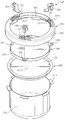
종래기술의 직접 가열방식 전기 압력밥솥과, 유도 가열방식 전기 압력밥솥은 도 1 및 도 2에서 보여지는 바와 같이, 크게 본체 케이스(1)와, 본체 케이스(1) 내부에 안치되도록 하는 내솥(70)과, 본체 케이스(1) 상부에 힌지 결합되도록 하는 뚜껑(3)으로 구성 되어진다.The direct heating type electric pressure cooker and the induction heating type electric pressure cooker of the prior art, as shown in Figures 1 and 2, the inner pot 70 is largely placed in the main body case 1 and the main body case (1). ), And the lid 3 to be hinged to the upper body case (1).
상기, 본체 케이스(1)는 내솥(70)을 가열시키기 위한 각종 전기장치와, 내솥(70)을 지지하는 지지플레이트(5)로 구성된다.The main body case 1 is composed of various electric devices for heating the inner pot 70 and a support plate 5 for supporting the inner pot 70.
여기서, 내솥(70)은 곡물을 수납하기 위한 원통형상의 수납공간(71)과, 수납공간(71)의 상단 외주연으로 다수개 형성한 체결턱(72)으로 이루어진 것이다.Here, the inner pot 70 is composed of a cylindrical accommodating space 71 for accommodating grains, and a fastening jaw 72 formed in plural at the outer circumference of the upper end of the accommodating space 71.
상기, 뚜껑(3)은 본체 케이스(1)에 힌지 결합되도록 하는 아웃커버(10)와, 아웃커버(10)의 핸들 결합홈(13)에 결합되어진 핸들(21)에 의해 작동 하는 잠금수단(20)과, 아웃커버(10)의 저부에 결합되어서 잠금수단(20)의 작동을 안내 하도록 된 인너커버(30)와, 인너커버(30)의 저부에 결합되어서 잠금수단(20)의 통제를 받도록된 록킹링(40)과, 록킹링(40)의 저부에서 핸들축(22)에 체결합되어서 상부의 록킹링(40)을 회동 가능한 상태로 지지하는 상부 가열판(50)과, 상부 가열판(50) 저면에 형성한 패킹홈(52)에 삽입되어서 내솥(70)의 기밀을 유지하도록한 패킹(60)으로 구성되어진 것이다.The lid 3 has a locking means operated by an outer cover 10 hinged to the main body case 1 and a handle 21 coupled to the handle coupling groove 13 of the outer cover 10. 20), the inner cover 30 is coupled to the bottom of the outer cover 10 to guide the operation of the locking means 20, and is coupled to the bottom of the inner cover 30 to control the locking means 20. Locking ring 40 to be received, the upper heating plate 50 is fastened to the handle shaft 22 at the bottom of the locking ring 40 to support the upper locking ring 40 in a rotatable state, and the upper heating plate ( 50) It is composed of the packing 60 to be inserted into the packing groove 52 formed on the bottom to maintain the airtight of the inner pot (70).
상기, 아웃커버(10)는 본체 케이스(1)에 결합하기 위해서 후면 끝단에 형성한 힌지부(11)와, 고압의 증기를 배출시키기 위해서 상면 후방에 형성한 증기 배출부(12)와, 핸들(21)을 결합하기 위해서 상면 전방에 형성한 핸들 결합홈(13)과, 본체 케이스(1)로 부터 뚜껑(3)이 열리게 하기 위해서 전면 끝단에 탄력적으로 형성한 열림버튼(14)으로 이루어진 것이다.The outer cover 10 includes a hinge portion 11 formed at the rear end of the rear cover for coupling to the main body case 1, a steam discharge portion 12 formed at the rear of the upper surface for discharging high pressure steam, and a handle. Handle coupling groove 13 formed in front of the upper surface for engaging the 21 and the open button 14 formed elastically at the front end to open the lid 3 from the body case (1) .
상기, 잠금수단(20)은 아웃커버(10)의 핸들 결합홈(13)에 결합되어지는 핸들(21)과, 핸들(21)의 저부로 일정길이만큼 형성되어진 핸들축(22)과, 핸들 축(22)에 끼워지도록된 상부와셔(23)및 하부와셔(24)와, 상부와셔(23)및 하부 와셔(24)에 의해 핸들축(22)에 체결되어지는 아암부재(25)로 이루어진 것이다.The locking means 20 includes a handle 21 coupled to the handle coupling groove 13 of the outer cover 10, a handle shaft 22 formed by a predetermined length at the bottom of the handle 21, and a handle. The upper washer 23 and the lower washer 24 to be fitted to the shaft 22, and the arm member 25 is fastened to the handle shaft 22 by the upper washer 23 and the lower washer 24. will be.
여기서, 아암부재(25)는 판상체를 직각으로 두번 절곡하여 된것으로서, 일측단에 형성한 축 홈(25a)이 핸들축(22)에 결속되고, 타측에 형성한 돌기 홈(25b)에는 록킹링(40)의 체결 돌기(41)가 결속되어지는 것이다.Here, the arm member 25 is formed by bending the plate-shaped body twice at a right angle, and the shaft groove 25a formed at one end is engaged with the handle shaft 22, and the locking groove 25b formed at the other side is locked. The fastening protrusion 41 of the ring 40 is to be bound.
상기, 인너커버(30)는 상단면에, 아암부재(25)가 체결된 핸들축(22)을 지지 하는 돌출홈부(31)와, 솔레노이드 밸브용 파이프및 압력추 밸브용 파이프(미도시)가 관통되도록 하는 파이프 관통홈(32)과, 록킹링(40)의 돌기부(41)가 관통되어서 일정각도를 회동하게 되는 가이드홈(33)이 형성된 것이다.The inner cover 30 has a protruding groove 31 for supporting the handle shaft 22 to which the arm member 25 is fastened, a solenoid valve pipe, and a pressure valve valve pipe (not shown) pass through the inner cover 30. The pipe through groove 32 and the guide portion 41 of the locking ring 40 are formed so that the guide groove 33 is rotated by a predetermined angle.
상기, 록킹링(40)은 상,하측 끝단면이 턱이 지고 내측면이 트인 원형링 형상으로 형성되어지는 것으로서, 내솥(70)의 체결턱(72)과 대응되도록 하측 끝단면이 턱이 지게 형성한 하단부 내주연으로 다수개를 형성한 체결홈(42)과, 상측 끝단면이 턱이 지게 형성한 상단부 한 곳에 돌기부(41)를 형성하여 이루어진 것이다.The locking ring 40 is formed in a circular ring shape in which the upper and lower end faces are jaws and the inner surface is open, and the lower end faces are made to correspond to the fastening jaw 72 of the inner pot 70. It is formed by forming a protrusion 41 in a plurality of fastening grooves 42 formed in the inner periphery of the formed lower end portion, and the upper end end portion is formed in the upper end so that the upper end face.
그리고, 상기 상부가열판(50)은 일정깊이 들어간 판상체 상에, 핸들축(22)을 체결하기 위해서 형성한 축고정부(51)와, 저면 둘레부에 패킹(60)이 삽입될 수 있도록 형성한 패킹홈(52)으로 이루어진 것이다.In addition, the upper heating plate 50 is formed on the plate-like body with a predetermined depth, the shaft fixing portion 51 formed to fasten the handle shaft 22 and the packing 60 can be inserted into the bottom periphery It is made of a packing groove (52).
여기서, 상부 가열판(50)은 내솥(70)의 기밀을 유지하는 개폐판 역할을 하는 것이다.Here, the upper heating plate 50 serves as an opening and closing plate to maintain the airtightness of the inner pot (70).
상기에서와 같은 구성으로 이루어진 종래의 전기 압력밥솥의 조립 공정에 대해 살펴보면 다음과 같다.Looking at the assembly process of a conventional electric pressure cooker made of a configuration as described above are as follows.
먼저, 본체 케이스(1)에 아웃커버(10)가 힌지결합 되도록 한다. First, the outer cover 10 is hinged to the body case (1).
그리고나서, 아웃커버(10)에 형성된 핸들 결합홈(13)에 핸들(21)을 결합하도록 한다. 아웃커버(10)를 관통하는 핸들축(22) 상에 상부와셔(23),아암부재(25), 하부 와셔(24)를 순서대로 체결하도록 한다.Then, the handle 21 is coupled to the handle coupling groove 13 formed in the outer cover 10. The upper washer 23, the arm member 25, and the lower washer 24 are sequentially fastened on the handle shaft 22 penetrating the outer cover 10 in order.
그런다음, 인너커버(30)를 결합하도록 하는데, 솔레노이드 밸브용 파이프및 압력추 밸브용 파이프(미도시)와 핸들축(22)이 각각, 파이프 관통홈(32)과 돌출홈부(31)에 일치하여 관통되도록 결합한다.Then, the inner cover 30 is coupled to each other, and the solenoid valve pipe, the pressure valve valve pipe (not shown), and the handle shaft 22 correspond to the pipe through groove 32 and the protrusion groove 31, respectively. Join to penetrate.
그리고나서, 록킹링(40)을 체결할 때, 돌기부(41)가 인너커버(30)의 가이드홈(33)를 관통하여 아암부재(25)의 돌기홈(25b)에 끼워지도록한다.Then, when the locking ring 40 is fastened, the protrusion 41 passes through the guide groove 33 of the inner cover 30 so as to fit into the protrusion groove 25b of the arm member 25.
그런다음, 상부 가열판(50)에 형성된 축 고정부(51)에 핸들축(22)이 체결되도록 한다.Then, the handle shaft 22 is fastened to the shaft fixing part 51 formed on the upper heating plate 50.
여기서, 축 고정부(51)와 핸들축(22)은 회동 가능한 상태로 체결되어지는 것이다.Here, the shaft fixing portion 51 and the handle shaft 22 are fastened in a rotatable state.
마지막으로, 상부 가열판(50)의 저부에 형성한 패킹홈(52)에 패킹이 결합되도록한다.Finally, the packing is coupled to the packing groove 52 formed in the bottom of the upper heating plate 50.
여기서, 상기한 바와 같은 조립공정으로 이루어진 종래기술의 작용에 대하여 살펴보면 다음과 같다.Here, looking at the operation of the prior art made of the assembly process as described above are as follows.
상기 조립공정으로 이루어진 뚜껑(3)을 닫게되면 록킹링(40)의 체결홈(42)과 내솥(70)의 체결턱(72)이 서로 간섭하지 않는 상태가 되는데, 이는 뚜껑을 자유롭게 열거나 닫을 수 있는 상태이며, 이미 취사가 끝난 밥을 보온하는 상태이기도 한것이다.When the lid 3 made of the assembly process is closed, the fastening groove 42 of the locking ring 40 and the fastening jaw 72 of the inner pot 70 do not interfere with each other, which opens or closes the lid freely. It is in a state that is able to keep cooking rice already cooked.
반면, 취사를 할 때는 취사시에 발생하는 고온의 압력을 견딜 수 있는 잠금수단(20)이 필요한 것으로서,On the other hand, when cooking is required as a locking means 20 capable of withstanding the high pressure generated during cooking,
이에 따른, 잠금수단(20)의 작용은, 아웃커버(10)의 상부에 결합된 핸들(21)을 잠금방향으로 일정각도 회동시키게되면, 핸들축(22)상에 체결된 아암부재(25)가 회동되고, 아암부재(25)의 타측 끝단에 형성된 돌기홈 (25b)에 끼움된 록킹링(40)의 돌기부(41)를 가이드홈(33)을 따라 회동 시키게 되면 록킹링(40)은 내솥(70)의 외주연으로 감싸듯 회동하게 되고 록킹링(40)의 체결홈(42)을 제외한 록킹부(43)에 내솥(70)의 체결턱(72)이 완전하게 진입하게 되면 회동이 끝나게 되고, 고온 고압의 취사에서도 충분히 압력을 견뎌내게 되는 것이다.Accordingly, the action of the locking means 20, when rotating the handle 21 coupled to the upper portion of the outer cover 10 by a predetermined angle in the locking direction, the arm member 25 is fastened on the handle shaft 22 Is rotated, and when the projection 41 of the locking ring 40 fitted in the projection groove 25b formed at the other end of the arm member 25 is rotated along the guide groove 33, the locking ring 40 is the inner pot Rotating as if wrapped around the outer periphery of the 70 and when the locking jaw 72 of the inner pot 70 completely enters the locking portion 43 except for the locking groove 42 of the locking ring 40, the rotation is completed. In this case, it is able to withstand pressure sufficiently even at high temperature and high pressure cooking.
취사가 끝난 후에는, 상기와 같은 방법의 역순으로 간단히 잠금을 해지할 수도 있는 것이다.After cooking is finished, the lock can be simply released in the reverse order of the above method.
이러한 종래기술에 따른 압력밥솥은, 취사과정에서 발생하는 증기가 외부로 유출되는 것을 방지하기 위하여 고무소재로 이루어진 패킹을 상부 가열판의 저부에 마련하고 있다. 그러나 이러한 패킹은 고무소재로 이루어져 있기 때문에 반복적인 뚜껑의 개폐과정에서 쉽게 마모될 수 밖에 없다는 문제점이 있다. 이와 같이 마모로 인하여 상기 패킹의 교체에 따른 유지비용이 증가하게 된다.The pressure cooker according to the prior art is provided with a packing made of a rubber material at the bottom of the upper heating plate in order to prevent the steam generated in the cooking process to flow out. However, this packing is made of a rubber material, there is a problem that can be easily worn in the opening and closing process of the lid repeatedly. As such, the wear cost increases due to the replacement of the packing.
또한, 취사되는 음식물로부터 발생되는 증기가 상기 패킹과 접촉하면서 물방울이 되어 다시 음식물로 떨어지게 되는데, 장기간 사용되어 부식된 패킹은 그 자체로서 오염물이 되기 때문에 이와 접촉한 수증기도 오염이 될 염려가 있게 된다. 특히, 패킹으로 사용되는 고무와 같은 합성수지 소재는 환경호르몬 유발의 염려도 있는 바, 건강의 측면에서도 바람직하지 않게 된다.In addition, the steam generated from the cooking food is dropped into the water when the contact with the packing drops again, the corrosion of the packing used for a long time is a contaminant itself, so there is a risk that the water vapor in contact with it will be contaminated. . In particular, a synthetic resin material such as rubber used as a packing may cause environmental hormones, and thus is not preferable in terms of health.
이하, 본 발명의 일실시예에 따른 전기 압력밥솥을 첨부된 도면을 참조하면서 상세하게 설명한다.Hereinafter, the electric pressure cooker according to an embodiment of the present invention will be described in detail with reference to the accompanying drawings.
본 발명에 따른 전기 압력밥솥은, 상부가 개방되어 있는 본체 케이스와, 상기 본체 케이스의 내부에 안치되는 내솥(100)과, 상기 본체 케이스에 힌지결합되며 본체 케이스의 상부를 덮도록 배치되는 뚜껑(110)을 가지는 것으로서, 본체 케이스 및 상기 뚜껑(110)의 아웃커버는 종래기술과 유사하므로 구체적인 설명은 생략한다. 이와 함께 내솥(100)을 가열하기 위한 전열수단등에 대해서도 구체적인 설명은 생략한다.The electric pressure cooker according to the present invention includes a main body case having an open top, an inner pot 100 placed inside the main body case, and a lid which is hinged to the main body case and disposed to cover an upper part of the main body case ( As having the 110, the body case and the cover of the lid 110 is similar to the prior art, so a detailed description thereof will be omitted. Along with this, detailed description of heat transfer means for heating the inner pot 100 is omitted.
상기 내솥(100)은, 본체 케이스에 안치되는 것으로서, 취사를 위한 쌀 및 물 등이 담겨지는 용기로서 상측에 개방되는 형상으로 이루어진다. 이러한 내솥(100)의 상부에는 원주방향을 따라서 일정간격으로 배치되는 다수의 플랜지부(101)가 마련된다. 이러한 플랜지부(101)는 외측으로 돌출되는 형상을 가지고 있으며, 록킹회전체(160)에 록킹되는 구성이다.The inner pot 100, which is settled in the main body case, made of a shape that is open on the upper side as a container in which rice and water for cooking. The upper portion of the inner pot 100 is provided with a plurality of flanges 101 are arranged at regular intervals along the circumferential direction. The flange portion 101 has a shape that protrudes outward, and is configured to be locked to the locking rotating body 160.
상기 내솥(100)의 상단은, 테이퍼진 경사면(102)이 형성되되, 구체적으로는 내측을 향하여 테이퍼진 경사면(102)이 형성되어 있다. 구체적으로 상기 경사면(102)은 내솥(100)의 상단에 원주방향을 따라서 연속하여 형성되어 있는 것으로서, 상단으로부터 하측으로 내려감에 따라서 내향경사지는 형태를 이룬다.The upper end of the inner pot 100, the tapered inclined surface 102 is formed, specifically, the tapered inclined surface 102 is formed toward the inner side. Specifically, the inclined surface 102 is formed continuously along the circumferential direction at the upper end of the inner pot 100, and forms an inwardly inclined shape as it descends from the upper end to the lower side.
상기 뚜껑(110)은, 밀폐부재(120), 내부커버(130), 탄성바이어스부재(140), 이탈방지부재(150) 및 록킹회전체(160)를 포함한다.The lid 110 may include a sealing member 120, an inner cover 130, an elastic bias member 140, a release preventing member 150, and a locking rotating body 160.
상기 밀폐부재(120)는, 중앙에 원형홀(121)이 형성되어 있으며 상기 내솥(100)에 안착되며 상기 내솥(100)에 안착되어 접촉되는 하면이 상기 내솥(100)의 상단과 대응되는 형상을 가지도록 구성된다. 구체적으로는 전체적으로 고리형태로 이루어지되, 가장자리를 따라서 2단으로 직각 절곡된 절곡부(122)가 마련되어 있다. 상기 절곡부(122)는 상기 내솥(100)의 경사면(102)과 상기 내부커버(130)의 내측면(132)에 접촉되어 있으며, 상기 절곡부(122)에서 상기 경사면(102)과 마주보는 부분에는 상기 경사면(102)과 대응되는 형상의 밀폐면(123)이 형성되어 있게 된다.The sealing member 120 has a circular hole 121 is formed in the center and is seated in the inner pot 100, the bottom surface which is seated in contact with the inner pot 100 corresponds to the upper end of the inner pot 100 It is configured to have. Specifically, it is made of a ring shape as a whole, the bent portion 122 is bent at two right angles along the edge is provided. The bent portion 122 is in contact with the inclined surface 102 of the inner pot 100 and the inner surface 132 of the inner cover 130, facing the inclined surface 102 in the bent portion 122 In the portion, a sealing surface 123 having a shape corresponding to the inclined surface 102 is formed.
구체적으로 밀폐면(123)은, 상측으로부터 하측으로 갈수록 내향경사지는 형태를 이루고 있는 형태를 이루게 된다. 한편, 상기 밀폐부재(120)의 가장자리 상면에는 하측으로 오목하게 패여진 제1홈(124)이 형성되어 있으며 상기 제1홈(124)에는 탄성바이어스부재(140)의 일단이 안착될 수 있다. 또한, 상기 밀폐부재(120)에는 상면과 하면을 상하방향으로 관통하는 제1통공(125)이 마련될 수 있다. 이러한 제1통공(125)에는 이탈방지부재(150)가 관통할 수 있다.Specifically, the sealing surface 123 forms an inclined inward shape from the upper side to the lower side. Meanwhile, a first groove 124 recessed downward is formed on the upper surface of the edge of the sealing member 120, and one end of the elastic bias member 140 may be seated in the first groove 124. In addition, the sealing member 120 may be provided with a first through hole 125 penetrating the upper and lower surfaces in the vertical direction. The separation prevention member 150 may penetrate the first through hole 125.
한편, 상기 밀폐부재(120)는, 부식방지가 가능한 금속소재라면 무엇이나 가능하나, 스테인리스 스틸이 바람직하다. 다만, 이에 한정되는 것은 아니며 다양한 금속소재, 세라믹소재 등이 사용될 수 있음은 물론이다.On the other hand, the sealing member 120, as long as it can be any metal material that can prevent corrosion, stainless steel is preferred. However, the present invention is not limited thereto, and various metal materials and ceramic materials may be used.
상기 내부커버(130)는, 전체적으로 원판형태로 이루어지되 가장자리가 하측으로 절곡되어 있게 된다. 이러한 내부커버(130)에는 취사과정에서 발생되는 증기압을 측정하거나 취사가 완료된 후에 증기를 외부로 빼내기 위한 구조가 설치될 수 있게 되나, 구체적인 설명은 생략한다.The inner cover 130 is made of a disk shape as a whole, but the edge is bent downward. The inner cover 130 may be provided with a structure for measuring the steam pressure generated during the cooking process or to remove the steam to the outside after the cooking is completed, a detailed description thereof will be omitted.
이러한 밀폐부재(120)가 내부에 삽입된 상태에서 그 밀폐부재(120)가 상하방향으로 이동할 수 있는 수용공간(131)을 내부에 마련하며, 상기 수용공간(131)의 내측면(132)이 상기 밀폐부재(120)의 가장자리 단부와 기밀성을 유지할 수 있도록 구성된다. 구체적으로, 상기 밀폐부재(120)의 수용공간(131)의 내경은 상기 밀폐부재(120)의 외경과 동등한 정도를 이루고 있어 상기 밀폐부재(120)와 내부커버(130)의 틈새로 증기가 외부로 유출되는 것을 최소화할 수 있도록 한다.In the state in which the sealing member 120 is inserted therein, there is provided an accommodation space 131 through which the sealing member 120 can move in an up and down direction, and an inner surface 132 of the accommodation space 131 is It is configured to maintain the airtightness with the edge end of the sealing member 120. Specifically, the inner diameter of the receiving space 131 of the sealing member 120 is formed to the same as the outer diameter of the sealing member 120, so that the vapor outside the gap between the sealing member 120 and the inner cover 130. To minimize spillage.
상기 내부커버(130)에서, 밀폐부재(120)의 제1홈(124)과 대응되는 위치에는 제2홈(133)이 마련되어 있으며 이에 따라서 탄성바이어스부재(140)의 타단이 상기 제2홈(133)에 삽입되어 안착될 수 있도록 한다.In the inner cover 130, a second groove 133 is provided at a position corresponding to the first groove 124 of the sealing member 120, and accordingly, the other end of the elastic bias member 140 is connected to the second groove ( 133) to be seated.
또한, 상기 밀폐부재(120)의 제1통공(125)과 대응되는 위치에는 체결홈(134)이 마련되어 있으며 이에 따라서 제1통공(125)을 관통하는 이탈방지부재(150)가 상기 제1통공(125)에 결합될 수 있도록 한다. 이때 상기 체결홈(134)은 내주면에 나사산이 형성되어 있어 상기 이탈방지부재(150)가 체결홈(134)에 나사결합될 수 있도록 한다.In addition, a fastening groove 134 is provided at a position corresponding to the first through hole 125 of the sealing member 120. Accordingly, the separation preventing member 150 penetrating through the first through hole 125 is provided in the first through hole. To (125). At this time, the fastening groove 134 has a screw thread formed on an inner circumferential surface thereof so that the detachment preventing member 150 can be screwed to the fastening groove 134.
상기 탄성바이어스부재(140)는 상기 밀폐부재(120)를 상기 내부커버(130)로부터 멀어지는 방향으로 탄성바이어스시킬 수 있는 것으로서, 상기 밀폐부재(120)와 상기 내부커버(130) 사이에 배치된다. 구체적으로 상기 탄성바이어스부재(140)는 압축코일스프링이 사용될 수 있으나, 이에 한정되는 것은 아니며 탄성복원되는 다양한 구조가 사용될 수 있다. 이러한 탄성바이어스부재(140)는 일단이 상기 밀폐부재(120)의 제1홈(124)에 위치하고 타단이 상기 내부커버(130)의 제2홈(133)에 위치할 수 있다.The elastic bias member 140 may elastically bias the sealing member 120 in a direction away from the inner cover 130 and is disposed between the sealing member 120 and the inner cover 130. Specifically, the elastic bias member 140 may be a compression coil spring, but is not limited thereto. Various structures for elastic restoration may be used. One end of the elastic bias member 140 may be located in the first groove 124 of the sealing member 120, and the other end thereof may be located in the second groove 133 of the inner cover 130.
상기 이탈방지부재(150)는, 상기 밀폐부재(120)와 내부커버(130)가 일정간격이상 이격되는 것을 방지하는 것으로서, 구체적으로는 상기 밀폐부재(120)가 내부커버(130)로부터 완전하게 이탈되는 것을 방지하는 것이다. 이러한 이탈방지부재(150)는 하단에 나사산이 형성되어 있으며 확경된 머리를 가지는 핀일 수 있다. 이러한 이탈방지부재(150)는 머리가 밀폐부재(120)의 하측에 위치한 상태에서 상기 제1통공(125)을 관통하여 상기 제2체결홈(134)에 단부가 결합되어 있게 된다. 상기 밀폐부재(120)는 이탈방지부재(150)의 머리에 의하여 지지될 수 있다. The release preventing member 150 is to prevent the sealing member 120 and the inner cover 130 from being spaced apart by a predetermined interval or more, and specifically, the sealing member 120 is completely from the inner cover 130. It is to prevent the departure. The detachment preventing member 150 may be a pin having a screw thread formed at a lower end thereof and having an enlarged head. The detachment preventing member 150 has an end coupled to the second fastening groove 134 through the first through hole 125 in a state where the head is located under the sealing member 120. The sealing member 120 may be supported by the head of the separation preventing member 150.
상기 록킹회전체(160)는 상기 내솥(100)에 대하여 상대적으로 회전하면서 플랜지부(101)와 선택적으로 록킹될 수 있는 것으로서, 공지의 회전수단에 의하여 상기 내솥(100)에 대하여 회전할 수 있으며 회전방향에 따라서 상기 플랜지부(101)에 록킹되거나 록킹해제될 수 있다. The locking rotating body 160 may be selectively locked with the flange portion 101 while being rotated relative to the inner pot 100, and may be rotated with respect to the inner pot 100 by a known rotating means. Depending on the direction of rotation may be locked or unlocked to the flange portion 101.
이러한 본 발명의 일실시예에 따른 전기 압력밥솥은 다음과 같이 작동할 수 있다.Electric pressure cooker according to an embodiment of the present invention can operate as follows.
먼저, 밥과 물과 같은 음식물을 내솥(100)에 넣은 상태에서 뚜껑(110)을 덮는다. 구체적으로는 아웃커버를 덮은 후에 록킹회전체(160)를 회전시켜 상기 록킹회전체(160)가 내솥(100)의 플랜지부(101)에 록킹될 수 있도록 한다. 이때, 내부커버(130)는 그 가장자리가 플랜지부(101)의 상면에 위치하고 있으며, 밀폐부재(120)는 내솥(100)의 경사면(102)과 내부커버(130)의 내측면(132)에 접촉되어 있게 된다. 이때, 밀폐부재(120)는 스프링에 의하여 탄성바이어스되어 있으므로 내솥(100)과의 밀착이 유지될 수 있다. 한편, 밀폐부재(120)의 밀폐면(123)이 내솥(100)의 경사면(102)에 밀착접촉되어 기밀상태를 유지할 수 있게 한다. First, cover the lid 110 in a state of putting food such as rice and water in the inner pot (100). Specifically, after the outer cover is covered, the locking rotating body 160 is rotated so that the locking rotating body 160 can be locked to the flange portion 101 of the inner pot 100. At this time, the edge of the inner cover 130 is located on the upper surface of the flange portion 101, the sealing member 120 is on the inclined surface 102 and the inner surface 132 of the inner cover 130 of the inner pot (100). To be in contact. At this time, since the sealing member 120 is elastically biased by the spring, the sealing member 120 may be maintained in close contact with the inner pot 100. On the other hand, the sealing surface 123 of the sealing member 120 is in close contact with the inclined surface 102 of the inner pot 100 to maintain the airtight state.
취사가 진행되면 도 4에 도시된 바와 같이, 증기가 발생되고 이 발생된 증기는 밀폐부재(120)를 가압하게 된다. 구체적으로는 밀폐부재(120)를 하측으로 밀어 그 밀폐부재(120)가 내솥(100)과 기밀성을 확실하게 유지하게 한다. 또한, 밀폐부재(120)는 그 단부가 내부커버(130)의 내측면(132)에 기밀성이 있도록 접촉되어 있으므로 증기의 배출이 최소화될 수 있다. As cooking is shown in FIG. 4, steam is generated and the generated steam pressurizes the sealing member 120. Specifically, the sealing member 120 is pushed downward to ensure that the sealing member 120 maintains the inner pot 100 and airtightness. In addition, since the end of the sealing member 120 is in contact with the inner surface 132 of the inner cover 130 so as to be airtight, the discharge of steam can be minimized.
이와 같이, 본원발명의 일실시예에 따른 전기 압력밥솥은 별도의 고무패킹이 없이 밀폐부재(120)를 이용하여 기밀성을 유지하고 있으므로 장기간 사용에 따른 교체등의 염려가 적고 이에 따라서 유지비용이 절감될 수 있는 효과가 있다.As such, the electric pressure cooker according to an embodiment of the present invention maintains the airtightness by using the sealing member 120 without a separate rubber packing, so there is little concern such as replacement due to long-term use, thereby reducing the maintenance cost. There is an effect that can be.
또한, 고무패킹에 의하여 발생될 환경호르몬 발생의 염려 내지는 부식된 고무패킹과 접촉되어 발생된 물방울이 음식물에 떨어짐으로 발생되는 위생상 불결함도 피할 수 있다는 장점이 있다.In addition, there is an advantage that the hygiene defects caused by falling of the water droplets generated in contact with the corroded rubber packing or the corrosion of the environmental hormone to be generated by the rubber packing can be avoided.
이러한 본 발명에 따른 고무패킹이 없는 전기압력밥솥은 다음과 같이 변형되는 것도 가능하다.Such a rubber packing electric pressure cooker according to the present invention may be modified as follows.
본 발명의 다른 실시예에 따른 전기 압력밥솥은, 도 6 및 도 7에 개시된 바와 같이 상부가 개방되어 있는 본체 케이스와, 상기 본체 케이스의 내부에 안치되는 내솥(200)과, 상기 본체 케이스에 힌지결합되며 본체 케이스의 상부를 덮도록 배치되는 뚜껑(210)을 가지는 것으로서, 본체 케이스 및 상기 뚜껑(210)의 아웃커버는 종래기술과 유사하므로 구체적인 설명은 생략한다. 이와 함께 내솥(200)을 가열하기 위한 전열수단 등에 대해서도 구체적인 설명은 생략한다.Electric pressure cooker according to another embodiment of the present invention, as shown in Figures 6 and 7, the upper case is open, the inner pot 200 is placed in the interior of the main body case, the hinge to the main body case Combined and having a lid 210 disposed to cover the upper portion of the main body case, the main body case and the outer cover of the lid 210 is similar to the prior art, so a detailed description thereof will be omitted. In addition, a detailed description of the heat transfer means for heating the inner pot 200 will be omitted.
상기 내솥(200)은, 본체 케이스에 안치되는 것으로서, 취사를 위한 쌀 및 물 등이 담겨지는 용기로서 상측에 개방되는 형상으로 이루어진다. 이러한 내솥(200)의 상부 외측면에는 원주방향을 따라서 일정간격으로 배치되는 다수의 플랜지부(201)가 마련된다. 이러한 플랜지부(201)는 외측으로 돌출되는 형상을 가지고 있으며, 록킹회전체(260)에 록킹되는 구성이다.The inner pot 200, which is settled in the main body case, made of a shape that is open to the upper side as a container in which rice and water for cooking. The upper outer surface of the inner pot 200 is provided with a plurality of flanges 201 disposed at regular intervals along the circumferential direction. The flange portion 201 has a shape that protrudes outward and is locked to the locking rotary body 260.
상기 내솥(200)의 상단 내주면(202)은 하측으로 갈수록 내솥(200)의 중심으로 근접하도록 하향 경사지도록 구성되어 있어 내솥(200) 내에 안치되는 밀폐부재(220)가 내솥(200)에 용이하게 삽입될 수 있도록 한다. 이러한 상단 내주면(202)은 라운드 처리되어 있어 밀폐부재(220)가 미끄러지듯이 상기 내솥(200) 내부로 삽입될 수 있도록 한다. 구체적으로는 상단 내주면(202)은 밀폐부재(220)의 제1부분(221)이 용이하게 삽입될 수 있도록 구성되어 있게 된다.The upper inner circumferential surface 202 of the inner pot 200 is configured to be inclined downward to approach the center of the inner pot 200 toward the lower side so that the sealing member 220 placed in the inner pot 200 is easily in the inner pot 200. To be inserted. The upper inner circumferential surface 202 is rounded so that the sealing member 220 can be inserted into the inner pot 200 as if the sliding member 220 is slipped. Specifically, the upper inner circumferential surface 202 is configured such that the first portion 221 of the sealing member 220 can be easily inserted.
상기 뚜껑(210)은, 밀폐부재(220), 내부커버(230), 탄성바이어스부재(240), 착탈식 결합수단(250) 및 록킹회전체(260)를 포함한다.The lid 210 includes a sealing member 220, an inner cover 230, an elastic bias member 240, a detachable coupling means 250, and a locking rotating body 260.
상기 밀폐부재(220)는, 가장자리에 상기 내솥(200)의 상면과 기밀성이 있도록 접촉할 수 있도록 하측으로 돌출되는 기밀용 돌기(222e)가 마련되고, 중앙에 상면과 하면을 관통하는 유통공(220b)이 마련되는 것이다. 이러한 밀폐부재(220)는, 내솥(200)의 내부로 삽입되는 제1부분(221)과, 상기 제1부분(221)과 일체로 결합되며 내솥(200)의 외부로 노출되어 가장자리 하면에 상기 기밀용 돌기(222e)가 마련되는 제2부분(222)을 포함한다.The sealing member 220 is provided with an airtight protrusion 222e protruding downward so as to be in contact with the upper surface of the inner pot 200 so as to be airtight at an edge thereof, and having a distribution hole penetrating the upper and lower surfaces at the center thereof ( 220b) is provided. The sealing member 220, the first portion 221 is inserted into the inner pot 200, the first portion 221 is integrally coupled with the outer surface of the inner pot 200 is exposed to the outer edge of the The second part 222 is provided with an airtight protrusion 222e.
이러한 밀폐부재(220)는, 전체적으로 원판형태로 이루어지되, 중앙에 착탈식 결합수단(250)인 나사가 삽입될 수 있는 결합공(220a)과, 상기 결합공(220a)의 주위에 배치되며 증기가 밀폐공간(S) 내로 유입될 수 있도록 하는 유통공(220b)을 포함하여 구성된다. The sealing member 220 is made of a disk shape as a whole, a coupling hole 220a into which a screw, which is a detachable coupling means 250, can be inserted in the center, and the steam is disposed around the coupling hole 220a. It is configured to include a distribution hole 220b to be introduced into the closed space (S).
상기 제2부분(222)은, 원판형의 원판부(222a)와, 상기 원판부(222a)로부터 바깥쪽으로 연장되어 하면이 내솥(200)의 상면과 마주보는 제1연장부(222b)와, 상기 제1연장부(222b)로부터 상측으로 절곡된 절곡부(222c)와, 상기 절곡부(222c)로부터 바깥쪽으로 연장된 제2연장부(222d)를 포함하여 구성된다. 상기 절곡부(222c)와 원판부(222a)의 상면에 의하여 밀폐공간(S)이 형성된다. 구체적으로, 상기 밀폐공간(S)은 상기 절곡부(222c), 원판부(222a)의 상면 및 상기 내부커버(230)에 형성되는 공간으로서, 유통공(220b)을 통하여 유입된 증기가 밀폐공간(S) 내에서 밀폐되어 외부와 차단될 수 있다.The second portion 222 has a disc-shaped disc portion 222a, a first extension portion 222b extending outward from the disc portion 222a and facing the upper surface of the inner pot 200; It includes a bent portion 222c bent upward from the first extension portion 222b, and a second extension portion 222d extending outwardly from the bent portion 222c. The closed space S is formed by the upper surfaces of the bent portion 222c and the disc portion 222a. Specifically, the closed space (S) is a space formed in the bent portion (222c), the upper surface of the disc portion (222a) and the inner cover 230, the vapor introduced through the distribution hole 220b is a closed space It may be sealed in (S) and cut off from the outside.
이때, 증기가 접촉되는 상기 밀폐부재(220)의 하면의 단면적보다, 상기 유통공(220b)을 통하여 상기 밀폐공간(S) 내에 유입된 증기가 접촉하는 밀폐부재(220)의 상면의 단면적이 커서, 취사과정에서 발생된 증기가 밀폐부재(220)의 기밀용 돌기(222e)를 내솥(200)의 상면에 가압할 수 있게 한다. 이때, 상기 밀폐공간(S)의 수평면적은 상기 내솥(200)의 수평면적보다 클 수 있다. 이에 따르면 상측에서 밀폐부재(220)를 하측으로 가압하는 가압력이 하측에서 증기가 밀폐부재(220)를 상측으로 밀어올리는 증기압보다 크기 때문에 상기 밀폐부재(220)가 내솥(200)에 확실하게 기밀성이 있도록 접촉할 수 있다. 이에 따라서 증기가 내솥(200)과 밀폐부재(220)의 사이로 빠져나가는 것을 방지할 수 있게 된다.At this time, the cross-sectional area of the upper surface of the sealing member 220 that the steam introduced into the sealed space (S) is greater than the cross-sectional area of the lower surface of the sealing member 220 that the steam is in contact with. The steam generated during the cooking process may pressurize the airtight protrusion 222e of the sealing member 220 to the upper surface of the inner pot 200. At this time, the horizontal area of the closed space (S) may be larger than the horizontal area of the inner pot (200). According to this, since the pressing force for pressing the sealing member 220 downward from the upper side is greater than the vapor pressure pushing up the sealing member 220 upward from the lower side, the sealing member 220 is tightly sealed to the inner pot 200. To make contact. Accordingly, it is possible to prevent the steam from escaping between the inner pot 200 and the sealing member 220.
상기 제1연장부(222b)의 하면에는 하측으로 돌출된 기밀용 돌기(222e)와, 요홈(222f)이 마련되어 있다. 상기 기밀용 돌기(222e)는, 대략 사다리꼴 단면형상을 가지되 내솥(200)의 상면과 접촉하는 면이 대략 평평한 형태를 가지게 된다. 이러한 기밀용 돌기(222e)는 내솥(200) 내부의 증기가 외부로 유출되는 것을 방지하기 위한 것으로서, 밀폐부재(220)를 이루는 소재와 동일한 소재로 이루어질 수 있다. 상기 요홈(222f)은, 상기 기밀용 돌기(222e)와 상기 제1부분(221)의 사이에 배치되는 것으로서 상측으로 오목하게 패여진 홈이다.The lower surface of the said 1st extension part 222b is provided with the airtight protrusion 222e which protrudes below, and the recess 222f. The airtight protrusion 222e has a substantially trapezoidal cross-sectional shape, but the surface contacting the upper surface of the inner pot 200 has a substantially flat shape. The airtight protrusion 222e is to prevent the steam in the inner pot 200 from leaking to the outside, and may be made of the same material as the material forming the sealing member 220. The groove 222f is a groove which is disposed between the airtight protrusion 222e and the first portion 221 and is recessed upward.
상기 밀폐부재(220)는, 부식방지가 가능한 금속소재라면 무엇이나 가능하나, 알루미늄, 선철, 구리, 황동 또는 스테인리스 스틸 중 어느 하나의 소재를 사용하는 것이 바람직하다. 다만, 이에 한정되는 것은 아니며 다양한 금속소재, 세라믹소재 등이 사용될 수 있음은 물론이다.The sealing member 220 may be any metal material capable of preventing corrosion, but it is preferable to use any one material of aluminum, pig iron, copper, brass or stainless steel. However, the present invention is not limited thereto, and various metal materials and ceramic materials may be used.
상기 내부커버(230)는, 상기 밀폐부재(220)가 상하방향으로 이동가능하게 상기 밀폐부재(220)를 가이드하는 것으로서, 록킹회전체(260)에 의하여 상기 플랜지부(201)에 위치고정되는 것이다. 이러한 내부커버(230)는, 전체적으로 원판형태로 이루어지되 상기 밀폐공간(S)과 대응되는 부분이 하측으로 돌출되어 있게 된다. 구체적으로는 내부커버(230)의 돌출된 부분의 측면이 상기 밀폐부재(220)의 절곡부(222c)의 내측면과 접촉될 수 있도록 구성되어 있게 된다. 이러한 내부커버(230)의 돌출된 부분과 절곡부(222c)의 사이에는 밀폐공간(S)의 기밀성을 유지하기 위한 오링(이 배치되어 있어 상기 밀폐부재(220)가 상하방향으로 이동하면서 밀폐부재(220)와 상기 내부커버(230)의 사이에서 증기가 외부로 유출되는 것을 방지할 수 있다.The inner cover 230 guides the sealing member 220 to move the sealing member 220 in the vertical direction, and is fixed to the flange portion 201 by the locking rotating body 260. will be. The inner cover 230 is made of a disk shape as a whole, but the portion corresponding to the closed space (S) protrudes downward. Specifically, the side surface of the protruding portion of the inner cover 230 is configured to be in contact with the inner surface of the bent portion (222c) of the sealing member 220. Between the protruding portion of the inner cover 230 and the bent portion 222c, an O-ring for arranging the airtightness of the sealed space S is disposed so that the sealing member 220 moves upward and downward to seal the sealing member. Between the 220 and the inner cover 230 may prevent the outflow of steam to the outside.
이러한 내부커버(230)의 중앙에는 착탈식 결합수단(250)이 체결될 수 있도록 내주면에 나사산이 형성된 체결공(231)이 마련되어 있으며, 밀폐부재(220)의 제2연장부(222d)와 대응되는 위치에는 탄성바이어스부재(240)가 삽입될 수 있는 삽입공(232)이 마련되어 있게 된다. 이러한 삽입공(232)은 내부커버(230)의 원주방향을 따라서 복수개가 배치된다. In the center of the inner cover 230 is provided with a fastening hole 231 formed with a screw thread on the inner circumferential surface so that the removable coupling means 250 can be fastened, and corresponds to the second extension portion 222d of the sealing member 220. The position is provided with an insertion hole 232 into which the elastic bias member 240 can be inserted. The insertion hole 232 is disposed in plurality along the circumferential direction of the inner cover 230.
상기 탄성바이어스부재(240)는 밀폐부재(220)를 내솥(200)측으로 탄성바이어스시키는 것으로서, 핀부재(241)와, 스프링(242)과 막음부재(243)를 포함하여 구성되며 상기 밀폐부재(220)의 삽입공(232) 내에 배치되는 것이다. The elastic bias member 240 is to elastically bias the sealing member 220 toward the inner pot 200, and includes a pin member 241, a spring 242, and a blocking member 243. It is arranged in the insertion hole 232 of the 220.
상기 핀부재(241)는, 핀형태로 구성되며 대략 중앙에 원판형 걸림부(241a)가 마련되어 있는 것이다. 상기 핀부재(241)의 상단은 막음부재(243)를 통과하여 막음부재(243)의 위쪽에 배치될 수 있으며, 핀부재(241)의 하단은 삽입공(232)을 벗어나서 외부로 돌출되어 있으며 밀폐부재(220)의 제2연장부(222d)와 접촉될 수 있다.The pin member 241 is configured in the form of a pin and is provided with a disk-shaped locking portion 241a at approximately the center. An upper end of the pin member 241 may be disposed above the blocking member 243 through the blocking member 243, and a lower end of the pin member 241 may protrude out of the insertion hole 232. It may be in contact with the second extension portion 222d of the sealing member 220.
상기 스프링(242)은 막음부재(243)와 원판형 걸림부(241a)의 사이에 배치되되 상기 원판형 걸림부(241a)를 막음부재(243)로부터 멀어지는 방향으로 탄성가압하는 것이다.The spring 242 is disposed between the blocking member 243 and the disc-shaped locking portion 241a to elastically press the disc-shaped locking portion 241a in a direction away from the blocking member 243.
상기 막음부재(243)는 중앙에 상기 핀부재(241)가 삽입될 수 있는 구멍이 형성되며 스프링(242)은 탄성지지하는 것이다. 이러한 막음부재(243)는 삽입공(232) 내에서 위치고정되어 있게 된다.The blocking member 243 has a hole in which the pin member 241 can be inserted, and the spring 242 is elastically supported. The blocking member 243 is positioned in the insertion hole 232 is fixed.
상기 착탈식 결합수단(250)은, 상기 내부커버(230)와 상기 밀폐부재(220)를 서로 착탈가능하게 결합하는 것으로서, 상기 내부커버(230)를 통과하여 상기 밀폐부재(220)에 나사고정되는 것이다. 이러한 착탈식 결합수단(250)은, 상부와 하부에 나사산이 형성되고 중앙은 매끄러운 표면을 가지는 원기둥형태의 나사부재(252)와, 상기 나사부재(252)의 하부에 형성된 나사산에 나사결합되는 너트부재(251)를 포함하여 구성된다. 상기 나사부재(252)의 상부에 마련된 나사산이 내부커버(230)에 나사결합된 상태에서, 밀폐부재(220)는 나사부재(252)의 매끄러운 중앙부분에 접촉하여 있게 된다. 너트부재(251)는 상기 밀폐부재(220)가 내솥(200)에 안착된 상태에서는 그 밀폐부재(220)와 다소 이격되어 배치되되 밀폐부재(220)가 내솥(200)으로부터 이격되는 경우에 내부커버(230)로부터 벗어나는 것을 방지하도록 구성된다. 다만, 너트부재(251)를 나사부재(252)로부터 풀어내는 경우에는 상기 밀폐부재(220)가 손쉽게 내부커버(230)로부터 이탈될 수 있게 된다.The detachable coupling means 250 is to detachably couple the inner cover 230 and the sealing member 220 to each other, and is screwed to the sealing member 220 through the inner cover 230. will be. The detachable coupling means 250 is a screw member 252 having a cylindrical shape having a screw thread formed on the upper and lower portions and a smooth surface at the center thereof, and a nut member screwed to the thread formed on the lower portion of the screw member 252. And 251. In a state in which a screw thread provided on an upper portion of the screw member 252 is screwed to the inner cover 230, the sealing member 220 is in contact with a smooth center portion of the screw member 252. The nut member 251 is disposed somewhat spaced apart from the sealing member 220 in the state in which the sealing member 220 is seated on the inner pot 200, but the sealing member 220 is spaced apart from the inner pot 200. Configured to prevent deviation from the cover 230. However, when the nut member 251 is released from the screw member 252, the sealing member 220 may be easily separated from the inner cover 230.
상기 록킹회전체(260)는 상기 내솥(200)에 대하여 상대적으로 회전하면서 플랜지부(201)와 선택적으로 록킹될 수 있는 것으로서, 공지의 회전수단에 의하여 상기 내솥(200)에 대하여 회전할 수 있으며 회전방향에 따라서 상기 플랜지부(201)에 록킹되거나 록킹해제될 수 있다. The locking rotator 260 may be selectively locked with the flange portion 201 while being rotated relative to the inner pot 200, and may be rotated with respect to the inner pot 200 by a known rotating means. Depending on the direction of rotation can be locked or unlocked to the flange portion 201.
이러한 본 발명의 일실시예에 따른 전기 압력밥솥은 다음과 같이 작동할 수 있다.Electric pressure cooker according to an embodiment of the present invention can operate as follows.
먼저, 밥과 물과 같은 음식물을 내솥(200)에 넣은 상태에서 뚜껑(210)을 덮는다. 구체적으로는 아웃커버를 덮은 후에 록킹회전체(260)를 회전시켜 상기 록킹회전체(260)가 내솥(200)의 플랜지부(201)에 록킹될 수 있도록 한다. 이때, 록킹회전체(260)는 상기 내부커버(230)를 플랜지부(201)에 대하여 위치고정시키고 있어 상기 내부커버(230)가 상하 좌우측으로 위치이동되는 것이 방지될 수 있다. 한편, 탄성바이어스부재(240)는, 밀폐부재(220)를 하측으로 가압하고 있으므로 상기 밀폐부재(220)는 내솥(200)에 소정의 힘으로 가압되어 접촉되어 있게 된다. First, the lid 210 is covered in a state in which food such as rice and water are put in the inner pot 200. Specifically, after the outer cover is covered, the locking rotating body 260 is rotated so that the locking rotating body 260 can be locked to the flange portion 201 of the inner pot 200. At this time, the locking rotating body 260 is fixed to the position of the inner cover 230 with respect to the flange portion 201 can be prevented that the inner cover 230 is moved up, down, left and right. On the other hand, since the elastic bias member 240 is pressing the sealing member 220 to the lower side, the sealing member 220 is pressed against the inner pot 200 by a predetermined force to be in contact.
취사가 진행되면 도 7에 도시된 바와 같이, 증기가 발생되고 이 발생된 증기는 밀폐부재(220)를 가압하게 된다. 구체적으로는 증기가 밀폐부재(220)를 하측으로 밀어 그 밀폐부재(220)가 내솥(200)과 기밀성을 확실하게 유지하게 한다. 구체적으로는 밀폐공간(S) 내에서 밀폐부재(220)를 하측으로 누르는 증기압이 하측으로부터 밀폐부재(220)를 상승시키려는 증기압보다 크기 때문에 상기 밀폐부재(220)는 확실하게 내솥(200)에 기밀성이 있도록 접촉될 수 있다.As cooking is shown in FIG. 7, steam is generated and the generated steam pressurizes the sealing member 220. Specifically, the steam pushes the sealing member 220 downward to ensure that the sealing member 220 maintains airtightness with the inner pot 200. Specifically, since the vapor pressure for pressing the sealing member 220 downward in the sealed space S is greater than the vapor pressure for raising the sealing member 220 from the lower side, the sealing member 220 is surely airtight to the inner pot 200. So that it can be contacted.
또한, 밀폐부재에서 내솥과 접촉되는 기밀용 돌기는 내솥과 접촉되는 면이 평평하면서도 좁은 면적을 가지고 있어 증기압에 의한 압력이 국소적으로 집중될 수 있으며 이에 따라서 밀폐부재와 내솥간의 기밀성이 확실하게 유지될 수 있다. 또한, 밀폐부재가 다소 내솥에 대하여 기울어진 상태에서 내솥 내에 삽입되는 경우에도 기밀성이 쉽게 유지될 수 있게 된다.In addition, the airtight protrusion in contact with the inner pot in the sealing member has a flat and narrow area in contact with the inner pot, so that the pressure due to the vapor pressure can be concentrated locally, thus maintaining the airtightness between the sealing member and the inner pot. Can be. In addition, the airtightness can be easily maintained even when the sealing member is inserted into the inner pot in a state inclined relative to the inner pot.
이와 같이, 본원발명의 일실시예에 따른 전기 압력밥솥은 증기압에 의하여 내솥과 밀폐부재 간의 기밀성이 유지될 수 있으므로 장기간 사용해도 내구성이 저하될 염려가 적게 된다. As such, the electric pressure cooker according to an embodiment of the present invention can maintain the airtightness between the inner pot and the sealing member by the vapor pressure, so there is less fear that durability will be reduced even if used for a long time.
또한, 별도의 고무패킹이 없이 밀폐부재(220)의 기밀용 돌기가 내솥과의 기밀성을 유지하고 있으므로 장기간 사용에 따른 교체 등의 염려가 적고 이에 따라서 유지비용이 절감될 수 있는 효과가 있다.In addition, since the airtight protrusion for the airtight member 220 maintains airtightness with the inner pot without a separate rubber packing, there is little concern such as replacement due to long-term use, thereby reducing the maintenance cost.
또한, 고무패킹에 의하여 발생될 환경호르몬 발생의 염려 내지는 부식된 고무패킹과 접촉되어 발생된 물방울이 음식물에 떨어짐으로 발생되는 위생상 불결함도 피할 수 있다는 장점이 있다.In addition, there is an advantage that the hygiene defects caused by falling of the water droplets generated in contact with the corroded rubber packing or the corrosion of the environmental hormone to be generated by the rubber packing can be avoided.
본 발명에 따른 고무패킹이 없는 압력식 조리기구는, 압력솥 내부에 마련된 쌀, 보리 등 각종 곡물 내지 조리가 필요한 재료를 가열하는 것으로서, 전기 압력밭솥일 수도 있으나, 이에 한정되는 것은 아니며 가스에 의하여 열을 공급받아 조리과정을 진행하는 압력솥일 수 있으며 기타 다양한 기구를 포함할 수 있다. The pressure cooker without rubber packing according to the present invention is to heat various grains or materials required for cooking, such as rice and barley provided inside the pressure cooker, but may be an electric pressure field cooker, but is not limited thereto. It may be a pressure cooker that is supplied with a cooking process and may include various other utensils.
예를 들어, 상술한 도 6 및 도 7의 실시예에서는 내솥의 상단 내측면이 경사지는 것을 예시하였으나, 이에 한정되는 것은 아니며 도 8에 도시된 바와 같이 상단 내측면(202')이 각진 모서리를 가지는 것도 가능하다. 또한, 상술한 도 6 및 도 7의 실시예에서는 기밀용 돌기(222e)가 밀폐부재와 동일소재로 이루어지는 것을 예시하였으나, 도 8에 도시된 바와 같이 기밀용 돌기(222e')다른 소재로 이루어지거나 동일소재이지만 표면에 소정의 열처리 등을 수행하는 것이 가능하다. 이와 같이 기밀용 돌기가 밀폐부재보다 강도가 높아지는 경우에는 장기간 사용해도 기밀성이 떨어지는 일이 적게 된다.For example, although the upper inner surface of the inner pot is inclined in the embodiments of FIGS. 6 and 7 described above, the upper inner surface 202 ′ has an angled edge as shown in FIG. 8. It is also possible to have. 6 and 7, the airtight protrusion 222e is made of the same material as the sealing member, but as shown in FIG. 8, the airtight protrusion 222e 'is made of another material. Although the same material, it is possible to perform a predetermined heat treatment on the surface. In this way, when the airtight protrusions become stronger than the sealing member, the airtightness is less likely to decrease even after long-term use.
또한, 상술한 도 6 및 도 7의 실시예에서는, 기밀용 돌기(222e)가 단일로 배치되는 것을 예시하였으나, 이에 한정되는 것은 아니며 도 9에 도시된 바와 같이 기밀용 돌기(222e'')이 2개 또는 그 이상 배치되는 것도 가능함은 물론이다.In addition, in the above-described embodiment of FIGS. 6 and 7, the airtight protrusion 222e is illustrated as being single, but is not limited thereto. As shown in FIG. 9, the airtight protrusion 222e ″ is shown in FIG. 9. Of course, it is also possible to arrange two or more.
본 발명의 다른 실시예를 도 10 내지 도 17를 참조하면서 상세하게 설명하겠다. 본 발명의 다른 실시예에 따른 고무패킹이 없는 압력식 조리기구(300)는, 압력솥(310) 내부에 마련된 쌀, 보리 등 각종 곡물 내지 조리가 필요한 재료를 가열하는 것으로서, 전기 압력밭솥일 수도 있으나, 이에 한정되는 것은 아니며 가스에 의하여 열을 공급받아 조리과정을 진행하는 압력솥(310)일 수 있으며 기타 다양한 기구를 포함할 수 있다. 다만 편의를 위하여 하기에서는 전기 압력밭솥을 기준으로 하여 본 발명을 설명하겠다.Another embodiment of the present invention will be described in detail with reference to FIGS. 10 to 17. The pressure-type cooking appliance 300 without rubber packing according to another embodiment of the present invention is to heat various kinds of grains, such as rice and barley, which are provided in the pressure cooker 310, or a material that requires cooking, but may be an electric pressure field cooker. However, the present invention is not limited thereto, and may be a pressure cooker 310 that receives a heat by a gas and proceeds a cooking process, and may include various other appliances. Just for convenience, below, the present invention will be described based on the electric pressure field cooker.
상기 고무패킹이 없는 압력식 조리기구(300)는, 압력솥(310), 록킹회전체(320), 밀폐부재(330), 내부커버(340) 및 위치이동수단(350)을 포함하여 구성될 수 있다.The pressure-type cooking appliance 300 without the rubber packing, may be configured to include a pressure cooker 310, the locking rotating body 320, the sealing member 330, the inner cover 340 and the position moving means 350. have.
상기 압력솥(310)은, 내부에 취사를 위한 쌀 및 물 등이 담겨지는 용기로서 상부가 개방되는 통 형상으로 이루어진다. 이러한 압력솥(310)의 상단에는 둘레를 따라서 소정간격 이격되어 배치되는 다수의 플렌지(311)를 포함한다. 이러한 플렌지(311)는 외측으로 돌출되는 형상을 가지고 있으며, 록킹회전체(320)에 록킹되는 구성이다.The pressure cooker 310 is a container in which rice and water for cooking are contained therein and has a tubular shape in which an upper portion thereof is opened. The upper end of the pressure cooker 310 includes a plurality of flanges 311 are spaced apart by a predetermined interval along the circumference. The flange 311 has a shape that protrudes outward, and is configured to be locked to the locking rotating body 320.
상기 록킹회전체(320)는, 상기 압력솥(310)에 대하여 상대적으로 회전하면서 플렌지(311)와 선택적으로 록킹될 수 있는 것으로서, 공지의 회전수단에 의하여 상기 압력솥(310)에 대하여 회전할 수 있으며 회전방향에 따라서 상기 플렌지(311)에 록킹되거나 록킹해제될 수 있다. 상기 록킹회전체(320)는 고리형상의 상부고리부(321)와, 상기 상부고리부(321)의 가장자리로부터 하측으로 절곡되는 절곡부(322)와, 상기 절곡부(322)의 하단으로부터 내측으로 연장되는 복수의 록킹부(323)를 포함하여 구성된다. 상기 상부고리부(321)에는, 원주방향을 따라서 연장되는 복수의 가이드홈(3211)을 포함한다. 상기 가이드홈(3211)에는 슬라이드부재(351)가 삽입되어 원주방향을 따라서 이동할 수 있다. The locking rotating body 320 may be selectively locked with the flange 311 while being rotated relative to the pressure cooker 310, and may be rotated with respect to the pressure cooker 310 by a known rotating means. The flange 311 may be locked or unlocked according to the rotation direction. The locking rotating body 320 has an annular upper ring portion 321, a bent portion 322 bent downward from the edge of the upper ring portion 321, and the inner side from the lower end of the bent portion 322 It is configured to include a plurality of locking portion 323 extending to. The upper ring portion 321 includes a plurality of guide grooves 3211 extending along the circumferential direction. The slide member 351 is inserted into the guide groove 3211 to move along the circumferential direction.
상기 밀폐부재(330)는, 가장자리에 상기 압력솥(310)의 상단과 접촉할 수 있는 밀폐면(3331)이 마련되고 압력솥(310)으로부터 발생된 증기가 상부로 배출될 수 있도록 상면과 하면을 관통하는 유통공(3311)이 형성되는 것이다. 이러한 밀폐부재(330)는 내부커버(340)에 의하여 가이드되어 상승 또는 하강될 수 있는 것으로서, 대략 원판형상의 원판부(331), 상기 원판부(331)의 가장자리에서 상측으로 절곡되는 제1절곡부(332), 상기 제1절곡부(332)로부터 외측으로 절곡되는 밀폐부(333), 상기 밀폐부(333)의 가장자리로부터 상측으로 절곡되는 제2절곡부(334) 및 상기 제2절곡부(334)로부터 외측으로 절곡되며 탄성가압부재(355)와 접촉되는 가압부를 포함하여 구성된다. 상기 원판부(331)에는 대략 중앙에 상면과 하면을 관통하는 복수의 유통공(3311)이 형성된다. 상기 유통공(3311)은 압력솥(310)으로부터 발생된 증기가 상부의 밀폐공간(S)으로 배출될 수 있도록 하는 것으로서 대략 4개 정도가 배치될 수 있으나 이에 한정되는 것은 아니며 그 위치 및 개수가 다양하게 변형되는 것도 가능하다. 상기 밀폐부(333)는, 그 하면에 압력솥(310)의 상단과 접촉될 수 있는 밀폐면(3331)이 마련되고, 구체적으로는 상기 밀폐면(3331)에는 하측으로 돌출된 밀폐용 돌기(3332)가 마련된다. 상기 밀폐용 돌기(3332)는 대략 하측으로 뒤집어진 사다리꼴 단면형상을 가질 수 있으나, 이에 한정되는 것은 아니며 다양하게 변형되는 것이 가능하다. 상기 제2절곡부(334)는, 그 내면이 내부커버(340)와 기밀성 있게 접촉되는 부분으로서 상기 제2절곡부(334)와 내부커버(340) 사이에는 오링(360)과 같이 기밀유지부재가 마련될 수 있다. 상기 가압부는 상기 탄성가압부재(355)의 가압핀(3551)에 접촉되는 부분으로서 상기 가압핀(3551)에 의하여 눌려서 상기 밀폐부가 상기 압력솥(310)의 상단과 접촉될 수 있도록 한다. 이러한 밀폐부재(330)는 알루미늄, 선철, 구리, 황동 또는 스테인리스 스틸 중 어느 하나일 수 있으나, 이에 한정되는 것을 아니며 다양하게 변형되는 것도 가능하다.The sealing member 330 is provided with a sealing surface 3331 that is in contact with the upper end of the pressure cooker 310 at the edge and penetrates the upper and lower surfaces so that the steam generated from the pressure cooker 310 can be discharged upward. The distribution hole 3311 is formed. The sealing member 330 is guided by the inner cover 340, which can be raised or lowered, the first bending of the upper disc portion 331, the upper side bent upward from the edge of the disc portion 331 The part 332, the sealing part 333 which is bent outward from the first bending part 332, the second bending part 334 and the second bending part bent upward from the edge of the sealing part 333. It is configured to include a pressing portion which is bent outward from 334 and in contact with the elastic pressing member 355. The disc part 331 has a plurality of distribution holes 3311 penetrating the upper and lower surfaces at approximately the center. The distribution hole 3311 is to allow the steam generated from the pressure cooker 310 to be discharged to the upper closed space (S) may be arranged about four, but is not limited thereto, and the position and number thereof vary It is also possible to be modified. The sealing part 333 is provided with a sealing surface 3331, which may be in contact with the upper end of the pressure cooker 310, and specifically, the sealing protrusion 3332 protrudes downward from the sealing surface 3331. ) Is provided. The sealing protrusion 3332 may have a trapezoidal cross-sectional shape that is substantially inverted downward, but is not limited thereto and may be variously modified. The second bent portion 334 is a portion whose inner surface is in airtight contact with the inner cover 340, and the airtight holding member, such as an O-ring 360, between the second bent portion 334 and the inner cover 340. May be provided. The pressing portion is a portion in contact with the pressing pin 3551 of the elastic pressing member 355 is pressed by the pressing pin 3551 so that the sealing portion can be in contact with the upper end of the pressure cooker (310). The sealing member 330 may be any one of aluminum, pig iron, copper, brass or stainless steel, but is not limited thereto and may be variously modified.
상기 내부커버(340)는, 상기 밀폐부재(330)가 상하방향으로 이동가능하게 상기 밀폐부재(330)를 가이드하는 것이다. 상기 내부커버(340)과 상기 밀폐부재(330)와의 사이에 압력솥(310)으로부터 발생된 증기가 채워지는 밀폐공간(S)이 마련된다. 이러한 내부커버(340)는 록킹회전체(320) 내에 배치되며 전기압력밥솥의 상부커버(미도시)에 의하여 위치고정될 수 있다. The inner cover 340 guides the sealing member 330 such that the sealing member 330 is movable upward and downward. Between the inner cover 340 and the sealing member 330 is provided a closed space (S) is filled with the steam generated from the pressure cooker (310). The inner cover 340 is disposed in the locking rotating body 320 may be fixed by the top cover (not shown) of the electric pressure cooker.
상기 내부커버(340)는 상기 밀폐부재(330)의 밀폐부와 대응되는 직경을 가지는 원판형의 커버몸체(341)와, 상기 커버몸체(341)의 가장자리로부터 절곡되어 상측으로 세워지는 기밀측벽(342)으로 구성된다. 상기 기밀측벽(342)의 일부에는 외측으로 절곡되는 연장부(343)가 마련된다. 이러한 연장부는 3개가 서로 동일간격을 이루면서 배치되되, 각각의 연장부(343)에는 슬라이드부재(351)와 대응되는 단면형상을 가지는 제1관통공(3431)이 형성되어 있다. 상기 제1관통공(3431)에는 슬라이드부재(351)가 삽입될 수 있다. 상기 내부커버(340)의 커버몸체(341)에는 상기 제1관통공(3431)의 직상방에 위치하되 상기 제1관통공(3431)으로부터 이격되어 배치되는 제2관통공(3441)이 마련되는 지지부재(344)가 결합된다. 이때, 상기 제2관통공(3441)에는 슬라이드부재(351)가 삽입될 수 있다. 슬라이드부재(351)는 상기 제1관통공(3431) 및 상기 제2관통공(3441)에 삽입되어 상하방향으로의 이동이 가이드될 수 있다.The inner cover 340 has a disc-shaped cover body 341 having a diameter corresponding to that of the sealing member 330 and an airtight side wall bent from an edge of the cover body 341 and erected upward. 342). A part of the hermetic side wall 342 is provided with an extension part 343 that is bent outward. Three of these extension parts are arranged at equal intervals from each other, and each of the extension parts 343 is provided with a first through hole 3431 having a cross-sectional shape corresponding to the slide member 351. The slide member 351 may be inserted into the first through hole 3431. The cover body 341 of the inner cover 340 is provided with a second through hole (3441) is located directly above the first through hole (3431) spaced apart from the first through hole (3431) The support member 344 is coupled. In this case, a slide member 351 may be inserted into the second through hole 3451. The slide member 351 may be inserted into the first through hole 3431 and the second through hole 3431 to guide movement in the vertical direction.
상기 위치이동수단(350)은, 록킹회전체(320)의 회전에 따라서 상기 밀폐부재(330)의 밀폐면(3331)이 상기 압력솥(310)의 상단과 접촉하는 제1위치(도 15에 도시된 위치)와, 상기 밀폐부재(330)의 밀폐면(3331)이 상기 압력솥(310)의 상단으로부터 이격된 제2위치(도 10에 도시된 위치) 사이에서 위치이동가능하도록 하는 것이다. 이러한 위치이동수단(350)은, 슬라이드부재(351), 가이드부재(357)를 포함한다. 상기 슬라이부재는 상기 밀폐부재(330)에 결합되어 상기 밀폐부재(330)와 함께 상승 또는 하강이 가능한 것으로서, 대략 직육면체 형상의 상측부(352), 상기 상측부(352)와 이격되어 배치되되 그 사이에 밀폐부재(330)의 가장자리기 끼워지는 하측부(353)와, 상기 상측부(352)와 하측부(353)를 연결하는 연결부(354)를 포함한다. 이때 상기 하측부(353)는 상기 연결부(354)에 대하여 상대적으로 회전함으로서 상기 밀폐부재(330)가 하측으로 빠져나가거나 하측부(353)에 의하여 걸려 위치고정되는 것이 가능하게 한다. 한편, 슬라이드부재(351)는 본 실시예에서는 총 3개를 개시하고 있으며, 이때 하측부(353)가 회전하는 것은 1개의 슬라이드부재(351)이면 되고 나머지 2개를 위치고정되어 있어도 무방하다. 상기 슬라이드부재(351)의 상측부(352)에는, 수직방향으로 관통되는 수직구멍(3521)과, 상기 수직구멍(3521)을 통과하며 수평방향으로 연장된 수평구멍(3522)이 형성된다. 상기 수직구멍(3521) 내에는 밀폐부재(330)를 하측으로 가압시키는 탄성가압부재(355)가 마련된다. 상기 탄성가압부재(355)는, 가압핀(3551), 스프링(3552), 막음체(3553)를 포함한다. 상기 가압핀(3551)은 일부가 슬라이드부재(351) 내에 배치되고, 나머지 일부가 상기 슬라이드부재(351)로부터 돌출되어 상기 밀폐부재(330)와 접촉할 수 있는 것이며, 상기 스프링(3552)은 상기 가압핀(3551)에 끼워지고 상기 막음체(3553)에 의하여 상단이 지지되어 상기 가압핀(3551)을 밀폐부재(330) 측으로 탄성가압하는 것이다. 이러한 스프링(3552)은 가압핀(3551)과 함께 슬라이드부재(351) 내에 배치된다. 상기 막음체(3553)는 상기 스프링(3552)의 상단을 지지하도록 상기 슬라이드부재(351) 내에 배치되며 소정의 핀에 의하여 위치고정될 수 있다. 상기 수평구멍(3522) 내에는 측면으로부터 돌출되는 가이드핀(356)을 포함하며 상기 가이드핀(356)은 돌출된 일부가 슬라이드부재(351)로부터 돌출되어 가이드부재(357)의 슬롯(3571) 내에 배치되고 나머지 일부는 수평구멍(3522) 내에 배치된다.The position shifting means 350 is a first position in which the sealing surface 3331 of the sealing member 330 is in contact with the upper end of the pressure cooker 310 in accordance with the rotation of the locking rotary body 320 (shown in Figure 15) Position) and the sealing surface 3331 of the sealing member 330 is movable between a second position (position shown in FIG. 10) spaced apart from an upper end of the pressure cooker 310. The position movement means 350, the slide member 351, includes a guide member 357. The slicing member is coupled to the sealing member 330 to be raised or lowered together with the sealing member 330, and is disposed to be spaced apart from the upper side portion 352 and the upper side portion 352 having a substantially rectangular parallelepiped shape. It includes a lower portion (353) that is fitted between the edge of the sealing member 330, and a connecting portion 354 connecting the upper portion 352 and the lower portion (353). In this case, the lower portion 353 rotates relative to the connection portion 354 so that the sealing member 330 can be pulled out downwardly or locked by the lower portion 353. On the other hand, a total of three slide members 351 are disclosed in this embodiment, and the lower portion 353 may rotate one slide member 351, and the remaining two may be fixed. The upper portion 352 of the slide member 351 is formed with a vertical hole 3551 penetrating in the vertical direction and a horizontal hole 3352 extending in the horizontal direction through the vertical hole 3551. An elastic pressing member 355 for pressing the sealing member 330 downward is provided in the vertical hole 3251. The elastic pressing member 355 includes a pressure pin (3551), a spring (3552), the blocking member (3553). A portion of the pressure pin 3551 is disposed in the slide member 351, and a portion of the pressure pin 3551 may protrude from the slide member 351 to be in contact with the sealing member 330. It is fitted to the pressure pin (3551) and the upper end is supported by the blocking member (3553) is to elastically press the pressure pin (3551) to the sealing member 330 side. The spring 3652 is disposed in the slide member 351 together with the pressure pin 3551. The blocking member 3553 may be disposed in the slide member 351 to support an upper end of the spring 3652 and may be fixed by a predetermined pin. The horizontal hole 3352 includes a guide pin 356 protruding from the side surface, and the guide pin 356 protrudes from the slide member 351 in the slot 3571 of the guide member 357. And the remaining part is disposed in the horizontal hole 3352.
상기 가이드부재(357)는 상기 가이드홈(3211)을 따라서 상측으로 세워지는 것으로서 상기 슬라이드부재(351)의 가이드핀(356)의 높이를 변화시키는 것이다. 상기 가이드부재(357)에는 가이드핀(356)이 끼워지며 원주방향을 따라서 높이가 변화되는 슬롯(3571)이 형성되어 있다. 상기 슬롯(3571)은 일측은 높이가 낮고 타측은 일측보다 상대적으로 높이가 높으며 일측과 타측의 사이는 서서히 높이가 증가되도록 구성되고, 슬롯(3571)에는 가이드핀(356)이 미끄럼가능하게 접촉된다. 이러한 가이드부재(357)는 슬라이드부재(351)와 대응되는 수만큼 마련된다. The guide member 357 is erected upward along the guide groove 3211 to change the height of the guide pin 356 of the slide member 351. The guide member 357 is provided with a guide pin 356 is inserted into the slot (3571) is changed in height along the circumferential direction. The slot (3571) is one side is low in height, the other side is relatively higher in height than one side and is configured to gradually increase in height between one side and the other side, the guide pin 356 is in sliding contact with the slot (3571) . The guide member 357 is provided in the number corresponding to the slide member 351.
한편, 본 발명의 실시예에서는 압력솥(310) 내부에서 증기가 발생되는 경우, 그 증기가 접촉되는 상기 밀폐부재(330)의 하면의 단면적보다, 상기 유통공(3311)을 통하여 상기 밀폐공간(S) 내에 유입된 증기가 접촉하는 밀폐부재(330)의 상면의 단면적이 커서, 증기가 밀폐부재(330)를 내솥의 상면에 가압할 수 있다. On the other hand, in the embodiment of the present invention, when steam is generated in the pressure cooker 310, the closed space (S) through the through hole 3311, rather than the cross-sectional area of the lower surface of the sealing member 330 is in contact with the steam The cross-sectional area of the upper surface of the sealing member 330 is in contact with the steam introduced into the large, the steam can press the sealing member 330 to the upper surface of the inner pot.
이러한 본 발명의 일실시예에 따른 전기 압력밥솥은 다음과 같이 작동할 수 있다.Electric pressure cooker according to an embodiment of the present invention can operate as follows.
먼저, 밥과 물과 같은 음식물을 압력솥(310)에 넣은 상태에서 밀폐부재(330) 및 내부커버(340) 및 록킹회전체(320)를 압력솥(310)의 상측에 위치되도록 한 후에, 록킹회전체(320)를 회전시켜 상기 록킹회전체(320)가 압력솥(310)의 플렌지(311)에 록킹될 수 있도록 한다. 이때, 탄성가압부재(355)는 상기 밀폐부재(330)를 하측으로 눌러 상기 밀폐부재(330)가 1차적으로 상기 압력솥(310)의 상단에 접촉될 수 있도록 한다. 이후에, 취사가 진행되면 도 16에 도시된 바와 같이, 증기가 발생되고 이 발생된 증기는 밀폐부재(330)를 가압하게 된다. 구체적으로는 증기가 밀폐부재(330)를 하측으로 밀어 그 밀폐부재(330)가 압력솥(310)과 기밀성을 확실하게 유지하게 한다. 구체적으로는 밀폐공간(S) 내에서 밀폐부재(330)를 하측으로 누르는 증기압이 하측으로부터 밀폐부재(330)를 상승시키려는 증기압보다 크기 때문에 상기 밀폐부재(330)는 확실하게 내솥에 기밀성이 있도록 접촉될 수 있다.First, in the state in which food and food such as rice and water in the pressure cooker 310, the sealing member 330 and the inner cover 340 and the locking rotating body 320 to be located above the pressure cooker 310, and then locking Rotating the entire 320 allows the locking rotor 320 to be locked to the flange 311 of the pressure cooker 310. In this case, the elastic pressing member 355 presses the sealing member 330 downward so that the sealing member 330 is primarily in contact with the upper end of the pressure cooker 310. Thereafter, when cooking is performed, as illustrated in FIG. 16, steam is generated and the generated steam pressurizes the sealing member 330. Specifically, the steam pushes the sealing member 330 downward to ensure that the sealing member 330 maintains the airtightness with the pressure cooker 310. Specifically, since the vapor pressure for pressing the sealing member 330 downward in the sealed space S is greater than the vapor pressure for raising the sealing member 330 from the lower side, the sealing member 330 is surely in contact with the inner pot for airtightness. Can be.
또한, 밀폐부재(330)에서 내솥과 접촉되는 밀폐용 돌기(3332)는 내솥과 접촉되는 면이 평평하면서도 좁은 면적을 가지고 있어 증기압에 의한 압력이 국소적으로 집중될 수 있으며 이에 따라서 밀폐부재(330)와 내솥간의 기밀성이 확실하게 유지될 수 있다. 또한, 밀폐부재(330)가 다소 내솥에 대하여 기울어진 상태에서 내솥 내에 삽입되는 경우에도 기밀성이 쉽게 유지될 수 있게 된다.In addition, the sealing protrusion 3332 in contact with the inner pot in the sealing member 330 has a flat and narrow area in contact with the inner pot, so that the pressure due to the vapor pressure may be locally concentrated, and thus the sealing member 330. ) And airtightness between the inner pot can be reliably maintained. In addition, the airtightness can be easily maintained even when the sealing member 330 is inserted into the inner pot in a slightly inclined state with respect to the inner pot.
취사가 완료된 후에, 증기를 일정정도 외부로 빼낸 후(미도시된 내부커버(340)에 배치된 증기배출구를 통하여 배출) 록킹회전체(320)를 회전시키면 상기 록킹회전체(320)의 회전에 따라서 가이드부재(357)의 슬롯(3571)이 회전하게 되고 이에 따라서 도 17에 도시된 바와 같이 슬라이드부재(351)의 가이드핀(356)은 상기 슬롯(3571)을 따라서 상승하게 된다. 가이드핀(356)이 상승함에 따라서 슬라이드부재(351)도 동시에 상승하게 되고 슬라이드부재(351)에 맞물린 밀폐부재(330)도 상승하여 상기 압력솥(310)으로부터 이격되게 된다. 이와 같이 밀폐부재(330)가 압력솥(310)으로부터 이격된 후에는 상기 밀폐부재(330)를 압력솥(310)으로부터 완전하게 분리시키는 것이 용이하게 된다.After the cooking is completed, the steam is removed to the outside to some extent (discharged through the steam outlet disposed in the inner cover 340 not shown) by rotating the locking rotary body 320 to the rotation of the locking rotary body 320 Accordingly, the slot 3651 of the guide member 357 rotates, and accordingly, as shown in FIG. 17, the guide pin 356 of the slide member 351 rises along the slot 3571. As the guide pin 356 rises, the slide member 351 also rises at the same time, and the sealing member 330 engaged with the slide member 351 also rises to be spaced apart from the pressure cooker 310. As such, after the sealing member 330 is spaced apart from the pressure cooker 310, it is easy to completely separate the sealing member 330 from the pressure cooker 310.
이와 같이 본 발명에 따른 고무패킹이 없는 압력식 조리기구는 금속소재로 이루어진 밀폐부재와 압력솥이 취사과정에서 서로 꽉끼여져 있는 경우에도 록킹회전체의 회전에 따라서 상기 밀폐부재가 서서히 압력솥으로부터 이탈될 수 있도록 구성됨에 따라서 밀폐부재를 용이하게 압력솥으로부터 뺄수 있다는 장점이 있다. As described above, the pressure cooker without the rubber packing according to the present invention may be detached from the pressure cooker gradually according to the rotation of the locking rotating body even when the sealing member made of a metal material and the pressure cooker are tightly fastened together. As it is configured to be able to easily remove the sealing member from the pressure cooker.
또한, 밀폐부재를 압력솥에 결합하는 과정에서도 밀폐부재가 압력솥에 서서히 접근하도록 함으로서 압력솥과 밀폐부재가 접촉되는 과정에서 발생하는 충격을 최소화할 수 있다는 장점이 있다.In addition, in the process of coupling the sealing member to the pressure cooker, the sealing member has an advantage to minimize the impact generated in the process of contacting the pressure cooker and the sealing member by gradually approaching the pressure cooker.
도 10 내지 도 17에 개시된 고무패킹이 없는 압력식 조리기구는 도 18 및 도 19에 도시된 바와 같이 변형되는 것도 가능하다. 상술한 실시예에서는 내부커버(340)과 밀폐부재(330) 사이의 기밀을 유지하기 위하여 기밀측벽(342) 및 제2절곡부(334) 사이에 오링을 설치하는 것을 예시하였으나, 이에 한정되는 것은 아니며 도 18 및 도 19에 도시된 바와 같이 벨로우즈 스프링을 배치하는 것도 가능하다.The rubber packing-less pressure cooker disclosed in FIGS. 10 to 17 may be modified as shown in FIGS. 18 and 19. In the above-described embodiment, the O-ring is installed between the airtight side wall 342 and the second bent portion 334 to maintain the airtightness between the inner cover 340 and the sealing member 330, but the present invention is not limited thereto. It is also possible to arrange the bellows spring as shown in FIGS. 18 and 19.
이때, 벨로우즈 스프링(361)은, 상기 내부커버(340)와 밀폐부재(330)의 사이에 배치되어 밀폐공간(S)의 기밀을 유지하기 위한 것으로서, 상기 벨로우즈 스프링(361)은, "C" 형상의 단면을 가지되, 내부커버(340)와 밀폐부재(330)의 거리가 변화함에 따라서 탄성압축 또는 탄성복원될 수 있다. 이러한 벨로우즈 스프링은 그 일단이 내부커버의 커버몸체 가장자리에 고정결합되고, 벨로우즈 스프링(361)의 타단은 밀폐부에 고정결합될 수 있다. 이러한 벨로우즈 스프링(361)은 오링과 달리 면접촉이 없이 내부커버(340)과 밀폐부재(330)을 실링할 수 있어 장기간 사용할 수 있다는 장점이 있다.At this time, the bellows spring 361 is disposed between the inner cover 340 and the sealing member 330 to maintain the airtightness of the sealed space (S), the bellows spring 361, "C" It has a cross section in shape, and may be elastically compressed or elastically restored as the distance between the inner cover 340 and the sealing member 330 changes. One end of the bellows spring may be fixedly coupled to the cover body edge of the inner cover, and the other end of the bellows spring 361 may be fixedly coupled to the sealing part. Unlike the O-ring, the bellows spring 361 may seal the inner cover 340 and the sealing member 330 without surface contact, and thus, the bellows spring 361 may be used for a long time.
한편, 도 20에 도시된 바와 같이 다수의 주름이 형성되는 벨로우즈 스프링(361')을 채용하는 것도 가능하며 기타 다양한 형상변경이 가능함은 물론이다.Meanwhile, as shown in FIG. 20, it is also possible to employ a bellows spring 361 ′ in which a plurality of corrugations are formed, and other various shapes can be changed.
이상, 본 발명을 바람직한 실시예를 들어 상세하게 설명하였으나, 본 발명은 상기 실시예에 한정되지 않으며, 본 발명의 범주를 벗어나지 않는 범위 내에서 여러 가지 많은 변형이 제공될 수 있다. 따라서, 본 발명의 진정한 기술적 보호 범위를 첨부된 특허청구범위의 기술적 사상에 의하여 정해져야 할 것이다. In the above, the present invention has been described in detail with reference to preferred embodiments, but the present invention is not limited to the above embodiments, and many other modifications may be provided without departing from the scope of the present invention. Therefore, the true technical protection scope of the present invention will be defined by the technical spirit of the appended claims.