WO2013035604A1 - Packet transfer device and wireless communication system - Google Patents
Packet transfer device and wireless communication system Download PDFInfo
- Publication number
- WO2013035604A1 WO2013035604A1 PCT/JP2012/071899 JP2012071899W WO2013035604A1 WO 2013035604 A1 WO2013035604 A1 WO 2013035604A1 JP 2012071899 W JP2012071899 W JP 2012071899W WO 2013035604 A1 WO2013035604 A1 WO 2013035604A1
- Authority
- WO
- WIPO (PCT)
- Prior art keywords
- wireless communication
- network
- processing unit
- packet transfer
- wireless
- Prior art date
Links
Images


Classifications
-
- H—ELECTRICITY
- H04—ELECTRIC COMMUNICATION TECHNIQUE
- H04L—TRANSMISSION OF DIGITAL INFORMATION, e.g. TELEGRAPHIC COMMUNICATION
- H04L45/00—Routing or path finding of packets in data switching networks
- H04L45/32—Flooding
-
- H—ELECTRICITY
- H04—ELECTRIC COMMUNICATION TECHNIQUE
- H04W—WIRELESS COMMUNICATION NETWORKS
- H04W40/00—Communication routing or communication path finding
-
- H—ELECTRICITY
- H04—ELECTRIC COMMUNICATION TECHNIQUE
- H04L—TRANSMISSION OF DIGITAL INFORMATION, e.g. TELEGRAPHIC COMMUNICATION
- H04L45/00—Routing or path finding of packets in data switching networks
- H04L45/74—Address processing for routing
- H04L45/741—Routing in networks with a plurality of addressing schemes, e.g. with both IPv4 and IPv6
-
- H—ELECTRICITY
- H04—ELECTRIC COMMUNICATION TECHNIQUE
- H04W—WIRELESS COMMUNICATION NETWORKS
- H04W92/00—Interfaces specially adapted for wireless communication networks
- H04W92/02—Inter-networking arrangements
Definitions
- provisioning In order for the wireless field device to enter the wireless communication network, it is necessary to perform device information (network parameter and security parameter) setting work called “provisioning” for the wireless field device.
- provisioning As a technique for performing this “provisioning”, OTA (Over The Air) provisioning that performs wireless communication in accordance with the above-described wireless communication standard ISA100.11a and sets device information and communication means different from this wireless communication ( For example, it is roughly classified into OOB (Out-Of-Band) provisioning for setting device information by performing communication by infrared communication or the like.
- OOB Out-Of-Band
- Non-Patent Document 1 stipulates a method for performing the above OTA provisioning using a dedicated tool for provisioning (provisioning device) and a method for performing without using such a tool. ing. Specifically, in the former method, another wireless communication network (provisioning network) physically separated from the wireless communication network (target network) to be entered is provided, and the tool and the wireless field device are provided via the provisioning network. Device information is set by performing wireless communication with the device. On the other hand, the latter method is a method of constructing a provisioning network logically separated on the target network and setting device information from the target network to the field device via the provisioning network.
- a management method for dividing and managing a wireless communication network into a plurality of small wireless communication networks is generally used from the viewpoint of efficiently distributing and managing communication resources.
- the divided wireless subnets are managed with different identifiers (subnet IDs). For this reason, the above-described target network and provisioning network are also managed with different subnet IDs.
- route control is performed in the network layer positioned above the data link layer of the OSI reference model, it is considered that packets can be transferred between wireless subnets having different subnet IDs.
- the route table used in the route control of the network layer can only distinguish the wireless communication network and the main network called “backbone network”. For this reason, in order to distinguish the individual wireless subnets constituting the wireless communication network, it is necessary to drastically change the route table used for route control in the network layer.
- the above-described route table is created by the system manager and stored in the field device. Assigned. Therefore, if the above-described routing table is changed, it is necessary to change the communication protocol for allocating the radio communication resources specified by the routing table, and the radio communication standard ISA100.11a must be changed. .
- the present invention provides a packet transfer apparatus capable of realizing packet transfer between wireless communication networks without changing the wireless communication standard, and a wireless communication system including the apparatus.
- the control device is configured to control the first and second wireless communication networks based on information indicating a connection relationship between the first and second wireless communication networks and the relay network and the first and second processing units of the packet transfer device.
- the first and second route information used in the processing unit may be generated.
- the wireless communication system may further include a main network to which the control device is connected and a first router device connected to the first wireless communication network.
- the wireless communication system may further include a second router device connected to the main network and the second wireless communication network.
- the first wireless communication network is an active wireless communication network in which wireless communication is performed by an entering wireless device under the control of the control device, and the second wireless communication network is the first wireless communication network.
- the control device includes an entry process for allowing a wireless device to enter the first and second wireless communication networks, and a setting process for setting the entry information for a wireless device participating in the second wireless communication network. You may go.
- Each of the first and second wireless communication networks may be a working wireless communication network in which wireless communication is performed by a participating wireless device under the control of the control device.
- the first processing unit of the packet transfer device transmits information for connecting a wireless device to the first wireless communication network as a first advertisement to the first wireless communication network under the control of the control device.
- the second processing unit of the packet transfer device directs information for connecting a wireless device to the second wireless communication network to the second wireless communication network as a second advertisement under the control of the control device. May be transmitted.
- the first processing unit performs the first route control using the first route information in which the first wireless communication network and the relay network are defined as the packet output destination, and the second wireless communication network.
- the second processing unit performs the second path control using the second path information in which the packet and the relay network are defined as the packet output destination.
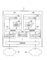
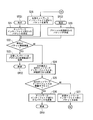
- FIG. 1 is a block diagram showing an overall configuration of a wireless communication system according to the first embodiment of the present invention.
- the wireless communication system 1 of this embodiment includes a wireless device 11, a packet transfer device 12, a backbone router 13 (first router device), and a system manager 14 (control device).
- the wireless communication system 1 can perform wireless communication (for example, wireless communication between the wireless device 11 and the backbone router 13) via the target network N1 (and also the provisioning network N2) under the control of the system manager 14. It is.
- the number of wireless devices is arbitrary.
- the target network N1 (first wireless communication network) is an original wireless communication network formed in the wireless communication system 1. That is, the target network N1 can also be said to be a working wireless communication network in which wireless communication is performed by a wireless device that has joined.
- the provisioning network N2 (second wireless communication network) is an auxiliary wireless communication network provided to perform OTA (Over The Air) provisioning that allows the wireless device 11 to enter the target network N1. That is, the provisioning network N2 sets the provisioning information (entry information) necessary for allowing the wireless device 11 to enter the target network N1 to the auxiliary wireless communication for setting the wireless device 11 that should enter the target network N1. It can also be called a network.
- the backbone network N (main network) to which the system manager 14 is connected is a network serving as a backbone of the wireless communication system 1.
- Both the target network N1 and the provisioning network N2 are wireless subnets that constitute a wireless communication network provided in the wireless communication system 1, and are assigned different subnet IDs (identifiers). For example, the subnet ID with the value “1” is assigned to the provisioning network N2, and any one subnet ID with the value “2” to “65535 (0xFFFF)” is assigned to the target network N1. ing.
- the wireless device 11 is, for example, a sensor device such as a flow meter or a temperature sensor, a valve device such as a flow control valve or an on-off valve, an actuator device such as a fan or a motor, or a wireless field device installed in another plant or factory.
- the wireless device 11 performs wireless communication conforming to ISA100.11a which is a wireless communication standard for industrial automation.
- the wireless device 11 enters the provisioning network N2 when OTA provisioning is performed, and enters the target network N1 under the control of the system manager 14 after OTA provisioning is performed.
- the packet transfer device 12 is capable of wireless communication conforming to the wireless communication standard ISA100.11a, and is connected to the target network N1 and the provisioning network N2 to transfer packets. Specifically, the packet transfer device 12 performs packet transfer in the target network N1, packet transfer in the provisioning network N2, and packet transfer between the target network N1 and the provisioning network N2.
- the packet transfer apparatus 12 transmits an advertisement (first advertisement) toward the target network N1, and transmits an advertisement (second advertisement) toward the provisioning network N2.
- the advertisement transmitted toward the target network N1 is information for connecting the wireless device 11 to the target network N1.
- the advertisement transmitted toward the provisioning network N2 is information for connecting the wireless device 11 to the provisioning network N2. Details of the packet transfer device 12 will be described later.
- the backbone router 13 is a device that connects the target network N1 and the backbone network N to which the system manager 14 is connected, and relays various data transmitted and received between the wireless device 11 and the system manager 14, for example.
- the backbone router 13 also performs wireless communication conforming to the wireless communication standard ISA100.11a.
- the system manager 14 supervises management control of the wireless communication system 1. For example, the system manager 14 controls wireless communication performed via the target network N1 to which the backbone router 13 is connected (further, the provisioning network N2 to which the packet transfer device 12 is connected). Specifically, allocation control of radio communication resources (time slots and communication channels) to the radio device 11, the packet transfer device 12, and the backbone router 13 is performed, and the target network N1 (and further, the provisioning network N2) is used. Wireless communication by TDMA is realized.
- the system manager 14 determines whether the wireless device 11 enters the target network N1 or the provisioning network N2 (entry processing), and provisioning information for the wireless device 11 (enters the wireless device 11 into the target network N1). (Information required to make a request) is set (OTA provisioning (provisioning via the provisioning network N2): setting process). In addition, the system manager 14 performs processing for causing the packet transfer apparatus 12 to enter the target network N1 and the provisioning network N2.
- the system manager 14 assigns the wireless communication resource related to the advertisement described above to the packet transfer apparatus 12.
- the packet transfer device 12 transmits a wireless communication resource for transmitting each of an advertisement directed to the target network N1 and an advertisement directed to the provisioning network N2, and a connection request from the wireless device 11 that has received each advertisement. Allocation with a radio communication resource for reception by the packet transfer apparatus 12 is performed. The details of the allocation of wireless communication resources related to the advertisement will be described later.
- the system manager 14 includes each device (the wireless device 11 to the system manager 14) constituting the wireless communication system 1 and a network (target network N1, provisioning network N2, backbone network N) provided in the wireless communication system 1.
- the connection relationship is grasped, and route information (route table) used in the packet transfer device 12 is generated based on the information indicating the connection relationship. Details of route information (route table) used in the packet transfer apparatus 12 and a method for creating the route information will be described later.
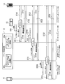
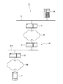
- FIG. 2 is a block diagram showing a main configuration of the packet transfer apparatus according to the first embodiment of the present invention.
- the packet transfer apparatus 12 of this embodiment includes a target network side processing unit 20a (first processing unit), a provisioning network side processing unit 20b (second processing unit), and a virtual network interface unit N3 (relay network). ), And a wireless communication unit C.
- the target network side processing unit 20a and the provisioning network side processing unit 20b are connected to each other via the virtual network interface unit N3.
- the target network side processing unit 20a and the provisioning network side processing unit 20b are connected to the target network N1 and the provisioning network N2 via the wireless communication unit C, respectively.
- the wireless communication unit C receives wireless signals from the target network N1 and the provisioning network N2, and outputs the received signals to the target network side processing unit 20a and the provisioning network side processing unit 20b, respectively.
- signals from the target network side processing unit 20a and the provisioning network side processing unit 20b are transmitted as radio signals to the target network N1 and the provisioning network N2, respectively.
- 2 illustrates a configuration in which one wireless communication unit C shared by the target network side processing unit 20a and the provisioning network side processing unit 20b is provided in the packet transfer device 12, the packet transfer device 12 is illustrated.
- a plurality of wireless communication units corresponding to each of the target network side processing unit 20a and the provisioning network side processing unit 20b may be provided.
- the virtual network interface unit N3 indicates an interface for a virtual network (virtual network) connecting the target network side processing unit 20a and the provisioning network side processing unit 20b.
- the virtual network interface unit N3 is realized by, for example, a connection line that connects the target network side processing unit 20a and the provisioning network side processing unit 20b.
- the virtual network interface unit N3 is realized by communication means (for example, inter-process communication) that manages communication between them. Is done.
- the target network side processing unit 20a includes a network interface unit 21a, a protocol processing unit 22a, a path control unit 23a, and a memory 24a.
- the target network side processing unit 20a is connected to the target network N1 via the wireless communication unit C, and processes packets input and output via the target network N1.
- the target network N1 and the virtual network interface unit N3 perform route control using a route table T1 (first route information) defined as a packet output destination. Further, the target network side processing unit 20a also performs an advertisement transmission process for the target network N1.
- the network interface unit 21a is connected to the target network N1 via the wireless communication unit C.
- the network interface unit 21a performs input / output of a packet transmitted to the packet transfer device 12 via the target network N1 and a packet to be transmitted from the packet transfer device 12 via the target network N1.
- the protocol processing unit 22a processes packets transmitted and received in accordance with a protocol defined by the wireless communication standard ISA100.11a.
- the target network side processing unit 20a performs a packet generation process starting from the target network, and the target network side processing unit 20a performs a packet reception process.
- the protocol processing unit 22a performs an advertisement transmission process for the target network N1 described above.
- the route control unit 23a searches the next relay point from the route table T1 stored in the memory 24a and performs route control of the packet to be transferred. Specifically, it controls whether to output a packet to the network interface unit 21a or to output a packet to the virtual network interface unit N3 in accordance with the contents of the routing table T1.
- the memory 24a is realized by a volatile storage element such as a RAM (Random Access Memory), for example, and stores the path table T1.
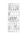
- FIG. 3 is a diagram showing the contents of the routing table T1 used in the packet transfer apparatus according to the first embodiment of the present invention.
- the route table T1 is a table in which the next relay point, the relay limit number, and the output network interface are defined for each end point address (device indicating the packet transfer destination).
- the route table T1 is in the table format as an example.
- the route table T1 is not necessarily in the table format.
- the routing table T1 sets the output destination of the packet to “wireless subnet (target network)” when the end point address exists on the target network N1 side.
- the output destination of the packet is the “backbone network (virtual network)”.
- the route information (route table) used in the route control of the network layer can basically distinguish only “wireless communication network” and “backbone network”. Wireless subnets with different subnet IDs cannot be distinguished.
- the route control unit 23a defines the route table T1.
- the “wireless subnet (wireless communication network)” is interpreted as a target network N1 which is one of the wireless subnets, and the “backbone network” is interpreted as a virtual network.
- the provisioning network side processing unit 20b includes a network interface unit 21b, a protocol processing unit 22b, a path control unit 23b, and a memory 24b.
- the provisioning network side processing unit 20b is connected to the provisioning network N2 via the wireless communication unit C and It processes packets that are input and output via Specifically, the provisioning network N2 and the virtual network interface unit N3 perform route control using a route table T2 (second route information) defined as a packet output destination.
- the provisioning network side processing unit 20b also performs transmission processing of advertisements directed to the provisioning network N2.
- the network interface unit 21b is connected to the provisioning network N2 via the wireless communication unit C, and is transmitted to the packet transfer device 12 via the provisioning network N2, and from the packet transfer device 12 via the provisioning network N2. Input / output packets to be transmitted.
- the protocol processing unit 22b processes packets transmitted and received in accordance with a protocol defined by the wireless communication standard ISA100.11a. For example, the provisioning network side processing unit 20b performs a packet generation process starting from the provisioning point, and the provisioning network side processing unit 20b performs a packet reception process. Further, the protocol processing unit 22b performs an advertisement transmission process for the above-described provisioning network N2.
- FIG. 4 is a diagram showing the contents of the routing table T2 used in the packet transfer apparatus according to the first embodiment of the present invention.
- the route table T2 is a table in which the next relay point, the relay limit number, and the output network interface are defined for each end point address, similarly to the route table T1.
- the route table T2 is not necessarily in the form of a table, like the route table T1.
- the route table T2 sets the packet output destination to “backbone network (virtual network)” when the end point address exists on the virtual network interface N3 side.
- the output destination of the packet is set to “wireless subnet (provisioning network)”.
- the route control unit 23b uses the route table T2. Is defined as a provisioning network N2 which is one of the wireless subnets, and a “backbone network” is interpreted as a virtual network.
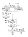
- FIG. 5 and 6 are flowcharts showing a packet transfer operation of the wireless communication system according to the first embodiment of the present invention.
- the process shown in FIG. 5 is a process performed on the target network N1 side from the virtual network interface unit N3 provided in the packet transfer apparatus 12.
- the processing shown in FIG. 6 shows processing performed on the provisioning network N2 side from the virtual network interface unit N3 provided in the packet transfer apparatus 12.
- the “start point” means the start point of communication
- the “end point” means the end point of communication
- the start point SP11 and the end point EP11 in FIG. 5 indicate that the wireless device that has joined the target network N1 or the device connected to the backbone network N is the start point and end point of communication, respectively.
- SP12 and end point EP12 indicate that the protocol processing unit 22a of the packet transfer device 12 is the start point and end point of communication, respectively.
- the start point SP21 and the end point EP21 in FIG. 6 indicate that the wireless devices that have entered the provisioning network N2 are the start point and the end point of communication, respectively. It shows that the protocol processing unit 22b is the start point and end point of communication, respectively.
- the path control unit 23b determines whether or not the obtained output network interface is a “wireless subnet” (step S25).
- the determination result of step S25 is “NO”.
- the path control unit 23b interprets the “backbone network” obtained as the output network interface as a virtual network, and outputs (transmits) the packet to the virtual network interface unit N3 (step S27).
- the packet output from the path control unit 23b of the provisioning network side processing unit 20b to the virtual network interface unit N3 is input to the target network side processing unit 20a and received by the path control unit 23a provided in the target network side processing unit 20a.
- the route control unit 23a determines whether or not the destination of the packet is its own device (packet transfer device 12) (step S12).
- packet transfer device 12 packet transfer device 12
- step S12 When the determination result in step S12 is “NO”, the route control unit 23a performs processing for retrieving the next relay point and the output network interface by searching the route table T1 stored in the memory 24a (step S14). .
- the route table T1 stored in the memory 24a
- the route control unit 23a performs processing for retrieving the next relay point and the output network interface by searching the route table T1 stored in the memory 24a (step S14).
- the route control unit 23a performs processing for retrieving the next relay point and the output network interface by searching the route table T1 stored in the memory 24a (step S14).
- the route control unit 23a performs processing for retrieving the next relay point and the output network interface by searching the route table T1 stored in the memory 24a (step S14).
- the route table T1 stored in the memory 24a
- the path control unit 23a determines whether or not the obtained output network interface is a “wireless subnet” (step S15).
- the determination result of step S15 is “YES”.
- the path control unit 23a interprets the “wireless subnet” obtained as the output network interface as the target network N1, and outputs the packet to the network interface unit 21a. Thereby, the packet is transmitted from the network interface unit 21a toward the target network N1 (step S16).
- the packet transmitted from the network interface unit 21a is received by the system manager 14 as the end point EP11 through the target network N1, the backbone router 13, and the backbone network N in this order.
- the packet transmitted from the wireless device 11 participating in the provisioning network N2 is received by the system manager 14 via the target network N1 to which a subnet ID different from the provisioning network N2 is attached.
- the start point SP11 in FIG. 5 is the start point of communication
- the end point EP21 in FIG. 6 is the end point of communication. That is, the packet transmitted from the system manager 14 is performed by sequentially performing the processes of steps S11, S12, S14, S15, and S17 in FIG. 5 and the processes of steps S28, S22, S24, S25, and S26 in FIG. Is received by the wireless device 11 that has joined the provisioning network N2 via the target network N1 and the provisioning network N2 to which different subnet IDs are attached in order.
- the operation of entering the wireless communication system 1 includes (1) an operation of causing the packet transfer apparatus 12 to enter the target network N1 and the provisioning network N2, (2) an operation of causing the wireless device 11 to enter the provisioning network N2, and (3) a wireless device. 11 is roughly divided into operations for entering the target network N1. Hereinafter, the entry operations (1) and (2) will be described.
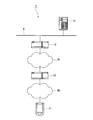
- FIG. 7 is a timing chart for explaining an entry operation to the wireless communication system according to the first embodiment of the present invention.
- an advertisement (information for connecting the wireless device 11 and the packet transfer apparatus 12 to the target network N1 is sent from the backbone router 13 to the target network N1. ) Is periodically transmitted (step ST0). It is assumed that the packet transfer device 12 is installed at a position where an advertisement transmitted from the backbone router 13 can be received.
- the target network side processing unit 20a of the packet transfer apparatus 12 When the power of the packet transfer apparatus 12 is turned on, first, an operation for causing the target network side processing unit 20a of the packet transfer apparatus 12 to enter the target network N1 is performed. Specifically, when an advertisement from the backbone router 13 is received by the target network side processing unit 20a of the packet transfer device 12, the target network side processing unit 20a sends a join request to the backbone router 13 (entry to the target network N1). Request) is transmitted (step ST11).
- the backbone router 13 Upon receiving the join request from the target network side processing unit 20a, the backbone router 13 transfers the join request from the target network side processing unit 20a to the system manager 14 via the backbone network N (step ST12).
- the start point SP12 in FIG. 5 is the communication start point
- the end point EP11 in FIG. 5 is the communication end point.
- the system manager 14 Upon receiving the join request transferred by proxy via the backbone network N, the system manager 14 authenticates the entry to the target network side processing unit 20a and makes a response according to the authentication result (response to the join request). .
- the response from the system manager 14 is transmitted to the backbone router 13 via the backbone network N (step ST13), and is proxy-transferred by the backbone router 13 to the target network side processing unit 20a (step ST14).
- the start point SP11 in FIG. 5 is the communication start point
- the end point EP12 in FIG. 5 is the communication end point.
- Step ST15 the radio communication resource of the backbone router 13 located on the communication path is updated by the system manager 14, and the system manager 14 sets the radio communication resource for the target network side processing unit 20a.
- communication via the communication path described above is communication in which the start point SP11 in FIG. 5 is the start point and the end point EP12 in FIG. 5 is the end point, and the start point SP12 in FIG. 5 is the start point and the end point EP11 in FIG. It consists of communication that is the end point.
- the wireless device 11 When the above operation is completed and the wireless device 11 is allowed to enter the provisioning network N2, the wireless device 11 is arranged at a position where the advertisement transmitted from the provisioning network side processing unit 20b of the packet transfer device 12 can be received. .
- a join request (request for entry to the provisioning network N2) is transmitted from the wireless device 11 to the provisioning network side processing unit 20b (step ST31).
- the start point SP21 in FIG. 6 is the communication start point
- the end point EP22 in FIG. 6 is the communication end point.
- the provisioning network side processing unit 20b When receiving the join request from the wireless device 11, the provisioning network side processing unit 20b performs proxy transfer of the join request from the wireless device 11 to the system manager 14 via the communication path established in step ST25 (step ST32). .
- the start point SP22 in FIG. 6 is the communication start point
- the end point EP11 in FIG. 5 is the communication end point.
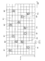
- the target network N1 and the provisioning network N2 are only logically separated by different subnet IDs and are not physically separated. For this reason, the packet transfer device 12 cannot transmit an advertisement to each network using the same communication channel at the same time. Similarly, a wireless device attempting to enter the target network N1 and a wireless device attempting to enter the provisioning network N2 cannot transmit a join request to each network using the same communication channel at the same time.
- squares with signs Q11 and Q12 indicate radio communication resources allocated based on the advertisement for the target network N1, and are given signs Q21 and Q22.
- the squares (the squares with diagonal lines and white letters) indicate radio communication resources allocated based on the advertisement to the provisioning network N2.
- the letter “T” in the squares denoted by reference numerals Q11 and Q21 indicates a wireless communication resource for transmission
- the letter “R” in the squares denoted by reference numerals Q12 and Q22 is a wireless communication for reception. Indicates a resource.
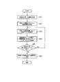
- FIG. 9 is a flowchart showing an operation of creating route information (route table) performed in the first embodiment of the present invention. Note that the processing of the flowchart shown in FIG. 9 is performed, for example, when the wireless communication system 1 is constructed and starts operating, when there is a join request from the wireless device 11 or the like, or when the wireless device 11 that has entered the target network N1 It is started when a communication request is made.
- the topology information is information indicating a connection relationship between each device constituting the wireless communication system 1 and a network provided in the wireless communication system 1, and is information managed by the system manager 14. .
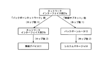
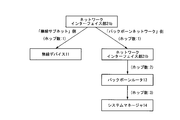
- FIG. 10 is a diagram for explaining topology information of the wireless communication system according to the first embodiment of the present invention.
- the topology information of the wireless communication system 1 is such that the system manager 14 is placed at the top, and the backbone router 13 and the target network side processing unit 20a ( This is information indicating how the network interface unit 21a), the provisioning network side processing unit 20b (network interface unit 21b) of the packet transfer device 12, and the wireless device 11 are connected by a network.
- the route information when the network interface unit 21a is the center is that the network interface unit 21a is arranged at the highest level, and the network interface unit 21b and the wireless device 11 are sequentially arranged on the “bank bone network” side.
- the backbone router 13 and the system manager 14 are sequentially arranged on the “wireless subnet” side.
- the number of relays (hops) to each device is specified with the network interface unit 21a as the center.
- the route information when the network interface unit 21b is the center is that the network interface unit 21b is arranged at the highest level, and the network interface unit 21a and the backbone router 13 are located on the “bank bone network” side. And the system manager 14 are arranged in order, and the wireless device 11 is arranged on the “wireless subnet” side. Also, in this route information, the number of relays (hops) to each device is specified with the network interface unit 21b as the center.
- the system manager 14 performs a process of setting an end point address (device indicating a packet transfer destination) for the route information created in step S32 (step S33). For example, the system manager 14 is set as the end point address for the route information described in FIG. 11A. With this processing, the network interface unit 21a shown in FIG. 11A is set as the start point address (device indicating the packet transfer source), and the route in which the system manager 14 is set as the end point address is specified.
- step S35 determines whether there is a remaining end point address to be set.
- the system manager 14 sets a new end point address (step S33), and the next relay point The relay limit number and the output network interface are acquired (step S34).
- step S35 when it is determined that there is no remaining end point address to be set (when the determination result in step S35 is “NO”), the system manager 14 uses the information acquired in step S34 to perform FIG. Is created (step S36).
- the created routing table T1 is transmitted to the packet transfer apparatus 12 and stored in the memory 24a of the target network side processing unit 20a. Note that it is determined that there is no remaining end point address to be set when, for example, all of the wireless device 11, the network interface unit 21b, the backbone router 13, and the system manager 14 illustrated in FIG. 11A are set as end point addresses. It is.
- FIG. 12 is a block diagram showing an overall configuration of a wireless communication system according to the second embodiment of the present invention.
- the wireless communication system 2 of the present embodiment has a configuration in which the packet transfer device 12 included in the wireless communication system 1 illustrated in FIG.
- the real network N10 is an arbitrary network (for example, Ethernet (registered trademark)).
- the target network side processing device 31 is connected to the target network N1 and the real network N10, and performs the same processing as the target network side processing unit 20a provided in the packet transfer device 12 shown in FIG.
- the provisioning network side processing device 32 is connected to the provisioning network N2 and the real network N10, and performs the same processing as the provisioning network side processing unit 20b included in the packet transfer device 12 shown in FIG.
- the packet transfer device 30 uses the virtual network interface unit N3 provided in the packet transfer device 12 shown in FIG. 1 as a real network N10 such as an existing wired network, and the target network side processing unit 20a and provisioning network provided in the packet transfer device 12
- the side processing unit 20b is an individual device (the target network side processing device 31 and the provisioning network side processing device 32).
- FIG. 13 is a block diagram showing an overall configuration of a wireless communication system according to the third embodiment of the present invention.
- the wireless communication system 3 of this embodiment is provided with two backbone routers 13 a and 13 b to form two target networks N 1 a and N 1 b, and these target networks N 1 a and N 1 b are connected by the packet transfer device 12. It is a connected configuration.
- the provisioning network N2 shown in FIGS. 1 and 12 is omitted.
- the wireless communication system 3 of this embodiment connects the target networks N1a and N1b to the backbone network N via the backbone routers 13a and 13b, and connects the target networks N1a and N1b to each other by the packet transfer device 12.
- the communication path is made redundant. For this reason, even if a failure occurs in the backbone router 13a while communication is being performed between the wireless device 11 entering the target network N1a and the system manager 14 via a route via the backbone router 13a. It is possible to continue communication by a route through the packet transfer device 12 and the backbone router 13b.
- FIG. 14 is a block diagram showing an overall configuration of a wireless communication system according to the fourth embodiment of the present invention.
- the wireless communication system 4 of the present embodiment forms two target networks N1a and N1b instead of the target network N1 and provisioning network N2 in FIG. 1, and these target networks N1a and N1b are packetized. In this configuration, the transfer device 12 is connected.
- the target network N1 and the provisioning network N2 are connected by the packet transfer device 12 in order to realize OTA provisioning for the wireless device 11.
- two target networks N1a and N1b are connected by the packet transfer device 12 without considering the provisioning network N2.
- the activation / stop of the packet transfer function between the target network N1 and the provisioning network N2 is performed, for example, based on a control signal from the system manager 14 on the provisioning network side processing unit 20b of the packet transfer apparatus 12 shown in FIG. This is performed by supplying / stopping power to the provisioning network side processing device 32) shown in FIG. By performing such power supply control, power saving can be achieved.
- the present invention can be widely applied to a packet transfer device and a wireless communication system including the packet transfer device, and enables packet transfer between wireless communication networks without changing the wireless communication standard.
- Wireless communication system 11 Wireless device 12 Packet transfer device 13 Backbone router (first router device) 13a Backbone router (first router device) 13b Backbone router (second router device) 14 System manager (control device) 20a Target network side processing unit (first processing unit) 20b Provisioning network side processing unit (second processing unit) 21a Network interface unit 21b Network interface unit 22a Protocol processing unit 22b Protocol processing unit 23a Path control unit 23b Path control unit 24a Memory 24b Memory 30 Packet transfer device 31 Target network side processing device (first processing unit) 32 Provisioning network side processing device (second processing unit) C Wireless communication part N Backbone network (main network) N1 target network (first wireless communication network) N1a target network (first wireless communication network) N1b target network (second wireless communication network) N2 provisioning network (second wireless communication network) N3 virtual network interface (relay network) N10 Real network (relay network) T1, T2 route table
Landscapes
- Engineering & Computer Science (AREA)
- Computer Networks & Wireless Communication (AREA)
- Signal Processing (AREA)
- Mobile Radio Communication Systems (AREA)
- Data Exchanges In Wide-Area Networks (AREA)
Abstract
Provided is a packet transfer device to perform packet transfer between first and second wireless communication networks to which mutually different identifiers are attached, wherein the packet transfer device is provided with: a relay network which is present between the first and second wireless communication networks; a first processing unit which is connected to the first wireless communication network, and performs first path control using first path information in which the first wireless communication network and the relay network are specified as output destinations of the packets; and a second processing unit which is connected to the second wireless communication network, and performs second path control using second path information in which the second wireless communication network and the relay network are specified as output destinations of the packets.
Description
本発明は、無線通信ネットワーク間におけるパケットの転送が可能なパケット転送装置、及び当該装置を備える無線通信システムに関する。
本願は、2011年9月5日に出願された日本国特許出願第2011-193264号および2012年7月11日に出願された日本国特許出願第2012-155650号に基づき優先権を主張し、その内容をここに援用する。 The present invention relates to a packet transfer apparatus capable of transferring a packet between wireless communication networks, and a wireless communication system including the apparatus.
This application claims priority based on Japanese Patent Application No. 2011-193264 filed on September 5, 2011 and Japanese Patent Application No. 2012-155650 filed on July 11, 2012. The contents are incorporated here.
近年、プラントや工場等においては、無線フィールド機器と呼ばれる無線通信が可能な現場機器(測定器、操作器)を設置し、無線フィールド機器を制御するための制御信号や無線フィールド機器で得られた測定信号等を、無線通信ネットワークを介して通信する無線通信システムが実現されている。このような無線通信システムで用いられる通信規格としては、例えば国際計測制御学会(ISA:International Society of Automation)で策定されたインダストリアル・オートメーション用無線通信規格であるISA100.11aが挙げられる。
In recent years, in plants and factories, field devices (measuring instruments, operating devices) capable of wireless communication called wireless field devices have been installed and obtained with control signals and wireless field devices for controlling wireless field devices. A wireless communication system that communicates measurement signals and the like via a wireless communication network is realized. As a communication standard used in such a wireless communication system, for example, ISA100.11a which is a wireless communication standard for industrial automation established by the International Society for Measurement and Control (ISA) is known.
上記の無線通信規格ISA100.11aに準拠した無線通信システムは、フィールド機器と、フィールド機器との間で無線通信ネットワークを形成するバックボーンルータと、無線通信ネットワークを介して行われる無線通信を統括して制御するシステムマネージャとから構成される。そして、システムマネージャの制御の下で、複数の通信チャネル(例えば、16チャネル)を用いたTDMA(Time Division Multiple Access:時分割多元接続)による無線通信が行われる。
The wireless communication system compliant with the above wireless communication standard ISA100.11a supervises field devices, a backbone router that forms a wireless communication network between the field devices, and wireless communication performed via the wireless communication network. It consists of a system manager to control. Under the control of the system manager, wireless communication is performed by TDMA (Time Division Multiple Access) using a plurality of communication channels (for example, 16 channels).
ここで、上記の無線フィールド機器を無線通信ネットワークに参入させるには、無線フィールド機器に対して「プロビジョニング(Provisioning)」と呼ばれる機器情報(ネットワークパラメータ及びセキュリティパラメータ)の設定作業を行う必要がある。この「プロビジョニング」を行う手法としては、上記の無線通信規格ISA100.11aに準拠した無線通信を行って機器情報の設定を行うOTA(Over The Air)プロビジョニングと、この無線通信とは異なる通信手段(例えば、赤外線通信等)による通信を行って機器情報の設定を行うOOB(Out-Of-Band)プロビジョニングとに大別される。
Here, in order for the wireless field device to enter the wireless communication network, it is necessary to perform device information (network parameter and security parameter) setting work called “provisioning” for the wireless field device. As a technique for performing this “provisioning”, OTA (Over The Air) provisioning that performs wireless communication in accordance with the above-described wireless communication standard ISA100.11a and sets device information and communication means different from this wireless communication ( For example, it is roughly classified into OOB (Out-Of-Band) provisioning for setting device information by performing communication by infrared communication or the like.
以下の非特許文献1には、上記のOTAプロビジョニングを行う方法として、プロビジョニングのための専用のツール(プロビジョニングデバイス)を用いて行う方法と、このようなツールを用いずに行う方法とが規定されている。具体的に、前者の方法は、参入すべき無線通信ネットワーク(ターゲットネットワーク)とは物理的に分離された別の無線通信ネットワーク(プロビジョニングネットワーク)を設け、このプロビジョニングネットワークを介してツールと無線フィールド機器との間で無線通信を行って機器情報の設定を行う方法である。これに対し、後者の方法は、ターゲットネットワーク上に論理的に分離されたプロビジョニングネットワークを構築し、ターゲットネットワークからプロビジョニングネットワークを介してフィールド機器に機器情報を設定する方法である。
Non-Patent Document 1 below stipulates a method for performing the above OTA provisioning using a dedicated tool for provisioning (provisioning device) and a method for performing without using such a tool. ing. Specifically, in the former method, another wireless communication network (provisioning network) physically separated from the wireless communication network (target network) to be entered is provided, and the tool and the wireless field device are provided via the provisioning network. Device information is set by performing wireless communication with the device. On the other hand, the latter method is a method of constructing a provisioning network logically separated on the target network and setting device information from the target network to the field device via the provisioning network.
ところで、無線通信システムにおいては、通信資源の分配や管理を効率的に行う観点から、無線通信ネットワークを複数の小さな無線通信ネットワーク(無線サブネット)に分割して管理する管理手法が一般的に用いられる。分割された無線サブネットは、それぞれ異なる識別子(サブネットID)を付して管理される。このため、上述したターゲットネットワーク及びプロビジョニングネットワークも、それぞれ異なるサブネットIDが付されて管理されることになる。
By the way, in a wireless communication system, a management method for dividing and managing a wireless communication network into a plurality of small wireless communication networks (wireless subnets) is generally used from the viewpoint of efficiently distributing and managing communication resources. . The divided wireless subnets are managed with different identifiers (subnet IDs). For this reason, the above-described target network and provisioning network are also managed with different subnet IDs.
上述した無線通信規格ISA100.11aは、サブネットIDが同じである1つの無線サブネット内におけるパケットを転送する仕組み(具体的には、OSI参照モデルのデータリンク層による転送)の詳細を規定はしているが、互いに異なるサブネットIDが付された無線サブネット間においてパケットを転送する仕組みの詳細を何ら規定していない。このため、互いに異なるサブネットIDが付されたターゲットネットワークとプロビジョニングネットワークとの間においてはパケットの転送を行うことができず、結局、前述したプロビジョニングデバイスを用いないOTAプロビジョニングを実現することができない。
The above-described wireless communication standard ISA100.11a defines details of a mechanism for transferring packets in one wireless subnet having the same subnet ID (specifically, transfer by the data link layer of the OSI reference model). However, it does not define any details of the mechanism for transferring packets between wireless subnets with different subnet IDs. For this reason, packet transfer cannot be performed between a target network and a provisioning network to which different subnet IDs are attached, and eventually OTA provisioning without using the above-described provisioning device cannot be realized.
ここで、OSI参照モデルのデータリンク層よりも上位に位置するネットワーク層で経路制御を行えば、サブネットIDが異なる無線サブネット間におけるパケットの転送を行うことができるとも考えられる。しかしながら、上述した無線通信規格ISA100.11aにおいて、ネットワーク層の経路制御で用いられる経路表では、無線通信ネットワークと「バックボーンネットワーク」と呼ばれる主ネットワークとを区別できるに過ぎない。このため、無線通信ネットワークを構成する個々の無線サブネットを区別するには、ネットワーク層の経路制御で用いられる経路表を大幅に変更する必要がある。
Here, if route control is performed in the network layer positioned above the data link layer of the OSI reference model, it is considered that packets can be transferred between wireless subnets having different subnet IDs. However, in the wireless communication standard ISA100.11a described above, the route table used in the route control of the network layer can only distinguish the wireless communication network and the main network called “backbone network”. For this reason, in order to distinguish the individual wireless subnets constituting the wireless communication network, it is necessary to drastically change the route table used for route control in the network layer.
上述した通り、無線通信規格ISA100.11aでは、無線通信ネットワークを介して行われる無線通信をシステムマネージャが統括して制御しているため、上述した経路表は、システムマネージャによって作成されてフィールド機器に割り当てられる。従って、上述した経路表が変更されてしまうと、経路表で規定される無線通信リソースの割り当てを行うための通信プロトコルも変更する必要が生じ、無線通信規格ISA100.11aを変更しなければならなくなる。
As described above, in the wireless communication standard ISA100.11a, since the system manager controls the wireless communication performed via the wireless communication network, the above-described route table is created by the system manager and stored in the field device. Assigned. Therefore, if the above-described routing table is changed, it is necessary to change the communication protocol for allocating the radio communication resources specified by the routing table, and the radio communication standard ISA100.11a must be changed. .
本発明は、無線通信規格を変更することなく無線通信ネットワーク間におけるパケット転送を実現することができるパケット転送装置、及び当該装置を備える無線通信システムを提供する。
The present invention provides a packet transfer apparatus capable of realizing packet transfer between wireless communication networks without changing the wireless communication standard, and a wireless communication system including the apparatus.
本発明の一実施形態に係るパケット転送装置は、互いに異なる識別子が付された第1,第2無線通信ネットワーク間におけるパケットの転送を行うパケット転送装置であって、前記第1,第2無線通信ネットワーク間に介在する中継ネットワークと、前記第1無線通信ネットワークに接続され、前記第1無線通信ネットワークと前記中継ネットワークとがパケットの出力先として規定された第1経路情報を用いて第1の経路制御を行う第1処理部と、前記第2無線通信ネットワークに接続され、前記第2無線通信ネットワークと前記中継ネットワークとがパケットの出力先として規定された第2経路情報を用いて第2の経路制御を行う第2処理部と、を備える。
前記第1および第2の経路情報の各々は、終点アドレス毎に、次中継点、中継限界数、及び出力ネットワークインターフェイスが規定されたテーブルであってもよい。
前記中継ネットワークは、前記第1処理部と前記第2処理部とを仮想的に接続する仮想ネットワークであってもよい。
前記中継ネットワークは、前記第1処理部と前記第2処理部とを物理的に接続する実ネットワークであってもよい。
前記第1,第2処理部は、前記中継ネットワークに接続された状態で別個の装置として設けられていてもよい。
本発明の一実施形態に係る無線通信システムは、互いに異なる識別子が付された第1,第2無線通信ネットワークを介して無線通信を行う無線通信システムであって、前記第1,第2無線通信ネットワークを介して行われる無線通信の制御を行う制御装置と、前記第1,第2無線通信ネットワーク間におけるパケットの転送を行う前記パケット転送装置と、を備える。
前記制御装置は、前記第1,第2無線通信ネットワークと、前記パケット転送装置の前記中継ネットワーク及び前記第1,第2処理部との接続関係を示す情報に基づいて、前記第1,第2処理部で用いられる前記第1,第2経路情報を生成してもよい。
前記無線通信システムは、前記制御装置が接続される主ネットワーク及び前記第1無線通信ネットワークに接続される第1ルータ装置を更に備えてもよい。
前記無線通信システムは、前記主ネットワーク及び前記第2無線通信ネットワークに接続される第2ルータ装置を更に備えてもよい。
前記第1無線通信ネットワークは、前記制御装置の制御の下で、参入している無線デバイスによる無線通信が行われる現用の無線通信ネットワークであり、前記第2無線通信ネットワークは、前記第1無線通信ネットワークに無線デバイスを参入させるために必要となる参入情報を、前記第1無線通信ネットワークに参入させるべき無線デバイスに設定するための補助的な無線通信ネットワークであってもよい。
前記制御装置は、無線デバイスを前記第1,第2無線通信ネットワークに参入させる参入処理と、前記第2無線通信ネットワークに参入している無線デバイスに対して前記参入情報を設定する設定処理とを行ってもよい。
前記第1,第2無線通信ネットワークは何れも、前記制御装置の制御の下で、参入している無線デバイスによる無線通信が行われる現用の無線通信ネットワークであってもよい。
前記パケット転送装置の前記第1処理部は、前記制御装置の制御の下で、無線デバイスを前記1無線通信ネットワークに接続させるための情報を第1広告として前記第1無線通信ネットワークに向けて送信し、前記パケット転送装置の前記第2処理部は、前記制御装置の制御の下で、無線デバイスを前記2無線通信ネットワークに接続させるための情報を第2広告として前記第2無線通信ネットワークに向けて送信してもよい。 A packet transfer apparatus according to an embodiment of the present invention is a packet transfer apparatus for transferring a packet between first and second wireless communication networks assigned with different identifiers, the first and second wireless communication A first route using first route information that is connected to the first wireless communication network and that is connected to the first wireless communication network, and in which the first wireless communication network and the relay network are defined as packet output destinations. A second route using second route information that is connected to the first processing unit that performs control and the second wireless communication network, and in which the second wireless communication network and the relay network are defined as packet output destinations A second processing unit that performs control.
Each of the first and second route information may be a table in which a next relay point, a relay limit number, and an output network interface are defined for each end point address.
The relay network may be a virtual network that virtually connects the first processing unit and the second processing unit.
The relay network may be a real network that physically connects the first processing unit and the second processing unit.
The first and second processing units may be provided as separate devices while being connected to the relay network.
A wireless communication system according to an embodiment of the present invention is a wireless communication system that performs wireless communication via first and second wireless communication networks assigned with different identifiers, the first and second wireless communication being performed. A control device that controls wireless communication performed via a network; and the packet transfer device that transfers packets between the first and second wireless communication networks.
The control device is configured to control the first and second wireless communication networks based on information indicating a connection relationship between the first and second wireless communication networks and the relay network and the first and second processing units of the packet transfer device. The first and second route information used in the processing unit may be generated.
The wireless communication system may further include a main network to which the control device is connected and a first router device connected to the first wireless communication network.
The wireless communication system may further include a second router device connected to the main network and the second wireless communication network.
The first wireless communication network is an active wireless communication network in which wireless communication is performed by an entering wireless device under the control of the control device, and the second wireless communication network is the first wireless communication network. It may be an auxiliary wireless communication network for setting entry information necessary for allowing a wireless device to enter the network to a wireless device that should be allowed to enter the first wireless communication network.
The control device includes an entry process for allowing a wireless device to enter the first and second wireless communication networks, and a setting process for setting the entry information for a wireless device participating in the second wireless communication network. You may go.
Each of the first and second wireless communication networks may be a working wireless communication network in which wireless communication is performed by a participating wireless device under the control of the control device.
The first processing unit of the packet transfer device transmits information for connecting a wireless device to the first wireless communication network as a first advertisement to the first wireless communication network under the control of the control device. Then, the second processing unit of the packet transfer device directs information for connecting a wireless device to the second wireless communication network to the second wireless communication network as a second advertisement under the control of the control device. May be transmitted.
本発明によれば、第1無線通信ネットワークと中継ネットワークとがパケットの出力先として規定された第1経路情報を用いて第1処理部が第1の経路制御を行うとともに、第2無線通信ネットワークと中継ネットワークとがパケットの出力先として規定された第2経路情報を用いて第2処理部が第2の経路制御を行っている。これにより、経路制御に用いられる経路表を大幅に変更することなく無線通信ネットワーク間におけるパケット転送を実現することができる。従って、無線通信規格を変更することなく無線通信ネットワーク間におけるパケット転送を実現することができる。
According to the present invention, the first processing unit performs the first route control using the first route information in which the first wireless communication network and the relay network are defined as the packet output destination, and the second wireless communication network. The second processing unit performs the second path control using the second path information in which the packet and the relay network are defined as the packet output destination. Thus, packet transfer between wireless communication networks can be realized without significantly changing the route table used for route control. Therefore, packet transfer between wireless communication networks can be realized without changing the wireless communication standard.
以下、図面を参照して本発明の実施形態によるパケット転送装置及び無線通信システムについて詳細に説明する。
Hereinafter, a packet transfer device and a wireless communication system according to an embodiment of the present invention will be described in detail with reference to the drawings.
(第1実施形態)
(無線通信システム)
図1は、本発明の第1実施形態による無線通信システムの全体構成を示すブロック図である。図1に示す通り、本実施形態の無線通信システム1は、無線デバイス11、パケット転送装置12、バックボーンルータ13(第1ルータ装置)、及びシステムマネージャ14(制御装置)を備える。無線通信システム1は、システムマネージャ14の制御の下で、ターゲットネットワークN1(更には、プロビジョニングネットワークN2)を介した無線通信(例えば、無線デバイス11とバックボーンルータ13との間の無線通信)が可能である。尚、図1では1つの無線デバイス11のみを示しているが、無線デバイスの数は任意である。 (First embodiment)
(Wireless communication system)
FIG. 1 is a block diagram showing an overall configuration of a wireless communication system according to the first embodiment of the present invention. As shown in FIG. 1, thewireless communication system 1 of this embodiment includes a wireless device 11, a packet transfer device 12, a backbone router 13 (first router device), and a system manager 14 (control device). The wireless communication system 1 can perform wireless communication (for example, wireless communication between the wireless device 11 and the backbone router 13) via the target network N1 (and also the provisioning network N2) under the control of the system manager 14. It is. Although only one wireless device 11 is shown in FIG. 1, the number of wireless devices is arbitrary.
(無線通信システム)
図1は、本発明の第1実施形態による無線通信システムの全体構成を示すブロック図である。図1に示す通り、本実施形態の無線通信システム1は、無線デバイス11、パケット転送装置12、バックボーンルータ13(第1ルータ装置)、及びシステムマネージャ14(制御装置)を備える。無線通信システム1は、システムマネージャ14の制御の下で、ターゲットネットワークN1(更には、プロビジョニングネットワークN2)を介した無線通信(例えば、無線デバイス11とバックボーンルータ13との間の無線通信)が可能である。尚、図1では1つの無線デバイス11のみを示しているが、無線デバイスの数は任意である。 (First embodiment)
(Wireless communication system)
FIG. 1 is a block diagram showing an overall configuration of a wireless communication system according to the first embodiment of the present invention. As shown in FIG. 1, the
ここで、ターゲットネットワークN1(第1無線通信ネットワーク)は、無線通信システム1に形成される本来の無線通信ネットワークである。つまり、ターゲットネットワークN1は、参入している無線デバイスによる無線通信が行われる現用の無線通信ネットワークということもできる。また、プロビジョニングネットワークN2(第2無線通信ネットワーク)は、無線デバイス11をターゲットネットワークN1に参入させるOTA(Over The Air)プロビジョニングを行うために設けられる補助的な無線通信ネットワークである。つまり、プロビジョニングネットワークN2は、ターゲットネットワークN1に無線デバイス11を参入させるために必要となるプロビジョニング情報(参入情報)を、ターゲットネットワークN1に参入させるべき無線デバイス11に設定するための補助的な無線通信ネットワークということもできる。尚、システムマネージャ14が接続されるバックボーンネットワークN(主ネットワーク)は、無線通信システム1の基幹となるネットワークである。
Here, the target network N1 (first wireless communication network) is an original wireless communication network formed in the wireless communication system 1. That is, the target network N1 can also be said to be a working wireless communication network in which wireless communication is performed by a wireless device that has joined. The provisioning network N2 (second wireless communication network) is an auxiliary wireless communication network provided to perform OTA (Over The Air) provisioning that allows the wireless device 11 to enter the target network N1. That is, the provisioning network N2 sets the provisioning information (entry information) necessary for allowing the wireless device 11 to enter the target network N1 to the auxiliary wireless communication for setting the wireless device 11 that should enter the target network N1. It can also be called a network. The backbone network N (main network) to which the system manager 14 is connected is a network serving as a backbone of the wireless communication system 1.
上記のターゲットネットワークN1及びプロビジョニングネットワークN2は何れも、無線通信システム1に設けられる無線通信ネットワークを構成する無線サブネットであり、互いに異なるサブネットID(識別子)が付されている。例えば、プロビジョニングネットワークN2には値が「1」のサブネットIDが付されており、ターゲットネットワークN1には値が「2」~「65535(0xFFFF)」のうちの何れか1つのサブネットIDが付されている。
Both the target network N1 and the provisioning network N2 are wireless subnets that constitute a wireless communication network provided in the wireless communication system 1, and are assigned different subnet IDs (identifiers). For example, the subnet ID with the value “1” is assigned to the provisioning network N2, and any one subnet ID with the value “2” to “65535 (0xFFFF)” is assigned to the target network N1. ing.
無線デバイス11は、例えば流量計や温度センサ等のセンサ機器、流量制御弁や開閉弁等のバルブ機器、ファンやモータ等のアクチュエータ機器、その他のプラントや工場に設置される無線フィールドデバイスである。無線デバイス11は、インダストリアル・オートメーション用無線通信規格であるISA100.11aに準拠した無線通信を行う。尚、無線デバイス11は、OTAプロビジョニングが行われるときにはプロビジョニングネットワークN2に参入し、OTAプロビジョニングが行われた後はシステムマネージャ14の制御の下でターゲットネットワークN1に参入する。
The wireless device 11 is, for example, a sensor device such as a flow meter or a temperature sensor, a valve device such as a flow control valve or an on-off valve, an actuator device such as a fan or a motor, or a wireless field device installed in another plant or factory. The wireless device 11 performs wireless communication conforming to ISA100.11a which is a wireless communication standard for industrial automation. The wireless device 11 enters the provisioning network N2 when OTA provisioning is performed, and enters the target network N1 under the control of the system manager 14 after OTA provisioning is performed.
パケット転送装置12は、上記の無線通信規格ISA100.11aに準拠した無線通信が可能であり、ターゲットネットワークN1とプロビジョニングネットワークN2とに接続されてパケットの転送を行う。具体的に、パケット転送装置12は、ターゲットネットワークN1内におけるパケット転送、プロビジョニングネットワークN2内におけるパケット転送、及びターゲットネットワークN1とプロビジョニングネットワークN2との間におけるパケットの転送を行う。
The packet transfer device 12 is capable of wireless communication conforming to the wireless communication standard ISA100.11a, and is connected to the target network N1 and the provisioning network N2 to transfer packets. Specifically, the packet transfer device 12 performs packet transfer in the target network N1, packet transfer in the provisioning network N2, and packet transfer between the target network N1 and the provisioning network N2.
また、パケット転送装置12は、システムマネージャ14の制御の下で、ターゲットネットワークN1に向けて広告(第1広告)を送信するとともに、プロビジョニングネットワークN2に向けて広告(第2広告)を送信する。ここで、ターゲットネットワークN1に向けて送信される広告は、無線デバイス11をターゲットネットワークN1に接続させるための情報である。プロビジョニングネットワークN2に向けて送信される広告は、無線デバイス11をプロビジョニングネットワークN2に接続させるための情報である。尚、パケット転送装置12の詳細は後述する。
Further, under the control of the system manager 14, the packet transfer apparatus 12 transmits an advertisement (first advertisement) toward the target network N1, and transmits an advertisement (second advertisement) toward the provisioning network N2. Here, the advertisement transmitted toward the target network N1 is information for connecting the wireless device 11 to the target network N1. The advertisement transmitted toward the provisioning network N2 is information for connecting the wireless device 11 to the provisioning network N2. Details of the packet transfer device 12 will be described later.
バックボーンルータ13は、ターゲットネットワークN1と、システムマネージャ14が接続されるバックボーンネットワークNとを接続し、例えば無線デバイス11とシステムマネージャ14との間で送受信される各種データの中継を行う装置である。尚、バックボーンルータ13も上記の無線通信規格ISA100.11aに準拠した無線通信を行う。
The backbone router 13 is a device that connects the target network N1 and the backbone network N to which the system manager 14 is connected, and relays various data transmitted and received between the wireless device 11 and the system manager 14, for example. The backbone router 13 also performs wireless communication conforming to the wireless communication standard ISA100.11a.
システムマネージャ14は、無線通信システム1の管理制御を統括して行う。例えば、システムマネージャ14は、バックボーンルータ13が接続されるターゲットネットワークN1(更には、パケット転送装置12が接続されるプロビジョニングネットワークN2)を介して行われる無線通信の制御を行う。具体的には、無線デバイス11、パケット転送装置12、及びバックボーンルータ13に対する無線通信リソース(タイムスロット及び通信チャネル)の割り当て制御を行って、ターゲットネットワークN1(更には、プロビジョニングネットワークN2)を介したTDMAによる無線通信を実現する。
The system manager 14 supervises management control of the wireless communication system 1. For example, the system manager 14 controls wireless communication performed via the target network N1 to which the backbone router 13 is connected (further, the provisioning network N2 to which the packet transfer device 12 is connected). Specifically, allocation control of radio communication resources (time slots and communication channels) to the radio device 11, the packet transfer device 12, and the backbone router 13 is performed, and the target network N1 (and further, the provisioning network N2) is used. Wireless communication by TDMA is realized.
また、システムマネージャ14は、無線デバイス11をターゲットネットワークN1又はプロビジョニングネットワークN2に参入させるか否かの処理(参入処理)、及び無線デバイス11に対してプロビジョニング情報(無線デバイス11をターゲットネットワークN1に参入させるために必要となる情報)を設定する処理(OTAプロビジョニング(プロビジョニングネットワークN2を介したプロビジョニング):設定処理)を行う。加えて、システムマネージャ14は、パケット転送装置12をターゲットネットワークN1及びプロビジョニングネットワークN2に参入させる処理を行う。
In addition, the system manager 14 determines whether the wireless device 11 enters the target network N1 or the provisioning network N2 (entry processing), and provisioning information for the wireless device 11 (enters the wireless device 11 into the target network N1). (Information required to make a request) is set (OTA provisioning (provisioning via the provisioning network N2): setting process). In addition, the system manager 14 performs processing for causing the packet transfer apparatus 12 to enter the target network N1 and the provisioning network N2.
また、システムマネージャ14は、パケット転送装置12に対して前述した広告に関する無線通信リソースの割り当てを行う。具体的には、パケット転送装置12がターゲットネットワークN1に向けた広告及びプロビジョニングネットワークN2に向けた広告の各々を送信するための無線通信リソースと、各広告を受信した無線デバイス11からの接続要求をパケット転送装置12が受信するための無線通信リソースとの割り当てを行う。尚、広告に関する無線通信リソースの割り当ての詳細については後述する。
In addition, the system manager 14 assigns the wireless communication resource related to the advertisement described above to the packet transfer apparatus 12. Specifically, the packet transfer device 12 transmits a wireless communication resource for transmitting each of an advertisement directed to the target network N1 and an advertisement directed to the provisioning network N2, and a connection request from the wireless device 11 that has received each advertisement. Allocation with a radio communication resource for reception by the packet transfer apparatus 12 is performed. The details of the allocation of wireless communication resources related to the advertisement will be described later.
また、システムマネージャ14は、無線通信システム1を構成する各機器(無線デバイス11~システムマネージャ14)と、無線通信システム1に設けられるネットワーク(ターゲットネットワークN1、プロビジョニングネットワークN2、バックボーンネットワークN)との接続関係を把握し、この接続関係を示す情報に基づいて、パケット転送装置12で用いられる経路情報(経路表)を生成する。尚、パケット転送装置12で用いられる経路情報(経路表)及びその作成方法の詳細については後述する。
Further, the system manager 14 includes each device (the wireless device 11 to the system manager 14) constituting the wireless communication system 1 and a network (target network N1, provisioning network N2, backbone network N) provided in the wireless communication system 1. The connection relationship is grasped, and route information (route table) used in the packet transfer device 12 is generated based on the information indicating the connection relationship. Details of route information (route table) used in the packet transfer apparatus 12 and a method for creating the route information will be described later.
(パケット転送装置)
図2は、本発明の第1実施形態によるパケット転送装置の要部構成を示すブロック図である。図2に示す通り、本実施形態のパケット転送装置12は、ターゲットネットワーク側処理部20a(第1処理部)、プロビジョニングネットワーク側処理部20b(第2処理部)、仮想ネットワークインターフェイス部N3(中継ネットワーク)、及び無線通信部Cを備える。ターゲットネットワーク側処理部20aとプロビジョニングネットワーク側処理部20bとが仮想ネットワークインターフェイス部N3を介して相互に接続されている。 (Packet transfer device)
FIG. 2 is a block diagram showing a main configuration of the packet transfer apparatus according to the first embodiment of the present invention. As shown in FIG. 2, thepacket transfer apparatus 12 of this embodiment includes a target network side processing unit 20a (first processing unit), a provisioning network side processing unit 20b (second processing unit), and a virtual network interface unit N3 (relay network). ), And a wireless communication unit C. The target network side processing unit 20a and the provisioning network side processing unit 20b are connected to each other via the virtual network interface unit N3.
図2は、本発明の第1実施形態によるパケット転送装置の要部構成を示すブロック図である。図2に示す通り、本実施形態のパケット転送装置12は、ターゲットネットワーク側処理部20a(第1処理部)、プロビジョニングネットワーク側処理部20b(第2処理部)、仮想ネットワークインターフェイス部N3(中継ネットワーク)、及び無線通信部Cを備える。ターゲットネットワーク側処理部20aとプロビジョニングネットワーク側処理部20bとが仮想ネットワークインターフェイス部N3を介して相互に接続されている。 (Packet transfer device)
FIG. 2 is a block diagram showing a main configuration of the packet transfer apparatus according to the first embodiment of the present invention. As shown in FIG. 2, the
また、ターゲットネットワーク側処理部20a及びプロビジョニングネットワーク側処理部20bは、無線通信部Cを介してターゲットネットワークN1及びプロビジョニングネットワークN2にそれぞれ接続される。無線通信部Cは、ターゲットネットワークN1及びプロビジョニングネットワークN2からの無線信号を受信し、その受信信号をターゲットネットワーク側処理部20a及びプロビジョニングネットワーク側処理部20bにそれぞれ出力する。また、ターゲットネットワーク側処理部20a及びプロビジョニングネットワーク側処理部20bからの信号を無線信号にしてターゲットネットワークN1及びプロビジョニングネットワークN2にそれぞれ送出する。尚、図2では、ターゲットネットワーク側処理部20a及びプロビジョニングネットワーク側処理部20bで共有される1つの無線通信部Cがパケット転送装置12に設けられた構成を図示しているが、パケット転送装置12には、ターゲットネットワーク側処理部20a及びプロビジョニングネットワーク側処理部20bの各々に対応した複数の無線通信部が設けられていても良い。
In addition, the target network side processing unit 20a and the provisioning network side processing unit 20b are connected to the target network N1 and the provisioning network N2 via the wireless communication unit C, respectively. The wireless communication unit C receives wireless signals from the target network N1 and the provisioning network N2, and outputs the received signals to the target network side processing unit 20a and the provisioning network side processing unit 20b, respectively. In addition, signals from the target network side processing unit 20a and the provisioning network side processing unit 20b are transmitted as radio signals to the target network N1 and the provisioning network N2, respectively. 2 illustrates a configuration in which one wireless communication unit C shared by the target network side processing unit 20a and the provisioning network side processing unit 20b is provided in the packet transfer device 12, the packet transfer device 12 is illustrated. A plurality of wireless communication units corresponding to each of the target network side processing unit 20a and the provisioning network side processing unit 20b may be provided.
ここで、仮想ネットワークインターフェイス部N3は、ターゲットネットワーク側処理部20aとプロビジョニングネットワーク側処理部20bとを接続する仮想的なネットワーク(仮想ネットワーク)に対するインターフェイスを示している。この仮想ネットワークインターフェイス部N3は、例えばターゲットネットワーク側処理部20aとプロビジョニングネットワーク側処理部20bとを接続する接続線によって実現される。尚、ターゲットネットワーク側処理部20a及びプロビジョニングネットワーク側処理部20bがソフトウェアによって実現される場合には、仮想ネットワークインターフェイス部N3は、これらの間の通信を司る通信手段(例えば、プロセス間通信)によって実現される。
Here, the virtual network interface unit N3 indicates an interface for a virtual network (virtual network) connecting the target network side processing unit 20a and the provisioning network side processing unit 20b. The virtual network interface unit N3 is realized by, for example, a connection line that connects the target network side processing unit 20a and the provisioning network side processing unit 20b. When the target network side processing unit 20a and the provisioning network side processing unit 20b are realized by software, the virtual network interface unit N3 is realized by communication means (for example, inter-process communication) that manages communication between them. Is done.
ターゲットネットワーク側処理部20aは、ネットワークインターフェイス部21a、プロトコル処理部22a、経路制御部23a、及びメモリ24aを備える。ターゲットネットワーク側処理部20aは、無線通信部Cを介してターゲットネットワークN1に接続されており、ターゲットネットワークN1を介して入出力されるパケットの処理を行う。具体的には、ターゲットネットワークN1と仮想ネットワークインターフェイス部N3とがパケットの出力先として規定された経路表T1(第1経路情報)を用いて経路制御を行う。また、ターゲットネットワーク側処理部20aは、ターゲットネットワークN1に向けた広告の送信処理も行う。
The target network side processing unit 20a includes a network interface unit 21a, a protocol processing unit 22a, a path control unit 23a, and a memory 24a. The target network side processing unit 20a is connected to the target network N1 via the wireless communication unit C, and processes packets input and output via the target network N1. Specifically, the target network N1 and the virtual network interface unit N3 perform route control using a route table T1 (first route information) defined as a packet output destination. Further, the target network side processing unit 20a also performs an advertisement transmission process for the target network N1.
ネットワークインターフェイス部21aは、無線通信部Cを介してターゲットネットワークN1に接続されている。ネットワークインターフェイス部21aは、ターゲットネットワークN1を介してパケット転送装置12に送信されてくるパケット、及び、パケット転送装置12からターゲットネットワークN1を介して送信すべきパケットの入出力を行う。プロトコル処理部22aは、無線通信規格ISA100.11aで規定されるプロトコルに準拠して送受信されるパケットの処理を行う。例えば、ターゲットネットワーク側処理部20aが始点となるパケットの生成処理、ターゲットネットワーク側処理部20aが終点となるパケットの受信処理等を行う。また、プロトコル処理部22aは、上述したターゲットネットワークN1に向けた広告の送信処理を行う。
The network interface unit 21a is connected to the target network N1 via the wireless communication unit C. The network interface unit 21a performs input / output of a packet transmitted to the packet transfer device 12 via the target network N1 and a packet to be transmitted from the packet transfer device 12 via the target network N1. The protocol processing unit 22a processes packets transmitted and received in accordance with a protocol defined by the wireless communication standard ISA100.11a. For example, the target network side processing unit 20a performs a packet generation process starting from the target network, and the target network side processing unit 20a performs a packet reception process. Further, the protocol processing unit 22a performs an advertisement transmission process for the target network N1 described above.
経路制御部23aは、メモリ24aに記憶された経路表T1から次中継点を検索して転送すべきパケットの経路制御を行う。具体的には、経路表T1の内容に従って、ネットワークインターフェイス部21aにパケットを出力するか、或いは、仮想ネットワークインターフェイス部N3にパケットを出力するかを制御する。メモリ24aは、例えばRAM(Random Access Memory)等の揮発性の記憶素子によって実現され、上記の経路表T1を記憶する。
The route control unit 23a searches the next relay point from the route table T1 stored in the memory 24a and performs route control of the packet to be transferred. Specifically, it controls whether to output a packet to the network interface unit 21a or to output a packet to the virtual network interface unit N3 in accordance with the contents of the routing table T1. The memory 24a is realized by a volatile storage element such as a RAM (Random Access Memory), for example, and stores the path table T1.
図3は、本発明の第1実施形態よるパケット転送装置で用いられる経路表T1の内容を示す図である。図3に示す通り、経路表T1は、終点アドレス(パケットの転送先を示す機器)毎に、次中継点、中継限界数、及び出力ネットワークインターフェイスが規定されたテーブルである。尚、本実施形態では、説明を簡単にするために、経路表T1がテーブル形式のものである場合を例に挙げて説明するが、必ずしもテーブル形式のものである必要はない。
FIG. 3 is a diagram showing the contents of the routing table T1 used in the packet transfer apparatus according to the first embodiment of the present invention. As shown in FIG. 3, the route table T1 is a table in which the next relay point, the relay limit number, and the output network interface are defined for each end point address (device indicating the packet transfer destination). In the present embodiment, in order to simplify the description, the case where the route table T1 is in the table format will be described as an example. However, the route table T1 is not necessarily in the table format.
経路表T1において、終点アドレスが「システムマネージャ」や「バックボーンルータ」である場合には、次中継点として「バックボーンルータ」が規定され、出力ネットワークインターフェイスとして「無線サブネット(ターゲットネットワーク)」が規定されている。これに対し、終点アドレスが「パケット転送装置(ネットワークインターフェイス部21b)」や「無線デバイス」である場合には、次中継点として「パケット転送装置(ネットワークインターフェイス部21b)」が規定され、出力ネットワークインターフェイスとして「バックボーンネットワーク(仮想ネットワーク)」が規定されている。
In the routing table T1, when the end address is “system manager” or “backbone router”, “backbone router” is defined as the next relay point, and “wireless subnet (target network)” is defined as the output network interface. ing. On the other hand, when the end point address is “packet transfer device (network interface unit 21b)” or “wireless device”, “packet transfer device (network interface unit 21b)” is defined as the next relay point, and the output network “Backbone network (virtual network)” is defined as an interface.
つまり、経路表T1は、終点アドレスがターゲットネットワークN1側に存在する場合には、パケットの出力先を「無線サブネット(ターゲットネットワーク)」にするものである。これに対し、終点アドレスが仮想ネットワークインターフェイス部N3側に存在する場合には、パケットの出力先を「バックボーンネットワーク(仮想ネットワーク)」にするものである。
In other words, the routing table T1 sets the output destination of the packet to “wireless subnet (target network)” when the end point address exists on the target network N1 side. On the other hand, when the end point address exists on the virtual network interface unit N3 side, the output destination of the packet is the “backbone network (virtual network)”.
ここで、上述した無線通信規格ISA100.11aにおいて、ネットワーク層の経路制御で用いられる経路情報(経路表)は、基本的に「無線通信ネットワーク」と「バックボーンネットワーク」とを区別できるに過ぎず、サブネットIDが異なる無線サブネットを区別することはできない。本実施形態では、経路表T1を大幅に変更することなく、サブネットIDが異なるターゲットネットワークN1とプロビジョニングネットワークN2との間のパケット転送を実現するために、経路制御部23aが、経路表T1で規定される「無線サブネット(無線通信ネットワーク)」を無線サブネットの1つであるターゲットネットワークN1と解釈し、「バックボーンネットワーク」を仮想ネットワークと解釈することとしている。
Here, in the above-mentioned wireless communication standard ISA100.11a, the route information (route table) used in the route control of the network layer can basically distinguish only “wireless communication network” and “backbone network”. Wireless subnets with different subnet IDs cannot be distinguished. In this embodiment, in order to realize packet transfer between the target network N1 and the provisioning network N2 having different subnet IDs without significantly changing the route table T1, the route control unit 23a defines the route table T1. The “wireless subnet (wireless communication network)” is interpreted as a target network N1 which is one of the wireless subnets, and the “backbone network” is interpreted as a virtual network.
プロビジョニングネットワーク側処理部20bは、ネットワークインターフェイス部21b、プロトコル処理部22b、経路制御部23b、及びメモリ24bを備えており、無線通信部Cを介してプロビジョニングネットワークN2に接続されて、プロビジョニングネットワークN2を介して入出力されるパケットの処理を行う。具体的には、プロビジョニングネットワークN2と仮想ネットワークインターフェイス部N3とがパケットの出力先として規定された経路表T2(第2経路情報)を用いて経路制御を行う。また、プロビジョニングネットワーク側処理部20bは、プロビジョニングネットワークN2に向けた広告の送信処理も行う。
The provisioning network side processing unit 20b includes a network interface unit 21b, a protocol processing unit 22b, a path control unit 23b, and a memory 24b. The provisioning network side processing unit 20b is connected to the provisioning network N2 via the wireless communication unit C and It processes packets that are input and output via Specifically, the provisioning network N2 and the virtual network interface unit N3 perform route control using a route table T2 (second route information) defined as a packet output destination. In addition, the provisioning network side processing unit 20b also performs transmission processing of advertisements directed to the provisioning network N2.
ネットワークインターフェイス部21bは、無線通信部Cを介してプロビジョニングネットワークN2に接続されて、プロビジョニングネットワークN2を介してパケット転送装置12に送信されてくるパケット、及び、パケット転送装置12からプロビジョニングネットワークN2を介して送信すべきパケットの入出力を行う。プロトコル処理部22bは、無線通信規格ISA100.11aで規定されるプロトコルに準拠して送受信されるパケットの処理を行う。例えば、プロビジョニングネットワーク側処理部20bが始点となるパケットの生成処理、プロビジョニングネットワーク側処理部20bが終点となるパケットの受信処理等を行う。また、プロトコル処理部22bは、上述したプロビジョニングネットワークN2に向けた広告の送信処理を行う。
The network interface unit 21b is connected to the provisioning network N2 via the wireless communication unit C, and is transmitted to the packet transfer device 12 via the provisioning network N2, and from the packet transfer device 12 via the provisioning network N2. Input / output packets to be transmitted. The protocol processing unit 22b processes packets transmitted and received in accordance with a protocol defined by the wireless communication standard ISA100.11a. For example, the provisioning network side processing unit 20b performs a packet generation process starting from the provisioning point, and the provisioning network side processing unit 20b performs a packet reception process. Further, the protocol processing unit 22b performs an advertisement transmission process for the above-described provisioning network N2.
経路制御部23bは、メモリ24bに記憶された経路表T2から次中継点を検索して転送すべきパケットの経路制御を行う。具体的には、経路表T2の内容に従って、ネットワークインターフェイス部21bにパケットを出力するか、或いは、仮想ネットワークインターフェイス部N3にパケットを出力するかを制御する。メモリ24bは、例えばRAM等の揮発性の記憶素子によって実現され、上記の経路表T2を記憶する。
The route control unit 23b searches for the next relay point from the route table T2 stored in the memory 24b and performs route control of the packet to be transferred. Specifically, whether to output a packet to the network interface unit 21b or to output a packet to the virtual network interface unit N3 is controlled according to the contents of the route table T2. The memory 24b is realized by a volatile storage element such as a RAM, for example, and stores the path table T2.
図4は、本発明の第1実施形態よるパケット転送装置で用いられる経路表T2の内容を示す図である。図4に示す通り、経路表T2は、経路表T1と同様に、終点アドレス毎に、次中継点、中継限界数、及び出力ネットワークインターフェイスが規定されたテーブルである。尚、経路表T2も経路表T1と同様に、必ずしもテーブル形式のものである必要はない。
FIG. 4 is a diagram showing the contents of the routing table T2 used in the packet transfer apparatus according to the first embodiment of the present invention. As shown in FIG. 4, the route table T2 is a table in which the next relay point, the relay limit number, and the output network interface are defined for each end point address, similarly to the route table T1. Note that the route table T2 is not necessarily in the form of a table, like the route table T1.
経路表T2において、終点アドレスが「システムマネージャ」、「バックボーンルータ」、「パケット転送装置(ネットワークインターフェイス部21a)」である場合には、次中継点として「パケット転送装置(ネットワークインターフェイス部21a)」が規定され、出力ネットワークインターフェイスとして「バックボーンネットワーク(仮想ネットワーク)」が規定されている。これに対し、終点アドレスが「無線デバイス」である場合には、次中継点として「無線デバイス」が規定され、出力ネットワークインターフェイスとして「無線サブネット(プロビジョニングネットワーク)」が規定されている。
In the routing table T2, when the destination address is “system manager”, “backbone router”, or “packet transfer device (network interface unit 21a)”, “packet transfer device (network interface unit 21a)” as the next relay point. And “backbone network (virtual network)” as the output network interface. On the other hand, when the end point address is “wireless device”, “wireless device” is defined as the next relay point, and “wireless subnet (provisioning network)” is defined as the output network interface.
つまり、経路表T2は、終点アドレスが仮想ネットワークインターフェイス部N3側に存在する場合には、パケットの出力先を「バックボーンネットワーク(仮想ネットワーク)」にするものである。これに対し、終点アドレスがプロビジョニングネットワークN2側に存在する場合には、パケットの出力先を「無線サブネット(プロビジョニングネットワーク)」にするものである。つまり、本実施形態では、経路表T2を大幅に変更することなく、サブネットIDが異なるターゲットネットワークN1とプロビジョニングネットワークN2との間のパケット転送を実現するために、経路制御部23bが、経路表T2で規定される「無線サブネット(無線通信ネットワーク)」を無線サブネットの1つであるプロビジョニングネットワークN2と解釈し、「バックボーンネットワーク」を仮想ネットワークと解釈することとしている。
That is, the route table T2 sets the packet output destination to “backbone network (virtual network)” when the end point address exists on the virtual network interface N3 side. On the other hand, when the end point address exists on the provisioning network N2 side, the output destination of the packet is set to “wireless subnet (provisioning network)”. In other words, in this embodiment, in order to realize packet transfer between the target network N1 and the provisioning network N2 having different subnet IDs without significantly changing the route table T2, the route control unit 23b uses the route table T2. Is defined as a provisioning network N2 which is one of the wireless subnets, and a “backbone network” is interpreted as a virtual network.
尚、本実施形態では、理解を容易にするために、ターゲットネットワーク側処理部20a及びプロビジョニングネットワーク側処理部20bにメモリ24a,24bをそれぞれ設け、これらメモリ24a,24bに経路表T1,T2をそれぞれ記憶させる例について説明する。しかしながら、ターゲットネットワーク側処理部20a及びプロビジョニングネットワーク側処理部20bで共用される1つのメモリに経路表T1,T2を記憶させても良い。
In this embodiment, in order to facilitate understanding, the memory 24a and 24b are provided in the target network side processing unit 20a and the provisioning network side processing unit 20b, respectively, and the path tables T1 and T2 are provided in the memories 24a and 24b, respectively. An example of storing will be described. However, the route tables T1 and T2 may be stored in one memory shared by the target network side processing unit 20a and the provisioning network side processing unit 20b.
(無線通信システムのパケット転送動作)
図5,図6は、本発明の第1実施形態による無線通信システムのパケット転送動作を示すフローチャートである。尚、図5に示す処理は、パケット転送装置12に設けられた仮想ネットワークインターフェイス部N3からターゲットネットワークN1側で行われる処理である。これに対し、図6に示す処理は、パケット転送装置12に設けられた仮想ネットワークインターフェイス部N3からプロビジョニングネットワークN2側で行われる処理を示している。 (Packet transfer operation of wireless communication system)
5 and 6 are flowcharts showing a packet transfer operation of the wireless communication system according to the first embodiment of the present invention. The process shown in FIG. 5 is a process performed on the target network N1 side from the virtual network interface unit N3 provided in thepacket transfer apparatus 12. On the other hand, the processing shown in FIG. 6 shows processing performed on the provisioning network N2 side from the virtual network interface unit N3 provided in the packet transfer apparatus 12.
図5,図6は、本発明の第1実施形態による無線通信システムのパケット転送動作を示すフローチャートである。尚、図5に示す処理は、パケット転送装置12に設けられた仮想ネットワークインターフェイス部N3からターゲットネットワークN1側で行われる処理である。これに対し、図6に示す処理は、パケット転送装置12に設けられた仮想ネットワークインターフェイス部N3からプロビジョニングネットワークN2側で行われる処理を示している。 (Packet transfer operation of wireless communication system)
5 and 6 are flowcharts showing a packet transfer operation of the wireless communication system according to the first embodiment of the present invention. The process shown in FIG. 5 is a process performed on the target network N1 side from the virtual network interface unit N3 provided in the
また、図5,図6中に示す「始点」は通信の始点を意味し、「終点」は通信の終点を意味する。具体的に、図5中における始点SP11及び終点EP11は、ターゲットネットワークN1に参入している無線デバイス或いはバックボーンネットワークNに接続されたデバイスが通信の始点及び終点であることをそれぞれ示しており、始点SP12及び終点EP12は、パケット転送装置12のプロトコル処理部22aが通信の始点及び終点であることをそれぞれ示している。また、図6中における始点SP21及び終点EP21は、プロビジョニングネットワークN2に参入している無線デバイスが通信の始点及び終点であることをそれぞれ示しており、始点SP22及び終点EP22は、パケット転送装置12のプロトコル処理部22bが通信の始点及び終点であることをそれぞれ示している。
5 and 6, the “start point” means the start point of communication, and the “end point” means the end point of communication. Specifically, the start point SP11 and the end point EP11 in FIG. 5 indicate that the wireless device that has joined the target network N1 or the device connected to the backbone network N is the start point and end point of communication, respectively. SP12 and end point EP12 indicate that the protocol processing unit 22a of the packet transfer device 12 is the start point and end point of communication, respectively. Further, the start point SP21 and the end point EP21 in FIG. 6 indicate that the wireless devices that have entered the provisioning network N2 are the start point and the end point of communication, respectively. It shows that the protocol processing unit 22b is the start point and end point of communication, respectively.
無線通信システム1においては、図5,図6中に示す4つの始点SP11,SP12,SP21,SP22の何れか1つを始点とし、図5,図6中に示す4つの終点EP11,EP12,EP21,EP22の何れか1つを終点とする通信が、図5,図6に示すフローチャートに従って行われる。以下では、プロビジョニングネットワークN2に参入している無線デバイス11がシステムマネージャ14宛てにパケットを送信する場合の動作を例に挙げて説明する。かかる場合には、図6中の始点SP21が通信の始点となり、図5中の終点EP11が通信の終点となる。
In the wireless communication system 1, any one of the four start points SP11, SP12, SP21, SP22 shown in FIGS. 5 and 6 is set as the start point, and the four end points EP11, EP12, EP21 shown in FIGS. , EP22 is performed in accordance with the flowcharts shown in FIGS. 5 and 6. Hereinafter, an operation when the wireless device 11 entering the provisioning network N2 transmits a packet to the system manager 14 will be described as an example. In such a case, the start point SP21 in FIG. 6 is the communication start point, and the end point EP11 in FIG. 5 is the communication end point.
始点SP21としての無線デバイス11から送信されたパケットは、プロビジョニングネットワークN2を介してパケット転送装置12に入力され、パケット転送装置12に設けられたプロビジョニングネットワーク側処理部20bのネットワークインターフェイス部21bで受信される(ステップS21)。受信されたパケットは、経路制御部23bにおいて、パケットの宛先が自装置(パケット転送装置12)であるか否かが判断される(ステップS22)。ここでは、無線デバイス11からシステムマネージャ14宛にパケットを送信する場合を考えているため、ステップS22の判断結果は「NO」になる。
The packet transmitted from the wireless device 11 as the start point SP21 is input to the packet transfer device 12 via the provisioning network N2, and is received by the network interface unit 21b of the provisioning network side processing unit 20b provided in the packet transfer device 12. (Step S21). For the received packet, the route control unit 23b determines whether or not the destination of the packet is its own device (packet transfer device 12) (step S22). Here, since the case where a packet is transmitted from the wireless device 11 to the system manager 14 is considered, the determination result in step S22 is “NO”.
ステップS22の判断結果が「NO」の場合には、メモリ24bに記憶された経路表T2を検索して次中継点と出力ネットワークインターフェイスとを得る処理が経路制御部23bによって行われる(ステップS24)。ここでは、無線デバイス11からシステムマネージャ14宛にパケットを送信する場合を考えており、図4に示す経路表T2から、終点アドレスが「システムマネージャ」のときには、次中継点として「パケット転送装置(ネットワークインターフェイス部21a)」が得られ、出力ネットワークインターフェイスとして「バックボーンネットワーク」が得られる。
If the determination result in step S22 is “NO”, the route control unit 23b performs processing for retrieving the next relay point and the output network interface by searching the route table T2 stored in the memory 24b (step S24). . Here, a case where a packet is transmitted from the wireless device 11 to the system manager 14 is considered. When the end address is “system manager” from the route table T2 shown in FIG. Network interface unit 21a) "and a" backbone network "as the output network interface.
以上の検索が終了すると、得られた出力ネットワークインターフェイスが「無線サブネット」であるか否かが経路制御部23bによって判断される(ステップS25)。ここでは、ステップS24の処理において、出力ネットワークインターフェイスとして「バックボーンネットワーク」が得られているため、ステップS25の判断結果は「NO」になる。すると、経路制御部23bは、出力ネットワークインターフェイスとして得られた「バックボーンネットワーク」を仮想ネットワークと解釈し、仮想ネットワークインターフェイス部N3にパケットを出力(送信)する(ステップS27)。
When the above search is completed, the path control unit 23b determines whether or not the obtained output network interface is a “wireless subnet” (step S25). Here, since “backbone network” is obtained as the output network interface in the process of step S24, the determination result of step S25 is “NO”. Then, the path control unit 23b interprets the “backbone network” obtained as the output network interface as a virtual network, and outputs (transmits) the packet to the virtual network interface unit N3 (step S27).
プロビジョニングネットワーク側処理部20bの経路制御部23bから仮想ネットワークインターフェイス部N3に出力されたパケットは、ターゲットネットワーク側処理部20aに入力され、ターゲットネットワーク側処理部20aに設けられた経路制御部23aで受信される(ステップS18)。受信されたパケットは、経路制御部23aにおいて、パケットの宛先が自装置(パケット転送装置12)であるか否かが判断される(ステップS12)。ここでは、無線デバイス11からシステムマネージャ14宛にパケットを送信する場合を考えているため、ステップS12の判断結果は「NO」になる。
The packet output from the path control unit 23b of the provisioning network side processing unit 20b to the virtual network interface unit N3 is input to the target network side processing unit 20a and received by the path control unit 23a provided in the target network side processing unit 20a. (Step S18). For the received packet, the route control unit 23a determines whether or not the destination of the packet is its own device (packet transfer device 12) (step S12). Here, since the case where a packet is transmitted from the wireless device 11 to the system manager 14 is considered, the determination result in step S12 is “NO”.
ステップS12の判断結果が「NO」の場合には、メモリ24aに記憶された経路表T1を検索して次中継点と出力ネットワークインターフェイスとを得る処理が経路制御部23aによって行われる(ステップS14)。ここでは、無線デバイス11からシステムマネージャ14宛にパケットを送信する場合を考えており、図3に示す経路表T1から、終点アドレスが「システムマネージャ」のときには、次中継点として「バックボーンルータ」が得られ、出力ネットワークインターフェイスとして「無線サブネット」が得られる。
When the determination result in step S12 is “NO”, the route control unit 23a performs processing for retrieving the next relay point and the output network interface by searching the route table T1 stored in the memory 24a (step S14). . Here, the case where a packet is transmitted from the wireless device 11 to the system manager 14 is considered. When the end point address is “system manager” from the route table T1 shown in FIG. 3, “backbone router” is set as the next relay point. As a result, a “wireless subnet” is obtained as an output network interface.
以上の検索が終了すると、得られた出力ネットワークインターフェイスが「無線サブネット」であるか否かが経路制御部23aによって判断される(ステップS15)。ここでは、ステップS14の処理において、出力ネットワークインターフェイスとして「無線サブネット」が得られているため、ステップS15の判断結果は「YES」になる。すると、経路制御部23aは、出力ネットワークインターフェイスとして得られた「無線サブネット」をターゲットネットワークN1と解釈し、ネットワークインターフェイス部21aにパケットを出力する。これにより、ネットワークインターフェイス部21aからターゲットネットワークN1に向けてパケットが送信される(ステップS16)。
When the above search is completed, the path control unit 23a determines whether or not the obtained output network interface is a “wireless subnet” (step S15). Here, since “wireless subnet” is obtained as the output network interface in the process of step S14, the determination result of step S15 is “YES”. Then, the path control unit 23a interprets the “wireless subnet” obtained as the output network interface as the target network N1, and outputs the packet to the network interface unit 21a. Thereby, the packet is transmitted from the network interface unit 21a toward the target network N1 (step S16).
ネットワークインターフェイス部21aから送信されたパケットは、ターゲットネットワークN1、バックボーンルータ13、及びバックボーンネットワークNを順に介して終点EP11としてのシステムマネージャ14に受信される。このようにして、プロビジョニングネットワークN2に参入している無線デバイス11から送信されたパケットが、プロビジョニングネットワークN2とは異なるサブネットIDが付されたターゲットネットワークN1を介してシステムマネージャ14に受信される。
The packet transmitted from the network interface unit 21a is received by the system manager 14 as the end point EP11 through the target network N1, the backbone router 13, and the backbone network N in this order. In this way, the packet transmitted from the wireless device 11 participating in the provisioning network N2 is received by the system manager 14 via the target network N1 to which a subnet ID different from the provisioning network N2 is attached.
また、システムマネージャ14からプロビジョニングネットワークN2に参入している無線デバイス11宛のパケット送信は、図5中の始点SP11が通信の始点となり、図6中の終点EP21が通信の終点となる。つまり、図5中のステップS11,S12,S14,S15,S17の処理及び図6中のステップS28,S22,S24,S25,S26の処理が順に行われることにより、システムマネージャ14から送信されたパケットが、互いに異なるサブネットIDが付されたターゲットネットワークN1及びプロビジョニングネットワークN2を順に介してプロビジョニングネットワークN2に参入している無線デバイス11に受信される。
Further, for packet transmission from the system manager 14 to the wireless device 11 entering the provisioning network N2, the start point SP11 in FIG. 5 is the start point of communication, and the end point EP21 in FIG. 6 is the end point of communication. That is, the packet transmitted from the system manager 14 is performed by sequentially performing the processes of steps S11, S12, S14, S15, and S17 in FIG. 5 and the processes of steps S28, S22, S24, S25, and S26 in FIG. Is received by the wireless device 11 that has joined the provisioning network N2 via the target network N1 and the provisioning network N2 to which different subnet IDs are attached in order.
(無線通信システムへの参入動作)
次に、以上説明した無線通信システム1に対して無線デバイス11やパケット転送装置12を参入させる場合の動作について説明する。無線通信システム1への参入動作は、(1)パケット転送装置12をターゲットネットワークN1及びプロビジョニングネットワークN2へ参入させる動作、(2)無線デバイス11をプロビジョニングネットワークN2へ参入させる動作、(3)無線デバイス11をターゲットネットワークN1へ参入させる動作に大別される。以下では、上記(1),(2)の参入動作について説明する。 (Entry into the wireless communication system)
Next, an operation when thewireless device 11 and the packet transfer apparatus 12 are allowed to enter the wireless communication system 1 described above will be described. The operation of entering the wireless communication system 1 includes (1) an operation of causing the packet transfer apparatus 12 to enter the target network N1 and the provisioning network N2, (2) an operation of causing the wireless device 11 to enter the provisioning network N2, and (3) a wireless device. 11 is roughly divided into operations for entering the target network N1. Hereinafter, the entry operations (1) and (2) will be described.
次に、以上説明した無線通信システム1に対して無線デバイス11やパケット転送装置12を参入させる場合の動作について説明する。無線通信システム1への参入動作は、(1)パケット転送装置12をターゲットネットワークN1及びプロビジョニングネットワークN2へ参入させる動作、(2)無線デバイス11をプロビジョニングネットワークN2へ参入させる動作、(3)無線デバイス11をターゲットネットワークN1へ参入させる動作に大別される。以下では、上記(1),(2)の参入動作について説明する。 (Entry into the wireless communication system)
Next, an operation when the
図7は、本発明の第1実施形態による無線通信システムへの参入動作を説明するためのタイミングチャートである。図7に示す通り、初期状態においては、システムマネージャ14の制御の下で、バックボーンルータ13からターゲットネットワークN1に対して広告(無線デバイス11やパケット転送装置12をターゲットネットワークN1に接続させるための情報)が定期的に送信されているものとする(ステップST0)。尚、パケット転送装置12は、バックボーンルータ13から送信されてくる広告を受信可能な位置に設置されているものとする。
FIG. 7 is a timing chart for explaining an entry operation to the wireless communication system according to the first embodiment of the present invention. As shown in FIG. 7, in the initial state, under the control of the system manager 14, an advertisement (information for connecting the wireless device 11 and the packet transfer apparatus 12 to the target network N1 is sent from the backbone router 13 to the target network N1. ) Is periodically transmitted (step ST0). It is assumed that the packet transfer device 12 is installed at a position where an advertisement transmitted from the backbone router 13 can be received.
パケット転送装置12の電源が投入されると、まずパケット転送装置12のターゲットネットワーク側処理部20aをターゲットネットワークN1へ参入させる動作が行われる。具体的には、バックボーンルータ13からの広告がパケット転送装置12のターゲットネットワーク側処理部20aで受信されると、ターゲットネットワーク側処理部20aからバックボーンルータ13に対してジョイン要求(ターゲットネットワークN1に対する参入の要求)が送信される(ステップST11)。
When the power of the packet transfer apparatus 12 is turned on, first, an operation for causing the target network side processing unit 20a of the packet transfer apparatus 12 to enter the target network N1 is performed. Specifically, when an advertisement from the backbone router 13 is received by the target network side processing unit 20a of the packet transfer device 12, the target network side processing unit 20a sends a join request to the backbone router 13 (entry to the target network N1). Request) is transmitted (step ST11).
ターゲットネットワーク側処理部20aからのジョイン要求を受信すると、バックボーンルータ13は、バックボーンネットワークNを介して、ターゲットネットワーク側処理部20aからのジョイン要求をシステムマネージャ14に代理転送する(ステップST12)。尚、このジョイン要求の送信は、図5中の始点SP12が通信の始点となり、図5中の終点EP11が通信の終点となる。
Upon receiving the join request from the target network side processing unit 20a, the backbone router 13 transfers the join request from the target network side processing unit 20a to the system manager 14 via the backbone network N (step ST12). In the transmission of the join request, the start point SP12 in FIG. 5 is the communication start point, and the end point EP11 in FIG. 5 is the communication end point.
バックボーンネットワークNを介して代理転送されてきたジョイン要求を受信すると、システムマネージャ14は、ターゲットネットワーク側処理部20aに対する参入の認証を行って、認証結果に応じた応答(ジョイン要求に対する応答)を行う。システムマネージャ14からの応答は、バックボーンネットワークNを介してバックボーンルータ13に送信され(ステップST13)、バックボーンルータ13によってターゲットネットワーク側処理部20aに代理転送される(ステップST14)。尚、この応答の送信は、図5中の始点SP11が通信の始点となり、図5中の終点EP12が通信の終点となる。
Upon receiving the join request transferred by proxy via the backbone network N, the system manager 14 authenticates the entry to the target network side processing unit 20a and makes a response according to the authentication result (response to the join request). . The response from the system manager 14 is transmitted to the backbone router 13 via the backbone network N (step ST13), and is proxy-transferred by the backbone router 13 to the target network side processing unit 20a (step ST14). In this response transmission, the start point SP11 in FIG. 5 is the communication start point, and the end point EP12 in FIG. 5 is the communication end point.
システムマネージャ14からの応答が、ターゲットネットワークN1に対する参入を許可する旨(ジョイン成功)を示すものである場合には、ターゲットネットワーク側処理部20aとシステムマネージャ14との間の通信経路が確立される(ステップST15)。すると、その通信経路上に位置するバックボーンルータ13の無線通信リソースがシステムマネージャ14によって更新され、システムマネージャ14からターゲットネットワーク側処理部20aに対する無線通信リソースの設定等が行われる。尚、上記の通信経路を介した通信は、図5中の始点SP11が始点となり図5中の終点EP12が終点となる通信と、図5中の始点SP12が始点となり図5中の終点EP11が終点となる通信とからなる。
If the response from the system manager 14 indicates that entry into the target network N1 is permitted (join success), a communication path between the target network side processing unit 20a and the system manager 14 is established. (Step ST15). Then, the radio communication resource of the backbone router 13 located on the communication path is updated by the system manager 14, and the system manager 14 sets the radio communication resource for the target network side processing unit 20a. Note that communication via the communication path described above is communication in which the start point SP11 in FIG. 5 is the start point and the end point EP12 in FIG. 5 is the end point, and the start point SP12 in FIG. 5 is the start point and the end point EP11 in FIG. It consists of communication that is the end point.
以上の処理が終了すると、システムマネージャ14の制御によって、ターゲットネットワーク側処理部20aからターゲットネットワークN1に対する広告(無線デバイス11をターゲットネットワークN1に接続させるための情報:第1広告)の送信が開始される(ステップST16)。これにより、パケット転送装置12を介したターゲットネットワークN1への参入が可能になる。以上により、パケット転送装置12のターゲットネットワーク側処理部20aをターゲットネットワークN1へ参入させる動作が終了する。
When the above processing is completed, transmission of an advertisement (information for connecting the wireless device 11 to the target network N1: first advertisement) from the target network side processing unit 20a to the target network N1 is started under the control of the system manager 14. (Step ST16). As a result, entry into the target network N1 via the packet transfer device 12 becomes possible. Thus, the operation of causing the target network side processing unit 20a of the packet transfer device 12 to enter the target network N1 is completed.
次に、パケット転送装置12のプロビジョニングネットワーク側処理部20bをプロビジョニングネットワークN2へ参入させる動作が行われる。尚、この時点では、プロビジョニングネットワーク側処理部20bが参入すべきプロビジョニングネットワークN2が形成されておらず、プロビジョニングネットワークN2に対する広告(無線デバイス11やパケット転送装置12をプロビジョニングネットワークN2に接続させるための情報)が無い。このため、プロビジョニングネットワーク側処理部20bは、ターゲットネットワーク側処理部20aに対してジョイン要求(プロビジョニングネットワークN2に対する参入の要求)を送信する(ステップST21)。尚、このジョイン要求の送信は、図6中の始点SP22が通信の始点となり、図5中の終点EP12が通信の終点となる。
Next, an operation for causing the provisioning network side processing unit 20b of the packet transfer apparatus 12 to enter the provisioning network N2 is performed. At this point, the provisioning network N2 to which the provisioning network side processing unit 20b should enter is not formed, and an advertisement for the provisioning network N2 (information for connecting the wireless device 11 and the packet transfer apparatus 12 to the provisioning network N2). ) Is missing. For this reason, the provisioning network side processing unit 20b transmits a join request (request for entry to the provisioning network N2) to the target network side processing unit 20a (step ST21). In the transmission of this join request, the start point SP22 in FIG. 6 is the communication start point, and the end point EP12 in FIG. 5 is the communication end point.
プロビジョニングネットワーク側処理部20bからのジョイン要求を受信すると、ターゲットネットワーク側処理部20aは、ステップST15で確立された通信経路を介して、プロビジョニングネットワーク側処理部20bからのジョイン要求をシステムマネージャ14に代理転送する(ステップST22)。尚、このジョイン要求の送信は、図5中の始点SP12が通信の始点となり、図5中の終点EP11が通信の終点となる。
When receiving the join request from the provisioning network side processing unit 20b, the target network side processing unit 20a substitutes the system manager 14 for the join request from the provisioning network side processing unit 20b via the communication path established in step ST15. Transfer (step ST22). In the transmission of the join request, the start point SP12 in FIG. 5 is the communication start point, and the end point EP11 in FIG. 5 is the communication end point.
代理転送されてきたジョイン要求を受信すると、システムマネージャ14は、プロビジョニングネットワーク側処理部20bに対する参入の認証を行って、認証結果に応じた応答(ジョイン要求に対する応答)を行う。システムマネージャ14からの応答は、上記の通信経路を介してターゲットネットワーク側処理部20aに送信される(ステップST23)。尚、この応答の送信は、図5中の始点SP11が通信の始点となり、図5中の終点EP12が通信の終点となる。
When receiving the join request transferred by proxy, the system manager 14 authenticates the entry to the provisioning network processing unit 20b, and makes a response according to the authentication result (response to the join request). The response from the system manager 14 is transmitted to the target network side processing unit 20a through the communication path (step ST23). In this response transmission, the start point SP11 in FIG. 5 is the communication start point, and the end point EP12 in FIG. 5 is the communication end point.
システムマネージャ14からの応答がターゲットネットワーク側処理部20aで受信されると、その応答は、ターゲットネットワーク側処理部20aによって、プロビジョニングネットワーク側処理部20bに代理転送される(ステップST24)。尚、この応答の代理転送は、図5中の始点SP12が通信の始点となり、図6中の終点EP22が通信の終点となる。
When the response from the system manager 14 is received by the target network side processing unit 20a, the response is proxy-transferred to the provisioning network side processing unit 20b by the target network side processing unit 20a (step ST24). In the proxy transfer of the response, the start point SP12 in FIG. 5 is the communication start point, and the end point EP22 in FIG. 6 is the communication end point.
システムマネージャ14からの応答が、プロビジョニングネットワークN2に対する参入を許可する旨(ジョイン成功)を示すものである場合には、プロビジョニングネットワーク側処理部20bとシステムマネージャ14との間の通信経路が確立される(ステップST25)。すると、その通信経路上に位置するバックボーンルータ13及びターゲットネットワーク側処理部20aの無線通信リソースがシステムマネージャ14によって更新され、システムマネージャ14からプロビジョニングネットワーク側処理部20bに対する無線通信リソースの設定等が行われる。尚、上記の通信経路を介した通信は、図5中の始点SP11が始点となり図6中の終点EP22が終点となる通信と、図6中の始点SP22が始点となり図5中の終点EP11が終点となる通信とからなる。
If the response from the system manager 14 indicates that entry to the provisioning network N2 is permitted (join success), a communication path between the provisioning network side processing unit 20b and the system manager 14 is established. (Step ST25). Then, the wireless communication resources of the backbone router 13 and the target network side processing unit 20a located on the communication path are updated by the system manager 14, and the setting of the wireless communication resources for the provisioning network side processing unit 20b from the system manager 14 is performed. Is called. Note that communication via the communication path described above is communication in which the start point SP11 in FIG. 5 is the start point and the end point EP22 in FIG. 6 is the end point, and the start point SP22 in FIG. 6 is the start point and the end point EP11 in FIG. It consists of communication that is the end point.
以上の処理が終了すると、システムマネージャ14の制御によって、プロビジョニングネットワーク側処理部20bからプロビジョニングネットワークN2に対する広告(無線デバイス11をプロビジョニングネットワークN2に接続させるための情報:第2広告)の送信が開始される(ステップST26)。これにより、プロビジョニングネットワークN2が形成されて、パケット転送装置12を介したプロビジョニングネットワークN2への参入が可能になる。以上により、プロビジョニングネットワーク側処理部20bをプロビジョニングネットワークN2へ参入させる動作が終了する。
When the above processing is completed, transmission of an advertisement (information for connecting the wireless device 11 to the provisioning network N2: second advertisement) from the provisioning network side processing unit 20b to the provisioning network N2 is started under the control of the system manager 14. (Step ST26). Thereby, the provisioning network N2 is formed, and it becomes possible to enter the provisioning network N2 via the packet transfer device 12. Thus, the operation of causing the provisioning network side processing unit 20b to enter the provisioning network N2 is completed.
以上の動作が終了し、無線デバイス11をプロビジョニングネットワークN2へ参入させる場合には、パケット転送装置12のプロビジョニングネットワーク側処理部20bから送信されてくる広告を受信可能な位置に無線デバイス11を配置する。この無線デバイス11が上記の広告を受信すると、無線デバイス11からプロビジョニングネットワーク側処理部20bに対してジョイン要求(プロビジョニングネットワークN2に対する参入の要求)が送信される(ステップST31)。尚、このジョイン要求の送信は、図6中の始点SP21が通信の始点となり、図6中の終点EP22が通信の終点となる。
When the above operation is completed and the wireless device 11 is allowed to enter the provisioning network N2, the wireless device 11 is arranged at a position where the advertisement transmitted from the provisioning network side processing unit 20b of the packet transfer device 12 can be received. . When the wireless device 11 receives the advertisement, a join request (request for entry to the provisioning network N2) is transmitted from the wireless device 11 to the provisioning network side processing unit 20b (step ST31). In the transmission of the join request, the start point SP21 in FIG. 6 is the communication start point, and the end point EP22 in FIG. 6 is the communication end point.
無線デバイス11からのジョイン要求を受信すると、プロビジョニングネットワーク側処理部20bは、ステップST25で確立された通信経路を介して、無線デバイス11からのジョイン要求をシステムマネージャ14に代理転送する(ステップST32)。尚、このジョイン要求の代理転送は、図6中の始点SP22が通信の始点となり、図5中の終点EP11が通信の終点となる。
When receiving the join request from the wireless device 11, the provisioning network side processing unit 20b performs proxy transfer of the join request from the wireless device 11 to the system manager 14 via the communication path established in step ST25 (step ST32). . In this proxy transfer of the join request, the start point SP22 in FIG. 6 is the communication start point, and the end point EP11 in FIG. 5 is the communication end point.
代理転送されてきたジョイン要求を受信すると、システムマネージャ14は、無線デバイス11に対する参入の認証を行って、認証結果に応じた応答(ジョイン要求に対する応答)を行う。システムマネージャ14からの応答は、上記の通信経路を介してプロビジョニングネットワーク側処理部20bに送信され(ステップST33)、プロビジョニングネットワーク側処理部20bによって無線デバイス11に代理転送される(ステップST34)。尚、この応答の送信は、図5中の始点SP11が始点となり図6中の終点EP22が終点となる通信と、図6中の始点SP22が始点となり図6中の終点EP21が終点となる通信とからなる。
When receiving the join request transferred by proxy, the system manager 14 authenticates the entry to the wireless device 11, and makes a response according to the authentication result (response to the join request). The response from the system manager 14 is transmitted to the provisioning network side processing unit 20b via the communication path (step ST33), and is proxy-transferred to the wireless device 11 by the provisioning network side processing unit 20b (step ST34). Note that this response is transmitted in such a way that the start point SP11 in FIG. 5 is the start point and the end point EP22 in FIG. 6 is the end point, and the start point SP22 in FIG. 6 is the start point and the end point EP21 in FIG. It consists of.
システムマネージャ14からの応答が、プロビジョニングネットワークN2に対する参入を許可する旨(ジョイン成功)を示すものである場合には、無線デバイス11とシステムマネージャ14との間の通信経路が確立される(ステップST35)。すると、その通信経路上に位置するバックボーンルータ13、ターゲットネットワーク側処理部20a、及びプロビジョニングネットワーク側処理部20bの無線通信リソースがシステムマネージャ14によって更新され、システムマネージャ14から無線デバイス11に対する無線通信リソースの設定が行われる。尚、上記の通信経路を介した通信は、図5中の始点SP11が始点となり図6中の終点EP21が終点となる通信と、図6中の始点SP21が始点となり図5中の終点EP11が終点となる通信とからなる。
If the response from the system manager 14 indicates that entry into the provisioning network N2 is permitted (join success), a communication path between the wireless device 11 and the system manager 14 is established (step ST35). ). Then, the wireless communication resources of the backbone router 13, the target network side processing unit 20a, and the provisioning network side processing unit 20b located on the communication path are updated by the system manager 14, and the wireless communication resources for the wireless device 11 from the system manager 14 are updated. Is set. Note that communication via the communication path described above is communication in which the start point SP11 in FIG. 5 is the start point and the end point EP21 in FIG. 6 is the end point, and the start point SP21 in FIG. 6 is the start point and the end point EP11 in FIG. It consists of communication that is the end point.
以上の動作によって、ターゲットネットワークN1及びプロビジョニングネットワークN2の双方に参入したパケット転送装置12によって、プロビジョニングネットワークN2に参入した無線デバイス11とシステムマネージャ14との間の通信経路が確立された状態になる。このため、システムマネージャ14が、無線デバイス11に対するOTAプロビジョニングを行うことが可能になる。
With the above operation, the communication path between the wireless device 11 that has entered the provisioning network N2 and the system manager 14 is established by the packet transfer apparatus 12 that has entered both the target network N1 and the provisioning network N2. Therefore, the system manager 14 can perform OTA provisioning for the wireless device 11.
ここで、パケット転送装置12から送信される広告について説明する。前述の通り、パケット転送装置12からは、システムマネージャ14の制御の下で、ターゲットネットワークN1に対する広告と、プロビジョニングネットワークN2に対する広告とが送信される。これらの広告には、ネットワークに接続させるための情報として、TDMAによる無線通信を行うために必要な時刻同期情報と、ジョイン要求を送信するために必要となる情報とが含まれている。
Here, the advertisement transmitted from the packet transfer device 12 will be described. As described above, the advertisement for the target network N1 and the advertisement for the provisioning network N2 are transmitted from the packet transfer apparatus 12 under the control of the system manager 14. These advertisements include time synchronization information necessary for wireless communication by TDMA and information necessary for transmitting a join request as information for connecting to the network.
ターゲットネットワークN1及びプロビジョニングネットワークN2は、互いに異なるサブネットIDで論理的に分離されているだけであって物理的に分離されている訳ではない。このため、パケット転送装置12が、同時刻に同じ通信チャネルを用いて各々のネットワークに対する広告を送信することはできない。同様に、ターゲットネットワークN1に参入しようとしている無線デバイスと、プロビジョニングネットワークN2に参入しようとしている無線デバイスとが、同時刻に同じ通信チャネルを用いて各々のネットワークに対するジョイン要求を送信することはできない。
The target network N1 and the provisioning network N2 are only logically separated by different subnet IDs and are not physically separated. For this reason, the packet transfer device 12 cannot transmit an advertisement to each network using the same communication channel at the same time. Similarly, a wireless device attempting to enter the target network N1 and a wireless device attempting to enter the provisioning network N2 cannot transmit a join request to each network using the same communication channel at the same time.
このため、システムマネージャ14は、ターゲットネットワークN1に対する広告についての無線通信リソースと、プロビジョニングネットワークN2に対する広告についての無線通信リソースとが重複しないように、無線通信リソースの割り当てを行う。図8は、本発明の第1実施形態において割り当てられる広告についての無線通信リソースを説明するための図である。尚、図8に示す図は、横軸に時間をとり、縦軸に通信チャネルをとっている。図8において、横軸方向の1マスは1つのタイムスロットを示しており、縦軸方向の1ますは1つの通信チャネルを示している。但し、図示の簡単化のために、図8においては通信チャネルを10チャネルのみ図示している。
For this reason, the system manager 14 assigns wireless communication resources so that the wireless communication resources for the advertisement to the target network N1 and the wireless communication resources for the advertisement to the provisioning network N2 do not overlap. FIG. 8 is a diagram for explaining radio communication resources for advertisements allocated in the first embodiment of the present invention. In the diagram shown in FIG. 8, the horizontal axis represents time and the vertical axis represents a communication channel. In FIG. 8, one square in the horizontal axis direction represents one time slot, and one square in the vertical axis direction represents one communication channel. However, for simplification of illustration, only 10 communication channels are shown in FIG.
図8において、符号Q11,Q12を付したマス(斜線及び黒字の文字が付されたマス)は、ターゲットネットワークN1に対する広告に基づいて割り当てられる無線通信リソースを示しており、符号Q21,Q22を付したマス(斜線及び白字の文字が付されたマス)は、プロビジョニングネットワークN2に対する広告に基づいて割り当てられる無線通信リソースを示している。尚、符号Q11,Q21を付したマス中の文字「T」は、送信用の無線通信リソースを示しており、符号Q12,Q22を付したマス中の文字「R」は、受信用の無線通信リソースを示している。
In FIG. 8, squares with signs Q11 and Q12 (hatched squares and black letters) indicate radio communication resources allocated based on the advertisement for the target network N1, and are given signs Q21 and Q22. The squares (the squares with diagonal lines and white letters) indicate radio communication resources allocated based on the advertisement to the provisioning network N2. Note that the letter “T” in the squares denoted by reference numerals Q11 and Q21 indicates a wireless communication resource for transmission, and the letter “R” in the squares denoted by reference numerals Q12 and Q22 is a wireless communication for reception. Indicates a resource.
図8を参照すると、符号Q11が付されたマス、符号Q12が付されたマス、符号Q21が付されたマス、及び符号Q22が付されたマスの全てが重ならないようにされている。これにより、ターゲットネットワークN1に対する広告に基づいて割り当てられる無線通信リソースと、プロビジョニングネットワークN2に対する広告に基づいて割り当てられる無線通信リソースとが重複しないように、無線通信リソースの割り当てが行われていることが分かる。
Referring to FIG. 8, all of the squares denoted by reference numeral Q11, the squares denoted by reference numeral Q12, the squares denoted by reference numeral Q21, and the squares denoted by reference numeral Q22 are prevented from overlapping. Thereby, the radio communication resource is allocated so that the radio communication resource allocated based on the advertisement for the target network N1 and the radio communication resource allocated based on the advertisement for the provisioning network N2 do not overlap. I understand.
尚、パケット転送装置12のターゲットネットワーク側処理部20aは、ターゲットネットワークN1に接続されたバックボーンルータ13からの広告を受信することで時刻同期をすることができるものの、パケット転送装置12のプロビジョニングネットワーク側処理部20bは、このような時刻同期を行うことができない。これは、プロビジョニングネットワークN2に対して広告を送信する機器がパケット転送装置12以外には接続されてないからである。
The target network side processing unit 20a of the packet transfer apparatus 12 can synchronize time by receiving an advertisement from the backbone router 13 connected to the target network N1, but the provisioning network side of the packet transfer apparatus 12 The processing unit 20b cannot perform such time synchronization. This is because a device that transmits an advertisement to the provisioning network N2 is not connected to any device other than the packet transfer device 12.
そこで、ターゲットネットワーク側処理部20aとプロビジョニングネットワーク側処理部20bとが、仮想ネットワークインターフェイス部N3を介して時刻同期情報を交換すれば、ターゲットネットワーク側処理部20aとプロビジョニングネットワーク側処理部20bとの間で時刻同期を行うことが可能になる。時刻同期情報の交換は、例えばNTP(Network Time Protocol)の様な汎用の通信プロトコルを用いても良いし、専用の通信プロトコルを用いても良い。尚、ターゲットネットワーク側処理部20aとプロビジョニングネットワーク側処理部20bとが同一のハードウェアで構成される場合には、パケット転送装置12で用いられる内部クロックを基準として時刻同期を行っても良い。
Therefore, if the target network side processing unit 20a and the provisioning network side processing unit 20b exchange time synchronization information via the virtual network interface unit N3, the target network side processing unit 20a and the provisioning network side processing unit 20b It becomes possible to perform time synchronization. For the exchange of time synchronization information, a general-purpose communication protocol such as NTP (Network Time Protocol) may be used, or a dedicated communication protocol may be used. When the target network side processing unit 20a and the provisioning network side processing unit 20b are configured by the same hardware, time synchronization may be performed with reference to an internal clock used in the packet transfer device 12.
(システムマネージャの経路情報作成動作)
次に、システムマネージャ14で行われる経路情報(パケット転送装置12で用いられる経路表T1,T2等)の作成動作について説明する。図9は、本発明の第1実施形態で行われる経路情報(経路表)の作成動作を示すフローチャートである。尚、図9に示すフローチャートの処理は、例えば無線通信システム1が構築されて動作を開始したとき、無線デバイス11等からのジョイン要求があったとき、或いはターゲットネットワークN1に参入した無線デバイス11が通信要求を行ったとき等に開始される。 (System Manager route information creation operation)
Next, the operation of creating route information (route tables T1, T2, etc. used in the packet transfer device 12) performed by thesystem manager 14 will be described. FIG. 9 is a flowchart showing an operation of creating route information (route table) performed in the first embodiment of the present invention. Note that the processing of the flowchart shown in FIG. 9 is performed, for example, when the wireless communication system 1 is constructed and starts operating, when there is a join request from the wireless device 11 or the like, or when the wireless device 11 that has entered the target network N1 It is started when a communication request is made.
次に、システムマネージャ14で行われる経路情報(パケット転送装置12で用いられる経路表T1,T2等)の作成動作について説明する。図9は、本発明の第1実施形態で行われる経路情報(経路表)の作成動作を示すフローチャートである。尚、図9に示すフローチャートの処理は、例えば無線通信システム1が構築されて動作を開始したとき、無線デバイス11等からのジョイン要求があったとき、或いはターゲットネットワークN1に参入した無線デバイス11が通信要求を行ったとき等に開始される。 (System Manager route information creation operation)
Next, the operation of creating route information (route tables T1, T2, etc. used in the packet transfer device 12) performed by the
処理が開始されると、まずシステムマネージャ14は、経路情報(経路表)を用いる機器を特定する処理を行う(ステップS31)。具体的に、システムマネージャ14は、無線通信システム1のトポロジ情報に基づいて、経路情報(経路表)を用いる機器を特定する。尚、ここでは、理解を容易にするために、システムマネージャ14によって、パケット転送装置12のターゲットネットワーク側処理部20a(ネットワークインターフェイス部21a)が特定されたとする。
When the process is started, the system manager 14 first performs a process of identifying a device that uses the path information (route table) (step S31). Specifically, the system manager 14 specifies a device that uses route information (route table) based on the topology information of the wireless communication system 1. Here, in order to facilitate understanding, it is assumed that the target network side processing unit 20a (network interface unit 21a) of the packet transfer apparatus 12 is specified by the system manager 14.
ここで、上記のトポロジ情報とは、無線通信システム1を構成する各機器と、無線通信システム1に設けられるネットワークとの接続関係を示す情報であって、システムマネージャ14に管理される情報である。図10は、本発明の第1実施形態による無線通信システムのトポロジ情報を説明するための図である。図10に示す通り、無線通信システム1のトポロジ情報は、システムマネージャ14が最上位に配置されており、このシステムマネージャ14に対し、バックボーンルータ13、パケット転送装置12のターゲットネットワーク側処理部20a(ネットワークインターフェイス部21a)、パケット転送装置12のプロビジョニングネットワーク側処理部20b(ネットワークインターフェイス部21b)、及び無線デバイス11がネットワークによってどのように接続されているかを示す情報である。
Here, the topology information is information indicating a connection relationship between each device constituting the wireless communication system 1 and a network provided in the wireless communication system 1, and is information managed by the system manager 14. . FIG. 10 is a diagram for explaining topology information of the wireless communication system according to the first embodiment of the present invention. As shown in FIG. 10, the topology information of the wireless communication system 1 is such that the system manager 14 is placed at the top, and the backbone router 13 and the target network side processing unit 20a ( This is information indicating how the network interface unit 21a), the provisioning network side processing unit 20b (network interface unit 21b) of the packet transfer device 12, and the wireless device 11 are connected by a network.
次に、システムマネージャ14は、上記のトポロジ情報を用いて、ステップS31で特定した機器を中心とした場合の各機器までの経路を示す経路情報を作成する(ステップS32)。図11Aおよび図11Bは、本発明の第1実施形態における経路情報作成動作で作成される経路情報を説明するための図である。尚、図11Aは、ターゲットネットワーク側処理部20a(ネットワークインターフェイス部21a)を中心とした場合の経路情報を説明するための図である。図11Bは、プロビジョニングネットワーク側処理部20b(ネットワークインターフェイス部21b)を中心とした場合の経路情報を説明するための図である。
Next, the system manager 14 uses the above topology information to create route information indicating the route to each device when the device identified in step S31 is the center (step S32). 11A and 11B are diagrams for explaining route information created by the route information creation operation in the first embodiment of the present invention. FIG. 11A is a diagram for explaining route information when the target network side processing unit 20a (network interface unit 21a) is the center. FIG. 11B is a diagram for explaining route information when the provisioning network side processing unit 20b (network interface unit 21b) is the center.
図11Aを参照すると、ネットワークインターフェイス部21aを中心とした場合の経路情報は、ネットワークインターフェイス部21aが最上位に配置されており、「バンクボーンネットワーク」側にネットワークインターフェイス部21b及び無線デバイス11が順に配置され、「無線サブネット」側にバックボーンルータ13及びシステムマネージャ14が順に配置されたものである。また、この経路情報では、ネットワークインターフェイス部21aを中心として、各機器までの中継数(ホップ数)も規定されている。
Referring to FIG. 11A, the route information when the network interface unit 21a is the center is that the network interface unit 21a is arranged at the highest level, and the network interface unit 21b and the wireless device 11 are sequentially arranged on the “bank bone network” side. The backbone router 13 and the system manager 14 are sequentially arranged on the “wireless subnet” side. Also, in this route information, the number of relays (hops) to each device is specified with the network interface unit 21a as the center.
尚、図11Bを参照すると、ネットワークインターフェイス部21bを中心とした場合の経路情報は、ネットワークインターフェイス部21bが最上位に配置されており、「バンクボーンネットワーク」側にネットワークインターフェイス部21a、バックボーンルータ13、及びシステムマネージャ14が順に配置され、「無線サブネット」側に無線デバイス11が配置されたものである。また、この経路情報では、ネットワークインターフェイス部21bを中心として、各機器までの中継数(ホップ数)も規定されている。
Referring to FIG. 11B, the route information when the network interface unit 21b is the center is that the network interface unit 21b is arranged at the highest level, and the network interface unit 21a and the backbone router 13 are located on the “bank bone network” side. And the system manager 14 are arranged in order, and the wireless device 11 is arranged on the “wireless subnet” side. Also, in this route information, the number of relays (hops) to each device is specified with the network interface unit 21b as the center.
次いで、システムマネージャ14は、ステップS32で作成した経路情報に対して終点アドレス(パケットの転送先を示す機器)を設定する処理を行う(ステップS33)。例えば、図11Aで説明した経路情報に対してシステムマネージャ14を終点アドレスとして設定する。かかる処理によって、図11Aに示すネットワークインターフェイス部21aが始点アドレス(パケットの転送元を示す機器)に設定され、システムマネージャ14が終点アドレスに設定された経路が特定される。
Next, the system manager 14 performs a process of setting an end point address (device indicating a packet transfer destination) for the route information created in step S32 (step S33). For example, the system manager 14 is set as the end point address for the route information described in FIG. 11A. With this processing, the network interface unit 21a shown in FIG. 11A is set as the start point address (device indicating the packet transfer source), and the route in which the system manager 14 is set as the end point address is specified.
続いて、システムマネージャ14は、経路情報を参照して、次中継点、中継限界数、及び出力ネットワークインターフェイスを取得する(ステップS34)。具体的には、図11Aを参照すると、ネットワークインターフェイス部21aが始点アドレスに設定され、システムマネージャ14が終点アドレスに設定された経路では、次中継点として「バックボーンルータ」を取得し、中継限界数(ホップ数)として「2」を取得し、出力ネットワークインターフェイスとして「無線サブネット」を取得する。
Subsequently, the system manager 14 refers to the route information and acquires the next relay point, the relay limit number, and the output network interface (step S34). Specifically, referring to FIG. 11A, in the route in which the network interface unit 21a is set as the start point address and the system manager 14 is set as the end point address, “backbone router” is acquired as the next relay point, and the relay limit number “2” is acquired as the (hop count), and “wireless subnet” is acquired as the output network interface.
以上の処理が終了すると、システムマネージャ14は、設定すべき残りの終点アドレスの有無を判断する(ステップS35)。設定すべき残りの終点アドレスが有ると判断した場合(ステップS35の判断結果が「YES」の場合)には、システムマネージャ14は、新たな終点アドレスを設定して(ステップS33)、次中継点、中継限界数、及び出力ネットワークインターフェイスを取得する(ステップS34)。
When the above processing is completed, the system manager 14 determines whether there is a remaining end point address to be set (step S35). When it is determined that there is a remaining end point address to be set (when the determination result of step S35 is “YES”), the system manager 14 sets a new end point address (step S33), and the next relay point The relay limit number and the output network interface are acquired (step S34).
これに対し、設定すべき残りの終点アドレスが無いと判断した場合(ステップS35の判断結果が「NO」の場合)には、システムマネージャ14は、ステップS34で取得した情報を用いて、図3に示す経路表T1を作成する(ステップS36)。作成された経路表T1は、パケット転送装置12に送信されて、ターゲットネットワーク側処理部20aのメモリ24aに記憶される。尚、設定すべき残りの終点アドレスが無いと判断されるのは、例えば図11Aに示す無線デバイス11、ネットワークインターフェイス部21b、バックボーンルータ13、及びシステムマネージャ14の全てが終点アドレスに設定された場合である。
On the other hand, when it is determined that there is no remaining end point address to be set (when the determination result in step S35 is “NO”), the system manager 14 uses the information acquired in step S34 to perform FIG. Is created (step S36). The created routing table T1 is transmitted to the packet transfer apparatus 12 and stored in the memory 24a of the target network side processing unit 20a. Note that it is determined that there is no remaining end point address to be set when, for example, all of the wireless device 11, the network interface unit 21b, the backbone router 13, and the system manager 14 illustrated in FIG. 11A are set as end point addresses. It is.
以上、システムマネージャ14で行われる経路情報(経路表)の作成動作について、パケット転送装置12のターゲットネットワーク側処理部20aで用いられる経路表T1を作成する場合を例に挙げて説明したが、プロビジョニングネットワーク側処理部20bで用いられる経路表T2を作成する場合にも同様の動作が行われる。尚、経路情報(経路表)は、パケット転送装置12のみで使用される訳ではなくバックボーンルータ13でも使用される。このバックボーンルータ13で使用される経路情報(経路表)も、基本的には図9に示すフローチャートに従って作成される。
As described above, the creation operation of the route information (route table) performed by the system manager 14 has been described by taking as an example the case of creating the route table T1 used in the target network side processing unit 20a of the packet transfer device 12. A similar operation is performed when the routing table T2 used in the network side processing unit 20b is created. Note that the route information (route table) is not used only by the packet transfer device 12 but is also used by the backbone router 13. The route information (route table) used in the backbone router 13 is also basically created according to the flowchart shown in FIG.
以上の通り、本実施形態では、仮想ネットワークインターフェイス部N3、ターゲットネットワーク側処理部20a、及びプロビジョニングネットワーク側処理部20bを備えるパケット転送装置12を、ターゲットネットワークN1とプロビジョニングネットワークN2との間に設けている。このパケット転送装置12では、ターゲットネットワークN1と仮想ネットワークインターフェイス部N3とがパケットの出力先として規定された経路表T1を用いた第1の経路制御がターゲットネットワーク側処理部20aによって行われ、プロビジョニングネットワークN2と仮想ネットワークインターフェイス部N3とがパケットの出力先として規定された経路表T2を用いた第2の経路制御がプロビジョニングネットワーク側処理部20bによって行われる。
As described above, in this embodiment, the packet transfer apparatus 12 including the virtual network interface unit N3, the target network side processing unit 20a, and the provisioning network side processing unit 20b is provided between the target network N1 and the provisioning network N2. Yes. In this packet transfer device 12, the target network side processing unit 20a performs the first route control using the route table T1 in which the target network N1 and the virtual network interface unit N3 are defined as the packet output destinations, and the provisioning network The second route control using the route table T2 in which N2 and the virtual network interface unit N3 are defined as packet output destinations is performed by the provisioning network side processing unit 20b.
このため、経路制御に用いられる経路情報(経路表)を大幅に変更することなく、互いに異なるサブネットIDが付されたターゲットネットワークN1とプロビジョニングネットワークN2との間におけるパケット転送を実現することができる。従って、無線通信規格を変更することなく上記のネットワーク間におけるパケット転送を実現することができる。これにより、プロビジョニングネットワークN2に参入している無線デバイス11に対し、ターゲットネットワークN1を介したOTAプロビジョニングを実現することが可能である。
Therefore, it is possible to realize packet transfer between the target network N1 and the provisioning network N2 to which different subnet IDs are attached without significantly changing the route information (route table) used for route control. Therefore, packet transfer between the networks can be realized without changing the wireless communication standard. Thereby, it is possible to realize OTA provisioning via the target network N1 for the wireless device 11 entering the provisioning network N2.
(第2実施形態)
図12は、本発明の第2実施形態による無線通信システムの全体構成を示すブロック図である。尚、図12において、図1に示した構成と同じ構成については同一の符号を付してある。図12に示す通り、本実施形態の無線通信システム2は、図1に示す無線通信システム1が備えるパケット転送装置12をパケット転送装置30に代えた構成である。 (Second Embodiment)
FIG. 12 is a block diagram showing an overall configuration of a wireless communication system according to the second embodiment of the present invention. In FIG. 12, the same components as those shown in FIG. As illustrated in FIG. 12, thewireless communication system 2 of the present embodiment has a configuration in which the packet transfer device 12 included in the wireless communication system 1 illustrated in FIG.
図12は、本発明の第2実施形態による無線通信システムの全体構成を示すブロック図である。尚、図12において、図1に示した構成と同じ構成については同一の符号を付してある。図12に示す通り、本実施形態の無線通信システム2は、図1に示す無線通信システム1が備えるパケット転送装置12をパケット転送装置30に代えた構成である。 (Second Embodiment)
FIG. 12 is a block diagram showing an overall configuration of a wireless communication system according to the second embodiment of the present invention. In FIG. 12, the same components as those shown in FIG. As illustrated in FIG. 12, the
パケット転送装置30は、実ネットワークN10(中継ネットワーク)、ターゲットネットワーク側処理装置31(第1処理部)、及びプロビジョニングネットワーク側処理装置32(第2処理部)を備えており、パケット転送装置12と同様の機能を有する。つまり、パケット転送装置30は、ターゲットネットワークN1内におけるパケット転送、プロビジョニングネットワークN2内におけるパケット転送、及びターゲットネットワークN1とプロビジョニングネットワークN2との間におけるパケットの転送を行う。
The packet transfer device 30 includes a real network N10 (relay network), a target network side processing device 31 (first processing unit), and a provisioning network side processing device 32 (second processing unit). It has the same function. That is, the packet transfer device 30 performs packet transfer in the target network N1, packet transfer in the provisioning network N2, and packet transfer between the target network N1 and the provisioning network N2.
実ネットワークN10は、任意のネットワーク(例えば、イーサネット(登録商標)等)である。ターゲットネットワーク側処理装置31は、ターゲットネットワークN1及び実ネットワークN10に接続されて、図2に示すパケット転送装置12が備えるターゲットネットワーク側処理部20aと同様の処理を行う。プロビジョニングネットワーク側処理装置32は、プロビジョニングネットワークN2及び実ネットワークN10に接続されて、図2に示すパケット転送装置12が備えるプロビジョニングネットワーク側処理部20bと同様の処理を行う。
The real network N10 is an arbitrary network (for example, Ethernet (registered trademark)). The target network side processing device 31 is connected to the target network N1 and the real network N10, and performs the same processing as the target network side processing unit 20a provided in the packet transfer device 12 shown in FIG. The provisioning network side processing device 32 is connected to the provisioning network N2 and the real network N10, and performs the same processing as the provisioning network side processing unit 20b included in the packet transfer device 12 shown in FIG.
つまり、パケット転送装置30は、図1に示すパケット転送装置12が備える仮想ネットワークインターフェイス部N3を現存する有線ネットワーク等の実ネットワークN10とし、パケット転送装置12が備えるターゲットネットワーク側処理部20a及びプロビジョニングネットワーク側処理部20bをそれぞれ個別の装置(ターゲットネットワーク側処理装置31及びプロビジョニングネットワーク側処理装置32)としたものである。
That is, the packet transfer device 30 uses the virtual network interface unit N3 provided in the packet transfer device 12 shown in FIG. 1 as a real network N10 such as an existing wired network, and the target network side processing unit 20a and provisioning network provided in the packet transfer device 12 The side processing unit 20b is an individual device (the target network side processing device 31 and the provisioning network side processing device 32).
以上の構成のパケット転送装置30では、ターゲットネットワーク側処理装置31において図3に示す経路表T1と同様の経路情報を用いて第1の経路制御が行われ、プロビジョニングネットワーク側処理装置32において図4に示す経路表T2と同様の経路情報を用いて第2の経路制御が行われる。但し、ターゲットネットワーク側処理装置31及びプロビジョニングネットワーク側処理装置32は、経路表T1,T2で規定される「バックボーンネットワーク」を実ネットワークN10と解釈して経路制御を行う。
In the packet transfer apparatus 30 configured as described above, the target network side processing apparatus 31 performs the first path control using the same path information as the path table T1 shown in FIG. 3, and the provisioning network side processing apparatus 32 performs FIG. The second route control is performed using route information similar to the route table T2 shown in FIG. However, the target network side processing device 31 and the provisioning network side processing device 32 interpret the “backbone network” defined by the route tables T1 and T2 as the real network N10 and perform route control.
以上の通り、本実施形態の無線通信システム2は、図1に示す無線通信システム1が備えるパケット転送装置12を、実ネットワークN10並びにターゲットネットワーク側処理装置31及びプロビジョニングネットワーク側処理装置32からなるパケット転送装置30に代えただけである。このため、無線通信システム2は、図1に示す無線通信システム1と同様に動作し、互いに異なるサブネットIDが付されたターゲットネットワークN1とプロビジョニングネットワークN2との間におけるパケット転送を実現することができる。よって、本実施形態においても、プロビジョニングネットワークN2に参入している無線デバイス11に対し、ターゲットネットワークN1を介したOTAプロビジョニングを実現することが可能である。
As described above, the wireless communication system 2 of the present embodiment uses the packet transfer device 12 included in the wireless communication system 1 illustrated in FIG. 1 as a packet including the real network N10, the target network side processing device 31, and the provisioning network side processing device 32. Only the transfer device 30 is replaced. Therefore, the wireless communication system 2 operates in the same manner as the wireless communication system 1 shown in FIG. 1, and can realize packet transfer between the target network N1 and the provisioning network N2 with different subnet IDs. . Therefore, also in this embodiment, it is possible to realize OTA provisioning via the target network N1 for the wireless device 11 that has entered the provisioning network N2.
(第3実施形態)
図13は、本発明の第3実施形態による無線通信システムの全体構成を示すブロック図である。尚、図13においては、図12と同様に、図1に示した構成と同じ構成については同一の符号を付してある。図13に示す通り、本実施形態の無線通信システム3は、2つのバックボーンルータ13a,13bを設けて2つのターゲットネットワークN1a,N1bを形成するとともに、これらターゲットネットワークN1a,N1bをパケット転送装置12で接続した構成である。尚、本実施形態においては、図1,図12に示すプロビジョニングネットワークN2は省略されている。 (Third embodiment)
FIG. 13 is a block diagram showing an overall configuration of a wireless communication system according to the third embodiment of the present invention. In FIG. 13, like FIG. 12, the same components as those shown in FIG. As shown in FIG. 13, thewireless communication system 3 of this embodiment is provided with two backbone routers 13 a and 13 b to form two target networks N 1 a and N 1 b, and these target networks N 1 a and N 1 b are connected by the packet transfer device 12. It is a connected configuration. In this embodiment, the provisioning network N2 shown in FIGS. 1 and 12 is omitted.
図13は、本発明の第3実施形態による無線通信システムの全体構成を示すブロック図である。尚、図13においては、図12と同様に、図1に示した構成と同じ構成については同一の符号を付してある。図13に示す通り、本実施形態の無線通信システム3は、2つのバックボーンルータ13a,13bを設けて2つのターゲットネットワークN1a,N1bを形成するとともに、これらターゲットネットワークN1a,N1bをパケット転送装置12で接続した構成である。尚、本実施形態においては、図1,図12に示すプロビジョニングネットワークN2は省略されている。 (Third embodiment)
FIG. 13 is a block diagram showing an overall configuration of a wireless communication system according to the third embodiment of the present invention. In FIG. 13, like FIG. 12, the same components as those shown in FIG. As shown in FIG. 13, the
バックボーンルータ13a(第1ルータ装置)は、ターゲットネットワークN1a(第1無線通信ネットワーク)とバックボーンネットワークNとを接続し、無線通信規格ISA100.11aに準拠した無線通信を行う。バックボーンルータ13b(第2ルータ装置)は、ターゲットネットワークN1b(第2無線通信ネットワーク)とバックボーンネットワークNとを接続し、無線通信規格ISA100.11aに準拠した無線通信を行う。これら、バックボーンルータ13a,13bは、図1,図12に示すバックボーンルータ13と同じものである。尚、ターゲットネットワークN1a,N1bには、互いに異なるサブネットIDが付されている。
The backbone router 13a (first router device) connects the target network N1a (first wireless communication network) and the backbone network N, and performs wireless communication conforming to the wireless communication standard ISA100.11a. The backbone router 13b (second router device) connects the target network N1b (second wireless communication network) and the backbone network N, and performs wireless communication conforming to the wireless communication standard ISA100.11a. These backbone routers 13a and 13b are the same as the backbone router 13 shown in FIGS. The target networks N1a and N1b are assigned different subnet IDs.
パケット転送装置12は、2つのターゲットネットワークN1a,N1bを接続する。前述した第1,第2実施形態において、パケット転送装置12は、ターゲットネットワークN1とプロビジョニングネットワークN2とを接続するものであった。ここで、ターゲットネットワークN1とプロビジョニングネットワークN2とはサブネットIDの値によって区別されているだけであって、無線通信規格ISA100.11aに準拠した無線通信ネットワークには変わりないため、2つのターゲットネットワークN1a,N1bは何の問題もなくパケット転送装置12によって接続される。
The packet transfer device 12 connects the two target networks N1a and N1b. In the first and second embodiments described above, the packet transfer device 12 connects the target network N1 and the provisioning network N2. Here, since the target network N1 and the provisioning network N2 are only distinguished by the value of the subnet ID, and are not changed to a wireless communication network conforming to the wireless communication standard ISA100.11a, the two target networks N1a, N1b is connected by the packet transfer apparatus 12 without any problem.
図13に示す通り、本実施形態の無線通信システム3は、バックボーンルータ13a,13bを介してターゲットネットワークN1a,N1bをバックボーンネットワークNに接続するとともに、ターゲットネットワークN1a,N1bをパケット転送装置12によって互いに接続することによって通信経路を冗長化している。このため、仮に、ターゲットネットワークN1aに参入している無線デバイス11とシステムマネージャ14との間でバックボーンルータ13aを介する経路によって通信が行われている最中にバックボーンルータ13aに障害が発生したとしても、パケット転送装置12及びバックボーンルータ13bを介する経路によって通信を継続することが可能である。
As shown in FIG. 13, the wireless communication system 3 of this embodiment connects the target networks N1a and N1b to the backbone network N via the backbone routers 13a and 13b, and connects the target networks N1a and N1b to each other by the packet transfer device 12. By connecting, the communication path is made redundant. For this reason, even if a failure occurs in the backbone router 13a while communication is being performed between the wireless device 11 entering the target network N1a and the system manager 14 via a route via the backbone router 13a. It is possible to continue communication by a route through the packet transfer device 12 and the backbone router 13b.
(第4実施形態)
図14は、本発明の第4実施形態による無線通信システムの全体構成を示すブロック図である。尚、図14においては、図1,図13に示した構成と同じ構成については同一の符号を付してある。図14に示す通り、本実施形態の無線通信システム4は、図1中のターゲットネットワークN1及びプロビジョニングネットワークN2に代えて、2つのターゲットネットワークN1a,N1bを形成し、これらターゲットネットワークN1a,N1bをパケット転送装置12で接続した構成である。 (Fourth embodiment)
FIG. 14 is a block diagram showing an overall configuration of a wireless communication system according to the fourth embodiment of the present invention. In FIG. 14, the same components as those shown in FIGS. 1 and 13 are denoted by the same reference numerals. As shown in FIG. 14, thewireless communication system 4 of the present embodiment forms two target networks N1a and N1b instead of the target network N1 and provisioning network N2 in FIG. 1, and these target networks N1a and N1b are packetized. In this configuration, the transfer device 12 is connected.
図14は、本発明の第4実施形態による無線通信システムの全体構成を示すブロック図である。尚、図14においては、図1,図13に示した構成と同じ構成については同一の符号を付してある。図14に示す通り、本実施形態の無線通信システム4は、図1中のターゲットネットワークN1及びプロビジョニングネットワークN2に代えて、2つのターゲットネットワークN1a,N1bを形成し、これらターゲットネットワークN1a,N1bをパケット転送装置12で接続した構成である。 (Fourth embodiment)
FIG. 14 is a block diagram showing an overall configuration of a wireless communication system according to the fourth embodiment of the present invention. In FIG. 14, the same components as those shown in FIGS. 1 and 13 are denoted by the same reference numerals. As shown in FIG. 14, the
つまり、本実施形態の無線通信システム4は、1つのバックボーンルータ13の配下に2つのターゲットネットワークN1a,N1bを収容したものである。尚、ターゲットネットワークN1a,N1bには、互いに異なるサブネットIDが付されている。また、2つのターゲットネットワークN1a,N1bは、第3実施形態で説明した理由と同様の理由で、何の問題もなくパケット転送装置12によって接続される。
That is, the wireless communication system 4 of this embodiment is one in which two target networks N1a and N1b are accommodated under one backbone router 13. The target networks N1a and N1b are assigned different subnet IDs. The two target networks N1a and N1b are connected by the packet transfer apparatus 12 without any problem for the same reason as described in the third embodiment.
前述した第1実施形態では、無線デバイス11に対するOTAプロビジョニングを実現するために、ターゲットネットワークN1とプロビジョニングネットワークN2とをパケット転送装置12で接続していた。これに対し、本実施形態では、プロビジョニングネットワークN2を全く考慮することなく、2つのターゲットネットワークN1a,N1bをパケット転送装置12で接続している。このような接続を行うことで、例えば互いに接続されているターゲットネットワークN1a,N1bの各々に異なるセキュリティポリシを適用するという運用が可能になる。
In the first embodiment described above, the target network N1 and the provisioning network N2 are connected by the packet transfer device 12 in order to realize OTA provisioning for the wireless device 11. On the other hand, in this embodiment, two target networks N1a and N1b are connected by the packet transfer device 12 without considering the provisioning network N2. By performing such a connection, for example, an operation of applying different security policies to each of the target networks N1a and N1b connected to each other becomes possible.
以上、本発明の実施形態によるパケット転送装置及び無線通信システムについて説明したが、本発明は上述した実施形態に制限されることなく、本発明の範囲内で自由に変更が可能である。例えば、上述した第1実施形態では、パケット転送装置12に仮想ネットワークインターフェイス部N3が設けられている例について説明したが、仮想ネットワークインターフェイス部N3に代えて、第2実施形態で説明した実ネットワークN10が設けられていても良い。
The packet transfer device and the wireless communication system according to the embodiment of the present invention have been described above, but the present invention is not limited to the above-described embodiment, and can be freely changed within the scope of the present invention. For example, in the first embodiment described above, the example in which the packet transfer apparatus 12 is provided with the virtual network interface unit N3 has been described. However, instead of the virtual network interface unit N3, the real network N10 described in the second embodiment is used. May be provided.
また、上記第1,第2実施形態において、ターゲットネットワークN1とプロビジョニングネットワークN2との間におけるパケットの転送機能を必要に応じて起動・停止させても良い。例えば、ターゲットネットワークN1を介した無線デバイス11に対するOTAプロビジョニングを行う場合にのみ上記の転送機能を起動し、OTAプロビジョニングを終えた後は上記の転送機能を停止するといった具合である。
In the first and second embodiments, the packet transfer function between the target network N1 and the provisioning network N2 may be started and stopped as necessary. For example, the transfer function is activated only when OTA provisioning is performed on the wireless device 11 via the target network N1, and the transfer function is stopped after the OTA provisioning is completed.
ターゲットネットワークN1とプロビジョニングネットワークN2との間におけるパケットの転送機能の起動・停止は、例えばシステムマネージャ14からの制御信号に基づいて、図2に示すパケット転送装置12のプロビジョニングネットワーク側処理部20b(或いは、図12に示すプロビジョニングネットワーク側処理装置32)に対する電源の供給・停止によって行う。かかる電源制御を行うことにより、省電力を図ることができる。
The activation / stop of the packet transfer function between the target network N1 and the provisioning network N2 is performed, for example, based on a control signal from the system manager 14 on the provisioning network side processing unit 20b of the packet transfer apparatus 12 shown in FIG. This is performed by supplying / stopping power to the provisioning network side processing device 32) shown in FIG. By performing such power supply control, power saving can be achieved.
尚、上記の電源の供給停止が行われた場合であっても、図2に示すパケット転送装置12のターゲットネットワーク側処理部20a(或いは、図12に示すターゲットネットワーク側処理装置31)に対する電源の供給は継続される。このため、パケット転送装置12(或いは、ターゲットネットワーク側処理装置31)は、ターゲットネットワークN1内におけるパケット転送を行う装置(通常の無線ルータ)として動作する。
Even when the supply of power is stopped as described above, the power supply to the target network side processing unit 20a (or the target network side processing device 31 shown in FIG. 12) of the packet transfer apparatus 12 shown in FIG. Supply continues. For this reason, the packet transfer apparatus 12 (or the target network side processing apparatus 31) operates as an apparatus (normal wireless router) that performs packet transfer in the target network N1.
本発明は、パケット転送装置、及びパケット転送装置を備える無線通信システムに広く適用でき、無線通信規格を変更することなく無線通信ネットワーク間におけるパケット転送を実現することを可能にする。
The present invention can be widely applied to a packet transfer device and a wireless communication system including the packet transfer device, and enables packet transfer between wireless communication networks without changing the wireless communication standard.
1~4 無線通信システム
11 無線デバイス
12 パケット転送装置
13 バックボーンルータ(第1ルータ装置)
13a バックボーンルータ(第1ルータ装置)
13b バックボーンルータ(第2ルータ装置)
14 システムマネージャ(制御装置)
20a ターゲットネットワーク側処理部(第1処理部)
20b プロビジョニングネットワーク側処理部(第2処理部)
21a ネットワークインターフェイス部
21b ネットワークインターフェイス部
22a プロトコル処理部
22b プロトコル処理部
23a 経路制御部
23b 経路制御部
24a メモリ
24b メモリ
30 パケット転送装置
31 ターゲットネットワーク側処理装置(第1処理部)
32 プロビジョニングネットワーク側処理装置(第2処理部)
C 無線通信部
N バックボーンネットワーク(主ネットワーク)
N1 ターゲットネットワーク(第1無線通信ネットワーク)
N1a ターゲットネットワーク(第1無線通信ネットワーク)
N1b ターゲットネットワーク(第2無線通信ネットワーク)
N2 プロビジョニングネットワーク(第2無線通信ネットワーク)
N3 仮想ネットワークインターフェイス部(中継ネットワーク)
N10 実ネットワーク(中継ネットワーク)
T1,T2 経路表 1 to 4Wireless communication system 11 Wireless device 12 Packet transfer device 13 Backbone router (first router device)
13a Backbone router (first router device)
13b Backbone router (second router device)
14 System manager (control device)
20a Target network side processing unit (first processing unit)
20b Provisioning network side processing unit (second processing unit)
21aNetwork interface unit 21b Network interface unit 22a Protocol processing unit 22b Protocol processing unit 23a Path control unit 23b Path control unit 24a Memory 24b Memory 30 Packet transfer device 31 Target network side processing device (first processing unit)
32 Provisioning network side processing device (second processing unit)
C Wireless communication part N Backbone network (main network)
N1 target network (first wireless communication network)
N1a target network (first wireless communication network)
N1b target network (second wireless communication network)
N2 provisioning network (second wireless communication network)
N3 virtual network interface (relay network)
N10 Real network (relay network)
T1, T2 route table
11 無線デバイス
12 パケット転送装置
13 バックボーンルータ(第1ルータ装置)
13a バックボーンルータ(第1ルータ装置)
13b バックボーンルータ(第2ルータ装置)
14 システムマネージャ(制御装置)
20a ターゲットネットワーク側処理部(第1処理部)
20b プロビジョニングネットワーク側処理部(第2処理部)
21a ネットワークインターフェイス部
21b ネットワークインターフェイス部
22a プロトコル処理部
22b プロトコル処理部
23a 経路制御部
23b 経路制御部
24a メモリ
24b メモリ
30 パケット転送装置
31 ターゲットネットワーク側処理装置(第1処理部)
32 プロビジョニングネットワーク側処理装置(第2処理部)
C 無線通信部
N バックボーンネットワーク(主ネットワーク)
N1 ターゲットネットワーク(第1無線通信ネットワーク)
N1a ターゲットネットワーク(第1無線通信ネットワーク)
N1b ターゲットネットワーク(第2無線通信ネットワーク)
N2 プロビジョニングネットワーク(第2無線通信ネットワーク)
N3 仮想ネットワークインターフェイス部(中継ネットワーク)
N10 実ネットワーク(中継ネットワーク)
T1,T2 経路表 1 to 4
13a Backbone router (first router device)
13b Backbone router (second router device)
14 System manager (control device)
20a Target network side processing unit (first processing unit)
20b Provisioning network side processing unit (second processing unit)
21a
32 Provisioning network side processing device (second processing unit)
C Wireless communication part N Backbone network (main network)
N1 target network (first wireless communication network)
N1a target network (first wireless communication network)
N1b target network (second wireless communication network)
N2 provisioning network (second wireless communication network)
N3 virtual network interface (relay network)
N10 Real network (relay network)
T1, T2 route table
Claims (13)
- 互いに異なる識別子が付された第1,第2無線通信ネットワーク間におけるパケットの転送を行うパケット転送装置であって、
前記第1,第2無線通信ネットワーク間に介在する中継ネットワークと、
前記第1無線通信ネットワークに接続され、前記第1無線通信ネットワークと前記中継ネットワークとがパケットの出力先として規定された第1経路情報を用いて第1の経路制御を行う第1処理部と、
前記第2無線通信ネットワークに接続され、前記第2無線通信ネットワークと前記中継ネットワークとがパケットの出力先として規定された第2経路情報を用いて第2の経路制御を行う第2処理部と、
を備える、パケット転送装置。 A packet transfer apparatus for transferring a packet between first and second wireless communication networks to which different identifiers are attached,
A relay network interposed between the first and second wireless communication networks;
A first processing unit that is connected to the first wireless communication network and performs first route control using first route information in which the first wireless communication network and the relay network are defined as packet output destinations;
A second processing unit that is connected to the second wireless communication network, and that performs second route control using second route information in which the second wireless communication network and the relay network are defined as packet output destinations;
A packet transfer device. - 前記第1および第2の経路情報の各々は、終点アドレス毎に、次中継点、中継限界数、及び出力ネットワークインターフェイスが規定されたテーブルである、請求項1記載のパケット転送装置。 The packet transfer apparatus according to claim 1, wherein each of the first and second route information is a table in which a next relay point, a relay limit number, and an output network interface are defined for each end point address.
- 前記中継ネットワークは、前記第1処理部と前記第2処理部とを仮想的に接続する仮想ネットワークである、請求項1記載のパケット転送装置。 The packet transfer apparatus according to claim 1, wherein the relay network is a virtual network that virtually connects the first processing unit and the second processing unit.
- 前記中継ネットワークは、前記第1処理部と前記第2処理部とを物理的に接続する実ネットワークである、請求項1記載のパケット転送装置。 The packet forwarding apparatus according to claim 1, wherein the relay network is a real network that physically connects the first processing unit and the second processing unit.
- 前記第1,第2処理部は、前記中継ネットワークに接続された状態で別個の装置として設けられている、請求項4記載のパケット転送装置。 The packet transfer device according to claim 4, wherein the first and second processing units are provided as separate devices while being connected to the relay network.
- 互いに異なる識別子が付された第1,第2無線通信ネットワークを介して無線通信を行う無線通信システムであって、
前記第1,第2無線通信ネットワークを介して行われる無線通信の制御を行う制御装置と、
前記第1,第2無線通信ネットワーク間におけるパケットの転送を行う請求項1記載のパケット転送装置と、
を備える、無線通信システム。 A wireless communication system that performs wireless communication via first and second wireless communication networks with different identifiers attached thereto,
A control device for controlling wireless communication performed via the first and second wireless communication networks;
The packet transfer apparatus according to claim 1, wherein the packet transfer apparatus transfers packets between the first and second wireless communication networks.
A wireless communication system. - 前記制御装置は、前記第1,第2無線通信ネットワークと、前記パケット転送装置の前記中継ネットワーク及び前記第1,第2処理部との接続関係を示す情報に基づいて、前記第1,第2処理部で用いられる前記第1,第2経路情報を生成する、請求項6記載の無線通信システム。 The control device is configured to control the first and second wireless communication networks based on information indicating a connection relationship between the first and second wireless communication networks and the relay network and the first and second processing units of the packet transfer device. The wireless communication system according to claim 6, wherein the first and second route information used in the processing unit is generated.
- 前記制御装置が接続される主ネットワーク及び前記第1無線通信ネットワークに接続される第1ルータ装置を更に備える、請求項6記載の無線通信システム。 The wireless communication system according to claim 6, further comprising a main network to which the control device is connected and a first router device connected to the first wireless communication network.
- 前記主ネットワーク及び前記第2無線通信ネットワークに接続される第2ルータ装置を更に備える、請求項8記載の無線通信システム。 The wireless communication system according to claim 8, further comprising a second router device connected to the main network and the second wireless communication network.
- 前記第1無線通信ネットワークは、前記制御装置の制御の下で、参入している無線デバイスによる無線通信が行われる現用の無線通信ネットワークであり、
前記第2無線通信ネットワークは、前記第1無線通信ネットワークに無線デバイスを参入させるために必要となる参入情報を、前記第1無線通信ネットワークに参入させるべき無線デバイスに設定するための補助的な無線通信ネットワークである、
請求項6記載の無線通信システム。 The first wireless communication network is an active wireless communication network in which wireless communication is performed by a participating wireless device under the control of the control device;
The second wireless communication network is an auxiliary wireless device for setting entry information necessary for allowing a wireless device to enter the first wireless communication network as a wireless device to be entered into the first wireless communication network. A communication network,
The wireless communication system according to claim 6. - 前記制御装置は、無線デバイスを前記第1,第2無線通信ネットワークに参入させる参入処理と、前記第2無線通信ネットワークに参入している無線デバイスに対して前記参入情報を設定する設定処理とを行う、請求項10記載の無線通信システム。 The control device includes an entry process for allowing a wireless device to enter the first and second wireless communication networks, and a setting process for setting the entry information for a wireless device participating in the second wireless communication network. The wireless communication system according to claim 10, which is performed.
- 前記第1,第2無線通信ネットワークは何れも、前記制御装置の制御の下で、参入している無線デバイスによる無線通信が行われる現用の無線通信ネットワークである、請求項6記載の無線通信システム。 The wireless communication system according to claim 6, wherein each of the first and second wireless communication networks is an active wireless communication network in which wireless communication is performed by an entering wireless device under the control of the control device. .
- 前記パケット転送装置の前記第1処理部は、前記制御装置の制御の下で、無線デバイスを前記1無線通信ネットワークに接続させるための情報を第1広告として前記第1無線通信ネットワークに向けて送信し、
前記パケット転送装置の前記第2処理部は、前記制御装置の制御の下で、無線デバイスを前記2無線通信ネットワークに接続させるための情報を第2広告として前記第2無線通信ネットワークに向けて送信する、
請求項6記載の無線通信システム。 The first processing unit of the packet transfer device transmits information for connecting a wireless device to the first wireless communication network as a first advertisement to the first wireless communication network under the control of the control device. And
The second processing unit of the packet transfer device transmits information for connecting a wireless device to the second wireless communication network as a second advertisement to the second wireless communication network under the control of the control device. To
The wireless communication system according to claim 6.
Priority Applications (3)
| Application Number | Priority Date | Filing Date | Title |
|---|---|---|---|
| EP12830740.2A EP2755355B1 (en) | 2011-09-05 | 2012-08-29 | Packet forwarding device and wireless communication system |
| CN201280036995.6A CN103733575B (en) | 2011-09-05 | 2012-08-29 | Packet forwarding device and wireless communication system |
| US14/190,242 US9350651B2 (en) | 2011-09-05 | 2014-02-26 | Packet forwarding device and wireless communication system |
Applications Claiming Priority (4)
| Application Number | Priority Date | Filing Date | Title |
|---|---|---|---|
| JP2011193264 | 2011-09-05 | ||
| JP2011-193264 | 2011-09-05 | ||
| JP2012155650A JP5477426B2 (en) | 2011-09-05 | 2012-07-11 | Packet transfer apparatus and wireless communication system |
| JP2012-155650 | 2012-07-11 |
Related Child Applications (1)
| Application Number | Title | Priority Date | Filing Date |
|---|---|---|---|
| US14/190,242 Continuation US9350651B2 (en) | 2011-09-05 | 2014-02-26 | Packet forwarding device and wireless communication system |
Publications (1)
| Publication Number | Publication Date |
|---|---|
| WO2013035604A1 true WO2013035604A1 (en) | 2013-03-14 |
Family
ID=47832053
Family Applications (1)
| Application Number | Title | Priority Date | Filing Date |
|---|---|---|---|
| PCT/JP2012/071899 WO2013035604A1 (en) | 2011-09-05 | 2012-08-29 | Packet transfer device and wireless communication system |
Country Status (5)
| Country | Link |
|---|---|
| US (1) | US9350651B2 (en) |
| EP (1) | EP2755355B1 (en) |
| JP (1) | JP5477426B2 (en) |
| CN (1) | CN103733575B (en) |
| WO (1) | WO2013035604A1 (en) |
Cited By (2)
| Publication number | Priority date | Publication date | Assignee | Title |
|---|---|---|---|---|
| CN103747539A (en) * | 2013-12-31 | 2014-04-23 | 上海斐讯数据通信技术有限公司 | Method of utilizing wireless router to support multi-network connection |
| JP2018520574A (en) * | 2015-05-22 | 2018-07-26 | リニアー テクノロジー コーポレイションLinear Technology Corporation | Low power sensor node operation in wireless network |
Families Citing this family (9)
| Publication number | Priority date | Publication date | Assignee | Title |
|---|---|---|---|---|
| JP5929890B2 (en) * | 2013-12-26 | 2016-06-08 | 横河電機株式会社 | Radio relay apparatus, radio communication system, and information setting method |
| US20170149658A1 (en) * | 2015-07-06 | 2017-05-25 | Telfonaktiebolaget Lm Ericsson (Publ) | Apparatus and Method for Forwarding Messages |
| JP6278278B2 (en) | 2015-08-27 | 2018-02-14 | 横河電機株式会社 | Wireless relay device, wireless communication system, and wireless communication method |
| JP6775928B2 (en) * | 2015-08-27 | 2020-10-28 | 横河電機株式会社 | Wireless relay equipment, control devices, wireless communication systems, and entry methods |
| US9973441B2 (en) * | 2015-11-07 | 2018-05-15 | King Abdulaziz City Of Science And Technology (Kacst) | Method and system for establishing routes in wireless ad-hoc networks utilizing Bayesian approach |
| US11165602B2 (en) * | 2017-10-31 | 2021-11-02 | Murata Machinery, Ltd. | Communication system, controlled device, and control method for communication system |
| US10728145B2 (en) * | 2018-08-30 | 2020-07-28 | Juniper Networks, Inc. | Multiple virtual network interface support for virtual execution elements |
| US10855531B2 (en) | 2018-08-30 | 2020-12-01 | Juniper Networks, Inc. | Multiple networks for virtual execution elements |
| US10841226B2 (en) | 2019-03-29 | 2020-11-17 | Juniper Networks, Inc. | Configuring service load balancers with specified backend virtual networks |
Citations (6)
| Publication number | Priority date | Publication date | Assignee | Title |
|---|---|---|---|---|
| JPH0779249A (en) * | 1993-09-06 | 1995-03-20 | Fuji Xerox Co Ltd | Packet repeating method and device therefor |
| WO2002023812A2 (en) * | 2000-09-13 | 2002-03-21 | Cosine Communications, Inc. | System and method for managing and provisioning virtual routers |
| JP2004193878A (en) * | 2002-12-10 | 2004-07-08 | Toshiba Corp | Network system, router apparatus, node apparatus, and packet transfer method and program |
| JP2006019785A (en) * | 2004-06-30 | 2006-01-19 | Hitachi Communication Technologies Ltd | Virtual router-orienting multicast packet repeater device |
| JP2008259203A (en) * | 2007-04-03 | 2008-10-23 | Ricoh Co Ltd | Configuration and management of wireless network device |
| WO2009130941A1 (en) * | 2008-04-22 | 2009-10-29 | 日本電気株式会社 | Relay device, network system, channel switching method, and recording medium |
Family Cites Families (7)
| Publication number | Priority date | Publication date | Assignee | Title |
|---|---|---|---|---|
| US20050169270A1 (en) * | 2003-03-19 | 2005-08-04 | Ryoichi Mutou | Router, frame forwarding method, and lower layer frame virtual forwarding system |
| KR100590862B1 (en) * | 2003-04-29 | 2006-06-19 | 삼성전자주식회사 | Apparatus and method for processing a data call in a private wireless high-speed data system |
| KR100644691B1 (en) * | 2005-04-15 | 2006-11-10 | 삼성전자주식회사 | Method and apparatus for forwarding frames in the extended LAN |
| CN101150498B (en) * | 2006-09-18 | 2012-06-20 | 华为技术有限公司 | Multi-jumper radio relay communication system and its download data transmission method |
| KR100789773B1 (en) * | 2006-12-08 | 2007-12-28 | 한국전자통신연구원 | A mesh networking auto configuration method, virtual link setting method, packet transmission method and terminal for its in multi hop wireless lan |
| JP4894076B2 (en) * | 2009-11-10 | 2012-03-07 | 横河電機株式会社 | Relay device and wireless control network management system using the same |
| JP5168596B2 (en) * | 2010-01-29 | 2013-03-21 | 横河電機株式会社 | Control network system |
-
2012
- 2012-07-11 JP JP2012155650A patent/JP5477426B2/en active Active
- 2012-08-29 WO PCT/JP2012/071899 patent/WO2013035604A1/en active Application Filing
- 2012-08-29 EP EP12830740.2A patent/EP2755355B1/en active Active
- 2012-08-29 CN CN201280036995.6A patent/CN103733575B/en active Active
-
2014
- 2014-02-26 US US14/190,242 patent/US9350651B2/en active Active
Patent Citations (6)
| Publication number | Priority date | Publication date | Assignee | Title |
|---|---|---|---|---|
| JPH0779249A (en) * | 1993-09-06 | 1995-03-20 | Fuji Xerox Co Ltd | Packet repeating method and device therefor |
| WO2002023812A2 (en) * | 2000-09-13 | 2002-03-21 | Cosine Communications, Inc. | System and method for managing and provisioning virtual routers |
| JP2004193878A (en) * | 2002-12-10 | 2004-07-08 | Toshiba Corp | Network system, router apparatus, node apparatus, and packet transfer method and program |
| JP2006019785A (en) * | 2004-06-30 | 2006-01-19 | Hitachi Communication Technologies Ltd | Virtual router-orienting multicast packet repeater device |
| JP2008259203A (en) * | 2007-04-03 | 2008-10-23 | Ricoh Co Ltd | Configuration and management of wireless network device |
| WO2009130941A1 (en) * | 2008-04-22 | 2009-10-29 | 日本電気株式会社 | Relay device, network system, channel switching method, and recording medium |
Non-Patent Citations (2)
| Title |
|---|
| "1SA-100.11 a-2009 Wireless systems for industrial automation: Process control and related applications", PROVISIONING, vol. 14, pages 666 - 693 |
| See also references of EP2755355A4 |
Cited By (3)
| Publication number | Priority date | Publication date | Assignee | Title |
|---|---|---|---|---|
| CN103747539A (en) * | 2013-12-31 | 2014-04-23 | 上海斐讯数据通信技术有限公司 | Method of utilizing wireless router to support multi-network connection |
| CN103747539B (en) * | 2013-12-31 | 2018-03-02 | 上海斐讯数据通信技术有限公司 | The method that wireless router supports Multi net voting connection |
| JP2018520574A (en) * | 2015-05-22 | 2018-07-26 | リニアー テクノロジー コーポレイションLinear Technology Corporation | Low power sensor node operation in wireless network |
Also Published As
| Publication number | Publication date |
|---|---|
| CN103733575B (en) | 2017-12-01 |
| US9350651B2 (en) | 2016-05-24 |
| EP2755355A1 (en) | 2014-07-16 |
| CN103733575A (en) | 2014-04-16 |
| US20140177518A1 (en) | 2014-06-26 |
| JP5477426B2 (en) | 2014-04-23 |
| JP2013070360A (en) | 2013-04-18 |
| EP2755355A4 (en) | 2015-04-08 |
| EP2755355B1 (en) | 2017-11-01 |
Similar Documents
| Publication | Publication Date | Title |
|---|---|---|
| JP5477426B2 (en) | Packet transfer apparatus and wireless communication system | |
| US9385949B2 (en) | Routing controlled by subnet managers | |
| EP2641377B1 (en) | Forwarding traffic flow in intelligent resilient framework system | |
| EP2974133B1 (en) | Method and system for controlling an underlying physical network by a software defined network | |
| JP4882555B2 (en) | Wireless bridge communication device | |
| WO2011083780A1 (en) | Communication system, control apparatus, processing rule setting method, packet transmitting method and program | |
| JP5472389B2 (en) | Wireless communication apparatus and wireless communication system | |
| CN103763207A (en) | In-band control connection establishment method and device in SDN | |
| EP3694157B1 (en) | Vxlan configuration method, device and system | |
| JP5987971B2 (en) | Communication system, switch, control device, control channel construction method and program | |
| US11245732B2 (en) | Method and device for the modular orientation of an AVB stream | |
| WO2013141191A1 (en) | Control apparatus, communication system, node control method and program | |
| JP2013021508A (en) | Relay server and relay communication system | |
| WO2010109767A1 (en) | Data synchronization system, data synchronization method, and synchronization control server | |
| WO2013080475A1 (en) | Relay server device and relay communication system | |
| JP5169237B2 (en) | Communication transmission apparatus and communication transmission method | |
| JP4444130B2 (en) | Wireless access point and route determination method or communication method thereof, wireless communication system and communication method thereof | |
| CN105723687A (en) | Methods for configuring and managing an IP network, corresponding devices and computer programs | |
| JP6111815B2 (en) | Management device and wireless communication system | |
| CN116018785A (en) | Method for operating a network | |
| JP2017098738A (en) | Control device, communication system, control method, and program | |
| CN108259292B (en) | Method and device for establishing tunnel | |
| KR102301827B1 (en) | Routing apparatus for low power wireless mesh network configuration based channel hopping time-multiplexed wireless link and method for the same | |
| JP7331066B2 (en) | Method and apparatus for modular routing of AVB streams | |
| JP5833184B2 (en) | Network congestion avoidance system and method |
Legal Events
| Date | Code | Title | Description |
|---|---|---|---|
| 121 | Ep: the epo has been informed by wipo that ep was designated in this application |
Ref document number: 12830740 Country of ref document: EP Kind code of ref document: A1 |
|
| REEP | Request for entry into the european phase |
Ref document number: 2012830740 Country of ref document: EP |
|
| NENP | Non-entry into the national phase |
Ref country code: DE |