WO2013032202A2 - Method and user equipment for receiving downlink signals, and method and base station for transmitting downlink signals - Google Patents
Method and user equipment for receiving downlink signals, and method and base station for transmitting downlink signals Download PDFInfo
- Publication number
- WO2013032202A2 WO2013032202A2 PCT/KR2012/006834 KR2012006834W WO2013032202A2 WO 2013032202 A2 WO2013032202 A2 WO 2013032202A2 KR 2012006834 W KR2012006834 W KR 2012006834W WO 2013032202 A2 WO2013032202 A2 WO 2013032202A2
- Authority
- WO
- WIPO (PCT)
- Prior art keywords
- resource
- grant
- downlink
- unit
- signal
- Prior art date
Links
Images


Classifications
-
- H—ELECTRICITY
- H04—ELECTRIC COMMUNICATION TECHNIQUE
- H04L—TRANSMISSION OF DIGITAL INFORMATION, e.g. TELEGRAPHIC COMMUNICATION
- H04L27/00—Modulated-carrier systems
- H04L27/26—Systems using multi-frequency codes
- H04L27/2601—Multicarrier modulation systems
- H04L27/2602—Signal structure
-
- H—ELECTRICITY
- H04—ELECTRIC COMMUNICATION TECHNIQUE
- H04L—TRANSMISSION OF DIGITAL INFORMATION, e.g. TELEGRAPHIC COMMUNICATION
- H04L5/00—Arrangements affording multiple use of the transmission path
- H04L5/003—Arrangements for allocating sub-channels of the transmission path
- H04L5/0037—Inter-user or inter-terminal allocation
-
- H—ELECTRICITY
- H04—ELECTRIC COMMUNICATION TECHNIQUE
- H04L—TRANSMISSION OF DIGITAL INFORMATION, e.g. TELEGRAPHIC COMMUNICATION
- H04L5/00—Arrangements affording multiple use of the transmission path
- H04L5/003—Arrangements for allocating sub-channels of the transmission path
- H04L5/0053—Allocation of signaling, i.e. of overhead other than pilot signals
-
- H—ELECTRICITY
- H04—ELECTRIC COMMUNICATION TECHNIQUE
- H04L—TRANSMISSION OF DIGITAL INFORMATION, e.g. TELEGRAPHIC COMMUNICATION
- H04L5/00—Arrangements affording multiple use of the transmission path
- H04L5/0091—Signaling for the administration of the divided path
- H04L5/0094—Indication of how sub-channels of the path are allocated
-
- H—ELECTRICITY
- H04—ELECTRIC COMMUNICATION TECHNIQUE
- H04W—WIRELESS COMMUNICATION NETWORKS
- H04W72/00—Local resource management
- H04W72/20—Control channels or signalling for resource management
- H04W72/23—Control channels or signalling for resource management in the downlink direction of a wireless link, i.e. towards a terminal
-
- H—ELECTRICITY
- H04—ELECTRIC COMMUNICATION TECHNIQUE
- H04L—TRANSMISSION OF DIGITAL INFORMATION, e.g. TELEGRAPHIC COMMUNICATION
- H04L27/00—Modulated-carrier systems
- H04L27/26—Systems using multi-frequency codes
- H04L27/2601—Multicarrier modulation systems
- H04L27/2647—Arrangements specific to the receiver only
Definitions
- the present invention relates to a wireless communication system, and more particularly, to a method and apparatus for transmitting / receiving a downlink signal.
- a node is a fixed point capable of transmitting / receiving a radio signal with a user device having one or more antennas.
- a communication system having a high density of nodes can provide higher performance communication services to user equipment by cooperation between nodes.
- the present invention provides a method and apparatus for efficiently transmitting / receiving a downlink signal.
- a base station receives a downlink signal from a user equipment in a wireless communication system, the downlink grant for the user equipment on the first resource unit of a plurality of resource units in a predetermined resource area from the base station (Hereinafter, referred to as a first downlink grant);
- a first downlink grant When resource allocation information in the first downlink grant has a first value, when an uplink grant is detected on a second resource unit among the plurality of resource units, and when the resource allocation information has a second value, A downlink signal receiving method for detecting downlink data on a resource unit is provided.
- a base station receives a downlink signal from a user equipment, the radio frequency (RF) unit configured to transmit / receive a signal; And a processor configured to control the RF unit, wherein the processor includes a downlink grant (hereinafter, referred to as a first downlink grant) for the user equipment on a first resource unit of a plurality of resource units in a predetermined resource region from the base station; Control the RF unit to receive;
- a downlink grant hereinafter, referred to as a first downlink grant
- the processor includes a downlink grant (hereinafter, referred to as a first downlink grant) for the user equipment on a first resource unit of a plurality of resource units in a predetermined resource region from the base station; Control the RF unit to receive;
- resource allocation information in the first downlink grant has a first value
- an uplink grant is detected on a second resource unit among the plurality of resource units, and when the resource allocation information has a second value
- a user equipment is provided, configured to
- a downlink grant for the user equipment on a first resource unit of a plurality of resource units in a predetermined resource area And transmit a first downlink grant) to the user equipment, and transmit uplink grant or downlink data to the user equipment on a second resource unit of the plurality of resource units, and on the second resource unit.
- the first downlink grant includes resource allocation information having a first value
- the first downlink grant is second
- a downlink signal transmission method including resource allocation information having a value is provided.
- a base station receives a downlink signal from a user equipment, the radio frequency (RF) unit being configured to transmit / receive a signal; And a processor configured to control the RF unit, wherein the processor is configured to perform a downlink grant (hereinafter, referred to as a first downlink grant) for the user equipment on a first resource unit among a plurality of resource units in a predetermined resource region.
- a downlink grant hereinafter, referred to as a first downlink grant
- the RF unit Control the RF unit to transmit to the user equipment, control the RF unit to transmit uplink grant or downlink data to the user equipment on a second resource unit of the plurality of resource units, and the second resource unit
- the uplink grant is transmitted on the first downlink grant
- the first downlink grant includes resource allocation information having a first value
- the first downlink grant Is provided which includes resource allocation information having a second value.
- additional information indicating whether a downlink grant (hereinafter referred to as a second downlink grant) for another user equipment may be transmitted from the base station to the user equipment.
- the additional information indicating the presence or absence of a downlink grant (hereinafter, referred to as a second downlink grant) for another user equipment indicates that the second downlink grant does not exist
- the downlink data may be transmitted / received on a third resource unit among resource units.
- the third The downlink data may not be transmitted / received on a resource unit.
- the efficiency of downlink resource usage is increased.
- FIG. 1 illustrates an example of a radio frame structure used in a wireless communication system.
- FIG. 2 illustrates an example of a downlink / uplink (DL / UL) slot structure in a wireless communication system.
- FIG 3 illustrates a downlink (DL) subframe structure used in a 3GPP LTE / LTE-A system.
- FIG. 4 illustrates an example of an uplink (UL) subframe structure used in a 3GPP LTE / LTE-A system.
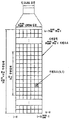
- FIG. 5 illustrates a method of mapping a virtual resource block to a physical resource block.
- Type 6 RA Resource Allocation
- Type 2 RA resource allocation examples
- FIG 9 and 10 illustrate examples of resource allocation according to an embodiment of the present invention.
- 11 to 13 illustrate examples of resource allocation according to another embodiment of the present invention.
- 16 is a block diagram showing the components of the transmitter 10 and the receiver 20 for carrying out the present invention.
- 17 illustrates an example of a signal processing process in the transmitter 10.
- a user equipment may be fixed or mobile, and various devices which transmit and receive user data and / or various control information by communicating with a base station (BS) belong to this.
- the UE may be a terminal equipment (MS), a mobile station (MS), a mobile terminal (MT), a user terminal (UT), a subscriber station (SS), a wireless device, a personal digital assistant (PDA), or a wireless modem. It may be called a modem, a handheld device, or the like.
- a BS generally refers to a fixed station communicating with the UE and / or another BS, and communicates with the UE and another BS to exchange various data and control information.
- the BS may be referred to in other terms such as ABS (Advanced Base Station), NB (Node-B), eNB (evolved-NodeB), BTS (Base Transceiver System), Access Point (Access Point), and Processing Server (PS).
- ABS Advanced Base Station
- NB Node-B
- eNB evolved-NodeB
- BTS Base Transceiver System
- Access Point Access Point
- PS Processing Server
- BS is collectively referred to as eNB.
- a node refers to a fixed point capable of transmitting / receiving a radio signal by communicating with a user equipment.
- Various forms of eNBs may be used as nodes regardless of their name.
- the node may be a BS, an NB, an eNB, a pico-cell eNB (PeNB), a home eNB (HeNB), a relay, a repeater, and the like.
- the node may not be an eNB.
- it may be a radio remote head (RRH), a radio remote unit (RRU).
- RRHs, RRUs, etc. generally have a power level lower than the power level of the eNB.
- RRH or RRU, RRH / RRU is generally connected to an eNB by a dedicated line such as an optical cable
- RRH / RRU and eNB are generally compared to cooperative communication by eNBs connected by a wireless line.
- cooperative communication can be performed smoothly.
- At least one antenna is installed at one node.
- the antenna may mean a physical antenna or may mean an antenna port, a virtual antenna, or an antenna group.
- Nodes are also called points. Unlike conventional centralized antenna systems (ie, single node systems) where antennas are centrally located at base stations and controlled by one eNB controller, in a multi-node system A plurality of nodes are typically located farther apart than a predetermined interval.
- the plurality of nodes may be managed by one or more eNBs or eNB controllers that control the operation of each node or schedule data to be transmitted / received through each node.
- Each node may be connected to the eNB or eNB controller that manages the node through a cable or dedicated line.
- the same cell identifier (ID) may be used or different cell IDs may be used for signal transmission / reception to / from a plurality of nodes.
- ID cell identifier
- each of the plurality of nodes behaves like some antenna group of one cell.
- a multi-node system may be regarded as a multi-cell (eg, macro-cell / femto-cell / pico-cell) system.
- the network formed by the multiple cells is particularly called a multi-tier network.
- the cell ID of the RRH / RRU and the cell ID of the eNB may be the same or may be different.
- both the RRH / RRU and the eNB operate as independent base stations.
- a cell refers to a certain geographic area in which one or more nodes provide a communication service. Therefore, in the present invention, communication with a specific cell may mean communication with an eNB or a node that provides a communication service to the specific cell.
- the downlink / uplink signal of a specific cell means a downlink / uplink signal from / to an eNB or a node that provides a communication service to the specific cell.
- the channel state / quality of a specific cell means a channel state / quality of a channel or communication link formed between an eNB or a node providing a communication service to the specific cell and a UE.
- a UE transmits a downlink channel state from a specific node on a channel CSI-RS (Channel State Information Reference Signal) resource to which the antenna port (s) of the specific node is assigned to the specific node. Can be measured using CSI-RS (s).
- CSI-RS Channel State Information Reference Signal
- adjacent nodes transmit corresponding CSI-RS resources on CSI-RS resources orthogonal to each other. Orthogonality of CSI-RS resources means that the CSI-RS is allocated by CSI-RS resource configuration, subframe offset, and transmission period that specify symbols and subcarriers carrying the CSI-RS. This means that at least one of a subframe configuration and a CSI-RS sequence for specifying the specified subframes are different from each other.
- Physical Downlink Control CHannel / Physical Control Format Indicator CHannel (PCFICH) / PHICH (Physical Hybrid automatic retransmit request Indicator CHannel) / PDSCH (Physical Downlink Shared CHannel) are respectively DCI (Downlink Control Information) / CFI ( Means a set of time-frequency resources or a set of resource elements that carry downlink format ACK / ACK / NACK (ACKnowlegement / Negative ACK) / downlink data, and also a physical uplink control channel (PUCCH) / physical (PUSCH).
- DCI Downlink Control Information
- CFI Means a set of time-frequency resources or a set of resource elements that carry downlink format ACK / ACK / NACK (ACKnowlegement / Negative ACK) / downlink data, and also a physical uplink control channel (PUCCH) / physical (PUSCH).
- Uplink Shared CHannel / PACH Physical Random Access CHannel refers to a set of time-frequency resources or a set of resource elements that carry uplink control information (UCI) / uplink data / random access signals, respectively.
- Resource elements (REs) are referred to as PDCCH / PCFICH / PHICH / PDSCH / PUCCH / PUSCH / PRACH RE or PDCCH / PCFICH / PHICH / PDSCH / PUCCH / PUSCH / PRACH resources, respectively.
- the expression that the user equipment transmits PUCCH / PUSCH / PRACH is used as the same meaning as transmitting uplink control information / uplink data / random access signal on or through the PUSCH / PUCCH / PRACH, respectively.
- the expression that the eNB transmits PDCCH / PCFICH / PHICH / PDSCH is used in the same sense as transmitting downlink data / control information on or through the PDCCH / PCFICH / PHICH / PDSCH, respectively.
- the time resource means a radio resource defined in the time domain
- the frequency resource means a radio resource defined in the frequency domain
- the spatial resource means a radio resource defined in the spatial domain.
- Temporal resources can be identified by OFDM / SC-FDM symbol, slot, subframe, or frame
- frequency resources can be identified by subcarrier, RB, RBG, carrier, and spatial resources by layer or antenna port. Can be distinguished.
- Figure 1 illustrates an example of a radio frame structure used in a wireless communication system.
- Figure 1 (a) shows a frame structure for frequency division duplex (FDD) used in the 3GPP LTE / LTE-A system
- Figure 1 (b) is used in the 3GPP LTE / LTE-A system
- the frame structure for time division duplex (TDD) is shown.
- a radio frame used in a 3GPP LTE / LTE-A system has a length of 10 ms (307200 T s ) and consists of 10 equally sized subframes (subframes). Numbers may be assigned to 10 subframes in one radio frame.
- Each subframe has a length of 1 ms and consists of two slots. 20 slots in one radio frame may be sequentially numbered from 0 to 19. Each slot is 0.5ms long.
- the time for transmitting one subframe is defined as a transmission time interval (TTI).
- the time resource may be classified by a radio frame number (also called a radio frame index), a subframe number (also called a subframe number), a slot number (or slot index), and the like.
- the radio frame may be configured differently according to the duplex mode. For example, in the FDD mode, since downlink transmission and uplink transmission are divided by frequency, a radio frame includes only one of a downlink subframe or an uplink subframe for a specific frequency band. In the TDD mode, since downlink transmission and uplink transmission are separated by time, a radio frame includes both a downlink subframe and an uplink subframe for a specific frequency band.
- Table 1 illustrates a DL-UL configuration of subframes in a radio frame in the TDD mode.
- D represents a downlink subframe
- U represents an uplink subframe
- S represents a special subframe.
- the singular subframe includes three fields of Downlink Pilot TimeSlot (DwPTS), Guard Period (GP), and Uplink Pilot TimeSlot (UpPTS).
- DwPTS is a time interval reserved for downlink transmission
- UpPTS is a time interval reserved for uplink transmission.
- Table 2 illustrates the configuration of a singular frame.
- FIG. 2 illustrates an example of a downlink / uplink (DL / UL) slot structure in a wireless communication system.
- FIG. 2 shows a structure of a resource grid of a 3GPP LTE / LTE-A system. There is one resource grid per antenna port.
- a slot includes a plurality of Orthogonal Frequency Division Multiplexing (OFDM) symbols in a time domain and a plurality of resource blocks (RBs) in a frequency domain.
- An OFDM symbol may mean a symbol period.
- a signal transmitted in each slot may be represented by a resource grid including N DL / UL RB * N RB sc subcarriers and N DL / UL symb OFDM symbols.
- N DL RB represents the number of resource blocks (RBs) in the downlink slot
- N UL RB represents the number of RBs in the UL slot.
- N DL RB and N UL RB depend on DL transmission bandwidth and UL transmission bandwidth, respectively.
- N DL symb represents the number of OFDM symbols in the downlink slot
- N UL symb represents the number of OFDM symbols in the UL slot.
- N RB sc represents the number of subcarriers constituting one RB.
- the OFDM symbol may be called an OFDM symbol, a Single Carrier Frequency Division Multiplexing (SC-FDM) symbol, or the like according to a multiple access scheme.
- the number of OFDM symbols included in one slot may vary depending on the channel bandwidth and the length of the cyclic prefix (CP). For example, in case of a normal CP, one slot includes 7 OFDM symbols, whereas in case of an extended CP, one slot includes 6 OFDM symbols.
- FIG. 2 illustrates a subframe in which one slot includes 7 OFDM symbols for convenience of description, embodiments of the present invention can be applied to subframes having other numbers of OFDM symbols in the same manner. Referring to FIG.
- each OFDM symbol includes N DL / UL RB * N RB sc subcarriers in the frequency domain.
- the types of subcarriers may be divided into data subcarriers for data transmission, reference signal subcarriers for transmission of reference signals, null subcarriers for guard band, and direct current (DC) components.
- the null subcarrier for the DC component is a subcarrier left unused and is mapped to a carrier frequency f 0 during an OFDM signal generation process or a frequency upconversion process.
- the carrier frequency is also called the center frequency.
- One RB is defined as N DL / UL symb (e.g., seven) consecutive OFDM symbols in the time domain and is defined by N RB sc (e.g., twelve) consecutive subcarriers in the frequency domain. Is defined.
- N DL / UL symb e.g., seven
- N RB sc e.g., twelve
- a resource composed of one OFDM symbol and one subcarrier is called a resource element (RE) or tone. Therefore, one RB is composed of N DL / UL symb * N RB sc resource elements.
- Each resource element in the resource grid may be uniquely defined by an index pair (k, 1) in one slot.
- k is an index given from 0 to N DL / UL RB * N RB sc ⁇ 1 in the frequency domain
- l is an index given from 0 to N DL / UL symb ⁇ 1 in the time domain.
- Two RBs each occupying N RB sc consecutive subcarriers in one subframe and one located in each of two slots of the subframe, are called a physical resource block (PRB) pair.
- Two RBs constituting a PRB pair have the same PRB number (or also referred to as a PRB index).
- FIG 3 illustrates a downlink (DL) subframe structure used in a 3GPP LTE / LTE-A system.
- a DL subframe is divided into a control region and a data region in the time domain.
- up to three (or four) OFDM symbols located in the first slot of a subframe correspond to a control region to which a control channel is allocated.
- a resource region available for PDCCH transmission in a DL subframe is called a PDCCH region.
- the remaining OFDM symbols other than the OFDM symbol (s) used as the control region correspond to a data region to which a Physical Downlink Shared CHannel (PDSCH) is allocated.
- PDSCH Physical Downlink Shared CHannel
- a resource region available for PDSCH transmission in a DL subframe is called a PDSCH region.
- Examples of DL control channels used in 3GPP LTE include a physical control format indicator channel (PCFICH), a physical downlink control channel (PDCCH), a physical hybrid ARQ indicator channel (PHICH), and the like.
- the PCFICH is transmitted in the first OFDM symbol of a subframe and carries information about the number of OFDM symbols used for transmission of a control channel within the subframe.
- the PHICH carries a Hybrid Automatic Repeat Request (HARQ) ACK / NACK (acknowledgment / negative-acknowledgment) signal in response to the UL transmission.
- HARQ Hybrid Automatic Repeat Request
- DCI downlink control information
- DL-SCH downlink shared channel
- UL-SCH uplink shared channel
- paging channel a downlink shared channel
- the transmission format and resource allocation information of a downlink shared channel may also be called DL scheduling information or a DL grant, and may be referred to as an uplink shared channel (UL-SCH).
- the transmission format and resource allocation information is also called UL scheduling information or UL grant.
- the DCI carried by one PDCCH has a different size and use depending on the DCI format, and its size may vary depending on a coding rate.
- various formats such as formats 0 and 4 for uplink and formats 1, 1A, 1B, 1C, 1D, 2, 2A, 2B, 2C, 3, and 3A are defined for uplink.
- Hopping flag RB allocation, modulation coding scheme (MCS), redundancy version (RV), new data indicator (NDI), transmit power control (TPC), and cyclic shift DMRS Control information such as shift demodulation reference signal (UL), UL index, CQI request, DL assignment index, HARQ process number, transmitted precoding matrix indicator (TPMI), and precoding matrix indicator (PMI) information
- MCS modulation coding scheme
- RV redundancy version
- NDI new data indicator
- TPC transmit power control
- cyclic shift DMRS Control information such as shift demodulation reference signal (UL), UL index, CQI request, DL assignment index, HARQ process number, transmitted precoding matrix indicator (TPMI), and precoding matrix indicator (PMI) information
- UL shift demodulation reference signal
- CQI request UL assignment index
- HARQ process number transmitted precoding matrix indicator
- PMI precoding matrix indicator
- the PDCCH is transmitted on an aggregation of one or a plurality of consecutive control channel elements (CCEs).
- CCE is a logical allocation unit used to provide a PDCCH with a coding rate based on radio channel conditions.
- the CCE corresponds to a plurality of resource element groups (REGs). For example, one CCE corresponds to nine REGs and one REG corresponds to four REs.
- REGs resource element groups
- a CCE set in which a PDCCH can be located is defined for each UE.
- the set of CCEs in which a UE can discover its PDCCH is referred to as a PDCCH search space, simply a search space (SS).
- SS search space
- PDCCH candidate An individual resource to which a PDCCH can be transmitted in a search space is called a PDCCH candidate.
- the collection of PDCCH candidates that the UE will monitor is defined as a search space.
- a search space for each DCI format may have a different size, and a dedicated search space and a common search space are defined.
- the dedicated search space is a UE-specific search space and is configured for each individual UE.
- the common search space is configured for a plurality of UEs. Table 3 illustrates the aggregation levels that define the search spaces.
- One PDCCH candidate corresponds to 1, 2, 4, or 8 CCEs according to a CCE aggregation level.
- the eNB sends the actual PDCCH (DCI) on any PDCCH candidate in the search space, and the UE monitors the search space to find the PDCCH (DCI).
- monitoring means attempting decoding of each PDCCH in a corresponding search space according to all monitored DCI formats.
- the UE may detect its own PDCCH by monitoring the plurality of PDCCHs. Basically, since the UE does not know where its PDCCH is transmitted, every Pframe attempts to decode the PDCCH until every PDCCH of the corresponding DCI format has detected a PDCCH having its own identifier. It is called blind detection (blind decoding).
- the eNB may transmit data for the UE or the UE group through the data area.
- Data transmitted through the data area is also called user data.
- a physical downlink shared channel (PDSCH) may be allocated to the data area.
- Paging channel (PCH) and downlink-shared channel (DL-SCH) are transmitted through PDSCH.
- the UE may read data transmitted through the PDSCH by decoding control information transmitted through the PDCCH.
- Information indicating to which UE or UE group data of the PDSCH is transmitted, how the UE or UE group should receive and decode PDSCH data, and the like are included in the PDCCH and transmitted.
- a specific PDCCH is masked with a cyclic redundancy check (CRC) with a Radio Network Temporary Identity (RNTI) of "A", a radio resource (eg, a frequency location) of "B” and a transmission of "C".
- CRC cyclic redundancy check
- RNTI Radio Network Temporary Identity
- format information eg, transport block size, modulation scheme, coding information, etc.
- FIG. 4 illustrates an example of an uplink (UL) subframe structure used in a 3GPP LTE / LTE-A system.
- the UL subframe may be divided into a control region and a data region in the frequency domain.
- One or several physical uplink control channels may be allocated to the control region to carry uplink control information (UCI).
- One or several physical uplink shared channels may be allocated to a data region of a UL subframe to carry user data.
- the PUSCH may be transmitted together with a DeModulation Reference Signal (DMRS), which is a reference signal (RS) for demodulation of user data transmitted through the PUSCH.
- DMRS DeModulation Reference Signal
- the control region and data region in the UL subframe may also be called a PUCCH region and a PUSCH region, respectively.
- a sounding reference signal may be allocated to the data area.
- the SRS is transmitted in the OFDM symbol located at the end of the UL subframe in the time domain and in the data transmission band of the UL subframe, that is, in the data domain, in the frequency domain.
- SRSs of several UEs transmitted / received in the last OFDM symbol of the same subframe may be distinguished according to frequency location / sequence.
- SC-FDMA Single Carrier Frequency Division Multiplexing Access
- PUCCH and PUSCH are performed on one carrier. Can't send at the same time.
- whether to support simultaneous transmission of a PUCCH and a PUSCH may be indicated in a higher layer.
- subcarriers having a long distance based on a direct current (DC) subcarrier are used as a control region.
- subcarriers located at both ends of the UL transmission bandwidth are allocated for transmission of uplink control information.
- the DC subcarrier is a component that is not used for signal transmission and is mapped to a carrier frequency f 0 during frequency upconversion.
- the PUCCH for one UE is allocated to an RB pair belonging to resources operating at one carrier frequency in one subframe, and the RBs belonging to the RB pair occupy different subcarriers in two slots.
- the PUCCH allocated in this way is expressed as that the RB pair allocated to the PUCCH is frequency hopped at the slot boundary. However, if frequency hopping is not applied, RB pairs occupy the same subcarrier.
- PUCCH may be used to transmit the following control information.
- SR Service Request: Information used for requesting an uplink UL-SCH resource. It is transmitted using OOK (On-Off Keying) method.
- HARQ-ACK A response to a PDCCH and / or a response to a downlink data packet (eg, codeword) on a PDSCH. This indicates whether the PDCCH or PDSCH is successfully received.
- One bit of HARQ-ACK is transmitted in response to a single downlink codeword, and two bits of HARQ-ACK are transmitted in response to two downlink codewords.
- HARQ-ACK response includes a positive ACK (simple, ACK), negative ACK (hereinafter, NACK), DTX (Discontinuous Transmission) or NACK / DTX.
- NACK negative ACK
- DTX discontinuous Transmission
- HARQ-ACK is mixed with HARQ ACK / NACK, ACK / NACK.
- CSI Channel State Information
- MIMO Multiple Input Multiple Output
- RI rank indicator
- PMI precoding matrix indicator
- PRBs Physical Resource Blocks
- VRBs Virtual Resource Blocks
- the PRB is the same as that illustrated in FIG. That is, PRB is defined as N DL symb contiguous OFDM symbols in the time domain and N RB sc contiguous subcarriers in the frequency domain. PRBs are numbered 0-N DL RB- 1 in the frequency domain.
- the relation between the PRB number n PRB and the resource element ( k, l ) in the slot is as follows.
- VRB is a kind of logical resource allocation unit introduced for resource allocation.
- VRB has the same size as PRB.
- a VRB is divided into a localized VRB (Localized VRB, LVRB) and a distributed type VRB (Distributed VRB, DVRB).
- a pair of resource blocks are allocated together by a single VRB number n VRB across two slots in a subframe.
- Two PRBs, one located in two slots of a subframe and having the same VRB number, are called VRB pairs.
- FIG. 5 illustrates a method of mapping a virtual resource block to a physical resource block.
- DVRBs are mapped to PRBs through interleaving. Therefore, DVRBs having the same VRB number may be mapped to PRBs having different numbers in the first slot and the second slot. Specifically, the DVRB may be mapped to the PRB as shown in Table 4. Table 4 illustrates the RB gap values.
- N gap represents the frequency interval (eg, PRB unit) when VRBs of the same number are mapped to PRBs of the first slot and the second slot.
- N gap N gap, 1
- two gap values N gap, 1 and N gap, 2 are defined.
- min (A, B) represents the smaller of A or B, floor is a rounding operation, and floor (x) represents the largest integer not greater than x.
- VRB number interleaving of each interleaving unit may be performed using four columns and N row rows.
- N row ⁇ ceil (N to DL VRB / (4P)) ⁇ ⁇ P, where P represents a resource block group (RBG) size.
- RBG resource block group
- the UE interprets the resource allocation field based on the detected PDCCH DCI format.
- the resource allocation field in each PDCCH includes two parts of a resource allocation header field and actual resource block allocation information.
- PDCCH DCI formats 1, 2, and 2A for type 0 and type 1 resource allocation are distinguished from each other through a single bit resource allocation header field having the same format and existing according to a downlink system band. Specifically, type 0 RA is indicated as 0 and type 1 RA is indicated as 1.
- PDCCH DCI formats 1, 2 and 2A are used for type 0 or type 1 RAs, while PDCCH DCI formats 1A, 1B, 1C and 1D are used for type 2 RAs.
- PDCCH DCI format with Type 2 RA does not have a resource allocation header field.
- the resource allocation field indicates the PRB set of the first slot.
- the PRB set of the second slot is determined by the slot hopping rule.
- the resource block allocation information in a type 0 RA includes a bitmap indicating a resource block group (RBG) allocated to the terminal.
- RBG is a set of consecutive PRBs.
- RBG size (P) depends on the system band as shown in Table 5.
- N RBG ceil (N DL RB / P)
- N DL RB / P the floor (N DL RB / P) RBGs have a size P
- N DL RB mod P> 0 one of the RBGs is N DL RB -P ⁇ (floor (N DL RB / P)).
- mod represents a modulo operation.
- the size of the bitmap is N RBG and each bit corresponds to one RBG.
- the total RBG is indexed from 0 to N RBG- 1 in the frequency increasing direction, and RBG 0 to RBG N RBG- 1 is mapped from the most significant bit (MSB) of the bitmap to the least significant bit (LSB).
- resource block assignment information having an N RBG size in a type 1 RA indicates to a scheduled UE resources in a RBG subset in PRB units.
- RBG subset p (0 ⁇ p ⁇ P) consists of every P th RBG starting from RBG p.
- Resource block allocation information is composed of three fields. The first field is ceil ⁇ log 2 (P) ⁇ bits and indicates an RBG subset selected from the P RBG subsets. The second field is 1 bit and indicates the shift of resource allocation span within the subset. If the bit value is 1, a shift is triggered and vice versa.
- the third field contains a bitmap, each bit indicating one PRB in the selected RBG set.
- the bitmap portion used to indicate the PRB in the selected RBG subset is N TYPE1 RB in size and is defined as follows.
- the addressable PRB number in the selected RBG subset may start from the offset ( ⁇ shift (p)) for the smallest PRB number in the selected RBG subset and map to the MSB of the bitmap.
- N RBGsubset RB (p) represents the number of PRBs in RBG subset p and can be obtained according to the following.
- resource block allocation information indicates a set of LVRBs or DVRBs continuously allocated to a scheduled UE.
- a 1-bit flag indicates whether an LVRB or DVRB is allocated (eg, 0 indicates LVRB allocation and 1 indicates DVRB allocation).
- PDCCH DCI format 1C only DVRB is always allocated.
- the type 2 resource allocation field includes a resource indication value (RIV), and the RIV corresponds to a start resource block RB start and a length. The length represents the number of resource blocks allocated virtually consecutively.
- a new remote radio head (RRH) is being discussed.
- a plurality of carriers may be configured in one UE.
- Each of the carrier aggregated carriers is called a component carrier (CC), and a CC configured in the UE is called a serving CC.
- CC component carrier
- serving CC serving CC
- a PDCCH according to the existing 3GPP LTE (-A) standard may be allocated to a PDCCH region of a DL subframe, and a PDCCH may be additionally or separately allocated using some resources of the PDSCH region.
- the conventional PDCCH transmitted in the PDCCH region is transmitted using resources that span a wide frequency band in the frequency domain, whereas the PDCCH transmitted in the PDSCH region is usually transmitted using only a narrow frequency band.
- the PDCCH transmitted in the latter OFDM symbols (PDSCH region) of the DL subframe is embedded PDCCH (e-PDCCH). It is called).
- the e-PDCCH may be referred to as an enhanced PDCCH (E-PDCCH) or an advanced PDCCH (A-PDCCH), and the PDSCH / PUSCH scheduled by the e-PDCCH may also be called an e-PDSCH / e-PUSCH.
- E-PDCCH enhanced PDCCH
- A-PDCCH advanced PDCCH
- PDSCH / PUSCH scheduled by the e-PDCCH may also be called an e-PDSCH / e-PUSCH.
- the R-PDCCH transmits downlink control information.
- the R-PDCCH carries a DCI for RNs.
- R-PDCCH is transmitted / received in PDSCH region unlike normal 3GPP LTE PDCCH, and DL R-PDCCH (i.e., R-PDCCH carrying DL grant) has UL R-PDCCH (i.e. carrying UL grant in the first slot).
- R-PDCCH is transmitted / received in the second slot.
- the R-PDCCH may be regarded as a kind of e-PDCCH in that it is located in the PDSCH region.
- the present invention proposes a structure of the proposed e-PDCCH and a resource allocation method using the same to overcome the limitations of the existing PDCCH.
- the e-PDCCH is largely classified into two categories-a DL grant and a UL grant.
- the DL grant carries information on time / frequency / spatial resources of the PDSCH carrying information that the UE should receive and information for decoding.
- the UL grant carries information on time / frequency / spatial resources of a PUSCH and data for decoding, which carries data that the UE should transmit on the uplink.
- the allocated resource region includes (a) the data for the UE or a UE group including the UE, (b) a UL grant for the UE, (c) There may be a DL grant for another UE and / or (d) an UL grant for another UE.
- the process for signal recovery varies according to the type of signal.
- the present invention proposes an (implicit) resource assignment method for a single layer or multiple layers, which is suitable for an e-PDCCH.
- the time-frequency region indicated by the time axis and the frequency axis corresponds to a downlink resource region allocated to one UE, and may have various sizes.
- resources may be allocated to the UE in units of PRB pairs or RBGs.
- the e-PDCCH DL / UL grant of the present invention may occupy one RB in the allocated pair or RBG, but may be configured to occupy a resource unit smaller than the RB.
- a number of REs corresponding to one-half or one-quarter of the RB may be used, with 12 subcarriers in which the RB is localized or continuous, and X rather than one slot.
- X has a structure defined by subcarriers of positive integers other than 12 and Y OFDM symbols (Y is positive integers other than 6 or 7) or is distributed or non-consecutive ) May have a structure defined by subcarriers and / or distributed / discontinuous OFDM symbols.
- Y is positive integers other than 6 or 7
- Y is distributed or non-consecutive
- a resource unit a unit of a resource occupied by an e-PDCCH carrying a DL / UL grant.
- an RBG consists of one or more consecutive RBs in the frequency domain.
- FIGS. 9 to 15 may be exemplified when the RBG includes three consecutive RBs.
- RB means PRB or VRB.
- 9 to 15 illustrate a case in which a predetermined resource region allocated to a UE or a UE group is divided into six small regions and one UL grant exists within the predetermined resource region, but the predetermined resource allocated to the UE or UE group is illustrated.
- the UL grant and / or the DL grant may be located in the predetermined resource region in a different form from that of FIGS. 9 to 15.
- a DL grant or higher layer signal transmitted through the PDCCH may carry information about a search space for the e-PDCCH of the UE.
- a predetermined downlink resource region eg, RBG
- RBG predetermined downlink resource region
- a specific resource unit eg, a resource in the RBG
- a resource unit with the lowest index of units may be defined as an e-PDCCH search space carrying a DL grant.
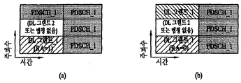
- FIG 9 and 10 illustrate examples of resource allocation according to an embodiment of the present invention.
- one bit (hereinafter, referred to as RA bit) of RA information included in a DL grant is assigned to (1) a PDSCH in a remaining region except for resources occupied by the DL grant among the allocated resource regions, or (2) It is interpreted as a signal indicating that PDSCH has been allocated to a region other than the resource occupied by the DL grant and a resource previously designated to occupy the UL grant.
- the location of the UL grant may be a resource unit (eg, a PRB) adjacent to the DL grant, but may also mean a resource unit of a previously designated location.
- FIG 9 illustrates a case where the present embodiment is applied to downlink signal transmission through a single antenna port (or layer).
- an eNB when an eNB allocates PDSCH (s) to resource units other than resource units occupied by a DL grant among RBG resource units to be allocated to a UE, the eNB May set the RA bit in the DL grant to 1 and transmit the DL grant to the UE through an e-PDCCH.
- the UE receives the DL grant including the RA bit set to 1, it can be seen that PDSCH (s) are allocated to the remaining resource units except the resource unit occupied by the DL grant among the resource units in the allocated RBG. have.
- the UE detects / acquires DCI by performing signal processing for restoring control information with respect to a signal received on a resource unit occupied by a DL grant among signals received on an allocated RBG, and detects / acquires a DCI and occupies the DL grant.
- an eNB when an eNB allocates a UL grant as well as a DL grant and a PDSCH to resource units of an RBG to be allocated to a UE, the eNB sets the RA bit in the DL grant to 0.
- the DL grant may be transmitted to the UE through an e-PDCCH.
- the UE receives the DL grant including the RA bit set to 0, the remaining resources except for the resource unit occupied by the DL grant and the resource unit occupied by a predetermined UL grant among the resource units in the RBG allocated to the UE.
- Units may be interpreted as having been assigned PDSCH (s).
- the UE detects and acquires a DL grant DCI by performing a signal processing procedure for restoring control information on a signal received on a resource unit occupied by a DL grant among signals received on an allocated RBG, and occupies a UL grant.
- Performing a signal processing for restoring control information on a signal received on a predetermined resource unit to detect / acquire a UL grant DCI, and receive the received data on resource units other than the resource unit occupied by the DL grant.
- Downlink data can be detected / acquired by performing a signal processing process for data restoration on the signal.
- FIG. 10 illustrates a case where the present embodiment is applied to downlink signal transmission (ie, downlink signal transmission by spatial multiplexing) through a plurality of antenna ports (or layers).
- FIG. 10 illustrates a case where the present embodiment is applied to a single user MIMO (SU-MIMO) in which one UE uses all layers.
- SU-MIMO single user MIMO
- a DL grant of antenna port 0 (hereinafter referred to as port 0) is detected and the RA bit in the DL grant is 1, that is, a DL grant transmitted through port 0 of the eNB is detected.
- the RA bit in the DL grant is 1, it means that the PDSCH is allocated to other resource units except for the corresponding resource unit of port 0 where the DL grant is detected and resource units of the remaining port (eg, port 1).
- the spatial multiplexing technique may not be applied to the transmission of the DL grant. When the spatial multiplexing technique is not applied to the transmission of the DL grant, as shown in FIG.
- the resource unit of the port 1 corresponding to the resource unit of the port 0 where the DL grant is detected (eg, the DL grant is detected).
- PDSCH is not mapped to a resource unit occupying the same time-frequency resource as that of the resource unit of port 0).
- a UL grant is transmitted from a resource unit of a predetermined position among resource regions allocated to the UE, and the DL grant and the UL grant are transmitted.
- the PDSCH is allocated to the remaining resource regions except for the resource units occupied by.
- the spatial multiplexing technique may not be applied to the transmission of the DL / UL grant for reliable detection of the DL / UL grant.
- MU-MIMO Multi-User MIMO
- an e-PDCCH of another UE may exist in a resource unit indicated by "no mapping" in FIGS. 10 (a) and 10 (b).
- the e-PDCCH itself is transmitted through multiple layers, the e-PDCCH of the corresponding (SU-MIMO) UE may be transmitted / received in a resource unit indicated by “no mapping”.
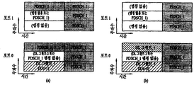
- 11 to 13 illustrate examples of resource allocation according to another embodiment of the present invention.
- 11 through 13 illustrate a method of transmitting a plurality of DL grants for a plurality of UEs in an RBG.
- FIG. 11 illustrates a case in which a plurality of DL grants allocated to an RBG are transmitted / received through a single layer / port
- FIGS. 12 and 13 illustrate a case in which the embodiment of FIG. 11 is extended to a plurality of layers / ports. It is an example.
- the location of the DL grant for another UE may be predefined as being a resource unit adjacent to the resource unit occupied by the DL grant of the UE, or the eNB is configured to have the location of the DL grant for another UE semi-statically configured May be signaled in advance.
- the RA bits described with reference to FIGS. 9 and 10 may be used as they are in FIGS. 11 to 13. However, when the eNB transmits not only the DL grant_1 but also the DL grant_2 in the RBG allocated to the UE 1, the UE 1 may know whether the DL grant_2 exists in the RBG allocated to the UE 1 using only RA bits. none. This is because the RA bit described in FIG. 9 and FIG. 10 only indicates the presence or absence of the UL grant of the UE 1. If UE 1 does not know the existence of the DL grant_2 and processes the signal received through the resource unit occupied by the DL grant_2 as data, the UE1 is likely to fail demodulation of the PDSCH_1.
- this embodiment causes the eNB to signal additional indication information indicating the presence or absence of the DL grant_2 to the UE 1 so that UE 1 can know the existence of the DL grant_2. According to this embodiment, demodulation performance of PDSCH_1 can be improved.
- UE 1 may know whether to demodulate data of PDSCH_1 from a signal received at a resource unit available for transmission of DL grant_2 according to the additional indication information. If the additional indication information indicates the presence of DL grant_2, UE 1 does not use the signal received on the resource unit indicated as "DL grant_1 or PDSCH_1" in FIG. 11 for data demodulation. On the other hand, if the additional indication information indicates the absence of the DL grant_2, UE 1 demodulates data from the signal received on the resource unit indicated as "DL grant_1 or PDSCH_1" in FIG.
- a resource unit mapped to a DL grant_1 in a specific layer / port may not be mapped to a PDSCH in another layer / port.
- an e-PDCCH of another UE may exist in a resource unit indicated by “no mapping” in FIG. 12.
- the e-PDCCH itself is transmitted through multiple layers, the e-PDCCH of UE 1 may be transmitted / received in a resource unit indicated by “no mapping”.
- the PDSCH may be transmitted / received in a resource unit indicated by “no mapping”.
- the PDSCH_1 signal may be transmitted / received in the corresponding resource unit of the port 1 and the port 2.
- the additional indication information indicates that the DL grant_2 is mapped to the resource unit in the RBG
- the DL grant_2 is transmitted / received in the corresponding resource unit of port 0 and shown in FIG. 12 on the corresponding resource unit of port 1. No signal may be sent.
- the e-PDCCH of another UE may be mapped to the resource unit indicated as “no mapping or PDSCH_1” in FIG. 12, and the e-PDCCH itself may be multiplexed.
- DL grant_2 of UE_2 may be mapped, and PDSCH may also be mapped if the inter-layer interference problem is ignored.
- FIG. 13 illustrates FIG. 12 in more detail.
- a control channel eg, e-PDCCH
- spatial multiplexing is applied to a data channel (eg, PDSCH).
- port 0 is used for e-PDCCH transmission among a plurality of ports of the eNB.
- a grant indication is signaling information indicating whether or not a DL grant_2 is transmitted.
- the signaling information may be configured as a signal separate from the existing signal, or may be configured by using a carrier indicator field (CIF) and other dedicated fields available in the DCI format.
- CIF is a field used to indicate which DCI is DCI.
- the eNB may be considered to have performed cross-carrier scheduling.
- the GI informs whether a DL grant (eg, DL grant_2) of another UE exists in the RBG to which a specific DL grant (eg, DL grant_1) is transmitted / detected.
- a GI of 1 may indicate that a DL grant of another UE exists in a corresponding RBG
- a GI of 0 may indicate that a DL grant of another UE does not exist in a corresponding RBG.
- the RA grant of the DL grant is 1, it means that the PDSCH is transmitted at the designated location. If the RA grant of the DL grant is 0, it means that the UL grant_1 is transmitted at the designated location.
- the location where the UE is to transmit / detect the RBG of its DL grant may be pre-designated.
- UE 1 may receive in advance information from the eNB about a search space to attempt decoding of the DL grant_1.
- the UE 1 receives / detects the DL grant_1 on a resource unit for a DL grant_1 of an RBG of port 0 and a resource for the DL grant_1 of an RBG of port 1.
- the unit receives / detects a null signal. That is, the UE 1 may not detect a signal at all on the resource unit for the DL grant_1 among the RBGs of the port 1 or may process the signal as a noise / interference signal even if any signal is received.
- the UE 1 may know that a DL grant_2 exists in the RBG allocated to the UE 1, and is reserved or designated for the DL grant_2 (hereinafter, reserved / designated).
- the signals transmitted by port 0 and port 1 on the resource unit may not be detected at all or may be regarded as noise / interference signals.
- the UE 1 receives / detects the DL grant_1 on a resource unit for a DL grant_1 of an RBG of port 0 and a resource for the DL grant_1 of an RBG of port 1.
- the unit receives / detects a null signal. If the RA included in the DL grant_1 is 1, the UE 1 may determine that there is no UL grant in the RBG. Upon receiving the GI set to 0, the UE 1 may know that the DL grant_2 does not exist in the RBG allocated to the UE 1.
- the UE 1 receives / detects the DL grant_1 on a resource unit for a DL grant_1 of an RBG of port 0 and a resource for the DL grant_1 of an RBG of port 1.
- the unit receives / detects a null signal.
- the UE 1 may know that a DL grant_2 exists in the RBG allocated to it, and port 0 and port 1 are transmitted on a resource unit reserved / designated for the DL grant_2.
- One signal may not be detected at all or may be considered as a noise / interference signal.
- the UE 1 receives / detects the DL grant_1 on a resource unit for a DL grant_1 of an RBG of port 0 and a resource for the DL grant_1 of an RBG of port 1.
- the unit receives / detects a null signal.
- the UE 1 may know that the DL grant_2 does not exist in the RBG allocated to it, and that the PDSCH_1 signal is transmitted on the resource unit reserved / specified in the DL grant_2. Can be.
- the embodiments of FIGS. 14 and 15 always leave the region in which the DL grant_2 is transmitted (eg, the DL grant search space) regardless of whether the DL grant_2 is actually transmitted or not. That is, the embodiments of FIGS. 14 and 15 reserve resources for the DL grant_2 in the resource region allocated to the UE. 14 and 15 results in a waste of resources if the resources reserved for the DL grant_2 are not actually used, i.e., if the DL grant_2 is not transmitted on the reserved resources.
- the resource allocation of the UL grant or PDSCH_1 may be implicitly represented using only the RA bits described with reference to FIGS. 9 and 10.
- FIG. 14 shows an example in which an embodiment of reserving resources for a DL grant_2 is applied to a single layer / port transmission
- FIG. 15 illustrates an embodiment of reserving a resource for a DL grant_2 in a multi-layer / port transmission. The applied example is shown.
- a signal received on a resource unit reserved for a DL grant_2 is not used for data demodulation regardless of whether or not the DL grant_2 is actually transmitted. This is because the resource unit reserved for the DL grant_2 is not used for transmission of the PDSCH in this embodiment.
- the port 0 may identify the predetermined resource unit.
- the DL grant_2 to the UE and port 1 may transmit no signal on the predetermined resource unit. In other words, the transmit power of the predetermined resource unit of port 1 is set to zero.
- the DL grant_2 and the PDSCH_1 may be multiplexed and transmitted on the predetermined resource unit.
- the DL grant_2 is not on the predetermined resource unit.
- DL grants of other UEs may be transmitted, and if DL transmission is applied to the e-PDCCH, DL grant_2 may be transmitted on port 0 and port 1 on the predetermined resource unit.
- port 1 has zero transmit power as shown in FIG. 15 in the resource unit corresponding to the resource unit reserved / designated for DL grant_1.
- the signal may be transmitted through the PDSCH or the PDSCH or the e-PDCCH.
- FIG. 9 to 15 illustrate a case in which spatial multiplexing (multiplexing of e-PDCCH and e-PDCCH or multiplexing of e-PDCCH and PDSCH) is not performed on the e-PDCCH. That is, in FIG. 9 to FIG. 15, when an e-PDCCH is mapped to a resource unit of a specific port, no information / data is mapped to the corresponding resource unit of another port. However, if the spatial multiplexing of the e-PDCCH and the e-PDCCH or the spatial multiplexing of the e-PDCCH and the PDSCH should be performed even though the interference between the layers occurs, it is preferable that the rules regarding the spatial multiplexing are defined in advance.
- the e-PDCCH DL grant of the present invention may all be constrained to be located only in the first slot.
- three resource units located forward on the time axis are resource units located in the first slot of the downlink subframe and three resource units located behind the two are located in the downlink subframe. It can be understood that the resource units located in the first slot.
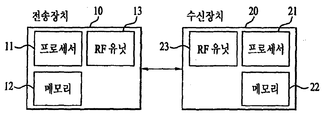
- 16 is a block diagram showing the components of the transmitter 10 and the receiver 20 for carrying out the present invention.
- the transmitter 10 and the receiver 20 are radio frequency (RF) units 13 and 23 capable of transmitting or receiving radio signals carrying information and / or data, signals, messages, and the like, and in a wireless communication system.
- the device is operatively connected to components such as the memory 12 and 22 storing the communication related information, the RF units 13 and 23 and the memory 12 and 22, and controls the components.
- a processor 11, 21 configured to control the memory 12, 22 and / or the RF units 13, 23, respectively, to perform at least one of the embodiments of the invention described above.
- the memories 12 and 22 may store a program for processing and controlling the processors 11 and 21, and may temporarily store input / output information.
- the memories 12 and 22 may be utilized as buffers.
- the processors 11 and 21 typically control the overall operation of the various modules in the transmitter or receiver. In particular, the processors 11 and 21 may perform various control functions for carrying out the present invention.
- the processors 11 and 21 may also be called controllers, microcontrollers, microprocessors, microcomputers, or the like.
- the processors 11 and 21 may be implemented by hardware or firmware, software, or a combination thereof.
- application specific integrated circuits ASICs
- DSPs digital signal processors
- DSPDs digital signal processing devices
- PLDs programmable logic devices
- FPGAs field programmable gate arrays
- the firmware or software when implementing the present invention using firmware or software, may be configured to include a module, a procedure, or a function for performing the functions or operations of the present invention, and configured to perform the present invention.
- the firmware or software may be provided in the processors 11 and 21 or stored in the memory 12 and 22 to be driven by the processors 11 and 21.
- the processor 11 of the transmission apparatus 10 is predetermined from the processor 11 or a scheduler connected to the processor 11 and has a predetermined encoding and modulation on a signal and / or data to be transmitted to the outside. After performing the transmission to the RF unit 13. For example, the processor 11 converts the data sequence to be transmitted into K layers through demultiplexing, channel encoding, scrambling, and modulation.
- the coded data string is also called a codeword and is equivalent to a transport block, which is a data block provided by the MAC layer.
- One transport block (TB) is encoded into one codeword, and each codeword is transmitted to a receiving device in the form of one or more layers.
- the RF unit 13 may include an oscillator for frequency upconversion.
- the RF unit 13 may include N t transmit antennas, where N t is a positive integer greater than or equal to one.
- the signal processing of the receiver 20 is the reverse of the signal processing of the transmitter 10.
- the RF unit 23 of the receiving device 20 receives a radio signal transmitted by the transmitting device 10.
- the RF unit 23 may include N r receive antennas, and the RF unit 23 frequency down-converts each of the signals received through the receive antennas to restore the baseband signal. .
- the RF unit 23 may include an oscillator for frequency downconversion.
- the processor 21 may decode and demodulate a radio signal received through a reception antenna to restore data originally transmitted by the transmission apparatus 10.
- the RF units 13, 23 have one or more antennas.
- the antenna transmits a signal processed by the RF units 13 and 23 to the outside or receives a radio signal from the outside according to an embodiment of the present invention under the control of the processors 11 and 21. , 23).
- Antennas are also called antenna ports.
- Each antenna may correspond to one physical antenna or may be configured by a combination of more than one physical antenna elements.
- the signal transmitted from each antenna can no longer be decomposed by the receiver 20.
- a reference signal (RS) transmitted corresponding to the corresponding antenna defines an antenna viewed from the perspective of the receiving apparatus 20, and includes a channel or whether the channel is a single radio channel from one physical antenna.
- RS reference signal
- the receiver 20 enables channel estimation for the antenna. That is, the antenna is defined such that a channel carrying a symbol on the antenna can be derived from the channel through which another symbol on the same antenna is delivered.
- the antenna In the case of an RF unit supporting a multi-input multi-output (MIMO) function for transmitting and receiving data using a plurality of antennas, two or more antennas may be connected.
- MIMO multi-input multi-output
- the UE operates as the transmitter 10 in the uplink and the receiver 20 in the downlink.
- the eNB operates as the receiving device 20 in the uplink, and operates as the transmitting device 10 in the downlink.
- the processor, the RF unit and the memory provided in the UE will be referred to as a UE processor, the UE RF unit and the UE memory, respectively, and the processor, the RF unit and the memory provided in the eNB will be referred to as an eNB processor, the eNB RF unit and the eNB memory, respectively.
- 17 illustrates an example of a signal processing process in the transmitter 10.
- the processor 11 in the transmitter 100 may include a channel encoder (not shown), a scrambler 301, a modulation mapper 302, a layer mapper 303, a precoder 304, and a resource element mapper. 305, an OFDM signal generator 306.
- the transmitter 10 may include one or more channel encoders (not shown) for channel encoding the UCI.
- the channel encoder may output an encoded bit sequence by applying a (30, O) RM code to the UCI.
- the transmitter 10 may include a plurality of channel encoders for channel encoding of each of a plurality of segments obtained by splitting UCI.
- the transmitter 10 may transmit one or more codewords. Coded bits in each codeword are scrambled by the scrambler 301 and transmitted on a physical channel. Codewords are also referred to as data streams and are equivalent to data blocks provided by the MAC layer. The data block provided by the MAC layer may also be referred to as a transport block.
- the scrambled bits are modulated into complex-valued modulation symbols by the modulation mapper 302.
- the modulation mapper 302 may modulate the scrambled bits according to a predetermined modulation scheme and place them as complex modulation symbols representing positions on a signal constellation. There is no restriction on a modulation scheme, and m-Phase Shift Keying (m-PSK) or m-Quadrature Amplitude Modulation (m-QAM) may be used to modulate the encoded data.
- m-PSK m-Phase Shift Keying
- m-QAM m-Quadrature Amplitude Modulation
- the complex modulation symbol is mapped to one or more transport layers by the layer mapper 303.
- Codeword-to-layer mapping may vary depending on the transmission scheme.
- SC-FDM access SC-FDMA
- SC-FDMA SC-FDM access
- the processor 11 of the transmitter 10 may include a conversion precoder.
- a Discrete Fourier Transform (DFT) module 307 (or a Fast Fourier Transform (FFT) module) may be used as the transform precoder.
- the transform precoder generates complex symbols by performing a Discrete Fourier Transform (DFT) or a Fast Fourier Transform (FFT) (hereinafter referred to as DFT / FFT) on the complex modulation symbols divided for mapping to each antenna port.
- DFT Discrete Fourier Transform
- FFT Fast Fourier Transform
- the complex symbols are precoded by the precoder 304 for transmission on the antenna port.
- the precoder 304 processes the complex symbols in a MIMO scheme according to a multiple transmit antenna to output antenna specific symbols and distributes the antenna specific symbols to the corresponding resource element mapper 305. That is, mapping of the transport layer to the antenna port is performed by the precoder 304.
- the precoder 304 may be output to the matrix z of the layer mapper 303, an output x N t ⁇ M t precoding matrix W is multiplied with N t ⁇ M F of the.
- the precoder 304 may distribute complex symbols input from one transform precoder to one resource element mapper associated with one antenna port.
- the resource element mapper 305 maps / assigns the complex modulation symbol for each antenna port to the appropriate resource elements.
- the resource element mapper 305 may assign a complex modulation symbol for each antenna port to an appropriate subcarrier and multiplex it according to a user.
- An OFDM signal generator 306 modulates a complex modulation symbol for each antenna port, that is, an antenna specific symbol by an OFDM or SC-FDM scheme, to perform a complex-valued time domain (OFDM) orthogonal frequency division multiplexing (OFDM).
- a symbol signal or a complex time domain SC-FDM (Single Carrier Frequency Division Multiplexing) symbol signal is generated.
- the OFDM signal generator 306 may perform an inverse fast fourier transform (IFFT) on an antenna specific symbol, and a cyclic prefix (CP) may be inserted into a time domain symbol on which the IFFT is performed.
- the OFDM symbol is transmitted to the receiving apparatus through each transmit antenna through digital-to-analog conversion, frequency upconversion, and the like.
- the OFDM signal generator 306 may include an IFFT module and a CP inserter, a digital-to-analog converter (DAC), a frequency up-converter, and the like.
- the signal processing of the receiver 20 is the reverse of the signal processing of the transmitter 10.
- the processor 21 of the receiving device 20 performs decoding and demodulation on the radio signal received through the RF unit 23 from the outside.
- the RF unit 23 may include N r multiple receive antennas, and each of the signals received through the receive antennas are restored to a baseband signal, and then transmitted by the transmitter 10 through multiplexing and MIMO demodulation.
- the data string is restored to the intended data sequence.
- the processor 21 may include a signal restorer for restoring a received signal to a baseband signal, a multiplexer for combining and multiplexing the received processed signal, and a channel demodulator for demodulating the multiplexed signal sequence with a corresponding codeword. .
- the signal restorer, the multiplexer, and the channel demodulator may be composed of one integrated module or each independent module for performing their functions. More specifically, the signal restorer is an analog-to-digital converter (ADC) for converting an analog signal into a digital signal, a CP remover for removing a CP from the digital signal, and a fast fourier transform (FFT) to the signal from which the CP is removed.
- FFT module for outputting a frequency domain symbol by applying a, and may include a resource element demapper (equalizer) to restore the frequency domain symbol to an antenna-specific symbol (equalizer).
- the antenna specific symbol is restored to a transmission layer by a multiplexer, and the transmission layer is restored to a codeword intended to be transmitted by the transmission apparatus 10 by a channel demodulator.
- the processor 21 when the receiver 20 receives a signal transmitted by the SC-FDMA method, the processor 21 further includes an Inverse Discrete Fourier Transform (IDFT) module (or IFFT module). Include.
- IDFT Inverse Discrete Fourier Transform
- the IDFT / IFFT module performs IDFT / IFFT on the antenna specific symbol recovered by the resource element demapper and outputs the IDFT / IFFT symbol to the multiplexer.
- the scrambler 301, the modulation mapper 302, the layer mapper 303, the transform precoder 307, the precoder 304, the resource element mapper 305, and the OFDM signal generator 306 are provided.
- the RF unit 13 of the transmitter 10 includes these components.
- the signal restorer, the multiplexer, the channel demodulator, etc. are described as being included in the processor 21 of the receiver 20, but these components are included in the RF unit 23 of the receiver 20. It is also possible.
- the transmission device 10 called a layer is obtained by converting data to be transmitted by the reception device 20 through demultiplexing, channel encoding, modulation, etc., and inputting the precoder. Corresponds to the path.
- the receiver 20 transmits each signal transmitted to the receiver 20 using a demodulation reference signal (DMRS) for each layer.
- DMRS demodulation reference signal
- the signal of the layer can be demodulated.
- DMRS is also called UE-specific RS because DMRS is not used by all UEs in a cell but by a specific UE or a specific UE group.
- a UE-specific RS is transmitted for each layer or antenna port used for the DL signal. For example, if an eNB transmits a PDSCH through four layers, the eNB transmits the four layers with four UE-specific RSs that correspond one-to-one to the four layers. Since the UE-specific RS transmitted by the eNB to the UE is transmitted to the UE after being precoded by the same precoder 304 as the corresponding layer, the UE can demodulate the signal of the layer using the UE-specific RS.
- the mapping relationship between the layer and the antenna port depends on the precoding matrix set in the precoder 304, but the UE may be UE-specific RS (s), or UE-specific RS (s) and RS for channel measurement (e.g. For example, it is possible to distinguish antenna ports of an eNB used for transmission of a downlink signal using a cell-specific RS (CRS) or a CSI-RS (CSI-RS).
- s UE-specific RS
- s UE-specific RS
- RS for channel measurement e.g.
- CRS cell-specific RS
- CSI-RS CSI-RS
- the eNB processor controls the eNB RF unit to transmit the PDCCH, e-PDCCH and / or PDSCH, and the UE processor may control the PDCCH, e-PDCCH and / or the like. Or control the UE RF unit to receive a PDSCH.
- the UE processor controls the eNB RF unit to transmit the PUCCH and the PUSCH, and the eNB processor controls the eNB RF unit to receive the PUCCH and the PUSCH.
- the eNB processor may control the eNB RF unit to allocate a certain DL resource region to the UE and transmit a DL grant for the UE on the e-PDCCH.
- the eNB processor may set the RA bit in the GI and / or the DL grant of the UE according to whether to allocate a UL grant and / or a DL grant of another UE to the allocated resource region.
- the eNB processor may control the eNB RF unit to send GI and RA bits.
- the eNB processor may control the eNB RF unit to send the RA bit on an e-PDCCH.
- the UE RF unit may receive a signal carrying GI and RA bits transmitted by the eNB.
- the UE processor may detect an e-PDCCH carrying a DL grant in the search space of the UE, and may know a resource region allocated to the UE based on the DL grant.
- the UE processor may know whether a UL grant exists in the allocated resource region based on the RA bit in the DL grant.
- the UE processor may know whether a DL grant (hereinafter, referred to as another DL grant) for another UE exists in the allocated resource region based on the GI.
- the UE processor is configured to receive a UE RF unit to receive a null signal on time-frequency-spatial resources corresponding to the UL grant and / or the other DL grant.
- the signal received or detected on the time-frequency-spatial resource may be treated as an interference / noise signal.
- the UE processor among the allocated resource regions, is a resource unit whose DL grant is detected, a resource unit of another DL grant indicated by the GI, or a resource unit other than the resource unit of the UL grant indicated by the RA.
- Downlink data may be obtained by demodulating a signal received by a.
- Embodiments of the present invention allow the DL grant, UL grant, and DL / UL grants of other UEs to be transmitted in other OFDM symbols other than the leading OFDM symbols of the downlink subframe by reusing existing bits or adding small bits. Almost distinguish from data. Therefore, according to the present invention, control information can be efficiently transmitted / received in the data region of the downlink subframe.
- Embodiments of the present invention may be used in a base station, relay or user equipment, and other equipment in a wireless communication system.
Landscapes
- Engineering & Computer Science (AREA)
- Signal Processing (AREA)
- Computer Networks & Wireless Communication (AREA)
- Mobile Radio Communication Systems (AREA)
Abstract
The present invention relates to methods and devices for transmitting/receiving downlink signals in a wireless communication system. The methods and devices according to the present invention receive a downlink grant for user equipment (referred to hereinafter as a first downlink grant) at a first of a plurality of resource units in a given resource region from a base station; and detect an uplink grant at a second of the plurality of resource units if resource assignment information in the first downlink grant has a first value, and detect downlink data at the resource unit if the resource assignment information has a second value.
Description
본 발명은 무선 통신 시스템에 관한 것으로서, 구체적으로는 하향링크 신호를 전송/수신하는 방법 및 장치에 관한 것이다.The present invention relates to a wireless communication system, and more particularly, to a method and apparatus for transmitting / receiving a downlink signal.
기기간(Machine-to-Machine, M2M) 통신과, 높은 데이터 전송량을 요구하는 스마트폰, 태블릿 PC 등의 다양한 장치 및 기술이 출현 및 보급되고 있다. 이에 따라, 셀룰러 망에서 처리될 것이 요구되는 데이터 양이 매우 빠르게 증가하고 있다. 이와 같이 빠르게 증가하는 데이터 처리 요구량을 만족시키기 위해, 더 많은 주파수 대역을 효율적으로 사용하기 위한 반송파 집성(carrier aggregation) 기술, 인지무선(cognitive radio) 기술 등과, 한정된 주파수 내에서 전송되는 데이터 용량을 높이기 위한 다중 안테나 기술, 다중 기지국 협력 기술 등이 발전하고 있다. 또한, 사용자기기가 주변에서 엑세스할 수 있는 노드의 밀도가 높아지는 방향으로 통신 환경이 진화하고 있다. 노드라 함은 하나 이상의 안테나를 구비하여 사용자기기와 무선 신호를 전송/수신할 수 있는 고정된 지점(point)을 말한다. 높은 밀도의 노드를 구비한 통신 시스템은 노드들 간의 협력에 의해 더 높은 성능의 통신 서비스를 사용자기기에게 제공할 수 있다. Various devices and technologies, such as smartphone-to-machine communication (M2M) and smart phones and tablet PCs, which require high data transmission rates, are emerging and spread. As a result, the amount of data required to be processed in a cellular network is growing very quickly. In order to meet this rapidly increasing data processing demand, carrier aggregation technology, cognitive radio technology, etc. to efficiently use more frequency bands, and increase the data capacity transmitted within a limited frequency Multi-antenna technology, multi-base station cooperation technology, and the like are developing. In addition, the communication environment is evolving in the direction of increasing the density of nodes that can be accessed by the user equipment in the vicinity. A node is a fixed point capable of transmitting / receiving a radio signal with a user device having one or more antennas. A communication system having a high density of nodes can provide higher performance communication services to user equipment by cooperation between nodes.
새로운 무선 통신 기술의 도입에 따라, 기지국이 소정 자원영역에서 서비스를 제공해야 하는 사용자기기들의 개수가 증가할 뿐만 아니라, 상기 기지국이 서비스를 제공하는 사용자기기들에게 전송해야 하는 하향링크 제어정보의 양이 증가하고 있다. 기지국이 사용자기기(들)과의 통신에 이용가능한 무선 자원의 양은 유한하므로, 기지국이 유한한 무선 자원을 이용하여 하향링크 제어정보 및/또는 하향링크 데이터를 사용자기기(들)에게 효율적으로 제공하기 위한 새로운 방안이 요구된다.With the introduction of a new wireless communication technology, not only the number of user equipments for which a base station should provide a service in a predetermined resource area increases, but also the amount of downlink control information that the base station should transmit to user equipments for providing a service. This is increasing. Since the amount of radio resources available for the base station to communicate with the user device (s) is finite, the base station efficiently provides downlink control information and / or downlink data to the user device (s) using the finite radio resources. New measures are needed.
따라서, 본 발명은 하향링크 신호를 효율적으로 전송/수신하는 방법 및 장치를 제공한다.Accordingly, the present invention provides a method and apparatus for efficiently transmitting / receiving a downlink signal.
본 발명이 이루고자 하는 기술적 과제들은 이상에서 언급한 기술적 과제들로 제한되지 않으며, 언급되지 않은 또 다른 기술적 과제들은 이하의 발명의 상세한 설명으로부터 본 발명이 속하는 기술분야에서 통상의 지식을 가진 자에게 명확하게 이해될 수 있을 것이다.Technical problems to be achieved by the present invention are not limited to the above-mentioned technical problems, and other technical problems not mentioned above are apparent to those skilled in the art from the following detailed description. Can be understood.
본 발명의 일 양상으로, 무선 통신 시스템에서 기지국이 사용자기기로부터 하향링크 신호를 수신함에 있어서, 상기 기지국으로부터 소정 자원 영역 내 복수의 자원 유닛들 중 제1자원 유닛 상에서 상기 사용자기기를 위한 하향링크 그랜트(이하, 제1하향링크 그랜트)를 수신하고; 상기 제1하향링크 그랜트 내 자원 할당 정보가 제1값을 갖는 경우, 상기 복수의 자원 유닛들 중 제2자원 유닛 상에서 상향링크 그랜트를 검출하고, 상기 자원 할당 정보가 제2값을 갖는 경우, 상기 자원 유닛 상에서 하향링크 데이터의 검출하는, 하향링크 신호 수신 방법이 제공된다.In one aspect of the present invention, a base station receives a downlink signal from a user equipment in a wireless communication system, the downlink grant for the user equipment on the first resource unit of a plurality of resource units in a predetermined resource area from the base station (Hereinafter, referred to as a first downlink grant); When resource allocation information in the first downlink grant has a first value, when an uplink grant is detected on a second resource unit among the plurality of resource units, and when the resource allocation information has a second value, A downlink signal receiving method for detecting downlink data on a resource unit is provided.
본 발명의 다른 양상으로, 무선 통신 시스템에서 기지국이 사용자기기로부터 하향링크 신호를 수신함에 있어서, 신호를 전송/수신하도록 구성된 무선 주파수(radio frequency, RF) 유닛; 및 상기 RF 유닛을 제어하도록 구성된 프로세서를 포함하며, 상기 프로세서는 상기 기지국으로부터 소정 자원 영역 내 복수의 자원 유닛들 중 제1자원 유닛 상에서 상기 사용자기기를 위한 하향링크 그랜트(이하, 제1하향링크 그랜트)를 수신하도록 상기 RF 유닛을 제어하고; 상기 제1하향링크 그랜트 내 자원 할당 정보가 제1값을 갖는 경우, 상기 복수의 자원 유닛들 중 제2자원 유닛 상에서 상향링크 그랜트를 검출하고, 상기 자원 할당 정보가 제2값을 갖는 경우, 상기 자원 유닛 상에서 하향링크 데이터를 검출하도록 구성된, 사용자기기가 제공된다.In another aspect of the present invention, in a wireless communication system, a base station receives a downlink signal from a user equipment, the radio frequency (RF) unit configured to transmit / receive a signal; And a processor configured to control the RF unit, wherein the processor includes a downlink grant (hereinafter, referred to as a first downlink grant) for the user equipment on a first resource unit of a plurality of resource units in a predetermined resource region from the base station; Control the RF unit to receive; When resource allocation information in the first downlink grant has a first value, when an uplink grant is detected on a second resource unit among the plurality of resource units, and when the resource allocation information has a second value, A user equipment is provided, configured to detect downlink data on a resource unit.
본 발명의 또 다른 양상으로, 무선 통신 시스템에서 기지국이 사용자기기에게 하향링크 신호를 전송함에 있어서, 소정 자원 영역 내 복수의 자원 유닛들 중 제1자원 유닛 상에서 상기 사용자기기를 위한 하향링크 그랜트(이하, 제1하향링크 그랜트)를 상기 사용자기기에게 전송하고, 상기 복수의 자원 유닛들 중 제2자원 유닛 상에서 상향링크 그랜트 또는 하향링크 데이터를 상기 사용자기기에게 전송하며, 상기 제2자원 유닛 상에서 상기 상향링크 그랜트가 전송되는 경우, 상기 제1하향링크 그랜트는 제1값을 갖는 자원 할당 정보를 포함하고, 상기 제2자원 유닛 상에서 상기 하향링크 데이터가 전송되는 경우, 상기 제1하향링크 그랜트는 제2값을 갖는 자원 할당 정보를 포함하는, 하향링크 신호 전송 방법이 제공된다.In another aspect of the present invention, in a base station transmitting a downlink signal to a user equipment in a wireless communication system, a downlink grant for the user equipment on a first resource unit of a plurality of resource units in a predetermined resource area And transmit a first downlink grant) to the user equipment, and transmit uplink grant or downlink data to the user equipment on a second resource unit of the plurality of resource units, and on the second resource unit. When the link grant is transmitted, the first downlink grant includes resource allocation information having a first value, and when the downlink data is transmitted on the second resource unit, the first downlink grant is second A downlink signal transmission method including resource allocation information having a value is provided.
본 발명의 또 다른 양상으로, 무선 통신 시스템에서 기지국이 사용자기기로부터 하향링크 신호를 수신함에 있어서, 신호를 전송/수신하도록 구성된 무선 주파수(radio frequency, RF) 유닛; 및 상기 RF 유닛을 제어하도록 구성된 프로세서를 포함하며, 상기 프로세서는 소정 자원 영역 내 복수의 자원 유닛들 중 제1자원 유닛 상에서 상기 사용자기기를 위한 하향링크 그랜트(이하, 제1하향링크 그랜트)를 상기 사용자기기에게 전송하도록 상기 RF 유닛을 제어하고, 상기 복수의 자원 유닛들 중 제2자원 유닛 상에서 상향링크 그랜트 또는 하향링크 데이터를 상기 사용자기기에게 전송하도록 상기 RF 유닛을 제어하며, 상기 제2자원 유닛 상에서 상기 상향링크 그랜트가 전송되는 경우, 상기 제1하향링크 그랜트는 제1값을 갖는 자원 할당 정보를 포함하고, 상기 제2자원 유닛 상에서 상기 하향링크 데이터가 전송되는 경우, 상기 제1하향링크 그랜트는 제2값을 갖는 자원 할당 정보를 포함하는, 기지국이 제공된다.In another aspect of the present invention, in a wireless communication system, a base station receives a downlink signal from a user equipment, the radio frequency (RF) unit being configured to transmit / receive a signal; And a processor configured to control the RF unit, wherein the processor is configured to perform a downlink grant (hereinafter, referred to as a first downlink grant) for the user equipment on a first resource unit among a plurality of resource units in a predetermined resource region. Control the RF unit to transmit to the user equipment, control the RF unit to transmit uplink grant or downlink data to the user equipment on a second resource unit of the plurality of resource units, and the second resource unit When the uplink grant is transmitted on the first downlink grant, the first downlink grant includes resource allocation information having a first value, and when the downlink data is transmitted on the second resource unit, the first downlink grant Is provided, which includes resource allocation information having a second value.
본 발명의 각 양상에 있어서, 제1항에 있어서, 다른 사용자기기를 위한 하향링크 그랜트(이하, 제2하향링크 그랜트)의 존재 유무를 나타내는 추가 정보가 상기 기지국으로부터 상기 사용자기기에게 전송될 수 있다.In each aspect of the present invention, according to claim 1, additional information indicating whether a downlink grant (hereinafter referred to as a second downlink grant) for another user equipment may be transmitted from the base station to the user equipment. .
본 발명의 각 양상에 있어서, 다른 사용자기기를 위한 하향링크 그랜트(이하, 제2하향링크 그랜트)의 존재 유무를 나타내는 추가 정보가 상기 제2하향링크 그랜트가 존재하지 않음을 나타내는 경우, 상기 복수의 자원 유닛들 중 제3자원 유닛 상에서 상기 하향링크 데이터가 전송/수신될 수 있다.In each aspect of the present invention, when the additional information indicating the presence or absence of a downlink grant (hereinafter, referred to as a second downlink grant) for another user equipment indicates that the second downlink grant does not exist, The downlink data may be transmitted / received on a third resource unit among resource units.
본 발명의 각 양상에 있어서, 다른 사용자기기를 위한 하향링크 그랜트(이하, 제2하향링크 그랜트)의 존재 유무를 나타내는 추가 정보가 상기 제2하향링크 그랜트가 존재하지 않음을 나타내는 경우, 상기 제3자원 유닛 상에서 상기 하향링크 데이터가 전송/수신되지 않을 수 있다.In each aspect of the present invention, if the additional information indicating the presence or absence of a downlink grant (hereinafter, referred to as a second downlink grant) for another user equipment indicates that the second downlink grant does not exist, the third The downlink data may not be transmitted / received on a resource unit.
상기 과제 해결방법들은 본 발명의 실시예들 중 일부에 불과하며, 본원 발명의 기술적 특징들이 반영된 다양한 실시예들이 당해 기술분야의 통상적인 지식을 가진 자에 의해 이하 상술할 본 발명의 상세한 설명을 기반으로 도출되고 이해될 수 있다.The problem solving methods are only a part of embodiments of the present invention, and various embodiments reflecting the technical features of the present invention are based on the detailed description of the present invention described below by those skilled in the art. Can be derived and understood.
본 실시예에 의하면, 하향링크 자원 사용의 효율성이 높아진다.According to this embodiment, the efficiency of downlink resource usage is increased.
본 발명에 따른 효과는 이상에서 언급한 효과들로 제한되지 않으며, 언급되지 않은 또 다른 효과는 이하의 발명의 상세한 설명으로부터 본 발명이 속하는 기술분야에서 통상의 지식을 가진 자에게 명확하게 이해될 수 있을 것이다.The effects according to the present invention are not limited to the above-mentioned effects, and other effects not mentioned above may be clearly understood by those skilled in the art from the detailed description of the present invention. There will be.
본 발명에 관한 이해를 돕기 위해 상세한 설명의 일부로 포함되는, 첨부 도면은 본 발명에 대한 실시예를 제공하고, 상세한 설명과 함께 본 발명의 기술적 사상을 설명한다.BRIEF DESCRIPTION OF THE DRAWINGS The accompanying drawings, which are included as part of the detailed description in order to provide a thorough understanding of the present invention, provide an embodiment of the present invention and together with the description, illustrate the technical idea of the present invention.
도 1 무선 통신 시스템에서 사용되는 무선 프레임 구조의 일 예를 나타낸 것이다.1 illustrates an example of a radio frame structure used in a wireless communication system.
도 2는 무선 통신 시스템에서 하향링크/상향링크(DL/UL) 슬롯 구조의 일례를 나타낸 것이다. 2 illustrates an example of a downlink / uplink (DL / UL) slot structure in a wireless communication system.
도 3은 3GPP LTE/LTE-A 시스템에서 사용되는 하향링크(downlink, DL) 서브프레임 구조를 예시한 것이다.3 illustrates a downlink (DL) subframe structure used in a 3GPP LTE / LTE-A system.
도 4는 3GPP LTE/LTE-A 시스템에서 사용되는 상향링크(uplink, UL) 서브프레임 구조의 일례를 나타낸 것이다.4 illustrates an example of an uplink (UL) subframe structure used in a 3GPP LTE / LTE-A system.
도 5는 가상 자원블록을 물리 자원블록으로 맵핑하는 방법을 예시한다.5 illustrates a method of mapping a virtual resource block to a physical resource block.
도 6, 도 7 및 도 8은 각각 타입 0 RA(Resource Allocation), 타입 1 RA 및 타입 2 RA를 위한 제어 정보 포맷 및 그에 따른 자원 할당 예를 나타낸다.6, 7, and 8 illustrate control information formats for Type 0 Resource Allocation (RA), Type 1 RA, and Type 2 RA, and corresponding resource allocation examples.
도 9 및 도 10은 본 발명의 일 실시예에 따른 자원 할당 예들을 도시한 것이다. 9 and 10 illustrate examples of resource allocation according to an embodiment of the present invention.
도 11 내지 도 13은 본 발명의 다른 실시예에 따른 자원 할당 예들을 도시한 것이다.11 to 13 illustrate examples of resource allocation according to another embodiment of the present invention.
도 14 및 도 15는 본 발명의 또 다른 실시예에 따른 자원 할당 예들을 도시한 것이다. 14 and 15 illustrate examples of resource allocation according to another embodiment of the present invention.
도 16은 본 발명을 수행하는 전송장치(10) 및 수신장치(20)의 구성요소를 나타내는 블록도이다.16 is a block diagram showing the components of the transmitter 10 and the receiver 20 for carrying out the present invention.
도 17은 전송장치(10) 내 신호 처리 과정의 일 예를 도시한 것이다. 17 illustrates an example of a signal processing process in the transmitter 10.
이하, 본 발명에 따른 바람직한 실시 형태를 첨부된 도면을 참조하여 상세하게 설명한다. 첨부된 도면과 함께 이하에 개시될 상세한 설명은 본 발명의 예시적인 실시형태를 설명하고자 하는 것이며, 본 발명이 실시될 수 있는 유일한 실시형태를 나타내고자 하는 것이 아니다. 이하의 상세한 설명은 본 발명의 완전한 이해를 제공하기 위해서 구체적 세부사항을 포함한다. 그러나, 당업자는 본 발명이 이러한 구체적 세부사항 없이도 실시될 수 있음을 안다.Hereinafter, exemplary embodiments of the present invention will be described in detail with reference to the accompanying drawings. The detailed description, which will be given below with reference to the accompanying drawings, is intended to explain exemplary embodiments of the present invention and is not intended to represent the only embodiments in which the present invention may be practiced. The following detailed description includes specific details in order to provide a thorough understanding of the present invention. However, one of ordinary skill in the art appreciates that the present invention may be practiced without these specific details.
몇몇 경우, 본 발명의 개념이 모호해지는 것을 피하기 위하여 공지의 구조 및 장치는 생략되거나, 각 구조 및 장치의 핵심기능을 중심으로 한 블록도 형식으로 도시될 수 있다. 또한, 본 명세서 전체에서 동일한 구성요소에 대해서는 동일한 도면 부호를 사용하여 설명한다.In some instances, well-known structures and devices may be omitted or shown in block diagram form centering on the core functions of the structures and devices in order to avoid obscuring the concepts of the present invention. In addition, the same components will be described with the same reference numerals throughout the present specification.
본 발명에 있어서, 사용자기기(user equipment, UE)는 고정되거나 이동성을 가질 수 있으며, 기지국(base station, BS)와 통신하여 사용자데이터 및/또는 각종 제어정보를 송수신하는 각종 기기들이 이에 속한다. UE는 단말(Terminal Equipment), MS(Mobile Station), MT(Mobile Terminal), UT(User Terminal), SS(Subscribe Station), 무선기기(wireless device), PDA(Personal Digital Assistant), 무선 모뎀(wireless modem), 휴대기기(handheld device) 등으로 불릴 수 있다. 또한, 본 발명에 있어서, BS는 일반적으로 UE 및/또는 다른 BS와 통신하는 고정국(fixed station)을 말하며, UE 및 타 BS와 통신하여 각종 데이터 및 제어정보를 교환한다. BS는 ABS(Advanced Base Station), NB(Node-B), eNB(evolved-NodeB), BTS(Base Transceiver System), 엑세스 포인트(Access Point), PS(Processing Server) 등 다른 용어로 불릴 수 있다. 이하의 본 발명에 관한 설명에서는, BS를 eNB로 통칭한다.In the present invention, a user equipment (UE) may be fixed or mobile, and various devices which transmit and receive user data and / or various control information by communicating with a base station (BS) belong to this. The UE may be a terminal equipment (MS), a mobile station (MS), a mobile terminal (MT), a user terminal (UT), a subscriber station (SS), a wireless device, a personal digital assistant (PDA), or a wireless modem. It may be called a modem, a handheld device, or the like. In addition, in the present invention, a BS generally refers to a fixed station communicating with the UE and / or another BS, and communicates with the UE and another BS to exchange various data and control information. The BS may be referred to in other terms such as ABS (Advanced Base Station), NB (Node-B), eNB (evolved-NodeB), BTS (Base Transceiver System), Access Point (Access Point), and Processing Server (PS). In the following description of the present invention, BS is collectively referred to as eNB.
본 발명에서 노드(node)라 함은 사용자기기와 통신하여 무선 신호를 전송/수신할 수 있는 고정된 지점(point)을 말한다. 다양한 형태의 eNB들이 그 명칭에 관계없이 노드로서 이용될 수 있다. 예를 들어, BS, NB, eNB, 피코-셀 eNB(PeNB), 홈 eNB(HeNB), 릴레이, 리피터 등이 노드가 될 수 있다. 또한, 노드는 eNB가 아니어도 될 수 있다. 예를 들어, 무선 리모트 헤드(radio remote head, RRH), 무선 리모트 유닛(radio remote unit, RRU)가 될 수 있다. RRH, RRU 등은 일반적으로 eNB의 전력 레벨(power level) 보다 낮은 전력 레벨을 갖는다. RRH 혹은 RRU이하, RRH/RRU)는 일반적으로 광 케이블 등의 전용 회선(dedicated line)으로 eNB에 연결되어 있기 때문에, 일반적으로 무선 회선으로 연결된 eNB들에 의한 협력 통신에 비해, RRH/RRU와 eNB에 의한 협력 통신이 원활하게 수행될 수 있다. 일 노드에는 최소 하나의 안테나가 설치된다. 상기 안테나는 물리 안테나를 의미할 수도 있으며, 안테나 포트, 가상 안테나, 또는 안테나 그룹을 의미할 수도 있다. 노드는 포인트(point)라고 불리기도 한다. 안테나들이 기지국에 집중되어 위치하여 하나의 eNB 컨트롤러(controller)에 의해 제어되는 기존의(conventional) 중앙 집중형 안테나 시스템(centralized antenna system, CAS)(즉, 단일 노드 시스템)과 달리, 다중 노드 시스템에서 복수의 노드는 통상 일정 간격 이상으로 떨어져 위치한다. 상기 복수의 노드는 각 노드의 동작을 제어하거나, 각 노드를 통해 송/수신될 데이터를 스케줄링(scheduling)하는 하나 이상의 eNB 혹은 eNB 컨트롤러에 의해 관리될 수 있다. 각 노드는 해당 노드를 관리하는 eNB 혹은 eNB 컨트롤러와 케이블(cable) 혹은 전용 회선(dedicated line)을 통해 연결될 수 있다. 다중 노드 시스템에서, 복수의 노드들로의/로부터의 통한 신호 전송/수신에는 동일한 셀 식별자(identifier, ID)가 이용될 수도 있고 서로 다른 셀 ID가 이용될 수도 있다. 복수의 노드들이 동일한 셀 ID를 갖는 경우, 상기 복수의 노드 각각은 하나의 셀의 일부 안테나 집단처럼 동작한다. 다중 노드 시스템에서 노드들이 서로 다른 셀 ID를 갖는다면, 이러한 다중 노드 시스템은 다중 셀(예를 들어, 매크로-셀/펨토-셀/피코-셀) 시스템이라고 볼 수 있다. 복수의 노드들 각각이 형성한 다중 셀들이 커버리지에 따라 오버레이되는 형태로 구성되면, 상기 다중 셀들이 형성한 네트워크를 특히 다중-계층(multi-tier) 네트워크라 부른다. RRH/RRU의 셀 ID와 eNB의 셀 ID는 동일할 수도 있고 다를 수도 있다. RRH/RRU가 eNB가 서로 다른 셀 ID를 사용하는 경우, RRH/RRU와 eNB는 모두 독립적인 기지국으로서 동작하게 된다. In the present invention, a node refers to a fixed point capable of transmitting / receiving a radio signal by communicating with a user equipment. Various forms of eNBs may be used as nodes regardless of their name. For example, the node may be a BS, an NB, an eNB, a pico-cell eNB (PeNB), a home eNB (HeNB), a relay, a repeater, and the like. Also, the node may not be an eNB. For example, it may be a radio remote head (RRH), a radio remote unit (RRU). RRHs, RRUs, etc. generally have a power level lower than the power level of the eNB. Since RRH or RRU, RRH / RRU) is generally connected to an eNB by a dedicated line such as an optical cable, RRH / RRU and eNB are generally compared to cooperative communication by eNBs connected by a wireless line. By cooperative communication can be performed smoothly. At least one antenna is installed at one node. The antenna may mean a physical antenna or may mean an antenna port, a virtual antenna, or an antenna group. Nodes are also called points. Unlike conventional centralized antenna systems (ie, single node systems) where antennas are centrally located at base stations and controlled by one eNB controller, in a multi-node system A plurality of nodes are typically located farther apart than a predetermined interval. The plurality of nodes may be managed by one or more eNBs or eNB controllers that control the operation of each node or schedule data to be transmitted / received through each node. Each node may be connected to the eNB or eNB controller that manages the node through a cable or dedicated line. In a multi-node system, the same cell identifier (ID) may be used or different cell IDs may be used for signal transmission / reception to / from a plurality of nodes. When a plurality of nodes have the same cell ID, each of the plurality of nodes behaves like some antenna group of one cell. If the nodes have different cell IDs in the multi-node system, such a multi-node system may be regarded as a multi-cell (eg, macro-cell / femto-cell / pico-cell) system. When the multiple cells formed by each of the plurality of nodes are configured to be overlaid according to coverage, the network formed by the multiple cells is particularly called a multi-tier network. The cell ID of the RRH / RRU and the cell ID of the eNB may be the same or may be different. When the RRH / RRU uses eNBs with different cell IDs, both the RRH / RRU and the eNB operate as independent base stations.
한편, 본 발명에서 셀(cell)이라 함은 하나 이상의 노드가 통신 서비스를 제공하는 일정 지리적 영역을 말한다. 따라서, 본 발명에서 특정 셀과 통신한다고 함은 상기 특정 셀에 통신 서비스를 제공하는 eNB 혹은 노드와 통신하는 것을 의미할 수 있다. 또한, 특정 셀의 하향링크/상향링크 신호는 상기 특정 셀에 통신 서비스를 제공하는 eNB 혹은 노드로부터의/로의 하향링크/상향링크 신호를 의미한다. 또한, 특정 셀의 채널 상태/품질은 상기 특정 셀에 통신 서비스를 제공하는 eNB 혹은 노드와 UE 사이에 형성된 채널 혹은 통신 링크의 채널 상태/품질을 의미한다. 3GPP LTE-A 기반의 시스템에서, UE는 특정 노드로부터의 하향링크 채널 상태를 상기 특정 노드의 안테나 포트(들)이 상기 특정 노드에 할당된 채널 CSI-RS(Channel State Information Reference Signal) 자원 상에서 전송하는 CSI-RS(들)을 이용하여 측정할 수 있다. 일반적으로 인접한 노드들은 서로 직교하는 CSI-RS 자원들 상에서 해당 CSI-RS 자원들을 전송한다. CSI-RS 자원들이 직교한다고 함은 CSI-RS를 나르는 심볼 및 부반송파를 특정하는 CSI-RS 자원 구성(resource configuration), 서브프레임 오프셋(offset) 및 전송 주기(transmission period) 등에 의해 CSI-RS가 할당된 서브프레임들을 특정하는 서브프레임 구성(subframe configuration), CSI-RS 시퀀스 중 최소 한가지가 서로 다름을 의미한다.Meanwhile, in the present invention, a cell refers to a certain geographic area in which one or more nodes provide a communication service. Therefore, in the present invention, communication with a specific cell may mean communication with an eNB or a node that provides a communication service to the specific cell. In addition, the downlink / uplink signal of a specific cell means a downlink / uplink signal from / to an eNB or a node that provides a communication service to the specific cell. In addition, the channel state / quality of a specific cell means a channel state / quality of a channel or communication link formed between an eNB or a node providing a communication service to the specific cell and a UE. In a 3GPP LTE-A based system, a UE transmits a downlink channel state from a specific node on a channel CSI-RS (Channel State Information Reference Signal) resource to which the antenna port (s) of the specific node is assigned to the specific node. Can be measured using CSI-RS (s). In general, adjacent nodes transmit corresponding CSI-RS resources on CSI-RS resources orthogonal to each other. Orthogonality of CSI-RS resources means that the CSI-RS is allocated by CSI-RS resource configuration, subframe offset, and transmission period that specify symbols and subcarriers carrying the CSI-RS. This means that at least one of a subframe configuration and a CSI-RS sequence for specifying the specified subframes are different from each other.
본 발명에서 PDCCH(Physical Downlink Control CHannel)/PCFICH(Physical Control Format Indicator CHannel)/PHICH((Physical Hybrid automatic retransmit request Indicator CHannel)/PDSCH(Physical Downlink Shared CHannel)은 각각 DCI(Downlink Control Information)/CFI(Control Format Indicator)/하향링크 ACK/NACK(ACKnowlegement/Negative ACK)/하향링크 데이터를 나르는 시간-주파수 자원의 집합 혹은 자원요소의 집합을 의미한다. 또한, PUCCH(Physical Uplink Control CHannel)/PUSCH(Physical Uplink Shared CHannel)/PRACH(Physical Random Access CHannel)는 각각 UCI(Uplink Control Information)/상향링크 데이터/랜덤 엑세스 신호를 나르는 시간-주파수 자원의 집합 혹은 자원요소의 집합을 의미한다. 본 발명에서는, 특히, PDCCH/PCFICH/PHICH/PDSCH/PUCCH/PUSCH/PRACH에 할당되거나 이에 속한 시간-주파수 자원 혹은 자원요소(Resource Element, RE)를 각각 PDCCH/PCFICH/PHICH/PDSCH/PUCCH/PUSCH/PRACH RE 또는 PDCCH/PCFICH/PHICH/PDSCH/PUCCH/PUSCH/PRACH 자원이라고 칭한다. 이하에서 사용자기기가 PUCCH/PUSCH/PRACH를 전송한다는 표현은, 각각, PUSCH/PUCCH/PRACH 상에서 혹은 통해서 상향링크 제어정보/상향링크 데이터/랜덤 엑세스 신호를 전송한다는 것과 동일한 의미로 사용된다. 또한, eNB가 PDCCH/PCFICH/PHICH/PDSCH를 전송한다는 표현은, 각각, PDCCH/PCFICH/PHICH/PDSCH 상에서 혹은 통해서 하향링크 데이터/제어정보를 전송한다는 것과 동일한 의미로 사용된다. In the present invention, Physical Downlink Control CHannel (PDCCH) / Physical Control Format Indicator CHannel (PCFICH) / PHICH (Physical Hybrid automatic retransmit request Indicator CHannel) / PDSCH (Physical Downlink Shared CHannel) are respectively DCI (Downlink Control Information) / CFI ( Means a set of time-frequency resources or a set of resource elements that carry downlink format ACK / ACK / NACK (ACKnowlegement / Negative ACK) / downlink data, and also a physical uplink control channel (PUCCH) / physical (PUSCH). Uplink Shared CHannel / PACH (Physical Random Access CHannel) refers to a set of time-frequency resources or a set of resource elements that carry uplink control information (UCI) / uplink data / random access signals, respectively. A time-frequency resource assigned to or belonging to PDCCH / PCFICH / PHICH / PDSCH / PUCCH / PUSCH / PRACH; Resource elements (REs) are referred to as PDCCH / PCFICH / PHICH / PDSCH / PUCCH / PUSCH / PRACH RE or PDCCH / PCFICH / PHICH / PDSCH / PUCCH / PUSCH / PRACH resources, respectively. Hereinafter, the expression that the user equipment transmits PUCCH / PUSCH / PRACH is used as the same meaning as transmitting uplink control information / uplink data / random access signal on or through the PUSCH / PUCCH / PRACH, respectively. In addition, the expression that the eNB transmits PDCCH / PCFICH / PHICH / PDSCH is used in the same sense as transmitting downlink data / control information on or through the PDCCH / PCFICH / PHICH / PDSCH, respectively.
본 발명에서, 시간 자원이라 함은 시간 도메인에서 정의되는 무선 자원(radio resource)를 의미하며, 주파수 자원이라 함은 주파수 도메인에서 정의되는 무선 자원을 의미하고, 공간 자원은 공간 도메인에서 정의되는 무선 자원을 의미한다. 시간 자원들은 OFDM/SC-FDM 심볼, 슬롯, 서브프레임, 혹은 프레임에 의해 구분될 수 있으며, 주파수 자원들은 부반송파, RB, RBG, 반송파에 의해 구분될 수 있고, 공간 자원들은 레이어 혹은 안테나 포트에 의해 구분될 수 있다.In the present invention, the time resource means a radio resource defined in the time domain, and the frequency resource means a radio resource defined in the frequency domain, and the spatial resource means a radio resource defined in the spatial domain. Means. Temporal resources can be identified by OFDM / SC-FDM symbol, slot, subframe, or frame, frequency resources can be identified by subcarrier, RB, RBG, carrier, and spatial resources by layer or antenna port. Can be distinguished.
도 1 무선 통신 시스템에서 사용되는 무선 프레임 구조의 일 예를 나타낸 것이다. 특히, 도 1(a)는 3GPP LTE/LTE-A 시스템에서 사용되는 주파수분할듀플렉스(frequency division duplex, FDD)용 프레임 구조를 나타낸 것이고, 도 1(b)는 3GPP LTE/LTE-A 시스템에서 사용되는 시분할듀플렉스(time division duplex, TDD)용 프레임 구조를 나타낸 것이다. 1 illustrates an example of a radio frame structure used in a wireless communication system. In particular, Figure 1 (a) shows a frame structure for frequency division duplex (FDD) used in the 3GPP LTE / LTE-A system, Figure 1 (b) is used in the 3GPP LTE / LTE-A system The frame structure for time division duplex (TDD) is shown.
도 1을 참조하면, 3GPP LTE/LTE-A 시스템에서 사용되는 무선프레임은 10ms(307200Ts)의 길이를 가지며, 10개의 균등한 크기의 서브프레임(subframe, SF)으로 구성된다. 일 무선프레임 내 10개의 서브프레임에는 각각 번호가 부여될 수 있다. 여기에서, Ts는 샘플링 시간을 나타내고, Ts=1/(2048*15kHz)로 표시된다. 각각의 서브프레임은 1ms의 길이를 가지며 2개의 슬롯으로 구성된다. 일 무선프레임 내에서 20개의 슬롯들은 0부터 19까지 순차적으로 넘버링될 수 있다. 각각의 슬롯은 0.5ms의 길이를 가진다. 일 서브프레임을 전송하기 위한 시간은 전송시간간격(transmission time interval, TTI)로 정의된다. 시간 자원은 무선프레임 번호(혹은 무선 프레임 인덱스라고도 함)와 서브프레임 번호(혹은 서브프레임 번호라고도 함), 슬롯 번호(혹은 슬롯 인덱스) 등에 의해 구분될 수 있다. Referring to FIG. 1, a radio frame used in a 3GPP LTE / LTE-A system has a length of 10 ms (307200 T s ) and consists of 10 equally sized subframes (subframes). Numbers may be assigned to 10 subframes in one radio frame. Here, T s represents the sampling time and is expressed as T s = 1 / (2048 * 15 kHz). Each subframe has a length of 1 ms and consists of two slots. 20 slots in one radio frame may be sequentially numbered from 0 to 19. Each slot is 0.5ms long. The time for transmitting one subframe is defined as a transmission time interval (TTI). The time resource may be classified by a radio frame number (also called a radio frame index), a subframe number (also called a subframe number), a slot number (or slot index), and the like.
무선 프레임은 듀플레스(duplex) 모드에 따라 다르게 구성(configure)될 수 있다. 예를 들어, FDD 모드에서, 하향링크 전송 및 상향링크 전송은 주파수에 의해 구분되므로, 무선 프레임은 특정 주파수 대역에 대해 하향링크 서브프레임 또는 상향링크 서브프레임 중 하나만을 포함한다. TDD 모드에서 하향링크 전송 및 상향링크 전송은 시간에 의해 구분되므로, 특정 주파수 대역에 대해 무선 프레임은 하향링크 서브프레임과 상향링크 서브프레임을 모두 포함한다. The radio frame may be configured differently according to the duplex mode. For example, in the FDD mode, since downlink transmission and uplink transmission are divided by frequency, a radio frame includes only one of a downlink subframe or an uplink subframe for a specific frequency band. In the TDD mode, since downlink transmission and uplink transmission are separated by time, a radio frame includes both a downlink subframe and an uplink subframe for a specific frequency band.
표 1은 TDD 모드에서, 무선 프레임 내 서브프레임들의 DL-UL 구성(configuration)을 예시한 것이다.Table 1 illustrates a DL-UL configuration of subframes in a radio frame in the TDD mode.
표 1
Table 1
| DL-UL configuration | Downlink-to-Uplink Switch-point periodicity | Subframe number | |||||||||
| 0 | 1 | 2 | 3 | 4 | 5 | 6 | 7 | 8 | 9 | ||
| 0 | 5ms | D | S | U | U | U | D | S | U | U | U |
| 1 | 5ms | D | S | U | U | D | D | S | U | U | D |
| 2 | 5ms | D | S | U | D | D | D | S | U | D | D |
| 3 | 10ms | D | S | U | U | U | D | D | D | D | D |
| 4 | 10ms | D | S | U | U | D | D | D | D | D | D |
| 5 | 10ms | D | S | U | D | D | D | D | D | D | D |
| 6 | 5ms | D | S | U | U | U | D | S | U | U | D |
| DL-UL configuration | Downlink-to-Uplink Switch-point | Subframe number | |||||||||||||||||||
| 0 | One | 2 | 3 | 4 | 5 | 6 | 7 | 8 | 9 | ||||||||||||
| 0 | 5 ms | D | S | U | U | U | D | S | U | | U | ||||||||||
| One | |||||||||||||||||||||
| 5 ms | D | S | U | U | D | D | S | | U | D | |||||||||||
| 2 | 5 ms | D | S | U | D | D | D | S | | D | D | ||||||||||
| 3 | 10 ms | D | S | U | U | U | D | D | | D | D | ||||||||||
| 4 | 10 ms | D | S | U | U | D | D | D | | D | D | ||||||||||
| 5 | 10 ms | D | S | U | D | D | D | D | | D | D | ||||||||||
| 6 | 5 ms | D | S | U | U | U | D | S | U | U | D | ||||||||||
표 1에서, D는 하향링크 서브프레임을, U는 상향링크 서브프레임을, S는 특이(special) 서브프레임을 나타낸다. 특이 서브프레임은 DwPTS(Downlink Pilot TimeSlot), GP(Guard Period), UpPTS(Uplink Pilot TimeSlot)의 3개 필드를 포함한다. DwPTS는 하향링크 전송용으로 유보되는 시간 구간이며, UpPTS는 상향링크 전송용으로 유보되는 시간 구간이다. 표 2는 특이 프레임의 구성(configuration)을 예시한 것이다.In Table 1, D represents a downlink subframe, U represents an uplink subframe, and S represents a special subframe. The singular subframe includes three fields of Downlink Pilot TimeSlot (DwPTS), Guard Period (GP), and Uplink Pilot TimeSlot (UpPTS). DwPTS is a time interval reserved for downlink transmission, and UpPTS is a time interval reserved for uplink transmission. Table 2 illustrates the configuration of a singular frame.
표 2
TABLE 2
| Special subframe configuration | Normal cyclic prefix in downlink | Extended cyclic prefix in downlink | ||||
| DwPTS | UpPTS | DwPTS | UpPTS | |||
| Normal cyclic prefix in uplink | Extended cyclic prefix in uplink | Normal cyclic prefix in uplink | Extended cyclic prefix in uplink | |||
| 0 | 6592·Ts | 2192·Ts | 2560·Ts | 7680·Ts | 2192·Ts | 2560·Ts |
| 1 | 19760·Ts | 20480·Ts | ||||
| 2 | 21952·Ts | 23040·Ts | ||||
| 3 | 24144·Ts | 25600·Ts | ||||
| 4 | 26336·Ts | 7680·Ts | 4384·Ts | 5120·Ts | ||
| 5 | 6592·Ts | 4384·Ts | 5120·Ts | 20480·Ts | ||
| 6 | 19760·Ts | 23040·Ts | ||||
| 7 | 21952·Ts | - | - | - | ||
| 8 | 24144·Ts | - | - | - | ||
| Special subframe configuration | Normal cyclic prefix in downlink | Extended cyclic prefix in downlink | ||||
| DwPTS | UpPTS | DwPTS | UpPTS | |||
| Normal cyclic prefix in uplink | Extended cyclic prefix in uplink | Normal cyclic prefix in uplink | Extended cyclic prefix in | |||
| 0 | 6592T s | 2192T s | 2560T s | 7680T s | 2192T s | 2560T s |
| One | 19760T s | 20480T s | ||||
| 2 | 21952T s | 23040T s | ||||
| 3 | 24144T s | 25600T s | ||||
| 4 | 26336T s | 7680T s | 4384T s | 5120T s | ||
| 5 | 6592T s | 4384T s | 5120T s | 20480T s | ||
| 6 | 19760T s | 23040T s | ||||
| 7 | 21952T s | - | - | - | ||
| 8 | 24144T s | - | - | - | ||
도 2는 무선 통신 시스템에서 하향링크/상향링크(DL/UL) 슬롯 구조의 일례를 나타낸 것이다. 특히, 도 2는 3GPP LTE/LTE-A 시스템의 자원격자(resource grid)의 구조를 나타낸다. 안테나 포트당 1개의 자원격자가 있다.2 illustrates an example of a downlink / uplink (DL / UL) slot structure in a wireless communication system. In particular, FIG. 2 shows a structure of a resource grid of a 3GPP LTE / LTE-A system. There is one resource grid per antenna port.
도 2를 참조하면, 슬롯은 시간 도메인(time domain)에서 복수의 OFDM(Orthogonal Frequency Division Multiplexing) 심볼을 포함하고, 주파수 도메인에서 복수의 자원블록(resource block, RB)을 포함한다. OFDM 심볼은 일 심볼 구간을 의미하기도 한다. 도 2를 참조하면, 각 슬롯에서 전송되는 신호는 NDL/UL
RB*NRB
sc개의 부반송파(subcarrier)와 NDL/UL
symb개의 OFDM 심볼로 구성되는 자원격자(resource grid)로 표현될 수 있다. 여기서, NDL
RB은 하향링크 슬롯에서의 자원블록(resource block, RB)의 개수를 나타내고, NUL
RB은 UL 슬롯에서의 RB의 개수를 나타낸다. NDL
RB와 NUL
RB은 DL 전송 대역폭과 UL 전송 대역폭에 각각 의존한다. NDL
symb은 하향링크 슬롯 내 OFDM 심볼의 개수를 나타내며, NUL
symb은 UL 슬롯 내 OFDM 심볼의 개수를 나타낸다. NRB
sc는 하나의 RB를 구성하는 부반송파의 개수를 나타낸다. Referring to FIG. 2, a slot includes a plurality of Orthogonal Frequency Division Multiplexing (OFDM) symbols in a time domain and a plurality of resource blocks (RBs) in a frequency domain. An OFDM symbol may mean a symbol period. Referring to FIG. 2, a signal transmitted in each slot may be represented by a resource grid including N DL / UL RB * N RB sc subcarriers and N DL / UL symb OFDM symbols. . Here, N DL RB represents the number of resource blocks (RBs) in the downlink slot, and N UL RB represents the number of RBs in the UL slot. N DL RB and N UL RB depend on DL transmission bandwidth and UL transmission bandwidth, respectively. N DL symb represents the number of OFDM symbols in the downlink slot, and N UL symb represents the number of OFDM symbols in the UL slot. N RB sc represents the number of subcarriers constituting one RB.
OFDM 심볼은 다중 접속 방식에 따라 OFDM 심볼, SC-FDM(Single Carrier Frequency Division Multiplexing) 심볼 등으로 불릴 수 있다. 하나의 슬롯에 포함되는 OFDM 심볼의 수는 채널 대역폭, CP(cyclic prefix)의 길이에 따라 다양하게 변경될 수 있다. 예를 들어, 정규(normal) CP의 경우에는 하나의 슬롯이 7개의 OFDM 심볼을 포함하나, 확장(extended) CP의 경우에는 하나의 슬롯이 6개의 OFDM 심볼을 포함한다. 도 2에서는 설명의 편의를 위하여 하나의 슬롯이 7 OFDM 심볼로 구성되는 서브프레임을 예시하였으나, 본 발명의 실시예들은 다른 개수의 OFDM 심볼을 갖는 서브프레임들에도 마찬가지의 방식으로 적용될 수 있다. 도 2를 참조하면, 각 OFDM 심볼은, 주파수 도메인에서, NDL/UL
RB*NRB
sc개의 부반송파를 포함한다. 부반송파의 유형은 데이터 전송을 위한 데이터 부반송파, 참조신호(reference signal)의 전송 위한 참조신호 부반송파, 가드 밴드(guard band) 및 직류(Direct Current, DC) 성분을 위한 널(null) 부반송파로 나뉠 수 있다. DC 성분을 위한 널 부반송파는 미사용인 채 남겨지는 부반송파로서, OFDM 신호 생성 과정 혹은 주파수 상향변환 과정에서 반송파 주파수(carrier frequency, f0)로 맵핑(mapping)된다. 반송파 주파수는 중심 주파수(center frequency)라고도 한다. The OFDM symbol may be called an OFDM symbol, a Single Carrier Frequency Division Multiplexing (SC-FDM) symbol, or the like according to a multiple access scheme. The number of OFDM symbols included in one slot may vary depending on the channel bandwidth and the length of the cyclic prefix (CP). For example, in case of a normal CP, one slot includes 7 OFDM symbols, whereas in case of an extended CP, one slot includes 6 OFDM symbols. Although FIG. 2 illustrates a subframe in which one slot includes 7 OFDM symbols for convenience of description, embodiments of the present invention can be applied to subframes having other numbers of OFDM symbols in the same manner. Referring to FIG. 2, each OFDM symbol includes N DL / UL RB * N RB sc subcarriers in the frequency domain. The types of subcarriers may be divided into data subcarriers for data transmission, reference signal subcarriers for transmission of reference signals, null subcarriers for guard band, and direct current (DC) components. . The null subcarrier for the DC component is a subcarrier left unused and is mapped to a carrier frequency f 0 during an OFDM signal generation process or a frequency upconversion process. The carrier frequency is also called the center frequency.
일 RB는 시간 도메인에서 NDL/UL
symb개(예를 들어, 7개)의 연속하는 OFDM 심볼로서 정의되며, 주파수 도메인에서 NRB
sc개(예를 들어, 12개)의 연속하는 부반송파에 의해 정의된다. 참고로, 하나의 OFDM 심볼과 하나의 부반송파로 구성된 자원을 자원요소(resource element, RE) 혹은 톤(tone)이라고 한다. 따라서, 하나의 RB는 NDL/UL
symb*NRB
sc개의 자원요소로 구성된다. 자원격자 내 각 자원요소는 일 슬롯 내 인덱스 쌍 (k, 1)에 의해 고유하게 정의될 수 있다. k는 주파수 도메인에서 0부터 NDL/UL
RB*NRB
sc-1까지 부여되는 인덱스이며, l은 시간 도메인에서 0부터 NDL/UL
symb-1까지 부여되는 인덱스이다. One RB is defined as N DL / UL symb (e.g., seven) consecutive OFDM symbols in the time domain and is defined by N RB sc (e.g., twelve) consecutive subcarriers in the frequency domain. Is defined. For reference, a resource composed of one OFDM symbol and one subcarrier is called a resource element (RE) or tone. Therefore, one RB is composed of N DL / UL symb * N RB sc resource elements. Each resource element in the resource grid may be uniquely defined by an index pair (k, 1) in one slot. k is an index given from 0 to N DL / UL RB * N RB sc −1 in the frequency domain, and l is an index given from 0 to N DL / UL symb −1 in the time domain.
일 서브프레임에서 NRB
sc개의 연속하는 동일한 부반송파를 점유하면서, 상기 서브프레임의 2개의 슬롯 각각에 1개씩 위치하는 2개의 RB를 물리자원블록(physical resource block, PRB) 쌍(pair)이라고 한다. PRB 쌍을 구성하는 2개의 RB는 동일한 PRB 번호(혹은, PRB 인덱스(index)라고도 함)를 갖는다. Two RBs , each occupying N RB sc consecutive subcarriers in one subframe and one located in each of two slots of the subframe, are called a physical resource block (PRB) pair. Two RBs constituting a PRB pair have the same PRB number (or also referred to as a PRB index).
도 3은 3GPP LTE/LTE-A 시스템에서 사용되는 하향링크(downlink, DL) 서브프레임 구조를 예시한 것이다.3 illustrates a downlink (DL) subframe structure used in a 3GPP LTE / LTE-A system.
도 3을 참조하면, DL 서브프레임은 시간 도메인에서 제어영역(control region)과 데이터영역(data region)으로 구분된다. 도 3을 참조하면, 서브프레임의 첫 번째 슬롯에서 앞부분에 위치한 최대 3(혹은 4)개의 OFDM 심볼은 제어 채널이 할당되는 제어영역(control region)에 대응한다. 이하, DL 서브프레임에서 PDCCH 전송에 이용가능한 자원 영역(resource region)을 PDCCH 영역이라 칭한다. 제어영역으로 사용되는 OFDM 심볼(들)이 아닌 남은 OFDM 심볼들은 PDSCH(Physical Downlink Shared CHannel)가 할당되는 데이터영역(data region)에 해당한다. 이하, DL 서브프레임에서 PDSCH 전송에 이용가능한 자원 영역을 PDSCH 영역이라 칭한다. 3GPP LTE에서 사용되는 DL 제어 채널의 예는 PCFICH(Physical Control Format Indicator Channel), PDCCH(Physical Downlink Control Channel), PHICH(Physical hybrid ARQ indicator Channel) 등을 포함한다. PCFICH는 서브프레임의 첫 번째 OFDM 심볼에서 전송되고 서브프레임 내에서 제어 채널의 전송에 사용되는 OFDM 심볼의 개수에 관한 정보를 나른다. PHICH는 UL 전송에 대한 응답으로 HARQ(Hybrid Automatic Repeat Request) ACK/NACK(acknowledgment/negative-acknowledgment) 신호를 나른다.Referring to FIG. 3, a DL subframe is divided into a control region and a data region in the time domain. Referring to FIG. 3, up to three (or four) OFDM symbols located in the first slot of a subframe correspond to a control region to which a control channel is allocated. Hereinafter, a resource region available for PDCCH transmission in a DL subframe is called a PDCCH region. The remaining OFDM symbols other than the OFDM symbol (s) used as the control region correspond to a data region to which a Physical Downlink Shared CHannel (PDSCH) is allocated. Hereinafter, a resource region available for PDSCH transmission in a DL subframe is called a PDSCH region. Examples of DL control channels used in 3GPP LTE include a physical control format indicator channel (PCFICH), a physical downlink control channel (PDCCH), a physical hybrid ARQ indicator channel (PHICH), and the like. The PCFICH is transmitted in the first OFDM symbol of a subframe and carries information about the number of OFDM symbols used for transmission of a control channel within the subframe. The PHICH carries a Hybrid Automatic Repeat Request (HARQ) ACK / NACK (acknowledgment / negative-acknowledgment) signal in response to the UL transmission.
PDCCH를 통해 전송되는 제어 정보를 상향링크 제어 정보(downlink control information, DCI)라고 지칭한다. DCI는 UE 또는 UE 그룹을 위한 자원 할당 정보 및 다른 제어 정보를 포함한다. 예를 들어, DCI는 DL 공유 채널(downlink shared channel, DL-SCH)의 전송 포맷 및 자원 할당 정보, UL 공유 채널(uplink shared channel, UL-SCH)의 전송 포맷 및 자원 할당 정보, 페이징 채널(paging channel, PCH) 상의 페이징 정보, DL-SCH 상의 시스템 정보, PDSCH 상에서 전송되는 임의 접속 응답과 같은 상위 계층(upper layer) 제어 메시지의 자원 할당 정보, UE 그룹 내의 개별 UE들에 대한 전송 전력 제어 명령(Transmit Control Command Set), 전송 전력 제어(Transmit Power Control) 명령, VoIP(Voice over IP)의 활성화(activation) 지시 정보, DAI(Downlink Assignment Index) 등을 포함한다. DL 공유 채널(downlink shared channel, DL-SCH)의 전송 포맷(Transmit Format) 및 자원 할당 정보는 DL 스케줄링 정보 혹은 DL 그랜트(DL grant)라고도 불리며, UL 공유 채널(uplink shared channel, UL-SCH)의 전송 포맷 및 자원 할당 정보는 UL 스케줄링 정보 혹은 UL 그랜트(UL grant)라고도 불린다. 일 PDCCH가 나르는 DCI는 DCI 포맷에 따라서 그 크기와 용도가 다르며, 부호화율에 따라 그 크기가 달라질 수 있다. 현재 3GPP LTE 시스템에서는 상향링크용으로 포맷 0 및 4, 하향링크용으로 포맷 1, 1A, 1B, 1C, 1D, 2, 2A, 2B, 2C, 3, 3A 등의 다양한 포맷이 정의되어 있다. DCI 포맷 각각의 용도에 맞게, 호핑 플래그, RB 할당(RB allocation), MCS(modulation coding scheme), RV(redundancy version), NDI(new data indicator), TPC(transmit power control), 순환 천이 DMRS(cyclic shift demodulation reference signal), UL 인덱스, CQI(channel quality information) 요청, DL 할당 인덱스(DL assignment index), HARQ 프로세스 넘버, TPMI(transmitted precoding matrix indicator), PMI(precoding matrix indicator) 정보 등의 제어정보가 취사 선택된 조합이 하향링크 제어정보로서 UE에게 전송된다. Control information transmitted through the PDCCH is referred to as downlink control information (DCI). DCI includes resource allocation information and other control information for the UE or UE group. For example, the DCI includes a transmission format and resource allocation information of a downlink shared channel (DL-SCH), a transmission format and resource allocation information of an uplink shared channel (UL-SCH), and a paging channel. channel, PCH) paging information, system information on the DL-SCH, resource allocation information of an upper layer control message such as a random access response transmitted on the PDSCH, transmission power control command for individual UEs in the UE group ( It includes a Transmit Control Command Set, a Transmit Power Control command, activation indication information of Voice over IP (VoIP), a Downlink Assignment Index (DAI), and the like. The transmission format and resource allocation information of a downlink shared channel (DL-SCH) may also be called DL scheduling information or a DL grant, and may be referred to as an uplink shared channel (UL-SCH). The transmission format and resource allocation information is also called UL scheduling information or UL grant. The DCI carried by one PDCCH has a different size and use depending on the DCI format, and its size may vary depending on a coding rate. In the current 3GPP LTE system, various formats such as formats 0 and 4 for uplink and formats 1, 1A, 1B, 1C, 1D, 2, 2A, 2B, 2C, 3, and 3A are defined for uplink. Hopping flag, RB allocation, modulation coding scheme (MCS), redundancy version (RV), new data indicator (NDI), transmit power control (TPC), and cyclic shift DMRS Control information such as shift demodulation reference signal (UL), UL index, CQI request, DL assignment index, HARQ process number, transmitted precoding matrix indicator (TPMI), and precoding matrix indicator (PMI) information The selected combination is transmitted to the UE as downlink control information.
PDCCH는 하나 또는 복수의 연속된 제어 채널 요소(control channel element, CCE)들의 집성(aggregation) 상에서 전송된다. CCE는 PDCCH에 무선 채널 상태에 기초한 부호화율(coding rate)를 제공하기 위해 사용되는 논리적 할당 유닛(unit)이다. CCE는 복수의 자원 요소 그룹(resource element group, REG)에 대응한다. 예를 들어, 하나의 CCE는 9개의 REG에 대응되고 하나의 REG는 4개의 RE에 대응한다. 3GPP LTE 시스템의 경우, 각각의 UE을 위해 PDCCH가 위치할 수 있는 CCE 세트를 정의하였다. UE가 자신의 PDCCH를 발견할 수 있는 CCE 세트를 PDCCH 탐색 공간, 간단히 탐색 공간(Search Space, SS)라고 지칭한다. 탐색 공간 내에서 PDCCH가 전송될 수 있는 개별 자원을 PDCCH 후보(candidate)라고 지칭한다. UE가 모니터링(monitoring)할 PDCCH 후보들의 모음은 탐색 공간으로 정의된다. 3GPP LTE/LTE-A 시스템에서 각각의 DCI 포맷을 위한 탐색 공간은 다른 크기를 가질 수 있으며, 전용(dedicated) 탐색 공간과 공통(common) 탐색 공간이 정의되어 있다. 전용 탐색 공간은 UE-특정(specific) 탐색 공간이며, 각각의 개별 UE를 위해 구성(configuration)된다. 공통 탐색 공간은 복수의 UE들을 위해 구성된다. 표 3은 탐색 공간들을 정의하는 집성 레벨들을 예시한 것이다. The PDCCH is transmitted on an aggregation of one or a plurality of consecutive control channel elements (CCEs). CCE is a logical allocation unit used to provide a PDCCH with a coding rate based on radio channel conditions. The CCE corresponds to a plurality of resource element groups (REGs). For example, one CCE corresponds to nine REGs and one REG corresponds to four REs. In the 3GPP LTE system, a CCE set in which a PDCCH can be located is defined for each UE. The set of CCEs in which a UE can discover its PDCCH is referred to as a PDCCH search space, simply a search space (SS). An individual resource to which a PDCCH can be transmitted in a search space is called a PDCCH candidate. The collection of PDCCH candidates that the UE will monitor is defined as a search space. In the 3GPP LTE / LTE-A system, a search space for each DCI format may have a different size, and a dedicated search space and a common search space are defined. The dedicated search space is a UE-specific search space and is configured for each individual UE. The common search space is configured for a plurality of UEs. Table 3 illustrates the aggregation levels that define the search spaces.
표 3
TABLE 3
| Search Space | Number of PDCCH candidates M(L) | ||
| Type | Aggregation level L | Size [in CCEs] | |
| UE-specific | 1 | 6 | 6 |
| 2 | 12 | 6 | |
| 4 | 8 | 2 | |
| 8 | 16 | 2 | |
| Common | 4 | 16 | 4 |
| 8 | 16 | 2 | |
| Search space | Number of PDCCH candidates M (L) | |||
| Type | Aggregation level L | Size [in CCEs] | ||
| UE- | One | 6 | 6 | |
| 2 | 12 | 6 | ||
| 4 | 8 | 2 | ||
| 8 | 16 | 2 | ||
| | 4 | 16 | 4 | |
| 8 | 16 | 2 | ||
하나의 PDCCH 후보는 CCE 집성 레벨(aggregation level)에 따라 1, 2, 4 또는 8개의 CCE에 대응한다. eNB는 탐색 공간 내의 임의의 PDCCH 후보 상에서 실제 PDCCH (DCI)를 전송하고, UE는 PDCCH (DCI)를 찾기 위해 탐색 공간을 모니터링한다. 여기서, 모니터링이라 함은 모든 모니터링되는 DCI 포맷들에 따라 해당 탐색 공간 내의 각 PDCCH의 복호(decoding)를 시도(attempt)하는 것을 의미한다. UE는 상기 복수의 PDCCH를 모니터링하여, 자신의 PDCCH를 검출할 수 있다. 기본적으로 UE는 자신의 PDCCH가 전송되는 위치를 모르기 때문에, 매 서브프레임마다 해당 DCI 포맷의 모든 PDCCH를 자신의 식별자를 가진 PDCCH를 검출할 때까지 PDCCH의 복호를 시도하는데, 이러한 과정을 블라인드 검출(blind detection)(블라인드 복호(blind decoding, BD))이라고 한다.One PDCCH candidate corresponds to 1, 2, 4, or 8 CCEs according to a CCE aggregation level. The eNB sends the actual PDCCH (DCI) on any PDCCH candidate in the search space, and the UE monitors the search space to find the PDCCH (DCI). Here, monitoring means attempting decoding of each PDCCH in a corresponding search space according to all monitored DCI formats. The UE may detect its own PDCCH by monitoring the plurality of PDCCHs. Basically, since the UE does not know where its PDCCH is transmitted, every Pframe attempts to decode the PDCCH until every PDCCH of the corresponding DCI format has detected a PDCCH having its own identifier. It is called blind detection (blind decoding).
eNB는 데이터영역을 통해 UE 혹은 UE 그룹을 위한 데이터를 전송할 수 있다. 상기 데이터영역을 통해 전송되는 데이터를 사용자데이터라 칭하기도 한다. 사용자데이터의 전송을 위해, 데이터영역에는 PDSCH(Physical Downlink Shared CHannel)가 할당될 수 있다. PCH(Paging channel) 및 DL-SCH(Downlink-shared channel)는 PDSCH를 통해 전송된다. UE는 PDCCH를 통해 전송되는 제어정보를 복호하여 PDSCH를 통해 전송되는 데이터를 읽을 수 있다. PDSCH의 데이터가 어떤 UE 혹은 UE 그룹에게 전송되는지, 상기 UE 혹은 UE 그룹이 어떻게 PDSCH 데이터를 수신하고 복호해야 하는지 등을 나타내는 정보가 PDCCH에 포함되어 전송된다. 예를 들어, 특정 PDCCH가 "A"라는 RNTI(Radio Network Temporary Identity)로 CRC(cyclic redundancy check) 마스킹(masking)되어 있고, "B"라는 무선자원(예, 주파수 위치) 및 "C"라는 전송형식정보(예, 전송 블록 사이즈, 변조 방식, 코딩 정보 등)를 이용해 전송되는 데이터에 관한 정보가 특정 DL 서브프레임을 통해 전송된다고 가정한다. UE는 자신이 가지고 있는 RNTI 정보를 이용하여 PDCCH를 모니터링하고, "A"라는 RNTI를 가지고 있는 UE는 PDCCH를 검출하고, 수신한 PDCCH의 정보를 통해 "B"와 "C"에 의해 지시되는 PDSCH를 수신한다. The eNB may transmit data for the UE or the UE group through the data area. Data transmitted through the data area is also called user data. For transmission of user data, a physical downlink shared channel (PDSCH) may be allocated to the data area. Paging channel (PCH) and downlink-shared channel (DL-SCH) are transmitted through PDSCH. The UE may read data transmitted through the PDSCH by decoding control information transmitted through the PDCCH. Information indicating to which UE or UE group data of the PDSCH is transmitted, how the UE or UE group should receive and decode PDSCH data, and the like are included in the PDCCH and transmitted. For example, a specific PDCCH is masked with a cyclic redundancy check (CRC) with a Radio Network Temporary Identity (RNTI) of "A", a radio resource (eg, a frequency location) of "B" and a transmission of "C". It is assumed that information about data transmitted using format information (eg, transport block size, modulation scheme, coding information, etc.) is transmitted through a specific DL subframe. The UE monitors the PDCCH using its own RNTI information, and the UE having the RNTI "A" detects the PDCCH, and the PDSCH indicated by "B" and "C" through the received PDCCH information. Receive
도 4는 3GPP LTE/LTE-A 시스템에서 사용되는 상향링크(uplink, UL) 서브프레임 구조의 일례를 나타낸 것이다.4 illustrates an example of an uplink (UL) subframe structure used in a 3GPP LTE / LTE-A system.
도 4를 참조하면, UL 서브프레임은 주파수 도메인에서 제어영역과 데이터영역으로 구분될 수 있다. 하나 또는 여러 PUCCH(physical uplink control channel)가 상향링크 제어 정보(uplink control information, UCI)를 나르기 위해, 상기 제어영역에 할당될 수 있다. 하나 또는 여러 PUSCH(physical uplink shared channel)가 사용자 데이터를 나르기 위해, UL 서브프레임의 데이터영역에 할당될 수 있다. PUSCH는 상기 PUSCH를 통해 전송되는 사용자 데이터의 복조를위한 참조신호(reference signal, RS)인 DMRS(DeModulation Reference Signal)과 함께 전송될 수 있다. UL 서브프레임 내 제어영역과 데이터영역은 PUCCH 영역과 PUSCH 영역으로 각각 불리기도 한다. 상기 데이터영역에는 사운딩 참조신호(sounding reference signal, SRS)가 할당될 수도 있다. SRS는 시간 도메인에서는 UL 서브프레임의 가장 마지막에 위치하는 OFDM 심볼, 주파수 도메인에서는 상기 UL 서브프레임의 데이터 전송 대역, 즉, 데이터영역 상에서 전송된다. 동일한 서브프레임의 마지막 OFDM 심볼에서 전송/수신되는 여러 UE들의 SRS들은 주파수 위치/시퀀스에 따라 구분이 가능하다.Referring to FIG. 4, the UL subframe may be divided into a control region and a data region in the frequency domain. One or several physical uplink control channels (PUCCHs) may be allocated to the control region to carry uplink control information (UCI). One or several physical uplink shared channels (PUSCHs) may be allocated to a data region of a UL subframe to carry user data. The PUSCH may be transmitted together with a DeModulation Reference Signal (DMRS), which is a reference signal (RS) for demodulation of user data transmitted through the PUSCH. The control region and data region in the UL subframe may also be called a PUCCH region and a PUSCH region, respectively. A sounding reference signal (SRS) may be allocated to the data area. The SRS is transmitted in the OFDM symbol located at the end of the UL subframe in the time domain and in the data transmission band of the UL subframe, that is, in the data domain, in the frequency domain. SRSs of several UEs transmitted / received in the last OFDM symbol of the same subframe may be distinguished according to frequency location / sequence.
UE가 UL 전송에 SC-FDMA(Single Carrier Frequency Division Multiplexing Access) 방식을 채택하는 경우, 단일 반송파 특성을 유지하기 위해, 3GPP LTE 릴리즈(release) 8 혹은 릴리즈 9 시스템에서는, 일 반송파 상에서는 PUCCH와 PUSCH를 동시에 전송할 수 없다. 3GPP LTE 릴리즈 10 시스템에서는, PUCCH와 PUSCH의 동시 전송 지원 여부가 상위 계층에서 지시될 수 있다. When the UE adopts a Single Carrier Frequency Division Multiplexing Access (SC-FDMA) scheme for UL transmission, in order to maintain a single carrier characteristic, in a 3GPP LTE release 8 or release 9 system, PUCCH and PUSCH are performed on one carrier. Can't send at the same time. In the 3GPP LTE Release 10 system, whether to support simultaneous transmission of a PUCCH and a PUSCH may be indicated in a higher layer.
UL 서브프레임에서는 DC(Direct Current) 부반송파를 기준으로 거리가 먼 부반송파들이 제어영역으로 활용된다. 다시 말해, UL 전송 대역폭의 양쪽 끝부분에 위치하는 부반송파들이 상향링크 제어정보의 전송에 할당된다. DC 부반송파는 신호 전송에 사용되지 않고 남겨지는 성분으로서, 주파수 상향변환 과정에서 반송파 주파수 f0로 맵핑된다. 일 UE에 대한 PUCCH는 일 서브프레임에서, 일 반송파 주파수에서 동작하는 자원들에 속한 RB 쌍에 할당되며, 상기 RB 쌍에 속한 RB들은 두 개의 슬롯에서 각각 다른 부반송파를 점유한다. 이와 같이 할당되는 PUCCH를, PUCCH에 할당된 RB 쌍이 슬롯 경계에서 주파수 호핑된다고 표현한다. 다만, 주파수 호핑이 적용되지 않는 경우에는, RB 쌍이 동일한 부반송파를 점유한다. In the UL subframe, subcarriers having a long distance based on a direct current (DC) subcarrier are used as a control region. In other words, subcarriers located at both ends of the UL transmission bandwidth are allocated for transmission of uplink control information. The DC subcarrier is a component that is not used for signal transmission and is mapped to a carrier frequency f 0 during frequency upconversion. The PUCCH for one UE is allocated to an RB pair belonging to resources operating at one carrier frequency in one subframe, and the RBs belonging to the RB pair occupy different subcarriers in two slots. The PUCCH allocated in this way is expressed as that the RB pair allocated to the PUCCH is frequency hopped at the slot boundary. However, if frequency hopping is not applied, RB pairs occupy the same subcarrier.
PUCCH는 다음의 제어 정보를 전송하는데 사용될 수 있다.PUCCH may be used to transmit the following control information.
- SR(Scheduling Request): 상향링크 UL-SCH 자원을 요청하는데 사용되는 정보이다. OOK(On-Off Keying) 방식을 이용하여 전송된다.SR (Scheduling Request): Information used for requesting an uplink UL-SCH resource. It is transmitted using OOK (On-Off Keying) method.
- HARQ-ACK: PDCCH에 대한 응답 및/또는 PDSCH 상의 하향링크 데이터 패킷(예, 코드워드)에 대한 응답이다. PDCCH 혹은 PDSCH가 성공적으로 수신되었는지 여부를 나타낸다. 단일 하향링크 코드워드에 대한 응답으로 HARQ-ACK 1비트가 전송되고, 두 개의 하향링크 코드워드에 대한 응답으로 HARQ-ACK 2비트가 전송된다. HARQ-ACK 응답은 포지티브 ACK(간단히, ACK), 네거티브 ACK(이하, NACK), DTX(Discontinuous Transmission) 또는 NACK/DTX를 포함한다. 여기서, HARQ-ACK은 HARQ ACK/NACK, ACK/NACK과 혼용된다.HARQ-ACK: A response to a PDCCH and / or a response to a downlink data packet (eg, codeword) on a PDSCH. This indicates whether the PDCCH or PDSCH is successfully received. One bit of HARQ-ACK is transmitted in response to a single downlink codeword, and two bits of HARQ-ACK are transmitted in response to two downlink codewords. HARQ-ACK response includes a positive ACK (simple, ACK), negative ACK (hereinafter, NACK), DTX (Discontinuous Transmission) or NACK / DTX. Here, HARQ-ACK is mixed with HARQ ACK / NACK, ACK / NACK.
- CSI(Channel State Information): 하향링크 채널에 대한 피드백 정보(feedback information)이다. MIMO(Multiple Input Multiple Output)-관련 피드백 정보는 RI(Rank Indicator) 및 PMI(Precoding Matrix Indicator)를 포함한다. Channel State Information (CSI): Feedback information for the downlink channel. Multiple Input Multiple Output (MIMO) -related feedback information includes a rank indicator (RI) and a precoding matrix indicator (PMI).
이하, 자원블록 맵핑에 대해서 설명한다. 물리자원블록(Physical Resource Block, PRB)과 가상자원블록(Virtual Resource Block, VRB)이 정의된다. PRB는 도 2에서 예시한 것과 동일하다. 즉, PRB는 시간 도메인에서 NDL
symb개의 연속된 OFDM 심볼과 주파수 영역에서 NRB
sc개의 연속된 부반송파로 정의된다. PRB는 주파수 도메인에서 0~NDL
RB-1로 번호가 주어진다. PRB 번호(nPRB)와 슬롯에서 자원요소 (k,l)의 관계는 다음과 같다.Hereinafter, resource block mapping will be described. Physical Resource Blocks (PRBs) and Virtual Resource Blocks (VRBs) are defined. The PRB is the same as that illustrated in FIG. That is, PRB is defined as N DL symb contiguous OFDM symbols in the time domain and N RB sc contiguous subcarriers in the frequency domain. PRBs are numbered 0-N DL RB- 1 in the frequency domain. The relation between the PRB number n PRB and the resource element ( k, l ) in the slot is as follows.
수학식 1 
Equation 1
VRB는 자원할당을 위해 도입된 일종의 논리적 자원할당 단위이다. VRB는 PRB와 동일한 크기를 갖는다. VRB를 PRB로 맵핑하는 방식에 따라, VRB는 로컬라이즈(localized) 타입의 VRB(Localized VRB, LVRB)와 분산(distributed) 타입의 VRB(Distributed VRB, DVRB)로 구분된다. VRB의 타입과 관계 없이, 서브프레임에서 두 개의 슬롯에 걸쳐 한 쌍의 자원블록이 단일 VRB 번호(nVRB)에 의해 함께 할당된다. 서브프레임의 두 슬롯에 1개씩 위치하며 동일한 VRB 번호를 갖는 2개의 PRB를 VRB 쌍이라 칭한다.VRB is a kind of logical resource allocation unit introduced for resource allocation. VRB has the same size as PRB. According to a method of mapping a VRB to a PRB, a VRB is divided into a localized VRB (Localized VRB, LVRB) and a distributed type VRB (Distributed VRB, DVRB). Regardless of the type of VRB, a pair of resource blocks are allocated together by a single VRB number n VRB across two slots in a subframe. Two PRBs, one located in two slots of a subframe and having the same VRB number, are called VRB pairs.
도 5는 가상 자원블록을 물리 자원블록으로 맵핑하는 방법을 예시한다.5 illustrates a method of mapping a virtual resource block to a physical resource block.
도 5를 참조하면, LVRB들은 PRB들에 바로 맵핑되어, VRB 번호(VRB 인덱스라고도 함)가 PRB 번호에 바로 대응된다. 즉, nPRB=nVRB가 된다. LVRB들에는 0부터 NDL
VRB-1 순으로 번호가 부여되며, NDL
VRB=NDL
RB이다. 따라서, 로컬라이즈 맵핑 방식에 의하면, 동일한 VRB 번호를 갖는 VRB가 첫 번째 슬롯과 두 번째 슬롯에서, 동일 PRB 번호의 PRB에 맵핑된다. 반면, DVRB는 인터리빙을 거쳐 PRB에 맵핑된다. 따라서, 동일한 VRB 번호를 갖는 DVRB는 첫 번째 슬롯과 두 번째 슬롯에서 서로 다른 번호의 PRB에 맵핑될 수 있다. 구체적으로, DVRB는 PRB에 표 4와 같이 맵핑될 수 있다. 표 4는 RB 갭 값을 예시한다.Referring to FIG. 5, LVRBs are directly mapped to PRBs so that a VRB number (also called a VRB index) directly corresponds to a PRB number. That is, n PRB = n VRB . LVRBs are numbered in order from 0 to N DL VRB -1, where N DL VRB = N DL RB . Therefore, according to the localization mapping scheme, VRBs having the same VRB number are mapped to PRBs having the same PRB number in the first slot and the second slot. DVRBs, on the other hand, are mapped to PRBs through interleaving. Therefore, DVRBs having the same VRB number may be mapped to PRBs having different numbers in the first slot and the second slot. Specifically, the DVRB may be mapped to the PRB as shown in Table 4. Table 4 illustrates the RB gap values.
표 4
Table 4
| System BW (NDL RB) | Gap (Ngap) | |
| 1st Gap (Ngap,1) | 1nd Gap (Ngap,2) | |
| 6-10 | | N/A |
| 11 | 4 | N/A |
| 12-19 | 8 | N/A |
| 20-26 | 12 | N/A |
| 27-44 | 18 | N/A |
| 45-49 | 27 | N/A |
| 50-63 | 27 | 9 |
| 64-79 | 32 | 16 |
| 80-110 | 48 | 16 |
| System BW (N DL RB ) | Gap (N gap ) | |
| 1 st Gap (N gap, 1 ) | 1 nd Gap (N gap, 2 ) | |
| 6-10 | | N / |
| 11 | 4 | N / A |
| 12-19 | 8 | N / A |
| 20-26 | 12 | N / A |
| 27-44 | 18 | N / A |
| 45-49 | 27 | N / A |
| 50-63 | 27 | 9 |
| 64-79 | 32 | 16 |
| 80-110 | 48 | 16 |
Ngap은 동일 번호의 VRB가 첫 번째 슬롯과 두 번째 슬롯의 PRB에 맵핑될 때의 주파수 간격(예, PRB 단위)을 나타낸다. 6≤NDL
RB≤49의 경우, 하나의 갭 값만이 정의된다(Ngap=Ngap,1). 50≤NDL
RB≤110의 경우, 두 개의 갭 값(Ngap,1 및 Ngap,2)이 정의된다. Ngap=Ngap,1 또는 Ngap=Ngap,2는 하향링크 스케줄링을 통해 시그널링된다. DVRB는 0~NDL
VRB-1로 번호가 주어지며, Ngap=Ngap,1에 대해 NDL
VRB=NDL
VRB,gap1=2·min(Ngap, NDL
RB - Ngap)이고, Ngap=Ngap,2에 대해 NDL
VRB=NDL
VRB,gap2=floor(NDL
RB/2·Ngap)·2·Ngap이다. min(A,B)은 A 또는 B 중에서 작은 값을 나타내며, floor는 내림 연산으로서, floor(x)는 x보다 크지 않은 최대 정수를 나타낸다.N gap represents the frequency interval (eg, PRB unit) when VRBs of the same number are mapped to PRBs of the first slot and the second slot. For 6 ≦ N DL RB ≦ 49, only one gap value is defined (N gap = N gap, 1 ). In the case of 50 ≦ N DL RB ≦ 110, two gap values N gap, 1 and N gap, 2 are defined. N gap = N gap, 1 or N gap = N gap, 2 is signaled through downlink scheduling. DVRB is numbered 0 ~ N DL VRB -1, N DL VRB = N DL VRB, gap1 = 2 · min (N gap , N DL RB -N gap ) for N gap = N gap, 1 , For N gap = N gap, 2 , N DL VRB = N DL VRB, gap2 = floor (N DL RB / 2N gap ) · 2 N gap . min (A, B) represents the smaller of A or B, floor is a rounding operation, and floor (x) represents the largest integer not greater than x.
연속된 N~DL
VRB개의 VRB 번호들은 VRB 번호 인터리빙을 위한 단위를 구성한다. Ngap = Ngap,1인 경우에는 N~DL
VRB = NDL
VRB이며, Ngap = Ngap,2인 경우에는 N~DL
VRB = 2Ngap이다. 각 인터리빙 유닛의 VRB 번호 인터리빙은 4개의 열과 Nrow개의 행을 이용해 수행될 수 있다. Nrow = {ceil(N~DL
VRB/(4P))}·P이고, P는 자원블록 그룹(Resource Block Group, RBG) 크기를 나타낸다. 여기서, ceil은 올림 연산을 나타내는 것으로서, ceil(x)는 x보다 작지 않은 최소 정수를 나타낸다. RBG는 P개의 연속된 자원블록으로 정의된다. VRB 번호는 행렬에 행-바이-행(row-by-row)으로 기록되고 열-바이-열(column-by-column)로 독출된다. Nnull개의 널(null)이 두 번째 및 네 번째 열의 마지막 Nnull/2개의 행에 삽입되고, Nnull = Nrow - N~DL
VRB이다. 널 값은 독출 시에 무시된다.Consecutive N to DL VRB VRB numbers constitute a unit for VRB number interleaving. If N gap = N gap, 1 , then N to DL VRB = N DL VRB , and if N gap = N gap, 2 , then N to DL VRB = 2N gap . VRB number interleaving of each interleaving unit may be performed using four columns and N row rows. N row = {ceil (N to DL VRB / (4P))} · P, where P represents a resource block group (RBG) size. Here, ceil denotes a rounding operation, and ceil (x) denotes a minimum integer not smaller than x. RBG is defined as P consecutive resource blocks. VRB numbers are written row-by-row in a matrix and read out as column-by-column. N null nulls are inserted into the last N null / 2 rows of the second and fourth columns, where N null = N row -N to DL VRB . Null values are ignored on read.
이하, 도면을 참조하여 기존의 LTE에 정의된 자원 할당에 대해 설명한다. 도 6, 도 7 및 도 8은 각각 타입 0 RA(Resource Allocation), 타입 1 RA 및 타입 2 RA를 위한 제어 정보 포맷 및 그에 따른 자원 할당 예를 나타낸다.Hereinafter, resource allocation defined in the existing LTE will be described with reference to the drawings. 6, 7, and 8 illustrate control information formats for Type 0 Resource Allocation (RA), Type 1 RA, and Type 2 RA, and corresponding resource allocation examples.
UE는 검출된 PDCCH DCI 포맷에 기초해서 자원 할당 필드를 해석한다. 각각의 PDCCH 내의 자원 할당 필드는 자원 할당 헤더 필드와 실제 자원블록 할당 정보의 두 부분(part)을 포함한다. 타입 0 및 타입 1 자원 할당을 위한 PDCCH DCI 포맷 1, 2 및 2A는 동일한 포맷을 갖고 하향링크 시스템 대역에 따라 존재하는 단일 비트 자원 할당 헤더 필드를 통해 서로 구분된다. 구체적으로, 타입 0 RA는 0으로 지시되고 타입 1 RA는 1로 지시된다. PDCCH DCI 포맷 1, 2 및 2A가 타입 0 또는 타입 1 RA에 사용되는 반면, PDCCH DCI 포맷 1A, 1B, 1C 및 1D는 타입 2 RA에 사용된다. 타입 2 RA를 갖는 PDCCH DCI 포맷은 자원 할당 헤더 필드를 갖지 않는다. 자원 할당 필드는 첫 번째 슬롯의 PRB 세트를 지시한다. 뒤에서 설명하겠지만, 자원 할당 타입 0, 1, 2-LVRB의 경우 첫 번째 슬롯과 두 번째 슬롯간의 슬롯 호핑이 없으므로, 두 번째 슬롯에서는 첫 번째 슬롯과 동일한 PRB 세트가 할당된다(즉, PRB 인덱스(첫 번째 슬롯) = PRB 인덱스(두 번째 슬롯)). 반면, 자원 할당 타입 2-DVRB의 경우, 첫 번째 슬롯의 PRB 세트가 주어지면, 두 번째 슬롯의 PRB 세트는 슬롯 호핑 규칙에 의해 결정된다.The UE interprets the resource allocation field based on the detected PDCCH DCI format. The resource allocation field in each PDCCH includes two parts of a resource allocation header field and actual resource block allocation information. PDCCH DCI formats 1, 2, and 2A for type 0 and type 1 resource allocation are distinguished from each other through a single bit resource allocation header field having the same format and existing according to a downlink system band. Specifically, type 0 RA is indicated as 0 and type 1 RA is indicated as 1. PDCCH DCI formats 1, 2 and 2A are used for type 0 or type 1 RAs, while PDCCH DCI formats 1A, 1B, 1C and 1D are used for type 2 RAs. PDCCH DCI format with Type 2 RA does not have a resource allocation header field. The resource allocation field indicates the PRB set of the first slot. As will be explained later, for resource allocation types 0, 1, and 2-LVRB, there is no slot hopping between the first slot and the second slot, so the second slot is allocated the same set of PRBs as the first slot (that is, the PRB index (first Slot 1) = PRB index (second slot). On the other hand, for resource allocation type 2-DVRB, given the PRB set of the first slot, the PRB set of the second slot is determined by the slot hopping rule.
도 6을 참조하면, 타입 0 RA에서 자원블록 할당 정보는 단말에게 할당된 자원블록 그룹(Resource Block Group, RBG)을 지시하는 비트맵을 포함한다. RBG는 연속된 PRB의 세트이다. RBG 크기(P)는 표 5와 같이 시스템 대역에 의존한다.Referring to FIG. 6, the resource block allocation information in a type 0 RA includes a bitmap indicating a resource block group (RBG) allocated to the terminal. RBG is a set of consecutive PRBs. RBG size (P) depends on the system band as shown in Table 5.
표 5
Table 5
| System BandwidthNDL RB | RBG size(P) |
| ≤10 | 1 |
| 11-26 | 2 |
| 27-63 | 3 |
| 64-110 | 4 |
| System BandwidthN DL RB | RBG size (P) |
| ≤10 | One |
| 11-26 | 2 |
| 27-63 | 3 |
| 64-110 | 4 |
NDL
RB개의 PRB를 갖는 하향링크 시스템 대역에서 RBG의 총 개수(NRBG)는 NRBG = ceil(NDL
RB/P)로 주어지고, floor(NDL
RB/P)개의 RBG는 크기가 P이며, NDL
RB mod P > 0인 경우, RBG 중 하나는 크기가 NDL
RB - P·(floor(NDL
RB/P))가 된다. 여기서, mod는 모듈로(modulo) 연산을 나타낸다. 비트맵의 크기는 NRBG이고 각각의 비트는 하나의 RBG에 대응한다. 전체 RBG는 주파수 증가 방향으로 0 ~ NRBG-1로 인덱싱되고, RBG 0 ~ RBG NRBG-1은 비트맵의 MSB(most significant bit)에서 LSB(least significant bit)로 맵핑된다.In a downlink system band having N DL RB PRBs, the total number of RBGs (N RBG ) is given by N RBG = ceil (N DL RB / P), and the floor (N DL RB / P) RBGs have a size P When N DL RB mod P> 0, one of the RBGs is N DL RB -P · (floor (N DL RB / P)). Here, mod represents a modulo operation. The size of the bitmap is N RBG and each bit corresponds to one RBG. The total RBG is indexed from 0 to N RBG- 1 in the frequency increasing direction, and RBG 0 to RBG N RBG- 1 is mapped from the most significant bit (MSB) of the bitmap to the least significant bit (LSB).
도 7을 참조하면, 타입 1 RA에서 NRBG 크기의 자원블록 할당 정보(resource block assignment information)는 스케줄링 된 UE에게 RBG 서브세트 내의 자원을 PRB 단위로 지시한다. RBG 서브세트 p (0≤p<P)는 RBG p로부터 시작해서 매 P번째 RBG로 구성된다. 자원블록 할당 정보는 세 개의 필드로 구성된다. 첫 번째 필드는 ceil{log2(P)}개의 비트이고, P개의 RBG 서브세트 중에서 선택된 RBG 서브세트를 지시한다. 두 번째 필드는 1 비트이고 서브세트 내에서 자원 할당 스팬(span)의 천이(shift)를 지시한다. 비트 값이 1인 경우 천이(shift)가 트리거링되고 반대의 경우 트리거링되지 않는다. 세 번째 필드는 비트맵을 포함하고, 각각의 비트는 선택된 RBG 세트 내에서 하나의 PRB를 지시한다. 선택된 RBG 서브세트 내에서 PRB를 지시하는데 사용되는 비트맵 부분은 크기가 NTYPE1
RB이고, 다음과 같이 정의된다.Referring to FIG. 7, resource block assignment information having an N RBG size in a type 1 RA indicates to a scheduled UE resources in a RBG subset in PRB units. RBG subset p (0 ≦ p <P) consists of every P th RBG starting from RBG p. Resource block allocation information is composed of three fields. The first field is ceil {log 2 (P)} bits and indicates an RBG subset selected from the P RBG subsets. The second field is 1 bit and indicates the shift of resource allocation span within the subset. If the bit value is 1, a shift is triggered and vice versa. The third field contains a bitmap, each bit indicating one PRB in the selected RBG set. The bitmap portion used to indicate the PRB in the selected RBG subset is N TYPE1 RB in size and is defined as follows.
수학식 2 
Equation 2
선택된 RBG 서브세트에서 어드레스 가능한(addressable) PRB 번호는 선택된 RBG 서브세트 내에서 가장 작은 PRB 번호에 대한 오프셋(△shift(p))으로부터 시작하고 비트맵의 MSB에 맵핑될 수 있다. 오프셋은 PRB의 개수로 표현되고 선택된 RBG 서브세트 내에서 적용된다. 자원 할당 스팬의 천이(shift)를 위한 두 번째 필드 내의 비트 값이 0으로 세팅된 경우 RBG 서브세트 p를 위한 오프셋은 △shift(p)=0으로 주어진다. 그 외의 경우, RBG 서브세트 p를 위한 오프셋은 △shift(p) = NRBGsubset
RB(p)-NTYPE1
RB로 주어진다. NRBGsubset
RB(p)는 RBG 서브세트 p 내에서의 PRB의 개수를 나타내고 다음에 따라 구할 수 있다.The addressable PRB number in the selected RBG subset may start from the offset (Δ shift (p)) for the smallest PRB number in the selected RBG subset and map to the MSB of the bitmap. The offset is expressed in number of PRBs and applied within the selected RBG subset. If the bit value in the second field for shift of resource allocation span is set to 0, the offset for the RBG subset p is given by Δ shift (p) = 0. Otherwise, the offset for the RBG subset p is given by Δ shift (p) = N RBGsubset RB (p) -N TYPE1 RB . N RBGsubset RB (p) represents the number of PRBs in RBG subset p and can be obtained according to the following.
수학식 3 
Equation 3
도 8을 참조하면, 타입 2 RA에서 자원블록 할당 정보는 스케줄링 된 UE에게 연속적으로 할당된 LVRB 또는 DVRB의 세트를 지시한다. PDCCH DCI 포맷 1A, 1B 또는 1D로 자원 할당을 시그널링 한 경우, 1-비트 플래그가 LVRB 또는 DVRB가 할당되는지 지시한다(예, 0은 LVRB 할당을 나타내고, 1은 DVRB 할당을 나타낸다). 반면, PDCCH DCI 포맷 1C로 자원 할당을 시그널링할 경우 항상 DVRB만이 할당된다. 타입 2 자원 할당 필드는 자원 지시 값(Resource Indication Value, RIV)을 포함하고, RIV는 시작 자원블록(RBstart) 및 길이에 대응한다. 길이는 가상적으로 연속되게 할당된 자원블록의 개수를 나타낸다.Referring to FIG. 8, in the type 2 RA, resource block allocation information indicates a set of LVRBs or DVRBs continuously allocated to a scheduled UE. When resource allocation is signaled in PDCCH DCI format 1A, 1B or 1D, a 1-bit flag indicates whether an LVRB or DVRB is allocated (eg, 0 indicates LVRB allocation and 1 indicates DVRB allocation). On the other hand, when signaling resource allocation in PDCCH DCI format 1C, only DVRB is always allocated. The type 2 resource allocation field includes a resource indication value (RIV), and the RIV corresponds to a start resource block RB start and a length. The length represents the number of resource blocks allocated virtually consecutively.
시스템의 성능 향상을 위해 새로이 RRH (remote radio head)의 도입이 논의되고 있다. 또한, 반송파 집성 상황 하에서는 일 UE에 복수의 반송파가 구성(configure)될 수 있다. 반송파 집성된 반송파들 각각을 컴포넌트 반송파(component carrier, CC)라고 하며, UE에게 구성된 CC를 서빙 CC라고 한다. UE에게 복수의 CC가 구성된 경우, 채널상황이 좋은 서빙 CC에서 다른 CC를 위한 UL/DL 그랜트를 전송하는 방안이 논의되고 있다. 이와 같이, 스케줄링 정보인 UL/DL 그랜트를 나르는 CC와 UL/DL 그랜트에 대응하는 UL/DL 전송이 수행되는 CC가 다른 경우, 이를 크로스-반송파 스케줄링이라 한다. RRH 기술, 크로스-반송파 스케줄링 기술 등이 도입되면, eNB가 전송해야 할 PDCCH의 양이 점점 늘어나게 된다. 그러나, PDCCH가 전송될 수 있는 제어영역의 크기는 종전과 동일하므로, PDCCH 전송이 시스템 성능의 보틀넥(bottleneck)으로 작용하게 된다. 따라서, PDCCH 전송이 시스템 성능을 제약하는 것을 방지하기 위하여, DL 서브프레임의 PDSCH 영역을 이용하여 PDCCH 전송을 수행하려는 논의가 있다. 도 3을 참조하면, DL 서브프레임의 PDCCH 영역에는 기존 3GPP LTE(-A) 표준에 따른 PDCCH가 할당될 수 있으며, PDSCH 영역의 일부 자원을 이용하여 PDCCH가 추가 혹은 별도로 할당될 수 있다. PDCCH 영역에서 전송되는 기존의 PDCCH는 주파수 도메인에서 넓은 주파수 대역에 걸쳐 있는 자원들을 이용하여 전송됨에 반하여, PDSCH 영역에서 전송되는 PDCCH는 통상 좁은 주파수 대역만을 이용하여 전송된다. 이하, DL 서브프레임의 선두 OFDM 심볼(들)에서 전송되는 기존의 PDCCH와의 구분을 위하여, DL 서브프레임의 후반 OFDM 심볼들(PDSCH 영역)에서 전송되는 PDCCH를 임베드된 PDCCH(embedded PDCCH, e-PDCCH)라고 칭한다. e-PDCCH는 E-PDCCH(enhanced PDCCH) 혹은 A-PDCCH(advanced PDCCH)라 칭해지기도 하며, e-PDCCH에 의해 스케줄링된 PDSCH/PUSCH는 e-PDSCH/e-PUSCH라고 불리기도 한다. In order to improve the performance of the system, the introduction of a new remote radio head (RRH) is being discussed. In addition, under a carrier aggregation situation, a plurality of carriers may be configured in one UE. Each of the carrier aggregated carriers is called a component carrier (CC), and a CC configured in the UE is called a serving CC. When a plurality of CCs are configured for a UE, a method of transmitting a UL / DL grant for another CC in a channel CC having a good channel situation is discussed. As such, when the CC carrying the UL / DL grant, which is scheduling information, and the CC on which the UL / DL transmission corresponding to the UL / DL grant is performed, this is called cross-carrier scheduling. When the RRH technology, the cross-carrier scheduling technology, and the like are introduced, the amount of PDCCH to be transmitted by the eNB is gradually increased. However, since the size of the control region in which the PDCCH can be transmitted is the same as before, the PDCCH transmission serves as a bottleneck of system performance. Therefore, in order to prevent PDCCH transmission from limiting system performance, there is a discussion to perform PDCCH transmission using a PDSCH region of a DL subframe. Referring to FIG. 3, a PDCCH according to the existing 3GPP LTE (-A) standard may be allocated to a PDCCH region of a DL subframe, and a PDCCH may be additionally or separately allocated using some resources of the PDSCH region. The conventional PDCCH transmitted in the PDCCH region is transmitted using resources that span a wide frequency band in the frequency domain, whereas the PDCCH transmitted in the PDSCH region is usually transmitted using only a narrow frequency band. Hereinafter, to distinguish from the existing PDCCH transmitted in the first OFDM symbol (s) of the DL subframe, the PDCCH transmitted in the latter OFDM symbols (PDSCH region) of the DL subframe is embedded PDCCH (e-PDCCH). It is called). The e-PDCCH may be referred to as an enhanced PDCCH (E-PDCCH) or an advanced PDCCH (A-PDCCH), and the PDSCH / PUSCH scheduled by the e-PDCCH may also be called an e-PDSCH / e-PUSCH.
릴레이(relay) 동작(operation)에 관한 3GPP TS 36.216에 따르면, eNB와 릴레이 노드(relay node, RN) 사이의 링크(이하, eNB-RN 링크(백홀))에서는 R-PDCCH가 하향링크 제어정보를 나른다. 즉, R-PDCCH는 RN들을 위한 DCI를 나른다. R-PDCCH는 보통의 3GPP LTE PDCCH와 달리 PDSCH 영역에서 전송/수신되며, DL R-PDCCH(즉, DL 그랜트를 나르는 R-PDCCH)는 첫 번째 슬롯에서 UL R-PDCCH(즉, UL 그랜트를 나르는 R-PDCCH)는 두 번째 슬롯에서 전송/수신된다. R-PDCCH는 PDSCH 영역에 위치한다는 점에서 e-PDCCH의 일종으로 볼 수 있다. According to 3GPP TS 36.216 regarding relay operation, in the link between the eNB and the relay node (RN) (hereinafter referred to as an eNB-RN link (backhaul)), the R-PDCCH transmits downlink control information. Carry That is, the R-PDCCH carries a DCI for RNs. R-PDCCH is transmitted / received in PDSCH region unlike normal 3GPP LTE PDCCH, and DL R-PDCCH (i.e., R-PDCCH carrying DL grant) has UL R-PDCCH (i.e. carrying UL grant in the first slot). R-PDCCH) is transmitted / received in the second slot. The R-PDCCH may be regarded as a kind of e-PDCCH in that it is located in the PDSCH region.
이하, 본 발명은 기존 PDCCH의 한계를 극복하기 위하여 제안된 e-PDCCH의 구조와 이를 이용한 자원할당 방법을 제안한다. e-PDCCH는 크게 2가지 카테고리 - DL 그랜트와 UL 그랜트 - 로 분류된다. DL 그랜트는 UE가 수신해야 하는 데이터를 나르는 PDSCH의 시간/주파수/공간 자원에 대한 정보와 복호를 위한 정보를 나른다. UL 그랜트는 UE가 상향링크로 전송해야 하는 데이터를 나르는 PUSCH의 시간/주파수/공간 자원에 대한 정보와 복호를 위한 정보를 나른다. UE에게 할당된 자원 영역에 DL 그랜트가 존재하는 경우, 상기 할당된 자원 영역에는 (a) 상기 UE 혹은 상기 UE를 포함하는 UE 그룹을 위한 데이터, (b) 상기 UE를 위한 UL 그랜트, (c) 다른 UE를 위한 DL 그랜트 및/또는 (d) 다른 UE를 위한 UL 그랜트가 존재할 수 있다. UE가 자신에게 할당된 자원 영역에서 수신한 신호를 제대로 복호하기 위해서는 상기 할당된 자원 영역에 (a)~(d) 중 어떤 신호가 존재하는지를 알아야 한다. 신호의 종류에 따라, 신호 복원을 위한 과정이 달라지기 때문이다. 예를 들어, UE가 (a)~(d) 중 어떤 신호가 자신에게 할당된 자원 영역에서 수신되는지를 알지 못하면, 자신의 UL 그랜트 혹은 다른 UE를 위한 DL/UL 그랜트를 데이터로 처리하거나, 반대로 데이터를 하향링크 제어정보로서 처리할 위험이 존재한다. 따라서, 본 발명은 e-PDCCH에 적합한, 단일 레이어 혹은 다중 레이어를 위한 (암묵적(implicit)) 자원 할당(resource assignment) 방법을 제안한다. 이하, 도 9 내지 도 15를 참조하여, 본 발명의 실시예들이 설명된다. Hereinafter, the present invention proposes a structure of the proposed e-PDCCH and a resource allocation method using the same to overcome the limitations of the existing PDCCH. The e-PDCCH is largely classified into two categories-a DL grant and a UL grant. The DL grant carries information on time / frequency / spatial resources of the PDSCH carrying information that the UE should receive and information for decoding. The UL grant carries information on time / frequency / spatial resources of a PUSCH and data for decoding, which carries data that the UE should transmit on the uplink. If there is a DL grant in the resource region allocated to the UE, the allocated resource region includes (a) the data for the UE or a UE group including the UE, (b) a UL grant for the UE, (c) There may be a DL grant for another UE and / or (d) an UL grant for another UE. In order to properly decode a signal received in the resource region allocated to the UE, it is necessary to know which signal (a) to (d) exists in the allocated resource region. This is because the process for signal recovery varies according to the type of signal. For example, if a UE does not know which of (a)-(d) signals are received in its allocated resource area, it may process its UL grant or DL / UL grant for another UE as data, or vice versa. There is a risk of processing data as downlink control information. Accordingly, the present invention proposes an (implicit) resource assignment method for a single layer or multiple layers, which is suitable for an e-PDCCH. Hereinafter, embodiments of the present invention will be described with reference to FIGS. 9 to 15.
도 9 내지 도 15에서, 시간 축 및 주파수 축에 의해 표시된 시간-주파수 영역은 일 UE에게 할당된 하향링크 자원 영역에 해당하며, 그 크기는 다양하게 구성될 수 있다. 예를 들어, 도 5 내지 도 8에서 설명한 바와 같이, PRB 쌍 혹은 RBG 단위로 UE에게 자원이 할당될 수 있다. 이때, 본 발명의 e-PDCCH DL/UL 그랜트는 할당된 쌍 혹은 RBG 내에서 1개의 RB를 점유할 수도 있으나, RB보다 작은 자원 유닛(resource unit)를 점유하도록 구성될 수도 있다. 예를 들어, RB의 1/2 또는 1/4에 해당하는 개수의 RE들이 사용될 수도 있으며, RB가 로컬라이즈된(localized) 혹은 연속한(consecutive) 12개의 부반송파 및 1개의 슬롯이 아닌 X개(X는 12가 아닌 양의 정수)의 부반송파들 및 Y개(Y는 6 또는 7이 아닌 양의 정수)의 OFDM 심볼들로 정의된 구조를 가지거나 분산된(distributed) 혹은 불연속한(non-consecutive) 부반송파들 및/또는 분산된/불연속한 OFDM 심볼들에 의해 정의된 구조를 가질 수도 있다. 이하에서는 DL/UL 그랜트를 나르는 e-PDCCH가 점유하는 자원의 단위를 자원 유닛이라 칭하여 본 발명의 실시예들이 설명된다. 따라서, 예를 들어, e-PDCCH가 1개의 RB를 점유하는 경우에는 1개의 RB가 1개의 자원 유닛에 해당하며, e-PDCCH가 4개의 RE를 점유하는 경우에는 4개의 RE가 1개의 자원 유닛에 해당한다.9 to 15, the time-frequency region indicated by the time axis and the frequency axis corresponds to a downlink resource region allocated to one UE, and may have various sizes. For example, as described with reference to FIGS. 5 to 8, resources may be allocated to the UE in units of PRB pairs or RBGs. In this case, the e-PDCCH DL / UL grant of the present invention may occupy one RB in the allocated pair or RBG, but may be configured to occupy a resource unit smaller than the RB. For example, a number of REs corresponding to one-half or one-quarter of the RB may be used, with 12 subcarriers in which the RB is localized or continuous, and X rather than one slot. X has a structure defined by subcarriers of positive integers other than 12 and Y OFDM symbols (Y is positive integers other than 6 or 7) or is distributed or non-consecutive ) May have a structure defined by subcarriers and / or distributed / discontinuous OFDM symbols. Hereinafter, embodiments of the present invention will be described in which a unit of a resource occupied by an e-PDCCH carrying a DL / UL grant is called a resource unit. Thus, for example, when an e-PDCCH occupies one RB, one RB corresponds to one resource unit, and when an e-PDCCH occupies four REs, four REs correspond to one resource unit. Corresponds to
한편, 이하에서는 설명의 편의를 위하여, 도 9 내지 도 15에서는 UE에게 할당된 소정 자원 영역이 하나의 RBG에 해당한다고 가정하여 본 발명의 실시예들이 설명된다. 표 5를 참조하면, RBG는 주파수 도메인에서 하나 이상의 연속한 RB로 구성된다. e-PDCCH가 1개의 RB를 점유하고 UE에게 할당된 자원 영역이 RBG라고 가정할 경우, 도 9 내지 도 15는 RBG가 3개의 연속한 RB를 포함하는 경우를 예시한 것으로 볼 수 있다. 여기서, RB는 PRB 혹은 VRB를 의미한다. Meanwhile, hereinafter, for convenience of description, embodiments of the present invention will be described on the assumption that a predetermined resource region allocated to a UE corresponds to one RBG in FIGS. 9 to 15. Referring to Table 5, an RBG consists of one or more consecutive RBs in the frequency domain. Assuming that the e-PDCCH occupies one RB and the resource region allocated to the UE is an RBG, FIGS. 9 to 15 may be exemplified when the RBG includes three consecutive RBs. Here, RB means PRB or VRB.
도 9 내지 도 15에서는 UE 혹은 UE 그룹에 할당된 소정 자원 영역이 6개의 작은 영역으로 구분되고 상기 소정 자원 영역 내에 UL 그랜트가 1개 존재하는 경우가 예시되나, UE 혹은 UE 그룹에 할당된 소정 자원 영역이 도 9 내지 도 15에서와는 다른 형태로 구분되고 도 9 내지 도 15에서와는 다른 형태로 상기 소정 자원 영역에 UL 그랜트 및/또는 DL 그랜트가 위치할 수도 있다. 9 to 15 illustrate a case in which a predetermined resource region allocated to a UE or a UE group is divided into six small regions and one UL grant exists within the predetermined resource region, but the predetermined resource allocated to the UE or UE group is illustrated. 9 to 15, the UL grant and / or the DL grant may be located in the predetermined resource region in a different form from that of FIGS. 9 to 15.
도 9 내지 도 15에서 UE는 자신의 DL 그랜트를 나르는 e-PDCCH를 PDSCH 영역 중 어떤 영역에서 검출하는지 안다고 가정된다. PDCCH를 통해 전송되는 DL 그랜트 혹은 상위 계층 신호가 UE의 e-PDCCH를 위한 탐색 공간에 관한 정보를 나를 수 있다. PDCCH를 통해 전송되는 DL 그랜트 혹은 상위 계층 시그널링을 통해 UE에게 소정 하향링크 자원 영역(예, RBG)이 할당되고, 상기 할당된 자원 영역의 자원 유닛들 중 특정 자원 유닛(예를 들어, RBG 내 자원 유닛들 최저(lowest) 인덱스를 갖는 자원 유닛)이 DL 그랜트를 나르는 e-PDCCH 탐색 공간으로 기정의될 수도 있다.In FIG. 9 to FIG. 15, it is assumed that the UE knows in which region of the PDSCH region the e-PDCCH carrying its DL grant is detected. A DL grant or higher layer signal transmitted through the PDCCH may carry information about a search space for the e-PDCCH of the UE. A predetermined downlink resource region (eg, RBG) is allocated to the UE through DL grant or higher layer signaling transmitted through the PDCCH, and a specific resource unit (eg, a resource in the RBG) among the resource units of the allocated resource region is allocated. A resource unit with the lowest index of units) may be defined as an e-PDCCH search space carrying a DL grant.
도 9 및 도 10은 본 발명의 일 실시예에 따른 자원 할당 예들을 도시한 것이다. 9 and 10 illustrate examples of resource allocation according to an embodiment of the present invention.
본 발명의 일 실시예는 DL 그랜트에 포함되는 RA 정보의 1 비트(이하, RA 비트)를 (1) 할당된 자원 영역 중 DL 그랜트가 점유하는 자원을 제외한 나머지 영역에 PDSCH가 할당 혹은 (2) 상기 DL 그랜트가 점유하는 자원 및 UL 그랜트가 점유하도록 사전에 지정된 자원을 제외한 나머지 영역에 PDSCH가 할당되었음을 알리는 신호로서 해석한다. 여기서, UL 그랜트의 위치는 DL 그랜트와 인접한 자원 유닛(예, PRB)일 수 있지만, 사전에 지정된 위치의 자원 유닛을 의미할 수도 있다.According to an embodiment of the present invention, one bit (hereinafter, referred to as RA bit) of RA information included in a DL grant is assigned to (1) a PDSCH in a remaining region except for resources occupied by the DL grant among the allocated resource regions, or (2) It is interpreted as a signal indicating that PDSCH has been allocated to a region other than the resource occupied by the DL grant and a resource previously designated to occupy the UL grant. Here, the location of the UL grant may be a resource unit (eg, a PRB) adjacent to the DL grant, but may also mean a resource unit of a previously designated location.
도 9는 단일 안테나 포트(혹은 레이어)를 통한 하향링크 신호 전송에 본 실시예가 적용된 경우를 예시한 것이다.9 illustrates a case where the present embodiment is applied to downlink signal transmission through a single antenna port (or layer).
도 9(a)를 참조하면, 예를 들어, eNB가 UE에게 할당할 RBG의 자원 유닛들 중 DL 그랜트가 점유한 자원 유닛을 제외한 나머지 자원 유닛들에 PDSCH(들)에 할당한 경우, 상기 eNB는 DL 그랜트 내 RA 비트를 1로 설정하고 상기 DL 그랜트를 e-PDCCH를 통해 상기 UE에게 전송할 수 있다. UE는 1로 설정된 RA 비트를 포함하는 DL 그랜트를 수신하면, 할당된 RBG 내 자원 유닛들 중 상기 DL 그랜트가 점유한 자원 유닛을 제외한 나머지 자원 유닛들에는 PDSCH(들)이 할당되어 있음을 알 수 있다. 상기 UE는 할당된 RBG 상에서 수신한 신호들 중 DL 그랜트가 점유하는 자원 유닛 상에서 수신한 신호에 대해 제어 정보의 복원을 위한 신호 처리 과정을 수행하여 DCI를 검출/획득하고, 상기 DL 그랜트가 점유하는 자원 유닛을 제외한 자원 유닛들 상에서 수신한 신호에 대해 데이터 복원을 위한 신호 처리 과정을 수행하여 하향링크 데이터를 검출/획득할 수 있다. 즉, UE는 RA=1이면 UL 그랜트를 위한 자원 유닛 상에서 하향링크 데이터 신호를 검출하고, RA=0이면 UL 그랜트를 검출한다. Referring to FIG. 9 (a), for example, when an eNB allocates PDSCH (s) to resource units other than resource units occupied by a DL grant among RBG resource units to be allocated to a UE, the eNB May set the RA bit in the DL grant to 1 and transmit the DL grant to the UE through an e-PDCCH. When the UE receives the DL grant including the RA bit set to 1, it can be seen that PDSCH (s) are allocated to the remaining resource units except the resource unit occupied by the DL grant among the resource units in the allocated RBG. have. The UE detects / acquires DCI by performing signal processing for restoring control information with respect to a signal received on a resource unit occupied by a DL grant among signals received on an allocated RBG, and detects / acquires a DCI and occupies the DL grant. Downlink data may be detected / acquired by performing a signal processing process for data restoration on signals received on resource units other than the resource unit. That is, the UE detects the downlink data signal on the resource unit for the UL grant if RA = 1, and detects the UL grant if RA = 0.
도 9(b)를 참조하면, 예를 들어, eNB가 UE에게 할당할 RBG의 자원 유닛들에 DL 그랜트 및 PDSCH 뿐만 아니라 UL 그랜트를 할당하는 경우, 상기 eNB는DL 그랜트 내 RA 비트를 0로 설정하고, 상기 DL 그랜트를 e-PDCCH를 통해 상기 UE에게 전송할 수 있다. UE는 0으로 설정된 RA 비트를 포함하는 DL 그랜트를 수신하면, 상기 UE에게 할당된 RBG 내 자원 유닛들 중 상기 DL 그랜트가 점유하는 자원 유닛 및 사전에 지정된 UL 그랜트가 점유한 자원 유닛을 제외한 나머지 자원 유닛들에는 PDSCH(들)이 할당된 것으로 해석할 수 있다. 상기 UE는 할당된 RBG 상에서 수신한 신호들 중 DL 그랜트가 점유하는 자원 유닛 상에서 수신한 신호에 대해 제어 정보의 복원을 위한 신호 처리 과정을 수행하여 DL 그랜트 DCI를 검출/획득하고, UL 그랜트가 점유하는 것으로 사전에 지정된 자원 유닛 상에서 수신한 신호에 대해 제어 정보의 복원을 위한 신호 처리 과정을 수행하여 UL 그랜트 DCI를 검출/획득하며, 상기 DL 그랜트가 점유하는 자원 유닛을 제외한 자원 유닛들 상에서 수신한 신호에 대해 데이터 복원을 위한 신호 처리 과정을 수행하여 하향링크 데이터를 검출/획득할 수 있다. Referring to FIG. 9B, for example, when an eNB allocates a UL grant as well as a DL grant and a PDSCH to resource units of an RBG to be allocated to a UE, the eNB sets the RA bit in the DL grant to 0. The DL grant may be transmitted to the UE through an e-PDCCH. When the UE receives the DL grant including the RA bit set to 0, the remaining resources except for the resource unit occupied by the DL grant and the resource unit occupied by a predetermined UL grant among the resource units in the RBG allocated to the UE. Units may be interpreted as having been assigned PDSCH (s). The UE detects and acquires a DL grant DCI by performing a signal processing procedure for restoring control information on a signal received on a resource unit occupied by a DL grant among signals received on an allocated RBG, and occupies a UL grant. Performing a signal processing for restoring control information on a signal received on a predetermined resource unit to detect / acquire a UL grant DCI, and receive the received data on resource units other than the resource unit occupied by the DL grant. Downlink data can be detected / acquired by performing a signal processing process for data restoration on the signal.
도 10은 다수의 안테나 포트(혹은 레이어)를 통한 하향링크 신호 전송(즉, 공간 다중화에 의한 하향링크 신호 전송)에 본 실시예가 적용된 경우를 예시한 것이다. 특히, 도 10은 본 실시예가 1개의 UE가 모든 레이어를 사용하는 SU-MIMO (Single User MIMO)에 적용된 경우를 예시한 것이다.FIG. 10 illustrates a case where the present embodiment is applied to downlink signal transmission (ie, downlink signal transmission by spatial multiplexing) through a plurality of antenna ports (or layers). In particular, FIG. 10 illustrates a case where the present embodiment is applied to a single user MIMO (SU-MIMO) in which one UE uses all layers.
도 10(a)를 참조하면, 안테나 포트 0(이하, 포트 0)의 DL 그랜트가 검출되고 상기 DL 그랜트 내 RA 비트가 1이면, 다시 말해, eNB의 포트 0를 통해 전송된 DL 그랜트가 검출되고 상기 DL 그랜트 내 RA 비트가 1이면, 상기 DL 그랜트가 검출된 포트 0의 해당 자원 유닛을 제외한 그 외 자원 유닛들과 나머지 포트(예, 포트 1)의 자원 유닛들에 PDSCH가 할당되었음을 의미한다. DL 그랜트의 강인성(robustness)를 위하여 DL 그랜트의 전송에는 공간 다중화 기법이 적용되지 않을 수 있다. DL 그랜트의 전송에는 공간 다중화 기법이 적용되지 않는 경우, 도 10에 도시된 바와 같이, DL 그랜트가 검출된 포트 0의 자원 유닛에 대응하는 포트 1의 자원 유닛(예를 들어, DL 그랜트가 검출된 포트 0의 자원 유닛과 동일한 시간-주파수 자원을 점유하는 자원 유닛)에는 PDSCH가 맵핑되지 않는다.Referring to FIG. 10A, if a DL grant of antenna port 0 (hereinafter referred to as port 0) is detected and the RA bit in the DL grant is 1, that is, a DL grant transmitted through port 0 of the eNB is detected. If the RA bit in the DL grant is 1, it means that the PDSCH is allocated to other resource units except for the corresponding resource unit of port 0 where the DL grant is detected and resource units of the remaining port (eg, port 1). For the robustness of the DL grant, the spatial multiplexing technique may not be applied to the transmission of the DL grant. When the spatial multiplexing technique is not applied to the transmission of the DL grant, as shown in FIG. 10, the resource unit of the port 1 corresponding to the resource unit of the port 0 where the DL grant is detected (eg, the DL grant is detected). PDSCH is not mapped to a resource unit occupying the same time-frequency resource as that of the resource unit of port 0).
한편, 도 10(b)를 참조하면, DL 그랜트 내 RA 비트가 0으로 설정되어 있으면, UE에게 할당된 자원 영역 중 사전에 지정된 위치의 자원 유닛에서 UL 그랜트가 전송되고 상기 DL 그랜트 및 상기 UL 그랜트가 점유하는 자원 유닛들을 제외한 나머지 자원 영역에 PDSCH가 할당됨을 의미한다. 여기에서도, DL/UL 그랜트의 신뢰성 있는 검출을 위하여 DL/UL 그랜트의 전송에는 공간 다중화 기법이 적용되지 않을 수 있다. 다만, e-PDCCH에 MU-MIMO(Multi-User MIMO)가 적용되면, 도 10(a) 및 도 10(b)에서 "no mapping"으로 표시된 자원 유닛에 다른 UE의 e-PDCCH가 존재할 수 있다. 나아가, e-PDCCH 자체가 다중 레이어를 통해 전송되는 경우, 해당 (SU-MIMO) UE의 e-PDCCH가 "no mapping"으로 표시된 자원 유닛에서 전송/수신될 수 있다.Meanwhile, referring to FIG. 10 (b), if the RA bit in the DL grant is set to 0, a UL grant is transmitted from a resource unit of a predetermined position among resource regions allocated to the UE, and the DL grant and the UL grant are transmitted. This means that the PDSCH is allocated to the remaining resource regions except for the resource units occupied by. Here, the spatial multiplexing technique may not be applied to the transmission of the DL / UL grant for reliable detection of the DL / UL grant. However, when MU-MIMO (Multi-User MIMO) is applied to the e-PDCCH, an e-PDCCH of another UE may exist in a resource unit indicated by "no mapping" in FIGS. 10 (a) and 10 (b). . Furthermore, when the e-PDCCH itself is transmitted through multiple layers, the e-PDCCH of the corresponding (SU-MIMO) UE may be transmitted / received in a resource unit indicated by “no mapping”.
도 11 내지 도 13은 본 발명의 다른 실시예에 따른 자원 할당 예들을 도시한 것이다. 도 11 내지 도 13의 실시예는 RBG에서 복수의 UE를 위한 복수의 DL 그랜트를 전송하는 방안을 제시한다. 특히, 도 11은 RBG에 할당된 복수의 DL 그랜트가 단일 레이어/포트를 통해 전송/수신되는 경우를 예시한 것이고, 도 12 및 도 13은 도 11의 실시예가 복수의 레이어/포트에 확장 적용된 경우를 예시한 것이다.11 to 13 illustrate examples of resource allocation according to another embodiment of the present invention. 11 through 13 illustrate a method of transmitting a plurality of DL grants for a plurality of UEs in an RBG. In particular, FIG. 11 illustrates a case in which a plurality of DL grants allocated to an RBG are transmitted / received through a single layer / port, and FIGS. 12 and 13 illustrate a case in which the embodiment of FIG. 11 is extended to a plurality of layers / ports. It is an example.
이하, 도 11 내지 도 13을 참조하여, 일 UE가 RBG 내 각 DL 그랜트의 RA 비트를 해석하는 방법과 eNB가 복수의 DL 그랜트에 의한 자원 할당 방법을 설명한다. 이하, UE i(i=1,2,...)을 위한 DL 그랜트, UL 그랜트 및 PDSCH를 각각 DL 그랜트_i, UL 그랜트_i 및 PDSCH_i라 칭한다. 본 실시예에서, UE는 다른 UE를 위한 DL 그랜트의 전송에 이용가능한 자원 유닛을 알고 있다고 가정된다. 다른 UE를 위한 DL 그랜트의 위치는 당해 UE의 DL 그랜트가 점유한 자원 유닛과 인접한 자원 유닛인 것으로 미리 정의될 수도 있고, eNB에 다른 UE를 위한 DL 그랜트의 위치가 준-정적으로 구성되어 당해 UE에게 사전에 시그널링될 수도 있다.Hereinafter, a method in which one UE interprets RA bits of each DL grant in an RBG and an eNB in which a resource allocation method is performed by a plurality of DL grants will be described with reference to FIGS. 11 to 13. Hereinafter, the DL grant, UL grant and PDSCH for UE i (i = 1, 2, ...) are referred to as DL grant_i, UL grant_i and PDSCH_i, respectively. In this embodiment, it is assumed that the UE knows the resource units available for transmission of DL grants for other UEs. The location of the DL grant for another UE may be predefined as being a resource unit adjacent to the resource unit occupied by the DL grant of the UE, or the eNB is configured to have the location of the DL grant for another UE semi-statically configured May be signaled in advance.
도 9 및 도 10에서 설명한 RA 비트가 도 11 내지 도 13에서 그대로 사용될 수 있다. 다만, eNB가 UE 1에게 할당한 RBG에서 DL 그랜트_1 뿐만 아니라 DL 그랜트_2도 전송하는 경우, 상기 UE 1은 RA 비트만으로는 상기 UE 1에 할당된 RBG에 DL 그랜트_2가 존재하는지를 알 수 없다. 도 9 및 도 10에서 설명된 RA 비트는 상기 UE 1의 UL 그랜트의 존재 유무만을 나타내기 때문이다. UE 1이 DL 그랜트_2의 존재를 알지 못하여 DL 그랜트_2가 점유한 자원 유닛을 통해 수신한 신호를 데이터로서 처리하면, 상기 UE 1은 PDSCH_1의 복조에 실패할 가능성이 높아진다. 따라서, 본 실시예는 UE 1이 DL 그랜트_2의 존재를 알 수 있도록, eNB로 하여금 DL 그랜트_2의 존재 유무를 나타내는 추가적인 지시 정보를 상기 UE 1에게 시그널링하도록 한다. 본 실시예에 의하면, PDSCH_1의 복조 성능이 높아질 수 있다. The RA bits described with reference to FIGS. 9 and 10 may be used as they are in FIGS. 11 to 13. However, when the eNB transmits not only the DL grant_1 but also the DL grant_2 in the RBG allocated to the UE 1, the UE 1 may know whether the DL grant_2 exists in the RBG allocated to the UE 1 using only RA bits. none. This is because the RA bit described in FIG. 9 and FIG. 10 only indicates the presence or absence of the UL grant of the UE 1. If UE 1 does not know the existence of the DL grant_2 and processes the signal received through the resource unit occupied by the DL grant_2 as data, the UE1 is likely to fail demodulation of the PDSCH_1. Therefore, this embodiment causes the eNB to signal additional indication information indicating the presence or absence of the DL grant_2 to the UE 1 so that UE 1 can know the existence of the DL grant_2. According to this embodiment, demodulation performance of PDSCH_1 can be improved.
UE 1은 상기 추가적인 지시 정보에 따라 DL 그랜트_2의 전송에 이용가능한 자원 유닛에서 수신한 신호로부터 PDSCH_1의 데이터를 복조할 것인지를 알 수 있다. 상기 추가적인 지시 정보가 DL 그랜트_2의 존재를 나타내면, UE 1은 도 11에서 "DL grant_1 or PDSCH_1"으로 표시된 자원 유닛 상에서 수신한 신호를 데이터 복조에 사용하지 않는다. 반면, 상기 추가적인 지시 정보가 DL 그랜트_2의 부존재를 나타내면, UE 1은 도 11에서 "DL grant_1 or PDSCH_1"이라고 표시된 자원 유닛 상에서 수신한 신호로부터 데이터를 복조한다. UE 1 may know whether to demodulate data of PDSCH_1 from a signal received at a resource unit available for transmission of DL grant_2 according to the additional indication information. If the additional indication information indicates the presence of DL grant_2, UE 1 does not use the signal received on the resource unit indicated as "DL grant_1 or PDSCH_1" in FIG. 11 for data demodulation. On the other hand, if the additional indication information indicates the absence of the DL grant_2, UE 1 demodulates data from the signal received on the resource unit indicated as "DL grant_1 or PDSCH_1" in FIG.
다중 레이어/포트 전송의 경우, 도 12에 도시된 바와 같이 특정 레이어/포트에서 DL 그랜트_1에 맵핑된 자원 유닛은 다른 레이어/포트에서는 PDSCH에 맵핑되지 않을 수 있다. 그러나, 도 10에서 설명한 바와 같이, e-PDCCH에 MU-MIMO가 적용되면, 도 12에서 "no mapping"으로 표시된 자원 유닛에 다른 UE의 e-PDCCH가 존재할 수 있다. 나아가, e-PDCCH 자체가 다중 레이어를 통해 전송되는 경우, UE 1의 e-PDCCH가 "no mapping"으로 표시된 자원 유닛에서 전송/수신될 수 있다. 또한, 레이어 간 간섭 문제가 발생하기는 하나, PDSCH가 "no mapping"으로 표시된 자원 유닛에서 전송/수신될 수도 있다. In the case of multi-layer / port transmission, as illustrated in FIG. 12, a resource unit mapped to a DL grant_1 in a specific layer / port may not be mapped to a PDSCH in another layer / port. However, as described in FIG. 10, when MU-MIMO is applied to the e-PDCCH, an e-PDCCH of another UE may exist in a resource unit indicated by “no mapping” in FIG. 12. Furthermore, when the e-PDCCH itself is transmitted through multiple layers, the e-PDCCH of UE 1 may be transmitted / received in a resource unit indicated by “no mapping”. In addition, although an inter-layer interference problem occurs, the PDSCH may be transmitted / received in a resource unit indicated by “no mapping”.
추가적인 지시 정보가 RBG 내 자원 유닛에 DL 그랜트_2가 없음을 나타내면, 포트 1 및 포트 2의 해당 자원 유닛에서는 PDSCH_1 신호가 전송/수신될 수 있다. 반면, 추가적인 지시 정보가 RBG 내 자원 유닛에 DL 그랜트_2가 맵핑됨을 나타내면, 포트 0의 해당 자원 유닛에서는 DL 그랜트_2가 전송/수신되고 포트 1의 해당 자원 유닛 상에서는 도 12에 도시된 바와 같이 아무런 신호가 전송되지 않을 수 있다. 다만, 앞서 설명한 바와 같이, 도 12에서 "no mapping or PDSCH_1"으로 표시된 자원 유닛에는, e-PDCCH에 MU-MIMO가 적용되면 다른 UE의 e-PDCCH가 맵핑될 수 있고, e-PDCCH 자체가 다중 레이어를 통해 전송되는 경우에는 UE_2의 DL 그랜트_2가 맵핑될 수 있으며, 레이어 간 간섭 문제를 무시하면 PDSCH도 맵핑될 수도 있다. If the additional indication information indicates that there is no DL grant_2 in the resource unit in the RBG, the PDSCH_1 signal may be transmitted / received in the corresponding resource unit of the port 1 and the port 2. On the other hand, if the additional indication information indicates that the DL grant_2 is mapped to the resource unit in the RBG, the DL grant_2 is transmitted / received in the corresponding resource unit of port 0 and shown in FIG. 12 on the corresponding resource unit of port 1. No signal may be sent. However, as described above, when MU-MIMO is applied to the e-PDCCH, the e-PDCCH of another UE may be mapped to the resource unit indicated as “no mapping or PDSCH_1” in FIG. 12, and the e-PDCCH itself may be multiplexed. When transmitted through a layer, DL grant_2 of UE_2 may be mapped, and PDSCH may also be mapped if the inter-layer interference problem is ignored.
도 13은 도 12를 조금 더 자세히 도시한 것이다. 도 13에서는 제어 채널(예, e-PDCCH)에는 공간 다중화가 적용되지 않고 데이터 채널(예, PDSCH)에는 공간 다중화가 적용된다고 가정된다. 또한, eNB의 복수의 포트들 중에서 포트 0가 e-PDCCH 전송에 사용된다고 가정된다.FIG. 13 illustrates FIG. 12 in more detail. In FIG. 13, it is assumed that spatial multiplexing is not applied to a control channel (eg, e-PDCCH) and spatial multiplexing is applied to a data channel (eg, PDSCH). In addition, it is assumed that port 0 is used for e-PDCCH transmission among a plurality of ports of the eNB.
도 13에서 그랜트 지시(grant indication, GI)는 DL 그랜트_2의 전송 여부를 알려주는 시그널링 정보이다. 상기 시그널링 정보는 기존 신호와는 별도의 신호로써 구성될 수도 있고, DCI 포맷에 존재하는 반송파 지시 필드(carrier indicator field, CIF), 그 외 전용 가능한 필드를 전용하여 구성될 수도 있다. 여기서, CIF는 DCI가 어떤 CC의 DCI인지를 지시하는 데 사용되는 필드이다. DCI 내 CIF가 상기 DCI가 검출된 CC가 아닌 다른 CC를 지시하는 경우, eNB가 크로스-반송파 스케줄링을 수행한 것으로 볼 수 있다. GI는 특정 DL 그랜트(예, DL 그랜트_1)가 전송/검출된 RBG 내에 다른 UE의 DL 그랜트(예, DL 그랜트_2)가 존재하는지를 알려준다. 예를 들어, GI가 1이면 해당 RBG 내에 다른 UE의 DL 그랜트가 존재함을 나타내고, GI가 0이면 해당 RBG 내에 다른 UE의 DL 그랜트가 존재하지 않음을 나타낼 수 있다. 한편, DL 그랜트의 RA 비트가 1이면 지정된 위치에서 PDSCH가 전송된다는 것을 의미하며, DL 그랜트의 RA 비트가 0이면 지정된 위치에서 UL 그랜트_1이 전송된다는 것을 의미한다.In FIG. 13, a grant indication (GI) is signaling information indicating whether or not a DL grant_2 is transmitted. The signaling information may be configured as a signal separate from the existing signal, or may be configured by using a carrier indicator field (CIF) and other dedicated fields available in the DCI format. Here, CIF is a field used to indicate which DCI is DCI. When the CIF in the DCI indicates a CC other than the CC in which the DCI is detected, the eNB may be considered to have performed cross-carrier scheduling. The GI informs whether a DL grant (eg, DL grant_2) of another UE exists in the RBG to which a specific DL grant (eg, DL grant_1) is transmitted / detected. For example, a GI of 1 may indicate that a DL grant of another UE exists in a corresponding RBG, and a GI of 0 may indicate that a DL grant of another UE does not exist in a corresponding RBG. Meanwhile, if the RA grant of the DL grant is 1, it means that the PDSCH is transmitted at the designated location. If the RA grant of the DL grant is 0, it means that the UL grant_1 is transmitted at the designated location.
UE가 자신의 DL 그랜트의 RBG가 전송/검출될 위치는 사전에 미리 지정될 수 있다. 예를 들어, UE 1은 DL 그랜트_1의 복호를 시도할 탐색 공간에 관한 정보를 eNB로부터 미리 수신할 수 있다. The location where the UE is to transmit / detect the RBG of its DL grant may be pre-designated. For example, UE 1 may receive in advance information from the eNB about a search space to attempt decoding of the DL grant_1.
도 13(a)를 참조하면, 상기 UE 1은 포트 0의 RBG 중 DL 그랜트_1을 위한 자원 유닛 상에서는 상기 DL 그랜트_1을 수신/검출하고 포트 1의 RBG 중 상기 DL 그랜트_1을 위한 자원 유닛 상에서는 널 신호를 수신/검출한다. 즉, 상기 UE 1은 포트 1의 RBG 중 상기 DL 그랜트_1을 위한 자원 유닛 상에서 신호를 아예 검출하지 않거나, 어떤 신호를 수신하더라도 해당 신호를 잡음/간섭 신호로 간주하여 처리할 수 있다. 1로 설정된 GI를 수신하면 상기 UE 1은 상기 UE 1에 할당된 RBG에 DL 그랜트_2가 존재함을 알 수 있고, 상기 DL 그랜트_2를 위해 예약된 혹은 지정된(이하, 예약된/지정된) 자원 유닛 상에서 포트 0 및 포트 1이 전송한 신호는 아예 검출하지 않거나 잡음/간섭 신호로서 간주할 수 있다. 상기 DL 그랜트_1에 포함된 RA가 1이면, 상기 UE 1은 상기 RBG에 UL 그랜트가 없다고 판단할 수 있다. 따라서, GI=1 및 RA=1을 수신한 UE 1은 할당된 RBG 내 자원 유닛들 중 DL 그랜트_1 및 DL 그랜트_2를 위한 자원 유닛들을 제외한 나머지 자원 유닛들 상에서 PDSCH_1 신호를 수신/검출하여, eNB가 상기 UE 1에게 전송한 데이터를 복조한다.Referring to FIG. 13 (a), the UE 1 receives / detects the DL grant_1 on a resource unit for a DL grant_1 of an RBG of port 0 and a resource for the DL grant_1 of an RBG of port 1. The unit receives / detects a null signal. That is, the UE 1 may not detect a signal at all on the resource unit for the DL grant_1 among the RBGs of the port 1 or may process the signal as a noise / interference signal even if any signal is received. Upon receiving the GI set to 1, the UE 1 may know that a DL grant_2 exists in the RBG allocated to the UE 1, and is reserved or designated for the DL grant_2 (hereinafter, reserved / designated). The signals transmitted by port 0 and port 1 on the resource unit may not be detected at all or may be regarded as noise / interference signals. If the RA included in the DL grant_1 is 1, the UE 1 may determine that there is no UL grant in the RBG. Accordingly, UE 1 receiving GI = 1 and RA = 1 receives / detects the PDSCH_1 signal on the remaining resource units except for the DL grant_1 and the DL grant_2 among the resource units in the allocated RBG. , the demodulation data transmitted by the eNB to the UE1.
도 13(b)를 참조하면, 상기 UE 1은 포트 0의 RBG 중 DL 그랜트_1을 위한 자원 유닛 상에서는 상기 DL 그랜트_1을 수신/검출하고 포트 1의 RBG 중 상기 DL 그랜트_1을 위한 자원 유닛 상에서는 널 신호를 수신/검출한다. 상기 DL 그랜트_1에 포함된 RA가 1이면, 상기 UE 1은 상기 RBG에 UL 그랜트가 없다고 판단할 수 있다. 0으로 설정된 GI를 수신하면 상기 UE 1은 상기 UE 1에 할당된 RBG에 DL 그랜트_2가 존재하지 않음을 알 수 있다. 따라서, GI=0 및 RA=1을 수신한 UE 1은 할당된 RBG 내 자원 유닛들 중 DL 그랜트_1을 위한 자원 유닛을 제외한 나머지 자원 유닛들 상에서 PDSCH_1 신호를 수신/검출하여, eNB가 상기 UE 1에게 전송한 데이터를 복조한다.Referring to FIG. 13B, the UE 1 receives / detects the DL grant_1 on a resource unit for a DL grant_1 of an RBG of port 0 and a resource for the DL grant_1 of an RBG of port 1. The unit receives / detects a null signal. If the RA included in the DL grant_1 is 1, the UE 1 may determine that there is no UL grant in the RBG. Upon receiving the GI set to 0, the UE 1 may know that the DL grant_2 does not exist in the RBG allocated to the UE 1. Accordingly, UE 1 receiving GI = 0 and RA = 1 receives / detects a PDSCH_1 signal on resource units other than the resource unit for DL grant_1 among the resource units in the allocated RBG, so that the eNB receives the UE. Demodulate the data sent to 1.
도 13(c)를 참조하면, 상기 UE 1은 포트 0의 RBG 중 DL 그랜트_1을 위한 자원 유닛 상에서는 상기 DL 그랜트_1을 수신/검출하고 포트 1의 RBG 중 상기 DL 그랜트_1을 위한 자원 유닛 상에서는 널 신호를 수신/검출한다. 1로 설정된 GI를 수신하면 상기 UE 1은 자신에게 할당된 RBG에 DL 그랜트_2가 존재함을 알 수 있고, 상기 DL 그랜트_2를 위해 예약된/지정된 자원 유닛 상에서 포트 0 및 포트 1이 전송한 신호는 아예 검출하지 않거나 잡음/간섭 신호로서 간주할 수 있다. 상기 DL 그랜트_1에 포함된 RA가 0이면, 상기 UE 1은 상기 RBG에 UL 그랜트_1이 존재한다고 판단하여, 상기 UL 그랜트_1을 위한 자원 유닛 상에서 포트 0 및 포트 1이 전송한 신호는 아예 검출하지 않거나 잡음/간섭 신호로서 간주할 수 있다. 따라서, GI=1 및 RA=0을 수신한 UE 1은 자신에게 할당된 RBG 내 자원 유닛들 중 DL 그랜트_1, DL 그랜트_2 및 UL 그랜트_1을 위한 자원 유닛들을 제외한 나머지 자원 유닛들 상에서 PDSCH_1 신호를 수신/검출하여, eNB가 상기 UE 1에게 전송한 데이터를 복조한다.Referring to FIG. 13 (c), the UE 1 receives / detects the DL grant_1 on a resource unit for a DL grant_1 of an RBG of port 0 and a resource for the DL grant_1 of an RBG of port 1. The unit receives / detects a null signal. Upon receiving the GI set to 1, the UE 1 may know that a DL grant_2 exists in the RBG allocated to it, and port 0 and port 1 are transmitted on a resource unit reserved / designated for the DL grant_2. One signal may not be detected at all or may be considered as a noise / interference signal. If the RA included in the DL grant_1 is 0, the UE 1 determines that UL grant_1 exists in the RBG, so that the signal transmitted by port 0 and port 1 on the resource unit for the UL grant_1 is It can be either not detected at all or considered as a noise / interference signal. Accordingly, UE 1 receiving GI = 1 and RA = 0 is on the remaining resource units except the resource units for DL grant_1, DL grant_2 and UL grant_1 among the resource units in the RBG allocated to it. Receives / detects a PDSCH_1 signal and demodulates data transmitted by the eNB to the UE 1.
도 13(d)를 참조하면, 상기 UE 1은 포트 0의 RBG 중 DL 그랜트_1을 위한 자원 유닛 상에서는 상기 DL 그랜트_1을 수신/검출하고 포트 1의 RBG 중 상기 DL 그랜트_1을 위한 자원 유닛 상에서는 널 신호를 수신/검출한다. 0으로 설정된 GI를 수신하면, 상기 UE 1은 자신에게 할당된 RBG에 DL 그랜트_2가 존재하지 않음을 알 수 있고, 상기 DL 그랜트_2에 예약된/지정된 자원 유닛 상에서는 PDSCH_1 신호가 전송됨을 알 수 있다. 상기 DL 그랜트_1에 포함된 RA가 0이면 상기 UE 1은 상기 RBG에 UL 그랜트가 존재한다고 판단하여, 상기 UL 그랜트_1을 위해 예약된/지정된 자원 유닛 상에서 포트 0 및 포트 1이 전송한 신호는 아예 검출하지 않거나 잡음/간섭 신호로서 간주할 수 있다. 따라서, GI=0 및 RA=0을 수신한 UE 1은 할당된 RBG 내 자원 유닛들 중 DL 그랜트_1 및 UL 그랜트_1을 위한 자원 유닛들을 제외한 나머지 자원 유닛들 상에서 PDSCH_1 신호를 수신/검출하여, eNB가 상기 UE 1에게 전송한 데이터를 복조한다.Referring to FIG. 13 (d), the UE 1 receives / detects the DL grant_1 on a resource unit for a DL grant_1 of an RBG of port 0 and a resource for the DL grant_1 of an RBG of port 1. The unit receives / detects a null signal. Upon receiving the GI set to 0, the UE 1 may know that the DL grant_2 does not exist in the RBG allocated to it, and that the PDSCH_1 signal is transmitted on the resource unit reserved / specified in the DL grant_2. Can be. If the RA included in the DL grant_1 is 0, the UE 1 determines that an UL grant exists in the RBG, and thus a signal transmitted by port 0 and port 1 on a resource unit reserved / designated for the UL grant_1 May not be detected at all or may be regarded as a noise / interference signal. Accordingly, UE 1 receiving GI = 0 and RA = 0 receives / detects a PDSCH_1 signal on the remaining resource units except for the DL grant_1 and the UL grant_1 among the resource units in the allocated RBG. , the demodulation data transmitted by the eNB to the UE1.
도 14 및 도 15는 본 발명의 또 다른 실시예에 따른 자원 할당 예들을 도시한 것이다. 14 and 15 illustrate examples of resource allocation according to another embodiment of the present invention.
도 14 및 도 15의 실시예는 DL 그랜트_2가 전송되는 영역(예, DL 그랜트 탐색 공간)을 DL 그랜트_2의 실제 전송 여부에 관계없이 항상 비워 둔다. 즉, 도 14 및 도 15의 실시예는 UE에게 할당되는 자원 영역에 DL 그랜트_2를 위한 자원을 예약해 둔다. 도 14 및 도 15의 실시예는 DL 그랜트_2를 위해 예약된 자원이 실제로 사용되지 않을 경우, 즉, 상기 예약된 자원 상에서 DL 그랜트_2가 전송되지 않을 경우에는 자원의 낭비를 초래한다. 그러나, 도 14 및 도 15의 실시예에 의하면, 도 9 및 도 10에서 설명한 RA 비트만으로 UL 그랜트 혹은 PDSCH_1의 자원 할당을 암묵적(implicit)으로 나타낼 수 있다. 14 and 15 always leave the region in which the DL grant_2 is transmitted (eg, the DL grant search space) regardless of whether the DL grant_2 is actually transmitted or not. That is, the embodiments of FIGS. 14 and 15 reserve resources for the DL grant_2 in the resource region allocated to the UE. 14 and 15 results in a waste of resources if the resources reserved for the DL grant_2 are not actually used, i.e., if the DL grant_2 is not transmitted on the reserved resources. However, according to the embodiments of FIGS. 14 and 15, the resource allocation of the UL grant or PDSCH_1 may be implicitly represented using only the RA bits described with reference to FIGS. 9 and 10.
도 14는 DL 그랜트_2를 위한 자원을 예약해 두는 본 실시예가 단일 레이어/포트 전송에 적용된 예이고, 도 15는 DL 그랜트_2를 위한 자원을 예약해 두는 본 실시예가 다중 레이어/포트 전송에 적용된 예를 나타낸다. FIG. 14 shows an example in which an embodiment of reserving resources for a DL grant_2 is applied to a single layer / port transmission, and FIG. 15 illustrates an embodiment of reserving a resource for a DL grant_2 in a multi-layer / port transmission. The applied example is shown.
도 14를 참조하면, DL 그랜트_2의 실제 전송 여부와 관계없이 DL 그랜트_2를 위해 예약된 자원 유닛 상에서 수신된 신호는 데이터 복조에 사용되지 않는다. 본 실시예에서, DL 그랜트_2를 위해 예약된 자원 유닛은 PDSCH의 전송에 사용되지 않기 때문이다.Referring to FIG. 14, a signal received on a resource unit reserved for a DL grant_2 is not used for data demodulation regardless of whether or not the DL grant_2 is actually transmitted. This is because the resource unit reserved for the DL grant_2 is not used for transmission of the PDSCH in this embodiment.
도 15를 참조하면, 본 실시예에서 DL 그랜트를 위해 예약된 시간-주파수-공간 자원은 실제 DL 그랜트의 전송 여부에 관계없이 비워지게 되므로, DL 그랜트_2가 실제로 할당되지 않으면 해당 포트의 해당 자원 유닛에서는 아무런 신호가 전송되지 않는다. 도 15는 공간 다중화 및 MU-MIMO, 다중 레이어 전송이 적용되지 않을 경우를 도시한 것이다. 도 15를 참조하며, 예를 들어, 포트 0의 소정 자원 유닛(도 14에서 "no mapping or PDSCH_1"으로 표시된 자원 유닛)에 DL 그랜트_2가 실제로 할당되면, 상기 포트 0는 상기 소정 자원 유닛을 이용하여 상기 DL 그랜트_2를 UE에게 전송하고 포트 1은 상기 소정 자원 유닛 상에서 아무런 신호를 전송하지 않을 수 있다. 다시 말해, 포트 1의 상기 소정 자원 유닛의 전송 전력은 제로(0)로 설정된다. Referring to FIG. 15, since the time-frequency-spatial resource reserved for the DL grant in this embodiment is emptied regardless of whether or not the actual DL grant is transmitted, the corresponding resource of the corresponding port if the DL grant_2 is not actually allocated. No signal is sent from the unit. 15 illustrates a case in which spatial multiplexing, MU-MIMO, and multi-layer transmission are not applied. Referring to FIG. 15, for example, if a DL grant_2 is actually allocated to a predetermined resource unit of port 0 (a resource unit indicated as “no mapping or PDSCH_1” in FIG. 14), the port 0 may identify the predetermined resource unit. The DL grant_2 to the UE and port 1 may transmit no signal on the predetermined resource unit. In other words, the transmit power of the predetermined resource unit of port 1 is set to zero.
다만, 본 실시예에 공간 다중화가 적용되면 DL 그랜트_2와 PDSCH_1이 다중화되어 상기 소정 자원 유닛 상에서 전송될 수 있으며, e-PDCCH에 MU-MIMO가 적용되면 소정 자원 유닛 상에서 DL 그랜트_2가 아닌 다른 UE의 DL 그랜트가 전송될 수도 있고, e-PDCCH에 다중 레이어 전송이 적용되면 DL 그랜트_2가 상기 소정 자원 유닛 상에서 포트 0 및 포트 1를 통해 전송될 수도 있다. 마찬가지로, 공간 다중화, MU-MIMO, 다중 레이어 전송 등의 적용 여부에 따라, 포트 1은 DL 그랜트_1을 위해 예약된/지정된 자원 유닛에 대응하는 자원 유닛에서 도 15에 도시된 바와 같이 제로 전송 전력으로 신호를 전송하거나, PDSCH 혹은 e-PDCCH를 전송할 수 있다.However, when the spatial multiplexing is applied to the present embodiment, the DL grant_2 and the PDSCH_1 may be multiplexed and transmitted on the predetermined resource unit. When the MU-MIMO is applied to the e-PDCCH, the DL grant_2 is not on the predetermined resource unit. DL grants of other UEs may be transmitted, and if DL transmission is applied to the e-PDCCH, DL grant_2 may be transmitted on port 0 and port 1 on the predetermined resource unit. Similarly, depending on whether spatial multiplexing, MU-MIMO, multi-layer transmission, etc. is applied, port 1 has zero transmit power as shown in FIG. 15 in the resource unit corresponding to the resource unit reserved / designated for DL grant_1. The signal may be transmitted through the PDSCH or the PDSCH or the e-PDCCH.
도 9 내지 도 15는 e-PDCCH에 공간 다중화(e-PDCCH와 e-PDCCH의 다중화 혹은 e-PDCCH와 PDSCH의 다중화)를 수행하지 않는 경우를 도시한다. 즉, 도 9 내지 도 15에서는 특정 포트의 자원 유닛에 e-PDCCH가 맵핑되면, 다른 포트의 해당 자원 유닛에는 어떠한 정보/데이터도 맵핑되지 않는 경우가 도시된다. 그러나, 레이어 사이의 간섭을 겪더라도 e-PDCCH와 e-PDCCH의 공간 다중화 혹은 e-PDCCH와 PDSCH의 공간 다중화가 수행되어야 한다면, 사전에 공간 다중화에 관한 규칙이 사전에 정의되는 것이 바람직하다.9 to 15 illustrate a case in which spatial multiplexing (multiplexing of e-PDCCH and e-PDCCH or multiplexing of e-PDCCH and PDSCH) is not performed on the e-PDCCH. That is, in FIG. 9 to FIG. 15, when an e-PDCCH is mapped to a resource unit of a specific port, no information / data is mapped to the corresponding resource unit of another port. However, if the spatial multiplexing of the e-PDCCH and the e-PDCCH or the spatial multiplexing of the e-PDCCH and the PDSCH should be performed even though the interference between the layers occurs, it is preferable that the rules regarding the spatial multiplexing are defined in advance.
한편, UE가 PDSCH에 대한 복호를 시도하기 전에, e-PDCCH를 통해 수신되는, DL 그랜트 또는 UL 그랜트의 일부 또는 전부에 대해 복호를 수행할 수 있도록 하기 위하여, 본 발명의 e-PDCCH DL 그랜트와 e-PDCCH UL 그랜트는 모두 첫 번째 슬롯에서만 위치하도록 제약될 수 있다. 이 경우, 도 9 내지 도 15에서, 시간 축 상에서 앞쪽에 위치한 3개의 자원 유닛들은 하향링크 서브프레임의 첫 번째 슬롯에 위치하는 자원 유닛들이고 뒤쪽에 위치한 3개의 자원 유닛들은 상기 하향링크 서브프레임의 두 번째 슬롯에 위치하는 자원 유닛들인 것으로 이해될 수 있다.On the other hand, before the UE attempts to decode the PDSCH, in order to be able to perform decoding on some or all of the DL grant or the UL grant, which is received via the e-PDCCH, the e-PDCCH DL grant of the present invention; The e-PDCCH UL grants may all be constrained to be located only in the first slot. In this case, in FIG. 9 to FIG. 15, three resource units located forward on the time axis are resource units located in the first slot of the downlink subframe and three resource units located behind the two are located in the downlink subframe. It can be understood that the resource units located in the first slot.
도 16은 본 발명을 수행하는 전송장치(10) 및 수신장치(20)의 구성요소를 나타내는 블록도이다.16 is a block diagram showing the components of the transmitter 10 and the receiver 20 for carrying out the present invention.
전송장치(10) 및 수신장치(20)는 정보 및/또는 데이터, 신호, 메시지 등을 나르는 무선 신호를 전송 또는 수신할 수 있는 RF(Radio Frequency) 유닛(13, 23)과, 무선통신 시스템 내 통신과 관련된 각종 정보를 저장하는 메모리(12, 22), 상기 RF 유닛(13, 23) 및 메모리(12, 22)등의 구성요소와 동작적으로 연결되어, 상기 구성요소를 제어하여 해당 장치가 전술한 본 발명의 실시예들 중 적어도 하나를 수행하도록 메모리(12, 22) 및/또는 RF 유닛(13,23)을 제어하도록 구성된 프로세서(11, 21)를 각각 포함한다. The transmitter 10 and the receiver 20 are radio frequency (RF) units 13 and 23 capable of transmitting or receiving radio signals carrying information and / or data, signals, messages, and the like, and in a wireless communication system. The device is operatively connected to components such as the memory 12 and 22 storing the communication related information, the RF units 13 and 23 and the memory 12 and 22, and controls the components. And a processor 11, 21 configured to control the memory 12, 22 and / or the RF units 13, 23, respectively, to perform at least one of the embodiments of the invention described above.
메모리(12, 22)는 프로세서(11, 21)의 처리 및 제어를 위한 프로그램을 저장할 수 있고, 입/출력되는 정보를 임시 저장할 수 있다. 메모리(12, 22)가 버퍼로서 활용될 수 있다. The memories 12 and 22 may store a program for processing and controlling the processors 11 and 21, and may temporarily store input / output information. The memories 12 and 22 may be utilized as buffers.
프로세서(11, 21)는 통상적으로 전송장치 또는 수신장치 내 각종 모듈의 전반적인 동작을 제어한다. 특히, 프로세서(11, 21)는 본 발명을 수행하기 위한 각종 제어 기능을 수행할 수 있다. 프로세서(11, 21)는 컨트롤러(controller), 마이크로 컨트롤러(microcontroller), 마이크로 프로세서(microprocessor), 마이크로 컴퓨터(microcomputer) 등으로도 불릴 수 있다. 프로세서(11, 21)는 하드웨어(hardware) 또는 펌웨어(firmware), 소프트웨어, 또는 이들의 결합에 의해 구현될 수 있다. 하드웨어를 이용하여 본 발명을 구현하는 경우에는, 본 발명을 수행하도록 구성된 ASICs(application specific integrated circuits) 또는 DSPs(digital signal processors), DSPDs(digital signal processing devices), PLDs(programmable logic devices), FPGAs(field programmable gate arrays) 등이 프로세서(400a, 400b)에 구비될 수 있다. 한편, 펌웨어나 소프트웨어를 이용하여 본 발명을 구현하는 경우에는 본 발명의 기능 또는 동작들을 수행하는 모듈, 절차 또는 함수 등을 포함하도록 펌웨어나 소프트웨어가 구성될 수 있으며, 본 발명을 수행할 수 있도록 구성된 펌웨어 또는 소프트웨어는 프로세서(11, 21) 내에 구비되거나 메모리(12, 22)에 저장되어 프로세서(11, 21)에 의해 구동될 수 있다. The processors 11 and 21 typically control the overall operation of the various modules in the transmitter or receiver. In particular, the processors 11 and 21 may perform various control functions for carrying out the present invention. The processors 11 and 21 may also be called controllers, microcontrollers, microprocessors, microcomputers, or the like. The processors 11 and 21 may be implemented by hardware or firmware, software, or a combination thereof. When implementing the present invention using hardware, application specific integrated circuits (ASICs) or digital signal processors (DSPs), digital signal processing devices (DSPDs), programmable logic devices (PLDs), FPGAs ( field programmable gate arrays) may be provided in the processors 400a and 400b. Meanwhile, when implementing the present invention using firmware or software, the firmware or software may be configured to include a module, a procedure, or a function for performing the functions or operations of the present invention, and configured to perform the present invention. The firmware or software may be provided in the processors 11 and 21 or stored in the memory 12 and 22 to be driven by the processors 11 and 21.
전송장치(10)의 프로세서(11)는 상기 프로세서(11) 또는 상기 프로세서(11)와 연결된 스케줄러로부터 스케줄링되어 외부로 전송될 신호 및/또는 데이터에 대하여 소정의 부호화(coding) 및 변조(modulation)를 수행한 후 RF 유닛(13)에 전송한다. 예를 들어, 프로세서(11)는 전송하고자 하는 데이터 열을 역다중화 및 채널 부호화, 스크램블링, 변조과정 등을 거쳐 K개의 레이어로 변환한다. 부호화된 데이터 열은 코드워드로 지칭되기도 하며, MAC 계층이 제공하는 데이터 블록인 전송 블록과 등가이다. 일 전송블록(transport block, TB)은 일 코드워드로 부호화되며, 각 코드워드는 하나 이상의 레이어의 형태로 수신장치에 전송되게 된다. 주파수 상향 변환을 위해 RF 유닛(13)은 오실레이터(oscillator)를 포함할 수 있다. RF 유닛(13)은 Nt개(Nt는 1보다 이상의 양의 정수)의 전송 안테나를 포함할 수 있다. The processor 11 of the transmission apparatus 10 is predetermined from the processor 11 or a scheduler connected to the processor 11 and has a predetermined encoding and modulation on a signal and / or data to be transmitted to the outside. After performing the transmission to the RF unit 13. For example, the processor 11 converts the data sequence to be transmitted into K layers through demultiplexing, channel encoding, scrambling, and modulation. The coded data string is also called a codeword and is equivalent to a transport block, which is a data block provided by the MAC layer. One transport block (TB) is encoded into one codeword, and each codeword is transmitted to a receiving device in the form of one or more layers. The RF unit 13 may include an oscillator for frequency upconversion. The RF unit 13 may include N t transmit antennas, where N t is a positive integer greater than or equal to one.
수신장치(20)의 신호 처리 과정은 전송장치(10)의 신호 처리 과정의 역으로 구성된다. 프로세서(21)의 제어 하에, 수신장치(20)의 RF 유닛(23)은 전송장치(10)에 의해 전송된 무선 신호를 수신한다. 상기 RF 유닛(23)은 Nr개의 수신 안테나를 포함할 수 있으며, 상기 RF 유닛(23)은 수신 안테나를 통해 수신된 신호 각각을 주파수 하향 변환하여(frequency down-convert) 기저대역 신호로 복원한다. RF 유닛(23)은 주파수 하향 변환을 위해 오실레이터를 포함할 수 있다. 상기 프로세서(21)는 수신 안테나를 통하여 수신된 무선 신호에 대한 복호(decoding) 및 복조(demodulation)를 수행하여, 전송장치(10)가 본래 전송하고자 했던 데이터를 복원할 수 있다. The signal processing of the receiver 20 is the reverse of the signal processing of the transmitter 10. Under the control of the processor 21, the RF unit 23 of the receiving device 20 receives a radio signal transmitted by the transmitting device 10. The RF unit 23 may include N r receive antennas, and the RF unit 23 frequency down-converts each of the signals received through the receive antennas to restore the baseband signal. . The RF unit 23 may include an oscillator for frequency downconversion. The processor 21 may decode and demodulate a radio signal received through a reception antenna to restore data originally transmitted by the transmission apparatus 10.
RF 유닛(13, 23)은 하나 이상의 안테나를 구비한다. 안테나는, 프로세서(11, 21)의 제어 하에 본 발명의 일 실시예에 따라, RF 유닛(13, 23)에 의해 처리된 신호를 외부로 전송하거나, 외부로부터 무선 신호를 수신하여 RF 유닛(13, 23)으로 전달하는 기능을 수행한다. 안테나는 안테나 포트로 불리기도 한다. 각 안테나는 하나의 물리 안테나에 해당하거나 하나보다 많은 물리 안테나 요소(element)의 조합에 의해 구성될 수 있다. 각 안테나로부터 전송된 신호는 수신장치(20)에 의해 더 이상 분해될 수 없다. 해당 안테나에 대응하여 전송된 참조신호(reference signal, RS)는 수신장치(20)의 관점에서 본 안테나를 정의하며, 채널이 일 물리 안테나로부터의 단일(single) 무선 채널인지 혹은 상기 안테나를 포함하는 복수의 물리 안테나 요소(element)들로부터의 합성(composite) 채널인지에 관계없이, 상기 수신장치(20)로 하여금 상기 안테나에 대한 채널 추정을 가능하게 한다. 즉, 안테나는 상기 안테나 상의 심볼을 전달하는 채널이 상기 동일 안테나 상의 다른 심볼이 전달되는 상기 채널로부터 도출될 수 있도록 정의된다. 복수의 안테나를 이용하여 데이터를 송수신하는 다중 입출력(Multi-Input Multi-Output, MIMO) 기능을 지원하는 RF 유닛의 경우에는 2개 이상의 안테나와 연결될 수 있다. The RF units 13, 23 have one or more antennas. The antenna transmits a signal processed by the RF units 13 and 23 to the outside or receives a radio signal from the outside according to an embodiment of the present invention under the control of the processors 11 and 21. , 23). Antennas are also called antenna ports. Each antenna may correspond to one physical antenna or may be configured by a combination of more than one physical antenna elements. The signal transmitted from each antenna can no longer be decomposed by the receiver 20. A reference signal (RS) transmitted corresponding to the corresponding antenna defines an antenna viewed from the perspective of the receiving apparatus 20, and includes a channel or whether the channel is a single radio channel from one physical antenna. Regardless of whether it is a composite channel from a plurality of physical antenna elements, the receiver 20 enables channel estimation for the antenna. That is, the antenna is defined such that a channel carrying a symbol on the antenna can be derived from the channel through which another symbol on the same antenna is delivered. In the case of an RF unit supporting a multi-input multi-output (MIMO) function for transmitting and receiving data using a plurality of antennas, two or more antennas may be connected.
본 발명의 실시예들에 있어서, UE는 상향링크에서는 전송장치(10)로 동작하고, 하향링크에서는 수신장치(20)로 동작한다. 본 발명의 실시예들에 있어서, eNB는 상향링크에서는 수신장치(20)로 동작하고, 하향링크에서는 전송장치(10)로 동작한다. 이하, UE에 구비된 프로세서, RF 유닛 및 메모리를 UE 프로세서, UE RF 유닛 및 UE 메모리라 각각 칭하고, eNB에 구비된 프로세서, RF 유닛 및 메모리를 eNB 프로세서, eNB RF 유닛 및 eNB 메모리라 각각 칭한다.In the embodiments of the present invention, the UE operates as the transmitter 10 in the uplink and the receiver 20 in the downlink. In the embodiments of the present invention, the eNB operates as the receiving device 20 in the uplink, and operates as the transmitting device 10 in the downlink. Hereinafter, the processor, the RF unit and the memory provided in the UE will be referred to as a UE processor, the UE RF unit and the UE memory, respectively, and the processor, the RF unit and the memory provided in the eNB will be referred to as an eNB processor, the eNB RF unit and the eNB memory, respectively.
도 17은 전송장치(10) 내 신호 처리 과정의 일 예를 도시한 것이다. 17 illustrates an example of a signal processing process in the transmitter 10.
도 17을 참조하면, 전송장치(100) 내 프로세서(11)는 채널 부호기(미도시), 스크램블러(301) 및 변조맵퍼(302), 레이어 맵퍼(303), 프리코더(304), 자원 요소 맵퍼(305), OFDM 신호생성기(306)를 포함할 수 있다.Referring to FIG. 17, the processor 11 in the transmitter 100 may include a channel encoder (not shown), a scrambler 301, a modulation mapper 302, a layer mapper 303, a precoder 304, and a resource element mapper. 305, an OFDM signal generator 306.
전송장치(10)는 UCI를 채널 부호화하는 채널 부호기(미도시)를 하나 이상 포함할 수 있다. 상기 채널 부호기는 (30,O) RM 부호를 UCI에 적용하여 인코딩된 비트 시퀀스를 출력할 수 있다. 상기 전송장치(10)는 UCI가 분할되어 얻어진 복수의 세그먼트들 각각의 채널 부호화를 위해 복수의 채널 부호기를 포함할 수 있다. The transmitter 10 may include one or more channel encoders (not shown) for channel encoding the UCI. The channel encoder may output an encoded bit sequence by applying a (30, O) RM code to the UCI. The transmitter 10 may include a plurality of channel encoders for channel encoding of each of a plurality of segments obtained by splitting UCI.
전송장치(10)는 하나 이상의 코드워드(codeword)를 전송할 수 있다. 각 코드워드 내 부호화된 비트(coded bits)는 각각 상기 스크램블러(301)에 의해 스크램블링되어 물리채널 상에서 전송된다. 코드워드는 데이터열로 지칭되기도 하며, MAC 계층이 제공하는 데이터 블록과 등가이다. MAC 계층이 제공하는 데이터 블록은 전송 블록으로 지칭되기도 한다. The transmitter 10 may transmit one or more codewords. Coded bits in each codeword are scrambled by the scrambler 301 and transmitted on a physical channel. Codewords are also referred to as data streams and are equivalent to data blocks provided by the MAC layer. The data block provided by the MAC layer may also be referred to as a transport block.
스크램블링된 비트는 상기 변조 맵퍼(302)에 의해 복소 변조 심볼(complex-valued modulation symbols)로 변조된다. 상기 변조 맵퍼(302)는 상기 스크램블링된 비트를 기결정된 변조 방식에 따라 변조하여 신호 성상(signal constellation) 상의 위치를 표현하는 복소 변조 심볼로 배치할 수 있다. 변조 방식(modulation scheme)에는 제한이 없으며, m-PSK(m-Phase Shift Keying) 또는 m-QAM(m-Quadrature Amplitude Modulation) 등이 상기 부호화된 데이터의 변조에 이용될 수 있다. The scrambled bits are modulated into complex-valued modulation symbols by the modulation mapper 302. The modulation mapper 302 may modulate the scrambled bits according to a predetermined modulation scheme and place them as complex modulation symbols representing positions on a signal constellation. There is no restriction on a modulation scheme, and m-Phase Shift Keying (m-PSK) or m-Quadrature Amplitude Modulation (m-QAM) may be used to modulate the encoded data.
상기 복소 변조 심볼은 상기 레이어 맵퍼(303)에 의해 하나 이상의 전송 레이어로 맵핑된다. 코드워드-대-레이어 맵핑은 전송 방식에 따라 달라질 수 있다.The complex modulation symbol is mapped to one or more transport layers by the layer mapper 303. Codeword-to-layer mapping may vary depending on the transmission scheme.
본 발명에서는 UCI 전송에 SC-FDM 접속(SC-FDMA) 방식이 사용된다. 코드워드의 전송에 SC-FDM 접속(SC-FDMA) 방식이 채택되는 경우, 전송장치(10)의 프로세서(11)는 변환 프리코더를 포함할 수 있다. 이산푸리에변환(Discrete Fourier Transform, DFT) 모듈(307)(혹은 고속푸리에변환(Fast Fourier Transform, FFT) 모듈)이 상기 변환 프리코더로 사용될 수 있다. 상기 변환 프리코더는 각 안테나 포트로의 맵핑을 위해 분주된 상기 복소 변조 심볼들에 DFT(Discrete Fourier Transform) 혹은 FFT(Fast Fourier Transform)(이하, DFT/FFT)를 수행하여 복소 심볼들을 생성한다.In the present invention, SC-FDM access (SC-FDMA) is used for UCI transmission. When the SC-FDM connection (SC-FDMA) scheme is adopted for the transmission of the codeword, the processor 11 of the transmitter 10 may include a conversion precoder. A Discrete Fourier Transform (DFT) module 307 (or a Fast Fourier Transform (FFT) module) may be used as the transform precoder. The transform precoder generates complex symbols by performing a Discrete Fourier Transform (DFT) or a Fast Fourier Transform (FFT) (hereinafter referred to as DFT / FFT) on the complex modulation symbols divided for mapping to each antenna port.
상기 복소 심볼들은 안테나 포트 상에서의 전송을 위해 프리코더(304)에 의해 프리코딩된다. 구체적으로, 프리코더(304)는 상기 복소 심볼들을 다중 전송 안테나에 따른 MIMO 방식으로 처리하여 안테나 특정 심볼들을 출력하고 상기 안테나 특정 심볼들을 해당 자원 요소 맵퍼(305)로 분배한다. 즉, 전송 레이어의 안테나 포트로의 맵핑은 프리코더(304)에 의해 수행된다. 프리코더(304)는 레이어 맵퍼(303)의 출력 x를 Nt×Mt의 프리코딩 행렬 W와 곱해 Nt×MF의 행렬 z로 출력할 수 있다. 본 발명의 실시예들에 있어서, 프리코더(304)는 일 변환 프리코더로부터 입력된 복소 심볼들을 일 안테나 포트에 연관된 일 자원 요소 맵퍼로 분배할 수 있다. The complex symbols are precoded by the precoder 304 for transmission on the antenna port. In detail, the precoder 304 processes the complex symbols in a MIMO scheme according to a multiple transmit antenna to output antenna specific symbols and distributes the antenna specific symbols to the corresponding resource element mapper 305. That is, mapping of the transport layer to the antenna port is performed by the precoder 304. The precoder 304 may be output to the matrix z of the layer mapper 303, an output x N t × M t precoding matrix W is multiplied with N t × M F of the. In embodiments of the present invention, the precoder 304 may distribute complex symbols input from one transform precoder to one resource element mapper associated with one antenna port.
상기 자원 요소 맵퍼(305)는 각 안테나 포트에 대한 복소 변조 심볼을 적절한 자원요소(resource elements)에 맵핑/할당한다. 상기 자원 요소 맵퍼(305)는 상기 각 안테나 포트에 대한 복소 변조 심볼을 적절한 부반송파에 할당하고, 사용자에 따라 다중화할 수 있다. The resource element mapper 305 maps / assigns the complex modulation symbol for each antenna port to the appropriate resource elements. The resource element mapper 305 may assign a complex modulation symbol for each antenna port to an appropriate subcarrier and multiplex it according to a user.
OFDM 신호생성기(306)는 상기 각 안테나 포트에 대한 복소 변조 심볼, 즉, 안테나 특정 심볼을 OFDM 또는 SC-FDM 방식으로 변조하여, 복소시간도메인(complex-valued time domain) OFDM(Orthogonal Frequency Division Multiplexing) 심볼 신호 또는 복소시간도메인 SC-FDM(Single Carrier Frequency Division Multiplexing) 심볼 신호를 생성한다. OFDM 신호생성기(306)는 안테나 특정 심볼에 대해 IFFT(Inverse Fast Fourier Transform)을 수행할 수 있으며, IFFT가 수행된 시간 도메인 심볼에는 CP(Cyclic Prefix)가 삽입될 수 있다. OFDM 심볼은 디지털-아날로그(digital-to-analog) 변환, 주파수 상향변환 등을 거쳐, 각 전송 안테나를 통해 수신장치로 전송된다. OFDM 신호생성기(306)는 IFFT 모듈 및 CP 삽입기, DAC(Digital-to-Analog Converter), 주파수 상향 변환기(frequency up-converter) 등을 포함할 수 있다.An OFDM signal generator 306 modulates a complex modulation symbol for each antenna port, that is, an antenna specific symbol by an OFDM or SC-FDM scheme, to perform a complex-valued time domain (OFDM) orthogonal frequency division multiplexing (OFDM). A symbol signal or a complex time domain SC-FDM (Single Carrier Frequency Division Multiplexing) symbol signal is generated. The OFDM signal generator 306 may perform an inverse fast fourier transform (IFFT) on an antenna specific symbol, and a cyclic prefix (CP) may be inserted into a time domain symbol on which the IFFT is performed. The OFDM symbol is transmitted to the receiving apparatus through each transmit antenna through digital-to-analog conversion, frequency upconversion, and the like. The OFDM signal generator 306 may include an IFFT module and a CP inserter, a digital-to-analog converter (DAC), a frequency up-converter, and the like.
수신장치(20)의 신호 처리 과정은 전송장치(10)의 신호 처리 과정의 역으로 구성된다. 구체적으로, 수신장치(20)의 프로세서(21)는 외부에서 RF 유닛(23)을 통하여 수신된 무선 신호에 대한 복호(decoding) 및 복조(demodulation)를 수행한다. 상기 RF 유닛(23)은 Nr개의 다중 수신 안테나를 포함할 수 있으며, 수신 안테나를 통해 수신된 신호 각각은 기저대역 신호로 복원된 후 다중화 및 MIMO 복조화를 거쳐 전송장치(10)가 본래 전송하고자 했던 데이터열로 복원된다. 상기 프로세서(21)는 수신된 신호를 기저대역 신호로 복원하기 위한 신호복원기, 수신 처리된 신호를 결합하여 다중화하는 다중화기, 다중화된 신호열을 해당 코드워드로 복조하는 채널복조기를 포함할 수 있다. 상기 신호복원기 및 다중화기, 채널복조기는 이들의 기능을 수행하는 통합된 하나의 모듈 또는 각각의 독립된 모듈로 구성될 수 있다. 조금 더 구체적으로, 상기 신호복원기는 아날로그 신호를 디지털 신호로 변환하는 ADC(analog-to-digital converter), 상기 디지털 신호로부터 CP를 제거하는 CP 제거기, CP가 제거된 신호에 FFT(fast Fourier transform)를 적용하여 주파수 도메인 심볼을 출력하는 FFT 모듈, 상기 주파수 도메인 심볼을 안테나 특정 심볼로 복원하는 자원요소디맵퍼(resource element demapper)/등화기(equalizer)를 포함할 수 있다. 상기 안테나 특정 심볼은 다중화기에 의해 전송레이어로 복원되며, 상기 전송레이어는 채널복조기에 의해 전송장치(10)가 전송하고자 했던 코드워드로 복원된다. The signal processing of the receiver 20 is the reverse of the signal processing of the transmitter 10. In detail, the processor 21 of the receiving device 20 performs decoding and demodulation on the radio signal received through the RF unit 23 from the outside. The RF unit 23 may include N r multiple receive antennas, and each of the signals received through the receive antennas are restored to a baseband signal, and then transmitted by the transmitter 10 through multiplexing and MIMO demodulation. The data string is restored to the intended data sequence. The processor 21 may include a signal restorer for restoring a received signal to a baseband signal, a multiplexer for combining and multiplexing the received processed signal, and a channel demodulator for demodulating the multiplexed signal sequence with a corresponding codeword. . The signal restorer, the multiplexer, and the channel demodulator may be composed of one integrated module or each independent module for performing their functions. More specifically, the signal restorer is an analog-to-digital converter (ADC) for converting an analog signal into a digital signal, a CP remover for removing a CP from the digital signal, and a fast fourier transform (FFT) to the signal from which the CP is removed. FFT module for outputting a frequency domain symbol by applying a, and may include a resource element demapper (equalizer) to restore the frequency domain symbol to an antenna-specific symbol (equalizer). The antenna specific symbol is restored to a transmission layer by a multiplexer, and the transmission layer is restored to a codeword intended to be transmitted by the transmission apparatus 10 by a channel demodulator.
한편, 상기 수신장치(20)가 SC-FDMA 방식에 의해 전송된 신호를 수신하는 경우, 상기 프로세서(21)는 역이산푸리에변환(Inverse Discrete Fourier Transform, IDFT) 모듈(혹은 IFFT 모듈)을 추가로 포함한다. 상기 IDFT/IFFT 모듈은 자원요소디맵퍼에 의해 복원된 안테나 특정 심볼에 IDFT/IFFT를 수행하여, IDFT/IFFT된 심볼을 다중화기에 출력한다. On the other hand, when the receiver 20 receives a signal transmitted by the SC-FDMA method, the processor 21 further includes an Inverse Discrete Fourier Transform (IDFT) module (or IFFT module). Include. The IDFT / IFFT module performs IDFT / IFFT on the antenna specific symbol recovered by the resource element demapper and outputs the IDFT / IFFT symbol to the multiplexer.
참고로, 도 17에서 스크램블러(301) 및 변조맵퍼(302), 레이어 맵퍼(303), 변환 프리코더(307), 프리코더(304), 자원 요소 맵퍼(305), OFDM 신호생성기(306)가 전송장치(10)의 프로세서(11)에 포함되는 것으로 설명하였으나, 상기 전송장치(10)의 RF 유닛(13)이 이들 구성요소를 포함하는 것도 가능하다. 마찬가지로, 도 19에서는 신호복원기 및 다중화기, 채널복조기 등이 수신장치(20)의 프로세서(21)에 포함되는 것으로 설명하였으나, 수신장치(20)의 RF 유닛(23)에 이들 구성요소들이 포함되는 것도 가능하다. For reference, in FIG. 17, the scrambler 301, the modulation mapper 302, the layer mapper 303, the transform precoder 307, the precoder 304, the resource element mapper 305, and the OFDM signal generator 306 are provided. Although described as being included in the processor 11 of the transmitter 10, it is also possible that the RF unit 13 of the transmitter 10 includes these components. Similarly, in FIG. 19, the signal restorer, the multiplexer, the channel demodulator, etc. are described as being included in the processor 21 of the receiver 20, but these components are included in the RF unit 23 of the receiver 20. It is also possible.
전술한 본 발명의 실시예들에 있어서, 레이어라는 전송장치(10)가 수신장치(20)전송하고자 하는 데이터가 역다중화, 채널 부호화, 변조과정 등을 통해 변환되어 얻어진 것으로서, 프리코더로의 입력 경로에 해당한다. 전송장치(10)가 복수의 레이어를 이용하여 신호를 전송하는 경우, 수신장치(20)는 레이어별 복조용 참조 신호(demodulation reference signal, DMRS)을 이용하여 상기 수신장치(20)에 전송된 각 레이어의 신호를 복조할 수 있다. DMRS는 셀 내의 모든 UE들에 의해 사용되는 것이 아니라 특정 UE 혹은 특정 UE 그룹에 의해 사용되기 때문에, DMRS는 UE-특정 RS라고 불리기도 한다. DL 신호의 경우, 상기 DL 신호에 사용된 레이어별 혹은 안테나 포트별로 UE-특정 RS가 전송된다. 예를 들어, eNB가 4개의 레이어를 통해 PDSCH를 전송하면, 상기 eNB는 상기 4개의 레이어를 상기 4개의 레이어에 일대일로 대응하는 4개의 UE-특정 RS와 함께 전송한다. eNB가 UE에게 전송하는 UE-특정 RS는 해당 레이어와 동일한 프리코더(304)에 의해 프리코딩된 후 상기 UE에게 전송되므로, UE는 UE-특정 RS를 이용하여 레이어의 신호를 복조할 수 있다. 레이어와 안테나 포트 사이의 맵핑 관계는 프리코더(304)에 설정된 프리코딩 행렬에 따라 달라지지만, UE는 UE-특정 RS(들), 혹은 UE-특정 RS(들) 및 채널 측정용 RS(예를 들어, CRS(Cell-specific RS) 혹은 CSI-RS)을 사용하여 하향링크 신호의 전송에 사용된 eNB의 안테나 포트들을 구별할 수 있다. In the above-described embodiments of the present invention, the transmission device 10 called a layer is obtained by converting data to be transmitted by the reception device 20 through demultiplexing, channel encoding, modulation, etc., and inputting the precoder. Corresponds to the path. When the transmitter 10 transmits signals using a plurality of layers, the receiver 20 transmits each signal transmitted to the receiver 20 using a demodulation reference signal (DMRS) for each layer. The signal of the layer can be demodulated. DMRS is also called UE-specific RS because DMRS is not used by all UEs in a cell but by a specific UE or a specific UE group. In the case of a DL signal, a UE-specific RS is transmitted for each layer or antenna port used for the DL signal. For example, if an eNB transmits a PDSCH through four layers, the eNB transmits the four layers with four UE-specific RSs that correspond one-to-one to the four layers. Since the UE-specific RS transmitted by the eNB to the UE is transmitted to the UE after being precoded by the same precoder 304 as the corresponding layer, the UE can demodulate the signal of the layer using the UE-specific RS. The mapping relationship between the layer and the antenna port depends on the precoding matrix set in the precoder 304, but the UE may be UE-specific RS (s), or UE-specific RS (s) and RS for channel measurement (e.g. For example, it is possible to distinguish antenna ports of an eNB used for transmission of a downlink signal using a cell-specific RS (CRS) or a CSI-RS (CSI-RS).
도 16 및 도 17을 참조하면, 본 발명의 실시예들에 따라, eNB 프로세서는 PDCCH, e-PDCCH 및/또는 PDSCH를 전송하도록 eNB RF 유닛을 제어하며, UE 프로세서는 PDCCH, e-PDCCH 및/또는 PDSCH를 수신하도록 UE RF 유닛을 제어한다. 본 발명의 실시예들에 따라, UE 프로세서는 PUCCH 및 PUSCH를 전송하도록 eNB RF 유닛을 제어하며, eNB 프로세서는 PUCCH 및 PUSCH를 수신하도록 eNB RF 유닛을 제어한다. 16 and 17, according to embodiments of the present invention, the eNB processor controls the eNB RF unit to transmit the PDCCH, e-PDCCH and / or PDSCH, and the UE processor may control the PDCCH, e-PDCCH and / or the like. Or control the UE RF unit to receive a PDSCH. According to embodiments of the present invention, the UE processor controls the eNB RF unit to transmit the PUCCH and the PUSCH, and the eNB processor controls the eNB RF unit to receive the PUCCH and the PUSCH.
eNB 프로세서는 UE에게 일정 DL 자원 영역을 할당하고, 상기 UE를 위한 DL 그랜트를 e-PDCCH를 통해 전송하도록 eNB RF 유닛을 제어할 수 잇다. 상기 eNB 프로세서는 상기 할당된 자원 영역에 UL 그랜트 및/또는 타 UE의 DL 그랜트를 할당하는지 여부에 따라 GI 및/또는 상기 UE의 DL 그랜트 내의 RA 비트를 설정할 수 있다. 상기 eNB 프로세서는 GI 및 RA 비트를 전송하도록 eNB RF 유닛을 제어할 수 있다. 상기 eNB 프로세서는 상기 RA 비트를 e-PDCCH를 통해 전송하도록 상기 eNB RF 유닛을 제어할 수 있다.The eNB processor may control the eNB RF unit to allocate a certain DL resource region to the UE and transmit a DL grant for the UE on the e-PDCCH. The eNB processor may set the RA bit in the GI and / or the DL grant of the UE according to whether to allocate a UL grant and / or a DL grant of another UE to the allocated resource region. The eNB processor may control the eNB RF unit to send GI and RA bits. The eNB processor may control the eNB RF unit to send the RA bit on an e-PDCCH.
UE 프로세서의 제어 하에, UE RF 유닛은 eNB가 전송한 GI 및 RA 비트를 나르는 신호를 수신할 수 있다. 상기 UE 프로세서는 상기 UE의 탐색 공간에서 DL 그랜트를 나르는 e-PDCCH를 검출할 수 있으며, 상기 DL 그랜트를 기반으로 상기 UE에게 할당된 자원 영역을 알 수 있다. 또한, 상기 UE 프로세서는 상기 DL 그랜트 내 RA 비트를 기반으로 상기 할당된 자원 영역에 UL 그랜트가 존재하는지를 알 수 있다. 또한, 상기 UE 프로세서는 상기 GI를 기반으로 상기 할당된 자원 영역에 타 UE를 위한 DL 그랜트(이하, 다른 DL 그랜트)가 존재하는지를 알 수 있다. 할당된 자원 영역에 UL 그랜트 및/또는 다른 DL 그랜트가 존재하면, 상기 UE 프로세서는 상기 UL 그랜트 및/또는 상기 다른 DL 그랜트에 대응하는 시간-주파수-공간 자원 상에서는 널 신호를 수신하도록 UE RF 유닛을 제어하거나, 상기 시간-주파수-공간 자원 상에서 수신/검출된 신호는 간섭/잡음 신호인 것으로 처리할 수 있다. 상기 UE 프로세서는 할당된 자원 영역 중 자신의 DL 그랜트가 검출된 자원 유닛, GI에 의해 존재한다고 지시된 타 DL 그랜트의 자원 유닛, RA에 의해 존재한다고 지시된 UL 그랜트의 자원 유닛이 아닌 다른 자원 유닛에서 수신한 신호를 복조하여 하향링크 데이터를 획득할 수 있다. Under the control of the UE processor, the UE RF unit may receive a signal carrying GI and RA bits transmitted by the eNB. The UE processor may detect an e-PDCCH carrying a DL grant in the search space of the UE, and may know a resource region allocated to the UE based on the DL grant. In addition, the UE processor may know whether a UL grant exists in the allocated resource region based on the RA bit in the DL grant. In addition, the UE processor may know whether a DL grant (hereinafter, referred to as another DL grant) for another UE exists in the allocated resource region based on the GI. If there is a UL grant and / or another DL grant in the allocated resource region, then the UE processor is configured to receive a UE RF unit to receive a null signal on time-frequency-spatial resources corresponding to the UL grant and / or the other DL grant. The signal received or detected on the time-frequency-spatial resource may be treated as an interference / noise signal. The UE processor, among the allocated resource regions, is a resource unit whose DL grant is detected, a resource unit of another DL grant indicated by the GI, or a resource unit other than the resource unit of the UL grant indicated by the RA. Downlink data may be obtained by demodulating a signal received by a.
본 발명의 실시예들은 기존 비트를 재사용 혹은 작은 크기의 비트를 추가함으로써, 하향링크 서브프레임의 선두 OFDM 심볼들이 아닌 다른 OFDM 심볼들에서 전송되는 DL 그랜트, UL 그랜트 및 타 UE의 DL/UL 그랜트들이 데이터와 용이하게 구별한다. 따라서, 본 발명에 의하면, 하향링크 서브프레임의 데이터 영역에서 제어정보가 효율적으로 전송/수신될 수 있다.Embodiments of the present invention allow the DL grant, UL grant, and DL / UL grants of other UEs to be transmitted in other OFDM symbols other than the leading OFDM symbols of the downlink subframe by reusing existing bits or adding small bits. Easily distinguish from data. Therefore, according to the present invention, control information can be efficiently transmitted / received in the data region of the downlink subframe.
상술한 바와 같이 개시된 본 발명의 바람직한 실시예들에 대한 상세한 설명은 당업자가 본 발명을 구현하고 실시할 수 있도록 제공되었다. 상기에서는 본 발명의 바람직한 실시예들을 참조하여 설명하였지만, 해당 기술 분야의 숙련된 당업자는 하기의 특허 청구의 범위에 기재된 본 발명의 사상 및 영역으로부터 벗어나지 않는 범위 내에서 본 발명을 다양하게 수정 및 변경시킬 수 있음을 이해할 수 있을 것이다. 따라서, 본 발명은 여기에 나타난 실시형태들에 제한되려는 것이 아니라, 여기서 개시된 원리들 및 신규한 특징들과 일치하는 최광의 범위를 부여하려는 것이다.The detailed description of the preferred embodiments of the invention disclosed as described above is provided to enable those skilled in the art to implement and practice the invention. Although the above has been described with reference to preferred embodiments of the present invention, those skilled in the art will variously modify and change the present invention without departing from the spirit and scope of the invention as set forth in the claims below. I can understand that you can. Thus, the present invention is not intended to be limited to the embodiments shown herein but is to be accorded the widest scope consistent with the principles and novel features disclosed herein.
본 발명의 실시예들은 무선 통신 시스템에서, 기지국, 릴레이 또는 사용자기기, 기타 다른 장비에 사용될 수 있다.Embodiments of the present invention may be used in a base station, relay or user equipment, and other equipment in a wireless communication system.
Claims (8)
- 무선 통신 시스템에서 기지국이 사용자기기로부터 하향링크 신호를 수신함에 있어서,In receiving a downlink signal from a user equipment in a wireless communication system,상기 기지국으로부터 소정 자원 영역 내 복수의 자원 유닛들 중 제1자원 유닛 상에서 상기 사용자기기를 위한 하향링크 그랜트(이하, 제1하향링크 그랜트)를 수신하고;Receiving a downlink grant (hereinafter, referred to as a first downlink grant) for the user equipment on a first resource unit of a plurality of resource units in a predetermined resource region from the base station;상기 제1하향링크 그랜트 내 자원 할당 정보가 제1값을 갖는 경우, 상기 복수의 자원 유닛들 중 제2자원 유닛 상에서 상향링크 그랜트를 검출하고, 상기 자원 할당 정보가 제2값을 갖는 경우, 상기 자원 유닛 상에서 하향링크 데이터의 검출하는,When resource allocation information in the first downlink grant has a first value, when an uplink grant is detected on a second resource unit among the plurality of resource units, and when the resource allocation information has a second value, Detecting downlink data on a resource unit,하향링크 신호 수신 방법.Downlink signal receiving method.
- 제1항에 있어서,The method of claim 1,상기 기지국으로부터 다른 사용자기기를 위한 하향링크 그랜트(이하, 제2하향링크 그랜트)의 존재 유무를 나타내는 추가 정보를 수신하고,Receiving additional information indicating the presence or absence of a downlink grant (hereinafter, referred to as a second downlink grant) for another user equipment from the base station;상기 추가 정보가 상기 제2하향링크 그랜트가 존재하지 않음을 나타내는 경우, 상기 복수의 자원 유닛들 중 제3자원 유닛 상에서 상기 하향링크 데이터를 검출하는,When the additional information indicates that the second downlink grant does not exist, detecting the downlink data on a third resource unit of the plurality of resource units;하향링크 신호 수신 방법.Downlink signal receiving method.
- 제2항에 있어서,The method of claim 2,상기 추가 정보가 상기 제2하향링크 그랜트가 존재함을 나타내는 경우, 상기 제3자원 유닛 상에서 상기 하향링크 데이터의 검출을 시도하지 않는,If the additional information indicates that the second downlink grant exists, do not attempt to detect the downlink data on the third resource unit;하향링크 신호 수신 방법.Downlink signal receiving method.
- 무선 통신 시스템에서 기지국이 사용자기기로부터 하향링크 신호를 수신함에 있어서,In receiving a downlink signal from a user equipment in a wireless communication system,신호를 전송/수신하도록 구성된 무선 주파수(radio frequency, RF) 유닛; 및A radio frequency (RF) unit configured to transmit / receive a signal; And상기 RF 유닛을 제어하도록 구성된 프로세서를 포함하며,A processor configured to control the RF unit,상기 프로세서는 상기 기지국으로부터 소정 자원 영역 내 복수의 자원 유닛들 중 제1자원 유닛 상에서 상기 사용자기기를 위한 하향링크 그랜트(이하, 제1하향링크 그랜트)를 수신하도록 상기 RF 유닛을 제어하고; 상기 제1하향링크 그랜트 내 자원 할당 정보가 제1값을 갖는 경우, 상기 복수의 자원 유닛들 중 제2자원 유닛 상에서 상향링크 그랜트를 검출하고, 상기 자원 할당 정보가 제2값을 갖는 경우, 상기 자원 유닛 상에서 하향링크 데이터를 검출하도록 구성된,The processor controls the RF unit to receive a downlink grant (hereinafter referred to as a first downlink grant) for the user equipment on a first resource unit of a plurality of resource units in a predetermined resource region from the base station; When resource allocation information in the first downlink grant has a first value, when an uplink grant is detected on a second resource unit among the plurality of resource units, and when the resource allocation information has a second value, Configured to detect downlink data on a resource unit,사용자기기.User device.
- 제4항에 있어서,The method of claim 4, wherein상기 프로세서는 상기 기지국으로부터 다른 사용자기기를 위한 하향링크 그랜트(이하, 제2하향링크 그랜트)의 존재 유무를 나타내는 추가 정보를 수신하도록 상기 RF 유닛을 제어하고, 상기 추가 정보가 상기 제2하향링크 그랜트가 존재하지 않음을 나타내는 경우, 상기 복수의 자원 유닛들 중 제3자원 유닛 상에서 상기 하향링크 데이터를 검출하도록 구성된,The processor controls the RF unit to receive additional information indicating the presence or absence of a downlink grant (hereinafter, referred to as a second downlink grant) for another user equipment from the base station, and wherein the additional information is included in the second downlink grant. Is configured to detect the downlink data on a third resource unit of the plurality of resource units,사용자기기.User device.
- 제5항에 있어서,The method of claim 5,상기 추가 정보가 상기 제2하향링크 그랜트가 존재함을 나타내는 경우, 상기 프로세서는 상기 제3자원 유닛 상에서 상기 하향링크 데이터의 검출을 시도하지 않는,If the additional information indicates that the second downlink grant exists, the processor does not attempt to detect the downlink data on the third resource unit;사용자기기.User device.
- 무선 통신 시스템에서 기지국이 사용자기기에게 하향링크 신호를 전송함에 있어서,In the base station transmits a downlink signal to the user equipment in a wireless communication system,소정 자원 영역 내 복수의 자원 유닛들 중 제1자원 유닛 상에서 상기 사용자기기를 위한 하향링크 그랜트(이하, 제1하향링크 그랜트)를 상기 사용자기기에게 전송하고, Transmitting a downlink grant (hereinafter, referred to as a first downlink grant) for the user equipment to the user equipment on a first resource unit of a plurality of resource units in a predetermined resource region;상기 복수의 자원 유닛들 중 제2자원 유닛 상에서 상향링크 그랜트 또는 하향링크 데이터를 상기 사용자기기에게 전송하며,Transmitting uplink grant or downlink data to the user equipment on a second resource unit of the plurality of resource units;상기 제2자원 유닛 상에서 상기 상향링크 그랜트가 전송되는 경우, 상기 제1하향링크 그랜트는 제1값을 갖는 자원 할당 정보를 포함하고, 상기 제2자원 유닛 상에서 상기 하향링크 데이터가 전송되는 경우, 상기 제1하향링크 그랜트는 제2값을 갖는 자원 할당 정보를 포함하는, When the uplink grant is transmitted on the second resource unit, the first downlink grant includes resource allocation information having a first value, and when the downlink data is transmitted on the second resource unit, The first downlink grant includes resource allocation information having a second value.하향링크 신호 전송 방법.Downlink signal transmission method.
- 무선 통신 시스템에서 기지국이 사용자기기로부터 하향링크 신호를 수신함에 있어서,In receiving a downlink signal from a user equipment in a wireless communication system,신호를 전송/수신하도록 구성된 무선 주파수(radio frequency, RF) 유닛; 및A radio frequency (RF) unit configured to transmit / receive a signal; And상기 RF 유닛을 제어하도록 구성된 프로세서를 포함하며,A processor configured to control the RF unit,상기 프로세서는 소정 자원 영역 내 복수의 자원 유닛들 중 제1자원 유닛 상에서 상기 사용자기기를 위한 하향링크 그랜트(이하, 제1하향링크 그랜트)를 상기 사용자기기에게 전송하도록 상기 RF 유닛을 제어하고, 상기 복수의 자원 유닛들 중 제2자원 유닛 상에서 상향링크 그랜트 또는 하향링크 데이터를 상기 사용자기기에게 전송하도록 상기 RF 유닛을 제어하며,The processor controls the RF unit to transmit a downlink grant (hereinafter, referred to as a first downlink grant) for the user equipment to the user equipment on a first resource unit of a plurality of resource units in a predetermined resource region, Control the RF unit to transmit uplink grant or downlink data to the user equipment on a second resource unit among a plurality of resource units;상기 제2자원 유닛 상에서 상기 상향링크 그랜트가 전송되는 경우, 상기 제1하향링크 그랜트는 제1값을 갖는 자원 할당 정보를 포함하고, 상기 제2자원 유닛 상에서 상기 하향링크 데이터가 전송되는 경우, 상기 제1하향링크 그랜트는 제2값을 갖는 자원 할당 정보를 포함하는, When the uplink grant is transmitted on the second resource unit, the first downlink grant includes resource allocation information having a first value, and when the downlink data is transmitted on the second resource unit, The first downlink grant includes resource allocation information having a second value.기지국.Base station.
Priority Applications (1)
| Application Number | Priority Date | Filing Date | Title |
|---|---|---|---|
| US14/241,371 US10205569B2 (en) | 2011-08-26 | 2012-08-27 | Method and user equipment for receiving downlink signals, and method and base station for transmitting downlink signals |
Applications Claiming Priority (2)
| Application Number | Priority Date | Filing Date | Title |
|---|---|---|---|
| US201161527621P | 2011-08-26 | 2011-08-26 | |
| US61/527,621 | 2011-08-26 |
Publications (2)
| Publication Number | Publication Date |
|---|---|
| WO2013032202A2 true WO2013032202A2 (en) | 2013-03-07 |
| WO2013032202A3 WO2013032202A3 (en) | 2013-05-02 |
Family
ID=47757037
Family Applications (1)
| Application Number | Title | Priority Date | Filing Date |
|---|---|---|---|
| PCT/KR2012/006834 WO2013032202A2 (en) | 2011-08-26 | 2012-08-27 | Method and user equipment for receiving downlink signals, and method and base station for transmitting downlink signals |
Country Status (2)
| Country | Link |
|---|---|
| US (1) | US10205569B2 (en) |
| WO (1) | WO2013032202A2 (en) |
Families Citing this family (42)
| Publication number | Priority date | Publication date | Assignee | Title |
|---|---|---|---|---|
| GB2544932B (en) | 2011-11-28 | 2017-08-23 | Ubiquisys Ltd | Power management in a cellular system |
| EP3301974B1 (en) | 2012-03-25 | 2019-12-11 | Intucell Ltd. | Apparatus and method for optimizing performance of a communication network |
| IL222709A (en) | 2012-10-25 | 2016-02-29 | Intucell Ltd | Method and apparatus for using inter cell interference coordination mechanism in cellular systems |
| US9167444B2 (en) | 2012-12-04 | 2015-10-20 | Cisco Technology, Inc. | Method for managing heterogeneous cellular networks |
| US9014004B2 (en) | 2012-12-04 | 2015-04-21 | Cisco Technology, Inc. | Method for managing load balance in a cellular heterogeneous network |
| US9832717B2 (en) | 2012-12-19 | 2017-11-28 | Blackberry Limited | Method and apparatus for layer 3 configuration in a heterogeneous network |
| US9271324B2 (en) | 2012-12-19 | 2016-02-23 | Blackberry Limited | Method and apparatus for assisted serving cell configuration in a heterogeneous network architecture |
| US9036578B2 (en) * | 2012-12-19 | 2015-05-19 | Blackberry Limited | Method and apparatus for control channel configuration in a heterogeneous network architecture |
| US9072021B2 (en) | 2012-12-19 | 2015-06-30 | Blackberry Limited | Method and apparatus for hybrid automatic repeat request operation in a heterogeneous network architecture |
| IL224926A0 (en) | 2013-02-26 | 2013-07-31 | Valdimir Yanover | Method and system for dynamic allocation of resources in a cellular network |
| EP2962485B1 (en) * | 2013-03-01 | 2019-08-21 | Intel IP Corporation | Wireless local area network (wlan) traffic offloading |
| GB2518584B (en) | 2013-07-09 | 2019-12-25 | Cisco Tech Inc | Power setting |
| US9414310B2 (en) | 2013-11-27 | 2016-08-09 | Cisco Technology, Inc. | System and method for small cell power control in an enterprise network environment |
| US9655102B2 (en) | 2014-06-20 | 2017-05-16 | Cisco Technology, Inc. | Interference control in a cellular communications network |
| US9402195B2 (en) | 2014-09-07 | 2016-07-26 | Cisco Technology, Inc. | Operation of base station in a cellular communications network |
| US9844070B2 (en) | 2014-09-10 | 2017-12-12 | Cisco Technology, Inc. | System and method for decoupling long term evolution media access control scheduling from subframe rate procedures |
| US9729396B2 (en) | 2014-11-04 | 2017-08-08 | Cisco Technology, Inc. | System and method for providing dynamic radio access network orchestration |
| JP2018050089A (en) * | 2015-01-29 | 2018-03-29 | シャープ株式会社 | Terminal device, base station device, integrated circuit and communication method |
| US10057896B2 (en) * | 2015-04-09 | 2018-08-21 | Telefonaktiebolaget Lm Ericsson (Publ) | Resolving colliding signals |
| US9918314B2 (en) | 2015-04-14 | 2018-03-13 | Cisco Technology, Inc. | System and method for providing uplink inter cell interference coordination in a network environment |
| US10244422B2 (en) | 2015-07-16 | 2019-03-26 | Cisco Technology, Inc. | System and method to manage network utilization according to wireless backhaul and radio access network conditions |
| US9648569B2 (en) | 2015-07-25 | 2017-05-09 | Cisco Technology, Inc. | System and method to facilitate small cell uplink power control in a network environment |
| US9860852B2 (en) | 2015-07-25 | 2018-01-02 | Cisco Technology, Inc. | System and method to facilitate small cell uplink power control in a network environment |
| US9854535B2 (en) | 2015-07-28 | 2017-12-26 | Cisco Technology, Inc. | Determining fractional frequency reuse power levels for downlink transmissions |
| US9854536B2 (en) | 2015-08-03 | 2017-12-26 | Cisco Technology, Inc. | User equipment power level selection for downlink transmissions |
| US9967067B2 (en) | 2015-09-08 | 2018-05-08 | Cisco Technology, Inc. | Serving noise/macro interference limited user equipment for downlink inter-cell interference coordination |
| US9826408B2 (en) | 2015-12-07 | 2017-11-21 | Cisco Technology, Inc. | System and method to provide uplink interference coordination in a network environment |
| US10143002B2 (en) | 2016-01-12 | 2018-11-27 | Cisco Technology, Inc. | System and method to facilitate centralized radio resource management in a split radio access network environment |
| US9813970B2 (en) | 2016-01-20 | 2017-11-07 | Cisco Technology, Inc. | System and method to provide small cell power control and load balancing for high mobility user equipment in a network environment |
| US10433283B2 (en) * | 2016-01-26 | 2019-10-01 | Huawei Technologies Co., Ltd. | System and method for bandwidth division and resource block allocation |
| US10420134B2 (en) | 2016-02-02 | 2019-09-17 | Cisco Technology, Inc. | System and method to facilitate subframe scheduling in a split medium access control radio access network environment |
| US10091697B1 (en) | 2016-02-08 | 2018-10-02 | Cisco Technology, Inc. | Mitigation of uplink interference within heterogeneous wireless communications networks |
| KR101950995B1 (en) * | 2017-06-08 | 2019-02-22 | 엘지전자 주식회사 | Signaling method related to resource allocation in a wireless communication system and apparatus using the method |
| US11323227B2 (en) * | 2017-11-17 | 2022-05-03 | Qualcomm Incorporated | Multiplexing of physical uplink shared channel (PUSCH) and physical uplink control channel (PUCCH) in uplink short burst transmission |
| US11246143B2 (en) | 2017-12-15 | 2022-02-08 | Google Llc | Beamforming enhancement via strategic resource utilization |
| WO2019137403A1 (en) * | 2018-01-09 | 2019-07-18 | Mediatek Singapore Pte. Ltd. | Resource allocation and vrb-to-prb mapping in mobile communications |
| KR101954433B1 (en) * | 2018-01-11 | 2019-03-05 | 엘지전자 주식회사 | A method of receiving a downlink signal for a terminal in a wireless communication system and a terminal using the same |
| US10448388B2 (en) * | 2018-01-11 | 2019-10-15 | Lg Electronics Inc. | Method for receiving downlink signal in wireless communication system and terminal using the same |
| US10827516B2 (en) * | 2018-01-19 | 2020-11-03 | Qualcomm Incorporated | Resource splitting among different types of control information and uplink data for a transmission on an uplink shared channel |
| US11251847B2 (en) | 2018-03-28 | 2022-02-15 | Google Llc | User device beamforming |
| US11233548B2 (en) | 2018-09-10 | 2022-01-25 | Google Llc | Fast beam tracking |
| WO2020155062A1 (en) * | 2019-01-31 | 2020-08-06 | 北京小米移动软件有限公司 | Method and apparatus for receiving target downlink signal, and device and system |
Citations (4)
| Publication number | Priority date | Publication date | Assignee | Title |
|---|---|---|---|---|
| US20100195599A1 (en) * | 2009-02-02 | 2010-08-05 | Samsung Electronics Co., Ltd. | System and method for multi-user and multi-cell mimo transmissions |
| WO2011071341A2 (en) * | 2009-12-10 | 2011-06-16 | Samsung Electronics Co., Ltd. | Apparatus and method for performing contention based access in mobile communication system |
| WO2011071317A2 (en) * | 2009-12-11 | 2011-06-16 | 삼성전자 주식회사 | Method and apparatus for performing contention-based access in a mobile communication system |
| KR20110068807A (en) * | 2009-12-16 | 2011-06-22 | 엘지전자 주식회사 | A method and an apparatus for uplink grant or downnlink grant in wierles communication system supporting uplink and downlink multiple input multiple outpout |
Family Cites Families (26)
| Publication number | Priority date | Publication date | Assignee | Title |
|---|---|---|---|---|
| EP1988649A1 (en) * | 2007-05-04 | 2008-11-05 | Nokia Siemens Networks Oy | Methods, systems, apparatuses and related computer program product for allocation of communication resources |
| US8000272B2 (en) * | 2007-08-14 | 2011-08-16 | Nokia Corporation | Uplink scheduling grant for time division duplex with asymmetric uplink and downlink configuration |
| US20100067512A1 (en) * | 2008-09-17 | 2010-03-18 | Samsung Electronics Co., Ltd. | Uplink transmit diversity schemes with 4 antenna ports |
| KR101556794B1 (en) * | 2008-09-29 | 2015-10-13 | 한국전자통신연구원 | Apparatus and method for transmitting and receiving data in wireless communication system using relay |
| KR101481590B1 (en) * | 2008-12-09 | 2015-01-13 | 엘지전자 주식회사 | Reference signal transmission method for downlink multiple input multiple output system |
| US20100195748A1 (en) * | 2009-02-02 | 2010-08-05 | Samsung Electronics Co., Ltd. | Method and system for reference signal pattern design in resource blocks |
| US8260356B2 (en) * | 2009-06-18 | 2012-09-04 | Samsung Electronics Co., Ltd. | Method and system for indicating method used to scramble dedicated reference signals |
| US9351293B2 (en) * | 2009-09-11 | 2016-05-24 | Qualcomm Incorporated | Multiple carrier indication and downlink control information interaction |
| CN102036398B (en) * | 2009-09-29 | 2015-06-03 | 中兴通讯股份有限公司 | Relay node (RN) and method thereof for transmitting data |
| US9949261B2 (en) * | 2009-10-15 | 2018-04-17 | Qualcomm Incorporated | Method and apparatus for conveying resource assignment for multiple system bandwidths |
| WO2011081505A2 (en) * | 2010-01-04 | 2011-07-07 | 엘지전자 주식회사 | Method and apparatus for uplink transmission in wireless communication system |
| US8804586B2 (en) * | 2010-01-11 | 2014-08-12 | Blackberry Limited | Control channel interference management and extended PDCCH for heterogeneous network |
| KR101740221B1 (en) * | 2010-01-18 | 2017-05-29 | 주식회사 골드피크이노베이션즈 | Method and Apparatus for allocating Channel State Information-Reference Signal in wireless communication system |
| WO2011096646A2 (en) * | 2010-02-07 | 2011-08-11 | Lg Electronics Inc. | Method and apparatus for transmitting downlink reference signal in wireless communication system supporting multiple antennas |
| US8270359B2 (en) * | 2010-03-15 | 2012-09-18 | Motorola Mobility Llc | Antenna port information signaling in wireless communication system |
| EP2369775B1 (en) * | 2010-03-16 | 2019-05-08 | Lg Electronics Inc. | Method and base station for transmitting reference signals, and method and user equipment for receiving reference signals |
| AU2011243372B2 (en) * | 2010-04-23 | 2014-10-23 | Lg Electronics Inc. | Method for transceiving signals between a base station and a relay node in a multiuser multi-antenna wireless communication system, and apparatus for same |
| KR20110122033A (en) * | 2010-05-03 | 2011-11-09 | 주식회사 팬택 | Apparatus and method of transmiting control information in multiple component carrier system |
| US9237583B2 (en) * | 2010-05-03 | 2016-01-12 | Qualcomm Incorporated | Resource availability for PDSCH in relay backhaul transmissions |
| US8891446B2 (en) * | 2010-05-10 | 2014-11-18 | Qualcomm Incorporated | Power control with cross-subframe assignment |
| KR101868622B1 (en) * | 2010-06-17 | 2018-06-18 | 엘지전자 주식회사 | Method and apparatus for transmitting and receiving r-pdcch |
| WO2011162568A2 (en) * | 2010-06-24 | 2011-12-29 | 엘지전자 주식회사 | Method and device for transmitting uplink control information in a wireless communication system |
| WO2012008815A2 (en) * | 2010-07-16 | 2012-01-19 | 엘지전자 주식회사 | Method for transmitting control information and apparatus for same |
| US9112692B2 (en) * | 2010-08-16 | 2015-08-18 | Qualcomm Incorporated | ACK/NACK transmission for multi-carrier operation |
| US8718003B2 (en) * | 2011-06-20 | 2014-05-06 | Samsung Electronics Co., Ltd. | System and method for an uplink control signal in wireless communication systems |
| US20130003664A1 (en) * | 2011-06-28 | 2013-01-03 | Telefonaktiebolaget Lm Ericsson (Publ) | Scheduling of a User Equipment in a Radio Communication System |
-
2012
- 2012-08-27 US US14/241,371 patent/US10205569B2/en active Active
- 2012-08-27 WO PCT/KR2012/006834 patent/WO2013032202A2/en active Application Filing
Patent Citations (4)
| Publication number | Priority date | Publication date | Assignee | Title |
|---|---|---|---|---|
| US20100195599A1 (en) * | 2009-02-02 | 2010-08-05 | Samsung Electronics Co., Ltd. | System and method for multi-user and multi-cell mimo transmissions |
| WO2011071341A2 (en) * | 2009-12-10 | 2011-06-16 | Samsung Electronics Co., Ltd. | Apparatus and method for performing contention based access in mobile communication system |
| WO2011071317A2 (en) * | 2009-12-11 | 2011-06-16 | 삼성전자 주식회사 | Method and apparatus for performing contention-based access in a mobile communication system |
| KR20110068807A (en) * | 2009-12-16 | 2011-06-22 | 엘지전자 주식회사 | A method and an apparatus for uplink grant or downnlink grant in wierles communication system supporting uplink and downlink multiple input multiple outpout |
Also Published As
| Publication number | Publication date |
|---|---|
| WO2013032202A3 (en) | 2013-05-02 |
| US20140211739A1 (en) | 2014-07-31 |
| US10205569B2 (en) | 2019-02-12 |
Similar Documents
| Publication | Publication Date | Title |
|---|---|---|
| WO2013032202A2 (en) | Method and user equipment for receiving downlink signals, and method and base station for transmitting downlink signals | |
| WO2018182383A1 (en) | Method for transmitting or receiving uplink signal for terminal supporting short transmission time interval in wireless communication system, and apparatus therefor | |
| WO2012150823A2 (en) | Method for receiving downlink signal, and user device, and method for transmitting downlink signal, and base station | |
| WO2012177073A2 (en) | Method for transmitting uplink control information, user equipment, method for receiving uplink control information, and base station | |
| WO2017200307A1 (en) | Method for transmitting uplink control information in wireless communication system, and device therefor | |
| WO2012150822A2 (en) | Method for receiving downlink signal, and user device, and method for transmitting downlink signal, and base station | |
| WO2018143621A1 (en) | Method for supporting plurality of transmission time intervals, plurality of subcarrier intervals or plurality of processing times in wireless communication system, and device therefor | |
| WO2013105832A1 (en) | Method for receiving downlink control signal, user equipment, method for transmitting downlink control signal and base station | |
| WO2017196065A1 (en) | Method for controlling uplink transmission power in wireless communication system and device therefor | |
| WO2013015637A2 (en) | Method for transmitting uplink signal, user equipment, method for receiving uplink signal, and base station | |
| WO2018088857A1 (en) | Method for transmitting uplink signal in wireless communication system and device therefor | |
| WO2013122384A1 (en) | Device to device communication method and device for performing same | |
| WO2013009089A2 (en) | Method for transmitting or receiving pdcch and user equipment or base station for the method | |
| WO2011142608A2 (en) | Method for transmitting an srs-triggering-based srs in a wireless communication system | |
| WO2012169753A2 (en) | Method for transmitting uplink control information and user equipment, and method for receiving uplink control information and base station | |
| WO2013133608A1 (en) | Method and apparatus for transmitting or receiving downlink signal | |
| WO2011068358A2 (en) | Method and apparatus for transceiving data via a contention-based physical uplink data channel | |
| WO2013141594A1 (en) | Method for transmitting or receiving ack/nack signal | |
| WO2018062766A1 (en) | Method for plurality of processing time or plurality of transmission time intervals in wireless communication system, and apparatus therefor | |
| WO2011021878A2 (en) | Method and system for assigning physical uplink control channel (pucch) resources | |
| WO2017026777A1 (en) | Method for receiving downlink channel or transmitting uplink channel in wireless communication system and device for same | |
| WO2011118940A2 (en) | Method and user equipment for transmitting uplink control information | |
| WO2016190631A1 (en) | Channel sensing in wireless communication system, transmission method based on same, and device therefor | |
| WO2013125872A1 (en) | Method for receiving or transmitting downlink signal and apparatus for same | |
| WO2012169716A1 (en) | Method for transmitting/receiving control information and apparatus for transmitting/receiving |
Legal Events
| Date | Code | Title | Description |
|---|---|---|---|
| 121 | Ep: the epo has been informed by wipo that ep was designated in this application |
Ref document number: 12827704 Country of ref document: EP Kind code of ref document: A2 |
|
| NENP | Non-entry into the national phase |
Ref country code: DE |
|
| WWE | Wipo information: entry into national phase |
Ref document number: 14241371 Country of ref document: US |
|
| 122 | Ep: pct application non-entry in european phase |
Ref document number: 12827704 Country of ref document: EP Kind code of ref document: A2 |