이하, 본 발명에 따른 바람직한 실시 형태를 첨부된 도면을 참조하여 상세하게 설명한다. 첨부된 도면과 함께 이하에 개시될 상세한 설명은 본 발명의 예시적인 실시형태를 설명하고자 하는 것이며, 본 발명이 실시될 수 있는 유일한 실시형태를 나타내고자 하는 것이 아니다. 이하의 상세한 설명은 본 발명의 완전한 이해를 제공하기 위해서 구체적 세부사항을 포함한다. 그러나, 당업자는 본 발명이 이러한 구체적 세부사항 없이도 실시될 수 있음을 안다. Hereinafter, exemplary embodiments of the present invention will be described in detail with reference to the accompanying drawings. The detailed description, which will be given below with reference to the accompanying drawings, is intended to explain exemplary embodiments of the present invention and is not intended to represent the only embodiments in which the present invention may be practiced. The following detailed description includes specific details in order to provide a thorough understanding of the present invention. However, one of ordinary skill in the art appreciates that the present invention may be practiced without these specific details.
한편, 몇몇 경우, 본 발명의 개념이 모호해지는 것을 피하기 위하여 공지의 구조 및 장치는 생략되거나, 각 구조 및 장치의 핵심기능을 중심으로 한 블록도 형식으로 도시된다. 또한, 본 명세서 전체에서 동일한 구성요소에 대해서는 동일한 도면 부호를 사용하여 설명한다.On the other hand, in some cases, well-known structures and devices are omitted in order to avoid obscuring the concepts of the present invention, or shown in block diagram form centering on the core functions of each structure and device. In addition, the same components will be described with the same reference numerals throughout the present specification.
먼저, 무선랜 시스템의 일반적인 구성에 대해 도 1 및 2를 참조하여 설명한다. First, a general configuration of a WLAN system will be described with reference to FIGS. 1 and 2.
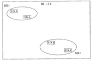
도 1은 무선랜 시스템의 구성의 일례를 나타낸 도면이다.1 is a diagram illustrating an example of a configuration of a WLAN system.
도 1에 도시된 바와 같이, 무선랜 시스템은 하나 이상의 기본 서비스 세트(Basic Service Set, BSS)를 포함한다. BSS는 성공적으로 동기화를 이루어서 서로 통신할 수 있는 스테이션(Station, STA)의 집합이다. As shown in FIG. 1, the WLAN system includes one or more basic service sets (BSSs). A BSS is a set of stations (STAs) that can successfully synchronize and communicate with each other.
STA는 매체 접속 제어(Medium Access Control, MAC)와 무선 매체에 대한 물리층(Physical Layer) 인터페이스를 포함하는 논리 개체로서, 액세스 포인트(access point, AP)와 비AP STA(Non-AP Station)을 포함한다. STA 중에서 사용자가 조작하는 휴대용 단말은 Non-AP STA로써, 단순히 STA이라고 할 때는 Non-AP STA을 가리키기도 한다. Non-AP STA은 단말(terminal), 무선 송수신 유닛(Wireless Transmit/Receive Unit, WTRU), 사용자 장비(User Equipment, UE), 이동국(Mobile Station, MS), 휴대용 단말(Mobile Terminal), 또는 이동 가입자 유닛(Mobile Subscriber Unit) 등의 다른 명칭으로도 불릴 수 있다. STA is a logical entity that includes a medium access control (MAC) and a physical layer interface to a wireless medium, and includes an access point (AP) and a non-AP non-AP station (STA). do. The portable terminal operated by the user among the STAs is a non-AP STA, and when referred to simply as an STA, it may also refer to a non-AP STA. A non-AP STA is a terminal, a wireless transmit / receive unit (WTRU), a user equipment (UE), a mobile station (MS), a mobile terminal, or a mobile subscriber. It may also be called another name such as a mobile subscriber unit.
그리고, AP는 자신에게 결합된 STA(Associated Station)에게 무선 매체를 통해 분배 시스템(Distribution System, DS)으로의 접속을 제공하는 개체이다. AP는 집중 제어기, 기지국(Base Station, BS), Node-B, BTS(Base Transceiver System), 또는 사이트 제어기 등으로 불릴 수도 있다. The AP is an entity that provides an associated station (STA) coupled to the AP to access a distribution system (DS) through a wireless medium. The AP may be called a centralized controller, a base station (BS), a Node-B, a base transceiver system (BTS), or a site controller.
BSS는 인프라스트럭처(infrastructure) BSS와 독립적인(Independent) BSS(IBSS)로 구분할 수 있다.BSS can be divided into infrastructure BSS and Independent BSS (IBSS).
도 1에 도시된 BBS는 IBSS이다. IBSS는 AP를 포함하지 않는 BSS를 의미하고, AP를 포함하지 않으므로, DS로의 접속이 허용되지 않아서 자기 완비적 네트워크(self-contained network)를 이룬다.The BBS shown in FIG. 1 is an IBSS. The IBSS means a BSS that does not include an AP. Since the IBSS does not include an AP, access to the DS is not allowed, thereby forming a self-contained network.
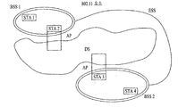
도 2는 무선랜 시스템의 구성의 다른 예를 나타낸 도면이다.2 is a diagram illustrating another example of a configuration of a WLAN system.
도 2에 도시된 BSS는 인프라스트럭처 BSS이다. 인프라스트럭처 BSS는 하나 이상의 STA 및 AP를 포함한다. 인프라스트럭처 BSS에서 비AP STA들 사이의 통신은 AP를 경유하여 이루어지는 것이 원칙이나, 비AP STA 간에 직접 링크(link)가 설정된 경우에는 비AP STA들 사이에서 직접 통신도 가능하다.The BSS shown in FIG. 2 is an infrastructure BSS. Infrastructure BSS includes one or more STAs and APs. In the infrastructure BSS, communication between non-AP STAs is performed via an AP. However, when a direct link is established between non-AP STAs, direct communication between non-AP STAs is also possible.
도 2에 도시된 바와 같이, 복수의 인프라스트럭처 BSS는 DS를 통해 상호 연결될 수 있다. DS를 통하여 연결된 복수의 BSS를 확장 서비스 세트(Extended Service Set, ESS)라 한다. ESS에 포함되는 STA들은 서로 통신할 수 있으며, 동일한 ESS 내에서 비AP STA은 끊김 없이 통신하면서 하나의 BSS에서 다른 BSS로 이동할 수 있다.As shown in FIG. 2, a plurality of infrastructure BSSs may be interconnected through a DS. A plurality of BSSs connected through a DS is called an extended service set (ESS). STAs included in the ESS may communicate with each other, and a non-AP STA may move from one BSS to another BSS while seamlessly communicating within the same ESS.
DS는 복수의 AP들을 연결하는 메커니즘(mechanism)으로서, 반드시 네트워크일 필요는 없으며, 소정의 분배 서비스를 제공할 수 있다면 그 형태에 대해서는 아무런 제한이 없다. 예컨대, DS는 메쉬(mesh) 네트워크와 같은 무선 네트워크일 수도 있고, AP들을 서로 연결시켜 주는 물리적인 구조물일 수도 있다.The DS is a mechanism for connecting a plurality of APs. The DS is not necessarily a network, and there is no limitation on the form if it can provide a predetermined distribution service. For example, the DS may be a wireless network such as a mesh network or a physical structure that connects APs to each other.
상술한 바와 같이 이하에서는 임의의 STA이 백홀 접속성(backhaul connection)을 가지는 비AP STA와의 직접 링크 설정을 통해 DS 접속을 획득하는 방법에 대해 설명한다. As described above, the following describes a method in which an arbitrary STA acquires a DS connection through direct link establishment with a non-AP STA having backhaul connection.
멀티 무선(Multi radio) STA은 둘 이상의 무선 주파수 대역을 지원하는 STA이다. 예를 들면, TVWS 대역과 2.4GHz/5GHz 대역을 모두 지원하는 단말이 이에 속할 수 있다. 멀리 무선 STA는 각 주파수 대역에 사용되는 PHY/MAC 프로토콜 스텍(protocol stack)을 모두 가지고 있으며, 각 주파수 대역에서 구현된 기능에 따라 서로 다른 역할을 수행할 수 있다. Multi radio STAs are STAs that support two or more radio frequency bands. For example, a terminal supporting both the TVWS band and the 2.4 GHz / 5 GHz band may belong to this. Far away, the STA has both PHY / MAC protocol stacks used in each frequency band and may play a different role depending on the function implemented in each frequency band.
예를 들면, 2.4GHz/5GHz 대역과 TVWS 대역의 이중 무선 대역을 지원하는 STA가 있을 때, 이 STA는 2.4GHz/5GHz 대역에서 AP로 기능하는 반면, TVWS 대역에서는 비 AP로 기능할 수 있다.For example, when there is an STA that supports dual radio bands of the 2.4 GHz / 5 GHz band and the TVWS band, the STA may function as an AP in the 2.4 GHz / 5 GHz band, while serving as a non-AP in the TVWS band.
이하 본 발명에 대한 실시형태들에 대한 설명의 편의를 위해 2중 주파수 대역을 지원하는 STA의 주파수 대역별 동작에 따라 다음과 같은 STA 타입을 가정하여 설명한다.For convenience of description of the embodiments of the present invention, the following STA types are assumed in accordance with the operation of each frequency band of an STA supporting a dual frequency band.
- STA1: 2.4GHz/5GHz 대역에서는 AP로 동작, TVWS 대역에서는 비AP로 동작STA1: Operates as an AP in the 2.4 GHz / 5 GHz band and operates as a non-AP in the TVWS band
- STA2: 2.5GHz/5GHz 대역 및 TVWS 대역 모두에서 비AP로 동작STA2: Non-AP operation in both 2.5GHz / 5GHz and TVWS bands
- STA3: TVWS 대역에서 AP로 동작STA3: operates as an AP in the TVWS band
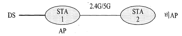
도 3은 상술한 STA 타입에 대한 정의를 바탕으로 한 2.4GHz/5GHz 대역에서의 BSS 동작을 나타낸 도면이다. 3 is a diagram illustrating a BSS operation in a 2.4 GHz / 5 GHz band based on the above-described definition of an STA type.
백홀 접속성(Backhaul connection)을 가지고 있는 STA1은 2.4GHz/5GHz 대역에서 AP로 동작한다. 비AP STA인 STA 2는 STA1으로부터 비콘(beacon)을 수신하거나, STA1에게 프로브 요청 메시지(Probe request message)를 전송하여 STA1을 발견하고, STA1과 링크를 설정함으로써 DS 접속을 획득할 수 있다.STA1 with backhaul connectivity operates as an AP in the 2.4 GHz / 5 GHz band. STA2, which is a non-AP STA, may receive a beacon from STA1 or transmit a probe request message to STA1 to discover STA1 and establish a link with STA1 to obtain a DS connection.
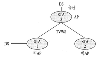
도 4는 상술한 STA 타입에 대한 정의를 바탕으로 한 TVWS 대역에서의 BSS 동작을 나타낸 도면이다. 4 is a diagram illustrating a BSS operation in a TVWS band based on the above-described definition of an STA type.
TVWS 동작을 위해서 비AP STA들은 반드시 AP STA로부터 활성화 신호(enabling signal)를 수신하고 성공적으로 활성화 과정을 완료하여야 한다. 즉, TVWS에서 AP STA는 활성화 STA이기도 하다. 활성화 신호란 TVWS 비AP STA에게 신호 전송을 허락하는 신호이다. 비AP STA가 TVWS에서 신호를 전송하기 위해서는 활성화 STA로부터 활성화 신호를 수신해야 한다. 활성화 과정이랑 활성화 신호를 수신한 비AP STA에게 TVWS 동작을 허락하는 과정이다.For the TVWS operation, the non-AP STAs must receive an activation signal from the AP STA and complete the activation process successfully. That is, in TVWS, the AP STA is also an active STA. The activation signal is a signal that allows signal transmission to the TVWS non-AP STA. The non-AP STA must receive an activation signal from the activating STA in order to transmit the signal in the TVWS. An activation process and a process of allowing TVWS operation to a non-AP STA receiving the activation signal.
상술한 STA 타입 정의에서 보는 바와 같이, STA1과 STA2는 2.4/5GHz 대역과 TVWS 대역을 모두 지원하는 다중 무선 STA이다. 본 예에서 STA1과 STA2는 STA3로부터 활성화 신호를 수신하여 활성화되는 것을 가정하며, STA3를 통해 DS 접속을 획득할 수 있다. As shown in the above-described STA type definition, STA1 and STA2 are multiple wireless STAs that support both the 2.4 / 5 GHz band and the TVWS band. In this example, it is assumed that STA1 and STA2 are activated by receiving an activation signal from STA3, and can obtain a DS connection through STA3.
STA1과 STA2는 모두 TVWS 대역에서는 비AP STA이지만 다음과 같은 차이점이 있다. STA1의 경우, 백홀 접속성을 가지고 있는 반면, STA2는 그렇지 않다. 이에 따라 STA1은 STA3를 통하지 않고 DS에 직접 접속할 수 있다.STA1 and STA2 are both non-AP STAs in the TVWS band, but have the following differences. In the case of STA1, it has backhaul connectivity, while STA2 does not. Accordingly, the STA1 can directly connect to the DS without going through the STA3.
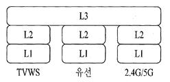
도 5는 다중 무선 STA의 프로세서가 포함할 프로토콜 스텍 구조를 도시한 도면이다.FIG. 5 is a diagram illustrating a protocol stack structure to be included in a processor of multiple wireless STAs.
도 5에 도시된 바와 같이 다중 무선 STA은 여러 개의 프로토콜 스텍을 가지고 있으며, 특히 백홀 접속성을 구성하는 무선 PHY(L1)/MAC(L2)을 가지고 있어서 DS 접속을 할 수 있다. As shown in FIG. 5, the multiple wireless STAs have several protocol stacks, and in particular, they have a wireless PHY (L1) / MAC (L2) constituting backhaul connectivity, thereby enabling DS connection.
하지만 AP의 역할은 해당 주파수 대역에서 구현된 기능에 따라 가능할 수도 있고, 가능하지 않을 수도 있다. 여기서, AP의 역할이란 다른 STA의 DS 접속을 활성화해주는 것을 말한다. STA1은 상술한 STA 타입 규정 가정에서와 같이 2.4/5GHz 대역에서는 AP의 기능을 가지고 있으며, TVWS 대역에서는 그렇지 않은 것을 가정한다.However, the role of the AP may or may not be possible depending on the function implemented in the corresponding frequency band. Here, the role of the AP refers to activating DS access of another STA. STA1 assumes that the AP has a function of the AP in the 2.4 / 5 GHz band, as in the STA type regulation assumption, and not in the TVWS band.
STA3는 TVWS 대역에서 다른 STA에게 DS 접속을 제공해주는 역할을 할 수 있다. 하지만 STA3중에는 TVWS에서의 활성화 기능에만 특화되어 설계된 STA도 있을 수 있다. 이러한 STA3는 제한된 대역을 가지며, STA1이나 STA2의 인증과 DB 접속 기능 등 만을 수행할 수 있다. 이러한 경우, STA1이나 STA2는 일단 STA3로부터 활성화되어 TVWS에서 신호를 전송할 수 있게 되면, 다른 화이트 스페이스 대역 AP와 링크를 설정하여 데이터 전송을 할 수도 있다.STA3 may serve to provide DS access to another STA in the TVWS band. However, some STA3 may be designed to be specific to the activation function in the TVWS. The STA3 has a limited band and can perform only authentication and DB access functions of the STA1 or the STA2. In this case, once STA1 or STA2 is activated from STA3 to transmit a signal in TVWS, the STA1 or STA2 may establish a link with another white space band AP to transmit data.
한편, 백홀 접속성을 가지고 AP로 동작하는 STA는 비AP STA에게 DS 접속을 제공함은 상술한 바와 같다. Meanwhile, as described above, the STA operating as the AP with the backhaul connectivity provides the DS access to the non-AP STA.
도 6은 2.4/5GHz 대역에서 STA2가 STA1에게 전송하는 패킷의 포맷을 도시한 도면이다.FIG. 6 is a diagram illustrating a format of a packet transmitted from STA2 to STA1 in the 2.4 / 5 GHz band.
2.4/5GHz에서 STA1은 비콘을 주기적으로 전송하고, STA2는 이 비콘을 듣고 AP(STA1)와 연결할 수 있다. STA2가 STA1을 통해 DS로 보내는 패킷은 도 6과 같은 포맷을 가질 수 있다. At 2.4 / 5 GHz, STA1 periodically transmits a beacon, and STA2 can listen to this beacon and connect with the AP STA1. A packet transmitted from the STA2 to the DS through the STA1 may have a format as shown in FIG. 6.
도 6을 참조하면, 패킷은 4개의 주소 필드를 포함하는 예를 들어 도시하고 있다. 다만, 특정 주소 필드는 해당 패킷의 용도에 따라 이용되지 않을 수 있다. 본 예에서 제 1 주소 필드는 수신 STA 주소를, 제 2 주소 필드는 전송 STA 주소를, 제 3 주소 필드는 목적지 주소를 나타내는 것을 가정한다. 이 경우 제 1 주소 필드는 STA1의 주소를, 제 2 주소 필드는 STA2의 주소를, 제 3 주소 필드는 DS(또는 Default Gateway) 주소를 나타내는 것을 가정한다.Referring to FIG. 6, a packet is illustrated as an example including four address fields. However, a specific address field may not be used depending on the purpose of the corresponding packet. In this example, it is assumed that the first address field indicates a receiving STA address, the second address field indicates a transmitting STA address, and the third address field indicates a destination address. In this case, it is assumed that the first address field indicates an address of STA1, the second address field indicates an address of STA2, and the third address field indicates a DS (or Default Gateway) address.
도 7은 도 3과 같이 STA2가 STA1을 통해 2.4/5GHz 대역에서 DS에 접속하는 경로를 설명하기 위한 도면이다.FIG. 7 is a diagram for describing a path in which STA2 accesses the DS in the 2.4 / 5 GHz band through STA1 as shown in FIG. 3.
STA2가 보내는 MAC 프레임의 목적지 주소가 DS로 설정되어 있기 때문에, 이를 수신한 STA1은 L2에서 MAC 헤더를 읽어보고 해당 프레임을 default gateway로 보낼 수 있다. 즉, STA2에서는 수신한 패킷을 L3에까지 올릴 필요 없이 목적지 주소만을 보고 바로 스위치/Default Gateway로 해당 패킷을 전달할 수 있다.Since the destination address of the MAC frame sent by STA2 is set to DS, the STA1 receiving the STA2 may read the MAC header at L2 and send the frame to the default gateway. In other words, STA2 can directly forward the packet to the switch / Default Gateway based on the destination address without having to upload the received packet to L3.
Default gateway에서는 L3 패킷의 목적지 IP 주소를 보고 라우팅을 수행한 다음, 적합한 경로의 다음 라우터로 해당 패킷을 보낼 수 있다.In the default gateway, you can view the destination IP address of the L3 packet, perform routing, and then send the packet to the next router in the appropriate path.
한편, 본 발명의 일 실시형태에서는 STA1이 2.4/5GHz에서 전송하는 비콘 또는 프로브 응답에 GDC (Geolocation Database Control) 링크 식별자 및 WSM을 포함하는 것을 제안한다.Meanwhile, one embodiment of the present invention proposes that the STA1 include a Geolocation Database Control (GDC) link identifier and a WSM in a beacon or probe response transmitted at 2.4 / 5 GHz.
도 8 및 도 9는 STA1이 2.4G/5GHz에서 전송하는 비콘 또는 프로브 응답 메시지가 GDC 링크 식별자 및/또는 WSM(White Space Map)을 포함하는 실시형태를 설명하기 위한 도면이다.8 and 9 are diagrams for describing an embodiment in which a beacon or probe response message transmitted by STA1 at 2.4G / 5GHz includes a GDC link identifier and / or a white space map (WSM).
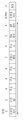
도 8은 구체적으로 GDC 링크 식별자 요소 포맷을, 도 9는 동작 채널 필드를 추가적으로 포함하는 GDC 링크 식별자 요소 포맷을 도시하고 있다. 도 8 및 도 9에서 활성화 STA 주소 필드는 6 옥텟으로 GDC 링크 식별자를 전송하는 STA를 활성화시킨 AP STA의 MAC 주소를 나타낼 수 있다. 도 9에서 채널 번호 필드와 동작 클래스 필드의 조합은 활성화 STA 주소가 나타내는 STA의 동작 채널 번호를 알려줄 수 있다. 본 실시형태에서 STA1은 상기 도 3 및 도 4의 상황에서 2.4G/5GHz 대역에서 GDC 링크 식별자를 전송하는 것을 가정한다. GDC 링크 식별자의 활성화 STA 주소는 STA3의 MAC 주소를 나타낼 수 있다. 이때, 동작 클래스와 채널 번호는 STA3의 TVWS 동작 채널 번호를 의미할 수 있다.8 specifically illustrates a GDC link identifier element format, and FIG. 9 illustrates a GDC link identifier element format additionally including an operation channel field. 8 and 9, the activating STA address field may indicate the MAC address of the AP STA that activated the STA that transmits the GDC link identifier in 6 octets. In FIG. 9, the combination of the channel number field and the operation class field may inform the operation channel number of the STA indicated by the activating STA address. In the present embodiment, it is assumed that STA1 transmits a GDC link identifier in the 2.4G / 5GHz band in the situation of FIGS. 3 and 4. The activation STA address of the GDC link identifier may indicate the MAC address of STA3. In this case, the operation class and the channel number may refer to the TVWS operating channel number of the STA3.
도 8에 도시된 바와 같이 GDC 링크 식별자를 전송하는 경우, GDC 링크 식별자는 동작 채널 정보를 포함하지 않고, 비콘/프로브 응답 메시지에 추가적으로 도 10과 같은 WSM(White Space Map)의 형태로 전송될 수 있다.When transmitting the GDC link identifier as shown in FIG. 8, the GDC link identifier does not include operation channel information and may be transmitted in the form of a white space map (WSM) as shown in FIG. 10 in addition to the beacon / probe response message. have.
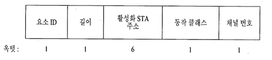
도 10은 STA1이 2/4/5GHz 대역에서 GDC 링크 식별자와 별도로 활성화 STA의 동작 채널을 알려주기 위한 WSM을 전송하는 포맷을 도시한 도면이다.FIG. 10 is a diagram illustrating a format in which STA1 transmits a WSM for indicating an operation channel of an active STA separately from the GDC link identifier in the 2/4/5 GHz band.
도 10에 도시된 바와 같이 동작 클래스 및 채널 번호 필드는 반복될 수 있다.As shown in FIG. 10, the operation class and channel number fields may be repeated.
STA2는 2.4G/5GHz에서 비AP로 동작하며, STA1에 연결(associated)되어 있다. STA2는 STA1으로부터 GDC 링크 식별자 요소를 수신함으로써 STA1을 TVWS에서 활성화한 STA(STA3)의 정보를 획득할 수 있다. 즉, 활성화 STA 주소에 해당 하는 MAC 주소가 STA1의 활성화 STA의 식별자가 된다. 동작 클래스 및 채널 번호의 조합은 활성화 STA의 동작 채널을 알려준다. STA2 operates as a non-AP at 2.4G / 5GHz and is associated with STA1. The STA2 may obtain information of the STA (STA3) that has activated the STA1 in the TVWS by receiving the GDC link identifier element from the STA1. That is, the MAC address corresponding to the activation STA address becomes the identifier of the activation STA of STA1. The combination of operating class and channel number informs the operating channel of the activating STA.
GDC 링크 식별자를 수신한 STA2가 STA1의 2.4/5GHz 커버리지(coverage)를 벗어나게 되면, STA1 신호가 약해지게 된다. 따라서 STA1/STA2는 TVWS에서 STA3를 검색한다. STA2는 STA3 발견을 위하여 GDC 링크 식별자 흑은 WSM의 동작 클래스와 채널 번호가 지시하는 TVWS 채널에서 GDC 링크 식별자의 활성화 STA 주소를 가지는 AP를 검색할 수 있다. 이에 따라 STA2가 STA3를 발견하면, STA3로부터 활성화 신호를 수신할 수 있으며, 이에 따라 TVWS에서 활성화될 수 있다. STA2가 활성화되면 STA2는 STA3와 연결한 후 STA3를 통해 DS 접속을 획득할 수 있다.When the STA2 receiving the GDC link identifier is out of the 2.4 / 5 GHz coverage of the STA1, the STA1 signal is weakened. Accordingly, STA1 / STA2 searches for STA3 in TVWS. The STA2 may search for an AP having an active STA address of the GDC link identifier in the TVWS channel indicated by the operation class and channel number of the GDC link identifier black or WSM, for the discovery of the STA3. Accordingly, when STA2 discovers STA3, it may receive an activation signal from STA3, and thus may be activated in TVWS. If STA2 is activated, STA2 may connect with STA3 and obtain a DS connection through STA3.
한편, 본 발명의 바람직한 일 실시형태에서는 TVWS에서 STA2가 STA3를 통하지 않고, STA1을 통해 DS 접속을 수행할 수 있는 방법을 제공한다. 이를 위해, STA2는 STA1과의 직접 링크를 설정할 수 있는 것을 가정한다. On the other hand, in a preferred embodiment of the present invention, STA2 in TVWS provides a method for performing a DS connection through STA1, rather than through STA3. For this purpose, it is assumed that STA2 can establish a direct link with STA1.
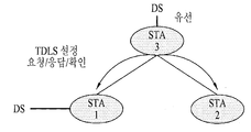
도 11 및 도 12는 STA1과 STA2가 TVWS 대역에서 직접링크설정 과정을 수행하는 것을 설명하기 위한 도면이다.11 and 12 illustrate STA1 and STA2 performing a direct link setup process in a TVWS band.
도 11에 도시된 바와 같이 STA1은 STA2와 TVWS에서 직접링크설정(TDLS; Tunneled Direct Link Setup) 과정을 수행할 수 있다. 이러한 과정은 STA3를 통하여 수행될 수 있다. As illustrated in FIG. 11, the STA1 may perform a Tunneled Direct Link Setup (TDLS) process between the STA2 and the TVWS. This process may be performed through STA3.
직접 링크 설정을 위해서는 (1) 먼저 STA2가 (STA3를 통해) STA1에 직접 링크 설정 요청(TDLS Setup Request)을 수행하고, (2) STA1이 (STA3를 통해) STA2에 직접 링크 설정 응답(TDLS Setup Response)을 수행할 수 있다. (3) 그 후, STA2는 STA1에 직접 링크 설정 확인(TDLS Setup Confirm) 관리 작용 프레임을 데이터 프레임으로 캡슐화 되어 전송할 수 있다.For direct link setup, (1) STA2 first performs a TDLS Setup Request (via STA3), and (2) STA1 responds directly to STA2 (via STA3) (TDLS Setup). Response) can be performed. (3) Thereafter, the STA2 can directly encapsulate the TDLS Setup Confirm management action frame as a data frame and transmit it to the STA1.
성공적으로 TDLS가 완료되면, 도 12에 도시된 바와 같이 STA2는 STA1과의 직접 링크를 통해 DS로 가는 데이터를 전송할 수 있다. TVWS 직접 링크를 통해 STA2가 STA1에 전송하는 패킷의 MAC 프레임 헤더는, (1) 전송 STA 주소를 나타내는 제 1 주소 필드, (2) 수신 STA 주소를 나타내는 제 2 주소 필드 및 (3) 활성화 STA 주소를 나타내는 제 3 주소 필드를 포함하는 것을 제안한다. 이와 같이 주소 필드들을 규정할 경우, 상기 제 1 주소 필드는 STA2의 주소를, 상기 제 2 주소 필드는 STA1의 주소를, 그리고 상기 제 3 주소 필드는 상기 제 1 STA 및 상기 제 2 STA의 공통된 활성화 STA의 주소인 STA3의 주소를 나타낼 수 있다.If the TDLS is successfully completed, as shown in FIG. 12, the STA2 may transmit data to the DS through a direct link with the STA1. The MAC frame header of a packet transmitted by STA2 to STA1 via a TVWS direct link includes (1) a first address field indicating a transmission STA address, (2) a second address field indicating a receiving STA address, and (3) an active STA address. It is proposed to include a third address field indicating. When the address fields are defined in this way, the first address field is an address of STA2, the second address field is an address of STA1, and the third address field is common activation of the first STA and the second STA. It may indicate the address of STA3 which is the address of the STA.
도 13은 본 발명의 바람직한 일 실시형태에 따라 STA2가 STA1을 통해 DS 접속을 획득하는 경우 패킷 전달 경로를 설명하기 위한 도면이다.FIG. 13 is a diagram for explaining a packet forwarding path when STA2 acquires a DS connection through STA1 according to one embodiment of the present invention.
본 실시형태에서 STA1은 STA2의 peer STA이며, 도 3과 같이 2.4G/5GHz에서 STA1이 AP로 동작 할 때와 도 12와 같이 TVWS에서 STA1이 비AP로 동작할 때는 차이점이 있다. In the present embodiment, STA1 is a peer STA of STA2, and there is a difference when STA1 operates as an AP in 2.4G / 5GHz as shown in FIG. 3 and when STA1 operates as a non-AP in TVWS as shown in FIG. 12.
구체적으로, STA1이 비AP STA인 경우, STA1은 STA2로부터 수신한 L2 MAC 프레임의 MAC 헤더를 보고 라우터(Router)로 프레임을 전달하는 것이 아니라, 도 13에 도시된 바와 같이 IP 계층인 L3에서 목적지 IP 주소를 확인하여 Default gateway로 해당 패킷이 전송되어야 할 지 여부가 결정되는 차이가 있다. STA1은 MAC 헤더의 주소만으로는 해당 패킷의 최종 목적지가 자신인지 서브넷 밖의 객체인지 여부를 분별할 수 없기 때문이다.Specifically, when the STA1 is a non-AP STA, the STA1 does not transfer the frame to the router by looking at the MAC header of the L2 MAC frame received from the STA2, but instead the destination in the IP layer L3 as shown in FIG. 13. There is a difference that determines whether the corresponding packet should be sent to the default gateway by checking the IP address. This is because the STA1 cannot distinguish whether the final destination of the packet is itself or an object outside the subnet using only the address of the MAC header.
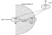
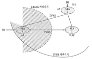
도 14 및 도 15는 본 발명의 바람직한 일 실시형태에 따라 STA1과의 TVWS 직접링크를 통해 DS 접속을 수행함으로써 DS 접속 커버리지가 확대되는 것을 설명하기 위한 도면이다.14 and 15 are diagrams for explaining that DS connection coverage is expanded by performing a DS connection through a TVWS direct link with STA1 according to an exemplary embodiment of the present invention.
도 14에 도시된 바와 같이 STA2는 2.4G/5GHz 대역에서 STA1을 통해 DS 접속을 획득한다. 다만, 본 실시형태에 따를 경우 도 15에 도시된 바와 같이 STA2는 STA1의 2.4/5GHz 대역 커버리지를 벗어나더라도 무선 전파(radio propagation) 성능이 상대적으로 우수한 TVWS 대역에서 STA1과 직접 링크를 설정함으로써 STA1을 통해 계속해서 DS 접속을 획득할 수 있다. As shown in FIG. 14, STA2 acquires a DS connection through STA1 in the 2.4G / 5GHz band. However, according to the present embodiment, as shown in FIG. 15, STA2 sets STA1 by directly establishing a link with STA1 in a TVWS band having relatively high radio propagation performance even if the STA1 is out of 2.4 / 5 GHz band coverage. Can continue to acquire a DS connection.
본 발명의 실시형태들에 있어서 STA1과 STA2는 STA3로부터 활성화 신호를 수신하고 활성화된 다음 TVWS에서 연관을 수행한다. 한편, 본 발명의 일 실시형태에서는, 연관을 성공적으로 수행한 STA1이 TVWS에서 STA2가 자신과 직접연결설정을 요청하도록 유도하기 위해 TDLS Discovery 프레임을 방송하는 것을 제안한다. 본 실시형태에 따른 TDLS Discovery는 아래 표 1과 같이 GDC 링크 식별자 및 기기 성능 요소를 포함하는 것을 제안한다. In embodiments of the present invention, STA1 and STA2 receive an activation signal from STA3 and perform association in TVWS after being activated. On the other hand, in one embodiment of the present invention, it is proposed that STA1 that successfully performs association broadcasts a TDLS Discovery frame to induce STA2 to request direct connection establishment with the TVWS. TDLS Discovery according to this embodiment proposes to include a GDC link identifier and device performance elements as shown in Table 1 below.
표 1 | 순서 | 정보 |
| 1 | 카테고리 |
| 2 | 동작 |
| 3 | 기기 성능 |
| 4 | GDC 링크 식별자 |
Table 1 | order | Information |
| One | category |
| 2 | action |
| 3 | Instrument performance |
| 4 | GDC link identifier |
상기 표 1에서 기기 성능(Device Capability) 필드는 STA의 TVWS에서의 성능을 나타낼 수 있으며, 본 발명의 일 실시형태에서는 본 필드를 통해 STA의 백홀 연결성(Backhaul connectivity)을 나타내는 것을 제안한다. 백홀 연결성이 1이면 TDLS Discovery를 전송하는 STA가 백홀 연결성을 가지고 있음을 뜻하며, 1 이외의 값을 가지면 백홀 연결성을 가지고 있지 않음을 나타낼 수 있다.In Table 1, the Device Capability field may indicate the performance of the STA in TVWS, and an embodiment of the present invention proposes to indicate the backhaul connectivity of the STA through this field. If the backhaul connectivity is 1, it means that the STA that transmits the TDLS Discovery has the backhaul connectivity. If the value is other than 1, it may represent that the backhaul connectivity does not have the backhaul connectivity.
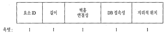
도 16은 본 발명의 일 실시형태에 따라 STA1이 방송하는 TDLS Discovery 프레임 내 기기 성능 정보 요소의 포맷을 도시한 도면이다.FIG. 16 illustrates a format of a device performance information element in a TDLS Discovery frame broadcast by STA1 according to an embodiment of the present invention.
상술한 실시형태에서 STA1은 자신의 성능 정보를 TDLS Discovery 프레임으로 방송할 수 있으며, 구체적으로 상기 표 1의 정보 요소 중 기기 성능(Device Capability) 정보 요소는 도 16과 같이 자신의 백홀 연결성, DB 접속 성능 등을 포함할 수 있다. 도 16은 기기 성능 정보 요소가 추가적으로 자신의 지리적 위치 정보를 포함하여 전송되는 것을 도시하고 있다.In the above-described embodiment, the STA1 may broadcast its performance information in a TDLS Discovery frame. Specifically, among the information elements of Table 1, the device capability information element may have its backhaul connectivity and DB connection as shown in FIG. Performance, and the like. FIG. 16 shows that the device capability information element is additionally transmitted including its geographic location information.
상술한 실시형태에서 STA2는 TVWS에서 STA1으로부터 TDLS Discovery를 수신하면, GDC 링크 식별자의 활성화 STA 주소로부터 STA1이 연관된 BSS가 자신이 연관된 BSS와 동일한지 여부를 판단할 수 있다. In the above-described embodiment, when the STA2 receives the TDLS Discovery from the STA1 in the TVWS, the STA2 may determine whether the BSS associated with the STA1 is the same as the BSS with which the STA is associated from the activation STA address of the GDC link identifier.
만약 GDC 링크 식별자의 활성화 STA 주소가 자신의 AP(또는 활성화 STA)와 동일하고 기기 성능의 백홀 접속성 필드가 1을 나타내는 경우, STA2는 STA1과 직접 링크를 설정하여 DS 접속을 수행할 수 있다. 즉, 도 11 및 도 12와 관련하여 상술한 바와 같이 STA2는 STA1과 직접 링크 설정 요청(TDLS Setup Request), 직접 링크 설정 응답(TDLS Setup Response), 직접 링크 설정 확인(TDLS Setup Confirm) 관리 작용 프레임이 데이터 프레임으로 캡슐화 되어 전송될 수 있다.If the activating STA address of the GDC link identifier is the same as its AP (or activating STA) and the backhaul connectivity field of the device capability indicates 1, STA2 may establish a direct link with STA1 to perform DS access. That is, as described above with reference to FIGS. 11 and 12, the STA2 has a direct link setup request (TDLS Setup Request), a direct link setup response (TDLS Setup Response), and a direct link setup confirmation (TDLS Setup Confirm) management action frame with the STA1. This data frame can be encapsulated and transmitted.
성공적으로 TDLS 절차가 완료되면, STA2는 STA1의 백홀 접속성을 이용하여 인터넷 패킷을 주고 받을 수 있다.If the TDLS procedure is successfully completed, the STA2 may exchange Internet packets using the backhaul connectivity of the STA1.
한편, 본 발명의 다른 일 실시형태에서는 STA1이 직접 자신의 성능 정보를 방송하는 것이 아니라 TVWS의 활성화 STA인 STA3이 DS 접속성을 가진 STA의 정보를 STA2에게 알려주는 것을 제안한다.On the other hand, in another embodiment of the present invention, instead of STA1 broadcasting its own performance information, it is proposed that STA3, which is an active STA of TVWS, informs STA2 of information of an STA having DS connectivity.
본 실시형태에서 STA1은 TVWS에서 STA3에 연관될 때 STA1이 STA3에게 전송하는 연결 요청 프레임은 아래 표 2와 같은 기기 성능 정보를 전달할 수 있다.In the present embodiment, when the STA1 is associated with the STA3 in the TVWS, the connection request frame transmitted by the STA1 to the STA3 may transmit device performance information as shown in Table 2 below.
표 2 | 순서 | 정보 |
| 24 | 기기 성능(Device Capability) |
TABLE 2 | order | Information |
| 24 | Device Capability |
한편, 본 실시형태에서 STA3는 자신과 연관된 STA중 백홀 접속성을 가지고 있는 STA의 리스트를 STA2에게 전달해 줄 수 있다. Meanwhile, in the present embodiment, the STA3 may transmit a list of STAs having backhaul connectivity among the STAs associated with the STA3 to the STA2.
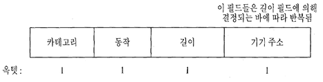
도 17은 본 발명의 일 실시형태에 따라 STA3이 자신에게 연관된 STA 중 백홀 접속성을 가지는 STA의 정보를 STA2에게 알려주는 방법을 설명하기 위한 도면이다.FIG. 17 is a diagram for describing a method of informing STA2 of STA3 having backhaul connectivity among STAs associated with the STA3 according to an embodiment of the present invention.
본 실시형태에서 STA3은 도 17에 도시된 바와 같은 프레임을 STA1에 전송할 수 있다. 즉, 연관된 STA중 기기 성능의 백홀 접속성 필드가 1로 설정된 STA의 MAC 주소를 STA2에게 리스트 형태로 전달할 수 있다. In the present embodiment, the STA3 may transmit a frame as shown in FIG. 17 to the STA1. That is, the MAC address of the STA with the backhaul connectivity field of the device capability of the associated STAs set to 1 may be transmitted to the STA2 in a list form.
도 17에 도시된 바와 같이 기기 주소 필드는 반복될 수 있으며, 각 기기 주소 필드는 백홀 접속성이 1로 설정된 STA의 MAC 주소들을 나타낼 수 있다.As shown in FIG. 17, the device address field may be repeated, and each device address field may indicate MAC addresses of STAs having backhaul connectivity set to 1.
이와 같은 프레임을 STA3으로부터 수신한 STA2는 수신된 TDLS Discovery의 리스트에 포함된 STA(예를 들어, STA1)에게 직접 링크 설정을 요청할 수 있다. 성공적으로 직접 링크 설정이 완료되면, STA2는 STA1의 백홀 접속성을 통해 인터넷 패킷을 주고 받을 수 있다.STA2 receiving such a frame from STA3 may request a link establishment directly from an STA (eg, STA1) included in the received TDLS Discovery list. If the direct link setup is successfully completed, the STA2 may exchange Internet packets through the backhaul connectivity of the STA1.
상술한 바와 같은 설명을 바탕으로 이하에서는 상술한 WLAN 통신 방식을 수행하기 위한 STA 장치 구성에 대해 설명한다.Based on the above description, a description will be given of an STA device configuration for performing the above-described WLAN communication scheme.
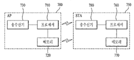
도 18은 본 발명의 일 실시형태에 따라 WLAN 통신을 수행하는 STA 장치 구성을 개략적으로 나타낸 도면이다.18 is a diagram schematically illustrating a configuration of a STA apparatus for performing WLAN communication according to an embodiment of the present invention.
도 18에 도시된 바와 같이, STA 장치(750)는 WLAN 신호 송수신을 위한 송수신기(780), 송수신 신호의 일시 저장 등을 위한 메모리(770) 및 상기 송수신기(780) 및 메모리(770)와 연결되어 이들을 제어하기 위한 프로세서(760)를 포함할 수 있다. 이러한 구성은 STA과 통신을 수행하는 AP(700) 역시 유사할 수 있다.As shown in FIG. 18, the STA device 750 is connected to a transceiver 780 for transmitting and receiving WLAN signals, a memory 770 for temporarily storing a transmission / reception signal, and the transceiver 780 and the memory 770. It may include a processor 760 to control them. This configuration may be similar to the AP 700 that communicates with the STA.
이와 같은 기본 구조 하에서 본 발명에 따른 STA 장치는 제 1 주파수 대역 WLAN 통신을 수행하기 위한 제 1 통신 모듈과 제 2 주파수 대역 WLAN 통신을 수행하기 위한 제 2 통신 모듈을 포함하는 이중 또는 다중 무선 모듈을 구비하는 것을 특징으로 한다. 이는 도 18에서 복수의 송수신기(780)에 의해 구현될 수도, 하나의 송수신기(780)를 프로세서(760)에 의해 기능적으로 구분되어 구현될 수도 있다.Under such a basic structure, an STA apparatus according to the present invention provides a dual or multiple radio module including a first communication module for performing a first frequency band WLAN communication and a second communication module for performing a second frequency band WLAN communication. It is characterized by including. This may be implemented by the plurality of transceivers 780 in FIG. 18, or one transceiver 780 may be functionally divided by the processor 760.
만일, 도 18의 STA 장치(750)가 상술한 실시형태들에서 STA2에 대응하는 경우, 프로세서(760)는 상기 제 1 통신 모듈 및 상기 제 2 통신 모듈과 연결되어, STA1과 TVWS 대역 직접링크설정 절차를 수행하고, 이 직접링크를 통해 DS에 접속하는 것을 제어할 수 있다.If the STA apparatus 750 of FIG. 18 corresponds to STA2 in the above-described embodiments, the processor 760 is connected with the first communication module and the second communication module to directly establish TVWS band link with STA1. You can perform the procedure and control access to the DS through this direct link.
또한, 도 18의 STA 장치(750)가 상술한 실시형태들에서 STA1에 대응하는 경우, 프로세서(760)는 STA(750)이 2.4/5GHz 대역에서 APFH, TVWS 대역에서 비AP STA으로 동작하도록 제어하도록 구성될 수 있으며, 추가적으로 STA2의 직접링크 설정 절차를 수행하여 STA2의 DS 접속을 제공하도록 구성될 수 있다.In addition, when the STA apparatus 750 of FIG. 18 corresponds to STA1 in the above-described embodiments, the processor 760 controls the STA 750 to operate as a non-AP STA in the APFH and TVWS bands in the 2.4 / 5 GHz band. It may be configured to further provide a DS connection of the STA2 by performing a direct link setup procedure of the STA2.
상술한 바와 같이 개시된 본 발명의 바람직한 실시형태에 대한 상세한 설명은 당업자가 본 발명을 구현하고 실시할 수 있도록 제공되었다. 상기에서는 본 발명의 바람직한 실시 형태를 참조하여 설명하였지만, 해당 기술 분야의 숙련된 당업자는 하기의 특허 청구의 범위에 기재된 본 발명의 사상 및 영역으로부터 벗어나지 않는 범위 내에서 본 발명을 다양하게 수정 및 변경시킬 수 있음을 이해할 수 있을 것이다. 따라서, 본 발명은 여기에 나타난 실시형태들에 제한되려는 것이 아니라, 여기서 개시된 원리들 및 신규한 특징들과 일치하는 최광의 범위를 부여하려는 것이다.The detailed description of the preferred embodiments of the invention disclosed as described above is provided to enable any person skilled in the art to make and practice the invention. Although the above has been described with reference to the preferred embodiments of the present invention, those skilled in the art will variously modify and change the present invention without departing from the spirit and scope of the invention as set forth in the claims below. I can understand that you can. Thus, the present invention is not intended to be limited to the embodiments shown herein but is to be accorded the widest scope consistent with the principles and novel features disclosed herein.