WO2013027628A1 - Information processing device, information processing method, and program - Google Patents
Information processing device, information processing method, and program Download PDFInfo
- Publication number
- WO2013027628A1 WO2013027628A1 PCT/JP2012/070677 JP2012070677W WO2013027628A1 WO 2013027628 A1 WO2013027628 A1 WO 2013027628A1 JP 2012070677 W JP2012070677 W JP 2012070677W WO 2013027628 A1 WO2013027628 A1 WO 2013027628A1
- Authority
- WO
- WIPO (PCT)
- Prior art keywords
- plane
- information processing
- unit
- processing apparatus
- image
- Prior art date
Links
Images


Classifications
-
- G—PHYSICS
- G06—COMPUTING; CALCULATING OR COUNTING
- G06T—IMAGE DATA PROCESSING OR GENERATION, IN GENERAL
- G06T11/00—2D [Two Dimensional] image generation
- G06T11/60—Editing figures and text; Combining figures or text
-
- G—PHYSICS
- G01—MEASURING; TESTING
- G01C—MEASURING DISTANCES, LEVELS OR BEARINGS; SURVEYING; NAVIGATION; GYROSCOPIC INSTRUMENTS; PHOTOGRAMMETRY OR VIDEOGRAMMETRY
- G01C21/00—Navigation; Navigational instruments not provided for in groups G01C1/00 - G01C19/00
- G01C21/26—Navigation; Navigational instruments not provided for in groups G01C1/00 - G01C19/00 specially adapted for navigation in a road network
- G01C21/34—Route searching; Route guidance
- G01C21/36—Input/output arrangements for on-board computers
- G01C21/3626—Details of the output of route guidance instructions
- G01C21/3647—Guidance involving output of stored or live camera images or video streams
-
- G—PHYSICS
- G06—COMPUTING; CALCULATING OR COUNTING
- G06F—ELECTRIC DIGITAL DATA PROCESSING
- G06F3/00—Input arrangements for transferring data to be processed into a form capable of being handled by the computer; Output arrangements for transferring data from processing unit to output unit, e.g. interface arrangements
- G06F3/01—Input arrangements or combined input and output arrangements for interaction between user and computer
- G06F3/03—Arrangements for converting the position or the displacement of a member into a coded form
- G06F3/0304—Detection arrangements using opto-electronic means
-
- G—PHYSICS
- G06—COMPUTING; CALCULATING OR COUNTING
- G06F—ELECTRIC DIGITAL DATA PROCESSING
- G06F3/00—Input arrangements for transferring data to be processed into a form capable of being handled by the computer; Output arrangements for transferring data from processing unit to output unit, e.g. interface arrangements
- G06F3/01—Input arrangements or combined input and output arrangements for interaction between user and computer
- G06F3/03—Arrangements for converting the position or the displacement of a member into a coded form
- G06F3/033—Pointing devices displaced or positioned by the user, e.g. mice, trackballs, pens or joysticks; Accessories therefor
- G06F3/0346—Pointing devices displaced or positioned by the user, e.g. mice, trackballs, pens or joysticks; Accessories therefor with detection of the device orientation or free movement in a 3D space, e.g. 3D mice, 6-DOF [six degrees of freedom] pointers using gyroscopes, accelerometers or tilt-sensors
-
- G—PHYSICS
- G06—COMPUTING; CALCULATING OR COUNTING
- G06T—IMAGE DATA PROCESSING OR GENERATION, IN GENERAL
- G06T19/00—Manipulating 3D models or images for computer graphics
- G06T19/006—Mixed reality
-
- G—PHYSICS
- G06—COMPUTING; CALCULATING OR COUNTING
- G06T—IMAGE DATA PROCESSING OR GENERATION, IN GENERAL
- G06T7/00—Image analysis
- G06T7/70—Determining position or orientation of objects or cameras
Definitions
- the present disclosure relates to an information processing apparatus, an information processing method, and a program.
- AR augmented reality
- Information presented to the user in AR technology is also called annotation, and can be visualized using various forms of virtual objects such as text, icons or animations.
- the placement of annotations in the AR space is usually performed based on recognition of the three-dimensional structure of the real space shown in the image.
- SfM Structure from Motion
- SLAM Simultaneous Localization And Mapping
- Patent Document 1 discloses a technique for recognizing a three-dimensional position of a feature point selected at the time of initialization in the SLAM method using the SfM method.
- the position and orientation of an object (or the real space itself) existing in the real space with respect to the imaging plane of the image can be recognized.
- a technique based on image recognition such as the SfM method may not achieve sufficient recognition accuracy.
- the recognition accuracy of the SfM method deteriorates for a two-dimensional plane (for example, a horizontal plane such as the ground, a floor or a ceiling, or a vertical plane such as a wall of a building) in which an image change due to parallax hardly occurs. easy.
- a two-dimensional plane for example, a horizontal plane such as the ground, a floor or a ceiling, or a vertical plane such as a wall of a building
- improvement in the accuracy of recognition of the plane pose is particularly strongly required in the AR technology.
- a data acquisition unit that acquires sensor data indicating a direction of gravity applied to an imaging device that captures an image that reflects a real space, and a relative plane of the real space with respect to the image based on the sensor data Conversion between a determination unit that determines a specific posture and a three-dimensional position of a given point on the plane and a corresponding two-dimensional position in the image, using the posture determined by the determination unit And an information processing apparatus including the conversion unit.
- the sensor data indicating the direction of gravity applied to the imaging device that captures the image that reflects the real space is acquired, and based on the sensor data, Determining the relative pose of the real space plane relative to the image and the transformation between the 3D position of a given point on the plane and the corresponding 2D position in the image was determined And performing using the posture.
- the computer that controls the information processing device is configured to acquire a sensor data indicating a direction of gravity applied to the imaging device that captures an image that reflects a real space, and based on the sensor data.
- FIG. 6 is a flowchart illustrating a third example of the flow of plane determination processing by the determination unit illustrated in FIG. 4.
- 5 is a flowchart illustrating an example of a flow of SLAM calculation processing by a SLAM calculation unit illustrated in FIG. 4.
- 15 is a flowchart illustrating an example of a flow of initialization processing included in the SLAM calculation processing illustrated in FIG. 14. It is explanatory drawing for demonstrating the feature point set on a real object. It is explanatory drawing for demonstrating addition of a feature point. It is explanatory drawing for demonstrating an example of a prediction model. It is explanatory drawing for demonstrating an example of a structure of feature data.
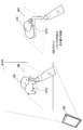
- FIG. 1 is a first explanatory diagram for explaining an overview of an information processing apparatus 100 according to an embodiment.
- the information processing apparatus 100 includes an imaging unit 102 and a display unit 110 that are directed to the real space 10.
- a road 12 a wall surface 13 a of a building, and a wall surface 13 b of a building exist in the real space 10.
- the information processing apparatus 100 includes an AR application for navigation, and superimposes annotations A11 and A12 for navigation on an image Im01 captured by the imaging unit 102.
- the annotation A1 is an annotation in the shape of an arrow that guides the route to the user Ua, and is arranged on a horizontal plane along the road 12 shown in the image Im01.
- the annotation A12 is an annotation that conveys some guidance message to the user Ua, and is arranged on the vertical plane along the wall surface 13a shown in the image Im01.
- FIG. 1 shows a mobile terminal as an example of the information processing apparatus 100.
- the information processing apparatus 100 is not limited to such an example.
- the information processing apparatus 100 may be, for example, a PC (Personal Computer), a PDA (Personal Digital Assistant), a smartphone, a game terminal, a PND (Portable Navigation Device), a content player, or a digital home appliance.
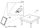
- FIG. 2 is a second explanatory diagram for explaining an overview of the information processing apparatus 100.
- the information processing device 100 is a server device connected to the terminal device 20 that the user Ua has.
- the terminal device 20 includes an imaging unit 22 and a display unit 24 that are directed to the real space 10.
- a table 14 exists in the real space 10.
- the information processing apparatus 100 superimposes the annotation A2 on the image Im02 captured by the terminal device 20.
- the annotation A2 is an annotation in the shape of a virtual car running on the table 14, and is arranged on a horizontal plane along the surface of the table 14 shown in the image Im02.
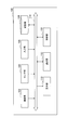
- FIG. 3 is a block diagram illustrating an example of a hardware configuration of the information processing apparatus 100 according to the first embodiment.
- the information processing apparatus 100 includes an imaging unit 102, a sensor unit 104, an input unit 106, a storage unit 108, a display unit 110, a communication unit 112, a bus 116, and a control unit 118.
- Imaging unit 102 is a camera module that captures an image.
- the imaging unit 102 images a real space using an imaging element such as a charge coupled device (CCD) or a complementary metal oxide semiconductor (CMOS), and generates a captured image.
- the captured image generated by the imaging unit 102 is an input image for image processing by the control unit 118.
- the imaging unit 102 is not necessarily a part of the information processing apparatus 100.
- an imaging apparatus connected to the information processing apparatus 100 by wire or wireless may be handled as the imaging unit 102.
- the sensor unit 104 may include various sensors that are used to assist the information processing apparatus 100 in determining the plane posture.
- the sensor unit 104 includes a triaxial acceleration sensor that measures gravitational acceleration applied to the imaging unit 102.
- the three-axis acceleration sensor measures the gravitational acceleration applied to the imaging unit 102 and generates sensor data (acceleration data) that three-dimensionally represents the magnitude and direction of the gravitational acceleration.
- the sensor unit 104 may include a geomagnetic sensor that measures the direction of geomagnetism.
- the geomagnetic sensor generates sensor data (geomagnetic data) indicating the direction of geomagnetism in the coordinate system of the imaging unit 102.
- the sensor unit 104 may include a positioning sensor (for example, a GPS (Global Positioning System) sensor) that measures the position of the information processing apparatus 100.
- the positioning sensor generates sensor data (positioning data) representing the latitude and longitude of the information processing apparatus 100 in real space. Note that the sensor unit 104 is not necessarily a part of the information processing apparatus 100.
- the input unit 106 is an input device used by a user to operate the information processing apparatus 100 or input information to the information processing apparatus 100.
- the input unit 106 may include, for example, a touch sensor that detects a user's touch on the screen of the display unit 110.
- the input unit 106 may include a pointing device such as a mouse or a touchpad.
- the input unit 106 may include other types of input devices such as a keyboard, keypad, buttons, or switches.
- the storage unit 108 is configured by a storage medium such as a semiconductor memory or a hard disk, and stores a program and data for processing by the information processing apparatus 100.
- the data stored by the storage unit 108 may include, for example, captured image data, sensor data, and data in various databases (DB) described later.
- DB databases
- some of the programs and data described in this specification may be acquired from an external data source (for example, a data server, a network storage, or an external memory) without being stored in the storage unit 108. .
- the display unit 110 is a display module including a display such as an LCD (Liquid Crystal Display), an OLED (Organic light-Emitting Diode), or a CRT (Cathode Ray Tube).
- the display unit 110 is used, for example, to display an AR application image generated by the information processing apparatus 100.
- the display unit 110 is not necessarily a part of the information processing apparatus 100.
- a display device connected to the information processing device 100 by wire or wireless may be handled as the display unit 110.
- the communication unit 112 is a communication interface that mediates communication between the information processing apparatus 100 and other apparatuses.
- the communication unit 112 supports an arbitrary wireless communication protocol or wired communication protocol, and establishes a communication connection with another device.
- Bus The bus 116 connects the imaging unit 102, the sensor unit 104, the input unit 106, the storage unit 108, the display unit 110, the communication unit 112, and the control unit 118 to each other.
- the control unit 118 corresponds to a processor such as a CPU (Central Processing Unit) or a DSP (Digital Signal Processor).
- the control unit 118 operates various functions of the information processing apparatus 100 to be described later by executing a program stored in the storage unit 108 or another storage medium.
- [2-2. Functional configuration] 4 is a block diagram illustrating an example of a configuration of logical functions realized by the storage unit 108 and the control unit 118 of the information processing apparatus 100 illustrated in FIG.
- the information processing apparatus 100 includes an image acquisition unit 120, a data acquisition unit 125, a determination unit 130, a three-dimensional (3D) structure DB 135, a conversion unit 140, a SLAM calculation unit 145, an object DB 150, and an image recognition unit 156. , Annotation DB 160, display control unit 165, and user interface unit 170.
- the image acquisition unit 120 acquires a captured image generated by the imaging unit 102 as an input image.
- the input image acquired by the image acquisition unit 120 is an image showing a real space.
- the input image may be a still image or each frame constituting a moving image.
- the image acquisition unit 120 outputs the acquired input image to the SLAM calculation unit 145, the image recognition unit 156, and the display control unit 165.
- the data acquisition unit 125 acquires data used for plane determination processing by the determination unit 130.
- the data acquisition unit 125 acquires sensor data generated by the sensor unit 104 that may include at least one of acceleration data, geomagnetic data, and positioning data.
- the data acquisition unit 125 may acquire map data for the surrounding area of the position indicated by the positioning data from a database stored in advance by the information processing apparatus 100 or an external data server. Then, the data acquisition unit 125 outputs the acquired data to the determination unit 130.
- the determining unit 130 determines the relative posture of the plane of the real space with respect to the imaging surface of the input image based on the sensor data acquired by the data acquiring unit 125.
- the method for determining the attitude of the horizontal plane will be described in detail first, and then the determination of the attitude of the vertical plane and other planes will be described.
- FIG. 5 is an explanatory diagram for explaining the relationship among the imaging plane, the horizontal plane, and the direction of gravity.
- the horizontal plane HP may be a plane such as an existing ground, floor, or ceiling, or may be an imaginary plane.
- the horizontal plane HP is orthogonal to the direction of gravity.
- the attitude of the horizontal plane HP with respect to the imaging plane IP (or the attitude of the imaging plane IP with respect to the horizontal plane HP) can change depending on the attitude of the imaging unit 102. Therefore, determining unit 130, the gravity direction vector V G indicated by the sensor data described above, to determine the relative orientation of the horizontal plane HP with respect to the imaging plane IP.
- the determination unit 130 if the sensor data (3 axis accelerometer) 3-dimensional coordinate system and the three-dimensional coordinate system of the imaging surface (and depth) do not match, the gravity direction vector V G, coordinate Rotational transformation and scale transformation may be performed so that system differences are absorbed.
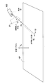
- FIG. 6 is an explanatory diagram for describing parameters related to the 3D structure of the horizontal plane.
- a normal vector V N representing the horizontal plane attitude in the coordinate system of the imaging unit 102 is shown.
- the size of the gravity direction vector V G is assumed to be normalized.
- the horizontal plane HP in this case can correspond to the ground or floor surface below the focal point of the imaging unit 102.
- the horizontal plane HP in this case can correspond to a ceiling surface above the focus of the imaging unit 102.
- the horizontal plane is obtained using the distance D from the origin to the horizontal plane HP.
- the distance D changes depending on the position of the horizontal plane in the real space. Further, when the distance D changes, the scale of the horizontal plane in the input image changes.
- FIG. 7 is a flowchart illustrating a first example of a plane determination process performed by the determination unit 130.
- the posture of the horizontal plane is determined.
- the data acquisition unit 125 acquires sensor data indicating the direction of gravity applied to the imaging unit 102 (step S1).
- the determination unit 130 determines the attitude of the horizontal plane (the normal vector V N described above) based on the sensor data acquired by the data acquisition unit 125 (step S2).
- the orientation of the horizontal plane may be determined depending on whether the imaging unit 102 is facing upward or downward.
- the horizontal plane can be determined using only acceleration data indicating the direction of gravity.
- the attitude of the vertical plane can be determined by using some restrictions, additional sensor data, or user input.
- the posture of a real space plane includes an elevation angle component and an azimuth angle component.
- the elevation angle (Elevation) is an angle in the vertical direction with respect to the horizontal plane, and usually takes a value within a range of ⁇ 90 ° to 90 ° (angle ⁇ of vector V 0 in FIG. 8).
- the azimuth is an angle in the east, west, south, and north directions with respect to some vertical plane, and usually takes a value within a range of 0 ° to 360 ° (angle ⁇ of the vector V 0 in FIG. 8).
- the elevation angle component can be determined by a method similar to the determination of the posture of the horizontal plane. Several approaches may exist to determine the remaining azimuth component.
- the determination unit 130 determines the attitude of the vertical plane based on the acceleration data and the predefined direction constraints.
- the predefined direction constraint may be, for example, a constraint that the imaging surface is directly facing the target vertical surface (the camera is set so that they are facing each other).
- the determination unit 130 is a unit vector that is orthogonal to the normal vector of the horizontal plane that is determined based on the direction of gravity, and that is closest to the optical axis of the camera (for example, a vector that faces the opposite direction of the optical axis) Can be determined as the normal vector of the vertical plane of interest.
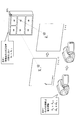
- the determination unit 130 determines the attitude of the vertical plane based on the acceleration data and the positioning data. More specifically, the determination unit 130 acquires map data about the area around the position of the information processing apparatus 100 indicated by the positioning data via the data acquisition unit 125 (upper left in FIG. 9). The map data acquired here indicates a positional relationship between the imaging unit 102 and one or more vertical planes located around the information processing apparatus 100. Further, the determination unit 130 calculates the azimuth of the optical axis of the imaging unit 102 based on the geomagnetic data (upper right in FIG. 9).
- the determination unit 130 specifies a vertical plane that enters the angle of view of the imaging unit 102 (that is, a vertical plane that appears in the input image) from one or more vertical planes in the map data.
- the vertical plane specified here may be a plane (such as a building wall surface) on which a line segment extending in the optical axis direction of the imaging unit 102 collides for the first time on the map from the position indicated by the positioning data (FIG. 9). under).
- the determination unit 130 acquires the orientation of the specified vertical plane in the real space coordinate system from the map data, and uses the geomagnetic direction indicated by the geomagnetic data to determine the orientation of the specified vertical plane in the coordinate system of the imaging unit 102. Convert to orientation.
- the determination unit 130 calculates a vector closest to the orientation of the vertical plane after conversion from among unit vectors orthogonal to the normal vector of the horizontal plane (in the coordinate system of the imaging unit 102). It can be determined as a line vector.
- the determination unit 130 uses the azimuth of the optical axis calculated based on the geomagnetic data, and instead of specifying on the map the vertical plane that appears in the input image, the determination unit 130 The surface may be specified by the user.
- a map MP is superimposed on an image Im03 on the screen of the display unit 110.
- the map MP indicates the position of the wall surface of the building or the like existing in the surrounding area of the position indicated by the positioning data.
- the user designates the vertical plane shown in the input image by an operation such as a touch on the map MP, for example.
- the determination unit 130 can recognize which vertical plane on the map is reflected in the input image.
- the determination unit 130 may recognize which vertical plane on the map appears in the input image by matching the image of a known building with the input image.
- FIG. 11 is a flowchart illustrating a second example of the flow of the plane determination process executed by the determination unit 130.
- the posture of the vertical plane is determined according to the second method described above.
- the data acquisition unit 125 acquires sensor data that can include acceleration data, positioning data, and geomagnetic data (step S1).
- the determination part 130 determines the normal vector of a horizontal surface based on the acceleration data which shows the direction of gravity (step S2).
- the determination unit 130 acquires map data of the surrounding area at the position indicated by the positioning data (step S4).
- the determination unit 130 specifies a vertical plane shown in the input image on the map using, for example, geomagnetic data (step S5).
- the determination unit 130 determines the normal vector of the specified vertical plane that is orthogonal to the normal vector of the horizontal plane determined in step S2 (step S6).
- the determination unit 130 determines the plane equation of the specified vertical plane using a provisional value that is defined in advance as a constant term of the plane equation (step S7).
- FIG. 12A is an explanatory diagram showing an example of a user interface for allowing the user to specify an arbitrary plane posture.
- a user interface UI1 having a spherical appearance is superimposed on an image Im04.
- the reference plane RP is a horizontal plane that passes through the center of the sphere of the user interface UI1.
- the determination unit 130 determines the posture of the reference plane RP according to the above-described method for determining the posture of the horizontal plane.
- the user interface UI1 is arranged in the AR space by the user interface unit 170 described later with reference to the orientation of the reference plane RP. By tracking the direction of gravity, the arrangement of the user interface UI1 is maintained in the AR space over a plurality of frames. As a result, the user interface UI1 is displayed as if it is fixed in the real space even if the angle of view changes.
- the user interface UI1 has a disk-like operation surface OD1 that passes through the center of the sphere.
- the operation surface OD1 may be disposed horizontally in the same manner as the reference surface RP.
- Two axes AX1 and AX2 associated with the operation surface OD1 are axes that are perpendicular to each other and parallel to the operation surface OD1.
- the axis AX3 is an axis perpendicular to the axes AX1 and AX2.
- the operation surface OD1 can be three-dimensionally rotated by the user. For example, when the user slides (drags) a finger horizontally on the screen, the operation surface OD1 rotates about the axis AX3.
- the operation surface OD1 rotates around the axis AX2. Through such an operation, the user rotates the operation surface OD1 three-dimensionally so that the arbitrary plane reflected in the input image and the operation surface OD1 are parallel to each other. And the determination part 130 determines the attitude
- the normal vector of the arbitrary plane has the same direction as the axis AX3 after the operation.
- the user interface for determining the orientation of an arbitrary plane is not limited to the example of FIG. 12A.
- the user interface may have a shape other than a spherical shape, and the operation surface may have a shape other than a disk.
- the operation surface OD1 may be rotatable in accordance with a different type of operation from the operation of sliding the finger (for example, tapping a predetermined button, pressing a cross key, etc.).
- a vertical plane may be used as a reference plane for arranging the user interface instead of the horizontal plane.
- FIG. 12B is an explanatory diagram showing another example of a user interface for allowing the user to specify the posture of an arbitrary plane.
- a user interface UI2 having the appearance of an animal character is superimposed on an image Im05.
- the user interface UI2 may be one of annotations for the AR application instead of a dedicated user interface for determining the orientation of the plane.
- the determination unit 130 determines the posture of the reference plane RP according to the above-described method for determining the posture of the horizontal plane. Then, the user interface UI2 is arranged in the AR space with reference to the orientation of the reference plane RP.
- the user interface UI2 has an operation surface OD2 arranged in parallel with the reference surface RP in the initial state.
- the operation surface OD2 has a character-like appearance.
- the user interface UI2 (character and its shadow) can be rotated three-dimensionally by the user. Through the operation, the user rotates the user interface UI2 three-dimensionally so that an arbitrary plane reflected in the input image and the operation surface OD2 are parallel to each other.
- the determination part 130 determines the attitude
- FIG. 13 is a flowchart illustrating a third example of the flow of the plane determination process executed by the determination unit 130.
- the posture of an arbitrary plane is determined using the above-described user interface.
- the data acquisition unit 125 acquires sensor data indicating the direction of gravity (step S1).
- the determination part 130 determines the attitude
- the user interface UI1 illustrated in FIG. 12A (or the user interface UI2 illustrated in FIG. 12B) is arranged in the AR space with reference to the orientation of the reference plane, and is displayed on the screen (step S8).
- the display of the user interface can be continued until, for example, a user input indicating the end of the operation is detected.
- the determination unit 130 determines a normal vector of an arbitrary plane from the attitude of the operated operation surface of the user interface, and further determines a plane equation of the arbitrary plane (step S9).
- the 3D structure DB 135 is a database that stores a 3D structure of real space imaged by the imaging unit 102.
- the 3D structure DB 135 stores, for example, constant terms and coefficients constituting the plane equation of the plane determined by the determination unit 130, that is, the position and orientation.
- the 3D structure DB 135 may store the position and orientation of the imaging unit 102 that are additionally recognized by the SLAM calculation unit 145 and can change with time.
- the 3D structure DB 135 may store the position and orientation of a real object that can be recognized by the image recognition unit 156.
- the display control unit 165 described later determines the placement of annotations in the AR space according to the position and orientation of a plane stored in the 3D structure DB 135 or the position and orientation of a real object.
- the conversion unit 140 performs conversion between the three-dimensional position of a given point on the plane and the two-dimensional position in the image corresponding to the three-dimensional position (that is, on the imaging surface). The determination is performed using the plane orientation determined by the determination unit 130.
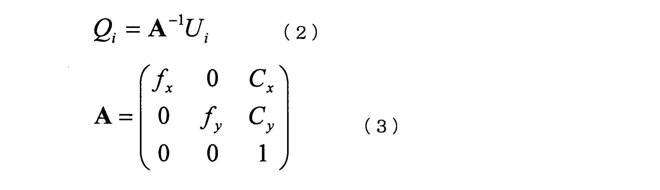
- the calculation process for conversion between the three-dimensional position and the two-dimensional position by the conversion unit 140 may be performed according to a known pinhole camera model. The calculation process performed by the conversion unit 140 according to the pinhole camera model will be described with reference to FIG. 6 again, taking a horizontal plane as an example.
- Point U i is projected to point Q i in three-dimensional space using the inverse matrix A ⁇ 1 of camera internal parameter matrix A as follows:
- (f x , f y ) represents a scale change rate between the imaging surface and the real space.
- (C x , C y ) is the center position of the imaging surface.
- the scale r i in equation (4) is derived by the following equation.
- D may be a provisional value defined in advance.
- the three-dimensional position T i of the point is obtained using the posture V N and the position D of the horizontal plane HP.
- a method for obtaining the two-dimensional position U i on the imaging surface corresponding to the point is also derived according to a similar pinhole camera model. obtain.
- given points to be subjected to calculation processing by the conversion unit 140 include at least feature points selected at the time of initialization of the SLAM method described below.
- the point constituting the annotation for the AR application can also be a target of calculation processing by the conversion unit 140. Note that even when a vertical plane or an arbitrary plane is used instead of the horizontal plane, the coordinate conversion can be performed in the same manner as described here.
- the SLAM operation unit 145 dynamically recognizes the 3D structure of the real space reflected in the input image from the monocular camera and the position and orientation of the imaging unit 102 by performing an operation according to the SLAM method. To do.
- FIG. 14 is a flowchart showing an example of the flow of SLAM calculation processing by the SLAM calculation unit 145.
- the SLAM calculation unit 145 first executes an initialization process to initialize state variables (step S10).
- the state variable is a vector including, as elements, the position and orientation (rotation angle) of the camera, the moving speed and angular velocity of the camera, and the position of one or more feature points.
- the input images acquired by the image acquisition unit 120 are sequentially input to the SLAM calculation unit 145 (step S20). The processing from step 30 to step S50 can be repeated for each input image (ie, every frame).
- step S40 the SLAM calculation unit 145 generates a predicted value of the state variable after one frame, for example, based on a predetermined prediction model.
- step S50 the SLAM computing unit 145 updates the state variable using the predicted value of the state variable generated in step S40 and the observed value corresponding to the position of the feature point detected in step S30.
- the SLAM calculation unit 145 executes the processes in steps S40 and S50 based on the principle of the extended Kalman filter.
- step S10 the contents of each process of state variable initialization (step S10), feature point tracking (step S30), state variable prediction (step S40), and state variable update (step S50) will be described more specifically. To do.
- the state variable used by the SLAM operation unit 145 is initialized through the initialization process illustrated in FIG. Referring to FIG. 15, first, the determination unit 130 performs plane determination processing (step S11). As a result, the relative position and orientation of the real space plane with respect to the imaging surface are determined. Next, the SLAM calculation unit 145 selects a plurality of feature points from the input image (step S12). The feature point selected here may be, for example, a point at a characteristic pixel position corresponding to an edge or corner of a texture. Next, the conversion unit 140 calculates a three-dimensional position on the plane corresponding to each feature point selected by the SLAM calculation unit 145 according to the above-described equation (6) (step S13). Next, the SLAM calculation unit 145 extracts patch data of each selected feature point from the input image (step S14). Using the patch data extracted here, the feature points can be tracked in step S30 of FIG.
- FIG. 16 shows a chest (left in the figure) and a calendar (right in the figure) as two examples of real objects.
- One or more feature points (FP) are set on each real object.
- the feature point FP1 is a feature point that is set as a dress, and a patch Pth1 is defined in association with the feature point FP1.
- the feature point FP2 is a feature point set in the calendar, and a patch Pth2 is defined in association with the feature point FP2.
- the SLAM calculation unit 145 collates the feature point patch data extracted in the initialization process illustrated in FIG. 15 or the newly set feature point patch data with a partial image included in the input image. Then, the SLAM calculation unit 145 specifies the position of the feature point included in the input image (for example, the position of the center pixel of the detected patch) as a result of the collation.
- the SLAM calculation unit 145 uses a state variable X shown in the following equation as a state variable to which the extended Kalman filter is to be applied.
- the first element of the state variable X in Equation (7) represents the three-dimensional position of the camera in real space as shown in the following equation.
- the second element of the state variable is a four-dimensional vector ⁇ having a quaternion corresponding to a rotation matrix representing the posture of the camera as an element.
- the posture of the camera may be expressed using Euler angles instead of quaternions.
- the third and fourth elements of the state variable represent the moving speed and angular velocity of the camera, respectively.
- the number N of feature points can change during processing.
- the SLAM calculation unit 145 generates a predicted value of the state variable for the latest frame based on the value of the state variable X initialized in step S10 or the value of the state variable X updated in the previous frame.
- the predicted value of the state variable is generated according to the state equation of the extended Kalman filter according to the multidimensional normal distribution shown by the following equation.
- F is a prediction model for system state transition
- a is a prediction condition
- w is Gaussian noise, and may include, for example, a model approximation error and an observation error. Generally, the average of the Gaussian noise w is zero.
- FIG. 18 is an explanatory diagram for describing an example of a prediction model according to the present embodiment. Referring to FIG. 18, two prediction conditions in the prediction model according to the present embodiment are shown. First, as a first condition, it is assumed that the three-dimensional position of the feature point does not change. That is, when the three-dimensional position of the feature point FP1 at time T and p T, the following relationship is established.
- the SLAM calculation unit 145 Based on the prediction model and the state equation shown in Equation (10), the SLAM calculation unit 145 generates a predicted value of the state variable for the latest frame.
- the SLAM calculation unit 145 uses, for example, the observation information predicted from the predicted value of the state variable and the actual observation information obtained as the result of tracking the feature point Evaluate the error.
- ⁇ is the error.
- H represents an observation model.
- the position of the feature point FP i on the imaging surface (uv plane) is defined as follows:
- the position of the camera x, the posture of the camera omega, and three-dimensional position p i of the feature point FP i are both given as elements of the state variable X.
- the position of the feature point FP i on the imaging surface is derived using the following equation.
- ⁇ is a parameter for normalization
- A is a camera internal parameter matrix
- R ⁇ is a rotation matrix corresponding to a quaternion ⁇ representing the posture of the camera included in the state variable X.
- the SLAM operation unit 145 stores the value of each parameter included in the state variable X dynamically updated according to the SLAM method in this way in the 3D structure DB 135.
- the object DB 150 is a database in which feature data representing features of a real object is stored in advance.
- the feature data stored by the object DB 150 is used in image recognition processing by the image recognition unit 156 described later.
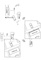
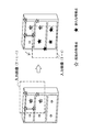
- FIG. 19 is an explanatory diagram for explaining an example of a configuration of feature data.
- the feature data 151 includes an object ID 152, image data 153 captured from six directions, patch data 154, and three-dimensional shape data 155.
- the object ID 152 is an identifier for uniquely identifying the real object Obj1.
- the image data 153 includes six pieces of image data obtained by imaging the real object Obj1 from six directions of front, rear, left, right, upper, and lower.
- the patch data 154 is a set of small images centered on each feature point for each feature point set on the real object.
- the three-dimensional shape data 155 is a position representing the three-dimensional position of each feature point in the local coordinate system of the real object Obj1 (that is, the position of each feature point relative to the origin defined locally in the real object Obj1). Contains information.
- the image recognition unit 156 recognizes which real object appears in the input image using the above-described feature data stored in the object DB 150. More specifically, for example, the image recognition unit 156 collates the partial image included in the input image acquired by the image acquisition unit 120 with the patch of each feature point included in the feature data, and is included in the input image. Detect feature points. The image recognition unit 156 may reuse the tracking result of the feature points by the SLAM calculation unit 145. Next, when the feature points belonging to one real object are detected at a high density in a certain area in the image, the image recognition unit 156 can recognize that the real object is reflected in the area.
- the image recognition unit 156 can further recognize the position and orientation of the recognized real object based on the positional relationship between the detected feature points and the three-dimensional shape data illustrated in FIG. Based on the position and posture of the real object recognized by the image recognition unit 156 and the position and posture of the imaging unit 102 recognized by the SLAM calculation unit 145, the position and posture of the real object after initialization of the SLAM method are determined. Tracking is realized. The position and orientation of the tracked real object are stored by the 3D structure DB 135.
- annotation DB 160 is a database that stores in advance annotation data related to annotations to be superimposed on an input image in the AR application.
- the annotation data may include, for example, identifiers, shape data, motion data, and related object IDs of various real objects including annotations A11, A12, and A2 illustrated in FIGS.
- the display control unit 165 controls display of the AR application using the display unit 110.
- the display control unit 165 arranges the annotation selected from the annotation DB 160 according to the purpose of the AR application in the AR space corresponding to the real space reflected in the input image.
- the arrangement of the annotation may be determined according to the position and orientation of the plane determined by the determination unit 130, for example.
- the conversion unit 140 uses the position and orientation of the plane on which the annotation is to be placed, using the two-dimensional position on the imaging surface corresponding to the feature points (or the vertices of the polygons, etc.) constituting the annotation placed in the AR space. calculate.
- the display control unit 165 superimposes the selected annotation on the input image in accordance with the calculation result by the conversion unit 140.
- the image on which the annotation is superimposed is displayed using the display of the display unit 110.
- the user interface unit 170 provides a user interface to the user of the information processing apparatus 100 using the input unit 106 and the display unit 110 illustrated in FIG.
- the user interface unit 170 displays an operation screen for allowing the user to operate the AR application on the display unit 110 and detects a user input through the operation screen.
- annotation selection, change, or movement may be performed via the user interface unit 170.
- the user interface unit 170 may superimpose on the input image a user interface for causing the user to designate a vertical plane shown in the input image on the map, as described with reference to FIG.
- the user interface unit 170 may superimpose a user interface for allowing the user to specify the posture of the arbitrary plane as described with reference to FIG. 12A on the input image in which the arbitrary plane is reflected.
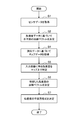
- FIG. 20 is a flowchart illustrating an example of the overall processing flow by the information processing apparatus 100 according to the present embodiment.
- an annotation to be displayed is selected by the display control unit 165 (or by the user via the user interface unit 170) (step S110).
- the display control unit 165 acquires, from the 3D structure DB 135, the 3D structure of the real space recognized based on the SLAM calculation (for example, the position and orientation of the real object or the plane associated with the selected annotation). (Step S120).
- the display control unit 165 arranges the selected annotation in the AR space according to the 3D structure of the real space (step S130).
- the conversion unit 140 calculates the display position of the annotation arranged in the AR space according to the above-described pinhole camera model (step S140). Then, the display control unit 165 superimposes the selected annotation on the input image according to the calculation result by the conversion unit 140 (step S150). As a result of such display control processing, display of the AR application as illustrated in FIGS. 1 and 2 can be realized.
- a normal vector of a horizontal plane in real space is recognized based on sensor data indicating the direction of gravity applied to the imaging device, and a plane such as a horizontal plane or a vertical plane is used using the recognized normal vector.
- the relative posture with respect to the imaging surface is determined.
- a state variable of the SLAM method is initialized by coordinate conversion using the determined plane orientation.
- the recognition accuracy in the vertical direction by the triaxial acceleration sensor is higher than the recognition of the horizontal plane based on the image recognition. Therefore, it is possible to initialize the state variable with higher accuracy than when the state variable is initialized using a method based on image recognition.
- the recognition accuracy at the time of initialization of the SLAM method affects the accuracy of the subsequent tracking of the 3D structure in the real space. Therefore, by initializing the state variables with higher accuracy, it is possible to accurately track the 3D structure in the real space thereafter.
- the relative position of the plane is easily determined as a temporary position. Therefore, the annotation is not arranged so as to completely coincide with the ground or floor surface of the real space.
- the accuracy of the posture is ensured with at least high accuracy, it is possible to superimpose an annotation that is arranged along a plane or moves on the plane in a natural manner.
- the purpose of the application can be sufficiently achieved if the orientation of the plane can be accurately determined without accurately determining the relative position of the plane.
- parallax is not used as in the SfM method in determining the orientation of the plane. Therefore, the orientation of the plane can be determined without moving the imaging device or in a situation where the imaging device is fixed.
- the posture of the horizontal plane can be determined easily and accurately using only sensor data from the three-axis acceleration sensor. Furthermore, by using predefined direction constraints, additional sensor data, or user input, the vertical plane attitude can also be accurately determined. It is also possible to determine the posture of an arbitrary plane via the user interface. Therefore, in many scenes where the AR application is used, it is possible to initialize the SLAM method with high accuracy by using various planes reflected in the input image.
- the adoption of the technology according to the present disclosure is also beneficial for AR applications that do not use the SLAM method. Therefore, as a second embodiment, an information processing apparatus 200 that implements an AR application that does not use the SLAM method will be described.
- the information processing apparatus 200 according to the present embodiment may be the terminal apparatus illustrated in FIG. 1 as with the information processing apparatus 100 according to the first embodiment, or the server illustrated in FIG. It may be a device.
- the information processing device 200 is a terminal device, the information processing device 200 may have a hardware configuration illustrated in FIG.
- FIG. 21 is a block diagram illustrating an example of a configuration of logical functions of the information processing apparatus 200 according to the second embodiment.
- the information processing apparatus 200 includes an image acquisition unit 120, a data acquisition unit 125, a determination unit 130, a 3D structure DB 135, a conversion unit 140, an object DB 150, an image recognition unit 156, an annotation DB 160, a user interface unit 170, and A display control unit 265 is included.
- the determination unit 130 determines the relative posture of the real space plane (horizontal plane, vertical plane, or arbitrary plane) with respect to the imaging surface based on the sensor data acquired by the data acquisition unit 125. Then, the determination unit 130 causes the 3D structure DB 135 to store the planar 3D structure having the determined posture.
- the conversion unit 140 calculates the two-dimensional position in the image (that is, on the imaging surface) corresponding to the three-dimensional position of a given point on the plane using the plane orientation determined by the determination unit 130. .
- a given point that is a target of calculation processing by the conversion unit 140 is a point that constitutes an annotation for an AR application.
- the image recognizing unit 156 recognizes which actual object appears in the input image using the feature data stored in the object DB 150. The result of recognition by the image recognition unit 156 may be used when the display control unit 265 selects and arranges annotation.
- the display control unit 265 controls the display of the AR application using the display. For example, the display control unit 265 arranges the annotation selected from the annotation DB 160 according to the purpose of the AR application in the AR space corresponding to the real space reflected in the input image.
- the arrangement of the annotation may be determined according to the recognition result of the real object by the image recognition unit 156. Instead, the annotation may be placed so as to be placed or pasted on a plane determined by the determination unit 130 and posted.
- the conversion unit 140 calculates a two-dimensional position on the imaging surface corresponding to a feature point (or a vertex of a polygon, etc.) constituting an annotation arranged in the AR space using the position and orientation of the real object or the plane. .
- the display control unit 265 superimposes the selected annotation on the input image in accordance with the calculation result by the conversion unit 140.
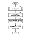
- FIG. 22 is a flowchart illustrating an example of the overall processing flow by the information processing apparatus 100 according to the present embodiment.
- the determination unit 130 performs a plane determination process (step S200).
- an annotation to be displayed is selected by the display control unit 265 (step S210).
- the display control unit 265 arranges the selected annotation in the AR space (step S230).
- the annotation may be arranged to be placed on a plane.
- the conversion unit 140 calculates the display position of the annotation arranged in the AR space according to the above-described pinhole camera model (step S240).
- the display control unit 265 superimposes the selected annotation on the input image according to the calculation result by the conversion unit 140 (step S250).
- display of the AR application as illustrated in FIGS. 1 and 2 can be realized.
- a normal vector of a horizontal plane in real space is recognized based on sensor data indicating the direction of gravity applied to the imaging device, and a horizontal plane, a vertical plane, or the like is used using the recognized normal vector.
- a relative posture of the plane with respect to the imaging surface is determined.
- the display position of the annotation arranged in association with the determined plane is easily calculated using the orientation of the plane.
- the recognition accuracy in the vertical direction by the triaxial acceleration sensor is higher than the recognition of the horizontal plane based on the image recognition. Therefore, it is possible to realize a more natural display of the annotation in the AR application as compared with the case where the annotation is arranged in association with the plane recognized using the method based on the image recognition.
- the posture of the horizontal plane can be determined easily and accurately using only sensor data from the three-axis acceleration sensor. Furthermore, by using predefined direction constraints, additional sensor data, or user input, the vertical plane attitude can also be accurately determined. It is also possible to determine the posture of an arbitrary plane via the user interface. Therefore, in many scenes where the AR application is used, it is possible to naturally display annotations in association with various planes reflected in the input image.
- the plane determined by the determination unit 130 has a virtual scale. That is, the value of the constant term D of the plane equation of the plane is a temporary value.
- the determination unit 130 may adjust the value of the constant term D so that the position of the plane coincides with the ground surface, the floor surface, the ceiling surface, or the surface of a real object (for example, the wall surface of a building). Further, the determination unit 130 may adjust the value of the constant term D according to the requirements of the AR application. In this section, three methods for adjusting the scale of a plane will be described using a horizontal plane as an example.
- a known size of a real object shown in an input image is used.
- the difference in position between two feature points belonging to one real object in the three-dimensional shape data (see FIG. 19) included in the feature data stored in the object DB 150 can be handled as a known size of the real object. .
- FIG. 23 is an explanatory diagram for describing a first technique for determining a plane scale.
- the two feature points T 1 and T 2 on the horizontal plane HP is shown.
- Feature point T 1 corresponds to the position U 1 on the imaging plane IP
- the feature point T 2 are corresponds to the position U 2 on the imaging plane IP.
- These feature points T 1 and T 2 belong to one real object.
- the image recognition unit 156 recognizes a real object including these feature points T 1 and T 2 from the input image.
- the determination unit 130 calculates a distance d HP between the feature points T 1 and T 2 from the three-dimensional shape data included in the feature data of the recognized real object. Then, the determination unit 130 uses the constant term D of the plane equation as an unknown variable, and derives a value of D at which the distance between the feature points T 1 and T 2 is d HP .
- [4-2. Second method] data related to the distance between the plane reflected in the input image and the imaging device is used.
- the plane reflected in the input image is a horizontal plane such as the ground or floor
- data related to the height of the imaging device from these horizontal planes can be used.
- the plane reflected in the input image is a vertical surface such as a wall surface of a building
- the distance between the wall surface calculated from the map data and the imaging device can be used.
- FIG. 24 is an explanatory diagram for explaining a second method for determining a plane scale.
- FIG. 24 shows the user Ua standing on the horizontal plane HP and the information processing apparatus 100 carried by the user Ua.
- the height of the user Ua is stored in advance as known data, or is input to the information processing apparatus 100 by the user Ua.
- the determination unit 130 estimates the height Ha of the imaging unit 102 of the information processing apparatus 100 by multiplying the height of the user Ua by a certain ratio.
- the determination unit 130 can use the height Ha thus estimated as the constant term D of the plane equation.
- the display size of the annotation displayed superimposed on the input image is used.
- the annotation DB 160 it is assumed that the size of the annotation in the three-dimensional AR space is defined.
- the plane scale can be determined from these two sizes.
- FIG. 25 is a first explanatory diagram for describing a third technique for determining a plane scale.
- FIG. 25 shows an image Im11 showing the table 14 existing in the real space.
- the annotation A2 is superimposed on the image Im11 as if it were placed on the surface of the table 14.
- the AR application displays the annotation A2 with a display size d disp that is fixedly defined.
- the determining unit 130 determines the constant term D of the plane equation so that the annotation A2 arranged in the AR space has the display size d disp on the imaging surface.
- the display size of the annotation A2 arranged on the plane becomes a predetermined display size d disp .
- FIG. 26 is a second explanatory diagram for describing the third technique for determining the plane scale.
- FIG. 26 shows an image Im12 on which the annotation A2 is superimposed as if it is placed on the surface of the table.
- the display size d disp of the annotation A2 is designated by the user via the user interface unit 170.
- the determining unit 130 determines the constant term D of the plane equation so that the annotation A2 arranged in the AR space has the display size d disp on the imaging surface. As a result, the display size of the annotation A2 arranged on the plane becomes the specified display size d disp .
- the position of the plane can be matched with the actual ground surface, floor surface, ceiling surface, or surface of the real object reflected in the input image.
- the display of annotations associated with these existing planes becomes more natural.
- the annotation can be displayed in a desired display size by adjusting the scale of the plane.
- the technology according to the present disclosure displays, for example, a horizontal plane and a vertical plane at the time of positioning of the imaging device, or adds a sign indicating the horizontal plane or the vertical plane to a recorded image. It may be applied to various uses.
- some of the logical functions of the information processing apparatus 100 or 200 described above may be mounted on a device existing in the cloud computing environment instead of being mounted on these devices.
- information exchanged between logical functions can be transmitted or received between devices via the communication unit 112 illustrated in FIG.
- the series of processing by each device described in this specification may be realized using any of software, hardware, and a combination of software and hardware.
- a program constituting the software is stored in advance in a storage medium provided inside or outside each device.
- Each program is read into a RAM (Random Access Memory) at the time of execution and executed by a processor such as a CPU.
- RAM Random Access Memory
- a data acquisition unit that acquires sensor data indicating the direction of gravity applied to an imaging device that captures an image that reflects real space
- a determination unit that determines a relative posture of a plane of the real space with respect to the image based on the sensor data
- a conversion unit that performs conversion between a three-dimensional position of a given point on the plane and a corresponding two-dimensional position in the image using the posture determined by the determination unit;
- An information processing apparatus comprising: (2) The information processing apparatus according to (1), wherein the given point on the plane is a feature point selected during initialization of a SLAM (Simultaneous Localization And Mapping) method.
- SLAM Simultaneous Localization And Mapping
- the information processing apparatus determines a virtual plane having the posture and a temporary position determined based on the sensor data;
- the information processing apparatus further includes a display control unit that superimposes the annotation on the image, The annotation is superimposed on a two-dimensional position in the image converted by the conversion unit from a three-dimensional position on the virtual plane.
- the information processing apparatus according to (3).
- the information processing apparatus further includes a recognition unit that recognizes an object shown in the image, The determination unit further determines the position of the plane reflected in the image using known data about the actual size of the object recognized by the recognition unit.
- the information processing apparatus according to (2) or (3).
- the determination unit further determines the position of the plane using data related to the distance between the plane reflected in the image and the imaging device, according to any one of (1) to (3).
- the information processing apparatus described in 1. The information processing apparatus according to (3), wherein the determination unit further determines a position of the plane on which the annotation is arranged using a display size of the displayed annotation.
- the plane is a horizontal plane; The determining unit determines whether the imaging device is facing upward or downward based on the sensor data, and determines the posture of the horizontal plane according to a result of the determination.
- the information processing apparatus according to any one of (1) to (8).
- the plane is a vertical plane;
- the determining unit determines the posture of the vertical plane based on the sensor data indicating the direction of gravity and a predefined direction constraint.
- the information processing apparatus according to any one of (1) to (8).
- the plane is a vertical plane;
- the determining unit determines an attitude of the vertical plane based on the sensor data indicating a direction of gravity and map data indicating a positional relationship between the imaging device and the vertical plane.
- the information processing apparatus according to any one of (1) to (8).
- the determination unit estimates a vertical plane reflected in the image using sensor data indicating a direction of geomagnetism from one or more vertical plane candidates included in the map data, and determines the estimated posture of the vertical plane,
- the determination unit determines the posture of the vertical plane designated by the user from one or more vertical plane candidates included in the map data based on the map data and the direction of gravity. The information processing apparatus described.
- the information processing apparatus includes: A user interface unit that arranges a user interface in the augmented reality space for allowing the user to specify the orientation of the plane based on the orientation of the horizontal plane or the vertical plane determined based on the sensor data,
- the information processing apparatus according to any one of (1) to (8), further including: (15) The information processing apparatus according to (14), wherein the arrangement of the user interface is maintained in the augmented reality space over a plurality of frames.
- the user interface has an operation surface that can be three-dimensionally rotated, The determining unit determines the orientation of the plane using the orientation of the operation surface operated by a user so as to be parallel to the plane.
- the information processing apparatus according to (15).
- a computer that controls an information processing device, Acquiring sensor data indicating the direction of gravity applied to an imaging device that captures an image reflecting real space; Determining a relative orientation of the plane of the real space with respect to the image based on the sensor data; Performing a transformation between a three-dimensional position of a given point on the plane and a corresponding two-dimensional position in the image using the determined posture;
- An information processing method including: (20) A computer for controlling the information processing apparatus; A data acquisition unit that acquires sensor data indicating the direction of gravity applied to an imaging device that captures an image that reflects real space; A determination unit that determines a relative posture of a plane of the real space with respect to the image based on the sensor data; A conversion unit that performs conversion between a three-dimensional position of a given point on the plane and a corresponding two-dimensional position in the image using the posture determined by the determination unit; Program to function as.
Landscapes
- Engineering & Computer Science (AREA)
- Theoretical Computer Science (AREA)
- Physics & Mathematics (AREA)
- General Physics & Mathematics (AREA)
- General Engineering & Computer Science (AREA)
- Remote Sensing (AREA)
- Radar, Positioning & Navigation (AREA)
- Automation & Control Theory (AREA)
- Human Computer Interaction (AREA)
- Software Systems (AREA)
- Multimedia (AREA)
- Computer Hardware Design (AREA)
- Computer Graphics (AREA)
- Computer Vision & Pattern Recognition (AREA)
- User Interface Of Digital Computer (AREA)
- Image Processing (AREA)
- Processing Or Creating Images (AREA)
- Position Input By Displaying (AREA)
Abstract
Description
1.装置の概要
2.第1の実施形態の詳細
2-1.ハードウェア構成
2-2.機能構成
2-3.処理の流れ
2-4.第1の実施形態のまとめ
3.第2の実施形態の詳細
3-1.機能構成
3-2.処理の流れ
3-3.第2の実施形態のまとめ
4.スケールの調整
4-1.第1の手法
4-2.第2の手法
4-3.第3の手法
5.総括 The description will be given in the following order.
1. Outline of the
まず、図1及び図2を用いて、本開示に係る情報処理装置の概要を説明する。 <1. Outline of equipment>
First, an overview of an information processing apparatus according to the present disclosure will be described with reference to FIGS. 1 and 2.
[2-1.ハードウェア構成]
図3は、第1の実施形態に係る情報処理装置100のハードウェア構成の一例を示すブロック図である。図3を参照すると、情報処理装置100は、撮像部102、センサ部104、入力部106、記憶部108、表示部110、通信部112、バス116及び制御部118を備える。 <2. Details of First Embodiment>
[2-1. Hardware configuration]
FIG. 3 is a block diagram illustrating an example of a hardware configuration of the
撮像部102は、画像を撮像するカメラモジュールである。撮像部102は、CCD(Charge Coupled Device)又はCMOS(Complementary Metal Oxide Semiconductor)などの撮像素子を用いて実空間を撮像し、撮像画像を生成する。撮像部102により生成される撮像画像は、制御部118による画像処理の入力画像となる。なお、撮像部102は、必ずしも情報処理装置100の一部でなくてもよい。例えば、情報処理装置100と有線又は無線で接続される撮像装置が撮像部102として扱われてもよい。 (1) Imaging unit The
センサ部104は、情報処理装置100による平面の姿勢の決定を支援するために利用される様々なセンサを含み得る。例えば、センサ部104は、撮像部102に加わる重力加速度を測定する3軸加速度センサを含む。3軸加速度センサは、撮像部102に加わる重力加速度を測定し、重力加速度の大きさ及び方向を3次元的に表すセンサデータ(加速度データ)を生成する。追加的に、センサ部104は、地磁気の方向を測定する地磁気センサを含んでもよい。地磁気センサは、撮像部102の座標系における地磁気の方向を表すセンサデータ(地磁気データ)を生成する。さらに、センサ部104は、情報処理装置100の位置を測定する測位センサ(例えば、GPS(Global Positioning System)センサ)を含んでもよい。測位センサは、実空間における情報処理装置100の緯度及び経度を表すセンサデータ(測位データ)を生成する。なお、センサ部104もまた、必ずしも情報処理装置100の一部でなくてもよい。 (2) Sensor Unit The
入力部106は、ユーザが情報処理装置100を操作し又は情報処理装置100へ情報を入力するために使用される入力デバイスである。入力部106は、例えば、表示部110の画面上へのユーザによるタッチを検出するタッチセンサを含んでもよい。その代わりに(又はそれに加えて)、入力部106は、マウス若しくはタッチパッドなどのポインティングデバイスを含んでもよい。さらに、入力部106は、キーボード、キーパッド、ボタン又はスイッチなどのその他の種類の入力デバイスを含んでもよい。 (3) Input unit The
記憶部108は、半導体メモリ又はハードディスクなどの記憶媒体により構成され、情報処理装置100による処理のためのプログラム及びデータを記憶する。記憶部108により記憶されるデータは、例えば、撮像画像データ、センサデータ及び後に説明する様々なデータベース(DB)内のデータを含み得る。なお、本明細書で説明するプログラム及びデータの一部は、記憶部108により記憶されることなく、外部のデータソース(例えば、データサーバ、ネットワークストレージ又は外付けメモリなど)から取得されてもよい。 (4) Storage Unit The
表示部110は、LCD(Liquid Crystal Display)、OLED(Organic light-Emitting Diode)又はCRT(Cathode Ray Tube)などのディスプレイを含む表示モジュールである。表示部110は、例えば、情報処理装置100により生成されるARアプリケーションの画像を表示するために使用される。なお、表示部110もまた、必ずしも情報処理装置100の一部でなくてもよい。例えば、情報処理装置100と有線又は無線で接続される表示装置が表示部110として扱われてもよい。 (5) Display Unit The
通信部112は、情報処理装置100による他の装置との間の通信を仲介する通信インタフェースである。通信部112は、任意の無線通信プロトコル又は有線通信プロトコルをサポートし、他の装置との間の通信接続を確立する。 (6) Communication unit The
バス116は、撮像部102、センサ部104、入力部106、記憶部108、表示部110、通信部112及び制御部118を相互に接続する。 (7) Bus The
制御部118は、CPU(Central Processing Unit)又はDSP(Digital Signal Processor)などのプロセッサに相当する。制御部118は、記憶部108又は他の記憶媒体に記憶されるプログラムを実行することにより、後に説明する情報処理装置100の様々な機能を動作させる。 (8) Control Unit The
図4は、図3に示した情報処理装置100の記憶部108及び制御部118により実現される論理的機能の構成の一例を示すブロック図である。図4を参照すると、情報処理装置100は、画像取得部120、データ取得部125、決定部130、3次元(3D)構造DB135、変換部140、SLAM演算部145、物体DB150、画像認識部156、アノテーションDB160、表示制御部165及びユーザインタフェース部170を含む。 [2-2. Functional configuration]
4 is a block diagram illustrating an example of a configuration of logical functions realized by the
画像取得部120は、撮像部102により生成される撮像画像を入力画像として取得する。画像取得部120により取得される入力画像は、実空間を映した画像である。当該入力画像は、静止画であってもよく、動画を構成する各フレームであってもよい。画像取得部120は、取得した入力画像を、SLAM演算部145、画像認識部156及び表示制御部165へ出力する。 (1) Image Acquisition Unit The
データ取得部125は、決定部130による平面決定処理のために使用されるデータを取得する。例えば、データ取得部125は、センサ部104により生成される、加速度データ、地磁気データ及び測位データの少なくとも1つを含み得るセンサデータを取得する。また、データ取得部125は、測位データにより示される位置の周辺地域についてのマップデータを、情報処理装置100により予め記憶されるデータベース又は外部のデータサーバから取得してもよい。そして、データ取得部125は、取得したデータを決定部130へ出力する。 (2) Data Acquisition Unit The
決定部130は、データ取得部125により取得されるセンサデータに基づいて、入力画像の撮像面に対する実空間の平面の相対的な姿勢を決定する。ここでは、まず水平面の姿勢を決定するための手法について詳細に説明し、次に鉛直面及びその他の平面の姿勢の決定について説明する。 (3) Determining unit The determining
図5は、撮像面、水平面及び重力方向の間の関係について説明するための説明図である。図5を参照すると、入力画像の撮像面IP及び実空間の水平面HPが示されている。水平面HPは、実在する地面、床面又は天井などの平面であってもよく、又は架空の平面であってもよい。水平面HPは、重力方向と直交する。撮像面IPに対する水平面HPの姿勢(あるいは水平面HPに対する撮像面IPの姿勢)は、撮像部102の姿勢に依存して変化し得る。そこで、決定部130は、上述したセンサデータにより示される重力方向ベクトルVGから、撮像面IPに対する水平面HPの相対的な姿勢を決定する。なお、決定部130は、センサデータの(3軸加速度センサの)3次元座標系と撮像面(及びその奥行き)の3次元座標系とが一致しない場合には、重力方向ベクトルVGについて、座標系の差が吸収されるように回転変換及びスケール変換を行ってよい。 (3-1) Determination of Horizontal Plane Position FIG. 5 is an explanatory diagram for explaining the relationship among the imaging plane, the horizontal plane, and the direction of gravity. Referring to FIG. 5, an imaging surface IP of an input image and a horizontal plane HP in real space are shown. The horizontal plane HP may be a plane such as an existing ground, floor, or ceiling, or may be an imaginary plane. The horizontal plane HP is orthogonal to the direction of gravity. The attitude of the horizontal plane HP with respect to the imaging plane IP (or the attitude of the imaging plane IP with respect to the horizontal plane HP) can change depending on the attitude of the
上述したように、水平面の姿勢は、重力の方向を示す加速度データのみを用いて決定され得る。これに対し、何らかの制約、追加的なセンサデータ又はユーザ入力を用いることで、鉛直面の姿勢を決定することもできる。一般的に、実空間の平面の姿勢は、仰俯角成分及び方位角成分からなる。仰俯角(Elevation)は、水平面を基準とした上下方向の角度であり、通常-90°~90°の範囲内の値をとる(図8のベクトルV0の角度θ)。方位角(Azimuth)は、何らかの鉛直面を基準とした東西南北方向の角度であり、通常0°~360°の範囲内の値をとる(図8のベクトルV0の角度φ)。このうち、仰俯角成分は、水平面の姿勢の決定と同様の手法で決定され得る。残りの方位角成分を決定するために、いくつかの手法が存在し得る。 (3-2) Determination of Vertical Plane As described above, the horizontal plane can be determined using only acceleration data indicating the direction of gravity. On the other hand, the attitude of the vertical plane can be determined by using some restrictions, additional sensor data, or user input. In general, the posture of a real space plane includes an elevation angle component and an azimuth angle component. The elevation angle (Elevation) is an angle in the vertical direction with respect to the horizontal plane, and usually takes a value within a range of −90 ° to 90 ° (angle θ of vector V 0 in FIG. 8). The azimuth (Azimuth) is an angle in the east, west, south, and north directions with respect to some vertical plane, and usually takes a value within a range of 0 ° to 360 ° (angle φ of the vector V 0 in FIG. 8). Among these, the elevation angle component can be determined by a method similar to the determination of the posture of the horizontal plane. Several approaches may exist to determine the remaining azimuth component.
水平面でも鉛直面でもない平面(以下、任意平面という)の姿勢は、重力の方向及びその他のセンサデータから直接的には決定されない。但し、上述した手法に従って決定される水平面又は鉛直面の姿勢を基準として、任意平面の姿勢をユーザに指定させるためのユーザインタフェースをAR空間内に配置することが可能である。 (3-3) Determination of posture of other plane The posture of a plane that is neither a horizontal plane nor a vertical plane (hereinafter referred to as an arbitrary plane) is not directly determined from the direction of gravity and other sensor data. However, it is possible to arrange a user interface in the AR space for allowing the user to specify the posture of an arbitrary plane with reference to the posture of the horizontal plane or the vertical plane determined according to the method described above.
3D構造DB135は、撮像部102により撮像される実空間の3D構造を記憶するデータベースである。3D構造DB135は、例えば、決定部130により決定される平面の平面方程式を構成する定数項及び係数、即ち位置及び姿勢を記憶する。また、3D構造DB135は、SLAM演算部145により追加的に認識される、時間を追って変化し得る撮像部102の位置及び姿勢を記憶してもよい。さらに、3D構造DB135は、画像認識部156により認識され得る実物体の位置及び姿勢を記憶してもよい。後述する表示制御部165は、3D構造DB135により記憶される平面の位置及び姿勢、又は実物体の位置及び姿勢に応じて、AR空間内のアノテーションの配置を決定する。 (4) 3D structure DB
The
変換部140は、平面上の所与の点の3次元位置と当該3次元位置に対応する画像内の(即ち、撮像面上の)2次元位置との間の変換を、決定部130により決定される平面の姿勢を用いて行う。変換部140による3次元位置と2次元位置との間の変換のための計算処理は、公知のピンホールカメラモデルに従って行われてよい。ピンホールカメラモデルに従って行われる変換部140による計算処理について、再び図6を参照しながら、水平面を例にとって説明する。 (5) Conversion unit The


SLAM演算部145は、SLAM法に従った演算を行うことにより、単眼カメラからの入力画像に映る実空間の3D構造と撮像部102の位置及び姿勢とを動的に認識する。 (6) SLAM operation unit The
SLAM演算部145により使用される状態変数は、図15に例示する初期化処理を通じて初期化される。図15を参照すると、まず、決定部130により平面決定処理が行われる(ステップS11)。その結果、撮像面に対する実空間の平面の相対的な位置及び姿勢が決定される。次に、SLAM演算部145は、入力画像から複数の特徴点を選択する(ステップS12)。ここで選択される特徴点は、例えば、テクスチャのエッジ又はコーナーなどに該当する特徴的な画素位置の点であってよい。次に、変換部140は、上述した式(6)に従って、SLAM演算部145により選択された各特徴点に対応する平面上の3次元位置を計算する(ステップS13)。次に、SLAM演算部145は、選択された各特徴点のパッチデータを入力画像から抽出する(ステップS14)。ここで抽出されたパッチデータを用いて、図14のステップS30における特徴点の追跡が行われ得る。 (6-1) Initialization of State Variable The state variable used by the
特徴点の追跡は、実空間内に存在し得る物体(実物体)の外観に現れる1つ以上の特徴点についてのパッチデータを用いて行われる。図16には、実物体の2つの例として、タンス(図中左)及びカレンダー(図中右)が示されている。各実物体上には、1つ以上の特徴点(FP:Feature Point)が設定されている。例えば、特徴点FP1はタンスに設定された特徴点であり、特徴点FP1と関連付けてパッチPth1が定義されている。また、特徴点FP2はカレンダーに設定された特徴点であり、特徴点FP2と関連付けてパッチPth2が定義されている。 (6-2) Feature Point Tracking Feature points are tracked using patch data for one or more feature points that appear in the appearance of an object (real object) that may exist in real space. FIG. 16 shows a chest (left in the figure) and a calendar (right in the figure) as two examples of real objects. One or more feature points (FP) are set on each real object. For example, the feature point FP1 is a feature point that is set as a dress, and a patch Pth1 is defined in association with the feature point FP1. The feature point FP2 is a feature point set in the calendar, and a patch Pth2 is defined in association with the feature point FP2.
本実施形態において、SLAM演算部145は、拡張カルマンフィルタを適用すべき状態変数として、次式に示す状態変数Xを用いる。 (6-3) Prediction of State Variable In this embodiment, the


そして、SLAM演算部145は、観測方程式を用いて、例えば状態変数の予測値から予測される観測情報と、特徴点の追跡結果として得られる実際の観測情報との誤差を評価する。なお、式(14)におけるνがその誤差である。 (6-4) Update of State Variable Then, using the observation equation, the


物体DB150は、実物体の特徴を表す特徴データを予め記憶しているデータベースである。物体DB150により記憶される特徴データは、後述する画像認識部156による画像認識処理において使用される。図19は、特徴データの構成の一例について説明するための説明図である。 (7) Object DB
The
画像認識部156は、物体DB150により記憶されている上述した特徴データを用いて、入力画像にどの実物体が映っているかを認識する。より具体的には、例えば、画像認識部156は、画像取得部120により取得される入力画像に含まれる部分画像と、特徴データに含まれる各特徴点のパッチとを照合し、入力画像に含まれる特徴点を検出する。画像認識部156は、SLAM演算部145による特徴点の追跡結果を再利用してもよい。次に、画像認識部156は、画像内のある領域に1つの実物体に属する特徴点が高い密度で検出された場合には、当該領域にその実物体が映っていると認識し得る。画像認識部156は、検出された特徴点の間の位置関係と図19に例示した3次元形状データとに基づいて、認識された実物体の位置及び姿勢をさらに認識し得る。画像認識部156により認識される実物体の位置及び姿勢と、SLAM演算部145により認識される撮像部102の位置及び姿勢とに基づいて、SLAM法の初期化後の実物体の位置及び姿勢の追跡が実現される。追跡される実物体の位置及び姿勢は、3D構造DB135により記憶される。 (8) Image Recognition Unit The
アノテーションDB160は、ARアプリケーションにおいて入力画像に重畳されるアノテーションに関するアノテーションデータを予め記憶しているデータベースである。アノテーションデータとは、例えば、図1及び図2に例示したアノテーションA11、A12及びA2を含む様々なアノテーションについての識別子、形状データ、動きデータ並びに関連する実物体の物体IDなどを含んでよい。 (9) Annotation DB
The
表示制御部165は、表示部110を用いたARアプリケーションの表示を制御する。例えば、表示制御部165は、ARアプリケーションの目的に応じてアノテーションDB160から選択されるアノテーションを、入力画像に映る実空間に対応するAR空間内に配置する。アノテーションの配置は、例えば、決定部130により決定された平面の位置及び姿勢に応じて決定されてよい。変換部140は、AR空間内に配置されたアノテーションを構成する特徴点(又はポリゴンの頂点など)に対応する撮像面上の2次元位置を、アノテーションを配置すべき平面の位置及び姿勢を用いて計算する。表示制御部165は、このような変換部140による計算結果に応じて、選択されたアノテーションを入力画像に重畳する。アノテーションが重畳された画像は、表示部110のディスプレイを用いて表示される。 (10) Display Control Unit The
ユーザインタフェース部170は、図3に示した入力部106及び表示部110を用いて、情報処理装置100のユーザにユーザインタフェースを提供する。例えば、ユーザインタフェース部170は、ARアプリケーションをユーザに操作させるための操作画面を表示部110に表示させ、当該操作画面を通じてユーザ入力を検出する。例えば、アノテーションの選択、変更又は移動などがユーザインタフェース部170を介して行われてもよい。また、ユーザインタフェース部170は、図10を用いて説明したような、入力画像に映る鉛直面をマップ上でユーザに指定させるためのユーザインタフェースを入力画像に重畳してもよい。また、ユーザインタフェース部170は、図12Aを用いて説明したような、任意平面の姿勢をユーザに指定させるためのユーザインタフェースを、当該任意平面が映る入力画像に重畳してもよい。 (11) User Interface Unit The
図20は、本実施形態に係る情報処理装置100による全体的な処理の流れの一例を示すフローチャートである。図20を参照すると、まず、表示制御部165により(又はユーザインタフェース部170を介してユーザにより)表示すべきアノテーションが選択される(ステップS110)。次に、表示制御部165は、SLAM演算に基づいて認識される実空間の3D構造(例えば、選択されたアノテーションと関連付けられている実物体又は平面の位置及び姿勢)を、3D構造DB135から取得する(ステップS120)。次に、表示制御部165は、選択されたアノテーションを実空間の3D構造に応じてAR空間内に配置する(ステップS130)。次に、変換部140は、AR空間内に配置されたアノテーションの表示位置を、上述したピンホールカメラモデルに従って計算する(ステップS140)。そして、表示制御部165は、変換部140による計算結果に応じて、選択されたアノテーションを入力画像に重畳する(ステップS150)。このような表示制御処理の結果、図1及び図2に例示したようなARアプリケーションの表示が実現され得る。 [2-3. Process flow]
FIG. 20 is a flowchart illustrating an example of the overall processing flow by the
本実施形態によれば、撮像装置に加わる重力の方向を示すセンサデータに基づいて実空間の水平面の法線ベクトルが認識され、認識された法線ベクトルを用いて、水平面又は鉛直面などの平面の撮像面に対する相対的な姿勢が決定される。そして、決定された平面の姿勢を用いた座標変換により、SLAM法の状態変数が初期化される。一般的に、画像認識に基づく水平面の認識よりも、3軸加速度センサによる鉛直方向の認識の方が高い認識精度が得られる。従って、画像認識に基づく手法を用いて状態変数が初期化される場合と比較して、より高い精度で状態変数を初期化することができる。特に、SLAM法の初期化の際の認識精度は、その後の実空間の3D構造の追跡の精度を左右する。そのため、状態変数をより高い精度で初期化することで、その後の実空間の3D構造の追跡をも正確に行うことが可能となる。 [2-4. Summary of First Embodiment]
According to the present embodiment, a normal vector of a horizontal plane in real space is recognized based on sensor data indicating the direction of gravity applied to the imaging device, and a plane such as a horizontal plane or a vertical plane is used using the recognized normal vector. The relative posture with respect to the imaging surface is determined. Then, a state variable of the SLAM method is initialized by coordinate conversion using the determined plane orientation. Generally, the recognition accuracy in the vertical direction by the triaxial acceleration sensor is higher than the recognition of the horizontal plane based on the image recognition. Therefore, it is possible to initialize the state variable with higher accuracy than when the state variable is initialized using a method based on image recognition. In particular, the recognition accuracy at the time of initialization of the SLAM method affects the accuracy of the subsequent tracking of the 3D structure in the real space. Therefore, by initializing the state variables with higher accuracy, it is possible to accurately track the 3D structure in the real space thereafter.
本開示に係る技術の採用は、SLAM法を利用しないARアプリケーションにとっても有益である。そこで、第2の実施形態として、SLAM法を利用しないARアプリケーションを実装する情報処理装置200について説明する。なお、本実施形態に係る情報処理装置200は、第1の実施形態に係る情報処理装置100と同様、図1に例示したような端末装置であってもよく、図2に例示したようなサーバ装置であってもよい。情報処理装置200が端末装置である場合には、情報処理装置200は、図3に例示したようなハードウェア構成を有し得る。 <3. Details of Second Embodiment>
The adoption of the technology according to the present disclosure is also beneficial for AR applications that do not use the SLAM method. Therefore, as a second embodiment, an
図21は、第2の実施形態に係る情報処理装置200の論理的機能の構成の一例を示すブロック図である。図21を参照すると、情報処理装置200は、画像取得部120、データ取得部125、決定部130、3D構造DB135、変換部140、物体DB150、画像認識部156、アノテーションDB160、ユーザインタフェース部170及び表示制御部265を含む。 [3-1. Functional configuration]
FIG. 21 is a block diagram illustrating an example of a configuration of logical functions of the
図22は、本実施形態に係る情報処理装置100による全体的な処理の流れの一例を示すフローチャートである。図22を参照すると、まず、決定部130により平面決定処理が行われる(ステップS200)。次に、表示制御部265により表示すべきアノテーションが選択される(ステップS210)。次に、表示制御部265は、選択されたアノテーションをAR空間内に配置する(ステップS230)。一例として、アノテーションは、平面上に載置されるように配置され得る。次に、変換部140は、AR空間内に配置されたアノテーションの表示位置を、上述したピンホールカメラモデルに従って計算する(ステップS240)。そして、表示制御部265は、変換部140による計算結果に応じて、選択されたアノテーションを入力画像に重畳する(ステップS250)。このような表示制御処理の結果、図1及び図2に例示したようなARアプリケーションの表示が実現され得る。 [3-2. Process flow]
FIG. 22 is a flowchart illustrating an example of the overall processing flow by the
本実施形態によれば、撮像装置に加わる重力の方向を示すセンサデータに基づいて、実空間の水平面の法線ベクトルが認識され、認識された法線ベクトルを用いて、水平面又は鉛直面などの平面の撮像面に対する相対的な姿勢が決定される。そして、決定された平面と関連付けて配置されるアノテーションの表示位置が、当該平面の姿勢を用いて簡易に計算される。上述したように、一般的に、画像認識に基づく水平面の認識よりも、3軸加速度センサによる鉛直方向の認識の方が高い認識精度が得られる。従って、画像認識に基づく手法を用いて認識される平面と関連付けてアノテーションが配置される場合と比較して、ARアプリケーションにおいてより自然なアノテーションの表示を実現することができる。 [3-3. Summary of Second Embodiment]
According to the present embodiment, a normal vector of a horizontal plane in real space is recognized based on sensor data indicating the direction of gravity applied to the imaging device, and a horizontal plane, a vertical plane, or the like is used using the recognized normal vector. A relative posture of the plane with respect to the imaging surface is determined. Then, the display position of the annotation arranged in association with the determined plane is easily calculated using the orientation of the plane. As described above, generally, the recognition accuracy in the vertical direction by the triaxial acceleration sensor is higher than the recognition of the horizontal plane based on the image recognition. Therefore, it is possible to realize a more natural display of the annotation in the AR application as compared with the case where the annotation is arranged in association with the plane recognized using the method based on the image recognition.
第1及び第2の実施形態では、決定部130により決定される平面は、仮想的なスケールを有する。即ち、当該平面の平面方程式の定数項Dの値は、仮の値である。決定部130は、かかる定数項Dの値を調整し、平面の位置を地面、床面、天井面又は実物体の表面(例えば、建物の壁面)などに一致させてもよい。また、決定部130は、ARアプリケーションの要件に応じて定数項Dの値を調整してもよい。本節では、水平面を例にとって、平面のスケールを調整するための3つの手法を説明する。 <4. Scale adjustment>
In the first and second embodiments, the plane determined by the
第1の手法では、入力画像に映る実物体の既知のサイズが利用される。例えば、物体DB150により記憶される特徴データに含まれる3次元形状データ(図19参照)における1つの実物体に属する2つの特徴点の位置の差を、実物体の既知のサイズとして扱うことができる。 [4-1. First method]
In the first method, a known size of a real object shown in an input image is used. For example, the difference in position between two feature points belonging to one real object in the three-dimensional shape data (see FIG. 19) included in the feature data stored in the
第2の手法では、入力画像に映る平面と撮像装置との間の距離に関連するデータが利用される。例えば、入力画像に映る平面が地面又は床面などの水平面である場合には、撮像装置のこれら水平面からの高さに関連するデータが利用され得る。また、例えば、入力画像に映る平面が建物の壁面などの鉛直面である場合には、マップデータから計算される当該壁面と撮像装置との間の距離が利用され得る。 [4-2. Second method]
In the second method, data related to the distance between the plane reflected in the input image and the imaging device is used. For example, when the plane reflected in the input image is a horizontal plane such as the ground or floor, data related to the height of the imaging device from these horizontal planes can be used. Further, for example, when the plane reflected in the input image is a vertical surface such as a wall surface of a building, the distance between the wall surface calculated from the map data and the imaging device can be used.
第3の手法では、入力画像に重畳して表示されるアノテーションについての表示サイズが利用される。例えば、アノテーションDB160において、3次元のAR空間内でのアノテーションのサイズが定義されているものとする。この場合、平面上に配置されるアノテーションの撮像面上でのサイズ、即ち表示サイズがさらに特定されれば、これら2つのサイズから平面のスケールを決定することができる。 [4-3. Third method]
In the third method, the display size of the annotation displayed superimposed on the input image is used. For example, in the
ここまで、図1~図26を用いて、本開示に係る技術の2つの実施形態について詳細に説明した。これら実施形態によれば、画像認識に基づく手法が利用される場合と比較して、実空間の平面の姿勢をより正確に認識して当該平面の姿勢をAR技術のために利用することができる。 <5. Summary>
So far, the two embodiments of the technology according to the present disclosure have been described in detail with reference to FIGS. 1 to 26. According to these embodiments, compared to the case where a method based on image recognition is used, the posture of a plane in real space can be recognized more accurately, and the posture of the plane can be used for AR technology. .
(1)
実空間を映す画像を撮像する撮像装置に加わる重力の方向を示すセンサデータを取得するデータ取得部と、
前記センサデータに基づいて、前記画像に対する前記実空間の平面の相対的な姿勢を決定する決定部と、
前記平面上の所与の点の3次元位置と対応する前記画像内の2次元位置との間の変換を、前記決定部により決定される前記姿勢を用いて行う変換部と、
を備える情報処理装置。
(2)
前記平面上の前記所与の点は、SLAM(Simultaneous Localization And Mapping)法の初期化の際に選択される特徴点である、前記(1)に記載の情報処理装置。
(3)
前記平面上の前記所与の点は、拡張現実のためのアノテーションを構成する点である、前記(1)に記載の情報処理装置。
(4)
前記決定部は、前記センサデータに基づいて決定される前記姿勢と仮の位置とを有する仮想的な平面を決定し、
前記情報処理装置は、前記アノテーションを前記画像に重畳する表示制御部、をさらに備え、
前記アノテーションは、前記仮想的な平面上の3次元位置から前記変換部により変換される前記画像内の2次元位置に重畳される、
前記(3)に記載の情報処理装置。
(5)
前記情報処理装置は、前記画像に映る物体を認識する認識部、をさらに備え、
前記決定部は、前記認識部により認識される物体の実サイズについての既知のデータを用いて、前記画像に映る前記平面の位置をさらに決定する、
前記(2)又は前記(3)に記載の情報処理装置。
(6)
前記決定部は、前記画像に映る前記平面と前記撮像装置との間の距離に関連するデータを用いて、前記平面の位置をさらに決定する、前記(1)~(3)のいずれか1項に記載の情報処理装置。
(7)
前記決定部は、表示される前記アノテーションについての表示サイズを用いて、前記アノテーションが配置される前記平面の位置をさらに決定する、前記(3)に記載の情報処理装置。
(8)
前記情報処理装置は、前記表示サイズをユーザに指定させるユーザインタフェース部、をさらに備える、前記(7)に記載の情報処理装置。
(9)
前記平面は、水平面であり、
前記決定部は、前記撮像装置が上方及び下方のいずれを向いているかを前記センサデータに基づいて判定し、当該判定の結果に応じて前記水平面の前記姿勢を決定する、
前記(1)~(8)のいずれか1項に記載の情報処理装置。
(10)
前記平面は、鉛直面であり、
前記決定部は、重力の方向を示す前記センサデータと予め定義される方向の制約とに基づいて、前記鉛直面の姿勢を決定する、
前記(1)~(8)のいずれか1項に記載の情報処理装置。
(11)
前記平面は、鉛直面であり、
前記決定部は、重力の方向を示す前記センサデータと前記撮像装置及び前記鉛直面の位置関係を示すマップデータとに基づいて、前記鉛直面の姿勢を決定する、
前記(1)~(8)のいずれか1項に記載の情報処理装置。
(12)
前記決定部は、前記マップデータに含まれる1つ以上の鉛直面の候補から、地磁気の方向を示すセンサデータを用いて前記画像に映る鉛直面を推定し、推定した前記鉛直面の姿勢を、前記マップデータと重力の方向とに基づいて決定する、前記(11)に記載の情報処理装置。
(13)
前記決定部は、前記マップデータに含まれる1つ以上の鉛直面の候補からユーザにより指定される鉛直面の姿勢を、前記マップデータと重力の方向とに基づいて決定する、前記(11)に記載の情報処理装置。
(14)
前記情報処理装置は、
前記センサデータに基づいて決定される水平面又は鉛直面の姿勢を基準として、前記平面の姿勢をユーザに指定させるためのユーザインタフェースを拡張現実空間内に配置するユーザインタフェース部、
をさらに備える、前記(1)~(8)のいずれか1項に記載の情報処理装置。
(15)
前記ユーザインタフェースの配置は、複数のフレームにわたって前記拡張現実空間内で維持される、前記(14)に記載の情報処理装置。
(16)
前記ユーザインタフェースは、3次元的に回転操作可能な操作面を有し、
前記決定部は、前記平面と平行となるようにユーザにより操作された前記操作面の姿勢を用いて、前記平面の姿勢を決定する、
前記(15)に記載の情報処理装置。
(17)
前記情報処理装置は、前記撮像装置と前記センサデータを出力するセンサとをさらに備える端末装置である、前記(1)~(16)のいずれか1項に記載の情報処理装置。
(18)
前記データ取得部、前記決定部及び前記変換部のうち少なくとも1つが前記情報処理装置の代わりにクラウドコンピューティング環境内に存在する装置上に実装される、前記(1)~(17)のいずれか1項に記載の情報処理装置。
(19)
情報処理装置を制御するコンピュータにおいて、
実空間を映す画像を撮像する撮像装置に加わる重力の方向を示すセンサデータを取得することと、
前記センサデータに基づいて、前記画像に対する前記実空間の平面の相対的な姿勢を決定することと、
前記平面上の所与の点の3次元位置と対応する前記画像内の2次元位置との間の変換を、決定された前記姿勢を用いて行うことと、
を含む情報処理方法。
(20)
情報処理装置を制御するコンピュータを、
実空間を映す画像を撮像する撮像装置に加わる重力の方向を示すセンサデータを取得するデータ取得部と、
前記センサデータに基づいて、前記画像に対する前記実空間の平面の相対的な姿勢を決定する決定部と、
前記平面上の所与の点の3次元位置と対応する前記画像内の2次元位置との間の変換を、前記決定部により決定される前記姿勢を用いて行う変換部と、
として機能させるためのプログラム。 The following configurations also belong to the technical scope of the present disclosure.
(1)
A data acquisition unit that acquires sensor data indicating the direction of gravity applied to an imaging device that captures an image that reflects real space;
A determination unit that determines a relative posture of a plane of the real space with respect to the image based on the sensor data;
A conversion unit that performs conversion between a three-dimensional position of a given point on the plane and a corresponding two-dimensional position in the image using the posture determined by the determination unit;
An information processing apparatus comprising:
(2)
The information processing apparatus according to (1), wherein the given point on the plane is a feature point selected during initialization of a SLAM (Simultaneous Localization And Mapping) method.
(3)
The information processing apparatus according to (1), wherein the given point on the plane is a point constituting an annotation for augmented reality.
(4)
The determining unit determines a virtual plane having the posture and a temporary position determined based on the sensor data;
The information processing apparatus further includes a display control unit that superimposes the annotation on the image,
The annotation is superimposed on a two-dimensional position in the image converted by the conversion unit from a three-dimensional position on the virtual plane.
The information processing apparatus according to (3).
(5)
The information processing apparatus further includes a recognition unit that recognizes an object shown in the image,
The determination unit further determines the position of the plane reflected in the image using known data about the actual size of the object recognized by the recognition unit.
The information processing apparatus according to (2) or (3).
(6)
The determination unit further determines the position of the plane using data related to the distance between the plane reflected in the image and the imaging device, according to any one of (1) to (3). The information processing apparatus described in 1.
(7)
The information processing apparatus according to (3), wherein the determination unit further determines a position of the plane on which the annotation is arranged using a display size of the displayed annotation.
(8)
The information processing apparatus according to (7), further including a user interface unit that allows a user to specify the display size.
(9)
The plane is a horizontal plane;
The determining unit determines whether the imaging device is facing upward or downward based on the sensor data, and determines the posture of the horizontal plane according to a result of the determination.
The information processing apparatus according to any one of (1) to (8).
(10)
The plane is a vertical plane;
The determining unit determines the posture of the vertical plane based on the sensor data indicating the direction of gravity and a predefined direction constraint.
The information processing apparatus according to any one of (1) to (8).
(11)
The plane is a vertical plane;
The determining unit determines an attitude of the vertical plane based on the sensor data indicating a direction of gravity and map data indicating a positional relationship between the imaging device and the vertical plane.
The information processing apparatus according to any one of (1) to (8).
(12)
The determination unit estimates a vertical plane reflected in the image using sensor data indicating a direction of geomagnetism from one or more vertical plane candidates included in the map data, and determines the estimated posture of the vertical plane, The information processing apparatus according to (11), which is determined based on the map data and a direction of gravity.
(13)
The determination unit determines the posture of the vertical plane designated by the user from one or more vertical plane candidates included in the map data based on the map data and the direction of gravity. The information processing apparatus described.
(14)
The information processing apparatus includes:
A user interface unit that arranges a user interface in the augmented reality space for allowing the user to specify the orientation of the plane based on the orientation of the horizontal plane or the vertical plane determined based on the sensor data,
The information processing apparatus according to any one of (1) to (8), further including:
(15)
The information processing apparatus according to (14), wherein the arrangement of the user interface is maintained in the augmented reality space over a plurality of frames.
(16)
The user interface has an operation surface that can be three-dimensionally rotated,
The determining unit determines the orientation of the plane using the orientation of the operation surface operated by a user so as to be parallel to the plane.
The information processing apparatus according to (15).
(17)
The information processing apparatus according to any one of (1) to (16), wherein the information processing apparatus is a terminal device that further includes the imaging device and a sensor that outputs the sensor data.
(18)
Any one of (1) to (17), wherein at least one of the data acquisition unit, the determination unit, and the conversion unit is mounted on a device that exists in a cloud computing environment instead of the information processing device The information processing apparatus according to
(19)
In a computer that controls an information processing device,
Acquiring sensor data indicating the direction of gravity applied to an imaging device that captures an image reflecting real space;
Determining a relative orientation of the plane of the real space with respect to the image based on the sensor data;
Performing a transformation between a three-dimensional position of a given point on the plane and a corresponding two-dimensional position in the image using the determined posture;
An information processing method including:
(20)
A computer for controlling the information processing apparatus;
A data acquisition unit that acquires sensor data indicating the direction of gravity applied to an imaging device that captures an image that reflects real space;
A determination unit that determines a relative posture of a plane of the real space with respect to the image based on the sensor data;
A conversion unit that performs conversion between a three-dimensional position of a given point on the plane and a corresponding two-dimensional position in the image using the posture determined by the determination unit;
Program to function as.
102 撮像部
104 センサ部
125 データ取得部
130 決定部
140 変換部
156 認識部
165,265 表示制御部
170 ユーザインタフェース部
HP 水平面
IP 撮像面
DESCRIPTION OF SYMBOLS 100,200
Claims (20)
- 実空間を映す画像を撮像する撮像装置に加わる重力の方向を示すセンサデータを取得するデータ取得部と、
前記センサデータに基づいて、前記画像に対する前記実空間の平面の相対的な姿勢を決定する決定部と、
前記平面上の所与の点の3次元位置と対応する前記画像内の2次元位置との間の変換を、前記決定部により決定される前記姿勢を用いて行う変換部と、
を備える情報処理装置。 A data acquisition unit that acquires sensor data indicating the direction of gravity applied to an imaging device that captures an image that reflects real space;
A determination unit that determines a relative posture of a plane of the real space with respect to the image based on the sensor data;
A conversion unit that performs conversion between a three-dimensional position of a given point on the plane and a corresponding two-dimensional position in the image using the posture determined by the determination unit;
An information processing apparatus comprising: - 前記平面上の前記所与の点は、SLAM(Simultaneous Localization And Mapping)法の初期化の際に選択される特徴点である、請求項1に記載の情報処理装置。 The information processing apparatus according to claim 1, wherein the given point on the plane is a feature point selected at the time of initialization of a SLAM (Simultaneous Localization And Mapping) method.
- 前記平面上の前記所与の点は、拡張現実のためのアノテーションを構成する点である、請求項1に記載の情報処理装置。 The information processing apparatus according to claim 1, wherein the given point on the plane is a point constituting an annotation for augmented reality.
- 前記決定部は、前記センサデータに基づいて決定される前記姿勢と仮の位置とを有する仮想的な平面を決定し、
前記情報処理装置は、前記アノテーションを前記画像に重畳する表示制御部、をさらに備え、
前記アノテーションは、前記仮想的な平面上の3次元位置から前記変換部により変換される前記画像内の2次元位置に重畳される、
請求項3に記載の情報処理装置。 The determining unit determines a virtual plane having the posture and a temporary position determined based on the sensor data;
The information processing apparatus further includes a display control unit that superimposes the annotation on the image,
The annotation is superimposed on a two-dimensional position in the image converted by the conversion unit from a three-dimensional position on the virtual plane.
The information processing apparatus according to claim 3. - 前記情報処理装置は、前記画像に映る物体を認識する認識部、をさらに備え、
前記決定部は、前記認識部により認識される物体の実サイズについての既知のデータを用いて、前記画像に映る前記平面の位置をさらに決定する、
請求項2に記載の情報処理装置。 The information processing apparatus further includes a recognition unit that recognizes an object shown in the image,
The determination unit further determines the position of the plane reflected in the image using known data about the actual size of the object recognized by the recognition unit.
The information processing apparatus according to claim 2. - 前記決定部は、前記画像に映る前記平面と前記撮像装置との間の距離に関連するデータを用いて、前記平面の位置をさらに決定する、請求項1に記載の情報処理装置。 The information processing apparatus according to claim 1, wherein the determination unit further determines a position of the plane using data related to a distance between the plane reflected in the image and the imaging apparatus.
- 前記決定部は、表示される前記アノテーションについての表示サイズを用いて、前記アノテーションが配置される前記平面の位置をさらに決定する、請求項3に記載の情報処理装置。 The information processing apparatus according to claim 3, wherein the determination unit further determines a position of the plane on which the annotation is arranged using a display size of the displayed annotation.
- 前記情報処理装置は、前記表示サイズをユーザに指定させるユーザインタフェース部、をさらに備える、請求項7に記載の情報処理装置。 The information processing apparatus according to claim 7, further comprising a user interface unit that allows a user to specify the display size.
- 前記平面は、水平面であり、
前記決定部は、前記撮像装置が上方及び下方のいずれを向いているかを前記センサデータに基づいて判定し、当該判定の結果に応じて前記水平面の前記姿勢を決定する、
請求項1に記載の情報処理装置。 The plane is a horizontal plane;
The determining unit determines whether the imaging device is facing upward or downward based on the sensor data, and determines the posture of the horizontal plane according to a result of the determination.
The information processing apparatus according to claim 1. - 前記平面は、鉛直面であり、
前記決定部は、重力の方向を示す前記センサデータと予め定義される方向の制約とに基づいて、前記鉛直面の姿勢を決定する、
請求項1に記載の情報処理装置。 The plane is a vertical plane;
The determining unit determines the posture of the vertical plane based on the sensor data indicating the direction of gravity and a predefined direction constraint.
The information processing apparatus according to claim 1. - 前記平面は、鉛直面であり、
前記決定部は、重力の方向を示す前記センサデータと前記撮像装置及び前記鉛直面の位置関係を示すマップデータとに基づいて、前記鉛直面の姿勢を決定する、
請求項1に記載の情報処理装置。 The plane is a vertical plane;
The determining unit determines an attitude of the vertical plane based on the sensor data indicating a direction of gravity and map data indicating a positional relationship between the imaging device and the vertical plane.
The information processing apparatus according to claim 1. - 前記決定部は、前記マップデータに含まれる1つ以上の鉛直面の候補から、地磁気の方向を示すセンサデータを用いて前記画像に映る鉛直面を推定し、推定した前記鉛直面の姿勢を、前記マップデータと重力の方向とに基づいて決定する、請求項11に記載の情報処理装置。 The determination unit estimates a vertical plane reflected in the image using sensor data indicating a direction of geomagnetism from one or more vertical plane candidates included in the map data, and determines the estimated posture of the vertical plane, The information processing apparatus according to claim 11, wherein the information processing apparatus is determined based on the map data and a direction of gravity.
- 前記決定部は、前記マップデータに含まれる1つ以上の鉛直面の候補からユーザにより指定される鉛直面の姿勢を、前記マップデータと重力の方向とに基づいて決定する、請求項11に記載の情報処理装置。 The said determination part determines the attitude | position of the vertical surface designated by the user from the candidate of the 1 or more vertical surface contained in the said map data based on the said map data and the direction of gravity. Information processing device.
- 前記情報処理装置は、
前記センサデータに基づいて決定される水平面又は鉛直面の姿勢を基準として、前記平面の姿勢をユーザに指定させるためのユーザインタフェースを拡張現実空間内に配置するユーザインタフェース部、
をさらに備える、請求項1に記載の情報処理装置。 The information processing apparatus includes:
A user interface unit that arranges a user interface in the augmented reality space for allowing the user to specify the orientation of the plane based on the orientation of the horizontal plane or the vertical plane determined based on the sensor data,
The information processing apparatus according to claim 1, further comprising: - 前記ユーザインタフェースの配置は、複数のフレームにわたって前記拡張現実空間内で維持される、請求項14に記載の情報処理装置。 The information processing apparatus according to claim 14, wherein the arrangement of the user interface is maintained in the augmented reality space over a plurality of frames.
- 前記ユーザインタフェースは、3次元的に回転操作可能な操作面を有し、
前記決定部は、前記平面と平行となるようにユーザにより操作された前記操作面の姿勢を用いて、前記平面の姿勢を決定する、
請求項15に記載の情報処理装置。 The user interface has an operation surface that can be three-dimensionally rotated,
The determining unit determines the orientation of the plane using the orientation of the operation surface operated by a user so as to be parallel to the plane.
The information processing apparatus according to claim 15. - 前記情報処理装置は、前記撮像装置と前記センサデータを出力するセンサとをさらに備える端末装置である、請求項1に記載の情報処理装置。 The information processing apparatus according to claim 1, wherein the information processing apparatus is a terminal device further including the imaging device and a sensor that outputs the sensor data.
- 前記データ取得部、前記決定部及び前記変換部のうち少なくとも1つが前記情報処理装置の代わりにクラウドコンピューティング環境内に存在する装置上に実装される、請求項1に記載の情報処理装置。 The information processing apparatus according to claim 1, wherein at least one of the data acquisition unit, the determination unit, and the conversion unit is mounted on a device that exists in a cloud computing environment instead of the information processing device.
- 情報処理装置を制御するコンピュータにおいて、
実空間を映す画像を撮像する撮像装置に加わる重力の方向を示すセンサデータを取得することと、
前記センサデータに基づいて、前記画像に対する前記実空間の平面の相対的な姿勢を決定することと、
前記平面上の所与の点の3次元位置と対応する前記画像内の2次元位置との間の変換を、決定された前記姿勢を用いて行うことと、
を含む情報処理方法。 In a computer that controls an information processing device,
Acquiring sensor data indicating the direction of gravity applied to an imaging device that captures an image reflecting real space;
Determining a relative orientation of the plane of the real space with respect to the image based on the sensor data;
Performing a transformation between a three-dimensional position of a given point on the plane and a corresponding two-dimensional position in the image using the determined posture;
An information processing method including: - 情報処理装置を制御するコンピュータを、
実空間を映す画像を撮像する撮像装置に加わる重力の方向を示すセンサデータを取得するデータ取得部と、
前記センサデータに基づいて、前記画像に対する前記実空間の平面の相対的な姿勢を決定する決定部と、
前記平面上の所与の点の3次元位置と対応する前記画像内の2次元位置との間の変換を、前記決定部により決定される前記姿勢を用いて行う変換部と、
として機能させるためのプログラム。
A computer for controlling the information processing apparatus;
A data acquisition unit that acquires sensor data indicating the direction of gravity applied to an imaging device that captures an image that reflects real space;
A determination unit that determines a relative posture of a plane of the real space with respect to the image based on the sensor data;
A conversion unit that performs conversion between a three-dimensional position of a given point on the plane and a corresponding two-dimensional position in the image using the posture determined by the determination unit;
Program to function as.
Priority Applications (6)
| Application Number | Priority Date | Filing Date | Title |
|---|---|---|---|
| EP20156603.1A EP3680863B1 (en) | 2011-08-24 | 2012-08-14 | Information processing device, information processing method, and program |
| EP12825620.3A EP2750110B1 (en) | 2011-08-24 | 2012-08-14 | Information processing device, information processing method, and program |
| RU2014105775/08A RU2014105775A (en) | 2011-08-24 | 2012-08-14 | INFORMATION PROCESSING DEVICE, INFORMATION PROCESSING METHOD AND PROGRAM |
| CN201280040105.9A CN103733229A (en) | 2011-08-24 | 2012-08-14 | Information processing device, information processing method, and program |
| JP2013529976A JP5920352B2 (en) | 2011-08-24 | 2012-08-14 | Information processing apparatus, information processing method, and program |
| US14/238,978 US9355451B2 (en) | 2011-08-24 | 2012-08-14 | Information processing device, information processing method, and program for recognizing attitude of a plane |
Applications Claiming Priority (2)
| Application Number | Priority Date | Filing Date | Title |
|---|---|---|---|
| JP2011-182693 | 2011-08-24 | ||
| JP2011182693 | 2011-08-24 |
Publications (1)
| Publication Number | Publication Date |
|---|---|
| WO2013027628A1 true WO2013027628A1 (en) | 2013-02-28 |
Family
ID=47746375
Family Applications (1)
| Application Number | Title | Priority Date | Filing Date |
|---|---|---|---|
| PCT/JP2012/070677 WO2013027628A1 (en) | 2011-08-24 | 2012-08-14 | Information processing device, information processing method, and program |
Country Status (6)
| Country | Link |
|---|---|
| US (1) | US9355451B2 (en) |
| EP (2) | EP3680863B1 (en) |
| JP (1) | JP5920352B2 (en) |
| CN (1) | CN103733229A (en) |
| RU (1) | RU2014105775A (en) |
| WO (1) | WO2013027628A1 (en) |
Cited By (11)
| Publication number | Priority date | Publication date | Assignee | Title |
|---|---|---|---|---|
| GB2506338A (en) * | 2012-07-30 | 2014-04-02 | Sony Comp Entertainment Europe | A method of localisation and mapping |
| WO2015093129A1 (en) * | 2013-12-17 | 2015-06-25 | ソニー株式会社 | Information processing device, information processing method, and program |
| WO2016017253A1 (en) * | 2014-08-01 | 2016-02-04 | ソニー株式会社 | Information processing device, information processing method, and program |
| WO2016017254A1 (en) * | 2014-08-01 | 2016-02-04 | ソニー株式会社 | Information processing device, information processing method, and program |
| JP2016038867A (en) * | 2014-08-11 | 2016-03-22 | 株式会社大林組 | Arrangement plan support system, arrangement plan support method, and arrangement plan support program |
| JP2016048455A (en) * | 2014-08-27 | 2016-04-07 | 株式会社リコー | Image processor, image processing method, and program |
| JP2016515254A (en) * | 2013-03-15 | 2016-05-26 | クアルコム,インコーポレイテッド | Client-server based dynamic search |
| JP2020509505A (en) * | 2017-03-06 | 2020-03-26 | Line株式会社 | Method, apparatus and computer program for providing augmented reality |
| WO2020116352A1 (en) * | 2018-12-04 | 2020-06-11 | アイシン精機株式会社 | Road surface detection device and road surface detection program |
| JP2020535509A (en) * | 2017-09-29 | 2020-12-03 | アリババ・グループ・ホールディング・リミテッドAlibaba Group Holding Limited | Methods, devices and systems for automatically annotating target objects in images |
| JP2023502192A (en) * | 2020-10-23 | 2023-01-23 | チョーチアン センスタイム テクノロジー デベロップメント カンパニー,リミテッド | Visual positioning method and related apparatus, equipment and computer readable storage medium |
Families Citing this family (23)
| Publication number | Priority date | Publication date | Assignee | Title |
|---|---|---|---|---|
| CN105264572B (en) * | 2013-04-04 | 2018-09-21 | 索尼公司 | Information processing equipment, information processing method and program |
| US20150269436A1 (en) * | 2014-03-18 | 2015-09-24 | Qualcomm Incorporated | Line segment tracking in computer vision applications |
| WO2016021252A1 (en) * | 2014-08-05 | 2016-02-11 | ソニー株式会社 | Information processing device, information processing method, and image display system |
| JP6459706B2 (en) * | 2015-03-27 | 2019-01-30 | セイコーエプソン株式会社 | Interactive projector and interactive projection system |
| US10360718B2 (en) * | 2015-08-14 | 2019-07-23 | Samsung Electronics Co., Ltd. | Method and apparatus for constructing three dimensional model of object |
| CN107949866A (en) * | 2015-09-15 | 2018-04-20 | 三菱电机株式会社 | Image processing apparatus, image processing system and image processing method |
| CN107025662B (en) * | 2016-01-29 | 2020-06-09 | 成都理想境界科技有限公司 | Method, server, terminal and system for realizing augmented reality |
| CN107025661B (en) * | 2016-01-29 | 2020-08-04 | 成都理想境界科技有限公司 | Method, server, terminal and system for realizing augmented reality |
| CN108629248A (en) * | 2017-03-24 | 2018-10-09 | 成都理想境界科技有限公司 | A kind of method and apparatus for realizing augmented reality |
| KR20200009003A (en) * | 2017-05-18 | 2020-01-29 | 소니 주식회사 | Information processing device, information processing method, program |
| DE102017217923A1 (en) * | 2017-10-09 | 2019-04-11 | Audi Ag | Method for operating a display device in a motor vehicle |
| CN107704106B (en) * | 2017-10-17 | 2021-04-09 | 宁波视睿迪光电有限公司 | Attitude positioning method and device and electronic equipment |
| JP6770208B2 (en) * | 2018-01-30 | 2020-10-14 | 株式会社ソニー・インタラクティブエンタテインメント | Information processing device |
| WO2019164514A1 (en) * | 2018-02-23 | 2019-08-29 | Google Llc | Transitioning between map view and augmented reality view |
| CH714968A1 (en) * | 2018-05-07 | 2019-11-15 | Brugg Rohr Ag Holding | Method and device for producing a thermally insulated conduit. |
| US10482674B1 (en) * | 2018-06-27 | 2019-11-19 | Beijing Jingdong Shangke Information Technology Co., Ltd. | System and method for mobile augmented reality |
| US10628964B2 (en) * | 2018-09-19 | 2020-04-21 | Seiko Epson Corporation | Methods and devices for extended reality device training data creation |
| CN109579745A (en) * | 2018-11-26 | 2019-04-05 | 江苏科技大学 | Novel house Area computing method based on augmented reality and cell phone software |
| CN111256683A (en) * | 2018-12-03 | 2020-06-09 | 北京科加触控技术有限公司 | Positioning method and device |
| JP2020089947A (en) * | 2018-12-06 | 2020-06-11 | ソニー株式会社 | Information processing device, information processing method, and program |
| JP7341736B2 (en) * | 2019-06-06 | 2023-09-11 | キヤノン株式会社 | Information processing device, information processing method and program |
| US11430151B2 (en) | 2019-11-06 | 2022-08-30 | Seiko Epson Corporation | Online learning for 3D pose estimation using simplified constellations |
| JPWO2021124826A1 (en) * | 2019-12-17 | 2021-06-24 |
Citations (4)
| Publication number | Priority date | Publication date | Assignee | Title |
|---|---|---|---|---|
| JP2005107248A (en) * | 2003-09-30 | 2005-04-21 | Canon Inc | Data transformation method and system, and attitude measuring instrument |
| JP2006292417A (en) * | 2005-04-06 | 2006-10-26 | Canon Inc | Method and apparatus for measuring position and attitude |
| JP2007271563A (en) * | 2006-03-31 | 2007-10-18 | Canon Inc | Position and attitude measuring method and device |
| JP2009237845A (en) | 2008-03-27 | 2009-10-15 | Sony Corp | Information processor, information processing method, and computer program |
Family Cites Families (5)
| Publication number | Priority date | Publication date | Assignee | Title |
|---|---|---|---|---|
| CN101609506B (en) * | 2008-06-20 | 2012-05-23 | 索尼株式会社 | Method and device for recognizing model object in image |
| US8350871B2 (en) * | 2009-02-04 | 2013-01-08 | Motorola Mobility Llc | Method and apparatus for creating virtual graffiti in a mobile virtual and augmented reality system |
| KR101633359B1 (en) * | 2009-10-20 | 2016-06-27 | 삼성전자 주식회사 | Marker-less augmented reality system using projective invariant and method the same |
| KR101667033B1 (en) * | 2010-01-04 | 2016-10-17 | 삼성전자 주식회사 | Augmented reality service apparatus using location based data and method the same |
| US8797353B2 (en) * | 2010-02-12 | 2014-08-05 | Samsung Electronics Co., Ltd. | Augmented media message |
-
2012
- 2012-08-14 JP JP2013529976A patent/JP5920352B2/en active Active
- 2012-08-14 US US14/238,978 patent/US9355451B2/en active Active
- 2012-08-14 EP EP20156603.1A patent/EP3680863B1/en active Active
- 2012-08-14 WO PCT/JP2012/070677 patent/WO2013027628A1/en active Application Filing
- 2012-08-14 CN CN201280040105.9A patent/CN103733229A/en active Pending
- 2012-08-14 EP EP12825620.3A patent/EP2750110B1/en active Active
- 2012-08-14 RU RU2014105775/08A patent/RU2014105775A/en not_active Application Discontinuation
Patent Citations (4)
| Publication number | Priority date | Publication date | Assignee | Title |
|---|---|---|---|---|
| JP2005107248A (en) * | 2003-09-30 | 2005-04-21 | Canon Inc | Data transformation method and system, and attitude measuring instrument |
| JP2006292417A (en) * | 2005-04-06 | 2006-10-26 | Canon Inc | Method and apparatus for measuring position and attitude |
| JP2007271563A (en) * | 2006-03-31 | 2007-10-18 | Canon Inc | Position and attitude measuring method and device |
| JP2009237845A (en) | 2008-03-27 | 2009-10-15 | Sony Corp | Information processor, information processing method, and computer program |
Non-Patent Citations (2)
| Title |
|---|
| ANDREW J. DAVISON: "Real-Time Simultaneous Localization and Mapping with a Single Camera", PROCEEDINGS OF THE 9TH IEEE INTERNATIONAL CONFERENCE ON COMPUTER VISION VOLUME, vol. 2, 2003, pages 1403 - 1410 |
| See also references of EP2750110A4 |
Cited By (32)
| Publication number | Priority date | Publication date | Assignee | Title |
|---|---|---|---|---|
| US9415310B2 (en) | 2012-07-30 | 2016-08-16 | Sony Computer Entertainment Europe Limited | Localisation and mapping |
| US10657663B2 (en) | 2012-07-30 | 2020-05-19 | Sony Interactive Entertainment Europe Limited | Localisation and mapping |
| GB2506338A (en) * | 2012-07-30 | 2014-04-02 | Sony Comp Entertainment Europe | A method of localisation and mapping |
| US9824450B2 (en) | 2012-07-30 | 2017-11-21 | Sony Interactive Entertainment Europe Limited | Localisation and mapping |
| US9779509B2 (en) | 2012-07-30 | 2017-10-03 | Sony Interactive Entertainment Europe Limited | Localisation and mapping |
| US9704244B2 (en) | 2012-07-30 | 2017-07-11 | Sony Computer Entertainment Europe Limited | Localisation and mapping |
| US9679381B2 (en) | 2012-07-30 | 2017-06-13 | Sony Computer Entertainment Europe Limited | Localisation and mapping |
| JP2016515254A (en) * | 2013-03-15 | 2016-05-26 | クアルコム,インコーポレイテッド | Client-server based dynamic search |
| US10452892B2 (en) | 2013-12-17 | 2019-10-22 | Sony Corporation | Controlling image processing device to display data based on state of object in real space |
| CN105814611B (en) * | 2013-12-17 | 2020-08-18 | 索尼公司 | Information processing apparatus and method, and non-volatile computer-readable storage medium |
| US11462028B2 (en) | 2013-12-17 | 2022-10-04 | Sony Corporation | Information processing device and information processing method to generate a virtual object image based on change in state of object in real space |
| WO2015093129A1 (en) * | 2013-12-17 | 2015-06-25 | ソニー株式会社 | Information processing device, information processing method, and program |
| CN105814611A (en) * | 2013-12-17 | 2016-07-27 | 索尼公司 | Information processing device, information processing method, and program |
| JPWO2015093129A1 (en) * | 2013-12-17 | 2017-03-16 | ソニー株式会社 | Information processing apparatus, information processing method, and program |
| WO2016017254A1 (en) * | 2014-08-01 | 2016-02-04 | ソニー株式会社 | Information processing device, information processing method, and program |
| WO2016017253A1 (en) * | 2014-08-01 | 2016-02-04 | ソニー株式会社 | Information processing device, information processing method, and program |
| US10462406B2 (en) | 2014-08-01 | 2019-10-29 | Sony Corporation | Information processing apparatus and information processing method |
| US10499002B2 (en) | 2014-08-01 | 2019-12-03 | Sony Corporation | Information processing apparatus and information processing method |
| JPWO2016017253A1 (en) * | 2014-08-01 | 2017-05-18 | ソニー株式会社 | Information processing apparatus, information processing method, and program |
| JPWO2016017254A1 (en) * | 2014-08-01 | 2017-05-18 | ソニー株式会社 | Information processing apparatus, information processing method, and program |
| JP2016038867A (en) * | 2014-08-11 | 2016-03-22 | 株式会社大林組 | Arrangement plan support system, arrangement plan support method, and arrangement plan support program |
| JP2016048455A (en) * | 2014-08-27 | 2016-04-07 | 株式会社リコー | Image processor, image processing method, and program |
| JP2020509505A (en) * | 2017-03-06 | 2020-03-26 | Line株式会社 | Method, apparatus and computer program for providing augmented reality |
| US11120629B2 (en) | 2017-03-06 | 2021-09-14 | Line Corporation | Method and device for providing augmented reality, and computer program |
| US11562545B2 (en) | 2017-03-06 | 2023-01-24 | Line Corporation | Method and device for providing augmented reality, and computer program |
| JP2020535509A (en) * | 2017-09-29 | 2020-12-03 | アリババ・グループ・ホールディング・リミテッドAlibaba Group Holding Limited | Methods, devices and systems for automatically annotating target objects in images |
| JP7231306B2 (en) | 2017-09-29 | 2023-03-01 | アリババ・グループ・ホールディング・リミテッド | Method, Apparatus and System for Automatically Annotating Target Objects in Images |
| JP2020090138A (en) * | 2018-12-04 | 2020-06-11 | アイシン精機株式会社 | Road surface detection device and road surface detection program |
| WO2020116352A1 (en) * | 2018-12-04 | 2020-06-11 | アイシン精機株式会社 | Road surface detection device and road surface detection program |
| JP7211047B2 (en) | 2018-12-04 | 2023-01-24 | 株式会社アイシン | Road surface detection device and road surface detection program |
| JP2023502192A (en) * | 2020-10-23 | 2023-01-23 | チョーチアン センスタイム テクノロジー デベロップメント カンパニー,リミテッド | Visual positioning method and related apparatus, equipment and computer readable storage medium |
| JP7280385B2 (en) | 2020-10-23 | 2023-05-23 | チョーチアン センスタイム テクノロジー デベロップメント カンパニー,リミテッド | Visual positioning method and related apparatus, equipment and computer readable storage medium |
Also Published As
| Publication number | Publication date |
|---|---|
| US9355451B2 (en) | 2016-05-31 |
| EP2750110A4 (en) | 2015-08-26 |
| US20140168268A1 (en) | 2014-06-19 |
| EP2750110B1 (en) | 2020-03-18 |
| EP3680863B1 (en) | 2024-01-10 |
| RU2014105775A (en) | 2015-08-27 |
| EP2750110A1 (en) | 2014-07-02 |
| JPWO2013027628A1 (en) | 2015-03-19 |
| EP3680863A1 (en) | 2020-07-15 |
| CN103733229A (en) | 2014-04-16 |
| JP5920352B2 (en) | 2016-05-18 |
Similar Documents
| Publication | Publication Date | Title |
|---|---|---|
| JP5920352B2 (en) | Information processing apparatus, information processing method, and program | |
| US9996982B2 (en) | Information processing device, authoring method, and program | |
| TWI505709B (en) | System and method for determining individualized depth information in augmented reality scene | |
| EP3176757A1 (en) | Information processing device, information processing method, and program | |
| WO2020227734A1 (en) | Methods and apparatus for venue based augmented reality | |
| Bostanci et al. | User tracking methods for augmented reality | |
| US20140267234A1 (en) | Generation and Sharing Coordinate System Between Users on Mobile | |
| US20140009384A1 (en) | Methods and systems for determining location of handheld device within 3d environment | |
| JP2013225245A (en) | Image processing device, image processing method, and program | |
| JP6609640B2 (en) | Managing feature data for environment mapping on electronic devices | |
| JP2011095797A (en) | Image processing device, image processing method and program | |
| JP2011186808A (en) | Information processing apparatus, map update method, program, and information processing system | |
| JP2011203823A (en) | Image processing device, image processing method and program | |
| Marto et al. | DinofelisAR demo augmented reality based on natural features | |
| Ye et al. | 6-DOF pose estimation of a robotic navigation aid by tracking visual and geometric features | |
| JP2011203824A (en) | Image processing device, image processing method and program | |
| JP2021103168A (en) | Augmented reality device and positioning method | |
| CN116349222A (en) | Rendering depth-based three-dimensional models using integrated image frames | |
| Alam et al. | Pose estimation algorithm for mobile augmented reality based on inertial sensor fusion. | |
| Araujo et al. | Life cycle of a slam system: Implementation, evaluation and port to the project tango device | |
| WO2021111613A1 (en) | Three-dimensional map creation device, three-dimensional map creation method, and three-dimensional map creation program | |
| WO2023226593A1 (en) | Picture display method, system and apparatus, device, and storage medium | |
| Bostanci et al. | Tracking methods for augmented reality | |
| WO2024095744A1 (en) | Information processing device, information processing method, and program | |
| Li | A new efficient pose estimation and tracking method for personal devices: application to interaction in smart spaces |
Legal Events
| Date | Code | Title | Description |
|---|---|---|---|
| 121 | Ep: the epo has been informed by wipo that ep was designated in this application |
Ref document number: 12825620 Country of ref document: EP Kind code of ref document: A1 |
|
| ENP | Entry into the national phase |
Ref document number: 2013529976 Country of ref document: JP Kind code of ref document: A |
|
| WWE | Wipo information: entry into national phase |
Ref document number: 14238978 Country of ref document: US |
|
| ENP | Entry into the national phase |
Ref document number: 2014105775 Country of ref document: RU Kind code of ref document: A |
|
| NENP | Non-entry into the national phase |
Ref country code: DE |