WO2013025236A1 - System and method of uplink power control in a wireless communication system - Google Patents
System and method of uplink power control in a wireless communication system Download PDFInfo
- Publication number
- WO2013025236A1 WO2013025236A1 PCT/US2011/065604 US2011065604W WO2013025236A1 WO 2013025236 A1 WO2013025236 A1 WO 2013025236A1 US 2011065604 W US2011065604 W US 2011065604W WO 2013025236 A1 WO2013025236 A1 WO 2013025236A1
- Authority
- WO
- WIPO (PCT)
- Prior art keywords
- pusch
- sinr
- parameter
- transmission
- serving cell
- Prior art date
Links
Classifications
-
- H—ELECTRICITY
- H04—ELECTRIC COMMUNICATION TECHNIQUE
- H04B—TRANSMISSION
- H04B7/00—Radio transmission systems, i.e. using radiation field
- H04B7/24—Radio transmission systems, i.e. using radiation field for communication between two or more posts
- H04B7/26—Radio transmission systems, i.e. using radiation field for communication between two or more posts at least one of which is mobile
- H04B7/2612—Arrangements for wireless medium access control, e.g. by allocating physical layer transmission capacity
-
- H—ELECTRICITY
- H04—ELECTRIC COMMUNICATION TECHNIQUE
- H04W—WIRELESS COMMUNICATION NETWORKS
- H04W56/00—Synchronisation arrangements
- H04W56/004—Synchronisation arrangements compensating for timing error of reception due to propagation delay
- H04W56/0045—Synchronisation arrangements compensating for timing error of reception due to propagation delay compensating for timing error by altering transmission time
-
- H—ELECTRICITY
- H04—ELECTRIC COMMUNICATION TECHNIQUE
- H04B—TRANSMISSION
- H04B3/00—Line transmission systems
- H04B3/02—Details
- H04B3/36—Repeater circuits
-
- H—ELECTRICITY
- H04—ELECTRIC COMMUNICATION TECHNIQUE
- H04B—TRANSMISSION
- H04B7/00—Radio transmission systems, i.e. using radiation field
- H04B7/02—Diversity systems; Multi-antenna system, i.e. transmission or reception using multiple antennas
- H04B7/04—Diversity systems; Multi-antenna system, i.e. transmission or reception using multiple antennas using two or more spaced independent antennas
- H04B7/0413—MIMO systems
-
- H—ELECTRICITY
- H04—ELECTRIC COMMUNICATION TECHNIQUE
- H04L—TRANSMISSION OF DIGITAL INFORMATION, e.g. TELEGRAPHIC COMMUNICATION
- H04L1/00—Arrangements for detecting or preventing errors in the information received
- H04L1/0001—Systems modifying transmission characteristics according to link quality, e.g. power backoff
- H04L1/0002—Systems modifying transmission characteristics according to link quality, e.g. power backoff by adapting the transmission rate
- H04L1/0003—Systems modifying transmission characteristics according to link quality, e.g. power backoff by adapting the transmission rate by switching between different modulation schemes
-
- H—ELECTRICITY
- H04—ELECTRIC COMMUNICATION TECHNIQUE
- H04L—TRANSMISSION OF DIGITAL INFORMATION, e.g. TELEGRAPHIC COMMUNICATION
- H04L1/00—Arrangements for detecting or preventing errors in the information received
- H04L1/0001—Systems modifying transmission characteristics according to link quality, e.g. power backoff
- H04L1/0023—Systems modifying transmission characteristics according to link quality, e.g. power backoff characterised by the signalling
- H04L1/0026—Transmission of channel quality indication
-
- H—ELECTRICITY
- H04—ELECTRIC COMMUNICATION TECHNIQUE
- H04L—TRANSMISSION OF DIGITAL INFORMATION, e.g. TELEGRAPHIC COMMUNICATION
- H04L1/00—Arrangements for detecting or preventing errors in the information received
- H04L1/12—Arrangements for detecting or preventing errors in the information received by using return channel
- H04L1/16—Arrangements for detecting or preventing errors in the information received by using return channel in which the return channel carries supervisory signals, e.g. repetition request signals
- H04L1/18—Automatic repetition systems, e.g. Van Duuren systems
- H04L1/1812—Hybrid protocols; Hybrid automatic repeat request [HARQ]
-
- H—ELECTRICITY
- H04—ELECTRIC COMMUNICATION TECHNIQUE
- H04L—TRANSMISSION OF DIGITAL INFORMATION, e.g. TELEGRAPHIC COMMUNICATION
- H04L5/00—Arrangements affording multiple use of the transmission path
- H04L5/0001—Arrangements for dividing the transmission path
- H04L5/0003—Two-dimensional division
- H04L5/0005—Time-frequency
- H04L5/0007—Time-frequency the frequencies being orthogonal, e.g. OFDM(A), DMT
- H04L5/001—Time-frequency the frequencies being orthogonal, e.g. OFDM(A), DMT the frequencies being arranged in component carriers
-
- H—ELECTRICITY
- H04—ELECTRIC COMMUNICATION TECHNIQUE
- H04L—TRANSMISSION OF DIGITAL INFORMATION, e.g. TELEGRAPHIC COMMUNICATION
- H04L5/00—Arrangements affording multiple use of the transmission path
- H04L5/003—Arrangements for allocating sub-channels of the transmission path
- H04L5/0032—Distributed allocation, i.e. involving a plurality of allocating devices, each making partial allocation
-
- H—ELECTRICITY
- H04—ELECTRIC COMMUNICATION TECHNIQUE
- H04L—TRANSMISSION OF DIGITAL INFORMATION, e.g. TELEGRAPHIC COMMUNICATION
- H04L5/00—Arrangements affording multiple use of the transmission path
- H04L5/003—Arrangements for allocating sub-channels of the transmission path
- H04L5/0053—Allocation of signaling, i.e. of overhead other than pilot signals
- H04L5/0057—Physical resource allocation for CQI
-
- H—ELECTRICITY
- H04—ELECTRIC COMMUNICATION TECHNIQUE
- H04L—TRANSMISSION OF DIGITAL INFORMATION, e.g. TELEGRAPHIC COMMUNICATION
- H04L5/00—Arrangements affording multiple use of the transmission path
- H04L5/003—Arrangements for allocating sub-channels of the transmission path
- H04L5/0058—Allocation criteria
- H04L5/0073—Allocation arrangements that take into account other cell interferences
-
- H—ELECTRICITY
- H04—ELECTRIC COMMUNICATION TECHNIQUE
- H04L—TRANSMISSION OF DIGITAL INFORMATION, e.g. TELEGRAPHIC COMMUNICATION
- H04L5/00—Arrangements affording multiple use of the transmission path
- H04L5/0091—Signaling for the administration of the divided path
-
- H—ELECTRICITY
- H04—ELECTRIC COMMUNICATION TECHNIQUE
- H04W—WIRELESS COMMUNICATION NETWORKS
- H04W24/00—Supervisory, monitoring or testing arrangements
- H04W24/02—Arrangements for optimising operational condition
-
- H—ELECTRICITY
- H04—ELECTRIC COMMUNICATION TECHNIQUE
- H04W—WIRELESS COMMUNICATION NETWORKS
- H04W48/00—Access restriction; Network selection; Access point selection
- H04W48/08—Access restriction or access information delivery, e.g. discovery data delivery
- H04W48/12—Access restriction or access information delivery, e.g. discovery data delivery using downlink control channel
-
- H—ELECTRICITY
- H04—ELECTRIC COMMUNICATION TECHNIQUE
- H04W—WIRELESS COMMUNICATION NETWORKS
- H04W52/00—Power management, e.g. TPC [Transmission Power Control], power saving or power classes
- H04W52/04—TPC
- H04W52/30—TPC using constraints in the total amount of available transmission power
- H04W52/34—TPC management, i.e. sharing limited amount of power among users or channels or data types, e.g. cell loading
-
- H—ELECTRICITY
- H04—ELECTRIC COMMUNICATION TECHNIQUE
- H04W—WIRELESS COMMUNICATION NETWORKS
- H04W76/00—Connection management
- H04W76/20—Manipulation of established connections
- H04W76/27—Transitions between radio resource control [RRC] states
-
- H—ELECTRICITY
- H04—ELECTRIC COMMUNICATION TECHNIQUE
- H04B—TRANSMISSION
- H04B7/00—Radio transmission systems, i.e. using radiation field
- H04B7/02—Diversity systems; Multi-antenna system, i.e. transmission or reception using multiple antennas
- H04B7/022—Site diversity; Macro-diversity
- H04B7/024—Co-operative use of antennas of several sites, e.g. in co-ordinated multipoint or co-operative multiple-input multiple-output [MIMO] systems
-
- H—ELECTRICITY
- H04—ELECTRIC COMMUNICATION TECHNIQUE
- H04W—WIRELESS COMMUNICATION NETWORKS
- H04W16/00—Network planning, e.g. coverage or traffic planning tools; Network deployment, e.g. resource partitioning or cells structures
- H04W16/14—Spectrum sharing arrangements between different networks
-
- H—ELECTRICITY
- H04—ELECTRIC COMMUNICATION TECHNIQUE
- H04W—WIRELESS COMMUNICATION NETWORKS
- H04W52/00—Power management, e.g. TPC [Transmission Power Control], power saving or power classes
- H04W52/04—TPC
- H04W52/06—TPC algorithms
- H04W52/14—Separate analysis of uplink or downlink
- H04W52/146—Uplink power control
-
- H—ELECTRICITY
- H04—ELECTRIC COMMUNICATION TECHNIQUE
- H04W—WIRELESS COMMUNICATION NETWORKS
- H04W52/00—Power management, e.g. TPC [Transmission Power Control], power saving or power classes
- H04W52/04—TPC
- H04W52/18—TPC being performed according to specific parameters
- H04W52/24—TPC being performed according to specific parameters using SIR [Signal to Interference Ratio] or other wireless path parameters
- H04W52/241—TPC being performed according to specific parameters using SIR [Signal to Interference Ratio] or other wireless path parameters taking into account channel quality metrics, e.g. SIR, SNR, CIR, Eb/lo
-
- H—ELECTRICITY
- H04—ELECTRIC COMMUNICATION TECHNIQUE
- H04W—WIRELESS COMMUNICATION NETWORKS
- H04W84/00—Network topologies
- H04W84/02—Hierarchically pre-organised networks, e.g. paging networks, cellular networks, WLAN [Wireless Local Area Network] or WLL [Wireless Local Loop]
- H04W84/04—Large scale networks; Deep hierarchical networks
- H04W84/042—Public Land Mobile systems, e.g. cellular systems
- H04W84/045—Public Land Mobile systems, e.g. cellular systems using private Base Stations, e.g. femto Base Stations, home Node B
Abstract
An apparatus may include a transceiver operable to receive a downlink message from a base station for a serving cell, the downlink message allocating a set of control parameters. The apparatus may also include a processor circuit communicatively coupled to the transceiver and an uplink power control module operable on the processor circuit to read the set of control parameters, and apply a signal-to-noise-and-interference (SINR) parameter based on the received set of control parameters to determine physical uplink shared channel (PUSCH) power to be applied for a PUSCH transmission. Other embodiments are disclosed and claimed.
Description
SYSTEM AND METHOD OF UPLINK POWER CONTROL IN A WIRELESS
COMMUNICATION SYSTEM
[0001] This application claims priority to U.S. provisional patent application serial number 61/523,080, filed Aug 12, 2011, and incorporated by reference herein in its entirety.
BACKGROUND
[0002] In wireless communications, the need to arrange communications efficiently continues to grow with the proliferation of new communications network configurations. In heterogeneous network configurations (HetNet) for example, a common network operator may simultaneously manage two different overlapping networks having different coverage areas and/or radio power, in which optimum power levels to be employed for uplink communications may vary between different networks.
[0003] At present, the control of uplink power specified by current standards is designed to enhance performance in radio access network (RAN) configurations involving a homogeneous network of macro extended Node B (eNB) base stations that each provide coverage over an area whose radius may extend hundreds or thousands of meters. Such procedures may involve estimating uplink power based upon fraction pathloss (FPC) algorithm. However, uplink power control using the FPC algorithm may be problematic for other network configurations. For example, in many areas, network operators have begun implementing HetNets, which may include additional radio
networks besides the conventional network of macro base station, such as eNBs. For example, a HetNet may involve a distributed base station architecture, in which a group of Remote Radio Heads (RRH) installed on towers and buildings are connected via a standardized fiber interface to a central eNB base station. HetNet architecture may additionally or alternatively include a network of low power pico-cells and/or femtocells that are each linked to the central base station. One issue that arises with such a HetNet configuration is that, because of the different downlink transmission power level in the eNB transmitter as compared to the RRH transmitter, the coverage areas are different for downlink and uplink transmissions. The pathloss used in the FPC algorithm accordingly may greatly reduce the uplink throughput in such a HetNet configuration. Accordingly, the FPC-based procedures for determining uplink transmit power may yield less-than- ideal results in a heterogeneous radio network environment provided by the HetNet.
[0004] In addition, even in homogenous networks, the FPC algorithm for determining uplink transmit power may result in performance shortcomings.
[0005] It is with respect to these and other considerations that the present
improvements have been needed.
BRIEF DESCRIPTION OF THE DRAWINGS
[0006] FIG. 1 depicts a scenario for deployment of an exemplary wireless terminal in a heterogeneous network consistent with the present embodiments.
[0007] FIG. 2 depicts an embodiment of a wireless terminal consistent with the present embodiments.
[0008] FIG. 3 depicts exemplary signaling between a base station and wireless terminal consistent with various embodiments.
[0009] FIG. 4 presents results of simulations that compare performance metric values provided by conventional uplink FPC-based power control procedures to performance metric values provided by present embodiments.
[0010] FIG. 5 provides a comparison of values produced by another combination of performance metrics using conventional FPC-based techniques compared to values produced by the present embodiments for the same set of conditions illustrated in FIG. 4.
[0011] FIG. 6 provides a further performance metric comparison between FPC-based techniques and the present embodiments using another combination of performance metrics for the same set of simulated conditions illustrated in FIGs. 4 and 5.
[0012] FIG. 7 illustrates an exemplary logic flow consistent with some embodiments.
[0013] FIG. 8 depicts another logic flow consistent with further embodiments.
[0014] FIG. 9 depicts still another logic flow consistent with further embodiments.
[0015] FIG.10 depicts a further logic flow consistent with further embodiments.
[0016] FIG. 11 is a diagram of an exemplary system embodiment.
[0017] FIG. 12 illustrates an embodiment of an exemplary computing architecture.
DETAILED DESCRIPTION
[0018] Various embodiments are directed to wireless communications to control uplink power from a wireless terminal, also referred to as user equipment (UE), to a base station (eNB) of a radio access network. Some embodiments of a communications device or system may be implemented with a radio technology such as LTE-advanced (LTE-A), which is an evolution of the 3GPP LTE 3rd generation partnership project (3GPP). Long term evolution (LTE) is a part of an evolved UMTS (E-UMTS) using the E-UTRA. The UTRA is a part of a universal mobile telecommunication system (UMTS). Although some embodiments are described with reference to a particular radio technology by way of example and not limitation, it may be appreciated that the embodiments may be implemented for any radio technology utilizing power control procedures. The embodiments are not limited in this context.
[0019] In some embodiments are directed to determining power for uplink transmissions based upon a full pathloss compensation procedure. In various
embodiments, the power control procedure used for physical uplink control channel (PUSCH) transmission may be modified to remove the conventional FPC algorithm specified by current LTE standards, and may instead employ full pathloss compensation to determine PUSCH transmit power. The full pathloss compensation procedure may determine optimum uplink transmit power in a manner that avoids the problems encountered in heterogeneous networks when fractional pathloss compensation is applied.
[0020] In some embodiments, a new signal-to-interference-and-noise ratio (SINR) parameter may be applied to determine uplink power, which SINR parameter may be determined by an eNodeB for broadcast to UEs within the transmission range of the eNB.
[0021] FIG. 1 depicts a scenario for deployment of an exemplary wireless terminal in a heterogeneous network 100 for implementing uplink power control consistent with the present embodiments. As illustrated, the heterogeneous network 100 may include one or more base stations (eNB) 102, which may form part of a radio access network (including multiple eNBs) to provide services to users of a wireless terminal or users equipment (UE) 104 that enter into a coverage area 106. Some embodiments of a UE 104 include a cellular telephone, a smart phone, a tablet computer, a portable computer, a personal digital assistant, a touch screen device or other display device. The heterogeneous network 100 may also include a set of remote radio heads (RRH) such as RRHs 108, 110. The RRHs 108, 110 may be connected to eNB 102 via a wired connection, such as a fiber optic cable. The heterogeneous network 100 may further include a set of pico cell access points, as illustrated by picocell access points 112, 114. The picocell access points 112, 114 may be small wireless base stations having less transmit power than the eNB 102. The heterogeneous network 100 may also include femtocell access points 116, 118, 120, which may also be low power base stations, typically designed for home or small business environments.
[0022] To better illustrate the present embodiments, it may be useful to first consider shortcomings of conventional uplink power control when applied to a heterogeneous
network scenario, such as that depicted in FIG. l. In current 3GPP LTE and LTE advanced generations (LTE-A) (R.8, R.9, RIO) uplink power control is specified for the physical uplink shared channel (PUSCH) (data channel) based on a Fractional Pathloss
Compensation (FPC) algorithm. In particular, a recent LTE release (3 rd Generation Partnership Project, Technical Specification 36.213 Group Radio Access Network, section 5.1.1.1; Evolved Universal Terrestrial Radio Access (E-UTRA); (release 10), 06- 2011) specifies the PUSCH power for a wireless terminal or user equipment (UE) in the cases where the PUSCH is transmitted with or without a simultaneous transmission of a physical uplink control channel for a given serving cell. In particular, when transmitting only the PUSCH the UE transmit power puscH,c( f°r PUSCH transmission in a subframe i for the serving cell c is given by

[0023] As noted, the LTE release 10 specifies that a PUCCH transmission can take place simultaneously with the transmission of a PUSCH transmission. In the case of simultaneous transmission with the PUCCH, the UE transmit power /puscH,c( f°r
PUSCH transmission in a subframe i for the serving cell c is given by:
... ...
-PpuscH C (i) = (2).

[0025] The parameter MPUSCH c (i) is the bandwidth of the PUSCH resource assignment expressed in number of resource blocks valid for subframe i and serving cell c . In addition, PQ PUSCH.C O) is a parameter composed of the sum of a component po NOMINAL PUSCH.C O) provided from higher layers for j=0 and 1 and a component po UE PUSCH,C(J) provided by higher layers for j=0 and 1 for serving cell c . The parameter PLC is the downlink pathloss estimate calculated in the UE for serving cell c in dB.
[0026] A central component of Eqs. (1) and (2) is the fractional pathloss
compensation (FPC) procedure, which can be expressed by:
^^perRB^ = ^O PUSCH,c + (4) where PSD rSBtC is the transmission power of one resource block (RB) size, PQ PUSCH c is the power base value sent by the base station (eNodeB), and c is the FPC control parameter that can be 0, 0.4, 0.5, 0.6, 0.7, 0.8, 0.9, 1. The above FPC compensation procedure sets the transmission power to compensate for only a portion of the pathloss, may therefore be beneficial for cell-edge users who generally experience large pathloss
and generate significant interference with neighboring cells. By limiting the transmit power via fractional pathloss compensation, entities such as interference-over-thermal noise (IoT) experienced in neighboring cells may be reduced significantly, providing improvements both in cell average and cell-edge user throughput.
[0027] The above procedures specified in EQs. (1)- (4) may enhance performance in radio access network (RAN) configurations involving a homogeneous network of macro extended Node B (eNB) base stations that each provide coverage over an area whose radius may extend hundreds or thousands of meters. However, uplink power control using the FPC algorithm may be problematic for other network configurations. For example, in many areas, network operators have begun implementing HetNets, which may include additional radio networks besides the conventional network of macro base station, such as eNBs. For example, a HetNet may involve a distributed base station architecture, in which a group of Remote Radio Heads (RRH) installed on towers and buildings are connected via a standardized fiber interface to a central eNB base station. HetNet architecture may additionally or alternatively include a network of low power pico-cells and/or femtocells that are each linked to the central base station. One issue that arises with HetNet configurations including architecture similar to that of the
heterogeneous network 100, is that, because of the different downlink transmission power level in the eNB transmitter as compared to the RRH transmitter, the coverage areas are different for downlink and uplink transmissions. The pathloss used in the FPC algorithm accordingly may greatly reduce the uplink throughput in such a HetNet configuration. Accordingly, the FPC-based procedures specified in EQs. (l)-(4) for determining uplink
transmit power may yield less-than-ideal results in a heterogeneous radio network environment provided by the HetNet.
[0028] Consistent with the present embodiments, when a UE 104 moves to different locations within the heterogeneous network 100, at a given instance, communications may be scheduled between the UE 104 and any of the base stations/access points of the heterogeneous network 100 using full pathloss compensation techniques. In particular, when scheduling communications between a UE 104 and an eNB 102 or RRH 108, for example, in order to determine the proper PUSCH power, the UE may employ an uplink power control module 122, whose operation is detailed below. Due to the differences in downlink transmission power levels between communications from the eNB 102 compared to communications received from RRH 108, the coverage areas may be different for downlink and uplink communications. In such a scenario, the pathloss used in conventional procedures employing FPC to determine the presence of a cell edge or not may greatly reduce uplink throughput. In various embodiments, this issue is addressed by the uplink power control module 122, which may apply a new power control procedure that employs full pathloss compensation to determine uplink power to be employed in a PUSCH communication by UE 104.
[0029] FIG. 2 depicts an embodiment of UE 104 in which a processor 202 is coupled to an uplink power control module 122, which may be employed to set the uplink power for PUSCH data transmission as detailed in the FIGs. to follow. The uplink power control module 122 may employ a full pathloss compensation procedure based on
parameters received from an eNB. As illustrated, the uplink power control module may contain an uplink channel scheduling module 208 and uplink power determining module 210. The uplink channel scheduling module 208 may determine the structure of transmissions in an uplink sub-frame to be employed by UE 104. For example, the uplink scheduling module 208 may determine whether or not in a given uplink sub-frame a data transmission via PUSCH is to be accompanied by a PUCCH transmission. Once the uplink scheduling has determined if a PUSCH transmission is to take place alone or accompanied with a PUCCH transmission, this information may be forwarded to uplink power determining module 210. As detailed below, the uplink power determining module 210 may employ the information from uplink scheduling module 208 together with signaling information received from its serving cell to set the uplink power to be used during PUSCH transmission. In so doing, the uplink power determining module 210 may employ full pathloss compensation to determine transmit power for UE 104, as opposed to approaches using fractional pathloss compensation. In addition, the uplink power determining module 210 may employ a signal-to-noise-and interference parameter, which may be derived from information received from the eNB of the serving cell, as detailed below.
[0030] In accordance with various embodiments, the uplink power determining module 210 may determine UE transmit power as follows. If the UE 104 is to transmit PUSCH without a simultaneous PUCCH for the serving cell c, then the UE transmit power PUSCH c (i) for PUSCH transmission in subframe i for the serving cell c is given by
^puscH = min (5).
0 [>c ( j) + PLc + SINRopt ) + ATF>C (i) + fc (i)
If the UE transmits PUSCH simultaneous with PUCCH for the serving cell c, then the UE transmit power PpVSCH c (i) for the PUSCH transmission in subframe i for the serving cell c is given by

As is evident from inspection of Eqs. (5) and (6), the procedures embodied therein involve many of the parameters specified by respective Eqs. ( 1 ) and (2) above, which set forth the UE uplink transmit power procedures specified by LTE standard Release 10. However, Eqs. (5) and (6) specify a full pathloss compensation procedure rather than the fractional pathloss compensation procedure of Eqs. (1 ) and (2). Additionally, the Eqs. (5) and (6) introduce a parameter SINR t c (j) , which represents an SINR value derived from a minimum expected cell edge SINR, and may be used to achieve optimum uplink performance. Consistent with various embodiments, the SINRopt c (j) may be calculated by the uplink power determining module 210, as described below.
[0031] In some embodiments, SINRopt c (j) may be derived from a signal-to-noise parameter calculated by a base station of the serving cell for a UE at a given instance. The parameter j may denote one of three PUSCH transmission types corresponding to j=
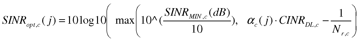
0,1, 2. For transmissions corresponding to a semi-persistent grant, j=0. For transmissions corresponding to a dynamic scheduled grant j=l, while for transmissions corresponding to a random access response j=2. Turning once more to FIG. 1, a base station, such as eNB 102, may measure radio signals in its environment, including noise and interference, in order to calculate an SINR parameter to be used by the UE 104 to determine transmit power to be used in an uplink PUSCH transmission. In particular, based upon its measurements, the eNB 102 may determine a parameter SINRMIN c (dB) that represents the minimum expected cell edge SINR value for serving cell c. The value of SINRMIN c (dB) may then be transmitted to UE 104, which may use the received SINRMIN c (dB) value to calculate SINR t c (j) as follows:
SINRMIN (dB)
SINRopt ( j) = ogl0 max ( M ). acU) - CINR, (7).
10 " 6 ' ULj'c N
[0032] In the Eq. (7), the term c ( j) is a fairness adjustment value for the serving cell c , which may be decided by eNodeB 102 for fairness and interference- over- thermal noise (IoT) control. The latter factor represent the interference perceived at a cell normalized to the thermal noise level.
[0033] The term Nr refers to the number of receiving antenna in eNodeB for the serving cell c, while the parameter CINR DL, refers to the carrier-to-interference-and- noise ratio, which denotes the ratio of power of the downlink carrier bearing the desired downlink signal to the total power of interfering signals and noise. In particular, the
parameter CINRDL c represents the downlink CINR measured value reported by a UE, such as UE 104 for the serving cell c.
[0034] Thus, once the eNB 102 transmits a current SINRMN c (dB) value to the UE
104, the current value of SINRopt c (j) can be determined by the UE 104 as shown above. After determining whether a subsequent PUSCH transmission is to be accompanied by a PUCCH transmission, this optimal SINR value SINRopt c (j) may then be used to determine the appropriate PUSCH transmit power as set forth in the alternative Eqs. (5) or (6).
[0035] The above Eq. (7) may be considered an optimal solution that may yield a best performance in principle. However, in another embodiment, a simpler procedure may be employed to determine SINRopt c (j) . In the simpler procedure,
SINR t c (j) may be determined as

[0036] The determination of SINRopt c ( j) using Eq. (8) may yield performance that is slightly less than when Eq. (7) is used to determine SINRopt c (j) ; however, the algorithm defined in Eq. (7) may be simpler to implement.
[0037] FIG. 3 depicts a scenario showing exemplary signaling between a base station and mobile terminal consistent with various embodiments. As illustrated, a
sequence of actions may be performed beginning with actions taken by an eNB 102 in a serving cell for UE 104. As illustrated, the eNB 102 may perform
measurements to determine noise and interference levels in its vicinity. The eNB 102 may then set SINRMIN c (dB) and may set a parameter P0--NOMINAL— PUSCH ,
which is a cell-specific parameter provided by higher layers and is related to 0— PUSCH as follows:
Po— PUSCH (j) = Po- "NOMINAL— PUSCH (j) + ^O-'UE— PUSCH (j) (9) where 0.-UE— PUSCH (j) is a UE-specific parameter provided by Radio Resource Control (RRC) signaling.
[0038] Consistent with present embodiments, the parameter
 (j) may be set as: o_NOMiNAL_ puscH,c (i) = Quantizcition(NI ) ( 10).
In Eq. (10), NI represents the average power level (dBm) of the noise and interference per resource block (RB) as measured at the eNB. In various
embodiments, the Quantization function of Eq. ( 10) may quantize the NI value into multiple different levels characterized by small dBm increments. In one example, quantization may proceed in 1 dBm steps in a range of - 126 to -24 dBm.
[0039] After determining SINRMlN c (dB) and P0--NOMINAL-PUSCH (j), the eNB may
also determine the fairness parameter ac(j), as defined above.. Subsequently, as illustrated in FIG. 3, the eNB 102 may send an information element
UplinkPowerControlCommon in the form of a broadcast message 302, which may be a MAC message, and may include the parameters SINRMIN c (dB) , P0--NOMINAL-PUSCH (j), and CCc(j). The broadcast message 302 may be received by any UE 104 that is within a broadcast range of the eNB 102, as shown. When a UE 104 receives the broadcast message 302, the uplink power control module 122 may process information contained therein to determine uplink transmit power. As shown in FIG. 3, the uplink power control module 122 may determine uplink transmission power using information received in the UplinkPowerControlCommon message in conjunction with the procedures specified by the Eqs. (5) or (6). Thus, the uplink power control module 122 may use the value of 0.-NOMINAL— PUSCH (j) received from eNB 102 to determine Po— PUSCH (j) using the procedure of Eq. (9). The calculated value of parameter o— PUSCH (j) and the values of SINRMIN c (dB) and ac(j) received from eNB 102 may be substituted into Eqs. (5) or (6) to determine PUSCH c (i) . The determined value of power level may then be set as the PPUSCH c (i) for subsequent uplink PUSCH transmission(s). Subsequently, during the appropriate uplink subframe(s), the PUSCH data may be transmitted by UE 104 at the determined uplink power level PUSCH c (i) . In addition, to improve performance, radio measurements or other information may be exchanged between neighboring eNBs.
[0040] In accordance with the present embodiments, various performance parameters may be enhanced over standard uplink power schemes, such as those specified in Eqs. (1)
and (2). FIG. 4 presents results of simulations that illustrate one type of performance metric in which the cell edge spectral efficiency (SE) is plotted as a function of the uplink sector SE for five different conditions. The four curves 402, 404, 406, and 408 correspond to conventional procedures for determining power PUSCH c (i) power as set forth in Eqs. (2) and (3) above, while the fifth curve 410 reflects the results of PUSCH power determination according to the present embodiments as set forth in Eq. (5). In particular, the SINRMIN IS set for 2 dB for the PUSCH power scenario illustrated by curve 410. The parameters used to produce the curves 402, 404, 406, and 408 differ among one another only in the target SNR value, which ranges from 8- 14 dB as illustrated. As evident from FIG. 4, all the curves exhibit a cell edge SE value in a similar range of 0.03- 0.04 for lower values of uplink sector SE (<1). It is also evident that increasing the target SNR value to higher dB levels as demonstrated by the progression in curves 402, 404, 406, and 408, has only a modest effect on the SE behavior. However, when the uplink sector SE exceeds about 1.1 bps/Hz the cell edge SE plunges toward zero for all dB levels of the SNR. In contrast, curve 410 (SINR = 2dB ), maintains a cell edge SE value of about 0.04 up to uplink sector SE values of about 1.4.
[0041] FIG. 5 provides a further performance comparison using additional performance metrics for the same set of simulated conditions illustrated in FIG. 4. In particular, FIG. 5 depicts uplink cell edge SE as a function of the interference- over- thermal noise (IoT) parameter. As illustrated, curve 502, corresponds to the same simulated conditions as curve 402, curve 504 corresponds to the same simulated conditions as curve 404, and so forth. Thus, curves 502, 504, 506, and 508 are simulated
curves based on the procedures for determining PPUSCH set forth in the conventional Eqs. (1) and (2), while curve 510 illustrates the results of simulations for determining PPUSCH in accordance with the present embodiments. For the conventional simulations, at IoT values below about 10 dB, the uplink cell edge SE increases in a moderate fashion with increasing SNR target values from 8 dB to 14 dB. Curve 510, determined by simulation according to Eqs. (5), presents the results for the SINRMIN value of 2 dB, as in the curve 410. In this case, at IoT values below about 10 dB, the uplink cell edge SE is
(marginally) higher than that of the conventional curves 502-508.
[0042] FIG. 6 provides a further performance comparison using another combination of performance metrics for the same set of simulated conditions illustrated in FIGs. 4 and
5. In particular, FIG. 6 depicts uplink sector SE as a function of the interference-over- thermal noise (IoT) parameter. As illustrated, curve 602 corresponds to the same simulated conditions as curves 402, 502; curve 604 corresponds to the same simulated conditions as curves 404, 504; and so forth. Thus, curves 602, 604, 606, and 608 are simulated curves based on the procedures for determining PPUSCH set forth in the conventional Eqs. (1) and (2), while curve 610 illustrates the results of simulations for determining PPUSCH in accordance with the present embodiments. As illustrated in FIG.
6, for the simulations of conventional PUSCH power determination, increasing SNR target values from 8 dB to 14 dB has little systematic effect on uplink sector SE and the maximum uplink sector value is about 1.2 bps/Hz. On the other hand, the simulation according to the present embodiments illustrated by curve 610 produces a substantially higher uplink sector SE value at all values of IoT.
[0043] Included herein is a set of flow charts representative of exemplary methodologies for performing novel aspects of the disclosed architecture. While, for purposes of simplicity of explanation, the one or more methodologies shown herein, for example, in the form of a flow chart or flow diagram, are shown and described as a series of acts, it is to be understood and appreciated that the methodologies are not limited by the order of acts, as some acts may, in accordance therewith, occur in a different order and/or concurrently with other acts from that shown and described herein. For example, those skilled in the art will understand and appreciate that a methodology could alternatively be represented as a series of interrelated states or events, such as in a state diagram. Moreover, not all acts illustrated in a methodology may be required for a novel implementation.
[0044] FIG. 7 illustrates an exemplary logic flow 700. At block 702, a PUSCH transmission is scheduled. At block 704, a determination is made as to whether a PUUCH is to be transmitted with the scheduled PUSCH transmission. If, at block 704, a PUUCH is to be transmitted with the scheduled PUSCH transmission, the flow moves to block 708. At block 708, the uplink PUSCH power is determined according to
„ ... . {l01Og10 (PCMAX,C( -

101og10(M PUSCH.c (0) + ^ 0_PUSCH,c (j) + PLc + SINRopt,c (j) + Amc (0 + fc ( 1
[0045] If, at block 704, a determination is made that no PUUCH is to be transmitted with the PUSCH, the flow proceeds to block 706. At block 706, the uplink PUSCH
power is determined according to

[0046] After block 706 or block 708, the flow moves to block 710, where the appropriate determined PUSCH power is set.
[0047] FIG. 8 illustrates another exemplary logic flow 800. At block 802, an SINRMIN c (dB) parameter is received from a base station (eNB). At block 804, a signal- to-interference-and-noise ratio is determined according to:
( { SINRM!N (dB)
SINRoptM) max l 0A ( > a U) . CINR

[0048] At block 806, a determination is made as to whether a PUUCH is to be transmitted with the scheduled PUSCH transmission. If, at block 806, a PUUCH is to be transmitted with the scheduled PUSCH transmission, the flow moves to block 810. At block 810, the uplink PUSCH power is determined according to

[0049] If, at block 806, a determination is made that no PUUCH is to be transmitted with the PUSCH, the flow proceeds to block 808. At block 808, the uplink PUSCH power is determined according to
ΡρτκΓν, Λι) = .
—

[0051] FIG. 9 depicts still another logic flow 900 consistent with further embodiments. At block 902, an SINRMIN c (dB) parameter is received from a base station (eNB). At block
904, a signal-to-interference-and-noise ratio is determined according to:
max( SINRM1NtC (dB), lOlog I0(ae (j)) + CINRDL c (dB) ), if c (j)≠ 0
SINRMlN (dB), if ae (j) = 0
[0052] At block 906, a determination is made as to whether a PUUCH is to be transmitted with the scheduled PUSCH transmission. If, at block 906, a PUUCH is to be transmitted with the scheduled PUSCH transmission, the flow moves to block 910. At block 910, the uplink PUSCH power is determined according to ) - PmjcCR (i)),

[0053] If, at block 906, a determination is made that no PUUCH is to be transmitted with the PUSCH, the flow proceeds to block 908. At block 908, the uplink PUSCH power is determined according to
'

[0054] After blocks 908 or 910, the flow moves to block 912, where the appropriate determined PUSCH power is set.
[0055] FIG. 10 depicts still another logic flow 1000 consistent with further embodiments. At block 1002, an SINRMIN c (dB) parameter is received from a base station (eNB). At block 1004, a signal-to-noise-and-interference ratio SINRopt c (j) is determined according to the received SINRMIN c (dB) .
[0056] At block 1006, a parameter P0 NOMINAL PUSCH C U) is set using the measured average power level NI of the noise and interference per resource block at the base station.
[0057] At block 1008, the uplink transmit power is determined according to the set 0_NOMINAL_ PUSCH,c (i) aIld the SINR^j) -
[0058] FIG. 11 is a diagram of an exemplary system embodiment and in particular, FIG. 11 is a diagram showing a platform 1100, which may include various elements. For instance, FIG. 11 shows that platform (system) 1110 may include a processor/graphics core 1102 which may include an applications processor, a chipset/platform control hub (PCH) 1104, an input/output (I/O) device 1106, a random access memory (RAM) (such as dynamic RAM (DRAM)) 1108, and a read only memory (ROM) 1110, display electronics 1120, display backlight 1122, non-volatile memory port (NVMP) 1124, antenna 1126, and various other platform components 1114 (e.g., a fan, a crossflow blower, a heat sink, DTM system, cooling system, housing, vents, and so forth). System 1100 may also include wireless communications chip 1116 and graphics device 1118. The display electronics may include a liquid crystal display (LCD) screen, touch screen
display, or other display. The I/O device 1106 may include a keyboard, mouse, and /or speakers. The embodiments, however, are not limited to these elements.
[0059] As shown in FIG. 11, 1/0 device 1106, RAM 1108, and ROM 1110 are coupled to processor 1102 by way of chipset 1104. Chipset 1104 may be coupled to processor 1102 by a bus 1112. Accordingly, bus 1112 may include multiple lines.
[0060] Processor 1102 may be a central processing unit comprising one or more processor cores and may include any number of processors having any number of processor cores. The processor 1102 may include any type of processing unit, such as, for example, CPU, multi-processing unit, a reduced instruction set computer (RISC), a processor that have a pipeline, a complex instruction set computer (CISC), digital signal processor (DSP), and so forth. In some embodiments, processor 1102 may be multiple separate processors located on separate integrated circuit chips. In some embodiments processor 1102 may be a processor having integrated graphics, while in other
embodiments processor 1102 may be a graphics core or cores.
[0061] FIG. 12 illustrates an embodiment of an exemplary computing architecture 1200 suitable for implementing various embodiments as previously described. As used in this application, the terms "system" and "device" and "component" are intended to refer to a computer-related entity, either hardware, a combination of hardware and software, software, or software in execution, examples of which are provided by the exemplary computing architecture 1200. For example, a component can be, but is not limited to being, a process running on a processor, a processor, a hard disk drive, multiple storage drives (of optical and/or magnetic storage medium), an object, an executable, a
thread of execution, a program, and/or a computer. By way of illustration, both an application running on a server and the server can be a component. One or more components can reside within a process and/or thread of execution, and a component can be localized on one computer and/or distributed between two or more computers.
Further, components may be communicatively coupled to each other by various types of communications media to coordinate operations. The coordination may involve the unidirectional or bi-directional exchange of information. For instance, the components may communicate information in the form of signals communicated over the communications media. The information can be implemented as signals allocated to various signal lines. In such allocations, each message is a signal. Further embodiments, however, may alternatively employ data messages. Such data messages may be sent across various connections. Exemplary connections include parallel interfaces, serial interfaces, and bus interfaces.
[0062] In one embodiment, the computing architecture 1200 may comprise or be implemented as part of an electronic device. Examples of an electronic device may include without limitation a mobile device, a personal digital assistant, a mobile computing device, a smart phone, a cellular telephone, a handset, a one-way pager, a two- way pager, a messaging device, a computer, a personal computer (PC), a desktop computer, a laptop computer, a notebook computer, a handheld computer, a tablet computer, a server, a server array or server farm, a web server, a network server, an Internet server, a work station, a mini-computer, a main frame computer, a
supercomputer, a network appliance, a web appliance, a distributed computing system,
multiprocessor systems, processor-based systems, consumer electronics, programmable consumer electronics, television, digital television, set top box, wireless access point, base station, subscriber station, mobile subscriber center, radio network controller, router, hub, gateway, bridge, switch, machine, or combination thereof. The embodiments are not limited in this context.
[0063] The computing architecture 1200 includes various common computing elements, such as one or more processors, co-processors, memory units, chipsets, controllers, peripherals, interfaces, oscillators, timing devices, video cards, audio cards, multimedia input/output (I/O) components, and so forth. The embodiments, however, are not limited to implementation by the computing architecture 1200.
[0064] As shown in FIG. 12, the computing architecture 1200 comprises a processing unit 1204, a system memory 1206 and a system bus 1208. The processing unit 1204 can be any of various commercially available processors. Dual microprocessors and other multi processor architectures may also be employed as the processing unit 1204. The system bus 1208 provides an interface for system components including, but not limited to, the system memory 1206 to the processing unit 1204. The system bus 1208 can be any of several types of bus structure that may further interconnect to a memory bus (with or without a memory controller), a peripheral bus, and a local bus using any of a variety of commercially available bus architectures.
[0065] The computing architecture 1200 may comprise or implement various articles of manufacture. An article of manufacture may comprise a computer-readable storage
medium to store various forms of programming logic. Examples of a computer-readable storage medium may include any tangible media capable of storing electronic data, including volatile memory or non-volatile memory, removable or non-removable memory, erasable or non-erasable memory, writeable or re-writeable memory, and so forth. Examples of programming logic may include executable computer program instructions implemented using any suitable type of code, such as source code, compiled code, interpreted code, executable code, static code, dynamic code, object-oriented code, visual code, and the like.
[0066] The system memory 1206 may include various types of computer-readable storage media in the form of one or more higher speed memory units, such as read-only memory (ROM), random-access memory (RAM), dynamic RAM (DRAM), Double- Data-Rate DRAM (DDR AM), synchronous DRAM (SDRAM), static RAM (SRAM), programmable ROM (PROM), erasable programmable ROM (EPROM), electrically erasable programmable ROM (EEPROM), flash memory, polymer memory such as ferroelectric polymer memory, ovonic memory, phase change or ferroelectric memory, silicon-oxide-nitride-oxide-silicon (SONOS) memory, magnetic or optical cards, or any other type of media suitable for storing information. In the illustrated embodiment shown in FIG. 12, the system memory 1206 can include non-volatile memory 1210 and/or volatile memory 1212. A basic input/output system (BIOS) can be stored in the nonvolatile memory 1210.
[0067] The computer 1202 may include various types of computer-readable storage media in the form of one or more lower speed memory units, including an internal hard
disk drive (HDD) 1214, a magnetic floppy disk drive (FDD) 1216 to read from or write to a removable magnetic disk 1218, and an optical disk drive 1220 to read from or write to a removable optical disk 1222 (e.g., a CD-ROM or DVD). The HDD 1214, FDD 1216 and optical disk drive 1220 can be connected to the system bus 1208 by a HDD interface 1224, an FDD interface 1226 and an optical drive interface 1228, respectively. The HDD interface 1224 for external drive implementations can include at least one or both of Universal Serial Bus (USB) and IEEE 1194 interface technologies.
[0068] The drives and associated computer-readable media provide volatile and/or nonvolatile storage of data, data structures, computer-executable instructions, and so forth. For example, a number of program modules can be stored in the drives and memory units 1210, 1212, including an operating system 1230, one or more application programs 1232, other program modules 1234, and program data 1236.
[0069] A user can enter commands and information into the computer 1202 through one or more wire/wireless input devices, for example, a keyboard 1238 and a pointing device, such as a mouse 1240. Other input devices may include a microphone, an infrared (IR) remote control, a joystick, a game pad, a stylus pen, touch screen, or the like. These and other input devices are often connected to the processing unit 1204 through an input device interface 1242 that is coupled to the system bus 1208, but can be connected by other interfaces such as a parallel port, IEEE 1194 serial port, a game port, a USB port, an IR interface, and so forth.
[0070] A monitor 1244 or other type of display device is also connected to the system bus 1208 via an interface, such as a video adaptor 1246. In addition to the monitor 1244, a computer typically includes other peripheral output devices, such as speakers, printers, and so forth.
[0071] The computer 1202 may operate in a networked environment using logical connections via wire and/or wireless communications to one or more remote computers, such as a remote computer 1248. The remote computer 1248 can be a workstation, a server computer, a router, a personal computer, portable computer, microprocessor-based entertainment appliance, a peer device or other common network node, and typically includes many or all of the elements described relative to the computer 1202, although, for purposes of brevity, only a memory/storage device 1250 is illustrated. The logical connections depicted include wire/wireless connectivity to a local area network (LAN) 1252 and/or larger networks, for example, a wide area network (WAN) 1254. Such LAN and WAN networking environments are commonplace in offices and companies, and facilitate enterprise- wide computer networks, such as intranets, all of which may connect to a global communications network, for example, the Internet.
[0072] When used in a LAN networking environment, the computer 1202 is connected to the LAN 1252 through a wire and/or wireless communication network interface or adaptor 1256. The adaptor 1256 can facilitate wire and/or wireless communications to the LAN 1252, which may also include a wireless access point disposed thereon for communicating with the wireless functionality of the adaptor 1256.
[0073] When used in a WAN networking environment, the computer 1202 can include a modem 1258, or is connected to a communications server on the WAN 1254, or has other means for establishing communications over the WAN 1254, such as by way of the Internet. The modem 1258, which can be internal or external and a wire and/or wireless device, connects to the system bus 1208 via the input device interface 1242. In a networked environment, program modules depicted relative to the computer 1202, or portions thereof, can be stored in the remote memory/storage device 1250. It will be appreciated that the network connections shown are exemplary and other means of establishing a communications link between the computers can be used.
[0074] The computer 1202 is operable to communicate with wire and wireless devices or entities using the IEEE 802 family of standards, such as wireless devices operatively disposed in wireless communication (e.g., IEEE 802.11 over-the-air modulation techniques) with, for example, a printer, scanner, desktop and/or portable computer, personal digital assistant (PDA), communications satellite, any piece of equipment or location associated with a wirelessly detectable tag (e.g., a kiosk, news stand, restroom), and telephone. This includes at least Wi-Fi (or Wireless Fidelity), WiMax, and Bluetooth™ wireless technologies. Thus, the communication can be a predefined structure as with a conventional network or simply an ad hoc communication between at least two devices. Wi-Fi networks use radio technologies called IEEE 802.1 lx (a, b, g, n, etc.) to provide secure, reliable, fast wireless connectivity. A Wi-Fi network can be used to connect computers to each other, to the Internet, and to wire networks (which use IEEE 802.3-related media and functions).
[0075] Some embodiments may be described using the expression "one embodiment" or "an embodiment" along with their derivatives. These terms mean that a particular feature, structure, or characteristic described in connection with the embodiment is included in at least one embodiment. The appearances of the phrase "in one
embodiment" in various places in the specification are not necessarily all referring to the same embodiment. Further, some embodiments may be described using the expression "coupled" and "connected" along with their derivatives. These terms are not necessarily intended as synonyms for each other. For example, some embodiments may be described using the terms "connected" and/or "coupled" to indicate that two or more elements are in direct physical or electrical contact with each other. The term "coupled," however, may also mean that two or more elements are not in direct contact with each other, but yet still co-operate or interact with each other.
[0076] It is emphasized that the Abstract of the Disclosure is provided to allow a reader to quickly ascertain the nature of the technical disclosure. It is submitted with the understanding that it will not be used to interpret or limit the scope or meaning of the claims. In addition, in the foregoing Detailed Description, it can be seen that various features are grouped together in a single embodiment for the purpose of streamlining the disclosure. This method of disclosure is not to be interpreted as reflecting an intention that the claimed embodiments require more features than are expressly recited in each claim. Rather, as the following claims reflect, inventive subject matter lies in less than all features of a single disclosed embodiment. Thus the following claims are hereby incorporated into the Detailed Description, with each claim standing on its own as a
separate embodiment. In the appended claims, the terms "including" and "in which" are used as the plain-English equivalents of the respective terms "comprising" and "wherein," respectively. Moreover, the terms "first," "second," "third," and so forth, are used merely as labels, and are not intended to impose numerical requirements on their objects.
[0077] What has been described above includes examples of the disclosed
architecture. It is, of course, not possible to describe every conceivable combination of components and/or methodologies, but one of ordinary skill in the art may recognize that many further combinations and permutations are possible. Accordingly, the novel architecture is intended to embrace all such alterations, modifications and variations that fall within the spirit and scope of the appended claims.
[0078] Various embodiments may be implemented using hardware elements, software elements, or a combination of both. Examples of hardware elements may include processors, microprocessors, circuits, circuit elements (e.g., transistors, resistors, capacitors, inductors, and so forth), integrated circuits, application specific integrated circuits (ASIC), programmable logic devices (PLD), digital signal processors (DSP), field programmable gate array (FPGA), logic gates, registers, semiconductor device, chips, microchips, chip sets, and so forth. Examples of software may include software components, programs, applications, computer programs, application programs, system programs, machine programs, operating system software, middleware, firmware, software modules, routines, subroutines, functions, methods, procedures, software interfaces, application program interfaces (API), instruction sets, computing code,
computer code, code segments, computer code segments, words, values, symbols, or any combination thereof. Determining whether an embodiment is implemented using hardware elements and/or software elements may vary in accordance with any number of factors, such as desired computational rate, power levels, heat tolerances, processing cycle budget, input data rates, output data rates, memory resources, data bus speeds and other design or performance constraints.
[0079] Some embodiments may be described using the expression "coupled" and "connected" along with their derivatives. These terms are not intended as synonyms for each other. For example, some embodiments may be described using the terms
"connected" and/or "coupled" to indicate that two or more elements are in direct physical or electrical contact with each other. The term "coupled," however, may also mean that two or more elements are not in direct contact with each other, but yet still co-operate or interact with each other.
[0080] Some embodiments may be implemented, for example, using a computer- readable medium or article which may store an instruction or a set of instructions that, if executed by a computer, may cause the computer to perform a method and/or operations in accordance with the embodiments. Such a computer may include, for example, any suitable processing platform, computing platform, computing device, processing device, computing system, processing system, computer, processor, or the like, and may be implemented using any suitable combination of hardware and/or software. The computer-readable medium or article may include, for example, any suitable type of
memory unit, memory device, memory article, memory medium, storage device, storage article, storage medium and/or storage unit, for example, memory, removable or nonremovable media, erasable or non-erasable media, writeable or re-writeable media, digital or analog media, hard disk, floppy disk, Compact Disk Read Only Memory (CD-ROM), Compact Disk Recordable (CD- ?), Compact Disk Rewriteable (CD-RW), optical disk, magnetic media, magneto-optical media, removable memory cards or disks, various types of Digital Versatile Disk (DVD), a tape, a cassette, or the like. The instructions may include any suitable type of code, such as source code, compiled code, interpreted code, executable code, static code, dynamic code, encrypted code, and the like, implemented using any suitable high-level, low-level, object-oriented, visual, compiled and/or interpreted programming language.
[0081] Unless specifically stated otherwise, it may be appreciated that terms such as "processing," "computing," "calculating," "determining," or the like, refer to the action and/or processes of a computer or computing system, or similar electronic computing device, that manipulates and/or transforms data represented as physical quantities (e.g., electronic) within the computing system's registers and/or memories into other data similarly represented as physical quantities within the computing system's memories, registers or other such information storage, transmission or display devices. The embodiments are not limited in this context.
[0082] Although the subject matter has been described in language specific to structural features and/or methodological acts, it is to be understood that the subject
matter defined in the appended claims is not necessarily limited to the specific features or acts described above. Rather, the specific features and acts described above are disclosed as example forms of implementing the claims.
Claims
1. An apparatus, comprising:
a transceiver operable to receive a downlink message from a base station for a serving cell, the downlink message allocating a set of control parameters;
a processor circuit communicatively coupled to the transceiver; and
an uplink power control module operable on the processor circuit to:
read the set of control parameters; and
apply a signal-to-noise-and-interference (SINR) parameter based on the received set of control parameters to determine physical uplink shared channel (PUSCH) power to be applied for a PUSCH transmission.
2. The apparatus of claim 1, the SINR parameter defined by SINRopt c (j) , where c represents the serving cell, and j represents a PUSCH transmission parameter.
3. The apparatus of claim 1, the uplink power control module operable on the processor circuit to determine PUSCH power by applying full pathloss compensation.
4. The apparatus of claim 1, the uplink power control module operable on the processor circuit to:
determine whether a physical uplink control channel (PUUCH) transmission is to accompany the PUSCH transmission; and
set the PUSCH power according to whether the PUUCH transmission is to accompany the PUSCH transmission.
5. The apparatus of claim 4, the uplink power control module operable on the processor to determine the PUSCH power PUSCH c (i) for a subframe i and serving cell c according to:
D . .. . ^ CMAX ,c (j ),
— 101og10 (M PUSCH.c (i)) + P0. PUSCH.c (j) + PLc + SINR^ (j) + ATF;C ( + fc (i) when no PUUCH transmission is to accompany the PUSCH transmission.
6. The apparatus of claim 4, the uplink power control module operable on the processor to determine the PUSCH power PUSCH c (i) for a subframe i and serving cell c according to:
 U) + ATF,C (0 + fc (0 ] when PUUCH transmission is to accompany the PUSCH transmission.
7. The apparatus of claim 2, SINRopt c (j) determined from a received control parameter SINRMIN c (dB) that denotes a minimum expected cell edge SINR value for the serving cell.
8. The apparatus of claim 7, the uplink power control module operable on the processor circuit to determine SINR (j) according to:
where CINR DL, is carrier-to-interference-and-noise ratio and c { j) is a fairness adjustment value for the serving cell c.
9. The apparatus of claim 7, the uplink power control module operable on the processor circuit to determine SINRopt c (j) according to:
f max( SINRM!N dB), 101ogl0(ac(y)) + CINRDL c(dB) ), if a )≠ 0
.A ) I SINRMIN c(dB), if ac( j) = 0 ' where CINR DL, is carrier-to-interference-and-noise ratio and c { j) is a fairness adjustment value for the serving cell c .
10. The apparatus of claim 5, the uplink power control module operable on the processor circuit to:
read a parameter P0. -NOMINAL— PUSCH (j) forwarded in the downlink message; and
determine Po— PUSCH (j) according to:
P O— PUSCH (j) = Po- "NOMINAL— PUSCH (j) + Po-~VE— PUSCH (j) ,
where PO-UE— PUSCH (j) is a UE-specific parameter provided by radio resource control (RRC) signaling.
11. The apparatus of claim 5, the parameter P0_ -NOMINAL— PUSCH (j) set as
o_NOMiNAL_ puscH,c (i) = Quantization (NI) , where values of NI are quantized in 1 dBm increments in a range of - 126 to 24 dBm.
12. The apparatus of claim 1, comprising a touch screen display communicatively coupled to the processor circuit.
13. At least one computer-readable storage medium comprising instructions that, when executed, cause a system to:
read a set of control parameters sent in a downlink message; and
apply a signal-to-noise-and-interference (SINR) parameter based on the received set of control parameters to determine physical uplink shared channel (PUSCH) power to be applied for a PUSCH transmission.
14. The computer-readable storage medium of claim 13, the signal-to-interference- and-noise parameter defined by SINRoptc(j) , where c represents the serving cell, and j represents a PUSCH transmission parameter.
15. The computer-readable storage medium of claim 13, comprising instructions that when executed cause the system to determine PUSCH power by applying full pathloss compensation.
16. The computer-readable storage medium of claim 13, comprising instructions that when executed cause the system to determine the PUSCH power PUSCH c (i) for a subframe i and servicing cell c according to: . CMAX.c
— 101og10(M PUSCH.c (i)) + Po_ PUSCH.c (j) + PLC + SINRopt,c (j) + ATF;C ( + fc (i) when no PUUCH transmission is not to accompany the PUSCH transmission.
17. The computer-readable storage medium of claim 13, comprising instructions that when executed cause the system to determine the PUSCH power PUSCH c (i) for a subframe i and servicing cell c according to:
... . fl01Og10( MAX,c( - uCCH( ),
^PUSCHcW = mmi
101og10( PUSCHc( ) + PUSCH.C ( j) + PL + SINR^U) + ( + fc (i)
when PUUCH transmission is to accompany the PUSCH transmission.
18. The computer-readable storage medium of claim 13, comprising instructions that when executed cause the system to determine SINRopt c (j) from a received control parameter SINRMIN c (dB) that denotes a minimum expected cell edge SINR value for a serving cell c.
The computer-readable storage medium of claim 13, comprising instructions that when executed cause the system to determine SINR (j) according to
SINROP1 A j) = mogio max| i 0A

20. The computer-readable storage medium of claim 13, comprising instructions that when executed cause the system to determine SINRopt c (j) according to:
SINR ( 1 = 1 maX( SINRMIN- (dB)' 101ο§10(^Ο')) + CINRDL c(dB) ), if ac(j)≠ 0 where CINR DL, is carrier-to-interference-and-noise ratio and ac ( j) is a fairness adjustment value for a serving cell c .
21. The computer-readable storage medium of claim 13, comprising instructions that when executed cause the system to:
read a parameter P0_ -NOMINAL— PUSCH (j) forwarded in the downlink message; and determine Po— PUSCH (j) according to:
P O— PUSCH (j) = Po- "NOMINAL— PUSCH (j) + o-'VE— PUSCH (j) ,
where PO-UE— PUSCH (j) is a UE-specific parameter provided by radio resource control (RRC) signaling.
22. The computer-readable storage medium of claim 21, the parameter P0_ -NOMINAL— PUSCH (j) set as P0 NOMINAL PUSCH,C ( J ) = Q antizati on(NI) } where values of NI are quantized in 1 dBm increments in a range of - 126 to 24 dBm.
23. A method, comprising:
reading a set of control parameters sent in a downlink message from a serving cell; and
applying a signal-to-noise-and-interference parameter SINRopt c (j) based on the set of control parameters to determine physical uplink shared channel (PUSCH) power to be applied for a PUSCH transmission, where c represents the serving cell, and j represents a PUSCH transmission parameter.
24. The method of claim 23, comprising:
determining that no physical uplink control channel (PUUCH) transmission is to accompany the PUSCH transmission; and applying full pathloss compensation to determine PUSCH power ^PUSCH c ( for a subframe i and servicing cell c according to according to:
PUSCH'C 101og10 (MPUSCH;C (0) + ^PUSCH, U) + PL + SINR^ (j) + Δ_ (i) + fc (i)
The method of claim 23, comprising determining SINR (j) from a control parameter SINRMIN c (dB) of the set of control parameters, SINRMIN c (dB) denoting a minimum expected cell edge SINR value for serving cell c.
26. The method of claim 25, comprising determining SINR (j) according to
( (
S/-VRo_ O-) = 101og l0 max 10Λ (

27. The method of claim 25, comprising determining SINR (j) according to max( SINRMIN c(dB), 101ogl0(ac(y)) + CINRDL c(dB) ), if ac(j)≠ 0
SINRopt (j) -.
SINRM!N (dB), if ac(j) = 0
where CINR DL, is carrier-to-interference-and-noise ratio and c ( j) is a fairness adjustment value for the serving cell c .
28. The method of claim 24 comprising:
reading a parameter P0_ -NOMINAL— PUSCH (j) from the set of parameters; and determining P0— PUSCH (j) according to:
Po— PUSCH (j) = P o- "NOMINAL— PUSCH (j) + P 0-~X5E— PUSCH (j) ,
where PO-UE— PUSCH is a UE-specific parameter provided by radio resource control (RRC) signaling.
Priority Applications (2)
| Application Number | Priority Date | Filing Date | Title |
|---|---|---|---|
| US13/976,452 US9363780B2 (en) | 2011-08-12 | 2011-12-16 | System and method of uplink power control in a wireless communication system |
| EP11870852.8A EP2742748A4 (en) | 2011-08-12 | 2011-12-16 | System and method of uplink power control in a wireless communication system |
Applications Claiming Priority (2)
| Application Number | Priority Date | Filing Date | Title |
|---|---|---|---|
| US201161523080P | 2011-08-12 | 2011-08-12 | |
| US61/523,080 | 2011-08-12 |
Publications (1)
| Publication Number | Publication Date |
|---|---|
| WO2013025236A1 true WO2013025236A1 (en) | 2013-02-21 |
Family
ID=47715344
Family Applications (6)
| Application Number | Title | Priority Date | Filing Date |
|---|---|---|---|
| PCT/US2011/065604 WO2013025236A1 (en) | 2011-08-12 | 2011-12-16 | System and method of uplink power control in a wireless communication system |
| PCT/US2011/066212 WO2013025237A1 (en) | 2011-08-12 | 2011-12-20 | Forming carrier aggregation timing advance groups in a heterogeneous network |
| PCT/US2012/031329 WO2013025258A1 (en) | 2011-08-12 | 2012-03-30 | Updating channel state information in a wireless network |
| PCT/US2012/041636 WO2013025279A1 (en) | 2011-08-12 | 2012-06-08 | Truncated zadoff-chu sequence for lte uplink reference signals |
| PCT/US2012/049601 WO2013025379A1 (en) | 2011-08-12 | 2012-08-03 | ASSOCIATION BIASING FOR A HETEROGENEOUS NETWORK (HetNet) |
| PCT/US2012/050007 WO2013025419A1 (en) | 2011-08-12 | 2012-08-08 | Support for asynchronous time division duplexing in adjacent cells of a wireless communication system |
Family Applications After (5)
| Application Number | Title | Priority Date | Filing Date |
|---|---|---|---|
| PCT/US2011/066212 WO2013025237A1 (en) | 2011-08-12 | 2011-12-20 | Forming carrier aggregation timing advance groups in a heterogeneous network |
| PCT/US2012/031329 WO2013025258A1 (en) | 2011-08-12 | 2012-03-30 | Updating channel state information in a wireless network |
| PCT/US2012/041636 WO2013025279A1 (en) | 2011-08-12 | 2012-06-08 | Truncated zadoff-chu sequence for lte uplink reference signals |
| PCT/US2012/049601 WO2013025379A1 (en) | 2011-08-12 | 2012-08-03 | ASSOCIATION BIASING FOR A HETEROGENEOUS NETWORK (HetNet) |
| PCT/US2012/050007 WO2013025419A1 (en) | 2011-08-12 | 2012-08-08 | Support for asynchronous time division duplexing in adjacent cells of a wireless communication system |
Country Status (10)
| Country | Link |
|---|---|
| US (8) | US9363780B2 (en) |
| EP (3) | EP2742748A4 (en) |
| JP (1) | JP2014522198A (en) |
| KR (1) | KR101546203B1 (en) |
| CN (5) | CN103765968B (en) |
| BR (1) | BR112014002694B1 (en) |
| HK (1) | HK1256892A1 (en) |
| IN (1) | IN2014CN01081A (en) |
| RU (2) | RU2569932C2 (en) |
| WO (6) | WO2013025236A1 (en) |
Cited By (5)
| Publication number | Priority date | Publication date | Assignee | Title |
|---|---|---|---|---|
| CN104202110A (en) * | 2014-09-23 | 2014-12-10 | 中国人民解放军重庆通信学院 | Method and device for generating mutually orthogonal quasi-complementary matched sequence sets |
| US9078220B2 (en) | 2013-09-27 | 2015-07-07 | Motorola Solutions, Inc. | Method and apparatus for UE power class adaption for coverage extension in LTE |
| US9686759B2 (en) | 2014-07-18 | 2017-06-20 | Sharp Kabushiki Kaisha | Systems and methods for uplink transmission power control |
| WO2017171481A1 (en) * | 2016-03-31 | 2017-10-05 | Samsung Electronics Co., Ltd. | Method and apparatus for transmitting and receiving reference signals in wireless communication |
| US9867146B2 (en) | 2014-08-06 | 2018-01-09 | Sharp Kabushiki Kaisha | Systems and methods for dual-connectivity operation |
Families Citing this family (134)
| Publication number | Priority date | Publication date | Assignee | Title |
|---|---|---|---|---|
| US8897182B2 (en) * | 2010-08-11 | 2014-11-25 | Pantech Co., Ltd. | Apparatus and method for transmitting muting information, and apparatus and method for acquiring channel state using same |
| KR102032846B1 (en) | 2011-03-24 | 2019-10-16 | 엘지전자 주식회사 | Method for transmitting/receiving signal and device therefor |
| US8395985B2 (en) | 2011-07-25 | 2013-03-12 | Ofinno Technologies, Llc | Time alignment in multicarrier OFDM network |
| EP2739099B1 (en) | 2011-07-29 | 2019-09-25 | NEC Corporation | Wireless station, wireless terminal, and time alignment timer control method in wireless communication system |
| US10321419B2 (en) | 2011-08-10 | 2019-06-11 | Samsung Electronics Co., Ltd. | Method and apparatus for transmitting data using a multi-carrier in a mobile communication system |
| EP3429307B1 (en) | 2011-08-10 | 2022-06-15 | Samsung Electronics Co., Ltd. | Method and apparatus for transmitting data using a multi-carrier in a mobile communication system |
| KR102247818B1 (en) | 2011-08-10 | 2021-05-04 | 삼성전자 주식회사 | Method and apparatus for transmitting data in mobile communication system with multiple carrier |
| EP2744132A4 (en) * | 2011-08-10 | 2015-05-06 | Samsung Electronics Co Ltd | Method and apparatus for transmitting data using a multi-carrier in a mobile communication system |
| EP2742748A4 (en) | 2011-08-12 | 2015-08-26 | Intel Corp | System and method of uplink power control in a wireless communication system |
| US8797966B2 (en) | 2011-09-23 | 2014-08-05 | Ofinno Technologies, Llc | Channel state information transmission |
| EP2986067A3 (en) * | 2011-11-04 | 2016-02-24 | Interdigital Patent Holdings, Inc. | Methods of multiple point hsdpa transmission in single or different frequencies |
| US8885569B2 (en) | 2011-12-19 | 2014-11-11 | Ofinno Technologies, Llc | Beamforming signaling in a wireless network |
| CN103200662B (en) * | 2012-01-09 | 2016-03-09 | 华为技术有限公司 | Uplink transmission power defining method and subscriber equipment |
| US9237537B2 (en) | 2012-01-25 | 2016-01-12 | Ofinno Technologies, Llc | Random access process in a multicarrier base station and wireless device |
| US8995405B2 (en) | 2012-01-25 | 2015-03-31 | Ofinno Technologies, Llc | Pathloss reference configuration in a wireless device and base station |
| US8964683B2 (en) | 2012-04-20 | 2015-02-24 | Ofinno Technologies, Llc | Sounding signal in a multicarrier wireless device |
| US8964780B2 (en) | 2012-01-25 | 2015-02-24 | Ofinno Technologies, Llc | Sounding in multicarrier wireless communications |
| KR20140122748A (en) * | 2012-02-02 | 2014-10-20 | 노키아 솔루션스 앤드 네트웍스 오와이 | Signaling of uplink scheduling information in case of carrier aggregation |
| JP5859865B2 (en) * | 2012-02-03 | 2016-02-16 | 株式会社Nttドコモ | Mobile station |
| US9325454B2 (en) * | 2012-02-24 | 2016-04-26 | Futurewei Technologies, Inc. | System and method for HARQ entity configuration |
| JP5905749B2 (en) * | 2012-03-06 | 2016-04-20 | 株式会社Nttドコモ | Wireless base station |
| US9832658B2 (en) * | 2012-03-23 | 2017-11-28 | Nokia Solutions And Networks Oy | Interference coordination by means of directional antenna beams in a wireless system |
| US20150009895A1 (en) * | 2012-03-27 | 2015-01-08 | Nec (China) Co., Ltd. | Method and apparatus for reporting and cancelling cross-subframe co-channel interference |
| US20130258862A1 (en) | 2012-04-01 | 2013-10-03 | Esmael Hejazi Dinan | Radio Access for a Wireless Device and Base Station |
| WO2013151651A1 (en) | 2012-04-01 | 2013-10-10 | Dinan Esmael Hejazi | Cell group configuration in a wireless device and base station with timing advance groups |
| US11943813B2 (en) | 2012-04-01 | 2024-03-26 | Comcast Cable Communications, Llc | Cell grouping for wireless communications |
| US20130259008A1 (en) | 2012-04-01 | 2013-10-03 | Esmael Hejazi Dinan | Random Access Response Process in a Wireless Communications |
| US8958342B2 (en) | 2012-04-17 | 2015-02-17 | Ofinno Technologies, Llc | Uplink transmission power in a multicarrier wireless device |
| US8964593B2 (en) | 2012-04-16 | 2015-02-24 | Ofinno Technologies, Llc | Wireless device transmission power |
| US11582704B2 (en) | 2012-04-16 | 2023-02-14 | Comcast Cable Communications, Llc | Signal transmission power adjustment in a wireless device |
| EP2839705B1 (en) | 2012-04-16 | 2017-09-06 | Comcast Cable Communications, LLC | Cell group configuration for uplink transmission in a multicarrier wireless device and base station with timing advance groups |
| US11825419B2 (en) | 2012-04-16 | 2023-11-21 | Comcast Cable Communications, Llc | Cell timing in a wireless device and base station |
| US11252679B2 (en) | 2012-04-16 | 2022-02-15 | Comcast Cable Communications, Llc | Signal transmission power adjustment in a wireless device |
| US9179425B2 (en) | 2012-04-17 | 2015-11-03 | Ofinno Technologies, Llc | Transmit power control in multicarrier communications |
| US9226173B2 (en) * | 2012-04-18 | 2015-12-29 | Qualcomm Incorporated | Multi-radio coexistence |
| WO2013165138A1 (en) * | 2012-04-29 | 2013-11-07 | 엘지전자 주식회사 | Method for transmitting and receiving uplink signals, and apparatus therefor |
| WO2013172769A1 (en) | 2012-05-16 | 2013-11-21 | Telefonaktiebolaget Lm Ericsson (Publ) | Method and arrangement in a communications network |
| US9084203B2 (en) * | 2012-05-21 | 2015-07-14 | Qualcomm Incorporated | Methods and apparatus for providing transmit power control for devices engaged in D2D communications |
| US9084228B2 (en) | 2012-06-20 | 2015-07-14 | Ofinno Technologies, Llc | Automobile communication device |
| US9179457B2 (en) | 2012-06-20 | 2015-11-03 | Ofinno Technologies, Llc | Carrier configuration in wireless networks |
| US11882560B2 (en) | 2012-06-18 | 2024-01-23 | Comcast Cable Communications, Llc | Carrier grouping in multicarrier wireless networks |
| US11622372B2 (en) | 2012-06-18 | 2023-04-04 | Comcast Cable Communications, Llc | Communication device |
| US9210619B2 (en) | 2012-06-20 | 2015-12-08 | Ofinno Technologies, Llc | Signalling mechanisms for wireless device handover |
| US9107206B2 (en) | 2012-06-18 | 2015-08-11 | Ofinne Technologies, LLC | Carrier grouping in multicarrier wireless networks |
| US9113387B2 (en) * | 2012-06-20 | 2015-08-18 | Ofinno Technologies, Llc | Handover signalling in wireless networks |
| US8971298B2 (en) | 2012-06-18 | 2015-03-03 | Ofinno Technologies, Llc | Wireless device connection to an application server |
| US8885752B2 (en) * | 2012-07-27 | 2014-11-11 | Intel Corporation | Method and apparatus for feedback in 3D MIMO wireless systems |
| US9648573B2 (en) * | 2012-08-13 | 2017-05-09 | Telefonaktiebolaget Lm Ericsson (Publ) | Enhancing positioning with transmit-timing adjustment information |
| US9363749B2 (en) * | 2012-09-13 | 2016-06-07 | Qualcomm Incorporated | Dynamic power scaling of digital modems |
| KR101898050B1 (en) * | 2012-10-15 | 2018-10-04 | 삼성전자주식회사 | Mehtod and appartus for seamless handover operation in a wireless communication system |
| TWI487408B (en) * | 2012-11-01 | 2015-06-01 | Innovative Sonic Corp | Method to handle uplink information in a wireless communication system |
| GB2508383B (en) * | 2012-11-29 | 2014-12-17 | Aceaxis Ltd | Processing interference due to non-linear products in a wireless network |
| US9407489B2 (en) * | 2013-01-24 | 2016-08-02 | Blackberry Limited | Cell identity design for LTE-advanced |
| US11005613B2 (en) * | 2013-01-24 | 2021-05-11 | Qualcomm Incorporated | Multiple power control and timing advance loops during wireless communication |
| JP6085041B2 (en) * | 2013-02-07 | 2017-02-22 | アイディーエーシー ホールディングス インコーポレイテッド | Interference measurement and management in directional mesh networks |
| US9042218B2 (en) * | 2013-03-07 | 2015-05-26 | Qualcomm Incorporated | Apparatus, method, and system for incentivizing open access to closed subscriber group low-power base stations |
| US9300451B2 (en) | 2013-03-13 | 2016-03-29 | Samsung Electronics Co., Ltd. | Transmission of sounding reference signals for adaptively configured TDD communication systems |
| US9306725B2 (en) * | 2013-03-13 | 2016-04-05 | Samsung Electronics Co., Ltd. | Channel state information for adaptively configured TDD communication systems |
| EP2997756B1 (en) * | 2013-05-14 | 2017-12-06 | Nokia Solutions and Networks Oy | Method and network device for cell anomaly detection |
| KR101664876B1 (en) * | 2013-05-14 | 2016-10-12 | 삼성전자 주식회사 | Method and apparatus of interference measurement for inter-cell interference mitigation in tdd wireless communication system |
| US9386461B2 (en) * | 2013-06-21 | 2016-07-05 | Qualcomm Incorporated | Location aware self-locating access point |
| EP3435726B1 (en) | 2013-07-19 | 2021-10-27 | LG Electronics Inc. | Method and apparatus for performing random access procedure in wireless communication system |
| JP6204100B2 (en) * | 2013-07-23 | 2017-09-27 | 株式会社Nttドコモ | Wireless base station and wireless communication method |
| KR20160039573A (en) * | 2013-08-01 | 2016-04-11 | 엘지전자 주식회사 | Method for performing random access by terminal, and terminal |
| KR20150020018A (en) | 2013-08-14 | 2015-02-25 | 삼성전자주식회사 | Method and apparatus for transmitting and receiving a data using a plurality of carriers in mobilre communication system |
| US10411820B2 (en) * | 2013-08-15 | 2019-09-10 | Telefonaktiebolaget Lm Ericsson (Publ) | Methods, user equipment and radio network node for interference mitigation in a dynamic time division duplex system |
| JP6148573B2 (en) * | 2013-08-16 | 2017-06-14 | 株式会社Nttドコモ | COMMUNICATION CONTROL DEVICE, COMMUNICATION CONTROL SYSTEM, AND COMMUNICATION CONTROL METHOD |
| JP6446710B2 (en) * | 2013-08-20 | 2019-01-09 | シャープ株式会社 | Base station apparatus, terminal apparatus, wireless communication method, and integrated circuit |
| KR102071535B1 (en) | 2013-08-26 | 2020-01-30 | 삼성전자주식회사 | Apparatus and method for allocating resources to switch between macro cell and small cell in wireless communication system |
| EP3069500B1 (en) | 2013-11-17 | 2021-01-06 | Ping Liang | Massive mimo multi-user beamforming and single channel full duplex for wireless networks |
| KR102355625B1 (en) * | 2013-12-05 | 2022-01-26 | 엘지전자 주식회사 | Method and apparatus for transceiving signal in wireless communication system |
| EP3085180B1 (en) | 2013-12-20 | 2018-04-04 | Ping Liang | Method for acquiring channel state information in fdd mimo wireless networks |
| US9847819B2 (en) | 2013-12-20 | 2017-12-19 | RF DSP Inc. | Adaptive precoding in a MIMO wireless communication system |
| JP6442140B2 (en) * | 2013-12-26 | 2018-12-19 | 株式会社Nttドコモ | User terminal, radio base station, and radio communication method |
| CN105981463B (en) * | 2014-02-16 | 2019-12-10 | Lg电子株式会社 | Resource allocation method and device in wireless access system supporting FDR transmission |
| CN108199809B (en) * | 2014-05-23 | 2021-10-01 | 华为技术有限公司 | Information transmission method, base station and user equipment |
| US10237838B2 (en) * | 2014-08-05 | 2019-03-19 | Nec Corporation | Communication device, communication system, control method, and non-transitory computer readable medium storing communication program |
| WO2016024894A1 (en) * | 2014-08-15 | 2016-02-18 | Telefonaktiebolaget L M Ericsson (Publ) | Adaptive cell selection in heterogeneous networks |
| KR101814248B1 (en) | 2014-09-05 | 2018-01-04 | 주식회사 케이티 | Methods for transmitting data using a WLAN carrier and Apparatuses thereof |
| US10334481B2 (en) | 2014-09-18 | 2019-06-25 | Kt Corporation | Method and apparatus for processing user plane data |
| US10736175B2 (en) | 2014-10-02 | 2020-08-04 | Kt Corporation | Method for processing data using WLAN carrier and apparatus therefor |
| CN107148791B (en) * | 2014-11-06 | 2023-03-10 | 株式会社Ntt都科摩 | Terminal, radio base station, and radio communication method |
| US9900134B2 (en) * | 2014-12-15 | 2018-02-20 | Intel IP Corporation | Reference signal presence detection based license assisted access and reference signal sequence design |
| CN106165514B (en) * | 2015-02-09 | 2020-07-03 | 诸暨市元畅信息技术咨询服务部 | RLC data packet retransmission method and base station |
| US9871572B2 (en) * | 2015-03-09 | 2018-01-16 | Ofinno Technologies, Llc | Uplink control channel in a wireless network |
| WO2016163506A1 (en) * | 2015-04-09 | 2016-10-13 | 株式会社Nttドコモ | User terminal, radio base station and radio communication method |
| EP3288321B1 (en) | 2015-04-20 | 2020-06-03 | LG Electronics Inc. | Method for d2d operation performed by terminal in wireless communication system, and terminal using same |
| US10687309B2 (en) * | 2015-05-08 | 2020-06-16 | Texas Instruments Incorporated | Enhanced broadcast transmission in unslotted channel hopping medium access control |
| EP3294025B1 (en) * | 2015-06-04 | 2021-08-04 | Huawei Technologies Co., Ltd. | Method, device and system for information transmission |
| CN105099528B (en) * | 2015-08-28 | 2018-11-30 | 河北电信设计咨询有限公司 | Adjacent sectors data harmonization sending method |
| CN105245320B (en) * | 2015-09-09 | 2018-11-06 | 北京思朗科技有限责任公司 | The generation method and device of the q rank ZC sequences of LTE uplink reference signals |
| US10015757B2 (en) | 2015-09-14 | 2018-07-03 | Ofinno Technologies, Llc | Uplink timing advance configuration of a wireless device and base station |
| EP3376814A4 (en) * | 2015-11-12 | 2018-10-31 | Fujitsu Limited | Terminal device, base station device, wireless communication system, and wireless communication method |
| US10123347B2 (en) * | 2015-12-04 | 2018-11-06 | Qualcomm Incorporated | Method and apparatus for decoupling uplink latency using common uplink burst in TDD subframe structure |
| US10708016B2 (en) * | 2015-12-14 | 2020-07-07 | Qualcomm Incorporated | Reference signals for estimating mixed interference |
| TWI609577B (en) | 2016-01-29 | 2017-12-21 | 財團法人工業技術研究院 | Method of performing uplink channel estimation and base station using the same |
| EP3420657A4 (en) * | 2016-02-24 | 2019-10-02 | Intel IP Corporation | Physical uplink control channel formats for 5g |
| US20170289917A1 (en) * | 2016-04-01 | 2017-10-05 | Nokia Solutions And Networks Oy | Dynamic time division duplex interference mitigation in a wireless network |
| US9742480B1 (en) * | 2016-05-25 | 2017-08-22 | Futurewei Technologies, Inc. | Channel-state information determination in wireless networks |
| US10211907B1 (en) | 2016-05-26 | 2019-02-19 | Sprint Spectrum L.P. | Coordinated multipoint mode selection for relay base station |
| CN107548094B (en) | 2016-06-23 | 2020-08-25 | 华为技术有限公司 | Method for transmitting user sequence, network equipment and terminal equipment |
| WO2018018377A1 (en) * | 2016-07-25 | 2018-02-01 | 华为技术有限公司 | Scheduling method, power control method, and base station |
| CN108207120A (en) * | 2016-09-14 | 2018-06-26 | 联发科技股份有限公司 | In the short physical uplink control channel of new radio net |
| US10433301B2 (en) | 2016-09-19 | 2019-10-01 | Asustek Computer Inc. | Method and apparatus for handling timing advance for uplink transmission in a wireless communication system |
| US10440693B2 (en) * | 2016-11-04 | 2019-10-08 | At&T Intellectual Property I, L.P. | Asynchronous multi-point transmission schemes |
| US10652894B2 (en) * | 2016-11-11 | 2020-05-12 | Qualcomm Incorporated | Timing advance reporting for latency reduction |
| CN110235391B (en) * | 2016-12-16 | 2020-12-08 | 康普技术有限责任公司 | Method and apparatus for operating co-located transceivers on the same frequency band |
| CN108289021B (en) | 2017-01-09 | 2021-10-01 | 华为技术有限公司 | Transmission method and device of reference signal |
| US11044032B2 (en) * | 2017-03-03 | 2021-06-22 | Telefonaktiebolaget Lm Ericsson (Publ) | Sequence generation |
| US10356776B1 (en) * | 2017-03-22 | 2019-07-16 | Sprint Spectrum Lp | Dynamic deployment of new frame configuration |
| US10237759B1 (en) * | 2017-03-29 | 2019-03-19 | Sprint Spectrum L.P. | Coordinated multipoint set selection based on donor status |
| US10164800B2 (en) * | 2017-03-31 | 2018-12-25 | Intel Corporation | Channel estimation using peak cancellation |
| DE112017007382T5 (en) * | 2017-03-31 | 2020-01-02 | Intel IP Corporation | WIRELESS DEVICE-HANDOVER |
| CN108811102A (en) * | 2017-05-04 | 2018-11-13 | 株式会社Ntt都科摩 | Interference coordination information interacting method, the method for mitigating cross link interference and base station |
| US10694334B2 (en) * | 2017-05-08 | 2020-06-23 | Qualcomm Incorporated | Method and/or system for positioning of a mobile device |
| CN111164906B (en) * | 2017-10-02 | 2022-10-18 | 联想(新加坡)私人有限公司 | Uplink power control |
| CN111108783B (en) * | 2017-11-03 | 2021-10-01 | 华为技术有限公司 | Management of time advance values |
| WO2019092835A1 (en) * | 2017-11-09 | 2019-05-16 | 株式会社Nttドコモ | User terminal and wireless communication method |
| WO2019105394A1 (en) * | 2017-11-28 | 2019-06-06 | Guangdong Oppo Mobile Telecommunications Corp., Ltd. | Synchronization transmission carrier selection |
| US10674518B2 (en) | 2017-12-27 | 2020-06-02 | Comcast Cable Communications, Llc | Dynamic management of interference and coverage in wireless communications |
| DE102019200958A1 (en) * | 2018-01-25 | 2019-07-25 | Yazaki Corporation | Wireless communication terminal and communication control method |
| US11166184B2 (en) * | 2018-06-29 | 2021-11-02 | Qualcomm Incorporated | Techniques to reduce base station to base station interference in semi-synchronous time division duplex operations |
| EP3629506A1 (en) * | 2018-09-27 | 2020-04-01 | Panasonic Intellectual Property Corporation of America | User equipment and base station involved in the transmission of data |
| CN110392350B (en) * | 2019-08-06 | 2021-05-07 | 北京邮电大学 | User-centered unmanned aerial vehicle group construction method based on Backhaul capacity perception |
| CN112989124B (en) * | 2019-12-02 | 2023-04-07 | 中国移动通信集团浙江有限公司 | Multi-network linkage data collaborative configuration method and device, computing equipment and storage medium |
| US11329851B2 (en) * | 2019-12-10 | 2022-05-10 | Qualcomm Incorporated | Techniques for generating signal sequences for wireless communications |
| US11706790B2 (en) * | 2019-12-20 | 2023-07-18 | Qualcomm Incorporated | Group selection for uplink transmission |
| US11742931B2 (en) * | 2020-06-26 | 2023-08-29 | Wilson Electronics, Llc | Time division duplex (TDD) network protection repeater |
| WO2022043742A1 (en) * | 2020-08-25 | 2022-03-03 | Telefonaktiebolaget Lm Ericsson (Publ) | Interference robust adaptive tdd configuration with multi-trp |
| FI20215005A1 (en) | 2021-01-04 | 2022-07-05 | Nokia Technologies Oy | Reference Signal Arrangement |
| US20230232249A1 (en) * | 2022-01-19 | 2023-07-20 | Lg Electronics Inc. | Method and apparatus for reducing interference effects in wireless communication systems |
| WO2023137767A1 (en) * | 2022-01-24 | 2023-07-27 | Zte Corporation | A method of sensing based interference management for network nodes |
| CN116744324A (en) * | 2022-03-02 | 2023-09-12 | 中兴通讯股份有限公司 | Channel state information updating method, base station, equipment and storage medium |
| TWI816343B (en) * | 2022-03-30 | 2023-09-21 | 新加坡商鴻運科股份有限公司 | Method for providing better connecting signals, electronic device and computer readable storage medium |
Citations (4)
| Publication number | Priority date | Publication date | Assignee | Title |
|---|---|---|---|---|
| US20100067496A1 (en) * | 2008-09-15 | 2010-03-18 | Infineon Technologies Ag | Methods for controlling an uplink signal transmission power and communication devices |
| US20100285830A1 (en) * | 2008-01-07 | 2010-11-11 | Telefonaktiebolaget Lm Ericsson (Publ) | Uplink Power Control for Power Limited Terminals |
| US20110014875A1 (en) * | 2009-07-14 | 2011-01-20 | Futurewei Technologies, Inc. | System and Method for Uplink Power Control in a Wireless Communications System |
| US20110190026A1 (en) * | 2008-07-24 | 2011-08-04 | Ntt Docomo, Inc. | Closed-loop transmission power control method and radio base station apparatus |
Family Cites Families (125)
| Publication number | Priority date | Publication date | Assignee | Title |
|---|---|---|---|---|
| FI112841B (en) * | 1999-06-01 | 2004-01-15 | Nokia Corp | Method and apparatus for forming a connection between mobile station and base station and mobile station |
| GB0000528D0 (en) * | 2000-01-11 | 2000-03-01 | Nokia Networks Oy | Location of a station in a telecommunications system |
| WO2004068314A2 (en) * | 2003-01-27 | 2004-08-12 | Raza Microelectronics, Inc. | Method and device for the classification and redirection of data packets in a heterogeneous network |
| KR100827105B1 (en) * | 2004-02-13 | 2008-05-02 | 삼성전자주식회사 | Method and apparatus for ranging to support fast handover in broadband wireless communication system |
| IL161419A (en) * | 2004-04-15 | 2010-02-17 | Alvarion Ltd | Handling communication interferences in wireless systems |
| EP2222127B1 (en) * | 2005-02-18 | 2012-09-12 | Fujitsu Limited | Base station and interference reduction method in base station |
| KR100996023B1 (en) * | 2005-10-31 | 2010-11-22 | 삼성전자주식회사 | Apparatsu and method for transmitting/receiving of data in a multiple antenna communication system |
| FR2893433B1 (en) * | 2005-11-16 | 2008-06-27 | Commissariat Energie Atomique | METHODS AND DEVICES FOR FLEXIBLE DEMODULATION IN AN OFDM-CDMA SYSTEM |
| US8014455B2 (en) * | 2006-03-27 | 2011-09-06 | Qualcomm Incorporated | Feedback of differentially encoded channel state information for multiple-input multiple-output (MIMO) and subband scheduling in a wireless communication system |
| KR100895166B1 (en) * | 2006-04-21 | 2009-05-04 | 삼성전자주식회사 | Apparatus and method for channel quality in wireless communication system |
| JP2009542099A (en) * | 2006-06-23 | 2009-11-26 | ビーエーイー・システムズ・インフォメーション・アンド・エレクトロニック・システムズ・インテグレーション・インコーポレーテッド | Support for Mobile Ad-Hoc Network (MANET) and Inter-Node Point-to-Multipoint (PMP) Communication in Wireless Networks |
| JP5077525B2 (en) * | 2006-08-22 | 2012-11-21 | 日本電気株式会社 | Reference signal multiplexing method and radio communication apparatus in radio communication system |
| KR100770145B1 (en) | 2006-09-13 | 2007-10-25 | 한국정보통신주식회사 | Mobile devices for multi-mode communication based on platform and recording medium |
| CN101617551B (en) * | 2006-10-13 | 2013-04-10 | 法国电信 | Method for accessing a service from a user's terminal through a heterogeneous network in which several access types |
| KR101045180B1 (en) * | 2006-12-08 | 2011-06-28 | 후지쯔 가부시끼가이샤 | Method for reducing interference, and base station apparatus |
| US8837337B2 (en) * | 2007-01-12 | 2014-09-16 | Qualcomm Incorporated | Signaling of power information for MIMO transmission in a wireless communication system |
| US7944980B2 (en) * | 2007-02-02 | 2011-05-17 | Research In Motion Limited | Apparatus, and associated method, for communicating a data block in a multi carrier modulation communication scheme |
| KR20080072508A (en) * | 2007-02-02 | 2008-08-06 | 엘지전자 주식회사 | Method for allocating sequence having various resource block length, and method for grouping sequence for the same |
| JP4935993B2 (en) * | 2007-02-05 | 2012-05-23 | 日本電気株式会社 | Method and apparatus for generating reference signal in wireless communication system |
| CN101257701A (en) * | 2007-03-02 | 2008-09-03 | 华为技术有限公司 | Method and device for operating chain circuit in isomerization network switch |
| US8112041B2 (en) * | 2007-03-14 | 2012-02-07 | Sharp Kabushiki Kaisha | Systems and methods for generating sequences that are nearest to a set of sequences with minimum average cross-correlation |
| US7899481B2 (en) * | 2007-03-19 | 2011-03-01 | Freescale Semiconductor, Inc. | Reference signal selection techniques for a wireless communication system |
| US8165228B2 (en) * | 2007-03-20 | 2012-04-24 | Alcatel Lucent | Non-coherent transmission method for uplink control signals using a constant amplitude zero-autocorrelation sequence |
| US8036702B2 (en) | 2007-05-14 | 2011-10-11 | Intel Corporation | Method and apparatus for multicarrier communication in wireless systems |
| US8750917B2 (en) * | 2007-05-18 | 2014-06-10 | Qualcomm Incorporated | Multiplexing and power control of uplink control channels in a wireless communication system |
| HUE031920T2 (en) * | 2007-06-18 | 2017-08-28 | Panasonic Ip Corp America | Sequence allocating method, transmitting method and wireless mobile station device |
| WO2009019878A1 (en) * | 2007-08-08 | 2009-02-12 | Panasonic Corporation | Radio transmission device and radio communication method |
| CN101094529B (en) * | 2007-08-10 | 2011-03-02 | 中兴通讯股份有限公司 | Method and device for sorting ZC sequence of random access channel |
| JP5514109B2 (en) * | 2007-09-12 | 2014-06-04 | アップル インコーポレイテッド | System and method for uplink signaling |
| US20090073944A1 (en) * | 2007-09-17 | 2009-03-19 | Jing Jiang | Restricted Cyclic Shift Configuration for Random Access Preambles in Wireless Networks |
| WO2009041066A1 (en) * | 2007-09-28 | 2009-04-02 | Panasonic Corporation | Radio communication device and sequence length adjusting method |
| US8553624B2 (en) * | 2007-10-10 | 2013-10-08 | Samsung Electronics Co., Ltd. | Asynchronous hybrid ARQ process indication in a MIMO wireless communication system |
| US8150443B2 (en) * | 2007-10-31 | 2012-04-03 | Nokia Siemens Networks Oy | Overload indicator for adjusting open loop power control parameters |
| US8705506B2 (en) * | 2007-11-16 | 2014-04-22 | Qualcomm Incorporated | Time reservation for a dominant interference scenario in a wireless communication network |
| EP2219302B1 (en) * | 2007-12-03 | 2016-04-06 | Fujitsu Limited | Method for uplink transmission-power control, communication terminal apparatus, base station device, and mobile communication system |
| CN101179860B (en) * | 2007-12-05 | 2011-03-16 | 中兴通讯股份有限公司 | ZC sequence ranking method and apparatus for random access channel |
| JPWO2009084224A1 (en) * | 2007-12-27 | 2011-05-12 | パナソニック株式会社 | Sequence hopping method, radio communication terminal apparatus, and radio communication base station apparatus |
| WO2009084222A1 (en) * | 2007-12-27 | 2009-07-09 | Panasonic Corporation | Sequence number establishing method, wireless communication terminal apparatus and wireless communication base station apparatus |
| WO2009084225A1 (en) * | 2007-12-27 | 2009-07-09 | Panasonic Corporation | Sequence number establishing method, wireless communication terminal apparatus and wireless communication base station apparatus |
| US8504091B2 (en) | 2008-02-01 | 2013-08-06 | Qualcomm Incorporated | Interference mitigation for control channels in a wireless communication network |
| US8127197B2 (en) * | 2008-03-13 | 2012-02-28 | Motorola Mobility, Inc. | Method and apparatus for radio link control padding for enhanced general packet radio service |
| EP4106461B1 (en) * | 2008-03-19 | 2024-01-17 | NEC Corporation | Wireless communication system, wireless communication setting method, base station, mobile station, and program |
| US9001747B2 (en) * | 2008-03-26 | 2015-04-07 | Nokia Corporation | Reporting channel state information |
| US8811353B2 (en) * | 2008-04-22 | 2014-08-19 | Texas Instruments Incorporated | Rank and PMI in download control signaling for uplink single-user MIMO (UL SU-MIMO) |
| US8626223B2 (en) * | 2008-05-07 | 2014-01-07 | At&T Mobility Ii Llc | Femto cell signaling gating |
| WO2010022773A1 (en) * | 2008-08-27 | 2010-03-04 | Nokia Siemens Networks Oy | Multiple power control parameter sets for wireless uplink data transmission |
| US8111655B2 (en) * | 2008-08-28 | 2012-02-07 | Airhop Communications, Inc. | System and method of base station performance enhancement using coordinated antenna array |
| US20100093354A1 (en) * | 2008-10-09 | 2010-04-15 | Qualcomm Incorporated | System and method to utilize pre-assigned resources to support handoff of a mobile station from a macro base station to a femto base station |
| WO2010050899A1 (en) * | 2008-10-28 | 2010-05-06 | Agency For Science, Technology And Research | A method of optimising bandwidth allocation in a wireless communication network |
| US8249531B2 (en) * | 2008-10-31 | 2012-08-21 | Apple, Inc. | Transmit power measurement and control methods and apparatus |
| US9019902B2 (en) * | 2008-11-11 | 2015-04-28 | Qualcomm Incorporated | Channel quality feedback in multicarrier systems |
| KR101122095B1 (en) | 2009-01-05 | 2012-03-19 | 엘지전자 주식회사 | Random Access Scheme Preventing from Unnecessary Retransmission, and User Equipment For the Same |
| WO2010093205A2 (en) * | 2009-02-12 | 2010-08-19 | (주)엘지전자 | Method for avoiding interference |
| US8238483B2 (en) | 2009-02-27 | 2012-08-07 | Marvell World Trade Ltd. | Signaling of dedicated reference signal (DRS) precoding granularity |
| US8611331B2 (en) * | 2009-02-27 | 2013-12-17 | Qualcomm Incorporated | Time division duplexing (TDD) configuration for access point base stations |
| CA2755825C (en) * | 2009-03-17 | 2017-04-04 | Samsung Electronics Co., Ltd. | Uplink transmission power control in multi-carrier communication systems |
| US20100267386A1 (en) * | 2009-04-17 | 2010-10-21 | Qualcomm Incorporated | Methods and apparatus for facilitating handoff between a femtocell base station and a cellular base station |
| EP2553986B1 (en) * | 2010-04-01 | 2016-09-07 | Sun Patent Trust | Transmit power control for physical random access channels |
| US20110110455A1 (en) | 2009-04-23 | 2011-05-12 | Qualcomm Incorporated | Rank and precoding indication for mimo operation |
| US20110261704A1 (en) | 2010-04-23 | 2011-10-27 | Kamran Etemad | Multi-carrier operational modes in wireless communications protocol, method of initializing a mobile station in order to prepare for multi-carrier operation in same, and carrier management method in same |
| KR101641971B1 (en) * | 2009-05-15 | 2016-07-22 | 엘지전자 주식회사 | Method for transmitting sounding reference signal in wireless communication system and apparatus therefor |
| WO2010134773A2 (en) * | 2009-05-21 | 2010-11-25 | 엘지전자 주식회사 | Method and apparatus for transmitting reference signal in multi-antenna system |
| EP3240335B1 (en) * | 2009-05-22 | 2018-08-08 | BlackBerry Limited | Reporting power headroom for aggregated carriers |
| US8537750B2 (en) * | 2009-06-02 | 2013-09-17 | Futurewei Technologies, Inc. | System and method for transport block size design for multiple-input, multiple-output (MIMO) in a wireless communications system |
| CN101924586A (en) * | 2009-06-10 | 2010-12-22 | 中兴通讯股份有限公司 | Multi-user beamforming method and base station |
| US8238323B2 (en) * | 2009-06-11 | 2012-08-07 | Intel Corporation | OFDMA cellular network and method for mitigating interference |
| JP2011004161A (en) * | 2009-06-18 | 2011-01-06 | Sharp Corp | Communication system, communication equipment and communication method |
| US8923143B2 (en) * | 2009-06-29 | 2014-12-30 | Qualcomm Incorporated | Open loop channel reporting in a wireless communication system |
| US8630229B2 (en) * | 2009-07-06 | 2014-01-14 | Intel Corporation | Base station and method for reducing asynchronous interference in a multi-tier OFDMA overlay network |
| WO2011005011A2 (en) * | 2009-07-06 | 2011-01-13 | 엘지전자 주식회사 | Method and apparatus for random access in a wireless communication system |
| US8761094B2 (en) * | 2009-07-22 | 2014-06-24 | Qualcomm Incorporated | Method and apparatus that facilitates interference cancellation for control channels in heterogenous networks |
| US20110021197A1 (en) | 2009-07-24 | 2011-01-27 | Qualcomm Incorporated | Apparatus and method for facilitating transfer to a secondary cell |
| US8477705B2 (en) * | 2009-07-30 | 2013-07-02 | Qualcomm Incorporated | Efficient control channel decoding in CoMP communications |
| US8428521B2 (en) * | 2009-08-04 | 2013-04-23 | Qualcomm Incorporated | Control for uplink in MIMO communication system |
| US8386875B2 (en) * | 2009-08-07 | 2013-02-26 | Research In Motion Limited | Method and system for handling HARQ operations during transmission mode changes |
| TW201114303A (en) * | 2009-08-14 | 2011-04-16 | Interdigital Patent Holdings | MCCH notification scheduling and contents |
| EP2533591B1 (en) * | 2009-08-14 | 2015-10-14 | NEC Corporation | Detecting a downlink control structure for carrier aggregation |
| WO2011027091A1 (en) * | 2009-09-03 | 2011-03-10 | Toshiba Research Europe Limited | Wireless communication method and apparatus |
| AU2010290233B2 (en) * | 2009-09-07 | 2014-08-28 | Lg Electronics Inc. | Method and apparatus for transmitting/receiving a reference signal in a wireless communication system |
| CN102014477B (en) * | 2009-10-30 | 2013-11-06 | 电信科学技术研究院 | Method, apparatus and system for uplink synchronization |
| EP2317815A1 (en) * | 2009-11-02 | 2011-05-04 | Panasonic Corporation | Power-limit reporting in a communication system using carrier aggregation |
| EP2320699A1 (en) * | 2009-11-10 | 2011-05-11 | Alcatel Lucent | A Femtocell base station, and a method of triggering transfer of a radio connection with a user terminal from a macrocell base station to a femtocell base station |
| US8483242B2 (en) * | 2009-11-11 | 2013-07-09 | Lg Electronics Inc. | Method and apparatus for processing inter-rat measurement in dual modem device |
| US8478342B2 (en) * | 2009-11-19 | 2013-07-02 | Texas Instruments Incorporated | Inter-cell interference coordination |
| WO2011069442A1 (en) * | 2009-12-07 | 2011-06-16 | Mediatek Inc. | Method of reducing interference between two communication systems operating in adjacent frequency bands |
| CN102123525A (en) * | 2010-01-07 | 2011-07-13 | 夏普株式会社 | Interference coordination method of downlink multi-antenna multiple base stations and base station |
| KR101689039B1 (en) * | 2010-01-07 | 2017-01-03 | 엘지전자 주식회사 | Method and apparatus of generating reference singal sequence in wireless communication system |
| CN102812658B (en) * | 2010-01-08 | 2015-12-16 | 交互数字专利控股公司 | For the method and apparatus of the channel state information transmission of multiple carrier wave |
| KR101512388B1 (en) | 2010-01-08 | 2015-04-16 | 인터디지탈 패튼 홀딩스, 인크 | Maintaining time alignment with multiple uplink carriers |
| CN102123475B (en) * | 2010-01-12 | 2015-08-19 | 华为技术有限公司 | A kind of defining method of timing advance grouping and device |
| US8693414B2 (en) * | 2010-01-15 | 2014-04-08 | Ralink Technology Corp. | Multi-user transmission method, multiple input multiple output transmission system using the same, scheduling method and access point using the same for scheduling simultaneous transmission |
| US8953507B2 (en) * | 2010-02-11 | 2015-02-10 | Qualcomm Incorporated | Frequency and time domain range expansion |
| ES2742350T3 (en) * | 2010-02-12 | 2020-02-14 | Blackberry Ltd | Reference signal for a coordinated multipoint network implementation |
| EP2360866A1 (en) * | 2010-02-12 | 2011-08-24 | Panasonic Corporation | Component carrier activation and deactivation using resource assignments |
| KR101674958B1 (en) * | 2010-03-05 | 2016-11-10 | 엘지전자 주식회사 | The apparatus and method for controlling inter-cell interference |
| US8953522B2 (en) * | 2010-03-29 | 2015-02-10 | Samsung Electronics Co., Ltd. | Method and apparatus for controlling retransmission on uplink in a wireless communication system supporting MIMO |
| US8774092B2 (en) * | 2010-04-20 | 2014-07-08 | Qualcomm Incorporated | Enhancing uplink coverage in interference scenarios |
| US20110267948A1 (en) | 2010-05-03 | 2011-11-03 | Koc Ali T | Techniques for communicating and managing congestion in a wireless network |
| US8761097B2 (en) * | 2010-05-19 | 2014-06-24 | Qualcomm Incorporated | Systems and methods for enhancing uplink coverage in interference scenerios |
| US8971261B2 (en) * | 2010-06-02 | 2015-03-03 | Samsung Electronics Co., Ltd. | Method and system for transmitting channel state information in wireless communication systems |
| KR101227520B1 (en) * | 2010-07-09 | 2013-01-31 | 엘지전자 주식회사 | Method for transmitting uplink reference signal in multiple antenna wireless communication system and apparatus therefor |
| CA2805037A1 (en) * | 2010-07-14 | 2012-01-19 | Research In Motion Limited | Idle mode hybrid mobility procedures in a heterogeneous network |
| KR101702666B1 (en) * | 2010-07-29 | 2017-02-06 | 삼성전자주식회사 | Method and apparatus for controling uplink power in wireless communication system |
| US9136953B2 (en) * | 2010-08-03 | 2015-09-15 | Qualcomm Incorporated | Interference estimation for wireless communication |
| WO2012034269A1 (en) * | 2010-09-14 | 2012-03-22 | Nokia Corporation | Interference measurement and reporting for device-to-device communications in communication system |
| US20120069833A1 (en) * | 2010-09-16 | 2012-03-22 | Molnar Karl J | Channel state information reporting for a successively decoded, precoded multi-antenna transmission |
| CN103141129A (en) * | 2010-09-28 | 2013-06-05 | 富士通株式会社 | Micro base station, micro base station interference coordination method, and user terminal |
| US8512481B2 (en) | 2010-10-22 | 2013-08-20 | Presstek, Inc. | Press cleaning with low-VOC solvent compositions |
| US9344248B2 (en) * | 2010-11-12 | 2016-05-17 | Google Technology Holdings LLC | Positioning reference signal assistance data signaling for enhanced interference coordination in a wireless communication network |
| WO2012087982A2 (en) | 2010-12-20 | 2012-06-28 | Targeted Growth, Inc. | Modified photosynthetic microorganisms for producing lipids |
| KR101776873B1 (en) * | 2011-01-11 | 2017-09-11 | 삼성전자 주식회사 | Method and apparatus for setting uplink transmission power in mobile communication system |
| CN102111246B (en) * | 2011-01-12 | 2017-03-29 | 中兴通讯股份有限公司 | The method and user equipment of feeding back channel state information |
| GB2487757B (en) * | 2011-02-03 | 2015-11-04 | Nvidia Corp | Apparatus and method for reducing interference |
| KR102073027B1 (en) * | 2011-04-05 | 2020-02-04 | 삼성전자 주식회사 | Method and appratus of operating multiple time alignment timer in mobile communication system using carrier aggregation |
| KR101820678B1 (en) * | 2011-02-22 | 2018-01-22 | 삼성전자주식회사 | Apparatus and method for hierarchical rate splitting in hierarchical cell communication system |
| WO2012154094A1 (en) * | 2011-05-09 | 2012-11-15 | Telefonaktiebolaget L M Ericsson (Publ) | Methods and arrangements for transmitting and receiving sub - frame specific power offset information |
| WO2012154100A1 (en) * | 2011-05-12 | 2012-11-15 | Telefonaktiebolaget L M Ericsson (Publ) | Methods in base stations, base stations, computer programs and computer program products |
| WO2013005948A2 (en) | 2011-07-04 | 2013-01-10 | 엘지전자 주식회사 | Method for terminal to control uplink timing in a wireless communication system, and device for same |
| EP2730139A1 (en) * | 2011-07-08 | 2014-05-14 | Telefonaktiebolaget L M Ericsson (publ) | Methods and arrangements for handling a downlink transmission in a cellular network |
| US20130034085A1 (en) * | 2011-08-05 | 2013-02-07 | Bostroem Lisa | Medium Access Control Timing Advance Group Assignment |
| CN103748810B (en) | 2011-08-11 | 2017-05-10 | 英特尔公司 | Methods and equipment for switching from a mbms download to an http-based delivery of dash formatted content |
| US8861430B2 (en) * | 2011-08-11 | 2014-10-14 | Mediatek Inc. | Methods of point association for cooperative multiple point transmission |
| EP2742748A4 (en) | 2011-08-12 | 2015-08-26 | Intel Corp | System and method of uplink power control in a wireless communication system |
| US9008018B2 (en) * | 2011-11-04 | 2015-04-14 | Intel Corporation | Dynamic point selection via a coordinating set of base stations |
| US9231723B2 (en) * | 2012-05-11 | 2016-01-05 | Intel Corporation | Coordinated dynamic point selection (DPS) with cell range expansion in a coordinated multipoint (CoMP) system |
-
2011
- 2011-12-16 EP EP11870852.8A patent/EP2742748A4/en not_active Withdrawn
- 2011-12-16 US US13/976,452 patent/US9363780B2/en active Active
- 2011-12-16 WO PCT/US2011/065604 patent/WO2013025236A1/en active Application Filing
- 2011-12-20 EP EP11870861.9A patent/EP2742755A4/en not_active Withdrawn
- 2011-12-20 CN CN201180073142.5A patent/CN103765968B/en active Active
- 2011-12-20 RU RU2014107942/07A patent/RU2569932C2/en active
- 2011-12-20 BR BR112014002694-7A patent/BR112014002694B1/en active IP Right Grant
- 2011-12-20 US US13/994,111 patent/US9578616B2/en active Active
- 2011-12-20 CN CN201810795348.2A patent/CN108736920B/en active Active
- 2011-12-20 IN IN1081CHN2014 patent/IN2014CN01081A/en unknown
- 2011-12-20 WO PCT/US2011/066212 patent/WO2013025237A1/en active Application Filing
- 2011-12-20 JP JP2014525001A patent/JP2014522198A/en active Pending
- 2011-12-20 KR KR1020147004949A patent/KR101546203B1/en active IP Right Grant
- 2011-12-28 RU RU2011154105/08A patent/RU2491628C1/en not_active IP Right Cessation
-
2012
- 2012-03-30 EP EP12824293.0A patent/EP2742619A4/en not_active Withdrawn
- 2012-03-30 WO PCT/US2012/031329 patent/WO2013025258A1/en active Application Filing
- 2012-03-30 US US13/992,726 patent/US9807723B2/en active Active
- 2012-06-08 CN CN201280042294.3A patent/CN103765802B/en not_active Expired - Fee Related
- 2012-06-08 WO PCT/US2012/041636 patent/WO2013025279A1/en active Application Filing
- 2012-06-08 US US13/997,238 patent/US20140177427A1/en not_active Abandoned
- 2012-08-03 US US13/994,119 patent/US9271249B2/en active Active
- 2012-08-03 WO PCT/US2012/049601 patent/WO2013025379A1/en active Application Filing
- 2012-08-03 CN CN201280042293.9A patent/CN103891159B/en active Active
- 2012-08-08 US US13/994,744 patent/US9820250B2/en active Active
- 2012-08-08 CN CN201280042353.7A patent/CN103765793B/en active Active
- 2012-08-08 WO PCT/US2012/050007 patent/WO2013025419A1/en active Application Filing
-
2016
- 2016-04-07 US US15/093,628 patent/US9999018B2/en active Active
-
2017
- 2017-06-05 US US15/613,818 patent/US10009864B2/en active Active
-
2018
- 2018-12-13 HK HK18115993.5A patent/HK1256892A1/en unknown
Patent Citations (4)
| Publication number | Priority date | Publication date | Assignee | Title |
|---|---|---|---|---|
| US20100285830A1 (en) * | 2008-01-07 | 2010-11-11 | Telefonaktiebolaget Lm Ericsson (Publ) | Uplink Power Control for Power Limited Terminals |
| US20110190026A1 (en) * | 2008-07-24 | 2011-08-04 | Ntt Docomo, Inc. | Closed-loop transmission power control method and radio base station apparatus |
| US20100067496A1 (en) * | 2008-09-15 | 2010-03-18 | Infineon Technologies Ag | Methods for controlling an uplink signal transmission power and communication devices |
| US20110014875A1 (en) * | 2009-07-14 | 2011-01-20 | Futurewei Technologies, Inc. | System and Method for Uplink Power Control in a Wireless Communications System |
Non-Patent Citations (1)
| Title |
|---|
| See also references of EP2742748A4 * |
Cited By (8)
| Publication number | Priority date | Publication date | Assignee | Title |
|---|---|---|---|---|
| US9078220B2 (en) | 2013-09-27 | 2015-07-07 | Motorola Solutions, Inc. | Method and apparatus for UE power class adaption for coverage extension in LTE |
| US9686759B2 (en) | 2014-07-18 | 2017-06-20 | Sharp Kabushiki Kaisha | Systems and methods for uplink transmission power control |
| US9867146B2 (en) | 2014-08-06 | 2018-01-09 | Sharp Kabushiki Kaisha | Systems and methods for dual-connectivity operation |
| CN104202110A (en) * | 2014-09-23 | 2014-12-10 | 中国人民解放军重庆通信学院 | Method and device for generating mutually orthogonal quasi-complementary matched sequence sets |
| CN104202110B (en) * | 2014-09-23 | 2017-03-29 | 中国人民解放军重庆通信学院 | A kind of mutually orthogonal quasi- complementary pairing arrangement set generation method and device |
| WO2017171481A1 (en) * | 2016-03-31 | 2017-10-05 | Samsung Electronics Co., Ltd. | Method and apparatus for transmitting and receiving reference signals in wireless communication |
| US20170288743A1 (en) * | 2016-03-31 | 2017-10-05 | Samsung Electronics Co., Ltd | Method and apparatus for transmitting and receiving reference signals in wireless communication |
| US11038557B2 (en) | 2016-03-31 | 2021-06-15 | Samsung Electronics Co., Ltd. | Method and apparatus for transmitting and receiving reference signals in wireless communication |
Also Published As
Similar Documents
| Publication | Publication Date | Title |
|---|---|---|
| US9363780B2 (en) | System and method of uplink power control in a wireless communication system | |
| US9370018B2 (en) | Techniques for uplink power control | |
| EP2807890B1 (en) | Techniques for uplink coverage analysis | |
| CN102474834B (en) | Up-link power in MIMO communication system controls | |
| JP5893138B2 (en) | Method used for uplink power control in heterogeneous network with cell ID sharing | |
| US11930523B2 (en) | Data transmission method and terminal device | |
| JP5440494B2 (en) | Base station apparatus, radio resource control method, radio station control program, and radio communication system | |
| JP2020520201A (en) | Wireless power control system and method | |
| US20180070316A1 (en) | Power Control In A Wireless Network | |
| CA3050022C (en) | Methods and apparatuses for power control in a wireless communication system | |
| TW201924239A (en) | Uplink beam training | |
| US20210289445A1 (en) | Systems and methods for fast uplink power control | |
| KR20170045016A (en) | Apparatus and method for controlling user equipment operation by considering interference characteristic in communication system | |
| US20130324143A1 (en) | Wireless control apparatus, wireless communication system, control program, and integrated circuit | |
| AU2018201817A1 (en) | Power offset signaling techniques for network-assisted interference cancellation and suppression (naics) receivers | |
| JP5089754B2 (en) | Mobile communication system, base station, and transmission power control method | |
| WO2018127100A1 (en) | Uplink power control method and communication apparatus | |
| JP5832630B2 (en) | Method and device for controlling uplink power | |
| JP6194730B2 (en) | Radio station and transmission power control method | |
| JP2016005218A (en) | Terminal device | |
| US20170195979A1 (en) | Terminal apparatus | |
| CN108810930B (en) | Communication method, device and system | |
| WO2023179707A1 (en) | Power control method and apparatus, and terminal | |
| US20220312229A1 (en) | Methods and devices for wireless communication | |
| US20220330274A1 (en) | Methods and Devices for Wireless Communication |
Legal Events
| Date | Code | Title | Description |
|---|---|---|---|
| 121 | Ep: the epo has been informed by wipo that ep was designated in this application |
Ref document number: 11870852 Country of ref document: EP Kind code of ref document: A1 |
|
| WWE | Wipo information: entry into national phase |
Ref document number: 13976452 Country of ref document: US |
|
| NENP | Non-entry into the national phase |
Ref country code: DE |