WO2013018133A1 - Pulmonary artery band - Google Patents
Pulmonary artery band Download PDFInfo
- Publication number
- WO2013018133A1 WO2013018133A1 PCT/JP2011/004370 JP2011004370W WO2013018133A1 WO 2013018133 A1 WO2013018133 A1 WO 2013018133A1 JP 2011004370 W JP2011004370 W JP 2011004370W WO 2013018133 A1 WO2013018133 A1 WO 2013018133A1
- Authority
- WO
- WIPO (PCT)
- Prior art keywords
- pulmonary artery
- band
- section
- main body
- oxygen saturation
- Prior art date
Links
Images


Classifications
-
- A—HUMAN NECESSITIES
- A61—MEDICAL OR VETERINARY SCIENCE; HYGIENE
- A61B—DIAGNOSIS; SURGERY; IDENTIFICATION
- A61B17/00—Surgical instruments, devices or methods, e.g. tourniquets
- A61B17/12—Surgical instruments, devices or methods, e.g. tourniquets for ligaturing or otherwise compressing tubular parts of the body, e.g. blood vessels, umbilical cord
- A61B17/12009—Implements for ligaturing other than by clamps or clips, e.g. using a loop with a slip knot
- A61B17/12013—Implements for ligaturing other than by clamps or clips, e.g. using a loop with a slip knot for use in minimally invasive surgery, e.g. endoscopic surgery
-
- A—HUMAN NECESSITIES
- A61—MEDICAL OR VETERINARY SCIENCE; HYGIENE
- A61B—DIAGNOSIS; SURGERY; IDENTIFICATION
- A61B17/00—Surgical instruments, devices or methods, e.g. tourniquets
- A61B2017/00535—Surgical instruments, devices or methods, e.g. tourniquets pneumatically or hydraulically operated
- A61B2017/00544—Surgical instruments, devices or methods, e.g. tourniquets pneumatically or hydraulically operated pneumatically
-
- A—HUMAN NECESSITIES
- A61—MEDICAL OR VETERINARY SCIENCE; HYGIENE
- A61B—DIAGNOSIS; SURGERY; IDENTIFICATION
- A61B5/00—Measuring for diagnostic purposes; Identification of persons
- A61B5/145—Measuring characteristics of blood in vivo, e.g. gas concentration, pH value; Measuring characteristics of body fluids or tissues, e.g. interstitial fluid, cerebral tissue
- A61B5/1455—Measuring characteristics of blood in vivo, e.g. gas concentration, pH value; Measuring characteristics of body fluids or tissues, e.g. interstitial fluid, cerebral tissue using optical sensors, e.g. spectral photometrical oximeters
- A61B5/14551—Measuring characteristics of blood in vivo, e.g. gas concentration, pH value; Measuring characteristics of body fluids or tissues, e.g. interstitial fluid, cerebral tissue using optical sensors, e.g. spectral photometrical oximeters for measuring blood gases
-
- A—HUMAN NECESSITIES
- A61—MEDICAL OR VETERINARY SCIENCE; HYGIENE
- A61B—DIAGNOSIS; SURGERY; IDENTIFICATION
- A61B5/00—Measuring for diagnostic purposes; Identification of persons
- A61B5/145—Measuring characteristics of blood in vivo, e.g. gas concentration, pH value; Measuring characteristics of body fluids or tissues, e.g. interstitial fluid, cerebral tissue
- A61B5/1455—Measuring characteristics of blood in vivo, e.g. gas concentration, pH value; Measuring characteristics of body fluids or tissues, e.g. interstitial fluid, cerebral tissue using optical sensors, e.g. spectral photometrical oximeters
- A61B5/1459—Measuring characteristics of blood in vivo, e.g. gas concentration, pH value; Measuring characteristics of body fluids or tissues, e.g. interstitial fluid, cerebral tissue using optical sensors, e.g. spectral photometrical oximeters invasive, e.g. introduced into the body by a catheter
Definitions
- the present invention relates to a pulmonary artery band usable for, for example, pulmonary artery banding.
- a newborn has a disease by which, for example, the heart wall has a hole and the venous blood and the arterial blood are mixed together, a great amount of blood flows into the pulmonary blood vessels, which are soft and allow blood to flow thereto easily.
- the newborn suffers from dyspnea or heart failure and has difficulty drinking milk, and his/her body weight does not increase.
- the pulmonary blood vessels are damaged and the newborn may suffer from a serious case of pulmonary hypertension (a state where blood does not smoothly flow into the lungs), which is difficult to be cured. Therefore, the treatment of the newborn needs to be started before this occurs.
- One technique of treatment for this disease is a radical cure such as, for example, open heart surgery of performing an intracardiac repair using a heart-lung machine.
- a radical cure such as, for example, open heart surgery of performing an intracardiac repair using a heart-lung machine.
- a cure is hard on both of the heart and the body.
- surgery of artificially adjusting the pulmonary bloodstream (pulmonary artery banding) using a pulmonary artery band as disclosed in Non-patent Document 1 or 2 is occasionally conducted.
- Non-patent Document 1 discloses a pulmonary artery band as follows. While being attached in the body, the pulmonary artery band is controlled from outside the body so that a micromotor incorporated into the pulmonary artery band is rotated to extend or shorten a press shaft. Thus, the closed area is enlarged or reduced so that the pulmonary artery has an appropriate size.
- Non-patent Document 2 discloses various ideas such as, for example, driving a press shaft by means of a piston using a fluid cylinder, driving the press shaft by means of an electromagnetic force, controlling the size of the pulmonary artery wirelessly by tightening a closed loop, and incorporating a power supply.
- the oxygen saturation value needs to be adjusted in accordance with, for example, the growth of the patient. Therefore, each time when pulmonary artery banding is to be performed, the operator needs to set the size of the closed area of the pulmonary artery band by checking the output of the oxygen saturation meter separately provided. This requires a lot of time and labor, and the precision thereof may undesirably depend on the level of the operational skill of the operator.
- the present invention made in light of the above-described problems has an object of providing a pulmonary artery band capable of controlling the closed area for binding the pulmonary artery to be enlarged or reduced without much time or labor.
- the present invention is directed to a pulmonary artery band, comprising a pulmonary artery band body including a holding section for holding a power supply section and a control section, a band section coupled to the holding section for forming a closed loop, and area enlargement and reduction means for enlarging or reducing a closed area defined by the closed loop; and an oxygen saturation meter integral with the pulmonary artery band body.
- the control section controls the enlargement and reduction means to enlarge or reduce the closed area in accordance with a result which is output from the oxygen saturation meter.
- the band section may be formed of a member having an appropriate level of deformability, for example, a cord, a belt, a chain, a wire or the like.
- the oxygen saturation meter may be of a separate type in which the oxygen saturation meter main body and the sensor are separate from each other, or of an integral type in which the oxygen saturation meter main body and the sensor are integral with each other.
- the sensor may be of a 2-probe type or of a 1-probe type.
- the closed area for binding the pulmonary artery can be controlled to be enlarged or reduced without much time or labor.
- the pulmonary artery band body and the oxygen saturation meter are formed to be integral with each other; namely, both of these elements are to be implanted in the body. Therefore, when the pulmonary artery band is attached in the body, the oxygen saturation meter is also attached integrally therewith in the body.
- the control section controls the area enlargement and reduction means to enlarge or reduce the closed area in accordance with the measurement result on the artery which is output from the oxygen saturation meter.
- the closed area can be controlled automatically and continuously to be enlarged or reduced with no need of the operator setting the size of the closed area each time by referring to the output from the oxygen saturation meter separately provided, as is necessary with the conventional pulmonary artery band. Accordingly, the closed area can be controlled to be enlarged or reduced at high precision to adjust the bloodstream in the pulmonary artery regardless of the level of the operational skill of the operator.
- the closed area is automatically controlled to be enlarged or reduced in accordance with the measurement result provided by the oxygen saturation meter attached in the body integrally with the pulmonary artery band body. Therefore, the closed area can be controlled to be enlarged or reduced to adjust the bloodstream in the pulmonary artery in response to even a drastic change in the oxygen saturation value. Thus, the safety is further improved.
- the power supply section may supply power to the pulmonary artery band body and the oxygen saturation meter.
- the pulmonary artery band can be structured to be more compact.
- the control section may control the enlargement and reduction means to enlarge or reduce the closed area at a predetermined time interval.
- the pulmonary artery bound by the pulmonary artery band can be kneaded to prevent contracture of the pulmonary artery.
- the pulmonary artery band is often kept attached for almost one year in general, and the pulmonary artery is kept bound by the pulmonary artery band for such a period.
- the wall thereof is fiberized and contracture of the pulmonary artery occurs. Namely, there is an undesirable possibility that the dilation of the pulmonary artery is restricted regardless of the size of the closed area.
- the area enlargement and reduction means is controlled to enlarge or reduce the closed area at a predetermined time interval, the fiberization of the pulmonary artery bound by the pulmonary artery band can be minimized and thus contracture of the pulmonary artery can be prevented.
- the band section may be formed of an arch section of an arched shape which is connected to both of two ends of the holding section so as to stride over the holding section, and the closed loop may be formed by the arch section and the holding section.
- the arch section of an arched shape and the holding section form the closed loop for binding the pulmonary artery. Therefore, the pulmonary artery band can be formed to be compact and used safely with no risk of damaging the pulmonary artery.
- the pulmonary artery band can have an external shape with few convexed or concaved portions. Therefore, when being attached inside the body, the pulmonary artery band can be used safely with no risk of damaging other blood vessels or organs.
- projection means provided to the holding section and projecting toward the arch section for enlarging or reducing the closed area in accordance with a projecting amount thereof acts as the area enlargement and reduction means.
- the closed area can be controlled to be enlarged or reduced in accordance with a projecting amount of the projection means, inside the closed loop formed by the arch section of an arched shape and the holding section, to adjust the bloodstream in the pulmonary artery. Therefore, the pulmonary artery band can be used safely without influencing other blood vessels or organs.
- connection sections provided at both of two ends of the arch section connected to the holding section may be formed of an extendable and contractable connection section which is extendable and contractable with respect to the holding section, and the area enlargement and reduction means may include the extendable and contractable connection section.
- the closed area can be controlled to be enlarged or reduced by a simple structure to adjust the bloodstream in the pulmonary artery.
- the present invention can provide a pulmonary artery band capable of controlling the closed area for binding the pulmonary artery to be enlarged or reduced without much time or labor.
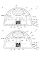
- Fig. 1 is an isometric view of a pulmonary artery band.
- Fig. 2 illustrates the pulmonary artery band.
- Fig. 3 is a block diagram showing a structure of the pulmonary artery band.
- Fig. 4 illustrates driving of the pulmonary artery band.
- Fig. 5 illustrates a pulmonary artery band in another embodiment.
- Fig. 6 illustrates a pulmonary artery band in still another embodiment.
- Fig. 7 is a schematic view illustrating a position at which a pulmonary artery band is to be attached.
- FIG. 1 is an isometric view of a pulmonary artery band 1, in which internal elements of the pulmonary artery band 1 are schematically represented by dashed lines.
- FIG. 2 illustrates the pulmonary artery band 1.
- FIG. 2(a) is a front view of the pulmonary artery band 1
- FIG. 2(b) is a reduced front view thereof showing a state where an arch band 40 is opened.
- FIG. 3 is a block diagram showing a structure of the pulmonary artery band 1, and FIG. 4 illustrates driving of the pulmonary artery band 1.
- FIG. 4(a) is a partially cross-sectioned front view of the pulmonary artery band 1, showing a state before a closed area X is reduced
- FIG. 4(b) is a partially cross-sectioned front view of the pulmonary artery band 1, showing a state where the closed area X is reduced.
- FIGs. 4(a) and 4(b) are partially cross-sectioned so that the inside of a main body 20 is shown for easier explanation.
- FIG. 7 is a schematic view illustrating a position at which the pulmonary artery band 1 is to be attached (part "a" enclosed by the dashed line).
- pulmonary artery 110 extending from heart 100 includes primary pulmonary artery 111 and right and left pulmonary arteries 112 branched from the primary pulmonary artery 111.
- the pulmonary artery band 1 is a treatment device which is to be attached to the primary pulmonary artery 111, before the primary pulmonary artery 110 is branched into the right and left pulmonary arteries 112, to bind and narrow the primary pulmonary artery 111. In this way, the pulmonary artery band 1 controls the bloodstream in the primary pulmonary artery 111 so that too much blood does not flow to the lungs.
- the pulmonary artery band 1 includes a pulmonary artery band body 2 and an oxygen saturation meter 3.
- the pulmonary artery band body 2 and the oxygen saturation meter 3 included in the pulmonary artery band 1 are each formed of a biologically safe material.
- the oxygen saturation meter 3 includes an oxygen saturation meter main body 30 and an oxygen saturation meter sensor 31.
- the oxygen saturation meter main body 30 and the oxygen saturation meter sensor 31 are connected to each other by a connection cable 32.
- the pulmonary artery band body 2 includes a main body 20 (corresponding to the holding section) located in a lower part thereof and the arch band 40 (corresponding to the band section) located in an upper part thereof.
- the main body 20 accommodates therein a control section 21, a driving motor 22 acting as a driving section for driving a press mechanism 50 described later, and a power supply section 23 for supplying electric power to the driving motor 22.
- the oxygen saturation meter main body 30 of the oxygen saturation meter 3 described above is also built in the main body 20.
- the power supply section 23 is connected to the control section 21, the driving motor 22, and also the oxygen saturation meter main body 30.
- the control section 21, the driving motor 22, and the oxygen saturation meter main body 30 are structured to be actuated by the power supplied from the power supply section 23.
- the driving motor 22 and the oxygen saturation meter main body 30 are each connected to the control section 21, and the oxygen saturation meter main body 30 measures an oxygen saturation value under the control of the control section 21 and transmits the measurement result to the control section 21.
- the control section 21 controls the driving motor 22 and the oxygen saturation meter main body 30 connected to the control section 21, and also stores driving data of the driving motor 22 and the measurement results provided by the oxygen saturation meter main body 30 in a storage section built in the control section 21.
- the driving motor 22 is structured to be driven under the control of the control section 21 based on the measurement result received from the oxygen saturation meter main body 30.
- the driving motor 22 has a gear 24 at a tip thereof.
- the gear 24 is engageable with a grooved rack 56a provided on a surface of a support shaft 56 of the press mechanism 50 described later.
- the arch band 40 (corresponding to the band section and the arch section) includes arch pedestals 41 (41, 41b) planted at both of two ends of a top surface of the main body 20 to be directed upward, and an upper arch section 42 pivotable around a hinge 41c as the pivot axis.
- the hinge 41c is provided at a top end of the right arch pedestal 41b, which is provided on the right when seen in the front view, among the two arch pedestals 41.
- an insertable convexed portion 43 is provided at a tip of the upper arch section 42 pivotable with respect to the right arch pedestal 41b.
- the insertable convexed portion 43 is inserted into an engageable concaved portion (not shown) formed in a top surface of the left arch pedestal 41a and fixed thereto.
- the arch band 40 has a planoconvex cross-section which is convexed on the external side.
- the press mechanism 50 Internally to the arch band 40, the press mechanism 50 is provided.
- the press mechanism 50 together with an inner surface of the upper arch section 42, forms a closed loop for allowing the primary pulmonary artery 111 to be fit therein and defines a closed area X in the closed loop.
- the press mechanism 50 includes a press plate 51 crossing the area internal to the arch band 40 in a width direction (the left-right direction in FIGs. 2(a) and 2(b)), and a moving mechanism 55 for moving up and down the press plate 51, namely, adjusting an amount by which the press plate 51 is projected with respect to the main body 20 toward the upper arch section 42.
- the moving mechanism 55 corresponds to the area enlargement and reduction means and the projection means.
- the press plate 51 includes a central plate 52 located at a central position thereof in the width direction, and elastic connection members 53 respectively for connecting both of two ends of the central plate 52 to positions of the right and left arch pedestals 41 that are in the vicinity of the top ends thereof.
- the central plate 52 and the elastic connection members 53 are formed to have substantially the same depth as the arch band 40.
- the moving mechanism 55 includes the support shaft 56 extending from the inside of the main body 20 and passing through the top surface thereof for supporting the central plate 52 from below, and the grooved rack 56a provided on the outer circumferential surface of a part of the support shaft 56 that is positioned inside the main body 20.
- the grooved rack 56a is engaged with the gear 24 of the driving motor 22 mentioned above and moves the support shaft 56 up and down in accordance with the rotation of the gear 24.
- the gear 24 of the driving motor 22 and the grooved rack 56a provided on the outer circumferential surface of the support shaft 56 are directly engaged with each other.
- a deceleration gear (not shown) providing an appropriate deceleration ratio may be provided between the gear 24 and the grooved rack 56a.
- the pulmonary artery band 1 having the above-described structure is attached as follows.
- the chest is opened, and as shown in FIG. 2(b), the upper arch section 42 of the arch band 40 is once opened to locate the pulmonary artery band body 2 such that the primary pulmonary artery 111 (part "a" in FIG. 7) is placed on a top surface of the press plate 51.
- the upper arch section 42 is closed, and the pulmonary artery band body 2 is attached such that the primary pulmonary artery 111 is located in the closed area X defined by the press plate 51 of the press mechanism 50 and the arch band 40.
- the oxygen saturation meter sensor 31 connected to the oxygen saturation meter main body 30 by the connection cable 32 drawn from the main body 20 is located at an appropriate position in the vicinity of the main body 20, and thus the attachment of the pulmonary artery band 1 is completed.
- the pulmonary artery band 1 attached at a predetermined attachment position transmits a sensing result provided by the oxygen saturation meter sensor 31 to the oxygen saturation meter main body 30 via the connection cable 32.
- the oxygen saturation meter main body 30 Upon receiving the sensing result, transmits the measured oxygen saturation value to the control section 21 as the measurement result.
- the control section 21 drives the driving motor 22 to rotate in accordance with the measurement result. As shown in FIG. 4(b), the control section 21 elevates the support shaft 56 and the central plate 52 by the engagement of the gear 24 and the grooved rack 56a to reduce the closed area X.
- the primary pulmonary artery 111 bound in the closed area X defined by the press plate 51 of the press mechanism 50 and the inner surface of the upper arch section 42, is constricted. In this manner, the bloodstream in the primary pulmonary artery 111 is restricted.
- the control section 21 rotates the driving motor 22 in the backward direction to lower the support shaft 56 and the central plate 52.
- the reduced closed area X is enlarged as necessary to release the primary pulmonary artery 111 constricted in the closed area X as necessary. In this manner, the bloodstream in the primary pulmonary artery 111 is adjusted.
- the control section 21 rotates the driving motor 22 forward and backward at a preset time interval to move the press plate 51 up and down, and thus the primary pulmonary artery 111 is kneaded.
- the rotation speed of the driving motor 22 may be first set to be slow, increased gradually, and lowered again before the driving motor 22 is stopped, in order to alleviate the burden on the primary pulmonary artery 111.
- the bloodstream in the primary pulmonary artery 111 fit in the closed area X, defined by the press plate 51 of the press mechanism 50 and the inner surface of the upper arch section 42, is controlled by moving the press plate 51 up and down, namely, by adjusting the projecting amount of the press plate 51, by means of the moving mechanism 55.
- the bloodstream in the primary pulmonary artery 111 may be controlled by, for example, as shown in FIGs. 5(a) and 5(b), by pivoting a movable arch band 40a to enlarge or reduce the closed area X.
- a pulmonary artery band 1a including the movable arch band 40a (corresponding to the band section and the arch section) includes a movable upper arch section 42a attached to the right arch pedestal 41b to be pivotable with respect thereto around the hinge 41c as the pivot axis, and an extendable piston 25 connected to a tip of the movable upper arch section 42a via a connection hinge 44.
- the extendable piston 25 is provided instead of the left arch pedestal 41a and the driving motor 22 of the pulmonary artery band 1.
- identical elements as those in the pulmonary artery band 1 described above will bear identical reference signs thereto and the detailed descriptions thereof will be omitted.
- the extendable piston 25 corresponding to the area enlargement and reduction means and the extendable and contractable connection means is a piston for extending or shortening an inner pipe 26 by means of a pressure of a pump (not shown).
- a tip of the inner pipe 26 is connected to the movable upper arch section 42a via the connection hinge 44.
- the extendable piston 25 provided instead of the driving motor 22 is structured to extend or shorten the inner pipe 26 under the control of the control section 21, like the driving motor 22.
- the pulmonary artery band 1a includes a support table 27 on the top surface of the main body 20, instead of the press mechanism 50.
- the support table 27 has an appropriate flexibility and supports the primary pulmonary artery 111.
- a closed loop is formed by a top surface of the support table 27 and the movable upper arch section 42a, and the closed area X is defined by the closed loop.
- the pulmonary artery band 1a having the above-described structure fits the primary pulmonary artery 111 in the closed area X formed by the top surface of the support table 27 and an inner surface of the movable upper arch section 42a.
- the control section 21 controls the extendable piston 25 to be contracted.
- the pulmonary artery band 1a is formed of a biologically safe material like the pulmonary artery band 1.
- the tip of the movable upper arch 42a is moved downward via the connection hinge 44.
- the movable upper arch 42a pivots counterclockwise around the hinge 41c at the top end of the right arch pedestal 41b as the pivot axis to reduce the closed area X.
- the primary pulmonary artery 111 bound in the closed area X defined by the support table 27 and the inner surface of the movable upper arch section 42a, is constricted. In this manner, the bloodstream in the primary pulmonary artery 111 is restricted.
- the inner pipe 26 of the extendable piston 25 is extended based on the control of the control section 21 to pivot the movable upper arch section 42a clockwise.
- the reduced closed area X is enlarged as necessary to release, as necessary, the primary pulmonary artery 111 constricted in the closed area X. In this manner, the bloodstream in the primary pulmonary artery 111 is adjusted.
- the pulmonary artery bands 1 and 1a described above each have a structure, by which the closed area X is defined by the arch band 40 and the press plate 51, or by the movable arch band 40a and the support table 27, and the primary pulmonary artery 111 bound in the closed area X is constricted by the upward and downward movement of the press plate 51 or by the pivoting movement of the movable upper arch section 42a to restrict the bloodstream in the primary pulmonary artery 111.
- the closed loop may be formed by a flexible constricting band to define the closed area X therein, and the bloodstream in the primary pulmonary artery 111 may be restricted by adjusting the circumferential length of the closed-looped constricting band.
- a pulmonary artery band 1b for restricting the bloodstream in the primary pulmonary artery 111 by means of a constricting band 60 includes a main body 70 which has a rectangular shape longer in the vertical direction when seen in the front view, and the constricting band 60 projecting in a looped state from a top surface of the main body 70.
- the main body 70 corresponds to the holding section, and the constricting band 60 corresponds to the band section.
- the pulmonary artery band 1b is also formed of a biologically safe material like the pulmonary artery bands 1 and 1a.
- the constricting band 60 (corresponding to the band section) is a band having an appropriate depth and an appropriate flexibility.
- One band end 60a of the constricting band 60 is detachably fixed to a top inner surface of the main body 70, and a band intermediate part 60c of the constricting band 60 is projected upward through a constricting section 71 provided on the main body 70.
- the constricting band 60 forms the closed loop which defines the closed area X.
- the other band end 60b of the constricting band 60 passes through the constricting section 71 and is connected to the tip of the inner pipe 26 of the extendable piston 25 located inside the main body 70.
- the main body 70 accommodates therein the control section 21, the power supply section 23 and the oxygen saturation meter main body 30 like the pulmonary artery bands 1 and 1a, in addition to the above-mentioned extendable piston 25 (corresponding to the area enlargement and reduction means).
- the main body 70 also accommodates therein a communication section 80 which is communicable with outside the body while being attached inside the body. As shown in FIG. 3 by the dashed line, the communication section 80 is connected to the control section 21 so that control can be performed by the control section 21 through communication from outside the body via the communication section 80.
- the pulmonary artery band 1b having the above-described structure is attached as follows.
- the one band end 60a is once detached from the main body 70, and the constricting band 60 is attached so as to surround the primary pulmonary artery 111 at a predetermined attachment position.
- the one band end 60a is again fixed to the inner surface of the main body 70, and thus the pulmonary artery band 1b is set such that the primary pulmonary artery 111 is located in the closed area X.
- the control section 21 in the attached pulmonary artery band 1b controls the inner pipe 26 of the extendable piston 25 to be extended downward based on the measurement result provided by the oxygen saturation meter 3.
- the other band end 60b connected to the tip of the inner pipe 26 extended downward reduces the closed area X in the closed loop to constrict the primary pulmonary artery 111 bound in the closed area X defined by the band intermediate part 60c. In this manner, the bloodstream in the primary pulmonary artery 111 is restricted.
- the inner pipe 26 of the extendable piston 25 is shortened based on the control of the control section 21.
- the reduced closed area X is enlarged as necessary to release, as necessary, the primary pulmonary artery 111 constricted in the closed area X. In this manner, the bloodstream in the primary pulmonary artery 111 is adjusted.
- the pulmonary artery band 1b includes the communication section 80 connected to the control section 21. Therefore, for example, when calibration is to be made, or even if the oxygen saturation meter 3 malfunctions, the control section 21 can be controlled from outside the body via the communication section 80.
- the closed area X can be enlarged or reduced to adjust the bloodstream in the primary pulmonary artery 111, or various types of data stored on the storage section in the control section 21 can be transmitted to outside the body to be used as materials based on which a diagnosis is made.
- the communication section 80 may be included in the pulmonary artery band 1 or 1a, so that the control section 21 can be controlled from outside the body via the communication section 80 to enlarge or reduce the closed area X, thus to adjust the bloodstream in the primary pulmonary artery 111.
- the pulmonary artery band 1 (1a, 1b) includes the pulmonary artery band body 2 including the main body 20 (70) for holding the power supply section 23 and the control section 21, the arch band 40 (movable arch band 40a, constricting band 60) coupled to the main body 20 (70) for forming the closed loop, and the press plate 51 (extendable piston 25) for enlarging or reducing the closed area X in the closed loop, and also includes the oxygen saturation meter main body 30 integrally formed with the pulmonary artery band body 2.
- the control section 21 controls the closed area X to be enlarged or reduced in accordance with the result which is output from the oxygen saturation meter main body 30.
- the pulmonary artery band body 2 and the oxygen saturation meter main body 30 are integrally formed. Therefore, when the pulmonary artery band 1 (1a, 1b) is attached in the body, the oxygen saturation meter main body 30 is also attached integrally therewith in the body.
- the control section 21 controls the press plate 51 (extendable piston 25) to enlarge or reduce the closed area X in accordance with the result which is output from the oxygen saturation meter main body 30. Therefore, the closed area X can be automatically controlled to be enlarged or reduced with no need of the operator setting the size of the closed area X each time by referring to the output from the oxygen saturation meter main body separately provided, as is necessary with the conventional pulmonary artery band. Accordingly, the closed area X can be controlled to be enlarged or reduced at high precision to adjust the bloodstream in the primary pulmonary artery 111 regardless of the level of the operational skill of the operator.
- the closed area X is automatically controlled to be enlarged or reduced in accordance with the measurement result provided by the oxygen saturation meter main body 30 attached in the body integrally with the pulmonary artery band body 2. Therefore, the bloodstream in the primary pulmonary artery 111 can be controlled in response to even a drastic change in the oxygen saturation value. Thus, the safety is further improved.
- the power supply section 23 supplies power commonly to the control section 21 and the driving motor 22 (extendable piston 25) in the pulmonary artery band body 2 and also to the oxygen saturation meter main body 30.
- the pulmonary artery band 1 (1a, 1b) can be structured to be more compact.
- the control section 21 controls the press plate 51 (extendable piston 25) to enlarge or reduce the closed area X at a predetermined time interval. Therefore, the primary pulmonary artery 111 bound by the pulmonary artery band 1 (1a, 1b) can be kneaded, and so contracture of the primary pulmonary artery 111 can be prevented.
- the pulmonary artery band 1 (1a, 1b) is often kept attached for almost one year in general, and the primary pulmonary artery 111 is kept bound by the pulmonary artery band 1 (1a, 1b) for such a period.
- the control section 21 controls the press plate 51 (extendable piston 25) to enlarge or reduce the closed area X at a predetermined time interval. Owing to this, contracture of the primary pulmonary artery 111 bound by the pulmonary artery band 1 (1a, 1b) can be prevented.
- the closed loop for binding the primary pulmonary artery 111 is defined by the main body 20 and the arch band 40 (movable arch band 40a) of an arched shape which is connected to both of two ends of the main body 20 so as to stride over the main body 20.
- the closed area X is defined. Therefore, the pulmonary artery band 1 (1a) can be formed to be compact and safely used with no risk of damaging the primary pulmonary artery 111.
- the pulmonary artery band 1 (1a) can have an external shape with few convexed or concaved portions. Therefore, when being attached inside the body, the pulmonary artery band 1 (1a) can be used safely with no risk of damaging other blood vessels or organs.
- the press plate 51 which is projected toward the arch band 40 and enlarges or reduces the closed area X in accordance with the projecting amount thereof, is provided to the main body 20.
- the closed area X in the closed loop can be controlled to be enlarged or reduced in accordance with the projecting amount of the press plate 51, and thus the bloodstream in the primary pulmonary artery 111 can be adjusted. Therefore, the pulmonary artery band 1 can be safely used without influencing other blood vessels or organs.
- the tip of the movable upper arch section 42a pivotably connected to the top end of the right arch pedestal 41b planted on the main body 20, is connected to the extendable piston 25 extendable and contractable with respect to the main body 20.
- the closed area X in the closed loop defined by the movable arch band 40a of the arched shape and the main body 20 can be easily enlarged or reduced to control the bloodstream in the primary pulmonary artery 111.
- the elements of the present invention and the elements of the above-described embodiments correspond as follows.
- the holding section of the present invention corresponds to the main body 20 or 70 of the above-described embodiments;
- the band section corresponds to the arch band 40, the movable arch band 40a or the constricting band 60;
- the area enlargement and reduction means corresponds to the press plate 51 or the extendable piston 25;
- the oxygen saturation meter corresponds to the oxygen saturation meter main body 30;
- the arch section corresponds to the arch band 40 or the movable arch band 40a;
- the projection means corresponds to the press plate 51; and
- the extendable and contractable connection section corresponds to the extendable piston 25.
- the present invention is not limited to the above-described embodiments and can be carried out in various other embodiments.
- the oxygen saturation meter main body 30 is accommodated in the main body 20 or 70.
- the oxygen saturation meter main body 30 may be provided on an outer surface of the main body 20 or 70, integrally with the main body 20 or 70.
- the extendable piston may be provided on each of both sides of the main body 20 and both of two ends of the movable arch band may be connected to the extendable pistons respectively to enlarge or reduce the closed area X by the inner pipes 26 of the extendable pistons being extended or shortened.
- the constricting band 60 of the pulmonary artery band 1b may be formed of a cord, a belt, a chain, a wire or the like.
- the present invention is usable as, for example, a treatment/operation device for artificially adjusting the bloodstream in pulmonary artery banding or the like.
- Pulmonary artery band 2 ... Pulmonary artery band body 20, 70 ... Main body 21 ... Control section 23 ... Power supply section 25 ... Extendable piston 30 ... Oxygen saturation meter main body 40 ... Arch band 40a ... Movable arch band 51 ... Press plate 60 ... Constricting band X ... Closed area
Landscapes
- Health & Medical Sciences (AREA)
- Surgery (AREA)
- Life Sciences & Earth Sciences (AREA)
- Heart & Thoracic Surgery (AREA)
- Nuclear Medicine, Radiotherapy & Molecular Imaging (AREA)
- Vascular Medicine (AREA)
- Engineering & Computer Science (AREA)
- Biomedical Technology (AREA)
- Reproductive Health (AREA)
- Medical Informatics (AREA)
- Molecular Biology (AREA)
- Animal Behavior & Ethology (AREA)
- General Health & Medical Sciences (AREA)
- Public Health (AREA)
- Veterinary Medicine (AREA)
- Measurement Of The Respiration, Hearing Ability, Form, And Blood Characteristics Of Living Organisms (AREA)
Abstract
Has an object of providing a pulmonary artery band capable of controlling a closed area for binding the pulmonary artery to be enlarged or reduced without much time or labor. The pulmonary artery band comprises a pulmonary artery band body 2 including a main body 20 for holding a power supply section 23 and a control section 21, an arch band 40 coupled to the main body 20 for forming a closed loop, and a press mechanism 50 for enlarging or reducing a closed area X defined by the closed loop, and also comprises an oxygen saturation meter main body 30 integral with the pulmonary artery band body 2. The control section 21 controls the press mechanism 50 to enlarge or reduce the closed area X in accordance with a result which is output from the oxygen saturation meter main body 30.
Description
The present invention relates to a pulmonary artery band usable for, for example, pulmonary artery banding.
When a newborn has a disease by which, for example, the heart wall has a hole and the venous blood and the arterial blood are mixed together, a great amount of blood flows into the pulmonary blood vessels, which are soft and allow blood to flow thereto easily. As a result, the newborn suffers from dyspnea or heart failure and has difficulty drinking milk, and his/her body weight does not increase. When the newborn is left in such a state for a long time, the pulmonary blood vessels are damaged and the newborn may suffer from a serious case of pulmonary hypertension (a state where blood does not smoothly flow into the lungs), which is difficult to be cured. Therefore, the treatment of the newborn needs to be started before this occurs.
One technique of treatment for this disease is a radical cure such as, for example, open heart surgery of performing an intracardiac repair using a heart-lung machine. However, such a cure is hard on both of the heart and the body. When, for example, such a radical cure cannot be conducted for this reason, surgery of artificially adjusting the pulmonary bloodstream (pulmonary artery banding) using a pulmonary artery band as disclosed in Non-patent Document 1 or 2 is occasionally conducted.
In pulmonary artery banding, the degree of tightening the pulmonary artery band is adjusted in accordance with the measured oxygen saturation value. Non-patent Document 1 discloses a pulmonary artery band as follows. While being attached in the body, the pulmonary artery band is controlled from outside the body so that a micromotor incorporated into the pulmonary artery band is rotated to extend or shorten a press shaft. Thus, the closed area is enlarged or reduced so that the pulmonary artery has an appropriate size.
Non-patent Document 2 discloses various ideas such as, for example, driving a press shaft by means of a piston using a fluid cylinder, driving the press shaft by means of an electromagnetic force, controlling the size of the pulmonary artery wirelessly by tightening a closed loop, and incorporating a power supply.
However, the oxygen saturation value needs to be adjusted in accordance with, for example, the growth of the patient. Therefore, each time when pulmonary artery banding is to be performed, the operator needs to set the size of the closed area of the pulmonary artery band by checking the output of the oxygen saturation meter separately provided. This requires a lot of time and labor, and the precision thereof may undesirably depend on the level of the operational skill of the operator.
"Telemetrically Adjustable Pulmonary Artery Banding: First Application in Greece", Hellenic Journal of Cardiology 2008:49:195-198
"Hydraulic Remotely Adjustable Pulmonary Artery Banding", Proceedings of the 2010 Design of Medical Devices Conference DMD 2010 April 13-15, 2010, Minneapolis, MN, USA
The present invention made in light of the above-described problems has an object of providing a pulmonary artery band capable of controlling the closed area for binding the pulmonary artery to be enlarged or reduced without much time or labor.
The present invention is directed to a pulmonary artery band, comprising a pulmonary artery band body including a holding section for holding a power supply section and a control section, a band section coupled to the holding section for forming a closed loop, and area enlargement and reduction means for enlarging or reducing a closed area defined by the closed loop; and an oxygen saturation meter integral with the pulmonary artery band body. The control section controls the enlargement and reduction means to enlarge or reduce the closed area in accordance with a result which is output from the oxygen saturation meter.
The band section may be formed of a member having an appropriate level of deformability, for example, a cord, a belt, a chain, a wire or the like.
The oxygen saturation meter may be of a separate type in which the oxygen saturation meter main body and the sensor are separate from each other, or of an integral type in which the oxygen saturation meter main body and the sensor are integral with each other. The sensor may be of a 2-probe type or of a 1-probe type.
The oxygen saturation meter may be of a separate type in which the oxygen saturation meter main body and the sensor are separate from each other, or of an integral type in which the oxygen saturation meter main body and the sensor are integral with each other. The sensor may be of a 2-probe type or of a 1-probe type.
According to this invention, the closed area for binding the pulmonary artery can be controlled to be enlarged or reduced without much time or labor.
In more detail, the pulmonary artery band body and the oxygen saturation meter are formed to be integral with each other; namely, both of these elements are to be implanted in the body. Therefore, when the pulmonary artery band is attached in the body, the oxygen saturation meter is also attached integrally therewith in the body. The control section controls the area enlargement and reduction means to enlarge or reduce the closed area in accordance with the measurement result on the artery which is output from the oxygen saturation meter. Therefore, the closed area can be controlled automatically and continuously to be enlarged or reduced with no need of the operator setting the size of the closed area each time by referring to the output from the oxygen saturation meter separately provided, as is necessary with the conventional pulmonary artery band. Accordingly, the closed area can be controlled to be enlarged or reduced at high precision to adjust the bloodstream in the pulmonary artery regardless of the level of the operational skill of the operator.
In more detail, the pulmonary artery band body and the oxygen saturation meter are formed to be integral with each other; namely, both of these elements are to be implanted in the body. Therefore, when the pulmonary artery band is attached in the body, the oxygen saturation meter is also attached integrally therewith in the body. The control section controls the area enlargement and reduction means to enlarge or reduce the closed area in accordance with the measurement result on the artery which is output from the oxygen saturation meter. Therefore, the closed area can be controlled automatically and continuously to be enlarged or reduced with no need of the operator setting the size of the closed area each time by referring to the output from the oxygen saturation meter separately provided, as is necessary with the conventional pulmonary artery band. Accordingly, the closed area can be controlled to be enlarged or reduced at high precision to adjust the bloodstream in the pulmonary artery regardless of the level of the operational skill of the operator.
The closed area is automatically controlled to be enlarged or reduced in accordance with the measurement result provided by the oxygen saturation meter attached in the body integrally with the pulmonary artery band body. Therefore, the closed area can be controlled to be enlarged or reduced to adjust the bloodstream in the pulmonary artery in response to even a drastic change in the oxygen saturation value. Thus, the safety is further improved.
In an embodiment of the present invention, the power supply section may supply power to the pulmonary artery band body and the oxygen saturation meter.
According to this invention, as compared with the case where the pulmonary artery band body and the oxygen saturation meter each have a power supply section, the pulmonary artery band can be structured to be more compact.
According to this invention, as compared with the case where the pulmonary artery band body and the oxygen saturation meter each have a power supply section, the pulmonary artery band can be structured to be more compact.
In an embodiment of the present invention, the control section may control the enlargement and reduction means to enlarge or reduce the closed area at a predetermined time interval.
According to this invention, the pulmonary artery bound by the pulmonary artery band can be kneaded to prevent contracture of the pulmonary artery. In more detail, the pulmonary artery band is often kept attached for almost one year in general, and the pulmonary artery is kept bound by the pulmonary artery band for such a period. There is a risk that as a result of keeping the pulmonary artery at the same size for a long time, the wall thereof is fiberized and contracture of the pulmonary artery occurs. Namely, there is an undesirable possibility that the dilation of the pulmonary artery is restricted regardless of the size of the closed area. However, when the area enlargement and reduction means is controlled to enlarge or reduce the closed area at a predetermined time interval, the fiberization of the pulmonary artery bound by the pulmonary artery band can be minimized and thus contracture of the pulmonary artery can be prevented.
According to this invention, the pulmonary artery bound by the pulmonary artery band can be kneaded to prevent contracture of the pulmonary artery. In more detail, the pulmonary artery band is often kept attached for almost one year in general, and the pulmonary artery is kept bound by the pulmonary artery band for such a period. There is a risk that as a result of keeping the pulmonary artery at the same size for a long time, the wall thereof is fiberized and contracture of the pulmonary artery occurs. Namely, there is an undesirable possibility that the dilation of the pulmonary artery is restricted regardless of the size of the closed area. However, when the area enlargement and reduction means is controlled to enlarge or reduce the closed area at a predetermined time interval, the fiberization of the pulmonary artery bound by the pulmonary artery band can be minimized and thus contracture of the pulmonary artery can be prevented.
In an embodiment of the present invention, the band section may be formed of an arch section of an arched shape which is connected to both of two ends of the holding section so as to stride over the holding section, and the closed loop may be formed by the arch section and the holding section.
According to this invention, the arch section of an arched shape and the holding section form the closed loop for binding the pulmonary artery. Therefore, the pulmonary artery band can be formed to be compact and used safely with no risk of damaging the pulmonary artery. The pulmonary artery band can have an external shape with few convexed or concaved portions. Therefore, when being attached inside the body, the pulmonary artery band can be used safely with no risk of damaging other blood vessels or organs.
In an embodiment of the present invention, projection means provided to the holding section and projecting toward the arch section for enlarging or reducing the closed area in accordance with a projecting amount thereof acts as the area enlargement and reduction means.
According to this invention, the closed area can be controlled to be enlarged or reduced in accordance with a projecting amount of the projection means, inside the closed loop formed by the arch section of an arched shape and the holding section, to adjust the bloodstream in the pulmonary artery. Therefore, the pulmonary artery band can be used safely without influencing other blood vessels or organs.
In an embodiment of the present invention, at least one of connection sections provided at both of two ends of the arch section connected to the holding section may be formed of an extendable and contractable connection section which is extendable and contractable with respect to the holding section, and the area enlargement and reduction means may include the extendable and contractable connection section.
According to this invention, the closed area can be controlled to be enlarged or reduced by a simple structure to adjust the bloodstream in the pulmonary artery.
According to this invention, the closed area can be controlled to be enlarged or reduced by a simple structure to adjust the bloodstream in the pulmonary artery.
The present invention can provide a pulmonary artery band capable of controlling the closed area for binding the pulmonary artery to be enlarged or reduced without much time or labor.
Hereinafter, an embodiment of the present invention will be described with reference to the drawings.
FIG. 1 is an isometric view of apulmonary artery band 1, in which internal elements of the pulmonary artery band 1 are schematically represented by dashed lines. FIG. 2 illustrates the pulmonary artery band 1. In more detail, FIG. 2(a) is a front view of the pulmonary artery band 1, and FIG. 2(b) is a reduced front view thereof showing a state where an arch band 40 is opened.
FIG. 1 is an isometric view of a
FIG. 3 is a block diagram showing a structure of the pulmonary artery band 1, and FIG. 4 illustrates driving of the pulmonary artery band 1. In more detail, FIG. 4(a) is a partially cross-sectioned front view of the pulmonary artery band 1, showing a state before a closed area X is reduced, and FIG. 4(b) is a partially cross-sectioned front view of the pulmonary artery band 1, showing a state where the closed area X is reduced. FIGs. 4(a) and 4(b) are partially cross-sectioned so that the inside of a main body 20 is shown for easier explanation.
FIG. 7 is a schematic view illustrating a position at which the pulmonary artery band 1 is to be attached (part "a" enclosed by the dashed line). As shown in FIG. 7, pulmonary artery 110 extending from heart 100 includes primary pulmonary artery 111 and right and left pulmonary arteries 112 branched from the primary pulmonary artery 111. The pulmonary artery band 1 is a treatment device which is to be attached to the primary pulmonary artery 111, before the primary pulmonary artery 110 is branched into the right and left pulmonary arteries 112, to bind and narrow the primary pulmonary artery 111. In this way, the pulmonary artery band 1 controls the bloodstream in the primary pulmonary artery 111 so that too much blood does not flow to the lungs.
As shown in FIG. 1 through 3, the pulmonary artery band 1 includes a pulmonary artery band body 2 and an oxygen saturation meter 3. The pulmonary artery band body 2 and the oxygen saturation meter 3 included in the pulmonary artery band 1 are each formed of a biologically safe material.
Theoxygen saturation meter 3 includes an oxygen saturation meter main body 30 and an oxygen saturation meter sensor 31. The oxygen saturation meter main body 30 and the oxygen saturation meter sensor 31 are connected to each other by a connection cable 32.
The
The pulmonary artery band body 2 includes a main body 20 (corresponding to the holding section) located in a lower part thereof and the arch band 40 (corresponding to the band section) located in an upper part thereof. The main body 20 accommodates therein a control section 21, a driving motor 22 acting as a driving section for driving a press mechanism 50 described later, and a power supply section 23 for supplying electric power to the driving motor 22. The oxygen saturation meter main body 30 of the oxygen saturation meter 3 described above is also built in the main body 20.
As shown in FIG. 3, the power supply section 23 is connected to the control section 21, the driving motor 22, and also the oxygen saturation meter main body 30. The control section 21, the driving motor 22, and the oxygen saturation meter main body 30 are structured to be actuated by the power supplied from the power supply section 23.
Also as shown in FIG. 3, the driving motor 22 and the oxygen saturation meter main body 30 are each connected to the control section 21, and the oxygen saturation meter main body 30 measures an oxygen saturation value under the control of the control section 21 and transmits the measurement result to the control section 21.
The control section 21 controls the driving motor 22 and the oxygen saturation meter main body 30 connected to the control section 21, and also stores driving data of the driving motor 22 and the measurement results provided by the oxygen saturation meter main body 30 in a storage section built in the control section 21.
The driving motor 22 is structured to be driven under the control of the control section 21 based on the measurement result received from the oxygen saturation meter main body 30. The driving motor 22 has a gear 24 at a tip thereof. The gear 24 is engageable with a grooved rack 56a provided on a surface of a support shaft 56 of the press mechanism 50 described later.
The arch band 40 (corresponding to the band section and the arch section) includes arch pedestals 41 (41, 41b) planted at both of two ends of a top surface of the main body 20 to be directed upward, and an upper arch section 42 pivotable around a hinge 41c as the pivot axis. The hinge 41c is provided at a top end of the right arch pedestal 41b, which is provided on the right when seen in the front view, among the two arch pedestals 41.
As shown in FIG. 2(b), at a tip of the upper arch section 42 pivotable with respect to the right arch pedestal 41b, an insertable convexed portion 43 is provided. The insertable convexed portion 43 is inserted into an engageable concaved portion (not shown) formed in a top surface of the left arch pedestal 41a and fixed thereto. The arch band 40 has a planoconvex cross-section which is convexed on the external side.
Internally to the arch band 40, the press mechanism 50 is provided. The press mechanism 50, together with an inner surface of the upper arch section 42, forms a closed loop for allowing the primary pulmonary artery 111 to be fit therein and defines a closed area X in the closed loop.
The press mechanism 50 includes a press plate 51 crossing the area internal to the arch band 40 in a width direction (the left-right direction in FIGs. 2(a) and 2(b)), and a moving mechanism 55 for moving up and down the press plate 51, namely, adjusting an amount by which the press plate 51 is projected with respect to the main body 20 toward the upper arch section 42. The moving mechanism 55 corresponds to the area enlargement and reduction means and the projection means.
The press plate 51 includes a central plate 52 located at a central position thereof in the width direction, and elastic connection members 53 respectively for connecting both of two ends of the central plate 52 to positions of the right and left arch pedestals 41 that are in the vicinity of the top ends thereof. The central plate 52 and the elastic connection members 53 are formed to have substantially the same depth as the arch band 40.
The moving mechanism 55 includes the support shaft 56 extending from the inside of the main body 20 and passing through the top surface thereof for supporting the central plate 52 from below, and the grooved rack 56a provided on the outer circumferential surface of a part of the support shaft 56 that is positioned inside the main body 20. The grooved rack 56a is engaged with the gear 24 of the driving motor 22 mentioned above and moves the support shaft 56 up and down in accordance with the rotation of the gear 24. In FIGs. 4(a) and 4(b), the gear 24 of the driving motor 22 and the grooved rack 56a provided on the outer circumferential surface of the support shaft 56 are directly engaged with each other. Alternatively, a deceleration gear (not shown) providing an appropriate deceleration ratio may be provided between the gear 24 and the grooved rack 56a.
The pulmonary artery band 1 having the above-described structure is attached as follows. The chest is opened, and as shown in FIG. 2(b), the upper arch section 42 of the arch band 40 is once opened to locate the pulmonary artery band body 2 such that the primary pulmonary artery 111 (part "a" in FIG. 7) is placed on a top surface of the press plate 51. Then, the upper arch section 42 is closed, and the pulmonary artery band body 2 is attached such that the primary pulmonary artery 111 is located in the closed area X defined by the press plate 51 of the press mechanism 50 and the arch band 40.
At this point, the oxygen saturation meter sensor 31 connected to the oxygen saturation meter main body 30 by the connection cable 32 drawn from the main body 20 is located at an appropriate position in the vicinity of the main body 20, and thus the attachment of the pulmonary artery band 1 is completed.
The pulmonary artery band 1 attached at a predetermined attachment position transmits a sensing result provided by the oxygen saturation meter sensor 31 to the oxygen saturation meter main body 30 via the connection cable 32. Upon receiving the sensing result, the oxygen saturation meter main body 30 transmits the measured oxygen saturation value to the control section 21 as the measurement result.
Upon receiving the measurement result from the oxygen saturation meter main body 30, the control section 21 drives the driving motor 22 to rotate in accordance with the measurement result. As shown in FIG. 4(b), the control section 21 elevates the support shaft 56 and the central plate 52 by the engagement of the gear 24 and the grooved rack 56a to reduce the closed area X. Thus, the primary pulmonary artery 111 bound in the closed area X, defined by the press plate 51 of the press mechanism 50 and the inner surface of the upper arch section 42, is constricted. In this manner, the bloodstream in the primary pulmonary artery 111 is restricted.
By contrast, when, for example, the measurement result obtained by the oxygen saturation meter main body 30 exhibits an excessive reduction in the oxygen saturation value, the control section 21 rotates the driving motor 22 in the backward direction to lower the support shaft 56 and the central plate 52. Thus, the reduced closed area X is enlarged as necessary to release the primary pulmonary artery 111 constricted in the closed area X as necessary. In this manner, the bloodstream in the primary pulmonary artery 111 is adjusted.
In order to prevent contracture of the primary pulmonary artery 111, the control section 21 rotates the driving motor 22 forward and backward at a preset time interval to move the press plate 51 up and down, and thus the primary pulmonary artery 111 is kneaded. For realizing the above-described operations of constriction, releasing or kneading, the rotation speed of the driving motor 22 may be first set to be slow, increased gradually, and lowered again before the driving motor 22 is stopped, in order to alleviate the burden on the primary pulmonary artery 111.
In the above description, the bloodstream in the primary pulmonary artery 111 fit in the closed area X, defined by the press plate 51 of the press mechanism 50 and the inner surface of the upper arch section 42, is controlled by moving the press plate 51 up and down, namely, by adjusting the projecting amount of the press plate 51, by means of the moving mechanism 55. Alternatively, the bloodstream in the primary pulmonary artery 111 may be controlled by, for example, as shown in FIGs. 5(a) and 5(b), by pivoting a movable arch band 40a to enlarge or reduce the closed area X.
A pulmonary artery band 1a including the movable arch band 40a (corresponding to the band section and the arch section) includes a movable upper arch section 42a attached to the right arch pedestal 41b to be pivotable with respect thereto around the hinge 41c as the pivot axis, and an extendable piston 25 connected to a tip of the movable upper arch section 42a via a connection hinge 44. The extendable piston 25 is provided instead of the left arch pedestal 41a and the driving motor 22 of the pulmonary artery band 1. Regarding the pulmonary artery band 1a shown in FIGs. 5(a) and 5(b), identical elements as those in the pulmonary artery band 1 described above will bear identical reference signs thereto and the detailed descriptions thereof will be omitted.
The extendable piston 25 corresponding to the area enlargement and reduction means and the extendable and contractable connection means is a piston for extending or shortening an inner pipe 26 by means of a pressure of a pump (not shown). A tip of the inner pipe 26 is connected to the movable upper arch section 42a via the connection hinge 44.
Theextendable piston 25 provided instead of the driving motor 22 is structured to extend or shorten the inner pipe 26 under the control of the control section 21, like the driving motor 22.
The
In the pulmonary artery band 1, the press plate 51 is moved up and down; whereas in the pulmonary artery band 1a, the movable upper arch section 42a is pivoted. The pulmonary artery band 1a includes a support table 27 on the top surface of the main body 20, instead of the press mechanism 50. The support table 27 has an appropriate flexibility and supports the primary pulmonary artery 111. A closed loop is formed by a top surface of the support table 27 and the movable upper arch section 42a, and the closed area X is defined by the closed loop.
As shown in FIGs. 5(a) and 5(b), the pulmonary artery band 1a having the above-described structure fits the primary pulmonary artery 111 in the closed area X formed by the top surface of the support table 27 and an inner surface of the movable upper arch section 42a. Based on the measurement result provided by the oxygen saturation meter 3 (see FIG. 3), the control section 21 controls the extendable piston 25 to be contracted. The pulmonary artery band 1a is formed of a biologically safe material like the pulmonary artery band 1.
When the inner pipe 26 is shortened by the control section 21 controlling the extendable piston 25 to be contracted, the tip of the movable upper arch 42a is moved downward via the connection hinge 44. Namely, the movable upper arch 42a pivots counterclockwise around the hinge 41c at the top end of the right arch pedestal 41b as the pivot axis to reduce the closed area X. Thus, the primary pulmonary artery 111 bound in the closed area X, defined by the support table 27 and the inner surface of the movable upper arch section 42a, is constricted. In this manner, the bloodstream in the primary pulmonary artery 111 is restricted.
By contrast, for example, in order to enlarge the closed area X as required in accordance with the measurement result provided by the oxygen saturation meter main body 30, or at a predetermined time interval, the inner pipe 26 of the extendable piston 25 is extended based on the control of the control section 21 to pivot the movable upper arch section 42a clockwise. Thus, the reduced closed area X is enlarged as necessary to release, as necessary, the primary pulmonary artery 111 constricted in the closed area X. In this manner, the bloodstream in the primary pulmonary artery 111 is adjusted.
The pulmonary artery bands 1 and 1a described above each have a structure, by which the closed area X is defined by the arch band 40 and the press plate 51, or by the movable arch band 40a and the support table 27, and the primary pulmonary artery 111 bound in the closed area X is constricted by the upward and downward movement of the press plate 51 or by the pivoting movement of the movable upper arch section 42a to restrict the bloodstream in the primary pulmonary artery 111. Alternatively, the closed loop may be formed by a flexible constricting band to define the closed area X therein, and the bloodstream in the primary pulmonary artery 111 may be restricted by adjusting the circumferential length of the closed-looped constricting band.
As shown in FIGs. 6(a) and 6(b), a pulmonary artery band 1b for restricting the bloodstream in the primary pulmonary artery 111 by means of a constricting band 60, for example, includes a main body 70 which has a rectangular shape longer in the vertical direction when seen in the front view, and the constricting band 60 projecting in a looped state from a top surface of the main body 70. The main body 70 corresponds to the holding section, and the constricting band 60 corresponds to the band section. The pulmonary artery band 1b is also formed of a biologically safe material like the pulmonary artery bands 1 and 1a.
The constricting band 60 (corresponding to the band section) is a band having an appropriate depth and an appropriate flexibility. One band end 60a of the constricting band 60 is detachably fixed to a top inner surface of the main body 70, and a band intermediate part 60c of the constricting band 60 is projected upward through a constricting section 71 provided on the main body 70. Thus, the constricting band 60 forms the closed loop which defines the closed area X. The other band end 60b of the constricting band 60 passes through the constricting section 71 and is connected to the tip of the inner pipe 26 of the extendable piston 25 located inside the main body 70.
The main body 70 accommodates therein the control section 21, the power supply section 23 and the oxygen saturation meter main body 30 like the pulmonary artery bands 1 and 1a, in addition to the above-mentioned extendable piston 25 (corresponding to the area enlargement and reduction means). The main body 70 also accommodates therein a communication section 80 which is communicable with outside the body while being attached inside the body. As shown in FIG. 3 by the dashed line, the communication section 80 is connected to the control section 21 so that control can be performed by the control section 21 through communication from outside the body via the communication section 80.
The pulmonary artery band 1b having the above-described structure is attached as follows. The one band end 60a is once detached from the main body 70, and the constricting band 60 is attached so as to surround the primary pulmonary artery 111 at a predetermined attachment position. Then, the one band end 60a is again fixed to the inner surface of the main body 70, and thus the pulmonary artery band 1b is set such that the primary pulmonary artery 111 is located in the closed area X.
The control section 21 in the attached pulmonary artery band 1b controls the inner pipe 26 of the extendable piston 25 to be extended downward based on the measurement result provided by the oxygen saturation meter 3. The other band end 60b connected to the tip of the inner pipe 26 extended downward reduces the closed area X in the closed loop to constrict the primary pulmonary artery 111 bound in the closed area X defined by the band intermediate part 60c. In this manner, the bloodstream in the primary pulmonary artery 111 is restricted.
By contrast, for example, in order to enlarge the closed area X as required in accordance with the measurement result provided by the oxygen saturation meter main body 30, or at a predetermined time interval, the inner pipe 26 of the extendable piston 25 is shortened based on the control of the control section 21. Thus, the reduced closed area X is enlarged as necessary to release, as necessary, the primary pulmonary artery 111 constricted in the closed area X. In this manner, the bloodstream in the primary pulmonary artery 111 is adjusted.
As described above, the pulmonary artery band 1b includes the communication section 80 connected to the control section 21. Therefore, for example, when calibration is to be made, or even if the oxygen saturation meter 3 malfunctions, the control section 21 can be controlled from outside the body via the communication section 80. Thus, the closed area X can be enlarged or reduced to adjust the bloodstream in the primary pulmonary artery 111, or various types of data stored on the storage section in the control section 21 can be transmitted to outside the body to be used as materials based on which a diagnosis is made.
The communication section 80 may be included in the pulmonary artery band 1 or 1a, so that the control section 21 can be controlled from outside the body via the communication section 80 to enlarge or reduce the closed area X, thus to adjust the bloodstream in the primary pulmonary artery 111.
As described above, the pulmonary artery band 1 (1a, 1b) includes the pulmonary artery band body 2 including the main body 20 (70) for holding the power supply section 23 and the control section 21, the arch band 40 (movable arch band 40a, constricting band 60) coupled to the main body 20 (70) for forming the closed loop, and the press plate 51 (extendable piston 25) for enlarging or reducing the closed area X in the closed loop, and also includes the oxygen saturation meter main body 30 integrally formed with the pulmonary artery band body 2. The control section 21 controls the closed area X to be enlarged or reduced in accordance with the result which is output from the oxygen saturation meter main body 30. By attaching the pulmonary artery band 1 (1a, 1b) to the primary pulmonary artery 111, the closed area X can be controlled to be enlarged or reduced to adjust the bloodstream in the primary pulmonary artery 111 without much time or labor.
In more detail, the pulmonary artery band body 2 and the oxygen saturation meter main body 30 are integrally formed. Therefore, when the pulmonary artery band 1 (1a, 1b) is attached in the body, the oxygen saturation meter main body 30 is also attached integrally therewith in the body. The control section 21 controls the press plate 51 (extendable piston 25) to enlarge or reduce the closed area X in accordance with the result which is output from the oxygen saturation meter main body 30. Therefore, the closed area X can be automatically controlled to be enlarged or reduced with no need of the operator setting the size of the closed area X each time by referring to the output from the oxygen saturation meter main body separately provided, as is necessary with the conventional pulmonary artery band. Accordingly, the closed area X can be controlled to be enlarged or reduced at high precision to adjust the bloodstream in the primary pulmonary artery 111 regardless of the level of the operational skill of the operator.
The closed area X is automatically controlled to be enlarged or reduced in accordance with the measurement result provided by the oxygen saturation meter main body 30 attached in the body integrally with the pulmonary artery band body 2. Therefore, the bloodstream in the primary pulmonary artery 111 can be controlled in response to even a drastic change in the oxygen saturation value. Thus, the safety is further improved.
With the pulmonary artery band 1 (1a, 1b), the power supply section 23 supplies power commonly to the control section 21 and the driving motor 22 (extendable piston 25) in the pulmonary artery band body 2 and also to the oxygen saturation meter main body 30. As compared with the case where the pulmonary artery band body 2 and the oxygen saturation meter main body 30 each have the power supply section 23, the pulmonary artery band 1 (1a, 1b) can be structured to be more compact.
With the pulmonary artery band 1 (1a, 1b), the control section 21 controls the press plate 51 (extendable piston 25) to enlarge or reduce the closed area X at a predetermined time interval. Therefore, the primary pulmonary artery 111 bound by the pulmonary artery band 1 (1a, 1b) can be kneaded, and so contracture of the primary pulmonary artery 111 can be prevented.
In more detail, the pulmonary artery band 1 (1a, 1b) is often kept attached for almost one year in general, and the primary pulmonary artery 111 is kept bound by the pulmonary artery band 1 (1a, 1b) for such a period. As a result, there is a risk that contracture of the primary pulmonary artery 111 occurs. However, with the pulmonary artery band 1 (1a, 1b), the control section 21 controls the press plate 51 (extendable piston 25) to enlarge or reduce the closed area X at a predetermined time interval. Owing to this, contracture of the primary pulmonary artery 111 bound by the pulmonary artery band 1 (1a, 1b) can be prevented.
With the pulmonary artery band 1 (1a), the closed loop for binding the primary pulmonary artery 111 is defined by the main body 20 and the arch band 40 (movable arch band 40a) of an arched shape which is connected to both of two ends of the main body 20 so as to stride over the main body 20. In the closed loop, the closed area X is defined. Therefore, the pulmonary artery band 1 (1a) can be formed to be compact and safely used with no risk of damaging the primary pulmonary artery 111. The pulmonary artery band 1 (1a) can have an external shape with few convexed or concaved portions. Therefore, when being attached inside the body, the pulmonary artery band 1 (1a) can be used safely with no risk of damaging other blood vessels or organs.
With the pulmonary artery band 1, the press plate 51, which is projected toward the arch band 40 and enlarges or reduces the closed area X in accordance with the projecting amount thereof, is provided to the main body 20. The closed area X in the closed loop can be controlled to be enlarged or reduced in accordance with the projecting amount of the press plate 51, and thus the bloodstream in the primary pulmonary artery 111 can be adjusted. Therefore, the pulmonary artery band 1 can be safely used without influencing other blood vessels or organs.
With the pulmonary artery band 1a, the tip of the movable upper arch section 42a, pivotably connected to the top end of the right arch pedestal 41b planted on the main body 20, is connected to the extendable piston 25 extendable and contractable with respect to the main body 20. Owing to this, the closed area X in the closed loop defined by the movable arch band 40a of the arched shape and the main body 20 can be easily enlarged or reduced to control the bloodstream in the primary pulmonary artery 111.
The elements of the present invention and the elements of the above-described embodiments correspond as follows.
The holding section of the present invention corresponds to the main body 20 or 70 of the above-described embodiments;
the band section corresponds to thearch band 40, the movable arch band 40a or the constricting band 60;
the area enlargement and reduction means corresponds to thepress plate 51 or the extendable piston 25;
the oxygen saturation meter corresponds to the oxygen saturation metermain body 30;
the arch section corresponds to thearch band 40 or the movable arch band 40a;
the projection means corresponds to thepress plate 51; and
the extendable and contractable connection section corresponds to theextendable piston 25.
However, the present invention is not limited to the above-described embodiments and can be carried out in various other embodiments.
The holding section of the present invention corresponds to the
the band section corresponds to the
the area enlargement and reduction means corresponds to the
the oxygen saturation meter corresponds to the oxygen saturation meter
the arch section corresponds to the
the projection means corresponds to the
the extendable and contractable connection section corresponds to the
However, the present invention is not limited to the above-described embodiments and can be carried out in various other embodiments.
For example, with each of the above-described pulmonary artery bands 1, 1a and 1b, the oxygen saturation meter main body 30 is accommodated in the main body 20 or 70. Alternatively, the oxygen saturation meter main body 30 may be provided on an outer surface of the main body 20 or 70, integrally with the main body 20 or 70.
With the above-described pulmonary artery band 1a, only one end of the movable arch band is connected to the extendable piston and pivots with respect to the main body 20 to enlarge or reduce the closed area X. Alternatively, the extendable piston may be provided on each of both sides of the main body 20 and both of two ends of the movable arch band may be connected to the extendable pistons respectively to enlarge or reduce the closed area X by the inner pipes 26 of the extendable pistons being extended or shortened.
The constricting band 60 of the pulmonary artery band 1b may be formed of a cord, a belt, a chain, a wire or the like.
The present invention is usable as, for example, a treatment/operation device for artificially adjusting the bloodstream in pulmonary artery banding or the like.
1, 1a, 1b ... Pulmonary artery band
2 ... Pulmonary artery band body
20, 70 ... Main body
21 ... Control section
23 ... Power supply section
25 ... Extendable piston
30 ... Oxygen saturation meter main body
40 ... Arch band
40a ... Movable arch band
51 ... Press plate
60 ... Constricting band
X ... Closed area
2 ... Pulmonary artery band body
20, 70 ... Main body
21 ... Control section
23 ... Power supply section
25 ... Extendable piston
30 ... Oxygen saturation meter main body
40 ... Arch band
40a ... Movable arch band
51 ... Press plate
60 ... Constricting band
X ... Closed area
Claims (6)
- A pulmonary artery band, comprising:
a pulmonary artery band body including a holding section for holding a power supply section and a control section, a band section coupled to the holding section for forming a closed loop, and area enlargement and reduction means for enlarging or reducing a closed area defined by the closed loop; and
an oxygen saturation meter integral with the pulmonary artery band body;
wherein the control section controls the enlargement and reduction means to enlarge or reduce the closed area in accordance with a result which is output from the oxygen saturation meter. - A pulmonary artery band according to claim 1, wherein the power supply section supplies power to the pulmonary artery band body and the oxygen saturation meter.
- A pulmonary artery band according to claim 1 or 2, wherein the control section controls the enlargement and reduction means to enlarge or reduce the closed area at a predetermined time interval.
- A pulmonary artery band according to any one of claims 1 through 3, wherein the band section is formed of an arch section of an arched shape which is connected to both of two ends of the holding section so as to stride over the holding section, and the closed loop is formed by the arch section and the holding section.
- A pulmonary artery band according to claim 4, wherein projection means provided to the holding section and projecting toward the arch section for enlarging or reducing the closed area in accordance with a projecting amount thereof acts as the area enlargement and reduction means.
- A pulmonary artery band according to claim 4, wherein at least one of connection sections provided at both of two ends of the arch section connected to the holding section is formed of an extendable and contractable connection section which is extendable and contractable with respect to the holding section, and the area enlargement and reduction means includes the extendable and contractable connection section.
Priority Applications (1)
| Application Number | Priority Date | Filing Date | Title |
|---|---|---|---|
| PCT/JP2011/004370 WO2013018133A1 (en) | 2011-08-02 | 2011-08-02 | Pulmonary artery band |
Applications Claiming Priority (1)
| Application Number | Priority Date | Filing Date | Title |
|---|---|---|---|
| PCT/JP2011/004370 WO2013018133A1 (en) | 2011-08-02 | 2011-08-02 | Pulmonary artery band |
Publications (1)
| Publication Number | Publication Date |
|---|---|
| WO2013018133A1 true WO2013018133A1 (en) | 2013-02-07 |
Family
ID=47628710
Family Applications (1)
| Application Number | Title | Priority Date | Filing Date |
|---|---|---|---|
| PCT/JP2011/004370 WO2013018133A1 (en) | 2011-08-02 | 2011-08-02 | Pulmonary artery band |
Country Status (1)
| Country | Link |
|---|---|
| WO (1) | WO2013018133A1 (en) |
Cited By (4)
| Publication number | Priority date | Publication date | Assignee | Title |
|---|---|---|---|---|
| CN103610485A (en) * | 2013-12-10 | 2014-03-05 | 四川大学 | Device and method for automatically controlling blood occlusion of carotid artery |
| CN105250007A (en) * | 2015-10-27 | 2016-01-20 | 李诗贤 | Binding type pressing hemostasis device for department of cardiology |
| WO2017125636A1 (en) * | 2016-01-20 | 2017-07-27 | Servicio Andaluz De Salud | Device for controlling the flow of blood in a blood vessel |
| CN109044472A (en) * | 2018-10-08 | 2018-12-21 | 范军 | A kind of intelligent pressing haemostatic device of Cardiological |
Citations (4)
| Publication number | Priority date | Publication date | Assignee | Title |
|---|---|---|---|---|
| JPH10502547A (en) * | 1994-07-11 | 1998-03-10 | デーコムド コーポレーション | Canal obstruction prosthesis |
| JP2003504166A (en) * | 1999-07-19 | 2003-02-04 | エンドアート・エス・エイ | Flow control method and device |
| JP2010512176A (en) * | 2006-12-06 | 2010-04-22 | ザ・ホスピタル・フォー・シック・チルドレン | System for remote preconditioning |
| US20100125288A1 (en) * | 2008-11-17 | 2010-05-20 | G&L Consulting, Llc | Method and apparatus for reducing renal blood pressure |
-
2011
- 2011-08-02 WO PCT/JP2011/004370 patent/WO2013018133A1/en active Application Filing
Patent Citations (4)
| Publication number | Priority date | Publication date | Assignee | Title |
|---|---|---|---|---|
| JPH10502547A (en) * | 1994-07-11 | 1998-03-10 | デーコムド コーポレーション | Canal obstruction prosthesis |
| JP2003504166A (en) * | 1999-07-19 | 2003-02-04 | エンドアート・エス・エイ | Flow control method and device |
| JP2010512176A (en) * | 2006-12-06 | 2010-04-22 | ザ・ホスピタル・フォー・シック・チルドレン | System for remote preconditioning |
| US20100125288A1 (en) * | 2008-11-17 | 2010-05-20 | G&L Consulting, Llc | Method and apparatus for reducing renal blood pressure |
Non-Patent Citations (1)
| Title |
|---|
| KALAVROUZIOTIS, GEORGIOS: "Telemetrically Adjustable Pulmonary Artery Banding: First Application in Greece", HELLENIC JOURNAL OF CARDIOLOGY, vol. 49, 2008, pages 195 - 198 * |
Cited By (5)
| Publication number | Priority date | Publication date | Assignee | Title |
|---|---|---|---|---|
| CN103610485A (en) * | 2013-12-10 | 2014-03-05 | 四川大学 | Device and method for automatically controlling blood occlusion of carotid artery |
| CN103610485B (en) * | 2013-12-10 | 2015-07-01 | 四川大学 | Device and method for automatically controlling blood occlusion of carotid artery |
| CN105250007A (en) * | 2015-10-27 | 2016-01-20 | 李诗贤 | Binding type pressing hemostasis device for department of cardiology |
| WO2017125636A1 (en) * | 2016-01-20 | 2017-07-27 | Servicio Andaluz De Salud | Device for controlling the flow of blood in a blood vessel |
| CN109044472A (en) * | 2018-10-08 | 2018-12-21 | 范军 | A kind of intelligent pressing haemostatic device of Cardiological |
Similar Documents
| Publication | Publication Date | Title |
|---|---|---|
| US20210008344A1 (en) | Bendable Sheath and Delivery System Using Bendable Sheath | |
| US11793995B2 (en) | Systems and methods for reducing pressure at an outflow of a duct | |
| WO2013018133A1 (en) | Pulmonary artery band | |
| JP6139630B2 (en) | Direct drive endoscopy system | |
| JP7300138B2 (en) | Head stabilization system with stabilizing element with multiple chambers and method of stabilizing the head with the stabilizing element | |
| JP5323850B2 (en) | Operating table device | |
| US7316040B2 (en) | System and method for positioning patient limbs during surgical procedures | |
| US7846080B2 (en) | Machine and method for head, neck and, shoulder stretching | |
| JP6852189B2 (en) | Surgical Stent Delivery System and Surgical Stent System | |
| ES2960321T3 (en) | Patient limb positioning device | |
| KR101745434B1 (en) | Self-assistant apparatus for dental clinic | |
| CN107693120A (en) | A kind of operated eye robot | |
| CN105903117A (en) | Conduit | |
| CN207236937U (en) | Multipurpose supports air cushion | |
| CN205698858U (en) | Conduit | |
| CN112515714A (en) | Operation fixing device for fixing viscera in minimally invasive operation | |
| CN208958267U (en) | Intracavitary membrane-repturing device for Endovascular operation | |
| CN109793634A (en) | A kind of bracket that can be adjusted flexibly for fixing head | |
| CN207286184U (en) | Transport system | |
| CN209032529U (en) | A kind of auxiliary instrument facilitating Patients with Cholelithiasis row's stone | |
| KR101451900B1 (en) | Operating table for animal | |
| CN209392294U (en) | Position positioning device is assisted after a kind of Burn-plastic surgery | |
| US20210220205A1 (en) | Knee continuous passive machine and method | |
| KR101380473B1 (en) | Digital radioactive-ray photographing apparatus for dental procedure | |
| CN208710383U (en) | A kind of operating bed facilitating adjusting |
Legal Events
| Date | Code | Title | Description |
|---|---|---|---|
| 121 | Ep: the epo has been informed by wipo that ep was designated in this application |
Ref document number: 11870475 Country of ref document: EP Kind code of ref document: A1 |
|
| NENP | Non-entry into the national phase |
Ref country code: DE |
|
| 122 | Ep: pct application non-entry in european phase |
Ref document number: 11870475 Country of ref document: EP Kind code of ref document: A1 |