WO2012176332A1 - Roll screen device - Google Patents
Roll screen device Download PDFInfo
- Publication number
- WO2012176332A1 WO2012176332A1 PCT/JP2011/064553 JP2011064553W WO2012176332A1 WO 2012176332 A1 WO2012176332 A1 WO 2012176332A1 JP 2011064553 W JP2011064553 W JP 2011064553W WO 2012176332 A1 WO2012176332 A1 WO 2012176332A1
- Authority
- WO
- WIPO (PCT)
- Prior art keywords
- guide
- rail
- ridges
- pair
- screen device
- Prior art date
Links
- 238000004804 winding Methods 0.000 claims abstract description 24
- 230000000717 retained effect Effects 0.000 claims abstract 2
- 229920003002 synthetic resin Polymers 0.000 claims description 10
- 239000000057 synthetic resin Substances 0.000 claims description 10
- 239000000758 substrate Substances 0.000 claims description 8
- BZHJMEDXRYGGRV-UHFFFAOYSA-N Vinyl chloride Chemical compound ClC=C BZHJMEDXRYGGRV-UHFFFAOYSA-N 0.000 claims description 2
- 239000000463 material Substances 0.000 claims description 2
- 229920000515 polycarbonate Polymers 0.000 claims description 2
- 239000004417 polycarbonate Substances 0.000 claims description 2
- 229920005989 resin Polymers 0.000 description 5
- 239000011347 resin Substances 0.000 description 5
- 230000037431 insertion Effects 0.000 description 4
- 238000003780 insertion Methods 0.000 description 4
- 238000000465 moulding Methods 0.000 description 4
- 239000010409 thin film Substances 0.000 description 2
- 230000008602 contraction Effects 0.000 description 1
- 230000037303 wrinkles Effects 0.000 description 1
Images


Classifications
-
- E—FIXED CONSTRUCTIONS
- E06—DOORS, WINDOWS, SHUTTERS, OR ROLLER BLINDS IN GENERAL; LADDERS
- E06B—FIXED OR MOVABLE CLOSURES FOR OPENINGS IN BUILDINGS, VEHICLES, FENCES OR LIKE ENCLOSURES IN GENERAL, e.g. DOORS, WINDOWS, BLINDS, GATES
- E06B9/00—Screening or protective devices for wall or similar openings, with or without operating or securing mechanisms; Closures of similar construction
- E06B9/56—Operating, guiding or securing devices or arrangements for roll-type closures; Spring drums; Tape drums; Counterweighting arrangements therefor
- E06B9/58—Guiding devices
- E06B9/581—Means to prevent or induce disengagement of shutter from side rails
-
- E—FIXED CONSTRUCTIONS
- E06—DOORS, WINDOWS, SHUTTERS, OR ROLLER BLINDS IN GENERAL; LADDERS
- E06B—FIXED OR MOVABLE CLOSURES FOR OPENINGS IN BUILDINGS, VEHICLES, FENCES OR LIKE ENCLOSURES IN GENERAL, e.g. DOORS, WINDOWS, BLINDS, GATES
- E06B9/00—Screening or protective devices for wall or similar openings, with or without operating or securing mechanisms; Closures of similar construction
- E06B9/24—Screens or other constructions affording protection against light, especially against sunshine; Similar screens for privacy or appearance; Slat blinds
- E06B9/40—Roller blinds
Definitions
- This invention relates to a roll screen device used when opening and closing a daylighting part or an opening part of a building.
- Patent Document 1 As this kind of roll screen device, one described in Patent Document 1 has been known.
- an inner rail is incorporated into each of a pair of opposed guide rails that guide the movement of both side edges of the screen drawn out from the winding shaft by the winding shaft.
- the rail is provided with a guide groove that is movably inserted in a spirally wound guide protrusion provided along both side edges of the screen, and a pair of inward flanges are provided at the opening end of the guide groove.
- the guide ridges are slidably guided in a retaining state by the pair of inward flanges.
- the fastener tape in the slide fastener is usually superposed on the side edge of the screen and fixed by a high frequency welder, and the fastener element provided along the one side edge of the fastener tape is guided. It is a ridge.
- the screen when the thickness of the fastener element as the guide protrusion is thicker than the thickness of the screen, the screen is wound in a spiral state by the winding shaft.
- the guide ridges overlap and the winding diameter at both ends is larger than the winding diameter at the center, the screen is wound into a drum shape, wrinkles are formed at both ends, or the guide ridge is wound first
- the screen is meandering with respect to the guide ridge in the width direction of the screen, the screen meanders, and the resistance at the time of winding is large, so that it cannot be smoothly wound.
- the thickness of the screen is made thicker than the thickness of the guide ridge so that the guide ridge does not overlap and wind up. Yes.
- the screen can be wound up very neatly, since the thickness of the screen is thicker than the thickness of the guide protrusion, the screen becomes heavy and a large operating force is required for winding.
- the roll screen device becomes larger as the length of the screen becomes longer, the application range of the roll screen device becomes narrower, and there are points to be improved in expanding the application range. .
- the inner rail that guides the movement of the fastener element as the guide protrusion is a molded product of synthetic resin, and in the inner part where the pair of inward flanges are formed, the fastener tape is between the opposing parts of the inward flanges.
- There is a gap for guiding the movement and there is no gap on the outer side on the opposite side, and the outer side of the inner rail contracts in the width direction after molding depending on the presence or absence of the gap.
- a guide clearance large enough to hold the fastener element between the opposing surfaces of a pair of inward flanges, specifically, a guide clearance of about 0.7 mm is ensured. It cannot be secured.
- An object of the present invention is to make it possible to employ a fastener element of an extremely thin fastener tape as guide protrusions on both side edges of a screen wound by a winding shaft, thereby expanding the application range.
- An object of the present invention is to provide a roll screen device.
- guide ridges that can be wound in a spiral shape are provided on both side edges of a screen that is wound around the outer periphery of the winding shaft by rotation in one direction.
- An inner rail made of a synthetic resin molded product is incorporated inside a pair of fixed guide rails that guide the movement of both side edges of the screen unwound from the shaft, and the guide protrusion is moved in the length direction of the inner rail.
- the guide groove of the inner rail A slide guide rail is incorporated in the slide guide rail, and the slide guide rail is composed of a pair of resin molded rail members.
- An outer protrusion is provided on one side of the strip-like rail substrate having a width dimension substantially equal to the depth, and the height is approximately 1 ⁇ 2 of the groove width dimension of the guide groove, and the outer side is provided on the other side.
- It is configured to have an inner side ridge that is lower in height than the ridge and higher than the inward flange, and the pair of rail members abut the outer side ridge between the opposing portions of the inner side ridge. And a slit-like minute gap is formed in the guide groove so that the minute gap faces the guide gap formed between the opposing portions of the inward flange, and the guide is formed by the inner side protrusion.
- a configuration is adopted in which the ridges are slidably guided in a retaining state.
- the pair of rail members that form the minute gaps are substantially U-shaped in cross section and have almost uniform thickness throughout, so there is almost no deformation due to shrinkage after resin molding, and the rail members have high dimensional accuracy.
- the fastener element of the ultra-thin fastener tape described above can be employed as a guide protrusion, and a thin film-like screen can be employed as a screen, thereby providing a roll screen device having a wide application range. it can.
- the synthetic resin as the material for forming the rail member is preferably hard.
- examples of such a resin include vinyl chloride and polycarbonate.
- the pair of resin-molded rail members provided with the inner side ridges and the outer side ridges having different heights on both sides of the rail substrate are used as the outer side ridges having a high height.
- it is incorporated into the guide groove of the inner rail, so that a small clearance smaller than the guide clearance formed between the facing portions of the pair of inward flanges is ensured between the facing portions of the pair of inner side ridges.
- the thin guide protrusions can be reliably slidably guided in the retaining state by the pair of inner side protrusions.
- the fastener element of the ultra-thin fastener tape can be employed as the guide protrusion, and a thin film can be employed as the screen, so that a roll screen device having a wide application range can be provided.
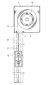
- FIG. 1 is a partially cutaway cross-sectional view showing a part where the winding shaft of FIG. 1 is assembled. Sectional drawing which expands and shows a part of FIG.
- the bottom plate 2 of the screen storage box 1 having a rectangular tube shape is provided with a drawer port 3 extending long in the left and right end directions.
- a take-up shaft 10 is incorporated in the screen storage box 1.
- One end of a screen 11 is connected to the winding shaft 10.
- the screen 11 is wound and rewound by the rotation of the winding shaft 10.
- the screen 11 is drawn downward from the drawer opening 3 formed in the bottom plate 2 of the screen storage box 1, and a weight bar that applies tension in the length direction of the screen 11 at the lower end. 12 is provided.
- guide ridges 13 are provided on both side edges of the screen 11.
- the guide ridge 13 is composed of a fastener element attached to the side edge of the fastener tape 14 of the slide fastener, and the fastener tape 14 provided with the fastener element is superimposed on the side edge of the screen 11 and fixed and integrated. ing.
- the take-up shaft 10 is driven to rotate by a motor 15 incorporated therein, but the take-up shaft is rotated in the rewinding direction by pulling out the screen 11 by the operation of lowering the weight bar 12.
- the torsional deformation may be caused in the winding spring incorporated in the winding shaft, and the winding shaft may be rotated in the winding direction by the restoring elasticity of the winding spring.
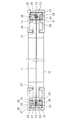
- the upper ends of a pair of guide rails 20 that are opposed to each other and extend in the vertical direction are connected to both ends of the lower surface of the screen storage box 1.
- the guide rail 20 is formed with an insertion groove 21 that opens on the opposite surface and a rail storage space 22 that communicates with the insertion groove 21.
- Each of the insertion groove 21 and the rail storage space 22 extends long in the length direction (vertical direction) of the guide rail 20, and the upper end opening of the insertion groove 21 faces both ends of the drawer opening 3 of the screen storage box 1. Both ends of the weight bar 12 are slidably fitted in the groove 21.
- An inner rail 23 is incorporated in the rail storage space 22.
- the inner rail 23 has the same length as the guide rail 20.
- the inner rail 23 is formed with a guide groove 24 into which the side edge of the screen 11 can be inserted, and a pair of inward flanges 25 are formed at the opening end of the guide groove 24. Has been.
- the inner rail 23 is made of a synthetic resin molded product, and a guide clearance 26 is formed between the opposing surfaces of the pair of inward flanges 25.
- ⁇ shown in FIG. 5 indicates the size of the guide clearance 26, and the size is about 1.0 mm, which is a limit in resin molding of the inner rail 23.
- a slide guide rail 30 is fitted in the guide groove 24 of the inner rail 23.
- the slide guide rail 30 includes a pair of rail members 31.
- the rail member 31 is formed of a synthetic resin molded product in which an outer side protrusion 33 is provided on one side of the rail substrate 32 and an inner side protrusion 34 is formed on the other side.
- the width w1 of the rail substrate 32 is as follows.
- the guide groove 24 formed in the inner rail 23 is substantially equal to the groove depth H1.
- the height h1 of the outer ridge 33 is approximately 1 ⁇ 2 of the groove width dimension W1 of the guide groove 24 in the inner rail 23. Further, the height h2 of the inner ridge 34 is lower than the height h1 than the outer ridge 33 and higher than the height h3 of the inward flange 25.
- the pair of rail members 31 is a combination in which the outer protrusion 33 is abutted and a slit-shaped minute gap 35 is formed between the opposed portions of the inner protrusion 34, and the minute gap 35 is opposed to the inward flange 25. It is incorporated in the guide groove 24 of the inner rail 23 so as to face the guide clearance 26 formed between the sections, and is secured by a pair of inward flanges 25 provided at the opening end of the guide groove 24. .
- a guide groove 36 is formed between the opposed portions of the pair of rail members 31, and when the screen 11 is pulled out from the winding shaft 10, Fastener tape 14 provided on both side edges is guided by a minute gap 35 of the slide guide rail 30, and the guide protrusion 13 is inserted into the guide groove 36, and is slid in a secured state by the pair of inner side protrusions 34. Guided.
- the inner rail 23 is formed with a bulging portion 27 projecting forward and backward on the outer surface, and an elastic body 28 such as a sponge is incorporated between the bulging portion 27 and the inner wall of the guide rail 20. ing.
- the elastic body 28 urges the inner rail 23 toward the outer side to apply a tension in the width direction to the screen 11.
- a pair of the rail members 31 made of synthetic resin provided with the outer side protrusions 33 and the inner side protrusions 34 having different heights on one surface of the rail substrate 32 are connected to the outer member having a high height. Since the side ridges 33 are opposed to each other, a minute gap 35 that guides the movement of the fastener tape 14 can be formed between the pair of opposed inner ridges 34. In addition, a guide groove 36 having a smaller cross-sectional shape than the guide groove 24 of the inner rail 23 can be formed between the opposed portions of the pair of rail members 31.
- the pair of rail members 31 forming the minute gaps 35 are U-shaped in cross section and substantially uniform in thickness throughout, so that the rails with high dimensional accuracy are very little deformed by shrinkage after resin molding.
- the member 31 can be resin-molded.
- the height h2 of the inner ridge 34 is set lower than the height h1 of the outer ridge 33 and higher than the height h3 of the inward flange 25, whereby a pair of inner side ridges 34 is formed.
- a small clearance 35 smaller than the guide clearance 26 formed between the opposed portions of the pair of inward flanges 25 can be formed.
Landscapes
- Engineering & Computer Science (AREA)
- Structural Engineering (AREA)
- Architecture (AREA)
- Civil Engineering (AREA)
- Operating, Guiding And Securing Of Roll- Type Closing Members (AREA)
Abstract
Description
11 スクリーン
13 ガイド突条
20 ガイドレール
23 インナレール
24 ガイド溝
25 内向きフランジ
26 案内すきま
30 スライド案内レール
31 レール部材
32 レール基板
33 アウタ側突条
34 インナ側突条
35 微小すきま 10 winding
Claims (3)
- 巻取軸の一方向の回転によってその外周に巻き取られるスクリーンの両側縁部に渦巻き状に巻取り可能なガイド突条を設け、前記巻取軸から巻き戻されるスクリーンの両側縁部の移動を案内する一対の固定のガイドレールの内側に合成樹脂の成形品からなるインナレールを組込み、そのインナレールの長さ方向に前記ガイド突条の移動を案内するガイド溝を設け、そのガイド溝の開口端に設けられた対向一対の内向きフランジによって前記ガイド突条を抜止めする状態で摺動案内するロールスクリーン装置において、
前記インナレールのガイド溝内にスライド案内レールを組込み、そのスライド案内レールが、樹脂成型された一対のレール部材からなり、そのレール部材が、前記ガイド溝の溝深さにほぼ等しい幅寸法の帯板状レール基板の一側部に、高さがガイド溝の溝幅寸法のほぼ1/2とされたアウタ側突条を設け、他側部にそのアウタ側突条より高さが低く、前記内向きフランジより高さの高いインナ側突条を設けた構成とされ、その一対のレール部材は、アウタ側突条を突き合わせ、インナ側突条の対向部間にスリット状の微小すきまが形成される組み合わせとされ、その微小すきまが前記内向きフランジの対向部間に形成された案内すきまに臨むようにして前記ガイド溝内に組込み、前記インナ側突条により前記ガイド突条を抜止め状態で摺動案内するようにしたことを特徴とするロールスクリーン装置。 Guide ridges that can be wound in a spiral shape are provided on both side edges of the screen wound around the outer periphery of the winding shaft by rotation in one direction, and the movement of both side edges of the screen that is rewound from the winding shaft is performed. An inner rail made of synthetic resin is incorporated inside a pair of fixed guide rails to be guided, and a guide groove for guiding the movement of the guide protrusion is provided in the length direction of the inner rail. In a roll screen device that slides and guides the guide protrusions in a state of retaining the guide protrusions by a pair of opposed inward flanges provided at the ends,
A slide guide rail is assembled in the guide groove of the inner rail, and the slide guide rail is composed of a pair of resin-molded rail members, and the rail member has a width dimension substantially equal to the groove depth of the guide groove. Provided on one side of the plate-like rail substrate is an outer side protrusion whose height is approximately ½ of the groove width dimension of the guide groove, and the other side has a lower height than the outer side protrusion, The inner side ridges are higher than the inward flange, and the pair of rail members abut the outer side ridges, and a slit-shaped minute gap is formed between the opposing parts of the inner side ridges. It is assembled in the guide groove so that the minute clearance faces the guide clearance formed between the opposing portions of the inward flange, and the guide projection is slid in a state of being retained by the inner projection. Plan Rolling screen device being characterized in that so as to. - 前記一対のレール部材の形成素材としての合成樹脂が、硬質の合成樹脂からなる請求項1に記載のロールスクリーン装置。 The roll screen device according to claim 1, wherein the synthetic resin as a forming material of the pair of rail members is made of a hard synthetic resin.
- 前記合成樹脂が、塩化ビニルとポリカーボネイトの一種からなる請求項2に記載のロールスクリーン装置。 The roll screen device according to claim 2, wherein the synthetic resin is made of one of vinyl chloride and polycarbonate.
Priority Applications (4)
| Application Number | Priority Date | Filing Date | Title |
|---|---|---|---|
| PCT/JP2011/064553 WO2012176332A1 (en) | 2011-06-24 | 2011-06-24 | Roll screen device |
| JP2012519645A JP5647683B2 (en) | 2011-06-24 | 2011-06-24 | Roll screen device |
| US13/392,542 US8607841B2 (en) | 2011-06-24 | 2011-06-24 | Roll screen device |
| EP11811307.5A EP2757224B1 (en) | 2011-06-24 | 2011-06-24 | Roll screen device |
Applications Claiming Priority (1)
| Application Number | Priority Date | Filing Date | Title |
|---|---|---|---|
| PCT/JP2011/064553 WO2012176332A1 (en) | 2011-06-24 | 2011-06-24 | Roll screen device |
Publications (1)
| Publication Number | Publication Date |
|---|---|
| WO2012176332A1 true WO2012176332A1 (en) | 2012-12-27 |
Family
ID=47360712
Family Applications (1)
| Application Number | Title | Priority Date | Filing Date |
|---|---|---|---|
| PCT/JP2011/064553 WO2012176332A1 (en) | 2011-06-24 | 2011-06-24 | Roll screen device |
Country Status (4)
| Country | Link |
|---|---|
| US (1) | US8607841B2 (en) |
| EP (1) | EP2757224B1 (en) |
| JP (1) | JP5647683B2 (en) |
| WO (1) | WO2012176332A1 (en) |
Cited By (2)
| Publication number | Priority date | Publication date | Assignee | Title |
|---|---|---|---|---|
| WO2015156222A1 (en) * | 2014-04-11 | 2015-10-15 | フクビ化学工業株式会社 | Screen device and method for manufacturing same |
| US20220090444A1 (en) * | 2011-05-11 | 2022-03-24 | Rajiva A. Dwarka | Retractable curtain panel with track guide |
Families Citing this family (26)
| Publication number | Priority date | Publication date | Assignee | Title |
|---|---|---|---|---|
| US8851147B2 (en) | 2011-03-23 | 2014-10-07 | Rytec Corporation | Segmented wind lock configuration for overhead roll-up doors and method of constructing the same |
| US9347258B2 (en) * | 2011-05-11 | 2016-05-24 | Rajiva A. Dwarka | Retractable curtain panel with track guide |
| US20170009524A1 (en) * | 2011-05-11 | 2017-01-12 | Rajiva A. Dwarka | Retractable curtain panel and enhanced stiffeners |
| US8887790B2 (en) * | 2011-09-13 | 2014-11-18 | Rytec Corporation | Wind lock configuration for overhead roll-up doors |
| GB2502039B (en) * | 2012-02-29 | 2017-11-15 | Ideas By Design Ltd | Apparatus for mounting a screen guide rail |
| CH706619B1 (en) * | 2012-06-05 | 2014-10-15 | Plastex Sa | Shock absorber for a screening system. |
| US11434692B2 (en) | 2012-06-05 | 2022-09-06 | Plastex Sa | Cushion for shading system |
| EP2943635B1 (en) | 2013-01-08 | 2020-08-12 | Rytec Corporation | Roll-up door with a wind lock |
| FR3004212B1 (en) | 2013-04-04 | 2015-04-10 | Ferrari Serge Sas | GUIDING DEVICE, SOLAR PROTECTION STORAGE CANVAS AND ASSEMBLY EQUIPPED WITH SUCH A GUIDE DEVICE |
| KR20150069262A (en) * | 2013-12-13 | 2015-06-23 | 현대자동차주식회사 | Apparatus for preventing droop of blind for panorama sunroof |
| US9458666B2 (en) * | 2014-02-27 | 2016-10-04 | Michael Murray | Tension adjustable retractable screen assembly |
| DE102014110401A1 (en) | 2014-07-23 | 2016-01-28 | Mhz Hachtel Gmbh & Co. Kg | Flat protective device with spaced holding parts |
| EP2987667B1 (en) | 2014-08-18 | 2019-10-09 | Inalfa Roof Systems Group B.V. | Guide and sunshade assembly provided therewith |
| EP2987668B1 (en) | 2014-08-18 | 2019-04-24 | Inalfa Roof Systems Group B.V. | Sunshade assembly |
| MX2017014453A (en) * | 2016-04-08 | 2018-03-16 | Plastex Sa | Cushion for the guiding rail of a sunshade for doors or windows. |
| US11421474B2 (en) | 2016-08-03 | 2022-08-23 | Defender Screens International, Llc | Self-tensioning magnetic tracks and track assemblies |
| US9719292B1 (en) * | 2016-08-03 | 2017-08-01 | Defender Screens International LLC | Self-tensioning magnetic tracks and track assemblies |
| FR3058753B1 (en) | 2016-11-14 | 2018-11-23 | Serge Ferrari Sas | COATED TEXTILE WITH SLINGS HAVING A RIBBON AND DEVICES COMPRISING SUCH A TEXTILE |
| US10253563B2 (en) * | 2017-01-03 | 2019-04-09 | Mechoshade Systems, Llc | Base channel coupling |
| US10260280B2 (en) | 2017-01-03 | 2019-04-16 | Mechoshade Systems, Llc | Systems and methods for roller blind channel coupling |
| US20190048658A1 (en) * | 2017-08-09 | 2019-02-14 | Professional Blinds System Inc. | Construction assembly for installing a roller blind or the like |
| CA3135634A1 (en) | 2019-04-03 | 2020-10-08 | Michael Heissenberg | Retractable screen with tensioning track |
| CA3144723A1 (en) * | 2019-07-22 | 2021-01-28 | Arthur James | Self-tensioning magnetic tracks and track assemblies |
| GB2589328B (en) * | 2019-11-26 | 2021-11-17 | Yewdale Investments Ltd | Roller blind barrel sleeve |
| US20230366268A1 (en) | 2022-05-16 | 2023-11-16 | Michael Heissenberg | Adjustable vertical barrier for a retractable screen |
| US20240060362A1 (en) | 2022-08-17 | 2024-02-22 | Michael Heissenberg | Screen retention track |
Citations (3)
| Publication number | Priority date | Publication date | Assignee | Title |
|---|---|---|---|---|
| JPH0610591U (en) * | 1992-07-15 | 1994-02-10 | 林口工業株式会社 | Screen device |
| JP2004211298A (en) * | 2002-12-26 | 2004-07-29 | Tachikawa Blind Mfg Co Ltd | Screen guiding device of roll blind |
| JP2008520859A (en) * | 2004-11-19 | 2008-06-19 | ベバスト・アクチィエンゲゼルシャフト | Rolling blind device for vehicle |
Family Cites Families (11)
| Publication number | Priority date | Publication date | Assignee | Title |
|---|---|---|---|---|
| DE3316263A1 (en) * | 1983-05-04 | 1984-11-08 | Rolf-Diether 4330 Mülheim Weiblen | DEVICE FOR HEAT INSULATION AND AIR CONDITIONING |
| BE1004897A3 (en) * | 1991-05-24 | 1993-02-16 | Coenraets Benoit | Closure device, or separation of coverage. |
| JPH0610591A (en) | 1992-06-25 | 1994-01-18 | Mitsubishi Heavy Ind Ltd | Bedrock excavator |
| RU2167254C2 (en) * | 1994-04-29 | 2001-05-20 | Динако Интернасьональ | Flexible curtain closing device |
| JP4270674B2 (en) | 1999-10-05 | 2009-06-03 | 林口工業株式会社 | Screen for roll screen and roll screen |
| CN1580479B (en) * | 2003-08-12 | 2010-06-23 | 三和控股株式会社 | Sheet roller shutter door |
| BE1016495A3 (en) * | 2005-04-15 | 2006-12-05 | Dynaco International Sa | |
| EP1840321A1 (en) * | 2006-03-29 | 2007-10-03 | Dynaco International S.A. | Device for guiding a roll-type closure |
| US8037921B2 (en) * | 2006-06-05 | 2011-10-18 | Rite-Hite Holding Corporation | Track and guide system for a door |
| DE502007003134D1 (en) * | 2007-01-31 | 2010-04-29 | Arvinmeritor Gmbh | Guiding system for a roller blind of a sunroof system |
| AU2010100720B4 (en) * | 2009-10-29 | 2011-09-08 | Acmeda Pty Ltd | A blind system |
-
2011
- 2011-06-24 US US13/392,542 patent/US8607841B2/en active Active
- 2011-06-24 WO PCT/JP2011/064553 patent/WO2012176332A1/en active Application Filing
- 2011-06-24 EP EP11811307.5A patent/EP2757224B1/en not_active Not-in-force
- 2011-06-24 JP JP2012519645A patent/JP5647683B2/en active Active
Patent Citations (3)
| Publication number | Priority date | Publication date | Assignee | Title |
|---|---|---|---|---|
| JPH0610591U (en) * | 1992-07-15 | 1994-02-10 | 林口工業株式会社 | Screen device |
| JP2004211298A (en) * | 2002-12-26 | 2004-07-29 | Tachikawa Blind Mfg Co Ltd | Screen guiding device of roll blind |
| JP2008520859A (en) * | 2004-11-19 | 2008-06-19 | ベバスト・アクチィエンゲゼルシャフト | Rolling blind device for vehicle |
Non-Patent Citations (1)
| Title |
|---|
| See also references of EP2757224A4 * |
Cited By (5)
| Publication number | Priority date | Publication date | Assignee | Title |
|---|---|---|---|---|
| US20220090444A1 (en) * | 2011-05-11 | 2022-03-24 | Rajiva A. Dwarka | Retractable curtain panel with track guide |
| WO2015156222A1 (en) * | 2014-04-11 | 2015-10-15 | フクビ化学工業株式会社 | Screen device and method for manufacturing same |
| JP2015203186A (en) * | 2014-04-11 | 2015-11-16 | フクビ化学工業株式会社 | Screen device and manufacturing method thereof |
| US10260279B2 (en) | 2014-04-11 | 2019-04-16 | Hayashiguchi Mfg Co., Ltd. | Screen apparatus and method for producing the same |
| EP3130741B1 (en) * | 2014-04-11 | 2021-07-21 | Hayashiguchi Mfg Co., Ltd. | Screen apparatus and method for manufacturing the same |
Also Published As
| Publication number | Publication date |
|---|---|
| EP2757224A4 (en) | 2015-03-25 |
| JP5647683B2 (en) | 2015-01-07 |
| US20120325416A1 (en) | 2012-12-27 |
| EP2757224A1 (en) | 2014-07-23 |
| JPWO2012176332A1 (en) | 2015-02-23 |
| EP2757224B1 (en) | 2017-02-15 |
| US8607841B2 (en) | 2013-12-17 |
Similar Documents
| Publication | Publication Date | Title |
|---|---|---|
| JP5647683B2 (en) | Roll screen device | |
| JP2004346578A (en) | Winding type screen device | |
| KR101241427B1 (en) | Maintenance device for tension of curtain of sunroof | |
| CN113808490A (en) | Flexible display device | |
| JP6140647B2 (en) | Blackboard equipment | |
| JP5316791B2 (en) | Roll screen device | |
| JP2016537541A (en) | How to make a screen guide rail | |
| JP2013023843A (en) | Roll screen device | |
| JP6694773B2 (en) | Guide rail structure for shutter | |
| JP2006310213A (en) | Flat cable and its manufacturing method | |
| JP2016132920A (en) | Winding screen device | |
| JP2008285934A (en) | Slide assisting device for sliding door | |
| JP6514962B2 (en) | Winding type screen device | |
| JP2001107666A (en) | Roll screen and screen therefor | |
| JP5466959B2 (en) | Guide means for opening / closing device and resin cover member | |
| JP7449101B2 (en) | switchgear | |
| WO2018047373A1 (en) | Magnet screen device | |
| JP5032793B2 (en) | Shutter device | |
| JP6694699B2 (en) | Open / close body structure | |
| JP3841765B2 (en) | Retractable screen device | |
| JP6741604B2 (en) | Screen device | |
| JP2017223058A (en) | Roll curtain device | |
| JP6964455B2 (en) | Screen device | |
| JP6983564B2 (en) | Screen fixing structure and screen device | |
| JP2011001689A (en) | Roll screen |
Legal Events
| Date | Code | Title | Description |
|---|---|---|---|
| REEP | Request for entry into the european phase |
Ref document number: 2011811307 Country of ref document: EP |
|
| WWE | Wipo information: entry into national phase |
Ref document number: 2011811307 Country of ref document: EP |
|
| ENP | Entry into the national phase |
Ref document number: 2012519645 Country of ref document: JP Kind code of ref document: A |
|
| WWE | Wipo information: entry into national phase |
Ref document number: 13392542 Country of ref document: US |
|
| 121 | Ep: the epo has been informed by wipo that ep was designated in this application |
Ref document number: 11811307 Country of ref document: EP Kind code of ref document: A1 |
|
| NENP | Non-entry into the national phase |
Ref country code: DE |