COMBINING POWER FROM MULTIPLE RESONANCE MAGNETIC RECEIVERS IN RESONANCE MAGNETIC POWER SYSTEM
TECHNICAL FIELD
[0001] The described embodiments relate generally to utilizing a wireless power transmission in a portable computing environment.
BACKGROUND
[0002] Energy or power may be transferred wirelessly using a variety of known radiative, or far- field, and non-radiative, or near- field, techniques. For example, radiative wireless information transfer using low-directionality antennas, such as those used in radio and cellular communications systems and home computer networks, may be considered wireless energy transfer. However, this type of radiative transfer is very inefficient because only a tiny portion of the supplied or radiated power, namely, that portion in the direction of, and overlapping with, the receiver is picked up. The vast majority of the power is radiated away in all the other directions and lost in free space. Such inefficient power transfer may be acceptable for data transmission, but is not practical for transferring useful amounts of electrical energy for the purpose of doing work, such as for powering or charging electrical devices.
[0003] One way to improve the transfer efficiency of some radiative energy transfer schemes is to use directional antennas to confine and preferentially direct the radiated energy towards a receiver. However, these directed radiation schemes may require an uninterruptible line-of- sight and potentially complicated tracking and steering mechanisms in the case of mobile transmitters and/or receivers. In addition, such schemes may pose hazards to objects or people that cross or intersect the beam when modest to high amounts of power are being transmitted. A known non-radiative, or near-field, wireless energy transfer scheme, often referred to as either induction or traditional induction, does not (intentionally) radiate power, but uses an oscillating current passing through a primary coil, to generate an oscillating magnetic near-field that induces currents in a near-by receiving or secondary coil. Traditional induction schemes have demonstrated the transmission of modest to large amounts of power, however only over very short distances, and with very small offset tolerances between the primary power supply unit and the secondary receiver unit. Electric transformers and proximity chargers are examples of devices that utilize this known short range, near-field energy transfer scheme.
[0004] It is well known that useable power can be transferred wirelessly from a power source to a receiver located within a distance referred to as a near field. By near field it is meant that within a distance a few times larger than that of both objects involved in the transfer (about one meter or so for most applications) a relatively large amount of power (at least on the order of a few watts) can be transferred between a wireless source device and a receiver with an acceptable efficiency. In this way, a realistic and practical approach to wireless transferring useable amounts of power over distances suitable for limited applications can be realized. Typically, each battery powered device such as a wireless electronic device requires its own charger and power source, which is usually an alternating current (AC) power outlet. Such a wired configuration becomes unwieldy when many devices need charging.
[0005] What is desired are methods, systems, and apparatus for efficient and user friendly interaction between peripheral devices in a wirelessly powered local computing environment.
[0006] The following are from Annals of Physics 323 (2008) 34-48 "Efficient
Wireless non- radiative mid-range energy transfer" by Aristeidis Karalis et al., available online April 27, 2007.
L i rodued ii
In the early days of electromagnet n > before the ele trical- ire grid was deployed- serious interest and effort as devoted (most notably b Nikola 'fes a j'lj} t wards the development of schemes to transport energy over long distances without any carrier medium (e.g. wirelessly). These efforts appear to have met with little success. Radiative modes of
omni -directional an tennas ( which work very well for information transfer) are not suitable for such energy transfer, because a. vast majority of energy is asted into free spice- Directed radiation modes* using lasers or highly-directional antennas,, can be efficiently used for energy transfer, even for long distances (transfer distance ½¾ANS fl £».v> where ^eir is the characteristic size of the de ice}, but require existence of an uninterruptible iine-oi-sight and a complicated tracking system in the case of mobile objects. Rapid development of autonomous electronics of recent years (e.g. laptops. eeM-phonest hous -hol robots, that all typically rel on chemical energy sto age} justifies revisiting investigation of this issue. Today, we face a different challenge than Tesla: since the existing electrical-wire god carries energy aim t everywhere, even a medium-range ("^TRA S ¾ fe ^X-pKv} wireless energy transfer would be quite useful for many applications* 'there are several currently used schemes, which rel on non-radiative modes (magnetic induction), but they are restricted to very close-range ( T«A S « ¾>κν) or very low-power (~iaW) energy transfers [2»4
In contrast to all the above schemes, we investigate the feasibility of using long-lived oscillatory resonant elect roirragnetie modes, with localized slowly -evanescent tleld patterns, for efficient wireless m-radk mid-rmge energy transfer. The proposed method is based on the well known principle of resonant coupling (the fact that two same-frequency resonant objects tend to couple, while interacting weakly with other off-resonant environmental objects) and, in particular, resonant evanescent coupling ί where the coupling i«echaoi¾¾» is mediated through the overlap of the non-radiative near-fields of the two objects), This well known p sics leads trivially to the result that energy can be efficiently coupled between objects in the extremely near field (e.g. in optical waveguide or cavity couplers and in resonant inductive electric transformers). However, ii is far from obvious how this same physics per forms at mid-range distances and, to o r knowledge, there is no work i« the literature that demonstrates efficient energy transfer fo distances few times larger that the largest dimension of both objects involved in the transfer, In the present paper, our detailed theoretical and numerical analvsis shows that such an efficient mid-ranse wireless enerev- exch ge can actually be achieved,, while suffering only modest transfer and dissipation of energy into other ofl-resonant objects, provided the exchange system is carefully designed to operate in a regime of "strong coupling"' compared to all intrinsic loss rates, the physics of "strong coupling" is also known but in very different areas, such as those of light-matter interactions [7], In this favorable operating regime, we quantitatively address the following questions: up to which distances can such a scheme be elBcient and how sensitive is it to external perturbations? The omnidirectional but sta tiona y (non-lossy) nature of thenearfield makes this mechanism suitable for mobile wireless receivers. It could therefore have a variety of possible applications including for example, placing a source (connected to the wired electricity network} on the ceiling of a factory room, while devices (robots, vehicles, computers, or similar) are roaming freely within the room. Other possible applications include electric-engine buses, RFIDs, and perhaps even nano-robots,
2, Range anil rate s>f eminliitg
The range and rate of the proposed wireless energy-transfer scheme are the first subjects of examination, without considering yet energy drainage from the system for use into work. An ap rop iate analytical framework for modeling this resonant energy-exchange is that of the well-known coupled-mode theor (CMT) [81 In this picture, the held of
the system of two resona t objects 1 nd 2 is ap roximated by Fir,*) ¾(i}i¾r) - i¾( ?)l¾ f where
5 j(r) are the eigentraod.es of 1 and 2 alone, and then the field amplitudes iii(i) and # ) can he shown |8| to satisfy, to lowest order:
where ,3 are the in ividu l eigen frequencies, fLi are the resonance widths due to the objects' intrinsic (absorption, radiation, etc.) losses, and a is the coupling coefficient. Eq$, fl i show that at exact resonance (I¾J s <»2 and f s ~~ A), the normal modes of the combined system are split by 2 A;; the e ergy exchange b tween the two objects takes place in time ~»-jt/2& and is nearly perfect, apart tor losses, which are minimal when the coupling rate is much faster than ail loss rates i .¾ f uh* ' 1 ^ exactly this ratio ν ; Ϊ that we will set as our fi ure-of-me it for any system under consider tion for wireless energy-transfer, along with the distance over which this ratio can be achieved. The desired optimal regime Κ Γ } Γ> » 1 is called "sirong-conpling" regime.
Consequently, our energy-transfer application requires resonant modes of high ·.·.·.·. ,.,/ 2Γ for low (slow) intrinsic-loss rates f , and this is why we propose a scheme where the coupling is implemented using, not the lossy radiative Car-field, but the evanescent (non- lossy t stationary near- le!d, Furthermos¾5 strong (fast) coupling rate a is required over distances l arger than the characteristic sizes of the objects, and therefore,, since the extent of the near-field into the air surrounding a finite-sh^d resonant object is set typically by the wavelength < and. ua ified rigorously by the "radiation caustic" j, this mid-range non- radiative coupling can. only be achieved using resonant objects of snbwaveiength sfee, and thus significantly longer evanescent field-tails. This is a regime of operation that has t been studied extensively, since one usually prefers short tails to minimize interference with nearby devices. As will be seen in examples later on, such subwaw.len.gth resonances can often be accompanied with a high radtation-O, so this will typically be the appropriate choice for the possibly- mobile resonant device-object H. Mote, though, that the resonant source-object $ will in practice often be imm bile and. with less stringent restrictions on its allowed geometry and size, which can be therefore chosen large enoug that the near-held extent is not limited by the wavelength (using for example waveguides with guided modes tuned close to the "light line" in air for slo exponential decay therein) .
The proposed scheme is very general and any type of resonant structure (e,g, electromagnetic, acoustic,, nuclear) satisfying the above requirements can be used for its implementation. As examples and for dehniteness. we choose to work with two well-known, but quite different, electromagnetic resonant systems; dielectric disks and capacitively-loaded eond eting-wire loops. Even without optimization, and despite their simplicity, both will be shown to exhibit acceptably good performance.
2. /. Di iec!riC disks
Consider a 2D dielectric disk object of radius r nd relative permittivity e surrounded by air that supp rts Λ½1Μ2 '' hispering-ga'lkry*' resonant modes (fig, I). The loss mechanisms for the energy stored inside s ch a resonant system are radiation into free space and absorption inside the disk material High-^ ®* and long-tailed subwavelength resonances can be achieved, only when the dielectric permittivity g is large and the a uih.a.1 field variations are slow (namely of small principal number m). Material absorption is related to the material loss tangent: Ref e}/Im|g| .. Mode-solving calculations for this type of disk resonances were performed using two independent methods: n merically, 2D finite-difference frequency- omain (FDFDf simulations ( which solve Maxwelf s Equations in frequency domai actl apart for spatial discretimtion) were conducted with
radiativc coupling such that D 2rc, w ere rc™· mAZx is the radius of the radi ation tic, the two methods agree very well, and we finally find (Fig.2) coupling-to-loss rati os in the range hit <- 1-50. Alth ugh the achieved ai -of-merit valises do not fall in the ideal "strong-coupling"* operating regime κΓ 1, they are still large enough to be useful for applications, as we will see later on,
2.2-. (.apacitmeiy-i iii!ii cmrfwtmg-wm: kna s
takes skin-depth effects into account) and ¾J zfafoirXY [151 were used to determine
tiie resomutt fre uency &— l/v"i!. 'ami its is.a3it;y ftictors (f** ?.·.·. M R^ and Qrari :::: l Rrws. By iiisiins; the capacitance and l:hts-s the resonant frequency, the total ^ ecoises highest: im soine optimal freqiseiicy determined by the Itxsp parameiers: at low feq encies it is d minatcxi by ohmfc l ss anti at itigfe fre u ncies by radialion.. Ihe results for two sub- wawletigt modes ίλ/r > 70 (namei highly suiable for near-tseld coupling and really in the quasi-stati limit} at this optimal frequency are s nte in Fig, 3. The- two methods are again in very good agreement arid show that expected quality factors in the microwave are (>":r< > HHK) atid ( * K OO0.
For the rate of energy transfer between two loops 1 and 2 at distance i> betwe-en their centers ( Fig.4): !iiiXHericaii , the FEFD mode-solver satnulalions gh« κ again tlttxsiigli tie frequency splitting ί 2κ) of the normal modes of the combined system: analytically, κ is
scheme and the well-known non-resonant inductive scheme f r energy transfer. Using CM it is easy to show that, keeping the geometry and the energy stored at the sonree fixed, the reson t inductive mechanism, allows for ^ξ ~j0*} times more power delivered for work at the device than the traditional non-resonant mechanism. This is why only close-range contact-less medium -power (~W) transfer is possible with the latter [23], while with resonance either close-range but large-power (^kW) transfer is allowed [4,5] or, as currently proposed, if one also ensures operation in the strongly-coupled regime, medium-range and medium-power transfer is possible. Capadtivelydoaded condtictive loops are actually being widely used also as resonant antennas (for example in cell phones), but those operate in the far- field regime with D r » kr l ~ 1 , and the radiation (7s are intentionally designed to he small to make the a tenna efficient so they are not appropriate for energy transfer..
3. influence of extraneous wtyecls
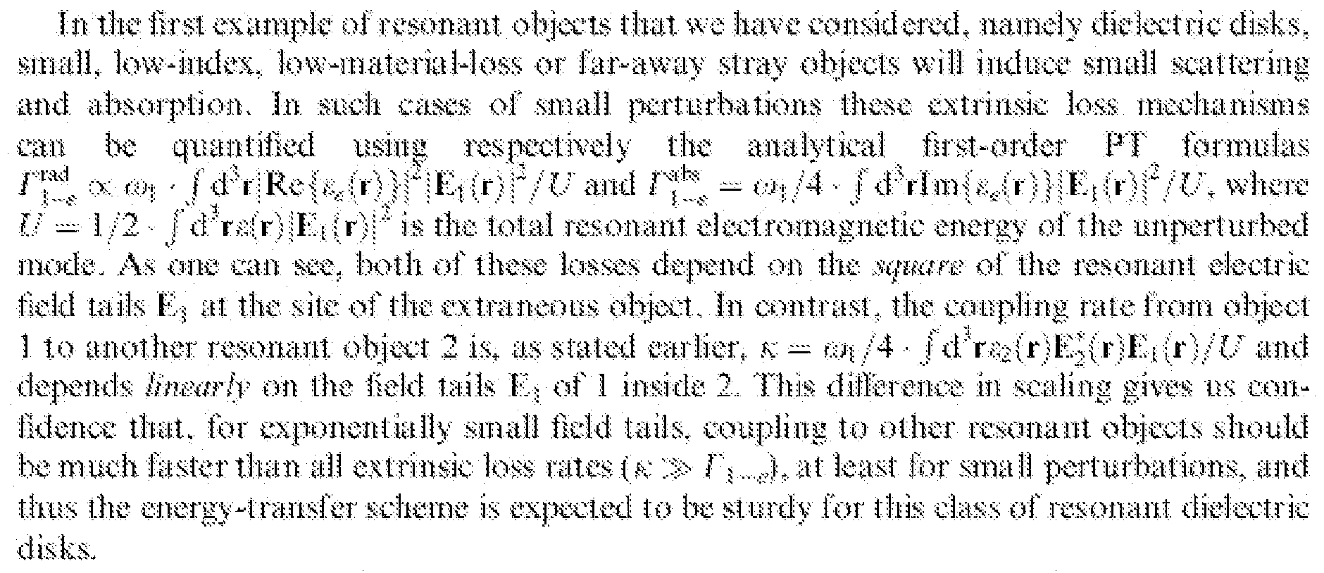
Qearfy,. the success of the prop s d resonance-basal wireless energy-transier sc eme depends strongly on the robustness of the objects* resonances. Therefore, their sensitivity to the near presence of random non-resonant extra eous objects is another aspect of the proposed scheme thai, requi es analysis. The appropriate analytical model, now is that of perturbation, theory (FT) [8], which suggests that in th j¾sence of art extraneous object <? the field amplitude # inside the resonant object 1 satisfies, to first order:
where again is the frequency nd Γ the trkiste (absor tion. radiation, etc. l ss ate, while K j ;... is the frequency shift induced onto 1 due to the presence of «> and Γ¾ ...4, is the extrinsic dec to « (absorption inside et scattering from ^ etc.) loss r e*. The frequency shift i a problem that can be " ked"' rather easily by applying to evsry device a fee back mechanism that corrects its frequency (e.g. through small chaaps in geometry) and matches it to that of the source. Ho ever, the extrinsic loss can be detrimental to the functionality of the energy-transfer scheme,, because it cannot be remedied, so the total loss rate f¾ = -F /" ^ and the corresponding figure -obnaerk κ^ -'Γί^ ^, where the perturbed coupling rate, must be quantified,
J., 1. Dieiectrk disks
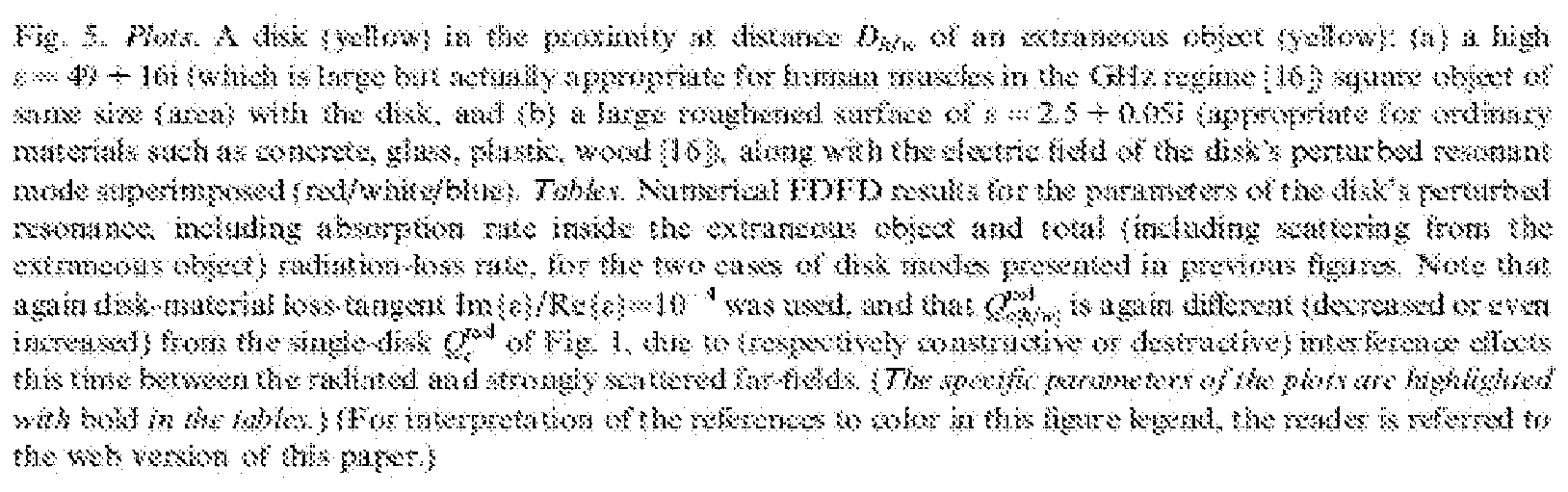
However, we also want to examine certain possible situations where extraneous objects cause perturbations too strong to anal ze using the above first-order FT approach. For xample, we place a dielectric disk c close to another off- res n nce object of large Re 1 , imfe} and of same si but different shape (such as a human being ku as shown in Fig, 5a, and a roughened surface of large extent but of small Re|«|, I'mfsl (such as a wall nj, as shown In Fig. 5b. For distances .D -Jr∞ .10--3 between the disk-center and the "humane-center/* waif*, the numerical FDFD simulation results presented in Fig. 5 suggest that C¾ £¾ ·· IQ O ί instead of the initial ξ 2000), CK - 10 > 000 (naturally unchanged). ~ l£f' -. 30\ and (J^w ~ lO' -IO4. namely the disk resonance seems to be fairly robust, since it is not detrimentally disturbed by the presence of extraneous objects, with the exception of the wy close proximity of high-loss objects [lb
To examine th influence of large perturbations on an entire energ -tr nsfer system we consider two res nant disks in the close presence of both a '%n an** and a f * all' \ The numerical FDFD simulations show that the system performance deteriorates from. <e/ f . 1 5 (Fig,. .2} to K$ *?)f "-■·■ 0,5- Id (Fig, 6f i,e, only by acceptably small amounts.
A 3
In the SSCSOIKI exampl of issorta ni objects that we have eonsictered, the wtKiiictbg- ife ops, the ij'LJ enee of extraneous objects «>« the teso« ances is nearly absent. The reason is that, in t he quasi - tat ic regime of operation (r « A) that we are considerin , the near field m the air rsgkm su.rroisndiiig the loo is redominantly magnetic (since the eieetric ikitt k locfilimt inside the capacitor t, t herefore estrarieoiss non-raetaliic objects ø that iM interact with this iseld and act as a perttif atisxi to the resonance are those having significant niagttctic properties (Hi agnei ic pti nieability &&{μ} > 1 or naagnetk tern ίϊα {μ\ > 0). Since atmiss!: all every-da nmtet'ials arc neti-inagne ie, limy resipotid to triagnetk fields in the san e a as tree space, and thus wilt not disturb the resonance of a eottdisetirtg-wi e loop- To get only a rough estimate of this disturbance, we use the .FT formula, -stated -earlier.
two disks wft¾ 0:■?· !■ I".· ··,.. ; and i!wsli" ¾
Re(sp 4?,7, SK ?! 331)0 12774 426
A / r * 20 5 5?!i ern l.i¾K» itm 323 3,3 iS 5 « 10.00 7 I32 S sum 3542 2W7 <m 2.
I 1:8447 mm % 225Λ r 1.3
R*{s}-»65.6, ίίι-3 3 6764 SM 14? y.4
Af * IQ ■5 721:3? wim m.$ 1.114 2.3 S 101.00 7 1 26 ί 5194 83*57 O.fi
An extremely imp r an implication f this f ct relates to safety considerations for hum n beings. Humans are also non-magnetic andean sustain strong magnetic fields without undergoing any risk. A t ic l example, where magnetic fields B 1 T are safely used on h ans, is the magnetic resonance imaging (MRl} t chnique for medical testing. In contrast, the agnetic near-held required by our scheme in order to provide a fe Watts of power t devices is only B MY
"4 T which is actually comparable to the magnitude of the Earth's magnetic field.. Since, as explained above, a strong electric near-field is also not present and the radiation roduced fr m this non-radiative scheme is minimal, it is mason- able to expect that our proposed e ergy-transfer method should be sale for living organisms.
in eomparison of the tw classes of resonant systems under examination, the strong immunity to extraneous objects and the absence of risks for humans probably makes the conducting- wire loops the preferred choice for many real-world applications: on the other hand, systems of disks (or spheres) of high (effective) refractive index have the advantage that they are als applicable to much smaller length-scales (for example in the optkal regime dielectrics prevail, since conductive materials are highly lossy).
4. Elfckney of energy-tr&itsier scheme
Consider again the combined system of a resonant source and device d m the presence of a set of extraneous objects i?, and let us no w study the efficiency of this res na ce- based energy-transfer scheme, when energy k being drained from the device at rate wilT.fe for use into operational work. The coupled-mode- heory equation for the device field-amplitude is
— -→(i0 --·■ ir^i kiy - if»% r( irk¾; (3)
disks and conducting loops wit values for their parameters within the ranges determined earlier.
T get a numerical estimate for a system performance, take, for example, coupling distance />/r 5, a "h roan" extraneous object at distance j¾/r«a» 10, and that Pwrfe™ 10 W must be delivered to the load. Tlren, for dielectric disks we have (based on Fig. 5} (gPj (';pj .-, H)\ Of' - g < ··., ]ff . g';. ~ g^ ,, 5 x )if ll]lt\ (based on Figs, 2." and €l f iri:,,.: · 3, so from Fig..7 we find efficiency ilwwk ::~ 5.2% and that F^. ¾ 8.3 W will
be radiated to free space
* P
x « 0, 5 W will be dissipated inside the source. P ¾
■ - 3 W inside the device
* and P
k .¾ 0.2 W nside the huma . On the other hand
* for conducting loops we hav (based on Figs. 5 and 4) ¾ - g¾ ·■ 10
4 > g * ==. g * ~ g¾ ... ^
h " ;x and ί· !;η
!Λ ; ····· 4. so we ind ™ 61%,
'/·'„
., -- 0 W, P, s J W, ¾ s I.2 W, and most importantly /¾ ·
■■■> 0.
5, Cwteiusiott
in concl sion,, we present a scheme based on <t ongly-eo ledf ! resonances f r raid- ran e wireless on-mdiative energy transfer. Although our consideration has be n for a static me try ( namely κ and were independent of time), all the results can. be applied directly lor the dy namic geometries of mobile objects* since the energy- transfer time κ'"1 (■-■-■1 - TOO us lor microwave applications) is much shorter than any timeseale associated with motions of macroscopic objects. Analyses of very simple implementation geometries provide encouraging performance characteristics and further improvement is expected with serious design optimisation. Thus the proposed mechanism is promising for many modern applications* For example, in the macroscopic world, this scheme eoisid potentially be sed to deliver power to robots and/or computers in a factory room* or electric buses on a highway (source-cavity would, in this ease be a "pipe** running above the highway). In the microscopic world, where much smaller wavelengths would be used, and smaller powers are needed, one could use it to implement optical inter-connects for CMOS electronics, or to transfer energy to autonomous nano-objects ie.g. MEMS or nano- robots} without worrying much about the relative alignment between the sources and the devices,.
As a venue of future scientific research, enhanced performance should be pursued for electromagnetic systems either by exploring different materials* such, as plasnionic or met- allodielectric structures of large effective refractive index, or by ftne tmring the system design, tor example by exploiting the earlier mentioned interference effects between (he radiation fields of the coupled objects, Furthermore* the range of applicability could be extended to acoustic systems, where the source and. device are connected via a common condensed-matter object.
SUMMARY
[0007] The present invention provides a system and method for utilizing wireless near field magnetic resonance (NFMR) power transmission in a computing environment. In particular, methods, systems, and apparatus that describe a peripheral device arranged to wirelessly receive power from an NFMR power transmitter in useable amounts while positioned in about any spatial orientation with respect to the NFMF transmitter.
[0008] In one embodiment, a wireless power unit arranged to provide at least a minimum amount of power to a device wirelessly received from a magnetic field provided by a near field magnetic resonance (NFMR) transmitter unit having a resonance frequency COT, the minimum amount of power delivered to the device being independent of a spatial orientation of the portable power unit with respect to the magnetic field. The wireless power unit includes at least a first resonator structure, the first resonator structure having a resonant frequency coi, and a characteristic size Li, a second resonator structure, the second resonator structure having a resonant frequency co2, and a characteristic size L2 wherein the first and second resonator structures are magnetically decoupled such that an effective magnetic coupling coefficient Keff between the first and second resonator structures is about zero, and a power combining circuit coupled to the magnetically decoupled first and second resonator structures arranged to: load match the first and second resonator structures and the device, load balance power from the first and second resonator structures, and maintain an effective magnetic coupling coefficient between the first and second resonator structures at about zero regardless of a spatial orientation of the wireless power unit with regards to the NFMR magnetic field such that the device wirelessly receives the at least the minimum amount of power from the wireless power unit regardless of an orientation of the at least two NFMR power receivers with respect to the NFMR magnetic field.
[0009] In another embodiment, a peripheral device arranged to wirelessly receive power from a NFMR power transmitter is described. The peripheral device includes at least a power receiving unit having a least two magnetically de-coupled NFMR power receivers. In other words, a coupling coefficient between the at least two magnetically de-coupled NFMR power receivers is about zero regardless of the spatial orientation of the power receiving unit with regards to a magnetic field generated by the NFMR power transmitter. In this way, power is received from the NFMR power transmitter at the peripheral device in usable amounts regardless of the relative orientation of the magnetic field generated by the NFMR power transmitter and the peripheral device.
[0010] In one embodiment the peripheral device is a user input device such as a computer mouse and the NFMR power transmitter is incorporated into a computing system in communication with the computer mouse. Furthermore, the magnetically
de-coupled NFMR power receivers in the power receiving unit have a shape and size consistent with a conventional battery unit each having longitudinal axes that in some cases overlap each other at about ninety degrees while in other cases are orthogonal to each other but do not overlap.
[0011] In another embodiment, a small form factor wireless power unit arranged to provide useable power. The small form factor wireless power unit includes at least a resonance power coil arranged to receive power from a near field magnetic resonance (NFMR) transmitter coupled to a power supply by way of a power transfer channel when the resonance power coil is configured to operate at a resonance frequency of the NFMR transmitter, wherein the small form factor wireless power unit is sized to fit within a battery compartment of a peripheral device.
[0012] In one aspect of the described embodiment, the peripheral unit includes at least three NFMR power receiver units around perpendicular to each other. In this way, the peripheral device can be moved in any three dimensional spatial volume without a substantial loss in power wirelessly received from an NFMR power transmitter.
[0013] Other apparatuses, methods, features and advantages of the described embodiments will be or will become apparent to one with skill in the art upon examination of the following figures and detailed description. It is target that all such additional apparatuses, methods, features and advantages be included within this description be within the scope of and protected by the accompanying claims.
BRIEF DESCRIPTION OF THE DRAWINGS
[0014] The included drawings are for illustrative purposes and serve only to provide examples of possible structures and arrangements for the disclosed embodiments. These drawings in no way limit any changes in form and detail that may be made to the described embodiments by one skilled in the art without departing from the spirit and scope of the embodiments.
[0015] FIGS. 1A - 1C illustrate a relationship between magnetic flux and spatial orientation of a closed loop.
[0016] FIG. 2 graphically illustrates a relationship between induced voltage, or EMF, and spatial orientation angle Θ.
[0017] FIGS. 3 A - 3B shows power supply unit having an output voltage that is dependent on spatial orientation.
[0018] FIGS. 4A-4B and 5A-5F show an orientation independent power supply unit with various arrangements of resonance receivers in accordance with the described embodiments.
[0019] FIGS. 6 A - 6C show various embodiments of a functional block diagram of a combining circuit suitable for combining power between multiple resonant receivers in accordance with a described embodiment.
[0020] FIG. 7 shows a particular implementation of the power sharing circuit shown in FIG. 6 A.
[0021] FIG. 8 shows multiple frequency resonance power unit having multiple independent resonance receivers in accordance with a described embodiment
[0022] FIG. 9 shows a flowchart detailing a method performed by a combiner unit of FIG. 8 in accordance with the described embodiments.
[0023] FIGS. 10 and 11 shows representative peripheral devices having small form factor wireless power unit for providing power received from a magnetic field.
[0024] FIG. 12 shows a distributed system in accordance with the described embodiments.
[0025] FIG. 13 shows a computing system in accordance with the described embodiments.
DETAILED DESCRIPTION
[0026] Various embodiments of a wirelessly powered local computing environment are described. The wireless powered local computing environment includes at least a near field magnetic resonance (NFMR) power supply arranged to wirelessly provide power to any of a number of suitably configured devices. In the described embodiments, the devices arranged to receive power wirelessly from the NFMR power supply can be located in a region known as the near field that extends about a distance D that can be a few times a characteristic size of the NFMR power supply transmission device. Typically, the distance D can be on the order of 1 meter or so.
[0027] In the context of this discussion, it is well known that useable power can be wirelessly transmitted by way of a wireless transmitter and receiver transiently coupled by way of a magnetic field. More specifically, a system in accordance with the described embodiments can include a wireless power receiver incorporated within or electrically coupled to a peripheral device that can wirelessly receive useful
amounts of power from an external power supply. In the described system, the wireless power receiver can include a first resonator structure having a first resonant frequency coi, a first Q factor Qi (a measure of power transfer efficiency), and a first characteristic size Li. For example, in the context of a computing system where the peripheral device takes the form of a computer mouse or other input device, the characteristic size Li can be on the order of a few inches or centimeters. The system can also include a power supply coupled to at least a second resonator structure positioned a variable distance d from the first resonator structure having a second resonant frequency co2 and a second Q factor Q2 and second characteristic size L^. For example, the second resonator structure can be incorporated within a computer such as a desktop or laptop computer. In this way, a charging region can be formed around the computer in which the peripheral device (or any other appropriately configured device) can wirelessly receive useful amounts of power from the power supply via the second resonator structure.
[0028] When first and second resonant frequencies coi and ω2 are close together, a coupling region between the first and second resonator structures can be formed. Within this coupling region, useful power can be transferred by way of a non- radiative energy transfer mechanism that utilizes resonant-field evanescent tails of the magnetic field provided by the second resonator structure. For example, when the first resonator structure is incorporated into a peripheral device such as a computer mouse, the computer mouse can be at least partially supplied with power from the second resonator structure coupled to the power supply. In this way, the peripheral device can operate in a wireless mode without the need for a separate power supply other than that provided in the computing device. The amount and duration of power that can be delivered to the peripheral device can be strongly dependent on a number of factors. For example, the coupling between the first resonator structure and the second resonator structure can be dependent upon a spatial orientation of the second resonator structure and a magnetic field generated by the first resonant magnetic structure as well as by variable distance d.
[0029] In order to avoid or at least reduce the spatial orientation dependence, the peripheral device in the described embodiments can include a power receiving unit that incorporates a plurality of individual resonators having different spatial orientations with respect to each other. In this way, power wirelessly received at the
power receiving unit can be essentially independent from any movement of the peripheral device with respect to the magnetic field generated by the second resonator structure (hereinafter referred to as the NFMR magnetic field). However, each of the individual resonators can themselves create a magnetic field in response to the NFMR magnetic field that, in turn, can couple with others of the individual resonators. The coupling between the individual resonators in the power receiving unit can be characterized by coupling coefficient κ that can range from zero (0) in those cases where there is little or no magnetic coupling to about one (1) when there is strong magnetic coupling. In those arrangements where the individual resonators are strongly coupled, each resonator can have a substantial effect on other resonators thereby affecting the performance of the power receiving unit as a whole. Therefore it would be advantageous for those power receiving units having more than one individual resonator that coupling coefficient κ between the more than one resonators be as close to zero as practicable. This is particularly true for peripheral devices that can be moved about within the charging region where the relative orientation between the resonator structures and the NFMR magnetic field used to transfer energy from the power supply can vary greatly.
[0030] Accordingly, in one embodiment a wirelessly powered local computing environment is described. The wirelessly powered local computing environment can include a NFMR wireless power supply arranged to use a resonance channel to transfer useable energy to resonance circuits within near field distance D. (that defines an outermost wireless range of a magnetic field transmitted by an NFMR power supply transmitter) and a central processing unit that provides processing resources to the NFMR power supply. Also included in the local computing environment is a peripheral device that can freely move about within the local computing environment arranged to wirelessly receive power from the NFMR power transmitter. The peripheral device can include at least a power receiving unit having a least two magnetically de-coupled NFMR power receivers in the form of individual resonators that are electrically coupled to each other to provide output voltage Vout. Since magnetic coupling coefficient κ between the receiver resonators is about zero, output voltage Vout is substantially independent of the spatial orientation of the peripheral device with respect to the NFMR magnetic field. In this way, the
peripheral device can wirelessly receive a usable amount of power from the NFMR power supply regardless of its orientation.
[0031] These and other embodiments are discussed below with reference to
Figs. 1-9. However, those skilled in the art will readily appreciate that the detailed description given herein with respect to these figures is for explanatory purposes only and should not be construed as limiting.
[0032] The magnetic coupling between individual resonators in the power receiving unit can be described using Faraday's Law of Induction or more simply Faraday' s Law that defines electromotive force (EMF) or voltage as the amount of work done moving unit charge q around the closed curve as shown in FIG. 1A as system 100. According to Faraday's Law, the EMF produced around closed loop path 102 is proportional to time rate of change (dO/dt) of magnetic flux Φ bounded by closed loop path 102 and associated with surface A with normal vector A. In this way, electric current can be induced in any closed circuit when the magnetic flux ΦΒ through surface A changes. The relationship between electromotive force (or voltage) and the change in magnetic flux can satisfy the differential form of Faraday' s Law in the form of Eq. (1):
Eq. (1) where S is ^ ~ ^ electromotive force, or voltage, developed by a change in magnetic flux ΦΒ enclosed within area A of a single one of N conductive closed loops each having the same cross sectional area.
[0033] Magnetic flux ΦΒ is a scalar that is related to magnetic field vector B and normal vector A corresponding to surface A defined by closed loop path 102 according to Eq. (2):
Eq. (2) ΦΒ = B-A
where:
B is magnetic field vector,
A is normal vector of surface A enclosed by closed loop 102; and
B-A is the dot product vectors B and A, or in scalar form, ABcos(9).
[0034] Therefore, magnetic flux ΦΒ varies as the cosine of orientation angle Θ where orientation angle Θ represents the spatial orientation of magnetic field vector B and normal vector A shown in Figs. IB and 1C. According to Eq. (2) and shown in
FIG. IB, when magnetic field vector B and normal vector A align with each other (i.e., angle Θ is zero and therefore cos(9) is 1), magnetic flux ΦΒ is a maximum value and therefore any change magnetic flux ΦΒ can result in a maximum EMF (S ) or voltage induced in closed loop 102. It is this induced voltage that can be used to characterize coupling coefficient κ between any two individual conductive loops. It should be noted that, as orientation angle Θ varies from 0 and approaches ninety degrees (or π/2 radians), magnetic flux <¾ goes from maximum magnetic flux Osmax to zero as illustrated in FIG. 1C. Therefore, using Eq. (1) and Eq. (2), as shown in FIG. 2 , the induced voltage, or EMF, is also related to the orientation angle Θ in much the same way as magnetic flux <¾. In this way, the magnetic coupling coefficient κ between resonators will determine to a substantial degree the overall performance of a wireless power unit with respect to spatial orientation.
[0035] FIG. 3A shows wireless power unit 300 having first resonator 302 and second resonator 304 having a magnetic coupling coefficient κ with a value of about 1.0 (indicating a strong coupling configuration) and a spatial orientation angle Θ with respect to NFMR magnetic field BNFMR- In this configuration, the effect of magnetic coupling between the two resonators is strong enough that a voltage generated at one resonator can effectively cancel out a voltage generated at the other resonator. In this example, and for sake of simplicity, resonators 302 and 304 can each be cylindrical in shape having characteristic length L with N loops of conductive wire 306 that terminates at one end at a common potential (system GND) and another end at terminal nodes 308 and 310 providing voltages VI and V2, respectively. Wireless power unit 300 can provide output voltage Vout as a difference of voltages VI and V2. In this arrangement, output voltage Vout is dependent upon the spatial orientation of wireless power unit 300 with respect to NFMR magnetic field BNFMR as well as the intrinsic coupling between first resonator 302 and second resonator 304 (characterized by magnetic coupling coefficient κ ~ 1.0). More specifically, any magnetic field generated by first resonator 302 that magnetically couples with second resonator 304 results in a voltage induced in second resonator 304 that is about equal in magnitude and opposite in polarity to that induced in first resonator 302.
[0036] More specifically, first resonator 302 can resonate with magnetic field
BNFMR to create magnetic field Bi. Since magnetic coupling coefficient κ ~ 1.0 any
magnetic field generated by first resonator 302 will magnetically couple with second resonator 304 (and vice versa). For example, as shown in FIG. 3B, magnetic field Bi will interact with second resonator 304 to induce voltage V2 at node 310 that is 180° out of phase with and equal in magnitude with voltage VI at node 308 (in other words, VI = -V2) which as shown in FIG. 3B results in a null value for output voltage Vout which is clearly unacceptable.
[0037] Therefore, by changing the orientation and position of first resonator
302 and second resonator 304 with respect to each other, the magnetic coupling between the resonators can be substantially reduced. In other words, properly orienting and positioning first resonator 302 and second resonator 304 can result in effectively magnetically de-coupling of first resonator 302 and second resonator 304 in which case an effective magnetic coupling coefficient Keff can approach zero. For example, FIG. 4A shows wireless power supply 400 in accordance the described embodiments characterized as having an effective magnetic coupling coefficient KEFF ~ 0 by which it is meant that the net effect of any magnetic coupling between first resonator 302 and second resonator 304 effectively cancel each other out thereby simulating a situation of no magnetic coupling. More specifically, when first resonator 302 resonates with magnetic field BNFMR, induced magnetic field Bi will be generated by first resonator 302. However, unlike the situation where first resonator 302 and second resonator 304 are strongly coupled, magnetic field lines from magnetic field Bi intersect second resonator 304 at about 90°. In this way and in accordance with Eq. (2), the magnetic flux Φ and therefore any EMF generated in second resonator 304 is about zero.
[0038] FIG. 4B shows another situation where second resonator 304 resonates with magnetic field BNFMR creating induced magnetic field B2. In this situation, induced magnetic field B2 interacts with first portion 302-1 of resonator 302 to induce voltage VA . Concurrently, induced magnetic field B2 interacts with second portion 302-2 of resonator 302 to induce voltage VB that in accordance with Lenz's Law (also known as the right hand rule) is equal in magnitude but opposite in polarity to VA- In this way, any voltages VA and VB induced in first resonator 302 effectively cancel each other out resulting in no net induced voltage in first resonator 302 simulating an effective magnetic coupling coefficient Keff of about zero for all orientation angles Θ.
[0039] FIG. 5A shows another embodiment of orientation independent wireless power supply 400 in the form of wireless power supply 500 in which first resonator 302 and second resonator 304 are placed perpendicular in a cross like arrangement. In this arrangement, the midpoints of both first resonator 302 and second resonator 304 are coincident with each other and displaced in the Z direction distance "r". In this way, magnetic field lines of a magnetic field generated by first resonator 302 intersect second resonator 304 at ninety degrees resulting in magnetic Φ304 for second resonator 304 being about zero. As with the situation described above with respect to FIG. 4A, the net EMF generated is zero resulting in an effective magnetic coupling coefficient Keff ~ 0. FIG. 5B shows an equivalent situation for second resonator 304 with respect to first resonator 302. In this way, the symmetric nature of the magnetic field B2 generated by second resonator with respect to first resonator 302 results in an effective coupling coefficient coupling Keff ~ 0. FIG. 5C shows additional arrangements of first resonator 302 and second resonator 304 that are divided in substantially equal portions 302a, 302b and 304a, 304b respectively that maintains an effective magnetic coupling coefficient Keff ~ 0. FIG. 5D shows additional arrangements of first resonator 302 and second resonator 304 where either one or the other of resonator 302 or 304 are divided in substantially equal portions. For example, as shown second resonator 304 can be divided into substantially equal portions 304a, 304b respectively and arranged in such a way with respect to first resonator 302 that maintains an effective magnetic coupling coefficient Keff ~ 0. FIG. 5E and FIG. 5F show representative peripheral devices in the form of computer mouse 500 having various configurations of first resonator 302 and second resonator 304 in accordance with the described embodiments.
[0040] However, for magnetic resonance power units having more than one resonant receiver, assuring that the magnetic coupling coefficient Keff ~ 0 for the receivers is only the first step to be able to combine their power additively. In particular, the resonating circuit attached to each receiver is required to be isolated from the resonating circuit of another receiver as well as provide load sharing duties for a load device. FIG. 6A is a functional block diagram of a particular embodiment of combining circuit 600 that can be used to transfer power from a plurality of resonant receivers in accordance with the described embodiments. More specifically, each receiver 302 and 304 can be coupled independently to corresponding branches of
combining circuit 600. For example, receiver 302 can be coupled to first branch 600- 1 that can include at least impedance matching network 602 arranged to match impedances between device 604 and receiver 302. Rectification circuit 606 can be used to convert varying signals (such as AC signal 608) from receiver 302 to DC signal 610 that can then be provided as input to OR circuit 612. Likewise, receiver 304 can be electrically coupled to branch 600-2 that can include impedance matching network 616, rectification circuit 618 that outputs DC signal 620 that can in turn be provided as input to OR circuit 612. In the described embodiment, OR circuit 612 can act as a load balance in order that power P is provided to device 604 in a relatively continuous manner. In other words, if receiver 302 is receiving more power from magnetic field B FRM than is receiver 304, then OR circuit 612 will allow receiver 302 to provide more power to device 604 than receiver 304, and vice versa.
[0041] FIG. 6B shows a specific implementation of OR circuit 612 formed of diodes 622 and 624. FIG. 6C on the other hand shows yet another implementation of OR circuit 612 that includes energy storage elements 626 and 628 arranged to temporarily store energy received from branches 600-1 and 600-2 in the form of rectified DC voltage 608 and 620, respectively. In one embodiment, energy storage elements 626 and 628 can take the form of capacitors 626 and 628. Load balancing switches 630 and 632 can be used to assure proper load balancing between resonators 302 and 304 providing consistent power to device 604.
[0042] FIG. 7 shows a model 700 of resonant receivers 302 and 304 power sharing circuit 600. More specifically, each of receivers 302 and 304 can be modeled as inductor L702 and series resister R704. Impedance matching network can be modeled as capacitances CI and C2 arranged to match receiver load RR with device load RL. Full bridge rectifier 706 can be used to convert AC signals from transmitters 302 and 304 to DC signals for use by device 606.
[0043] FIG. 8 shows multiple frequency resonance power unit 800 having multiple independent resonance receivers 802-1, 802-2...802-n in accordance with a described embodiment. In the described embodiment, independent resonance receivers 802-1, 802-2...802-n can each be configured to operate most effectively at different frequency bands. This arrangement can be useful in those situations where, for example, different countries may restrict the use of certain frequency bands due to local regulations leaving a limited number of frequency bands for use to wirelessly
provide power. Accordingly, multiple receiver power unit 800 can be configured to include multiple receiving resonators each configured to receive power from a NFMR magnetic field most effectively at a specific frequency band. For example, resonance receiver 802-1 can be configured to receive power most effectively from a NFMR magnetic field in which it is immersed at frequency coi. On the other hand, resonance receiver 802-2 can be configured to receive power most effectively from the NFMR magnetic field in which it is immersed at frequency co2. In any case, power combiner unit 804 can be used to combine power of the receivers in those situations where useable power is being received at frequency coi and frequency ω2.
[0044] However, in situations where power is received from the NFMR magnetic field at either frequency coi or frequency ω2, combiner unit 804 can be used to select whichever resonance receiver (either resonance receiver 802-1 or resonance receiver 802-2) is operating or at least receiving an amount of power greater than a threshold value. In this situation, combiner unit 804 can sense an amount of power being received at resonance receivers 802-1 and 802-2 and based upon the
comparison, combiner unit 804 can select the appropriate resonance power receiver to provide power to a circuit. In one embodiment, the resonance receiver deemed to be most effective in its interaction with the NFMR magnetic field (based upon an amount of real power received, for example) can be selected. The effectiveness of the interaction with the NFMR magnetic field can be based upon an amount of induced magnetic flux in one or the other resonance receivers. It should be noted that the sensing and selecting can be ongoing and performed in real time. In this way, the multiple resonance receivers can be placed in close physical proximity to each other resulting in an effective magnetic coupling coefficient Keff > 0.
[0045] FIG. 9 shows a flow chart detailing process 900 carried out by combiner unit 804 in accordance with an embodiment of the invention. Process 900 can begin at 902 by the combiner unit sensing power received from at least two resonant power receivers each of which is arranged to receive power from an NFMR magnetic field at specified resonant frequencies that are different from each other. At 904, the combiner unit identifies which of the sensed resonant power receivers is providing the most power. At 906, the combiner unit provides power from the identified resonant power receivers.
[0046] FIG. 10 shows a representative peripheral device in the form of computer keyboard 1000 in accordance with the described embodiments. Computer mouse 1000 can include at least first small form factor wireless power unit 1002 and second small form wireless power unit 1004 each of which can wirelessly receive power from magnetic field B . In the described embodiment, magnetic field B can be provided by magnetic transmitter unit 1006 incorporated into, for example, computing device 1008, such as a desktop computer. During most foreseeable operational scenarios, keyboard 1000 will be positioned with respect to desktop computer 1008 in front facing arrangement. In this way, there is no need to magnetically de-couple small form factor wireless power unit 1002 and 1004 and as such both can provide power at the same time that can be used to operate keyboard 1000. Since small form factor wireless power units 1002 and 1004 can be sized along the lines of a standard AAA battery, small form factor wireless power units 1002 and 1004 (or just one if need be) can be accommodated into battery compartment 1010 of keyboard 1000 as shown in FIG. 11. In this way, small form factor wireless power supply 1002 and 1004 can be used to systematically replace conventional batteries along the lines of standard AAA batteries. It should be noted however, that since small form factor wireless power units 1002 and 1004 can be of any size and shape, it is contemplated that any battery of any size or configuration can be replaced by small form factor power units 1002 and 1004.
[0047] Fig. 12 shows representative virtual charging area 1100 in accordance with the described embodiments. Virtual charging area 1100 provides region R of charging for suitably configured devices placed within the region R. NFMR power supply can be placed in central unit such as desktop computer. In this way, the desktop computer can provide the NFMR power supply with computing resources. It should be noted that the near field magnetic resonance (NFMR) power supply can include high Q circuit that relies upon near field magnetic coupling by way of a resonance channel formed between resonances of the power source and sink to transfer power. The NFMR power supply can be a standalone unit such as, for example, included in a desk top computer, laptop computer, tablet computer, and so on. In other embodiments, the NFMR power supply can take the form of a portable type unit such as a dongle that can be connected to a legacy device such as a desktop computer thereby providing the ability to retrofit devices. In still other embodiments,
housing or a portion of a housing used to enclose the NFMR power source can act to extend a useful range of the NFMR power supply.
[0048] As shown in Fig. 12 virtual charging area 1100 includes central unit
1102 (desktop computer) that can include the NFMR power supply, keyboard 1104, mouse 1106, and portable media player 1108. In one embodiment, keyboard 1104 can be configured to receive power directly from the NFMR power supply included in desktop computer 1102 as can mouse 1106 and portable media player 1108 (when located within range R).
[0049] In some cases, the ability of desktop computer 1102 to provide power directly to mouse 1108, for example, can be reduced due to any number of factors.
Such factors can include, for example, the addition of other devices into region R that require power from the NFMR power supply, obstacles interfering with the direct power channel formed between the NFMR and mouse 1106, and so on. In this case, keyboard 1104 can act as a re-resonator such that a portion of the power delivered to keyboard 1104 from the NFMR power supply can be passed on by way of a re- resonator transmission unit (not shown) in keyboard 1104. In this way, any power loss experienced by mouse 1106 can be ameliorated by the power received from keyboard 1104. This arrangement can be transitory or can last for as long as mouse 1106 is not able to receive adequate power directly from the NFMR power supply. In other cases, the locating of portable media player 1108 within region R can reduce the amount of power available to keyboard 1104 and mouse 1106. In this case, if a battery in keyboard 1106 is fully charged (or additional charge is not necessary) then keyboard 1106 can decouple a charging circuit while still maintaining a re-resonator circuit providing power to mouse 1106.
[0050] In some embodiments, dongle 1110 can be connected to desktop computer 1102 (by way of a USB port or cable, for example). So connected, dongle 1110 can, in turn, act as a range extender for the NFMR power supply. In this way, dongle 1110 can extend a range that power can be provided by the NFMR power supply included in desktop computer 1102. In some cases, dongle 1110 can re- resonate power already received from the NFMR power supply while in other cases, dongle 1110 can include its own NFMR power supply. By having its own NFMR power supply, dongle 1110 can provide additional power wirelessly to those devices within virtual charging region 1100 separate from the power provided by the NFMR
power supply included in desktop 1102. It should be noted that in some
embodiments, the housing of desktop computer 1102 (or a portion thereof ) can be used as a resonator as part of the NFMR power supply.
[0051] FIG. 13 is a block diagram of computing system 1200 in accordance with the described embodiments. Computing system 1200 includes processor 1202 that pertains to a microprocessor or controller for controlling the overall operation of computing system 1200. Computing system 1200 stores data pertaining to media items, for example, in a file system 1204 and a cache 1206. The file system 1204 is, typically, a storage disk or a plurality of disks. The file system typically provides high capacity storage capability for computing system 1200. However, since the access time to the file system 1204 is relatively slow, computing system 1200 also includes a cache 1206. The cache 1206 is, for example, Random- Access Memory (RAM) provided by semiconductor memory. The relative access time to the cache 1206 is substantially shorter than for the file system 1204. However, the cache 1206 does not have the large storage capacity of the file system 1204. Further, the file system 1204, when active, consumes more power than does the cache 1206. The power consumption is particularly important when the computing system 1200 is a portable media player that is powered by a battery (not shown).
[0052] Computing system 1200 also includes a user input device 1208 that allows a user of computing system 1200 to interact with computing system 1200. For example, the user input device 1208 can take a variety of forms, such as a button, keypad, dial, etc. Still further, the computing system 1200 includes data bus 1210 can facilitate data transfer between at least the file system 1204, the cache 1206, the processor 1202, and the CODEC 1212.
[0053] In one embodiment, computing system 1200 serves to store a plurality of media items (e.g., songs) in the file system 1204. When a user desires to have the media player play a particular media item, a list of available media items is displayed on the display 1210. Then, using the user input device 1208, a user can select one of the available media items. The processor 1202, upon receiving a selection of a particular media item, supplies the media data (e.g., audio file) for the particular media item to a coder/decoder (CODEC) 1212. The CODEC 1212 then produces audio output signals for audio jack 1214 to output to an external circuit. For example, headphones or earphones that connect to computing system 1200 would be considered
an example of the external circuit. In another embodiment, a computer-readable medium is provided that includes computer program instructions.
[0054] The various aspects, embodiments, implementations or features of the described embodiments can be used separately or in any combination. Various aspects of the described embodiments can be implemented by software, hardware or a combination of hardware and software. The described embodiments can also be embodied as computer readable code on a computer readable medium for controlling manufacturing operations or as computer readable code on a computer readable medium for controlling a manufacturing line. The computer readable medium is any data storage device that can store data which can thereafter be read by a computer system. Examples of the computer readable medium include read-only memory, random-access memory, CD-ROMs, DVDs, magnetic tape, and optical data storage devices. The computer readable medium can also be distributed over network- coupled computer systems so that the computer readable code is stored and executed in a distributed fashion.
[0055] The foregoing description, for purposes of explanation, used specific nomenclature to provide a thorough understanding of the described embodiments. However, it will be apparent to one skilled in the art that the specific details are not required in order to practice the invention. Thus, the foregoing descriptions of specific embodiments are presented for purposes of illustration and description. They are not intended to be exhaustive or to limit the invention to the precise forms disclosed. It will be apparent to one of ordinary skill in the art that many
modifications and variations are possible in view of the above teachings.