WO2012164838A1 - Optical fiber assembly, optical probe, and method for manufacturing optical fiber assembly - Google Patents
Optical fiber assembly, optical probe, and method for manufacturing optical fiber assembly Download PDFInfo
- Publication number
- WO2012164838A1 WO2012164838A1 PCT/JP2012/003112 JP2012003112W WO2012164838A1 WO 2012164838 A1 WO2012164838 A1 WO 2012164838A1 JP 2012003112 W JP2012003112 W JP 2012003112W WO 2012164838 A1 WO2012164838 A1 WO 2012164838A1
- Authority
- WO
- WIPO (PCT)
- Prior art keywords
- adhesive
- optical
- optical fiber
- optical fibers
- fiber assembly
- Prior art date
Links
Images


Classifications
-
- G—PHYSICS
- G02—OPTICS
- G02B—OPTICAL ELEMENTS, SYSTEMS OR APPARATUS
- G02B6/00—Light guides; Structural details of arrangements comprising light guides and other optical elements, e.g. couplings
- G02B6/44—Mechanical structures for providing tensile strength and external protection for fibres, e.g. optical transmission cables
-
- B—PERFORMING OPERATIONS; TRANSPORTING
- B29—WORKING OF PLASTICS; WORKING OF SUBSTANCES IN A PLASTIC STATE IN GENERAL
- B29D—PRODUCING PARTICULAR ARTICLES FROM PLASTICS OR FROM SUBSTANCES IN A PLASTIC STATE
- B29D11/00—Producing optical elements, e.g. lenses or prisms
- B29D11/00663—Production of light guides
- B29D11/00721—Production of light guides involving preforms for the manufacture of light guides
-
- G—PHYSICS
- G02—OPTICS
- G02B—OPTICAL ELEMENTS, SYSTEMS OR APPARATUS
- G02B6/00—Light guides; Structural details of arrangements comprising light guides and other optical elements, e.g. couplings
- G02B6/04—Light guides; Structural details of arrangements comprising light guides and other optical elements, e.g. couplings formed by bundles of fibres
-
- G—PHYSICS
- G02—OPTICS
- G02B—OPTICAL ELEMENTS, SYSTEMS OR APPARATUS
- G02B6/00—Light guides; Structural details of arrangements comprising light guides and other optical elements, e.g. couplings
- G02B6/24—Coupling light guides
- G02B6/42—Coupling light guides with opto-electronic elements
- G02B6/4201—Packages, e.g. shape, construction, internal or external details
- G02B6/4219—Mechanical fixtures for holding or positioning the elements relative to each other in the couplings; Alignment methods for the elements, e.g. measuring or observing methods especially used therefor
- G02B6/4234—Passive alignment along the optical axis and active alignment perpendicular to the optical axis
-
- G—PHYSICS
- G02—OPTICS
- G02B—OPTICAL ELEMENTS, SYSTEMS OR APPARATUS
- G02B6/00—Light guides; Structural details of arrangements comprising light guides and other optical elements, e.g. couplings
- G02B6/04—Light guides; Structural details of arrangements comprising light guides and other optical elements, e.g. couplings formed by bundles of fibres
- G02B6/06—Light guides; Structural details of arrangements comprising light guides and other optical elements, e.g. couplings formed by bundles of fibres the relative position of the fibres being the same at both ends, e.g. for transporting images
- G02B6/08—Light guides; Structural details of arrangements comprising light guides and other optical elements, e.g. couplings formed by bundles of fibres the relative position of the fibres being the same at both ends, e.g. for transporting images with fibre bundle in form of plate
Definitions
- the present invention relates to an optical fiber assembly in which a plurality of optical fibers are assembled, an optical probe incorporating the optical fiber assembly, and a method for manufacturing the optical fiber assembly.
- an optical analyzer that analyzes an inspection object by irradiating an inspection object such as a lumen of a living body with light such as excitation light and measuring emitted light from the inspection object such as fluorescence generated by the irradiation light.
- an optical probe that transmits light between the apparatus and a test object is used.
- the optical probe is bent along the lumen in the living body, or bent according to the movement of the endoscope by being inserted into a channel formed in the endoscope inserted into the lumen of the living body. Often used as curved. For this reason, predetermined flexibility is required for the plurality of optical fibers built in the optical probe.
- the plurality of optical fibers are arranged in a state in which the respective tip portions are close to each other by an arrangement member, and are fixed by an adhesive.
- the adhesive may be transmitted in the longitudinal direction of the optical fiber due to a capillary phenomenon and then solidify in a long range. . Since the flexibility of the optical fiber is lowered in the range where the adhesive is solidified, there is a possibility that the optical fiber is broken when this portion is bent.
- An object of the present invention is to provide an optical fiber assembly capable of maintaining the flexibility in the vicinity of the array member, a manufacturing method thereof, and an optical probe using the optical fiber assembly.
- An optical fiber assembly includes a plurality of optical fibers, an array member that holds the plurality of optical fibers in an array, and the array member and the plurality of optical fibers by a first adhesive having a curing property.
- the plurality of optical fibers are bonded to each other within a predetermined distance from the rear end of the array member by the first adhesive portion to which the first and second adhesives are fixed and the second adhesive that is harder and harder than the first adhesive.
- the structure provided with the made 2nd adhesion part is taken.
- the method for manufacturing an optical fiber assembly according to the present invention includes a plurality of optical fibers, an array member, a first adhesive having curability, and a first adhesive that is more flexible than the first adhesive.
- a method of manufacturing an optical fiber assembly using an adhesive wherein a fiber array step for arranging the tip portions of the plurality of optical fibers by holding them on the array member, and before or after the fiber array step
- the first adhesive for fixing the optical fiber and the array member is transmitted and solidified over a long section in the longitudinal direction of the optical fiber by the second adhesive portion. Is prevented. Therefore, the flexibility of the vicinity of the array member in the optical fiber assembly can be maintained.
- the first adhesive for fixing the optical fiber and the array member is transmitted over a long section in the longitudinal direction of the optical fiber by the second adhesive portion. It is possible to manufacture an optical fiber assembly in which the solidification is prevented and the flexibility in the vicinity of the arrangement member is maintained.
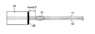
- FIG. 1A and 1B show an optical fiber assembly of an embodiment of the present invention
- FIG. 1A is a side view thereof
- FIG. 1B is an enlarged view of an adhesive portion thereof.
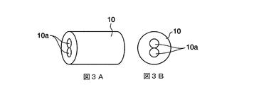
- FIG. 3A is a perspective view
- FIG. 3B is a front view showing an array member.
- FIG. 6A is a partially cutaway side view of the tip portion
- FIG. 6B is a plan view of the whole.
- 7A to 7F are explanatory views showing the flow of the manufacturing process of the optical fiber assembly.
- FIG. 1 shows an optical fiber assembly according to an embodiment of the present invention
- FIG. 1A is a side view thereof
- FIG. 1B is an enlarged view of the fiber bonding portion
- FIG. 2 is a front end portion of the optical fiber assembly.
- 3A and 3B show the array member 10, FIG. 3A is a perspective view thereof, and FIG. 3B is a front view thereof.
- the optical fiber assembly includes two optical fibers 11 and 12 and an array member (array member) in which the tips of the two optical fibers 11 and 12 are arranged close to each other. ) 10. Further, in this optical fiber assembly, an array bonded portion (first bonded portion) 20 to which the optical fibers 11 and 12 and the array member 10 are fixed, and a predetermined distance from the rear end of the array member 10 closest to the array member 10 are provided. The second bonding portion 21 where the optical fibers 11 and 12 are bonded to each other at a position within the distance range, and a plurality of fiber bonding portions (fiber barrel side bonding) where the optical fibers 11 and 12 are bonded to each other at a plurality of locations where the section is opened. Part) 22, 22... Are provided.
- Optical fibers 11 and 12 are core wires in which a bare wire composed of a core and a clad is coated with polyimide as a primary film. These optical fibers 11 and 12 are not provided with a thick fiber coating and have a very small diameter of, for example, 0.05 to 0.5 mm. For this reason, if a plurality of pieces are in bulk, they become tangled or entangled, making it very difficult to handle.
- the array member 10 is a microcapillary member in which two through holes 10a are provided in the center of a cylindrical block.
- the inner diameter of each through-hole 10a is a diameter obtained by adding a very small clearance to the outer diameter of the optical fibers 11 and 12, and the two optical fibers 11 and 12 are passed through.
- the optical axis is held in a state adjusted to a predetermined arrangement.
- the array member 10 can be made of zirconia or quartz glass. Further, it can be made of metal as long as it can be precisely processed and has a predetermined strength.
- the array member 10 may be a V-groove type other than a microcapillary type. Further, the shape and size can be variously changed.
- the two optical fibers 11 and 12 and the array member 10 are fixed to each other by the first adhesive at the rear end surface of the array member 10 and the inner surface of the through hole 10a.
- the hardened first adhesive is the array bonded portion 20 in FIG.
- the front end surface of the array member 10 is polished together with the end surfaces of the optical fibers 11 and 12 after the first adhesive is cured, so that the end surfaces are flush with each other.
- the first adhesive that fixes the optical fibers 11 and 12 to the array member 10 is not particularly limited, but is a thermosetting adhesive such as an epoxy resin adhesive.
- a thermosetting adhesive By using a thermosetting adhesive, there is no inconvenience that the curing characteristics will vary due to an error in the mixing ratio of the liquid compared to the two-liquid mixed adhesive, and curing after applying the adhesive. It is possible to obtain an effect that the time until the control can be arbitrarily controlled. Further, as compared with the ultraviolet curable adhesive, there is an effect that it can be surely cured even at a location where ultraviolet rays are difficult to reach, such as the inner surface of the through hole 10a.
- the first adhesive has a hardness that does not cause a positional deviation of the optical fibers 11 and 12 when the optical fibers 11 and 12 are firmly fixed after being cured and the tip surface of the array member 10 is polished. It has become a thing.
- an adhesive there is a one-component thermosetting epoxy resin adhesive EP171 manufactured by Cemedine. This adhesive has a durometer hardness of 87 (type A durometer hardness) after curing, and since the temperature condition necessary for curing is as low as 80 ° C. or more, good workability is obtained in the curing process. It is like that.
- the second adhesive portion 21 is obtained by adhering the optical fibers 11 and 12 to each other with a second adhesive that is harder and more flexible than the first adhesive.
- the plurality of fiber body side bonding portions 22 are obtained by bonding the optical fibers 11 and 12 to each other with a third adhesive that is harder and harder than the first adhesive.
- the second bonding portion 21 and the fiber body side bonding portions 22, 22 Largely protrude outside the optical fibers 11, 12, the probe cables 80 of the optical probe 100 described later are used. Reduces workability when passing through. Therefore, as shown in the enlarged view of FIG. 1B, the second adhesive portion 21 and the fiber body side adhesive portion 22... Remain in the adjacent valley portions of the optical fibers 11 and 12 so that the adhesive is applied. Good.
- the second adhesive and the third adhesive are both adhesives that are more flexible and hardened than the first adhesive, and may be different types of adhesives or the same. Good.
- FIG. 4 is a side view showing an example in which the adhesive flows into the tip portion of the optical fiber assembly.
- the second bonding portion 21 is used to block the adhesive of the array bonding portion 20 from flowing into the gap between the optical fibers 11 and 12 due to capillary action and being transmitted over a long section at the tip of the optical fiber assembly. It is. As shown in FIG. 2, the end portion of the second adhesive portion 21 on the array member 10 side is provided so as to be in a range of 7 mm or less (more preferably 5 mm or less) from the rear end of the array member 10. With such an arrangement, as shown in FIG. 4, even when the adhesive flows into the array bonded portion 20, the hardened portion 20 a due to the flow can be made to be a predetermined length or less.
- the hardened portion 20a is a portion where the adhesive of the hardened array bonding portion 20 is hardened, the hardened portion 20a is poor in flexibility, and the optical fibers 11 and 12 may be damaged by bending this portion.
- the second adhesive portion 21 is too close to the array member 10, the second adhesive and the first adhesive of the array adhesive portion 20 may be contacted and mixed before curing, and a predetermined curing performance may not be obtained. Therefore, it is more preferable that the two are separated so as not to touch (for example, 1 mm or more).
- the optical fiber assembly according to the present embodiment is built in an optical probe 100 (FIG. 6) that is inserted into a human body through a channel of an endoscope, and its distal end is the distal end of a tube of the endoscope. It is necessary to be able to flex flexibly following the movement of the arm.
- the endoscope is configured so that the direction of the tip can be bent nearly 180 degrees in the human esophagus, and in order to follow this change and bend the tip of the optical probe 100 flexibly, the endoscope is flexible. It is necessary that the scarce part is 10 mm at the longest from the tip of the array member 10 and that the part exceeding 10 mm has flexibility. Since the array member 10 is formed to a length of about 3 mm, the flexibility required for the tip portion of the optical fiber assembly can be ensured by arranging the second adhesive portion 21 as described above.
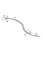
- FIG. 5 shows a side view of the optical fiber assembly in a curved state.
- the plurality of fiber barrel side adhesive portions 22, 22... Provided on the barrel side are for easily handling the plurality of optical fibers 11 and 12.
- the plurality of fiber barrel side adhesive portions 22, 22... Are provided at a plurality of positions with arbitrary intervals, and the plurality of optical fibers 11, 12 are not bonded between the fiber barrel side adhesive portions 22, 22. Has been. With such a configuration, the plurality of optical fibers 11 and 12 are prevented from being entangled or entangled with each other, and the optical fibers 11 and 12 are oriented in any direction as shown in FIG. Can be flexibly curved.
- the second adhesive and the third adhesive constituting the second adhesive part 21 and the fiber body side adhesive part 22... are harder and more flexible than the first adhesive constituting the array adhesive part 20. is there.
- KE45T made by Shin-Etsu silicone, which is a one-component room temperature curable liquid silicone rubber, can be employed as the second adhesive and the third adhesive.
- This adhesive has a durometer hardness of 30 (type A durometer hardness) after curing, and is deformed against external forces such as an elongation rate of 350% when pulled by a tensile strength of 2.0 MPa (megapascal). It has the characteristic that it is easy to do.
- the hardness at curing is a Type A durometer hardness of 5 to 60 and the elongation under the same conditions is 120% to 500%, it can be applied as the second adhesive and the third adhesive. Also, substantially the same effect as described above can be obtained.
- a UV curable adhesive can be used, and specifically, 3168, 3163, 3164D manufactured by Three Bond Co., Ltd. can be used.
- the second adhesive and the third adhesive the same one may be selected and used, or different ones may be selected and used.
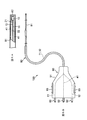
- FIG. 6 shows an optical probe 100 with a built-in optical fiber assembly
- FIG. 6A is a partially broken side view of the tip
- FIG. 6B is a plan view of the whole.
- the optical probe 100 of the present embodiment includes a probe cable 80 in which a plurality of optical fibers 11, 12, 41,... Are passed through a tube 81, an optical connector plug 90 that is connected to an optical device and inputs and outputs light, and the like.
- Consists of The optical connector plug 90 includes a housing 91 having a locking piece 93 that is engaged with a connection portion of the optical device, three ferrules 92 that are joined to the optical axis in the optical device, and the like. Two of the three ferrules 92 and 92 are connected to two optical fibers 11 and 12 of an optical fiber assembly, respectively, and the other one ferrule 92 is connected to a plurality of other optical fibers 41. .
- the array member 10 is fixed in front of the condensing lens 82, and the distal ends of the other optical fibers 41 so as to surround the array member 10 Is fixed.
- excitation light is irradiated by one optical fiber 11 passed through the array member 10, and fluorescence is captured by the other optical fiber 12. Further, illumination light is irradiated by the other plurality of optical fibers 41.
- the optical probe 100 configured in this manner is used as follows to perform fluorescence analysis of the examination site inside the human body. That is, first, the optical connector plug 90 of the optical probe 100 is connected to the optical device, while the probe cable 80 of the optical probe 100 is passed through the insertion / extraction channel provided in the endoscope. Then, the doctor inserts the endoscope into the human body, and moves the distal end portion of the endoscope to the examination site inside the human body while viewing the video of the endoscope. When moving to the examination site, the inside of the human body is observed while bending or twisting the distal end portion of the endoscope in a range close to 180 degrees from the front to the rear. At this time, the distal end portion of the probe cable 80 and the distal end portions of the optical fibers 11 and 12 are similarly bent or twisted following the movement of the endoscope.
- the doctor leads the distal end of the probe cable 80 from the distal end of the endoscope to the outside, and starts the fluorescence analysis process with the distal end directed toward the examination site.
- the illumination of the endoscope is turned off and switched to the illumination of the optical probe 100.
- the illumination of the optical probe 100 stops for a moment, and excitation light is irradiated to the examination site via one optical fiber 11 of the optical probe 100 in the meantime.
- the fluorescence emitted from the examination site due to the excitation light is sent to the optical device via another optical fiber 12 of the optical probe 100. Then, the intensity of the fluorescence and the spectral spectrum are measured in the optical device, and the examination site is analyzed. After such measurement is repeatedly performed on a necessary examination site and necessary measurement data is obtained, the probe cable 80 is disconnected from the endoscope, and the optical connector plug 90 is detached from the optical device. One fluorescence analysis process is completed. Since the optical probe 100 is inserted into the human body, it is discarded every time it is used and replaced with a new one.
- FIG. 7 is an explanatory view showing the flow of the manufacturing process of the optical fiber assembly, and FIGS. 7A to 7F show the first to sixth steps.
- the optical fiber assembly manufacturing process first, as shown in FIGS. 7A and 7B, a plurality of optical fibers 11 and 12 are pulled out and arranged in parallel, and at a plurality of locations where an arbitrary section is opened except for the tip.
- a third adhesive that is hardened with flexibility is applied and cured to bond the plurality of optical fibers 11 and 12 (fiber barrel side bonding step). At this time, it is preferable that the third adhesive is applied and hardened only in the valley portion where the optical fibers 11 and 12 are close to each other. In addition, when the third adhesive is applied so as to bulge out of the two optical fibers 11 and 12, this portion may be wiped off.
- the tip end portions of the optical fibers 11 and 12 are passed through the array member 10 (fiber arranging step), and the first adhesive 20A (the array adhesive portion 20
- the state of the adhesive before curing is represented by reference numeral 20A) is applied to the rear end surface of the array member 10 and is allowed to flow into the inner surface of the through hole 10a (adhesive application step).
- the first adhesive 20A be applied to a degree that rises slightly from the rear end surface of the array member 10 so that a certain level of strength can be obtained.
- excessive application (such as application that swells beyond the outer shape of the array member 10) interferes with other components of the optical probe 100, so that it is required to be controlled to an appropriate amount.
- the second adhesive 21A (the state before the fiber bonding portion 21 is cured is indicated by reference numeral 21A) is applied and cured within a predetermined range from the array member 10 (fiber tip side bonding step). ).
- the position where the second adhesive 21A is applied is a position (a range of 7 mm or less from the rear end of the array member 10) that is separated from the rear end of the array member 10 by a predetermined distance.
- coating and hardening of this 2nd adhesive agent 21A is performed in the process before passing the optical fibers 11 and 12 to the array member 10 of FIG. 7C, or before apply
- the position where the second adhesive 21 ⁇ / b> A is applied is preferably 1 mm or more away from the rear end of the array member 10.
- the first adhesive 20A is cured by heat treatment (adhesive curing step).
- the first adhesive 20A that is uncured and has a low viscosity may flow into the gap between the optical fibers 11 and 12, but the second bonding portion 21 blocks this flow in the middle.
- the hardened portion 20a due to this flow can be shortened.
- the first adhesive of the array adhesive portion 20 is capillarity by the second adhesive portion 21 provided within a predetermined distance range in the vicinity of the array member 10. For example, it is possible to prevent the optical fibers 11 and 12 from flowing over a long interval. Thereby, the flexibility of the tip of the optical fiber assembly can be maintained.
- the second adhesive portion 21 in the vicinity of the array member 10 is provided within 7 mm from the rear end of the array member 10, when the fiber assembly is built in the optical probe 100 and used through the endoscope, The flexibility that can follow the movement of the distal end portion of the endoscope can be imparted to the distal end portion of the optical fiber assembly.
- a plurality of portions in the longitudinal direction of the optical fibers 11 and 12 are bonded by the fiber barrel side adhesive portions 22.
- a plurality of optical fibers 11 and 12 are not bonded in a section between the two. Therefore, the plurality of optical fibers 11 and 12 can be easily handled together, and the plurality of optical fibers 11 and 12 can be bent almost uniformly in any direction.
- the optical probe 100 of the present embodiment when the optical fibers 11 and 12 are passed through the tube 81 of the probe cable 80 by the optical fiber assembly that maintains the flexibility as described above and is easy to handle. Workability is improved. Therefore, the yield of the optical probe 100 can be improved and the manufacturing cost can be reduced. In addition, since the flexibility of the optical fiber assembly is maintained, the flexibility of the probe cable 80 is not hindered.
- an optical fiber assembly in which the two optical fibers 11 and 12 are combined has been illustrated.
- an optical fiber assembly may be configured by combining three or more optical fibers in the same manner.
- an optical fiber assembly may be configured by bonding together optical fibers for illumination. When collecting three or more optical fibers, all the optical fibers may be bonded to each of the fiber barrel side bonded portions, or at least one of the fiber barrel side bonded portions may be bonded.
- the optical fiber may be non-adhered and the other two or more optical fibers may be bonded together, and all the optical fibers may be combined by a plurality of fiber barrel side bonding portions.
- the apparatus that measures fluorescence as emitted light from the measurement target portion has been described as an example.
- the present invention is not limited thereto, and the Raman emitted from the measurement target portion is irradiated with light.
- An apparatus that measures light, scattered light, or the like may be used.
- the present invention can be applied to, for example, an optical probe used in a medical optical analyzer, an optical fiber assembly built in the optical probe, and a method of manufacturing the optical fiber assembly.
- an optical probe or an optical cable used for various purposes it can be applied to an optical fiber assembly incorporated therein and a manufacturing method thereof.
Landscapes
- Physics & Mathematics (AREA)
- General Physics & Mathematics (AREA)
- Optics & Photonics (AREA)
- Engineering & Computer Science (AREA)
- Health & Medical Sciences (AREA)
- Manufacturing & Machinery (AREA)
- Ophthalmology & Optometry (AREA)
- Mechanical Engineering (AREA)
- Endoscopes (AREA)
- Instruments For Viewing The Inside Of Hollow Bodies (AREA)
Abstract
Description
10a 貫通孔
11,12 光ファイバ
20 アレイ接着部(第1接着部)
21 第2接着部
22 ファイバ胴側接着部
80 プローブケーブル
81 チューブ
82 集光レンズ
90 光コネクタプラグ
92 フェルール
100 光プローブ
DESCRIPTION OF
21
Claims (10)
- 複数の光ファイバと、
これら複数の光ファイバを配列させて保持する配列部材と、
硬化性を有する第1接着剤により前記配列部材と前記複数の光ファイバとが固着された第1接着部と、
前記第1接着剤よりも柔軟性を有して固まる第2接着剤により前記複数の光ファイバが前記配列部材の後端から所定の距離範囲内で互いに接着された第2接着部と、
を備えている光ファイバ集合体。 A plurality of optical fibers;
An array member for arranging and holding the plurality of optical fibers;
A first adhesive part in which the array member and the plurality of optical fibers are fixed by a first adhesive having a curing property;
A second adhesive part in which the plurality of optical fibers are adhered to each other within a predetermined distance from the rear end of the array member by a second adhesive that is harder and more flexible than the first adhesive;
An optical fiber assembly comprising: - 前記所定の距離範囲は、前記配列部材の後端から7mm以下である請求項1記載の光ファイバ集合体。 The optical fiber assembly according to claim 1, wherein the predetermined distance range is 7 mm or less from a rear end of the array member.
- 前記複数の光ファイバの長手方向の複数箇所に設けられ当該複数の光ファイバが前記第1接着剤よりも柔軟性を有して固まる前記第3接着剤により互いに接着されたファイバ胴側接着部を備えている請求項1又は2記載の光ファイバ集合体。 A fiber body side adhesive portion that is provided at a plurality of locations in the longitudinal direction of the plurality of optical fibers and that the plurality of optical fibers are bonded to each other by the third adhesive that is more flexible than the first adhesive. The optical fiber assembly according to claim 1 or 2, further comprising:
- 前記第2接着剤と前記第3接着剤が同じ接着剤である請求項3記載の光ファイバ集合体。 The optical fiber assembly according to claim 3, wherein the second adhesive and the third adhesive are the same adhesive.
- 前記複数の光ファイバは3本以上の光ファイバを含み、
前記ファイバ胴側接着部では少なくとも1本光ファイバが非接着にされている請求項3又は4記載の光ファイバ集合体。 The plurality of optical fibers include three or more optical fibers,
The optical fiber assembly according to claim 3 or 4, wherein at least one optical fiber is not bonded at the fiber body side bonding portion. - 前記複数の光ファイバは、コアとクラッドと少なくとも一次皮膜とを有し、繊維皮膜の付されていない心線である請求項1~5のいずれか一項に記載の光ファイバ集合体。 The optical fiber assembly according to any one of claims 1 to 5, wherein the plurality of optical fibers are core wires each having a core, a clad, and at least a primary coating, and having no fiber coating.
- 請求項1~6のいずれか一項に記載の光ファイバ集合体と、
この光ファイバ集合体が通されるチューブと、
このチューブの後端側に設けられて光学装置に接続可能な光コネクタと、
を備え、
前記光ファイバ集合体の前記配列部材が前記チューブの先端側に固定され、前記光ファイバ集合体の後端側が前記光コネクタに連結されて光が入出射可能にされている光プローブ。 An optical fiber assembly according to any one of claims 1 to 6;
A tube through which this optical fiber assembly is passed;
An optical connector provided on the rear end side of the tube and connectable to an optical device;
With
An optical probe in which the array member of the optical fiber assembly is fixed to a distal end side of the tube, and a rear end side of the optical fiber assembly is connected to the optical connector so that light can enter and exit. - 複数の光ファイバと、配列部材と、硬化性を有する第1接着剤と、当該第1接着剤よりも柔軟性を有して固まる第2接着剤とを用いた光ファイバ集合体の製造方法であって、
前記複数の光ファイバの先端部を前記配列部材に保持させて配列させるファイバ配列ステップと、
当該ファイバ配列ステップの前後または途中で前記複数の光ファイバと前記配列部材との接触部位に前記第1接着剤を塗布する接着剤塗布ステップと、
前記塗布された第1接着剤を硬化させる接着剤硬化ステップと、
前記配列部材の後端から所定の距離範囲内の位置で前記複数の光ファイバを前記第2接着剤により互いに接着するファイバ先端側接着ステップと、
を含み、
前記接着剤硬化ステップが前記ファイバ先端側接着ステップの後に行われる光ファイバ集合体の製造方法。 In a method of manufacturing an optical fiber assembly using a plurality of optical fibers, an array member, a first adhesive having curability, and a second adhesive that is harder and harder than the first adhesive There,
A fiber array step in which tips of the plurality of optical fibers are held by the array member and arrayed;
An adhesive application step of applying the first adhesive to a contact portion between the plurality of optical fibers and the array member before, during or after the fiber alignment step;
An adhesive curing step of curing the applied first adhesive;
A fiber tip side bonding step of bonding the plurality of optical fibers to each other with the second adhesive at a position within a predetermined distance range from a rear end of the array member;
Including
An optical fiber assembly manufacturing method in which the adhesive curing step is performed after the fiber tip side adhesion step. - 前記複数の光ファイバを当該光ファイバの長手方向の複数箇所で前記第1接着剤よりも柔軟性を有して固まる第3接着剤により互いに接着させるファイバ胴側接着ステップと、
を含む請求項8に記載の光ファイバ集合体の製造方法。 A fiber barrel side bonding step in which the plurality of optical fibers are bonded to each other by a third adhesive that is harder and more flexible than the first adhesive at a plurality of locations in the longitudinal direction of the optical fiber;
The manufacturing method of the optical fiber aggregate | assembly of Claim 8 containing this. - 前記第2接着剤と前記第3接着剤が同じ接着剤である請求項9記載の光ファイバ集合体の製造方法。
The method of manufacturing an optical fiber assembly according to claim 9, wherein the second adhesive and the third adhesive are the same adhesive.
Priority Applications (2)
| Application Number | Priority Date | Filing Date | Title |
|---|---|---|---|
| US14/122,890 US9389380B2 (en) | 2011-05-31 | 2012-05-11 | Optical fiber assembly, optical probe, and method for manufacturing optical fiber assembly |
| JP2013517839A JP5928456B2 (en) | 2011-05-31 | 2012-05-11 | Optical fiber assembly, optical probe, and optical fiber assembly manufacturing method |
Applications Claiming Priority (2)
| Application Number | Priority Date | Filing Date | Title |
|---|---|---|---|
| JP2011-121644 | 2011-05-31 | ||
| JP2011121644 | 2011-05-31 |
Publications (1)
| Publication Number | Publication Date |
|---|---|
| WO2012164838A1 true WO2012164838A1 (en) | 2012-12-06 |
Family
ID=47258716
Family Applications (1)
| Application Number | Title | Priority Date | Filing Date |
|---|---|---|---|
| PCT/JP2012/003112 WO2012164838A1 (en) | 2011-05-31 | 2012-05-11 | Optical fiber assembly, optical probe, and method for manufacturing optical fiber assembly |
Country Status (3)
| Country | Link |
|---|---|
| US (1) | US9389380B2 (en) |
| JP (1) | JP5928456B2 (en) |
| WO (1) | WO2012164838A1 (en) |
Families Citing this family (1)
| Publication number | Priority date | Publication date | Assignee | Title |
|---|---|---|---|---|
| WO2020021637A1 (en) * | 2018-07-24 | 2020-01-30 | オリンパス株式会社 | Endoscope tip structure and endoscope |
Citations (6)
| Publication number | Priority date | Publication date | Assignee | Title |
|---|---|---|---|---|
| JPS6413008U (en) * | 1987-07-13 | 1989-01-24 | ||
| JPH01115704U (en) * | 1988-01-28 | 1989-08-03 | ||
| JP2002034896A (en) * | 2000-07-27 | 2002-02-05 | Asahi Optical Co Ltd | Optical fiber bundle of endoscope |
| JP2005134824A (en) * | 2003-10-31 | 2005-05-26 | Hoya Candeo Optronics株式会社 | Light guide |
| JP2005237436A (en) * | 2004-02-24 | 2005-09-08 | Fujikura Ltd | Endoscope system using extremely fine diameter composite optical fiber |
| JP2006023639A (en) * | 2004-07-09 | 2006-01-26 | Fujinon Corp | Optical fiber bundle and its manufacturing method |
Family Cites Families (9)
| Publication number | Priority date | Publication date | Assignee | Title |
|---|---|---|---|---|
| GB8713747D0 (en) | 1987-06-12 | 1987-07-15 | Unilever Plc | Skin treatment composition |
| US5073048A (en) | 1987-07-06 | 1991-12-17 | Asahi Kogaku Kogyo K.K. | Optical fiber bundle |
| JPH01115704A (en) | 1987-10-29 | 1989-05-09 | Bridgestone Corp | Low noise tyre wheel |
| JP3450104B2 (en) * | 1995-11-13 | 2003-09-22 | 古河電気工業株式会社 | Optical coupler |
| US7582057B2 (en) | 2004-02-24 | 2009-09-01 | Japan Atomic Energy Research Institute | Endoscopic system using an extremely fine composite optical fiber |
| US7492998B2 (en) * | 2004-08-31 | 2009-02-17 | Corning Incorporated | Fiber bundles and methods of making fiber bundles |
| JP2007132792A (en) | 2005-11-10 | 2007-05-31 | Nippon Sheet Glass Co Ltd | Optical measuring instrument and optical coupling system with sample |
| JP5631585B2 (en) * | 2006-03-22 | 2014-11-26 | コーニンクレッカ フィリップス エレクトロニクス エヌ.ヴィ. | Optical fiber equipment sensing system |
| WO2010137375A1 (en) * | 2009-05-28 | 2010-12-02 | コニカミノルタオプト株式会社 | Optical connector and optical tomograph |
-
2012
- 2012-05-11 JP JP2013517839A patent/JP5928456B2/en not_active Expired - Fee Related
- 2012-05-11 WO PCT/JP2012/003112 patent/WO2012164838A1/en active Application Filing
- 2012-05-11 US US14/122,890 patent/US9389380B2/en active Active
Patent Citations (6)
| Publication number | Priority date | Publication date | Assignee | Title |
|---|---|---|---|---|
| JPS6413008U (en) * | 1987-07-13 | 1989-01-24 | ||
| JPH01115704U (en) * | 1988-01-28 | 1989-08-03 | ||
| JP2002034896A (en) * | 2000-07-27 | 2002-02-05 | Asahi Optical Co Ltd | Optical fiber bundle of endoscope |
| JP2005134824A (en) * | 2003-10-31 | 2005-05-26 | Hoya Candeo Optronics株式会社 | Light guide |
| JP2005237436A (en) * | 2004-02-24 | 2005-09-08 | Fujikura Ltd | Endoscope system using extremely fine diameter composite optical fiber |
| JP2006023639A (en) * | 2004-07-09 | 2006-01-26 | Fujinon Corp | Optical fiber bundle and its manufacturing method |
Also Published As
| Publication number | Publication date |
|---|---|
| US20140093209A1 (en) | 2014-04-03 |
| JP5928456B2 (en) | 2016-06-01 |
| US9389380B2 (en) | 2016-07-12 |
| JPWO2012164838A1 (en) | 2015-02-23 |
Similar Documents
| Publication | Publication Date | Title |
|---|---|---|
| JP4915243B2 (en) | Optical connector | |
| JP5414806B2 (en) | Endoscope with camera housing and method of making camera housing | |
| US10568491B2 (en) | Endoscope | |
| US9158103B2 (en) | Endoscope having adhesives with different bonding strengths | |
| CN105828689A (en) | Imaging device and endoscope device | |
| JP2012230242A (en) | Optical connector | |
| JP5928456B2 (en) | Optical fiber assembly, optical probe, and optical fiber assembly manufacturing method | |
| US8967880B2 (en) | Optical collimator and optical connector using same | |
| WO2015122487A1 (en) | Insertion device | |
| JP7285270B2 (en) | Endoscope | |
| WO2014002882A1 (en) | Optical fiber assembly, method of fabricating same, and probe | |
| JP4280851B2 (en) | Optical connector and manufacturing method thereof | |
| WO2014168187A1 (en) | Optical-fiber module and manufacturing method therefor | |
| US10598868B2 (en) | Sealing a fiber bundle end with glass fritting | |
| JP2009244612A (en) | Optical waveguide attaching component, optical waveguide connector, and method for manufacturing optical waveguide connector | |
| JPWO2007046498A1 (en) | Optical fiber connection coupler and method of attaching optical fiber to the coupler | |
| WO2023106106A1 (en) | Multi-fiber optical ferrule and optical connector | |
| JP2010139526A (en) | Method of manufacturing optical connector | |
| JP5555138B2 (en) | Optical fiber with glass ferrule | |
| JP2009300799A (en) | Optical connector, and method of assembling optical connector | |
| JP2007108796A (en) | Ferrule assembly | |
| JP5477365B2 (en) | Optical connector | |
| EP3591448A1 (en) | Cleaning tool and adhesive body | |
| JP3930265B2 (en) | Ferrule assembly | |
| JP2013059438A (en) | Endoscope |
Legal Events
| Date | Code | Title | Description |
|---|---|---|---|
| 121 | Ep: the epo has been informed by wipo that ep was designated in this application |
Ref document number: 12792238 Country of ref document: EP Kind code of ref document: A1 |
|
| ENP | Entry into the national phase |
Ref document number: 2013517839 Country of ref document: JP Kind code of ref document: A |
|
| WWE | Wipo information: entry into national phase |
Ref document number: 14122890 Country of ref document: US |
|
| NENP | Non-entry into the national phase |
Ref country code: DE |
|
| 122 | Ep: pct application non-entry in european phase |
Ref document number: 12792238 Country of ref document: EP Kind code of ref document: A1 |